! plans df farm buildings - national agricultural library
TRANSCRIPT
! PLANS DF FARM BUILDINGS
U. S. DEPARTMENT OF AGRICULTURE MISCELLANEOUS PUBLICATION NO. 278 REVISEO

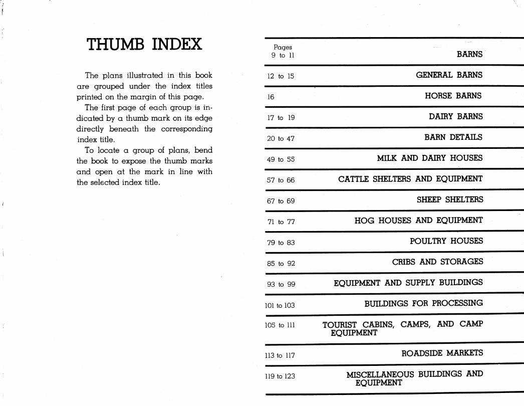
THUMB INDEX
The plans illustrated in this hook are grouped under the index titles printed on the margin of this page.
The first page of each group is in- dicated by a thumb mark on its edge directly beneath the corresponding index title.
To locate a group of plans, bend the book to expose the thumb marks and open at the mark in line with the selected index title.
Pages 9 to 11 BARNS
12 to 15 GENERAL BARNS
16 HORSE BARNS
17 to 19 DAIRY BARNS
20 to 47 BARN DETAILS
49 to 55 MILK AND DAIRY HOUSES
57 to 66 CATTLE SHELTERS AND EQUIPMENT
67 to 69 SHEEP SHELTERS
71 to 77 HOG HOUSES AND EQUIPMENT
79 to 83 POULTRY HOUSES
85 to 92
93 to 99
101 to 103
113 to 117
119 to 123
CRIBS AND STORAGES
EQUIPMENT AND SUPPLY BUILDINGS
BUILDINGS FOR PROCESSING
105 to 111 TOURIST CABINS, CAMPS, AND CAMP EQUIPMENT
ROADSIDE MARKETS
MISCELLANEOUS BUILDINGS AND EQUIPMENT
FOR SALE BY THE SUPERINTENDENT OF DOCUMENTS, WASHINGTON 25, D. G. PRICE $1.00
UNITED STATES GOVERNMENT PRINTING OFFICE • 1951
PLANS OF FARM BUILDINGS FOR NORTHEASTERN STATES
Compiled by
THE BUREAU OF PLANT INDUSTRY, SOILS, AND AGRICULTURAL ENGINEERING AND THE EXTENSION SERVICE IN COOPERATION WITH THE FOLLOWING COLLEGES AND UNIVERSITIES AND THEIR COOPERATIVE EXTENSION SERVICES
College of Agriculture, University of Connecticut.
School of Agriculture, University of Delaware . .
College of Agriculture, University of Maine . . .
University of Maryland
School of Enginering, University of Massachusetts
College of Agriculture, University of New Hampshire
Storrs, Conn.
Newark, Del.
Orono, Maine
College Park, Md.
Amherst, Mass.
Durham, N. H.
New Jersey State College of Agriculture, Rutgers New Brunswick, N. J. University.
New York State College of Agriculture, Cornell Ithaca, N. Y. University.
School of Agriculture, Pennsylvania State College . . . State College, Pa.
School of Agriculture, Rhode Island State College . . . Kingston, R. I.
College of Agriculture, University of Vermont Burlington, Vt.
College of Agriculture, West Virginia University .... Morgantown, W. Va.
UNITED STATES DEPARTMENT OF AGRICULTURE—MISCELLANEOUS PUBLICATION NO. 278—WASHINGTON, D. C. Revised—1950
INTRODUCTION parts of the region where heavy winds
damage.
may cause
TARM BUILDING PLAN SERVICES are organized in
four regions, the Northeast, South, West, and Midwest.
These plan services are conducted cooperatively by
the United States Department of Agriculture, the State
extension services, and in some States the agricultural
engineering departments of the State agricultural col-
leges. The best plans for various types of farm build-
ings developed by the State extension services, the
agricultural colleges, or the Department of Agriculture
are made available to farmers through the plan
services within the region for which they are suited.
HOW PLANS WERE SELECTED
The selection of plans for this publication was made
by a committee representing the State colleges and
universities of the Northeçistern region listed on the title
page. Included are the various types of buildings in
common use throughout this region. These plans
incorporate the latest research findings and the best
available information on the arrangement and con-
struction of buildings for livestock, processing and
storage of farm products, storage of equipment, and
other purposes. The types of construction shown have
been well tested in actual practice. „Special details
are included for barns that are to be constructed in
PLANNING FOR LOCAL CONDITIONS
The plans shown in this book are generally adapted
to conditions of the Northeastern States. A few of the
designs, however, may not be suitable for particular
parts of the region without some modification.
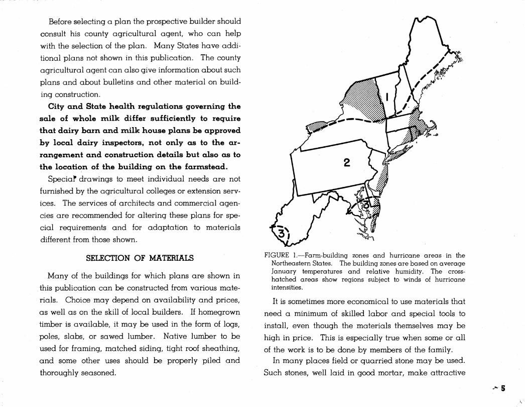
Climatic conditions in the Northeast differ. The map
in figure 1 suggests broad variations in three of the
factors, temperature, humidity, and wind, that must be
considered in the construction of buildings. In zone 1,
insulation and ventilation must be planned to meet
severe winter conditions, whereas in zone 2, although
temperatures well below freezing are to be expected,
winter weather is less extreme. In the small part of
the Northeastern region lying in zone 3 winters are
relatively mild. Naturally temperature and humidity
within these zones are not uniform but vary with altitude
and other local factors. There are no abrupt changes at the zone lines, and, in general, differences are
noticeable only over considerable distances.
In the hurricane areas shown on the map, new build-
ings should incorporate the special construction fea-
tures shown on the drawings to lessen the possibility of
wind damage. Rainfall and soil conditions, as well as
temperature, humidity, and wind, must be considered
in planning for sufficiently deep foundations and for
location and protection of water pipes.
Before selecting a plan the prospective builder should
consult his county agricultural agent, who can help
with the selection of the plan. Many States have addi-
tional plans not shown in this publication. The county
agricultural agent can also give information about such
plans and about bulletins and other material on build-
ing construction.
City and State health regulations governing the
sale of whole milk differ sufficiently to require
that dairy barn and milk house plans be approved
by local dairy inspectors, not only as to the ar-
rangement and construction details but also as to
the location of the building on the farmstead.
SpeciaF drawings to meet individual needs are not
furnished by the agricultural colleges or extension serv-
ices. The services of architects and commercial agen-
cies are recommended for altering these plans for spe-
cial reguirements and for adaptation to materials
different from those shown.
SELECTION OF MATERIALS
Many of the buildings for which plans are shown in
this publication can be constructed from various mate-
rials. Choice may depend on availability and prices,
as well as on the skill of local builders. If homegrown
timber is available, it may be used in the form of logs,
poles, slabs, or sawed lumber. Native lumber to be
used for framing, matched siding, tight roof sheathing,
and some other uses should be properly piled and
thoroughly seasoned.
FIGURE 1.—Farm-building zones and hurricane areas in the Northeastern States. The building zones are based on average January temperatures and relative humidity. The cross- hatched areas show regions subject to winds of hurricane intensities.
It is sometimes more economical to use materials that
need a minimum of skilled labor and special tools to
install, even though the materials themselves may be
high in price. This is especially true when some or all
of the work is to be done by members of the family. In many places field or guarried stone may be used.
Such stones, well laid in good mortar, make attractive
and durable walls. Sand and gravel or broken stone
from the farm can be used for concrete.
New materials and equipment, their suitability, ad-
vantages, and cost, should be compared with those
commonly used. Publications listed in the United States
Department of Agriculture Miscellaneous Publication
60, *'List of Available Publications," contain informa-
tion on building problems. Miscellaneous Publication
60 may be obtained from the Office of Information,
United States Department of Agriculture, Washington
25, D. C. Many agricultural colleges also have bulle-
tins dealing with materials and construction. Informa-
tion about commercial building materials can be ob-
tained from local dealers and from manufacturers.
Booklets about the correct and economical use of many
products are also supplied by trade associations, such
as those listed below. Mention of these associations
implies no endorsement by the United States Depart-
ment of Agriculture nor can any discrimination be
inferred against organizations omitted.
Aluminum Association, 420 Lexington Avenue, New York 17, N. Y. American Institute of Steel Construction, 101 Park Avenue, New
York 17, N. Y. American Zinc Institute, 60 East Forty-second Street, New York 17,
N. Y. Asbestos Cement Products Association, 509 Madison Avenue,
New York 22, N. Y. Asphalt Roofing Industry Bureau, 2 West Forty-fifth Street, New
York 19, N. Y. Barn Equipment Association, Board of Trade Building, Chicago 4,
111. Copper and Brass Research Association, 420 Lexington Avenue,
New York 17, N. Y. Copper Institute, 50 Broadway, New York 4, N. Y.
Douglas Fir Plywood Association, Tacoma Building, Tacoma 2 Wash.
Edison Electric Institute, 420 Lexington Avenue, New York 17, N. Y.
Fir Door Institute, 1205 Rust Building, Tacoma 2, Wash. Gypsum Association, 20 North Wacker Drive, Chicago 6, 111. Insulation Board Institute, 111 West Washington Street, Chicago 2,
111. Metal Window Institute, 806 Rowland Road, Cheltenham, Pa. National Association of Domestic and Farm Pump Manufacturers,
39 South La Salle Street, Chicago 3, 111. National Association of Sheet Metal Distributors, 505 Arch Street,
Philadelphia 6, Pa. National Association of Silo Manufacturers, P. O. Box 30, Nor-
wich, N. Y. National Board of Fire Underwriters, 85 lohn Street, New York 7,
N. Y. National Door Manufacturers Association, 332 South Michigan
Avenue, Chicago 4, 111. National Electrical Manufacturers Association, 155 East Forty-
fourth Street, New York 17, N. Y. National Fire Protection Association, 60 Batteryma^ch Street,
Boston 10, Mass. National Lumber Manufacturers Association, 1319 Eighteenth
Street, Washington 6, D. C. National Paint, Varnish and Lacquer Association, 1500 Rhode
Island Avenue, Washington 5, D. C. National Mineral Wool Association, 1270 Sixth Avenue, New
York20, N. Y. National Retail Lumber Dealers Association, Ring Building,
Washington 6, D. C. National Woodwork Manufacturing Association, 332 South Mich-
igan Avenue, Chicago 4, 111. Northeastern Lumber Manufacturers Association, 271 Madison
Avenue, New York 16, N. Y. Portland Cement Association, 33 West Grand Avenue, Chicago
10, 111., and 347 Madison Avenue, New York 17, N. Y. Red Cedar Shingle Bureau, 5510 White Building, Seattle 1, Wash. Southern Pine Association, Canal Building, New Orleans 4, La. Structural Clay Products Institute, 1520 Eighteenth Street NW.,
Washington 6, D. C. Vermiculite Institute, 208 South La Salle Street, Chicago 4, 111.
The cost of a building will vary v\rith local wage rates
and prices of material. Before a correct estimate can
be made, it must be decided how much material and
6
labor is to be supplied by the farm and whether the
work is to be done on the basis of day labor, or cost
of material and labor plus a bonus, or by contract.
The most accurate way to learn the cost is to submit
plans and specifications to two or three local builders
and obtain written bids for the complete work. All
bidders should be required to submit bids on the same
quality of materials, equipment, and workmanship.
HOW TO ORDER WORKING DRAWINGS
Workinq drawinqs for any buildinq in this publica-
tion may be ordered from the State extension aqricul-
tural enqineer at most of the State colleqes in the
Northeastern reqion. A nominal charqe, varyinq in
the different States, may be made to cover printinq and
mailinq costs.
Residents of Rhode Island may obtain workinq draw-
inqs by writinq to the extension aqricultural enqineer,
University of Massachusetts, Amherst, Mass.
In orderinq plans, be sure to qive the number of the
plan wanted as well as the title.
If for any reason you cannot obtain the workinq
drawinqs of the plan you want, write to the Division
of Farm Buildinqs and Rural Housinq, Bureau of Plant
Industry, Soils, and Aqricultural Enqineerinq, United
States Department of Aqriculture, Beltsville, Md. This
office cannot send you the workinq drawinqs, but it
will direct you to the nearest State that can supply the
plan you want.

BARNS
General Barn, drawing No. 5635; Horse Barn, draw-
ing No. 5640; and Dairy Barns, drawings Nos. 5628,
5629, and 5630, show only floor plans and are so de-
signed that they may be built of either frame or masonry
in any of the roof types illustrated on the following
pages. The detail sheets that go to make up a com-
plete set of working drawings are shown on pages 20
to 44. In ordering working drawings for any of the
above-mentioned plans, be sure to give not only the
drawing number of the barn plan but also the title and
drawing number of each of the detail sheets reguired
to build the type of barn you want. If in doubt as to
the detail sheets you need, consult your county agricul-
tural agent.
Working drawings for all other barn plans shown in
this publication are complete in themselves but may be
built of materials other than those shown by ordering
the appropriate detail sheets.
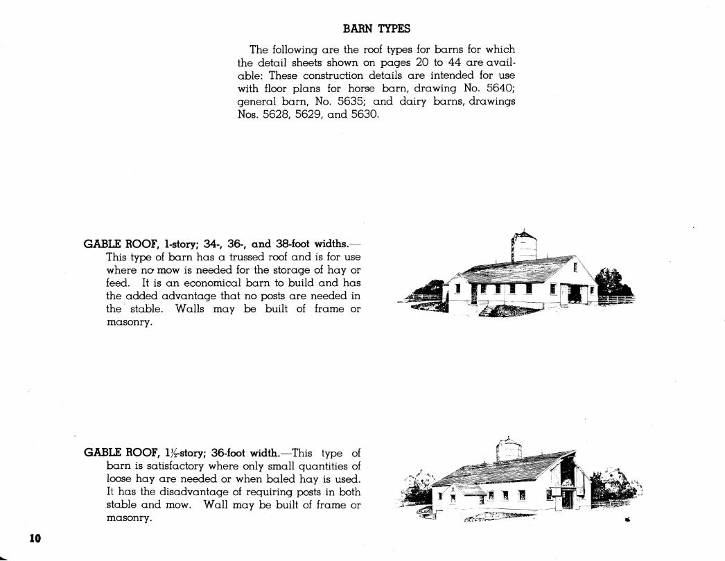
BARN TYPES
The following are the roof types for barns for which the detail sheets shown on pages 20 to 44 are avail- able: These construction details are intended for use with floor plans for horse barn, drawing No. 5640; general barn. No. 5635; and dairy barns, drawings Nos. 5628, 5629, and 5630.
GABLE ROOF, l-story; 34-, 36-, and 38-foot widths.— This type of barn has a trussed roof and is for use where no- mow is needed for the storage of hay or feed. It is an economical barn to build and has the added advantage that no posts are needed in the stable. Walls may be built of frame or masonry.
GABLE ROOF, l}^-story; 36.foot width.—This type of barn is satisfactory where only small quantities of loose hay are needed or when baled hay is used. It has the disadvantage of requiring posts in both stable and mow. Wall may be built of frame or masonry.
10
^ A É
■ií?
íSí < '''?
>rH, k 'Sí ^' " ^líis^ -'^ »íA fecr^^^ n^"-^ m ■■^^^^^^
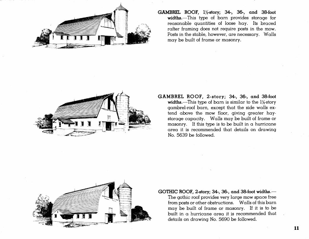
GAMBREL ROOF, IK-story; 34-, 36-, and 38-foot widths.—This type of barn provides storage for reasonable quantities of loose hay. Its braced rafter framing does not require posts in the mow. Posts in the stable, however, are necessary. Walls may be built of frame or masonry.
GAMBREL ROOF, 2-story; 34-, 36-, and 38-foot widths.—This type of barn is similar to the l^-story gambrel-roof barn, except that the side walls ex- tend above the mow floor, giving greater hay- storage capacity. Walls may be built of frame or masonry. If this type is to be built in a hurricane area it is recommended that details on drawing No. 5639 be followed.
GOTHIC ROOF, 2-story; 34-, 36-, and 38-foot widths.— The gothic roof provides very large mow space free from posts or other obstructions. Walls of this barn may be built of frame or masonry. If it is to be built in a hurricane area it is recommended that details on drawing No. 5690 be followed.
11
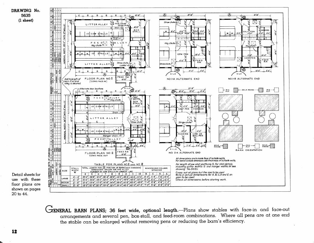
DRAWING 5635
(1 sheet)
No.
Detail sheets for use with these floor plans are shown on pages 20 to 44.
TABLE FOR PLANS NO.l AND NO. 2
STALL WIDTH
w
TOTAL LENGTH FOR (A) PORTION OF BARN (INSIDE DIMENSION) DIMENSIONS INCLUDE ONE END ALLE.Y
NUMBER 0\- COW STALLS IN LONGEST LINE
3'-8" 3'-6'
21-0"
19-0"
26-8"
23-4" 22-6"
27-0" 26-0"
35-4"
29'-G"
39-8"
as'-o'
44-0'
38-0"
48-4" 45-0" 41-8" 40-0"
49-0" 49-0"
SI LO
NO. I-A ALTERNATE END
SILO
NO. I-B ALTERNATE END
L_J ""'• I I BARN ORIENTATION
NO. 2-A ALTERNATE END
ä-a' 8'-0" 7-4" 7^-0"
6-0" 5-8" 5-4" 6-8" I0'-6"
A// dimensions are fo inside face of outside walls. Fbr overall outside dimensions add ifiickness of outside walls.
For length of œw stall platforms S. for stall details Including gutter widths 6 and manger widths M see drawing No. 5661. Cross out all plans but the one to t^ used. Write in actual dimensions tor A. B. C, D and £ on plan fo be used. Check all dimensions before starting work.
GENERAL BARN PLANS,- se feet wide, optional length.—Plans show stables with face-in and face-out arrangements and several pen, box-stall, and feed-room combinations. Where all pens are at one end the stable can be enlarged without removing pens or reducing the barn's efficiency.
12
l'^x-4"Brace on underside of
* T J~ ~¡ Carry foundations -LI 1 below frost and to
V'^'^^-A ^ood bearing soil:
\ SECTION OF GAMBREL ROOF BARN SCALE ié"=1-0 "
NOTE: Hay chutea and ladder shown for gambrel roof barn.
WIRING SYMBOLS O Ceiling outlet
OPS Ceiling auf let with pull switch =© Convenience outlet s Switch
NOTE: Use utility light on extension cord for mow.
DRAWING No. 5166
(1 sheet)
K
G
Additional de- tail sheets sug- gested: Nos. 5661; 5107; 5175; and 5697..
Details for ma- sonry walls: Drawing Nos. 5669; 5670.
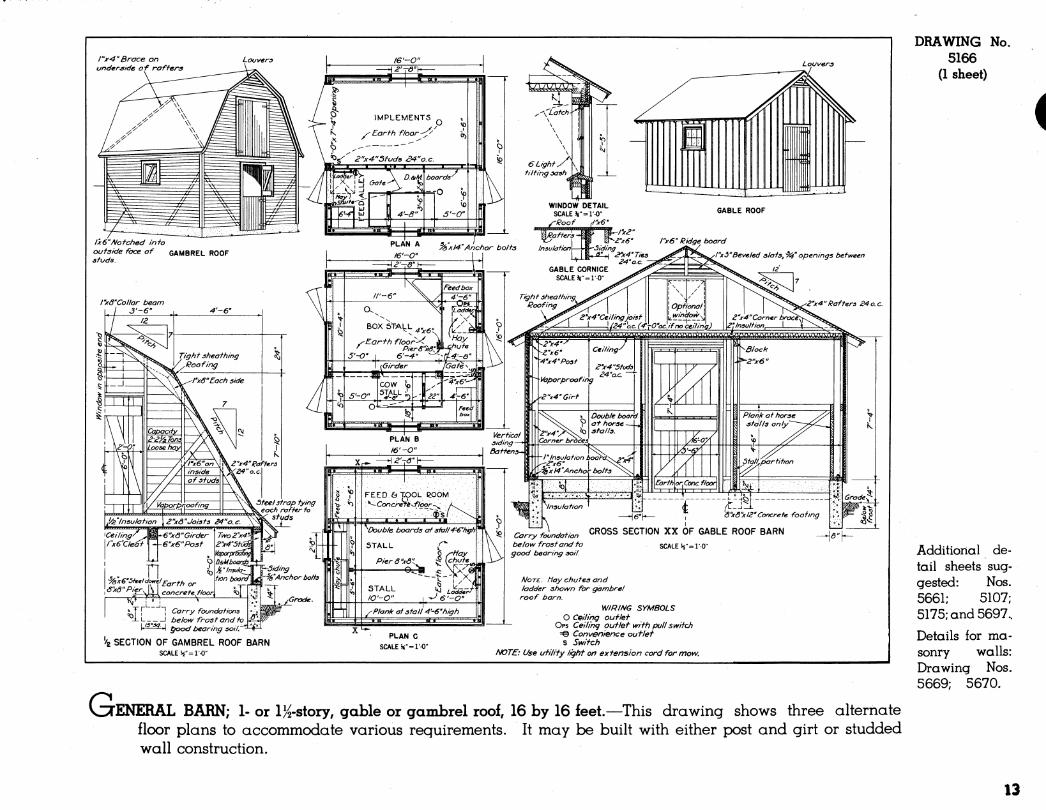
ENERAL BARN; 1- or l}^-story, gable or gambrel roof, 16 by 16 feet.—This drawing shows three alternate floor plans to accommodate various requirements. It may be built with either post and girt or studded wall construction.
13
DRAWING No. 5167
(1 sheet)
Additional sheets sug- gested: Nos. 5631; 5697.
Details for ma- sonry walls: Drawing No. 5670.
_/'4"«4" POSTS TIGHT SHEATHiNG-
MOW FLOOR
END FRAMING ELEVATION SCALE 4 ""''"O"
DOOR SCHEDULE (T) 3'-6"« 7-A' DUTCH DOORS. ® 3'- O"« Y-A' @ 3'-0"x 6'- Ô" SINGLE DOOR..
@ 2'-a"x 6'-ô"
WIRING SYMBOLS
O CEILING OUTLET =^ CONVENIENCE
OUTLET S SWITCH
NOTE: Use UTILITY LIGHT ON EXTENSION CORD FOR MOW.
HORSE STALL DETAIL SCALI
ALL D! j-e4'»''-o''
FLOO.R PLAN SCALE. ^'-I'-O'
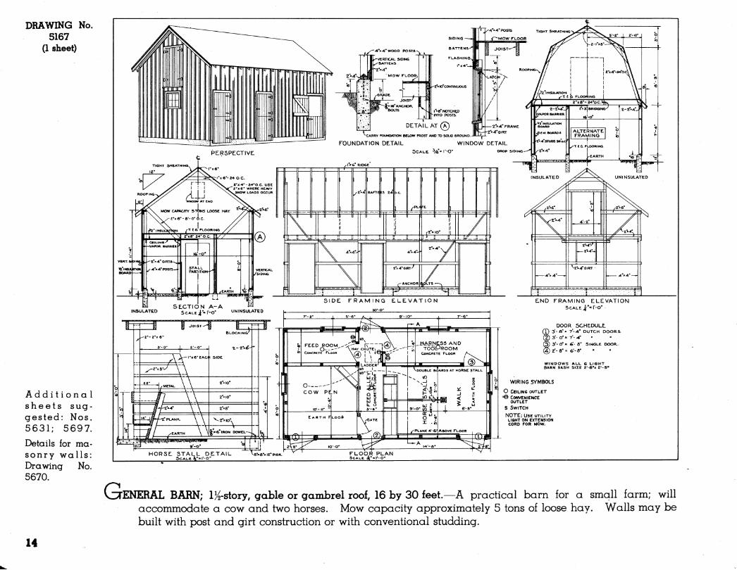
VITENERAL BARN; l}^-story, gable or gambrel roof, 16 by 30 feet.—A practical barn for a small farm; will accommodate a cow and two horses. Mow capacity approximately 5 tons of loose hay. Walls may be built with px)st and girt construction or with conventional studding.
14
MOIV CAPACtT^ loos£ HAY: 0.2 TONS PER UN,FT. BALED HAY ■ MAX. DEPTH ¿'/Z FT.
:PLÀJ^ SCAL
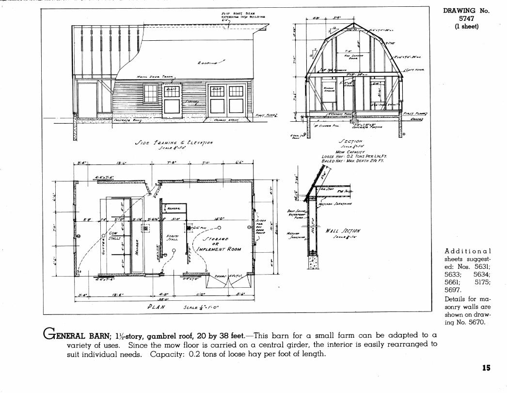
VCTENERAL BARN; l^íS-story, gambrel roof, 20 by 38 feet.—This barn for a small farm can be adapted to a variety of uses. Since the mow floor is carried on a central girder, the interior is easily rearranged to suit individual needs. Capacity: 0.2 tons of loose hay per foot of length.
DRAWING No. 5747
(1 sheet)
Add i t i o n a 1 sheets suggest- ed: Nos. 5631 5633; 5634 5661; 5175 5697. Details for ma- sonry walls are shown on draw- ing No. 5670.
15
DRAWING 5640
(1 sheet)
No.
Detail sheets for use with these floor plans are shown on pages 20 to 44.
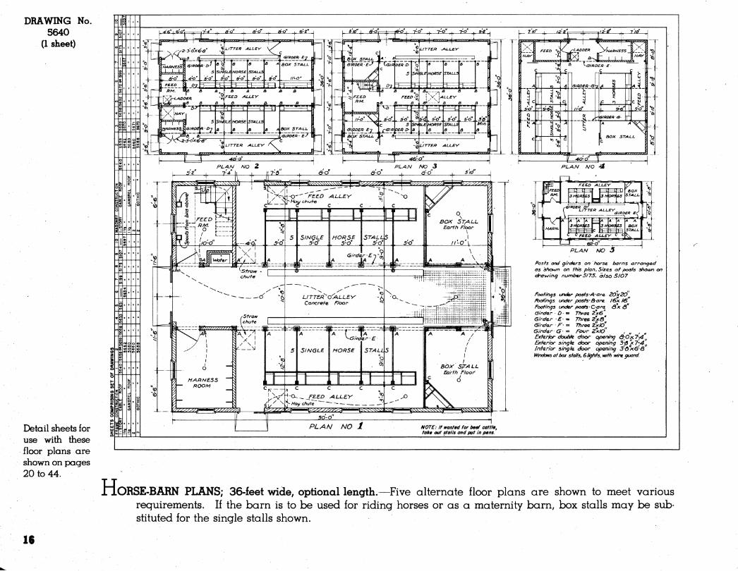
H ORSE-BARN PLANS; 36-feet wide, optional length.—^Five alternate floor plans are shown to meet various requirements. If the barn is to be used for riding horses or as a maternity barn, box stalls may be sub- stituted for the single stalls shown.
16
DRAWING 5628
(1 sheet)
No.
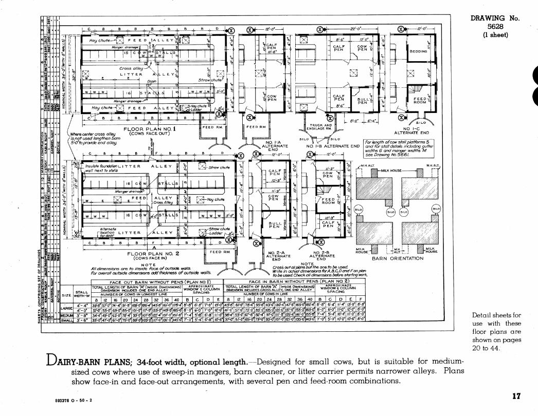
JL)AIRY-BARN PLANS; 34-foot width, optional length.—Designed ior small cows, but is suitable for medium- sized cows where use of sweep-in mangers, barn cleaner, or litter carrier permits narrower alleys. Plans show face-in and face-out arrangements, with several pen and feed-room combinations.
Detail sheets for use with these floor plans are shown on pages 20 to 44:
893378 O - 50 - 2 17
DRAWING No. 5629
(1 sheet)
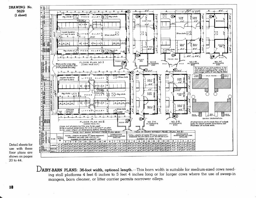
Detail sheets for use with these floor plans are shown on pages 20 to 44.
JL)AERY-BARN PLANS: 36-foot width, optional length.—This barn width is suitable for medium-sized cows need- ing stall platforms 4 feet 6 inches to 5 feet 4 inches long or for larger cows where the use of sweep-in mangers, barn cleaner, or litter carrier permits narrower alleys.
18
DRAWING 5630
(1 sheet)
No.
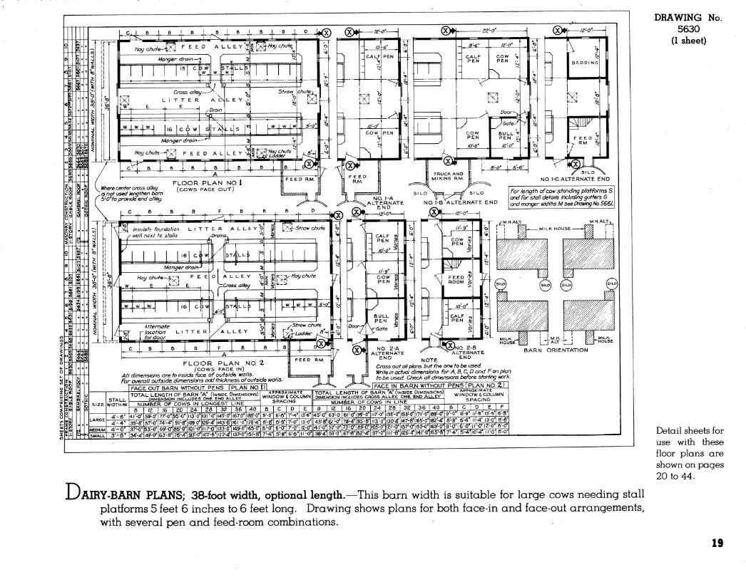
JUAIRY-BARN PLANS; 38-foot width, optional length.—This barn width is suitable for large cows needing stall platforms 5 feet 6 inches to 6 feet long. Drawing shows plans for both face-in and face-out arrangements, with several pen and feed-room combinations.
Detail sheets for use with these floor plans are shown on pages 20 to 44.
19
DRAWING 5658
(1 sheet)
No.
Not illustrated: DRAWING No.
5665 (I sheet)
For barns 38 feet wide
Details for ma- sonry walls are shown on draw- ing No. 5669.
Trusses, 24'''o.c.- 2'x4-' nailed fo inside of studs
2''x4''block-
- rx6'nai/ed fo lont^er edge of rafters on bofh end 4i bofh roof slopes of barn
Naif siding fo all rxS" diagonal braces nofched info sfuds
MATERIAL FOR ONE ROOF TRUSS 34 OR 36 FOOT WIDTH
Raffars 3 - 2''X4"KI4'
ri9s 3 - 2"x4'xl2'
Inner braces 2 - 2''x4''x/2'
Oufer braces 1 - 2'r4''x/4'
l^erfical struts 1 - 2''x4''x 14'
Gussets Appnox. Id sq. ft 4^' pliji^ood
Nails 6d, 2.Ö lbs.
Length of barn
^5« BRACING DIAGRAM
Fasten 2-2 plates tv/ffy 16 d nai/s, S'o. c.
ISOMETRIC DETAIL OF TRUSS
Foundation to reach solid ground belom^ frost line FRAMING CROSS SECTION
Scott '/4" = I'- 0" 4" drain tile-/ around foundation
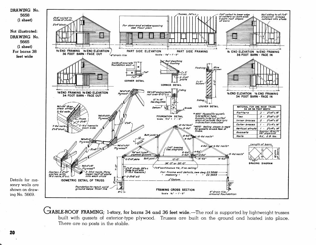
VITABLE-ROOF FRAMING; 1-story, for barns 34 and 36 feet wide.—The roof is supported by lightweight trusses built with gussets of exterior-type plywood. Trusses ore built on the ground and hoisted into place. There are no posts in the stable.
20
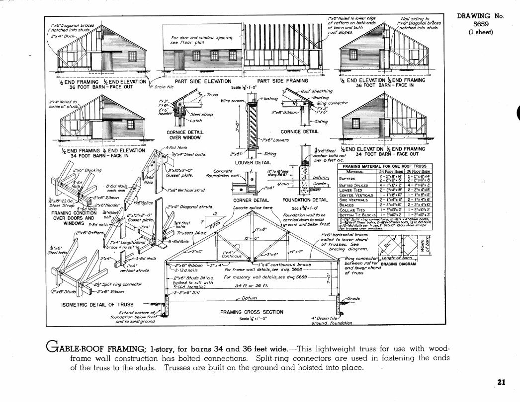
/"xô" Nailed to loyver edge of rafiers on bo+h ends of barn and both roof slopes.
Nail siding fo rx 6" Diagonal braces notched into sfuds.
% END ELEVATION ifeEND FRAMING 36 FOOT BARN - FACE IN
Roof sheathing
■Roofing Ring connector
'x3" x6'
^'xió-steei i^END ELEVATION 'y^ END FRAMING ■anchor bolts not 34 FOOT BARN - FACE OUT over 6 feet o.e.
1 FRAMING MATERIAL FOR ONE ROOF TRUSS | MATEEIAL 34FOOTBAEN 36FOOTBAEN
RAFTERS 2-2"x6"xl4' 2 - Z'-xG-x 6'
2-2"x6"xl4' 2-2"x6"xô'
CAFTCR SPLICES 4 - 1 ''x6"x 2' 4- I"x6"x2' LOWER TIES 2-2''x4"xl6' 2-2"x4"xlô' CENTER VERTICALS 1 - I"x8"xl0' 1 - I"x8"xl2' SIDE VERTICALS 2- I"x4"x6' 2- rx4"x6' BRACES 2-2"x4"xlO' 2-2"x4"xlO' COLLAR TIES 1 - 2"xlO"x V 1 -2"xlO"x2' BOTTOM TIE BLOCKS l-2"xlO"x2' 1 -2"xKyx2' £-2^' Sprit ring connectors, IZ-%'* ^-4'Steel bolts, 2-%'ix4-Steel bolts,2-%'*x6'Steelbolts, i±lb.ôdNails Ô IO-l6d Noils per truss, ¿-^'xld'-/8Ga. steel straps for trusses over windows.
/"x6' horizontal braces nailed to loiver chord of trusses. See
bracing diagram. \2s/- I-
Ring ronne>'C+ar | ^ Length of barn ^ | between rafter BRACING DIAGRAM and lower chord of truss
Grade
ta» 4'Drain tile^ around foundation
DRAWING 5659
(1 sheet)
No.
CuABLE-ROOF FRAMING; 1-story, for barns 34 and 36 feet wide. -This lightweight truss for use with wood- frame wall construction has bolted connections. Split-ring connectors are used in fastening the ends of the truss to the studs. Trusses are built on the ground and hoisted into place.
21
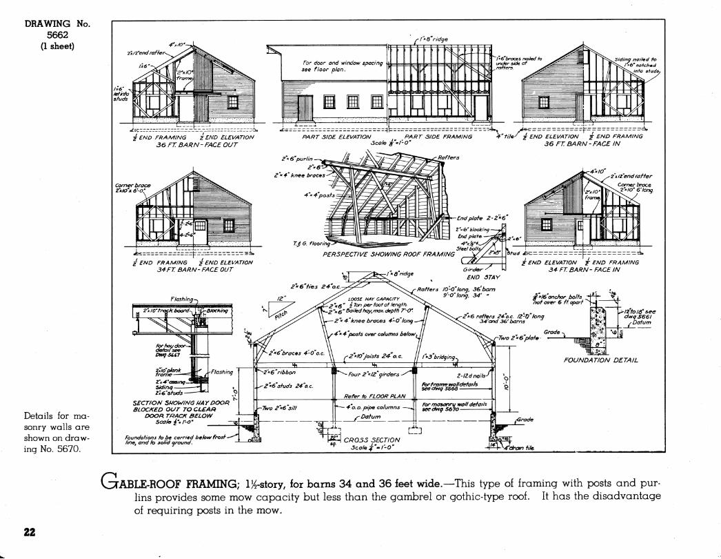
DRAWING No. 5662
(1 sheet)
Details for ma- sonry walls are shown on draw- ing No. 5670.
/-¡""6" ridge
j END FRAMING i END ELEVATION 36 FT BARN-FACE OUT
Corner brace Z'KIO'X 6'-O^
PART SIDE ELEVATION PART SIDE FRAMING Scale ^"'I'-O"
file^ j END ELEVATION J ^^^ FRAMING 36 FT BARM - FACE /N
^"x 6"purlin
¿"x^" knee braces
'4-'" 4-''posf-^
Rafters
T.^ G. flooring
¿END FRAMING ¿ END ELEVATION 34FT BARN-FACE OUT
End plate Z-Z^'S
—I Z'^b' blocking- 3 End plate. ■
Steelbolh. ,,,. , PERSPECTIVE SHOWING ROOF FRAMING \//¿'<Q
2"»e"fies 24''o.c. ^<^^
Oir-der-^ U
END STAY
ö/oching
Z\^'aosinq^ Sidinq Zxe'studs -
■Flashing
SECT/ON SNOWING NA Y DOOR BLOCKED OUT TO CLBAR
DOOR TRACf( BELOW Scah í'M I-O'
Foundations to be carried be/ow frost line, and to solid ground.
Rafters lO'-O"long. 36'l>am ^ ^ S'-O' lona. 34' "
LOOSE HAY CAPACITY ^O^ ^ * 6 " i Ton per foot of length.
"^Q" Bailed hay, max. depth J'-O".
2"x 4'knee braces 4-0"long
-4 * 4 "posts over columns below^
Z'^IO'Joists 24-"o.e.
2"6 rafters 24 o.e. 12-0 lona 34'and 36'barns
Two 2"^6"plate
y^Z"" 6" ribbon
2"xe'studs 24"o.c.
^Two 2x6 s ill
Four 2"" 12" girders
Refer to FLOOR PLAN
- 4 0.0. pipe columns
y^ Datum
W CR055 SECTION ^' Scale ^"'^ I'-0"
é END ELEVATION T END FRAMING 34 FT BARN'FACE JN
^""16'anchor bolts j not over S ft apart
Grade -
M—^ ■ ^12'toiei'sec
dwgS66l /■Datum
'vO 1 Wh
FOUNDATION DETAIL
'¡rade
-^!^^4'drain file.
C3TABLE-ROOF FRAMING; IK-story, for barns 34 and 36 feet wide.—This type of framing with posts and pur- lins provides some mow capacity but less than the gambrel or gothic-type roof. It has the disadvantage of requiring posts in the mow.
22
4-9'' 7'-3
4" file
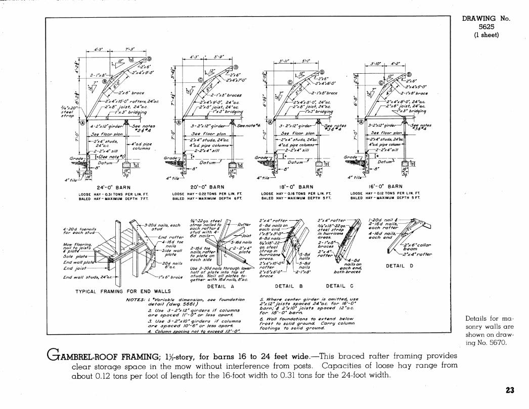
24'-0" BARN LOOSE HAY-0.31 TONS PER LIN. FT. BALED HAY-MAXIMUM DEPTH 7 FT
20'-0" BARN l8'-0" BARN l6'-0" BARN
LOOSE HAY BALED HAY
■0.22TONS PER LIN. FT. ■MAXIMUM DEPTH 6 FT.
LOOSE HAY BALED HAY
• 0.16 TONS PER LIN. FT. -MAXIMUM DEPTH 5 FT.
LOOSE HAY BALED HAY
-0.12 TONS PER LIN. FT. -MAXIMUM DEPTH 5 FT.
4-20d foe nail s for each sfud
3-20d nails, each stud
End naffer 4-l6d foe
nails Side wall
piafe
•^"-22^0. of eel ¿frap nailed fo each raff er 4 sfud ivifh 4- 6d nails
£nd wall piafe End joisf
End wall sfuds, 24''ac.-Y-
20d nails 6" o.e.
Tx 6" brace
2-l6d foe nails, raff er fo piafe on each side
Use 3-30d nails fhrouqh loiver^ half of piafe info fop of sfuds. Nail all piafes fo- gefher tvifh 16anails, a'ac.
l-20d nail 4 2-l6d nails, each naffer 4-l6d nails, each end
—¿"jf 6 "collar beam
-2''x 4" raffen
TYPICAL FRAMING FOR END WALLS DETAIL A DETAIL B
-4-ôd nails on
each end, bofh Jbnaces
DETAIL C
DETAIL D
NOTES: / *i/'aniable dimension, see foundation de fail fdwg, 5661 )
2. Use 3-2"x 12' girders if columns are spaced ll'-O' or Jess apart
3. Use 3 -2"X10' girders if columns are spaced 10'-6" or less apart.
4. Column spacing nof fp exceed /2'-0''.
Ó. Where center girder is omitted, use 2'x 12'Joists spaced 24'ac. for 16'-C barn; 4 2"x 10" joists spaced l2"o.c. for /Ô'-C barn.
6. yVall foundations to extend below frost to solid ground. Canny column footings to solid g noun d.
DRAWING 5625
(1 sheet)
No.
Details for ma- sonry walls ore shown on draw- ing No. 5670.
r^ VCTAMBREL-ROOF FRAMING; IX-story, for barns 16 to 24 feet wide.—This braced rafter framing provides
clear storage space in the mow without interference from posts. Capacities of loose hay range from about 0.12 tons per foot of length for the 16-foot width to 0.31 tons for the 24-foot width.
23
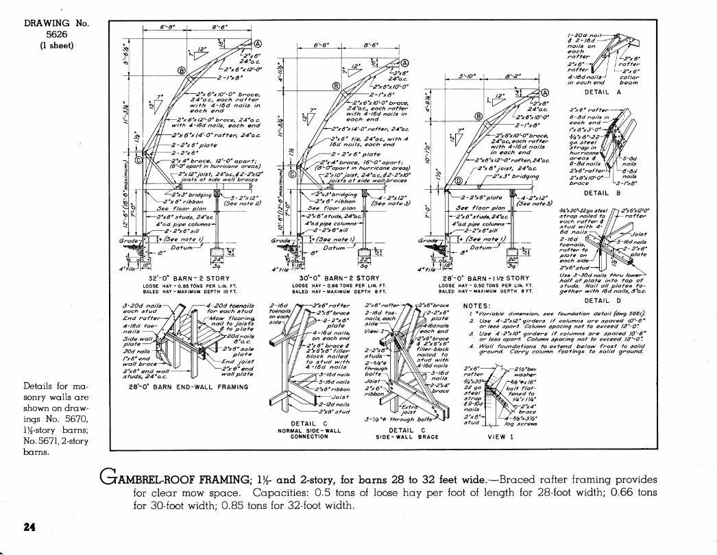
DRAWING 5626
(1 sheet)
No.
Details for ma- sonry walls are shown on draw- ings No. 5670, l)^-story barns; No. 5671,2-story barns.
32'-0" BARN- 2 STORY LOOSE HAY-0.85 TONS PER LIN. FT. BALED HAY-MAXIMUM DEPTH 10 FT.
30'-0" BARN-2 STORY LOOSE HAY-0.66 TONS PER LIN. FT. BALED HAY-MAXIMUM DEPTH 8 FT.
28'-0" BARN-11/2 STORY LOOSE HAY - 0.50 TONS PER LIN. FT. BALED HAY-MAXIMUM DEPTH 8 FT.
â-20d nails each stud
£nd rafter
4-l6d foe- nails
Side ^all^ plate
20d nails
lyS" end H/'ail brace
2"x6' end t^all studs, 24"o.e.
4-20d toenails for eacfi afud
-Mo\^ flooring, nail to Joists
"* to plate
-20d nails 6''o.c.
2''x6" sole plate
-£nd Joist
2''x6'' end uwall plate
2-l6d toenails on each¡ side
28'-0" BARN END-WALL FRAMING
-2 "xô" rafter
2''x6'' brace
-2-2"x6" plate
4-/6d nails, on each end
_ "x 6" brace / 2 y 6'x 6" filler block nailed to si-ud kvith 4-l6d nails
'3 -i6d nails
5-l6d nails
2 "x 6" ribbon
Joist
-2-l2dnaHs
2''x6'' stud
DETAIL C NORMAL SIDE-WALL
CONNECTION
2"x 6" rafter
2-l6d toe nails, each side
Vieiiv
2"x6'' brace
f2-2''x6' plate
i-l6dnalls /each end
?''x6''brace 2''x6"x6''
filler-block nailed to stud v\/ith
\4-l6d nails
2''x6'' rafter
4-lôd nails in each end
DETA
2''x6'' rafter
6-öd nails each end
rxo^J'-O' ■^y4yô"-22 ga. steel strap in hurricane areas 4 6-Sd nails
2''x6'rafter
2'x6yi0'-0' brace
DETAIL
'3A'x20'-22ga steel strap nailed to each rafter 4 stud i/^ith 4- 6d nails-
2-l6d toenails, rafter to plate on each side-
2''x6''stud-
Use á-30d nails thru lo^er^ half of plate into top of studs. Nail all plates to- gether ki^ith /6d nails, ó'ac.
DETAIL D
3-'/¿'''P through
DETAIL SIDE-WALL
NOTES: / * Variable dimension, see foundation detail (dtvg. 5661).
Use 4-2'x 12"girders if columns are spaced lO'-ô" or less apart. Column spacing not to exceed 12'-O'.
Use 4-2'xlO'' girders if columns are spaced lO'-â" or less apart. Column spacing not to exceed 12'-O".
yVall foundations to extend belo^ frost fo solid ground. Carry column footings to solid ground.
^'/è'be^/. v\/asher
^ya-'i>xl6'' bolt flat- tened to
lyWxI'A'
-2"x4'' brace
■4-'Va''x3y2'' lag screivs
VIEW
CAMBREL-ROOF FRAMING; 1^- and 2-story, for barns 28 to 32 feet wide.—Braced rafter framing provides for clear mow space. Capacities: 0.5 tons of loose hay per foot of length for 28-foot width; 0.66 tons for 30-foot width; 0.85 tons for 32-foot width.
24
Z'xIZ'end raffen at hay doon only Z'xé" raffen. 2'xi»' sfuds
Nail siding to all l'Are" diagonal bnaces
>tched info sfuds
1/2 END FRAMING 1/2 END ELEVATION 36 FT. BARN FACE OUT (34 FT. IS SIMILAR)
6-ôd nails iya''x3'-0' 2-1^8
Wx/8''22ga. sfeelsfnap, in hurricane area é-&d nails- ¿"xe'raffers^
PART SIDE ELEVATION PART SIDE FRAMING Scale: 1/8"= I'-O
1/2END ELEVATION 1/2 END ELEVATION 36 FT BARN FACE IN (34FT IS SIMILAR)
Sole piafe End wallplo\ End Joisf
End wall sfuds, 24''o.c.—'-
2-20d nails
4-20 d foenails for each sfud
(*4-30d naits, hay door end 4 6 -JOd nails, rear end wal ' '
Mow flooring, nail to Joisf s 4 piafe
3-20dC'2-4Od4l-30d) nails, each sfud
End raff er .4-l6d(*4-20d) foenails
Side wa//p/afe
® Z-Z'AQ' sfuds—
3-30d nails^ 2-2'j(&'L^^^^
DETAIL (T)
l-30d nail ^ 2''x6* end rafter
2-40dnails^ 2'/(8' end wall sfud—
DETAIL @
3-30dnails^ 2^8'
A-20d nails
(HURRICANE AREAS*)
4 ßoofsheaf hing, fasten •p^V^ with 8d nails k'o. c.
^^^2'x 6'piafe 2-30d nails
(HURRICANE AREAS*)
NOTE : All details and nailing marked with an asterisk (*)are recommended for use in areas subject to hurricanes. HOTE- In hurricane areas, ¿"x8"sills, sfuds and plates shall be used for end wall framing.
Scale. 1/2"» I "^Use 5-Z'x I4'girder if column spacing is more ffian l2'-0'
m^^*''^ drain
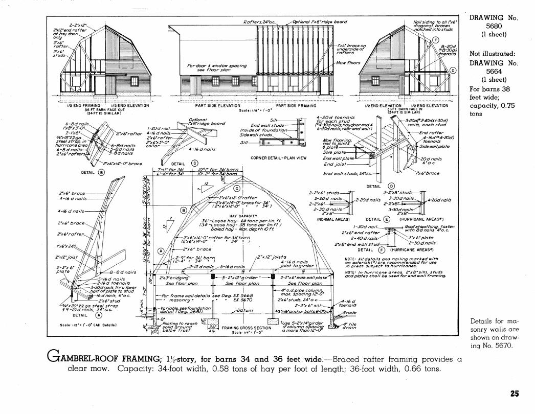
G AMBREL-ROOF FRAMING; l^-story, for barns 34 and 36 feet wide.—Braced rafter framing provides a clear mow. Capacity: 34-foot width, 0.58 tons of hay per foot of length; 36-foot width, 0.66 tons.
DRAWING 5680
(1 sheet)
No.
Not illustrated: DRAWING No.
5664 (1 sheet)
For barns 38 feet wide; capacity, 0.75 tons
Details for ma- sonry walls are shown on draw- ing No. 5670.
25
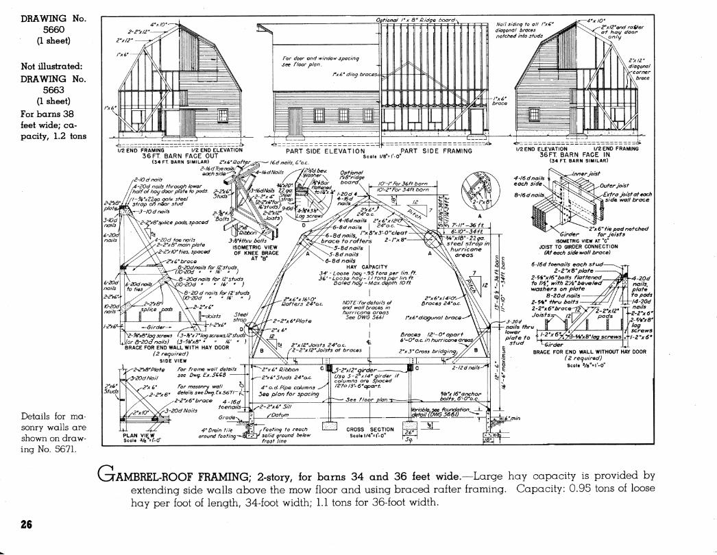
DRAWING 5660
(1 sheet)
No.
Not illustrated: DRAWING No.
5663 (1 sheet)
For barns 38 feet wide; ca- pacity, 1.2 tons
Details for ma- sonry walls are shown on draw- ing No. 5671.
^AMBREL-ROOF FRAMING; 2-story, for barns 34 and 36 feet wide.—Large hay capacity is provided by extending side walls above the mow floor and using braced rafter framing. Capacity: 0.95 tons of loose hay per foot of length, 34-foot width; 1.1 tons for 36-foot width.
26
Z'X/2' ñJD^JS
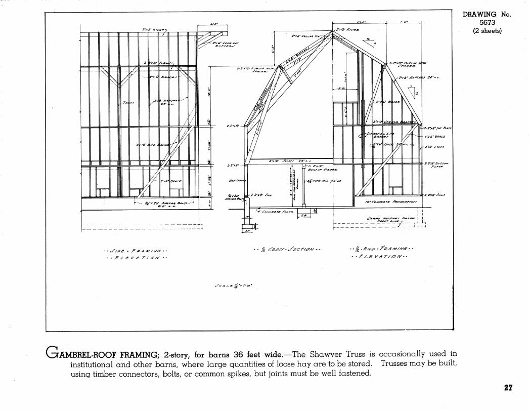
DRAWING No. 5673
(2 sheets)
1 I
• ' £ ¿. £ i^ y1 r / ¿PA/ ' '
J C/i^/y- J'^cr/^py^ - -
^c:^^^ ^y^'~/-o'
CuAMBREL-ROOF FRAMING; 2-story, for barns 36 feet wide.—The Shawver Truss is occasionally used in institutional and other barns, where large quantities of loose hay are to be stored. Trusses may be built, using timber connectors, bolts, or common spikes, but joints must be well fastened.
27
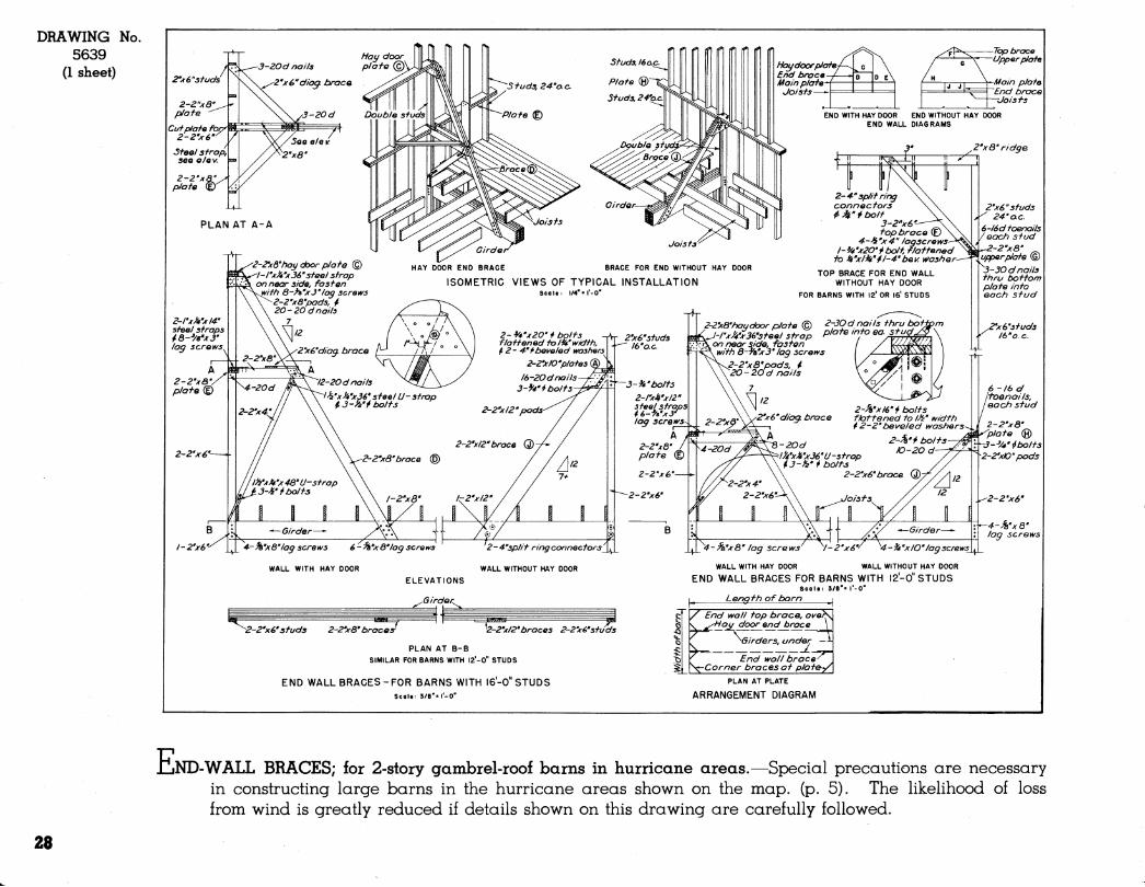
DRAWING No. 5639
(1 sheet)
JLJND-WALL BRACES; for 2-story gambrel-roof barns in hurricane areas.—Special precautions are necessary in constructing large barns in the hurricane areas shown on the map. (p. 5). The likelihood of loss from wind is greatly reduced if details shown on this drawing are carefully followed.
28

4"x/0'' 2''x/0''f/e 2"xl2' ¿"x/O £'x/0'
Rafi^rs 24''o.c. v / 2"x8''coi/ar fies A/a/7 sidinq fo /"xß" díagonai braces
-notched info siuds
1/2 END FRAMING •/£ END ELEVATION FACE-OUT BARN
2-2yô"plai-e 2-20d nails. /oM^&n piafe fo eacf) pad 7-20d nails each pad. or 2-^A''*ffirubolfs 2-2'x6"sfuds
PART SIDE ELEVATION PART SIDE FRAMING 4''drainfile '/2 END ELEVATION '/2 END FRAMING Seal«: '/8"« I'-O" FACE-IN BARN
2'ifâ"collor f/es. 2-4" o. c.
3-ply raffers builf up tyifb rxlO boards cuf on ou fer edge fo suif radius gi\/en. All buffs sfaggered 2'-0" (See defaii of nai/tnq) Each raffer consisfs of 14 - 6'- O" secfions, plus fhe foiiotvinq:
Firsf pig - 2'- O"secfIon af ridge Cenfer - - 4'-0" - each end Third " - 2'-0" " af piafe
CAPACITY Loose hag - /. 2 fons per lin. ff. Baled hag - Max. depfh lOff.
Buff join fin firsf pig S-ôdnails fhru all 3 pigs, each side of each join f
Buff joinf in f bird pig
Z-2''x8"blocking 4^ 6-öd nails _
(fhru sheafhing). 2-2''xd "blocking ^ 0-6 d nails
(fhru sheaf hing) 3-pig raffers End raffer —
3-30d nails fhru longer half piafe fo sfuds. Mai/piafe fo- gefher tyifh I6d, 6" o.e.
r-2-l2dnails/j ±1 5-2"xl2"a/rders —
'(Lise 5-2yi4" if columns are spaced 12-O'fo I3'-6''J
See floor plan
■•—For frame y^aii de fails see Dkif^g. EX. 566Ô " masonrg •• - » » « 5670
"—4"od.pipe columns Da furn
Joisfs
END WALL BRACE (4 required) 4''drain file
Foofing fo reach I I solid ground beloiv frosf line
FRAMING Scale: '/4'
/ 2"xô " corner brace ' t^ifh 5-20d nails af each end
5-20d f^^.fs^ /foenails
4-l6d foenails
-5-16 d nails 4 • 16 d foenails
2''x 12"joisfs 24"o.c. I /— 2''x3 ' bridging
Sfuds
2-2''x8" piafe - Diag. brace
Moiv floor 4'l6d
/foenails ^ 2y6''
sole piafe
'2-x6' piafe
tVindoiv i/nfe/ Sfuds (4'ôd foenai/s, fop * boffom)
~ Diaqona/ brace
FRAMING AT CORNER
^ ^ariable.see defaii^ r^ \[ (Dy^g.5660
SECTION ^6'5q\" •-I'-O" ^ ^
V3TOTHIC-ROOF FRAMING; 2-story, for barn 34 feet wide.—This type of roof may be framed with factory- built rafters or with the home-made rafters shown. Capacity: 1.2 tons of loose hay per foot of length.
DRAWING 5687
(1 sheet)
No.
Not illustrated: DRAWING No.
5688 (1 sheet)
For barn 36 feet wide; ca- pacity, 1.39 tons
DRAWING No. 5689
(1 sheet) For barn 38 feet wide; ca- pacity, 1.43 tons
Details for ma- sonry walls are shown on draw- ing No. 5670.
29
DRAWING 5690
(1 sheet)
No.
¿"X 6'studs.
-â-2''xô"p/ate Z'xS" studs. 24 "o. c. Z'xó" b/ock/ng 2'x 6' brace, 7-0' a boue f/oor
£nc/ rafter sect/ors are same as tor rorrra/ areas——
2''x4''pad at eact) j'o/rt bettveen sect/'o/7S ot end ratter
2-2 "xâTend ^a// brace 2-2''x6' studs ¿'xô'so/e pJate
A/foi^/ t/oar
-3-20d nai/s to each stud
Space s tads /6 'o. c. tor at /east 4-0' eac/t s/de ot iÉ.
4-20d toena//s,
each stud
J-JOd na//s ¿'xS"corner brace iv/th 5-30d na//s at eact? end
A/ai/ sheath/nç to 2-2''xâ' b/oc/</n^ iv/th 6-/0d na//s—
Naif sheath/ng to 2-2'xô'' b/oc/<7nq vi^/th /2-/Od na//s
SOd na//s, /2Qa staggered
H-2y6'stud ^^-Vs'xô' /a^ scretvs
TYPICAL INSTALLATION (34'-0"a 38-0" WIDTH BARNS)
-/-¿"xô"brace
tag scretvs
DETAIL B
5-20d toena//s, each stud
2-/Od na//s to each stud
5-20d toena//Sf each stud
/ffd naiJs, 6''o.c. staggered
4-20d toena//s, each stud 2-/0d na//s to each stud 4.-20d toena//s, each stud
'/2 ELEVATION -
tJOT£: S/ze ot mem/bers, 4 fastening deta//s are same as apec/f/ec/ for 34'-0''43S -O" barns above.
WITH HAY DOOR I/2 ELEVATION - WITHOUT HAY DOOR
TYPICAL END WALL FRAMING SCALE: 1/4"= r-0"
Langi-h ot barn
2'x6' Studs
ô-2''xS''pJat9
3--Vf' thru bo/ts
2-2'x/2'pads
£-2'x6'' studs TYPICAL INSTALLATION (36'-0" WIDTH BARNS)
END WALL BRACE (4 REQUIRED)
¿-'/^'xZO"bo/ts f/aftened to /V4''i^/dth and 2-4''4> beu^e/ed t^ashers
3-V^' thru bo/ts
4-20d nat/s, each pad
2-2''xS' brace 7
PLAN AT PLATE
ARRANGEMENT DIAGRAM
DETAIL A SCALE: I"= r-0"
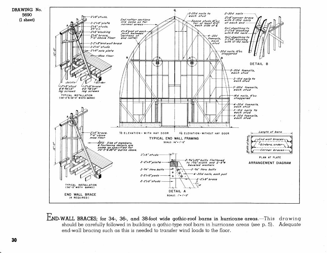
JCJND-WALL BRACES; for 34-, 36-, and 38-foot wide gothic-roof barns in hurricane areas.—This drawing should be carefully followed in building a gothic-type roof barn in hurricane areas (see p. 5). Adeguate end-wall bracing such as this is needed to transfer wind loads to the floor.
30
SUGGESTED CEILING SECTIONS
11/2 8 2 Story Barns
fr-
I Story Barns
R=ao U=0.1II
\^ar\mí]anf\f\ñf\í\nÁ 5: ao94
"-I'AG'D^M flooring '— ¡deflective insulation
(shiny surface both sides) ^— l'x¿>'D4'M boards
'— Air space, both sides
m 2'baf, blanket or fill
insulation or 3'dry shavings
- Vapor barrier * Ceiling finish (Any type
shown on this sheet)
\Cold areas of ZONE I (Large or small barns) |
R = 787 U = 0.I27
I'— l'xi>'D 4-M flooring ^^z'insulation board
'~ Vapor barrier * I X^"0 4-M boards
t n A mann nnnnn A/^/i -\ir\( -lR=8.i; Í U=O.I
2'dry shavings
'— Vapor barrier * Ceiling finish (Any ;
shown on this shee
\Average areas of ZONE KLorge or small borns)|
T R = 7I4 U= 0.14
l'xé'D^M flooring ^%2'insulation board
Vapor barrier * '— /'^'asbestos-cement b'd hard- board or ext type plywood
Ç —1R = 6. 3u=o.
= 6.94 144
Reflective insulation (3hiny surface t>oth sides)
^—l'xtí'Di'M boards
Warm areas of ZONE I (Large or small barns) Cold areas of ZONE 2(Large or small borns)
I R = 6.74 U= 0.148
- l'xá>'D^M flooring ^/sz'insulation board
Vapor t>arrier *
r 1 R=6.36 s^saau=0.157
^%z' insulation board — Vapor txjrrier * I'xi.'D^M boards
{Average areas of ZONE 2(Large or small barns)]
f ñAow floor Joist - Ceiling Joist
R=5.68 U=0.I76
^ l'xi,'D i M flooring rxé'D 4-flA boards
T R=5.55 U=0.I8
I Warm areas of ZONE 2 (Large or smoll boms) |
'%2' insulation board ~ Vapor barrier *
- 'Wcement asbestos board, hard board or plywood
* Vapor txjrriers stKilltx. either shiny-surfaced building paper infused with asphalt, or metal foil When insulation board is used as inside finish, the vapor t>arrier shall be two coats of asphalt base aluminum -flake paint applied to the inside surface of the board.
SUGGESTED WALL SECTIONS
'M'drop siding or metal siding 5'/¿'dry shavings, or commercial fill insulation
Vapor barrier *
l'x^'D4M boards or %' exteriorior type plywood
Cold areas of ZOHE I (Large or small barns)
R = 12.09 U= 0.083
- ^/4."drop siding or -/a exterior type plywood
-Z'quilt or blanket insulation
•—Vapor barrier *
-rxé'D 4M boards or ^a"exterior type f^y wood
Cold areas of ZONE \ (Large or small barns)
R = 7.46 U=0.I34
;
Bevel siding
I'xá>' sheathing
Reflective insulation (shiny surface t>oth sides) ys' exterior type plywood or I'x a," D f-MI boards
5tud Average areas of ZONE I
(Large or small barns)
R = 6.07 U= 0.165
Bevel siding
^32"insulation btoard
I'x é>' boards
Vapor barrier *
'/à'asbestos -cement tx^ard or hard board
Asbestos - cernen t
'/z'gypsum sheathing
^z'insulation board
Vapor barrier *
'M'fiard board
Cold areas of ZONE I (Large barns) Warm areas of ZONE KSmall barns) Cold areas of ZONE 2 (Large,SmaLI)
Warm areas of ZONE I (Large barns) Average areas of Z0NE2(Large barns) Warm areas of ZONE 2 (Large,SmoH)
R = 4.58 U = 0.219
-Asbestos -cement, asphalt or metal siding
n "/3z"insulation board
h—I'x é' boards
-Vapor barrier ^
—'/e'asbestos -cement board or hard board
Average areas of ZONE KLorge born^ Cold areas of ZONE 2 (Large barns) Average areas of ZONE 2(Small barns)
L
-Bevel siding
—Bui/ding paper
—l'x(o' sheathing
-I'xá>'DIM boards or exterior type plywood
Warm areas of ZONE I ( Large barns) Average areas of ZONE 2 (Large barns) Warm areas of ZONE 2 (Large,Small)
R=3.76 U= 0.267
V't'drop siding
^Vsz ' Ínsula fian b>oard
Vapor barrier *
'/8"hardboard or asbestos -cement tjoard
Stud
Average areas of ZONE I (Large barns) Cold areas of ZONE 2 (Large barns) Average areas of ZONE 2(Small borns)
■ ^' drop siding
■ Building paper
- I'x¿'04-M boards or Wexterior type plywood
-Stud \Warm areas of ZONE 2(Lorge borns) |
NOTE' These wall and ceiling sections show types of con- struction suitable for the temperature zones shown on the map at right.
In most cases the insu I - ating value is minimum for the part of zone indicated.
DRAWING 5668
(1 sheet)
No.
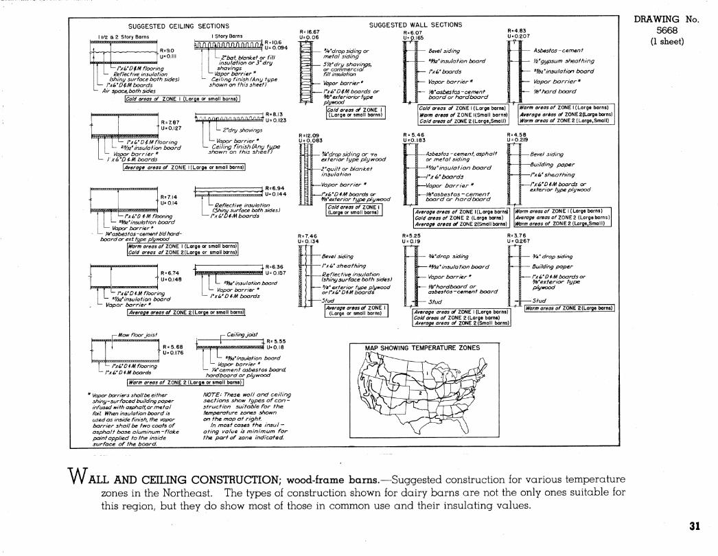
w ALL AND CEILING CONSTRUCTION; wood-frame barns.—Suggested construction for various temperature zones in the Northeast. The types of construction shown for (dairy barns are not the only ones suitable for this region, but they do show most of those in common use and their insulating values.
31
DRAWING No. 5669
(1 sheet) Sheathing-
P/ywood gusset^
Clip angle^
® - /Insulation board
._^ (T)| \ /jj\/aportkinrier ^^-^
Ceiling finish \S"x6'ptot€
8 "KÔ"continuous œncrefe beam '/z "xZ-Tanchor bolts, 6-0" o.e. è"x. Cx y^'p/ate washer
—<9'>( l2"xlZ" structural clay tile units
Flashing- ^2_ Weep holes^
Grade wm^
Carry footing to firm soil below frost line \
^Insulation ■Waporbarrier (A)
^/Ceiling finish '"J'xô'plate S'x B'M "continuous concrete beam
'z"xl'-3"anchor bolt5,5'-^"o.c.
^^''x4'xWpiafe washer
'Metal ties every other course
J%'
- 4" X S "x lé "concrete j¡/^' masonry units "
Datum-
Ceiling finish
Grade
^3"xâ-plate
^8"tie rod hooked to U-bolt after wall is laid up, spaced 5-4"oc in concrete masonry wall and é'-Co.ein structural clay tile wall
Concrefe masonry or structural clay tile units
After tie rod is in place fill space with mortar and close opening with split unit
yz" U-bolt set 12"in .WA concrete foundation m ^-
Datum-
j —I" furring
"Vapor barrier (I) Inside finish
r furring -Insulation board yapor barrier (I)
■Inside finish
Granular insu'f.
Vapor barrier (2)
Z "cavity I" furring
-Vapor barrier (I) Inside finish
Z" cavity I" furring Insulation board Vapor barrier (I) ■Inside finish
CONCRETE MASONRY STRUCTURAL CLAY TILE
CAVITY WALL CONCRETE MASONRY
CAVITY WALL STRUCT. CLAY TILE
WALL DETAIL FOR HURRICANE AREAS
Scale 3/4"= I'-0"
SUGGESTED WALL CONST
FOR VARIOUS TEMPERATURE ZONES
MAP SHOWING TEMPERATURE ZONES TABLE DESCRIBING SUGGESTED WALL 8 CEILING CONSTRUCTION FOR VARIOUS TEMP
6"con.masonry or struct, day file
ff'conmasonry orstructclaytile
WALL CONSTRUCTION
ff'con. masonry orsfructclayfile
4'con. masonry or struct clay tile
4'con.masonry orstruct clay file
4''con. masonry orstruct. chy file
4'con.masonry orsfructclayfile
JiinsuL board Asbestos cement,
hard board orplastei
Voids filled with granular insul.
Cavity filled wiff) granular insul.
^ insul board
INSIDE FINISH
^/4'D^t^ boards
APPR.
4.48
optional
W cement plaster
optional
WD $1^ boards
Asbestos cement, hard board or plaster
5.93
5.00
3.75
7.00
5.73
7.18
CEILING CONSTRUCTION
Winsul board Asbestos cement or hard board
Z"commercial or 3" dry shavings
VIood.asbestos cement, hard board or plywood
Winsul. tfoard
Z"commercial
INSIDE FINISH
lO.GQ
Asbestos cement, or hard board
Wood.asbestos cement, or S dry shavings hard board or plywood
5.55 Ceiling
10. éO
5.55
10.60
lO.GO
Z(warmpart)
Walls $ ceiling
Zkoldparf) ¡(warm part)
Walls 4 ceiling
Ceiling
Walls i ceiling
Ceiling
men ^"^"^ ^ 10.60 ceiling
ZONES
/ Z(warm part)
Ceiling constructions need not be used with wall construction shown and may t>e used with any other wall construction suitable for the same zone.
NOTE: (l)Vapor barriers to be building paper in/used and coated v^ifh asphalt or metal foil. (Zyaporbarrier fobeZ coats asphalt base aluminum-flake paint applied to inside surface. (3) Ply wood tobe exterior type.,.^ (4)0-0" to be used with MangerKAU. ^-v
6'-6"fobe used with Manger^BprKQ 5ee Dwg. 5661 for details
{5)For details of roof trusses see dwgs. EX. 565S for 34 ft t 36 ft barns and EX. 5665 -for 38 ft barns.
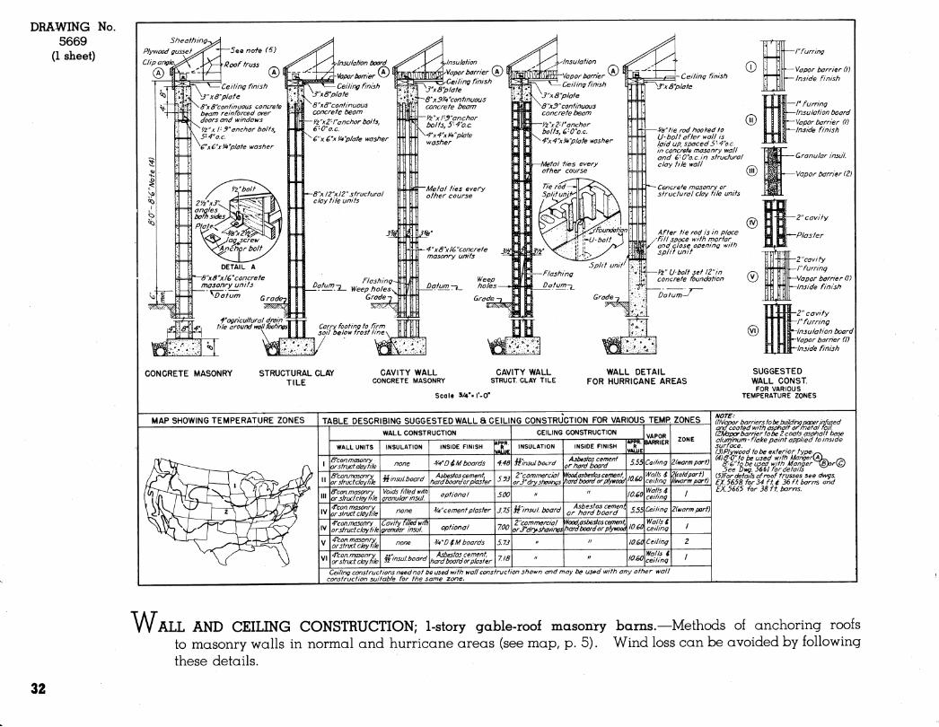
vJ ALL AND CEILING CONSTRUCTION; 1-story gable-roof masonry barns,—Methods of anchoring roofs to masonry walls in normal and hurricane areas (see map, p. 5). Wind loss can be avoided by following these details.
32
Sheathing^ -I" furring
'—Vapor barrier (I)
•'^Inferior finish
I' furring Insulation board
\—Vapor barrier (I)
■Inside finish
-Granular insu I.
IÏ"— Vapor barrier(Z)
CONCRETE MASONRY a FRAME
STRUCTURAL CLAY TILE
CONCRETE MASONRY STRUCT. CLAY TILE CAVITY WALL CONCRETE MASONRY OR STRUCT.
CLAY TILE UNITS Scale V4"=r-0"
-Z"cavily -/" furring
^Vopor barrierd) "Inside finish
-2" cavity -I" furring ^Insulation board "-Vapor barrierd) "Inside finish
SUGGESTED WALL CONST. FOR VARIOUS
TEMPERATURE ZONES
MAP SHOWING TEMPERATURE ZONES TABLE DESCRIBING SUGGESTED WALL a CEILING CONSTRUCTION FOR VARIOUS TEMP ZONES
S'con.masonry or struct day file
o'conmasonry orjtructclayfil^
WALL CONSTRUCTION
ff'con. masonry or struct, clay file
4'con. masonry or struct, clay file
4'con. masonr\f or struct clay tik
4'con. masonry or struct clay tile
INSULATION
Hinsul.board 'Wasbestos cement^ t>ard board or plywood
Voids filled Witt) granular insul.
Cavity filled with granular insulation
4 con. masonry 2r:„^..,u^ , /A'asbestos cement, or struct clay file fi msul.board t)ard board or plywood
INSIDE FINISH .PPR.
^A'DiM boards
.ïâUL 4.48
^Wcement plaster
3/4"D$M boards
5.33
5.00
3.75
é.34
5.58
7.16
CEILING CONSTRUCTION
INSULATION
jzinsuf. board
ST insu I board
Qeflectiveinsul wit/) airspace eactiside
INSIDE FINISH APPR.
YAUtfS
C.74
^/4-D4M boards
JdrysHavings ^^¿-^^g^^j^. 12.10
^W D $ fiA boards
Z"t)lonlcetj bat, or 'Wastiestos cement, fill insulation hard boardorplywood
if;^^.,i h^^^^ ^asbestos cement, St insuL board hard board or plywood
^WD 4M boards
Ceiling
7.87 Walls $ ceiling
5.é8
12.10
713
9.00
I average
Walls 4 ceiling
Walls 4 ceiling
Ceiling
Z average
I cold part
2¥varmpart
Icoldpart
I warm port Z cold part
I cold part
Ceiling const ructions need not be used with wall construction shown and may be used with any other wall construction suitable for the same zone.
NOTE: llWapor barriers to be buildingpc^rinfused and coated with asphalt or metal foil. (¿Wapor barri er tobe 2 coats asphalt base alurninum - flalce paint applied to inside surface. (3)Pluwaod lobe exterior type. (4)In hurricane areas, top masonry walls withS'x&'concrete beam reinforced over ojpeninas. (5) &- u" to be used with MangerÇ£)
6 '- é" to be used with Manger (§)orlQ See Dwg. 5661 for details.
DRAWING 5670
(1 sheet)
No.
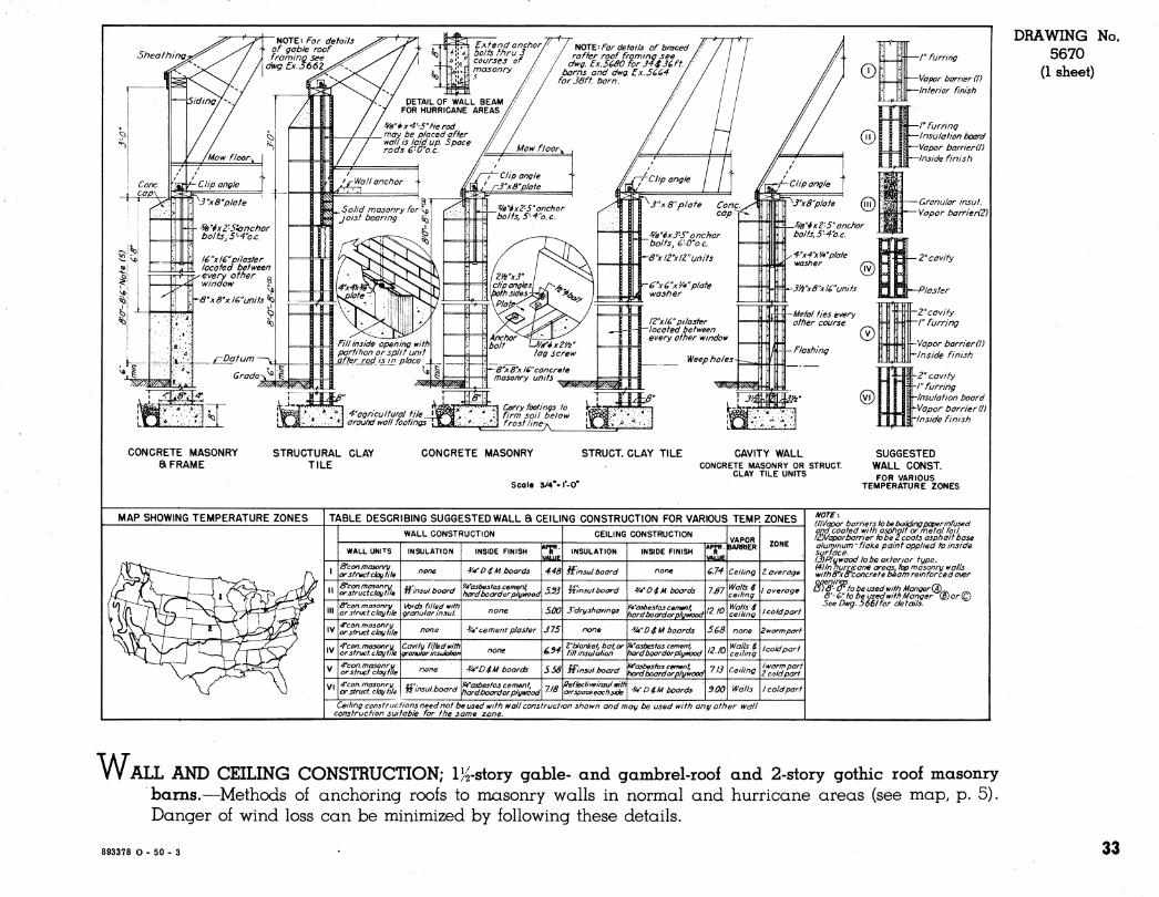
w ALL AND CEILING CONSTRUCTION; IK-story gable- and gambrel-roof and 2-story gothic roof masonry bams.—Methods of anchoring roofs to masonry walls in normal and hurricane areas (see map, p. 5). Danger of wind loss can be minimized by following these details.
893378 O - 50 - 3 33
DRAWING 5671
(1 sheet)
No. Roofing
Sheathing.
Steel strap
-/" furring
Vapor barriera)
"^Inside finish
¡'furring
fapor barrier (I) ■Insul board
-Inside finish
Granular insulation
"^por barrier (Z)
■Plaster
■Z'cavity
furring Z' cavity
T~ Vapor barrier (I)
\*-lnside finish
Z'cavity 'furring
—Insulation board
Vapor barrier (I) *-In side finish
CONCRETE MASONRY a FRAME
CONCRETE MASONRY STRUCTURAL CLAY TILE a FRAME
SHOWING ALTERNATE METHOD OF ANCHORING
STRUCT CLAY TILE CAVITY WALL CONCRETE MASONRY OR STRUCT
CLAY TILE UNITS
SUGGESTED WALL CONST
FOR VARIOUS TEMPERATURE ZONES
Scale 1/2" = I -O"
MAP SHOWING TEMPERATURE ZONES TABLE DESCRIBING SUGGESTED WALL a CEILING CONSTRUCTION FOR VARIOUS TEMP ZONES
&con.masonry or struct day tile
ô'con. masonry orstructclaytile
WALL CONSTRUCTION
8'con. masonry or struct clay file
4'con. masonry orstructclaytile
4'con. masonry or struct ckxj tile
4'con masonry or struct clay hie
INSULATION
iz'insul bcxjrd 'Wasbestos cement, hard board or plywood
Voids filled with granular insul.
Cavity filled with granular insulation
INSIDE FINISH
^A'DiM boards
%'cement plaster
^D^M boards
wi 4'con masonry Jtsl'i^.,,, i,^^^^ 'M'asbiestoscement, -, ,f. Reflective insul with «,, n ^ i>i <.^-w a nn Wn/u ^^ or struct day tile TÜ^'"^^'^°^'^d hard board or plymod ^'^ airspaceeochside ^D$M boards 9.00 Walls
'4.48
5.93
5.00
3.75
6.94
5.58
CEILING CONSTRUCTION
INSULATION
fflnsul board
Winsul board
31'dry shavings
¿'blanket, bat or fill insulotion
it Insul txxjrd
INSIDE FINISH
WDilA boards
Wasbestos cement tiard board or plywood
^4fD4,M boards
Ik'asbestos cement, hard boardor plywood
Wasbestos cement, hard board or plywood
6.74
7.67
5.68
IZ.IO
7.13
Ceiling 2 (average)
Walls $ ceiling
leverage)
Walls $ ceiling
Walls i ceiling
Ceiling
I (coldpart)
2(worm part)
Ifpoldpart)
¡{worm port) Z(coldpart)
I (coldpart)
Ceiling constructions need not t>e used with wall construction shown and may be used with any other tvall construction suitable for the same zone.
NOTES: U) Vcpor barriers tobe buildingpaperinfused ana coated with asphalt or metal foil. (2)\/oport>arrier tobe Z coats asphalt base aluminum -flake paint applied to inside surface. 13)Plywood to be exterior type. (4) Innurricane areas, top masonry walls with 8'xô'concrete beam reinforced over openings. ^^ 15) &-(y to be used with Manger®
d'-6' to be used with Manger (B)or\Q See Dwg. 5661 for details.
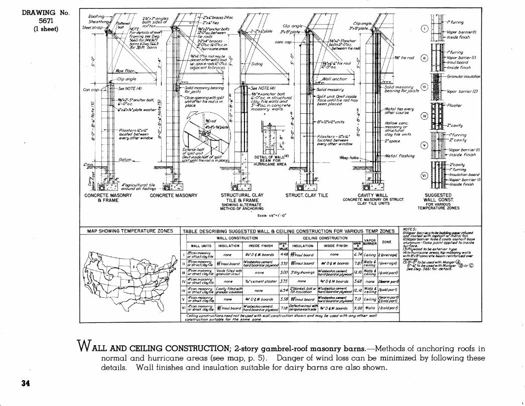
W. ALL AND CEILING CONSTRUCTION; 2-story gambrel-roof masonry bams.—Methods of anchoring roofs in normal and hurricane areas (see map, p. 5). Danger of wind loss can be minimized by following these details. Wall finishes and insulation suitable for dairy barns are also shown.
34
5fud-> ■
Blocking
SECT/ON H-H
^\ \\^^^i^>^
==^\^^^^ =^^^J^\^^^^^^
^^ ^^
1 / 1
board ► H
Roof sheathing^
CORNICE NO-1
)rBlockin<j
-f-M-
SECTION R-R
CORNICE NO-Z
^Roof sheathing
, Rafter
/ij" ^ ̂ -ím- ^-(.A^ ^°°**=== plate
Siding
Corner
=^^^ —-
board *
CORNICE NO-3
'Siding
SECTION J-J
Flashing ■2§ y 24'block
Corner board Siding
Z>'2 nailing cleat -
SECTION l-I
2>'2''on fop of roof boards\ for nailing ends of dormer\ siding.
ßarn rafters not to t>e cut -
CROSS SECTION
Flashing
'^^S^'crown molding Corner board
SECTION S-S
HALF PLAN
DORMER DETAILS Scale i"-1-0"
1 1 F* 1
1 .^zzz^zzzznm
EXTERIOR ELEVATION Scale ¿"'I'-O"
Roof sheathing-.
Rafter - Stud—
/njj^/^jj})K))}}n/7^^
2>^4 4-0 oc aïv ^T''^^
16"
^1^2
-Siding
SECTION F-F
SECTION V-V
Scale li^'I'-O" CORNICE NO'4
DRAWING No. 5199
(1 sheet)
Not illustrated: DRAWING No.
5672 (1 sheet)
For masonry walls
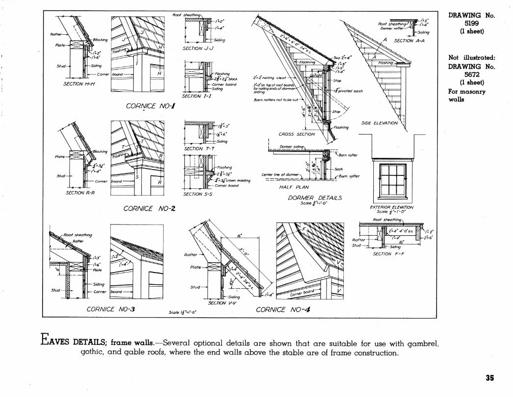
JuAVES DETAILS; frame walls.—Several optional details are shown that are suitable for use with gambrel, gothiC; and gable roofs, where the end walls above the stable are of frame construction.
35
DRAWING 5631
(1 sheet)
No.
Not illustrated: DRAWING No.
5632 (1 sheet)
For masonry walls
EXTERIOR ELEVATION (ALTERNATE DESIGN)
Sco/ef^l'-O"
■Siding-^ ßlocf^jng
SECTION K-K rrr-*->
Braces notched into raits
|N5/f'>2/i"x*;r"Z with I" diam. holes 4"o.e. as shown
SECTION H-H
t - =^ /ÍA6' rail
/ brace. ':::; ~-^ i/x 6" rail
N / r ^ l¿x 6" rail
hardwood strip \ Ú - \/£x G" frame screwed fo ;^j! \ ,« .Lfi
SECTION J-J
H^astic
DOOR FRAME ELEVATION (FOR HINGED DOORS)
^ Blocking^ ^'A''xi''x24"anchor EXTERIOR ELEVATION (DUTCH DOOR) Scalef^l'-O"
Scale ¡i'^l'-O"
Hardwood cap set in white lead and screwed fo frame.
¡4x8 frame
^increase as re<fij so apron will clear rolhr
SECTION D-D Scale l£'f-0"
*NOTE: DOOR HEIGHTS MAY VARY, DEPENDING ON TYPE OF BARN AND TYPE OF FEED ALLEY.
(VERIFY DIMENSIONS ON JOB)
-^-Door
DETAIL-OF HEAD (FOR SLIDING DOOR)
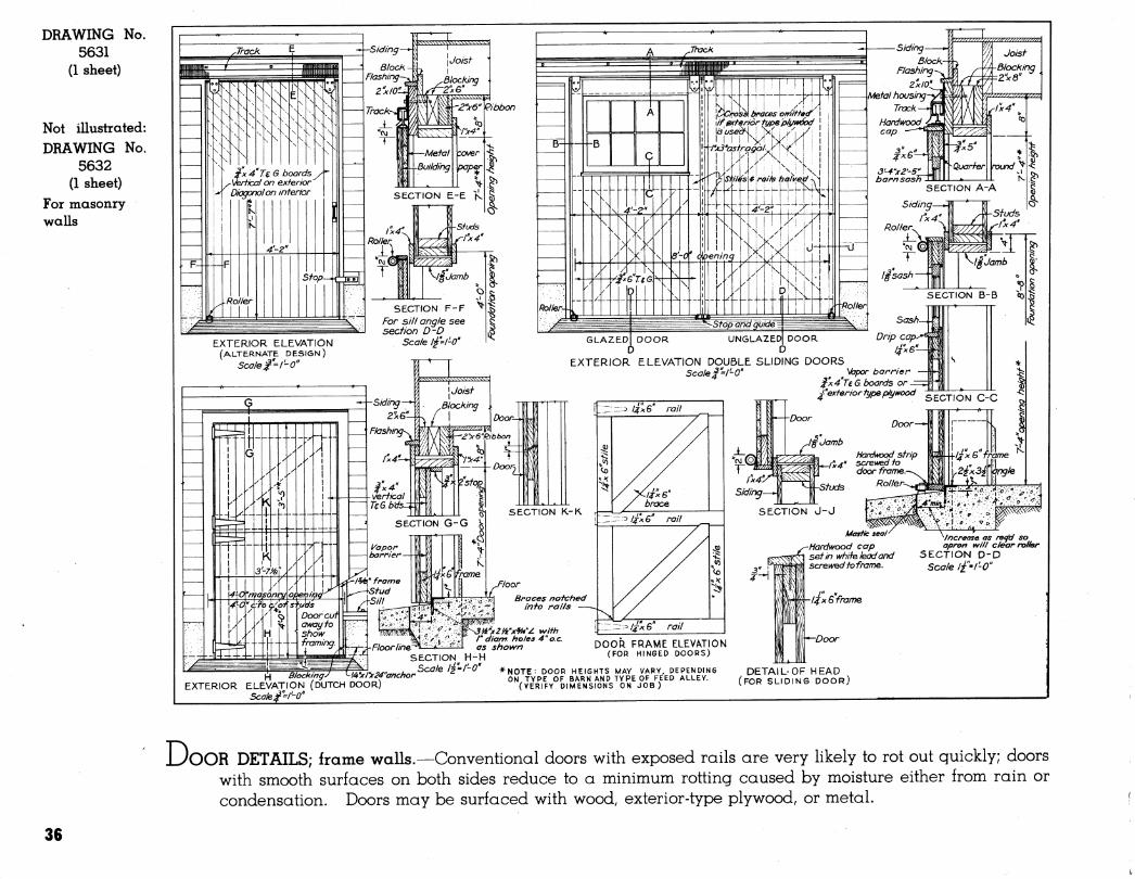
iJoOR DETAILS; frame walls.—Conventional doors with exposed rails are very likely to rot out quickly; doors with smooth surfaces on both sides reduce to a minimum rotting caused by moisture either from rain or condensation. Doors may be surfaced with wood, exterior-type plywood, or metal.
36
DRAWING 5634
(1 sheet)
No.
Not illustrated: DRAWING No.
5667 (1 sheet)
For masonry walls
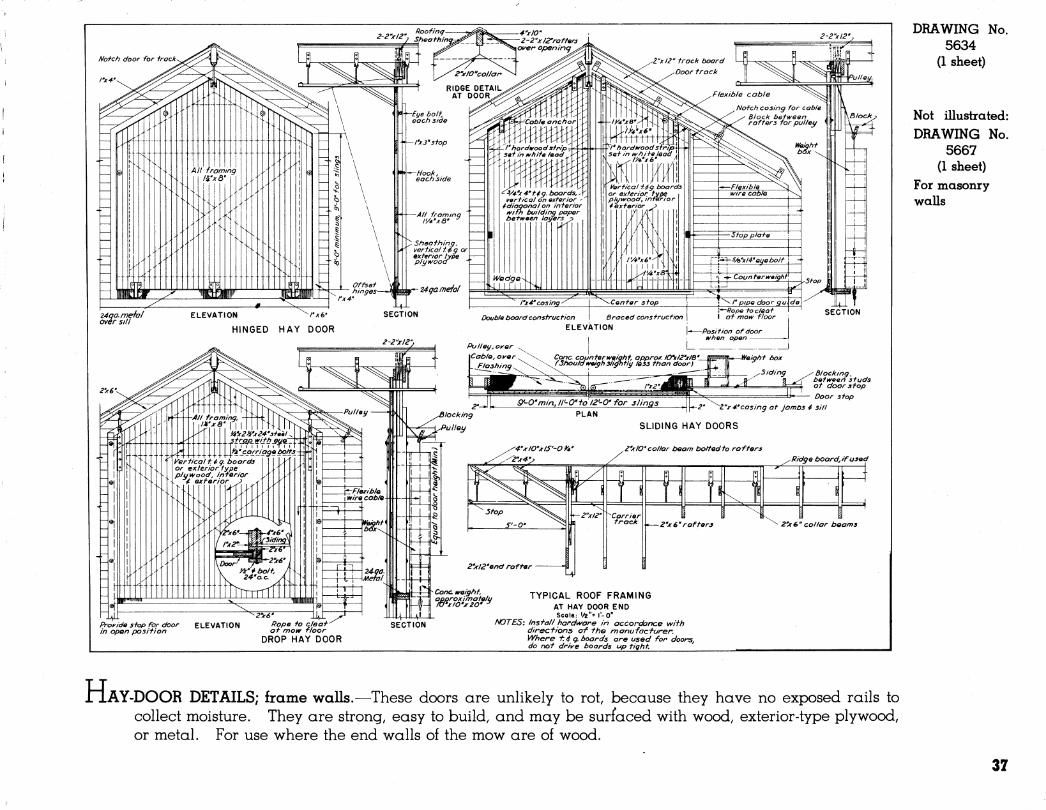
H AY-DOOR DETAILS; frame walls.—These doors are unlikely to rot, because they have no exposed rails to collect moisture. They are strong, easy to build, and may be surfaced with wood, exterior-type plywood, or metal. For use where the end walls of the mow are of wood.
37
DRAWING 5633
(1 sheet)
No.
Not illustrated: DRAWING No.
5638 (1 sheet)
For masonry walls
Glass oreo= 7.0 sq. ft
EXTERIOR ELEVATION
Note-.sfeeJ sash size is opprox ¡mate. S fee/sash vary in sfz.e and shape depending on manufacfurer Determine ocft/a/size afsasf) before framing openings.
Inside finish
CROSS SECTION
^
oreo' 9. s stf.ft.
Flashing^
Rougf) opening I PLAN
STEEL SASH
m \/x4 cosing
EXTERIOR ELEVATION
2.-a'
5iding^^ Sheathing^
-Inside finish
¥"
Blocf^inq gnashing-
«r CROSS SECTION
2\6'Ribbon^ *... * i
2i>
HALF PLAN ¡ HALF PLAN FRAME WTTHOÜT WEIGHTS ' FRAME WITH WEIGHTS
DOUBLE HUNG (STOCK FRAME)
SUTABLE FOR MILK HOUSES Z'x 6'Ribbon^
Blocking^ ^„^loshing^
Glass area ' S.49g.ff.
I Z'-0' II
\».n.mV 2 .
EXTERIOR ELEVATION Siding-
EXTERIOR ELEVATION
2'-//' ftough opening
Siding-^
CROSS SECTION
CROSS SECTION
^Inside finish
PLAN
TILTING SASH (STOCK FRAME)
Double studs yyhere 3t70ivn
on framing detail sheets.
'1x4-cosing
SLIDING SASH (PLANK FRAME)
SCALE 1= I'-O
/-<?'
6.0sgfi
t''6'
EXTERIOR ELEVATION
4'-0'
Siding Inside f/nisf?
CROSS SECTION
4 - loi Rough Opening r-iiii I'-iiiL'
r yjt 4 Casing
MULLION WINDOWS-TILTING SASH (PLANK FRAME)
••—Inside finish
1 STANDARD WOOD, BARN SASH OPENING SIZES¥ j
nui 1 î Í B
1 B _i B LLJ
1 UA^ LAJ ►^A- A U-A-
A B •^' A B «CMCA safT A B
•LARU »»FT. A B 6L.AReA
saPT
2--0- 2-84' 3.7 .•-4" M' 2.o 2-0- r-ii" 2.S l'-4- l'-e" 1.3
2-4" 2*-lli* ,4.» 2'.MV 2.5 2-4- 2-1" 3.3 l'-a" 2-1- 2.2
3'-5V 5.9 Í-«* z'-nit 3.3 2'-5- A.O 2'-6" 2.7
i-UJt 6.9 *6i- A.O 2-9- 4.7 2-9" 3.1
2-a' »•-M" l.O 3--..Í 4.« 3'-r 5.3 2-0- 2-1" 3.6
'r*i 7.6 2'-0" »;-''* 5.0 2-8" 2-5" 4.6 2-5" , 3.3 s'-.,i A.2 3..Í" 5.» 2'-9" 5.4 2-9'' 3.0
3'-0^ 2-11 i tf.6 4'-24- 6.0 3-1- 6.1 »'-!" 4.4
í-ni' 9.4 2-4' 3'-lli' 7.0 a'-o" 2-5- S.3 2^-4" 2'-5- A.O
S'-4" 3--6Í1 ».O 4'-5^' a.o 2'-ir 6.7 3'-r 5.3
4--UÍ- "•' 4'-„4J 9.0 s*-s- 7.9 3'-«- 6.7
» BASeO ON MODULAH STANOAItO STOCK WWOOUfS ANO SASM ßftCOMMBNOBD BY THE NATIONAL OOOR MANWACTUnSfS ASSOCIATION, rom AOOITIONAL SIZES CONSULT LOCAL OBALSm.
NOTES: Sosh and frames to be clear pine. Sosh and frames tobe primed before ins to/ling. Sash and frames tobe pointed»<fifh two coots of hod and oi/paint offer instaf/ing. Before gfozing, prinye off g/oss rabbets
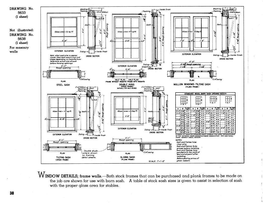
WINDOW DETAILS; frame walls.—Both stock frames that can be purchased and plank frames to be made on the job are shown for use with barn sash. A table of stock sash sizes is given to assist in selection of sash with the proper glass area for stables.
38
M-S-I^i"
Hl j pipe braclcet ai '~* evcrLj other staii
t'-6'
MANGER @ N
LEVa FEED ALLEY)
NOTE All concreta corners to be rounded
Install stalls accordincj to manufacturers instructions
X a—u-
n
-^ U IJ
^' I'pipe naij rati
This heic^ht according io breed of cows Not over 5'-e" Not less than 5'-4'
Mternate tupe stall p,art/f/on shoivn by doned lines
-15lb. asphalt felt
Gravel, cinders, or other porous fill under standing platform only., where floor is on poorly drained earth.
F20NT ELEVATION öcaie ki''l'-0"
■ßaise concrete I'atpartihons I ^Floor 3lop*dl"
^.^ I ^ Pat urn \
m^ ~T
Stanchion curb
Metal lath around column-
MANGER (B]
SECTION TH20U6H COW 5TàLL FL002 3cole i^" = r-0"
End curb
Gutter drain at low point
in gutter.
Grade-f
FOUNDATION DETAIL
y-12"min. nähere manger fl) / is used.
I^min^here mangers Sca/e^"=/'-0 \^or[Q)are used.
AIOTE: Where floor of barn slopes, the relation between the outside grade and the datum shall be established at the point where the floor will be lowest.
Floor to slope I" in lO'-O" longitudinally.
All concrete except foundation n/a//s, 1-2 3 mix.
Floors, float finished. Curbs, mangers 4 gutters tron/el finished.
If manger divisions are used.
5ECTI0N
DETAIL 5H0WIN6 METHOD OF Í2EINF02CIN6 WHEN PIPE COLUMN 15 LOCATED AT CUSß
Ócale %" = l'-0
BIÍEED *WIDTH -W LENGTH'S
SMALL MEDIUM LAfZQE l^olitein- Priesian A-'-O' to 4'-6" 5'- O" 5'-4^ 6'-0'
BroiVrj S^/ss 4.-0" to 4'-6' 5'-0' ' s'-r- 6-0"
Shorthorn 4.'-0' to 4.'-6' 5'-0" 5'-4^ 6'- 0"
Ai^rshire 4'-0" tû4.'-6' 4^''10" 5-2" 5''6"
Ouernsei^ 3-6* to 4-0' A'-e' A.'- 10' 5'- Z"
Jersey a'-erto 4'-0" 4.'-4.' 4-'- Ö" 5'- O"
Nelters Z'-9' to 3-Z" 5'-ö" 5'- 10" 4.'- Z"
Gutter vyidth G'13"mth stalls 5'-6"and longer G =16" with all others.
Length of partitions P= 3'-€" for cows, 3'-2' for heifers.
ISOMETRIC SHOWING MANGER CORNER
form manger kvith templet furnished bg manufacturer.
* No stall less than 3'-6'wide should be used for cows in milt.
Where curbs are placed between stalls, stalls shall be 6 inches wider, óome large cqws may require stalls up to 4'- 10" ¡f^ide
DRAWING No. 5661
(1 sheet)
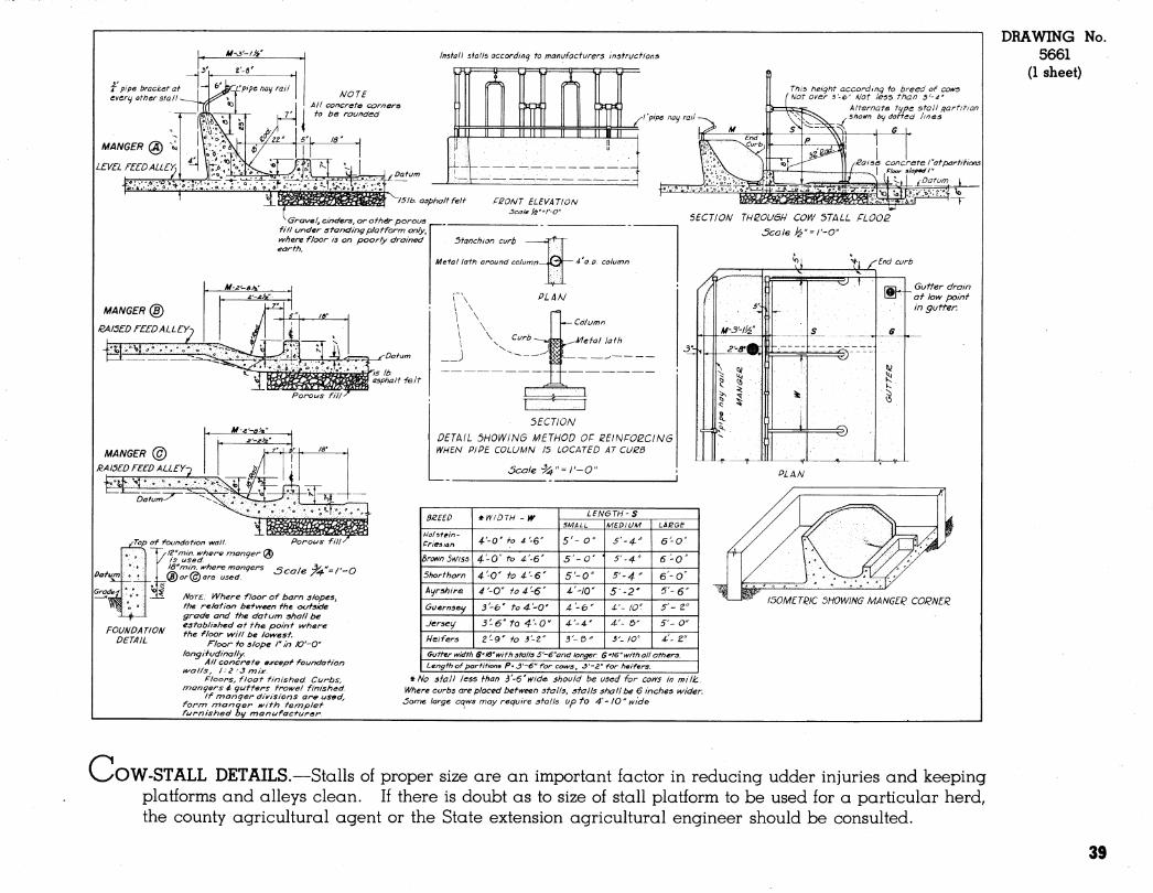
V^OW-STALL DETAILS.—Stalls of proper size are an important factor in reducing udder injuries and keeping platforms and alleys clean. If there is doubt as to size of stall platform to be used for a particular herd, the county agricultural agent or the State extension agricultural engineer should be consulted.
39
DRAWING No. 5107
(1 sheet)
i"bolf^
y pipe bracket at every ott)er stall
2''bolt^ ^BIocK TOP VIEW OF STANCHION
i"x fr-frap^^^^^^f^olts
' '^ ^ a^i wJ//^/ ""3 'hardwood
Block
SECTION T-T Scale I'/£"'/-0"
CROSS SECTION ELEVATION
bolt
1^4" Pin
i" 12"guards-*
rl"- 'S"^ '1x4 hinged-^
^Z'x^^z o.e.-"
• -T 2"x4'
SECTION N-N
WOOD COW STALL AND STANCHION .stanchions. ]^Íf-/'o5te
^r--ri rV --IX4'
^4^
to ceiling 7^ " sr IO'-0"o.c-¥- ,
Posts to ceilir)g. Not over 6-0"apart of bo/I pen. Not over 8 '-0 'apart at cow pen.
l^N ELEVATION AT MANGER
I "x 12 "guard ^ T \5iXa Hinged front-^ i _ f _ i *
I 20'minirSum 24\pv^ \average
PLAN AT MANGER
CALF PEN
SECTION R-R "apart >en.
3-6"
5^
}2''6/bc^itensy [ -5 Q-
^ ' ' "' II / T ¿j* *[*>/
PLAN AT GATE
INTERIOR ELEVATION SHOWING STANCHION ELEVATION AT GATE
COW AND BULL PENS
ó dowel ■a'^a'pier FEED TROUGH
' FOR LOOSE STOCK
4''^s'post at wall-^ -l^h^^^'^e'/iVo/^ -^ß°"^''
2" PLAN
SECTION E-E
Scale f^ I-O"
WITH SLIDING GATE HORSE BOX STALLS PLAN
WITH SWINGING GATE
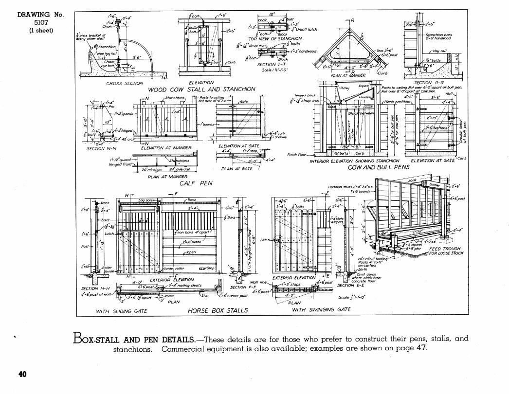
BoX-STALL AND PEN DETAILS.—These details are for those who prefer to construct their pens, stalls, and stanchions. Commercial equipment is also available; examples are shown on page 47.
40
Posfs extend to ceiling
Posta extend to cei/ing Place rack wtiere
'convenient for feeding
Removable wire tie prevents spreading between £"x2"plates PERSPECTIVE OF
INDIVIDUAL CALF PEN
l"x¿"óetoijtl'
>5o//d wa// kvhen lie^t to a nattier pen
1 A Tl L NO .
' V
111
«
-t
PLAN 4'-0"or5'-0"
Slatted floor may be tilted up to allow cleaning underneath
SCALE r = 1-0" Î
¿"Strap hinge-\
^ ''Blocks of ends I 1 -Slobe ^
False floor is renno\/able to
allow for cleaning
PERSPECTIVE OF FEED BOX (Place nvhere con\/enieni- for feeding)
NOTE: For small breeds width and length may be reduced a foot.
I0-I"x2"x2'-0" Slats
SECTION M-M
-^
^l"x2''Slafs r'apart^
j^3~£''x4''x3'-T'Joists Id'o.c.-*-
J'-O-fo^'-O"
\ ^Pin
}i^ rnlZ'guards
r 7x5"
ELEVATION AT MANGER SECTION N-N
FALSE FLOOR CALF PEN TO BE USED IN BOX STALL
SCALE >é" = rO''
CROSS SECTION OF CALF PEN SCALE r= 1-0"
y^Barn floor
DRAWING No. 5624
(1 sheet)
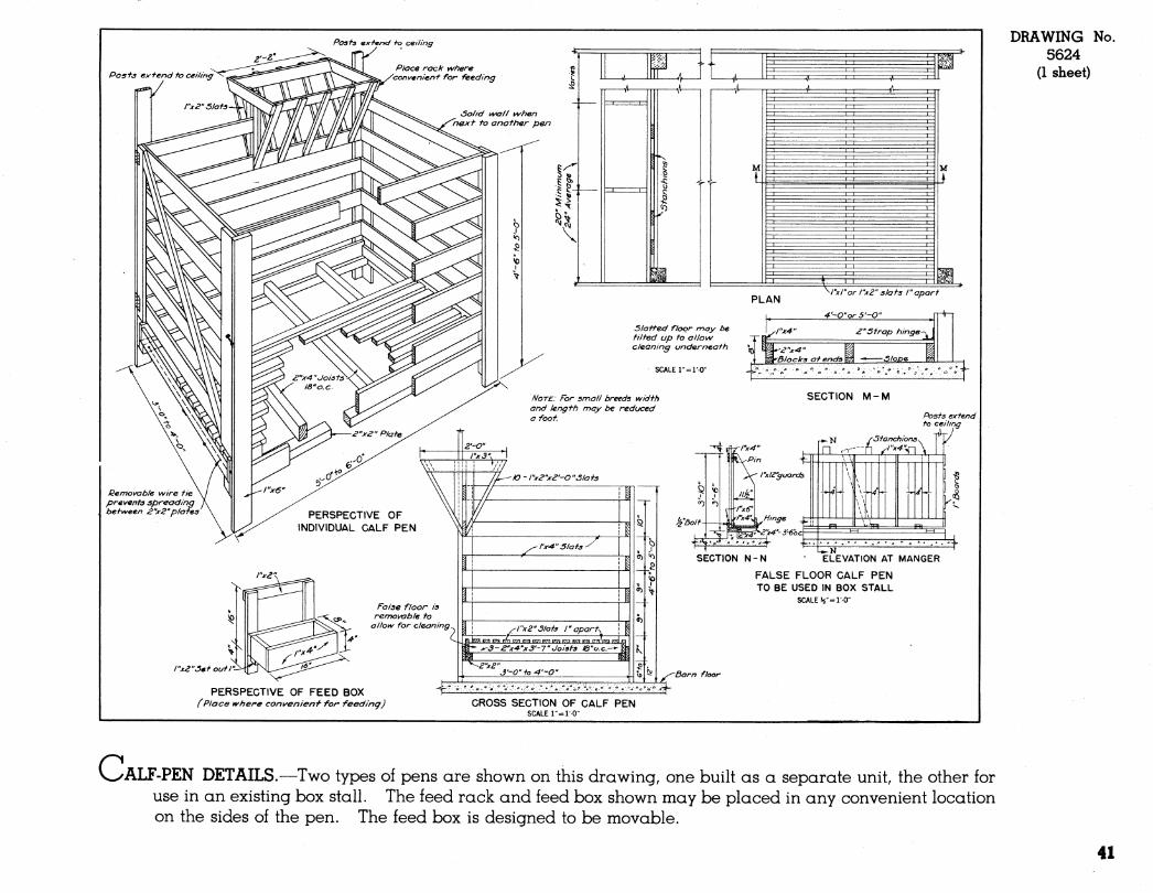
c ALF-PEN DETAILS.—T^o types of pens are shown on this drawing, one built as a separate unit, the other for use in an existing box stall. The feed rack and feed box shown may be placed in any convenient location on the sides of the pen. The feed box is designed to be movable.
41
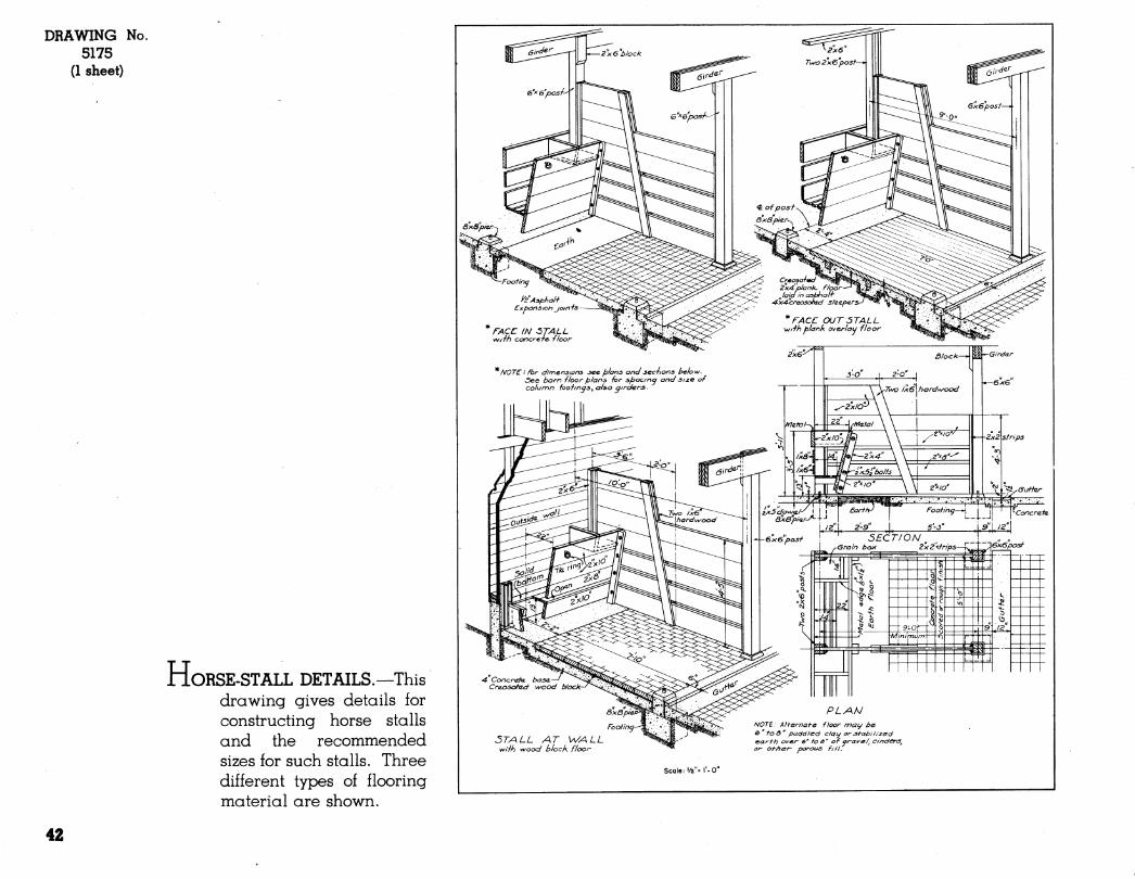
DRAWING No. 5175
(1 sheet)
H ORSE-STALL DETAILS.—This drawing gives details for constructing horse stalls and the recommended sizes for such stalls. Three different types of flooring material are shown.
NOTE'• For dimensions see plans anJ seciions he/ow. öee barn -floor plans -for spactn<^ and size of column fooiinas^ also airaers- \'Two /xGwordv^ood
2 strips
'\6x.6posf'
4 Conczraaa. basa.- CraxDsafad \A/ood bic
3T/\LL AT WALL wiih wood block floor
PLAN NOTE Alternate floor noac/ be if* too" puddled clat^ or^f-abilized earth o^er 6' to a' of orave/j cinders^ or other porous f/ll.
Scale: '/2"= 1-0
42
HAY DOOR SERVICE PLATFORM
^Hardwood rungs
^1'^2'oa^/er strip
DETAIL
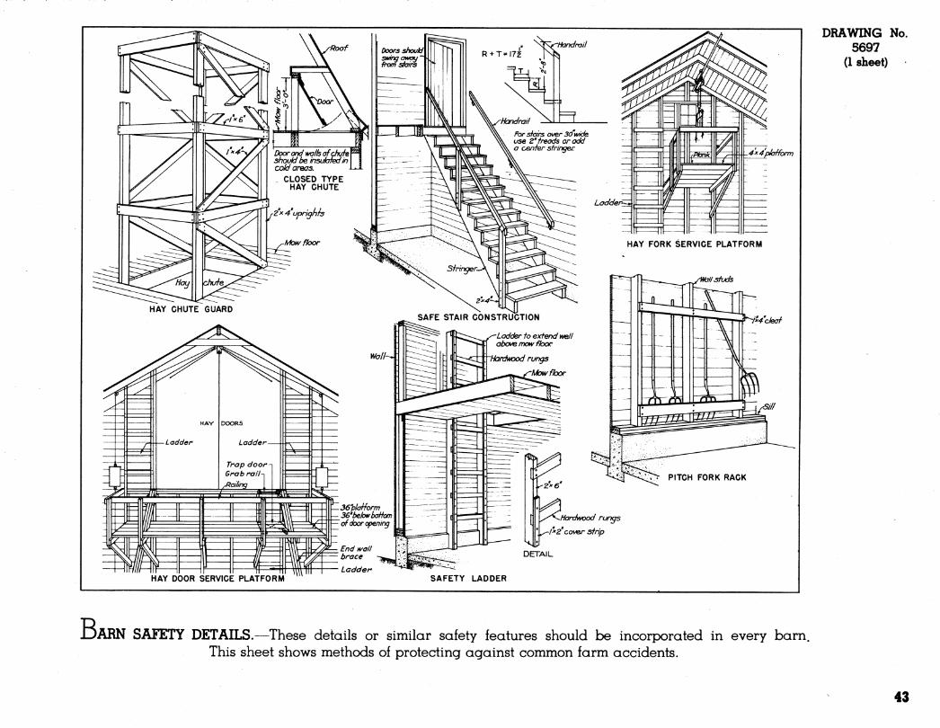
DRAWING No. 5697
(1 sheet)
SAFETY LADDER
B 'ARN SAFETY DETAILS.—These details or similar safety features should be incorpx)rated in every barn. This sheet shows methods of protecting against common farm accidents.
43
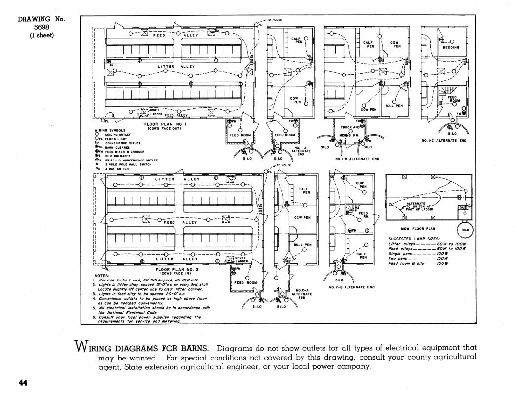
DRAWING No. 5698
(1 sheet)
SUGGESTED LAMP SIZES: Litter alleys 60W to lOOW Feed alleys 60W to 100 W Single pens 100 W Two pens I50W Feed room 8 silo 100 W
NOTES: 1. Service to be 3-wire, 60-100 ampere, 110-220 volt 2. Lights in litter alley spaced l2'-0"o.c. or every 3rd. stall.
Locate slightly off center line to clear litter carrier. 3. Lights in feed alley to be spaced 20'-O"o.e. 4. Convenience outlets to be placed as high above floor
as con be reached conveniently. 5. All electrical installation should be in accordance with
the National Electrical Code. 6. Consult your local power supplier regarding the
requirements for service and metering.
SILO
N0.2-B ALTERNATE END
WIRING DIAGRAMS FOR BARNS.—Diagrams do not show outlets for all types of electrical equipment that may be wanted. For special conditions not covered by this drawing, consult your county agricultural agent, State extension agricultural engineer, or your local power company.
44
BARN EQUIPMENT
Most equipment needed in barns can be purchased
ready-made. The illustration on page 47 shows typical
examples of some of the equipment available from va-
rious manufacturers.
45
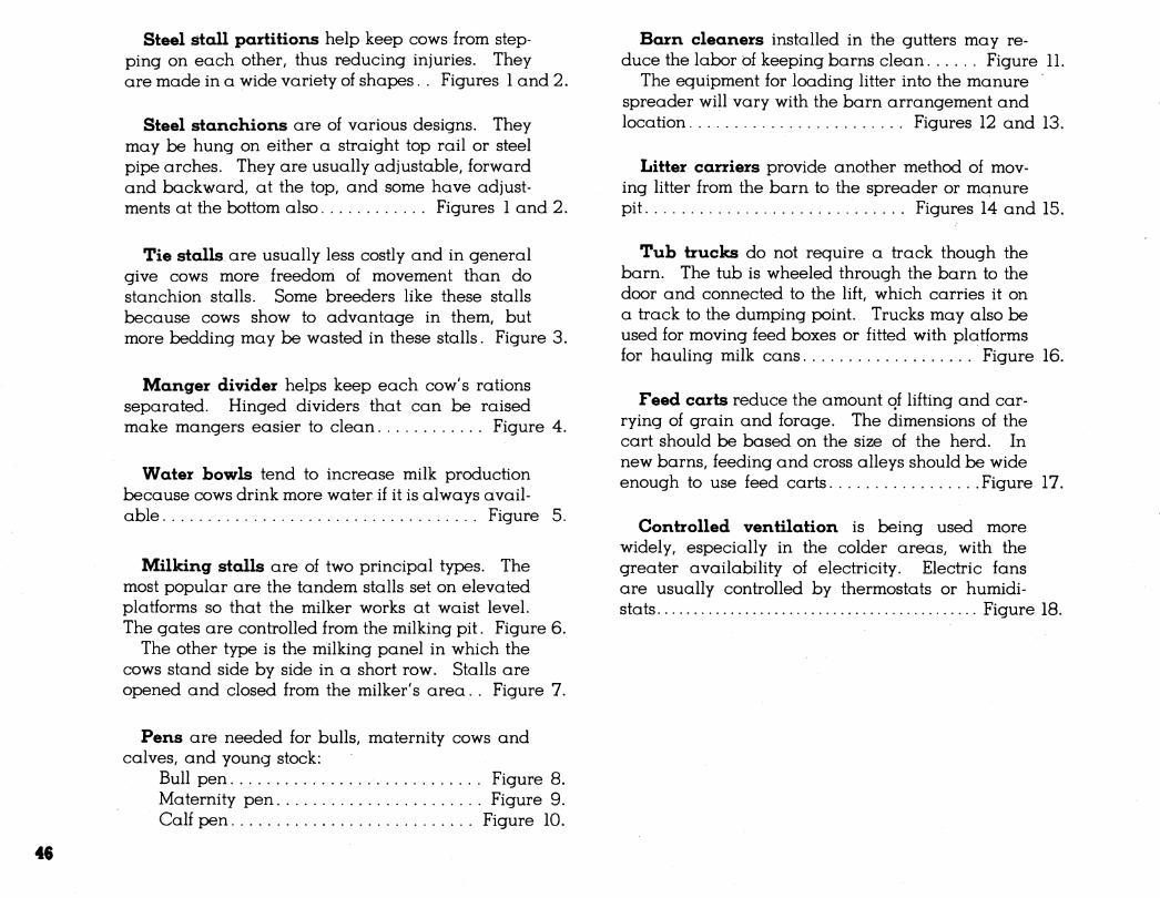
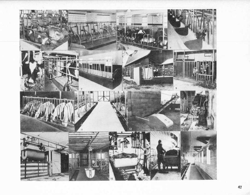
Steel stall partitions help keep cows from step- ping on each other, thus reducing injuries. They are made in a wide variety of shapes. . Figures 1 and 2.
Steel stanchions are of various designs. They may be hung on either a straight top rail or steel pipe arches. They are usually adjustable, forward and backward; at the top, and some have adjust- ments at the bottom also Figures 1 and 2.
Barn cleaners installed in the gutters may re- duce the labor of keeping barns clean Figure 11.
The equipment for loading litter into the manure spreader will vary with the barn arrangement and location Figures 12 and 13.
Litter carriers provide another method of mov- ing litter from the barn to the spreader or manure pit Figures 14 and 15.
Tie stalls are usually less costly and in general give cows more freedom of movement than do stanchion stalls. Some breeders like these stalls because cows show to advantage in them, but more bedding may be wasted in these stalls. Figure 3.
Manger divider helps keep each cow's rations separated. Hinged dividers that can be raised make mangers easier to clean Figure 4.
Water bowls tend to increase milk production because cows drink more water if it is always avail- able Figure 5.
Milking stalls are of two principal types. The most popular are the tandem stalls set on elevated platforms so that the milker works at waist level. The gates are controlled from the milking pit. Figure 6.
The other type is the milking panel in which the cows stand side by side in a short row. Stalls are opened and closed from the milker's area. . Figure 7.
Tub trucks do not reguire a track though the barn. The tub is wheeled through the barn to the door and connected to the lift, which carries it on a track to the dumping point. Trucks may also be used for moving feed boxes or fitted with platforms for hauling milk cans Figure 16.
Feed carts reduce the amount of lifting and car- rying of grain and forage. The dimensions of the cart should be based on the size of the herd. In new barnS; feeding and cross alleys should be wide enough to use feed carts Figure 17.
Controlled ventilation is being used more widely, especially in the colder areas, with the greater availability of electricity. Electric fans are usually controlled by thermostats or humidi- stats Figure 18.
Pens are needed for bulls, maternity cows and calves, and young stock:
Bull pen Figure 8. Maternity pen Figure 9. Calf pen Figure 10.
46
k,-: r^mmpsrpt m
47

MILK AND DAIRY HOUSES
<
893378 O - 50 - 4 49
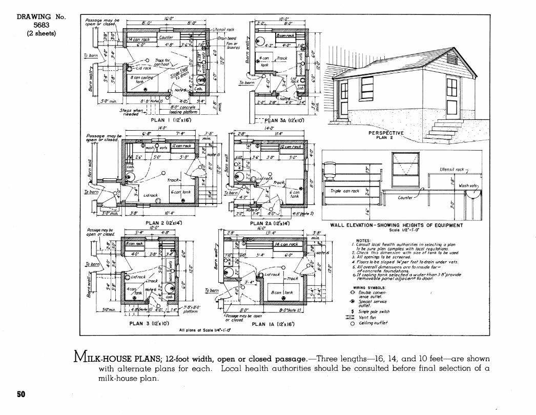
DRAWING No. 5683
(2 sheets)
Passage may be open or dosed\
ICO" Jûl^
5-0'min.
Passage may be open or closed.
PLAN 2 (I2'xl4') lO-O'
PLAN 2A (12x14') lé'O'
WALL
^Passage may be open , , ,. or dosed
PLAN 3 (12x10) PLAN lA (12x16*) All plans ot Scale l/4"«r-tf'
ELEVATION-SHOWING HEIGHTS OF EQUIPMENT Scale 1/2"= I'-0"
NOTES: /. Consult local healfh author/ties In selecting a plan
to be sure plan complies with local regulations. 2. Ctieck ttiis dimension wifti size of tank to be used. 3. All openings fo be screened. 4. Floors tobe sloped 'Wper Foot to drain under vats. 5. All overall dimensjons are t-o inside fac
of concrets foundafions- e.If coolinq tank selecfedis wider fhon 3-0"provide
removable panel adjocenf fo door
WIRING SYMBOLS:
=©= Double conven- > ience outlet.
-® Special service outlet.
? Single pole switch JIEU Vent fan
O Cetlinq ouile^
IVLlLK-HOUSE PLANS; 12-foot width, open or closed passage.—Three lengths—16, 14, and 10 feet—are shown with alternate plans for each. Local health authorities should be consulted before final selection of a milk-house plan.
50
DRAWING No. 5684
(2 sheets)
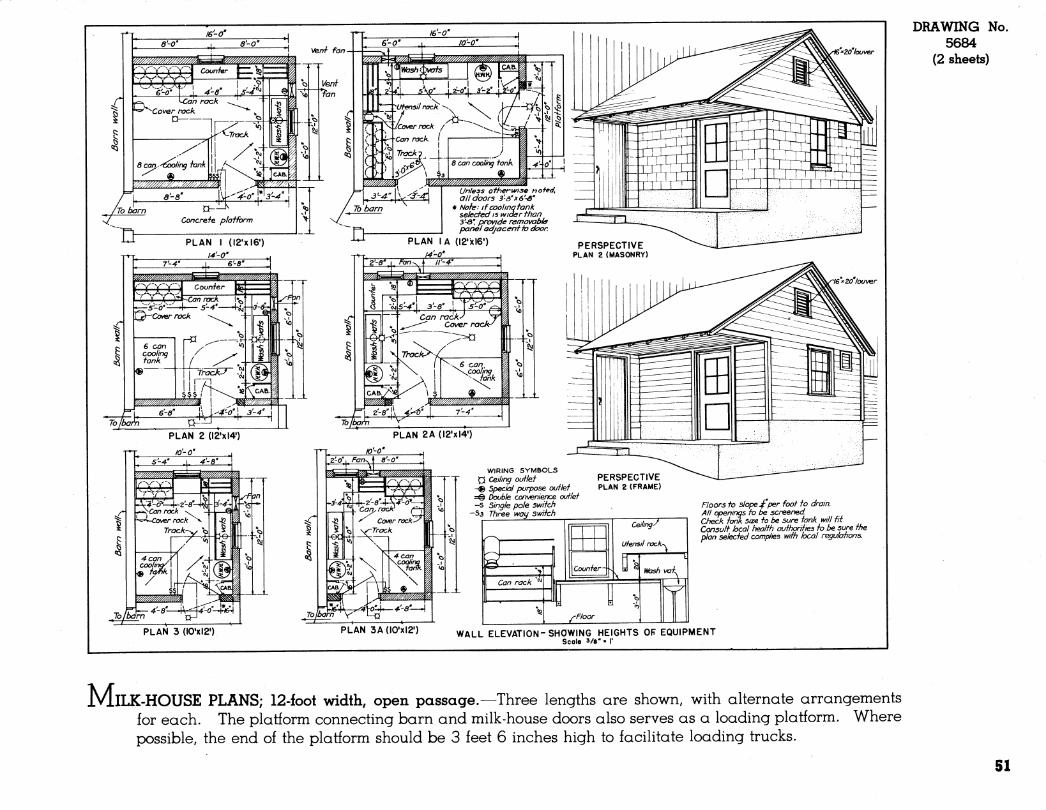
JVLlLK-HOUSE PLANS; 12-foot width, open passage.—Three lengths are shown, with alternate arrangements for each. The platform connecting barn and milk-house doors also serves as a loading platform. Where possible, the end of the platform should be 3 feet 6 inches high to facilitate loading trucks.
51
DRAWING No. 5685
(1 sheet) Precast cement cap^
■ê^ Ventilators- ^'
Flashing—^
TCflue lining
Protected opening in (each end of gable.
2'x4"Rafters e4"o.c. "
¿"AÔ-Plate bolted to walL
r r T T III
I ,-...1 'ii-a ̂ Concrete ' I y slab walkway)
lit.,_ ., ,.:¿,
^Concrete footings to extend down to solid ground and below frost.
e"x3''xl6" Masonry units
SIDE ELEVATION
Floor to slope A" to I'-O' toward drain.
Concrete'
CROSS SECTION '^^^''^^^
¿^x6" Ceiling ^joists ¿4'O.C:
S> 2- 4"xô"Precast "concrete lintel.
2-4"x6'' Precast concrete lintels a/er doors and windows. ■2-^'iôars
Tilting in sash
Metal sash centered in
masonry walle wedged in plat.
Precast.^ concrete sill.
SILL
WINDOW DETAILS
Scale it «r-O" Barn wall
ALTERNATE SIZES OF BUILDINGS
Dimensions of
Buildings
I4'X32'
I6'X36'
Room Sizes Cooling Room
l4'-07l3'-IO"l4-a'XIO'-ICr
l6'-0"X!6*-4"
Wbsh Room
l6'-Cn(l2-4"
BOILER Room
l6'-0"X7'-4'
FLOiDR PLAN (le'x 5e')
ALTERNATE COOLING
ROOM PLAN
Î' Steam V-Water
Scale '/4"=l'-0"
NOTE: Window area including door glass to equal at least IO% of floor area in both cooling and wash rooms.
All openings to be screened.
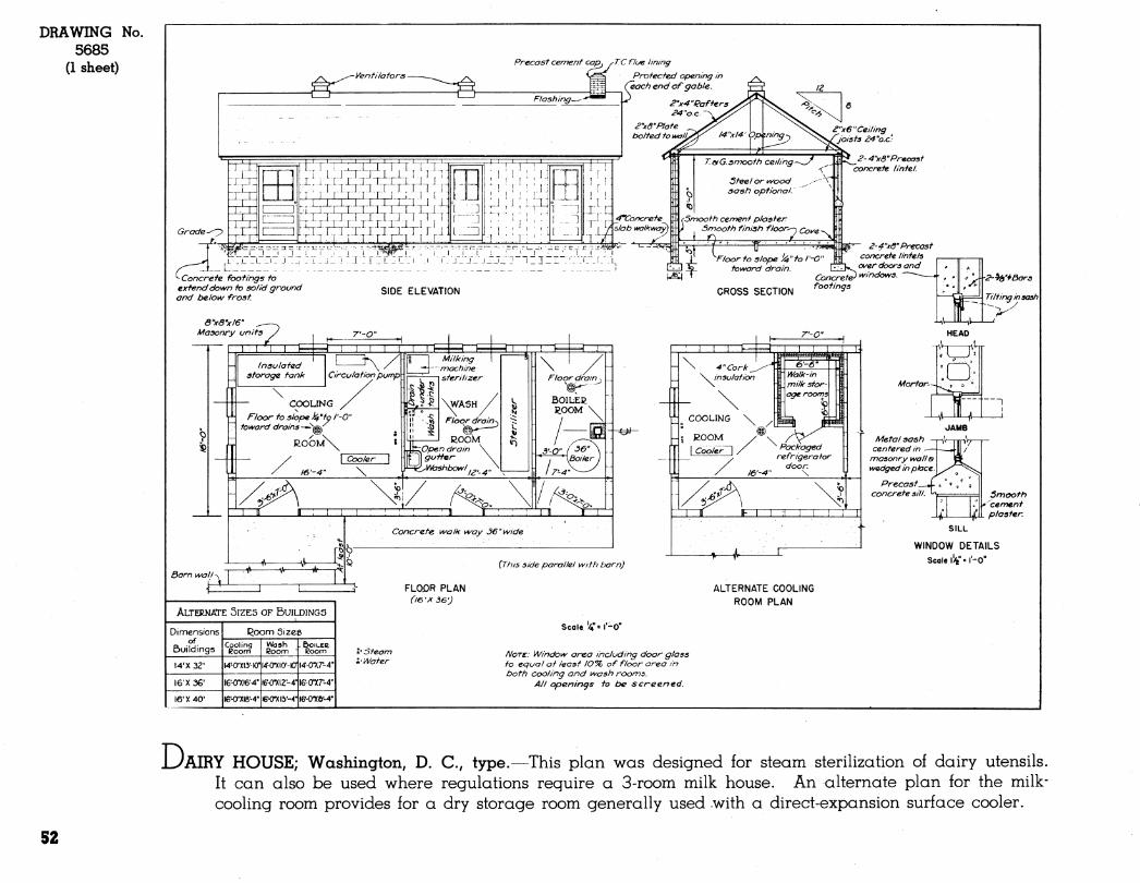
UAIRY HOUSE; Washington, D. C, type.—This plan was designed for steam sterilization of dairy utensils. It can also be used where regulations require a 3-room milk house. An alternate plan for the milk- cooling room provides for a dry storage room generally used with a direct-expansion surface cooler.
52
Protected opening in each e.nd of gable-
Flue Ô venti/ator o^er wash room only.
2'xô''P/ate . bolted to wall.L
1 m IT T T^ ZZE
j_ I J__L_L_I ' I I __L
SIDE ELEVATION
rMasonry walls. ^Outside screens.
ash room.
\ô"xo'Precast concrete lintel.
--Outside screen.
To solid ground & below frost.
Concrete footings.
rTT nur
r5" Concrete floor toshpe toward drains.- ^ \ / II \ / _^_WA5H_ ^_M___COOLlNG
Jm* Floor Drains — «^
ßOOMx II ROOM, / \ -<
y owinging door-
Woll-^^
3zcn Glass area in windows to be at least lO % of floor area.
PLAN OF DAIRY HOUSE Scal«V=l'-0"
Self closing outside door with no glass.
INSIDE ROOM DIMENSIONS IN FEET
A B c j fbr less tttan 60 gallons
per day 10" 6' 10
2 For from QO to I60 ^- gallons per day.
10" Ô' \z 3 For from I60 to 240
' gallons per day. 10' 10' 14'
Far larger herds consult tteatth Department representative.
CROSS SECTION
1—^'—[ rhi ^ 1
«> *v
1^ 1 •5
«0
Passage to dairy house.
te
1 0
k V r V
_ - Precasf concrete lintel
^ Tilting sasti wittt stop chain.
3ash \¥edged ' 1 place. ^^
PORTION OF BARN PLAN SHOWING MILKING STABLE
SILL Metal sash
centered in masonry wall.
Precast . concrete lintel.
Caulking--.
' "*'*. .Latct,
i-> HEAD
/■Stop chai
i H 1 1 1
SILL Metal sash
flush with inside of noaaonry wall.
WINDOW DETAILS Seal« i"»r-o"
Hinge
SILL Wood saet,
flush with inside of maeonry wall.
DRAWING No. 5686
(1 sheet)
NOTE • AU openings to be screened.
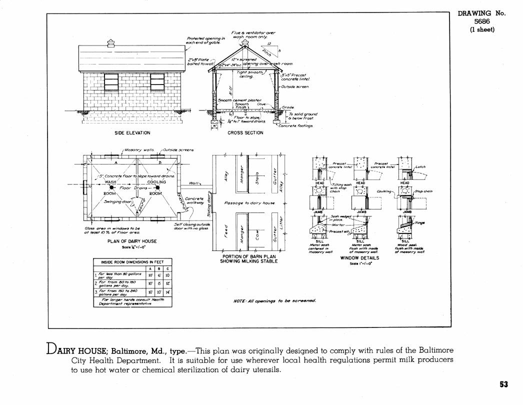
LyAIRY HOUSE; Baltimore, Md., type.—This plan was originally designed to comply with rules of the Baltimore City Health Department. It is suitable for use wherever local health regulations permit milk producers to use hot water or chemical sterilization of dairy utensils.
53
DRAWING No. 5696
(1 sheet) 8"xö' precasi concnefe linfel c¿-'/e' '^ bars
■¿"xß y/4'-0 "rafters. Z4 'o. c.
¿"xô'joisis, 24" oc.
¿'screened yenf slof
/"xô " fritr)
ye''xlh''x28- splash guardx .
Sheet metal y/ash i/^ats^ 2'drain —Ô
Precast concrete sill
Smooth cement plaster
WINDOW DETAIL
'/s'i( 20'anchor bolts not over e'-O" O.e.
•*-8"concrete masonry ^all
Poured cone, y foundation
Bell trap with-' grating Asphalt- Insulation board\
¡"asphalt inprecf-/ nahsd ínsula tion
TYPICAL WALL DETAIL
SCALE 3/4"=r-0'
Roofing Roof sheathing
Insulation Vapor barrier
26'-0-
^Screeri '■'3'-4'M
Note: Some states require wash vat drain to be trapped f vented. Consult local regulations.
SECTION THROUGH WASH VATS
Screened lou\/ers with hinged covers
4" tile drain
SECTION A-A SCALE 1/4" = I'-0"
FLOOR PLAN SCALE 1/4"= I'-0"
Wiring symbols S Single pole switch 3, Three way switch _ Oouble convenience ^ outlet /fc Special service * outlet O Ceiling outlet
PERSPECTIVE
Notes: 1. Consult local health authorities to
be sure plan complies with local regulations.
2. All openinas to be screened. 3. Sic^e all floors ¡^"per. Ft. to drains. 4. All doors are Ô'-S"high. Door
ividthsare shoyvn on plan. 5. Hfindows shown are commercial
projected type.
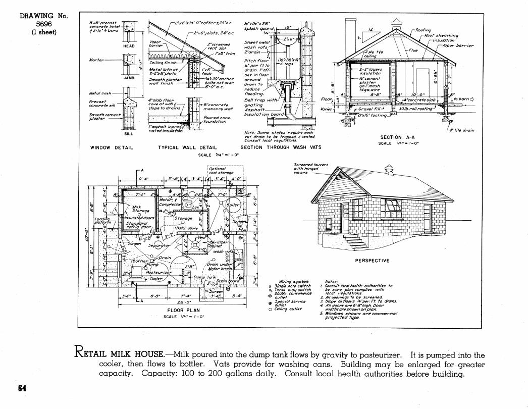
R ETAIL MILK HOUSE.—Milk poured into the dump tank flows by gravity to pasteurizer. It is pumped into the cooler, then flows to bottler. Vats provide for washing cans. Building may be enlarged for greater capacity. Capacity: 100 to 200 gallons daily. Consult local health authorities before building.
S4
y-S'n/f T.c./'ít/e
■e>e./c/e. cTM/j^f^er'
à'^A»* í/f/M?
- ^i^LL J'/ze
fVA AÍÍ.
¡nr rujz ooTS/DC WALLS mr//
Afej-AL LATH 4PI-\
D 4' s/coaeD TtLS fÀXpr/OAfJ »tirM fa/ejLAAfP CRM en/ KAr/ez
A/ore--
J^^CT/¿P/V J'À
¿>ûûj^, i^/A/oo/r <z fciu/PAfâAi/- ycfffpi/Lû-
24'x4S' ß/AS» ^/A/<g.
7Z' C^^i^CEA
¿,'-arx/'-a'x4'o' 3^' CooUBJi.
DoA4P/NtS eereKvoiB.
¿:-5i X 4-3' f^EEL fASH
±jJt^ M/LK. PVMP 4 MOTO^
Ces A M fsPABATO»-
3-si'* 4-r (Si.m»*o 4-oî i
Pf
4'-ff¿x4'jJ- Símt.eO
J-8% "
4--o"x ¿,-~ù*Xl^' 61AUD
A'-o'^
2-4'" yi í,s' eeFei^.
2-^''x¿.'¿>'.x/j--
REVISED 1949
DRAWING No. 5156
(2 sheets)
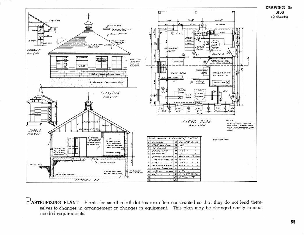
ASTEURIZING PLANT.—Plants for small retail dairies are often constructed so that they do not lend them- selves to changes in arrangement or changes in equipment. This plan may be changed easily to meet needed reguirements.
55

CATTLE SHELTERS AND EQUIPMENT
i
57
DRAWING 5637
(1 sheet)
No.
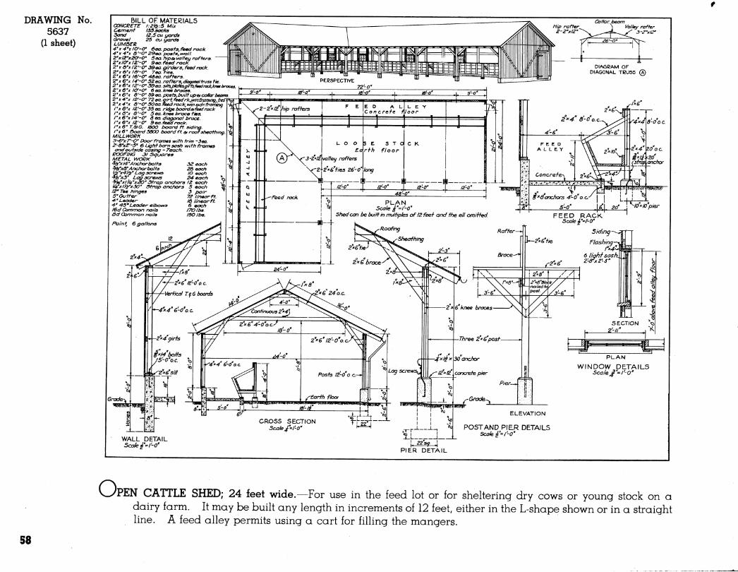
O: PEN CATTLE SHED; 24 feet wide.—For use in the feed lot or for sheltering dry cows or young stock on a dairy farm. It may be built any length in increments of 12 feet, either in the L-shape shown or in a straight line. A feed alley permits using a cart for filling the mangers.
S8
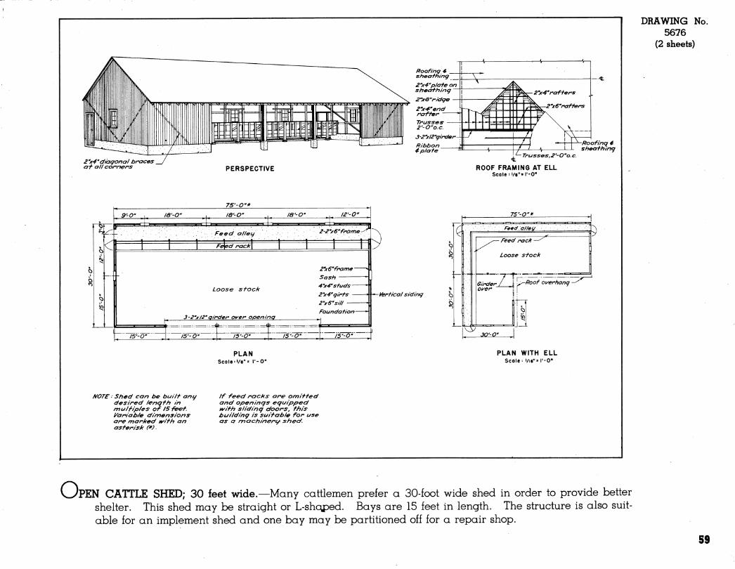
2'x4'raffers
2''x6''raff ers
2''x4''díagonai braces at all corners PERSPECTIVE
75'-O"*
yerfical siding
G
- Trusses,2'-O"o.e.
ROOF FRAMING AT ELL Scale:i/8"«l'-0"
75'-O"*
-Roofing é sheafhing
Feeda/lei/ d - Feed rack —^
Loose sfocii
Girder/ . ¡j \j^Floof o\/erhang - Oi^er •;. \
i;
\S JO'-O"
NOTE ■• Shed can be buiif ang desired length in mulfip/es of 15 feet, yariab/e dimensions are marked i%^ifh an asterisk (*).
PLAN Scale'«/8"= I'-O"
If feed racks are omitted and openings eguipped tvith sliding doors, this building is suitable for use as a nnachinerg^ shed.
PLAN WITH ELL Scale- 1/16"= r-O"
DRAWING No. 5676
(2 sheets)
v^PEN CATTLE SHED; 30 feet wide.—Many cattlemen preier a 30-foot wide shed in order to provide better shelter. This shed may be straight or L-shqped. Bays are 15 feet in length. The structure is also suit- able for an implement shed and one bay may be partitioned off for a repair shop.
59
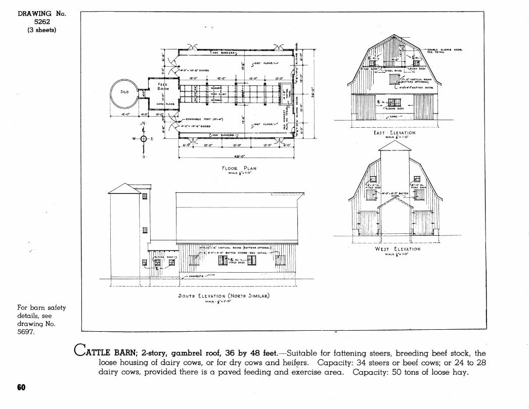
DRAWING No. 5262
(3 sheets)
For barn safety details, see drawing No. 5697.
c
, 6'-0" I l2'-0" le-o" 1 6
r~"
FLOOR PLAN SCALE, i"» l-O"
ffl
•--k|-jl xl|z" VtETlC
ITIM I' mm
vtETicAL sioiN« (BATTENS OPTIOHAL)|
O* BATTEN OOOeS • SEE. OCTAIL •
- CONCCCTE. -
¿OUTH LLLVATION (NoeTH 5IMILAB,) SCALE, - jr"« r- O"
EAST • LLEVATION SCALE. ¿"« I'-O"
WEST LLEIVATION SCALE, -i"« I'-O"
ATTLE BARN; 2-story, gambrel roof, 36 by 48 feet.—Suitable for fattening steers, breeding beef stock, the loose housing of dairy cows, or for dry cows and heifers. Capacity: 34 steers or beef cows; or 24 to 28 dairy cows, provided there is a paved feeding and exercise area. Capacity: 50 tons of loose hay.
60
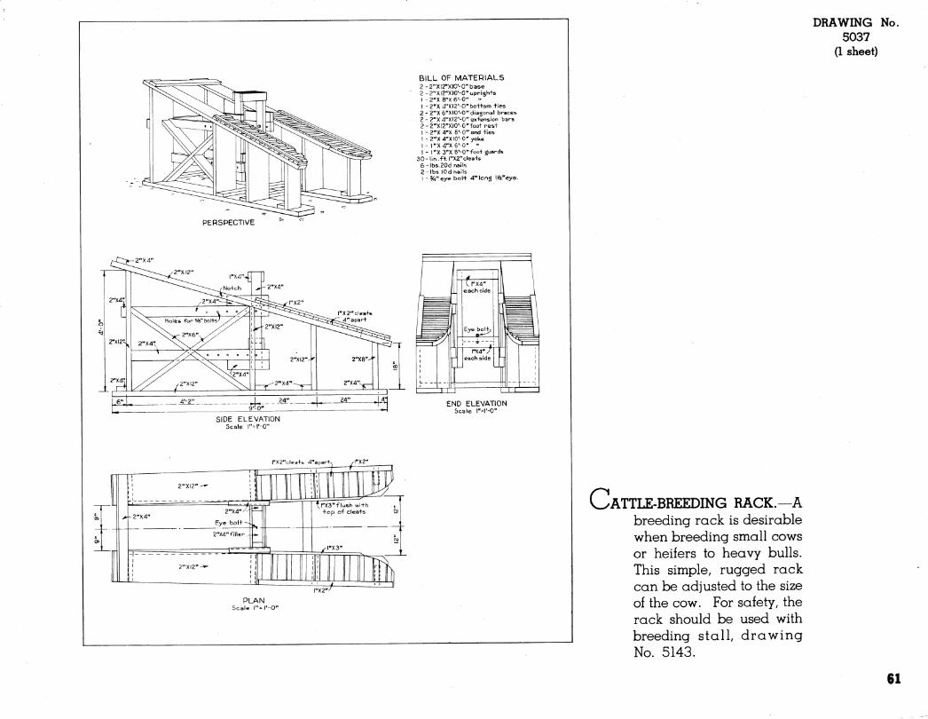
BILL OF MATERIALS 2-2"XI2"XIO'-0"base 2 -2"X12"XI0'-0"uprigh+s
I -2"X 8"X6'-0" " 1 -2''X a"XI2'-0"boi+om ties 2 - 2"X 6"XI0'-0"diagonal braces 2-2"X4"XI2'-0"ex+ension bars 2-2"X12"XI0'-0"foo+ rest I -2"X4"X 8'-0"end +ies I -2"X4"XI0'-0''yoke I - l"X4"X6'-0" '• 1 - r'X 3"X 8'-0"foo+ guards
30-lin.f+. l"X2"clea+s 6-lbs.20d nails 2-lbs lOdhails I -%"eye bol+ 4" long !Vii"eye.
PERSPECTIVE
E] [ZO
END ELEVATION Scale r-l'-O"
DRAWING 5037
(1 sheet)
No.
SIDE ELEVATION Scale l"=l'-0"
PLAN Scale l"=l'-0"
CATTLE-BREEDING RACK.—A breeding rack is desirable when breeding small cows or heifers to heavy bulls. This simple, rugged rack can be adjusted to the size of the cow. For safety, the rack should be used with breeding stall, drawing No. 5143.
61
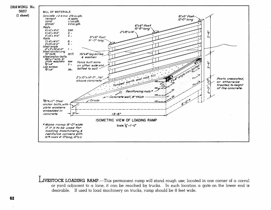
DRAWING 5657
(1 sheet)
No. BILL OF MATERIALS Concrete -1-2 4 mix 2'/2cu.(/ds.
Cement is socks sand grovel
Posts S'A^'K/Z'-O" 6'\6"x lO-O" à'xe'x 9-0"
Roils 2"xe^Jif4'-0" Z'xJOfx/^'O"
stee/ angle 4''x3''x'/2"x6'-0''
Steel re in to re I no '/zTods ^
steel anchor t>olts s/a"xjrmtt} 3" plate washers f2"x4''
Lag screh/5 r2''x4"
/Jcu.gds. 2.2cugds.
6"x6"Posf- ¡¿'-O'/ong
%"i>xll" 5feel anchor holts^ with plate H/ashers embedded in concrete
"^ Make romp Ô'-O"ivide If If Is to be used for loading mactiinery,4* reinforce corners t^ith '/z"i> rods 4'-0Vong, l2"o.c.
Posts creosoted^ or ot/ierkt^ise treafed, to height of the concrete.
ISOMETRIC VIEW OF LOADING RAMP
Scale ^2 =''-0"
L iIVESTOCK LOADING RAMP.—This permanent ramp will stand rough use; located in one corner of a corral or yard adjacent to a lane, it can be reached by trucks. In such location a gate on the lower end is desirable. If used to load machinery on trucks, ramp should be 8 feet wide.
62
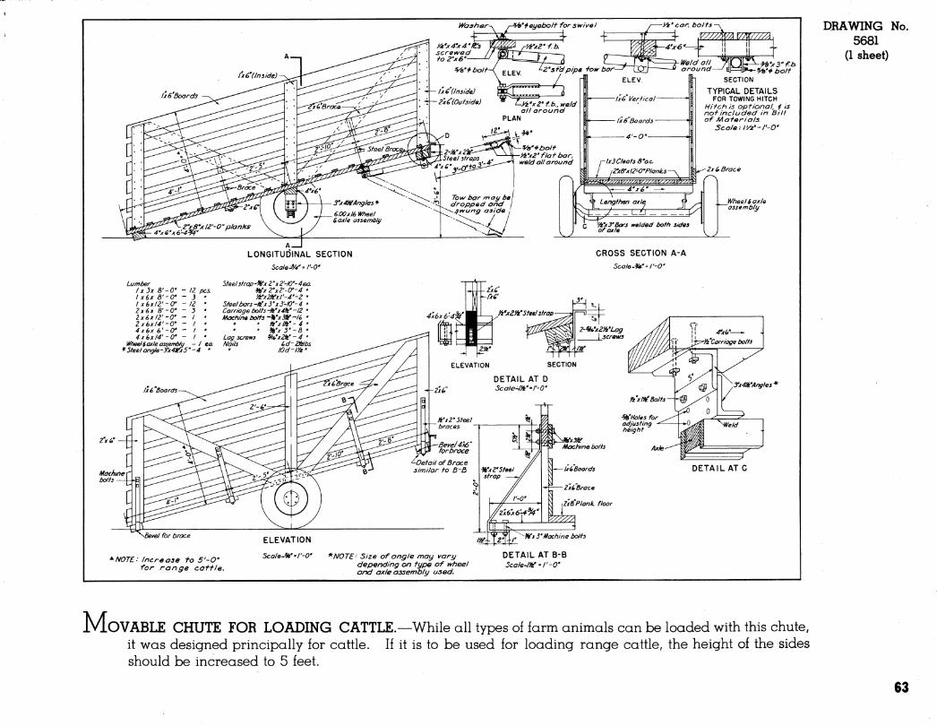
^eyeboíf for swivel
Z'sf'dpipe -tow bor-
1x6'Boards
n'x3"f.b. ^> boJf
SECTION
TYPICAL DETAILS FOR TOWING HITCH
Hit chis optional, i is nof included in Bill of Materials.
Scaleil'/2'-l'-0'
2xi> Brace
^\ Lengthen axle y /-"
r Wx3'Bars welded both sides of axle
_Wheel$axle assembly
LONGITUDINAL SECTION Scale J/r = I'-O'
CROSS SECTION A-A
Scale^^'-r-O"
Lumber IX 3x S'-O" - IZ PCS. I x6x Ô'-O" - 3 I X6x12'-a - 12 2x6x 8'-0' 1x6x12'-0' - I 2x6xl4'-0' 4x6x é'-O' - I 4x6x14'-0' - I
Wheel^ axle assemblu - I ea *5teelangle-í''x4¡^x5''-4 '
5teel3trop-Hfx2'x2'-IO' > 2''x2'-0'-
'A'x2fii:xl'-4' Steel bars -H'x 3'x 3-10'- Carriage bolts -iVxdh" Machine bolts -Wx3tf
' fSi'x ■ ■
Lag screws Nails
'-4ea. 4 ' 2 •
-4 • ■12 ' lé ' 4 '
yx4a!'Angles'^
¡uf,^^Vi' ""^x 3'Machine bolts
^NOTE: Increase to S'-O" for range cattle.
*NOTE- Size of angle may vary depending on type of wh and axle assembly used.
DETAIL AT B-B Scale-IW-l'-O'
DRAWING 5681
(1 sheet)
No.
M. OVABLE CHUTE FOR LOADING CATTLE.—While all types of farm animals can be loaded with this chute, it was designed principally for cattle. If it is to be used for loading range cattle, the height of the sides should be increased to 5 feet.
63
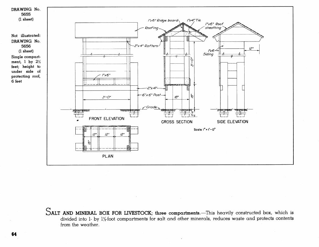
DRAWING No. 5655
(1 sheet)
Not illustrated: DRAWING No.
5656 (1 sheet)
Single compart- ment, 1 by 2% ieet; height to under side of protecting roof, 6 feet
/y6" Ridge board^ ¡"x^'J Tie
Roofing
'^^'' ^"^f4" Rafters^
- I"x6"
rr- =^2-H= .JJ__
I! __iL_
Ô'-O"
FRONT ELEVATION
-a"x^"-—^1 -6"x6" Post-
^ Grade ^
10" SP
[
:l-4Hf—4
CROSS SECTION SIDE ELEVATION
Scale l"=l'-0"
PLAN
OALT AND MINERAL BOX FOR LIVESTOCK; three compartments.—This heavily constructed box, which is divided into 1- by IK-foot compartments for salt and other minerals, reduces waste and protects contents from the weather.
64
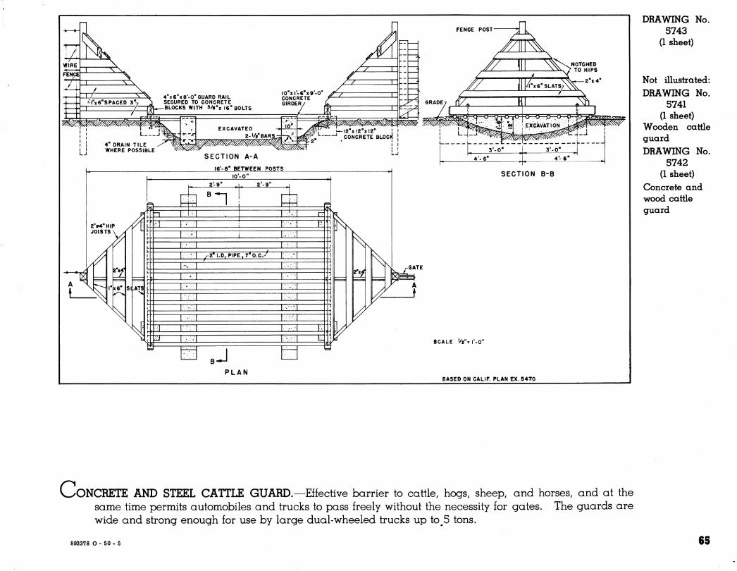
4 x6 x8'-0' GUARD RAIL SECURED TO CONCRETE BLOCKS WITH 3/8"x 16" BOLTS
4" DRAIN TILE WHERE POSSIBLE
SECTION A-A
16'-8" BETWEEN POSTS
EXCAVATED 2-'/2''BAR,S^^"
10'-0"
2"»M»"HIP Á JOISTS \ X
/'
N '^N =
Txe"
\
ñ
Ni
2-9 2'-9"
n T"^ T^'^ I
I -I ^2'I.O.PIPE.T'O.cy I .'I
Tx^ T-^ T-^-T
J
h
2"x/
SECTION B-B
rGATE
v
w /
PLAN
SCALE '/2"= I'-O"
BASED ON CALIF. PLAN EX. 5470
DRAWING No. 5743
(1 sheet)
Not illustrated: DRAWING No.
5741 (1 sheet)
Wooden cattle guard DRAWING No.
5742 (1 sheet)
Concrete and wood cattle guard
V^^ONCRETE AND STEEL CATTLE GUARD.—Effective barrier to cattle, hogs, sheep, and horses, and at the same time permits automobiles and trucks to pass freely without the necessity for gates. The guards are wide and strong enough for use by large dual-wheeled trucks up to^5 tons.
893378 O - 50 - 5 65
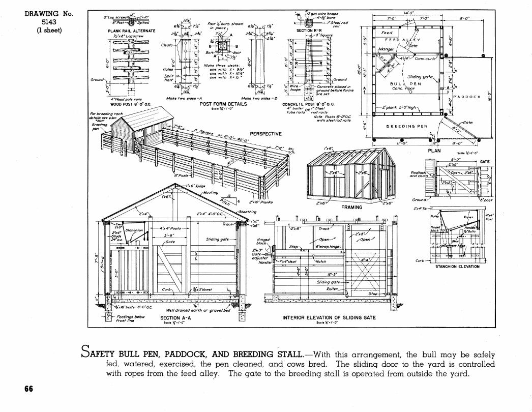
DRAWING No. 5143
(1 sheet)
OAFETY BULL PEN, PADDOCK, AND BREEDING STALL.—With this arrangement, the bull may be safely fed, watered, exercised, the pen cleaned, and cows bred. The sliding door to the yard is controlled with ropes from the feed alley. The gate to the breeding stall is operated from outside the yard.
66
SHEEP SHELTERS
4
67
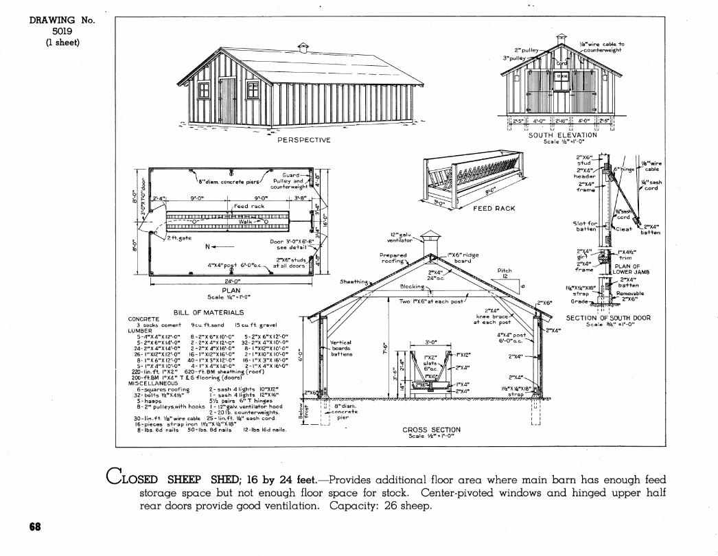
DRAWING 5019
(1 sheet)
No.
2" pulley 3" pu I ley
'/fe^wire cable +o •coun+erweigh+
PERSPECTIVE SOUTH ELEVATION
Scale '/4"=l'-0-
\ ® / Guard—i^k) ^8"diam. concrefe piers^ Pulley and yf\\:
coun+erwei;
9'-0"
IIIIIIIIIIIIIIIIIIIIIIIIJ IIJJ M if tm MMM OUT O-" Walk -^^
f%/I^ III IIIIIMMMIIiinLlI
9^0"
to III! IIIIII II llllllll INI nil II II im
ga+e N-e-
Door 3'-0"X6'-6:: see derail
2"X6"s+ud5 4"X4"pos+ 6'-0"o.c.^ a+all doors
24'-0''
PLAN Scale '/4" = l'-0"
BILL OF MATERIALS CONCRETE
3 sacks cemen+ 9cu. f+.sand I5cu. fi. grovel LUMBER
5-4"X4"XI2'-0" 5-2"X6"XI4'-0''
24-2"X4"Xl4'-0" 26-l"XI2''XI2'-0" 8- l"X6"XI2'-0" 5- l"X4"XI0'-0"
220-lin.ft l"X2
5-2''X6"XI2'-0" 32-2"X4"XI0'-0" 8- l"XI2"XI0'-O" 2-l"XI0"XI0'-0"
l6-l"X3"XI6'-0" 2-l"X4"XI6'-0"
S-Z-'Xe-XIO'-O" 2-2"X4"XI2'-0" 2-2"X4"XI6'-0" l6-l"XI2"XI6'-0" 40-l"X3"XI2'-0" 4-l"X4"XI4'-0"
620-f+. BM shea+hmg(roof) 200-f+.BM l"X4" T 16 flooring (doors)
MISCELLANEOUS 6-Squares roofing 2-sash 4 lighfs I0"X12"
32-bol+s •/a"X4'/2" I- sash 4 ligh-^s I2''XI6" 5-hasps 5Vz pairs €>"T hinges 8-2" pulleys,wi+h hooks I - I2"galv. ven+ila+or hood
2 - 20 I b. coun+erweigh+5. 30-lin.f+. '/8"wire cable 25-lin.f+. «4" sash cord. 16-pieces s+rap iron |»/2"X«/4"XI8'' 8-lbs. 6d nails 50-lbs. 8d nails 12-lbs I6d nails
2"X6" Sfud 2"X4'
header
2";
2"X*+ _^ E| PLAN OF •franne ^JJ^LOWER JAMB
. 2-X4" ba+fen
Removable 2-X6"
SECTION OF SOUTH DOOR Scale 3/4" =l'-0"
2"X4"
CROSS SECTION Scale '/2" = l'-0"
C LOSED SHEEP SHED; 16 by 24 feet.—Provides additional floor area where main barn has enough feed storage space but not enough floor space for stock. Center-pivoted windows and hinged upper half rear doors provide good ventilation. Capacity: 26 sheep.
68
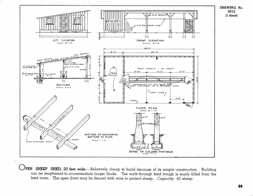
LEFT LLLVATION se ALL V = >'-Cf
X3,OOP\*i^/
q-l-k- SE.CTION
SCALE. ^"=1-0
r^-S f■^^
FRONT LLLVATION SCALE.- y^^\'-0'
o'-o'
II II
ao' - o*
II u II II IL HE Il II I
SHE.D CAPACITY - 4.0 SHEE.P
COM&IMATIOM HAY AKJD GßAlW ßACK 'O*^ MADE. STATIOWi.üY OC IM l¿EMOVAe»Le. UNITS
/ tlABTW FLOOti
7
FLOOR PLAN SCALE,: V = r-O"
IP E :^.ô~ DowenLs-
MLTHOD OF ANCHORING RAFTERS TO PLATL
SCALE.: r= r-o"
'^m'.'' 7»
iä-L FBONT CENTER.
DETAIL OF COLUMN FOOTINGS SCALE: l"=r-0-
DRAWING No. 5572
(1 sheet)
vyPEN SHEEP SHED; 20 feet wide.—^Relatively cheap to build because of its simple construction. Building can be lengthened to accommodate larger flocks. The walk-through feed trough is easily filled from the feed room. The open front may be fenced with wire to protect sheep. Capacity: 40 sheep.
69

HOG HOUSES AND EQUIPMENT
«
71
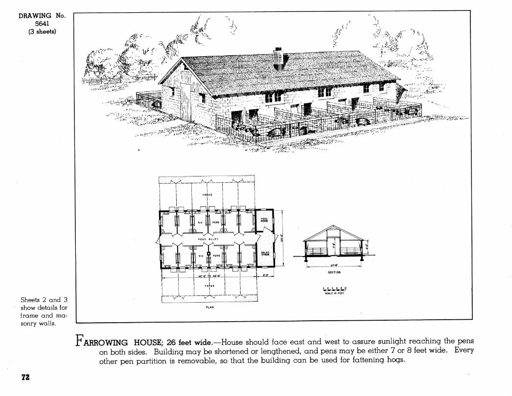
DRAWING No. 5641
(3 sheets)
Sheets 2 and 3 show details for frame and ma- sonry walls.
í2#'^-- MJí"''\
^;>v--
o 2 4 6 8 10
SCALE IN FEET
r ARROWING HOUSE; 26 feet wide.—House should face east and west to assure sunlight reaching the pens on both sides. Building may be shortened or lengthened, and pens may be either 7 or 8 feet wide. Every other pen partition is removable, so that the building can be used for fattening hogs.
72
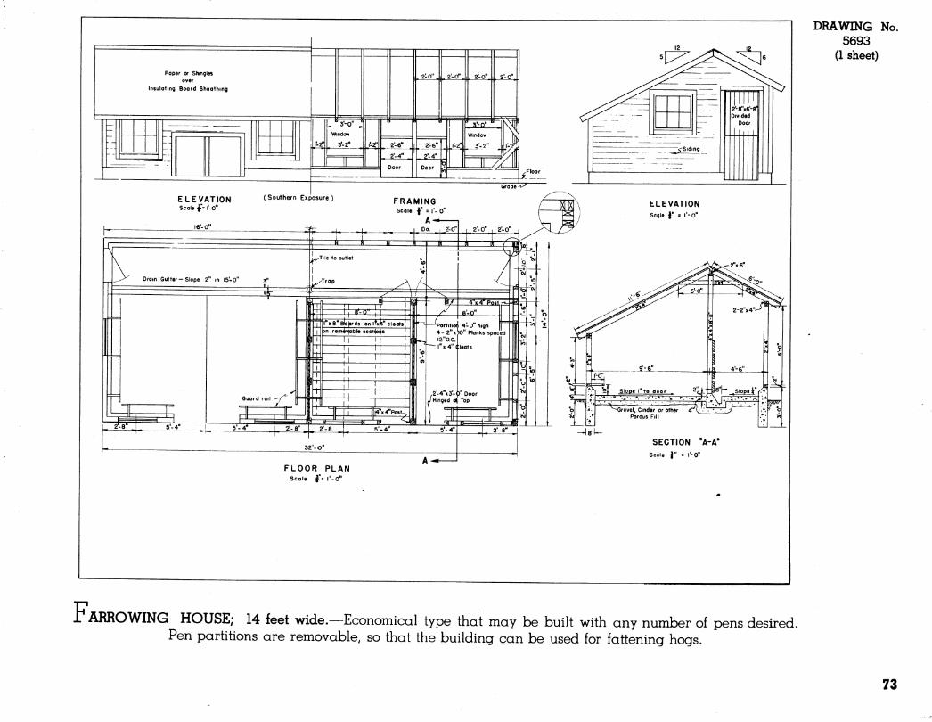
Paper or Shingles over
Insulating Board Sheathing
'
. 2-0" . . 2-0\ \. 2'-0". , 2-0".
- —
l'-2f'
r 3'-0"
1 '-2^'
r 1 n 1 l*-2"|
'-^^:^^^
1
Window
3'.2" ^: ^ 2-6" . 2'-6" 3-2" . L_J_^ 2-4" 0' A"
5 ■—-
~JZ
--7 '- ... -^ II Door II /. 1 j kî y^i^
Grade ̂
\-
ELEVATION Scale -fsl'-o"
16-0"
( Southern Exposure ) FRAMING Scole •§■" = 1'- 0"
Dram Gutter-Slope 2" m 15-0"
^
L^ 2'-8" I 2'-8
32'-O"
FLOOR PLAN Scale •!"= I'-O"
^Gravel. Cinder or other /1L\- / . • • •/ ^Grovel, Cinder or other 4 ' Porous Fill
SECTION "A-A" Scale I" = I'-O"
DRAWING No. 5693
(1 sheet)
r ARROWING HOUSE; 14 feet wide.—Economical type that may be built with any number of pens desired. Pen partitions are removable, so that the building can be used for fattening hogs.
73
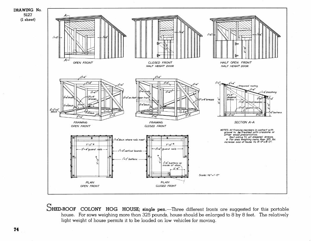
DRAWING No. 5127
(1 sheet)
/4-J OPEN FRONT CLOSED FRONT
HALF HEIGHT DOOR HALF OPEN FRONT HALF HEIGHT DOOR
2" X 4" braces ^
■^1 f2 baffens
FRAMING OPEN FRONT
FRAMING CLOSED FRONT
/x^b/ock where rails meef-
/ X !2 verhcal boards -
l"^2" baffens
7-0
guard rails -
/*6 baffens on inside of door^
a HyiiiiiiiUtJ.mJ*jtf*J-
SECTION A-A
NOTES: AH framing members in contact with ground to be treated with creosote or other wood preservative.
Nail siding to all diagonal braces. ¥- For sows weighing more than 325 lbs.
increase size of house -to B'-Cxd'-O".
Scale: '/^''^I'-O"
PLAN OPEN FRONT
PLAN CLOSED FRONT
OHED-ROOF COLONY HOG HOUSE; single pen.—Three different fronts are suggested for this portable house. For sows weighing more than 325 pounds, house should be enlarged to 8 by 8 feet. The relatively light weight of house permits it to be loaded on low vehicles for moving.
74
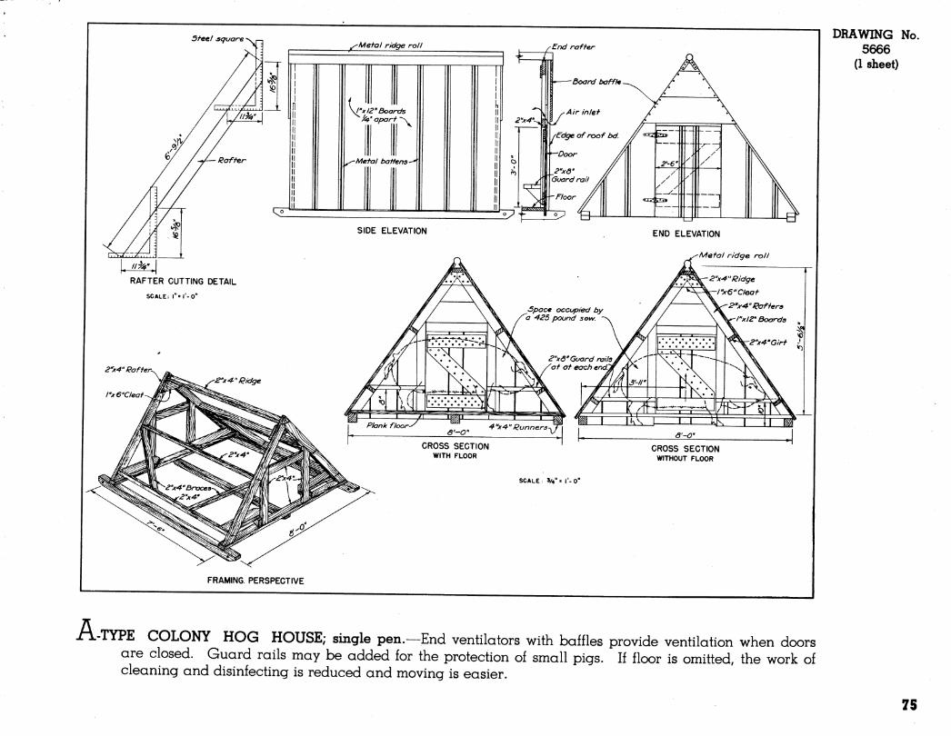
A •TYPE COLONY HOG HOUSE; single pen.—End ventilators with baffles provide ventilation when doors are closed. Guard rails may be added for the protection of small pigs. If floor is omitted, the work of cleaning and disinfecting is reduced and moving is easier.
DRAWING No. 5666
(1 sheet)
75
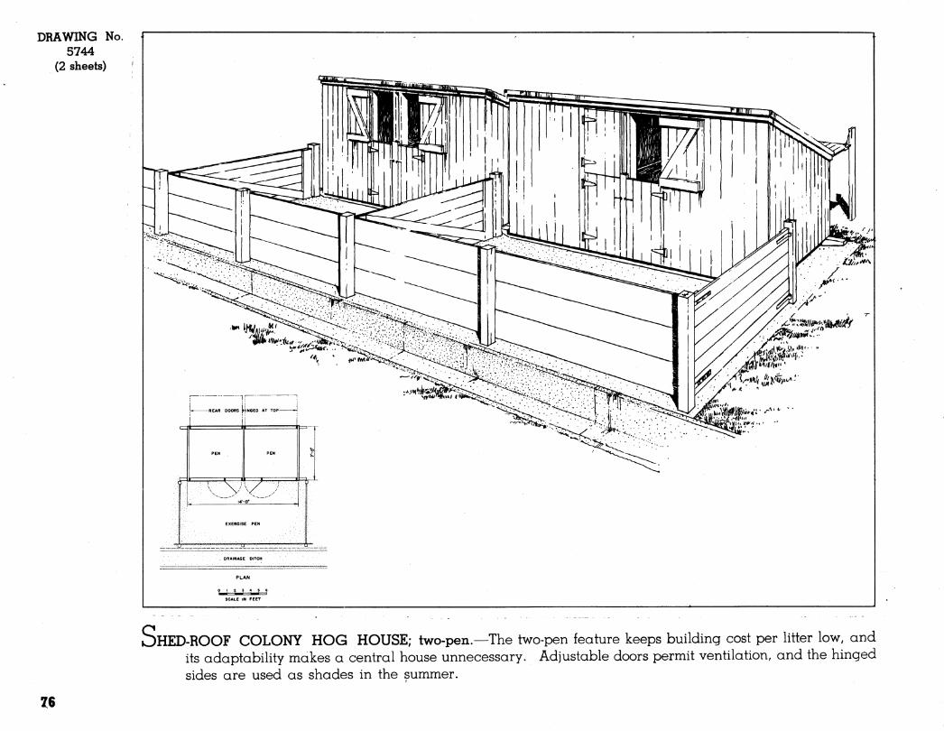
DRAWING No. 5744
(2 sheets)
EXERCISE PEN
DRAINAGE OITCH
SCALE IN FEET
OHED-ROOF COLONY HOG HOUSE; two-pen.—The two-pen feature keeps building cost per litter low, and its adaptability makes a central house unnecessary. Adjustable doors permit ventilation, and the hinged sides are used as shades in the summer.
Z6
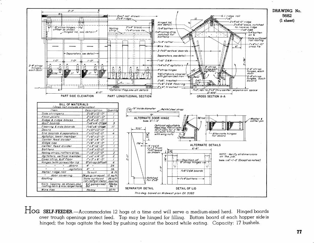
ridge block., notched
VQ ridge D$M I'x 4" baffen on <L Slate surfaced roll roofing
expansion space
PART SIDE ELEVATION PART LONGITUDINAL SECTION GROSS SEGTION A-A
BILL OF MATERIALS 1 (Does not include alfemafes) \
Jfem Description Quantity Side stringers 2"xa"^/2'-0' Floor Jo is f s 2''x4.'xl0'-0' R-idge 4 ridge blocks Z''x4''x&-0' Qoof boards I'xe'xl4'-0'D$M 5 Flooring $ side boards rxé'xe'-cD^Ai 17 Doors I'xIO'xIZ'-O' End boards 4 separators rxio"xiz'-o' 4 Agitator, lower member r x<b'xia'-o" Center feed divider i'xe"xe'-o' ßidge cap l-xê' xW-O' Center Feed divider l"x4.'x6'-0" Battens r x4' xlO'-O' Nailing strips, rafters 4 ties 1" x4'xl2'-0' 2 /agitators, vertical member 1" x4"xl4'-0'' 2 Cover strip, toff loor rxS" x6'-0" 1 ti ingés (with screws) for lid 8'strap (offset) 4
" ,doors 4' „ 24 ' ' ' , agitators 4" « 36
Metal ridge roll To suit 6 ft " door CO vering 26 ça. g. i or equal 12 sq.ft
Roofing 51a te -surfac e d roll roof'g or metal
28sq.ft approx.
Nails (appro^. as shown,plus roofing nails 4 misc. larger nails)
6 d galvanized 3y4-lbs.
Wire ties Heavy 20 ft
(^ y2'inside diameter ^e-x^^'steel strap
ALTERNATE DOOR HINGE Scale : 6"= I'-O"
Optional adjustable feed flap, <T>i'xir, with '/z'x3'slots for 2-Va" can bolts fitted with wing nuts
■14 req'd. cut 2 from I'x 10'board i as shown i
Wrod T ^ f \
r W ^—Alternate hinges
for doors
^Washer 4 coffer pin
m
Notched for Z'xÔ'
ALTERNATE DETAILS e'-e"
' Position of 8' strap hinges -
l'x6'D 4M boards
\^l"x4'baffens -
w
NOTE ■ Verify all dimensions on the Job.
SCO le ; 11/2" = I'- o" (Exceptas noted)
SEPARATOR DETAIL DETAIL OF LID
Thisdwg. based on Midwest plan EX. 3383
DRAWING 5682
(1 sheet)
No.
ilOG SELF-FEEDER.—Accommodates 12 hogs at a time and will serve a medium-sized herd. Hinged boards over trough openings protect feed. Top may be hinged for filling. Bottom board of each hopper side is hinged; the hogs agitate the feed by pushing against the board while eating. Capacity: 17 bushels.
77

POULTRY HOUSES
i
79

DRAWING No. 5652
(4 sheets)
.,./;•<. 4j;»v
I i I 1 r '/^''*^'íiíM"''''^-»^<*4^í
DROPPING I BOARDS OR PITS I BOARDS OR PITS I ^
^
©
24'-0"
FOUNTAIN
24-0
s/ FEED ROOM
12-0" 24'-0" PLAN
SCALE IN FEET
24'-0" SECTION
80
i WO-STORY POULTRY HOUSE; 24 feet wide.—Because of climatic variations within the region, no venti- lating system is shown. The county agricultural agent or State agricultural engineer should be consulted about ventilation. Capacity: 160 small birds or 140 large birds per pen.
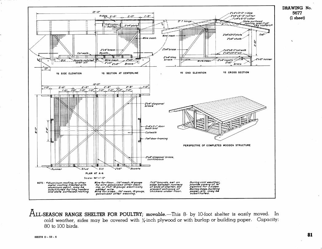
-_ii ^IT Ca-f- k^a/k-^
~r¡rtL„ J'z/¿ _ Sy^oQßfsnqt^i
1/2 SIDE ELEVATION «/2 SECTION AT CENTERLINE
^ £'V^V/J'-O" ridge ^ 2-x4^'x6'-0'' naffer
.l''x4^xS'-0"coHar ^ Slate -surfaced
~^^^r_\^'^°^''?f!^aB,,,^oof/r7Ç^ q{/er r'x6" r. roofers*
\ y-Z'xIZ" runner
•/2 END ELEVATION 1/2 CROSS SECTION
2''x4" diagonal brace
Z-4''x3'-l" door each end
Cafn^alk
l''x4''door framing
¿"x^" diagonal brace, continuous
PERSPECTIVE OF COMPLETED WOODEN STRUCTURE
^ Stud \ Sill
PLAN AT A-A
Scale-. VA*
*Alunrtinum roofing, or other metal roofing treated ivith aluminum painf, may be substituted for f.4ig. roofers and slate surfaced roofin<j.
Wire for floor... li/i"mesh,14-gauge fox tvire aalyanized after nt^eai^- ing, or I'x2" 14- gauge electricallg i^^e/ded H^ire.
IVire for sides... I'/z" mesh, 18 gauge, galvanized after iñ^eai^ing.
rx 12" boards, set on edge bettveen runners at ends of shelf er, mil prevenf entrance of chickens under floor.
During cold ^eafher. provide covers of 'A^' pit/wood for 3 sides. Burlap bags, building paper, efc. mag be subsfitufed.
DRAWING No. 5677
(1 sheet)
ÄLL-SEASON RANGE SHELTER FOR POULTRY; movable.—This 8- by 10-foot shelter is easily moved. In cold weather, sides may be covered with )^-inch plywood or with burlap or building paper. Capacity: 80 to 100 birds.
893378 O - 50 - 6 81
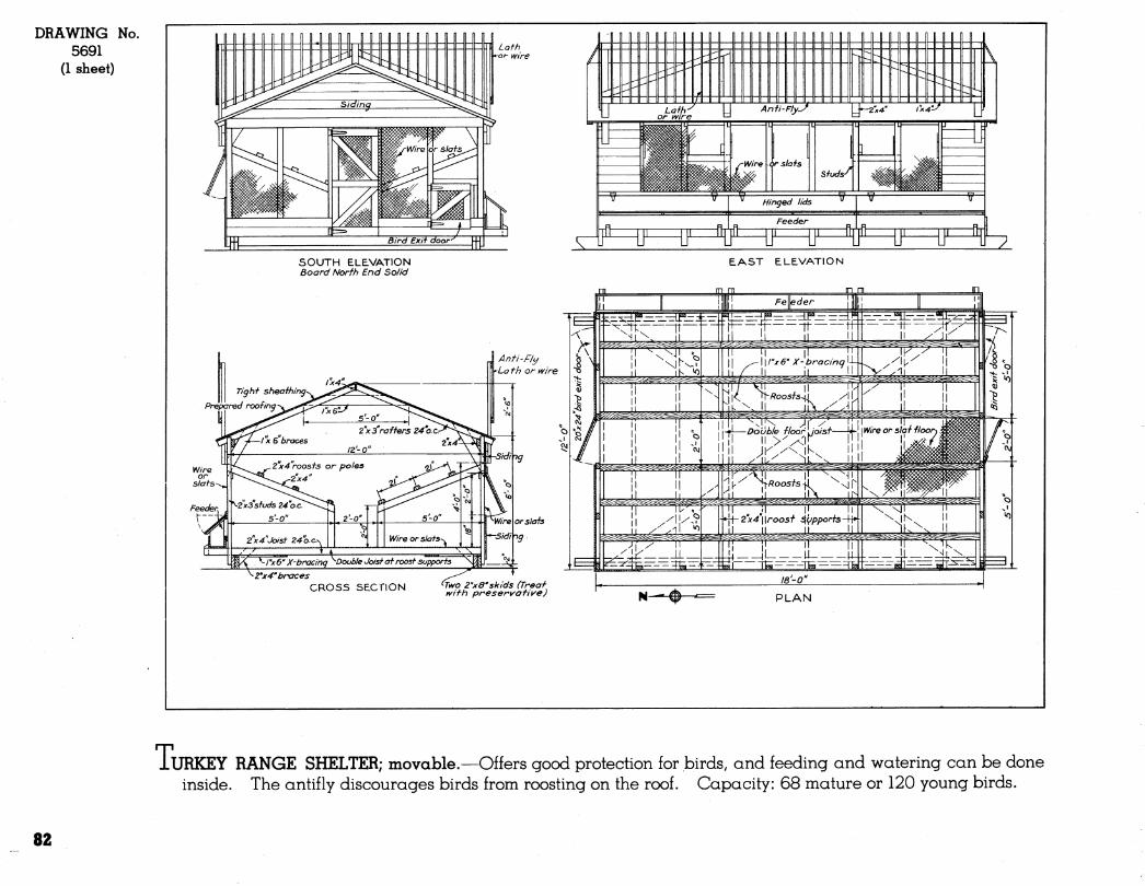
DRAWING 5691
(1 sheet)
No.
SOUTH ELEVATION Board North End Solid
EAST ELEVATION
CROSS SECTION *7ivo 2"x8''skids (Treat with preservative) PLAN
Ti URKEY RANGE SHELTER; movable.—Offers good protection for birds, and feeding and watering can be done inside. The antifly discourages birds from roosting on the roof. Capacity: 68 mature or 120 young birds.
82
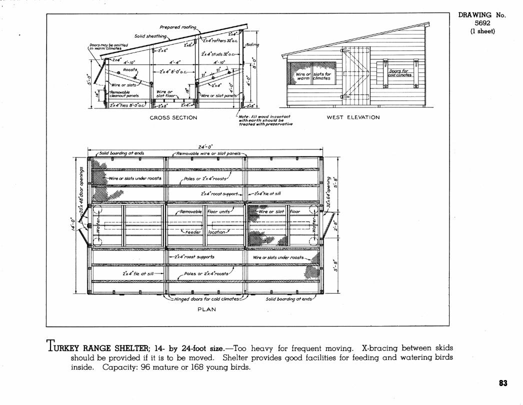
GROSS SECTION "-Note: AU wood in contact with earth s h ou id be treated with preservative
WEST ELEVATION
24-0" ^Solid boarding at ends
^^^^^^^=^=^^=^^4=^^^%^
2x4 He at sill-
y^Removable wire or slat panels-
•*—2x4"roost supports
:^^:<i^s^s^^^^^^^
^
T Poles or 2x4 'roosts'^
g
5^s^í^s!.j^í¿^¿=fe^.¿i^.í¿gfefe^=j^;i^^;^^^
Wire or slats under roosts
^^.^¿^i^^-^¿=^¿=¿==^^^^=i¿>^^
^-^tf/nged doors for cold climates:¿^
PLAN
Solid boarding at ends- T
DRAWING No. 5692
(1 sheet)
iURKEY RANGE SHELTER; 14- by 24-foot size.—Too heavy for frequent moving. X-bracing between skids should be provided if it is to be moved. Shelter provides good facilities for feeding and watering birds inside. Capacity: 96 mature or 168 young birds.
83

CRIBS AND STORAGES
85
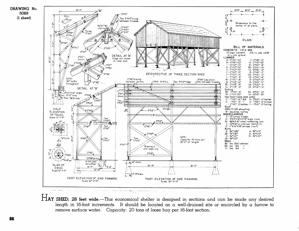
DRAWING No. 5089
(1 sheet) Pi+ch !2
l5'-9" . ', l6'-0" J5'-9"
PLAN OF PIERS
Scale Va"--I'-O'
PART ELEVATION OF END FRAMING Scale '/4" = l'-0"
PART ELEVATION OF SIDE FRAMING Scale 'V^r-O"
iP Dimensions +o +he — cen+er of all piers.
1^3" -4-
PLAN
BILL OF MATERIALS CONCRETE: 1:3 = 5 MIX
22 bags cement 2'/2 cu.yds.sarfd 4cu.yds. gravel
LUMBER 4-6"X6"-24' I- 2''X8''-I0' 8-4"X6"-20' IO-2"X6''-20'
1 -4"X4"~I0' I0-2"X6"'I8' 6-Z"XI2"-24' 30-2"X6"-!6' 2-2"X12"-20' 12 -2''X6"-I4' 2-2"XI2"-l6' 8-2"X6"-l2' 2 - 2"XI2"- 16' 20-2"X6"'IO'
1 - 2"XI2"- 6' I8-2"X4"-I6' 16- 2"XI0"-I8' . 4-2"X4"-l4' 8-2"X8" 20' 8 - 2"X4"-12'
36--2"X8" 16» I4-2-X4"- 6' I2-2"X8'' 14' 12 -2"X2"-I4' Siding 58 - I"XI2"-14' 56-'yfe"X3" 14- 18 - l"Xi2"-20' l6-'/2"X3" 20'
Hay Door (one end only) 12 - rX6"-l4'TÍG 3- 2"X4"-IO'ba++en 12-;"X6" 12' " 2- rxe"-12'braces
i -2"XI0" 10ba++^n I - rXIC" lO'furring Roof 2000f+. BM shea+hing 18 - squares roofing
MISCELLANEOUS 3 -10" s+rap hinges
12 - 3"X3"X'/A"X3'-3"ar.éle irons 32 - ^/ô''X4'-8" S+eel reinforcing rod?^
2 - l/2"X'/4"w.i.s+irrup5 (De+^il "A") 12 - I"X'/A"X18" straps Croof), Bol+s 8-%"X4fe" 4-V4''Xl3"
28-WX8'' S-VXId" 4-VA"XII" I2-V4"XI6''
28-3/4" XI a" NAILS 80-lbs. 20d common 60-lbs. 8d 10-lbs. 6d
H AY SHED; 28 feet wide.—This economical shelter is designed in sections and can be made any desired length in 16-foot increments. It should be located on a well-drained site or encircled by a furrow to remove surface water. Capacity: 20 tons of loose hay per 16-foot section.
86
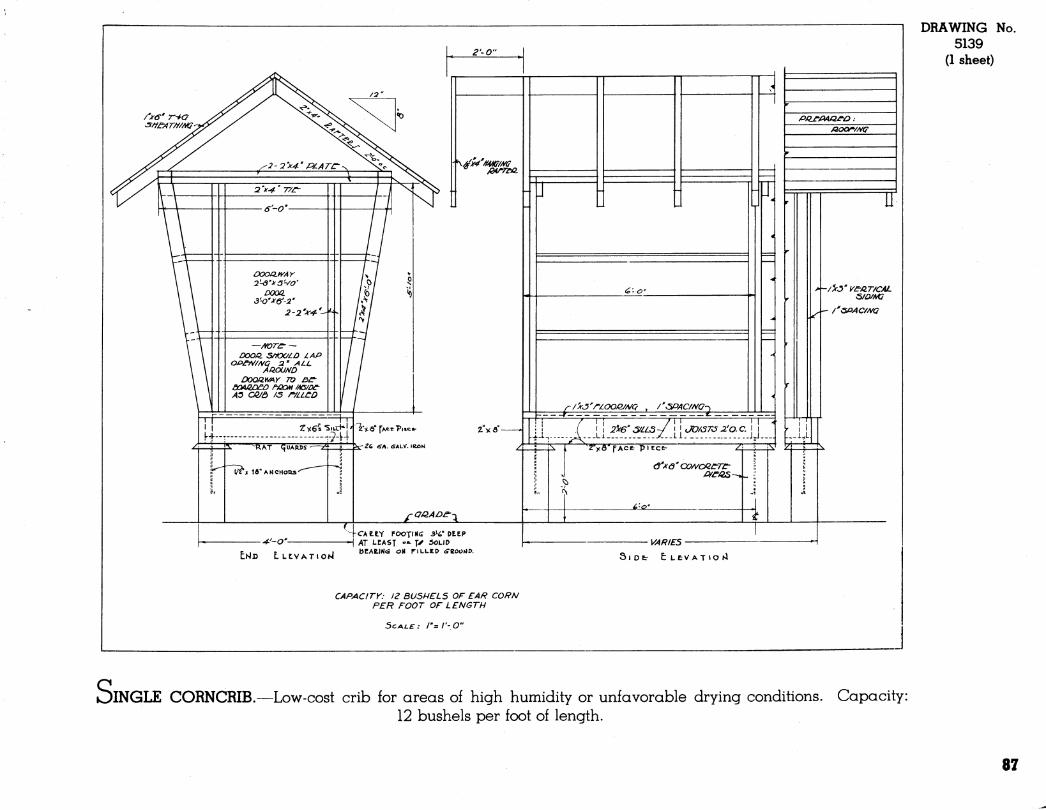
EHD LLtVATlOhl
-CAetY FOOTfHff 3-6* DEEP >\T LEAST "■• T^ 50LID bEAKINâ OM TILLED <SZOOíÍV.
SlDfc- tLCVAT»Ol4
CAPACITY: 12 BUSHELS OF EAR CORN PER FOOT OF LENGTH
SCALE: /"= l'-,0"
DRAWING No. 5139
(1 sheet)
)INGLE CORNCRIB.—Low-cost crib for areas of high humidity or unfavorable drying conditions. Capacity: 12 bushels per foot of length.
87
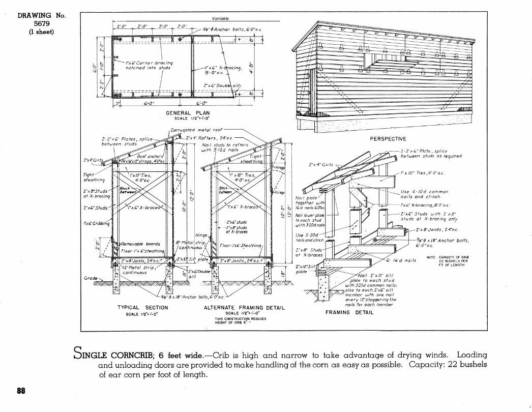
DRAWING No. 5679
(1 sheet)
Variable
Grade -^
2\4"Girt5^
Ticfhf sheath ina
Z-xO'Sfuds-^ ' at X-bra cinq
Z"xC"Sfuds^f
I-
¡"xC'Cribbinq I
-■%" <i) X16"Anchor bolts, CO"o.c.
-%"<f> X 18"Anchor bolts, é'-0"ac.
NOTE . CAPACITY OF CRIB 22 BUSHELS PER FT. OF LENGTH
TYPICAL SECTION SCALE 1/2"= I-0"
ALTERNATE FRAMING DETAIL SCALE l/2"'r-0"
THIS CONSTRUCTION REDUCES HEIGHT OF CRIB 6" •
^Nail rxlO" sill 'opiate to each stud
LdithJ-ZOd common nails; -AOISO to each Z"xG" sill ' member uith one nail every IZ"staqqerinq the nails for each member
FRAMING DETAIL
OiNGLE CORNCRIB; 6 feet wide.—Crib is high and narrow to take advantage of drying winds. Loading and unloading doors are provided to make handhng of the corn as easy as possible. Capacity: 22 bushels of ear corn per foot of length.
88
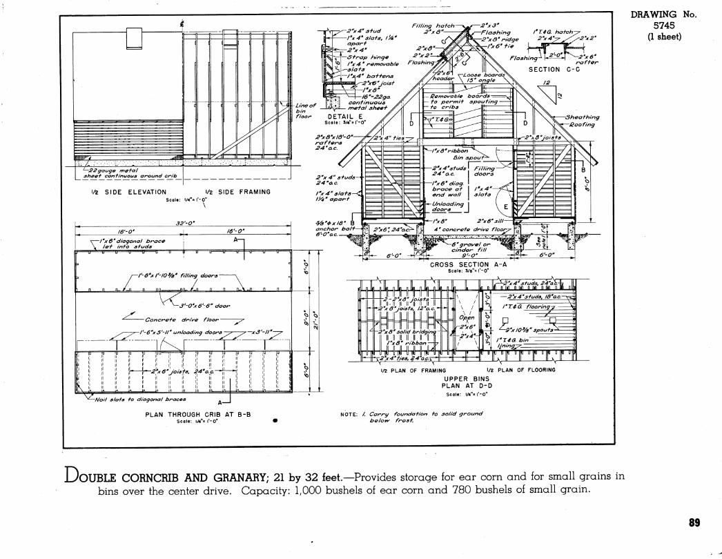
DRAWING No. 5745
(1 sheet)
DOUBLE CORNCRIB AND GRANARY; 21 by 32 feet.—Provides storage for ear corn and for small grains in bins over the center drive. Capacity: 1,000 bushels of ear corn and 780 bushels of small grain.
89
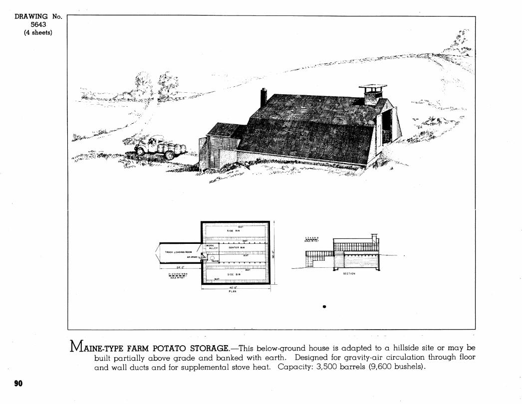
DRAWING No. 5643
(4 sheets)
--rjr^'^^d^-:^
TRUCK LOADING ROOM
mnEzi:
SCALE IN FEET
CENTER BIN
IHülü'liilllil
lüüirMiiiiii
' z ■ \
p^tt J Ttt tS
+ #í m 11
i t IT i 1 .__= ~ _ —
-:rz| --= ^ ̂ ^Zï^2^ """^^ 1-1 LJ
M.AINE-TYPE FARM POTATO STORAGE.—This below-ground house is adapted to a hillside site or may be built partially above grade and banked with earth. Designed for gravity-air circulation through floor and wall ducts and for supplemental stove heat. Capacity: 3,500 barrels (9,600 bushels).
90
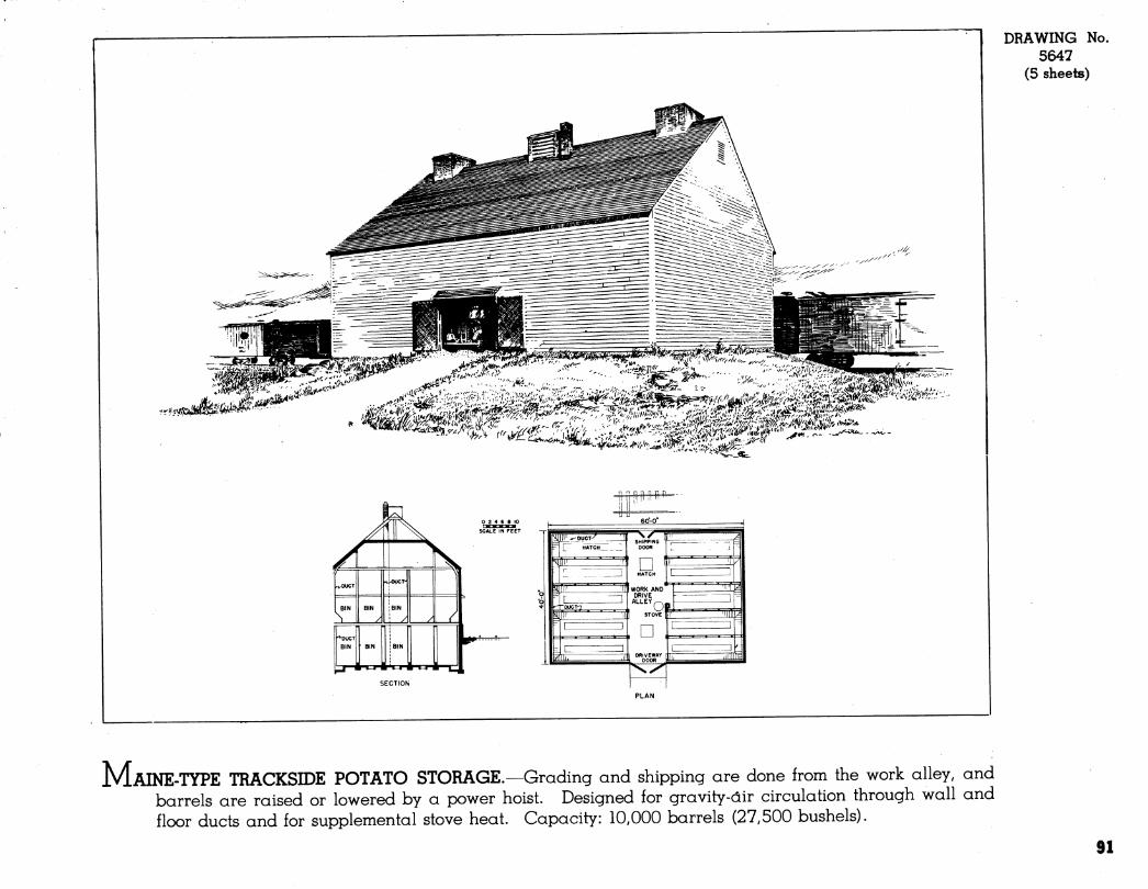
DRAWING No. 5647
(5 sheets)
■r'uïvS
A Â '4 ^ \.
\ f^^ 1
Y
r^OUCT n|^)OCT-
BIN
S BIN
/ JBIN
i ./ / / "DUCT
BIN
3-
' BIN
rf=i-
BIN
rt^n ^
0246810
SCALE IN FEET
MAINE-TYPE TRACKSIDE POTATO STORAGE.—Grading and shipping are done from the work alley, and barrels are raised or lowered by a power hoist. Designed for gravity-air circulation through wall and floor ducts and for supplemental stove heat. Capacity: 10,000 barrels (27,500 bushels).
91
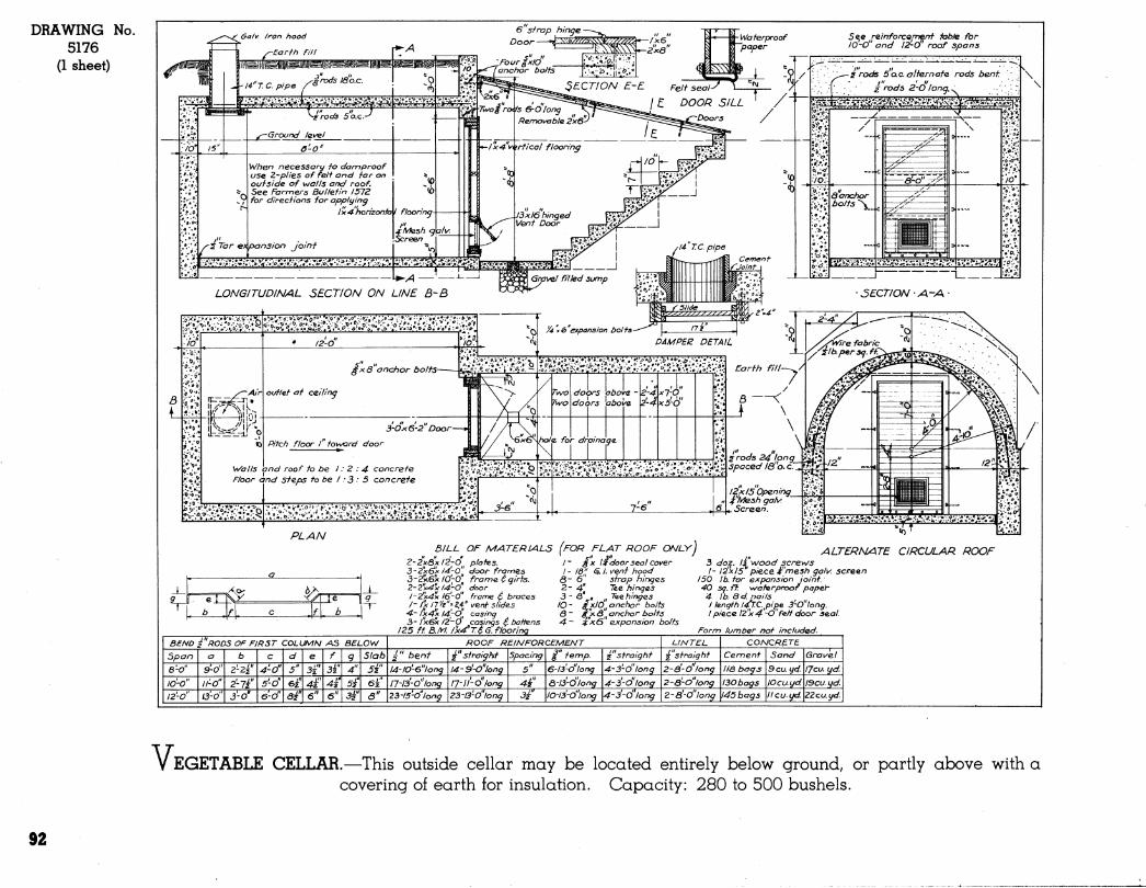
DRAWING No. 5176
(1 sheet)
5e^e reinforcQrnenf fahle for /O-O" and I^O" roof spans
PLAN
V :^S i>
ß/LL OF MATERIALS (FOR FLAT ROOF O^LY)
'"'"'' /- £x l:f door sea/cover I - lô'/^ ^. I. veni hood
ô~ o sirap hinges 2- 4l Tee hinges 3 - â" „ „ Tec hinges
lO- ixlO^^anchor bolts & - g^y <S„ anchor bolts -4 - ^'^0 expansion bo/ts
Z~2xQxl2~0^^ plote.s. 3~'¿xexl4-0" door frames 3-2'Ue'k lO'-O frame ^ girts. Z-Z"x^y/4;0^^ door /-2x4v l6'-o" frame ^ braces /- A 11'/^"*^," vent Slides 4~ ix-4'x I4^~0^^ casing 3- /x6x /"¿-Ó casings é battens
125 ft B.M. /X4"T4 G. flooring
BEND Í"RODS OF FIRST COLUMN AS BELOW ROOF REIS/FORCEMENT LINTEL CONCRETE !
Span a b C d e f 9 Slab i" bent i"straighf Spacing i" temp ¿"straight 2 straight Cement Sand Gra\/el
a-o" 9-0" ¿-z^ 4-0" 5" 3i" 3i" 4" Sa" l4-JO'-e"long l4-9'~0''long 5" 6-l3-o"long 4-3'-d'long 2-ä-Ö'long lia bags 9cuyd. IJcu. yd.
lo'-o" ll-O" ¿-7Í' 5'-d' 6¿" 4Í 4Í 5Í 6¿" l7-l3-o"long^ ¡7-II'-6'long 4Í ö-/3'-d'/ong 4-3'-o"/ong 2-drO"long I30bags lOcuyd. I9cu. yd.
l2'-o" O-o" 3-0' e'o" e^ 6" 6" 3à" ö" 23-15-0"long Z3-l3'-o"long 3à' lO-/3-o"long 4-3'-Ó'long Z-8'-o"long 145 bags lieu. yd. ZZcu.yd.
ALTERNANTE CIRCULAR ROOF 3 doj^, I2^wood screws I- I2'x 15' piece 4^"me5h galv. screen
150 lb. far expansion joint. 40 sg. ft. waf<e.rproof papeY- 4 lb. 8 d. nails I length l4^.C.pifie 3-0"long. /piece I2"x4'~0"feff door seal
Form lumber not included.
V EGETABLE CELLAR.—This outside cellar may be located entirely below ground, or partly above with a covering of earth for insulation. Capacity: 280 to 500 bushels.
92
EQUIPMENT AND SUPPLY BUILDINGS
93
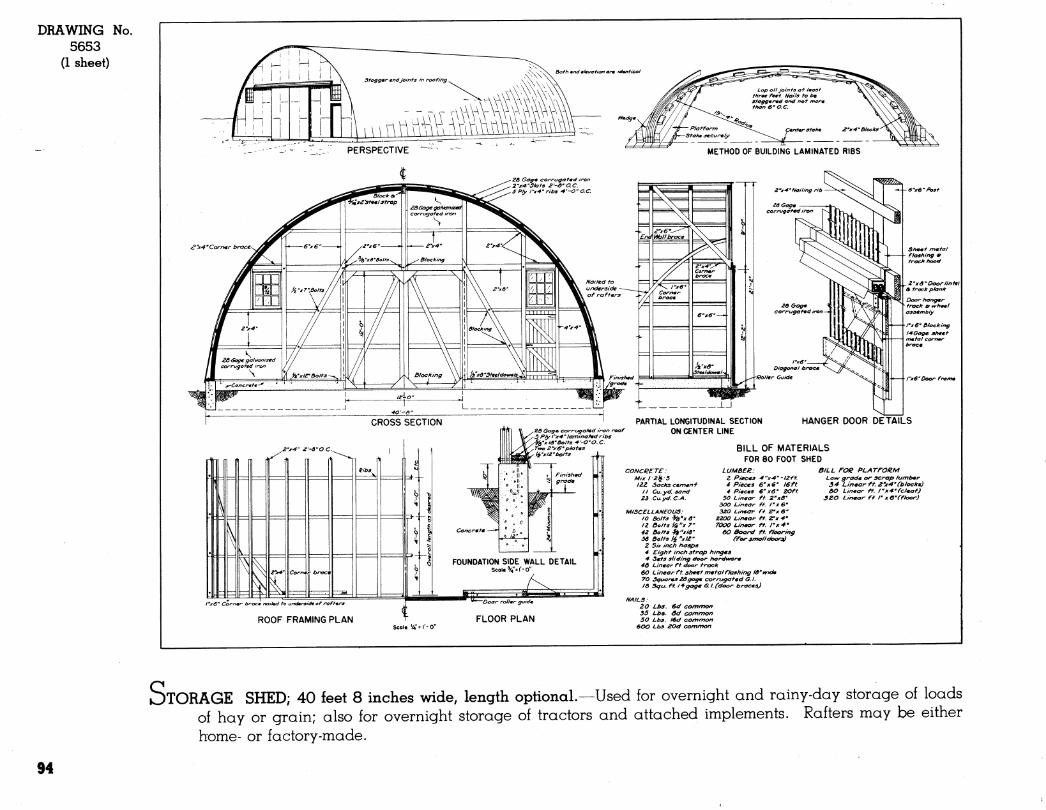
DRAWING No. 5653
(1 sheet)
PERSPECTIVE METHOD OF BUILDING LAMINATED RIBS
e"x4'Corn«rb
20 Gag* corragafmd h 2-xA"Slaf9 2--ô'O.C. 5 Ply fx-4' riba ^'-O'O.C.
CROSS SECTION
Z'jrA"Nailing rib
29 Gag* corrugaftd iron
20 Oogm corrugated iron—
Diagonal brae* ■Rollmr Guide
2<3 Gag* corrugaf*d iron roof 5 Ply l"X'4' laminafmd ribs ^¿"x IS'bolts ^-O-O. C. Two ¿"xff'p/ot*s ii'x 12-bolts
. LJ
PARTIAL LONGITUDINAL SECTION ON CENTER LINE
.2'xô'Doortint*l 4 track pkink
"xe'Door from*
HANGER DOOR DETAILS
CONCRETE: Mix l:2¡í:5 I2.Z Sacks c*m*ryf
n Cu.yd. sand Z3 Cu.yd.C.A.
BILL OF MATERIALS FOR 80 FOOT SHED
BILL FOR PLATFORM Law grad* or scrap h/mb*r
LUMBER: Z P/ec*s '4"xA"-l2ft. 4 Pieces 6'x6' 16ft 4 Pi*c*9 €" x6- ZOft
SO Linear ft Z-xô' 300 Linear ft. I'xe- 320 Linear ft. Z'xß-
2200 Linear ft. ZTx ¥' 7000 Linear ft. /"x'*'
60 Board ft. f/oaring ffor small doorjjf
34 Linear ft 2'x'4'Cbloeks) AO Linear ft. /"x^'fcleat)
3ZO Linear ft I' x C'Cfloor)
ROOF FRAMING PLAN
MISCELLANEOUS: 10 Bolts ■Jà'jr <5" n ßolts iik"x7" 42 Bolts 4i"xlô" Ä5 Bolts ii "xl¿-
Z Six inch ttasps 4 Eight inch strap hinges 4- Sets sliding door ttardware
4Ô Linear ft door track 60 L inear ft. sheet metal flashing IB" wide 70 Squares 26gage corrugated G. I. 16 3gu. ft 14gage G.I.("door braces)
NAILS: 20 Lbs. 6d common 35 Lbs. ôd common 50 Lbs. I€d common
600 Lbs. 20d common
STORAGE SHED; 40 íeet 8 inches wide, length optional.—Used for overnight and rainy-day storage of loads of hay or grain; also for overnight storage of tractors and attached implements. Rafters may be either home- or factory-made.
94
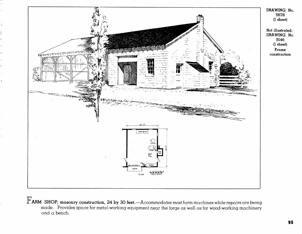
DRAWING No. 5678
(1 sheet)
Not illustrated: DRAWING No.
5146 (1 sheet) Frame
construction
01 23 45 67 69 10
PLAN SCALE IN FEET
r ARM SHOP; masonry construction, 24 by 30 feet.—Accommodates most farm machines while repairs are being made. Provides space for metal-working eguipment near the forge as well as for wood-working machinery and a bench.
95
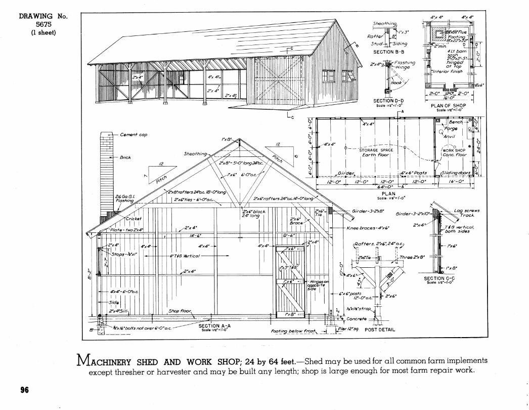
DRAWING No. 5675
(1 sheet)
Q. "|fv]~ ^'x/é'bolis nof over4>'-0"o.c. Fooi¿ngbelow_f_roz1:^ rrLl^*'''^'■'9' '^'^^'^ ^^■^*"-
MACHINERY SHED AND WORK SHOP; 24 by 64 feet.—Shed may be used for all common farm implements except thresher or harvester and may be built any length; shop is large enough for most farm repair work.
96
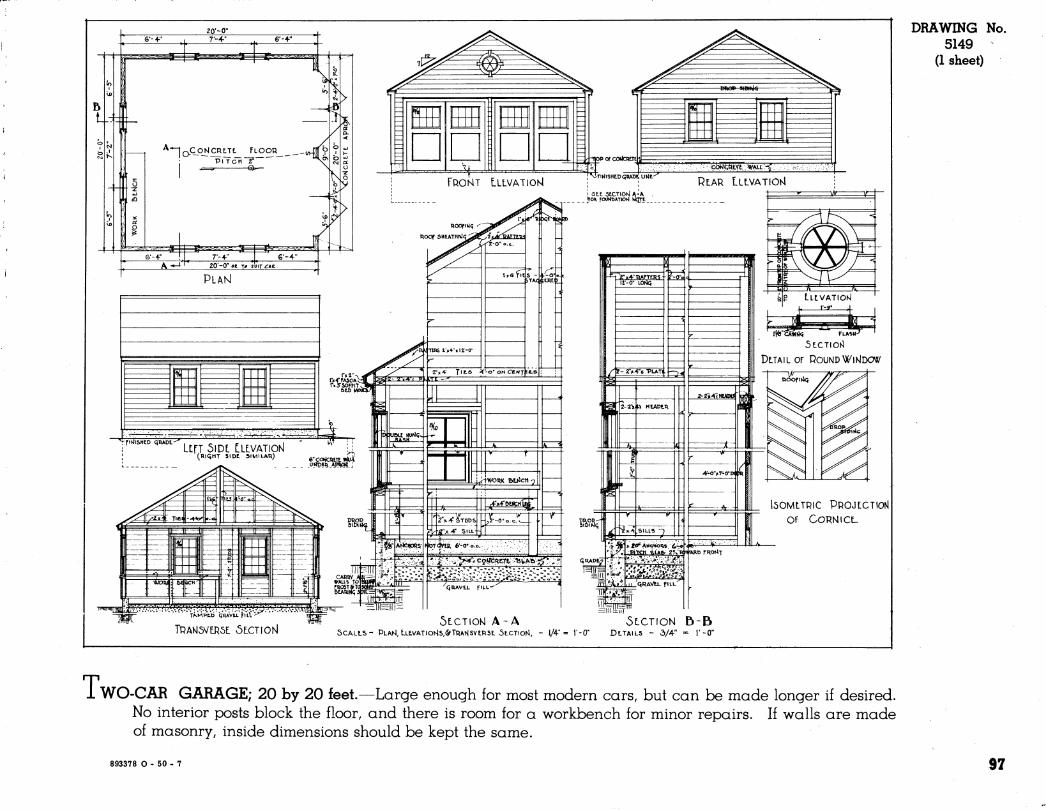
150MLTRIC PROJLCTIOM
Of CORN I CL
^r ■ TÀ.MPtt> "qRAv'tL h'ii
TRAKJ5VLR5L ÓLCTIOlsl ^r 5tCTiONJA-A
SCALLS" PUAH, t-LE.VATION|S,<SfTRANSVLR5L 5LCTIOI4, - I/4-" =
5LCTION B-B I'-O" DLTAILS - 3/4" « V-O"
DRAWING No. 5149
(1 sheet)
T WO-CAR GARAGE; 20 by 20 feet.—Large enough for most modern cars, but can be made longer if desired. No interior posts block the floor, and there is room for a workbench for minor repairs. If walls are made of masonry, inside dimensions should be kept the same.
893378 O - 50 - 7 97
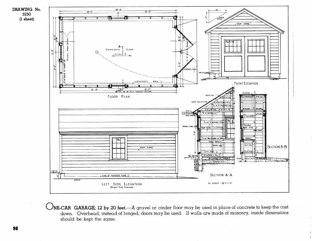
DRAWING No. 5150
(1 sheet)
J
*1 I^OMCRLTE. ¡ fio
■i—tti" I'm
/^CONCP.ILTl ^X^ALl -7
t< fei
TOP Of COhtOUT^ -i I
quscr A
..*
L : :.
^5>i^t!tt
fRONTtLLVATION
FLOOR PLAM
.DRiOP 5IDIhJ<i
r \lNt OF COMCR.LTI. flOOa -7
K°'\ '^^^^'^eWcR^-^
5LCT10Ñ E)-B
' ' '. 'N. '^ • •■
LLfT 5lDL LLLVATIONI (TliQhT StDf. SIMILAR)
5LCTIONI A-A
ALU SCALEJ5 - 1/2"- l-O"
WNE-CAR GARAGE; 12 by 20 feet.—A gravel or cinder floor may be used in place of concrete to keep the cost down. Overhead, instead of hinged, doors may be used. If walls are made of masonry, inside dimensions should be kept the same.
98
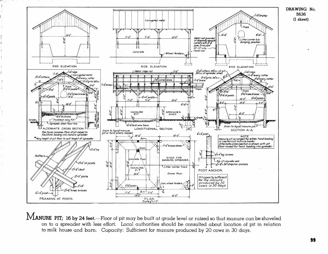
Corrugated metal
7-0"
i^ Wheel fénders.,^^
Ixo'shiphp
tt/lefal roofarounded at diagonalfu opposjfe comers wrffi i-^' pipe. Drive pipe /O'-O'info
^ moist soi/.
eW-^ ( \
V Litter carrier tub dumping posifKjn.
END ELEVATION
2x4 rafters^
12
I »'S ridge Corrugated metal
rafter 2''x4''girts36o.c.
ALTERNATE CROSS SECTION
FOR HAND LoADiNG-ñoor of pit raised to facilitate loading into manure spreader
yarg fieight of pit floor to suit heigtit Cff spreader
SIDE ELEVATION
/^Metal ridge roll 2"»^^ rafters 28'o.c. atpit.-^ 30 OÇ. ai spreader shed.
END ELEVATION
/xQ'ridge ^x 8"every rafter
■6'every rafter
¡xGbrxxe
éxGNolO wire fabric [__! ^L'tlllb^ , , , LONGITUDINAL SECTION "^""tzo'l
Drain to liquid manure ^ ^ pit or tank where needed
\\ J 14-2' Ju lO'-o"
Drain to Iicjuid manure pify H^^V SECTION A-A.
-2xe tie
Gx6 post—
FRAMING AT POSTS
-2x6'at posts
2x6'cleat
Z^xQ' plate
2x0'
Z'xG'knee braces
^ cvi
-fr WfUrain
Concrete floor
/MANURE ' / PIT
pr l"x 6" braces above-^'
SHED FOR MANURE SPREADER
)><;\^ Gx6"po3ts
^ A-J 7-0"
6x6 post-.
^Litter carrier track I ^
Gravel floor
Cone, wheel fenders.
k- PLAN
Scale ^"=/'-0"
t^ NOTE
Manure pit arranged for either, hand loading or mechanical manure loader Alternate cross section is shown with pit floor raised for hand loading into ^reader
. ^i ^A^'^ screws.
^Töp of concrete wall =:^x /^x 24'stmpiron anchors
POST ANCHOR
Pit capacity efficient for the manure produced by 20 coivs in 30 days.
DRAWING No. 5636
(1 sheet)
M, ANURE PIT; 16 by 24 feet.—Floor of pit may be built at grade level or raised so that manure can be shoveled on to a spreader with less effort. Local authorities should be consulted about location of pit in relation to milk house and barn. Capacity: Sufficient for manure produced by 20 cows in 30 days.
99

BUILDINGS FOR PROCESSING
i
101
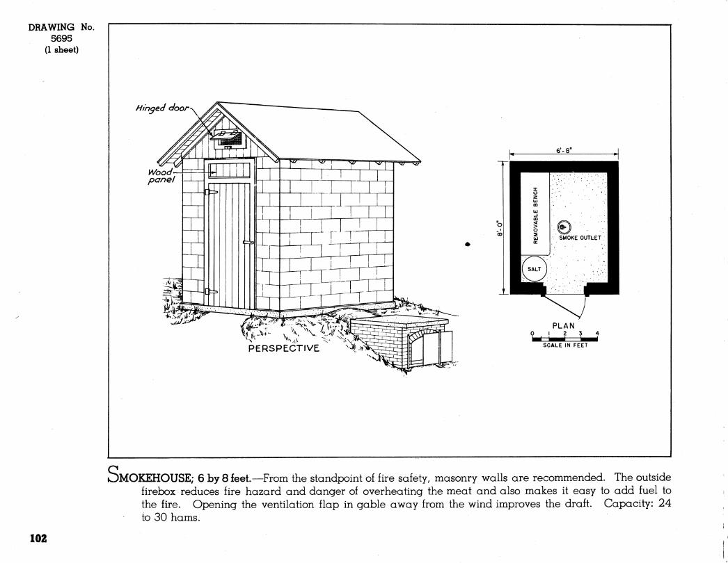
DRAWING No. 5695
(1 sheet)
Hinged door
Wood- panel
6'-8"
PERSPECTIVE
PLAN ¡234
SCALE IN FEET
)MOKEHOUSE; 6 by 8 feet.—From the standpoint of fire safety, masonry walls are recommended. The outside firebox reduces fire hazard and danger of overheating the meat and also makes it easy to add fuel to the fire. Opening the ventilation flap in gable away from the wind improves the draft. Capacity: 24 to 30 hams.
102
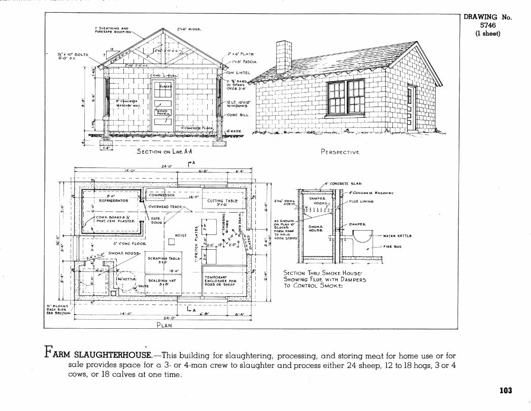
r SMEATHINQ AND FIRESAFE ROOFING
2")f<i>- RIDGE.
/2"X to' OOUTS
^
DRAWING No. 5746
(1 sheet)
CL .- •—p- ; , r-
[ J" [<:OrJJC.'Ll.jlTÉL
111 LZL
6' CöHcanhe.
SV ^^pö^
ECgxr^aír^ii^ Tszsm
SECTION ON LINE. A-A
24-O- I
/O' &LOC(¿S EACH SIDE. / SftE SECf/OW
A5> S HOW M ON PLAN lO' E>LOCK.%> POEM EDGE TO HOLD HOOK: STRIPS
'ER5PECTIVE.
y4" (TONCBETE SLAfc
-^'CONCBCTE MASOes/ltY
' FLUE LtNlN6
■ WATEa KETTLE
SECTION THRU SMOKE HOUSET SHOWINS FLUE, WITH DAMPERS TO CONTROL SMOK-E:
PLAN
r ARM SLAUGHTERHOUSE.—This building for slaughtering, processing, and storing meat for home use or for sale provides space for a 3- or 4-man crew to slaughter and process either 24 sheep, 12 to 18 hogs, 3 or 4 cows, or 18 calves at one time.
103

TOURIST CABINS, CAMPS, AND CAMP EQUIPMENT
i
105
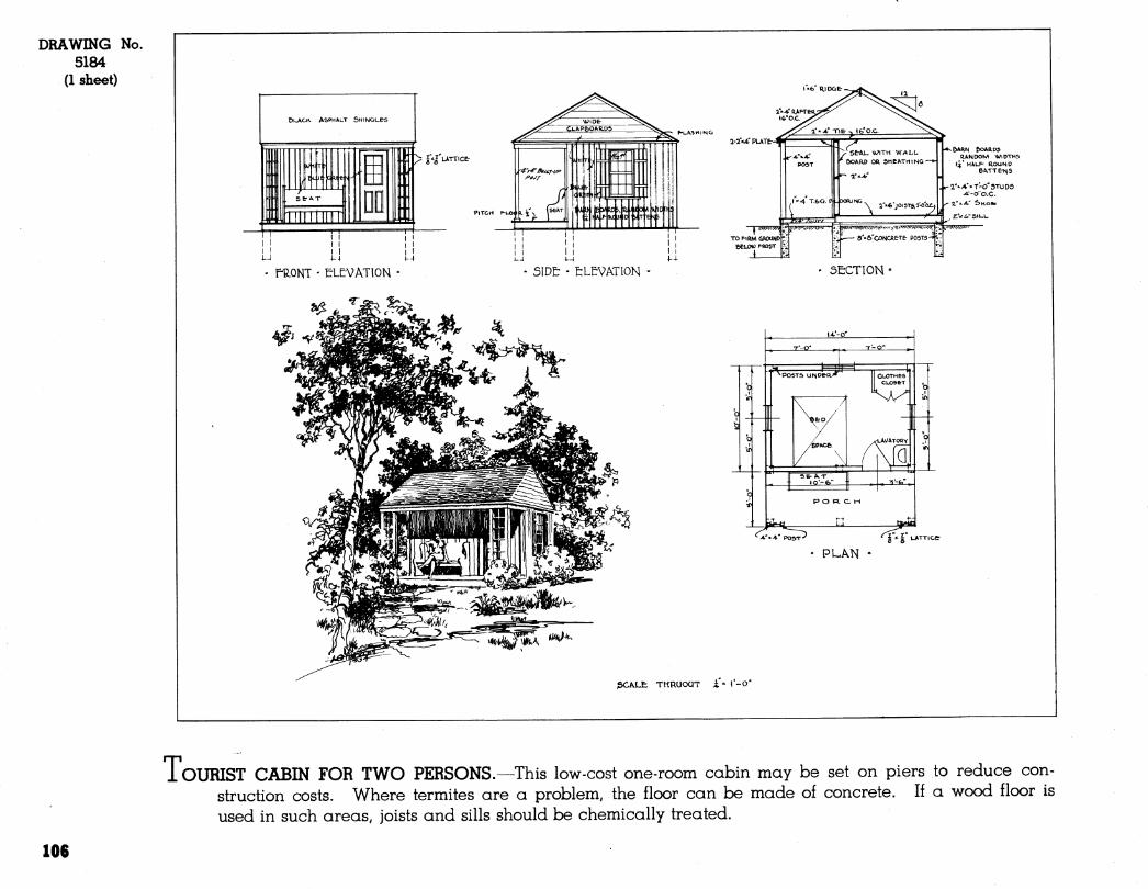
DRAWING No. 5184
(1 sheet)
*| UTTICE-
f-ilONT - eLE-VATlON SIDE: - tLEVATlON
IIANOOM WIDTHS l^" »KI.F- R.OUN0
6ATTetH5
r-^'^^'HT-O-JTuDS -*'-o"o.C.
ZV¿,"SlL.l_
ÔECT10H '
1*1 UATTlCt
PLAN
ßC^LE THRUOQT i» i'-O'
TOURIST CABIN FOR TWO PERSONS.—This low-cost one-room cabin may be set on piers to reduce con- struction costs. Where termites are a problem, the floor can be made of concrete. If a wood floor is used in such areas, joists and sills should be chemically treated.
106
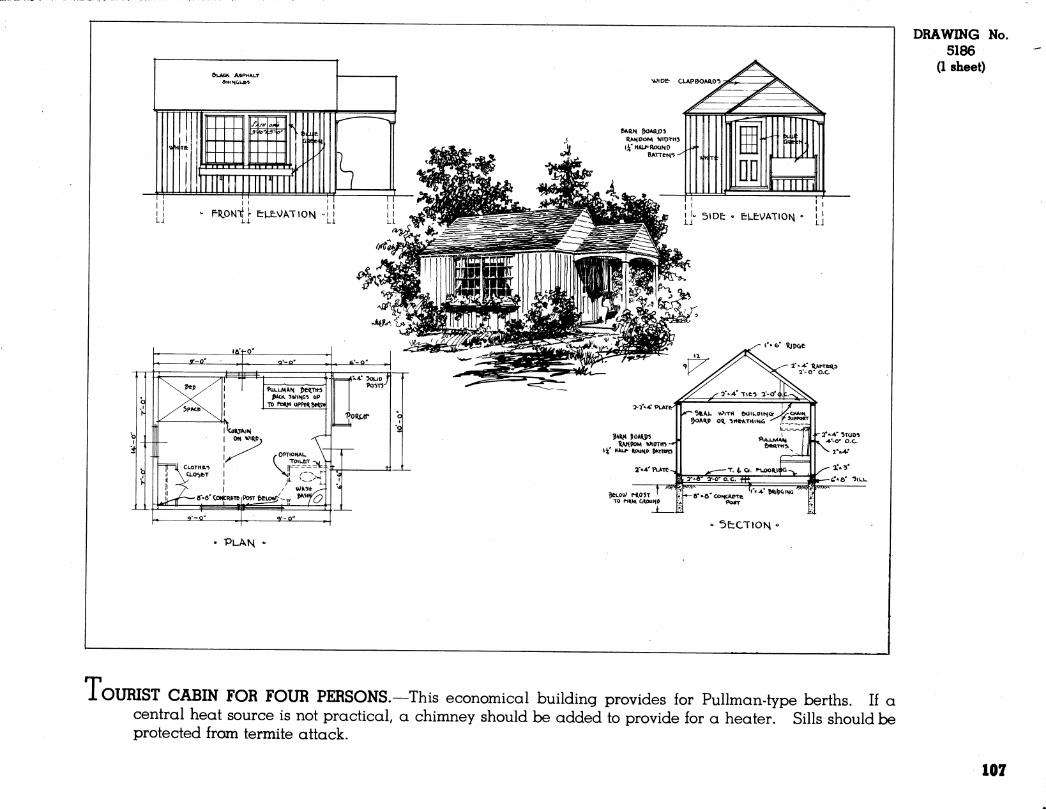
DRAWING No. 5186
(1 sheet)
« 5fcCTtON
• PLAN «•
1OURIST CABIN FOR FOUR PERSONS.—This economical building provides for Pullman-type berths. If a central heat source is not practical, a chimney should be added to provide for a heater. Sills should be protected from termite attack.
107
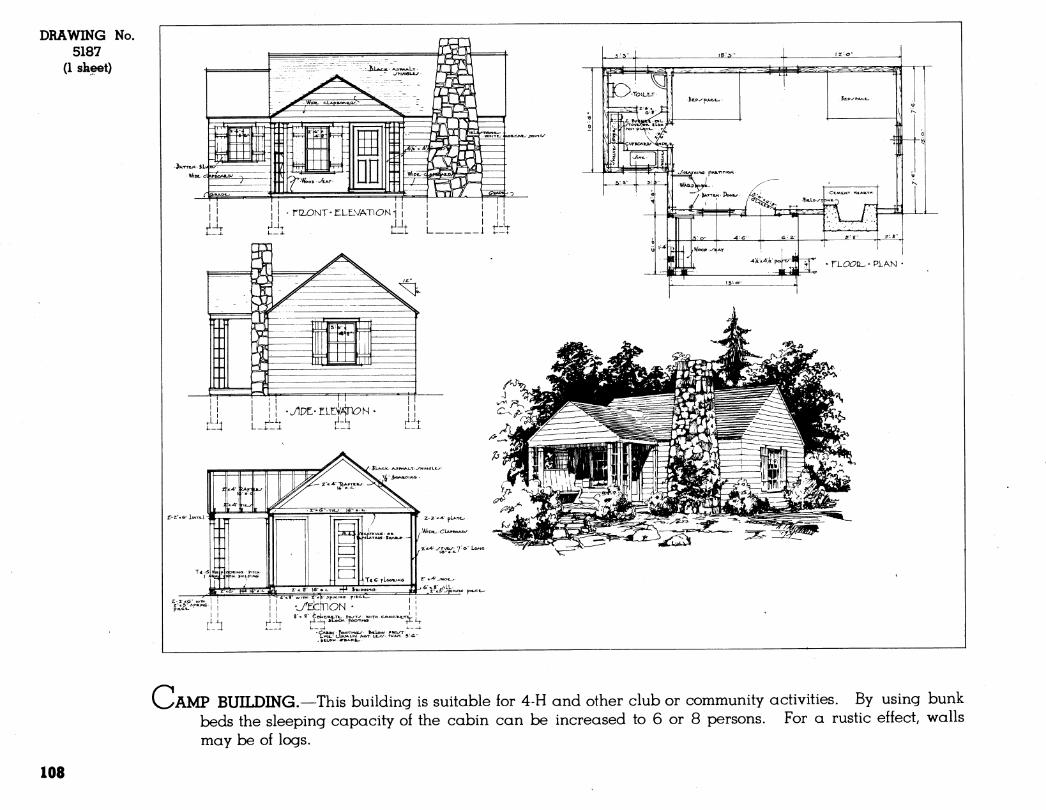
DRAWING No. 5187
(1 skeet)
Z-Z'^&' iwTt-L - I r^^---
OAMP BUILDING.—This building is suitable for 4-H and other club or community activities. By using bunk beds the sleeping capacity of the cabin can be increased to 6 or 8 persons. For a rustic effect, walls may be of logs.
108
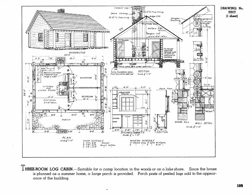
DRAWING No. 5507
(1 sheet)
i HREE-ROOM LOG CABIN.—Suitable for a camp location in the woods or on a lake shore. Since the house is planned as a summer home, a large porch is provided. Porch posts of peeled logs add to the appear- ance of the building.
109
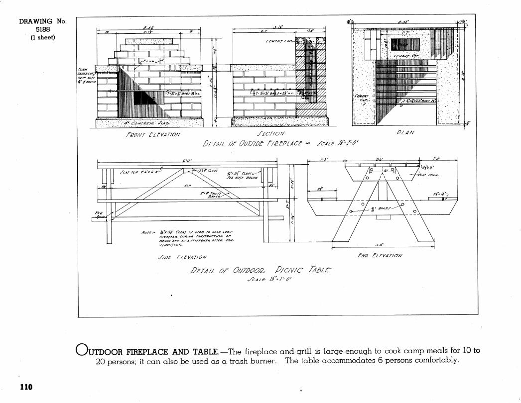
DRAWING No. 5188
(1 sheet) j-'fj-
t
' •' :'•'■^*. ¿^jùA/céere, ' J'ute^', .
J--/Í'
Cr£M£/^T C/f^^
^zj'
r^ûNT tir VATI ON yœr/oA/ DtTÂ/L or OULT/Dt r/^uPLÂCt - yc^if /f'J-û'
PLAN
//ore:- %'xSé' Ci£AT /^ (/y^o ro //OLO LC^W
&eA/CH A/vo Ay À /T/rFENeti AFTCIZ. COA/- jfei/c/iaA/.
'Z'^Á' yrocj^
Sfx/f ■
y/JPj^ ÜLtVATION £Nû nLn^AT/o/y
OUTDOOR FIREPLACE AND TABLE.—The fireplace and grill is large enough to cook camp meals for 10 to 20 persons; it can also be used as a trash burner. The table accommodates 6 persons comfortably.
110
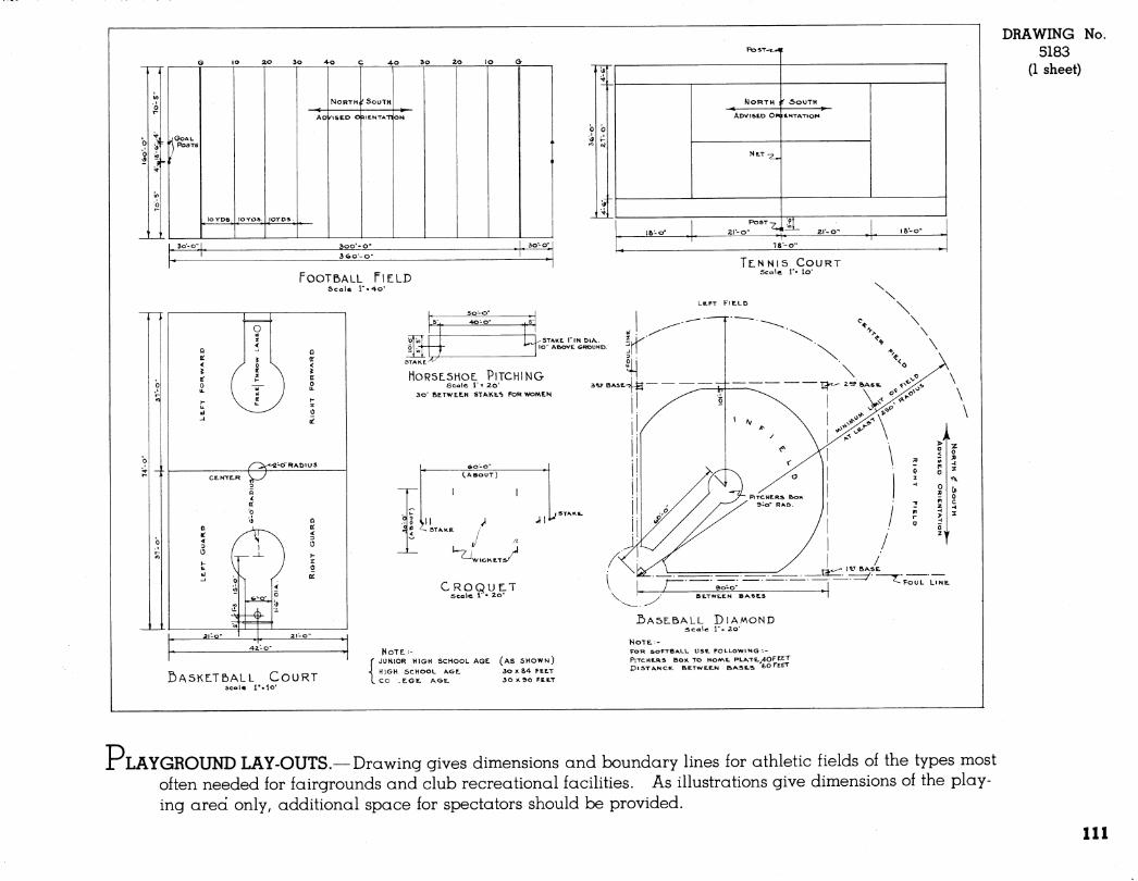
h A
lO ZO 30 4-0 C 4-0 So 20 lO G_
NoRTHii SOUTH
AO/ISED OîlENTATION
POST-t^
v9 r
b
■4
NORTH ¡S' äOUTH
b 'v9
ADVISED ORIENTATION
NE.T^_
lô-o- EI--0- ^7^ zr-o- lô'-O" [- r
78-0"
TOOTBALL riELD Scale r=»4.o'
TLN NI5 COURT Scale r» lo'
■^^
fl STAKE ^
HOR5L5HOL PITCHING ôcale 1 = 20'
3o" BETWEtN STAKE.*» FOR WOMEN
0 lu ^1
J
DASKLTBALL COURT scole r.lo*
—'wiCKtTS^
CROQULT scale 1- 2o'
NoTt- JUKIOR HIGH SCHOOL AGE (AS SHOWN)
HIGH SCHOOL AGE 30 X 84 FEET .CO .EGE. AGE. 30X.90FEtT
FOUL LINE.
I)A5E.BALL DIAMOND seal« 1"= 2o'
NOTE::- FOR SOFTBALL UST FOLLOWING-.-
PlTCHtí^S BOX. TO HOíAt PLATE.^40FEET DISTANCE, BETWE-EN &ASK.S 6O FEET
DRAWING No. 5183
(1 sheet)
LAYGROUND LAY-OUTS.—Drawing gives dimensions and boundary lines for athletic fields of the types most often needed for fairgrounds and club recreational facilities. As illustrations give dimensions of the play- ing area only, additional space for spectators should be provided.
Ill

ROADSIDE MARKETS
(
893378 O - 50 - 8 113
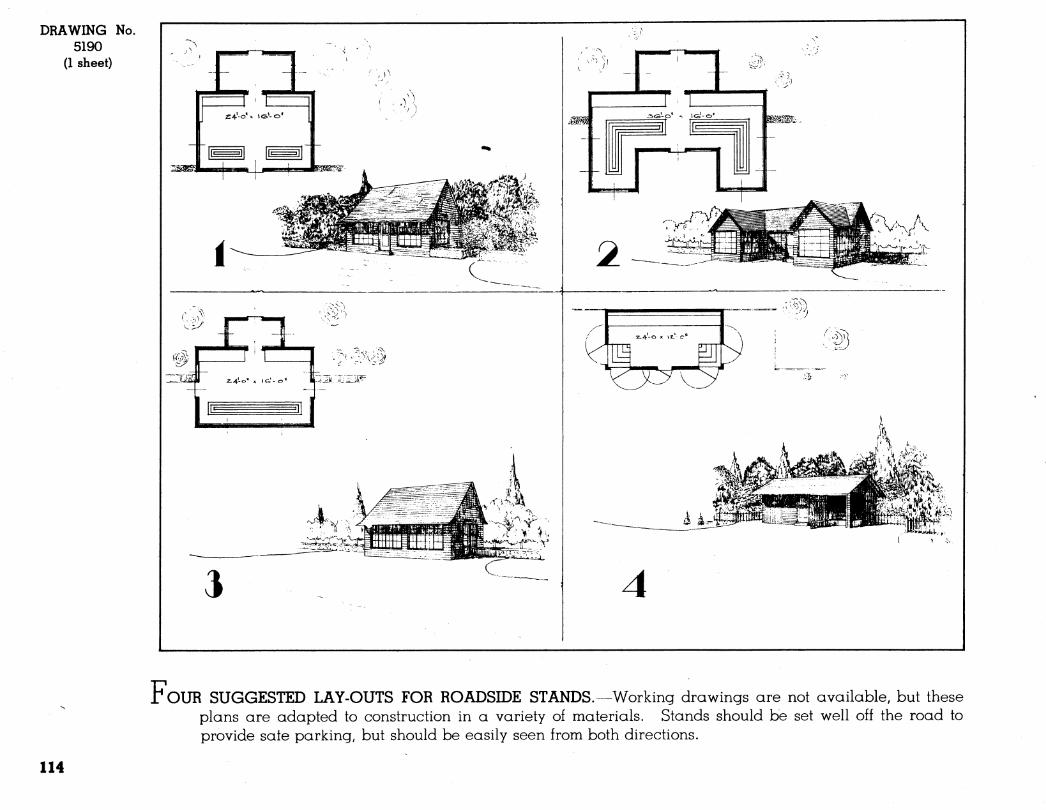
DRAWING No. 5190
(1 sheet)
r OUR SUGGESTED LAY-OUTS FOR ROADSIDE STANDS.—Working drawings are not available, but these plans are adapted to construction in a variety of materials. Stands should be set well off the road to provide sate parking, but should be easily seen from both directions.
114
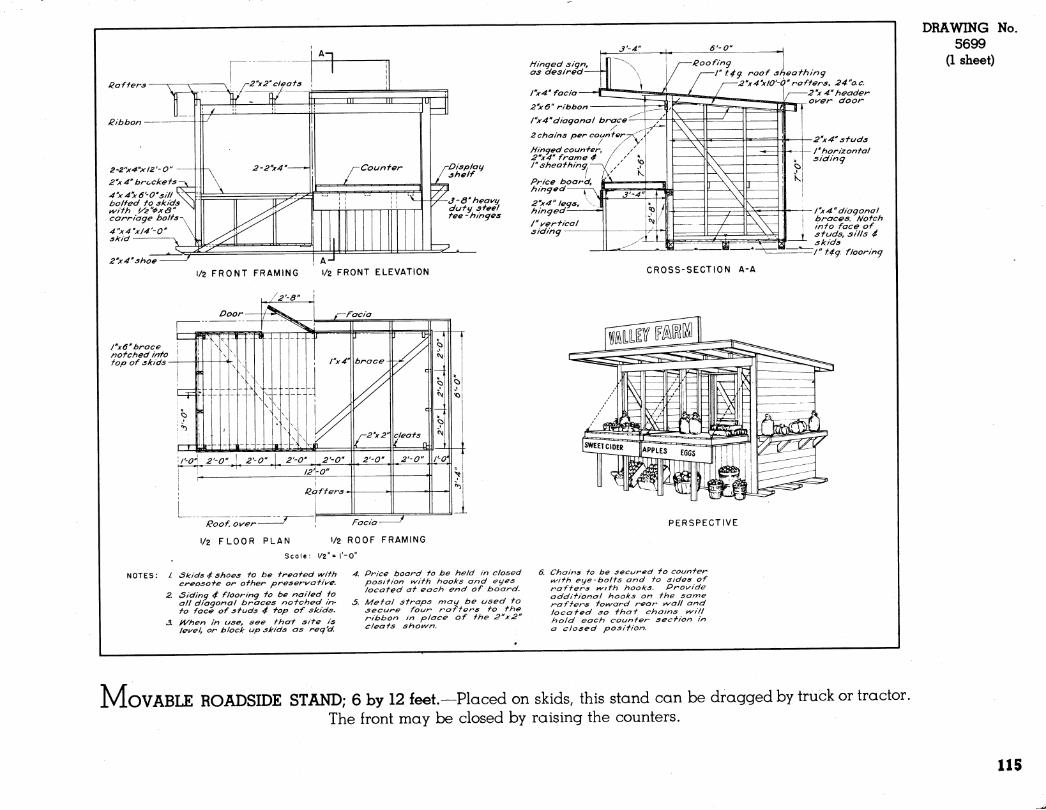
i^a fiers
ßibbon
2-2"x'4"xl2'-0" 2''x4'' brocke fs
4''x4x6'-0'si// bolfed fo skids ^ifh '/2"<Pxa carriage bo Its-^^
4"x4'xi4'-0'' skid y
2''x4''shoe
Displau shelf
J-d" heawy duty steel tee-hinges
1/2 FRONT FRAMING 1/2 FRONT ELEVATION
/"xô" brace notched into \ top of skids
Roof. o\xer Facia
1/2 FLOOR PLAN i/2 ROOF FRAMING
Scale: 1/2" = I'-O"
Skids 4 shoes to be treated v\/ith creosofe or other preser\/'ati\^e. Siding 4 flooring to be nailed to all diagonal braces notched in- to face of studs 4 top of skids, ^hen in use, see that site is lewel, or block up skids as req'd.
3-4"
tiinqed sign, as desired
rx4' facia
2'x6" ribbon
/"x4"diagonal brace
2 chains per counter
Hinged counter, 2^x4" frame 4 I" sheathing
Price boardf hinged r-
2"x4" legs, hinged /" i^ertical siding
6'-0"
ßoofing r t4g roof sheathing
2''x4'xlO'-à''rafters, 24"o.c. 2''x 4" header o^er door
2''x4''studs /'horizontal siding
/"x 4" diagonal braces. Notch into face of studs, sills 4 skids /" t.4g flooring
CROSS-SECTION A-A
DRAWING 5699
(1 sheet)
No.
PERSPECTIVE
4. Price board to be held in closed position kvith hooks and eyes located at each end of board.
5. Metal straps may be used to secure four raftens to the ribbon in place of the 2"x2" cleats shot^n.
Chains to be secured to counter uvifh eye-bolts and to sides of rafters i^ith hooks. Pro\yide additional hooks on the same rafters toi/\/ard rear v^/all and located so that chains t^iil hold each counter section in a closed position.
MOVABLE ROADSIDE STAND; 6 by 12 feet.—Placed on skids, this stand can be dragged by truck or tractor. The front may be closed by raising the counters.
115
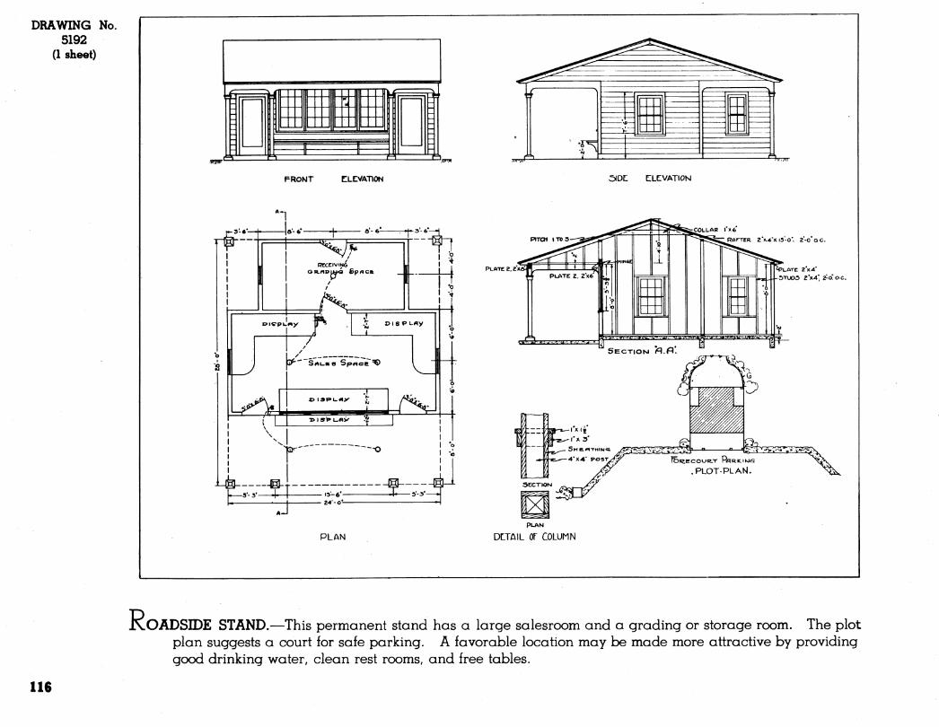
DRAWING No. 5192
(1 sheet)
^^ ti ■ tá h„
FRONT CLCVATION
RCCtlViNG 1 -^
oicpuMy
s^-'s' ̂ i-me dpAce ^ LI- X> I3I»L.A>-
IGT' —-O
[—5-3- 4—1 '3; 6'^ ■!■ ^''•=*'^
PLAN
:?^
SIDE: CILCVATION
S^W.'.i^i^TTTê
rCOLLAB \ X6
'■■^/.«¿VTJ'.W
SECTIOM fl.fl*.
Z >V4'Kl5-0. 2-0 QC.
»LATE 2X4 5TU05 EV4*2-O'O.C.
•i¿j.v,t.^-wig^i;w.^a.vv.iv l=^
r^^« y,
ya-«—i'xii
^ SHe.«TMIW<*
4"X4" posT/í^ ^3Ssâ
ÍE>íe.ECOUR.-r PflRICIKJS
.PLOT-PLAN.
PLAN
DLTAIL or COLUMN
JxOADSBDE STAND.—This permanent stand has a large salesroom and a grading or storage room. The plot plan suggests a court for safe parking. A favorable location may be made more attractive by providing good drinking water, clean rest rooms, and free tables.
116
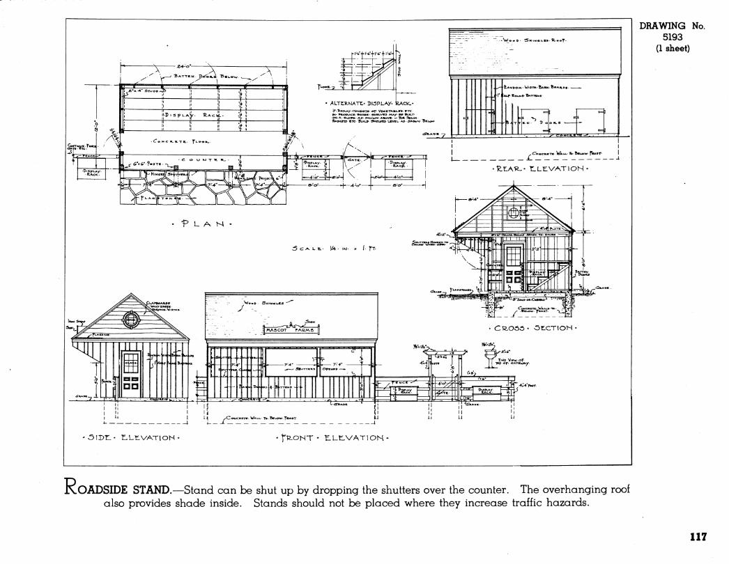
h ^. ^..
I * »«.-4 STV»09->ii> ii n ,t i| ¡r
ALTtTe-NATt« DlÖPLAy. kACiC- IF ThspiAy. CONSISTS- «T Ve<ier».»i-e»- BTC IN- PROOUCB- aoXB«' SHSLVVS- MA/- BeVVU-T-
■eM.A-4l.op«- AS- 9HOWM'ABOVE- — lb«. J%ACH • ftAsiceTT «re- BvwLP SMnves^ Leveu AS- ^»OMN/ "BetoM/
T'-ÎîLZ.
'P L A W -
:5c^Lt.. í¿v- /. ÎT
CT^Oöö- ÖTLCTIOH«
>3 iitriTj jjiifntTi II iiMiiiiiii^^^^i I i< CifiiAoe I II
r ^MD VlFW-or- TDpor- «ATeWA^.
J^
c ._^_ WALI. TO-NTLOW-^ROST
M II II
p'igRy. a a s^
ÔIDr.- tLtVATlOH- tl^ONT • tUE-VATlON •
DRAWING No. 5193
(1 sheet)
JKOADSIDE ST.AND.—Stand can be shut up by dropping the shutters over the counter. The overhanging roof also provides shade inside. Stands should not be placed where they increase traffic hazards.
117


MISCELLANEOUS BUILDINGS AND EQUIPMENT
i 119
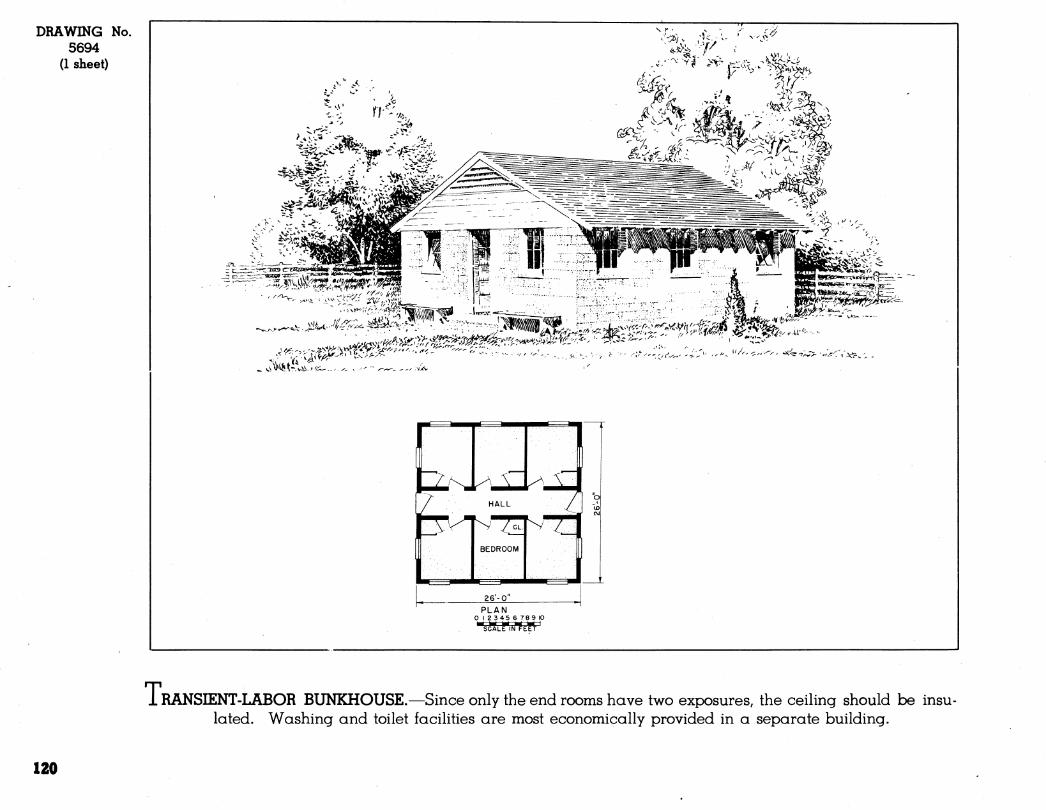
DRAWING No. 5694
(1 sheet)
.,X^
-Ùi^. yi^^Kí^"
S^^.t~\:^-i^a^..^.^. V '-"^ ^^^ ^ ■ vxv '^
^-.
26-0
PLAN o 123456 78 9 10 Ért M hiÉ ^ M I
SCALE IN FEET
T: RANSIENT-LABOR BUNKHOUSE.—Since only the end rooms have two exposures, the ceiUng should be insu- lated. Washing and toilet facilities are most economically provided in a separate building.
120
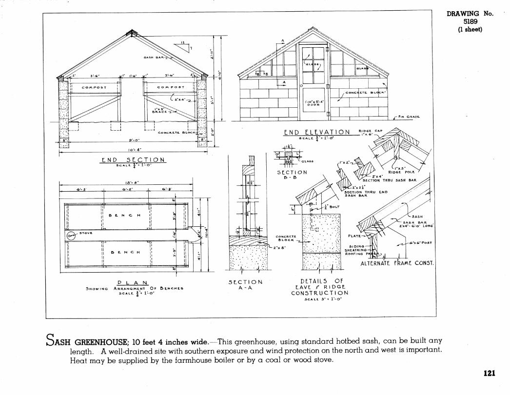
DRAWING No. 5189
(1 sheet)
PLAN SHOWING ARRANGMENT OP BENCHES
SCALE. |"= l-o"
5LCTION A -A
DtTAlL5 OF LAVE ^ RlDGL
CONSTRUCTION AC ALL 3" = l*-0"
)ASH GREENHOUSE; 10 feet 4 inches wide.—This greenhouse, using standard hotbed sash, can be built any length. A well-drained site with southern exposure and wind protection on the north and west is important. Heat may be supplied by the farmhouse boiler or by a coal or wood stove.
121
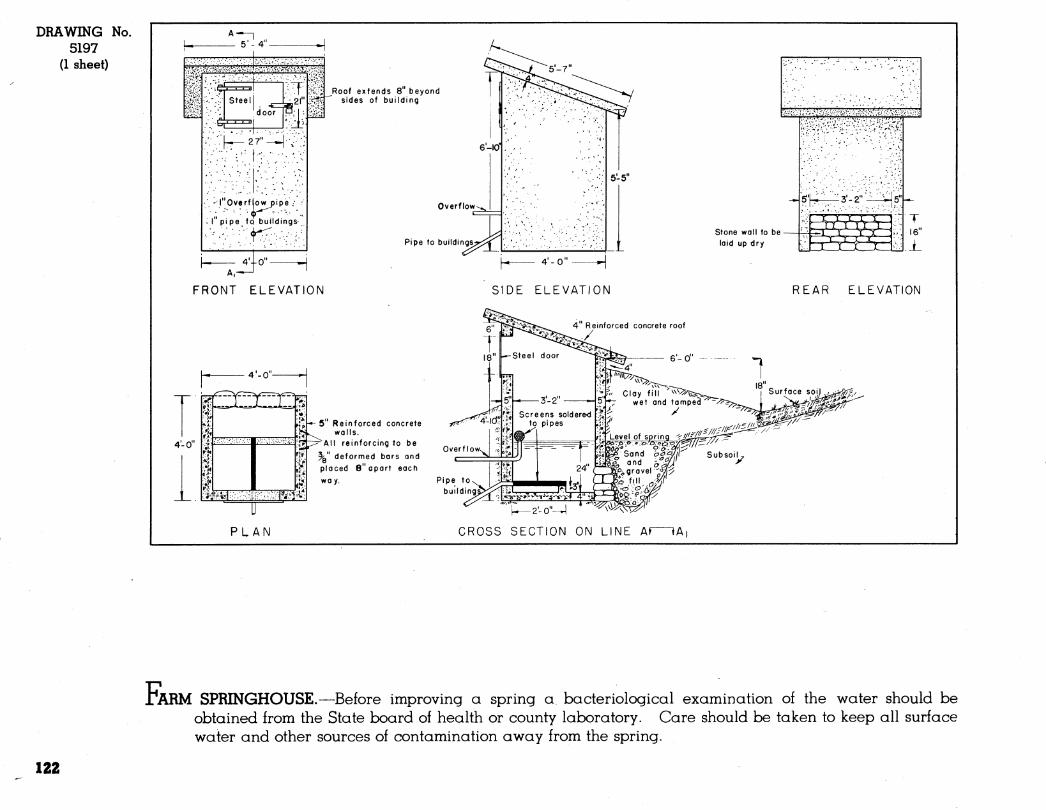
DRAWING No. 5197
(1 sheet)
5-4
-:''ê^
r::\^2r-^-,-::
'I* Overfiowpipé ,•
^ l" pipe to buildings-
Roof extends 8" beyond sides of building
Overflow
Pipe to buildings
4'|o"-
FRONT ELEVATION
stone wall to be - laid up dry
SIDE ELEVATION
T 16"
REAR ELEVATION
4" Reinforced concrete roof
y
4'-0-
4-0
■mm Wim
•*- 5" Reinforced concrete walls,
^All reinforcing to be
^" deformed bars ond placed 8" apart each
way.
PLAN
Overflow^
Pipe to building
-2-0"—]
CROSS SECTION ON LINE Af \^
i*ARM SPRINGHOUSE.—Before improving a spring a bacteriological examination of the water should be obtained from the State board of health or county laboratory. Care should be taken to keep all surface water and other sources of contamination away from the spring.
122
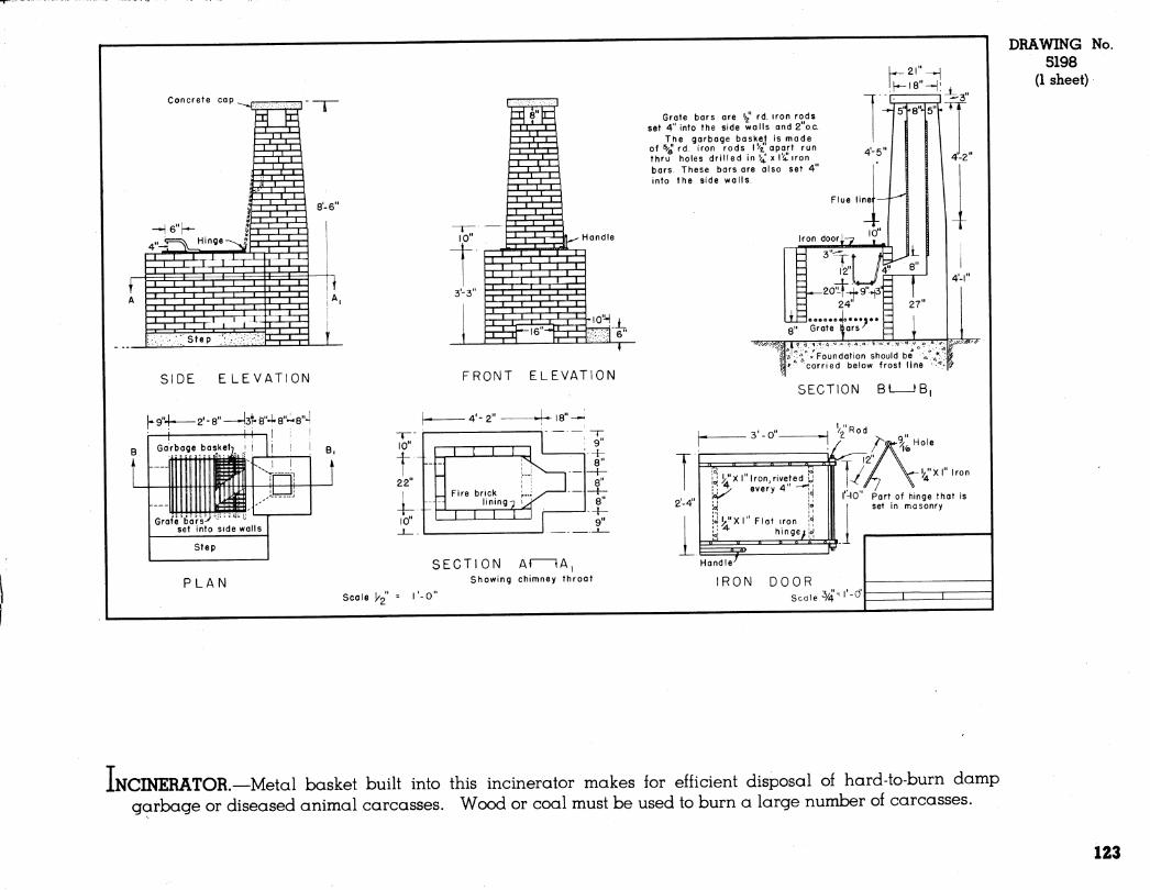
Concrete cap
SIDE ELEVATION
2' - 8" —^3t- 8"4* 8"- 8"*l
PLAN
FRONT ELEVATION
SECTION AÍ lA, Showing chimney throat
Scale j/g" = I'-O"
Grate bars are '/g" rd. iron rods set 4" into the side walls and 2"o.c.
The garbage basket is made of ^/Q rd. iron rods l'''^ opart run thru holes drilled in !i¿'x l'¿'iron bars. These bars are also set 4" into the side walls.
IK-I8"H:J_
4-5
Iron door u T,
12
3^20^-*j.9"-^3"Ë
TT
2"
= 24" Y I 1 eooe««Jo•••«•« Q" Grate bars'^
- 27
IJ. >'''^» Foundation should be ^ >*'' carried below frost line
4-1
pz^Si^
SECTION Bt fB,
2-4
¡J j^'X I" Iron, riveted i, ! \^ every 4" "^
joiyx I" Flat iron ^ hingei
-l/'Xl" Iron
I'-IO" Part of hinge that is set in masonry
IRON DOOR Scale 3/4" ''-'^'
DRAWING No. 5198
(1 sheet)
INCINERATOR.—Metal basket built into this incinerator makes for efficient disposal of hard-to-burn damp garbage or diseased animal carcasses. Wood or coal must be used to burn a large number of carcasses.
123

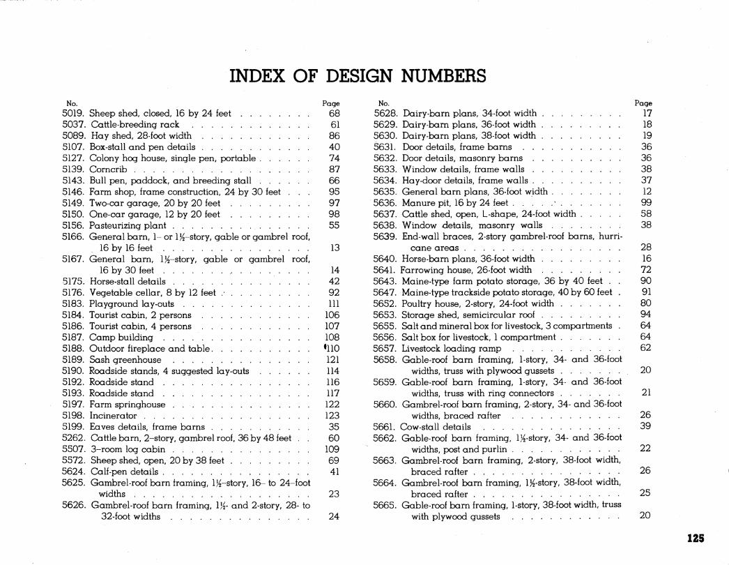
INDEX OF DESIGN NUMBERS No. Page No.
5019. Sheep shed, closed, 16 by 24 feet 68 5628. 5037. Cattle-breeding rack 61 5629. 5089. Hay shed, 28-foot width 86 5630. 5107. Box-stall and pen details 40 5631. 5127. Colony hog house, single pen, portable 74 5632. 5139. Corncrib 87 5633. 5143. Bull pen, paddock, and breeding stall 66 5634. 5146. Farm shop, frame construction, 24 by 30 feet ... 95 5635. 5149. Two-car garage, 20 by 20 feet 97 5636. 5150. One-car garage, 12 by 20 feet 98 5637. 5156. Pasteurizing plant 55 5638. 5166. General barn, 1- or l^-story, gable or gambrel roof, 5639.
16 by 16 feet 13 5167. General barn, l}^-story, gable or gambrel roof, 5640.
16 by 30 feet 14 5641. 5175. Horse-stall details 42 5643. 5176. Vegetable cellar, 8 by 12 feet .• 92 5647. 5183. Playground lay-outs Ill 5652. 5184. Tourist cabin, 2 persons 106 5653. 5186. Tourist cabin, 4 persons 107 5655. 5187. Camp building 108 5656. 5188. Outdoor fireplace and table •llO 5657. 5189. Sash greenhouse 121 5658. 5190. Roadside stands, 4 suggested lay-outs 114 5192. Roadside stand 116 5659. 5193. Roadside stand 117 5197. Farm springhouse . 122 5660. 5198. Incinerator . 123 5199. Eaves details, frame barns 35 5661. 5262. Cattle barn, 2-story, gambrel roof, 36 by 48 feet . . 60 5662. 5507. 3-room log cabin 109 5572. Sheep shed, open, 20 by 38 feet 69 5663. 5624. Calf-pen details 41 5625. Gambrel-roof barn framing, l)^-story, 16-to 24-foot 5664.
widths 23 5626. Gambrel-roof barn framing, VA- and 2-story, 28- to 5665.
32-foot widths 24
Page Dairy-barn plans, 34-foot width 17 Dairy-barn plans, 36-foot width 18 Dairy-barn plans, 38-foot width 19 Door details, frame barns 36 Door details, masonry barns 36 Window details, frame walls 38 Hay-door details, frame walls 37 General barn plans, 36-foot width 12 Manure pit, 16 by 24 feet * 99 Cattle shed, open, L-shape, 24-foot width 58 Window details, masonry walls 38 End-wall braces, 2-story gambrel-roof barns, hurri-
cane areas 28 Horse-barn plans, 36-foot width 16 Farrowing house, 26-foot width 72 Maine-type farm potato storage, 36 by 40 feet . . 90 Maine-type trackside potato storage, 40 by 60 feet . 91 Poultry house, 2-story, 24-foot width 80 Storage shed, semicircular roof 94 Salt and mineral box for livestock, 3 compartments . 64 Salt box for livestock, 1 comportment 64 Livestock loading ramp 62 Gable-roof barn framing, 1-story, 34- and 36-foot
widths, truss with plywood gussets 20 Gable-roof barn framing, 1-story, 34- and 36-foot
widths, truss with ring connectors 21 Gambrel-roof barn framing, 2-story, 34- and 36-foot
widths, braced rafter 26 Cow-stall details 39 Gable-roof barn framing, l}i-story, 34- and 36-foot
widths, px^st and purlin 22 Gambrel-roof barn framing, 2-story, 38-foot width,
braced rafter 26 Gambrel-roof barn framing, IJfstory, 38-foot width,
braced rafter 25 Gable-roof barn framing, 1-story, 38-foot width, truss
with plywood gussets 20
125
No. 5666. 5667. 5668. 5669.
5670.
5671.
5672. 5673.
5675. 5676. 5677.
5678. 5679. 5680.
5681. 5682. 5683. 5684.
Page No. Colony hog house, A-type, single pen, portable . . 75 5685. Hay-door details, masonry walls 37 5686. Wall and ceiling construction, frame barns .... 31 5687. Wall and ceiling construction, 1-story, gable-roof 5688.
masonry barns 32 5689. Wall and ceiling construction, IK-story, gable- and 5690.
gambrel-roof and 2-story gothic-roof masonry barns • . • 33 5691.
Wall and ceiling construction, 2-story, gambrel-roof 5692. masonry barns 34 5693.
Eaves details, masonry barns 35 5694. Gambrel-roof barn framing, 2-story, 36-foot width, 5695.
Shawver truss 27 5696. Machinery shed and work shop, 24 by 64 feet ... 96 5697. Cattle shed, open, 30-foot width 59 5698. All-season range shelter for poultry, movable, 8 by 5699.
10 feet 81 5741. Farm shop, masonry, 24 by 30 feet . 95 5742. Corncrib, single, 6-foot width 88 5743. Gambrel-roof barn framing, IK-story, 34- and 36- 5744.
foot widths, braced rafter 25 5745. Movable chute for loading cattle 63 5746. Hog self-feeder 77 5747. Milk house, open or closed passage, 12-foot width . 50 Milk house, open passage, 12-foot width 51
Page Dairy house, Washington, D. C, type 52 Dairy house, Baltimore, Md., type 29 Gothic-roof barn framing, 2-story, 34-foot width . . 29 Gothic-roof barn framing, 2-story, 36-foot width . . 29 Gothic-roof barn framing, 2-story, 38-foot width . . 29 End-wall braces, gothic-roof barns, 34-, 36-, and
38-foot widths, hurricane areas 30 Turkey range shelter, movable, 12 by 18 feet ... 82 Turkey range shelter, 14 by 24 feet 83 Farrowing house, single-row, 14 by 32 feet .... 73 Transient-labor bunkhouse 120 Smokehouse, 6 by 8 feet 102 Retail milk house 54 Barn safety details 43 Barn wiring diagrams 44 Movable roadside stand, 6 by 12 feet 115 Cattle guard, wood 65 Cattle guard, concrete and wood 65 Cattle guard, concrete and steel 65 Colony hog house, 2-pen, portable 76 Double corncrib and granary, 21 by 32 feet .... 89 Farm slaughterhouse, 16 by 24 feet 103 General barn, IJ^story, gambrel roof, 20 by 38
feet 15
126 U. S. GOVERNMENT PRINTING OFFICE : C