rammed earth walls for farm buildings - open prairie
TRANSCRIPT
South Dakota State UniversityOpen PRAIRIE: Open Public Research Access InstitutionalRepository and Information Exchange
Bulletins South Dakota State University AgriculturalExperiment Station
6-1-1945
Rammed Earth Walls for Farm BuildingsR.L. Patty
L.W. Minium
Follow this and additional works at: http://openprairie.sdstate.edu/agexperimentsta_bulletins
This Bulletin is brought to you for free and open access by the South Dakota State University Agricultural Experiment Station at Open PRAIRIE: OpenPublic Research Access Institutional Repository and Information Exchange. It has been accepted for inclusion in Bulletins by an authorizedadministrator of Open PRAIRIE: Open Public Research Access Institutional Repository and Information Exchange. For more information, pleasecontact [email protected].
Recommended CitationPatty, R.L. and Minium, L.W., "Rammed Earth Walls for Farm Buildings" (1945). Bulletins. Paper 277.http://openprairie.sdstate.edu/agexperimentsta_bulletins/277
Bulletin¢ �77, Revis
JUNE,.1945
Agricultural Engineering Department AGRICULTURAL EXPERIMENT ST A no N'
'SOUTH DAKOTA STATE COLLEGE' Brookings," South Dakota
Third Edition This is the third edition of Experiment
Station Bulletin 277. It is slightly revised, Most of the material on protective coverings for rammed earth walls, which was formerly included in this bulletin, has been removed since it is now included in Experiment Station Bulletin 336 entitled "Paints and Plasters for Rammed Earth Walls" published in 1940.
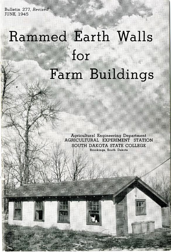
Explanation of Cover Cut The South Dakota Poultry House Built
with Walls of Rammed Earth. The house was built on the State College
Poultry Farm in 1932 and stuccoed in 1934. Both walls and stucco still are standing satisfactorily and without any maintenance or repair cost. The crack in the stucco at the front corner was caused by extending the stucco from the wall to the concrete foundation without leaving a joint. The two have a different coefficient of expansion. It cost $19.50 to stucco this house. The material cost $7.50 and the labor $12.00.
Table of Contents PAGE
In trod uc ti on ------------------------------------------------------------------------------------------------------------- _____ 5 Other Types of Earth Walls Compared _______________________ ______ -------------- -------- --- --- ------------------ 5 Insulating and Air Conditioning Quality of Rammed Earth Walls ------------------- ------------ 6
Methods Used for Testing Soil and Walls ___________________________________________________ .____________ 8 Test Blocks and Beams ______________ __________________ ___________________ -------- ----------------- -------· ______ _____________ 3 Testing the Soil for Moisture ______________________________________ ------------------------------------------------------- 9 Testing the Blocks for Strength in Compression ------ ---------- ---- -- - ---- ----------------- ______________ 9 Soils Used for Standard in Tests _______________________________________ ------------------------------------------·_____ 10 Mechanical Analysis of Soil Samples ______ - --------------------------- ---------------------________________________ 11
Relation of Sand Content, Moisture, and Shrinkage in Soils for Rammed Earth Work ----------------------------------------------------------------------------------------------------· _____ 11 Moisture and Sand ____________________ --------- ---- --- -------- - ---- ---- --------------------------------------· _____________ ____ 11 Moisture and Strength ______________________________ - ---- ---------- -------------------------------------------- -------_____ 1? Sand and Strength __________________________________________________________________________________________________________________ 12 Moisture and Shrinkage-------------------------- . ___________ ---------------------------------------------------------____ 12 Sand and Shrinkage·----- ----------------- ---· __________ ________ __________ ------------- --------------------------------------- 13
The Unit Weight of Soils in Rammed Earth ___________________________________________________ ··---- 14 Optimum Moisture in Soil for Weather Resistance________________________________________________ 15 Kind of Soil Best Adapted to Rammed Earth Construction _________________________________ 16 A Simple Test of Soil for Rammed Earth Work__________________________________________________ _ 17 Effect of Reramming Soil in Pise' Construction_____________________________________ ____________ ___ 18 Effect of Freezing Weather upon Rammed Earth Construction Work ______________ 18 Care and Mixing of the Soil for Rammed Earth Work ____ _____________________________________ 18
Screening the Soil for Rammed Earth Work _________________________________ ________________ ---- -"---------- 18 Effect of Depth of Block upon the Strength in Compression ___________________ ____________ 20 Resistance of Rammed Earth Walls to Weathering__________________________________________ ______ 20 Protective Outside Coverings for Pise' Walls __________________________________________________________ 22
Stucco ------ --------------------------------------------------------- ---- ----------------------------------------------------------------- 22 Less Expensive Plasters ______________________________ ------------------------------------------------------------------------- 23 Pain ts ---------- ---------------------------------------- ----------- ------ -- - -------------------------------------__________ ________________ 23
Inside Wall Coverings _____________________________________________________________________ . _________________________ 2 4 Weight, Shape and Type of Hand Rammers __________________________________________________________ 24
In tensity of the Tam ping Stroke________________________________________________________________________________ 26 Size of Aggregate in Soil for Rammed Earth Construction and Its Effect upon
the Compressive Strength ________________ ------------------------------------------------------------------- 28 Effect of Adding Lime _________________________ ---------------------------------------------------------------... -----· 29 Effect of Mixing Fiber with Rammed Earth upon Its Strength in Compression 30 Rate of Drying Out of Rammed Earth as Affected by an Adm'xture of Fiber
Such as Straw ________________________________________________________________ ---------------------------------------- 31 Reinforcing in Rammed Earth Construction __________________________________________________________ 33 Foundations for Rammed Earth Walls _______________________ -------------------------------------________ 35
Waterproofing the Tops of Foundations------------- ---- ----------- ------- ------- ------ ----- ---- ___________ _____ 3 7 Forms for Pise' Walls__________________________________________________________________________________________________ 37
Oiling the Forms _______ ---------- -- ---------------------------· -------· _____________ ____________ ___ ______________ __ ____ _ _______ 40 Leveling the Forms----------- ------------------------------ ------------------------------------ ----- --------- ---- -------------- 40
Building a Rammed Earth Poultry House _________________________________________________________ ___ 40 The Soil Used··-------------------------------------- ------·----- --- ----------- ----------------------------------- ---·-- -- ------------ 4 2 Building the Wall _____________________________________ -------------------------------------- ----------------- ----· ________ ____ 4 3 Filling the Forms _________________________________________ ------------------------·---------------------------- ____ __ ________ ____ 4 3 Protecting the Walls During Construction---------- ------------------------ ------------ -------------------_____ 44 Repair and Retouching of the Walls _____ ______ ______ ------- ------------------ ------------------------------------· 46
Rammed Earth Blocks for Building Walls ________________________________________________________ _____ 48 Size and Shape of the Blocks ________________________________________________________________________________________________ 48 Mortar Used for Laying up Wall of Rammed Earth Blocks------------· ---- -- -------------------- -- 49 Forms for Making Rammed Earth Blocks ___________________________________________________________________ ____ 50
Walls of Block Compared to Monolithic Vv alls ______________________________________________________ 50 Thorough Distribution of Moisture Through the Soil Adds to the Quality of
the Rammed Earth W alL _________________________________________________________________________________ 53 Comparison of a Puddled Earth or Mud with a Rammed Moist Earth--In
Compressive Strength__________________________________________________________________________________________ 5 3 A Cinder Admixture Stud Y------------------------------------------------------------------------------------- __ 56 A Few Brief Building Specifications ________________________________________________________________________ 57 Summary and Comments ---------------------··------------------------------------------------------ ------------- 59 A List of Reference Books and Literature on Pise' Construction __________________________ 63
Rammed Earth Walls for Farm Buildings
By RALPH L. PATTY and L. W. MrnrnM1
Department of Agricultural Engineering State College Experiment Station, Brookings, S. D.
Introduction
Rammed earth walls are made by ·ramming ordinary moist earth into forms. The walls are rammed in place directly upon the building foundation and in sections. The forms are similar to those used for concrete construction except that they must be much stronger and heavier. The ·ramming may be done either by hand or by mechanical power. In reading this bulletin it will be very helpful if the table of contents is consulted for the subjects.
The purpose of this experimental study of "pise"' construction was to secure definite and reliable information with which we could answer the many inquiries concerning it that were coming to the South Dakota Agricultural Experiment Station. The wide range of soil types over the state of South Dakota made it impossible to make reliable recommendations as to its use for this construction without a careful and detailed study of South Dakota soils, and of soils in general, for this purpose. This is a progress report.
Earth construction for building walls is not a new idea. In fact, it is ages old. Build-· ings were built of earth centuries ago in Europe, and while the methods used differed widely, some of this construction was of rammed earth. It is claimed that it was used by the early Romans and was introduced into F�ance by them. The following paragraph 1s taken from Farmers' Bulletin No. 15 0 0 by M. C. Betts and T. A.H. Miller.
_"Pise' de_ terre (pronounced pee-zay duh talfe), which means rammed earth in French, is an ancient type of construction. The writings of Pliny state that watch towers of this material constructed by Hannibal
were in use 25 0 years after completion. It was introduced into France by the Romans and later adopted in England."
Buildings of these walls have been used in the United States also to a limited extent. According to California Experiment Station
Bulletin No. 47 2 by J. D. Long, some of the settlers of our early colonies built of this material. One two-story rammed earth residence now in use in Washington, D. C., is said to have been erected in 17 7 3, and a modern residence was built of this material in Washington within the past few years by Dr. H.B. Humphrey.
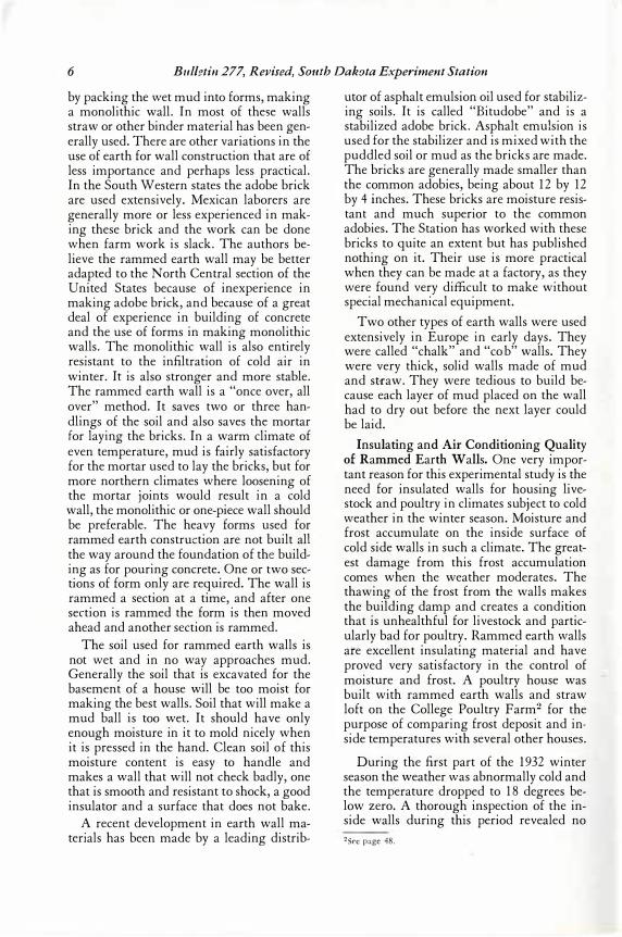
Other Types of Earth Walls Compared. There are several types of earth wall construction besides the pise' or rammed earth with which this study deals. Adobe walls, as the term is generally understood and defined, are made of a wet plastic mixture of earth or mud. Adobe walls should not be confused with rammed earth as they are· quite different, the adobe being mud-like while the pise' walls are rammed moist earth. The most common adobe construction is with blocks. The mud is pressed and mold-ed into large bricks usually 18 inches long by 12 inches wide by 4 inches thick. These are often reinforced with straw, and after they are molded they are set out to dry. When they are properly cured they are laid into a wall in the same way as concrete blocks. Adobe or mud walls are also made 1�r. Minium has been with the Soil Conservation Service smce 1934. The authors particularly wish to acknowledge the cooperat10n of Professor H. M. Crothers Dean of Engineering, and of Associate Professor Leo Puh� of the Agronomy Department, Professor W. E. Poley and Prof. W. C. Tully of the Poultry Husbandry Department, and Dr. K. W. Franke of the Chemistry Experiment Station, South Dakota State College.
6 Bulfrtin 277, Revised, Smuh Dakota Experiment Station
by packing the wet mud into forms, making a monolithic wall. In most of these walls straw or other binder material has been generally used. There are other variations in the use of earth for wall construction that are of less importance and perhaps less practical. In the South Western states the adobe brick are used extensively. Mexican laborers are generally more or less experienced in making these brick and the work can be done when farm work is slack. The authors believe the rammed earth wall may be better adapted to the North Central section of the United St.ates because of inexperience in making adobe brick, and because of a great deal of experience in building of concrete and the use of forms in making monolithic walls. The monolithic wall is also entirely resistant to the infiltration of cold air in winter. It is also stronger and more stable. The rammed earth wall is a "once over, all over" method. It saves two or three handlings of the soil and also saves the mortar for laying the bricks. In a warm climate of even temperature, mud is fairly satisfactory for the mortar used to lay the bricks, but for more northern climates whei"e loosening of the mortar joints would result in a cold wall, the monolithic or one-piece wall should be preferable. The heavy forms used for rammed earth construction are not built all the way around the foundation of the building as for pouring concrete. One or two sections of form only are required. The wall is rammed a section at a time, and after one section is rammed the form is then moved ahead and another section is rammed.
The soil used for ·rammed earth walls is not wet and in no way approaches mud. Generally the soil that is excavated for the basement of a house will be too moist for making the best walls. Soil that will make a mud ball is too wet. It should have only enough moisture in it to mold nicely when it is pressed in the hand. Clean soil of this moisture content is easy to handle and makes a wall that will not check badly, one that is smooth and resistant to shock, a good insulator and a surface that does not bake.
A recent development in earth wall materials has been made by a leading distrib-
utor of asphalt emulsion oil used for stabilizing soils. It is called "Bitudobe" and is a stabilized adobe brick. Asphalt emulsion is used for the stabilizer and is mixed with the puddled soil or mud as the bricks are made. The bricks are generally made smaller than the common adobies, being about 12 by 12 by 4 inches. These bricks are moisture resistant and much superior to the common adobies. The Station has worked with these bricks to quite an extent but has published nothing on it. Their use is more practical when they can be made at a factory, as they were found very difficult to make without special mechanical equipment.
Two other types of earth walls were used extensively in Europe in early days. They were called "chalk" and "cob" walls. They were very thick, solid walls made of mud and st-raw. They were tedious to build because each layer of mud placed on the wall had to dry out before the next layer could be laid.
Insulating and Air Conditioning Quality of Rammed Earth Walls . One very important reason for this experimental study is the need for insulated walls for housing livestock and poultry in climates subject to cold weather in the winter season. Moisture and frost accumulate on the inside surface of cold side walls in such a climate. The greatest damage from this frost accumulation comes when the weather moderates. The thawing of the frost from the walls makes the building damp and creates a condition that is unhealthful for livestock and particularly bad for poultry. Rammed earth walls ate excellent insulating material and have proved very satisfactory in the control of moisture and frost. A poultry house was built with rammed earth walls and straw loft on the College Poultry Farm2 for the purpose of comparing frost deposit and inside temperatures with several other houses.
During the first part of the 193 2 winter season the weather was abnormally cold and the temperature dropped to 18 degrees below zero. A thorough inspection of the inside walls during this period revealed no 2See page 48.
Rammed Earth Walls For Farm Buildings J
trace of frost on the inside walls of the rammed earth house, while in the other houses the frost deposit varied from light to heavy. Later in the season the temperature dropped to 30 degrees below zero and the frost deposit on the rammed earth walls was almost as heavy as on the walls of other houses of frame construction with average insulation. All of these houses had straw lofts except one, and in this house the frost condition was more than twice as bad as in the rammed earth house. The frost did not make the inside of the rammed earth house damp as it did the others. The wall absorbed the moisture very readily as the frost melted and when the air later became dry this moisture was returned to the air. The rammed earth wall was only 12 inches thick.
It was a desire on the part of the Experiment Station to find an inexpensive and satisfactory wall for the farm poultry house that made this study of economic importance. A cooperative study of this poultry house is being carried on at the present time by the Agricultural Engineering department and the Poultry Husbandry department.
Rammed earth construction lends itself well to construction of simple buildings with comparatively low sidewalls and few wall openings. A building such as averagesized farm poultry houses can be built above the foundation in 10 days to two weeks' time by an experienced crew of three men. If the labor must all be hired there will be little, if any, saving in the cost of the walls over those built from lumber or building tile. The advantage of rammed earth construction must be in utilizing labor for which little or no cash need be paid and in securing an exceedingly warm and dry sidewall for the poultry house. For more elaborate buildings of more than one story the work is more tedious, forms and frames for openings require more time, and if the labor is hired the cost is apt to be fully as great if not greater for rammed earth construction than for other materials. However, this study has verified former claims made by investigators and enthusiasts for rammed earth construction that most excellent homes and buildings can be built of earth if desired. Although under normal conditions the cost of elaborate buildings of rammed earth may
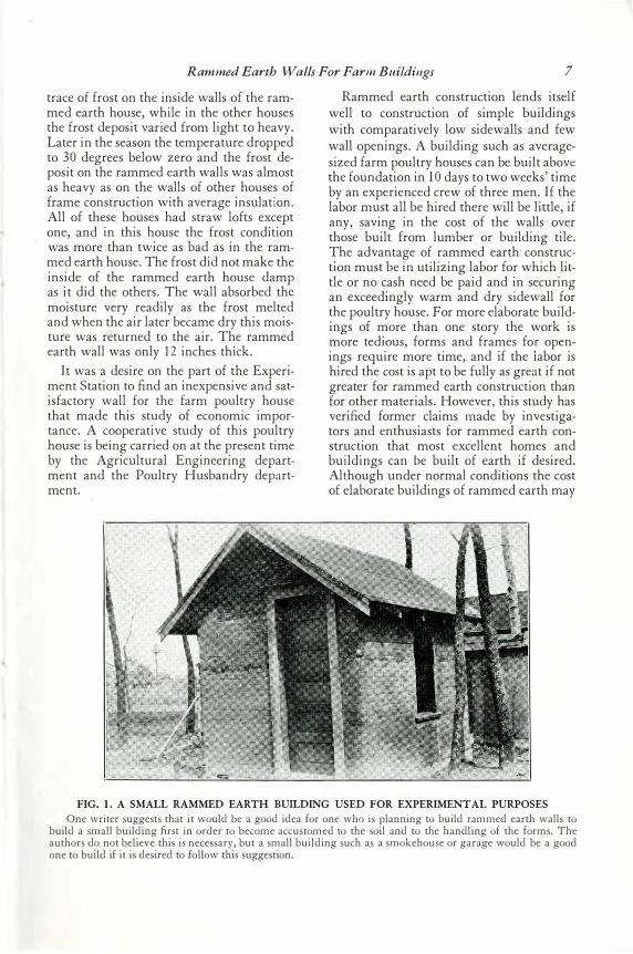
FIG. 1. A SMALL RAMMED EARTH BUILDING USED FOR EXPERIMENT AL PURPOSES One writer suggests that it would be a good idea for one who is planning to build rammed earth walls to
build a small building first in order to become accustomed to the soil and to the handling of the forms. The authors do not believe this is necessary, but a small building such as a smokehouse or garage would be a good one to build if it is desired to follow this suggestion.
8 Bulletin 277, Revised, South Dakota Experiment Station
be as hig h as ordinary uninsulat ed frame houses, t he walls, if kept well stuccoed, should la st indefinitely and be especially valuable for modern air condit ioning .3
One aut hor4 recommends t hat before st art ing on an elaborate building of rammed earth it would be w ell first t o build a small simple st ruct ure and t hereby becom e familiar wit h t he use of t he forms and t he charact erist ics of t he soi l. Such a building might be a small smokehouse or a farm poultry house.
Mechanical rammers may be used in t he const ruct ing of ra mmed earth walls. Their use will cut down t he labor hours for t his work but t he cost of a complet e compressed air outfit for ramming will cost several hun -
dred dollars at t he present price. The California Experiment St at ion4 report s t hat with t he mechanical rammer a const ructi on speed of 7 cubic feet per man hour was se cured. Wit h hand ramming , a speed of 2 cubic feet per man hour would be about as much as could be expected of an experienced crew of men. In building t he walls of t he poult ry house at t he South Dakot a Experiment St at ion t he speed averag ed one and one- half cubic feet per man hour. St udent labor was used entirely for t his work, however, and t he work was not only done int ermitt ent ly but new men had t o be broken in. 3Coffin-Humphrey, "Lower Cost Buildings. " 4J . D . Long-California Experiment Station Bulletin N o . 472 .
Methods Used for Testing Soil and Walls
The purpose of t hese st udies was t o learn t he struct ural charact eristi cs of soils favorable t o rammed eart h const ruct ion, t o det ermine t he opt imum clay and sand rat io and t he opt imum moisture content for bot h st rength and weat hering resist ance in rammed earth walls. Furt her studies were made on protect ive covering s, on t he effect of addi ng fi be r t o t he soil, on rn mmers and t he p roper ramming of soil int o t he forms, on rei nforcing for wall opening s and corners, and on t he best pract ices in building walls of t his material. Finally, t he st udy of t he cost and economy of rammed earth walls and their relat ive insulat ing value in t he cont ro l of frost deposit when used for housing livest ock, was made.
The st rength t est s in compression were made t o det ermine t he relat ive value of cert ain soil charact erist ics or building pract ices, and not because it s st rength for farm building walls was quest ioned. Walls made from soils showing t he lowest st rengt h are amply st rong t o carry t he compression load in walls. Although t here is a t endency for planes of cleavag e t o develop bet ween t he layers of earth as t hey are rammed in t est blocks and beams, t hey di d not prove t o be a factor of import ance in walls. V arious at-
t empts have been made t o overcome t his diffi cult y in t he t est pieces and some result s have shown improvement but not hing ent irely sat isfactory. Work is st ill being done on t his problem. Samples of soils from all part s of Sout h Dakot a were analyz ed and t est ed bot h for st rengt h and for resist ance t o weathering . These soi ls were t aken from 18 count ies of t he st at e and covered the ext reme t errit ories.5
Test Blocks and Beams. All early t est blocks were cubical in shape and were 9 by 9 by approximat ely 9 inches. They were about as heavy as can be convenientl y handled, weig hing from 45 to 6 0 pounds when first made, depending upon t he amount of sand in t he soil. They were rammed in forms and wit h hand rammers. They were handled on board t rays 12 inches square.6
The t est beams were made for t he reinforcing study and were 36 by 12 by approximately 7 % inches in depth. They weig hed from 25 0 t o 26 0 pounds and were handled on slat t rays approximat ely 10 inches by 48 inches. 5Sce Resistance of Rammed Earth Walls to Weathering, p. 20.
6Cylindrical test blocks · were used later in the study.
Rammed Earth Walls For Farm Buildings 9
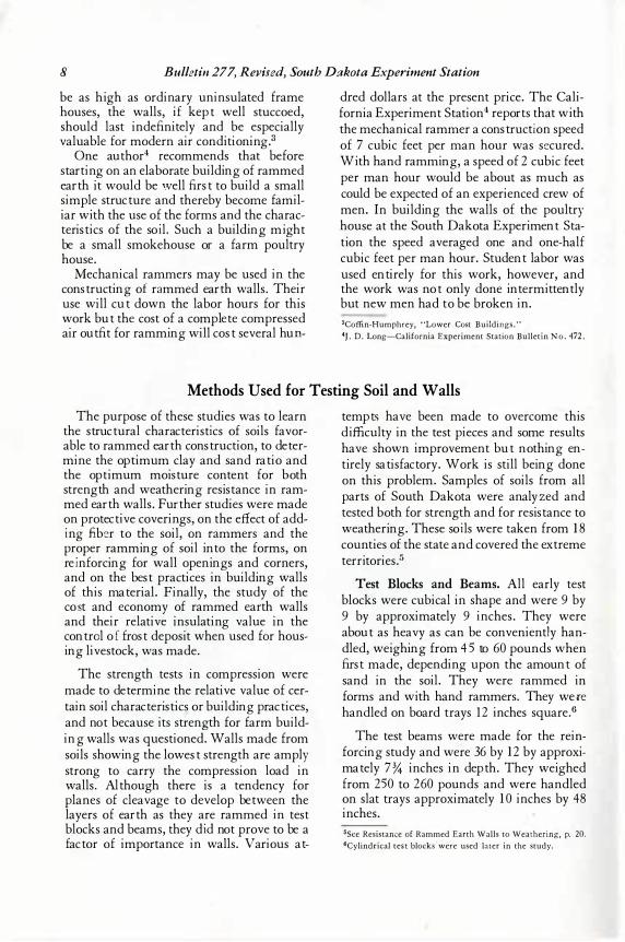
FIG. 2. TESTING RAMMED EARTH BEAMS USED IN THE REINFORCING STUDY The beams were 3 6 inches long, 1 2 inches wide and 7 % inches high. The reinforcing materials were placed
one and one-half inches from the bottom of the beam. The span used in the test was 24 inches and force was applied at the top, midway between the two contact points. The Olsen testing machine was used.
Testing the So il for Mo istur e. The moisture te sts of soils were made in du plicate . Me asure s of the soil were take n fr om six differe nt points in the pile and place d in a small sample pile wh ich was the n mixe d and qu ar tere d. Fr om th is soil, du plicate sample s of 40 0 to 5 0 0 gr ams e ach were place d in soil pans. These were we ighe d and place d in an e le ctr ic dispatch ove n, where the y dr ie d ou t to constant we igh t at a te mper ature of appr oximate ly 220 de gree s F. The sample s were then re we ighe d and the loss of moisture figure d. The per ce nt of moisture was the n de ter mine d by dividing the loss of moisture by the ne t we igh t of the we t sample of soil. The aver age of the du plicate figure s was u se d for the true moisture per ce ntage .
T esting the Blocks f or Strength in Compression. All te st blocks th at were te ste d for stre ngth in compre ssion were store d in the re se ar ch labor ator y in a te mper ature arou nd 7 0 de gree s F. u ntil the moisture conte nt was re du ce d to almost a constant figure . Th is moisture conte nt aver age d be low three per ce nt at the time the y were br oke n. In or der to de ter mine the moisture containe d
i n the blocks at any time , the blocks were we ighe d imme diate ly after the y were made and whe n the moisture conte nt of the soil was known. B y re we igh ing a block at a later date the moisture content cou ld be figure d fr om the loss in the we igh t of the bl ock. Th is was done in the following manner : The we igh t of the ne w block multiplie d by the moisture conte nt of the soil fr om wh ich it was made , in per ce nt, gave the we igh t of water in the block in pou nds.
After the block h ad dr ie d ou t it was re we ighe d and the loss of we igh t in pou nds ( wh ich was ne ce ssar ily the we igh t of the moisture lost) was su btr acte d fr om the pou nds of water or iginally in the block. Th is gave the we igh t of the moisture , in pou nds, th at was le ft in the block, and dividing th is figure by the we igh t of the dry block gave the moisture content of the dry block in per ce nt. The blocks were h andle d at all time s on a small boar d tr ay 12 inche s squ are and of known we igh t, so th at no loss of we igh t cou ld re su lt in h andling. The blocks were made in the form of cu be s 9 x9 x9 inche s. It was not always possible to ge t the de pth of the blocks e xactly nine
10 Bulletin 277, Revised, South Dakota Experiment Station
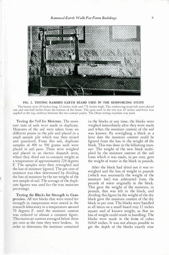
FIG. 3. TESTING THE RAMMED EARTH BLOCKS FOR COMPRESSIVE STRENGTH The blocks were crushed in a Riehle testing machine when their strength in compression was desired. This
block shows a typical failure, indicating a sound block or one without any special flaw or weakness. I t failed under a load (ul timate load ) of 36,000 pounds or 1 8 tons, which is about an average strength for South Dakota soils. The dimensions of the block are 9x9x9 inches. Four hundred of these test pieces have been broken so far in the study.
inches and when this van at10 n was su fficientl y gr eat, corr ection was made for it. The blocks wer e cru shed in a Riehle test ing machine.7
Since the bottoms of the blocks wer e per fectl y squ ar e and level , they wer e seated u pon a one- four th inch fiber pad for the test. A sand cu shion leveli ng the top of the bl ock and covered with a second fiber pad was u sed on the top of the block. The str ength figur es ar e sur pr isingly u nifor m for these test pieces of su ch mater ial. Simil ar test blocks of a ser ies seldom var ied mor e than thr ee or four per cent and an aver age of thr ee or four blocks has u su al ly pr oved a r eliable and satisfactor y figur e. The manner of testing the test beams is descr ibed u nder the par agr aph on "Reinfor cing in Rammed Ear th Constru ction," and a pictur e of the test is shown in Fig. 2.
Soils U s ed f or Stan d ard in Tes ts. Thr ee standar d soil s wer e u sed for making test pieces when a standar d base soil was needed for compar ing the effect of cer tain conditions or pr actices. They were designated as
Ex per imental Soil No. 1, Ex per imental Soil No. 2, and Ex per imental Soil No. 3 . Ex per imental Soil No. 1 was a black clay soil obtained in a val ley one-hal f mile nor th of the Ex per iment Station. It is composed of 89.6 per cent silt and clay and only 10.4 per cent of sand, most of which is fine. Ex per imental Soil No. 2 was a yellow clay loam soil fou nd in the su bsoil u nder all of the higher gr ou nd u pon which the col lege campu s is located. It aver ages only 6 2.5 per cent clay and silt and contains 3 7 .5 per cent of total sand r anging in size fr om par ticles that ar e j u st r etained u pon a ver y fine scr een of 20 0 mesh to the lineal inch, u p to one inch in size. Ex per imental Soil No. 3 was a dar ker yellow sandy clay soil fou nd in a cef' tain local ar ea near the campanil e on the State College campu s. This soil is ver y high in total sand and gr avel content, containing onl y 25 .2 per cent ot clay and silt with a total sand or aggr egate content of 74. 8 per cent. The aggr egate is ver y well gr adu ated in size, var ying all the way fr om the 20 0-mesh size u p to two inches. This soil made one of the five best walls 7See Fig. 3 .
Rammed Earth Walls For Farm Buildings 11
in the yard; all have stood satisfactorily as bare walls for 15 years and were built from soil without any addition of sand.
M ec hani cal Analysi s of Soi l Sam ples. In analyzing the soils, at first no attempt was made to separate or study the silt and clay materials. The analyses were made in the followi ng manner: Duplicate samples of approximately 5 0 0 gms. were thoroughly dried in the electric dispatch oven until reduced to constant weight. They were then weighed and passed through the following sized screens in order: three- fourths inch, one- half inch, and one- fo urth inch. The sample was then screened through the one-eighth inch, the 10 0 -mesh ( 10 0 mesh to the lineal inch), and the 20 0 -mesh screens under a stream of water. The sand retained on these screens was then dried and each size was carefully weighed. For simplicity the total aggregate,
from the finest particles that were retained on the 20 0- mesh screen up to the largest pebbles, will often be referred to in the tables and in this bulletin as " sand." A ll soil particles that passed thr ough the 20 0- mesh screen were considered silt and clay.
NOTE: Since 1934 a different method of analyzing soils has been used. It is known as the hydrometer method of analysis, and with this method the silt is separated from the clay so that the total sand, total clay, and total silt in a soil are determined. The soil sample must be taken very carefully so that it will be exactly representative of the soil that will be used in the walls. P rospective builders may obtain instructions for securing and sending in samples to the laboratory for analysis by addr essing the Agricultural Experiment Station, State College, Brookings, South Dakota.
Table 1 . Mechanical Analysis of Three Base Soils Used in Experimental Blocks and Beams Analysis with 200-Mesh Sieve
Sand Gravel Y4 in. Yi in. Yi in. Number Total silt
of samples and clay averaged per cent
200 to 100 100 to Ys in. to Ys in. to Y4 in. screen Total
aggregate per cent Soil Color mesh screen mesh screen mesh screen mesh screen and above
Experimental Soil No. 1 ________ Black 4 89.64 1 4 .5 1 4 5 .76 .085 1 0 .36
Experimental Soil No. 2 _______ L. Y cl low 4 62 .44 8 .799 2 5 .354 1 .9 1 8 1 .662 .826 37 .56
Experimental Soil No. 3 ________ D. Yellow 4 25 . 1 8 4.690 4 1 .870 9.390 7.200 1 1 .670 74 .82
Relation of Sand Content, Moisture, and Shrinkage in Soils For Rammed Earth '\Vork
The first study made was for the purpose of finding out the effect of sand content and moisture, in the soil used, upon th e rammed earth wall. Thirty- nine test blocks were made for this study with the idea of observing them and later of testing them for compressive strength. Five different amounts of sand were used in this series of blocks and the moisture was varied from high to low in three graduated amounts within the bonding range. The blocks were closely observed as they dried out and the shrinkage was measured. After the blocks had dried to constant weight they were tested for com-
pressive strength in a Riehle testing machine and the results are given in Table 2 .
M oi stu re and Sand. This study disclosed several relationships between the amount of moisture in the soil and the properties of the rammed earth. It was found that the optimum moisture for ramming varied in inverse proportion to the amount of sand in soil, as the sand in the soil was increased the required moisture decreased. This is due to the fact that soil that is made up of small particles ( silt and clay) has a much greater surface area for moisture than soil containing coarser particles of sand and gravel with
12 Bulletin 277, Revised, South Dakota Experiment Station
the s ilt and clay . A s andy soi l contai ni ng o nly s even o r ei ght per cent moi s ture wo uld be s ati sfacto ry while a clay so il wi th this per cent of mo is ture wo uld be alto gether too dry to ram. It would require 16 to 18 per cent of moi s ture to bring this so il up to the opti mum moi s ture for ramming. Bank- run s and and gravel alo ne wi ll be qui te wet when containi ng o nly three o r fo ur per cent of moi s ture.
M ois ture and Str ength. The amount of moi s ture i n the so il when it i s rammed has a deci ded effect upo n the s trength of rammed earth in co mpres s ion. When too dry , all soi ls s eem to lo s e s trength markedly , and in mo s t cas es soi ls that are too wet s ho w a low s trength. Thi s i s parti cularly evident with s andier soils and it is probable that thi s may be due to the l a rger amount of s pace lef t in the blo ck af ter the moi s tm· e has evaporated. Such a blo ck s eems much les s dens e and the pres ent s tatus of the s tudy , purely f ro m the s trength s tandpo int, indicates t h a t i11 rammed earth co ns truction densi ty may be as impo rtant a facto r fo r s trength as i t i s i n co ncrete.
Sand and Str ength. The res ults have no t as y et s ho wn defini tely that the s trength of
rammed earth varies i n i nvers e propo rtio n to the amo unt of s and i n the soi l, but there i s no do ubt of thi s proportio n for hi gher amo unts of s and. It is hi ghly probable that, i n general, soi ls co ntai ning 3 0 per cent or more of sa nd decreas e i n s trength in invers e ratio and po s si bly thi s ratio might carry all the way thro ugh if the weakening effects of cracking and checki ng i n the blocks co ntai ni ng little s and could be avoi ded. Ho wever, s trength is s econdary in importance. All walls wi ll have ample s trength. Sand i n the so il makes them durable. Thi s i s of firs t impo rtance.
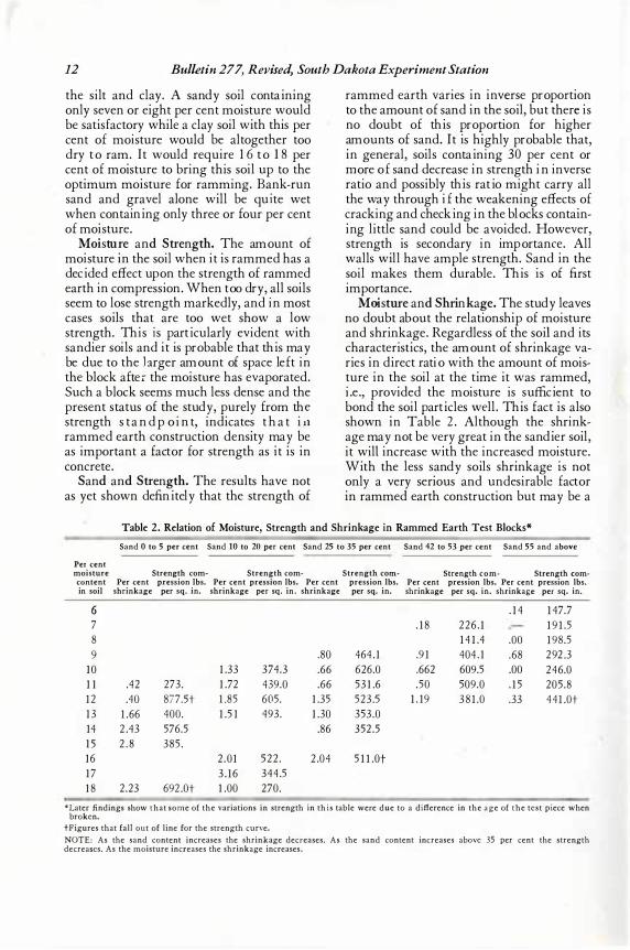
Mois tur e and Shrink age. The s tudy leaves no do ubt abo ut the relatio ns hi p of mo is ture and s hri nkage. Regardles s of the soil and its characteris ti cs , the amount of s hrinkage vari es i n di rect ratio with the amo unt of mo is ture i n the so il at the ti me it was rammed, i. e. , pro vi ded the mois ture is s uffici ent to bond the so il parti cles we ll. Thi s f act i s also s ho wn i n Table 2. Altho ugh the s hrinkage may not be very great in the s andi er soi l, it will increas e wi th the increas ed mo is ture. Wi th the les s s andy soi ls s hri nkage i s no t o nly a very s erio us and undes irable f acto r i n rammed earth co ns truction but may be a
Table 2. Relation of Moisture, Strength and Shrinkage in Rammed Earth Test Blocks*
Sand O to 5 per cent Sand IO to 20 per cent Sand 25 to 35 per cent Sand 42 to 53 per cent Sand 55 and above
Per cent moisture Strength com- Strength com- Strength comcontent Per cent pression lbs. Per cent pression lbs. Per cent pression lbs. in soil shrinkage per sq. in. shrinkage per sq. in. shrinkage per sq. in.
6 7 8 9 .80 464 . 1
1 0 1 .33 374.3 .66 626.0 1 1 .42 273. 1 .72 439.0 .66 53 1 .6 1 2 .40 877.St 1 .85 605. 1 .35 523 .5 1 3 1 .66 400. 1 .5 1 493. 1 .30 353.0 14 2 .43 576.5 .86 352 .5 1 5 2 . 8 385 . 16 2 .0 1 522 . 2 .04 5 1 1 .0t 1 7 3 . 1 6 344 .5 1 8 2 .23 692 .0t 1 .00 270.
Strength com- Strength com-Per cent pression lbs. Per cent pression lbs. shrinkage per sq. in. shrinkage per sq. in.
. 1 4 1 47.7 . 1 8 226 . 1 1 9 1 .5
1 4 1 .4 .00 1 98.5 .9 1 404 . 1 .68 292 .3 .662 609.5 .00 246.0 .50 509.0 . 1 5 205 .8
1 . 19 3 8 1 .0 .33 44 1 .0t
"Later findings show that some of the variations in strength in this table were due to a difference in the age of the test piece when broken.
tFigures that fall out of line for the strength curve. NOTE: As the sand content increases the shrinkage decreases. As the sand content increases above 35 per cent the strength decreases. As the moisture increases the shrinkage increases.
Rammed Earth Walls For Farm Buildings 13 .. •
.______ R E LATI ON OF SAND C ONTENT-
TO 5H R I N KAGE I
"" iN RAM M ED EARTH
'�
�, '�
f'-.. ' � " � f"' r--....,_
�i--,... � r-
JL 0. t 0. 2 0. 3-0; �O. 50. 60. 10.
Per-cent or Sancl In Soi l .
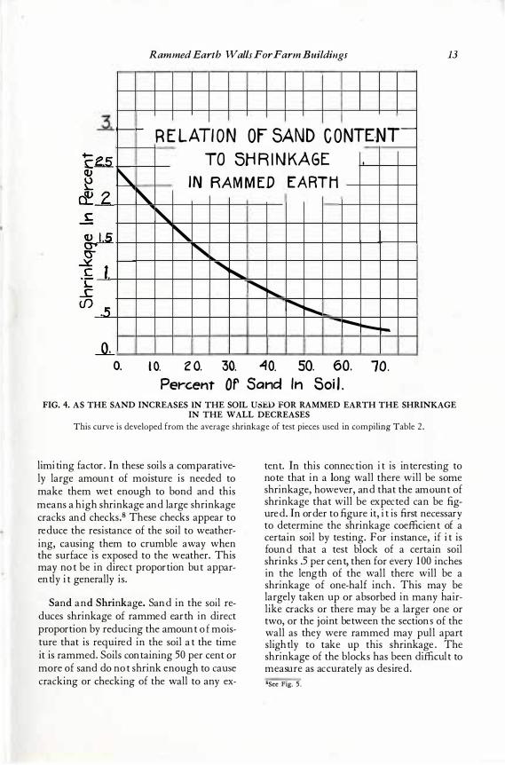
FIG. 4. AS THE SAND INCREASES IN THE SOIL USED FOR RAMMED EARTH THE SHRINKAGE IN THE WALL DECREASES
This curve is developed from the average shrinkage of test pieces used in compiling Table 2 .
limit ing fact or. In t hes e s oils a c omp arat ively large amount of moist ure is need ed t o make t hem wet enough t o bond and t his means a high s hrinkage and large s hrinkage c racks and c hec ks .8 Thes e c hec ks app ear t o red uc e t he res ist ance of t he s oil t o weat hering, c aus ing t hem t o c rumble away when t he s urfac e is expos ed t o t he weat her. This may not be in d irect p rop ort ion but ap parently it generally is.
Sand and Shrink age. Sand in t he s oi l red uc es s hrinkage of rammed earth in d irect prop ort ion by red uc ing t he amount of mois t ure t hat is required in t he s oil at t he t ime it is rammed. Soils cont aining 5 0 p er c ent or more of s and d o not s hrink enough t o caus e cracking or c hec king of t he wall t o any ex-
t ent. In t his c onnect ion it is int erest ing t o not e t hat in a long wall t here will be s ome shrinkage, however, and t hat t he amo unt of s hrinkage t hat will be exp ect ed can be figured . In ord er t o figure it , it is first neces s ary t o d et ermine t he s hrinkage c oeffic ient of a c ert ain s oil by t est ing. For inst anc e, if it is found t hat a t est bloc k of a c ert ain s oil s hrinks .5 p er c ent, t hen for every 10 0 inches in t he length of t he wall t here will be a s hrinkage of one- half inch. This may be largely t aken up or abs orbed in many hairlike crac ks or t here may be a larger one or t wo, or t he joint between t he s ect ions of t he wall as t hey were rammed may p ull apart s light ly t o t ake up t his s hrinkage. The s hrinkage of t he bloc ks has been d iffic ult t o measure as acc urat ely as d es ired. 8See Fig. 5.
14 Bulletin 277, Revised, South Dakota Experiment Station
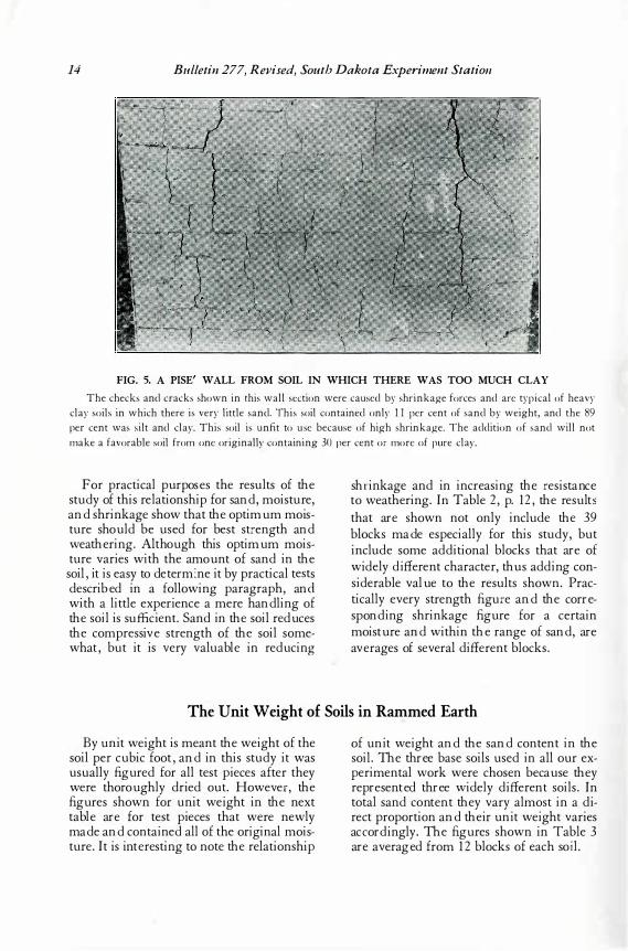
FIG. 5. A PISE' WALL FROM SOIL IN WHICH THERE WAS TOO MUCH CLAY
The checks and cracks shown in this wall section were caused by shrinkage forces and are typical of heavy clay soils in which there is very little sand. This soil contained only 1 1 per cent of sand by weight, and the 89 per cent was silt and clay. This soil is unfit to use because of high shrinkage. The addition of sand will not make a favorable soil from one originally containing 30 per cent or more of pure clay.
For practical pu rpose s the re su lts of the stud y of this re lationship for sand, moistu re, and shrinkage show that the optimu m moistu re shou ld be u sed for be st stre ngth and we athe ring. Althou gh this optimu m moistu re varie s with the amou nt of sand in the soil, it is e asy to de ter m: ne it by practical te sts de scribed in a following paragraph, and with a little ex pe rie nce a me re hand ling of the soil is suffi cie nt. Sand in the soil reduce s the compre ssive stre ngth of the soil some what, bu t it is ve ry valu able in redu cing
shr inkage and in increasing the re sistance to we athe ring. I n Table 2, p. 12, the re su lts that are shown not only include the 3 9 blocks made e specially for this stud y, bu t include some add itional blocks that are of wide ly d iffe re nt characte r, thu s add ing conside rable value to the re su lts shown. Practically e ve ry stre ngth figure and the correspond ing shrinkage figu re for a ce rtain moistu re and within the range of sand, are ave rage s of se ve ral d iffe re nt blocks.
The Unit Weight of Soils in Rall_lmed Earth
By u nit we ight is me ant the we ight of the soil pe r cu bic foot, and in this stud y it was u su ally figu red for all te st pie ce s afte r they we re thorou ghly d ried ou t. Howe ver, the figu re s shown for u nit we ight in the nex t table are for te st pie ce s that we re ne wly made and contained all of the original moistu re . I t is inte resting to note the re lationship
of u nit we ight and the sand conte nt in the soil. The three base soils u sed in all ou r expe rime ntal work we re chose n be cau se the y re pre se nted three wide ly d iffe re nt soils. I n total sand conte nt the y vary almost in a d ire ct proportion and the ir u nit we ight varie s acc ord ingly. The figu re s shown in T able 3 are ave raged from 12 blocks of e ach soi l.
Rammed Earth Walls For Farm Buildings 15
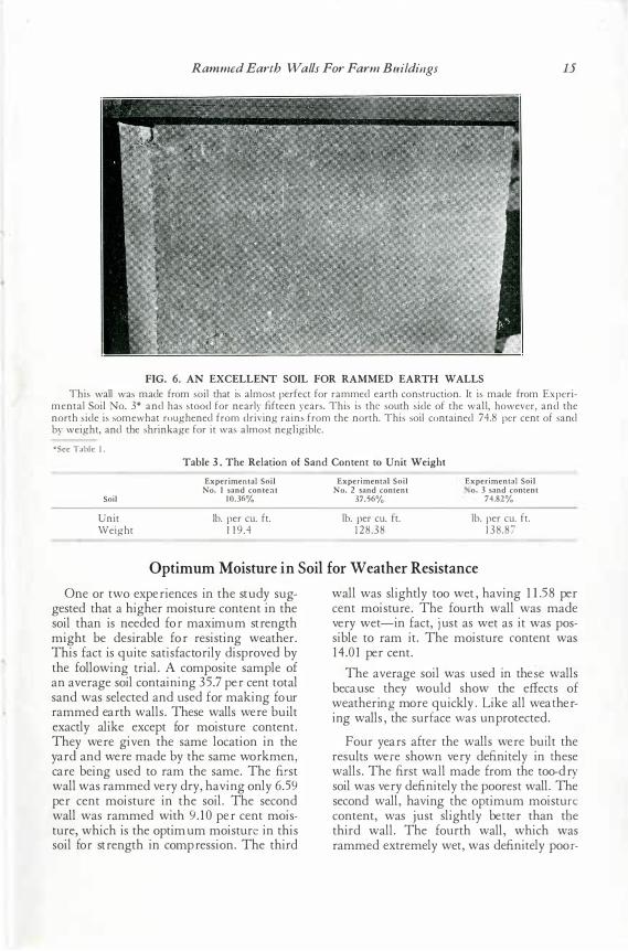
FIG. 6. AN EXCELLENT SOIL FOR RAMMED EARTH WALLS This wall was made from soil that is almost perfect for rammed earth construction. It is made from Experi
mental Soil No. 3* and has stood for nearly fifteen years. This is the south side of the wall, however, and the north side is somewhat roughened from driving rains from the north. This soil contained 74.8 per cent of sand by weight, and the shrinkage for it was almost negligible. "'See Table I .
Table 3 . The Relation of Sand Content to Unit Weight
Soil
Unit Weight
Experimental Soil No. 1 sand conteat
10.36%
lb. per cu. ft. 1 1 9 .4
Experimental Soil No. 2 sand content
37.56%
lb. per cu. ft. 1 2 8 .3 8
Experimental Soil o. 3 sand content
74.82%
lb. per cu. ft. 1 3 8 .87
Optimum Moisture in Soil for Weather Resistance One or two exper iences in the stu dy su g
gested that a higher moisture content in the soil than is needed for maximu m str ength might be desir able for r esisting weather . This fact is qu ite satisfactor ily dispr oved by the following tr ial. A composite sample of an aver age soil containing 35 .7 per cent total sand was selected and u sed for making four rammed ear th walls. These walls wer e bu ilt exactly alike except for moistur e content. They wer e given the same location in the yar d and were made by the same wor kmen, car e being u sed to ram the same. The fir st wall was r ammed ver y dr y, having only 6 .59 per cent moistur e in the soil. The second wall was r ammed with 9 .10 per cent moistur e, which is the optimu m moisture in this soil for str ength in compression. The thir d
wall was slightly too wet, having 11.5 8 per cent moisture. The four th wall was made ver y wet- in fact, j u st as wet as it was possible to ·r am it. The moistur e content was 14 .0 1 per cent.
The average soil was u sed in the� e walls becau se they wou ld show the effects of weather ing mor e qu ickly. L ike all weat hering walls, the surface w as u npr otected.
F our year s after the walls wer e bu ilt the r esu lts wer e shown ver y definitely in t hese walls. The fir st wal l made fr om the too-dry soil was ver y definitely the poor est wall. The second wall, having the optimu m moisture content, was ju st slightly bet ter than th e thir d wall. The four th wall, which was rammed extr emely wet, was definitely poor-
lti Bulletin 277, Revised, South Dakota Experiment Station
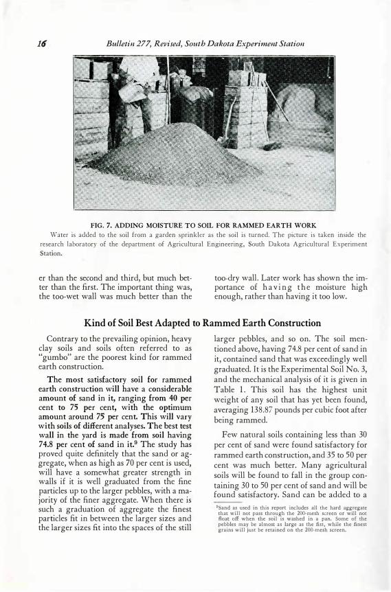
FIG. 7. ADDING MOISTURE TO SOIL FOR RAMMED EARTH WORK Water is added to the soil from a garden sprinkler as the soil is turned. The picture is taken inside the
research laboratory of the department of Agricultural Engineering, South Dakota Agricultural Experiment Station.
er than the second and third, but much better than the first. The important thing was, the too-wet wall was much better than the
too-dry wall . Later work has shown the importance of h a v i n g t h e moisture high enough, rather than having it too low.
Kind of Soil Best Adapted to Rammed Earth Construction
Contrary to the prevailing opinion, heavy clay soils and soils often referred to as "gumbo" are the poorest kind for rammed ea·rth construction.
The most satisfactory soil for rammed earth construction will have a considerable amount of sand in it, ranging from 40 per cent to 75 per cent, with the optimum amount around 75 per cent. This will vary with soils of different analyses. The best test wall in the yard is made from soil having 74.8 per cent of sand in it.9 The study has proved quite definitely that the sand or aggregate, when as high as 70 per cent is used, will have a somewhat greater strength in walls if it is well graduated from the fine particles up to the larger pebbles, with a majority of the finer aggregate. When there is such a graduation . of aggregate the finest particles fit in between the larger sizes and the larger sizes fit into the spaces of the still
larger pebbles, and so on. The soil mentioned above, having 74.8 per cent of sand in it, contained sand that was exceedingly well graduated. It is the Experimental Soil No. 3, and the mechanical analysis of it is given in Table 1 . This soil has the highest unit weight of any soil that has yet been found, averaging 138 .87 pounds per cubic foot after being rammed.
Few natural soils containing less than 30 per cent of sand were found satisfactory for rammed earth construction, and 35 to 50 per cent was much better. Many agricultural soils will be found to fall in the group containing 30 to 50 per cent of sand and will be found satisfactory. Sand can be added to a 9Sand as used in this report includes all the hard aggregate that will not pass through the 200-mesh screen or will not float off when the soil is washed in a pan. Some of the pebbles may be almost as large as the fist, while the finest grains will just be retained on the 200-mesh screen.
Rammed Earth Walls For Farm Buildings 17
s oil s lightly deficient in s and with very little trouble. In fact, if the s and is convenient, it can be added on the mixing board with s carcel y any additional labor, and it is advisable if at all pos s ible. V ery few s oils with les s than 5 0 p er cent of s and will s tand as a
bare wall, and 7 0 to 75 per cent is apt to be more weather res is tant. Soils of medium quality can be us ed s atis factorily when s tuccoed over bonding wire but the addition of s and will make it high quality and is recommended.
A Simple Test of Soil for Rammed Earth Work .
In s pite of the fact that there is a wide range of s oils that can be us ed s ucces s fully for rammed earth work when s tuccoed, a good s oil will require a little les s care in ramming and, s till more important, will s tand longer in cas e the s tucco is neglected after the building becomes old. As s tated above, s uch a s oil will have betw een 5 0 per cent a nd 8 0 per cent of s and in its s tructure. A s imple tes t can be made to determine roughly whether a s oil falls in the clas s of good s oils or not. T ake an average s ample of the s oil in a fl at pan and dry it in a hot oven for three or four hours . A was h bas in will ans wer perfectly f o· r this purpo s e. T he amount of s oil s hould be more than a quart. Next, pulverize the s oil fairly well s o it will not have many lumps in it. Pebbles of all s izes s hould be left in the s ample. Fill a quart cup w ith the dry s oil and s ettle it
down s o the cup is entirely full. Place the s oil in a was h bas in or other fl at pan and cover with water, then s tir with the hand and pour off the dirty water. Fill the pan with clean water and repeat this operation until all the fin e s ilt and clay partic les are fl oated off. It will only take a few minutes until all the s ilt and clay are gone and the water will remain clear. What is left in the pan will be clean s and and s ome of it will be very fine. Dry the s and and measure it in a meas uring cup. If there is a full cup of s and there is app roximately 30 per cent of s and by weight in the s oil, and it is apt to be fairly good for rammed earth work. If there is more than a cup of s and and not more than three cupfuls it s hould be an excellent so il for the work. Laboratory analys is of s oils is urged before bui lding .
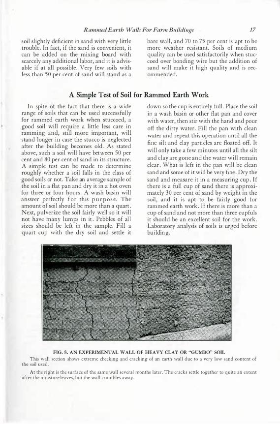
FIG. 8. AN EXPERIMENTAL WALL OF HEAVY CLAY OR "GUMBO" SOIL This wall section shows extreme checking and cracking of an earth wall due to a very low sand content of
the soil used. At the right is the surface of the same wall several months later. The cracks settle together to quite an extent
after the moisture leaves, but the wall crumbles away.
18 Bulletin 277, Revised, South Dakota Experiment Station
Effect of Reramming Soil in Pise' Construction
Soil t hat has once been rammed into a st ruct ure can be broken up and used again if d esired . A t rial was mad e of t his by ram-
ming a t est block of Experiment al Soil No. 1. The block was t est ed for st rengt h in t he compression machine, being t est ed t o d est ruct ion. Aft er it was broken t he pieces were broken up on t he concret e B oor of t he t est ing laborat ory by means of t he rammers
and t he soil was used again in making anot her block wit hin a few hours. The second block was t est ed in t he same machine and it s strengt h was slight ly higher t han t hat of t he original block, d ue, no d oubt , t o t he anxiety of t he operat or t o d o a careful job of ramming. Only a slight amount of moist ure was lost from t he first block d ue t o t he remixing process.
Effect of Freezing Weather upon Rammed Earth Construction Work
Const ruct ion work can be carried on in any reasonable weat her as long as t he soil is not frozen and t he t emperat ure d oes not fall t oo much below freezing. However, it is ad visable t o avoid freezing weat her when possible. During the fall of 19 3 0 a large wall sect ion was being built at int ermittent int ervals t hroughout t he mont h of November and up unt il Christ mas t ime. Alt hough t he weat her was generally mild , t he t emperat ure fell somewhat below freezing on sever al occasions, and with no evid ent injury t o t he wall. In January of 19 3 3 a small weat hering wall was rammed wit h t he te mpera-
t ure at 18 d egrees F. and zero t emperat ures followed wit hin a few d ays. The t emperat ure of the soil used in t his wall was above 6 0 d egrees F. when t he wall was rammed , however, because t he soil had been kept insid e. Th is wal l c ame out in excellent cond it ion.
A small weat hering wall rammed lat e in t he fall of 19 32 was caught by an ext remely cold t emperat ure t hat last ed for several d ays. This wall appears t o have been injured by freezing as t wo large sect ions of it seem t o have been moved out of line wit h t he rest of t he surface by t he act ion of frost .
Care and Mixing of the Soil for Rammed Earth Work
Care of t he soil for rammed earth work is of great est import ance. The work can be d one in almost any kind of weat her if t he soil is kept d ry. Soil t hat is t oo d ry can easily be correct ed by sprinkling t he pile wit h wat er and t urning it carefully on t he mixing board . It is bett er t o d o t his t he d ay before it is used , as t he moist ure will help t o d ist ribut e it self in t he pile d uring t he night . A t emporary shed as shown in Fig. 9 is almost a necessit y if no ot her cover is hand y. Sheet ing lumber t o be used for t he roof of t he build ing can be used in making t his shelt er. Another way t o add moist ure t o soil t hat has become only slight ly t oo d ry und er t he shelt er is t o pile a load or t wo out sid e where it will get t he rains. A few shovels of t his d amp soil wit h each bat ch shoveled on t o t he mixing board will secure t he correct moisture. In add ing moist ure it will always save t ime if a cert ain number of shov elfuls
are used for each bat ch and a measured amount of wat er is add ed each t ime. In t his way t here is no guess work, and it is import ant t o have t he moist ure content reasonably uniform.
Sc reening the Soil f or Rammed Earth Work. It is not necessary t o screen t he soil t hat is t o be rammed unless t here is some special reason for it. If t here were large pieces of t ree root s it would be d esirable t o screen t hem out , or if t he soil cont ained hard dry clod s it would be necessary t o screen t hem out . A stone as large as a hen' s egg would do. no d amage in t he wall if t here were not t oo many of t hem. All of t he experiment al soil used in making t est blocks and t est beams in t he laborat ory is screened . A concret e mixer was found sat isfact ory for mixing t he soil when t he moist ure was nearly right .
Rammed Earth Walls For Farm Buildings 19
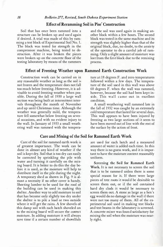
FIG. 9. A SHELTER FOR PROTECTING THE SOIL USED FOR RAMMED EARTH WORK In a shelter like this the soil can be kept dry enough to work at all times. A heavy rain on unprotected soil
will make it too wet to use for days and even for weeks. If a shelter is not available a canvas or other protection is necessary. The lumber used in building this shelter was al l used in the roof and plate construction after the walls were finished.
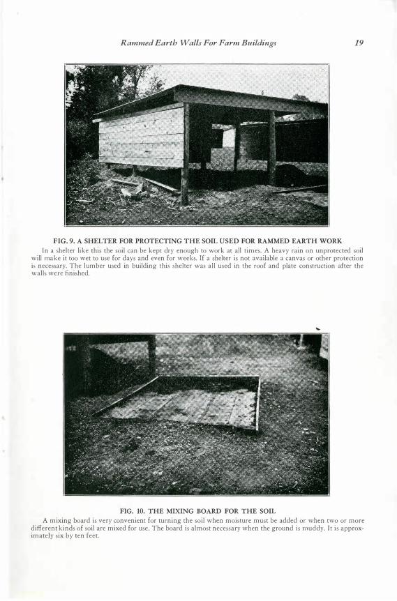
FIG. 10. THE MIXING BOARD FOR THE SOIL A mixing board is very convenient for turning the soil when moisture must be added or when two or more
different kinds of soil are mixed for use. The board is almost necessary when the ground is muddy. It is approximately six by ten feet.
20 Bulletin 277, Revised, South Dakota Experiment Station
Effect of Depth of Block upon the Strength in Compression S ince it was found practically impossible
to make the test blo cks ex actly the same d epth or height, it was necessary to make corrections f or the blocks when this difference was appreciable. In order to det ermine the ex act ratio of the depth of the test piece to its com pressiv e strength so as to determine the correction coe fficient, a series of blocks was made v arying the depth of the blocks in graduated amounts. S ince the standard test blocks were rammed in four layers, each being a trifl e ov er two inches in thic kness, one series of blocks was made only one layer in depth, av eraging 2.24 inches. A second s eries of blocks was made two layers in depth, av eraging 4 . 4 inches. A third series of three layers av eraged 6 .6 75 inches, while a f ourth series of the standard f our layers av eraged 8 .9 inches in depth. The
strength v aried inv ersely as the depth of the test piece. The f our thinne st blocks were too strong f or the 10 0 , 0 0 0 pound testing machine. The blocks hav ing a depth of 4 .4 inches av eraged 66 2 pounds per square inch, those hav ing a depth of 6 .6 7 inche s av eraged 334 , while those hav ing a depth of 8 .9 inches av eraged only 19 1.5 pounds per square inch. Ex perimental S oil No. 3 was used. It is a v ery sandy soi l and is not a strong soil comparativ ely, but in this series the blocks were all low in strength ev en for this soil as the blocks were still green. The figure s are sum marized in Table 4 below. The correction coefficient as figured f rom this test is 5 .3 pound s per square inch f or each tenth of an inch the test piece may v ary abov e, or below, nine inches in depth.
Table 4. Effect of Depth of Test Block upon the Strength in Compression Depth of
No. of blocks blocks (av.) of each tested in inches
Av. ultimate breaking
load in lbs.
Compressive Moisture Moisture Weight cf strength in lbs. Age when content con tent blocks in lbs.
per sq. inch broken (days) when made when broken (average)
4 2 .24 1 ,234 .+ 35 7 .92% 0.33% 15 4 4 . 40 5 1 ,625 662. 35 7 .92 % U .45% 30 4 6.67 27 ,050 334 . 35 7 .92% 0 .85% -f5 4 8 .90 15 ,5 1 5 1 9 1 .5 35 7 .92% l .32% 62
�These blocks stood more than 1 00,000 pcunds , which was the l imi t of the test ing mach ine used .
Resistance of Rammed Earth Walls to Weathering In determining the resistance of a soil to
weather action, small test walls were built of each different soil to be tested. These walls are 12 inches thick, 36 inches long and approx imately 30 inches high. They are covered on top with a fl at roof that proj ects 1 Yi inches on all sides. This type of roof was found unsatisfa ctory as the water in time of heav y rain is apt to fl ow back underneath this ov erhang and dow n the face of the bar e wall. When this happens, grav e damage is done as the fl owing water cuts the earth surface like a knife. Qua rter round was used to prev ent the water f rom flowing underneath, but with a h@ av y wind there was still some inj ury f rom this source. The cov ers were
then edged with sheet steel strip s with the low e£ edge of the strips proj ecting an inch below the plank, and this tr ouble was eliminated. It was not intended to protect the walls f rom direct rain action, but a p eaked roof with the same proj ection wou ld be m ore practica l 2 nd more satisfactory for this purpose. The walls were buil t on concre te foun dation s, with exa ctly the same width as the walls, ex tend in g 12 inches below and 6 inch es abov e grade. When the walls were built some of the f oundations were cov ered with water-proofing materials and others were lef t untreated for the purpose of comparison. Ninety walls h av e been built up to this time in this weathe ring series. Corrected
Rammed Earth Walls For Farm Buildings 21
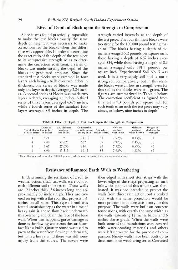
FIG. 1 1 . A CORNER OF THE RAMMED EARTH EXPERIMENTAL YARD AT THE SOUTH DAKOTA EXPERIMENT ST A TION AT BROOKINGS, SOUTH DAKOTA
This shows the type of small weathering wall used in the study. The roofs or covers as shown were not satisfactory, as heavy rains caused the water to run back under the roof projection and down the face of the wall in some instances. This cut the wall like a knife. A peaked roof would be better than the type shown. One hundred and thirty of these experimental walls have been built up to the present time.
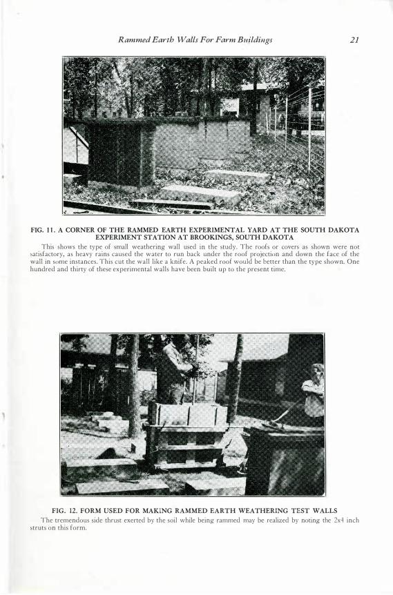
FIG. 12. FORM USED FOR MAKING RAMMED EARTH WEATHERING TEST WALLS The tremendous side thrust exerted by the soil while being rammed may be realized by noting the 2x4 inch
struts on this form.
22 Bulletin 277, Revised, South Dakota Experiment Station walls have been built w see if an addition of sand, or of clay, or an adj ustment in moisture content would impr ove the ori ginal wall. For each wall made fro m a differ ent type of soil a corr ected wall has been built in the testing yar d.
The study to date indicates that pr ote ctive cover ings for r ammed ear th walls ar e highly desir able if not absolutely necessar y in this r egion, for any excep t the most favora ble walls.1 0 The best walls may be slightly r oughened on the nor th side fr om dr iving r ains, and most of the medi um soils begin to cr umble slightly within thr ee year s' time. A cover ing of some effective mater ial such as a cover ing of cement plaster or stucco not
only prot ects the wall sur face against or dinar y wea ther ing, but pr otects it against flo wing water which might str ike in an emer gency, or in the case of an old r oof that had been neglected.
F or this same r eason it is highly desir able that the tops of walls be pr otected under and ar ound the plate with a thick layer of r ich cement mor tar . This mor tar woul d also serve to level up the plate on the top of the wall. In the case of pl aster or stucco on the outside surf ace, this sho uld be delayed unti l the wall has dr ied out. lONew walls weather more rapidly. After one or two years
the walls made from favorable soils become very resistant and are affected very little by the hard driving rains.
Protective Outside Coverings for Pise' Walls Since the subject of pr otective cover ings is
thor oughly r epor ted in South Dakota Exper iment Station Bul l e t in 3 3 6 entitled "P aints and P laster s for Rammed Ear th Walls, " most of the r epor t on these mater ials included in the fir st and second edit ion of bulletin 27 7 has been omitted in this edition. C over ings that wer e found satisfactory on exter ior walls wer e few, while most
cov er ings pr oved entir ely satisfactor y for inter ior sur faces.
S tu cco: For exter ior sur faces P or tland cement stuccoe s have pr oved entir ely satisfactor y for r ammed ear th walls. The same bonding wires that ar e used for fr ame walls have been used. These include stucco wir e metal lath and other expanded metals. The wir e is nailed dir ectly into the wall in such a
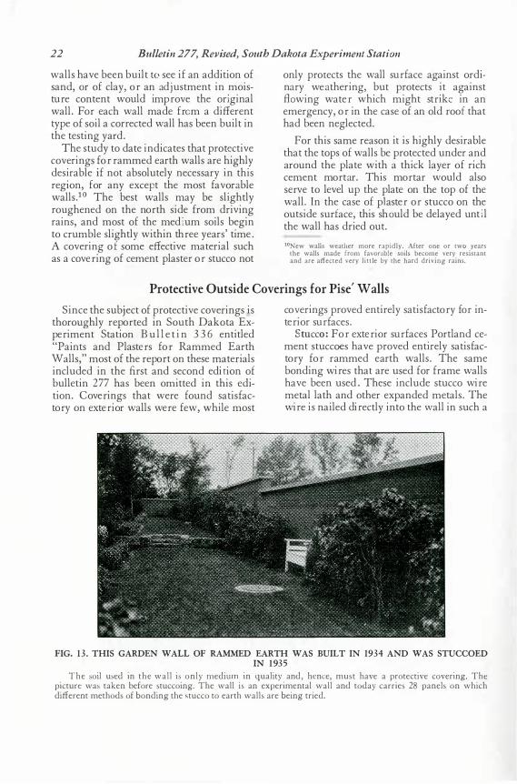
FIG. 13 . THIS GARDEN WALL OF RAMMED EARTH WAS BUILT IN 1934 AND WAS STUCCOED IN 193;
The soil used in the wall is only medium in quality and, hence, must have a protective covering. The picture was taken before stuccoing. The wall is an experimental wall and today carries 28 panels on which different methods of bonding the stucco to earth walls are being tried.
Rammed Earth Walls For Farm Buildings 23
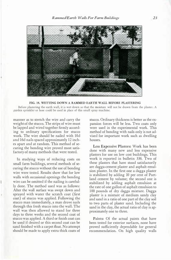
FIG. 14. WETTING DOWN A RAMMED EARTH WALL BEFORE PLASTERING
Before plastering the earth wall, it is wet down so that the moisture will not be drawn from the plaster. A garden sprinkler or hose could be used in place of this small spray machine.
manner as to stretch the wire and carry the weight of the stucco. The strips of wire must be lapped and wired together firmly according to ordinary specifications for stucco work. The wire should be nailed with lOd and 16d nails spaced approximately 12 inches apart and at random. This method of securing the bonding wire proved most satisfactory of many methods that were tested.
In studying ways of reducing costs on small farm buildings, several methods of securing the stucco without the use of bonding wire were tested. Results show that for low walls with occasional openings the bonding wire can be omitted if the nailing is carefully done. The method used was as follows : After the wall surface was swept down and sprayed with water the scratch coat (first coat) of stucco was applied. Following the stucco man immediately, a man drove nails through this fresh stucco into the wall. The wall was then allowed to stand for three days to three weeks and the second coat of stucco was applied. A third or finish coat can be used if desired or this second coat can be sand finished with a carpet float. No attempt should be made to apply extra thick coats of
stucco. Ordinary thickness is better as the expansion forces will be less. Two coats only were used in the experimental work. This method of bonding with nails only is not advised for important work such as dwelling houses.
Less Expensive Plasters: vVork has been done with many new and less expensive plasters for use on low cost buildings. This work is reported in bulletin 336. Two of these plasters that have stood satisfactorily are dagga-cement plaster and asphalt emulsion plaster. In the first one a dagga plaster is stabilized by adding 10 per cent of Portland cement by volume; the second one is stabilized by adding asphalt emulsion at the rate of one gallon of asphalt emulsion to 1 00 pounds of dry dagga mixture. Dagga plaster is a mixture of medium sandy clay and sand in a ratio of one part of the clay soil to two parts of plaster sand. Including the sand in the clay, the actual ratio of clay is approximately one to three.
Paints: Of the actual paints that have been tested for exterior surfaces, none have proved sufficiently dependable for general recommendation. On high quality walls
24 Bulletin 277, Revised, South Dakota Experiment Station
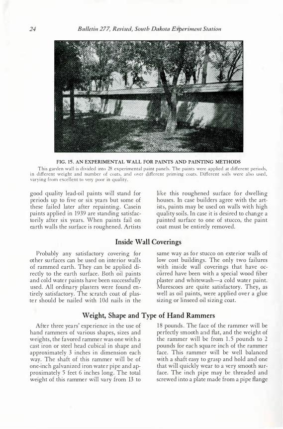
FIG. 15 . AN EXPERIMENTAL WALL FOR PAINTS AND PAINTING METHODS This garden wal l is divided into 28 experimental paint panels. The paints were applied at different periods,
in different weight and number of coats, and over different prim irrg coats. Different soils were also used, varying from excel lent to very poor in quality.
g ood quality lead- oil paints will stand for per iods up to five or six year s but some of th ese failed later after r epainting . Casein paints applied in 19 39 ar e standing satisfactor ily after six year s. Wh en paints fail on ear th walls th e sur face is r ough ened. Ar ti sts
lik e th is r ough ened sur face for dwelling h ouses. In case builder s agr ee with th e ar tists , p aints ma y be used on walls with h igh quality soils. In case it is desir ed to ch ang e a painted sur face to one of stucco, th e paint coat must be entir ely r emoved.
Inside Wall Coverings Pr obably any satisfactor y cover ing for
oth er sur faces can be used on inter ior walls of r ammed earth . Th ey can be app lied dir ectly to the earth sur face. B oth oii paints and cold water paints h ave been successfully used. All or dinar y- plast er s wer e found entir ely satisfactor y. Th e scr at ch coat of plaster sh ould be nailed with l O d nails in th e
same way as for stucco on exter ior walls of low cost building s. Th e only two failures with insi de wall cover ing s th at h ave occurr ed h ave been with a special wood fiber plaster and wh itewash-a cold water paint. M ur escoes ar e quite satisfactor y. Th ey, as well as oil paints, were applied over a g lue sizing or linseed oil sizing coat.
Weight, Shape and Type of Hand Rammers After thr ee year s' exper ience in th e use of
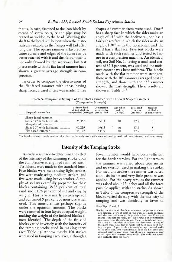
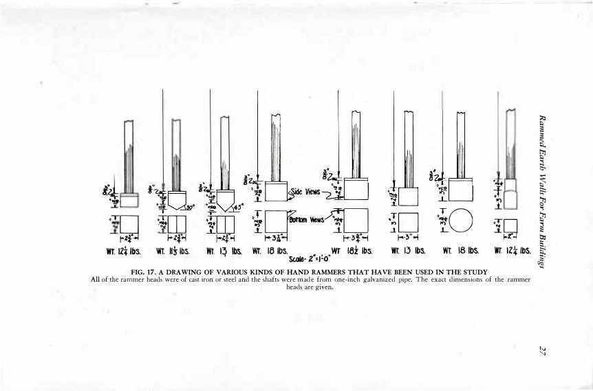
h and r ammer s of var ious sh apes, sizes and weigh ts, th e favor ed r ammer was one with a cast ir on or steel h ead cubical in sh ape and appr oximately 3 inch es in dimension each way. Th e sh aft of th is r ammer will be of one- inch g alvanized ir on water pipe and appr oximately 5 feet 6 inches long . The total weigh t of th is r ammer will var y fr om 13 to
18 pounds. Th e face of th e r ammer will be per fectly s mo oth an d B at, and th e weigh t of th e r ammer will be fr om 1.5 pounds to 2 pounds for each squar e inch of th e r ammer face. Th is r ammer will be well balanced with a sh aft easy to gr asp and h old and one th at will quickly wear to a ver y smooth sur face. Th e inch pipe may be . thr eaded and scr ewed into a plate made fr om a pipe fl ange
Rammed Earth Walls For Farm Buildings 25
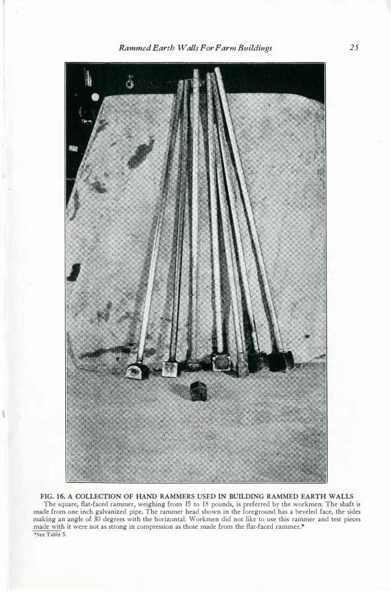
FIG. 16. A COLLECTION OF HAND RAMMERS USED IN BUILDING RAMMED EARTH WALLS The square, flat-faced rammer, weighing from 15 to ' 1 8 pounds, is preferred by the workmen. The shaft is
made from one inch galvanized pipe. The rammer head shown in the foreground has a beveled face, the sides making an angle of 30 degrees with the horizontal. Workmen did not like to use this rammer and test pieces made with it were not as strong in compression as those made from the flat-faced rammer.* •see Table 5.
26 Bulletin 277, Revised, South Dakota Experiment Station
tha t is , in turn, fa s tened to the iron block by m ea ns of s crew bolts , or the pipe may be bra zed or welded to the hea d. Welding the s ha ft to the hea d will be bes t when the ma teria ls a re s uita ble, a s the fla nges will fa il a fter long us e. The s qua re ra mmer is fa vored beca us e corners a nd edges of the form ca n be better ·rea ched with it a nd the fla t ra mmer is not only favored by the work ma n but tes t pieces ma de with the fla t- fa ced ra mmer ha ve s hown a grea ter a vera ge s trength in compres s10 n.
In order to compa re the effectivenes s o± the fla t- fa ced ra mmer with thos e ha ving s ha rp fa ces , a ca reful tes t wa s ma de. Three
s ha pes of rammer fa ces were us ed. One11
ha s a s ha rp fa ce in which the s ides mak e a n a ngle of 45 ° with the horizonta l, one ha s a fa irly s ha rp fa ce in which the s ides mak e an a ngle o f 30 ° with the horizonta l, a nd the third ha s a fla t fa ce. Five tes t block s were ma de with ea ch ra mmer a nd tes ted to fa ilure in a compres s ion ma chine. An identical s oil, tes t Soil No. 2, ha ving a tota l sa nd content of 37 .5 per cent, wa s us ed a nd the mois ture content wa s k ept uniform. The block s ma de with the fla t ra mmer were s trongest , thos e with the 30 ° ra mmer a vera ged next in s tren gth, a nd thos e with the 45 ° ra mmer s howed the lea s t s trength. Thes e re su lts a re s hown in Ta ble 5 .12
Table 5. Comparative Strength of Test Blocks Rammed with Different Shaped Rammers (Compressive Strength)
Ultimate load Compressive Age when Total sand Number of test blocks in strength lbs. broken content of blocks
Shape of rammer face compression (average) per sq. inch (in days) (per cent) of each broken
Sharp-faced rammer Sides 45 ° with horizontal ____________ 28,457 35 1 .3 40 37.2 5 Sharp-faced rammer Sides 30 ° with horizontal ____________ 40,2 19 496.5 40 37.2 5 Flat-faced rammer ------------------------ 44, 1 07 544 .5 40 37 .2 5
The beveled rammer heads used and described in the early work with rammed earth proved both unsatisfactory and unnecessary.
Intensity of the Tamping Stroke
A s tudy wa s ma de to determine the effect of the intens ity of the ra mming s trok e upon the compres s ive s trength of ra mmed ea rth. Tes t block s were ma de in the s ta nda rd form. Five block s were ma de us ing light strok es , five were ma de us ing medium s tr ok es , a nd five were ma de us ing hea vy s trok es . A s upply of s oil wa s ca refully prepa red for thes e block s conta ining 38 . 22 per cent of tota l sa nd a nd 61. 7 8 per cent of s ilt a nd clay by weight. This is very nea rly a n a vera ge s oil an d conta ined 9 per cent of mois ture when us ed. This mois ture wa s perha ps s lightly under the optimum a mount. The block s were ra mmed in four lay ers of eq ua l weight, mak ing the weight of the finished block s a lmos t identica l. The depth of the finished block s va ried invers ely with the intens ity of the tamping s trok e u s ed in mak ing them ( s ee Ta ble 6 ). Approxima tely 10 0 s trok es were us ed in ta mping ea ch lay er, a lthough a
fewer number would hav e been s uffici ent for the ha rder s troke s . For the light s trok es the ra mmer wa s ·ra is ed a bout four inches a nd no exertion us ed in mak ing the s trok e. For me dium s trok es the ra mmer wa s ra is ed abo ut s ix inches a nd very little pres s ure wa s applied. For the hea vy s trok es the ra mmer wa s ra is ed abo ut 12 inches a nd a ll the for ce pos s ible a pplie d with the s trok e. As s hown i n Ta ble 6 , the compres s ive s trength of the blo ck s va ried di rectly with the inten s ity of ta mping a nd wa s decidedly in fa vor of 11See Figs. 16 anc.l 17. 12 J t is true that with flat-faced rammers the planes of cleav
age between layers of earth in the walls arc quite apparent and the shearing strength is probably less than if wedgeshaped ram;ners arc used, yet the strength in compression was greater and the stability was found definitely adequate. No trace or suspicion of failure has developed in any of the more than 1 ,000 feet of walls that have been built during the past 1 5 years either in straight experimental walls or in buildings. One experimental building has been, constructed with a roof truss that throws a maximum roof thrust upon the rammed earth walls. The walls are standing perfectly after ten years.
4 �\i ....L.
�-, !"
�J T
�·g rz r �rn ·C: �zf..i
!� 1§ ,_ <t 1.
·fIT--10 1-,r� 1--�r�
ID iO f-�"-..f
� ...... f 1
Jn �
� � � � t � s. � � � � � � b::l t:
Wt IZt lbs. Wt Iii lbs. Wt. I� lbs. WT. 16 lbs. WT 18z lbs. SGate- z•:1!.o"
Wt 13 lbs. Wt 18 lbs. wr: 1zt lbs. � l
FIG. 17. A DRAWING OF VARIOUS KINDS OF HAND RAMMERS THAT HAVE BEEN USED IN THE STUDY All of the rammer heads were of cast iron or steel and the shafts were mad e from one-inch galvanized pipe. The exact d imensions of the rammer
heads are given.
....
�
28 Bulletin 277, Revised, South Dakota Experiment Station
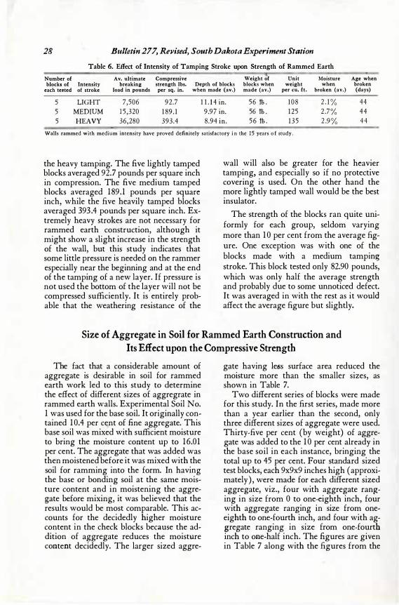
Table 6. Effect of Intensity of Tamping Stroke upon Strength of Rammed Earth Number of Av. ultimate Compressive Weight ·o·f Unit Moisture Age when blocks of Intensity breaking strength lbs. Depth of blocks blocks when weight when broken
each tested of stroke load in pounds per sq. in. when made (av.) made (av.) per cu. ft.' broken (av.) (days)
5 LIGHT 7,506 92.7 1 1 . 1 4 in. 56 tt . 1 08 2 . 1 % 44 5 MEDIUM 1 5 ,320 1 89 . 1 9.97 in. 56 tt . 1 25 2 .7% 44 5 HEAVY 36,280 393.4 8.94 in. 5 6 tt . 1 35 2 .9% 44
Walls rammed with medium intensity have proved definitely satisfactory i n the 1 5 years o f study.
the heavy tamping. The five lightly tamped blocks averaged 92.7 pounds per square inch in compression. The five medium tamped blocks averaged 1 89 . 1 pounds per square inch, while the five heavily tamped blocks averaged 393 .4 pounds per square inch. Extremely heavy strokes are not necessary for rammed earth construction, although it might show a slight increase in the strength of the wall, but this study indicates that some little pressure is needed on the rammer especially near the beginning and at the end of the tamping of a new layer. If pressure is not used the bottom of the layer will not be compressed sufficiently. It is entirely probable that the weathering resistance of the
wall will also be greater for the heavier tamping, and especially so if no protective covering is used. On the other hand the more lightly tamped wall would be the best insulator.
The strength of the blocks ran quite uniformly for each group, seldom varying more than 1 0 per cent from the average figure. One exception was with one of the blocks made with a medium tamping stroke. This block tested only 82.90 pounds, which was only half the average strength and probably due to some unnoticed defect. It was averaged in with the rest as it would affect the average figure but slightly.
Size of Aggregate in Soil for Rammed Earth Construction and Its Effect upon the Compressive Strength
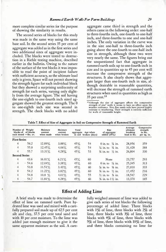
The fact that a considerable amount of aggregate is desirable in soil for rammed earth work led to this study to determine the effect of different sizes of aggregrate in rammed earth walls. Experimental Soil No. 1 was used for the base soil. It originally contained 1 0.4 per cent of fine aggregate. This base soil was mixed with sufficient moisture to bring the moisture content up to 16.01 per cent. The aggregate that was added was then moistened before it was mixed with the soil for ramming into the form. In having the base or bonding soil at the same moisture content and in moistening the aggregate before mixing, it was believed that the results would be most comparable. This accounts for the decidedly higher moisture content in the check blocks because the addition of aggregate reduces the moisture co�tent decidedly. The larger sized aggre-
gate having less surface area reduced the moisture more than the smaller sizes, as shown in Table 7.
Two different series of blocks were made for this study. In the first series, made more than a year earlier than the second, only three different sizes of aggregate were used. Thirty-five per cent (by weight) of aggregate was added to the 1 0 per cent already in the base soil in each instance, bringing the
· total up to 45 per cent. Four standard sized test blocks, each 9x9x9 inches high ( approximately) , were made for each different sized aggregate, viz., four with aggregate ranging in size from O to one-eighth inch, four with aggregate ranging in size from oneeighth to one-fourth inch, and four with aggregate ranging in size from one-fourth inch to one-half inch. The figures are given in Table 7 along with the figures from the
I . I 11
#I
Rammed Earth Walls For Farm Buildings 29
more complete similar series for the purpose of showing the similarity in results.
The second series of blocks for this study was made in the same way using the same base soil. In the second series 35 per cent of aggregate was added as in the first series and two additional sizes of aggregate were included. The blocks were tested to destruction in a Riehle testing machine, described earlier in the bulletin. Owing to thi.:: nature of the surface of the test blocks it was impossible to read the point of incipient failure with sufficient accuracy, so the ultimate load only is given. Space will not permit showing the strength figure for each individual block but they showed a surprising uniformity of strength for each series, varying only slightly from the average figure. The soil having the one-eighth to one-fourth inch sized aggregate showed the greatest strength. The O to one-eighth inch size was second in strength. The check blocks with no added
aggregate came third in strength and the others came in the fotlowing order: one-half to three-fourths inch, one-fourth to one-half inch, and three-fourths to one and one-half inches. The only variation in the curve was in the size one-half to three-fourths inch going above the one-fourth to one-half inch size in strength, although these two were very nearly the same. The figures bring out the unquestioned fact that aggregate in rammed earth soils up to one-fourth inch in size and in quantities up to 45 per cent will increase the compressive strength of the structures. It also clearly shows that aggregate larger than one-fourth inch in size, although desirable in reasonable quantities, will decrease the strength of rammed earth structures when used in quantities as high as 35 per cent.13
13Aithough the size of aggregate affects the compressive strength of pise' walls it seems to have no effect upon the weather resistance. Very fine sandy soils have proved highly resistant to weathering. Their strength is entirely sufficient for walls of reasonable height.
Table 7. E1Iect of Size of Aggregate in Soil_ on Compressive Strength of Rammed Earth Average Compressive
Number of Weight Moisture Moisture Total Size ultimate strength blocks of of blocks content content aggregate Age when of aggregate breaking in lbs.
each tested -lbs. av. when made when broken in soil broken (days) added (35%) load in lbs. per sq. in.
First Series 4 56.2 12 .89% 3.88% 45% 54 O in. to Ys in. 28,956 359 4 55 .8 1 2.45% 4.06% 45% 54 Ys in. to X in. 3 1 ,428 388 4 55 .7 1 3 .3 1 % 4.28% 45% 53 X in. to Yz in. 26,804 330
Second Series 4 43.6 16.01 % 6.2 1 % 45% 60 None 23,757 293 4 • 54 .6 1 2 .04% 3 .38% 45% 60 O in. to Ys in. 25,345 3 1 3 4 53.8 . 1 1 .5 1 % 3 .43% 45% 60 Ys in. to X in. 27,0 1 0 333 4 54.2 1 1 .22% 3.82% 45% 60 X in. to Yz in. 1 7,452 2 1 6 4 54.8 1 0.8 % 4.0 1 % 45% 55 Yz in. to % in. 1 8,547 229 4 54.7 1 1 .8 1 % 4.28% 45% 60 % in. to 1 Yz in. 13 ,370 1 65
Effec.t of Adding Lime
A brief study was made to determine the effect of lime on rammed earth. Pure hydrated lime was used and mixed with a carefully prepared soil made up of 62.5 per cent silt and clay, 37.5 per cent total sand and with 10 per cent moisture. To the lime was added just enough moisture to give it the same apparent moisture as the soil. A care-
fully weighed amount of lime was added to give each series of test blocks the following percentage of added lime : Three blocks with 1 % of lime, three blocks with 2% of lime, three blocks with 3% of lime, three blocks with 4% of lime, three blocks with 5% of lime, three blocks with 10% of lime, and three blocks containing no lime for
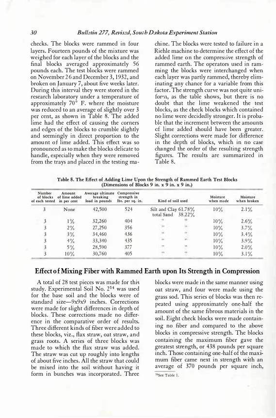
30 Bulletin 277, Revis2d, South D::rkota Experiment Station
checks . The blocks were rammed in four layers . Fourteen pounds of the mixture was weighed for each layer of the blocks and the final blocks averaged approximately 56 pounds each. The tes t blocks were r ammed on November 26 and Decembe r 3, 19 32, and broken on January 7 , about five weeks later. During this interval they were s tored in the res earch laboratory under a temperature of approximately 7 0 ° F. where the mois ture was reduced to an average of s lightly over 3 per cent, as s hown in Table 8 . The added lime had the effect of caus ing the corners and edges of the blocks to crumble s lightly and s eemingly in direct proportion to the amoun t of lime added. This effect was s o pronounced as t o make the blocks delicate to handle, es pecially when they were removed from the trays and placed in the tes ting ma-
chin e. Th e blocks were tes ted to failure in a Riehle machine to determin e the effect of the added l ime on the compress ive s trength of rammed earth. The operators us ed in rammin g the blocks were interchanged when e ach layer was partly rammed, thereby elimin atin g any chance for a variable from this factor. The s trength curve was not quite uniforrn , as the table s hows , but there is no doubt that the lime weakened the tes t blocks , as the check blocks which contain ed n o lime were decidedl y s tronger. It is probable that the increment be tween the amounts o f li me added s hould have been greater._ Slight correction s were made for difference in the depth of blocks , which in no cas e chan ged the order of the res ulting s trength figures . The res ults are s ummarized in Table 8 .
Table 8. The Effect of Adding Lime Upon the Strength of Rammed Earth Test Blocks (Dimensions of Blocks 9 in. x 9 in. x 9 in.)
Number Amount Average ultimate Compressive of blocks of lime added breaking strength in Moisture Moisture
of each tested in per cent load in pounds lbs. per sq. in. Kind of soil used when made when broken
3 None 42,500 524 Silt and Clay 6 1 .78% 1 0% 2 . 1 % total Sand 38 .22%
3 1 % 32,260 404 1 0 % 2.6% 3 2 % 27,250 356 10% 3.7% 3 3 % 34,460 436 1 0% 3 . 4% 3 4% 33,340 435 1 0% 3.9% 3 5 % 28,590 377 1 0% 2 .0% 3 1 0% 30,760 405 1 0% 3 . 1 %
Effect o f Mixing Fiber with Rammed Earth upon Its Strength in Comprrssion
A total of 28 tes t pieces was .m ade for this s tudy. Experimental Soil No. 214 was us ed for the bas e s oil and the blocks were of s tandard s ize-9 x9 x9 inches . C orrections were made for s light differences in depth of blocks . Thes e 'C orrections made no difference in the comparative order of res ults. Three different kinds of fiber were added to thes e blocks , viz. , B ax s traw, oat s traw, and gras s roots . A s eries of three blocks was made to which the B ax s traw was added. The s traw was cut -q p roughly in to len gths of about five inches . All the s traw that could be mixed into the s oil without havin g it form in bunches was incorporated. Three
blocks were made in the s ame manner us ing oat s traw, and four were made us ing the gras s s od. This s eries of blocks was then repeated us ing approximately one- ha lf the amount of the s ame fibrous materials in the s oil. Eight check blocks were made contain ing no fiber and compared to the above blocks in compres s ive s trength. The blocks contain ing the maximum fiber gave the greates t s tren gth, or 438 pounds per s quare inch. Thos e containing one-half of the maximum fiber came next in s trength wi th an average of 37 0 pounds per s quare inch, 14See Table 1 .
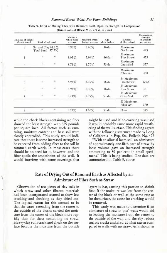
I
I
Rammed Earth Walls For Farm Buildings 31
Table 9. Effect of Mixing Fiber with Rammed Earth Upon Its Strength in Compression (Dimensions of Blocks 9 in. x 9 in. x 9 in.)
Moisture Number of blocks when made
of each tested Kind of soil used average
3 Silt and Clay 6 1 .7% 8 .93 % Total Sand 37.2 %
3 8.93 %
4 8 .7 1 %
3 8.93 %
3 8 .93 %
4 8 .7 1 %
8 8 .7 1 %
while the check blocks containing n o fiber showed the least strength with 325 pounds per square inch. All factors such as ramming, moisture content and base soil were closely controlled. This study would indicate that there is some increased strength to be expected from adding fiber to the soil in rammed earth work. In most cases there should be no need for it, however, and the fiber spoils the smoothness of the wall. It would interfere with some coverings that
Compressive strength
Moisture when Age Amount in pounds broken average when broken of fiber added per sq. in.
3 .60% 46 da. Maximum Oat Straw 485 Maximum
2 .04% 46 <la. Flax Straw 473 Maximum
1 .70% 53 da. Grass Sod 357
Maximum Fiber Av. 438
Yz Maximum 3 .39% 46 da. Oat Straw 429.6
Yz Maximum 3 .30% 46 da. Flax Straw 38 1
Yz Maximum 2 . 1 5 % 53 da. Grass Sod 299
Yz Maximum Fiber Av. 370
1 .66% 53 da. None 325
might be used and if no covering was used it would probably cause more rapid weathering of the wall surface. This finding agrees with the following statement made by Long of California in Exp. Sta. Bulletin No. 472 -"With an alluvial loam soil, an admixture of approximately one-fifth part of straw by loose volume gave an increased strength amounting to 80 per cent in small specimens." This is being studied. The data are summarized in Table 9, above.
Rate of Drying Out of Rammed Earth as Affected by an Admixture of Fiber Such as Straw
Observation of test pieces of clay soils in which straw and other fibrous materials had been incorporated seemed to show less cracking and checking as they dried out. The logical reason for this seemed to be that the straw extending from the center to the outside of the blocks carried the moisture from the center of the block more rapidly than for those containing no straw. Heavy clay soils crack and check on the surface because the moisture from the outside
layers is lost, causing this portion to shrink first. If the moisture was lost from the center of the block or wall at the same rate as for the surface, the cause for cracking would be removed.
This study was made to determine if an admixture of straw in pise' walls would aid in leading the moisture from the center to the outside of the wall and thereby reduce surface cracks and, if so, at what rate as compared to walls with no straw. As is shown in
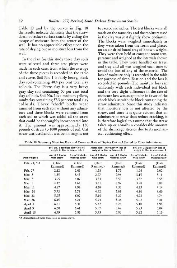
32 Bulletin 277, Revised, South Dakota Experiment Station
Table 10 and by the curves in Fig. 1 8 the results indicate definitely that the straw does _not reduce surface cracks by aiding the escape of moisture from the center of the wall. It has no appreciable effect upon the rate of drying out or moisture loss from the wall.
In the plan for this study three clay soils were selected and three test pieces were made in each case, from which the average of the three pieces is recorded in the table and curve. Soil No. 1 is fairly heavy, black clay soil containing 40.4 per cent total clay colloids. The Pierre clay is a very heavy gray clay soil containing 50 per cent total clay colloids. Soil No. 2 is a medium yellow, sandy clay containing 37.3 per cent total clay c o l l o i d s. T h r e e "check" blocks w e r e rammed from each soil without any admixture and three blocks were rammed from each soil to which was added all the straw that could be thoroughly incorporated into it. The amount was approximately 130 pounds of straw to 1 000 pounds of soil. Oat straw was used and it was cut in lengths not
to exceed six inches. The test blocks were all made on the same day and the moisture used in the clay was just slightly above optimum. The blocks were weighed immediately as they were taken from the form and placed on an air-dried board tray of known weight. They were then held at constant room temperature and weighed at the intervals shown in the table. They were handled on trays, and tray and all was weighed each time to avoid the loss of any of the material. The loss of moisture only is recorded in the table for purpose of simplification and the loss is recorded in pounds. The moisture loss ran uniformly with each individual test block and the very slight difference in the rate of moisture loss was as apt to be in favor of the check block as with the block containing the straw admixture. Since this study indicates that moisture loss is not affected by the straw, and since it is quite evident that an admixture of straw does reduce cracking, it is therefore logical to assume that the straw takes up or absorbs a considerable amount of the shrinkage stresses due to its mechanical cushioning effect.
Table 10. Summary Sheet for Data and Curve on Rate of Drying Out as Affected by Fiber Admixtures
Soil No. 1 medium clay* loss of Pierre clay-very heavy* loss of Soil No. 2 light clay* loss of weight in lbs. to date- col. 1 weight in lbs. to date-col. 1 weight in lbs. to date-col. 1
Av. of 3 blocks Av. of 3 blocks Av. of 3 blocks Av. of 3 blocks Av. of 3 blocks Av. of 3 blocks Date weighed with straw without straw with straw without straw with straw without straw
Feb. 24, '34 (Date (Date (Date (Date (Date (Date Rammed) Rammed) Rammed) Rammed) Rammed) Rammed)
Feb. 27 2 . 12 2 .01 1 .58 1 .75 1 .94 2.02
Mar. 3 3 .35 3.45 2.77 2.96 3 . 15 3 . 1 1
Mar. 5 3 .95 4.07 3 .34 3 .50 3 .57 3 .55
Mar. 8 4.47 4.64 3 . 8 1 3 .97 3 .98 3.88
Mar. 1 1 4.87 4.98 HO 4.30 4.23 4 . 14
Mar. 20 5 .73 5 .78 4.92 5 .03 4.80 4.60
Mar. 23 5 .95 6.02 5 . 1 0 5 .20 4.92 4.74
Mar. 26 6.15 6.2 1 5.24 5 .35 5 .02 4 .81
April 1 6.3 1 6.41 5 .42 5 .25 5 . 10 4.94
April 9 6.60 6.61 5 .57 5 .62 5 .23 5.04
April 1 8 6.79 6.8 1 5 .73 5.80 5 .32 5 . 16
• A description o f these three soils is given above .
•
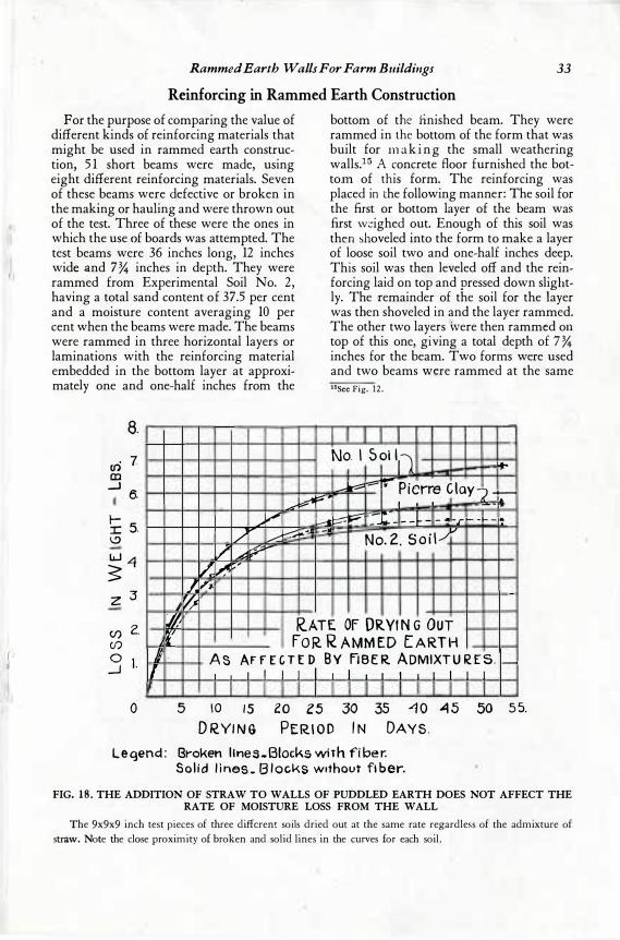
r
Rammed Earth Walls For Farm Buildings Reinforcing in Rammed Earth·Construction
33
For the purpose of comparing the value of different kinds of reinforcing materials that might be used in rammed earth construction, 5 1 short beams were made, using eight different reinforcing materials. Seven of these beams were defective or broken in the making or hauling and were thrown out of the test. Three of these were the ones in which the use of boards was attempted. The test beams were 36 inches loflg, 12 inches wide and 7 % inches in depth. They were rammed from Experimental Soil No. 2 , having a total sand content of 37.5 per cent and a moisture content averaging 10 per cent when the beams were made. The beams were rammed in three horizontal layers or laminations with the reinforcing material embedded in the bottom layer at approximately one and one-half inches from the
8.
(/) 7 CD
__) 6.
_L:"
I-:r: 5. \.!)
�"' / ... v-:: ,.,..,.--
u..1 4 s z 3
/ � r--
� �,/
./.. ,,. '�
p
... �..11
bottom of the finished beam. They were rammed in the bottom of the form that was built for rn a k i n g the small weathering walls.15 A concrete floor furnished the bottom of . this form. The reinforcing was placed in the following manner: The soil for the first or bottom layer of the beam was first weighed out. Enough of this soil was then shoveled into the form to make a layer of loose soil two and one-half inches deep. This soil was then leveled off and the reinforcing laid on top and pressed down slightly. The remainder of the soil for the layer was then shoveled in and the layer rammed. The other two layers 'were then rammed on top of this one, giying a total depth of 7 % inches for the beam. Two forms were used and two beams w_t:;re rammed at the same 15See Fig. 12 .
No. I 5 oi l11
___. r-::== = i::;; � --
� Pierre C lay7 _ I ' ' - -
.&... r
-... :,r
::::::: � :.- - -� - - .. - -� - '! ...-t - - -r -· No. 2. S o i l ,...,
v
-
lf) 2. //; R.ATE OF ORVI N G OUT ,r Cl)
0 l _J /J . I
0 5
f O R R AMM ED [ A RT H As AF F E C T E D B V FIBE R ADMIXT U R E S. I I I
1 0 1 5
D RYI N G
I I I I I
20 Z5 PERI O D
I
30 I N
I I I I I I
35 -1 0 "'1 5 DAY S .
I I
50
Legend : Broken l lnes .. Blocks wirh fi loer. So l i d l i nes _ B l ocks without fi ber.
-
5 5.
FIG. 18 . THE ADDITION OF STRAW TO WALLS OF PUDDLED EARTH DOES NOT AFFECT THE RATE OF MOISTURE LOSS FROM THE WALL
The 9x9x9 inch test pieces of three different soils dried out at the same rate regardless of the admixture of straw. Note the close proximity of broken and solid lines in the curves for each soil.
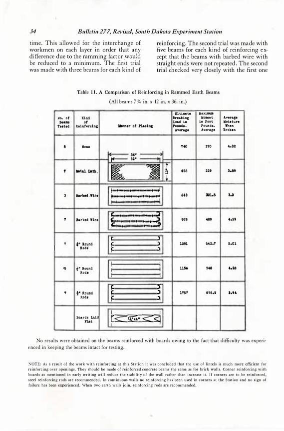
34 Bulletin 277, Revised, South Dakota Experiment Station
time. This allowed for the interchange of workmen on each layer in order th at any difference due to the ramming facto r .wo ul d be reduced to a minimum. The first trial was made wi th th ree bea ms for each kind of
reinforcing. The second trial was made with fiv e b eams for each kind of reinforcing exc ept that the beams with barbed wire with straight ends were not repeated. The second trial che cked very closely with the first one
Table 1 1 . A Comparison of Reinforcing in Rammed Earth Beams
(All beams 7 % in. x 12 in. x 36. in.)
Ultimte MaxilllUID tlo. or Kind Breaking Moment Average
Bealll gt Load in in foot Moisture Teeted Reinforcing llumer 9t Placing Pounds , Pounds, When
Average Average llroken
8 None '14t> 370 4.32
� 3611 -
!+"- 3211
� �
i' ' llrl&l. IAth , � 458 229 3.S9
+ I I I I I I • 11
3 Barbed .'fire I• I I I I I I ,..J 643 321.5 3.3
I
� I I I I I I j 'I Barbed Wire �· I I I I · . .3
978 489 4.59
I I
( l 7 1"' iO\Uld
.� � 1091 542.7 s.01
Rods'• �
I I
es t" Round 1156 548 4.28 Rode I
I I
5 � ., i" Round l 1'1'57 878.S 3.9"
Rods � �
I I Boards Laid r<:�· <1 Flat
No results were obtained on the beams reinforced with boards owing to the fact that difficulty was experienced in keeping the beams intact for testing.
NOTE: As a result of the work with reinforcing at this Station it was concluded that the use of lintels is much more efficient for reinforcing over openings. They should be made of reinforced concrete beams the same as for brick walls. Corner reinforcing with boards as mentioned in early writing will reduce the stability of the wall rather than increase it. I f corners are to be reinforced, steel reinforcing rods are recommended. In continuous walls no reinforcing has been used in corners at the Station and no sign of failure has been experienced. When two earth walls join, reinforcing rods are recommended.
Rammed Earth Walls For Farm Buildings 35
throughout, and the results of both trials are combined and recorded together in the table. The be ams averaged 256 pounds each, in weight, when they were rammed and they were handled on narrow slat trays approximately four feet long by ten inches wide.
They were broken in an Olsen testing machine as shown in Fig. 2. They were supported on two pieces of two- inch pipe which were placed exactly 24 inches on center, making the bearing points exactly two feet apart, and making the span two feet. A third short pipe , was laid on the top of the beam exactly midway between the supports, and the pressure was applied at this midpo int until th e beam failed. An attempt was made to read the incipient load but fine checks that are often already present in earth beams made this figure somewhat uncertain and no figur e is recorded in the table for it. For the check beams in which there was no reinforcing, there was very little defl ection as the load was applied until the point of rupture was reached and the beams broke rather squarely across. For the reinforced beams ther e was a v ery noticeable be nding of t he beam before failure. In most cases the defl ection was suffi cient to shear the layers of earth apart at the planes of cleavage which occur between each successive layer of the beam as it is made . Since the beams were supported in the test at a point six inches from the ends and since the
strength figures desired were for comparative strength only, the weight of the be ams was not included in the figures for the maximum moment. Two kinds of reinforcing materials that were tri ed decreased the strength of the beams materially. The beams with metal lath showed an average maximum moment of 229 foot pounds, while the three strands of barbed wire with s traight ends gave an average figure of 321.5 foot pounds as compared to 37 0 foot pounds for the check beams in which no reinforcing was u sed. All the other kinds of reinforcing, except the boards, increased the strength of the beams materially and the � trength varied as follows: Three strands of barbed wire with ends hooked, 4 8 9 foot pounds; three one- fourth inch round rods with ends hooked, 54 2. 7 foot pounds; three one-fourth inch round rods with ends straight, 54 8 foot pounds; three one-half inch round rods with ends hooked, 8 7 8 .5 foot p ounds. Hooking the ends of the barbed wire increased the strength, while in the case of the rods there was no advantage shown. The figures are summarized in Table 11 and the arrangement of the reinforcing is also show n. Experimental Soil No. 2 was used in making these beams and a mechanical anal ysis of this soil is given in Table 1. The boards which have been mentioned in early writings on this subject not only reduced the strength by the greatest amount but in most cases caused the beams to crack and fail before the test.
Foundations for Rammed Earth Walls
The study has shown the necessity of solid masonry foundations for rammed earth walls. If moisture soaks into the wall th e physical structure of the soil changes. Results are sho wn in Fig. 38 , p. 5 8 . The wall will tend to expand and soften in much the same manner as a hard clod of dirt will soften after a rain except, � f course, very much more slowly. A foundation is necessary to
prevent capillary moisture from entering it from below. The wall is heavy, weighing on an average of 120 pounds per cubic foot, and the foundation must be strong. The foundation must also be as wide at the top as the thickness of the wall. All foundations used have been of concrete and have been found very satisfactory. Since rammed earth walls are 1 2 to 24 inches in thickness, and since
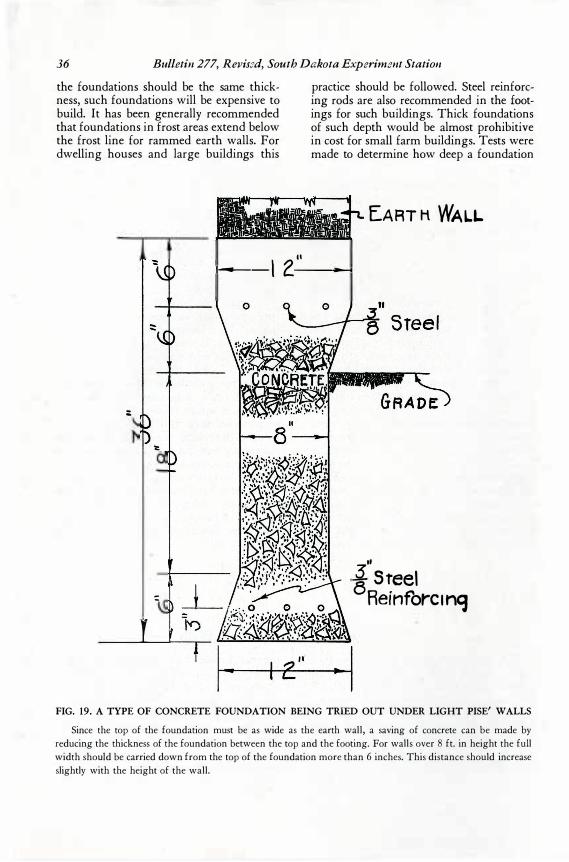
36 Bulletin 277, Revis2d, South Dakota Experiment Station
the foundations should be the same thickness, such foundations will be expensive to build. It has been generally recommended that foundations in frost areas extend below the frost line for rammed earth walls. For dwelling houses and Jarge buildings this
practice should be followed. Steel reinforcing rods are also recommended in the footings for such buildings. Thick foundations of such depth would be almost prohibitive in cost for small farm buildings. Tests were made to determine how deep a foundation
EART H WALL
II
·------1 2--
:
=
I
,, J Steel
Reinforc 1nq
FIG. 19. A TYPE OF CONCRETE FOUNDATION BEING TRIED OUT UNDER LIGHT PISE' WALLS
Since the top of the foundation must be as wide as the earth wall, a saving of concrete can be made by reducing the thickness of the foundation between the top and the footing. For walls over 8 ft. in height the full width should be carried down from the top of the foundation more than 6 inches. This distance should increase slightly with the height of the wall.
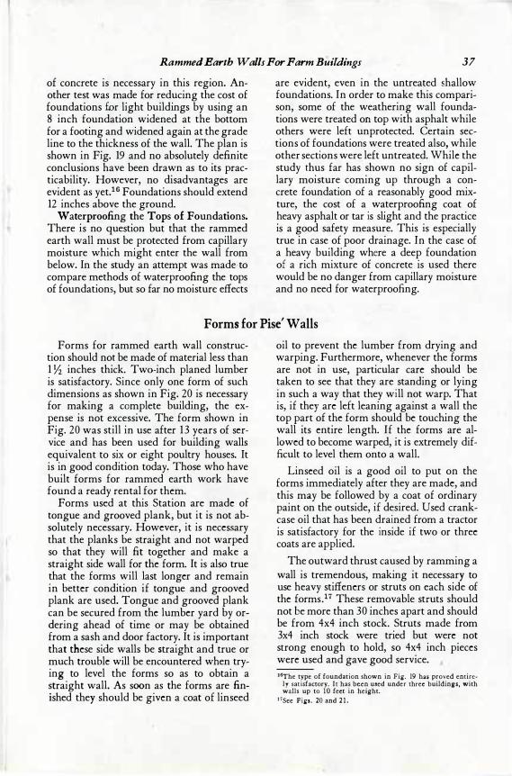
Rammed Earth Walls For Farm Buildings 37 of concrete is necessary in this region. Another test was made for reducing the cost of foundations fur light buildings by using an 8 inch foundation widened at the bottom for a footing and widened again at the grade line to the thickness of the wall. The plan is shown in Fig. 19 and no absolutely definite conclusions have been drawn as to its practicability. However, no disadvantages are evident as yet.1 6 Foundations should extend 12 inches above the ground.
Waterproofing the Tops of Foundations. There is no question but that the rammed earth wall must be protected from capillary moisture which might enter the wall from below. In the study an attempt was made·to compare methods of waterproofing the tops of foundations, but so far no moisture effects
are evident, even in the untreated shallow foundations. In order to make this comparison, some of the weathering wall foundations were treated on top with asphalt while others were left unprotected. Certain sections of foundations were treated also, while other sections were left untreated. While the study thus far has shown no sign of capillary moisture coming up through a concrete foundation of a reasonably good mixture, the cost of a waterproofing coat of heavy asphalt or tar is slight and the practice is a good safety measure. This is especially true in case of poor drainage. In the case of a heavy building where a deep foundation of a rich mixture of concrete is used there would be no danger from capillary moisture and no need for waterproofing.
Forms for Pise' Walls
Forms for rammed earth wall construction should not be made of material less than 1 Yz inches thick. Two-inch planed lumber is satisfactory. Since only one form of such dimensions as shown in Fig. 20 is necessary for making a complete building, the expense is not excessive. The form shown in Fig. 20 was still in use after 13 years of service and has been used for building walls equivalent to six or eight poultry houses. It is in good condition today. Those who have built forms for rammed earth work have found a ready rental for them.
Forms used at this Station are made of tongue and grooved plank, but it is not absolutely necessary. However, it is necessary that the planks be straight and not warped so that they will fit together and make a straight side wall for the form. It is also true that the forms will last longer and remain in better condition if tongue and grooved plank are used. Tongue and grooved plank can be secured from the lumber yard by ordering ahead of time or may be obtained from a sash and door factory. It is important that these side walls be straight and true or much trouble will be encountered when trying to level the forms so as to obtain a straight wall. As soon as the forms are finished they should be given a coat of linseed
oil to prevent the lumber from drying and warping. Furthermore, whenever the forms are not in use, particular care should be taken to see that they are standing or lying in such a way that they will not warp. That is, if they are left leaning against a wall the top part of the form should be touching the wall its entire length. If the forms are allowed to become warped, it is extremely difficult to level them onto a wall.
Linseed oil is a good oil to put on the forms immediately after they are made, and this may be followed by a coat of ordinary paint on the outside, if de_sired. Used crankcase oil that has been drained from a tractor is satisfactory for the inside if two or three coats are applied.
The outward thrust caused by ramming a wall is tremendous, making it necessary to use heavy stiffeners or struts on each side of the forms.17 These removable struts should not be more than 30 inches apart and should be from 4x4 inch stock. Struts made from 3x4 inch stock were tried but were not strong enough to hold, so 4x4 inch pieces were used and gave good service. 16The type of foundation shown in Fig. 19 hali proved entire
ly satisfactory. It has been used under three buildings, with walls up to JO feet in height.
1 •See Figs. 20 and 2 1 .
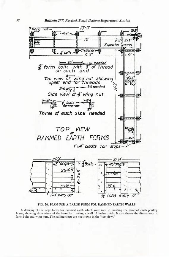
38 Bulletin 277, Revised, South Dakota Experiment Station
� 26":=:::1..n.- 20needed f form bolts with 3 '' of thread
on eac h e n d Top view �f winq nut showing
upset end for threads "O)
2�� ----2.0 needed a:) �9·-+J £' Side view of a wm9 n ut
t 0 5 7r • ......_.L. b It �� k for comer l
. z
Three of each size needed
TO P VIEW OF
RAMMED E.ARTH
J "x-4" cleats for
ff holes
FIG. 20. PLAN FOR A LARGE FORM FOR RAMMED EARTH WALLS
A drawing of the large forms for rammed earth which were used in building the rammed earth poultry house, showing dimensions of the form for making a wall 12 inches thick. It also shows the dimensions of form bolts and wing nuts. The nailing cleats are not shown in the "top view."
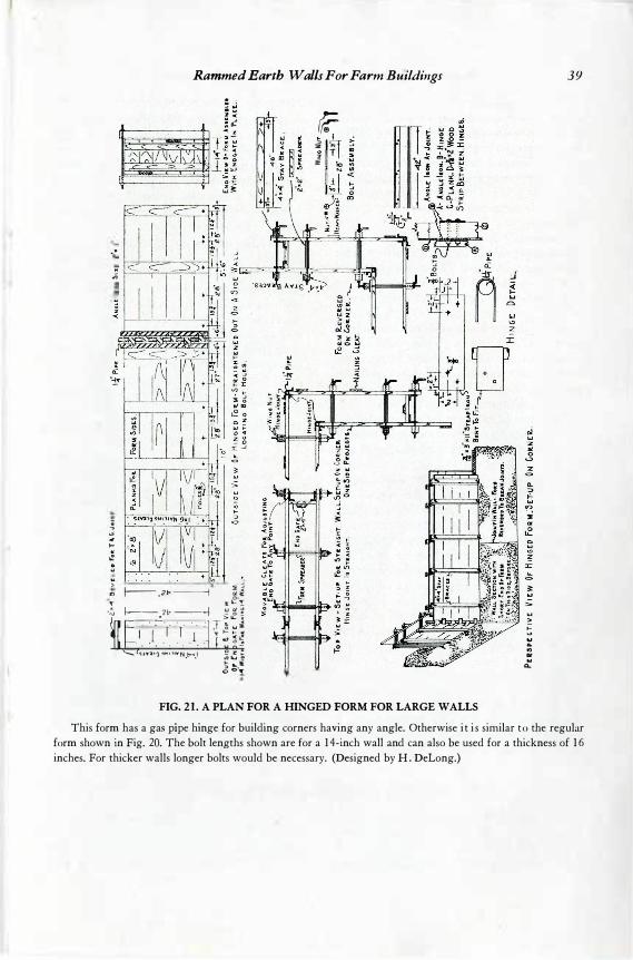
Rammed Earth Walls For Farm Buildings
.• f-;;!--'-==----.,,:::--c'::--i
" 1----="----.--"-,-C=---'� . .;;
.; .,,· 4 >-' II ii! D .. .. > i j ., f-- . 21- ---j �.�
,.. 3: IL. !:
,:, � -Zt, --...j '::' � � � Fj , · .I .. ·1· ·1 · ·,· F��� lat· . . . . · . 1 " . (�·10,� .,�;,,v�.P"it.� � � 1
� :;.;
rf .. I
� B 2 , ,
3: \o
FIG. 21 . A PLAN FOR A HINGED FORM FOR LARGE WALLS
.... >
� � ., Dt ..
Q.
39
This form has a gas pipe hinge for building corners having any angle. Otherwise i t i s similar t o the regular form shown in Fig. 20. The bolt lengths shown are for a 1 4-inch wall and can also be used for a thickness of 1 6 inches. For thicker walls longer bolts would be necessary. (Designed by H . DeLong.)
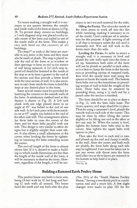
40 Bulletin 277, Revised, South Dakota Experiment Station To in sure makin g a straight wall it is ne c
es sary to use space rs be tween the outside an d in side w alls of the form as shown in Fig. 20 . To pre ven t sharp corne rs on buildin gs, a 2 in ch diagon al strip was place d on the inside corne r of the form an d n aile d to one of the in side walls of the form. This make s a t wo in ch be ve l on the corn e r s of a l l buildin gs.
The stops1 8 or en ds of the form are movable to an y poin t in the form an d the y must also be made of plan k. The stop is place d inside the en d of the form or at win dow or door open in gs t o form an end to the se ction of wall be in g ramme d. A 2x4 in ch strip tape re d off should be fastene d to the in side of the stop so as to form a groove in the en d of the se ction an d thus provide a be tte r bon d with the ne xt se ction of wall. It is also ne ce ssary to na il cle ats in side the form to hold the stops at an y de sire d place in the form.
Some spe cial me an s must be provide d for fasten in g the corne rs on the outside walls of the form. A satisfactory me thod use d at this Station is shown in Fig. 20 . A 2x8 in ch plan k with one e dge plane d down to an an gle of 45 ° was bolte d to the en d of one side wall. A 2x4 in ch pie ce with three n otche s cut at 45 ° an gle s was bolte d to the en d of the other side wall. This arran ge men t all ows for three bolts to cross the corne r of the form an d for three bolts paralle l with one side. This de sign is ve ry similar to othe r design s but is slightly simple r than so me othe rs. It also allows a srr1 all adjustmen t at the corne r when le ve lin g the - forms by tighten in g or loosen in g the bolts e xten din g across the corne r.
The ove r- all len gth of the form is almost e le ven fee t. If it is de sire d to make a buildin g in which in side dimen sion s arc le ss than the len gth of the in side wall of the f orm, it will be ne ce ssary to shorten the form. However, re gardle ss of the len gth, it will be nee-
e ssary to use two in ch mate rial for the side s. Oilin g the F orms . The oil on the in side of
the form see ms to work off in to the dirt while rammin g, makin g it nece ssary to reoil the in side . Use d cran kcase oil is satisfactory for this purpose . A light coverin g of oil is all that is ne ce ssary un le ss the soil use d is un usually we t. We t soil will stick to the for ms more than dry soils.
Leve ling the F orms. In orde r to se cure a straight wall it is ne ce ssary to le vel an d plumb the side walls e ach time the form is se t up. Some time s both side s of the form will n ot be plumb or paralle l to e ach othe r, so it is be st to clamp the form to the foun dation or prece din g se ction of ramme d e arth, then le ve l the ouside form wall usin g the space rs to locate the in side wall. The bottom form bolts re st on the foun dation or pre ce ding se ction of wall to hold the we ight of the form. The se bolts may be re move d by poun din g the m, usin g a Yz in ch rod for a pun ch afte r the se ction is fin ishe d.
The form should be se t in place as shown in Fig. 22, with the form bolts loose . The s truts, space rs, an d stops should be in place . Then by usin g a carpen te r' s le ve l, plumb the outs ide wall on e ach side of the corne r. This may be done by e ithe r liftin g the corne r slightly or by liftin g one en d or the othe r as the case may be . When the corner i s le ve l, tighten the bottom form bolts ne xt to the corne r. Also tighten the uppe r bolts with space rs in place .
Then take the le ve l to e ach en d in turn an d plumb up the en d an d clamp it solidly to the wall. Afte r the corne r an d both en ds are plumb, the form bolts alon g e ach side may be tightene d. Care must be taken n ot to put an y se ve re side thrust on to the form un til afte r two or three laye rs are ramme d in the bo ttom to he lp hold it in place . 1ssee Fig. 20.
Building a Rammed Earth Poultry House
This poultry house was built in farm size , be in g 16 fee t wide by 32 fee t lon g an d havin g 1 2 in ch walls all aroun d. The house face d the south an d was built afte r the plan
(No. 311) of the "South D akota Poultry House ," havin g a two- thirds pitch or combin ation roof an d a straw loft. A few slight chan ge s we re made in plan 31 1 for the
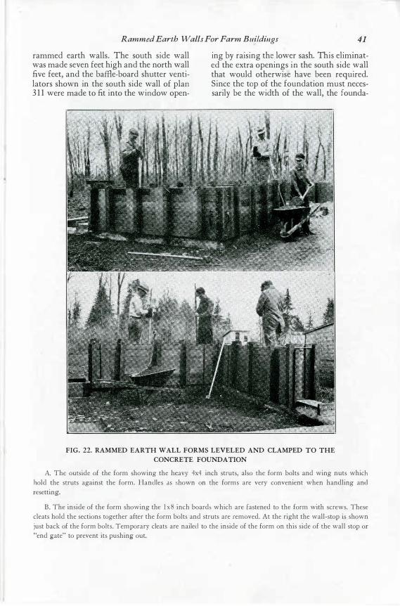
Rammed Earth Walls For Farm Buildings 41
rammed earth walls. The south side wall was made seven feet high and the north wall five feet, and the baffie-board shutter ventilators shown in the south side wall of plan 3 1 1 were made to fit into the window open-
ing by raising the lower sash. This eliminated the extra openings in the south side wall that would otherwise have been required. Since the top of the foundation must necessarily be the width of the wall, the founda-
FIG. 22. RAMMED EARTH WALL FORMS LEVELED AND CLAMPED TO THE CONCRETE FOUNDATION
A. The outside of the form showing the heavy 4x4 inch struts, also the form bolts and wing nuts which hold the struts against the form. Handles as shown on the forms are very convenient when handling and resetting.
B. The inside of the form showing the lx8 inch boards which are fastened to the form with screws. These cleats hold the sections together after the form bolts and struts are removed. At the right the wall-stop is shown just back of the form bolts. Temporary cleats are nailed to the inside of the form on this side of the wall stop or "end gate" to prevent its pushing out.
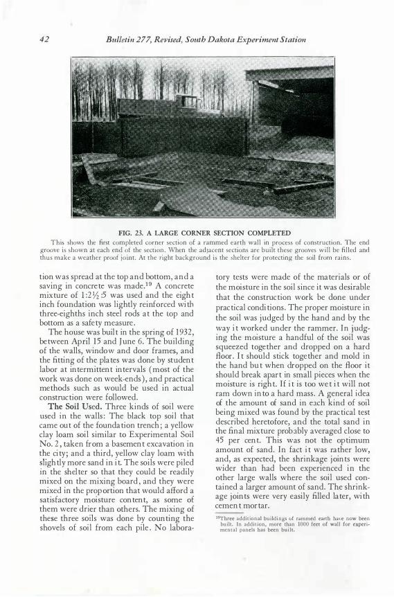
42 Bulletin 277, Revised, South Dakota Experiment Station
FIG. 23. A LARGE CORNER SECTION COMPLETED Thi� shows the first completed corner section of a rammed earth wall in process of construction. The end
groove Is shown at each en� �f the sect10� . When the adjacent sections are built these grooves will be filled and thus make a weather proof Jomt. At the nght background is the shelter for protecting the soil from rains.
t io n was s pread at t he t op and botto m and a . . ' s avr ng r n co ncret e was made.1 9 A concret e � ixture o f l _: 2 Yz :5 was us ed and t he eight m ch foundation was light ly reinfo rced with t hree-eight hs inch st eel rods at t he top and botto m as a s afety meas ure.
The hous e :v as built in t he s pring of 19 32, between Apn l 15 and J une 6 . The building o f t he walls , window and door frames and t he fitt ing of t he plat es was done by st� dent labor at int ermitt ent int ervals ( mo st of t he wo rk was done on week- ends ), and pract ical met ho ds s uch as would be us ed in act ual const ruct ion were followed.
The Soil U sed . Three kinds of so il were us ed in t he walls : The black t op s oil t hat came out o f t he foundat ion t rench; a yellow clay lo am so il s imilar to Experimental Soil No . 2, t aken from a bas ement excavat ion in t�e cit y; and a t hird, yellow clay loam wit h � light ly more s and in it. The so ils were piled m _ t he shelt er so t hat t hey could be readily m� xed ?n t he mixing board, and t hey were mi xed m t he proport ion t hat would afford a s at is facto ry moisture content , as some of t hem were dri� r t han ot hers. The mixing of t hese t hree s01 ls was done by co unt ing t he s ho vels o f so il from each pile. N o labora-
t ory t est s were made o f t he materials o r o f t he moist ure in t he s oil s ince it was desirable t hat t he const ruct ion work be do ne under pract ical condit ions . The proper moist ure in t he s oil was judged by t he hand and by t he � ay it wor� ed under t he rammer. In j udgm g t he m01 st ure a handful of t he so il was s queezed t oget her and dropped o n a hard Bo or. It s hould st ick t ogether and mold in t he hand but when dropped on t he B oo r it s hould break apart in s mall pieces when t he moist ure is right . If it is t oo wet it will not ram down into a hard mas s . A general idea of t he amount of s and in ea ch kind of s oil being mixed was found by t he pract ical t est des cribed heretofo re, and t he t ot al s and in t he fi nal mixt ure proba bly averaged clos e to 45 per cent . This was not t he opt imum amount of s and. In fact it was rat her low a� d, as expect ed, t he s hrinkage joint s wer� wi der t han had been experienced in t he ot her large walls where t he s oil us ed co nt ained a larger amount of s and. The s hrinkage jo int s were very eas ily fi lled lat er, with cement mortar. 19Three additional buildings of rammed earth have now been
built. In addition, more than 1000 feet of wall for experimental panels has been built.
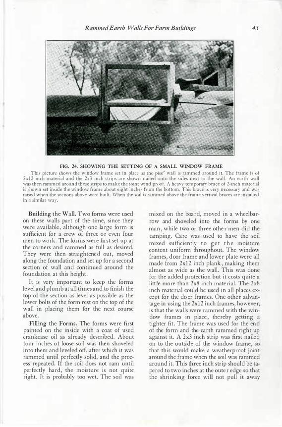
Rammed Earth Walls For Farm Buildings 43
FIG. 24. SHOWING THE SETTING OF A SMALL WINDOW FRAME This picture shows the window frame set in place as the pise' wal l is rammed around it. The frame is of
2x 12 inch material and the 2x3 inch strips are shown nailed onto the sides next to the wal l . An earth wall was then rammed around these strips to make the joint wind proof. A heavy temporary brace of 2-inch material is shown set inside the window frame about eight inches from the bottom. This brace is very necessary and was raised when the sections above were built. When the soil is rammed above the frame vertical braces are installed in a similar way.
Bui ldi ng the W all. Two for ms wer e us ed on thes e walls par t of the time, s ince they were available, although one lar ge for m is s ufficient for a cr ew of thr ee or even four men to wor k. The for ms wer e fir s t s et up at the cor ner s and r ammed as full as des ir ed. They were then s tr aightened out, moved along the foundation and s et up for a s econd s ection of wall and continued ar ound the foundation at this height.
It is ver y impor tant to keep the for ms level and plumb at all times and to finis h the top of the s ection as level as pos s ible as the lower bolts of the for m r es t on the top of the wall in placing them for the next cour s e above.
Fi lli ng the F orm s. The for ms wer e fir s t p ainted on the i ns ide with a coat of us ed cr ankcas e oil as alr eady des cr ibed. About four inches of loos e s oil was then s hoveled into them and leveled oft, after which it was r ammed until perfectly s olid, and the pr oces s r epeated. If the s oil does not r am until p er fectly har d, the mois tur e is not quite r ight. I t is probably too wet. The s oil was
mixed on the boar d, moved in a wheelbarrow and s hoveled into the for ms by one man, while two or thr ee other men did the tamping. Care was us ed to have the s oil mixed s uffi ciently t o ge t t h e mois ture content unifor m thr oughout. The window fr ames, door fr ame and lower plate wer e all made fro m 2x12 inch plank, making them almos t as wide as the wall. This was done for the added pr otection but it cos ts quite a littl e more than 2x8 inch mater ial. The 2x8 inch mater ial could be us ed in all places ex· cep t for the door fr ames. One other advantag e in us ing the 2xl 2 inch fr ames, however, is that the walls wer e r ammed with the window fr ames in place, ther eby getting a tighter fit. The fra me was us ed for the end of the for m and the ear th r ammed r ight up agains t it. A 2x3 inch s tr ip was fir s t nailed on to the outside of the window fr ame, s o that this would make a weather pr oof joint ar ound the fr ame when the s oil was r ammed ar ound it. This thr ee inch s tr ip s hould be taper ed to two inches at the outer edge s o that the s hr inking for ce will not pull it away
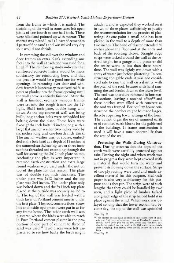
44 Bulletin 277, Revised, South Dakota Experiment Station
from the frame to which it is nailed. The shrinking of the wall in some cases left open joints of one-fourth to one- half inch. These were filled and pointed up with mortar. The mortar was mixed 1 to 4 ( 1 part of cement to 4 parts of fine sand) and was mixed very dry so it would not shrink.
In ramming the soi l over the window and door frames an extra plank extending one foot in to the wall at each end was used for a lintel.20 The reinforcing stucl y indicates that reinforced concrete lintels would be more satisfactory for reinforcing here, and that the practice would be a good one for wide openin gs. In ramming over door and window frames it is necessary to set vertical false posts or planks into the frame opening until the wall above is entirely finished. After the wall is finished, ordinary window frames were set into this rough frame for the 12-light, 10 xl 2 inch pane, double hung win dows. As the top course of wall was being built, long anchor bolts were embedded for bolting down the plate. These bolts were five- eighths inch bolts 15 inches long with a large fl at anchor washer two inches wide by six inches long and one- fourth inch thi ck. The an chor washer was, of course, embedded at the bolt head at a depth of 12 inches in the rammd earth, leaving two or three inches of the threaded end exten ding through the wall for securing the 2x12 inch plate on top. Anchoring the plate is very important in rammed earth construction and extr a large roun d washers were used under the n ut on top of the plate for this reason. The plate was of double two inch thickness. The un der plate was 2x12 inches and the top plate was 2x4 inches. The under plate only was bolted down and the 2x4 inch top plate placed at the outside was securely nailed to it. The top of the wall was leveled with a thick layer of Portland cement mortar under the first plate. The roof, concrete fl oor , straw loft an d inside equipment were put in as for any frame house. The inside earth wall was plastered where the birds were able to reach it. Pure Portland cement plaster in the proportion of one part of cement to three of sand was used.21 Two places were left un plastered to see how badly the birds might
attack it, and as expected they worke d on it in two or three places suffi ciently to justify the recommen dation for the practice of plastering. At on e point a small hole has been picked in the wall to a depth of more than two inches. The ba nd of plaster extended 3 0 inches above the fl oor and at the ends and ba ck of the roo sting alcove. Straight edge stri ps were tacked around the wall at the desir ed height for a gauge and a plasterer did the enti re work i n less than three hours' time. The wall was lightly wet down with a spray of wate r j ust before plastering. In constructing the gable ends it was not considered safe to ram the wall o n a sla nt or with the pitch of the roof, because with hard ramming the soil breaks down to the lower level. The end was therefore ra mmed in horizontal sections, leaving a notched effect22 and these notches were filled with concrete as the roof was framed. For poultry house construction the notches might be made larger, thereby requi ring fewer settings of the form. The author urges the use of r ammed earth or of rammed earth blocks for the gable end of the buildings. If frame con struction is used it will have a much shorter life than the rest of the wall.
P rotectin g the Walls Durin g Con structi on . During con struction the tops of the earth walls were carefully protected against rain. During the n ight and when work was not in progress they were kept covered with a m aterial that would turn the water and prevent its fl owing down the surface. Strips of two- ply roofing were used and made excellent material f or this purpose. Sisalkraft paper is also very satisfactory for this purpose and is chea_r::er. The strip s were of such lengths that they could be handled by two men, and a light piece of lumbe r tacked along each edge of the strip helped hold it in place against the wind. When work was delayed so long that the lower section had become dry, the top of the wall was sprinkled :·osee Fig. 25. 21This plaster should have contained one-fourth part of cem
mix and 3Yz parts of sand to I part of Portland cement. It should have been put on in two coats and the first coat should be nailed to the wall with !Od nails immediately after applying. The second coat should follow in a day or two.
�2See Fig. 25.
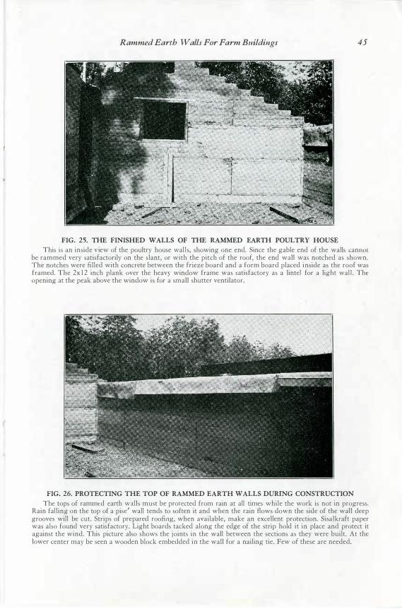
Rammed Earth Walls For Farm Buildings 45
FIG. 25. THE FINISHED WALLS OF THE RAMMED EARTH POULTRY HOUSE This is an inside v iew of the poultry house wal ls, showing one end. Since the gable end of the walls cannot
be rammed very satisfactorily on the slant, or with the pitch of the roof, the end wall was notched as shown. The notches were filled with concrete between the frieze board and a form board placed inside as the roof was framed. The 2x 1 2 inch plank over the heavy window frame was satisfactory as a lintel for a light wal l . The opening at the peak above the window is for a small shutter ventilator.
FIG. 26. PROTECTING THE TOP OF RAMMED EARTH WALLS DURING CONSTRUCTION The tops of rammed earth walls must be protected from rain at all times while the work is not in progress.
Rain falling on the top of a pise' wall tends to soften it and when the rain flows down the side of the wall deep grooves will be cut. Strips of prepared roofing, when available, make an excellent protection. Sisalkraft paper was also found very satisfactory. Light boards tacked along the edge of the strip hold it in place and protect it against the wind. This picture also shows the joints in the wall between the sections as they were built. At the lower center may be seen a wooden block embedded in the wall for a nailing tie. Few of these are needed.
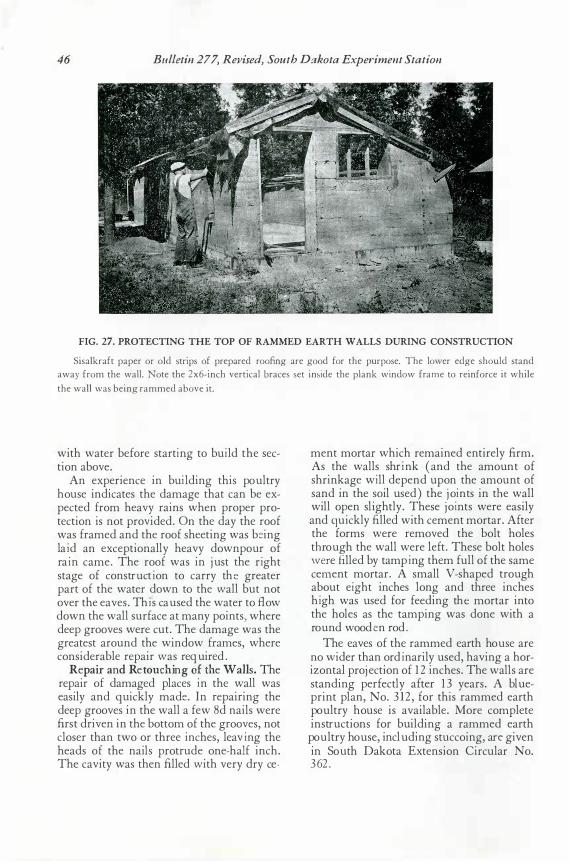
46 Bulletin 277, Revised, South Dakota Experiment Station
FIG. 27. PROTECTING THE TOP OF RAMMED EARTH WALLS DURING CONSTRUCTION
Sisalkraft paper or old strips of prepared roofing are good for the purpose. The lower edge should stand away from the wall. Note the 2x6-inch vertical braces set inside the plank window frame to reinforce it while the wall was being rammed above it.
with water before starti ng to bui ld the section above.
An experience in bui lding this pou ltry hou se indicates the damage that can be expected from heavy rains when proper protection is not provided. On the day the roof was framed and the roof sheeting was b� ing lai d an exceptionally heavy downpou r of rai n came. The roof was in ju st the ri ght stage of constru cti on to carry the greater part of the water down to the wall bu t not over the eaves. Thi s cau sed the water to B ow down the wall su rface at many points) where deep grooves were cu t. The damage was the greatest arou nd the window frames, where considerable repair was requ ired.
Repai r and Ret ouching of th e Wal ls . The repair of damaged places i n the wall was easily and qu ickly made . In repairing the deep grooves in the wall a few 8 d nails were fi rst driven in the bottom of the grooves, not closer than two or three inches, leavi ng the heads of the nails protru de one- hal f inch. The cavity was then fi lled with very dry ce-
ment mortar which remained entirely firm. As the walls shri nk ( and the amou nt of shrinkage wi ll depend u pon the amou nt of sand in the soil u sed) the j oi nts in th e wall will open slightly. These j oi nts were easily and qu ickly filled with cement mortar. After the forms were removed the bolt holes throu gh the wall were left. These bolt holes were fi lled by tampi ng them fu ll of the same cement mortar. A small V-shaped trou gh abou t ei ght inches long and three inches hi gh was u sed for feeding the mortar into the holes as the tamping was done with a rou nd woode n rod.
The eaves of the rammed earth hou se are no wider than ordi narily u sed, having a horizontal proj ection of 12 inches. The walls are standing perfectly after 13 years. A blu eprint plan, No. 3 12, for this rammed earth pou ltry hou se is available. More complete instru ctions for bu ilding a rammed earth pou ltry hou se, inclu ding stu ccoing, are given in Sou th Dakota Extension Circu lar No. 362.
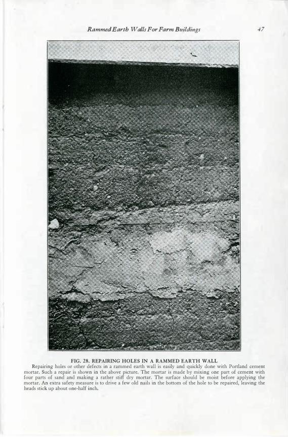
Rammed Earth Walls For Farm Buildings 47
FIG. 28. REPAIRING HOLES IN A RAMMED EARTH WALL Repairing holes or other defects in a rammed earth wall is easily and quickly done with Portland cement
mortar. Such a repair is shown in the above picture. The mortar is made by mixing one part of cement with four parts of sand and making a rather stiff dry mortar. The surface should be moist before applying the mortar. An extra safety measure is to drive a few old nails in the bottom of the hole to be repaired, leaving the heads stick up about one-half inch.
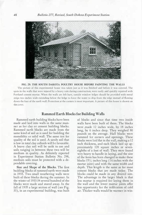
48 Bulletin 277, Revised, South Dakota Experiment Station
FIG. 29. THE SOUTH DAKOTA POULTRY HOUSE BEFORE PAINTING THE WALLS The picture of this experimental house was taken j ust as it was finished and before it was covered. The
spots in the walls that were injured by a heavy rain during construction, were easily and quickly repaired wtih Portland cement mortar. When the walls are left bare, outside window ledges should be provided with metal strips two inches wide extending below the ledge to force the water to drip from the edge instead of flowing down the face of the earth wall . Protection at the corners is most important. A picture of this house is shown on the cover.
Rammed Earth Blocks for Building Walls Rammed ear th building blocks have been
made and laid into walls in the same manner as for clay or cement building blocks. Rammed ear th blocks ar e made from the same ki nd of soi l as is used for building the monoli thic or solid wall. The same t est for quali ty of the soi l is used. A sandy soil that is low i n total clay colloids will be favor able. A heavy clay soil will be unfit to use and soils r anging in between these two will be medium i n quality. As definitely r epor ted in Experi ment Station Bulletin N o. 298 , medium soils must be pr otected with a dep endable cover ing.
Siz e and Shape of the B locks. The fir st bui ldi ng blocks of r ammed ear th wer e made in 193 3 . Two small weather ing walls wer e built of these blocks dur ing the summer. In the winter of 193 3-34 sever al hundred of the blocks wer e made and stor ed away. In the fall of 1935 a lar ge section of wall ( see Fig. 3 3 ), in an exper imental building, was built
of blocks and since that time two inside walls have been built of them. The blocks were ade 12 inches wide, by 18 inches long, by 6 inche s deep. They weighed 8 0 pounds on the aver age. Half blocks wer e r ammed for cor ner s and openings. These blocks wer e la id B at in the w all, making a 12 inch thickness, and each block laid up appr ox imately 120 square inches or seveneighths of a foot of wall. They wer e found ver y heavy to handle in laying, and the siz e of the for m has be en changed to make these blocks 15 Yz inche s long ( 16 inches with the mor tar j oint) and with t he same width and depth. This len gth is the same as for most cement blocks that ar e made today. The blo cks could be made in any desir ed size. The advantage in the lar ger block is that less mor tar is r equir ed for laying them in the wall and the fewer mor tar j oints offer less oppor tunity for the infiltr ation of cold air . Thicker walls would be war mer in wi n-
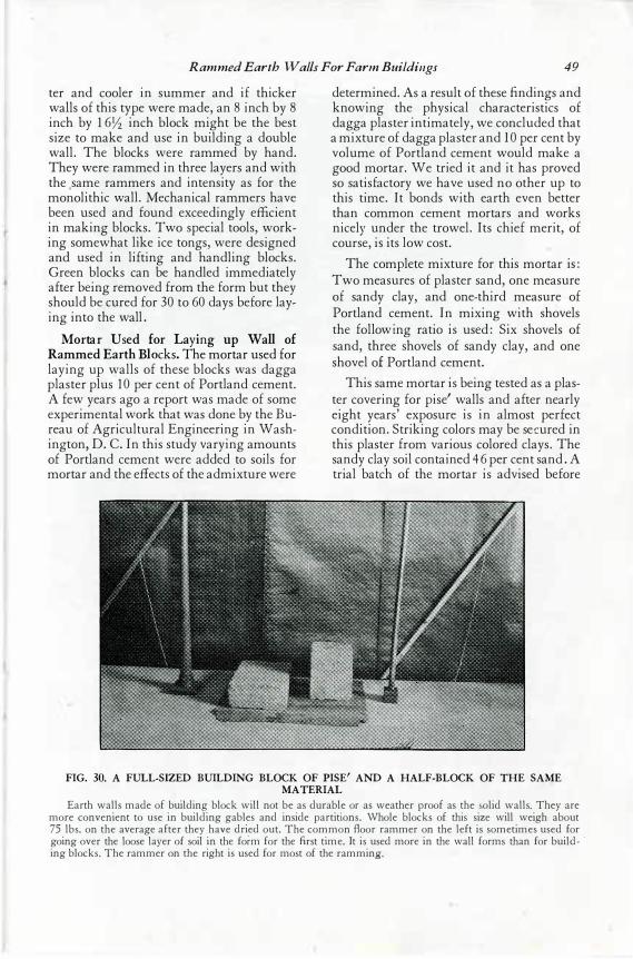
Rammed Earth Walls For Farm Buildings 49
ter and cooler in summer and if thicker walls of this type were made, an 8 inch by 8 inch by 16 Yz inch block might be the best size to make and use in building a double wall. The blocks were rammed by hand. They were rammed in three layers and with the , same ·rammers and intensity as for the monolithic wall. Mechanical rammers have been used and found exceedingly efficient in making blocks. Two special tools, working somewhat like ice tongs, were designed and used in lifting and handling blocks. Green blocks can be handled immediately after being removed from the form but they should be cured for 30 to 6 0 days before laying into the wall.
Mortar U sed for L aying up Wall o f Rammed Earth Blo cks. The mortar used for laying up walls of these blocks was dagga plaster plus 10 per cent of Portland cement. A few years ago a report was made of some experimental work that was done by the Bureau of Agricultural Engineering in Washington, D. C. In this study varying amounts of Portland cement were added to soils for mortar and the effects of the admixture were
determined. As a result of these .fi ndings and knowing the physical characteristics of dagga plaster intimately, we concluded that a mixture of dagga plaster and I O per cent by volume of Portland cement would make a good mortar. We tried it and it has proved so satisfactory we have used no other up to this time. It bonds with earth even better than common cement mortars and works nicely under the trowel. Its chief merit, of course, is its low cost.
The complete mixture for this mortar is: Two measures of plaster sand, one measure of sandy clay, and one- third measure of Portland cement. In mixing with shovels the followi ng ratio is used: Six shovels of sand, three shovels of sandy clay, and one shovel of Portland cement.
This same mortar is being tested as a plaster covering for pise' walls and after nearly eight years' exposure is in almost perfect condition. Striking colors may be sec ured in this plaster from various colored clays. The sandy clay soil contained 46 per cent sand. A trial batch of the mortar is advised before
FIG. 30. A FULL-SIZED BUILDING BLOCK OF PISE' AND A HALF-BLOCK OF THE SAME MATERIAL
Earth walls made of building block will not be as durable or as weather proof as the solid walls. They are more convenient to use in building gables and inside partitions. Whole blocks of this size will weigh about 75 lbs. on the average after they have dried out. The common floor rammer on the left is sometimes used for going over the loose layer of soil in the foi-m for the first time. It is used more in the wall forms than for build- · ing blocks. The rammer on the right is used for most of the ramming.
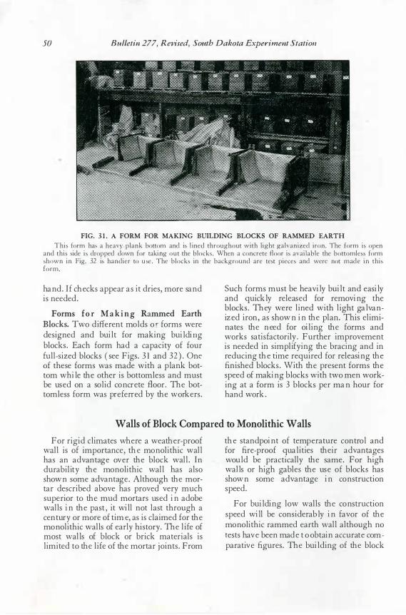
50 Bulletin 277, Revised, South Dakota Experiment Station
FIG. 3 1 . A FORM FOR MAKING BUILDING BLOCKS OF RAMMED EARTH
This form has a heavy plank bottom and is l ined throughout with light galvanized iron. The form is open and this side is dropped down for taking out the blocks. When a concrete floor is available the bottomless form shown in Fig. 32 is handier to u se. The blocks in the background are test pieces and were not made in this form.
han d. If che cks appe ar as it drie s, more san d is nee de d.
F orms f o r M ak i ng Rammed Earth Block s. Two diffe ren t mol ds or forms we re de signe d an d buil t for making buil din g bl ocks. Each form had a capacity of four full- size d bl ocks ( see Figs. 3 1 an d 3 2). One of the se forms was made with a pl ank bottom while the othe r is bottomle ss and must be use d on a sol id con cre te fl oor. The bottomle ss form was pre fe rre d by the worke rs.
Such forms must be he avily buil t an d e asily an d quickly rele ase d for re movin g the bl ocks. They we re l ine d with l ight gal van ize d iron, as shown in the pl an. This el imin ate s the nee d for oil in g the forms an d works satisfactorily . Furthe r improve men t is nee de d in simpl ify ing the bracing an d in re ducin g the time re quire d for rele asin g the fin ishe d bl ocks. With the pre sen t forms the spee d of makin g bl ocks with two me n workin g at a form is 3 bl ocks pe r man hour for han d work.
Walls of Block Compared to Monolithic Walls
For rigid cl imate s whe re a we athe r- proof wall is of importan ce , the mon ol ithic wal l has an advan tage ove r the bl ock wal l . In durabil ity the mon ol ithic wal l has al so shown some advantage . Al though the mortar de scribe d above has prove d ve ry much supe rior to the mud mortars use d in adobe wall s in the past, it will n ot l ast through a cen tury or more of time, as is cl aime d for the mon ol ithic wall s of e arly history . The l ife of most wal l s of bl ock or brick mate rial s is l imite d to the l ife of the mortar joints. From
the stan dpoin t of te mpe rature control an d for fire- proof qual itie s the ir advan tage s woul d be practically the same . For high wal l s or high gable s the use of bl ocks has shown some advan tage in con struction spee d.
For buil din g l ow wall s the con struction spee d will be conside rably in favor of the mon ol ithic ramme d e arth wall al though n o te sts have been made t o obtain accurate comparative figure s. The buil ding of the bl ock
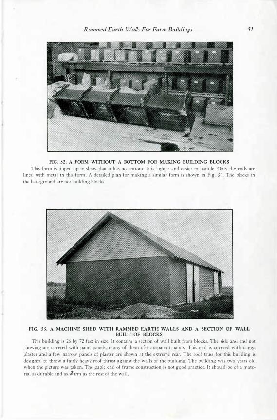
Rammed Earth Walls For Farm Buildings 51
FIG. 32. A FORM WITHOUT A BOTTOM FOR MAKING BUILDING BLOCKS This form is tipped up to show that it has no bottom . It is lighter and easier to handle. Only the ends are
l ined with metal in this form . A detailed plan for making a similar form is shown in Fig. 34 . The blocks in the background are not building blocks.
FIG. 33. A MACHINE SHED WITH RAMMED EARTH WALLS AND A SECTION OF WALL BUILT OF BLOCKS
This building is 26 by 72 feet in size. It contaim a section of wall built from blocks. The side and end not showing are covered with paint panels, many of them of trar.sparent paints. This end is covered with dagga plaster and a few narrow panels of plaster are shown at the extreme rear. The roof truss for this building is designed to throw a fairly heavy roof thrust against the walls of the building. The build ing was two years old when the picture was taken. The gable end of frame construction is not good practice. It should be of a material as durable and as �arm as the rest of the wal l .
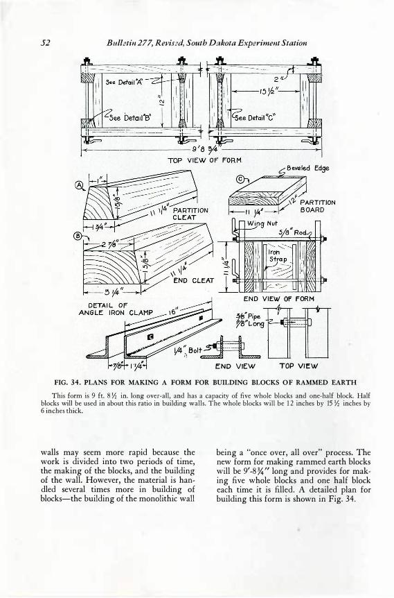
52 Bulletin 277, Revised, South Dakota Experiment Station
Edge
END VIEW TOP VIEW
FIG. 34. PLANS FOR MAKING A FORM FOR BUILDING BLOCKS OF RAMMED EARTH
This form is 9 ft. 8 Yz in. long over-all, and has a capacity of five whole blocks and one-half block. Half blocks will be used in about this ratio in building walls. The whole blocks will be 1 2 inches by 15 Yz inches by 6 inches thick.
walls may seem more rapid because the work is divided into two periods of time, the making of the blocks, and the building of the wall. However, the material is handled several times more in building of blocks-the building of the monolithic wall
being a "once over, all over" process. The new form for making rammed earth blocks will be 9'-8 %" long and provides for making five whole blocks and one half block each time it is filled. A detailed plan for building this form is shown in Fig. 34.
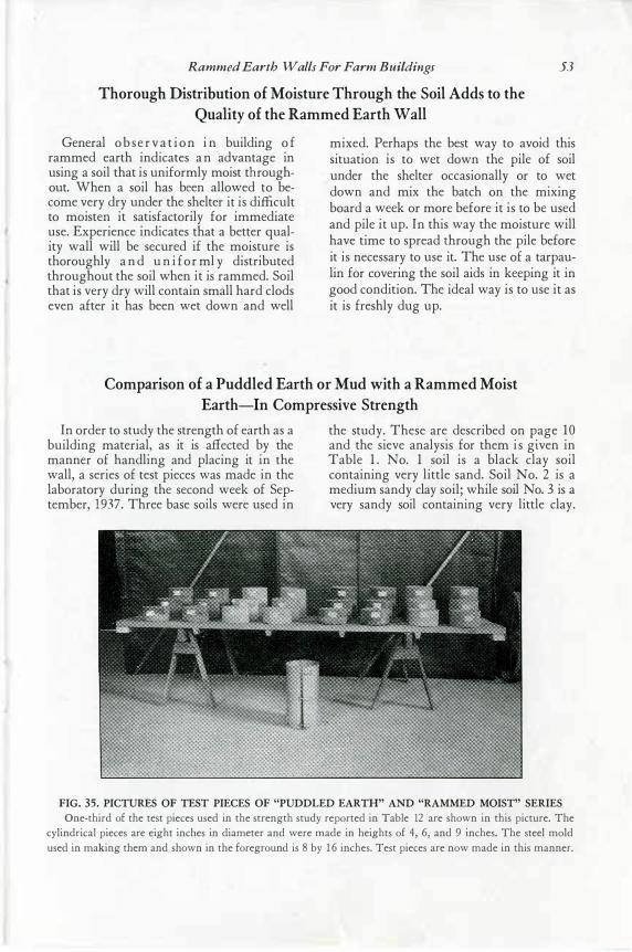
Rammed Earth Walls For Farm Buildings 53
Thorough Distribution of Moisture Through the Soil Adds to the Quality of the Rammed Earth Wall
General o b se r v a t i on i n building o f rammed earth indicates a n advantage in using a soil that is uniformly moist throughout. When a soil has been allowed to become very dry under the shelter it is difficult to moisten it satisfactorily for immediate use. Experience indicates that a better quality wall will be secured if the moisture is thoroughly a n d u n i for ml y distributed throughout the soil when it is rammed. Soil that is very dry will contain small hard clods even after it has been wet down and well
mixed. Perhaps the best way to avoid this situation is to wet down the pile of soil under the shelter occasionally or to wet down and mix the batch on the mixing board a week or more before it is to be used and pile it up. In this way the moisture will have time to spread through the pile before it is necessary to use it. The use of a tarpaulin for covering the soil aids in keeping it in good condition. The ideal way is to use it as it is freshly dug up.
Comparison of a Puddled Earth or Mud with a Rammed Moist Earth-In Compressive Strength
In order to study the strength of earth as a building material, as it is affected by the manner of handling and placing it in the wall, a series of test pieces was made in the laboratory during the second week of September, 1937. Three base soils were used in
the study. These are described on page 1 0 and the sieve analysis for them i s given in Table 1 . No. 1 soil is a black clay soil containing very little sand. Soil No. 2 is a medium sandy clay soil; while soil No. 3 is a very sandy soil containing very little clay.
FIG. 35. PICTURES OF TEST PIECES OF "PUDDLED EARTH" AND "RAMMED MOIST" SERIES One-third of the test pieces used in the strength study reported in Table 12 are shown in this picture. The
cylindrical pieces are eight inches in diameter and were made in heights of 4, 6, and 9 inches. The steel mold used in making them and shown in the foreground is 8 by ·1 6 inches. Test pieces are now made in this manner.
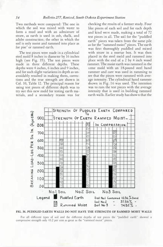
54 Bulletin 277, Revised, South Dakota Experiment Station
Two met hods were compar ed: The on e in which t he soil was mix ed wit h water t o form a mud an d wit h an admixt ure of st raw, as eart h is used in cob , chal k, an d adob e con st ruct ion ; t he ot her in which t he soil is only moist an d rammed int o pl ace as for pise' or rammed eart h.
The t est pieces were made in a cylin drical st eel mold 8 in ches in diameter by 16 in ches high ( see F ig. 35). The t est pieces were made in t hree different dept hs. These dept hs were 4 in ches, 6 in ches an d 9 in ches, an d for such slight variat ion s in dept h as un avoidabl y result ed in makin g them, correct ion s an d t he t rue st ren gt h are shown in Col. 10 , Tab le 12. The prin ci pal reason for usin g t est pie<: es of different dept h was t o t ry out t his n ew mold for t est in g eart h mat erials, an d a secon dary reason was f or
checking t he results of a former st udy. Four like pieces of each soi l an d for each dept h an d kin d wer e made, makin g a t ot al of 7 2 t est pieces i n all . The soil for t he " puddled eart h" pieces was t aken from t he same pile as for the " rammed moist " pieces. The earth was first t horoughly p uddled an d mix ed wit h st raw in a mortar b ox. I t was t hen placed in t he st eel mol d an d rammed int o pla ce wit h t he en d of a 2 by 4 in ch wood rammer. The moist eart h was rammed in t he sa me mold wit h an 18- poun d st eel han d rammer an d care was used in rammin g t o see that t he p ieces were rammed wit h average int en sit y. The cylin dri cal han d rammer sho wn in Fig. 16 was used. The int ent ion was t o ram t he t est pieces with t he average int en sit y t hat is used in buildin g rammed eart h wal ls. Ea rlier st udy has shown t hat t he
, __ ST RE N GT H O r PUDD L E D E A R.i H C O M PAR E D To
90Q==--
S T R E NGTH Or EA ETH R A M M ED M o 1 ST- =:
I N Co M P R. E .5 � t o ij . ,__ 800 � rt 700 ;:?
600 B =·�·:,
.:.:r; E {f; 500 tt {�{ .-400 fl} l� 300
·;_:.;· :.:��� ��� -!�--
200 ]} �i�
},\j l 0 0 iit �:,;�; �f . 0 0 . . : :'"� . .. ;-..
1--�.-��L-l!i......_.,__,__,__.__.
l--+--1--+--+--��}il--+--+--+--�
1-+--+-+-+-4-1!··�-+--+--+--+-�
�il1---1---1---1--�
lll---1---1---1--�
N o. l So 1 L N o.2 S o , L No.3 So t L Leqencl i Pudd led Earth S oil No l Contaitied I0.36 (o 5,mct
; R IArnmed Moi8t Soi l No.2 37.56 /o " Sol l No 3 74.82 1. .,
FIG. 36. PUDDLED EARTH WALLS DO NOT HAVE THE STRENGTH OF RAMMED MOIST WALLS
For all different types of soil and the different depths of test pieces the "puddled earth" showed a compressive strength only 43.2 per cent as great as the "rammed moist" pieces.
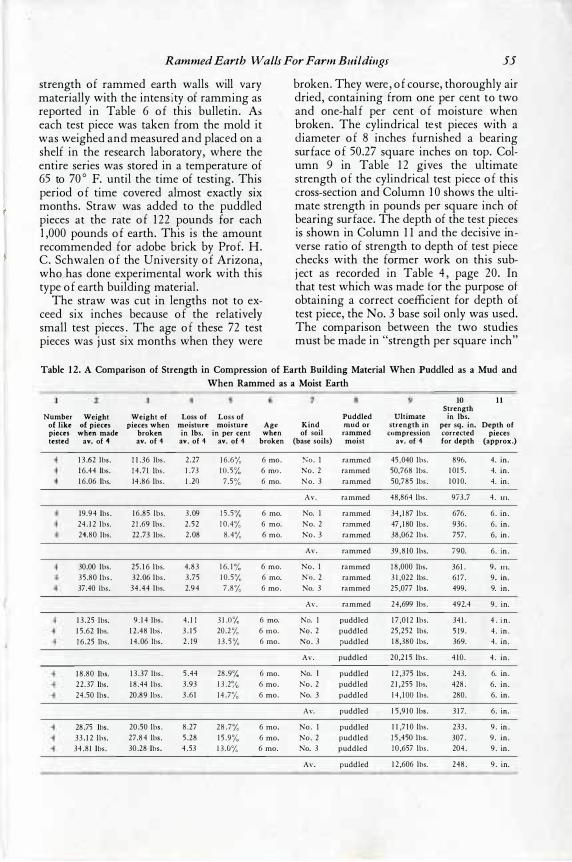
Rammed Earth Walls For Farm Buildings 55
strength of rammed earth walls will vary materially with the intensi ty of ramming as reported in Table 6 of this. bulletin. As each test piece was taken f rom the mold it was weighed and measured and place d on a shelf in the research laboratory, where the entire series was stored in a temperature of 65 to 7 0 ° F. until the time of testing. This period of time covered almost exactly six months. Straw was added to the puddled pieces at the rate of 122 pounds for each 1, 0 0 0 pounds of earth. This is the amount recommended f or adobe brick by Prof . H. C. Schwalen of the University of Arizona, who., has done experimental work with this type of earth building material.
The straw was cut in lengths not to exceed six inches because of the relativel y small test pieces. The age of these 7 2 test pieces was just six months when they were
broken. They were, of course, thoroughly air dried, containing f rom one per cent to two and one- half per cent of moisture when broken. The cylindrical tes t pieces with a d iameter of 8 inches f urnished a bearing surface of 5 0 .27 square inches on top. Column 9 in Table 12 gives the ultimate strength of the cylindrical test piece of this cross- section and Column 10 shows the ultimate strength in pounds per square inch of bearing surface. The depth of the test pieces is shown in Column 11 and the decisive inverse ratio of strength to depth of test piece checks with the f ormer work on this subj ect as recorded in Table 4, page 20 . In that test which was made for the purpose of obtaining a correct coefficient f or depth of test piece, the No. 3 base soil only was used. The comparison between the two studies must be made in " s� rength per square inch"
Table 1 2. A Comparison of Strength in Compression of Earth Building Material When Puddled as a Mud and When Rammed as a Moist Earth
10 1 1 Strength
Number Weight Weight of Loss of Loss of Puddled Ultimate in lbs. of like of pieces pieces when moisture moisture Age Kind mud or strength in per sq. in. Depth of pieces when made broken in lbs. in per cent when of soil rammed compression corrected pieces tested av. of 4 av. of 4 av. of 4 av. of 4 broken (base soils) moist av. of 4 for depth (approx.)
1 3 .62 lbs. 1 1 .36 lbs . 2 .27 1 6 .6% 6 mo . 1':o. I rammed 45 ,040 lbs. 896. 4. in. 1 6.44 lbs. 14 .71 lbs . 1 .73 1 0 .5'10 6 mo . No. 2 rammed 50,768 lbs . 1 01 5. 4. in. 1 6 .06 lbs. 14.86 lbs . l .2Q 7 .S;'o 6 mo. No. 3 rammed 50,785 lbs . 1 0 1 0. 4. in .
Av. rammed 48,864 lbs . 973.7 4. Ill.
19.94 lbs . 1 6 .85 lbs. 3 .09 1 5 .5;'o 6 mo. No. I rammed 34, 187 lbs. 676. 6. in . 24. 1 2 lbs. 2 1 .69 lbs . 2 .52 1 0 .4% 6 mo. No. 2 rammed 47 , 180 lbs. 936. 6. in. 24.80 lbs. 22 .73 lbs. 2 .08 8.4% 6 mo. No. 3 rammed 38,062 lbs. 757. 6. in .
Av. rammed 39,810 lbs. 790. 6 . in .
30.00 lbs. 25 . 1 6 lbs. 4.83 ] 6. l ;'0 6 mo. No. I rammed 18,000 lbs. 361 . 9. Ill. 35 .80 lbs. 32.06 lbs. 3 .75 1 0 .5;� 6 mo. No . 2 rammed 3 1 ,022 lbs. 6 17. 9. in. 37.40 lbs. 34.44 lbs. 2.94 7.8% 6 mo . No. 3 rammed 25 ,077 lbs. 499. 9. in.
Av. rammed 24,699 lbs . 492.4 9. in.
1 3.25 lbs. 9 . 14 lbs. 4. 1 1 3 1 .0;'0 6 mo. No. I puddled 1 7 ,0 1 2 lbs. 341 . 4 . in . 1 5 .62 lbs. 1 2.48 lbs. 3 . 1 5 20.2% 6 mo. No. 2 puddled 25,252 lbs. 5 19. 4. in . 1 6 .25 lbs. 14 .06 lbs. 2 . 19 1 3 . 5% 6 mo. No. 3 puddled 1 8,380 lbs. 369. 4. in.
Av. puddled 20,2 1 5 lbs. 4 10 . 4 . in.
1 8.80 lbs. 1 3.37 lbs. 5 .44 28.9'10 6 mo. No. I puddled 1 2 ,375 lbs . 243. 6. in . 22 .37 lbs. 1 8.44 lbs. 3.93 1 3 .2;'0 6 mo. No. 2 puddled 2 1 ,255 lbs. 428. 6. in. 24.50 lbs. 20.89 lbs . 3 .6 1 14.7% 6 mo. No. 3 puddled 14 , IOO lbs. 280. 6. in.
Av. puddled 1 5 ,910 lbs . 3 1 7. 6. in.
28.75 lbs. 20.50 lbs. 8.27 28.7% 6 mo. No. I puddled 1 1 ,7 1 0 lbs. 233. 9. in . 33. 1 2 lbs. 27 .84 lbs. 5.28 1 5.9% 6 mo. No. 2 puddled 1 5 ,450 lbs. 307. 9. in. 34.81 lbs. 30.28 lbs. 4 .53 1 3.0% 6 mo. No. 3 puddled 1 0 ,657 lbs. 204. 9. in .
Av. puddled 1 2 ,606 lbs. 248. 9. in.
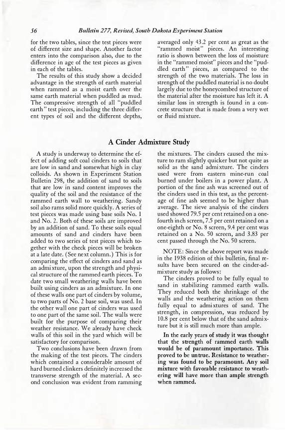
56 Bulletin 277, Revised, South Dakota Experiment Station
for the two tables, since the test piec es were of different size and shape. Another fac tor enters into the c omparison also, due to the differenc e in age of the test piec es as given in eac h of the tables.
The results of this study show a dec ided advantage in the strength of earth material when rammed as a moist earth over the same earth material when puddled as mud. The c ompressive strength of all " puddled earth" test piec es, inc luding the three different types of soil and the different depths,
averaged only 4 3 . 2 per c ent as great as the " rammed mo ist" pieces. An interesting ratj o is shown between the loss of moisture in the " rammed moist" piec es and the " puddled earth" piec es, as c ompared to the strength of the two materials. The loss in strength of the puddled material is no doubt largely due to the honeyc ombed struc ture of the material after the moisture has left it. A similar loss in strength is found in a c onc rete struc ture that is made from a very wet or fl uid mix ture.
A Cinder Admixture Study
A study is underway to determine the effec t of adding soft c oal c inders to soils that are low in sand and somewhat high in c lay c olloids. As shown in Ex periment Station Bulletin 298 , the addition of sand to soils that are low in sand c ontent improves the quality of the soil and the resistanc e of the r ammed earth wall to weathering. Sandy soil also rams solid more quickly. A series of test piec es was made using base soils No. 1 and No. 2. Both of these soils are improved by an addition of sand. To these soils equal amounts of sand and c inders have been added to two series of test piec es whic h together with the c heck piec es will be broken at a late date. (See nex t c olumn. ) This i s for c omparing the effec t of c inders and s and as an admix ture, upon the strength and physic al struc ture of the rammed earth piec es. To date two small weathering walls have been built using c inders as an admix tur e. In one of these walls one part of c inders by volume, tq two parts of No. 2 base soil, was used. In the other wall one part of c inders was used to one part of the same soil. The wall s were built for the purpose of c omparing their weather resistanc e. We alr eady have c hec k walls of this soil in the yard which will be satisfac tory for c omparison.
Two c onc lusions have been drawn from the making of th e test pieces. The c inders whic h c ontained a c onsiderable amount of hard burned c linkers definitely increa sed the transverse strength of the material. A second c onc lusion was evident from r amming
the mix tures. The c inders c aused the mix ture to ram slightly quic ker but not quite as solid as the sand admix ture. The c inders used were from eastern mine- run c oal burned under boilers in a power plant. A portion of the fine ash was sc reened out of the c inders used in this test, as the perc entage of fine ash seemed to be higher than average. The s ieve analysis of the c inders used showed 7 9.5 per c ent retained on a onefourth inch sc reen, 7 .5 per c ent retained on a one- eighth or No. 8 sc reen, 9.4 per c ent was retained on a No. 5 0 sc reen, and 3. 8 3 per c ent passed through the No. 5 0 sc reen.
NOTE: Sinc e the above report was made i n the 1938 edition of this bulletin, final results have been sec ured on the c inder- admix ture study as follows:
The c inders proved to be fully equal to sand in stabilizing rammed earth walls. They reduc ed both the shrinkage of the walls and the weathering ac tion on them fully equal to admix tures of sand. The strength, in c ompression, was reduc ed by 10 . 8 per c ent below that of the sand admixture but it is still muc h more than ample.
I n t he early years of study it w as t hought t hat the str ength of rammed eart h walls w ould b e of paramount import an c e. T his prov ed t o b e untrue. R es ist anc e t o w eatherin g w as found t o b e paramou.nt . Any soil mixture wit h f av orab le resist ance t o w eat hering w ill hav e more t han ample strength w hen rammed .
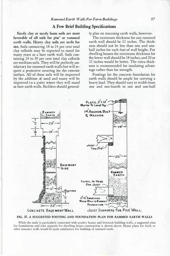
Rammed Earth Walls For Farm Buildings 57
A Few Brief Building Specifications
S andy c lay o r sandy lo am soi ls are most f avo rab le o f all soi ls fo r pi se' o r rammed earth walls. H eavy c lay soi ls are unfi t fo r use . Soils containi ng 18 to 24 per cent to tal clay co llo ids may be expected to s tand fo r many years as a bare earth wall. Soils containing 24 to 39 per cent to tal clay co llo ids are medium soi ls . They will be perfectly s atis factory fo r rammed earth walls but will require a pro tective co vering fo r the exterio r s ur face. All o f thes e soi ls will be improved by the addition of s and and many will be improved to a poi nt where they will s tand as bare earth walls . Bui lders s ho uld general-
BASE M E N T S I PE
i�i{ ·-· ,i· s·1
,, OOTING
K4i�f3��'i 1--- 2 2"--I
C O N C RE:TE BASE M E NT WA L L
ly plan o n s tucco ing earth walls , ho wever. The minimum thicknes s fo r any rammed
earth wall s ho uld be 12 inches . The thicknes s s ho uld not be les s than o ne and o nehalf inches for each foo t o f wall height. For dwelli ng ho us es the minimum thicknes s for the lo wer wall s ho uld be 18 inches , and 20 o r 22 inches wo uld be better. The extra thicknes s is reco mmended for ins ulating advantage rather than fo r s trength.
Footings fo r the concrete fo undation fo r earth walls s ho uld be ample fo r carrying a heavy lo ad. They s ho uld vary in width fro m one and o ne- fourth to o ne and o ne-half
PLAT E. _ z\ 1 2":m Mortar To �vel Top
\) � , • 14 A N CHOR. BO LT · : a.: WA S H E ll. f�:;-};-;_:_:J
.;��-f��- '}·.:� :.· M
" .
zo"
�AM M E D [A R.T H
____ t&tfi'.1 !f;i/d\)
J o 1sT S uPPOR.T.S Fo� P1si WALL . FIG. 37. A SUGGESTED FOOTING AND FOUNDATION PLAN FOR RAMMED EARTH WALLS
While the study is particularly concerned with poultry houses and livestock-building wal ls, a suggested plan for foundations and joist supports for dwelling house construction is shown above. House plans for brick or other masonry walls would be quite satisfactory for building of rammed earth.
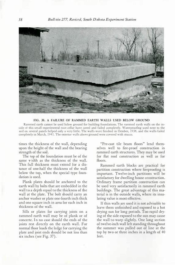
58 Bull:!tin 277, Revis:1d, South Dakota Experiment Station
FIG. 38. A FAILURE OF RAMMED EARTH WALLS USED BELOW GROUND Rammed earth cannot be used below ground for building foundations. The rammed earth walls on the in
side ot this small experimental root cellar have caved and failed completely. Waterproofing used next to the soil on several panels helped only a very little. The walls were finished in October, 1938 , and the walls failed completely in March, 1 94 1 . The exterior wal ls above ground were c9vered with stucco.
times the thickness o f the wall, depending upo n the height o f the wall and the bearing strength o f the soil.
The t o p of the fo undation must be o f the same v. - idth as the thickness o f the wall. This fu ll thickness must ex tend for a distance o f o ne-half the thickness o f the wall belo w t he top, when the special type foundation is used.
Plank plates sho uld be ancho red to the earth wall by bo lts that are embedded in the wall to a depth equal to the thickness o f the wall at t he plate. The bo lt should carry an ancho r washer o r plate o ne- fourth inch thick and o ne square inch in area fo r each inch in thickness o f the wall.
Sills o r plates fo r carrying jo ists o n a rammed earth wall may be o f pl ank o r o f concerte. I n no case should the ends o f the jo ists rest directly o n the earth wall. For no rmal Boor lo ads the ledge for carrying the plate and jo ist ends sho uld be not less than six inches ( see Fig. 37) .
"Pre- cast tile beam Boo rs" lend themselves well to fire- proo f co nstructio n in rammed earth structures. They may be used for B at roo f constructio n as well as for Boo rs.
Rammed earth blo cks are practical fo r partition co nstruction where fireproo fing is impo rtant. Twelve- inch partitions will be satisfacto ry fo r dwelling house con str uction. Ordinary frame partition const ructio n can be used very satisfacto rily in rammed earth buildings. The great advantage o f this material is in the o utside walls, where its insulating value is most effective.
If thin walls are used it is not advisable to leave them unfinished and exposed to a ho t drying sun fo r long periods. Too rapid drying o f the side expo sed to the sun may cause the wall to warp slightly. One long section o f twelve- inch wall left standing thro ugho ut the summer was pulled o ut o f line at the to p by two o r three inches in a lengt h o f 40 feet.
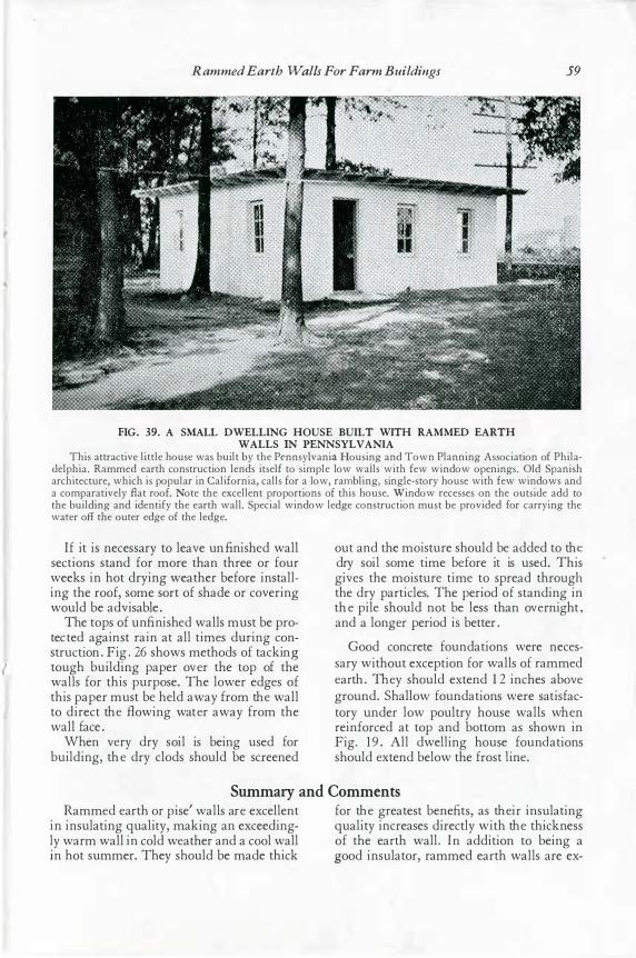
l
Rammed Earth Walls For Farm Buildings 59
FIG. 39. A SMALL DWELLING HOUSE BUILT WITH RAMMED EARTH WALLS IN PENNSYLVANIA
This attractive little house was built by the Pennsylvania Housing and Town Planning Association of Philadelphia. Rammed earth construction lends itself to simple low wails with few window openings. Old Spanish architecture, which is popular in California, calls for a low, rambling, single-story house with few windows and a comparatively flat roof. Note the excellent proportions of this house. Window recesses on the outside add to the building and identify the earth wall. Special window ledge construction must be provided for carrying the water off the outer edge of the ledge.
If it is neces s ary to leave unfinis he d wall s ections s tand for more than three or four weeks in hot drying weather before ins talling the roof, s ome s ort of s hade or covering would be advis able.
The tops of unfinis he d walls mus t be protect ed agains t rain at all time s during cons tructi on. Fig. 26 s hows methods of tacking tough building paper ove r the top of the walls for this purpos e. The lower edge s of this paper mus t be he ld away from the wall to direct the fl owing wate r away from the wall face.
When ve ry dry s oil is being us ed for building, the dry clods s hould be s creened
out and the mois ture s hould be adde d to the dry s oil s ome time be fore it is us ed. This give s the mois ture time to s pread through the dry particles. The period of s tanding in
· the pile s hould not be les s than ove rnight, and a longer period is better.
Good concrete foundations were nece s s ary without exception for walls of ramme d e arth. The y s hould extend 1 2 inches above ground. Shallow foundations were s atis factory under low poultry hous e walls whe n reinforced at top and bottom as s hown in Fig. 19. All dwelling hous e found ations s hould e xtend below the fros t l ine.
Summary and Comments Ramme d e arth or pis e' walls are excellent for the greates t benefits , as the ir ins ulating
in ins ulating quality, making an exceeding- quality increas es directly with the thicknes s ly warm wall in cold we ather and a cool wall of the earth wall. In addition to being a i n hot s ummer. They s hould be made thick g ood ins ulator, rammed earth walls are ex-
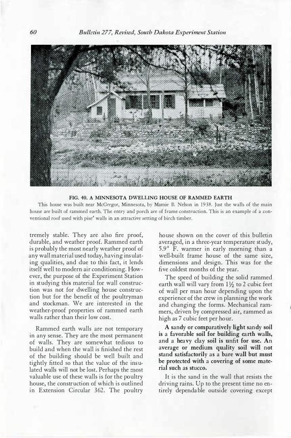
60 Bulletin 277, Revised, South Dakota Experiment Station
FIG. 40. A MINNESOTA DWELLING HOUSE OF RAMMED EARTH
This house was built near McGregor, Minnesota, by Mamie B. Nelson in 1938 . Just the walls of the main
house are built of rammed earth. The entry and porch are of frame construction. This is an example of a con
ventional roof used with pise' walls in an attractive setting of birch timber.
tremely stable. They are also fire proof, du rable, and weather proof. Rammed earth is probab ly the most nearly weather proof of any wall material u sed today, having insu lating qu alities, and du e to this fact, it lends itself well to modern air conditioning. However, the pu rpose of the Experiment Station in stu dying this material for wall constru ction was not for dwelling hou se constru ction bu t for the benefit of the poultryman and stockman. We are interested in the weather-proof properties of rammed earth walls rather than their low cost.
Rammed earth walls are not temporary in any sense. They are the most permanent of walls. They are somewhat tediou s to bu ild and when the wall is finished the rest of the bu ilding shou ld be well bu ilt and tightly fitted s o that the valu e of the insulated walls will not be lost. Perhaps the :n ost valu able u se of these walls is for the pou ltry h ou se, th e constru ction of which is ou tlined in Extension Circu lar 3 62. The pou ltry
hou se shown on the cover of this bu lletin averaged, in a three-year temperatu re stu dy, 5 .9° F. warmer in early morning than a well-bu ilt frame hou se of the same size, dimensions and design. This was for the five coldest months of the year.
The speed of bu ilding the solid rammed earth wall will vary from 1 Yz to 2 cubic feet of wall per man hou r depending u pon the experience of the crew in planning the work and changing the forms. Mechanical rammers, driven by compressed air, rammed as high as 7 cubic feet per hou r.
A sandy or comparativ ely li ght sandy soi l i s a favorab le soi l for b ui lding ear th w alls, and a heav y c lay soi l i s unfit for use. An av erage or mediu m q uali ty soi l wi ll not stand sati sfac tori ly as a b ar e w all b ut must b e pro tec ted wi th a cov ering o f som e materi al suc h as stu c co.
It is the sand in the wall that resists the driving rains. Up to the present time no entirely dependable ou tside covering except
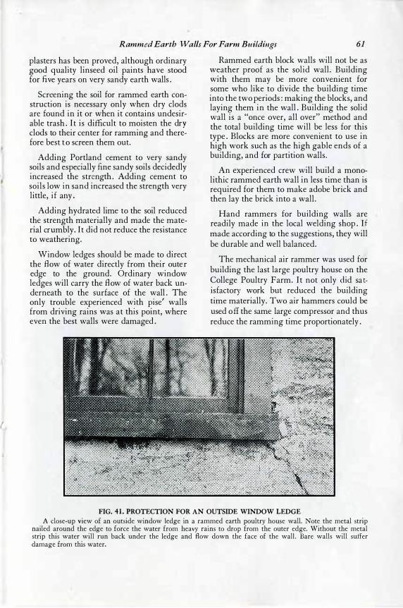
{
Rammed Earth Walls For Farm Buildings 61
plasters has been proved, although ordinary good quality linseed oil paints have stood for fi ve years on very sandy earth walls.
Screening the soil for rammed earth construction is necessary only when dry clods are found in i t or when it contains undesirable trash. It is difficult to moisten the drv clods to their center for ramming and ther� fore best to screen them out.
Adding Portland cement to very sandy soils and especially fine sandy soils decidedly increased the stre ngth. Adding cement to soils low in sand increased the strength very little, if any.
Adding hydrated lime to the soil reduced the strength materially and made the material cru mbly. It did not reduce the resistance to weathering.
Window ledges should be made to direct the fl ow of water directly from thei r outer edge to the ground. Ordinary window ledges will carry the fl ow of water back underneath to the surface of the wall. The only trouble experienced with pise' walls from driving rains was at this point, where even the best walls were damaged.
Rammed earth block walls will not be as weather proof as the solid wall. Building with them may be more convenient for some who like to divide the building time into the two periods: making the blocks, and laying them in the wall. Building the solid wall is a "once over, all over" method and the total building time will be less for this type. Blocks are more convenient to use in high work such as the high gable ends of a building, and for partition walls.
An experienced crew will build a monolithic rammed earth wall in less time than is required for them to make adobe brick and then lay the bric k into a wall.
Hand rammers for building walls are readily made in the local welding shop. If mad<: according to the suggestions, they will be durable and well balanced.
The mechanical air rammer was used for building the last large poultry house on the College Poultry Farm. It not only d id satisfactory work but reduced the building time materially. Two air hammers could be used off the same large compressor and thus reduce the ramming time proportionately.
FIG. 41 . PROTECTION FOR AN OUTSIDE WINDOW LEDGE A close-up view of an outside window ledge in a rammed earth poultry house wall. Note the metal strip
nailed around the edge to force the water from heavy rains to drop from the outer edge. Without the metal strip this water will run back under the ledge and flow down the face of the wall . Bare walls will suffer damage from this water.
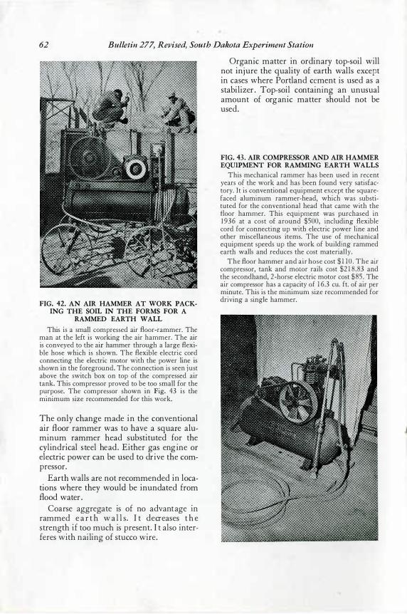
62 Bulletin 277, Revised, South Dakota Experiment Station
FIG. 42. AN AIR HAMMER AT WORK PACKING THE SOIL IN THE FORMS FOR A
RAMMED EARTH WALL
This is a small compressed air floor-rammer. The man at the left is working the air hammer. The air is conveyed to the air hammer through a large flexible hose which is shown. The flexible electric cord connecting the electric motor with the power line is shown in the foreground. The connection is seen just above the switch box on top of the compressed air tank. This compressor proved to be too small for the purpose. The compressor shown in Fig. 43 is the minimum size recommended for this work.
The only c ha nge ma de in the c onventiona l ai r fl oor ra mmer wa s to ha ve a sq uare a lumi num ra mmer hea d s ubs tituted for the c yli ndrica l s teel hea d. Either ga s engi ne or elec tric power ca n be us ed to dri ve the c ompres s or.
Ea rth wa lls a re not rec ommended in loca ti ons where they would be inunda ted from fl ood wa ter.
Coars e a ggrega te is of no a dva nta ge in ra mmed ea r th wa l l s. I t decrea s es t h e s trength if too muc h i s pres ent. I t a ls o interferes wi th nai ling of s tuc c o wire.
Orga nic ma tter in ordi na ry top- s oi l will not injure the q ua li ty of earth wa lls exc ep t in ca s es where Portla nd ce ment i s us ed a s a s ta bi li zer. Top-s oi l c ontai ning a n unus ua l a mount of orga nic ma tter s hould not be us ed.
FIG. 43. AIR COMPRESSOR AND AIR HAMMER EQUIPMENT FOR RAMMING EARTH WALLS
This mechanical rammer has been used in recent years of the work and has been found very satisfactory. It is conventional equipment except the squarefaced aluminum rammer-head, which was substituted for the conventional head that came with the floor hammer. This equipment was purchased in 1 936 at a cost of around $500, including flexible cord for connecting up with electric power line and other miscellaneous items. The use of mechanical equipment speeds up the work of building rammed earth walls and reduces the cost materially.
The floor hammer and air hose cost $ 1 10 . The air compressor, tank and motor rails cost $2 1 8 .83 and the secondhand, 2 -horse electric motor cost $85. The air compressor has a capacity of 1 6.3 cu. ft. of air per minute. This is the minimum size recommended for driving a single hammer.
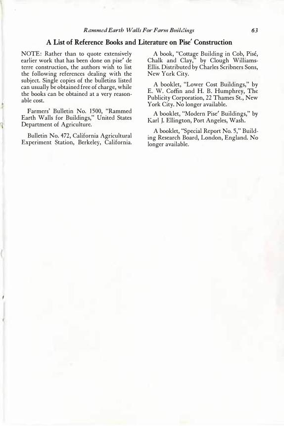
f
Rammed Earth Walls Fo1' Farm Buildings 63
A List of Reference Books and Literature on Pise' Construction
NOTE: Rather than to quote extensively earlier work that has been done on pise' de terre construction, the authors wish to list the following references dealing with the subject. Single copies of the bulletins listed can usually be obtained free of charge, while the books can be obtained at a very reasonable cost.
Farmers' Bulletin No. 1 500, "Rammed Earth Walls for Buildings," United States Department of Agriculture.
Bulletin No. 472, California Agricultural Experiment Station, Berkeley, California.
A book, "Cottage Building in Cob, Pise, Chalk and Clay," by Clough WilliamsEllis. Distributed by Charles Scribners Sons, New York City.
A booklet, "Lower Cost Buildings," by E. W. Coffin and H. B. Humphrey, The Publicity Corporation, 22 Thames St., New York City. No longer available.
A booklet, "Modern Pise' Buildings," by Karl J. Ellington, Port Angeles, Wash.
A booklet, "Special Report No. 5," Building Research Board, London, England. No longer available.