ec frameless – installation manual - maxon group
TRANSCRIPT
«EC frameless» | maxon Frameless DrivesInstallation Manual
mmag | Edition 2021-03 | DocID rel10039
Installation Manual
Table of Contents
«EC frameless» Installation ManualA-2 mmag | 2021-03 | rel10039
1 GENERAL INFORMATION 31.1 About this Document. . . . . . . . . . . . . . . . . . . . . . . . . . . . . . . . . . . . . . . . . . . . . . . 31.2 About the Device. . . . . . . . . . . . . . . . . . . . . . . . . . . . . . . . . . . . . . . . . . . . . . . . . . 51.3 About the Safety Precautions . . . . . . . . . . . . . . . . . . . . . . . . . . . . . . . . . . . . . . . . 5
2 SPECIFICATIONS 72.1 Technical Data . . . . . . . . . . . . . . . . . . . . . . . . . . . . . . . . . . . . . . . . . . . . . . . . . . . 72.2 Nameplate. . . . . . . . . . . . . . . . . . . . . . . . . . . . . . . . . . . . . . . . . . . . . . . . . . . . . . . 82.3 Standards . . . . . . . . . . . . . . . . . . . . . . . . . . . . . . . . . . . . . . . . . . . . . . . . . . . . . . . 8
3 INSTALLATION 93.1 General Rules . . . . . . . . . . . . . . . . . . . . . . . . . . . . . . . . . . . . . . . . . . . . . . . . . . . . 93.2 Dimensioning . . . . . . . . . . . . . . . . . . . . . . . . . . . . . . . . . . . . . . . . . . . . . . . . . . . 113.3 Verification . . . . . . . . . . . . . . . . . . . . . . . . . . . . . . . . . . . . . . . . . . . . . . . . . . . . . 123.4 Mechanical Installation . . . . . . . . . . . . . . . . . . . . . . . . . . . . . . . . . . . . . . . . . . . . 143.5 Electrical Installation . . . . . . . . . . . . . . . . . . . . . . . . . . . . . . . . . . . . . . . . . . . . . . 23
4 MAINTENANCE 25DECLARATION OF INCORPORATION 26LIST OF FIGURES 27LIST OF TABLES 28INDEX 29APPENDIX 30
TABLE OF CONTENTS
READ THIS FIRSTBY PRINCIPLE, THE «EC FRAMELESS» COMPRISES PARTS THAT PRODUCE STRONG MAGNETIC FIELDS. IT ISTHEREFORE MOST IMPORTANT THAT YOU ARE AWARE OF THE CONSEQUENCES OF THESE MAGNETIC FORCES,THAT YOU TAKE THE APPROPRIATE PRECAUTIONARY MEASURES, AND THAT YOU COMMUNICATE THIS FACT TOPERSONS IN YOUR VICINITY!
These instructions are intended for qualified technical personnel. Prior commencing with any activities…• you must carefully read and understand this manual and• you must follow the instructions given therein.
The «EC frameless» is considered as partly completed machinery according to EU Directive 2006/42/EC, Article 2, Clause (g)and is intended to be incorporated into or assembled with other machinery or other partly completed machinery orequipment.Therefore, you must not put the device into service,…• unless you have made completely sure that the other machinery fully complies with the EU directive’s requirements!• unless the other machinery fulfills all relevant health and safety aspects!• unless all respective interfaces have been established and fulfill the herein stated requirements!
General InformationAbout this Document
«EC frameless» Installation Manualmmag | 2021-03 | rel10039 1-3
1 GENERAL INFORMATION
1.1 About this Document
1.1.1 Intended PurposeThe purpose of the present document is to familiarize you with the direct drive «EC frameless». It will high-light the tasks for safe and adequate installation and/or commissioning. Follow the described instructions …
• to avoid dangerous situations,• to keep installation and/or commissioning time at a minimum,• to increase reliability and service life of the described equipment.
1.1.2 Target AudienceThe present document is intended for trained and skilled personnel. It conveys information on how to under-stand and fulfill the respective work and duties.
1.1.3 How to useThroughout the document, the following notations and codes will be used.
Table 1-1 Notation used
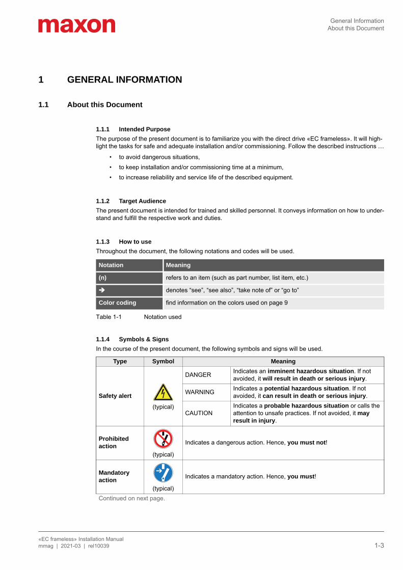
1.1.4 Symbols & SignsIn the course of the present document, the following symbols and signs will be used.
Notation Meaning
(n) refers to an item (such as part number, list item, etc.)
denotes “see”, “see also”, “take note of” or “go to”
Color coding find information on the colors used on page 9
Type Symbol Meaning
Safety alert
(typical)
DANGER Indicates an imminent hazardous situation. If not avoided, it will result in death or serious injury.
WARNING Indicates a potential hazardous situation. If not avoided, it can result in death or serious injury.
CAUTIONIndicates a probable hazardous situation or calls the attention to unsafe practices. If not avoided, it may result in injury.
Prohibitedaction
(typical)
Indicates a dangerous action. Hence, you must not!
Mandatoryaction
(typical)
Indicates a mandatory action. Hence, you must!
Continued on next page.
General InformationAbout this Document
«EC frameless» Installation Manual1-4 mmag | 2021-03 | rel10039
Table 1-2 Symbols and signs
1.1.5 Trademarks and Brand NamesFor easier legibility, registered brand names are listed below and will not be further tagged with their respec-tive trademark. It must be understood that the brands (the list below is not necessarily concluding) are pro-tected by copyright and/or other intellectual property rights even if their legal trademarks are omitted in the later course of this document.
Table 1-3 Brand names and trademark owners
1.1.6 CopyrightThis document is protected by copyright. Any further use (including reproduction, translation, microfilming, and other means of electronic data processing) without prior written approval is not permitted. The men-tioned trademarks belong to their respective owners and are protected under intellectual property rights.© 2021 maxon. All rights reserved. Subject to change without prior notice.
mmag | «EC frameless» Installation Manual | Edition 2021-03 | DocID rel10039
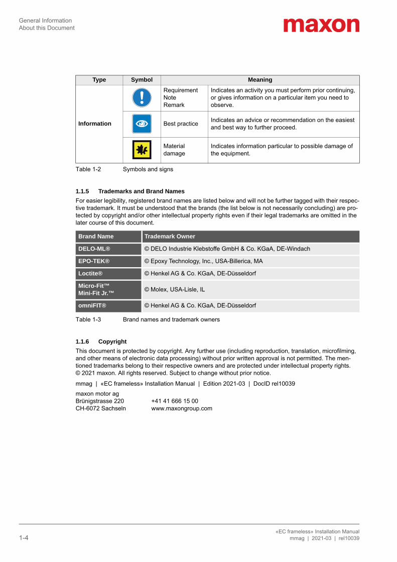
Information
RequirementNoteRemark
Indicates an activity you must perform prior continuing, or gives information on a particular item you need to observe.
Best practice Indicates an advice or recommendation on the easiest and best way to further proceed.
Material damage
Indicates information particular to possible damage of the equipment.
Brand Name Trademark Owner
DELO-ML® © DELO Industrie Klebstoffe GmbH & Co. KGaA, DE-Windach
EPO-TEK® © Epoxy Technology, Inc., USA-Billerica, MA
Loctite® © Henkel AG & Co. KGaA, DE-Düsseldorf
Micro-Fit™Mini-Fit Jr.™ © Molex, USA-Lisle, IL
omniFIT® © Henkel AG & Co. KGaA, DE-Düsseldorf
maxon motor agBrünigstrasse 220CH-6072 Sachseln
+41 41 666 15 00www.maxongroup.com
Type Symbol Meaning
General InformationAbout the Device
«EC frameless» Installation Manualmmag | 2021-03 | rel10039 1-5
1.2 About the DeviceThe direct drive «EC frameless» is a high-performance, high-torque brushless DC external rotor motor (BLDC motor). It is available in various sizes and is designed to be incorporated into a specially adapted outer body that serves both as the motor’s supporting structure and as torque-carrying device.
The «EC frameless» composes two main parts:
• Stator with electric connections; for installation into a customer-provided outer body (such as housing, machine structure, or carrier system)
• Magnetic rotor; for on-site assembly with the installed stator and the customer-provided torque-carrying device
Outer body, motor shaft, and bearings are not part of the «EC frameless»’s scope of delivery and are being designed for a particular case of application by the customer.
1.3 About the Safety PrecautionsSafety first—always!
BY PRINCIPLE, THE «EC FRAMELESS» COMPRISES PARTS THAT PRODUCE STRONG MAGNETICFIELDS. IT IS THEREFORE MOST IMPORTANT THAT YOU ARE AWARE OF THE CONSEQUENCESOF THESE MAGNETIC FORCES, THAT YOU TAKE THE APPROPRIATE PRECAUTIONARY MEA-SURES, AND THAT YOU COMMUNICATE THIS FACT TO PERSONS IN YOUR VICINITY!READ THE FOLLOWING INSTRUCTIONS CAREFULLY BEFORE YOU ENGAGE WITH ANY WORKAND FOLLOW THE INSTRUCTIONS GIVEN AT ALL TIMES!
• Make sure that you have read and understood the note “READ THIS FIRST” on page 2!• Do not engage with any work unless you possess the stated skills (chapter “1.1.2 Target Audi-
ence” on page 3)!• Consult chapter “1.1.4 Symbols & Signs” on page 3 to understand the subsequently used indica-
tors!• You must observe any regulation applicable in the country and/or at the site of implementation with
regard to health and safety/accident prevention and/or environmental protection!
DANGER
High voltage and/or electrical shockTouching live wires causes death or serious injuries!• Consider any power cable as connected to live power, unless you have proven the opposite!• Make sure that neither end of cable is connected to live power!• Make sure that the power source cannot be engaged while work is in process!• Obey lock-out/tag-out procedures!• Make sure to securely lock any power engaging equipment against unintentional engagement and tag
it with your name!
General InformationAbout the Safety Precautions
«EC frameless» Installation Manual1-6 mmag | 2021-03 | rel10039
Strong magnetic fieldThe high magnetic forces produced by the device constitute an imminent hazard to persons wearing a car-diac pacemaker or metal implants.All persons who possibly may suffer impairment caused by strong magnetic fields must not approach the device and must stay clear and in a safe distance of at least two (2) meters.
General rules• Make sure that all associated devices and components are installed according to local regulations.• Be aware that, by principle, an electronic apparatus cannot be considered fail-safe. Therefore, you must
make sure that any machine/apparatus has been fitted with independent monitoring and safety equip-ment. If the machine/apparatus should break down, if it is operated incorrectly, if the control unit breaks down or if the cables break or get disconnected, etc., the complete drive system must return—and be kept—in a safe operating mode.
• Be aware that you are not entitled to perform any repair on components supplied by maxon motor.
Electrostatic Sensitive Device (ESD)• Wear electrically conductive clothing and footwear.• Observe ESD protective measures.
WARNING
Strong magnetic fieldHigh magnetic force can cause serious injuries!• Keep stator and rotor mechanically blocked at all times! Do so by using a mechanical locking device,
a mounting aid, or non-magnetic spacers!• Make sure to remove/keep clear any metal parts or metallic items—also such as cardiac pacemakers,
implants, watches, bracelets, credit cards, mobile phones, etc—before you approach the motor!• Use only non-magnetic tools when you work on the motor or in its vicinity!• Put up warning signs stating STRONG MAGNETIC FIELDS around the installation area and at the
storage location!• Inform persons around of the potential danger. Instruct them accordingly and request them to follow
the precautionary measures!
WARNING
Pinching and shearing riskSudden movement and shift of rotor can cause serious injuries!To prevent sudden shift during installation you must keep both stator and rotor blocked at all times. Do so by using a mechanical locking device, a mounting aid, or non-magnetic spacers!
SpecificationsTechnical Data
«EC frameless» Installation Manualmmag | 2021-03 | rel10039 2-7
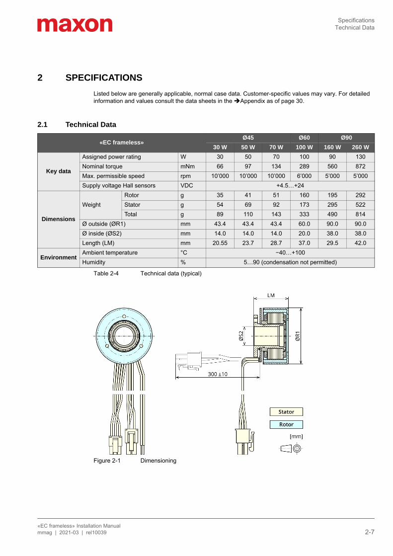
2 SPECIFICATIONSListed below are generally applicable, normal case data. Customer-specific values may vary. For detailed information and values consult the data sheets in the Appendix as of page 30.
2.1 Technical Data
Table 2-4 Technical data (typical)
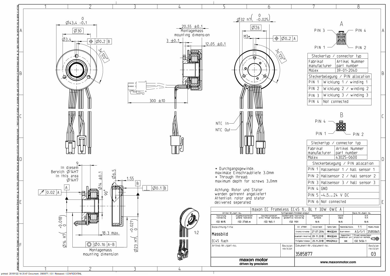
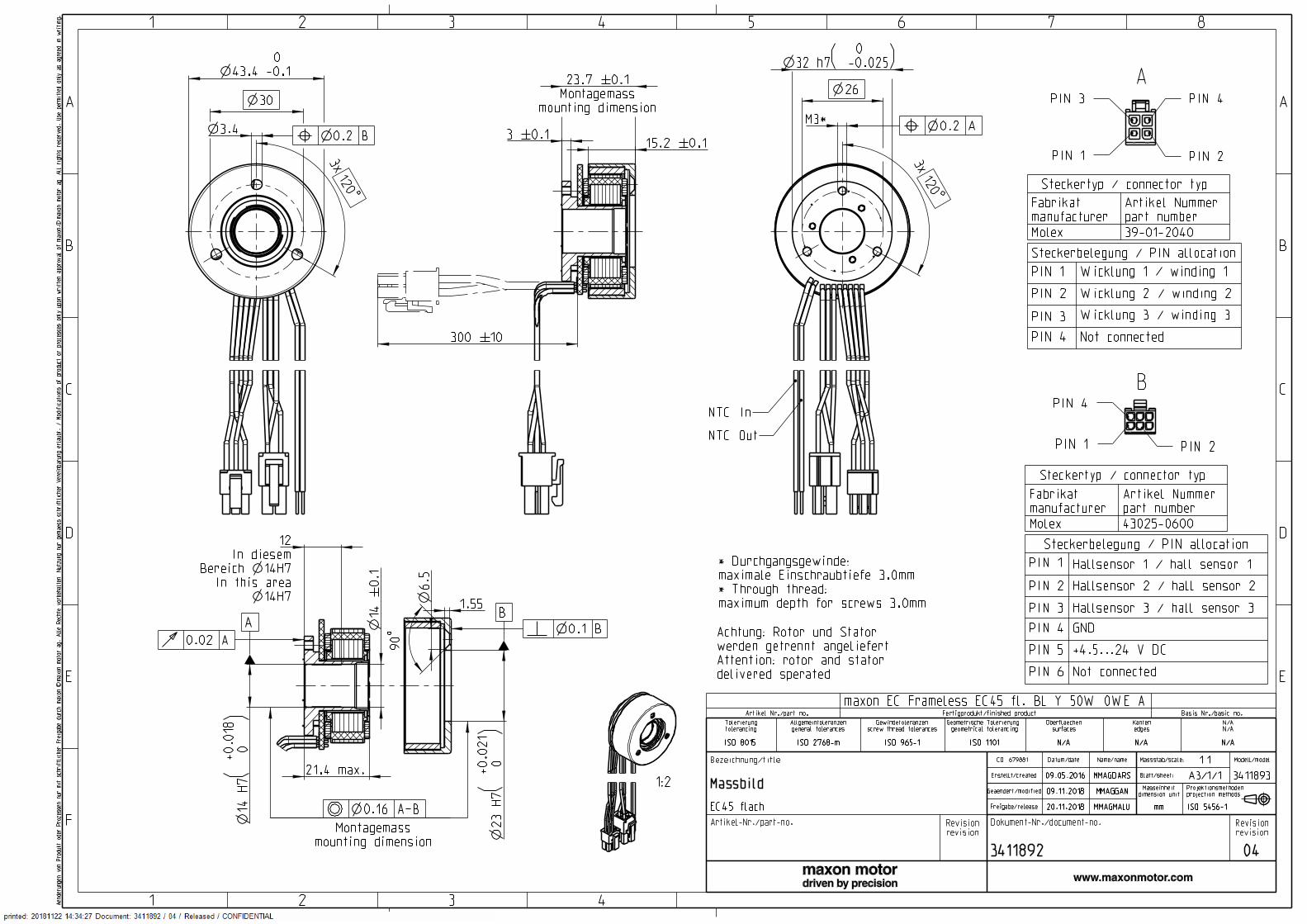
Figure 2-1 Dimensioning
«EC frameless»Ø45 Ø60 Ø90
30 W 50 W 70 W 100 W 160 W 260 W
Key data
Assigned power rating W 30 50 70 100 90 130Nominal torque mNm 66 97 134 289 560 872Max. permissible speed rpm 10’000 10’000 10’000 6’000 5’000 5’000Supply voltage Hall sensors VDC +4.5…+24
Dimensions
WeightRotor g 35 41 51 160 195 292Stator g 54 69 92 173 295 522Total g 89 110 143 333 490 814
Ø outside (ØR1) mm 43.4 43.4 43.4 60.0 90.0 90.0Ø inside (ØS2) mm 14.0 14.0 14.0 20.0 38.0 38.0Length (LM) mm 20.55 23.7 28.7 37.0 29.5 42.0
EnvironmentAmbient temperature °C −40…+100Humidity % 5…90 (condensation not permitted)
SpecificationsNameplate
«EC frameless» Installation Manual2-8 mmag | 2021-03 | rel10039
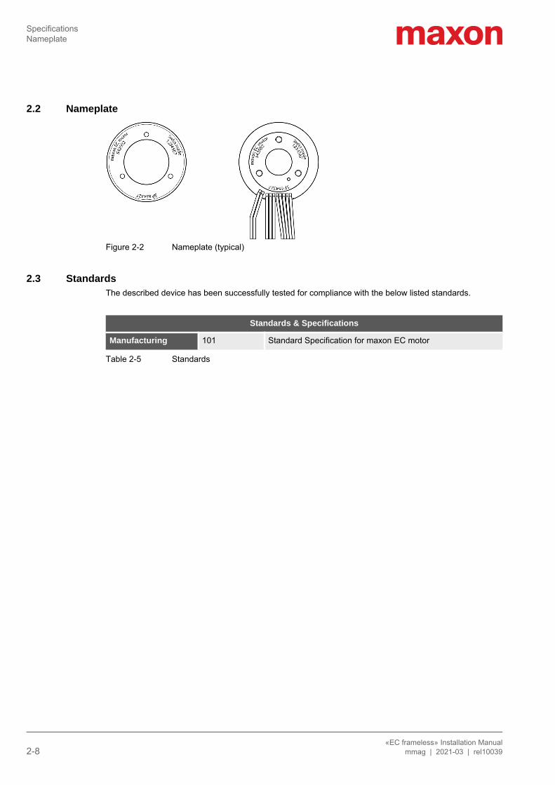
2.2 Nameplate
Figure 2-2 Nameplate (typical)
2.3 StandardsThe described device has been successfully tested for compliance with the below listed standards.
Table 2-5 Standards
Standards & Specifications
Manufacturing 101 Standard Specification for maxon EC motor
InstallationGeneral Rules
«EC frameless» Installation Manualmmag | 2021-03 | rel10039 3-9
3 INSTALLATIONThe motor’s two main components—stator with electric connections and magnetic rotor—come in unmounted condition in packaged cases.
Besides special precautions in respect to health and safety, the «EC frameless» must be installed in a par-ticular and specific way. For both safe and easy installation as well as reliable operation closely follow the below described information in given order.
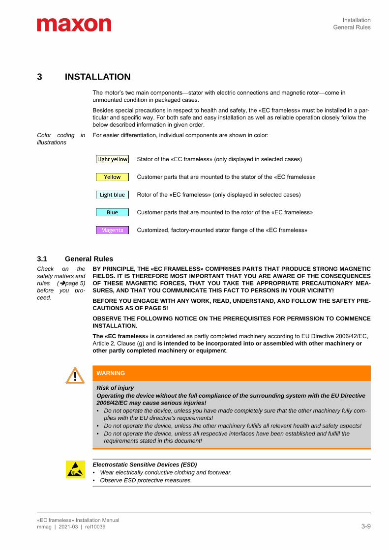
Color coding inillustrations
For easier differentiation, individual components are shown in color:
3.1 General RulesCheck on thesafety matters andrules (page 5)before you pro-ceed.
BY PRINCIPLE, THE «EC FRAMELESS» COMPRISES PARTS THAT PRODUCE STRONG MAGNETICFIELDS. IT IS THEREFORE MOST IMPORTANT THAT YOU ARE AWARE OF THE CONSEQUENCESOF THESE MAGNETIC FORCES, THAT YOU TAKE THE APPROPRIATE PRECAUTIONARY MEA-SURES, AND THAT YOU COMMUNICATE THIS FACT TO PERSONS IN YOUR VICINITY!BEFORE YOU ENGAGE WITH ANY WORK, READ, UNDERSTAND, AND FOLLOW THE SAFETY PRE-CAUTIONS AS OF PAGE 5!OBSERVE THE FOLLOWING NOTICE ON THE PREREQUISITES FOR PERMISSION TO COMMENCEINSTALLATION.The «EC frameless» is considered as partly completed machinery according to EU Directive 2006/42/EC, Article 2, Clause (g) and is intended to be incorporated into or assembled with other machinery or other partly completed machinery or equipment.
Electrostatic Sensitive Devices (ESD)• Wear electrically conductive clothing and footwear.• Observe ESD protective measures.
Stator of the «EC frameless» (only displayed in selected cases)
Customer parts that are mounted to the stator of the «EC frameless»
Rotor of the «EC frameless» (only displayed in selected cases)
Customer parts that are mounted to the rotor of the «EC frameless»
Customized, factory-mounted stator flange of the «EC frameless»
WARNING
Risk of injuryOperating the device without the full compliance of the surrounding system with the EU Directive 2006/42/EC may cause serious injuries!• Do not operate the device, unless you have made completely sure that the other machinery fully com-
plies with the EU directive’s requirements!• Do not operate the device, unless the other machinery fulfills all relevant health and safety aspects!• Do not operate the device, unless all respective interfaces have been established and fulfill the
requirements stated in this document!
InstallationGeneral Rules
«EC frameless» Installation Manual3-10 mmag | 2021-03 | rel10039
Possible irreversible damage of motorUntil completion of the installation, individual components can be permanently damaged by improper han-dling. • Handle the components with particular care.• Pay special attention to cleanliness.• Make sure that no impurities, foreign objects, or particles penetrate the drive or can be attracted by the
motor magnets.
InstallationDimensioning
«EC frameless» Installation Manualmmag | 2021-03 | rel10039 3-11
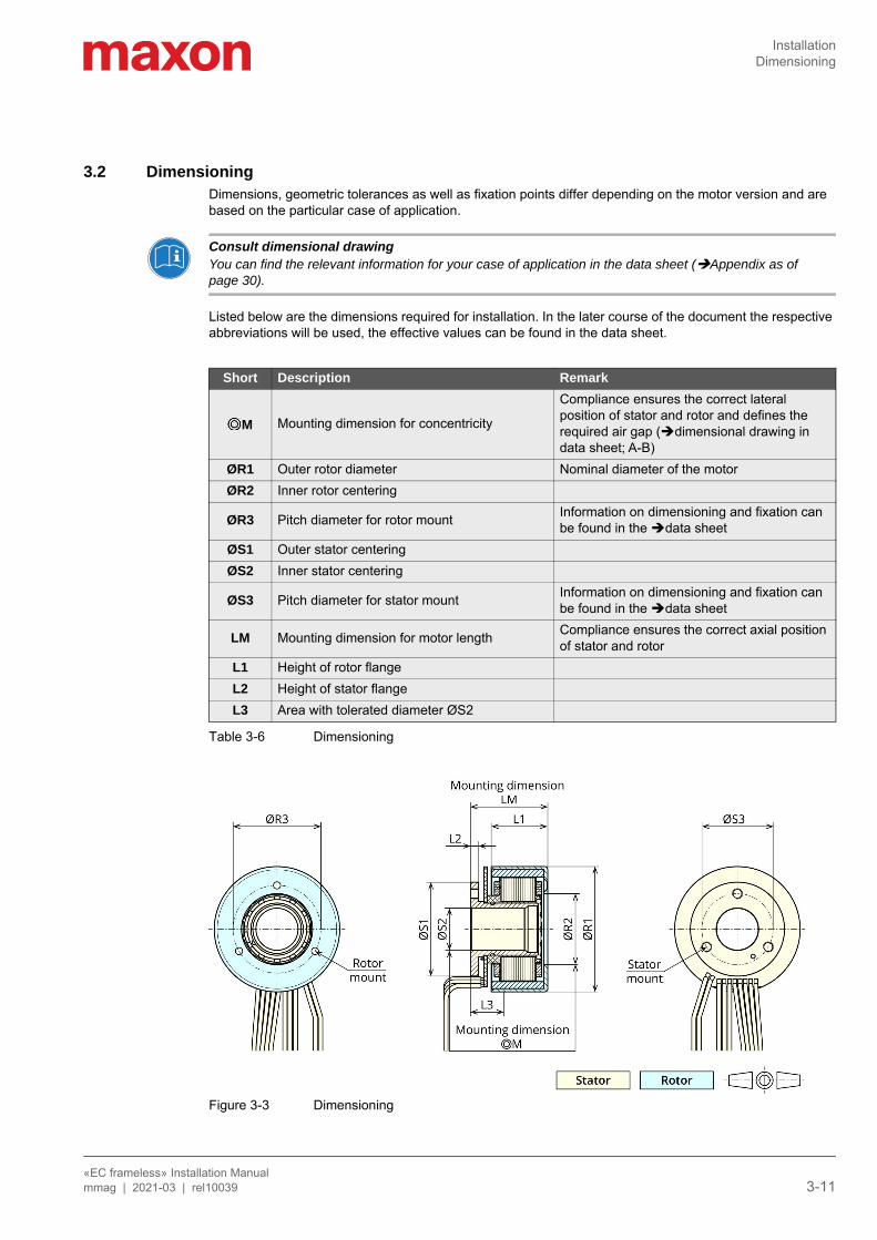
3.2 DimensioningDimensions, geometric tolerances as well as fixation points differ depending on the motor version and are based on the particular case of application.
Consult dimensional drawingYou can find the relevant information for your case of application in the data sheet (Appendix as of page 30).
Listed below are the dimensions required for installation. In the later course of the document the respective abbreviations will be used, the effective values can be found in the data sheet.
Table 3-6 Dimensioning
Figure 3-3 Dimensioning
Short Description Remark
M Mounting dimension for concentricity
Compliance ensures the correct lateral position of stator and rotor and defines the required air gap (dimensional drawing in data sheet; A-B)
ØR1 Outer rotor diameter Nominal diameter of the motorØR2 Inner rotor centering
ØR3 Pitch diameter for rotor mount Information on dimensioning and fixation can be found in the data sheet
ØS1 Outer stator centeringØS2 Inner stator centering
ØS3 Pitch diameter for stator mount Information on dimensioning and fixation can be found in the data sheet
LM Mounting dimension for motor length Compliance ensures the correct axial position of stator and rotor
L1 Height of rotor flangeL2 Height of stator flangeL3 Area with tolerated diameter ØS2
InstallationVerification
«EC frameless» Installation Manual3-12 mmag | 2021-03 | rel10039
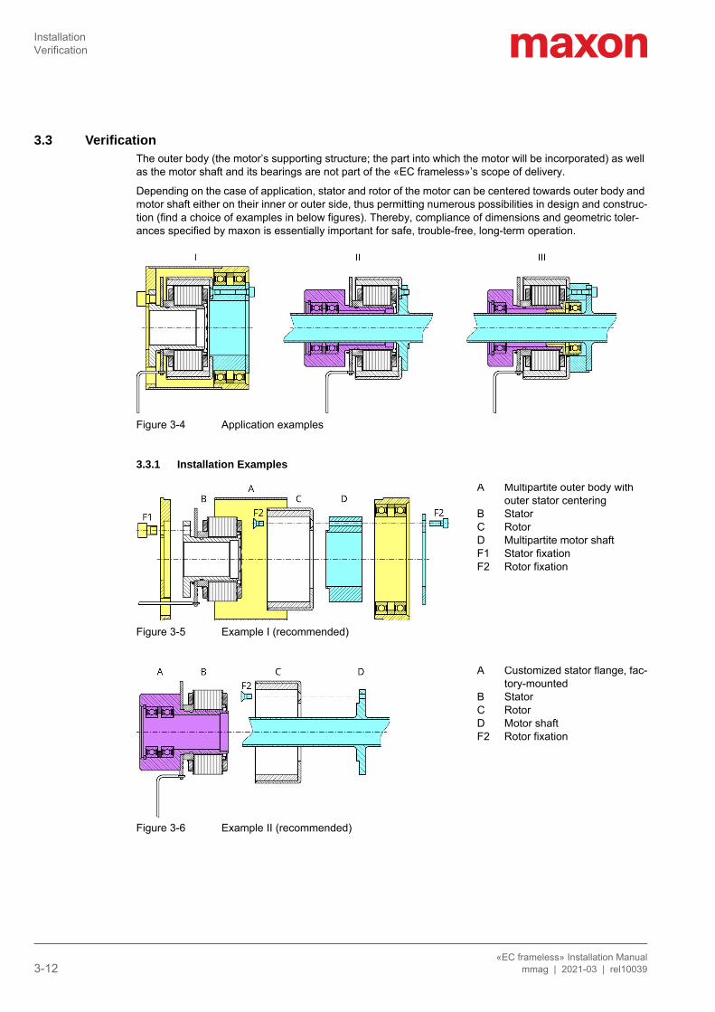
3.3 VerificationThe outer body (the motor’s supporting structure; the part into which the motor will be incorporated) as well as the motor shaft and its bearings are not part of the «EC frameless»’s scope of delivery.
Depending on the case of application, stator and rotor of the motor can be centered towards outer body and motor shaft either on their inner or outer side, thus permitting numerous possibilities in design and construc-tion (find a choice of examples in below figures). Thereby, compliance of dimensions and geometric toler-ances specified by maxon is essentially important for safe, trouble-free, long-term operation.
Figure 3-4 Application examples
3.3.1 Installation Examples
Figure 3-5 Example I (recommended)
Figure 3-6 Example II (recommended)
A Multipartite outer body with outer stator centering
B StatorC RotorD Multipartite motor shaftF1 Stator fixationF2 Rotor fixation
A Customized stator flange, fac-tory-mounted
B StatorC RotorD Motor shaftF2 Rotor fixation
InstallationVerification
«EC frameless» Installation Manualmmag | 2021-03 | rel10039 3-13
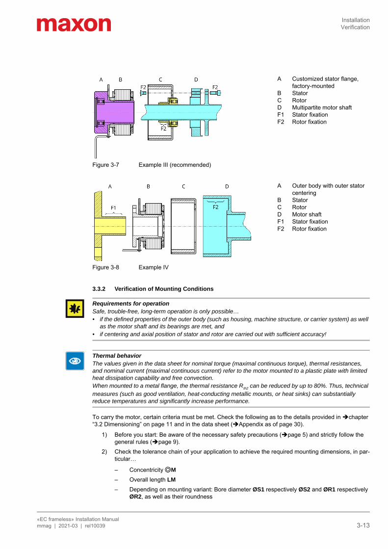
Figure 3-7 Example III (recommended)
Figure 3-8 Example IV
3.3.2 Verification of Mounting Conditions
Requirements for operationSafe, trouble-free, long-term operation is only possible…• if the defined properties of the outer body (such as housing, machine structure, or carrier system) as well
as the motor shaft and its bearings are met, and• if centering and axial position of stator and rotor are carried out with sufficient accuracy!
Thermal behaviorThe values given in the data sheet for nominal torque (maximal continuous torque), thermal resistances, and nominal current (maximal continuous current) refer to the motor mounted to a plastic plate with limited heat dissipation capability and free convection.When mounted to a metal flange, the thermal resistance Rth2 can be reduced by up to 80%. Thus, technical measures (such as good ventilation, heat-conducting metallic mounts, or heat sinks) can substantially reduce temperatures and significantly increase performance.
To carry the motor, certain criteria must be met. Check the following as to the details provided in chapter “3.2 Dimensioning” on page 11 and in the data sheet (Appendix as of page 30).
1) Before you start: Be aware of the necessary safety precautions (page 5) and strictly follow the general rules (page 9).
2) Check the tolerance chain of your application to achieve the required mounting dimensions, in par-ticular…
– Concentricity M – Overall length LM – Depending on mounting variant: Bore diameter ØS1 respectively ØS2 and ØR1 respectively
ØR2, as well as their roundness
A Customized stator flange, factory-mounted
B StatorC RotorD Multipartite motor shaftF1 Stator fixationF2 Rotor fixation
A Outer body with outer stator centering
B StatorC RotorD Motor shaftF1 Stator fixationF2 Rotor fixation
InstallationMechanical Installation
«EC frameless» Installation Manual3-14 mmag | 2021-03 | rel10039
– With bolted connection: Circle diameter ØS3 and ØR3, circle angle, and dimensioning of fixa-tion threads
– Diameter, depth, and surface finish of centering– Diameter, shape, and length of shaft and its bearings
3) Make sure that the outer body meets the specified characteristics (chapter “2.1 Technical Data” on page 7 / «Environment»):– Heat dissipation capability (note “Thermal behavior” on page 13)– Electrical connections and cable routing
Requirements for operationThe function of the drive is only guaranteed if all specified design characteristics and tolerances are met. Do only continue if this is actually the case. If this is not the case you must rectify the deviations, first.
3.4 Mechanical Installation
3.4.1 EquipmentIn the later course of the installation and depending on the mounting method used, some additional equip-ment and components will be needed.
TOOLS & EQUIPMENT
Table 3-7 Tools & equipment
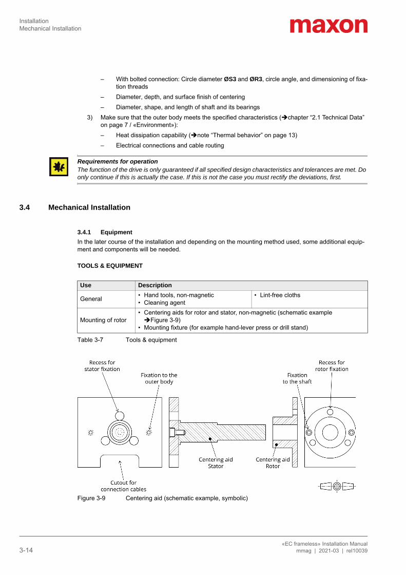
Figure 3-9 Centering aid (schematic example, symbolic)
Use Description
General • Hand tools, non-magnetic• Cleaning agent
• Lint-free cloths
Mounting of rotor• Centering aids for rotor and stator, non-magnetic (schematic example Figure 3-9)
• Mounting fixture (for example hand-lever press or drill stand)
InstallationMechanical Installation
«EC frameless» Installation Manualmmag | 2021-03 | rel10039 3-15
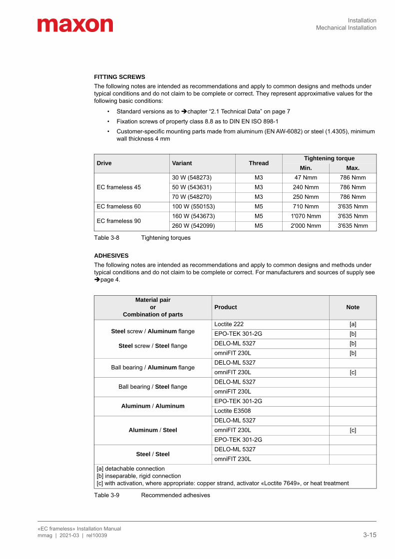
FITTING SCREWSThe following notes are intended as recommendations and apply to common designs and methods under typical conditions and do not claim to be complete or correct. They represent approximative values for the following basic conditions:
• Standard versions as to chapter “2.1 Technical Data” on page 7• Fixation screws of property class 8.8 as to DIN EN ISO 898-1• Customer-specific mounting parts made from aluminum (EN AW-6082) or steel (1.4305), minimum
wall thickness 4 mm
Table 3-8 Tightening torques
ADHESIVESThe following notes are intended as recommendations and apply to common designs and methods under typical conditions and do not claim to be complete or correct. For manufacturers and sources of supply see page 4.
Table 3-9 Recommended adhesives
Drive Variant ThreadTightening torque
Min. Max.
EC frameless 4530 W (548273) M3 47 Nmm 786 Nmm50 W (543631) M3 240 Nmm 786 Nmm70 W (548270) M3 250 Nmm 786 Nmm
EC frameless 60 100 W (550153) M5 710 Nmm 3'635 Nmm
EC frameless 90160 W (543673) M5 1'070 Nmm 3'635 Nmm260 W (542099) M5 2'000 Nmm 3'635 Nmm
Material pairor
Combination of partsProduct Note
Steel screw / Aluminum flange
Steel screw / Steel flange
Loctite 222 [a]EPO-TEK 301-2G [b]DELO-ML 5327 [b]omniFIT 230L [b]
Ball bearing / Aluminum flangeDELO-ML 5327omniFIT 230L [c]
Ball bearing / Steel flangeDELO-ML 5327omniFIT 230L
Aluminum / AluminumEPO-TEK 301-2GLoctite E3508
Aluminum / SteelDELO-ML 5327omniFIT 230L [c]EPO-TEK 301-2G
Steel / SteelDELO-ML 5327omniFIT 230L
[a] detachable connection[b] inseparable, rigid connection[c] with activation, where appropriate: copper strand, activator «Loctite 7649», or heat treatment
InstallationMechanical Installation
«EC frameless» Installation Manual3-16 mmag | 2021-03 | rel10039
3.4.2 Installing the Stator
Remember• Keep all parts (motor, outer body, shaft, bearings) and the surrounding area clean during the entire instal-
lation process and protect against contaminations and foreign particles.• Use only non-magnetic tools.• Do not apply impacts or hard strikes to the stator or rotor. These might damage the bearings.• Be careful not to squeeze, kink, or excessively bend the leads and do not damage the plugs.
The stator can be installed to the outer body by either using bolts at the axial front face (recommended) or adhesive applied to the radial circumference.
1) Before you start: Be aware of the necessary safety precautions (page 5) and strictly follow the general rules (page 9).
2) Decide on the fixation method and proceed with the respective step:Bolted fixation (step “3”)Adhesive fixation (step “13”)
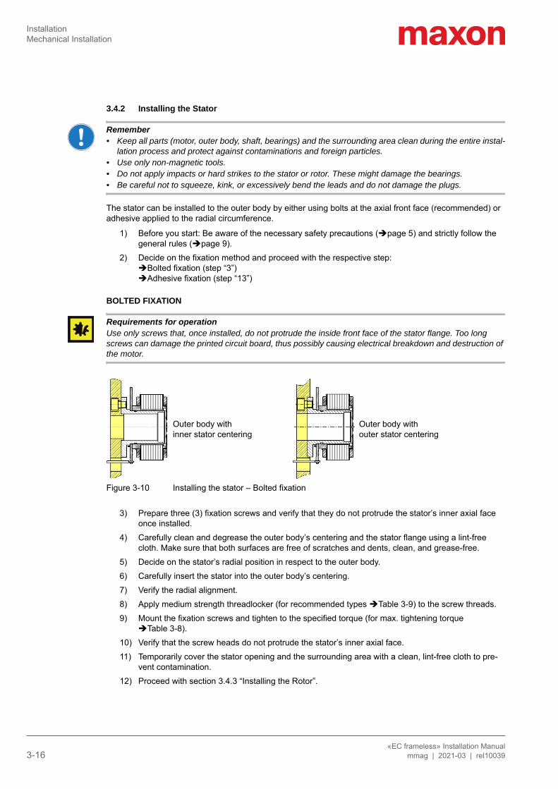
BOLTED FIXATION
Requirements for operationUse only screws that, once installed, do not protrude the inside front face of the stator flange. Too long screws can damage the printed circuit board, thus possibly causing electrical breakdown and destruction of the motor.
Figure 3-10 Installing the stator – Bolted fixation
3) Prepare three (3) fixation screws and verify that they do not protrude the stator’s inner axial face once installed.
4) Carefully clean and degrease the outer body’s centering and the stator flange using a lint-free cloth. Make sure that both surfaces are free of scratches and dents, clean, and grease-free.
5) Decide on the stator’s radial position in respect to the outer body.6) Carefully insert the stator into the outer body’s centering.7) Verify the radial alignment.8) Apply medium strength threadlocker (for recommended types Table 3-9) to the screw threads.9) Mount the fixation screws and tighten to the specified torque (for max. tightening torque
Table 3-8).10) Verify that the screw heads do not protrude the stator’s inner axial face.11) Temporarily cover the stator opening and the surrounding area with a clean, lint-free cloth to pre-
vent contamination.12) Proceed with section 3.4.3 “Installing the Rotor”.
Outer body with inner stator centering
Outer body with outer stator centering
InstallationMechanical Installation
«EC frameless» Installation Manualmmag | 2021-03 | rel10039 3-17
ADHESIVE FIXATION
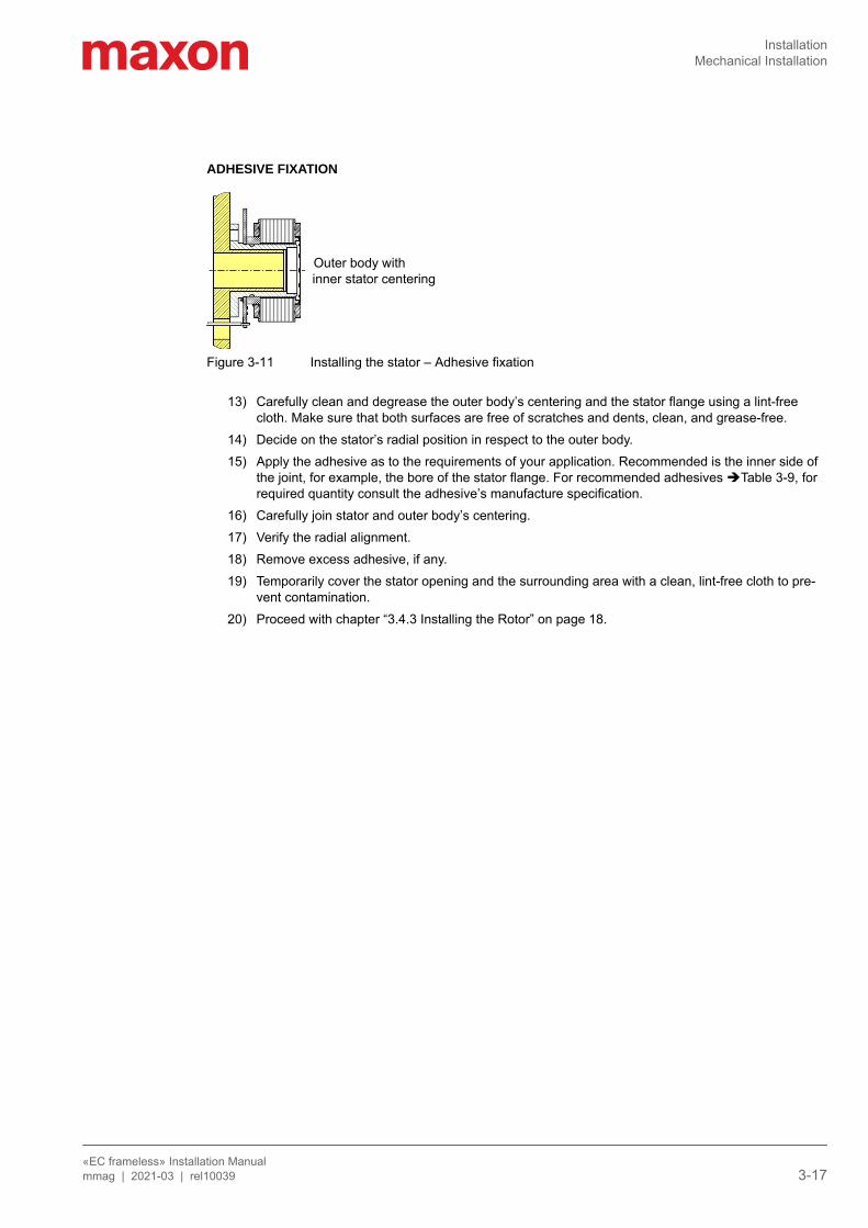
Figure 3-11 Installing the stator – Adhesive fixation
13) Carefully clean and degrease the outer body’s centering and the stator flange using a lint-free cloth. Make sure that both surfaces are free of scratches and dents, clean, and grease-free.
14) Decide on the stator’s radial position in respect to the outer body.15) Apply the adhesive as to the requirements of your application. Recommended is the inner side of
the joint, for example, the bore of the stator flange. For recommended adhesives Table 3-9, for required quantity consult the adhesive’s manufacture specification.
16) Carefully join stator and outer body’s centering.17) Verify the radial alignment.18) Remove excess adhesive, if any.19) Temporarily cover the stator opening and the surrounding area with a clean, lint-free cloth to pre-
vent contamination.20) Proceed with chapter “3.4.3 Installing the Rotor” on page 18.
Outer body with inner stator centering
InstallationMechanical Installation
«EC frameless» Installation Manual3-18 mmag | 2021-03 | rel10039
3.4.3 Installing the RotorThe rotor can be installed to the shaft by either using bolts at the axial front face (recommended) or adhe-sive applied to the radial circumference.
21) Decide on the fixation method and proceed with the respective step:Bolted fixation (step “22”)Adhesive fixation (step “30”)
BOLTED FIXATION
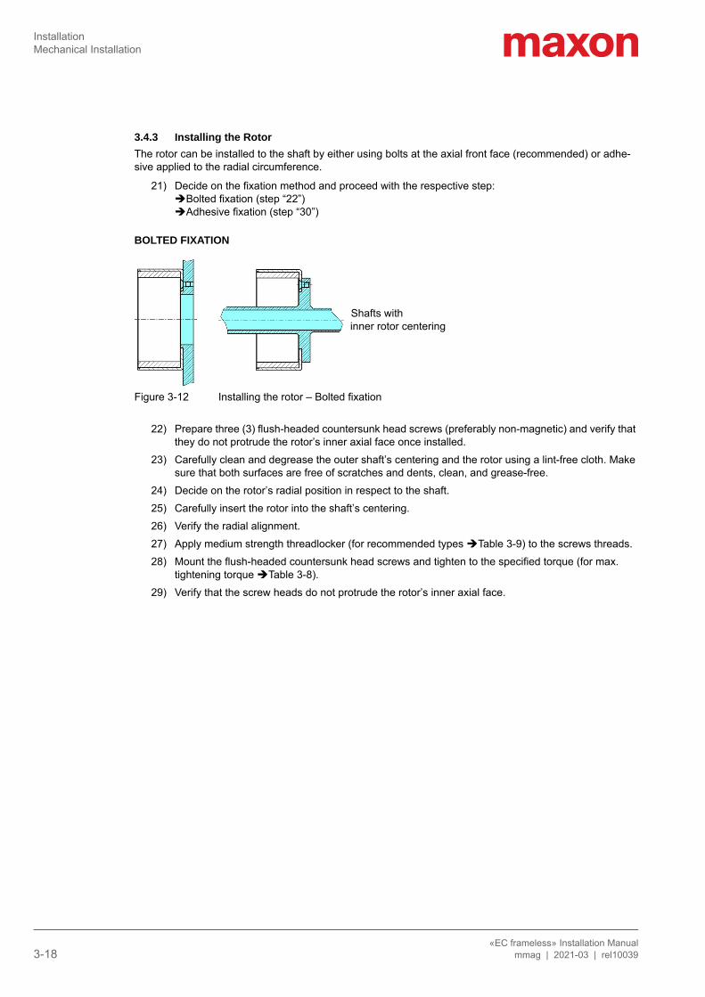
Figure 3-12 Installing the rotor – Bolted fixation
22) Prepare three (3) flush-headed countersunk head screws (preferably non-magnetic) and verify that they do not protrude the rotor’s inner axial face once installed.
23) Carefully clean and degrease the outer shaft’s centering and the rotor using a lint-free cloth. Make sure that both surfaces are free of scratches and dents, clean, and grease-free.
24) Decide on the rotor’s radial position in respect to the shaft.25) Carefully insert the rotor into the shaft’s centering.26) Verify the radial alignment.27) Apply medium strength threadlocker (for recommended types Table 3-9) to the screws threads.28) Mount the flush-headed countersunk head screws and tighten to the specified torque (for max.
tightening torque Table 3-8).29) Verify that the screw heads do not protrude the rotor’s inner axial face.
Shafts with inner rotor centering
InstallationMechanical Installation
«EC frameless» Installation Manualmmag | 2021-03 | rel10039 3-19
ADHESIVE FIXATION
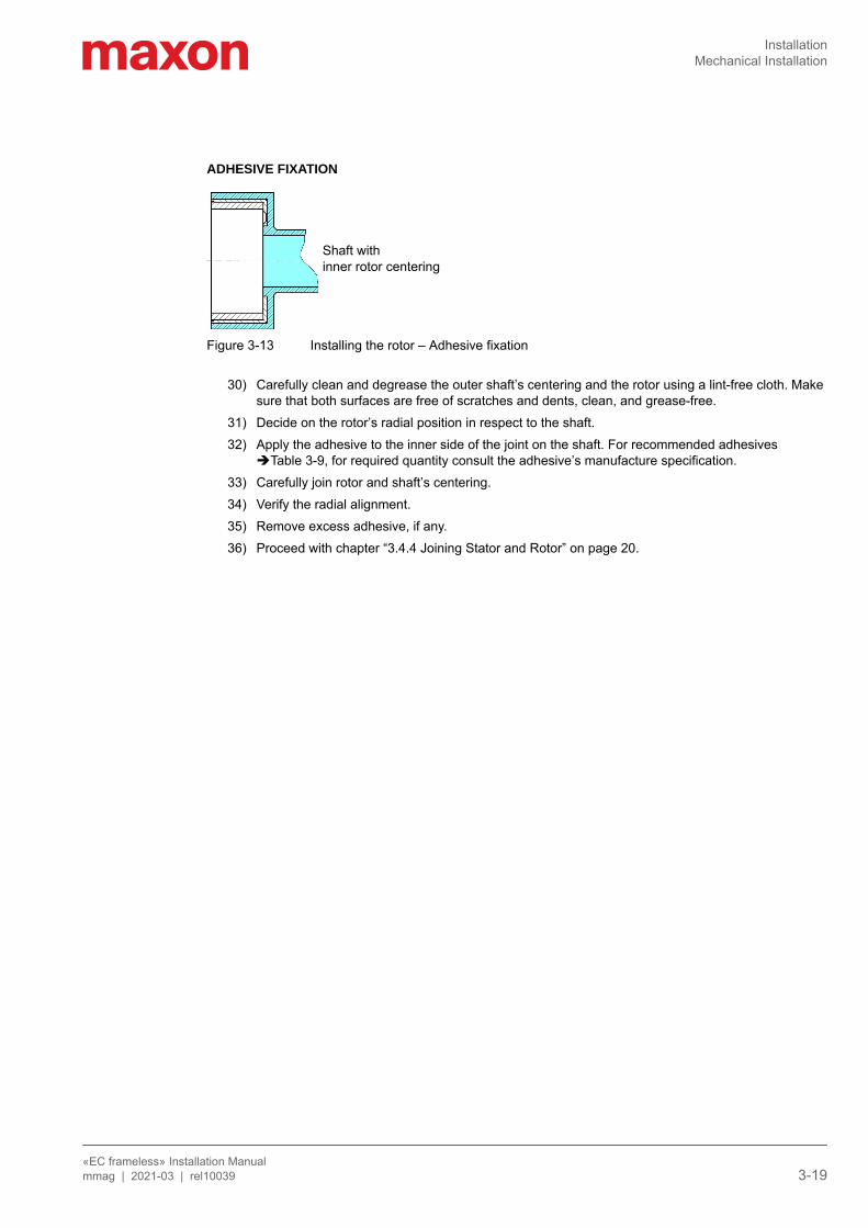
Figure 3-13 Installing the rotor – Adhesive fixation
30) Carefully clean and degrease the outer shaft’s centering and the rotor using a lint-free cloth. Make sure that both surfaces are free of scratches and dents, clean, and grease-free.
31) Decide on the rotor’s radial position in respect to the shaft.32) Apply the adhesive to the inner side of the joint on the shaft. For recommended adhesives
Table 3-9, for required quantity consult the adhesive’s manufacture specification.33) Carefully join rotor and shaft’s centering.34) Verify the radial alignment.35) Remove excess adhesive, if any.36) Proceed with chapter “3.4.4 Joining Stator and Rotor” on page 20.
Shaft with inner rotor centering
InstallationMechanical Installation
«EC frameless» Installation Manual3-20 mmag | 2021-03 | rel10039
3.4.4 Joining Stator and Rotor
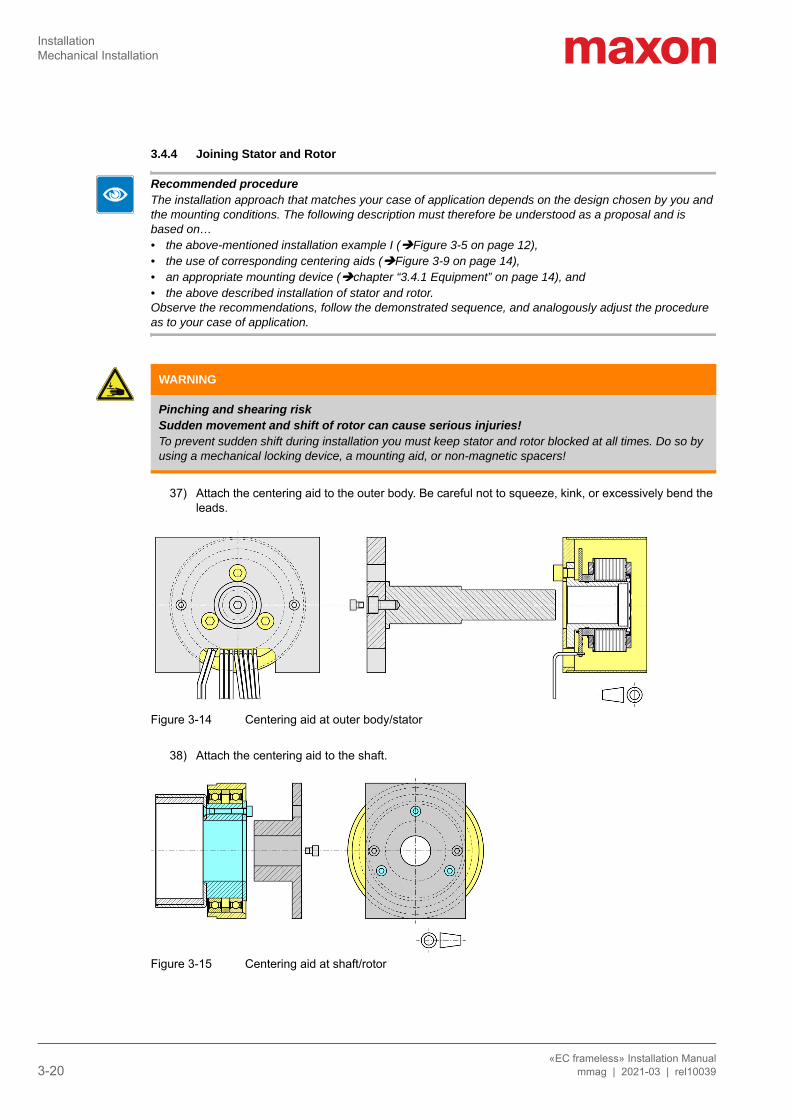
Recommended procedureThe installation approach that matches your case of application depends on the design chosen by you and the mounting conditions. The following description must therefore be understood as a proposal and is based on…• the above-mentioned installation example I (Figure 3-5 on page 12),• the use of corresponding centering aids (Figure 3-9 on page 14),• an appropriate mounting device (chapter “3.4.1 Equipment” on page 14), and• the above described installation of stator and rotor.Observe the recommendations, follow the demonstrated sequence, and analogously adjust the procedure as to your case of application.
37) Attach the centering aid to the outer body. Be careful not to squeeze, kink, or excessively bend the leads.
Figure 3-14 Centering aid at outer body/stator
38) Attach the centering aid to the shaft.
Figure 3-15 Centering aid at shaft/rotor
WARNING
Pinching and shearing riskSudden movement and shift of rotor can cause serious injuries!To prevent sudden shift during installation you must keep stator and rotor blocked at all times. Do so by using a mechanical locking device, a mounting aid, or non-magnetic spacers!
InstallationMechanical Installation
«EC frameless» Installation Manualmmag | 2021-03 | rel10039 3-21
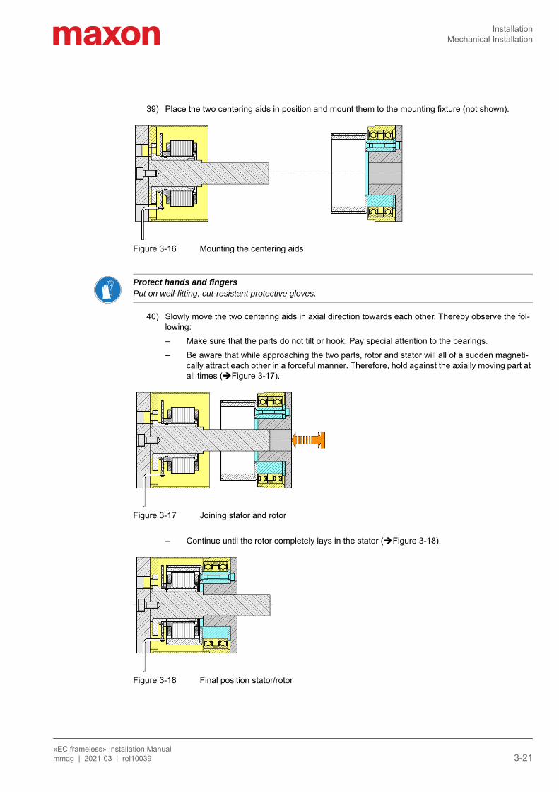
39) Place the two centering aids in position and mount them to the mounting fixture (not shown).
Figure 3-16 Mounting the centering aids
Protect hands and fingersPut on well-fitting, cut-resistant protective gloves.
40) Slowly move the two centering aids in axial direction towards each other. Thereby observe the fol-lowing:– Make sure that the parts do not tilt or hook. Pay special attention to the bearings.– Be aware that while approaching the two parts, rotor and stator will all of a sudden magneti-
cally attract each other in a forceful manner. Therefore, hold against the axially moving part at all times (Figure 3-17).
Figure 3-17 Joining stator and rotor
– Continue until the rotor completely lays in the stator (Figure 3-18).
Figure 3-18 Final position stator/rotor
InstallationMechanical Installation
«EC frameless» Installation Manual3-22 mmag | 2021-03 | rel10039
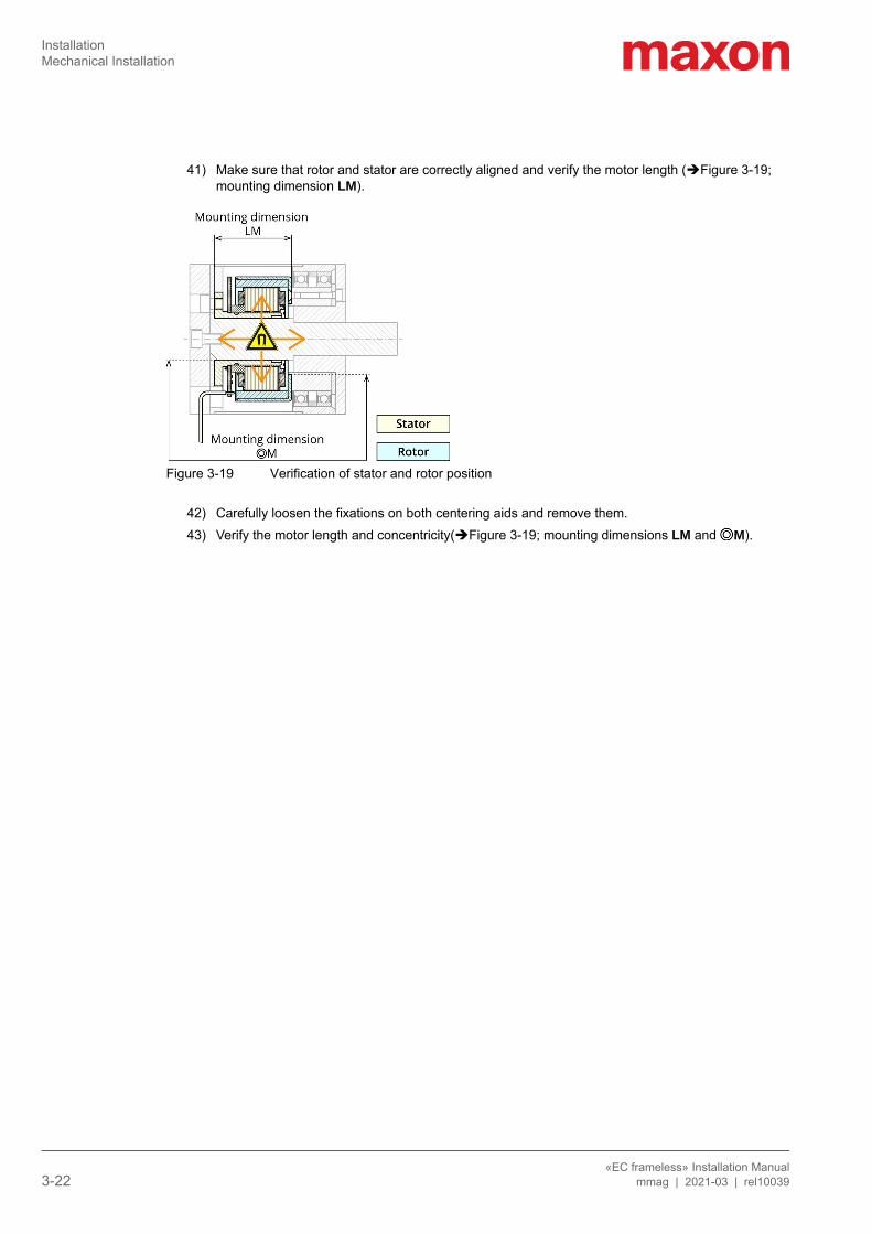
41) Make sure that rotor and stator are correctly aligned and verify the motor length (Figure 3-19; mounting dimension LM).
Figure 3-19 Verification of stator and rotor position
42) Carefully loosen the fixations on both centering aids and remove them.43) Verify the motor length and concentricity(Figure 3-19; mounting dimensions LM and M).
InstallationElectrical Installation
«EC frameless» Installation Manualmmag | 2021-03 | rel10039 3-23
3.5 Electrical Installation
3.5.1 Connections
Electrical Interface—possible permanent damage• Handle connections and cables with special care!• Do not kink cable, do not bend around small radii, do not route around sharp edges!• Do not apply tensile stress, use strain relief!
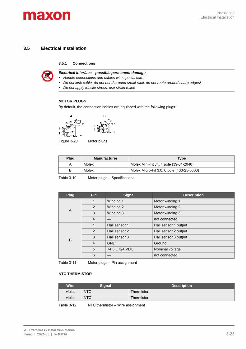
MOTOR PLUGSBy default, the connection cables are equipped with the following plugs.
Figure 3-20 Motor plugs
Table 3-10 Motor plugs – Specifications
Table 3-11 Motor plugs – Pin assignment
NTC THERMISTOR
Table 3-12 NTC thermistor – Wire assignment
Plug Manufacturer TypeA Molex Molex Mini-Fit Jr., 4 pole (39-01-2040)B Molex Molex Micro-Fit 3.0, 6 pole (430-25-0600)
Plug Pin Signal Description
A
1 Winding 1 Motor winding 12 Winding 2 Motor winding 23 Winding 3 Motor winding 34 — not connected
B
1 Hall sensor 1 Hall sensor 1 output2 Hall sensor 2 Hall sensor 2 output3 Hall sensor 3 Hall sensor 3 output4 GND Ground5 +4.5…+24 VDC Nominal voltage6 — not connected
Wire Signal Descriptionviolet NTC Thermistorviolet NTC Thermistor
InstallationElectrical Installation
«EC frameless» Installation Manual3-24 mmag | 2021-03 | rel10039
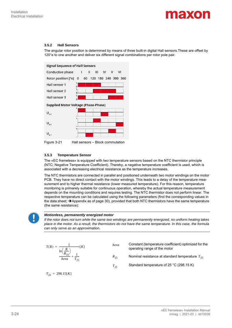
3.5.2 Hall SensorsThe angular rotor position is determined by means of three built-in digital Hall sensors.These are offset by 120°e to one another and deliver six different signal combinations per rotor pole pair.
Figure 3-21 Hall sensors – Block commutation
3.5.3 Temperature SensorThe «EC frameless» is equipped with two temperature sensors based on the NTC thermistor principle (NTC; Negative Temperature Coefficient). Thereby, a negative temperature coefficient is used, which is associated with a decreasing electrical resistance as the temperature increases.
The NTC thermistors are connected in parallel and positioned underneath two motor windings on the motor PCB. They have no direct contact with the motor windings. This leads to a delay of the temperature mea-surement and to higher thermal resistance (lower measured temperature). For this reason, temperature monitoring is primarely suitable for continuous operation, whereby the actual temperature measurement depends on the mounting conditions and requires testing. The NTC thermistor does not perform linear. The respective temperature can be calculated using the following parameters (find the corresponding values in the data sheet; Appendix as of page 30), provided that both NTC thermistors have the same temperature (the same resistance):
Motionless, permanently energized motorIf the rotor does not turn while the same two windings are permanently energized, no uniform heating takes place in the motor. As a result, the thermistors do not have the same temperature. In this case, the formula can only serve as an approximation.
Constant (temperature coefficient) optimized for the operating range of the motor
Nominal resistance at standard temperature
Standard temperature of 25 °C (298.15 K)
T R( ) 1R
R25-------- ln
beta------------------- 1
T25--------+
----------------------------------- K[ ]=
T25 298.15 K[ ]=
beta
R25 T25
T25
Maintenance
«EC frameless» Installation Manualmmag | 2021-03 | rel10039 1-25
4 MAINTENANCE
4.1 Periodic InspectionThe «EC frameless» as a whole and its individual parts are maintenance-free.
Outer body, motor shaft, and bearings are customer-made parts. For their maintenance and repair consult the relevant instructions. Thereby observe the following:
If you performmaintenance onouter body, motorshaft, and bear-ings:
• Before you start: Be aware of the necessary safety precautions (page 5) and strictly follow the general rules (page 9).
• Verify the correct position of the motor before re-commissioning. Specially important are the mounting dimensions LM and M (page 11).
4.2 StorageObserve all safety aspects (“About the Safety Precautions” on page 5) and the stated environmental con-ditions (“Technical Data” on page 7).
Physically separate the storage location to prevent all persons who possibly may suffer impairment caused by strong magnetic fields from approaching the device and force them to stay clear in a safe distance of at least two (2) meters. Put up warning signs stating STRONG MAGNETIC FIELDS.
4.3 Decommissioning & DismantlingDismantling follows basically the Installation in reverse order (chapter “3.4 Mechanical Installation” on page 14). Be aware of the necessary safety precautions (page 5) and strictly follow the general rules (page 9).
4.4 DisposalIn no case dispose used components with normal domestic waste.
Dispose used components only via official collection sites or a certified recycling company. Draw to atten-tion that the high magnetic forces produced by the device constitute an imminent hazard to persons wearing a cardiac pacemaker or metal implants.
«EC frameless» Installation Manual2-26 mmag | 2021-03 | rel10039
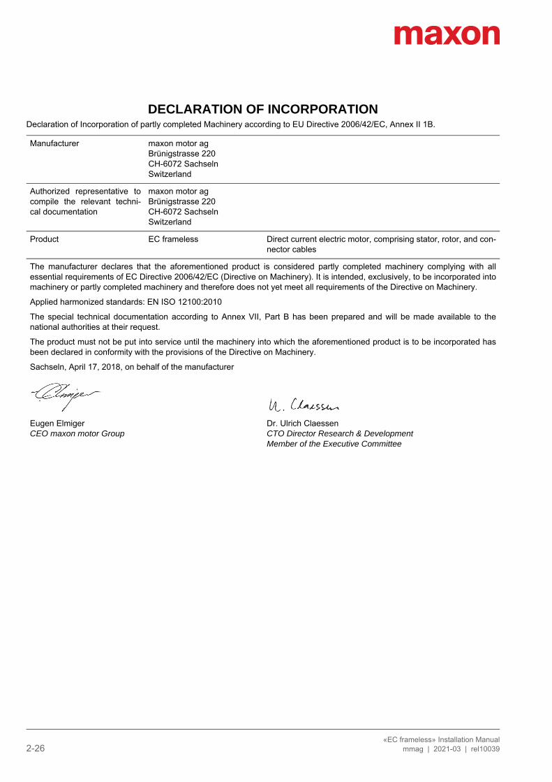
DECLARATION OF INCORPORATIONDeclaration of Incorporation of partly completed Machinery according to EU Directive 2006/42/EC, Annex II 1B.
Manufacturer maxon motor agBrünigstrasse 220CH-6072 SachselnSwitzerland
Authorized representative tocompile the relevant techni-cal documentation
maxon motor agBrünigstrasse 220CH-6072 SachselnSwitzerland
Product EC frameless Direct current electric motor, comprising stator, rotor, and con-nector cables
The manufacturer declares that the aforementioned product is considered partly completed machinery complying with allessential requirements of EC Directive 2006/42/EC (Directive on Machinery). It is intended, exclusively, to be incorporated intomachinery or partly completed machinery and therefore does not yet meet all requirements of the Directive on Machinery.
Applied harmonized standards: EN ISO 12100:2010
The special technical documentation according to Annex VII, Part B has been prepared and will be made available to thenational authorities at their request.
The product must not be put into service until the machinery into which the aforementioned product is to be incorporated hasbeen declared in conformity with the provisions of the Directive on Machinery.
Sachseln, April 17, 2018, on behalf of the manufacturer
Eugen ElmigerCEO maxon motor Group
Dr. Ulrich ClaessenCTO Director Research & DevelopmentMember of the Executive Committee
List of Figures
«EC frameless» Installation Manualmmag | 2021-03 | rel10039 Z-27
Figure 2-1 Dimensioning. . . . . . . . . . . . . . . . . . . . . . . . . . . . . . . . . . . . . . . . . . . . . . . . . . . . . . . . . . . . . . . . . . . . . . . . . . . 7Figure 2-2 Nameplate (typical) . . . . . . . . . . . . . . . . . . . . . . . . . . . . . . . . . . . . . . . . . . . . . . . . . . . . . . . . . . . . . . . . . . . . . . 8Figure 3-3 Dimensioning. . . . . . . . . . . . . . . . . . . . . . . . . . . . . . . . . . . . . . . . . . . . . . . . . . . . . . . . . . . . . . . . . . . . . . . . . . 11Figure 3-4 Application examples . . . . . . . . . . . . . . . . . . . . . . . . . . . . . . . . . . . . . . . . . . . . . . . . . . . . . . . . . . . . . . . . . . . 12Figure 3-5 Example I (recommended) . . . . . . . . . . . . . . . . . . . . . . . . . . . . . . . . . . . . . . . . . . . . . . . . . . . . . . . . . . . . . . . 12Figure 3-6 Example II (recommended) . . . . . . . . . . . . . . . . . . . . . . . . . . . . . . . . . . . . . . . . . . . . . . . . . . . . . . . . . . . . . . . 12Figure 3-7 Example III (recommended) . . . . . . . . . . . . . . . . . . . . . . . . . . . . . . . . . . . . . . . . . . . . . . . . . . . . . . . . . . . . . . 13Figure 3-8 Example IV . . . . . . . . . . . . . . . . . . . . . . . . . . . . . . . . . . . . . . . . . . . . . . . . . . . . . . . . . . . . . . . . . . . . . . . . . . . 13Figure 3-9 Centering aid (schematic example, symbolic). . . . . . . . . . . . . . . . . . . . . . . . . . . . . . . . . . . . . . . . . . . . . . . . . 14Figure 3-10 Installing the stator – Bolted fixation . . . . . . . . . . . . . . . . . . . . . . . . . . . . . . . . . . . . . . . . . . . . . . . . . . . . . . . . 16Figure 3-11 Installing the stator – Adhesive fixation . . . . . . . . . . . . . . . . . . . . . . . . . . . . . . . . . . . . . . . . . . . . . . . . . . . . . . 17Figure 3-12 Installing the rotor – Bolted fixation . . . . . . . . . . . . . . . . . . . . . . . . . . . . . . . . . . . . . . . . . . . . . . . . . . . . . . . . . 18Figure 3-13 Installing the rotor – Adhesive fixation. . . . . . . . . . . . . . . . . . . . . . . . . . . . . . . . . . . . . . . . . . . . . . . . . . . . . . . 19Figure 3-14 Centering aid at outer body/stator . . . . . . . . . . . . . . . . . . . . . . . . . . . . . . . . . . . . . . . . . . . . . . . . . . . . . . . . . . 20Figure 3-15 Centering aid at shaft/rotor . . . . . . . . . . . . . . . . . . . . . . . . . . . . . . . . . . . . . . . . . . . . . . . . . . . . . . . . . . . . . . . 20Figure 3-16 Mounting the centering aids . . . . . . . . . . . . . . . . . . . . . . . . . . . . . . . . . . . . . . . . . . . . . . . . . . . . . . . . . . . . . . 21Figure 3-17 Joining stator and rotor . . . . . . . . . . . . . . . . . . . . . . . . . . . . . . . . . . . . . . . . . . . . . . . . . . . . . . . . . . . . . . . . . . 21Figure 3-18 Final position stator/rotor. . . . . . . . . . . . . . . . . . . . . . . . . . . . . . . . . . . . . . . . . . . . . . . . . . . . . . . . . . . . . . . . . 21Figure 3-19 Verification of stator and rotor position . . . . . . . . . . . . . . . . . . . . . . . . . . . . . . . . . . . . . . . . . . . . . . . . . . . . . . 22Figure 3-20 Motor plugs . . . . . . . . . . . . . . . . . . . . . . . . . . . . . . . . . . . . . . . . . . . . . . . . . . . . . . . . . . . . . . . . . . . . . . . . . . . 23Figure 3-21 Hall sensors – Block commutation . . . . . . . . . . . . . . . . . . . . . . . . . . . . . . . . . . . . . . . . . . . . . . . . . . . . . . . . . 24
LIST OF FIGURES
«EC frameless» Installation ManualZ-28 mmag | 2021-03 | rel10039
List of Tables
Table 1-1 Notation used . . . . . . . . . . . . . . . . . . . . . . . . . . . . . . . . . . . . . . . . . . . . . . . . . . . . . . . . . . . . . . . . . . . . . . . . . . . 3Table 1-2 Symbols and signs . . . . . . . . . . . . . . . . . . . . . . . . . . . . . . . . . . . . . . . . . . . . . . . . . . . . . . . . . . . . . . . . . . . . . . . 4Table 1-3 Brand names and trademark owners . . . . . . . . . . . . . . . . . . . . . . . . . . . . . . . . . . . . . . . . . . . . . . . . . . . . . . . . . 4Table 2-4 Technical data (typical). . . . . . . . . . . . . . . . . . . . . . . . . . . . . . . . . . . . . . . . . . . . . . . . . . . . . . . . . . . . . . . . . . . . 7Table 2-5 Standards . . . . . . . . . . . . . . . . . . . . . . . . . . . . . . . . . . . . . . . . . . . . . . . . . . . . . . . . . . . . . . . . . . . . . . . . . . . . . . 8Table 3-6 Dimensioning . . . . . . . . . . . . . . . . . . . . . . . . . . . . . . . . . . . . . . . . . . . . . . . . . . . . . . . . . . . . . . . . . . . . . . . . . . 11Table 3-7 Tools & equipment . . . . . . . . . . . . . . . . . . . . . . . . . . . . . . . . . . . . . . . . . . . . . . . . . . . . . . . . . . . . . . . . . . . . . . 14Table 3-8 Tightening torques . . . . . . . . . . . . . . . . . . . . . . . . . . . . . . . . . . . . . . . . . . . . . . . . . . . . . . . . . . . . . . . . . . . . . . 15Table 3-9 Recommended adhesives . . . . . . . . . . . . . . . . . . . . . . . . . . . . . . . . . . . . . . . . . . . . . . . . . . . . . . . . . . . . . . . . 15Table 3-10 Motor plugs – Specifications. . . . . . . . . . . . . . . . . . . . . . . . . . . . . . . . . . . . . . . . . . . . . . . . . . . . . . . . . . . . . . . 23Table 3-11 Motor plugs – Pin assignment . . . . . . . . . . . . . . . . . . . . . . . . . . . . . . . . . . . . . . . . . . . . . . . . . . . . . . . . . . . . . 23Table 3-12 NTC thermistor – Wire assignment . . . . . . . . . . . . . . . . . . . . . . . . . . . . . . . . . . . . . . . . . . . . . . . . . . . . . . . . . 23
LIST OF TABLES
«EC frameless» Installation Manualmmag | 2021-03 | rel10039 Z-29
Index
Aalerts 3applicable EU directive 9applicable regulations 5
BBLDC motor 5
Ccentering aid 14color coding in illustrations 9country-specific regulations 5
Ddeclaration of incorporation 26delivery scope 5dismantling 25disposal 25
Eelectrical motor connection 23environmental conditions 7ESD protection 6EU directive, applicable 9
HHall sensors 24
Iillustrations, color code used 9increased drive power 13informatory signs 4inspection (periodic) 25
Llong-term storage 25
Mmandatory action signs 3motor connections 23
Nnotations used 3NTC thermistor 24
Pperformance data 7performance increase 13pin assignment 23precautions 5prerequisites prior installation 9prohibitive signs 3purpose
of the device 5of the document 3
Rregulations, applicable 5rotor position 24
Ssafety alerts 3scope of delivery 5signs used 3standards, fulfilled 8Storage 25storage conditions 7symbols used 3
Ttechnical data 7temperature monitoring 24thermal behavior 13thermistor 24
INDEX

«EC frameless» Installation ManualZ-30 mmag | 2021-03 | rel10039
APPENDIX
LXII
548273 574536 574537 574538
12 18 24 364360 4890 4360 4750163 129 81.4 61.62910 3510 2930 329054.9 57.8 54.7 662.02 1.63 1.01 0.847247 295 251 3789.69 8.61 4.93 5.3576.3 77.5 76.5 80.1
1.24 2.09 4.87 6.730.56 0.697 2.24 4.2925.5 34.3 51 70.6374 278 187 13518.2 17 17.9 12.928.6 30.8 28.1 20.2150 150 150 150
M 1:2
0 20 40 60 80 M [mNm]0.15 0.86 1.6 2.3 3 I [A]
0
2000
4000
6000
8000
10000
12000 6.73 K/W 3.92 K/W 11.4 s 296 s -40…+100°C +125°C
8 3 89 g
35 g 54 g
ESCON Module 24/2 426ESCON 36/3 EC 427 ESCON Mod. 50/4 EC-S 427ESCON Module 50/5 427ESCON 50/5 428DEC Module 24/2 430 DEC Module 50/5 430EPOS2 24/2 434EPOS2 Module 36/2 434EPOS2 24/5, 50/5 435EPOS2 P 24/5 438EPOS4 Mod./CB 24/1.5 441EPOS4 Module/CB 50/5 442MAXPOS 50/5 447
maxon special program September 2017 edition / subject to change
max
on
spec
ial p
rog
ram
Stock programStandard programSpecial program (on request)
Part Numbers
Specifications Operating Range Comments
n [rpm] Continuous operation: In observation of above listed thermal resistance (lines 17 and 18) the maximum permissible winding temperature will be reached during continuous operation at 25°C ambient = Thermal limit.
Continuous operation with reduced thermal resistance Rth2 50%.
Short term operation: The motor may be briefly over-loaded (recurring).
Assigned power ratin
maxon Modular System Overview on page 29–33
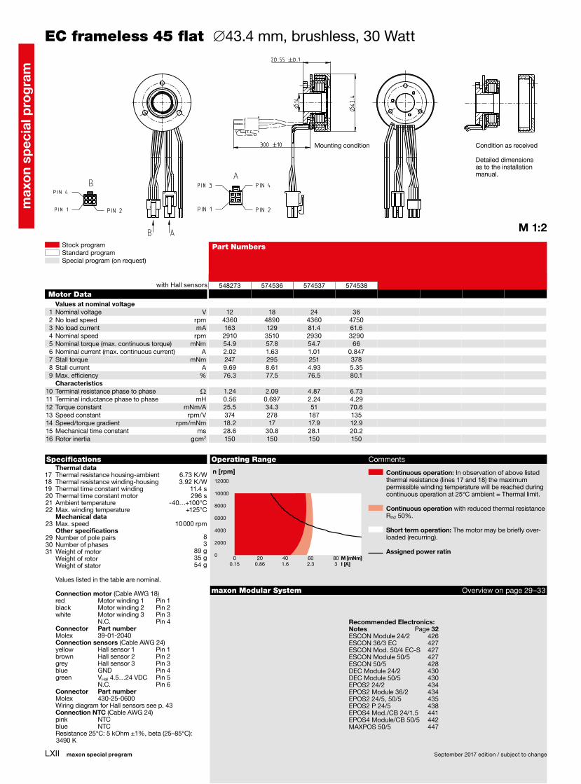
EC frameless 45 flat ∅43.4 mm, brushless, 30 Watt
Motor DataValues at nominal voltage
1 Nominal voltage V2 No load speed rpm3 No load current mA4 Nominal speed rpm5 Nominal torque (max. continuous torque) mNm6 Nominal current (max. continuous current) A7 Stall torque mNm8 Stall current A9 Max. efficiency %
Characteristics10 Terminal resistance phase to phase W11 Terminal inductance phase to phase mH12 Torque constant mNm/A13 Speed constant rpm/V14 Speed/torque gradient rpm/mNm15 Mechanical time constant ms16 Rotor inertia gcm2
Thermal data17 Thermal resistance housing-ambient 18 Thermal resistance winding-housing 19 Thermal time constant winding 20 Thermal time constant motor 21 Ambient temperature 22 Max. winding temperature Mechanical data23 Max. speed 10 000 rpm Other specifications29 Number of pole pairs 30 Number of phases 31 Weight of motor Weight of rotor Weight of stator
Values listed in the table are nominal.
Connection motor (Cable AWG 18) red Motor winding 1 Pin 1 black Motor winding 2 Pin 2 white Motor winding 3 Pin 3 N.C. Pin 4 Connector Part number Molex 39-01-2040 Connection sensors (Cable AWG 24) yellow Hall sensor 1 Pin 1 brown Hall sensor 2 Pin 2 grey Hall sensor 3 Pin 3 blue GND Pin 4 green VHall 4.5…24 VDC Pin 5 N.C. Pin 6 Connector Part number Molex 430-25-0600 Wiring diagram for Hall sensors see p. 43 Connection NTC (Cable AWG 24) pink NTC blue NTC Resistance 25°C: 5 kOhm ±1%, beta (25–85°C):
3490 K
Recommended Electronics:Notes Page 32
with Hall sensors
Mounting condition Condition as received
Detailed dimensions as to the installation manual.
E
D
C
B
A
87654321
A
B
C
D
E
F
1 2 3 4Aenderungen von Produkt oder Prozessen nur mit schriftlicher Freigabe durch
maxon. maxon motor ag. Alle Rechte vorbehalten. Nutzung nur gemaess
schriftlicher Vereinbarung erlaubt. / Modifications of product or processes
only upon written approval of maxon. maxon motor ag. All rights reserved. Use
permitted only as agreed in writing.
cc
14 �#�0.1
In diesemBereich �n�14H7In this area
9
A
14 H7
+0.018
0
()
A�-�B
Montagemassmounting dimension
B
23 H7
+0.021
0
()
26
M *3A
30
3.4B
32 h7 0 -0.025( )
Montagemassmounting dimension
20.55 �#�0.1
Bezeichnung/title CO: 679881 Datum/date Name/name Massstab/scale: 1:1 Modell/model
MassbildErstellt/created 27.07.2016 MMAGGAN Blatt/sheet:
A3/1/1 3585865
Geaendert/modified09.11.2018 MMAGGAN Masseinheitdimension unit
Projektionsmethodenprojection methods
EC45 flach Freigabe/release 20.11.2018 MMAGMALU mm ISO 5456-1
Artikel-Nr./part-no. Revisionrevision
Dokument-Nr./document-no. Revisionrevision
3585877 03
Tolerierungtolerancing
Allgemeintoleranzengeneral tolerances
Gewindetoleranzenscrew thread tolerances
Geometrische Tolerierung geometrical tolerancing
Oberflaechensurfaces
Kantenedges
N/AN/A
ISO 8015 ISO 2768-m ISO 965-1 ISO 1101 N/A N/A N/A
Steckerbelegung / PIN allocation
PIN 1 Hallsensor 1 / hall sensor 1
PIN 2 Hallsensor 2 / hall sensor 2
PIN 3 Hallsensor 3 / hall sensor 3
PIN 4 GND
PIN 5 +4.5...24 V DC
PIN 6 Not connected
43025-0600Molex
Artikel Nummerpart number
Fabrikatmanufacturer
Steckertyp / connector typ
Steckerbelegung / PIN allocation
PIN 1 Wicklung 1 / winding 1
PIN 2 Wicklung 2 / winding 2
PIN 3 Wicklung 3 / winding 3
PIN 4 Not connected
39-01-2040Molex
Artikel Nummerpart number
Fabrikatmanufacturer
Steckertyp / connector typ
NTC Out
NTC In
* Durchgangsgewinde:maximale Einschraubtiefe 3.0mm* Through thread:maximum depth for screws 3.0mm
Achtung: Rotor und Statorwerden getrennt angeliefertAttention: rotor and statordelivered seperated
1:2
PIN 3
PIN 1 PIN 2
PIN 4
A
PIN 1 PIN 2
PIN 4
B
BA
Artikel Nr./part no. Fertigprodukt/finished product Basis Nr./basic no.
maxon EC Frameless EC45 fl. BL Y 30W 0WE A
1.55
3 �#�0.112.05 �#�0.1
3x120�$�
3x120�$�
max.18.3
6.5
90�$�
43.4 0 -0.1
300 �#�10

LXIII
543631 574402 574403 574404
18 24 24 366720 6710 4730 3360247 185 106 42.3
5190 5240 3480 236097.1 83.4 69.6 90.53.52 2.33 1.41 0.828975 780 402 48438.8 23.3 8.47 4.8185 83.3 79.3 82.4
0.464 1.03 2.83 7.480.322 0.572 1.15 5.1525.1 33.5 47.5 101380 285 201 957.02 8.77 12 7.0713.6 17 23.3 13.7185 185 185 185
M 1:1
0 50 100 M [mNm]0.04 0.5 0.95 I [A]
0
2000
4000
6000
8000
10000
12000 4.53 K/W 4.75 K/W 17.7 s 227 s -40…+100°C +125°C
8 3 110 g
41 g 69 g
ESCON Module 24/2 426ESCON 36/3 EC 427 ESCON Mod. 50/4 EC-S 427ESCON Module 50/5 427ESCON 50/5 428DEC Module 24/2 430 DEC Module 50/5 430EPOS2 24/2 434EPOS2 Module 36/2 434EPOS2 24/5, 50/5 435EPOS2 P 24/5 438EPOS4 Mod./CB 24/1.5 441EPOS4 Module/CB 50/5 442MAXPOS 50/5 447
maxon special program September 2017 edition / subject to change
max
on
spec
ial p
rog
ram
Stock programStandard programSpecial program (on request)
Part Numbers
Specifications Operating Range Comments
n [rpm] Continuous operation: In observation of above listed thermal resistance (lines 17 and 18) the maximum permissible winding temperature will be reached during continuous operation at 25°C ambient = Thermal limit.
Continuous operation with reduced thermal resistance Rth2 50%.
Short term operation: The motor may be briefly over-loaded (recurring).
Assigned power ratin
maxon Modular System Overview on page 29–33
EC frameless 45 flat ∅43.4 mm, brushless, 50 Watt
Motor DataValues at nominal voltage
1 Nominal voltage V2 No load speed rpm3 No load current mA4 Nominal speed rpm5 Nominal torque (max. continuous torque) mNm6 Nominal current (max. continuous current) A7 Stall torque mNm8 Stall current A9 Max. efficiency %
Characteristics10 Terminal resistance phase to phase W11 Terminal inductance phase to phase mH12 Torque constant mNm/A13 Speed constant rpm/V14 Speed/torque gradient rpm/mNm15 Mechanical time constant ms16 Rotor inertia gcm2
Thermal data17 Thermal resistance housing-ambient 18 Thermal resistance winding-housing 19 Thermal time constant winding 20 Thermal time constant motor 21 Ambient temperature 22 Max. winding temperature Mechanical data23 Max. speed 10 000 rpm Other specifications29 Number of pole pairs 30 Number of phases 31 Weight of motor Weight of rotor Weight of stator
Values listed in the table are nominal.
Connection motor (Cable AWG 18) red Motor winding 1 Pin 1 black Motor winding 2 Pin 2 white Motor winding 3 Pin 3 N.C. Pin 4 Connector Part number Molex 39-01-2040 Connection sensors (Cable AWG 24) yellow Hall sensor 1 Pin 1 brown Hall sensor 2 Pin 2 grey Hall sensor 3 Pin 3 blue GND Pin 4 green VHall 4.5…24 VDC Pin 5 N.C. Pin 6 Connector Part number Molex 430-25-0600 Wiring diagram for Hall sensors see p. 43 Connection NTC (Cable AWG 24) pink NTC blue NTC Resistance 25°C: 5 kOhm ±1%, beta (25–85°C):
3490 K
Recommended Electronics:Notes Page 32
with Hall sensors
Mounting condition Condition as received
Detailed dimensions as to the installation manual.
E
D
C
B
A
87654321
A
B
C
D
E
F
1 2 3 4Aenderungen von Produkt oder Prozessen nur mit schriftlicher Freigabe durch
maxon. maxon motor ag. Alle Rechte vorbehalten. Nutzung nur gemaess
schriftlicher Vereinbarung erlaubt. / Modifications of product or processes
only upon written approval of maxon. maxon motor ag. All rights reserved. Use
permitted only as agreed in writing.
cc
14 �#�0.1
In diesemBereich �n�14H7In this area
12
A
14 H7
+0.018
0
()
A�-�B
Montagemassmounting dimension
B
23 H7
+0.021
0
()
26
M *3A
30
3.4B
32 h7 0 -0.025( )
Montagemassmounting dimension
23.7 �#�0.1
Bezeichnung/title CO: 679881 Datum/date Name/name Massstab/scale: 1:1 Modell/model
MassbildErstellt/created 09.05.2016 MMAGDARS Blatt/sheet:
A3/1/1 3411893
Geaendert/modified09.11.2018 MMAGGAN Masseinheitdimension unit
Projektionsmethodenprojection methods
EC45 flach Freigabe/release 20.11.2018 MMAGMALU mm ISO 5456-1
Artikel-Nr./part-no. Revisionrevision
Dokument-Nr./document-no. Revisionrevision
3411892 04
Tolerierungtolerancing
Allgemeintoleranzengeneral tolerances
Gewindetoleranzenscrew thread tolerances
Geometrische Tolerierung geometrical tolerancing
Oberflaechensurfaces
Kantenedges
N/AN/A
ISO 8015 ISO 2768-m ISO 965-1 ISO 1101 N/A N/A N/A
Steckerbelegung / PIN allocation
PIN 1 Hallsensor 1 / hall sensor 1
PIN 2 Hallsensor 2 / hall sensor 2
PIN 3 Hallsensor 3 / hall sensor 3
PIN 4 GND
PIN 5 +4.5...24 V DC
PIN 6 Not connected
43025-0600Molex
Artikel Nummerpart number
Fabrikatmanufacturer
Steckertyp / connector typ
Steckerbelegung / PIN allocation
PIN 1 Wicklung 1 / winding 1
PIN 2 Wicklung 2 / winding 2
PIN 3 Wicklung 3 / winding 3
PIN 4 Not connected
39-01-2040Molex
Artikel Nummerpart number
Fabrikatmanufacturer
Steckertyp / connector typ
* Durchgangsgewinde:maximale Einschraubtiefe 3.0mm* Through thread:maximum depth for screws 3.0mm
Achtung: Rotor und Statorwerden getrennt angeliefertAttention: rotor and statordelivered sperated
1:2
NTC Out
NTC In
PIN 3
PIN 1 PIN 2
PIN 4
A
PIN 1 PIN 2
PIN 4
B
BA
Artikel Nr./part no. Fertigprodukt/finished product Basis Nr./basic no.
maxon EC Frameless EC45 fl. BL Y 50W 0WE A
3 �#�0.115.2 �#�0.1
3x120�$�
3x120�$�
max.21.4
43.4 0 -0.1
300 �#�10
90�$�
6.5
1.55
LXIV
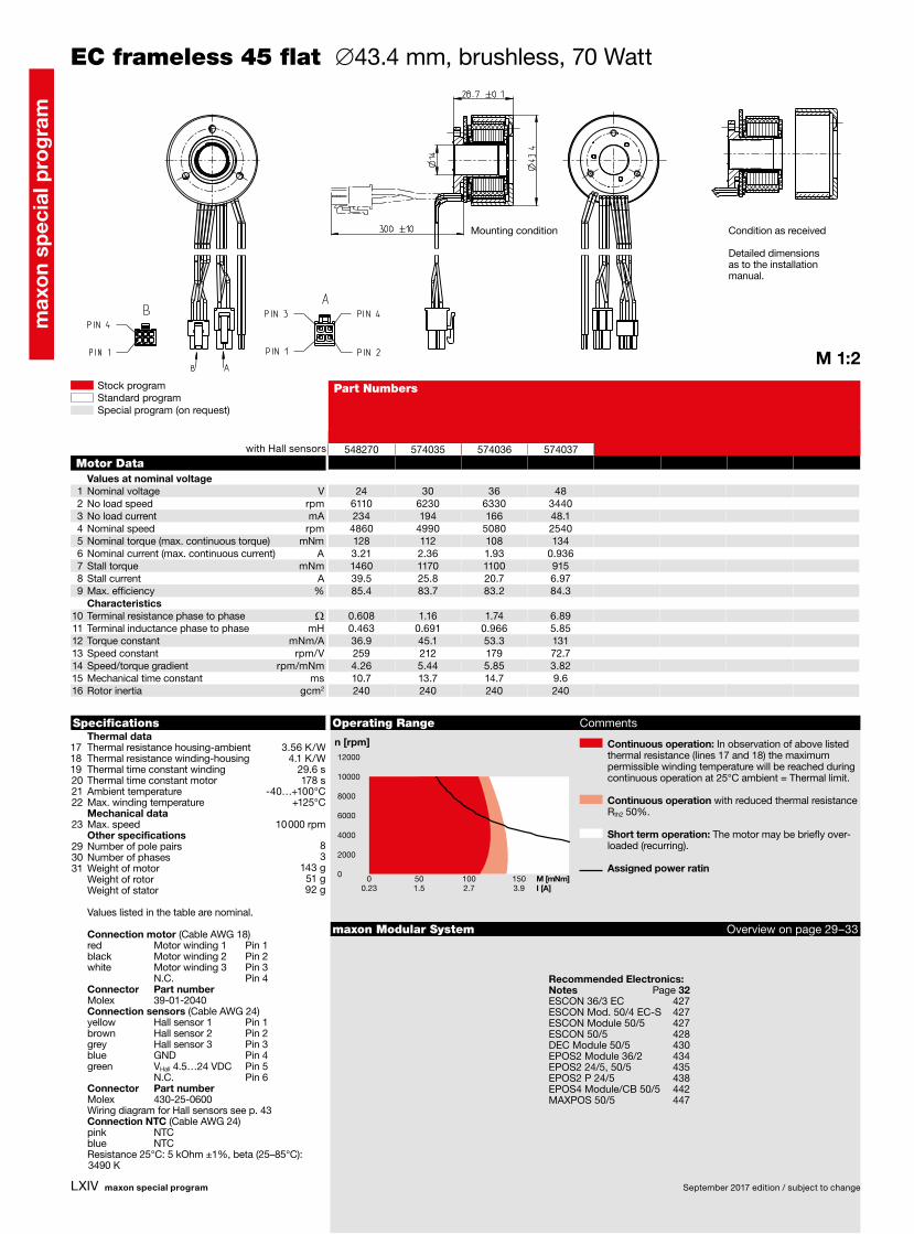
548270 574035 574036 574037
24 30 36 486110 6230 6330 3440234 194 166 48.1
4860 4990 5080 2540128 112 108 1343.21 2.36 1.93 0.9361460 1170 1100 91539.5 25.8 20.7 6.9785.4 83.7 83.2 84.3
0.608 1.16 1.74 6.890.463 0.691 0.966 5.8536.9 45.1 53.3 131259 212 179 72.74.26 5.44 5.85 3.8210.7 13.7 14.7 9.6240 240 240 240
M 1:2
0 50 100 150 M [mNm]0.23 1.5 2.7 3.9 I [A]
0
2000
4000
6000
8000
10000
12000 3.56 K/W 4.1 K/W 29.6 s 178 s -40…+100°C +125°C
8 3 143 g 51 g 92 g
ESCON 36/3 EC 427 ESCON Mod. 50/4 EC-S 427ESCON Module 50/5 427ESCON 50/5 428DEC Module 50/5 430EPOS2 Module 36/2 434EPOS2 24/5, 50/5 435EPOS2 P 24/5 438EPOS4 Module/CB 50/5 442MAXPOS 50/5 447
maxon special program September 2017 edition / subject to change
max
on
spec
ial p
rog
ram
Stock programStandard programSpecial program (on request)
Part Numbers
Specifications Operating Range Comments
n [rpm] Continuous operation: In observation of above listed thermal resistance (lines 17 and 18) the maximum permissible winding temperature will be reached during continuous operation at 25°C ambient = Thermal limit.
Continuous operation with reduced thermal resistance Rth2 50%.
Short term operation: The motor may be briefly over-loaded (recurring).
Assigned power ratin
maxon Modular System Overview on page 29–33
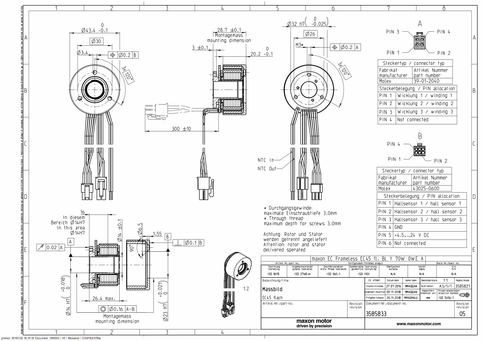
EC frameless 45 flat ∅43.4 mm, brushless, 70 Watt
Motor DataValues at nominal voltage
1 Nominal voltage V2 No load speed rpm3 No load current mA4 Nominal speed rpm5 Nominal torque (max. continuous torque) mNm6 Nominal current (max. continuous current) A7 Stall torque mNm8 Stall current A9 Max. efficiency %
Characteristics10 Terminal resistance phase to phase W11 Terminal inductance phase to phase mH12 Torque constant mNm/A13 Speed constant rpm/V14 Speed/torque gradient rpm/mNm15 Mechanical time constant ms16 Rotor inertia gcm2
Thermal data17 Thermal resistance housing-ambient 18 Thermal resistance winding-housing 19 Thermal time constant winding 20 Thermal time constant motor 21 Ambient temperature 22 Max. winding temperature Mechanical data23 Max. speed 10 000 rpm Other specifications29 Number of pole pairs 30 Number of phases 31 Weight of motor Weight of rotor Weight of stator
Values listed in the table are nominal.
Connection motor (Cable AWG 18) red Motor winding 1 Pin 1 black Motor winding 2 Pin 2 white Motor winding 3 Pin 3 N.C. Pin 4 Connector Part number Molex 39-01-2040 Connection sensors (Cable AWG 24) yellow Hall sensor 1 Pin 1 brown Hall sensor 2 Pin 2 grey Hall sensor 3 Pin 3 blue GND Pin 4 green VHall 4.5…24 VDC Pin 5 N.C. Pin 6 Connector Part number Molex 430-25-0600 Wiring diagram for Hall sensors see p. 43 Connection NTC (Cable AWG 24) pink NTC blue NTC Resistance 25°C: 5 kOhm ±1%, beta (25–85°C):
3490 K
Recommended Electronics:Notes Page 32
with Hall sensors
Mounting condition Condition as received
Detailed dimensions as to the installation manual.
E
D
C
B
A
87654321
A
B
C
D
E
F
1 2 3 4Aenderungen von Produkt oder Prozessen nur mit schriftlicher Freigabe durch
maxon. maxon motor ag. Alle Rechte vorbehalten. Nutzung nur gemaess
schriftlicher Vereinbarung erlaubt. / Modifications of product or processes
only upon written approval of maxon. maxon motor ag. All rights reserved. Use
permitted only as agreed in writing.
cc
14 �#�0.1In diesem
Bereich �n�14H7In this area
16
14 H7
+0.018
0
()
23 H7
+0.021
0
()
26
M *330
3.4
32 h7 0 -0.025( )
3 �#�0.1
Montagemassmounting dimension
28.7 �#�0.1
20.2 0 -0.1
AB
BA
1.55
3x120�$�
3x120�$�
max.26.4
6.5
90�$�
43.4 0 -0.1
300 �#�10
A�-�B
Montagemassmounting dimension
A
B
Bezeichnung/title CO: 679881 Datum/date Name/name Massstab/scale: 1:1 Modell/model
MassbildErstellt/created 27.07.2016 MMAGGAN Blatt/sheet:
A3/1/1 3585821
Geaendert/modified09.11.2018 MMAGGAN Masseinheitdimension unit
Projektionsmethodenprojection methods
EC45 flach Freigabe/release 20.11.2018 MMAGMALU mm ISO 5456-1
Artikel-Nr./part-no. Revisionrevision
Dokument-Nr./document-no. Revisionrevision
3585833 05
Tolerierungtolerancing
Allgemeintoleranzengeneral tolerances
Gewindetoleranzenscrew thread tolerances
Geometrische Tolerierung geometrical tolerancing
Oberflaechensurfaces
Kantenedges
N/AN/A
ISO 8015 ISO 2768-m ISO 965-1 ISO 1101 N/A N/A N/A
Steckerbelegung / PIN allocation
PIN 1 Hallsensor 1 / hall sensor 1
PIN 2 Hallsensor 2 / hall sensor 2
PIN 3 Hallsensor 3 / hall sensor 3
PIN 4 GND
PIN 5 +4.5...24 V DC
PIN 6 Not connected
43025-0600Molex
Artikel Nummerpart number
Fabrikatmanufacturer
Steckertyp / connector typ
Steckerbelegung / PIN allocation
PIN 1 Wicklung 1 / winding 1
PIN 2 Wicklung 2 / winding 2
PIN 3 Wicklung 3 / winding 3
PIN 4 Not connected
39-01-2040Molex
Artikel Nummerpart number
Fabrikatmanufacturer
Steckertyp / connector typ
NTC Out
NTC In
* Durchgangsgewinde:maximale Einschraubtiefe 3.0mm* Through thread:maximum depth for screws 3.0mm
Achtung: Rotor und Statorwerden getrennt angeliefertAttention: rotor and statordelivered sperated
1:2
PIN 3
PIN 1 PIN 2
PIN 4
A
PIN 1 PIN 2
PIN 4
B
Artikel Nr./part no. Fertigprodukt/finished product Basis Nr./basic no.
maxon EC Frameless EC45 fl. BL Y 70W 0WE A
LXV
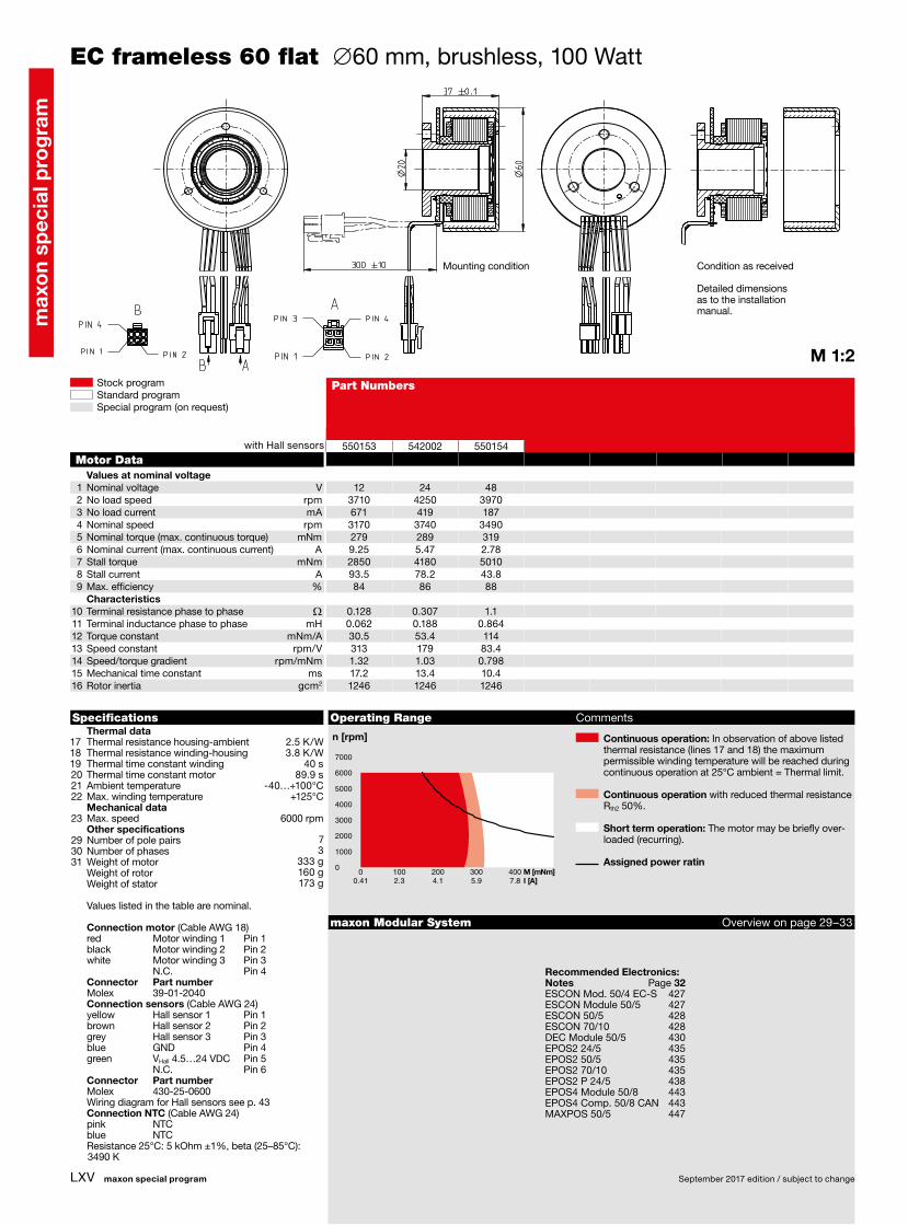
550153 542002 550154
12 24 483710 4250 3970671 419 1873170 3740 3490279 289 3199.25 5.47 2.782850 4180 501093.5 78.2 43.884 86 88
0.128 0.307 1.10.062 0.188 0.86430.5 53.4 114313 179 83.41.32 1.03 0.79817.2 13.4 10.41246 1246 1246
M 1:2
0 100 200 300 400 M [mNm]0.41 2.3 4.1 5.9 7.8 I [A]
0
1000
2000
3000
4000
5000
6000
7000
MICB/21.03.2017
2.5 K/W 3.8 K/W 40 s 89.9 s -40…+100°C +125°C
7 3 333 g 160 g 173 g
ESCON Mod. 50/4 EC-S 427ESCON Module 50/5 427ESCON 50/5 428ESCON 70/10 428DEC Module 50/5 430EPOS2 24/5 435EPOS2 50/5 435EPOS2 70/10 435EPOS2 P 24/5 438EPOS4 Module 50/8 443EPOS4 Comp. 50/8 CAN 443MAXPOS 50/5 447
maxon special program September 2017 edition / subject to change
max
on
spec
ial p
rog
ram
Stock programStandard programSpecial program (on request)
Part Numbers
Specifications Operating Range Comments
n [rpm] Continuous operation: In observation of above listed thermal resistance (lines 17 and 18) the maximum permissible winding temperature will be reached during continuous operation at 25°C ambient = Thermal limit.
Continuous operation with reduced thermal resistance Rth2 50%.
Short term operation: The motor may be briefly over-loaded (recurring).
Assigned power ratin
maxon Modular System Overview on page 29–33
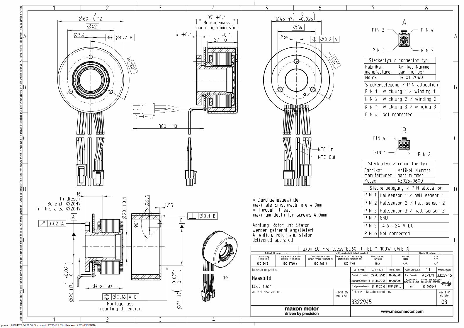
EC frameless 60 flat ∅60 mm, brushless, 100 Watt
Motor DataValues at nominal voltage
1 Nominal voltage V2 No load speed rpm3 No load current mA4 Nominal speed rpm5 Nominal torque (max. continuous torque) mNm6 Nominal current (max. continuous current) A7 Stall torque mNm8 Stall current A9 Max. efficiency %
Characteristics10 Terminal resistance phase to phase W11 Terminal inductance phase to phase mH12 Torque constant mNm/A13 Speed constant rpm/V14 Speed/torque gradient rpm/mNm15 Mechanical time constant ms16 Rotor inertia gcm2
Thermal data17 Thermal resistance housing-ambient 18 Thermal resistance winding-housing 19 Thermal time constant winding 20 Thermal time constant motor 21 Ambient temperature 22 Max. winding temperature Mechanical data23 Max. speed 6000 rpm Other specifications29 Number of pole pairs 30 Number of phases 31 Weight of motor Weight of rotor Weight of stator
Values listed in the table are nominal.
Connection motor (Cable AWG 18) red Motor winding 1 Pin 1 black Motor winding 2 Pin 2 white Motor winding 3 Pin 3 N.C. Pin 4 Connector Part number Molex 39-01-2040 Connection sensors (Cable AWG 24) yellow Hall sensor 1 Pin 1 brown Hall sensor 2 Pin 2 grey Hall sensor 3 Pin 3 blue GND Pin 4 green VHall 4.5…24 VDC Pin 5 N.C. Pin 6 Connector Part number Molex 430-25-0600 Wiring diagram for Hall sensors see p. 43 Connection NTC (Cable AWG 24) pink NTC blue NTC Resistance 25°C: 5 kOhm ±1%, beta (25–85°C):
3490 K
Recommended Electronics:Notes Page 32
with Hall sensors
Mounting condition Condition as received
Detailed dimensions as to the installation manual.
E
D
C
B
A
87654321
A
B
C
D
E
F
1 2 3 4Aenderungen von Produkt oder Prozessen nur mit schriftlicher Freigabe durch
maxon. maxon motor ag. Alle Rechte vorbehalten. Nutzung nur gemaess
schriftlicher Vereinbarung erlaubt. / Modifications of product or processes
only upon written approval of maxon. maxon motor ag. All rights reserved. Use
permitted only as agreed in writing.
cc
20 �#�0.1In diesem
Bereich �n�20H7In this area �n�20H7
16
20 H7
+0.021
0
()
A�-�B
Montagemassmounting dimension
34 H7
+0.025
0
()
42
3.4B
60 0 -0.12 45 h7
0 -0.025( )34
M *5A
4 �#�0.127
+0.1 0
Montagemassmounting dimension
37 �#�0.1
Bezeichnung/title CO: 679881 Datum/date Name/name Massstab/scale: 1:1 Modell/model
MassbildErstellt/created 24.03.2016 MMAGGAN Blatt/sheet:
A3/1/1 3322946
Geaendert/modified09.11.2018 MMAGGAN Masseinheitdimension unit
Projektionsmethodenprojection methods
EC60 flach Freigabe/release 20.11.2018 MMAGMALU mm ISO 5456-1
Artikel-Nr./part-no. Revisionrevision
Dokument-Nr./document-no. Revisionrevision
3322945 03
Tolerierungtolerancing
Allgemeintoleranzengeneral tolerances
Gewindetoleranzenscrew thread tolerances
Geometrische Tolerierung geometrical tolerancing
Oberflaechensurfaces
Kantenedges
N/AN/A
ISO 8015 ISO 2768-m ISO 965-1 ISO 1101 N/A N/A N/A
Steckerbelegung / PIN allocation
PIN 1 Hallsensor 1 / hall sensor 1
PIN 2 Hallsensor 2 / hall sensor 2
PIN 3 Hallsensor 3 / hall sensor 3
PIN 4 GND
PIN 5 +4.5...24 V DC
PIN 6 Not connected
43025-0600Molex
Artikel Nummerpart number
Fabrikatmanufacturer
Steckertyp / connector typ
Steckerbelegung / PIN allocation
PIN 1 Wicklung 1 / winding 1
PIN 2 Wicklung 2 / winding 2
PIN 3 Wicklung 3 / winding 3
PIN 4 Not connected
39-01-2040Molex
Artikel Nummerpart number
Fabrikatmanufacturer
Steckertyp / connector typ
NTC Out
NTC In
* Durchgangsgewinde:maximale Einschraubtiefe 4.0mm* Through thread:maximum depth for screws 4.0mm
Achtung: Rotor und Statorwerden getrennt angeliefertAttention: rotor and statordelivered sperated
1:2
PIN 3
PIN 1 PIN 2
PIN 4
A
PIN 1 PIN 2
PIN 4
B
AB
B
A
Artikel Nr./part no. Fertigprodukt/finished product Basis Nr./basic no.
maxon EC Frameless EC60 fl. BL Y 100W 0WE A
3x120�$�
1.55
max.34.5
3x120�$�
6.5
90�$�
300 �#�10
LXVI
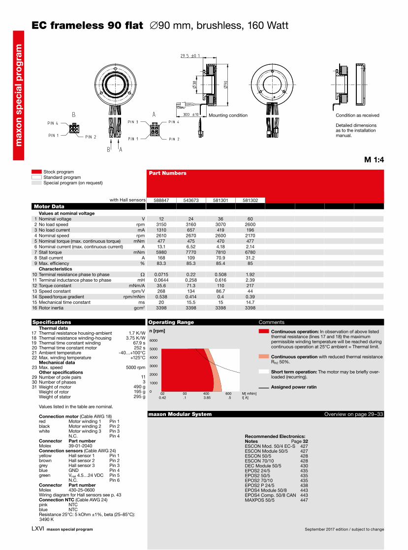
588847 543673 581301 581302
12 24 36 603150 3160 3070 26001310 657 419 1962610 2670 2600 2170477 475 470 47713.1 6.52 4.18 2.145980 7770 7810 6780168 109 70.9 31.283.3 85.3 85.4 85
0.0715 0.22 0.508 1.920.0644 0.258 0.616 2.39
35.6 71.3 110 217268 134 86.7 44
0.538 0.414 0.4 0.3920 15.5 15 14.7
3398 3398 3398 3398
M 1:4
1.7 K/W 3.75 K/W 67.9 s 252 s -40…+100°C +125°C
11 3 490 g 195 g 295 g
ESCON Mod. 50/4 EC-S 427ESCON Module 50/5 427ESCON 50/5 428ESCON 70/10 428DEC Module 50/5 430EPOS2 24/5 435EPOS2 50/5 435EPOS2 70/10 435EPOS2 P 24/5 438EPOS4 Module 50/8 443EPOS4 Comp. 50/8 CAN 443MAXPOS 50/5 447
02 00 400 600 M[ mNm]0.42 .1 3.85 .5 I[ A]
0
1000
2000
3000
4000
5000
6000
maxon special program September 2017 edition / subject to change
max
on
spec
ial p
rog
ram
Stock programStandard programSpecial program (on request)
Part Numbers
Specifications Operating Range Comments
n [rpm] Continuous operation: In observation of above listed thermal resistance (lines 17 and 18) the maximum permissible winding temperature will be reached during continuous operation at 25°C ambient = Thermal limit.
Continuous operation with reduced thermal resistance Rth2 50%.
Short term operation: The motor may be briefly over-loaded (recurring).
Assigned power ratin
maxon Modular System Overview on page 29–33
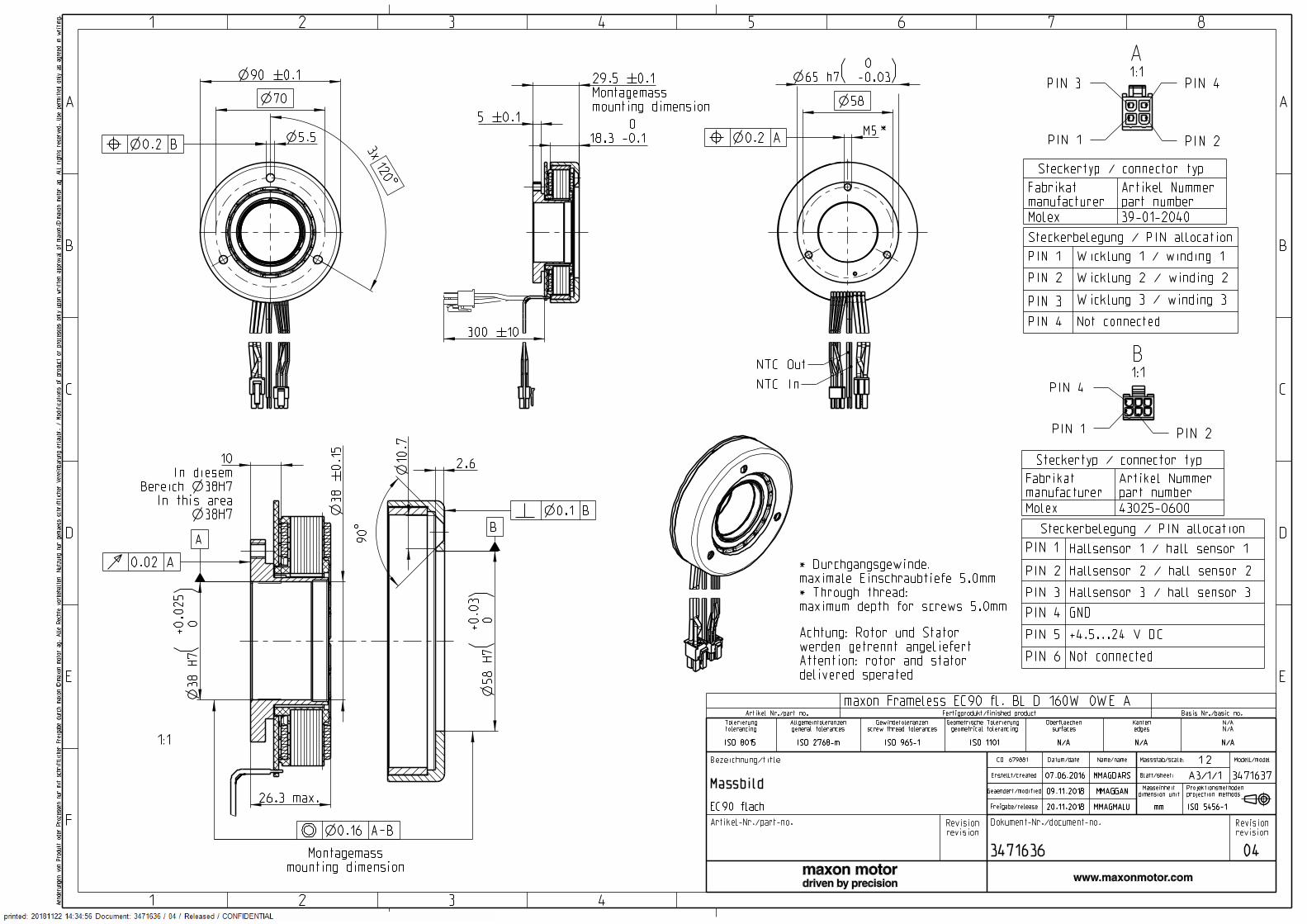
EC frameless 90 flat ∅90 mm, brushless, 160 Watt
Motor DataValues at nominal voltage
1 Nominal voltage V2 No load speed rpm3 No load current mA4 Nominal speed rpm5 Nominal torque (max. continuous torque) mNm6 Nominal current (max. continuous current) A7 Stall torque mNm8 Stall current A9 Max. efficiency %
Characteristics10 Terminal resistance phase to phase W11 Terminal inductance phase to phase mH12 Torque constant mNm/A13 Speed constant rpm/V14 Speed/torque gradient rpm/mNm15 Mechanical time constant ms16 Rotor inertia gcm2
Thermal data17 Thermal resistance housing-ambient 18 Thermal resistance winding-housing 19 Thermal time constant winding 20 Thermal time constant motor 21 Ambient temperature 22 Max. winding temperature Mechanical data23 Max. speed 5000 rpm Other specifications29 Number of pole pairs 30 Number of phases 31 Weight of motor Weight of rotor Weight of stator
Values listed in the table are nominal.
Connection motor (Cable AWG 18) red Motor winding 1 Pin 1 black Motor winding 2 Pin 2 white Motor winding 3 Pin 3 N.C. Pin 4 Connector Part number Molex 39-01-2040 Connection sensors (Cable AWG 24) yellow Hall sensor 1 Pin 1 brown Hall sensor 2 Pin 2 grey Hall sensor 3 Pin 3 blue GND Pin 4 green VHall 4.5…24 VDC Pin 5 N.C. Pin 6 Connector Part number Molex 430-25-0600 Wiring diagram for Hall sensors see p. 43 Connection NTC (Cable AWG 24) pink NTC blue NTC Resistance 25°C: 5 kOhm ±1%, beta (25–85°C):
3490 K
Recommended Electronics:Notes Page 32
with Hall sensors
Mounting condition Condition as received
Detailed dimensions as to the installation manual.
E
D
C
B
A
87654321
A
B
C
D
E
F
1 2 3 4Aenderungen von Produkt oder Prozessen nur mit schriftlicher Freigabe durch
maxon. maxon motor ag. Alle Rechte vorbehalten. Nutzung nur gemaess
schriftlicher Vereinbarung erlaubt. / Modifications of product or processes
only upon written approval of maxon. maxon motor ag. All rights reserved. Use
permitted only as agreed in writing.
cc
38 �#�0.15
In diesemBereich �n�38H7
In this area
10
58 H7
+0.03
0
()
A�-�B
38 H7
+0.025
0
()
5.5B
65 h7 0 -0.03( )
70 Montagemassmounting dimension
29.5 �#�0.1
58
M5A
Bezeichnung/title CO: 679881 Datum/date Name/name Massstab/scale: 1:2 Modell/model
MassbildErstellt/created 07.06.2016 MMAGDARS Blatt/sheet:
A3/1/1 3471637
Geaendert/modified09.11.2018 MMAGGAN Masseinheitdimension unit
Projektionsmethodenprojection methods
EC90 flach Freigabe/release 20.11.2018 MMAGMALU mm ISO 5456-1
Artikel-Nr./part-no. Revisionrevision
Dokument-Nr./document-no. Revisionrevision
3471636 04
Tolerierungtolerancing
Allgemeintoleranzengeneral tolerances
Gewindetoleranzenscrew thread tolerances
Geometrische Tolerierung geometrical tolerancing
Oberflaechensurfaces
Kantenedges
N/AN/A
ISO 8015 ISO 2768-m ISO 965-1 ISO 1101 N/A N/A N/A
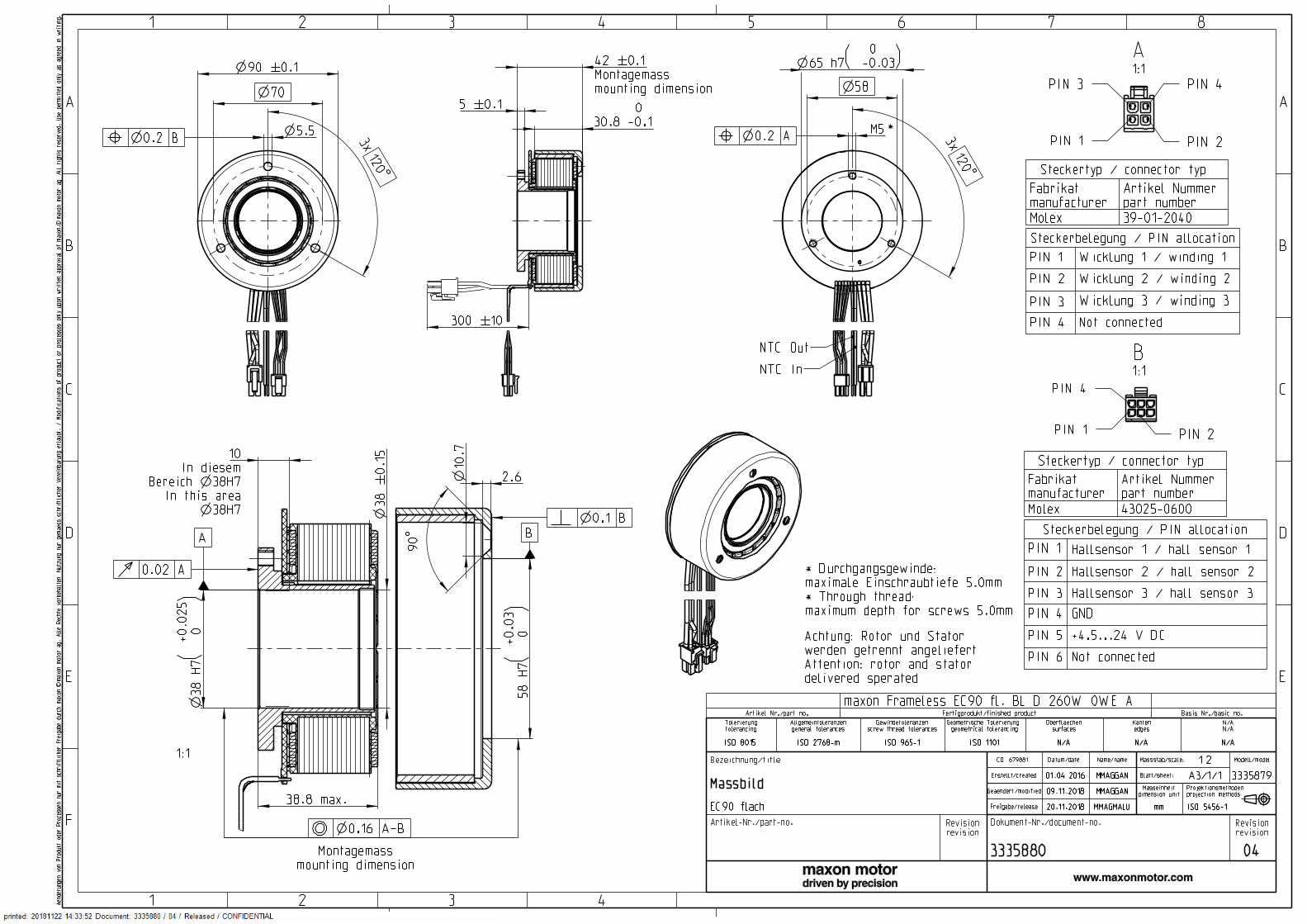
Steckerbelegung / PIN allocation
PIN 1 Hallsensor 1 / hall sensor 1
PIN 2 Hallsensor 2 / hall sensor 2
PIN 3 Hallsensor 3 / hall sensor 3
PIN 4 GND
PIN 5 +4.5...24 V DC
PIN 6 Not connected
43025-0600Molex
Artikel Nummerpart number
Fabrikatmanufacturer
Steckertyp / connector typ
Steckerbelegung / PIN allocation
PIN 1 Wicklung 1 / winding 1
PIN 2 Wicklung 2 / winding 2
PIN 3 Wicklung 3 / winding 3
PIN 4 Not connected
39-01-2040Molex
Artikel Nummerpart number
Fabrikatmanufacturer
Steckertyp / connector typ
NTC Out
NTC In
* Durchgangsgewinde:maximale Einschraubtiefe 5.0mm* Through thread:maximum depth for screws 5.0mm
Achtung: Rotor und Statorwerden getrennt angeliefertAttention: rotor and statordelivered sperated
*
Montagemassmounting dimension
1:1
PIN 3
PIN 1 PIN 2
PIN 4
A1:1
PIN 1 PIN 2
PIN 4
B1:1
AB
300 �#�10
A
B
Artikel Nr./part no. Fertigprodukt/finished product Basis Nr./basic no.
maxon Frameless EC90 fl. BL D 160W 0WE A
18.3 0 -0.1
3x120�$�
90�$�
2.6
max.26.3
5 �#�0.1
10.7
90 �#�0.1

LXVII
588849 542099 581294 581295
18 30 48 602110 2120 1990 2020831 502 285 2321810 1820 1700 17301030 992 968 96812.4 7.24 4.16 3.37
15700 15100 13500 13700195 113 59.5 48.887.6 87.3 86.8 86.9
0.0923 0.266 0.807 1.230.12 0.334 0.964 1.4780.7 134 228 281118 71.4 42 34
0.135 0.142 0.149 0.1497.59 7.88 8.26 8.255301 5301 5301 5301
M 1:4
1.36 K/W 1.82 K/W 54.6 s 202 s -40…+100°C +125°C
11 3
814 g 292 g 522 g
05 00 1000 M[ mNm]0.54 .1 7.7I [A]
0
1000
2000
3000
4000
5000
6000
ESCON Mod. 50/4 EC-S 427ESCON Module 50/5 427ESCON 50/5 428ESCON 70/10 428DEC Module 50/5 430EPOS2 24/5 435EPOS2 50/5 435EPOS2 70/10 435EPOS2 P 24/5 438EPOS4 Module 50/8 443EPOS4 Comp. 50/8 CAN 443MAXPOS 50/5 447
maxon special program September 2017 edition / subject to change
max
on
spec
ial p
rog
ram
Stock programStandard programSpecial program (on request)
Part Numbers
Specifications Operating Range Comments
n [rpm] Continuous operation: In observation of above listed thermal resistance (lines 17 and 18) the maximum permissible winding temperature will be reached during continuous operation at 25°C ambient = Thermal limit.
Continuous operation with reduced thermal resistance Rth2 50%.
Short term operation: The motor may be briefly over-loaded (recurring).
Assigned power ratin
maxon Modular System Overview on page 29–33
EC frameless 90 flat ∅90 mm, brushless, 260 Watt
Motor DataValues at nominal voltage
1 Nominal voltage V2 No load speed rpm3 No load current mA4 Nominal speed rpm5 Nominal torque (max. continuous torque) mNm6 Nominal current (max. continuous current) A7 Stall torque mNm8 Stall current A9 Max. efficiency %
Characteristics10 Terminal resistance phase to phase W11 Terminal inductance phase to phase mH12 Torque constant mNm/A13 Speed constant rpm/V14 Speed/torque gradient rpm/mNm15 Mechanical time constant ms16 Rotor inertia gcm2
Thermal data17 Thermal resistance housing-ambient 18 Thermal resistance winding-housing 19 Thermal time constant winding 20 Thermal time constant motor 21 Ambient temperature 22 Max. winding temperature Mechanical data23 Max. speed 5000 rpm Other specifications29 Number of pole pairs 30 Number of phases 31 Weight of motor Weight of rotor Weight of stator
Values listed in the table are nominal.
Connection motor (Cable AWG 18) red Motor winding 1 Pin 1 black Motor winding 2 Pin 2 white Motor winding 3 Pin 3 N.C. Pin 4 Connector Part number Molex 39-01-2040 Connection sensors (Cable AWG 24) yellow Hall sensor 1 Pin 1 brown Hall sensor 2 Pin 2 grey Hall sensor 3 Pin 3 blue GND Pin 4 green VHall 4.5…24 VDC Pin 5 N.C. Pin 6 Connector Part number Molex 430-25-0600 Wiring diagram for Hall sensors see p. 43 Connection NTC (Cable AWG 24) pink NTC blue NTC Resistance 25°C: 5 kOhm ±1%, beta (25–85°C):
3490 K
Recommended Electronics:Notes Page 32
with Hall sensors
Mounting condition Condition as received
Detailed dimensions as to the installation manual.
E
D
C
B
A
87654321
A
B
C
D
E
F
1 2 3 4Aenderungen von Produkt oder Prozessen nur mit schriftlicher Freigabe durch
maxon. maxon motor ag. Alle Rechte vorbehalten. Nutzung nur gemaess
schriftlicher Vereinbarung erlaubt. / Modifications of product or processes
only upon written approval of maxon. maxon motor ag. All rights reserved. Use
permitted only as agreed in writing.
cc
38 �#�0.15
In diesemBereich �n�38H7
In this area
10
5.5B
38 H7
+0.025
0
()
A�-�B
58 H7
+0.03
0
()
65 h7 0 -0.03( )58
M5A
70
Montagemassmounting dimension
42 �#�0.1
Bezeichnung/title CO: 679881 Datum/date Name/name Massstab/scale: 1:2 Modell/model
MassbildErstellt/created 01.04.2016 MMAGGAN Blatt/sheet:
A3/1/1 3335879
Geaendert/modified09.11.2018 MMAGGAN Masseinheitdimension unit
Projektionsmethodenprojection methods
EC90 flach Freigabe/release 20.11.2018 MMAGMALU mm ISO 5456-1
Artikel-Nr./part-no. Revisionrevision
Dokument-Nr./document-no. Revisionrevision
3335880 04
Tolerierungtolerancing
Allgemeintoleranzengeneral tolerances
Gewindetoleranzenscrew thread tolerances
Geometrische Tolerierung geometrical tolerancing
Oberflaechensurfaces
Kantenedges
N/AN/A
ISO 8015 ISO 2768-m ISO 965-1 ISO 1101 N/A N/A N/A
Steckerbelegung / PIN allocation
PIN 1 Hallsensor 1 / hall sensor 1
PIN 2 Hallsensor 2 / hall sensor 2
PIN 3 Hallsensor 3 / hall sensor 3
PIN 4 GND
PIN 5 +4.5...24 V DC
PIN 6 Not connected
43025-0600Molex
Artikel Nummerpart number
Fabrikatmanufacturer
Steckertyp / connector typ
Steckerbelegung / PIN allocation
PIN 1 Wicklung 1 / winding 1
PIN 2 Wicklung 2 / winding 2
PIN 3 Wicklung 3 / winding 3
PIN 4 Not connected
39-01-2040Molex
Artikel Nummerpart number
Fabrikatmanufacturer
Steckertyp / connector typ
* Durchgangsgewinde:maximale Einschraubtiefe 5.0mm* Through thread:maximum depth for screws 5.0mm
Achtung: Rotor und Statorwerden getrennt angeliefertAttention: rotor and statordelivered sperated
*
Montagemassmounting dimension
1:1
NTC Out
NTC In
PIN 3
PIN 1 PIN 2
PIN 4
A1:1
PIN 1 PIN 2
PIN 4
B1:1
A B
300 �#�10
A
B
Artikel Nr./part no. Fertigprodukt/finished product Basis Nr./basic no.
maxon Frameless EC90 fl. BL D 260W 0WE A
30.8 0 -0.1
3x120�$�
90�$�
2.6
max.38.8
3x120�$�
5 �#�0.1
90 �#�0.1
10.7

This document is protected by copyright. Any further use (including reproduction, translation, microfilming, and other means ofelectronic data processing) without prior written approval is not permitted. The mentioned trademarks belong to their respectiveowners and are protected under intellectual property rights.© 2021 maxon. All rights reserved. Subject to change without prior notice.
mmag | «EC frameless» Installation Manual | Edition 2021-03 | DocID rel10039maxon motor agBrünigstrasse 220CH-6072 Sachseln
+41 41 666 15 00www.maxongroup.com