setup accuracy of the novalis exactrac 6dof system for frameless radiosurgery
TRANSCRIPT
Int. J. Radiation Oncology Biol. Phys., Vol. 82, No. 5, pp. 1627–1635, 2012Copyright � 2012 Elsevier Inc.
Printed in the USA. All rights reserved0360-3016/$ - see front matter
jrobp.2011.01.052
doi:10.1016/j.iPHYSICS CONTRIBUTION
SETUP ACCURACY OF THE NOVALIS EXACTRAC 6DOF SYSTEM FORFRAMELESS RADIOSURGERY
THIERRY GEVAERT, M.SC., DIRK VERELLEN, PH.D., KOEN TOURNEL, M.S., NADINE LINTHOUT, PH.D.,SAMUEL BRAL, M.D., BENEDIKT ENGELS, M.D., CHRISTINE COLLEN, M.D., TOM DEPUYDT, I.R.,
MICHAEL DUCHATEAU, M.SC., TRUUS REYNDERS, M.SC., GUY STORME, M.D., PH.D.,AND MARK DE RIDDER, M.D., PH.D.
Department of Radiotherapy, Universitair Ziekenhuis Brussel, Vrije Universiteit Brussel, Brussels, Belgium
ReprinRadiotherTel: (+32gevaert@
Purpose: Stereotactic radiosurgery using frame-based positioning is a well-established technique for the treatmentof benign and malignant lesions. By contrast, a new trend toward frameless systems using image-guided position-ing techniques is gainingmainstream acceptance. This studywas designed tomeasure the detection and positioningaccuracy of the ExacTrac/Novalis Body (ET/NB) for rotations and to compare the accuracy of the frameless withthe frame-based radiosurgery technique.Methods andMaterials: A programwas developed in house to rotate reference computed tomography images. Theangles measured by the system were compared with the known rotations. The accuracy of ET/NB was evaluatedwith a head phantom with seven lead beads inserted, mounted on a treatment couch equipped with a robotic tiltmodule, and was measured with a digital water level and portal films. Multiple hidden target tests (HTT) wereperformed to measure the overall accuracy of the different positioning techniques for radiosurgery (i.e., framelessand frame-based with relocatable mask or invasive ring, respectively).Results: The ET/NB system can detect rotational setup errors with an average accuracy of 0.09� (standard devi-ation [SD] 0.06�), 0.02� (SD 0.07�), and 0.06� (SD 0.14�) for longitudinal, lateral, and vertical rotations, respectively.The average positioning accuracy was 0.06� (SD 0.04�), 0.08� (SD 0.06�), and 0.08� (SD 0.07�) for longitudinal,lateral and vertical rotations, respectively. The results of the HTT showed an overall three-dimensional accuracyof 0.76 mm (SD 0.46 mm) for the frameless technique, 0.87 mm (SD 0.44 mm) for the relocatable mask, and 1.19mm (SD 0.45 mm) for the frame-based technique.Conclusions: The study showed high detection accuracy and a subdegree positioning accuracy. On the basis ofphantom studies, the frameless technique showed comparable accuracy to the frame-based approach. � 2012Elsevier Inc.
Radiosurgery, Frameless image guide positioning, Frame-based positioning, Overall accuracy.
INTRODUCTION
Stereotactic radiosurgery (SRS) is a well-established tech-nique for the treatment of both benign and malignant lesionsof the brain. The concept was defined by Leksell (1) as a sin-gle high dose of radiation stereotactically directed to anintracranial region of interest, thereby minimizing exposureto normal healthy tissue and maximizing local control. Thestereotactic irradiation apparatus was implemented in theform of the Gamma Knife. The requirement for preciselocalization and immobilization of the targeted lesion sug-gested the use of a rigid, invasive stereotactic head-ring.When SRS migrated to linear accelerators (linacs), stereo-tactic frames were adopted for most intracranial radiosur-gery systems (2). Although they provide high accuracy, the
t requests to: Thierry Gevaert, M.Sc., Department ofapy, UZ Brussel, Laarbeeklaan 101, B-1090 Brussels.) 2-477-61-31; Fax: (+32) 2-477-54-50; E-mail: thierry.uzbrussel.be
1627
disadvantages of standard head-rings include pain and gen-eral discomfort. The invasive nature of this technique hasmainly limited its use to single-fraction treatments. To applythe benefit of stereotactic localization to fractionated treat-ment courses, noninvasive stereotactic systems have beendeveloped (3).
To compensate for the possible accuracy loss of noninva-sive techniques, linacs were equipped with various forms ofimage-guided radiotherapy (IGRT) systems for localization(4–6). These imaging modalities apply internal anatomyrather than external landmarks to avoid geographic miss.The use of IGRT has been efficacious for single-fractionand fractionated radiotherapy to several extracranial ana-tomic sites (7, 8). In our clinic, IGRT is among others
Supported in part by the Hercules Foundation and the Fonds voorWetenschappelijk Onderzoek Vlaanderen ProjectG.0412.08.Conflict of interest: none.Received Aug 30, 2010, and in revised form Dec 29, 2010.
Accepted for publication Jan 12, 2011.
1628 I. J. Radiation Oncology d Biology d Physics Volume 82, Number 5, 2012
performed with the ExacTrac/Novalis Body (ET/NB)(BrainLAB AG, Feldkirchen, Germany) system. With theinstallation of the robotic tilt module (RTM) underneath thetable top, the opportunity arose to correct the translationaland rotational setup errors found by the 6� of freedom(6DOF) registration. Verellen et al. (9) verified the detectionaccuracy of the 6DOF algorithm. Because the RTM was notyet available at that time, the positioning accuracy was inves-tigated only for translations. In this study we wanted to vali-date the system’s performance to detect rotations and theaccuracy of performing the necessary corrections. In addition,the overall accuracy of the frameless radiosurgery technique(using the ET/NB imaging device and 6DOF positioning)was compared with the frame-based technique (using the in-vasive head-ring, which is the gold standard, or a relocatablemask system), based on the independent hidden target test(HTT) (10, 11).
METHODS AND MATERIALS
Treatment systemThe Novalis system provides an integrated system that features
treatment planning (BrainSCAN v5.3), automated patient position-ing, and image guidance based on infrared marker detection (ET)and stereoscopic x-ray imaging (NB), capable of real-time monitor-ing and adjustment of the patient setup. The typical clinical settingsfor cranial cases to acquire X-ray images at the UniversitairZiekenhuis Brussel are 100 kV, 100 mA, and 100 ms. Patientpositioning can be either frame-based, by means of the BrainLABstereotactic head-ring fixed on the patient’s head or fitted to a relo-catable mask, both using the same localizer box, or frameless, bymeans of a custom-fitted thermoplastic mask and the use of ET/NB. The latter system and its algorithm for the automatic registra-tion have been described earlier (9, 12–14). The output of the NB6DOF registration contains six parameters (three translations andthree rotations) that are communicated to the treatment couch.The three translations and the vertical rotation are performed bythe treatment couch itself. The longitudinal and lateral rotationsare compensated by the RTM and are limited to 3.0� and 2.5�,respectively, for patient safety. The vertical rotation is limited to10.0�, but avoiding collisions with the gantry, whereas there is nolimitation on the translations.
PhantomThe evaluation was performed with an anthropomorphic phan-
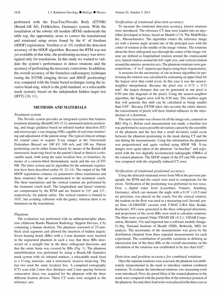
tom (Alderson Rando Phantom Radiology Support Devices, CA)containing a human skeleton. The phantom consisted of 25-mm-thick axial segments and allowed the insertion of hidden targets.Seven bearing beads (BBs) with a 2-mm diameter were insertedin the segmented phantom in such a way that three BBs inter-sected on a straight line in the three orthogonal directions andthat the entire brain was covered by BBs (Fig. 1). The phantomimmobilization was performed by using a BrainLAB framelessmask system with six infrared markers, a relocatable mask fixedto a U-ring structure, and a stereotactic invasive head-ring. Thelast two used the same localizer box. A computed tomography(CT) scan with 2-mm slice thickness and 2-mm spacing betweenconsecutive slices was acquired for the phantom with the threedifferent fixation devices. These CT scans were assigned as thereference sets.
Verification of rotational detection accuracyTo measure the rotational detection accuracy, known rotations
were introduced. The reference CT data were loaded into an algo-rithm developed in house, based on Matlab (v7.0, The MathWorksInc., Massachusetts). The algorithm rotates the reference imageset with a known angle around one of the principal axes with thecenter of rotation in the middle of the image volume. The rotationsabout the three orthogonal axes through the center of the image vol-ume are defined as longitudinal rotation around the craniocaudalaxis, lateral rotation around the left–right axis, and vertical rotationaround the anterior–posterior axis. The phantom rotationswere gen-erated from�4� to 4� stepwise per degree using basic trigonometry.A measure for the uncertainty of our in-house algorithm for per-
forming the rotation was calculated by estimating an upper limit forthe largest error that could occur. In this case it was the nearest-neighbor interpolation. Because the pixel size is 0.73 � 0.73mm2, the largest distance that can be generated in one pixel is0.99 mm (the diagonal of the pixel). Using the nearest-neighboralgorithm, the biggest error will be 0.50 mm. The smallest anglethat will generate this shift can be calculated as being smallerthan 0.05�. Because ET/NB takes into account the entire dataset,the reassortment of pixels will have limited influence in the intro-duction of a distortion.The same isocenter was chosen for all the image sets, centered on
BB1 (Fig.1). Before each measurement was made, a baseline testwas performed to assess possible deviations caused by the assemblyof the phantom and the fact that a small deviation could occurbetween the phantom positioning in the mask during CT and theone during the measurements. Using this information the phantomwas prepositioned and again verified using 6DOF NB. X-rayimages were again taken of the phantom ‘‘in baseline’’ and regis-tered with the two digitally reconstructed radiographs (DRRs) ofthe rotated phantom. The 6DOF output of the ET and NB systemswas compared with the originally induced CT error.
Verification of rotational positional accuracyUsing the detected rotational errors from NB in the previous par-
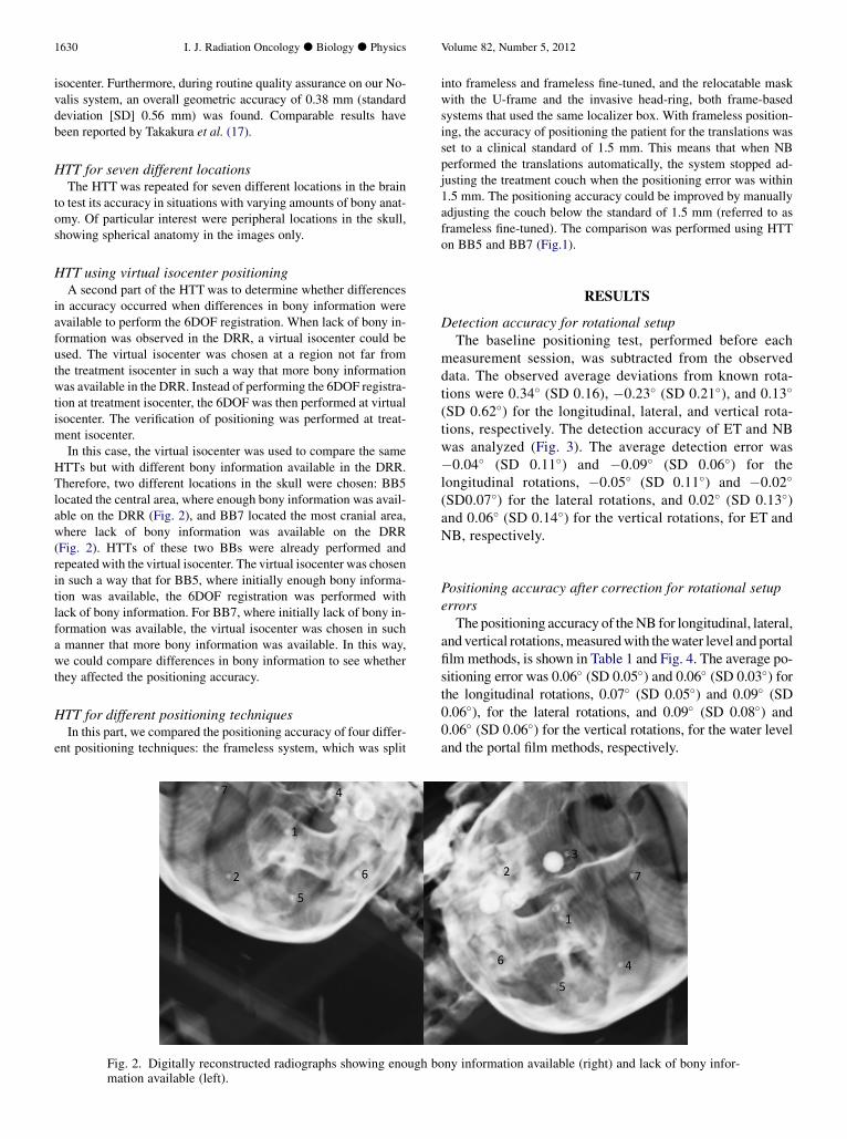
agraph, the RTM and the couch were used to compensate for theerrors. Verification of the positioning was performed in two ways.First, a digital water level (Laserliner, Vmarex, Arnsberg,Germany), which can measure the angle with a 0.10� (�0.5 mm/m) precision, was placed on the couch. For the vertical rotation,the readout on the floor was used as a measuring tool. Second, por-tal films (X-OMATIC cassette with T-MAT L/RA film: Kodak,Rochester, NY) were generated in the three orthogonal directions,and projections of the seven BBs were used to calculate rotations.The films were scanned (Vidar TWAIN DS v5.2.1, VIDAR Corpo-ration, Herndon, VA) and imported into a software module (Image-J1.40g, National Institute of Health (NIH), Bethesda, MD) foranalysis. The uncertainty of the measurements was given by thedistribution obtained from three repeated measurements for eachexperiment. The contribution of possible variations in defining anintersection line of the three BBs to the overall uncertainty on thecalculation of the rotations was established to be less than 0.02�.
Detection and position accuracy for combined rotationsOnce the separate rotationswere assessed, the phantomwas delib-
erately mispositioned in the mask to introduce random combinedrotations. To evaluate the introduced rotations, two measuring toolswere introduced. First, the portal films of the rotated phantom in themask were compared with the portal film of the reference position ofthephantom. Second, three leadwireswere placed in the three axes at
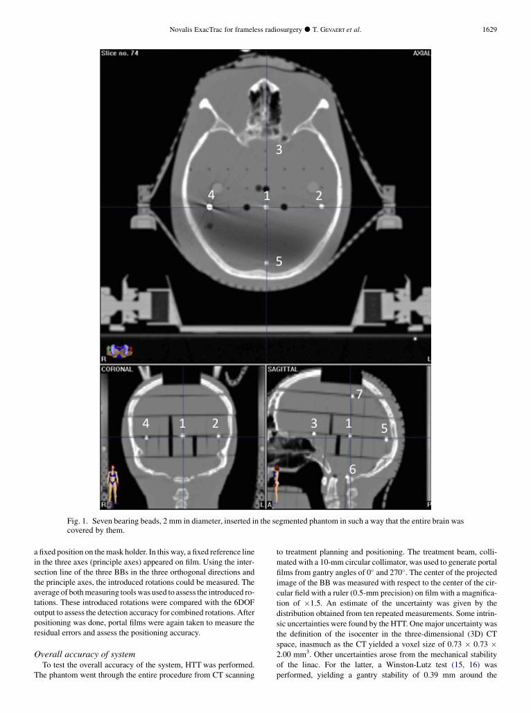
Fig. 1. Seven bearing beads, 2 mm in diameter, inserted in the segmented phantom in such a way that the entire brain wascovered by them.
Novalis ExacTrac for frameless radiosurgery d T. GEVAERT et al. 1629
a fixed position on themask holder. In this way, a fixed reference linein the three axes (principle axes) appeared on film. Using the inter-section line of the three BBs in the three orthogonal directions andthe principle axes, the introduced rotations could be measured. Theaverage of bothmeasuring toolswas used to assess the introduced ro-tations. These introduced rotations were compared with the 6DOFoutput to assess the detection accuracy for combined rotations. Afterpositioning was done, portal films were again taken to measure theresidual errors and assess the positioning accuracy.
Overall accuracy of systemTo test the overall accuracy of the system, HTT was performed.
The phantom went through the entire procedure from CT scanning
to treatment planning and positioning. The treatment beam, colli-
mated with a 10-mm circular collimator, was used to generate portal
films from gantry angles of 0� and 270�. The center of the projectedimage of the BB was measured with respect to the center of the cir-
cular field with a ruler (0.5-mm precision) on film with a magnifica-
tion of �1.5. An estimate of the uncertainty was given by the
distribution obtained from ten repeated measurements. Some intrin-
sic uncertainties were found by the HTT. Onemajor uncertainty was
the definition of the isocenter in the three-dimensional (3D) CT
space, inasmuch as the CT yielded a voxel size of 0.73 � 0.73 �2.00 mm3. Other uncertainties arose from the mechanical stability
of the linac. For the latter, a Winston-Lutz test (15, 16) was
performed, yielding a gantry stability of 0.39 mm around the
1630 I. J. Radiation Oncology d Biology d Physics Volume 82, Number 5, 2012
isocenter. Furthermore, during routine quality assurance on our No-valis system, an overall geometric accuracy of 0.38 mm (standarddeviation [SD] 0.56 mm) was found. Comparable results havebeen reported by Takakura et al. (17).
HTT for seven different locationsThe HTT was repeated for seven different locations in the brain
to test its accuracy in situations with varying amounts of bony anat-omy. Of particular interest were peripheral locations in the skull,showing spherical anatomy in the images only.
HTT using virtual isocenter positioningA second part of the HTTwas to determine whether differences
in accuracy occurred when differences in bony information wereavailable to perform the 6DOF registration. When lack of bony in-formation was observed in the DRR, a virtual isocenter could beused. The virtual isocenter was chosen at a region not far fromthe treatment isocenter in such a way that more bony informationwas available in the DRR. Instead of performing the 6DOF registra-tion at treatment isocenter, the 6DOF was then performed at virtualisocenter. The verification of positioning was performed at treat-ment isocenter.In this case, the virtual isocenter was used to compare the same
HTTs but with different bony information available in the DRR.Therefore, two different locations in the skull were chosen: BB5located the central area, where enough bony information was avail-able on the DRR (Fig. 2), and BB7 located the most cranial area,where lack of bony information was available on the DRR(Fig. 2). HTTs of these two BBs were already performed andrepeated with the virtual isocenter. The virtual isocenter was chosenin such a way that for BB5, where initially enough bony informa-tion was available, the 6DOF registration was performed withlack of bony information. For BB7, where initially lack of bony in-formation was available, the virtual isocenter was chosen in sucha manner that more bony information was available. In this way,we could compare differences in bony information to see whetherthey affected the positioning accuracy.
HTT for different positioning techniquesIn this part, we compared the positioning accuracy of four differ-
ent positioning techniques: the frameless system, which was split
Fig. 2. Digitally reconstructed radiographs showing enough bmation available (left).
into frameless and frameless fine-tuned, and the relocatable maskwith the U-frame and the invasive head-ring, both frame-basedsystems that used the same localizer box. With frameless position-ing, the accuracy of positioning the patient for the translations wasset to a clinical standard of 1.5 mm. This means that when NBperformed the translations automatically, the system stopped ad-justing the treatment couch when the positioning error was within1.5 mm. The positioning accuracy could be improved by manuallyadjusting the couch below the standard of 1.5 mm (referred to asframeless fine-tuned). The comparison was performed using HTTon BB5 and BB7 (Fig.1).
RESULTS
Detection accuracy for rotational setupThe baseline positioning test, performed before each
measurement session, was subtracted from the observeddata. The observed average deviations from known rota-tions were 0.34� (SD 0.16), �0.23� (SD 0.21�), and 0.13�
(SD 0.62�) for the longitudinal, lateral, and vertical rota-tions, respectively. The detection accuracy of ET and NBwas analyzed (Fig. 3). The average detection error was�0.04� (SD 0.11�) and �0.09� (SD 0.06�) for thelongitudinal rotations, �0.05� (SD 0.11�) and �0.02�
(SD0.07�) for the lateral rotations, and 0.02� (SD 0.13�)and 0.06� (SD 0.14�) for the vertical rotations, for ET andNB, respectively.
Positioning accuracy after correction for rotational setuperrors
The positioning accuracy of theNB for longitudinal, lateral,and vertical rotations,measuredwith thewater level and portalfilm methods, is shown in Table 1 and Fig. 4. The average po-sitioning error was 0.06� (SD 0.05�) and 0.06� (SD 0.03�) forthe longitudinal rotations, 0.07� (SD 0.05�) and 0.09� (SD0.06�), for the lateral rotations, and 0.09� (SD 0.08�) and0.06� (SD 0.06�) for the vertical rotations, for the water leveland the portal film methods, respectively.
ony information available (right) and lack of bony infor-
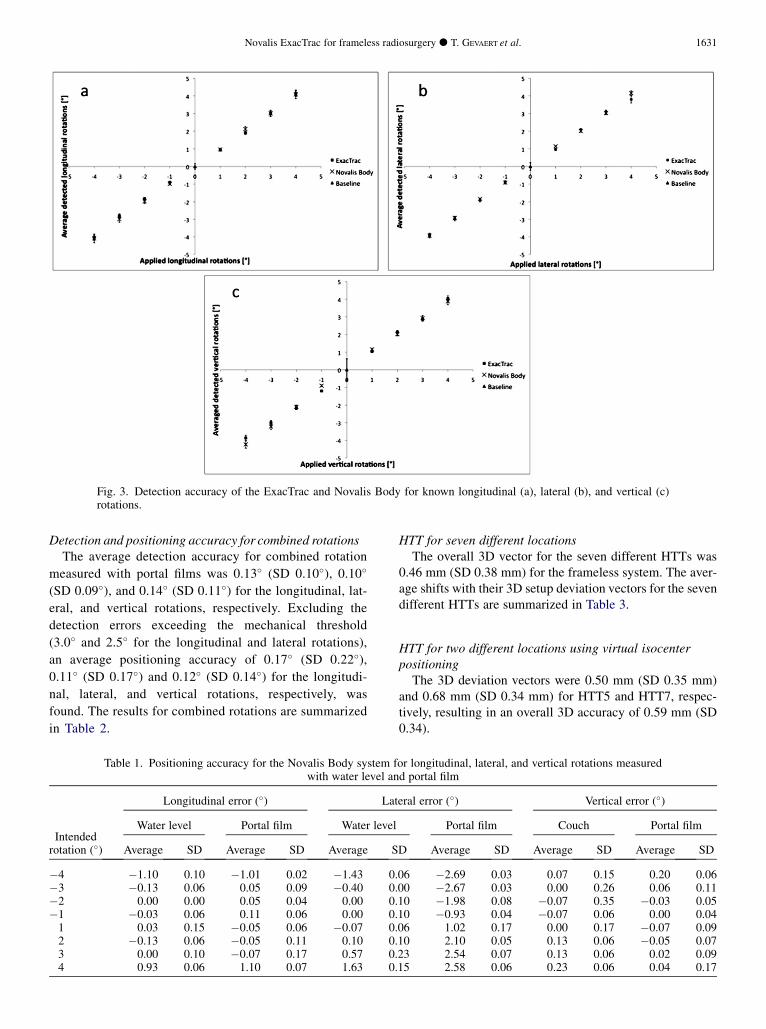
Fig. 3. Detection accuracy of the ExacTrac and Novalis Body for known longitudinal (a), lateral (b), and vertical (c)rotations.
Novalis ExacTrac for frameless radiosurgery d T. GEVAERT et al. 1631
Detection and positioning accuracy for combined rotationsThe average detection accuracy for combined rotation
measured with portal films was 0.13� (SD 0.10�), 0.10�
(SD 0.09�), and 0.14� (SD 0.11�) for the longitudinal, lat-
eral, and vertical rotations, respectively. Excluding the
detection errors exceeding the mechanical threshold
(3.0� and 2.5� for the longitudinal and lateral rotations),
an average positioning accuracy of 0.17� (SD 0.22�),0.11� (SD 0.17�) and 0.12� (SD 0.14�) for the longitudi-
nal, lateral, and vertical rotations, respectively, was
found. The results for combined rotations are summarized
in Table 2.
Table 1. Positioning accuracy for the Novalis Body system fwith water level an
Intendedrotation (�)
Longitudinal error (�) Lat
Water level Portal film Water level
Average SD Average SD Average S
�4 �1.10 0.10 �1.01 0.02 �1.43 0.�3 �0.13 0.06 0.05 0.09 �0.40 0.�2 0.00 0.00 0.05 0.04 0.00 0.�1 �0.03 0.06 0.11 0.06 0.00 0.1 0.03 0.15 �0.05 0.06 �0.07 0.2 �0.13 0.06 �0.05 0.11 0.10 0.3 0.00 0.10 �0.07 0.17 0.57 0.4 0.93 0.06 1.10 0.07 1.63 0.
HTT for seven different locationsThe overall 3D vector for the seven different HTTs was
0.46 mm (SD 0.38 mm) for the frameless system. The aver-age shifts with their 3D setup deviation vectors for the sevendifferent HTTs are summarized in Table 3.
HTT for two different locations using virtual isocenterpositioning
The 3D deviation vectors were 0.50 mm (SD 0.35 mm)and 0.68 mm (SD 0.34 mm) for HTT5 and HTT7, respec-tively, resulting in an overall 3D accuracy of 0.59 mm (SD0.34).
or longitudinal, lateral, and vertical rotations measuredd portal film
eral error (�) Vertical error (�)
Portal film Couch Portal film
D Average SD Average SD Average SD
06 �2.69 0.03 0.07 0.15 0.20 0.0600 �2.67 0.03 0.00 0.26 0.06 0.1110 �1.98 0.08 �0.07 0.35 �0.03 0.0510 �0.93 0.04 �0.07 0.06 0.00 0.0406 1.02 0.17 0.00 0.17 �0.07 0.0910 2.10 0.05 0.13 0.06 �0.05 0.0723 2.54 0.07 0.13 0.06 0.02 0.0915 2.58 0.06 0.23 0.06 0.04 0.17
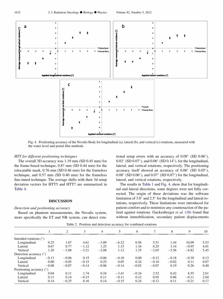
Fig. 4. Positioning accuracy of the Novalis Body for longitudinal (a), lateral (b), and vertical (c) rotations, measured withthe water level and portal film methods.
1632 I. J. Radiation Oncology d Biology d Physics Volume 82, Number 5, 2012
HTT for different positioning techniquesThe overall 3D accuracy was 1.19 mm (SD 0.45 mm) for
the frame-based technique, 0.87 mm (SD 0.44 mm) for therelocatable mask, 0.76 mm (SD 0.46 mm) for the framelesstechnique, and 0.57 mm (SD 0.40 mm) for the framelessfine-tuned technique. The average shifts with their 3d setupdeviation vectors for HTT5 and HTT7 are summarized inTable 4.
DISCUSSION
Detection and positioning accuracyBased on phantom measurements, the Novalis system,
more specifically the ET and NB system, can detect rota-
Table 2. Position and detection acc
1 2 3 4
Intended rotations (�)Longitudinal 0.25 1.67 4.61 �3.09Lateral 0.67 0.77 �1.12 1.25Vertical 1.20 �3.88 �3.21 �2.08
Detection accuracy (�)Longitudinal �0.13 �0.06 0.15 �0.06Lateral 0.00 �0.05 �0.15 0.25Vertical �0.08 �0.07 �0.14 �0.06
Positioning accuracy (�)Longitudinal 0.04 0.11 1.74 0.24Lateral 0.11 0.14 �0.15 0.11Vertical 0.14 �0.25 0.16 0.14
tional setup errors with an accuracy of 0.09� (SD 0.06�),0.02� (SD 0.07�), and 0.06� (SD 0.14�), for the longitudinal,lateral, and vertical rotations, respectively. The positioningaccuracy itself showed an accuracy of 0.06� (SD 0.05�),0.08� (SD 0.06�), and 0.07� (SD 0.07�) for the longitudinal,lateral, and vertical rotations, respectively.
The results in Table 1 and Fig. 4, show that for longitudi-nal and lateral directions, some degrees were not fully cor-rected. The origin of these deviations was the softwarelimitation of 3.0� and 2.5� for the longitudinal and lateral ro-tations, respectively. These limitations were introduced forpatient comfort and to minimize any counteraction of the pa-tient against rotations. Guckenberger et al. (18) found thatwithout immobilization, secondary patient displacements
uracy for combined rotations
5 6 7 8 9 10
�6.22 0.56 5.51 1.44 10.09 5.531.15 1.16 0.25 3.14 �0.95 4.011.12 1.35 �2.65 �5.56 �6.82 5.45
�0.10 0.00 �0.12 �0.18 �0.39 0.130.05 0.24 �0.10 �0.02 0.11 0.07
�0.14 �0.02 �0.07 0.19 0.26 0.40
�3.41 �0.24 2.52 0.42 6.55 2.61�0.11 0.12 0.05 0.86 �0.11 2.04�0.15 0.24 �0.12 0.11 �0.21 0.17
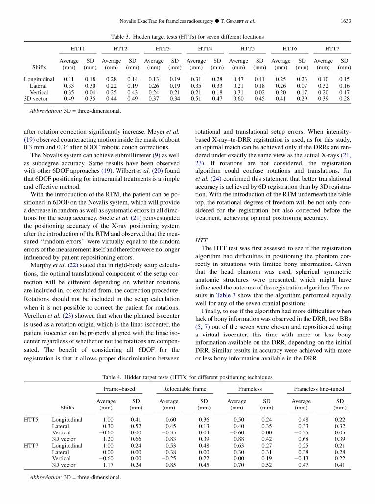
Table 3. Hidden target tests (HTTs) for seven different locations
Shifts
HTT1 HTT2 HTT3 HTT4 HTT5 HTT6 HTT7
Average SD Average SD Average SD Average SD Average SD Average SD Average SD(mm) (mm) (mm) (mm) (mm) (mm) (mm) (mm) (mm) (mm) (mm) (mm) (mm) (mm)
Longitudinal 0.11 0.18 0.28 0.14 0.13 0.19 0.31 0.28 0.47 0.41 0.25 0.23 0.10 0.15Lateral 0.33 0.30 0.22 0.19 0.26 0.19 0.35 0.33 0.21 0.18 0.26 0.07 0.32 0.16Vertical 0.35 0.04 0.25 0.43 0.24 0.21 0.21 0.18 0.31 0.02 0.20 0.17 0.20 0.17
3D vector 0.49 0.35 0.44 0.49 0.37 0.34 0.51 0.47 0.60 0.45 0.41 0.29 0.39 0.28
Abbreviation: 3D = three-dimensional.
Novalis ExacTrac for frameless radiosurgery d T. GEVAERT et al. 1633
after rotation correction significantly increase. Meyer et al.(19) observed counteracting motion inside the mask of about0.3 mm and 0.3� after 6DOF robotic couch corrections.
The Novalis system can achieve submillimeter (9) as wellas subdegree accuracy. Same results have been observedwith other 6DOF approaches (19). Wilbert et al. (20) foundthat 6DOF positioning for intracranial treatments is a simpleand effective method.
With the introduction of the RTM, the patient can be po-sitioned in 6DOF on the Novalis system, which will providea decrease in random as well as systematic errors in all direc-tions for the setup accuracy. Soete et al. (21) reinvestigatedthe positioning accuracy of the X-ray positioning systemafter the introduction of the RTM and observed that the mea-sured ‘‘random errors’’ were virtually equal to the randomerrors of the measurement itself and thereforewere no longerinfluenced by patient repositioning errors.
Murphy et al. (22) stated that in rigid-body setup calcula-
tions, the optimal translational component of the setup cor-
rection will be different depending on whether rotations
are included in, or excluded from, the correction procedure.
Rotations should not be included in the setup calculation
when it is not possible to correct the patient for rotations.
Verellen et al. (23) showed that when the planned isocenter
is used as a rotation origin, which is the linac isocenter, the
patient isocenter can be properly aligned with the linac iso-
center regardless of whether or not the rotations are compen-
sated. The benefit of considering all 6DOF for the
registration is that it allows proper discrimination between
Table 4. Hidden target tests (HTTs) fo
Shifts
Frame–based Relocatable f
Average SD Average(mm) (mm) (mm)
HTT5 Longitudinal 1.00 0.41 0.60Lateral 0.30 0.52 0.45Vertical �0.60 0.00 �0.353D vector 1.20 0.66 0.83
HTT7 Longitudinal 1.00 0.24 0.53Lateral 0.00 0.00 0.38Vertical �0.60 0.00 �0.253D vector 1.17 0.24 0.85
Abbreviation: 3D = three-dimensional.
rotational and translational setup errors. When intensity-based X-ray–to-DRR registration is used, as for this study,an optimal match can be achieved only if the DRRs are ren-dered under exactly the same view as the actual X-rays (21,23). If rotations are not considered, the registrationalgorithm could confuse rotations and translations. Jinet al. (24) confirmed this statement that better translationalaccuracy is achieved by 6D registration than by 3D registra-tion. With the introduction of the RTM underneath the tabletop, the rotational degrees of freedom will be not only con-sidered for the registration but also corrected before thetreatment, achieving optimal positioning accuracy.
HTTThe HTT test was first assessed to see if the registration
algorithm had difficulties in positioning the phantom cor-rectly in situations with limited bony information. Giventhat the head phantom was used, spherical symmetricanatomic structures were presented, which might haveinfluenced the outcome of the registration algorithm. The re-sults in Table 3 show that the algorithm performed equallywell for any of the seven cranial positions.
Finally, to see if the algorithm had more difficulties whenlack of bony information was observed in the DRR, two BBs(5, 7) out of the seven were chosen and repositioned usinga virtual isocenter, this time with more or less bonyinformation available on the DRR, depending on the initialDRR. Similar results in accuracy were achieved with moreor less bony information available in the DRR.
r different positioning techniques
rame Frameless Frameless fine–tuned
SD Average SD Average SD(mm) (mm) (mm) (mm) (mm)
0.36 0.50 0.24 0.48 0.220.13 0.40 0.35 0.33 0.320.04 �0.60 0.00 �0.35 0.050.39 0.88 0.42 0.68 0.390.48 0.63 0.27 0.25 0.210.00 0.30 0.31 0.38 0.280.22 0.00 0.19 �0.13 0.220.45 0.70 0.52 0.47 0.41
1634 I. J. Radiation Oncology d Biology d Physics Volume 82, Number 5, 2012
Although head-ring placement is perceived as minimallyinvasive while providing a high degree of accuracy, it maynot be optimal because it sometimes causes pain and dis-comfort (25). Moreover, positioning is based on external ref-erences, not on the actual anatomy of the patient, assumingthe relationship between tumor and reference frame isunchanged between the different imaging sessions and theactual treatment. Frameless SRS has significant advantagesin terms of patient comfort and the ability to apply fraction-ated treatment schedules, but it has also disadvantages withrespect to movement into the mask. We observed that for theframe-based technique, the highest uncertainty was seen inthe longitudinal direction. The isocenter is reconstructedon three target positioner overlays where the lasers arealigned to and will have a higher uncertainty in the longitu-dinal direction than in the other two directions, because inthe longitudinal direction the reconstruction will dependon the CT slice thickness of 2.0 mm. Yan et al. (14) observedfor the pelvic region that the positioning errors along the lon-gitudinal axis were slightly larger than on the other two axes.The authors also related this to resolution of CT imagesalong the longitudinal axis (i.e., determined by the slicethickness). Murphy (26) showed that the precision of headlocalization improves by a factor of two when the CT slicethickness is reduced from 3.0 to 1.5 mm. This indicatesthat, in radiosurgical applications, image-guided beamalignment can be significantly influenced by the spatial res-olution of the reference CT study.
For the manually adjusted frameless fine-tuned system,there is a small gain in accuracy compared with the fully au-tomated setup. Therefore, the setting has now been changedto 1.0 mm, and it is still advisable to perform the final posi-tion manually. Finally, the relocatable mask showed resultsthat were comparable with those of the other techniques,but with the disadvantage that the rotations introducedbefore the treatment, originating from movement into themask, would not be corrected.
This study showed that the accuracy of positioning thephantom is very similar for the different techniques. Themain difference will be the patient positioning method itself:an external 3D co-ordinate system with the localizer boxassuming that the tumor remains fixed with respect to the
invasive head-ring, the historically established frame-basedtechnique, against the anatomy-based registration, with theET and NB, for the frameless technique. The major issuefor the frameless technique is to deal with the mean registra-tion error, which is caused primarily by the finite CT voxelsizes, and patient motion during image acquisition and treat-ment (intrafraction motion into the mask), which has beenshown to be the dominant contributor to the overall errorin frameless SRS (3). This study was performed on phantomand showed subdegree detection and positioning accuracy.When we translate these observations to living patients,we also must deal with the intrafraction motion of the patientduring treatment, in both the frameless approach and the in-vasive head-ring. Meijer et al. (27) and Combs et al. (28)suggested minimal gross tumor volume to planning tumorvolume margins of 1.0 to 2.0 mm, both for single-fractionSRS using the invasive head-ring and for fractionated stereo-tactic radiotherapy. In our department, the intrafractionmotion was evaluated for 150 patients treated with theframeless/IGRT technique, indicating a minimum safetymargin (gross tumor volume to planning target volume) of2.0 mm (data not shown, 2009). This finding concurs withthose in previous reports (27, 28). Another possibility toreduce intrafraction motion and/or the margin is to applyverification images on a regular basis during treatment.
CONCLUSION
A phantom study was performed to evaluate the detectionaccuracy of ET and NB and the positioning accuracy of theRTM underneath the table top, for longitudinal and lateralrotations and the couch, for the vertical rotation. Experimen-tal tests on positioning accuracy showed a subdegree accu-racy of the RTM and the couch for frameless SRS. TheHTT was performed to compare the accuracy of frame-based radiosurgery with that of frameless radiosurgery tech-niques. Comparable results for the different positioningtechniques were observed on phantom.With proper immobi-lization during treatment, X-ray–based positioning can re-place the use of traditional frames, with the option of X-ray verification images on a regular basis during treatmentor application of a margin.
REFERENCES
1. Leksell L. The stereotaxic method and radiosurgery of thebrain. Acta Chirg Scand 1951;102:316–319.
2. Lutz W, Winston KR, Maleki N. A system for stereotactic ra-diosurgery with a linear accelerator. Int J Radiat Oncol BiolPhys 1988;14:373–381.
3. Meeks SL, Bova FJ, Wagner TH, et al. Image localization forframeless stereotactic radiotherapy. Int J Radiat Oncol BiolPhys 2000;46:1291–1299.
4. Verellen D, Ridder MD, Linthout N, et al. Innovations inimage-guided radiotherapy. Nat Rev Cancer 2007;7:949–960.
5. Verellen D, Soete G, Linthout N, et al. Optimal control of set-up margins and internal margins for intra- and extracranialradiotherapy using stereoscopic kilovoltage imaging. CancerRadiother 2006;10:235–244.
6. Guckenberger M, Wilbert J, Krieger T, et al. Four-dimensionaltreatment planning for stereotactic body radiotherapy. Int JRadiat Oncol Biol Phys 2007;69:276–285.
7. Ryu S, Fang Yin F, et al. Image-guided and intensity-modulated radiosurgery for patients with spinal metastasis.Cancer 2003;97:2013–2018.
8. Redpath AT, Muren LP. CT-guided intensity-modulatedradiotherapy for bladder cancer: Isocentre shifts, marginsand their impact on target dose. Radiother Oncol 2006;81:276–283.
9. Verellen D, Linthout N, Soete G, et al. Quality assurance ofa system for improved target localization and patient set-upthat combines real-time infrared tracking and stereoscopicX-ray imaging. Radiother Oncol 2003;67:129–141.
Novalis ExacTrac for frameless radiosurgery d T. GEVAERT et al. 1635
10. Shell M, Bova JF, Larson AD. Stereotactic radiosurgery AAPMreport No. 54 of task group 42 Radiation Therapy Committee.AAPM.Amercian institute of physics,Woodbury, NY. 1995:1–4.
11. Verellen D, Linthout N, Bel A, et al. Assessment of the uncer-tainties in dose delivery of a commercial system for LINAC-based stereotactic radiosurgery. Int J Radiat Oncol Biol Phys1999;44:421–433.
12. Linthout N, Verellen D, Tournel K, et al. Six dimensional anal-ysis with daily stereoscopic x-ray imaging of intrafractionpatient motion in head and neck treatments using fice pointsfixation masks. Med Phys 2006;33:504–513.
13. Verellen D, Linthout N, Soete G, et al. Considerations on treat-ment efficiency of different conformal radiation therapy tech-niques for prostate cancer. Radiother Oncol 2002;63:27–36.
14. Yan H, Yin F, Kim J. A phantom study on the positioning accu-racy of the Novalis body system.Med Phys 2003;30:3052–3060.
15. Rahimian J, Yin F, Rao A, et al. Geometrical accuracy of theNovalis stereotactic radiosurgery system for trigeminal neural-gia. J Neurosurg 2004;101(Suppl 3):351–355.
16. Winston K, Lutz W. Linear accelerator as a neurosurgical toolfor stereotactic radiosurgery. Neurosurgery 1988;22:454–464.
17. Takakura T, Mizowaki T, Nakata M, et al. The geometric accu-racy of frameless stereotactic radiosurgery using a 6D roboticcouch system. Phys Med Biol 2010;55:1–10.
18. Guckenberger M, Meyer J, Wilbert J, et al. Precision of image-guided radiotherapy (IGRT) in six degrees of freedom andlimitation in clinical practice. Stralenther Onkol 2007;183:307–313.
19. Meyer J,Wilbert J, Baier K, et al. Positioning accuracy of cone-beam computed tomography in combination with a hexapodrobot treatment table. Int J Radiat Oncol Biol Phys 2007;67:1220–1228.
20. Wilbert J, Guckenberger M, Polat B, et al. Semi-robotic 6 de-gree of freedom positioning for intracranial high precision ra-
diotherapy: First phantom and clinical results. Radiat Oncol2010;26:42.
21. Soete G, Verellen D, Tournel K, et al. Setup accuracy of stereo-scopic X-ray positioning with automated correction for rota-tional errors in patients treated with conformal arcradiotherapy for prostate cancer. Radiother Oncol 2006;80:371–374.
22. Murphy MJ. Image-guided patient positioning: If one cannotcorrect for rotational offsets in external-beam radiotherapysetup, how should rotational offsets be managed? Med Phys2007;34:1880–1883.
23. Verellen D, Soete G, Erbel S, et al. Comment on "Image-guidedpatient positioning: If one cannot correct for rotational offsetsin external-beam radiotherapy setup, how should rotationaloffsets be managed?" [Med Phys 34, 1880–1883 (2007). MedPhys 2007;34:4064–4065.
24. Jin J, Ryu S, Faber K, et al. 2D/3D image fusion for accuratetarget localization and evaluation of a mask based stereotacticsystem in fractionated stereotactic radiotherapy of craniallesions. Med Phys 2006;33:4557–4566.
25. FriedmanWA, Bova FJ. The University of Florida radiosurgerysystem. Surg Neurol 1989;32:334–342.
26. Murphy M. The importance of computed tomography slicethickness in radiographic patient positioning for radiosurgery.Med Phys 1999;26:171–175.
27. Meijer OWM, VandertopW, Baayen J, et al. Single-fraction vs.fractionated linac-based stereotactic radiosurgery for vestibu-lar schwannoma: A single-institution study. Int J Radiat OncolBiol Phys 2003;56:1390–1396.
28. Combs SE, Welzel T, Schulz-Ertner D, et al. Differences inclinical results after LINAC-based single-dose radiosurgeryversus fractionated stereotactic radiotherapy for patients withvestibular schwannomas. Int J Radiat Oncol Biol Phys 2010;76:193–200.