design of pilot plant based on new blasting explosives
TRANSCRIPT

Design of Pilot Plant based on New Blasting
Explosives Developed from Decanted
Trinitrotoluene (TNT)
By
MUHAMMAD FAROOQ AHMAD
School of Chemical and Materials Engineering (SCME)
National University of Sciences and Technology (NUST)
2018

Design of Pilot Plant based on New Blasting
Explosives Developed from Decanted
Trinitrotoluene (TNT)
Author: MUHAMMAD FAROOQ AHMAD
Registration No: 2011-NUST-TfrPhD-EM-E-90
This thesis is submitted as a partial fulfillment of the requirements for
the degree of doctor of philosophy
PhD in Energetic Materials Engineering
Supervisor Name: Dr. Arshad Hussain
Co- Supervisor: Dr. Abdul Qadeer Malik
School of Chemical and Materials Engineering (SCME)
National University of Sciences and Technology (NUST)
H-12 Islamabad, Pakistan
September, 2018


Dedication
To
My Beloved Parents
(Whose untiring efforts have made me achieve this milestone)
Loving Wife, Caring Siblings & Pretty Daughter
(Who always stood with me, encouraged and
helped me in achieving my goals)
Pakistan Army
Respected Teachers
Trustworthy Friends
Time Tested Colleagues &
Shuhada e Pakistan

Acknowledgments
All praise is due to Almighty Allah (S.W.T.), the ultimately, the
most Merciful and the Most Beneficent who gave me potential for
completion of my research work. All the respect to Our Holy
Prophet Hazrat Muhammad (P.B.U.H) who assisted us in
recognition of our Creator
I would like to express my most sincere gratitude to my supervisor
Dr. Arshad Hussain. His endless support and assistance coupled with his
tolerance, sound knowledge and perseverance made my research goals
attainable. I shall never forget his gentle attitude, supervision, and kind
concerns. My thanks are also due to my co-supervisor Dr. Abdul Qadeer
Malik for his benign guidance and everlasting support. Without supervision
of Dr. Abdul Qadeer Malik, I think my goals were never going to be
fulfilled. His words of advice in the crucial times of my research work
always paid me a lot for which I am really obliged to Dr. Abdul Qadeer
Malik. Besides my supervisors, I would like to acknowledge my GEC
members not only for their insightful comments and encouragement, but
also for the hard questions which incited me to widen my research from
various perspectives. Worthy members of the GEC include Dr. Habib Nasir,
Dr. Iftikhar Ahmed Salarzai and Dr. Nazr e Haider (ex Director
D.E.S.T.O).
I would also like to say thanks to Pakistan Army Ordnance Corps in
general and Brigadier Zulfiqar Sadiq in particular for sparing me to
complete my PhD at National University of Sciences and Technology

(NUST). With this, my appreciation also goes to School of Chemical and
Materials Engineering (SCME), NUST for providing me with an
opportunity and sufficient funds to complete my research work.
I would like to express my thanks to my friends Mr.Jawwad Akbar,
Mr. Abu Bakr, Mr. Imran Ali Shah, Dr. Rizwan, Dr. Adil Shah, Mr. Amir
Mukhtar, Dr. Muhammad Ahsan, Mr. Nawaid Ahmad for helping me
throughout these years with their moral support and extreme help whenever I
was feeling discouraged and frustrated. I am extremely thankful to entire
SCME staff for their consistent help and support in every possible manner. I
also applaud the nice company of my class fellows i.e. Dr. Zaheer ud Din
Babar, Mr. Muddassar Ahmad, Mr. Syed Sajid Ali Shah, Dr. Mukhtar
Ahmad Gondal, Mr. Azizullah Khan and Mr. Sajid Nawaz Malik. I always
cherish the happy moments spent with them.
I would love to recognize the sacrifices of “Shuhada e Pakistan”
who are our “Real Heroes” as they shed their blood and lose their lives
while defending our motherland.
I pay my homage and sweet sensation of love and respect to my
family including my parents, my siblings, my wife, my sweet daughter and
my close relatives who prayed for me all the time and helped me in every
possible manner. It would not have been easy to complete this work without
their cooperation and prayers.
Thanks a bunch!
(Muhammad Farooq Ahmed)

Abstract
This work presented in the thesis pertains to the design of a pilot plant based on
new blasting explosives developed from decanted Trinitrotoluene (TNT). Disposal of
life-expired and unwanted munitions is a great challenge across the globe. In the past,
these unserviceable explosives were disposed of through conventional disposal
techniques such as Open Burning/ Open Detonation (OB/OD), sea dumping,
underground demolition, incineration and biological degradation. Production of
poisonous and toxic gases such as NOx, COx, etc. during these disposal techniques have
always been a great concern for Environmental Protection Agency (EPA). Besides,
labour cost for the preparation of disposal pits, fuel requirement for shifting of explosives
to munition disposal sites and use of large quantities of serviceable explosives during
disposal of these unwanted munitions makes these techniques most uneconomical, unsafe
and unfriendly for the environment.
In order to curtail all these practices, decanting of explosives through decanting
plant were carried out for different munitions. All decanted explosives, particularly
decanted TNT, were disposed of further through open air burning. In the present research
work, efforts have been made to reutilize the decanted TNT. For this purpose, various
ingredients such as oxidizers, stabilizers and additional fuels have been added to the
decanted TNT to convert it into viable blasting explosive compositions. Laboratory scale
experiments using decanted TNT and other ingredients such as calcium ammonium
nitrate (CaAN), commercial grade wax and calcium carbonate (CaCO3) have been
carried out to make different blasting compositions. All the newly formulated
compositions were characterized through different analytical techniques such as
Scanning Electron Microscopy (SEM), X-ray diffraction (XRD), Thermogravimetry/
Differential Thermal Analysis (TG/DTA) and Fourier Transform Infrared (FTIR) to
study their morphological and thermal cum kinetic properties. Simultaneously, Horowitz
and Metzger method is used for calculation of activation energy (Ea) and enthalpy of
different samples. Once all compositions were certified for their future use, velocities of
detonation (VOD) measurements were conducted. Besides, stability tests, the density of

all these compositions were also measured.
In order to translate the laboratory scale compositions into useable blasting
explosives, a pilot scale plant has been designed using PTC-Creo Parametric 3D
modeling software. Similarly, simulation of the design was carried out through Aspen
Plus® V8.4 simulation software. Based on the successful simulation and design results, a
state-of-the-art, safe, feasible and environment friendly semi-automatic pilot scale plant
has been fabricated and installed for the conversion of decanted explosive into blasting
explosives for civil and military applications. Main components of the plant include
double jacketed mixing drums, brass-made mashing roller, 5 Horse Power (HP) motor,
vertical gear box and fume discharging unit having explosives production capacity of
about 10kg/ hour per batch. All the safety parameters required during manufacture,
filling and formulation of explosives have been ensured to avoid any untoward situation.
Functional test of this plant was performed using dummy explosive materials having
almost similar compositions. Subsequently, blasting explosive samples were produced
utilizing decanted TNT and other suitable ingredients. To ascertain their performance,
VOD tests of all newly formulated blasting explosives have been performed. It is worth
mentioning that the resultant VOD of all the samples fall between 2600-4400 m/s which
makes it the most suitable product for use in blasting applications such as mining,
quarrying, underwater blasting, etc.
In a nutshell, the present research work not only provides an opportunity for risk-
free reutilization of decanted TNT where new products are easily manufactured, cheap in
cost and safe in handling; but EPA concerns regarding emissions of toxic gases into the
atmosphere are also amicably addressed through reutilization of unwanted TNT that will
ultimately enhance Carbon Credit Ratings of Pakistan around the globe.

i
List of Contents
Chapter No. 1: General Introduction
1.1 Energetic Materials 1
1.2 Constituents of Explosives 2
1.2.1 High Explosives 3
1.2.2 Low Explosives 4
1.2.3 Distinction between Propellants, Explosives and Pyrotechnics 4
1.3 Types of Explosions 4
1.4 Deflagration (Fast Combustion) 5
1.5 Detonation (Supersonic Combustion) 5
1.6 Chemical Composition and Behaviour of Explosives 6
1.6.1 Explosive Mixtures 6
1.6.2 Explosive Compounds 7
1.7 Applications of Explosives 7
1.8 Military High Explosives 8
1.8.1 Physical Properties of Military High Explosives 9
1.8.2 Broad Categories of Military High Explosives 10
1.8.2.1 Primary High Explosives 10
1.8.2.2 Booster or Intermediary Charges 11

ii
1.8.2.3 Secondary High Explosives 11
1.9 Commercial Explosives 13
1.9.1 Blasting Caps (Detonators) 13
1.9.2 Safety Fuse 15
1.9.3 Detonating Cord 16
1.9.4 Explosive Boosters 17
1.9.5 Dynamite 18
1.10 Environmental Impact 18
1.11 Demilitarization 18
1.11.1 Dominating Features for Disposal of Unwanted Munitions 19
1.11.2 Environmental Hazards 19
1.11.3 Economic Effects 20
1.11.4 Safety Concerns 20
1.11.5 Obsolete or Outdated Munitions 20
1.11.6 Steps involved in Demilitarization 21
1.11.6.1 Transportation of Unwanted Munitions 21
1.11.6.2 Unpacking and Disassembly 21
1.11.6.3 Removal of Explosives 23
1.11.6.4 Open Burning/ Open Detonation (OB/OD) 23
1.11.6.5 Resource, Recovery and Reutilization (R3) 25

iii
1.11.7 Dumping 26
1.11.8 Sea Dumping 26
1.11.9 Demolition 27
1.11.10 Explosive Train 28
1.12 Environmental Protection Agency (EPA) and Pak-EPA 29
1.13 Motivation for the Present Research Work 30
1.14 Scope of the Present Research Work 31
References 36
Chapter No. 2: Experimental Techniques, Materials and
Methods
2.1 Purpose of the Present Research Work 37
2.2 Experimental Techniques 37
2.3 Thermal Analysis 37
2.3.1 Thermal Analysis Methods 38
2.3.1.1 Differential Thermal Analysis (DTA) 38
2.3.1.2 Thermogravimetery (TG) 39
2.3.1.3 Differential Scanning Calorimetry (DSC) 39
2.3.1.4 Thermo Mechanical Analysis (TMA) 39
2.3.1.5 Dynamic Mechanical Analysis (DMA) 39

iv
2.3.1.6 Thermo-magnetometry (TM) 39
2.3.1.7 Emanation Thermal Analysis (ETA) 39
2.3.2 Differential Thermal Analysis (DTA) 39
2.3.2.1 Sample Related Factors 41
2.3.2.2 Instrument Related Factors 41
2.3.3 Thermogravimetry (TG) 42
2.3.3.1 Working Principal of TG 43
2.4 X-ray diffraction (XRD) 44
2.5 Scanning Electron Microscopy (SEM) 46
2.6 Velocity of Detonation (VOD) Measurement 47
2.7 Fourier Transform Infrared (FTIR) Spectroscopy 49
2.8 Materials Used 50
2.8.1 Oxidizers 50
2.8.2 Fuels 50
2.8.2.1 Recovered/ Decanted TNT 50
2.8.2.2 Aluminium (Al) Powder 51
2.8.2.3 Saw Dust 52
2.8.3 Paraffin Wax 53
2.8.4 Calcium Carbonate (CaCO3) 53

v
2.9 Compositions of Newly Formulated Blasting Explosives 53
2.9.1 Compositions Formulated at Laboratory Scale 54
2.9.1.1 Composition No.1 with TNT and 15% Al (TAL-1) 54
2.9.1.2 Composition No.2 with TNT and
26% Al Powder (TAL-2) 54
2.9.1.3 Composition No. 3 (TAN) 55
2.9.1.4 Composition No. 4 (TCAN) 55
2.9.1.5 Composition No. 5 (TACAN-1) 56
2.9.1.6 Composition No. 6 (TACAN-2) 56
2.9.2 Compositions Formulated through Pilot Plant 57
2.9.2.1 Composition No. 7 (TCAN-1) 57
2.9.2.2 Composition No. 8 (TCAN-2) 58
2.9.2.3 Composition No. 9 (TCAN-3) 58
2.9.2.4 Composition No. 10 (TCAN-4) 58
2.9.2.5 Composition No. 11 (TCAN-5) 59
2.9.2.6 Composition No. 12 (TCAN-6) 59
2.10 Kinetic Evaluation Methods 59
2.10.1 Significance of Kinetic Evaluation for Explosives 59
2.10.2 Horowitz and Metzger Method 60
References 62

vi
Chapter No. 3: Morphological and Thermal cum Kinetic
Studies of Assorted Explosives
3.1 Summary of the Present Research Work 64
3.2 Experimental Conditions 65
3.2.1 Arrangement of Explosives 65
3.2.2 Recovery of TNT and RDX from US Comp B Explosive 65
3.2.3 Analytical Techniques 67
3.2.3.1 Scanning Electron Microscopy (SEM) Analysis 67
3.2.3.2 Thermo gravimetric/ Differential Thermal Analysis
(TG/DTA) 67
3.2.3.3 X-ray Diffraction (XRD) Analysis 68
3.2.3.4 Fourier Transform Infrared (FTIR) Spectroscopy 68
3.3 Results and Discussion 68
3.3.1 Scanning Electron Microscopy (SEM) Analysis 69
3.3.1.1 US Composition B 69
3.3.1.2 Recovered TNT 70
3.3.1.3 Original TNT 72
3.3.1.4 Recovered RDX 74
3.3.1.5 Original RDX 75

vii
3.3.2 Thermogravimetric (TG) Analysis 77
3.3.3 Differential Thermal Analysis (DTA) 78
3.3.4 X-ray Diffraction (XRD) Analysis 79
3.3.5 Fourier Transform Infrared (FTIR) Spectroscopy 80
3.4 Conclusion 83
References 84
Chapter No. 4: Comparative Analysis of Decanted TNT
Vis-à-vis Serviceable TNT for Reutilization as Blasting
Explosive
4.1 Summary of the Present Research Work 85
4.2 Experimental Conditions 86
4.2.1 Decanting of TNT from Unserviceable Munitions 86
4.2.2 Equipment of Decanting Plant 87
4.2.3 Arrangement of TNT Samples 88
4.3 Analytical Techniques 88
4.3.1 SEM Analysis 88
4.3.2 TG/DTA 88
4.3.3 XRD Analysis 89
4.4 Kinetic Evaluation Methods 89

viii
4.5 Results and Discussion 89
4.5.1 Scanning Electron Microscopy (SEM) Analysis 89
4.5.1.1 Decanted TNT Unsvc 89
4.5.1.2 TNT Svc 91
4.5.2 Thermogravimetric (TG) Analysis 93
4.5.3 Differential Thermal Analysis (DTA) 94
4.5.4 Horowitz and Metzger Method 94
4.5.5 X-ray Diffraction (XRD) Analysis 97
4.6 Conclusion 98
References 99
Chapter No. 5: Formulation of New Blasting Explosives
Developed from Decanted TNT and Aluminium Powder
5.1 Summary of the Present Research Work 100
5.2 Formulation of New Blasting Explosives Developed from
Decanted TNT and Al Powder 101
5.3 Experimental Conditions 101
5.3.1 Formulations Process 101
5.3.2 Percentages of Ingredients used during Experiments with Al Powder 103
5.3.3 Characterization of Serviceable and Unserviceable Explosives 104

ix
5.4 Results and Discussion 105
5.4.1 Scanning Electron Microscopy (SEM) Analysis 105
5.4.1.1 Chinese TNT Svc 105
5.4.1.2 Decanted TNT Unsvc 107
5.4.1.3 TNT / 15%Al Sample 109
5.4.1.4 TNT / 26%Al Sample 111
5.4.2 Thermogravimetric (TG) Analysis 114
5.4.3 Differential Thermal Analysis (DTA) 115
5.4.4 X-ray Diffraction (XRD) Analysis 116
5.5 Conclusion 118
References ` 119
Chapter No. 6: Formulation of New Blasting Explosives
Developed from Decanted TNT and Suitable Ingredients
6.1 Summary of the Present Research Work 121
6.2 Laboratory Scale Formulations of Blasting Explosives 122
6.2.1 Materials Selection 122
6.2.2 Procedure Adopted during Laboratory Scale Experiments 123
6.2.3 Special Precautions Kept in Mind During Experiments 124
6.2.4 Abel Heat Test of Laboratory Formulated Blasting Explosive Samples 125

x
6.2.5 Procedure Adopted for VOD Measurements 126
6.2.6 Field Tests of Laboratory Formulated Blasting Explosives
using VOD Meter 128
6.2.7 Density (g/cc) Calculation of Laboratory Formulated
Blasting Explosives Samples 130
6.3 Formulations of New Blasting Explosives though Pilot Plant
and Their Field Tests 131
6.3.1 Materials Selection 131
6.3.2 Procedure Adopted During Real Time Experiments 132
6.3.3 Stability Tests of New Blasting Explosive Formulated through
Pilot Plant 133
6.3.4 VOD Measurements of New Blasting Explosive Formulated
through Pilot Plant 134
6.3.5 Density (g/cc) Calculation of New Blasting Explosive Formulated
through Pilot Plant 137
6.4 Conclusion 138
Reference 138
Chapter No. 7: Pilot Plant Design, Simulation and
3D Modeling
7.1 Summary of the Present Research 139
7.2 Process Flow Diagram (PFD) of Pilot Plant 140

xi
7.2.1 Aspen PLUS® V8.4 Simulation Software 140
7.2.2 Steps involved During Simulation Process 141
7.2.2.1 Components Selection 142
7.2.2.2 Global Selection 142
7.2.2.3 Streams and Blocks Selection 144
7.2.2.4 Component Materials Characteristics 145
7.2.2.5 Heaters Characteristics 147
7.2.2.6 Mixers Characteristics 149
7.3 Simulation Results 150
7.4 3D Model of Decanted TNT Reutilization Plant 151
7.5 Conclusion 152
References 153
Chapter No. 8: Pilot Plant Fabrication, New Blasting
Explosives Analyses General Conclusion and Suggestions for
Future Work
8.1 Summary of the Present Research Work 154
8.2 Pilot Plant Fabrication 155
8.2.1 Components of Pilot Plant 156
8.2.2 Technical Data of Pilot Plant 157

xii
8.3 General Hazards involved During Formulation of Explosives 157
8.4 Safety Precautions Taken During Blasting Explosives Formulation 158
8.5 Cost Analysis (Commercial Vs New Blasting Explosives) 160
8.5.1 Commercial Products (Blasting Explosives) and their Characteristics 160
8.5.2 New Blasting Explosives Formulated in Laboratory
and their Characteristics 161
8.5.3 Comparative Analyses of Commercial Vs Laboratory Formulated
New Blasting Explosives 162
8.5.4 Newly Formulated Blasting Explosives using Pilot Plant
with their Characteristics 165
8.6 Estimation of Timeline Required for Total Cost Recovery
of Industrial Scale Batch Plant (Approximately 300 kg) 167
8.7 Conclusion 168
General Conclusions 169
Suggestions for Future Work 170

xiii
List of Figures
Figure 1.1: Detailed Classification of Explosives 2
Figure 1.2: Graph showing Military High Explosives with their VOD (m/s) 12
Figure 1.3: Graph showing Military High Explosives with their Densities (g/cc) 13
Figure 1.4: Mechanical or Non-Electric Blasting Caps (Detonators) 14
Figure 1.5: Electric Blasting Caps (Detonators) 15
Figure 1.6(a) and (b): Typical Safety Fuse used During various Disposal Techniques 16
Figure 1.7: Detonation Cord filled with PETN Explosive 17
Figure 1.8: Tetryl CE used in Demolition 17
Figure 1.9: Munitions Hydraulic Breakdown Machine 22
Figure 1.10: Defuzing and Prime-Deprime Machines 23
Figure 1.11: Open Detonation of High Explosive Filled Shells 24
Figure 1.12: Open Burning of Propellant Charges used with Ammunition 24
Figure 1.13: Complete Life Cycle of Military Munitions 25
Figure 1.14: Dumping of Unserviceable Munitions 26
Figure 1.15 (a) and (b): Sea Dumping of Unwanted Munitions 27
Figure 1.16: Schematic Layout of an Explosive Train 29
Figure 1.17: Road Map for Completion of the Present Research Work 32
Figure 1.18: Explosive Decanting Plant with Decanted TNT 34
Figure 2.1: Diamond TG/DTA - Perkin Elmer Instrument 40

xiv
Figure 2.2: Main Components of TG Equipment 43
Figure 2.3: Working Principle of a TG Instrument 44
Figure 2.4: X-ray Diffraction (XRD) STOE Machine 45
Figure 2.5: Scanning Electron Microscope JEOL (JSM- 6490 LA) 47
Figure 2.6: (a) VOD Meter, (b) VOD Meter with Accessories and Box 48
Figure 2.7: Perkin Elmer FTIR Spectrum 100, MID IR 49
Figure 2.8: Decanted TNT with Decanted Shell Free From Explosives (FFE) 51
Figure 2.9: Open Air Experiments using Al as Thermite Composition 52
Figure 2.10: Fine Quality Saw Dust used in Research Work 53
Figure 3.1: Solubility of RDX in gram per 100 g of Solvent 66
Figure 3.2: Solubility of TNT in gram per 100 g of Solvent 66
Figure 3.3: SEM Images of US Composition B Explosive Sample at 5.0kV
and Magnifications of (a) 1500; (b) 3000; (c) 10000, respectively 70
Figure 3.4: SEM Images of Recovered TNT Explosive Sample at 5.0kV
and Magnifications of (a) 1500; (b) 3000; (c) 10000, respectively 72
Figure 3.5: SEM Images of Original TNT energetic material sample at 3.0kV
and Magnifications of (a) 1500; (b) 3000; (c) 10000 74
Figure 3.6: SEM Images of Recovered RDX Explosive Sample at 20-5.0kV
and Magnifications of (a) 1500; (b) 3000; (c) 10000 75
Figure 3.7: SEM Images of Original RDX Explosive Sample at 5.0kV
and Magnifications of (a) 1500; (b) 3000; (c) 10000 77
Figure 3.8: TG Curves of Five Different Samples 78

xv
Figure 3.9: DTA Curves of US Composition B, RDX and TNT Samples 79
Figure 3.10: XRD Patterns of Five Different Samples 80
Figure 3.11: FTIR Spectra of US Composition B, Recovered TNT,
Original TNT, Recovered RDX and Original RDX 81
Figure 4.1: Explosives Decanting Plant 87
Figure 4.2: SEM images of Decanted TNT Unsvc Sample at 5.0kV
and Magnifications of (a) 10000X; (b) 3000X; (c) 1500X 91
Figure 4.3: SEM images of TNT Svc sample at 3.0kV and Magnifications
of (a) 10000X; (b) 3000X; (c) 1500X 92
Figure 4.4: TG Curves of Decanted TNT Unsvc and TNT Svc Samples 93
Figure 4.5: DTA Curves of Decanted TNT Unsvc and TNT Svc samples 94
Figure 4.6: Calculation of Kinetic Parameters of (a) Decanted TNT Unsvc
(b) TNT Svc Sample, respectively 96
Figure 4.7: XRD patterns of Decanted TNT Unsvc and TNT Svc Samples 97
Figure 5.1: Open Air Experiments using Decanted TNT and Al Powder 101
Figure 5.2 (a) and (b): Percentage of Different Ingredients used with
Decanted TNT 103
Figure 5.3: SEM Images of Chinese TNT Svc Sample at Magnifications of
(a) 250; (b) 3000; (c) 5000; (d) 10000 107
Figure 5.4: SEM Images of Decanted TNT Unsvc Sample at Magnifications of
(a) 250; (b) 3000; (c) 5000; (d) 10000 109

xvi
Figure 5.5: SEM Images of TNT/15%Al Sample at Magnifications of
(a) 250; (b) 3000; (c) 5000; (d) 10000 111
Figure 5.6: SEM Images of TNT/26%Al Sample at Magnifications of
(a) 250; (b) 3000; (c) 5000; (d) 10000 114
Figure 5.7: TG Analysis of Chinese TNT Svc, Decanted TNT Unsvc,
TNT/15% Al and TNT/ 26% Al Samples 115
Figure 5.8: DTA of Chinese TNT Svc, Decanted TNT Unsvc, TNT/15% Al and
TNT/ 26% Al Samples 116
Figure 5.9: XRD Pattern of Four Types of TNT Samples 117
Figure 6.1: Safety Gadgets used During Explosives Formulation Process 124
Figure 6.2: Results of Abel Heat Tests 126
Figure 6.3: Layout of Demolition Stores used During Field Tests 127
Figure 6.4: Stepwise Images of Blasting Explosives
(Formulation Till Final Disposal) 128
Figure 6.5: VOD (m/s) Measurements of Different Samples including
Decanted TNT 129
Figure 6.6: VOD (m/s) Results of Laboratory Formulated Blasting
Explosives Samples 130
Figure 6.7: Density (g/cc) of Different Samples including Decanted TNT 131
Figure 6.8: Results of Abel Heat Tests 133
Figure 6.9: VOD (m/s) Measurement of Newly Formulated Blasting
Explosive Developed from Decanted TNT through Pilot Plant 135

xvii
Figure 6.10: VOD (m/s) Results of all New Blasting Explosives Formulated
through Pilot Plant 136
Figure 6.11: Density (g/cc) of New Blasting Explosives Samples including
Decanted TNT 137
Figure 7.1: Flow Sheet of Pilot Plant for Decanted TNT 140
Figure 7.2: Components Specified from Aspen PLUS® Data Bases 142
Figure 7.3: Set up Selected for Steady-State Simulation Process 142
Figure 7.4: Selected SR-POLAR Property Method 143
Figure 7.5: Streams Specified in Simulation Process 144
Figure 7.6: Blocks Specified in Simulation Process 145
Figure 7.7 (a), (b), (c) and (d): Components with Characteristic Values
used in Simulation Process 147
Figure 7.8 (a), (b) and (c): Different Heaters with their Input Values
used in Simulation Process 149
Figure 7.9: Mixers with Input Values used in Simulation Process 150
Figure 7.10: 3D Model of Decanted TNT Re-utilization Plant 152
Figure 8.1: Pilot Plant Fabricated and Installed for New Blasting Explosives 155
Figure 8.2: Plant Room Constructed for Formulation of New Blasting Explosives 156
Figure 8.3: Pilot Plant with Newly Formulated Blasting Explosives and
Decanted Shells 157
Figure 8.4: Graph Showing Comparative Analysis of VOD (m/s)
for Commercial Explosives Vs New Blasting Explosives 163

xviii
Figure 8.5: Graph Showing Comparative Analysis of Cost (in PKR)
for Commercial Explosives Vs New Blasting Explosives 164
Figure 8.6: Graph Showing Comparison of VOD (m/s) for
Commercial Explosives Vs New Blasting Explosives 166
Figure 8.7: Graph Showing Cost Analysis of Commercial Explosives
Vs New Blasting Explosives Formulated through Pilot Plant 167

xix
List of Tables
Table 1.1: List of Most widely used Military High Explosives 9
Table 1.2: List of commonly used Primary High Explosives 11
Table 1.3: List of Demolition Stores used during Explosive Train Layout 29
Table 2.1: Percentage of ingredients used in Composition no. 1 (TAL-1) 54
Table 2.2: Percentage of each ingredient used in Composition no. 2 (TAL-2) 55
Table 2.3: Percentage of each ingredient used in Composition no. 3 (TAN) 55
Table 2.4: Percentage of each ingredient used in Composition no. 4 (TCAN) 56
Table 2.5: Percentage of each ingredient used in Composition no. 5 (TACAN-1) 56
Table 2.6: Percentage of each ingredient used in Composition no. 6 (TACAN-2) 57
Table 2.7: Percentage of each ingredient used in Composition no. 7 (TCAN-1) 57
Table 2.8: Percentage of each ingredient used in Composition no. 8 (TCAN-2) 58
Table 2.9: Percentage of each ingredient used in Composition no. 9 (TCAN-3) 58
Table 2.10: Percentage of each ingredient used in Composition no. 10 (TCAN-4) 58
Table 2.11: Percentage of each ingredient used in Composition no. 11 (TCAN-5) 59
Table 2.12: Percentage of each ingredient used in Composition no. 12 (TCAN-6) 59
Table 3.1: Experimental Vibrational Frequencies (cm-1) of RDX and TNT
Observed in FTIR Spectra along with their Descriptions 82
Table 4.1: Kinetic Evaluation Results of Decanted TNT Unsvc and Svc TNT 96

xx
Table 5.1: Materials Used in Formulation of New Blasting Explosives
Developed from Decanted TNT and Al Sample 102
Table 6.1: Compositions Used with Decanted TNT in Chemical Laboratory 123
Table 6.2: Various Types of Compositions Used with Decanted TNT 132
Table 7.1: Mass Flow Rate of Various Components Per Batch 144
Table 7.2: Components with their Characteristic Values 145
Table 7.3: Heaters with Specified Conditions Used in Simulation 148
Table 7.4: Simulation Results obtained through Aspen Plus® V8.4 Software 151
Table 8.1: Cost of Some of the Commercial Explosives Available in Pakistan
with VOD (m/s) 161
Table 8.2: Cost (in PKR) of New Blasting Explosives Formulated in
Laboratory with their Densities (g/cc) and VODs (m/s) 162
Table 8.3: Comparative Analysis of Cost (in PKR) of Commercial Explosives
Vs New Blasting Explosives Formulated in Laboratory 164
Table 8.4: Cost of New Blasting Explosives Formulated using Pilot Plant
with their Calculated Densities (g/cc) and VODs (m/s) 165
Table 8.5: Comparative Analysis of Cost (in PKR) of Commercial Explosives
Vs New Blasting Explosives Formulated using Pilot Plant 166

xxi
Abbreviations
Al Aluminium
CaAN Calcium Ammonium Nitrate
CaCO3 Calcium Carbonate
Comp B Composition B
DTA Differential Thermal Analysis
EPA Environmental Protection Agency
Ea Activation Energy (kJmol-1
) corresponds to a specific degree of
conversion
FTIR Fourier Transform Infrared
FBMR Fluidized Bed Membrane Reactor
HMX High Melting Explosive Cyclotetramethylenetetranitarmine)
HP Horse Power
NG Nitroglycerine
(NH, NI) Nitrogen Tri-iodide and Azoimide
OB/OD Open Burning/ Open Detonation
PAK-EPA Pakistan Environmental Protection Agency
PEPA Pakistan Environmental Protection Act
Pb(N3)2 Lead Azide
PFD Process Flow Diagram

xxii
PETN Pentaerythritol tetranitrate
R Gas constant (Jmol-1
K-1
)
RR Recoilless Rifle
R3 Resource Recovery and Re-utilization
RDX Royal Development Explosive (Cyclotrimethylenetrinitramine)
R&D Research and Development
RPM Revolutions per minute
SEM Scanning Electron Microscopy (SEM)
Svc Serviceable
STP Standard Temperature and Pressure
SOP Standard Operating Procedure
SMR Steam Methane Reforming
Tetryl CE Tetryl Composition Exploding
TNT Trinitrotoluene
TG Thermogravimetry
Unsvc Unserviceable
VOD Velocity of Detonation (m/s)
XRD X-ray Diffraction

1
Chapter No. 1
General Introduction
1.1 Energetic Materials
Human beings have had a tendency to use various types of firearms against their
adversaries for several centuries. In the past, people used to fight with swords and
battleaxes to safeguard their property, land and other possessions in the battlefields.
These practices, however, diminished after the invention of modern weapons and
ammunitions. Ammunition is used as a destructive material that is fired from a weapon
and is considered to be a most precious commodity. Its serviceability, consistency and
ability to produce the desired results during training and actual combat situations is of
prime importance. Special attention, safety and care is always required during the
filling, formulation and handling stage to enhance the shelf-life of ammunition under
ideal conditions. Ammunition mainly consists of a casing, initiating mechanism and an
explosive charge.
Explosives, also known as “Energetic Materials”, are very sensitive to external stimuli
[1-2]. Black powder, or gunpowder as it is better known, is considered to be the oldest
form of explosive known. Although the exact history about the inventor of black
powder is not known, the Chinese are considered to have started using black powder
during the 9th
century. Historians, therefore, mention black powder as the initial class of
explosive used by human beings for a wide range of applications. Initially, mining,
blasting, fireworks and signaling tasks were performed through use of different forms
of black powder. Later on, however, the use of black powder as a ballistic propellant
was introduced. In 1831, the first ever safety fuse was invented by the British
businessman William Bickford. Thus, with the invention of the safety fuse, the use of
black powder for practical purposes became safer and easier.
Despite the use of explosives in conventional military warheads, its application for
civilian purposes cannot be ruled out. Researchers around the globe are working in

2
different areas of interests to find newer version of explosives – carrying out in-depth
study on molecular dynamics and its structure. An explosive is a substance which
requires a suitable means of initiation i.e. a spark, flame, shock, impact or heat and then
undergoes a rapid chemical reaction to release a large amount of stored energy in the
form of immense heat and high pressure [3-4]. Based on sensitivity to external stimuli,
performance and characteristics, explosives are mainly classified under civilian and
military categories. Military explosives are further categorized into three main groups,
namely Pyrotechnics, Low explosives (Propellants) and High explosives. A flow chart
showing a broad classification of explosives is given in Figure 1.1. It is considered
prudent to briefly introduce all aspects of explosives so that the actual content of the
present research work is comprehended beforehand.
Figure 1.1: Detailed Classification of Explosives [5]
1.2 Constituents of Explosives
Explosives mostly contain Oxygen (O2) and Nitrogen (N2); in addition to oxidizing
elements like Carbon (C) and Hydrogen (H2) except Lead Azide (PbN), Nitrogen Tri-
iodide and Azoimide (NH, NI) etc. which contain no O2 in their compound. Explosives,

3
once initiated, give rise to chemical reactions where N2 and O2 molecules are liberated.
These separated molecules then immediately combine with oxidizing elements to
produce final products.
2C7H5N3O6 → 7CO + 5H2O + 7C + 3N2 ---------------------------------- (1.1)
In equation (1.1), a chemical reaction taking place during the thermal decomposition of
TNT has been shown. During the thermal decomposition, immense pressure and heat is
produced. Heat generated during such a process is the difference between the initial
heat required for initiation (stimuli) and the heat liberated during the formation of final
products which then form CO2, H2O, N2, etc.
1.2.1 High Explosives
Due to technological advancements in the field of explosives, the handling, formulation
and storage of high explosives has become safer and more secure. Generally, high
explosives have higher densities than other classes of explosives and they tend to
remain serviceable for a longer period of time. However, the rate of explosion
propagation for high explosives is very fast [6]. In other words, high explosives are
incredibly powerful – having a supersonic rate of decomposition. Their
Velocity of Detonation (VoD) varies between 3000 to 9000 m/sec. This speed
is a few times faster than the speed of sound. Additionally, the VOD of HMX in
comparison to the speed of sound is, interestingly, almost 28 times greater than
the speed of the sound. High explosives find its use in a variety of applications,
ranging from conventional warheads to blasting and other demolition tasks.
High explosives greatly differ in physical and chemical properties from other
classes of explosives. Generally speaking, high explosives require proper
means of initiation i.e. shock from blasting cap, etc. Once initiated, the burning
surface moves from particle to particle at very high speed owing to the granular
shape of the explosive. The speed of this burning surface denotes the type of
reaction taking place. Low explosives deflagrate, whereas high explosives
detonate. Therefore, the combustion of high explosives is defined as
instantaneous combustion.

4
1.2.2 Low Explosives
Contrary to high explosives – which undergo detonation on initiation – low explosives
decompose at a much lower burning rate, commonly known as deflagration. In this
case, the flame front travels with subsonic velocity [7]. Low explosives also differ
greatly from high explosives in their composition. Low explosives contain an
insufficient amount of O2 required for combustion, thus, oxidizer is added as a separate
ingredient during the manufacturing process. The main types of low explosives can be
categorized as propellants and pyrotechnics.
1.2.3 Distinction between Propellants, Explosives and Pyrotechnics
A detailed investigation of various classes of explosives is quite essential to
differentiate them from one another. All types of explosives are utilized in a variety of
applications. High explosives serve as the main filling in military munitions.
Propellants are used for propulsion purposes in rockets, gun munitions and missiles.
Similarly, pyrotechnic compositions are used for heat, smoke, light and sound effects,
where required [8]. All types of explosives can be easily distinguished on the basis of
their combustion behaviour. High explosives detonate and their burning rate is
extremely fast. However, propellant and pyrotechnic compositions deflagrate with
comparatively lower combustion rates.
1.3 Types of Explosions
As discussed previously, high explosives undergo detonation once suitably initiated.
However, the rate of burning dictates the type of chemical reactions. In the case of
detonation, supersonic shock waves travel from point of initiation to the far end,
whereas, the deflagration wave is of low intensity and thus travels at moderate speed
throughout the burning process. In simple terms, deflagration is a rapid chemical
reaction followed by the release of a large amount of gas and an intense heat wave,
pressure and high sound.
Explosion, or deflagration under confinement, is categorized as:
a. Chemical Explosion
b. Mechanical Explosion

5
c. Atomic Explosion
1.4 Deflagration (Fast Combustion)
In deflagration, combustion propagates at subsonic speed through an explosive
substance. It differs from detonation due to the speed of the shockwave. The
propagation speed of combustion is lower than detonation. The most commonly known
type of deflagration is an ordinary fire. However, once explosive materials are confined
into a suitable casing, deflagration converts into detonation. In this case, the detonation
wave travels at supersonic speeds instead of subsonic speeds. More specifically,
deflagration is a controlled type of combustion, whereas, detonation is uncontrollable
once initiated. Combustion, deflagration and detonation mainly differ from each other
on the basis of the speed of the burning.
1.5 Detonation (Supersonic Combustion)
It is commonly known that explosives are the most densely stored energy materials that
release a large volume of hot gases along with intense pressure on detonation. In the
process of detonation, the detonation wave travels at supersonic speeds leaving behind a
rapid chemical reaction. The detonation produces a chemical reaction which is highly
exothermic in nature [9]. A powerful shock wave is always required to initiate the
detonation process, I the absence of which the detonation phenomena will not occur. In
general, all military explosives – once properly initiated – undergo detonation.
However, the speed of the detonation wave varies according to the composition of the
explosive. Solid and liquid based explosives are more powerful as compared to gaseous
explosives since their velocities of detonations are greater. Detonation is also a form of
instantaneous combustion because a time interval is required for the instantaneous and
complete combustion of explosive particles during the detonation process. The speed
with which the detonation wave travels through explosive particles is termed as VoD,
also represented as “D”. Experimentally, VoD is measured with the help of a VoD
meter. Detonation is also classified into two categories, namely, high order detonation
and low order detonation. High order detonation occurs in high explosives having the
highest measure of VoD as a complete detonation of the explosive particles take place.
However, in the case of low order detonation, either a partial or incomplete detonation

6
occurs; where the VoD is lower than the optimally required velocity even with a
complete detonation. Possible causes of low order detonation are listed below:
a. insufficient power generated by blasting cap (detonator)
b. explosive charge affected by moisture, dampness or even corrosion
c. bad contact between blasting cap (detonator) and the explosive charge
d. manufacturing defects in explosive charge i.e. porosity, cracking,
cavities and other defects
e. existence of discontinuities and exudation in the explosive charge
1.6 Chemical Composition and Behavior of Explosives
Explosives can be categorized as either simple compositions or a mixture of various
elements blended together to form a chemical composition. Explosive compositions are
more aggressive and energy rich chemical compositions. Thus, when properly initiated,
they decompose swiftly with the liberation of a large amount of heat, gases and
immense pressure. The physical and chemical behaviour of reactants and products are
always different from each other. During the combustion or detonation process, a self-
propagating process takes place in the explosive particles which ultimately results in the
formation of shock waves and a bang. It is really important for the chemical
composition in any explosive to have a sufficient amount of O2 otherwise the reaction
fails to produce the desired products. For this purpose, an oxidizer is added to all
chemical explosives having suboptimal levels of O2 in their composition. The oxidizer
ultimately provides a sufficient amount of O2 for the sustenance of decomposition
reactions in order to produce the desired products. Commonly known oxidizers include
nitrates, chlorates, perchlorates, transition metal oxides, peroxides, etc. They are all
used as oxidizers in the formulation of different explosive compositions. It is pertinent
to mention that atmospheric O2 also acts as an additional oxidizer for some explosive
compositions, for example, Fuel- Air Explosives (FAE) [10].
1.6.1 Explosive Mixtures
Explosive mixtures are compositions where an oxidizer is mixed with fuel and other
ingredients mechanically. However, for high explosive compositions, an oxidizer is
blended in through pouring, melt cast and pressing techniques. All these techniques are

7
used to obtain high grades of precision and accuracy to avoid filling defects in high
explosives. A mechanical blending technique is also used in the case of low explosives
and propellants because they are rapidly burning materials and give rise to gaseous
production. These gases, in return, are utilized for mechanical work. In situations where
the ordinary mixing of oxidizer and low explosives is not feasible, water is added to
make a paste containing fine particles. All these efforts are made during the
manufacturing and filling process to eliminate any chances of cracks, voids or ruptures
appearing in the explosive mixture; a phenomenon most commonly seen to occur in the
dry season or during field transportation.
1.6.2 Explosive Compounds
High explosives are the chemical compounds which detonate under the influence of a
sufficient shock wave. They are formulated in such a way that the fuel and oxidizer are
blended together during the filling process, being tightly bonded. Since a mechanical
blending technique is considered unreliable in the case of high explosives, thus, more
reliable blending techniques such as melt casting, pouring and pressing techniques are
adopted.
1.7 Applications of Explosives
An explosive is a chemical substance that contains a large amount of useful energy
which can be utilized for multiple tasks according to the requirement. Explosives may
embody a single ingredient or a combination of two or more substances. High
explosives usually produce a high rate of shattering and destructive effects on the target
materials. Whereas low explosives, being less powerful, are used for specialized effects
like propulsion, smoke, light and heat. Therefore, the use of explosives in conventional
military munitions and in various commercial applications, including civil and
industrial purposes, cannot be ruled out. Since commercial explosives are relatively less
powerful than military explosives, they are employed in drilling, blasting, quarrying and
mining tasks. It is, therefore, important to select an explosive on the basis of its physical
and chemical characteristics.

8
1.8 Military High Explosives
Currently, a large number of various categories of explosives are available but not all of
them are being used for military purposes. On the contrary, military-utilized explosives
are fewer in number but are of a high-performance grade. Military grade explosives are
designed and manufactured to have very long shelf and in-service life (~20-25 years).
They are kept in specially designed and constructed storage accommodations under
ideal conditions. Every explosive intended for conventional military use is passed
through a certain number of bench-marks and proof tests. At each stage, the quality and
performance of the explosive is checked to ensure prolonged shelf life and high
performance during field service. Additionally, these rigorous tests are performed to
ensure that the final product is free from any kind of defects that may occur during the
formulation, filling and manufacturing processes. Defects, if any, are rectified in-situ
and the final data received after completion of tests is compared with standard
explosive data. It is of paramount importance for military grade explosives to function
precisely and consistently and also achieve the desired results once fired. Besides
performance criteria, the explosive must prove safe and reliable during the handling,
storage and transportation stages [10]. Some of the most widely used military high
explosives with their chemical formula are given in enlisted in Table 1.1.

9
Table 1.1: List of Most widely used Military High Explosives
S No. Military
High Explosive
Molecular
Formula
Structural
Formula
Velocity of
Detonation
(D)
1 2,4,6 Trinitrotoluene
(TNT) C7H5N3O6
6900
2 1,3,5-Trinitro-1,3,5-
triazinane (RDX) C3H6N6O6
8750
3 Pentaerythritol
tetranitrate
(PETN)
C5H8N4O12
8400
4 1,3,5,7-Tetranitro-
1,3,5,7-tetrazocane
(HMX)
C4H8N8O8
9100
1.8.1 Physical Properties of Military High Explosives
All military high explosives are used in a conventional manner against adversaries. Any
chance of misfire or malfunction during intended fire may lead to undesirable results,
understandably unacceptable in such situations. In order to maintain optimal
performance during a prolonged shelf life, military explosives need to qualify on the
basis of the following physical properties.
a. Availability and Cost

10
b. Sensitivity
c. Brisance and Power
d. Stability
e. Density
f. Volatility and Reactivity
g. Toxicity
1.8.2 Broad Categories of Military High Explosives
Based on the performance and combustion rate, military high explosives are further
classified into two broad categories i.e. Primary high explosives and Secondary high
explosives. Both vary in their rate of thermal decomposition; primary explosives burn
quickly (deflagrates). On the other hand, secondary high explosives, being more
powerful, detonate (burn with supersonic speed) once sufficient energy from a
shockwave is provided. Various categories of military high explosives differ from each
other based on their rate of sensitivity and performance; therefore, all these categories
are discussed here in detail to aid comprehension.
1.8.2.1 Primary High Explosives
Primary high explosives are designed to have a higher sensitivity (within reason),
increased initiation ability for the detonating explosives (boosters or intermediary
charges), a higher reliability and, finally, superior stability under ordinary conditions.
They are sensitive enough to be initiated by external stimuli, spark, friction, heat or
even a static charge. Their sensitivity is higher than PETN explosives due to which they
are used to initiate intermediary explosion i.e. Tetryl CE (Composition Exploding).
Since their sensitivity is greater than intermediary explosives, a small amount of
primary high explosive is filled into blasting caps (mg) to initiate the booster charge.
Primary explosives have low bulk densities and high specific areas. The most
commonly used primary high explosives are listed in Table 1.2.

11
Table 1.2: List of Commonly used Primary High Explosives
S.No Primary Explosive Chemical
Formula Characteristics
1 Lead Azide Pb(N3)2 Less hygroscopic, stable in storage at STP
2 Lead Styphnate C6HN3O8Pb Stable in storage at STP
3 Mercury
Fulminate Hg(CNO)2 Non-corrosive, less toxic and more stable
4 Silver Azide AgN3 Very toxic
5 Sodium Azide NaN3 Very acutely toxic
6 Lead Azide Pb(N3)2 Stable in storage at STP
7 Tetrazine C2H2N4 Less stable in nature
1.8.2.2 Boosters or Intermediary Charges
Boosters act as median explosives between primary high explosives and secondary high
explosives and are also termed as “intermediary charges”. They are designed to be more
stable and more powerful but less sensitive than primary high explosives. Boosters are
used to translate low power shock waves from primary high explosives in order to
detonate secondary high explosives. Tetryl CE is usually used as a booster in military
actions. In some cases, however, pellets of PETN (Pentaerythritoltetranitrate) and RDX
(Cyclotrimethylenetrinitramine) have also been used as boosters instead of Tetryl CE.
1.8.2.3 Secondary High Explosives
Secondary high explosives are most powerful high explosives, used as the main
bursting charges in military warheads and munitions. They differ in both physical and
chemical properties from other classes of explosives. On detonation, secondary high
explosives exert intense pressure on surrounding medium and induce the liberation of a
large amount of heat and gases. Mostly, secondary high explosive are rated according to
their VoD and employed according to their shattering effects. Confinement provides

12
additional power to the explosive as discharge gases are confined to a small area which
ultimately increases the shattering power of an explosive. Similarly, the VoD is directly
proportional to various physical and chemical properties such as initial density, initial
ambient temperature, pressure, particle size, charge diameter and degree of
confinement. Additionally, VoD of an explosive may be increased by decreasing the
particle size or increasing its charge diameter. It is universally considered that there is a
negative shift of about 70 to 80 percent in the case of unconfined velocity as compared
to a confined one. In Figure 1.2, a graph showing some of the most widely used
secondary high explosives with their VODs has been displayed. Figure 1.3 shows a
graph depicting military high explosives with the densities. HMX bears the highest
VOD of 9162 m/s [11].
Figure 1.2: Graph showing Military High Explosives with their VOD (m/s)
6900
8750 9162
7350

13
Figure 1.3: Graph showing Military High Explosives with their Densities (g/cc)
1.9 Commercial Explosives
A wide range of explosives are manufactured around the globe and utilized in a number
of applications. Some are used for military purposes while others find its use in civil
sectors. The basic manufacturing techniques of all explosives almost remains the same,
however, the chemical composition varies between various classes of explosives.
Commercial explosives are most prominently used in blasting, mining, quarrying,
underwater blasting applications, etc. Their formulation greatly differs from military
explosives, as commercial explosives are intended mainly for blasting, shattering and
brisance purposes. Some of the most widely used commercial explosives are briefly
described in subsequent sections.
1.9.1 Blasting Caps (Detonators)
Blasting caps also known as detonators are used to detonate more powerful explosives
such as booster or secondary explosives. Mostly blasting caps are encased in silver or
copper materials having a cylindrical shape. Very small amounts of super sensitive,
least stable and less powerful primary explosives are filled in blasting cap. A special
primary explosive called ASA compound is pressed into a commercial blasting cap.
ASA is a combination of lead azide, lead styphnate and aluminium. ASA compound is a
1.60 1.76
1.91 1.93

14
highly sensitive composition, thus special care is taken while handling the blasting cap
[10]. Two types of blasting caps are available in the market, i.e. mechanical and
electrical blasting caps. For initiation of mechanical or non-electric blasting, a cap
safety fuse filled with PETN is used. A safety fuse carries flame from initiators and
transmits it to the ASA compound in the blasting cap. Electrical blasting caps are initiated
through electronic source where heat passing through an electrical wire is transmitted to
the far end of the blasting cap. Explosive experts always go for extreme care while
handling all types of blasting caps. It must be noted that electric blasting caps are not used
where there is danger of any static charge or any chance of automatically current
generation. For safety purposes, all types of blasting caps are kept isolated and under
observation to avoid any accidents during storage, handling and transportation.
Specimens of mechanical and electric blasting caps (detonators) are given in Figure 1.4
and Figure 1.5, respectively.
Figure 1.4: Mechanical or Non-Electric Blasting Caps (Detonators)

15
Figure 1.5: Electric Blasting Caps (Detonators)
1.9.2 Safety Fuse
A safety fuse is a safety mechanism introduced during the demolition process where a
mechanical blasting cap is used. A safety fuse gives time delay for initiation of an
explosive train according to the user‟s choice. Thus, this unique feature, coupled with
the necessary safety arrangements, makes it convenient for use in demolition processes.
Internally, a safety fuse is covered with a black powder core and, externally, a
waterproof jacket is bonded. Safety fuses are designed to burn smoothly even in water
but its storage and handling in a wet environment is not feasible. Figure 1.6 (a) and (b)
shows typical safety fuses used during blasting and demolition processes.

16
Figure 1.6 (a) and (b): Typical Safety Fuse used During various Disposal Techniques
1.9.3 Detonating Cord
A detonating cord, also known as detonation cord, is similar in design to a
safety fuse but it has got a different composition. Just like a safety fuse, a
detonation cord is a flexible plastic tube filled with PETN explosive. A
detonating cord is made waterproof through exterior sheathing and plastic
wrapping and is used to transfer detonation wave from blasting cap (detonator)
to the booster charge at an extremely fast rate. Most importantly, a detonating
cord can easily be used for blasting of more than one charge simultaneously.
Figure 1.7 shows detonating cord filled with PETN explosive.
(a)
(b)

17
Figure 1.7: Detonation Cord filled with PETN Explosive
1.9.4 Explosive Boosters
Explosive boosters are used to enhance the power of a detonation wave. It acts as the
bridging material between the blasting cap (detonator) and the main bursting charge.
Tetryl CE (sometimes called Primer CE) is mostly used as an explosive booster in both
commercial and military blasting activities. However, with the advent of newer versions
of explosive boosters, Tetryl CE has been replaced by other compositions like PETN
and phlegmetized RDX pellets. Almost all types of explosive boosters carry a hole to fit
the blasting cap so that detonation waves are further transmitted to the main explosive
charge. Figure 1.8 shows Tetryl CE used as booster in demolition tasks.
Figure 1.8: Tetryl CE used in Demolition

18
1.9.5 Dynamite
Dynamite is a type of explosive used for blasting, mining, construction works, etc.
Initially, nitroglycerine (NG) based dynamites were used worldwide for mining and
blasting purposes. With time, ammonium nitrate (AN) based explosives replaced NG
based dynamites. There is also another type of military dynamite where NG is replaced
with a much more stable ingredient. This type of military dynamite is considered more
safe and secure during handling and in storage for longer period of time. It has been
learnt through experience that older lots of NG dynamite are hazardous for use as they
pose a serious threat during handling.
1.10 Environmental Impact
Adverse affects from the use of all types of explosives, whether military or commercial,
have been observed on human lives. Explosives not only pollute the environment but
also give rise to devastating effects when used in any form. More severely affected
areas are manufacturing and storage sites, filling areas, field fire and disposal grounds,
etc. There is also a considerable increase in global warming which is directly linked to
extensive use of Explosives. The Environmental Protection Agency (EPA), a leading
agency which dedicates its operations to the safe-guarding of the environment, has
shown greatest concerns over rapid environmental degradation globally. In order to
combat these issues, advance stage measures are required. One of the best alternatives
is to demilitarize all unwanted/ defective munitions and explosives through
environment friendly techniques.
1.11 Demilitarization
Although military munitions are considered very dangerous allies during conflict
situations against adversaries, their adverse effects on the environment during the
manufacturing, storage and disposal stages cannot be neglected [3]. If these munitions
become unwanted or unserviceable due to some reason, hazard prevails. The primary
hazard starts immediately once unwanted munitions start deteriorating, leading to
untoward incidents. Globally, different techniques are adopted for the disposal of all
unwanted and unserviceable munitions. These include Open Burning/ Open Detonation
(OB/OD), sea dumping, underground demolition, incineration and biological

19
degradation [4]. Although unwanted munitions are commonly disposed of through these
techniques, despite this, the environmental hazards start multiplying. Secondly, hazards
during the employment of disposal techniques are also serious issues which are
encountered a number of times internationally. Highly Explosives such as TNT, RDX,
HMX and PETN generate considerable hazards during detonation/ disposal. Such high
explosives contaminate soil surface and subsurface areas due to leaching of toxic
materials [1]. Other prominent hazards include air emissions, noise production and
residual materials. To safely combat all these issues, demilitarization procedures are
presently adopted in advanced militaries. Demilitarization is a very useful technique
where unwanted munitions are disposed of safely, thus addressing EPA concerns. Also,
approved policies relating to safety, security and the environment are followed [2].
1.11.1Dominating Features for Disposal of Unwanted Munitions
Multiple factors influence premature disposal of unwanted or unserviceable munition
during shelf life. A few dominating features are:-
a. exudation and other defects giving rise to environmental hazards
b. requirement of continuous maintenance during storage, thus becoming
unproductive and uneconomical
c. safety concerns specially while in storage, handling and transportation
d. obsolete or outdated type
1.11.2 Environmental Hazards
Almost all disposal techniques involve environmental hazards which pose a serious
threat to human lives. Unfortunately, munitions cannot be stored for a very longer
period of times once declared unserviceable or unwanted. Thus, an immediate disposal
procedure is adopted. Demolition has been practiced for quite some times around the
globe but due to inherent hazards involved, it is not practiced in advanced countries any
more. Similarly, OB/OD is considered ineffective due to air emissions, bang and
leaving behind residual materials. Residual materials, whether energetic or toxic,
ultimately contaminate the soil water being used by human beings, which is
understandably undesirable. Incineration is considered a somewhat acceptable
technique due to controlled and safe emission treating process and for this purpose

20
different types of incinerators are in use for disposal [5]. Other techniques involve
oxidation and biodegradation which are fairly similar to incineration. In both these
techniques, water is used for treating purpose which ultimately becomes waste water
and is equally hazardous. So it is beyond any question that all these disposal techniques
contribute to environmental pollution and hazards.
1.11.3 Economic Effects
All disposal techniques of unwanted or unserviceable munitions also involve use of
additional resources. Similarly, prolonged maintenance during storage necessitates use
of trained staff for monitoring of inventory management through check of ground
balances and condition of stocks. Pakistan, being a developing country, cannot afford to
maintain huge stocks of unwanted munitions in storage areas. Thus, a need is being felt
to adopt a proper mechanism for recovery and recycling of explosives, one where useful
energy stored in explosives is transformed through viable means.
1.11.4 Safety Concerns
Safety of human life and safety of other stored serviceable munitions from the threat of
all unwanted munitions are the two major concerns. Human life is in constant danger
from all unwanted and deteriorated munitions due to the threat of accidental initiation
during storage, transportation or while handling. Spontaneous combustion has taken
place a number of times, something that may ultimately lead to deflagration or even
detonation of the main charges of munitions. Moreover, staff involved in the regular
maintenance, care, preservation and final disposal procedures is continuously exposed
to accidental blasts or toxic fumes and gases.
1.11.5 Obsolete or Outdated Munitions
All outdated and obsolete munitions are considered waste material after the induction of
newer types of munitions. Outdated or obsolete munitions are then segregated from
serviceable or latest munitions to avoid accidental incorporation and are disposed of
accordingly. As mentioned earlier, keeping obsolete munition is highly unproductive
and hazardous and thus needs immediate disposal. For all those munitions where
recovery of components and explosives are safely manageable, disassembly and

21
demilitarization procedure are adopted. But in case of complete rounds where fuzing
and priming mechanisms are fixed, and removal of components and explosives is
inappropriate, then OB/OD, dumping, Sea dumping and demolition techniques are
adopted for disposal.
1.11.6 Steps involved in Demilitarization
Demilitarization of unwanted munitions is carried out in order to decant the explosive
from the shell body. The process of complete demilitarization involves a certain number
of steps. Every step in demilitarization involves careful handling of the munitions and
requires a safe environment for the handler. Each of these steps will be discuss briefly
for better assimilation. The main steps involved in the demilitarization process are listed
below:
a. transportation of unwanted munitions
b. unpacking and disassembly
c. removal of explosives
d. burning of explosives
e. resource recovery and re-utilization
1.11.6.1 Transportation of Unwanted Munitions
Transportation of unwanted munitions to the disposal site is a major part of a
comprehensive disposal procedure. All explosives produce large amounts of heat,
pressure and gases when detonated. Also, debris and splinters can travel a long distance
once munition is properly initiated. It is important that the disposal site be selected at a
suitable distance from general population, communities, living areas or other buildings,
etc. Proper arrangements for the transportation of unwanted munitions to the disposal
site are to be made. Standard Operating Procedures (SOPs) are to be strictly followed
and transportation is to be carried out according to the laid down SOPs.
1.11.6.2 Unpacking and Disassembly
Most of the munitions are seal packed or kept in close containers, boxes and packaging.
It is most important for unwanted munitions to be carefully transported to the disposal
site in proper packaging. The basic purpose of the packing material is to absorb jolts

22
and shocks during handling and transportation. Upon arrival at the site, munitions are
unpacked and laid out for proper disassembling. During disassembling process, all
components and explosives are removed so that it is ready for final disposal through a
suitable technique [6]. Fused munitions are also dissembled, with the removal of the
fuse being the first stage, to make it safe and secure for further handling. Thus,
arrangements for the disassembly of the complete round are made beforehand. Munition
hydraulic breakdown, defusing and prime-deprime machines are shown in Figure 1.9
and Figure 1.10, respectively.
Figure 1.9: Munitions Hydraulic Breakdown Machine

23
Figure 1.10: Defuzing and Prime-Deprime Machines
1.11.6.3 Removal of Explosives
Depending on the nature and type of explosives, recovery or removal of explosives is
carried out through specified techniques. In case of melt cast explosives such as TNT,
RDX and PETN, melting through steam or a hot water spray technique is adopted.
However, in some cases a nozzle jet spraying technology is applied for removal of
certain explosives, e.g. bombs, rocket motors and heavy calibre shells. Low power
explosives such as pyrotechnic compositions and propellants are removed through a
simple recovery machine.
1.11.6.4 Open Burning/ Open Detonation (OB/OD)
OB/OD has been one of the most widely used disposal technique for unwanted
munitions all around the world, especially after WW-II. This technique has been used
extensively as it provides a simple, cost effective and straightforward process of
munitions handling, laying and initiation. Not much effort is involved in laying
unwanted munitions for OB/OD; furthermore, also collection of material residues after
demolitions is quite an uncomplicated task. Secondly, OB/OD makes it possible to
dispose of almost all types of unserviceable munitions conveniently. However, this
technique was abandoned due to inherent hazards involved. One of the biggest hazards
is air emission where toxic gases like NOx, COx, etc. are liberated during OBOD.
24
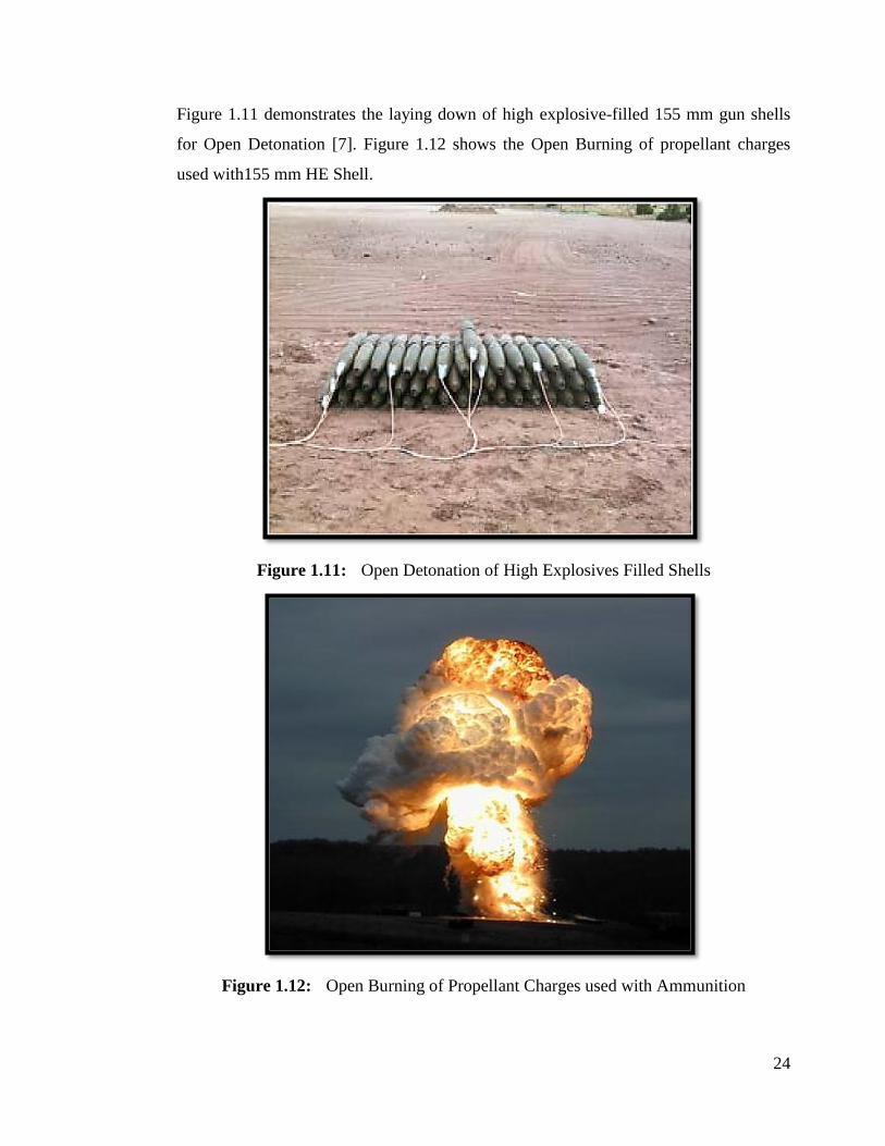
Figure 1.11 demonstrates the laying down of high explosive-filled 155 mm gun shells
for Open Detonation [7]. Figure 1.12 shows the Open Burning of propellant charges
used with155 mm HE Shell.
Figure 1.11: Open Detonation of High Explosives Filled Shells
Figure 1.12: Open Burning of Propellant Charges used with Ammunition

25
1.11.6.5 Resource, Recovery and Reutilization (R3)
In the last phase of demilitarization, recovered explosives are either burnt or re-utilized
for useful purposes. Subsequently, metal parts and scraps of munitions are immediately
collected from disposal sites and reused in several ways. For example, metal parts
including scraps can be recycled in recovery plants, if the facility is available. On the
other hand, the same may be sold in the civilian market after altering the entire
specification, shape and design. All the metal parts, especially copper and brass made
components, are very costly and can be easily reutilized for other tasks. However, the
sale of munitions metal and scrap components is only allowed to authorized dealers
who are contractually bound to immediately change, and convert, all these military
components into specific molds not resembling military designs and shapes. Figure 1.13
illustrates the complete life cycle of military munitions from storage up until final
disposal.
Figure 1.13: Complete Life Cycle of Military Munitions

26
1.11.7 Dumping
Before the global move towards environmentally suitable disposal technologies,
dumping was carried out worldwide to get rid of unwanted munitions post World War-
2. All unserviceable, defective and unwanted munitions were dumped in remote areas
where it was considered to be safe for disposal. As unwanted munitions were never
disposed of permanently in this process, munitions used to remain alive on the dumping
site, with all their incumbent safety hazards and risks. A great numbers of incidents
have been reported of dumping site blasts where humans have lost their limbs and/or
lives. Secondly, environmental pollution due to exudation and leakage of explosives
also increased manifolds in this practice. However, this practice for munitions dumping
is not in practice any more. Figure 1.14 shows the dumping of unserviceable munitions.
Figure 1.14: Dumping of Unserviceable Munitions
1.11.8 Sea Dumping
In line with the dumping technique discussed previously, world armies also adopted sea
dumping of unwanted munitions for permanent disposal after WW-II. But the practice
of sea dumping lasted only until the advent of the “1972 United Nation Convention on
the Prevention of Marine Pollution by the Dumping of Wastes and Other Matter
(London Convention)” [8]. Through this Convention, the disposal of unwanted
munitions through sea dumping was banned forthwith. A major cause of this ban was to

27
protect sea life from chemical hazards produced by explosives and also from the rusting
of the metallic parts of munitions which immediately started upon exposure to water.
Figure 1.15 (a) and (b) demonstrates sea dumping of unwanted munitions.
Figure 1.15 (a) and (b): Sea Dumping of Unwanted Munitions
1.11.9 Demolition
Demolition is the most common disposal technique still in practice for disposal of
unwanted munitions (both military and commercial). In this technique, all unwanted
munitions are disposed of conveniently in a well prepared underground pit. Demolition
(b)
(a)

28
may seem quite similar to OB/OD but its harmful effects on the surrounding
environment are contained more suitably than in OB/OD. During demolition, an
explosive train (discussed in detail in subsequent paragraphs) is connected to the
unwanted munitions laid in a definite pattern inside an underground pit. Although a
great effort is involved in digging the underground pit for disposal of unwanted
munitions, the risks to human lives are minimized to a great extent with this technique.
On initiation, the explosive train produces a shock wave sufficient enough to detonate
the main explosive charge of munitions. The amount of debris and splinters resulting
from the demolition of unwanted munitions is less significant than in the process of
OB/OD.
1.11.10 Explosive Train
An explosive train can basically be defined as a “Progressive grouping of explosives to
detonate the main charge of a munition”. It involves the successive layout of
explosives according to sensitivity, moving from most to least sensitive, and also on the
basis of stability, in reverse order. It consists of a safety fuse connected to a blasting cap
which is further linked to a booster in order to detonate the main explosive charge.
Procedurally, the burning flame of the safety fuse gives sufficient energy to the blasting
cap which, in turn, produces a detonation wave. A detonating cord attached with the
blasting cap transfers the detonation wave travelling at supersonic speed to the booster
(Tetryl CE). Finally, the booster or intermediary charge further enhances the detonation
wave to detonate the main high explosive charge. Table 1.3, lists the demolition stores
with the filling details utilized in the explosive train. Any damage or disruption caused
during the layout or initiation of an explosive train will lead to the failure of the
detonation process during demolition. Figure 1.16 gives a schematic layout of an
explosive train.

29
Figure 1.16: Schematic Layout of an Explosive Train
Table 1.3: List of Demolition Stores used during Explosive Train Layout
S.No Item used Explosive Filling Purpose
1 Safety Fuse Gun Powder Flash Carrier
2 Blasting Cap Lead Azide, Lead Styphnate
and Mercury Fulminate
Detonation wave
Producer
3 Detonating
Cord
Pentaerythritoltetranitrate
(PETN)
Detonation wave
Carrier
4
Booster
Charge
Tetryl CE (Composition
Exploding)
Detonation wave
Enhancer
5
Plastic
Explosive
(PE-3A)
RDX 87%,Wax 11%,
Lecithin 1%
Main bursting
charge/ explosive
1.12 Environmental Protection Agency (EPA) and Pak-EPA
The Environmental Protection Agency (EPA) is an agency which works for the
protection of human lives and the environment. Initially, the EPA was established in

30
the USA on 02 December, 1970; subsequently, the EPA branched out its operations to
almost all countries. The EPA conducts a series of environmental assessment initiatives,
research operations and educational awareness programs globally. The EPA has written
legislation and regulations pertaining to environmental protection for enforcement in
the society. Its work mainly revolves around the protection of air, land, and water
resources; including a focus on hazardous wastes and materials. Pertaining to
explosives, the EPA has always voiced great concern about the wide spread disposal of
military munitions. Additionally, an increase in global warming, pollution levels in the
environment and the widening of the Ozone layer is seen to be directly linked to the
massive adversarial use of military munitions in the World. The use of high explosive-
filled munitions during the two major World Wars of 1914 and 1939 has left
immeasurable adverse effects on the human environment. The EPA has published
stringent regulations for the reduction of hazardous materials and policies for
environmental protection. Pakistan, being a nuclear weapon state, also takes full
responsibility to ensure environmental protection. Pakistan Environmental Protection
Agency (Pak-EPA) was established under section (5) of Pakistan Environmental
Protection Act, (PEPA) 1997. One of the main responsibilities of Pak-EPA is to prevent
pollution and to protect the environment from contamination resulting from explosives
through strict enforcement of PEPA-1997 rules & regulations. Additionally, Pak-EPA
gives approval for projects requiring Environmental Impact Assessment (EIA) and
deals with the issuance of Initial Environmental Examination (IEE) Certificates for
establishment of Environment Laboratories. Pak-EPA states, “Protection of
Environment is Our Moral and Legal Obligation. Support Pakistan Environmental
Protection Agency (Pak-EPA) in implementation of Pakistan Environmental
Protection Act (PEPA)”.
1.13 Motivation for the Present Research Work
Disposal of life-expired and unwanted munitions is a great challenge across the globe.
In the past, these unserviceable explosives were disposed of through conventional
disposal techniques such as Open Burning/ Open Detonation (OB/OD), sea dumping,
underground demolition, incineration and biological degradation. Production of
poisonous and toxic gases such as NOx, COx, etc. during these disposal techniques

31
have always been a great concern for Environmental Protection Agency (EPA). It is
very obvious that a completely hazard-free solution cannot be achieved in its entirety
but the best available option is to minimize these hazards through alternative means of
disposal. There is also an international consensus that due to the excessive use of
military and commercial explosives, global warming has increased to life-threatening
proportions. Moreover, the sustainability of a clean environment that enables economic
and social development has also been endangered due to hazardous materials. The
present work is aimed at finding the most feasible solution for the disposal of all
unserviceable explosives. Pakistan army, being one of the largest militaries in the
world, is holding huge stockpiles of unserviceable and unwanted munitions. There is an
ever-present need to devise a suitable mechanism for the reutilization of high
explosives. With this motivation, the present research work was initiated, and through
repetitive experimentations and field tests, new blasting explosives have been
formulated using decanted TNT, amongst other ingredients. All these newly formulated
explosives have qualified the required standards and are considered appropriate for
adoption as a blasting explosive to be used in mining, quarrying and other military and
commercial applications.
1.14 Scope of the Present Research Work
A brief literature survey has been carried out to find various fields of recent
research pertaining to demilitarization and reutilization of high explosives. The aim
was also to identify research work where thermal cum kinetic evaluation studies have
been performed on these high explosives. Important aspects of the literature survey
pertaining to various research areas are mentioned in the introductory section of each
chapter. A road map for the completion of the present research work is given in Figure
1.17.

32
Figure 1.17: Road Map for Completion of the Present Research Work
A brief literature survey, along with the comprehensive research work done in
specified fields, will be discussed in concerned chapters but some of the aspects are
also covered in subsequent paragraphs of this chapter.

33
The first two chapters of this thesis cover introductory sections and do not include any
part of the present research work. However, in Chapter 3, the first portion of the
research work has been discussed briefly. It contains solvent based recovery of TNT
and RDX from an unserviceable Composition B (US Comp B) explosives shell. Once
fully recovered, a comparative analysis of these recovered samples has been carried
out with serviceable samples of TNT and RDX using different instrumental techniques.
All the samples were investigated using simultaneous Thermo-gravimetric/ Differential
Thermal Analysis (TG/DTA). The most important aspect during this phase of research
was to maintain identical conditions for each sample under investigation so that
resultant values could be easily compared. Similarly, for the morphological study,
Scanning Electron Microscopy (SEM) was selected and all samples were subjected to
scanning through SEM. In addition to this, X-ray diffraction (XRD) and Fourier
Transform Infrared (FTIR) analyses have also been carried out to discover the
crystalline nature and spectroscopy of all the samples. Any change in surface
morphology, crystallinity and vibrational peaks of both serviceable and recovered
samples of TNT and RDX have been identified and recorded for further research work.
Chapter 4 of this thesis covers decanting of TNT from unserviceable munitions using
an explosive decanting plant (Figure 1.18). The decanting of explosives through boiler-
less decanting plant is one of the safest and most advanced methods in comparison to
conventional explosive recovery techniques. Thus, for all future requirements during
present research work, decanted TNT recovered from decanting plant was utilized.

34
Figure 1.18: Explosive Decanting Plant with Decanted TNT
Samples of decanted TNT, once fully drained from moisture contents, were further
compared with serviceable TNT samples using different analytical techniques. The
purpose of this comparison was to get a fair idea of the possible use of decanted TNT
for the formulation of new blasting explosives. Consequently, kinetic evaluation using
Horowitz and Metzger method was carried out for the calculation of activation
energies (Ea) and enthalpies of both the TNT samples. For this purpose, Battery
software was employed using a curve fitting program. It has been discovered through
the results obtained that decanted TNT has lower Ea in comparison to serviceable
TNT. Thus, sensitivity of decanted TNT has increased primarily because of the
presence of impurities, etc.
In Chapter 5 and Chapter 6 of this thesis, laboratory scale formulation of new blasting
explosives developed from decanted TNT and suitable oxidizers, fuels and stabilizers
have been discussed in details. Initially, analytical grade aluminium has been used as
thermite composition to enhance the blast efficiency of newly formulated blasting
explosives. However, high value of VOD makes it unsuitable for use in routine blasting
operations. Thus, ammonium nitrate (AN) and calcium ammonium nitrate (CaAN) have
been selected for use with decanted TNT. Field tests of all newly formulated blasting
explosives were conducted with the help of VOD meter (Explomet-fo-2000,

35
manufactured by KONTINITRO AG). The purpose was to ascertain the performance
and blast efficiency of all newly formulated blasting explosives. VOD results show that
almost all the new blasting explosive samples have qualified the required standards and
are considered appropriate for adoption as blasting explosives. Similarly, all the
samples have also achieved the desired level of stability and densities. All these results
have been recorded and briefly discussed in Chapter 5 and Chapter 6.
In Chapter 7, brief descriptions about the design of a pilot plant based on new blasting
explosives developed from decanted TNT have been given. Pilot scale plant has been
designed using Creo-parametric 3D modeling software. In later sections of the chapter,
the simulation of plant through Aspen PLUS® V8.4 software has been covered. After
successful simulation, results have been discussed in details in Chapter 6.
Chapter 8 adequately covers fabrication, installations and functional tests of pilot plant
based on new blasting explosives. Initially, dummy materials have been used to check
the functionality of fabricated plant. Once the plant has qualified all the criteria, real
experiments are performed using decanted TNT, CaAN, wax and CaCO3 to formulate
new blasting explosives. Adherence to the explosive safety regulations and Standard
Operating Procedures (SOPs) has been ensured at all stages of the experiments to
avoid any untoward incident. Performance and stability tests of all the newly
formulated blasting explosives through pilot plant were performed using VOD meter
and Abel Heat tests. Furthermore, a cost analyses of commercially available blasting
explosives vis-à-vis newly formulated blasting explosive in this research work have
been made. Surprisingly, all the newly formulated blasting explosives account for as
little as one-third of the cost of available commercial blasting explosives having
similar characteristics. All the acquired results have been thoroughly discussed in
Chapter 8 of this thesis.

36
References
[1] C.B. Aakeroy, T.K. Wijethunga, J. Desper, Chemistry-A European Journal 21
(2015) 11029.
[2] J.P. Agrawal, R. D. Hodgson, book on “Organic Chemistry of Explosives”, John
Wiley & Sons Ltd, England (2007).
[3] D. Guo, Q. An, W. A. Goddard, S. V. Zybin, F. Huang, J. Phys. Chem. C. 118
(51) (2014) 30202.
[4] T.Yan, K. Wang, X. Tan, J. Liu, B. Liu, B. Zou, J. Phys. Chem. C. 118 (40)
(2014) 22960.
[5] S. Kumar, P. Jain, M. Sharma, Importance of Forensic Investigation in
Explosion: A Case study, J Forensic Res. (2016).
[6] J. Akhavan, The Chemistry of Explosives 2 (2004).
[7] M.R. Anvekar, P. Kallolimath, Journal of Aeronautics & Aerospace Engineering
(2013).
[8] J.P. Agrawal, High Energy Materials: Propellants, Explosives and Pyrotechnics,
John Wiley & Sons (2010).
[9] J. Mathieu, H. Stucki. Military High Explosives, CHIMIA International Journal
for Chemistry 58(58) (2004), 383.
[10] L. Türker, Defence Technology 12 (6) (2016) 423.
[11] S. S. Samudre, U. R. Nair, G. M. Gore, R. K. Sinha, A. K. Sikder, S. N.
Asthana, Propellants Explos. Pyrotech. 34 (2009) 145.

37
Chapter No. 2
Experimental Techniques, Materials and Methods
2.1 Purpose of the Present Research Work
Experimental techniques form an essential part of research work when confirmatory
analysis is required. A number of experimental techniques are available to support
scientific work. Since the present research work aims at finding various morphological,
thermal and kinetic evaluations of various explosive samples, care has been taken to
adopt some of the major experimental techniques for this purpose. A brief description
of experimental techniques used in the present research work is given in succeeding
paragraphs.
2.2 Experimental Techniques
In the present research work, thermal analysis has been carried out using its various
experimental modes. Explosives can be easily investigated for their thermal evaluation
using these experimental techniques. Thermal properties are also directly associated
with kinetic parameters of explosives. For a brief evaluation of kinetic parameters,
thermal data of material under investigation is utilized. In all, the following
experimental techniques have been used for evaluation of explosives.
a. Differential Thermal Analysis (DTA)
b. Thermogravimetery (TG)
c. X-ray Diffraction (XRD)
d. Scanning Electron Microscopy (SEM)
e. Velocity of Detonation (VOD) Measurement
f. Fourier Transform Infrared (FTIR) Spectroscopy
2.3 Thermal Analysis
Thermal analysis is a very useful technique for the detailed investigation of any
chemical composition or material substance. Chemical and physical behaviour and

38
associated properties of elements, pure compounds and mixtures are simply analyzed
with the help of thermal analysis techniques. Due to their sensitive nature and erratic
behaviour, explosives are considered most complex organic compositions for thermal
analysis. Usually, investigation of explosives is carried out using thermal analysis
techniques. These methods are used primarily because very small quantities of an
explosive are needed for the analysis. Thus, small quantities of the samples make it
safer and easier to analyze different classes of explosives [1-3]. During thermal analysis
of a sample, any change in its properties, i.e. physical or chemical properties, occurs
due to sudden exposure to high temperature. Sample temperature is systematically
increased in a controlled manner. Sample and inner reference materials are placed in a
heating chamber and the difference in temperature over time is observed. Some of the
physical and chemical properties such as boiling point, melting point, phase transition
and thermal decomposition, etc. can be easily obtained using thermal analysis.
Similarly, heat flow measurement defines endothermic or exothermic behaviour of
material during thermal events. Moreover, useful information on activation energy (Ea),
frequency factor or pre-exponential factor (E) and reaction rate can be easily obtained
through thermal analysis. Thermal analysis can be effectively used for:
a. Description of various polymers [4]
b. Explosives characterization
c. Design and development of pharmaceutical [5]
d. Soil investigation and evaluation [6]
e. Thermal study of foods [7]
2.3.1 Thermal Analysis Methods
Different methods are available for the thermal analysis of a chemical composition or
substance. In each method, the material under investigation is observed for any specific
change in property with respect to temperature change. A few of the useful thermal
analysis methods are enlisted below [8].
2.3.1.1 Differential Thermal Analysis (DTA)
DTA is used for the measurement of temperature difference between sample and inert
reference material over time.

39
2.3.1.2 Thermogravimetery (TG)
TG provides useful information about change in sample mass in relation to change in
temperature or time. Change in mass loss can be further used for measurement of
various kinetic parameters of the sample.
2.3.1.3 Differential Scanning Calorimetry (DSC)
In DSC, difference in heat flow between sample and inert material is measured. Various
changes in melting point, boiling points, thermal decomposition temperatures and phase
transformations can be easily observed through DSC. This method is frequently used
for thermal and kinetic evaluation of different explosives [9-11].
2.3.1.4 Thermo Mechanical Analysis (TMA)
Unlike other methods, TMA provides very useful information about various mechanical
properties of the materials.
2.3.1.5 Dynamic Mechanical Analysis (DMA)
DMA is used to measure mechanical stiffness and damping of material.
2.3.1.6 Thermo-magnetometry (TM)
This method is employed where magnetic properties of a material are required.
2.3.1.7 Emanation Thermal Analysis (ETA)
ETA mainly gives observation about evolution of radioactive gas from a material. In
order to discover various properties of a sample, thermal analysis is carried out. In
general, thermal analysis is a set of the most effective tools to measure chemical, physical
and mechanical properties of a sample upon heating. Thermal cum kinetic evaluation of
explosives can be easily observed using thermal analysis methods. In the present research
work, Thermogravimetery (TG) and Differential Thermal Analysis (DTA) methods
have been used for investigation of different explosives which are briefly discussed.
2.3.2 Differential Thermal Analysis (DTA)
Differential Thermal Analysis (DTA) is a wonderful technique for the thermal analysis
of explosives. In the present research, DTA has been used extensively for the thermal

40
and kinetic analysis of different explosives. It has been used to get useful information
on melting points, thermal decompositions, phase transformations, glass transitions
temperature, crystallization rates, etc. [12-14]. In DTA, a small quantity of sample
material is placed in Perkin Elmer ceramic crucible simultaneously with reference
material in another ceramic crucible for the thermal analysis. Both the materials are
then exposed to the required heating rate. The process for thermal analysis is carried out
under a controlled temperature program. Once the input is complete and the program
has been run, any change in temperature between sample material and reference
material is recorded and plotted as a function of temperature. The resulting curve is
called “Thermogram”. Through DTA, various kinetic parameters such as activation
energy (Ea), enthalpy etc. have been measured. Diamond TG/DTA-Perkin Elmer
Model Pyris instrument shown in Figure 2.1 has been used in the present research
work.
Figure 2.1: Diamond TG/DTA - Perkin Elmer Instrument
Reference materials used in DTA have a great effect on final results obtained from DTA

41
thermogram. The following characteristics must be kept in mind while selecting reference
material:-
a. Since reference material is used for comparative analysis, it must remain
inert thermally during the entire course of the thermal analysis.
b. Reference material should also remain neutral and non-reactive with
other ceramic crucible and thermocouples, etc.
c. Alumina or carborandum crucibles are considered most desirable
reference materials for thermal analysis as they possess almost all of the
above properties.
In addition to the above, a few other factors also have a direct impact and bear an
effect on DTA thermogram results. It is also important to know that all such factors
have a direct influence on TG curves as well.
2.3.2.1 Sample Related Factors
Sample characteristics and its nature are the key factors affecting the final results of
DTA curve. Some of the main factors are:
a. sample mass or weight
b. particle size and loading density of the sample
c. sample heat capacity and thermal conductivity
d. sample activation energy
2.3.2.2 Instrument Related Factors
a. heating rate of furnace selected for the sample
b. crucible material
c. crucible geometry
d. atmosphere of the chemical reaction
e. furnace type
f. exact position of thermocouple
g. instrument response and its specification
h. total time of investigation

42
For a brief thermal analysis of explosives, both TG and DTA techniques can be used
concurrently. As both TG and DTA are run under same environmental conditions,
kinetic parameters of any energetic material can be obtained easily using resultant
curves. In the present work, both TG and DTA have been used simultaneously.
2.3.3 Thermogravimetery (TG)
Thermogravimetry (TG) is a suitable technique used for the determination of energetic
material reaction. It is also termed as Thermogravimetric Analysis (TGA). In TG, a
small quantity of sample material is placed on a balance inside a heating oven and the
temperature is raised to the desired heating rate under a controlled temperature program.
Any change in weight gain or weight loss of the sample material is noted as a function
of temperature. In case of sample weight loss with rise in temperature, it may be linked
to the liberation of gaseous products due to chemical reaction, thermal decomposition of
sample material over time, etc. In cases where the sample has gained weight during TG,
it may be attributed to the chemical reaction of sample material with surrounding
environment, e.g. oxidation of metals [4]. In both cases of weight loss or weight gain,
sufficient useful information is obtained concerning the sample material. Either way,
obtained data regarding sample mass is correlated with other materials having similar
properties to recognize thermal events that have been observed in defined temperature
range. Weight vs. temperature curve plotted for the available data on sample material
gives very useful information about its thermal stability and decomposition. For the
measurement of possible changes in sample weight with temperature increases, thermo-
balance is utilized [5]. Based on all this information, TG analysis has been
comprehensively used for thermal analysis of explosives [15-17]. In the present work,
TG curves have been used for the measurement of thermal analysis and kinetic evaluation of
different samples of explosives. The main components of TG equipment are shown in Figure
2.2.

43
Figure 2.2: Main Components of TG Equipment
2.3.3.1 Working Principle of TG
In TG system, the sample material is filled in one pan whereas reference material is
placed in an adjacent pan. The two microbalances are linked with respective driving
coils. Any change in sample mass during DTA is observed closely with the help of
optical position sensors containing a slit. An optical beam is transmitted to the two
microbalances connected with driving coils through an optical position sensor. The
resulting current or input data is then passed to the driving coil to make sure that the slit
returns to its original location. It must be noted that sample weight loss or weight gain is
directly linked to the current passed by the microbalance to the driving coil. This way it is
easy to detect any change in sample mass with respect to reference material. Figure 2.3
shows the working principle of a TG instrument.

44
Figure 2.3: Working Principle of a TG Instrument
2.4 X-ray diffraction (XRD)
One of the most powerful and extensively used techniques for the identification of the
atomic or molecular structure of crystalline materials is X-ray diffraction (XRD). XRD
provides useful information about crystal structure of materials and is thus utilized in
the fields of Materials Science and Chemistry. Experts and research students working in
the fields of explosives widely use XRD for multiple reasons [18-20]. In this technique,
the incident X-rays are dispersed in var ious directions. This dispersion is caused
because of the X-ray‟s interface with the materials‟ atoms. The interference of an X-ray
may be constructive or destructive in nature. Bragg‟s law briefly explains the
constructive interference:
nλ = 2dsinθ
Here,
„n‟ shows an integer,
„λ‟ signifies incident X-rays wavelength,
„d‟ denotes the spacing between the planes and
θ represents the angle between the incident X-rays and set of crystal planes.
X-rays are electromagnetic radiations having a wavelength between 0.5-2.5Ao.

45
Within this wave length range, it is quite easy to find the crystal structure of any
materials at their atomic level. In the present research work, XRD has been used for the
description of serviceable and decanted TNT, RDX and Composition B explosives.
XRD is quite effective in identifying the residues produced as a result of the thermal
decomposition of the sample energetic material. In this work, XRD analysis was
performed using STOE Germany Theta-Theta Diffractometer, Germany; as shown in
Figure 2.4.
Figure 2.4: X-ray Diffraction (XRD) STOE Machine
The XRD instrument broadly consists of the following basic components:
a. An X-ray source usually named Monochromatic
b. Pan or holder for the sample
c. Main data collector or Scintillation counter
d. Cu and Kα X-rays
As discussed above, XRD is mostly used for the identification of the crystal structures
of materials and their atomic layout, etc. However, there is other useful information
which can also be deduced from the XRD analysis. Some of them are enlisted below:
a. recognition of phase composition
b. identification lattice parameters of unit cells
c. crystalline structure of materials

46
d. surface morphology/orientation
e. exact size of crystallite
2.5 Scanning Electron Microscopy (SEM)
SEM is a highly unique and resourceful technique being used by scientists and research
students around the world for multi-research in the fields of science and technology [21].
SEM works as an electron beam focused on the target material for brief scanning. A
specific signal is generated once the electron beam strikes the material surface. Structural
information as well as the composition of the sample material is obtained through the
action of the electron beam. In comparison with commonly used microscopes, Scanning
Electron Microscope produces extraordinary results. Due to the short wavelength of
the electron and its improved focusing qualities, SEM can attain a resolution of <1 nm.
The wavelength of white light is comparatively higher than the electrons‟ wavelength.
Because of the inherent limitations of this high wavelength, the focusing resolution of
latest model microscopes is not >250nm.
In the present work, SEM has been used effectively for the analysis of surface features
and morphologies of various types of high explosives such as TNT, RDX and
Composition B (Comp B). Additionally, newly formulated blasting explosives have
also been investigated through SEM. This technique has been used primarily for the
surface investigation of all serviceable, decanted and newly formulated blasting
explosives to determine possible changes which may have occurred during their shelf
life. This technique also gave an insight into the various defects; including porosity,
cracks, minor holes, and other structural changes; found on the materials‟ surface
during a comparative analysis of different explosives. For this purpose, a scanning
electron microscope made by JEOL (JSM- 6490 LA), Japan, has been used which is
shown in Figure 2.5.

47
Figure 2.5: Scanning Electron Microscope JEOL (JSM- 6490 LA)
2.6 Velocity of Detonation (VOD) Measurement
The Velocity of detonation (VOD) Meter is a very dynamic tool for the measurement of
explosive efficiency with regards to blasting power. It helps in the identification of various
classes of explosives for selection on the basis of their use and applications. The VOD
meter helps to determine the strength and the performance of the explosive. The
EXPLOMET-FO-2000™ (KONTINITRO AG made in Switzerland) has been used
during the field testing of almost all explosives. This instrument has an accuracy of
+0.1 microsecond (µs).VODs of all samples of explosives, i.e. serviceable, decanted
and newly formulated blasting explosives have been measured using VOD meter. The
VOD meter actually works as a digital counter for the recording of VODs up to 10km/s.
Optical fiber probes in VOD meters are used to transmit light emitted during the
detonation of an explosive sample. The VOD meter is connected to two probes which
are attached on either side of the sample material. Once the explosive is initiated, the
detonation wave travels through optical fibers and its velocity is recorded automatically
in the VOD meter, thereby acting as an electronic counter between 0.1 micro-second
and 10 seconds. The resultant velocity is then used to determine the blast efficiency of
explosives. The VOD meter finds its use in a vast variety of scenarios for the
measurement of the VODs of various explosives; including the military, commercial

48
mining and other civil industries. Figure 2.6 (a) and (b) shows a VOD meter and a VOD
meter with accessories and box, respectively.
Figure 2.6: (a) VOD Meter, (b) VOD Meter with Accessories and Box
(a)
(b)

49
2.7 Fourier Transform Infrared (FTIR) Spectroscopy
Fourier Transform Infrared (FTIR) Spectroscopy is a very dynamic technique used for
the qualitative structure analysis of any material. The infrared region is used for the
measurement of the transmittance or absorption spectra with the help of a spectrometer.
In FTIR spectroscopy, the existence of various functional groups attached to the sample
material is verified. This technique is also very useful for the identification of the band
position, peak intensity and shape of explosives. A structural analysis of different
explosives used during the present research work has been done with the help of FTIR
spectroscopy. The stretching and vibration of various bonds in the explosive transmit
and absorb an infrared light which is further used for analytical purposes. All further
information was obtained through intensity/ wavelength curves [10].
In this research, FTIR (FT-IR Spectrum 100 Perkin Elmer, MID IR) shown in Figure
2.7 has been used for the qualitative structure analysis of serviceable and unserviceable
explosives samples; with 1 cm−1 resolution in the transmission mode from wave
numbers 450–4000 cm−1. Small quantities of both categories of explosives have been
prepared according to the requirement and placed in the pallet holder. Next, the holder
was placed in the Perkin Elmer FTIR instrument mentioned above. The resultant
spectra of all the explosive materials were recorded at an ambient temperature.
Figure 2.7: Perkin Elmer FTIR Spectrum 100, MID IR

50
2.8 Materials Used
2.8.1 Oxidizers
During the present research work, new blasting explosives have been formulated using
decanted and recovered TNT along with other suitable ingredients. One of the
ingredients worth mentioning is an oxidizer which is used for maintaining the fuel
levels needed to burn properly during the detonation process. TNT, being an oxygen
deficient explosive, always requires a sufficient amount of oxidizing agent to increase
its energy and efficiency. In order to enhance the oxygen levels in new blasting
explosive compositions, commercial grade Ammonium Nitrate (AN) and Calcium
Ammonium Nitrate (CaAN) have been selected and used in different proportions
during research work. Purity levels of all oxidizers used in the present work are lower
than in analytical grades because of two reasons, i.e. cost effectiveness and its utility as
per the requirement of blasting explosives. Since commercial blasting explosives are
used for low profile tasks as compared to military applications, not much precision and
accuracy is required in terms of range and power. AN and CaAN have been purchased
from local markets, thus, ensuring that both the oxidizers are easily available during the
formulation of new blasting explosives on a large scale basis. Before embarking on the
impregnation of TNT with oxidizers, all oxidizers have been sieved through ~18 mesh
size after being finely ground.
2.8.2 Fuels
2.8.2.1 Recovered/ Decanted TNT
TNT is one of the most powerful explosives used for both military and commercial
purposes. TNT finds its application as a fuel and as an energizing material due to its
powerful nature, high VOD and thermal stability. Initially, unserviceable TNT was
recovered from Comp B explosive through a solvent based technique. However, for all
other experiments, unserviceable TNT was recovered from unserviceable munitions
through a decanting process. Both types of TNT were used as the main fuel in the
formulation of new blasting explosives. Due to the high energetic value of contents,
decanted TNT has been used in different percentages along with various other
ingredients for the formulations of new blasting explosives. Figure 2.8 shows decanted

51
TNT placed in a wooden box; alongside its decanted shell showing a residue free
surface post the decantation of TNT explosive.
Figure 2.8: Decanted TNT with Decanted Shell Free From Explosive (FFE)
2.8.2.2 Aluminium (Al) Powder
During the initial phases of the present research work, Al powder was used due to its
high thermal effect, high heat of combustion and ease of availability [22]. Al powder
not only enhances the blast energy of explosives due to its high calorific value but also
enhances its brisance and shattering power. Analytical grade Al powder produced by
Panreac (Spain) was purchased. The average particle size of the analytical grade Al
was 26.98 µm. Al powder was used with TNT recovered from Comp B explosive for the
formulation of blasting explosives. Experiments using analytical grade Al were carried
out in an open atmosphere for safety reasons as the heating of Al powder requires
special handling and care. Figure 2.9 shows an open-air experimental area set up for the
formulation of blasting explosives using Al as fuel.

52
Figure 2.9: Open-Air Experiments using Al as Thermite Composition
2.88.2.3 Saw Dust
Saw dust, also commonly known as wood dust, is a flammable material which can
produce sufficient amounts of heat and energy. Commonly available saw dust has been
purchased from the local market for simultaneous use with decanted TNT, as an
additional fuel in order to act as a blasting agent. Small quantities of the finest quality
saw dust has been used in different proportions during the experimentation process. The
main reason behind its use was to produce additional energy and to increase the overall
heat of the newly formulated blasting explosives. Figure 2.10 shows fine quality
sawdust used during the research work.

53
Figure 2.10: Finest Quality Saw Dust used in Research Work
2.8.3 Paraffin Wax
Paraffin Wax is commonly used for lubrication, insulation and candle work. However,
it can be effectively use as a fuel, a phlegmatizing agent and for waterproofing
purposes. Additionally, wax works as an anti-caking agent and a moisture-repellant.
Two types of waxes have been used in the present research work to determine their
utility with respect to cost, availability and ease of handling; the first being an
analytical grade wax (made by Merck, Germany, having a solidification point between
56-58oC) and the second being a commercial grade wax. After initial laboratory scale
experiments, the analytical grade wax was replaced with commercial grade wax due to
cost effectiveness and availability.
2.8.4 Calcium Carbonate (CaCO3)
Calcium Carbonate (CaCO3), also known as Chalk, is a very useful composition which
is used in a variety of civil applications. Due to its inherent characteristics as a sound
base, it can be effectively used as a free acid absorbent. Chalk has been used to stabilize
the sensitivity of decanted TNT. It also helps in reducing the degradation process of
explosives and increases their shelf life. A very small quantity (~1-2%) of chalk has
been used in different explosive formulations to get the desired results.
2.9 Compositions of Newly Formulated Blasting Explosives
During the entire course of the research work, a large numbers of experiments have

54
been conducted for the formulation of new blasting explosives developed from
decanted TNT. Some of the samples achieved the desired results while others failed to
do so. Almost all the newly formulated explosives have been characterized, tested and
analyzed through various instrumental techniques. Detailed compositions of all newly
formulated blasting explosives are mentioned below.
2.9.1 Compositions Formulated at Laboratory Scale
2.9.1.1 Composition No.1 with TNT and 15% Al (TAL-1)
In this composition decanted TNT has been used with 15% Al to increase the blast
effects and energy of the new formulation. Nitrocellulose (NC) as flammable compound
was added to the composition. Wax was added as an insulation and desensitizing agent.
Besides, methanol and dry lecithin were also added to the composition in small
quantities according to its requirement. The percentage of each ingredient used in
Composition no.1 (TAL-1) is shown in Table 2.1.
Table 2.1: Percentage of ingredients used in Composition no. 1 (TAL-1)
S. No Chemical used Percentage (%)
1 Decanted or Recovered TNT 56
2 Al powder 15
3 AR Grade NC 13
4 Methanol 1
5 Wax 14
6 Dry Lecithin 1
Total 100
2.9.1.2 Composition No.2 with TNT and 26% Al Powder (TAL-2)
In this composition, decanted TNT has been used with 26% Al to further enhance the
blast effectiveness of the new formulation. Similarly, NC % has been increased
slightly to see the final effect. The percentage of each ingredient used in Composition
no.2 (TAL-2) is given in Table2.2.

55
Table 2.2: Percentage of each ingredient used in Composition no. 2 (TAL-2)
S. No Chemical used Percentage (%)
1 Decanted or Recovered TNT 45
2 Al powder 26
3 AR Grade NC 14
4 Methanol 1
5 Wax 13
6 Dry Lecithin 1
Total 100
2.9.1.3 Composition No. 3 (TAN)
In this particular sample, decanted TNT was used with AN to determine the results for
comparison with CaAN samples. Results of Composition no. 3 are discussed in a
relevant chapter of this thesis. Table 2.3 shows the percentages of ingredients used in
this composition.
Table 2.3: Percentage of each ingredient used in Composition no. 3 (TAN)
S. No Chemical used Percentage (%)
1 Decanted TNT 7
2 AN 88
3 CaCO3 0.5
4 Wax 0.5
5 Sawdust 4
Total 100
2.9.1.4 Composition No. 4 (TCAN)
In this particular sample, a blasting explosive was developed from decanted TNT
using a sufficient quantity of CaAN as an oxidizer. The VOD and other field test
results show remarkable achievement, including cost effectiveness. Although, data in
literature form regarding use of CaAN with unserviceable TNT for reutilization
purposes is not available. Cost effectiveness, safety in handling and availability

56
aspects also makes it seem like the most practical candidate for use as an oxidizer.
Table 2.4 gives percentage-wise details of the composition used.
Table 2.4: Percentage of each ingredient used in Composition no. 4 (TCAN)
S. No Chemical used Percentage (%)
1 Decanted TNT 20
2 CaAN 74
3 CaCO3 0.5
4 Wax 0.5
5 Sawdust 5
Total 100
2.9.1.5 Composition No. 5 (TACAN-1)
In this composition, a mixture of CaAN and AN has been used to determine their
results. Wonderful results have been achieved which are discussed in detail in a
relevant chapter of the thesis. Table 2.5 gives percentage-wise details of the
composition used.
Table 2.5: Percentage of each ingredient used in Composition no. 5 (TACAN-1)
S. No Chemical used Percentage (%)
1 Decanted TNT 30
2 AN/ CaAN 60
3 CaCO3 0.5
4 Wax 0.5
5 Sawdust 9
Total 100
2.9.1.6 Composition No. 6 (TACAN-2)
In line with composition no. 5, different percentages have been used to determine the
final results which are discussed in a later chapter. Table 2.6 gives percentage wise
details of composition used.

57
Table 2.6: Percentage of each ingredient used in Composition no. 6 (TACAN-2)
S. No Chemical used Percentage (%)
1 Decanted TNT 15
2 AN/ CaAN 80
3 CaCO3 0.5
4 Wax 0.5
5 Sawdust 4
Total 100
All these newly formulated explosives have been analyzed through various thermal and
analytical techniques and results have been deduced accordingly.
2.9.2 Compositions Formulated through Pilot Plant
In order to achieve comparative results based on similar ingredients, different
percentages have been used in all compositions formulated through the pilot plant. The
purpose was to obtain VOD results having different values, so that required samples of
blasting explosive may be used according to their VODs. All these compositions have
been formulated through a personally fabricated plant using decanted TNT along with
other ingredients. Percentage-wise details of each composition formulated through
pilot scale plant are mentioned in Table 2.7 to Table 2.12.
2.9.2.1 Composition No. 7 (TCAN-1)
Table 2.7: Percentage of each ingredient used in Composition no. 7 (TCAN-1)
S. No Chemical used Percentage (%)
1 Decanted TNT 30
2 CaAN 60
3 CaCO3 2
4 Wax 1
5 Sawdust 7
Total 100

58
2.9.2.2 Composition No. 8 (TCAN-2)
Table 2.8: Percentage of each ingredient used in Composition no. 8 (TCAN-2)
S. No Chemical used Percentage (%)
1 Decanted TNT 25
2 CaAN 70
3 CaCO3 1.5
4 Wax 0.5
5 Sawdust 3
Total 100
2.9.2.3 Composition No. 9 (TCAN-3)
Table 2.9: Percentage of each ingredient used in Composition no. 9 (TCAN-3)
S. No Chemical used Percentage (%)
1 Decanted TNT 20
2 CaAN 75
3 CaCO3 1.5
4 Wax 0.5
5 Sawdust 3
Total 100
2.9.2.4 Composition No. 10 (TCAN-4)
Table 2.10: Percentage of each ingredient used in Composition no. 10 (TCAN-4)
S. No Chemical used Percentage (%)
1 Decanted TNT 40
2 CaAN 50
3 CaCO3 1.5
4 Wax 0.5
5 Sawdust 8
Total 100

59
2.9.2.5 Composition No. 11 (TCAN-5)
Table 2.11: Percentage of each ingredient used in Composition no. 11 (TCAN-5)
S. No Chemical used Percentage (%)
1 Decanted TNT 35
2 CaAN 60
3 CaCO3 1.5
4 Wax 0.5
5 Sawdust 3
Total 100
Composition No. 12 (TCAN-6)
Table 2.12: Percentage of each ingredient used in Composition no. 12 (TCAN-6)
S. No Chemical used Percentage (%)
1 Decanted TNT 25
2 CaAN 65
3 CaCO3 1.5
4 Wax 0.5
5 Sawdust 8
Total 100
2.10 Kinetic Evaluation Methods
2.10.1 Significance of Kinetic Evaluation for Explosives
Since explosives are energy rich compounds having very reactive and sensitive natures,
kinetic evaluation is significant prior to their handling, storage and transportation. It is of
paramount importance to evaluate explosives according to their thermal stability and
sensitivity. In the present research work, explosive data recorded during TG and DTA has
been used for the kinetic parameters evaluation of their thermal decompositions. Kinetics
evaluation is also important because it not only provides insight into the route of the
chemical reaction but also finds stability and suitability of different compositions with
each other. Thermal cum kinetic evaluation also provides assistance with the selection

60
and formulation of new versions of compositions along with their safety procedures.
Over a period of time, large numbers of thermal cum kinetic methods have been
devised for thorough evaluation of explosives. A key feature of TG/ DTA instrument is
that both the thermal analysis and kinetic evaluation of a particular energetic material is
obtained using a single instance of data.
It is also pertinent to mention that non-isothermal methods are better than conventional
isothermal techniques [23-24]. Some of the key features of non-isothermal methods are:
a. In all these methods, temperature scan of sample material over intended
range of temperature is a fast and easy process.
b. These methods provide continuous opportunity for the kinetic evaluation
of a sample over intended temperature range.
c. Non isothermal method sometimes form part of isothermal method as
the sample temperature has to be increased to the intended temperature
non-isothermally where the sample may be in danger of experiencing
some chemical reaction. However, these issues do not exist in the case
of non-isothermal methods.
d. All such methods need very little experimental data in a short span of
time.
e. For better results, numerous heating rates are chosen but where such an
option is not available, a single heating rate is still acceptable.
During this research, non-isothermal methods of kinetic analysis have been used.
Some of the most commonly used methods for kinetic evaluation are enlisted below:
a. Kissinger method
b. Ozawa method
c. Horowitz and Metzger method
d. Friedman method
e. Flynn–Wall–Ozawa method
2.10.2 Horowitz and Metzger Method
The Horowitz and Metzger method has been used in the present work as it can easily
manage to measure the activation energy (Ea) using a single heating rate in the

61
experiment. In this method, a reference temperature is determined and marked as Ts.
At this temperature, decomposition of any material under investigation reaches its
peak rate. The relationship shown in equation (2.2) helps in calculating Ts from TG
data obtained through analysis.
Ts = Wt / Wo = 1/e ------------------------------------------------------ (2.1)
Where, “Ts” denotes reference temperature, “Wt” is samples weight recorded at any
given temperature T, “Wo” is the total starting weight of the sample and “e” is the
exponential. In case the reference temperature “Ts” is already known, then difference
in temperatures ө (theta) can be calculated with the help of equation (2.2).
ө = T- Ts ------------------------------------------------------- (2.2)
Here “T” is temperature of the sample at any weight “Wt”. The “ө” is then plotted
against lnlnWo/ Wt. The value of Ea is then calculated using a gradient or the slope of
a nearly straight line obtained from the above mentioned graph [25].
Slope = Ea/ RTs2
------------------------------------------------ (2.3)
Where,
Ea is the activation energy,
R is the Universal Gas Constant and
Ts is the reference temperature.

62
References
[1] D. Ouyang, G. Pan, H. Guan, C. Zhu, X. Chen, Thermochimica Acta 513
(2011) 119.
[2] P.R. Patil, V.N. Krishnamurthy, S.S. Joshi, Propellants Explos. Pyrotech. 31
(2006) 442.
[3] L.Liu, G. He, Y. Wang, Journal of Thermal Analysis and Calorimetry 114
(2013) 1057.
[4] M.P. Sepe, Book on Thermal Analysis of Polymers, Smithers Rapra Publishing
(1997).
[5] D. Giron, Journal of Thermal Analysis and Calorimetry 68 (2002) 335.
[6] A.F. Plante, J.M. Fernández, J. Leifeld, Geoderma 153 (2009) 1.
[7] Y. Roos, Journal of Thermal Analysis and Calorimetry 71 (2003) 197.
[8] M.E. Brown, Book on Introduction to Thermal Analysis: Techniques and
Applications, Second Edition (2001).
[9] B. Berger, A. Brammer, E. Charsley, J. Rooney, S. Wirrington, Journal
of Thermal Analysis and Calorimetry 49 (1997) 1327.
[10] J.S. Lee, C.K. Hsu, C.L. Chang, Thermochimica Acta 392 (2002) 173.
[11] R. Sivabalan, M. Talawar, N. Senthilkumar, B. Kavitha, S. Asthana, Journal
of Thermal Analysis and Calorimetry 78 (2004) 781.
[12] H.-H. Licht, Propellants Explos. Pyrotech. 25 (2000) 126.
[13] Z. Ma, F. Li, H. Bai, Propellants Explos. Pyrotech. 31 (2006) 447.
[14] S.Pourmortazavi, M. Fathollahi, S. Hajimirsadeghi, S. Hosseini,
Thermochimica Acta 443 (2006) 129.
[15] X. Kang, J. Zhang, Q. Zhang, K. Du, Y. Tang, Journal of Thermal Analysis
and Calorimetry 109 (2012) 1333.
[16] J. Luman, B. Wehrman, K. Kuo, R. Yetter, N. Masoud, T. Manning, L. Harris,
H.Bruck, Proceedings of the Combustion Institute 31 (2007) 2089.
[17] Q.S. Kwok, R.C. Fouchard, A.M. Turcotte, P.D. Lightfoot, R. Bowes, D.E.
Jones, Propellants Explos. Pyrotech. 27 (2002) 229.
[18] G. Harding, A. Harding, Book on Counterterrorist Detection Techniques of
Explosives (2007) 199.

63
[19] L. Meda, G. Marra, L. Galfetti, F. Severini, L. De Luca, Materials Science
and Engineering: C 27 (2007) 1393.
[20] S.H. Ba, Z. Zhang, M.H. Yan, Z.X. Sun, X.P. Teng, Applied Mechanics
and Materials 217 (2012) 669.
[21] J.R. Verkouteren, Journal of Forensic Sciences 52 (2007) 335.
[22] Lemi TÜRK, Defence Technology 12 (2016) 423.
[23] S. Maitra, S. Mukherjee, N. Saha, J. Pramanik, Ceramica 53 (2007) 284.
[24] S. Vyazovkin, C.A. Wight, International Reviews in Physical Chemistry
17 (1998) 407.
[25] M.V. Kok, R. Pamir, Oil Shale 20 (2003) 57.

64
Chapter No. 3
Morphological and Thermal cum Kinetic Studies of
Assorted Explosives
3.1 Summary of the Present Research Work
Explosives experience widespread application in military as well as commercial
applications. They are being used for multiple purposes ranging from war field weapons
to the commercial mining and underwater blasting activities. Explosives are casted into
military shells by two different methods i.e. melt cast and press cast method [1]. Just
like other chemical compositions, explosives have a specified shelf life after which they
become unserviceable (US) for use, particularly in military operations. Out of various
classes of explosives, nitramines are ranked at the top due to their high energetic
properties and that is why technical application of these explosives is always useful [2-
3]. Composition B explosive is a mixture of 60% RDX, 40%TNT but in some cases 1%
wax is also added as desensitizing agent. Since both RDX and TNT are mostly used as
the main explosive charge for filling the military munitions, therefore, successful re-
utilization of these precious materials after completion of shelf life helps to reduce the
wastage of these explosives. A. Maranda et al., mentioned in their research that
application of unwanted explosives in the surface mining industry is in widespread
demand [4]. Similarly H. Krause investigated the conversion of military high explosives
into various forms of raw materials such as TNT into DAT and mentioned some of their
applicability into plastic industry [5]. Globally, efforts are underway for the safest
disposal of these unwanted explosives but these techniques are still hazardous for
human beings. J. C. Pennington et al., predicted in their research on unwanted
munitions that all degraded particles left over in the soil after a demolition process
produce adverse biological effects on human beings [6-8].
The present research work is aimed at successful recovery of RDX and TNT from US
Composition B using solvent based technique. This technique is not only safe but

65
environmentally acceptable because explosives are treated with solvent without heating
or exposing to external stimuli. After successful recovery of TNT and RDX, both the
samples have been investigated through various analytical techniques their thermal,
morphological and kinetic evaluations. Thermo-gravimetric/ Differential Thermal
Analysis (TG/DTA), Scanning Electron Microscopy (SEM), X-ray Diffraction (XRD)
and Fourier Transform Infrared (FTIR) techniques have been used during analyses of
both TNT and RDX. Special focus has been made on TNT explosive because of its
insensitive nature, thermal stability and relative cost-effectiveness [9-11]. To be more
confident about the recovered samples, original TNT and RDX were arranged. For in-
depth analyses, all the four samples of Recovered TNT and RDX vis-a-vis Original
TNT and RDX were used in the present work. SEM analysis has particularly been done
so that morphological changes between recovered and Original explosive samples could
be easily compared.
3.2 Experimental Conditions
3.2.1 Arrangement of Explosives
US Composition B was recovered arranged through defense organization for the present
research work. However, original TNT and original RDX were purchased from
Pakistan Ordnance Factories (POFs), Wah. After thorough literature study, analytical
grade chloroform was selected as suitable solvent for recovery of Composition B
ingredients (i.e. RDX and TNT).
3.2.2 Recovery of RDX and TNT from US Composition B Explosive
Composition B containing 59.5 % RDX / 39.5 % TNT and about 1% paraffin wax is a
melt cast explosive mixture. In order to recover TNT and RDX from US Composition
B using chloroform, the solubility of RDX and TNT in 100g of solvent have been
studied within temperature range of 20-25oC. Resultant data is shown in Figure 3.1 and
Figure 3.2 respectively [12].

66
Figure 3.1: Solubility of RDX in gram per 100 g of Solvent
Figure 3.2: Solubility of TNT in gram per 100 g of Solvent
Table 3.1 and Table 3.2 reveals that chloroform, being the most important solvent,
based on solubility difference, can be used for the recovery of RDX and TNT from US
Composition B explosive sample [12]. During experiment, small amount of chloroform
was added to US Composition B sample in a separating funnel. After proper shaking,
sample material was allowed to remain stationary on the clamp stand for a while so that
TNT and RDX could be completely recovered from US Composition B in two distinct
layers based on solubility difference in the chloroform. The process was repeated

67
several times until two distinct layers were visible. Brownish layer of TNT at the top
while white crystalline particles of RDX was present in the bottom layer. RDX was
drained out through bottom vent in the separating funnel. Recovered RDX was then
dried in the open air for further analysis. Chloroform solvent being very volatile in
nature completely evaporated in open air. In line with RDX, TNT particles were
collected from the bottom vent and subsequently dried through heating process just
below its melting point of 81+1 oC. Lastly, distilled water was added to left over
particles of TNT/ wax mixture so that insoluble wax floating on the top most layer
could be easily recovered and collected. Recovered TNT and RDX were then analyzed
through different techniques to find out their thermal behavior and surface morphology.
3.2.3 Analytical Techniques
Thermal and morphological analysis of all five samples including US Composition B,
Recovered RDX, Recovered TNT, Original TNT and Original RDX have been carried
out. Different instruments used during present research work included Scanning
Electron Microscopy (SEM-6490A JEOL made in Japan), Thermo gravimetric
/Differential Thermal Analyzer (TG/DTA- Perkin Elmer Model Pyris Diamond), X-Ray
Diffraction (XRD- made by Theta-Theta Toe, Germany) and Fourier Transform
Infrared (FTIR-Model Spectrum 100).
3.2.3.1 Scanning Electron Microscopy (SEM) Analysis
SEM, being one of the most versatile tools in identification of structural information,
can be employed in the field of explosive detection and identification. To carry out the
present work, Scanning Electron Microscope (SEM) instrument, 6490A JEOL has been
used. Variable voltages of 2-20kV and magnifications of 1500, 3000 and 10000 were
applied at different angles keeping in view the sensitivity and nature of the samples
3.2.3.2 Thermo gravimetric/ Differential Thermal Analysis
(TG/DTA)
TG/DTA is a very strong tool for thermal and kinetic studies of the sample under
controlled temperature program. Perkin Elmer Model Pyris Diamond TG/DTA (Thermo
gravimetric/ Differential Thermal Analysis) instrument available at SCME, NUST has

68
been used for the thermal analysis of various samples. All five samples were examined
using Perkin Elmer TG/DTA. This instrument works at a heating rate of 0.001oC/min to
200oC/min. In order to calibrate the apparatus, standards were run and then initial setup
for actual analysis was made. Nitrogen (N2) was used as purging gas for creation of
inert atmosphere. All five samples were subjected to a heating rate of 10oC/min and
temperature range was kept between 25oC to 350
oC during entire thermal analyses.
3.2.3.3 X-ray Diffraction (XRD) Analysis
X-ray Diffraction (XRD) analysis has also been carried out in the present research work
due to its wide range of investigation for a particular sample. Various parameters such
as crystal structure, atomic arrangement, phase orientation, lattice parameters, grain size
and density etc. of any sample can be easily identified.
3.2.3.4 Fourier Transform Infrared (FTIR) Spectroscopy
This instrument is particularly used to observe band position, shape and peak intensity
of various samples so that characteristics of functional groups can be identified. It has a
wave number ranging from 10000 cm-1
to 100 cm-1
. In this technique IR spectrum of
absorption, emission and Raman scattering of a solid, liquid or gas can be obtained.
3.3 Results and Discussion
During present work different results have been achieved through analytical techniques
which are briefly explained in the succeeding paragraphs. Sequentially all the samples
are discussed to get optimum information about each of the five explosive samples.

69
3.3.1 Scanning Electron Microscopy (SEM) Analysis
3.3.1.1 US Composition B
In Figure 3.3, US Composition B explosive sample in powder form was subjected to
SEM analysis and investigation. From SEM images it has been revealed that US
Composition B has spindle-like structure with multiple cracks and porosity of 160-521
nm size visible on the surface. The sample was examined at variable voltages between
3.0-5.0kV because at higher magnification and with increase in voltage, sample
behavior showed abrupt changes which proved unsafe for further analysis. The sample
has completed its shelf life; therefore various climatic changes may have rendered
multiple cracks and porosity in its surface. These cracks adversely affect the sensitivity
of this explosive and render it unsafe.
(a)

70
Figure 3.3: SEM Images of US Composition B Explosive Sample at 5.0kV
and Magnifications of (a) 1500; (b) 3000; (c) 10000, respectively
3.3.1.2 Recovered TNT
In Figure 3.4, a small quantity of Original TNT was investigated for its morphology. It
has been noted from the in- depth analysis that Original TNT has an even surface with
irregular blocks shape microstructure. Very few pores can be seen in the image which
shows that the sample is uniformed having integrated particle structure and is defect-
free explosive sample unlike Recovered TNT sample. Presence of cracks on explosive
surface has multiple reasons, some of which may be inappropriate storage conditions
and adverse climatic effects. An explosive is designed to be free from any kind of
(c)
(b)

71
filling or formulation defects, otherwise it may cause premature ignition of the
munitions. Similarly, exudation process can also be a cause of some defects during hot
climate. For the explosives, both the physical as well as chemical behaviors are most
important aspects. These include explosives crystalline or non-crystalline shape, pore
size and its density, ignition temperature etc.
(b)
(a)

72
Figure 3.4: SEM Images of Recovered TNT Explosive Sample at 5.0kV and
Magnifications of (a) 1500; (b) 3000; (c) 10000, respectively
3.3.1.3 Original TNT
In Figure 3.5, a small quantity of Recovered TNT sample was examined through SEM
analysis at 3.0kV and different magnification for its complete picture. Morphological
studies reveal that the sample has an irregular shape with no specific orientation.
Multiple pores in the size range of 247-608 nm are visible which render this sample
unsuitable for field utility as compared to Original TNT sample whose surface is
smooth and homogeneous [13]. Since sample was treated with water during separation
process, therefore chances for increase in porosity cannot be ruled out. However, a
major reason for large number of pores on the surface is long shelf life.
Multiple
tiny holes
(c)

73
(a)
(b)

74
Figure 3.5: SEM Images of Original TNT explosive sample at 3.0kV and
Magnifications of (a) 1500; (b) 3000; (c) 10000
3.3.1.4 Recovered RDX
In Figure 3.6, SEM analysis of Recovered RDX revealed that this particular sample is
more dangerous in nature especially once exposed to high temperature environment.
The sample was analyzed between voltages of 5.0-20.0kV, keeping in view its erratic
behavior. Sample has multiple cracks with width sizes of 212- 384 nm and varied
lengths. The surface seems to be more compact and flat in shape. Multiple cracks on its
surface are quite evident.
Even Surface
without tiny
holes or cracks
(c)
(a)

75
Figure 3.6: SEM Images of Recovered RDX Explosive Sample at 20-5.0kV
and Magnifications of (a) 1500; (b) 3000; (c) 10000
3.3.1.5 Original RDX
In Figure 3.7, SEM analysis of original RDX revealed that this particular sample has
spherical shaped morphology with multiple tiny holes spread across the surface.
Analysis was carried out at constant voltage of 5.0kV but at different magnifications of
1500, 3000 and 10000. No much difference has been observed in this particular sample
as compared to the Recovered RDX Sample. Surface is flat with multiple cracks of
170.88-475.39 nm sizes and varied lengths.
Multiple cracks
of ~2-6µm
(c)
(b)

76
(a)
(b)

77
Figure 3.7: SEM Images of Original RDX Explosive Sample at 5.0kV and
Magnifications of (a) 1500; (b) 3000; (c) 10000
3.3.2 Thermogravimetric (TG) Analysis
TG curves of all five explosive samples including US Composition B, Recovered TNT,
Original TNT, Recovered RDX and Original RDX are given in Figure 3.8. It has been
noted that TG curves for all samples exhibit nearly 100% mass loss in a single step.
Onset of mass loss for TNT samples both in Recovered and Original samples seems to
start near 165oC, whereas for RDX sample, mass loss is observed to start near 180
oC. A
rapid shift in mass loss has been identified between 180-245oC due to thermal
decomposition of TNT and RDX. Hence the total mass loss for all the samples over
controlled temperature range of 165-245oC was found to be nearly 99%.
Surface with less
no of tiny holes
(c)

78
Figure 3.8: TG Curves of Five Different Samples
3.3.3 Differential Thermal Analysis (DTA)
Figure 3.9 shows DTA thermograms for various explosive samples including US
Composition B, RDX and TNT. Two different thermal behaviors have been found with
endothermic reaction occurring in first stage. Before melting of TNT, there is no
significant change in the thermal behavior of TNT and RDX. However, sharp
endothermic event can be observed between 81-83oC which corresponds to melting of
TNT [14-16]. Similarly, early stage melting of RDX is obtained near 190oC in case of
US Composition B and original RDX sample melting near 204oC [17-19] can be
deduced from Figure 3.7 above. This shift in melting point of RDX is due to presence
of more impurities in case of US Composition B sample and slightly less number of
impurities for Recovered RDX. In the next stage, exothermic peaks are visible for RDX
decomposition between 239-250oC, which corresponds to thermal decomposition of
RDX. However, for TNT, thermal decomposition between 235- 239oC occurs with
endothermic reaction. A few degrees temperature difference for all thermograms in
respect of RDX and TNT is probably because of the presence of impurities in
Composition B sample and variation of environmental condition during solvent
treatment of the samples.

79
Figure 3.9: DTA Curves of US Composition B, RDX and TNT Samples
3.3.4 X-ray Diffraction (XRD) Analysis
XRD results of RDX and TNT shown in Figure 3.10 reveal several different distinctive
diffraction peaks with varying intensity. It has been observed that both TNT and RDX
maintain crystalline structure in all types of state. XRD spectra exhibited these peaks in
the range of 10 to 40 (2 theta degree). The diffraction pattern of RDX can be easily
distinguished from TNT. Spectra revealed that TNT exists in monoclinic structure
possessing more stability than meta-stable state in both samples under observation.
Miller indices have been identified on XRD spectra with number of h, k, l values of
(-202), (004), (021), (-315) for TNT and (111), (210), (102) and (132) for RDX crystals.
Spectra showed that RDX exists in cubic crystal structure and its peak at h, k, l value of
(102) seemed to be more intense and sharp due to high crystalline nature. It has also
been noted that both Recovered and original RDX exhibits almost similar spectra.
Similarly, TNT peak with h, k, l value of (004) gives more intense value due to higher
degree of crystalline nature in TNT crystal. Experimental results so obtained are in
agreement with literature values for TNT and RDX in original form and thus proves its
existence in its actual state even after treatment with solvent.

80
Figure 3.10: XRD Patterns of Five Different Samples
3.3.5 Fourier Transform Infrared (FTIR) Spectroscopy
All selected explosives sample shown in Figure 3.11 were subjected to spectroscopic
characterization between 350 cm-1
to 3600 cm-1
and various absorption lines have been
observed in this range. Observed vibrational frequencies of Original and Recovered
TNT samples are 460.87, 639.41, 717.92, 717.60, 1351.62, 1351.72, 3095.98 and 3096.
However, for Original and Recovered RDX, numerous vibrations of 585.07, 585.10,
779.48, 779.51, 1386.51, 1038.49, 1591.79, 1591.88, 3074.74 and 3074.96 have been
identified. Table 3.1 gives experimental vibrational frequencies of TNT and RDX
observed in FTIR spectra along with available literature data on original explosive [20].

81
Figure 3.11: FTIR Spectra of US Composition B, Recovered TNT, Original
TNT, Recovered RDX and Original RDX
Spectral lines show similarity between experimental values and literature data. It has
been observed that RDX exists in original form with strong vibrational frequencies in
the range of 3074.74 to 585.07 cm-1
due to C-H, NO, C-N and N-N-O stretching.
However, TNT shows variant vibrational frequencies. At 3095.98 cm-1
, frequency
shows weak intensity due to C-H ring antisymmetric stretch whereas at 1351.62 cm-1
,
frequency band shows very strong C-C ring stretch. At lower frequencies of 639.41 cm-
1 and 460.87 cm
-1, band shows comparatively low intensity due to C-C ring stretch and
Ring torsion, respectively.

82
Table 3.1: Experimental Vibrational Frequencies (cm-1) of RDX and TNT observed
in FTIR Spectra along with their Descriptions
Name of
Explosive
Experimental
vibrational
frequencies (cm-1
)
of RDX and TNT
Available
literature data
on vibrational
frequencies
(cm-1
) of
Original RDX
and TNT
Description of
the normal
modes of
vibration
Peak
strength
RDX
(Original
and
Recovered)
3074.76
3074.96 3075
C-H stretch
(symmetric) Strong
1591.79
1591.88 1593 N-O stretch Strong
1386.32
1386.10 1390 C-N stretch Strong
1038.51
1038.49 1040 C-N stretch Strong
779.48
779.51 783 N–N–O bend Strong
585.07
585.10 590
Ring distortion
at C atoms
Medium
overlap
TNT
(Original
and
Recovered)
3095.98
3096.00 3097
C–H ring stretch
(antisymmetric)
Weak
1351.62
1351.72 1354 C–C ring stretch
Very
strong
639.41 639 C–C ring
bending Small
460.87 462 Ring torsion Very small

83
3.4 Conclusion
In this study various aspects like thermal behavior, possible degradation, crystalline
structure and morphology have been evaluated for US Composition B, Original TNT,
Original RDX, Recovered TNT and RDX. Results from these analytical techniques
indicate that the presence of impurities in these explosives have ultimately resulted into
degradation of these substances and thus rendered them US for further use. However,
these US explosive substances can be effectively reutilized in multiple applications
such as for civil, industrial and commercial purposes after the modification. Solvent
based technique used in the present research work has resulted into successful recovery
of TNT and RDX from US Composition B. The technique is quite safe, cost effective
and environmentally friendly process for reutilization of unwanted but most precious
commodity i.e. highly explosives. It has been noticed that recovered TNT and RDX
samples are of good purity and have various characteristics like melting point,
decomposition temperatures comparable with original TNT and RDX. Thus their
reutilization in commercial and military based applications cannot be ruled out.

84
References
[1] J. S. Lee, C. K. Hsu, Thermochim. Acta 371 (2001) 367.
[2] G. A. Olah, D. R. Squire, Chemistry of Explosives, Academic Press, San Diego,
CA. (1991).
[3] M. H. Keshavarz, J. Hazard. Mater. 162 (2009) 1557.
[4] A. Maranda, J. Nowaczewski, A. Paplinski, Defense Industries: Science and
Technology Related to Security, Kluwer Academic Publishers, Netherland
(2004) 361.
[5] H. Krause, Book on Conversion Concepts for Commercial Applications and
Disposal Technologies of Energetic Systems (1997).
[6] J. C. Pennington, J. M. Brannon, Thermochim. Acta 384 (2002) 163.
[7] J. M. Conder, T. W. La Point, J. A. Steevens, G. R. Lotufo, Environ. Toxicol.
Chem. 23 (2004) 141.
[8] X. Zhanga, Y. Lina, X. Shanb, Z.Chena, Chem. Eng. J. 158 (2010) 566.
[9] T. B. Brill, K. James, Chem. Rev. 93 (1993) 2667.
[10] G. T. Long, B. A. Brems, C. A. Wight, Thermochim. Acta 388 (2002) 175.
[11] T. B. Brill, K. J. James, Chem. Rev. 93 (1993) 2667.
[12] J. Yinon, S. Zitrin, Book on Modern Methods and Applications in Analysis of
Explosives (1996) 3.
[13] G. R. Miller, A. N Garroway, A Review of the Crystal Structures of Common
Explosives Part I: RDX, HMX, TNT, PETN, and Tetryl, University of Maryland
College Park (2001).
[14] T. Gibbs, A. Popolato (Eds.), LASL Explosive Property Data, University of
California Press, California (1980).
[15] S. V. Ingale, P. B. Wagh, R. Tewari, S. C. Gupta, J. Non-Cryst. Solids 356
(2010) 2162.
[16] S. Lixia, H. Rongzu, L. Jiamin, Thermochim. Acta 253 (1995) 111.
[17] R. Meyer, Explosives 3 (1987).
[18] G. Singh, S. P. Felix, P. Soni, Thermochim. Acta 426 (2005) 131.
[19] M. Fathollahi, B. Mohammadi, J. Mohammadi, Fuel 104 (2013) 95.
[20] A. Banas, K. Banas, M. Bahou, H. O. Moser, L. Wena, P. Yang, Z. J. Li, M.
Cholewa, S. K. Lim, C. H. Lim, Vib. Spectrosc. 51 (2009) 168.

85
Chapter No. 4
Comparative Analysis of Decanted TNT Vis-à-vis
Serviceable TNT for Reutilization as Blasting
Explosive
4.1 Summary of the Present Research Work
In this particular work, TNT has been decanted from an unserviceable munition through
properly designed and fabricated decanting plant installed in ammunition site. Although
in chapter 3, solvent based recovery of TNT from US Composition B for reutilization as
new blasting explosives has been discussed but to find out best possible recovery of
TNT through more convenient, safe and easy way, present research work has been
started. It has been noticed that this alternative method for decanting of TNT is easier
to handle, safe and economical as compared to solvent based technique. Besides, large
numbers of military calibres are filled with TNT alone, thus decanting makes it suitable
method for recovery of TNT from these shells. Cohen R et.al., Brill T B et.al., already
mentioned in their individual researches the presence and availability of TNT in pure
form as an explosive substance for use in various ways [1-4]. It has been extensively
used in military munitions as main charge and once declared unserviceable, TNT has
been disposed of through different techniques such as OB/OD, incineration, demolition,
etc. [5-6]. S. Ojha, in his PhD thesis very wisely covered various aspect of wasted TNT
including its possible hazards during conventional disposal techniques and also
mentioned about various forms of research work carried by scientists to mineralize TNT
[7]. These forms include phytoremediation, composting, advance oxidation and
photocatalytic degradations of waste TNT. Although these researches are equally good
for adoption but their utilities are very limited and thus could not spread too much as
alternate means for a very long.
In this work, decanting TNT was critically analyzed for its structural cum kinetic
studies so that surface morphology and also thermochemical decomposition of TNT is

86
observed. Since surface morphology and thermal characteristics clearly defines possible
reutilization of TNT or otherwise. A small quantity of decanted TNT in unserviceable
(Unsvc) form has been used for comparative study with serviceable (Svc) TNT. Both
the samples have been investigated for their thermal cum kinetic behaviour with the
help of available techniques such as TG/DTA, XRD and SEM. TG curves have further
been used for the determination of Arrhenius kinetic parameters, e.g. activation energy
(Ea) and enthalpy of formation of both Svc and Unsvc samples of TNT using Horowitz
and Metzger Method. Simultaneously, mass loss/ gain and thermal decomposition
ranges have also been evaluated using TG/DTA curves. For detailed structural analysis,
XRD technique has been used which gave distinct diffraction peaks showing crystalline
nature of TNT. Similarly, molecular structures of both TNT samples have been
examined through SEM analysis. SEM analysis revealed variety of defects present in
Unsvc sample. These defects include porosity, cracks, voids, etc. Interestingly, it has
been observed that the thermal as well as kinetic behavior of both the samples vary to a
great extent, keeping in view various aspects such as shelf life, environmental
conditions, manufacturing, filling and formulation processes. Additionally, resultant
data show that the decomposition temperature of decanted TNT has increased
substantially. Besides, prominent changes in activation energy (Ea) of both the samples
under investigation have also been observed.
4.2 Experimental Conditions
4.2.1 Decanting of TNT from Unserviceable Munitions
Decanting is one of the most advance techniques for safe disposal of energetic
materials. It mainly works on the principle of melting out chemical composition filled
in munition through steam jet. In case of TNT, water is heated to 95oC through steam
generator and then spray onto the nozzle of the shell place upside down on decanting
table. Hot steam jet melts out TNT around 82oC which is then collected in receiving
trays placed underneath decanting table. Collected TNT is then dried in open air or
through hot air blow until 1% of the moisture contents remains. Steam water sprayed
onto TNT shells is drained to soakage pits where left over residues of TNT are also
collected through special wire mesh. Figure 4.1 shows decanting plant installed at
ammunition site.

87
Figure 4.1: Explosives Decanting Plant
4.2.2 Equipment of Decanting Plant
Decanting plant mainly consists of the following equipment:-
a. Overhead Water Tank for storage of water
b. Water Softening Unit
c. Feed Water Tank
d. Steam Generator
e. Steam Holder
f. Hot Water Tank
g. Decanting Table
h. Receiving Tray
i. Soakage Pit
j. Control Panel

88
4.2.3 Arrangement of TNT Samples
Two types of TNT samples have been used in the present research work i.e. TNT
Serviceable (Svc) and Decanted TNT Unserviceable (Unsvc). TNT Svc sample was
arranged through POF Wah. Whereas, TNT Unsvc was decanted from unserviceable
shell filled with TNT through previously described decanting. In routine procedure,
decanted TNT after drying for an hour is burnt in open air according to OB/OD
technique. However, in present research decanted TNT sample (unserviceable) has been
used for comparative analysis with serviceable TNT sample so that its viability for
further use in making blasting energetic materials can be worked out.
4.3 Analytical Techniques
Both the TNT samples have been analyzed through various instrumental techniques
used in the present work. These include SEM-6490A JEOL made in Japan, TG/DTA-
Perkin Elmer Model Pyris Diamond and XRD- made by Theta-Theta Toe, Germany.
4.3.1 SEM Analysis
SEM has been used for the extraction of structural and chemical information of both the
explosive samples under investigation through topographic imaging, e.g. fracture
surface, cracks etc. SEM version 6490A JEOL (made in Japan) has been used for the
microscopic study of samples from various dimensions which is available at SCME,
NUST. Different electron beam energies have been applied to obtain maximum output
from the SEM images with magnifications ranging from 1500X to 10000X.
4.3.2 TG/DTA
Wide utility of TG/DTA makes it one of the most versatile tools for the verification and
thermal cum kinetic studies of material sample using a controlled temperature
environment. In order to obtain thermal data about the samples, Perkin Elmer Model
Pyris Diamond TG/DTA instrument has been used. N2 has been used as purge gas to
maintain an inert environment for the samples. A heating rate of 10oC/min was kept
constant throughout the analysis along with temperatures ranging between room
temperature to 340oC.

89
4.3.3 XRD Analysis
XRD analysis, being a widely used method for the crystallographic identification of
material sample, has been selected to identify crystal structure of both the samples.
XRD analysis gave useful information about the samples which includes their
crystalline phases, atomic arrangement, orientation of a single crystal, lattice parameters
and density.
4.4 Kinetic Evaluation Methods
Literature finds various methods for the measurement of activation energy (Ea) and
enthalpy of explosive material. Few of the most commonly known methods are; Doyle
method, Coats and Red fern method, Horowitz and Metzger method, Freeman and
Carroll method and Newkirt method. Although all of the these methods are quite
accurate and reliable in use , however, present study for the calculation of Ea and
enthalpy of TNT explosive samples have been carried out with help of Horowitz and
Metzger method using a curve fitting program.
4.5 Results and Discussion
4.5.1 Scanning Electron Microscopy (SEM) Analysis
4.5.1.1 Decanted TNT Unsvc
For an in-depth analysis of Decanted TNT Unsvc, about 5mg of sample was examined
at 5.0kV electron beam energy and various magnifications through SEM instrument as
shown in Figure 4.2. All three images at different magnifications show an irregular
dough shaped morphology with no definite orientation of TNT sample. A predictable
number of pores in the size range of 247-608 nm are visible on the surface, giving an
indication of less possibility for potential use as military grade high explosive.
Similarly, a wide range of cracks on the sample surface renders it unsuitable for use in
pure form. One of the primary reasons for these pores and cracks may be linked to
treatment with hot water spray during its decanting process along with storage
conditions and handling processes.

90
Multiple
tiny holes
(a)
(b)

91
Figure 4.2: SEM images of Decanted TNT Unsvc Sample at 5.0kV and
Magnifications of (a) 10000X; (b) 3000X; (c) 1500X
4.5.1.2 TNT Svc
A small quantity of TNT in Svc form was utilized for analysis through SEM instrument
which is shown in Figure 4.3 above. The idea was to compare structural changes
occurring between Decanted TNT Unsvc and TNT Svc. Once exposed for investigation,
it is revealed that the TNT Svc sample has a smooth surface, with irregular pebble like
shape and no distinct orientation. The number and size of pores (between 240.00-
905.54 nm) visible on sample surface are fewer than those on Decanted TNT Unsvc
sample surface. Similarly, a very small quantity of cracks can be found on the
microstructure. It can be deduced from both the samples under investigation that TNT
Svc sample covers the basic requirement of pure explosive use for military grade
because of its clear, compact, smooth and homogeneous microstructure; unlike that of
the Decanted TNT Unsvc explosive sample. Variation in storage conditions, handling
procedure and climatic effects greatly affect the explosive‟s physical as well as
chemical properties and its shelf life.
(c)

92
Figure 4.3: SEM images TNT Svc sample at 3.0kV and Magnifications of
(a) 10000X; (b) 3000X; (c) 1500X
Even Surface
without tiny
holes or cracks
(a)
(b)
(c)

93
4.5.2 Thermogravimetric (TG) Analysis
For thermal analysis, Decanted TNT Unsvc and TNT Svc were examined through
Perkin Elmer TG/DTA instrument. Figure 4.4 gives TG curves for both the samples
under investigations. Study of TG curves shows that weight loss occurred in both
samples in one step with both the samples diminishing nearly 98% around 285oC which
is in agreement with literature data [8-9]. Interestingly, onset of weight loss of both the
samples seems to occur around between 152-155oC. A rapid change in mass loss has
generally been observed between 175-266oC, which can be related to thermal
decomposition of both TNT explosive samples. Consequently, total weight loss for
Decanted TNT Unsvc sample under inquiry over prescribed temperature range of 155-
266oC is observed to be nearly 98%, whereas for Svc TNT sample, the decline in
weight loss seems to progress further and comes closer to 95% exhaustion around
285oC. This implies that the Decanted TNT Unsvc sample decomposes earlier than the
TNT Svc sample, which could be due to impurities, prolonged exposure to high
temperature environment, a long shelf life or even treatment with hot water spray
during decanting process.
Figure 4.4: TG Curves of Decanted TNT Unsvc and TNT Svc Samples

94
4.5.3 Differential Thermal Analysis (DTA)
DTA curves for Decanted TNT Unsvc and TNT Svc have been observed in Figure 4.5
below. DTA thermogram indicate that both the samples nearly exhibit similar curves
until 1st sharp endothermic peaks for melting point of TNT between 81-83
oC are visible
[10-12]. Close examination reveals that TNT Svc started melting earlier than Decanted
TNT Unsvc explosive sample. Similarly, second endothermic event with slightly broad
peaks between 245-255oC corresponds to endothermic decomposition of both TNT
samples [13-14]. A slightly earlier decomposition of Decanted TNT Unsvc explosive as
compared to TNT Svc has been observed, which may be linked primarily to the
existence of the impurities in Decanted TNT Unsvc sample. However, presence of
moisture content in this particular sample may also contribute as impurity.
Figure 4.5: DTA Curves of Decanted TNT Unsvc and TNT Svc Samples
4.5.4 Horowitz and Metzger Method
Kinetic parameters like activation energy (Ea) and enthalpy of the decomposition for
Decanted TNT Unsvc as well as TNT Svc explosive samples have been determined
with the help of Horowitz and Metzger Method using TG curves. Graphs used for the
calculation of kinetic parameters are shown in Figure 4.6 (a) and (b) for Decanted TNT
Unsvc and TNT Svc samples respectively. Figure 4.6 (a) and (b), show that activation

95
energy (Ea) of Decanted TNT Unsvc explosive sample under controlled temperature
program is lower i.e. 203.40 kJmol-1
(48.613 kcalmol-1
) than the literature value for the
pure TNT i.e. 222 kJmol-1
(53.06 kcalmol-1
). However, activation energy (Ea) of TNT
Svc calculated from Horowitz and Metzger method is 217.78 kJmol-1
(52.05 kcalmol-1
),
which is in close agreement to the literature value for pure TNT [15]. On the other
hand, enthalpy of decomposition of Decanted TNT Unsvc explosive sample is
determined to be 203.20 kJmol-1
(48.56 kcalmol-1
), whereas, the same is 215.91 kJmol-1
(52.08 kcalmol-1
) for TNT Svc sample. It has been deduced from comparative study
that TNT Svc sample will result into a better performance in terms of its thermal
stability and sensitivity. Its rate of thermal decomposition and activation energy (Ea)
are well defined. On the contrary, Decanted TNT Unsvc explosive compound has
shown slight variation in its chemical characteristics which can be related to variety of
reasons such as ingress of moisture contents, impurity etc. All or some of these
properties may have affected serviceability of TNT and resulted into change of its
chemical or physical properties, for instance, decrease in activation energy and enthalpy
of decomposition. This decrease in Ea of the Decanted TNT Unsvc explosive has
negative impact on its thermal stability and shock sensitivity because thermally stable
compounds are more difficult to detonate.
(a)

96
Figure 4.6: Calculation of Kinetic Parameters of (a) Decanted TNT Unsvc
(b) TNT Svc Sample
Table 4.1 shows summary of kinetic evaluation results for two energetic materials
samples under investigation.
Table 4.1: Kinetic Evaluation Results of Decanted TNT Unsvc and Svc TNT
S.
No
Type of
Sample
Melting
point
(oC)
Activation
energy Ea
(kJmol-1
)
aLiterature
Value of Ea
for pure
TNT
(kJmol-1
)
Enthalpy
(kJmol-)
Decomposition
Range (oC)
1
Decanted
TNT
Unsvc
81.30 203.40 222 203.20 155 – 266
2 Svc TNT 80.81 217.78 222 215.91 155 – 285
a S. R. Ahmed et al. [15].
(b)

97
4.5.5 X-ray Diffraction (XRD) Analysis
XRD results of Decanted TNT Unsvc and TNT Svc shown in Figure 4.7 reveal several
different distinctive diffraction peaks with varying intensity. During XRD analysis, it
has been noted that both the TNT samples has maintained their crystalline nature. XRD
spectra exhibited these peaks in the range of 20 to 40 (2 theta degree). The diffraction
pattern of TNT Svc can be easily distinguished from Decanted TNT Unsvc. XRD
Spectra revealed that TNT exists in monoclinic structure possessing more stability than
meta-stable state in both samples under observation [16]. Miller indices have been
identified on XRD spectra with number of h, k, l values of (004), (021), (-315), (1021)
for TNT. Similarly, TNT peak with h, k, l value of (004) is the most crystalline peak of
TNT spectra. Experimental results so obtained are quite close to the literature values for
pure TNT sample and thus proves its existence in its actual state even after aging and
treatment with hot water spray.
Figure 4.7: XRD patterns of Decanted TNT Unsvc and TNT Svc Samples

98
4.6 Conclusion
During present work, various characteristics of two different types of TNT explosive
samples such as thermal decomposition, microstructure analysis, surface morphology,
etc. have been carried out/ conducted. Results show that Decanted TNT Unsvc
explosive has gained impurity during storage, handling and transportation. Presence of
impurities has adversely affected its thermal properties, while its activation energy (Ea)
became lower than intended value thus making it more sensitive to accidental initiation
by friction or shock. Similarly, surface morphology of decanted TNT sample reveals
that it has become rough with multiple cracks and porosity thus giving rise to the
creation of hotspot. Likewise, earlier decomposition of decanted TNT sample reveals
that the sample contains impurities thus making it decompose prematurely. Although
numerous changes have been observed for the Decanted TNT Unsvc sample throughout
the analysis but interestingly it has maintained its crystalline nature even though after a
long shelf life, aging and exposure to variant climatic condition. This in-depth research
has given us hope that decanted TNT can be effectively used with other ingredients for
conversion into blasting explosives. This method of decanting is not only very simple,
easy in handling but also very quick in operation.

99
References
[1] R. Cohen, Y. Zeiri, E. Wurzberg, R. Kosloff, J. Phys. Chem. A. 111
(2007)11074.
[2] T. B. Brill, K. J. James, Chem. Rev.93 (1993) 2667.
[3] T. B. Brill, K. J. James, J. Phys. Chem. 97 (1993) 8759.
[4] T. B. Brill, K. J. James, R. Chawla, G. Nicol, A. Shukla, I. H. Futrell, J. Phys.
Org. Chem. 12 (1991) 819.
[5] J. Becanova, Z. Friedl, Z. Simek, Int. J. Mass Spectrom. 291 (2010) 133.
[6] J.C. Pennington, J. M. Brannon, Thermochim. Acta 384 (2002) 163.
[7] O. Sandeep, PhD Thesis submitted in University of California, LA. (1997).
[8] S. V. Ingale, P. B. Wagh, R. Tewari, S. C. Gupta, J. Non-Cryst. Solids 356
(2010) 2162.
[9] P. S. Makashir, E. M. Kurian, J. Therm. Anal. Calorim. 55 (1991) 173.
[10] T. R. Gibbs, A. Popolato, LASL Explosive Property Data University of
California Press Barkeley and Los Angeles, California (1980) 281.
[11] O. Srihakulung, Y. Soongsumal, World Academy of Science Engineering and
Technology 54 (2011).
[12] S. Lixia, Hu Rongzu, Li Jiamin Thermochim. Acta 253 (1995) 111.
[13] J. Yinon, S. Zitrin, Book on The Analysis of explosives Pergamon series in
analytical chemistry 3 (1984) 136.
[14] G. T. Long, B. A. Brems, C. A. Wight, Thermochim. Acta,388 (2002) 175.
[15] S. R. Ahmed, M. Cartwright, Book on Laser Ignition of Energetic Materials
John Wiley & Sons 1 (2014) 161.
[16] G. R. Miller, A. N. Garroway, Naval Research Laboratory 4555 Overlook
Avenue, SW Washington, DC. (2001) 20375.

100
Chapter No. 5
Formulation of New Blasting Explosives Developed
from Decanted TNT and Aluminium Powder
5.1 Summary of the Present Research Work
In this chapter, use of decanted TNT (decanting process has already been discussed in
chapter 4) with suitable ingredients such as fuels, oxidizers, stabilizers, etc. for the
formulation of new blasting explosives will be discussed. Since, existence of debris
from conventional disposal sites not only contaminates the soil but also creates severe
biological effects on living beings [1-3]. Nico H et. al., S.D. Harvey et. al., John Pichtel
et. al., Mark E. et. al., Paul Wanninger and Oldrich Machacek et. al., all these
explosive scientists have tried to recycle and reutilize various types of unserviceable
explosives and this practice is still in hand globally [4-9]. TNT has been selected for
reutilization through present research work due to its widespread application in military
munitions and also due its safe nature in handling and formulations [10]. In this chapter
use of aluminium (Al) powder with decanted TNT in different proportion have been
covered to see its final results. As we know that Al powder having high calorific value
has also been used in the past in different explosives formulation for both commercial
as well as military grades [11-12]. This is because Al particles contribute towards
energy level of explosives and thus enhance the blast effect of explosives [13-14].
Germans started extracting explosives out of the munitions casing and then letting these
materials burn in open air. Although their technique was comparatively easy to
implement but produced harmful results mostly due to uncontrollable combustion and
emission of toxic gases such as NOx, COx and SOx, etc. into the atmosphere [15].

101
5.2 Formulation of New Blasting Explosives Developed from
Decanted TNT and Al Powder
Two types of compositions have been formulated in SCME, NUST laboratories. All
aspects related to safety in handling of Al with melted TNT and other ingredients have
been kept in mind while doing these experiments. It is important to mention that all
these experiments were conducted in open air to avoid accumulation of any unwanted
toxic gases as addition of Al is highly exothermic in nature. Figure 5.1 shows layout of
experimental setup for formulation of blasting explosives using decanted TNT and Al
powder. In later part of the experiments, all samples have been characterized through
various analytical techniques available in SCME, NUST. Results obtained from
analytical methods have been noted and interpreted accordingly.
Figure 5.1: Open Air Experiments using Decanted TNT and Al Powder
5.3 Experimental Conditions
5.3.1 Formulations Process
Formulations of new blasting explosives using decanted TNT and Al powder carried
out at specially designed safe yard of SCME, NUST laboratories, involved various steps
which have been discussed in succeeding paragraphs. List of different ingredients
including decanted TNT is given in Table 5.1.

102
Table 5.1: Materials Used in Formulation of New Blasting Explosives Developed
from Decanted TNT and Al Sample
S. No Material used Specifications Company/ Supplier
1 Decanted TNT Unsvc Military Grade Ammunition installation
2 Nitrocellulose (NC) Military Grade Government defense
sector
3
Aluminium powder (Al)
(average particle size 45
µm)
Analytical Grade Panreac
4 Methanol Analytical Grade Sigma-Aldrich (Riedel-de
Haen)
5 Paraffin Wax Analytical Grade Merck / MP Biomedicals
6 Dry Lecithin Analytical Grade Expert Scientist/
Germany
7 Glycerin Analytical Grade Scharlau/ Spain
8 Calcium Carbonate Analytical Grade Sigma-Aldrich (Riedel-de
Haen)
During initial experiments using decanted with Al powder, melted paraffin wax was
added to dry lecithin in a beaker and the mixture is stirred continuously at selected rpm.
Simultaneously, a small quantity of nitrocellulose (NC) was mixed with methanol and
then poured into wax mixture prepared earlier along with CaCO3. Upon compete
mixing; the whole blend was poured in an open pan. Finally, a small quantity of
decanted TNT unsvc was melted and subsequently added to the whole blend along with
moderately heated free flow wax coated Al. In this step, a beaker containing whole
blend of different ingredients was kept in a specially designed container filled with
glycerin to serve as an oil bath; the aim being to avoid direct contact of heat with beaker
containing decanted TNT and other materials. Percentage of Al was successively
changed during number of experiments to get an optimum value of newly formulated
TNT/Al based blasting explosive. After complete mixing of the blended, a small
quantity of newly formulated TNT/Al blasting explosive was used for advanced
analysis and characterization.

103
5.3.2 Percentages of Ingredients used during Experiments with Al
Powder
During these experiments all ingredients previously mentioned in Table 5.1 have been
used. Figure 5.2 (a) and (b), give details of each ingredient used during experiments,
respectively.
Figure 5.2 (a) and (b): Percentage of Different Ingredients used with Decanted TNT
1
14
1
13
15
56
45
26
14
1
13
1
(b)
(a)

104
5.3.3 Characterization of Serviceable and Unserviceable Explosives
Four types of explosives samples i.e. Chinese TNT serviceable (svc), decanted TNT
(unserviceable) unsvc, TNT/15%Al and TNT/26%Al have been used during this
particular research work. All the samples have been thoroughly investigated using
SEM, TG/DTA and XRD techniques. SEM analyses have been done with intention to
see apparent changes in the structure and morphology of all four samples. For scanning
purpose, SEM-6490A JEOL (made in Japan) has been used. Various magnifications of
250-10000 times were applied during scan process of all four samples at different
angles. For thermal cum kinetic studies of all four samples, Perkin Elmer TG/DTA
instrument have been used. Like previously conducted analyses, N2 gas has been used
as purging gas to produce inert atmosphere. Small quantities of all four samples have
been subjected to non-isothermal environment having controlled temperature program.
The whole examinations were conducted between temperature ranges of 25oC- 325
oC.
Controlled heating rate of 10oC/min was kept during entire analyses for all four
samples. Simultaneously, all these samples have also been characterized through XRD
using Theta-Theta (Toe), Germany made instrument. XRD have been used to get
valuable information about various parameters such as crystalline phase and orientation,
structural properties and lattice parameter, etc.

105
5.4 Results and Discussion
5.4.1 Scanning Electron Microscopy (SEM) Analysis
5.4.1.1 Chinese TNT Svc
In Figure 5.3 below, small quantity of Chinese TNT Svc has been analysed for an in-
depth morphology. Closer observation reveals that Chinese TNT Svc has a flake-type
microstructure with few tiny pores and cracks on its surface. These voids may be linked
to the filling, handling and processing defects. Explosives are mostly classified with
regards to their various physical and chemical properties such as shape, size and density
of powder particles along with its thermal and kinetic properties. Therefore, minor
defects in filling and formulation processes or inappropriate handling while in storage
may give rise to an untoward situation.
Spindle like
surface
(a)

106
Surface with visible
cracks on places
(b)
(c)
Cracks of
~2-5 µm visible
on surface

107
Figure 5.3: SEM Images of Chinese TNT Svc Sample at Magnifications
of (a) 250; (b) 3000; (c) 5000; (d) 10000
5.4.1.2 Decanted TNT Unsvc
In Figure 5.4, small quantity of unsvc decanted TNT sample has been examined at
varying magnifications. SEM images show that the sample has an irregular granular-
type shape with comparatively more pores and cracks visible on the surface of
microstructure [16]. As decanted TNT Unsvc was treated with steam jet during
decanting process, therefore the number of pores and cracks were observed to have
increased. Resultantly, impurities in the decanted TNT Unsvc sample have increased
manifold. Presence of such a large numbers of pores and cracks are prone to affect the
sensitivity and thermal characteristics of explosives.
Visible pores and
cracks on surface
(d)

108
(a)
(b)
Multiple tiny
holes and pores
on the surface

109
Figure 5.4: SEM Images of Decanted TNT Unsvc Sample at Magnifications
of (a) 250; (b) 3000; (c) 5000; (d) 10000
5.4.1.3 TNT/15%Al Sample
Figure 5.5 shows SEM images of newly formulated blasting explosives developed from
decanted TNT and 15% Al powder. In order to check the difference in addition of
various ingredients to decanted TNT, SEM analyses of the newly formulated samples
have been carried out. From Figure 5.5, it can be easily deduced that the structure of the
(c)
(d)
Multiple cracks
~5-8 µm visible
on the surface
Slightly smooth
surface

110
sample is spindle like having smooth, uniform and homogeneous surface. More
precisely the newly formulated blasting explosive has fewer numbers of pores and
cracks and thus its surface is very neat and clear. This shows that addition of various
ingredients to decanted TNT unsvc have overall very positive impacts on the structural
morphology.
Rough surface with
dough shape morphology
(a)
(b)
Compact surface
with fewer no of
pores and cracks

111
Figure 5.5: SEM Images of TNT/15%Al Sample at Magnifications
of (a) 250; (b) 3000; (c) 5000; (d) 10000
5.4.1.4 TNT/26%Al Sample
Figure 5.6 shows SEM of newly formulated blasting explosive developed from
decanted TNT with 26% Al powder. The percentage of Al has been increased in this
particular experiment to see the impact of addition of Al on surface morphology and
physical characteristics of newly formulated blasting explosive. Explosive sample was
(c)
(d)
Smooth surface
with negligible
number of pores
and cracks
More compact
surface without
pores and cracks

112
scanned at varying magnifications set for previous sample under investigation. It has
been observed that TNT/26%Al sample has spheroidal type shape with smooth and
integrated particle surface. SEM images of the two newly formulated blasting
explosives developed from decanted TNT with addition of 15%Al and 26%Al,
respectively show remarkable changes in their surface morphology. It has been noticed
that addition of more quantity of Al powder has amazingly reduced the number of pores
and cracks besides giving clear, compact and homogeneous particle surface. Since,
increased number of pores and cracks tend to increase chances of premature
degradation of explosives during prolonged storage.
(a)
Spheroidal type shape with
smooth and integrated
particle surface

113
(b)
(c)
More smooth and
integrated surface
Surface without
pores and cracks

114
Figure 5.6: SEM Images of TNT/26%Al Sample at Magnifications
of (a) 250; (b) 3000; (c) 5000; (d) 10000
5.4.2 Thermogravimetric (TG) Analysis
In Figure 5.7 all four samples have been examined with the help of Perkin Elmer-
TG/DTA instrument. From TG curves, it has been noted that weight loss of all four
explosive samples started near 165oC. Weight loss remained almost constant till 180
oC
but became rapid between 180-245oC due to thermal decomposition of TNT. Thermal
decomposition of all four samples over controlled temperature range of 180-245oC have
also found to be 86%. During brief investigation of TG curves, it has also been
observed that all the four samples undergo single stage reaction during thermal
decomposition.
(d)
Most compact and
smooth surface

115
Figure 5.7: TG Analysis of Chinese TNT Svc, Decanted TNT Unsvc,
TNT/15% Al and TNT/ 26% Al Samples
5.4.3 Differential Thermal Analysis (DTA)
For thermal analysis of all four samples, DTA curves of Perkin Elmer-TG/DTA
instrument as shown in Figure 5.8 have been recorded. The results indicate that DTA
curves (heat flow curve) of Chinese TNT svc and decanted TNT Unsvc give two
distinct sharp peaks which are endothermic in nature. The 1st peak near 80+1
oC
corresponds to the melting of TNT samples which is in quite agreement with already
reported data [17-19]. Similarly, next endothermic peak around 240+5oC correspond to
thermal decomposition of TNT samples. However, in case of newly formulated blasting
explosive using decanted TNT/Al powder, small peaks prior to the melting of TNT
have also been observed which can be attributed to the melting point of paraffin wax
near 52oC. Since experiments were conducted in open atmosphere, therefore, slight
variations in thermal decomposition peaks for newly formulated blasting explosives
using decanted TNT/Al powder have been observed. It is also pertinent to mention that
decanted TNT unsvc sample melted earlier than Chinese TNT svc. However, thermal
decomposition phenomena took place later in decanted TNT unsvc as compared to

116
Chinese TNT svc. These slight variations in thermal behaviour may be linked to the
various types of impurities present in the decanted TNT unsvc sample. If we look at the
results of newly formulated blasting explosive using decanted TNT/Al powder, it can
be easily defined that both the samples started melting earlier than the rest of the two
samples. However their decomposition temperature occurred later than decanted TNT
and Chinese TNT samples. Interestingly, elevation of curves in case of newly
formulated blasting explosive using decanted TNT/Al powder on the heat flow axis
have been recorded that may be linked to the slow oxidation of Al metal which is an
exothermic process [20].
Figure 5.8: DTA of Chinese TNT Svc, Decanted TNT Unsvc,
TNT/15% Al and TNT/ 26% Al Samples
5.4.4 X-ray Diffraction (XRD) Analysis
XRD analyses of all the four samples have been carried out for crystallographic studies.
Samples were scanned in the range of 20ᶿ to 43ᶿ angles and their XRD patterns are
shown in Figure 5.9. From XRD pattern, it can be deduced that there are four distinct
diffraction peaks available in case of Chinese TNT svc as well as for decanted TNT
unsvc samples. These peaks are very much similar to diffraction peaks present in XRD

117
pattern for pure TNT sample (as discussed earlier in chapter 3). However, in case of
newly formulated blasting explosives using decanted TNT/Al powder, additional
diffraction peaks for Al crystals have also been observed. Miller indices have been
marked on XRD peaks with h, k, l values of (004), (021), (-315) and (1021) for TNT
and (111) for Al crystals. The results from XRD pattern also reveals that TNT in all
crystalline states of four samples exist in monoclinic form and is considered more stable
than orthorhombic form which is metastable at room temperature [16]. It has also been
noticed that TNT samples belong to space group C2/c and space group number 15
which is in close agreement with literature data [21]. All four peaks with h, k, l value of
(004) seems to be more sharp and intense than the other recorded peaks. This intensity
shows higher value of TNT crystallinity as compared to other ingredients used in the
formulation processes. XRD pattern also exhibits that Al exist in cubic crystal system
with h, k, l value of (111) having space group Fm-3m and space group number 225.
Figure 5.9: XRD Pattern of Four Types of TNT Samples

118
5.5 Conclusion
After a brief investigation through various analytical techniques, it has been observed
that decanted TNT‟s unserviceable sample has lost some of the characteristics values
needed for military applications. Most noteworthy is the earlier decomposition of the
sample with lower activation energy (Ea). Existence of impurities is a prime factor for
degradation of explosives. Presence of any such impurities and defects in explosives
may lead to enhanced chances of premature ignition and an increase in the sensitivity of
explosives to shock and impact during storage and operations. It has been noted during
recent experimental work that the energy level of both the newly formulated TNT/Al
samples have increased due to the addition of Al particles. The same has also been
noted during DTA analysis of newly formulated samples where exothermic elevations
were observed. Amazingly, it has also been noticed that the presence of a multiple
number of pores and cracks in the microstructure of formulated TNT/Al samples have
been reduced to an appreciable limit. All these experiments for the formulation of new
TNT/Al samples have been quite successful and are considered appropriate for adoption
on a large scale. However, to improve further upon the safety aspects whilst handling
and formulating, it was considered best to eliminate Al and NC from the formulation
processes. For this purpose, a few more experiments were conducted in the present
research work and the same are discussed in Chapter 6.

119
References
[1] J.C. Pennington, J.M. Brannon, Thermochim. Acta 384 (2002) 163.
[2] J. M. Conder, T. W. La Point, J. A. Steevens, G. R. Lotufo, Environ. Toxicol.
Chem. 23, (2004) 141.
[3] X. Zhanga, Y. Lina, X. Shanb, Z. Chena, Chem. Eng. J. 158 (2010) 566.
[4] N. H. A van Ham, Waste Manage. 17 (1997) 147.
[5] S. D. Harvey, H. Galloway and A. Krupsha, J. Chromatogr. A 775 (1997) 117.
[6] J. Pichtel, Applied and Environmental Soil Science (2012) 1.
[7] M. E. Morgan, P. L. Miller, International Journal of Explosives and Chemical
Propulsion 4 (1997) 199.
[8] P. Wanninger, International Journal of Explosives and Chemical Propulsion 4
(1997) 155.
[9] O. Machacek , J. B. Gilion , G. Eck , J. Lipkin , R. Michalak , R. Perry, A.
McKenzie, L. Morgan, International Journal of Explosives and Chemical
Propulsion 4 (1997) 177.
[10] T. B. Brill, K. J. James, Chem. Rev 93 (1993) 2667.
[11] V. A. Babuk, V. A. Vassiliev, V. V. Sviridov, Combust. Sci. Technol. 163
(2001) 261.
[12] H. Ninga, L. Yudea, Z. Hongpengb, L. Chunpenga, International Symposium on
Safety Science and Engineering in China. Procedia Engineering 43 (2012) 449.
[13] Q. S. M. Kwok, R. C. Fouchard, A. M. Turcotte, P. D. Lightfoot, R. Bowes, D.
E. G. Jones, Propell. Explos. Pyrot. 27 (2002) 229.
[14] P. Brousseau, C. J. Anderson, 12th International Detonation Symposium, San
Diego, California (2002).
[15] N. J. Duijm, F. Markert, J. Hazard. Mater. A 90 (2002) 137.
[16] G. R. Miller, Naval Research Laboratory Washington, D.C., USA (2001).
[17] T. R. Gibbs, Alphonse P, LASL Energetic material Property Data. University of
California Press, L.A., USA (1980).
[18] O. Srihakulung and Y. Soongsumal, World Academy of Science, Engineering
and Technology 5 (2011) 739.
[19] S. Lixia, H. Rongzu, L. Jiamin, Thermochim. Acta. 253 (1995) 111.

120
[20] P. E. Snyder, H. Seltz, Carnegie Institute of Technology, Carnegie Mellon
University, USA (1945).
[21] Chongwei, J. Wang, W. Xu, F. Li, Propell. Explos. Pyrot. 35 (2010) 365.
[22] A. Maranda, J. Nowaczewski, A. Paplieski, Military University of Technology,
(2004), 361.

121
Chapter No. 6
Formulation of New Blasting Explosives Developed
from Decanted TNT and Suitable Ingredients
6.1 Summary of the Present Research Work
After going through various aspects of TNT/Al samples, it was decided to experiment
with a new formulation without the addition of Al and NC as both the chemicals have
proven very costly and sensitive in nature. Also, the resultant VODs of TNT/Al samples
are much greater than the VODs of normal blasting explosives available in the market.
Thus, an effort has been made to identify and use alternative oxidizers with decanted
TNT for the formulation of new blasting explosives. For this purpose, ammonium
nitrate (AN) and calcium ammonium nitrate (CaAN) have been selected and used in
different proportions with decanted TNT to formulate various blasting explosives.
Additionally, calcium carbonate (CaCO3), suitable wax and saw dust have been used as
stabilizers, anti-caking agents and additional fuels for the first time during the present
experimental work. Andrzej Maranda et. al., have already investigated the use of waste
TNT with AN in their research on the possible reuse of energetic materials for industrial
purposes [1]. However, in the current work, a different method has been used for the
possible reutilization of decanted TNT with AN. Additionally, to the best of our
knowledge, the use of CaAN as an alternative to AN has not been mentioned in the
available literature, thus, we have used it as the main oxidizer for the first time with
decanted TNT and the results proved remarkable! In this work, different samples have
been prepared in the laboratory using decanted TNT and other suitable ingredients.
Besides achieving additional safety in conversion, the aim was to formulate new
blasting explosives using decanted TNT with other suitable ingredients; while also
achieving cost effectiveness. Laboratory scale experiments have been conducted using
decanted TNT and other suitable ingredients. Furthermore, all the samples were tested
in the field and their ensuing results are described in detail in concerned sections of this

122
chapter. Once all the prerequisites of blasting explosives at laboratory scale had been
achieved, a pilot scale batch plant was designed, simulated and fabricated for the
formulation of blasting explosives developed from decanted TNT and other ingredients.
Real time experiments with decanted TNT and various essential ingredients have been
conducted through the pilot plant and all the samples have been tested in the field with
the help of a VOD meter and an Abel heat Test; along with the calculation of their
densities. The newly formulated blasting explosives developed from decanted TNT and
other ingredients are not only cheap but also very safe in handling and formulation. The
VOD results of all samples confirmed that the samples qualified on the basis of the
desired standards of commercial blasting explosives.
6.2 Laboratory Scale Formulations of Blasting Explosives
6.2.1 Materials Selection
All the ingredients utilized during the entire research work of this thesis have been
sourced locally to ensure timely availability and cost effectiveness. During laboratory
scale experiments, various ingredients mentioned in Table 6.1 have been used with
decanted TNT for the formulation of new blasting explosives. Different compositions
have been prepared during the present research work. It is evident from the resultant
data that altering the percentages of each composition, comprising of decanted TNT for
formulations of new blasting explosives, greatly affect the performance and overall
results. Interestingly, all the newly formulated blasting explosives developed in the
chemical laboratory have qualified upon the basic stability and VOD standards.
Moreover, the overall cost of final products (covered in Chapter 8) is remarkably less
than currently available products in the market.

123
Table 6.1: Compositions Used with Decanted TNT in Chemical Laboratory
Composition
No.
Composition
Name
Ingredients with %ages
Decanted
TNT CaAN AN CaCO3 Wax
Saw
Dust
3 (TAN) 7 - 88 0.5 0.5 4
4 (TCAN) 20 74 - 0.5 0.5 5
5 (TACAN-1) 30 30 30 0.5 0.5 9
6 (TACAN-2) 15 40 40 0.5 0.5 4
6.2.2 Procedure Adopted during Laboratory Scale Experiments
During the formulation of the entire compositions at laboratory scale proportions, a
similar procedure was adopted to ensure that the comparative analysis was conveniently
done and that there was no doubt appertaining to procedural changes. Pertinently, the
following steps have been taken during the formulation of new blasting explosives:
a. Measured quantity of the oxidizer was heated in a beaker kept in a water
bath and the material was stirred for a while.
b. Required quantity of decanted TNT was then added to the already heated
oxidizer and heated to sufficient temperature so that decanted TNT
remained in melted form during the entire formulation process.
c. Thereafter, a sufficient quantity of pre-melted wax was added to the
mixture and stirred continuously.
d. Finally, Chalk (CaCO3) was then mixed with the blend and mixture was
stirred continuously until homogeneous mixing was achieved.
e. Composition material was then allowed to cool down before a small
quantity of fine quality saw dust was sprinkled onto the composition.
f. The newly formulated explosive was sufficiently mixed through
continuous stirring before filling into suitable moulds such as plastic
tubes or polythene bags, etc.

124
Some of the safety gadgets used during explosives formulation processes are given in
Figure 6.1.
Figure 6.1: Safety Gadgets used During Explosives Formulation Process
6.2.3 Special Precautions Kept in Mind during Experiments
In this regard, the following precautionary measures have been ensured:
a. Formulations were carried out in such a way that heat was supplied
through indirect source to avoid contact between the material and the
heat source.
b. A hot water bath was used as heating source for the entire range of
experiments.
c. All electrical panels and connections were kept in isolation and away
from explosives to avoid generation of static charge.
d. Special gadgets including face mask, gloves, shoes and anti-static
laboratory coat were used during these experiments.
e. Experiments were carried out in isolation to keep all individuals and
materials away from any hazard or untoward situation during the
formulation process.
f. Waste materials were washed away immediately and collected using a

125
suitable tray.
g. Only a wooden stirrer was used during all laboratory experiments.
h. Newly formulated materials were preserved appropriately in an isolation
room ready for field testing through a VOD meter.
i. Additional experiments were performed using a fabricated plan. In this
regard, safety rules and regulations laid down for manufacturing of
explosives were thoroughly followed.
6.2.4 Abel Heat Test of Laboratory Formulated Blasting Explosive
Samples
In order to see the stability of all newly formulated blasting explosives at laboratory
scale, the Abel Heat Test was selected due to their simplicity and handiness. The Abel
Heat Test can be performed in any chemical or physical laboratory. It gives a fair idea
about the stability of a sample before its chemical or thermal degradation starts.
Results shown in Figure 6.2 reveals that all newly formulated blasting explosives
developed at laboratory scale are stable enough to sustain ordinary environmental
conditions. However, changes in compositions will automatically alter the state of
stability. During Abel Heat Tests, small quantities of all these newly formulated
blasting explosive samples were put in a beaker already filled with normal water. Water
temperature was raised to 81oC and then maintained at this temperature. Starch paper
(pre-dipped in a starch iodine solution) was then inserted into the beaker. Since iodine
solution immediately reacts with nitric fumes once exposed to them, any discolouration
of starch paper means that the degradation process has started. Commercial explosives
are considered stable enough if their degradation does not start before twenty minutes.
However, it is ideal that the samples must sustain beyond thirty minutes for prolonged
stability.

126
Figure 6.2: Results of Abel Heat Tests
6.2.5 Procedure Adopted for VOD Measurements
In order to obtain the VOD results for all newly formulated blasting explosives,
Explomet-fo-2000 VOD meter available in SCME have been used in the field firing
range. During the VOD measurements, the following steps are involved:
a. Arrangement for demolition stores including Tetryl CE, Electric/ Non
Electric Blasting Caps, Detonator holders, Dynamo Exploder, Crimper,
Anti-static Cutter, Safety Fuze, Flash Instantaneous Detonating (FID)
Cord, Match Fuze, Binding Tapes, Sand bags, Concrete Blocks, Digging
Tools, etc. Figure 6.3 shows the layout of some of the demolition stores
used during field tests.
TAN TCAN TANCAN-1 TANCAN-2
22
23
24
23
Decomposition Time (minutes)

127
Figure 6.3: Layout of Demolition Stores used During Field Tests
b. All these arrangements are necessary to complete the explosive train for
the initiation of the main explosive charge.
c. Coordination and arrangements for fire fighting personnel, medical aid
and various other administration groups to cater for emergency situations
during the disposal process.
d. Proper arrangements for warning signs and alarm systems to keep all
individuals and materials away from the demolition sites during the
ongoing procedure.
e. Clearance of the area before, and immediately after, the demolition
process.
f. Setting up of the VOD Meter and the fibre optical wires for clearance,
including the connectivity of all related connections in order to complete
the process of the VOD measurements.
g. Input of the required data pertaining to the sample into Explomet-fo-
2000 VOD meter before final measurements.
h. Once all procedures and SOPs are completed, the sample is initiated
through the blasting cap and the results are recorded in the
Explomet-fo-2000 VOD meter for use later on. Figure 6.4 gives a

128
general layout of the blasting explosive formulation till final disposal in
the field.
Figure 6.4: Stepwise Images of Blasting Explosives (Formulation till Final Disposal)
6.2.6 Field Tests of Laboratory Formulated Blasting Explosives using
VOD Meter
Field tests of all newly formulated blasting explosives including decanted TNT/Al
powder samples have been conducted using the VOD meter. The main purpose of the
VOD tests was to check the blast efficiency and field performance of newly formulated
samples. The VOD meter is a very effective and useful instrument available for the
measurement of VOD (m/s) of any particular material. It works as a digital counter for

129
measuring VOD up till 10km/s. It uses optical fiber probes that transmit emitted light
during the detonation of energetic material. The VOD meter clearly displays the power
and strength of any explosive. For present research work, the Explomet-fo-2000™
VOD Meter has been used for the VOD measurements of all samples. Before final tests
of all VOD samples were conducted, the VOD of Tetryl CE was measured through
VOD testing. Results were checked and verified with reference to literature data. Upon
confirmation of serviceability of the VOD Meter, proper VOD tests were conducted for
all newly formulated blasting explosives. The VOD meter results for different samples
are given in Figure 6.5.
Figure 6.5: VOD (m/s) Measurements of Different Samples including Decanted TNT
It has been noticed that all the newly formulated blasting explosives developed from
decanted TNT, along with other suitable ingredients, bear sufficient VODs. Since
commercial blasting explosives for rock blasting, mining and quarrying purposes
require materials having VOD greater than 2.5 km/s, it is determined that all of these
newly formulated samples can be effectively employed as blasting explosives for both
civil and military applications. Some of the measured results are displayed in Figure
6.6.
4929
5645
3601
2688 2624 2840 2617
VOD (m/s)

130
Figure 6.6: VOD (m/s) Results of Laboratory Formulated Blasting Explosives Samples
6.2.7 Density (g/cc) Calculation of Laboratory Formulated Blasting
Explosives
In the present research work, densities of all newly formulated samples along with
decanted TNT have been calculated using a simple measurement technique. The density
of each sample was calculated by putting a small quantity of the sample into a pre-
measured quantity of normal water poured into a graduated cylinder. Any change in the
volume was noted and recorded as the density of the sample. Calculated densities for all
samples including decanted TNT have been presented in Figure 6.7.

131
Figure 6.7: Density (g/cc) of Different Samples including Decanted TNT
6.3 Formulations of New Blasting Explosives though Pilot Plant and
Their Field Tests
As a mandatory part of the present PhD research work, a pilot scale plant was designed,
simulated and fabricated based on new blasting explosives developed from decanted
TNT. Further details about the plant are given in the subsequent chapter of this thesis.
Since all laboratory scale formulations have proved to be successful in giving positive
results about their VODs and densities, it was considered highly pertinent to translate
the laboratory scale compositions into useable blasting explosives through a pilot scale
plant. After successful completion of plant installation and functional trials, real time
experiments were conducted. In totality, 6 x different formulations of blasting
explosives were formulated using decanted TNT along with various other ingredients.
Approximately 6-8 kgs of each composition has been formulated through the pilot
plant. All of these 6x new blasting explosives have been verified through compulsory
field tests, i.e. VOD measurements, density calculations and stability tests through Abel
Heat tests. Subsequently, results of these tests are briefly explained below for each of
the 6 x samples.
6.3.1 Materials Selection
Although a large number of experiments have been conducted through the pilot plant,
1.47 1.43 1.392
0.95 0.85 0.81 0.84
Density (g/cc)

132
only 6 x types of compositions are being discussed here because the rest of the samples
were observed to bear almost similar results. Details of the 6 x different compositions
formulated through the pilot plant are mentioned in Table 6.2.
Table 6.2: Various Types of Compositions Used with Decanted TNT
Composition
No.
Composition
Name
Ingredients with %ages
Decanted
TNT CaAN CaCO3 Wax Saw Dust
7 TCAN-1 30 60 2 1 7
8 TCAN-2 25 70 1.5 0.5 3
9 TCAN-3 20 75 1.5 0.5 3
10 TCAN-4 40 50 1.5 0.5 8
11 TCAN-5 35 60 1.5 0.5 3
12 TCAN-6 25 65 1.5 0.5 8
6.3.2 Procedure Adopted During Real Time Experiments
Almost a similar procedure, as already discussed in the previous section of this chapter,
has been adopted during the formulation of all compositions through the pilot plant.
However, a few additional steps involved during real time experiments through the pilot
plant are appended below:
a. The water in the lower jacket of the plant is properly heated before the
operation starts.
b. Measured quantities of the selected oxidizer, i.e. CaAN or AN, is then
sufficiently heated in the plant from the heat produced by hot water
available in the lower jacket of the plant. Material is properly pressed
with the help of mashing rollers installed in the plant.
c. A sufficient quantity of decanted TNT is then added to the oxidizer and
the mixture is continuously mashed through rollers and a scrapper in the
plant.
d. Once the melted TNT properly impregnates on the oxidizers prills, pre-
measured quantity of wax is then added to the composition and the

133
operation continues until wax is properly coated onto the composition.
Wax acts as Phlegmetizer and also as anti-caking agent.
e. Finally, measured quantity of Chalk (CaCO3) is then added to the
composition to stabilize the sensitivity of decanted TNT. Composition is
allowed to mix continuously through the mashing roller and scrapper in
the plant until it is perfectly blended. Meanwhile, the temperature of the
plant is lowered to ambient levels.
f. Once the composition temperature reaches an ambient temperature, very
fine quality saw dust is sprinkled onto the composition in the plant and
the pressing through roller continues for a short while.
g. Composition once fully prepared is then poured into a desired mould for
further field tests, etc.
6.3.3 Stability Tests of New Blasting Explosive Formulated through
Pilot Plant
In line with already adopted procedure for stability of all newly formulated blasting
explosives through pilot scale plant, Abel Heat Test was selected. Since all samples
prepared to laboratory scale lack some stability, sufficient quantities of chalk were
added to all the samples formulated through pilot scale plant to make them more stable.
Figure 6.8 shows a brief account of results for all newly formulated blasting explosives.
Figure 6.8: Results of Abel Heat Tests
24
25
26
27
28
29
30
31
32
TCAN-1 TCAN-2 TCAN-3 TCAN-4 TCAN-5 TCAN-6
Decomposition Time (minutes)
28
32
27
31
28
29

134
Results shown in Figure 6.8 reveal that all newly formulated blasting explosives
developed through pilot plant are more stable than previously formulated samples at
laboratory scale. The main reason for enhanced stability may be attributed to an
increase in the percentage of chalk in all these formulations. Hence, all of these samples
can easily sustain normal environmental conditions. Furthermore, stability of all new
blasting explosives may be altered with changes in the percentages of the ingredients.
The results of all the samples are very satisfactory and it shows that the samples are
adequate enough to be accepted as commercial blasting explosives.
6.3.4 VOD Measurements of New Blasting Explosive Formulated
through Pilot Plant
Similar to all previous samples prepared at laboratory scale, the VOD measurements for
newly formulated blasting explosives have been carried out using the VOD meter.
Figure 6.9 shows the VOD results of all the newly formulated blasting explosives
developed from decanted TNT. The VOD tests were conducted on the Explomet-fo-
2000 VOD Meter. All the formulations have performed exceptionally well and
produced very promising and encouraging results. It has been noticed that the VODs for
all 6x newly formulated blasting explosives fall between 3409 m/s and 4335 m/s, which
makes them highly suitable for adoption as commercial blasting explosives.
Additionally, formulations of a wide range of new blasting explosives with different
compositions and varied VODs – i.e. higher and lower – are in hand. Thus, field
requirements for any kind of blasting explosive can be easily met through these
formulations.

135
Figure 6.9: VOD (m/s) Measurement of Newly Formulated Blasting Explosive
Developed from Decanted TNT through Pilot Plant
The VODs results of all new blasting explosives formulated through pilot plant are
given in Figure 6.10.
TCAN-1TCAN-2
TCAN-3TCAN-4
TCAN-5TCAN-6
3947 3807
4335
4000 3954
3409
VOD (m/s)

136
Figure 6.10: VOD (m/s) Results of all New Blasting Explosives Formulated through
Pilot Plant

137
6.3.5 Density (g/cc) Calculation of New Blasting Explosive Formulated
through Pilot Plant
Densities of all 6 x new formulations of blasting explosives have been calculated using
a simple measurement method (the detailed procedure has already been discussed in the
previous section of this chapter). Calculated densities for all 6 x newly formulated
samples have been presented in Figure 6.11.
Figure 6.11: Density (g/cc) of New Blasting Explosives Samples
including Decanted TNT
TCAN-1 TCAN-2 TCAN-3 TCAN-4 TCAN-5 TCAN-6
0.87
0.81
0.83
0.91
0.81
0.88
Density (g/cc)

138
6.4 Conclusion
In this work, multiple samples of new blasting explosives have been formulated using
decanted TNT and varied other ingredients. Initially, Al powder was used to experiment
with its effects on the new formulations. However, high cost, sensitive nature and
complicated handling make it an unsuitable candidate for ordinary blasting explosive
formulations. As an alternative, AN and CaAN have been used in subsequent
experiments and it has been observed that all the newly formulated samples using
decanted TNT, with either AN or CaAN, makes them most suitable oxidizers. Both, AN
and CaAN are relatively very cheap and insensitive during handling. Particularly, use of
CaAN as permanent oxidizer in next few samples formulated through indigenously
manufactured plant has given very promising results. CaAN is also very cheap, easily
available and has proven itself as a stable oxidizer due to which the overall cost of new
blasting explosives has been greatly reduced.
Reference
[1] Andrzej M., Jerzy N. and Andrzej P, Military University of Technology (2004)
361.

139
Chapter No. 7
Pilot Plant Design, Simulation and 3D Modeling
7.1 Summary of the Present Research
With the advancements in technologies, scientists and research around the world have
focused on modeling and simulation of various plants through suitable softwares.
Adoption of this mechanism has not only brought about a reasonable change in the
production cost of materials and chemical processing plant but also helped in finding
accurate results. Currently, a large numbers of simulation softwares are available in the
market. Researchers working in the field of explosives have also used variety of
simulation softwares for different tasks on explosives. Daniel O. Asante et al. (2015)
used Computational Fluid Dynamics (CFD) software package with the help of ANSYS
FLUENT for their research work on TNT. During their work, numerical CFD
simulation was carried out for the thermal behaviour of TNT including cook-off and
thermal decomposition [1]. The work done by M. Hobbs (2009) investigated the
convection and the non-convection effects of the detonation for confined explosives.
The COMSOL Multi-physics CFD tool was used during his simulation on TNT work
[2]. Similarly, L. Chen et al. (2010) carried out their simulation for the execution of fast
and slow cook-off behaviour in TNT explosives employing multiple heating rates [3].
The present research work is also based on the designing and simulation of pilot scale
plant for the formulation of new blasting explosives developed from decanted TNT.
Initially, Aspen HYSYS software was selected for design and simulation purpose.
However, the idea was replaced with Aspen PLUS®
simulation softwares as certain key
components were not available in Aspen HYSYS data base. Aspen PLUS® V8.4 being
most dynamic process simulator has thus been used for present design and simulation
work. Besides, PTC-Creo Parametric 3D Modeling Software has also been used for
modeling of the plant. A brief description of the research is given in succeeding
paragraphs.

140
7.2 Process Flow Diagram (PFD) of Pilot Plant
Process Flow Diagram (PFD) is a very simple and most effective way of demonstrating
common flow of chemical process. PFD is commonly used in chemical and process
engineering to facilitate in designing specific plant, its equipment and other major tools.
PFD broadly indicates the linkage between different parts and equipment of a chemical
plant. Thus before final simulation of pilot plant for decanted TNT through Aspen
PLUS® V8.4 simulation software, PFD or flow sheet was developed which is shown in
Figure 7.1.
Figure 7.1: Flow Sheet of Pilot Plant for Decanted TNT
7.2.1 Aspen PLUS® V8.4 Simulation Software
In the present research work, modeling and steady-state simulation of pilot plant for
reutilization of decanted TNT was carried out through Aspen PLUS®
V 8.4 simulation
software. Process simulation helps in evaluating the operating variable, optimization
and proper configuration in any design. In some of the process simulators few of the
modules are missing e.g. unit operation modules. In such a case, all missing details
regarding modules are manually added. However in modern simulators significant
toolboxes and unit operation modules are added as built in unit operations. Such an
addition not only saves time by doing very fast optimization of any process design but
is also considered easy to use and user friendly. Aspen PLUS® developed by Aspen
Technology, Inc. sufficiently assists in designing and simulating various forms of

141
chemical processes. During whole process of design and simulation, it is possible to
amend any specifications i.e. material composition, flow pattern and other working
conditions to suit the final design. In the present simulation work following
assumptions have been made to keep the steady-state simulation process easily
converged and to obtain the desired results in simple way:
a. Materials remained neutral as no chemical reaction took place between
different components and decanted TNT throughout the steady-state
simulation process.
b. Temperature of 90oC was kept for heater (H2) in case of decanted TNT
and 60oC for the other two heaters i.e (H1 and H3).
c. Ambient pressure of 1.013 bar was kept constant throughout the
simulation process and there was no pressure gradient.
d. Mass flow rate was set at kilogram/hour (kg/hr) for all components
including decanted TNT.
e. Maximum of 30 iterations were performed during steady-state
simulation process.
7.2.2 Steps involved During Simulation Process
During the conversion of complete decanted TNT reutilization process into Aspen
PLUS® V8.4 process simulation model, following steps were involved:
a. Components Selection
b. Global Selection
c. Properties Selection
d. Streams and Blocks Selection
e. Components Materials Characteristics
f. Heaters Characteristics
g. Mixers Characteristics
7.2.2.1 Components Selection
Before the start of simulation process, all chemical components involved in the
experimental work have been specified from the Aspen PLUS® V8.4 data bases. These
includes TNT, AN, CaCO3 and wax. Figure 7.2 displays various components specified

142
from Aspen Plus data bases.
Figure 7.2: Components Specified from Aspen PLUS® Data Bases
7.2.2.2 Global Selection
User defined unit set was selected so that all values obtained at the end are easily
interpreted and can be correlated with available data. Figure 7.3 shows selected set up
for steady-state simulation process.
Figure 7.3: Set up Selected for Steady-State Simulation Process
Similarly, SR-POLAR base method was selected for the simulation process. The main

143
reason for selection of SR- POLAR property method was that this method suits the
equation of states for highly non ideal systems. The Schwartzentruber-Renon is the
basis for the SR-POLAR property method. This method is effectively used for modeling
of chemically non-ideal systems [4-6]. Its accuracy is almost similar to that of activity
co-efficient property methods like WILSON property method. Figure 7.4 displays
SR-POLAR property method selected during steady state simulation process for the
present research work.
Figure 7.4: Selected SR-POLAR Property Method
After selection of appropriate thermodynamic model, flow sheet was configured using
physical properties of components and mixer. The batch type pilot plant for reutilization
of decanted TNT was deliberated with a total production capacity of 8-10 kg/ hr. For
present simulation process, mass flow rate of 8 kg/ hr of whole product have been
selected. Table 7.1 shows breakdown of mass flow rate (kg/hr) for each component
used in the present simulation.

144
Table 7.1: Mass Flow Rate of Various Components Per Batch
S. No Ingredients Flow rate/ batch in kg/hr
1 TNT 0.64
2 AN 7.20
3 CaCO3 0.08
4 Wax 0.08
Total product/ batch 8.00 kgs/hr
After specifying the basic data including thermodynamic conditions such as
temperature and pressure to be used in the simulation process, flow sheet was organized
which has previously been discussed in Figure 7.1.
7.2.2.3 Streams and Blocks Selection
Unless all the streams and blocks are completely defined, simulation process cannot
proceed. Thus it is very significant to specify all streams and blocks used in any process
simulation appropriately. In the present simulation process, all streams and blocks have
been specified with requisite inputs. Figure 7.5 and Figure 7.6 shows various streams
and blocks used in present simulation process, respectively.
Figure 7.5: Streams Specified in Simulation Process

145
Figure 7.6: Blocks Specified in Simulation Process
Results obtained after simulation process for each stream and block have been deduced
which will be discussed in succeeding paragraphs.
7.2.2.4 Component Materials Characteristics
For the present simulation work, different component materials used in real laboratory
work have been selected. All the component materials have been enlisted in Table 7.2
along with required input details and other characteristic values.
Table 7.2: Components with their Characteristic Values
S. No Component
Temperature (oC) Pressure
(bar)
Mass Flow
rate (kg/hr) Initial Final
1 TNT 25 90 1.013 0.64
2 AN 25 60 1.013 7.20
3 CaCO3 25 25 1.013 0.08
4 Wax 25 60 1.013 0.08
Figure 7.7 (a), (b), (c) and (d) shows all components with their characteristic values
specified in Aspen PLUS® simulation process.

146
(a)
(b)

147
Figure 7.7 (a), (b), (c) and (d): Components with Characteristic Values used in
Simulation Process
7.2.2.5 Heaters Characteristics
In order to provide sufficient heat to certain component materials during simulation
process, three (3) heaters with varying conditions have been used in the present
(d)
(c)

148
simulation process. Table 7.3 shows heaters with specified condition and their uses.
Ambient pressure (1.013 bar) was kept constant throughout the simulation process.
Figure 7.8 (a), (b) and (c) represents all heaters with their specified input values.
Table 7.3: Heaters with Specified Conditions Used in Simulation
S.
No Heater ID Used with Valid Phase
Temperature
(oC)
Stream
1 H1 AN Solid 60 S1
2 H2 TNT Liquid 90 S2
3 H3 Wax Liquid 60 S3
(a)

149
Figure 7.8 (a), (b) and (c): Different Heaters with their Input Values used in
Simulation
7.2.2.6 Mixers Characteristics
Unlike chemical plants where chemical reaction takes place during mixing formulation,
no such chemical reaction is expected during formulation of decanted TNT with
oxidizer and other components. Thus, any chances of pressure build up or accumulation
(b)
(c)

150
of gaseous product inside plant is least expected. Secondly provision of fume
discharging unit in case of real fabricated plant also minimizes any chance of pressure
build etc. Simple mixer was selected for the present simulation work with expected
temperature of around 85oC inside the plant. Figure 7.9 shows input values of mixer
Figure 7.9: Mixers with Input Values used in Simulation Process
7.3 Simulation Results
Once all the input values regarding each component, stream and block were completed
successfully, simulation was run. It has been learnt that the process simulation has
converged successfully and results have been displayed in separate excel sheet. Values
for the entire simulation have been given in Table 7.4. It has been noticed that the final
product has a density of 1.704 g/cc. Total mass flow of the product during process
simulation remained 8.0 kg/hr. Although, maximum temperature of 90oC was supplied
during input data but simulation results shows temperature of the final product as
94.3oC.This rise in temperature of the final product may be linked to accumulation of
heat inside the plant which has ultimately raised the internal temperature of the final
product. Pressure of 1.013 bar remained constant throughout simulation and no pressure
gradient has been observed from resultant data. Average MW of the final product is
calculated as 85.26. Remaining minor details (self-explanatory) obtained as excel sheet
are shown in Table 7.4.

151
Table 7.4: Simulation Results obtained through Aspen PLUS® V8.4 Software
Heat and Material Balance Table
Steam ID - AN CaCO3 FP S1 S2 S3 TNT Wax
From - - - MX H1 H2 H3 - -
To - H1 MX - MX MX MX H2 H3
Phase - LIQ LIQ SOLID SOLID LIQ LIQ LIQ LIQ
Substream:
MIXED - - - - - - - - -
Mole Flow kmol/hr - - - - - - - -
TNT - 0.0 0.0 .81E-3 0.0 .81E-3 0.0 .81E-3 0.0
AN - .0899 0.0 .089 0.089 0.0 0.0 0.0 0.0
CHALK - 40.0 .99E-4 .99E-4 0.0 0.0 0.0 0.0 0.0
WAX - 0.0 0.0 .57E-4 0.0 0.0 .57E-4 0.0 .57E-4
Total Flow kg/h 7.20 .08 8.0 7.20 0.64 .08 .64 .08
Temperature C 25.0 25.0 94.30 60.0 90.0 60.0 25.0 25.0
Pressure bar 1.013 1.013 1.013 1.013 1.013 1.013 1.013 1.013
Density g/cc .267 .334 1.70 1.72 1.066 .542 1.094 .549
Average MW - 80.04 100.0 85.26 80.04 227.13 310.60 227.13 310.60
7.4 3D Model of Decanted TNT Reutilization Plant
Pilot plant fabrication requires brief model and accurate specifications before
undertaking fabrication work. For the fabrication of present plant for reutilization of
decanted TNT, detailed paper work and funds allocation was required. Once all the
formalities were finalized, 3D model of pilot scale plant was created through PTC-Creo
Parametric 3D Modeling Software. This software is quite dynamic in its application
having powerful and flexible 3D CAD capabilities.
Some of the key features of PTC-Creo Parametric 3D Modeling Software are:
a. Creation of 3D models of any part or assembly in very fast time and in
comfortable way.
b. It helps in creating different designs automatically giving full reliabilities
and confidence.
c. It has both features of parametric and direct modeling.
d. Enhance design aesthetics with broad surfacing power.

152
e. Easy accessibility to brief learning materials and manuals for user
benefits.
Figure 7.10 shows 3D model created on PTC-Creo Parametric 3D Modeling Software
for re-utilization of decanted TNT.
Figure 7.10: 3D Model of Decanted TNT Re-utilization Plant
7.5 Conclusion
With the advent of new technologies and latest softwares, it is relatively easy to design
and fabricate a production facility for any composition. However, a great deal of effort
and dedication are required to translate theoretical knowledge into practical application.
The use of most advanced softwares like the Aspen PLUS® process simulator and the
PTC-Creo Parametric 3D Modeling Software have helped in achieving the desired
model for the formulation of new blasting explosive using decanted TNT. Simulation
results also enabled us to investigate and predict possible production costs of the plant
and materials. Through these results, it has been possible to fabricate and install pilot
scale plant at SCME, NUST during the course of present research work.

153
References
[1] D. O. Asante, S. Kim, J. Chae, H. Kim, M. Oh, Propellants Explos. Pyrotech. 40
(2015) 699.
[2] M. Hobbs, Society for Experimental Mechanics Inc. USA. (2009).
[3] L. Chen, C. Wang, X. Ma, F. Wang, Workshop on Energetics, Hong Kong
(2010).
[4] G. Soave, Chem. Eng. Sci. 27 (1972) 1196.
[5] J. Schwartzentruber, H. Renon, Ind. Eng. Chem. Res. 28 (1989) 1049.
[6] A. Peneloux, E. Rauzy, R. Freze, Fluid Phase Eq. 28 (1982) 7.

154
Chapter No. 8
Pilot Plant Fabrication, New Blasting Explosives
Analyses, General Conclusion and Suggestions for
Future Work
8.1 Summary of the Present Research Work
During previous chapters of this thesis, various phases of research work, including
materials management, sample preparation, characterization and related aspects, have
been discussed at length. The aim of the present research work is to build a platform for
the successful reutilization of unwanted explosive, i.e. decanted TNT into blasting
explosives. The Pakistan army, being one of the largest armies of the World, maintains
large stockpiles of munitions containing both serviceable and unserviceable lots.
Although, a great deal of effort has been made in the past to safely discard these
munitions, there is still a dire need to arrange an alternate solution for the disposal of
unwanted munitions. In the present research work, decanted TNT has been reutilized in
combination with other suitable ingredients to formulate new blasting explosives which
can be used in civil and military applications like mining, quarrying and rock blasting,
digging trenches, demolitions, etc. In order to accomplish the last part of the present
research work, a pilot scale plant has been designed, simulated and fabricated; whereby
useful blasting explosives are formulated on this plant. Details regarding the fabrication
of the plant, safety aspects of the plant and cost analyses of both commercially available
products vis-a-vis these products have been discussed in detail in this chapter. Lastly, a
few general conclusions and suggestions have been given for future research work.

155
8.2 Pilot Plant Fabrication
In order to complete the current research work, a process flow diagram was made and
thereafter, the process of designing, simulation and fabrication was carried out.
Adequate measures were taken to ensure that all safety aspects were completed before
finalization of the fabrication work. The structure of the batch type plant is made of
mild steel and it has a production capacity of 8-10 kg/ batch in an hour. This plant was
installed in the Chemical Engineering Department of SCME, NUST and its functional
tests were conducted using non-explosives materials to ensure safety during the plant‟s
trial stage. After successful installation, real experiments were conducted using
decanted TNT and various other ingredients to formulate new blasting explosives.
Figure 8.1 shows the pilot plant fabricated and installed at SCME, NUST for the
production of new blasting explosives using decanted TNT and various other
ingredients. Figure 8.2 demonstrates plant room constructed for accommodation of the
pilot plant.
Figure 8.1: Pilot Plant Fabricated and Installed for New Blasting Explosives

156
Figure 8.2: Plant Room Constructed for Formulation of New Blasting Explosives
8.2.1 Components of Pilot Plant
Pilot plant mainly composed of following components:
a. Double jacketed mixing drums with 1m diameter and approximately18
inches height for mixing of ingredients. Hot water rotates in the lower
drum and provides sufficient heat to the mixer components.
b. Meshing roller with angular mixing blade for homogeneous mixing of
decanted TNT and other ingredients.
c. 5 Horse Power (HP) electric motor with RPM control mechanism
(installed outside plant room).
d. Vertical gear box with rotary mechanism.
e. Fume discharging unit.
f. Heat source (coiled band heater).
g. Water pipes for hot and cold water supply.
h. Outlet vent or hoper for removal of final product.
In Figure 8.3, pilot plant along with newly formulated blasting explosives samples

157
developed from decanted TNT as well as decanted shells have been given.
Figure 8.3: Pilot Plant with Newly Formulated Blasting Explosives
and Decanted Shells
8.2.2 Technical Data of Pilot Plant
Some of the main features of fabricated plant are appended below:
a. Capacity - ~8 to 10 kg/ batch
b. Time required per batch - ~1 hour
c. Operating temperature in lower jacket - 90oC
d. Decanted TNT melting temperature - ~81 oC [1-2]
e. Operating pressure - 1.013 bar
f. Electric motor power - 5 HP (3-phase)
g. Maximum men limit - 3
(1 technical staff, 2 labours)
h. Fabrication and installation cost (in PKR) - 0.625 million
(including General Sales Tax)
8.3 General Hazards involved During Formulation of Explosives
Explosives are highly sensitive compositions as compared to common organic
compounds. Extra precautionary measures, safety and care are required during

158
formulation, handling, transportation and storage conditions. It is therefore extremely
important to cater for all kind of associated hazards involved with explosives. Some of
the notable hazards involved during formulation of explosives are listed below:
a. Creation of excessive heat and pressure during ingredient mixing and
formulation of decanted TNT and other ingredients.
b. Production of fumes and gases during mixing and processing of different
ingredients with decanted TNT.
c. Initiation of electric spark and flash from electric panels and
switchboards.
d. Spilling of explosives and other ingredients on the sides of reutilization
plant or on floor surface during materials pouring and mixing and
extraction.
8.4 Safety Precautions Taken During Blasting Explosives
Formulations
Strict adherence to the Standard Operating Procedures (SOPs) on safety of explosives is
mandatory as explosives are very sensitive and extremely precarious if roughly handled.
In the present research work all possible safety precautions have been ensured to cater
for any chance of accidents and hazards. Some of the major safety measures adopted
during processing of decanted TNT with other ingredients are listed below:
a. Open space between building and roof top for clear discharge of fumes
and gases.
b. Plant room has been designed in such a way to allow immediate escape
of accumulated pressure through the roof to avoid extreme damage to
surrounding environment and building.
c. Use of fume discharging unit at the top also helps in safe discharge of
fumes and toxic gases.
d. Heating of decanted TNT and other composition through hot water flow
in the lower jacket of the pilot scale plant. Thus avoiding direct heating
of explosive materials through electric source which may ignite the
composition through spark or flash.

159
e. Use of protection wall inside plant room to ensure extra safety during
explosives formulation.
f. Arrangement for protection/ safety screens to ensure remote observation
during explosives processing.
g. Complete checking and inspection of explosive-proof electric switches
and other equipment before processing of explosives.
h. Use of heat and fire resistant bricks in plant room floor for heat and fire
resistance.
i. Use of hot and cold water supply to the pilot scale reutilization plant.
j. Use of water supply for immediate washing and removal of spilled
explosives or other ingredients on floor surface.
k. Plant room has been constructed in such a way that sun light is directly
available during working hours and there is no requirement for
additional electric source of light (conduit wiring, bulbs, etc.).
l. All electric appliances have been kept outside plant room to deny
accessibility of any spark and light to the reutilization plant.
m. Limited quantity of explosives is processed batch wise to facilitate safety
and security.
n. Arrangement for recycling of waste water after circulation.
o. Special care and attention during mixing and formulation.
p. Regular monitoring through cameras fitted inside plant room.
q. Plant room is constructed in isolation to keep all men and materials away
from any untoward incident.
r. Only minimum allowed men are given access to the plant room and none
other is allowed to visit the facility.
s. Outside walls and structure including main entrance gate of explosives
field testing area are made strong enough to sustain any kind of blast and
fire.
t. Strict adherence to working time is ensured and no one is allowed access
thereafter.

160
u. In order to avoid accumulation of static charge, lighting conductors have
been installed in the plant room and its serviceability is ensured through
regular check and monitoring.
v. Use of protection clothes, helmet, gloves and glasses by the technical
staff during working environment has been ensured.
w. Copper scrubbers have been arranged for scrapping of explosives from
plant surfaces.
x. Use of automatic discharge fire extinguishers and auto fire extinguisher
balls in plant room.
8.5 Cost Analysis (Commercial Vs New Blasting Explosives)
Explosives are used according to their characteristics and power. Similarly their costs
are estimated as per their utilities and shelf life. All military and commercial grade
explosives are required to be cost effective to save economy. In the present research
work, efforts have been made to formulate very cheap and cost effective blasting
explosives using decanted TNT and other ingredients. Estimated costs of these newly
formulated blasting explosives have been compared with commercially available
products (blasting explosives) to see the difference in cost.
8.5.1 Commercial Products (Blasting Explosives) and their
Characteristics
Commercially available blasting explosives are used by both civil and military
organizations for their mining, quarrying, road construction, underwater blasting, etc.
Almost all types of commercial explosives are utilized in various defense and civil
industries. Latest costs (in Pakistan currency, Rupees) of various commercial explosives
provided by two major industries in Pakistan are available. However, these are
estimated costs and may vary to some extent. Table 8.1 gives costs of some of the
locally available commercial explosives.

161
Table 8.1: Cost of Some of the Commercial Explosives Available in Pakistan with
VOD (m/s)
S. No Product
Name
Density
(g/cc)
VoD
(m/s)
Rate in PKR
per kg Consistency Company
1 Wabox 1.5±.10 5000 460.00+20 Gelatinous
#WAH
NOBEL
Pakistan
2 Wabox
80% 1.45±.10 5000 450.00+20 Gelatinous
3 Wabox
60% 1.40±.10 3000 445.00+20 Gelatinous
4 Wabox
40% 1.40±.10 2500 390.00+20 Gelatinous
5 Wabofite 1.0±.05 3000 325.00+20 Semi
Gelatinous
6 Wabonite 0.90±.05 2500 260.00+20 Powder
7 Wapril 0.75±.03 2500 260.00+20 Powder
8 BIO-
BULK 0.88±.04 9185 360.00+20 Gelatinous *BIAFO
Industries
Pakistan 9 BIO
PRIL 0.85±.04 8202 260.00+20 Powder
Source: #http://www.wahnobel.com/index.php, *http://www.biafo.com/index.html
8.5.2 New Blasting Explosives Formulated in Laboratory and their
Characteristics
For the present research work, decanted TNT was arranged through defense
organization, whereas other ingredients were purchased from local market to formulate
new blasting explosives. Both analytical and commercial grades chemical materials
were used during experimental work to suit the explosive nature and final cost of the
new blasting explosives. Table 8.2 shows cost analysis of newly formulated blasting
explosives.

162
Table 8.2: Cost (in PKR) of New Blasting Explosives Formulated in Laboratory with
their Densities (g/cc) and VODs (m/s)
S.
No
Product
Name
Density
(g/cc)
VOD
(m/s)
Rate in
PKR per
kg
Consistency Company
1 TAL-1 1.43±.10 5645±5.6 200.00+20 Solid
Composite
SCME,
NUST
Pakistan
2 TAL-2 1.392±.10 3601±3.6 195.00+20 Solid
Composite
3 TAN 0.95±.05 2840±2.8 100.00+20 Powder
4 TCAN-1 0.85±.05 2617±2.6 100.00+20 Powder
5 TCAN-2 0.80±.05 2688±2.6 100.00+20 Powder
Estimated costs of the entire ranges of newly formulated blasting explosive have been
calculated. However, there may be some variation in cost of the product depending on
large scale production, changes in percentages of different ingredients and other
associated factors.
8.5.3 Comparative Analyses of Commercial Vs Laboratory
Formulated New Blasting Explosives
In order to qualify for the required standard, comparative analyses of newly formulated
blasting explosives have been carried out with commercially available products having
almost similar characteristics. Since all the samples produced during this research work
have qualified the basic criteria for blasting explosives, therefore, final comparison
between new blasting explosives vis-a-vis commercial products have been recorded.
Mainly comparisons have been drawn in two major categories i.e. VOD (m/s) and Cost
(in PKR) for commercial explosives vs new blasting explosives. VOD comparison
graph is shown in Figure 8.4.

163
Figure 8.4: Graph Showing Comparative Analysis of VOD (m/s) for Commercial
Explosives Vs New Blasting Explosives
Similarly compasrison of the cost in Pakistan currency have been drawn for both the
commercial products vs new blasting explosives. It has been noticed that almost all the
newly formulated blasting explosives are very cheap and bear minimum cost in
comparison to the available commercial products. Cost analysis of both the categories
of products has been displayed in graphical form as shown in Figure 8.5.

164
Figure 8.5: Graph Showing Comparative Analysis of Cost (in PKR) for Commercial
Explosives Vs New Blasting Explosives
To further elaborate upon the cost analysis, comparative analyses of both commercial
products and new blasting explosives is given in table 8.3.
Table 8.3: Comparative Analysis of Cost (in PKR) of Commercial Explosives Vs New
Blasting Explosives Formulated in Laboratory
S.No Commercial
Explosives
Cost per
kg
New Blasting
Explosive Cost per kg
Difference in
Cost (PKR)
1 Wabox 460.00±20 TAL-1 375.00±20 85.00±20
2 Wabox 80% 445.00±20 TAL-2 290.00±20 155.00±20
3 Wabonite 260.00±20 TAN 110.00±20 150.00±20
4 Wabox 40% 390.00±20 TCAN 110.00±20 290.00±20
5 Wabofite 325.00±20 TACAN-1 100.00±20 225.00±20
6 Wapril 260.00±20 TACAN-2 100.00±20 160.00±20

165
8.5.4 Newly Formulated Blasting Explosives using Pilot Plant with
their Characteristics
After successful installation of pilot plant multiple samples were formulated using
decanted TNT and different ingredients. Approximated cost for all newly formulated
blasting explosives have been calculated based on the current market rates including
labour and energy costs. Final cost of each type of sample was estimated at an average
of Rs. 120/ kg as almost all the formulations bears similar ingredients. Details of each
type of formulation with characteristic values are given in Table 8.4.
Table 8.4: Cost of New Blasting Explosives Formulated using Pilot Plant with their
Calculated Densities (g/cc) and VODs (m/s)
S.No Commercial
Product
Density
(g/cc)
VoD
(m/s)
Rate in
PKR per
kg
Consistency Company
1 TCAN-1 0.87±.05 3947±3.9 120.00±20 Powder
SCME,
NUST
Pakistan
2 TCAN-2 0.81±.05 3807±3.8 120.00±20 Powder
3 TCAN-3 0.83±.05 4335±4.3 120.00±20 Powder
4 TCAN-4 0.91±.05 4000±4.0 120.00±20 Powder
5 TCAN-5 0.81±.05 3954±3.9 120.00±20 Powder
6 TCAN-6 0.88±.05 3409±3.4 120.00±20 Powder
Comparative analysis of the costs for both commercial products as well as new blasting
explosives formulated through pilot plant is given in Table 8.5.

166
Table 8.5: Comparative Analysis of Cost (in PKR) of Commercial Explosives Vs New
Blasting Explosives Formulated using Pilot Plant
S. No Commercial
Product
Cost per
kg
New Blasting
Explosive
Cost per
kg
Difference in
Cost (PKR)
1 Wabox 460.00±20 TCAN-3 120.00±20 340.00±20
2 Wabox
80% 445.00±20 TCAN-4 120.00±20 325.00±20
3 Wabonite 260.00±20 TCAN-2 120.00±20 140.00±20
4 Wabox
60% 430.00±20 TCAN-5 120.00±20 310.00±20
5 Wabofite 325.00±20 TCAN-1 120.00±20 205.00±20
6 Wapril 260.00±20 TCAN-6 120.00±20 140.00±20
Since, laboratory scale experiments have been translated into real time products
formulated through pilot plant, thus comparison of both VODs and costs for all new
blasting explosive formulated through pilot plant have been displayed in graphical
form. VOD comparison graph is shown in Figure 8.6.
Figure 8.6: Graph Showing Comparison of VOD (m/s) for Commercial Explosives Vs
New Blasting Explosives

167
In line with laboratory scale formulated new blasting explosives, all the samples
formulated through pilot plant have proved to be very cost effective and economical as
their rates are almost 1/3rd
of the available commercial products having similar VOD
and other specifications. Cost analysis has been shown in graphical form which is given
in Figure 8.7.
Figure 8.7: Graph Showing Cost Analysis of Commercial Explosives Vs New
Blasting Explosives Formulated through Pilot Plant
8.6 Estimation of Timeline Required for Cost Recovery of Industrial
Scale Batch Plant (Approximately 300 kg)
The existing pilot plant has a capacity of about 8-10 kg/ hour per batch. It has a total
cost of Rs. 0.625 million. Since, this plant was a part of PhD research work whereby
additional cost on research and development, trials and installations has incurred.
However, in case of industrial scale batch plant with a total capacity of about 300 kg/ hr
per batch, the total cost may be estimated at Rs. 7.0 million. This cost may be earned
back through savings from product sale in about one year time.

168
Following details will further clarify the plant estimates:-
a. Average Per kg saving of blasting explosives - Rs. 150/-
b. Per 300 kg saving of blasting explosives - Rs. 45,000/
(on daily basis)
c. Per Month saving of blasting explosive - Rs. 7,20,000/-
(planned on 4 x working days a week)
d. No of Months required to complete the cost - 10 months
e. Total Cost in 10 months x Rs.7,20,000/-) - Rs.70,20,000/
Rs.7.02 Million
Note: These are estimated calculations based on current difference between the cost of
commercial products and new blasting explosives developed from decanted TNT.
These estimated data may vary to a great extent once practically applied. However, as a
guideline industrial plant with a minimum operating life of 10 years, it may help save
about Rs. 60.00 million to the government exchequer.
8.7 Conclusion
Various aspects of the pilot plant have been discussed briefly in this chapter. The most
prominent feature is the pilot plant fabrication for the safe reutilization of decanted
TNT into new blasting explosives. Other main highlights are the technical data
pertaining to the plant, its main components, and safety in explosives formulation
procedures. Moreover, this chapter broadly covers the VODs and cost analyses of both
commercially available blasting explosives vis-à-vis newly formulated blasting
explosives, containing both laboratory scale formulations and also formulations through
pilot plant. It has been learnt after comparative analysis that almost all the formulations
carried out in the present research work are not only viable for use as blasting
explosives in both military and commercial applications but also very cheap and cost
effective. All the samples formulated in the present work meet the requirements of
blasting explosives and their ingredients can be easily altered to suit other requirements.
Additionally, all the ingredients used in the formulation of the present samples utilizing
decanted TNT are easily available in the local market. The fabricated plant can also be
maintained effortlessly through local market and all parts and accessories are available.

169
General Conclusion
Explosives are categorized as one of the most sensitive and highly energetic materials.
A great deal of respect and care during handling, formulation, transportation and during
storage conditions is demanded by these high explosives. Previously, all these precious
commodities were disposed of through conventional disposal techniques such as
OB/OD, incineration, sea dumping, demolition, etc. However, in the present research
work, the aim was to successfully reutilize unserviceable TNT into blasting type
explosives. During the initial stages of the research work, decanted TNT was used with
Al powder in measured quantity to formulate new blasting explosives. Al is highly
exothermic in nature and relatively very sensitive while handling in experiments with
high explosives, therefore, as an alternate, AN and CaAN have been used in subsequent
blasting explosives formulations. All these newly formulated samples, including Al
based formulations, were subjected to thermal cum kinetic evaluation to determine
various thermal, chemical and morphological characteristics. In addition to this, the
stability, density and VOD tests have been conducted for all new blasting explosives.
Subsequently, a pilot scale plant has been designed, simulated and fabricated during the
present research work. Multiple experiments were conducted for the formulation of new
blasting explosives developed from decanted TNT and suitable ingredients. Lastly,
comparative cost and VOD analyses of all the newly formulated blasting explosive
samples were carried out with commercially available products to determine the
comparative difference. Fortunately, in cost vis-à-vis effectiveness, almost the entire
ranges of new blasting explosive samples have achieved an economical edge over the
commercially available products. Through this project, Pak-EPA‟s concerns about
environmental pollution regarding disposal techniques will be addressed. In addition to
this, the current research holds the potential honour of increasing Pakistan’s Carbon
Credit Rating around the globe!

170
Suggestions for Future Work
The suggestions based on the extant research work are as follows:
a. Research work carried out at pilot scale to be translated into industrial scale for
commercialization so that optimum utilization of available unwanted munition
is carried out.
b. PhD research to be initiated on various other explosives such as RDX, HMX,
etc. to cope with the requirement of safe handling of these unwanted munitions.