blasting plan for nordic aquafarms, inc. cianbro corporation
TRANSCRIPT
Maine Drilling & Blasting, Inc. Divisional Offices P.O. Box 1140 Connecticut 860.242.7419 423 Brunswick Avenue Maine 207.582.2338 Gardiner, ME 04345 Massachusetts/RI 508.478.0273 207.582.2338 New Hampshire 603.647.0299 207.582.8794 FAX New York 518.632.9170 Pennsylvania 800.422.4927 Vermont 802.479.3341
Setting Earth-Shattering Standards Since 1966 • An Equal Opportunity Employer
Blasting Plan
for
Nordic Aquafarms, Inc. 285 Northport Avenue
Belfast, ME
Date: April 18, 2019
Prepared For:
CIANBRO Corporation 101 Cianbro Square
Pittsfield, ME 04967
Prepared By: Brett Doyon
Setting Earth-Shattering Standards Since 1966 • www.mainedrilling.com
Table of Contents
General
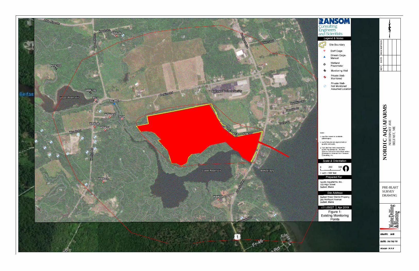
Pre-Blast Surveys
Blast Monitoring
Sequence of Blasting
Blasting Procedures
Blasting Mats
Blast Area Security and Warning Signals
Explosives
Blaster Qualifications
Blasting Personnel
Licenses and Permits
Blast Vibration & Air-Blast
Blast Reports
Typical Blast Design
Setting Earth-Shattering Standards Since 1966 • www.mainedrilling.com
General
Maine Drilling & Blasting considers safety as the priority during all phases of blasting
operations. We are knowledgeable of and will follow all local, state and federal regulations
related to transportation and use of explosives. The project specifications and conditions
have been reviewed. Details of procedures for pre-blast surveys, explosives use, blast
security, monitoring and documentation are enclosed. Blasting will be in accordance with
blasting law for site location of development projects: 38 MRSA paragraph 490-
Z(14)(Blasting).
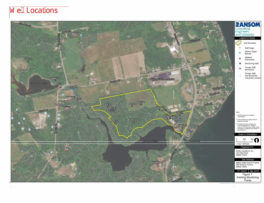
Pre-Blast Surveys / Notifications Pre-blast surveys will be offered to all property owners within a 2,000 foot radius of the blast
site. Appropriate notices will be given and appointments arranged for those owners who
desire a survey. Pre-blast surveys will be conducted by a Company Representative. Results
of those surveys will be documented through video or still photographs and appropriate
narration or written reports. The property owner will be offered to have their well water
tested for quantity and quality of water. These results will be submitted to the Department at
the property owner’s authorization.
Property owners within 2,000 feet of the blast area will be provided a blasting schedule. The
blasting schedule shall contain, at a minimum - (1) Name, address, and telephone number of
the operator, (2) Identification of the specific areas in which blasting will take place, (3)
Dates and time periods when explosives are to be detonated, (4) Methods to be used to
control access to the blasting areas, and (5) Type and patterns of audible warning and all-
clear signals to be used before and after blasting.
Blast Monitoring All blasts will be monitored by a representative of Maine Drilling & Blasting, Inc. who has
been properly trained in the setup and use of seismic monitoring equipment. At least one
seismograph will be in use at all times. Placement of monitoring equipment will be at the
nearest structure to the blast site with the instrument’s transducer firmly coupled to the
ground. Maine Drilling & Blasting, Inc. monitoring equipment will consist of Instantel type
seismographs. Details are enclosed. Seismographs meet all requirements outlined in
subsection M of 28 MRSA paragraph 490-Z(14). Results of blast monitoring will typically be
available before the next blast, usually immediately following a blast. Results can be
reviewed and modifications can be made to the blast design for the next blast if necessary.
Sequence of Blasting
All blasting operations will be strictly coordinated with Engineers, and Fire Department.
Emphasis will be on the safe and efficient removal of the rock existing on this project
without impact to surrounding structures. Blasts will be developed so as to create adequate
relief which will minimize ground vibrations and offer the greatest protection possible to the
surrounding structures.
Setting Earth-Shattering Standards Since 1966 • www.mainedrilling.com
Blasting Procedures
1. Blasting may not occur in the period between sundown and sunrise the following day
or in the period between 7:00 p.m. and 7:00 a.m., whichever is greater. Blasting will
not occur more frequently than 4 times per day. Blasting will not be allowed on
Saturday and Sunday.
2. Blasting cannot be conducted at times different from those announced in the blasting
schedule except in emergency situations, such as electrical storms or public safety
required unscheduled detonation.
3. Warning and all-clear signals of different character that are audible within a range of
one-quarter mile from the point of the blast shall be given. All persons within the
permit area shall be notified of the meaning of the signals through appropriate
instructions and signs posted.
4. Access to blasting area shall be regulated to protect the public from the effects of
blasting. Access to the blasting area shall be controlled to prevent unauthorized entry
before each blast and until the perimeter's authorized representative has determined
that no unusual circumstances exist after the blast. Access to and travel in or through
the area can then safely resume.
5. Areas in which charged holes are awaiting firing shall be guarded, barricaded and
posted, or flagged against unauthorized entry.
6. All blasts shall be made in the direction of the stress relieved face previously marked
out or previously blasted.
7. All stemming shall be minimum as specified using clean, dry 3/8'' crushed stone.
8. Blasting mats shall be used as necessary to cover blasts.
9. The Blasting Contractor shall insure that extra safety and judgment is exercised by his
blaster to prevent the simultaneous blasting of numerous holes.
10. If a blast is initiated by a detonating cord, the detonating cord will be covered by
crushed stone or other suitable cover to reduce noise and other concussion effects.
Setting Earth-Shattering Standards Since 1966 • www.mainedrilling.com
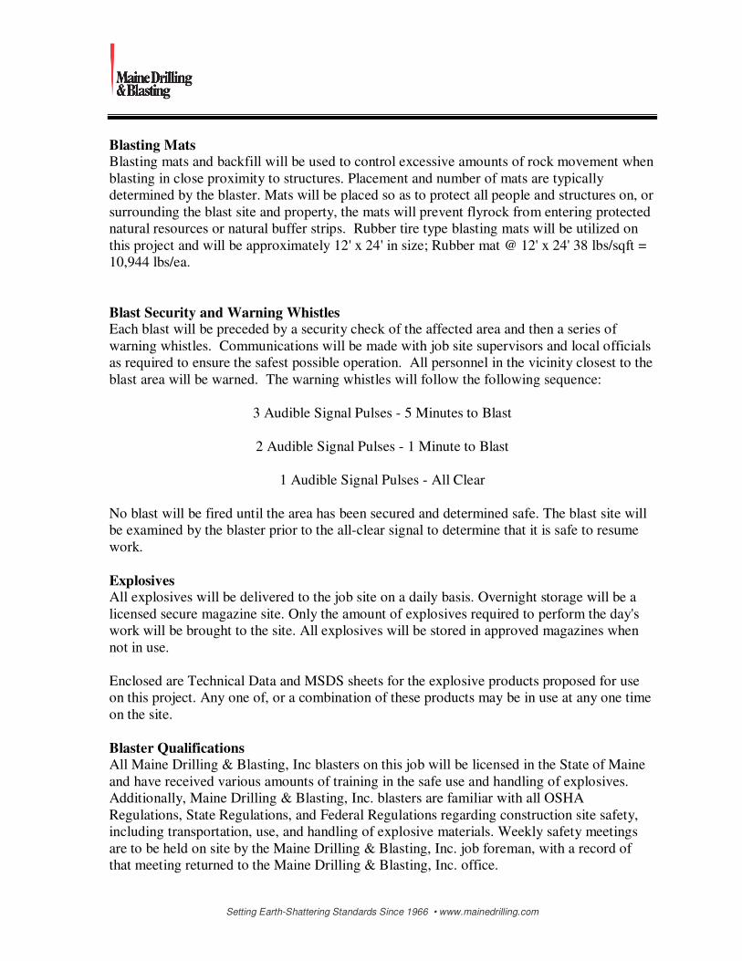
Blasting Mats Blasting mats and backfill will be used to control excessive amounts of rock movement when
blasting in close proximity to structures. Placement and number of mats are typically
determined by the blaster. Mats will be placed so as to protect all people and structures on, or
surrounding the blast site and property, the mats will prevent flyrock from entering protected
natural resources or natural buffer strips. Rubber tire type blasting mats will be utilized on
this project and will be approximately 12' x 24' in size; Rubber mat @ 12' x 24' 38 lbs/sqft =
10,944 lbs/ea.
Blast Security and Warning Whistles Each blast will be preceded by a security check of the affected area and then a series of
warning whistles. Communications will be made with job site supervisors and local officials
as required to ensure the safest possible operation. All personnel in the vicinity closest to the
blast area will be warned. The warning whistles will follow the following sequence:
3 Audible Signal Pulses - 5 Minutes to Blast
2 Audible Signal Pulses - 1 Minute to Blast
1 Audible Signal Pulses - All Clear
No blast will be fired until the area has been secured and determined safe. The blast site will
be examined by the blaster prior to the all-clear signal to determine that it is safe to resume
work.
Explosives All explosives will be delivered to the job site on a daily basis. Overnight storage will be a
licensed secure magazine site. Only the amount of explosives required to perform the day's
work will be brought to the site. All explosives will be stored in approved magazines when
not in use.
Enclosed are Technical Data and MSDS sheets for the explosive products proposed for use
on this project. Any one of, or a combination of these products may be in use at any one time
on the site.
Blaster Qualifications All Maine Drilling & Blasting, Inc blasters on this job will be licensed in the State of Maine
and have received various amounts of training in the safe use and handling of explosives.
Additionally, Maine Drilling & Blasting, Inc. blasters are familiar with all OSHA
Regulations, State Regulations, and Federal Regulations regarding construction site safety,
including transportation, use, and handling of explosive materials. Weekly safety meetings
are to be held on site by the Maine Drilling & Blasting, Inc. job foreman, with a record of
that meeting returned to the Maine Drilling & Blasting, Inc. office.
Setting Earth-Shattering Standards Since 1966 • www.mainedrilling.com
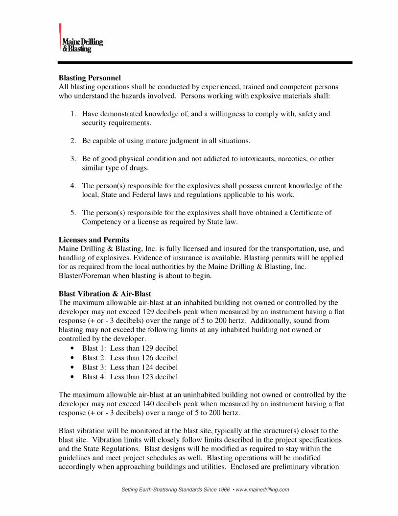
Blasting Personnel All blasting operations shall be conducted by experienced, trained and competent persons
who understand the hazards involved. Persons working with explosive materials shall:
1. Have demonstrated knowledge of, and a willingness to comply with, safety and
security requirements.
2. Be capable of using mature judgment in all situations.
3. Be of good physical condition and not addicted to intoxicants, narcotics, or other
similar type of drugs.
4. The person(s) responsible for the explosives shall possess current knowledge of the
local, State and Federal laws and regulations applicable to his work.
5. The person(s) responsible for the explosives shall have obtained a Certificate of
Competency or a license as required by State law.
Licenses and Permits Maine Drilling & Blasting, Inc. is fully licensed and insured for the transportation, use, and
handling of explosives. Evidence of insurance is available. Blasting permits will be applied
for as required from the local authorities by the Maine Drilling & Blasting, Inc.
Blaster/Foreman when blasting is about to begin.
Blast Vibration & Air-Blast The maximum allowable air-blast at an inhabited building not owned or controlled by the
developer may not exceed 129 decibels peak when measured by an instrument having a flat
response (+ or - 3 decibels) over the range of 5 to 200 hertz. Additionally, sound from
blasting may not exceed the following limits at any inhabited building not owned or
controlled by the developer.
• Blast 1: Less than 129 decibel
• Blast 2: Less than 126 decibel
• Blast 3: Less than 124 decibel
• Blast 4: Less than 123 decibel
The maximum allowable air-blast at an uninhabited building not owned or controlled by the
developer may not exceed 140 decibels peak when measured by an instrument having a flat
response (+ or - 3 decibels) over a range of 5 to 200 hertz.
Blast vibration will be monitored at the blast site, typically at the structure(s) closet to the
blast site. Vibration limits will closely follow limits described in the project specifications
and the State Regulations. Blast designs will be modified as required to stay within the
guidelines and meet project schedules as well. Blasting operations will be modified
accordingly when approaching buildings and utilities. Enclosed are preliminary vibration

Setting Earth-Shattering Standards Since 1966 • www.mainedrilling.com
calculations based on known distances to the structures of concern and anticipated initial
blast designs.
Ground Vibration peak particle velocity limits shall not exceed:
Refer to Appendix B, Figure B-1, U.S. Bureau of Mines RI 8507.
In addition, the maximum peak particle velocity at inhabitable structures not owned or
controlled by the developer will not exceed the levels established below:
Distance from the Blast (ft.) Max PPV
0 to 300 feet 1.25 in/sec
301 5000 feet 1.00 in/sec
Greater than 5000 feet 0.75 in/sec
Blast Reports
Enclosed is a sample of a Maine Drilling & Blasting, Inc last Report. This report will be
filled out for each blast and copies supplied as needed. The reports will be kept for at least
one year and will be available for inspection. The Maine DEP will be notified within 48
hours of any blast which exceeds the standards of 38 MRSA paragraph 490 Z-(14), the
information in subsection N will be provided with the notification.
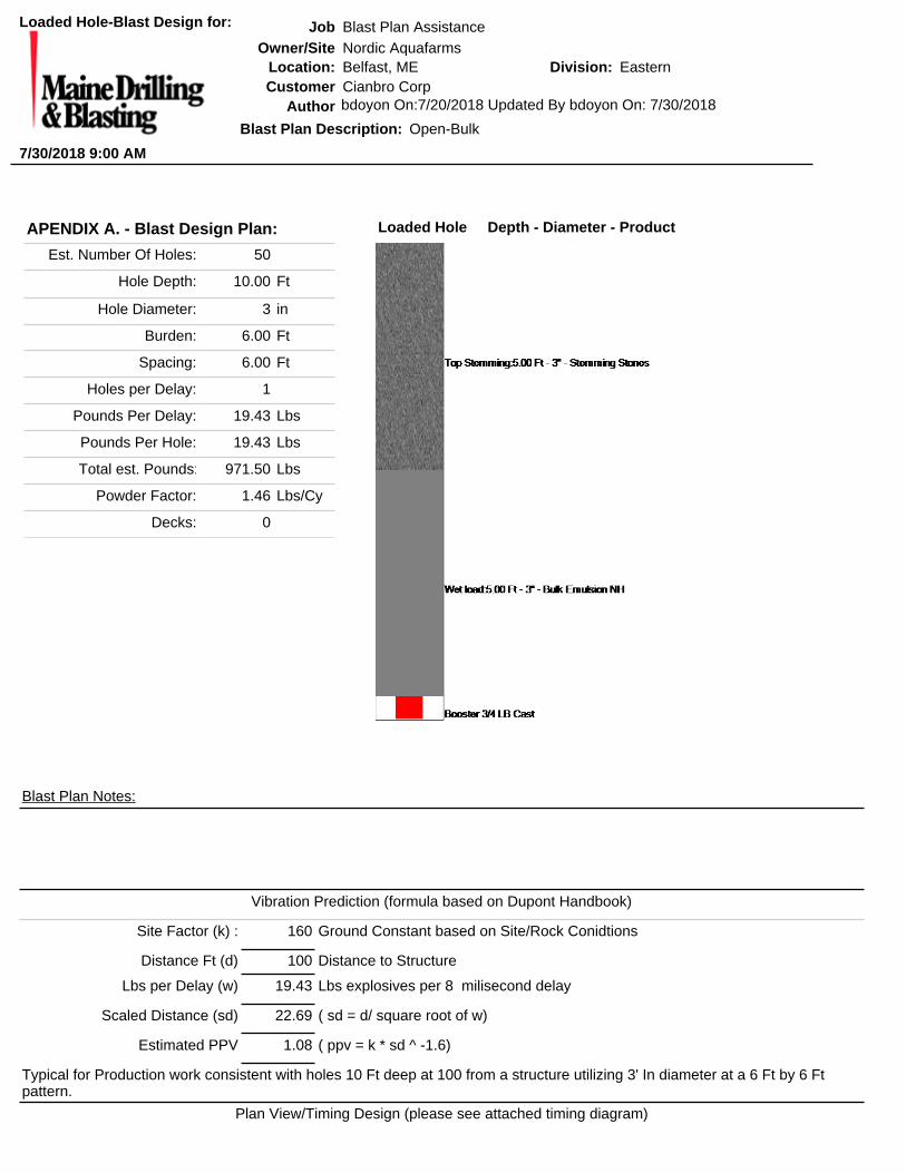
Typical Blast Design Enclosed is what would be considered typical blast designs for this project. Hole sizes,
depths, spacing and loading information is provided. These designs are to be considered a
good starting point. Modifications are usually made, if necessary, following the first blast to
meet control and seismic considerations.
N
O
R
T
H
P
O
R
T
A
V
E
N
U
E
(
U
.
S
.
R
O
U
T
E
1
)
S
E
E
N
O
T
E
(
3
)
S
H
E
D
2
5
2
0
1
5
1
0
5
5
2
0
9
3
9
5
3
6
8
8
2
1
3
3
1
5
9
1
7
6
1
9
5
2
0
9
2
2
8
2
4
1
2
5
3
2
7
1
2
9
1
3
0
7
3
2
0
3
3
5
3
4
7
3
5
3
3
5
9
3
7
3
4
2
1
4
5
3
4
8
0
0
8
0
75
7
0
6
5
6
0
5
5
5
0
45
40
35
70
65
60
5
5
4
5
5
0
4
5
5
0
4
5
6
5
6
0
5
5
5
0
4
5
5
0
4
5
4
0
5
0
4
5
4
5
4
0
4
5
3
5
3
5
3
0
2
5
4
5
4
0
3
5
3
5
4
0
30
3
0
3
0
3
5
3
0
2
5
2
0
1
5
1
0
40
35
3
0
3
0
25
3
0
25
3
0
2
5
6
0
5
5
5
0
5
0
5
5
6
5
6
0
5
5
7
5
7
5
8
0
8
0
75
7
0
7
5
7
0
6
5
6
0
6
5
60
5
5
5
0
4
5
DN
DN
DN
DN
SS
S
S
S
S
S
SS
S
S
S
S
S
S
S
S
SS
S
S
S
S
S
S
SS
S
S
S
S
S
S
S
S
+63.83
+63.55
+63.83
+63.55
+63.83
+63.55
+63.83
+63.55
DN
DN
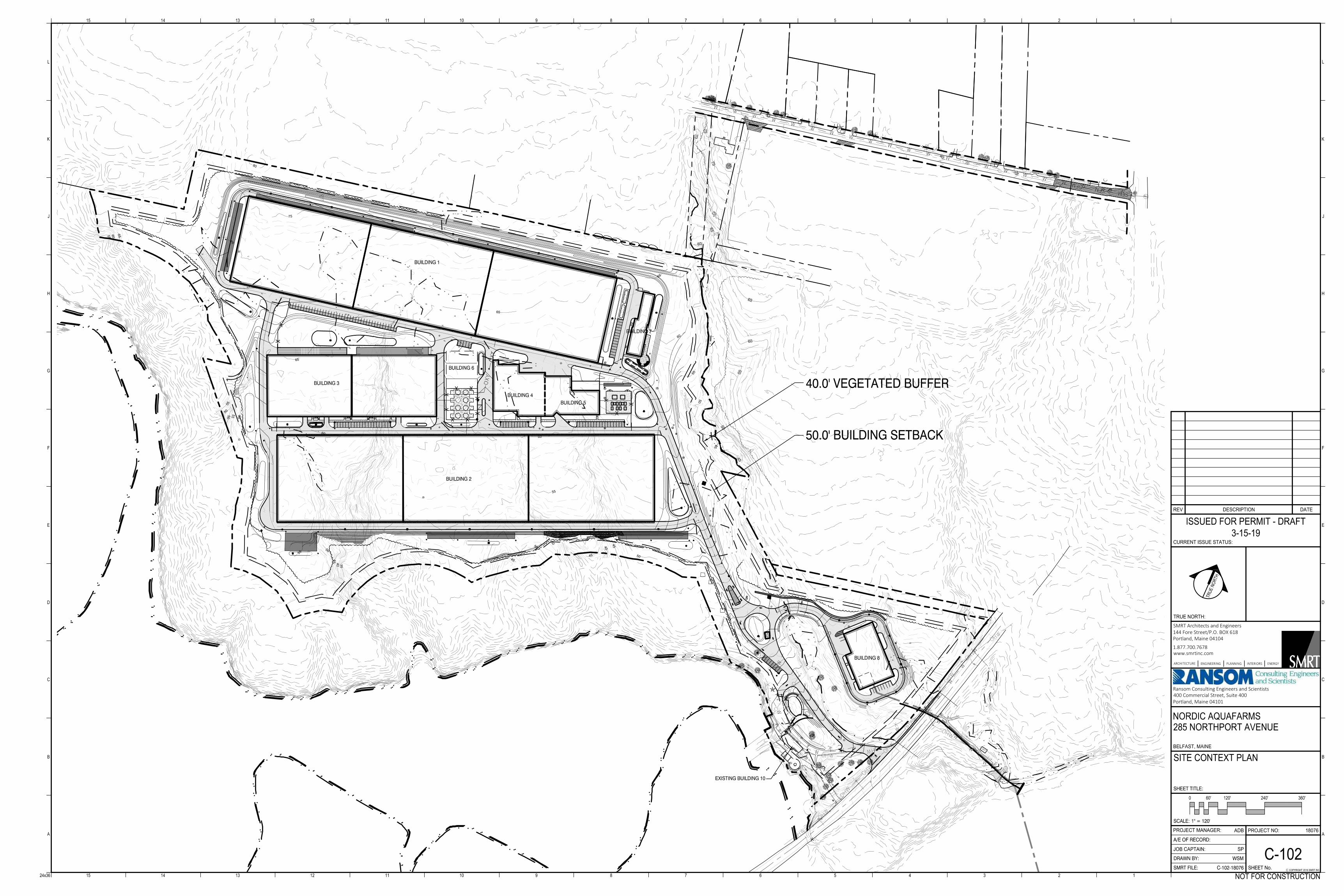
40.0' VEGETATED BUFFER
50.0' BUILDING SETBACK
BUILDING 1
BUILDING 3
BUILDING 4BUILDING 5
BUILDING 2
BUILDING 6
BUILDING 7
BUILDING 8
EXISTING BUILDING 10
CURRENT ISSUE STATUS:
REV DESCRIPTION DATE
C COPYRIGHT 2016 SMRT INC.
TRUE NORTH:
0
SMRT Architects and Engineers144 Fore Street/P.O. BOX 618Portland, Maine 04104
1.877.700.7678www.smrtinc.com
PROJECT MANAGER:PROJECT NO: 18076ADB
JOB CAPTAIN: SP
NORDIC AQUAFARMS
BELFAST, MAINE
285 NORTHPORT AVENUE
ARCHITECTUREENGINEERING PLANNING INTERIORS ENERGY
15 14 13 12 11 10 9 8 7 6 5 4 3 2 1
L
K
J
H
G
F
E
D
C
B
A
L
K
J
H
G
F
E
D
C
B
A
15 14 13 12 11 10 9 8 7 6 5 4 3 2 1
24x36
T
R
U
E
N
O
R
T
H
ISSUED FOR PERMIT - DRAFT
3-15-19
NOT FOR CONSTRUCTION
Ransom Consulting Engineers and Scientists400 Commercial Street, Suite 400Portland, Maine 04101
SCALE:
SHEET TITLE:
DRAWN BY:
A/E OF RECORD:
SMRT FILE: SHEET No.
SITE CONTEXT PLAN
C-102
C-102-18076
1" = 120'
WSM
240'120'60' 360'
2830
26
24
22
20
8
6
4
18
16
14
12
10
32
3436
38
40
42
44
46
48 5052
2830
34
6
38
8
1624
28
26
34
22
26
32
4
18
32
26
34
36
B203
B402B401
B405B404
B403
B202
B201
B113
S9 S7
S8
W6
W9
W7
W5W8
¯
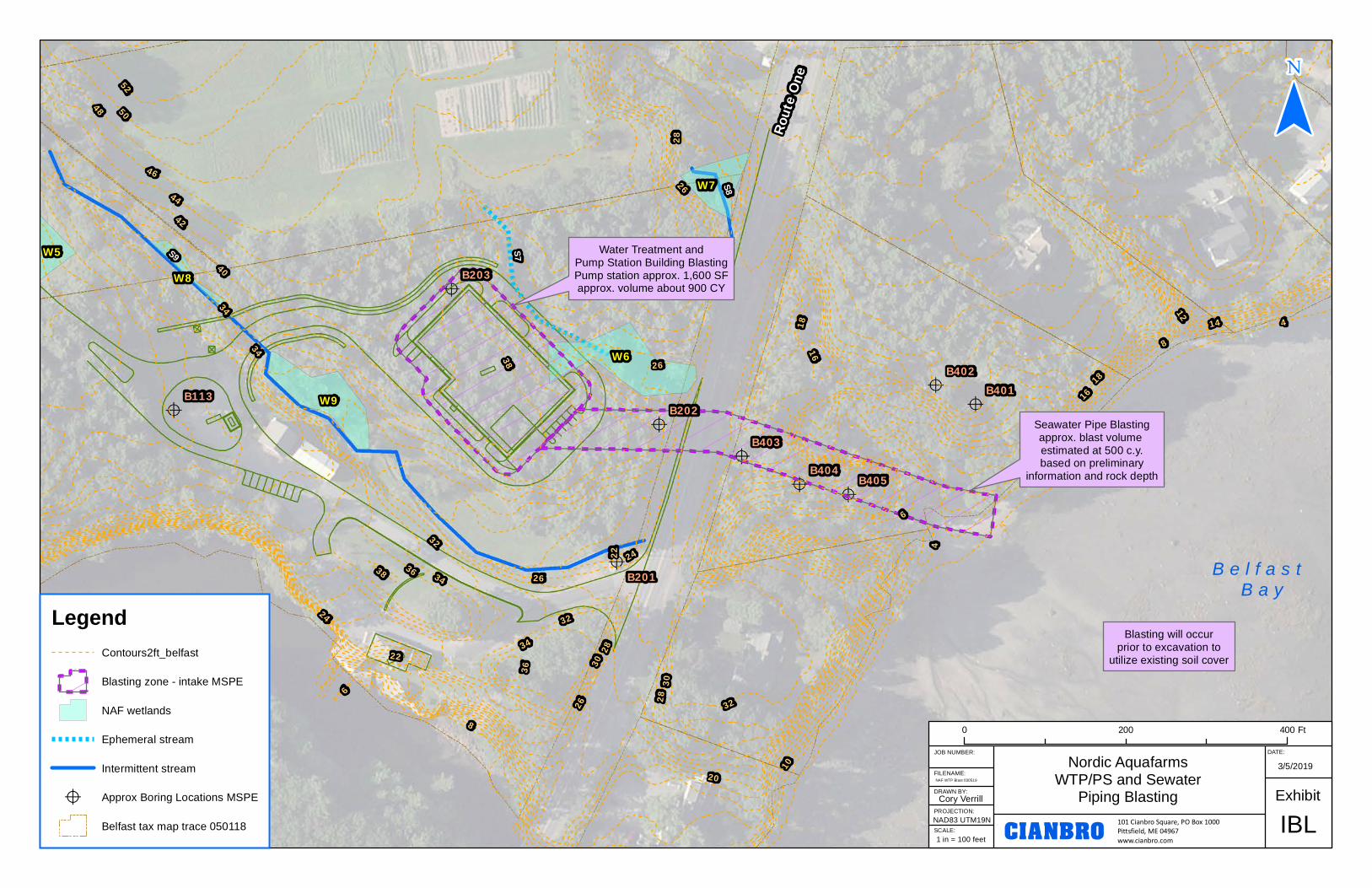
Nordic AquafarmsWTP/PS and Sewater
Piping Blasting ExhibitIBL
JOB NUMBER:
FILENAME:
DRAWN BY:
PROJECTION:
SCALE:
Cory Verrill
DATE:
101 Cianbro Square, PO Box 1000Pittsfield, ME 04967www.cianbro.com
0 400200 Ft
CIANBRO1 in = 100 feet
NAF WTP Blast 030519
3/5/2019
NAD83 UTM19N
Rout
e One
B e l f a s t B a y
Seawater Pipe Blastingapprox. blast volume estimated at 500 c.y.based on preliminary
information and rock depth
Water Treatment andPump Station Building BlastingPump station approx. 1,600 SFapprox. volume about 900 CY
Blasting will occurprior to excavation to
utilize existing soil cover
LegendContours2ft_belfast
Blasting zone - intake MSPE
NAF wetlands
Ephemeral stream
Intermittent stream
? Approx Boring Locations MSPE
Belfast tax map trace 050118
NO
RD
IC
A
QU
AFA
RM
S
NO
RTH
PO
RT AVE
BELFAST, M
E
RE
VD
AT
ED
ESC
RIP
TIO
N
PRE-BLAST
SURVEY
DRAWING
Blast Plan AssistanceNordic Aquafarms
Cianbro CorpBelfast, ME Eastern
JobOwner/Site
CustomerLocation: Division:
Loaded Hole-Blast Design for:
7/30/2018 9:00 AM
APENDIX A. - Blast Design Plan:
Est. Number Of Holes: 50
Hole Depth: 10.00 Ft
Hole Diameter: 3 in
Burden: 6.00 Ft
Spacing: 6.00 Ft
Holes per Delay: 1
Pounds Per Delay: 19.43 Lbs
Pounds Per Hole: 19.43 Lbs
Total est. Pounds: 971.50 Lbs
Powder Factor: 1.46 Lbs/Cy
Decks: 0
Author bdoyon On:7/20/2018 Updated By bdoyon On: 7/30/2018
Blast Plan Description: Open-Bulk
Blast Plan Notes:
Vibration Prediction (formula based on Dupont Handbook)
Site Factor (k) : 160 Ground Constant based on Site/Rock Conidtions
Distance Ft (d) 100 Distance to Structure
Lbs per Delay (w) 19.43 Lbs explosives per 8 milisecond delay
Scaled Distance (sd) 22.69 ( sd = d/ square root of w)
Estimated PPV 1.08 ( ppv = k * sd ^ -1.6)
Typical for Production work consistent with holes 10 Ft deep at 100 from a structure utilizing 3' In diameter at a 6 Ft by 6 Ft pattern.
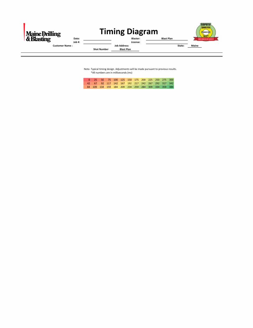
Plan View/Timing Design (please see attached timing diagram)
Loaded Hole Depth - Diameter - Product

Note- Typical timing design. Adjustments will be made pursuant to previous results.
*All numbers are in milliseconds (ms)
0 25 50 75 100 125 150 175 200 225 250 275 300
42 67 92 117 142 167 192 217 242 267 292 317 342
84 109 134 159 184 209 234 259 284 309 334 359 384
Shot Number Blast Plan
Maine
Date: Blaster: Blast Plan
Customer Name :
License:Job #:
Timing Diagram
State:Job Address:

Blast Plan AssistanceNordic Aquafarms
Cianbro CorpBelfast, ME Eastern
JobOwner/Site
CustomerLocation: Division:
Loaded Hole-Blast Design for:
7/30/2018 8:59 AM
APENDIX A. - Blast Design Plan:
Est. Number Of Holes: 50
Hole Depth: 10.00 Ft
Hole Diameter: 3 in
Burden: 5.00 Ft
Spacing: 6.00 Ft
Holes per Delay: 1
Pounds Per Delay: 16.07 Lbs
Pounds Per Hole: 16.07 Lbs
Total est. Pounds: 803.50 Lbs
Powder Factor: 1.45 Lbs/Cy
Decks: 0
Author bdoyon On:7/20/2018 Updated By bdoyon On: 7/30/2018
Blast Plan Description: Open-Stick
Blast Plan Notes:
Vibration Prediction (formula based on Dupont Handbook)
Site Factor (k) : 160 Ground Constant based on Site/Rock Conidtions
Distance Ft (d) 100 Distance to Structure
Lbs per Delay (w) 16.07 Lbs explosives per 8 milisecond delay
Scaled Distance (sd) 24.95 ( sd = d/ square root of w)
Estimated PPV 0.93 ( ppv = k * sd ^ -1.6)
Typical for Production work consistent with holes 10 Ft deep at 100 from a structure utilizing 3' In diameter at a 5 Ft by 6 Ft pattern.
Plan View/Timing Design (please see attached timing diagram)
Loaded Hole Depth - Diameter - Product
Note- Typical timing design. Adjustments will be made pursuant to previous results.
*All numbers are in milliseconds (ms)
0 25 50 75 100 125 150 175 200 225 250 275 300
42 67 92 117 142 167 192 217 242 267 292 317 342
84 109 134 159 184 209 234 259 284 309 334 359 384
Shot Number Blast Plan
Maine
Date: Blaster: Blast Plan
Customer Name :
License:Job #:
Timing Diagram
State:Job Address:
Blast Plan AssistanceNordic Aquafarms
Cianbro CorpBelfast, ME Eastern
JobOwner/Site
CustomerLocation: Division:
Loaded Hole-Blast Design for:
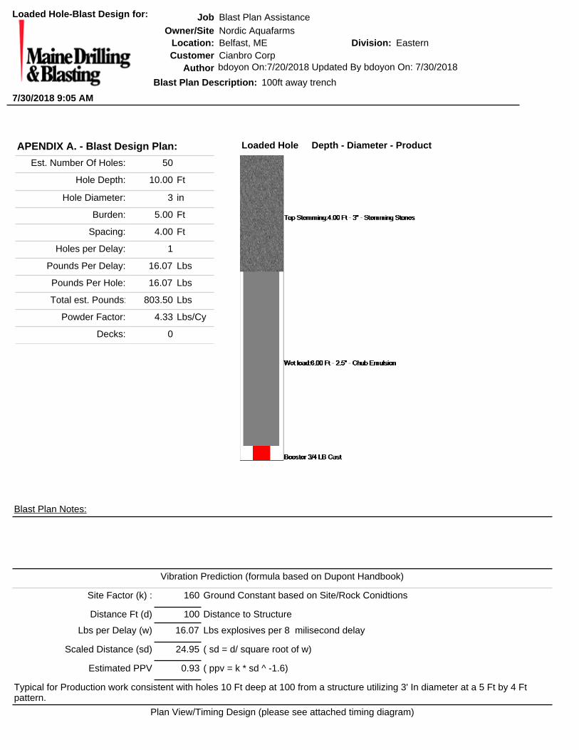
7/30/2018 9:05 AM
APENDIX A. - Blast Design Plan:
Est. Number Of Holes: 50
Hole Depth: 10.00 Ft
Hole Diameter: 3 in
Burden: 5.00 Ft
Spacing: 4.00 Ft
Holes per Delay: 1
Pounds Per Delay: 16.07 Lbs
Pounds Per Hole: 16.07 Lbs
Total est. Pounds: 803.50 Lbs
Powder Factor: 4.33 Lbs/Cy
Decks: 0
Author bdoyon On:7/20/2018 Updated By bdoyon On: 7/30/2018
Blast Plan Description: 100ft away trench
Blast Plan Notes:
Vibration Prediction (formula based on Dupont Handbook)
Site Factor (k) : 160 Ground Constant based on Site/Rock Conidtions
Distance Ft (d) 100 Distance to Structure
Lbs per Delay (w) 16.07 Lbs explosives per 8 milisecond delay
Scaled Distance (sd) 24.95 ( sd = d/ square root of w)
Estimated PPV 0.93 ( ppv = k * sd ^ -1.6)
Typical for Production work consistent with holes 10 Ft deep at 100 from a structure utilizing 3' In diameter at a 5 Ft by 4 Ft pattern.
Plan View/Timing Design (please see attached timing diagram)
Loaded Hole Depth - Diameter - Product

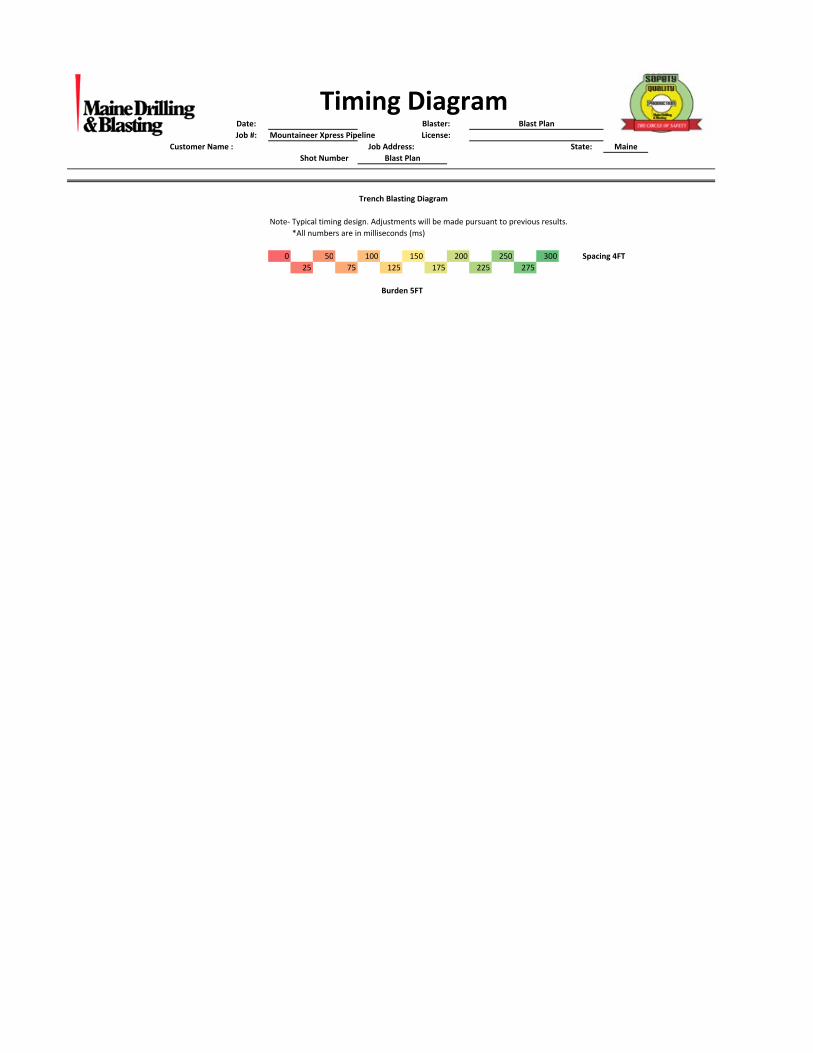
Mountaineer Xpress Pipeline
Trench Blasting Diagram
Note- Typical timing design. Adjustments will be made pursuant to previous results.
*All numbers are in milliseconds (ms)
0 50 100 150 200 250 300 Spacing 4FT
25 75 125 175 225 275
Burden 5FT
Timing Diagram
State:Job Address:
Shot Number Blast Plan
Maine
Date: Blaster: Blast Plan
Customer Name :
License:Job #:
Blast Plan AssistanceNordic Aquafarms
Cianbro CorpBelfast, ME Eastern
JobOwner/Site
CustomerLocation: Division:
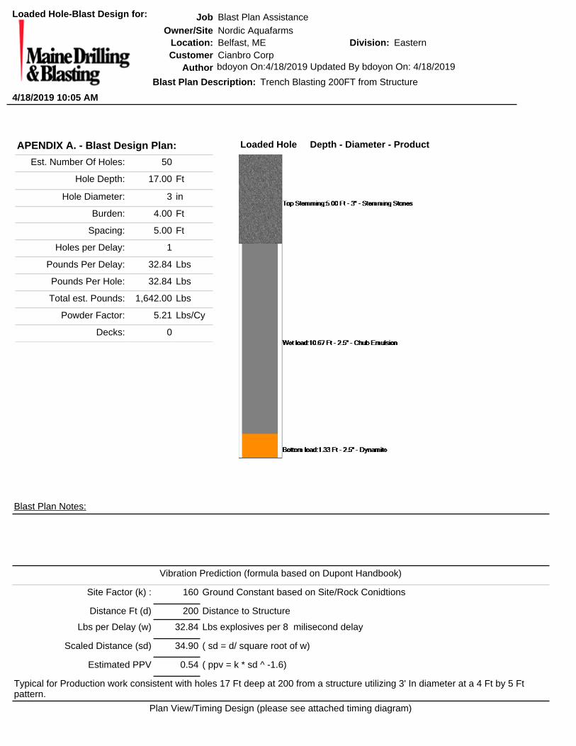
Loaded Hole-Blast Design for:
4/18/2019 10:05 AM
APENDIX A. - Blast Design Plan:
Est. Number Of Holes: 50
Hole Depth: 17.00 Ft
Hole Diameter: 3 in
Burden: 4.00 Ft
Spacing: 5.00 Ft
Holes per Delay: 1
Pounds Per Delay: 32.84 Lbs
Pounds Per Hole: 32.84 Lbs
Total est. Pounds: 1,642.00 Lbs
Powder Factor: 5.21 Lbs/Cy
Decks: 0
Author bdoyon On:4/18/2019 Updated By bdoyon On: 4/18/2019
Blast Plan Description: Trench Blasting 200FT from Structure
Blast Plan Notes:
Vibration Prediction (formula based on Dupont Handbook)
Site Factor (k) : 160 Ground Constant based on Site/Rock Conidtions
Distance Ft (d) 200 Distance to Structure
Lbs per Delay (w) 32.84 Lbs explosives per 8 milisecond delay
Scaled Distance (sd) 34.90 ( sd = d/ square root of w)
Estimated PPV 0.54 ( ppv = k * sd ^ -1.6)
Typical for Production work consistent with holes 17 Ft deep at 200 from a structure utilizing 3' In diameter at a 4 Ft by 5 Ft pattern.
Plan View/Timing Design (please see attached timing diagram)
Loaded Hole Depth - Diameter - Product
Mountaineer Xpress Pipeline
Trench Blasting Diagram
Note- Typical timing design. Adjustments will be made pursuant to previous results.
*All numbers are in milliseconds (ms)
0 50 100 150 200 250 300 Spacing 4FT
25 75 125 175 225 275
Burden 5FT
Timing Diagram
State:Job Address:
Shot Number Blast Plan
Maine
Date: Blaster: Blast Plan
Customer Name :
License:Job #:

Setting Earth-Shattering Standards Since 1966 • www.mainedrilling.com
Company Qualifications

A Breed Apart
A T R U S T E D B R E E D • A T R U S T E D B R E E D
Experience Counts … because
for everything
making it happenYOUR TRUSTED BREEDCompany Information & Qualifications

Page 1
Maine Drilling & Blasting: Your Trusted Breed Making it Happen
• Need to make way for underground utilities?
• Building a project in an extremely remote location with difficult access?
• Does your project call for rock bolting or hoe rams?
• Need to remove rock in very tight quarters adjacent to existing structures?
• Have hundreds of thousand of cubic yards of rock to move in a tight
deadline, under less than ideal conditions?
• Need drilling and blasting for a pipeline, wind farm, or transmission lines?
• Need rock stabilized on a heavily trafficked highway?
• Have new interstate ramp systems to install through granite bedrock?
Whatever your needs, Maine Drilling & Blasting can get the job done
skillfully and smoothly. Whether you are a general contractor, commercial
contractor, municipality, or homeowner, we can provide you with the
professional experience you need to get your job done right, on schedule
and in budget. Maine Drilling & Blasting is nearby and at the ready.
It’s all about having the resources when you need them and working with
someone who offers you proven results on demanding schedules.
• Local resources throughout the Northeast
• Full service company … your true one-stop source.
• Remote access capability for almost all terrains including a proven
system for underwater drilling and blasting, and an internally-
engineered bulk skid to deliver product to backwoods mountain terrains.
• We optimize drill types and explosive options from in-house sources.
Since 1966, our standards are steeped in the tradition of being family-
owned and operated. We’re a close and cohesive group. We’re also
owners. Maine Drilling & Blasting began the transition to employee
ownership in 2004, resulting in progressively greater individual
responsibility in the work produced. We work with the unity of a family
and the determination of business owners. Qualified employees now own
51% of the Company.
Our employees are proud of our past 51 years. We’ve persevered,
adapted, and grown stronger and smarter, all the while holding true to our
founding principles of hard work, honesty and quality of services. That’s
why MD&B is the Trusted Breed for so many throughout the Northeast.
Maine Drilling & Blasting: cost competitive AND expert source for your
project needs.
Page 2
Maine Drilling & Blasting Information & Qualifications
This comprehensive package is offered to evidence our Company’s ability
to perform drilling and blasting work on various projects throughout the
Northeast, New York, and Pennsylvania. It includes general corporate
information, experience, performance, safety, quality, and environmental
management capacity.
COMPANY INFORMATION:
Name of Company: Maine Drilling & Blasting, Inc.
Address: 542 Brunswick Avenue, Gardiner, ME 04345
Phone: 207-582-2338 Fax: 207-582-8794
Primary Contacts: Aaron Flewelling
Phone: 603-647-0299 Cell: 603-454-8385
Email Address: [email protected]
Company Website: www.mainedrilling.com
Ownership/Management: Maine Drilling & Blasting is an employee-
owned company started by Ted Purington, Sr. in 1966. Two generations of
blasters preceded him. Ted Sr. retired in 1996. Today, Bill Purington is
Company Chairman and CEO working out of the corporate office in
Gardiner, ME. Ted, Jr. is the Executive V.P. heading up Operations from
the Auburn, NH office.
Nature of Business: The Company is one of the largest of its kind in North
America, with the majority of the volume of explosives utilized in New
England and New York. Core services are drilling and blasting and hoe ram
services for construction, quarry and energy markets throughout the
Northeast, New York, Pennsylvania, Maryland, Delaware, Virginia and
West Virginia. Specialty services include rock anchors, laser profiling,
boretraking, training, and public relations.
Years in Business: Maine Drilling and Blasting, Inc. has been in business
for 51 years.
Page 3
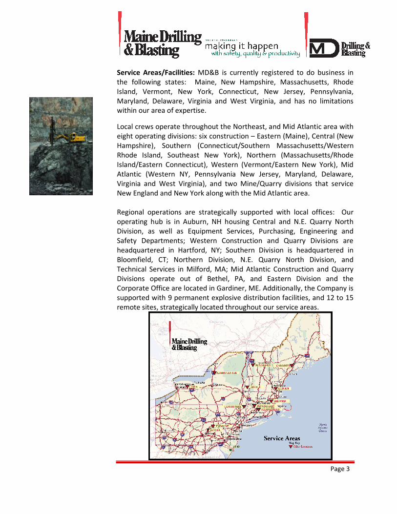
Service Areas/Facilities: MD&B is currently registered to do business in
the following states: Maine, New Hampshire, Massachusetts, Rhode
Island, Vermont, New York, Connecticut, New Jersey, Pennsylvania,
Maryland, Delaware, Virginia and West Virginia, and has no limitations
within our area of expertise.
Local crews operate throughout the Northeast, and Mid Atlantic area with
eight operating divisions: six construction – Eastern (Maine), Central (New
Hampshire), Southern (Connecticut/Southern Massachusetts/Western
Rhode Island, Southeast New York), Northern (Massachusetts/Rhode
Island/Eastern Connecticut), Western (Vermont/Eastern New York), Mid
Atlantic (Western NY, Pennsylvania New Jersey, Maryland, Delaware,
Virginia and West Virginia), and two Mine/Quarry divisions that service
New England and New York along with the Mid Atlantic area.
Regional operations are strategically supported with local offices: Our
operating hub is in Auburn, NH housing Central and N.E. Quarry North
Division, as well as Equipment Services, Purchasing, Engineering and
Safety Departments; Western Construction and Quarry Divisions are
headquartered in Hartford, NY; Southern Division is headquartered in
Bloomfield, CT; Northern Division, N.E. Quarry North Division, and
Technical Services in Milford, MA; Mid Atlantic Construction and Quarry
Divisions operate out of Bethel, PA, and Eastern Division and the
Corporate Office are located in Gardiner, ME. Additionally, the Company is
supported with 9 permanent explosive distribution facilities, and 12 to 15
remote sites, strategically located throughout our service areas.
Page 4
List Professional Affiliations & Licenses:
International Society of Explosives
Associated General Contractors of Maine, Vermont, NH, NY, Mass
Milford Area Chamber of Commerce
Northern NE Concrete Producers Association
Associated Builders & Contractors, Inc. – Maine Chapter
Maine Better Transport Association
Maine Motor Transport Association
Maine State Chamber of Commerce
New Hampshire Good Roads
Construction Financial Management Association
National Association of Women in Construction
Tug Users Group
BA of Greater Boston
Maine Aggregate Association
Kennebec Valley Chamber of Commerce
Construction Industry of MA (CCIA)
MA Aggregate & Asphalt Pavement Association
American Society of Civil Engineers (ASCE)
Society for Human Resources Management (SHRM)
New Hampshire Motor Transport Association
Institute of Makers of Explosives
National Ski Areas Association
New York Construction Materials Association
Maine Economic Research Institute
The ESOP Association
National Center for Employee Ownership
Associated Builders & Contractors, Inc. – Eastern Pennsylvania
American Society of Civil Engineers
Page 5
Construction Marketing Association
Status of Business/Company: Corporation
Labor Relations: Both Open Shop, and Union served by Maine Drilling &
Blasting.
SAFETY CREDENTIALS:
MD&B has an aggressive Safety Program in place with a designated safety
officer and support Department: Michael Weider, Safety Manager,
603-647-0299, [email protected]
• Safety is the bedrock of our training, the cornerstone of our
technology. Safety-specific training includes: Dupont’s Safety
Training Observation Program (STOP), MSHA Part 46 Training,
OSHA 10-hour Training, Job Hazard Analysis, Division Meeting
Safety Topics, Daily Safety Meetings, Lessons Learned. In addition
to training specifically related to safety, an array of mandatory,
formal job skill training courses ensures the best practices on the
job. All MD&B Drillers and Blasters undergo rigorous training and
company certification. MD&B Blasters also hold state-specific
industry licenses for operation.
• Seismic Monitoring is performed on every project. MD&B holds
itself accountable for the seismic monitoring. We objectively
measure vibrations caused by our blasts with state of the art
equipment, and make those measurements available for analysis.
• Job Hazard Analysis on each and every project. MD&B performs a
thorough site-specific Job Hazard Analysis on every project, and we
reassess for every change in project parameters. Maine Drilling &
Blasting instituted this non-industry-mandated process company-
wide years ago.
Page 6
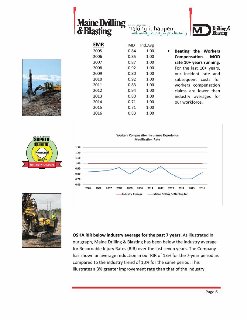
• Beating the Workers
Compensation MOD
rate 10+ years running.
For the last 10+ years,
our incident rate and
subsequent costs for
workers compensation
claims are lower than
industry averages for
our workforce.
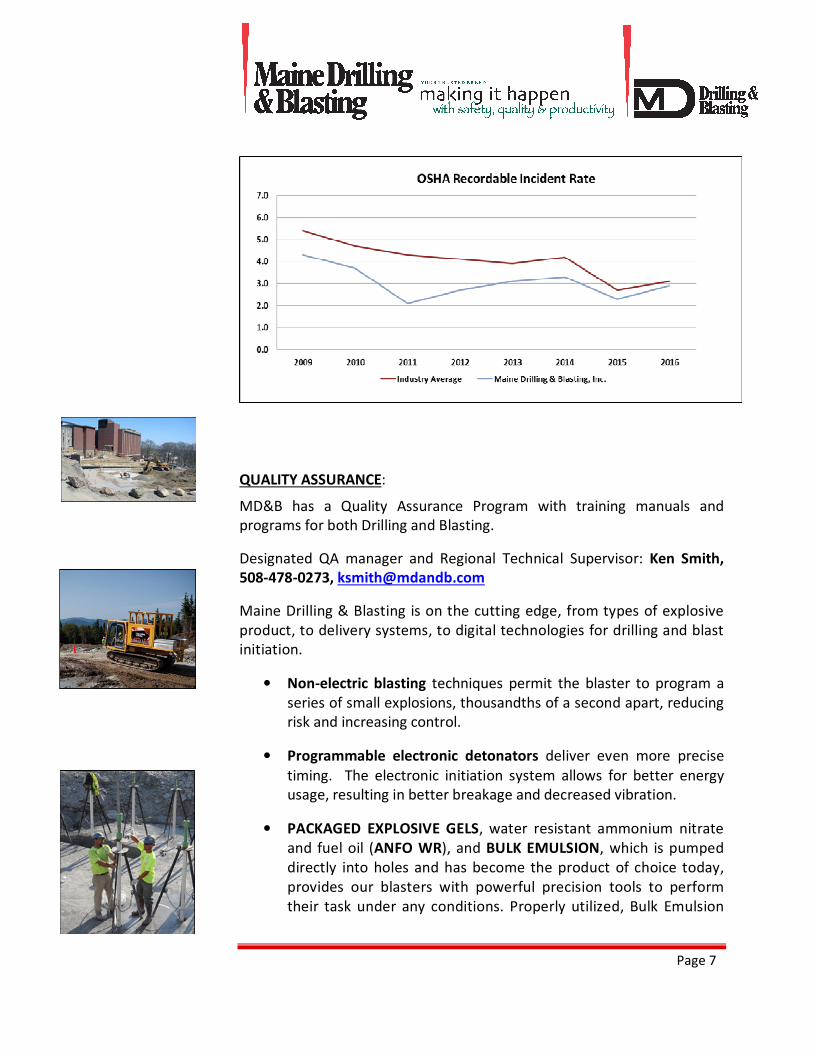
OSHA RIR below industry average for the past 7 years. As illustrated in
our graph, Maine Drilling & Blasting has been below the industry average
for Recordable Injury Rates (RIR) over the last seven years. The Company
has shown an average reduction in our RIR of 13% for the 7-year period as
compared to the industry trend of 10% for the same period. This
illustrates a 3% greater improvement rate than that of the industry.
EMR MD Ind.Avg
2005 0.84 1.00
2006 0.85 1.00
2007 0.87 1.00
2008 0.92 1.00
2009 0.80 1.00
2010 0.92 1.00
2011 0.83 1.00
2012 0.94 1.00
2013 0.80 1.00
2014 0.71 1.00
2015 0.71 1.00
2016 0.83 1.00
Page 7
QUALITY ASSURANCE:
MD&B has a Quality Assurance Program with training manuals and
programs for both Drilling and Blasting.
Designated QA manager and Regional Technical Supervisor: Ken Smith,
508-478-0273, [email protected]
Maine Drilling & Blasting is on the cutting edge, from types of explosive
product, to delivery systems, to digital technologies for drilling and blast
initiation.
• Non-electric blasting techniques permit the blaster to program a
series of small explosions, thousandths of a second apart, reducing
risk and increasing control.
• Programmable electronic detonators deliver even more precise
timing. The electronic initiation system allows for better energy
usage, resulting in better breakage and decreased vibration.
• PACKAGED EXPLOSIVE GELS, water resistant ammonium nitrate
and fuel oil (ANFO WR), and BULK EMULSION, which is pumped
directly into holes and has become the product of choice today,
provides our blasters with powerful precision tools to perform
their task under any conditions. Properly utilized, Bulk Emulsion
Page 8
reduces drilling cost in all applications, allowing for efficient use
of hole diameters and hole patterns, minimizing loading labor.
• Computer-aided blast design and test-blast practices have
replaced trial-and-error, providing for a controlled blasting
environment.
• Laser Profiling a rock face provides a 3 dimensional view of the
blast area for use in the proper design and layout of the borehole
locations for the drilling and blasting operation.
• Boretrak System: “BoreTraking” provides a 3 dimensional view of
each borehole as it relates to every other borehole in the blast.
When it is matched with the laser profile it will show how each
borehole relates to the rock face so the blaster will be able to
distribute the explosives where they will perform the best.
• In House Engineering Services provide added value for our
customers. We provide accurate estimates of rock quantities,
determine the scope of work, verify the topographical accuracy of
the engineering, and provide value engineering to maintain
efficiencies and blasting cost reductions. Our engineering
department also provides us with the ability to perform Engineer,
Perform, and Construct projects, which we have performed
successfully.
• Remote Project Efficiencies: Maine Drilling & Blasting has the
experience, expertise and equipment necessary for any terrain and
the most isolated locations commonly found at wind farms,
pipelines, transmission lines, substations, and hydroelectric
facilities. Maine Drilling & Blasting has adapted and even engineered
our own transports capable of bringing our crews, products and
supplies to very hard-to-reach places with terrain many consider
impassable.
• Congested/Close Shooting Expertise: Maine Drilling & Blasting is
very experienced performing controlled blasting in areas with
very close adjacencies to existing structures, operating railroads,
operating power plants, live transmission lines, open hospitals
and in-session schools, etc. Maine Drilling & Blasting understands
these challenges and delivers based upon 1) our resources and
experience with electronic detonator technology and bulk
Page 9
explosive application, and 2) our strong Safety Culture including
our Zero Tolerance policies.
• Foundation Services: MD&B utilizes our fleet of drills and
experienced craftspeople to install rock anchors, dowels, guy
anchors and micro-piles for a variety of construction needs.
Foundation components requiring structural connections to
bedrock is a specialty that compliments our fundamental service of
drilling and blasting. Over the past 20 years, Maine Drilling &
Blasting has become recognized as a leader in the installation of
rock anchors throughout the Northeast. Our engineers routinely
work with customers at the design phase to assist in development
of cost-effective and constructible solutions. We perform in
diverse conditions from remote access transmission line ROWs and
wind site ridgelines to the tight work areas of existing
communication tower sites. From atop mountains to on water,
from inside cofferdams to the complexities of urban work, we’ve
provided routine and unique rock bolting and ground anchor
services for hundreds of projects, installing over 10,000 post
tension anchors and reinforcement dowels. We self-perform rock
anchor activities starting with the drilling, through the grouting and
tensioning activities. Each anchor is tested well above design load.
Our experience ranges from small diameter to 3-inch with 700kips.
• In House Distribution: Maine Drilling & Blasting has instituted an
in-house distribution network with the ability to supply all regions
without depending on outside suppliers and distributors.
• Schedules & Liquidated Damages: With Maine Drilling &
Blasting’s access to over 80 drills ad specialty equipment, we
meet or exceed schedule deadlines, and we will accept liquidated
damages in our contracts.
• Public Relations: Maine Drilling & Blasting utilizes the Safety and
Technical departments to give presentations to towns, neighbors
and public safety departments who have concerns about blasting
to help with the permitting and approval process.
Page 10
ENVIRONMENTAL:
• MD&B has an Environmental Management Program in place. We
have taken a leadership role within our industry to improve
environmental stewardship. We recognize and accept our own
responsibility to proactively apply environmental best practices to
all aspects of our business, and work with suppliers and customers
to promote environmentally responsible actions and products. In
all cases, our aim is to optimize our environmental performance up
to the technical limits practically achievable, and to explore
environmentally-driven innovations, technologies and business
opportunities to expand those limits to achieve nothing less than
environmental excellence.
MANAGEMENT, EMPLOYEES, AND RESOURCES:
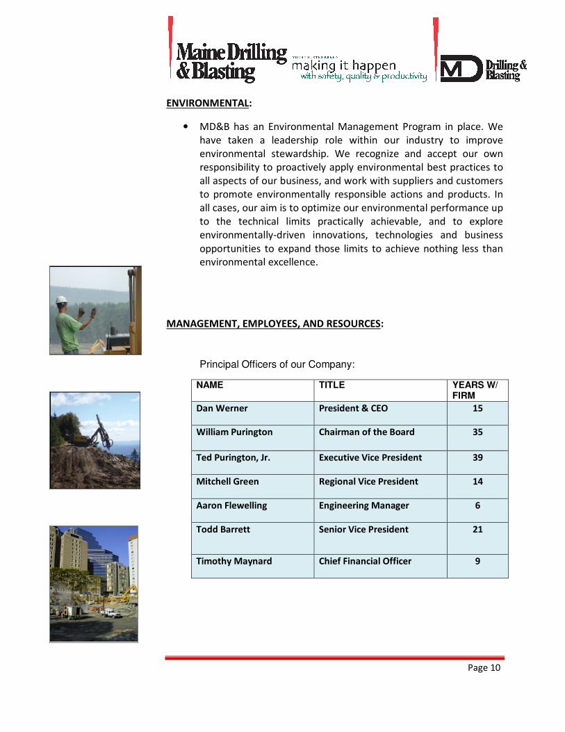
Principal Officers of our Company:
NAME TITLE YEARS W/
FIRM
Dan Werner President & CEO 15
William Purington Chairman of the Board 35
Ted Purington, Jr. Executive Vice President 39
Mitchell Green Regional Vice President 14
Aaron Flewelling Engineering Manager 6
Todd Barrett Senior Vice President 21
Timothy Maynard Chief Financial Officer 9
Page 11
Typical Project Organizational Chart
Project Responsibility:
• Our Supervisory and Management team are all Company
employees.
• The Division Manager accepts the Project Manager responsibilities.
The principal officers have authorized all construction signatures.
The decision-making is done with the division manager or the
principals as needed. The Project Manager handles as many as five
projects. Assistance from the company departments, the
engineering group, and the Division Manager spread the workload.
• The Division Manager provides leadership to the construction team
in the areas of safety, resource leveling, scheduling and
management of the project. This position is further supported by
Regional Superintendents and Project Superintendents, who run
the larger jobs for the Company.
Software Support:
• As a specialty contractor, our estimating and contracts software is
a proprietary program. GPS, Total Station, Carlson Software and
Paydirt software are utilized to predict rock quantities and
complexities. This data is used to estimate resources needed for
each cut area. As redesigns are considered, the CAD input is
Division Manager
Project Engineer Project Superintendent Project Safety
Manager
Blasting Superintendent Rock Anchor Superintendent
Page 12
digitized to generate updated input for an updated resource
estimate. Our accounting software is Sage Timberline Office.
Number of Employees:
Main Office Staff 43
Support Staff (mechanics,
safety, engineering, etc.)
51
Field Supervisory Staff 47
Craft Workers 119 Blasters, Laborers & Drivers
Equipment Operators 81 Drillers & Hoe Ram Operators
Major Construction Equipment: MD&B currently owns over 80 hydraulic
drills and specialty equipment, and 12 excavators. Additional drills are
rented during peak season as needed. Maine Drilling & Blasting owns
approximately 190 vehicles in its fleet including pickups, tractor/trailer
vehicles, box trucks and bulk trucks.
Page 13
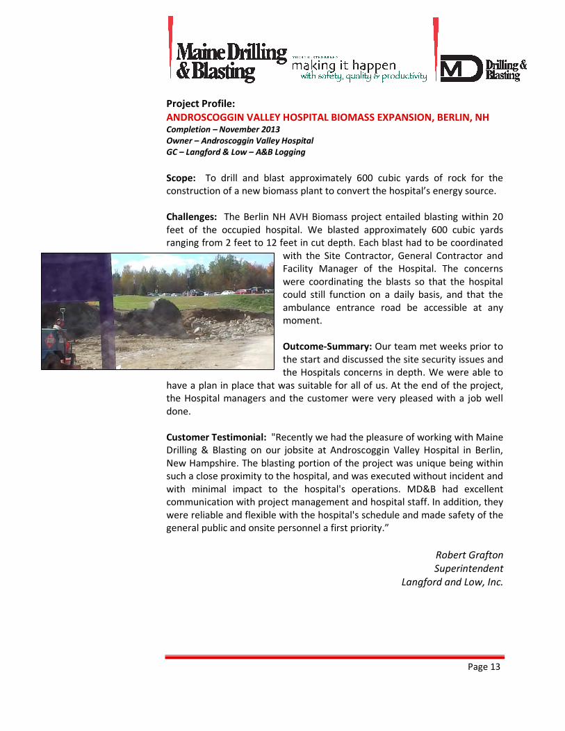
Project Profile:
ANDROSCOGGIN VALLEY HOSPITAL BIOMASS EXPANSION, BERLIN, NH Completion – November 2013
Owner – Androscoggin Valley Hospital
GC – Langford & Low – A&B Logging
Scope: To drill and blast approximately 600 cubic yards of rock for the
construction of a new biomass plant to convert the hospital’s energy source.
Challenges: The Berlin NH AVH Biomass project entailed blasting within 20
feet of the occupied hospital. We blasted approximately 600 cubic yards
ranging from 2 feet to 12 feet in cut depth. Each blast had to be coordinated
with the Site Contractor, General Contractor and
Facility Manager of the Hospital. The concerns
were coordinating the blasts so that the hospital
could still function on a daily basis, and that the
ambulance entrance road be accessible at any
moment.
Outcome-Summary: Our team met weeks prior to
the start and discussed the site security issues and
the Hospitals concerns in depth. We were able to
have a plan in place that was suitable for all of us. At the end of the project,
the Hospital managers and the customer were very pleased with a job well
done.
Customer Testimonial: "Recently we had the pleasure of working with Maine
Drilling & Blasting on our jobsite at Androscoggin Valley Hospital in Berlin,
New Hampshire. The blasting portion of the project was unique being within
such a close proximity to the hospital, and was executed without incident and
with minimal impact to the hospital's operations. MD&B had excellent
communication with project management and hospital staff. In addition, they
were reliable and flexible with the hospital's schedule and made safety of the
general public and onsite personnel a first priority.”
Robert Grafton
Superintendent
Langford and Low, Inc.
Page 14
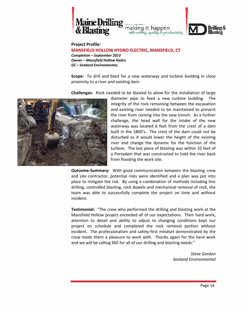
Project Profile:
MANSFIELD HOLLOW HYDRO ELECTRIC, MANSFIELD, CT Completion – September 2013
Owner – Mansfield Hollow Hydro
GC – Sealand Environmenta;
Scope: To drill and blast for a new waterway and turbine building in close
proximity to a river and existing dam.
Challenges: Rock needed to be blasted to allow for the installation of large
diameter pipe to feed a new turbine building. The
integrity of the rock remaining between the excavation
and existing river needed to be maintained to prevent
the river from coming into the new trench. As a further
challenge, the head wall for the intake of the new
waterway was located 6 feet from the crest of a dam
built in the 1800’s. The crest of the dam could not be
disturbed as it would lower the height of the existing
river and change the dynamic for the function of the
turbine. The last piece of blasting was within 10 feet of
a Portadam that was constructed to hold the river back
from flooding the work site.
Outcome-Summary: With good communication between the blasting crew
and site contractor, potential risks were identified and a plan was put into
place to mitigate the risk. By using a combination of methods including line
drilling, controlled blasting, rock dowels and mechanical removal of rock, the
team was able to successfully complete the project on time and without
incident.
Testimonial: "The crew who performed the drilling and blasting work at the
Mansfield Hollow project exceeded all of our expectations. Their hard work,
attention to detail and ability to adjust to changing conditions kept our
project on schedule and completed the rock removal portion without
incident. The professionalism and safety-first mindset demonstrated by the
crew made them a pleasure to work with. Thanks again for the hard work
and we will be calling MD for all of our drilling and blasting needs."
Steve Gordon
Sealand Environmental
Page 15
Project Profile:
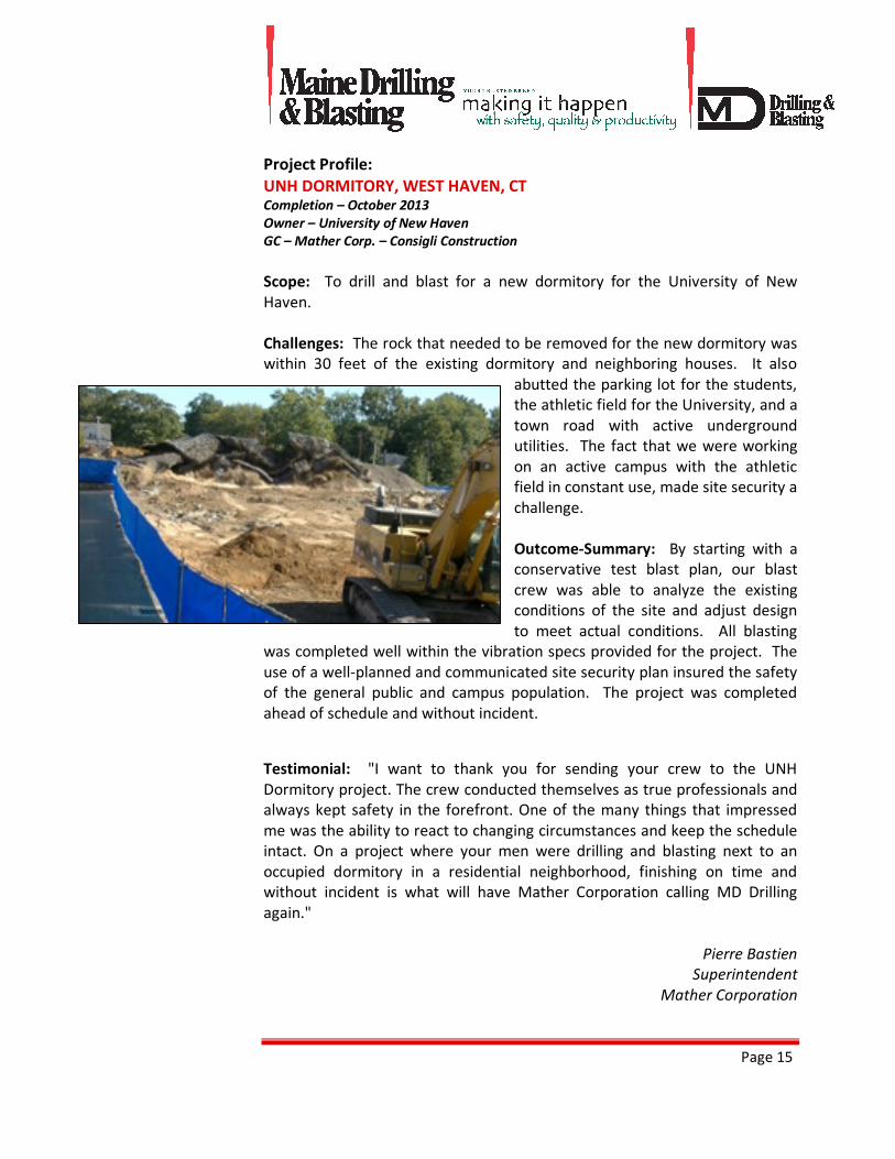
UNH DORMITORY, WEST HAVEN, CT Completion – October 2013
Owner – University of New Haven
GC – Mather Corp. – Consigli Construction
Scope: To drill and blast for a new dormitory for the University of New
Haven.
Challenges: The rock that needed to be removed for the new dormitory was
within 30 feet of the existing dormitory and neighboring houses. It also
abutted the parking lot for the students,
the athletic field for the University, and a
town road with active underground
utilities. The fact that we were working
on an active campus with the athletic
field in constant use, made site security a
challenge.
Outcome-Summary: By starting with a
conservative test blast plan, our blast
crew was able to analyze the existing
conditions of the site and adjust design
to meet actual conditions. All blasting
was completed well within the vibration specs provided for the project. The
use of a well-planned and communicated site security plan insured the safety
of the general public and campus population. The project was completed
ahead of schedule and without incident.
Testimonial: "I want to thank you for sending your crew to the UNH
Dormitory project. The crew conducted themselves as true professionals and
always kept safety in the forefront. One of the many things that impressed
me was the ability to react to changing circumstances and keep the schedule
intact. On a project where your men were drilling and blasting next to an
occupied dormitory in a residential neighborhood, finishing on time and
without incident is what will have Mather Corporation calling MD Drilling
again."
Pierre Bastien
Superintendent
Mather Corporation
Page 16
Project Profile:
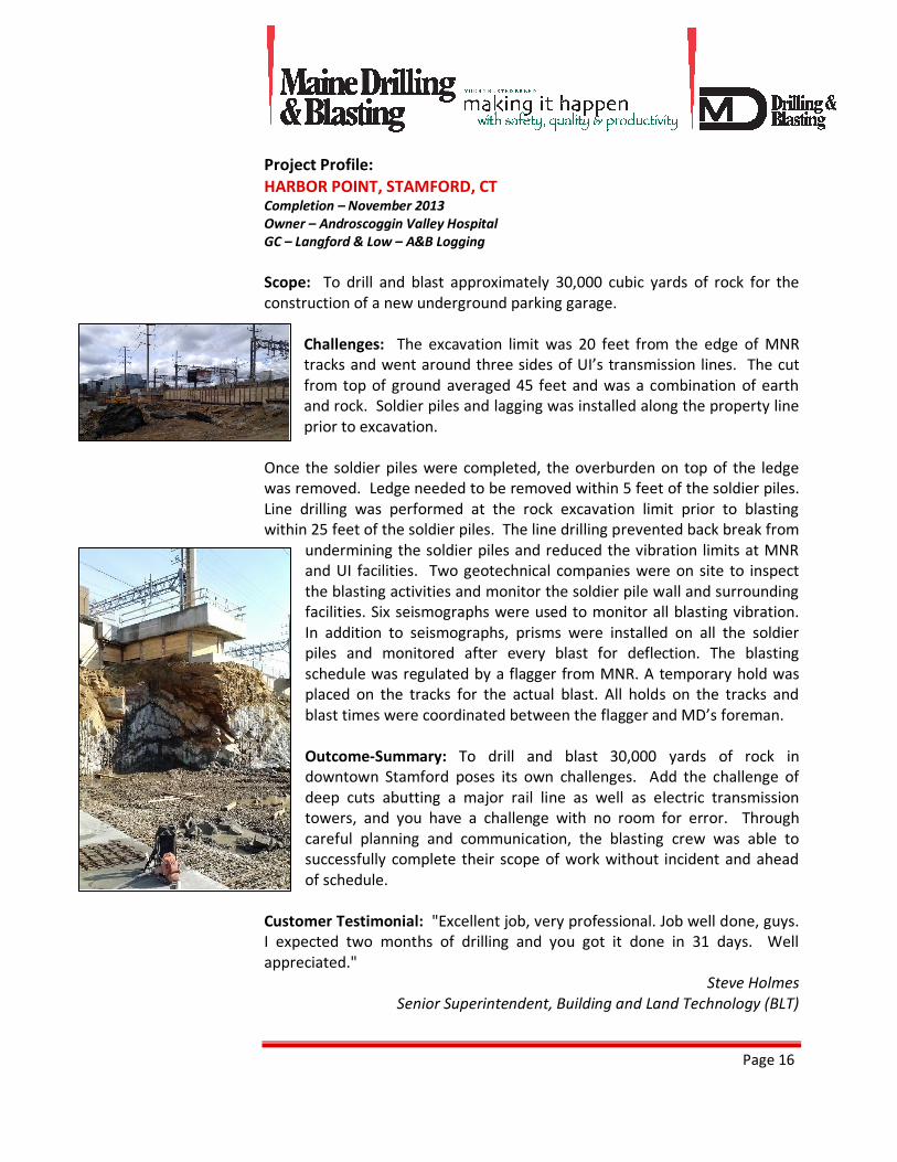
HARBOR POINT, STAMFORD, CT Completion – November 2013
Owner – Androscoggin Valley Hospital
GC – Langford & Low – A&B Logging
Scope: To drill and blast approximately 30,000 cubic yards of rock for the
construction of a new underground parking garage.
Challenges: The excavation limit was 20 feet from the edge of MNR
tracks and went around three sides of UI’s transmission lines. The cut
from top of ground averaged 45 feet and was a combination of earth
and rock. Soldier piles and lagging was installed along the property line
prior to excavation.
Once the soldier piles were completed, the overburden on top of the ledge
was removed. Ledge needed to be removed within 5 feet of the soldier piles.
Line drilling was performed at the rock excavation limit prior to blasting
within 25 feet of the soldier piles. The line drilling prevented back break from
undermining the soldier piles and reduced the vibration limits at MNR
and UI facilities. Two geotechnical companies were on site to inspect
the blasting activities and monitor the soldier pile wall and surrounding
facilities. Six seismographs were used to monitor all blasting vibration.
In addition to seismographs, prisms were installed on all the soldier
piles and monitored after every blast for deflection. The blasting
schedule was regulated by a flagger from MNR. A temporary hold was
placed on the tracks for the actual blast. All holds on the tracks and
blast times were coordinated between the flagger and MD’s foreman.
Outcome-Summary: To drill and blast 30,000 yards of rock in
downtown Stamford poses its own challenges. Add the challenge of
deep cuts abutting a major rail line as well as electric transmission
towers, and you have a challenge with no room for error. Through
careful planning and communication, the blasting crew was able to
successfully complete their scope of work without incident and ahead
of schedule.
Customer Testimonial: "Excellent job, very professional. Job well done, guys.
I expected two months of drilling and you got it done in 31 days. Well
appreciated."
Steve Holmes
Senior Superintendent, Building and Land Technology (BLT)
Page 17
Project Profile:
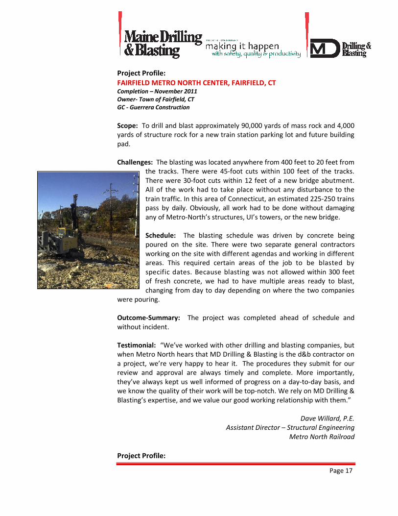
FAIRFIELD METRO NORTH CENTER, FAIRFIELD, CT Completion – November 2011
Owner- Town of Fairfield, CT
GC - Guerrera Construction
Scope: To drill and blast approximately 90,000 yards of mass rock and 4,000
yards of structure rock for a new train station parking lot and future building
pad.
Challenges: The blasting was located anywhere from 400 feet to 20 feet from
the tracks. There were 45-foot cuts within 100 feet of the tracks.
There were 30-foot cuts within 12 feet of a new bridge abutment.
All of the work had to take place without any disturbance to the
train traffic. In this area of Connecticut, an estimated 225-250 trains
pass by daily. Obviously, all work had to be done without damaging
any of Metro-North’s structures, UI’s towers, or the new bridge.
Schedule: The blasting schedule was driven by concrete being
poured on the site. There were two separate general contractors
working on the site with different agendas and working in different
areas. This required certain areas of the job to be blasted by
specific dates. Because blasting was not allowed within 300 feet
of fresh concrete, we had to have multiple areas ready to blast,
changing from day to day depending on where the two companies
were pouring.
Outcome-Summary: The project was completed ahead of schedule and
without incident.
Testimonial: “We’ve worked with other drilling and blasting companies, but
when Metro North hears that MD Drilling & Blasting is the d&b contractor on
a project, we’re very happy to hear it. The procedures they submit for our
review and approval are always timely and complete. More importantly,
they’ve always kept us well informed of progress on a day-to-day basis, and
we know the quality of their work will be top-notch. We rely on MD Drilling &
Blasting’s expertise, and we value our good working relationship with them.”
Dave Willard, P.E.
Assistant Director – Structural Engineering
Metro North Railroad
Project Profile:
Page 18
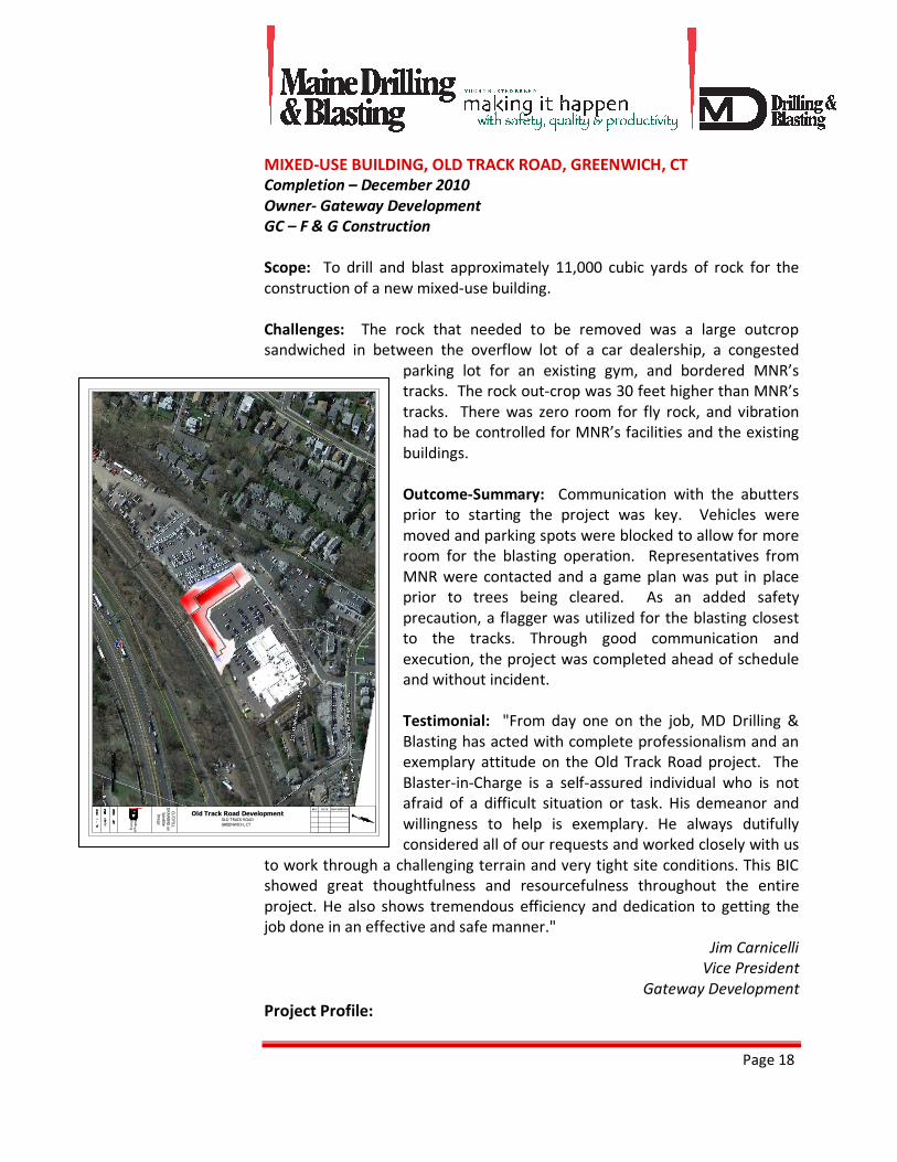
MIXED-USE BUILDING, OLD TRACK ROAD, GREENWICH, CT
Completion – December 2010
Owner- Gateway Development
GC – F & G Construction
Scope: To drill and blast approximately 11,000 cubic yards of rock for the
construction of a new mixed-use building.
Challenges: The rock that needed to be removed was a large outcrop
sandwiched in between the overflow lot of a car dealership, a congested
parking lot for an existing gym, and bordered MNR’s
tracks. The rock out-crop was 30 feet higher than MNR’s
tracks. There was zero room for fly rock, and vibration
had to be controlled for MNR’s facilities and the existing
buildings.
Outcome-Summary: Communication with the abutters
prior to starting the project was key. Vehicles were
moved and parking spots were blocked to allow for more
room for the blasting operation. Representatives from
MNR were contacted and a game plan was put in place
prior to trees being cleared. As an added safety
precaution, a flagger was utilized for the blasting closest
to the tracks. Through good communication and
execution, the project was completed ahead of schedule
and without incident.
Testimonial: "From day one on the job, MD Drilling &
Blasting has acted with complete professionalism and an
exemplary attitude on the Old Track Road project. The
Blaster-in-Charge is a self-assured individual who is not
afraid of a difficult situation or task. His demeanor and
willingness to help is exemplary. He always dutifully
considered all of our requests and worked closely with us
to work through a challenging terrain and very tight site conditions. This BIC
showed great thoughtfulness and resourcefulness throughout the entire
project. He also shows tremendous efficiency and dedication to getting the
job done in an effective and safe manner."
Jim Carnicelli
Vice President
Gateway Development
Project Profile:
CUT/FILL
DRAWING on
Satellite
Image
DESCRIPTIONDATEREV
OLD TRACK ROAD
GREENWICH, CT
Old Track Road Development
Page 19
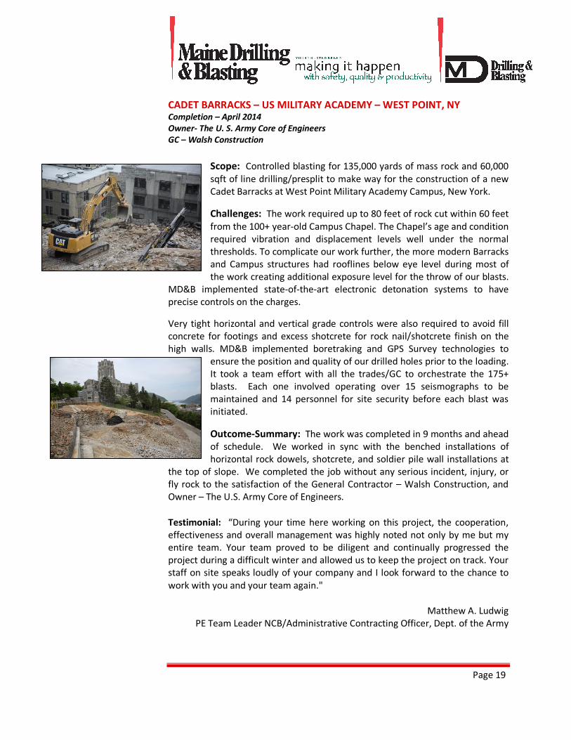
CADET BARRACKS – US MILITARY ACADEMY – WEST POINT, NY Completion – April 2014
Owner- The U. S. Army Core of Engineers
GC – Walsh Construction
Scope: Controlled blasting for 135,000 yards of mass rock and 60,000
sqft of line drilling/presplit to make way for the construction of a new
Cadet Barracks at West Point Military Academy Campus, New York.
Challenges: The work required up to 80 feet of rock cut within 60 feet
from the 100+ year-old Campus Chapel. The Chapel’s age and condition
required vibration and displacement levels well under the normal
thresholds. To complicate our work further, the more modern Barracks
and Campus structures had rooflines below eye level during most of
the work creating additional exposure level for the throw of our blasts.
MD&B implemented state-of-the-art electronic detonation systems to have
precise controls on the charges.
Very tight horizontal and vertical grade controls were also required to avoid fill
concrete for footings and excess shotcrete for rock nail/shotcrete finish on the
high walls. MD&B implemented boretraking and GPS Survey technologies to
ensure the position and quality of our drilled holes prior to the loading.
It took a team effort with all the trades/GC to orchestrate the 175+
blasts. Each one involved operating over 15 seismographs to be
maintained and 14 personnel for site security before each blast was
initiated.
Outcome-Summary: The work was completed in 9 months and ahead
of schedule. We worked in sync with the benched installations of
horizontal rock dowels, shotcrete, and soldier pile wall installations at
the top of slope. We completed the job without any serious incident, injury, or
fly rock to the satisfaction of the General Contractor – Walsh Construction, and
Owner – The U.S. Army Core of Engineers.
Testimonial: “During your time here working on this project, the cooperation,
effectiveness and overall management was highly noted not only by me but my
entire team. Your team proved to be diligent and continually progressed the
project during a difficult winter and allowed us to keep the project on track. Your
staff on site speaks loudly of your company and I look forward to the chance to
work with you and your team again."
Matthew A. Ludwig
PE Team Leader NCB/Administrative Contracting Officer, Dept. of the Army

A T R U S T E D B R E E D • A T R U S T E D B R E E D
Setting Earth-Shattering Standards Since 1966 • www.mainedrilling.com
Misfire Prevention Guidelines, Fly Rock Prevention Guidelines& IME Blasting Best Practices

Setting Earth-Shattering Standards Since 1966 • www.mainedrilling.com
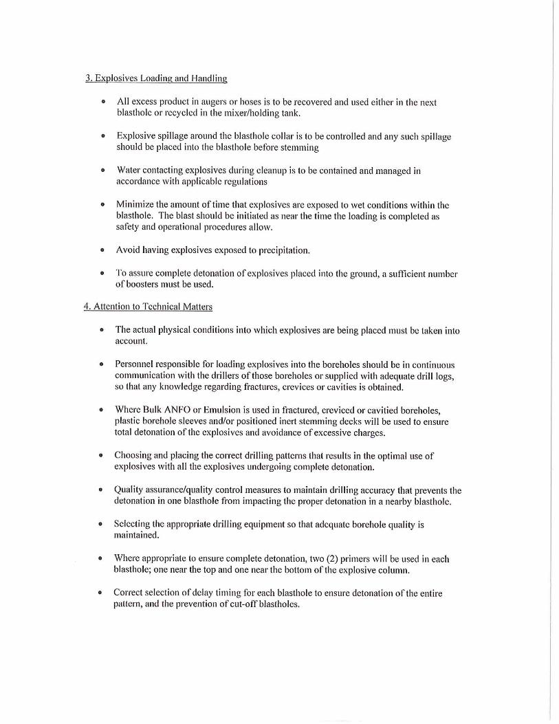
Blasting Mats Cut Sheet
Dynamat inc.100, rue de la StationLaval, QuébecH7M 3H7
Printed on : July 20 2016
Phone : 450 662-1803Fax : 450 662-9668Toll free : 1 800 363-8026E-mail : [email protected] : http://www.dynamat.qc.ca/
th
Blasting mats
Popular Products :
• 8 ft. x 16 ft. (2.43m x 4.87m)
• 10 ft. x 15 ft. (3m x 4.5m)
• 12 ft. x 24 ft. (3.65m x 7.3m)
Custom Made Products
Our equipment enables us to produce blasting mats to your particular specifications in sizes
ranging from 4 x 4 ft. (1.2 x 1.2m.) to 16 x 28 ft. (4.87 x 8.53m.). A flexibility that is unique in the
industry.
WHY CHOOSE DYNAMAT BLASTING MATS?
Our Innovative Processes
The Dynamat Advantage Our Goals
Automated processesWe have developed automated processes that let us measure the
compaction of the blasting mats.To ensure consistent quality.
Meticulous tire selection Our manufacturing processes demand it.
Our Added Value
The Dynamat Advantage Our Goals
Blasting mats over 12 feet (3.66 m) wideWe are the only manufacturer in North America to make products of
such widths.To match our client’s needs.
12 inches (30 cm) between each cable
We have always spaced them this way. All our competitors, on the
other hand, leave a gap of 14 to 16 inches (35 to 41 cm) between their
cables.
To produce safe blasting mats that control flying debris better.
Forged circular rings We used forged rings, while the competition used welded ones. To make blasting mats easier to handle.
Two dimensions of rings We use 10 and 13-inch (25and 33 cm) rings. To obtain the resistance required for hoisting.
The benefits of traditional blasting mats vs. blasting mats made of truck tires (transport mat)
• greater flexibility and adaptability to the terrain.• maximal absorption of the energy released by dynamiting.
• reduced possibilities of a partial blast.• unequalled ease in handling.
To provide a safe product that not only eliminates all risk of flying debris when dynamiting, but also ensures optimal
performance.
Superior quality = safety
Our products are subject to rigorous quality control at every step of the manufacturing process. Carefully selected, the recovered tires that make up our blasting mats are
tied together with new cables, and that translates into solidity and resistance. All the rubber pieces are perforated in order to minimize tears. This means that clients can
use our blasting mats in total safety.
Traceability
In a process that’s unique to Dynamat, blasting mats are individually numbered to allow them to be easily traced and identified wherever they are on a project involving
dynamiting. Now that’s an advantage that’s undeniably Dynamat!
Page 1 of 1Blasting mat and security mat
7/20/2016http://www.dynamat.qc.ca/blasting-mat-691-construction.php

Setting Earth-Shattering Standards Since 1966 • www.mainedrilling.com
Blastmate 3 Seismograph Cut Sheet
The World’s Most Trusted Vibration Monitors www.instantel.com
714B0053 R
ev 07 –
Pro
dcu
ct S
pec
ifi ca
tions
are
Subje
ct t
o C
han
ge
TM
Full-Featured, Advanced Vibration and Overpressure Monitor
Range of Applications:
•Βlast-monitoring for compliance• Near-fi eld blast analysis• Pile driving• Construction activity• Demolition activity• Heavy transportation• Bridge monitoring• Structural analysis• Underwater blast monitoring• 4 or 8 channel data aquisition• Remote monitoring - Auto Call HomeTM
Consultants, engineers and contractors the world over recognize the Instantel® Blastmate III™ vibration and overpressure monitor as the most versatile and most reliable full featured monitor available. It provides all of the industry-leading features of the Instantel Minimate Plus™ monitor, conveniently packaged with a full keyboard and a high-resolution printer. This allows you to setup, add notes and print complete event reports in the fi eld, without a computer.
VersatileWith standard features like the Instantel Histogram ComboTM monitoring mode, zero dead-time between events, and fl exible sample rates up to 65,536 S/s, the Blastmate III system provides you with control and confi dence to monitor reliably in any situation. For added versatility, you have the option to add 4 more channels and extra memory, providing two complete standard monitors in a single package. For more demanding monitoring applications, the Instantel Blastware® Advanced Module software provides the capability to monitor a broad selection of vibration and overpressure sensors, as well as sensors for related structural and environmental measurements. Monitor vibration, ambient environmental conditions, and the movement of structural cracks, all at the same time, all using the same Blastmate III monitor.
Easy to useThe features and versatility of the Blastmate III monitor set it apart, but the fact that it is also easy to use makes it truly revolutionary. The dedicated single use function keys, backlit LCD and simple menu-driven operation make setup and operation quick and easy, even for inexperienced personnel.
ToughThe Blastmate III monitor has been built to survive, with a fully sealed top panel, non-corrosive industrial grade connectors and sealed electronics, all packed in a rugged, water-resistant case. Blastmate III - Reliability and versatility for any monitoring application.
Key FeaturesFast high-resolution thermal printer for event reports in the fi eld without the need for a computer.
Full keyboard simplifi es entry of job-specifi c notes and information.
Dedicated function keys and intuitive menu-driven operation enable quick and easy setup.
Histogram Combo mode allows capture of full waveform records while recording in histogram mode.
Sample rates from 1,024 to 16,384 S/s per channel - up to 65,536 S/s available on a single channel.
Available 8-channel option allows for 2 standard triaxial geophones and 2 microphones to be used on a single Blastmate III monitor.
Continuous monitoring means zero dead time, even while the unit is processing.
Any channel can be matched to a wide variety of sensors - geophones, accelerometers, or hydrophones.
714B0053 R
ev 07 –
Pro
dcu
ct S
pec
ifi ca
tions
are
Subje
ct t
o C
han
ge
The World’s Most Trusted Vibration Monitors
Corporate Offi ce:309 Legget Drive, Ottawa, Ontario K2K 3A3 Canada
Toll Free: (800) 267 9111Telephone: (613) 592 4642Facsimile: (613) 592 4296Email: [email protected]
US Offi ce:808 Commerce Park Drive, Ogdensburg, New York 13669USA
TM
© 2009 Xmark Corporation. Instantel, the Instantel logo, Auto Call Home, AutoRecord, Blastmate, Blastware, Histogram Combo and Minimate, are trademarks of The Stanley Works or its affi liates.
Channels
Vibration Monitoring (with Standard Triaxial Geophone) Range Resolution Accuracy (ISEE / DIN) Transducer Density Frequency Range (ISEE / DIN) Maximum Cable Length (ISEE / DIN)Air Overpressure Monitoring Weighting Scales Linear Range Linear Resolution Linear Accuracy Linear Frequency Response A-weight Range A-weight Resolution
Record ModesSeismic TriggerAcoustic Triggers Linear A-weightSample Rate
Record Stop ModeRecord TimeAutoRecord Time
Cycle TimeStorage Capacity Full Waveform Events Event Summaries
Record Modes
Recording IntervalStorage Capacity
Dimensions WeightBatteryUser InterfaceDisplayPrinterPC InterfaceAuxillary Inputs and OutputsEnvironmental Printer/LCD Operating Temperature Electronics Operating TemperatureRemote Communications
Additional Features
Blastmate IIIGeneral Specifi cations
Waveform Recording
Histogram Recording
Physical Specifi cations
Microphone and Triaxial Geophone or 4 independent user-confi gurable channels (two Microphones and two Triaxial Geophones or 8 independent channels with optional 8-channel upgrade)
Up to 254 mm/s (10 in/s)0.127 mm/s (0.005 in/s) or 0.0159 mm/s (0.000625 in/s) with built-in preamp+/- 5% or 0.5 mm/s (0.02 in/s), whichever is larger, between 4 and 125 Hz / DIN 45669-1 standard2.13 g/cc (133 lbs/ft3)2 to 250 Hz, within zero to -3 dB of an ideal fl at response / 1 to 315 Hz75 m (250 ft) / 1,000 m (3,280 ft)
Linear or A-weight88 to 148 dB (500 Pa (0.072 PSI) Peak)0.25 Pa (0.0000363 PSI)+/- 10% or +/- 1 dB, whichever is larger, between 4 and 125 Hz2 to 250 Hz between -3 dB roll off points 50 to 110 dBA0.1 dBA
Manual, Single-shot, Continuous0.125 to 254 mm/s (0.005 to 10 in/s)
100 to 148 dB55 to 110 dBA1,024 to 16,384 S/s per channel (independent of record time), up to 65,536 S/sin single-channel mode with advanced software (maximum 8,192 S/s per channel for 8 channels)Fixed record time, Instantel® AutoRecord™ record stop mode1 to 100 seconds (programmable in one-second steps) or 500 seconds plus 0.25 seconds pre-triggerAuto window programmable from 1 to 9 seconds, plus a 0.25 second pre-trigger. Event is recorded untilactivity remains below trigger level for duration of auto window, or until available memory is fi lled. Recording uninterrupted by event processing - No dead time
300 one-second events at 1,024 S/s sample rate (1,500 event capacity with optional memory upgrade)1,750 (8,750 event capacity with optional memory upgrade)
Histogram and Instantel Histogram Combo™ (monitor captures triggered waveforms while recording in Histogram mode)2, 5 or 15 seconds; 1, 5 or 15 minutes46,656 intervals - 3 days at 5-second intervals or 102 days at 15 minute intervals (with memory upgrade - 15 days at 5-second intervals or 540 days at 15 minute intervals)
269 x 355 x 165 mm (10.6 x 14.0 x 6.5 in)6.4 kg (14 lbs)Rechargeable 6 V sealed gel cell - capacity for 30 days of continuous monitoring63 domed tactile keys including full keyboard and dedicated keys for common functions4-line x 20 character, high contrast, backlit LCD with online helpHigh resolution thermal plotterRS-232External Trigger, Remote Alarm, coordinate download from GPS
-10 to 500C (14 to 1220F)-20 to 600C (-4 to 1400F)Compatible with Telephone, GSM, Cellular, RF, Satellite, Short-haul modems, and Ethernet® device servers. Automatically transfers events when they occur through Instantel Auto Call Home™ feature.Monitor start/stop timer
Setting Earth-Shattering Standards Since 1966 • www.mainedrilling.com
Explosive Data Sheets
(SDS Sheets Available Upon Request)
Technical Information
Properties
NONEL® Lead LineNonelectric Shock Tube
Product DescriptionNONEL LEAD LINE is NONEL shock tube spooled at the factory in 763 meter (2,500 foot) lengths for easy application and deployment. NONEL LEAD LINE shock tube is a small diameter, three-layer plastic tube coated on the innermost wall with a reactive explosive compound. When initiated, NONEL shock tube propagates a low energy signal, similar to a dust explosion, at approximately 2000 m/sec (6,500 ft/sec) along the tube’s length with minimal disturbance to the outside of the tube. The signal is transmitted from one NONEL shock tube to another through field-assembled splices.
NONEL LEAD LINE provides maximum flexibility to the blaster in choosing a position of safety from which to initiate nonelectric blast rounds in either underground or surface applications. NONEL LEAD LINE is the only NONEL product that can be cut and spliced into a NONEL detonator product to construct a custom length nonelectric starter assembly.
Application Recommendations• ALWAYS splice NONEL LEAD LINE to NONEL EZTL™ nonelectric trunkline delay
detonators, NONEL EZ DET® nonelectric blast initiation system, NONEL TD or NONEL Starter detonators to make-up the nonelectric starter assembly when using
I-28-05-02-11
See Product Disclaimer on page 2.
MSDS #1124
Net Explosive Content per 100 units 0.0044 kg 0.0097 lbs
Hazardous Shipping Description Articles, Explosives, N.O.S. (HMX, Aluminum), 1.4S, UN 0349, PG II
LengthSpools / Case
m ft762 2500 2
• Length rounded to nearest one-half meter. • See case label for exact case weight.
Technical Information
Product Disclaimer Dyno Nobel Inc. and its subsidiaries disclaim any warranties with respect to this product, the safety or suitability thereof, or the results to be obtained, whether express or implied, INCLUDING WITHOUT LIMITATION, ANY IMPLIED WARRANTY OF MERCHANTABILITY OR FITNESS FOR A PARTICULAR PURPOSE AND/OR OTHER WARRANTY. Buyers and users assume all risk, responsibility and liability whatsoever from any and all injuries (including death), losses, or damages to persons or property arising from the use of this product. Under no circumstances shall Dyno Nobel Inc. or any of its subsidiaries be liable for special, consequential or incidental damages or for anticipated loss of profits.
Dyno Nobel Inc.2795 East Cottonwood Parkway, Suite 500, Salt Lake City, Utah 84121 USAPhone 800-732-7534 Fax 801-328-6452 Web www.dynonobel.com
NONEL® Lead Line
NONEL LEAD LINE as the primary initiator for NONEL blast rounds.• ALWAYS trim at least 3 m [10 ft] of tubing before inserting into a nonelectric shock
tube starting device or whenever dirt and/or moisture may have compromised the open tube ends before making a splice connection.
• ALWAYS replace the plastic tube closure over the open end of any NONEL LEAD LINE that remains on the spool and is intended to be used to make up another nonelectric starter assembly.
• ALWAYS make the final hook-up of the nonelectric starter assembly to the blast round only after all equipment and non-essential personnel are clear of the blast area.
• ALWAYS unspool NONEL LEAD LINE by hand if the starter assembly has been spliced to it and is attached to the blast round.
• ALWAYS keep any NONEL LEAD LINE tube ends sealed and free from dirt and moisture since dirt or moisture in the shock tube may cause a misfire.
• NEVER use NONEL LEAD LINE for in-hole use. NONEL LEAD LINE is for use outside the borehole only.
• NEVER attempt to knot different lengths of shock tube together. Shock tube will not initiate itself through knot connections. It must be spliced.
• NEVER remove the plastic tube closure from the NONEL LEAD LINE shock tube until just before splicing.
• NEVER attach the starter assembly to the blast round until after the LEAD LINE deployment is complete whenever NONEL LEAD LINE is to be unspooled by any method other than by hand,
• NEVER run over NONEL LEAD LINE with equipment. This may damage the shock tube and may cause a misfire. ALWAYS replace the NONEL LEAD LINE if it is damaged.
• When making a nonelectric starter assembly using NONEL LEAD LINE, ALWAYS remove the plastic tube closure and save for later use. Splice two freshly-cut ends of NONEL shock tube together (one from the NONEL LEAD LINE and the other from the NONEL detonator) by inserting them into opposite ends of the plastic connector sleeve and pushing them toward one another until they are both at least ½ cm (¼ in) in the splice.
Transportation, Storage and Handling• NONEL LEAD LINE must be transported, stored, handled and used in conformity
with all federal, state, provincial and local laws and regulations. • For maximum shelf life (3 years), NONEL LEAD LINE must be stored in a cool, dry,
well ventilated magazine. Explosive inventory should be rotated. Avoid using new materials before the old. For recommended good practices in transporting, storing, handling and using this product, see the booklet “Prevention of Accidents in the Use of Explosive Materials” packed inside each case and the Safety Library Publications of the Institute of Makers of Explosives.
Case Dimensions 51 x 25 x 28 cm 20 x 9 ⅞ x 10 ⅞ in
Application Recommendations (continued) Application Recommendations (continued)
Technical Information
Properties
NONEL® EZ DET® 1.4B
Nonelectric Blast Initiation System
Product DescriptionNONEL® nonelectric delay detonator EZ DET® 1.4B units consist of a length of orange shock tube with a surface detonator attached to one end and a Standard (#8) in-hole detonator on the other. The surface detonator is inside a color-coded plastic EZ™ Connector block to facilitate easy connections to shock tube leads. This block can hold up to 6 shock tube leads. Easy-to-read, color-coded delay tags display the delay number and nominal firing time prominently.
NONEL EZ DET units can be easily connected to one another to satisfy basic blast design requirements in construction, mining, and quarry operations. They can also be used in combination with NONEL MS, NONEL EZTL™ and/or NONEL TD detonators to satisfy complex blast design requirements and minimize inventory of initiation system components.
Application RecommendationsFor detailed application recommendations, ALWAYS request a copy of Dyno Nobel’s Product Manual: NONEL® and PRIMACORD® from your Dyno Nobel representative.• ALWAYS select a NONEL EZ DET unit having more than enough tubing length to
extend from the planned primer location in the borehole to the collar of the next hole.
I-33-05-02-11
See Product Disclaimer on page 2.
MSDS #1122
Hazardous Shipping Description Detonator assemblies nonelectric, 1.4B, UN 0361 PG II
Net Explosive Content per 100 units 0.0810 kg 0.1782 lbs
This product is only available in the United States.
Nominal Time(msec)
Nominal Time(msec)
Nominal Time(msec)
Connector Block Color
17 / 350 17 / 500 17 / 700 Yellow25 / 350 25 / 500 25 / 700 Red42 / 350 42 / 500 42 / 700 White25 / 375 Red
Technical Information
Product Disclaimer Dyno Nobel Inc. and its subsidiaries disclaim any warranties with respect to this product, the safety or suitability thereof, or the results to be obtained, whether express or implied, INCLUDING WITHOUT LIMITATION, ANY IMPLIED WARRANTY OF MERCHANTABILITY OR FITNESS FOR A PARTICULAR PURPOSE AND/OR OTHER WARRANTY. Buyers and users assume all risk, responsibility and liability whatsoever from any and all injuries (including death), losses, or damages to persons or property arising from the use of this product. Under no circumstances shall Dyno Nobel Inc. or any of its subsidiaries be liable for special, consequential or incidental damages or for anticipated loss of profits.
Dyno Nobel Inc.2795 East Cottonwood Parkway, Suite 500, Salt Lake City, Utah 84121 USAPhone 800-732-7534 Fax 801-328-6452 Web www.dynonobel.com
NONEL® EZ DET® 1.4BPackaging
LengthCase Type
Quantity / Case
case subpackm ft3.5 12 D 180 904.5 16 D 120 607 24 D 120 609 30 D 80 40
12 40 D 60 3015 50 D 60 3018 60 D 50 2524 80 DC 50 --30 100 DC 40 --37 120 DC 30 --
• Length rounded to nearest one-half meter. • Case weight varies by length & delay; see case label for exact weight.
Case Dimensions Detpak Case (DC) 48 x 45 x 26 cm 18¾ x 17¾ x 10¼ in Detpak (D) subpack 44 x 22 x 25 cm 17 ½ x 8 ¾ x 10 in strapped case 44 x 45 x 25 cm 17 ½ x 17 ⅝ x 10 in
• ALWAYS protect the plastic EZ Connector block and all shock tube leads from impact or damage during the loading and stemming operations. Use care when placing blasting mats and cover material on top of the blasting circuit. The EZ Connector block contains a detonator and is subject to detonation caused by abuse such as impact. Shock tube which has been cut, ruptured or damaged may cause misfires.
• ALWAYS be sure that the shock tube(s) are securely inserted, one at a time, into the EZ Connector block. The head of the EZ Connector block should rise to accept the shock tube and return to a closed position with an audible click.
• ALWAYS ensure that individual shock tubes remain aligned side by side in the connector channel and do not cross one over the another on insertion.
• NEVER use NONEL EZ DET units with detonating cord. The low strength surface detonator will not initiate detonating cord and may cause misfires.
• NEVER attempt to disassemble the delay detonator from the plastic EZ Connector block or use the detonator without the connector.
• NEVER place more than 6 shock tube leads into the plastic EZ Connector block. Misfires may result.
• NEVER pull, stretch, kink or put tension on shock tube such that the tube could break.
• NEVER splice NONEL EZ DET shock tube together to extend between holes.• NEVER connect NONEL EZ DET units together until all holes have been primed,
loaded and stemmed and the blast site has been cleared.
Transportation, Storage and Handling• NONEL EZ DET must be transported, stored, handled and used in conformity with
all federal, state, provincial and local laws and regulations. • For maximum shelf life (3 years), NONEL EZ DET must be stored in a cool, dry,
well ventilated magazine. Explosive inventory should be rotated. Avoid using new materials before the old. For recommended good practices in transporting, storing, handling and using this product, see the booklet “Prevention of Accidents in the Use of Explosive Materials” packed inside each case and the Safety Library Publications of the Institute of Makers of Explosives
Application Recommendations (continued)
Note: This product is also available with a High Strength cap. For more information, please contact your local Dyno Nobel sales representative.
Technical Information
Properties
NONEL® EZTL™
Nonelectric Trunkline Delay Detonators
Product DescriptionNONEL® nonelectric delay detonator EZTL™ units consist of a length of yellow shock tube, with a surface detonator attached to one end and the other end sealed. The detonator is housed in a plastic EZ Connector block which facilitates easy connection to shock tube. A white J-hook is affixed near the sealed end. Easy-to-read, color-coded delay tags display the delay number and nominal firing time prominently.
EZTL detonators are designed for use with NONEL MS and EZ DET® units to provide effective and accurate surface timing between blastholes and/or rows of blastholes in surface and underground blasting designs. Application RecommendationsFor detailed application recommendations, ALWAYS request a copy of Dyno Nobel’s Product Manual: NONEL® and PRIMACORD® from your Dyno Nobel representative.• ALWAYS be sure that the shock tube(s) are securely inserted, one at a time, into the
plastic EZ connector. The head of the connector block should rise to accept the tube, and return to a closed position with an audible click.
• ALWAYS ensure that the individual shock tubes remain aligned side by side in the EZ connector channel and do not cross over one another during insertion.
• ALWAYS protect the plastic EZ connector and all shock tube leads from impact or
I-29-05-02-11
See Product Disclaimer on page 2.
MSDS #1122
Net Explosive Content per 100 units 0.0240 kg 0.0529 lbs
Hazardous Shipping Description Detonator assemblies nonelectric, 1.4B, UN 0361 PG II
Delay Time(msec) Connector Block Color
9 Green17 Yellow25 Red33 Green42 White67 Blue
100 Black109 Black
Technical Information
Product Disclaimer Dyno Nobel Inc. and its subsidiaries disclaim any warranties with respect to this product, the safety or suitability thereof, or the results to be obtained, whether express or implied, INCLUDING WITHOUT LIMITATION, ANY IMPLIED WARRANTY OF MERCHANTABILITY OR FITNESS FOR A PARTICULAR PURPOSE AND/OR OTHER WARRANTY. Buyers and users assume all risk, responsibility and liability whatsoever from any and all injuries (including death), losses, or damages to persons or property arising from the use of this product. Under no circumstances shall Dyno Nobel Inc. or any of its subsidiaries be liable for special, consequential or incidental damages or for anticipated loss of profits.
Dyno Nobel Inc.2795 East Cottonwood Parkway, Suite 500, Salt Lake City, Utah 84121 USAPhone 800-732-7534 Fax 801-328-6452 Web www.dynonobel.com
NONEL® EZTL™
Packaging
LengthCase Type
Quantity / Casem ft case subpack
2.5 10 D 180 903.5 12 D 180 906 20 D 150 759 30 D 120 60
12 40 D 100 5015 50 D 90 4518 60 D 70 35
• Length rounded to nearest one-half meter.
• Case weight varies by length & delay; see case label for exact weight.
Case Dimensions Detpak (D) subpack 44 x 22 x 25 cm 17½ x 8¾ x 10 in strapped case 44 x 45 x 25 cm 17½ x 17⅝ x 10 in
damage. Use care when placing blasting mats and cover material on top of the blasting circuit. The EZ connector contains a detonator and is subject to detonation caused by abuse such as impact. Shock tube which has been cut, ruptured or damaged may cause misfires.
• NEVER use NONEL EZTL detonators with detonating cord. The low strength surface detonator will not initiate detonating cord.
• NEVER attempt to disassemble the delay detonator from the EZ connector block or use the detonator without the connector.
• NEVER place more than 6 shock tube leads into an EZ connector block. Misfires may result.
• NEVER tie-in NONEL EZTL units until all holes have been primed, loaded, stemmed and the blast site has been cleared.
Transportation, Storage and Handling• NONEL EZTL must be transported, stored, handled and used in conformity with all
federal, state, provincial and local laws and regulations. • For maximum shelf life (3 years), NONEL EZTL must be stored in a cool, dry, well
ventilated magazine. Explosive inventory should be rotated. Avoid using new materials before the old. For recommended good practices in transporting, storing, handling and using this product, see the booklet “Prevention of Accidents in the Use of Explosive Materials” packed inside each case and the Safety Library Publications of the Institute of Makers of Explosives.
Application Recommendations (continued)
Technical Information
Properties
TROJAN® SPARTAN® SR™
Shock Resistant Cast Booster
Product DescriptionTROJAN SPARTAN SR cast boosters are detonator sensitive, high density, high energy molecular explosives available in three sizes designed to optimize initiatiion of all booster detonator sensitive explosives.
In addition to the internal through-tunnel and detonator well, the TROJAN SPARTAN SR (Shock Resistant) cast booster has an internal sleeve to protect the circuit board in electronc detonators and is designed specifically for use with Dyno Nobel’s DigiShot®, DigiShot Plus and SmartShot® electronic detonators. The Trojan Spartan SR can, however, also be used with any detonator (minimum length = 8.89 cm / 3.5 in) that may require additional protection from high shock, water hammer, effects during decking, corner operations or in certain geologies
The TROJAN SPARTAN SR (Shock Resistant ) cast booster also incorporates the unique Caplock™ feature which holds the detonator in place more securely and makes it more difficult for the detonator to be pulled out of capwell position while it is being lowered into the borehole. Even with this new Caplock feature, the detonator can still be removed if necessary.
Hazardous Shipping Description UN 0042 Boosters, 1.1D PG II
Density (g/cc) Avg 1.65
Velocity (m/sec)
(ft/s)
7,550
24,800
Detonation Pressure (Kbars) 235
Water Resistance 6 months with no loss of sensitivity
Shelf Life Maximum 5 years (from date of production)
Maximum Usage Temperature 65°C (150°F)
MSDS #1108
C-13-10-17-11
See Product Disclaimer on page 2.
All Dyno Nobel Inc. energy and gas volume values except Velocity and Detonation Pressure are calculated using PRODET™ the computer code developed by Dyno Nobel Inc. for its exclusive use. Other computer codes may give different values.
Velocity and Detonation Pressure are the result of empirical methods during May 2009.
Product Description continuedTROJAN SPARTAN SR cast boosters are formulated from the highest quality PETN and other high explosive materials ensuring reliability, consistency and durability in all blasting environments.The fluorescent yellow container makes the TROJAN SPARTAN booster more visible on the blast site and reduces the possibility of misplaced charges.
IMPORTANT!!! WARNING!!!!! IMPORTANT!!!!!
NEVER USE A DETONATOR LESS THAN8.89 CM / 3.5 in LONG WITH THE
TROJAN SPARTAN SR CAST BOOSTER. MISFIRES MAY RESULT.
Technical Information
Product Disclaimer Dyno Nobel Inc. and its subsidiaries disclaim any warranties with respect to this product, the safety or suitability thereof, or the results to be obtained, whether express or implied, INCLUDING WITHOUT LIMITATION, ANY IMPLIED WARRANTY OF MERCHANTABILITY OR FITNESS FOR A PARTICULAR PURPOSE AND/OR OTHER WARRANTY. Buyers and users assume all risk, responsibility and liability whatsoever from any and all injuries (including death), losses, or damages to persons or property arising from the use of this product. Under no circumstances shall Dyno Nobel Inc. or any of its subsidiaries be liable for special, consequential or incidental damages or for anticipated loss of profits.
Dyno Nobel Inc.2795 East Cottonwood Parkway, Suite 500, Salt Lake City, Utah 84121 USAPhone 800-732-7534 Fax 801-328-6452 Web www.dynonobel.com
Application Recommendations • NEVER force the detonator into the through-tunnel, the detonator-well or otherwise
attempt to clear these areas if obstructed. If the through-tunnel or detonator-well does not accommodate the detonator, do not use the booster. Notify your Dyno Nobel representative.
• ALWAYS use a detonator with a minimum length of 8.89 cm (3.5 in). The detonator well length is 10.2 cm (4.0 in).
• Extremely low temperatures do not affect the performance of cast boosters with commercial detonators. Low temperatures do affect detonators and detonating cord. Be certain your initiation system is suitable for your application in extremely low temperatures. Cast boosters are more susceptible to breakage during handling in extremely cold temperatures.
Transportation, Storage and Handling • Dyno Nobel cast boosters must be transported, stored, handled and used in
conformity with all federal, state, provincial and local laws and regulations. • For maximum shelf life (5 years), Dyno Nobel cast boosters must be stored in a
cool, dry, well ventilated magazine. Explosive inventory should be rotated. Avoid using new materials before the old.
TROJAN® SPARTAN® SR™
Case Dimensions 42 x 33 x 14 cm 16 ½ x 13 x 5 ½ in
Packaging
Unit Weight Unit Dimensions Case
Quantity
Gross Weight/Case
g ozLength Diameter
kg lbscm in cm in
350 12 11.9 4.7 5.0 2.0 49 16.9 39.5
400 14 11.9 4.7 5.5 2.2 40 16.7 36.8
450 16 11.9 4.7 5.8 2.3 36 16.9 37.3
Note: All weights and dimensions are approximate.
Technical
Information
Properties
TROJAN SPARTAN®
Cast Booster
Product Description
TROJAN SPARTAN cast boosters are detonator sensitive, high density, high energy
molecular explosives avaliable in various sizes designed to optimize initiation of all
booster sensitive explosives. All TROJAN SPARTAN boosters are manufactured
with an internal through-tunnel and detonator well for easy application with either
electric, electronic or nonelectric detonators or 10.6 g/m (50 gr/ft) minimum strength
detonating cord.
TROJAN SPARTAN boosters are formulated from the highest quality PETN and other
high explosive materials ensuring reliability, consistency and durability in all blasting
TROJAN
SPARTAN booster more visible on the blast site (as well as in low light situations) and
pulled out of the capwell position while it is being lowered into the borehole.
Application Recommendations
NEVER force the detonator into the through-tunnel, the detonator-well or otherwise
attempt to clear these areas if obstructed. If the through-tunnel or detonator-well
does not accommodate the detonator, do not use the booster. Notify your Dyno
Nobel representative.
Hazardous Shipping Description
UN 0042 Boosters, 1.1D PG II
Density (g/cc) Avg 1.65
Velocity (m/sec)
(ft/s)
7,550
24,800
Detonation Pressure (Kbars) 235
Water Resistance 6 months with no loss of sensitivity
Shelf Life Maximum 5 years (from date of production)
Maximum Usage Temperature 60°C (150°F)
MSDS
#1108
C-07-10-05-12
See Product Disclaimer on page 2.
All Dyno Nobel Inc. energy and gas volume values except Velocity and Detonation Pressure
exclusive use. Other computer codes may give different values.
Velocity and Detonation Pressure are the result of empirical methods during May 2009.
Technical
Information
Product Disclaimer Dyno Nobel Inc. and its subsidiaries disclaim any warranties with respect to this product, the safety or suitability thereof, or the results to be obtained, whether express or
implied, INCLUDING WITHOUT LIMITATION, ANY IMPLIED WARRANTY OF MERCHANTABILITY OR FITNESS FOR A PARTICULAR PURPOSE AND/OR OTHER WARRANTY. Buyers and users
assume all risk, responsibility and liability whatsoever from any and all injuries (including death), losses, or damages to persons or property arising from the use of this product. Under no circumstances
Dyno Nobel Inc.2795 East Cottonwood Parkway, Suite 500, Salt Lake City, Utah 84121 USA
Phone 800-732-7534 Fax 801-328-6452 Web www.dynonobel.com
Application Recommendations (continued)
ALWAYS use detonating cord with a coreload of 10.6 g/m (50 gr/ft) or higher when
initiating the TROJAN SPARTAN booster with detonating cord.
Minimum detonator is No. 8 strength for temperatures above -40º C (-40º F). A high
strength detonator is recommended for temperatures below -40º C (-40º F).
Extremely low temperatures do not affect the performance of cast boosters with
commercial detonators. Low temperatures do affect detonators and detonating
cord. Be certain your initiation system is suitable for your application in extremely
in extremely cold temperatures.
Transportation, Storage and Handling
Dyno Nobel cast boosters must be transported, stored, handled and used in
conformity with all federal, state, provincial and local laws and regulations.
For maximum shelf life (5 years), Dyno Nobel cast boosters must be stored in a
cool, dry, well ventilated magazine. Explosive inventory should be rotated. Avoid
using new materials before the old.
TROJAN® SPARTAN®
Case Dimensions
42 x 33 x 14 cm 16 ½ x 13 x 5 ½ in
Packaging
Unit Weight Unit Dimensions Case
Quantity
Gross Weight/
Case
g ozLength Diameter
lbscm in cm in
90 3.2 11.9 4.7 2.7 1.1 150 14.0 30.8
150 5.5 11.9 4.7 3.6 1.4 95 16.7 36.7
200 7 11.7 4.6 4.1 1.6 72 16.5 36.4
350 12 11.9 4.7 5.0 2.0 49 17.9 39.5
400 14 11.9 4.7 5.5 2.2 40 17.6 38.8
450 16 11.9 4.7 5.8 2.3 36 17.8 39.2
900 32 12.9 5.1 7.9 3.1 18 17.8 39.2
Note: All weights and dimensions are approximate.
Technical Information
Properties
D-14-05-11-12
See Product Disclaimer on page 2
DYNOMAX™ PRO Extra Gelatin Nitroglycerin Dynamite
Hazardous Shipping Description Explosive, Blasting, Type A 1.1D UN 0081 II
a All Dyno Nobel Inc. energy and gas volume values are calculated using PRODET™ the
computer code developed by Dyno Nobel Inc. for its exclusive use. Other computer codes may give different values.
b ANFO = 1.00 @ 0.82 g/cc c Unconfined @ 50 mm (2 in) diameter.d IME Fume Class 1 in convolute paper shell only. Not Fume Class 1 in paper tube shell.
Natural Resources Canada Fume Class approvals pending.
MSDS#1019
Density (g/cc) Avg 1.45 Energya (cal/g) 1,055 (cal/cc) 1,510 Relative Weight Strengtha 1.20
Relative Bulk Strengtha,b 2.10
Velocityc (m/s) 6,000 (ft/s) 19,700 Detonation Pressurec (Kbars) 130 Gas Volumea (moles/kg) 32Water Resistance Excellent
Fume Classd IME1
Product DescriptionDYNOMAX PRO is desensitized extra gelatin dynamite designed to satisfy the majority of explosive application requirements. DYNOMAX PRO is formulated to consistently deliver high detonation velocity and excellent water resistance while reducing cartridge to cartridge gap sensitivity and hole-to-hole propagation problems. DYNOMAX PRO is recommended for bottom loading and as the main explosive charge where high density and energy is required. DYNOMAX PRO is recommended for use as booster, bottom load or floor control solution.
Application Recommendations• DYNOMAX PRO is an excellent primer for Dynomix (ANFO), Dynomix WR (WR ANFO) or other detonator sensitive packaged product and can be used as a secondary primer in hard seams or at the top of the explosive column.
• Minimum diameter is 32 mm (1¼ in).• Minimum detonator is No. 8 strength.• DYNOMAX PRO has been formulated to reduce susceptibility to sympathetic
detonation when applied in very wet conditions where boreholes are closely spaced and/or where geological conditions promote this effect. Consult your Dyno Nobel representative for product recommendations where these conditions exist.
• Storage at elevated temperatures and/or high humidity for 12-18 months can reduce the performance of DYNOMAX PRO depending on the diameter. Consult your Dyno Nobel representative for specific recommendations.
Technical Information
Product Disclaimer Dyno Nobel Inc. and its subsidiaries disclaim any warranties with respect to this product, the safety or suitability thereof, or the results to be obtained, whether express or implied, INCLUDING WITHOUT LIMITATION, ANY IMPLIED WARRANTY OF MERCHANTABILITY OR FITNESS FOR A PARTICULAR PURPOSE AND/OR OTHER WARRANTY. Buyers and users assume all risk, responsibility and liability whatsoever from any and all injuries (including death), losses, or damages to persons or property arising from the use of this product. Under no circumstances shall Dyno Nobel Inc. or any of its subsidiaries be liable for special, consequential or incidental damages or for anticipated loss of profits.
Dyno Nobel Inc. 2795 East Cottonwood Parkway, Suite 500, Salt Lake City, Utah 84121 USA Phone 800-732-7534 Fax 801-328-6452 Web www.dynonobel.com
DYNOMAX™ PRO Transportation, Storage and Handling• For maximum shelf-life, DYNOMAX PRO dynamite must be stored in cool, dry and
well-ventilated magazines. Explosive inventory should always be rotated by using the oldest materials first. For recommended good practices in transporting, storing, handling and using this product, see the booklet “Prevention of Accidents in the Use of Explosive Materials” packed inside each case and the Safety Library Publications of the Institute of Makers of Explosives.
• DYNOMAX PRO must be transported, stored, handled and used in conformity with all applicable federal, state, provincial and local laws and regulations.
Case Dimensions
DA 17¾ x 13⅜ x 6⅜ in 34 x 34 x 17 cm DB 17⅞ x 13⅜ x 5⅞ in 45 x 34 x 15 cm DE 17⅝ x 13 5/16 x 6¾ in 45 x 34 x 17 cm
a Avaliable in spiral tube shell with tapered end. • Note: All weights are approximate.**Available upon request. Check with your Dyno Nobel representative should you have any questions.• Product density is 1.40 g/cc for package diameters less than 50mm (2 in). Use cartridge count to
determine actual explosive charge weight.• DYNOMAX PRO is available in a wide variety of sizes. Custom sizes are subject to surcharge and
may require longer than usual lead times.
Diameter x Length Qty / Case
Case Type
Nominal Case Weight
mm in kg lbs
32 x 200 1 1/4 x 8 88 DA 20 4432 x 400 1 1/4 x 16 44 DA 20 4440 x 200 1 1/2 x 8 60 DA 20 4450 x 200 2 x 8 34 DB 20 4350 x 400a 2 x 16 a 17 DB 20 4365 x 400a 2 1/2 x 16 a 10 DB 19 4175 x 200 3 x 8 a 16 DE 20 4475 x 400a 3 x 16 a 8 DE 20 44
Packaging
Technical Information
Properties
D-07-05-11-12
See Product Disclaimer on page 2
UNIMAX® Extra Gelatin Nitroglycerin Dynamite
Hazardous Shipping Description Explosive, Blasting, Type A, 1.1D, UN 0081 II
a All Dyno Nobel Inc. energy and gas volume values are calculated using PRODET™ the
computer code developed by Dyno Nobel Inc. for its exclusive use. Other computer codes may give different values.
b ANFO = 1.00 @ 0.82 g/cc c Unconfined @ 50 mm (2 in) diameter.d Approved by Natural Resources Canada as Fume Class 1.
MSDS#1019
Density (g/cc) Avg 1.51 Energya (cal/g) 1,055 (cal/cc) 1,510 Relative Weight Strengtha 1.20Relative Bulk Strengtha,b 2.10Velocityc (m/s) 5,300 (ft/s) 17,400 Detonation Pressurec (Kbars) 106 Gas Volumea (moles/kg) 32Water Resistance Excellent Fume Class IME1 & NRCan1d
Product DescriptionUNIMAX is an extra gelatin dynamite formulated to consistently deliver high detonation velocity and excellent water resistance. UNIMAX is designed to satisfy the vast majority of explosive applications in hard rock and may be used as the main explosive charge where high density and energy is required or as a primer for ANFO.
Application Recommendations• UNIMAX is an excellent primer for Dynomix (ANFO), Dynomix-WR (WR ANFO) or
other detonator sensitive packaged product and can be used as a secondary primer in hard seams or at the top of the explosive column.
• Minimum diameter is 25 mm (1 in).• Minimum detonator is No. 8 strength. • Storage at elevated temperatures and/or high humidity for 1 to 6 months can reduce
the performance of Unimax depending on the diameter. Consult your Dyno Nobel representative for specific recommendations.
• Dynamites are susceptible to sympathetic detonation when applied in very wet conditions where boreholes are closely spaced and/or where geological conditions promote this effect. Consult your Dyno Nobel representative for recommendations where these conditions exist.
Technical Information
Product Disclaimer Dyno Nobel Inc. and its subsidiaries disclaim any warranties with respect to this product, the safety or suitability thereof, or the results to be obtained, whether express or implied, INCLUDING WITHOUT LIMITATION, ANY IMPLIED WARRANTY OF MERCHANTABILITY OR FITNESS FOR A PARTICULAR PURPOSE AND/OR OTHER WARRANTY. Buyers and users assume all risk, responsibility and liability whatsoever from any and all injuries (including death), losses, or damages to persons or property arising from the use of this product. Under no circumstances shall Dyno Nobel Inc. or any of its subsidiaries be liable for special, consequential or incidental damages or for anticipated loss of profits.
Dyno Nobel Inc. 2795 East Cottonwood Parkway, Suite 500, Salt Lake City, Utah 84121 USA Phone 800-732-7534 Fax 801-328-6452 Web www.dynonobel.com
UNIMAX®
Transportation, Storage and Handling• UNIMAX must be transported, stored, handled and used in conformity with all
applicable federal, state, provincial and local laws and regulations.• For maximum shelf-life, dynamite must be stored in cool, dry and well-ventilated
magazines. Dynamite inventory should always be rotated by using the oldest materials first. For recommended good practices in transporting, storing, handling and using this product, see the booklet “Prevention of Accidents in the Use of Explosive Materials” packed inside each case and the Safety Library Publications of the Institute of Makers of Explosives.
Diameter x Length Quantity / Case
Case Type
Nominal Case Weight
mm in kg lbs25 x 200 1 x 8 140 DA 20.4 44.832 x 200 1 1/4 x 8 88 DA 20.0 44.032 x 400 1 1/4 x 16 44 DA 20.0 44.040 x 200 1 1/2 x 8 60 DA 19.4 42.640 x 400 1 1/2 x 16 30 DA 20.5 45.050 x 200 2 x 8 34 DB 19.3 42.550 x 400a 2 x 16a 17 DB 19.3 42.560 x 400a 2 1/4 x 16a 13 DA 18.1 39.865 x 400a 2 1/2 x 16a 10 DB 18.6 41.075 x 200 3 x 8 16 DE 19.9 43.775 x 400a 3 x 16a 8 DE 20.4 44.8
a Avaliable in spiral tube shell with tapered end.• Note: all weights are approximate.• Product density is 1.50 g/cc for package diameters less than 50 mm (2 in). Use cartridge count
to determine actual explosive charge weight.• UNIMAX is available in a wide variety of sizes. Custom sizes are subject to surcharge and may
require longer than usual lead times.
**Available upon request. Check with your Dyno Nobel representative should you have any questions.Case Dimensions DA 45 x 34 x 17 cm 17¾ x 13⅜ x 6⅜ in DB 45 x 34 x 15 cm 17⅞ x 13⅜ x 5⅞ in DE 45 X 34 X 17 cm 17⅝ x 13 5/16 x 6¾ in
Technical Information
Properties
P-10-09-09-13
See Product Disclaimer on page 2
BLASTEX®
Hazardous Shipping Description Explosive, Blasting, Type E, 1.5D, UN 0332 II
MSDS#1063
BLASTEX BLASTEX PLUS
Density (g/cc) Avg 1.26 1.26
Energya (cal/g) 740 800
(cal/cc) 930 1,010
Relative Weight Strengtha 0.84 0.91
Relative Bulk Strengtha,b 1.29 1.40
Velocityc (m/s) 5,000 4,900
(ft/s) 16,400 16,100
Detonation Pressurec (Kbars) 79 76
Gas Volumea (moles/kg) 44 39
Fume Class IME1 & NRCand IME1
Shelf Life Maximum 1 year (from date of production)
Maximum Water Depth 45 m (150 ft)
Water Resistance Excellent
a All Dyno Nobel Inc. energy and gas volume values are calculated using PRODET™ the computer code developed by Dyno Nobel Inc. for its exclusive use. Other computer codes may give different values.
b ANFO = 1.00 @ 0.82 g/cc c
d Approved by Natural Resources Canada as Fume Class 1 in: *valeron chub 50 mm (2 in) diameter and greater *shot bag 125 mm (5 in) diameter and greater
Small & Large Diameter Cast Booster Sensitive Emulsion
Product DescriptionBLASTEX is a booster sensitive, water resistant, packaged emulsion explosive designed to satisfy a majority of medium diameter explosive applications for quarry and construction blasting. It is a cost effective alternative to most detonator sensitive, water resistant, packaged emulsion explosives. BLASTEX is available in two grades with increasing energy level for each.
Application Recommendations
actual explosive charge weight.
whenever column separation is suspected, multiple priming is recommended.
order or fail completely when applied in very wet conditions, where explosive charges or decks are closely spaced and/or where geological conditions promote this effect. Consult your Dyno Nobel representative for alternate product recommendations when these conditions exist.ALWAYS use a cast booster as a primer for BLASTEX to ensure maximum performance. ALWAYS use a 340 g (12 oz) or larger cast booster at internal product temperatures higher than -18º C (0º F). At internal product temperatures below -18º C (0º F) and higher than -34º C (-30º F) use a 454 g (16 oz) or larger cast booster. NEVER use BLASTEX at internal product temperatures below -34º C (-30º F). At internal product temperatures below -34º C (-30º F), adequate product warm-up time must be allowed after loading into boreholes and before initiation.
Technical Information
Product Disclaimer Dyno Nobel Inc. and its subsidiaries disclaim any warranties with respect to this product, the safety or suitability thereof, or the results to be obtained, whether express or implied, INCLUDING WITHOUT LIMITATION, ANY IMPLIED WARRANTY OF MERCHANTABILITY OR FITNESS FOR A PARTICULAR PURPOSE AND/OR OTHER WARRANTY. Buyers and users assume all risk, responsibility and liability whatsoever from any and all injuries (including death), losses, or damages to persons or property arising from the use of this product. Under no circumstances
Dyno Nobel Inc.2795 East Cottonwood Parkway, Suite 500, Salt Lake City, Utah 84121 USAPhone 800-732-7534 Fax 801-328-6452 Web www.dynonobel.com
BLASTEX® Transportation, Storage and Handling
conformity with all applicable federal, state, provincial and local laws and regulations.
between -18º C and 38º C (0º F and 100º F). Explosive inventory should be rotated. Avoid using new materials before the old. For recommended good practices in
Library Publications of the Institute of Makers of Explosives.
Case Dimensions 44 x 35 x 20 cm 17.25 x 13.875 x 7.875 in
Packaging = Chub
Diameter x LengthBlastex
Blastex Plus
Case Quantity
Pallet Box
Quantity
Case WeightNet Explosive Weight / Chub
mm in kg lbs kg lbs
50 x 400 2 x 16 18 N/A 18.0 40 1.00 2.20
57 x 400 2¼ x 16 14 N/A 17.7 39 1.26 2.78
65 x 400 2½ x 16 12 N/A 18.1 40 1.51 3.33
65 x 862 2½ x 34 N/A 250 909 2,000 3.63 8.00
70 x 400 2¾ x 16 9 N/A 17.3 38 1.92 4.23
70 x 862 2¾ x 34 N/A 222 908 1,998 4.09 9.00
75 x 400 3 x 16 8 N/A 18.2 40 2.27 5.00
75 x 862 3 x 34 N/A 200 909 2,000 4.54 10.00
89 x 400 3½ x 16 6 N/A 16.7 37 2.77 6.11
Packaging DetailsPackage diameter and type affect product density. Use cartridge count to determine actual explosive charge weight. All weights are approximate. BLASTEX and BLASTEX PLUS are available in a wide variety of sizes. Custom sizes are subject to surcharge and may require longer than usual lead times. Check with your Dyno Nobel representative should you have any questions.
SDS Date: 03/16/2018 Page 1 of 9
Safety Data Sheet ssssSSherrSheetSSheeSheet
SECTION 1 – IDENTIFICATION Name, Address, and Telephone of the Responsible Party
Maine Drilling & Blasting 88 Gold Ledge Ave, Auburn, NH 03032 Phone: (207) 582-2338 Toll Free: (800) 370-2338
Date: 03/16/2018 Supersedes: 08/24/2015 & 09/2005
Product Identifier Product Form: Mixture Product Name: 1966 Emulsion Blend
Other Means of Identification Product Class: Emulsion Trade Names:
1966 Emulsion Blend
Intended Use of the Product Industrial applications
Emergency Telephone Numbers: DAY: 603-647-0299 FOR 24 HOUR EMERGENCY, CALL CHEMTREC (USA) 800-424-9300 CANUTEC (CANADA) 613-996-6666
SECTION 2 – HAZARD(S) IDENTIFICATION
Classification of the Substance or Mixture Classification (GHS-US) Expl. 1.5 H205 Eye Irrit. 2A H319 Carc. 2 H351 STOT RE 2 H373
Label Elements GHS-US Labeling Hazard Pictograms (GHS-US) :
GHS07
GHS08
Signal Word (GHS-US) : Danger Hazard Statements (GHS-US) : H205 - May mass explode in fire.
H319 - Causes serious eye irritation. H351 – Contains materials suspected of causing cancer. H373 - May cause damage to organs through prolonged or repeated exposure.
Precautionary Statements (GHS-US) : P201 - Obtain special instructions before use. P202 - Do not handle until all safety precautions have been read and understood. P210 - Keep away from heat, hot surfaces, open flames, sparks. - No smoking. P220 - Keep/Store away from combustible materials. P221 - Take any precaution to avoid mixing with combustible materials.
Setting Earth Shattering Standards
Since 1966
SDS Date: 03/16/2018 Page 2 of 9
Safety Data Sheet ssssSSherrSheetSSheeSheet
P240 - Ground/bond container and receiving equipment. Consult manufacturer for detailed guidance on appropriate grounding/bonding. P260 - Do not breathe dust, mist, vapors. P264 - Wash hands, forearms and exposed areas thoroughly after handling. P273 - Avoid release to the environment. P280 - Wear eye protection, protective clothing, protective gloves. P305+P351+P338 - IF IN EYES: Rinse cautiously with water for several minutes. Remove contact lenses, if present and easy to do. Continue rinsing. P308+P313 - If exposed or concerned: Get medical advice/attention. P314 - Get medical advice/attention if you feel unwell. P337+P313 - If eye irritation persists: Get medical advice/attention. P370+P378 - In case of fire: Do NOT attempt to fight fire. P370+P380 - In case of fire: Evacuate area. P372 - Explosion risk in case of fire. P373 - DO NOT fight fire when fire reaches explosives. P401 - Store as defined in the Explosives Act of Canada and the provisions of the Bureau of Alcohol, Tobacco and Firearms regulations contained in 27 CFR Part 555.. P405 - Store locked up. P501 - Dispose of contents/container in accordance with local, regional, national, territorial, provincial, and international regulations.
SECTION 3 - COMPOSITION/INFORMATION ON INGREDIENTS
Mixture
Name Product identifier % (w/w) Ingredient Classification (GHS-US)
Ammonium nitrate (CAS No) 6484-52-2 65 - 90 Ox. Sol. 3, H272 Eye Irrit. 2A, H319
Fuel oil / mineral oil blend (CAS No) 68476-30-2 3 - 9 Flam. Liq. 3, H226 Acute Tox. 4 (Inhalation:dust,mist), H332 Skin Irrit. 2, H315 Carc. 2, H351 STOT RE 2, H373 Asp. Tox. 1, H304 Aquatic Acute 3, H402 Aquatic Chronic 2, H411
Polymeric Surfactant NA 0.5 – 2 Not available
More than one of the ranges of concentration prescribed by Controlled Products Regulations has been used where necessary, due to varying composition. Ingredients, other than those mentioned above, as used in this product are not hazardous as defined under current Department of Labor regulations, or are present in deminimus concentrations (less than 0.1% for carcinogens, less than 1.0% for other hazardous materials).
SECTION 4 - FIRST AID MEASURES
Description of First Aid Measures General: Never give anything by mouth to an unconscious person. If you feel unwell, seek medical advice (show the label where possible).
Inhalation: Remove to fresh air and keep at rest in a position comfortable for breathing. Obtain medical attention if breathing difficulty persists. Skin Contact: Remove contaminated clothing and wash before reuse. Gently wash with plenty of soap and water.
Eye Contact: Rinse cautiously with water for at least 15 minutes. Remove contact lenses, if present and easy to do. Continue rinsing. Obtain medical attention if irritation develops or persists.
SDS Date: 03/16/2018 Page 3 of 9
Safety Data Sheet ssssSSherrSheetSSheeSheet
Ingestion: Rinse mouth. Do not induce vomiting. Immediately call a POISON CENTER or doctor/physician. Most Important Symptoms and Effects Both Acute and Delayed General: May cause serious eye irritation. Contains material suspected of causing cancer. May cause damage to organs through prolonged or repeated exposure.
Inhalation: May cause respiratory irritation.
Skin Contact: May cause skin irritation.
Eye Contact: May cause serious eye irritation.
Ingestion: Ingestion is likely to be harmful or have adverse effects.
Chronic Symptoms: Contains material suspected of causing cancer. May cause damage to organs through prolonged or repeated exposure.
Indication of Any Immediate Medical Attention and Special Treatment Needed If exposed or concerned, get medical advice and attention. If ingested, causes methemoglobenemia – emergency response should treat appropriately, such as by intravenous administration of methylene blue.
SECTION 5 - FIRE-FIGHTING MEASURES
Extinguishing Media Suitable Extinguishing Media: DO NOT FIGHT FIRES INVOLVING EXPLOSIVES. Unsuitable Extinguishing Media: Do not attempt to fight fires involving explosive materials. Evacuate all personnel to a predetermined safe location, no less than 2,500 feet in all directions. Special Hazards Arising From the Substance or Mixture Fire Hazard: Can explode or detonate under fire conditions. Burning material may produce toxic vapors. Explosion Hazard: Explosion risk in case of fire. This product is an explosive with mass detonation hazard. Heat may build pressure, rupturing closed containers, spreading fire and increasing risk of burns and injuries. Reactivity: Stable under normal conditions. May explode when subjected to fire, supersonic shock or high-energy projectile impact, especially when confined or in large quantities. Advice for Firefighters Firefighting Instructions: DO NOT ATTEMPT TO FIGHT FIRES INVOLVING EXPLOSIVE MATERIALS. Evacuate all personnel to a predetermined safe location, no less than 2,500 feet in all directions. Can explode or detonate under fire conditions. Burning material may produce toxic vapors. Hazardous Combustion Products: Carbon Monoxide (CO) and Nitrogen Oxides (NOx) Reference to Other Sections: Refer to section 9 for flammability properties.
SECTION 6 - ACCIDENTAL RELEASE MEASURES Personal Precautions, Protective Equipment and Emergency Procedures General Measures: Avoid all contact with skin, eyes, or clothing. Avoid breathing (vapor, mist, dust).
For Non-Emergency Personnel Protective Equipment: Use appropriate personal protection equipment (PPE). Emergency Procedures: Evacuate unnecessary personnel.
For Emergency Personnel Protective Equipment: Use appropriate personal protection equipment (PPE). Emergency Procedures: Stop release if safe to do so. Eliminate ignition sources. Ventilate area.
Environmental Precautions Prevent entry to sewers and public waters.
Methods and Material for Containment and Cleaning Up For Containment: Contain any spills with dikes to prevent migration and entry into sewers or streams. Do not use combustible absorbents and do not mix with other materials. Methods for Cleaning Up: Collect spillage for possible reuse. Clean up spills immediately and dispose of waste in accordance with appropriate Federal, State and local regulations.
Reference to Other Sections See heading 8, Exposure Controls and Personal Protection
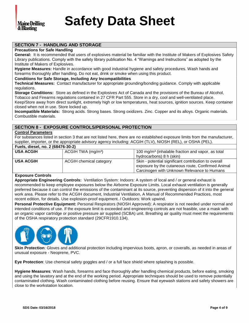
SDS Date: 03/16/2018 Page 4 of 9
Safety Data Sheet ssssSSherrSheetSSheeSheet
SECTION 7 - HANDLING AND STORAGE
Precautions for Safe Handling General: It is recommended that users of explosives material be familiar with the Institute of Makers of Explosives Safety Library publications. Comply with the safety library publication No. 4 “Warnings and Instructions” as adopted by the Institute of Makers of Explosives. Hygiene Measures: Handle in accordance with good industrial hygiene and safety procedures. Wash hands and forearms thoroughly after handling. Do not eat, drink or smoke when using this product.
Conditions for Safe Storage, Including Any Incompatibilities Technical Measures: Contact manufacturer for appropriate grounding/bonding guidance. Comply with applicable regulations. Storage Conditions: Store as defined in the Explosives Act of Canada and the provisions of the Bureau of Alcohol, Tobacco and Firearms regulations contained in 27 CFR Part 555. Store in a dry, cool and well-ventilated place. Keep/Store away from direct sunlight, extremely high or low temperatures, heat sources, ignition sources. Keep container closed when not in use. Store locked up. Incompatible Materials: Strong acids. Strong bases. Strong oxidizers. Zinc. Copper and its alloys. Organic materials. Combustible materials.
SECTION 8 - EXPOSURE CONTROLS/PERSONAL PROTECTION Control Parameters For substances listed in section 3 that are not listed here, there are no established exposure limits from the manufacturer, supplier, importer, or the appropriate advisory agency including: ACGIH (TLV), NIOSH (REL), or OSHA (PEL).
Fuels, diesel, no. 2 (68476-30-2)
USA ACGIH ACGIH TWA (mg/m³) 100 mg/m³ (inhalable fraction and vapor, as total hydrocarbons) 8 h (skin)
USA ACGIH ACGIH chemical category Skin - potential significant contribution to overall exposure by the cutaneous route, Confirmed Animal Carcinogen with Unknown Relevance to Humans
Exposure Controls Appropriate Engineering Controls: Ventilation System: Indoors: A system of local and / or general exhaust is recommended to keep employee exposures below the Airborne Exposure Limits. Local exhaust ventilation is generally preferred because it can control the emissions of the contaminant at its source, preventing dispersion of it into the general work area. Please refer to the ACGIH document, Industrial Ventilation, A Manual of Recommended Practices, most recent edition, for details. Use explosion-proof equipment. / Outdoors: Work upwind.
Personal Protective Equipment: Personal Respirators (NIOSH Approved): A respirator is not needed under normal and intended conditions of use. If the exposure limit is exceeded and engineering controls are not feasible, use a mask with an organic vapor cartridge or positive pressure air supplied (SCBA) unit. Breathing air quality must meet the requirements of the OSHA respiratory protection standard (29CFR1910.134).
Skin Protection: Gloves and additional protection including impervious boots, apron, or coveralls, as needed in areas of unusual exposure - Neoprene, PVC. Eye Protection: Use chemical safety goggles and / or a full face shield where splashing is possible. Hygiene Measures: Wash hands, forearms and face thoroughly after handling chemical products, before eating, smoking and using the lavatory and at the end of the working period. Appropriate techniques should be used to remove potentially contaminated clothing. Wash contaminated clothing before reusing. Ensure that eyewash stations and safety showers are close to the workstation location.
SDS Date: 03/16/2018 Page 5 of 9
Safety Data Sheet ssssSSherrSheetSSheeSheet
SECTION 9 - PHYSICAL AND CHEMICAL PROPERTIES
Information on Basic Physical and Chemical Properties
Physical State : Solid
Appearance : White to tan colored thick cream. If aluminim is present, gray metal particles will be visible. If ammonium nitrate prill is present, white to tan colored granules will be visible.
Odor : Slight odor of fuel oil
Odor Threshold : Not available
pH : Not available
Evaporation Rate : Not available
Melting Point : Not available
Freezing Point : Not available
Boiling Point : Not available
Flash Point : 165 °F (74 °C) (PMCC)
Auto-ignition Temperature : Not available
Decomposition Temperature : Not available
Flammability (solid, gas) : Not available
Lower Flammable Limit : Not available
Upper Flammable Limit : Not available
Vapor Pressure : Not available
Relative Vapor Density at 20 °C : Not available
Density : Not available Specific Gravity : 1.20 – 1.30
Solubility : Not available
Partition Coefficient: N-Octanol/Water : Not available
Viscosity : Not available
Explosive properties : Explosive; fire, blast or projection hazard
Explosion Data – Sensitivity to Mechanical Impact
: Not expected to present an explosion hazard due to mechanical impact.
Explosion Data – Sensitivity to Static Discharge
: Not expected to present an explosion hazard due to static discharge.
SECTION 10 - STABILITY AND REACTIVITY
Reactivity: May cause or intensify fire; oxidizer. May accelerate the burning of other combustible materials. Contact with organic material or combustible material may cause an explosive situation.
Chemical Stability: Stable under recommended handling and storage conditions (see section 7). May explode when subjected to fire, supersonic shock or high-energy projectile impact, especially when confined or in large quantities.
Possibility of Hazardous Reactions: Hazardous polymerization will not occur.
Conditions to Avoid: Avoid temperatures above (212°F (100°C).
Incompatible Materials: Avoid all contamination, especially peroxides and chlorates. Alkaline contamination may liberate ammonia fumes.
Hazardous Decomposition Products: Gaseous nitrogen oxides and carbon oxides: Toxic decomposition products including carbon monoxide (CO) may migrate to off blast-site areas.
SECTION 11 - TOXICOLOGICAL INFORMATION
Information on Toxicological Effects - Product Acute Toxicity: Not classified LD50 and LC50 Data: Not available
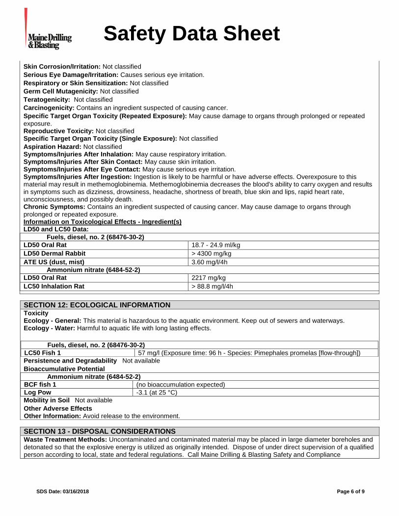
SDS Date: 03/16/2018 Page 6 of 9
Safety Data Sheet ssssSSherrSheetSSheeSheet
Skin Corrosion/Irritation: Not classified
Serious Eye Damage/Irritation: Causes serious eye irritation.
Respiratory or Skin Sensitization: Not classified
Germ Cell Mutagenicity: Not classified
Teratogenicity: Not classified
Carcinogenicity: Contains an ingredient suspected of causing cancer.
Specific Target Organ Toxicity (Repeated Exposure): May cause damage to organs through prolonged or repeated exposure. Reproductive Toxicity: Not classified Specific Target Organ Toxicity (Single Exposure): Not classified
Aspiration Hazard: Not classified Symptoms/Injuries After Inhalation: May cause respiratory irritation. Symptoms/Injuries After Skin Contact: May cause skin irritation. Symptoms/Injuries After Eye Contact: May cause serious eye irritation. Symptoms/Injuries After Ingestion: Ingestion is likely to be harmful or have adverse effects. Overexposure to this material may result in methemoglobinemia. Methemoglobinemia decreases the blood's ability to carry oxygen and results in symptoms such as dizziness, drowsiness, headache, shortness of breath, blue skin and lips, rapid heart rate, unconsciousness, and possibly death. Chronic Symptoms: Contains an ingredient suspected of causing cancer. May cause damage to organs through prolonged or repeated exposure. Information on Toxicological Effects - Ingredient(s) LD50 and LC50 Data:
Fuels, diesel, no. 2 (68476-30-2)
LD50 Oral Rat 18.7 - 24.9 ml/kg
LD50 Dermal Rabbit > 4300 mg/kg
ATE US (dust, mist) 3.60 mg/l/4h
Ammonium nitrate (6484-52-2)
LD50 Oral Rat 2217 mg/kg
LC50 Inhalation Rat > 88.8 mg/l/4h
SECTION 12: ECOLOGICAL INFORMATION Toxicity Ecology - General: This material is hazardous to the aquatic environment. Keep out of sewers and waterways. Ecology - Water: Harmful to aquatic life with long lasting effects.
Fuels, diesel, no. 2 (68476-30-2)
LC50 Fish 1 57 mg/l (Exposure time: 96 h - Species: Pimephales promelas [flow-through])
Persistence and Degradability Not available
Bioaccumulative Potential
Ammonium nitrate (6484-52-2)
BCF fish 1 (no bioaccumulation expected)
Log Pow -3.1 (at 25 °C)
Mobility in Soil Not available
Other Adverse Effects Other Information: Avoid release to the environment.
SECTION 13 - DISPOSAL CONSIDERATIONS
Waste Treatment Methods: Uncontaminated and contaminated material may be placed in large diameter boreholes and detonated so that the explosive energy is utilized as originally intended. Dispose of under direct supervision of a qualified person according to local, state and federal regulations. Call Maine Drilling & Blasting Safety and Compliance
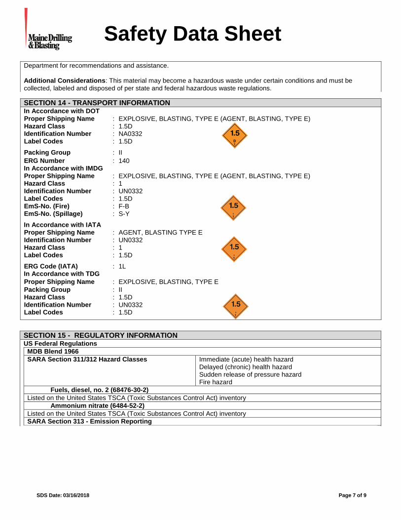
SDS Date: 03/16/2018 Page 7 of 9
Safety Data Sheet ssssSSherrSheetSSheeSheet
Department for recommendations and assistance. Additional Considerations: This material may become a hazardous waste under certain conditions and must be collected, labeled and disposed of per state and federal hazardous waste regulations.
SECTION 14 - TRANSPORT INFORMATION In Accordance with DOT Proper Shipping Name : EXPLOSIVE, BLASTING, TYPE E (AGENT, BLASTING, TYPE E) Hazard Class : 1.5D
Identification Number : NA0332 Label Codes : 1.5D
Packing Group : II
ERG Number : 140 In Accordance with IMDG Proper Shipping Name : EXPLOSIVE, BLASTING, TYPE E (AGENT, BLASTING, TYPE E) Hazard Class : 1 Identification Number : UN0332 Label Codes : 1.5D
EmS-No. (Fire) : F-B EmS-No. (Spillage) : S-Y
In Accordance with IATA Proper Shipping Name : AGENT, BLASTING TYPE E Identification Number : UN0332
Hazard Class : 1 Label Codes : 1.5D
ERG Code (IATA) : 1L In Accordance with TDG
Proper Shipping Name : EXPLOSIVE, BLASTING, TYPE E
Packing Group : II Hazard Class : 1.5D
Identification Number : UN0332 Label Codes : 1.5D
SECTION 15 - REGULATORY INFORMATION US Federal Regulations
MDB Blend 1966
SARA Section 311/312 Hazard Classes Immediate (acute) health hazard Delayed (chronic) health hazard Sudden release of pressure hazard Fire hazard
Fuels, diesel, no. 2 (68476-30-2)
Listed on the United States TSCA (Toxic Substances Control Act) inventory
Ammonium nitrate (6484-52-2)
Listed on the United States TSCA (Toxic Substances Control Act) inventory
SARA Section 313 - Emission Reporting 1.0 % (dust or fume only)
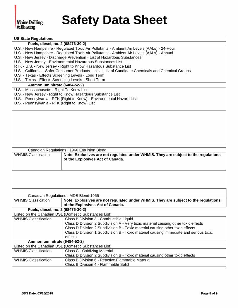
SDS Date: 03/16/2018 Page 8 of 9
Safety Data Sheet ssssSSherrSheetSSheeSheet
US State Regulations
Fuels, diesel, no. 2 (68476-30-2)
U.S. - New Hampshire - Regulated Toxic Air Pollutants - Ambient Air Levels (AALs) - 24-Hour U.S. - New Hampshire - Regulated Toxic Air Pollutants - Ambient Air Levels (AALs) - Annual U.S. - New Jersey - Discharge Prevention - List of Hazardous Substances U.S. - New Jersey - Environmental Hazardous Substances List RTK - U.S. - New Jersey - Right to Know Hazardous Substance List U.S. - California - Safer Consumer Products - Initial List of Candidate Chemicals and Chemical Groups U.S. - Texas - Effects Screening Levels - Long Term U.S. - Texas - Effects Screening Levels - Short Term
Ammonium nitrate (6484-52-2)
U.S. - Massachusetts - Right To Know List U.S. - New Jersey - Right to Know Hazardous Substance List U.S. - Pennsylvania - RTK (Right to Know) - Environmental Hazard List U.S. - Pennsylvania - RTK (Right to Know) List
Canadian Regulations 1966 Emulsion Blend
WHMIS Classication Note: Explosives are not regulated under WHMIS. They are subject to the regulations of the Explosives Act of Canada.
Canadian Regulations MDB Blend 1966
WHMIS Classication Note: Explosives are not regulated under WHMIS. They are subject to the regulations of the Explosives Act of Canada.
Fuels, diesel, no. 2 (68476-30-2)
Listed on the Canadian DSL (Domestic Substances List)
WHMIS Classification Class B Division 3 - Combustible Liquid Class D Division 2 Subdivision A - Very toxic material causing other toxic effects Class D Division 2 Subdivision B - Toxic material causing other toxic effects Class D Division 1 Subdivision B - Toxic material causing immediate and serious toxic effects
Ammonium nitrate (6484-52-2)
Listed on the Canadian DSL (Domestic Substances List)
WHMIS Classification Class C - Oxidizing Material Class D Division 2 Subdivision B - Toxic material causing other toxic effects
WHMIS Classification Class B Division 6 - Reactive Flammable Material Class B Division 4 - Flammable Solid
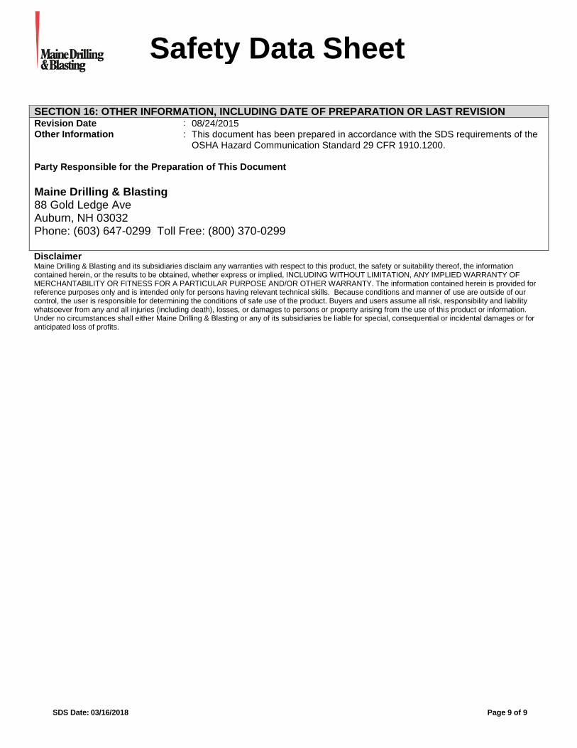
SDS Date: 03/16/2018 Page 9 of 9
Safety Data Sheet ssssSSherrSheetSSheeSheet
Disclaimer Maine Drilling & Blasting and its subsidiaries disclaim any warranties with respect to this product, the safety or suitability thereof, the information contained herein, or the results to be obtained, whether express or implied, INCLUDING WITHOUT LIMITATION, ANY IMPLIED WARRANTY OF MERCHANTABILITY OR FITNESS FOR A PARTICULAR PURPOSE AND/OR OTHER WARRANTY. The information contained herein is provided for reference purposes only and is intended only for persons having relevant technical skills. Because conditions and manner of use are outside of our control, the user is responsible for determining the conditions of safe use of the product. Buyers and users assume all risk, responsibility and liability whatsoever from any and all injuries (including death), losses, or damages to persons or property arising from the use of this product or information. Under no circumstances shall either Maine Drilling & Blasting or any of its subsidiaries be liable for special, consequential or incidental damages or for anticipated loss of profits.
SECTION 16: OTHER INFORMATION, INCLUDING DATE OF PREPARATION OR LAST REVISION Revision Date : 08/24/2015 Other Information : This document has been prepared in accordance with the SDS requirements of the
OSHA Hazard Communication Standard 29 CFR 1910.1200.
Party Responsible for the Preparation of This Document
Maine Drilling & Blasting 88 Gold Ledge Ave Auburn, NH 03032 Phone: (603) 647-0299 Toll Free: (800) 370-0299

Setting Earth-Shattering Standards Since 1966 • www.mainedrilling.com
USBM Appendix B Alternative Blasting Level Criteria
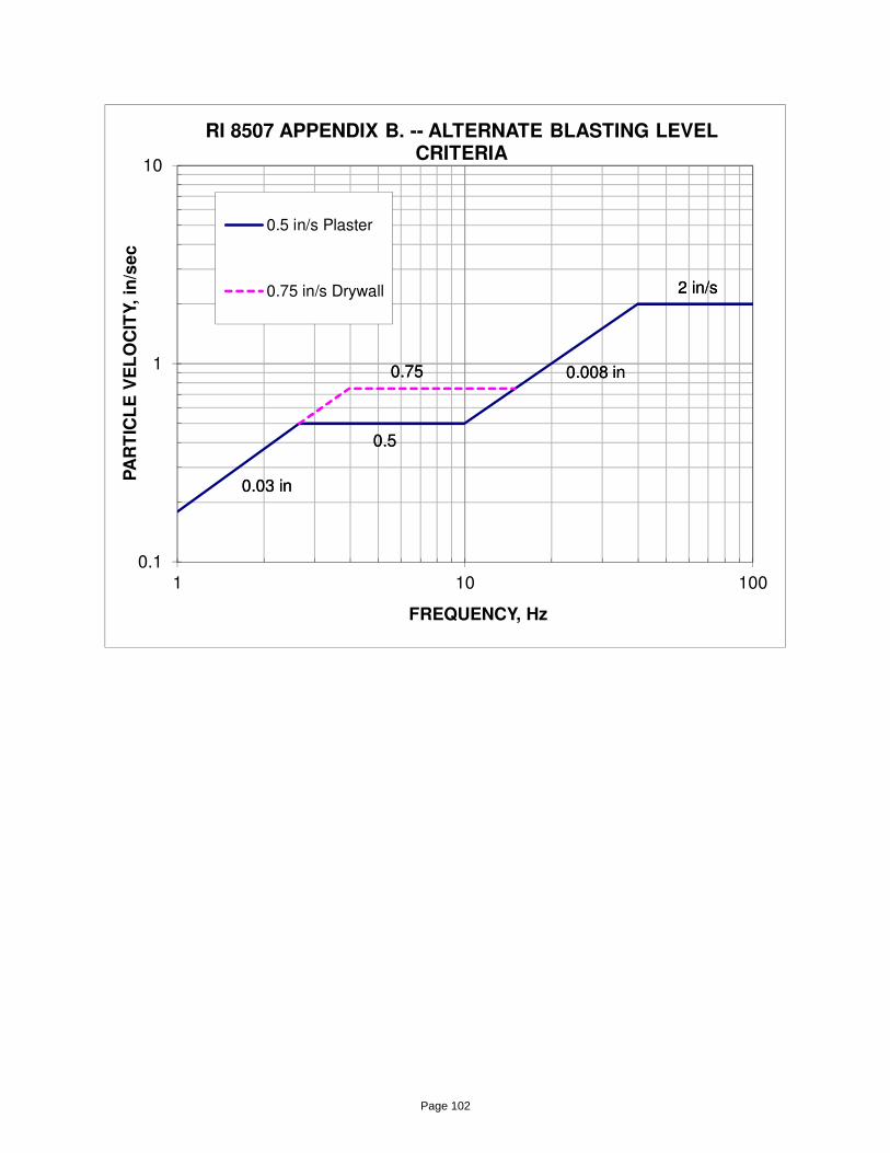
0.1
1
10
1 10 100
PA
RT
ICL
E V
EL
OC
ITY,
in/s
ec
FREQUENCY, Hz
RI 8507 APPENDIX B. -- ALTERNATE BLASTING LEVEL CRITERIA
0.5 in/s Plaster
0.75 in/s Drywall
0.03 in
0.008 in
2 in/s
0.5
0.75
0.03 in
0.008 in
2 in/s
0.5
0.75
Page 102
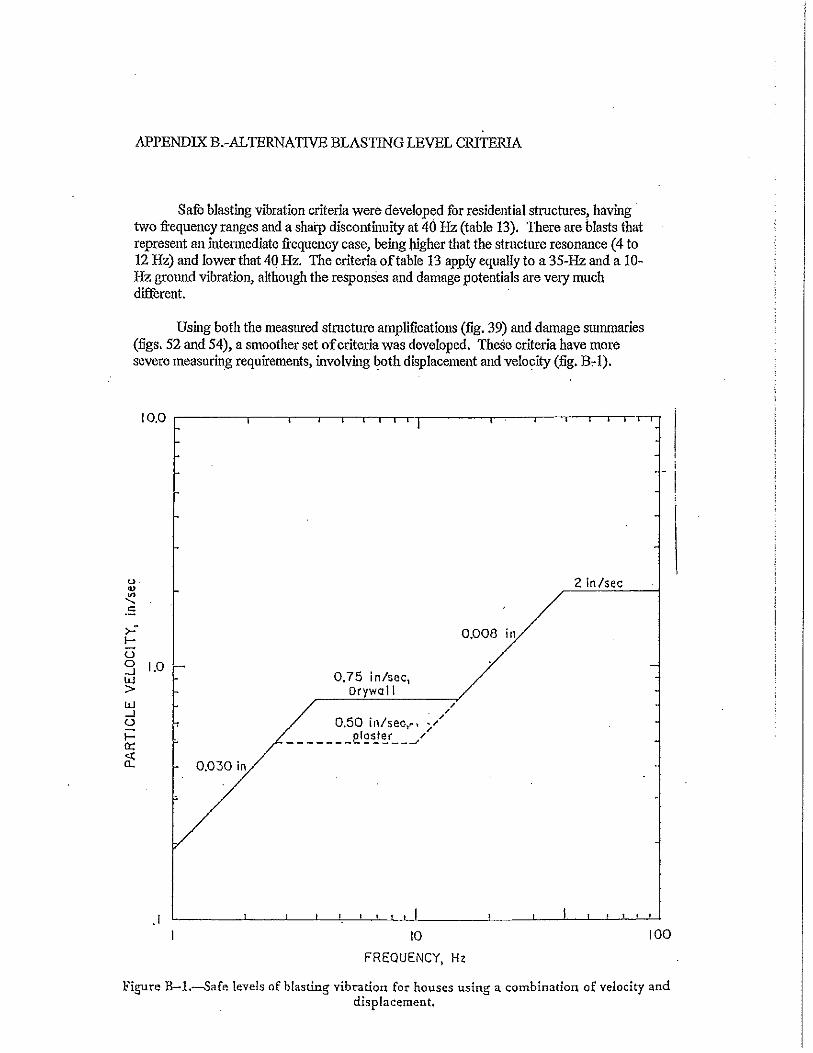

Setting Earth-Shattering Standards Since 1966 • www.mainedrilling.com
Sample Blast Report
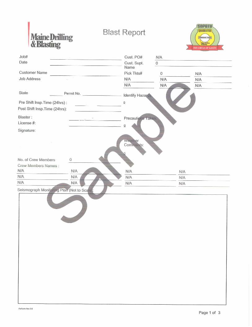
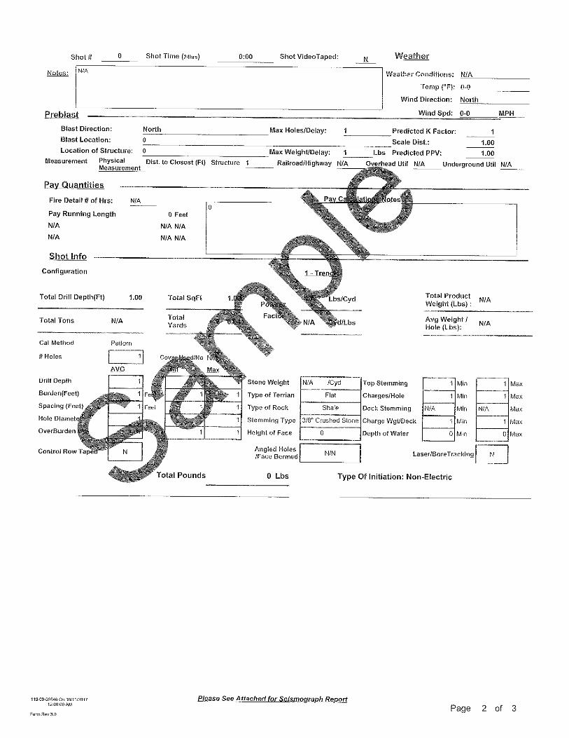
Setting Earth-Shattering Standards Since 1966 • www.mainedrilling.com
WoodsCan Electric Air Horn- Audible Device for Blast Notification

WoodsCan HornetRechargeable Electric Air HornThe world’s most advanced portable signaling device for industrial and commercial safety
I have been using the WoodsCan blasting horn on
a daily basis for urban and downtown blasting
procedures since it was first introduced. Never
would I want to go back to an aerosol device. With
the in-truck quick charge, I have never yet been in
a position where my signal warning device fails to
work. In my line of work this is imperative. Every
blaster that I come in contact with either has one
or wants one...they work!Bruce Rowell - Western Grater Contracting, Ltd.
Reliable• A consistent 120+ decibels of sound• Reliable even in cold weather• Improves crew productivity over
disposable compressed gas air horns
Safe• No frostbite from leaking gas cans• No more explosion risks in hot weather• Transportable on an airplane
Go Green• No more metal cans to dispose of• No more tetrafluoroethane (potent
greenhouse gas) discharged into the atmosphere
• Ozone friendly
Cost Effective• Pays for itself within a few months• Save hundreds the first year alone• Save more each year thereafter

WoodsCan Hornet product highlights:
• Cost-effective signaling device
• Extremely reliable – no more leaky gas cans
• Consistent 120 decibels of sound
• High intensity LED light
• Patented design
• Over 500 one-second pulls per charge
• Rechargeable 14 volt lithium-ion battery
• 30 minute charge time
• Easy to operate
• Environmentally friendly with no greenhouse gas discharged
• Six month limited warranty
Each WoodsCan Hornet kit includes:
• WoodsCan Hornet electric air horn
• 14 volt rechargeable lithium-ion battery
• Charger (120 or 230 VAC)
• 12 volt inverter
• Durable carrying case
• (Optional) second lithium-ion battery
• User’s manual
• Mining
• Quarrying
• Construction
• Seismic Exploration
• Animal Control
• Special Events
• Many more…
Regardless of your application, the WoodsCan Hornet will meet your signaling needs:
For more information, contact us at [email protected] or visit: www.woodscan.com