stability assessment of soil slopes subject to blasting ... - hkie
TRANSCRIPT

HKIE TRANSACTIONS, 2016VOL. 23, NO. 3, 130–137http://dx.doi.org/10.1080/1023697X.2016.1201438
Stability assessment of soil slopes subject to blasting vibrations based on timehistory analyses
Raymond C H Koo, Julian S H Kwan and Eric H Y Sze
Geotechnical Engineering Office, Civil Engineering and Development Department, the HKSAR Government, Hong Kong, People’s Republicof China
ABSTRACTTechnical guidelines on using a pseudo-static method to analytically assess the stability of soilslopes subject to the effects of blasting vibrations have been implemented since the early 1990sinHong Kong. Thismethod,which simplifies the blasting action into an equivalent static blastingforce, does not consider the dynamic nature of transient blastingwaves or the frequency contentthat affects the soil dynamic responses. This paper presents a study of the recent technical devel-opments of the subject and recommends a time history analysis for slope stability assessment toaccount for the effects of blasting vibrations. The proposedmethodmakes use of the representa-tive time histories of blasting vibrations of bedrock derived from the actual site monitoring dataand a numerical site response analysis to assess the dynamic stability of soil slopes. It allows arefinement of the limiting peak particle velocity of slopes in a rational and practical manner. Thepotential of using time history analyses as an alternative, less conservative approach via the con-sideration of blasting frequency and energy contents is demonstrated. This advanced numericalmethod can be also applied elsewhere with recorded blasting monitoring.
ARTICLE HISTORYReceived 21 April 2015Accepted 10 June 2016
KEYWORDSSlopes; stability assessment;blasting; time historyanalysis; Hong Kong
1. Introduction
An analysis of slope stability which takes into con-sideration the effects of blasting vibrations is some-times required in local engineering practice, as stip-ulated by the Geotechnical Engineering Office (GEO)of the Civil Engineering and Development Department(CEDD) of the HKSAR Government.[1] The pseudo-static methodology presented in GEO Report No. 15 isoften used for analysing non-degrading soil slope sta-bility when conducting blasting assessments.[2] Thismethod applies an equivalent static blasting force to thefeature under consideration within a limit equilibriumanalysis. However, it does not consider the dynamicnature of the transient blasting waves or the frequencycontent that affects the soil’s dynamic responses. Incontrast, it is noted from recent technical publicationsthat more rigorous dynamic assessments, which usedsite-specific time history analyses, are becoming morecommon in engineering practice.[3,4] In order to havea better understanding of the dynamic effects of blast-ing on the stability of soil slopes and boulders, thispaper presents a pilot study which examines the effectsof blasting on slopes based on non-linear and dynamicnumerical analyses. Blasting time histories recordedfrom different sites are used as bedrock input beneathslopes within the numerical analyses. The soil slope dis-placements from the numerical analyses are calculated
CONTACT Raymond C H Koo [email protected]
based on a range of blasting records with a peak particlevelocity (PPV) ranging from 25mm/s to 100mm/s.
2. Assessment of the stability ofnon-degrading soil slopes subject toblasting vibrations
Wong and Pang [2] proposed a pseudo-static approachto assess the stability of non-degrading soil slopes sub-ject to blasting vibrations. The approach adopts limitequilibrium analysis in which horizontal accelerationis applied to potential failure mass on a slope. Thehorizontal acceleration correlates with the peak parti-cle acceleration induced by the blasting operation. Inorder to take into account the dynamic response ofslopes, the peak particle acceleration is modified by amagnification factor (Ka). The value of Ka is calcu-lated from a multi-degree-of-freedom model (Figure 1shows the case of a dry slope on horizontal bedrock).The analytical solution developed by Ambraseys [5] isadopted with the assumption that the input bedrockvibration is represented by an infinite harmonicmotionwith a frequency of 30Hz. Interaction between sloperesponses induced from different frequencies of blast-ing vibrations is not considered. Experience shows thatthe pseudo-static approach produces a conservativeestimate of the critical peak particle velocity (PPVc)
© 2016 The Hong Kong Institution of Engineers

131
Figure 1. Pseudo-static approach for assessing the stability of soil slopes subject to blasting vibrations.[2]
of soil slopes. Enhancement of this approach could bemade by considering a suitable time history of blast-ing vibrations, instead of the simple assumption of a30Hz harmonic motion. The use of a single frequencyof vibration was also proposed by Chen et al. [6] toassess the dynamic stability of rock slopes based on thelimit equilibrium analysis with attenuation of blastingvibration calculated based on an empirical factor.
Recent technical development work on blastingassessment of non-degrading soil slopes focuses onthe application of numerical analysis. Kwong andLo [7] and Koo et al. [8] used the computer pro-grammes QUAKE/W and fast lagrangian analysis ofcontinua (FLAC), respectively to study the dynamicresponse of soil slopes subjected to blasting vibra-tions. When undertaking numerical analysis, represen-tative or design time histories of blasting vibrations areneeded. Analyses which consider the vibration timehistories have been applied extensively to the assess-ment of the blasting vibration limits of structures. DaiandChen [9] andChen et al. [10] proposed that the rep-resentative or design vibration time history of a specificsite could be obtained by considering the envelope ofthe response spectra of blasting vibrations recorded onthe site.
More recently, Kong [11] proposed a methodologyfor assessing the PPVc of the soil slopes. The method-ology considers the stress state of a soil element in themiddle portion of an assumed landslide slip plane inthe soil slope and calculates the disturbing stress thatwould cause failure of the slip plane based on Mohrcircle analysis. The PPVc is then determined using thecompressive wave stress equation for elastic materialsas presented by Kong.[11] Kong’s methodology does
not consider the transient nature of blasting vibrationsand in many situations consistently produces smallerPPVc values compared to the pseudo-static approachsuggested by Wong and Pang [2].
3. Proposed pseudo-static approach usingtime history analysis
It is proposed that a numerical site response analysiswhich considers representative time histories of blast-ing vibrations of bedrock can be adopted to establish thevalues ofKa for site-specific applications (Figure 2). Therepresentative time history can be established based onthe envelope of bedrock vibration response spectra.[12]Chen et al. [10], Conner et al. [13] and Dowding [14]described the procedures for developing the responsespectra for blasting sites in the United States (US)for evaluating the blasting limits of structures. Lamet al. [15] also carried out parametric studies involv-ing time history analyses of simple cantilevered wallmodels subject to the blasting loads that were based onresponse spectrum solutions. The stability assessmentof cantilevered walls subject to blasting vibration canbe designed according to a simple response spectrummodel were demonstrated.
An example which uses the monitoring data col-lected during the Anderson Road RedevelopmentProject is used for demonstrating the approach illus-trated in Figure 2. Details of the site conditions, blast-ing design, monitoring scheme including instrumenta-tion used, were documented by Lam [16]. The blast-ing vibrations were recorded using geophones of threeorthogonal directions on rock sites. Figure 3 shows oneof the radial velocity time history records. It is noted
HKIE TRANSACTIONS

132
Figure 2. Proposed methodology for establishing the value of Ka based on the time history analysis.
Figure 3. Velocity time history of a blasting record (Test 9B).
Period (second)
Figure 4. Radial velocity response spectra.
that the deduced peak particle acceleration (PPA) of themonitoring record shown in Figure 3 is as high as 65%of g, but the peak horizontal displacement is less than1mm. Time traces of the radial velocity are convertedto the response spectra based on a single-degree-of-freedom model. The conversion of the velocity timehistory data into velocity spectra can be performedusing typical response spectrum analysis tools. Theseresponse spectra are obtained by firstly normalising the
Table 1. Plan distances betweenmonitoring points and sourceof blasting and the PPV recorded.
Test No.Plan distances between monitoringpoint and source of blasting (m) PPV(mm/s)
Test 15 23 101Test 3 10 70Test 9B 17 32Test 5 32 29Test 9C 22 25Test 18 21 23
velocity time history via the corresponding PPV andthen converting the normalised data into the responsespectra. The so-generated normalised response spectrausing data collected at different locations of the site arepresented in Figure 4. The proposed distances betweenthe monitoring points and the source of blasting as wellas the PPV measured are summarised in Table 1. Theresponse spectra comprise similar frequency content(i.e. they are of a similar shape). The peak responseappears at about 0.03 seconds (i.e. 30Hz). The reddashed line in Figure 4 represents the envelope of theresponse spectra, which is used to obtain a represen-tative time history of the radial velocity for the siteresponse analysis.
With the envelope response spectrum, a timehistory of the radial velocity which represents thebedrock vibrations induced by the blasting opera-tion can be determined using the frequency analysis
R. C. H. KOO ET AL.

133
Figure 5. Magnification factor (Ka) calculated based on the site-specific velocity time history at the Anderson Road.Note: S = shear wave velocity.
programmes.[18] The duration of this specified velocitytime history should tally with the measured records.
The numerical package Oasys SIREN [19] – a one-dimensional dynamic explicit finite difference pro-gramme – was used in this study to carry out thetime history dynamic analyses. In SIREN, the groundcondition is modelled as a column of soil overlyingbedrock. Other programmes can also be used to per-form the blasting assessment if appropriate. Propertiesare assigned to the bedrock and the soil is modelled bya non-linear stress-strain curve with hysteresis effects.Excitation in the form of a time history is appliedat bedrock level and an explicit numerical analysis iscarried out to calculate the soil response over time.Such a modelling technique suggests that the proposedmethod is applicable to the cases where the blastingsource is located in certain distance away from theslope. This echoes the engineering need, as blastingis mostly avoided close to the slopes due to stabilityconcerns. The shear wave velocity (S) of the soil isassumed to be 300m/s, while the S value of rock isassumed to be 1500m/s. The densities (γ ) of the soiland rock are taken to be 1900 kg/m3 and 2500 kg/m3,respectively.
Calibration of the numerical model was carried outbased on a 30Hz harmonic motion at the bedrock levelto identify an appropriate value of viscous dampingof 0.3%, with a view to reproducing the Ka values ofWong and Pang [2]. Figure 5 shows the values of Kaestablished using the radial velocity time history gener-ated, based on the frequency spectrum envelope of theAnderson Road (Figure 4). The PPV of the radial veloc-ity time history is scaled to 30mm/s, which is compa-rable to the typical PPV values observed on-site. Thevalues are overlain on theKa chart as reported byWongand Pang [2], represented by solid lines for comparison.A reduction in the Ka values of 20% to 40% is obtained,which is represented by the broken lines. This can resultfrom the interaction between slope responses induced
by different frequencies of the blasting vibrations asconsidered explicitly in the time history analysis.
4. Advanced numerical dynamic analysis
Apart from the pseudo-static analysis, the possibleuse of advanced numerical dynamic analysis has beenexplored. Nowadays, dynamic analysis of soil slopesis a common module for finite-element and finite-difference numerical packages. To demonstrate thepotential application of the numerical dynamic analy-sis for blasting assessments, the numerical package ofthe FLAC dynamic version 7.0 [20] is adopted as anillustrative example. The FLAC uses the explicit finite-difference method to solve the full equation of motionusing the lumped grid point mass derived from the sur-rounding finite elements, and it uses a Lagrangian pro-cedure for coping with large deformations. The FLAChas been used extensively to model dams and slopesin dynamic analyses.[3,21,22] The application of theFLAC for dynamic analysis has been validated withother well-accepted one-dimensional non-linear soilresponse analysis programmes.[23]
The illustrative example considers a soil cut slopeof 10m in height with a slope angle of 45°. The slopecomprises completely decomposed granite (CDG)underlain by moderately decomposed granite (MDG)(Figure 6). The slope is assumed to be dry. The effect ofsuction on the dry slope, which is positive to slope sta-bility, is not included in the analysis. In practice, designwater conditions established from groundwater moni-toring data and site observations can be incorporatedinto the numerical analysis. The material propertiesare determined from the range of parameters recom-mended by the GEO [24] (Tables 2 and 3). The staticfactor of safety (FoS) of the slope determined using theMorgenstern and Price [25] method of slices is 1.15.
Leung et al. [17] carried out physical dynamictests on CDG in Hong Kong using laboratory bender
HKIE TRANSACTIONS

134
Figure 6. FLAC model of a 45° cut slope.
Table 2. Material properties of CDG.
Soil model Input parameters
Failure criterion Mohr-CoulombEffective cohesion (c′) 5 kPaAngle of shear resistance (φ′) 37°Density (ρ) 1900 kg/m3
Poisson’s ratio (ν) 0.3Shear wave velocity (S) 300m/sInitial shear modulus (G0 = γ S2) 171MPaShear modulus degradation (G/G0) Leung et al. [17]
Table 3. Material properties of MDG.
Rock model Input parameters
Material property ElasticDensity (ρ) 2500 kg/m3
Poisson’s ratio (ν) 0.25Shear wave velocity (S) 1500m/sInitial shear modulus (G0 = γ S2) 5625MPa
element tests to determine the small strain shear mod-ulus (G0) of CDG. They also reported the cyclic triaxialtest results pertaining to the shearmodulus degradation(G/G0) and hysteretic damping ratio of the soil. Thereported dynamic soil properties have been adopted inthe present numerical analysis.
The boundary conditions of the numericalmodel areshown in Figure 6. The boundary at the base of themodel moves in the x-direction following the velocitytime history generated based on the envelope of theresponse spectra (Figure 4). Free-field boundaries arespecified at the vertical boundaries to simulate an infi-nite domain and to ensure that dynamic waves are notreflected at these side boundaries. The time required toset up amodel depends on the experience of the person-nel. The numerical model of the present analysis tookaround 24 man hours for the professionals to set up.The mesh size of the model is selected to provide accu-rate wave transmission based upon the premise thata maximum frequency of 1000Hz can be transmitted.The grid size of the soil model is 0.2m × 0.2m, and asensitivity analysis has been carried out to ensure thatthe effect of further reducing the grid size does nothave a significant impact on the numerical result. Thetime step employed is sufficiently small to cater for themaximum frequency.
Prior to the dynamic analysis, the model is ini-tialised with gravitational acceleration applied to estab-lish internal forces within the computation domain. Inthis example, the calculated shear strain of the slope
after initialisation is 0.02%. An input blasting vibrationin the form of a time history is applied to the bottomhorizontal boundary of the bedrock level underneaththe slope. This loading method corresponds to thedistant-source blasting scenario, which is the primaryfocus of this study. Nevertheless, since the proposedtime history method has taken into account differentfrequency contents, it is also considered applicable tonear-source blasting, in which loading is in the form ofa high-frequency impulse. Furthermore, only the hor-izontal time history component is considered becausevertical acceleration attenuatesmuchmore rapidly thanhorizontal acceleration, rendering it less critical to theanalysis. Such observations have also been made inactual blasting site measurements.[16]
Figure 7 presents the calculated dynamically-inducedhorizontal displacements and displacement vectors ofthe slope where the PPV of the input velocity time his-tory is specified as 30mm/s, which corresponds to thecommon control limit of the PPV on-site. The calcu-lated maximum displacement vector is 5mm and thecalculated maximum shear strain induced is less than1% (Figure 8).
The PPVc of the above slope model was calcu-lated using the pseudo-static approach. The FoS of theslope model is 1.15. A constant horizontal accelera-tion required to give an FoS of the slope of unity is0.1 g. Based on the pseudo-static approach fromWongand Pang [2], the calculated PPVc is 12mm/s, withKa = 0.2763 for y/H = 1 and S/H = 30. If the mod-ified Ka value of 0.17 determined by the time historyanalysis is used, the corresponding PPVc of the slopebecomes 20mm/s. The fact that vertical acceleration isnot modelled to compute the FoS is explained above.
The PPVc can also be determined using the FLACanalyses. A series of analyses was carried out to investi-gate the dynamic responses of the above slope modelsubject to different PPV levels of blasting motions.Assessment of the PPVc should be based on the max-imum shear strain, which includes the shear strain ofthe slope before blasting and the dynamically-inducedstrain due to blasting. In the present example, the shearstrain of the slope before blasting is taken as the calcu-lated shear strain after the initialisation of the numeri-cal model, i.e. 0.02%. In practice, the shear strain beforeblasting should be assessed with consideration of theconditions observed on-site, the development historyand the failure/movement records, if any, of the slope.Figure 9 plots the calculated maximum shear strain ofthe slope against the average calculated PPV along theslope surface profile.
The maximum shear strain increases with the aver-age PPV of the slope (Figure 9). It should be notedthat the rate of increase becomes higher when the cal-culated maximum shear strain exceeds 1%. It wouldbe prudent to limit the maximum shear strain at thislevel for this example for serviceability control. With
R. C. H. KOO ET AL.

135
Figure 7. Dynamically-induced horizontal displacement and displacement vector plot.
Figure 8. Dynamically-induced shear strain plot (PPV of the bedrock input motion is 30mm/s).
Figure 9. Maximum shear strain at slip surface against averagePPV calculated at the top of the slope.
this limit, the calculated PPVc of the slope would be25mm/s. Table 4 summarises the PPVc calculated usingdifferent approaches. In addition, capping the maxi-mum shear strains could ensure that the slope deformsin a ductile manner. In practice, the maximum allow-able shear strain may be determined by laboratory test-ing as the limiting strain above which softening of the
Table 4. Summary of the PPVc calculated using differentapproaches.
Approach PPVc
Wong and Pang [2] 12mm/sPseudo-static approach with time history analysis 20mm/sFLAC analysis 25mm/s
soil commences. According to Jibson [26], thePPVcwassensitive to the initial static FoS of the slope. The ini-tial FoS was controlled by the soil strength parameters,slope height, inclination, groundwater conditions, etc.Attention should be paid to the sensitivity of the cal-culated results with respect to the input parameters. Itis recommended to undertake a sensitivity analysis aspart of the assessment of the PPVc.
5. Discussion
The characteristics of blasting-induced ground vibra-tions can be sensitive to various parameters, suchas travel distance, site geology, topography, chargeweights and other factors. Given the variability of theseparameters from site to site, it may not be easy to obtain
HKIE TRANSACTIONS
136
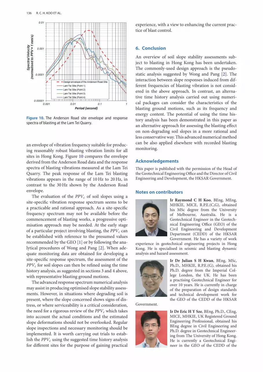
Figure 10. The Anderson Road site envelope and responsespectra of blasting at the Lam Tei Quarry.
an envelope of vibration frequency suitable for produc-ing reasonably robust blasting vibration limits for allsites in Hong Kong. Figure 10 compares the envelopederived from the Anderson Road data and the responsespectra of blasting vibrations measured at the Lam TeiQuarry. The peak response of the Lam Tei blastingvibrations appears in the range of 10Hz to 20Hz, incontrast to the 30Hz shown by the Anderson Roadenvelope.
The evaluation of the PPVc of soil slopes using asite-specific vibration response spectrum seems to bea practicable and rational approach. As a site-specificfrequency spectrum may not be available before thecommencement of blasting works, a progressive opti-misation approach may be needed. At the early stageof a particular project involving blasting, the PPVc canbe established with reference to the presumed valuesrecommended by the GEO [1] or by following the ana-lytical procedures of Wong and Pang [2]. When ade-quate monitoring data are obtained for developing asite-specific response spectrum, the assessment of thePPVc for soil slopes can then be refined using the timehistory analysis, as suggested in sections 3 and 4 above,with representative blasting ground motions.
The advanced response spectrumnumerical analysismay assist in producing optimised slope stability assess-ments. However, in situations where degrading soil ispresent, where the slope concerned shows signs of dis-tress, or where serviceability is a critical consideration,the need for a rigorous review of the PPVc which takesinto account the actual conditions and the estimatedslope deformations should not be overlooked. Regularslope inspections and necessary monitoring should beimplemented. It is worth carrying out trials to estab-lish the PPVc using the suggested time history analysisfor different sites for the purpose of gaining practical
experience, with a view to enhancing the current prac-tice of blast control.
6. Conclusion
An overview of soil slope stability assessments sub-ject to blasting in Hong Kong has been undertaken.The commonly-used design approach is the pseudo-static analysis suggested by Wong and Pang [2]. Theinteraction between slope responses induced from dif-ferent frequencies of blasting vibration is not consid-ered in the above approach. In contrast, an alterna-tive time history analysis carried out using numeri-cal packages can consider the characteristics of theblasting ground motions, such as its frequency andenergy content. The potential of using the time his-tory analysis has been demonstrated in this paper asan alternative approach for assessing the blasting effecton non-degrading soil slopes in a more rational andless conservativeway. This advanced numericalmethodcan be also applied elsewhere with recorded blastingmonitoring.
Acknowledgements
This paper is published with the permission of the Head ofthe Geotechnical EngineeringOffice and theDirector of CivilEngineering and Development, the HKSAR Government.
Notes on contributors
Ir Raymond C H Koo, BEng, MEng,MHKIE, MICE, R.P.E.(C,G), obtainedhis MSc degree from the Universityof Melbourne, Australia. He is aGeotechnical Engineer in the Geotech-nical Engineering Office (GEO) of theCivil Engineering and DevelopmentDepartment (CEDD) of the HKSARGovernment. He has a variety of work
experience in geotechnical engineering projects in HongKong. He is specialised in seismic and blasting dynamicanalysis and hazard assessment.
Ir Dr Julian S H Kwan, BEng, MSc,Ph.D., MHKIE, R.P.E.(G), obtained hisPh.D. degree from the Imperial Col-lege London, the UK. He has beena practising Geotechnical Engineer forover 10 years. He is currently in chargeof the preparation of design standardsand technical development work forthe GEO of the CEDD of the HKSAR
Government.
Ir Dr Eric H Y Sze, BEng, Ph.D., CEng,MICE, MHKIE, UK Registered GroundEngineering Professional, obtained hisBEng degree in Civil Engineering andPh.D. degree in Geotechnical Engineer-ing from The University of Hong Kong.He is currently a Geotechnical Engi-neer in the GEO of the CEDD of the
R. C. H. KOO ET AL.

137
HKSAR Government. His research interests include soildynamics and liquefaction of granular soils.
References
[1] Geotechnical Engineering Office (GEO). New controlframework for soil slopes subjected to blasting vibra-tions. GEO Technical Guidance Note No. 28. HongKong: Geotechnical Engineering Office, Civil Engineer-ing and Development Department, the HKSAR Gov-ernment; 2010. p. 4.
[2] Wong HN, Pang RPL. Assessment of stability ofslopes subjected to blasting vibration. GEO ReportNo. 15. Hong Kong: Geotechnical Engineering Office,Civil Engineering and Development Department, theHKSAR Government; 1992. p. 112.
[3] Marcuson WF, Hynes ME, Franklin AG. Seismicdesign and analysis of embankment dams: the stateof practice. Proc of the 4th Civil Engineering Confer-ence in the Asian Region, June 25–28, Taipei; 2007.p. 15.
[4] Pappin JW, Koo RCH. Procedures for seismic designof below ground structures. Proc of the InternationalWorkshop on Soil-Foundation-Structure Interaction,University of Auckland,NewZealand; 26–27November2009; 2009. p. 201–212.
[5] Ambraseys NN. The seismic stability of earth dams.Proc Sec W Conf Earthquake Eng. 1960;2:1345–1363.
[6] Chen M, Lu WB, Yan P, Zhou CB. New method fordynamic stability analysis of rock slope under blastingvibration based on equivalent acceleration and Sarmamethod. Can Geotech J. 2014;51:441–448.
[7] Kwong AKL, Lo JYC. Finite element study of blast-induced vibration from construction of tunnels withparticular emphasis on its effect to nearby slopes. Procof the 5th Asian Rock Mechanics Symposium 2008(ARMS5), Tehran, Iran, 24-26 November 2008. Inter-national Society for Rock Mechanics; 2008. p. 1093–1100.
[8] Koo RCH, Pappin JW, Rule DC, Wallace MI, Yim IPH.Dynamic analyses of slopes in Hong Kong. Proc ofthe Australian Earthquake Engineering Society AnnualConference, Australian Earthquake Engineering Soci-ety; 2011. p. 12.
[9] Dai K, Chen S. Blast limits for transmission structures.I: response spectra development. J Perform Const FacilASCE. 2010;24:53–60.
[10] Chen C, Zhang YB, Yan GB. Response spectrumanalysis of surface shallow hole blasting vibration.Inform Comput Application C Comput Inform Sci.2010;105:384–389.
[11] KongWK. Blasting assessment of slopes and risks plan-ning. Aust J Civil Eng. 2012;10(2):177–192.
[12] Tedesco JW, McDougal WG, Ross CA. Structuraldynamics theory and applications. Boston: AddisonWesley Longman, Inc.; 1999. p. 816.
[13] Conner E, Dai K, Chen S. A comprehensive blastplan for transmission structures due to mining inducedblasts. Proc of IMAC-XXV: Conference & Expositionon Structural Dynamics; 2007. p. 6.
[14] Dowding CH. Blasting vibration monitoring and con-trol. Englewood Cliffs (NJ): Prentice-Hall; 1985. p. 295.
[15] Lam N, Mendis P, Ngo T. Response spectrum solutionsfor blast loading. El J Struct Eng. 2004;4:28–44.
[16] Lam TSK. Results of blasting vibration test carried outat the development at anderson road project site. CaseReport in File Reference CGME; 2012. p.13.
[17] Leung E, Pappin J, Koo RCH. Determination of smallstrain modulus and degradation for in-situ weatheredrock and old alluvium deposits. Proc of the 15th Inter-national Conference on Recent Advances in Geotech-nical Earthquake Engineering and Soil Dynamics, SanDiego, California; 2010. p. 10.
[18] Hancock J, Watson-Lamprey J, Abrahamson NA, et al.An improved method of matching response spectra ofrecorded earthquake ground motion using wavelets. JEarthquake Eng. 2006;10(1):1–23.
[19] Oasys. Oasys SIRENUser Guide Version 8.0.0.1. Oasys,2006, p. 33. Available from: http://www.gemsoft.us/Siren.htm.
[20] Itasca. FLAC – Fast langrangian analysis of con-tinua, dynamic analysis, version 7, user’s manual. Min-neapolis (MN): Itasca Consulting Group Inc; 2011.p. 283.
[21] Chugh AK, Stark TD. Displacement analysis of a land-slide. Landslides and Avalanches: ICFL 2005 Norway– Proc of the 11th International Conference and FieldTrip on Landslides, Tromso, Norway, September; 2005.p. 73–81.
[22] Cetin KO, Isik NS. A comparative study on the actualand estimated seismic response of Kiralkizi Dam inTurkey. J Earthquake Eng. 2005;9(4):445–460.
[23] Ordonez GA. SHAKE2000 a computer program forthe 1-D analysis of geotechnical earthquake engineer-ing problems, user’s manual. Berkeley: University ofCalifornia; 2011. p. 252.
[24] Geotechnical Engineering Office (GEO). Guide toretaining wall design, 2nd Edition, geoguide 1. HongKong: Geotechnical Engineering Office, Civil Engineer-ing and Development Department, the HKSAR Gov-ernment; 1993. p. 258.
[25] MorgensternNR, Price VE. TheAnalysis of the Stabilityof General Slip Surfaces. Geotechnique. 1965;15:79–93.
[26] Jibson RW. Methods for assessing the stability ofslopes during earthquakes—a retrospective. Eng Geol.2011;122:43–50.
HKIE TRANSACTIONS