introduction to explosives - wordpress.com
TRANSCRIPT

CHAPTER – 1
1
INTRODUCTION TO EXPLOSIVES
1. DEVELOPMENT OF BLACKPOWDER
Blackpowder, also known as gunpowder, was most likely the first explosive
composition. In 220 BC an accident was reported involving blackpowder
when some Chinese alchemists accidentally made black-powder while
separating gold from silver during a low-temperature reaction. According to
Dr Heizo Mambo the alchemists added potassium nitrate [also known as
saltpeter (KNO3)] and sulfur to the gold ore in the alchemists’ furnace but
forgot to add charcoal in the first step of the reaction. Trying to rectify their
error they added charcoal in the last step. Unknown to them they had just
made blackpowder which resulted in a tremendous explosion.
Blackpowder was not introduced into Europe until the 13th century when an
English monk called Roger Bacon in 1249 experimented with potassium
nitrate and produced blackpowder, and in 1320 a German monk called
Berthold Schwartz (although many dispute his existence) studied the
writings of Bacon and began to make blackpowder and study its properties.
The results of Schwartz’s research probably speeded up the adoption of
blackpowder in central Europe. By the end of the 13th century many
countries were using blackpowder as military aid to breach the walls of
castles and cities.
Blackpowder contains a fuel and an oxidizer. The fuel is a powdered mixture
of charcoal and sulfur which is mixed with potassium nitrate (oxidizer). The
mixing process was improved tremendously in 1425 when the Corning, or
granulating, process was developed. Heavy wheels were used to grind and
press the fuels and oxidizer into a solid mass, which was subsequently
Chapter 1 Introduction to Explosives
2
broken down into smaller grains. These grains contained and intimate
mixture of the fuels and oxidizer, resulting in a blackpowder which was
physically superior. Corned blackpowder gradually came into use for small
guns and hand grenades during the 15th century and for big guns in the
16th century. Blackpowder mills (using the Corning process) were erected at
Rotherhithe and Waltham Abbey in England between 1554 and 1603.
The first recording of blackpowder being used in civil engineering was during
1548-1627 blackpowder was used as a blasting aid for recovering ore in
Hungary. Soon, blackpowder was being used for blasting in Germany,
Sweden and other countries. In England, the first use of blackpowder for
blasting was in the Corninsh copper mines in 1670. Bofors Industries of
Sweden was established in 1646 and became the main manufacturer of
commercial blackpowder in Europe.
2. DEVELOPMENT OF NYTROGLYCERINE
By the middle of the 19th century the limitations of blackpowder as a
blasting explosive were becoming apparent. Difficult mining and turnneling
operations required a ‘better’ explosive. In 1846 the Italian, Professor
Ascanio Sobrero discovered liquid nitroglycerine [C3H5O3(NO2)3]. He soon
became aware of the explosive nature of nitroglycerine and discontinued his
investigations. A few years later the Swedish inventor, Immanuel Nobel
developed a process for manufacturing nitroglycerine, and in 1863 he
erected a small manufacturing plant in Helenborg near Stockholm with his
son, Alfred. Their initial manufacturing method was to mix glycerol with a
cooled mixture of nitric and sulfuric acids in stone jugs. The mixture was
strried by hand and kept cool by iced water, after the reaction had gone to
completion the mixture was poured into excess cold water. The second
manufacturing process was to pour glycerol and cooled mixed acids into a
conical lead vessel which had perforations in the constriction. The product
Chapter 1 Introduction to Explosives
3
nitroglycerine flowed through the restrictions into a cold water bath. Both
methods involved the washing of nitroglycerine with warm water and a warm
alkaline solution to remove the acids. Nobel began to license the
construction of nitroglycerine plants which were generally built very close to
the site of intended use, as transportation of liquid nitroglycerine tended to
generate loss of life and property.
The Nobel family suffered many setbacks in marketing nitroglycerine
because it was prone to accidental initiation, and its initiation in bore holes
by blackpowder was unreliable. There were many accidental explosions, one
of which destroyed the Nobel factory in 1864 and killed Alfred’s brother,
Emil. Alfred Nobel in 1864 invented the metal ‘blasting cap’ detonator which
greatly improved the initiation of blackpowder, The detonator contained
mercury fulminate [Hg(CNO)2] and was able to replace black powder for the
initiation of nitroglycerine in bore holes. The mercury fulminate blasting cap
produced an initial shock which was transferred to a separate container of
nitroglycerine via a fuse, initiating the nitroglycerine.
After another major explosion in 1866 which completely demolished the
nitroglycerine factory. Alfred turned his attentions into the safety problems
of transporting nitroglycerine. To reduce the sensitivity of nitroglycerine
Alfred mixed it with an absorbent clay, ‘Kieselguhr’. This mixture became
known as ghur dynamite and was patented in 1867.
Nitroglycerine (1.1) has a great advantage over blackpowder since it contains
both fuel and oxidizer elements in the same molecule. This gives the most
intimate contact for both components.
3. DEVELOPMENT OF MERCURY FULMINATE
Mercury fulminate was first prepared in the 17th century by the Swedish-

Chapter 1 Introduction to Explosives
4
German alchemist, Baron Johann Kunkei von Lőwnstern. He obtained this
dangerous explosive by treating mercury with nitric acid and alcohol. At that
time, Kunkel and other alchemists could not find a use for the explosive and
the compound became forgotten unti Edward Howard of England
rediscovered it between 1799 and 1980. Howard examined the properties of
mercury fulminate and proposed its use as percussion initiator for
blackpowder and in1807 a Scottish Clergyman, Alexander Forsyth patented
the device.
Fig: Nitroglycerine (1.1)
4. DEVELOPMENT OF NITROCELLULOSE
At the same time as nitroglycerine was being prepared, the nitration of
cellulose to produce nitrocellulose (also known as guncotton) was also being
undertaken by different workers, notably Schőbein at Basel and Bőttger at
Frankfurt-am-Main during 1845-47. Earlier in 1833, Braconnot had
nitrated starch, and in 1838, Pelouze, continuing the experiments of
Braconnot, also nitrated paper, cotton and various other materials but did
not realize that he had prepared nitrocellulose. With the announcement by
Schőbein in 1846, and in the same year by Bőttger that nitrocellulose had
been prepared, the names of these two men soon became associated with
the discovery and utilization of nitrocellulose. However, the published
literature at that time contains papers by several investigators on the
nitration of cellulose before the process of Schőnbein was known.

Chapter 1 Introduction to Explosives
5
Many accidents occurred during the preparation of nitrocellulose, and
manufacturing plants were destroyed in France, England and Austria.
During these years, Sir Frederick Abel was working on the instability
problem of nitrocellulose for the British Government at Woolwich and
Waltham Abbey, and in 1865 he published his solution to this problem by
converting nitrocellulose into a pulp. Abel showed through his process of
pulpling, boiling and washing that the stability of nitrocellulose could be
greatly improved. Nitrocellulose was not used in military and commercial
explosives until 1868 when Abel’s assistant, E.A. Brown discovered that dry,
compressed, highly-nitrated nitrocellulose could be detonated using a
mercury fulminate detonator, and wet, compressed nitrocellulose could be
exploded by a small quantity of dry nitrocellulose (the principle of a Booster).
Thus, large blocks of wet nitrocellulose could be used with comparative
safety.
5. DEVELOPMENT OF DYNAMITE
In 1875 Alfred Nobel discovered that on mixing nitrocellulose with
nitroglycerine a gel was formed. This gel was developed to produce blasting
gelatine, gelatine dynamite and later in 1888, ballistite, the first smokeless
powder. Ballistite was a mixture of nitrocellulose, nitroglycerine, benzene
and camphor. In 1889 a rival product of similar composition to ballistite was
patented by the British Government in the names of Abel and Dewar call
‘Cordite’ In its various forms Cordite remained the main propellant of the
British Forces until the 1930s.
In 1867, the Swedish chemists Ohlsson and Norrbin found that the
explosive properties of dynamites were enhanced by the addition of
ammonium nitrate (NH4NO3). Alfred Nobel subsequently acquired the patent
of Ohlsson and Norbbin for ammonium nitrate and used this in his
explosive compositions.
Chapter 1 Introduction to Explosives
6
6. DEVELOPMENT OF AMMONIUM NITRATE
Ammonium nitrate was first prepared in 1654 by Glauber but it was not
until the beginning of the 19th century when it was considered for use in
explosives by Grindel and Robin as a replacement for potassium nitrate in
blackpowder. Its explosive properties were also reported in 1849 by Reise
and Millon when a mixture of powdered ammonium nitrate and charcoal
exploded on heating.
Ammonium nitrate was not considered to be an explosive although small
fires and explosions involving ammonium nitrate occurred throughout the
world.
After the end of World War II, the USA Government began shipments to
Europe of so-called Fertilizer Grade Ammonium Nitrate (FGAN), which
consisted of grained ammonium nitrate coated with about 0.75% wax and
conditioned with about 3.5% clay. Since this material was not considered to
be an explosive, no special precaution were taken during its handling and
shipment – workmen even smoked during the loading of the material.
Numerous shipments were made without trouble prior to 16 and 17 April
1947, when a terrible explosion occurred. The SS Grandchamp and the SS
Highflyer, both moored in the harbor of Texas City and loaded with FGAN,
blew up. As a consequence of these disasters, a series of investigation was
started in the USA in an attempt to determine the possible cause of the
explosions. At the same time a more thorough study of the explosive
properties ammonium nitrate and its mixtures with organic and inorganic
materials was also conducted. The explosion at Texas City had barely taken
place when a similar one aboard the SS Ocean Liberty shook the harbor of
Brest in France on 28 July 1947.

Chapter 1 Introduction to Explosives
7
The investigations showed that ammonium nitrate is much more dangerous
than previously thought and more rigid regulations governing its storage,
loading and transporting in the USA promptly put into effect.
7. DEVELOPMENT OF COMMERCIAL EXPLOSIVES
7.1 DEVELOPMENT OF PERMITTED EXPLOSIVES
Until 1870, blackpowder was the only explosive used in coal mining, and
several disastrous explosions occurred. Many attempts were made to modify
blackpowder, these included mixing blackpowder with ‘cooling agents’ such
as ammonium sulfate, starch, paraffin, etc., and placing a cylinder filled
with water into the bore hole containing the blacpowder. None of these
methods proved to be successful.
When nitrocellulose and nitroglycerine were invented, attempts were made
to use these as ingredients for coal mining explosives instead of blackpowder
but they were found not to be suitable for use in gaseous coal mines. It was
not until the development of dynamite and blasting Gelatine by Nobel that
nitroglycerine-based explosives began to dominate the commercial blasting
and mining industries. The growing use of explosives in coal mining brought
a corresponding increase in the number of gas and dust explosions, with
appalling casualty totals. Some European governments were considering
prohibiting the use of explosives in coal mines and resorting to the use of
hydraulic devices or compressed air. Before resorting to such drastic
measures, some governments decided to appoint scientists, or commissions
headed by them, to investigate this problem. Between 1877 and 1880,
commissions were created in France, Great Britain, Belgium and Germany.
As a result of the work of the French Commission, maximum temperatures
were set for explosions in rock blasting and gaseous coal mines. In Germany
and England it was recongnized that regulating the temperature of the
explosion was only one of the factors in making an explosive safe and that
Chapter 1 Introduction to Explosives
8
other factors should be considered. Consequently, a Testing gallery was
constructed in 1880 Gelsenkirchen in Germany in order to test the newly-
developed explosives. The testing gallery was intended to imitate as closely
as possible the conditions in the mines. A Committee was appointed in
England in 1888 and a trial testing gallery at Hebburn Colliery was
completed around 1890. After experimenting with various explosives the use
of several explosive materials was recommended, mostly based on
ammonium nitrate. Explosives which passed the tests were called ‘permitted
explosives’. Dynamite and blackpowder both failed the tests and were
replaced by explosives based on ammonium nitrate. The results obtained by
this Committee led to the Coal Mines Regulation Act of 1906. Following this
Act, testing galleries were constructed at Woolwich Arsenal and Rotherham
in England.
7.2 DEVELOPMENT OF ANFO AND SLURRY EXPLOSIVES
By 1913, British coal production reached an all-time peak of 287 million
tons, consuming more than 5000 tons of explosives annually and by 1917,
92% of these explosives were based on ammonium nitrate. In order to
reduce the cost of explosive compositions the explosives industry added
more of the cheaper compound ammonium nitrate to the formulations, but
this had an unfortunate side effect of reducing the explosives regularly filled
with water. Chemists overcame this problem by coating the ammonium
nitrate with a various inorganic powders before mixing it with dynamite, and
by improving the packaging of the explosives to prevent water ingress.
Accidental explosions still occurred involving minimum explosives, and in
1950 manufacturers started to develop explosives which were waterproof
and solely contained the less hazardous ammonium nitrate. The most
notable compositions was ANFO (Ammonium Nitrate Fuel Oil). In the 1970s,
the USA companies Ireco and DuPont began adding paint-grade aluminium
and mono-methylamine nitrate (MAN) to their formulations to produce gelled
Chapter 1 Introduction to Explosives
9
explosives which could detonate more easily. More recent developments
concern the production of emulsion explosives which contain droplets of a
solution of ammonium nitrate in oil. These emulsions are waterproof
because the continuous phase is a layer of oil, and they can readily detonate
since the ammonium nitrate and oil are in close contact. Emulsion
explosives are safer than dynamite, and are simple and cheap to
manufacture.
8. DEVELOPMENT OF MILITARY EXPLOSIVES
8.1 DEVELOPMENT OF PICRIC ACID
Picric acid [(trinitrophenol) (C6H3N3O7)] was found to be a suitable
replacement for blackpowder in 1885 by Turpin and in 1888 blackpowder
was replaced by picric acid in British munitions under the name Liddite.
Picric acid is probably the earliest known nitrophenol: it is mentioned in the
alchemical writings of Glauber as early as 1742. In the second half of the
19th century, picric acid was widely used as fast dye for silk and wool. It was
not until 1830 that the possibility of using picric acid as and explosive was
explored by Welter.
(1.2)
Designolle and Brugere suggested that picrate salts could be used as a
propellant, while in 1871, Abel proposed the use of ammonium picrate as an
explosive, In 1873, Sprengel showed that picric acid could be detonated to
an explosion and Turpin, utilizing these results, replaced blackpowder with
Chapter 1 Introduction to Explosives
10
picric acid for the filling of munition shells. In Russia, Panpushko prepared
picric acid in 1894 and soon realized its potential as an explosive.
Eventually, picric acid (1.2) was accepted all over the world as the basic
explosive for military uses.
Picric acid did have its problems: in the presence of water it caused
corrosion of the shells, its salts were quite sensitive and prone to accidental
initiation, and picric acid required prolonged heating at high temperatures
in order for it to melt.
8.2 DEVELOPMENT OF TETRYL
An explosive called tetryl was also being developed at athe same time as
picric acid. Tetryl was first prepared in 1877 by Mertens and its structure
established by Romburgh in 1883. Tetryl (1.3) was used as an explosive in
1906, and in the early part of this century it was frequently used as the base
charge of blasting caps.
(1.3)
8.3 DEVELOPMENT OF TNT
Around 1902 the Germans and British had experimented with
trinitrotoluene [(TNT) (C7H5N3O6)], first prepared by Wilbrand in 1863. The
first detailed study of the preparation of 2,4,6- trinitrotoluene was by
Beilstein and Kuhlberh in 1870 when they discovered the isomer 2,4,5-
Chapter 1 Introduction to Explosives
11
trinitrotoluene. Pure 2,4,6- trinitrotoluene was prepared in 1880 by Hepp
and its structure established in 1883 by Claus and Beeker. The
manufacture of TNT began in Germany in 1891 and in 1899 aluminium was
mixed with TNT to produce and explosive composition. In 1902, TNT was
adopted for use by the German Army replacing picric acid, and in 1912 the
US Army also started to use TNT. By 1914, TNT (1.4) became the standard
explosive for all armies during World War I.
(1.4)
Production of TNT was limited by the availability of toluene from coal tar and
it failed to meet demand for the filling of munitions. Use of a mixture of TNT
and ammonium nitrate, called amatol, became wide-spread to relieve the
shortage of TNT. Underwater explosive used the same formulation with the
addition of aluminium and was called animal.
8.4 DEVELOPMENT OF NITROGUANIDINE
The explosive nitroguanidine was also used in World War I by the Germans
as an ingredient for bursting charges. It was mixed with ammonium nitrate
and paraffin for filling trench mortar shells. Nitroguanidine was also used
during World War II and later in triple-base propellants.
Nitroguanidine (CH4N4O2) was first prepared by Jousselin in 1877 and its
properties investigated by Vieille in 1901. In World War I nitroguanidine was
mixed with nitrocellulose and used as a flashless propellant. However, there
were problems associated with this composition; nitroguanidine attached
Chapter 1 Introduction to Explosives
12
nitrocellulose during its storage. This problem was overcome in 1937 by the
company Dynamite AG who developed a propellant composition containing
nitroguanidine called ‘Gudol Pulver’ Gudol Pulver produced very little
smoke, had no evidence of a muzzle flash on firing , and was also found to
increase the life of the gun barrel.
After World War I, major research programmes were inaugurated to find new
and more powerful explosive materials. From these programmes came
cyclotrimethylenetrinitramine [(RDX) (C3H6N6O6)] also called Cyclonite or
Hexogen, and pentaerythritol tetranitrate [(PETN) (C5H8N4O12)].
8.5 DEVELOPMENT OF PETN
PETN was first prepared in 1894 by nitration of pentaerythritol. Commercial
production of PETN could not be achieved until formaldehyde and
acetaldehyde required in the synthesis of pentaerythritol became readily
available about a decade before World War II. During World War II, RDX was
utilized more than PETN because PETN was more sensitive to impact and its
chemical stability was poor. Explosive compositions containing 50% PETN
and 50% TNT were developed and called ‘Pentrolit’ or ‘Pentolite; this
composition was used for filling hand and anti-tank grenades and detonator.
8.9 DEVELOPMENT OF RDX AND HMX
RDX was first prepared in 1899 by German, Henning for medicinal use. Its
value as an explosive was not recognized until 1920 by Herz.
Herz succeeded in preparing RDX by direct nitration of hexamine, but the
yields were low and the process was expensive and unattractive for large
scale production. Hale, at Picatinny Arsenal in 1925, developed a process for
manufacturing RDX which produced yields of 68%. However, no further
Chapter 1 Introduction to Explosives
13
substantial improvements were made in the manufacture of RDX until 1940
when Meissner developed a continuous method for manufacturing process
for RDX (1.5) from hexamine which gave the greatest yield.
(1.5)
Bachmann’s products were known as Type B RDX and contained a
constant impurity level of 8-12%. The explosive properties of this impurity
were later utilized and the explosive HMX, also known as Octogen, was
developed. The Bachmann process was adopted in Canada during World
War II, and later in the USA by the Tennessee-Eastman Company. This
manufacturing process was more economical and also led to the discovery of
several new explosives. A manufacturing route for the synthesis of pure RDX
(no impurities) was developed by Brockman, and this became know as Type
A RDX.
In Great Britain the Armament Research Department at Woolwich began
developing a manufacturing route for RDX after the publication of Herz’s
patent in 1920. A small-scale pilot plant producing 75 lbs of RDX per day
was installed in 1933 and operated until 1939. Another plant was installed
in 1939 at Waltham Abbey and a full-scale plant was erected in 1941 near
bridgewater. RDX was not used as the main filling in British shells and
bombs during World War II but was added to TNT to increase the power of
the explosive compositions. RDX was used in explosive compositions in
Germany, France, Italy, Japan, Russia, USA, Spain and Sweden.
Research and development continued throughout World War II to develop

Chapter 1 Introduction to Explosives
14
new and more powerful explosives and explosive compositions. Torpex
(TNT/RDX/aluminium) cyclotetramethylenetetranitramine, known as
Octogen [(HMX) (C4H8N8O8)], became available at the end of the World War
II. In 1952 and explosive composition called ‘Octol’ was developed; this
contained 75% HMX and 25% TNT. Mouldable plastic explosives were also
developed during World War II; these often contained Vaseline or gelatinized
liquied nitro compounds to give a plastic –like consistency. A summary of
explosive compositions used in World War II is presented in Table 1.1.
Table 1.1 Example of explosive compositions used in World War II
Name Composition
Baronal Barium nitrate, TNT and alunimium
Composition A 88.3% RDX and 11.7% non-explosive plasticizer
Composition B RDX, TNT and wax (cyclotol)
H-6 45% RDX, 30% TNT, 20% aluminium and 5% wax
Minol-2 40% TNT, 40% ammonium nitrate and 20% aluminium
Pentolites 50% PETN and 50% TNT
Picratol 52% Picric acid and 48% TNT
PIPE 81% of PETN and 19 % Gulf Crown E Oil
PTX-1 30 % of RDX, 50% tetryl and 20% TNT
PTX-2 41-44% RDX, 26-28% PETN and 28-33% TNT
PVA-4 90% RDX, 8% PVA and 2% dibutyl phthalate
RIPE 85% RDX, and 15% Gulf Crown E Oil
Tetrytols 70% Tetryl and 30% TNT
Torpex 42% RDX, 40% TNT and 18% aluminium
9. POLYMER BONDED EXPLOSIVES
Polymer bonded explosives (PBXs) were developed to reduce the sensitivity of
the newly-synthesized explosive crystals by embedding the explosive crystals
in a rubber-like polymeric matrix. The first PBX composition was developed

Chapter 1 Introduction to Explosives
15
at Los Alamos Scientific Laboratories in USA in 1952. The composition
consisted of RDX crystals embedded in plasticized polystyrene, since 1952,
Lawrence Livermore Laboratories, the US Navy and many other
organizations have developed a series of PBX formulations, some of which
are listed in Table 1.2.
HMX-based PBXs were developed for projectiles and lunar scismic
experiments during the 1960s and early 1970s using Teflon (polytetra-
fluoroethylene) as the binder. PBXs based on RDX and RDX/PETN have also
been developed and are known as Semtex. Development is continuing in this
area to produce PBXs which contain polymers that are energetic and will
contribute to the explosive performance of the PBX. Inert prepolymer have
been substituted by energetic prepolymers [(mainly hydroxyl terminated
polybutadiene (HTPB)] in explosive composition, in order to increase the
explosive performance, without compromising its vulnerability to accidental
initiation. In the last ten years it has become apparent that PBXs containing
inert of energetic binders are more sensitive to impact compared to
traditional explosive compositions. The addition of a plasticizer has reduced
the sensitivity of PBXs whilst improving its processability and mechanical
properties. Energetic plasticizers have also been developed for PBXs.
Examples of energetic polymers and energetic plasticizers under
investigation are presented in Table 1.3 and 1.4, respectively.
Table 1.2 Examples of PBX compositions, where HMX is cyclo-
tetramethylene-tetranitramine (Octogen), HNS is hexanitrostilebene,
PETN is pentaerythritol tetranitrate, RDX is cyclotetramethylene-
tetranitramine (Hexogen) and TATB is 1, 3, 5-triamino-2, 4, 6-
trinitrobenzene.
Explosive Binder and plasticizer
HMX Acetyl-formyl-2, 2-dinitropropanol (DNPAF) and polyurethane
Chapter 1 Introduction to Explosives
16
HMX Cariflex (thermoplastic elastomer)
HMX Hydroxy-terminated polybutadiene(polyurethane)
HMX Hydroxy-terminated polyester
HMX Kraton(block copolymer of styrene and ethylene-butylene)
HMX Nylon (polyamide)
HMX Polyester resin-styrene
HMX Polyethylene
HMX Polyurethane
HMX Poly (vinyl) alcohol
HMX Poly (vinyl) butyral resin
HMX Teflon (polytetrafluoroethylene)
HMX Viton (fluoroelastomer)
HNS Teflon (polytetrafluoroethylene)
NTO Cariflex (block copolymer of butadiene-styrene)
NTO/HMX Cariflex (block copolymer of butadiene-styrene)
NTO/HMX Estane (polyester polyurethane copolymer)
NTO/HMX Hytemp (thermoplastic elastomer)
PETN Butyl rubber with acetyl tributylcitrate
PETN Epoxy resin – diethylenetriamine
PETN Kraton (block copolymer of styrene and ethylene – butylene)
Explosive Binder and plasticizer
PETN Latex with bis-(2-ethylhexyl adipate)
PETN Nylon (polyamide)
PETN Polyester and styrene copolymer
PETN Poly (ethyl acrylate) with dibutyl phthalate
PETN Silicone rubber
PETN Viton (fluoroelastomer)
PETN Teflon (polytetrafluoroethylene)
RDX Epoxy ether
RDX Exon (polychlorotrifluoroethylene / vinylidine chloride)
RDX Hydroxy – terminated polybutadiene (polyurethane)
Chapter 1 Introduction to Explosives
17
RDX Kel – F (polychlorotrifluoroethylene)
RDX Nylon (polymide)
RDX Nylon and aluminium
RDX Nitro-fluoroalkyl epoxides
RDX Polyacrylate and paraffin
RDX Polyamide resin
RDX Polyisobutylene / Teflon (polytetrafluoroethylene)
RDX Polyester
RDX Polystyrene
RDX Teflon (polytetrafluoroethylene)
TATB/HMX Kraton (block copolymer of styrene and ethylene – butylene)
Table 1.3 Example of energetic polymers
Common Name Chemical Name Structure
GLYN Clycidyl nitrate
polyGLYN Poly(glycidyl nitrate)
Common Name Chemical Name Structure
NIMMO (monomer) 3-Nitratomythyl-3methyl oxetane
poly NIMMO Poly(3-nitratomethyl-3- methyl oxetane)
GAP Glycidyl azide polymer
Chapter 1 Introduction to Explosives
18
AMMO (monomer) 3-Azidomethyl-3-methyl oxetane
PolyAMMO Poly(3-azidomethyl-3-methyl Oxetane)
BAMMO (monomer) 3,3-Bis-azidomethyl oxetane
PolyBAMMO (monomer)
Poly(3,3-bis-azidomethyl oxatane)
Table 1.4 Examples of energetic plasticizers
Common Name Chemical Name Structure
NENAs Alkyl nitratoethyl nitramines
Common Name Chemical Name Structure
EGDEN Ethylene glycol dinitrate
MTN Metriol trinitrate
BTTN Butane-1, 2, 4-triol
Trinitrate
Chapter 1 Introduction to Explosives
19
K10 Mixture of di- and tri-nitroethylbenzene
BDNPA/F Mixture of bis-
dinitropropylacetal and bis-dinitropropylformal
10. RECENT DEVELOPMENTS
Recent developments in explosives have seen the production of
hexanitrostilbene [(HNS) (C14H6N6O12)] in 1966 by Shipp, and
traminotrinitrobenzene {(TATB) [(NH2)3 C6 (NO2)3]} in 1978 by Adkins and
Norris. Both of these materials are able to withstand relatively high
temperatures compared with other explosives. TATB was first prepared in
1988 by Jackson and Wing, who also determined its solubility
characteristics. In the 1950s, the USA Naval Ordance Laboratories
recognized TATB as useful heat-resistant explosive, and successful small
scale preparations and synthetic routes for large-scale production were
achieved to give high yields.
Nitro-1,2,4-triazole-3one [(NTO) (C2H2N4O2)] is one of t he new explosives
with high energy and low sensitivity. It has a high heat of reaction and
shows autocatalytic behavior during thermal decomposition. NTO was first
reported in 1905 from the nitration of 1,2,4-triazole-3one. There was
renewed interest in NTO in the late 1960s, but it wasn’t until 1987 that Lee,
Chapman and Coburn reported the explosive properties of NTO. NTO is now
widely used in explosive formulations, PBXs and gas generation for
automobile inflatable airbag systems. The salt derivatives of NTO are also
insensitive and are potential energetic ballistic additives for solid rocket

Chapter 1 Introduction to Explosives
20
propellants.
2,4,6,8,10,12-Hexanitrohexaazaisowurtzitane (C6H6N12O12) or HNIW, more
commonly called CL-20 was first eynthesized in 1987 by Anie Nielsen, and is
now being produced at SNPE in France in quantities of 50-100kg on an
industrial pilot scale plant.
Nitrocubanes are probably athe most powerful explosives with a predicted
detonation velocity of > 10,000 ms-1. Cubanes were first synthesized at the
University of Chicago, USA by Eaton and Cole in 1964. The US Army
Armament Research Development Centre (ARDEC) them funded
development into the formation of octanitrocubane [(ONC) (C8N8O16)] and
heptanitrocubane [(HpNC) (C8N7O14)]. ONC and HpNC were successfully
synthesized in 1997 and 2000 respectively by Eaton and co-workers. The
basic structure of ONC is a cubane molecule where all the hydrogens have
been replaced by nitro groups (1.6) HpNC is denser than ONC and predicted
to be a more powerful, shock – insensitive explosive.
(1.6)
The research into energetic molecules which produce a large amount of gas
per unit mass, led to molecular structures which have a high hydrogen to
carbon ratio. Examples of these structures are hydrazinium nitroformate
(HNF) and ammonium dinitramide (ADN). The majority of the development of
HNF has been carried out in The Netherlands whereas the development of
Chapter 1 Introduction to Explosives
21
ADN has taken place in Russia, USA and Sweden. ADN is a dense non
chlorine containing powerful oxidizer and is an interesting candidate for
replacing ammonium perchlorate as an oxidizer for composite propellants.
ADN is less sensitive to impact than RDX and HMX, but more sensitive to
friction and electrostatic spark.
11. INTENSIVE MUNITIONS
Recent developments of novel explosive materials have concentrated on
reducing the sensitivity of the explosive materials to accidental initiation by
shock,, impact and thermal effects. The explosive materials, which have this
reduced sensitivity, are call Insensitive Munitions, (IM). Although these
explosive materials are insensitive to accidental initiation they still perform
very well when suitably initiated. Examples of some explosive molecules
under development are presented in Table 1.5 A summary of the significant
discoveries in the history of explosives throughout the world is presented in
Table 1.6.
12. POLLUTION PREVENTION
Historically waste explosive compositions (including propellants) have been
disposed of by dumping the waste composition in the sea, or by burning or
detonating the composition in an open bonfire. In 1994 the United Nations
banned the dumping of explosive waste into the sea, and due to an increase
in environmental awareness burning the explosive waste in an open bonfire
will soon be banned since it is environmentally unacceptable. Methods are
currently being developed to remove the waste explosive compositions safely
from the casing using a high pressure water jet. The recovered material then
has to be disposed; one method is to reformulate the material into a
commercial explosive. In the future, when formulating a new explosive
composition, scientists must not only consider its overall performance but
must make sure that it falls into the ‘insensitive munitions’ category and

Chapter 1 Introduction to Explosives
22
that it can easily be disposed or recycled in an environmentally friendly
manner.
Table 1.5 Examples of explosive molecules under development
Common Name Chemical Name Structure
NTO 5-Nitro-1,2,4-triazol-3-one
ADN Ammonium dinitramide
TNAZ 1,3,3-Trinitroazetidine
CL-202 2,4,6,8,10,12-
Hexanitro-2,4,6,8,10,12-hexa-azatetracyclododecane
Table 1.6 Some significant discoveries in the history of incendiaries, fireworks, blackpowder and Explosive
Date Explosive
220 BC Chinese alchemists accidentally made blackpowder
222 - 235 AD Alexander VI of the Roman Empire called a ball of quicklime and asphalt ‘automatic fire’ which Spontaneously ignited on coming into contact with water.
690 Arabs used blackpowder at the siege of Mecca.
940 The Chinese invented athe ‘Fire Ball’ which is made of an explosive composition similar to blackpowder.
Chapter 1 Introduction to Explosives
23
1040 The Chinese built a blackpowder plant in Pein King.
1169 – 1189 The Chinese started to make fireworks.
1249 Roger Bacon first made blackpowder in England
1320 The German, Schwartz studied blackpowder and helped it to be introduced into central Europe.
1425 Corning, or granulating, process was developed.
1627 The Hungarian, Kaspar Weindl used blackpowder in blasting.
1646 Swedish Bofors Industries began to manufacture blackpowder.
1654 Preparation of ammonium nitrate was undertaken by Glauber.
1690 Ther German, Kunkel prepared mercury fulminate.
1742 Glauber preapared picric acid.
1830 Welter explored the use of picric acid in explosive
1838 The Frenchman, Pelouze carried out nitration of paper and cotton.
1646 Schőbein and Bőttger nitrated cellulose to produce guncotton.
1846 The Italian, Sobrero discovered liquid nitroglycerine.
1849 Reise and Millon reported that a mixture of charcoal and ammonium nitrate exploded on heating.
1863 The Swedish inventor, Nobel manufactured nitroglycerine.
1863 The German, Wilbrand prepared TNT.
1864 Schultze prepared nitrocellulose propellants.
Date Explosive
1864 Nitrocellulose propellants were also prepared by Vieile.
1864 Nobel developed the mercury fulminate detonator.
1865 An increase in the stability of nitrocellulose was achieved by Abel.
1867 Nobel invented dynamite.
1867 The Swedish chemists, Ohlsson and Norrbin added ammonium nitrate to dynamites.
1868 Brown discovered that dry, compressed guncotton could be detonated.
1868 Brown also found that wet, compressed nitrocellulose could be exploded by a small quantity of dry nitrocellulose.
Chapter 1 Introduction to Explosives
24
1871 Abel proposed that ammonium picrate could be used as an explosive.
1873 Sprengel showed that picric acid could be detonated.
1875 Nobel mixed nitroglycerine with nitrocellulose to form a gel.
1877 Mertens first prepared tetryl.
1879 Nobel manufactured Ammonium Nitrate Gelatine Dynamite.
1880 The German, Hepp prepared pure 2, 4, 6-trinitrotoluene (TNT).
1883 The structure of tetryl was established by Romburgh.
1883 The structure of TNT was established by Claus and Becker.
1855 Turpin replaced blackpowder with picric acid.
1888 Jackson and Wing first prepared TATB.
1888 Picric acid was used in British Munitions called Liddite.
1888 Nobel invented Ballistite.
1889 The British Scientist, Abel and Dewar Patented Cordite.
1891 Manufacture of TNT began in Germany.
1894 The Russian, Panpushko prepared picric acid.
1894 Preparation of PETN was carried out in Germany.
1899 Preparation of RDX for medicinal use was achieved by Hennings.
Date Explosive
1899 Aluminium was mixed with TNT in Germany.
1900 Preparation of nitroguanidine was developed by Jousselin.
1902 The German Army replaced picric with TNT.
1905 NTO was first reported from the nitration of,2,4-triazol–3 one.
1906 Tertryl was used as an explosive.
1912 The US Army started to use TNT in munitions.
1920 Preparation of RDX by the German, Herz.
1925 Preparation of a large quantity of RDX in the U.S.A
1940 Meissner developed the continuous method for the manufacture of RDX.
1940 Bachman developed the manufacturing process for RDX.
1943 Bachman prepared HMX.
Chapter 1 Introduction to Explosives
25
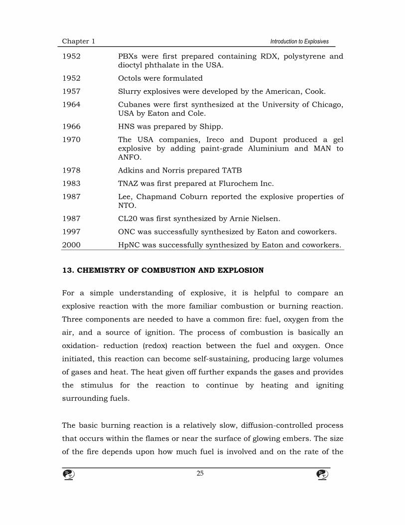
1952 PBXs were first prepared containing RDX, polystyrene and dioctyl phthalate in the USA.
1952 Octols were formulated
1957 Slurry explosives were developed by the American, Cook.
1964 Cubanes were first synthesized at the University of Chicago, USA by Eaton and Cole.
1966 HNS was prepared by Shipp.
1970 The USA companies, Ireco and Dupont produced a gel explosive by adding paint-grade Aluminium and MAN to ANFO.
1978 Adkins and Norris prepared TATB
1983 TNAZ was first prepared at Flurochem Inc.
1987 Lee, Chapmand Coburn reported the explosive properties of NTO.
1987 CL20 was first synthesized by Arnie Nielsen.
1997 ONC was successfully synthesized by Eaton and coworkers.
2000 HpNC was successfully synthesized by Eaton and coworkers.
13. CHEMISTRY OF COMBUSTION AND EXPLOSION
For a simple understanding of explosive, it is helpful to compare an
explosive reaction with the more familiar combustion or burning reaction.
Three components are needed to have a common fire: fuel, oxygen from the
air, and a source of ignition. The process of combustion is basically an
oxidation- reduction (redox) reaction between the fuel and oxygen. Once
initiated, this reaction can become self-sustaining, producing large volumes
of gases and heat. The heat given off further expands the gases and provides
the stimulus for the reaction to continue by heating and igniting
surrounding fuels.
The basic burning reaction is a relatively slow, diffusion-controlled process
that occurs within the flames or near the surface of glowing embers. The size
of the fire depends upon how much fuel is involved and on the rate of the
Chapter 1 Introduction to Explosives
26
combustion reaction. The rate of combustion reaction depends on how
finely divided the fuel is and how rapidly the oxygen reaches the flame, that
is the intimacy of contact between the fuel and the oxygen in the air.
Burning rate is greatly increased when convection of the air, natural (wind)
or man-made (fanning the flame), joins diffusion in supplying oxygen to the
flame.
Another result of an intimate mixture of the fuel and air is the completeness
or efficiency of the reaction. In a complete combustion all the fuel elements
are oxidized to their highest oxidation state. Thus, burning of wood, being
mainly cellulose and gasoline being generally a hydrocarbon (e.g., octane),
produces primarily carbon dioxide and water vapor upon complete
combustion. Once initiated, these burning reactions give off heat energy,
which sustain the reactions. Heat is released because the oxidized products
of the reactions are in a lower energy state (more stable) than the reactants.
The maximum potential energy release can be calculated from the respective
heats of formation of the products and reactants. Actual heats of
combustion can be measured experimentally by causing the reaction to
occur in a bomb calorimeter. The calculated energy values for the above
reactions are 3.875 cal/g for cellulose and 10,704 cal/g for octane.
In the case of an inefficient burn, some less stable ore higher-energy
products are formed so that the resultant heat energy given off is lower than
that for complete combustion. In the above examples, inefficient combustion
could result from lack or accessible oxygen, producing carbon monoxide or
even carbon particles instead of carbon dioxide. A smoky flame is evidence
of unburned carbon particles and results from inefficient combustion where
fuel particles are so large or so dense that oxygen cannot diffuse to the
burning surface fast enough. If this inefficiency is great enough, insufficient
heat is given off to keep the reaction going, and the fire will die out.

Chapter 1 Introduction to Explosives
27
All chemical explosive reactions involve similar redox reactions; so the above
principles of combustion can help illustrate, in a very basic way, the
chemistry involved in explosions. As in a fire, there components (fuel,
oxidizer, ignition source) are needed for an explosion. Figure 2.1 shows the
explosion triangle, which is similar to a fire triangle. In general, the products
of an explosion are gases and heat, although some solid oxidation products
may be
Oxidation-Reduction gases + heat
(fast)
Fig. 2.1 An explosion triangle
Fig. 2.2 Chemical Structure of three molecular explosive
Produced, depending upon the chemical explosive composition. As in normal
combustion, the gases produced usually include carbon dioxide and water
vapor plus other gases such as nitrogen, again depending upon the
Chapter 1 Introduction to Explosives
28
composition of the chemical explosive.
It should be noted that an explosion differs from ordinary combustion in two
very significant ways. First, oxygen from the air is not major reactant in the
redox reactions of most explosives. The source of oxygen (or other reducible
species) needed for reaction with the fuel-oxidizer-maybe part of the same
molecule as the fuel or a separate intermixed material. Thus, an explosive
may be thought of as merely an intimate mixture of oxidizer and fuel. This
high degree of intimacy contributes to the second significant difference
between an explosion and normal combustion – the speed with which the
reaction occurs.
Explosives in which the oxidizer and fuel portions are part of the same
molecule are called molecular are called molecular explosives. Classical
examples or molecular explosives are 2, 4, 6-trinitroluene (TNT),
penaerythhritol tetranitrate (PETN) and nitroglycerine (NG) or, more
precisely. Glycerol trinitrate. The chemical structures of these explosives are
shown in Fig. 2.2.
As can be seen in the structures, the oxidizer portions of the explosives are
the nitro (-NO2) groups in PETN and NG. The fuel portions of all three
explosives are the carbon and hydrogen (C and H) atoms. Comparison of the
ratios of carbon to oxygen in these explosives (i.e. approximately 1:1 for TNT,
approximately 1:2 for PETN, and 1:3 for NG) shows that TNT and PETN are
deficient in oxygen; that is, there is insufficient oxygen present in the
molecule to fully oxidize the carbon hydrogen. Consequently, products such
as carbon monoxide, solid carbon (soot), and hydrogen are produced, as well
as carbon dioxide and water vapor. Prediction, as well as carbon dioxide and
water vapor. Prediction of exact products of explosives, because the amounts
of CO2, CO, H2O and H2 will vary as will a host of trace products such as
residual hydrocarbons, depending upon reaction conditions (explosive

Chapter 1 Introduction to Explosives
29
density, degree of confinement of the explosive, etc.) [4, 5]. The following
equations show typical ideal reaction products along with calculated heats
of reaction for these molecular explosives:
TNT: C7H5 N3O6 1.5CO2 + 0.5CO + 2.5H2O + 1.5N2 + 5C + 1,290cal/g PETN: C5HgN4O12 4CO2 + 4H2O + 2N2 + C + 1,510cal/g NG: C3H5N3O9 3CO2 + 2.5H2O + 1.5N2 + 0.25O2 + 1,480cal/g
Explosive in which the oxidizer and fuel portions come from different
molecules are called composite explosives because they are a mixture of two
of more chemicals, A classic industrial example is a mixture of solid
ammonium nitrate (AN) and liquid fuel oil (FO), The common designation for
this explosive is the acronym, ANFO. The oil used (typically #2 diesel fuel) is
added in sufficient quantity to react with the available oxygen from the
nitrate portion of AN. The redox reaction of ANFO is as follows.
3NH4NO3 + CH2 CO2 + 7H2O + 3N + 880cal/g AN FO
“Oxygen balance” (O.B) is the term applied to quantify either the excess
oxygen in an explosive compound or mixture (beyond what is needed for
complete combustion of the fuel elements) or oxygen deficiency (compared to
the amount required for complete combustion). It is expressed as either a
percentage or a decimal fraction of the molecular weight of the oxygen in
excess (+) or deficiency (-) divided by the molecular weight of the explosive or
the ingredient being considered. Individual components of an explosive
mixture have O.B. values that may be summed for the mixture. Shown
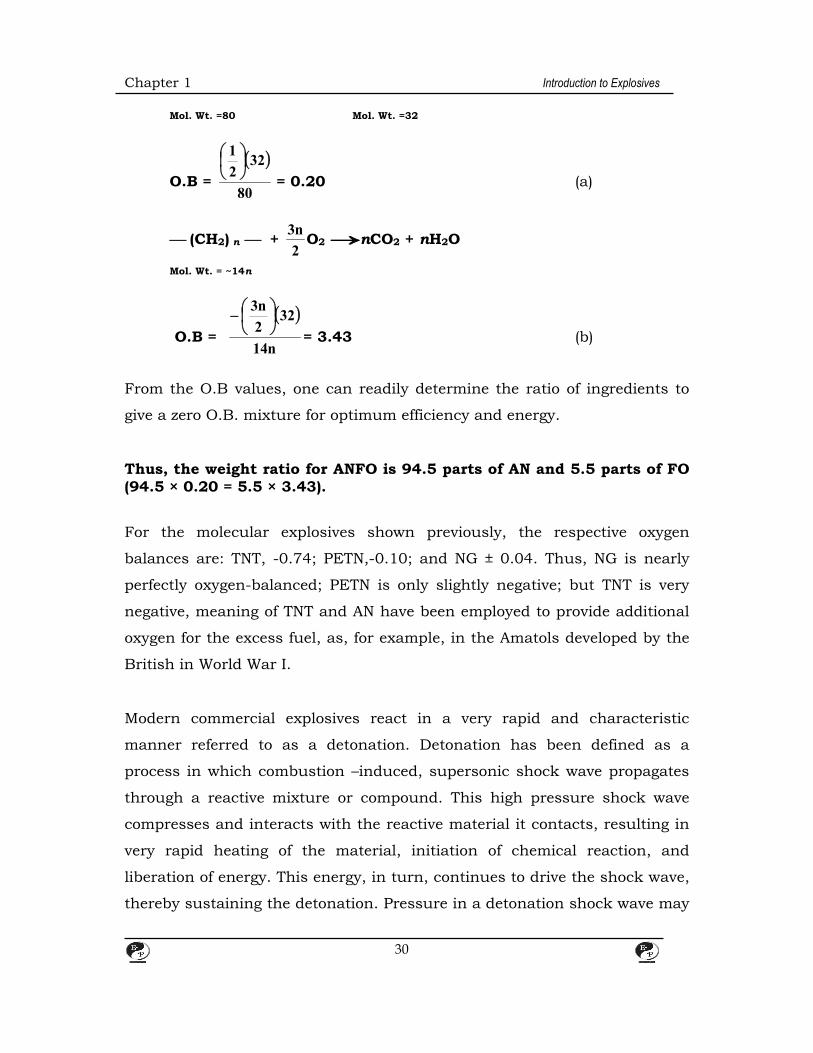
below are the O.B. calculations for AN and FO.
NH4NO3 2H2O + N2 + 2
1O2
AN O2
Chapter 1 Introduction to Explosives
30
Mol. Wt. =80 Mol. Wt. =32
O.B =
80
322
1
= 0.20 (a)
(CH2) n + 2
n3O2 nCO2 + nH2O
Mol. Wt. = ~14n
O.B =
n14
322
n3
= 3.43 (b)
From the O.B values, one can readily determine the ratio of ingredients to
give a zero O.B. mixture for optimum efficiency and energy.
Thus, the weight ratio for ANFO is 94.5 parts of AN and 5.5 parts of FO (94.5 × 0.20 = 5.5 × 3.43).
For the molecular explosives shown previously, the respective oxygen
balances are: TNT, -0.74; PETN,-0.10; and NG ± 0.04. Thus, NG is nearly
perfectly oxygen-balanced; PETN is only slightly negative; but TNT is very
negative, meaning of TNT and AN have been employed to provide additional
oxygen for the excess fuel, as, for example, in the Amatols developed by the
British in World War I.
Modern commercial explosives react in a very rapid and characteristic
manner referred to as a detonation. Detonation has been defined as a
process in which combustion –induced, supersonic shock wave propagates
through a reactive mixture or compound. This high pressure shock wave
compresses and interacts with the reactive material it contacts, resulting in
very rapid heating of the material, initiation of chemical reaction, and
liberation of energy. This energy, in turn, continues to drive the shock wave,
thereby sustaining the detonation. Pressure in a detonation shock wave may
Chapter 1 Introduction to Explosives
31
reach millions of pounds per square inch. Once initiated, molecular
explosives also have steady-state detonation velocities, but these velocities
are more variable than those of molecular explosives and are influenced by
such factors as diameter of the charge, temperature, density, and
confinement.
14. MODERN DEVELOPMENT
Soon after the advent of porous AN prills, introduced in the early 1950s,
investigators realized that these prills could readily absorb just the right
amount of FO to produce an oxygen-balanced mixture that was both an
inexpensive and effective blasting agent, in addition to being safe and simple
to manufacture. This technology was widely adopted and soon constituted
85% of the industrial explosives produced in the United States [17]. With
ANFO’S cost and safety characteristics, it became practical for surface
miners to drill larger boreholes and to utilize bulk ANFO delivery systems.
Nevertheless, ANFO had two significant limitations: AN is very water soluble,
so wet boreholes readily deactivated the explosives; and ANFO’s low density
of 0.85% g/cc limited its bulk explosive strength. Cook [18] hit upon the
idea of dissolving the AN in a small amount of hot water, mixing in fuels
such as aluminum powder, sulfur, or charcoal, and adding a thickening
agent to gel the mixture and hold the slurried ingredients in place. As this
mixture cooled down, the AN salt crystals would precipitate, but the gel
would preserve the close contact between the oxidizer and the fuels,
resulting in a detonable explosive. Other oxidizers also could be added, and
the density could be adjusted with chemical foaming agents to vary the bulk
explosive strength of the product. With the addition of cross linking agent,
the slurry could be converted to a semisolid material, generally called a
water gel, having some water resistance. The latest significant development
in industrial explosives actually was invented only a few years after slurries.
Water-in-oil emulsion explosives involve essentially the same ingredients

Chapter 1 Introduction to Explosives
32
that slurry composite explosives do, but in a different physical form.
Emulsion explosives are discussed fully under the section titled “Explosives
Manufacturing and Use” The main developments in military types of
explosives since World War II have been trends toward the use of plastic
bonded explosives (PBXs) and the development of insensitive high
explosives. Driving these trends are desires for increased safety and
improved economics in the process of replacing aging TNT-based munitions
and bomb fills. PBXs involve the coating of fine particles of molecular
explosives such as RDX and HMX (1,3,5,7-tetranitro-1,3,5,7-
tetrazacyclooctane) with polymeric binders and then pressing the resultant
powder under vacuum to give a solid mass with the desired density. The
final form or shape usually is obtained by machining. Explosives such as
triminotrinitrobenzene (TATB), nitroguanidine [21], and hexanitrostilbene
(HNS) are of interest because of their high levels of shock insensitivity and
thermal stability. The development of new, explosive compounds and
compositions is an ongoing area of research, including interest in composite
explosives similar to those used by industry. Examples are Eak, a eutectic
mixture of ethylenediamine dinitrate, AN, and potassium nitrate, and
nonaqueous hardend or cast emulsion-based mixtures.
15. CLASSIFICATION OF EXPLOSIVES
The original classification of explosives separated them into two very general
types: low and high, referring to the relative speeds of their chemical
reactions and the relative pressures produced by these reactions. This
classification still is used, but is of limited utility because the only low
explosives of any significance are black powder and smoke-less powder. All
other commercial and military explosives are high explosives.
High explosives are classified further according to their sensitivity level ore
ease of initiation. Actually sensitivity is more of a continuum than a series of

Chapter 1 Introduction to Explosives
33
discrete levels, but it is convenient to speak of primary, secondary, and
tertiary high explosives. Primary explosives are the most sensitive, being
readily initiated by heat, friction, impact, or spark. They are used only in
very small quantities and usually in an initiator as part of an explosive train
involving less sensitive materials, such as in a blasting cap. They are very
dangerous materials to handle and must be manufactured with the utmost
care, generally involving only remotely controlled operations, Mercury
fulminate, used in Nobel’s first blasting cap, is in this category, as is the
more commonly used lead azide. On the other end of the spectrum are the
tertiary explosives that are so insensitive that they generally are not
considered explosives.
By far the largest grouping is secondary explosives, which includes all of the
major military and industrial explosives. They are much less easily brought
to detonation than primary explosives and are less hazardous to
manufacture. Beyond that, however, generalizations are difficult because
their sensitivity to initiation covers a very wide range. Generally, the military
products tend to be more sensitive and the industrial products less
sensitive, but all are potentially hazardous and should be handled and
stored as prescribed by law. Table 2.1 lists some of the more prominent
explosives of each type, along with a few of their properties.
For industrial applications, secondary explosives are subdivided according
to their initiation sensitivity into two classes: Class 1.1 and Class 1.5 Class
1.1 explosives are sensitive to initiation by blasting cap and usually are used
in relatively small-diameter applications of 1-3-in. boreholes. Class 1.5
(historically known as blasting agents) are high explosives that are not
initiated by a Standard #8 electric blasting cap under test conditions defined
by the U.S. Department of Transportation (DOT) and that pass other defined
tests designed to show that the explosives is “so insensitive that there is very
little probability of accidental initiation to explosion or of the transition from
Chapter 1 Introduction to Explosives
34
deflagration to detonation” [27]. Being less sensitive, blasting agents are
generally used in medium- and large-diameter boreholes and in bulk
applications. Dynamites are always Clas 1.1, but other composite explosives
made from mixtures of oxidizers and fuels can be made either Clas 1.1 or
1.5, depending upon the formulation and the density. Density plays a
significant role in the performance of most explosives, and this is especially
true for commercial, composite explosives such as slurries and emulsions
where the density may be adjusted by air incorporation, foaming agents or
physical bulking agents, irrespective of the formulation. The 1.5 explosives
(blasting agents) are of interest because regulations governing
transportation, use, and storage are less stringent than for Class 1.1
explosive. (Propellants and fireworks are classified by the DOT as Class 1.2
or 1.3 explosives, and blasting caps and detonating cord as Class 1.4).
16. STRUCTURAL CHARACTERISTICS OF EXPLOSIVES
The number of potentially explosive compounds is virtually unlimited. A
listing by the U.S Bureau of Alcohol, Tobacco and Firearms of explosive
materials under federal regulation [28] numbered 225, and many of the
items listed were broad, general categories. The ten-volume Encyclopedia of
Explosives and Related Items compiled by the U.S Army Picatinny Arsenal
over a 25-year period contains several thousand entries. New organic
molecular explosives are still being synthesized; composite explosives, such
as current commercial products that are mixtures of oxidizers and fuels,
present an infinite number of possible combinations. The complexity of
trying to comprehensively list the chemical structures of explosives is shown
by a 1977 reference that listed 13 separate categories just for primary
explosives [29]. However; the majority of the most important explosives can
be grouped into a few classes sharing common structural features that are
of value to researchers in understanding and predicting explosive properties.
Chapter 1 Introduction to Explosives
35
The following seven categories, updated to include the relatively recent
fluoroderivatives, appear to be the most encompassing, Manny explosives
may contain more that one category, but not every compound that contains
one of these chemical groups is necessarily an explosive.
-NO -N-N-, -NN-, and -N≡N -C≡N- and -C≡N -C≡C- -CIO -N-X, where X = C1, F, I -O-O-
Table 2.1 Some properties of common explosives
Common name Symbol Composition Molecular weight
Density (g/cc)
Detonation velocity (km/s)
Detonation pressure
(k/bar)
Explosive energy (cal/g)
Primary explosives
Mercury fulminate Hg(CNO2) 284.7 3.6 4.7 220 428
Lead azide Pb(N3)2 291.3 4.0 5.1 250 366
Silver azide AgN3 149.9 5.1 6.8 - 452
Lead styphnate C6H(NO2)3O2Pb 468.3 2.5 4.8 150 368
Mannitol hexanitrate ( nitromannite)
MHN C6H8(ONO2)6 452.2 1.7 8.3 300 1,420
Diazodinitrophenol DDNP C6H2N4O5 210.1 1.5 6.6 160 820
Tetrazene C2H8N10O 188.2 1.5 - - 658
Secondary Explosive
Nitrogleycerin NG C3H5(ONO2)3 227.1 1.6 7.6 253 1,480
Pentaerythritol tetranitrate
PETN C(CH2ONO2)4 316.2 1.6 7.9 300 1,510
Trinitrotoluene TNT CH3C6H2(NO2)3 227.0 1.6 6.9 190 900
Ethyleneglycol dinitrate
EGDN C2H4(ONO2)2 152.1 1.5 7.4 1,430
Cyclotrimethylenetrinitramine ( hexogen or cyclonite)
RDX C3H6N3(NO2)3 222.1 1.6 8.0 347 1,320
Chapter 1 Introduction to Explosives
36
Cycloetramethylenetetanitraminem (Octogen)
HMX C4H8N4(NO2)4 296.2 1.9 9.1 393 950
Trinitrophenylmethylnitramine (tetryl)
(NO2)3C6H2N(CH3)NO2
287.2 1.4 7.6 251 721
Nitroguanidine NQ CH4N3NO2 104.1 1.6 7.6 256 1,188
Nitromethane NM CH3NO2 61.0 1.1 6.2 125 950
Nitrocellulose NC Variable - 1.4 6.4 210 829
Triaminotrinitrobenzene
TATB C6H6N3(NO2)3 258.2 1.8 7.9 315 993
Diaminotrinitrobenzene
DATB C6H5N2(NO2)3 243.2 1.6 7.5 259 948
Ethylenediamine dinitratc
EDDN C2H10N4O6 186.1 1.5 6.8 - 1,080
Ethylenedinitramine(haleite)
EDNA C2H6N2(NO2)2 150.1 1.5 7.6 266 1,000
Picric acid C6H3O(NO2)3 229.1 1.7 7.4 265 800
Common name Symbol Composition Molecular weight
Density (g/cc)
Detonation velocity (km/s)
Detonation pressure
(k/bar)
Explosive energy (cal/g)
Ammonium picrate (explosive D)
C6H6NO(NO2)3 246.1 1.6 6.9 - 1,070
Picramide C6H6N(NO2)3 228.1 1.7 7.3 - 1,100
Hexanitrostilbene HNS [C6H3C(NO2)3]2 450.2 1.7 7.1 200 950
TACOT-Z C12H4N8O8 388.2 1.6 7.2 181 675-1,090
Azobishexanitrobiphenyl
ABH C24H6N14O24 874.4 1.8 7.6 - 800
Dinitrotoluene DNT CH3C6H3(NO2)2 182.1 1.5 5.0 - 600-1,1200
Composition B 49/50/1 TNT/PDX/wax
- 1.7 8.0 294 700-1,200
Pentolite 50/50 TNT/PETN
- 1.6 7.7 245 700-1,100
Amatol 50/50/ TNT/AN
- 1.6 6.5 - 755-815
Dynamite Variable NG and various oxidizers and fuels
- 0.8-1.6
1.8-7.6 30-160
Prilled AN-fuel oil ANFO 94/6 AN/FO - 0.8-0.9
1.5-4.0 (Depends
on diameter)
-
Slurries or water gels
Variable mixture of oxidizers, fuels, and water
- 0.9-1.4
3.5-5.0 -

Chapter 1 Introduction to Explosives
37
Emulsions Variable solutions of oxidizers in water and fuels
- 0.9-1.4
4.5-6.0
-
Heavy ANFO 50-75% AN with 50-25% emulsion
- 1.1-1.3
4.0-4.5 4.0-4.5
Tertiary explosives
Mononitrotoluene MNT CH3C6H4NO2 137.1 1.2
Ammonium perchlorate
AP NH4C1O4 117.5 1.9 3.4 187 488
Ammonium nitrate AN NH4NO3 80.1 1.4 3.2 - 346
Category 1 is by far the largest. It includes intro groups, both aliphatic and
aromatic; nitrate esters; nitrate salts; nitramines; and nitrosamines. Nearly
all of the explosives listed in Table 2.1 fall into this category. Prominent
examples are: nitromethane, an aliphatic nitro compound; TNT, an aromatic
nitro compound; NG and PETN, nitrate esters; EDDN and ammonium
nitrate, nitrate salts; and RDX and HMX, nitramines. Category 2 represents
the hydrazine, azo, diazo and azide compounds, both organic and inorganic.
Hydrazine, tetrazene, and lead azide are examples of this group. Category 3
is represented by the explosives mercury fulminate and cyanogen,
respectively. Acetylene and metallic acetylide salts constitute category 4.
Category 5 consists mainly of inorganic and organic ammonium salts of
chloric and perchloric acid, but would also include various chlorine oxides.
Category 6 is generalized to include most of the amine halogens, nitrogen
triiodide being a classic example. Also, considerable synthetic work has
focused on interesting the energetic difluoroamine groups into various
organic molecules to form explosives that fall into this category. Category 7
includes organic peroxides and ozonides as well as hydrogen peroxide itself.
Commercial industrial explosives such as dynamites, slurries, and
emulsions are included in these categories because their major components,
nitrate esters and nitrate and perchlorate salts, are listed. However,
mixtures of fuels and oxygen or other gases that may be explosives at
Chapter 1 Introduction to Explosives
38
certain ratios are not covered, including the liquid oxygen explosives that
saw limited application earlier in the twentieth century.
16.1 TNT
TNT is no longer manufactured in certain couthe United States for either
commercial or military use. It is produced commercially in other countries
and is imported into the United States for use in cast boosters to initatate
industrial blasting agents. TNT use in military applications is still
significant, but starting to decline as other higher technology munition and
bomb fills come into use. Current TNT military needs are supplied from off-
shore sources as well as through recycling from demilitarized weapons. A lot
of the demilitarized TNT is also used commercially in the U.S. in cast
boosters. In a relatively straightforward process, TNT is made by the direct
tri-nitration of toluene with nitric acid. Most modern processes are set up for
continuous production in a series of nitrators and separators with nitrating
acid flowing counter-currently. This procedure avoids having to isolate the
intermediate mono-and dinitration products and may also employ
continuous purification and crystallization, being carried out simultaneously
with production.
Mixed nitric and sulfuric acids sometimes are used with the addition of SO3
or oleum. The sulfuric acids or oleum helps drive the reaction to completion
by removing the water produced by nitration and by dehydrating nitric acid
to form the more reactive nitronium ion (NO2+). Because toluene is not very
soluble in the acid, powerful agitation is required. The spent acid is removed
in successive separation steps, and the sulfuric acid is reused after the
addition of more nitric acid. The molten TNT product is purified with
multiple water and sodium sulfate washes. Which produce significant
quantities of “yellow water” and “red water” waste streams, respectively that
must be properly handled to avoid environmental problems. The low melting

Chapter 1 Introduction to Explosives
39
point of TNT (80-82°C) is ideal for melt casting, and TNT usually is employed
as a mixture with other higher –melting explosives such as PETN, RDX,
HMX, and Tetryl. This feature and the excellent chemical stability of TNT
have made it, historically, the most popular and widely used military
explosive in the world.
16.2 RDX and HMX
Both RDX and HMX are cyclic nitramines made by nitrolysis of
hexamethylene tetramine (HMT). Their good thermal stabilities, high melting
points (7200°C), and high energy properties make these crystalline
compounds popular as projectile and bomb fills and for use in cast boosters
and flexible, sheet explosives. HMX has superior detonation properties and a
higher melting point than RDX, but it is more difficult and more expensive
to manufacture. Reaction I shows the formation of RDX by the action of
nitric acid on HMT. Schematically, RDX formation can be pictured as
nitration of the three “outside” nitrogen atoms of HMT (in more accurate,
three-dimensional representations all four nitrogens are equivalent) with
removal of the “inside” nitrogen and methylene (-CH2-) groups. AN (NH4NO3)
and formaldehyde (CH2O) are produced as by-products, but can be used to
form more RDX with the addition of acetic anhydride, as shown in Reaction
2. In actual practice these two reactions are run simultaneously, as shown
in the combined reaction to produce approximately 2 mol of RDX for each
mole of HMT.

Chapter 1 Introduction to Explosives
40
HMX was discovered as an impurity produced in the RDX reaction. It is
composed of an eith –membered ring rather than the six-membered ring of
RDX. The latter is more readily formed that the eight-membered ring, but
with adjustment of reaction conditions (lower temperature and different
ingredient rations), HMX formation can be favored, Schematically, its
formation can be pictured by nitration of all four nitrogens in HMT and
removal of two methylene groups as indicated in Reaction 3. To obtain pure
HMX, the RDX “impurity” must be removed by alkaline hydrolysis or by
differential solubility in acetone.
Reaction 2 3CH2O + 3NH4NO3 + 6(CH3CO)2O 2(CH2 . N . NO2)3 + 12CH3COOH Combined Reaction (CH2)6 N4 + 4HNO3 + 2NH4NO3 + 6(CH3CO)2
Chapter 1 Introduction to Explosives
41
2(CH2 . N . NO2)3 + 12CH3COOH Reaction 3
16.3 HNS (2, 2, 4, 4, 6, 6-Hexanitrostilbene)
This explosive was prepared unequivocally for the first time in the early
1906s [32, 33]. It is of interest primarily for two reasons (1) its high melting
point (316°C) and excellent thermal stability, and (2) its unique crystal –
habit-modifying effects on cast TNT. The former makes HNS useful in
certain military and space applications as well as in hot, very deep wells,
and the second property is used to improve TNT castings. It can be
manufactured continuously by oxidative coupling of TNT as shown below.
This relatively simple process from readily available TNT and household
bleach (5% NaOC1 solution) has been shown to involve as series of
intermediate steps that give HNS in only low to moderate yields (30-45%)
with many by-products. Although it also involves the use of expensive
organic solvents that must be recovered, this synthesis is used commercially
[34, 35].
16.4 TATB (1,3,5-Triamino -2,4,6 Trinitrobenzene)
This highly symmetrical explosive molecule has even higher thermal stability
than HNS (greater than 400°C) and has ongoing interest because of its
extreme insensitivity [36-38]. Because accidental initiation is highly
unlikely, TATB has been used in nuclear warheads and has been explored
for use in plastic bonded systems for a number of military and space
applications. It is manufactured in large-scale batch processes that are little
Chapter 1 Introduction to Explosives
42
changed from its original synthesis over 100 years ago. The two-steps
process involves tri-nitration of trichlorobenzene followed by amination to
displace the chlorine groups as shown below.
Both steps require high temperature and considerable reaction time but give
80 -90% yields. The major problem areas are chloride impurities in the final
product and the excessively fine particle size of the final product and the
excessively fine particle size of the final product. Because TATB is highly
insoluble in most solvents, it is difficult to purify the product or to change
its particle size by recrystallization. Also the starting material is expensive
and not very readily available. More recently, a similar synthetic procedure
starting with 3, 5 dichloranisole was reported.
16.5 DDNP
This yellow –to-brown crystalline material (melting point 188°C) is a primary
explosives used as the initiator charge in electric blasting caps as an
alternative to lead azide. It is less stable than lead azide but much more
stable than lead styphnate and is a stronger explosive than either of them
because it does not contain any metal atoms. 2-Diazo-4, 6 dinitrophenol
Chapter 1 Introduction to Explosives
43
(DDNP) is also characterized as not being subject to dead pressing (tested at
pressures as high as 130,000 psi). It was the first diazo compound
discovered (1858) and was commercially prepared in 1928. It is manufacture
in a single-step, batch process by diazotizing slurry of sodium picramate in
water
The structure shown in this reaction is convenient for visualization
purposes, but DDNP actually exists in several tautomeric forms as shown
below with form (2) apparently predominating. The sodium picramate
starting material is itself explosive, but is commercially available as a
chemical intermediate. It can be made by the reduction of picric acid with
reducing agents such as sodium sulfide. The key to making useful DDNP is
to control the rate of diazotization so that relatively large, rounded crystals
area formed instead of needles or platelets that do not flow or pack well.
Chapter 1 Introduction to Explosives
44
16.6 PETN
Although known as an explosive since 1894, PETN was used very little until
after World War I when the ingredients to make the starting material became
commercially available. The symmetrical, solid alcohol starting material,
pentaerythritol, is made from acetaldehyd formaldehyde, which react by
aldol condensation under basic catalysis followed by a crossed Cannizzaro
disproportionation to produce the alcohol and formate salt. Although the
reaction takes place in a single mixture, it is shown below in two steps for
clarity.
For PETN manufacture the pentaerythritol starting materialcan be readily
purchased as a commodity chemical from commercial suppliers. The
nitration is relatively simple, involving only nitric acid (96-98%) and the
solid alcohol added slowly with mixing and cooling. PETN is not very soluble
in nitric acid or water and is readily filtered directly from the acid or after
Chapter 1 Introduction to Explosives
45
dilution of the acid with water. Water washing and recrystallization from
acetone-water mixtures give the desired particle size ranges and the desired
purity. PETN can be made either batch wise or continuously for large-scale
production.
Pure PETN is a white, crystalline solid with a melting point of 141.3°C.
Because of its symmetry, it is said to heave higher chemical stability than all
other nitrate esters [40]. Relatively insensitive to friction or spark initiation,
PETN is easily initiated by an explosive, shock and has been described
overall as one of the most sensitive, non-initiating, military explosives [41].
As with most explosives, the detonation velocity of PETN varies with the bulk
density of the explosive. Most military applications of PETN have been
converted to RDX because of its greater thermal stability. However, in
industry PETN is widely used as a major component in cast boosters for
initiating blasting agents, as the explosive core in detonating cord, and as
the base load in detonators and blasting caps. For safety in handling, PETN
in cloth bags immersed in water-alcohol mixtures and dried just before use.
16.7 NG (NITROGLYCERIN OR GLYERCOL TRINITRATE)
This nitrate ester is one of only a very few liquid molecular explosives that
are manufactured commercially. It is a clear, oily liquid that freezes when
pure at 13°C. As seen in the historical section, the first practical use of NG
was in dynamites, where it is still used today more than 140 years later. It
also is used as a component in multi-based propellants and as a medicine to
treat certain coronary ailments. This latter usage is attributed to NG’s ability
to be rapidly absorbed by skin contact or inhalation into the blood, where it
acts as a vasodilator. (At high exposure levels such as in dynamite
manufacture and handling, this property is responsible for the infamous
powder headache.) NG is undoubtedly the most sensitive explosive
manufactured in relatively large quantities. Its sensitivity to initiation by
Chapter 1 Introduction to Explosives
46
shock, friction, and impact is very close to that of primary explosives, and
extreme safety precautions are taken during manufacture. Pure glycerin is
nitrated in very concentrated nitric and sulfuric acid mixtures (typically a
40/60 ratio), separated from excess acid, and washed with water, sodium
carbonate solution, and water again until free from traces of acid or base,
Pure NG is stable below 50°C, but storage is not recommended. It is
transported over short distances only as an emulsion in water or dissolved
in an organic solvent such as acetone. Traditionally, it is been made in large
batch processes, but safety improvements have led to the use of several
types of continuous nitrators that minimize the reaction times and
quantities of explosives involved. Because of its sensitivity, NG is utilized
only when desensitized with other liquids, combined with absorbent solids
or compounded with nitrocellulose.
17. PACKAGED EXPLOSIVES
Packaged explosives dominated the explosives market from the time
dynamite was invented in 1867 until the middle of the twentieth century. At
that time, other composite type packaged technologies began appearing,
particularly in the 1960s and 1970s, concurrent with increasing market
penetration of bulk explosives. During those years of rapid technology
development, two packaged product types emerged, first water-gel
explosives, followed in the 1970s and early 1980s by packaged emulsion
explosives. All of these packaged product technologies remain active in parts
of the world as of the date of this edition, but in the U.S. emulsions are pre-
eminent followed by dynamites. Both are discussed below.
17.1 DYNAMITE
Dynamite is not a single molecular compound, but a mixture of explosive
and non-explosive materials formulated in cylindrical paper or cardboard
cartridges for a number of different blasting application. Originally Nobel
Chapter 1 Introduction to Explosives
47
simply absorbed NG into kieselguhr, an inert diatomaceous material, but
later he replaced that with active ingredients- mixtures of finely divided fuels
(including absorbent combustibles) and oxidizers called dopes. Thus, energy
is derived not only from the NG, but also from the reaction of oxidizers such
as sodium nitrate with the combustible.
The manufacture of dynamite involves mixing carefully weighed proportions
of NG and various dopes to the desired consistency and then loading
preformed paper shells through automatic equipment. Because dynamites
represent the most sensitive commercial products produced today, stringent
safety precautions such as the use of non-sparking and very-little-metal
equipment, good housekeeping practices, limited personel exposure, and
barricaded separation between processing stations are necessary for
manufacturing. Today, the “NG” used in dynamite is actually a mixture of
EGDN (ethylene glycol dinitrate) and NG formed by nitrating mixtures of the
two alcohols (ethylene glycol and glycerin), in which NG is usually the minor
component. Table 2.2 lists the common general types of dynamites with
their distinguishing features. The straight dynamites and gelatins largely
have been replaced by the ammonia dynamites and ammonia gelatins for
better economy and safety characteristics.
The used of NG-based dynamite continues to decline throughout the world.
For example, by 1995 there was only one dynamite manufacturing plant left
in North America, and in 2010 the dynamite production at this plant had
dropped to about one-third the amount produced in 1990. The reasons for
the declining use of dynamite are its unpopular properties of sensitivity to
accidental initiation and the headache-causing fumes. However (despites its
higher cost), for some difficult blasting application it remains the product of
choice due to its high density and high energy and sensitivity.

Chapter 1 Introduction to Explosives
48
Table 2.2 General types of dynamite
1. Straight dynamite Grannular texture with NG the major source of energy
2. Ammonia dynamite (“extra” dynamite)
AN replacing part of the NG and sodium nitrate of the straight dynamite
3. Straight gelatin dynamite Small amount of nitrocellulose added to produce soft to tough rubbery gel
4. Ammonia gelatin dynamite (“extra” gelatin)
AN replacing part of the NG an sodium nitrate of the straight gelatin
5. Semigelatin dynamite Combination of types 2 and 4 within-between properties
6. Permissible dynamite Ammonia dynamite or gelatin with added flame retardant
18. PACKAGED EMULSIONS
The first major non – dynamite package product technology was water gels.
These were composite mixture of hot, concentrated, dissolved oxidizer
solution slurried with other ingredients including soluble and insoluble
liquid fuels, particulate fuels, solid oxidizer salts, and thickeners consisting
of natural and synthetic water soluble polymers. The thickened solution
could be gelled by addition of crosslinking agents, typically inorganic salts of
certain metals. The gelled structure gave significant, but not excellent water
resistance.
Chapter 1 Introduction to Explosives
49
Fig. 2.3 Commercial packaged emulsion cartridges
(Courtesy Dyno Nobel)
Packaged water-in-oil emulsions are made from essentially the same oxidizer
solutions as used for water-gel products, but are fueled with an organic
external liquid hydrocarbon phase that provides much better water
resistance. These products are basically formed with the same
manufacturing equipment as the bulk emulsions (see next section). The fuel
component usually contains waxes and other thickeners to give the
emulsions a thick, putty-like consistency, and the oxidizer salt to produce
optimum energy, physical stability, and improved after-blast fumes. After
manufacture, the hot, thick emulsion is extruded into packaging material,
normally a plastic film. The final product is then clipped together with metal
clips forming firm, sausage-like chubs and is cooled which further thickens
the product. Some packaged emulsions are also available in paper
cartridges, designed to simulate dynamite packaging. To obtain reliable
detonability in small diameters, the density of packaged emulsions must be
maintained at a relatively low value, typically 1.10-1.20 g/.cc. On the other
hand, some dynamites are available with densities in excess of 1.40 g/cc.
Chapter 1 Introduction to Explosives
50
Figure 2.3 shows some commercial packaged emulsion cartridges in both
plastic and paper wrappings.
19. BULK EXPLOSIVES
19.1 AMMONIUM NITRATE AND ANFO
Ammonium nitrate (AN) continues to be the most widely used component of
commercial explosives. It is used in nearly all of the packaged and bulk
explosives on the market. Ammonia is the main raw material needed to
manufacture AN. Some of the AN manufacturers make their own ammonia
and some purchase it on the open market. It is obvious that the cost of
manufacturing AN will depend on the price of ammonia and, even more
basically, natural gas from which ammonia is made. Figure 2.4 shows the
volatility in the cost of explosives, although significant natural gas
development in the U.S. over the past few years seems to be suppressing
some of the price fluctuation.
There are many producers of AN in North America making both AN solution
and explosive-grade AN prills. The AN solution is used in the manufacture of
packaged and bulk emulsion and water-gel explosives, and explosive-grade
AN prills are used to make ANFO, a composite explosive described in an
earlier section. These low density AN prills are made by a specialized
process, in which internal Voids are created, making the prills porous and
able to absorb the required 5.5-6% FO. ANFO remains the largest volume
commercial explosive in use today around the world. Because of this, ANFO
is commonly used as a reference when defining and comparing explosive
properties. Some of these important explosive properties include density,
detonation velocity, and energy release.
The crystal density of AN is about 1.72g/cc, and the particle density of
explosive-grade AND prills ranges from about 1.40 to 1.45 g/cc depending
Chapter 1 Introduction to Explosives
51
upon the manufacturing process. This difference in crystal and particle
density reveals the volume of pores or voids created by the specialized
prilling process. The porosity of AN prills is the property desired in the
manufacture of ANFO, since this determines how much FO can be absorbed.
This intimate mixture of AN with FO is critical to the efficient detonability of
ANFO. The AN prill particle density and inherent void-space value also
become important when predicting and calculating densities of ANFO blends
with water-gel and emulsion explosives.
Fig. 2.4 volatility of natural gas prices from 2004 to 2010, New York.
The bulk density of ANFO ranges from about 0.80 to 0.87g/cc. So, clearly
about half of the ANFO is air or void space. Most commercial explosives
require a certain amount of entrained void space in order to detonate
optimally. These void spaces play a major role in the detonation reaction by
creating reaction sites, “hot spots,” under adiabatic compression and
interaction with the shock wave in the detonation front [42]. The amount of
void space in any given explosive and the resultant change in density have

Chapter 1 Introduction to Explosives
52
significant impact on the detonation properties like detonation velocity,
sensitivity, and even energy release.
Generally speaking, the detonation velocity of a composite explosive will
increase with density until a failure point is reached. This failure point is
commonly referred to as the critical density of that particular explosive in
that particular diameter or other configuration. The density at that point is
so high and the void space so low that the detonation cannot be sustained
and failure occurs.
Other important parameters that affect the detonation velocity and
performance of ANFO are charge diameter and confinement. The detonation
velocity of commercial composite explosives such as ANFO will drop
dramatically as the diameter of the charge nears the failure diameter. At a
given density, the diameter below which a charge fails to propagate a
detonation is called the critical diameter. As a charge diameter is increased
from this point, the detonation velocity increases asymptotically to a
maximum value for that particular explosive formulation. The detonation
velocity of ANFO will also increase noticeably when the charge confinement
is changed, such as from PVC tube to a Schedule 40 steel pipe. A summary
of test data on ANFO velocity vs. confinement and diameter is shown in Fig.
2.5. The temperature of composite explosives also affects sensitivity and
critical properties.
Chapter 1 Introduction to Explosives
53
Fig.2.5 Detonation velocity of ANFO vs. diameter and confinement
The basic chemical reaction of ANFO can be described with following equation:
3NH4NO3 + CH2 CO2 + 7H2O + 3N2 + 880 cal/g
Using CH2 to represent FO is generally accepted, but it really is an over-
simplification, since it is a mixture of hydrocarbons. The heat energy release
of 880 cal/g is the theoretical maximum value based upon the heats of
formation of the reactants and products. Of course, all of the products of
detonation are gases at the detonation temperature of about 2,700 °K.
The theoretical work energy that is released from an explosive reaction can
be calculated using a variety of equations of state and computer programs.
Explosive energy can also be measured by a variety of techniques including
underwater detonation of limited size charges with concurrent
measurements of the shock and bubble energies. Each explosive
manufacturer has an energy measurement and equation of state that is
used to calculate and report their product properties. This often leads to
confusion and controversy when explosive consumers try to compare
product lines when given only technical information sheets. Since theoretical
calculations must of necessity be based on a number of assumptions, the

Chapter 1 Introduction to Explosives
54
most valid comparisons are done in the field with product testing and
detailed evaluation of results.
20. BULK EMULSIONS
During the past 50 years, the commercial use of bulk delivered explosives,
including ANFO and other composite explosives, has continued to increase
while the use of packaged explosives continued to fall on a percentage basis.
Due to low cost and superior sensitivity compared to earlier water-resistant
technologies such as water gels, bulk emulsions have been leading this
trend over the last 25-30 years. Bulk products initially became very popular
in large volume open-pit mining operations and this accelerated with the
advent of bulk emulsion products and blends with ANFO. More recently,
bulk emulsions have increasingly replaced packaged products in
underground mining and particularly in quarry operations.
Emulsions are made by combining an oxidizer solution and a fuel solution
using a high-shear mixing process. The oxidizer solution is normally 90-95%
by weight of the emulsion. It contains AN, water, and sometimes a second
oxidizer salt such as sodium or calcium nitrate. The solution must be kept
quite hot, since the water is minimized for increased energy, and the
crystallization temperature is typically 50-70°C.
The fuel solution contains liquid organic fuels, such as FO and/or mineral
oils, and one or more emulsifiers. An emulsifier is a surface active chemical
that has both polar and nonpolar ends of the molecule. In the high-shear
manufacturing process, the oxidizer solution is broken up into small
droplets, each of which is coated with a layer of fuel solution. The droplets in
this meta-stable, water-in-oil emulsion are basically held together with the
emulsifier molecules, which migrate to the surface of the dispersed droplets
and form a link between the hydro-phobic external (continuous) oil phase

Chapter 1 Introduction to Explosives
55
and the hydrophilic phase within the droplets. In today’s explosives
industry, much of the research work is directed towards developing better
and more-efficient, emulsifier molecules that will improve the storage life
and handling characteristics of the bulk and packaged emulsions. The
emulsifiers currently used in commercial explosives range from relatively
simple fatty acid esters with molecular weights of 300-400 to the more
complex polymeric emulsifiers having molecular weights in excess of 2,000.
Figure 2.6 shows a photomicrograph of an emulsion explosive at 400 power
with the typical distribution of the fuel-coated oxidizer solution droplets
(nominally 1-5 µm in diameter). Figure 2.7 shows a bulk emulsion exiting a
loading hose and displaying the soft ice cream-like texture typical of bulk
emulsions. The viscosities of bulk emulsions can range from nearly as thin
as 90 weight oil to thicker than mayonnaise, depending upon the application
requirements. Emulsion viscosity increase with product cooling, but most
emulsions continue to remain stable at temperatures well below 0°C,
dramatically below the crystallization temperature of the oxidizer solution.
The oxidizer solution droplets in the emulsion are therefore held in a
supersaturated state. Over time, the surface layers created by the emulsifier
molecules can become less stable due to chemical degradation (oxidation) of
the emulsifier or other spontaneous physical and chemical process.
Movement of the emulsion is also stressful to these systems, which in reality
are thermodynamically unstable, tending towards crystallization and
coalescence.
Chapter 1 Introduction to Explosives
56
Fig. 2.6 Photomicrograph of a bulk emulsion
Fig. 2.7 (a) Bulk emulsion loading
Chapter 1 Introduction to Explosives
57
Fig. 2.7 (b) Bulk emulsion exiting a loading hose
Crystals can begin to form that break though the emulsifier layer and the
emulsion begins to “break down” and further crystallize, thereby
diminishing some of the desirable physical and detonation properties. For
this reason emulsion compositions must be optimized for a particular
application in terms of product stability and usable storage life.
The intimate mixing of oxidizer and fuel in emulsions gives these explosives
much high detonation velocities when compared to ANFO. For example, in
150 mm diameter PVC, ANFO at a density of ~0.82 g/cc has a velocity of
about 4,000 m/s, and a sensitized emulsion would have a velocity closer to
6,000 m/s at a density of 1.20 -1.25 g/cc.
Also, the layer of oil surrounding each oxidizer solution droplet protects the
emulsion from extraneous water intrusion and subsequent deterioration of
the explosive. Many studies have shown that when mining operations use
emulsion explosives rather than ANFO, which has basically no water
Chapter 1 Introduction to Explosives
58
resistance, the amount of nitrate salts in mine ground water is reduces
considerably. This can be a very important factor in today’s environmentally
conscious mining and explosives industry.
Bulk emulsions are generally non-detonable per se and are typically
sensitized with some type of density control medium to become usable
blasting agents. These voids interact with the shock wave, creating “hot
spots,” which are required to sustain the detonation front. The two most
commonly used density control methods are hollow solid microspheres and
gas bubbles created by an in situ chemical reaction. Both glass and plastic
hollow microspheres are commercially available and used by explosives
manufacturers. The in situ chemical gassing techniques require
considerably more expertise and generally utilize proprietary technology.
Emulsion blended with ANFO, with its internal and interstitial air voids, is
also widely used as ales efficient but effective sensitizer in larger diameter
boreholes.
Fig. 2.8 (a) Underground pressure vessel loader. (b) Compressed-air,
powered pumper for underground bulk emulsion (Courtesy Dyno Nobel)
20.1 UNDERGROUND BULK EMULSIONS
Chapter 1 Introduction to Explosives
59
In the past decade the use of sensitized bulk emulsions has continued to
increase in underground mining. In addition to the necessary small
diameter sensitivity of emulsion based explosives in these applications,
much of this trend has been due to t he development of innovative loading
equipment and techniques. One example of this is shown in Fig. 2.8 a,
which shows a small-volume pressure vessel that can be used for
development and tunnel rounds utilizing horizontally drilled boreholes. The
bulk emulsion blasting agent is pressurized inside the vessel and literally
squeezed through the loading hose into the boreholes. A continuous column
of explosives is assured by inserting the loading hose to the back of the hole
and extracting it as the product is loaded. A more recently designed air-
powered pumper unit for underground delivery of bulk emulsion is shown in
Fig. 2.8 b. This unit typically uses compressed air, available in most
underground mines, to power a pump that delivers the bulk explosive. Much
more complex underground loading unit are available for loading bulk
emulsion into boreholes drilled at any angle to the horizontal from straight
up to straight down.
The emulsion explosives used in these specialized loading units were
specifically designed for underground use nearly 30 years ago and remain
essentially the same today. They are manufactured in central plants, either
sensitized with microballoons to form as a 1.5 explosive or as gassable
matrix that can be transported and stored as a non-explosive, thence
sensitized with gas bubbles at the point of use. They have been successfully
used in underground mining operations around the world. The fuel and
oxidizer contents are carefully balanced, and this, combined with excellent
water resistance and detonation efficiency, results in the near elimination of
after-blast toxic fumes, such as CO, NO, and NO2. The fume characteristics
of this product have been shown to be considerably superior to either
dynamite or ANFOR. For example, a series of tests in an underground

Chapter 1 Introduction to Explosives
60
chamber in Sweden compared the after-blast fumes of this emulsion to
ANFO. The CO was reduced from 11 to less than 6l/kg of explosive, and the
NO plus NO2 was reduced from about 7 to less than 1 L /kg of explosives.
Fig. 2.9 Bulk emulsion loading truck in a Florida quarry
20.2 SURFACE BULK EMULSIONS
Many open-pit quarries also use bulk emulsions for their blasting
operations. As the size of the quarry increases, the size of the explosive
loading trucks also must increase. Truck payloads can range from 5,000 to
30,000 lb of product. Figure 2.9 shows an emulsion pumper truck in a
quarry in south Florida. These particular trucks, with a payload of about
20,000 lb, are specially designed for a site-mixed system, in which each
truck is an emulsion manufacturing unit. Combining non-explosive raw
materials directly on the truck maximizes safety and minimizes requirement
for explosive storage. This particular bulk emulsion is manufactured at a
rate between 300 and 500 lb/min and sensitized to the desired density with
a chemical gassing system as it is loaded into the boreholes.
Figure 2.10 shows Florida blast in progress. Note the ejection of cardboard
tubes from some holes. These tubes must be used in most areas to keep the
Chapter 1 Introduction to Explosives
61
boreholes from collapsing in the layered, coral limestone formation.
Other surface, bulk delivery trucks use emulsions that are manufactured in
central plants, then shipped to a surface depot, off-loaded into a bin or
overhead silo, and loaded as needed into delivery trucks by pumping or
gravity flow. The products can be shipped pre-sensitized with microballoons
or as a non-sensitized, gas able matrix. The application of the product can
be as a pumped straight emulsion or as a pumped or augured
emulsion/ANFO blend.
Many of the large volume metal and coal mining operations around the
world have both bulk emulsion and AN prills stored either on site or nearby
so that any combination of these two products can be used. Figure 37.12
shows a typical explosive staging area in a large open-pit coal mine in
Wyoming. The explosive truck in the foreground has compartments on board
for emulsion, AN prills, and FO, so any combination of products ranging
from straight emulsion to straight ANFO can be loaded. The truck has a
capacity of about 50,000 lb and can deliver product to the boreholes at up to
a ton per minute. Each borehole can contain as much as 5 tons of explosive,
and some of the blast patterns can contain as much as ten million total
pounds.
The emulsion/ANFO explosive blend selection to be used in any given
mining application depends upon may factors. Typically, ANFO is the least
expensive product, but it also has the lowest density and no water
resistance. As emulsion is added to ANFO, it begins to coat the AN prills and
fill the interstitial voids between the solid particles. This increases the
density, detonation velocity, and water resistance compared to ANFO. The
density increases nearly linearly with percent emulsion from about 0.85g/cc
with ANFO to about 1.32 g/cc with 50/50 blend. This range of emulsion
ANFO blend is commonly referred to as Heavy ANFO. As the density
increases, the amount of explosive that can be loaded into each borehole
Chapter 1 Introduction to Explosives
62
increases, and either drill patterns based on ANFO can be spread out or
better blasting results can be obtained.
It is commonly accepted in the explosive and mining industry that at least
45-50% emulsion is required to protect the Heavy ANFO blend from borehole
water intrusion. Pumped explosive blends with 60-80% emulsion can be
used for even better water resistance when severe water conditions are
encountered. These products can be pumped through a loading hose, which
can be lowered to the bottom of the borehole and displace the water during
loading. Trucks similar to that shown in Fig. 37.10 can be used for these
products. Most Heavy ANFO products are more simply mixed through an
auger and discharged into the top of boreholes by trucks similar to the one
shown in Fig. 2.11 for Heavy ANFO products, especially those with less than
~45% emulsion, the holes should be either dry or dewatered using pumps.
The basic chemical composition of a typical all-AN oxidizer emulsion
explosive would be: AN plus about 16% water plus about 5% fuels. The fuels
may contain fuel oil, mineral oil, and emulsifiers: the majority of which can
generally be described as CH2 hydrocarbon chains. Therefore, a very
simplified chemical reaction for a basic emulsion is similar to that for ANFO
shown earlier.
Chapter 1 Introduction to Explosives
63
Fig. 2.10 Florida quarry blast in progress (Courtesy Dyno Nobel)
Fig. 2.11 Typical bulk explosives staging area in a large opt-pit mine
By adding 16% water to the ANFO reaction described earlier, the theoretical
Chapter 1 Introduction to Explosives
64
heat energy release is reduced from 880 to 680 cal/g. The difference is the
energy price paid for using water due to converting it to steam in the
detonation reaction plus the energy loss in diluting the ANFO with a non-
energy producing additive (water). The advantages and disadvantages of
using ANFO or emulsions begin to become clear. ANFO is easily mixed and
is probably the least expensive form of explosive energy, but it has no water
resistance and has relatively low loading density. Emulsions are
considerably more complicated to formulate and manufacture, but they have
excellent water resistance and more flexibility in terms of density, velocity,
and higher bulk energy to match rock types and blasting applications.
21. HOME-MADE EXPLOSIVES
According to the US Government Hazardous Substances Database, several
substances and mixtures can be used for the realization of this kind of
explosives, starting from chemicals sold in markets and pharmacies. Among
others, two were often adopted for terrorist attacks, suicide bombing, and
other malicious uses: Ammonium Nitrate (AN) − Fuel Oil (i.e. ANFO)
mixtures and Acetone Peroxide or Triacetone Triperoxide Peroxyacetone
(TATP) mixtures(]. These two materials were considered as reference
explosives for the analysis presented in the present study.
ANFO is a tertiary explosive (note that TNT is a secondary explosive) and is
generally composed by 94% of AN prills and 6% of adsorbed fuel oil [32]. It is
extensively used for several authorized purposes as in mine blasting. The
TNT equivalence is typically around 80% and the ideal explosion (detonation)
energy is 3890 kJ/kg (pure ammonium nitrate has an explosion energy of
1592 kJ/kg). AN prills used for mining applications are however physically
different from fertilizer prills used in home-made explosives. The commercial
ammonium nitrate prills used for mine blasting have a 20% void fractions
and are coated with #2 fuel oil (mainly C10−C20 linear hydrocarbons) or

Chapter 1 Introduction to Explosives
65
kerosene. Hence, ANFO has a bulk density of approximately 840 kg/m3
when starting from AN prills for mining applications, having a density of
about 1300 kg/m3 (the density of pure crystalline ammonium nitrate is
1700 kg/m3). On the other hand, homemade explosives prepared from AN
fertilizers do not have a so high void fraction and are less efficient: e.g. the
new European regulations for fertilizers state that they must contain less
than 45% of AN (16% N) for being traded to the general public. Such
fertilizers still may be used to obtain explosives, but require processing to
achieve a detonation. If commercial AN (containing about 50% of inert, as
dolomite) and diesel fuel is used, a detonation energy of about 1071 kJ/kg is
obtained, much less than pure ANFO [30]. Furthermore, it has been
observed that when amounts of dolomite higher than 30%, are present, no
detonation is observed.
TATP is a primary explosive which is notable since it does not contain
nitrogen. Thus, it is used to avoid conventional chemical bomb detection
systems, and it is almost undetectable by either analytical system or by
sniffer dogs [34]. It can be obtained from common household items such as
sulphuric acid, hydrogen peroxide, and acetone [35].
TATP is very unstable: it can be ignited by touch and can explode
spontaneously. It is often used for improvised detonators itself. It is actually
composed by isomers and conformers, the dimer being more stable but
having lower decomposition energy (see Fig. 3).
The actual components of TATP: (a) dimer and (b) trimer peroxides.The
density of the pure molecule is typically considered to be 1220 kg/m3.
However, home-made TAPT formulations are typically in the range of 450–
500 kg/m3. Finally, TATP is often stabilized with carbonaceous liquids and
waxes so that the net charge is even lower .Nevertheless, Lefebvre et al.have
demonstrated that home-made TATP is a primary explosive and very
Chapter 1 Introduction to Explosives
66
sensitive to impact or friction, although the strength of explosion may
strongly vary since the quality of the final product is very sensitive to the
temperature during its synthesis.
TATP is highly volatile and decomposes to form large number of gas phase
molecules (entropic explosion) [39] and [40]. Acetone and ozone are
predicted to be the main decomposition products, along with oxygen, methyl
acetate, ethane, and carbon dioxide [41].
Fig. 3. The actual components of TATP:
(a) dimer and (b) trimer peroxides.
22. DEVELOPMENT OF INITIATION SYSTEM
22.1 HISTORY OF INITIATION SYSTEMS
The first reliable initiation system for commercial explosives could probably
be traced back to Alfred Nobel’s invention of the blasting cap in 1864. These
early caps had to be initiated with a strong shock, limiting their safety and
convenience. In 1867, Nobel developed a cap that could be initiated with a
fuse, a more convenient system that allowed an element of timing (length of
the fuse) to the initiation of a blast, and hence, some increase in safety and
predictability. This, combined with his invention of dynamite in 1866 [46],
basically ushered in the modern era of blasting. The fuse cap and dynamite
dominated the emerging blasting industry for several decades. In the

Chapter 1 Introduction to Explosives
67
century that followed, the initiation systems became more and more
sophisticated and safe. The electric blasting cap which could be initiated by
electrical current was developed around the turn of the century, adding
further safety to blasting. Detonating cord, a flexible cord made of cloth or
plastic with a core load of high explosives-usually PETN, was developed in
Europe around the same time. Strings or circuits of detonating cord could
be utilized to initiate several explosive charges with only one blasting cap.
Electric caps were introduced in 1946 equipped with built-in, variable-delay
elements (pyrotechnics that burn reproducibly) [46]. This allowed long rows
of boreholes to be initiated in a sequential manner, optimizing blasting
effectiveness as well as better controlling ground vibration and air blast
damage to the surrounding. With caps having delays ranging from a few
milliseconds to many hundreds and eventually thousands of milliseconds,
the number of sequentially fired boreholes in a row depended only on the
desired timing and the amperage capability of the electric blasting machine
or other firing circuit. Sequential blasting machines were developed that
could be used to control firing times between a number of rows of
blastholes, greatly expanding the times between a number of rows of
blastholes, greatly expanding the timing possibilities and size of blast
patterns.
Fig. 2.12 Variety of commercial cast boosters (Courtesy Dyno Nobel)

Chapter 1 Introduction to Explosives
68
23. BOOSTERS
Prior to about 1950s, most of the commercial explosives in the market were
reliably detonable with just a blasting cap or detonating cord as the initiator.
However, the use of non-cap-sensitive explosives (blasting agents) began
emerging into the explosives market in the 1930s and 1940s. These
products really took off with the advent of ANFO in the mid-1950s and water
gels, invented by Melvin A. Cook in 1957 [47], Emulsion based blasting
agent products, which began significant commercialization in the mid-
1970s, became the dominant non-ANFO product by the late 1980s and
remains so to the present day. All of these blasting agents were adaptable to
larger diameter packaged products and particularly to bulk loading.
These blasting agent explosive products were considerably less sensitive
than dynamites and required larger “booster” charges for reliable detonation.
At first, a high density and high velocity dynamite was used as the booster
charge. Later, TNT-based cast boosters came into the market. Cast TNT by
itself is not reliably detonable with a blasting cap or detonating cord, and so
40-60% PETN is normally added to the TNT melt and subsequent cast. The
combination of TNT and PETN is called Pentolite. TNT has a melting point of
about 80°C, which makes it an excellent base explosive for casting into
forms, The military has used this concept for decades for filling bomb
casings. Once the TNT has melted, other material can be added to give the
final cast explosive composition the desired properties. Additives used for
military purpose have included such as aluminum, ammonium nitrate,
RDX, and also PETN, but Pentolite been dominant in commercial cast
boosters. Cast boosters are available in a variety of sizes from about 10 to
800 g, as shown Fig. 2.12, and continue to be predominant today in nearly
all large mining operations and other blasting applications, Cap-sensitive
composite explosives such as emulsion cartridges, composite explosives
such as emulsion cartridges, dynamite, etc. are also used in less demanding
Chapter 1 Introduction to Explosives
69
situations, Coupled with the flexibility of blasting caps with variable delays
to initiate the booster charge which then initiates the main charge, large
patterns containing many thousands of pounds of explosive can be blasted.
24. NON-ELECTRIC INITIATION
In 1967, Per –Anders Persson of Nitro Nobel AB in Sweden invented a non-
electric initiation system, designated Nonel® , that eventually revolutionized
the explosives industry [46]. The Nonel system consists of an extruded
hollow plastic tube (shock tube) that contains an internal coating of a
mixture of powdered molecular explosive and aluminum. The plastic tube is
inserted into and attached to a specially designed detonator or blasting cap.
The Nonel tubing can be initiated by a number of starter devices, one of
which uses a simple shotgun shell primer. The explosive/aluminum mixture
explodes down the inside of the tube at about 2,000 m/s and will run at this
velocity until all the interconnected tubing reacts, including initiating all the
blasting caps. The tubing is about 3 mm outside diameter and 1 mm inside
diameter and the explosive core load is only about 18 mg/m, not even
enough to rupture the tubing. The Nonel product is not susceptible to the
hazard associated with electric blasting caps wherein premature initiation
by extraneous electric sources can occur. Figure 2.13 is a photograph of
both an electric blasting cap with the two electrical wires and a typical Nonel
unit with the plastic tubing.
During the 1980s and 1990s, Nonel products continued to replace both
electric blasting caps and detonating cord down lines around the world. It
has long been known that detonating cord down lines disrupt and partially
react with blasting agents causing some degree of energy and sensitivity
loss. Also, the use of surface detonating cords to initiate blasts can lead to
noise complaints. Using a range of long-lead delay caps down the borehole,
a surface trunk-line of shock tubing, surface connectors to tie the tubing
Chapter 1 Introduction to Explosives
70
together, and surface delay elements that are available with this technology,
huge and complex blasting patterns can be laid out and blasted with a
multitude of possibilities as to timing and sequence.
Fig. 2.13 An electric blasting cap showing electrical wires, typical
Nonel unit with plastic tubing
As delay elements were perfected for the Nonel blasting caps, their
application and use grew even further, especially in underground mining
where a large percentage of blasting caps is used.
25. ELECTRIC DETONATORS
The development of detonators with delay periods that were based on
pyrotechnic elements (timing controlled by the burn rate and length of the
element) had a dramatic effect on the explosives industry, enabling much of
the size and complexity of modern blasting, as well as reducing off-site blast
effects caused by ground vibration and air blast. When a blasting pattern is
properly timed, the detonation of individual holes is such that damage from
air blast and ground vibration is greatly reduced. This is a result of

Chapter 1 Introduction to Explosives
71
destructive wave interference, i.e., the ground vibration waves from
detonation of each hole combine with each other and the air blast waves
from the detonation of each hole combine with each other in such a way that
the resulting wave patterns propagating from the blast have lower
amplitudes and higher frequencies. This is key to controlling off-site
structural damage. Over many years of development delays was improved
dramatically. However, delay times can still vary from detonator to detonator
and from the target delay time by a few milliseconds to tens of milliseconds
depending on the delay period of the detonator. There are also occasional
fliers that occur well outside the normal scatter for a given delay detonator
that can upset the blasting pattern. It was surmised that these variations
could result in less than optimum blasts, considering not just air blast and
ground vibration but also ground movement, fragmentation, ore dilution, fly-
rock, etc.
In the late 1980s and early 1990s, several companies began developing and
testing detonators wherein the delay timing was controlled with an
integrated electronic circuit. These were initially very expensive and, by
today’s standards, were crude devices. However, they did demonstrate the
promise of very accurate caps. As electronics technology improved into the
1990s, testing and field evaluation of such caps increased. However, cost
and complexity in assembling the caps, increased. However, cost and
complexity in assembling the caps, the development of user friendly
controllers to program and initiate them, and the unfamiliar equipment and
technology on the blasting patterns slowed widespread implementation. It
wasn’t until mounting commercial experience began to demonstrate
improved blasting results that the tide began to turn. This in turn resulted
in accelerated improvements in manufacturing technology to make the caps
less expensive, more reliable, improve ease of use, and increase expertise
available to blasters in the field. By the 2000s, the technical case for
electronic detonators had been well established. Despite the significant cost

Chapter 1 Introduction to Explosives
72
differences that remain between electric or non-electric detonators and
electronic detonators, amounting to factors of perhaps five to ten times more
costly per unit, there are dramatic increases in the use of electronic
detonators in the blasting industry today. As of the date of this edition, they
are still a minor part of the total global detonator market, but the market
share is increasing. Several manufacturing companies with independent
detonator technologies are involved and use is occurring in all segments of
mining, construction, and other commercial blasting applications.
The construction of an electronic detonator has some features in common
across all manufacturers. The timing and programmability features depend
on an integrated circuit. One ore more capacitors are included to store the
electrical energy necessary to run the circuitry and to initiate the detonator
via bridge or igniter elements. The detonator can be built to have a preset
delay time or can be programmable as to delay period at the point of use.
Electrical and electronic communication with the detonators is established
via two or four lead wire connections, depending on the system chosen and
blast design, flexibility, control, and programmability features desired or
needed by the blasters. The lead-wires are connected to the blasting
machine which enables all of the features in the particular technology
chosen, including programming (if needed), arming, and eventually initiating
each line of detonators. The timing accuracy is on the order of only 1 to a
few milliseconds depending on delay times, and variability is typically
reduced by and order of magnitude compared to pyrotechnic detonators.
Figure 2.14 shows the components of a four wired system

Chapter 1 Introduction to Explosives
73
Fig.2.14 Components of an electronic cap initiating system.
L-R, logger, cap, base station (blasting machine), Connectors
Courtesy Dyno Nobel)
And includes the cap, connectors, tagger (identifies and tags each detonator
as it is placed in the borehole), and blasting machine (herein called the base
station).
References
1. Mineral Information Institute. Soc Metallurg Explor Foundation.
http://www.mii.org/MiiBabyMain
2. United States Geological Survey. Minerals Yearbook, Explosive Statistics and
Information. Compiled Information from years 2000-2009.
3. Apodaca LE (2009) United States Geological Survey. Minerals Yearbook,
Explosive Statistic and Information (advance release).
4. Ornellas J (1968) Phys Chem 72:2390.
5. Kaye SM (1978) Encyclopedia of explosives and related items, PATR 2700, Vol 8.
U.S. Army Armament Research and development Command, Dover, pp 99-100.
6. Engineering design handbook: explosives series. Army Material Command

Chapter 1 Introduction to Explosives
74
Pamphlet 706-177, AD 764, 340, p 12, distributed by NITS, Jan 1971.
7. Fedoroff BT, Sheffield OE (1962) Encyclopedia of explosives and related items,
PATR 2700, vol 2. Picatinny Arsenal, Dover, p B165.
CHAPTER – 2
EXPLOSIVES: CHEMISTRY AND ENERGETICS
1. Introduction The most generally accepted definition of an explosive is expressed in the
following terms:
“A solid or liquid substance or a mixture of substances which on the
application of a of a suitable stimulus to a small portion of the mass is
converted in a very short interval of time into other more stable even
substances, largely or entirely, gaseous, with the development of heat
and high pressure”
It is obvious that the explosive substances are in a metastable state and are
therefore capable of undergoing a chemical reaction under the influence of
an external stimulus (for e.g. impact, heat or shock) to yield the more stable
products. The reaction products are predominantly gaseous like N2, CO2 and
H2O while other gases like the oxides of nitrogen are also formed sometimes,
it is also necessary that an explosive should be capable of producing this
large quantity of gas under high pressure so rapidly that the surroundings
are subjected to a strong dynamic pressure.
A synoptive view of the entire field of explosive materials is given in Table 1.
2. Classification Explosives While there can be several ways of classifying explosives depending on their
use and composition the following three main types are generally
recongnised.
75

Chapter 2 Explosives : Chemistry & Energetics
1. Deflagrating (or propellant) explosives.
2. High explosives (sometimes called secondary explosives).
3. Initiating explosives (sometimes called primary explosives).
Deflagrating or low explosives were the earliest to be developed. These lead
to an explosion which is really a rapid form of combustion in which the
particles burn at their surface and more of the bulk until all has been
consumed. Typical examples of this category are the blasting powder or
gunpowder, propellants in ammunition, rocket propellants and
pyrotechnics.
High explosives, depending on their composition, detonate at velocities of
5,000 – 25,000 feet per second and produce large volumes of gases at
considerable heat at extremely high pressures.
Table 1 : Explosive Materials and their Application
76

Chapter 2 Explosives : Chemistry & Energetics
High explosives usually contain chemical components with more or less
unstable molecular structure capable, on detonation of molecular re
arrangement into more stable forms of potential energy. These are generally
gases (solid products tend to produce smoke) which are very high
temperature and pressure. Secondary explosives of this type are military
explosive like TNT, RDX, PETN, Tetryl and other combinations of these and
industrial explosives like nitroglycerine, gelatins, slurries, water gels, ANFO
and other powder explosives. These explosives are normally set off with
suitable initiating devices like detonators, and detonating fuse.
Initiating explosives or primary explosives are those that can detonate by the
action of a relatively weak mechanical shock or spark. The most important
primary explosives are mercury fulminate, lead azide, lead styphnate,
diazodinitrophenol, tetrazene and other mixtures.
Before going into a discussion of the aforementioned groups individually, it
would be useful to understand certain technical terms that would be
repeatedly used.
3. Detonation and Deflagration Brisance is the destructive fragmentation effect of a charge on its immediate
77
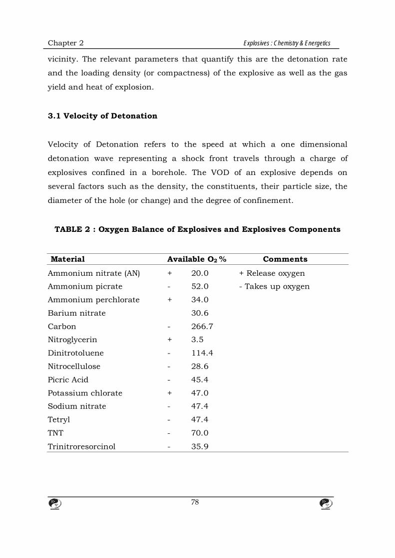
Chapter 2 Explosives : Chemistry & Energetics
vicinity. The relevant parameters that quantify this are the detonation rate
and the loading density (or compactness) of the explosive as well as the gas
yield and heat of explosion.
3.1 Velocity of Detonation
Velocity of Detonation refers to the speed at which a one dimensional
detonation wave representing a shock front travels through a charge of
explosives confined in a borehole. The VOD of an explosive depends on
several factors such as the density, the constituents, their particle size, the
diameter of the hole (or change) and the degree of confinement.
TABLE 2 : Oxygen Balance of Explosives and Explosives Components
Material Available O2 % Comments
Ammonium nitrate (AN) + 20.0 + Release oxygen
Ammonium picrate - 52.0 - Takes up oxygen
Ammonium perchlorate + 34.0
Barium nitrate 30.6
Carbon - 266.7
Nitroglycerin + 3.5
Dinitrotoluene - 114.4
Nitrocellulose - 28.6
Picric Acid - 45.4
Potassium chlorate + 47.0
Sodium nitrate - 47.4
Tetryl - 47.4
TNT - 70.0
Trinitroresorcinol - 35.9
78
Chapter 2 Explosives : Chemistry & Energetics
3.1 Oxygen Balance The amount of oxygen expressed in weight percent, liberated as a result of
complete conversion of the explosive material to CO2, H2O, SO2, AL2O3, etc.
(“ Positive” oxygen balance). If the amount of oxygen bound in the explosive
is insufficient for the complete oxidation reaction the compound has a
negative oxygen balance (Table 2)
Commercial explosives must have and oxygen balance close to zero in order
to reduce to the minimum the amount of toxic gases, particularly CO and
nitrous gases.
4. High Explosive The basic requirements of high explosives particularly of the industrial type
are the following:
1. Maximum power per unit volume.
2. Minimum weight per unit of power.
3. High velocity of detonation.
4. Insensitivity to shock on firing and impact, and yet sensitivity to
initiate readily when property initiated.
5. Good water resistance.
6. Good fume characteristics.
7. The reaction must be exothermic in order to increase the pressure.
8. The substance(s) should be simple and inexpensive to produce from
readily available raw materials.
The most important properties of the commonest military explosives are
listed in Table 3.3. Their structures are also given below.
79
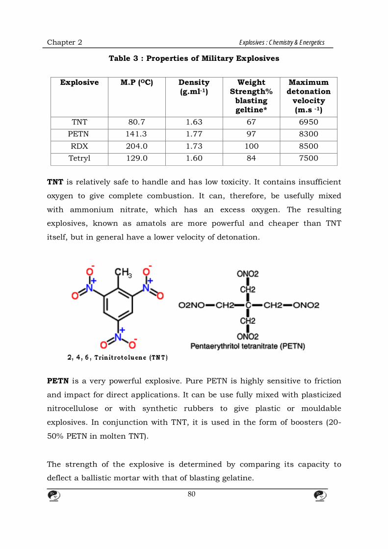
Chapter 2 Explosives : Chemistry & Energetics
Table 3 : Properties of Military Explosives
Explosive M.P (OC)
Density (g.ml-1)
Weight Strength%
blasting geltine*
Maximum detonation
velocity (m.s -1)
TNT 80.7 1.63 67 6950 PETN 141.3 1.77 97 8300 RDX 204.0 1.73 100 8500 Tetryl 129.0 1.60 84 7500
TNT is relatively safe to handle and has low toxicity. It contains insufficient
oxygen to give complete combustion. It can, therefore, be usefully mixed
with ammonium nitrate, which has an excess oxygen. The resulting
explosives, known as amatols are more powerful and cheaper than TNT
itself, but in general have a lower velocity of detonation.
PETN is a very powerful explosive. Pure PETN is highly sensitive to friction
and impact for direct applications. It can be use fully mixed with plasticized
nitrocellulose or with synthetic rubbers to give plastic or mouldable
explosives. In conjunction with TNT, it is used in the form of boosters (20-
50% PETN in molten TNT).
The strength of the explosive is determined by comparing its capacity to
deflect a ballistic mortar with that of blasting gelatine.
80

Chapter 2 Explosives : Chemistry & Energetics
Trymethylene Trinitramine
(RDX)
O2N N CH2 N NO2
CH2 CH2
O2N N CH2 N NO2
Tetramethylene Tetranitramine (HMX)
RDX has a lower sensitiveness than PETN. It is still too sensitive to impact
or friction. It is either desensitized with wax or else used like PETN in
admixture with TNT.
5. Commercial Explosives Most high explosives in this category consist of mechanical mixtures of two
or more explosive bases and other additives.
Tetryl 2, 4, 6, trinitrophenyl methyl nitramine
81
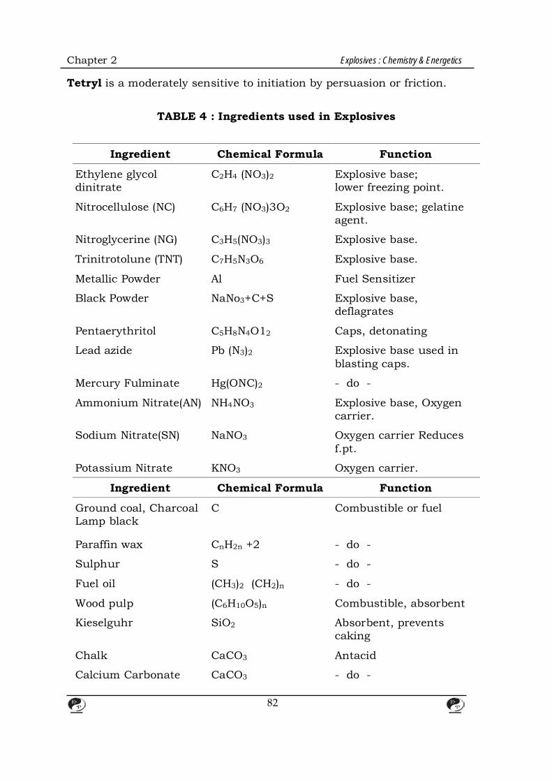
Chapter 2 Explosives : Chemistry & Energetics
Tetryl is a moderately sensitive to initiation by persuasion or friction.
TABLE 4 : Ingredients used in Explosives
Ingredient Chemical Formula Function
Ethylene glycol dinitrate
C2H4 (NO3)2 Explosive base; lower freezing point.
Nitrocellulose (NC) C6H7 (NO3)3O2 Explosive base; gelatine agent.
Nitroglycerine (NG) C3H5(NO3)3 Explosive base.
Trinitrotolune (TNT) C7H5N3O6 Explosive base.
Metallic Powder Al Fuel Sensitizer
Black Powder NaNo3+C+S Explosive base, deflagrates
Pentaerythritol C5H8N4O12 Caps, detonating
Lead azide Pb (N3)2 Explosive base used in blasting caps.
Mercury Fulminate Hg(ONC)2 - do -
Ammonium Nitrate(AN) NH4NO3 Explosive base, Oxygen carrier.
Sodium Nitrate(SN) NaNO3 Oxygen carrier Reduces f.pt.
Potassium Nitrate KNO3 Oxygen carrier.
Ingredient Chemical Formula Function
Ground coal, Charcoal Lamp black
C Combustible or fuel
Paraffin wax CnH2n +2 - do -
Sulphur S - do -
Fuel oil (CH3)2 (CH2)n - do -
Wood pulp (C6H10O5)n Combustible, absorbent
Kieselguhr SiO2 Absorbent, prevents caking
Chalk CaCO3 Antacid
Calcium Carbonate CaCO3 - do -
82
Chapter 2 Explosives : Chemistry & Energetics
Zinc Oxide ZnO - do -
Sodium chloride NaCl Flame depressant (permissible explosives).
In formulating mixtures of explosives, it is necessary to achieve an oxygen
balance in order to:
a. Maximize the explosive energy of the reaction by aiming at complete
Combustion, and
b. To avoid the presence of toxic gases in the combustion products.
This is generally achieved by using, i) combustibles / fuels to react with the
excess oxygen and thereby prevent the formation of toxic oxides of nitrogen
or, ii) oxidizing agents to promote full oxidation of Carbon to Carbon dioxide,
thereby inhibiting the formation of toxic Carbon monoxide. An adsorbent
such as Kieselguhr has been used to absorb liquid explosives such as
nitroglycerine, Antacids promote stability in storage. Low freezing point
compounds reduce the propensity of the mixture to freeze in cold weather.
Gelatinising agents promote water resistance. Flame depressants or coolants
reduce the size, duration and temperature of the flame during the explosive
reaction to avoid methane/coal dust explosion in coal mines.
In the category of high explosives, the chief base are nitroglycerine (NG) and
ammonium nitrate (AN) although TNT also has a limited application in the
industrial explosive area. There are three different categories of high
explosives, each of different physical characteristics and chemical
composition; but all have comparable values as explosive. These three
categories are:
a. TNT
b. Dynamites and gelatins, &
c. Slurry explosives.
83

Chapter 2 Explosives : Chemistry & Energetics
A brief account of each of these is given below. 5.1 Trinitrotoluene TNT is a high density explosive of excellent water resistance. Although
primarily used in the field of military explosives, it is used particularly in the
U.S. in commercial explosives also as pellets, flakes or grains. It combines
the important advantages of a high strength explosive base with that of low
hazard sensitivity. Pelleted TNT is marketed in the US under the trade name
of ‘ Nitropel’. Nitropel can be poured direct into wet or dry quarry holes
either as the main charge or to fill the annular space around rigid cartridges
as supplement.
In the latter case it is primed by the surrounding charge. When used as a
main charge it calls for a high strength primer. When detonated, TNT
produces much fume; therefore it cannot be used underground.
Crystalline TNT (flaked and grained) is used in the manufacture of Pentolite
boosters, in certain slurry explosives and in some blasting accessories.
5.2 Dynamite and Gelatines Nitroglycerine or glycerol trinitrate has the following formula.
CH2 O NO2 CH O NO2 CH2 O NO2
Discovered by Sobrero in 1847. It was developed to a commercial scale by
Alfred Nobel. Nitro glycerine is a viscous yellow liquid which freezes at 13.2
°C to a sensitive solid explosive. In both forms it is too sensitive to be
handled safely. It is therefore converted into a more convenient gelatinous
84
Chapter 2 Explosives : Chemistry & Energetics
(plastic) solid by the addition of 8% gun cotton or nitro cellulose (obtained by
the nitration of cotton) to form Blasting gelatine or by absorbing it in
Kieselguhr to give straight dynamite (containing about 75% NG) or by
admixtures with other explosive agents and additives to form other types of
dynamites such as the following.
i. Ammonia dynamites: (also called extra dynamites)
Contain AN in place of SN, in addition to NG. They have lower VOD,
lower density, higher shock resistance and better fume
characteristics.
ii. Semi gelatins or low NG, high AN explosives:
Nitroglycerine is mixed with nitrocellulose to form a gel matrix to
which AN is added in various proportions. Fuels like starch and wood
meal are also added. In case of use in coal mines (permitted
explosives) coolants like sodium chloride, calcium formate etc., are
incorporated.
6. Slurry Explosives The gelatine explosives suffer from two important drawbacks. One is their
susceptibility to accidental detonation by impact or friction and the other is
the danger of exudation of NG from the cartridge. Therefore during the last
few years a different kind of high explosives called the slurry explosives,
have been increasingly used. Their main explosive base is ammonium
nitrate (which is an oxidizer). Its use depends on the complementary
reaction of a reducing agent (called the sensitizer ) to support or provide the
chemical (explosive) reaction. These sensitizers comprise a range of
carbonaceous combustibles or fuels. TNT, smokeless powder, finely divided
light metals (such as aluminum) and certain organic compounds.
A Slurry explosive may be defined as a semi-solid or pasty suspension of an
85

Chapter 2 Explosives : Chemistry & Energetics
oxidizer, fuel and sensitizer in a thickening agent such as guargum,
crosslinked and stablised by inorganic salts of antimony or chromium.
These ‘cross-link’ slurries are sometimes called ‘Watergel’ explosives. Some
times microballoons (3-4 microns) are also used as additional sensitizers.
The slurry explosives have the following distinct advantages:
1. Built in safety against impact, friction and fire.
2. Water compatibility.
3. Reduction of post-blast fumes containing, CO, NO & NO2
4. Elimination of NG headaches.
5. Increased borehole coupling.
6. Greater control of density.
7. Powder Explosives One of the major applications of prilled ammonium nitrate coated with
anticaking agents is in the manufacture of powder explosives.
ANFO – a mixture of AN (94.53) and Fuel Oil (No. 2 diesel 5.52) – is one such
explosive. Air voids present in the prilled AN act as snsitizers. This mixture
detonates at a velocity of 10,000 to 14,000 feet per second according to the
general reaction.
3 NH4NO3 + CH2 (X) 7 H2O + CO2 + 3N2
These mixtures can have their sensitivity increased by the addition of
sensitizers like TNT, DNT, NG, Nitrostarch, etc. Other fuels like woodmeal,
rice husk, coal powder etc., are also often used. These mixture are regarded
mostly as flammable rather than as explosives. These explosives suffer from
the following disadvantages.
86
Chapter 2 Explosives : Chemistry & Energetics
1. Caking of explosive.
2. Poor water compatibility
3. Low density.
4. Bad post blast fumes.
5. Dust problems in handling powders.
8. Energetics of Explosives The usefulness of an explosive or an explosive mixture arises from the
availability of a large amount of heat released suddenly under high pressure.
The science of thermodynamics and thermochemistry can help in the
calculation of the energy produced in such explosive reaction.
C + O2 CO2 + 94.05 K.Cals.
When an oxide of nitrogen such as NO is formed from the elements energy is
taken from the surroundings – an endothermic reaction takes place :
21 N2 +
21 O2 NO - 22 K.Cal. The energy released or absorbed is
generally represented in K. Cals or K. joules. Elements in the standard
states of aggregation are assumed to have zero heat content. Therefore the
heat content of CO2
Is -94.05 K. Cals. Similarly NO has a content of 22 K.Cal per mole.
The amount of heat liberated on the total combustion of a mole of
nitroglycerine is 344 K.Cals. This may be determined experimentally
(calorimetrically) and also theoretically as follows.
87
Chapter 2 Explosives : Chemistry & Energetics
CH2 – ONO2
CH – ONO2 12CO2 + 10H2O + 6N2 + O2 +1375.8 K. Cals. CH2 – ONO2
NG is said to have a positive oxygen balance because of the liberation of
excess O2.
Heat of formation of CO2 = + 94.05 K. Cals.
Heat of formation of H2O = + 57.8 K. Cals.
Heat of formation of nitroglycerine.
3C + 225 H2 +
23 N2 ← NG + 82.7 K. Cals.
According to the foregoing equation 82.7 K. Cals are required to convert 1
mole of NG into its constituent elements. The heat content of NG is therefore
-82.7 K.Cals. The net heat of combustion of 4 molecules of NG will be
((12 x 94.05 + 10 x 57.8) – (4 x 82.7)) K. Cals = 1375.8 K. Cals.
Or, 1 mole of NG can liberate 344 K. Cals of heat, and 1 kg of NG can
liberate 1515.2 K. Cals of heat.
(1 mole of NG = 227 gm).
The energy obtainable from two typical explosives is calculated as under:
Explosive Formula % in explosive Oxygen Balance* AN NH4 NO3 89 89 x (+0.2) = 17.8 DNT C7 H6 N2O4 8 8 (-1.14) = - 9.12 Woodmeal (C6H10O5) n 3 3 (-1.10) = - 3.30
Total oxygen balance = + 5.38
88
Chapter 2 Explosives : Chemistry & Energetics
8.1 Reactions
NH4 NO3 N2 + 2H2O + 21 O2 + X cals.
C7H6N2O4 + 23 O2 7CO2 + 3H2O + N2 + X cals.
C6H10 O5 + 602 6CO2 + 5H2O + X cals. In one kg. of the explosive AN 890 gm 11.125 moles
DNT 80 gm 0.44 moles
Woodmeal 30 gm 0.185 moles
Amount of N2 = 11.125 x 1 + 0.44 x 1 = 11.565 moles
Amount of CO2 = 0.44 x 7 + 0.185 x 6 = 4.190 moles
Amount of steam = 11.125 x 2 + 0.44 x 3
+ 0.185 x 5 = 24.495 moles
Amount of oxygen not used,
= (11.125 x 0.5) – (0.44 x2
13 ) – (0.185 x 6)
= 1.5925 moles.
Total no. of moles of gases after explosion = 11.565 + 4.190 + 41.8425 + 24.495 +1.5925 = 41.8425
Total vol. of gas at NTP = 22.4 X 41.8425 = 937.272 litres.
(Note: 1 gm mole of any gas occupies 22.4 litres at NTP)
So, 1 Kg of exolosives can produce upto 937.272 litres of gas.
89
Chapter 2 Explosives : Chemistry & Energetics
Total Energy Energy released =
= (Heat of formation of products) – (Heat of formation of reactants)
= (No. of moles of CO2, H2O, N2, O2 x (respective H) –
No. of moles x (H of AN, DNT and Woodmeal)
= (4.19 x 94.05 + 24.495 x 57.8) – (11.125 x 81.23 + 0.44 x
16.9 + 0.185 x 8.108 )
= 897.261 K. Cals per kg. (H for Heat)
So, 1 Kg of explosives can produce upto 897.261 K Cals per Kg.
Example 2: Calculation of the energy of a slurry formulation.
Component % in Composition Weight in 1000 gms. AN 61 610 SN (Sodium Nitrate) 5 50 SPC (Sodium Per chlorate) 8 80 Water 12 120 A1 7 70 Ethylene glycol 6 60 Gum 1 10
100 1000 Reactions Assumed
NH4NO3 N2 + 2H2O +21 O2
2NaNO3 Na2O + N2 + 25 O2
NaClO4 NaCl + 2O2
2A1 + 23 O2 Al2O3
C2H6O2 + 25 O2 2CO2 + 3H2O
90

Chapter 2 Explosives : Chemistry & Energetics
C6H10O5 + 6O2 6CO2 + 5H2O
Total Oxygen Balance of the Compositions: 61 x 0.2 + 5.0 x 0.47 + 8.0 x 0.5 + 7 x (-0.9) + 6 x (-1.3) + 1.0 (-1.1)
= 18.55 – 15.2 = + 3.35
The explosive composition is thus a oxygen positive formulation.
No of moles of Products
No. of moles of N2 H2O CO2 O2 A12O3 Reactants AN = 7.625 7.625 5.25 - 3.8125 - SN = 0.588 0.294 - - 0.7350 - SPC = 0.653 - - - 1.3060 - A1 = 2.590 - - - -1.9425 1.295 EG = 0.967 - 2.901 1.934 -2.4175 - Gum= 0.055 - 0.275 0.330 - 0.3300 -
Total no. of 7.919 18.426 2.264 +1.1635 1.295 Moles Total no of moles = 31.0675
∴Total gas volume produced = 31.0675 x 22.4 = 695.9 litres/kg.
Total Energy = Heat of formation of products (H2O, CO2, Al2O3) – (Heat of formation of
Reactants AN, SN, SPC, EG, Gum + Latent Heat of evaporation of water).
= (18.426 (57.8) + 2.264 (94.05) + 1.295 (399)
- ((7.625 (81.53) + 0.588 (111.54) + 0.653 (92.18)
+ 0.967 (108.7) + 1265 x 10 + 0.583 (120))
1000
91
Chapter 2 Explosives : Chemistry & Energetics
= 1794.657 – 935.165 K. Cals/kg.
= 859.498 K. Cals/kg.
8.2 Detonation Temperature The heat of explosion raises the reaction products to the detonation
temperature. One method that can be adopted to estimate the detonation
temperature is the use of the following expression. Explosion temp (T) = Heat
liberated H/Specific heat of gases (Cv)
For example 1, where H = 871.44 K. Cals., T = 2149° K or 1876° C.
An alternative and more elegant method for calculation of the detonation
temperature is to assume two temperature values and to sum up the
internal energies for the reaction product multiplied by their corresponding
mole number. Two caloric values are obtained of which one may be higher
than the calculated heat of explosion and the other slightly lower. The
detonation temperature is found by interpolation between these two values.
For Example 2, two temperatures 2100 K and 2200 K may be assumed. The
following table gives the internal energies.
@2100 K No. of Product @2200K Product K. Cal per mole moles K. Cal K. Cal per mole K. Cal CO2 27.19 4.2 114.2 28.66 120.4 H2O 21.51 24.5 527.9 22.79 558.4 N2 16.60 11.6 912.6 17.47 202.9 O2 17.51 1.6 28.0 18.41 29.5
41.9 861.8 910.8 The interpolated temperature value for 864 K. Cal would be nearer 2100 K.
92

Chapter 2 Explosives : Chemistry & Energetics
9. Factors Affecting the Performance of High Explosive 9.1 Oxygen Balance As was mentioned earlier, during detonation, the fuel elements in the
explosive get oxidized vary fast. Therefore oxygen balance, i.e the percentage
of excess oxygen in the composition is an important factor in energy
production. In an ideal composition, the oxygen balance should be zero. If
fuel or oxidizer is in excess harmful gases like carbon monoxide or oxides of
nitrogen are produced, apart from loss of energy.
9.2 Completion of Reaction It is also important that the reaction taking place during an explosion
should go to completion at the required speed. For example, it the Carbon in
the system is oxidized to CO rather than CO2, the production of energy
comes down by 75%. The formation of oxides of nitrogen also involve
absorption of energy.
C + O2 CO2 + 94 K.Cal.
C + 21 O2 CO + 26 K. Cal.
21 N2 +
21 O2 NO – 22 K.Cal.
9.3 Compatibility of Ingredients The ingredients used in the formulation of an explosive should be such as
not to lead to extraneous complications. For instance if the AN used in
ANFO contains more than 1% moisture, caking results. This extra moisture
content would also result in lowered energy production. If the surface of
sensitizer grade A1 is not properly protected, it might react with water to
produce hydrogen in an exothermic reaction. This prelibation of gas would
93
Chapter 2 Explosives : Chemistry & Energetics
result in bursting of cartridges and loss of power.
9.4 Critical Diameter The critical diameter is the minimum diameter of an explosive charge at
which detonation can still take place. The detonation wave tends to fail or
fade when the diameter of the explosive charge decreases. Normally the
propagation sensitivity of an explosive is measured at a length at least six
times the diameter cartridge and the VOD is measured at a length at least
six times is measured at a distance of six inches from the point of initiation.
At a lower diameter, even if the explosive is sensitive, the reaction in the
cartridge may be incomplete. The above phenomenon can be eliminated by
carefully controlling the critical density or the ‘Loading Density’.
9.5 Critical Density Density is an important characteristic of explosives. Raising the density (e.g.
by pressing or Casting) improves brisance and detonation velocity. In
contrast low density explosives produce a milder thrust effect. The critical
density of ANFO is less than 1g/cc and that of TNT is 1.76 g/cc.
9.6 Packaging The packaging of an explosive is yet another important factor that governs
the quality of an explosive. Moisture can affect the performance of certain
explosives packed in craft paper. In powder explosives, the AN component
cakes up because of water incursion. Proper waxing of the cartridge is also
necessary. Aluminum clips are not permitted in underground coal mines.
9.7 Strength Measurement The strength of an explosive is usually assessed by a series of tests chosen
94

Chapter 2 Explosives : Chemistry & Energetics
to measure the performances of the explosives under various conditions.
Whilst these tests are of considerable value, particularly for comparative
purposes, it must be remembered that no laboratory test or series of tests
can preduct precisely the performance of explosives in the field.
9.8 Power The power or strength of any explosive is usually expressed in terms of
power per unit weight which is appropriate for comparing explosives used in
charges measured by weight. One of the most satisfactory instruments for
carrying out this measurement in the laboratory is the Ballistic mortar (Fig.
1). This consists of a pendulum 3 m long at the bottom of which is a bob
weighing 333 kg. A shot is used of 12.37 cm diameter weighing 16.6 kg and
fitting with a clearance of 0.88 mm. Ten grammes of the explosive under test
are wrapped in tin foil and fired with a standard copper detonator. The
explosive ejects the shot on to rubber matting. The corresponding recoil of
the bob is shown on a scale and is a measure of the energy imparted by the
explosive to the system. In Great Britain, the standard explosive is blasting
gelatine and results are expressed as a percentage of the strength of blasting
gelatine.
An older form of measuring power was the Trautzel lead block test (Fig. 2).
The explosive under test is placed in a cylindrical hole in a block of specially
cast lead and the remainder of the hole filled with sand. When the explosive
is fired, it causes an expansion of the hole in the lead block and this
expansion is measured by filling with water. For most explosives there is an
adequate correlation between lead block results and ballistic mortar
measurements (Fig. 3).
The ballistic mortar and lead block tests are not applicable to slurry
explosives which are too insensitive to detonate properly under such
95
Chapter 2 Explosives : Chemistry & Energetics
conditions where only small amounts of explosives are used. For these
explosives, it is useful to fire larger amounts of several kg. Under water and
measure the period of oscillation of the gas bubble produced. The longer the
period of oscillation of the gas bubble, the greater the energy of the gas
bubbles. This part of the total energy correlates well with the blasting affect
of the explosive.
9.9 Velocity of Detonation VOD is generally measured by the well-known ‘Dautriche method’, the
principle of which is illustrated in Figure 4. The two ends of a length
detonating fuse (usually 10 g/m) are inserted in the explosive under test at a
known distance apart. The midpoint of the piece of detonating use is known
and the part of the fuse near this point is placed over a V-shaped groove in a
thin lead plate. When the explosive is fired, the fuse commences to detonate
first at the end nearer the detonator and later at the other end. When the
two detonation waves in the fuse meet, they reinforce and produce a distinct
mark on the lead plate, visible particularly as a spit on the back, This point
will be removed from the midpoint of the fuse by a distance which depends
on the velocity of detonation of the explosive under test according to the
following equation D = D11 / 212 where D is the velocity of detonation of the
explosive, d is the velocity of detonation of the detonating fuse, 11 is the
length of the explosive under test, 12 is the distance between the centre of
the fuse and the mark on the plate.
In recent time, VOD is more effectively measured by the use of high speed
cameras, and also electronically.
Sensitiveness: One of the commonest methods to evaluate the sensitiveness of an explosive
to impact is the ‘fall hammer test; which determines the minimum height
96

Chapter 2 Explosives : Chemistry & Energetics
from which a given weight must be dropped in order to initiate detonation. A
simple and practical method of this experiment is shown in Fig. 5. In this,
the explosive is put between two roller bearings, themselves placed in a ring
of hardened steel and resting on a hardened steel base. The falling weight is
arranged to hit the upper of the steel cylinders. Typical weights employed
are from 0.5 to 5 kg. and height of fall may be upto 200 cm.
A corresponding useful test for the safety of an explosive during handling
(when it can be subjected to a blow at a glancing angle) is the torpedo
friction test.
Results of sensitiveness tests on typical explosives are given in Table 5, for
steel to steel surfaces, in the absence of grit.
Table 5 : Sensitiveness of Explosives
Fall Hammer Torpedo Friction (0.5 kg) (cm) (1 kg at 80°) (cm) TNT 200 80 – 120 RDX/TNT 80 – 100 40 – 45 RDX 25 – 30 10 – 20 PETN 60 – 80 35 – 40 NG Powder 20 – 30 150 TNT Powder 160 – 200 100 – 120 9.10 Detonation Pressure Detonation pressure of an explosive depends on the density of an explosive.
Higher the density, the higher will be the detonation pressure for a given
composition. Above the critical density, detonation pressure is zero as the
cartridge will not explode.
The following generalized formula can be used for calculating detonation
97
Chapter 2 Explosives : Chemistry & Energetics
pressure.
P = 0.00987 + D2 P/4
Where P = density of the explosive and D = VOD in kilometers per sec.
It can be observed that higher VOD and higher density would lead to higher
detonation pressure.
9.11 Explosion Temperature Explosion temperature is the calculated temperature of the fumes of an
explosive material which is supposed to have been detonated while confined
in a shell assumed to be indestructible and impermeable to heat. Its
calculation is based on the heat of explosion and on the decomposition
reaction, with allowance for the dissociation equilibrist and the relevant gas
reaction. The real detonation temperature is higher than the calculated one.
This parameter has important implications. For instance, in case of coal
mine explosives, a balancing of explosion temperature and the gas volume
plays an important role. If the composition has high explosion temperature
(< 2000° C), it will make the methane air atmosphere incendive. If it is too
low (< 1000°) the composition will not have any useful energy for dislodging
coal.
10. SLURRY EXPLOSIVES One of the major advances in the production of commercial high explosives
during the last 20 years has been the development of ‘Slurry Explosives’ also
called ‘Water-gel’ explosives. These formulations possess demonstrated
advantages like safety and fume characteristics over the NG based
explosives with the result that their manufacture and use have grown by
leaps and bounds during the last two decades.
An aqueous slurry explosive composition generally contains a suspension of
98

Chapter 2 Explosives : Chemistry & Energetics
inorganic oxidising salt, usually predominantly ammonium nitrate,
suspended in a saturated aqueous. solution of oxidising salt together with
sensitiser and optionally additional fuel. To prevent separation of the
ingredients and to improve the resistance to deterioration of the composition
in wet conditions the aqueous phase is usually thickened with a dissolved
thickening agent, the currently preferred thickener being guar gum. The
composition is often further gelled by crosslinking the thickening agent with
a crosslinking agent such as a chromate, dichromate or pyroantimonate.
Although the term 'slurry' is universally applied to such compositions, the
degree of consistency may range from pourable to highly viscous extrudable
gels.In order to improve the explosive sensitivity, the composition often
contains an aeration agent which usually is a chemical such as sodium
nitrite which reacts in situ in the composition to generate small gas bubbles
throughout the mass and thus reduce the density.The advantages of
incorporating gas bubbles in aqueous slurry explosives by means of gassing
agents or by the addition of gas-containing material for density and
sensitivity control are now well known. The beneficial sensitising effect of the
gas bubbles is believed to be attributable to the 'hot- spots' obtained by the
adiabatic compression of the gas bubbles by the shockwave produced during
detonation. In accordance with the present invention, the gassing efficiency
and productivity of nitrite salts can be susbtantially improved by combining
with a nitrite salt a gassing accelerator comprising the thiocyanate ion SCN-.
Preferred thiocyanate ion-containing materials include, for example, sodium
thiocyanate and ammonium thiocyanate or a mixture of these.
An aqueous slurry explosive composition of the type suitable for use in large
diameter borehole charges was prepared according to the following
formulation the amounts shown being expressed as percent by weight:
99
Chapter 2 Explosives : Chemistry & Energetics
Nearly all commercial and mining explosives used in the world today are
based on ammonium nitrate (AN) or combinations of AN with other alkaline
and/or alkaline earth nitrate salts, eg. sodium or calcium nitrata Most
explosives of this type rely on the energetic reaction of nitrogen compounds
incorporated within the explosive to provide the necessary explosive power.
AN, which is a strong oxidiser, has been used as the base of commercial
explosives for at least the last 50-60 years.
Initially, mining companies used AN as an explosive on its own. However,
they soon realised that the addition of diesel increased the energy output
without a large increase on costs (ammonium nitrate- fuel oil, now
commonly referred to as 'ANFO'). However, the water resistance of ANFO is
quite poor, which limited its use in wet blast holes. To ameliorate this issue,
slurries and watergels were developed. Slurries typically comprise AN
dissolved dispersed in water, other salts (calcium nitrate, sodium nitrate,
etc) to depress the crystallisation point of the AN solution, and other
additives such as guar gum (as thickener) and fuel (diesel). They can also be
blended with ANFO depending on the characteristics of the ground being
blasted. Slurries also typical ly include solid sensitisers (aluminium and
high explosives such as TNT, RDX, efc) to enable the slurry to detonate and
100
Chapter 2 Explosives : Chemistry & Energetics
to minimise misfires. Watergels have similar compositions to slurries,
however, crosslinkers can be added to enhance the water resistance of the
product. Watergels can be aerated or gassed with bubbles chemically
generated in situ or mixed with glass/plastic miaospheresto lower the
density, improve sensitivity and change the levels of energy delivered to the
ground being blasted.
One of the drawbacks of watergels and slurries is that there is a limit of AN
which can be incorporated into the solution. This drawback was overcome
by the development of water-in-oil emulsions.
These emulsions can contain AN in high concentration (see US Patent No.
3,447,978). Water in oil emulsions are made of a hot aqueous phase
(composed of AN, other nitrate salts, perchlorate salts, etc) dispersed into an
organic fuel. The aqueous - organic mixture is stabilised by the use of an
emulsifier. Emulsions can also be blended with ANFO in different ratios
Watergels can be aerated, gassed with bubbles chemically generated in situ
or mixed with glass plastic microspheres to lower the density, improve
sensitivity velocity of detonation (VOD) and change the levels of energy
delivered to the ground being blasted.
Despite the development of AN emulsions, AN slurries and watergels,
however, there is still a need to develop improved explosives, which are
preferably more cost effective compared to existing explosive compositions
and are capable of being produced in large quantities to meet the high
demand from industry. Preferably any explosive composition which can be
substituted for an AN-based explosive is insensitive to misfires and is not
desensitised by wet blast holes Furthermore, preferably any AN substitute is
a sustainable raw material which has a relatively low carbon footprint, and
which can be manufactured relatively easily and preferably near the actual
mine site to minimise transport issues. In addition, preferably any AN
101

Chapter 2 Explosives : Chemistry & Energetics
substitute can be produced on an as- needs basis to minimise the need for
stockpiling and to increase safety. Further still, preferably any AN substitute
can be used in slurry or in emulsion form so that existing equipment can be
used, and when in slurry form or is emulsified such that the viscosity
enables pumping without difficulty. It would also be ideal if there are no
onerous regulatory requirements for such a substitute, thereby reducing
administrative costs It would also be preferable for the explosive composition
to be cross linkable in- situ to increase viscosity down the blast hole.
Despite of the advances on the types of composition that can be
manufactured from ammonium nitrate, one of the disadvantages is that
during the detonation NOx fumes can be generated, due to the presence of
nitrogen compounds in the explosive composition (from nitrates). These NOx
fumes are toxic and can affect the health of mine site personnel. Therefore
the emission of NOx fume after blasting is a safety issue and in countries
like Australia there are now strict regulatory controls in place to manage
such emissions.
Slurry Explosives are ‘fuel’ sensitized AN with or without other oxidisers
such as Sodium nitrate (SN) or sodium perchlorate (SPC) or ammonium
perchlorate in which the solid fuel and the solid part of the oxidisers(s) are
dispersed in a continuous fluid medium generally an aqueous solution with
our without other polar solvents and often more or less aerated. They have
been designated differentially as slurry explosives (SE) when they are
sensitized with explosives (e.g. TNT) and slurry blasting agents (SBA) when
the fuel is not an explosive (e.g. aluminium, sulfur and solid hydrocarbon). A
further division of these water-based explosives is into watergels and
emulsion explosives.
The water gel explosives have the oxygen donor in the form of nitrate salts
fully or partly in a water solution which is gelled. In this gel, the fuel which
is dissolved or distributed, quite often consists of aluminium powder,
102
Chapter 2 Explosives : Chemistry & Energetics
methylamine nitrate (MAN), glycol and urea. Some of the fuels also sensitize
the mixture. Additional sensitizing is achieved by the acid of small gas
bubbles.
The emulsion explosives have an oxygen donor consisting of nitrates and
perchlorates in an acqeous solution. The water phase is in the form of small
droplets in the continuous oil phase which constitutes the fuel. The fuel
constitutes the fuel. The fuel consists of mixtures of waxes and oils. The
explosives are in this case sensitized by gas bubbles in the form of
microspheres. Additional strength can be achieved by the addition of fuels
such as aluminium powder.
10.1 Development of Slurry Explosives One of the first formulations in this direction viz. AN/FO interestingly owes
its origin and development to two major catastrophic incidents – one in
Texas city in the US and the other aboard a ship in Breast in France. These
explosions incidentally revealed that AN is a low-cost, powerful explosive
especially in the presence of fuels like oil or wax. The first of the watergel
explosives contained about 20% water 23% coarse TNT and 55% AN or
mixed AN and SN, thickened to a slurry consistency with guar gum. The
TNT acted both as the fuel and the sensitizer. The next development was the
production of the slurry blasting agent SBA – A1 which contained
Aluminium particles of a special grade in place of TNT.
In both the systems described above, the mechanism of sensitivity depended
on the existence of small air bubbles get compressed adiabatically when
initiated, raising the temperatures of the slurry to several thousands of
degrees centigrade. This high temperature leads to the explosion.
It should be noted that, in the case of TNT, TNT itself acts as a detonating
103
Chapter 2 Explosives : Chemistry & Energetics
high explosive leading to a shock wave mechanism. The effectiveness of TNT
depends on the concentration and size of the particles.
In the aluminized slurries, the mechanism called the ‘hotspot’ is governed by
the following ‘factors.
1. Air bubbles of the size 2 - 4 micron should be present for providing
initiation spots, and
2. These bubbles must be in contact with the aluminium particles.
The earlier non-crosslinked slurries suffered from the following
disadvantages:
1. Solids separate out on storage due to gravity and the solid solution
equilibrium cannot be effectively controlled.
2. The enclosed air bubbles, if allowed to escape, reduced the sensitivity
of the explosives.
104

Chapter 2 Explosives : Chemistry & Energetics
11. A Comparison of Slurry /Water Gel and Emulsion Explosives One material that is also an oxidiser and that has the potential to meet at
least some of the health and safety needs of modern times is hydrogen
peroxide (HP). Use of HP as a liquid explosive has been patented by Shanley
(US Patent No. 2,452,074) in which HP was mixed with glycerol and water,
and initiated with a detonator. US 2,452,074 teaches that to achieve
detonation the explosive compositions can only contain up to 52 wt% water.
More recently, in 1990 mixtures of HP and water soluble resins were
patented by Bouillet as a packaged explosive (US Patent No. 4,942,800).
Examples provided in the patent show that some of the mixtures detonated
at velocities above 6,000 m/s (in 33 mm diameter, unconfined blasts). Also,
work published by Shell Co. (Concentrated Hydrogen peroxide, summary of
research data on safety limitations, 1961) presents the detonation limits of
the system HP-acetic acid-water in a ternary diagram. In 2004 an
investigation into the detonation properties of HP and alcohols was
published {"Investigation of explosive hazard of mixtures containing
hydrogen peroxide and different alcohols", Journal of Hazardous Materials,
A 108 pp. 1-7, 2004).
Structure of concentrated oil-in-water Pickering emulsions
105
Chapter 2 Explosives : Chemistry & Energetics
12. Water gel-technology for HP-based explosive HP-based watergels can be prepared with either water-miscible or water
immiscible fuels. Water-soluble fuels which can be used with the present
invention can be selected from the group consisting of: glycerol, sugar,
amine nitrates, hexamine and urea Water-insoluble fuels which can be used
with the present invention can be selected from the group consisting of:
include aliphatic, alicyclic and aromatic compounds and mixtures thereof
which are in the liquid state at the formulation temperature. Suitable
organic fuels may be chosen from fuel oil, diesel oil, distillate, kerosene,
naphtha, waxes, (eg. microcrystalline wax, paraffin wax and slack wax)
paraffin oils, benzene, toluene, xylenes, asphaltic materials, polymeric oils
such as the low molecular weight polymers of olefins, vegetable oils, animal
oils, fish oils, and other mineral, hydrocarbon or fatty oils, and mixtures
thereof. Preferred organic fuels are liquid hydrocarbons generally referred to
as petroleum distillates such as gasoline, kerosene, fuel oils, paraffin oils
and vegetable oils or mixture thereof.
Reaction schematic of emulsion explosives( in a different setting)
106

Chapter 2 Explosives : Chemistry & Energetics
12.1 Thickeners and cross-linkers Because bubbles of gas and materials enclosing gas have a relatively low
density, they will tend to migrate towards the surface of the column of
explosive if the viscosity of the HP-based explosive composition is not
capable of maintaining the sensitising material homogeneously dispersed
throughout. Migration of the sensitising material towards the surface is
undesirable as it may render the explosive too insensitive to initiation, and
therefore the explosive composition may not deliver the energy and gases
needed to break and move the rock as required or even worst, the explosive
may undergo a misfire. One way to ameliorate this issue is to formulate the
explosive composition into a watergel. These types of compositions can be
formulated with different levels of viscosity by using a thickener. Viscosities
can be selected to generally retain the sensitising material in a
homogeneously dispersed state throughout the composition.
Microscopic image of a Water Gel Explosive
13. Emulsion-technology for HP- based explosive compositions HP-based emulsions can be prepared with water-immiscible fuels The water-
immiscible organic phase component of the composition comprises the
continuous "oil" phase of the water-in-oil emulsion and is the fuel. Suitable
107

Chapter 2 Explosives : Chemistry & Energetics
organic fuels include aliphatic, alicyclic and aromatic compounds and
mixtures thereof which are in the liquid state at the formulation
temperature. Suitable organic fuels may be chosen from fuel oil, diesel oil,
distillate, kerosene, naphtha, waxes, (e.g. micrccrystalline wax, paraffin wax
and slack wax) paraffin oils, benzene, toluene, xylenes, asphaltic materials,
polymeric oils such as the low molecular weight polymers of olefins,
vegetable oils, animal oils, fish oils, and other mineral, hydrocarbon or fatty
oils, and mixtures thereof. Preferred organic fuels are liquid hydrocarbons
generally referred to as petroleum distillates such as gasoline, kerosene, fuel
oils paraffin oils and vegetable oils or mixture thereof.
13.1 Emulsifier/Stabiliser HP-based emulsion compositions are made of a discontinuous phase of
oxidising material that is dispersed in a continuous phase of an organic fuel
in the presence of one or more emulsifying agents. The emulsifying agent is
adapted or chosen to maintain phase separation. The emulsifying agent
component of the composition of the present invention may be chosen from
the wide range of emulsifying agents known in the art for the preparation of
water-in-oil emulsion explosive compositions. Among the preferred
emulsifying agents are the 2-alkyl- and 2- alkenyl-4,4'-bis (hydroxymethyl
oxazoline, the fatty acid esters of sorbitol, lecithin, copolymers of poly
(oxyalkylene) glycols and poly (12-hydroxystearic acid), and mixtures
thereof.
13.2 Energy Diluents (optional) In the context of both types of explosives, energy diluting agents are inert
materials that have minimal contribution to the detonation process and can
be used to replace part of the energetic material in the composition and
therefore reduce the energy output of the hydrogen peroxide-based
108
Chapter 2 Explosives : Chemistry & Energetics
explosive. In some cases these energy diluting agents are able to reduce the
density of the HP-based composition without increasing the sensitivity.
Examples of these diluents materials are granulated/shredded rubber (from
tyres), cotton seeds, saw dust, husk, expanded pop corn, plastic beads, wool
meal, saw dust, bagasse, peanut and oat husks, peanut shells etc.
Table 6 lists the components of explosive systems discussed herein and
provides typical ranges for each.
Table 6: Components for explosive systems discussed herein with
typical ranges for each.
The present comparison relates to a peroxide-based explosive composition
that is preferably prepared as watergel or water-in-oil emulsion, and is
sensitized. Typical components for each type of explosive technology are
listed in Table 7.
This section describes the LC model and Inventory developed to assess the
emulsion explosive production carried out by a specific European company,
109
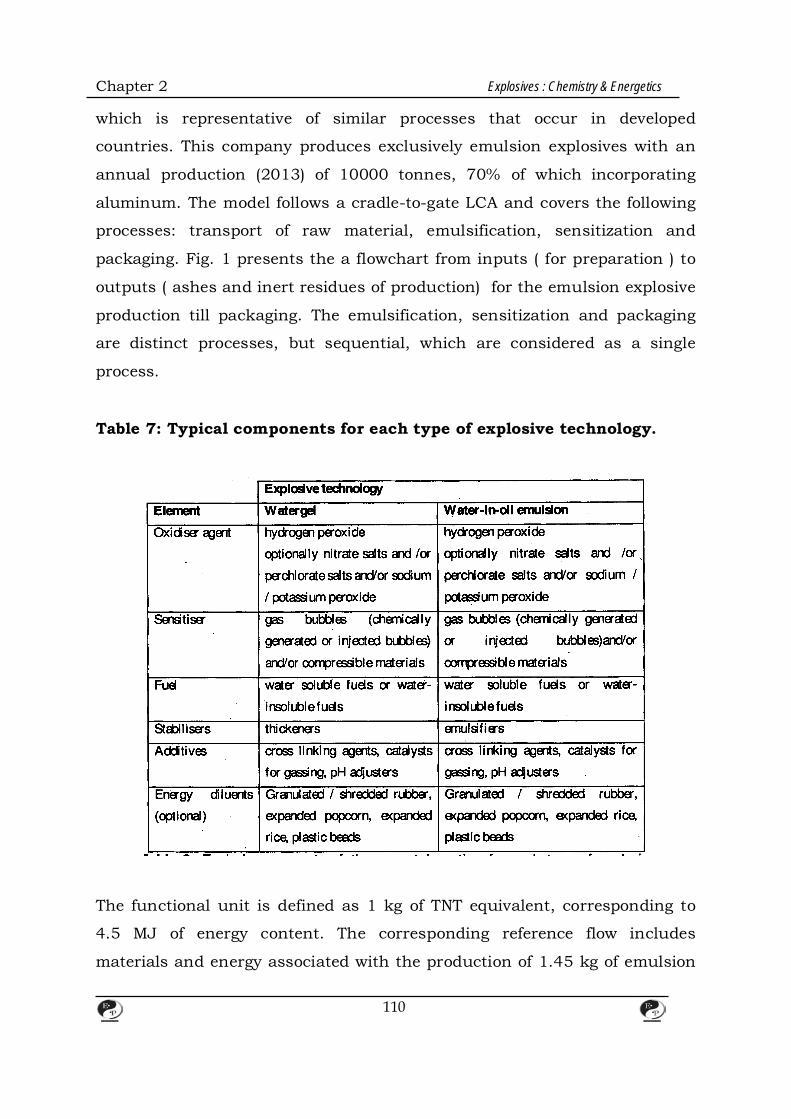
Chapter 2 Explosives : Chemistry & Energetics
which is representative of similar processes that occur in developed
countries. This company produces exclusively emulsion explosives with an
annual production (2013) of 10000 tonnes, 70% of which incorporating
aluminum. The model follows a cradle-to-gate LCA and covers the following
processes: transport of raw material, emulsification, sensitization and
packaging. Fig. 1 presents the a flowchart from inputs ( for preparation ) to
outputs ( ashes and inert residues of production) for the emulsion explosive
production till packaging. The emulsification, sensitization and packaging
are distinct processes, but sequential, which are considered as a single
process.
Table 7: Typical components for each type of explosive technology.
The functional unit is defined as 1 kg of TNT equivalent, corresponding to
4.5 MJ of energy content. The corresponding reference flow includes
materials and energy associated with the production of 1.45 kg of emulsion
110
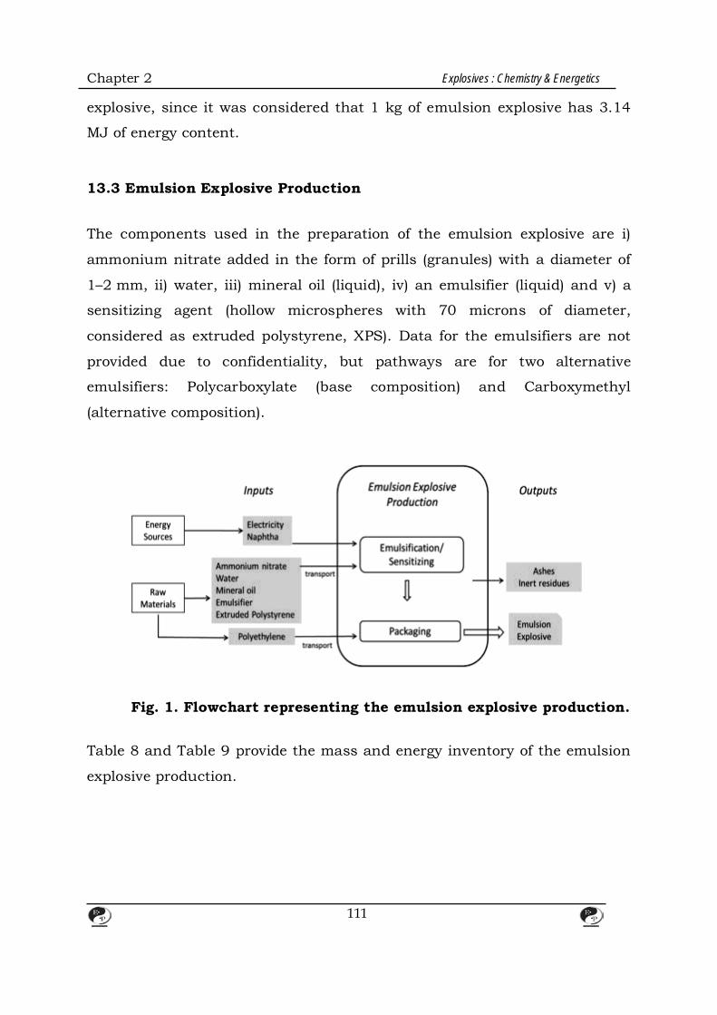
Chapter 2 Explosives : Chemistry & Energetics
explosive, since it was considered that 1 kg of emulsion explosive has 3.14
MJ of energy content.
13.3 Emulsion Explosive Production The components used in the preparation of the emulsion explosive are i)
ammonium nitrate added in the form of prills (granules) with a diameter of
1–2 mm, ii) water, iii) mineral oil (liquid), iv) an emulsifier (liquid) and v) a
sensitizing agent (hollow microspheres with 70 microns of diameter,
considered as extruded polystyrene, XPS). Data for the emulsifiers are not
provided due to confidentiality, but pathways are for two alternative
emulsifiers: Polycarboxylate (base composition) and Carboxymethyl
(alternative composition).
Fig. 1. Flowchart representing the emulsion explosive production. Table 8 and Table 9 provide the mass and energy inventory of the emulsion
explosive production.
111
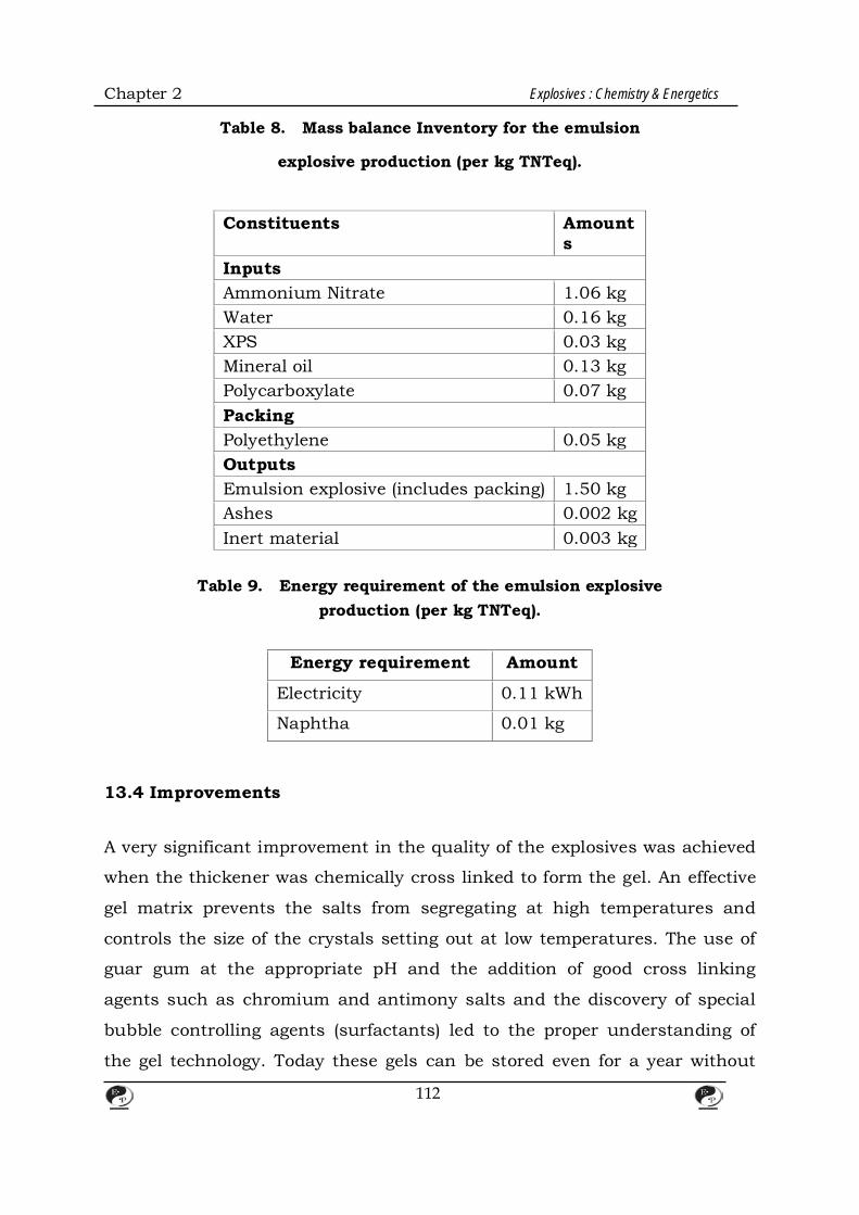
Chapter 2 Explosives : Chemistry & Energetics
Table 8. Mass balance Inventory for the emulsion
explosive production (per kg TNTeq).
Constituents Amounts
Inputs Ammonium Nitrate 1.06 kg Water 0.16 kg XPS 0.03 kg Mineral oil 0.13 kg Polycarboxylate 0.07 kg Packing Polyethylene 0.05 kg Outputs Emulsion explosive (includes packing) 1.50 kg Ashes 0.002 kg Inert material 0.003 kg
Table 9. Energy requirement of the emulsion explosive
production (per kg TNTeq).
Energy requirement Amount
Electricity 0.11 kWh
Naphtha 0.01 kg
13.4 Improvements A very significant improvement in the quality of the explosives was achieved
when the thickener was chemically cross linked to form the gel. An effective
gel matrix prevents the salts from segregating at high temperatures and
controls the size of the crystals setting out at low temperatures. The use of
guar gum at the appropriate pH and the addition of good cross linking
agents such as chromium and antimony salts and the discovery of special
bubble controlling agents (surfactants) led to the proper understanding of
the gel technology. Today these gels can be stored even for a year without
112
Chapter 2 Explosives : Chemistry & Energetics
any deterioration in physical condition of stable detonation properties.
13.5 Advantages of Slurry Explosives
1. Tailored energy requirements.
2. Water compatibility.
3. Greater safety.
4. No head-ache causing ingredients.
5. Wide choice of densities.
6. Explosives may be loaded by priming straight into bore holes which
can be completely filled with the explosive material.
7. The possibility of secondary explosions is reduced considerably
because of the water present.
13.6 Types of Slurry Explosive
There are two types of Slurry Explosives:
Non-Aluminised Slurries Aluminised Slurries
Organic Compound-Sensitised Flake grade Aluminium
Slurries powder as Sensitiser
e.g.,
Nitro Starch
Nitro Sugar
Alkyl amine nitrates
Alkanolamine nitratres
The different ingredients of a Slurry Explosives are grouped and presented
in Table 8 to 15.
113
Chapter 2 Explosives : Chemistry & Energetics
TABLE 10 Some Aerating Agents Fibrous pulp and meals Vermuculite Pearlite Resin balloons(Microballoons) Cork Glass microballoons Ammonium nitrate prills
TABLE 11 Some Gas Formers
Peroxides Acetone/Cresote in HNO3 gels Sodium/Potassium nitrates Sodium bicarbonate
TABLE 11 Oxidisers
Ammonium Nitrate Sodium Nitrate Calcium Nitrate Sodium Perchlorite Potassium Perchlorite Ammonium Perchlorate Potassium Nitrate
TABLE 13 Sensitisers
TNT A1 (Flake or Paint Grade) Nitro Starch Methyl Ammonium Nitrates Ethanolamine Nitrate Microballoons(Glass/Polymeric)
TABLE 14 Thickners
Guar Gum Ethyl Guar CMC (Carboxy Methyl Starches Cellulose) Propylguar
14. Conclusions Emulsion Type Explosives are making great strides in explosives technology
and promise more advances in the future as operators become more aware
of their potential uses and manufacturers develop new markets for a
versatile product. Economic analysis of emulsions as compared with
114
Chapter 2 Explosives : Chemistry & Energetics
straight ANFO indicates two major advantages for Emulsion Type System
over straight ANFO. First, they can provide increased fragmentation over
equivalent amounts of ANFO, due to the emulsions increased energy and
efficiency, albeit at a higher (blasting) cost per unit of overburden. Secondly,
and more importantly, emulsion blasting costs can be reduced below that
of straight ANFO by taking advantage of the product's explosive
characteristics and spreading the blasting pattern to the break- even point.
A mathematical model has been developed which enables an economic
comparison between any two explosive systems based on their densities and
cost per unit of explosive material.
References: 1. Sybil P.Parker, (Ed.), McGraw-Hill Encyclopedia of Science and Technology,
5th edn., McGraw-Hill, New York, 1982.
2. T. McDonald,. Farmers Supply and Explosives, Inc., Barbourville, KY,
August18, 1986.
3. Nitro Nobel. Emuliteis breaking new ground in bulk blasting :( advertising
pamphlet); Gyttorp, Sweden. (1985)., Balkema, Rotterdam.
115
CHAPTER – 3
116
INFLUENCE OF AMMONIUM NITRATE PRILL PROPERTIES ON DETONATION
VELOCITY
1. Introduction
Ammonium nitrate (AN) is commonly used as a basic ingredient of ANFO
explosives. Thanks to low cost, simple technology, and accessibility of raw
materials required for manufacturing, this type of explosive competes very
effectively with other improved types of explosives commercially available.
More than half of the world production of explosives used in civil
applications is of type ANFO mixtures; in developed countries their share
exceeds 80%. Laboratory and field tests performed in the mining industry
have shown that the replacement of the agriculture nonporous AN with a
porous material considerably improves the efficiency of ANFO action; it also
eliminates oil oozing and reduces the emission of toxic gases to the
atmosphere.
On the other hand, all positive features of the granulated form of ANFO
explosives are retained. Commonly used ANFO consists of 94.5% of AN and
5.5% of fuel oil. AN is the dominant and sole ingredient which has explosive
properties in such a mixture. This implies that explosive properties of ANFO
are closely bounded with the explosive characteristics of AN, which are
strongly connected with its physical features and chemical composition. The
physical features and chemical composition of AN prills/granules may vary
within a wide range depending on the technology of production and the
content of additives. The storage and transport conditions such as
temperature and humidity fluctuation, stacking height and contamination
by other substances can also have a significant influence.

Chapter 3 Influence of Ammonium Nitrate Prill Properties on Detonation Velocity
117
It is well known that the crucial features influencing the detonation
parameters of explosives are: charge density, size of the explosives particles
and the content of mixture ingredients [2, 3]. The detonation of ANFO
mixtures is regarded as an example of a non-ideal detonation regime and
one can expect that a change in the basic physical parameters of AN
prills/granules may influence the detonation parameters of the explosive to
a high degree. The first goal of the work was to determine the influence of
the porosity (over a wide range from 0 to 15 cm3 of fuel oil per 100g of prilled
AN and of the size of the prills on the ANFO explosives detonation velocity.
The second aim was to examine how the changes in the proportion of AN
and fuel oil affect the detonation velocity of such explosive mixtures.
2. Method of Manufacturing Porous AN
The most suitable product to make porous prills is AN without any inorganic
additives. But such a type of AN is produced very rarely. Almost all types of
agricultural AN contain inorganic additives which improve their quality but
make the process of manufacturing porous AN more difficult. A relatively
small influence on such a process is exerted by ammonium sulfate
(NH4)2SO4. Other additives, like calcium or magnesium nitrate, make the
manufacturing of high porosity AN very difficult. The prilled AN used in our
work contained about 1% of ammonium sulfate. The process of
manufacturing porous prills was based on a polymorphic transition ofAN
crystals, which runs at +320C.
During the transition of IVIIIIV, the density of AN crystals changes
slightly, which creates a porous structure and cracks crystals inside the
prills. The difference in the internal structure of prills of different porosity is
Chapter 3 Influence of Ammonium Nitrate Prill Properties on Detonation Velocity
118
shown on the scanning electron microscope photographs (Figure 1). The
porous product has significantly bigger oil absorption and detonation ability
as measured by tube test. The process consisted in heating an AN sample to
above 320C, storing it for some time, and then cooling to room temperature.
An additive that accelerated and increased porosity was also used. As a
result of a different number of thermal cycles and the amount of the above-
mentioned additive, AN prills of a broad range of physical characteristics can
be produced. Examinations of physical properties of the manufactured AN
were conducted. Some ANFO mixtures were prepared in a mechanical
blender and their detonation velocity was determined.
It is a common practice in military technology that HE charges should have
the highest density. With increasing density, one can observe an increase in
velocity and detonation pressure, which enhances the brisance of the
explosive. However, when charge density increases, the sensitivity to
initiation impulse decreases and the charge is more difficult to initiate. This
problem is especially important in the case of ANFO explosives, which are in
general little sensitive to initiation. The porosity of materials influences
greatly their density. The rise of porosity is accompanied by an increase of
empty spaces in materials, which cause a drop of density. The diagram
below (Figure 2) shows a relationship between the bulk density of the prilled
AN and the porosity of prills. The AN was made porous in a manner
described in Section 2. The oil absorption by a unit of mass of prills,
expressed as the volume of fuel oil absorbed by 100 g of AN prills
(cm3/100g) has been adopted as a measure of AN prills porosity.
As seen in the diagram (Figure 2), AN density drops when its porosity
increases. The AN prills of agricultural grade showed no oil absorption
(0.0cm3/100g) and their bulk density was 0.95 g/cm3. When AN heated and
cooled a few times with the additive, the rise of the porosity caused a rise of
oil absorption up to 15 cm3/100 g and a drop in bulk density to 0.59 g/cm3.
Chapter 3 Influence of Ammonium Nitrate Prill Properties on Detonation Velocity
119
Figure 1. Cross-sections of the nonporous agricultural-grade AN prill
(left) and of the porous prill showing an oil absorption of 15 cm3/100g
after several thermal cycles (right).
Figure 2. Bulk density of prilled AN vs. its oil absorption.
3. Influence of Prills & Porosity on the Detonation Velocity of ANFO
Detonation velocity is one of the most important and most often determined
properties of explosives. To measure detonation velocity, ANFO explosives
were prepared by mechanical mixing of AN prills (size of prills: 1.5–2.5 mm)
and fuel oil. The ratio was 94.5% AN and 5.5% fuel oil where oxygen balance
equals zero. The explosives were poured into steel tubes of 36 mm internal
Chapter 3 Influence of Ammonium Nitrate Prill Properties on Detonation Velocity
120
diameter and 3 mm wall thickness. Detonation of the charges was initiated
by boosters (weight 14 g, RDX 90%, TNT 10%). The dependence of
detonation velocity on the density of ANFO charges is presented in Figure 3.
As can be seen in Figure 3, the density decrease of ANFO charges from 0.90
to 0.68 g/cm3 caused a rise of the detonation velocity from 1.6 to 2.7 km/s.
Detonation failed for charges with a density above 0.90 g/cm3. Considering
the dependence of the density on the porosity as in Figure 2, the detonation
velocity of ANFO increases with the prills porosity. ANFO charges made of
AN with an oil absorption below 2.5 cm3/100 g, did not detonate under the
test conditions. A minimal oil absorption of AN prills, at which detonation of
full charges was observed, was about 2.5–3.0cm3/100g. The measured
detonation velocity was then 1.6–1.7 km/s. When oil absorption was at the
level of 12–15 cm3/100 g, the detonation velocity was maximal reaching 2.7
km/s. A tendency to further growth was not observed.
Figure 3. Detonation velocity of ANFO vs. density of charges.
It can also be seen in Figure 3 that when the oil absorption rises from 0 to
15 cm3/100 g the density of AN falls by about 35%. Despite this drop, the
detonation velocity of ANFO increases by more than 70% (the range of oil
Chapter 3 Influence of Ammonium Nitrate Prill Properties on Detonation Velocity
121
absorption 3.0–15.0 cm3/100 g). These relationships between
porosity/density and detonation velocity are different from the dependence
observed for typical high explosives. For that type of explosives the
detonation velocity decreases with decreasing density. The measurement
points in Figure 3 are scattered because of different physical characteristics
of AN prills (density, mechanical strength, water content, amount of dust,
etc.), the uncertainty of oil absorption determination and the poor physical
stability of ANFO made of low porosity AN.
4. Influence of Prills & Size on the Detonation Velocity of ANFO
The size of crystals, grains, granules, prills, etc. has a great influence on the
properties of explosives, especially on oxidizer-fuel mixtures. For this type of
materials, the sensitivity to external stimuli and the parameters of
detonation increase when the size of the particles decreases.
Taking into consideration typical high explosives, their detonation velocity
depends only slightly on the granulometric distribution of grains. In this
part of the work prills of small size were examined; the so-called undersize
prills which are created in an industrial installation during a granulation
process are then sieved out from the trade product and recycled. The
undersize prills for the research were sieved to different fractions and used
to manufacture an ANFO of stoichiometric composition. The shape of AN
prills was spherical, similar to the grains of the commercial product. Prills of
smaller size were nonporous, similar to the commercial product. As the oil
absorption of the undersize prills was poor, the physical stability of such
ANFO was unsatisfactory. The detonation velocity of ANFO manufactured
with small size prills was determined under conditions described.
The results collected in Table 1 indicate that the detonation velocity of ANFO
increases when the size of AN prills decreases. ANFO made of prills of about

Chapter 3 Influence of Ammonium Nitrate Prill Properties on Detonation Velocity
122
1.00–1.20 mm did not detonate under the test conditions. An explosive
manufactured using the smallest prills (0.20–0.50 mm) detonated fully,
reaching a velocity of about 3.0 km/s. For comparison, ANFO was made of
ground grains of 0.2–0.5 mm. In spite of a lower density, it detonated with
significantly higher velocity than parallel samples made of regular
nonporous prills.
Table 1. Detonation velocity of ANFO prepared from AN prills of different dimensions.
Prills size Density of ANFO Detonation velocity
mm g/cm3 km/s
1.00 – 1.20 1.02 Detonation decay
0.63 – 1.00 1.01 2.33
0.50 – 0.63 1.02 2.50
0.20 – 0.50 0.98 2.96
0.20 – 0.50 (ground) 0.86 3.44
Figure 4. Detonation velocity of ANFO vs. content of fuel oil.

Chapter 3 Influence of Ammonium Nitrate Prill Properties on Detonation Velocity
123
5. Influence of Fuel Oil Content on Detonation Velocity of ANFO
The detonation velocity tests described above refer to an ANFO explosive with oxygen balance equaling zero, manufactured from AN prills whose porosity and size were altered. However, it may happen that the ANFO composition is different from the one designed and the oxygen balance is positive or negative. The maximum heat of explosion is expected from the stoichiometric mixture; the heat of explosion of other compositions is less. In order to determine the influence of the fuel oil content on the detonation velocity of ANFO, different kinds of AN– of low and high porosity (4 and 10cm3/100g of the oil absorption) –were chosen. The method of preparing mixtures and determining their velocity of detonation was the same as described in Section 4. The results of the experiments are presented in the diagram (Figure 4). It is interesting that ANFO explosives of both relatively high and low oxygen balance were capable to detonate. We would like to underline a weak dependence between the detonation velocity and the content of fuel oil in mixtures made of low porosity AN prills. In the case of ANFO manufactured with high porosity AN, the dependence is remarkable.
6. Conclusions
The conducted experiments confirm the importance of prills physical
structure (porosity and particle size) on the detonation parameters of ANFO
mixtures. The porosity of AN prills influences significantly the detonation
parameters of ANFO explosives. The increase of prills porosity results in a
remarkable increase in the detonation velocity of ANFO mixtures under the
conditions of the experiments. The ANFO charges prepared from AN
granules of oil absorption below 2.5 cm3/100 g did not detonate at all. The
threshold of AN oil absorption above which a stable detonation of ANFO
could be observed was 2.5–3.0cm3/100g and the measured detonation
velocity was 1.6–1.7 km/s. Along with the increase of AN porosity, the
detonation velocity of ANFO increased up to 2.7 km/s at a level of oil
absorption of 12–15 cm3/100g. The described
effect took place in spite of the fact that the increase of AN prills porosity
Chapter 3 Influence of Ammonium Nitrate Prill Properties on Detonation Velocity
124
caused a significant drop of the ANFO density from 0.9 g/cm3 (for 2.5
cm3/100 g) to 0.6 g/cm3 (for 15 cm3/100 g of oil absorption of prills).
The dependence of ANFO detonation velocity on its density, as observed in
the experiments, is quite different from that existing in the case of typical
high explosives where the detonation velocity of explosives is always
proportional to their density. The observed effect can be explained by the
dominant influence of the AN prills structure, which overrides the influence
of density. Such behavior is observed also in other explosive mixtures
consisting of two ingredients – an oxidizer and a fuel. The described
experiments prove that the detonation velocity of ANFO mixtures depends
strongly on the AN particle size. The charges of ANFO prepared from fine
grade nonporous prills are capable to detonate (under the conditions of the
experiment) only in the case of prills below 1.0 mm. In that case the
dependence between detonation velocity and particle size is the same
compared with other types of explosives. The charges of ANFO mixtures
prepared from nonporous, ground prills detonate with much higher velocity
compared to charges prepared from granulated AN of similar particle size.
The explanation of the fact, apart from the lower density of the mixture,
might lie in the higher contact surface of reagents – oxidizer and fuel in the
case of ground formless grains, which enables a fuller run of exothermic
reactions. The influence of fuel oil content on the detonation velocity of
ANFO seems evident. The strong dependence observed for high-porosity
granules and the weak dependence for low-porosity granules could be
explained in the light of creating an energetically optimal system (for
stoichiometric mixture) within the volume of a single, porous granule.
7. References
[1] D. Buczkowski, B. Zygmunt, Influence of Ammonium Nitrate Prills Porosity
and Dimensions on Detonation Velocity of ANFO Explosives, 5th Int. Seminar
New Trends in Research of Energetic Materials, Pardubice, Czech Republic,
Chapter 3 Influence of Ammonium Nitrate Prill Properties on Detonation Velocity
125
April 21 – 23, 2003.
[2] B. Zygmunt, Explosive Properties of Ammonals and Hydroammonals, 3rd Int.
Autumn Seminar on Propellants, Explosives and Pyrotechnics, Chengdu,
China, October 5 – 8, 1999.
[3] B. Zygmunt, The Detonation Properties of Explosive-Water Mixture,
Propellants,Explos .,Pyrotech. 1982, 4, 107.
[4] D. Buczkowski, W. Pa˛gowski, B. Zygmunt, Evaluation of the Influence of
Modificating Substances on Resistance to Detonation of Fertilizer grade
Ammonium Nitrate, 3rd Int. Seminar New Trends in Research of Energetic
Materials, Pardubice, Czech Republic, April 12 – 13, 2000.

CHAPTER – 4
BULK LOADING SYSTEMS FOR EXPLOSIVES
The explosive are delivered in bulk tankers or onsite mixed and delivered,
with following advantages:
i) The cost of packing material can be saved.
ii) Transport of 15% and above water present in packaged explosives over
long distances is avoided,
iii) Since mostly these types of explosives are in a pumpable form at the
time of delivery, the loading rates can be much higher than conventional
packaged slurries or emulsion, and
iv) Since the explosive is pumped into the borehole, a better coupling is
ensured with the boreholes walls.
Both slurries and emulsions are ideally suited for these types of operations.
The following considerations are also quite relevant in the context of
selecting these types of systems.
1. Normally these types of operations are more suited for large operations
and naturally problems may arise when we come across limited size of
individual mines and quarries. For smaller units the shared services of a
pump trunk and its support facilities may be necessary. In such
situations to operate this system effectively a strictly prearranged
schedule of hole loading may be necessary.
2. Not only blasting must be arranged to a given schedule, but also the size
126

Chapter 4 Bulk Loading Systems for Explosives
of the shots tailored to suit the capacities of pump trucks and support
facility.
3. Another relevant consideration is about the usage of increased explosive
charge per hole (upto 20%) because of the better coupling afforded by
these type of explosives. This may pose vibrational problems if mines are
near urban areas.
The above operations can be broadly classified into three categories:
1. Bulk trucks (On-Site Mix Trucks).
2. Pump Trucks.
3. Bulk Mix Trucks (for ANFO).
The details of these are given below:
1. BULK TRUCKS:
Bulk Slurry/Emulsion On Site Mix Trucks: Here, essentially the raw
materials for making the explosive likes:
i) Ammonium Nitrate, Sodium Nitrate solutions from a Support
Plant.
ii) Fuels like TNT, and Aluminium Powder,
iii) Gelling agents,
iv) Cross linking agents, and
v) Gassing agents
Are carried in trucks and the explosives made at the blasting site.
2. PUMP TRUCKS: These are delivery trucks of pre-mixed slurry or emulsion.
127
Chapter 4 Bulk Loading Systems for Explosives
3. BULK MIX TRUCKS OR ANFO TRUCKS: These essentially mix and deliver ANFO/Aluminium Powder explosive.
4. BULK TRUCKS OR ON-SITE MIX TRUCKS:
There are two major categories:
i) One using the high explosive sensitizer TNT, and
ii) Others sensitized mostly by air bubbles.
i) High Explosives Sensitized Bulk Trucks: The Ammonium Nitrate, Sodium Nitrate, etc. are taken in the forms of
solution and the various ingredients like guar gum, aluminium, etc. are
auger-fed to a common mix funnel which can optionally have a mixer to get
better mixing. The product from the mixer is pumped from the mixing funnel
to boreholes. Some times aluminium and other fuels can be premixed a part
of the oxidiser AN can be added in dry form. For many mixes the liquor can
also be pregelled. This has the advantage of putting a substantial quantity of
air bubbles into the liquor. Additionally gassing agents are also premised
with fuels to give various densities for final products. Since controlled
feeding of TNT requires a vibrating pan feeder, these types of trucks
necessarily have provision for leveling the trucks using hydraulic jacks. A
simple diagram describing the location of various raw materials, mixing
bowel and hose bundle is shown in Fig.1.
128

Chapter 4 Bulk Loading Systems for Explosives
Fig. 1 Schematic Layout of an On Site Mix Truck Regulation In the western countries the following regulations are followed with the type
of operation:
129

Chapter 4 Bulk Loading Systems for Explosives
In the case of High Explosive Sensitised (e.g. TNT) Slurries, the truck is
classed as a mobile factory. Table of distance apply based on the quantity of
High Explosive aboard on arrival and line of sight distance e.g. ‘For 5000
lbs. of TNT -400ft.’ No man other than those on licence can work within this
line of sight radius. Because of this rule the use of On Site Mix Trucks may
not be possible in certain circumstances. Passing radius is generally 25 ft.
ii) Air Bubble Sensitized Bulk Trucks: These trucks are also very similar to HE sensitized bulk trucks, consisting of
tanks or bins for various raw materials like Ammonium Nitrate, Sodium
Nitrate, Aluminium, gelling agents, cross linking agents, etc. Here more
rigorous control on amount of gassing agents added and extent of gassing of
final product is essential as these explosives depend for sensitivity mostly on
gas bubbles in the absence of high explosive sensitizer.
Regulations: In the case of NCN mixture, only passing radius applies. 5. PUMP TRUCKS These are delivery trucks of pre-mixed slurry or emulsion. The slurry or
emulsion is produced in a steam jacketed ribbon mixer or by a continuous
process at a plant, partially gelled to eliminate segregation but not so much
that it cannot be handled. It is stored in large tanks and then pumped into
bulk carriers. From these carriers it is pumped out at the mine site.
Additional cross linking agents, gums, etc. may be added here as it is
pumped out. Gum may be added as dispersion in glycol for easy addition.
Some tipping system to get all slurry/emulsion out is necessary as these
explosives leave a heal in the tanker in normal position. The details of a
Pump Truck are given schematically in Fig. 2.
130
Chapter 4 Bulk Loading Systems for Explosives
Fig. 2 Schematic diagram of a Pump Truck
Regulations: In the western countries, both NCN and HE pump trucks as opposed to
onsite mix trucks are classified as bulk carriers and passing radius is the
only regulation that applies.
Since the two already described systems deliver same type of explosive, vis.
Emulsion or slurry explosive, it is relevant to discuss the merits and
demerits of these two systems in some details.
6. ON SITE MIXING – vs. – PUMP TRUCKS
Comparative Advantages & Dis-Advantages:
i) The main advantage of pump truck system is the lower investment for
large operations utilizing several trucks. The is because pump trucks
are all of very simple design consisting of essentially a big tanker to
carry the explosives, suitable pumping system for getting reasonable
pumping rates and a ‘hose role’ system. One can optionally have small
131
Chapter 4 Bulk Loading Systems for Explosives
mixing bowl to add additional gums, cross linker, etc. But in the case of
on-site mixing systems, a number of containers for various raw
materials like, Ammonium nitrate/sodium nitrate liquor, gums,
aluminium, cross linker, TNT have to be provided with additional
facilities like guar feeders, vibratory feeders, etc. to control the feeding
of most of raw materials. Hence the cost of an on-site mix truck is
much higher than a single pump truck.
ii) In case of site mix truck, since all the ingredients have to be fed in a
controlled manner it calls for sophisticated control mechanism and
control panels. Especially if the support plant is some distance away
from the mines. The mix truck has to travel a long distance on public
roads. The break downs of ‘mix-trucks’ with lot of sophisticated
controls and equipments on the trucks are more serious.
The routine servicing and maintenance for breakdowns can be carried
out on a simpler work shop in the case of pump trucks.
iii) Fore HE Sensitized mixes, TNT feeding poses more problems, since
controlled feeding of TNT is done only by vibratory feeders. This type of
trucks should have provisions for leveling the trucks using hydraulic
jacks. Since temperature affects this type of feeding, the whole systems
has to be heated to get a consistent feeding rate. Composition based on
Aluminium or air bubble sensitization have critical densities beyond
which they will not shoot. These are considerably lower than HE
sensitized slurries and so have to be controlled very carefully on the
site. In the case of PUMP TRUCKS the explosives are made in a plant
where quality control checks on raw materials and finished products
can be done in a better manner and final density, percentage of
Aluminium checked in a reliable fashion in a well equipped quality
control laboratory.
132
Chapter 4 Bulk Loading Systems for Explosives
iv) The gassing agents and their uniform distribution throughout the
matrix should be precisely controlled at the site in the case of on site
mixing trucks. Even a slight variation in temperature, pH, etc. can
affect this phenomena. In case of Pump trucks, such precise control is
much easier to achieve as most of the air bubbles are incorporated into
the system at the manufacturing site itself.
v) Pump trucks give products having much faster felling and cross linking
rates than on site mixed products and this can be more desirable in
watery holes. In the case of onsite mixed slurries it the slurry is too
thin, there can be substantial losses in cracks in the rocks. For wet
holes, the product needs to cross link rapidly to avoid water take-up.
vi) The aluminium and water content, density and explosive content
control the sensitivity and strength. These depend on quality of raw
materials whose specifications should be checked on routine basis.
These operations may be more advantageously done in a well equipped
plant with a good quality control laboratory.
vii) In the case of on-site mixing, the support plant is a non-explosive unit
whereas in case of pump trucks, it is an explosive manufacturing
facility attracting regulations.
viii) In the case of on site mix plant it is possible right at site to easily vary
the formulation to give a range of strengths and densities. Such a thing
is not possible with pump trucks; however, this disadvantage can be
offset to a certain extent by having compartments in the pump trucks
for different explosives with different strength and density.
7. AMMONIUM NITRATE DRY MIXES
These consist essentially of hoppers for AN etc., augers, a mix chamber and
an air system to convey the mixed product into the borehole through loading
133

Chapter 4 Bulk Loading Systems for Explosives
hose and special valves to stop air bleeding back into the system. Augers
may also be used to carry the mixed product to the borehole instead of the
air system. Aluminium is usually stored in another chamber and augered
into the mixing chamber. Even for horizontal blast hole loading upto 120’
depth, special pneumatic loading systems have been developed. The
operational details are explained in Fig. 3 and Fig. 4.
Fig. 3 Schematic of Amerind AN/A1/FO Mix Truck
134
Chapter 4 Bulk Loading Systems for Explosives
Fig. 4 Schematic of the Feeding and Mixing Arrangement
The following are some of the important consideration on the usage of
these types of products:
1. Prilled Ammonium Nitrate of suitable density and oil retention
properties along with fuels like fuel oil, aluminium are usually used.
2. Use of excessive aluminium is to be avoided as it leads to more fraction
of solid product of reaction, viz. Al2O3 which has energy trapped in it and
thus not available for doing useful work. This is explained as given
below:
When aluminiuim is added to AN the following reaction takes place: 2 Al + 3 NH4NO3 → 3N2 + 6H2O + Al2O + 1.65 Kcal/gm (1)
At higher percentages of Aluminium, Oxygen from the steam is stripped off
and Al2O3 is formed.
135
Chapter 4 Bulk Loading Systems for Explosives
2 Al + NH4NO3 → N2 + H2 + Al2O3 + 2.3 Kcal/gm (2)
At low Al, percentage, the first reaction is more predominant and has
increased thermochemical energy as compared to ANFO (900 cal/gm).
However, when the second reaction takes place, Al2O3 is formed and this
has energy trapped in it.
On examination of equations (1) and (2), one can see that in the case of (1)
when Aluminium and AN are mixed in the mole ratios of 2:3 the energy
obtained is 1.65 Kcal/gm and in the case of (2) when Aluminium and AN are
mixed in mole ratio of 2:1 the energy output rises to only 2.3 Kcal/gm of
mix. In other words, in the first case of a mixture containing only about 18%
aluminium, the energy output is 1.65 Kcal/gm mixture, whereas the other
mixture which contains about 40% aluminium (more than double) gives only
2.3 Kcal/gm of energy. From blasting studies using explosives yielding
appreciable solid products, it has been noted that the thermal energy
trapped in the solid products is not at all available for useful work.
3. Some Specifications of AN and Aluminium used for Site-mix ANFO
Type of Products:
AMMONIUM NITRATE
Size: 1 to 3 mm.
Density: Usually around 0.82 to 0.90 gm/cc
Porosity: Minimum oil retention of 6% by weight. Free flowing in nature for
easy auger feeding.
Hardness: Should not excessively break down during auger feeding, in
temperature cycling and during handling. Fines can choke the auger by
depositing in the gaps between stator and rotor.
136
Chapter 4 Bulk Loading Systems for Explosives
The prills should not go to detonation in burning test.
8. ALUMINIUM: Aluminium also should be of free flowing nature having a consistent density
so that the calibration of metering devices need not be changed often. These
should also be dust free to avoid any fire mishap.
Recently other fuels have also been tried especially when the smell of FO can
be objectionable. Fuels like glycol, methanol, ground coal, FeSi, Fep, etc. are
the other candidates.
Use of these products mostly may require blast hole dewatering for which
several types of dewatering units are available. Generally these dewatering
units are hydraulically driven though electrical and pneumatic units are
also available. The unit may be mounted on a pick up or attached to the
front of ANFO truck. Generally pumps of rugged stainless steel construction
are used; however, they are affected by Slurries in the hole or adverse pH
conditions. Dryliners are also used for preventing influx of water into the
borehole loaded with dry mix blasting agent. These should be so constructed
that they are water proof, flexible and will not crack when exposed to low
temperature.
9. COMPARISON BETWEEN SLURRIES AND DRY MIXES:
Figure 5 shows the effect of Aluminium addition to ANFO on its weight
strength. It also gives weight strength values for typical slurries for both TNT
sensitized and NCN varieties. From this it can be seen that the dry mixes at
the same percentage of aluminium have consistently higher weight strength
as compared to slurries. This is on account of diluent effect of water in
slurries which does not react during detonation and therefore reduces the
137
Chapter 4 Bulk Loading Systems for Explosives
energy output by about same percentage as it is present. But on a volume
basis or bulk strength basis – which is what one is interested in blasting the
case is different as can be seen from Fig. 5. The values plotted in Fig. 5 have
been taken from Table 1. One should remember that while the density of
Aluminised ANFO varies from 0.85 to 0.93 gm/cc, the density of NCN
slurries are taken as follows:
1% Al NCN Slurry – 1.25 gm/cc; 7% Al NCN slurry – 1.30 gm/cc; 10% Al
slurry 1.35 gm/cc.
The densities mentioned above for NCN slurries are the densities that would
exist after they have load on them and they are compressed somewhat at
the bottom of a 50’ bore hole. From this it can be seen, for example, that a
7% Al NCN slurry bottom loaded will be equivalent to 16% Aluminium dry
mix.
Therefore, it is possible to match the energy/ft of hole of any NCN slurry
with Aluminised dry mix to produce the same blasting results. In view of the
above under the prevailing costs of raw materials in India, the economies
favours the use of slurry.
It may be pointed out that the choice of particular system among the various
above mentioned options depends on consideration of the following major
factors.
1. Strata conditions with particular reference to site geology.
2. Size of operations, the flexibility and specific nature of services
required.
3. Location of explosive plant vis-à-vis the mines.
4. Watery conditions of borehole.
138
Chapter 4 Bulk Loading Systems for Explosives
5. Energy requirements per foot of the borehole for proper fragmentation
and throw, and
6. Cost of raw materials as prevailing in each country.
Fig. 5 Bulk Strengths of Dry Mixes and Slurries with different
Aluminum contents
139
Chapter 4 Bulk Loading Systems for Explosives
10. EMULSION EXPLOSIVES INTRODUCTION This is another family of explosives based on the same broad principles on
which slurry type of explosives have been developed. Similar to slurry
explosive, this also combines the rapid combustion and water resistant
properties of nitroglycerine with safety characteristics of power explosive.
General Chemistry of Emulsions When oil and water are mixed together without an emulsifier the initial
dispersion of oil is quite unstable. (the oil rapidly coalesces until complete
separation into a layer of oil and water results). This can be anticipated as
the increase in surface area by the dispersion of the oil or water greatly
increases the free surface energy of the system and at such a high energy
level the system is unstable. Free surface energy is dependent on both
surface area (capacity factor) and the interfacial tension (intensity factory). If
a stable emulsion is to be produced, it is necessary to add a third material
i.e. an emulsifying agent, which by its presence at the interface, prevents
coalescence of the oil or water gloubles. These emulsifiers may be surface
active compounds (monoglycerides and diglycerides). Gums (gum acacia,
methyl cellulose) or finely divided clays (cocos, gums, etc.). Though these
three act in different ways, the basic mechanism operative are as follows:
1. Reduction of interfacial tension. 2. Formation of rigid interfacial film. 3. Electrical charges.
At best conditions a surface active compound lowers the interfacial energy
by a factor of 20 or 25 which is rather small when one considers that the
interfacial energy of an emulsified system is 106 times higher than that of
140

Chapter 4 Bulk Loading Systems for Explosives
broken emulsion.
The most important factor is the formation of rigid interfacial film. It is a
known fact that the surface active agent forms a rigid film between
immiscible phases and the film may act as a mechanical barrier both to
flocculation and coalescence of the emulsion droplets.
The third factor which contributes to stability is electrical charge
contributed by a certain family of emulsifiers – anionic and cationic types.
For this phenomena to happen the molecules that concentrate on the
interface must be dipoles, i.e., their geometrical and electrical centres are
not coincident and the molecules are electrically asymmetrical thus acting
like small magnets.
Selection of emulsifier for a particular system is still an art rather than a
science and lot of experimentation goes in before arriving at the best. Still
HLB method of selection which depends on the hydrophile – lipophile
balance of an emulsifier is the best guide available to determine the type of
emulsion formed and the selection of different emulsifiers for various tasks.
Several techniques are available for production of emulsions ranging from
batch methods using propeller type of impellers to continuous type using
colloid mills. Ultrasonic energy has also been used to form stable emulsions.
The art and science of forming emulsions of explosive type are still more
complicated by the presence of electrolytes which tend to oppose the
electrical charges of emulsifiers. Moreover, these emulsions are of high
internal phase ratio types whose stability is very suspect.
141
Chapter 4 Bulk Loading Systems for Explosives
11. TYPES OF EMULSIONS There are two types of emulsions
i) Oil emulsified in water type, and
ii) Water emulsified in oil type.
12. RAW MATERIALS USED IN EMULSIONS Both these types of emulsions have been used to produce explosives. The
raw materials for these emulsions consist of the following ingredients:
i) Oxidisers like Ammonium Nitrate, Sodium Nitrate, Calcium Nitrate,
barium Nitrate, Sodium Perchlorate, Ammonium perchlorate.
ii) Fuel sensitisers like, Methyl amine nitrates, DNT Oil, Aluminium,
iii) Fuels like waxes, mineral oils,
iv) Water
v) Bulking agents like glass microballoons, expanded perlites, and
vi) Emulsifiers.
One can see all the above raw materials are by nature non explosive. Hence,
enormous levels of safety can be built in production, distribution and also
handling of explosives in the field. The safety levels of slurry and emulsion
explosives are given later.
How Emulsions are Sensitized: The presence of tiny air bubbles in the size range of 20 to 100 microns (Av.
60 microns) is responsible for sustaining a detonation wave created by a
detonator or booster in the explosive column. The mechanism by which they
sensitize the explosive is by providing ‘hot spots’ having temperatures
greatly exceeding that of the rest of the explosives. This is achieved by the
142
Chapter 4 Bulk Loading Systems for Explosives
adiabatic compression of these air bubbles by the high pressures of
advancing shock wave by which the gases are heated to high temperatures
of the order of 1000°C. This heats the inner surface of the bubble starting a
rapid decomposition reaction. By having a multitude of such air bubbles the
shock wave is sustained.
What Are the Advantages for Practical Users i) As mentioned earlier, (the ingredients which got to make this types of
explosives are anon explosive in nature.) The sensitivity is derived
mainly by the incorporation of tiny air bubbles or microballoons in the
diameter range of 0.1 mm. As mentioned above, these tiny bubbles
collapse when they are struck by the shock wave with the result the
temperature in the explosive substance becomes sufficiently high
locally to start the rapid explosive combustion. The absence of high
explosive sensitisers render the emulsions or slurry explosives highly
inactive to other forms of stimuli such as friction and fire. This provides
them the high degree of handling safety.
ii) A part of the sensitivity is also derived by the nature of intimate contact
between the oxidiser solution and the fuel phase consisting of waxes
and oils. When magnified, emulsion looks like honeycombs in which
honey is replaced by Ammonium Nitrate solution. The diameter of cells
is no more than a few thousandths of a millimetre and the thickness of
wax membrane separating the cells is less than one thousandth of a
millimeter. Such an intimate contact between the oxidiser and the fuel
helps in better sensitivity and full release of energy.
iii) Both types of emulsions can be made to be highly water resistant by
the very nature of formation of these products. In the case of ‘water in
oil type’ emulsion, the oxidiser solution is protected by the oil barrier
143
Chapter 4 Bulk Loading Systems for Explosives
against evaporation and also against penetration of external water (e.g.
water in boreholes, water under pressure) into the explosives. In case of
“oil in water” type emulsion, external water phase is usually gelled to
get protection from water.
iv) Safety during manufacture, transportation and usage: During
manufacture, lot of safety advantages are derived from the above
mentioned properties, since emulsion’s basic matrix can be considered
to be extremely safe until the final stage of production process when
microballoons are added. The finished product is also equally safe for
transportation and usage as evidenced by safety tests mentioned in
detail later in this paper.
v) As in the case of slurry explosives, the consistency of these explosives
can be varied. This is done by changing the nature of oil phase and the
emulsifier. Thus from a very firm consistency similar to margarine in
different qualities(which is suitable for cartridging) to a lesser viscous
form which can be pumped and delivered to customers in road tankers
(similar to pumpable slurries) can be easily obtained.
General comparison between “NG” ‘slurry’ and ‘Emulsion’
Explosives:
NG Explosives Slurries Emulsions
Water resistance
Good Better than NG Explosives.
Excellent, uch Better than other Categories.
Safety Fair Much safer than NG explosives as Given under Safety tests
Equivalent to slurries.
144
Chapter 4 Bulk Loading Systems for Explosives
Wt. strength All ranges Possible. Here also any desired range of strength can be obtained by simple and easy manipulating of composition.
The flexibility and ease of obtaining products with different wt. strengths is more in case of slurries and emulsions.
Quality of raw Material required
Good quality raw materials are needed and any small deviation in raw material specification will adversely affect the product quality.
This can tolerate slight fluctuation in the quality of raw materials.
The raw material should pass through stringent quality tests.
Shelf life Good Fair Fair
Influence of physical properties of ammonium nitrate Ammonium nitrate (AN) and AN-based explosives have been widely used as
industrial explosives or energetic compositions such as ANFO, emulsion
explosives or amatol (AN/TNT) etc. They are explosives known for their non-
ideal detonation behaviour. This is shown, for example, by the detonation
velocity which does not easily reach theoretically predicted values.
Explosives behave non-ideally between the critical diameter (dc) below which
a steady detonation wave cannot be sustained, and the minimum diameter
(dm) above which the detonation is ideal. AN and AN-based explosives are
typical “non-ideal” explosives because they have large values for dm and
relatively small values for dc. For most practical conditions they will never
reach the ideal behaviour as predicted by thermo hydrodynamic theory.
Generally the non-ideal detonation behaviour is explained by the relatively
low decomposition rate of AN, which causes a wide reaction zone, in
combination with lateral heat losses and rarefaction waves which extinguish
the decomposition reactions ( Cook, 1958).
145

Chapter 4 Bulk Loading Systems for Explosives
Miyake eta l ( 2001) investigated to obtain a better understanding of the
non-ideal detonation behaviour of AN-based explosives. A series of
experiments were carried out to study the influence of the physical
properties of AN on the detonation velocities of ANFO.
13. RESULTS AND DISCUSSION The measured detonation velocities of ANFO are shown in Table 2. In this
table the capital letters of the sample name (A, B, . . .) indicate the sample of
ANFO prepared with the AN shown in Table 1 with the lower-case letters (a,
b, . . .), and the capital letters with # show the 12 month aged ANFO. Two or
more shots were carried out in the same conditions for unaged ANFO and
one shot for each aged ANFO. A stable detonation was observed in all shots
and the indexes of non-ideality of detonation (Dobs/Dcal) were determined.
Table 2. Experimentally observed and calculated
detonation velocities of ANFO
Sample Loading density
(kg/m3) Dobs
(km/s) Dcal
(km/s) Dobs/Dcal
A-1 845 2.85 4.95 0.58 A-2 845 2.95 4.95 0.60 A# 855 2.90 4.99 0.58 B-1 870 3.35 5.04 0.62 B-2 870 3.20 5.04 0.63 B# 865 3.20 5.02 0.64 C-1 850 3.30 4.97 0.66 C-2 850 3.50 4.97 0.70 C# 875 3.25 5.06 0.64 D-1 840 2.90 4.93 0.59 D-2 840 2.95 4.93 0.60 D# 825 3.05 4.88 0.63 E-1 850 3.40 4.97 0.68 E-2 850 3.45 4.97 0.69 E# 860 3.30 5.01 0.66
146

Chapter 4 Bulk Loading Systems for Explosives
F-1 860 3.75 5.10 0.74 F-2 865 3.85 5.10 0.75 F# 885 3.65 5.10 0.72
13.1 Influence of the pore diameter and volume Figure 6 shows the influence of the mode pore diameter of AN on the index
of non-ideality of detonation (Dobs/Dcal) of ANFO samples A∼C. Sample A
showed the detonation velocity of 2.85 and 2.95 km/s and they were
estimated as 58 and 60% of the calculated detonation velocity. The
detonation velocity increased with the decrease of the mode pore diameter,
and the highest detonation velocity was observed as 3.50 km/s when the
mode pore diameter was 4.5 μm and it corresponded to 70% of the
calculated value.
Fig. 6.Influence of the mode pore diameter of AN
on the detonation velocity of ANFO samples A∼C.
Figure 7 shows the influence of the total pore volume on the detonation
velocity of the same samples of ANFO, and the Dobs/Dcal value increased with
147

Chapter 4 Bulk Loading Systems for Explosives
the decrease of the total pore volume. Since the total pore area of samples
A–C is comparable, the number of the pore is considered as almost the same
level. So that it is obvious that the pore diameter has a strong influence on
the detonation velocity. Moreover, as the pore diameter distribution of
samples A and B was seen as a normal distribution, the distribution of
sample C had two peaks and looked as if it had two distributions which are
mode pore diameters of 4 and 8 μm. From the plot shown in Fig. 4 it may be
concluded that pores of diameter less than 8 μm act more effectively than
larger pores.
Fig. 7. Influence of the total pore volume of AN
on the detonation velocity of ANFO samples A∼C.
In general, the pore in the particle is considered to act as the hot spot when
the shock wave comes in and it provides the local high temperature and
high pressure, so that it makes the detonation propagation easier. The
formation of the hot spot is influenced by the size and the volume of the
pore which exists after mixing with the oil. If the pore is relatively small, the
oil is restrained from permeating into the particle because of the surface
148
Chapter 4 Bulk Loading Systems for Explosives
tension, and then the rest of the voids could be hot spots. It is possible to
consider that the role played by the pore is different depending on its size,
and a smaller pore has a strong influence on the detonation propagation.
Since ANFO is a typical heterogeneous composition, understanding the role
of the pore, i.e. the role of hot spots, is quite difficult. For the understanding
of the detonation mechanism of ANFO, an understanding of both the
reaction mechanism between AN and fuel oil, and of hot spot at the pore, is
needed. As the distribution of the pore dimensions may also play an
important role, the effective pore size for the detonation propagation and its
spatial distribution should be subject to further investigation.
13.2 Influence of the particle diameter and the specific surface area
Figure 8 shows the influence of the specific surface area on the detonation
velocity of ANFO samples D–F. Since samples D–F were prepared with the
same batch of AN, the physical properties were considered as the same in
each ANFO except the particle diameter. The detonation velocity increased
with the decrease of the particle diameter, i.e. the increase of the specific
surface area, and the highest detonation velocity was observed as 3.85 km/s
when we used the smallest particle diameter (<0.85 mm). The value
corresponded to 75% of the calculated value.
149
Chapter 4 Bulk Loading Systems for Explosives
Fig. 8. Influence of the specific surface area of
AN on the detonation velocity of ANFO samples D∼F.
Based on the concept of mechanochemistry, shear or collapse of the particle
due to the high pressure of the shock wave causes the increase of the
internal energy and raises the activity of the surface (Kubo, Jimbo, Suito,
Takahashi, & Hayakawa, 1979). During shock compression, the
intergranular forces play a major role in determining the yield strength of
the material and it fails when the yield strength is exceeded.
Concerning the hot spot concept, several models have been proposed such
as the pore collapse mechanism or the mesoscopic shear mechanism (Lee et
al., 1985 and Cheret, 1993). As both models are applicable to the ANFO
detonation, for detailed discussion additional information such as the
curvature of the detonation front, the reaction zone length and the reaction
rate of AN, as well as the microscopic information, are needed.
As the physical properties of AN such as the pore dimensions and their
distribution play an important role, the hot spot mechanism as well as the
150

Chapter 4 Bulk Loading Systems for Explosives
reaction kinetics of AN and/or ANFO are the key for understanding the non-
ideal detonation behaviour of ANFO.
13.3 Influence of aging The influence of aging can be discussed by comparing aged samples with
unaged samples. Samples A and B did not show a significant change of the
detonation velocity between the with and without aging, and samples C, E
and F showed a slight decrease of the detonation velocities after 12 months
aging at room temperature. It is considered that the quality of the oil within
the AN particle degraded during the 12 months and the combustion
performance of the oil decreased. However, sample D showed an increase of
the detonation velocity. AN sample d originally had a larger diameter but
small specific surface area and showed a relatively lower detonation velocity.
If the contact between AN particle and oil becomes better during the 12
months, the reaction between the two materials proceeds smoothly and it
may lead the detonation velocity of sample D to become higher.
Summary
From the detonation velocity measurement of ANFO prepared with six kinds
of AN which had different pore dimensions and particle sizes, the following
conclusions can be drawn:
For the same particle diameter ANFO:
(1) The detonation velocity increased with the decrease of the mode pore
diameter, and the highest detonation velocity was observed as 3.50 km/s
which corresponded to 70% of the theoretically predicted value by the
CHEETAH code with the JCZ3-EOS.
(2) The Dobs/Dcal value increased in the manner of a polynomial function with
the decrease of the pore volume. And the pores with diameter less than 8
151

Chapter 4 Bulk Loading Systems for Explosives
μm act more effectively than larger pores.
For the same total pore volume ANFO:
(3) The detonation velocity increased with the decrease of the particle
diameter, i.e. the increase of the specific surface area, and the highest
detonation velocity was observed as 3.85 km/s when the smallest particle
diameter was used. The value corresponded to 75% of the calculated value.
Regarding the 12 months aging at room temperature:
(4) Although the detonation velocity of most of ANFO showed no changes or
a slight decrease, sample D showed a slight increase of the detonation
velocity. The physical properties of AN have a strong influence on the
sensitivity and the propagation behaviour of the detonation of ANFO.
14. SOME IMPORTANT EXPLOSIVE PROPERTIES Emulsions can be formulated a variety of diameters with a range of
sensitivities. Addition of Aluminium, while increasing the energy values,
does not alter to a great extent the other properties like velocity of
detonation, sensitivity, shelf life, etc. The addition of Aluminium is primarily
for the thermochemical energy of these explosives. (Fig. 9).
152

Chapter 4 Bulk Loading Systems for Explosives
Fig. 9 Thermochemical Properties of Emulsions
14.1 Velocity of Detonation The unconfined velocities of emulsions are high, particularly considering the
fact that emulsions do not contain any high explosive sensitizers. The
change in diameter of explosive has only a small influence on the VOD.
Though velocity and diameter are linearly related, the differences in velocity
between a 1” dia. Explosive and a 4” dia. Explosive is in the range of 4000
153
Chapter 4 Bulk Loading Systems for Explosives
fps only.
14.2 Detonation Pressure The detonation pressure is dependent primarily upon density and velocity.
Since these types of explosives have high velocities, they also display high
detonation pressures. The detonation pressure as measured by the
Aquarium technique are in the range of 100 to 120 kbars.
14.3 Bubble Energy
The bubble energy of the emulsions represents a practical demonstration of
the contribution of Aluminium to thermochemical energy. Some of the
typical values are displayed graphically in Fig. (10).
154
Chapter 4 Bulk Loading Systems for Explosives
Fig. 10 Relative Bubble Energy of Emulsions vs. Aluminum
15. SOME SAFETY CHARACTERISTICS OF EMULSION EXPLOSIVES Some of the finished products of emulsion explosives have been subjected to
various types of safety tests with the following results.
155
Chapter 4 Bulk Loading Systems for Explosives
15.1 Drop Impact Test This is found by the standard fall hammer tests. The results can be
summarised as follows:
Explosive Fall wt. Fall wt. Fall Energy (kg) (kg) (kg.m.) Blasting Gelatine 1 0.2 0.2 Ammonium Nitrate 1 0.2 0.2 Nitroglycol gelatin Nitroglycerin sensitized 5 0.2 1.0 Powders and permitted Explosives Powder explosives 5 0.4 2.0 Emulsion and Slurry No explosion even if a 2 kg.wt. is dropped Explosives from 2.25 M (Fall Energy 4.5 kg. m.) 15.2 Differential Thermal Analysis DTA registers small temperature differences which appear during
simultaneous heating of the sample and a comparison substance. In this
way, all physical and chemical processes which are accompanied by an
additional absorption or evolution of heat by the substances are recorded.
Examples of such processes are changes taking place in the crystal lattice,
melting, evaporation, chemical reaction and decomposition. Emulsion
explosives when subjected to these tests showed no exotherm until water
had boiled off. The dry residue after loss of water burned at 250 to 255°c.
156

Chapter 4 Bulk Loading Systems for Explosives
15.3 Friction Tests When subjected to standard TORPEDO FRICTION Tests, the emulsions did
not show any reaction when a 0.550 kg torpedo from a height of 2.25 cms is
allowed to slide over a 2 gm sample of the explosive.
15.4 Thermal Stability This test gives an indication of the tendency for explosives to go from
deflagration to detonation when they are heated, under circumstances
where the reaction products from a small first reaction do not have chance
for free escape. The explosive is confined in a steel casing closed with a
nozzle plate that has a hole of 1 mm diameter. The steel casing is heated up
electrically and the total added energy at detonation is a figure of the
thermal sensitivity. The most sensitive emulsion explosive gives a value in
the range of 20 KJ. Whereas a typical dynamex explosive gives 13 KJ: slurry
explosive falls in the range of 27 KJ.
The above are the typical safety tests conducted for evaluating the safety
levels of any type of explosives. Emulsions have been subjected to other
stringest safety tests like PROJECTILE IMPACT TEST & IMPULSE TEST and
are found to possess similar safety levels as water gels.
16. PRODUCT RANGE POSSIBLE WITH EMULSION EXPLOSIVES: It is possible to formulate a wide range of products with different densities
and energy levels for different specific applications ranging from underwater
application in small dia holes to pumpable emulsions in large dia holes
sensitive to no. 8 cap at ranges of 20° F to 10°; booster sensitive explosives
in the diameter range from 50 mm to 200 mm, cap sensitive explosives from
25 mm to 200 mm (boosters). The strengths can be varied from 40% to 90%
wt. strengths relative to blasting gelatine. It is also possible to develop
157

Chapter 4 Bulk Loading Systems for Explosives
permitted type emulsions for use in gassy coal mines. The following table
gives the wide range of products available.
Diameter Sensitive Booster Pumpable/ Permitted Cap. 6/8 sensitive packages non-permitted 25 mm to 40 mm Packaged Non-permitted 32 mm (permitted) Packaged Permitted 50 mm, 75 mm Packaged Non-permitted 75 mm to 200 mm Packaged Non-permitted 75 mm to 200 mm Pumpable Non-permitted Thus emulsion is another family of explosives similar to slurries in many of
the basic principles and applications, developed with a view to built in lot of
safety in the manufacture, transport and use of explosives. Both these types
contain water in the composition which makes them quite safe during the
above operations. But due to inherent differences in the chemistry of
emulsification and gelling /cross linking both these types have unique roles
to play in the explosive industry.
17. CONCLUSION As a conclusion it will be relevant at this stage to discuss some detail, the
various range of products possible in the different systems mentioned above
with the main emphasis on density, weight strength and bulk strength vis-à-
vis the composition.
158
CHAPTER – 5
TESTS FOR EXPLOSIVES 1. Ballistic Bomb Closed Vessel The ballistic bomb (pressure bomb, manometric bomb) is used to study the
burning behavior of a Gunpowder or Propellant charge powder. It consists of
a pressure-resistant (dynamic loading up to about 1000 MPa (10000 bar)
hollow steel body that can be bolted together and has a hole to adapt a
piezoelectric pressure transducer. The pressure p in the bomb is measured
as a function of time t. As a rule, studies of powder in the pressure bomb
are carried out in comparison with a powder of known ballistic performance.
They are very useful both in the development of powders and in production
monitoring. If the dynamic liveliness L (= 1/pmax * dlnp/dt) is determined
as a function of p/pmax from the primary measured signal, then for a
defined powder geometry the parameters characterising its burn-up, the
linear burning rate e˙ (W Burning Rate) and the pressure exponent a can be
determined. Pressure bomb shots of the same powder at different charge
densities d (= mass mc of powder/volume VB of the pressure vessel) enable
the specific covolume h of the combustion gases from the powder and the
force f (powder force) of the powder to be determined in addition. From
these, if the W Heat of Explosion QEx of the powder is known, the value of
the average adiabatic coefficient æ (= 1 + f/QEx) of the combustion gases,
which is of interest for the ballistic performance, can be derived. Since the
combustion gases of powders satisfy Abel’s equation of state to a good
approximation, it is possible by using the auxiliary parameters (rc) density of
the powder) D : = mc/(VB * rc) ‘normalised charge density’ (1) x : = (1 – hrc) *
D/(1 – D) ‘real gas correction term’ (2) F : = frcD/(1 – D) ‘characteristic
pressure’ (3) to write the relationship between the pressure p in the
manometric bomb and the burnt volume proportion z of the powder as
z(p/pmax) = p/pmax/{1 + x(1 – p/pmax)} (4) and p(z) = F * z / (1 + xz). (5)
159
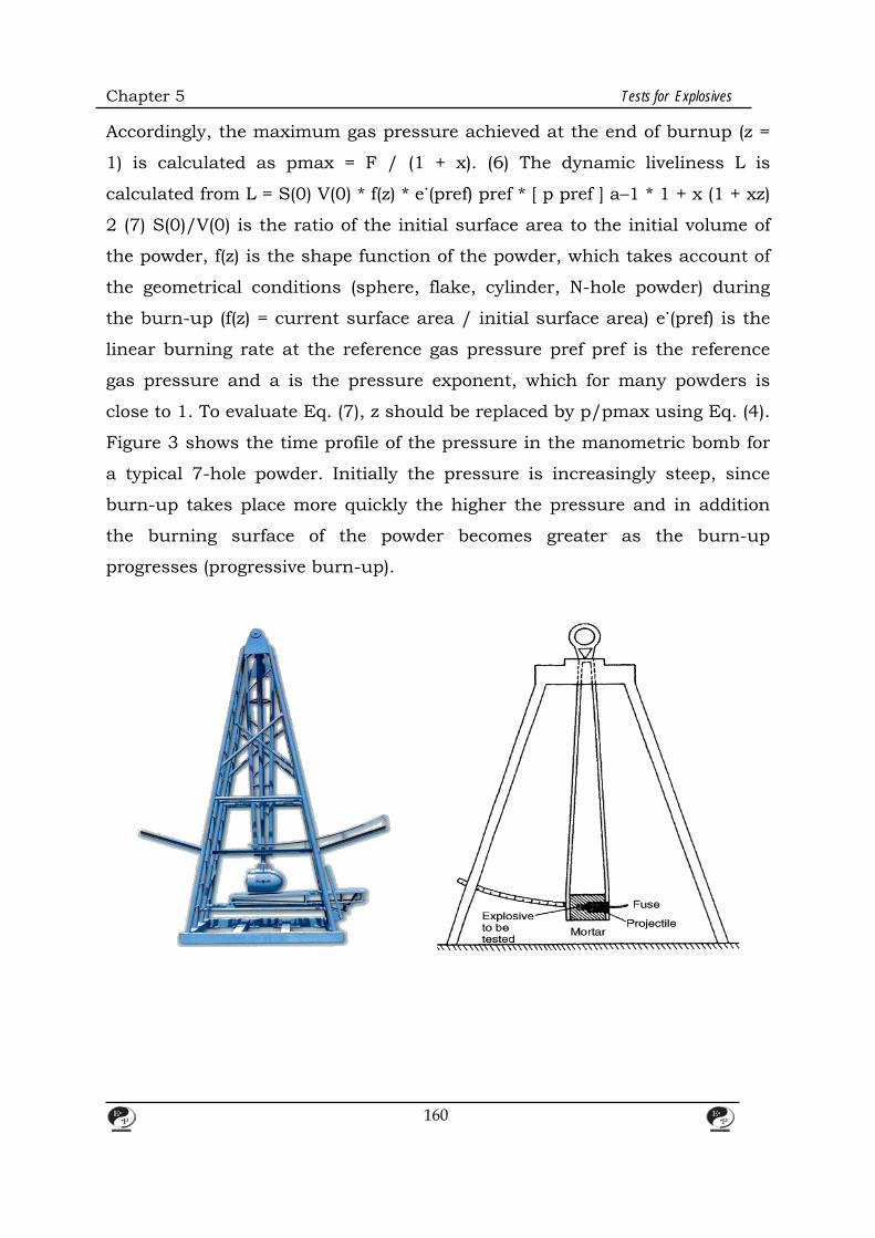
Chapter 5 Tests for Explosives
Accordingly, the maximum gas pressure achieved at the end of burnup (z =
1) is calculated as pmax = F / (1 + x). (6) The dynamic liveliness L is
calculated from L = S(0) V(0) * f(z) * e˙(pref) pref * [ p pref ] a–1 * 1 + x (1 + xz)
2 (7) S(0)/V(0) is the ratio of the initial surface area to the initial volume of
the powder, f(z) is the shape function of the powder, which takes account of
the geometrical conditions (sphere, flake, cylinder, N-hole powder) during
the burn-up (f(z) = current surface area / initial surface area) e˙(pref) is the
linear burning rate at the reference gas pressure pref pref is the reference
gas pressure and a is the pressure exponent, which for many powders is
close to 1. To evaluate Eq. (7), z should be replaced by p/pmax using Eq. (4).
Figure 3 shows the time profile of the pressure in the manometric bomb for
a typical 7-hole powder. Initially the pressure is increasingly steep, since
burn-up takes place more quickly the higher the pressure and in addition
the burning surface of the powder becomes greater as the burn-up
progresses (progressive burn-up).
160
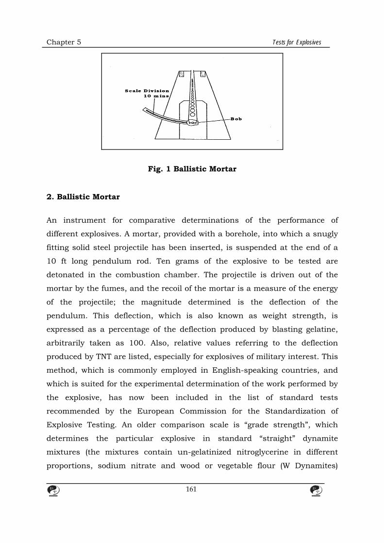
Chapter 5 Tests for Explosives
Fig. 1 Ballistic Mortar
2. Ballistic Mortar An instrument for comparative determinations of the performance of
different explosives. A mortar, provided with a borehole, into which a snugly
fitting solid steel projectile has been inserted, is suspended at the end of a
10 ft long pendulum rod. Ten grams of the explosive to be tested are
detonated in the combustion chamber. The projectile is driven out of the
mortar by the fumes, and the recoil of the mortar is a measure of the energy
of the projectile; the magnitude determined is the deflection of the
pendulum. This deflection, which is also known as weight strength, is
expressed as a percentage of the deflection produced by blasting gelatine,
arbitrarily taken as 100. Also, relative values referring to the deflection
produced by TNT are listed, especially for explosives of military interest. This
method, which is commonly employed in English-speaking countries, and
which is suited for the experimental determination of the work performed by
the explosive, has now been included in the list of standard tests
recommended by the European Commission for the Standardization of
Explosive Testing. An older comparison scale is “grade strength”, which
determines the particular explosive in standard “straight” dynamite
mixtures (the mixtures contain un-gelatinized nitroglycerine in different
proportions, sodium nitrate and wood or vegetable flour (W Dynamites)
161

Chapter 5 Tests for Explosives
which gives a pendulum deflection equal to that given by the test material.
The percentage of nitroglycerine contained in the comparative explosive is
reported as grade strength. The grade strength percentage is not a linear
indicator of the performance of the explosive; the performance of a 30%
dynamite is more than half of the performance of a 60% dynamite, because
the fueloxidizer mixtures as well as nitroglycerine also contribute to the gas
and heat-generating explosive reaction.
3. Lead Block Test The Trauzl lead block test is a comparative method for the determination of
the Strength of an explosive. Ten grams of the test sample, wrapped in
tinfoil, are introduced into the central borehole (125 mm deep, 25 mm in
diameter) of a massive soft lead cylinder, 200 mm in diameter and 200 mm
long. A copper blasting cap No. 8 with an electric primer is introduced into
the center of the explosive charge, and the remaining free space is filled with
quartz sand of standard grain size. After the explosion, the volume of the
resulting bulge is determined by filling it with water. A volume of 61 cm3 ,
which is the original volume of the cavity, is deducted from the result thus
obtained. In France the lead block performance value is given by the
coefficient d’utilisation pratique (c. u. p.): if mx is the mass of the tested
explosive, which gives exactly the same excavation as 15 g of picric acid, the
ratio 15 mx · 100 =% c. u. p. is the coefficient d’utilisation pratique. Also, 10
g of picric acid can be applied as a standard comparison explosive. For the
relationship with other testing procedures W Strength. Another modification
of the lead block test is recommended by BAM (Bundesanstalt für
Materialprüfung, Germany). The test sample is prepared as follows: a special
instrument wraps the sample in tinfoil and molds it into a cylinder of 11 ml
capacity (24.5 mm in diameter, 25 mm in height, with a coaxial cavity 7 mm
in diameter and 20 mm long for the blasting cap), whereby the resulting
density should be only slightly higher than the pour (bulk) density. Liquids
162
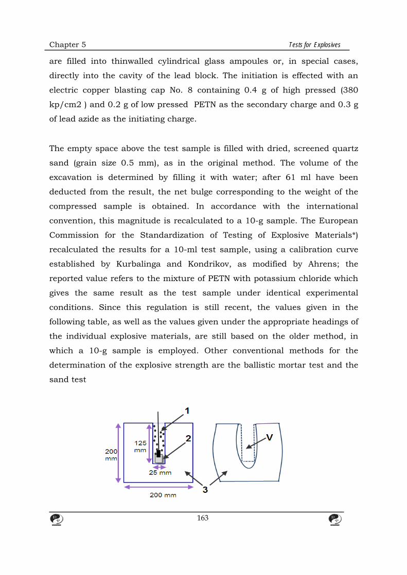
Chapter 5 Tests for Explosives
are filled into thinwalled cylindrical glass ampoules or, in special cases,
directly into the cavity of the lead block. The initiation is effected with an
electric copper blasting cap No. 8 containing 0.4 g of high pressed (380
kp/cm2 ) and 0.2 g of low pressed PETN as the secondary charge and 0.3 g
of lead azide as the initiating charge.
The empty space above the test sample is filled with dried, screened quartz
sand (grain size 0.5 mm), as in the original method. The volume of the
excavation is determined by filling it with water; after 61 ml have been
deducted from the result, the net bulge corresponding to the weight of the
compressed sample is obtained. In accordance with the international
convention, this magnitude is recalculated to a 10-g sample. The European
Commission for the Standardization of Testing of Explosive Materials*)
recalculated the results for a 10-ml test sample, using a calibration curve
established by Kurbalinga and Kondrikov, as modified by Ahrens; the
reported value refers to the mixture of PETN with potassium chloride which
gives the same result as the test sample under identical experimental
conditions. Since this regulation is still recent, the values given in the
following table, as well as the values given under the appropriate headings of
the individual explosive materials, are still based on the older method, in
which a 10-g sample is employed. Other conventional methods for the
determination of the explosive strength are the ballistic mortar test and the
sand test
163
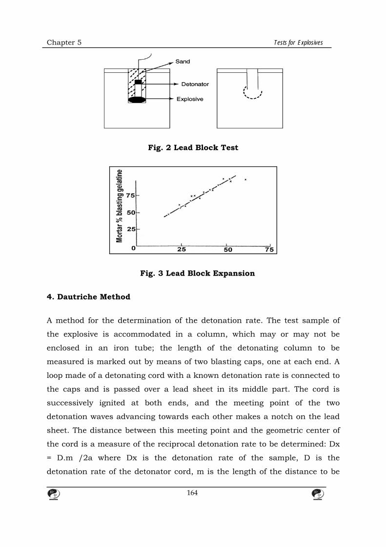
Chapter 5 Tests for Explosives
Fig. 2 Lead Block Test
Fig. 3 Lead Block Expansion 4. Dautriche Method A method for the determination of the detonation rate. The test sample of
the explosive is accommodated in a column, which may or may not be
enclosed in an iron tube; the length of the detonating column to be
measured is marked out by means of two blasting caps, one at each end. A
loop made of a detonating cord with a known detonation rate is connected to
the caps and is passed over a lead sheet in its middle part. The cord is
successively ignited at both ends, and the meeting point of the two
detonation waves advancing towards each other makes a notch on the lead
sheet. The distance between this meeting point and the geometric center of
the cord is a measure of the reciprocal detonation rate to be determined: Dx
= D.m /2a where Dx is the detonation rate of the sample, D is the
detonation rate of the detonator cord, m is the length of the distance to be
164

Chapter 5 Tests for Explosives
measured, and a is the distance between the notch and the center of the
cord length. The method is easy to carry out and no special chronometer is
required. If, Dautriche method for the determination of detonation velocity:
A= explosive B,C=holes for the detonators
D=detonating fuse E=detonators
F=lead plate
Fig. 4 Dautriche Test 5. Bergmann-Junk Test A method, developed by Bergmann and Junk in 1904, for testing the
chemical stability of nitrocellulose; it was also subsequently employed for
165

Chapter 5 Tests for Explosives
testing single-base powders. The test tube, which contains the specimen
being tested, and which is equipped with a cup attachment, is heated at 132
°C = 270.4°F for two hours (nitrocellulose) or five hours (single base
powders). At the end of the heating period the sample is extracted with
water, and the test tube filled to the 50-ml mark with the water in the cup.
The solution is filtered, and the content of nitrous oxides is determined by
the Schulze-Tiemann method on an aliquot of the filtrate. The main
disadvantage of the method is that nitrous compounds are only incompletely
absorbed in water, especially since the atmospheric oxygen which has
remained behind in the tube is expelled during heating or is displaced by
the carbon dioxide evolved at the powder surface. Moreover, the results vary
with the volume of the specimen employed, since differing volumes of water
are required to fill the tube up to the mark in gelled and porous powders.
Siebert suggested the use of H2O2 rather than water as the absorption
medium in 1942. He also suggested that the employed apparatus should be
redesigned, to avoid gas losses which occur when the cup attachment is
taken off. In the new design, the cup is replaced by a large (over 50 ml)
attachment resembling a fermentation tube, which need not be taken off
during the extraction of the sample. In this way quantitative determination
of the liberated No, even in large amounts, becomes possible. Siebert also
suggested that the total acidity be determined by titration against N/100
NaOH, in the presence of Tashiro’s indicator. In this manner W Double Base
Propellants can also be tested as well; the test is carried out at 115 °C, the
duration of heating being 8 or 16 hours depending on the nitroglycerine
content of the sample (or of similar products, e.g. Diethyleneglycol
Dinitrate).
6. Sympathetic Detonation or Gap Test Also known as flash over; coefficient de self-excitation These terms denote
the initiation of an explosive charge without a priming device by the
166
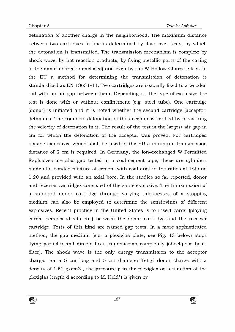
Chapter 5 Tests for Explosives
detonation of another charge in the neighborhood. The maximum distance
between two cartridges in line is determined by flash-over tests, by which
the detonation is transmitted. The transmission mechanism is complex: by
shock wave, by hot reaction products, by flying metallic parts of the casing
(if the donor charge is enclosed) and even by the W Hollow Charge effect. In
the EU a method for determining the transmission of detonation is
standardized as EN 13631-11. Two cartridges are coaxially fixed to a wooden
rod with an air gap between them. Depending on the type of explosive the
test is done with or without confinement (e.g. steel tube). One cartridge
(donor) is initiated and it is noted whether the second cartridge (acceptor)
detonates. The complete detonation of the acceptor is verified by measuring
the velocity of detonation in it. The result of the test is the largest air gap in
cm for which the detonation of the acceptor was proved. For cartridged
blasing explosives which shall be used in the EU a minimum transmission
distance of 2 cm is required. In Germany, the ion-exchanged W Permitted
Explosives are also gap tested in a coal-cement pipe; these are cylinders
made of a bonded mixture of cement with coal dust in the ratios of 1:2 and
1:20 and provided with an axial bore. In the studies so far reported, donor
and receiver cartridges consisted of the same explosive. The transmission of
a standard donor cartridge through varying thicknesses of a stopping
medium can also be employed to determine the sensitivities of different
explosives. Recent practice in the United States is to insert cards (playing
cards, perspex sheets etc.) between the donor cartridge and the receiver
cartridge. Tests of this kind are named gap tests. In a more sophisticated
method, the gap medium (e.g. a plexiglas plate, see Fig. 13 below) stops
flying particles and directs heat transmission completely (shockpass heat-
filter). The shock wave is the only energy transmission to the acceptor
charge. For a 5 cm long and 5 cm diameter Tetryl donor charge with a
density of 1.51 g/cm3 , the pressure p in the plexiglas as a function of the
plexiglas length d according to M. Held*) is given by
167

Chapter 5 Tests for Explosives
p = 105 e 0.0358d
p in kbar, d in mm. The result of the gap test is recorded as the minimum pressure at which the
acceptor charge detonates. F. Trimborn (Explosivstoffe vol. 15, pp. 169–175
(1967) described a simple method in which water is used as the heat
blocking medium; the method can also be used to classify explosives which
are hard to detonate and are insensitive to blasting caps. The gap test
explosive train is directed from bottom to top. The donor charge (Hexogen
with 5% wax) is placed into a plexiglas tube and covered with water. The
acceptor charge to be tested is introduced into the water column from above.
The distance between the two charges can be easily varied. A detonating
cord, terminating on a lead plate, serves as evidence for detonation.
7. Heat Sensitivity Koenen Test Procedure The sample substance is introduced into a
cylindrical steel sleeve (25 mm dia.V24 mm dia.V75 mm) up to a height of
60 mm, and the capsule is closed with a nozzle plate with a central hole of a
given diameter. The diameter of the hole can vary between 1 and 20 mm;
when the plate is not employed, the effect is equivalent to that of a 24-mm
hole. The charged sleeve is placed inside a protective box and is
simultaneously heated by four burners; the time elapsed up to incipient
combustion and the duration of the combustion itself are measured with a
stop watch. The plate perforation diameter is varied, and the limiting
perforation diameter corresponding to an explosion caused by accumulation
of pressure inside the steel sleeve is determined. Explosion is understood to
mean fragmentation of the sleeve into three or more fragments or into a
greater number of smaller fragments. In this way, reproducible numerical
data are obtained which allow classification of different explosives according
to the explosion danger they represent. The parameter which is reported is
the largest diameter of the circular perforation in mm (limiting diameter) at
168
Chapter 5 Tests for Explosives
which at least one explosion occurs in the course of three successive trials.
8. Resistance wire continuous VOD measurement system Microtrap The continuous resistance wire method was developed in the early 1960s by
the United States Bureau of Mines (USBM). Operation is based on the basic
Ohm’s law, (E = RI), where E = Voltage, R = Resistance and I = Current.
When the current is held constant against a shortened (i.e. detonated) wire
of known resistance per unit length, a voltage drop can be measured
instantaneously at any point in time. The voltage drop is equivalent to the
length of resistance wire consumed in the detonation. Resistance wire
probes actually consist of two wires which must be physically shorted out by
the detonation through ionisation. Some resistance wire probes consist of
just two insulated wires twisted together and other probes consist of one
coated wire placed inside of a small metal tube which acts as the second
wire. Providing that the wires are adequately shorted during the detonation,
the resistance wire method does provide a truly continuous VOD along the
explosive column due to the high sampling rates ranging from 1.25 MHz to
over 10 MHz. If the wires are not adequately shorted in a continuous and
reliable fashion, erroneous results, excessive electronic noise and severe
drop outs are the norm. The details of the experimental hole are shown in
Fig. 2.
9. Impedance Detonation velocity of the explosive can be used to calculate the impedance
of an explosive which is defined as the product of the density and the
detonation velocity of the explosive. For good blasts, it is reported that the
impedance of the explosive should match with that of the rock. Berta [12]
mentions that the transfer of energy to the rock is a function of both the
characteristics of the explosive and the rock. According to him, the energy
169
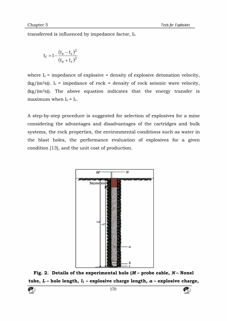
Chapter 5 Tests for Explosives
transferred is influenced by impedance factor, If.
( )( )2re
2re
fII
II1I
+
−−=
where Ie = impedance of explosive = density of explosive detonation velocity,
(kg/(m2s)). Ir = impedance of rock = density of rock seismic wave velocity,
(kg/(m2s)). The above equation indicates that the energy transfer is
maximum when Ie = Ir.
A step-by-step procedure is suggested for selection of explosives for a mine
considering the advantages and disadvantages of the cartridges and bulk
systems, the rock properties, the environmental conditions such as water in
the blast holes, the performance evaluation of explosives for a given
condition [13], and the unit cost of production.
Fig. 2. Details of the experimental hole (M – probe cable, N – Nonel
tube, L – hole length, l1 – explosive charge length, a – explosive charge,
170
Chapter 5 Tests for Explosives
b – primer, c – NONEL detonator).
10. Hot Storage Tests These tests are applied to accelerate the decomposition of an explosive
material, which is usually very slow at normal temperatures, able to
evaluate the stability and the expected service life of the material from the
identity and the amount of the decomposition prod- 177 Hot Storage Tests
ucts. Various procedures, applicable at different temperatures, may be
employed for this purpose. 1. Methods in which the escaping nitrous gases
can be recognized visually or by noting the color change of a strip of dyed
filter paper. The former methods include the qualitative tests at 132, 100,
75, and 65.5 °C (270, 212, 167, and 150 °F). These tests include the U.S.
supervision test, the methyl violet test, the Abel test, and the Vieille test. 2.
Methods involving quantitative determination of the gases evolved. Here we
distinguish between tests for the determination of acidic products (nitrous
gases) only, such as the Bergmann-Junk test and methods which determine
all the decomposition products, including manometric methods and weight
loss methods. 3. Methods which give information on the extent of
decomposition of the explosive material (and thus also on its stability),
based on the identity and the amount of the decomposition products of the
stabilizer formed during the storage. These include polarographic, thin-layer
chromatographic and spectrophotometric methods. 4. Methods providing
information on the stability of the explosive based on the heat of
decomposition evolved during storage (silvered vessel test). 5. Methods in
which stability can be estimated from the physical degradation of a
nitrocellulose gel (viscometric measurements). The tests actually employed
vary with the kind of explosive tested (explosives, single-base, double-base
or triple-base powders, or solid propellants) and the temporal and thermal
exposure to be expected (railway transportation or many years’ storage
under varying climatic conditions). In the case of propellants about to be
171

Chapter 5 Tests for Explosives
transported by train, only short-time testing is required. However, to obtain
an estimate of the expected service life is required, the so-called long-time
tests must be performed at 75 °C (167 °F) and below. The duration of such a
storage is up to 24 months, depending on the propellant type. Shorttime
tests – the Bergmann-Junk test, the Dutch test, the methyl violet test, the
Vieille test and, very rarely, the Abel test – are mostly employed in routine
control of propellants of known composition, i.e., propellants whose
expected service life may be assumed to be known. In selecting the test to be
applied, the composition of the propellant and the kind and amounts of the
resulting decomposition products must also be considered. Contrary to the
common propellants, which contain nitrates, the so-called composite
propellants cannot be tested in the conventional manner owing to the
relatively high chemical stability of the incorporated oxidants, e.g.,
ammonium perchlorate. In such cases the stability Hot Storage Tests 178
criterion of the propellants is the condition of the binder and its chemical
and physical change.
11. Fall Hammer Method The sensitiveness to impact of solid, liquid, or gelatinous explosives is tested
by the fall hammer method. Samples of the explosives are subjected to the
action of falling weights of different sizes. The parameter to be determined is
the height of fall at which a sufficient amount of impact energy is
transmitted to the sample for it to decompose or to explode. The US
standard procedures are: (a) Impact sensitivity test for solids: a sample
(approximately 0.02 g) of explosive is subjected to the action of a falling
weight, usually 2 kg. A 20-milligram sample of explosive is always used in
the Bureau of Mines (BM) apparatus when testing solid explosives. The
weight of the sample used in the Picatinny Arsenal (PA) apparatus is
indicated in each case. The impact test value is the minimum height at
which at least one of 10 trials results in explosion. In the BM apparatus, the
172
Chapter 5 Tests for Explosives
explosive is held between two flat, parallel hardened steel surfaces; in the PA
apparatus it is placed in the depression of a small steel die-cup, capped by a
thin brass cover, in the center of which a slotted-vented cylindrical steel
plug is placed, with the slotted side downwards. In the BM apparatus, the
impact impulse is transmitted to the sample by the upper flat surface; in the
PA, by the vented plug. The main differences between the two tests are that
the PA test involves greater confinement, distributes the translational
impulse over a smaller area (due to the inclined sides of the die cup cavity),
and involves a frictional component (against the inclined sides). The test
value obtained with the PA apparatus depends greatly on the sample
density. This value indicates the hazard to be expected on subjecting the
particular sample to an impact blow, but is of value in assessing a material’s
inherent sensitivity only if the apparent density (charge weight) is recorded
along with the impact test value. The samples are screened between 50 and
100 mesh, U.S. where single component explosives are involved, and
through 50 mesh for mixtures. (b) Impact sensitivity test for liquids: the PA
Impact Test for liquids is run in the same way as for solids. The die-cup is
filled, and the top of the liquid meniscus is adjusted to coincide with the
plane of the top rim of the die-cup. To date, this visual observation has been
found adequate to assure that the liquid does not wet the die-cup rim after
the brass cup has been set in place. Thus far, the reproducibility of data
obtained in this way indicates that variations in sample size obtained are
not significant. In the case of the BM apparatus, the procedure that was
described for solids is used with the following variations: 1. The weight of
explosives tested is 0.007 g. 2. A disc of desiccated filter paper (Whatman
No. 1) 9.5 mm P is laid on each drop, on the anvil, and then the plunger is
lowered onto the sample absorbed in the filter paper. The fallhammer
method was modified by the German Bundesanstalt für Material prüfung
(BAM), so as to obtain better reproducible data*). The sample is placed in a
confinement device, which consists of two coaxial cylinders placed one on
top of the other and guided by a ring. The cylinders have a diameter of 10–
173
Chapter 5 Tests for Explosives
0,003 –0,005 mm and a height of 10 mm, while the ring has an external
diameter of 16 mm, a height of 13 mm and a bore of 10+0,005 +0,01 mm;
all parts, cylinders and rings, must have the same hardness*). Cylinders and
rings are renewed for each falling test procedure. If the sample is a powder
or a paste, the upper cylinder is slightly pressed into the charged
confinement device as far as it will go without flattening the sample. If
liquids are tested, the distance between the cylinders is 2 mm. The charged
device is put on the anvil of the fallhammer apparatus, and the falling
weight, guided by two steel rods, is unlocked. For sensitive explosives such
as primary explosives, a small fallhammer is used for insensitive explosives
a large hammer. The small hammer involves the use of fall weight of up to
1000 g, while the fall weights utilized with the large hammer are 1, 5 and 10
kg. The fall heights are 10–50 cm for the 1-kg weight, 15–50 cm for the 5-kg
weight and 35–50 cm for the 10-kg weight. This method is the recommended
test method in the UN-recommendations for the transport of dangerous
goods and it is standardized as EN 13631-4 as a so-called Harmonized
European Standard.
174

Chapter 5 Tests for Explosives
Fig: BAM fall hammer BFH serves for measuring impact sensitivity of
solid high explosives
12. Testing galleries for explosives in coal mines All coal-mining countries have issued detailed regulations for the testing,
approval, and use of explosives which are safe in firedamp. The main
instrument for these tests is the testing gallery. A test gallery consists of a
steel cylinder which initates an underground roadway; the cross sectional
area is about 2 m2 (5ft P; one end is closed by a shield of about 30 cm (1ft)
P, against which the cannon is placed. The other end of the chamber which
has a volume of ca. 10 m3 (18ft length) is closed by means of a paper
screen. The remaining part of the tube length (10 m; 32ft) behind the paper
screen is left open to the atmosphere. (The gallery tube can be constructed
in closed form if the noise of the test shots can be diminished.) After
charging and positioning the cannon, the closed chamber is filled with a
methane-air mixture (containing, e.g., 9.5% CH4 to give the most dangerous
175

Chapter 5 Tests for Explosives
composition), and the charge is fired. Whether or not ignition of the gas
occurs is observed from a safe position. Amongst the known types of
mortars is the borehole cannon, as shown in Fig. 18. A steel cylinder about
1.5 m (5ft) long and about 35 cm (1–1/8ft) in diameter has in it a borehole of
55 mm (2–11/64 in.) diameter and 1.20 m (47 in.) length. The explosive to
be tested is placed in the borehole, unstemmed or stemmed by a clay plug,
and the detonator is introduced last in the hole (direct initiation). If the
detonator is inserted first, followed by the train of cartridges, initiation is
“inverse”. The required test conditions can be severe; ignition of the gas
mixture is more probable to occur using unstemmed charges and inverse
initiation than with stemmed charges and direct initiation. The different
mortars are designed to simulate different underground conditions. The
borehole cannon in the testing gallery illustrates the action of a single shot
in the roadway of gassy mines. The British break test and the slotted mortar
in Poland imitate the exposure of a charge and, consequently, the more
extended contact between the firing charge and the firedamp atmosphere
where breaks in the strata intersect a shothole: Two steel plates are held at
a given distance by means of a closing angle and a plug. The lower plate has
a groove for the cartridge train. The plate arrangement is covered with a
polythene sheet laid upon two steel side walls; the gas-tight room is filled
with the methane-air mixture after charging. The break test conditions are
varied; permitted explosives which meet the most stringent test conditions
belong to the British safety class P4. The slotted mortar allows similar test
procedures.
The slot does not extend over the whole length of the borehole and does not
begin at the mouth of the hole. A specially dangerous condition can arise
when several shots are fired in one round by means of electric delay
detonators. A preceding shot may then break the coal of another hole or
even cut off the whole burden of the charge in question so that it is partly or
completely exposed. This condition is simulated in the angle-mortar test. A
176
Chapter 5 Tests for Explosives
steel cylinder of 230 mm (9 in.) diameter and 2 m (~1/2ft) in length with a
right-angled groove is positioned in the gas chamber of a testing gallery
against an impact steel plate at given distances and different impact angles,
as shown in Fig. 21. Trains of several cartridges or of the full length of 2 m
are placed in the groove of the angle and fired into the methane-air mixture.
13. Sand Test A performance test of an explosive, used in the USA. A known amount of the
explosive is exploded in sand consisting of a single grain size (sieve) fraction;
the magnitude determined is the amount of sand which passes a finer-
meshed sieve following the fragmentation. The test descriptions follow: (a)
Sand test for solids. A 0.4-g sample of explosive, pressed at 3000 psi into a
No. 6 cap, is initiated by lead azide or mercury fulminate (or, if necessary, by
lead azide and tetryl) in a sand test bomb containing 200 g of “on 30 mesh”
Ottawa sand. The amount of azide of Tetryl that must be used to ensure that
the sample crushes the maximum net weight of sand, is designated as its
sensitivity to initiation, and the net weight of sand crushed, finer than 30
mesh, is termed the sand test value. The net weight of sand crushed is
obtained by subtracting from the total amount crushed by the initiator when
shot alone. 275 Sand Test (b) Sand test for liquids. The sand test for liquids
is made in accordance with the procedure given for solids except that the
following procedure for loading the test samples is substituted: Cut the
closed end of a No. 6 blasting cap and load one end of the cylinder with 0.20
g of lead azide and 0.25 g of tetryl, using a pressure of 3000 psi to
consolidate each charge. With a pin, prick the powder train at one end of a
piece of miner’s black powder fuse, 8 or 9 inches long. Crimp a loaded
cylinder to the pricked end, taking care that the end of the fuse is held
firmly against the charge in the cap. Crimp near the mouth of the cap to
avoid squeezing the charge. Transfer of 0.400 g of the test explosive to an
aluminum cap, taking precautions with liquid explosives to insert the
177

Chapter 5 Tests for Explosives
sample so that as little as possible adheres to the side walls of the cap; when
a solid material is being tested, use material fine enough to pass through a
No. 100 U.S. Standard Sieve. The caps used should have the following
dimensions: length 2.00 inches, internal diameter 0.248 inch, wall thickness
0.025 inch. Press solid explosives, after insertion into the aluminum cap, by
means of hand pressure to an apparent density of approximately 1.2 g per
cubic centimeter. This is done by exerting hand pressure on a wooden
plunger until the plunger has entered the cap to a depth of 3.93
centimeters. The dimensions of the interior of the cap are: height 5.00 cm,
area of cross section 0.312 square centimeters. Insert the cylinder
containing the fuse and explosive charge to Tetryl and lead azide into the
aluminum cap containing the test explosive for the determination of sand
crushed.
14. Upsetting Tests Upsetting tests are used to determinate the Brisance of the explosives. An
unconfined cartridge (enveloped in paper or in metal sheet) acts upon a
copper or lead crusher; the loss of height of the crusher is a measure for the
brisant performance of the tested explosive (Brisance). The cartridge shock
acts by means of a guided pestle onto a copper crusher of 7 mm P and 10.5
mm height. The simplified test according to Hess is shown in Fig. 26 (see
opposite page): A lead cylinder, 60 mm (2.36 in.) high, 40 mm (1.57 in.) ∅,
protected by two, 6 mm-thick steel disks, is upset by a 100-g (3.53 oz.)
cartridge of the same diameter, 40 mm. The cylinder is pressed down into a
mushroom shape; in the case of sensitized special gelatins for seismic use,
the cylinder can be destroyed completely.
15. Vacuum Test This test, which was developed in the USA and has been adopted by several
countries, and is a modification of the Taliani Test, in which the gaseous
178

Chapter 5 Tests for Explosives
products of the reaction are determined volumetrically rather than by
manometry. The test, which is carried out at 100 °C (212 °F) for single base
propellants and at 90 °C (194 °F) for multibase propellants, is terminated
after 40 hours, unlike the Taliani Test, which is interrupted after a given
pressure or a given volume has been attained. The vacuum test is used for
compatibility testing and applied as a so-called reactivity test. The
compatibility between the explosive and the contact material (adhesive,
varnish, etc.) is tested by determining the gases liberated by the explosive
alone, by the contact material alone, and by the two together. The measure
of compatibility (reactivity) is the difference between the sum of the gas
volume liberated by each component separately and the gas volume
obtained after storing the explosive and the contact material together. If this
difference is below 3 ml, the compatibility is considered to be “stable”,
between 3 and 5 ml, the compatibility is considered „uncertain“; above 5 ml,
the two materials are incompatible.
16. Water Resistance Test
In the USA the following method is employed for testing the water resistance
of commercial explosives: Sixteen regularly spaced holes (about 6 mm P) are
cut in the cartridge paper (30 mm in diameter, 200 mm long) of the
explosive to be tested, and the flaps on the front faces are sealed with tallow.
The cartridges thus prepared are placed in a flat, porcelain coated dish
covered with a thin layer of sand, and water at 17–25 °C (63–77 °F) is
poured over the sand layer up to a height of about 25 mm. The cartridges
are left under water for a certain period of time, are then taken out, the seal
is cut off at one end, and the cartridge is tested for detonation and
transmission with the aid of a No. 6 blasting cap. The criterion for the water
resistance of the explosive is the time of exposure to water, after which it
still retains its capacity to detonate the cartridge in three trials, without
leaving any non-detonated residual explosive behind. There is no generally
179
Chapter 5 Tests for Explosives
accepted quality classification. Nevertheless, water resistance of an explosive
is considered to be satisfactory, acceptable, or poor if the cartridge can still
be detonated after 24, 8, or 2 hours respectively. In Germany, the following
method for testing the water resistance of powder-form permissibles has
been laid down at the Test Station at Dortmund-Derne. A train of four
cartridges is fixed in a file on a wooden board; the first of the four cartridges
is equipped with a detonator No. 8. Five longitudinal, 2 cm long notches,
uniformly distributed over the circumference, are cut into each cartridge.
The train is immersed for 5 hours in water, in a horizontal position, 20 cm
under the water surface, after which they are detonated. The train must
detonate in its entirety. This method, including some additions regarding the
preparation of the test sample is standardized as EN 13631-5 as a so-called
Harmonized European Standard. The water resistance of partly water –
soluble, powder-form explosives (e.g. ammonium nitrate explosives or
blasting agents) can be improved by the addition of hydrophobic or gelling
agents. If e.g. W Guar Gum is added, the water entering immediately forms a
gel which blocks the penetration of more water.
180
CHAPTER – 6
MODERN METHODS OF EXPLOSIVE FORENSICS
1. Introduction With the apparent increased use of explosives in recent years , the ability to
quickly, sensitively and reliably identify and determine a wide range of
chemical components is essential in forensic. Some of the recent high-
profile terrorist attacks using improvised explosive devices (IEDs) include
those are used regularly in India, Pakistan, Afghanistan, Iraq and Syria and
have been used in London (1999, 2005), Norway (2011) and Boston (2013)
amongst several others. The devices used in these events highlighted the
array of possible chemicals that may exist and, in some cases, the relative
ease in obtaining them. Therefore, the significant challenges placed on
analytical scientists to prepare for and hopefully prevent such events,
despite their complexity, is unfortunately an ongoing problem.
Explosives can be sub-divided by compound sensitivity into primary,
secondary and tertiary explosives as shown in Fig. 1. Primary explosives are
highly sensitive, unstable materials and can ignite by shock, friction, heat or
impact. Tri Acetone Tri Peroxide (TATP) is an example of a primary explosive
and one which can be analytically challenging to determine due to this
instability. Secondary organic explosives typically contain a nitro group such
as 2,4,6-trinitrotoluene (TNT) or nitroglycerin (NG). These are comparatively
more stable and are frequently used with a small amount of primary
explosive to initiate a detonation. They are regularly mixed with gels,
sensitisers or stabilisers depending on the application requirement. Primary
and secondary explosives are generally termed “high-order explosives” as
they detonate upon discharge. The majority of inorganic compounds,
containing salts of chlorate, perchlorate or nitrate ions for example, are
181

Chapter 6 Modern Methods of Explosive Forensics
considered “low-order explosives”. These materials generally deflagrate and
are often used in pyrotechnics and propellants. However, some inorganic
compounds, such as ammonium nitrate, are still classed as high-order
explosive materials and are known as tertiary explosives. These are very
insensitive to shock and require an explosive booster of secondary explosive.
Any of the above explosive types can be used in IEDs, and the identification
of the components present can be used to determine the source and possibly
provide a link to a suspect. The term “pre-blast” describes a point in time
before an explosion has occurred. Conversely, “post-blast” pertains to a
time-point after discharge of an explosive. Pre-blast detection of explosives
can either involve bulk (mg to kg) analysis of the charge itself, or trace
analysis (fg to mg) of the explosive on skin, clothing, solid surfaces and
soil for example. Post-blast analysis typically involves trace analysis of non-
combusted explosive material or its combusted products either in the
surrounding vicinity of the explosion, on any fragments or material
belonging to the IED or on articles affected by the explosion. Whilst
potentially linking suspects with pre-blast materials analysis might arguably
be considered more straightforward (e.g. through the their detection in
fingermarks, it is significantly more challenging to do so with post-blast
residues containing a mixture of the parent components and their
combustion products, as well as the high risk of environmental
contamination.
182
Chapter 6 Modern Methods of Explosive Forensics
Fig. 1. Schematic of energetic materials classifications. High-order
explosives detonate and are further divided by sensitivity, whereas low
order explosives deflagrate. The dashed line highlights the groups that
primarily contain inorganic components included in this Chapter. NC,
Nitrocellulose; NG, nitroglycerin; TNT, trinitrotoluene, TATP,
triacetone triperoxide; HMTD, hexamethylene triperoxide diamine.
The majority of analytical methods employing hyphenated separation and
mass spectrometric techniques for energetic materials analysis have
focussed on the organic high-order explosives, and as a result there are
many reviews available on this topic. The two main separation techniques
used for confirmatory detection of such compounds are gas
chromatography (GC) and high performance liquid chromatography
(HPLC) and coupled to mass spectrometry (MS). The choice of separation
mode is often dependent on analyte vapour pressure. For example, the
vapour pressure of octahydro-1,3,5,7-tetranitro-1,3,5,7-tetrazocine (HMX;
speculatively named, “High-velocity Military explosive”, amongst other
pseudonyms) is low and, along with its thermal lability, it is more amenable
to LC-MS rather than GC-MS[24]. However, and despite the large body of
literature available on trace high-order explosives analysis, there still exists
a gap in confirmatory analytical separations-based technologies for low-
order inorganic or organic ion explosives. Along with some other techniques,
183
Chapter 6 Modern Methods of Explosive Forensics
many low-order and related species have been routinely and widely
determined by IC coupled to relatively non-specific detectors such as
suppressed conductivity, electrochemical or ultraviolet detection for over 30
years in many different fields of application . Most importantly, the ability to
speciate gives IC an obvious advantage over several other analytical
techniques. Speciation can be vital when it comes to the identification and
characterisation of low-order explosive residue especially regarding
differentiation of oxychloride species from the free chloride ion;
distinguishing transition metal ion valencies (such as Fe(II)/Fe(III)); and
separating nitrogen-containing species such as nitrate, nitrite, thiocyanate
and cyanate. Relatively recent research either directly or indirectly related to
IC-MS has demonstrated a number of important findings, which could offer
some insight and potential value to forensic practitioners planning or
currently operating this technique.
Therefore, the aim and scope of this review is to (a) examine the contexts
and subsequent emergence of IC-MS technology for this application; (b) to
detail the recent technological advances and challenges associated with
practical trace IC-MS from an environmental and forensic science
perspective; (c) to critically compare its usefulness in comparison to other
orthogonal confirmatory methods; and (d) to identify future avenues for
application of this technology in forensic and environmental science. To the
authors’ knowledge, this is the first review focussing specifically on IC-MS
technologies for the analysis of explosive residues.
2. The Impact of Improvised Explosive Devices and the need for IC-MS
Component parts of low-order explosives-based IEDs are readily available in
the form of fertilisers, propellants and pyrotechnics. The type and amount of
explosive present often differs considerably. Complementary separation
techniques to IC such as capillary zone electrophoresis (CZE) have been
traditionally used to confirm identity or source from a residue deposited on
184
Chapter 6 Modern Methods of Explosive Forensics
a suitable surface. Smoke emitted during discharge may indicate the type of
explosive used and can be sampled for analysis. Oxidisers such as
potassiated salts of nitrate, chlorate and perchlorate are combined with a
fuel (such as a sugar), an optional coolant (e.g. NaHCO3), and a dye to
generate a coloured smoke seen often during pyrotechnic displays. The
presence or absence of smoke, as well as the time for discharge
(deflagrations are much slower than detonations), can give invaluable
intelligence regarding the identity of an explosive material before analysis
and therefore may direct which technique to apply. The deadly nature of
IEDs is in part due to their ease of concealment and subsequent blast
impact over short distances. The US Technology Support Working Group
(TSWG) specifies the safe evacuation distances for a range of IED sizes.
For example, an unimpeded outdoor radius of 900 ft (274 m) is
recommended for an IED contained within a letter or small package
with an explosive capacity of 1 lb. Scaling up to a full-size car/minivan
with an explosive capacity of 1000 lb for example, this translates to a
safe radius distance of 2400 ft (732 m) in an outdoor environment. In
an indoor environment, these safe distances may be much reduced,
presumably due to obstruction of high-velocity shrapnel. Therefore from
an analytical point of view, this represents a significant challenge in terms of
deciding where and how to responsively sample trace residue evidence over
a potentially unknown distance, coupled with minimising the effects of
matrix/environmental interference on the analytical determination. Putting
this into context, the Boston Marathon attack in 2013 represents just one
recent example of how IEDs were used to inflict mass casualties among
civilians. Three people were killed and over 264 injured when explosive
materials along with nails and other metal parts were sealed within two
pressure-cookers and discharged ∼190 m apart in a crowded Boylston street.
Even though the immediate blast only occurred over a radius of ∼10 m,
injuries from debris were reported at much further distances. A wider list of
details relating to recent IED attacks is shown in Table 1 for comparison.
185
Chapter 6 Modern Methods of Explosive Forensics
Interestingly, a recent survey by the TSWG revealed that the 468 bomb
squads in the US were called to investigate ∼32,000 potentially IED-related
incidents nationally per year from 2005 to 2010. IEDs also pose a serious
threat in military operations. It has been reported that in Afghanistan, the
number of IED-related coalition fatalities rose to its height at 368 in 2010
out of a confirmed 630 total hostile deaths. Across 2001–2013, an average of
∼51% of all hostile military coalition deaths were due to IEDs in Afghanistan
alone. This translates to 1370 out of 2690 total hostile conflict deaths. In
Iraq by comparison, 1588 fatalities were recorded as being due to IEDs from
2003 to 2007.
Table 1. Examples of high profile terrorist incidences using IEDs.
Year Place Numbers killed/ injured
Explosives used Additional info
1969-Present
England and Northern Ireland
∼1800/ ∼48,000
RDX, PETN, ANFO –
1988
Pam Am Flight 103, Lockerbie, Scotland
270/0 Trace PETN/RDX found
–
1993 World Trade Centre, USA 6/1042 Urea nitrate
Aluminium, magnesium and ferric oxide to enhance reaction temperature. Ammonium nitrate, lead azide and smokeless powder used as boosters
1995 Oklahoma, USA 168/∼680 ANFO –
1996 Olympic Park, Atlanta, USA
2/111 Smokeless powder Nails
186

Chapter 6 Modern Methods of Explosive Forensics
1999 London, UK 3/139 Flash powder from fireworks
Nails
2002 Bali, Indonesia 202/209
Potassium chlorate, aluminium, sulphur
TNT booster. PETN detonating cord. RDX detonators. Thermobaric
2004 Madrid, Spain 191/2050
Unconfirmed—variation of dynamite/nitroglycol
–
2005 London, UK 52/∼700 TATP, HMTD –
2006 Transatlantic flight 0/0 TATP –
2006 Mumbai, India 209/714 RDX, ANFO Thermobaric—
pressure cooker 2011 Norway 8/209 ANFO Fertiliser
2013 Boston, USA 3/282 Unconfirmed—sugar chlorate
Thermobaric—pressure cooker with nails
ANFO: Ammonium nitrate and fuel oil; RDX: research department explosive;
HMX: high velocity military explosive; TATP: triacetone triperoxide; HMTD:
hexamethylene triperoxide diamine; TNT: trinitrotoluene.
Based on these figures, and the potential capability offered by IC-MS over
hyphenation to non-specific detection modes for low molecular weight low-
order explosives and their combustion residues, it seems obvious that more
research efforts are required to tailor this approach towards such forensic
applications. Some issues surrounding sample collection need to be
considered early in this process. For example, recent work has shown that
the practices for the analysis of primary and secondary explosives cannot be
assumed valid when undertaking an analysis of low-order inorganic
explosive species deposited on a surface. For example the extraction of ions
in organic solutions (generally applied for high-order organic explosives) is
not optimal and sample reconstitution in aqueous media is required for IC
187
Chapter 6 Modern Methods of Explosive Forensics
compatibility to reduce self-elution, baseline distortion and momentary
polymer resin dis-equilibration. Furthermore, like high-order explosives,
some specific low molecular weight ionic species were partially/non-
recoverable (such as nitrite and cyanate), displayed unacceptably high
variation using traditional cotton or rayon swabbing devices, suffered high
levels of matrix, method or co-analyte interference or remained unidentified
using non-specific suppressed conductivity detection . Careful consideration
of these issues have recently facilitated the pg detection and quantification a
range of low-order explosive species using IC with suppressed conductivity
detection in latent fingermarks and also in chemically and physically
enhanced fingermarks. However multi-analyte selectivity still remains the
largest challenge and one where IC-MS may offer an obvious solution.
Therefore, from a forensic standpoint, there exists a current need to extend
the repertoire of IC-MS to the confirmatory detection and identification of
such species in complex trace evidence matrices.
Aside from those already discussed, several other low-order ionic explosives-
related species are frequently encountered during pre-/post-blast analysis.
These include alkylated ammonium ions such as methyl- or
ethylammonium; indicative metal ions used to increase the reaction
temperature such as magnesium or aluminium; low molecular weight
organic acids including benzoate and oxalate; and cyano-containing species
such as thiocyanate, cyanate (fulminate), azide . Thiocyanate is known to
occur in certain foods and has been detected in the urine of smokers at
elevated mg L−1 levels using IC . This ion has also been detected in GSR and
can be used along with other ions to distinguish between ammunition
types . Furthermore, it should be noted that post-blast residues of nitro-
group containing organic explosives compounds such as the nitrosamines,
nitro-esters, and the nitrated sugar polyols often contain elevated
concentrations of the nitrite or nitrate ion after discharge. Previous studies
have used the ratio between the two in an attempt to identify the source
(Wheals and Ellison studied the generation of these ions from the hydrolysis
188

Chapter 6 Modern Methods of Explosive Forensics
of nitrocellulose and nitroglycerine to determine the relative concentration
ratio for forensic purposes). Many on-site spot tests, such as those based on
the Greiss diazotisation reaction can be used to preliminarily assess whether
a nitro-group containing organic species is to be expected through detection
of nitrite. Other ions such as thiocyanate arise from sulphur-containing
explosive ingredients. Confirmatory forensic analysis is usually performed
using a combination of ion separation or detection techniques such as IC ,
CZE , various modes of Raman spectroscopy and, occasionally, MS. Unless
present in significantly high amounts (mid- mg L−1 levels and higher), it has
been shown that the presence of the nitrite or nitrate ion alone does not
offer significant intelligence or forensic value to an investigation due to the
potential for environmental or method-related background interference . A
list of species reported in the literature relating to low-order explosives is
given in Table 2.
Table 2. Inorganic and organic ions present in low-order energetic
materials and its post-discharge residue and examples of sources of
reported occurrence.
Ion Source
Al3+ Primer, fuel, commercial blasting agents
As3+ IEDs
Ba2+ Primer, propellant, oxidiser, IEDs
Ca2+ IEDs, primer, propellant, smokeless powder, fuel
CH3CH2NH3+ IEDs
CH3 NH3+ IEDs
Cu2+ Projectiles (e.g. bullets), ammunition casing
Fe2+/Fe3+ Projectiles
K+ Primer, IEDs, black powder, smokeless powder
Mg2+ IEDs, primer, smokeless powder
189
Chapter 6 Modern Methods of Explosive Forensics
Na+ Primer, propellant, IEDs, black powder, smokeless
powder
NH4+ ANFO, smokeless powder, IEDs
Ni2+ Ammunition casing
Pb2+ Primer, projectiles, explosive
Sb3+ Primer, ammunition casing, fuel
Zn2+ IEDs, primer, ammunition casing
Cl− Degradation product of chlorite, chlorate, perchlorate
and other Cl-containing species
ClO2− Reduction product of chlorate/perchlorate-based
explosives
ClO3− Chlorate-type IEDs, GSR
ClO4− Perchlorate-type IEDs, GSR, oxidiser
CNO− GSR
CO32− Black powder substitutes, GSR
NO2− Degradation product, GSR
NO3− ANFO, black powder, oxidiser
N3− IEDs
SCN− GSR
SO42− Black powder
S2O32− Combustion product of sulphur in IEDs
PO43− IEDs
Acetate GSR, PETN-based explosives
Ascorbate Black powder substitutes
Benzoate GSR
Formate GSR, PETN-based explosives
Glycerate Degradation product
Monohydrated Degradation product
190

Chapter 6 Modern Methods of Explosive Forensics
diketogulonic
acid
Oxalate Degradation product, GSR, PETN-based explosives
Phthalate Propellant powder, plasticiser
Threonate Degradation product
ANFO: Ammonium nitrate and fuel oil; PETN: pentaerythritol tetranitrate; GSR:
gunshot residue; IED: improvised explosive device.
3. Isotopic and elemental profiling of ammonium nitrate
3.1 Background
Ammonium nitrate (AN) has applications in explosives in industry, such as
mining and civil construction. Its chemical stability and low sensitivity to
shock and friction make it relatively safe to produce and to handle in large
quantities. Combined with its low costs these properties make AN a suitable
ingredient for explosive devices. Explosive-grade ammonium nitrate
generally exists in the form of slurries, emulsions, or porous prills mixed
with a fuel (ammonium nitrate fuel oil, ANFO). Obtaining explosive-grade AN
for criminal abuse is difficult due to extensive regulations, but AN in the
form of fertilizer prills or granules is widely available. The European
Commission prohibits the distribution of ammonium nitrate-containing
fertilizers with a nitrogen percentage higher than 16% to private parties. In
addition, detonation tests should be performed on fertilizers with a nitrogen
content of more than 28%. Fertilizer prills have a higher density and a lower
porosity than explosive-grade prills, reducing the sensitivity to detonate.
However, fertilizer-grade ammonium nitrate can still detonate or be made to
detonate. Besides industrial applications of AN-based explosives, terrorist
attacks involving the use of AN in improvised explosive devices (IEDs) have
been a concern for many years. In such cases of criminal use of AN in an
IED, chemical profiling can be an important tool to investigate the origin of
191

Chapter 6 Modern Methods of Explosive Forensics
the material used.
The possibility of tracing ammonium nitrate back to its production location
is important. Product classification can yield important information
especially for intelligence purposes and in the absence of leads and
suspects. Chemical profiling of AN is especially challenging because of its
inorganic nature and the bulk quantities in which it is produced. In this
work the potential of profiling based on trace-elemental composition and
isotope ratios has been investigated.
Ammonium nitrate is manufactured from ammonia and nitric acid.
Ammonia production occurs through the reaction of hydrogen with
atmospheric nitrogen according to the Haber process. Thereafter, nitric acid
is formed by the oxidation of ammonia (the Ostwald process). Both the
nitrogen and oxygen in ammonium nitrate are retrieved from the
atmosphere. Although there is not much variation in the isotopic
composition of atmospheric nitrogen and oxygen around the world,
fractionation can occur during AN synthesis resulting in variation in both
δ15N and δ18O values for different samples. Fertilizer prills or granules
consist, besides ammonium nitrate, of various additives, such as gypsum,
dolomite and magnesium nitrate. In addition, the prills are coated with a
water-repellent material to prevent the prills from absorbing water. These
additives also contribute to the isotopic signature of the prills/granules.
Moreover, the additives used during the manufacturing of AN-based
fertilizers are rich in elements and therefore determine the elemental
composition of the fertilizer prills. Two techniques that are, therefore, of
special interest for profiling AN are isotope-ratio mass spectrometry
(IRMS) and inductively-coupled plasma–mass spectrometry (ICP–MS). As
part of the ICP–MS study also the application of laser-ablation ICP–MS
(LA–ICP–MS) was investigated for element profiling of individual
granules or prills. LA–ICP–MS could provide profiling options in forensic
post-explosion investigations where only a limited number of granules
192
Chapter 6 Modern Methods of Explosive Forensics
or prills are found.
3.2. Applications of IRMS and ICP–MS Most of the analytical techniques conventionally used in forensic science are
not able to determine whether samples with the same chemical identity have
a common source. IRMS can in principle be used to study the source of
samples based on their isotopic composition. In the field of explosives, IRMS
was previously used to discriminate between different sources of Semtex,
triacetone triperoxide (TATP), pentaerythritol tetranitrate (PETN), black
powder, flash powder, nitromethane, plastic explosive no. 4 (PE4),
trinitrotoluene (TNT), urea nitrate, and ammonium nitrate. With one
exception these were all preliminary studies with either a small sample set
or limited information on the origin of the materials. In addition to the
ability to examine the source of explosive samples, IRMS has also been used
to study relationships between precursors and the explosive product for
urea nitrate, cyclotrimethylenetrinitramine (RDX)and hexamethylene
triperoxide diamine (HMTD).
ICP–MS is capable of detecting and quantifying multiple elements and thus
of producing trace-elemental signatures. Samples can be introduced in the
plasma either by nebulization (liquids or solutions) or by laser ablation (LA–
ICP–MS). When sufficient evidence material is available, spraying from
solution will provide the most accurate quantitative analysis as it allows for
homogenization of the material. However, the use of laser ablation allows for
trace-element profiling of small amounts of material and for studying the
spatial distribution of the trace elements (2D and 3D profiling). Elemental
profiles obtained using ICP–MS have been used to discriminate between
different sources of glass, paint, tapes, white cotton fibers, beer,
bullets, methylamphetamine, human bones and teeth, and in the
detection of art forgeries . The combination of IRMS and ICP–MS may
result in complementary information on the origin of a material and has
193

Chapter 6 Modern Methods of Explosive Forensics
shown to be powerful in discriminating between different sources.
3.3. Challenges for IRMS of nitrates Stable-isotope analysis of nitrogen-containing samples and nitrates in
particular poses some challenges. There is an influence of N2 gas formed
during high-temperature reduction of nitrogen-rich compounds on the
analysis for 2H isotope abundance. Partial overlap of the N2 and H2 peaks
after GC separation resulted in inaccurate and imprecise δ2H values, either
due to dilution of the H2 peak or to ionization competition between H2 and
N2 gas. Mimicking nitrogen-rich samples by adding silver nitrate to benzoic
acid samples resulted in a shift of roughly 5‰ toward more negative δ2H
values for an N:H ratio of one compared to ‘nitrogen-free’ benzoic acid.
Analysis of18O/16O isotope ratios is performed by conversion of elemental
oxygen in the sample to carbon monoxide (CO) using high-temperature
conversion (HTC) in a reactor packed with glassy carbon. The IRMS is then
used to measure the amounts of m/z 28 (12C16O) and m/z 30 (12C18O) to
determine 18O/16O ratios in a sample. Conversion of oxygen in inorganic
samples to CO has proven to be challenging. Powdered or nickelized carbon
has been added either to the reactor or directly to the capsules containing
the samples. Nickel acts as a catalyst, enhancing the conversion to CO and
allowing the use of lower reaction temperatures. The use of nickelized
carbon resulted in more precise 18O/16O determinations.
The hygroscopic nature of AN is another point of concern. For prills or
granules, water absorption is minimized by coating with an inert,
hydrophobic material. However, sample preparation for IRMS requires
grinding of the prills or granules, causing interaction with atmospheric
water. Exchange of oxygen was not observed for KNO3 and NaNO3 reference
materials (USGS34, IAEA-NO-3 and USGS35). In addition, δ18O values of
these dried nitrate standards were not affected by repeated sorption and
194

Chapter 6 Modern Methods of Explosive Forensics
desorption of H2O. This suggests that oxygen exchange should not be an
issue for ammonium nitrate, if a suitable drying and storage procedure is
used to prevent absorption of water.
During high-temperature conversion, nitrogen in a sample is converted to
N2, which is isobaric to CO (m/z 28). Although N2 and CO can be separated
using a 5-Å molecular-sieve GC column, the presence of small traces of
oxygen may result in formation of NO+ at the hot filament of the ion source.
Whereas the signals of m/z 28 (14N2) and m/z 29 (14N15N) quickly diminish
after elution of the N2 peak, NO disappears slowly from the ion source,
resulting in a long tail in the m/z -30 signal that extends into the 12C18O
peak, rendering accurate 18O/16O measurements impossible. The extent of
N2 interference is related to the amount of N2 formed during high-
temperature conversion, which in turn depends on the type of compound
analyzed. Hunsinger et al. demonstrated that nitrogen from nitro or nitrate
groups was efficiently converted to N2, whereas the N2 yield for
amine/amide-containing compounds was around 65% and for caffeine the
N2 yield was even lower. The high nitrogen content of ammonium nitrate
necessitates effective removal of the N2 interferences, as suggested by
Benson et al.
Several approaches to eliminate or reduce the isobaric interference of N2
with CO measurements have been reported. Separation of N2 and CO can be
improved by replacing the conventional 0.6-m GC column with a longer one,
allowing more time for the m/z 30 signal to return to the baseline. However,
merely extending the length of the column led to a reduction of them/z30
background offset, but it did not eliminate the N2interference, especially not
for samples having a high nitrogen content. Another option to reduce the
interference of N2 with 18O/16O determinations is to reduce the amount of
N2 in the ion source or to prevent N2 from entering the ion source altogether.
This can be achieved by installing a switching valve between the GC column
and the IRMS to divert the gas stream during elution of the N2 peak or by
195
Chapter 6 Modern Methods of Explosive Forensics
diluting the N2 peak with helium using the open–split interface between the
GC column and the IRMS observed that combining the use of a longer
column with diversion of the N2 peak yielded the most accurate and precise
δ18O values. Diversion of the N2 peak requires the installation of a switching
valve between the elemental analyzer and the IRMS. Therefore, our approach
to minimize N2 interference was to combine the use of a longer column with
He-dilution through the existing open–split interface. Other possible
measures to reduce the interference of N2 with 18O/16O measurements
include application of a CO-reference-gas pulse between the N2 and CO
peaks and improving background correction by subtracting the tail of the N2
peak from the area of the CO peak.
4. Characterization of ANFO by high accuracy ESI(±)–FTMS with
forensic identification on real samples by EASI(−)–MS
Ammonium nitrate fuel oil (ANFO) is one of the most widely used explosives
in the world. ANFO is commonly composed of a mixture of approximately
94% ammonium nitrate (AN) particles soaked in 6% fuel oil (FO) .
Unfortunately, the use of ANFO has not been limited to mining and
construction but has also been used in terrorist attacks.
In Brazil, criminals have found a new and threatening application for ANFO:
the explosion of automated teller machines (ATMs). According to the sixth
edition of the national survey on attacks on banks in Brazil, enforced bank
break-ins have increased from 911 cases in 2011 to 2085 cases in 2013—a
total increase of 117% . Interestingly, theft of ANFO from quarries has also
been increasing in Brazil, showing a direct correlation with its use in ATM
explosions. The scene of the action is shown in the Fig 2. Figs 2 A,B and C
show the simulation results.
196
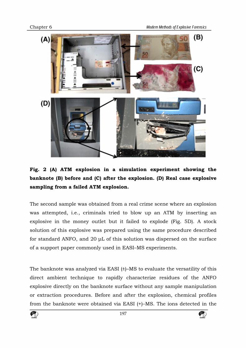
Chapter 6 Modern Methods of Explosive Forensics
Fig. 2 (A) ATM explosion in a simulation experiment showing the
banknote (B) before and (C) after the explosion. (D) Real case explosive
sampling from a failed ATM explosion.
The second sample was obtained from a real crime scene where an explosion
was attempted, i.e., criminals tried to blow up an ATM by inserting an
explosive in the money outlet but it failed to explode (Fig. 5D). A stock
solution of this explosive was prepared using the same procedure described
for standard ANFO, and 20 μL of this solution was dispersed on the surface
of a support paper commonly used in EASI–MS experiments.
The banknote was analyzed via EASI (±)–MS to evaluate the versatility of this
direct ambient technique to rapidly characterize residues of the ANFO
explosive directly on the banknote surface without any sample manipulation
or extraction procedures. Before and after the explosion, chemical profiles
from the banknote were obtained via EASI (+)–MS. The ions detected in the
197
Chapter 6 Modern Methods of Explosive Forensics
banknote before the explosion (Fig. 3A) were typical of ion markers for
Brazilian banknotes. After the explosion, however, the EASI (+)–MS obtained
directly from an area of the banknote surface, with apparently no ink
deposited (Fig. 3B), showed a major ion of m/z 443.3, which was
assigned to rhodamine B, the major component of the dye applied for
antitheft purposes. The ions of m/z 106, 311 and 391 are likely a result of
residual fuel oil contamination from ANFO after the explosion. For analyses
in a high density ink area (Fig. 3C), the rhodamine ion of m/z 433 was
predominant. The EASI(+)–MS for the explosive obtained from a real crime
scene (Fig. 6D) presented the typical profile of fuel oil expected for
unexploded ANFO (see Fig. 1A). When Fig. 6B and C are compared with Fig.
3D, it is clear that an ANFO explosion leaves few, if any, FO markers.
The EASI(−)–MS profile of a banknote acquired before and after explosion are
also clearly distinct and characteristic. Before the explosion (Fig. 4A), only
hand manipulation contaminants, i.e., palmitic acid (m/z 255) and oleic acid
(m/z 281), were detected. After the explosion, the area of the banknote
surface with low ink density (Fig. 4B) provided nearly the same profile as the
high ink density region (Fig. 4C) except for the ions of m/z350–450
attributed to the ink components. These results demonstrate that the
magnesium-nitrate cluster ionization is preferable to that of the ink
components and that detection of m/z 210 would be possible even in the
presence of this interference. For the real crime scene sample (Fig. 4D),
aside from the predominance of m/z 210, the spectra also displayed nitrate
ions of considerable abundances. This result may be explained by either the
higher nitrate concentration before the explosion or in source fragmentation,
which was also observed in Fig. 4 C and D. For this specific case, in-source
fragmentation is useful for the confirmation of nitrate ions and a more
confident composition determination of the marker ion of m/z 210, leading
to more reliable detection. In-source fragmentation was not observed in the
QIT–MS data.
198

Chapter 6 Modern Methods of Explosive Forensics
Fig. 3. EASI(+)–MS from the surface of (A) an undisturbed Brazilian
banknote; (B) and (C) the banknote after ANFO explosion; and (D) an
199
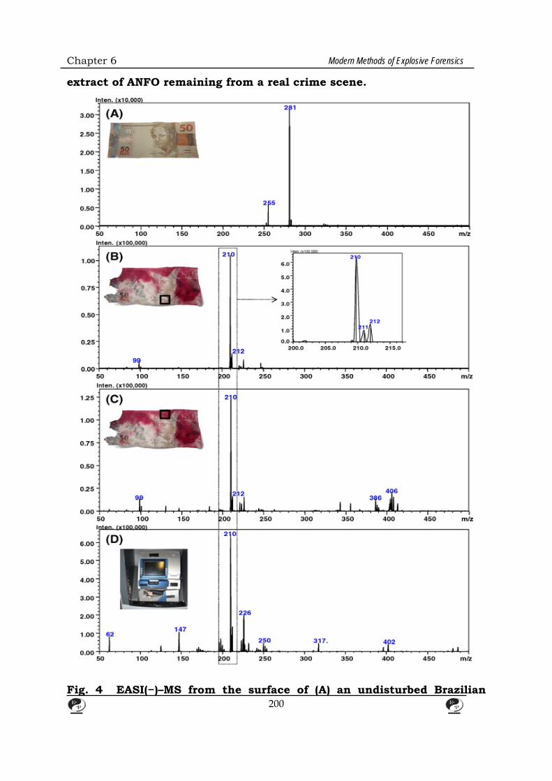
Chapter 6 Modern Methods of Explosive Forensics
extract of ANFO remaining from a real crime scene.
Fig. 4 EASI(−)–MS from the surface of (A) an undisturbed Brazilian
200

Chapter 6 Modern Methods of Explosive Forensics
banknote; (B) and (C) the banknote after ANFO explosion; and (D) an
extract of ANFO remaining from a real crime scene.
In such forensic investigations, there is therefore a need for a precise
methodology for ANFO characterization and its rapid detection in different
explosion residues. Forensic investigations of ammonium nitrate-based
explosives have been performed via several strategies , such as colorimetry ,
ion chromatography (IC) , capillary electrophoresis (CE) , voltammetry and
real-time neutron radiography , which have been the main techniques
applied to inorganic explosives analysis. Field analyses of ANFO have also
used photodissociation detection. According to the procedures for the
analysis of explosives evidence from the North Carolina Department of
Justice , three protocols can be applied for the analysis of blasting agents,
slurries and emulsions. The first employs analysis of the inorganic oxidizing
agent either by scanning electron microscopy with energy dispersive X-ray,
X-ray diffraction or CE. The second protocol employs analysis of the
sensitizer, if present, generally via thin layer chromatography (TLC) or gas
chromatography coupled to mass spectrometry (GC–MS). The third protocol
calls for the characterization of the fuel oil via techniques such as Fourier
transform infrared spectroscopy or GC–MS.
Ion mobility spectroscopy (IMS) has also been reported for ANFO
detection with a limit of detection as low as 10 pg. Thermospray mass
spectrometry (TS–MS), atmospheric pressure chemical ionization mass
spectrometry (APCI–MS) and electrospray ionization mass spectrometry
(ESI–MS) of nitrates have been shown to detect ion clusters that span a
broad m/z region depending on the heated capillary temperature and the
polarity (positive or negative) mode of the analysis. For ESI–MS, Zhao and
Yinon demonstrated that nitrate salts form ion clusters with well-defined
proportions, and suggested their molecular formulas based on the measured
m/z values, ion fragmentation patterns and 15N isotopic labelling.
201
Chapter 6 Modern Methods of Explosive Forensics
Recently, a series of desorption/ionization techniques capable of performing
direct ambient MS analyses has been introduced. These revolutionary
techniques have proven to be suitable for forensic investigations because
they provide fast chemical profiles from the undisturbed sample with
unprecedented simplicity and speed. Analyte desorption and ionization
directly from sample surfaces is performed in an open atmosphere, followed
by MS characterization, with little to no sample preparation. Although
ambient MS was pioneered by desorption electrospray ionization (DESI) and
direct analysis in real time (DART) ], a variety of related techniques are
currently available, including atmospheric pressure solid analysis probe
(ASAP) , electrospray-assisted laser desorption ionization (ELDI) , extractive
electrospray ionization (EESI) , desorption atmospheric pressure photo
ionization (DAPPI) and easy ambient sonic-spray ionization (EASI) .
4.1. ESI–QIT–MS For the analysis performed via quadrupole ion trap mass spectrometry (QIT–
MS), ANFO samples are injected with a syringe pump at a flow rate of 300
μL h−1 and the analysis is performed with a direct infusion electrospray
ionization source (ESI) operating in either the positive (+) or negative (−) ion
modes in an HCT Ultra spectrometer (Bruker—Bremen, Germany). The QIT
is operated in the ultra-scan mode over a range of m/z50–1000. The ion
charge control (ICC) target is set to 100,000 with a maximum accumulation
time of 100 ms. The ion source parameters are set as follows: ESI voltage of
−3000 V (positive ion mode) and 3000 V (negative ion mode), dry
temperature of 300 C, nebulizer pressure of 10 psi and dry gas flow of 5 L
min−1. MS/MS data are obtained in the negative ion mode with a
fragmentation amplitude of 1.07 V.
4.2. ESI–FTMS ANFO samples are measured in a 7.2 T LTQ FT Ultra mass spectrometer
202

Chapter 6 Modern Methods of Explosive Forensics
(Thermo Scientific, Bremen, Germany) equipped with an electrospray
ionization source (ESI) operating in the positive and negative ion modes
under the following conditions: capillary voltage of ±3.0 kV, tube lens at
+115 and −125 V, capillary temperature of 280 C. Nitrogen was used as the
nebulization gas. The mass resolving power is m/Δm(50%) = 400,000 at m/z
400 and 100 μscans are accumulated for each spectrum. The data
acquisition is performed in the range of m/z 100–1000 using Xcalibur 2.0
software.
4.3. EASI–MS Direct desorption/ionization analysis via EASI–MS [40] is performed on a
single quadrupole mass spectrometer (LCMS-2010EV; Shimadzu Corp.,
Kyoto, Japan) equipped with a homemade EASI source [39]. Acidified
methanol (with 0.1% volume of formic acid) at a flow rate of 20 μL min−1 and
N2 at 100 psi is used to form the sonic spray for the positive and negative
ion modes. The entrance angle of the capillary relative to the sample surface
is 45.
5. Forensics for Home made Explosives
Background
Unlike standard explosive operational procedures, homemade explosives (or
improvised explosives) vary widely with regard to composition, morphology,
and preparation. Currently, forensic identification of homemade explosives
(HME) is inadequate for determining the procedures used during their
formulation, storage, and deployment [1]. Needed is a repository of data
characterizing HME behavior, which can be used by the forensic science
community, law enforcement organizations, and military agencies to
interpret pre- and post-blast forensic evidence, assist in developing insights
and protocols to disrupt/discourage HME production, and provide for safe
HME disposal.
203

Chapter 6 Modern Methods of Explosive Forensics
A common formulation used widely by terrorists is the mixing of ammonium
nitrate (AN) with a number of different fuels to make oxidizer-fuel explosives.
Ammonium nitrate is often mixed with No. 2 diesel fuel oil (FO) or
nitromethane (NM); terrorists tend to use whatever fuel is readily available.
Countermeasures to restrict their distribution have focused on limited AN
access and fertilizer production with inert additives to inhibit AN explosive
capability.
The ANFO detonation behavior is considered by theoreticians to be non-ideal
because detonation reaction kinetics are relatively slow (long detonation
zone) and dependent on a variety of physical parameters. Such explosives
are generally high-porosity, low-density materials for which the fuel and
oxidizer are not mixed on a molecular level. They exhibit low detonation
velocities and larger detonation reaction zones. A review of ANFO is
presented by Hurley, which describes various physical parameters (e.g.,
charge diameter, fuel oil content, particle size, particle size distribution,
loading density, moisture content, porosity, additives, and charge
confinement) that influence detonation properties. Prill morphological effects
(i.e., bulk density, surface features, shape) on explosive behavior were
investigated by Rao et al. They argue that the maximum energy release will
depend on stoichiometric fuel/oxygen mixing and maximizing the surface
area throughout the prill. The interface region between the AN and FO has
the highest temperatures and chemical exothermic reactivity. The
confinement of ANFO had a strong influence on the detonation velocity (a
measure of the quantity of energy released) and the detonation front
curvature. A velocity interferometry system has been used to investigate the
effect of prill compaction and prill-to-prill interactions on detonation by low-
stress impact. They observed post-shock particle velocity variations and in-
between-prill jetting. Trace detection of explosives is difficult, with nearly
every analytical chemical method having been employed to this problem. As
discussed above, the non-ideal behavior of ANFO, and other similar HMEs,
make it difficult to predict their thermochemical and thermo-physical
204

Chapter 6 Modern Methods of Explosive Forensics
characteristics (especially for ANFO which has been investigated extensively
in the past, e.g., over a variety of relevant physical conditions). To address
this issue, a data measurement approach is needed that 1) operates over
physical conditions and heating rates relevant to HME applications, and 2)
provides a means for comparative analysis of existing HME mixture
formulations.
HME precursors are studied individually, i.e., ammonium nitrate (AN) and
nitromethane (NM), using a novel laser-based technique (referred to as the
laser-driven thermal reactor) to characterize material
thermochemical/thermo-physical behavior. The technique provides
temporally resolved temperature-time thermograms, which are used to
identify trends and characteristics unique to each HME chemical mixture.
The objective of the current study was to evaluate the thermal
decomposition of HME oxidizer-fuel mixtures, i.e., ammonium
nitrate/nitromethane (ANNM, a single composition fuel) and AN mixed with
No. 2 diesel fuel oil (ANFO, a multi-hydrocarbon composition fuel) with
respect to sample steady-state temperature, initial mass, and fuel/mixture
mass fraction. Also, discussed are issues associated with sample aging and
changes in the mixture composition and volatility with time.
5.1 The Laser-driven Thermal Reactor (LDTR) The laser-driven thermal reactor ( LDTR) consists of a sphere-shaped, gold-
plated, copper-foil reactor (with an outer diameter of 18.2 ± 0.1 mm and
thickness of 0.14 mm) mounted within a vacuum chamber, along with
optical, gas supply, and computer-controlled data acquisition subsystems
(see Fig. 1 and Fig. 2). The reactor is open on the top and bottom for access
to within the sphere. The sample is supported on a customized K-type fine-
wire thermocouple (0.25 mm bead diameter, unsheathed, and 0.200 s ±
0.002 s response time) stationed at the center of the reactor (defining the
‘sample’ temperature). A second thermocouple is flush with the reactor wall
205

Chapter 6 Modern Methods of Explosive Forensics
inner surface (defining the ‘reactor’ temperature). The reactor assembly is
heated from opposing sides by an infrared, continuous-wave, Nd: YAG laser
beam (operating at a wavelength of 1.064 μm) to achieve nearly uniform
sample temperature. The reactor is stationed within the vacuum chamber
that allows for control of the environment (e.g., gas pressure and
composition) around the sample. In general, measurements are carried out
at vacuum pressure, which eliminates thermal convection within the reactor
sphere, and thus conduction and radiation are the dominant modes of heat
transfer. The sample and reactor temperatures are recorded with respect to
time (referred to as ‘thermograms’) by the data acquisition system and then
processed for the specified thermochemical and thermo-physical information
of interest. The data-acquisition sampling rate is 1 MHz, which is averaged
and reported every 0.25 s because of the thermocouple response time.
Chemical-kinetics parameters of the process can also be deduced and
compared with the literature. The mode of thermal analysis for these
experiments is based on heating the reactor to a steady-state temperature
(referred to as the ‘heating-rate’ approach). Experiments were initially
carried out for the ‘baseline’ (i.e., thermogram measurements with a copper
pan substrate and no sample), and then repeated with the sample mixture.
5.2. HME precursors In this investigation, both ammonium nitrate/nitromethane (ANNM)
mixtures and ammonium nitrate/No. 2 diesel fuel oil mixtures (ANFO) were
formulated according to established recipe procedures . In general, mixtures
were prepared by dripping fuel onto AN particles with a syringe until the
desired stoichiometric value was ascertained with an electronic precision
balance. The mixture had the texture of a moist aggregated sediment. The
quantity of sample used for each experiment was 1–10 mg, and the laser
heating rate (Rlh, defined by the baseline thermogram maximum slope) was
20–100 K s−1. The use of HME-related chemicals required modification of the
reactor to ensure its safe and reliable operation. The issue of possible
206
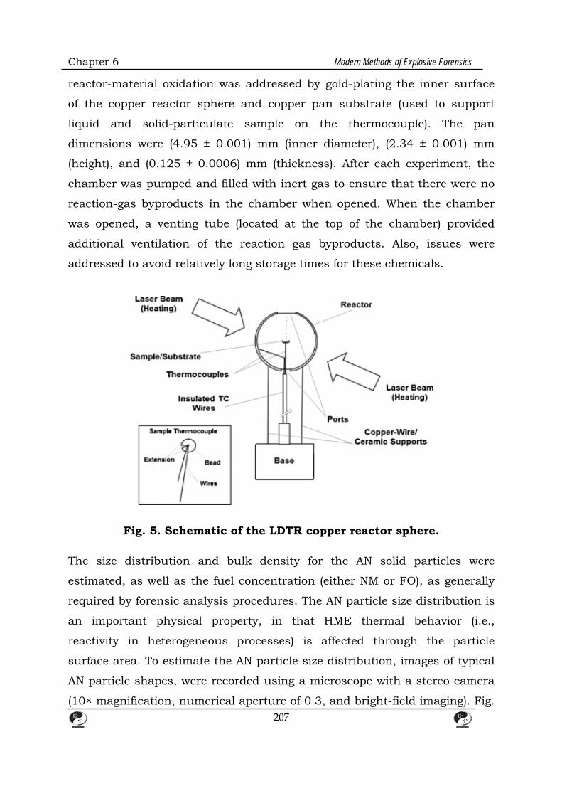
Chapter 6 Modern Methods of Explosive Forensics
reactor-material oxidation was addressed by gold-plating the inner surface
of the copper reactor sphere and copper pan substrate (used to support
liquid and solid-particulate sample on the thermocouple). The pan
dimensions were (4.95 ± 0.001) mm (inner diameter), (2.34 ± 0.001) mm
(height), and (0.125 ± 0.0006) mm (thickness). After each experiment, the
chamber was pumped and filled with inert gas to ensure that there were no
reaction-gas byproducts in the chamber when opened. When the chamber
was opened, a venting tube (located at the top of the chamber) provided
additional ventilation of the reaction gas byproducts. Also, issues were
addressed to avoid relatively long storage times for these chemicals.
Fig. 5. Schematic of the LDTR copper reactor sphere.
The size distribution and bulk density for the AN solid particles were
estimated, as well as the fuel concentration (either NM or FO), as generally
required by forensic analysis procedures. The AN particle size distribution is
an important physical property, in that HME thermal behavior (i.e.,
reactivity in heterogeneous processes) is affected through the particle
surface area. To estimate the AN particle size distribution, images of typical
AN particle shapes, were recorded using a microscope with a stereo camera
(10× magnification, numerical aperture of 0.3, and bright-field imaging). Fig.
207
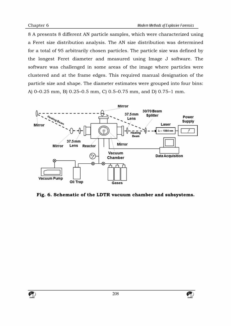
Chapter 6 Modern Methods of Explosive Forensics
8 A presents 8 different AN particle samples, which were characterized using
a Feret size distribution analysis. The AN size distribution was determined
for a total of 95 arbitrarily chosen particles. The particle size was defined by
the longest Feret diameter and measured using Image J software. The
software was challenged in some areas of the image where particles were
clustered and at the frame edges. This required manual designation of the
particle size and shape. The diameter estimates were grouped into four bins:
A) 0–0.25 mm, B) 0.25–0.5 mm, C) 0.5–0.75 mm, and D) 0.75–1 mm.
Fig. 6. Schematic of the LDTR vacuum chamber and subsystems.
208

Chapter 6 Modern Methods of Explosive Forensics
Fig. 7. Schematic of the LDTR thermal analysis protocol using the
heating-rate approach. Each baseline run includes the change in sample
and reactor temperature with time for two different laser fluences.
209
Chapter 6 Modern Methods of Explosive Forensics
Fig. 8. (A) Eight photographs of the various in AN particle shapes and
sizes. (B) Particle-size histogram obtained for the AN particles with the
peak in the size range of (0.25–0.50) mm.
Fig. 8B presents the longest Ferret diameter distribution (relative to the total
number of counted particles) for the sampled AN particles. Most of the
particles were sub-millimeter in length, and the distribution peaks for size
bin (0.25–0.50) mm. The material bulk density was determined by
estimating the volume of the particles within a container and obtaining the
particle mass from a commercial electronic mass balance. The literature
210

Chapter 6 Modern Methods of Explosive Forensics
value for the crystal AN particle density is 1.72 g cm−3[25], however, the
measured values were lower due to particle packing effects (see Fig. 5 which
presents the bulk density with regard to the estimated sample volume).
Increasing the AN volume resulted in increased particle mass and “self-
packing”, with the calculated bulk density increasing from 0.2 g cm−3 to 0.8
g cm−3. The AN surface area was estimated by assuming an average particle
diameter of 0.5 mm (i.e., the largest size particles in the size bin with the
highest distribution probability in Fig. 8B).
Fig. 9. Variation of AN density with its volume. The value of AN density
at zero volume is the bulk value for AN from the archival literature.
211
Chapter 6 Modern Methods of Explosive Forensics
Fig. 10. Variation of the fuel/HME mixture mass fraction with time
relative to the initial stoichiometric values for ANNM and ANFO.
Regression curve fit: w(t)NM = wNM,f + wNM,ife−t/τ where wNM,f = (0.32 ±
0.14)%,wNM,if = (1.32 ± 0.13)%, and τ = (2.45 ± 0.41) day for 0 < t < 3
days; w (t)FO = wFO,f + wFO,ife−t/τ wherewFO,f = (0.60 ± 0.01)%, wFO,if =
(0.36 ± 0.01)%, and τ = (11.54 ± 0.98) day for 0 < t < 33 days. Note that
the units are dimensionless (relative to the initial value). The error bars
represent the estimated expanded uncertainty for the fuel/HME
mixture mass fraction, as determined by the Type A evaluation of
uncertainty.
For ANNM, the recommended sample preparation procedures (for optimizing
reaction) were used along with an initial stoichiometric NM/ANNM mass-
fraction of about 29%. The total ANNM mass changed less than 0.5 mg (NM
evaporation reduced the NM/ANNM mass fraction from 29% to 3%) over a
period of three days (see Fig. 6), being much longer than the sample
preparation time of a few minutes. The vapor pressure for nitromethane is
3.65 kPa. It is important to estimate how the initial concentration of NM
changes with time. There are practical reasons for measuring the change,
which include: 1) from a measurement perspective, obtaining consistent
results for experiments over time (e.g., days/week), 2) from a law-
212
Chapter 6 Modern Methods of Explosive Forensics
enforcement perspective, HME shelf life may provide important information
on activities prior to an attack, and 3) from a forensics perspective, on HME
sample preservation and potency. Regarding consistency, HMEs are
prepared in quantities larger than required per experiment, so it is
important to know the actual oxidizer-fuel ratio each time test samples are
selected from the batch.
Unlike NM (a single-component fuel), FO is composed of a number of
hydrocarbons that have different vapor pressures and chemical/ignition
properties. The relative mass for different hydrocarbon fractions within the
No. 2 diesel fuel oil is estimated to be 14% foriso-paraffin, 20% for N-
paraffin, 36% for cyclo-paraffin, 15% for mono-aromatics, and 1% for di-
aromatics . The volatility (i.e., vapor pressure) of each fraction is different
and will evaporate preferentially (i.e., evaporation of the lighter hydrocarbon
fractions occurs at a faster rate than the heavier fractions due to their
higher vapor pressure). The overall mean vapor pressure for diesel fuel oil is
about 0.3 kPa at 293 K. The recommended ratio of precursor materials
varies slightly from recipe to recipe, but, in general, the initial stoichiometric
FO/ANFO mass fraction should be about 6%. The ANFO heat of explosion is
3890 kJ kg−1 and decomposition is initiated at a temperature of 476 K, both
properties higher than most other AN mixtures. Measurements determined
that the initial FO/ANFO mass fraction changes with time at a slower rate
than for NM/ANNM, i.e., changing to a FO/ANFO mass fraction of about 3.6
% after 33 days.
6. Direct Analysis in Eeal Time Mass Spectrometry
Background
Rapid explosives detection with minimal sample preparation remains an
area of interest to forensic science, homeland security, and military
agencies. The class and state of explosives investigated varies widely across
these fields and may include military-grade secondary explosives,
213
Chapter 6 Modern Methods of Explosive Forensics
homemade explosives (HMEs) such as nitrate esters and peroxides, primary
fuel-oxidizer explosives, improvised explosive device (IED) components,
synthesis precursors, and detonated decomposition products. There is an
extensive literature base involving the detection of military-grade nitrated
organic explosives, e.g. RDX or TNT, including common binders and
plasticizers. As non-state terrorism has evolved, there is an increased need
to explore the detection of HMEs, including their precursors, synthesis by-
products, impurities, and decomposition products. The detection of these
compounds and their mixtures may enhance chemical libraries or provide
valuable information into the route of synthesis and source materials.
Because of the potential additional information provided, it is crucial to not
only detect these compounds but also understand how they behave in
mixtures with the explosives.
One of the major classes of HMEs, nitrate ester explosives, represents a
broad category of organic explosives, both military-grade and homemade,
including compounds such as nitroglycerin (NG), pentaerythritol tetranitrate
(PETN), and erythritol tetranitrate (ETN). Nitrate esters are synthesized
through nitration of a sugar alcohol (polyol) precursor, as simplified in Fig.
1. This synthesis reaction may result in several potential by-products,
namely partially nitrated and polymeric nitrated species. While a number of
nitrate ester explosives exist, this work focuses on the nitration of glycerol
(leading to NG) and pentaerythritol (leading to PETN) and their potential
synthesis impurities. Both explosives have been synthesized militarily and
illicitly, and are studied extensively. A number of studies, mainly using
liquid chromatography mass spectrometry (LC/MS), have identified
impurities from NG and PETN synthesis, including partially nitrated and
dimer species. Partially nitrated species, such as 1,3-dinitroglycerin (DNG),
can occur from incomplete nitration of the sugar alcohol due to lack of
available free nitrate ions, abrupt cessation of the reaction, or other
improper synthesis conditions . Partially nitrated species can also form via
hydrolysis of a fully nitrated nitrate ester. Likewise, improper termination of
214
Chapter 6 Modern Methods of Explosive Forensics
the reaction process can cause the formation of dimer, trimer, and other
polymeric species. Dimer species can also be formed from impurities in the
starting sugar alcohol, such as the presence of diglycerol. In addition to by-
products formed during the reaction, a number of decomposition products,
also partially nitrated species, may be created. The relative amount of these
impurities and degradation products are dependent on the route of
synthesis and/or length of decomposition. Relative levels of DNG in
groundwater samples containing NG were 50% to 100% that of NG.
Similarly, the presence of PETriN in degradation samples ranged from 20%
to 100% that of PETN, while neat samples contained only approximately
0.1%.
DART-MS is an increasingly used ambient ionization (AI)-MS technique in
forensic science laboratories, requiring minimal or no sample preparation,
and has previously demonstrated detection of nitrate ester explosives and
their sugar alcohol precursors. Extensive details of DART ionization
pathways and analysis can be found in the literature. The characterization
presented here focused on identifying the mass spectral response of
potential by-products and decomposition products. The compounds
investigated included: 1-mononitroglycerin (1-MNG), 2-mononitroglycerin (2-
MNG), 1, 3-dinitroglycerin (DNG), pentaerythritol trinitrate (PETriN), and
dipentaerythritol hexanitrate (diPEHN). In addition to the DART-MS
characterization of these compounds, analysis of mixtures with their
corresponding explosive (NG or PETN) and/or precursors (glycerol or
pentaerythritol) was conducted. All compounds were readily detected in
negative ionization mode as adducts with anions such as molecular oxygen,
nitrite, and nitrate detectable in the low nanogram to sub nanogram range.
The detection of explosives from mixtures with by-products demonstrated
increasing ionization competition as by-product nitration increased. The
large volatility difference between monomers and dimers produce
significantly less competitive ionization with the explosive signal.
Competitive ionization for the mixtures examined increase as the mass ratio
215
Chapter 6 Modern Methods of Explosive Forensics
of by-product to explosive increased.
Fig. 11. Reaction pathway and potential by-products that occur during
the synthesis and decomposition of nitrate ester explosives. In this
example, pentaerythritol, pentaerythritol tetranitrate, and related
compounds are shown.
7. Thermal Analysis Methodologies Thermal analysis methodologies are commonly used to analyze the thermal
changes of a sample due to heating and cooling. The sample characteristics
that are derived from thermal analysis techniques include thermal (e.g.,
temperature, heat, enthalpy), physical (e.g., mass, volume, strength), and
chemical (e.g., chemical composition of products) characteristics. There are
a variety of commercially available measurement techniques that have been
developed and used to meet these needs. Thermal analysis techniques, such
as differential scanning calorimetry (DSC) and thermal gravimetric analysis
(TGA) are commonly employed in research to provide information on the
material explosive/energetic content and other thermal properties (e.g.,
decomposition, heating value, and thermal stability), and also for
composition identification of an unknown explosive material.
The thermal dissociation of solid and liquid AN is analyzed using DSC/TGA
methods. The experimental measurements were carried out at low heating
rates between 2.5 and 12.5 °C min−1. The resulting chemical kinetics
mechanism is assigned to the process of dissociative
216

Chapter 6 Modern Methods of Explosive Forensics
sublimation/vaporization. Oxley et al. carried out an investigation using
DSC to explore if this technique could be used as a benchmark for
evaluating the explosivity of ammonium nitrate. In this study, thermal
analysis was used to screen a large number of AN formulations in search of
possible deterrents. They found that sodium, potassium, ammonium and
calcium salts of sulfate, phosphate, or carbonate, as well as certain high-
nitrogen organics, can enhance AN thermal stability. The need to improve
thermal analysis techniques was also emphasized by Desilets et al. [6]. In
this work, the thermal decomposition of urea nitrate (UN) was studied at
higher temperatures. The UN non-isothermal decomposition kinetics and
products of reaction were analyzed using a DSC/TGA instrument in
conjunction with Fourier transform infrared and mass spectroscopic
instruments. Results indicated differences in the exothermic values of UN
thermal decomposition when compared to a dedicated DSC. The above-
mentioned studies represent some of the relevant AN thermal analysis
issues that arise with commonly used DSC and TGA techniques.
The data obtained with these instruments may underestimate the explosive
potential of a HME material under certain conditions. The non-standard
nature of the HME chemical composition and formulation/synthesis
procedures can present a formidable challenge for forensic analysis
instrumentation. Thus, improved techniques are required to provide data for
adequate HME forensic identification, which may not be accomplished
reliably with DSC and TGA. Development of a new methodology and
database of thermal and chemical signatures, along with other
thermophysical properties, of HME materials is required for different
compositions and ambient conditions.
8. Conclusions Whilst already having made a strong contribution in environmental
applications, many methods including IC-MS also has a strong potential for
217
Chapter 6 Modern Methods of Explosive Forensics
application in forensic analysis of explosive residues Low molecular weight
ions can be separated via a range of IC modes, many of which were also
compatible with ESI-MS or ICP-MS detection. In particular, IC-MS offers
advantages over other techniques in terms of its ability to speciate, as well
as offering chromatographic reproducibility and sensitivity at the trace level,
often in complex matrices. There exists further promises for ultra-trace
determinations of explosive residues using online pre-treatment, further
eluent modification, post-column ion enhancement, dual anion/cation
separations and semi-targeted screening using IC-HRMS technologies.
References 1. Ashot Nazarian, Cary Presser, Forensic methodology for the thermochemical
characterization of ANNM and ANFO homemade explosives, Thermochimica
Acta, Volume 608, 20 May 2015.
2. Edward Sisco, Thomas P. Forbes, Direct analysis in real time mass
spectrometry of potential by-products from homemade nitrate ester explosive
synthesis, Talanta, Volume 150, 1 April 2016.
3. Holly A. Yu, Simon W. Lewis, Matthew S. Beardah, Niamh NicDaeid Assessing
a novel contact heater as a new method of recovering explosives traces from
porous surfaces Talanta, Volume 148, 1 February 2016.
4. Ashot Nazarian, Cary Presser Forensic analysis methodology for thermal and
chemical characterization of homemade explosives Thermochimica Acta,
Volume 576, 20 January 2014.
5. D Xiaoma Xu, Mattijs Koeberg, Chris-Jan Kuijpers, Eric Kok evelopment and
validation of highly selective screening and confirmatory methods for the
qualitative forensic analysis of organic explosive compounds with high
performance liquid chromatography coupled with (photodiode array and) LTQ
ion trap/Orbitrap mass spectrometric detections (HPLC-(PDA)-LTQOrbitrap)
Science & Justice, Volume 54, Issue 1, January 2014.
218

Chapter 6 Modern Methods of Explosive Forensics
6. Isotopic and elemental profiling of ammonium nitrate in forensic explosives
investigations Forensic Science International, Volume 248, March 2015, Pages
101-112 Hanneke Brust, Mattijs Koeberg, Antoine van der Heijden, Wim
Wiarda, Ines Mügler, Marianne Schrader, Gabriel Vivo-Truyols, Peter
Schoenmakers, Arian van Asten
7. C Vinicius Veri Hernandes, Marcos Fernado Franco, Jandyson Machado
Santos, Jose J. Melendez-Perez, Damila Rodrigues de Morais, Werickson
Fortunato de Carvalho Rocha, Rodrigo Borges, Wanderley de Souza, Jorge
Jardim Zacca, Lucio Paulo Lima Logrado, Marcos Nogueira Eberlin, Deleon
Nascimento Correa characterization of ANFO explosive by high accuracy
ESI(±)–FTMS with forensic identification on real samples by EASI(−)–MS
Forensic Science International, Volume 249, April 2015.
219
CHAPTER – 7
CHARACTERIZATION OF EXPLOSIVES FOR COAL MINES
1. Introduction Powdery explosives for coal-mining, especially those for use in coal-mines
where fire damp/air mixtures can be present, are mixtures of inorganic
salts, e.g. sodium nitrate, ammonium nitrate, ammonium chloride and
organic nitrate, e.g. glyceroltrinitrate and glycoldinitrate. In addition are
present small quantities of calcium carbonate, metal salts of fatty acids and
waterproofing agents like guar powder or wheat flour.
Shot firing in coal mines constitutes a risk in the presence of firedamp and
coal dust. Permitted explosives are special compositions which produce
short-lived detonation flames and do not ignite methane-air or coal-
dust-air mixtures. The methane oxidation CH4 +2O2 = CO2 +2 H2O needs
an “induction period” before the reaction proceeds. If the time required
for ignition by the detonation flames is shorter than the induction
period, then ignition of firedamp will not occur. Thus, the composition of
permitted explosives must ensure that any secondary reactions with a
rather long duration, which follow the primary reaction in the detonation
front, are suppressed and that slow W Deflagration reactions are avoided (W
Audibert Tube). Such explosives are known as “permissibles” in the USA, as
“permitted explosives” in the United Kingdom, as “Wettersprengstoffe” in
Germany, as “explosifs antigrisouteux” in France, and as “explosifs S.G.P.”
(s´ecurit´e grisou poussi`eres) in Belgium. Safety measures to avoid ignition
of firedamp uses salt (NaCl, Ca(NO3)2, NaNO3 etc.) which is included in the
usual compositions of commercial explosives. It lowers the explosion
temperature and shortens the detonation flame.
220
Chapter 7 Characterization of Explosives for Coal Mines
Permitted explosives which are enveloped in a special salted cooling
“sheath”; they thus, got the name “Sheathed”. High-safety explosives, such
as sheathed explosives, whose structure is nevertheless homogeneous, are
known as “explosives equivalent to sheathed” (Eq. S.)
Higher safety grades are achieved in ion exchange explosives in which the
ammonium and sodium (or potassium) ions are exchanged; instead of
NH4NO3 + (inert) NaCl = N2 + 2 H2O + 1/2O2+(inert) NaCl the reaction is:
NH4Cl+NaNO3 (or KNO3) = N2+2 H2O + 1/2O2 + NaCl (or KCl). Thus, a flame-
extinguishing smoke of very fine salt particles is produced by the
decomposition reaction itself. Combinations of salt-pair reactions and
“classic” detonation reactions quenched by adding salt are possible.
Permitted explosives with a higher grade of safety are powder explosives.
They contain a minimum percentage of nitroglycerine-nitroglycol to ensure
reliable initiation and transmission of detonation and to exclude slow
deflagration reactions.
Explosive that has passed the Buxton tests and has been placed on the
British list of authorized explosives, implying that they are reasonably safe
to manufacture, handle, transport, and use in safety-lamp mines. Upon
detonation, a permitted explosive: (1) gives off the minimum possible
quantity of noxious gases, and (2) produces a flame of the lowest possible
temperature and shortest possible duration, to lessen the risk of
combustible gases ignition. The explosive contains cooling agents, such as
sodium chloride and sodium bicarbonate. The first British list of permitted
explosives was published in 1899. Permitted explosives are divided into four
groups: P.1., normal permitted explosives; P.2., sheathed explosives; P.3.,
equivalent to sheathed explosive; P.4., permitted explosives that have passed
additional and more stringent tests.
221
Chapter 7 Characterization of Explosives for Coal Mines
Explosives for the coal-mining are additionally regulated and controlled by
local –mining authorities. For the manufacturers of explosives it is therefore
necessary to produce materials, which are in compliance with these
regulations.
The properties of permitted explosives that affect their safety in use are as
follows: (a) incendivity, i.e. the likelihood that mixtures of methane and air,
or of coal dust and air, will be ignited by the action of blasting; (b)
deflagration, i.e. a naked flame after blasting as a result of the explosives
burning rather than detonating, which is extremely undesirable in an
underground coal mine; (c) impact and friction sensitivity; and (d) after-blast
fumes.
The produced explosive materials must have the same composition as the
first registrated and permitted samples. The productions must be controlled
by analysis of the manufactured material to determine the correct
composition.
Though at the first glance the analysis of the mixture of the few inorganic
salts seems to be simple, it is not so easy in practical work because of the
mutual influence of the salts with each other and the other components. The
following contribution describes methods which are used for the
characterisation of explosive materials for coal-mining. Table 1 gives three
types of coal mining explosives as description.
2. Quality Control The characterization of permitted explosives is performed under two
different aspects: Routine control of each batch and full analysis as random
test for statistical quality control.
This work is done by combination of classical wet analysis and modern
222

Chapter 7 Characterization of Explosives for Coal Mines
instrumental analysis.
Table 1 Gives a Qualitative of the three types of Coal-mining Explosives.
Type A Type B Type C
Nitroglycerin Nitroglycerin Nitroglycerin
Ethylenglycol- Ethylenglycol- Ethylenglycol- dynitrate dynitrate dynitrate
NH4Cl NH4Cl NH4Cl
KNO NaNO3/Ca(NO3)2 NH4NO3
CaCO3 CaCO3 CaCO3
3. The Probability of Ignition of Firedamp by Permissible Explosives
The so-called permissible, or permitted, explosives are used in
underground and confined works where there is a risk of occurrence of
flammable gases. They provide a lower temperature, shorter duration
flame, with a lower probability of ignition of methane or coal dust than
regular explosives. In permissible explosives, in some cases, Calcium
Nitrate is used which decomposes at a much lower rate than Ammonium
Nitrate thus reduces explosion temperature- at reduced strength but at a
lower risk of inflaming combustible methane or other gases. The evaluation
of this and other critical safety-related properties is done by conducting
elaborate tests (HSE, 1988 and MSHA, 1988) designed to model the
explosive-gas interaction in controlled laboratory conditions usually carried
out in government or independent institutions. As a result of such tests,
explosives are classified in various safety levels or classes. Besides holding
the “permissible” certification, explosives can only be used in potential
firedamp conditions under strict firing prescriptions, mainly related with the
charge to be fired per delay or per total round, and the allowable delay
times, which depend on the class in which the explosive is rated and the
type of working face where the blast is to be conducted. Regulations in coal
223
Chapter 7 Characterization of Explosives for Coal Mines
blasting generally restrict the amount of explosive to be loaded per hole. For
instance, the Spanish regulation states that no more than 2 kg of Class III
explosive can be loaded per hole unless special permission is issued. Such
restrictions are reasonable for typical drift blasting where holes are about
3 m long, but cannot be met in sublevel caving ring blasting with holes 10 or
20 m long; in such cases, blasting with higher charges per hole is carried
out, under special supervision. Besides the increased amount of explosive,
blasting with long holes may require some charging and priming
techniques that are not typically used with short holes: PVC casing to
facilitate the charge preparation and blasthole loading; detonating cord
along the charge to ensure continuity of the detonation; double (top and
bottom) initiation to reduce the probability of a failed shot hole, and
inhibitor salt decks. This part assesses the effect of these practices on the
probability of ignition of a methane–air atmosphere.
4. Gallery Testing of Permissible Explosives Regulations for the approval and use of explosives to be used under
potential firedamp conditions are enforced in all coal-mining countries. The
approval requires a certain capacity of no ignition of a methane atmosphere;
the main instrument for testing this capacity is the test gallery. Sanchidrián
et al (2008) reports a study on the permissible explosives under different
simulated field conditions with a gallery (Fig. 1) that consists of a steel
cylinder with one end permanently closed and the other end equipped with a
light closing device such as a paper sheet and a sealing ring. Inside this
closed cylinder, or explosion chamber, the explosive is positioned either
within a mortar or freely suspended. After positioning the mortar and
charging, the explosion chamber is sealed and filled with a methane–air
mixture of 9% methane and the charge is fired. Whether or not ignition of
the gas occurs is observed from a safe position.
224

Chapter 7 Characterization of Explosives for Coal Mines
Fig. 1. Test gallery. Different mortars and test conditions can be set to give a higher or lower
probability of ignition so that different safety grades of explosives can be
defined. We have used in the present work the angle mortar (Fig. 2): a steel
cylinder of 219 mm in diameter and 2 m in length with a right-angled
groove; it is positioned in the explosion chamber against a steel plate at
various distances and angles. Trains of several cartridges up to the full
mortar length are placed in the angle and fired in the methane–air mixture.
5. Test Series The explosive tested was a permissible ion-exchange explosive (class III
according to the Spanish classification [4]) in 32 mm diameter cartridges
with a nominal cartridge mass of 215 g. Class III explosives are not required
to pass the angle mortar test under the Spanish regulation; the Class III and
angle mortar combination was selected in order to provide a significant
probability of ignition for the statistical analysis with the different charging
characteristics. Several trial shots varying the orientation of the mortar's
angle and the distance to the reflection plate were done in order to obtain a
configuration that assured a high enough ignition frequency for the range of
explosive mass allowed by the length of the mortar and the resistance of the
chamber. Table 1 lists the configuration parameters of the test series
performed which are sketched in Fig. 3. The step values given in Table 1 are
the mean weights of a cartridge or half cartridge in the corresponding series.
225
Chapter 7 Characterization of Explosives for Coal Mines
Fig. 2. Angle mortar test layout.
Fig. 3. Test series charge configurations
Table 1.Test series configuration
226
Chapter 7 Characterization of Explosives for Coal Mines
Ser-ies Firing conditions
Distance to plate, LP
(cm)
Reflection length, LR
(cm)
Step (g)
1 Bare charge 47 32 215.2 2 PVC casing 47 32 214.5 3 PVC casing/detonating cord 47 32 214.9 4 PVC casing/detonating cord/salt 40 35 107.5 5 PVC casing/detonating cord 40 35 107.0 6 PVC casing/detonating cord/
double initiation 40 35 107.2
Table 2 gives the charge masses of all the shots for the six series.
Table 2. Charge masses (g)
Series # 1 2 3 4 5 6 No ignition 862 1274 1075 642 317 430
845 1281 855 635 440 438 1094 1063 1073 445 553 545 1275 866 1062 637 635 634 1067 1074 652 422 426 441 1305 1284 652 434 426 528 1496 1273 856 430 539 418 1074 1296 859 622 427 224 1089 1289 846 427 426 316 1290 1074 871 428 537 420 1301 1076 851 649 417 211 1292 1288 855 641 555 315 1494 1504 544 635 422 520 530
Total (m) 13 13 12 15 13 13
Ignition 1088 1515 1275 859 441 547 1500 1511 1283 863 739 746 1295 1302 1078 872 642 638 1735 1290 1302 645 530 529 1514 1072 1274 854 546 630 1286 1531 1086 628 648 551
227

Chapter 7 Characterization of Explosives for Coal Mines
1282 1478 847 664 547 548 1500 1508 854 648 534 426 1496 1488 1071 871 646 328 1731 1289 1078 645 532 528 1498 1269 1078 640 752 456 1300 1701 1055 862 653 319 1073 866 549 536 537 530 774 738 764 746 754 758
Total (n) 12 12 13 23 12 12 The distributions are shown in Fig. 4 in which the charge mass xp for a
probability p (probability points, or p-quantiles of F) is calculated.
Fig. 4. Distributions of probability of ignition.
6. Effect of the Various Firing Techniques on the Ignitability of
228
Chapter 7 Characterization of Explosives for Coal Mines
Firedamp
1. The casing of the charge with a PVC slotted pipe, useful in practice for
the charging of the holes, does not have an influence on the ignition
probability.
2. Detonating cord increases the probability of ignition with statistical
significance of 95%; for an ignition probability of 0.5, the charge mass is
reduced by a 26% when detonating cord is used.
3. The influence of salt is very limited in the amount used in the present
study (7% salt/explosive length ratio). In spite of an increase of 8% in
the mass at an ignition probability of 0.5, the use of salt in this quantity
cannot be considered an influential parameter at a 95% confidence level.
4. The double initiation increases the probability of ignition, the charge
mass being on average 14% smaller than with one-end initiation for a
0.5 probability of ignition. However, as with the use of salt, the influence
cannot be stated at a 95% confidence level.
REFERENCES
1. P. Lingens, in: Ullmanns Enzycopadie der techn. Chemie Verlag Chemie,
Weinheim, 1982, Band 21, 4. Auflage.
2. H. Kohler, in: Proceedings of the ICT international conference, Karlsruhe,
1984.
3. Ph. Naoum, Nitroglycerin and Nitroglycerin sprengstoffe, Springer Verlag,
Berlin, 1924.
229
Chapter 7 Characterization of Explosives for Coal Mines
4. HSE Test and approval of explosives for use in coal mines and other mines in
which flammable gas may be a hazard Testing Memorandum TM2, Health and
Safety Executive, Buxton, UK (1988).
5. MSHA Requirements for approval of explosives and sheathed explosive units
Code of Federal Regulations Title 30, Part 15.20, Mine Safety and Health
Administration, U.S. Department of Labor, Arlington, VA (1988).
6. J.A. Sanchidrián,, L.M. López, P. Segarra The influence of some blasting
techniques on the probability of ignition of firedamp by permissible explosives,
Journal of Hazardous Materials ,Volume 155, Issue 3, 15 July 2008.
230
CHAPTER – 8
HOME-MADE EXPLOSIVES AND THEIR EFFECTS
1. Introduction According to the US Government Hazardous Substances Database, several
substances and mixtures can be used for the realization of this kind of
explosives, starting from chemicals sold in markets and pharmacies. Among
others, two were often adopted for terrorist attacks, suicide bombing, and
other malicious uses: Ammonium Nitrate (AN) − Fuel Oil (i.e. ANFO)
mixtures and Acetone Peroxide or Triacetone Triperoxide Peroxyacetone
(TATP) mixtures. These two materials were considered as reference
explosives for the analysis presented in the present study.
ANFO is a tertiary explosive (note that TNT is a secondary explosive) and is
generally composed by 94% of AN prills and 6% of adsorbed fuel oil. It is
extensively used for several authorized purposes as in mine blasting. The
TNT equivalence is typically around 80% and the ideal explosion (detonation)
energy is 3890 kJ/kg (pure ammonium nitrate has an explosion energy of
1592 kJ/kg). AN prills used for mining applications are however physically
different from fertilizer prills used in home-made explosives. The commercial
ammonium nitrate prills used for mine blasting have a 20% void fractions
and are coated with #2 fuel oil (mainly C10−C20 linear hydrocarbons) or
kerosene. Hence, ANFO has a bulk density of approximately 840 kg/m3
when starting from ANprills for mining applications, having a density of
about 1300 kg/m3 (the density of pure crystalline ammonium nitrate is
1700 kg/m3). On the other hand, homemade explosives prepared from AN
fertilizers do not have a so high void fraction and are less efficient: e.g. the
new European regulations for fertilizers state that they must contain less
than 45% of AN (16% N) for being traded to the general public. Such
231
Capter 8 Home-made Explosives and their Effects
fertilizers still may be used to obtain explosives, but require processing to
achieve a detonation. If commercial AN (containing about 50% of inert, as
dolomite) and diesel fuel is used, a detonation energy of about 1071 kJ/kg is
obtained, much less than pure ANFO. Furthermore, it has been observed
that when amounts of dolomite higher than 30%, are present, no detonation
is observed.
2. Triacetone Triperoxide Peroxyacetone (TATP) TATP is a primary explosive which is notable since it does not contain
nitrogen. Thus, it is used to avoid conventional chemical bomb detection
systems, and it is almost undetectable by either analytical system or by
sniffer dogs. It can be obtained from common household items such as
sulphuric acid, hydrogen peroxide, and acetone.
TATP is very unstable: it can be ignited by touch and can explode
spontaneously. It is often used for improvised detonators itself. It is actually
composed by isomers and conformers, the dimer being more stable but
having lower decomposition energy (see Fig.1.).
(a) dimmer (b) trimer
Fig. 1. The actual components of TATP: (a) dimer and
(b) trimer peroxides.
The density of the pure molecule is typically considered to be 1220 kg/m3.
232
Capter 8 Home-made Explosives and their Effects
However, home-made TAPT formulations are typically in the range of 450–
500 kg/m3. Finally, TATP is often stabilized with carbonaceous liquids and
waxes so that the net charge is even lower. Nevertheless, Lefebvre et al. [38]
have demonstrated that home-made TATP is a primary explosive and very
sensitive to impact or friction, although the strength of explosion may
strongly vary since the quality of the final product is very sensitive to the
temperature during its synthesis.
TATP is highly volatile and decomposes to form large number of gas phase
molecules (entropic explosion). Acetone and ozone are predicted to be the
main decomposition products, along with oxygen, methyl acetate, ethane,
and carbon dioxide.
3. Assessment of Explosion Effects for Improvised Explosives The aim of the study is to support consequence and vulnerability
assessments of industrial plants (hence equipment) when subject to a shock
wave produced by improvised explosive devices based on ANFO or TATP. To
this aim, the calculation of the pressure history (maximum pressure,
positive duration, impulse) with respect to the distance from the explosion
point is needed. In order to obtain this information, the amount of explosive
and its efficiency with respect to an equivalent amount of TNT (WTNT) is
required. The Hopkinson−Cranz methodology to calculate the mass-scaled
distance (Z) is typically adopted for point-source explosives:
equation(1)
equation(2) where Wexp,n is the net mass of the explosive, ΔHTNT is the TNT explosion
energy, which is typically 4.6 MJ/kg, ΔHexp is the explosion energy of the
material of interest, related to the primary explosion only (decomposition or
233

Capter 8 Home-made Explosives and their Effects
detonation energy) and not to the overall combustion energy, r represents
the actual distance from the center of the explosion, and κ and η are
respectively (i) a coefficient which depends on the confinement or, more
specifically, to the mechanical energy adsorbed for the deformation and
failure of the containment system; (ii) the explosion efficiency, i.e. the energy
proportionality factor, which is discussed later. For explosives contained in
low-strength enclosure, a factor κ=0.7 could be adopted, however we used
unitary values in order to obtain safe-side evaluations.
Several previous publications provide data, references and correlations for
the shock wave produced by ANFO and TATP. What is relevant for the
present study is that: (i) the explosion energy gives a good reproduction of
the destructive power of the substances at constant, atmospheric pressure
(which is the case hereby analyzed); (ii) light confinement (even a paper
confinement) approximately doubles the severity of the explosion; (iii) high-
strength confinement as the steel case adopted for bombs and military
explosive devices has been not considered, hence the corresponding effects
of casing fragmentation have been neglected; and (iv) the energy output from
non-ideal explosives is dependent on charge size, which makes it difficult to
define it with traditional modeling methods. However, because the energy
output decreases with the charge size, we neglected the variation of TNT
efficiency adopting the correspondent maximum value in order to obtain
conservative estimations.
Table 1 reports the TNT efficiency (η) obtained from specific studies and
calculated as the ratio between the explosion energy of the mixture of
interest and the explosion energy of TNT (namely, detonation energy ratio)
for different types of explosives. In the case of non-ideal mixtures, the
property values have been calculated by using the Chemical Equilibrium
Model (CEA) as previously done in the literature for black powder and
pyrotechnics. Quite clearly, discrepancies can be found with respect of the
reaction heats given in the open literature. However, the figures
234
Capter 8 Home-made Explosives and their Effects
obtained by the CEA model are at least indicative of the explosion energies
involved.
Table 1 reports data for home-made explosives produced with 90% and 50%
non-porous AN in mass with dolomite as inert material mixed with fuel oil
(respectively “AN/dolomite (90/10)+diesel fuel” and “AN/dolomite
(50/50)+diesel fuel”). It is worth noticing that the efficiency of pure ANFO is
consistently larger than that of possible home-made explosives based on
fertilizers, in which some inert material as dolomite is used, and diesel fuel
and non-porous AN as explosive component are employed. Reduction to very
low values of TNT efficiencies can clearly be observed.
Table 1 : Experimental heat of explosion (ΔHexp) and combustion
(ΔHcomb) and TNT efficiencies (η) for the analyzed explosives.
AN : ammonium nitrate; FO: fuel oil; DF: diesel fuel.
Explosive
ΔHexp (kJ/kg)
ΔHcomb (kJ/kg)
η(dimensionless) Literature
data Calculateda
TNT 4680 14961 1.00 1.00
ANFO (94% AN; 6% FO) 3890 578 0.60–0.88 0.83
TATP (Trimer) 2803 28192 0.30–0.92b 0.60
DADP (Dimer) − 23465 − 1.26
AN/dolomite (90/10)+DF 3234 − − 0.69
AN/dolomite (50/50)+DF 1071 − − 0.23
a Ratio between the explosion energy of the mixture of interest and the explosion energy of TNT (namely, detonation energy ratio).
b Mixture of isomers.
Finally, it is well known that η refers to the shock wave produced in
unconfined explosion, which is only related to the primary explosion.
Besides, the heat of combustion, which is much larger with respect to the
235
Capter 8 Home-made Explosives and their Effects
explosion energy, should be considered for quasi-static analysis if
confinement is taken into account [48].
On the basis of the above assessed TNT efficiency values, the peak
overpressure may be estimated by adapting the following literature
correlation [49]:
equation(3) where Ps (bar) is the peak overpressure, r (m) is the distance from the center
of the explosion and WTNT is the equivalent mass of TNT expressed in kg,
calculated accordingly to the following expression for a given amount of
home-made explosive (Wexp expressed in kg):
equation(4) Where Wexp is the overall amount of home-made explosive including
additives, and f is the actual mass fraction of the explosive material, which
is introduced in order to consider the possible presence of inert materials in
home-made explosives.
Combining Eqs. (3) and (4), modified TNT diagrams were be obtained for
each of the explosive material obtained. The modified diagrams (see Section
4.1) allow the straightforward assessment of overpressure as a function of
distance, of explosive type and of explosive amount.
4. Assessment of Damage to Equipment Since the main aim of the article is determining the damage and impact of
blast waves caused by improvised explosive devices on process equipment,
vulnerability models need to be introduced to assess potential damages and
236
Capter 8 Home-made Explosives and their Effects
to verify the possibility of escalation triggering a domino chain leading to
further damage caused by fires [52], explosions [53] and fragment projection
[54] and [55]. Vulnerability of process equipment to blast waves depends on
the pressure history, and large difficulties arise if a deterministic analysis is
required. Hence, for the aim of the present study, existing dose-effects
analysis based on peak overpressure will be adopted, assuming
conservatively a static interaction [56], [57], [58] and [59]. In the static
analysis, hence neglecting the dynamic contribution, the escalation
threshold for the explosion resilience depends on the equipment
construction and operation characteristics, and is expressed as the peak
overpressure value at the position of the target equipment. A procedure and
specific threshold data for equipment damage assessment due to blast
waves are detailed in previous studies [56], [57], [58], [59] and [60]. The
quality of available data only allows defining broad categories of equipment
[60]. Table 2 summarizes the categories of equipment considered and the
corresponding overpressure threshold values for damage and escalation.
Table 2 : Escalation thresholds for the escalation due overpressure and
heat radiation for different equipment categories.
Equipment category Overpressure (bar)
Heat radiation (kW/m2)
Atmospheric vessels 0.22 15
Pressurized vessels 0.20 45
Pressurized elongated vessels
(toxic materials)
0.20 45
Pressurized elongated vessels
(flammable materials)
0.31 45
5. Impact Distances of Improvised Explosives The methodology adopted for the impact assessment of the improvised
237

Capter 8 Home-made Explosives and their Effects
explosives allows obtaining the impact charts shown in 2. In each chart, the
peak overpressure is reported as a function of the distance given the
explosive quantity (in kg), according to Eq. (3).
Fig. 2. Impact charts for the estimation of the peak overpressure (kPa)
as a function of the distance (m) from the explosion centre and of the
amount of explosive. (a) TATP; (b) AN/dolomite (50/50)+DF; (c) TNT.
2a shows the data obtained for TATP. Large amounts of this explosive are
238
Capter 8 Home-made Explosives and their Effects
too hazardous to produce, transport, and manipulate. Indeed, TATP is
typically an explosive adopted for single-man suicide attacks [35] and [41]. A
net-charge of 50 kg can be transported e.g. in backpack, while higher
quantities are deemed not to be credible in a terrorist attack as highlighted
in 2a due to both stability and transportation problems. Therefore, the
impact associated to TATP explosions may be significant only close to the
target equipment and it may be prevented adequately managing the physical
and operational security and the access to the industrial site.
Fig. 3. Calculated stand-off distance for different equipment categories
for the explosives considered in Table 1: (a) Atmospheric vessels; (b)
Pressurized vessels; (c) Pressurized horizontal vessels (toxic); (d)
239

Capter 8 Home-made Explosives and their Effects
Pressurized horizontal vessels (flammable).
Conversely, self-produced AN explosives may be obtained in extremely large
quantities, e.g. from several kilograms up to quantities as high as e.g. 50 t.
In the latter case, the explosive can be positioned outside the restricted
industrial area, loaded in a car or even in a truck parked on the road
adjacent to the fence of the industrial facility. This is confirmed by the
results in 2b, that show the impact chart for AN/dolomite (50/50) with
diesel fuel mixture (see Table 1). Even if the efficiency and the explosive
fraction (e.g. 50%) are limited, extremely high amounts of this type of
explosive may have a significant impact on equipment and structures even
from distances of few hundred meters.
The methodology defined may also be used to provide data for other
improvised explosives. Eq.(4) may be applied in order to estimate the
equivalent amount of TNT (WTNT). Hence, the classical TNT mass-scaled
chart (2c) may be used to estimate the impact distance.
In order to determine the potential impact of a terrorist attack carried out
with home-made explosives against process equipment, “stand-off distances”
were evaluated. In the present study, the stand-off distance is defined as the
minimum distance between the asset of interest and the area where an
explosive device can be placed without causing damages.
Fig.3 shows the calculated stand-off distances for several types of industrial
equipment reported as a function of the net explosive mass in the home-
made explosive charge. Fig. 5 was obtained applying Eqs. (3) and (4), and
considering the threshold values for domino effects (Table 2).
Fig.3a shows the results obtained for atmospheric equipment. Fig.3b and c
the results for different categories of pressurized equipment. Pure ANFO and
TATP exhibit similar results, due to the similar efficiency and to the absence
240
Capter 8 Home-made Explosives and their Effects
of inert material. However, the presence of dolomite and the lower efficiency
deplete AN improvised explosives. As shown in 3, the stand-off distance for
this type of explosive is about half of that calculated for the correspondent
pure explosive.
6. Conclusions In the present study, the potentiality of home-made improvised explosives to
trigger domino scenarios was investigated. A preliminary characterization of
improvised explosives was carried out determining the explosion potential
and stand-off distances. The classical TNT-energy or mass-scaled analysis
has been proved to give sufficiently accurate results with CHN-based high-
energy explosives similar to TNT. However, further work should be devoted
for non-ideal substances with lower explosion energies, or for the behavior of
an explosive material when density, composition, humidity and other
chemical and physical parameters affects their efficiency. The methodology
developed may be also applied to unintended explosion if solid explosives are
considered.
7. References
1. M.F. Milazzo, G. Ancione, R. Lisi, C. Vianello, G. Maschio Risk management of
terrorist attacks in the transport of hazardous materials using dynamic
geoevents J Loss Prev Process Ind, 22 (2009).
2. S. Bajpai, J.P. Gupta Terror-proofing chemical process industries Process Saf
Environ Prot, 85 (2007).
3. D.A. Moore, B. Fuller, M. Hazzan, J.W. Jones Development of a security
vulnerability assessment process for the RAMCAP chemical sector J Hazard
Mater, 142 (2007).
4. D.A. Moore, B. Fuller, D.A. Jones, M. Hazzan LNG security vulnerability
241

Capter 8 Home-made Explosives and their Effects
assessment AIChEAnnu Meet ConfProc (2006).
242
CHAPTER – 9
EXPLOSIONS OF CONSTITUENT SUBSTANCES OF EXPLOSIVE:
SPECIAL EMPHASIS ON AMMONIUM NITRATE
1. Introduction
On 17 April 2013 a massive explosion occurred in the city of West, Texas, a
small town in central (not western) Texas. The West Fertilizer Co. operated a
facility for storing, blending, and retailing of fertilizers and other agricultural
goods and services. The company functioned as a manufacturer (blending of
chemicals is defined as a manufacturing activity in the US), a retailer, and a
provider of services. The building dated from 1962 and was of Type V-N,
unprotected wood-frame, construction. The town of West possessed a
volunteer fire department but had neither a building code nor a fire code.
Shortly after closing time on the day of the disaster, a fire origin erupted in a
seed storage room adjacent to the ammonium nitrate (AN) storage areas of
the facility. The building had no alarm system nor fire sprinkler protection,
and the fire department was notified only when a man walking his dog in a
nearby park saw smoke rising from the building [4]. The volunteer fire
department arrived to find a large working fire within the premises. They
were able to apply two hose streams without much effect, but could not get
a better water supply since the closest fire hydrant was some 1600 ft (490
m) away. At 1951 h, some 21 min after the original phone call and 11 min
after the arrival of the first fire engine, a massive explosion occurred (Fig. 1).
Fifteen persons were killed, mostly volunteer firefighters, and some 260
persons were injured. The explosion registered a magnitude of 2.1 on the
Richter scale. Not only the fertilizer facility, but a number of nearby
buildings were demolished, including a nursing home. The facility was
243
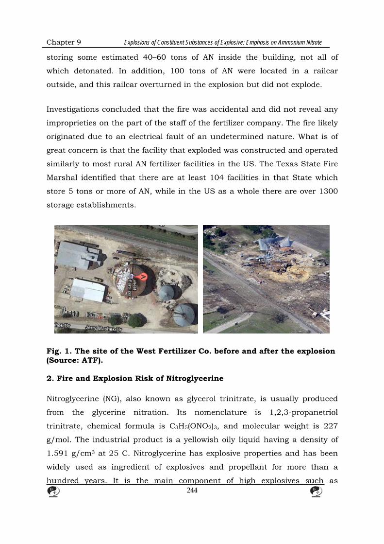
Chapter 9 Explosions of Constituent Substances of Explosive: Emphasis on Ammonium Nitrate
storing some estimated 40–60 tons of AN inside the building, not all of
which detonated. In addition, 100 tons of AN were located in a railcar
outside, and this railcar overturned in the explosion but did not explode.
Investigations concluded that the fire was accidental and did not reveal any
improprieties on the part of the staff of the fertilizer company. The fire likely
originated due to an electrical fault of an undetermined nature. What is of
great concern is that the facility that exploded was constructed and operated
similarly to most rural AN fertilizer facilities in the US. The Texas State Fire
Marshal identified that there are at least 104 facilities in that State which
store 5 tons or more of AN, while in the US as a whole there are over 1300
storage establishments.
Fig. 1. The site of the West Fertilizer Co. before and after the explosion (Source: ATF). 2. Fire and Explosion Risk of Nitroglycerine Nitroglycerine (NG), also known as glycerol trinitrate, is usually produced
from the glycerine nitration. Its nomenclature is 1,2,3-propanetriol
trinitrate, chemical formula is C3H5(ONO2)3, and molecular weight is 227
g/mol. The industrial product is a yellowish oily liquid having a density of
1.591 g/cm3 at 25 C. Nitroglycerine has explosive properties and has been
widely used as ingredient of explosives and propellant for more than a
hundred years. It is the main component of high explosives such as
244

Chapter 9 Explosions of Constituent Substances of Explosive: Emphasis on Ammonium Nitrate
dynamites, as well as an ingredient in most mining explosives. It was used
extensively in smokeless powder and together with nitrocellulose as a so-
called double base propellant, or with nitrocellulose and nitroguanidine as a
triple base propellant, which are used in larger calibre projectiles.
Furthermore, it has been used as ingredient of the solid propellant in
rockets.
Nitroglycerine has very high impact sensitivity and thermal instability. Thus,
many accidents have occurred during its manufacture and transport.
During the period from 1769 to 1980 among worldwide industrial accidents,
121 involved nitroglycerine which is approximately 24.2% of the total.
,showing that there were 43 industrial accidents involving nitroglycerine in
the period from 1954 to 1982. Obviously, the manufacturing process of
nitroglycerine is more dangerous than other chemical processes.
The manufacturing technique for nitroglycerine includes both batch and
continuous processes. Typical examples of the batch method are the Nobel
process from 1862 and the Nathan, Thomson and Rintoul process from
1908. A continuous method was first developed by the Schmid process in
1927 followed by the Biazzi process in 1935. Subsequently Nilssen and
Brunnberg developed a new injection nitration process in 1950. In 1978 the
Hercules Company in U.S.A. designed another new tubular process.
Although the manufacture of nitroglycerine has been developed for over 140
years, the dangerous industrial procedures involved have almost remained
the same. These procedures include preparing of mixed acid, nitration of
glycerine, separation of product and wastes, washing of product, filtration of
waste, recycling of nitroglycerine from waste acid and treating of waste acid.
Most of industrial accidents have occurred during the glycerine nitration
stage or the separation stage (approximately 50.4%). Therefore,
improvements in manufacturing procedures and the development of safety
control techniques are important requirements for this reaction. The kinetic
245

Chapter 9 Explosions of Constituent Substances of Explosive: Emphasis on Ammonium Nitrate
parameters of the nitroglycerine reaction and the operating conditions for its
industrial manufacture are not found in the open literature, presumably
because of its military importance.
3. Evaluation of Kinetic Parameters of Glycerine–nitric Acid
Reaction System
The elemental reaction of producing nitroglycerine is esterification reaction
of glycerine and nitric acid. This chemical reaction can be expressed as:
C3H5(OH)3 + 3HNO3 → 42SOH C3H5(ONO2)3 + 3H2O equation(1)
In this chemical reaction, the mixed feed acid contains both HNO3 and
H2SO4. The reagent H2SO4 acts as a dehydrating agent. Therefore, only the
HNO3 participates in this reaction. The chemical consumption can be
expressed by
CG=CG,0(1−xG) equation(2)
and
CN=CN,0−3CG,0xG=CG,0(M−3xG) equation(3)
where CG and CN denote the concentration of glycerine and nitric acid,
respectively. xG represents the fractional conversion of glycerine and M is the
initial concentration ratio of CN,0 to CG,0. Assuming the reaction is n order in
the glycerine and m order in the nitric acid and that the reaction rate
constant can be expressed as Arrhenius form, where A and E denote the
frequency factor and activation energy, respectively. Then, the reaction rate
of glycerine and nitric acid can be expressed as
( )( )mGGmn
0,GRTEm
NnG
RTEmN
nGG x3Mx1CeACCeACkCr −−===− +−−
equation (4)
246
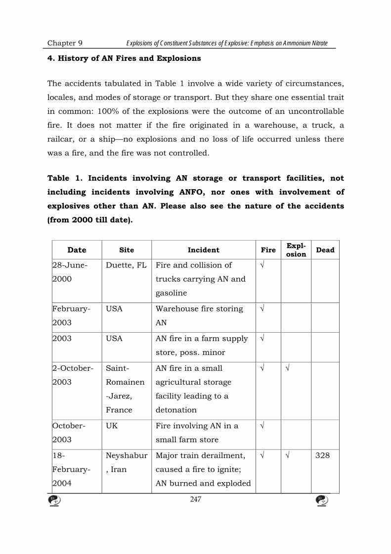
Chapter 9 Explosions of Constituent Substances of Explosive: Emphasis on Ammonium Nitrate
4. History of AN Fires and Explosions
The accidents tabulated in Table 1 involve a wide variety of circumstances,
locales, and modes of storage or transport. But they share one essential trait
in common: 100% of the explosions were the outcome of an uncontrollable
fire. It does not matter if the fire originated in a warehouse, a truck, a
railcar, or a ship—no explosions and no loss of life occurred unless there
was a fire, and the fire was not controlled.
Table 1. Incidents involving AN storage or transport facilities, not
including incidents involving ANFO, nor ones with involvement of
explosives other than AN. Please also see the nature of the accidents
(from 2000 till date).
Date Site Incident Fire Expl-osion Dead
28-June-
2000
Duette, FL Fire and collision of
trucks carrying AN and
gasoline
√
February-
2003
USA Warehouse fire storing
AN
√
2003 USA AN fire in a farm supply
store, poss. minor
√
2-October-
2003
Saint-
Romainen
-Jarez,
France
AN fire in a small
agricultural storage
facility leading to a
detonation
√ √
October-
2003
UK Fire involving AN in a
small farm store
√
18-
February-
2004
Neyshabur
, Iran
Major train derailment,
caused a fire to ignite;
AN burned and exploded
√ √ 328
247
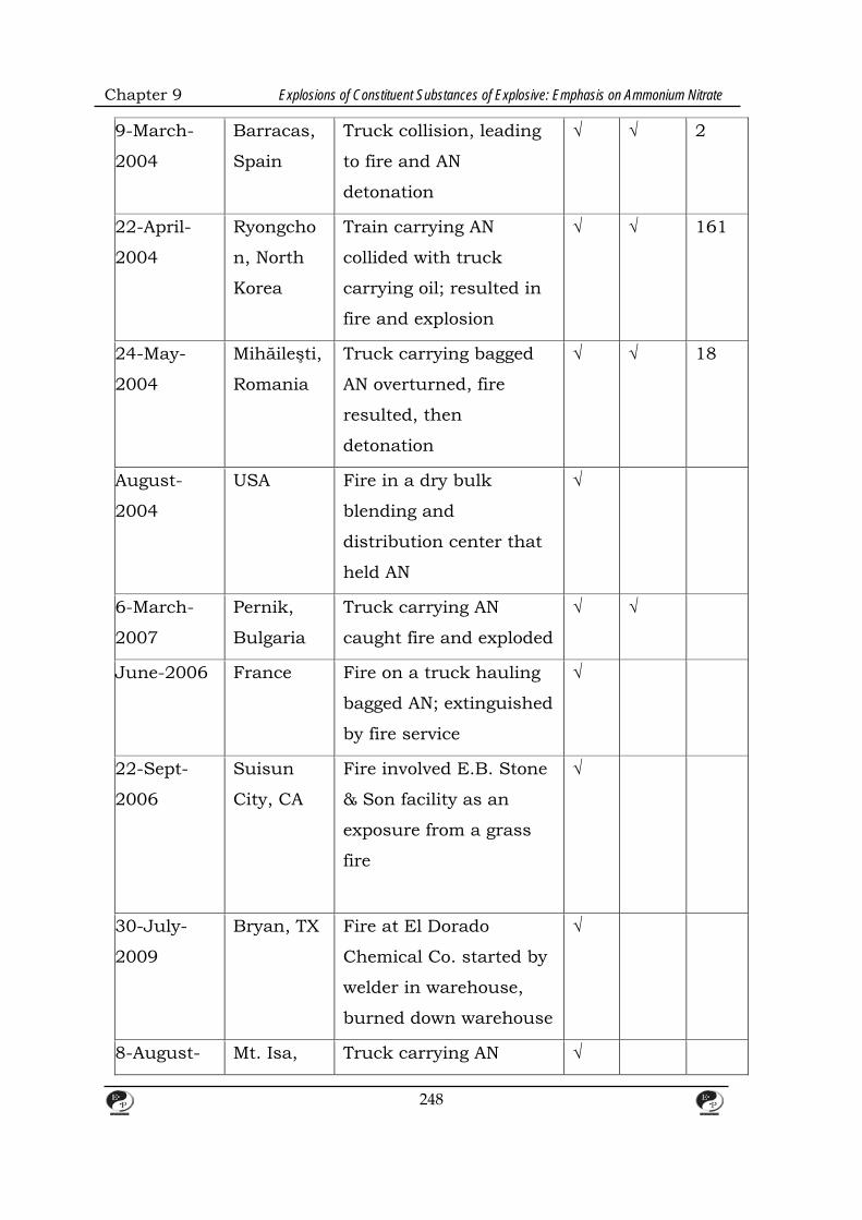
Chapter 9 Explosions of Constituent Substances of Explosive: Emphasis on Ammonium Nitrate
9-March-
2004
Barracas,
Spain
Truck collision, leading
to fire and AN
detonation
√ √ 2
22-April-
2004
Ryongcho
n, North
Korea
Train carrying AN
collided with truck
carrying oil; resulted in
fire and explosion
√ √ 161
24-May-
2004
Mihăileşti,
Romania
Truck carrying bagged
AN overturned, fire
resulted, then
detonation
√ √ 18
August-
2004
USA Fire in a dry bulk
blending and
distribution center that
held AN
√
6-March-
2007
Pernik,
Bulgaria
Truck carrying AN
caught fire and exploded
√ √
June-2006 France Fire on a truck hauling
bagged AN; extinguished
by fire service
√
22-Sept-
2006
Suisun
City, CA
Fire involved E.B. Stone
& Son facility as an
exposure from a grass
fire
√
30-July-
2009
Bryan, TX Fire at El Dorado
Chemical Co. started by
welder in warehouse,
burned down warehouse
√
8-August- Mt. Isa, Truck carrying AN √
248
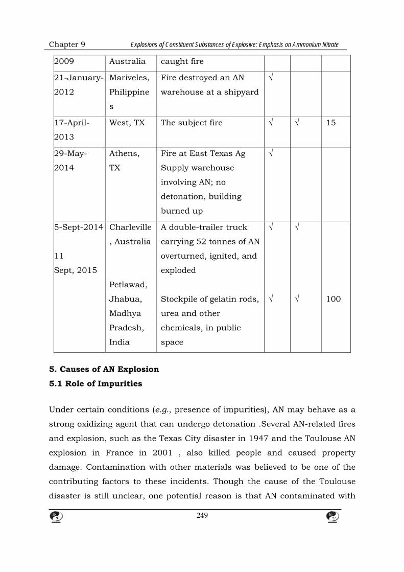
Chapter 9 Explosions of Constituent Substances of Explosive: Emphasis on Ammonium Nitrate
2009 Australia caught fire
21-January-
2012
Mariveles,
Philippine
s
Fire destroyed an AN
warehouse at a shipyard
√
17-April-
2013
West, TX The subject fire √ √ 15
29-May-
2014
Athens,
TX
Fire at East Texas Ag
Supply warehouse
involving AN; no
detonation, building
burned up
√
5-Sept-2014
11
Sept, 2015
Charleville
, Australia
Petlawad,
Jhabua,
Madhya
Pradesh,
India
A double-trailer truck
carrying 52 tonnes of AN
overturned, ignited, and
exploded
Stockpile of gelatin rods,
urea and other
chemicals, in public
space
√
√
√
√
100
5. Causes of AN Explosion
5.1 Role of Impurities
Under certain conditions (e.g., presence of impurities), AN may behave as a
strong oxidizing agent that can undergo detonation .Several AN-related fires
and explosion, such as the Texas City disaster in 1947 and the Toulouse AN
explosion in France in 2001 , also killed people and caused property
damage. Contamination with other materials was believed to be one of the
contributing factors to these incidents. Though the cause of the Toulouse
disaster is still unclear, one potential reason is that AN contaminated with
249
Chapter 9 Explosions of Constituent Substances of Explosive: Emphasis on Ammonium Nitrate
chloride (i.e., sodium dichloroisocyanurate (DCCNa)) caused the explosion.
Laboratory-scale experiment showed that AN–DCCNa mixture has higher
decomposition rates than pure AN [6]. In another research, it is reported
that moistened AN–DCCNa mixture could produce NCl3, leading to the
detonation of the mixture in the applied laboratory-scale.
AN decomposition with a single additive has been widely studied in
literature. In literature, binary mixtures with AN have been studied mainly
as explosives. Researchers mixed AN with more than one additives, such as
the mixture of ammonium sulfate, calcium carbonate, and urea. Low
thermal stability is indeed related to high explosivity, but high thermal
stability is no guarantee of low explosivity. AN was mixed with potassium
nitrate and complex one salts in order to phase-stabilize AN as an oxidant.
In other publications, AN mixture with binary additives has also been
reported- the thermodynamic effect of AN decomposition when mixed with
Ca and Mg carbonates with or without the presence of boron, manganese,
and copper compounds, such as AN mixture with CaCO3 and CuSO4; CaCO3
and H3BO3; CaCO3 and MnO2; etc. They found that equilibrium
concentrations does not depend on the carbonate origin of CaCO3, MgCO3,
or CaMg(CO3)2. In another research, AN was mixed with additives such as
FeS and urea, FeS2 and NaF, etc. Their conclusion was that salts of weak
acids and urea stabilized AN formulations, even in the presence of
destabilizing species.
The thermal decomposition of AN has been studied by various types of
calorimeters, typically employing sample sizes of the order of a few
milligrams and the data reported by different researchers have noticeable
differences. The AN decomposition has been reported to start at various
temperatures such as 210C , 200C , and 190C. The detected “onset”
temperatures of decomposition depend on the performance of the
calorimeter. It must be emphasized that there is not really an “onset”
temperature. According to Arrhenius law, reaction rates have an exponential
250
Chapter 9 Explosions of Constituent Substances of Explosive: Emphasis on Ammonium Nitrate
dependency on temperature, reaction rates at low temperatures are very
slow [16], and our ability to “detect” when a reaction “starts” depends on the
sensitivity of the employed experimental equipment. The so-called “onset”
temperature only marks the temperature at which the thermal effects
caused by the reaction become detectable by the employed equipment. Due
to different levels of accuracy of different equipment as well as testing
methods, the detected “onset” temperatures of AN decomposition vary.
Different macroscopic AN decomposition paths have also been proposed and
reported. The paths that attract more attention are listed below , in reaction
(1) and (2). It needs to be pointed out that the products of AN decomposition
are not limited to NH3, HNO3, N2O, and H2O. Several other gaseous products
can also be generated, including N2, O2, NO, and NO2.
NH4NO3 ⇌ HNO3 + NH3, ΔH 176 kJ mol−1 (at 170°C) equation(1)
NH4NO3 → N2O + 2H2O, ΔH −59 kJ mol−1 (above 170 °C) equation(2)
The generally accepted mechanism of AN decomposition is that the
dissociation of HNO3 leads to the subsequent oxidation of NH3, e.g., Rosser
et al. proposed reaction as the dissociation reaction of HNO3, which
generates NO2+, acting as the oxidizing species for NH3 as listed in reaction
(4). Reaction (5) shows a more realistic reaction path of HNO3
decomposition.
equation (3)
equation (4) equation (5)
To explain reaction (3) and (4) in more detail, in the presence of water, using
“acid” to indicate , H3O+, or HNO3, the following decomposition
mechanism equations (6)–(8)have been proposed, where reaction (7) is
considered the controlling step due to its slow reaction rate.
251

Chapter 9 Explosions of Constituent Substances of Explosive: Emphasis on Ammonium Nitrate
equation(6)
equation(7)
equation(8)
Reaction (7) is also described in terms of elementary reactions in the
literature [19] at the temperature range 342–387°C, where subsequently
oxidizes NH3, as listed in reactions (9)–(14). Reaction (15) is the overall
stoichiometry according to this theory.
equation(9)
NH2 + NO2 → NH + HNO2 equation(10)
NH + NO2 → HNO + NO equation(11)
NH2 + NO → N2 + H2O equation(12)
2HNO → N2O + H2O equation(13)
2HNO2 → NO2 + H2O + NO equation(14)
4NH3 + 5NO2 → N2O + 2N2 + 6H2O + 3NO equation(15)
Slightly different from the previously mentioned mechanism, another
approach [20]assumes that the formation of a nitramide intermediate out of
AN results in the decomposition of AN, as listed in reactions (16)–(20).
equation(16)
HONO2 → HO + NO2 equation(17)
HO + NH3 → HOH + NH2 equation(18)
NH2 + NO2 → NH2NO2 equation(19)
NH2NO2 → N2O + H2O equation(20)
252
Chapter 9 Explosions of Constituent Substances of Explosive: Emphasis on Ammonium Nitrate
5.2. The oxidizing Properties of AN
In broad terms, AN disasters have two causative factors due to the
chemistry of the substance: (1) its ability to detonate; and (2) its ability to
enhance a fire by means of its oxidizing behavior. Thus, the nature of its
oxidizing ability must be considered.
AN is not a fuel and cannot burn of itself. But since it is an oxidizing
chemical, it can promote combustion reactions of fuels. As an oxidant, it is a
weak one and is classified in the lowest class, Class 1, of oxidizers as viewed
by NFPA 400. Unlike some stronger oxidizers such as calcium hypochlorite,
there are no normally encountered products with which it combines to
produce a hypergolic ignition at room temperature. Unless quantities of AN
so massive were involved that self-heating would become an issue, for an AN
+ fuel reaction to occur, application of heat is necessary. The reactions
thereby occurring are complicated and not entirely unraveled, but it is likely
that evolution of HNO3 dominates, which is effective in igniting some fuels by
contact. Molten AN can ignite carbonaceous fuel by contact.
AN will show accelerated thermal decomposition reactions when combined
with a long list of contaminants. Many of these, e.g., chromium compounds,
are less likely to be encountered in actual accident scenarios, but chlorides
and copper can more readily be expected to be present; zinc can also be
important since it is contained in galvanizing coatings for steel. In some
cases, there can be a combined effect of organic material and chlorides or
copper reacting with AN.
Findlay and Rosebourne published the first study on the oxidizing properties
of AN in 1922. They mixed AN with ‘wood meal,’ i.e., fine sawdust, placed it
in a test tube and heated it to 100 °C. They also repeated the experiment
using powdered starch as the cellulosic fuel. In both cases, they got
evolution of N2, CO2, and H2O, but no CO or oxides of nitrogen.
Kistiakowsky and Guinn conducted oven-heating tests on AN mixed with
253
Chapter 9 Explosions of Constituent Substances of Explosive: Emphasis on Ammonium Nitrate
paper, and found that ignition occurred when a temperature of 132–154 °C
was reached. Macy et al. determined the ignition temperature of AN-
saturated paper bags to be 177–232 °C, but a more intimate mixture of
sawdust or paper with AN will ignite at 150 °C. All of these results are below
the normal ignition temperature of paper, ca. 250 °C, confirming the
oxidizing properties of AN. The important safety implication is that molten
AN at 169.6°C or higher is likely to greatly accelerate spread of fire by direct
ignition on contact, as it flows.
Despite the fact that chemists have been studying oxidizing chemical
properties for a century or more, no standardized test emerged for assessing
the oxidizing potential of chemicals that has engineering meaningfulness. In
fact, there even have been very few attempts to develop a standardized test,
and no attempt has resulted in a test which would be provide usable
engineering data, i.e., data that can be used as input to make some
calculation. Instead, all of the research has only produced schemes to
compare one substance against another on some arbitrary scale. The
earliest studies aimed at producing a standard test were conducted at BM,
who proposed a horizontal trough test. The oxidizer is to be mixed with wood
sawdust, ignited by a propane flame at one end, and the rate of fire
propagation timed. Materials showing a faster rate of progress are deemed to
be more hazardous. BM proposed classifying the results into 4 categories
already used by NFPA. Researchers at General Electric then conducted two
follow-up studies, where they endeavored to achieve better reproducibility
and also tested additional materials. In the course of this, they confirmed
AN to be an oxidizer of Class 1, in terms of the NFPA classification scheme.
It should be noted that classification of most AN-based fertilizer products is
not based on conducting the O.1 test. Instead, product classification is
accomplished by means of Special Provisions (SPs), which are based on the
chemical constituency of the product. Only products which do not fall under
the pertinent SPs would be classified by means of testing.
254
Chapter 9 Explosions of Constituent Substances of Explosive: Emphasis on Ammonium Nitrate
6. Learning from Disasters
Viewed at a level of fine-enough granularity, every disaster is unique. Thus,
this point of view is singularly unhelpful towards promoting of safety and
preventing of future disasters. Instead, a prudent risk management
philosophy has to entail examining past disasters and identifying what is
common among them, not what is unique and different[94]. For example,
after the S.S. High Flyer exploded, the Government panel focused on the fact
that there was nearby stowage of sulfur (a unique factor) instead of focusing
on the existence of uncontrolled fire (the common factor). As a result, the
necessary lesson was not learned. But by now, nearly 70 years later, the
record is so lengthy and so diverse, that hopefully the overwhelming
importance of the common factor—uncontrolled fire—in AN detonations can
be appreciated. This perspective allows one to see that there is nothing
substantively different between transportation and storage disasters. In each
case, a fuel is present, an ignition occurs, a fire burns fiercely, aided by the
oxidizing nature of AN, and effective fire control fails to be achieved. The
outcome then, at best, is a physical disaster without dead persons or, at
worst, a large life loss disaster. Conversely, not a single AN explosion
accident exists in a storage or transportation environment where there was
no fire, or where there was a small fire which was successfully controlled.
It is especially troubling that the fertilizer manufacturing industry, while
aware of the immense hazards of AN, persistently attempted to minimize the
implications of known accidents, instead of learning from them. For
example, the representatives of a large AN manufacturer in the UK, who
clearly knew the literature very well, wrote “the conditions of pressure…and
temperature required to explode ammonium nitrate are extreme…such severe
conditions are very unlikely to be met.” And, “It is generally believed that a
fire involving an unconfined mass of ammonium nitrate will not lead to an
explosion.” And, “… shock initiation of solid material is discounted as a
serious risk.” The attitude of government authorities, at least in the US, has
255
Chapter 9 Explosions of Constituent Substances of Explosive: Emphasis on Ammonium Nitrate
been no better. The safety provisions for dangerous substances in workplace
is handled in the US primarily by the Occupational Safety and Health
Administration (OSHA), whose regulations, as shown below, have been so
ineffectual as to be castigated by other Federal government agencies.
One prior incident is specifically noteworthy. In 2003, a French farm barn
containing stored AN suffered an fire which was not successfully controlled.
This led to detonation and widespread destructions, but fortunately no
fatalities. The West, Texas incident, 10 years later, was very similar to the
French accident, but with a disturbing life loss outcome. The details of the
French accident were documented both in a technical article and in an ARIA
report, yet the lesson went unheeded.
7. Preventing Uncontrollable Fires
There are two main techniques that can be used to prevent uncontrollable
AN fires: (1) reduce the fire hazard propensity of AN; and (2) provide
constructional fire safety measures for the facility. Both should be
implemented for assuring safety in storage environments. But it is generally
impossible to implement safety measures with regards to trucks or other
transportation environments which would reduce or eliminate potential fuels
for fire. Thus, since the second technique is not available for guarding
against transportation disasters, it is crucial that the first technique be
implemented across-the-board.
7.1. Reducing the Hazards of AN
Safety improvements in the chemical industry often follow the precepts of
Inherently Safer Technology (IST). The relevant IST principle here
is substitution—replacing a hazardous material with a safer option. The IST
‘substitution’ principle is also known as alternative safer design in product
defect literature. As will be shown below, alternatives for AN which
256

Chapter 9 Explosions of Constituent Substances of Explosive: Emphasis on Ammonium Nitrate
constitute safety improvement in regards to both fire safety and explosibility
exist, and some have existed for many decades.
Straight-AN, that is AN where the only added chemicals are a small amount
of coating chemicals used to reduce caking tendency, is susceptible to
disastrous detonation accidents. Already before 1920, the dangers of this
were recognized and the BASF factory at Oppau4 produced ANS (a double
salt of ammonium sulfate and AN) since straight AN was recognized to be
“too dangerous to handle for fertilizer purposes.” While this particular
product is indeed less susceptible to detonation than straight AN, additional
alternatives were subsequently developed, and the patent literature contains
a large number of such inventions. Here, three such products are
considered: (1) CAN, (2) Ferti-Safe, and (3) Sulf-N 26.
Calcium ammonium nitrate, CAN, has been made since the 1920s [19]. It
involves adding powdered calcium carbonate into the AN at the hot liquor
stage, in an amount of 20% (currently) to 40% (prior to the 1980s). CAN has
been described as “a non-detonable alternative to pure ammonium nitrate.”
This overstates its nature, but it is appropriate to view that “calcium
ammonium nitrate essentially removes any explosion hazard. ” Compared to
AN, CAN is (a) less likely to lead to uncontrollable fire, since it is a less
potent oxidizer; and (b) is both much less sensitive towards detonation, and
exhibits greatly lowered explosive power if boostered enough to detonate.
CAN, or alternative safety enhanced products, are utilized to the exclusion of
straight-AN fertilizer in a number of European countries , which includes
Belgium, Denmark, Eire, Finland, Germany, The Netherlands, Northern
Ireland, and Switzerland. This is directly due to the safety characteristics of
CAN versus AN.
With regards to the effect on fire of CAN, one of the earliest demonstrations
of the safety improvement that can be achieved by CAN were the pressure-
vessel experiments, discussed above. They concluded that the explosion
temperature is a useful criterion for examining the negative effects of
257
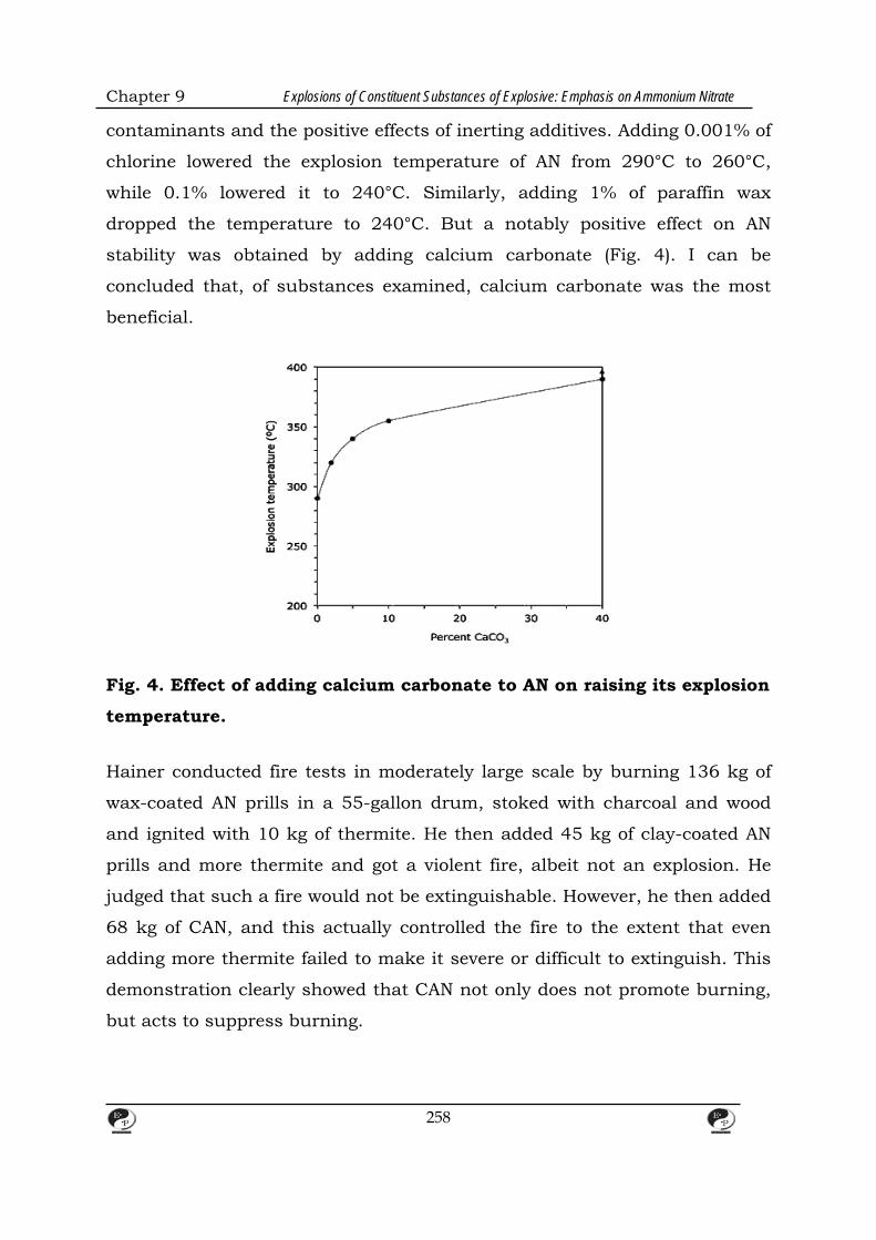
Chapter 9 Explosions of Constituent Substances of Explosive: Emphasis on Ammonium Nitrate
contaminants and the positive effects of inerting additives. Adding 0.001% of
chlorine lowered the explosion temperature of AN from 290°C to 260°C,
while 0.1% lowered it to 240°C. Similarly, adding 1% of paraffin wax
dropped the temperature to 240°C. But a notably positive effect on AN
stability was obtained by adding calcium carbonate (Fig. 4). I can be
concluded that, of substances examined, calcium carbonate was the most
beneficial.
Fig. 4. Effect of adding calcium carbonate to AN on raising its explosion
temperature. Hainer conducted fire tests in moderately large scale by burning 136 kg of
wax-coated AN prills in a 55-gallon drum, stoked with charcoal and wood
and ignited with 10 kg of thermite. He then added 45 kg of clay-coated AN
prills and more thermite and got a violent fire, albeit not an explosion. He
judged that such a fire would not be extinguishable. However, he then added
68 kg of CAN, and this actually controlled the fire to the extent that even
adding more thermite failed to make it severe or difficult to extinguish. This
demonstration clearly showed that CAN not only does not promote burning,
but acts to suppress burning.
258

Chapter 9 Explosions of Constituent Substances of Explosive: Emphasis on Ammonium Nitrate
With regards to detonation properties of CAN, Shaffer conducted sensitivity
tests on AN compounds to determine how much booster is needed for
detonating a tube filled with the test material. In these tests, he found that
commercial CAN specimens with AN content of 81% showed a detonation
sensitivity of 22%, as compared to straight AN. With sufficient boostering,
CAN can be detonated, even though much greater boostering would be
required. But even under that unlikely scenario, the outcome would be
notably less severe. The test results for the explosive power of CAN,
compared to AN and some other diluents, based on ballistic mortar tests are
shown (Fig. 5). This shows that by incorporating 20% of calcium carbonate,
the explosive power of AN can be reduced by more than 90%.
Fig. 5. The effect in the Mark IIIc RARDE ballistic mortar of AN with
various additives (Clancey and Turner), with results being expressed as
a percent of the effect for pure picric acid. Pure AN shows 80% the
energy value of picric acid. ANS (blend) denotes a mechanical blend of
ammonium nitrate and ammonium sulfate, while ANS (dbl. salt) denotes
a 1:1 molar ratio double salt.
259

Chapter 9 Explosions of Constituent Substances of Explosive: Emphasis on Ammonium Nitrate
Military authorities sometimes propose to take actions against improvised
explosive devices (IEDs), which are often based on AN. Thus, there have
been campaigns [119] to discover modifications to AN which would make it
non-explosive and ‘irrestorable.’ The latter concept means that the modified
substance could not be re-manufactured to yield an explosive material.
Such efforts to create a non-explosive and irrestorable version of AN have all
come to naught. But it is exceedingly important to realize that this campaign
is solely a security campaign and unrelated to safety concerns of this
chapter. To reduce the potential for accidental detonations involving AN, it is
not necessary to evolve a substance which is non-explosive and irrestorable.
What is needed is a formulation with reduced oxidizing potency, reduced
detonation sensitivity, and reduced explosive power. Unlike the objectives of
military authorities, these objectives are demonstrably practical and
feasible.
7.2. Making Buldings fire-safe
Safety improvements in the AN-based product may be the only strategy
available for improving transport safety. But for storage buildings, the
buildings themselves can be constructed so as to preclude the possibility of
an uncontrolled fire, and this should be done as an additional layer of
protection. A short list of crucial fire safety features would suffice to prevent
AN disasters, such as occurred at West. While the Texas facility was only
one of more than 1300 such in the US, it is useful to focus on its
shortcomings, since many agricultural AN storage facilities are built in a
similar manner.
AN storage bins should be made of noncombustible, non-
reactivematerials. Wood or galvanized metal should not be used. It has
been known since at least 1936 [121]that wood incontact with AN can get
saturated with the material and then, when ignited, will burn “ witha
much stronger flame than non-saturated wood.” But wood bins would be
260
Chapter 9 Explosions of Constituent Substances of Explosive: Emphasis on Ammonium Nitrate
an unacceptable source of fuel in proximity to stored AN, even if some
surface treatment were adopted which reduces direct impregnation, since
the fuel value of the wood is not reduced thereby.
In 1947, as a result of the tragedy in Texas City, the US Federal
government [80]concluded that “ The most common hazard to ammonium
nitrate fertilizer…is fire involving combustible containers or adjacent
combustible material that may be present…” Unfortunately, many decades
later, matters had not changed, leading directly to the West tragedy. The
AN was stored there in wooden bins, comprising a large fuel load in direct
contact with the AN.
The building construction should be of non-combustible materials except
for very small components for trim, wiring, or other purposes where
noncombustible alternatives do not exist.
The building wherein AN was stored was of ordinary, wood-framed
construction, with much exposed timber not even protected by plaster or
gypsum wallboard. Ordinary timber construction can be ignited from very
small ignition sources (e.g., electrical faults), while the large amount of
timber present serves to create a long-burning fire. It is highly unlikely
that the fire and detonation at West would have taken place, had the bins
and building materials not been combustible.
Any AN storage facility should be equipped with smoke or heat alarm
system monitored by a central station.
The fire occurred about 2 h after close of business for the day. The fire
department was notified only when a person in a nearby city park
observed smoke. By the time the fire department arrived, they faced a
fully involved fire. Had there been a fire or smoke alarm system
monitored by a central station, notification would have come to the fire
261
Chapter 9 Explosions of Constituent Substances of Explosive: Emphasis on Ammonium Nitrate
department much earlier, and it is likely that the fire would have been
suppressed successfully, rather than overwhelming the firefighters.
Any AN storage facility should be protected by an automatic fire sprinkler
system, properly designed for this purpose.
Apart from fire extinguishers, which are of no benefit to an unattended
facility (nor if the fire grows beyond a very early stage), there was no fire
suppression system. Had there been a properly designed fire sprinkler
system, this would have controlled the fire and, upon responding to the
fire, the firefighters would have encountered a suppressed, or nearly so,
fire.
Floors in an AN storage facility should be constructed so that there are
no elevator pits, drains, grates, or pipes to where molten AN could flow
into and accumulate.
At the West Fertilizer facility, the elevator contained a pit about 3 m deep
into which molten AN could flow. It is most probable that the actual
explosion originated at this pit. With a floor design that does not allow
molten material to be trapped, the molten AN would have been less prone
to detonation due to absence of a critical depth of liquid material.
To be effective, all of the above provisions need to be mandatory and not
just in the form of advisory suggestions.
As explained below, no mandatory safety requirements were laid upon
the owners of the West Fertilizer Co., beyond OSHA regulations, and
these did not include any of the above fire safety provisions.
8. The role of codes and suppliers
8.1. Fire safety measures for storage environments
262
Chapter 9 Explosions of Constituent Substances of Explosive: Emphasis on Ammonium Nitrate
Staff of agricultural fertilizer distribution companies are normally
knowledgeable only on matters of agronomy and do not have technical
knowledge on the fire or explosion safety of chemicals. Consequently, the
only way that agricultural fertilizer distribution facilities can be provided
with adequate fire safety is if there are mandatory requirements laid down
and enforced by technically competent entities, of which there are two: (1)
government authorities, and (2) AN manufacturers. Disasters such as the
one at West, Texas occur when neither takes effective action. In the case of
manufacturers, they actually have a dual role—to provide for safety
improvements in the product itself, discussed above, and to require safe
facilities at their customers. In a number of sectors of the chemical industry,
raw chemical suppliers have Product Stewardship procedures in place so
that they will not ship product to any facility that they have not inspected
and approved. The US suppliers of fertilizers had chosen not to implement
such requirements. Also, in West, as in much of other rural parts of Texas,
there exists no building code and no fire code. This is true of many other
locales in rural US, where codes are either absent or there are no local
authorities competent to inspect and control hazardous chemical facilities.
But even a competent authority will not be able to achieve adequate safety
unless there exists a suitable document for them to enforce. Thus, it is
important to examine some of the salient documents concerned with AN
safety.
Various codes and guidance documents often provide a plethora of
provisions regarding storage of AN, which tends to create the impression
that effective fire safety measures have been adopted, even when the
provisions adopted are marginal, obscure, or do not address the primary fire
safety needs. The requirements laid down by some of the relevant
documents are described in the sections below and summarized in Table 3.
It is of utmost importance to realize that adherence by the owners of the
West Fertilizer Co. to any of the documents discussed would not have
averted the disaster. The FM Global data sheet is the only one that contains
263
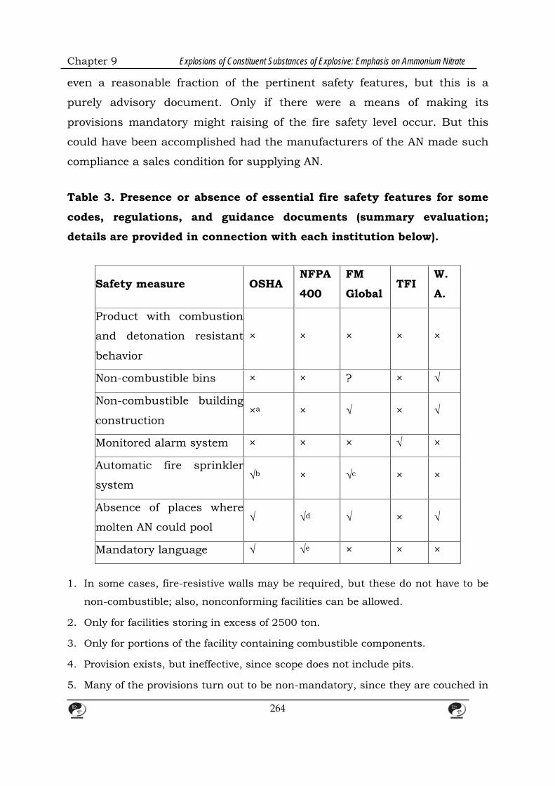
Chapter 9 Explosions of Constituent Substances of Explosive: Emphasis on Ammonium Nitrate
even a reasonable fraction of the pertinent safety features, but this is a
purely advisory document. Only if there were a means of making its
provisions mandatory might raising of the fire safety level occur. But this
could have been accomplished had the manufacturers of the AN made such
compliance a sales condition for supplying AN.
Table 3. Presence or absence of essential fire safety features for some
codes, regulations, and guidance documents (summary evaluation;
details are provided in connection with each institution below).
Safety measure OSHA NFPA
400
FM
Global TFI
W.
A.
Product with combustion
and detonation resistant
behavior
× × × × ×
Non-combustible bins × × ? × √
Non-combustible building
construction ×a × √ × √
Monitored alarm system × × × √ ×
Automatic fire sprinkler
system √b × √c × ×
Absence of places where
molten AN could pool √ √d √ × √
Mandatory language √ √e × × ×
1. In some cases, fire-resistive walls may be required, but these do not have to be
non-combustible; also, nonconforming facilities can be allowed.
2. Only for facilities storing in excess of 2500 ton.
3. Only for portions of the facility containing combustible components.
4. Provision exists, but ineffective, since scope does not include pits.
5. Many of the provisions turn out to be non-mandatory, since they are couched in
264

Chapter 9 Explosions of Constituent Substances of Explosive: Emphasis on Ammonium Nitrate
terms of subjective decisions by the AHJ, and especially allowing the AHJ to
permit nonconforming structures to continue being used.
8.1.1. OSHA regulations
In the US, section 29CFR 1910.109(i) of OSHA regulations include
provisions for the storage of explosives or blasting agents comprising AN.
However, these safety features are weak and compliance with them would
not have prevented the West disaster. Notably, wood construction is not
prohibited, while sprinkler protection is required only for facilities storing
over 2500 tons of AN (Table 3). The West facility, at the time of the
explosion, held 40–60 tons of AN, not counting the 100 tons in the parked
railcar which did not get involved. Furthermore, any reasonable reading of
the regulation indicates that it applies only to entities manufacturing or
storing explosives, but not to distributors of agricultural fertilizer. After the
West disaster, OSHA responded with a self-serving letter claiming that such
fertilizer storage facilities were subject to the above-cited section. However,
the whole section, not just subsection (i), of the regulation is
titled Explosives and blasting agents, with its scope being specified as: “ This
section applies to the manufacture, keeping, having, storage, sale,
transportation, and use of explosives, blasting agents, and pyrotechnics”
while fertilizer-grade AN is not classified as by any governmental entity as
being an explosive, blasting agent, or pyrotechnic . Two different, but non-
regulatory, Federal agencies documented the ineffectiveness of OSHA
towards establishing viable fire and explosion safety in agricultural AN
storage facilities. It is also of interest that OSHA inspected the West facility
in 1985 and cited it only for minor violations unrelated to the AN storage
building. Yet, the wooden building, the wood bins, the elevator pit, and other
relevant hazards were the same at the time of the inspection as in 2013.
8.1.2. NFPA 400 Hazardous Materials Code
265
Chapter 9 Explosions of Constituent Substances of Explosive: Emphasis on Ammonium Nitrate
The best-known document in the US concerned with the safety of AN
storage is the NFPA Hazardous Materials Code (NFPA 400 [82]), which is
considered here in its pre-West-disaster (2013) edition. It is published by
a private organization, but assumes the force of law in many US
jurisdictions since it is directly referred to by most US fire codes.
Unfortunately, this is a document which is inordinately opaque and
confusing.5 In addition, it is unreasonably wordy, being some 214 pages
long.6While technical knowledge necessary to adequately describe safe
storage of AN is not trivial, it unreasonable to expect even a chemist or
an engineer to read and comprehend a 214-page treatise in order to
arrange for safe storage of AN. An even more severe shortcoming of NFPA
400 is that it relies extremely heavily on subjective assessments and
approvals or disapprovals from the pertinent Authority Having
Jurisdiction (AHJ). This creates a lack of rigor and objectivity. But in a
locale which lacks a fire code and an AHJ, it makes the concept of AHJ-
dependent requirements illogical. An additional weakness is the
‘grandfathering’ of existing facilities. Sec. 11.5.5 specifies that “the
continued use of an existing storage building or structure not in strict
conformity with this code shall be approved by the AHJ in cases where
such continued use will not constitute a hazard to life or adjoining
property.” In a locale with has no AHJ, this implies that no restrictions
can be made with regards to existing buildings.
The NFPA Code does not require that bins be made of a non-combustible
materials, instead of being made from wood. The only bin materials
prohibited (Par. 11.3.2.3.3.2) are ones made of galvanized iron, copper,
lead, or zinc. Par. 11.3.2.3.3.3. states that “wooden bins protected
against impregnation by ammonium nitrate shall be permitted” but does
not prohibit wooden bins of any other kind. Furthermore, the concept of
“protected against impregnation” is meaningless since there does not
exist any test for this, nor are any instructions or specifications given in
the NFPA Code for establishing what constitutes protection.
266
Chapter 9 Explosions of Constituent Substances of Explosive: Emphasis on Ammonium Nitrate
The NFPA Code does not require that any other combustible
construction features of the building itself be eliminated. Par. 11.1.5
requires that the building “ be constructed in accordance with the
building code,” but this is meaningless for a locale that has no building
code. Furthermore, building code provisions are written to govern the
construction and not the operation of buildings. In other words, apart
from some optional additional provisions for existing buildings that
localities can include by local ordinance, any building already in
existence when a building code is adopted does not fall under the scope
of its regulation.
The NFPA Code has no requirement that an alarm system be installed.
There is a placeholder in Sec. 11.2.10, but no requirements or text.
The NFPA Code does not require that an automatic fire sprinkler system
be installed in the facility. Sec. 11.2.6 specifies that sprinkler
requirements are laid down in Sec. 6.2.1.1, but the latter only requires
sprinklers for chemicals which fall into Protection Levels 1 through 4,
while AN is outside the scope of Protection Levels, per Table 5.2.1.1.3. In
fact, the wording of the Code actively discourages installation of
sprinkler systems for AN: “11.2.6.1.2 Sprinkler protection shall be
permitted to be required by the AHJ for the storage of less than 2500 ton
(2268 metric tons) of ammonium nitrate where the location of the building
or the presence of other stored materials can present a special hazard.”
The provisions in the NFPA Code against pooling of molten AN are poor,
at best. Sec. 11.3.3.2 restricts drains, pockets, etc., within “flooring in
storage and handling areas.” The straightforward architectural
interpretation of these requirements is that they literally only prohibit
drains, gutters, trenches and channels coming down below the floor
level; an elevator pit such as was present at the West facility might be
267
Chapter 9 Explosions of Constituent Substances of Explosive: Emphasis on Ammonium Nitrate
considered simply a change in floor level, not an appurtenance
extending below the floor.
After the West disaster, an NFPA spokesperson admitted that NFPA is
still “learning more about ammonium nitrate” and proceeded to revise
AN provisions for the 2016 edition. An analysis [126] of this forthcoming
edition indicates that it is still unlikely to prevent AN disasters, despite
some improvements.
8.1.3. FM data sheet Instark contrast to NFPA 400, the FM Data Sheet 7–89 [127] is only 12
pages long, is written in clear, non-convoluted English, and lays out fire
safety provisions in readily comprehensible terms. Its main drawbacks are
that, being published by an insurance company, it is necessarily only
advisory, and that it includes some, but not all of the safety provisions
discussed above. It does not establish requirements for products safer than
straight AN, nor a monitored alarm system. However, it specifies non-
combustible building construction, and clearly prohibits pits where molten
AN could pool. An automatic fire sprinkler system is required anywhere that
combustible items might be installed. In the case of an agricultural fertilizer
facility, it is generally difficult to provide non-combustible elevators and
conveyor belts; thus, these would require sprinkler protection. It is not clear
if combustible bin materials are prohibited, but even if they are allowed, this
would have triggered a sprinkler requirement. If the West facility had been
rebuilt in non-combustible construction, had sprinklers provided for
combustible components, and had its elevator pit eliminated, it is highly
unlikely that a severe fire could have developed that ended as a detonation.
8.1.4. TFI Guidelines
In response to the West disaster, The Fertilizer Institute (TFI) issued in 2014
“Safety and Security Guidelines” for AN [128]. But this is a shockingly
268
Chapter 9 Explosions of Constituent Substances of Explosive: Emphasis on Ammonium Nitrate
inadequate document. There are basically only three provisions addressed
directly at the construction safety of storage buildings:
(1) Steel or wood bins should be protected by a coating such as sodium
silicate, epoxy, or PVC;
(2) If not continuously occupied, the building should have an automatic
detection and alarm system; and
(3) AN piles should not exceed a height of 40 ft (12.2 m).
Had these guidelines been in effect on 17 April 2013, nothing would have
changed. First and foremost, the document is presented in non-mandatory
language, e.g., “should,” not “shall”. Thus, any operator of an AN storage
facility would be entitled to conclude that compliance is optional and that
there is no burden to comply. But even if the wording were changed to
mandatory language, the safety level would be grossly inadequate. It may be
noted that research has shown AN piles over 1.5 m high are susceptible to
detonation, so limiting height to 12.2 m (much taller than at West, Texas) is
ineffectual. Since the consequences of an AN explosion can be so dire, it
should be clear that a strategy of protection-in-depth is necessary. In other
words, not only must all pertinent aspects of fire safety be included, but
there must be some redundancy, so that more than one layer of protection
would be in place to guard against deaths of exposed population. TFI
document, on the other hand, not only lacks any useful redundancy, but
fails to require even the most elementary safety precaution, noncombustible
construction.
8.1.5. Western Australia code of practice
An instructive contrast is the AN safety document issued by the government
of Western Australia (W.A.) in 2012 [130]. This notably predated the West
disaster, yet the treatment of constructional safety issues is dramatically
superior to the post-West TFI document. The document is also issued in a
269

Chapter 9 Explosions of Constituent Substances of Explosive: Emphasis on Ammonium Nitrate
non-regulatory context and thus is presented in “should” language. But at
least it includes a number of important safety issues:
(1) The entire building should be built of non-combustible materials;
(2) A clear explanation is given that drains pipes and tunnels should not
exist within which molten AN could accumulate;
(3) If there is any other facility within the AN storage building, a 5m clear
spacing should be established between the AN storage facility and
other uses within the building. Much greater distances are to be
provided for storage quantities in excess of 10 ton.
(4) Bins should be made only of non-combustible materials.
In addition, the document makes clear that chlorides are incompatible with
AN. This speaks directly to the issue at West where the same conveyor
system was used to transport KCl and AN, necessarily leading to
contamination of AN with KCl, since no cleaning regimen existed.
9. Manufacturers' Role
In the absence of effective government regulations, manufacturers of the
material can take active steps to ensure safety in transport and storage
using two tools: (1) a safety data sheet (SDS) for the material which contains
necessary prescriptions for safe transport, handing, and storage of the
product; and (2) a buyer qualification program, and these tools are best
used in concert. In the US, the manufacturers of AN have not taken either
task seriously. Even after being revised subsequent to the 2013 disaster, the
safety data sheets of the manufacturers remain totally inadequate. They lack
prescriptive language, and simply refer the user to NFPA 400 for actual fire
and explosion safety recommendations. Furthermore, the intention of a SDS
is defeated by such an approach. A useful SDS should be self-contained
270

Chapter 9 Explosions of Constituent Substances of Explosive: Emphasis on Ammonium Nitrate
with regards to safety requirements, and authors should not evade their
responsibility by simply suggesting that the user consult another document.
The manufacturers involved, however, could have prevented the West, Texas
disaster (and disasters which may occur in the future) by including in the
SDS the safety issues identified above, and doing this in a prescriptive and
clear language. This would need to be accompanied by an effective program
to inspect the buyer's facilities to ensure that they comply with the fire
safety requirements laid down in a suitably effective SDS. It is noteworthy
that in the case of the West, Texas disaster, employees testified that they
would have complied with any constructional safety requirements that they
would have been required to observe.
10. Conclusions Explosions of stored ammonium nitrate are rare events. But they are
recurrent, catastrophic, and preventable. The reason they have not been
prevented is because persons charged with safety responsibilities focused on
the differences characterizing each disaster, instead of examining what is
common among the disasters. The recent explosion killing 15 persons in
West, Texas, is but the latest disaster in a century's worth of AN explosions.
By examining this long record, it emerges that the common factor is an
uncontrollable fire. This is true irrespective of whether the material is stored
in a warehouse, or on a transportation conveyance. In the database
compiled, it is found that 100% of AN explosions in storage or transportation
environments (excluding manufacturing accidents or accidents involving
other explosives) have been caused by uncontrolled fire. Conversely, 30% of
uncontrolled fires involving AN have resulted in explosions, and about half
of these resulted in deaths.
There are some two centuries' worth of chemistry studies on the
characteristics of AN. These are helpful towards understanding AN behavior,
but do not enable reconstructions of accidents to be made. Explosives
271

Chapter 9 Explosions of Constituent Substances of Explosive: Emphasis on Ammonium Nitrate
researchers understand how AN can be detonated when a detonator and a
booster charge are used. But only some unvalidated theories exist to explain
how AN detonates in fires where neither of these is present. A handful of
researchers also tried to re-create such fire-induced detonation events, but
every one of them was unsuccessful. Yet, the tragic record of recurring
explosions due to fires demonstrate that the phenomenon is not only real,
but is a major hazard.
To avoid a second “century's worth of ammonium nitrate explosions,” the
solution is simple and should have been recognized already, even though it
has never been acknowledged. Stored AN disasters will not occur if
uncontrollable fires do not occur. The technology needing to be implemented
for this is twofold: (1) manufacturers must switch from making straight AN
to making fire- and detonation-resistant products; and (2) owners of storage
facilities need to implement building construction features which preclude
the possibility of an uncontrolled fire. The needed technology to achieve both
these objectives has existed for many decades and is in no way novel.
There are only two entities that can prevent future disasters—government
and manufacturers. In the US, both have been wholly ineffectual. US
government regulations can be on a Federal, State, or local level. But
building construction regulations are administered only on a local level. AN
fertilizer is predominantly stored and used in rural areas, and construction
regulation in such areas is generally ineffective or, as in the case of Texas,
nonexistent. Regulations to prohibit straight AN in preference to safer
fertilizer products could be enacted on a Federal level, but two different non-
regulatory Federal agencies, the US Chemical Safety Board and the
Government Accountability Office, explicitly documented the ineffectiveness
of OSHA, the agency which does have regulatory authority. The latter agency
could also abate hazards in most storage occupancies since they constitute
workplaces. However, the existing regulations are misguided and ineffective
towards achieving needed fire safety.
272
Chapter 9 Explosions of Constituent Substances of Explosive: Emphasis on Ammonium Nitrate
The AN manufacturers could prevent disasters in the absence of viable
governmental regulations. But unlike in some other areas of the chemical
industry, the manufacturers in this sector have consistently failed to
recognize the importance of Product Stewardship as a means of avoiding
death and injury. This means that product is routinely sold to parties not
competent to safely store the material. Finally, codes and standards in this
area have also been comprehensively defective. Notably, NFPA 400 has not
required safety features which are crucial towards avoiding AN disasters and
its recent improvements are insufficient.
11. References
1. Vytenis Babrauskas Explosions of ammonium nitrate fertilizer in storage or
transportation are preventable accidents Journal of Hazardous Materials, Volume
304,5 March 2016.
2. Zhe Han, Sonny Sachdeva, Maria I. Papadaki, Sam Mannan Effects of inhibitor and
promoter mixtures on ammonium nitrate fertilizer explosion hazards Thermochimica
Acta, Volume 624, 20 January 2016.
3. R.S. Ettouney, M.A. EL-Rifai Explosion of ammonium nitrate solutions, two case
studies Process Safety and Environmental Protection,Volume 90, Issue 1, January 2012.
4. Zhe Han, Sonny Sachdeva, Maria I. Papadaki, M. Sam Mannan Ammonium nitrate
thermal decomposition with additives Journal of Loss Prevention in the Process
Industries, Volume 35, May 2015, Zhe Han, Sonny Sachdeva, Maria I. Papadaki, M.
Sam Mannan
5. Bennett, D., West, Texas: The Town That Blew Up, Business Week (3 July 2013).
7. M2.1 Explosion—1 km NNE of West, Texas, 2013-04-18 00:50:38 UTC.
http://comcat.cr.usgs.gov/earthquakes/eventpage/usb000g9yl# summary.
8. State of Texas Outreach to Counties Having an Ammonium Nitrate Facility, Texas
State Fire Marshal's Office, [n.p.] (2014).
273
Chapter 9 Explosions of Constituent Substances of Explosive: Emphasis on Ammonium Nitrate
9. West Fertilizer/Adair Grain Company. Ammonium Nitrate Fire and Explosion, Public
Meeting, April 22, 2014, US Chemical Safety and Hazard Investigation Board,
Washington (2014).
10. Chemical Safety–Actions Needed to Improve Federal Oversight of Facilities with
Ammonium Nitrate (GAO-14-274), US Government Accountability Office, Washington
(2014).
12. Pasturenzi, L. Gigante, P. Cardillo Nitrato d'ammonio: un secolo di esplosioni La
Revista dei Combustibili, 67 (2) (2013).
274
CHAPTER – 10
EXPLOSIVE MANUFACTURING SITE
REMEDIATION 1. Technical introduction
1.1 Treatment Technologies for Explosive and Radioactive Waste at
Federal Facilities
Most of the treatment technologies for explosive waste discussed in this
document currently are being developed or implemented. These include
biological technologies, incineration, ultraviolet oxidation, granular activated
carbon treatment, and reuse/recycle options. Similarly, all of the radioactive
waste treatment technologies discussed in Chapter 6, including volume
reduction, polymer solidification and encapsulation, incineration, in situ
vitrification, in situ grout injection, and electro kinetic soil processing, have
been successfully demonstrated. This document also discusses four
treatment technologies that have not been successfully implemented for
explosive waste: wet air oxidation, low temperature thermal desorption,
solvent extraction, and volume reduction. For additional information on
treatment technologies for 2,4,6- trinitrotoluene (TNT) explosive waste,
please see Installation Restoration and Hazardous Waste Control
Technologies.
1.2 Explosive Waste
1.2.1 Types of Explosive Waste
The term explosive waste commonly is used to refer to propellants,
explosives, and pyrotechnics (PEP), which technically fall into the more
general category of energetic materials. These materials are susceptible to
initiation, or self-sustained energy release, when exposed to stimuli such as
heat, shock, friction, chemical incompatibility, or electrostatic discharge.
275

Chapter 10 Explosive Manufacturing Site Remediation
Each of these materials reacts differently to the aforementioned stimuli; all
will burn, but explosives and propellants can detonate under certain
conditions (e.g., confinement). Figure 1-1 outlines the various categories of
energetic materials. The emphasis of this document is on soil and ground
water contaminated with explosives rather than propellants or pyrotechnics.
Explosives
Explosives are classified as primary or secondary based on their
susceptibility to initiation. Primary explosives, which include lead azide and
lead styphnate, are highly susceptible to initiation. Primary explosives often
are referred to as initiating explosives, because they can be used to ignite
secondary explosives.
Secondary explosives, which include TNT, cyclo-1,3,5-trimethylene-2,4,6-
trinitramine (RDX or cyclonite), High Melting Explosives (HMX), and tetryl,
are much more prevalent at military sites than are primary explosives. Since
they are formulated to detonate only under specific circumstances,
secondary explosives often are used as main charge or boostering
Explosives. Secondary explosives can be loosely categorized into melt-pour
explosives, which are based on TNT, and plastic-bonded explosives (PBX),
which are based on a binder and a crystalline explosive such as RDX.
Secondary explosives also can be classified according to their chemical
structure as nitroaromatics, which include TNT, and nitramines, which
include RDX. Figure 1-2 shows the chemical structure of TNT and RDX. In
the TNT molecule, N02 groups are bonded to the aromatic ring; in the RDX
molecule, N02 groups are bonded to nitrogen.
Table 1-1 shows how frequently various nitroaromatics and nitramines
occur at explosives-contaminated sites with which the U.S. Army Cold
Regions Research and Engineering Laboratory (CAREL) and the Missouri
River Division (MRD) have been involved. TNT is the most common
276

Chapter 10 Explosive Manufacturing Site Remediation
contaminant, occurring in approximately 80 percent of the soil samples
found to be contaminated with explosives. Trinitrobenzene (TNB), which is a
photochemical decomposition product of TNT, was found in between 40 and
50 percent of these soils. Dinitrobenzene (DNB), 2,4-dinitrotoluene (2,4-
DNT), and 2,6-DNT, which are impurities in production-grade TNT, were
found in less than 40 percent of the soils. Figure 1-2 shows the chemical
structures of common explosive contaminants.
Propellants Propellants include both rocket and gun propellants. Most rocket
propellants are either (1) Hazard Class 1.3 composites, which are based on a
rubber binder, an ammonium perchlorate (AP) oxidizer, and a powdered
aluminum (AI) fuel; or (2) Hazard Class 1.1 composites, which are based on
a nitrate ester (usually nitroglycerine [NC]), nitrocellulose (NC), HMX, AP,
and Al.’ The nitrate ester propellants can be plastisol-bound (high NC) or
polymer-bound (low NC). If a binder is used, it usually is an isocyanate-
cured polyester or polyether. Some propellants contain combustion
modifiers, such as lead oxide. Gun propellants usually are single base (NC),
double base (NC and NC), or triple base (NC, NG, and nitroguanidine [NQ]).
Some of the newer, lower vulnerability gun propellants contain binders and
crystalline explosives and thus are similar to PBX.
277
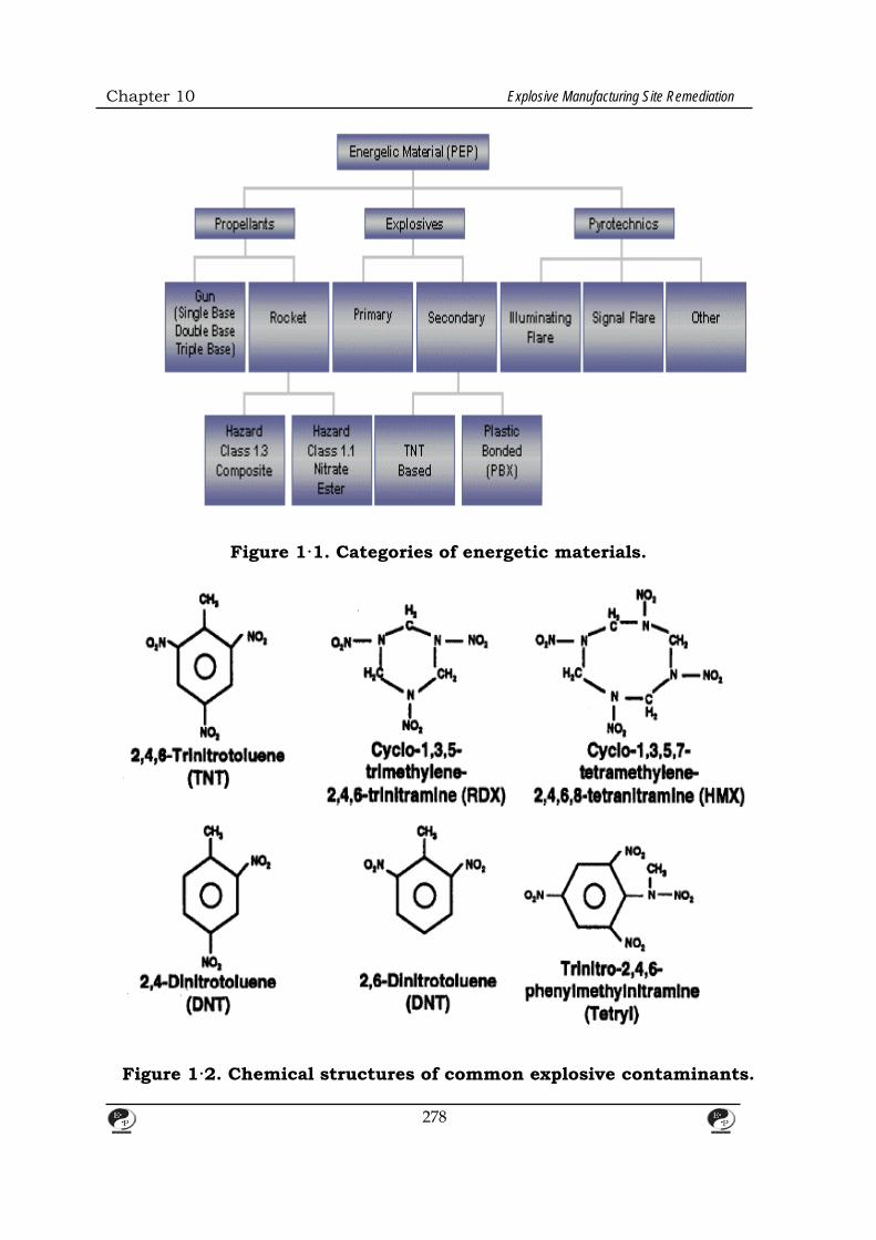
Chapter 10 Explosive Manufacturing Site Remediation
Figure 1·1. Categories of energetic materials.
Figure 1·2. Chemical structures of common explosive contaminants.
278
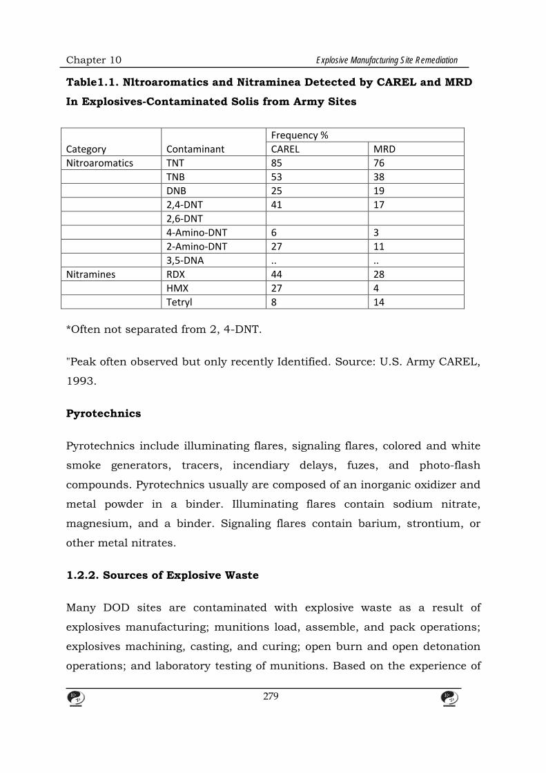
Chapter 10 Explosive Manufacturing Site Remediation
Table1.1. Nltroaromatics and Nitraminea Detected by CAREL and MRD
In Explosives-Contaminated Solis from Army Sites
Category Contaminant Frequency % CAREL MRD
Nitroaromatics TNT 85 76 TNB 53 38 DNB 25 19 2,4-DNT 41 17 2,6-DNT 4-Amino-DNT 6 3 2-Amino-DNT 27 11 3,5-DNA .. .. Nitramines RDX 44 28 HMX 27 4 Tetryl 8 14 *Often not separated from 2, 4-DNT.
"Peak often observed but only recently Identified. Source: U.S. Army CAREL,
1993.
Pyrotechnics
Pyrotechnics include illuminating flares, signaling flares, colored and white
smoke generators, tracers, incendiary delays, fuzes, and photo-flash
compounds. Pyrotechnics usually are composed of an inorganic oxidizer and
metal powder in a binder. Illuminating flares contain sodium nitrate,
magnesium, and a binder. Signaling flares contain barium, strontium, or
other metal nitrates.
1.2.2. Sources of Explosive Waste
Many DOD sites are contaminated with explosive waste as a result of
explosives manufacturing; munitions load, assemble, and pack operations;
explosives machining, casting, and curing; open burn and open detonation
operations; and laboratory testing of munitions. Based on the experience of
279
Chapter 10 Explosive Manufacturing Site Remediation
the U.S. Army Environmental Center (AEC) of DOD, one of the major
explosive wastes of concern at DOD sites are residues from land disposal of
explosives-contaminated process water.
Explosives-contaminated waters are subdivided into two categories: red
water, which comes strictly from the manufacture of TNT; and pink water,
which includes any wash water associated with load, assemble, and pack
operations or with the demilitarization of munitions involving contact with
finished TNT. Despite their names, red and pink water cannot be identified
by color. Both are clear when they emerge from their respective processes
and subsequently turn pink, light red, dark red, or black when exposed to
light. The chemical composition of pink water varies depending on the
process from which it is derived; red water has a more-defined chemical
composition. For this reason, it is difficult to simulate either red or pink
water in the laboratory.
The United States stopped production of TNT in the mid-1980s, so no red
water has been generated in this country since that Date (Hercules
Aerospace Company, 1991).
Most process waters found in the field are pink waters that were generated
by demilitarization operations conducted in the 1970s.ln these operations,
munitions were placed on racks with their fuzes and tops removed. Jets of
hot water then were used to mine the explosives out of the munitions. The
residual waters were placed in settling basins so that solid explosive
particles could be removed, and the remaining water was siphoned into
lagoons. Contaminants often present in these lagoon waters and the
surrounding soils include TNT; RDX; HMX; tetryl; 2,4-DNT; 2,6-DNT; 1,3-
DNB; 1, 3, 5-TNB; and nitrobenzene.
280
Chapter 10 Explosive Manufacturing Site Remediation
1.2.3 Radioactive Waste
Several radioactive elements, including uranium, radium, and radon, occur
naturally in soil and ground water. Radioactive contamination also can
result from processes associated with the production of nuclear energy and
nuclear weapons. Common radioactive-contaminated materials include dry
active wastes, such as paper, plastic, wood, cloth, rubber, canvas,
fiberglass, and charcoal; ion exchange resins used to polish condensate from
nuclear power plants; sewer sludges and lubricating oils contaminated with
radioactive materials; and air pollution control equipment. For the purposes
of this document radionuclides should be considered to have properties
similar to those of other heavy metals.
The Nuclear Weapons Complex (NWC) is a collection of enormous factories
devoted to metal fabrication, chemical separation processes, and electronic
assembly associated with the production of nuclear weapons. In
approximately 50 years of nuclear weapons production, these factories have
released vast quantities of hazardous chemicals and radionuclides to the
environment. Evidence exists that air, ground water, surface water,
sediment, and soil, as well as vegetation and wildlife, have been
contaminated at most, if not all, nuclear weapons production facilities. Table
1-2 shows the types of wastes often found at NWC sites.
Contamination of soil, sediments, surface water, and ground water is
widespread at the NWC, and contamination of ground water with radio
nuclides or hazardous chemicals has been confirmed at almost every facility.
Most sites in nonarid locations have surface water contamination as well.
Almost 4,000 solid waste management units (SWMUs) have been identified
throughout the NWC, and many of these units require some form of
remedial action. Substantial quantities of waste have been buried at the
NWC, often with inadequate records of the burial location or composition of
the waste buried. DOE estimates that a total of about 0.2 million m of
281
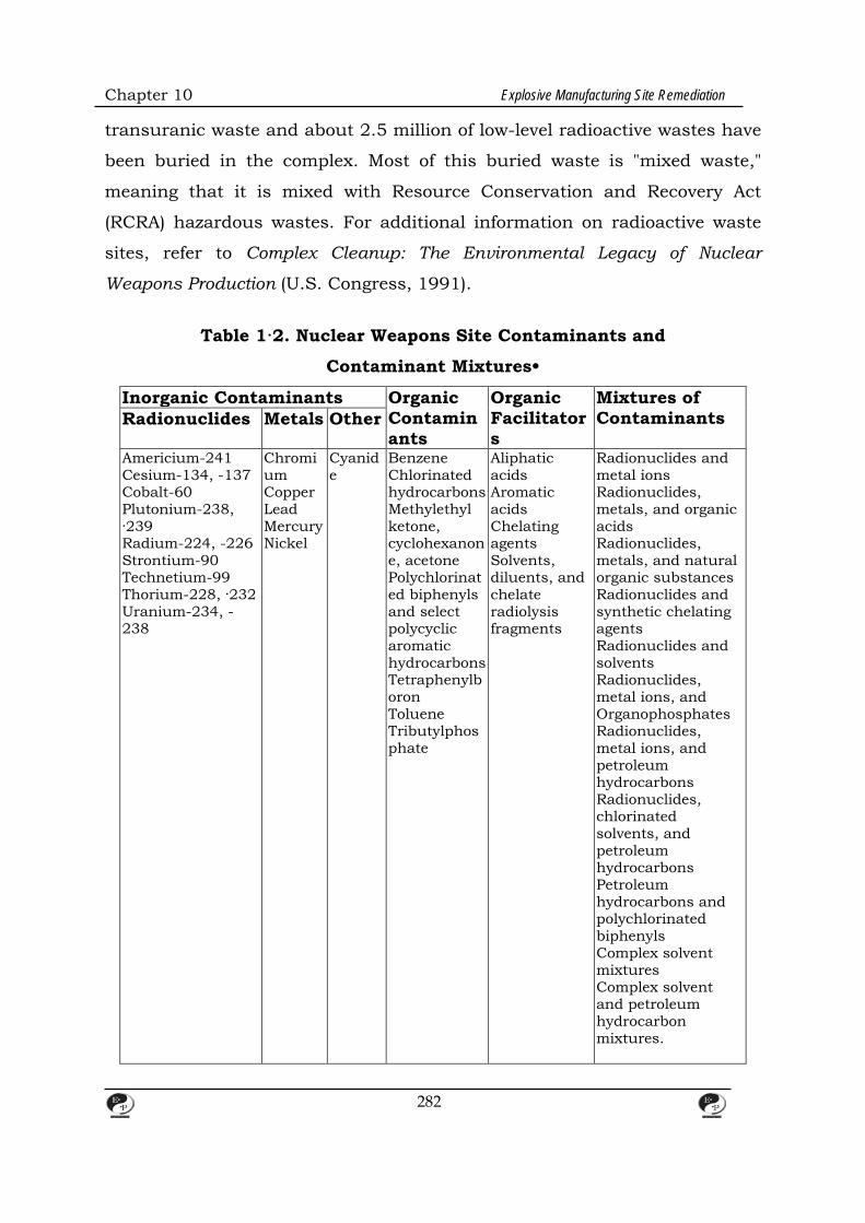
Chapter 10 Explosive Manufacturing Site Remediation
transuranic waste and about 2.5 million of low-level radioactive wastes have
been buried in the complex. Most of this buried waste is "mixed waste,"
meaning that it is mixed with Resource Conservation and Recovery Act
(RCRA) hazardous wastes. For additional information on radioactive waste
sites, refer to Complex Cleanup: The Environmental Legacy of Nuclear
Weapons Production (U.S. Congress, 1991).
Table 1·2. Nuclear Weapons Site Contaminants and
Contaminant Mixtures•
Inorganic Contaminants Organic Contaminants
Organic Facilitators
Mixtures of Contaminants Radionuclides Metals Other
Americium-241 Cesium-134, -137 Cobalt-60 Plutonium-238, ·239 Radium-224, -226 Strontium-90 Technetium-99 Thorium-228, ·232 Uranium-234, -238
Chromium Copper Lead Mercury Nickel
Cyanide
Benzene Chlorinated hydrocarbons Methylethyl ketone, cyclohexanone, acetone Polychlorinated biphenyls and select polycyclic aromatic hydrocarbons Tetraphenylboron Toluene Tributylphosphate
Aliphatic acids Aromatic acids Chelating agents Solvents, diluents, and chelate radiolysis fragments
Radionuclides and metal ions Radionuclides, metals, and organic acids Radionuclides, metals, and natural organic substances Radionuclides and synthetic chelating agents Radionuclides and solvents Radionuclides, metal ions, and Organophosphates Radionuclides, metal ions, and petroleum hydrocarbons Radionuclides, chlorinated solvents, and petroleum hydrocarbons Petroleum hydrocarbons and polychlorinated biphenyls Complex solvent mixtures Complex solvent and petroleum hydrocarbon mixtures.
282

CHAPTER – 11
TREATMENT TECHNOLOGIES FOR EXPLOSIVES WASTE
1. Biological Treatment Technologies
1.1 Background
Biological treatment, or bioremediation, is a developing technology that uses
microorganisms to degrade organic contaminants into less hazardous
compounds. Compared to conventional technologies, bioremediation has
several advantages: (1) it actually degrades target compounds, rather than
just transferring them from one medium to another; (2) it is publicly
accepted, because it is a natural process; and (3) it is probably less
expensive than incineration, especially for small volumes of contaminated
soil.
Although the two terms occasionally are interchanged, biodegradation is not
synonymous with mineralization. Mineralization, which is the process ·by
which compounds are transformed into carbon dioxide and water, is only
one of several fates of contaminants in biological treatment systems.
Contaminants also may be volatilized, bind to organic materials, be
assimilated into an active biomass, or be transformed into compounds other
than carbon dioxide and water. Mineralization of contaminants is a desired,
but rarely achieved, outcome of bioremediation. This section discusses the
types of explosives that can be bioremediated and highlights five specific
biological treatment technologies: aqueous-phase bioreactor treatment,
composting, land farming, white rot fungus treatment, and in situ biological
treatment.
1.2 Treatable Wastes and Media
Bioremediation is most effective for dilute solutions of explosives and
propellants. TNT in the ctystalline form is difficult to treat biologically.
283

Chapter 11 Treatment Technologies for Explosives Wastes
TNT degrades under aerobic conditions into monoamine-, diamino-, and
hydroxylamino-DNT, and tetranitro-azoxynitrotoluenes. RDX and HMX
degrade into carbon dioxide and water under anaerobic conditions.
Researchers have not identified any specific organisms that are particularly
effective for degrading explosives waste; a consortium of organisms usually
effects the degradation
1.3 Operation and Maintenance
DOD currently is developing or implementing five biological treatments for
explosives-contaminated soils: aqueous-phase bioreactor treatment;
composting, land farming, and white rot fungus treatment, which are solid-
phase treatments; and in situ biological treatment.
1.3.1 Aqueous-Phase Bioreactor Treatment
DOD is considering two types of aqueous-phase bioreactors for the
treatment of explosive contaminants. The first is the lagoon slurry reactor,
which allows contaminants to remain in a lagoon, be mixed with nutrients
and water, and degrade under anaerobic conditions. Figure 1 is a schematic
of a lagoon slurry reactor. The second is the aboveground slurry reactor,
which is either a concrete activated sludge basin or a commercially available
bioreactor. Figure 2 is a schematic of aboveground bioreactor treatment,
showing the excavation and screening of soils prior to treatment, dewatering
of the treated soil, and recycling of the extracted water to the reactor.
Aqueous-phase bioreactors provide good process control, can be configured
in several treatment trains to treat a variety of wastes, and potentially can
achieve very low contaminant concentrations. A drawback of bioreactor
treatment is that, unlike composting systems which bind contaminants to
humic material, bioreactors accumulate the products of biotransformation.
In addition, bioreactors have been shown to remediate explosives only at
284
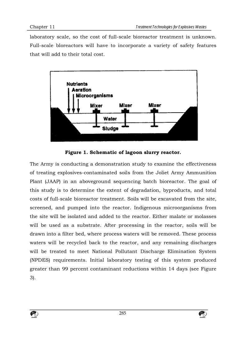
Chapter 11 Treatment Technologies for Explosives Wastes
laboratory scale, so the cost of full-scale bioreactor treatment is unknown.
Full-scale bloreactors will have to incorporate a variety of safety features
that will add to their total cost.
Figure 1. Schematic of lagoon slurry reactor.
The Army is conducting a demonstration study to examine the effectiveness
of treating explosives-contaminated soils from the Joliet Army Ammunition
Plant (JAAP) in an aboveground sequencing batch bioreactor. The goal of
this study is to determine the extent of degradation, byproducts, and total
costs of full-scale bioreactor treatment. Soils will be excavated from the site,
screened, and pumped into the reactor. Indigenous microorganisms from
the site will be isolated and added to the reactor. Either malate or molasses
will be used as a substrate. After processing in the reactor, soils will be
drawn into a filter bed, where process waters will be removed. These process
waters will be recycled back to the reactor, and any remaining discharges
will be treated to meet National Pollutant Discharge Elimination System
(NPDES) requirements. Initial laboratory testing of this system produced
greater than 99 percent contaminant reductions within 14 days (see Figure
3).
285
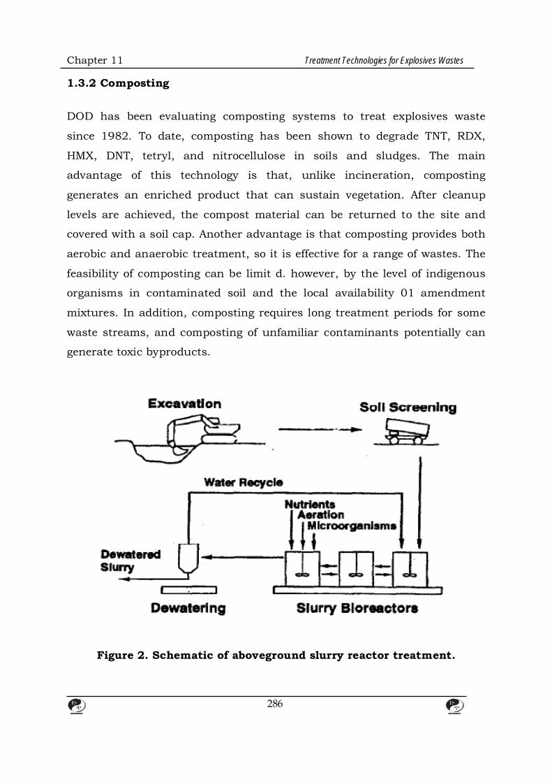
Chapter 11 Treatment Technologies for Explosives Wastes
1.3.2 Composting DOD has been evaluating composting systems to treat explosives waste
since 1982. To date, composting has been shown to degrade TNT, RDX,
HMX, DNT, tetryl, and nitrocellulose in soils and sludges. The main
advantage of this technology is that, unlike incineration, composting
generates an enriched product that can sustain vegetation. After cleanup
levels are achieved, the compost material can be returned to the site and
covered with a soil cap. Another advantage is that composting provides both
aerobic and anaerobic treatment, so it is effective for a range of wastes. The
feasibility of composting can be limit d. however, by the level of indigenous
organisms in contaminated soil and the local availability 01 amendment
mixtures. In addition, composting requires long treatment periods for some
waste streams, and composting of unfamiliar contaminants potentially can
generate toxic byproducts.
Figure 2. Schematic of aboveground slurry reactor treatment.
286

Chapter 11 Treatment Technologies for Explosives Wastes
Composting methods fall into four categories: (1) static-pile composting; (2)
in-vessel, static-pile composting; (3) mechanically agitated, in-vessel
composting; and (4) windrow composting. In static-pile composting,
contaminated material is excavated, placed in a pile under a protective
shelter, and mixed with readily degradable carbon sources. The pile
undergoes forced aeration to maintain aerobic and thermophilic (55 to 60°C)
conditions, which foster the growth of microorganisms. Bulking agents, such
as cow manure and vegetable waste, can be added to enhance
biodegradation. Figure 4 is a schematic of static-pile composting. In-vessel,
static-pile composting is similar to static-pile composting except the
compost pile is placed in a vessel. Figure 5 is a schematic of an in-vessel,
static-pile composting device. In mechanically agitated, in-vessel
composting, contaminated material is aerated and blended with carbon-
source materials in a mechanical composter. These devices have been used
at municipal sewage treatment facilities and applied to explosives waste.
Figure 6 is a schematic of a mechanical composter. Windrow composting is
similar to static-pile composting except that compost is aerated by a
mechanical rnixil1g vehicle, rather than a forced air system.
In 1988, the Army began a series of demonstration studies at the Louisiana
Army Ammunition Plant to determine the effectiveness of composting
explosives-contaminated soils. In the initial study, static-pile composting
required
153 days to remediate soils contaminated with just 3 percent explosive
waste by volume. Based on these results, the Army determined that static-
pile composting would not be cost effective for remediating large volumes of
explosives waste.
287
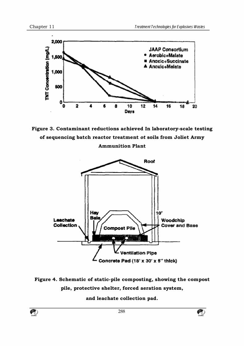
Chapter 11 Treatment Technologies for Explosives Wastes
Figure 3. Contaminant reductions achieved In laboratory-scale testing
of sequencing batch reactor treatment ot soils from Joliet Army
Ammunition Plant
Figure 4. Schematic of static-pile composting, showing the compost
pile, protective shelter, forced aeration system,
and leachate collection pad.
288
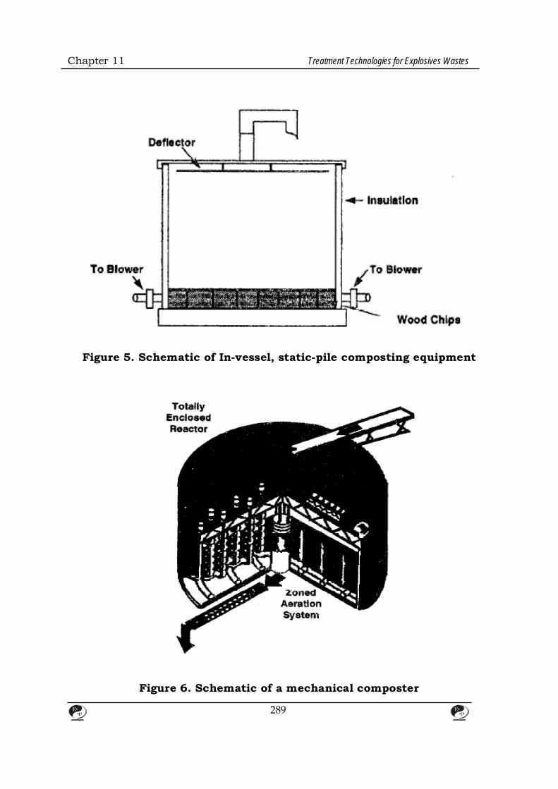
Chapter 11 Treatment Technologies for Explosives Wastes
Figure 5. Schematic of In-vessel, static-pile composting equipment
Figure 6. Schematic of a mechanical composter
289
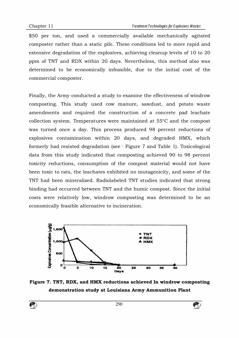
Chapter 11 Treatment Technologies for Explosives Wastes
$50 per ton, and used a commercially available mechanically agitated
composter rather than a static pile. These conditions led to more rapid and
extensive degradation of the explosives, achieving cleanup levels of 10 to 20
ppm of TNT and RDX within 20 days. Nevertheless, this method also was
determined to be economically infeasible, due to the initial cost of the
commercial composter.
Finally, the Army conducted a study to examine the effectiveness of windrow
composting. This study used cow manure, sawdust, and potato waste
amendments and required the construction of a concrete pad leachate
collection system. Temperatures were maintained at 55°C and the compost
was turned once a day. This process produced 98 percent reductions of
explosives contamination within 20 days, and degraded HMX, which
formerly had resisted degradation (see · Figure 7 and Table 1). Toxicological
data from this study indicated that composting achieved 90 to 98 percent
toxicity reductions, consumption of the compost material would not have
been toxic to rats, the leachates exhibited no mutagenicity, and some of the
TNT had been mineralized. Radiolabeled TNT studies indicated that strong
binding had occurred between TNT and the humic compost. Since the initial
costs were relatively low, windrow composting was determined to be an
economically feasible alternative to incineration.
Figure 7. TNT, RDX, and HMX reductions achieved In windrow composting
demonstration study at Louisiana Army Ammunition Plant
290
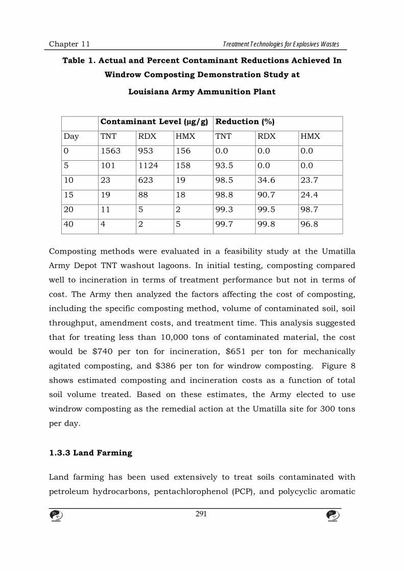
Chapter 11 Treatment Technologies for Explosives Wastes
Table 1. Actual and Percent Contaminant Reductions Achieved In
Windrow Composting Demonstration Study at
Louisiana Army Ammunition Plant
Contaminant Level (µg/g) Reduction (%)
Day TNT RDX HMX TNT RDX HMX
0 1563 953 156 0.0 0.0 0.0
5 101 1124 158 93.5 0.0 0.0
10 23 623 19 98.5 34.6 23.7
15 19 88 18 98.8 90.7 24.4
20 11 5 2 99.3 99.5 98.7
40 4 2 5 99.7 99.8 96.8
Composting methods were evaluated in a feasibility study at the Umatilla
Army Depot TNT washout lagoons. In initial testing, composting compared
well to incineration in terms of treatment performance but not in terms of
cost. The Army then analyzed the factors affecting the cost of composting,
including the specific composting method, volume of contaminated soil, soil
throughput, amendment costs, and treatment time. This analysis suggested
that for treating less than 10,000 tons of contaminated material, the cost
would be $740 per ton for incineration, $651 per ton for mechanically
agitated composting, and $386 per ton for windrow composting. Figure 8
shows estimated composting and incineration costs as a function of total
soil volume treated. Based on these estimates, the Army elected to use
windrow composting as the remedial action at the Umatilla site for 300 tons
per day.
1.3.3 Land Farming Land farming has been used extensively to treat soils contaminated with
petroleum hydrocarbons, pentachlorophenol (PCP), and polycyclic aromatic
291
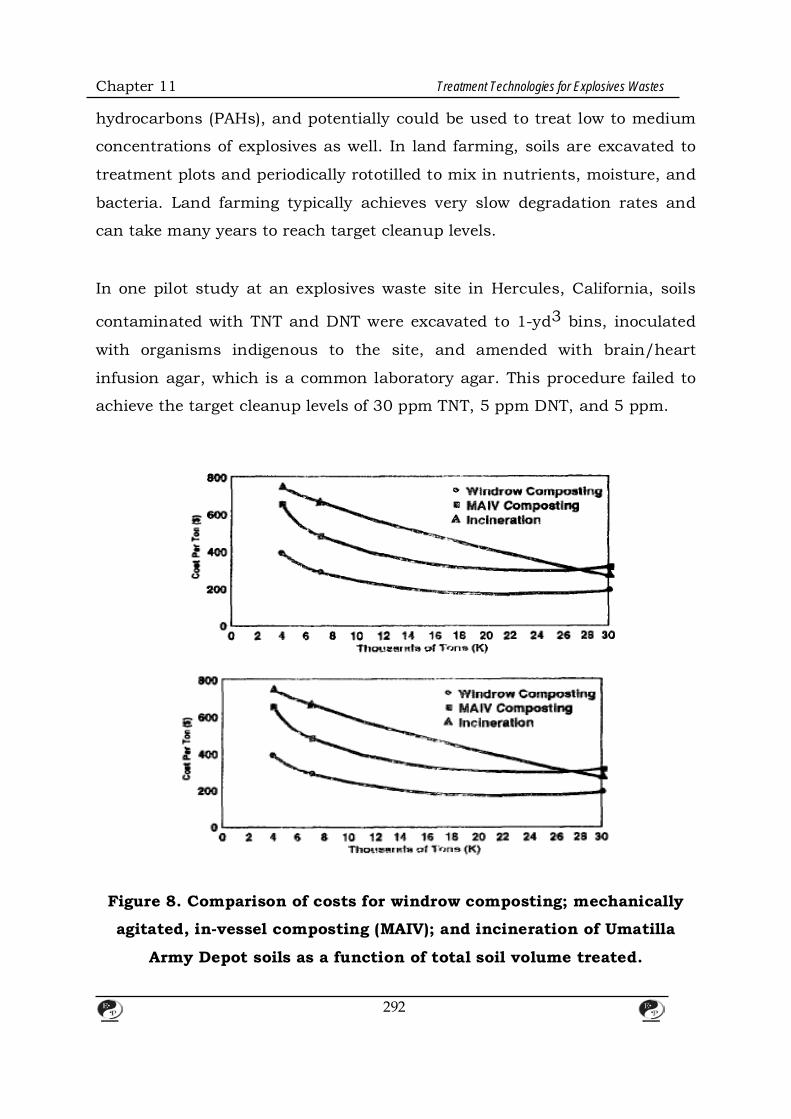
Chapter 11 Treatment Technologies for Explosives Wastes
hydrocarbons (PAHs), and potentially could be used to treat low to medium
concentrations of explosives as well. In land farming, soils are excavated to
treatment plots and periodically rototilled to mix in nutrients, moisture, and
bacteria. Land farming typically achieves very slow degradation rates and
can take many years to reach target cleanup levels.
In one pilot study at an explosives waste site in Hercules, California, soils
contaminated with TNT and DNT were excavated to 1-yd3 bins, inoculated
with organisms indigenous to the site, and amended with brain/heart
infusion agar, which is a common laboratory agar. This procedure failed to
achieve the target cleanup levels of 30 ppm TNT, 5 ppm DNT, and 5 ppm.
Figure 8. Comparison of costs for windrow composting; mechanically
agitated, in-vessel composting (MAIV); and incineration of Umatilla
Army Depot soils as a function of total soil volume treated.
292

Chapter 11 Treatment Technologies for Explosives Wastes
DNB, achieving instead a 30 to 40 percent contaminant degradation. 1.3.4 White Rot Fungus Treatment White rot fungus has been evaluated more extensively than any other fungal
species for remediating explosives waste. Although white rot fungus
degradation of TNT has been reported in laboratory-scale settings using pure
cultures (Berry and Boyd, 1985; Fernando et al. 1990), a number of factors
increase the difficulty of using this technology for full-scale remediation.
These factors include competition from native bacterial populations, toxicity
inhibition, chemical sorption, and the inability to meet risk-based cleanup
levels.
In bench-scale studies of mixed fungal and bacterial systems, most of the
reported degradation of TNT is attributable to native bacterial populations
(Lohr, 1993; McFarland et al., 1992).High TNT concentrations in soil also
can inhibit growth of white rot fungus. One study suggested that
Phanerochaete chrysosporium was incapable of growing in soils
contaminated with 20 ppm or more of TNT. In addition, some reports
indicate that TNT losses reported in white rot fungus studies can be
attributed to adsorption of TNT onto the fungus and soil amendments, such
as corn cobs and straw (Spiker et al., 1992).
A pilot-scale treatability study was conducted using white rot fungus at a
former ordnance open burn/open detonation area at Site D, Naval
Submarine Base, Bangor, Washington. Initial TNT concentrations of 1,844
ppm were degraded to 1,267 ppm in 30 days and 1,087 in 120 days. The
overall degradation was 41 percent, and final TNT soil levels were well above
the proposed cleanup level of 30 ppm (Spectrum Sciences & Software, Inc.,
and Utah State University, no date).
293

Chapter 11 Treatment Technologies for Explosives Wastes
1.3.5 In Situ Biological Treatment In situ treatments can be less expensive than other technologies and
produce low contaminant concentrations. The available data suggest,
however, that in situ treatment may not be effective for explosives waste. In
situ treatment of explosives might create more mobile intermediates during
biodegradation. In addition, biodegradation of explosive contaminants
typically involves cometabolism with another nutrient source, which is
difficult to deliver in an in situ environment. Mixing often affects the rate
and performance of explosives degradation. Finally, because in situ
remediation takes place beneath the surface, the effectiveness of in situ
treatment is difficult to verify both during and after treatment.
1.4 References Berry, D.F. and S.A. Boyd. 1985. Decontamination of soil through
enhanced formation of bound residues. Environmental Science and
Technology 19:1132-1133.
Fernando, T., J.A. Bumpus, and S.D. Aust. 1990. Biodegradation of
TNT (2,4,6-trinitrotoluene) by Phanerochaete chrysosporium. Applied
Environmental Microbiology 56:1667-1671.
Lohr, J.T. 1993. Bioremediation of TNT and RDX using white rot fungus
Phanerochaete chrysosporium. Utah State University. Prepared for
Naval Civil Engineering Laboratory, Port Hueneme, California. Contract
No. DML-03-86-D-0001.
McFarland, M.J., S. Kalaskar, and E. Baiden. 1992. Composting of
explosives-contaminated soil using the white rot fungus Phanerochaete
chrysosporium. Utah State University. Prepared for the U.S. Army
Research Office, Research Triangle Park, North Carolina. Contract No.
294
Chapter 11 Treatment Technologies for Explosives Wastes
DAAL-03-91-C-0034.
Spectrum Sciences & Software, Inc., and Utah State University. No
date. White rot remediation of ordnance-contaminated media. Prepared
for Naval Civil Engineering Laboratory, Port Hueneme, California.
Contract No. F49650-90-D5001/DO 5013.
Spiker, J.K., D.L. Crawford, and R.L. Crawford. 1992. Influence of
2,4,6-trinitrotoluene (TNT) concentration on ttle degradation of TNT in
explosive-contaminated soils by the white rot fungus Phanerochaete
c/uysosporium. Applied Environmental Microbiology 58:3199-3202.
2. Thermal Treatment Technologies
2.1 Incineration of Soils and Sludges
2.1.1 Background
AEC of DOD at Aberdeen Proving Ground, Maryland, oversees large-scale
incineration of munitions, explosives waste, and explosives-contaminated
soils as part of remedial actions at Army sites. This section discusses the
types of wastes and media that can be incinerated, looks at various devices
used to incinerate explosives waste, presents case studies of four sites
where incineration has been applied to explosives-contaminated soils, and
examines the advantages and disadvantages of incineration.
2.1.2 Treatable Wastes and Media Incineration processes can be used to treat the following waste streams:
explosives-contaminated soil and debris, explosives with other organics or
metals, initiating explosives, bulk explosives, unexploded ordnance, bulky
radioactive waste, and pyrophoric waste. In addition, incineration can be
applied to sites with a mixture of media, such as concrete, sand, clay,
295
Chapter 11 Treatment Technologies for Explosives Wastes
water, and sludge, provided the media can be fed to the incinerator and
heated for a sufficient period of time. With the approval of the DOD
Explosives Safety Board, the Army considers incineration of materials
containing less than 10 percent explosives by weight to be a non explosive
operation. Soil with less than 10 percent explosives by weight has been
shown by AEC to be nonreactive, that is, not to propagate a detonation
throughout the mass of soil. (The military explosives to which this limit
applies are secondary explosives such as TNT and RDX, and their
manufacturing byproducts.)
The Army's first pilot-scale use of rotary kiln incineration utilized soil well
above the 10 percent limit (up to 40 percent) with approval from the DOD
Explosives Safety Board. A consideration in conducting the test was the fact
th8t the kiln was not actually sealed and hence not thought to provide
confinement for the small amount of explosives fed. Another consideration
was a previous successful Army incineration of pure TNT without detonation
in a deactivation furnace. Though the pilot-scale test experienced no
detonation problems, the Army's full-scale incineration projects have
incorporated a blending step to reduce the explosives concentrations below
the 10 percent limit prior to feeding. The blending step is considered to be
an explosives operation that requires the preparation and approval by the
Army and DOD safety offices of a site plan/safety submission, which must
include an explosives hazard analysis. Finally, even at explosives
concentrations below 10 percent, each explosives project has unique
elements, and a thorough safety review is a necessity.
The Army also has developed and tested a feed system capable of feeding
reactive levels of explosives (up to 20 percent). The system includes multiple
units with breaks in between to prevent propagation of a possible detonation
throughout the system. Metal-to-metal contact also is minimized in the
system to reduce the chances of detonation by friction or spark.
296
Chapter 11 Treatment Technologies for Explosives Wastes
2.1.3 Operation and Maintenance The Army primarily uses three types of incineration devices: the rotary kiln
incinerator, deactivation furnace, and contaminated waste processor.
Rotary Kiln Incinerator The rotary kiln incinerator is used primarily to treat explosives-
contaminated soils. In rotary kiln incineration, soils are fed into a
primary combustion chamber, or rotary kiln, where organic constituents are
destroyed. The temperature of gases in the primary chamber ranges from
800 to 1,200°F, and the temperature of soils ranges from 600 to 800°F.
Retention time in the primary chamber, which is varied by changing the
rotation speed of the kiln, is approximately 30 minutes. Off gases from the
primary chamber pass into a secondary combustion chamber, which
destroys any residual organics. Gases from the secondary combustion
chamber pass into a quench tank where they are cooled from approximately
2,000°C to 200°C. From the quench tank, gases pass through a Venturi
scrubber and a series of baghouse filters, which remove acid gases and
particulates prior to release from the stack. The treated product of rotary
kiln incineration is ash (or treated soil), which drops from the primary
combustion chamber after organic contaminants have been destroyed. This
product is routed into a wet quench or a water spray to remoisturize it, then
transported to an interim storage area pending receipt of chemical analytical
results.
Deactivation Furnace The deactivation furnace also is referred to as Army Peculiar Equipment
(APE) 1236, because it is used almost exclusively by the Army to deactivate
large quantities of small arms cartridges, so-caliber machine gun
ammunition, mines, and grenades. The deactivation furnace is similar to
297
Chapter 11 Treatment Technologies for Explosives Wastes
the rotary kiln Incinerator, except that it is equipped with a thick-walled
primary combustion chamber capable of withstanding small detonations.
Deactivation furnaces do not have secondary combustion chambers,
because they are intended not to completely destroy the vaporized explosives
but to render the munitions unreactive. Most deactivation furnaces are
equipped with air pollution control equipment to limit lead emissions. The
operating temperature of deactivation furnaces is approximately 1,200 to
1,500°F.
Contaminated Waste Processor The contaminated waste processor handles materials, such as surface-
contaminated debris, that are lighter and less reactive than those processed
in the deactivation furnace. Contaminated waste processors are thin-walled,
stationary ovens that heat contaminated materials to about 600°C for 3 to 4
hours. The purpose of this process is not to destroy contaminated debris but
to lower contaminant levels to meet Army safety standards. AEC currently is
helping to develop standardized time and temperature processing
requirements to meet these safety standards.
2.1.4 Case Studies
Cornhusker Army Ammunition Plant
The Cornhusker Army Ammunition Plant (CAAP) in Grand Island, Nebras {a,
was the site of 58 explosives wastewater washout cesspools and leaching
pits. Explosives residues from these 1O-ft deep pits created a contaminated
ground water plume that extended into nearby residential areas. To prevent
further ground water contamination, the Army opted to incinerate
contaminated soils and sludges from the cesspools and leaching pits. For
each contaminant, the Army established two cleanup criteria: (1) an
excavation criterion, which was health risk based and determined the depth
298

Chapter 11 Treatment Technologies for Explosives Wastes
to which soils were excavated, and (2) an incineration criterion, which
equaled the nondetection level for each contaminant. Table 2 shows the
cleanup criteria for contaminants from the CAAP site.
Figure 9 is a schematic of the rotary kiln incineration system employed at
the CMP site. A three-stage feed system with a live bottom hopper, belt
conveyor, and gravity tube was used to feed contaminated material to the
incinerator. Ash from the incinerator was loaded into ash bins and subjected
to compositional analysis. Once the ash was determined to be clean (i.e., to
contain no detectable explosives), it was backfilled at a single location on the
CMP site. The CAAP project was completed successfully in 1988, after
incinerating 40,000 tons at an average total cost of $260 per ton. Some of
the difficulties encountered included (1) clogging of the quench tank by slag
that fell from the walls of the secondary combustion chamber, (2) unwanted
air infiltration through the air lock in the feed system, and (3) the need to
winterize the unit for cold weather operations.
Louisiana Army Ammunition Plant Over the years, wastewaters from ammunition load, assemble, and pacl'
operations at the Louisiana Army Ammunition Plant (LAAP) in Shreveport,
Louisiana, were shipped by true to 16 leaching/evaporation lagoons at ArP.a
P in south ·central LAAP. Explosives residues from these lagoons leached
into the underlying ground water, creating plumes of TNT and RDX. As at
the CAAP site, the Army opted to incinerate soils and sludges from the LAAP
lagoons and set the incineration cleanup criterion equal to the non detection
limit for each contaminant. Rather than assign each contaminant a specific
excavation criterion, the Army specified that the concentrations of all
contaminants total less than 100 ppm after 1 foot of lagoon material had
been excavated. Table 3 shows the cleanup criteria for the LAAP lagoons.
299
Chapter 11 Treatment Technologies for Explosives Wastes
The incineration system used at CAAP was transported to LAAP with a
significant modification to the quench to allow workers to clean it without
entering the tank. While operating at LAAP, some other modifications were
made to correct the following difficulties: (1} clayey wet feed soil plugged and
jammed the feed system and (2) buildup of soil on the secondary
combustion chamber fell into the quench tank causing a steam
overpressure. To remedy the first problem, the feed system was
strengthened and a high-speed slinger belt conveyor was used as the final
stage to throw the soil into the incinerator. To remedy the second problem,
which may have been aggravated by the lime used to dry the feed, the
quench was relocated in an offset position from the secondary combustion
chamber. The project was completed successfully in 1990 after incinerating
102,000 tons of soil at an average total cost $330 per ton.
Table 2. Cleanup Criteria for Cornhusker Army Ammunition Plant
Analyte Excavation
Criteria (ppm)
Incineration Criteria
{Method Detection
Limits [ppm])
RDX <10 <2.2
2,4,6 –TNT <5 <1.3
1,3,5 –TNB <0.5 <1.25
2,4-DNT <0.4 <0.24
2,6-DNT NA <126
HMX NA <2.9
1,3-DNB NA <1.2
NB NA <1.26
Tetryl NA <2.2
2A,4,6-DNT NA <1.25
300
Chapter 11 Treatment Technologies for Explosives Wastes
Figure 9. Schematic of rotary kiln Incineration system employed at
Cornhusker Army Ammunition Plant
Savanna Army Depot The Savanna Army Depot (SVAD) in Savanna, Illinois, formerly operated a
washout plant where hot water was used to melt the explosives out of
munitions. Wastewaters from these operations were pumped directly from
the facility through a metal trough into washout lagoons. Recently, SVAD
began piping wastewaters into two new washout lagoons on a sandy hill
near the facility. Both the old and new lagoons are contributing explosives
contamination to ground water beneath the site. The old lagoons are located
in a flood plain of the Mississippi River, which runs about 12 milewest of the
site. Periodically, the river floods the lagoons, spreading explosives
contamination from the centers of the lagoons.
The entire site was screened for unexploded ordnance prior to the start of
incineration operations. The Army then established health risk based
excavation criteria and non detection limit incineration criteria for the soils
301

Chapter 11 Treatment Technologies for Explosives Wastes
at the site (see Table 4). To reach the excavation criteria, some lagoons had
to be excavated to a depth of 10 ft and excavation had to be done outside of
the lagoons, apparently due to the periodic flooding by the Mississippi River.
As a safety precaution, excavated soils were blended to reduce overall
explosives levels to less than 10 percent by weight. Incineration currently is
under way. Some problems have arisen with the feed system clogging due to
the cold, wet conditions at the site, but incineration is expected to be
completed in fall of 1993. The estimated quantity of soil to be incinerated is
approximately 60,000 tons.
Table 3. Cleanup Criteria for Louisiana Army Ammunition Plant
Analyte Excavation Criteria
(ppm)
Incineration Criteria
(Method Detection
Limits.[ppm])
RDX Sum of all less than
100 ppm after 1 foot
excavation of lagoons
<2.2
2,4,6 –TNT <1.3
1,3,5 –TNB <1.25
2,4-DNT <0.24
2,6-DNT <126
HMX <2.9
1,3-DNB <1.2
NB <1.26
Tetryl <2.2
2A,4,6-DNT <1.25
Alabama Army Ammunition Plant In 1986, explosives- and lead-contaminated soils from the Alabama Army
302
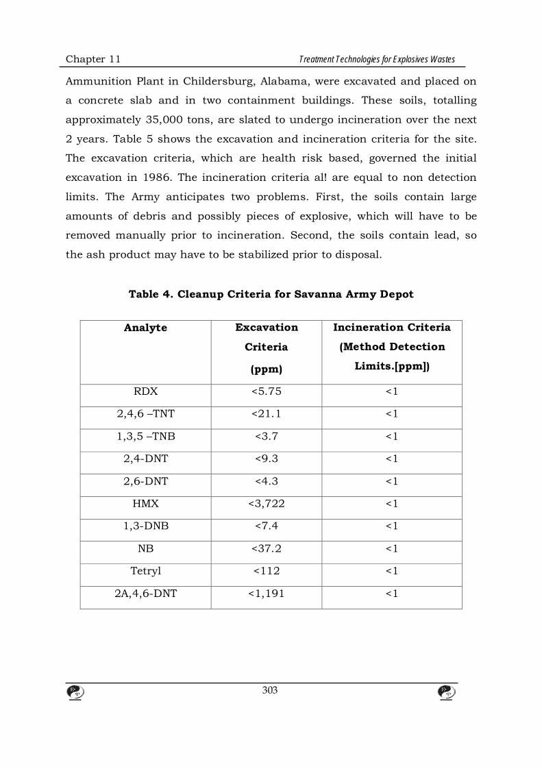
Chapter 11 Treatment Technologies for Explosives Wastes
Ammunition Plant in Childersburg, Alabama, were excavated and placed on
a concrete slab and in two containment buildings. These soils, totalling
approximately 35,000 tons, are slated to undergo incineration over the next
2 years. Table 5 shows the excavation and incineration criteria for the site.
The excavation criteria, which are health risk based, governed the initial
excavation in 1986. The incineration criteria al! are equal to non detection
limits. The Army anticipates two problems. First, the soils contain large
amounts of debris and possibly pieces of explosive, which will have to be
removed manually prior to incineration. Second, the soils contain lead, so
the ash product may have to be stabilized prior to disposal.
Table 4. Cleanup Criteria for Savanna Army Depot
Analyte Excavation
Criteria
(ppm)
Incineration Criteria
(Method Detection
Limits.[ppm])
RDX <5.75 <1
2,4,6 –TNT <21.1 <1
1,3,5 –TNB <3.7 <1
2,4-DNT <9.3 <1
2,6-DNT <4.3 <1
HMX <3,722 <1
1,3-DNB <7.4 <1
NB <37.2 <1
Tetryl <112 <1
2A,4,6-DNT <1,191 <1
303

Chapter 11 Treatment Technologies for Explosives Wastes
Table 5. Cleanup Criteria for Alabama Army Ammunition Plant
Analyte Excavation
Criteria
(ppm)
Incineration Criteria
(Method Detection
Limits.[ppm])
RDX None <1
2,4,6 –TNT <1.92 <1
1,3,5 –TNB <5.5 <1
2,4-DNT <0.42 <1
2,6-DNT <0.42 <1
HMX None <1
1,3-DNB <1.1 <1
NB None <1
Tetryl <1.7 <1
2A,4,6-DNT None <1
2.1.5 Advantages and Disadvantages Incineration has many advantages, including: • Effectiveness. With sufficiently long residence time and a sufficiently high
temperature, incineration usually reduces levels of organics to below
nondetection levels, which simplifies handling of treated soil and reduces
overall site cleanup levels.
• Demonstrated success. Incineration is a proven technology; the literature
on successful applications is extensive; many vendors offer incineration
services thereby driving down prices; and incineration equipment comes in
many sizes to fit the needs of any site.
304
Chapter 11 Treatment Technologies for Explosives Wastes
• Regulatory requirements. EPA's Land Disposal Restrictions (LDRs) specify
incineration as a best demonstrated available technology (BOAT) for many
types of wastes, meaning that these wastes must be incinerated prior to
land disposal. Also, incineration results were used to set concentration-
based BOAT standards for many contaminants and incineration probably
has the best chance of continuing to meet these standards.
Incineration of TNT also has many disadvantages, including: • Safety concerns. The foremost safety concern stems from exposing
explosive materials to open flame, but this can be addressed through
routine safety measures. Secondarily, hazards also are associated with
erecting and operating the incinerator, which is a large piece of industrial
equipment with moving parts and high temperature areas. For any
explosives operation, DOD must approve the incineration work plan and
may require a hazards analysis and site safety plan.
• Noise. The incinerator is driven by up to a 400 to 500 hp fan, which can
generate substantial noise. Residents neighboring the Savanna Army Depot
and the Louisiana Army Ammunition Plant have complained about the noise
from incineration activity at these sites.
• Air emissions. Emissions from the stack may contain nitrous oxides (NOx);
volatile metals, such as lead; and products of incomplete combustion (PICs).
Modeling may need to be conducted to predict the distribution of emissions.
• Capital costs. The capital mobilization and demobilization costs associated
with incineration typically range from $1 to $2 million. Over time, for a large
facility, incineration becomes more cost effective. Figure 10 shows the range
of estimated incineration costs as a function of site size.
305
Chapter 11 Treatment Technologies for Explosives Wastes
• Public perception. The public usually is wary of hazardous waste
incineration. There may be public concern that a mobile incinerator will be
established at a site and subsequently used to incinerate waste from other
sites. The public must be assured that, most often, mobile incinerators are
used only for single site cleanups and that incineration can be an effective
way to treat explosives waste.
• Required tests. Before an incinerator can be used to treat a large volume of
hazardous waste, it must pass a trial burn demonstrating that it can
achieve a 99. 99 percent organic destruction efficiency. If the soil at the site
does not contain enough contamination to demonstrate the 99.99 percent
destruction and removal efficiency, explosives might have to be shipped to
the site to spike the feed soil for the trial bum.
• Ash product. Incineration of combustible materials produces a volume
reduction, which can lead to higher concentrations of inorganic
contaminants in the ash product and create leachability problems.
Incineration of most contaminated soils produces only modest volume
reductions, so inorganics are not significantly concentrated in the treated
soil.
306
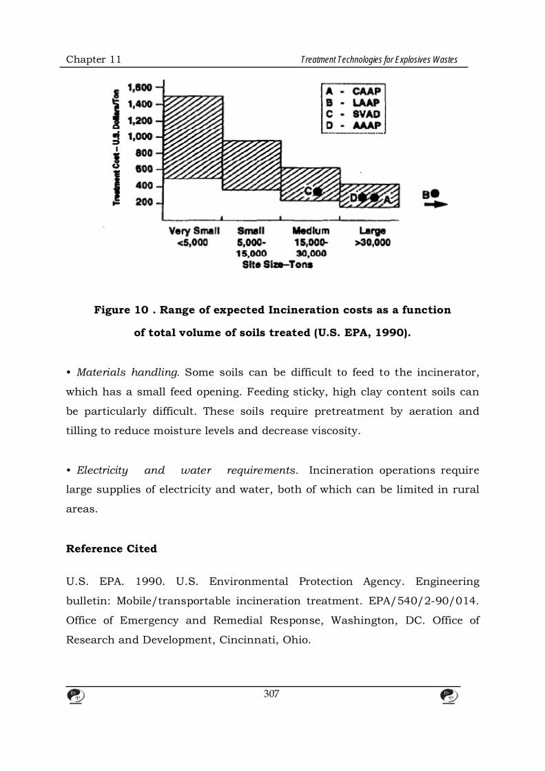
Chapter 11 Treatment Technologies for Explosives Wastes
Figure 10 . Range of expected Incineration costs as a function
of total volume of soils treated (U.S. EPA, 1990).
• Materials handling. Some soils can be difficult to feed to the incinerator,
which has a small feed opening. Feeding sticky, high clay content soils can
be particularly difficult. These soils require pretreatment by aeration and
tilling to reduce moisture levels and decrease viscosity.
• Electricity and water requirements. Incineration operations require
large supplies of electricity and water, both of which can be limited in rural
areas.
Reference Cited U.S. EPA. 1990. U.S. Environmental Protection Agency. Engineering
bulletin: Mobile/transportable incineration treatment. EPA/540/2-90/014.
Office of Emergency and Remedial Response, Washington, DC. Office of
Research and Development, Cincinnati, Ohio.
307
Chapter 11 Treatment Technologies for Explosives Wastes
2.2 Open Burn/Open Detonation
2.2.1 Background
Open burn OB and open detonation (OD) operations are conducted by DOD
and some private companies to destroy unserviceable, unstable, or unusable
munitions and explosive materials. In 08 operations, explosives or
munitions are destroyed by self-sustained combustion, which is ignited by
an external source, such as flame, heat, or a detonation wave (that does not
result in a detonation). In OD operations, detonable explosives and
munitions are destroyed by a detonation, which is initiated by the
detonation of a disposal charge. This section discusses types of wastes and
media that can be destroyed in 08/0D operations, 0810D procedures
currently being used, safety precautions associated with 0B/0D operations,
and a method recently developed for quantifying the level of hazardous
emissions from 0810D operations.
2.2.2 Treatable Wastes and Media 0B10D operations can destroy many types of explosives, pyrotechnics, and
propellants. 0B areas must be able to withstand accidental detonation of
any or all explosives being destroyed, unless the responsible 08 technicians
used recognize that the characteristics of the materials involved are such
that orderly burning without detonation can be ensured. Personnel with this
type of knowledge must be consulted before any attempt is made at 0B
disposal, especially if primary explosives are present in any quantity.
2.2.3 Operation 0B and 0D can be initiated either by electric or burning ignition systems. In
general, electric systems are preferable, because they provide better control
over the timing of the initiation. In an electric system, electric current heats
308

Chapter 11 Treatment Technologies for Explosives Wastes
a bridge wire, which ignites a primary explosive or pyrotechnic, which, in
turn, ignites or detonates the material slated to be burned or detonated. If
necessary, safety fuzes, which consist of propellants wrapped in plastic
weather stripping, are used to initiate the burn or detonation.
The following design and procedural specifications for 08100 operations are
taken from paragraph 27-16d of the Army Materiel Command Explosives
Safety Manual (U.S. AMC, 1985) and paragraph 8-44 of Air Force Regulation
127-100 on explosives safety standards (U.S. Air Force, 1990). 08 of non
fragmenting explosives is conducted in burning trays, which are designed
without cracks or angular corners to prevent the buildup of explosive
residues. The depth of explosive material in a tray may not exceed 3 in., and
the net explosive weight of materials in a tray may not exceed 1,000 lb. The
distance between the trays for explosive devices is determined by hazards
analysis, but, in the absence of such analysis, trays are placed parallel to
one another and separated by at least 150 ft. These distances may vary for
08 of bare explosives or explosives-contaminated soils. When wet explosives
are being burned, trays may be lined with non explosive combustible
materials, such as scrap wood, to ensure complete combustion. An 08 tray
may not be inspected until 12 hours after the conclusion of the burn, and a
tray may not be reused until 24 hours after the conclusion of the burn or
until all ash and residues have been removed from the tray.
If there is a significant risk of fragmentation, OB operations are conducted
in open pits, which must be at least 4ft deep and have sloped sides to
prevent cave in. The length and width of the pit is determined by the
quantity of waste being burned. If necessary, non explosive combustible
materials and fuel may be added to ensure complete combustion of explosive
materials. As with burning trays, 08 pits may not be inspected until12
hours after the conclusion of the burn.
309
Chapter 11 Treatment Technologies for Explosives Wastes
Facilities engineered specifically for OD operations are rare in practice.
Consequently, almost all OD operations are conducted in pits that are at
least 4 ft deep and covered with 2 ft of soil to minimize the risks associated
with fragmentation. Detonating cords, which are plastic cords filled with
RDX, are used to initiate buried disposal charges. Explosive components are
arranged in the pits to be in close contact with the disposal charge.
To prevent partial or incomplete destruction, site personnel must ensure
that the disposal charge is sufficiently powerful to propagate a detonation
throughout the explosive material. High brisance explosives and shaped
charges, which cut through metal casings, are very effective at propagating
detonations. If a misfire occurs, personnel are required to wait at least 30
minutes before inspecting the point of initiation. The misfire may be
inspected by no more than two personnel, who must follow specific
operating procedures.
After each detonation, the surrounding area is searched for unexploded
materials. Lumps of explosive material and unfuzed munitions are returned
to the detonation pit; fuzed ordnance or munitions that may have damaged
internal components are detonated in place.
2.2.4 Safety Precautions During 0B operations, munitions may rupture and produce fragments that
travel relatively short distances and explosive materials may detonate. OD
operations always produce dangerous overpressures and various types of
fragments, depending on the type of explosives being detonated. DOD has
developed specific safety precautions for 0B/0D operations, designed to
expose the fewest individuals to the least degree of hazard for the shortest
period of time. These precautions include minimum setbacks from 0B/0D
sites, provisions for the layout of 08/00 sites, optimum weather conditions
310
Chapter 11 Treatment Technologies for Explosives Wastes
for conducting 0B/0D operations, and training requirements for 0B/0D
personnel.
Minimum Safety Distances
As a basic precaution, personnel are required to maintain a minimum
distance from the OB/OD operation. This distance depends on the type of
material being burned or detonated. The following minimum safety distances
are outlined in paragraph 8-44 of Air Force Regulation 127-100 on
explosives safety standards (U.S. Air Force, 1990). (Various Armed Services
manuals contain distances that provide varying degrees of safety for
exposure to the detonation.) For non fragmenting explosive material, the
minimum distance is either 1,250 ft or the explosive's actual maximum
debris and fragment throw range, if known. For fragment-producing
materials, the minimum distance is 2,500 ft. For bombs and projectiles with
a caliber greater than 5 in., the minimum distance is 4,000 ft. For heavier
case munitions, the minimum distance can be calculated by the following
formula:
D = 300 X (NEW) %
where D is the minimum distance and NEW is the net explosive weight of
the munitions in pounds. This distance is the radius in which most
hazardous fragments will fall.
Even at the minimum distances, personnel may be exposed to some
fragments. To minimize this exposure, the base plates and suspension lugs
of bombs and projectiles should be pointed away from personnel prior to
0B/0D.
311
Chapter 11 Treatment Technologies for Explosives Wastes
Layout of the 0B/0D Site The following site layout specifications are taken from paragraphs 27-10 to
27 16 of the Army Materiel Command Explosives Safety Manual (U.S. AMC,
1985) and paragraph 8-44 of Air Force Regulation 127-100 on explosives
safety standards (U.S. Air Force, 1990). (Specifications from other Armed
Services manuals may vary.) The center of the OB/OD site typically consists
of several burning trays, burning pits, and detonation pits. All combustible
materials and loose stones are cleared within a 200-ft radius of the center of
the site. Personnel shelters are located a minimum of 300 ft from the site,
and holding areas for explosives awaiting detonation are located a minimum
of 1,250 ft from the site. Roadblocks are established at the perimeter of the
site to restrict entry during the operation.
Weather Conditions Weather conditions affect both the location and timing of OB/OD
operations. OB/OD operations are sited so that prevailing winds carry
sparks, flame, smoke, and toxic fumes away from neighboring facilities. The
optimum wind speed for an OB/OD is 4 to 15 mph, because winds at these
speeds tend not to change direction and, as a result, dissipate smoke
relatively rapidly. OB/OD operations are never conducted during sand,
snow, or electrical storms strong enough to produce static electricity, which
might cause premature detonation.
Personnel Training All OB/OD operations are supervised by a minimum of two experienced
personnel with training in general OB/OD safety procedures and the
handling of the specific materials being burned or detonated.
312
Chapter 11 Treatment Technologies for Explosives Wastes
2.2.5 Emissions from OB/OD Operations Quantifying the level of pollutants in the emissions from OB/00 operations
is a difficult undertaking. Results from laboratory-scale studies translate
poorly to the field, because only very small quantities of explosives can be
tested. At this scale, the initiator or blasting cap contributes significantly to
the total amount of pollutants in the system. Emissions from field-scale
operations also are difficult to measure, because contaminants usually are
not distributed homogeneously within the plume, and the plume dissipates
quickly.
Personnel at Dugway Proving Ground in Utah recently developed a facility
that is large enough to provide reliable, field-scale results while allowing the
plume to be captured and analyzed by precise laboratory methods (Teer et
al., 1993). The facility is a 1,000-m 3 enclosed hemisphere known as the
bangbox. Preliminary studies conducted in the bangbox indicate that
OB/OD operations emit traces of organics and small quantities of soot in
addition to C02, N2, and H20.
Based on data generated from bang box studies, modeling was conducted to
estimate the health risks associated with emissions of benzo (a) pyrene from
OB/OD of TNT. The modeling assumed a cancer potency of 1.7 x 10·3 for
benzo (a) pyrene and an emission factor of 3.01 x 1o·6-the highest factor
calculated in any bangbox trial (and an order of magnitude higher than that
of the second highest trial). It was determined that 500 tons of TNT would
have to be destroyed in OB/OD operations to produce a 1 in 100,000 cancer
risk from benzo (a) pyrene emissions since the assumed em1ss1on factor
was very conservative, the health risks associated with emissions from
OB/OD operations probably are minimal (Teer et al., 1993). Future bangbox
studies will examine different waste compositions to target other specific
analytes, such as benzidine, that pose particularly acute threats to human
313
Chapter 11 Treatment Technologies for Explosives Wastes
health.
References Cited Teer, R.G., R.E. Brown, and H.E. Sarvis. 1993. Status of RCRA
permitting of open burning and open detonation of explosive wastes.
Presented at Air and Waste Management Association Conference, 86th
Annual Meeting and Exposition. June 1993. Denver, Colorado.
U.S. Air Force. 1990. Air Force Regulation 127-100, Explosives Safety
Standards.
U.S. AMC. 1985. U.S. Army Materiel Command. Explosives Safety
Manual, AMC-R, 385-100.
2.3 Wet Air Oxidation
2.3.1 Background
Wet air oxidation is a high-temperature, high-pressure, liquid-phase
oxidation process. The technology is used in municipal wastewater
treatment, typically for treating dilute solutions of 5 to 10 percent solids or
organic matter. Wet air oxidation also has been tested but not used on a
large scale for treating explosives waste. In a typical wet air oxidation
system, contaminated slurries are pumped into a heat exchanger, where
they are heated to temperatures of 177 to 300°C, then into a reactor, where
they are treated at pressures of 1,000 to 1,800 psi.
2.3.2 Laboratory-Scale Applications
In 1982, the Army conducted a series of laboratory-scale studies on
technologies, including wet air oxidation, that formerly had been identified
314

Chapter 11 Treatment Technologies for Explosives Wastes
as technically or economically infeasible for treating explosives waste. Wet
air oxidation was applied to lagoon slurries containing 10 percent explosive
contamination with added chemical catalysts. Although the technology was
found to be very effective for treating RDX, several disadvantages were
noted. First, the treatment produced hazardous byproducts from TNT.
Second, the technology had high capital costs. Third, lagoon slurries had to
be diluted prior to treatment. Fourth, gaseous effluents from the oxidation
process, such as carbon monoxide (CO), C02, and NOx, needed to be treated
by another technology. Finally, the laboratory-scale system was found to
have a 5 to 10 percent down time, because clays blocked the pump system
and heat exchange lines, and solids built up in some of the reactors. The
Army still is evaluating wet air oxidation treatment for TNT-contaminated
red water (U.S. ATHAMA, 1992).
2.3.3 Reference Cited
U.S. ATHAMA. 1992. U.S. Army Toxic and Hazardous Materials Agency.
Installation restoration and hazardous waste control technologies.
CETHA-TS-CR-92053. Aberdeen Proving Ground, Maryland.
2.4 Low Temperature Thermal Desorption
Low temperature thermal desorption (LTID) technology originally was
developed for treating aqueous slurries contaminated with volatile organic
compounds (VOCs). The technology also has been tested for treating
explosives-contaminated slurries.
In LTID, contaminated slurries are fed into the system, heated to 200 to
300°C by a hot oil heating chamber, and treated under elevated pressures.
Emissions from the system are treated in an afterburner.
315

Chapter 11 Treatment Technologies for Explosives Wastes
The Army conducted a laboratory-scale study on low temperature thermal
desorption of explosives waste in 1982, as part of a series of studies on
technologies that previously had been demonstrated as unsuccessful for
treating explosives waste. LTTD was shown to achieve a 95 percent
destruction and removal efficiency (ORE) in 20 minutes, but two degradation
products-3,5-dinitroanaline and 3,5-dinitrophenol.were found to be
recalcitrant regardless of treatment time and temperature. The reactivity
and toxicity of these products were unknown at the time, meaning that the
product of thermal desorption might have to be treated as a hazardous
waste. Pilot-scale engineering and cost analyses of this technology have been
delayed, pending further testing of the degradation products.
3. Physical V Chemical Treatment Technologies
3.1 Ultraviolet Oxidation
3.1.1 Background
Ultraviolet (UV) oxidation has not been used extensively for remediating
water contaminated with explosives, because of the widespread use of
granular activated carbon (GAC) treatment. Nevertheless, UV oxidation can
be an effective treatment for explosives-contaminated water and, unlike
carbon treatment, actually destroys target compounds, rather than just
transferring them to a more easily disposable medium. This section
discusses the types of explosives-contaminated water that can be treated by
UV oxidation, examines some pilot-scale tests of UV oxidation, and provides
a detailed discussion of a treatability study of UV oxidation recently
conducted at Milan Army Ammunition Plant (AAP).
3.1.2 Treatable Wastes and Media
UV oxidation can be used to treat many types of organic explosives-
contaminated water, including process waters from the demilitarization of
316
Chapter 11 Treatment Technologies for Explosives Wastes
munitions (pink water) and ground water contaminated from disposal of
these process waters.
3.1.3 Pilot-Scale Applications In 1981, the Army conducted a pilot-scale study of UV oxidation for treating
waters from the Kansas AAP contaminated with RDX (U.S. AARRDC, 1982).
RDX concentrations in the process water ranged from 0.8 to 21.0 mg/L. The
UV oxidation system consisted of thirty 40-watt, UV lamps, and an ozone
generator, which provided ozone to the treatment process. Treatment times
in this system ranged from 37 to 375 minutes at flow rates of 0.2 to 2.0
gpm. Final RDX concentrations in the effluent ranged from 0.1 to 1.7 mg/L,
which would not have met current regulatory criteria.
Similar studies have been conducted at Crane AAP, Iowa AAP, Holston AAP,
and Picatinny Arsenal. It is difficult to compare performance data from these
studies, however, because each study operated under different treatment
conditions. Some used 40-watt, low pressure, UV bulbs; others used 65-
watt, medium pressure, UV bulbs. Some amended the water with hydrogen
peroxide (H202); others did not. The studies also used different
concentrations and species of contaminant, different total residence times,
and different concentrations of ozone. In addition, some of the studies used
simulated pink water, which usually lacks many of the constituents of real
pink water.
UV oxidation is being considered at Picatinny Arsenal for the treatment of
ground water containing 6.0 ppb of RDX. The Waterways Experiment
Station in Vicksburg, Mississippi, currently is running a pilot test on the
proposed UV oxidation system and a parallel test of an activated carbon
system to compare the economic feasibility of the two.
317
Chapter 11 Treatment Technologies for Explosives Wastes
3.1.4 Treatability Study at Milan AAP In the 1970s, Milan AAP was the site of munitions washout operations.
Process waters from these operations were placed in lagoons until the early-
1980s, when the waters were drained and the lagoons were capped. A
contaminated ground water plume is migrating from the site. The Army has
conducted a study to determine whether the contaminated ground water
could be treated by UV oxidation (U.S. ATHAMA, 1992). The treatability
study focused on how to optimize the performance of a full-scale UV
oxidation system, should UV oxidation be selected as the final remedial
technology at the site. The treatability study consisted of bench- and pilot-
scale tests.
3.1.4.1 Bench-Scale Tests Bench-scale UV oxidation tests were conducted on 15 gallons of
contaminated water from a site. The bench-scale system consisted of a 2.4-
L reactor with a single 4Q-watt UV bulb. Ozone was diffused through the
reactor at rates ranging from 2.8 to 15.0 (mg/L)/s, and a solution of 35
percent H202 by volume was used in the tests. The pH in the system ranged
from 4.0 to 8.5, and the pH of the water was found to drop due to the
production of organic acids during treatment. The concentration of all
explosives in the influent was 57,500 giL, with TNT, ADX,HMX, and tetryl
present in the highest concentrations. Residence times varied from 40 to
200 minutes per treatment batch. These tests indicated that UV radiation
degraded explosive contaminants and that longer UV exposure times yielded
better contaminant removals. H202 levels were found not to affect
contaminant degradation, and UV oxidation was found to be most effective
at pHs of 7 or greater. The level of 1,3,5-TNB, which is a product of the UV
oxidation of TNT, was the rate-limiting factor in each test; 1,3,5-TNB
concentrations actually increased after 40 minutes of UV exposure.
318
Chapter 11 Treatment Technologies for Explosives Wastes
3.1.4.2 Pilot-Scale Tests The pilot-scale tests had two purposes: (1) to obtain design data for a full-
scale, 500-gpm, UV oxidation system; and (2) to estimate the cost of
operating a full-scale UV oxidation system.
Pilot-scale UV oxidation tests were conducted in a 65Q-gallon Ultrox P-650
system, consisting of six reaction chambers, each containing twelve 65-
watt, low-pressure, UV lamps, and a cooling system to prevent temperature
increases during long exposure times. The treatment system was operated in
recycle batch mode, meaning that each 650-gallon batch was recycled
through the system seven or eight times. The total concentration of
explosives in the influent was about 20,656 giL. and the pH of the water
was maintained at 7 to 11 during treatment. Tests were conducted at ozone
doses ranging from 1.11 to 3.33 (mg/L)/minute and with residence times
ranging from 40 to 210 minutes. The pilot-scale study indicated that UV
oxidation was most effective at a pH of 9 and an ozone dosage of 3.3
(mg/L)/minute. Residence times greater than 180 minutes coupled with
high ozone doses destroyed all of the explosives, including 1,3,5-TNB.
Biotoxicity tests indicated that the effluent from the UV oxidation system
was toxic, due to leaching of metals from bronze Impellers within the
equipment.
References Cited U.S.MAROC.1982. U.S. Army Armament Research and Development
Command.Ultraviolet ozone treatment of RDX (cyclonite) contaminated
wastewater. ARLCD-CR-83034. Dover, New Jersey.
319

Chapter 11 Treatment Technologies for Explosives Wastes
3.2 Granular Activated Carbon
3.2.1 Background In the 1980s, the Army discontinued the practice of disposing of untreated
process waters from the production of munitions in open lagoons. Every
Army ammunition plant currently employs some type of granular activated
carbon system to treat process waters as they are generated. GAC is very
effective at removing a wide range of explosive contaminants from water.
GAC is a transfer technology only, however, and carbon adsorption media
can only be partially regenerated. This section outlines the types of
explosives-contaminated water that can be treated by GAC, discusses
isotherm tests, and looks at two studies of continuous flow column GAC
equipment conducted at Badger and Milan AAPs.
3.2.2 Treatable Wastes and Media GAC can be used to treat explosives-contaminated water, including process
waters from the manufacture and demilitarization of munitions (pink water)
and ground water contaminated from disposal of these process waters. GAC
is not used to treat red water produced during the manufacture of TNT.
3.2.3 Isotherm Tests Isotherm testing is a simple laboratory technique for initial screening of a
particular wastewater prior to GAC treatment. From 6 to 10 aliquots of
wastewater are measured Into containers that can be stirred or shaken for a
period of time. Into each container is introduced a known quantity of
pulverized carbon with a different amount of carbon for each container. After
stirring the mixture for a period of time, the mixture Is filtered and the
filtrate analyzed. The results of the tests indicate the relative adsorbability of
explosives, the adsorption capacity and exhaustion rate of the carbon, the
maximum degree of removal achievable, and whether there Is preferential
320

Chapter 11 Treatment Technologies for Explosives Wastes
adsorption of ·any explosives.
3.2.4 Continuous Flow Column Studies The Army conducted pilot-scale studies of continuous flow column GAC
equipment at Badger AAP and Milan AAP. At both sites, GAC treatment was
found to be effective for removing every type of explosive from the water and
removing 2,4- and 2,6-DNT to below detection levels.
Badger AAP At Badger AAP, residues from the open burning of rocket paste
contaminated ground water beneath the burning ground with 2,4- and 2,6-
DNT. A pilot-scale GAC system consisting of eight, 4.25-in. diameter
columns was tested at the site. The first column, which was the test column,
operated in series with the second column, which was a back-up column
used to remove contaminants when contaminant breakthrough occurred in
the first column (i.e., when contaminants began to appear in the effluent
from the first column). The fill depth in each column varied from 2 to 4 ft, a
range that generally provides good data. Fill depths of greater than 4 ft
require as much as 70,000 to 80,000 gallons of water to be pumped through
the system to get breakthrough.
Based on the data obtained in an isotherm test, two types of commercially
available carbon filters were selected for pilot-scale testing at Badger AAP:
Calgon Filter Sorb 300 and Hydrodarco 4000. Flow rates were maintained at
0.3, 0.5, and 0.7 gpm, and a total of about 20,000 gallons of water were
used in each test. Influent concentrations ranged from 200 to 600 J.Lg/L of
2,4- and 2,6-DNT. A packed-column air stripper was used prior to GAC
treatment to remove trichloroethylene from the water. All laboratory
analyses were conducted using HPLC equipment, rather than GC.
321
Chapter 11 Treatment Technologies for Explosives Wastes
The data obtained at Badger AAP were used to design a full-scale treatment
system that currently is being implemented.
Mllan AAP Ground water at Milan AAP was contaminated with seven types of
explosives. The GAC system tested at Milan AAP was similar to that tested at
Badger AAP, except that Atakim 830 carbon was substituted for the
Hydrodarco 4000. Tests were conducted at four flow rates ranging from 0.2
to 1.0 gpm, and as many as 56,000 gallons of water werused in each test.
The concentration of total explosives in the influent ranged from 600 to 900
J.Lg/L
The data from the pilot-scale GAC study are being evaluated concurrently
with data from a pilot-scale study of ultraviolet oxidation (see section
4.3.1.4).
3.3 Compressed Gas Cylinder Handling
3.3.1 Background
Compressed gas cylinders exhibit a wide a range of hazardous
characteristics. The chemicals contained within compressed gas cylinders
may be flammable, corrosive, pyrophoric, or poisonous, or they may be
oxidizers (definitions of these and other terms appear oxidizers (definitions of
these and other terms appear in Table 6). In addition, these chemicals are
contained within the cylinders by valves that are relatively small within the
cylinders by valves that are relatively small and vulnerable. Left unattended,
cylinders become more hazardous. Labels fall off and stenciling corrodes
making it difficult to identify the contents of the cylinders valves fail due to
corrosion, leaks develop, and emergency situations occur that demand
immediate attention. Many of the serious injuries and deaths attributed to
322

Chapter 11 Treatment Technologies for Explosives Wastes
hazardous materials result from accidents involving liquefied or compressed
gases.
Technologies now are available for safely managing compressed gas
cylinders. New recycling and EPA-permitted treatment facilities are in
operation, and antiquated disposal procedures have been replaced by
sophisticated systems designed to protect the environment.
The Compressed Gas Association (CGA) advises EPA and the Department of
Transportation (DOT) on technical matters directly affecting the compressed
gas industry. CGA members include gas manufacturers, suppliers, and
distributors; chemical manufacturers; consultants’ and environmental
contractors. CGA provides to the public numerous pamphlets and videos
that are useful as guidance and technical resources.
This section discusses criteria for inspecting compressed cylinders; systems
for handling and transporting unstable cylinders; and some methods that
have proven unsuccessful for disposing of compressed cylinders. Appendix B
presents a case study of compressed gas cylinder handling at a Superfund
site.
3.3.2 Cylinder Inspections Before a compressed cylinder can be transported or treated, a detailed
inspection and evaluation of the cylinder, including its valve, must be
conducted Cylinders should be inspected for the following.
• Leaks. All valves and fittings must be tested for leaks with recognized
CGA procedures, which might include the use of a soap or suitable
solution to detect the escape of gas, or a hand –held direct reading
instrument.
323
Chapter 11 Treatment Technologies for Explosives Wastes
Table 6. Definitions of Compressed Gas Cylinder Terms
Gas A formless fluid that fills the space of Its
enclosure and changes to the liquid or solid state
under increased pressure or decreased
temperature PPP.
Gas Pressure Gas pressure commonly is designated in pounds
per square Inch (psi); the analogous metric unit
Is the kilopascal (kPa); 1 psi equals 6.895 kPa.
The term psla refers to absolute pressure.
Absolute pre$8Ure Is based on a zero reference
point, a perfect vacuum. Measured from this
reference point, atmospheric pressure at sea
level Is 14.7 psi. Gauge pressure (pslg) has local
atmospheric pressure as a reference point. As
such, psla minus local atmospheric pressure
equals pslg.
Compressed Gas Any material or mixture contained at an
absolute pressure exceeding 40 psi at 700F or
exceeding 104 psi at 100°F; or any flammable
liquid having a vapor pressure exceeding 40 psi
at 1000F as determined by the American
National Standard Method of Testing for Vapor
Pressure of Petroleum Products, ANSVASTM
0323-79.
A gas contained at a pressure of 500 pslg (3448
kPa) or higher at 700F (21.1°C).
High Pressure
Gas
A gas that, Under the charged pressure, is
partially liquid at a temperature of 70°F.
324

Chapter 11 Treatment Technologies for Explosives Wastes
Liquefied
Compressed Gas
A gas other than a gas in solution that, under
the charged pressure, is entirely gaseous at
700F.
Non liquefied
Compressed Gas
A gas other than a gas in solution that, under
the charged pressure, is entirely gaseous at
700F.
Inert Gases Inert gases, which Include argon, carbon dioxide,
helium, krypton, neon, nitrogen, and xenon, are
simple asphyxiates which can displace the
oxygen in air necessary to sustain life and thus
cause suffocation.
Corrosive
Gas/Liquid
A liquid or gas that destroys IMng tissue by
chemical action
Irritant A noncorrosive liquid or gas that, on Immediate
or prolonged contact, Induces a local
inflammatory reaction in living tissue
Poison A gas or liquid that creates an immediate hazard
to health when inhaled, ingested, or absorbed
through the skin, and can be fatal In low
concentrations
Pyrophoric Gas A gas that will Ignite spontaneously in dry or
moist air at a temperature of 130°F or below.
Oxidizer A gas or liquid that accelerates combustion and
that, on contact with combustible material, may
cause fire or explosion.
325

Chapter 11 Treatment Technologies for Explosives Wastes
Pressure Relief
Device
A temperature- or pressure-activated device that
functions to prevent the rupturing of a charged
cylinder by releasing pressure above a
predetermined point.
• Dents Guidelines mandate that a dent at a weld be no deeper than 0.64
em. If a weld is not involved, dents may be no deeper than 10 percent of the
cylinder's greatest dimension. Dents are measured using a ruler and a dial
caliper.
• Gouges and cuts. Gouges and cuts reduce the thickness of cylinder walls.
Thickness gauging is required to determine whether cylinders with gouges or
cuts have structural weaknesses that constitute a safety hazard. Ultrasonic
thickness gauges often are used to measure cylinder wall thickness.
• Bulges. Bulging weakens a cylinder. Cylinders with bulges must be
evaluated by trained personnel to determine if the cylinders maintain their
structural integrity.
• Corrosion. While corrosion may be limited to surface rust, corroded
cylinders should be inspected using thickness gauging to evaluate the
integrity of their walls and to ensure that continued handling and
transportation of the cylinders will be safe.
• Fire damage. The following is evidence of fire damage: charring of paint or
protective coatings; burning or melting of fuze plugs, valves, and pressure.
relief devices; scarring or burning of metal surfaces; and disfiguring of the
cylinder. DOT regulations mandate that a cylinder showing evidence of fire
damage may not be placed into service or transported until it has been
reconditioned, unless a proper inspection reveals that the cylinder is only
326
Chapter 11 Treatment Technologies for Explosives Wastes
discolored or smudged and is in serviceable condition.
• Improper backfilling. Cylinders sometimes are backfilled with materials
that they were not designed to contain. This can cause many problems,
including corrosion of the interior walls.
• Retrofitted valves. Gas cylinders occasionally are retrofitted with valves or
fittings that are not designed for the cylinder or its contents. Proper
inspections should reveal if these conditions exist.
Cylinder labels and stenciling also should be inspected to determine the
contents of the cylinder. A cylinder is considered to be "unknown" under any
of the following circumstances:
• The cylinder has no original label or stenciling identifying its contents
The contents of an unknown cylinder must be identified through laboratory
analytical procedures, not by examining the cylinder's color, valve outlet, or
other markings. Applicable analytical procedures include mass
spectrometry, as well as Fourier transform infrared (FTIR) and GC. An
unknown cylinder cannot be shipped off site for disposal or recycling or
treated on site until its contents have been identified. An unknown cylinder
that is shipped off site for laboratory analysis must be given a tentative
shipping description (Hazard Class) as defined in 49 CFR 172.101{c){11).
3.3.3 Handling Techniques DOT regulations and CGA guidelines ensure that safe handling and
transportation procedures are being followed. Generators of compressed
cylinders must use hazardous waste manifests and licensed waste
transporters. Each generator also must have an EPA identification number
327
Chapter 11 Treatment Technologies for Explosives Wastes
as a small or large generator unless exempt.
Two handling procedures are available: hot tapping/controlled access and
overpacking.
Hot Tapping/Controlled Access The management of a cylinder with an inoperable valve requires state-of-the-
art hot-tapping equipment, which performs one of three operations:
• Drilling into the cylinder at a predetermined location, thereby allowing the
contents of the defective cylinder to flow into a primary containment vessel.
• Shearing the valve from the cylinder or shearing the cylinder in half and
capturing the gas or liquid in a primary containment vessel.
• Drilling into the cylinder while maintaining a tight seal and introducing a
new valve into the cylinder without releasing gas into a primary containment
system. Secondary containment may be used during this procedure
depending on the known or suspected gas involved.
The first two operations are followed either by onsite treatment of the gas in
the primary containment vessel or the recontainerization of this gas into a
DOT-approved cylinder for offsite treatment or recycling. All three operations
are identified as the current BOATs for managing compressed cylinders with
inoperable valves and essentially are the only methods in use today.
Overpacking Salvage cylinder overpacks can be used to contain a compressed gas
cylinder that is being transported to an offsite facility or is leaking. An
328

Chapter 11 Treatment Technologies for Explosives Wastes
overpack is an oversized cylinder fabricated to accept a smaller cylinder into
itself. Once closed, the overpack contains any release from the defective
cylinder. Valves and pressure gauges on the overpack allow its internal
pressure to be monitored so that the defective cylinder can be removed
safely. Cylinder over packs are similar to the 85 or 110-gallon salvage over
packs used to transport 55-gallon drums.
3.3.4 Treatment, Disposal, and Recycling Options Compressed cylinders may be sent to a treatment or recycling facility, or
treated on site.
Offsite Treatment Discarded and abandoned cylinders must be disposed of in EPA-permitted
treatment, storage, and disposal facilities (TSDFs}. TSDFs use two systems
to treat the contents of cylinders. In one system, vapor or gas is · drawn
from the cylinder through a manifold directly into an incinerator. In the
other system, vapor or gas is drawn from the cylinder into a chemical
scrubbing medium. In both systems, the remaining empty cylinder then is
purged, cleaned, devalved, and land filled or recovered for scrap.
Recycling If the contents of a cylinder are known, generators may send cylinders to a
recycling facility. At the recycling facility, the cylinder's contents are
removed from the cylinder through a manifold system and introduced back
into the manufacturing process as a raw material. The empty cylinder then
is either cleaned, devalved, and sent for stfkl scrap recycling or, if in suitable
condition, cleaned, painted, restamped, and hydrostatically tested for
reentry into the market as a filled and usable cylinder.
329

Chapter 11 Treatment Technologies for Explosives Wastes
Onsite Treatment In onsite treatment, cylinders of liquefied or compressed gases are treated,
neutralized, or otherwise disposed of at their location, without the use of an
offsite TSDF or recycling facility. Onsite treatment involves chemical
scrubbing, incineration, flaring, or controlled atmospheric venting of
cylinder contents. Onsite treatment may be used under any of the following
conditions:
• There are no available offsite management options.
• The cylinder is in a non-DOT transportable condition and cannot be
• removed from the site or recontainerized into another vessel.
• The cylinder is leaking and must be treated expeditiously.
• Regulatory authorities mandate onsite treatment only. Onsite treatment
of cylinders containing RCRA hazardous substances requires permit
approval by federal or local authorities.
3.3.5 Unsuccessful Treatment Approaches
Several techniques have been tested for the treatment and recycling of
compressed gas cylinders. Most of these techniques are no longer used
because they do not adequately protect human health or the environment.
Nevertheless, these methods occasionally are used by contractors or
regulators unaware of the current BOATs.
Detonation (Uncontrolled Release) A pressurized cylinder can be destroyed by the detonation of a disposal
charge that breaches the cylinder body or its valve. Chemicals contained in
the cylinder also might be destroyed during the explosion. In the past, this
330
Chapter 11 Treatment Technologies for Explosives Wastes
practice was used to dispose of cylinders with inoperable valves, for which
detonation was more cost effective than more sophisticated treatments or
recycling. Today, detonation is considered to have several drawbacks,
including fragmentation from the cylinder body. In addition, the cylinder can
rocket away from the detonation site.
Projectile Method (Uncontrolled Release) In the projectile method, a high-caliber projectile is fired from a rifle into a
cylinder, releasing gas· from the cylinder through the vent holes produced by
the impact. As with detonation, this procedure releases untreated gases to
the environment. In addition, the cylinder may rocket from the site or
detonate.
Valve Release (Controlled or Uncontrolled Release) In valve release, the cylinder's valve is opened, and the cylinder is allowed to
vent until empty. Like detonation and the projectile method, this procedure
releases potentially toxic or ozone-depleting substances untreated into the
environment. Valve release should be used only for atmospheric gases and
must be employed using both a regulator to control flow and a stack to
prevent the formation of an oxygen-deficient work area for the operator.
3.3.6 Reference Cited CGA. 1981. Compressed Gas Association. Handbook of Compressed Gases,
Third Edition.
3.4 Reactive Chemical Handling
3.4.1 Picric Acid
331

Chapter 11 Treatment Technologies for Explosives Wastes
Background Picric acid is a yellow crystalline substance that was discovered in 1771 by
the British chemist Peter Woulfe. Picric acid's name is derived from the
Greek word pikros, meaning bitter, due to the intensely bitter and persistent
taste of its yellow aqueous solution. In the past, this strong acid was used as
a fast dye for silk and wool and in aqueous solutions to reduce the pain of
burns and scalds.
When dry, picric acid has explosive characteristics similar to those of TNT.
Table 7 summarizes the explosive characteristics of picric acid. The first
experiments to use picric acid as an explosive bursting charge were
conducted in the town of Lydd, England, in 1885, and picric acid was
adopted by the British as a military explosive in 1888 under the name
Lyddite. Since that time picric acid has been used by many countries as a
bursting charge under the names Shimose (Japan), Granatfullung 88
(Germany), Pertite (Italy), Melinite (France), and trinitrophenol (United
States). Today, the use of picric acid as a military explosive has been largely
discontinued, because picric acid was found to have several disadvantages:
• It is prone to sympathetic detonation, wherein the detonation of a nearby
charge would cause it to detonate without a priming charge
Table 7. Explosive Properties of Picric Acid
Gross formula C2HaNaCr
Melting point 122.5°C
Auto ignition temperature 572°F
Molecular weight 229.1
Oxygen balance -45.4%
Heat of Explosion 1,080 kcaVkg
332
Chapter 11 Treatment Technologies for Explosives Wastes
.
Density 1.767 g/cm3
Lead block test 315 cmt10 g
Detonation velocity (when confined) 7350 mts
Deflagration point 570°F (3000C)
CAS 88-89-1
United Nations(dry or wetted with less than 30 percent water by weight) Class No
0154
United Nations (with 30 percent or more water by weight) Class No
1344
• When it contacts metals, such as mer(fury, copper, lead, or zinc, it forms
explosive salts that are sensitive to friction, heat, and impact. Special
precautions also are required if picric acid falls on concrete floors, because
this causes the formation of sensitive calcium salts.
• Metal and cement shells that contain picric acid must be sealed with a
protective varnish to prevent contact between the picric acid and the shell
lining.
In addition to its explosive properties, picric acid also is highly toxic. Like
many trinitro compounds, picric acid is absorbed through the skin and
through inhalation. Acute picric acid exposure can depress the central
nervous system and reduce the body's ability to carry oxygen through the
blood stream. Prolonged exposure may result in chronic kidney and liver
damage. Percutaneous absorption may cause vomiting, nausea, abdominal
pain, staining of the skin, convulsions, or death. The Occupational Safety
and Health Administration's (OSHA's) permissible exposure level (PEL) for
picric acid is a time weighted average (TWA) of 100 J.tg/m3, with a "skin"
notation to indicate the possibility of dermal absorption, and the American
Conference of Governmental Industrial Hygienists (ACGIH) recommends a
threshold limit value (TLV)-TWA of 0.1 rn9'm3
333

Chapter 11 Treatment Technologies for Explosives Wastes
Proper personal protective equipment, such as gloves, respirators, and self-
contained breathing apparatus {SCBA), including Level 8 attire, should be
worn when handling picric acid outside of an established laboratory
environment. The use of advanced personal protective equipment should be
commensurate with the activity of the individual. Individuals responding to
a spill of picric acid or handling spilled material should wear SCBA,
including Level B attire. On the other hand, chemists and technicians
working in a laboratory setting should wear gloves and work under a fume
hood to ensure safe handling of picric acid.
The following sections discuss handling procedures and disposal options for
picric acid.
Handling Procedures Picric acid is soluble in water and various solvents. When hydrated, picric
acid becomes non explosive and is safe to transport and incinerate in offsite
facilities. Nevertheless, dry picric acid residues on the outer surface of
containers as well as in threaded container closures present a significant
friction-sensitive hazard. This hazard prompts many generators to use
remote handling equipment when opening containers of picric acid, a
technique usually reserved for containers of dry (desiccated) material.
DOT classifies solutions of picric acid containing less than 10 percent water
as explosive materials and solutions of picric acid containing greater than
10 percent water as flammable solids. This regulatory distinction dictates
the mechanics of preparing picric acid for shipment, such as packaging,
labeling, and adhering to manifest documentation requirements. It has little
relevance to the facility receiving the picric acid for treatment.
334

Chapter 11 Treatment Technologies for Explosives Wastes
Disposal Options Incineration currently is the BOAT for the destruction of picric acid {40 CFR
261.23(a)(6)). Incineration facilities have varying acceptance criteria
governing the concentrations of picric acid in water; some require picric acid
concentrations to be as low as 1 percent, others will accept solutions with
picric acid concentrations as high as 50 percent.
Because of picric acid's history as a commercial and military explosive,
many civilian police bomb squads and military EOD units formerly accepted
picric acid for disposal through controlled detonation. Detonation was the
disposal method of choice until the mid-1980s, when it was discovered that
picric acid was not, in fact, destroyed by open air detonation but simply
dispersed by the explosion of the disposal charge. The resulting dispersal of
picric acid over the detonation site caused finely divided particles of the
substance to enter the surface strata. Testing of surface samples obtained
from picric acid detonation sites often showed trace quantities of the
compound unaffected by the detonation. In addition, slow motion video of
several picric acid detonations clearly showed a heavy yellow smoke of finely
divided picric acid particles, which negatively affected localized air quality.
3.4.2 Peroxides
Background Peroxides are shock-sensitive compounds that can explode if subjected to
mechanical shock, intense light, rapid changes in temperature, or heat. In
some cases, peroxides also can explode through a spontaneous reaction.
Peroxide structures are particularly dangerous when present in organic
solvents, which often are highly flammable. In testing conducted in the mid-
1980s, the detonation of a sample of a hard peroxide crystal destroyed a 4-lb
lead Trauzl block, a test used to determine whether or not a substance is
335
Chapter 11 Treatment Technologies for Explosives Wastes
explosive. Similarly, a controlled detonation of pure peroxide crystals
discovered in an evaporated bottle of isopropyl ether demonstrated that
peroxide explosions produce high levels of destructive fragments.
The following sections discuss the formation of peroxide compounds,
procedures for inspecting and testing for the presence of peroxides, and
options for treating and disposing of peroxides
Peroxide Formation/Inhibition Peroxides form In organic solvents as a result of autoxidation. Common
peroxide-forming solvents can be divided into the following groups:
• Ethers, including open chain and cyclic ethers, acetals, and ketals (e.g.,
ethyl ether, isopropyl ether).
• Hydrocarbons with allylic, benzylic, or proparglic hydrogen (e.g., cumene,
cyclohexane).
• Conjugated dienes, eneynes, and diynes (e.g., butadiene, furans). Most of these solvents are purchased from the manufacturer with an added
inhibitor, such as hydroquinone or tart-butyl catechol, which chemically
inhibits peroxide formation.
Autoxidation in solvents is facilitated by three factors: • Exposure to oxygen • Exposure to light, including sunlight • Storage time
336
Chapter 11 Treatment Technologies for Explosives Wastes
Oxygen is a necessary ingredient for peroxide formation. A cap or bung left
off a container or drum, or a loose fitting seal, may supply sufficient oxygen
to support peroxide formation by eliminating the inhibitor and supporting
the initiation of the autoxidation process. Light, including sunlight, also
promotes the elimination of inhibitors and stimulates the autoxidation
process. Light, however, cannot promote the autoxidation process unless
sufficient oxygen is present in the container. Once formed, peroxides can, in
direct sunlight, undergo autodetonation. Storage time simply allows
peroxides to develop and form structures. Since autoxidation is a self-
sustaining reaction, the rate of peroxide formation increases with time.
More than a decade ago, the National Safety Council (NSC) published easy-
to-follow laboratory guidelines (NSC, 1982) for preventing the formation of
peroxides in solvents; unfortunately, although these guidelines can be
obtained easily from the NSC, they seldom are followed. The formation of
peroxides in an organic solvent can be inhibited in two ways: (1) by adding
an inhibiting compound to the solvent, or (2) by purging the oxygen from the
free space in the solvent container. Chemical manufacturers add inhibitors
to almost all solvents, except those used for HPLC. These are specifically
manufactured without inhibitors, because inhibitors interfere with the UV
detection process. Inhibitors added by the manufacturer, however, are
effective only during shipping and marketing of the product; once the
solvent container is opened and exposed to oxygen, the autoxidation process
begins. Oxygen is the rate-limiting factor in peroxide formation. Replacing
oxygen in the free space of a solvent container with an inert gas, such as
nitrogen or argon, prevents autoxidation of the solvent. This method has
proven very successful in inhibiting peroxide formation.
Peroxide Detection Visual Inspections. Solvents stored in glass bottles can be inspected for
337
Chapter 11 Treatment Technologies for Explosives Wastes
peroxides visually. Bottles containing organic solvents usually are made
from amber or brown glass, so a soft light source, such as a flashlight, is
helpful for lighting the interior of the bottle to allow a good view of the liquid.
The light source should be placed behind or to the side of the bottle,
because light shone directly on the glass creates reflections that obstruct
inspection of the bottle's contents.
During the visual inspection, the investigator should look for two signs of
peroxide contamination:
• Gross contamination. Hard crystal formations in the form of chips, ice-like
structures, crystals, or solid masses, or an obscure cloudy medium.
• Contamination. Wisp-like structures floating in a clear liquid suspension. Peroxide formation may be present anywhere in the container, including the
bottom of the container, the side walls of tile glass, the threaded cap, or even
the outside of the container. Peroxide formation in ppm concentrations may
not be visually observable and must be identified through appropriate
testing procedures.
Metal cans and drums cannot be inspected visually and must be opened to
allow appropriate testing. Opening containers is a delicate procedure due to
the possibility of peroxide accumulation in the cap threads. While peroxide
contamination tends to occur less frequently in the cap area than in other
container areas, metal cans and drums should be opened only by trained
individuals, and the application of remote opening equipment should be
considered.
Metal containers are believed to accelerate the rate of peroxide formation.
The scientific documentation supporting this belief, however, is largely
338

Chapter 11 Treatment Technologies for Explosives Wastes
anecdotal.
Laboratory Testing. Several methods are employed to test for the presence of
peroxides. The following two tests are among the more common:
• Commercially available peroxide test strips. These test strips provide
quantitative results and are simple to use. The test strip is saturated with a
representative sample of the liquid in question. A section of the strip
changes color if peroxids are present; this color then is compared to a graph,
which indicates the peroxide concentration in ppm. Test strips typically
register as high as 100 ppm.
• Potassium iodide (KI) test. In this test, 100 mg of potassium iodide is
dissolved in 1mL of glacial acetic · acid. Then 1 mL of suspect solvent is
added. A pale yellow color indicates a low concentration of peroxides; a
bright yellow or brown color indicates a higher concentration of peroxides.
This is the preferred method for testing di-isopropyl ether.
A peroxide test should be performed each time material is removed from a
container. If the material is removed on a daily basis, tests should be done
every other day. Containers of peroxide-forming compounds should be
marked with the date the container was first received and first opened, the
results of the first peroxide test, and the results of the last peroxide test
before disposal. Tabies 4-8, 4-9, and 4-10 show the testing requirements for
common peroxidizable compounds during storage, as well as handling and
testing requirements for these compounds while in use.
The results of peroxide testing dictate how the material should be handled.
The following are the general levels of risk associated with various
concentrations of peroxides:
339
Chapter 11 Treatment Technologies for Explosives Wastes
• Between 3 and 30 ppm. Expired compounds testing within this range pose
little or no threat of violent reaction on the given test date. For compounds
testing in this range, the investigator should consider adding fresh inhibitor
to retard the autoxidation process, and the container should be tightly
sealed to prevent air and light exposure.
• Between 30 and 80 ppm. Expired or mismanaged compounds that test
within this range may pose a threat to operations in the laboratory or
facility. Several major exothermic reactions have occurred during the
reduction of peroxides within this range.
Table 8. Compounds That May Form Peroxides During Storage8
Compound Test Cycle in Storage
Special Handling and Tests While In Use
Isopropyl either Every 3 months Consume or discard within 3
days of opening these
containers.
Divinyl acetylene Every 3 months Consume or discard within 3
days of opening these
containers.
Vinyldene
chloride
Every 3 months
Potassium metal Every 3 months Avoid oil/hydrocarbons, if KO2
is present.
Sodium amide Every 3 months
• Greater than 80 ppm. Any solvent testing in excess of the maximum
quantifiable limits of standard peroxide test strips must be considered
340

Chapter 11 Treatment Technologies for Explosives Wastes
potentially shock sensitive.
Treatment and Disposal Options Deactivation. Most, if not all, peroxide-forming chemicals are regulated as
hazardous wastes. The BOAT for peroxides is deactivation to eliminate the
ignitability characteristic (55 FR 22546). Technologies that may be used to
deactivate peroxide-formers (classified as 0001 oxidizers) include chemical
oxidation, chemical reduction, incineration, and recovery. Any of these
technologies is acceptable, provided it eliminates the ignitability
characteristic. To
Be accepted by an offsite, EPA-permitted, treatment and disposal facility,
peroxide containers that no longer are in use must be peroxide free and
present no explosive hazard.
Stabilization/Reduction. Peroxides within a container can be chemically
stabilized. The following describes one chemical procedure that has been
used successfully to stabilize peroxides. (The reader is cautioned that any
procedure used to handle a sensitive chemical or eliminate peroxides should
be undertaken only by very experienced personnel who understand the
potential for uncontrolled exothermic reactions during the procedure.) The
solvent container is accessed through its cap by a remotely operated
titanium-coated drill. A Teflon catheter then is inserted through the access
point to draw a 1-cm3 sample of solvent for testing. Three standard peroxide
test strips are used to measure the sample’s peroxide concentration. All
negative indications are verified by adding a drop of sample solvent to a 10
percent potassium iodide solution for colorimetric evaluation.
If the container is found to contain peroxides, a solution of ferrous
ammonium sulfate is injected into the container. This produces an
341
Chapter 11 Treatment Technologies for Explosives Wastes
oxidation-reduction reaction that, while often very exothermic, has proven to
be successful in eliminating peroxides have been dissolved and peroxide
tests are shown to be negative. Hydroquinone then is added to stabilize the
container and guard against an immediate recurrence of peroxidation.
Finally, the container is resealed with a silicone sealant and standard
sealing ape and placed in a designated safe area pending offsite disposal.
Open Detonation. Open air detonation or burning of peroxide-forming
compounds formerly was used by police bomb squads and government
explosive technicians in an effort to assist the private sector. This practice
was found to have two major disadvantages.
• Potentially shock-sensitive materials were subjected to movement prior to
disposal
• The compound in question was dispersed untreated into the surrounding
air and soil.
3.4.3 Ethers Ethers are organic compounds with common uses as both medical
anesthesia and solvents. Simple ethers may be highly volatile and have
flammable and potentially explosive characteristics. The most commonly
used ether is diethyl ether-a clear, colorless liquid that vaporizes readily at
room temperature and is highly flammable. Diethyl ether's flashpoint is -
45°C and its flammable range extends from 1.85 to 48 percent by volume.
Aside from their flammability, liquid ethers also can contain organic
peroxides produced by a reaction between the ether and atmospheric oxygen
(Meyer, 1989).
342

Chapter 11 Treatment Technologies for Explosives Wastes
Table 9. Compounds That Readily Form Peroxides In Storage through
Evaporation or Distillation
Compound Test Cycle in
Storage
Special Handling and Tests
While in Use
Diethyl ether Every 12
months
HPLC grades of these
compounds are normally
packaged without peroxide
inhibitors. These uninhibited
containers should be stored in
an inert (oxygen-free)
atmosphere and tested at 3-
month Intervals. Limit these
containers to sizes appropriate
to the application In order to
prevent repeated exposures.
Tetrahydrofuran Every 12
months
Every 3 months, if uninhibited
Dioxane Every 12
months
Every 3 months, if uninhibited
Acetal Every 12
months
Every 3 months, if uninhibited
Methyl-isobutyl-
ketone
(Isopropylacetone)
Every 12
months
Every 3 months, if uninhibited
Ethylene glycol
dimethyl ether
Every 12
months
Every 3 months, if uninhibited
Vinyl ethers Every 12
months
Every 3 months, if uninhibited
Dicyclopentadiene Every 12
months
343

Chapter 11 Treatment Technologies for Explosives Wastes
Isoprene Every 12
months
Every 3 months, if uninhibited
Organometallics
(Grignard Reagents)
Every 12
months
Every 3 months, If uninhibited.
Do not store in a cold room.
These highly reactive
compounds accumulate
peroxide at low temperatures
because the peroxide
degradation rate is slowed
relative to the peroxide
formation rate.
Diacytylene Every 12
months
Every 3 months, if uninhibited
Methyl acetylene Every 12
months
Every 3 months, if uninhibited
Cumene Every 12
months
Every 3 months, if uninhibited
Tetrahydronaphthale
ne
Every 3 months Every 12 months
Cyclohexen Every 12
months
Every 3 months, if uninhibited
Methylcyclopentene Every 3 months Every 12 months
t-Butyl alcohol Every 12
months
Every 3 months, if uninhibited
344
Chapter 11 Treatment Technologies for Explosives Wastes
Acetaldehyde Every 12
months
Anhydrous acetaldehyde will
autoxldlze at OOC or below
under ultraviolet light catalysis
to form peracetic acid, which
may react with more
acetaldehyde to produce the
explosive acetaldehyde
monoperacetate
3.4.4 References Cited DOD. No date. Department of Defense. Publication, TM9-13Q0-214ff0 11A
1-34.
Material Safety Data Sheet. 1985. MSDS #534.Gunium, Publishing
Company. Schenectady, New York.
Meyer, E. 1989. The Chemistry of Hazardous Materials, Second Edition.
Prentice Hall, Inc. Englewood Cliffs, New Jersey. 394-395.
Meyer, R. 1981. Explosives, Second Revised and Expanded Edition.
Weinheim Publications. Deerfield, Florida.
NSC. 1982. National Safety Council. Industrial Safety Data Sheet I-655
Rev.82, Stock No. 123.09. Chicago.
345

Chapter 11 Treatment Technologies for Explosives Wastes
Table 10. Compounds That Pose Hazards Due to
Peroxide Initiation of Polymerization.
Compound Cycle In Storage Special Handling and Tests
While In Use8
Butadiene Every 12 months Every 3 months if stored as
liquid
Styrene Every 12 months Every 3 months if stored as
liquid
Tetrafluoroethylen
e
Every 12 months Every 3 months if stored as
liquid
Vinyl acetylene Every 12 months Every 3 months if stored as
liquid
Chlorobutadlene
(Chloroprene)
Every 12 months Every 3 months if stored as
liquid
Vinyl pyridine Every 12 months Every 3 months if stored as
liquid
Vinyl chloride Every 12 months Every 3 months if stored as
liquid
• When stored In the liquid state, the peroxide-forming potential
dra-matically Increases.
NSC. 1979. National Safety Council. Data Sheet 10351-79. 3.5 Reuse/Recycle Options for Propellants and Explosives
3.5.1 Background Recovery and reuse technologies for energetic materials, including both
346
Chapter 11 Treatment Technologies for Explosives Wastes
explosives and propellants, are available in production-scale facilities
capable of handling quantities greater than 100,000 lb. Recovery/ reuse
options should be considered at explosives waste sites for several reasons.
First, new recovery methods and potential uses for reclaimed explosive
materials are rapidly developing. Second, recovery/reuse options reduce
overall remediation costs by eliminating destruction costs and allowing the
value of reclaimed materials to be recovered. Finally, EPA's treatment
hierarchy, which is based on environmental considerations, favors
recovery/reuse options over destruction technologies.
This section describes the types of explosives waste and media that can be
recovered/reused, the available recovery/reuse technologies, some leading
recovery/reuse companies and institutions, potential applications for
recovered energetic materials, and advantages and limitations of
recovery/reuse technologies.
3.5.2 Treatable Wastes and Media A detailed knowledge of energetic materials is necessary to minimize the
risks associated with recovery/reuse and to develop a suitable
recovery/reuse plan. For a detailed description of energetic materials, refer
to section 1.2.2. In addition to pure energetic materials, munitions and
rocket motors and explosives-contaminated soils and sludges also can be
recovered/reused.
Energetic Materials Propellants that contain combustion modifiers, such as lead compounds,
are difficult to reuse because of the stringent controls on lead emissions.
Reuse of these propellants as commercial explosive additives is rarely an
option. Primary explosives and initiating explosives, such as lead azide,
generally are not candidates for recovery/reuse due to their high sensitivity.
347

Chapter 11 Treatment Technologies for Explosives Wastes
Very little has been done on recovering pyrotechnics, probably due to their
highly variable compositions, their sensitivity, and the low value of their
ingredients. This section does not discuss pyrotechnics in detail.
Munitions and Rocket Motors Recovery/reuse methods generally are applied only to munitions and rocket
motors that have documented histories, including documentation of how the
item was manufactured, its energetic fill, and its inert parts. In addition, the
recovered item must be present in sufficient quantities for the
recovery/reuse process to be economical. These criteria limit the types of
munitions for which recovery/reuse is feasible. Bunkered ordnance
discovered during a remediation effort may have a documented history and
sufficient quantity. Ordnance encountered during range cleanup often is in
various stages of physical disrepair and does not meet the criteria for
recovery/reuse.
Explosives-Contaminated Soils and Sludges Soils and sludges contaminated with energetic materials present handling
problems during recovery and reuse operations. AEC has established a
guideline that soils containing greater than 10 percent energetic materials
by weight should be considered explosive during handling and
transportation. As a general rule, soils and sludges containing less than 10
percent energetic materials by weight pass AEC's nonreactivity tests.
Reuse/recycle options are more feasible for contaminated soils and sludges
meeting the nonreactivity criteria, because they can be removed,
transported, and handled using conventional equipment, which could
provide a substantial cost savings. Unless diluted with fuel, the material
extracted from contaminated soils and sludges most likely must be treated
as an energetic material.
348

Chapter 11 Treatment Technologies for Explosives Wastes
3.5.3 Operation and Maintenance Recovered munitions and rocket motors either can be reused "as is," or the
energetic materials can be recovered from these items and reused or
recycled. If an ordnance item is to be reused as is, it is inspected, recrated,
and sold as reconditioned ordnance. Energetic materials recovered from
munitions can be reused in their original application, or specific ingredients
can be extracted and recycled into energetic materials. Explosives-
contaminated soils and sludges can be recovered for the fuel value of their
contaminants. Table 11 provides an overview of the potential uses for
recovered munitions and energetic materials.
Energetic Material Extraction One of the more technically challenging aspects of energetic material
recovery/reuse is the separation of energetic components from inert
components. For Hazard Class 1.3 composite propellant rocket motors and
items containing plastic-bonded explosives, high-pressure water washout
(hydromining) and machining are the established separation methods. Other
washout methods that have been demonstrated at bench scale include
liquid nitrogen and liquid ammonia washout at high pressure. The latter two
methods are scheduled to be demonstrated at prototype scale in the next
year under DOD's Large Rocket Motor Demilitarization Program.
Thiokol Corporation's washout facility near Brigham City, Utah, which has
been used mainly for rocket motor case and warhead body recovery, utilizes
hydromining technology (see Figure 11). In operation since the mid-1960s,
this facility has been used to remove over 17 million pounds of propellant
and recover over 3,000 motor cases. Another major hydromining facility in
the United States is the Aerojet Solid Propulsion Company facility in
Sacramento, California.
349

Chapter 11 Treatment Technologies for Explosives Wastes
Propellant machining is used in final grain shaping to provide desired
ballistics (i.e., propellant burn back pattern) and recover missile motor
cases. All of the propulsion companies have employed this method, in which
a drill, boring mill, or special tooling is used to cut propellants from motors
under carefully controlled conditions.
Recovery methods for TNT-based explosives are well established and involve
melt and steam-out processes. These processes liquify TNT so that it can be
poured out of the munition. TNT melt and steam-out facilities are located at
several Army ammunition plants and depots, and at the Western
Demilitarization Facility in Hawthorne, Nevada a Key: AI = aluminum; AN =
ammonium nitrate; AP = ammonium perchlorate; CEA = commercial
explosive additive; HMX = high melting explosives; IR = ingredient recovery
(most likely ingredient to be recovered); Mg = magnesium; MgN03 =
magnesium nitrate; NaN03 = sodium nitrate; NC = nitrocellulose; NG =
nitroglycerine; NQ = nitroguanidine; Original = original intended use; RDX =
royal demolition explosives, or cyclonite; TNT= trinitrotoluene.
Table 11. Overview of Items and Usesa
Item Energetic
Material
Typical
Ingredients
Potential
Reuse
Comments
Rocket
Motor
Hazard
Class 1.3
Propellant
Binder/AP/A
l
Original,
CEA,
IR(AP)
Original,
CEA,
IR(HMX)
CEA & AP recovery
have been
demonstrated full
scale, special additives
such as lead oxide may
require destruction
methods
350
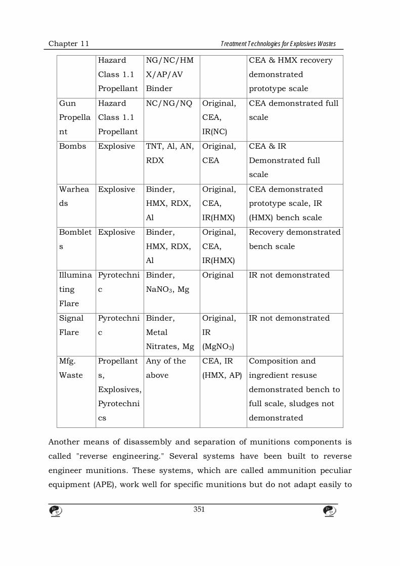
Chapter 11 Treatment Technologies for Explosives Wastes
Hazard
Class 1.1
Propellant
NG/NC/HM
X/AP/AV
Binder
CEA & HMX recovery
demonstrated
prototype scale
Gun
Propella
nt
Hazard
Class 1.1
Propellant
NC/NG/NQ Original,
CEA,
IR(NC)
CEA demonstrated full
scale
Bombs Explosive TNT, Al, AN,
RDX
Original,
CEA
CEA & IR
Demonstrated full
scale
Warhea
ds
Explosive Binder,
HMX, RDX,
Al
Original,
CEA,
IR(HMX)
CEA demonstrated
prototype scale, IR
(HMX) bench scale
Bomblet
s
Explosive Binder,
HMX, RDX,
Al
Original,
CEA,
IR(HMX)
Recovery demonstrated
bench scale
Illumina
ting
Flare
Pyrotechni
c
Binder,
NaNO3, Mg
Original IR not demonstrated
Signal
Flare
Pyrotechni
c
Binder,
Metal
Nitrates, Mg
Original,
IR
(MgNO3)
IR not demonstrated
Mfg.
Waste
Propellant
s,
Explosives,
Pyrotechni
cs
Any of the
above
CEA, IR
(HMX, AP)
Composition and
ingredient resuse
demonstrated bench to
full scale, sludges not
demonstrated
Another means of disassembly and separation of munitions components is
called "reverse engineering." Several systems have been built to reverse
engineer munitions. These systems, which are called ammunition peculiar
equipment (APE), work well for specific munitions but do not adapt easily to
351

Chapter 11 Treatment Technologies for Explosives Wastes
varying configurations. Reverse engineering methods disassemble munitions
down to the casing that contains the energetic material. Standard methods
for further reducing the size of the munition include wet saw cutting and
high pressure water jet.
A size reduction method called Cryofracture has been developed by General
Atomics Corporation. It involves cooling munitions to liquid nitrogen
temperatures and crushing them in a hydraulic press. After being processed
in this manner, the ordnance can be fed to a specially designed incinerator.
Several separation methods, including solvent, density, magnetic, and melt
and steam-out separation processes, could be applied to recover the
energetic material after fracturing. The types of items that have been
successfully Cryofractured are shown in Table 12. Because Cryofracture can
handle multiple versus individual munitions, the technology might be most
useful in separating inert and live materials in smaller items, such as
bomblets, for which reverse engineering is less practical.
Reuse of Energetic Materials Once energetic materials have been separated from inert materials, reuse is
more straightforward, and many large-scale reuse applications have been
demonstrated. Ordnance items and rockets routinely are reinspected and
used for training or similar applications. Surplus explosives also have been
purchased from the government by commercial explosives companies since
before World War II. In addition, the patent literature reveals many examples
of smokeless powders, TNT, tetryl, HMX, and RDX being added as
sensitizing agents and blast enhancers for slurry and emulsion explosives
used in the mining and quarry industries. According to the Institute of
Manufacturers of Explosives (IME), hundreds of millions of pounds of
slurries and emulsion explosives are used annually. While the feasibility of
using recovered propellants and explosives in slurries depends on their
352

Chapter 11 Treatment Technologies for Explosives Wastes
availability and cost, this potentially could be a significant market for
recovered energetic materials. When used in slurries, explosive additives are
generally in the range of 5 to 30 percent, and most major commercial
explosive formulations can be altered to accommodate military propellants
and explosives.
Figure 11.Flow diagram of hydromlnlng process.
Other smaller scale applications for recovered energetic materials recently
have been demonstrated. For example, Thiokol Corporation has made 2-lb
booster charges, used to initiate ammonium nitrate/fuel oil (ANFO) or slurry
explosives, from Hazard Class 1.1 rocket propellants. TPL, Inc., has
demonstrated using reclaimed granulated plastic-bonded explosives (PBX)
for explosive-metal bonding and forming applications. Requirements for this
type of application, such as a detonation velocity of 2.2 km/s with a
variation of± 50 mls, are fairly stringent. The TPL application was
demonstrated under a small business innovative research (SBIR) contract
from the Naval Surface Weapons Center in Crane, Indiana.
Ingredient Recovery Ingredient recovery from propellant or explosive compositions is the least
353
Chapter 11 Treatment Technologies for Explosives Wastes
advanced reuse technology. In theory, ingredient recovery is not difficult,
but, until recently, there has been no economic or environmental driving
force to recover individual ingredients. Moreover, many military programs
have a "no change" policy that prohibits changes in materials used in
ordnance manufacture. This policy also would distinguish between
recovered materials and virgin materials made from reactants. The "no
change" policy is starting to change under environmental and economic
pressures, but ingredient recovery probably will continue to meet resistance
from risk-averse program managers.
Three significant efforts are being conducted in the area of ingredient
recovery and reuse. In the first, AP is recovered from Hazard Class 1.3
composite rocket propellants. This technology involves leaching of the
soluble AP from size-reduced propellants, recrystallization at an AP vendor,
and reincorporation of AP into rocket propellant. Over 100,000 lb of AP have
been recovered and recrystallized using this method, and the propellants
made from the recovered AP cannot be distinguished from those made with
virgin materials. A schematic of the reclamation process is shown in Figure
12. Two companies, Thiokol Corporation and Aerojet Solid Propulsion
Company, are participating in this effort with support from two AP
producers, WECCO & Kerr McGee, as well as the U.S. Air Force and the
Large Rocket Motor Demilitarization Group another ingredient drawing
interest for recovery is HMX. The HMX recovery process involves separation
by dissolving and subsequent recrystallization using solvents such as
acetone or dimethyl sulfoxide (DMSO). At least two organizations have
reported successfully meeting material specifications for recovered HMX:
TPL, Inc., which recovers HMX from PBX; AND THE U.S. Army Missile
Command (MICOM), which recovers HMX from Hazard Class 1.1
propellants. In addition to reuse in military applications, HMX might have
commercial applications, such as serving as an oil well perforation charge.
354
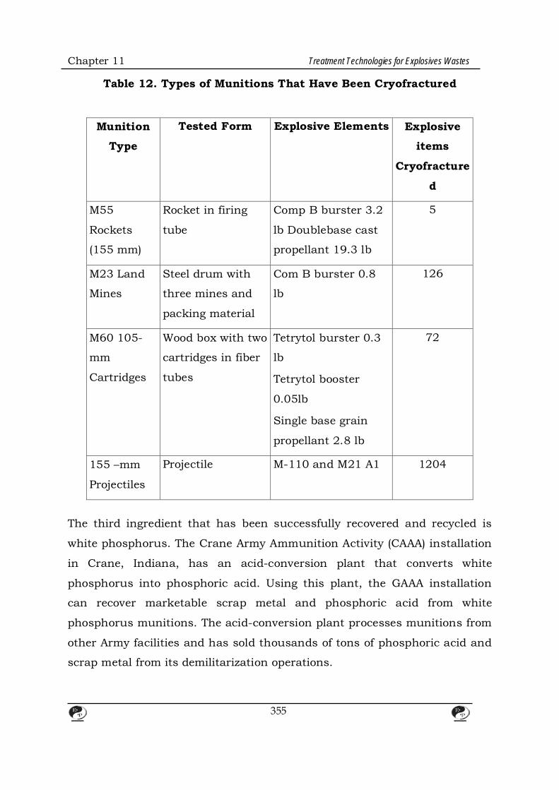
Chapter 11 Treatment Technologies for Explosives Wastes
Table 12. Types of Munitions That Have Been Cryofractured
Munition
Type
Tested Form Explosive Elements Explosive
items
Cryofracture
d
M55
Rockets
(155 mm)
Rocket in firing
tube
Comp B burster 3.2
lb Doublebase cast
propellant 19.3 lb
5
M23 Land
Mines
Steel drum with
three mines and
packing material
Com B burster 0.8
lb
126
M60 105-
mm
Cartridges
Wood box with two
cartridges in fiber
tubes
Tetrytol burster 0.3
lb
Tetrytol booster
0.05lb
Single base grain
propellant 2.8 lb
72
155 –mm
Projectiles
Projectile M-110 and M21 A1 1204
The third ingredient that has been successfully recovered and recycled is
white phosphorus. The Crane Army Ammunition Activity (CAAA) installation
in Crane, Indiana, has an acid-conversion plant that converts white
phosphorus into phosphoric acid. Using this plant, the GAAA installation
can recover marketable scrap metal and phosphoric acid from white
phosphorus munitions. The acid-conversion plant processes munitions from
other Army facilities and has sold thousands of tons of phosphoric acid and
scrap metal from its demilitarization operations.
355

Chapter 11 Treatment Technologies for Explosives Wastes
Figure 12. Flow diagram of ammonium
perchlorate reclamation process.
Energy Recovery One recovery/reuse approach proposed for energetic contaminants in soils
and sludges is solvent extraction followed by burning of the extract with
other fuels to provide energy. AEC has demonstrated that low levels of
smokeless powder, RDX, or TNT can be used to supplement boiler fuel. This
energy recovery approach also could be applied to extracted energetic
materials, using the AEC studies as a guide to the sensitivity and fuel value
of the materials.
3.5.4 Applications Table 13 lists a variety of recovery and reuse applications. Some, such as
the Louisiana Army Ammunition Plant's steam-out facility for TNT-based
explosives, which has been operational for decades, are well established
production-scale methods. These facilities normally have the infrastructure
to handle wastewaters from the recovery process. Others, such as the
356
Chapter 11 Treatment Technologies for Explosives Wastes
Cryowash process, which uses 12,000 to 30,000 psi liquid nitrogen to
remove energetic materials from cases, are emerging bench-scale
technologies. The Cryowash process has been demonstrated on hundreds
of pounds of energetic materials and is scheduled to undergo full-scale
prototype testing within the year. Developmental status must be considered
when selecting recovery/reuse technologies for particular applications.
3.5.5 Advantages and Limitations Recovery and reuse of energetic materials should be a goal in every
remediation effort. EPA places this option higher than destruction
technologies on the preferred treatment scale. Each situation, however,
requires a cost/risk/benefit assessment. At sites where rocket motors and
ordnance are in sufficient quantity and have known materials and histories,
recovery/reuse should be seriously considered. At sites where the pedigree
and volume criteria cannot be met, cost/risk/benefit assessments probably
will indicate that destruction technologies should be used. In each instance,
the safety of the operating personnel must be the highest priority.
3.6 Solvent Extraction Solvent extraction is a technology that the Army originally determined to be
infeasible for treating explosives--contaminated soils. The technology,
however, might have potential for treating these soils if a few lingering
technical issues can be resolved.
In 1982, the Army conducted laboratory-scale solvent extraction on
explosives-contaminated lagoon samples from a number of sites. Each
sample was washed with a solution of 90 percent acetone and 10 percent
water. This process achieved greater than 99 percent contaminant removals.
In 1985, the Army conducted a pilot-scale engineering analysis to determine
357
Chapter 11 Treatment Technologies for Explosives Wastes
the feasibility of full-scale solvent extraction. This analysis indicated that,
for solvent extraction to be economically feasible the number of required
washes would have to be reduced and acetone would have to be recovered
and reused. Currently, the only available technology for recovering acetone
is distillation, which exposes acetone to heat and pressure. Exposing a
solvent that has been used to extract explosive contaminants to heat and
pressure raises serious safety considerations. In fact, the distillation column
used to recover acetone often is referred to as an •acetone rocket."
Nevertheless, the Army believes that full-scale solvent extraction would be
feasible If a safe, efficient, alternative recovery method were developed.
3.7 Volume Reduction for Explosives Waste A soil washing procedure, termed the Lurgi Process, currently is being
developed in Stadtalendorf, Germany. Although no data have been
published on the effectiveness of this process, initial reports suggest that the
process can reduce levels of explosive contamination in soils to low ppm
levels. As with all soil washing technologies, the Lurgi Process produces
secondary wastes, such as washwater and concentrated explosives.
In the Lurgi Process, contaminated soils are excavated and processed in an
attrition reactor, which detaches the explosive material from the soil
particles. The mixture of detached particles then undergoes a separation
process to remove large rocks. These rocks are crushed and returned to the
site. The remaining material undergoes a second separation process, which
separates clean from contaminated particles. Clean particles are dewatered,
separated into heavy and light materials, and returned to the site.
Contaminated particles undergo a final series of washing, separat1on, and
chemical extraction processes to remove any remaining clean particles.
Finally, the contaminated material is clarified and concentrated before being
disposed of or treated.
358

CHAPTER – 12
SAFETY CONCERN OF EXPLOSIVES WASTE
1. Background Safety precautions must be taken at sites contaminated with explosives
wastes. AEC, which has been involved in sampling and treating explosives
waste sites since the early 1980s, has developed protocols for identifying
sites that require explosives safety precautions and for handling explosives
wastes at these sites. This section discusses AEC's sensitivity testing
protocol, specific precautions required for sampling and treating explosives
wastes, and some laboratory safety issues associated with analyzing
explosives-contaminated samples. The section does not cover statistical site
characterization or the work and health and safety plans suggested by the
Occupational Safety and Health Administration (OSHA).
2. Sensitivity Testing When AEC began to investigate explosives waste sites in the early 1980s, the
only available guidance on sampling and treating explosives-contaminated
soils was 40 CFR 261.23, which vaguely specifies waste identification.
Consequently, AEC developed its own protocol for determining whether soils
contaminated with explosives wastes are susceptible to initiation and
propagation, and, if so, how best to handle them. This original protocol
involved many tests, including impact tests, friction tests, and shock gap
tests. AEC quickly determined that the original protocol was too expensive
and unwieldy, due to the variety of available tests, and developed a two-test
protocol. This protocol involved (1) the deflagration-to-detonation test
(DDT),which measures an explosive material's reaction to flame: and (2) the
Bureau of Mines' zero gap test, which measures an explosive material's
359

Chapter 12 Safety Concern of Explosives Waste
reaction to shock. Both of these tests are extremely conservative, rendering
additional tests unnecessary. The drawback to this protocol was that both
tests required relatively large volumes of soil to be excavated and shipped,
often at great expense, to specially qualified laboratories.
AEC eventually developed its current protocol, which involves chemical
compositional analysis. By analyzing the composition of samples from a site,
AEC can determine quickly and inexpensively whether materials at the site
are susceptible to initiation and propagation. According to the DDT, soils
containing more than 12 percent secondary explosives by weight are
susceptible to initiation by flame; according to the shock gap test, soils
containing more than 15 percent secondary explosives by weight are
susceptible to initiation by shock. As a conservative limit, AEC considers all
soils containing more than 10 percent secondary explosives by weight to be
susceptible to initiation and propagation and exercises a number of safety
precautions when sampling and treating these soils. Sampling and
treatment precautions are exercised when handling soils that contain even
minute quantities of primary explosives.
The reliability of compositional analysis depends on obtaining enough
samples to generate a statistically valid characterization of the site. CAREL
has developed field screening methods to reduce the number of samples that
must be analyzed in the laboratory (see section 3.1). If contamination is in
the parts per million (ppm) or parts per billion (ppb) range by weight, the
samples could be shipped off site for analysis; If contamination is in the
percent range, special analytical arrangements must be made
3. Sampling and Treatment Precautions Work, sampling, and health and safety plans for explosives waste sites
should incorporate safety provisions that normally would not be included in
work and sampling plans for other sites. AEC works with other laboratories
360

Chapter 12 Safety Concern of Explosives Waste
such as the Bureau of Mines to conduct site-specific hazards analyses for
every proposed operation at explosives waste sites, including remedial
investigation, remedial design, and remedial action. These analyses include
hazards identification, hazards evaluation, risk assessment, and risk
management.
The most important safety precaution is to minimize exposure, which
involves minimizing the number of workers exposed to hazardous situations,
the duration of exposure, and the degree of hazard. To reduce the degree of
hazard at explosives wastes sites, operations usually are conducted on
materials that have been diluted to a wet slurry. If necessary, distilled water
can be added to the soil to achieve the desired moisture content. Water
desensitizes the explosives and reduces the effects of heat and friction.
Water, however, also can cause a localized detonation to propagate
throughout a soil mass, so moisture content should be adjusted on a sits-
by-site basis. As another safety precaution, nonsparking tools, conductive
and grounded plastic, and no-screw tops, which were developed for
manufacturing explosives, are standard equipment at explosives waste sites.
For example, nonsparking beryllium tools are used instead of ferrous tools.
If contamination is above the 10 percent limit in some areas of a site, the
contaminated material could be blended and screened to dilute the
contamination and produce a homogenous mixture below the 10 percent
limit. This blending is not by itself a remedial action but a safety precaution;
soils containing less than 10 percent secondary explosives by weight
occasionally experience localized detonations but generally resist widespread
propagation. Foreign objects and unexploded ordnance within the
contaminated soil often impede the blending process and require
unexploded ordnance contractors (see section 4.2).
Once blending is completed, soil treatments such as incineration and
361
Chapter 12 Safety Concern of Explosives Waste
bioremediation can proceed. Equipment used in treatment must have sealed
bearings and shielded electrical junction boxes. Equipment also must be
decontaminated frequently to prevent the buildup of explosive dust.
4. Laboratory Analysis of Explosives-contaminated Samples Although TNT and RDX are the most common contaminants at explosives
waste sites, many sites also are contaminated with impurities in
production.-TNT, such as DNB, 2,4-DNT, 2,6-DNT, and products of
photochemical decomposition of TNT, such as TNEL These impurities and
decomposition products are thermally labile and hydrophilic and
consequently should not be analyzed using certain tests and solvents. For
example, gas chromatography (GC), in particular, is not the best choice to
screen for these chemicals, because thermally labile compounds decompose
in GC equipment. High-performance liquid chromatography (HPLC) (SW846
method 8330) has been selected for routine laboratory analysis of soils from
military sites.
5. Safety Management Systems
Disposal and destruction activities in case of explosive wastes are high
hazard and comprise one of the main causes of accidents and incidents in
cases. Many incidents do not involve injury but injuries and deaths have
nevertheless occurred. Incidents can happen because of:
• a failure to recognise that explosives requiring disposal or destruction
are accumulating in process or storage areas.
• casual attitudes when dealing with the disposal and destruction of
explosives often arising out of a lack of competence or a failure to
properly supervise, inspect and audit the disposal activity;
362
Chapter 12 Safety Concern of Explosives Waste
• people not appreciating the properties and behaviour of explosives under
certain conditions (products requiring disposal or destruction may be
unusually sensitive due to changes in rheology and morphology,
deterioration, contamination or inadequate stabilisation);
• ill-considered systems of work or no basic safety precautions often
arising out of a failure to conduct suitable and sufficient risk
assessments or a failure to follow prescribed procedures;
There is also a risk of insufficient time and money being devoted to disposal
and destruction activities because of the potentially non-productive, non-
profit making nature of the job.
6. Destruction of Explosives Waste
This provides practical guidance with respect to the employment of four
main methods for the disposal of explosives wastes by destruction.
Guidance is provided with respect to burning, with respect to detonation,
with respect to dissolution or dilution and with respect to desensitisation
and chemical destruction.
7. Burning Explosive Wastes Substances And Specific Articles When burning explosives wastes, the risk of burning to detonation must be
taken into account, and measures taken to minimise the risk and to protect
against the effects of a detonation should it occur. The general rule is to only
burn small quantities at any one time while avoiding excessive transport
movements. Items which might be propelled form the fire when burned must
be suitably contained without confining the explosive. Incompatible explosives
363

Chapter 12 Safety Concern of Explosives Waste
must not be burned together. If there is any doubt about compatibility of
explosives they must be burned separately.
8. General Procedures and Risk Controls Subject to some form of pretreatment or special precautions, most
explosives waste substances can be burned safely provided that:
• as far as possible, burning is controlled, and the operation is designed to
minimise the possibility of the explosive burning to detonation,
deflagrating violently, projecting primary or secondary fragments and
burning brands or producing excessive thermal effects;
• it is assumed that the maximum credible event will occur and sufficient
precautions are taken to mitigate any resultant hazards.
364
CHAPTER – 13
LABORATORY-SCALE ANALYTICAL METHODS
1. Field Screening Methods for Munitions Residues in Soil
1.1 Background
Laboratory analysis of samples from sites contaminated with explosives
wastes is expensive and time consuming. Due to heterogeneous waste
distribution at many sites, it would not be unusual for 80 to 90 percent of
the soil samples from a given site to contain no contamination. As a result,
developing a site characterization with good spatial resolution is extremely
expensive. Field screening methods determine quickly and less expensively
which samples are contaminated with explosives residues, thereby reducing
total analytical costs. For example, field screening was found to be
acceptable for determining soil contamination areas at a military site (Craig
et al.1993). This section discusses the field screening procedures developed
by CAREL and advantages and limitations of CAREL's procedure. The
section does not cover soil sampling procedures.
1.2 Field Screening Methods In developing the field screening methodology, CAREL considered several
design criteria. The method needed to detect contaminants that were
present at most military sites. Based on data from sites Investigated by
CAREL and MAD, CAREL determined that most sites could be adequately
assessed by methods that screen first for TNT and RDX, and secondarily for
2, 4-DNT, TNB, DNB, and tetryl. The equipment needed to be portable
portable, so it could be shipped easily to sites, and simple to operate,
because field operators would not necessarily have experience in analytical
chemistry. Field screening procedures also needed to use only low toxicity
solvents and have a quick turnaround time, a large analytical range, a linear
365

Chapter 13 Laboratory-Scale Analytical Methods
calibration scale, and a sufficiently low detection limit. In addition, the
results of the procedure needed to correlate well with results from standard
laboratory method.
CAREL's methodology has three steps: extraction, TNT screening, and RDX
screening.
1.2.1 Extraction CAREL's procedure begins with a simple extraction process. A 2Q-g sample
of undried soil from the site is mixed with 100 mL of acetone. The sample is
shaken for at least 3 minutes, allowed to settle, and filtered with a syringe
filter. Very heavy clays might require longer extraction periods, but 3
minutes is often sufficient for most sandy and loamy soils. The efficiency of
acetone extraction is 95 percent that of standard laboratory methods. The
filtered extract then is subjected to CAREL's TNT and ADX screening
procedures. For more detailed information on these procedures, see U.S.
Army CAREL, 1990, and U.S. Army CAREL, 1991.
1.2.2 TNT Screening In the TNT screening procedure, the initial absorbance of the acetone extract
at 540 nanometers (nm) is obtained using a portable spectrophotometer. The
extract is amended with potassium hydroxide and sodium sulfite, agitated
for 3 minutes, and filtered again. The extract then can be analyzed visually.
If it has a reddish or pinkish color, it contains TNT; if it has a bluish color, it
contains 2,4-DNT. Figure 3-1 shows the reaction-known as the Janowsky
Reaction(1886)-that produces the reddish-colored anion from TNT and the
bluish-colored anion from 2, 4-DNT.
366

Chapter 13 Laboratory-Scale Analytical Methods
Figure 1. Schematic of the Janowsky Reaction
(1886) for TNT and 2, 4-DNT.
Absorbance measurements can be used to obtain quantitative results.
Figure 3-2 illustrates the visible absorbance spectrum of the Janowsky
Reaction product of TNT, showing the maximum absorbance at 460 and 540
nm. CAREL uses the peak at 540 nm to verify the presence of TNT, even
though the absorbance at 460 nm is greater, because of the potential for
interference from humic substances at 460 nm. Figure 3-3 illustrates the
visible absorbance spectrum of an acetone extract of uncontaminated
potting soil before and after Janowsky Reaction reagents are added, showing
the greater absorbance near the 460-nm as opposed to the 54Q-nm
wavelength.
367
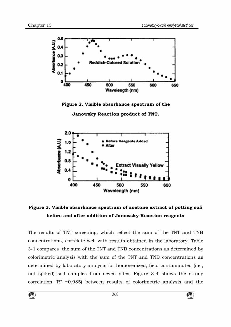
Chapter 13 Laboratory-Scale Analytical Methods
Figure 2. Visible absorbance spectrum of the
Janowsky Reaction product of TNT.
Figure 3. Visible absorbance spectrum of acetone extract of potting soli
before and after addition of Janowsky Reaction reagents
The results of TNT screening, which reflect the sum of the TNT and TNB
concentrations, correlate well with results obtained in the laboratory. Table
3-1 compares the sum of the TNT and TNB concentrations as determined by
colorimetric analysis with the sum of the TNT and TNB concentrations as
determined by laboratory analysis for homogenized, field-contaminated (i.e.,
not spiked) soil samples from seven sites. Figure 3-4 shows the strong
correlation (R2 =0.985) between results of colorimetric analysis and the
368
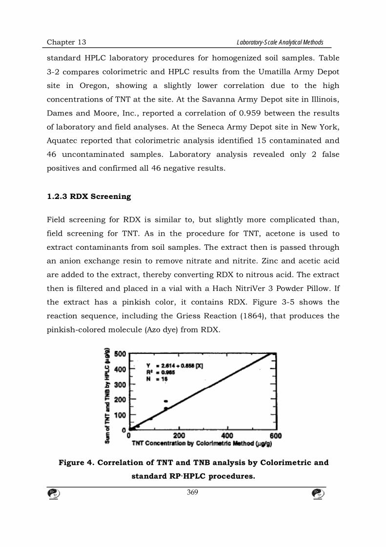
Chapter 13 Laboratory-Scale Analytical Methods
standard HPLC laboratory procedures for homogenized soil samples. Table
3-2 compares colorimetric and HPLC results from the Umatilla Army Depot
site in Oregon, showing a slightly lower correlation due to the high
concentrations of TNT at the site. At the Savanna Army Depot site in Illinois,
Dames and Moore, Inc., reported a correlation of 0.959 between the results
of laboratory and field analyses. At the Seneca Army Depot site in New York,
Aquatec reported that colorimetric analysis identified 15 contaminated and
46 uncontaminated samples. Laboratory analysis revealed only 2 false
positives and confirmed all 46 negative results.
1.2.3 RDX Screening Field screening for RDX is similar to, but slightly more complicated than,
field screening for TNT. As in the procedure for TNT, acetone is used to
extract contaminants from soil samples. The extract then is passed through
an anion exchange resin to remove nitrate and nitrite. Zinc and acetic acid
are added to the extract, thereby converting RDX to nitrous acid. The extract
then is filtered and placed in a vial with a Hach NitriVer 3 Powder Pillow. If
the extract has a pinkish color, it contains RDX. Figure 3-5 shows the
reaction sequence, including the Griess Reaction (1864), that produces the
pinkish-colored molecule (Azo dye) from RDX.
Figure 4. Correlation of TNT and TNB analysis by Colorimetric and
standard RP·HPLC procedures.
369
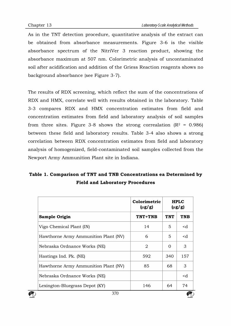
Chapter 13 Laboratory-Scale Analytical Methods
As in the TNT detection procedure, quantitative analysis of the extract can
be obtained from absorbance measurements. Figure 3-6 is the visible
absorbance spectrum of the NitriVer 3 reaction product, showing the
absorbance maximum at 507 nm. Colorimetric analysis of uncontaminated
soil after acidification and addition of the Griess Reaction reagents shows no
background absorbance {see Figure 3-7).
The results of RDX screening, which reflect the sum of the concentrations of
RDX and HMX, correlate well with results obtained in the laboratory. Table
3-3 compares RDX and HMX concentration estimates from field and
concentration estimates from field and laboratory analysis of soil samples
from three sites. Figure 3-8 shows the strong correalation (R2 = 0.986)
between these field and laboratory results. Table 3-4 also shows a strong
correlation between RDX concentration estimates from field and laboratory
analysis of homogenized, field-contaminated soil samples collected from the
Newport Army Ammunition Plant site in Indiana.
Table 1. Comparison of TNT and TNB Concentrations ea Determined by
Field and Laboratory Procedures
Colorimetric (µg/g)
HPLC (µg/g)
Sample Origin TNT+TNB TNT TNB
Vigo Chemical Plant (IN) 14 5 <d
Hawthorne Army Ammunition Plant (NV) 6 5 <d
Nebraska Ordnance Works (NE) 2 0 3
Hastings Ind. Pk. (NE) 592 340 157
Hawthorne Army Ammunition Plant (NV) 85 68 3
Nebraska Ordnance Works (NE) <d
Lexington-Bluegrass Depot (KY) 146 64 74
370
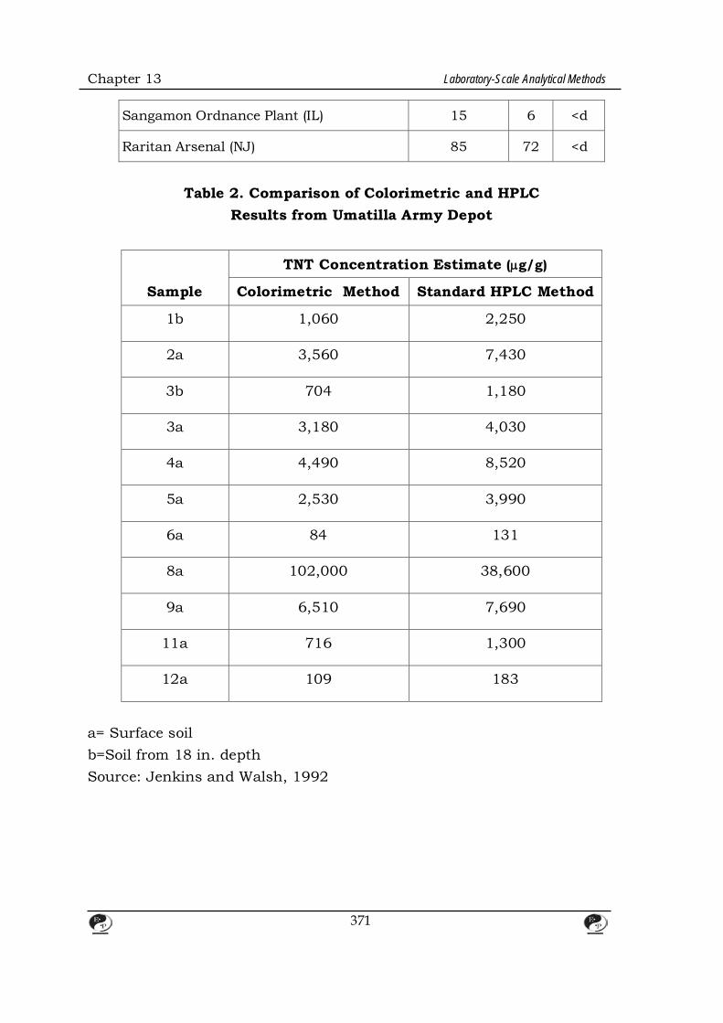
Chapter 13 Laboratory-Scale Analytical Methods
Sangamon Ordnance Plant (IL) 15 6 <d
Raritan Arsenal (NJ) 85 72 <d
Table 2. Comparison of Colorimetric and HPLC
Results from Umatilla Army Depot
Sample
TNT Concentration Estimate (µg/g)
Colorimetric Method Standard HPLC Method
1b 1,060 2,250
2a 3,560 7,430
3b 704 1,180
3a 3,180 4,030
4a 4,490 8,520
5a 2,530 3,990
6a 84 131
8a 102,000 38,600
9a 6,510 7,690
11a 716 1,300
12a 109 183
a= Surface soil b=Soil from 18 in. depth Source: Jenkins and Walsh, 1992
371

Chapter 13 Laboratory-Scale Analytical Methods
Figure 5. RDX reaction sequence, Including production of pinkish-
colored anion (Azo dye) by Griess Reaction (1864).
1.3 Advantages and Limitations of the Methodology CAREL' smethodology has several advantages, including:
• Speed. The TNT and RDX detection procedures take about 30 minutes per
sample, including the 15-minute color development stage. Typically, 25
samples can be analyzed per day for both RDX and TNT.
372

Chapter 13 Laboratory-Scale Analytical Methods
Figure 6. Visible absorbance spectrum of NitriVer 3 reaction product.
Figure 7. Visible absorbance spectrum of acetone extract of
uncontaminated soli before and after addition of Griess Reaction
reagents.
373
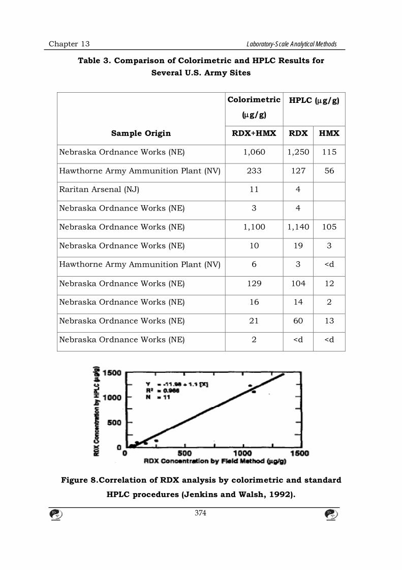
Chapter 13 Laboratory-Scale Analytical Methods
Table 3. Comparison of Colorimetric and HPLC Results for Several U.S. Army Sites
Sample Origin
Colorimetric
(µg/g)
HPLC (µg/g)
RDX+HMX RDX HMX
Nebraska Ordnance Works (NE) 1,060 1,250 115
Hawthorne Army Ammunition Plant (NV) 233 127 56
Raritan Arsenal (NJ) 11 4
Nebraska Ordnance Works (NE) 3 4
Nebraska Ordnance Works (NE) 1,100 1,140 105
Nebraska Ordnance Works (NE) 10 19 3
Hawthorne Army Ammunition Plant (NV) 6 3 <d
Nebraska Ordnance Works (NE) 129 104 12
Nebraska Ordnance Works (NE) 16 14 2
Nebraska Ordnance Works (NE) 21 60 13
Nebraska Ordnance Works (NE) 2 <d <d
Figure 8.Correlation of RDX analysis by colorimetric and standard
HPLC procedures (Jenkins and Walsh, 1992).
374

Chapter 13 Laboratory-Scale Analytical Methods
Cost. The solvents used in these tests are very inexpensive. The total cost for
materials to process each sample is about $20, relatively inexpensive
compared to other analytical methods.
Simplicity. The calibration of the colorimetric analysis is linear, and the test
has a zero intercept, meaning that all associated calculations are very
simple.
Table 4. Comparison of Colorimetric and HPLC Results
for Newport Army Ammunition Plant
RDX Concentration Estimate (µg/g)
Sample t Colorimetric Method Standard HPLC Method
1 0.55 0.05
2 2.86 1.31
3 4.55 3.15
4 6.62 15.5
5 5.87 8.45
6 253 299
7 17.4 38.8
8 45.4 258
9 674 1,800
10 2,430 3,170
11 7,690 12,200
• Laboratory correlation. The results of colorimetric analysis show strong
correlation with those obtained by HPLC procedures.
• Low incidence of falsa negatives. This is important since the procedure is
375

Chapter 13 Laboratory-Scale Analytical Methods
used to screen for explosives-contaminated soils.
• Low detection limits. The procedure can detect explosive residues at
concentrations as low as 1g/g.
The limitations of CRRELS’s procedure include:
Water content. Samples must contain 2 to 3 percent water by weight.
Samples from sites with dry conditions must be wetted with distilled water
prior to colour development.
Interferences. The TNT procedure detects other nitroaromatics and is
subject to positive interference from humic materials. These interferences
can be reduced by careful visual analysis prior to colorimetric analysis. The
RDX procedure detects other nitramines and nitrate esters such as
nitrocellulose and nitroglycerine
1.4 TNT and RDX Test Kits A private firm has developed and tested a field screening kit based on
CAREL's methodology. A "how to" videotape explaining the procedure is
available from Martin H. Stutz at the U.S. Army Environmental Center at
Aberdeen Proving Ground, Maryland 21010. Requests must be submitted in
writing.
References
Craig, H.D., A. Markos, H. Lewis, and C. Thompson. 1993. Remedial
investigation of site D at Naval Submarine Base, Bangor, Washington. In:
Proceedings of the 1993 Federal Environmental Restoration Conference,
Washington, DC.
Jenkins, T.F. and M.E. Walsh. 1992. Development of field screening methods for
TNT, 2,4-DNT, and RDX in soil. Talanta 39(4): 419-428.
376
Chapter 13 Laboratory-Scale Analytical Methods
U.S. Army CAREL. 1991. U.S. Army Cold Regions Research and Engineering
Laboratory. Development of a field screening method for RDX in soil. Walsh,
M.E. and T.F. Jenkins. CAREL Special Report 91-7. Hanover, New Hampshire.
U.S.Army CAREL. 1990. U.S. Army Cold Regions Research and Engineering
Laboratory. Development of a simplified field method for the determination of
TNT in soil. T.F. Jenkins. CAREL Special Report 90-38. Hanover, New
Hampshire.
2. Characterization of Radioactive Contaminants for Removal
Assessments
2.1 Background In 1987, EPA’s Office of Radiation and Indoor Air (ORIA) developed a
characterization protocol for determining the feasibility of reducing the
volume of soils contaminated with radioactive wastes at Superfund sites.
ORIA's protocol is more extensive than standard protocols, which require
only gamma spectroscopy of bulk samples to determine the levels of
radioactive constituents. In ORIA's protocol, sieving and sedimentation
techniques are used to separate soils into size fractions. Each fraction then
undergoes petrographic and radiochemical analysis to determine the values
of certain parameters, such as grain size distribution, mineral composition
and percentages, and physical properties of radioactive contaminants, that
affect the feasibility of volume reduction. This section discusses the potential
applicability of ORIA's protocol to radioactive soils at federal facilities,
examines the two tiers of the protocol, and presents a case study of a
radium-contaminated site where the protocol was applied.
2.2 Applicability to Military Installations
377

Chapter 13 Laboratory-Scale Analytical Methods
ORIA's protocol potentially could be used to characterize soils at military
sites contaminated with radioactive wastes. For example, at an Air Force
base in California, it was speculated that radium paint buried in a bunker
was contributing to elevated uranium levels in the well water of a nearby
field. Radiochemical analysis would have indicated that radium paint does
not contain the parent compound, uranium-238, so uranium at the site
could not have been derived from radium paint in the bunker. Similarly, at
an Air Force base in New Mexico, researchers conducted an analysis for
radium contamination near a particular bunker where radium paint also
might have been buried. This analysis found radium only at background
levels. A petrographic analysis of the soil would have revealed natural
radioactive minerals and led to the same conclusion.
ORIA's protocol is relatively inexpensive. Petrographic analysis of five
representative soil samples takes a petrographer about one week and costs
about $5,000. Radiochemical analysis takes three times as long and costs
about $15,000. Thus the total cost to develop a detailed characterization of
soil from a military installation, as a feasibility study for remediation
considerations, would be approximately $20,000.
2.3 OR/A's Sol/ Characterization Protocol ORIA's methodology was developed based on investigations at thorium-
contaminated sites in Wayne and Maywood, New Jersey; radium-
contaminated sites in Montclair and Glen Ridge, New Jersey; and plutonium
surrogate host soil at the Nevada Test Site. These investigations led to the
development of a two-tiered protocol: Tier 1 is a feasibility study; Tier 2 is an
optimization study.
2.3.1 Tier 1: Feasibility Study
378
Chapter 13 Laboratory-Scale Analytical Methods
The Tier 1 feasibility study has two stages: fractioning and analysis.
Fractioning Bulk samples are dried at 80°C and examined by high resolution gamma
spectroscopy. Samples then are split into representative 390-gram portions
by prescribed separation methods, and each portion to be tested is placed in
a beaker to create a slurry of five parts deionized water to one part solids.
After 24 hours, the slurry is stirred and poured through a nest of
increasingly fine sieves to separate the bulk sample into size fractions of
coarse, medium, and fine sand and silt.
Analysis The fractions obtained by sieving undergo three separate analyses. First, the
fractions are analyzed to obtain the sample’s grain size distribution curve,
which identifies each size fraction’s contribution to the total weight of the
sample. Figure 3-9 is a grain size distribution curve for soils from the
Nevada Test Site. Second, the fractions are analyzed for radioactivity as a
function of particle size. Figure 3-10 is a graph of radioactivity versus
particle size for radium-, thorium-, and uranium-contaminated soils, from
Maywood, New Jersey, showing increased radioactivity in the silt-size
fraction. Third, the size fractions undergo petrographic analyses, which
generate precise statistical counts of the various particles in the soil.
Coarse-size materials, which are greater than 0.6 mm, are analyzed visually.
Medium-size materials, which are between 0.038 and 0.60 mm, are
immersed in index oil and examined under petrographic and binocular
microscopes. Fine-size materials, which are less than 0.038 mm, are
examined by X-ray diffraction. Finally, medium-size materials undergo a
second petrographic analysis in which a separatory funnel containing
sodium polytungstate is used to extract minerals with specific gravities
greater than 3.0. These minerals, which usually represent a small
379
Chapter 13 Laboratory-Scale Analytical Methods
percentage of the total sample, contain disproportionately high levels of
radioactive materials. Figure 3-11 shows the heavy mineral composition of
soil from the Wayne and Maywood, New Jersey, sites. The heavy mineral
fraction of the soil from this site contains all of the radiation contaminants.
Monazite, which contains almost all of the radioactivity, represents only
about 10 percent of the heavy mineral fraction and comprises less than 1
percent of the total sample Zircon, which can contain up to 4 percent
substitution of thorium or uranium in the crystal lattice, constitutes the
remainder of the radioactive material at this site.
Figure 9. Grain size distribution curve and histogram for soil from the Nevada Test Site.
2.3.2 Tier 2: Optimization Study If Tier 1 suggests that volume reduction is feasible, further analyses can be
performed to characterize the contaminated soil. Size fractions can be
broken down into more precise increments by hydro classification and
centrifuge. In addition, chemical assays can be used to quantify the mineral
analysis if a chemical element is known to be solely associated with a
particular contaminant. For example, at one of the radium-contaminated
380
Chapter 13 Laboratory-Scale Analytical Methods
sites, the ore minerals for radium include a urinal vanadinate. Since
vanadium is rare, it can be used as a “chemical signature” to determine the
weight percentage of this ore mineral of radium. Instruments such as the
scanning electron microscope (SEM) and energy dispersive X-ray
spectrometer (EDX) also can be useful in identifying the morphology and
elements of specific particles in the submicroscopic size range.
Figure 10 Radiochemical analysis showing
Radioactivity as a function of particle size.
2.4 Case Study: Montclair/Glen Ridge Superfund Site From 1915 to 1926, acid leach tailings from the manufacture of radium
were deposited in open field pits in Montclair and Glen Ridge, New Jersey.
After operation ceased in 1926, residential housing was developed in the
area. Most of the contamination, which consists primarily of precipitates
and coprecipitates from the acid leach process, is within 8 ft of the surface.
381

Chapter 13 Laboratory-Scale Analytical Methods
Ground water contamination is confined to areas directly surrounding the
dump areas, and there is no ground water contamination in the bedrock,
which is 20 ft below the surface. Consolidated glacial till, along with other
materials that were dumped in the pits, is the host material for the radium-
contaminated tailings. The costto remove, transport, and dispose of all
300,000 yd 3 of soil from the site is estimated at close to $300 million,
making volume reduction an attractive option.
Tier 1 analyses indicated that the contaminated material consists of 15
percent ores, such as carnotite and uraninite, and 85 percent anthropogenic
materials. Within the latter group, most of the radioactivity is located in the
fine silt and clay fractions, particularly in the 10- to 20-f.lm fraction. A
linear density gradient analysis was used to separate the 10- to 20-f.lm
fraction into light, medium, and heavy particles (see Table 3-5). These three
groups of particles then underwent Tier 2 analyses, including gamma
spectroscopy, X-ray diffraction analysis, SEMIEDX analysis,
photomicrography, and autoradiography. Figures 3-12 and 3-13 illustrate
the results of some of these analyses. The light particles, which are mostly
amorphous silica, were found to contain about 25 percent of the radium; the
heavy particles, which are mostly radiobarite, were found to contain about
50 percent of the radium.
Based on the results of the characterization, site engineers decided to
remove the fine silt particles from the site and wash the remaining sand-size
particles of any residual clay. In laboratory testing, these procedures
reduced 30 to 40 percent of the material to a target level of 12 to 15
picocuries per gram of radium 226 (see Figure 3-14).
382

Chapter 13 Laboratory-Scale Analytical Methods
Figure 11. Heavy mineral composition of soil from the
Wayne and Maywood, Nf. IW Jersey, sites.
Table 5. Linear Density Gradient Analysis of 10. to 20.J.1m Size
Fraction of Soli from Glen Ridge, New Jersey, Site
Density Weight
Ra-226 Activity %Ra
Light 2.10.2.25
32.20 1,640 pCl/g 25.21
Medium 2.25-2.71
55.69 1,040 pCl/g 27.55
Heavy 2.71
12.01 8,270 pCl/g 47.24
383

Chapter 13 Laboratory-Scale Analytical Methods
Figure 12. SEM (Inset) and EDX analysis of amorphous silica from the
2.1o-2.25 density fraction of the 1Q- to 2G-J.1m grain size of radium-
contaminated soli from Glen Ridge, New Jersey.
2.5 References 1. U.S.EPA.1989. U.S. Environmental Protection Agency. Characterization
of contaminated soil from the Montclair/Glen Ridge, New Jersey,
Superfund sites.
2. EPA/520/1-89/012. U.S. EPA, Office of Radiation Programs.
Additional References Neiheisel, J. 1992. Petrographic methods in characterization of radioactive
and mixwaste. Proceedings of HMC/Superfund 1992, December 1-3,
Washington, DC, 192-195.
384
Chapter 13 Laboratory-Scale Analytical Methods
Figure 13. Autoredlograph (SEM) showing radiation etch tracks from
radlobarlte (Inset) and EDX of radlobarlte In the heavy fraction of 1o-
to 2G-J.1m grain size of radium-contaminated soil from Glen Ridge,
New Jersey.
Figure 14. Radium reduction produced by laboratory-scale water
washing and wet sieving of soli from Montclair and Glen Ridge sites.
385
CHAPTER – 14
REMEDIATION OF EXPLOSIVE-CONTAMINATED SOILS:
ALKALINE HYDROLYSIS AND SUB-CRITICALWATER DEGRADATION
1. Introduction
Natural water and soils near military sites where training regularly occurs are
vulnerable to contamination from explosives such as 2, 4, 6-trinitrotoluene
(TNT) and hexahydro-1, 3, 5- trinitro-1, 3, 5-triazine (RDX) (Rogers and
Bunce, 2001; Certini et al., 2013). TNT and RDX are toxic to organisms
including algae, fish, rats, and humans (Yinon, 1990), and are classified as
potential carcinogens by the United States Environmental Protection Agency
(US EPA) (McLellan et al., 1988). The intensive military training that has
occurred since the Korean War has resulted in explosive compounds
contaminating soil and groundwater near military training sites for artillery
fire. To replace costly incineration methods for the remediation of explosives,
many studies have sought alternative remediation methods to treat
explosives where they are found, including the use of aerobic and anaerobic
biodegradation (Bradley and Chapelle, 1995; Roberts et al., 1996),
composting (Bruns-Nagel et al., 1998), phyto remediation (Thompson et al.,
1998), and chemical oxidation (Li et al., 1997). However, these methods have
drawbacks, such as slow degradation rates, long treatment periods, high
energy consumption, expensive equipment, extra cost for additional
treatment, and the possible toxicity of degradation products.
Alkaline hydrolysis is a potential remediation method with low cost and rapid
reaction rates. Nucleophile attack using bases (e.g., OH−) easily transforms
nitro explosives in basic conditions (Bernasconi, 1971; Hoffsommer et al.,
1977). In recent decades, base-catalyzed transformation of TNT and RDX
386

Chapter 14 Remediation of Explosive-Contaminated Soils
has been increasingly studied (Heilmann et al., 1996; Emmrich, 1999;
2001; Balakrishnan et al., 2003; Bajpai et al., 2004; Hwang et al., 2005). The
degradation kinetics has been suggested in various conditions and possible
daughter products have been identified. Through a quantum chemical
approach using experimental data (Mills et al., 2003), Hill et al. (2012)
showed that possible initial steps of TNT alkaline hydrolysis were hydrogen
abstraction by OH−, Meisenheimer complex formation, and substitution of
nitro functional group with OH−. They also showed the formation of
polymeric products after the initial steps. Final products of RDX alkaline
hydrolysis were reported to be NO2−, HCHO, NH3, and N2O (Balakrishnan
et al., 2003). In addition, the United States Army has successfully
performed an in-situ field application of alkaline hydrolysis for explosive-
contaminated soils (Thorne et al., 2004).
Subcritical water is liquid water under pressure at temperatures between
the usual boiling point (100◦C) and the critical temperature (374.1◦C)
(LaGrega et al., 2000). Un- der subcritical conditions, the dielectric
constant, surface tension, and viscosity of water molecules are dramatically
decreased (Siskin et al., 1990; Kuhlmann et al., 1994; LaGrega et al., 2000).
In addition, the combination of subcritical water with oxidizing agents, such
as O2 and air, can effectively oxidize organic compounds that are normally
very difficult to oxidize (Kronholm et al., 2001; Dadkhah and Akgerman,
2002). Therefore, attempts have been made to utilize subcritical water to
extract or decompose polycyclic aromatic hydro- carbons (PAHs), pesticides,
polychlorinated biphenyls (PCBs), dioxin and other organic contaminants in
soil (Lagadec et al., 2000; Dadkhah and Akgerman, 2002; Weber et al.,
2002; Kubatova et al., 2002; Hashimoto et al., 2004). For the degradation of
explosives in contaminated soil, subcritical water degradation is also
currently suggested. Hawthorne et al. (2000) showed that significant
degradation of TNT and RDX started at 125 and 100◦C, respectively. Via
pilot-scale experiments, more than 99.9% of TNT and RDX in contaminated
387
Chapter 14 Remediation of Explosive-Contaminated Soils
soil was transformed at 275◦C for 1 h. Kalderis et al. (2008) found that
98-100% of TNT was degraded from highly contaminated soil (12% TNT) at
150–225◦C. They also showed that extraction or diffusion of TNT from
inside a soil matrix to the soil surface is a rate-limiting step of subcritical
water degradation of TNT and that the soil matrix can also catalyze the
degradation of TNT by subcritical water in a soil-water system. It is also
reported that heating at temperatures higher than 200 and 280◦C can induce
gasification and irreversible decomposition of hydrophobic compounds in soil
(DeBano et al., 1998).
Due to the difficulty of accessing military sites in South Korea, information
on explosive contamination in soil was limited and real contaminated soil in
artillery ranges cannot be easily obtained. In the present study, we selected
alkaline hydrolysis, a well-established, proven technology for explosive
treatment, to remediate explosive-contaminated soils in South Korea. We
also chose subcritical water degradation as an alternative process. Prior to
practical application as an ex-situ remediation process, we evaluated and
summarized the kinetics of alkaline hydrolysis and subcritical water
degradation using real explosive-contaminated soils in comparison with
previously reported data in water and soil. In addition, artificially
synthesized 2, 4-dinitrotoluene (DNT)-contaminated soil was also tested.
2. Materials and Methods
2.1 Chemicals and Explosive-Contaminated Soils
DNT (97%), a reference nitro-aromatic compound, was purchased from
Aldrich (Milwau- kee, WI, USA). TNT and RDX were provided by Hanwha
Corp. (Seoul, Korea). Standard stock solutions of TNT (1 mg mL−1 in
acetonitrile) and RDX (1 mg mL−1 in acetonitrile) were obtained from Accu
Standard (New Haven, CT, USA). Methanol (HPLC grade, SK Chemicals,
Korea), HCl (69-70%, Junsei Chemical, Japan), and NaOH (30%, Fisher
Scientific, Pittsburgh, PA, USA) were purchased and used as received
388
Chapter 14 Remediation of Explosive-Contaminated Soils
without further purification.
TNT- and RDX-contaminated soils were collected from two artillery ranges
(three samples from each range) operated by the Korean Army of South
Korea. According to site investigation (Jung, 2013), explosive contamination
was only shown at surface soil (< 15 cm). The randomly collected surface
soils were dried at room temperature. Dried soils were crushed using a
mortar and sieved at 2 mm to remove coarse particles. Particle size analysis
was conducted using a laser particle size analyzer (Mastersizer 2000, Malvern,
UK). Loss on ignition was determined by heating at 600 ± 25◦C for 3 h
using a muffle furnace (model 184A, Fisher Scientific). Soil pH was
measured after 1 h agitation of 5 g sediment and 25 ml deionized water using
an Accumet 925 pH/ion meter (Fisher Scientific). To find the concentrations of
TNT and RDX, the soil was extracted with methanol for 5 min and the filtrate
(GF/C) was analyzed by high-performance liquid chromatography (HPLC).
DNT-contaminated soil was artificially synthesized using fresh soil, which
was collected from a construction area near the University of Ulsan, and
concentrated DNT solution in acetone. The fresh soil was highly common
soil originating from granitic rocks in South Korea and included quartz,
feldspar, kaolinite, and goethite (Oh and Shin, 2014). Soil properties and
explosives concentrations of the soils are summarized in Tables 1 and 2.
2.2 Batch Experiments for Alkaline Hydrolysis
For alkaline hydrolysis of explosives in aqueous solution, 500 ml duplicate
flasks, including 200 ml of explosive solution, were shaken at 200 rpm.
Solution pH was adjusted to 11, 12, and 13 using 0.1 M NaOH. The initial
concentrations of DNT, TNT, and RDX were 47.1, 10.0, and 32.2 mg L−1,
respectively. At selected time intervals (10, 20, 30, 60, 120, and 180 min), a
2 ml sample was collected from each duplicate flask, quenched by adding a
drop of concentrated HCl, and immediately passed through a 0.22 µm
membrane filter (Millipore, Billerica, MA, USA) for chemical analysis. In
389

Chapter 14 Remediation of Explosive-Contaminated Soils
batch experiments for alkaline hydrolysis of explosives in contaminated
soils, 200 ml vials, including 10 g of explosive- contaminated soil and 50 ml
of NaOH solution (pH 11, 12, and 13), were shaken in a horizontal
position on a platform shaker rotating at 250 rpm. At each sampling time,
duplicate vials were taken, quenched by adding a drop of concentrated HCl,
and filtered through a 0.22 µm membrane filter. Remaining soil on the filter
was extracted by methanol for 5 min with a vortex shaker. The filtrate and the
extract of filtered soil were analyzed for the determination of explosives’
concentrations. Average recoveries of methanol extraction for DNT, TNT, and
RDX from the contaminated soils were 90%, 92%, and 89%, respectively. All
batch experiments were performed at 25 ± 3◦C.
2.3 Batch Experiments for Subcritical Water Degradation
Subcritical water degradation experiments were performed at 100, 150,
200, 250, and 300◦C, using a pre-designed, temperature-controlled,
pressurized reactor system. This sys- tem included a 500 mL main reactor, a
temperature controller, a shaking speed controller, a pressure gauge, and
gas sampling ports (Oh et al., 2011). The temperature was set to 100, 150,
200, 250, and 300◦C, and the internal pressure of the reactor was
maintained at the vapor pressure of steam at those temperatures. Therefore,
the internal pressures of the reactor at 100, 150, 200, 250, and 300◦C were
approximately 1, 4.7, 15, 39, and 85 atm (corresponding to 0.48, 1.52,
3.95, and 8.61 MPa), respectively. Forty grams of soil and 200 ml of
deionized water were put into a reactor and shaken at 150 rpm. The
reactors were prepared in duplicate to ensure reproducibility. To determine
the effect of soil-to- water ratio, soil dosage was changed to 20, 40, 50, and
60 g, corresponding to ratios of 1:10, 1:5, 1:4, and 1:3.3, respectively. After
shaking for the predetermined sampling time, the solution from each
replicate reactor was separated using a GF/C filter and analyzed using
HPLC. The filtered soil was also extracted with methanol for 5 min and the
390

Chapter 14 Remediation of Explosive-Contaminated Soils
filtrate (GF/C) was analyzed by HPLC. According to the soil-to-water ratio,
quantified concentrations of explosives in solution and soil were summed.
Control experiments were also performed under identical conditions without
soil to examine the degradation of DNT in water. Initial concentrations of
DNT, TNT, and RDX in water were 25, 200, and 25 mg L-1, respectively.
2.3 Chemical Analysis
DNT, TNT, and RDX were analyzed using a Dionex UltimateQR -3000 HPLC
(Sunnyvale, CA, USA) equipped with a Dionex AcclaimQR 120 guard
column (4.3 × 10 mm) and an AcclaimQR 120 C-18 column (4.6 × 250 mm,
5 µm). A methanol-water mixture (60:40, v:v) was used as the mobile
phase at a flow rate of 1.0 ml min−1. The injection volume was 100 µL and
the wavelength of the UV detector was set at 254 nm. The retention times
for DNT, TNT, and RDX were 10.72, 12.41, and 4.95 min, respectively.
Table1: Characteristics of explosive-contaminated soils used in this
study
Particle size
distribution
pH Loss
on
ignit
ion
(%)
Sand
(%)
Silt
(%)
Cla
y
(%)
Explosive
concentrat
ion (mg kg-
1)
TNT- contaminated soil 6.0
5.8
5.7
4.2
88.7
78.3
11.2
21.6
0.1
0.1
5.0 ±0.1
49.8±0.3
RDX- contaminated soil 6.2
7.9
6.9
5.1
2.0
1.8
80.4
85.7
79.9
19.4
13.8
19.7
0.2
0.5
0.4
200.4±1.3
26.1±1.3
25.2±0.2
391
Chapter 14 Remediation of Explosive-Contaminated Soils
DNT- contaminated soil 7.2
6.3
2.3
10.3
81.2
20.0
18.6
74.9
0.2
5.1
263.9±2.1
10.1±0.1-
50.2±0.5
DNT- contaminated soil
after sub-critical water
degradation 300◦C
7.5 1.9 12.0 82.7 5.3 n.da
aNot detected. Table2: Elemental contents of explosive-contaminated soils used in this
study (unit:wt %) a
Al Ca Fe K Mg Mn Na Si Ti
TNT-contaminatedsoil 23.34 0.21 9.95 1.23 3.58 0.11 1.54 53.15 0.55
RDX-
contaminatedsoil
22.2
5
0.18 8.87 0.85 5.15 0.05 2.04 57.28 0.86
DNT-
contaminatedsoil
20.8
9
0.33 10.08 1.10 4.46 0.18 1.02 52.38 1.36
3. Results and Discussion
3.1 Alkaline Hydrolysis of Explosives in Water and Contaminated Soils
The alkaline hydrolysis of DNT, TNT, and RDX in contaminated soils is
shown in Figure 1. The hydrolytic degradation of explosives was similar to
that in aqueous solution. Increasing pH enhanced explosives’ degradation.
Similar to the hydrolysis in solution, it is clearly shown that pH 12 and 13
were critical thresholds for increasing DNT and TNT, and RDX
transformation, respectively (Figure 1). The pseudo-first-order rates are
summarized in Table 3. The rates were similar in soil and aqueous
systems, showing that the existence of soil did not significantly affect the
hydrolytic degradation of explosives under the given conditions. To
determine the effect of the solution-to-soil ratio on the hydrolysis of
392

Chapter 14 Remediation of Explosive-Contaminated Soils
explosives, the amount of base solution was changed. Increasing the
solution to 80 and 100 mL (soil-to-solution ratios = 1:8 and 1:10,
respectively) did not affect the degradation rates (data not shown).
However, decreasing the solution to 40 mL (soil-to-solution ratio = 1:4)
significantly hindered the hydrolysis of the explosives. Even at pH 13,
the pseudo- first-order rates of DNT, TNT, and RDX were (4.6 ± 1.9)
×10−4, (5.2 ± 2.1) ×10−4, and (3.8 ± 2.0) ×10−4 min−1, respectively; these
were 2–3 orders of magnitude lower than those in 50 mL of solution (Table
3). The results suggest that the solution-to-soil ratio may affect the mass
transfer of hydroxyl ions to absorbed explosives or desorption of explosives to
aqueous solution under the given conditions.
We examined the alkaline hydrolysis of explosives in solution by comparing
our data with previously published data. At pH 11, removal of DNT, TNT,
and RDX was limited, showing 9, 33, and 4% removal, respectively. At pH 12,
the removal of DNT and TNT was significantly enhanced and complete
removal was obtained in 120 and 60 min, respectively. In contrast, only 19%
of RDX was hydrolyzed at pH 12 in 180 min. The transformation of RDX was
remarkably accelerated, with 84% of RDX removed at a pH of 13. The
pseudo- first-order rate constants of the explosives are summarized in
Table 4. The rate of TNT hydrolysis at pH 12 was (3.4 ± 0.5)×10−2 min−1,
which is similar to, but 3.7–5.9 times higher than, previously published
rates at various temperatures (Emmrich, 1999; Bajpai et al., 2004; Hwang
et al., 2005). These differences may be due to the temperature of the
solution, existence of acetonitrile in the TNT solution, and other
discrepancies in the experimental conditions. The rate of RDX degradation
at pH 12 ((1.2 ± 0.2)×10−3 min−1) was in the same order of magnitude as
the rate published for pH 12.4 (Hoffsommer et al., 1977).
393
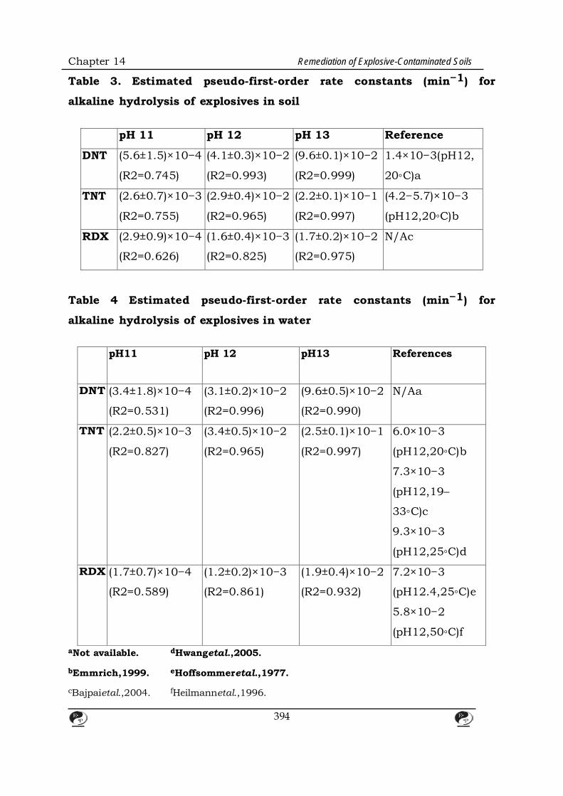
Chapter 14 Remediation of Explosive-Contaminated Soils
Table 3. Estimated pseudo-first-order rate constants (min−1) for
alkaline hydrolysis of explosives in soil
pH 11 pH 12 pH 13 Reference
DNT (5.6±1.5)×10−4
(R2=0.745)
(4.1±0.3)×10−2
(R2=0.993)
(9.6±0.1)×10−2
(R2=0.999)
1.4×10⁻³(pH12,
20◦C)a
TNT (2.6±0.7)×10−3
(R2=0.755)
(2.9±0.4)×10−2
(R2=0.965)
(2.2±0.1)×10−1
(R2=0.997)
(4.2−5.7)×10−3
(pH12,20◦C)b
RDX (2.9±0.9)×10−4
(R2=0.626)
(1.6±0.4)×10−3
(R2=0.825)
(1.7±0.2)×10−2
(R2=0.975)
N/Ac
Table 4 Estimated pseudo-first-order rate constants (min−1) for
alkaline hydrolysis of explosives in water
pH11 pH 12 pH13 References
DNT (3.4±1.8)×10−4
(R2=0.531)
(3.1±0.2)×10−2
(R2=0.996)
(9.6±0.5)×10−2
(R2=0.990)
N/Aa
TNT
(2.2±0.5)×10−3
(R2=0.827)
(3.4±0.5)×10−2
(R2=0.965)
(2.5±0.1)×10−1
(R2=0.997)
6.0×10⁻³
(pH12,20◦C)b
7.3×10⁻³
(pH12,19–
33◦C)c
9.3×10⁻³
(pH12,25◦C)d
RDX
(1.7±0.7)×10−4
(R2=0.589)
(1.2±0.2)×10−3
(R2=0.861)
(1.9±0.4)×10−2
(R2=0.932)
7.2×10⁻³
(pH12.4,25◦C)e
5.8×10⁻²
(pH12,50◦C)f aNot available. dHwangetal.,2005. bEmmrich,1999. eHoffsommeretal.,1977. cBajpaietal.,2004. fHeilmannetal.,1996.
394

Chapter 14 Remediation of Explosive-Contaminated Soils Table 5 Estimated pseudo-first-order rate constants for subcritical
water degradation of DNT, TNT, and RDX in water (unit: ×10−2 min−1)
100◦C 150◦C 200◦C 250◦C 300◦C
DNT 0.3 ± 0.1
(R2 = 0.673)
± 0.1
(R2 = 0.968)
1.7 ± 0.2
(R2 = 0.972)
4.45 ± 0.9
(R2 = 0.930)
9.0 ± 0.3
(R2 = 0.998)
TNT 0.6 ± 0.1
(R2 = 0.955)
1.5 ± 0.2
(R2 = 0.973)
2.2± 0.1
(R2 = 0.993)
6.3 ± 0.4
(R2 = 0.995)
9.5 ± 0.3
(R2 = 0.999)
RDX 0.3 ± 0.1
(R2 = 0.784)
1.4 ± 0.2
(R2 = 0.971)
3.2 ± 0.6
(R2 = 0.946)
10.1 ± 0.6
(R2 = 0.996)
15.6 ± 0.9
(R2 = 0.999)
3.2 Subcritical Water Degradation of Explosives in Water and
Contaminated Soils
Increases in temperature and pressure resulted in degradation of explosives
at subcritical conditions. Degradation of explosives in water under
subcritical conditions and pseudo- first-order rate constants are
summarized in Figure 2 and Table 5, respectively. In contrast to inert
removal at 20◦C (data not shown), 28% of DNT was removed at 100◦C in 120
min (Figure 2a). It appears that the degradation stopped after 60 min. As
temperature in- creased, the removal of DNT increased accordingly,
showing complete removal of DNT at 300◦C in 60 min.
395
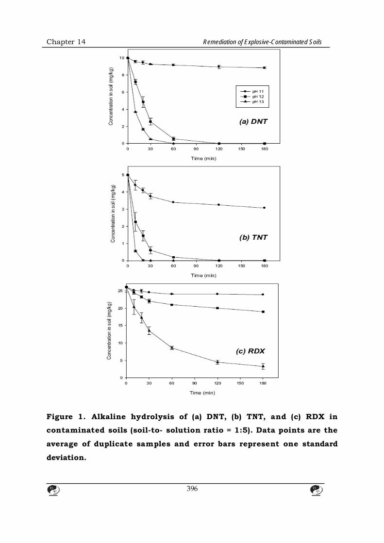
Chapter 14 Remediation of Explosive-Contaminated Soils
Figure 1. Alkaline hydrolysis of (a) DNT, (b) TNT, and (c) RDX in
contaminated soils (soil-to- solution ratio = 1:5). Data points are the
average of duplicate samples and error bars represent one standard
deviation.
396

Chapter 14 Remediation of Explosive-Contaminated Soils
Figure 2. Subcritical water degradation of (a) DNT, (b) TNT, and (c) RDX
in water. Data points are the average of duplicate samples and error bars
represent one standard deviation.
Similarly, 40% of TNT and 30% of RDX were degraded at 100◦C in 120
min. Complete degradation was achieved at 300◦C in 40 min. In the case of
397
Chapter 14 Remediation of Explosive-Contaminated Soils
RDX, more than 99% was removed at 300◦C in 20 min. The estimated
pseudo-first-order rates for DNT, TNT, and RDX degradation at 300◦C were
(9.0 ± 0.3)×10−2, (9.5 ± 0.3)×10−2, and (15.6 ± 1.0)×10−2, respectively.
These results clearly indicate that subcritical water degradation can rapidly
and completely remove the explosives, which is consistent with previous
results.
The degradation of explosives in contaminated soils under subcritical
conditions showed similar trends (Figure 3 and Table 6). However,
compared to the degradation of explosives in water, the extent of degradation
was somewhat faster. At every temperature between 100 and 300◦C, the
degradation of explosives was enhanced in the soil-water system (Figures 2
and 3, Tables 5 and 6). Complete removal of DNT, TNT, and RDX was
obtained at 300◦C in 40, 20, and 20 min, respectively. The estimated
pseudo-first-order rates for DNT, TNT, and RDX degradation in
contaminated soil at 300◦C were (9.4 ± 0.8)×10−2, (22.8 ± 0.3)×10−2, and
(16.4 ± 1.0)×10−2 min, respectively. The acceleration of explosives’
degradation by subcritical water in the presence of soil indicates that soil may
play the role of catalyst to enhance subcritical water degradation of
explosives, which is consistent with previous reported results on TNT
degradation by subcritical water (Kalderis et al., 2008). It is possible that
metal contents (e.g., Al and Fe) in soil may promote the degradation of
explosives by subcritical water (Table 2). More studies will be needed to
thoroughly understand the role of soil as a catalyst in the soil-water system
under subcritical conditions.
In order to determine the optimal conditions for the soil-to-water ratio in the
reactor, subcritical water degradation of the explosives was investigated as
the amount of soil was changed. When the soil-to-solution ratio was 1:10
and 1:5, degradation of the three explosives did not show a significant
difference. As the soil amount was further increased, the degradation of the
398

Chapter 14 Remediation of Explosive-Contaminated Soils
explosives was retarded. At a soil-to-solution ratio of 1:3.3, the degradation
was markedly slowed down. As shown in Figure 4, even at 300◦C, only
after treatment using 71–83% of explosives was degraded. Therefore, the
soil-to-solution ratio needed to obtain constant degradation of explosives
under the given condition is 1:5. According to a previous report by Kalderis et
al. (2008), the degradation of TNT in contaminated soil by subcritical water
was limited when the transfer of TNT from inside a soil matrix to the soil
surface was slowed. Similarly, it is likely that the limitation of mass
transfer of explosives may account for the retardation of degradation of
explosives in the soil-water system when the soil-to-solution ratio is higher
than 1:5.
Table 6 Estimated pseudo-first-order rate constants for subcritical water
degradation of DNT, TNT, and RDX in contaminated soils (unit: ×10−2
min−1)
100◦C 150◦C 200◦C 250◦C 300◦C
DNT 1.4±0.1
(R2=0.998)
2.0±0.1
(R2=0.997)
2.8±0.2
(R2=0.994)
6.0±0.4
(R2=0.995)
9.4±0.8
(R2=0.993)
TNT 1.5±0.2
(R2=0.978)
2.6±0.4
(R2=0.965)
2.6±0.4
(R2=0.965)
13.2±0.6
(R2=0.998)
22.8±0.3
(R2=0.999)
RDX 1.4±0.2
(R2=0.964)
3.9±0.5
(R2=0.975)
7.2±0.3
(R2=0.997)
12.9±0.1
(R2=0.998)
16.4±1.0
(R2=0.997)
3.3 Environmental Implications
Contamination from explosives in soil samples from artillery ranges was
heterogeneous. The concentrations of explosives in soil samples, even from
the same site, showed a striking difference by 2-3 orders of magnitude. In
this study, compared to reported data (Robert et al., 1996; Emmrich, 2001;
Hawthorne et al., 2000; Kalderis et al., 2008), the concentrations of TNT and
RDX in soil were relatively low (5.0–200.4 and 26.1–263.9 mg kg−1,
399

Chapter 14 Remediation of Explosive-Contaminated Soils
respectively). Therefore, it is necessary to assess alkaline hydrolysis and
subcritical water degradation with highly contaminated soils. However, this
research will be promising because previous reports clearly show that highly
contaminated soils can also be readily and rapidly transformed via alkaline
hydrolysis and subcritical water degradation.
To decide the most effective treatment option for explosive-contaminated
soils in artillery ranges, a cost analysis of each treatment process may be
needed. Though subcritical water degradation showed rapid and complete
removal of explosives from the contaminated soil, the increase in temperature
to 200–300◦C may require a substantial amount of operation costs. Therefore,
a cost-effective heating method may be needed for the application of
subcritical water degradation. In addition, in this study we evaluated ex-
situ options to remediate explosive-contaminated soil because operating
military sites were not easily accessible. In order to evaluate cost-
effectiveness for each option, in-situ application should also be considered. In
this case, mutual cooperation between the Korean Ministry of
Environment and the Ministry of Defense may be needed.
Increasing pH higher than 12 and elevating temperature at subcritical
conditions may result in significant changes in soil properties. We
determined the change of soil properties DNT-contaminated soils. In the case
of alkaline hydrolysis, except for the increase of pH (12–13), organic matter
content (loss-on-ignition) and particle size distribution were not changed.
400
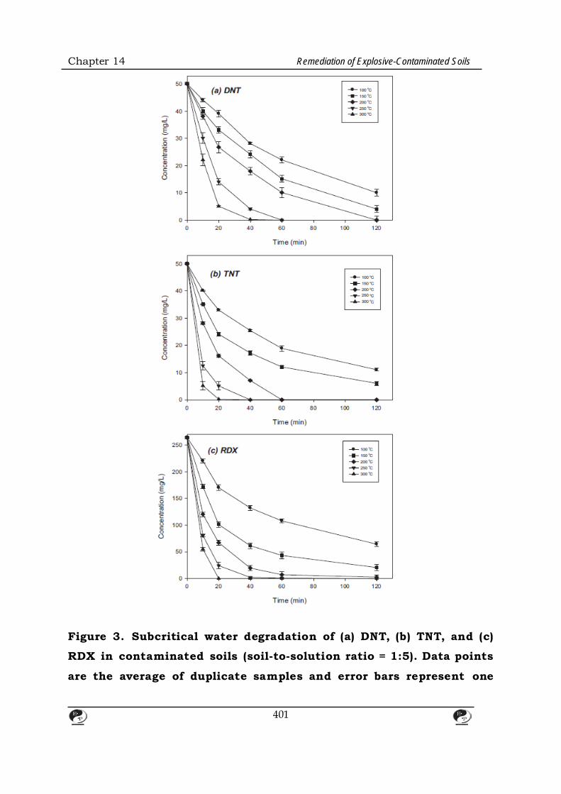
Chapter 14 Remediation of Explosive-Contaminated Soils
Figure 3. Subcritical water degradation of (a) DNT, (b) TNT, and (c)
RDX in contaminated soils (soil-to-solution ratio = 1:5). Data points
are the average of duplicate samples and error bars represent one
401

Chapter 14 Remediation of Explosive-Contaminated Soils
standard deviation
Figure 4. Subcritical water degradation of (a) DNT, (b) TNT, and (c)
402

Chapter 14 Remediation of Explosive-Contaminated Soils
RDX in contaminated soils (soil-to-solution ratio = 1:3.3). Data
points are the average of duplicate samples and error bars represent
one standard deviation. In contrast, subcritical water degradation changed those properties
according to temperatures (Table 1). As temperature increased from 150
to 300◦C, pH slightly increased from 6.3 to 7.5 and organic matter content
linearly decreased from10.3 to 1.9%. Silt and clay size portions were changed
from 80 to 88%. These changes may affect soil functions in terrestrial
ecosystems, such as microbial population and agri- cultural productivity
(Certini et al., 2013). The effect of alkaline hydrolysis and subcritical water
degradation on ecological environment in soil still remains to be explored.
4. Conclusions
In this study, we investigated alkaline hydrolysis and subcritical water
degradation for the treatment of explosive-contaminated soils from artillery
ranges in South Korea. Through batch experiments, it was shown that DNT,
TNT, and RDX in the contaminated soils were rapidly transformed in basic
solution. The critical thresholds for the hydrolytic transformation of DNT,
TNT, and RDX were pH 12, 12, and 13, respectively. Subcritical water
degradation removed the three explosives completely at 200-300◦C. The
maximum soil- to-solution ratio for alkaline hydrolysis and subcritical water
degradation in the soil-water system was 1:5. Our results suggest that
alkaline hydrolysis or subcritical water degradation may be a remediation
option for explosive-contaminated soils.
5. References
1. Bajpai, R., Parekh, D., Herrmann, S., Popovic, M., Paca, J., and Qasim, M.
2004. A kinetic model of aquoeus-phase alkali hydrolysis of 2,4,6-
trinitrotoluene. J. Hazard. Mater. 106B.
2. Balakrishnan, V. K., Halasz, A., and Hawari, J. 2003. Alkaline hydrolysis of
403
Chapter 14 Remediation of Explosive-Contaminated Soils the cyclic nitramine explosives RDX, HMX, and CL-20: New insight into
degradation pathways obtained by the observation of novel intermediates.
Environ. Sci. Technol. 37.
3. Bernasconi, C. F. 1971. Kinetic and spectral study of some reactions of 2,4,6-
trinitrotoluene in basic solution. I. Deprotonation and Janovsky complex
formation. J. Org. Chem. 36.
4. Bradley, P. M. and Chapelle, F. H. 1995. Factors affecting microbial 2,4,6-
trinitrotoluene mineralization in contaminated soil. Environ. Sci. Technol. 29.
5. Bruns-Nagel, D., Drzyzga, O., Steinbach, K., Schmidt, T. C., Von Low, E.,
Gorontzy, T., Blotevogel,H., and Gemsa, D. 1998. Anaerobic/aerobic composting
of 2,4,6-trinitrotoluene-contaminated soil in a reactor system. Environ. Sci.
Technol. 32.
6. Certini, G., Scalenghe, R., and Woods, W. I. 2013. The impact of warfare on the
soil environment. Earth-Science Reviews .
404
CHAPTER – 15
A WHITE PHOSPHORUS MUNITIONS DISPOSAL SITE: A CASE STUDY
1. INTRODUCTION This investigation concentrated on determining the presence, location and
characteristics of the White Phosphorus Munitions Burial Area (WPMBA).
The WPMBA is located in the Chesapeake Bay (Figure 1) within the confines
of the restricted waters of the U.S. Army Base at Aberdeen Proving Ground
(APG), Maryland.
This investigation was conducted as part of a Resource Conservation and
Recovery Act (RCRA) Corrective Action Permit Condition. This Permit
Condition required that the Permittee (APG) conduct a RCRA Facility
Assessment (RFA). The primacy purpose of the RFA is to insure the burial
area is studied and any released wastes are identified and evaluated.
The Aberdeen area of this base was established in 1917 as the Ordnance
Proving Ground. It became a permanent military post in 1919 and was
designated Aberdeen Proving Ground. Testing of ammunition was begun in
January of 1918 (Weston, 1978). Two other major additions to the base
occurred. Spesutie Island was acquired in 1945 and the Edgewood portioa
of the facility merged with APG in 1971.
The open water areas of APG total approximately 37,000 acres (15,000
hectares). Large segments have been used as ordnance impact areas since
1917. There are an estimated four million unexploded and sixteen million
inert projectiles of all calibers in these restricted waters (USATH.AMA. 1980).
The WPMBA is located on the western side of the Upper Chesapeake Bay.
405

Chapter 15 A White Phosphorus Munitions Disposal Site
The area is situated in the shallow waters off the mouth of Mosquito Creek,
between Black Point and Gull Island. Spesutie Narrows and Spesutie Island
lie to the north and northeast, respectively. The WPMBA is adjacent to and
offshore of the Main Front Land Range Area which has been active since
1917. An estimated one million rounds of all calibers up to 16 inches have
been fired at this range. The types of rounds frred included high explosives,
anti-personnel, armor defeating, incendiary, smoke, and illuminating
(USATHAMA, 1980). Although the WPMBA is adjacent to this range,
discussions with APG personnel have indicated that there are no records of
the open water areas of the WPMBA having been used as an impact area.
The closest active range is the Ballistics Workshop located just north of the
WPMBA. The WPMBA lies partially within the 1800 ft (550 m) safety
clearance of this range. The Fuze Range, another active range, is located to
the east of the WPMBA.
406

Chapter 15 A White Phosphorus Munitions Disposal Site
Based on interviews of former employees who worked on the base following
World War I (WWI) the existence of the WPMBA was discovered in the late
1970's. Reportedly, an unknown amount of WWI white phosphorus (WP)
munitions were buried in Chesapeake Bay in the area of Black Point during
the period
1922-1925. The ordnance supposedly consisted of U.S., British, and French
407
Chapter 15 A White Phosphorus Munitions Disposal Site
land mines, grenades, and artillery shells. Bulk phosphorus may also have
been disposed of here. It is possible that this disposal event involved a single
barge load of munitions; however it may have involved considerably more.
The site is located within Chesapeake Bay, a major estuarine ecosystem.
Numerous species of fish utilize the bay during various stages of their life
cycle. Up to 65 species of fish have been identified in the waters at APG and
the adjacent Upper Chesapeake Bay waters (Miller, Wihry, & Lee, Inc.,
1980). Several commercially and recreationally important species utilize the
area, including striped bass (Mor one saxatilis) and the blue crab
(Callinectes sapidus) (USATHAMA, 1980). Aberdeen Proving Ground also lies
in the_ pathway of the Atlantic Flyway, resulting in an abundance of
migratory waterfowl. Due to the toxicity of white phosphorus, releases from
the WPMBA could impact these resources within Chesapeake Bay. Fish are
especially sensitive to concentrations of WP in the water column. It is
important, therefore, to determine whether aquatic organisms and other
wildlife are being exposed to WP.
408
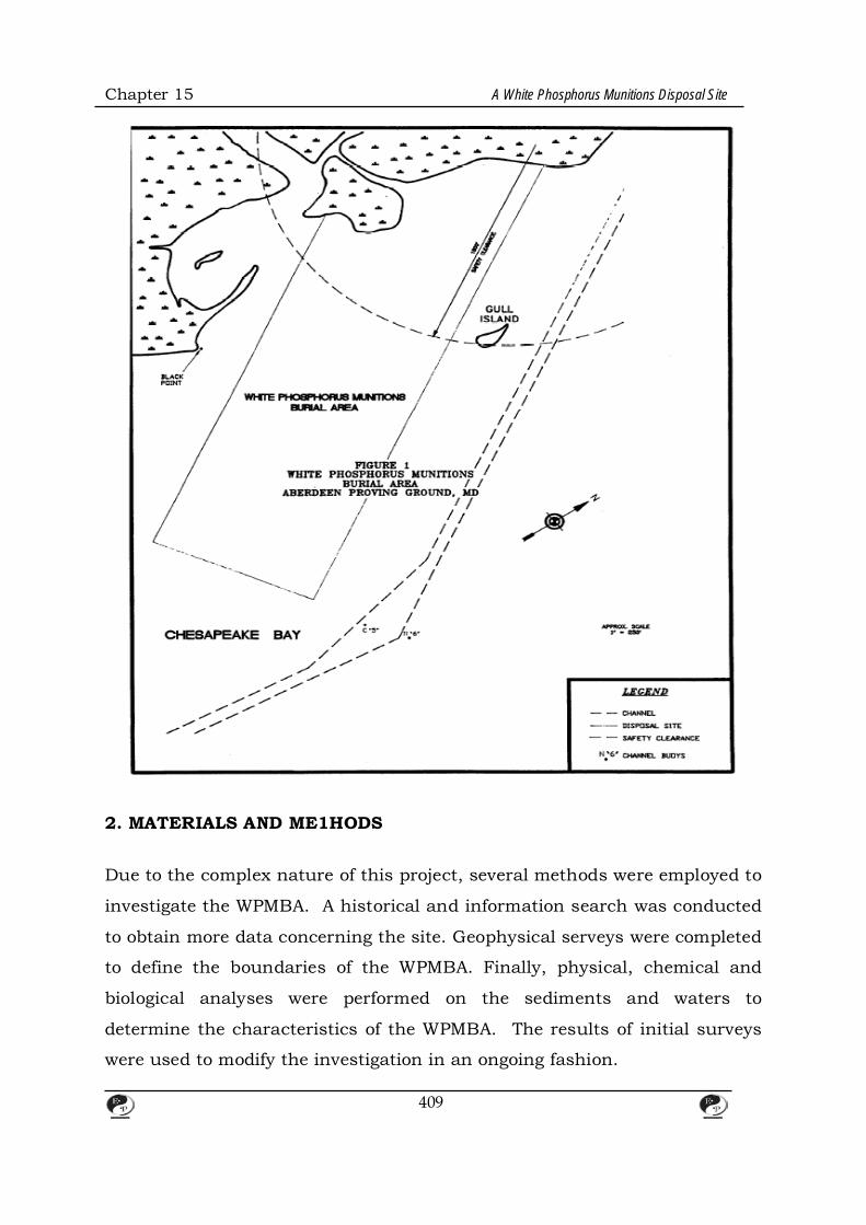
Chapter 15 A White Phosphorus Munitions Disposal Site
2. MATERIALS AND ME1HODS Due to the complex nature of this project, several methods were employed to
investigate the WPMBA. A historical and information search was conducted
to obtain more data concerning the site. Geophysical serveys were completed
to define the boundaries of the WPMBA. Finally, physical, chemical and
biological analyses were performed on the sediments and waters to
determine the characteristics of the WPMBA. The results of initial surveys
were used to modify the investigation in an ongoing fashion.
409
Chapter 15 A White Phosphorus Munitions Disposal Site
2.1 Historical Information Search Aberdeen Proving Ground records, historical maps. and aerial photographs
were reviewed and analyzed. The Library of Congress. National Archives. The
Ordnance Museum at APG, and several white phosphorus manufacturing
companies were contacted for relevant information.
Previous environmental impact assessment documents produced for the
installation were also reviewed. Attempts were made by APG to locate and
interview former employees. Two former employees were contacted and
questioned by APG.
Historical aerial photographs and bathymetric maps were reviewed to
determine if indications of the disposal site were evident. In addition, a
USGS Aeromagnetic map of the area was reviewed for indications of
magnetic field anomalies.
2.2 Geophysical Surveys On October 14-15, 1988, an in-depth geophysical investigation was
conducted in the WPMBA. Transects were completed in two phases due to
safety considerations and constraints of the nearby firing range. A Fisher
Proton 2 Marine Magnetometer was used to screen the entire WPMBA. A
proton magnetometer was deemed the most effective survey instrument
based on field tests comparing various remote sensing instrumentation. A
proton magnetometer is an electronic instrument which measures the
strength of the earth's magnetic field in gammas. Ferromagnetic materials
(containing iron) will alter the magnetic field and result in changes in the
gamma readings. This instrument has a sensitivity of 1 gamma and can
detect a large ferromagnetic object (several tons) from approximately 200
feet.
410
Chapter 15 A White Phosphorus Munitions Disposal Site
An area larger (approximately 285 acres) than that reported for the WPMBA
was screened to get maximum coverage. Transects were approximately 200
ft apart. The distance between transects was selected based on the reported
size of the actual burial area (6 hectares. or 15 acres). A Lowrance X-16
fathometer and a Sitex EZ-97 LORAN C (Long Range Navigation) receiver
were used throughout the sampling periods for bathymetric and
navigational purposes. respectively.
411
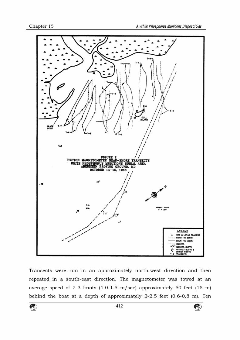
Chapter 15 A White Phosphorus Munitions Disposal Site
Transects were run in an approximately north-west direction and then
repeated in a south-east direction. The magnetometer was towed at an
average speed of 2-3 knots (1.0-1.5 m/sec) approximately 50 feet (15 m)
behind the boat at a depth of approximately 2-2.5 feet (0.6-0.8 m). Ten
412

Chapter 15 A White Phosphorus Munitions Disposal Site
transects were run in duplicate for a total of 20 passes over the near-shore
area. Seven additional transects were run in duplicate in the off-shore area.
A graphical representation of the transects is shown in Figures 2 and 3. The
path of the transects shown deviates from a straight line; this is a function
of the LORAN coordinates and the plotting techniques utilized.
413

Chapter 15 A White Phosphorus Munitions Disposal Site
Buoys were set and surveyed at those sites where large fluctuations were
recorded. indicating a target or anomaly, and which were deemed
significant. During this investigation, the magnetometer was "walked" over
414
Chapter 15 A White Phosphorus Munitions Disposal Site
Gull Island to determine its potential as a dump site.
Based on a review of the data in conjunction with the U.S EPA
Environmental Monitoring Services Lab (EMSL-Las Vegas).the area adjacent
to Black Point was selected for a more intensive survey in June of 1989.
Transects lines were set up every 20 feet (6 m) to more accurately define the
magnetic field and the associated anomalies. The even numbered transects
(i.e.• T-2. T-4) are depicted in Figure 4. while the odd numbered are shown
in Figure 5. Additional transects were run perpendicular to the north and
south transects in an east-to-west or a west-to-east direction at select
points. These were titled 'tie lines' and functioned to tie in the data from
adjacent transects for data interpretation. All data from the magnetometer
was passed through a digital-to-analog converter and then to a portable
strip chart recorder. Concurrently, LORAN coordinates were recorded
through an interface onto the fathometer chart paper at select time intervals
and at buoy markers.
2.3 Remote Sediment Coring Coring activities occurred August 7-17. 1989 and involved the remote
collection of 60 sediment cores within the WPMBA. Due to the inability to
confidently define the boundaries of the WPMBA, a systematic search
sampling method was employed in five areas. A square grid size of 273 feet
(83 m) was utilized assuming a circular target size of 150ft (46 m) with a 0.9
probability (90% chance) of finding the target. Based on this method. a total
of 50 cores would be required to cover those areas with numerous or large
magnetic field anomalies.
Cores were collected off Black Point, in the channel, north of Gull Island
(Area I).east of the channel (Area II). and west of the channel (Area III). In
addition. ten cores were collected in the adjacent APG channel to assist in
415
Chapter 15 A White Phosphorus Munitions Disposal Site
future dredging decisions. Sediment coring was utilized to secure samples
for white phosphorus and high explosives analysis.
Core liners (6 ft butyrate plastic tubes) were utilized throughout the WPMBA
investigation to collect, transport, store and maintain the integrity of the
cores. Four reference samples from two cores were collected in Spesutie
Narrows.
All core samples were screened at the staging area for high explosives using
a Scan X Jr. Portable Gas Chromatograph, inspected for white phosphorus,
and examined for stratigraphy. The Scan X Jr., a portable GC with an
Electron Capture Detector (ECD), was configured to detect the presence of
Nitroglycerine (NG) and trinitrotoluene (TNT).
If the stratigraphy of the core was relatively homogeneous, a composite
sample of the core was collected. The core composite was collected by using
a clean scoop to obtain equal amounts of sediment at six inch intervals
throughout the length of the core. If a discrete strata was observed. a
separate sample of that strata was collected. All sampling equipment was
decontaminated between samples following ERT/REAC procedures. and all
notes were logged on field data sheets or log notebooks. Each sample was
assigned a unique sample number which corresponded to a field data sheet.
To determine whether Gull Island was the location of the WPMBA, core
samples were collected in September of 1989. Soil cores were collected from
the south end and the north end of the island. Samples were collected at
one foot intervals from a depth of 5-8 ft and composited for WP and high
explosive analyses. A listing of the physical/chemical analyses performed
on the sediment samples is depicted in Table 1
416
Chapter 15 A White Phosphorus Munitions Disposal Site
Table.1 : List of Analyses Performed WLDTE Phosphorus Munitions
Burial Area Aberdeen Proving Ground, MD
ANALYSIS MATRIX
White Phosphorus s,w High Explosives s,w RCRA S EP Toxicity for Metals S EP Toxicity for Herbicides Pesticides S Reactive Cyanide S Reactive Sulfide S Ignitability(Flash Point) S Corrosivity S Total Organic Carbon S Grain Size S Metals W Base/Neutra V Acid Extractables W Pesticide!/PCBs W
2.4 Water Analysis During the remote coring operation, water samples were collected for white
phosphorus and high explosives analysis. Water samples were collected at
the surface and 0.5 m off the bottom of each coring area. This included the
reference area by Brier Point, the channel north of Gull Island, Black Point,
and Areas I, II, and III. Water samples were collected with a Kemmerer bottle
for bottom depths, and for surface samples by immersing the sample
containers under the water surface.
In-situ water quality data was collected at each site using a Hydrolab
Surveyor II. Parameters measured were dissolved oxygen, temperature, pH,
conductivity, oxidation-reduction potential and salinity. Readings were
417

Chapter 15 A White Phosphorus Munitions Disposal Site
taken at 0.5 m above the bottom and 0.5 m below the surface at all sites.
418
Chapter 15 A White Phosphorus Munitions Disposal Site
2.5 Analytical Methods Elemental phosphorus was extracted and analyzed using the methods and
419
Chapter 15 A White Phosphorus Munitions Disposal Site
techniques outlined in the method "Direct Determination of Elemental
Phosphorus by Gas-Liquid Cllromatography" by R.F. Addison and R.G.
Ackman (1970). Sediment and water samples were extracted with toluene
and analyzed by gas chromatography/mass spectrometry. The mass
spectrometer was selected as the detector because it can be programed to
scan specifically for the P4 molecule of elemental phosphorus. This
eliminates the misidentification of phosphorus due to coeluting peaks or any
interference in the matrix.
Matrix spike and matrix spike duplicate samples were analyzed for each
batch of ten samples for each matrix. Blanks were analyzed on each analysis
day. The method detection limit using GC/MS was 1.0 ug/L for water
samples, and 5.0 ug/l for sediment samples.
The high explosives (Table 2) in water and soil were extracted and analyzed
using Method No. UW01, Explosives in Water, and Method No. LW02,
Explosives in Soil (Roy F. Weston, Uonville Lab).
Water samples were not extracted and were analyzed by injecting 10 m1 of
sample onto a sample loop and then analyzing by High Pressure Liquid
Chromatography (HPLq. Soil samples were analyzed by extracting the
sediment with acetonitrile, filtering the extract, and analyzing by HPLC. The
HPLC was equipped with a diode array detector so wavelengths could be set
for specific
peaks to enhance sensitivity. Traditionally the wavelength is set at 250 nm.
Matrix spike and matrix spike duplicate samples were analyzed for each
batch of 10 samples for each matrix. Blanks were analyzed on each analysis
day. The method detection limit for nitro explosives was 5.0 ug/L for water
samples, and 1.0 mg/kg for sediment samples.
420
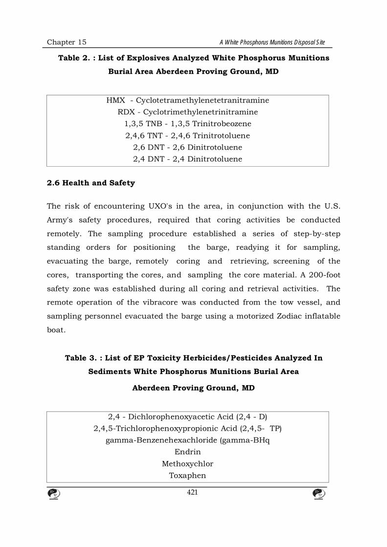
Chapter 15 A White Phosphorus Munitions Disposal Site
Table 2. : List of Explosives Analyzed White Phosphorus Munitions
Burial Area Aberdeen Proving Ground, MD
HMX - Cyclotetramethylenetetranitramine
RDX - Cyclotrimethylenetrinitramine 1,3,5 TNB - 1,3,5 Trinitrobeozene 2,4,6 TNT - 2,4,6 Trinitrotoluene
2,6 DNT - 2,6 Dinitrotoluene 2,4 DNT - 2,4 Dinitrotoluene
2.6 Health and Safety The risk of encountering UXO's in the area, in conjunction with the U.S.
Army's safety procedures, required that coring activities be conducted
remotely. The sampling procedure established a series of step-by-step
standing orders for positioning the barge, readying it for sampling,
evacuating the barge, remotely coring and retrieving, screening of the
cores, transporting the cores, and sampling the core material. A 200-foot
safety zone was established during all coring and retrieval activities. The
remote operation of the vibracore was conducted from the tow vessel, and
sampling personnel evacuated the barge using a motorized Zodiac inflatable
boat.
Table 3. : List of EP Toxicity Herbicides/Pesticides Analyzed In
Sediments White Phosphorus Munitions Burial Area
Aberdeen Proving Ground, MD
2,4 - Dichlorophenoxyacetic Acid (2,4 - D)
2,4,5-Trichlorophenoxypropionic Acid (2,4,5- TP) gamma-Benzenehexachloride (gamma-BHq
Endrin Methoxychlor
Toxaphen
421

Chapter 15 A White Phosphorus Munitions Disposal Site
Reactive Materials Management, Inc., was secured to provide assistance
with standard UXO safety procedures. Their primacy role was to survey and
inspect the core for metal objects after retrieval and prior to handling, and
assist sampling personnel in the event that munitions were found.
The maximum credible event (MCE) was discussed as well as procedures for
such an event. The MCE for this investigation involved determining what
was the most dangerous ordnance that would be encountered or entrained
within the core tube. The MCE for this investigation was determined to be a
40 mm grenade; it was improbable that larger munitions would be entrained
by the core.
The other major risk to personnel involved the potential contact with white
phosphorus and WP munitions. The hazards posed to sampling personnel
from WP included the potential for fire and explosion, and the inhalation of
toxic fumes produced during its burning.
Several contingencies were put in place in order to minimize the WP hazard.
A 55-gallon drum, filled with water and placed in close proximity to all core
handling operations (i.e., on the barge, near the sample prep table), was to
be used to submerge a core with an isolated flare-up. A pressurized hose
was also available on the barge (via pump) and at the sample prep area to
douse any core which could not be isolated and submerged. In the event of
an incipient fire, personnel were instructed to don emergency respiratory
equipment (self contained breathing apparatus) and evacuate the area
immediately. As a back-up to the water systems available, a ten gallon pail
filled with wet mud was placed on the barge and in the sample prep area.
In order to control incidental skin contact with WP or other contaminants
which may have been contained in sediments, personnel involved with
422

Chapter 15 A White Phosphorus Munitions Disposal Site
sample handling wore butyl aprons, rubber boots, nomex coveralls, and
long sleeve butyl gloves. Hard hats equipped with face shields prevented
sediments or contaminants from splashing into eyes. The use of protective
clothing increases the potential for heat stress related injuries. Frequent
breaks between sampling events, construction of shaded areas, and
resupply of fluids eliminated the hazards associated with the sun and hot
weather conditions.
3. RESULTS
3.1 Historical Information Search
The results of the historical and information search led only to clues as to
the location and contents of the WPMBA. The review of the Aberdeen Proving
Ground records did not reveal the exact location or the contents of the
WPMBA. A review of previous environmental impact assessment documents
revealed that no documentation of the actual dumping location was found. It
was stated in one of these reports that generally, records on the
manufacturing and disposal operations prior to World War II did not exist or
were largely incomplete (USATIIAMA, 1980). Reportedly, the existence of the
disposal site was based on interviews of former installation employees. One
reference stated the phosphorus disposal area, was established nearly 55
years ago to dispose of deteriorated World War I white phosphorus
projectiles of various calibers. After disposal in 5 feet of water, this area was
backfilled with earth. An additional two feet of fill was then placed over the
area" (USATHAMA, 1980). Another references stated the following: "Area 12,
just off Spesutie Island, was the site of a 1922 to 1925 dumping operation
for World War I munitions containing WP. The site is about 6 ha (hectare) in
area. The WP is buried under about 0.6 m of fill, covered with 0.9 m of
water. The amount of WP buried at this site is unknown" (ESE, 1981).
Another excerpt stated: "The burial reportedly occurred in the waterfront
region near Black's Point [sic], encompassing an area of 6 hectares (15
423
Chapter 15 A White Phosphorus Munitions Disposal Site
acres). When disposed, the munitions were placed in the tidal flats and
covered with 0.6 m of sediment".
No evidence of a disposal site was observed in any of the historical aerial
photographs reviewed. The most pertinent observation was the presence of
what appears to be dredge spoils on Gull Island in the 1944 photo. The size
of the island was greatly increased compared to earlier photos. Evidence of
shoaling and exposed dredge spoils is also evident inshore, northwest of the
island. The dredge spoils are not visible in the 1951 and 1956 photos,
indicating the rapid dispersal of these sediments by winds, tides, and
storms. The most obvious shoreline change is evident at Black Point. The
photos indicate the shoreline is growing due to an accretion of sand in a
northern direction towards the mouth of Mosquito Creek. The most recent
aerial photo, from 1981, shows that this accretion has extended
approximately halfway to the mouth. Based on field observations, this
process seems to have accelerated in recent years. At present, this peninsula
has formed a protected cove across the mouth of Mosquito Creek and only
an entrance way of approximately 10 meters is present.
A review of the NOAA historical bathymetric maps indicated: there was no
indication of Gull Island on any of the maps dated prior to the dumping,
Black Point was rounded with no visible peninsula, and the bathymetiy of
the area was similar.
The 1971 aeromagnetic map (USGS) that was examined did not indicate the
location of the WPMBA. The map indicated that the intensity contours were
bent towards Black Point and Mosquito Creek to the northwest, however, no
maximum or minimum intensities were recorded in the WPMBA.
No direct information concerning the disposal site was available from the
Library of Congress, the National Archives, or several white phosphorus
424

Chapter 15 A White Phosphorus Munitions Disposal Site
manufacturers, including E.I. Dupont a manufacturer of WP during WWI.
Through the examination of U.S. Army bulletins and other federal
regulations it was determined that bulk white phosphorus was transported
in iron or steel containers. The significance of this is that if bulk white
phosphorus was disposed at this site, it should have been contained in
ferrous metal containers. Therefore, if still present, these containers would
be detected by a proton magnetometer.
One major piece of information comes from Proclamation 2383, signed by
President Franklin D. Roosevelt on January 24, 1940. Previously, two areas
were designated as Migratory Waterfowl closed Areas under a regulation
adopted by the Acting Secretary of the Interior on December 12, 1939, under
the authority of the Migratory Bird Act of July 3, 1918 (40 Stat. 755, 16
U.S.C. 704). One of the areas approved by the proclamation was entitled the
"Phosphorus Area Unit".
Reportedly a large migratory waterfowl kill had occurred during the 1930's
due to a release of white phosphorus from this are. Speculation is that this
proclamation was a result of this kill.
This proclamation was the only written document found that specifically
mentions phosphorus and delineates the boundary of the area. The size of
this area encompasses approximately 130 acres (53 hectares). It was
assumed that the area described incorporated the WPMBA.
One former employee of the base was contacted by APG (I. Wrobel, APG,
Personal communication). He reported that a hurricane in the 1930's
uncovered the WPMBA which led to a large waterfowl kill. He stated that
"the ducks turned pink and died". The Army then placed a flood light on the
area to discourage waterfowl use. No other persons with knowledge of the
site were identified.
425
Chapter 15 A White Phosphorus Munitions Disposal Site
Several storms occurred during the 1930's which could have been
responsible for eroding the sediment cap on the WPMBA. with the August
23, 1933 hurricane the most likely of these. This storm was actually termed
a gale in the vicinity of APG with winds reaching 42 miles per hour (mph).
The storm reportedly caused the greatest statewide damage of all time.
Waves and tides caused the majority of damage and considerable erosion of
the western shore of Chesapeake Bay was reported (Tmitt, undated; USDA.
1933). Winds in the vicinity of APG were reported to be out of the northeast
shifting to the southeast during the storm. Waves impacting the Black Point
area from the southeast could have caused considerable erosion and led to
the uncovering of the WP munitions. Two other hurricanes occurred, in
1936 and 1938, and both passed by the coast of Maryland and caused high
winds inland.
Aberdeen Proving Ground supplied information concerning World War-I
munitions. In addition, several reference books were reviewed to determine
the types of munitions that may have been disposed at the site. Three types
of rounds which contained WP were listed by one reference (Prentifs, 1937).
All rounds were constructed of steel. One, a Livens Projectile, contained up
to 30 pounds (lbs) of fill (WP). Two sizes were in use, a 2 foot 9 inch, and a 4
foot projectile. The second type of round listed was a four inch Stokes
mortar shell. The fill in this shell was 6.3 to 9.5 lbs of WP. The third type
mentioned in this reference was a 4.2 inch mortar shell which contained
approximately 8 lbs of WP.
Another undated reference, entitled "Chemical Techniques and Practices of
Artilleey", contained information on two other types of ordnance. The first
was a 75-mm gun that used a shell containing 1.81lbs of WP. The bursting
charge contained 1.6lbs of TNT. The second ordnance was a 155-mm
howitzer that used shells containing 15.4 lbs of WP.
426
Chapter 15 A White Phosphorus Munitions Disposal Site
The APG records also included a more recent investigation involving samples
collected from the channel east of the WPMBA (USACOE, 1982).
Approximately eight sediment samples were collected in the channel
between the Mulberry Point dock and buoy number 2. Additional samples
were collected from Spesutie Narrows and disposal areas (presumable
dredge spoils) northeast and southwest of the WPMBA. These samples were
analyzed for metals, volatile solids, hexane extractables, chemical oxygen
demand, total kjeldabl nitrogen, total phosphate, phosphorus, and grain
size. No phosphorus was detected in any of the samples at a detection limit
of <30 ppb.
3.2 Geophysical Surveys The geophysical Surveys were initially set up to screen the entire WPMBA
with subsequent surveys focusing in on particular areas. A preliminary
review of the first survey results indicated that no large (i.e. several acres)
homogeneous burial area was evident. What was evident was the fact that
numerous isolated magnetic field anomalies were present within the entire
WPMBA. Some of these anomalies were outside of the WPMBA boundaries. A
total of approximately 110 major anomalies were detected during these
surveys (Figures2 and 3). Transects T-6, T-7, T-10, T-11, T-14, T-15, and T-
16 contained the majority of the anomalies and some of the largest in
magnitude. These magnetic field anomalies indicate the presence of ferrous
objects. This could include munitions from the WPMBA. UXO's from the
firing ranges, construction debris, or any other object containing iron which
may have been dumped in the area.
During the October, 1988 survey the proton magnetometer was utilized to
screen Gull Island. This survey did not detect any major anomalies on the
island.
427

Chapter 15 A White Phosphorus Munitions Disposal Site
The Black Point survey also detected numerous magnetic anomalies.
Anomalies greater than 400 gammas were observed throughout the
transects. Many of these anomalies were probably caused by single
containers (cannon shells). However, no homogeneous areas were detected
which would indicate the exact boundaries of the WPMBA. What was
detected was a heterogeneous zone with the majority of anomalies
concentrated in the near-shore transects (T.() - T-9). Three areas were
identified as containing clusters and the largest anomalies. One area was
located directly off Black Point along transects 3 and S; one was located
approximately 600 feet north of Black Point along transects S and 7; and
one was located approximately 400 feet south of Black Point along transects
S through 9. In these areas, a significant number of anomalies occurred on
at least four to six adjacent survey lines (approximately 80 to 120 feet
across).
3.3 Remote Sediment Coring The screening results indicated that none of the cores analyzed with the
Scan X Jr. had nitroglycerine present at a detection limit ranging from 1 to
10 ppm NG. The results of the elemental phosphorus (WP) analysis of the
sediment cores are listed in Table 4. A total of 11 samples out of 71
contained elemental phosphorus. The concentrations ranged from 0.62 -
4.64 ug/kg dry weight, and 0.28 -1.90 ug/kg wet weight. All concentrations
are reported as below the quantitation limit and are approximate. Seventeen
of the 60 cores collected were located directly in the assumed boundaries of
the WPMBA (Figure 6). Four of these cores contained WP. Thirty-three
cores were adjacent to or outside of the WPMBA. Six of these cores
contained WP. Ten cores were located in the boat channel and one contained
WP. The locations of the cores were distributed throughout the study area.
One core contained elemental phosphorus in Areas I, II and the channel;
three cores contained phosphorus in Area III; and five cores contained
428

Chapter 15 A White Phosphorus Munitions Disposal Site
elemental phosphorus in the Black Point area. The core lengths ranged
from less than one foot to nine feet. Three of the samples (17, 18, and 20) at
Black Point were adjacent to one another. The three cores in Area III were
also in close proximity, as were cores 3 and 31of Area I and the channel,
respectively. The remaining three cores were solitary. No elemental
phosphorus was detected in the samples collected on Gull Island.
An examination of the core locations in conjunction with the target locations
at Black Point reported by EMSL indicated that seven cores (9, 13, 14, 18,
19, 37, and 38) were within this target area. Only core 18 had detectable
concentrations of WP. It appears that cores 14 and 37 were collected almost
directly on top of two of the areas with major anomalies, neither detected
WP. Cores 17, 20, and 2S with concentrations of WP were adjacent to this
target zone. Nine other cores were adjacent to the areas outlined by EMSL,
none detected WP. Core 11, which also contained WP, was outside of the
EMSL survey area.
No high explosives were detected in any of the core samples. Four of the eight metals tested for in the RCRA EP toxicity analysis were
detected in the sediments in very low quantities. Arsenic (As) was detected in
fifty-four samples tested. Arsenic levels ranged from 0.002 mg/1, core 36, in
the Black Point Area to 0.18 mg/1, cores 11 and S6,in the Black Point Area
and Area III, respectively. Barium (Ba) was detected in fourteen locations in
each of four areas: Black Point- cores 1S and 36; Area II- core 49; Area III-
cores S1 and S2; Channel- cores 26-31 and 33-35. Detected barium levels
ranged from 0.8 mg/1, core 33, to 0.29 mg/1, core 30.
429
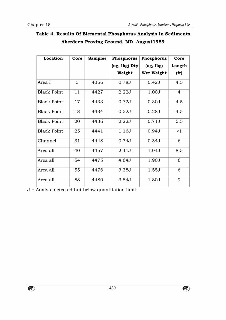
Chapter 15 A White Phosphorus Munitions Disposal Site
Table 4. Results Of Elemental Phosphorus Analysis In Sediments
Aberdeen Proving Ground, MD August1989
Location Core Sample# Phosphorus
(ug, lkg) Dty
Weight
Phosphorus
(ug, lkg)
Wet Weight
Core
Length
(ft)
Area I 3 4356 0.78J 0.42J 4.5
Black Point 11 4427 2.22J 1.00J 4
Black Point 17 4433 0.72J 0.30J 4.5
Black Point 18 4434 0.52J 0.28J 4.5
Black Point 20 4436 2.22J 0.71J 5.5
Black Point 25 4441 1.16J 0.94J <1
Channel 31 4448 0.74J 0.34J 6
Area all 40 4457 2.41J 1.04J 8.5
Area all 54 4475 4.64J 1.90J 6
Area all 55 4476 3.38J 1.55J 6
Area all 58 4480 3.84J 1.80J 9
J = Analyte detected but below quantitation limit
430
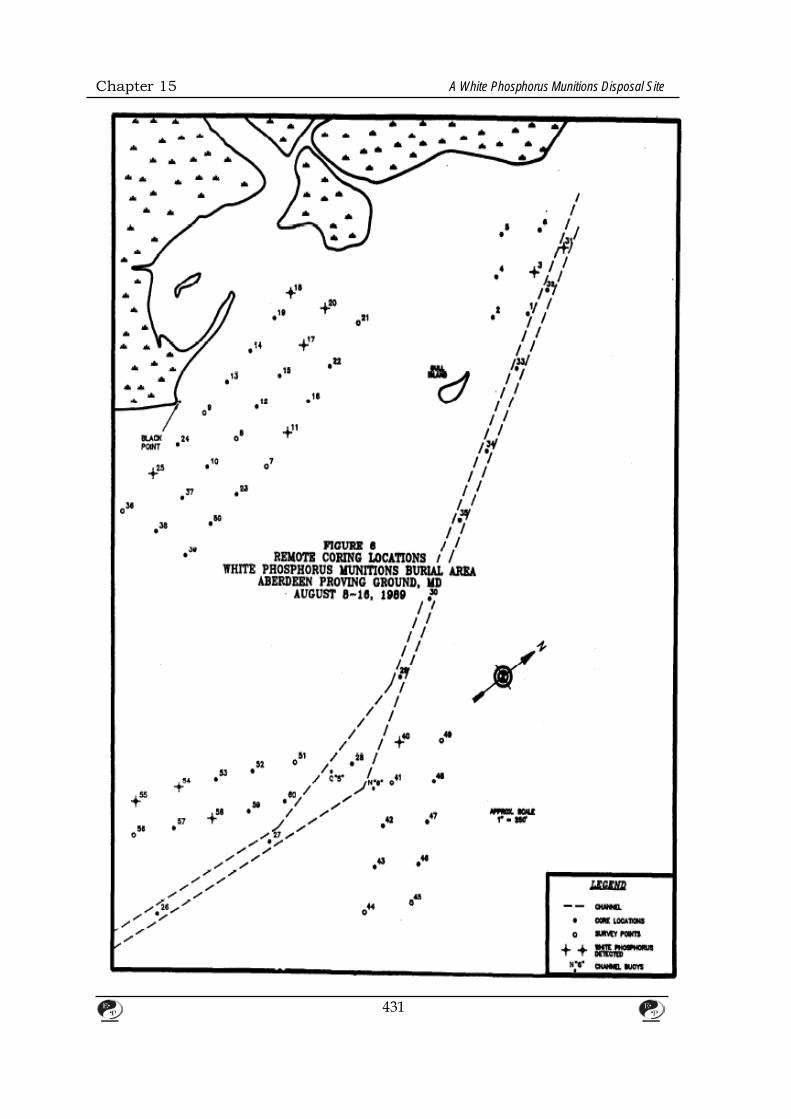
Chapter 15 A White Phosphorus Munitions Disposal Site
431
Chapter 15 A White Phosphorus Munitions Disposal Site
Cadmium (Cd) was detected only in the Chanel Area, core 30, at 0.0087
mg/1. Mercury (Hg) also was detected only in the Channel Area, core 32, at
0.0014 mg/1. Silver (Ag), chromium (Cr), lead (Pb), and selenium (Se) were
not detected in any of the EP Toxicity samples. All detected metal levels fell
below cited maximum contaminant concentrations for EP toxicity (40 CFR
01. 1 Sec. 261.24).
Herbicides and pesticides in the EP toxicity tests were undetected in a
samples. Additional RCRA inorganic analysis included ignitability,
corrosivity and reactivity for cyanide and sulfide. Cyanide reactivity was
below the detection limit for all sample analyzed Reactive sulfide was
detected in 24 samples and ranged from 13.6 to 157.0 mg/kg. 1be flash
point for all samples was greater than the limit of 200"F indicating the lack
of highly combustible material. The corrosivity was also below the detection
limit of 6.35 millimeters per year (mm/year) for all samples tested.
Sediment grain size analyses were performed to examine the composition
and characteristics of the cores. Based on these analysis results and field
observations the majority of cores exhibited a similar grain size composition.
Most cores were predominantly silt with lesser amounts of clay and sand.
This pattern was evident for Areas I, II, III, and the channel Black Point
sediments were similar offshore and north of the point. Close to Black Point
the sediments were predominantly sand with increasing amounts of fines
with depth. Peat and organic matter were common in the cores closer to
shore and at a shallower core depth. Cores 44 and 45 in Area III contained
peat at depths of 6.5 to 9 ft.
Total organic carbon concentrations in the sediments ranged from 34,000-
340,000 mg/kg (3.4 -34 %). The majority of the cores contained less than 10
% organic carbon
432

Chapter 15 A White Phosphorus Munitions Disposal Site
3.4 Water Analysis Fourteen water samples were secured in representative areas during the
coring operation in August, 1989. Samples were analyzed for elemental
phosphorus and high explosives. There was no elemental phosphorus
detected in any of the water samples at a minimum detection limit of 1.0
ugiL. The analysis for high explosives failed to reveal the presence of any of
the nine explosive compounds tested for at the S.O ugiL minimum detection
limit.
In-situ water quality parameters were consistent with seasonal variations
common for this estuarine water body.
4. DISCUSSION The purpose of this investigation was to answer questions related to a RCRA
Facility Assessment. The primary purpose was to insure that the burial area
was studied and any released wastes were identified and evaluated in
subsequent study phases. The only waste for which there is evidence of a
release is white phosphorus .The presence of WP in low concentrations in
11cores indicates sediment contamination. The source may or may not be
the WPMBA.
Other purposes of this investigation were to identify the boundaries of the
WPMBA. Based on the results of this investigation it appears that
boundaries for this burial area no longer exist. Due to the extended burial
period and the dynamic nature of the bay, it appears that the material
buried has been dispersed over a large area. It is also possible that isolated
dumping episodes occurred over the general area, or that the WP detected is
from more recent testing of munitions (UXO's). Another purpose of the RFA
was to determine if releases of hazardous waste are occurring or have
433
Chapter 15 A White Phosphorus Munitions Disposal Site
occurred. RCRA analyses indicated that the core samples would not be
characterized as a hazardous waste. The historical information would lend
credence to the reported uncovering of the WPMBA in the 1930's and
subsequent release. The presence of trace concentrations of WP in the
sediment indicate that releases have most likely occurred. However, the
magnitude of past releases, and the present mass of WP remaining are
unknown.
The results of the historical and information search revealed that no records
were found which would identify the exact location and content of the
WPMBA. The general area was determined based on references which were
based on interviews of former base employees and the delineation of the area
by the Migratory Bird Treaty Act. Relevant information indicated that white
phosphorus was stored in ferrous metal containers and therefore should be
detectable by proton magnetometers. An initial assumption that the shells
were intact to a sufficient degree was found to be accurate since many
targets were detected. In addition, the presence of WP in the areas where
magnetic anomalies were found indicated that this was a correct
assumption. A second important piece of information was the 1933
hurricane which was reported to have uncovered the WPMBA. Records
indicating extensive erosion of the western side of Chesapeake Bay during
this storm were located. This is further substantiating evidence that a
release of WP occurred during the1930's.
The fate of WP in the environment is an important issue at this site. "White
phosphorus enters the aquatic environment as phossy water which is
generated wherever WP is manufactured, stored under water, or spilled.
Phossy water contains dissolved and colloidal WP as well as larger
suspended particles. Data from manufacturing and munitions loading
plants indicate that much of the WP in phossy water is dispersed or colloidal
rather than dissolved. The mixture, whether dissolved, dispersed, or
434
Chapter 15 A White Phosphorus Munitions Disposal Site
colloidal, reacts with dissolved oxygen and hydroxide ion to form various
oxides, acids, and phosphine. In high concentrations as a suspension, it
results in low to zero dissolved oxygen in the surrounding water; unreacted
particles settle out and can be incorporated into aquatic sediments. These
particles, when buried in anoxic sediments, are stable for long periods of
time." (Environment Canada, 1984).
The lack of detectable quantities of WP in the water column indicates the
stability of the WP in the sediments. However, it is possible that WP could be
released to the water column during disruption of the substrate. Based on
the low concentrations of WP that cause toxicity and the detection limit of 1
ug/1 used in this study, it is important to look at concentrations that are
potentially present. The current US EPA criteria (1986) for marine or
estuarine waters is 0.10 ug/L of elemental phosphorus. An examination of
the water chemistry of WP will lend some additional insight, however, data
on reaction kinetics and decomposition products of WP in water are poorly
defined (Environment Canada, 1984). Oxidation rates vary widely and
appear to depend on pH, dissolved oxygen, temperature, metal ions, and the
degree of dispersion of colloidal or suspended material. Half-lives of WP in
seawater and freshwater were 240 and 150 hours, respectively, for an initial
concentration of 1-50 ppm at OOC (Environment Canada, 1984).
A major factor controlling the rate of disappearance of white phosphorus
apparently is whether it is suspended or dissolved. At concentrations below
the solubility limit, and where a majority of the material is dissolved, it
initially oxidizes in aerated water via a first order reaction to concentrations
below 0.01 ppm. The material continues to slowly oxidize to equilibrium
levels of 0.04 to 0.10 ppb. Other preliminary results, however, suggest that
white phosphorus at low concentrations rapidly oxidizes to below 0.01 ppb.
The disappearance rate from more concentrated suspensions apparently is
controlled by diffusion and the protection of the phosphorus from the
435
Chapter 15 A White Phosphorus Munitions Disposal Site
dissolved oxygen. It has been shown that saline water may influence the
reaction rate. The authors suggested that perhaps salts coagulate the
colloidal particles and make them less accessible to oxygen. It is suggested
that WP may oxidize in a single step or react stepwise to form several oxides
that are ultimately converted to phosphate as phosphoric acid.
(Environment Canada, 1984)
It is possible that the WP sediment concentrations observed in the various
areas are remnants of the disposal site. The dispersed nature of the WP may
indicate that the exposure of the site in the 1930's spread WP over a wide
area. Due to the assumed heavy sediment load in the water column during
the 1933 storm, the WP may have been dispersed and then quickly covered
by sediment. The anaerobic conditions observed in most of the cores would
indicate that the WP would be stable for a long period of time.
Another explanation could be that the WP detected in each area was the
result of isolated shells from prior testing which have deteriorated and
released WP. If WP was tested at the adjacent ranges, the munitions could
also have ended up in Mosquito Creek. Subsequently, contaminated
sediment could have been transported downstream to the mouth of
Mosquito Creek and the Black Point area. The lack of information on the life
of WP in sediments, whether aerobic or anaerobic, makes it difficult to
determine the source of this WP.
Low concentrations of elemental phosphorus in the water column have been
documented as causing acute effects on aquatic organisms. Existing toxicity
test data of WP on aquatic organisms was summarized by Sullivan et al.
(1979). They report that freshwater and marine invertebrates are less
sensitive to WP than fish. Various species of invertebrates were tested, with
results for Chironomus tentans reported as a 48-hour E<:o ov 140 ug/1 WP.
436

Chapter 15 A White Phosphorus Munitions Disposal Site
E<:;o is defined as the concentration of a contaminant that affects 50% of
the test population in a sublethal manner, such as immobilization. The
lowest 48-hour E<:;o was 30 ug/1 for the freshwater cladoceran, Daphnia
magna. Limited data was reported for marine invertebrates and included a
24-hour E<:; o of 6500 ug/1 for Gammarus oceanicus and a 168-hour E<:;o
of between 20 and 40 ug/1 of WP for the lobster (Homarus americanus).
Fish are much more sensitive to the effects of WP. Of the freshwater fish
studied, the bluegill (Lepomis macrochirus) was the most sensitive to WP
with a static 96-hour LC50 of 2 ug./L (Sullivan et al., 1979). Marine and
euryhaline fish are also very sensitive to WP. Atlantic salmon (Salmo salar)
had a reported 96- hour L<:; o of 2.3 ug/L whereas the strictly marine fish
Atlantic cod (Gadus morhua) had a reported value of 2.5 ug/L WP (Sullivan
et al., 1979).
Rapid bioaccumulation of WP has been documented and is related to the
lipid content of the organism. Bioconcentration factors of between 20 and
100 have been reported for aquatic organism tissues, and in an extreme
case up to several thousand in the Atlantic cod liver. Rapid removal from the
tissues has also been reported if the organism is transferred to clean water
(Sullivan et al., 1979).
The mechanism of toxicity of white phosphorus is reported to be related to
its potent reducing powers. WP enters via the gills or intestinal tract,
circulates in the blood and damages all tissues that it contacts. Damage
appears to be related to exposure time and concentration (Sullivan et al.,
1979). Gross effects of WP toxicity on fish include hemolysis with
symptomatic reddening of the skin, jaundiced liver, and/or green intestines.
In mammals, shock and cardiovascular system damage result in rapid death
due to acute poisoning (Craig et aL, 1978). Lower dosed deaths have been
437
Chapter 15 A White Phosphorus Munitions Disposal Site
attributed to renal or liver failure and digestive tract damage. The reported
threshold dietary level for retarding growth in rats is in the range of 0.003-
0.07 mg P/kg/d, while the lethal dose is 7 mg/kg. Humans are 1lbout five
times more sensitive than rats to the lethal effects of WP (NRCC, 1981;
Sullivan et al., 1979).
Another concern is the impacts of contamination through the food chain.
White phosphorus contamination in various fish tissues has been shown to
be toxic or lethal if ingested by other fish or mammals including humans
(NRCC, 1981; Sullivan, 1979). However, due to the reactivity of WP, the
transfer of this element through the food chain would not be expected to
last. In terms of long term food chain contamination, the potential from WP
is considered oil (Environment Canada, 1984).
Based on previous investigations, the "no effect level" for WP in sediment
probably lies below 2 ug/kg (wet weight). This value was the minimum
sediment concentration found at which adverse impacts occurred to the
benthic community in a freshwater system (Sullivan, 1979; Environment
Canada, 1984). All WP wet weight ·concentrations were below 2 ug/kg for
the WPMBA investigation. This would indicate "rio effect",, concentrations.
The fact that" these samples were composite samples may indicate that
higher concentrations were present in distinct layers. However, the relative
position in the core is important If WP is close to the surface it will probably
impact the benthic organisms; if WP is buried several feet under the surface
it will not impact the benthic biota, unless uncovered.
Examining the data for marine environments indicates that sediment
concentrations of WP above 70 ug/kg and water concentrations of 3 ug /L
have been associated with impacts on the invertebrate community in the
form of selected mortalities (Environment Canada, 1984). Furthermore, it is
438

Chapter 15 A White Phosphorus Munitions Disposal Site
stated that concentrations of WP greater than 1 ug/L do not persist for
appreciable periods of time, although resuspension of sediments may
maintain a concentration of 0.5-1.0 ug/L in overlying water. Marine
sediment concentrations of WP are also reported as stable (Environment
Canada, 1984).
The threat of exposure of migratory waterfowl to WP is considered minimal.
Eleven species of waterfowl associated with the Atlantic Flyway have been
indentified within the confines of APG. Dabbling ducks [mallard, black duck
(Anas rubripes), wood duck (Aix sponsa)], diving duck]. Canada geese,
whistling swan, loon (Gavia inner), merganser (Mergus merganser), gallinule
(Gallinula chloropus), and the Americal Coot (Eulica american ) have all
been observed (Miller, etal. 1980). APG waters and wetlands are primarily
utilized as winter habitat for all species cited. Wood duck have been
observed during the summer breeding season. The diving ducks, loons, and
mergansers are the species most apt to be of concern in relation to WP.
Since these are all subsurface foragers, particularly feeding in the sediment,
WP exposure is possible. Vegetative root stock, benthic invertebrates,
mussels, and soft shell crabs are preferred sources for the associated
species. Dabbling ducks feeding in shallow surface water on preferred
aquatic vegetation may also be exposed to bottom sediments. Ingestion of
WP could result during acquisition of the food source or directly from the
food source itself. The observed waterfowl kill from 1933 is suspected to
have occurred through actual consumption of available WP in the food and
sediment. No additional waterfowl kills in the WPMBA have been cited since
that time.
The absence or low levels of WP detected in the sediments of the WPMBA
suggests a low probability of WP toxicity to lower food chain organisms.
However, bioaccumulation to an upper level consumer, such as waterfowl,
should be considered. Bioaccumulation of WP is manifested through its
439
Chapter 15 A White Phosphorus Munitions Disposal Site
lipophilic tendency (Environment Canada, 1984). Waterfowl do exhibit high
lipid levels due to their insulation requirements, therefore WP accumulation
may be more pronounced. Avian toxicity data is minimal but the lethal dose
has been cited as 3 mg/kg (NRCC, 1981). Several factors, however, suggest
that bioaccumulation may be negligible. Waterfowl are utilizing the WPMBA
waters during a few months in the winter season. Therefore, exposure to the
small quantities of WP detected should be minimal Additionally, waterfowl
lipid content during the winter is elevated. This may serve to isolate any WP
ingested and prevent manifestation of acute WP symptoms until metabolism
can occur. Furthermore, large birds rather than more sensitive precocial
young would be utilizing the food resource. For these reasons, sub-lethal
effects on waterfowl should be isolated or of a low probability.
Previously cited references stated that the WPMBA was located in 0.9 m (3
ft) of water. Assuming this was low water, an examination of the bathymetry
of the WPMBA (Figure 7) and the core locations indicate that S of the cores
where WP was detected were in waters deeper than 4 feet (at low water). The
remaining six cores were located in water depths of between 2 ft and 4 ft.
The tidal range for this area of the Chesapeake Bay is approximately 0.8 to
2.4 feet depending on the tidal period. Even taking the tidal range into
account, the former five cores are located in deeper water. These were the
cores located in Areas II and III, and the channel Changes in bathymetry
have also most likely occurred due to storms, tides, and the closing of the
Spesutie Narrows causeway in the 1960's. A comparison with historical
bathymetric maps indicate that depth contours have changed in the WPMBA
due to the accretion of sand in the Black Point area, the addition of Gull
Island, and the dredging of the channel to Mulberry Point dock. The
majority of the WPMDA's bathymetry is similar. to historical maps, including
Areas II and III.
The physical processes which occur within the WPMBA also need
440
Chapter 15 A White Phosphorus Munitions Disposal Site
examination. Shorelines can be altered due to erosion and accretion.
Erosion occurs due to the refraction of waves, with the wave energy
concentrated on lands that extend into open water (Thurman, 1975). Storm
waves can cause more erosion in one day than by average waves in one year.
The rate of erosion is affected by the exposure of the shoreline, by the tidal
range, and by the composition of the shoreline. A smaller tidal range results
in greater erosion since there is less area to spread the wave energy
(Thurman, 1975). A longshore current is established when waves strike the
coast at an angle. This current of water carries sediment and is called
longshore drift. The deposition of this sediment is a form of accretion. An
example of this is Black Point, which can be termed a spit a linear ridge of
sediment attached at one end to land with the other end pointing in the
direction of longshore drift (Thurman, 1975). Sand eroding from the coast
south of the WPMBA is being transported along the coast and deposited on
the spit at Black Point. This will occur when the wind and waves are out of
the south, southwest, or south/southeast. Waves from the east/northeast
to the east/southeast will reverse the longshore drift to the
south/southwest. Winds out of the west, north, or northeast would probably
not cause a drift due to the sheltered position of the area and the small
fetch.
Periodic storms and shifts in winds and waves are the cause for changes in
the geomorphometric processes at Black Point and the WPMBA. Accretion
will occur when the longshore current and drift are in a northern direction.
Erosion of the spit may occur when the direction is reversed to the south.
An examination of the wind rose at APG (APG, 1988) indicates that winds
which may cause accretion occur approximately 26 % of the time. Winds
which may cause erosion occur approximately 16 % of the time, and the
WPMBA is sheltered from winds approximately 58 % of the time. Wave of
sufficient height and energy are needed to cause significant
geomorphometric charges and only occur with high winds. Waves of
441
Chapter 15 A White Phosphorus Munitions Disposal Site
sufficient height and energy are required to cause significant
geomorphometric changes and only occur with high winds (i.e. 1933
hurricane). Winds greater than 17 knots in the erosional or accreting
directions only occurred about 1 % of the time. This would indicate that
significant erosion or accretion would only occur during high winds and the
occasional severe storms.
5. CONCLUSIONS The lack of detectable quantities of WP in the water column, combined with
the relatively low concentration of WP in the sediments and the depth which
they were found, indicates that WP is probably not being released into the
water column. Based on the presence of WP in the sediments after such a
long burial, it seems unlikely that large quantities are being released to the
water. WP could be released when the sediments are distributed due to
severe storms or if dredging is conducted in the WPMBA. Without knowing
the amount of WP originally buried it is impossible to determine how much
WP has been released to the environment. It is possible that these detectable
quantities of WP are the last remnants of the WPMBA. And the vast majority
of the WP has already been released. Conversely, pockets of high
concentrations of WP could be present in areas between core locations.
Another possibility is that the observed WP concentrations reflect isolated
shells fired from nearby ranges.
The following conclusions are listed to summarize the findings of this investigation: 1) Numerous metallic objects were detected surrounding and within the
boundaries of the WPMBA. These objects may be ordnance from the
WPMBA or from nearby firing ranges, or from other disposal activities.
2) No definitive boundaries for the WPMBA could be determined, although
442
Chapter 15 A White Phosphorus Munitions Disposal Site
the largest concentration of magnetic anomalies (ferrous objects) was
detected in the Black Point region.
3) No high explosives were protected in the sediments or water of the
WPMBA. Therefore no impacts upon the ecosystem are expected from
high explosive contamination.
4) RCRA analyses indicated that the sediment cores would not be
considered a hazardous waste.
5) No white phosphorus was detected in the water column of the WPMBA.
therefore no impacts are expected upon the aquatic ecosystem. Releases
of WP are not expected unless the WPMBA is disturbed.
6) White phosphorus was detected in trace concentrations (<5 ug/kg) in 11
of the 60 sediment cores. Concentrations which would indicate a large
scale release or contamination problem were not detected.
7) White phosphorus was detected in all five areas sampled. These areas
were widely spaced in the general WPMBA and no discernable
contaminant pattern or trend was evident.
443
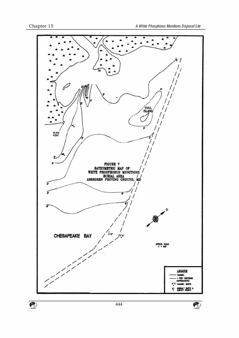
Chapter 15 A White Phosphorus Munitions Disposal Site
444

Chapter 15 A White Phosphorus Munitions Disposal Site
6. BIBLIOGRAPHY 1. Addison, R.F. and R.G. Ackman, 1990.Direct Determination of Elemental
Phosphorus by Gas-Liquid. Chromatography. J. Chromatog. 47 (1970) 421-
426.
2. Breinter, S., 1973. Applications Manual for Portable Magnetometers.
Geometries. Sunnyvale, CA.
3. Chemical Techniques and Practices of Artillery. "Source Unknown".
4. Craig, P.N.; K. Wasti; KJ.R. Abaidoo; and J.E. Villaume, 1978. Occupational
health and safety aspects of phosphorus smoke compounds. U.S.Army Medical
Research and Development Command Contract No. DAM0-
5. 17-77-C-7020. Final Report. Franklin Institute Research Laboratories,
Philadelphia, PA.
6. Environment Canada, 1984. "Environmental and Technical Information for
Problem Spills Phosphorus. Beauregard Press Limited. 122 pp.
445