fluids - wordpress.com
TRANSCRIPT
F L U I D S 14C H A P T E R
W H AT I S P H YS I C S ?14-1 The physics of fluids is the basis of hydraulic engineering, a branch ofengineering that is applied in a great many fields. A nuclear engineer might studythe fluid flow in the hydraulic system of an aging nuclear reactor, while a medicalengineer might study the blood flow in the arteries of an aging patient. An envi-ronmental engineer might be concerned about the drainage from waste sites orthe efficient irrigation of farmlands. A naval engineer might be concerned withthe dangers faced by a deep-sea diver or with the possibility of a crew escapingfrom a downed submarine. An aeronautical engineer might design the hydraulicsystems controlling the wing flaps that allow a jet airplane to land. Hydraulicengineering is also applied in many Broadway and Las Vegas shows, where hugesets are quickly put up and brought down by hydraulic systems.
Before we can study any such application of the physics of fluids, we mustfirst answer the question “What is a fluid?”
14-2 What Is a Fluid?A fluid, in contrast to a solid, is a substance that can flow. Fluids conform to theboundaries of any container in which we put them. They do so because a fluidcannot sustain a force that is tangential to its surface. (In the more formallanguage of Section 12-7, a fluid is a substance that flows because it cannot with-stand a shearing stress. It can, however, exert a force in the direction perpendicu-lar to its surface.) Some materials, such as pitch, take a long time to conform tothe boundaries of a container, but they do so eventually; thus, we classify eventhose materials as fluids.
You may wonder why we lump liquids and gases together and call themfluids. After all (you may say), liquid water is as different from steam as it is fromice.Actually, it is not. Ice, like other crystalline solids, has its constituent atoms or-ganized in a fairly rigid three-dimensional array called a crystalline lattice. In nei-ther steam nor liquid water, however, is there any such orderly long-rangearrangement.
14-3 Density and PressureWhen we discuss rigid bodies, we are concerned with particular lumps of matter,such as wooden blocks, baseballs, or metal rods. Physical quantities that we finduseful, and in whose terms we express Newton’s laws, are mass and force. Wemight speak, for example, of a 3.6 kg block acted on by a 25 N force.
With fluids, we are more interested in the extended substance and in propertiesthat can vary from point to point in that substance. It is more useful to speak ofdensity and pressure than of mass and force.
359
HALLIDAY REVISED
halliday_c14_359-385hr.qxd 26-10-2009 21:40 Page 359
360 CHAPTE R 14 FLU I DS
DensityTo find the density r of a fluid at any point, we isolate a small volume element !Varound that point and measure the mass !m of the fluid contained within that element.The density is then
(14-1)
In theory, the density at any point in a fluid is the limit of this ratio as the volume element !V at that point is made smaller and smaller. In practice, we assume that afluid sample is large relative to atomic dimensions and thus is “smooth” (with uni-form density), rather than “lumpy” with atoms. This assumption allows us to writeEq. 14-1 as
(uniform density), (14-2)
where m and V are the mass and volume of the sample.Density is a scalar property; its SI unit is the kilogram per cubic meter.
Table 14-1 shows the densities of some substances and the average densities ofsome objects. Note that the density of a gas (see Air in the table) varies consid-erably with pressure, but the density of a liquid (see Water) does not; that is,gases are readily compressible but liquids are not.
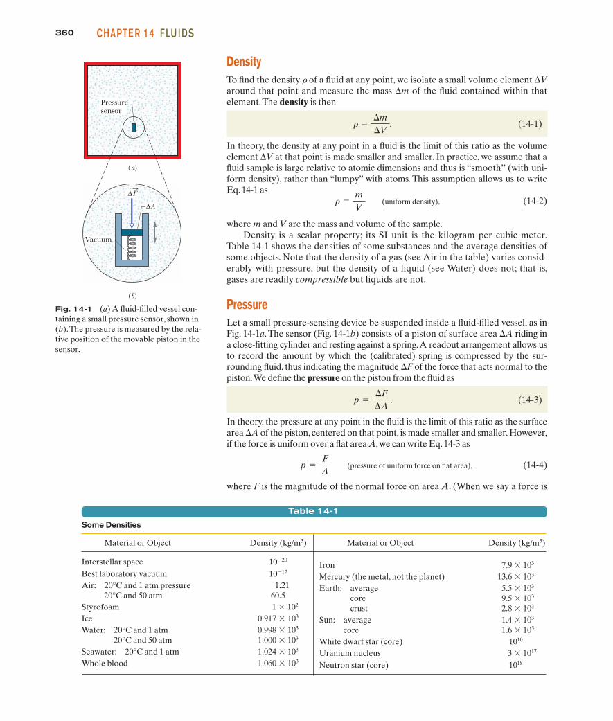
PressureLet a small pressure-sensing device be suspended inside a fluid-filled vessel, as inFig. 14-1a. The sensor (Fig. 14-1b) consists of a piston of surface area !A riding ina close-fitting cylinder and resting against a spring.A readout arrangement allows usto record the amount by which the (calibrated) spring is compressed by the sur-rounding fluid, thus indicating the magnitude !F of the force that acts normal to thepiston.We define the pressure on the piston from the fluid as
(14-3)
In theory, the pressure at any point in the fluid is the limit of this ratio as the surfacearea !A of the piston, centered on that point, is made smaller and smaller. However,if the force is uniform over a flat area A, we can write Eq. 14-3 as
(pressure of uniform force on flat area), (14-4)
where F is the magnitude of the normal force on area A. (When we say a force is
p "FA
p "!F!A
.
# "mV
# "!m!V
.
Fig. 14-1 (a) A fluid-filled vessel con-taining a small pressure sensor, shown in(b).The pressure is measured by the rela-tive position of the movable piston in thesensor.
(a)
(b)
Pressuresensor
Vacuum
∆
∆A
F
Table 14-1
Some Densities
Material or Object Density (kg/m3) Material or Object Density (kg/m3)
Interstellar space 10$20
Best laboratory vacuum 10$17
Air: 20°C and 1 atm pressure 1.2120°C and 50 atm 60.5
Styrofoam 1 % 102
Ice 0.917 % 103
Water: 20°C and 1 atm 0.998 % 103
20°C and 50 atm 1.000 % 103
Seawater: 20°C and 1 atm 1.024 % 103
Whole blood 1.060 % 103
Iron 7.9 % 103
Mercury (the metal, not the planet) 13.6 % 103
Earth: average 5.5 % 103
core 9.5 % 103
crust 2.8 % 103
Sun: average 1.4 % 103
core 1.6 % 105
White dwarf star (core) 1010
Uranium nucleus 3 % 1017
Neutron star (core) 1018
halliday_c14_359-385hr.qxd 26-10-2009 21:40 Page 360
36114-3 DE N S ITY AN D PR E SS U R EPART 2
uniform over an area, we mean that the force is evenly distributed over everypoint of the area.)
We find by experiment that at a given point in a fluid at rest, the pressure pdefined by Eq. 14-4 has the same value no matter how the pressure sensor isoriented. Pressure is a scalar, having no directional properties. It is true thatthe force acting on the piston of our pressure sensor is a vector quantity, butEq. 14-4 involves only the magnitude of that force, a scalar quantity.
The SI unit of pressure is the newton per square meter, which is given a specialname, the pascal (Pa). In metric countries, tire pressure gauges are calibrated inkilopascals.The pascal is related to some other common (non-SI) pressure units asfollows:
1 atm " 1.01 % 105 Pa " 760 torr " 14.7 lb/in.2.
The atmosphere (atm) is, as the name suggests, the approximate average pressureof the atmosphere at sea level. The torr (named for Evangelista Torricelli, who invented the mercury barometer in 1674) was formerly called the millimeter ofmercury (mm Hg).The pound per square inch is often abbreviated psi.Table 14-2shows some pressures.
Sample Problem
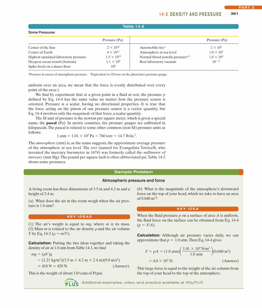
(b) What is the magnitude of the atmosphere’s downwardforce on the top of your head, which we take to have an areaof 0.040 m2?
When the fluid pressure p on a surface of area A is uniform,the fluid force on the surface can be obtained from Eq. 14-4(p " F/A).
Calculation: Although air pressure varies daily, we can approximate that p " 1.0 atm.Then Eq. 14-4 gives
" 4.0 % 103 N. (Answer)
This large force is equal to the weight of the air column fromthe top of your head to the top of the atmosphere.
F " pA " (1.0 atm)! 1.01 % 105 N/m2
1.0 atm "(0.040 m2)
Atmospheric pressure and force
A living room has floor dimensions of 3.5 m and 4.2 m and aheight of 2.4 m.
(a) What does the air in the room weigh when the air pres-sure is 1.0 atm?
(1) The air’s weight is equal to mg, where m is its mass.(2) Mass m is related to the air density r and the air volumeV by Eq. 14-2 (r " m/V).
Calculation: Putting the two ideas together and taking thedensity of air at 1.0 atm from Table 14-1, we find
mg " (rV)g" (1.21 kg/m3)(3.5 m % 4.2 m % 2.4 m)(9.8 m/s2)" 418 N # 420 N. (Answer)
This is the weight of about 110 cans of Pepsi.
KEY I DEAS
KEY I DEA
Additional examples, video, and practice available at WileyPLUS
Table 14-2
Some Pressures
Pressure (Pa) Pressure (Pa)
Center of the Sun 2 % 1016 Automobile tirea 2 % 105
Center of Earth 4 % 1011 Atmosphere at sea level 1.0 % 105
Highest sustained laboratory pressure 1.5 % 1010 Normal blood systolic pressurea,b 1.6 % 104
Deepest ocean trench (bottom) 1.1 % 108 Best laboratory vacuum 10$12
Spike heels on a dance floor 106
aPressure in excess of atmospheric pressure. bEquivalent to 120 torr on the physician’s pressure gauge.
halliday_c14_359-385hr.qxd 26-10-2009 21:40 Page 361

362 CHAPTE R 14 FLU I DS
A
Sample
mg
(e)
F1
F2
y1
y2
y = 0
y
(d)
mg
y1
y2 Level 2, p2
y = 0
y
(c)
F2
y1
y2
Level 1, p1
y = 0
y
(b)
F1
Sample
y1
y2
Air
Water
y = 0
y
(a)
Three forces act onthis sample of water.
This downward force isdue to the water pressurepushing on the top surface.
This upward force is due tothe water pressure pushingon the bottom surface.
Gravity pulls downwardon the sample.
The three forcesbalance.
Fig. 14-2 (a) Atank of water in whicha sample of water iscontained in an imagi-nary cylinder of hori-zontal base area A.(b) – (d) Force actsat the top surface ofthe cylinder; force acts at the bottomsurface of the cylin-der; the gravitationalforce on the water inthe cylinder is repre-sented by . (e) Afree-body diagram ofthe water sample.
mg:
F:
2
F:
1
14-4 Fluids at RestFigure 14-2a shows a tank of water—or other liquid—open to the atmosphere.As every diver knows, the pressure increases with depth below the air–waterinterface. The diver’s depth gauge, in fact, is a pressure sensor much like that ofFig. 14-1b. As every mountaineer knows, the pressure decreases with altitude asone ascends into the atmosphere.The pressures encountered by the diver and themountaineer are usually called hydrostatic pressures, because they are due to flu-ids that are static (at rest). Here we want to find an expression for hydrostaticpressure as a function of depth or altitude.
Let us look first at the increase in pressure with depth below the water’ssurface. We set up a vertical y axis in the tank, with its origin at the air–waterinterface and the positive direction upward. We next consider a water samplecontained in an imaginary right circular cylinder of horizontal base (or face) areaA, such that y1 and y2 (both of which are negative numbers) are the depths belowthe surface of the upper and lower cylinder faces, respectively.
Figure 14-2e shows a free-body diagram for the water in the cylinder.The water isin static equilibrium; that is, it is stationary and the forces on it balance.Three forcesact on it vertically: Force acts at the top surface of the cylinder and is due to thewater above the cylinder (Fig.14-2b). Similarly, force acts at the bottom surface ofthe cylinder and is due to the water just below the cylinder (Fig. 14-2c).The gravita-tional force on the water in the cylinder is represented by m , where m is the massg:
F:
2
F:
1
halliday_c14_359-385hr.qxd 26-10-2009 21:40 Page 362

36314-4 FLU I DS AT R E STPART 2
Fig. 14-3 The pressure p increaseswith depth h below the liquid surfaceaccording to Eq. 14-8.
p
h
Level 1
Level 2
Air
Liquid
y = 0
y
p0
The pressure at a point in a fluid in static equilibrium depends on the depth of thatpoint but not on any horizontal dimension of the fluid or its container.
Thus, Eq. 14-8 holds no matter what the shape of the container. If the bottom surface of the container is at depth h, then Eq. 14-8 gives the pressure p there.
In Eq. 14-8, p is said to be the total pressure, or absolute pressure, at level 2.To see why, note in Fig. 14-3 that the pressure p at level 2 consists of two contribu-tions: (1) p0, the pressure due to the atmosphere, which bears down on the liquid,and (2) rgh, the pressure due to the liquid above level 2, which bears down onlevel 2. In general, the difference between an absolute pressure and an atmos-pheric pressure is called the gauge pressure. (The name comes from the use of agauge to measure this difference in pressures.) For the situation of Fig. 14-3, thegauge pressure is rgh.
Equation 14-7 also holds above the liquid surface: It gives the atmospheric pres-sure at a given distance above level 1 in terms of the atmospheric pressure p1 at level 1(assuming that the atmospheric density is uniform over that distance). For example, tofind the atmospheric pressure at a distance d above level 1 in Fig.14-3,we substitute
y1 " 0, p1 " p0 and y2 " d, p2 " p.
Then with r " rair, we obtainp " p0 $ rairgd.
of the water in the cylinder (Fig.14-2d).The balance of these forces is written as
F2 " F1 & mg. (14-5)
We want to transform Eq. 14-5 into an equation involving pressures. FromEq. 14-4, we know that
F1 " p1A and F2 " p2A. (14-6)
The mass m of the water in the cylinder is, from Eq. 14-2, m " rV, where thecylinder’s volume V is the product of its face area A and its height y1 $ y2. Thus,m is equal to rA(y1 $ y2). Substituting this and Eq. 14-6 into Eq. 14-5, we find
p2A " p1A & rAg(y1 $ y2)
or p2 " p1 & rg(y1 $ y2). (14-7)
This equation can be used to find pressure both in a liquid (as a function ofdepth) and in the atmosphere (as a function of altitude or height). For the former,suppose we seek the pressure p at a depth h below the liquid surface. Then wechoose level 1 to be the surface, level 2 to be a distance h below it (as in Fig. 14-3),and p0 to represent the atmospheric pressure on the surface.We then substitute
y1 " 0, p1 " p0 and y2 " $h, p2 " pinto Eq. 14-7, which becomes
p " p0 & rgh (pressure at depth h). (14-8)
Note that the pressure at a given depth in the liquid depends on that depth butnot on any horizontal dimension.
h
(a) (b) (c) (d)
CHECKPOINT 1
The figure shows fourcontainers of olive oil.Rank them accordingto the pressure at depthh, greatest first.
halliday_c14_359-385hr.qxd 26-10-2009 21:40 Page 363

364 CHAPTE R 14 FLU I DS
Sample Problem
(998 kg/m3, from Table 14-1). As he ascends, the externalpressure on him decreases, until it is atmospheric pressurep0 at the surface. His blood pressure also decreases, until it isnormal. However, because he does not exhale, the air pres-sure in his lungs remains at the value it had at depth L.At the surface, the pressure difference between the higherpressure in his lungs and the lower pressure on his chest is
!p " p $ p0 " rgL,
from which we find
" 0.95 m. (Answer)
This is not deep! Yet, the pressure difference of 9.3 kPa(about 9% of atmospheric pressure) is sufficient to rupturethe diver’s lungs and force air from them into the depressur-ized blood, which then carries the air to the heart, killing thediver. If the diver follows instructions and gradually exhalesas he ascends, he allows the pressure in his lungs to equalizewith the external pressure, and then there is no danger.
L "!p#g
"9300 Pa
(998 kg/m3)(9.8 m/s2)
Gauge pressure on a scuba diver
A novice scuba diver practicing in a swimming pool takesenough air from his tank to fully expand his lungs beforeabandoning the tank at depth L and swimming to the sur-face. He ignores instructions and fails to exhale during hisascent. When he reaches the surface, the difference betweenthe external pressure on him and the air pressure in hislungs is 9.3 kPa. From what depth does he start? What po-tentially lethal danger does he face?
The pressure at depth h in a liquid of density r is given by Eq. 14-8 (p " p0 & rgh), where the gauge pressure rgh isadded to the atmospheric pressure p0.
Calculations: Here, when the diver fills his lungs atdepth L, the external pressure on him (and thus the airpressure within his lungs) is greater than normal andgiven by Eq. 14-8 as
p " p0 & rgL,
where p0 is atmospheric pressure and r is the water’s density
KEY I DEA
Sample Problem
Equating these two expressions and solving for the un-known density yield
" 915 kg/m3. (Answer)
Note that the answer does not depend on the atmosphericpressure p0 or the free-fall acceleration g.
#x " #w l
l & d" (998 kg/m3)
135 mm135 mm & 12.3 mm
Balancing of pressure in a U-tube
The U-tube in Fig. 14-4 contains two liquids in static equilib-rium: Water of density rw (" 998 kg/m3) is in the right arm,and oil of unknown density rx is in the left. Measurementgives l " 135 mm and d " 12.3 mm. What is the density ofthe oil?
(1) The pressure pint at the level of the oil–water interface inthe left arm depends on the density rx and height of the oilabove the interface. (2) The water in the right arm at thesame level must be at the same pressure pint. The reason isthat, because the water is in static equilibrium, pressures atpoints in the water at the same level must be the same even ifthe points are separated horizontally.
Calculations: In the right arm, the interface is a distance l be-low the free surface of the water, and we have, from Eq.14-8,
pint " p0 & rwgl (right arm).
In the left arm, the interface is a distance l & d below the freesurface of the oil, and we have,again from Eq.14-8,
pint " p0 & rxg(l & d) (left arm).
KEY I DEAS
Fig. 14-4 The oil in the left arm stands higher than the water inthe right arm because the oil is less dense than the water. Both fluidcolumns produce the same pressure pint at the level of the interface.
Interface
Water
Oil
l
d
This much oilbalances... ... this much
water.
Additional examples, video, and practice available at WileyPLUS
halliday_c14_359-385hr.qxd 26-10-2009 21:40 Page 364
36514-5 M EAS U R I NG PR E SS U R EPART 2
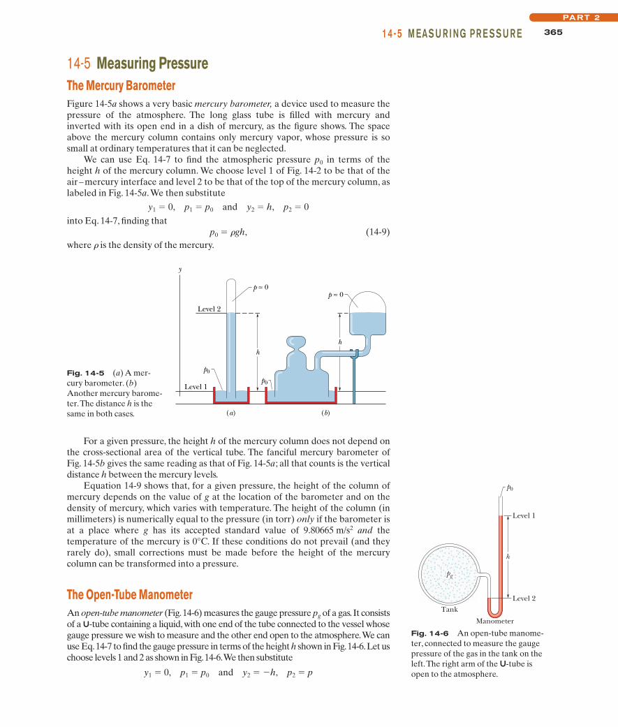
14-5 Measuring PressureThe Mercury BarometerFigure 14-5a shows a very basic mercury barometer, a device used to measure thepressure of the atmosphere. The long glass tube is filled with mercury andinverted with its open end in a dish of mercury, as the figure shows. The spaceabove the mercury column contains only mercury vapor, whose pressure is sosmall at ordinary temperatures that it can be neglected.
We can use Eq. 14-7 to find the atmospheric pressure p0 in terms of theheight h of the mercury column. We choose level 1 of Fig. 14-2 to be that of theair–mercury interface and level 2 to be that of the top of the mercury column, aslabeled in Fig. 14-5a.We then substitute
y1 " 0, p1 " p0 and y2 " h, p2 " 0into Eq. 14-7, finding that
p0 " rgh, (14-9)where r is the density of the mercury.
Fig. 14-5 (a) A mer-cury barometer. (b)Another mercury barome-ter.The distance h is thesame in both cases.
Level 1
p0
y
Level 2
h
p ≈ 0
h
p0
p ≈ 0
(a) (b)
For a given pressure, the height h of the mercury column does not depend onthe cross-sectional area of the vertical tube. The fanciful mercury barometer ofFig. 14-5b gives the same reading as that of Fig. 14-5a; all that counts is the verticaldistance h between the mercury levels.
Equation 14-9 shows that, for a given pressure, the height of the column ofmercury depends on the value of g at the location of the barometer and on thedensity of mercury, which varies with temperature. The height of the column (inmillimeters) is numerically equal to the pressure (in torr) only if the barometer isat a place where g has its accepted standard value of 9.80665 m/s2 and thetemperature of the mercury is 0°C. If these conditions do not prevail (and theyrarely do), small corrections must be made before the height of the mercurycolumn can be transformed into a pressure.
The Open-Tube ManometerAn open-tube manometer (Fig.14-6) measures the gauge pressure pg of a gas. It consistsof a U-tube containing a liquid, with one end of the tube connected to the vessel whosegauge pressure we wish to measure and the other end open to the atmosphere.We canuse Eq.14-7 to find the gauge pressure in terms of the height h shown in Fig.14-6.Let uschoose levels 1 and 2 as shown in Fig.14-6.We then substitute
y1 " 0, p1 " p0 and y2 " $h, p2 " p
Fig. 14-6 An open-tube manome-ter, connected to measure the gaugepressure of the gas in the tank on theleft.The right arm of the U-tube isopen to the atmosphere.
Tank
Manometer
Level 2
Level 1
p0
h
pg
halliday_c14_359-385hr.qxd 26-10-2009 21:40 Page 365

366 CHAPTE R 14 FLU I DS
into Eq. 14-7, finding thatpg " p $ p0 " rgh, (14-10)
where r is the density of the liquid in the tube. The gauge pressure pg is directlyproportional to h.
The gauge pressure can be positive or negative, depending on whether p ' p0 or p ( p0. In inflated tires or the human circulatory system, the (absolute)pressure is greater than atmospheric pressure, so the gauge pressure is a positivequantity, sometimes called the overpressure. If you suck on a straw to pull fluid upthe straw, the (absolute) pressure in your lungs is actually less than atmosphericpressure.The gauge pressure in your lungs is then a negative quantity.
14-6 Pascal’s PrincipleWhen you squeeze one end of a tube to get toothpaste out the other end, you arewatching Pascal’s principle in action. This principle is also the basis for theHeimlich maneuver, in which a sharp pressure increase properly applied to theabdomen is transmitted to the throat, forcefully ejecting food lodged there.The principle was first stated clearly in 1652 by Blaise Pascal (for whom the unitof pressure is named):
Fig. 14-7 Lead shot (small balls of lead)loaded onto the piston create a pressurepext at the top of the enclosed (incompress-ible) liquid. If pext is increased, by addingmore lead shot, the pressure increases bythe same amount at all points within theliquid.
Lead shot
Piston
P p
h
pext
Liquid
di
Input
Ai do
Oil
Ao
Output
Fi
Fo A small input force produces ...
... a large outputforce.
Fig. 14-8 A hydraulic arrangement thatcan be used to magnify a force .The workdone is, however, not magnified and is thesame for both the input and output forces.
F:
i
A change in the pressure applied to an enclosed incompressible fluid is transmittedundiminished to every portion of the fluid and to the walls of its container.
Demonstrating Pascal’s PrincipleConsider the case in which the incompressible fluid is a liquid contained in a tallcylinder, as in Fig. 14-7.The cylinder is fitted with a piston on which a container oflead shot rests.The atmosphere, container, and shot exert pressure pext on the pis-ton and thus on the liquid.The pressure p at any point P in the liquid is then
p " pext & rgh. (14-11)
Let us add a little more lead shot to the container to increase pext by an amount!pext. The quantities r, g, and h in Eq. 14-11 are unchanged, so the pressurechange at P is
!p " !pext. (14-12)
This pressure change is independent of h, so it must hold for all points within theliquid, as Pascal’s principle states.
Pascal’s Principle and the Hydraulic LeverFigure 14-8 shows how Pascal’s principle can be made the basis of a hydrauliclever. In operation, let an external force of magnitude Fi be directed downwardon the left-hand (or input) piston, whose surface area is Ai. An incompressibleliquid in the device then produces an upward force of magnitude Fo on the right-hand (or output) piston, whose surface area is Ao. To keep the system in equilib-rium, there must be a downward force of magnitude Fo on the output piston froman external load (not shown). The force applied on the left and the downwardF
:i
force from the load on the right produce a change !p in the pressure of the liq-uid that is given by
,
so . (14-13)Fo " Fi Ao
Ai
!p "Fi
Ai"
Fo
Ao
F:
o
halliday_c14_359-385hr.qxd 26-10-2009 21:40 Page 366
36714-7 ARCH I M E DE S’ PR I NCI PLEPART 2
Equation 14-13 shows that the output force Fo on the load must be greater thanthe input force Fi if Ao ' Ai, as is the case in Fig. 14-8.
If we move the input piston downward a distance di, the output piston movesupward a distance do, such that the same volume V of the incompressible liquid isdisplaced at both pistons.Then
V " Aidi " Aodo,which we can write as
. (14-14)
This shows that, if Ao ' Ai (as in Fig. 14-8), the output piston moves a smallerdistance than the input piston moves.
From Eqs. 14-13 and 14-14 we can write the output work as
(14-15)
which shows that the work W done on the input piston by the applied force isequal to the work W done by the output piston in lifting the load placed on it.
The advantage of a hydraulic lever is this:
W " Fo do " !Fi Ao
Ai"
!di
Ai
Ao" " Fi di,
do " di Ai
Ao
With a hydraulic lever, a given force applied over a given distance can be transformed to a greater force applied over a smaller distance.
The product of force and distance remains unchanged so that the same work isdone. However, there is often tremendous advantage in being able to exert thelarger force. Most of us, for example, cannot lift an automobile directly but canwith a hydraulic jack, even though we have to pump the handle farther thanthe automobile rises and in a series of small strokes.
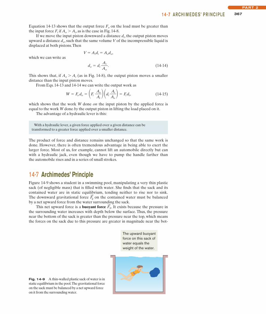
14-7 Archimedes’ PrincipleFigure 14-9 shows a student in a swimming pool, manipulating a very thin plasticsack (of negligible mass) that is filled with water. She finds that the sack and itscontained water are in static equilibrium, tending neither to rise nor to sink.The downward gravitational force on the contained water must be balancedby a net upward force from the water surrounding the sack.
This net upward force is a buoyant force . It exists because the pressure inthe surrounding water increases with depth below the surface. Thus, the pressurenear the bottom of the sack is greater than the pressure near the top, which meansthe forces on the sack due to this pressure are greater in magnitude near the bot-
F:
b
F:g
The upward buoyantforce on this sack ofwater equals theweight of the water.
Fig. 14-9 A thin-walled plastic sack of water is instatic equilibrium in the pool.The gravitational forceon the sack must be balanced by a net upward forceon it from the surrounding water.
halliday_c14_359-385hr.qxd 26-10-2009 21:40 Page 367
368 CHAPTE R 14 FLU I DS
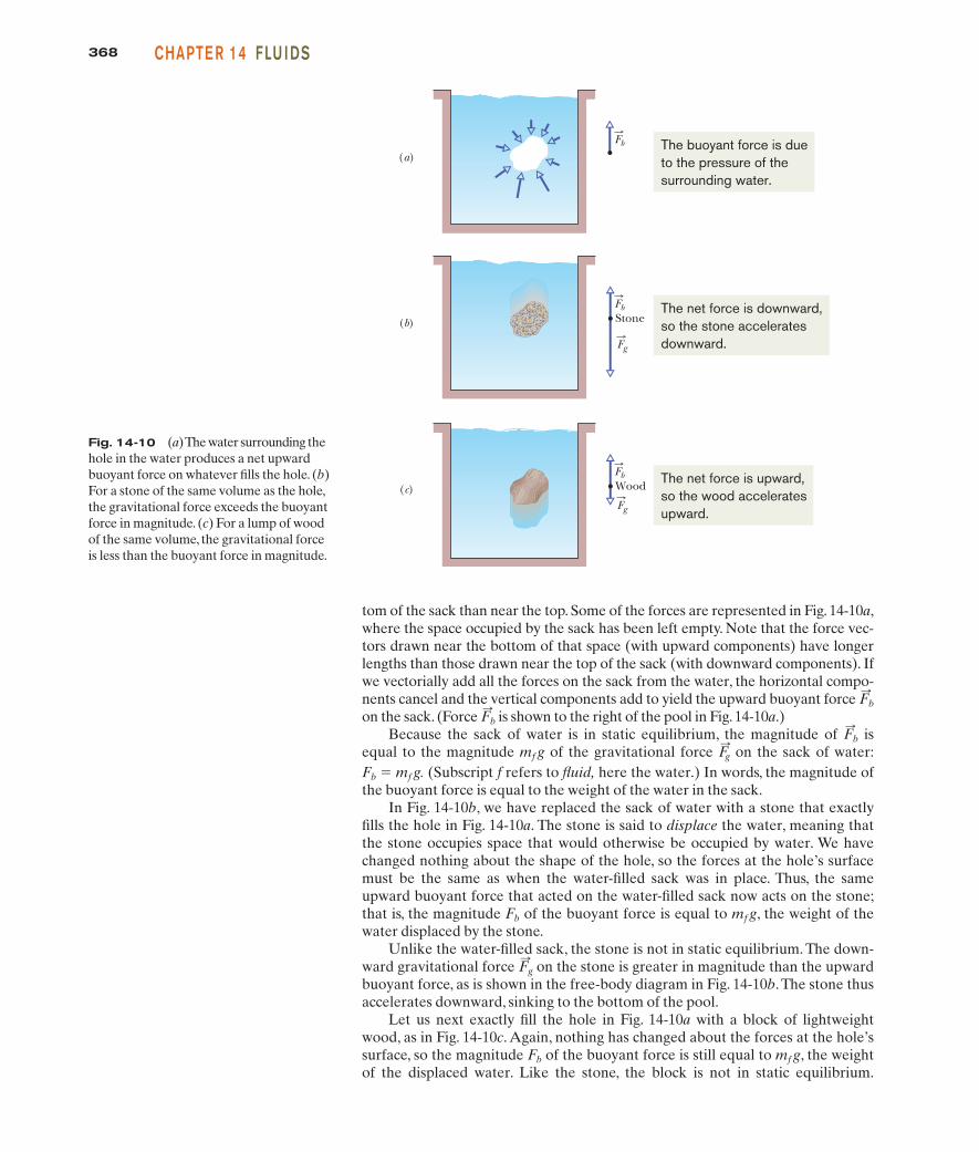
tom of the sack than near the top. Some of the forces are represented in Fig. 14-10a,where the space occupied by the sack has been left empty. Note that the force vec-tors drawn near the bottom of that space (with upward components) have longerlengths than those drawn near the top of the sack (with downward components). Ifwe vectorially add all the forces on the sack from the water, the horizontal compo-nents cancel and the vertical components add to yield the upward buoyant force on the sack. (Force is shown to the right of the pool in Fig. 14-10a.)
Because the sack of water is in static equilibrium, the magnitude of isequal to the magnitude mf g of the gravitational force on the sack of water:F
:g
F:
b
F:
b
F:
b
(a)
Stone(b)
(c) Wood
Fb
Fb
Fb
Fg
Fg
The buoyant force is dueto the pressure of thesurrounding water.
The net force is downward,so the stone acceleratesdownward.
The net force is upward,so the wood acceleratesupward.
Fig. 14-10 (a) The water surrounding thehole in the water produces a net upwardbuoyant force on whatever fills the hole. (b)For a stone of the same volume as the hole,the gravitational force exceeds the buoyantforce in magnitude. (c) For a lump of woodof the same volume, the gravitational forceis less than the buoyant force in magnitude.
Fb " mf g. (Subscript f refers to fluid, here the water.) In words, the magnitude ofthe buoyant force is equal to the weight of the water in the sack.
In Fig. 14-10b, we have replaced the sack of water with a stone that exactlyfills the hole in Fig. 14-10a. The stone is said to displace the water, meaning thatthe stone occupies space that would otherwise be occupied by water. We havechanged nothing about the shape of the hole, so the forces at the hole’s surfacemust be the same as when the water-filled sack was in place. Thus, the sameupward buoyant force that acted on the water-filled sack now acts on the stone;that is, the magnitude Fb of the buoyant force is equal to mf g, the weight of thewater displaced by the stone.
Unlike the water-filled sack, the stone is not in static equilibrium. The down-ward gravitational force on the stone is greater in magnitude than the upwardbuoyant force, as is shown in the free-body diagram in Fig. 14-10b.The stone thusaccelerates downward, sinking to the bottom of the pool.
Let us next exactly fill the hole in Fig. 14-10a with a block of lightweightwood, as in Fig. 14-10c. Again, nothing has changed about the forces at the hole’ssurface, so the magnitude Fb of the buoyant force is still equal to mf g, the weightof the displaced water. Like the stone, the block is not in static equilibrium.
F:
g
halliday_c14_359-385hr.qxd 26-10-2009 21:40 Page 368
36914-7 ARCH I M E DE S’ PR I NCI PLEPART 2
When a body is fully or partially submerged in a fluid, a buoyant force from thesurrounding fluid acts on the body.The force is directed upward and has a magnitudeequal to the weight mf g of the fluid that has been displaced by the body.
F:
b
We can write this statement as
Fg " mf g (floating). (14-18)
In other words, a floating body displaces its own weight of fluid.
Apparent Weight in a FluidIf we place a stone on a scale that is calibrated to measure weight, then thereading on the scale is the stone’s weight. However, if we do this underwater,the upward buoyant force on the stone from the water decreases the reading.That reading is then an apparent weight. In general, an apparent weight is relatedto the actual weight of a body and the buoyant force on the body by
which we can write as
weightapp " weight $ Fb (apparent weight). (14-19)
!apparentweight " " !actual
weight" $ !magnitude ofbuoyant force",
However, this time the gravitational force is lesser in magnitude than thebuoyant force (as shown to the right of the pool), and so the block accelerates upward, rising to the top surface of the water.
Our results with the sack, stone, and block apply to all fluids and are summarizedin Archimedes’ principle:
F:
g
The buoyant force on a body in a fluid has the magnitude
Fb " mf g (buoyant force), (14-16)
where mf is the mass of the fluid that is displaced by the body.
FloatingWhen we release a block of lightweight wood just above the water in a pool, theblock moves into the water because the gravitational force on it pulls it down-ward. As the block displaces more and more water, the magnitude Fb of theupward buoyant force acting on it increases. Eventually, Fb is large enough toequal the magnitude Fg of the downward gravitational force on the block, and theblock comes to rest.The block is then in static equilibrium and is said to be floatingin the water. In general,
When a body floats in a fluid, the magnitude Fg of the gravitational force on the bodyis equal to the weight mfg of the fluid that has been displaced by the body.
When a body floats in a fluid, the magnitude Fb of the buoyant force on the body isequal to the magnitude Fg of the gravitational force on the body.
We can write this statement as
Fb " Fg (floating). (14-17)
From Eq. 14-16, we know that Fb " mf g. Thus,
halliday_c14_359-385hr.qxd 26-10-2009 21:40 Page 369
370 CHAPTE R 14 FLU I DS
CHECKPOINT 2
A penguin floats first in a fluid of densityr0, then in a fluid of density 0.95r0, andthen in a fluid of density 1.1r0. (a) Rankthe densities according to the magnitudeof the buoyant force on the penguin,greatest first. (b) Rank the densities ac-cording to the amount of fluid displacedby the penguin, greatest first.
Sample Problem
m, then in terms of the block’s density r and (full) volume V,and then in terms of the block’s dimensions L, W, and H(the full height):
. (14-21)
The floating block is stationary. Thus, writing Newton’ssecond law for components along a vertical y axis with thepositive direction upward , we have
or from Eqs. 14-20 and 14-21,
which gives us
. (Answer)
(b) If the block is held fully submerged and then released,what is the magnitude of its acceleration?
Calculations: The gravitational force on the block is the samebut now, with the block fully submerged, the volume of the dis-placed water is (The full height of the block isused.) This means that the value of is now larger, and theblock will no longer be stationary but will accelerate upward.Now Newton’s second law yields
,
or ,
where we inserted for the mass m of the block. Solv-ing for a leads to
(Answer)" 4.9 m/s2.
a " ! #f
# $ 1"g " ! 1200 kg/m3
800 kg/m3 $ 1" (9.8 m/s2)
#LWH
#fLWHg $ #LWHg " #LWHa
Fb $ Fg " ma
Fb
V " LWH.
" 4.0 cm
h "##f
H "800 kg/m3
1200 kg/m3 (6.0 cm)
#fLWhg $ #LWHg " 0,
Fb $ Fg " m(0),
(Fnet,y " may)
Fg " mg " #Vg " #fLWHg
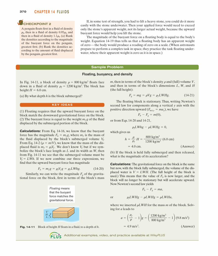
Floating, buoyancy, and density
In Fig. 14-11, a block of density floats facedown in a fluid of density . The block hasheight .
(a) By what depth h is the block submerged?
(1) Floating requires that the upward buoyant force on theblock match the downward gravitational force on the block.(2) The buoyant force is equal to the weight of the fluiddisplaced by the submerged portion of the block.
Calculations: From Eq. 14-16, we know that the buoyantforce has the magnitude , where is the mass ofthe fluid displaced by the block’s submerged volume .From Eq. 14-2 , we know that the mass of the dis-placed fluid is We don’t know but if we sym-bolize the block’s face length as L and its width as W, thenfrom Fig. 14-11 we see that the submerged volume must be
. If we now combine our three expressions, wefind that the upward buoyant force has magnitude
(14-20)
Similarly, we can write the magnitude of the gravita-tional force on the block, first in terms of the block’s mass
Fg
Fb " mf g " #fVf g " #fLWhg.
Vf " LWh
Vfmf " #fVf .(# " m/V)
Vf
mfFb " mf g
mf g
H " 6.0 cm#f " 1200 kg/m3
# " 800 kg/m3
KEY I DEAS
If, in some test of strength, you had to lift a heavy stone, you could do it moreeasily with the stone underwater. Then your applied force would need to exceedonly the stone’s apparent weight, not its larger actual weight, because the upwardbuoyant force would help you lift the stone.
The magnitude of the buoyant force on a floating body is equal to the body’sweight. Equation 14-19 thus tells us that a floating body has an apparent weightof zero—the body would produce a reading of zero on a scale. (When astronautsprepare to perform a complex task in space, they practice the task floating under-water, where their apparent weight is zero as it is in space.)
h H
Floating meansthat the buoyantforce matches thegravitational force.
Fig. 14-11 Block of height H floats in a fluid, to a depth of h.
Additional examples, video, and practice available at WileyPLUS
halliday_c14_359-385hr.qxd 26-10-2009 21:40 Page 370

37114-8 I DEAL FLU I DS I N MOTIONPART 2
14-8 Ideal Fluids in MotionThe motion of real fluids is very complicated and not yet fully understood.Instead, we shall discuss the motion of an ideal fluid, which is simpler to handlemathematically and yet provides useful results. Here are four assumptions thatwe make about our ideal fluid; they all are concerned with flow:
1. Steady flow In steady (or laminar) flow, the velocity of the moving fluid at anyfixed point does not change with time. The gentle flow of water near the center ofa quiet stream is steady; the flow in a chain of rapids is not. Figure 14-12 shows atransition from steady flow to nonsteady (or nonlaminar or turbulent) flow for arising stream of smoke. The speed of the smoke particles increases as they riseand, at a certain critical speed, the flow changes from steady to nonsteady.
2. Incompressible flow We assume, as for fluids at rest, that our ideal fluid is incompressible; that is, its density has a constant, uniform value.
3. Nonviscous flow Roughly speaking, the viscosity of a fluid is a measure of howresistive the fluid is to flow. For example, thick honey is more resistive to flowthan water, and so honey is said to be more viscous than water. Viscosity is thefluid analog of friction between solids; both are mechanisms by which the kineticenergy of moving objects can be transferred to thermal energy. In the absence offriction, a block could glide at constant speed along a horizontal surface. In thesame way, an object moving through a nonviscous fluid would experience no vis-cous drag force—that is, no resistive force due to viscosity; it could move at con-stant speed through the fluid.The British scientist Lord Rayleigh noted that in anideal fluid a ship’s propeller would not work, but, on the other hand, in an idealfluid a ship (once set into motion) would not need a propeller!
4. Irrotational flow Although it need not concern us further, we also assumethat the flow is irrotational. To test for this property, let a tiny grain of dustmove with the fluid.Although this test body may (or may not) move in a circu-lar path, in irrotational flow the test body will not rotate about an axis throughits own center of mass. For a loose analogy, the motion of a Ferris wheel is ro-tational; that of its passengers is irrotational.
We can make the flow of a fluid visible by adding a tracer. This might bea dye injected into many points across a liquid stream (Fig. 14-13) or smoke parti-cles added to a gas flow (Fig. 14-12). Each bit of a tracer follows a streamline,which is the path that a tiny element of the fluid would take as the fluid flows.Recall from Chapter 4 that the velocity of a particle is always tangent to thepath taken by the particle. Here the particle is the fluid element, and its velocity
is always tangent to a streamline (Fig. 14-14). For this reason, two streamlinescan never intersect; if they did, then an element arriving at their intersectionwould have two different velocities simultaneously—an impossibility.
v:
Fig. 14-12 At a certain point, therising flow of smoke and heated gaschanges from steady to turbulent.(Will McIntyre/Photo Researchers)
Fig. 14-13 The steadyflow of a fluid around acylinder, as revealed by adye tracer that was injectedinto the fluid upstream ofthe cylinder. (Courtesy D.H.Peregrine,University ofBristol)
Streamline
Fluidelement
v
Fig. 14-14 A fluid element tracesout a streamline as it moves.The ve-locity vector of the element is tan-gent to the streamline at every point.
halliday_c14_359-385hr.qxd 26-10-2009 21:40 Page 371
372 CHAPTE R 14 FLU I DS
14-9 The Equation of ContinuityYou may have noticed that you can increase the speed of the water emergingfrom a garden hose by partially closing the hose opening with your thumb.Apparently the speed v of the water depends on the cross-sectional area Athrough which the water flows.
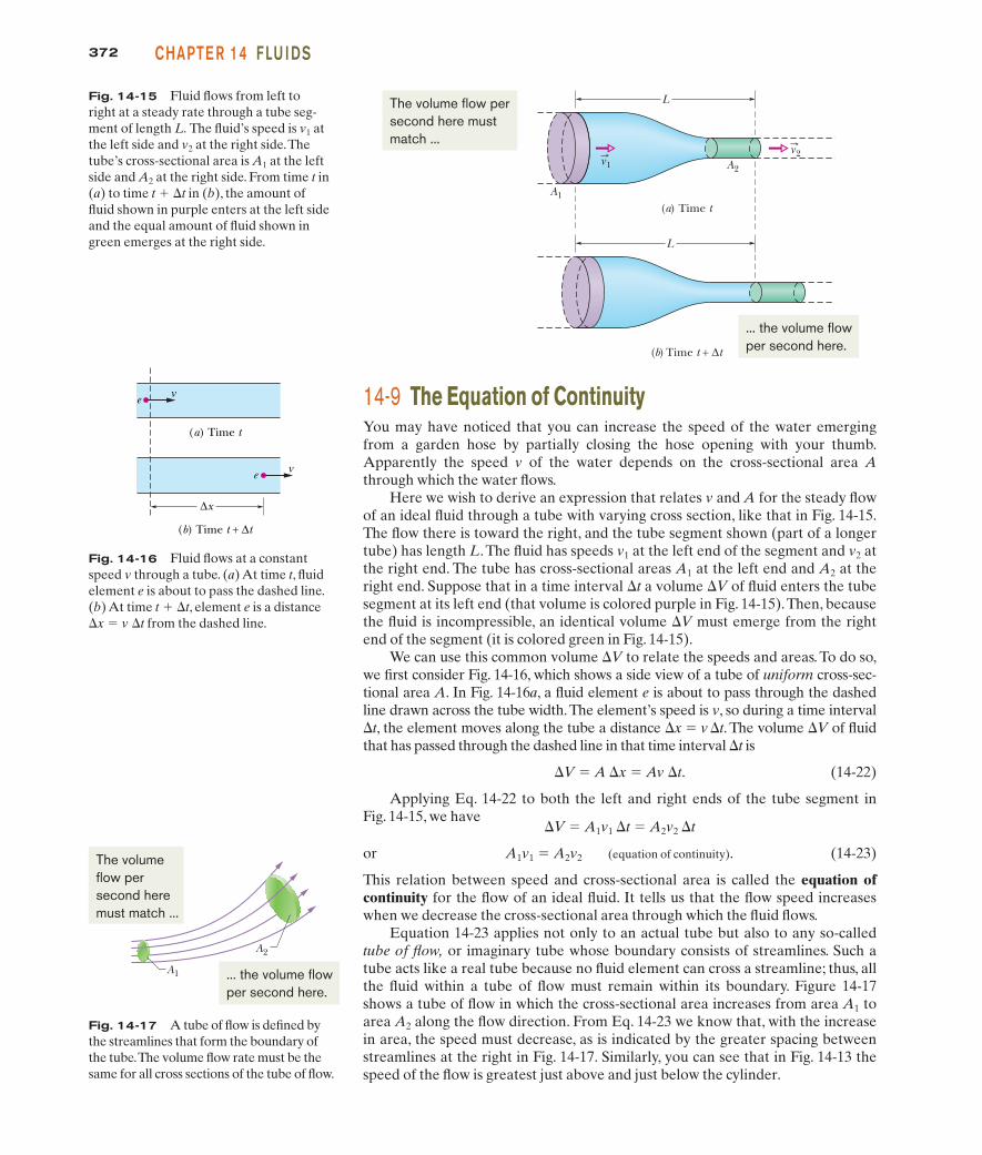
Here we wish to derive an expression that relates v and A for the steady flowof an ideal fluid through a tube with varying cross section, like that in Fig. 14-15.The flow there is toward the right, and the tube segment shown (part of a longertube) has length L.The fluid has speeds v1 at the left end of the segment and v2 atthe right end. The tube has cross-sectional areas A1 at the left end and A2 at theright end. Suppose that in a time interval !t a volume !V of fluid enters the tubesegment at its left end (that volume is colored purple in Fig. 14-15).Then, becausethe fluid is incompressible, an identical volume !V must emerge from the rightend of the segment (it is colored green in Fig. 14-15).
We can use this common volume !V to relate the speeds and areas. To do so,we first consider Fig. 14-16, which shows a side view of a tube of uniform cross-sec-tional area A. In Fig. 14-16a, a fluid element e is about to pass through the dashedline drawn across the tube width.The element’s speed is v, so during a time interval!t, the element moves along the tube a distance !x " v !t. The volume !V of fluidthat has passed through the dashed line in that time interval !t is
!V " A !x " Av !t. (14-22)
Applying Eq. 14-22 to both the left and right ends of the tube segment inFig. 14-15, we have
!V " A1v1 !t " A2v2 !t
or A1v1 " A2v2 (equation of continuity). (14-23)
This relation between speed and cross-sectional area is called the equation ofcontinuity for the flow of an ideal fluid. It tells us that the flow speed increaseswhen we decrease the cross-sectional area through which the fluid flows.
Equation 14-23 applies not only to an actual tube but also to any so-calledtube of flow, or imaginary tube whose boundary consists of streamlines. Such atube acts like a real tube because no fluid element can cross a streamline; thus, allthe fluid within a tube of flow must remain within its boundary. Figure 14-17shows a tube of flow in which the cross-sectional area increases from area A1 toarea A2 along the flow direction. From Eq. 14-23 we know that, with the increasein area, the speed must decrease, as is indicated by the greater spacing betweenstreamlines at the right in Fig. 14-17. Similarly, you can see that in Fig. 14-13 thespeed of the flow is greatest just above and just below the cylinder.
Fig. 14-16 Fluid flows at a constantspeed v through a tube. (a) At time t, fluidelement e is about to pass the dashed line.(b) At time t & !t, element e is a distance!x " v !t from the dashed line.
ve
ve
(a) Time t
(b) Time t + ∆t
∆x
Fig. 14-15 Fluid flows from left toright at a steady rate through a tube seg-ment of length L. The fluid’s speed is v1 atthe left side and v2 at the right side.Thetube’s cross-sectional area is A1 at the leftside and A2 at the right side. From time t in(a) to time t & !t in (b), the amount offluid shown in purple enters at the left sideand the equal amount of fluid shown ingreen emerges at the right side.
L
v1
A1
A2
v2
(a) Time t
L
(b) Time t + ∆t
The volume flow persecond here mustmatch ...
... the volume flowper second here.
A1
A2
The volume flow persecond here must match ...
... the volume flowper second here.
Fig. 14-17 A tube of flow is defined bythe streamlines that form the boundary ofthe tube.The volume flow rate must be thesame for all cross sections of the tube of flow.
halliday_c14_359-385hr.qxd 26-10-2009 21:40 Page 372
37314-9 TH E EQUATION OF CONTI N U ITYPART 2
We can rewrite Eq. 14-23 as
RV " Av " a constant (volume flow rate, equation of continuity), (14-24)
in which RV is the volume flow rate of the fluid (volume past a given point perunit time). Its SI unit is the cubic meter per second (m3/s). If the density r of thefluid is uniform, we can multiply Eq. 14-24 by that density to get the mass flowrate Rm (mass per unit time):
Rm " rRV " rAv " a constant (mass flow rate). (14-25)
The SI unit of mass flow rate is the kilogram per second (kg/s). Equation 14-25says that the mass that flows into the tube segment of Fig. 14-15 each second mustbe equal to the mass that flows out of that segment each second.
CHECKPOINT 3
The figure shows a pipe and gives the volume flow rate (in cm3/s) and the di-rection of flow for all but one section. What are the volume flow rate and thedirection of flow for that section?
4 8
2 56
4
Sample Problem
A water stream narrows as it falls
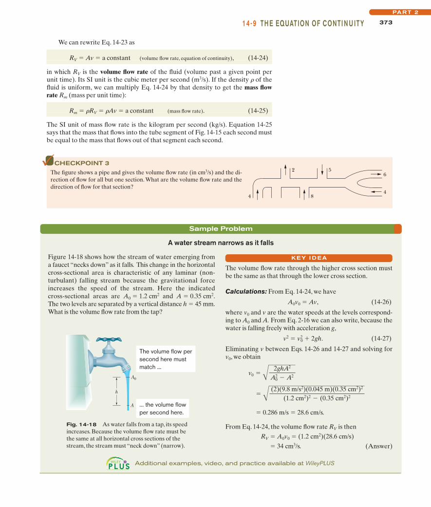
Figure 14-18 shows how the stream of water emerging froma faucet “necks down” as it falls. This change in the horizontalcross-sectional area is characteristic of any laminar (non-turbulant) falling stream because the gravitational forceincreases the speed of the stream. Here the indicatedcross-sectional areas are A0 " 1.2 cm2 and A " 0.35 cm2.The two levels are separated by a vertical distance h " 45 mm.What is the volume flow rate from the tap?
KEY I DEA
Fig. 14-18 As water falls from a tap, its speedincreases. Because the volume flow rate must bethe same at all horizontal cross sections of thestream, the stream must “neck down” (narrow).
h
A0
A
The volume flow persecond here mustmatch ...
... the volume flowper second here.
The volume flow rate through the higher cross section mustbe the same as that through the lower cross section.
Calculations: From Eq. 14-24, we have
A0v0 " Av, (14-26)
where v0 and v are the water speeds at the levels correspond-ing to A0 and A. From Eq. 2-16 we can also write, because thewater is falling freely with acceleration g,
v2 " v20 & 2gh. (14-27)
Eliminating v between Eqs. 14-26 and 14-27 and solving forv0, we obtain
" 0.286 m/s " 28.6 cm/s.
From Eq. 14-24, the volume flow rate RV is thenRV " A0v0 " (1.2 cm2)(28.6 cm/s)
" 34 cm3/s. (Answer)
" A (2)(9.8 m/s2)(0.045 m)(0.35 cm2)2
(1.2 cm2)2 $ (0.35 cm2)2
v0 " A 2ghA2
A20 $ A2
Additional examples, video, and practice available at WileyPLUS
halliday_c14_359-385hr.qxd 26-10-2009 21:40 Page 373
374 CHAPTE R 14 FLU I DS
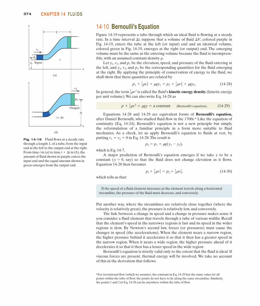
14-10 Bernoulli’s EquationFigure 14-19 represents a tube through which an ideal fluid is flowing at a steadyrate. In a time interval !t, suppose that a volume of fluid !V, colored purple inFig. 14-19, enters the tube at the left (or input) end and an identical volume,colored green in Fig. 14-19, emerges at the right (or output) end. The emergingvolume must be the same as the entering volume because the fluid is incompress-ible, with an assumed constant density r.
Let y1, v1, and p1 be the elevation, speed, and pressure of the fluid entering atthe left, and y2, v2, and p2 be the corresponding quantities for the fluid emergingat the right. By applying the principle of conservation of energy to the fluid, weshall show that these quantities are related by
(14-28)
In general, the term is called the fluid’s kinetic energy density (kinetic energyper unit volume).We can also write Eq. 14-28 as
(Bernoulli’s equation). (14-29)
Equations 14-28 and 14-29 are equivalent forms of Bernoulli’s equation,after Daniel Bernoulli, who studied fluid flow in the 1700s.* Like the equation ofcontinuity (Eq. 14-24), Bernoulli’s equation is not a new principle but simply the reformulation of a familiar principle in a form more suitable to fluid mechanics. As a check, let us apply Bernoulli’s equation to fluids at rest, byputting v1 " v2 " 0 in Eq. 14-28.The result is
p2 " p1 & rg(y1 $ y2),
which is Eq. 14-7.A major prediction of Bernoulli’s equation emerges if we take y to be a
constant (y " 0, say) so that the fluid does not change elevation as it flows.Equation 14-28 then becomes
(14-30)which tells us that:
p1& 12#v2
1 " p2 & 12#v2
2,
p & 12#v2 & #gy " a constant
12#v2
p1 & 12#v2
1 & #gy1 " p2 & 12#v2
2 & #gy2.
*For irrotational flow (which we assume), the constant in Eq. 14-29 has the same value for allpoints within the tube of flow; the points do not have to lie along the same streamline. Similarly,the points 1 and 2 in Eq. 14-28 can lie anywhere within the tube of flow.
If the speed of a fluid element increases as the element travels along a horizontalstreamline, the pressure of the fluid must decrease, and conversely.
Put another way, where the streamlines are relatively close together (where thevelocity is relatively great), the pressure is relatively low, and conversely.
The link between a change in speed and a change in pressure makes sense ifyou consider a fluid element that travels through a tube of various widths. Recallthat the element’s speed in the narrower regions is fast and its speed in the widerregions is slow. By Newton’s second law, forces (or pressures) must cause thechanges in speed (the accelerations). When the element nears a narrow region,the higher pressure behind it accelerates it so that it then has a greater speed inthe narrow region. When it nears a wide region, the higher pressure ahead of itdecelerates it so that it then has a lesser speed in the wide region.
Bernoulli’s equation is strictly valid only to the extent that the fluid is ideal. Ifviscous forces are present, thermal energy will be involved. We take no accountof this in the derivation that follows.
Fig. 14-19 Fluid flows at a steady ratethrough a length L of a tube, from the inputend at the left to the output end at the right.From time t in (a) to time t & !t in (b), theamount of fluid shown in purple enters theinput end and the equal amount shown ingreen emerges from the output end.
p1
L
Input
v1
y1
(a)
(b)
y
v2
p2
y2
y
x
t
t + ∆t
x
Output
halliday_c14_359-385hr.qxd 26-10-2009 21:40 Page 374
37514-10 B E R NOU LLI ’S EQUATIONPART 2
Proof of Bernoulli’s EquationLet us take as our system the entire volume of the (ideal) fluid shown in Fig. 14-19.We shall apply the principle of conservation of energy to this system asit moves from its initial state (Fig. 14-19a) to its final state (Fig. 14-19b). The fluidlying between the two vertical planes separated by a distance L in Fig. 14-19 doesnot change its properties during this process; we need be concerned only withchanges that take place at the input and output ends.
First, we apply energy conservation in the form of the work–kinetic energytheorem,
W " !K, (14-31)
which tells us that the change in the kinetic energy of our system must equal thenet work done on the system. The change in kinetic energy results from thechange in speed between the ends of the tube and is
, (14-32)
in which !m (" r !V) is the mass of the fluid that enters at the input end andleaves at the output end during a small time interval !t.
The work done on the system arises from two sources. The work Wg done bythe gravitational force on the fluid of mass !m during the vertical lift ofthe mass from the input level to the output level is
Wg " $!m g(y2 $ y1)
" $rg !V(y2 $ y1). (14-33)
This work is negative because the upward displacement and the downward gravi-tational force have opposite directions.
Work must also be done on the system (at the input end) to push the enteringfluid into the tube and by the system (at the output end) to push forward the fluidthat is located ahead of the emerging fluid. In general, the work done by a forceof magnitude F, acting on a fluid sample contained in a tube of area A to movethe fluid through a distance !x, is
F !x " ( pA)(!x) " p(A !x) " p !V.
The work done on the system is then p1 !V, and the work done by the systemis $p2 !V.Their sum Wp is
Wp " $p2 !V & p1 !V
" $( p2 $ p1) !V. (14-34)
The work–kinetic energy theorem of Eq. 14-31 now becomes
W " Wg & Wp " !K.
Substituting from Eqs. 14-32, 14-33, and 14-34 yields
.
This, after a slight rearrangement, matches Eq. 14-28, which we set out to prove.
$#g !V(y2 $ y1) $ !V(p2 $ p1) " 12# !V(v2
2 $ v21)
(!m g:)
" 12# !V(v2
2 $ v21)
!K " 12!m v2
2 $ 12!m v2
1
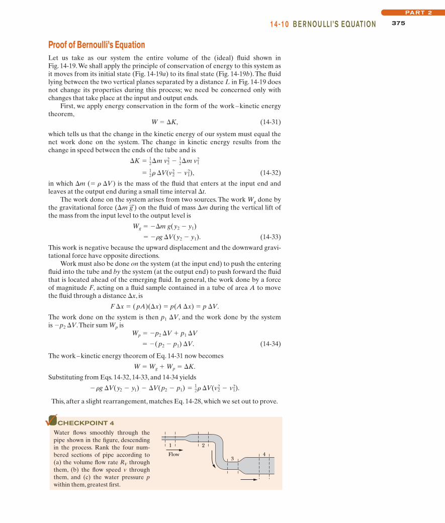
CHECKPOINT 4
Water flows smoothly through thepipe shown in the figure, descendingin the process. Rank the four num-bered sections of pipe according to(a) the volume flow rate RV throughthem, (b) the flow speed v throughthem, and (c) the water pressure pwithin them, greatest first.
1
Flow
2
34
halliday_c14_359-385hr.qxd 26-10-2009 21:40 Page 375
Sample Problem
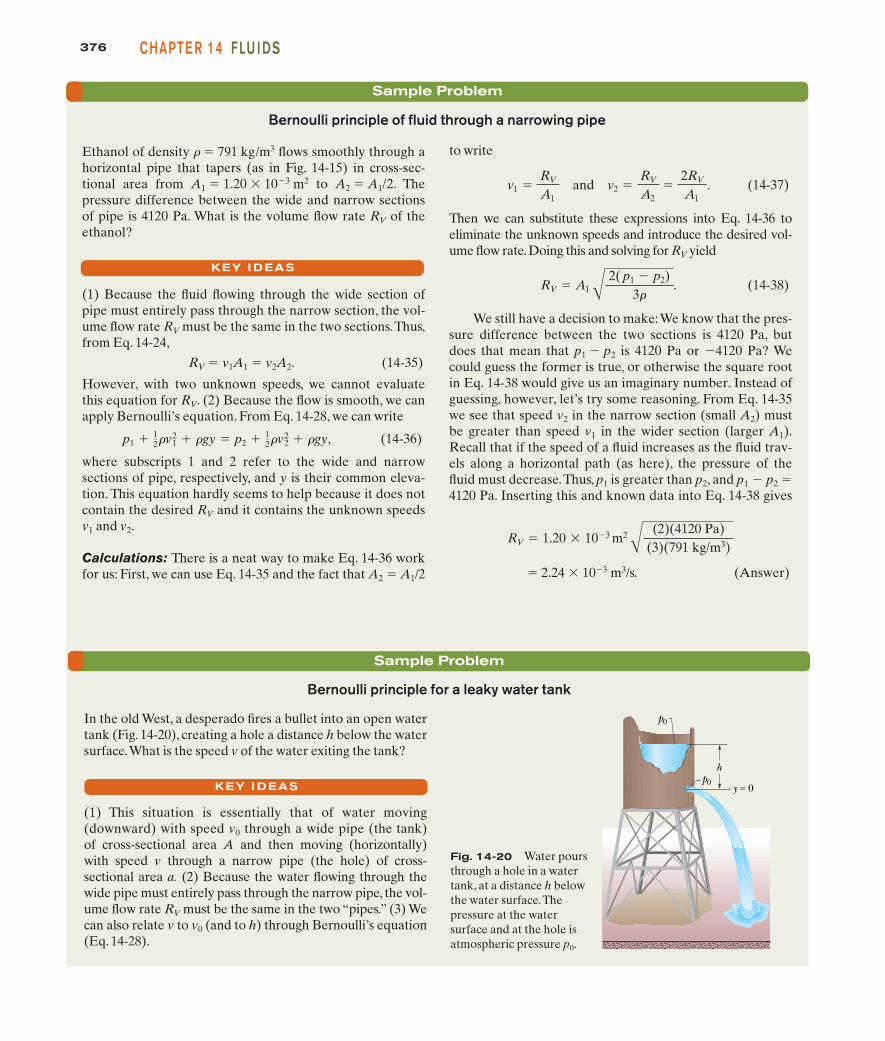
to write
and . (14-37)
Then we can substitute these expressions into Eq. 14-36 toeliminate the unknown speeds and introduce the desired vol-ume flow rate.Doing this and solving for RV yield
. (14-38)
We still have a decision to make:We know that the pres-sure difference between the two sections is 4120 Pa, butdoes that mean that p1 $ p2 is 4120 Pa or $4120 Pa? Wecould guess the former is true, or otherwise the square rootin Eq. 14-38 would give us an imaginary number. Instead ofguessing, however, let’s try some reasoning. From Eq. 14-35we see that speed v2 in the narrow section (small A2) mustbe greater than speed v1 in the wider section (larger A1).Recall that if the speed of a fluid increases as the fluid trav-els along a horizontal path (as here), the pressure of thefluid must decrease.Thus, p1 is greater than p2, and p1 $ p2 "4120 Pa. Inserting this and known data into Eq. 14-38 gives
" 2.24 % 10$3 m3/s. (Answer)
RV " 1.20 % 10$3 m2 A (2)(4120 Pa)(3)(791 kg/m3)
RV " A1 A 2( p1 $ p2)3#
v2 "RV
A2"
2RV
A1v1 "
RV
A1
Bernoulli principle of fluid through a narrowing pipe
Ethanol of density r " 791 kg/m3 flows smoothly through ahorizontal pipe that tapers (as in Fig. 14-15) in cross-sec-tional area from A1 " 1.20 % 10$3 m2 to A2 " A1/2. Thepressure difference between the wide and narrow sectionsof pipe is 4120 Pa. What is the volume flow rate RV of theethanol?
(1) Because the fluid flowing through the wide section ofpipe must entirely pass through the narrow section, the vol-ume flow rate RV must be the same in the two sections.Thus,from Eq. 14-24,
RV " v1A1 " v2A2. (14-35)
However, with two unknown speeds, we cannot evaluatethis equation for RV. (2) Because the flow is smooth, we canapply Bernoulli’s equation. From Eq. 14-28, we can write
, (14-36)
where subscripts 1 and 2 refer to the wide and narrowsections of pipe, respectively, and y is their common eleva-tion. This equation hardly seems to help because it does notcontain the desired RV and it contains the unknown speedsv1 and v2.
Calculations: There is a neat way to make Eq. 14-36 workfor us: First, we can use Eq. 14-35 and the fact that A2 " A1/2
p1 & 12#v2
1 & #gy " p2 & 12#v2
2 & #gy
KEY I DEAS
376 CHAPTE R 14 FLU I DS
Sample Problem
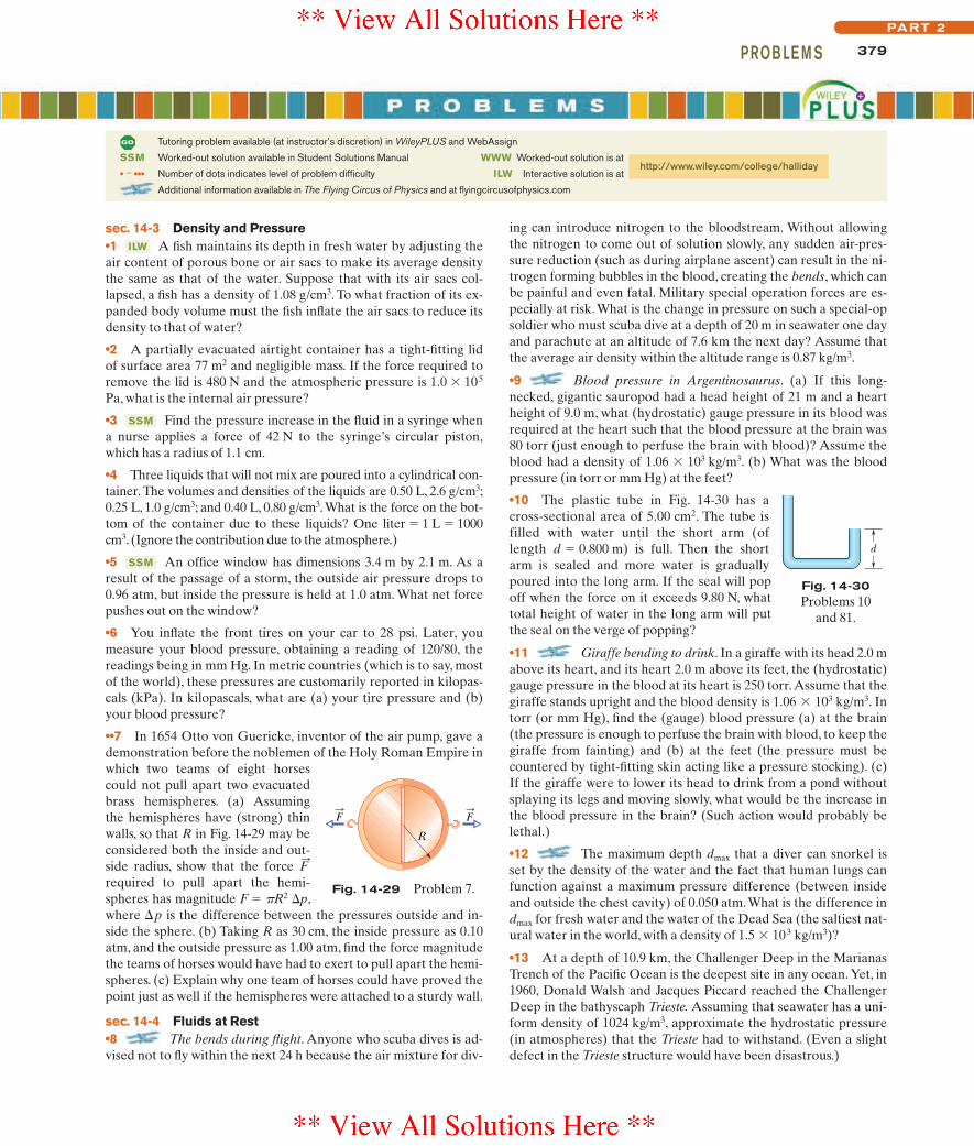
Bernoulli principle for a leaky water tank
In the old West, a desperado fires a bullet into an open watertank (Fig. 14-20), creating a hole a distance h below the watersurface.What is the speed v of the water exiting the tank?
(1) This situation is essentially that of water moving(downward) with speed v0 through a wide pipe (the tank)of cross-sectional area A and then moving (horizontally)with speed v through a narrow pipe (the hole) of cross-sectional area a. (2) Because the water flowing through thewide pipe must entirely pass through the narrow pipe, the vol-ume flow rate RV must be the same in the two “pipes.” (3) Wecan also relate v to v0 (and to h) through Bernoulli’s equation(Eq. 14-28).
KEY I DEAS
hp0
y = 0
p0
Fig. 14-20 Water poursthrough a hole in a watertank, at a distance h belowthe water surface.Thepressure at the water surface and at the hole isatmospheric pressure p0.
halliday_c14_359-385hr.qxd 26-10-2009 21:40 Page 376

377R EVI EW & S U M MARYPART 2
(Here the top of the tank is represented by the left side ofthe equation and the hole by the right side. The zero on theright indicates that the hole is at our reference level.)Before we solve Eq. 14-39 for v, we can use our result thatv0 v to simplify it: We assume that v2
0, and thus the termin Eq. 14-39, is negligible relative to the other terms,
and we drop it. Solving the remaining equation for v thenyields
(Answer)
This is the same speed that an object would have whenfalling a height h from rest.
v " 12gh.
12#v2
0
)
Additional examples, video, and practice available at WileyPLUS
Calculations: From Eq. 14-24,
RV " av " Av0
and thus
Because a A, we see that v0 v.To apply Bernoulli’s equa-tion, we take the level of the hole as our reference level formeasuring elevations (and thus gravitational potential en-ergy). Noting that the pressure at the top of the tank and atthe bullet hole is the atmospheric pressure p0 (because bothplaces are exposed to the atmosphere), we write Eq. 14-28 as
(14-39)p0 & 12#v2
0 & #gh " p0 & 12#v2 & #g(0).
))
v0 "aA
v.
Density The density r of any material is defined as the material’smass per unit volume:
(14-1)
Usually, where a material sample is much larger than atomic dimensions, we can write Eq. 14-1 as
(14-2)
Fluid Pressure A fluid is a substance that can flow; it conformsto the boundaries of its container because it cannot withstand shear-ing stress. It can, however, exert a force perpendicular to its surface.That force is described in terms of pressure p:
(14-3)
in which !F is the force acting on a surface element of area !A. If theforce is uniform over a flat area,Eq.14-3 can be written as
(14-4)
The force resulting from fluid pressure at a particular point in afluid has the same magnitude in all directions. Gauge pressure is thedifference between the actual pressure (or absolute pressure) at apoint and the atmospheric pressure.
Pressure Variation with Height and Depth Pressure in afluid at rest varies with vertical position y. For y measured positiveupward,
p2 " p1 & rg(y1 $ y2). (14-7)
The pressure in a fluid is the same for all points at the same level. Ifh is the depth of a fluid sample below some reference level at whichthe pressure is p0, Eq. 14-7 becomes
p " p0 & rgh, (14-8)
where p is the pressure in the sample.
p "FA
.
p "!F!A
,
# "mV
.
# "!m!V
.
Pascal’s Principle A change in the pressure applied to an en-closed fluid is transmitted undiminished to every portion of thefluid and to the walls of the containing vessel.
Archimedes’ Principle When a body is fully or partially sub-merged in a fluid,a buoyant force from the surrounding fluid acts onthe body.The force is directed upward and has a magnitude given by
Fb " mf g, (14-16)
where mf is the mass of the fluid that has been displaced by thebody (that is, the fluid that has been pushed out of the way by thebody).
When a body floats in a fluid, the magnitude Fb of the(upward) buoyant force on the body is equal to the magnitude Fg
of the (downward) gravitational force on the body. The apparentweight of a body on which a buoyant force acts is related to its ac-tual weight by
weightapp " weight $ Fb. (14-19)
Flow of Ideal Fluids An ideal fluid is incompressible andlacks viscosity, and its flow is steady and irrotational. A streamlineis the path followed by an individual fluid particle. A tube of flow isa bundle of streamlines. The flow within any tube of flow obeys theequation of continuity:
RV " Av " a constant, (14-24)
in which RV is the volume flow rate, A is the cross-sectional area ofthe tube of flow at any point, and v is the speed of the fluid at thatpoint.The mass flow rate Rm is
Rm " rRV " rAv " a constant. (14-25)
Bernoulli’s Equation Applying the principle of conservationof mechanical energy to the flow of an ideal fluid leads toBernoulli’s equation:
p & rv2 & rgy " a constant (14-29)
along any tube of flow.
12
F:
b
halliday_c14_359-385hr.qxd 26-10-2009 21:40 Page 377

378 CHAPTE R 14 FLU I DS
3 A boat with an anchor on board floats in a swimmingpool that is somewhat wider than the boat. Does the pool waterlevel move up, move down, or remain the same if the anchor is (a)dropped into the water or (b) thrown onto the surroundingground? (c) Does the water level inthe pool move upward, move down-ward, or remain the same if, instead,a cork is dropped from the boatinto the water, where it floats?
4 Figure 14-22 shows a tank filledwith water. Five horizontal floorsand ceilings are indicated; all havethe same area and are located atdistances L, 2L, or 3L below thetop of the tank. Rank them accord-ing to the force on them due to thewater, greatest first.
5 The teapot effect. Water poured slowly from a teapotspout can double back under the spout for a considerable dis-tance before detaching and falling. (The water layer is heldagainst the underside of the spout by atmospheric pressure.) InFig. 14-23, in the water layer insidethe spout, point a is at the top ofthe layer and point b is at the bot-tom of the layer; in the water layeroutside the spout, point c is at thetop of the layer and point d is atthe bottom of the layer. Rankthose four points according to thegauge pressure in the water there,most positive first.
6 Figure 14-24 shows three identical open-top containers filled to
8 A rectangular block is pushedfacedown into three liquids, in turn.The apparent weight Wapp of theblock versus depth h in the three liq-uids is plotted in Fig. 14-26. Rankthe liquids according to their weightper unit volume, greatest first.
9 Water flows smoothly in a hori-zontal pipe. Figure 14-27 shows the kinetic energy K of a water elementas it moves along an x axis that runs along the pipe.Rank the three let-tered sections of the pipe according to the pipe radius,greatest first.
Fig. 14-22 Question 4.
a
b
e
dc
Waterflow
d c
ba
Spout
Fig. 14-23 Question 5.
Fig. 14-24 Question 6.
(a) (b) (c)
2.00R 2.00RR(1)
3.00R R2.00R(2)
2.00R 3.00RR(3)
R R3.00R(4)
Fig. 14-25 Question 7.
Fig. 14-26 Question 8.
Wapp
h
a
b
c
K
xA B C
Fig. 14-27 Question 9.
pg
h
ab
c
Fig. 14-28 Question 10.
1 We fully submerge an irregular 3 kg lump of material in a cer-tain fluid. The fluid that would have been in the space now occu-pied by the lump has a mass of 2 kg. (a) When we release the lump,does it move upward, move downward, or remain in place? (b) Ifwe next fully submerge the lump in a less dense fluid and again re-lease it, what does it do?
2 Figure 14-21 shows four situations in which a red liquid and agray liquid are in a U-tube. In one situation the liquids cannot be instatic equilibrium. (a) Which situation is that? (b) For the otherthree situations, assume static equilibrium. For each, is the densityof the red liquid greater than, less than, or equal to the density ofthe gray liquid?
(1) (2) (3) (4)
Fig. 14-21 Question 2.
the brim with water; toy ducks float in two of them. Rank the contain-ers and contents according to their weight,greatest first.
7 Figure 14-25 shows four arrangements of pipes through whichwater flows smoothly toward the right. The radii of the pipe sec-tions are indicated. In which arrangements is the net work done ona unit volume of water moving from the leftmost section to therightmost section (a) zero, (b) positive, and (c) negative?
10 We have three containerswith different liquids. The gaugepressure pg versus depth h is plot-ted in Fig. 14-28 for the liquids. Ineach container, we will fully sub-merge a rigid plastic bead. Rankthe plots according to the magni-tude of the buoyant force on thebead, greatest first.
halliday_c14_359-385hr.qxd 26-10-2009 21:40 Page 378
379PROB LE M SPART 2
sec. 14-3 Density and Pressure•1 A fish maintains its depth in fresh water by adjusting theair content of porous bone or air sacs to make its average densitythe same as that of the water. Suppose that with its air sacs col-lapsed, a fish has a density of 1.08 g/cm3. To what fraction of its ex-panded body volume must the fish inflate the air sacs to reduce itsdensity to that of water?
•2 A partially evacuated airtight container has a tight-fitting lidof surface area 77 m2 and negligible mass. If the force required toremove the lid is 480 N and the atmospheric pressure is 1.0 % 105
Pa, what is the internal air pressure?
•3 Find the pressure increase in the fluid in a syringe whena nurse applies a force of 42 N to the syringe’s circular piston,which has a radius of 1.1 cm.
•4 Three liquids that will not mix are poured into a cylindrical con-tainer. The volumes and densities of the liquids are 0.50 L, 2.6 g/cm3;0.25 L, 1.0 g/cm3; and 0.40 L, 0.80 g/cm3.What is the force on the bot-tom of the container due to these liquids? One liter " 1 L " 1000cm3. (Ignore the contribution due to the atmosphere.)
•5 An office window has dimensions 3.4 m by 2.1 m. As aresult of the passage of a storm, the outside air pressure drops to0.96 atm, but inside the pressure is held at 1.0 atm. What net forcepushes out on the window?
•6 You inflate the front tires on your car to 28 psi. Later, youmeasure your blood pressure, obtaining a reading of 120/80, thereadings being in mm Hg. In metric countries (which is to say, mostof the world), these pressures are customarily reported in kilopas-cals (kPa). In kilopascals, what are (a) your tire pressure and (b)your blood pressure?
••7 In 1654 Otto von Guericke, inventor of the air pump, gave ademonstration before the noblemen of the Holy Roman Empire inwhich two teams of eight horsescould not pull apart two evacuatedbrass hemispheres. (a) Assumingthe hemispheres have (strong) thinwalls, so that R in Fig. 14-29 may beconsidered both the inside and out-side radius, show that the force required to pull apart the hemi-spheres has magnitude F " pR2 !p,where !p is the difference between the pressures outside and in-side the sphere. (b) Taking R as 30 cm, the inside pressure as 0.10atm, and the outside pressure as 1.00 atm, find the force magnitudethe teams of horses would have had to exert to pull apart the hemi-spheres. (c) Explain why one team of horses could have proved thepoint just as well if the hemispheres were attached to a sturdy wall.
sec. 14-4 Fluids at Rest•8 The bends during flight. Anyone who scuba dives is ad-vised not to fly within the next 24 h because the air mixture for div-
F:
SSM
SSM
ILW
ing can introduce nitrogen to the bloodstream. Without allowingthe nitrogen to come out of solution slowly, any sudden air-pres-sure reduction (such as during airplane ascent) can result in the ni-trogen forming bubbles in the blood, creating the bends, which canbe painful and even fatal. Military special operation forces are es-pecially at risk.What is the change in pressure on such a special-opsoldier who must scuba dive at a depth of 20 m in seawater one dayand parachute at an altitude of 7.6 km the next day? Assume thatthe average air density within the altitude range is 0.87 kg/m3.
•9 Blood pressure in Argentinosaurus. (a) If this long-necked, gigantic sauropod had a head height of 21 m and a heartheight of 9.0 m, what (hydrostatic) gauge pressure in its blood wasrequired at the heart such that the blood pressure at the brain was80 torr (just enough to perfuse the brain with blood)? Assume theblood had a density of . (b) What was the bloodpressure (in torr or mm Hg) at the feet?
•10 The plastic tube in Fig. 14-30 has across-sectional area of 5.00 cm2. The tube isfilled with water until the short arm (oflength d " 0.800 m) is full. Then the shortarm is sealed and more water is graduallypoured into the long arm. If the seal will popoff when the force on it exceeds 9.80 N, whattotal height of water in the long arm will putthe seal on the verge of popping?
•11 Giraffe bending to drink. In a giraffe with its head 2.0 mabove its heart, and its heart 2.0 m above its feet, the (hydrostatic)gauge pressure in the blood at its heart is 250 torr.Assume that thegiraffe stands upright and the blood density is . Intorr (or mm Hg), find the (gauge) blood pressure (a) at the brain(the pressure is enough to perfuse the brain with blood, to keep thegiraffe from fainting) and (b) at the feet (the pressure must becountered by tight-fitting skin acting like a pressure stocking). (c)If the giraffe were to lower its head to drink from a pond withoutsplaying its legs and moving slowly, what would be the increase inthe blood pressure in the brain? (Such action would probably belethal.)
•12 The maximum depth dmax that a diver can snorkel isset by the density of the water and the fact that human lungs canfunction against a maximum pressure difference (between insideand outside the chest cavity) of 0.050 atm.What is the difference indmax for fresh water and the water of the Dead Sea (the saltiest nat-ural water in the world, with a density of 1.5 % 103 kg/m3)?
•13 At a depth of 10.9 km, the Challenger Deep in the MarianasTrench of the Pacific Ocean is the deepest site in any ocean. Yet, in1960, Donald Walsh and Jacques Piccard reached the ChallengerDeep in the bathyscaph Trieste. Assuming that seawater has a uni-form density of 1024 kg/m3, approximate the hydrostatic pressure(in atmospheres) that the Trieste had to withstand. (Even a slightdefect in the Trieste structure would have been disastrous.)
1.06 % 103 kg/m3
1.06 % 103 kg/m3
R
FF
Fig. 14-29 Problem 7.
d
Fig. 14-30Problems 10
and 81.
Tutoring problem available (at instructor’s discretion) in WileyPLUS and WebAssign
SSM Worked-out solution available in Student Solutions Manual
• – ••• Number of dots indicates level of problem difficulty
Additional information available in The Flying Circus of Physics and at flyingcircusofphysics.com
WWW Worked-out solution is at
ILW Interactive solution is at http://www.wiley.com/college/halliday
halliday_c14_359-385hr.qxd 26-10-2009 21:40 Page 379
380 CHAPTE R 14 FLU I DS
•14 Calculate the hydrostatic difference in blood pressure be-tween the brain and the foot in a person of height 1.83 m. The den-sity of blood is 1.06 % 103 kg/m3.
•15 What gauge pressure must a machine produce in order to suckmud of density 1800 kg/m3 up a tube by a height of 1.5 m?
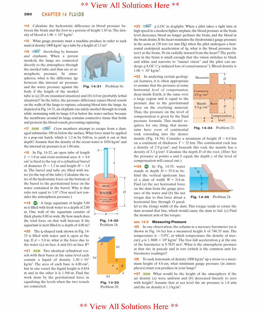
•16 Snorkeling by humansand elephants. When a personsnorkels, the lungs are connecteddirectly to the atmosphere throughthe snorkel tube and thus are at at-mospheric pressure. In atmo-spheres, what is the difference between this internal air pressureand the water pressure against thebody if the length of the snorkeltube is (a) 20 cm (standard situation) and (b) 4.0 m (probably lethalsituation)? In the latter, the pressure difference causes blood vesselson the walls of the lungs to rupture, releasing blood into the lungs.Asdepicted in Fig. 14-31, an elephant can safely snorkel through its trunkwhile swimming with its lungs 4.0 m below the water surface becausethe membrane around its lungs contains connective tissue that holdsand protects the blood vessels,preventing rupturing.
•17 Crew members attempt to escape from a dam-aged submarine 100 m below the surface.What force must be appliedto a pop-out hatch, which is 1.2 m by 0.60 m, to push it out at thatdepth? Assume that the density of the ocean water is 1024 kg/m3 andthe internal air pressure is at 1.00 atm.
•18 In Fig. 14-32, an open tube of length L " 1.8 m and cross-sectional area A " 4.6cm2 is fixed to the top of a cylindrical barrelof diameter D " 1.2 m and height H " 1.8m. The barrel and tube are filled with wa-ter (to the top of the tube). Calculate the ra-tio of the hydrostatic force on the bottom ofthe barrel to the gravitational force on thewater contained in the barrel. Why is thatratio not equal to 1.0? (You need not con-sider the atmospheric pressure.)
••19 A large aquarium of height 5.00m is filled with fresh water to a depth of 2.00m. One wall of the aquarium consists ofthick plastic 8.00 m wide. By how much doesthe total force on that wall increase if theaquarium is next filled to a depth of 4.00 m?
••20 The L-shaped tank shown in Fig. 14-33 is filled with water and is open at thetop. If d " 5.0 m, what is the force due tothe water (a) on face A and (b) on face B?
••21 Two identical cylindrical ves-sels with their bases at the same level eachcontain a liquid of density 1.30 % 103
kg/m3. The area of each base is 4.00 cm2,but in one vessel the liquid height is 0.854m and in the other it is 1.560 m. Find thework done by the gravitational force inequalizing the levels when the two vesselsare connected.
SSM
SSM
!p
••22 g-LOC in dogfights. When a pilot takes a tight turn athigh speed in a modern fighter airplane, the blood pressure at the brainlevel decreases, blood no longer perfuses the brain, and the blood inthe brain drains. If the heart maintains the (hydrostatic) gauge pressurein the aorta at 120 torr (or mm Hg) when the pilot undergoes a hori-zontal centripetal acceleration of 4g, what is the blood pressure (intorr) at the brain, 30 cm radially inward from the heart? The perfu-sion in the brain is small enough that the vision switches to blackand white and narrows to “tunnel vision” and the pilot can un-dergo g-LOC (“g-induced loss of consciousness”). Blood density is
.
••23 In analyzing certain geologi-cal features, it is often appropriateto assume that the pressure at somehorizontal level of compensation,deep inside Earth, is the same overa large region and is equal to thepressure due to the gravitationalforce on the overlying material.Thus, the pressure on the level ofcompensation is given by the fluidpressure formula. This model re-quires, for one thing, that moun-tains have roots of continentalrock extending into the densermantle (Fig. 14-34). Consider a mountain of height H " 6.0 kmon a continent of thickness T " 32 km. The continental rock hasa density of 2.9 g/cm3, and beneath this rock the mantle has adensity of 3.3 g/cm3. Calculate the depth D of the root. (Hint: Setthe pressure at points a and b equal; the depth y of the level ofcompensation will cancel out.)
•••24 In Fig. 14-35, waterstands at depth D " 35.0 m be-hind the vertical upstream faceof a dam of width W " 314 m.Find (a) the net horizontal forceon the dam from the gauge pres-sure of the water and (b) the nettorque due to that force about ahorizontal line through O paral-lel to the (long) width of the dam. This torque tends to rotate thedam around that line, which would cause the dam to fail. (c) Findthe moment arm of the torque.
sec. 14-5 Measuring Pressure•25 In one observation, the column in a mercury barometer (as isshown in Fig. 14-5a) has a measured height h of 740.35 mm. Thetemperature is $5.0ºC, at which temperature the density of mer-cury r is 1.3608 % 104 kg/m3. The free-fall acceleration g at the siteof the barometer is 9.7835 m/s2. What is the atmospheric pressureat that site in pascals and in torr (which is the common unit forbarometer readings)?
•26 To suck lemonade of density 1000 kg/m3 up a straw to a maxi-mum height of 4.0 cm, what minimum gauge pressure (in atmos-pheres) must you produce in your lungs?
••27 What would be the height of the atmosphere if theair density (a) were uniform and (b) decreased linearly to zerowith height? Assume that at sea level the air pressure is 1.0 atmand the air density is 1.3 kg/m3.
SSM
1.06 % 103 kg/m3
Fig. 14-31 Problem 16.
d
d
dd
d
3d
2d
2d
A
B
Fig. 14-33Problem 20.
Mountain
Mantle3.3 g/cm3
Compensationlevelb a
H
D y
TContinent2.9 g/cm3
Root
Fig. 14-34 Problem 23.
O
D
W
Fig. 14-35 Problem 24.
D
L
H
A
SUITABLE FOR
WATER
FRESH
DRINKING
Fig. 14-32Problem 18.
halliday_c14_359-385hr.qxd 26-10-2009 21:40 Page 380

381PROB LE M SPART 2
sec. 14-6 Pascal’s Principle•28 A piston of cross-sectionalarea a is used in a hydraulic press toexert a small force of magnitude fon the enclosed liquid. A connect-ing pipe leads to a larger piston ofcross-sectional area A (Fig. 14-36).(a) What force magnitude F will thelarger piston sustain without mov-ing? (b) If the piston diameters are3.80 cm and 53.0 cm, what forcemagnitude on the small piston will balance a 20.0 kN force on thelarge piston?
••29 In Fig. 14-37, a spring ofspring constant 3.00 % 104 N/m isbetween a rigid beam and the out-put piston of a hydraulic lever. Anempty container with negligiblemass sits on the input piston. Theinput piston has area Ai, and theoutput piston has area 18.0Ai.Initially the spring is at its restlength. How many kilograms of sand must be (slowly) poured intothe container to compress the spring by 5.00 cm?
sec. 14-7 Archimedes’ Principle•30 A 5.00 kg object is released from rest while fully submergedin a liquid. The liquid displaced by the submerged object has amass of 3.00 kg. How far and in what direction does the objectmove in 0.200 s, assuming that it moves freely and that the dragforce on it from the liquid is negligible?
•31 A block of wood floats in fresh water with two-thirdsof its volume V submerged and in oil with 0.90V submerged. Findthe density of (a) the wood and (b) the oil.
•32 In Fig. 14-38, a cube of edgelength L " 0.600 m and mass 450kg is suspended by a rope in anopen tank of liquid of density 1030kg/m3. Find (a) the magnitude ofthe total downward force on thetop of the cube from the liquid andthe atmosphere, assuming atmo-spheric pressure is 1.00 atm, (b) themagnitude of the total upwardforce on the bottom of the cube, and (c) the tension in the rope. (d)Calculate the magnitude of the buoyant force on the cube usingArchimedes’ principle. What relation exists among all these quan-tities?
•33 An iron anchor of density 7870 kg/m3 appears 200 Nlighter in water than in air. (a) What is the volume of the anchor?(b) How much does it weigh in air?
•34 A boat floating in fresh water displaces water weighing 35.6kN. (a) What is the weight of the water this boat displaces whenfloating in salt water of density 1.10 % 103 kg/m3? (b) What is thedifference between the volume of fresh water displaced and thevolume of salt water displaced?
•35 Three children, each of weight 356 N, make a log raft by lash-ing together logs of diameter 0.30 m and length 1.80 m. How many
SSM
SSM
logs will be needed to keep them afloat in fresh water? Take thedensity of the logs to be 800 kg/m3.
••36 In Fig. 14-39a, a rectangular block is gradually pushedfacedown into a liquid. The block has height d; on the bottom andtop the face area is A " 5.67 cm2. Figure 14-39b gives the apparentweight Wapp of the block as a function of the depth h of its lowerface.The scale on the vertical axis is set by Ws " 0.20 N. What is thedensity of the liquid?
Fig. 14-36Problem 28.
aA
Ff
Beam
SpringContainer
Fig. 14-37 Problem 29.
L
L/2
Fig. 14-38 Problem 32.
d
(a) (b)
Ws
0 1h (cm)
2
Wap
p (N
)
Fig. 14-39 Problem 36.
••37 A hollow spherical iron shell floats almost completelysubmerged in water.The outer diameter is 60.0 cm, and the densityof iron is 7.87 g/cm3. Find the inner diameter.
••38 A small solid ball is re-leased from rest while fully sub-merged in a liquid and then its ki-netic energy is measured when it hasmoved 4.0 cm in the liquid. Figure14-40 gives the results after manyliquids are used: The kinetic energyK is plotted versus the liquid densityrliq, and Ks " 1.60 J sets the scale onthe vertical axis. What are (a) thedensity and (b) the volume of the ball?
••39 A hollow sphere of inner radius 8.0 cm andouter radius 9.0 cm floats half-submerged in a liquid of density 800kg/m3. (a) What is the mass of the sphere? (b) Calculate the density ofthe material of which the sphere is made.
••40 Lurking alligators. Analligator waits for prey by floatingwith only the top of its head exposed,so that the prey cannot easily see it.One way it can adjust the extent ofsinking is by controlling the size of itslungs.Another way may be by swallowing stones (gastrolithes) thatthen reside in the stomach. Figure 14-41 shows a highly simplifiedmodel (a “rhombohedron gater”) of mass 130 kg that roams withits head partially exposed.The top head surface has area 0.20 m2. Ifthe alligator were to swallow stones with a total mass of 1.0% of itsbody mass (a typical amount), how far would it sink?
••41 What fraction of the volume of an iceberg (density 917kg/m3) would be visible if the iceberg floats (a) in the ocean(salt water, density 1024 kg/m3) and (b) in a river (fresh water,density 1000 kg/m3)? (When salt water freezes to form ice, thesalt is excluded. So, an iceberg could provide fresh water to acommunity.)
WWWSSM
ILW
K (
J)
Ks
10 2
liq (g/cm3)3
ρ
Fig. 14-40 Problem 38.
Fig. 14-41 Problem 40.
halliday_c14_359-385hr.qxd 26-10-2009 21:40 Page 381
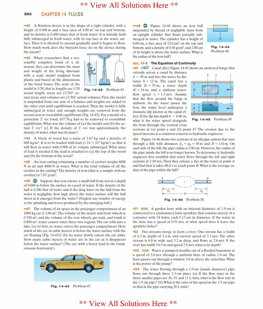
382 CHAPTE R 14 FLU I DS
••42 A flotation device is in the shape of a right cylinder, with aheight of 0.500 m and a face area of 4.00 m2 on top and bottom,and its density is 0.400 times that of fresh water. It is initially heldfully submerged in fresh water, with its top face at the water sur-face. Then it is allowed to ascend gradually until it begins to float.How much work does the buoyant force do on the device duringthe ascent?
••43 When researchers find a rea-sonably complete fossil of a di-nosaur, they can determine the massand weight of the living dinosaurwith a scale model sculpted fromplastic and based on the dimensionsof the fossil bones. The scale of themodel is 1/20; that is, lengths are 1/20actual length, areas are (1/20)2 ac-tual areas, and volumes are (1/20)3 actual volumes. First, the modelis suspended from one arm of a balance and weights are added tothe other arm until equilibrium is reached. Then the model is fullysubmerged in water and enough weights are removed from thesecond arm to reestablish equilibrium (Fig. 14-42). For a model of aparticular T. rex fossil, 637.76 g had to be removed to reestablishequilibrium. What was the volume of (a) the model and (b) the ac-tual T. rex? (c) If the density of T. rex was approximately thedensity of water, what was its mass?
••44 A block of wood has a mass of 3.67 kg and a density of600 kg/m3. It is to be loaded with lead (1.14 % 104 kg/m3) so that itwill float in water with 0.900 of its volume submerged. What massof lead is needed if the lead is attached to (a) the top of the woodand (b) the bottom of the wood?
••45 An iron casting containing a number of cavities weighs 6000N in air and 4000 N in water. What is the total volume of all thecavities in the casting? The density of iron (that is, a sample with nocavities) is 7.87 g/cm3.
••46 Suppose that you release a small ball from rest at a depthof 0.600 m below the surface in a pool of water. If the density of theball is 0.300 that of water and if the drag force on the ball from thewater is negligible, how high above the water surface will the ballshoot as it emerges from the water? (Neglect any transfer of energyto the splashing and waves produced by the emerging ball.)
••47 The volume of air space in the passenger compartment of an1800 kg car is 5.00 m3. The volume of the motor and front wheels is0.750 m3, and the volume of the rear wheels, gas tank, and trunk is0.800 m3; water cannot enter these two regions. The car rolls into alake. (a) At first, no water enters the passenger compartment. Howmuch of the car, in cubic meters, is below the water surface with thecar floating (Fig. 14-43)? (b) As water slowly enters, the car sinks.How many cubic meters of water are in the car as it disappearsbelow the water surface? (The car, with a heavy load in the trunk,remains horizontal.)
•••48 Figure 14-44 shows an iron ballsuspended by thread of negligible mass froman upright cylinder that floats partially sub-merged in water. The cylinder has a height of6.00 cm, a face area of 12.0 cm2 on the top andbottom, and a density of 0.30 g/cm3, and 2.00 cmof its height is above the water surface. What isthe radius of the iron ball?
sec. 14-9 The Equation of Continuity•49 Canal effect. Figure 14-45 shows an anchored barge thatextends across a canal by distance
and into the water by dis-tance . The canal has awidth , a water depth
, and a uniform water-flow speed . Assumethat the flow around the barge isuniform. As the water passes thebow, the water level undergoes adramatic dip known as the canal ef-fect. If the dip has depth ,what is the water speed alongsidethe boat through the vertical crosssections at (a) point a and (b) point b? The erosion due to thespeed increase is a common concern to hydraulic engineers.
•50 Figure 14-46 shows two sections of an old pipe system that runsthrough a hill, with distances dA " dB " 30 m and D " 110 m. Oneach side of the hill, the pipe radius is 2.00 cm. However, the radius ofthe pipe inside the hill is no longer known.To determine it, hydraulicengineers first establish that water flows through the left and rightsections at 2.50 m/s. Then they release a dye in the water at point Aand find that it takes 88.8 s to reach point B. What is the average ra-dius of the pipe within the hill?
h " 0.80 m
vi " 1.5 m/sH " 14 m
D " 55 mb " 12 m
d " 30 m
Fig. 14-42 Problem 43.
Fig. 14-43 Problem 47.
Fig. 14-44Problem 48.
bh
H
D d
b a i
vi
vi
Fig. 14-45 Problem 49.
dA dBD
A B?
Fig. 14-46 Problem 50.
•51 A garden hose with an internal diameter of 1.9 cm isconnected to a (stationary) lawn sprinkler that consists merely of acontainer with 24 holes, each 0.13 cm in diameter. If the water inthe hose has a speed of 0.91 m/s, at what speed does it leave thesprinkler holes?
•52 Two streams merge to form a river. One stream has a widthof 8.2 m, depth of 3.4 m, and current speed of 2.3 m/s. The otherstream is 6.8 m wide and 3.2 m deep, and flows at 2.6 m/s. If theriver has width 10.5 m and speed 2.9 m/s, what is its depth?
••53 Water is pumped steadily out of a flooded basement ata speed of 5.0 m/s through a uniform hose of radius 1.0 cm. Thehose passes out through a window 3.0 m above the waterline.Whatis the power of the pump?
••54 The water flowing through a 1.9 cm (inside diameter) pipeflows out through three 1.3 cm pipes. (a) If the flow rates in thethree smaller pipes are 26, 19, and 11 L/min, what is the flow rate inthe 1.9 cm pipe? (b) What is the ratio of the speed in the 1.9 cm pipeto that in the pipe carrying 26 L/min?
SSM
SSM
halliday_c14_359-385hr.qxd 26-10-2009 21:41 Page 382
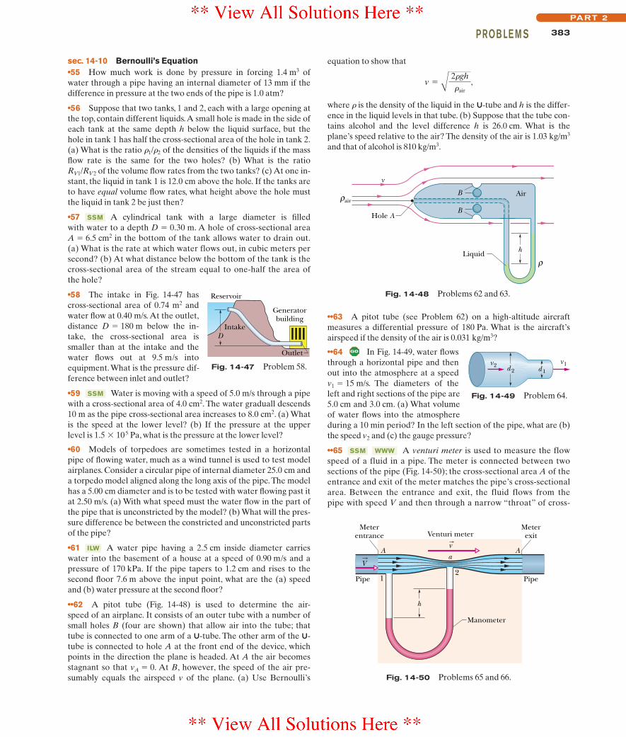
383PROB LE M SPART 2
sec. 14-10 Bernoulli’s Equation•55 How much work is done by pressure in forcing 1.4 m3 of water through a pipe having an internal diameter of 13 mm if thedifference in pressure at the two ends of the pipe is 1.0 atm?
•56 Suppose that two tanks, 1 and 2, each with a large opening atthe top, contain different liquids.A small hole is made in the side ofeach tank at the same depth h below the liquid surface, but thehole in tank 1 has half the cross-sectional area of the hole in tank 2.(a) What is the ratio r1/r2 of the densities of the liquids if the massflow rate is the same for the two holes? (b) What is the ratioRV1/RV2 of the volume flow rates from the two tanks? (c) At one in-stant, the liquid in tank 1 is 12.0 cm above the hole. If the tanks areto have equal volume flow rates, what height above the hole mustthe liquid in tank 2 be just then?
•57 A cylindrical tank with a large diameter is filledwith water to a depth D " 0.30 m. A hole of cross-sectional areaA " 6.5 cm2 in the bottom of the tank allows water to drain out.(a) What is the rate at which water flows out, in cubic meters persecond? (b) At what distance below the bottom of the tank is thecross-sectional area of the stream equal to one-half the area ofthe hole?
•58 The intake in Fig. 14-47 hascross-sectional area of 0.74 m2 andwater flow at 0.40 m/s. At the outlet,distance D " 180 m below the in-take, the cross-sectional area issmaller than at the intake and thewater flows out at 9.5 m/s intoequipment.What is the pressure dif-ference between inlet and outlet?
•59 Water is moving with a speed of 5.0 m/s through a pipewith a cross-sectional area of 4.0 cm2. The water graduall descends10 m as the pipe cross-sectional area increases to 8.0 cm2. (a) Whatis the speed at the lower level? (b) If the pressure at the upperlevel is 1.5 % 105 Pa, what is the pressure at the lower level?
•60 Models of torpedoes are sometimes tested in a horizontalpipe of flowing water, much as a wind tunnel is used to test modelairplanes. Consider a circular pipe of internal diameter 25.0 cm anda torpedo model aligned along the long axis of the pipe.The modelhas a 5.00 cm diameter and is to be tested with water flowing past itat 2.50 m/s. (a) With what speed must the water flow in the part ofthe pipe that is unconstricted by the model? (b) What will the pres-sure difference be between the constricted and unconstricted partsof the pipe?
•61 A water pipe having a 2.5 cm inside diameter carrieswater into the basement of a house at a speed of 0.90 m/s and apressure of 170 kPa. If the pipe tapers to 1.2 cm and rises to thesecond floor 7.6 m above the input point, what are the (a) speedand (b) water pressure at the second floor?
••62 A pitot tube (Fig. 14-48) is used to determine the air-speed of an airplane. It consists of an outer tube with a number ofsmall holes B (four are shown) that allow air into the tube; thattube is connected to one arm of a U-tube. The other arm of the U-tube is connected to hole A at the front end of the device, whichpoints in the direction the plane is headed. At A the air becomesstagnant so that vA " 0. At B, however, the speed of the air pre-sumably equals the airspeed v of the plane. (a) Use Bernoulli’s
ILW
SSM
SSM
equation to show that
,
where r is the density of the liquid in the U-tube and h is the differ-ence in the liquid levels in that tube. (b) Suppose that the tube con-tains alcohol and the level difference h is 26.0 cm. What is theplane’s speed relative to the air? The density of the air is 1.03 kg/m3
and that of alcohol is 810 kg/m3.
v " A 2#gh#air
Fig. 14-47 Problem 58.
Reservoir
Generatorbuilding
Outlet
IntakeD
airρ
Hole A
Liquid
v
B
ρh
B
Air
Fig. 14-48 Problems 62 and 63.
••63 A pitot tube (see Problem 62) on a high-altitude aircraftmeasures a differential pressure of 180 Pa. What is the aircraft’sairspeed if the density of the air is 0.031 kg/m3?
••64 In Fig. 14-49, water flowsthrough a horizontal pipe and thenout into the atmosphere at a speedv1 " 15 m/s. The diameters of theleft and right sections of the pipe are5.0 cm and 3.0 cm. (a) What volumeof water flows into the atmosphereduring a 10 min period? In the left section of the pipe, what are (b)the speed v2 and (c) the gauge pressure?
••65 A venturi meter is used to measure the flowspeed of a fluid in a pipe. The meter is connected between twosections of the pipe (Fig. 14-50); the cross-sectional area A of theentrance and exit of the meter matches the pipe’s cross-sectionalarea. Between the entrance and exit, the fluid flows from thepipe with speed V and then through a narrow “throat” of cross-
WWWSSM
d 2v1v2 d 1
Fig. 14-49 Problem 64.
Aa
12
h
Pipe Pipe
A
Meterentrance
MeterexitVenturi meter
Manometer
v
V
Fig. 14-50 Problems 65 and 66.
halliday_c14_359-385hr.qxd 26-10-2009 21:41 Page 383
384 CHAPTE R 14 FLU I DS
sectional area a with speed v. A manometer connects the widerportion of the meter to the narrower portion. The change in thefluid’s speed is accompanied by a change !p in the fluid’s pressure,which causes a height difference h of the liquid in the two arms ofthe manometer. (Here !p means pressure in the throat minus pres-sure in the pipe.) (a) By applying Bernoulli’s equation and theequation of continuity to points 1 and 2 in Fig. 14-50, show that
,
where r is the density of the fluid. (b) Suppose that the fluid is freshwater, that the cross-sectional areas are 64 cm2 in the pipe and 32cm2 in the throat, and that the pressure is 55 kPa in the pipe and 41kPa in the throat.What is the rate of water flow in cubic meters persecond?
••66 Consider the venturi tube of Problem 65 and Fig.14-50 without the manometer. Let A equal 5a. Suppose the pres-sure p1 at A is 2.0 atm. Compute the values of (a) the speed V at Aand (b) the speed v at a that make the pressure p2 at a equal tozero. (c) Compute the corresponding volume flow rate if the diam-eter at A is 5.0 cm. The phenomenon that occurs at a when p2 fallsto nearly zero is known as cavitation. The water vaporizes intosmall bubbles.
••67 In Fig. 14-51, the freshwater behind a reservoir dam hasdepth D " 15 m. A horizontal pipe4.0 cm in diameter passes throughthe dam at depth d " 6.0 m. A plugsecures the pipe opening.(a) Find themagnitude of the frictional force be-tween plug and pipe wall. (b) Theplug is removed.What water volumeexits the pipe in 3.0 h?
••68 Fresh water flows hori-zontally from pipe section 1 ofcross-sectional area A1 into pipesection 2 of cross-sectional areaA2. Figure 14-52 gives a plot of thepressure difference p2 $ p1 versusthe inverse area squared A1
$2 thatwould be expected for a volumeflow rate of a certain value if thewater flow were laminar under allcircumstances. The scale on the vertical axis is set by ∆ps " 300kN/m2. For the conditions of the figure, what are the values of (a)A2 and (b) the volume flow rate?
••69 A liquid of density 900 kg/m3 flows through a horizontal pipethat has a cross-sectional area of 1.90 % 10$2 m2 in region A and across-sectional area of 9.50 % 10$2 m2 in region B. The pressure differ-ence between the two regions is 7.20 % 103 Pa. What are (a) the vol-ume flow rate and (b) the mass flow rate?
••70 In Fig. 14-53, water flows steadily from the left pipe section
ILW
V " A 2a2 !p#(a2 $ A2)
(radius r1 " 2.00R), through the middle section (radius R), and into theright section (radius r3 " 3.00R).The speed of the water in the middlesection is 0.500 m/s.What is the net work done on 0.400 m3 of the wateras it moves from the left section to the right section?
••71 Figure 14-54 shows astream of water flowing througha hole at depth h " 10 cm in atank holding water to height H "40 cm. (a) At what distance xdoes the stream strike the floor?(b) At what depth should a sec-ond hole be made to give thesame value of x? (c) At whatdepth should a hole be made tomaximize x?
•••72 A very simplified schematic of the rain drainage system for ahome is shown in Fig. 14-55. Rain falling on the slanted roof runs offinto gutters around the roof edge; it then drains through downspouts(only one is shown) into a main drainage pipe M below the basement,which carries the water to an even larger pipe below the street. In Fig.14-55, a floor drain in the basement is also connected to drainage pipeM.Suppose the following apply:
1. the downspouts have height h1 " 11 m,2. the floor drain has height h2 " 1.2 m,3. pipe M has radius 3.0 cm,4. the house has side width w " 30 m and front length L " 60 m,5. all the water striking the roof goes through pipe M,6. the initial speed of the water in a downspout is negligible,7. the wind speed is negligible (the rain falls vertically).
At what rainfall rate, in centimeters per hour, will water from pipeM reach the height of the floor drain and threaten to flood thebasement?
Fig. 14-51 Problem 67.
D
d
r1 r3R
Fig. 14-53 Problem 70.
H
h
x
v
Fig. 14-54 Problem 71.
Floordrain
w
h1
h2
M
Fig. 14-55 Problem 72.
Fig. 14-52 Problem 68.
p 2 –
p1
(kN
/m2 ) ∆ps
–∆ps
016
A1–2 (m–4)
32
Additional Problems73 About one-third of the body of a person floating in theDead Sea will be above the waterline. Assuming that the humanbody density is 0.98 g/cm3, find the density of the water in theDead Sea. (Why is it so much greater than 1.0 g/cm3?)
74 A simple open U-tube contains mercury. When 11.2 cm of wa-ter is poured into the right arm of the tube, how high above its ini-tial level does the mercury rise in the left arm?
75 If a bubble in sparkling water accelerates upward at therate of 0.225 m/s2 and has a radius of 0.500 mm, what is its mass?Assume that the drag force on the bubble is negligible.
halliday_c14_359-385hr.qxd 26-10-2009 21:41 Page 384

385PROB LE M SPART 2
76 Suppose that your body has a uniform density of 0.95times that of water. (a) If you float in a swimming pool, what frac-tion of your body’s volume is above the water surface?
Quicksand is a fluid produced when water is forced up intosand, moving the sand grains away from one another so they are nolonger locked together by friction. Pools of quicksand can form whenwater drains underground from hills into valleys where there aresand pockets. (b) If you float in a deep pool of quicksand that has adensity 1.6 times that of water, what fraction of your body’s volume isabove the quicksand surface? (c) In particular, are you submergedenough to be unable to breathe?
77 A glass ball of radius 2.00 cm sits at the bottom of a containerof milk that has a density of 1.03 g/cm3. The normal force on theball from the container’s lower surface has magnitude 9.48 % 10$2 N.What is the mass of the ball?
78 Caught in an avalanche, a skier is fully submerged inflowing snow of density 96 kg/m3. Assume that the average densityof the skier, clothing, and skiing equipment is 1020 kg/m3. Whatpercentage of the gravitational force on the skier is offset by thebuoyant force from the snow?
79 An object hangs from a spring balance. The balance registers30 N in air, 20 N when this object is immersed in water, and 24 Nwhen the object is immersed in another liquid of unknown den-sity.What is the density of that other liquid?
80 In an experiment, a rectangular block with height h is allowedto float in four separate liquids. In the first liquid, which is water, itfloats fully submerged. In liquids A, B, and C, it floats with heightsh/2, 2h/3, and h/4 above the liquid surface, respectively. What arethe relative densities (the densities relative to that of water) of (a)A, (b) B, and (c) C?
81 Figure 14-30 shows a modified U-tube: the right arm isshorter than the left arm. The open end of the right arm is heightd " 10.0 cm above the laboratory bench. The radius throughoutthe tube is 1.50 cm. Water is gradually poured into the open end ofthe left arm until the water begins to flow out the open end of theright arm. Then a liquid of density 0.80 g/cm3 is gradually added tothe left arm until its height in that arm is 8.0 cm (it does not mixwith the water). How much water flows out of the right arm?
82 What is the acceleration of a rising hot-air balloon if the ratioof the air density outside the balloon to that inside is 1.39? Neglectthe mass of the balloon fabric and the basket.
SSM
83 Figure 14-56 shows a siphon, which is a device forremoving liquid from a container. Tube ABC must initially be filled,but once this has been done, liquid will flow through the tube untilthe liquid surface in the container is level with the tube opening atA. The liquid has density 1000 kg/m3 and negligible viscosity. Thedistances shown are h1 " 25 cm, d " 12 cm, and h2 " 40 cm. (a) Withwhat speed does the liquid emerge from the tube at C? (b) If the at-mospheric pressure is 1.0 % 105 Pa, what is the pressure in the liquidat the topmost point B? (c) Theoretically, what is the greatest possi-ble height h1 that a siphon can lift water?
A
B
h 2
d
h 1
C
Fig. 14-56 Problem 83.
84 When you cough, you expel air at high speed throughthe trachea and upper bronchi so that the air will remove excessmucus lining the pathway. You produce the high speed by this pro-cedure: You breathe in a large amount of air, trap it by closing theglottis (the narrow opening in the larynx), increase the air pressureby contracting the lungs, partially collapse the trachea and upperbronchi to narrow the pathway, and then expel the air through thepathway by suddenly reopening the glottis.Assume that during theexpulsion the volume flow rate is 7.0 % 10$3 m3/s. What multiple ofthe speed of sound vs (" 343 m/s) is the airspeed through the tra-chea if the trachea diameter (a) remains its normal value of 14 mmand (b) contracts to 5.2 mm?
85 A tin can has a total volume of 1200 cm3 and a mass of 130 g.How many grams of lead shot of density 11.4 g/cm3 could it carrywithout sinking in water?
halliday_c14_359-385hr.qxd 26-10-2009 21:41 Page 385