design, construction, and maintenance of highway safety
TRANSCRIPT
U.S. Department of Transportation Federal Highway Administration
NHI Course No. 38034
Publication No. FHWA-HI-98-000 May 1998
Design Construction and Maintenance of Highway Safety
atures and Appurtenances
tructor Guide
IlllZII National Highway institute

Technicnl Report Documentation Page . RcpdNa 2 Gcwcmmcn~ Accession No. 3. Rccipienrr c&l% No.
_ Xtle and Subtitle 5. Rtpor(Dak
Design, Construction and Maintenance of Highway September, 1997 Safety Features and Appurtenances. 6. Petforming orgnivtion Chic
Instructors Manual . Au&x(s) 8 Petforming Chganimtiom Repoti No.
Brian L. Bowman, Don J. Gripne, and James E. Bryden
. Performing Oq@atio. Name and Addmss IO. Woct Unit No. QRAIS)
Auburn University Highway Research Center 11. Chbxx or Grant No.
Harbert Engineering Center Auburn, AL 36849
DTFHGl-92-C-00036
2 Spot Agency Name and Address 13. -l-w of &port and Paiod covard
Federal Highway Administration Office of Highway Safety 400 Seventh Street, S.W. 14. spollroring Agency code
Washington, D.C. 20590
S. Supplemenhzy Notes
FHWA Contract Manager: Carl Hayden (HHS-20)
6. Al&ad
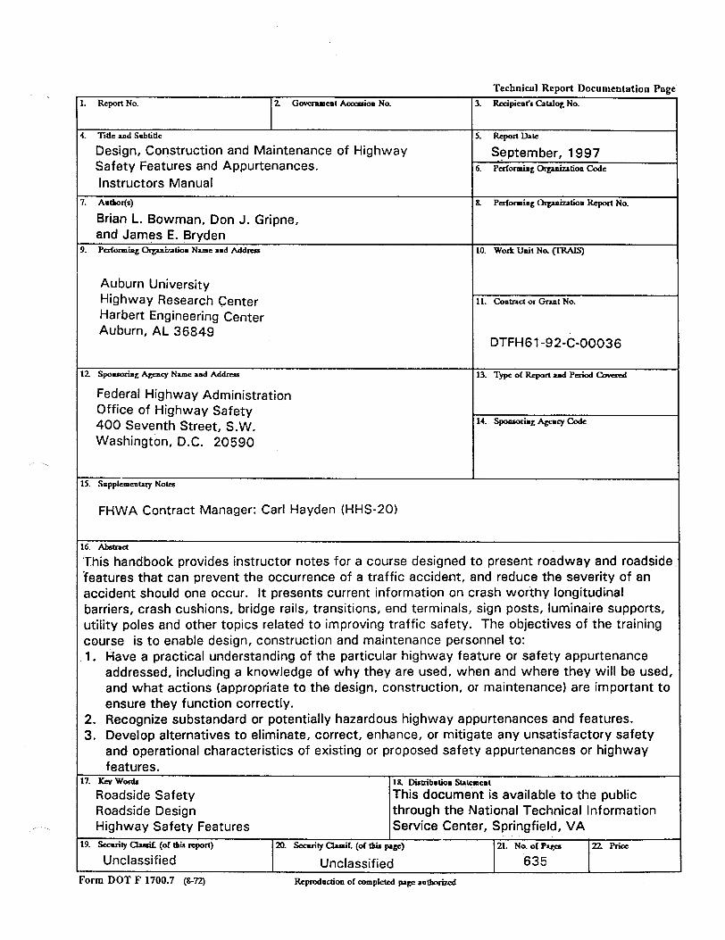
This handbook provides instructor notes for a course designed to present roadway and roadside features that can prevent the occurrence of a traffic accident, and reduce the severity of an accident should one occur. It presents current information on crash worthy longitudinal barriers, crash cushions, bridge rails, transitions, end terminals, sign posts, luminaire supports, utility poles and other topics related to improving traffic safety. The objectives of the training course is to enable design, construction and maintenance personnel to: 1. Have a practical understanding of the particular highway feature or safety appurtenance
addressed, including a knowledge of why they are used, when and where they will be used, and what actions (appropriate to the design, construction, or maintenance) are important to ensure they function correctly.
2. Recognize substandard or potentially hazardous highway appurtenances and features. 3. Develop alternatives to eliminate, correct, enhance, or mitigate any unsatisfactory safety
and operational characteristics of existing or proposed safety appurtenances or highway features.
7. Kcvwotds 18 Disbibuliom Sta+mt
Roadside Safety This document is available to the public Roadside Design through the National Technical Information Highway Safety Features Service Center, Springfield, VA
9. .scauity aasifl (of tbia rcporl) 20. secority CkrsiC (ol lhis page) 21. Na of Pap 22Rice
Unclassified Unclassified 635 Form DOT F 1700.7 (8-n) Repmdlldon of 03mplcted pqc ~utborizcd
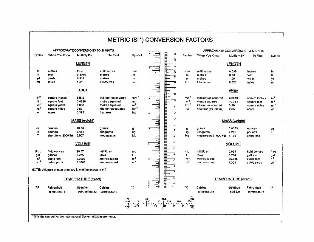
METRIC (§I*) CONVERSION FACTORS
APPROXIMATE CONVERSIONS TO Sl UNITS APPROXIMATE CONVERSIONS TO SI UNITS
When You Know Multiply By To Find Symbol When You Know Multiply By To Find
LENGTH
in inches 25.4 millimetres ft feet 0.3048 metres
yd yards 0.914 metres mi miles 1.61 kilometres
ARU\
in2 square inches ft*
vd2
square feet square yards
mi* square miles ac acres
645.2 millimetres squared 0.0929 metres squared 0.836 metres squared 2.59 kilometres squared 0.395 hectares
MASS (weight)
02 lb T
ounces 28.36 0.464
short tons (2000 lb) 0.907
gram5 kilograms megagrams
VOLUME
fl 02 fluid ounces 29.67 millilitres
gal gallons 3.785 litres ft3 cubic feet 0.0328 metres cubed
yd3 cubic yards 0.0785 metree cubed
mm m m km
mm2
;:
km2 ha
cl kg Mg
mL L
1:
NOTE: Volumes greater than 100 L shall be shown in m5.
TEMPERATURE (exact)
OF Fahrenheit 5/Q (after Celsius OC
LENGTH
mm millimetres 0.039 inches in m metres 3.28 feet ft m metres 1 .OQ yards yd
km kilometres 0.621 miles mi
AREA
mm2 millimetres squared 0.0016 square inches m* metres squared 10.764
km2 5quare feet
kilometres squared 0.39 square miles ha hectares (10 000 m ) 2.63 acres
in’ ft2 mi2 ac
MASS (weight)
k8g m
grams 0.0363 ounces kilograms 2.205 pounds megagrams (1 000 kg) 1.103 short tons
; T
VOLUME
mL L
;:
millilitres 0.034 fluid ounces fl 02 litres 0.264 gallon5 gal metres cubed 35.315 cubic feet It’ metres cubed 1.308 cubic yards yd 3
TEMPERATURE (exact)
Celsius Q/5 (then Fahrenheit
temperature add 32) temperature
OF
temperature subtracting 32) temperature
‘F 32 w.0 ;:2
* SI is the symbol for the International System of Measurements.
INTRODUCTION
This Instructor’s Manual contains the course content intended to supplement the User’s Guide, “Design Construction and Maintenance of Highway Safety Features and Appurtenances. II
The course and guide present concepts of traffic safety related to roadway and roadside features that can prevent the occurrence of a traffic accident, and reduce the severity of an accident should one occur. They present current information on crashworthy longitudinal barriers, crash cushions, bridge rails, transitions, end terminals, sign posts, luminaire supports, utility poles, and other topics related to improving traffic safety.
The purpose of the course is to provide design, construction and maintenance personnel information on roadway and roadside safety needs and the safety performance of highway safety features. The objectives of the manual are to enable the reader to:
1. Have a practical understanding of the particular highway feature, or safety appurtenance addressed, why, when and where they will be used, and what actions (appropriate to the design, construction, or maintenance) are important to ensure they function correctly.
2. Recognize substandard or potentially hazardous highway appurtenances and features.
3. Develop alternatives to eliminate, correct, enhance, or mitigate any unsatisfactory safety and operational characteristics of existing, or proposed safety appurtenances, or highway features.
SUMMARY OF COURSE FORMAT
The training course is designed to present those topics and hardware components that are of interest to the host agency. Each course section is designed to be presented by itself and each device has a construction and maintenance breakout session. However, to ensure proper instruction the following recommendations should be considered.
l Chapter 2 contains basic concepts that all course participants should know. Appropriate sections of Chapter 2 should always be presented as part of the course. For example, if the host agency is interested in information on longitudinal barriers and end treatments, then sections 2.1 (Clear Zone Concept), 2.3 (Overview of Traffic Barriers), 2.4 (Performance Requirement of Barriers), 2.5 (Barrier Selection Guidelines), and 2.6 (Design of Longitudinal Barriers) should be presented before the desired sections of Chapters 4 and 5. Similarly, an agency wishing to obtain training on bridge rails should include section 2.8 (Design of Bridge Rails and Transitions) before all sections in Chapter 6.
1
0 Workshops have been developed to reinforce the course topics. Some workshops require participants to work in small groups on problems, and in other instances the workshops consist of a series of good and bad practice visual aids.
To assist in selecting the proper sections of the course the content of the Participant’s Guide is summarized below.
1.1
2.1
2.2
2.3
2.4
2.5
2.6
2.7
2.8
1 INTRODUCTION TO THE SAFE ROADSIDE CONCEPT
- Background: An introduction to predominant roadside safety hazards and effective countermeasures. Also, included in the introduction are accident statistics, evolution of roadside safety, current testing procedures and problem areas associated with roadside hardware, present and future safety hardware, FHWA procedures for barrier acceptance, out of date installations, and steps to increase roadside safety.
2 DESIGN OF HIGHWAY SAFETY FEATURES
- Clear Zone Concept: Definition, description, history, and examples of the acceptable clear zone as defined by AASHTO for various geometric situations.
- Traversable and Non-Traversable Ditches and Backslopes: Describes the hazard areas of ditches, where ditches are acceptable, and alternatives to using ditches to remove water.
- Overview of Traffic Barriers: Describes roadside barriers, terminals, and transitions, and defines characteristics such as redirecting capability and pocketing, which are used to classify the barriers.
- Performance Requirements of Barriers: Testing procedures, such as vehicle weight, speed, and angle of impact, which are used to classify a barrier or bridge rail, and the performance levels by which barriers and bridge rails are evaluated.
- Barrier Selection Guidelines: Lists selection criteria with brief descriptions that should be considered in determining the barrier system that provides the required degree of shielding at the lowest cost.
- Design of Longitudinal Barriers: Definition of barrier design elements and discussion of the factors that must be considered in a barrier layout. Examples of calculating length of need for longitudinal barriers.
- Design of Crash Cushions: Outlines place of need, methods of operation, evaluation, and selection of FHWA approved crash cushions.
- Design of Bridge Rails and Transitions: Differences between bridge rails and roadside barriers; bridge rail performance levels and crash test criteria, and bridge
2
rail selection. Examples for determining appropriate performance levels and barrier types.
2.9 - Design of Traversable and Non-Traversable Drainage Features: Design concerns associated with curbs, pipes, culverts, headwalls, and drop inlets. Recommendations on the location, design, and maintenance of these features for increased safety.
2. IO - Construction and Maintenance of Drainage Features: Construction of drainage features and their maintenance needs including inspection checklists for ditches, drainage structures, and intakes.
2.11 - Safety Considerations of Landscaping and Vegetation Control: Compares advantages and disadvantages of landscaping along highways. Importance of properly maintaining vegetation, and impact of vegetation in different geometric situations.
3 BREAKAWAY DESIGNS
3.1 - Introduction to Breakaway Systems: Options available to engineers for providing safe designs of traffic signs, roadway illumination, utility service, and postal delivery hardware placed within the right-of-way.
3.2 - Design Orientated Single Mount Sign Supports: Situations in which signs require single support systems, and the most widely used approved sign support systems.
3.3 - Design Orientated Multiple Mount Sign Support: Differences between single and multiple mount sign supports. The most widely used approved multiple sign support systems.
3.4 - Maintenance and Construction of Single Sign Supports: Methods of installation, placement, and maintenance of single sign supports.
3.5 - Maintenance and Construction of Multi-Mount Sign Supports: Methods of installation, placement, and maintenance of multiple mount supports.
3.6 - Maintenance of Traffic Sign Panels and Posts: Sign vandalism problems including destruction, mutilation, and theft, with possible solutions and maintenance suggestions. Repair and replacement guidelines are also included for different sign types.
3.7 - Breakaway Utility Poles: Advantages of using breakaway utility poles in situations where other options are not available, available designs of breakaway systems, and tips for system selection.
3.8 - Crashworthy Mailbox Supports: Mailbox hazards and the need for their proper design, placement, and installation.
3
3.9 - Safety Considerations when Designing and Locating Traffic Signal Supports and Controller Boxes: Considerations required when installing traffic signals and control boxes.
3.10 - Crash Tested Light Supports: Advantages and disadvantages of the different types of materials available for use as light supports. Methods of designing and installing light support foundations, bases, and wiring systems. Guidelines for construction of lighting installations.
4.1
4.2
4.3
4.4
4.5
4.6
4.7
5.1
5.2
4 LONGITUDINAL BARRIER SYSTEMS
Rigid Barrier Systems: A listing of the various types of concrete barriers and discussion of their performance capabilities. Highway design parameters which must be met to ensure proper barrier performances. Barrier selection, inspection, and evaluation.
Strong Post W-Beam and Thrie-Beam Barriers: Historical development of W-beam and thrie-beam barriers and a discussion of their design and performance differences. Approved end treatments and transitions available for use. Selection and design considerations.
Construction and Maintenance of Semi-Rigid Systems: Details concerning layout, construction, and maintenance of strong post W-Beam and thrie-beam guardrails, transitions, and terminals.
Weak Post Barrier Systems: Construction and maintenance of flexible systems including weak post W-beam, weak post thrie-beams, and cable systems.
Treatment of Wide Medians, Barrier Envelopes, Curved Barrier Sections, and Other Methods of Protecting Large Areas: Methods of treating wide roadside areas that can pose as safety hazards.
Aesthetic and Lower Service Level Barrier Systems: Traffic barriers that provide impact performance comparable to conventional barrier systems with visual qualities to complement aesthetically sensitive environments.
Commercially Available Barrier Systems: Discusses configuration and dimensions of available commercial barrier systems.
5 TERMINALS AND CRASH CUSHIONS
Introduction to Terminals and Crash Cushions: Introduction to the need for proper end treatments and the principles by which these treatments operate.
Construction and Maintenance of Terminals: Construction and maintenance of various types of terminals, both proprietary and non-proprietary, available for use
4
W-beam and/or thrie-beam end treatments. Includes installation and maintenance checklists.
5.3 - Construction and Maintenance of Crash Cushions and Sand Barrels: Description, construction, maintenance, and product check lists of crash cushions, sand barrels, truck-mounted attentuators, and positive intrusion protection.
6 BRIDGE BARRIERS
6.1 - Crashworthy Bridge Railings: Dimensions and overall geometry of bridge railing systems.
6.2 - Transitions To Bridge Rail and Between Barrier Systems: Guardrail to bridge railings transitions.
6.3 - Identification of Deficient Bridge Rail Systems: Improper designs of bridge railings, corrective measures, and retrofit designs.
Appendix A -
Appendix B -
Appendix C -
Appendix D -
Appendix E -
Appendix F -
Appendix G -
Appendix H -
APPENDICES
Glossary: A list of important words and definitions used in the manual.
Characteristics of Crash Cushions, End Treatments and Truck Mounted Attentuators (TMA): Tables concerning general characteristics, roadside, median, and gore applications, and comparative maintenance requirements. Also included is a site inspection worksheet for crash cushion design.
Bridge Railings that Meet Performance Level Criteria: A list of bridge railings, along with their rail height, weight of test vehicle, impact speed, and impact angle, that meet performance level criteria.
Approved Single Sign Support Assemblies: A list of single sign support assemblies that have been tested and determined as acceptable for use.
Approved Multiple Sign Support Assemblies: A list of multiple sign support assemblies that have been tested and determined as acceptable for use.
Luminaire Supports: An introduction to luminaire supports followed by a list of luminaire support devices which have received FHWA acceptance.
AD-IV-S, Reinforced Timber Utility Pole Installation Instructions.
Model Regulation for the Accommodation of Mailboxes and Newspaper Delivery Boxes on Public Highway Rights-of-Way.
5
Appendix I - Inspection Forms: Individual inspection forms with corresponding checklists for all crash cushions, end terminals, and other roadside and median features discussed in this manual.
Appendix J - List of Manufacturers: A list of manufacturers, including addresses and phone numbers, featured in this manual.
Appendix K - A summary of the Background and Procedures for haining Federal Highway Administration Acceptance for Highway Features.
6
GUIDELINES FOR INSTRUCTORS
The Instructor’s Manual and the training materials are organized in the same order as that used in the User’s Guide. Reference to the User’s Guide is facilitated by the inclusion of page numbers at the beginning of each training session and, when appropriate, in the instructor’s description of each visual aid.
Each of the sessions has a session guide as its cover page. This session guide contains the session title, instructional objectives, helpful hints, and the number of slides and handouts for that session. An approximate duration for the session is also indicated. (This duration should be adjusted to meet the needs and interests of each group.)
The session guides are followed by a series of pages containing the text and slides for that session. The text is written below the “script” on the left side of the page and the associated slide is on the right side of the page. The script provides the key ideas that are to be presented and the slides illustrate and clarify these ideas. The script also tries to maintain continuity within each session and between sessions, highlighting changes in topics and providing transitions between topics.
Slides are numbered sequentially in two parts: The first number refers to the session and the second refers to the slide in that session. Each session begins with a slide indicating the name of the session. The overall time available for the session should guide the instructor in allocating time to spend on for each slide; the text amount associated with the slide. However, no fixed rule applies because of the differences between the purposes of each slide.
Text slides are presented to introduce new topics or subtopics, show the relationship between topics, or present a list of important points. Generally, these slides should be shown for the time required to elaborate the points summarized on the slide.
Figure slides may be displayed for longer periods of time as the instructor brings out key points, talks about the relationship between various parts of the figure, or clarifies the information contained in the figure with an example. Pages referencing the manual are indicated in the text portion when the tables or figures are also included in the manual.
Photographs and sketches make up the bulk of the slides. They have been included to illustrate the key points of the text and provide examples of typical real-world conditions and data collection techniques. The amount of time spent on these slides is variable.
The instructor should audit the course as a participant before teaching the material: With the Instructor’s Manual in hand, instructors should go through the slides one-by-one making notes and underlining key words in the script. If possible, they should rehearse their presentation in private, and again before one or two people who are familiar with the material. These rehearsals will give the instructor a better idea of how much time to spend on each slide and the overall pace of the session. Time-cues written in the Instructor’s Manual after each subtopic are often useful to suggest pace adjustments during the actual presentations.
7
It is important to introduce the participants to the “Session by Session Evaluation Form” during the first session. Periodically remind them to fill in the form after each session. Guidelines for improving presentations using the results of this and the overall evaluations are contained in the participant evaluation and feedback portion of this material.
Resource Selection
Instructional aids such as reports, procedures, specifications, etc., may from time to time, become available from FHWA, the State or local agencies and from private industry. They can be used to update the Instructor’s Manual as notes or appendixes.
New resources should also be developed and used as necessary to keep the course relevant to the agency’s needs and in recognition of new or revised national, State or local regulations.
Preparing a Lesson Plan
Good planning leads to effective teaching. It insures the appropriate use of time and complete coverage of the subject. An effective instructor plans his presentation regarding course objectives and presents the material in the language of the participants. When lessons are carefully planned, the instructor can approach the class with a feeling of confidence and enthusiasm.
Function of the Lesson Plan
The instructional lesson plan outlines the subject material and the time allocated for its presentation. The plan also serves the following functions:
l Aids preparation of the lesson. l Guides actual teaching. l Assists substitute instructors. l Promotes uniformity of instruction. l Specifies physical arrangements for the class.
Preparation of the Lesson Plan
Construction of the lesson plan begins after the material in the Instructor’s Manual has been carefully reviewed. The lesson plan should contain the following.
Introduction
An introduction should be written in narrative form to assist the instructor in getting through the initial few minutes of each session, usually the most difficult stage of the presentation. It serves four purposes.
Tie-in - It should relate the present session material to a previous session or to earlier related experiences. This will integrate each session as it is presented with the
8

whole series of sessions covered in the course. The objective is to create a continuous train of thought that relates each session to part of the overall topic.
Statement of Objective - The session objective must be clearly stated. This will produce anticipation of what is coming during the presentation of the material and help to motivate the interest of the participants. It will also establish a goal in the minds of the students.
Motivator - Developing interest at the start of each session makes holding the attention of the class much easier. Some “attention-getter” - something to switch the attention from the individuals own chain of thought to the group interest -- should be included in the introduction.
Reason - Motivating initial interest may not be enough. In every class there is one or more class members who may not have an interest in at least portions of the subject matter being covered. The introduction should include reasons why it is important to learn the material.
Develooment
After the preliminaries are over, the lesson material begins. It is in this part of the lesson plan that the actual instruction takes place. The main points are carefully explained, and the mission of the lesson achieved. This is the main body of the material included in the Instructor’s Manual.
The principal topics have been incorporated into the script of the Instructor’s Manual,with the associated slides selected to illustrate these points. Keywords in the script should be highlighted so they can be seen at a glance. Timing cues inserted in the guide help the instructor allocate enough time to various topics within the session and stay on schedule.
The questions that arise from the participants during a session most commonly indicate lack of understanding of the material. However, questions are sometimes suppressed for anyone or several reasons:
l The participants may not feel comfortable talking to the instructor, who they probably have not met before, particularly during the first few sessions of a course.
l The participants may feel that they should not interrupt the presentation.
l They may not want to show the other participants that they do not understand the material.
l They may feel that since no one else asked, their question cannot be very important.
The instructor should periodically ask for questions from the participants and include a series of questions in the lesson plan. This should be done at various intervals
9
throughout the lesson. The frequency of these questions can be determined by experience when the instructor discovers which areas of the lessons are most likely to encounter difficulty. Ideally, these class audits should be taken at the close of each difficult area. Questions to ask are:
0 “What does your agency do in this area?” e “How do they handle it?” 0 “What has been their experience?” l “What problems have they encountered doing something?” 0 “What solutions work the best?”
Summarv
A summary should be prepared in the instructor’s own words to review the important points and to tie-in the lesson with the one to come.
Review major points - Reviewing the important points will restore the overall relationships of all major items in the lesson. Likewise, review is a stimulus to recall. Therefore, at this time strong emphasis must be placed on each major point. This will fix the lesson material firmly in the participant’s minds.
The instructor should use the summary as a teaching tool. Taking full advantage of the opportunity to reestablish the important elements of the lesson is best. Treating the summary casually may weaken the presentation.
Tie-in with next lesson - Tying the lesson in with the one to follow will produce a continuous train of thought that remains unbroken by the lapse of time between the present lesson and the one to follow. This can be done as the final statement of the summary.
Revisions
No single instructor’s lesson plan will meet all future situations, regardless of the amount of time spent on the original planning. Conditions vary too much from day to day and from class to class. Likewise, unforeseen weaknesses in the instruction may not become apparent until the material has been presented several times.
The plan is updated and revised as the instructor becomes aware of deficiencies and omissions. Immediately after a lesson is taught, the plan should be examined for improvement possibilities. Notes should be made regarding mistakes, awkward spots, and omissions. Even after a lesson has been taught repeatedly, updates may be necessary to introduce new devices and new training aids that will improve participant learning.
Modifying the Course to Meet Local Needs
The Instructor’s Manual has been prepared for use nationwide. These instructional resources may be adapted or modified by the agency conducting the training
10
by including local practices and examples that will make the presentation more relevant to State or local regulations and the host agency’s situation.
Types of modifications of resources to be considered:
0 Include local anecdotes and examples instead of, or in addition to, the examples indicated.
0 Use 35 mm slides of local situations in place of the available slides.
0 Local agency procedures, standards, practices and requirements can be cited wherever appropriate.
a The course schedule can be adjusted to give more or less time to certain sessions as deemed necessary.
Training Techniques
The lecture is probably the easiest way of conducting a training session; it can also be the deadliest and perhaps the least effective. While the subject matter has some impact upon the outcome, the delivery technique is the critical element.
Techniques in Presentinq Lectures
There are several alternative techniques for presenting a lecture:
0 Reading from a prepared text. l Referring to a prepared text. 0 Outlining the text using notes. l Knowing the subject well and speaking extemporaneously.
None of these techniques are ideal for all individuals all of the time. The proper technique depends upon the instructor’s ease of speaking to groups of people and his knowledge of the subject matter.
Reading or Referring to a Prepared Text - When the script in the Instructor’s Manual is used because of the instructor’s general unfamiliarity with the subject:
l Read the Instructor’s Manual several times until you are familiar with it.
l Review the references for additional background particularly in areas where you have the least knowledge, or topics that may generate the most questions from the participants; and
l Talk to people in your agency with more knowledge of the various topics, those who are familiar with local practices and others who have taught the course before.
11

During the presentation of the prepared text, avoid monotones, change your expression, and give emphasis when needed. Keep eye contact with the audience.
Using Notes - The text in the Instructor’s Manual is essentially an outline intended to aid the lecturer in presenting the subject. Ideally, it should not be read verbatim. Adding the lecturer’s own experience or personal comments will improve the presentation and increase the audience’s interest.
Speaking Extemporaneously - Of all techniques in lecturing, this method can be the most effective. However, knowledge of the subject and the instructor’s speaking ability is the key in the use of this method. Caution is needed, however; be careful to:
l Follow the sequence of topics presented in the text. l Stay on the subject. l Keep the course on schedule. l Allow time for comments or questions from the participants.
All presentations, no matter what the technique, should be rehearsed in private and (if possible) before a small group of knowledgeable individuals before it is given to the intended audience.
Techniaues for Obtainina Classroom Discussion
One of the most effective techniques that can be used in training is getting the participants involved in a discussion of the subject matter. This is desirable for several reasons:
0 They become active participants, rather than a passive audience merely listening.
l They need to be challenged to become involved.
l Unless actively involved, the/r minds tend to wander and much of the information is lost.
The makeup of each class is different and class dynamics will vary. In some classes, everything clicks and the whole group becomes active with little effort on the instructor’s part. In other instances, the class will appear completely unresponsive and the instructor must use every tool at his command to draw the participants into the session presentations.
Most groups are generally withdrawn during the first few sessions, while they are becoming acquainted with their fellow class members, the subject matter, and the instructor. This is the time the instructor gets to know the class, by reviewing the sign- up sheet for the job mix of participants and by watching their response to the first few sessions.
Based on the instructor’s review of the group’s response to the first few sessions, he should select one or more of the following techniques to generate classroom
12

discussions:
0 Ask the class a question. e Direct a question to a specific person. l Ask the class for comments on a specific point. l Ask if the procedures vary in different districts or areas of the State. e Ask for experience that illustrates points under discussion.
Occasionally, the discussions by the class can get out of hand, with several groups talking at once. This must be prevented from continuing. The instructor must allow only one discussion at a time. It will also be necessary to stop discussions in order to stay on schedule. Classroom bull sessions are easy to start and of little productive value for the class as a whole.
Techniaues for Respondina to Questions
Responding to Questions - The instructor must, on the spot, decide how to best handle questions. Early in the course, questions often arise regarding items that will be covered later. Sometimes the major portion of a subsequent session may deal with a particular question.
Three options are available to the instructor:
l Answer the question when it arises and remember to delete the material during the subsequent session in which the subject was intended to be covered.
l Provide a short answer at this time and discuss it more fully in the subsequent session.
l Explain that this subject will be covered later and that you prefer to respond to the question when you can cover the material in detail and when you have the supporting visual aids that will clarify your presentation.
In many instances the second alternative will be the preferred one.
Answering Difficult Questions - Sometimes the instructor may have difficulty responding to questions raised by the class because the question is not understood, the answer is unknown, or more information is required.
Several courses of action may be taken in such instances. They include:
e Ask participant to rephrase the question in a more specific manner.
l Recognize that the question deals with a unique situation of interest to a particular participant and offer to discuss the solution further with him during the next break.
l Seek help from a fellow instructor or senior member of the class.
13

0 Ask the class as a whole for assistance.
l Arbitrarily pick one member of the class for suggestions.
l Stop and look up the answer in the manual.
l State that you do not have the answer, but will try to obtain it and discuss the matter later in the course.
The best course of action is to use all of the above techniques from time to time, and avoid the excessive use of any individual technique.
Techniques for Handlina Problem Participants
Occasionally, an instructor has problems with a participant who disrupts the class. This can occur if one individual asks too many questions, argues with the instructor or otherwise interferes with the classroom presentation. Actions to take in such situations include:
0 Ignore the question.
l Confront the individual during the class and ask for his cooperation.
l Discuss the problem of being able to effectively cover the course material due to the disruptions with the person during a break.
l Ask other participants to speak to the problem individual.
l Offer to discuss the person’s individual problems after class.
The best course of action for these cases should be determined based on the particular circumstances of the situation. However, continued interruption of the presentation will be detrimental to the remainder of the class.
Fact Versus Opinion
Occasionally participants will want either facts or opinions. It is clearly the obligation of the instructor to differentiate between the two. There are many speakers who deliver their own opinions as factual information. They include just enough facts to add credibility to their statements. As a rule, the instructor should restrict himself to presenting factual information, permitting the participant to formulate his own opinions. When an opinion is stated by an instructor in any lesson, the participants should be told that this is the instructor’s opinion and does not necessarily represent agency policy or facts.
Evaluation of Training Effectiveness
The evaluation phase of the training process is probably the least understood part of the process and is frequently ignored, or at most, given a low priority. However, the
14

evaluation of the training program will take place either formally or informally, whether planned or not. It cannot be avoided.
Evaluations are carried out for a variety of reasons, such as, ensuring that the training program is performed well, meeting the objectives of the organization conducting the program, and the people enrolled in the program. Several purposes for conducting training program evaluations are listed below.
l Evaluation motivates the instructor and participants. l Checks performance of the instructor and participants. e Reveals gaps in the learning process. l Maintains teaching standards. l Serves as a teaching device in itself. l Helps in counseling and post-course follow up.
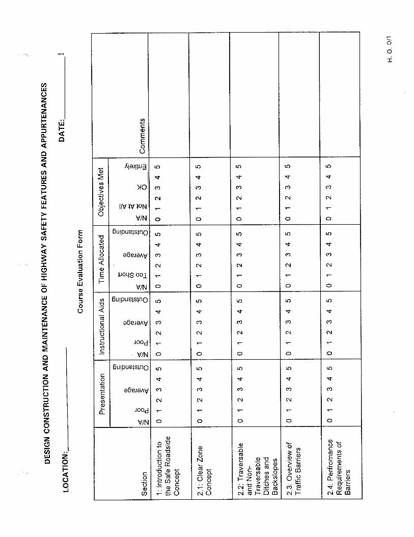
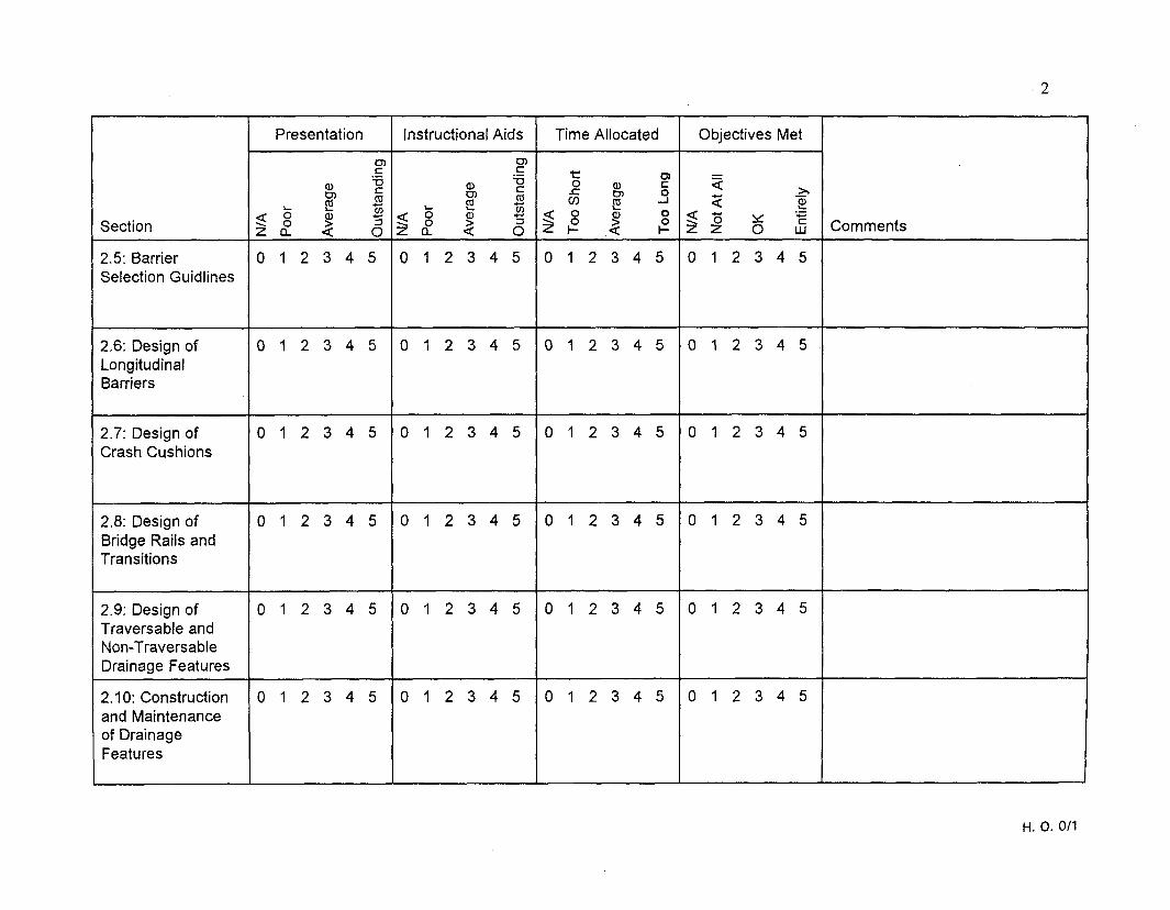
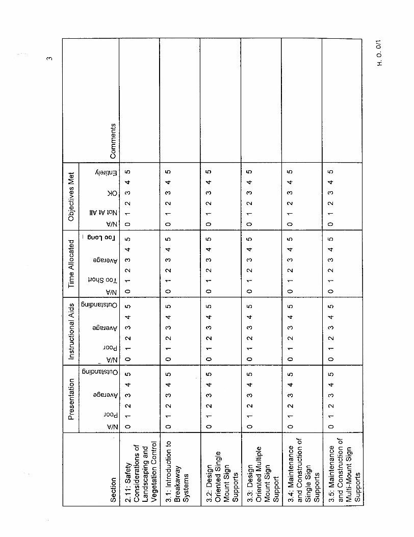
Evaluation Forms
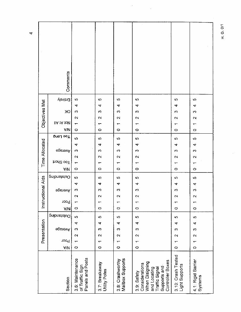
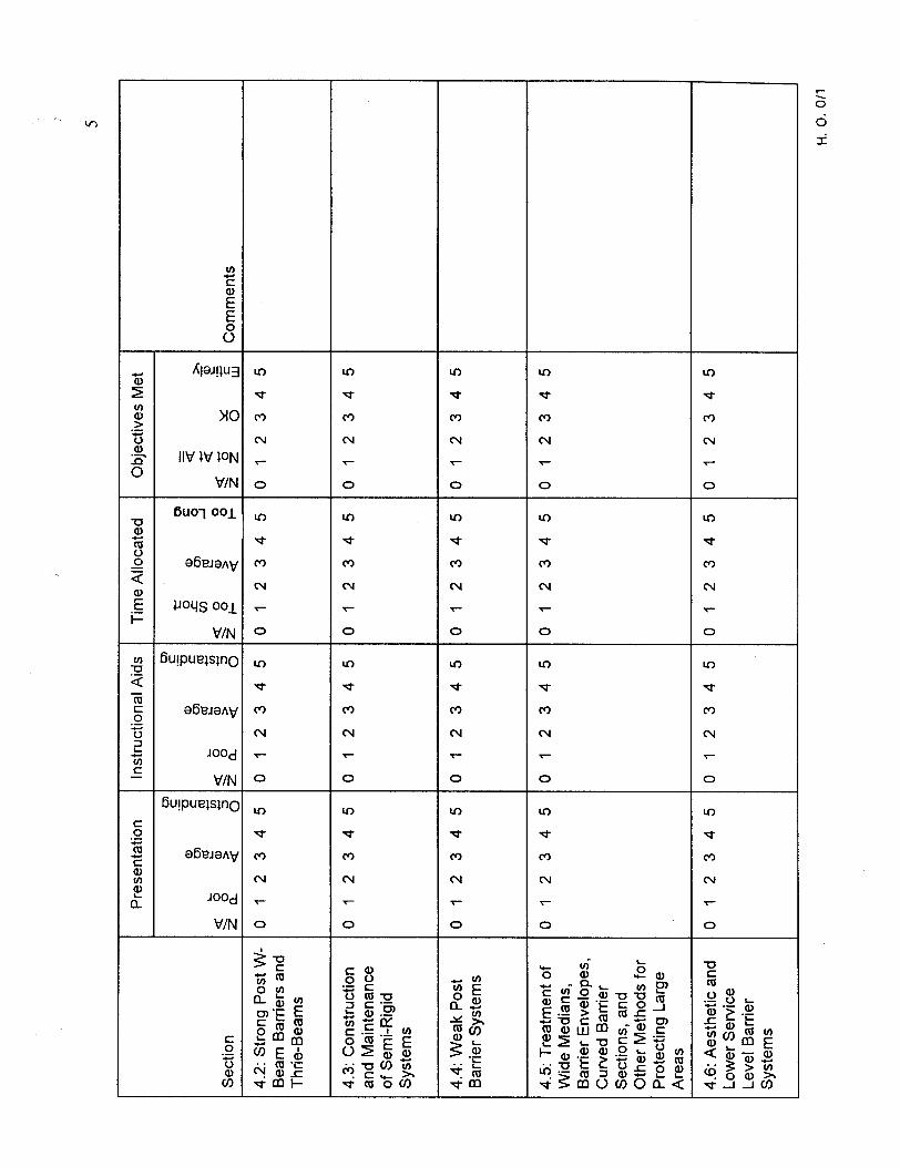
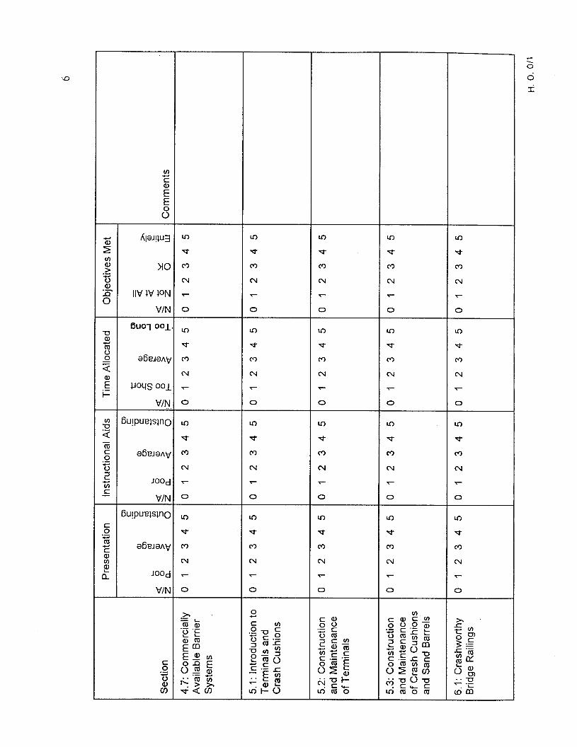
Evaluation forms are included with this Instructor’s Manual and are to be completed by the participants. The session by session form asks the participants to rate the course in four different areas: quality of presentation, quality of instructional aids, appropriateness of allocated time and the degree to which the objectives of the session were met. The rate scale for each question is 0 to 5.
The overall evaluation form requests responses to four questions:
l What session was most helpful and why? l Was adequate time available for asking questions? l What subjects should be added or expanded? l Other comments?
It is important to remind the participants to complete the session by session evaluation form after each session is completed. Only the participants’ immediate responses to the sessions will allow the instructor to improve the course on a session by session basis. The instructor should ask the participants to complete the overall evaluation form as part of his closing comments at the end of the course.
Critiauinq a Course
A vital purpose of evaluation is that it should indicate how well the training course is accomplishing its objectives. To further this purpose, the instructor should conduct a formal review or critique of the course.
A critique is a critical examination or discussion for revealing strong and weak points in a program. A training course should be critiqued after each course. The entire training program should be critically examined after the first two or three courses to determine what modifications may be necessary.
15
The critique can be accomplished by:
0 Reviewing the evaluation forms submitted by the participants.
l Discussing the course with the participants after a presentation.
0 Observing the attitude of the participants while the course is being conducted.
0 Measuring the effectiveness of the course in imparting knowledge to the participants.
Course Modifications Based on Evaluation
Results of the critique should be thoroughly reviewed by the training director, his staff and the instructor(s). They should determine:
0 What was done correctly.
l What was done wrong.
. What changes should be made in the course, in each session, and in the training program.
Training Facilities
Classroom and workshop arrangements should be conducted with the purpose of creating an informal, relaxed, inviting space in which to conduct the training. Even the best classrooms are not the most enjoyable places to be. The room arrangement should communicate to the participants that their needs and desires have been considered and that effort has been expended to make their stay as enjoyable and beneficial as possible. Beyond making the area functionally suitable for instruction from the physical facilities standpoint, consideration should be given to:
0 Adequate space. 0 Tables for writing and books. 0 Good heating, cooling, and ventilation. 0 Control of lighting levels. e Adequate sound control. 0 Rest rooms. 0 Facilities for coffee breaks. 0 Receipt of messages.
Lecturina Loaistics
A lectern of some type will be required if the instructor needs to refer frequently to printed material. Arrangements for this must be made before the session, allowing enough time to procure one if one is not available. If the Instructor’s Manual is referred to during the presentation, be sure the lectern is large enough to hold the notebook and
16
notes, or that a table is available in close proximity to the lectern to permit paging the notebook as required.
A podium light for the lectern is often used to ensure that there will be sufficient light to illuminate notes or the Instructor’s Manual. Remember that it may be necessary to turn off the lights to provide sufficient contrast for slide visibility. Don’t be surprised if all the lights must be off and there is no light on the podium. Have your own podium light.
Slide Loaistics
Before the presentation of a session using slides, the instructor should check to make sure that the screen and projector are properly placed, the proper carousel is in place and the first slide to be shown is in proper position and focused and that the remote slide advance is working. Locate the light switch in the room and arrange for someone to turn them off and on as requested. Go through all of the slides to make sure that they are right side up.
It is always a good practice to be sure that an extra projector bulb, an AC extension cord, and an extension cord for the remote slide advance are available. These items should be carried as part of the equipment kit. If not, be sure when planning for the course that the course coordinator makes them handy with the projector.
How to Obtain Training Resources
NHI can provide, free of charge, a set of visual aids and text books to support training for employees of public agencies. Other agencies may purchase or borrow the material.
Organizations not having a continual need for the aids should obtain the materials on a loan basis. Agencies desiring to launch a large-scale training effort will most likely want to use the set obtained from NHI as a master copy and reproduce additional sets for individual instructor teams.
Requests to NHI for materials should be submitted three months in advance.
SUMMARY OF HELPFUL INSTRUCTIONAL HINTS
The following summary of suggestions are offered to the instructor as an aid to conducting the course:
0 During the sessions, the instructor has the option of using the visual aids or other techniques such as lecture/discussion or step-by-step problem solving on a blackboard. The approach should be selected by the instructor considering the interests of the participants, their background, the facilities, and program schedule.
17
0
.
l
The User’s Guide should be issued to each participant as the basic course text, and the instructor should refer to it often to allow the participants to follow along. Frequent reference should be made by the instructor regarding page numbers, listings of information, examples in the text, and other items. This will help to familiarize the participants with the information contained in the User’s Guide and increase its value as a future reference document.
The instructor should read and become thoroughly familiar with the User’s Guide.
Throughout the course, encourage the participants to relate problems or experiences within their own highway agency. Try to create a dialogue instead of a monologue. Gaining participation from the class participants will increase their attention and interest and make the instructor’s task easier.
Be as familiar as possible with the agency where the training course will be held. It is helpful to request in advance information relating to problems and successes experienced in their agency.
Maintain an informal atmosphere during the course. Instructors should add their own experiences and illustrations where appropriate throughout the course to help hold the interest of participants and increase their understanding in certain areas. Encourage participants to feel free to ask questions anytime.
Try to include some participation by the State or federal representative(s). For example, the instructor may ask the State representative to give a brief discussion during the sessions to relay coordination of programs with local agencies. It is believed that this helps build communication links between the different levels of government toward the common goal of enhancing safety.
Mark with a highlighter, key words and important portions of the instructor’s notes. This will enable the instructor to refer to the notes
throughout the session while using original words to present the subject matter. Do not read directly from the instructor’s notes.
Try to use a variety of instructional methods and media throughout the course to sustain the interest of the participants. When more than one instructor is presenting a course, draw upon the expertise and experience of each through interaction while teaching. For example, one instructor may ask the other to comment on a point. The instructor in the audience may even wish to use the blackboard or flip charts to illustrate a point. This interaction between the instructors should be planned ahead of time. Discussion and workshop sessions which foster interaction between
18
participants is also encouraged as long as the time constraints are recognized.
l Throughout the course, instructors should mention the relevant reference documents that may be consulted for further details. If practical, instructors may wish to bring copies of the most relevant reference documents for review by the participants.
l As each procedure or concept is presented in the course the instructor should try to determine the comprehension of the participants through questions, facial expressions or interaction. If participants are already familiar with a particular procedure or concept, it is appropriate to move onto the next topic.
b Be aware of certain terms and phrases that may be sensitive or used differently in certain areas. For example, the term “hazardous location” is not used to discuss highway sites in some States due to the alleged legal ramifications.
l Each instructor should demonstrate interest and enthusiasm for the course material and stress the importance of each participant taking the initiative of making what was learned in the session a growing reality in their own agencies.
l Clearly state the objectives of each session both before and after the session.
l Extension Cord for Slide Advance.
b Multiple AC outlet adapter
l Ground Plug Adapters
COURSE SUMMARY
A course summary with estimated times is presented on the next 5 pages. It allocates time according to the content of each session and indicates available workshops. Some variation is likely to occur, but these time allocations are appropriate for adequately covering all course material. The instructor may choose to forward this summary to the host agency for selection of the training material topics. REQUEST THAT EACH PARTICIPANT BRING A CALCULATOR TO THE TRAINING COURSE.
Following the summary is a course log that can be used to track course activities. This log can help the instructor make adjustments to the time allocated for individual sessions based on the results of previous courses. If more than one instructor is teaching the course, the course log can be used to assign session responsibility.
19


COURSE OVERVIEW AND PLANNING FORM
This training course addresses concepts of traffic safety related to roadway and roadside features that can prevent the occurrence of a traffic accident, and reduce the severity of an accident should one occur. It presents current information on crash worthy longitudinal barriers, crash cushions, bridge rails, transitions, end terminals, sign posts, luminaire supports, utility poles and other topics related to improving traffic safety.
The purpose of the course is to provide design, construction and maintenance personnel information on roadway and roadside safety needs and the safety performance of highway safety features. The objectives of the manual are to enable the reader to:
1. Have a practical understanding of the particular highway feature or safety appurtenance addressed, including a knowledge of why they are used, when and where they will be used, and what actions (appropriate to the design, construction, or maintenance) are important to ensure they function correctly.
2. Recognize substandard or potentially hazardous highway appurtenances and features.
3. Develop alternatives to eliminate, correct, enhance, or mitigate any unsatisfactory safety and operational characteristics of existing or proposed safety appurtenances or highway features.
The training course can consist of from 2 to 4 days of instruction and be structured primarily for designers, or for construction\maintenance personnel. Please complete the bottom of this sheet and use the attached summary to select those sessions that are of primary interest. It is suggested that the course include the kickoff and sessions 1.1, 2.1 through 2.6 to establish the course framework. The other sessions can be selected individually or you can specify your training needs by category; such as strong post longitudinal barriers, bridge barriers, utility poles, etc. If the category is specified then necessary companion sessions will be selected that maintains the desired time frame.
PLEASE REQUEST THAT THE PARTICIPANTS BRING A CALCULATOR TO THE TRAINING COURSE,
Name: Telephone #
Host Agency:
Estimated Number of Participants:
Designers Sign Crew Barrier Crew
Please return to:

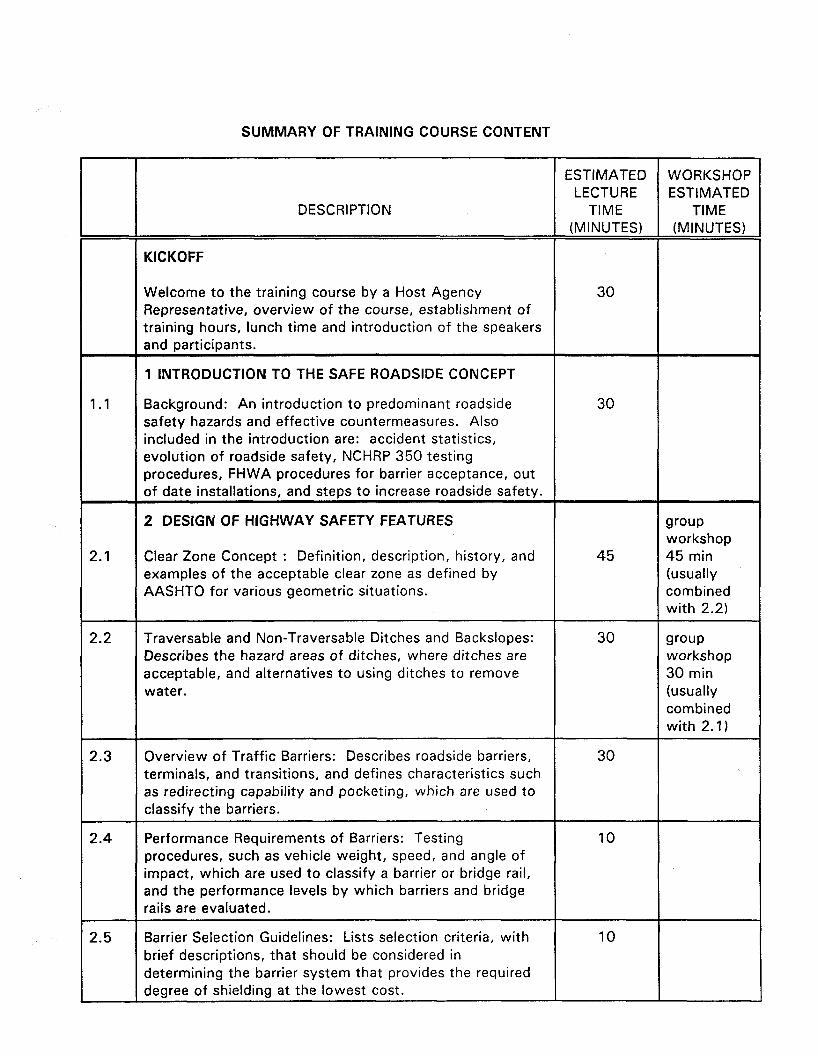
SUMMARY OF TRAINING COURSE CONTENT
ESTIMATED WORKSHOP LECTURE ESTIMATED
DESCRIPTION TIME TIME (MINUTES) (MINUTES)
KICKOFF
Welcome to the training course by a Host Agency Representative, overview of the course, establishment of training hours, lunch time and introduction of the speakers and participants.
30
1 INTRODUCTION TO THE SAFE ROADSIDE CONCEPT
1.1 Background: An introduction to predominant roadside 30 safety hazards and effective countermeasures. Also included in the introduction are: accident statistics, evolution of roadside safety, NCHRP 350 testing procedures, FHWA procedures for barrier acceptance, out of date installations, and steps to increase roadside safety.
2.1
2 DESIGN OF HIGHWAY SAFETY FEATURES
Clear Zone Concept : Definition, description, history, and examples of the acceptable clear zone as defined by AASHTO for various geometric situations.
45
group workshop 45 min (usually combined with 2.2)
2.2 Traversable and Non-Traversable Ditches and Backslopes: Describes the hazard areas of ditches, where ditches are acceptable, and alternatives to using ditches to remove water.
30 group workshop 30 min (usually combined with 2.1)
2.3 Overview of Traffic Barriers: Describes roadside barriers, terminals, and transitions, and defines characteristics such as redirecting capability and pocketing, which are used to classify the barriers.
30
2.4 Performance Requirements of Barriers: Testing procedures, such as vehicle weight, speed, and angle of impact, which are used to classify a barrier or bridge rail, and the performance levels by which barriers and bridge rails are evaluated.
10
2.5 Barrier Selection Guidelines: Lists selection criteria, with brief descriptions, that should be considered in determining the barrier system that provides the required degree of shielding at the lowest cost.
10
2.6
2.7
2.8
2.9
2.10
2.11
3.1
3.2
3.3
DESCRIPTION
ESTIMATED WORKSHOP LECTURE ESTIMATED
TIME TIME (MINUTES) (MINUTES)
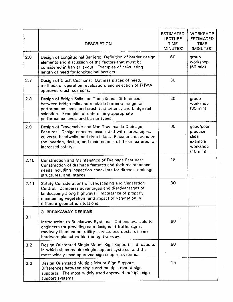
Design of Longitudinal Barriers: Definition of barrier design elements and discussion of the factors that must be considered in barrier layout. Examples of calculating length of need for longitudinal barriers.
60
Design of Crash Cushions: Outlines places of need, methods of operation, evaluation, and selection of FHWA approved crash cushions.
30
Design of Bridge Rails and Transitions: Differences between bridge rails and roadside barriers; bridge rail performance levels and crash test criteria, and bridge rail selection. Examples of determining appropriate oerformance levels and barrier types.
Design of Traversable and Non-Traversable Drainage Features: Design concerns associated with curbs, pipes, culverts, headwalls, and drop inlets. Recommendations on the location, design, and maintenance of these features for increased safety.
30
60
Construction and Maintenance of Drainage Features: Construction of drainage features and their maintenance needs including inspection checklists for ditches, drainage structures, and intakes.
Safety Considerations of Landscaping and Vegetation Control: Compares advantages and disadvantages of landscaping along highways. Importance of properly maintaining vegetation, and impact of vegetation in different geometric situations. I
15
30
3 BREAKAWAY DESIGNS I
Introduction to Breakaway Systems: Options available to engineers for providing safe designs of traffic signs, roadway illumination, utility service, and postal delivery hardware placed within the right-of-way.
Design Orientated Single Mount Sign Supports: Situations in which signs require single support systems, and the most widely used approved sign support systems.
Design Orientated Multiple Mount Sign Support: Differences between single and multiple mount sign supports. The most widely used approved multiple sign suooort svstems. I
60
60
15
wow workshop (60 min)
group workshop (30 min)
good/poor practice slide example workshop (15 min)
ESTIMATED WORKSHOP LECTURE ESTIMATED
DESCRIPTION TIME TIME (MINUTES) (MINUTES)
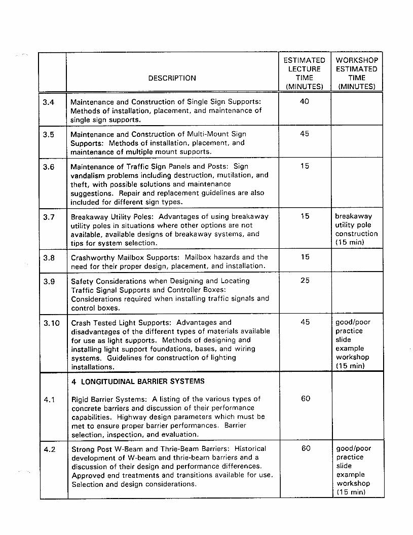
3.4 Maintenance and Construction of Single Sign Supports: 40 Methods of installation, placement, and maintenance of single sign supports.
3.5 Maintenance and Construction of Multi-Mount Sign 45 Supports: Methods of installation, placement, and maintenance of multiple mount supports.
3.6 Maintenance of Traffic Sign Panels and Posts: Sign 15 vandalism problems including destruction, mutilation, and theft, with possible solutions and maintenance suggestions. Repair and replacement guidelines are also included for different sign types.
3.7 Breakaway Utility Poles: Advantages of using breakaway 15 breakaway utility poles in situations where other options are not utility pole available, available designs of breakaway systems, and construction tips for system selection. (15 min)
3.8 Crashworthy Mailbox Supports: Mailbox hazards and the 15 need for their proper design, placement, and installation.
3.9 Safety Considerations when Designing and Locating 25 Traffic Signal Supports and Controller Boxes: Considerations required when installing traffic signals and control boxes.
3.10 Crash Tested Light Supports: Advantages and 45 good/poor disadvantages of the different types of materials available practice for use as light supports. Methods of designing and slide installing light support foundations, bases, and wiring example systems. Guidelines for construction of lighting workshop installations. (15 min)
4 LONGITUDINAL BARRIER SYSTEMS
$.I Rigid Barrier Systems: A listing of the various types of 60 concrete barriers and discussion of their performance capabilities. Highway design parameters which must be met to ensure proper barrier performances. Barrier selection, inspection, and evaluation.
4.2 Strong Post W-Beam and Thrie-Beam Barriers: Historical 60 good/poor development of W-beam and thrie-beam barriers and a practice discussion of their design and performance differences. slide Approved end treatments and transitions available for use. example Selection and design considerations. workshop
(15 min)
ESTIMATED WORKSHOP LECTURE ESTIMATED
DESCRIPTION TIME TIME (MINUTES) (MINUTES)
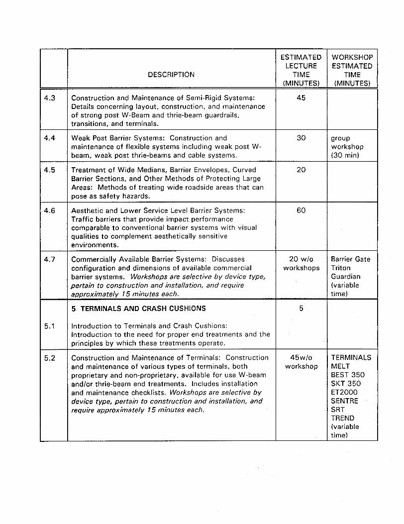
4.3 Construction and Maintenance of Semi-Rigid Systems: 45 Details concerning layout, construction, and maintenance of strong post W-Beam and thrie-beam guardrails, transitions, and terminals.
4.4 Weak Post Barrier Systems: Construction and 30 wow maintenance of flexible systems including weak post W- workshop beam, weak post thrie-beams and cable systems. (30 min)
4.5 Treatment of Wide Medians, Barrier Envelopes, Curved 20 Barrier Sections, and Other Methods of Protecting Large Areas: Methods of treating wide roadside areas that can pose as safety hazards.
4.6 Aesthetic and Lower Service Level Barrier Systems: 60 Traffic barriers that provide impact performance comparable to conventional barrier systems with visual qualities to complement aesthetically sensitive environments.
4.7 Commercially Available Barrier Systems: Discusses 20 w/o Barrier Gate configuration and dimensions of available commercial workshops Triton barrier systems. Workshops are selective by device type, Guardian pertain to construction and installation, and require (variable approximately 15 minutes each. time)
5 TERMINALS AND CRASH CUSHIONS 5
5.1 Introduction to Terminals and Crash Cushions: Introduction to the need for proper end treatments and the principles by which these treatments operate.
5.2 Construction and Maintenance of Terminals: Construction 45wlo TERMINALS and maintenance of various types of terminals, both workshop MELT proprietary and non-proprietary, available for use W-beam BEST 350 and/or thrie-beam end treatments. Includes installation SKT 350 and maintenance checklists. Workshops are selective by ET2000 device type, pertain to construction and installation, and SENTRE require approximately 15 minutes each. SRT
TREND (variable time)
ESTIMATED WORKSHOP LECTURE ESTIMATED
DESCRIPTION TIME TIME (MINUTES) (MINUTES)
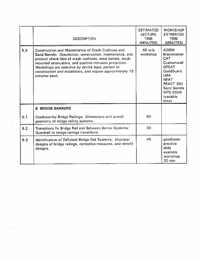
5.3 Construction and Maintenance of Crash Cushions and 45 w/o ADIEM Sand Barrels: Description, construction, maintenance, and workshop Brakemaster product check lists of crash cushions, sand barrels, truck- CAT mounted attenuators, and positive intrusion protection. Cushionwall Workshops are selective by device type, pertain to GREAT construction and installation, and require approximately 15 QuadGuard minutes each. LMA
NEAT REACT 350 Sand Barrels MPS-350111 (variable time)
6 BRIDGE BARRIERS
6.1 Crashworthy Bridge Railings: Dimensions and overall 60 geometry of bridge railing systems.
6.2 Transitions To Bridge Rail and Between Barrier Systems: 30 Guardrail to bridge railings transitions.
6.3 Identification of Deficient Bridge Rail Systems: Improper 45 good/poor designs of bridge railings, corrective measures, and retrofit practice designs. slide
example workshop 20 min

Location Location
Date: Date:
instructors: Instructors:
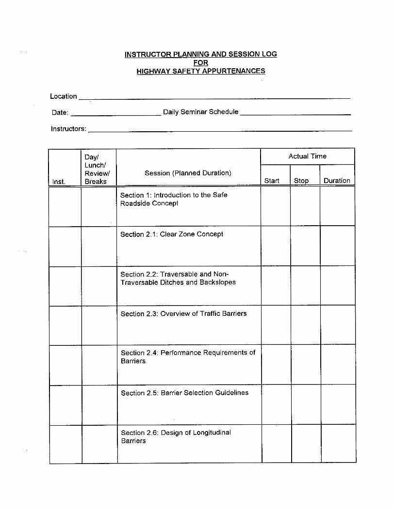
INSTRUCTOR PLANNING AND SESSION LOG INSTRUCTOR PLANNING AND SESSION LOG a a
HIGHWAY SAFETY APPURTENANCES HIGHWAY SAFETY APPURTENANCES
Daily Seminar Schedule Daily Seminar Schedule
Inst.
Day/ Actual Time Lunch/ Review/ Session (Planned Duration) Breaks Start stop Duration
Section 1: Introduction to the Safe Roadside Concept
Section 2.1: Clear Zone Concept
Section 2.2: Traversable and Non- Traversable Ditches and Backslopes
Section 2.3: Overview of Traffic Barriers
Section 2.4: Performance Requirements of Barriers
Section 2.5: Barrier Selection Guidelines
Section 2.6: Design of Longitudinal Barriers

HIGHWAY SAFETY APPURTENANCES (Continued1
Inst.
Day/ Actual Time Lunch/ Review/ Session (Planned Duration) Breaks Start stop Duration
Section 2.7: Design of Crash Cushions
Section 2.8: Design of Bridge Rails and Transitions
Section 2.9: Design of Traversable and Nontraversable Drainage Features
Section 2.10: Construction and Maintenance of Drainage Features
Section 2.11: Safety Considerations of Landscaping and Vegetation Control
Section 3.1: Introduction to Breakaway Systems
Section 3.2: Design Orientated Single Mount Sign Supports
Section 3.3: Design Orientated Multiple Mount Sign Supports
Section 3.4: Maintenance and Construction of Single Sign Supports
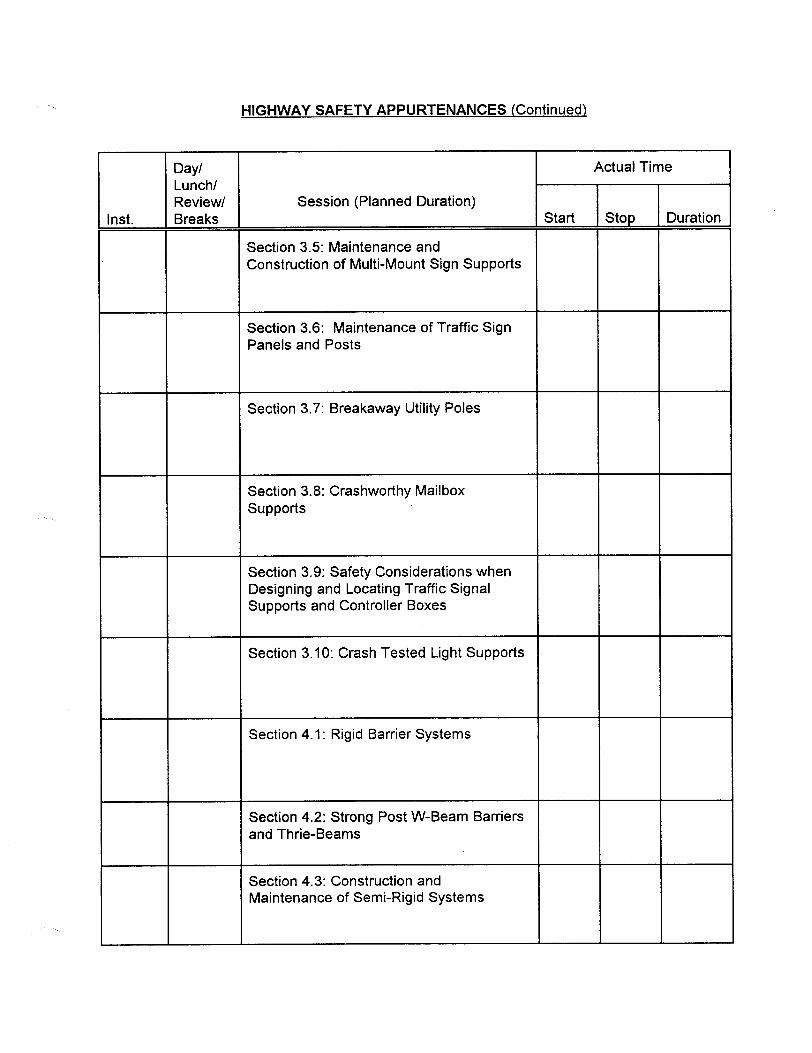
HIGHWAY SAFETY APPURTENANCES (Continued)
Inst.
Day/ Actual Time Lunch/ Review/ Session (Planned Duration) Breaks Start stop Duration
Section 3.5: Maintenance and Construction of Multi-Mount Sign Supports
Section 3.6: Maintenance of Traffic Sign Panels and Posts
Section 3.7: Breakaway Utility Poles
Section 3.8: Crashworthy Mailbox supports
Section 3.9: Safety Considerations when Designing and Locating Traffic Signal Supports and Controller Boxes
Section 3.10: Crash Tested Light Supports
Section 4.1: Rigid Barrier Systems
Section 4.2: Strong Post W-Beam Barriers and Thrie-Beams
Section 4.3: Construction and Maintenance of Semi-Rigid Systems

HIGHWAY SAFETY APPURTENANCES (Continued]
Inst.
Day/ Actual Time Lunch/ Review/ Session (Planned Duration) Breaks Start stop Duration
Section 4.4: Weak Post Barrier Systems
Section 4.5: Treatment of Wide Meadians, Barrier Envelopes, Curved Barrier Sections, and Other Methods for Protecting Large Areas
Section 4.6: Aesthetic and Lower Service Level Barrier Systems and Terminals
Section 4.7: Commercially Available Barrier Systems
Section 5.1: Introduction to Terminals and Crash Cushions
Section 5.2: Construction and Maintenance of Terminals
Section 5.3: Construction and Maintenance of Crash Cushions and Sand Barrels
Section 6.1: Crashworthy Bridge Railings

HIGHWAY SAFETY APPURTENANCES (Continued)
Inst.
Day/ Actual Time Lunch/ Review/ Session (Planned Duration) Breaks Start Stop Duration
Section 6.2: Transitions to Bridge Rail and Between Barrier Systems
Section 6.3: identification of Deficient Bridge Rail Systems

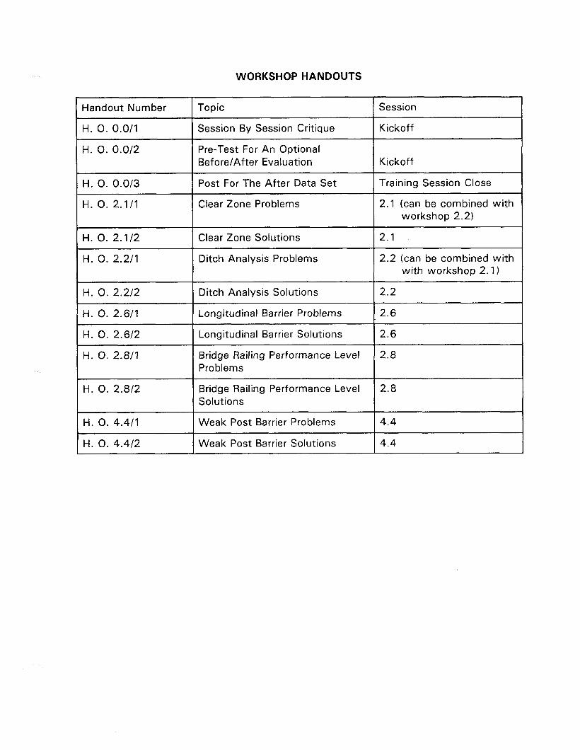
WORKSHOP HANDOUTS
Handout Number Topic Session
H. 0. 0.0/l Session By Session Critique Kickoff
H. 0. 0.0/2
H. 0. 0.0/3
H. 0. 2.1/l
Pre-Test For An Optional Before/After Evaluation
Post For The After Data Set
Clear Zone Problems
Kickoff
Training Session Close
2.1 (can be combined with workshop 2.2)
H. 0. 2.1/2
H. 0. 2.2/l
H. 0. 2.2/2
Clear Zone Solutions
Ditch Analysis Problems
Ditch Analysis Solutions
2.1
2.2 (can be combined with with workshop 2.1)
2.2
H. 0. 2.6/l I Longitudinal Barrier Problems I 2.6
H. 0. 2.6/2 Longitudinal Barrier Solutions 2.6
H. 0. 2.811 Bridge Railing Performance Level 2.8 Problems
H. 0. 2.8/2 Bridge Railing Performance Level 2.8 Solutions
H. 0. 4.4/l
H. 0. 4.4/2
Weak Post Barrier Problems
Weak Post Barrier Solutions
4.4
4.4

4aJ!lEI
I
NO’
IIV 1V 1ON
V/Ni
alkJaAQ
lJws 001
V/N
JOOd
V/N
JOOd
.2
Presentation Time Allocated instructional Aids Objectives Met
Section Comments
2.5: Barrier Selection Guidlines
012345 012345 012345
2.6: Design of Longitudinal Barriers
012345 012345 012345 012345
'012345 012345 012345 012345 2.7: Design of Crash Cushions
012345 012345 1012345 012345 2.8: Design of Bridge Rails and Transitions
2.9: Design of Traversable and Non-Traversable Drainage Features
012345 012345 012345 012345
2. IO: Construction and Maintenance of Drainage Features
'012345 012345 012345 012345
H. 0. o/l
JOOd
V/N
Bu!puetqnc
JOOd
V/N
E .- I-
JOOd
V/N
JOOd

IIV it’ PN
V/N
f3UOl 001
IJOW 001
V/N
3u!puwjnC
JOO,


1
Pre
HIGHWAY SAFETY APPURTENANCES
Name:
1.
2.
3.
4.
5.
6.
7.
8.
9.
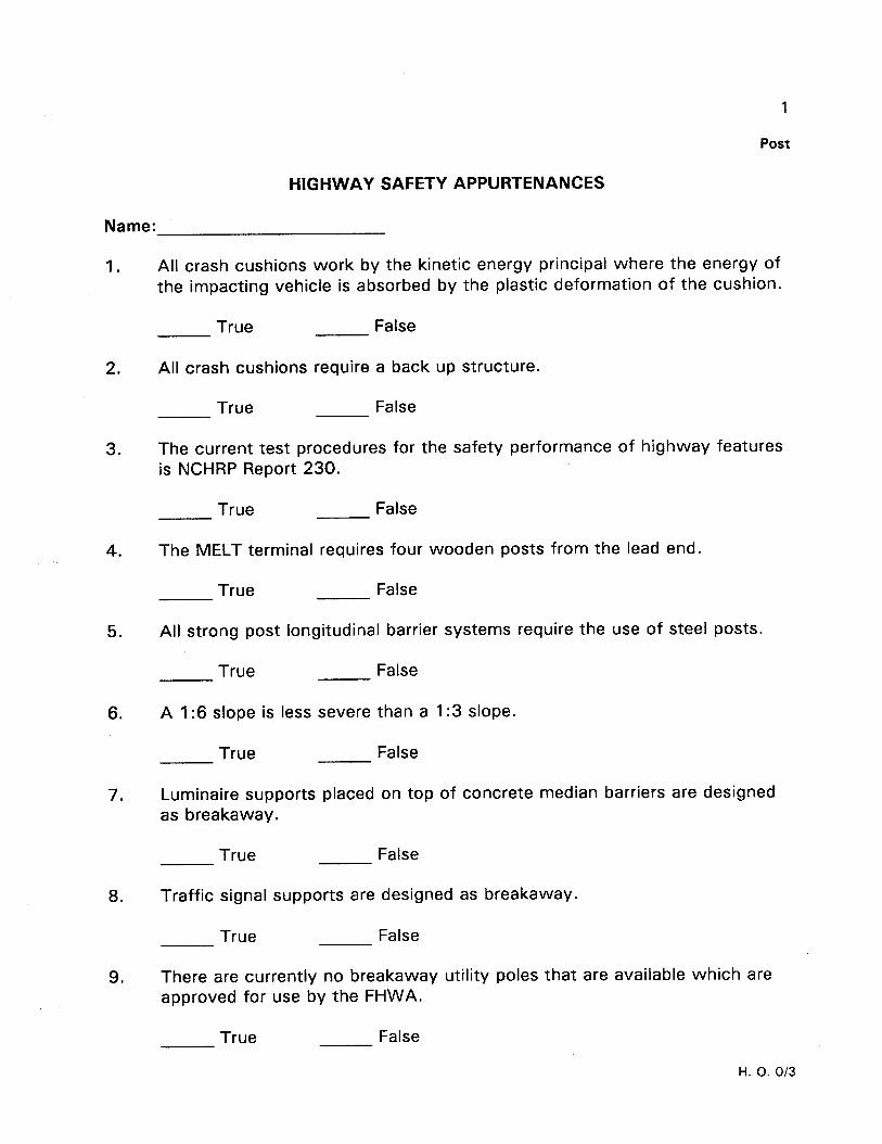
All crash cushions work by the kinetic energy principal where the energy of the impacting vehicle is absorbed by the plastic deformation of the cushion.
True False
All crash cushions require a back up structure.
True False
The current test procedures for the safety performance of highway features is NCHRP Report 230.
True False
The MELT terminal requires four wooden posts from the lead end.
True False
All strong post longitudinal barrier
True False
systems require the use of steel posts.
A I:6 slope is less severe than a I:3 slope.
True False
Luminaire supports placed on top of concrete median barriers are designed as breakaway.
True False
Traffic signal supports are designed as breakaway.
True False
There are currently no breakaway utility poles that are available which are approved for use by the FHWA.
True False
H. 0. O/2

l The special end anchor developed for this system is not a crashworthy terminal for high speed highways. It is acceptable for use on service roads, driveways, and other low speed facilities. For intersections on high speed highways, the curved installation should be terminated using a crashworthy terminal or connected to standard guardrail on the intersecting roadway.
l This system does not work well for angles which vary much from 90 degrees.
SCRIPT SLIDE 4.527
There are a number of treatments for separating hazards in wide medians from errant vehicles. The use of berms, crash cushions, envelopes, and bullnose designs, are dependent upon the situation and State practices. Bear in mind that due to the distance from the traveled way CONCLUSION
and the impact angles, the consequent severity of the impact can be severe.
4.5.11

3
19. Using the proper torque when assembling slip bases eliminates the need for a keeper plate.
True False
20. Anchor pieces on two piece sign supports should not extend more than
50 mm 100 mm 150 mm above the ground line.
H. 0. O/2

1
Post
HIGHWAY SAFETY APPURTENANCES
Name:
1.
2.
3.
4.
5.
All crash cushions work by the kinetic energy principal where the energy of the impacting vehicle is absorbed by the plastic deformation of the cushion.
True False
All crash cushions require a back up structure.
True False
The current test procedures for the safety performance of highway features is NCHRP Report 230.
True False
The MELT terminal requires four wooden posts from the lead end.
True False
All strong post longitudinal barrier systems require the use of steel posts.
True False
6. A I:6 slope is less severe than a I:3 slope.
7.
True False
Luminaire supports placed on top of concrete median barriers are designed as breakaway.
True False
8. Traffic signal supports are designed as breakaway.
True False
9. There are currently no breakaway utility poles that are available which are approved for use by the FHWA.
True False
H. 0. O/3

2
IO.
11.
12.
13.
14.
15.
16.
17.
18.
Parallel drainage outlets which require the use of cross members to make them traversable have the numbers placed
Horizontal Vertical Diagonal
Cable barriers contain errant vehicles through the development of vertical forces which gradually redirect the vehicle toward the roadway.
True False
The voltage used in the majority of underground wiring for roadway illumination is 220 volts.
True False
Accident frequency can be reduce by installing longitudinal barriers and crash cushions.
True False
Curbs in front of longitudinal barriers helps assure that they perform as planned when impacted by a vehicle.
True False
A high cost longitudinal barrier will prove to be more costly to maintain than a low cost barrier.
True False
Guardrail transition to a concrete bridge abutment requires at least three bolts when an end shoe is used.
True False
Vegetation can be used as an effective crash cushion.
True False
Sign supports spaced closer together than 2100 mm can use supports approved for use as single supports.
True False
H. 0. O/3

19.
20.
Using the proper a keeper plate.
torque when assembling slip bases eliminates the need for
True False
3
Anchor pieces on two piece sign supports should not extend more than
50 mm 100 mm 150 mm above the ground line.
H. 0. O/3

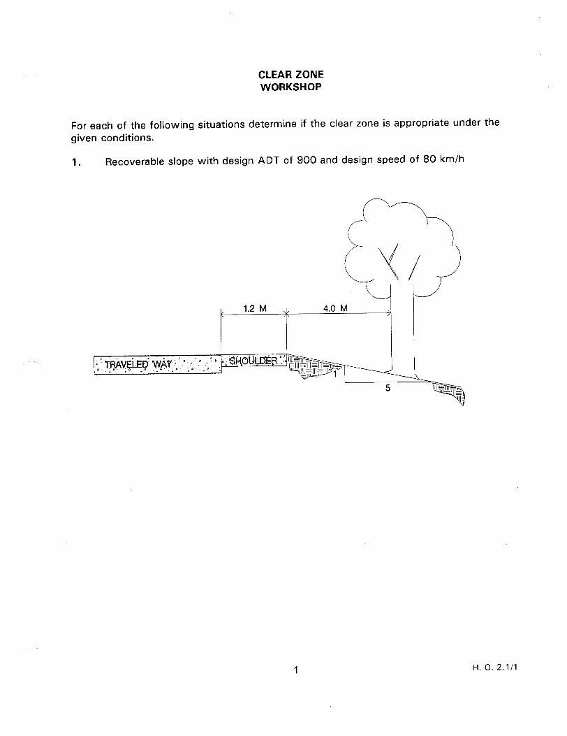
CLEAR ZONE WORKSHOP
For each of the following situations determine if the clear zone is appropriate under the given conditions.
1. Recoverable slope with design ADT of 900 and design speed of 80 km/h
1 H. 0. 2.1/l
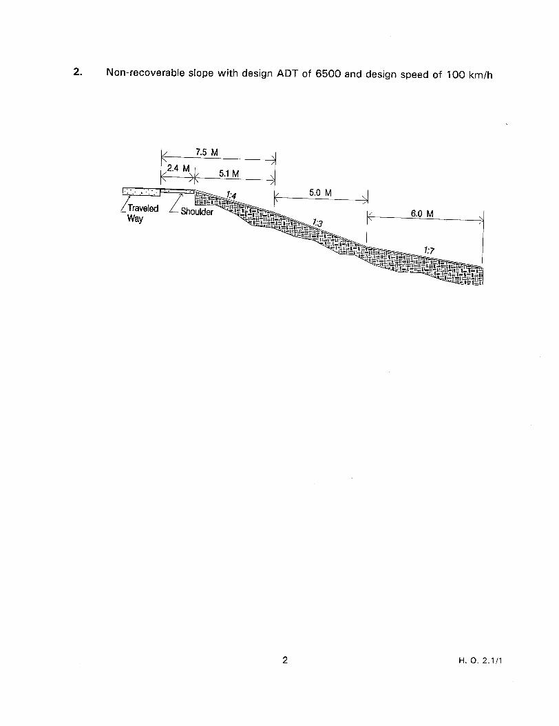
2. Non-recoverable slope with design ADT of 6500 and design speed of 100 km/h
H. 0. 2.1/l
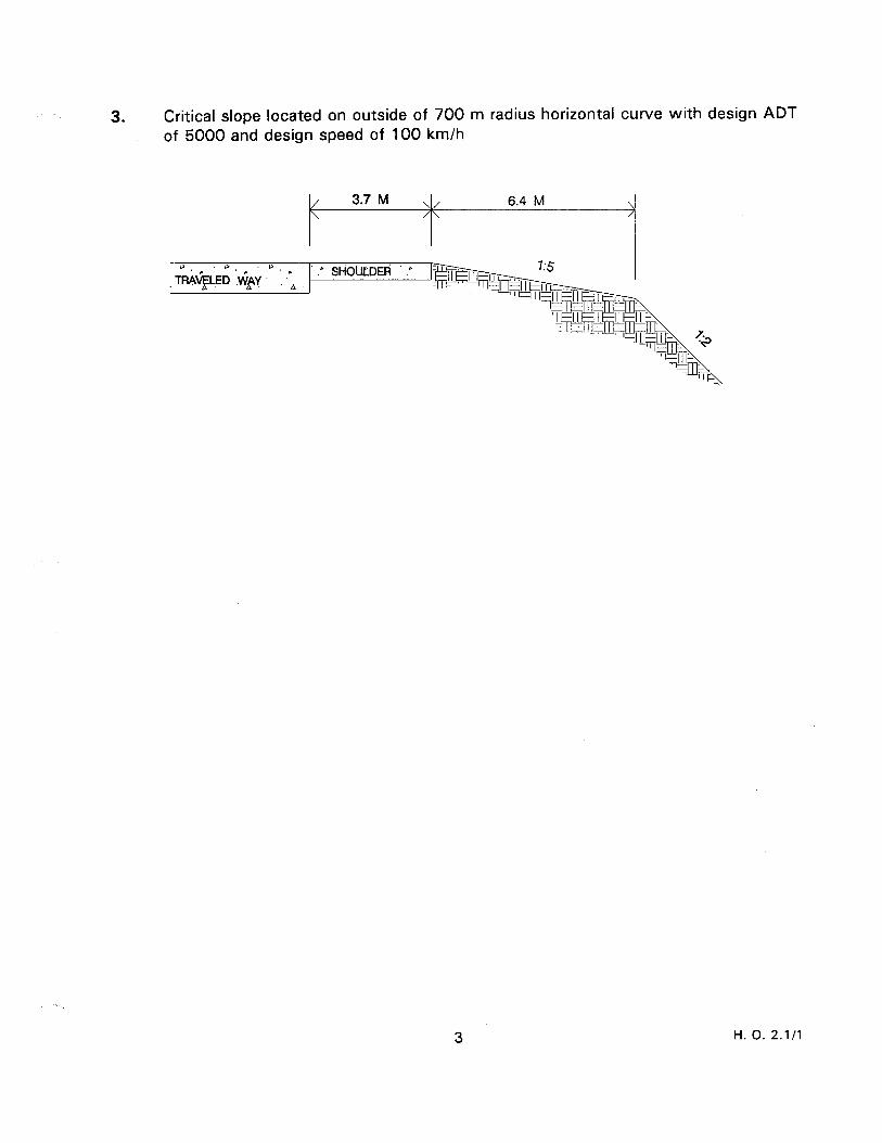
3. Critical slope located on outside of 700 m radius horizontal curve with design ADT of 5000 and design speed of 100 km/h
3 H. 0. 2.1/l
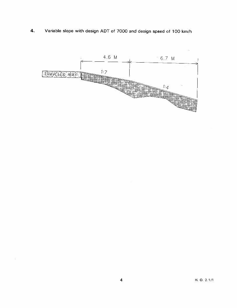
4. Variable slope with design ADT of 7000 and design speed of 100 km/h
4.6 M 6.7 M >
4 H. 0. 2.1 /I
CLEAR ZONE WORKSHOP SOLUTIONS
For each of the following situations determine if the clear zone is appropriate under the given conditions.
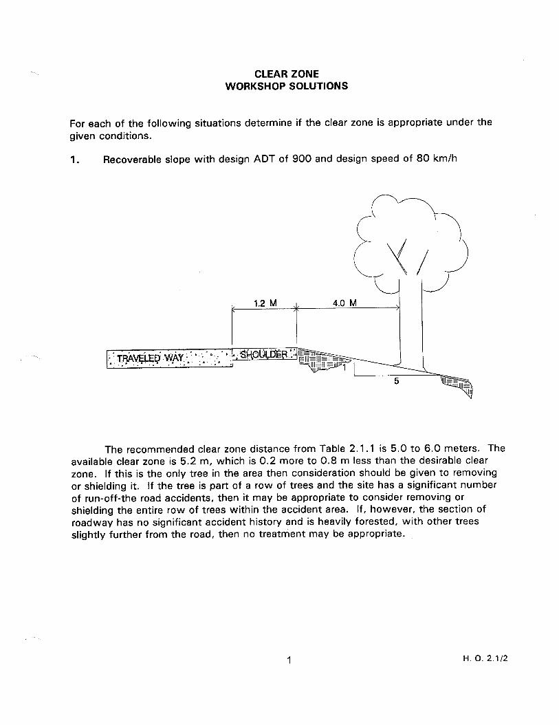
1. Recoverable slope with design ADT of 900 and design speed of 80 km/h
‘1
-
The recommended clear zone distance from Table 2.1.1 is 5.0 to 6.0 meters. The available clear zone is 5.2 m, which is 0.2 more to 0.8 m less than the desirable clear zone. If this is the only tree in the area then consideration should be given to removing or shielding it. If the tree is part of a row of trees and the site has a significant number of run-off-the road accidents, then it may be appropriate to consider removing or shielding the entire row of trees within the accident area. If, however, the section of roadway has no significant accident history and is heavily forested, with other trees slightly further from the road, then no treatment may be appropriate.
1 H. 0. 2.1/2

2. Non-recoverable slope with design ADT of 6500 and design speed of 100 km/h
/ 7.5 M \ / 2.4 M c 5.1 M \ /h
The desirable clear zone is based on the severest recoverable slope before or after a non-recoverable slope. This example indicates that the 1:4 slope should be used in table 2.1.1, for a desirable 1 1 .O to 13.5 m clear zone. Since 7.5 m are available at the top, an additional 3.5 to 6.0 m could be provided at the bottom, if practical. Note how the non-recoverable (I:3 slope) was not included in the available clear zone determination.
2 H. 0. 2.1/2
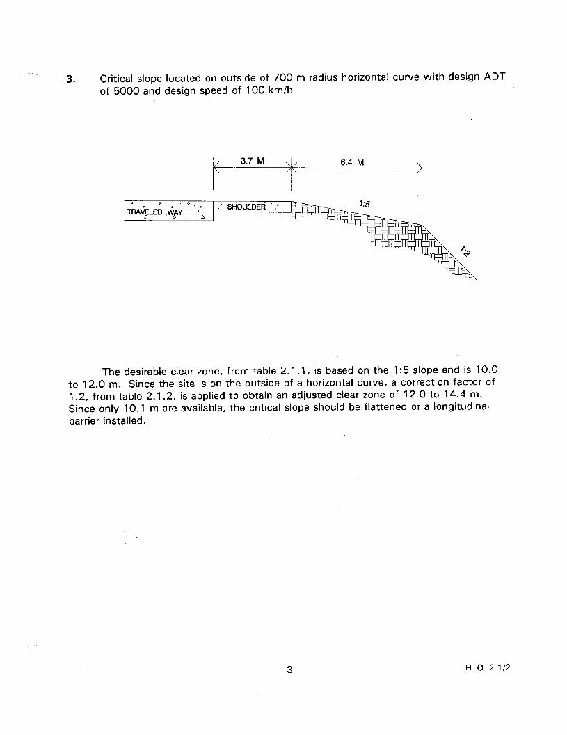
3. Critical slope located on outside of 700 m radius horizontal curve with design ADT of 5000 and design speed of 100 km/h
The desirable clear zone, from table 2.1.1, is based on the I:5 slope and is 10.0 to 12.0 m. Since the site is on the outside of a horizontal curve, a correction factor of 1.2, from table 2.1.2, is applied to obtain an adjusted clear zone of 12.0 to 14.4 m. Since only 10.1 m are available, the critical slope should be flattened or a longitudinal barrier installed.
3 H. 0. 2.1/2
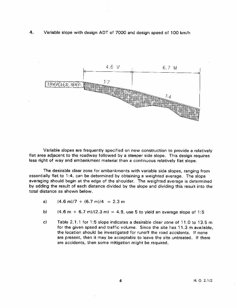
4. Variable slope with design ADT of 7000 and design speed of 100 km/h
4.6 M 6.7 M
Variable slopes are frequently specified on new construction to provide a relatively flat area adjacent to the roadway followed by a steeper side slope. This design requires less right of way and embankment material than a continuous relatively flat slope.
The desirable clear zone for embankments with variable side slopes, ranging from essentially flat to 1:4, can be determined by obtaining a weighted average. The slope averaging should begin at the edge of the shoulder. The weighted average is determined by adding the result of each distance divided by the slope and dividing this result into the total distance as shown below.
a) (4.6 ml/7 + (6.7 m)/4 = 2.3 m
b) (4.6 m + 6.7 m)/(2.3 m) = 4.9, use 5 to yield an average slope of 1:5
cl Table 2.1.1 for 1:5 slope indicates a desirable clear zone of 11 .O to 13.5 m for the given speed and traffic volume. Since the site has 1 1.3 m available, the location should be investigated for runoff the road accidents. If none are present, then it may be acceptable to leave the site untreated. If there are accidents, then some mitigation might be required.
H. 0. 2.1/2
DITCH ANALYSIS WORKSHOP
For each of the following situations determine if the design is appropriate under the given conditions.
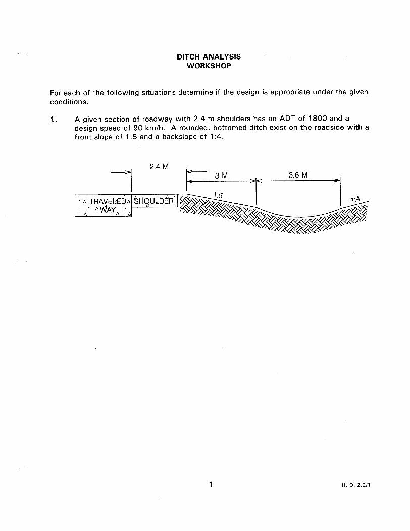
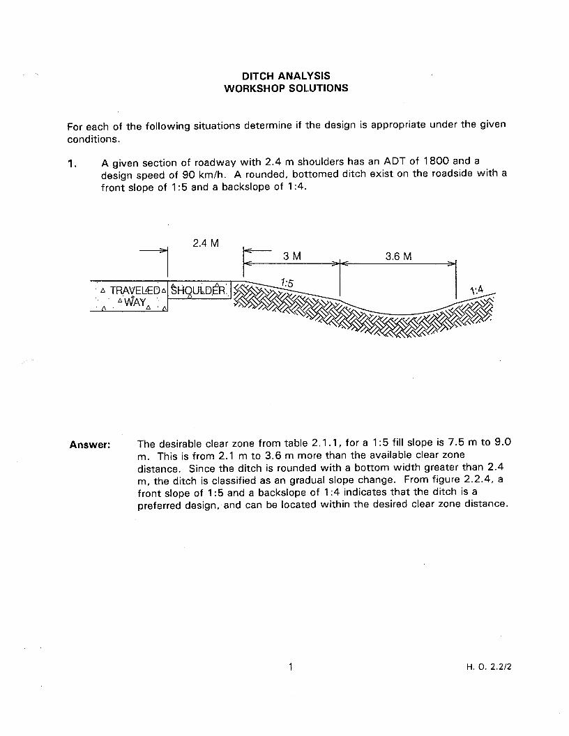
1. A given section of roadway with 2.4 m shoulders has an ADT of 1800 and a design speed of 90 km/h. A rounded, bottomed ditch exist on the roadside with a front slope of 1:5 and a backslope of 1:4.
1 H. 0. 2.211
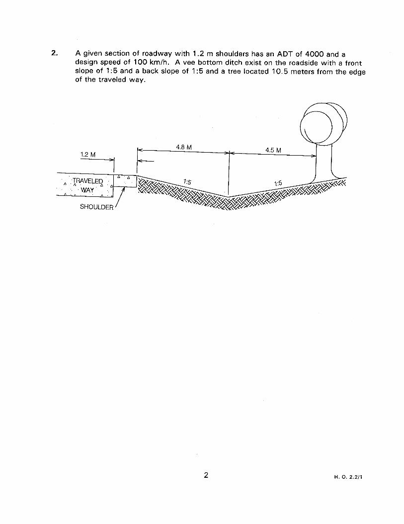
2. A given section of roadway with 1.2 m shoulders has an ADT of 4000 and a design speed of 100 km/h. A vee bottom ditch exist on the roadside with a front slope of 1:5 and a back slope of 1:5 and a tree located 10.5 meters from the edge of the traveled way.
H. 0. 2.2/l
DITCH ANALYSIS WORKSHOP SOLUTIONS
For each of the following situations determine if the design is appropriate under the given conditions.
1. A given section of roadway with 2.4 m shoulders has an ADT of 1800 and a design speed of 90 km/h. A rounded, bottomed ditch exist on the roadside with a front slope of 1:5 and a backslope of 1:4.
2.4 M <
3M I/ 3.6 M <
Answer: The desirable clear zone from table 2.1.1, for a 1:5 fill slope is 7.5 m to 9.0 m. This is from 2.1 m to 3.6 m more than the available clear zone distance. Since the ditch is rounded with a bottom width greater than 2.4 m, the ditch is classified as an gradual slope change. From figure 2.2.4, a front slope of 1:5 and a backslope of 1:4 indicates that the ditch is a preferred design, and can be located within the desired clear zone distance.
1 H. 0. 2.2/2
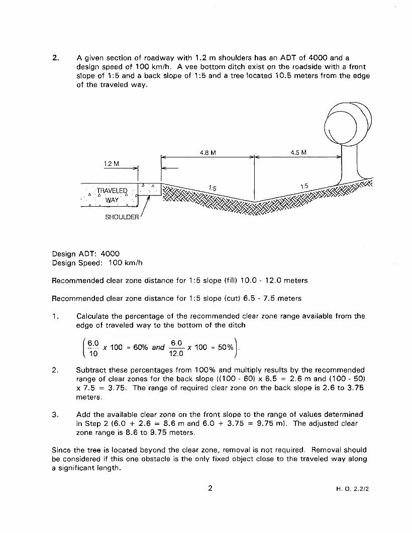
2. A given section of roadway with 1.2 m shoulders has an ADT of 4000 and a design speed of 100 km/h. A vee bottom ditch exist on the roadside with a front slope of I:5 and a back slope of 1:5 and a tree located 10.5 meters from the edge of the traveled way.
Design ADT: 4000 Design Speed: 100 km/h
Recommended clear zone distance for 1:5 slope (fill) 10.0 - 12.0 meters
Recommended clear zone distance for 1:5 slope (cut) 6.5 - 7.5 meters
1. Calculate the percentage of the recommended clear zone range available from the edge of traveled way to the bottom of the ditch
6.0 6.0 -x100 =6O?h and - IO 12.0
2. Subtract these percentages from 100% and multiply results by the recommended range of clear zones for the back slope ((I 00 - 60) x 6.5 = 2.6 m and (100 - 50) x 7.5 = 3.75. The range of required clear zone on the back slope is 2.6 to 3.75 meters.
3. Add the available clear zone on the front slope to the range of values determined in Step 2 (6.0 + 2.6 = 8.6 m and 6.0 + 3.75 = 9.75 m). The adjusted clear zone range is 8.6 to 9.75 meters.
Since the tree is loceted beyond the clear zone, removal is not required. Removal should be considered if this one obstacle is the only fixed object close to the traveled way along a significant length.
2 H. 0. 2.2/2
LONGITUDINAL BARRIER SYSTEMS WORKSHOP
For each of the following situations determine if the hazard is in the clear zone and the required length of need.
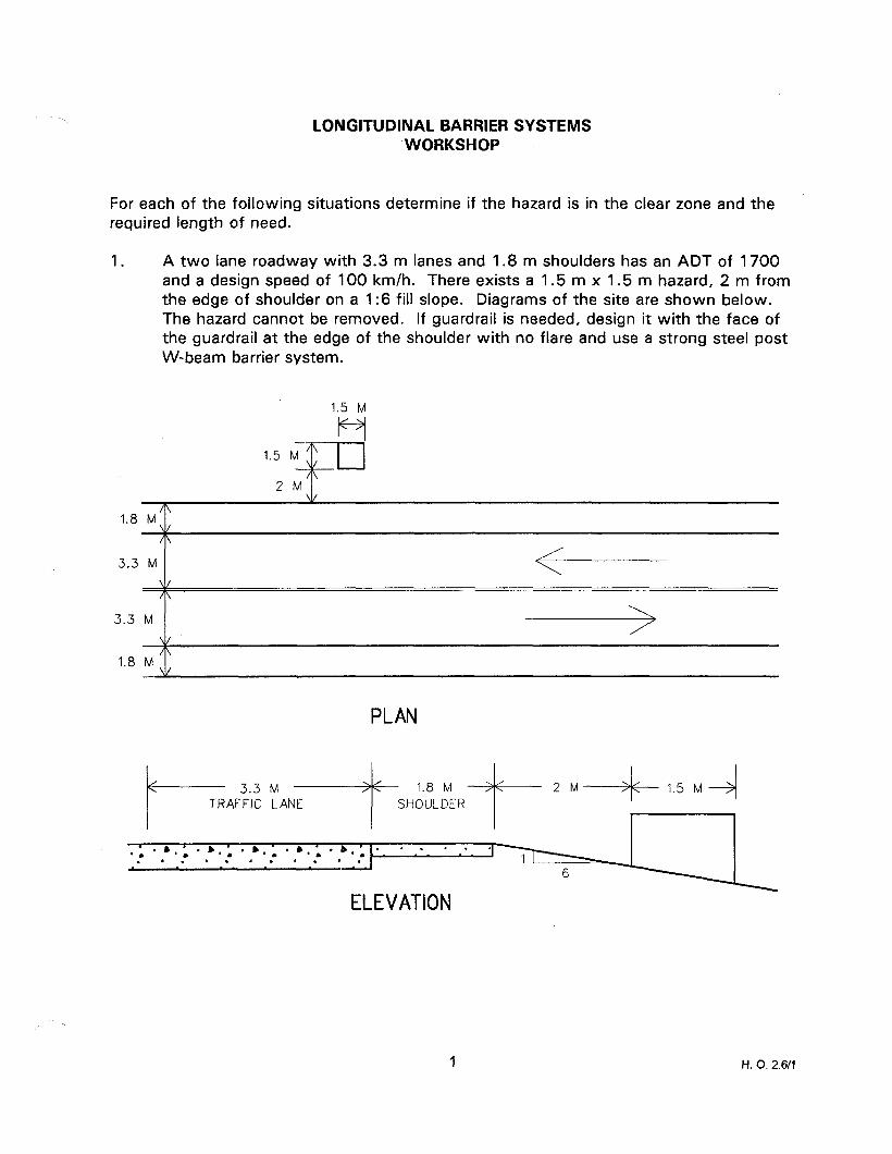
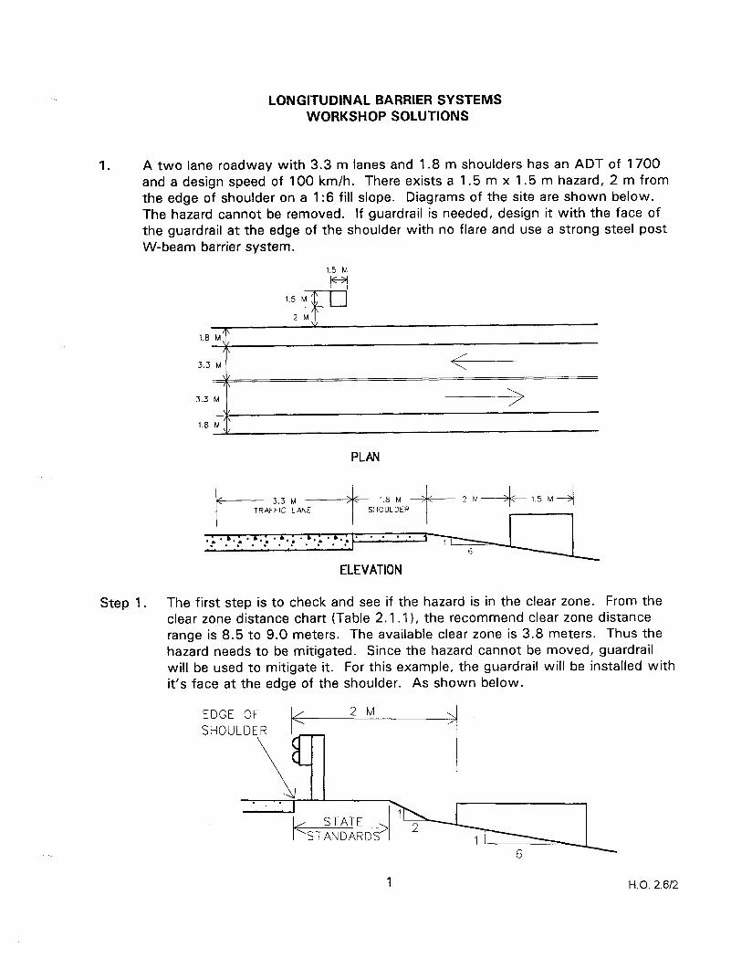
1. A two lane roadway with 3.3 m lanes and 1.8 m shoulders has an ADT of 1700 and a design speed of 100 km/h. There exists a 1.5 m x 1.5 m hazard, 2 m from the edge of shoulder on a 1:6 fill slope. Diagrams of the site are shown below. The hazard cannot be removed. If guardrail is needed, design it with the face of the guardrail at the edge of the shoulder with no flare and use a strong steel post W-beam barrier system.
1.5 M
ti 1.8 M,,
A -~~
3.3 M \/ A
3.3 M
1.8 M
PLAN
I---- 3.3 M 1, /\ 1.8 M TRAFFIC LANE SHOULDER
. . ,,I. b,’ . b,’ . b,’ . b; ‘a . , . . : I .- 1 : 8 .’ .- ’ _.- * *._ *
ELEVATION
1 H. 0.2.611
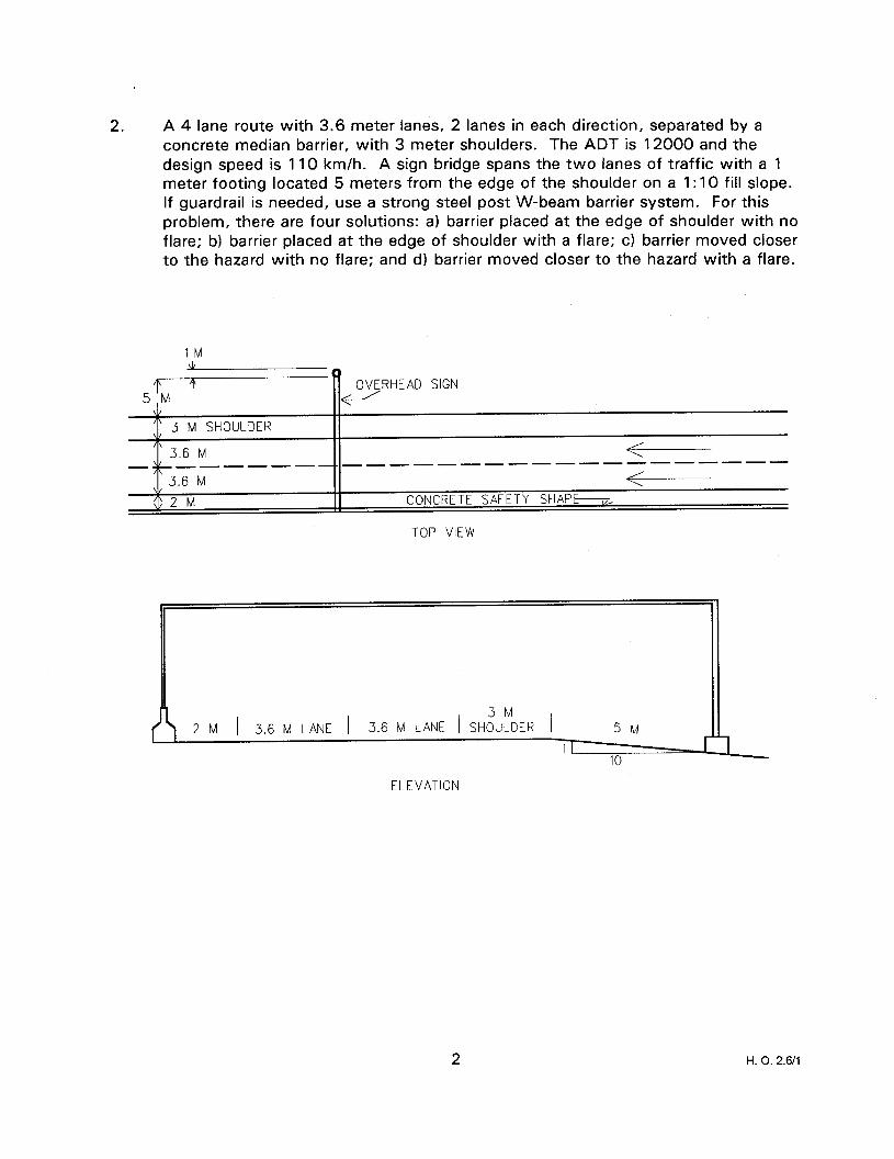
2. A 4 lane route with 3.6 meter lanes, 2 lanes in each direction, separated by a concrete median barrier, with 3 meter shoulders. The ADT is 12000 and the design speed is 110 km/h. A sign bridge spans the two lanes of traffic with a 1 meter footing located 5 meters from the edge of the shoulder on a 1: 10 fill slope. If guardrail is needed, use a strong steel post W-beam barrier system. For this problem, there are four solutions: a) barrier placed at the edge of shoulder with no flare; b) barrier placed at the edge of shoulder with a flare; c) barrier moved closer to the hazard with no flare: and d) barrier moved closer to the hazard with a flare.
IM \L
0 T OVERHEAD SIGN
\/ ” 3 M SHOULDER I\
3.6 M - __--____-_____-_-----------
3.6 M
$2 M CONCRETE SAFETY SHAPE---m
TOP VIEW
2 M 1 3.6 M LANE 1 3.6 M LANE 1 SH:“;DER / 5M
ELEVATION
2 H. 0. 2.6/l
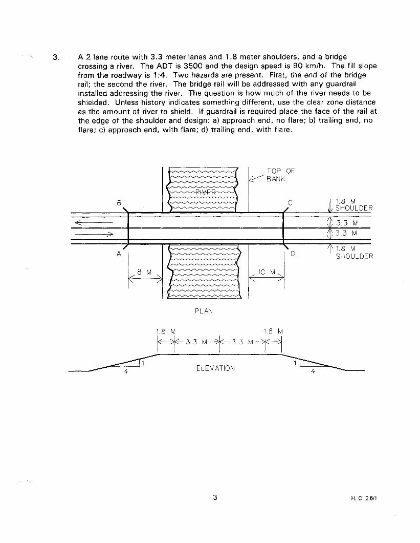
3. A 2 lane route with 3.3 meter lanes and 1.8 meter shoulders, and a bridge crossing a river. The ADT is 3500 and the design speed is 90 km/h. The fill slope from the roadway is 1:4. Two hazards are present. First, the end of the bridge rail; the second the river. The bridge rail will be addressed with any guardrail installed addressing the river. The question is how much of the river needs to be shielded. Unless history indicates something different, use the clear zone distance as the amount of river to shield. If guardrail is required place the face of the rail at the edge of the shoulder and design: a) approach end, no flare; b) trailing end, no flare; c) approach end, with flare; d) trailing end, with flare.
0
TOP OF ? BANK
C 1.8 M / SHOULDER I
PLAN
I
D T 1.8 M
SHOULDER
1.8 M 1.8 M
kC+f-3.3 M -4G3.3 M~+jC--+j
ELEVATION
3 H. 0. 2.611
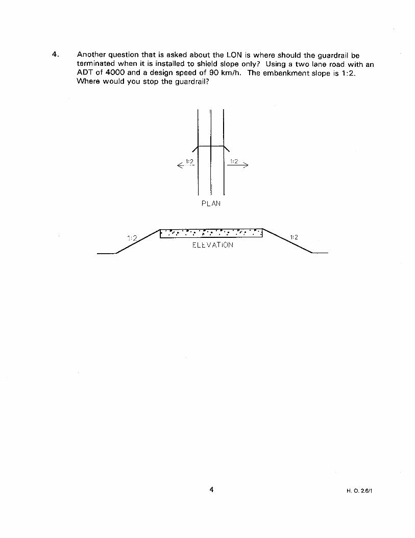
4. Another question that is asked about the LON is where should the guardrail be terminated when it is installed to shield slope only? Using a two lane road with an ADT of 4000 and a design speed of 90 km/h. The embankment slope is 1:2. Where would you stop the guardrail?
PLAN
H. 0. 2.611
LONGITUDINAL BARRIER SYSTEMS WORKSHOP SOLUTIONS
1. A two lane roadway with 3.3 m lanes and 1.8 m shoulders has an ADT of 1700 and a design speed of 100 km/h. There exists a 1.5 m x 1.5 m hazard, 2 m from the edge of shoulder on a 1:6 fill slope. Diagrams of the site are shown below. The hazard cannot be removed. If guardrail is needed, design it with the face of the guardrail at the edge of the shoulder with no flare and use a strong steel post W-beam barrier system.
1.5 M
w
1.5 M ; /\
2M
PLAN
Step 1. The first step is to check and see if the hazard is in the clear zone. From the clear zone distance chart (Table 2.1.11, the recommend clear zone distance range is 8.5 to 9.0 meters. The available clear zone is 3.8 meters. Thus the hazard needs to be mitigated. Since the hazard cannot be moved, guardrail will be used to mitigate it. For this example, the guardrail will be installed with it’s face at the edge of the shoulder. As shown below.
1 H.O. 2.612
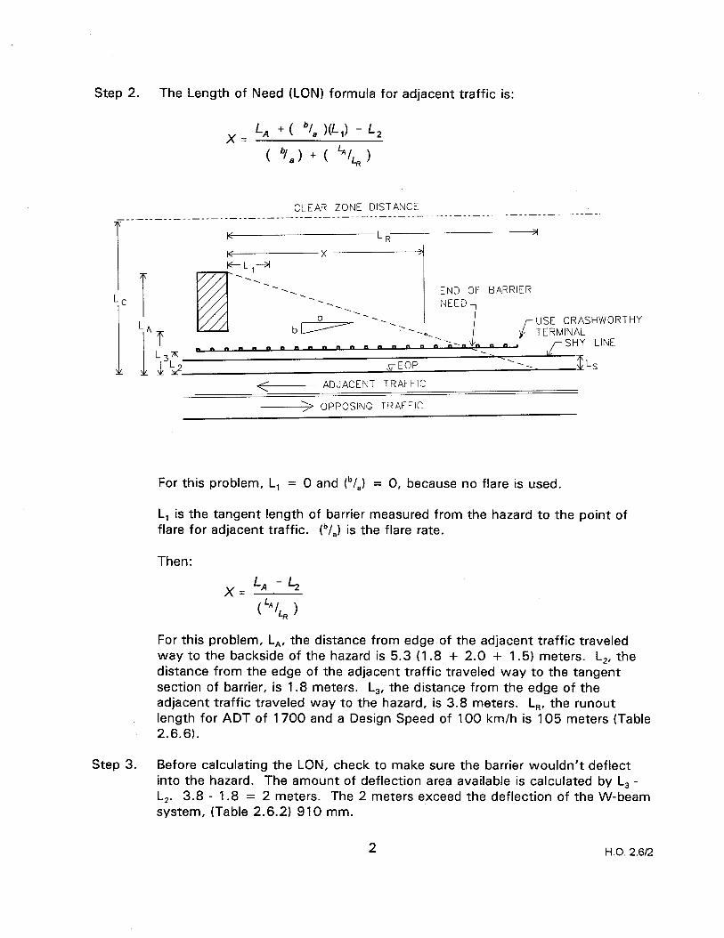
Step 2. The Length of Need (LON) formula for adjacent traffic is:
x= L, +( “/* )(L,) - L, ( q8 > + ( LAILR 1
CLEAR ZONE DISTANCE _______.___._______-----~-~---.-~~-. __-.__._______-__-_--~--~-----
K LR 2
END OF BARRIER -.
-. -. NEED
be -. -. -. USE CRASHWOR
--4 --.”
i- TERMINAL
O”““~~~~~“nmn”nnnnn d- SHY LINE
,r EOP
<- ADJACENT TRAFFIC
-> OPPOSING TRAFFIC
---. TLs
THY
For this problem, L, = 0 and Ib/,) = 0, because no flare is used.
L, is the tangent length of barrier measured from the hazard to the point of flare for adjacent traffic. lb/,) is the flare rate.
Then:
xzLA+’
(‘“/L, >
For this problem, L,, the distance from edge of the adjacent traffic traveled way to the backside of the hazard is 5.3 (1.8 + 2.0 + 1.5) meters. L,, the distance from the edge of the adjacent traffic traveled way to the tangent section of barrier, is 1.8 meters. L,, the distance from the edge of the adjacent traffic traveled way to the hazard, is 3.8 meters. L,, the runout length for ADT of 1700 and a Design Speed of 100 km/h is 105 meters (Table 2.6.6).
Step 3. Before calculating the LON, check to make sure the barrier wouldn’t deflect into the hazard. The amount of deflection area available is calculated by L, - L,. 3.8 - 1.8 = 2 meters. The 2 meters exceed the deflection of the W-beam system, (Table 2.6.2) 910 mm.
2 H.O. 2.612
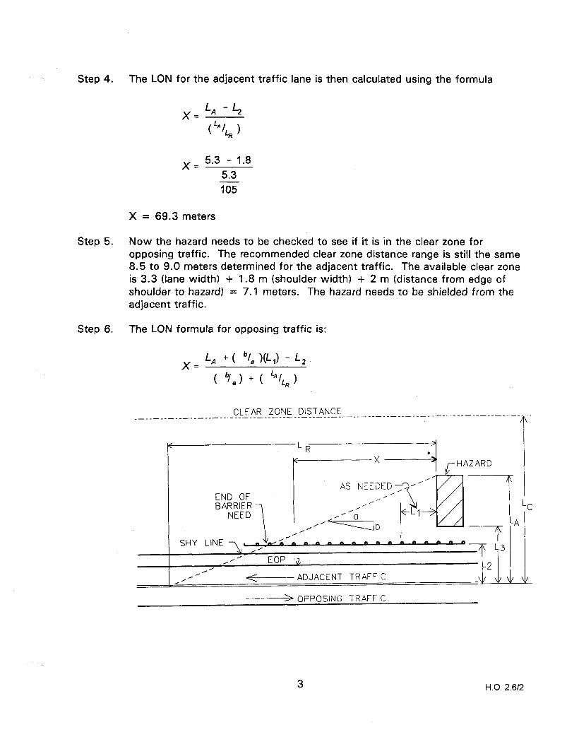
Step 4.
Step 5.
Step 6.
The LON for the adjacent traffic lane is then calculated using the formula
x= 5.3 - 1.8 5.3 ii%-
x= 69.3 meters
Now the hazard needs to be checked to see if it is in the clear zone for opposing traffic. The recommended clear zone distance range is still the same 8.5 to 9.0 meters determined for the adjacent traffic. The available clear zone is 3.3 (lane width) + 1.8 m (shoulder width) + 2 m (distance from edge of shoulder to hazard) = 7.1 meters. The hazard needs to be shielded from the adjacent traffic.
The LON formula for opposing traffic is:
x= LA +( “1, W,) - L,
-( V*) + ( ““/L, )
CLEAR ZONE DISTANCE ________________---.---------- ____________________--------------------------------
<
END OF
/2--m m II a n n m I a h A n FJ n 0 .’
, 4’ EOP -g,
4’ I’
/’ <- ADJACENT TRAFFIC
------+ OPPOSING TRAFFIC
3 H.O. 2.6/2

For this problem, L, = 0 and tb/,) = 0, because no flare is used.
L, is the tangent length of barrier measured from the hazard to the point of flare for opposing traffic. (“/,I is the flare rate. For this problem, L,, the distance from left edge of opposing traffic traveled way to the backside of the hazard, is 8.6 meters.
L,, the distance from the left edge of opposing traffic traveled way to the tangent section of barrier, is 5.1 meters. The LON for the opposing traffic lane is then calculated using the formula
)( = 8.6 - 5.1 8.6 105
X = 42.7 meters
Step 7. The rail needed to address the LON is 69.3 m + 42.7 m + 1.5 m = 113.5 m Depending on which anchor system is selected, additional rail will be needed depending on where the LON point is for the system.
cl c 9 n n -
a m n n n n n m m m m n =
I
I< 42.7 M 69.3 M 4
1.5 M ADJACENT TRAFFIC
-> OPPOSING TRAFFIC
4 H.O. 2.6/2

2. A 4 lane route with 3.6 meter lanes, 2 lanes in each direction, separated by a concrete median barrier, and with 3 meter shoulders. The ADT is 12000 and the Design Speed is 110 km/h. A sign bridge spans the two lanes of traffic with a 1 meter footing located 5 meters from the edge of the shoulder on a 1 :I0 fill slope. If guardrail is needed, use a strong steel post W-beam barrier system. For this problem, there are four solutions: a) barrier placed at the edge of shoulder with no flare; b) barrier placed at the edge of shoulder with a flare; c) barrier moved closer to the hazard with no flare; and d) barrier moved closer to the hazard with a flare.
For this problem, L, = 0 and (b/,) = 0
1M
L- OVERHEAD SIGN
\/ ” 3 M SHOULDER I\
3.6 M < ---------------------
3.6 M < $2 M !I CONCRETE SAFETY SHAPb
TOP VIEW
2 M 1 3.6 M LANE 1 3.6 M LANE 1 SH;“?DER /
10
ELEVATION
First, determine if the footing is in the clear zone. From the clear zone distance chart (Table 2.1 .I), the recommended clear zone distance range is 9.0 to 10.5 meters.
The available clear zone is 8 meters. Thus the footing needs to be mitigated. Since the footing cannot be moved, guardrail will be used to mitigate it.
5 H.O. 2.6R
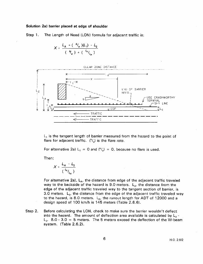
Solution 2a) barrier placed at edge of shoulder
Step 1. The Length of Need (LON) formula for adjacent traffic is:
x= LA +( “(JL,) -4 ( “/,) + ( LAq
CLEAR ZONE DISTANCE -----__-___
-. -. ‘. END OF BARRIER -. ‘. NEED
-. bc+==- -. ---. USE CRASHWOR
-0. TERMINAL -.
I-m •~--rrarr-rrrrrsrrar ,/-SHY LINE
THY
<- TRAFFIC __------------------
<- TRAFFIC
L, is the tangent length of barrier measured from the hazard to the point of flare for adjacent traffic. tb/,) is the flare rate.
For alternative 2a) L, = 0 and tb/,) = 0, because no flare is used.
Then:
For alternative 2a), L,, the distance from edge of the adjacent traffic traveled way to the backside of the hazard is 9.0 meters. L,, the distance from the edge of the adjacent traffic traveled way to the tangent section of barrier, is 3.0 meters. L,, the distance from the edge of the adjacent traffic traveled way to the hazard, is 8.0 meters. L,, the runout length for ADT of 12000 and a design speed of 100 km/h is 145 meters (Table 2.6.6).
Step 2. Before calculating the LON, check to make sure the barrier wouldn’t deflect into the hazard. The amount of deflection area available is calculated by L, - L,. 8.0 - 3.0 = 5 meters. The 5 meters exceed the deflection of the W-beam’ system. (Table 2.6.2).
6 H.O. 2.6/2
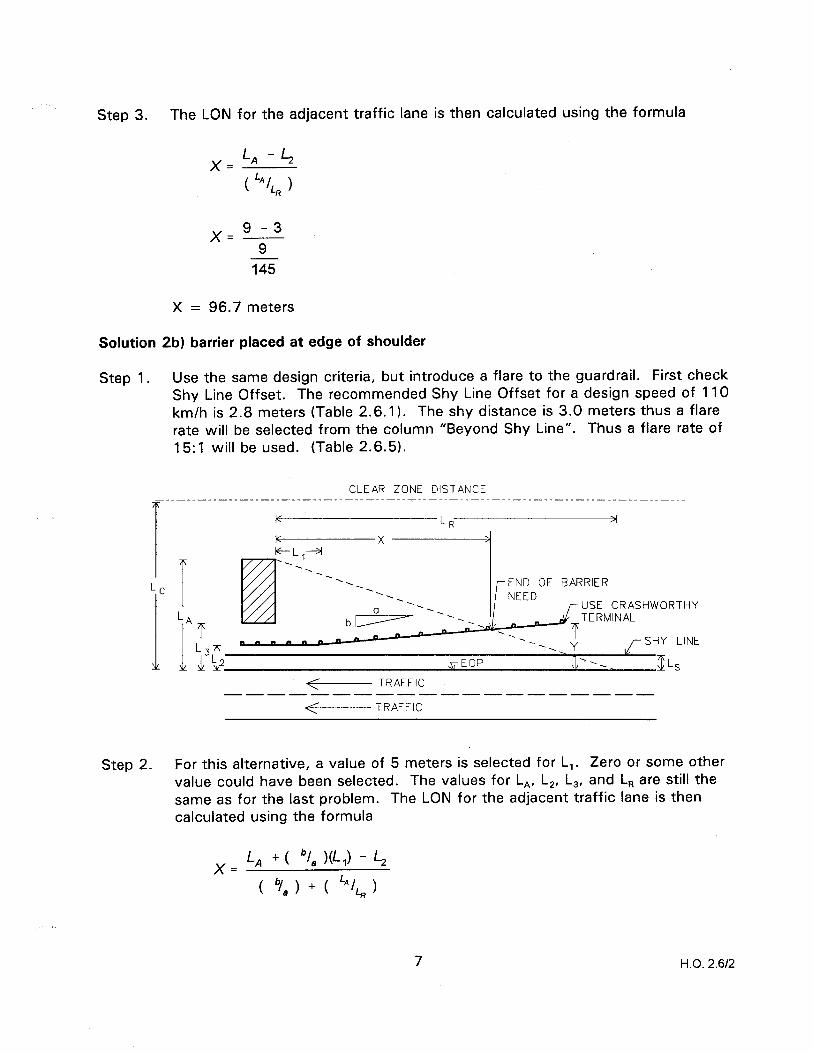
Step 3. The LON for the adjacent traffic lane is then calculated using the formula
145
X = 96.7 meters
Solution 2b) barrier placed at edge of shoulder
Step 1. Use the same design criteria, but introduce a flare to the guardrail. First check Shy Line Offset. The recommended Shy Line Offset for a design speed of 110 km/h is 2.8 meters (Table 2.6.1). The shy distance is 3.0 meters thus a flare rate will be selected from the column “Beyond Shy Line”. Thus a flare rate of 15:l will be used. (Table 2.6.5).
CLEAR ZONE DISTANCE
T K
LR 3
-. -. END OF BARRIER . .
--. NEED 0
. . ..~ J- USE CRASHWORTHY
7rn. 11h1 *I
. !b ,r EOP lx. ZLS
<- TRAFFIC --------------------
<- TRAFFIC
Step 2. For this alternative, a value of 5 meters is selected for L,. Zero or some other value could have been selected. The values for L,, L,, L,, and L, are still the same as for the last problem. The LON for the adjacent traffic lane is then calculated using the formula
X= LA +( “/,)(L,) - L2
( 9,) + ( LA/LR)
7 H.O. 2.6/2
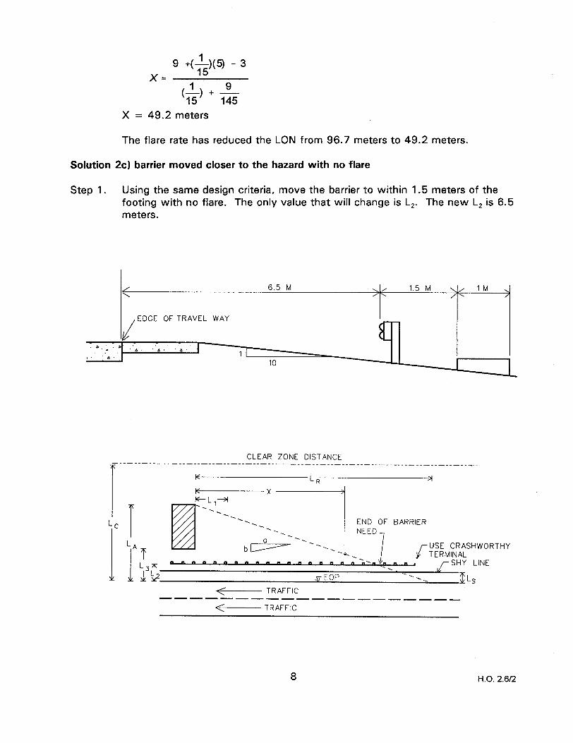
9 +(&Ml - 3 x=
x= 49.2
(&) + A- 145
meters
The flare rate has reduced the LON from 96.7 meters to 49.2 meters.
Solution 2c) barrier moved closer to the hazard with no flare
Step 1. Using the same design criteria, move the barrier to within 1.5 meters of the footing with no flare. The only value that will change is L,. The new L, is 6.5 meters.
< 6.5 M \ 1.5 M
/ \/ ‘M >
EDGE OF TRAVEL WAY
CLEAR ZONE DISTANCE -__-____-_-_____--______________________-.-----.-..-----.----------------~ T
I K LR >I
Lc I T
LA
1
T
>TJ
a?;:, %:DjF BARR’;uSE CRASHWORTHY
--a- ,‘ ‘“.,
TERMINAL a---n---~-~s”“-n” I r SHY LINE
$EOP .k. US .+--- TRAFFIC
--mm---m------------
<- TRAFFIC
8 H.O. 2.6/2

Step 2. The LON for the adjacent traffic lane is then calculated using the formula
x = 9 - 6.5 9
145
X = 40.3 meters
This solution reduces the required barrier by 8.9 meters from the last design, but also provides 3.5 more meters of area to recover in.
Solution 2d) barrier moved closer to the hazard with a flare
CLEAR ZONE DISTANCE -.--_-----_--------_____________________.~-..-.---~-~~----~~-~~-~~-~~-~~~~~~
T 3
F-I .-A
T LA
I
-1 -. -. -. -. END OF BARRIER -.
‘. NEED -.
d+=- -. USE CRASHWORTHY
T -l-.“, I ” TERMINAL
‘. $T L,m D m - m m m -. ‘. Y ,/-SHY LINE
L%? - Lb
,rEOP -. Ds
<- TRAFFIC --w----B------------
<- TRAFFIC
Step 1. Introduce a flare rate to Solution (cl. The same L, = 5 meters and a flare rate of 15:l will be used. The other values will remain the same. The LON for the adjacent traffic lane is then calculated using the formula
x= L/q + ( “/a W,) - L2 ( 9J + ( LA/LR)
9 H.O. 2.6/2
x= 9 +(-&) - 6.5
X = 22.0 meters
A summary of the results are: Solution a - 96.7 meters Solution b - 49.2 meters Solution c - 40.3 meters Solution d - 22.0 meters
All these solutions are correct, but Solution (d) provides the most area to recover in and the least amount of barrier, thus the best solution.
10 H.O. 2.612
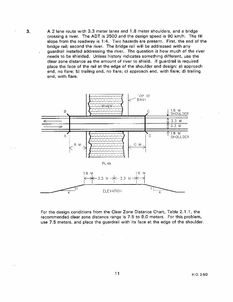
3. A 2 lane route with 3.3 meter lanes and 1.8 meter shoulders, and a bridge crossing a river. The ADT is 3500 and the design speed is 90 km/h. The fill slope from the roadway is 1:4. Two hazards are present. First, the end of the bridge rail; second the river. The bridge rail will be addressed with any guardrail installed addressing the river. The question is how much of the river needs to be shielded. Unless history indicates something different, use the clear zone distance as the amount of river to shield. If guardrail is required place the face of the rail at the edge of the shoulder and design: a) approach end, no flare; b) trailing end, no flare; c) approach end, with flare; d) trailing end, with flare.
PLAN
1.8 M 1.8 M f+-++3.3 MjG3.3 M+-Sj
ELEVATION
For the design conditions from the Clear Zone Distance Chart, Table 2.1 .I, the recommended clear zone distance range is 7.5 to 9.0 meters. For this problem, use 7.5 meters, and place the guardrail with its face at the edge of the shoulder.
11 H.O. 2.612
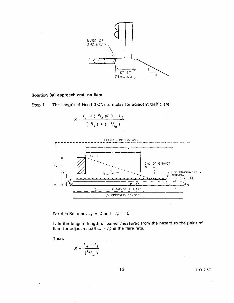
EDGE OF SHOULDER
\
Solution 3a) approach end, no flare
Step 1. The Length of Need (LON) formulas for adjacent traffic are:
X= L/q +( “/, W,) - L,
( 9, > + ( “IL* 1
CLEAR ZONE DISTANCE
T K 2
K K-I -3
x_lj
'1 .' -.
' - - -.
-. END OF BARRIER . .
-. NEED ‘.
td+- ---.__
. ..a.daad ‘. . al...
USE CRASHWORTHY TERMINAL
,/-SHY LINE
5 EOP
<+----- ADJACENT TRAFFIC
-> OPPOSING TRAFFIC
‘. f LS
For this Solution, L, = 0 and tb/,) = 0
L, is the tangent length of barrier measured from the hazard to the point of flare for adjacent traffic. ib/,) is the flare rate.
Then:
xzLA-b
( ‘“/L, )
12 H.O. 2.6f2
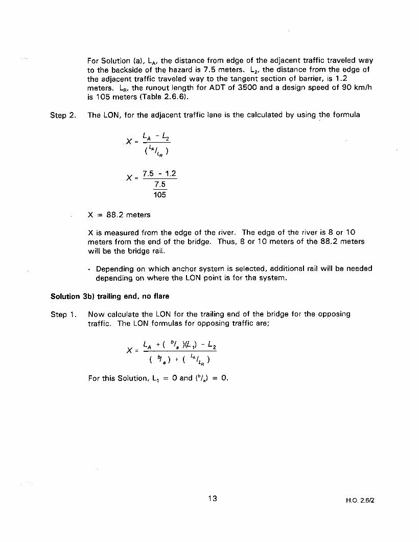
For Solution (a), L,, the distance from edge of the adjacent traffic traveled way to the backside of the hazard is 7.5 meters. L,, the distance from the edge of the adjacent traffic traveled way to the tangent section of barrier, is 1.2 meters. LR, the runout length for ADT of 3500 and a design speed of 90 km/h is 105 meters (Table 2.6.6).
Step 2. The LON, for the adjacent traffic lane is the calculated by using the formula
x = 7.5 - 1.2 7.5 105
x= 88.2 meters
X is measured from the edge of the river. The edge of the river is 8 or 10 meters from the end of the bridge. Thus, 8 or 10 meters of the 88.2 meters will be the bridge rail.
- Depending on which anchor system is selected, additional rail will be needed depending on where the LON point is for the system.
Solution 3b) trailing end, no flare
Step 1. Now calculate the LON for the trailing end of the bridge for the opposing traffic. The LON formulas for opposing traffic are;
x= LA +( “/a )(L,) - L,
For this Solution, L, = 0 and tb/,) = 0.
13 H.O. 2.6R

CLEAR ZONE DISTANCE -__-__-_____-__-__~.____________________~--~.--.---~~.-----~~~---~~.~~-~~
<
END OF BARRIER -
NEED
SHY LINE 3’ m a” -““““”
/’ EOP TI, .’
,/’ +&----- ADJACENT TRAFFIC
+ OPPOSING TRAFFIC
Then:
XcLA-b
(“/L, )
L, is the tangent length of barrier measured from the hazard to the point of flare for adjacent traffic. lb/,) is the flare rate. L,, the distance from the left edge of opposing traffic traveled way to the backside of the hazard, is 10.8 meters. L,, the distance from the left edge of opposing traffic traveled way to the tangent section of the barrier, is 4.5 m.
Step 2. The LON for the opposing traffic lane is then calculated using the formula
XcLA-b (‘“/L, >
x = 10.8 - 4.5 10.8 105
X = 61.3 meters
X is measured from the edge of the river. The edge of the river is 8 meters from the end of the bridge. Thus, 8 meters of the 61.3 meters will be the bridge rail.
- Depending on which anchor system is selected, additional rail will be needed depending on where the LON point is for the system.
14 H.O. 2.6/2

Solution (3~) approach end, with flare
Step 1. This will require the slope in front of the guardrail to be 1: 10 or flatter. Because of the flare, we will need to calculate the value for L, which is the tangent length of barrier before the flare. First check the shy line offset. The recommended shy line offset for a design speed of 90 km/h is 2.2 meters (Table 2.6.1). Even though the shy distance is 1.2 meters and the recommended shy distance is 2.2 meters, a flare rate will be selected from the column “Beyond Shy Line” (Table 2.6.5). Thus a flare rate of 12 + 1 will be used. For Solution (c), L, is 13.4 meters or 15.4 meters. Eight or ten meters are from the end of the bridge rail to the top of the river bank, and 5.4 meters for the transition leading into the bridge rail, because the barrier flare is starting outside the shy distance.
If part of the transition section could be flared, then the value of L, could be reduced. The values for L,, L,, and L, are still the same as for Solution (a).
CLEAR ZONE DISTANCE ___-_____-__-____--_____________________-----~-~-~.~~~~---~~~~---~~~-
T K LR 3
Step 2.
<- ADJACENT TRAFFIC ----------------------
-> OPPOSING TRAFFIC
The LON for the adjacent traffic lane is then calculated using the formula
x= L, + ( bla W,) - L, ( “/, > + ( lAjLR >
.HY
.INE
x, = 7.5 +(&X13.4) - 1.2
(-$I + g
15 H.O. 2.6/2
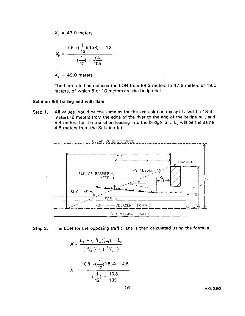
x, = 47.9 meters
%= 7.5 +(3(m) - 1.2
(-L) + 7.5 105
XII = 49.0 meters
The flare rate has reduced the LON from 88.2 meters to 47.9 meters or 49.0 meters, of which 8 or 10 meters are the bridge rial.
Solution 3d) trailing end with flare
Step 1. All values would be the same as for the last solution except L, will be 13.4 meters (8 meters from the edge of the river to the end of the bridge rail, and 5.4 meters for the transition leading into the bridge rail. L, will be the same 4.5 meters from the Solution (a).
CLEAR ZONE DISTANCE .----~---------.----~.-~~-..-~~-.~-~--~~~~----~----~----~~--~~~~-~~--~~~~- T
AS NEEDED-. END OF BARRIER /’
/’ I’
SHY LINE \ /’ I’ EOP TI,
L2
-- L,LL-~f----ADJACENTTR*FF’C_--~~-~ + OPPOSING TRAFFIC
LC
-A
1
Step 2. The LON for the opposing traffic lane is then calculated using the formula
x= L, + ( Q(q - 4 ( “1, > + ( LAILR >
XL= 10.8 +(&)(15.4) - 4.5
16 H.O. 2.612

x, = 40.7 meters
x, = 10.8 +($)(13.4) - 4.5
X, = 39.8 meters
The flare rate has reduced the LON from 61.3 meters to 39.8 meters or 40.7 meters, of which 8 or 10 meters is the bridge rail.
17 H.O. 2.612
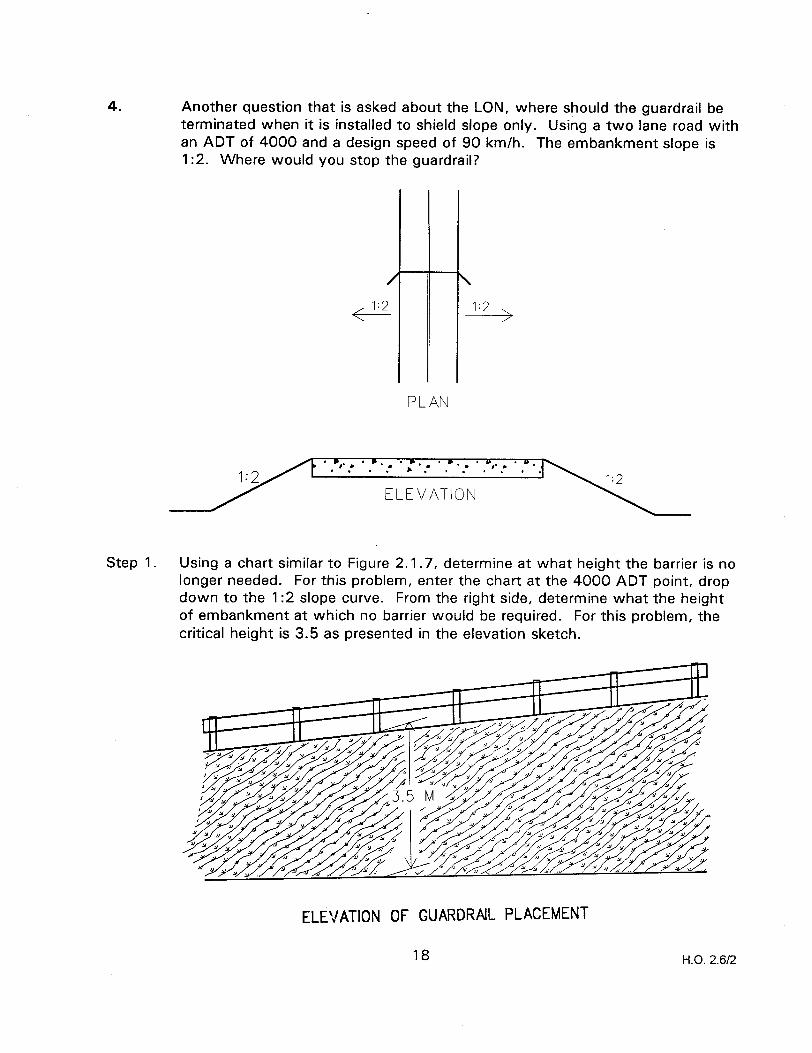
4. Another question that is asked about the LON, where should the guardrail be terminated when it is installed to shield slope only. Using a two lane road with an ADT of 4000 and a design speed of 90 km/h. The embankment slope is 1:2. Where would you stop the guardrail?
1 PLAN
\ 1:2
ELEVATION
Step 1. Using a chart similar to Figure 2.1.7, determine at what height the barrier is no longer needed. For this problem, enter the chart at the 4000 ADT point, drop down to the 1:2 slope curve. From the right side, determine what the height of embankment at which no barrier would be required. For this problem, the critical height is 3.5 as presented in the elevation sketch.
ELEVATION OF GUARDRAIL PLACEMENT
18 H.O. 2.612

\ Step 2. This then establishes the LON for the barrier.
It should be remembered that the guardrail is for the embankment only, and no other hazards are present.
19 H.O. 2.6R

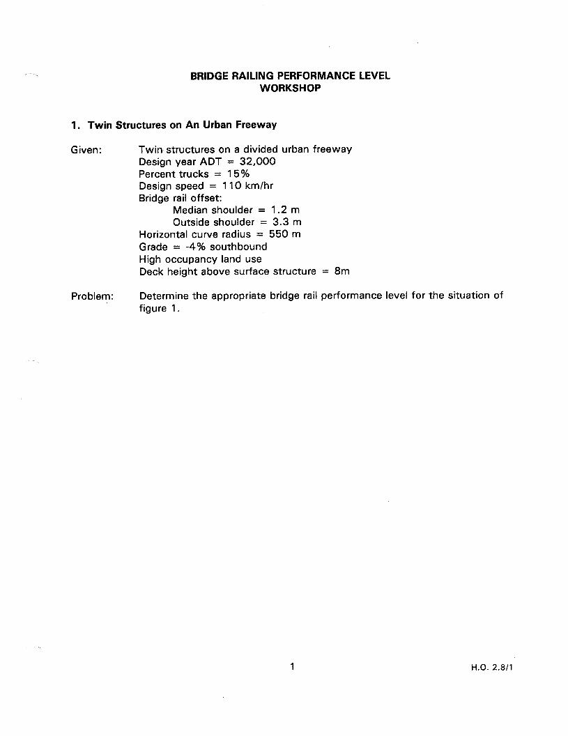
BRIDGE RAILING PERFORMANCE LEVEL WORKSHOP
1. Twin Structures on An Urban Freeway
Given: Twin structures on a divided urban freeway Design year ADT = 32,000 Percent trucks = 15% Design speed = 110 km/hr Bridge rail offset:
Median shoulder = 1.2 m Outside shoulder = 3.3 m
Horizontal curve radius = 550 m Grade = -4% southbound High occupancy land use Deck height above surface structure = 8m
Problem: Determine the appropriate bridge rail performance level for the situation of figure 1.
1 H.O. 2.8/l

\ \ I I I ”
I I
I f I I
:
: I
I 1
I I
I I
I I
I I
I I
I I
I
I ’
2 H.O. 2.8/l
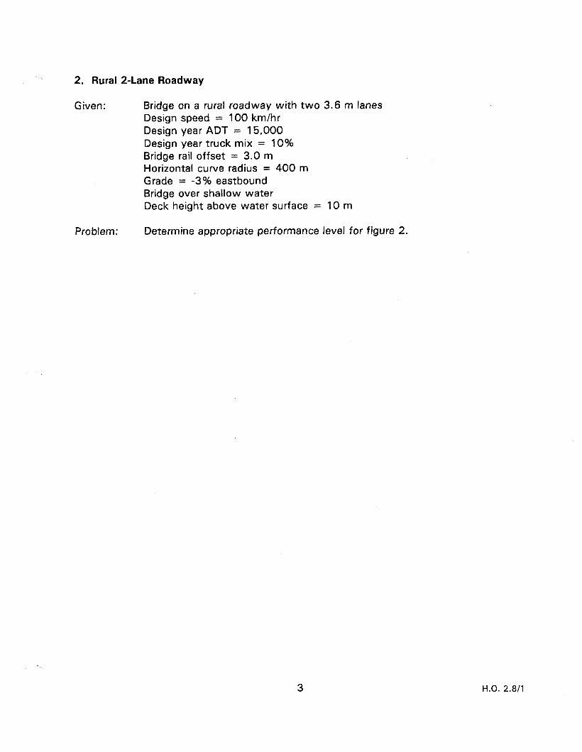
2. Rural 2-Lane Roadway
Given: Bridge on a rural roadway with two 3.6 m lanes Design speed = 100 km/hr Design year ADT = 15,000 Design year truck mix = 10% Bridge rail offset = 3.0 m Horizontal curve radius = 400 m Grade = -3% eastbound Bridge over shallow water Deck height above water surface = 10 m
Problem: Determine appropriate performance level for figure 2.
3 H.O. 2.8/l
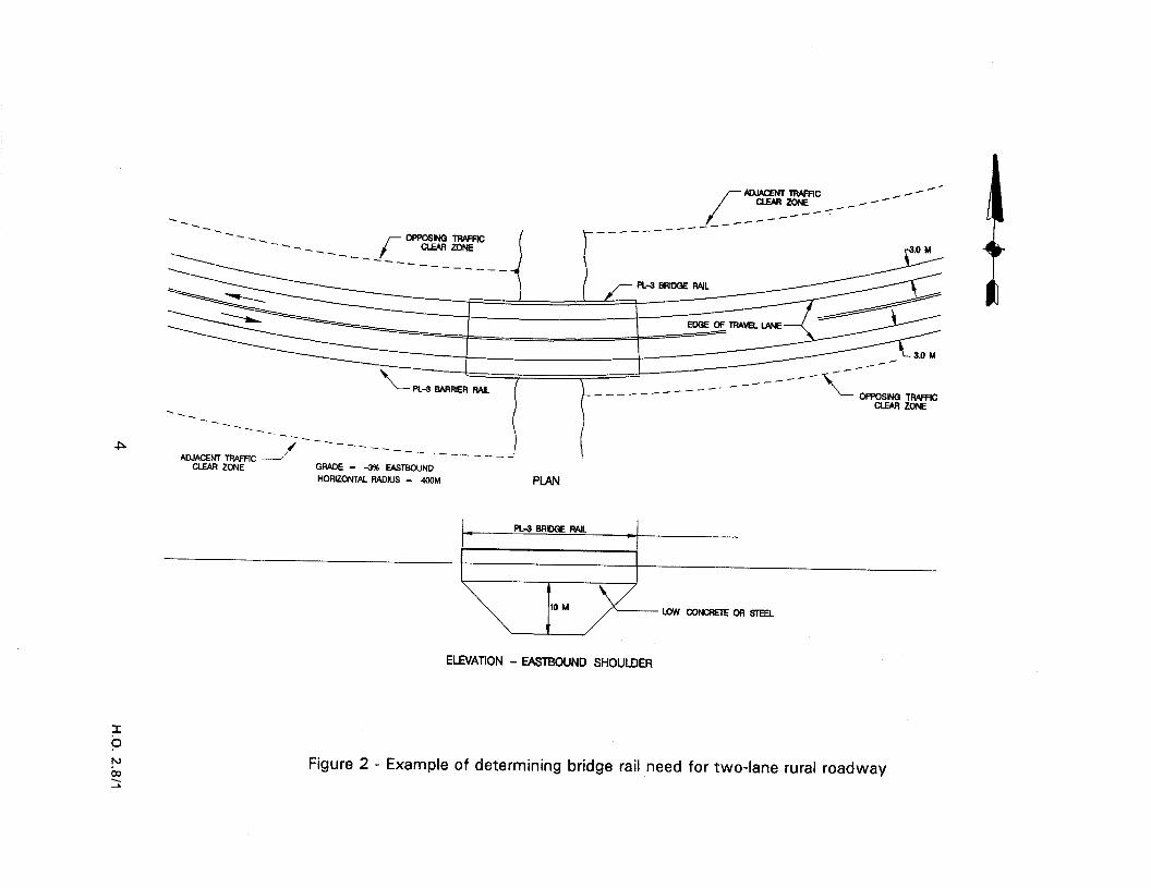
/-- AoJAcENTlRARlC
aJaFizoNE __.----- _/-*
-- / __---- ---- ----- <----
__----- --____ /ryf?-y--
I -
P ----__ ------_-_-_- GWDE - 3% EASTBOUND HoRKwa Flmius = 4GQM PLAN
ELEVATION - EASTEKIUND SHOULDER
Figure 2 - Example of determining bridge rail need for two-lane rural roadway
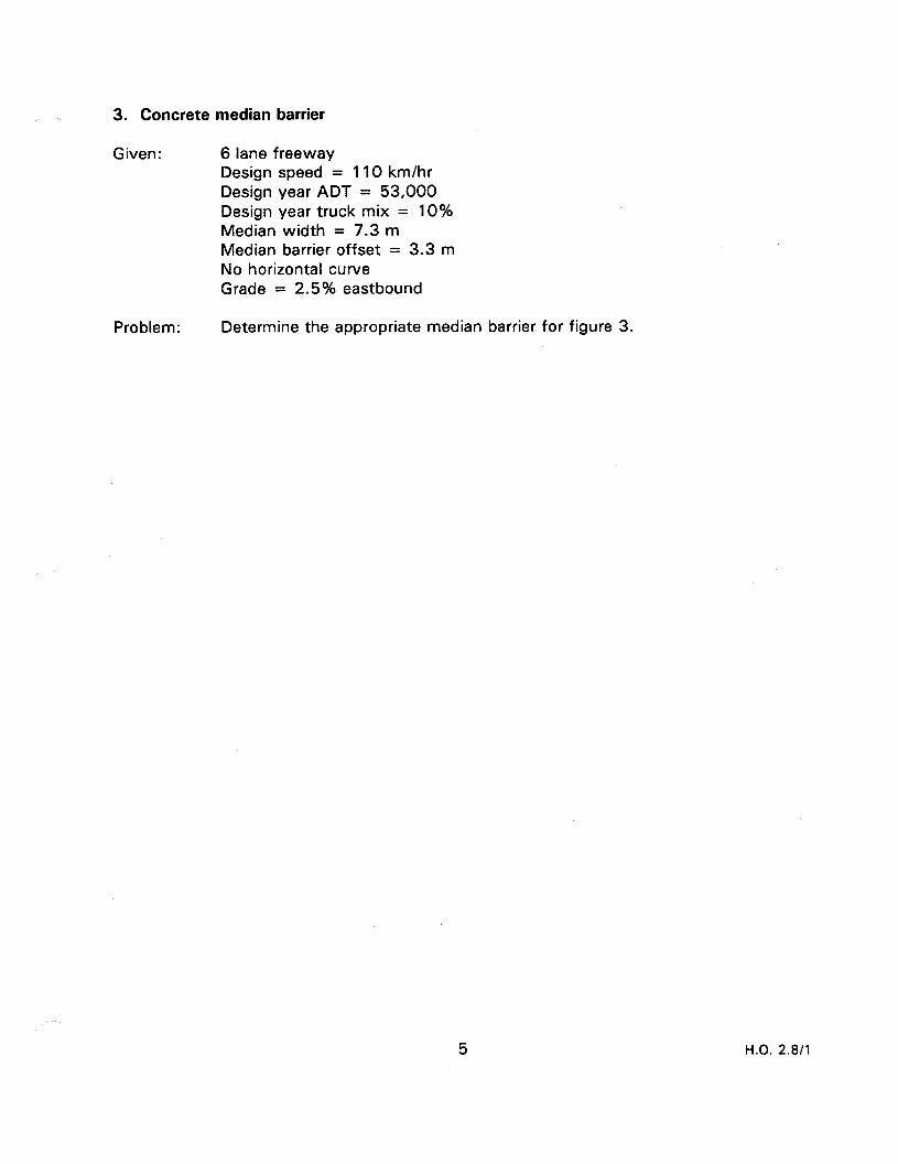
3. Concrete median barrier
Given: 6 lane freeway Design speed = 110 km/hr Design year ADT = 53,000 Design year truck mix = 10% Median width = 7.3 m Median barrier offset = 3.3 m No horizontal curve Grade = 2.5% eastbound
Problem: Determine the appropriate median barrier for figure 3.
5 H.O. 2.8/l
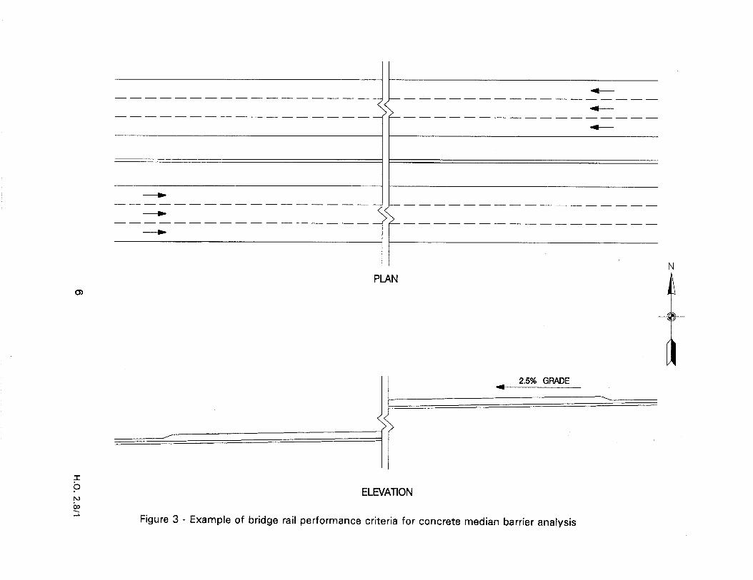
-------------------------____-_ -----
------- ---- ------ ---------_ -- -----
--___----- ---- ---- -- -----------__ --
--------- -------_ -- ----------___ --
l I
PLAN N
a
--?- a 2.5% GFViDE
ELEVATION
Figure 3 - Example of bridge rail performance criteria for concrete median barrier analysis
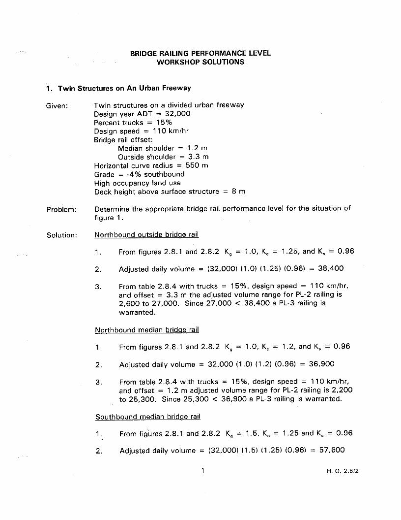
BRIDGE RAILING PERFORMANCE LEVEL WORKSHOP SOLUTIONS
1. Twin Structures on An Urban Freeway
Given: Twin structures on a divided urban freeway Design year ADT = 32,000 Percent trucks = 15% Design speed = 110 km/hr Bridge rail offset:
Median shoulder = 1.2 m Outside shoulder = 3.3 m
Horizontal curve radius = 550 m Grade = -4% southbound High occupancy land use Deck height above surface structure = 8 m
Problem: Determine the appropriate bridge rail performance level for the situation of figure 1.
Solu.tion: Northbound outside bridae rail
1. From figures 2.8.1 and 2.8.2 K, = 1.0, K, = 1.25, and K, = 0.96
2. Adjusted daily volume = (32,000) (1 .O) (1.25) (0.96) = 38,400
3. From table 2.8.4 with trucks = 15%, design speed = 110 km/hr, and offset = 3.3 m the adjusted volume range for PL-2 railing is 2,600 to 27,000. Since 27,000 < 38,400 a PL-3 railing is warranted.
Northbound median bridqe rail
1. From figures 2.8.1 and 2.8.2 K, = 1.0, K, = 1.2, and K, = 0.96
2. Adjusted daily volume = 32,000 (I .O) (1.2) (0.96) = 36,900
3. From table 2.8.4 with trucks = 15%, design speed = 110 km/hr, and offset = 1.2 m adjusted volume range for PL-2 railing is 2,200 to 25,300. Since 25,300 < 36,900 a PL-3 railing is warranted.
Southbound median bridae rail
1. From figures 2.8.1 and 2.8.2 K, = 1.5, K, = 1.25 and K, = 0.96
2. Adjusted daily volume = (32,000) (1.5) (1.25) (0.96) = 57,600
1 H. 0. 2.812
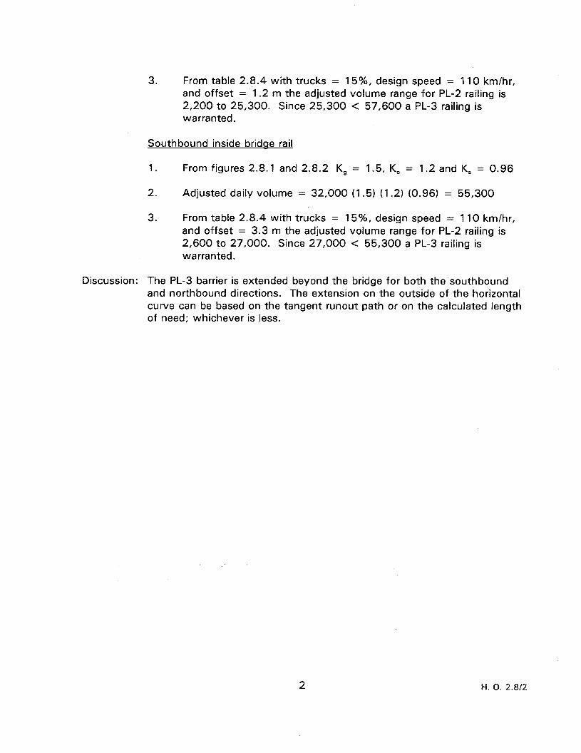
3. From table 2.8.4 with trucks = 15%, design speed = 110 km/hr, and offset = 1.2 m the adjusted volume range for PL-2 railing is 2,200 to 25,300. Since 25,300 < 57,600 a PL-3 railing is warranted.
Southbound inside bridqe rail
1. From figures 2.8.1 and 2.8.2 K, = 1.5, K, = 1.2 and K, = 0.96
2. Adjusted daily volume = 32,000 (1.5) (1.2) (0.96) = 55,300
3. From table 2.8.4 with trucks = 15%, design speed = 1 10 km/hr, and offset = 3.3 m the adjusted volume range for PL-2 railing is 2,600 to 27,000. Since 27,000 < 55,300 a PL-3 railing is warranted.
Discussion: The PL-3 barrier is extended beyond the bridge for both the southbound and northbound directions. The extension on the outside of the horizontal curve can be based on the tangent runout path or on the calculated length of need; whichever is less.
2 H. 0. 2.8/2
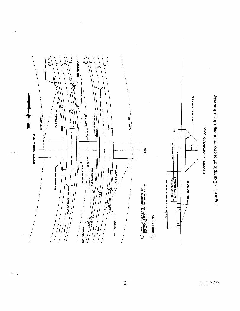
\ \ \ \ \ \ \ I \ \
I
I I II I
I
i I 1 I
1 ii I
3 H. 0. 2.812
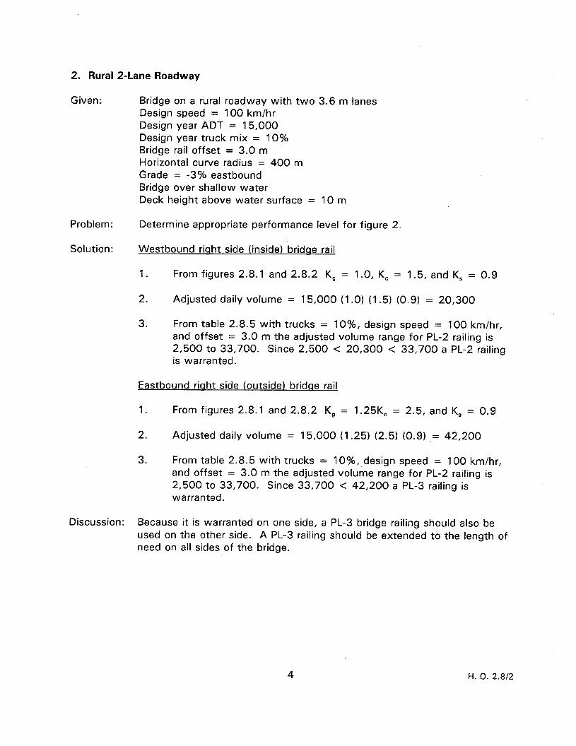
2. Rural a-Lane Roadway
Given: Bridge on a rural roadway with two 3.6 m lanes Design speed = 100 km/hr Design year ADT = 15,000 Design year truck mix = 10% Bridge rail offset = 3.0 m Horizontal curve radius = 400 m Grade = -3% eastbound Bridge over shallow water Deck height above water surface = 10 m
Problem: Determine appropriate performance level for figure 2.
Solution: Westbound rinht side (inside) bridoe rail
1. From figures 2.8.1 and 2.8.2 K, = 1.0, K, = 1.5, and K, = 0.9
2. Adjusted daily volume = 15,000 (I .O) (1.5) (0.9) = 20,300
3. From table 2.8.5 with trucks = lo%, design speed = 100 km/hr, and offset = 3.0 m the adjusted volume range for PL-2 railing is 2,500 to 33,700. Since 2,500 < 20,300 < 33,700 a PL-2 railing is warranted.
Eastbound riaht side (outside) bridae rail
1. From figures 2.8.1 and 2.8.2 K, = 1.25K, = 2.5, and K, = 0.9
2. Adjusted daily volume = 15,000 (1.25) (2.5) (0.9) ,= 42,200
3. From table 2.8.5 with trucks = IO%, design speed = 100 km/hr, and offset = 3.0 m the adjusted volume range for PL-2 railing is 2,500 to 33,700. Since 33,700 < 42,200 a PL-3 railing is warranted.
Discussion: Because it is warranted on one side, a PL-3 bridge railing should also be used on the other side. A PL-3 railing should be extended to the length of need on all sides of the bridge.
H. 0. 2.812

0 1 lENGlliOFNEEDORTOlNTER3ECTlONOF 0 3 LENG?HOFNEEDFORWE3TBOUH)@LWXNT)TIWFiC TANGENIW. RUNOUT PATH (WHlCHEWll3 L.E33) FOREASTBOWDcA[xwxNI)TRAFFIC. 0 4 LENf3HOFNEEDFOREASTBOUbD(OPPOSlNG)llWFC
0 LENGTHOFNEEDORTOlMER3ECTiONOF TANGENlW RUNOUT PATH (-‘M-liU-lEVER I3 LESJ FOR WESTSOUND (OPFQSING)lTWFlC.
/-
0-l
I
P N iw ‘N
ADJACENT TFIAFX /Hr
H-- CLEAR ZONE _.-H--
--A._ --A r-- Of’POSlNG TRAFFIC I
,-” _--// J-----------
-_ -?tl ”
END TREAThdENT J
--__ -. -- ---_
YEF ZzFC J
L PL-3 WRIER RAIL ‘1.
‘.
- - *iND TREATMENT “yz zKF”
‘1 ‘1
‘l\ ---- ‘. -----_ ------
GPADE = -a% EASTBOUND HORIZONTbl. WDlU3 - 4M)M
-
FL3 BARRIER ML PL-3 BRIDGE RAIL PL-3 BARRIER R4lL
END TREATMEM A l- END TREATMENT
10 M LOW CONCRETE OR STEEL
1
ELEVATION - EASTBOUND SHOULDER
Figure 2 - Example of determining bridge rail need for two-lane rural roadway
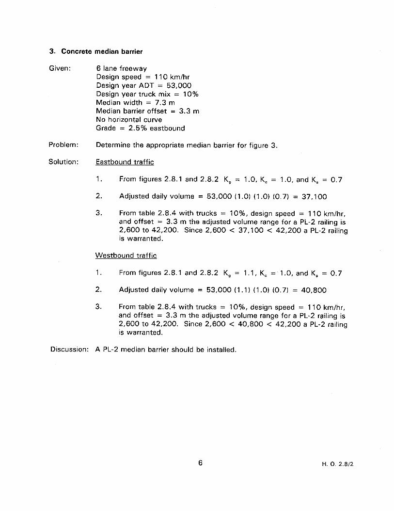
3. Concrete median barrier
Given: 6 lane freeway Design speed = 110 km/hr Design year ADT = 53,000 Design year truck mix = 10% Median width = 7.3 m Median barrier offset = 3.3 m No horizontal curve Grade = 2.5% eastbound
Problem: Determine the appropriate median barrier for figure 3.
Solution: Eastbound traffic
1. From figures 2.8.1 and 2.8.2 K, = 1.0, K, = 1.0, and K, = 0.7
2. Adjusted daily volume = 53,000 (1 .O) (1 .O) (0.7) = 37,100
3. From table 2.8.4 with trucks = lo%, design speed = 110 km/hr, and offset = 3.3 m the adjusted volume range for a PL-2 railing is 2,600 to 42,200. Since 2,600 < 37,100 < 42,200 a PL-2 railing is warranted.
Westbound traffic
1. From figures 2.8.1 and 2.8.2 K, = 1.1, K, = 1.0, and K, = 0.7
2. Adjusted daily volume = 53,000 (1 .l) !I .O) (0.7) = 40,800
3. From table 2.8.4 with trucks = IO%, design speed = 110 km/hr, and offset = 3.3 m the adjusted volume range for a PL-2 railing is 2,600 to 42,200. Since 2,600 < 40,800 < 42,200 a PL-2 railing is warranted.
Discussion: A PL-2 median barrier should be installed.
H. 0. 2.8/2

- _____-----_-------------------. -
____-----_------------------- ----------------------------- -
- __~-----------~---------------
- -----------------------------.
-
PLAN
0 PL-2 CONCRETE MEDIAN BARRIER
2.5% GRADE
@ STANDARD CONCRETE MEDIAN BARRIER (CMB).
ELEVATION
Figure 3 - Example of bridge rail performance criteria for concrete median barrier analysis
N
Q
P a

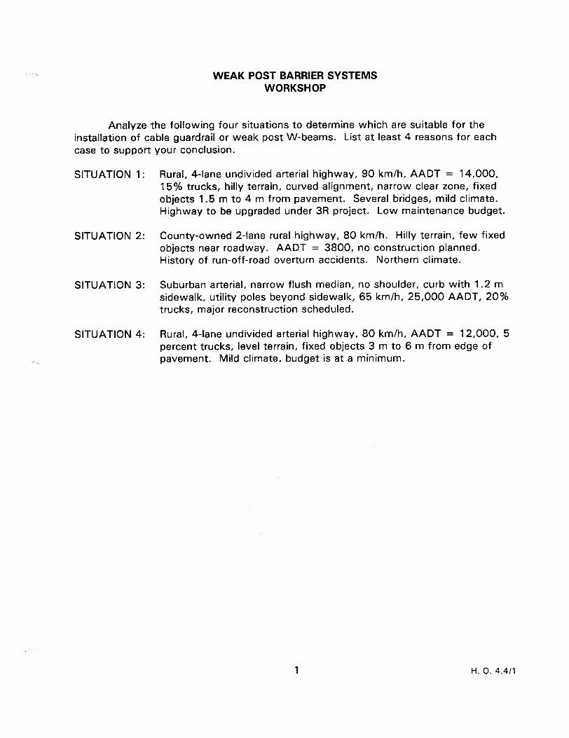
WEAK POST BARRIER SYSTEMS WORKSHOP
Analyze the following four situations to determine which are suitable for the installation of cable guardrail or weak post W-beams. List at least 4 reasons for each case to support your conclusion.
SITUATION 1:
SITUATION 2:
SITUATION 3:
SITUATION 4:
Rural, 4-lane undivided arterial highway, 90 km/h, AADT = 14,000, 15% trucks, hilly terrain, curved alignment, narrow clear zone, fixed objects 1.5 m to 4 m from pavement. Several bridges, mild climate. Highway to be upgraded under 3R project. Low maintenance budget.
County-owned 2-lane rural highway, 80 km/h. Hilly terrain, few fixed objects near roadway. AADT = 3800, no construction planned. History of run-off-road overturn accidents. Northern climate.
Suburban arterial, narrow flush median, no shoulder, curb with 1.2 m sidewalk, utility poles beyond sidewalk, 65 km/h, 25,000 AADT, 20% trucks, major reconstruction scheduled.
Rural, 4-lane undivided arterial highway, 80 km/h, AADT = 12,000, 5 percent trucks, level terrain, fixed objects 3 m to 6 m from edge of pavement. Mild climate, budget is at a minimum.
1 H. 0. 4.4/l

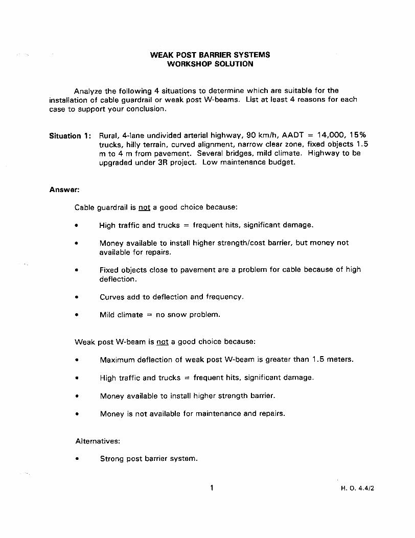
WEAK POST BARRIER SYSTEMS WORKSHOP SOLUTION
Analyze the following 4 situations to determine which are suitable for the installation of cable guardrail or weak post W-beams. List at least 4 reasons for each case to support your conclusion.
Situation 1: Rural, 4-lane undivided arterial highway, 90 km/h, AADT = 14,000, 15% trucks, hilly terrain, curved alignment, narrow clear zone, fixed objects 1.5 m to 4 m from pavement. Several bridges, mild climate. Highway to be upgraded under 3R project. Low maintenance budget.
Answer:
Cable guardrail is not a good choice because:
l High traffic and trucks = frequent hits, significant damage.
l Money available to install higher strength/cost barrier, but money not available for repairs.
l Fixed objects close to pavement are a problem for cable because of high deflection.
l Curves add to deflection and frequency.
l Mild climate = no snow problem.
Weak post W-beam is not a good choice because:
l Maximum deflection of weak post W-beam is greater than 1.5 meters.
l High traffic and trucks = frequent hits, significant damage.
l Money available to install higher strength barrier.
l Money is not available for maintenance and repairs.
Alternatives:
l Strong post barrier system.
H. 0. 4.4/2
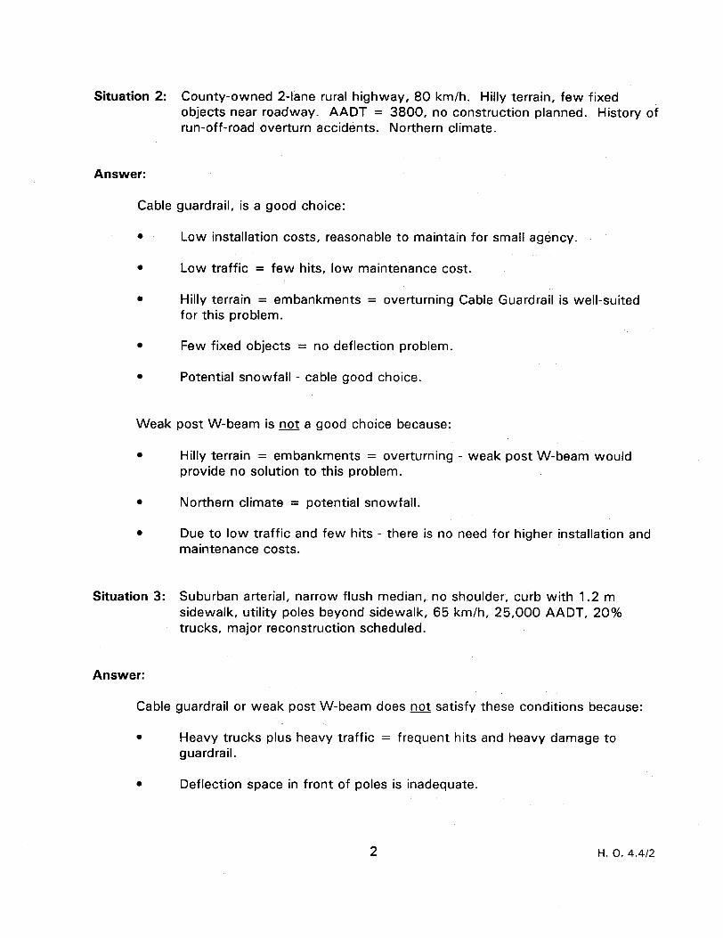
Situation 2: County-owned 2-lane rural highway, 80 km/h. Hilly terrain, few fixed objects near roadway. AADT = 3800, no construction planned. History of run-off-road overturn accidents. Northern climate.
Answer:
Cable guardrail, is a good choice:
l Low installation costs, reasonable to maintain for small agency.
l Low traffic = few hits, low maintenance cost.
0 Hilly terrain = embankments = overturning Cable Guardrail is well-suited for this problem.
l Few fixed objects = no deflection problem.
l Potential snowfall - cable good choice.
Weak post W-beam is not a good choice because:
0 Hilly terrain = embankments = overturning - weak post W-beam would provide no solution to this problem.
0 Northern climate = potential snowfall.
l Due to low traffic and few hits - there is no need for higher installation and maintenance costs.
Situation 3: Suburban arterial, narrow flush median, no shoulder, curb with 1.2 m sidewalk, utility poles beyond sidewalk, 65 km/h, 25,000 AADT, 20% trucks, major reconstruction scheduled.
Answer:
Cable guardrail or weak post W-beam does not satisfy these conditions because:
. Heavy trucks plus heavy traffic = frequent hits and heavy damage to guardrail.
0 Deflection space in front of poles is inadequate.
2 l-l. 0. 4.412
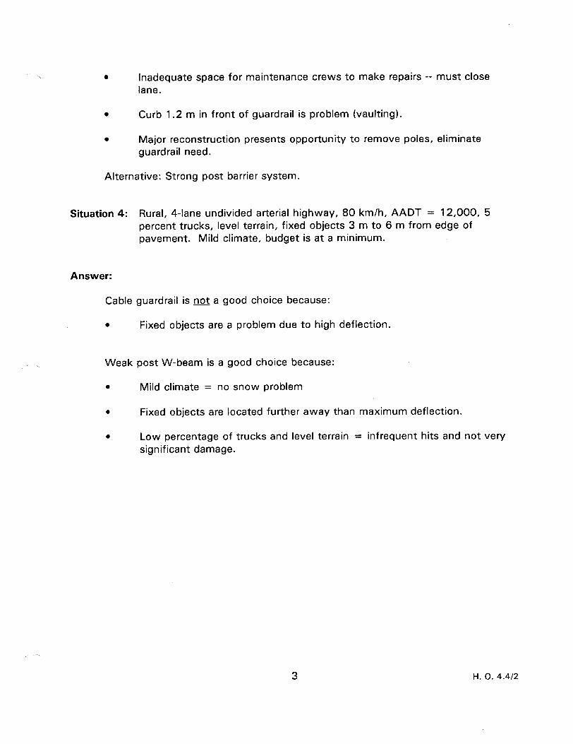
l Inadequate space for maintenance crews to make repairs -- must close lane.
0 Curb 1.2 m in front of guardrail is problem (vaulting).
0 Major reconstruction presents opportunity to remove poles, eliminate guardrail need.
Alternative: Strong post barrier system.
Situation 4: Rural, 4-lane undivided arterial highway, 80 km/h, AADT = 12,000, 5 percent trucks, level terrain, fixed objects 3 m to 6 m from edge of pavement. Mild climate, budget is at a minimum.
Answer:
Cable guardrail is not a good choice because:
0 Fixed objects are a problem due to high deflection.
Weak post W-beam is a good choice because:
0 Mild climate = no snow problem
0 Fixed objects are located further away than maximum deflection.
l Low percentage of trucks and level terrain = infrequent hits and not very significant damage.
3 H. 0. 4.4/2

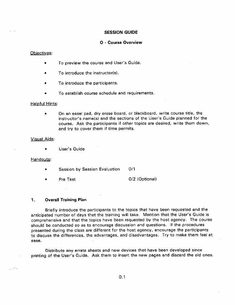
SESSION GUIDE
0 - Course Overview
Obiectives:
0 To preview the course and User’s Guide.
l To introduce the instructor(s).
a To introduce the participants.
l To establish course schedule and requirements.
Helpful Hints:
0 On an easel pad, dry erase board, or blackboard, write course title, the instructor’s name(s) and the sections of the User’s Guide planned for the course. Ask the participants if other topics are desired, write them down, and try to cover them if time permits.
Visual Aids:
l User’s Guide
Handouts:
0 Session by Session Evaluation O/l
0 Pre Test O/2 (Optional)
1. Overall Training Plan
Briefly introduce the participants to the topics that have been requested and the anticipated number of days that the training will take. Mention that the User’s Guide is comprehensive and that the topics have been requested by the host agency. The course should be conducted so as to encourage discussion and questions. If the procedures presented during the class are different for the host agency, encourage the participants to discuss the differences, the advantages, and disadvantages. Try to make them feel at ease.
Distribute any errata sheets and new devices that have been developed since printing of the User’s Guide. Ask them to insert the new pages and discard the old ones.
0.1
2. User’s Guide Description
Ask the participants to open their User’s Guide to page P.l and read the objectives. It may be beneficial to have this list on the easel pad in large letters. Spend some time familiarizing the participants with the Guide. Page P.3 summarizes every section. Walk them through the Chapter headings and have them turn to the appendices to see what is in each as you describe them from pages P.6 and P.7.
3. Course Evaluation
a) We want you to help us to improve the quality and usefulness of the procedural manual and future training courses.
b) A two-part evaluation system will be used to obtain input from you by: 1) evaluation of the specific sessions (i.e., lectures, case study, workshops, etc.) and 2) overall evaluation of the course and users manual which will be completed at the end of the course.
cl Feel free to make notes on any aspects of the course or procedural manual which you like or dislike and add these comments on the overall evaluation form.
d) Describe the session evaluation form.
4. Introductions
a) Introduce yourself and any other instructors by providing a brief biographical sketch. Rapport with technicians and local personnel is best established if they realize the instructors understand the subject matter and have practical experience. Establish a rapport on a first name basis. Remember: An expert is someone who does not know more than the participants, but has the material better organized and uses slides.
b) Have the participants introduce themselves mentioning, i.e., who they work for and their job function.
5. Housekeeping
Establish the best time and location for lunch, restroom facilities, phone messages, end time, and other related items. Be flexible.
0.2

Obiectives:
0 To
l To
l To
0 To
Heloful Hints:
SESSION GUIDE
I - INTRODUCTION TO THE SAFE ROADSIDE CONCEPT
provide background on the clear roadside concept.
present the philosophy of roadside design.
introduce NCHRP 350.
discuss broad categories of good roadside safety practice.
0 Use slides of good and bad practice from the local area.
Visual Aids:
0 24 - 35 mm slides
Estimated Time
0 30 minutes
Handouts:
a None

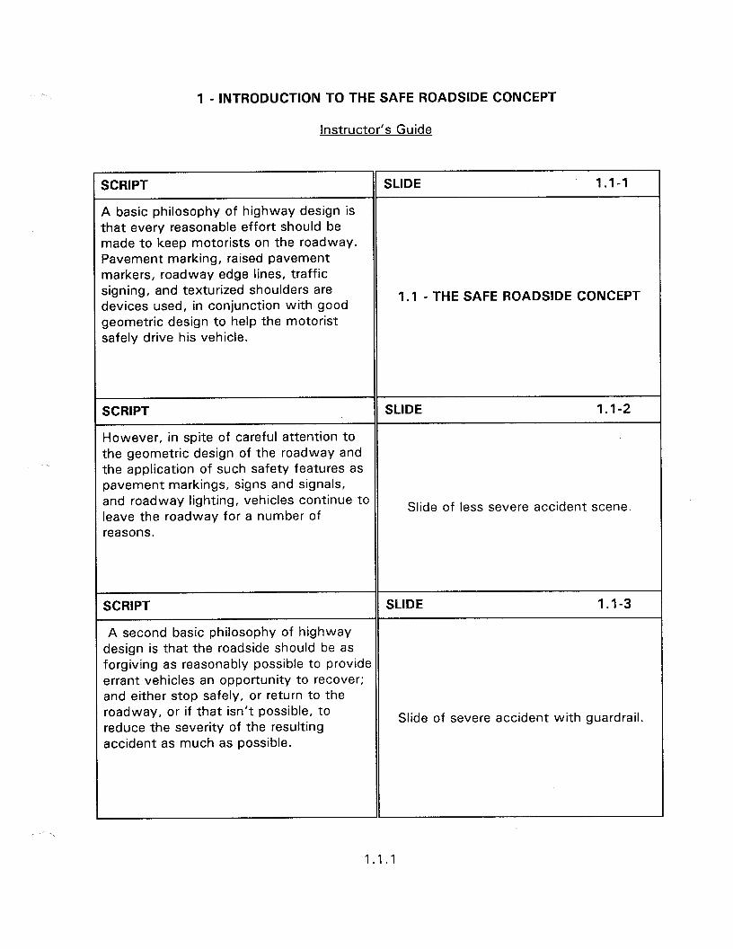
1 - INTRODUCTION TO THE SAFE ROADSIDE CONCEPT
instructor’s Guide
SCRIPT
A basic philosophy of highway design is that every reasonable effort should be made to keep motorists on the roadway. Pavement marking, raised pavement markers, roadway edge lines, traffic signing, and texturized shoulders are devices used, in conjunction with good geometric design to help the motorist safely drive his vehicle.
SLIDE 1.1-1
1.1 - THE SAFE ROADSIDE CONCEPT
SCRIPT SLIDE 1.1-2
However, in spite of careful attention to the geometric design of the roadway and the application of such safety features as pavement markings, signs and signals, and roadway lighting, vehicles continue to leave the roadway for a number of
Slide of less severe accident scene.
reasons.
SCRIPT SLIDE 1.1-3
A second basic philosophy of highway design is that the roadside should be as forgiving as reasonably possible to provide errant vehicles an opportunity to recover; and either stop safely, or return to the roadway, or if that isn’t possible, to reduce the severity of the resulting
Slide of severe accident with guardrail.
accident as much as possible.
1.1.1
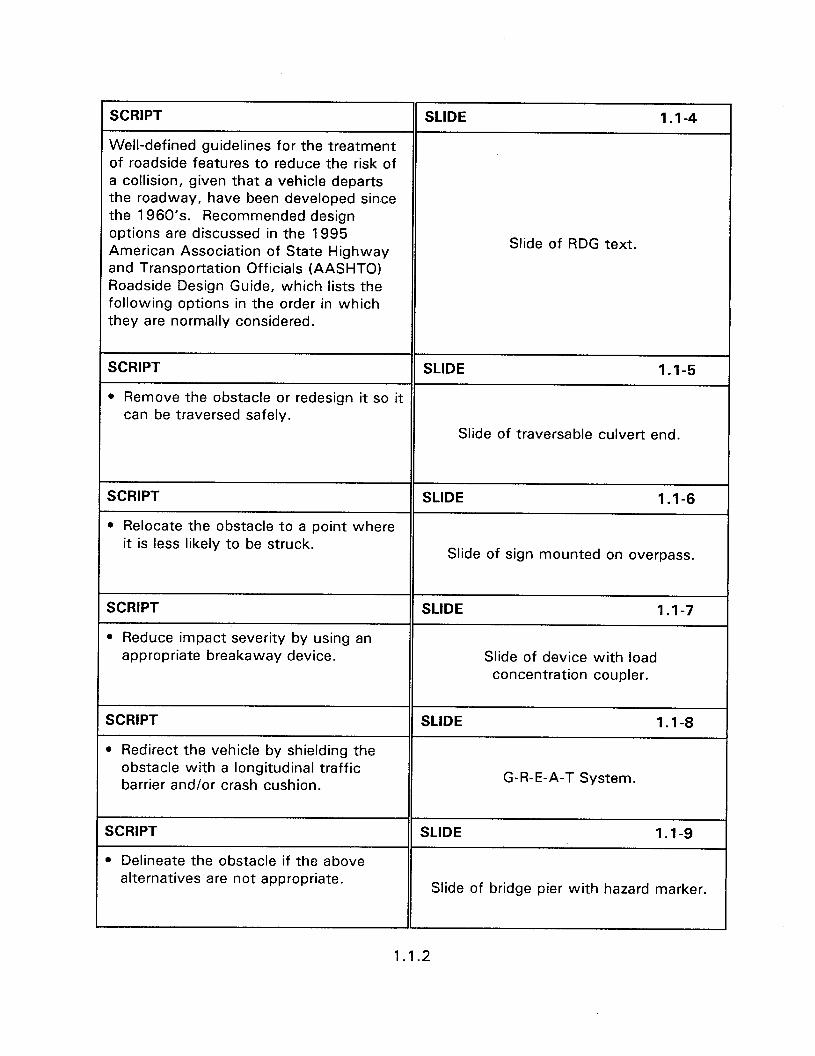
SCRIPT SLIDE 1.1-4
Well-defined guidelines for the treatment of roadside features to reduce the risk of a collision, given that a vehicle departs the roadway, have been developed since the 1960’s. Recommended design options are discussed in the 1995 American Association of State Highway Slide of RDG text.
and Transportation Officials (AASHTO) Roadside Design Guide, which lists the following options in the order in which they are normally considered.
SCRIPT SLIDE 1.1-5
l Remove the obstacle or redesign it so it can be traversed safely.
Slide of traversable culvert end.
SCRIPT SLIDE 1.1-6
l Relocate the obstacle to a point where it is less likely to be struck.
Slide of sign mounted on overpass.
SCRIPT
l Reduce impact severity by using an appropriate breakaway device.
SLIDE 1.1-7
Slide of device with load concentration coupler.
SCRIPT
l Redirect the vehicle by shielding the obstacle with a longitudinal traffic barrier and/or crash cushion.
SLIDE 1.1-8
G-R-E-A-T System.
SCRIPT
l Delineate the obstacle if the above alternatives are not appropriate.
SLIDE 1.1-9
Slide of bridge pier with hazard marker.
1.1.2
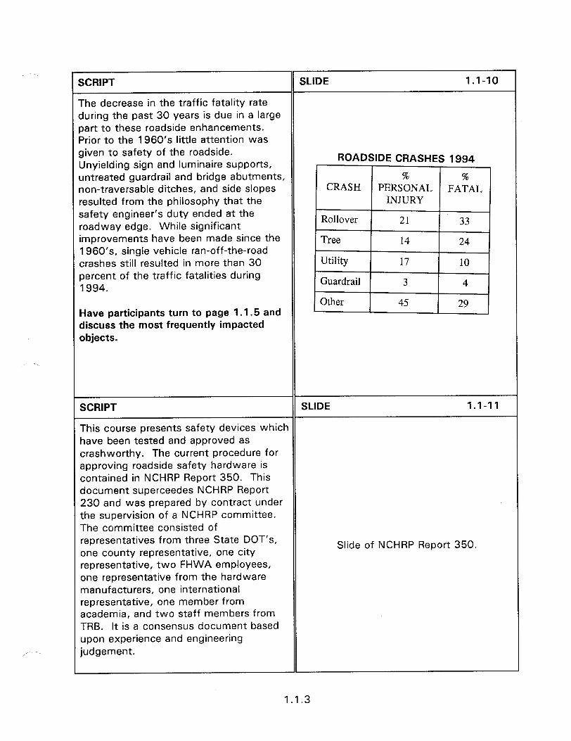
SCRIPT SLIDE 1.1-10
The decrease in the traffic fatality rate during the past 30 years is due in a large part to these roadside enhancements. Prior to the 1960’s little attention was given to safety of the roadside. Unyielding sign and luminaire supports,
ROADSIDE CRASHES 1 gg4
untreated guardrail and bridge abutments, non-traversable ditches, and side slopes resulted from the philosophy that the safety engineer’s duty ended at the roadway edge. While significant improvements have been made since the 1960’s, single vehicle ran-off-the-road crashes still resulted in more than 30 percent of the traffic fatalities during 1994.
Have participants turn to page 1 .1.5 and discuss the most frequently impacted objects.
SCRIPT SLIDE 1.1-11
This course presents safety devices which have been tested and approved as crashworthy. The current procedure for approving roadside safety hardware is contained in NCHRP Report 350. This document superceedes NCHRP Report 230 and was prepared by contract under the supervision of a NCHRP committee. The committee consisted of representatives from three State DOT’s, one county representative, one city
Slide of NCHRP Report 350.
representative, two FHWA employees, one representative from the hardware manufacturers, one international representative, one member from academia, and two staff members from TRB. It is a consensus document based upon experience and engineering judgement.
1.1.3
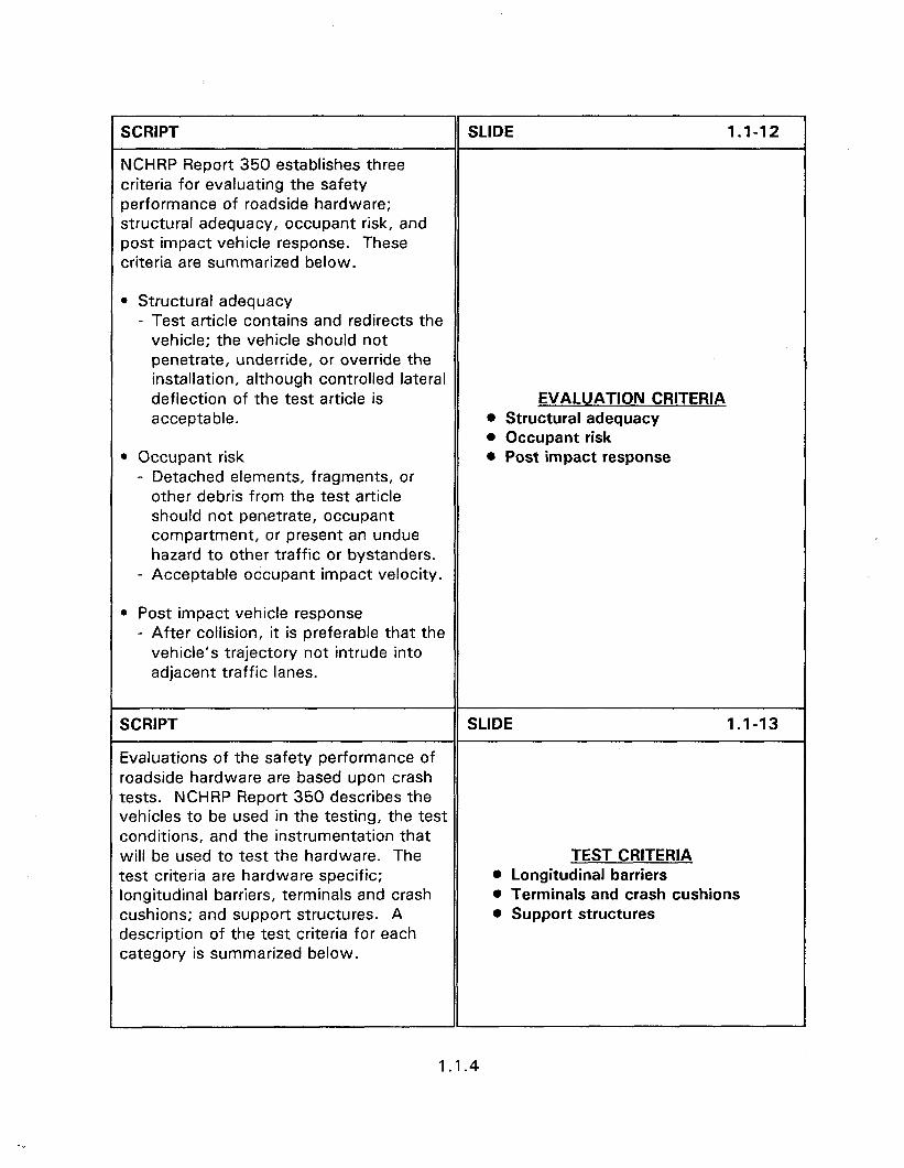
SCRIPT
NCHRP Report 350 establishes three criteria for evaluating the safety performance of roadside hardware; structural adequacy, occupant risk, and post impact vehicle response. These criteria are summarized below.
SLIDE 1.1-12
l Structural adequacy - Test article contains and redirects the
vehicle; the vehicle should not penetrate, underride, or override the installation, although controlled lateral deflection of the test article is acceptable.
l Occupant risk - Detached elements, fragments, or
other debris from the test article should not penetrate, occupant compartment, or present an undue hazard to other traffic or bystanders.
- Acceptable occupant impact velocity.
EVALUATION CRITERIA l Structural adequacy l Occupant risk l Post impact response
0 Post impact vehicle response - After collision, it is preferable that the
vehicle’s trajectory not intrude into adjacent traffic lanes.
SCRIPT SLIDE 1.1-13
Evaluations of the safety performance of roadside hardware are based upon crash tests. NCHRP Report 350 describes the vehicles to be used in the testing, the test conditions, and the instrumentation that will be used to test the hardware. The TEST CRITERIA test criteria are hardware specific; 0 Longitudinal barriers longitudinal barriers, terminals and crash l Terminals and crash cushions cushions; and support structures. A 0 Support structures description of the test criteria for each category is summarized below.
1.1.4
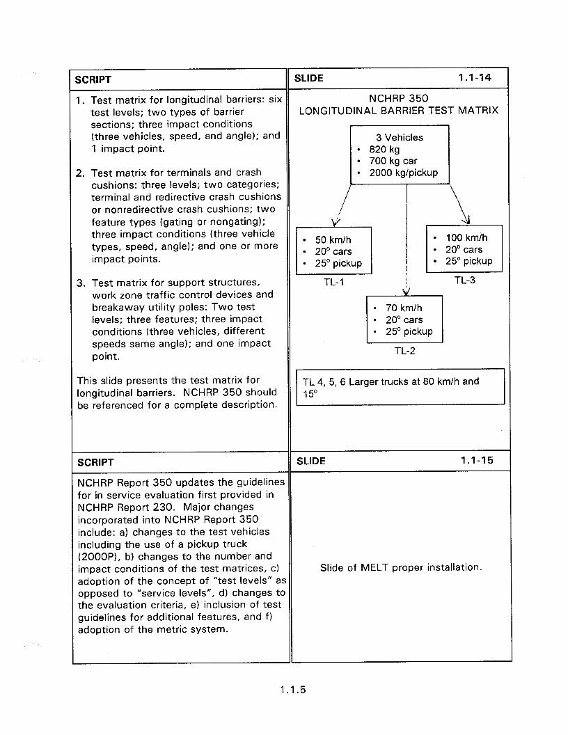
SCRIPT SLIDE 1 .I-14
I. Test matrix for longitudinal barriers: six NCHRP 350 test levels; two types of barrier LONGITUDINAL BARRIER TEST MATRIX sections; three impact conditions (three vehicles, speed, and angle); and 3 Vehicles 1 impact point. l 820 kg
l 700 kg car 2. Test matrix for terminals and crash
cushions: three levels; two categories; terminal and redirective crash cushions or nonredirective crash cushions; two feature types (gating or nongating); three impact conditions (three vehicle types, speed, angle); and one or more impact points.
l 2000 kg/pickup
3. Test matrix for support structures, work zone traffic control devices and breakaway utility poles: Two test levels; three features; three impact conditions (three vehicles, different speeds same angle); and one impact point.
TL-1 TL-3 Id
0 70 km/h l 20” cars l 25” pickup
TL-2
This slide presents the test matrix for longitudinal barriers. NCHRP 350 should be referenced for a complete description.
TL 4, 5, 6 Larger trucks at 80 km/h and 150
SCRIPT SLIDE 1.1-15
NCHRP Report 350 updates the guidelines for in service evaluation first provided in NCHRP Report 230. Major changes incorporated into NCHRP Report 350 include: a) changes to the test vehicles including the use of a pickup truck (2OOOP), b) changes to the number and impact conditions of the test matrices, c) Slide of MELT proper installation. adoption of the concept of “test levels” as opposed to “service levels”, d) changes to the evaluation criteria, e) inclusion of test guidelines for additional features, and f) adoption of the metric system.
1.1.5
SCRIPT
FHWA PROCEDURES FOR BARRIER ACCEPTANCE
SLIDE 1.1-16
Roadside safety hardware and terrain features that must be placed within the roadside clear zone adjacent to the traveled way of National Highway System (NHS) routes are required by FHWA to be of a crashworthy design. Guidance for determining desirable clear zone width is defined in the AASHTO “Roadside Design Guide”. In a memorandum issued on Nov. 12, 1993, FHWA sets forth criteria for determining the crash worthiness of safety features, which includes formal adoption by FHWA of the NCHRP Report 350 test procedures.
FHWA ACCEPTANCE l Required on NHS 0 Recommended everywhere l Acceptance procedure
As a service to hardware developers and manufacturers, highway agencies, and others in the highway industry, FHWA’s Office of Engineering reviews crash test documentation and issues letters of acceptance for crashworthy features and hardware. Appendix K summarizes the background and procedures for gaining FHWA acceptance.
SCRIPT SLIDE 1.1-17
Out of date installations are normally left in place until the roadway is reconstructed, or until they are damaged in an accident. When damaged in an accident, the decision of whether to replace it as originally constructed or to upgrade it to current standards needs to be made. The following rules of thumb are used by some agencies.
UPGRADING l 25% of bridge transition l 50% of barrier l State guidelines
l If 25% (one corner) of a guardrail transition, or connection, to a bridge is damaged beyond repair then all four corners should be upgraded to current
1.1.6

standards. It is possible that the current approach barrier will not attach to the older bridge rail. If this situation is encountered then a more extensive retrofit may be necessary.
l If 50% of an installation is damaged beyond repair then the entire barrier should be replaced with a barrier meeting current standards. This applies to long runs of barrier as well as short runs.
l When an upgrade is made notify the appropriate office within the agency to enable update of any record systems.
Other State guidelines include total replacement when 30 m or less of undamaged rail remain.
SCRIPT SLIDE 1 .I-18
Installing and maintaining a safe roadway environment requires knowledge of the safety devices that are available, and their proper design, construction, and maintenance. This course reviews all currently used highway safety Slide of traffic and good barrier appurtenances and discusses proper transitions and terminals. In addition, you
installation.
will be given the information to recognize good and bad practices and recognize when the following is required.
SCRIPT SLIDE 1.1-19
Replacement of blunt end terminals with crashworthy terminals;
Slide of a blunt end terminal.
1.1.7
SCRIPT SLIDE 1.1-20
Discontinue the use of turned-down ends on the approach end of roadside or median weak post W-beam barriers on high-speed, high-volume roads; Slide of turned down terminal.
SCRIPT SLIDE 1.1-21
Discontinue the use of Breakaway Cable Terminals on the approach end of barriers on high-speed, high-volume roads; Slide of BCT obsolete terminal.
SCRIPT SLIDE 1.1-22
Replacement of damaged substandard terminals with crashworthy terminals; and
Slide of damaged terminal.
SCRIPT SLIDE 1 .I-23
any remaining unconnected bridge- approach guardrail should be connected by an acceptable transition design within Slide of unconnected bridge approach three years. transition.
SCRIPT SLIDE 1 .I-24
By properly designing, installing, and maintaining our highway safety appurtenance we can increase roadway safety while being cost effective. This instructional video introduced the concepts of the general requirements for the selection and placement of safety
Slide of good guardrail, crash cushion
appurtenances. Further information on sand barriers, and etc.
the specific requirements of each selected device are required to ensure proper operation.
1.1.8
SESSION GUIDE
2.1 - CLEAR ZONE CONCEPT
Obiectives:
l Provide a discussion on the history of the clear zone concept.
Discuss the proper application of the clear zone concept.
Define the different types of embankments and their role in determining desirable clear zones.
Present the concepts of clear zones and fixed object hazards.
Helpful Hints:
l Where page numbers appear in bold it is advised to have the participants turn to that page during the presentation. This will help familiarize them with the contents of the Guide.
l Check with the State prior to the course to determine if they have criteria for embankment barrier need.
l There is a workshop on clear zone determination that is combined with a ditch design workshop of Session 2.2. If Session 2.2 is planned for presentation then give the workshop after Session 2.2.
Visual Aids:
l 30 - 35 mm slides
l Transparencies of Hand Outs (HO) 2.1/2
Estimated Time
l Session 2.1 - 30 minutes
l Workshop 2.1 - 30 minutes
Handouts:
l HO 2.1 /l (The first four problems are related to Session 2.1. Problems 5 and 6 of HO 2.1 are related to Session 2.2.)
l HO 2.1/2

2 - DESIGN OF HIGHWAY SAFETY FEATURES
Instructor’s Guide
2.1 - CLEAR ZONE CONCEPT
SCRIPT SLIDE 2.1-l
The American Association of State iighway Officials (AASHTO) has played a lotable role in the formation of highway design standards.
As early as the 1920s AASHTO was examining highway design features. These early efforts resulted in the publication of the “Blue Book” in 1954, “Policy of Geometric Design of Rural Highways” (revised in 1965). Urban design aspects were covered in the “Red Book, ” “A Policy on Arterial Highways in Urban Areas,” first published in 1957 and revised in 1973.
SCRIPT
A report of the Special AASHTO Traffic Safety Committee entitled “Highway Design and Operational Practices Related to Highway Safety,” the “Yellow Book,” was approved by the Executive Committee of AASHTO in 1966. A revised version was issued in 1974 and a new edition in 1997.
This report stresses identification of design and operational features which can be improved to increase safety. Emphasis is given to removing roadside hazards, providing flatter slopes, providing wider medians, breakaway supports for signs and lighting,
AASHTO “YELLOW BOOK” l Removing roadside hazards l Providing flatter slopes l Providing flatter medians l Breakaway supports (signs and
lighting)
SLIDE 2.1-2
SCRIPT SLIDE 2.1-3
improved guardrail and barrier designs, attenuation devices, improved signing and l Improved barrier designs
marking, and skid resistant surfaces. l Improved attenuation devices l Improved signing and marking l Improved skid resistant
surfaces
2.1 .I
SCRIPT SLIDE 2.1-4
The Yellow Book and its safety design principles were widely applied to highway construction projects, particularly high speed controlled access facilities. These principles included providing an unencumbered roadside recovery area that was as wide as practical to achieve adequate safety.
The Yellow Book presented the results of studies which indicated that a width of 9 m or more from the edge of the traveled way, on high speed highways, permitted about 80 percent of vehicles leaving a roadway to recover.
Slide of roadway with many signs.
SCRIPT SLIDE 2.1-5
Most highway agencies tried to provide a traversable and unobstructed roadside area extending 9 m beyond the edges of the roadway.
It became apparent that providing an unobstructed area of 9 m was not adequate in some instances where the embankment sloped significantly downward.
Slide of roadway with restricted clear zone.
In other instances, such as on low volume, low speed roadways providing a 9 m clear zone was excessive and could not be justified by engineering, economic, or environmental reasons.
SCRIPT SLIDE 2.1-6
The 9 m clear zone provision was modified by the 1977 AASHTO “Guide for Selecting, Locating, and Designing Traffic Barriers”.
Slide of cover of 1977 AASHTO Guide. This publication introduced a variable clear zone concept based on traffic volumes, vehicle speeds, and roadside geometry.
2.1.2
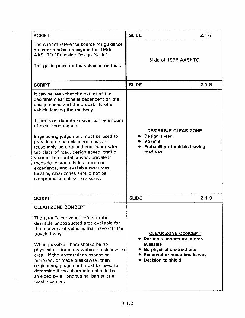
SCRIPT SLIDE 2.1-7
The current reference source for guidance on safer roadside design is the 1995 AASHTO “Roadside Design Guide”.
Slide of 1996 AASHTO The guide presents the values in metrics.
SCRIPT
It can be seen that the extent of the desirable clear zone is dependent on the design speed and the probability of a vehicle leaving the roadway.
SLIDE 2.1-8
There is no definite answer to the amount of clear zone required.
DESIRABLE CLEAR ZONE Engineering judgement must be used to provide as much clear zone as can reasonably be obtained consistent with the class of road, design speed, traffic volume, horizontal curves, prevalent roadside characteristics, accident experience, and available resources. Existing clear zones should not be compromised unless necessary.
l Design speed 0 Volume 0 Probability of vehicle leaving
roadway
SCRIPT
CLEAR ZONE CONCEPT
SLIDE 2.1-9
The term “clear zone” refers to the desirable unobstructed area available for the recovery of vehicles that have left the traveled way. CLEAR ZONE CONCEPT
l Desirable unobstructed area When possible, there should be no physical obstructions within the clear zone area. If the obstructions cannot be removed, or made breakaway, then engineering judgement must be used to determine if the obstruction should be shielded by a longitudinal barrier or a crash cushion.
available 0 No physical obstructions l Removed or made breakaway 0 Decision to shield
2.1.3
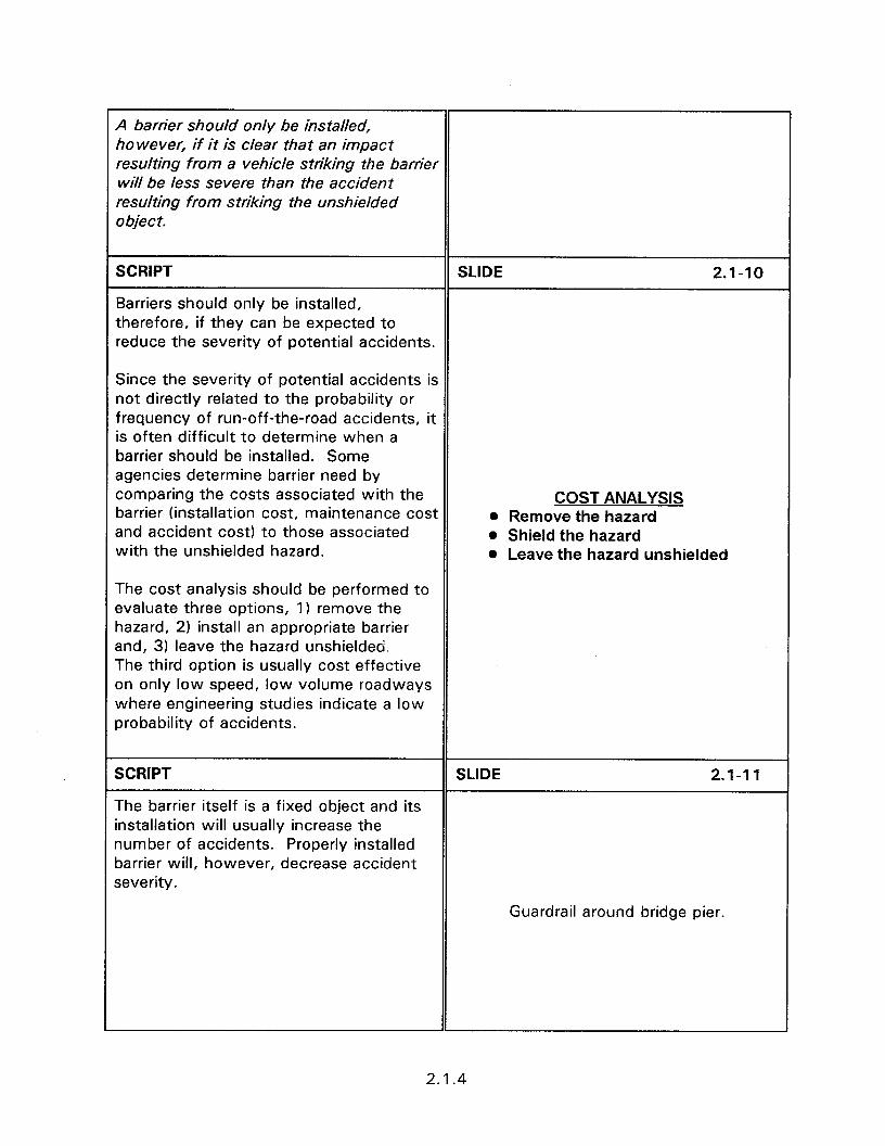
A barrier should only be installed, however, if it is clear that an impact resulting from a vehicle striking the barrier wili be less severe than the accident resulting from striking the unshielded objet t.
SCRIPT SLIDE 2.1-10
Barriers should only be installed, therefore, if they can be expected to reduce the severity of potential accidents.
Since the severity of potential accidents is not directly related to the probability or frequency of run-off-the-road accidents, it is often difficult to determine when a barrier should be installed. Some agencies determine barrier need by comparing the costs associated with the barrier (installation cost, maintenance cost and accident cost) to those associated with the unshielded hazard.
The cost analysis should be performed to evaluate three options, 1) remove the hazard, 2) install an appropriate barrier and, 3) leave the hazard unshielded The third option is usually cost effective on only low speed, low volume roadways where engineering studies indicate a low probability of accidents.
COST ANALYSIS l Remove the hazard l Shield the hazard l Leave the hazard unshielded
SCRIPT
The barrier itself is a fixed object and its installation will usually increase the number of accidents. Properly installed barrier will, however, decrease accident severity.
SLIDE 2.1-11
Guardrail around bridge pier.
2.1.4
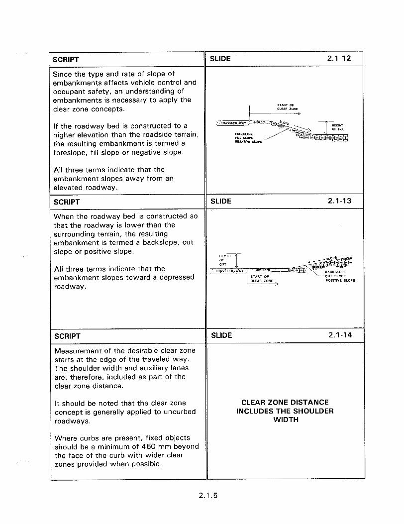
XRIPT SLIDE 2.1-12
Since the type and rate of slope of embankments affects vehicle control and occupant safety, an understanding of embankments is necessary to apply the clear zone concepts.
If the roadway bed is constructed to a ligher elevation than the roadside terrain, the resulting embankment is termed a Foreslope, fill slope or negative slope.
All three terms indicate that the smbankment slopes away from an slevated roadway.
SCRIPT SLIDE 2.1-13
When the roadway bed is constructed so that the roadway is lower than the surrounding terrain, the resulting embankment is termed a backslope, cut slope or positive slope.
All three terms indicate that the embankment slopes toward a depressed roadway.
SCRIPT
Measurement of the desirable clear zone starts at the edge of the traveled way. The shoulder width and auxiliary lanes are, therefore, included as part of the clear zone distance.
SLIDE 2.1-14
It should be noted that the clear zone CLEAR ZONE DISTANCE concept is generally applied to uncurbed INCLUDES THE SHOULDER roadways. WIDTH
Where curbs are present, fixed objects should be a minimum of 460 mm beyond the face of the curb with wider clear zones provided when possible.
2.1.5
SCRIPT
Parallel Slope Embankments
Embankments that are parallel to the traveled way are called parallel slopes.
SLIDE 2.1-15
Slide of parallel slope.
SCRIPT SLIDE 2.1-16
Parallel slopes are classified as recoverable, non-recoverable, or critical. This classification is based on the rate of slope. PARALLEL SLOPE
EMBANKMENTS l Recoverable @ Non-recoverable 0 Critical
SCRIPT SLIDE 2.1-17
Slope is a method of presenting the vertical rise and horizontal run of an embankment. llm]
A slope of I:6 indicates that there exists 6
3 rise of one unit for every six units of a) 1:6 slope
?orizontal distance.
The closer the two numbers, the more severe is the slope.
b) 1:3 slope
2.1.6
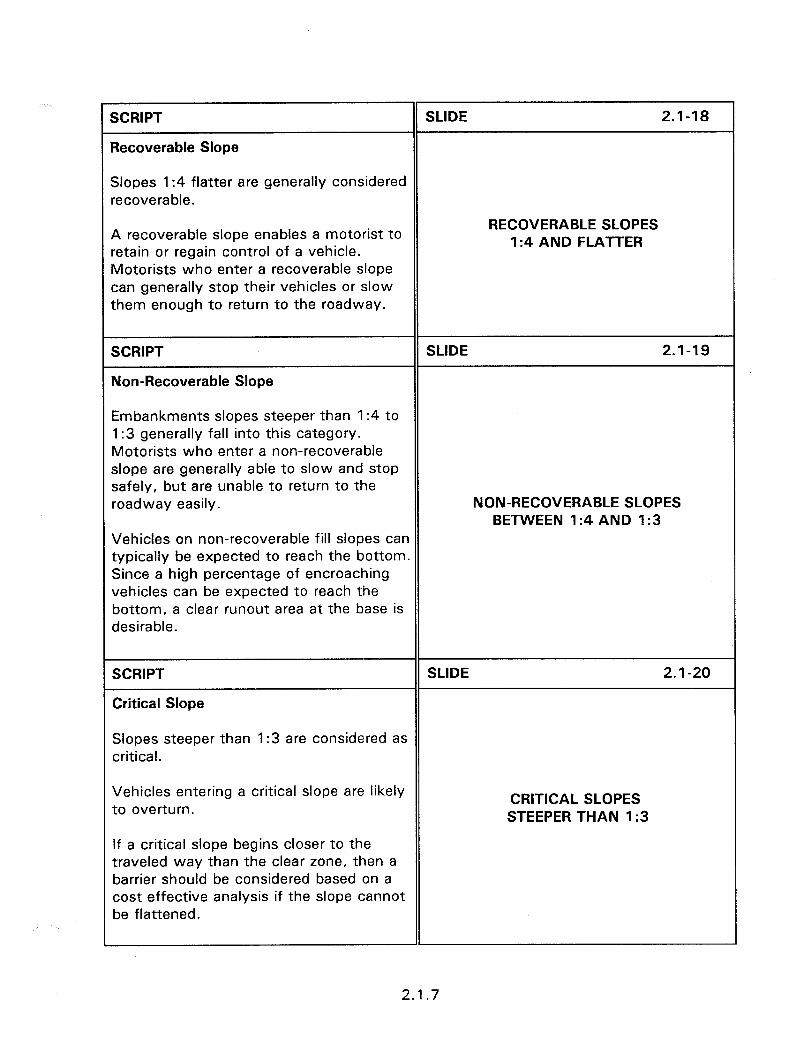
SCRIPT SLIDE 2.1-18
Recoverable Slope
Slopes 1:4 flatter are generally considered recoverable.
A recoverable slope enables a motorist to RECOVERABLE SLOPES
1:4 AND FLATTER retain or regain control of a vehicle. Motorists who enter a recoverable slope can generally stop their vehicles or slow them enough to return to the roadway.
SCRIPT SLIDE 2.1-19
Non-Recoverable Slope
Embankments slopes steeper than I:4 to 1:3 generally fall into this category. Motorists who enter a non-recoverable slope are generally able to slow and stop safely, but are unable to return to the roadway easily. NON-RECOVERABLE SLOPES
BETWEEN 1:4 AND 1:3 Vehicles on non-recoverable fill slopes can typically be expected to reach the bottom. Since a high percentage of encroaching vehicles can be expected to reach the bottom, a clear runout area at the base is desirable.
SCRIPT SLIDE 2.1-20
Critical Slope
Slopes steeper than 1:3 are considered as critical.
Vehicles entering a critical slope are likely CRITICAL SLOPES to overturn. STEEPER THAN 1:3
If a critical slope begins closer to the traveled way than the clear zone, then a barrier should be considered based on a cost effective analysis if the slope cannot be flattened.
2.1.7
SCRIPT SLIDE 2.1-21
Intersecting Embankments (Cross Slopes)
Intersecting embankments are slopes created by median crossovers, intersecting roadways or driveways. Intersecting embankments, or cross slopes, are typically struck head-on by run-off-the-road vehicles. Design can make it severe such as this
Roadside with driveway intersection with brick culvert.
SCRIPT
or more forgiving such as this.
SLIDE 2.1-22
Slide of better design.
SCRIPT
Cross slope embankments of 1:20 are desirable for that section of the
SLIDE 2.1-23
embankment immediately adjacent to traffic.
In many cases providing a 1:20 cross slope for intersecting roadways or driveways is not practical due to the limitations of width restrictions and maintenance problems associated with the long tapered ends of pipes or culverts.
INTERSECTING EMBANKMENTS (Cross Slopes)
l Desirable I:20 l High speed, high volume -
1:lO slope l Urban areas or low speed
facilities - steeper than 1: 10 slope
For intersecting roadways or driveways, a maximum intersecting slope of 1: 10 is suggested for high speed, high volume roadways.
may be considered
2.1.8
Embankment intersecting slopes steeper than 1: IO may be considered for urban areas or for low speed facilities.
SCRIPT
RECOVERABLE SLOPE CLEAR ZONE DISTANCES (Parallel Slopes)
SLIDE 2.1-24
Desirable clear zone distances for recoverable slopes of not steeper than I:3 and 1:4 or flatter may be obtained directly from the CLEAR ZONE DISTANCE provided in Table 2.1.1 or figure 2.1.6. (PAGES 2.1.7 and 2.1.8) The table is made up of ranges of ADT’s, side slopes, and clear zone distances. The designer should understand how the ranges are made up and not always use the minimum value for a location falling within the ADT and slope range. Instead, the designer should interpolate between the slopes and ADT, and select a distance from within the clear zone range.
It should be pointed out that the smallest value in the clear zone range refers to the smallest ADT and flatter slope. The largest value refers to the highest ADT and the steeper slope. It is preferred that the largest clear zone be used whenever practical.
PARALLEL SLOPE CLEAR ZONE DISTANCES
l Speed l Volume o Full and cut slope rate
2.1.9

SCRIPT
Clear Zone Distances (Parallel Slopes)
SLIDE 2.1-25
l Embankments no steeper than I:4 to I: 1 \r&
1:3 can be safely traversed by an errant $2 **‘$Q $y$:
MII‘CLC 114 c “+#
vehicle if they are free of fixed object ‘~~~5~~&, %Z
,:5 I#~ - m- .., E! 7 ‘k-
hazards. Ica kavn I:6 5c.x “PD. i
g I’,:,: - I - .A- ..,
AHSCEllr -EJ -5
l The severity of the 1:4 to I:3 slope ELEm ZWE d I FILL SLOPES l!oT” : 4 m 1.x - 1
I (non-recoverable), however, increases
FL*, I I I
the probability that vehicles will continue down to the bottom.
0 Therefore, a clear run-out area beyond the bottom of non-recoverable slopes should be provided.
l The width of the runout area can be the remainder of the desirable clear zone distance that is not part of a recoverable slope.
SCRIPT
Embankment Slopes (Parallel Slopes)
SLIDE 2.1-26
Critical slopes, slopes steeper than 1:3, and slopes of high height, can cause severe crashes.
Most States have developed cost effective criteria for addressing critical embankment slopes within the clear zone. If not then figure 2.1.8 can be used. (PAGE 2.1.11) Slide of guardrail at critical slope location. (Note: Check with the State ahead of time and pass out the State criteria.)
2.1.10
iCRlPT
IETERMINATION OF MEDIAN NEEDS
SLIDE 2.1-27
The safety needs of medians requires :onsideration to the fixed object and ,ollover potential for roadsides as well as :he potential for crashes with opposing :raffic.
Ygure 2.1.9 (PAGE 2.1.14) provides guidelines on the installation of median larriers and other mutilane divided lighways that have relatively flat, Jnobstructed medians. Barriers are typically considered for combinations of design year average daily traffic (ADT) snd median widths that fail within the ndicated area.
Slide of freeway median with barrier.
SCRIPT
Horizontal Curve Adjustment
SLIDE 2.1-28
The clear zone distance can be increased on the outside of horizontal curves. This modification is normally only necessary where there is a supporting accident history or where site inspection indicates an accident potential that could be reduced by increasing the clear zone width.
The Horizontal curve adjustment Table 2.1.2 (PAGE 2.1.12) contains adjustment factors that can be used to adjust the desirable clear zone distance on the outside of horizontal curves.
ADJUST FOR HORIZONTAL CURVES
2.1.11
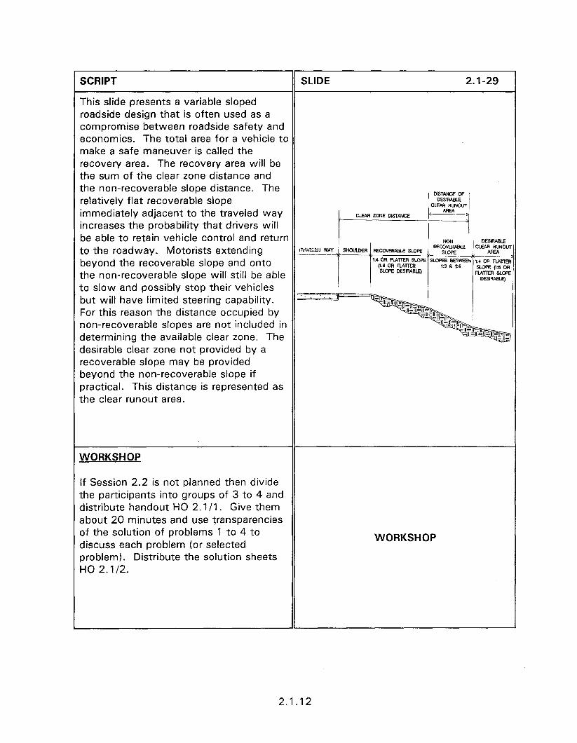
SCRIPT SLIDE 2.1-29
This slide presents a variable sloped roadside design that is often used as a compromise between roadside safety and economics. The total area for a vehicle to make a safe maneuver is called the recovery area. The recovery area will be the sum of the clear zone distance and the non-recoverable slope distance. The relatively flat recoverable slope immediately adjacent to the traveled way increases the probability that drivers will be able to retain vehicle control and return to the roadway. Motorists extending
j CLEWMNEDISTANCE !y c~~~~
zfey ., SHWLDER ,T(ECOVERABLE SU)PE , SLOPE beyond the recoverable slope and onto 1:4 OR MTIER SLCPE SLOPES SElwEN ,;4 DR )?&m
(1:tl OR Mm3 13 6 ,:a the non-recoverable slope will still be able
SLOPE MSIRAB~ SLcf?? (I:6 cm FLATTER SLCPE
to slow and possibly stop their vehicles but will have limited steering capability. ALZZ’ For this reason the distance occupied by non-recoverable slopes are not included in determining the available clear zone. The
-~~~
“’ ’ -+JE& desirable clear zone not provided by a recoverable slope may be provided beyond the non-recoverable slope if practical. This distance is represented as the clear runout area.
WORKSHOP
If Session 2.2 is not planned then divide the participants into groups of 3 to 4 and distribute handout HO 2.1/l. Give them about 20 minutes and use transparencies of the solution of problems 1 to 4 to discuss each problem (or selected problem). Distribute the solution sheets HO 2.1/2.
WORKSHOP
2.1.12
2.2 - TRAVERSABLE AND NON-TRAVERSABLE DITCHES AND BACK SLOPES
Obiectives:
l Introduce the clear zone concept for ditches and back slopes
0 Provide examples of clear zone calculations for ditches and back slopes
Helpful Hints:
l Have the participants turn to the pages of the Guide that are referenced by bold type.
0 The workshop for this session should be conducted by breaking them into groups of three or four, allowing them to work for 20 minutes, and then reviewing the workshop solutions by overhead transparencies.
Visual Aids:
If this session is conducted with session 2.1 then the workshops should be combined.
0 13 - 35 mm slides
l Transparencies
Estimated Time
0 Session 2.2 - 15 minutes
0 Workshop - 30 minutes
Handouts:
0 HO 2.2/l
HO 2.212

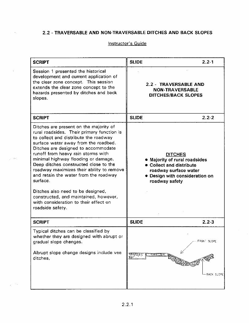
2.2 - TRAVERSABLE AND NON-TRAVERSABLE DITCHES AND BACK SLOPES
Instructor’s Guide
SCRIPT
Session 1 presented the historical development and current application of the clear zone concept. This session extends the clear zone concept to the hazards presented by ditches and back slopes.
SLIDE 2.2-l
2.2 - TRAVERSABLE AND NON-TRAVERSABLE
DITCHES/BACK SLOPES
SCRIPT SLIDE 2.2-2
Ditches are present on the majority of rural roadsides. Their primary function is to collect and distribute the roadway surface water away from the roadbed. Ditches are designed to accommodate runoff from heavy rain storms with DITCHES minimal highway flooding or damage. o Majority of rural roadsides Deep ditches constructed close to the l Collect and distribute roadway maximizes their ability to remove roadway surface water and retain the water from the roadway l Design with consideration on surface. roadway safety
Ditches also need to be designed, constructed, and maintained, however, with consideration to their effect on roadside safety.
SCRIPT SLIDE 2.2-3
Typical ditches can be classified by whether they are designed with abrupt or gradual slope changes. FRONT SLOPE
Abrupt slope change designs include vee ditches,
2.2.1
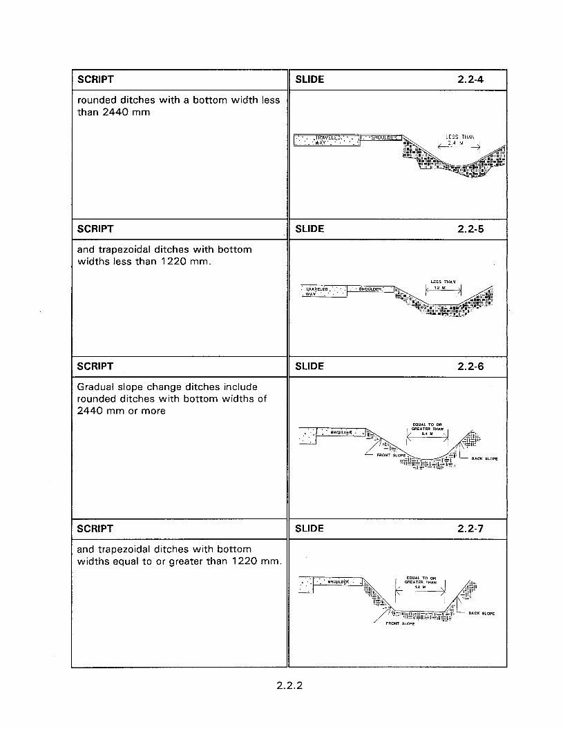
SCRIPT SLIDE 2.2-4
rounded ditches with a bottom width less than 2440 mm
SCRIPT
and trapezoidal ditches with bottom widths less than 1220 mm.
SLIDE 2.2-5
LESS TH*N ViACELiD.‘.:~ : - p;HmhDER.~ WY ‘_
SCRIPT
Gradual slope change ditches include rounded ditches with bottom widths of 2440 mm or more
SLIDE 2.2-6
SCRIPT SLIDE 2.2-7
and trapezoidal ditches with bottom widths equal to or greater than 1220 mm.
2.2.2
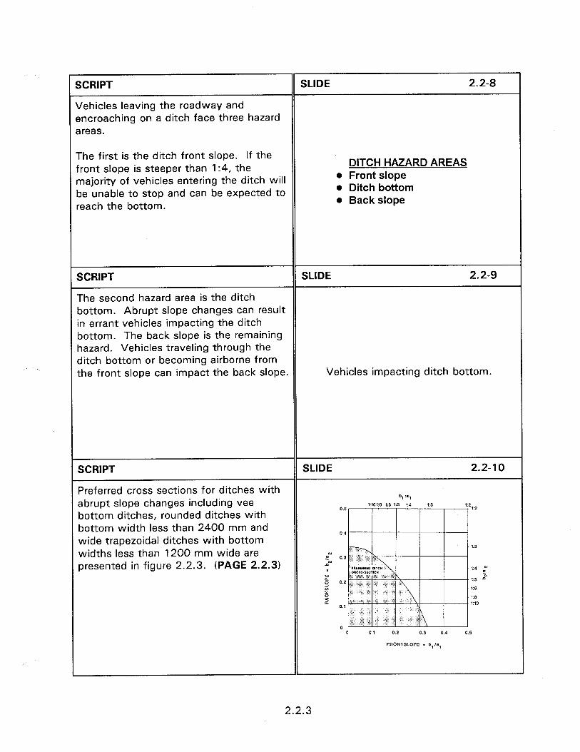
SCRIPT
Jehicles leaving the roadway and encroaching on a ditch face three hazard Ireas.
SLIDE 2.2-8
The first is the ditch front slope. If the ‘rant slope is steeper than 1:4, the najority of vehicles entering the ditch will ,e unable to stop and can be expected to *each the bottom.
DITCH HAZARD AREAS l Front slope l Ditch bottom l Back slope
SCRIPT SLIDE 2.2-9
The second hazard area is the ditch bottom. Abrupt slope changes can result in errant vehicles impacting the ditch bottom. The back slope is the remaining hazard. Vehicles traveling through the ditch bottom or becoming airborne from the front slope can impact the back slope. Vehicles impacting ditch bottom.
SCRIPT
Preferred cross sections for ditches with abrupt slope changes including vee
SLIDE 2.2-10
b, :a, ,:4
bottom ditches, rounded ditches with bottom width less than 2400 mm and wide trapezoidal ditches with bottom widths less than 1200 mm wide are presented in figure 2.2.3. (PAGE 2.2.3)
2.2.3
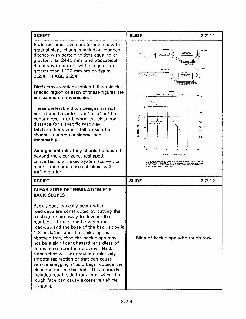
SCRIPT SLIDE 2.2-11
Preferred cross sections for ditches with gradual slope changes including rounded ditches with bottom widths equal to or greater than 2440 mm, and trapezoidal ditches with bottom widths equal to or greater than 1220 mm are on figure 2.2.4. (PAGE 2.2.4)
Ditch cross sections which fall within the shaded region of each of these figures are b, :a,
considered as traversable. *:101:8 1:6 15 ,:4 13 0.5 12 12
These preferable ditch designs are not 0.4
considered hazardous and need not be 1:s zN constructed at or beyond the clear zone 0.3 A?-
distance for a specific roadway. I ,A - 5 c 15 2
Ditch sections which fall outside the 0.2 s
:: 1:6 shaded area are considered non- : I:* traversable.
0.f 1:lO
0 As a general rule, they should be located 0 0.1 0.2 0.3 0.4 0.5
beyond the clear zone, reshaped, FRONTSLOPE - b,h(
converted to a closed system (culvert or PREFfER(IE” c*oss EECTIOUS FOR DIICrnS WT” YIADUAL DLOIE CUAWCES. wts C”ARI IO APP‘ICABLT TO ROWDEO DlTCHrs WIT” BOT,r,Y WiOT”5 oc pipe), or in some cases shielded with a
8.2 Y ns YORI. AYD TO TRAPEZOIOAL MICHES vmw BOTTOM WlDMS EOYAI TO w c?aEATW TIM” 3.1 Y traffic barrier.
SCRIPT SLIDE 2.2-l 2
CLEAR ZONE DETERMINATION FOR BACK SLOPES
Back slopes typically occur when roadways are constructed by cutting the existing terrain away to develop the roadbed. If the slope between the roadway and the base of the back slope is 1:3 or flatter, and the back slope is obstacle free, then the back slope may Slide of back slope with rough rock. not be a significant hazard regardless of its distance from the roadway. Back slopes that will not provide a relatively smooth redirection or that can cause vehicle snagging should begin outside the clear zone or be shielded. This normally includes rough sided rock cuts when the rough face can cause excessive vehicle snagging.
2.2.4

SCRIPT SLIDE 2.2-l 3
Divide the participants into groups of 3 or 4 and have them perform the workshop. The workshop problems are HO 2.2/l and the solution are HO 2.2/2.
DITCH SLOPE WORKSHOP
2.2.5

Obiectives:
l
SESSION GUIDE
2.3 - OVERVIEW OF TRAFFIC BARRIERS
To provide a basic introduction to the types of traffic barriers available for use.
Helbful Hints:
l This session defines roadside barriers, median barriers, bridge rails, and crash cushions. The amount of time required for each topic is small and each should be covered even if certain devices will not be covered in-depth during the training course.
Visual Aids:
0 36 - 35 mm slides
Estimated Time
0 30 minutes
Handouts:
l None

2.3 - OVERVIEW OF TRAFFIC BARRIERS
Instructor’s Guide
SCRIPT
OVERVIEW OF TRAFFIC BARRIERS
SLIDE 2.3-l
The “Roadside Design Guide” defines traffic barriers as devices used to prevent a vehicle from striking a more severe obstacle or feature located on the roadside or in the median, or to prevent a median crossover accident. Traffic barriers are typically classified by their primary function as follows:
2.3 - OVERVIEW OF TRAFFIC BARRIERS
SCRIPT SLIDE 2.3-2
l Roadside barrier - a longitudinal barrier used to shield roadside obstacles or non-traversable terrain features, or Slide of roadside barrier. occasionally to protect pedestrians or bystanders from vehicle traffic.
SCRIPT
l Median barrier - a longitudinal barrier used to prevent an errant vehicle from crossing the highway median.
SLIDE 2.3-3
Slide of median barrier.
SCRIPT SLIDE 2.3-4
l Bridge railing - a longitudinal barrier whose primary function is to prevent an errant vehicle from going over the side Slide of bridge railing. of the bridge structure.
SCRIPT SLIDE 2.3-5
0 Crash cushion - an impact attenuator device that prevents an errant vehicle from impacting fixed object hazards by Slide of crash cushion. gradually decelerating the vehicle to a safe stop or redirecting the vehicle away from the hazard.
2.3.1
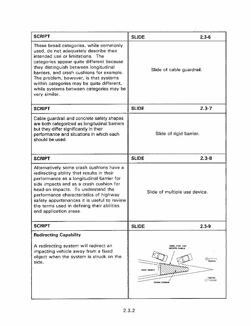
r SCRIPT SLIDE 2.3-6
These broad categories, while commonly used, do not adequately describe their intended use or limitations. The categories appear quite different because they distinguish between longitudinal barriers, and crash cushions for example. Slide of cable guardrail.
The problem, however, is that systems within categories may be quite different, while systems between categories may be very similar.
SCRIPT SLIDE 2.3-7
Cable guardrail and concrete safety shapes are both categorized as longitudinal barriers but they differ significantly in their performance and situations in which each Slide of rigid barrier. should be used.
SCRIPT SLIDE 2.3-8
Alternatively some crash cushions have a redirecting ability that results in their performance as a longitudinal barrier for side impacts and as a crash cushion for head-on impacts. To understand the performance characteristics of highway
Slide of multiple use device.
safety appurtenances it is useful to review the terms used in defining their abilities and application areas.
SCRIPT
Redirecting Capability
SLIDE 2.3-9
A redirecting system will redirect an impacting vehicle away from a fixed object when the system is struck on the side.
2.3.2

SCRIPT SLIDE 2.3-l 0
If a vehicle strikes a nonredirective system at an angle it will continue in nearly the same direction until it impacts a fixed object, another vehicle or comes to a stop. If it can redirect only one direction TRIFFK
of traffic, such as roadside, it is unidirectional. If two directions, such as median, it is bidirectional.
SCRIPT
Gating Capability
SLIDE 2.3-l 1
When a gating system is struck at an angle on the front (system nose) it allows the vehicle to pass through in the same general direction of travel.
SYSTEM LENQTH OF NEED POINT
SCRIPT SLIDE 2.3-l 2
If the safety device is nongating, it will bring the impacting vehicle to a controlled stop.
The decision to allow gating depends on whether the length-of-need has been used for the longitudinal barrier. If the length- of-need has been established then the end treatment could allow gating without being hazardous.
2.3.3
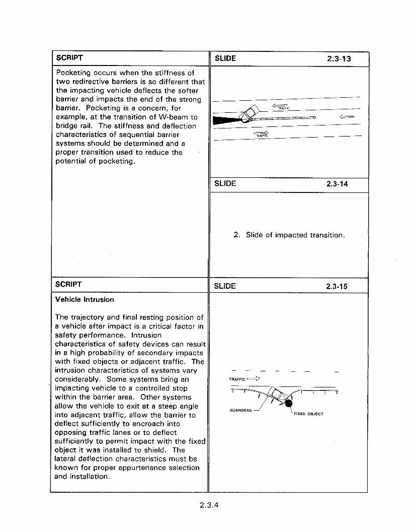
SCRIPT SLIDE 2.3-13
Pocketing occurs when the stiffness of two redirective barriers is so different that the impacting vehicle deflects the softer barrier and impacts the end of the strong -_ barrier. Pocketing is a concern, for
- example, at the transition of W-beam to bridge rail. The stiffness and deflection characteristics of sequential barrier 7iz2 systems should be determined and a proper transition used to reduce the potential of pocketing.
SLIDE 2.3-14
2. Slide of impacted transition.
SCRIPT
Vehicle Intrusion
SLIDE 2.3-l 5
The trajectory and final resting position of a vehicle after impact is a critical factor in safety performance. Intrusion characteristics of safety devices can result in a high probability of secondary impacts with fixed objects or adjacent traffic. The intrusion characteristics of systems vary considerably. Some systems bring an impacting vehicle to a controlled stop within the barrier area. Other systems allow the vehicle to exit at a steep angle into adjacent traffic, allow the barrier to deflect sufficiently to encroach into opposing traffic lanes or to deflect sufficiently to permit impact with the fixed object it was installed to shield. The lateral deflection characteristics must be known for proper appurtenance selection and installation.
TRAFFIC L1/
i * * *
FIXED OBJECT
2.3.4
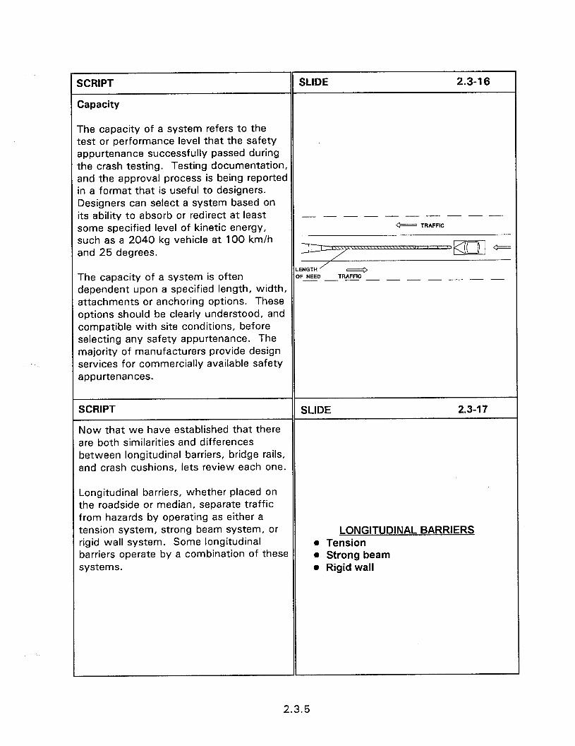
SCRIPT
Zapacity
SLIDE 2.3-l 6
The capacity of a system refers to the :est or performance level that the safety appurtenance successfully passed during [he crash testing. Testing documentation, xrd the approval process is being reported n a format that is useful to designers. Iesigners can select a system based on ts ability to absorb or redirect at least - - - - - - - - - - some specified level of kinetic energy, w TRAFFIC
such as a 2040 kg vehicle at 100 km/h snd 25 degrees.
The capacity of a system is often LENGTH’ LyI OF NEED TRAFFIC -- __--- ---
dependent upon a specified length, width, sttachments or anchoring options. These options should be clearly understood, and compatible with site conditions, before selecting any safety appurtenance. The majority of manufacturers provide design services for commercially available safety appurtenances.
SCRIPT SLIDE 2.3-l 7
Now that we have established that there are both similarities and differences between longitudinal barriers, bridge rails, and crash cushions, lets review each one.
Longitudinal barriers, whether placed on the roadside or median, separate traffic from hazards by operating as either a tension system, strong beam system, or rigid wail system. Some longitudinal barriers operate by a combination of these systems.
LONGITUDINAL BARRIERS l Tension l Strong beam l Rigid wall
2.3.5

SCRIPT SLIDE 2.3-l 8
Flexible systems resist impact through the development of tension in the rail element. As the rail is deflected laterally by the impacting vehicle, large tensile forces build up, and the lateral component of those forces redirect the vehicle. Slide of flexible force diagram. Tension anchors are required at each end of the barrier to resist the rail tension. “Flexible systems” provide the most lateral “give” on impact.
SCRIPT
Barriers in this category include cable barriers, and
SLIDE 2.3-l 9
Slide of cable barrier.
SCRIPT
Weak post W-beam.
SLIDE 2.3-20
Slide of weak post W-beam.
SCRIPT SLIDE 2.3-21
Strong beam systems are the most widely used barrier systems. They redirect vehicles primarily through beam action. Relatively strong rails act as beams to transfer impact loads to closely spaced posts, which in turn transfer the loads to the ground. Tensile forces in the rail also Slide of semi-rigid force diagram. contribute to their effectiveness to some extent and end anchors are used for many strong beam barriers. Strong beam systems undergo much less lateral impact deflection, and are frequently referred to as “semi-rigid” systems.
SCRIPT SLIDE 2.3-22
Barriers in this category include strong steel post W-beam
Slide of strong steel post W-beam.
2.3.6
SCRIPT
Strong wood posts,
SLIDE 2.3-23
Slide of strong wood post W-beam.
SCRIPT
strong post thrie-beam,
SLIDE 2.3-24
Slide of strong-post thrie-beam.
SCRIPT
and steel backed timber guardrail.
SLIDE 2.3-25
Slide of steel backed timber guardrail.
SCRIPT SLIDE 2.3-26
Rigid barriers resist impact loads by transferring impact loads directly into the ground, either with or without the use of a footing. Some of these barriers resist ,MPPiCT FORCES RESISTED B” BARRIER t&s5 IND ‘IRPIN5FER ,NTO GROUND impact through the inertial resistance of the massive barrier section, and by sliding \1 i J, \1 \1 J resistance of the barrier across the
t
roadway surface. As the name implies, barriers in this category experience little or no lateral deflection upon impact.
SCRIPT SLIDE 2.3-27
A number of different shapes are used on the traffic face of rigid barriers to absorb impact energy by partially lifting the vehicle, and to control the post-impact behavior of the vehicle. Barriers in this category include Slide of concrete safety shape. concrete safety shape and vertical concrete barriers, stone masonry walls, and various proprietary barriers.
SCRIPT
Concrete aesthetic barriers.
SLIDE 2.3-28
Slide of concrete aesthetic barrier.
2.3.7

BRIDGE RAILINGS
SCRIPT
Bridge Railings
SLIDE 2.3-29
Bridge railings are used to prevent a vehicle from running off the edge of a bridge or culvert. While roadside and median barriers transfer impact loads to the ground through posts or end anchors, bridge rails transfer impact loads to the bridge deck. Although some railings may undergo slight deflections on impact, most bridge railing are essentially rigid, and have virtually no deflection when impacted by an errant vehicle. Bridge railings are generally one of three types:
SCRIPT SLIDE 2.3-30
l Post and beam railings consist of strong beams supported by strong posts attached to the top or side of the deck. While posts and beams are most often metal or reinforced concrete, wood
Slide of post and beam railing.
posts and rails are also used.
SCRIPT SLIDE 2.3-31
l Solid parapet rigid walls generally constructed of concrete, frequently employing a concrete safety shape, are frequently used as bridge rails. Rigid metal parapets, also employing the Slide of solid parapet wall. safety shape, may be used where reduced weight on the structure is a consideration.
SCRIPT SLIDE 2.3-32
0 Combination railings consist of metal or concrete post and beams which are attached to the top of solid parapet railings to reduce weight and cost, or to Slide of combination railing. provide an open view from the bridge.
2.3.8
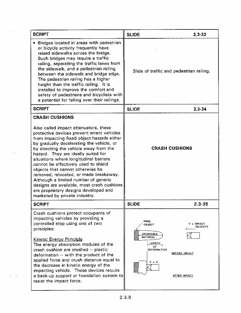
SCRIPT SLIDE 2.3-33
l Bridges located in areas with pedestrian or bicycle activity frequently have raised sidewalks across the bridge. Such bridges may require a traffic railing, separating the traffic lanes from the sidewalk, and a pedestrian railing between the sidewalk and bridge edge.
Slide of traffic and pedestrian railing.
The pedestrian railing has a higher height than the traffic railing. It is installed to improve the comfort and safety of pedestrians and bicyclists with a potential for falling over their railings.
SCRIPT SLIDE 2.3-34
CRASH CUSHIONS
Also called impact attenuators, these protective devices prevent errant vehicles from impacting fixed object hazards either by gradually decelerating the vehicle, or by directing the vehicle away from the CRASH CUSHIONS hazard. They are ideally suited for situations where longitudinal barriers cannot be effectively used to shield objects that cannot otherwise be removed, relocated, or made breakaway. Although a limited number of generic designs are available, most crash cushions are proprietary designs developed and marketed by private industry.
SCRIPT SLIDE 2.3-35
Crash cushions protect occupants of impacting vehicles by providing a controlled stop using one of two
RIGID
li
OBJECT V - IMPACT
principles: , VELOCITY
Kinetic Enerav Princiole El
The energy absorption modules of the crash cushion are crushed -- plastic ON
deformation -- with the product of the BEFORE IMPACT
applied force and crush distance equal to the decrease in kinetic energy of the impacting vehicle. These devices require a back-up support or foundation system to AFTER IMPACT
resist the impact force.
2.3.9
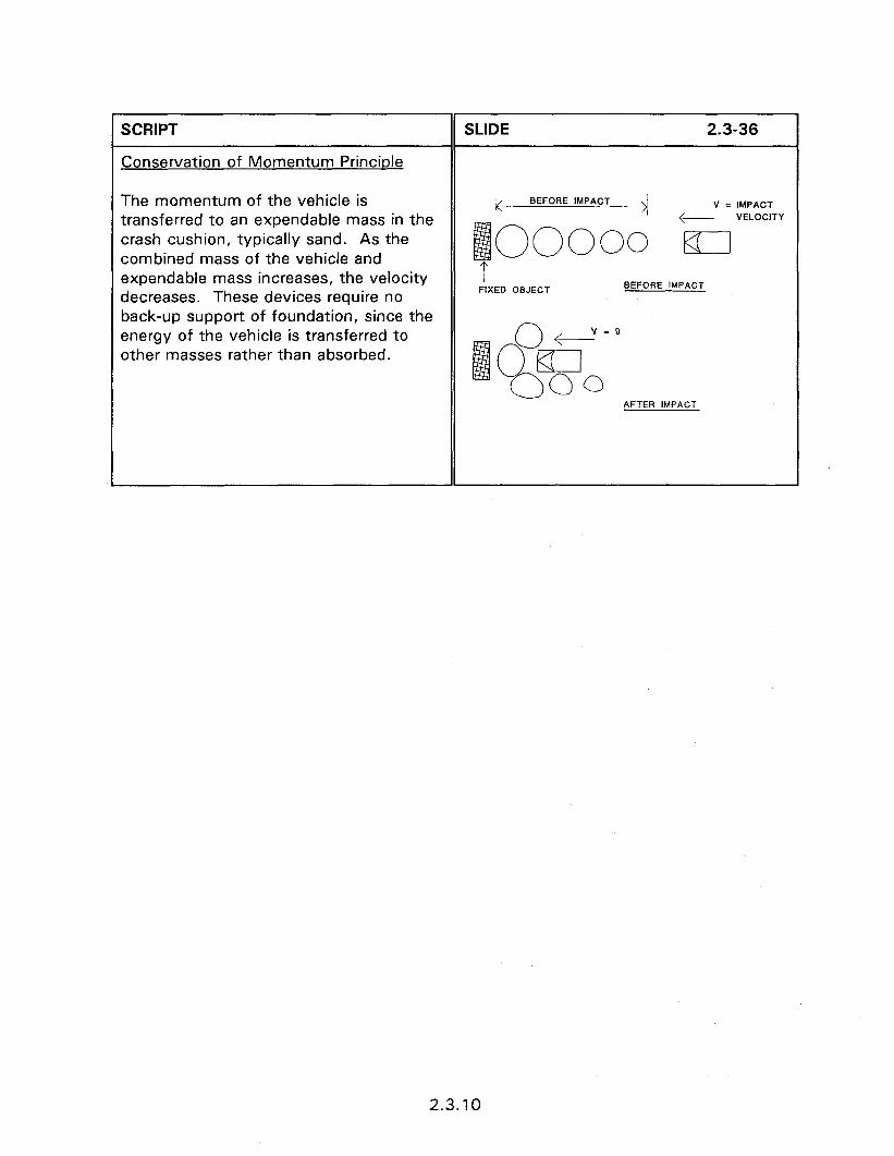
I SCRIPT
I Conservation of Momentum Principle
The momentum of the vehicle is transferred to an expendable mass in the crash cushion, typically sand. As the combined mass of the vehicle and expendable mass increases, the velocity decreases. These devices require no back-up support of foundation, since the energy of the vehicle is transferred to other masses rather than absorbed.
SLIDE 2.3-36 1
k BEI -ORE IMPACT >I V = IMPACT
boooo F ,VELOClTY
I FIXED OBJECT
BEFORE IMPACT
2.3.10

SESSION GUIDE
2.4 - PERFORMANCE REQUIREMENTS OF BARRIERS
Obiectives:
0 To develop an understanding of the performance criteria applied to traffic barriers.
Heloful Hints:
a The test levels discussed in this short session and the short session of 2.5 (Barrier Selection Guidelines) are good introductory material for the design of longitudinal barriers (Session 2.6).
Visual Aids:
0 11 - 35 mm slides
Estimated Time
l 10 minutes
Handouts:
0 None

2.4 - PERFORMANCE REQUIREMENTS OF BARRIERS
Instructor’s Guide
SCRIPT
PERFORMANCE REQUIREMENTS
SLIDE 2.4-l
Roadside barriers may be subjected to a wide range of impacts by errant vehicles, and in return, traffic barriers provide a wide range of protection to the occupants of impacting vehicles. An important 2.4 - PERFORMANCE REQUIREMENTS consideration in the selection and design OF BARRIERS of any roadside feature is to determine the level of impact severity for which it is desirable to provide protection, and to determine an appropriate level of protection to be provided by the feature.
SCRIPT SLIDE 2.4-2
Different roadways present different requirements in terms of the levels of impact severity for which it is desirable, or practical, to provide protection. Slide of nice rural roadway, few vehicles Accordingly, criteria now widely used for horizontal curve. the evaluation of roadside barriers consider a range of test levels.
SCRIPT SLIDE 2.4-3
NCHRP Report 350 “Recommended Procedures for the Safety Performance Evaluation of Highway Features”, provides testing procedures and performance requirements for barriers. These performance requirements are called test Slide of NCHRP Report 350 cover. levels and range from level 1 to level 6. (Table 2.4. I)
2.4.1
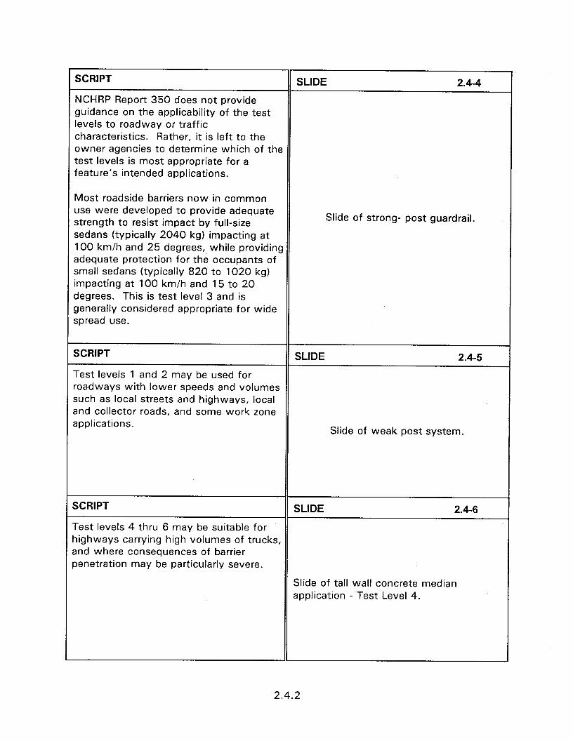
SCRIPT SLIDE 2.4-4
NCHRP Report 350 does not provide guidance on the applicability of the test levels to roadway or traffic characteristics. Rather, it is left to the owner agencies to determine which of the test levels is most appropriate for a feature’s intended applications.
Most roadside barriers now in common use were developed to provide adequate strength to resist impact by full-size sedans (typically 2040 kg) impacting at 100 km/h and 25 degrees, while providing adequate protection for the occupants of small sedans (typically 820 to 1020 kg) impacting at 100 km/h and 15 to 20 degrees. This is test level 3 and is generally considered appropriate for wide spread use.
Slide of strong- post guardrail.
SCRIPT SLIDE 2.4-5
Test levels 1 and 2 may be used for roadways with lower speeds and volumes such as local streets and highways, local and collector roads, and some work zone applications.
Slide of weak post system.
SCRIPT SLIDE 2.4-6
Test levels 4 thru 6 may be suitable for highways carrying high volumes of trucks, and where consequences of barrier penetration may be particularly severe.
Slide of tall wall concrete median application - Test Level 4.
2.4.2
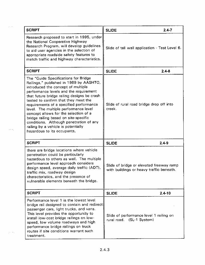
SCRIPT SLIDE 2.47
Research proposed to start in 1995, under the National Cooperative Highway Research Program, will develop guidelines to aid user agencies in the selection of
Slide of tall wall application - Test Level 6.
appropriate roadside safety features to match traffic and highway characteristics.
SCRIPT SLIDE 2.4-8
The “Guide Specifications for Bridge Railings,” published in 1989 by AASHTO, introduced the concept of multiple performance levels and the requirement that future bridge railing designs be crash tested to confirm that they meet the requirements of a specified performance Slide of rural road bridge drop off into level. The multiple performance level creek. concept allows for the selection of a bridge railing based on site-specific conditions. Although penetration of any railing by a vehicle is potentially hazardous to its occupants,
SCRIPT SLIDE 2.4-9
there are bridge locations where vehicle penetration could be particularly hazardous to others as well. The multiple performance level approach considers design speed, average daily traffic (ADT),
Slide of bridge or elevated freeway ramp
traffic mix, roadway design with buildings or heavy traffic beneath.
characteristics, and the presence of vulnerable elements beneath the bridge.
SCRIPT SLIDE 2.4-l 0
Performance level 1 is the lowest level bridge rail designed to contain and redirect passenger cars, light trucks, and vans. This level provides the opportunity to install low-cost bridge railings on low-
Slide of performance level 1 railing on
speed, low volume roadways and high rural road. (SL-1 System)
performance bridge railings on truck routes if site conditions warrant such treatment.
2.4.3
SCRIPT
Performance levels 2 and 3; the ability to contain and redirect larger vehicles, as required, is dependent upon the railings strength, effective height, and shape of the railing face. The required strength may be as high as 1.4 million Kilopascals for a 36,200 kg tractor-trailer striking the railing at 80 km/h at an angle of 15 degrees.
SLIDE 2.4-l 1
Slide of performance levels 2 and 3 bridge railings.
2.4.4
SESSION GUIDE
2.5 - BARRIER SELECTION GUIDELINES
Obiectives:
0 To identify the site specific criteria needed for proper barrier design.
Heloful Hints:
e This session and session 2.4 provides information that should be considered prior to the design of barriers.
Visual Aids:
0 12 - 35 mm slides
Estimated Time
0 10 minutes
Handouts:
l None

2.5 - BARRIER SELECTION GUIDELINES
instructor’s Guide
SCRIPT SLIDE 2.5-l
A wide variety of barriers are available to serve most roadside safety needs, and the designer is faced with selecting the individual barrier that provides the best level of protection, at the lowest overall cost, and with the fewest objectionable 2.5 - BARRIER SELECTION characteristics. GUIDELINES
Selection considerations for individual barrier systems are depended upon the operational characteristics, installation needs, and space requirements of each device.
SCRIPT SLIDE 2.5-2
Installing a barrier is really the least PREFERENCES desirable of the safety alternatives. l Eliminate hazard Preferable choices are to eliminate the l Redesign, relocate hazard, to redesign, or relocate it. l Shield
SCRIPT SLIDE 2.5-3
Benefit/Cost Analysis
While severity-based warrants call for the installation of a barrier when the consequences of a vehicle contacting the hazard are considered to be more severe than contact with the barrier, this method does not consider the likelihood that a roadside encroachment will occur, and does not consider the total costs of the shielded versus the unshielded conditions. Recent advances in the development of barrier warrants use benefit/cost analysis methodology to compare the costs and benefits of the shielded and unshielded conditions. Barrier costs associated with installation, maintenance, and accident costs are compared to similar costs for the unshielded hazard.
BENEFIT/COST ANALYSIS
2.5.1
The following are site characteristics that should be known prior to device selection. Designers may want to modify these concerns to adequately define consideration which are necessary in their area for proper appurtenance selection.
SCRIPT SLIDE 2.5-4
Hazard width and heiqht. The width, height, and type of hazard being shielded provides information necessary to determine attachment options and transition designs.
Slide of massive roadside obstacle.
For example the width of the hazard is a factor in determining the length of need for roadside barriers.
SCRIPT SLIDE 2.5-5
Hazard oroximity to traffic. The distances of the hazard from the lane line and to opposing traffic lanes are restrictions on lateral space that will influence proper system selection. There must be Slide of roadside barrier in front of sufficient clearance between the device luminaries. and traffic lane to not adversely affect driving behavior and sufficient deflection distance between the device and obstacle.
SCRIPT SLIDE 2.5-6
Available maintenance soace. If maintenance space is restricted there will be an increase in overall system safety and system maintenance costs. Restricted maintenance space exposes maintenance crews to personal safety risks, requires costly traffic controls, and
Slide of maintenance crew working on
results in traffic congestion during guardrail.
maintenance operations. There are significant differences between different appurtenance systems for both routine and post collision maintenance activities.
2.5.2

SCRIPT SLIDE 2.57
Surface conditions and anchorinq options. The anchoring options of the different systems vary considerably. It is necessary to know the soil characteristics, type of sub-base, the strength of portland cement concrete or asphaltic concrete,
Slide of crash cushions on bridge deck.
deck or no-deck application, and cross slopes for proper system selection. Knowledge of the presence and location of drainage features, expansion joints, and other surface features should be known.
SCRIPT
Probable impact speed. The probable impact speed is one operational variable that determines the required system capacity. This estimate can often be improved by consulting the local traffic engineer.
SLIDE 2.5-8
Slide of traffic.
SCRIPT SLIDE 2.59
Impact frequency. The traffic volume and site geometries, such as the outside of horizontal curves, can be used to provide an insight into the frequency of impact. For new installations this estimate can be enhanced by the experience at sites with Slide of horizontal curve guardrail with similar ADT, geometric, and speed numerous impact marks. characteristics. Estimates of impact frequency at existing sites can be obtained by inspecting accident history and conversations with the local maintenance crews.
SCRIPT SLIDE 2.5-10
Unidirectional or bidirectional traffic. The selected appurtenance must have the Slide of shoulder W-beam. capability of handling impacts probable for the site conditions. The direction of traffic in the vicinity along with other site geometries will help determine such key
Slide of median W-beam.
system requirements as unidirectional or bidirectional needs, redirection, and gating characteristics. Slide of concrete median barrier.
2.5.3

SESSION GUIDE
2.6 - DESIGN OF LONGITUDINAL BARRIERS
0 biectives:
l To provide the participants with a knowledge of the basic principles concerning the design of longitudinal barriers.
l To provide hands-on experience in the design of longitudinal barriers.
Heleful Hints:
l This session includes an introduction to the basic concepts of barrier design, a design example, and a workshop.
l Have the participants turn to the page of the text so they become familiar with the tables in the manual. The locations where they should be instructed to inspect the manual are referenced by bold highlight of the table and page in the instructor’s guide.
l The workshop should be conducted by breaking them into groups of 3 or 4 and using overheads to review the workshop answers and options.
Visual Aids:
l 38 - 35 mm slides
0 Transparencies of workshop solutions.
Estimated Time
l 45 minutes for Session 2.6.
l 60 minutes for workshop.
Handouts:
l HO 2.6/l Workshop problems
l HO 2.6/Z Workshop solutions

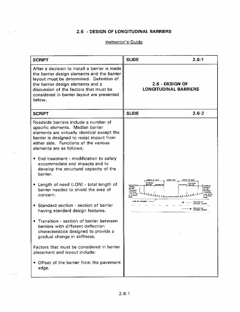
2.6 - DESIGN OF LONGITUDINAL BARRIERS
Instructor’s Guide
, .
SCRIPT SLIDE 2.6-l
After a decision to install a barrier is made the barrier design elements and the barrier layout must be determined. Definition of the barrier design elements and a 2.6 - DESIGN OF discussion of the factors that must be LONGITUDINAL BARRIERS considered in barrier layout are presented below.
SCRIPT SLIDE 2.6-2
Roadside barriers include a number of specific elements. Median barrier elements are virtually identical except the barrier is designed to resist impact from either side. Functions of the various elements are as follows:
0 End treatment - modification to safely accommodate end impacts and to develop the structural capacity of the barrier.
0 Length of need (LON) - total length of barrier needed to shield the area of concern.
l Standard section - section of barrier having standard design features.
* Transition - section of barrier between barriers with different deflection characteristics designed to provide a gradual change in stiffness.
Factors that must be considered in barrier placement and layout include:
l Offset of the barrier from the pavement edge.
2.6.1
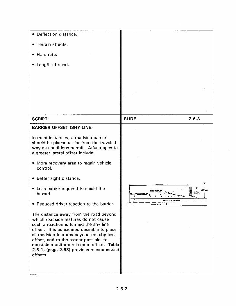
l Deflection distance.
l Terrain effects.
0 Flare rate.
l Length of need.
SCRIPT
BARRIER OFFSET (SHY LINE)
SLIDE 2.6-3
In most instances, a roadside barrier should be placed as far from the traveled way as conditions permit. Advantages to a greater lateral offset include:
l More recovery area to regain vehicle control.
l Better sight distance.
l Less barrier required to shield the hazard.
l Reduced driver reaction to the barrier.
The distance away from the road beyond which roadside features do not cause such a reaction is termed the shy line offset. It is considered desirable to place all roadside features beyond the shy line offset, and to the extent possible, to maintain a uniform minimum offset. Table 2.6.1, (page 2.63) provides recommended offsets.
2.6.2
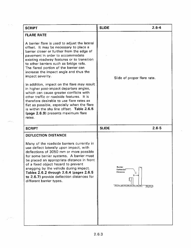
I
SCRIPT SLIDE 2.6-4
FLARE RATE
A barrier flare is used to adjust the lateral offset. It may be necessary to place a barrier closer or further from the edge of oavement in order to accommodate sxisting roadway features or to transition to other barriers such as bridge rails. The flared portion of the barrier can increase the impact angle and thus the impact severity.
In addition, impact on the flare may result in higher post-impact departure angles, which can cause greater conflicts with other traffic or roadside features. It is therefore desirable to use flare rates as flat as possible, especially when the flare is within the shy line offset. Table 2.6.5 (page 2.6.9) presents maximum flare rates.
Slide of proper flare rate.
SCRIPT
DEFLECTION DISTANCE
SLIDE 2.6-5
Many of the roadside barriers currently in use deflect laterally upon impact, with deflections of 3050 mm or more possible for some barrier systems. A barrier must be placed an appropriate distance in front of a fixed object hazard to prevent snagging by the vehicle during impact. Tables 2.6.2 through 2.6.4 (pages 2.6.5 to 2.6.7) provide deflection distances for different barrier types.
2.6.3
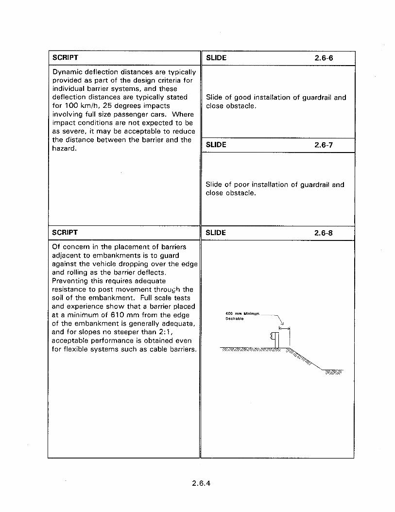
SCRIPT SLIDE 2.6-6
Dynamic deflection distances are typically provided as part of the design criteria for individual barrier systems, and these deflection distances are typically stated Slide of good installation of guardrail and for 100 km/h, 25 degrees impacts close obstacle. involving full size passenger cars. Where impact conditions are not expected to be as severe, it may be acceptable to reduce the distance between the barrier and the hazard. SLIDE 2.6-7
Slide of poor installation of guardrail and close obstacle.
SCRIPT SLIDE 2.6-8
Of concern in the placement of barriers adjacent to embankments is to guard against the vehicle dropping over the edge and rolling as the barrier deflects. Preventing this requires adequate resistance to post movement throu@ the soil of the embankment. Full scale tests and experience show that a barrier placed at a minimum of 610 mm from the edge 600 mm Mhlmum
of the embankment is generally adequate, Desirable ---\,
and for slopes no steeper than 2: 1, acceptable performance is obtained even for flexible systems such as cable barriers.
2.6.4
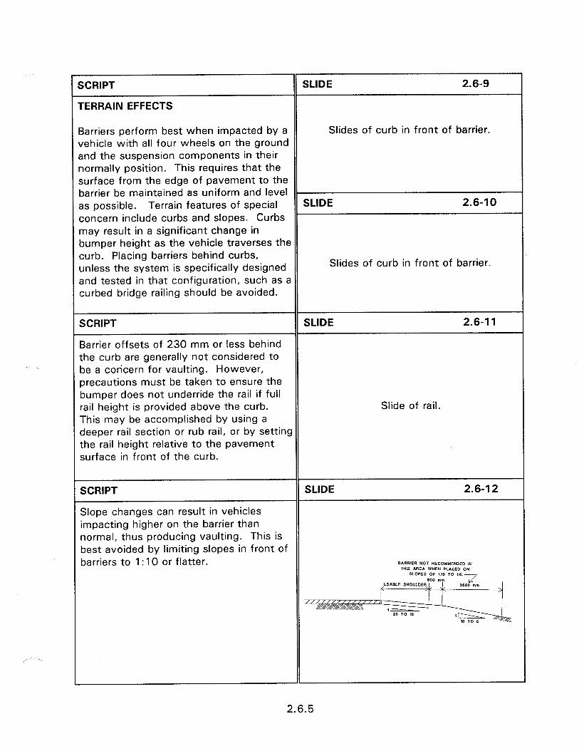
SCRIPT
rERRAlN EFFECTS
SLIDE 2.6-9
3arriers perform best when impacted by a Slides of curb in front of barrier. Jehicle with all four wheels on the ground snd the suspension components in their normally position. This requires that the surface from the edge of pavement to the barrier be maintained as uniform and level - 3s possible. Terrain features of special SLIDE 2.6-l 0 concern include curbs and slopes. Curbs may result in a significant change in bumper height as the vehicle traverses the curb. Placing barriers behind curbs, unless the system is specifically designed Slides of curb in front of barrier.
and tested in that configuration, such as a curbed bridge railing should be avoided.
SCRIPT SLIDE 2.6-l 1
Barrier offsets of 230 mm or less behind the curb are generally not considered to be a concern for vaulting. However, precautions must be taken to ensure the bumper does not underride the rail if full rail height is provided above the curb. Slide of rail. This may be accomplished by using a deeper rail section or rub rail, or by setting the rail height relative to the pavement surface in front of the curb.
SCRIPT SLIDE 2.6-l 2
Slope changes can result in vehicles impacting higher on the barrier than normal, thus producing vaulting. This is best avoided by limiting slopes in front of barriers to 1 : 10 or flatter. B*RRIER NOT RECOMMENDED IN nits AREA WHEN PLACED ON SLOPES OF ‘.I0 TO ,:e.- 600 nun “SABLE SHO”LDER J 3600 mm >
2.6.5

SCRIPT SLIDE 2.6-13
The design of barriers requires placing a sufficient length of barrier to prevent vehicles from leaving the roadway, traveling behind the rail and impacting the hazard prior to being capable of stopping. This length of barrier is called LENGTH OF NEED (LON).
LENGTH OF NEED
Total length of a longitudinal barrier needed to shield an area of concern.
SCRIPT SLIDE 2.6-14
These factors affect the LON of the barrier system. They include the lateral extent of the area of concern to be protected, the flare rate of the barrier, the location and X = Length of need. the flare is introduced, its lateral offset, and the required stopping distance for a L, = Distance from edge of traveled vehicle to avoid striking the object. way to the back of the hazard.
b/a = Barrier flare rate
L, = Tangent length of barrier upstream from the area of concern.
L = Lateral distance from the edge of the traveled way.
LR = Runout Length.
2.6.6

XRIPT
IDJACENT TRAFFIC
SLIDE 2.6-l 5
The LON for adjacent traffic is shown in igure 2.6.8. This figure shows that the -ON can be determined by scaling the larrier layout directly on the highway plan ;heet. The calculations will be covered ater with the use of an example. The ;teps in scaling the LON are as follows.
1. Determine the desirable clear zone (Lc) (table 2.1.1).
2. Select the runout length (L,) from table 2.6.6.
3. Determine the lateral distance to be protected by comparing the clear zone (Lc) and the lateral distance from the edge of traveled way to the outside edge of the hazard or area of concern (L,). Generally the smaller of Lc or L, is used.
4. Scale the runout length and the lateral distance on the drawing. The runout length is placed along the edge of the travel way and the lateral distance is scaled from, and perpendicular to, the edge of traveled way.
5. Draw a diagonal line “control line” from the traveled way and the edge of the runout length furthest from the hazard. This line simulates the vehicle runout path. To shield the hazard, the barrier must intersect this line.
6. An end treatment is added to the barrier.
2.6.7

SCRIPT
OPPOSING TRAFFIC
SLIDE 2.6-l 6
The same process is performed when opposing traffic can also impact the -. -.. - -. CLE~~~~EOIST*NCE _ _.. hazard. In this case, however, the runout length and the desirable clear zone are determined from the edge of the closest opposing traffic lane.
I -- - - - AD.MCENT TRAFFIC - OPPDSlNG TtMFFIC
SCRIPT
The trailing end is determined by the needs of opposing traffic or by assuming a 25 degree departure angle for adjacent traffic.
SLIDE 2.6-l 7
SCRIPT
The mathematical solutions are based on these two formulas. (Page 2.6.15 and 2.6.17)
SLIDE 2.6-l 8
2.6.8
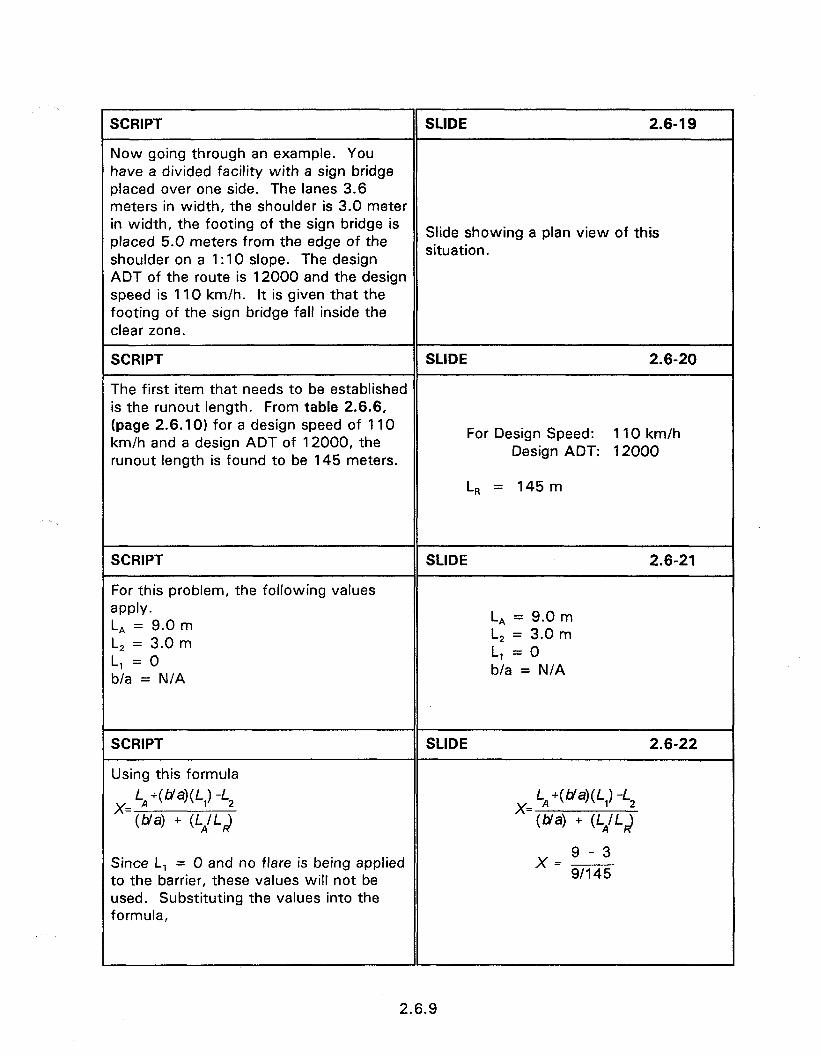
SCRIPT SLIDE 2.6-l 9
Now going through an example. You have a divided facility with a sign bridge placed over one side. The lanes 3.6 meters in width, the shoulder is 3.0 meter in width, the footing of the sign bridge is placed 5.0 meters from the edge of the
Slide showing a plan view of this
shoulder on a 1 :lO slope. The design situation.
ADT of the route is 12000 and the design speed is 110 km/h. It is given that the footing of the sign bridge fall inside the clear zone.
SCRIPT SLIDE 2.6-20
The first item that needs to be established is the runout length. From table 2.6.6, (page 2.6.101 for a design speed of 110 km/h and a design ADT of 12000, the
For Design Speed: 110 km/h
runout length is found to be 145 meters. Design ADT: 12000
L, = 145 m
SCRIPT
For this problem, the following values apply. L, = 9.0 m L, = 3.0 m L, = 0 b/a = N/A
SLIDE 2.6-21
L, = 9.0 m L, = 3.0 m L, = 0 b/a = N/A
SCRIPT
Using this formula
SLIDE 2.6-22
Since L, = 0 and no flare is being applied to the barrier, these values will not be used. Substituting the values into the formula,
x=9-3 9/l 45
2.6.9
_ ,-. -.- . . .1 .“.. ,...- . . .._.__ ._^_. __.____.
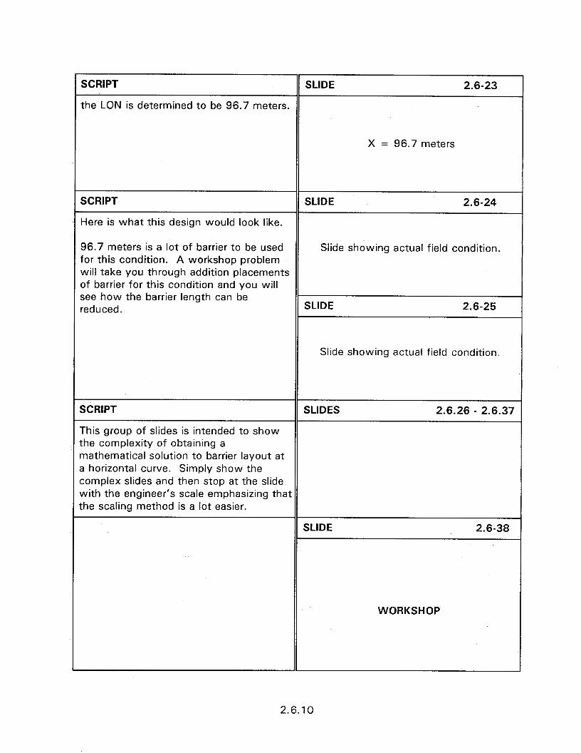
SCRIPT SLIDE 2.6-23
the LON is determined to be 96.7 meters.
X = 96.7 meters
SCRIPT
Here is what this design would look like.
SLIDE 2.6-24
96.7 meters is a lot of barrier to be used Slide showing actual field condition. for this condition. A workshop problem will take you through addition placements of barrier for this condition and you will see how the barrier length can be reduced. SLIDE 2.6-25
Slide showing actual field condition.
SCRIPT SLIDES 2.6.26 - 2.6.37
This group of slides is intended to show the complexity of obtaining a mathematical solution to barrier layout at a horizontal curve. Simply show the complex slides and then stop at the slide with the engineer’s scale emphasizing that the scaling method is a lot easier.
SLIDE 2.6-38
WORKSHOP
2.6.10
SESSION GUIDE
2.7 - DESIGN OF CRASH CUSHIONS
Obiectives:
l Present design concerns.
0 Discuss placement needs.
Helpful Hints:
l This session provides an overview of crash cushion design, specific devices are covered in the breakout section from Session 5.3.
0 Appendix B provides summary information to enable the designer to determine the structural, design, and placement characteristics of each system.
Visual Aids:
0 8 - 35 mm slides
Estimated Time
l 10 minutes
Handouts:
l None

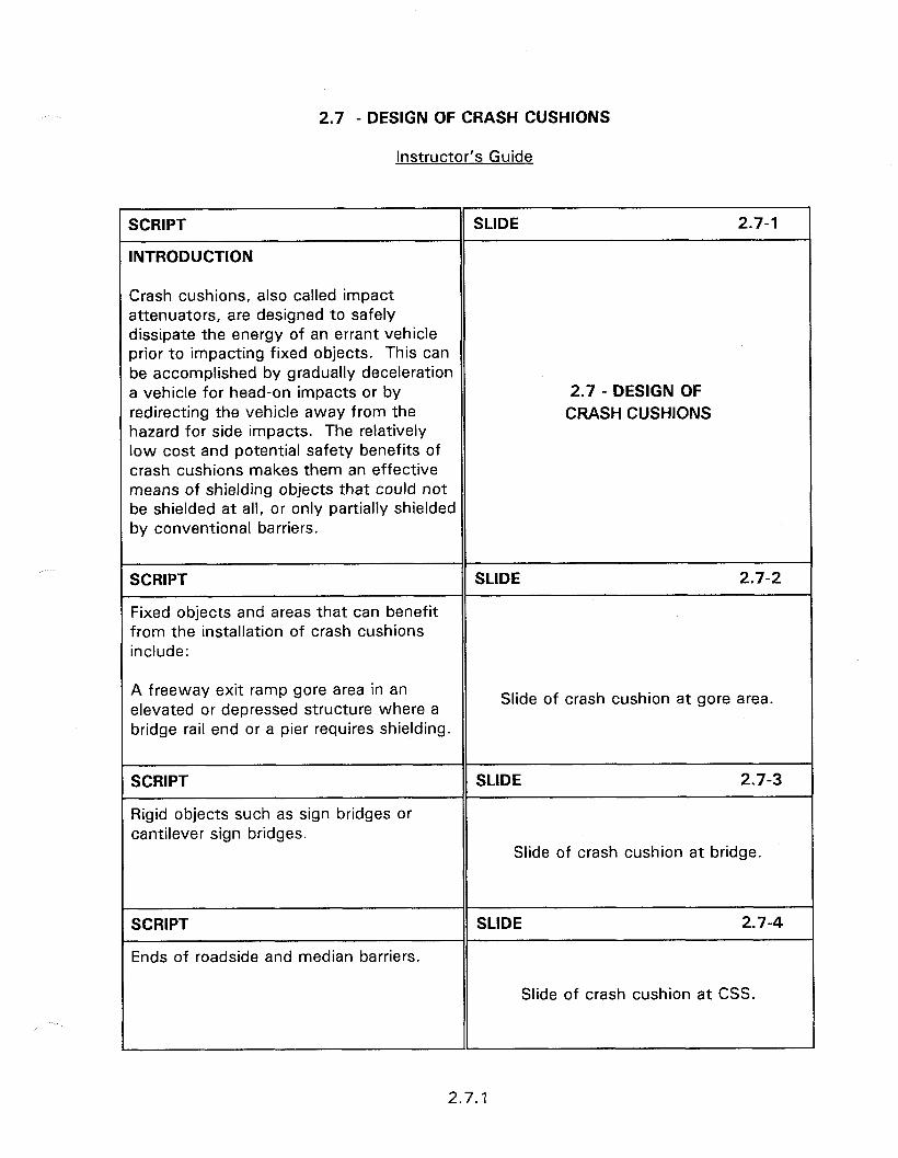
2.7 - DESIGN OF CRASH CUSHIONS
Instructor’s Guide
SCRIPT
INTRODUCTION
SLIDE 2.7-l
Crash cushions, also called impact attenuators, are designed to safely dissipate the energy of an errant vehicle orior to impacting fixed objects. This can be accomplished by gradually deceleration a vehicle for head-on impacts or by redirecting the vehicle away from the nazard for side impacts. The relatively low cost and potential safety benefits of crash cushions makes them an effective means of shielding objects that could not be shielded at all, or only partially shielded by conventional barriers.
2.7 - DESIGN OF CRASH CUSHIONS
SCRIPT
Fixed objects and areas that can benefit from the installation of crash cushions include:
SLIDE 2.7-2
A freeway exit ramp gore area in an elevated or depressed structure where a bridge rail end or a pier requires shielding.
Slide of crash cushion at gore area.
SCRIPT
Rigid objects such as sign bridges or cantilever sign bridges.
SLIDE 2.7-3
Slide of crash cushion at bridge.
SCRIPT
Ends of roadside and median barriers.
SLIDE 2.7-4
Slide of crash cushion at CSS.
2.7.1
--x ,. ._ ., - _ . _.--_ . ..-.- _.. .-- _.-.__...__.____.___I _c
SCRIPT SLIDE 2.7-5
A truck mounted attenuator can be used where a short term or a moving crash cushion would protect the work crews at
Slide of TMA.
work zones or a maintenance crew.
SCRIPT SLIDE 2.7-6
l A simple selection process for determining the most appropriate crash cushion for specific site is difficult to develop. This is due to the large number of factors which can complicate the selection process. In many instances there will be a number of crash cushions that will provide the required protection. The task of the SELECTION CONCERNS designer is to select the most l Type of hazard appropriate and cost-effective device l Site characteristics available. l Operational characteristics
Factors that need to be addressed are concerned with the type of hazard, available space for cushion placement, roadway and roadside features in the vicinity of the hazard, operational characteristics of the candidate systems,
SCRIPT SLIDE 2.7-7
Cost and maintenance requirements, and traffic characteristics. Purchase costs can vary greatly by the number of units purchased, site preparation needs, complexity of installation and area of the country. In addition, the repair and replacement costs can become significant 0 Life cycle costs over a period of time if the device is l Traffic characteristics located in an area where it is frequently l Desired performance level impacted. l Requirements are matched with
systems It is recommended that comparative costs be obtained from the manufacturers of candidate systems prior to purchase.
l State Practices
Crash cushion selection should be based on the desired performance level identified by the site characteristics.
2.7.2
After the site characteristics and desired performance levels have been identified, the parameters are matched with the individual system characteristics to select the proper system for the site. For example, crash cushions and end terminals are available with unidirectional or bidirectional and redirective or non- redirective capabilities. Table 2.7.2 provides guidelines that can be used to determine the appropriate application. As a general rule, the system should be capable of redirecting errant vehicles whenever the hazard is 3 m or closer to the traveled way. Bidirectional devices should be used when the distance to opposite direction traffic is 9 m or less or a history of opposite direction accidents has occurred.
SCRIPT SLIDE 2.7-8
Appendix B provides summary information to enable the designer to carefully evaluate the structural, design, and placement characteristics of each system.
These characteristics include design speed, redirection capability, anchorage, and backup structure requirements for crash cushions and end treatments.
l Table Bl - General characteristics of crash cushions and end terminals.
l Table B2 - Roadside applications of crush cushions and end terminals.
APPENDIX B
l Table B3 - Median applications of commercial crash cushions and end terminals.
l Table B4 - Gore applications of commercial crash cushions and end terminals.
2.7.3
l Table B5 - Comparative maintenance requirements of crash cushions and end terminals.
l Table B6 - General characteristics of truck mounted attenuators.
l Figure Bl - Site inspection worksheet from crash cushion design.
2.7.4
2.8 - DESIGN OF BRIDGE RAILS AND TRANSITIONS
Obiectives:
l
0
The performance levels, or multi-service level criteria, of crashworthy bridge rails.
The operational and design characteristics of crashworthy bridge rails.
Heloful Hints:
l Appendix C presents a summary of the testing results for the majority of bridge railings accepted for use.
l Figures 2.8.1 and 2.8.2 are located on page 2.8.13 and 2.8.14 respectively.
Visual Aids:
l 28 - 35 mm slides
l Transparencies of handouts (HO) 2.8
Estimated Time
l Session 2.8 - 25 minutes
l Workshop 2.8 - 30 minutes
Handouts:
l HO 2.8

2.8 - DESIGN OF BRIDGE RAILS AND TRANSITIONS
Instructor’s Guide
SCRIPT
INTRODUCTION
SLIDE 2.8-l
A bridge railing is a longitudinal structure installed to prevent an errant vehicle from running off the edge of a bridge or culvert.
2.8 - DESIGN OF BRIDGE RAILS AND TRANSITIONS
SCRIPT SLIDE 2.8-2
While the function of bridge rails is similar to that of a roadside longitudinal barrier, there are some important differences between bridge and roadside barriers.
l Bridge rails are usually designed to have virtually no deflection upon impact. They are normally constructed of metal on concrete post and railing system, a concrete safety shape, or a combination of metal and concrete.
Slide of concrete bridge rail.
SCRIPT SLIDE 2.8-3
l Most bridge rails are an integral part of the bridge structure. They are physically connected to the bridge deck and, in many cases, the lower portion Slide of lower portion of rail and deck. of the railing is part of the bridge structure concrete casting.
SCRIPT SLIDE 2.8-4
l As with longitudinal barriers, bridge railings are designed to protect occupants of impacting vehicles, and of other vehicles near the collision. Additionally, bridge railings are designed to protect pedestrians and/or property Slide of view below bridge.
on roadways and other areas underneath the bridge.
2.8.1
r SCRIPT
l The dead weight of the barrier system is also a design concern for bridge designers. Older structures are frequently posted with load limits that can be sensitive to the additional weight of the barrier itself.
SLIDE 2.8-5
Slide of old bridge with load limit.
SCRIPT SLIDE 2.8-6
l Available lane clearances from the face of the barrier often places a restriction on the types of bridge railing that can be installed. This is especially true in retrofit installations that require crashworthy systems.
Slide of lane clearance.
SCRIPT SLIDE 2.8-7
l Since bridges are structures carrying a roadway over a depression or obstacle, they often have safety provisions for pedestrians, in addition to vehicular traffic.
Slide of sidewalk on bridge.
SCRIPT SLIDE 2.8-8
l When the approach end of a parapet or bridge railing must have an appropriate crashworthy end treatment or crash cushion.
Slide of unprotected abutement.
2.8.2
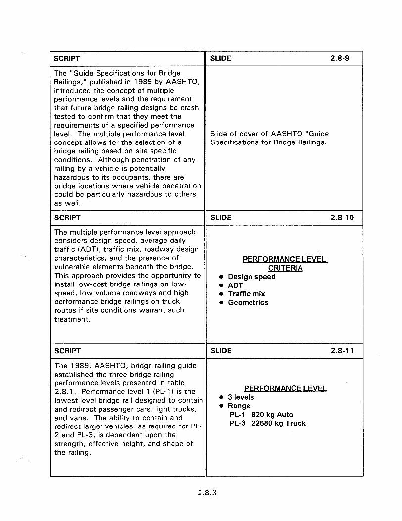
SCRIPT SLIDE 2.8-9
The “Guide Specifications for Bridge Railings,” published in 1989 by AASHTO, introduced the concept of multiple performance levels and the requirement that future bridge railing designs be crash tested to confirm that they meet the requirements of a specified performance level. The multiple performance level Slide of cover of AASHTO “Guide concept allows for the selection of a Specifications for Bridge Railings. bridge railing based on site-specific conditions. Although penetration of any railing by a vehicle is potentially hazardous to its occupants, there are bridge locations where vehicle penetration could be particularly hazardous to others as well.
SCRIPT SLIDE 2.8-l 0
The multiple performance level approach considers design speed, average daily traffic (ADT), traffic mix, roadway design characteristics, and the presence of PERFORMANCE LEVEL vulnerable elements beneath the bridge. CRITERIA This approach provides the opportunity to l Design speed install low-cost bridge railings on low- . ADT speed, low volume roadways and high l Traffic mix performance bridge railings on truck l Geometries routes if site conditions warrant such treatment.
SCRIPT SLIDE 2.8-11
The 1989, AASHTO, bridge railing guide established the three bridge railing performance levels presented in table 2.8.1. Performance level 1 (PL-1) is the PERFORMANCE LEVEL
lowest level bridge rail designed to contain 0 3 levels
and redirect passenger cars, light trucks, l Range
and vans. The ability to contain and PL-1 820 kg Auto
redirect larger vehicles, as required for PL- PL-3 22680 kg Truck
2 and PL-3, is dependent upon the strength, effective height, and shape of the railing.
2.8.3
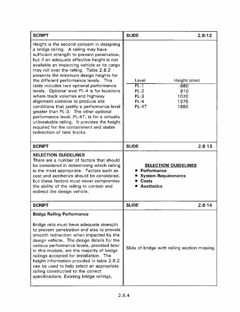
SCRIPT SLIDE 2.8-12
Height is the second concern in designing a bridge railing. A railing may have sufficient strength to prevent penetration, but if an adequate effective height is not available an impacting vehicle or its cargo may roll over the railing. Table 2.8.2 presents the minimum design heights for the different performance levels. This Level Height (mm) table includes two optional performance PL-1 680 levels. Optional level PL-4 is for locations PL-2 810 where truck volumes and highway PL-3 1070 alignment combine to produce site PL-4 1375 conditions that justify a performance level PL-4T 1980 greater than PL-3. The other optional performance level, PL-4T, is for a virtually unbreakable railing. It provides the height required for the containment and stable redirection of tank trucks
SCRIPT
SELECTION GUIDELINES
SLIDE 2.8-13
There are a number of factors that should be considered in determining which railing is the most appropriate. Factors such as cost and aesthetics should be considered, but these factors must never compromise the ability of the railing to contain and redirect the design vehicle.
SELECTION GUIDELINES l Performance l System Requirements . costs l Aesthetics
SCRIPT
Bridge Railing Performance
SLIDE 2.8-14
Bridge rails must have adequate strength to prevent penetration and also to provide smooth redirection when impacted by the design vehicle. The design details for the various performance levels, provided later in this module, are the majority of bridge
Slide of bridge with railing section missing.
railings accepted for installation. The height information provided in table 2.8.2 can be used to help select an appropriate railing constructed to the correct specifications. Existing bridge railings,
2.8.4
r especially those constructed prior to 1964, may not meet current performance levels. Identification of substandard bridge rails, guardrail transitions to bridge rails, and available retrofit enhancements, are presented in section 6.
SCRIPT SLIDE 2.8-I 5
Environmental performance is always a concern in most geographical areas. Solid rail designs, such as concrete safety shapes or parapet walls, can result in the accumulation of sand and snow. The solid rails prevent the sand and snow from blowing off the bridge deck as it would Slide of solid concrete rail. through a support post railing system. The solid rails can also result in snow plowing and surface drainage problems which compound icing conditions and potential hydroplaning.
SCRIPT
System Requirements
SLIDE 2.8-l 6
Bridge railings must be considered within the system of longitudinal barriers. When the approach roadside barrier differs in strength, height, and deflection characteristics from the bridge railing,
Slide of longitudinal barrier up to bridge.
then a crashworthy transition section is required. Crashworthy transition sections are discussed later in this module.
SCRIPT
Costs
SLIDE 2.8-l 7
The initial construction, long term maintenance, and property damage costs resulting from impacts with the railing system all require consideration.
COSTS 0 Construction l Maintenance l Accident
2.8.5

SCRIPT SLIDE 2.8-l 8
As a general rule the initial cost of a system increases as the performance level increases. The increased rigidity and strength of a high performance system demands railing to bridge deck anchorage requirements that can significantly Slide of high performance rail. increase installation costs. In addition, high performance railings can add considerable dead load to the bridge, especially on long spans.
SCRIPT SLIDE 2.8-19
Conversely, long term maintenance costs decrease as the performance level increases. Some high performance railings are essentially maintenance free unless impacted by a heavy vehicle. For overall cost considerations, lower performance level railings should be standardized within each roadway agency. This reduces the amount of replacement
Slide of low performance rail.
parts that need to be stocked for maintenance repairs. Another maintenance concern is the probability of damage to the bridge deck upon impact. Railings that eliminate or minimize bridge deck damage reduce maintenance costs.
SCRIPT SLIDE 2.8-20
Accident costs include those associated with occupant injury and vehicle damage. Generally, the higher the performance level, the greater the property damage to impacting vehicles. The rigidity and associated deformation characteristics of a railing has a significant affect on its overall performance. A railing that allows Slide of damaged rail. deflection absorbs some of the impact energy, results in a smoother redirection, and imparts a smaller roll angle than a rigid railing.
2.8.6

SCRIPT
Aesthetics
SLIDE 2.8-21
Along scenic routes and park roadways the appearance of bridge railings is often considered as important. The importance of aesthetics, however, should never be greater than functional performance. Section 4.6 provides information on crashworthy aesthetic barriers.
Slide of aesthetic bridge rail.
SCRIPT
Appendix C and table 2.8.3 provide a listing of crashworthy bridge rails and performance levels.
SLIDE 2.8-22
APPENDIX C
SCRIPT SLIDE 2.8-23
LENGTH OF NEED FOR PL-2 AND HIGHER BRIDGE RAILINGS
The length of need beyond the bridge for performance level 2, or greater, bridge railings is determined in the same way as L- .I_ Lw.sm the length of need for roadside barriers. 1 The extension of the higher performance rails is used because the rail is specifically - KM:- - - - - -.Z--- - - -, - intended to contain large trucks. These - , trucks can depart the roadway in advance of the bridge as well as at the bridge. If the rail is on the outside of a horizontal curve then its length should be based on the barrier length of need or the tangent runout path, whichever is less. The bridge rail should extend in advance of the structure, for both adjacent and opposing traffic on two way roadways for the necessary length of need distance or the tangent runout path; whichever is less.
1
2.8.7
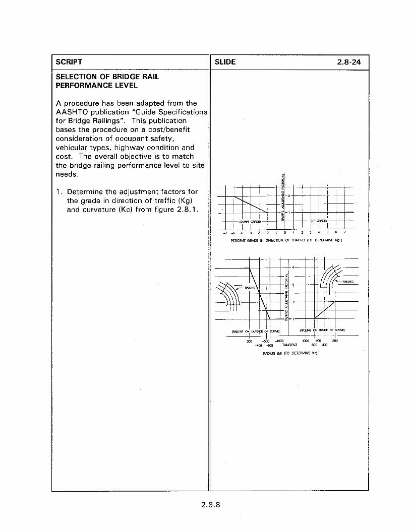
SCRIPT
SELECTION OF BRIDGE RAIL PERFORMANCE LEVEL
A procedure has been adapted from the AASHTO publication “Guide Specifications for Bridge Railings”. This publication bases the procedure on a cost/benefit consideration of occupant safety, vehicular types, highway condition and cost. The overall objective is to match the bridge railing performance level to site needs.
1 Determine the adjustment factors for the grade in direction of traffic (Kg) and curvature (Kc) from figure 2.8.1.
SLIDE 2.8-24
PERCENT GRADE IN DlREOTlON OF TRAFFIC (r0 DETERMINE Q )
2.8.8
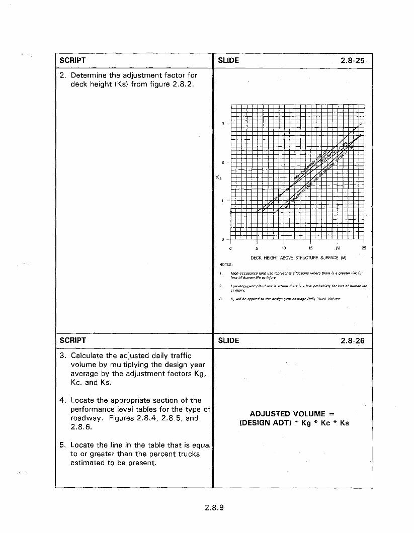
r SCRIPT
2. Determine the adjustment factor for deck height (KS) from figure 2.8.2.
SLIDE 2.8-25
KS
1
SCRIPT SLIDE 2.8-26
3. Calculate the adjusted daily traffic volume by multiplying the design year average by the adjustment factors Kg, Kc. and KS.
4. Locate the appropriate section of the performance level tables for the type of roadway. Figures 2.8.4, 2.8.5, and 2.8.6.
5. Locate the line in the table that is equal to or greater than the percent trucks estimated to be present.
ADJUSTED VOLUME = (DESIGN ADT) * Kg * Kc * KS
1
2.8.9
6. If the adjusted volume is within the range of the table then a PL-2 rail is warranted. If the adjusted volume exceeds the table volume then a PL-3 rail is warranted. If the adjusted volume is less than the table volumes then a PI-1 can be installed.
Tables 2.8.4 to 2.8.6 and figures 2.8.1 and 2.8.2 are from the AASHTO bridge railing guide. The tables and figures have been converted from AASHTO’s original format into metric units. In addition, the tables have been reduced to only include a limited range of truck mix percentages and design speeds. The AASHTO guide should be used to determine the bridge railing level warranted for truck mix percentages and design speeds not represented in tables 2.8.4 through 2.8.6.
SCRIPT SLIDE 2.8-27
. The AASHTO “Guide Specifications for Bridge Rails” provides criteria for determining the different Performance Levels for bridge rails. Selecting the most appropriate railing requires consideration of the traffic mix, ADT, speed, and roadway geometries. PL-1 is the lowest level (autos) PL-3 the
CONCLUSIONS
highest (single unit trucks) with special 0 Performance levels
PL-4 levels for large trucks. High l Use approved railings
performance levels have a higher initial 0 Substandard railings
cost, less maintenance cost, higher l Transitions
potential accident severity and more dead weight.
l Only bridge railings approved for use by FHWA should be installed.
SCRIPT SLIDE 2.8-28
Break the participants into groups of 4 or 5 and distribute the workshop.
BRIDGE RAIL WORKSHOP
2.8.10

2.9 - DESIGN OF TRAVERSABLE AND NONTRAVERSABLE DRAINAGE FEATURES
Obiectives:
0 identify how drainage features can affect vehicle control and stability.
l Recognize the requirements for designing safe median, cross and parallel drainage structures.
Helnful Hints:
l This session has numerous examples of drainage features and ends with a workshop. The workshop is a series of good and bad practice slides. These slides can be replaced or supplemented with local area slides.
l During the workshop prompt the participants to discuss each slide discussing what is good and what is improper.
Visual Aids:
l 53 - 35 mm slides in Session 2.9.
0 Variable number of workshop slides.
Estimated Time
l 60 minutes
Handouts:
None

2.9 - DESIGN OF TRAVERSABLE AND NONTRAVERSABLE DRAINAGE FEATURES
Instructor’s Guide
SCRIPT SLIDE 2.9-l
It has been shown that the greatest safety is achieved on an obstacle free, almost level roadside. If this obstacle free area could be extended for large distances, then the majority of vehicles that leave the roadway would be able to safely stop and return to the roadway.
While this may be an ideal situation, it is not realistic. Constraints in available right- of-way, roadside terrain features, natural obstacles and man made obstacles require compromises. This compromise is between absolute safety and engineering needs.
2.9 - DESIGN OF TRAVERSABLE AND NONTRAVERSABLE DRAINAGE
FEATURES
SCRIPT SLIDE 2.9-2
One engineering need, that itself has a direct impact on safety, is providing adequate drainage. Roadways are constructed as crowned, rotated or superelevated sections to remove water from the road surface. Adequate drainage facilities are required to channel this water away from the roadway to prevent damage to the road bed and surface ponding.
In addition to hydraulic concerns drainage features must be designed with proper consideration to their consequences on roadside safety.
Slide of roadway with ditch section.
2.9.1
SCRIPT SLIDE 2.9-3
The desirable clear zone distances obtained from Clear Zone table are intended as general guidelines, not absolute values.
Consideration to the magnitude of the hazard, potential of vehicle impact and proximity of other fixed objects should be performed.
CLEAR ZONE As with many engineering applications, the appropriate countermeasure at a specific location depends on the exercise of good engineering judgement and assessment of the associated costs and benefits.
0 Guidelines 0 Accident potential 0 Proximity of other hazards 0 Costs and benefits
SCRIPT SLIDE 2.9-4
It is common for drainage features such as culvert ends and headwalls to interrupt otherwise traversable roadside clear zones and medians. If left untreated, vehicle impacts on these features may be Slide of untreated culvert headwall. extremely severe, resulting in violent rollovers or abrupt stops.
SLIDE 2.9-5
Slide of damaged truck.
2.9.2
SCRIPT SLIDE 2.9-6
This section addresses the safety problems associated with curbs, pipes and culverts, headwalls and drop inlets. Provides recommendations on the location and design of these features that can increase their safety performance without decreasing their hydraulic performance. In general the following alternatives, listed in order of preference, are applicable to all drainage features.
DRAINAGE FEATURE l Eliminate any drainage structures that
are not necessary. ALTERNATIVES
0 Eliminate l Redesign or modify
l Design or modify drainage features so that they minimize the hazard to an errant vehicle.
l Shield
l If a necessary drainage feature cannot be designed safely or relocated, then it should be shielded by a suitable traffic barrier if it presents a hazard to vehicles.
SCRIPT SLIDE 2.9-7
Shielding by the use of longitudinal barriers and crash cushions should only be performed when the hazard posed by the barrier or cushion is less than that posed by the unshielded obstacle.
Barriers and crash cushions are located closer to the traveled way, extend over a greater length or occupy more area and reduce the available recovery area than Slide of barrier shielding a fixed object. just the obstacle alone. The use of longitudinal barriers and crash cushions can, therefore, be expected to increase the number of accidents experienced at a specific location. The use of properly designed barriers can, however, reduce the severity of accidents.
2.9.3
SCRIPT
CURBS
9 Curbs are often believed to have the sole purpose of separating the roadway from the roadside.
Curbs are also installed to reduce maintenance operations, provide pavement edge support and to assist in drainage control.
While curbs are frequently used on all types of urban roadways, their use of rural roadways should be exercised with caution.
Slide of curbs on low speed roadway.
Curbs should not be used on rural, high speed, roadways when the same objective for their installation can be obtained by another method. If they are, they should be removed when their use is no longer needed.
SCRIPT SLIDE 2.9-9
Curbs are classified into the general categories of barrier or mountable curbs. Each category has numerous types and design details. Both barrier and mountable curb designs are frequently provided with a gutter section to form the principal drainage system for the roadway.
Drainage inlets provided in the gutter or curb, and designed at the proper size and spacing, can keep the spread of water on the traveled way within tolerable limits. Improperly designed drainage facilities on curbed roadways can result in vehicles hydroplaning on the roadway surface water.
CURB TYPES 0 Barrier curbs * Mountable curbs
2.9.4

SCRIPT
Barrier curbs are relatively high and steep faced and are intended to inhibit vehicles from leaving the roadway.
SLIDE 2.9-10
Slide of barrier curb. Barrier curbs are usually 150 mm to 230 mm high with the top offset from the roadway by 25 mm to 76 mm.
SCRIPT SLIDE 2.9-l 1
Mountable curbs are designed so that vehicles can easily cross them. Mountable curbs designed with 1:2 or flatter ratios should have a height limit of 150 mm to prevent snagging of the vehicle Slide showing mountable curb. undercarriage. When the face slope is 1: 1, the height of mountable curbs should not exceed 100 mm.
SCRIPT
In general neither barrier nor mountable curbs should be used on roadways where design speeds exceed 65 km/h. When impacted at high speeds, curbs do not prevent a vehicle from leaving the roadway.
SLIDE 2.9-l 2
CURBS
Curbs can cause vehicle rollover if impacted while the vehicle is spinning or slipping sideways.
l Do not prevent vehicle leaving roadway
l Can cause loss of control l Can cause rollover
Under other impact conditions, vehicles can become airborne after striking a curb. This not only results in loss of control, but can become critical if secondary impacts occur with traffic barriers or other roadside appurtenances.
l Can cause vaulting
SCRIPT SLIDE 2.9-l 3
Curbs are not desirable, therefore, in front of traffic barriers on roadways with design speeds over 65 km/h since they can result in unpredictable post impact trajectories. Slide of guardrail and curb. If a curb must be used, it should be placed flush with the face of the barrier or behind it and not higher than 100 mm.
2.9.5
SCRIPT SLIDE 2.9-14
ON-ROADWAY DRAINAGE INLETS
On-roadway drainage inlets are usually located near or on the curb or shoulder of a roadway. They are designed to remove
ON-ROADWAY INLETS
the runoff from the road surface. l Grated inlets l Curb opening inlets
On-roadway inlets include grated inlets, curb opening inlets, slotted drain lets or a combination of these basic designs.
l Slotted drain lets l Combination
SCRIPT
Proper design of on-road inlets requires: That they pose no hazard to errant motorists.
SLIDE 2.9-l 5
This is usually not a problem since they are installed either flush with the roadway surface
Slide of surface grate inlet.
SCRIPT
or into the curb face.
SLIDE 2.9-l 6
Slide of curb opening inlet.
SCRIPT SLIDE 2.9-l 7
A poor inlet design presents a hazard to motorists that can result in loss of vehicle control, vehicle vaulting and damage to vehicle steering mechanisms. Slide of unacceptable inlet design.
2.9.6
SCRIPT SLIDE 2.9-18
Surface inlets must be capable of supporting vehicle wheel loads and present no obstacle to pedestrian and bicycle traffic.
Grate size and design are usually standardized by each State. The proper selection of those standard sizes is dependent upon cost, safety for passing traffic, hydraulic efficiency, structural strength and debris retention.
Spacings as small as 20 mm between parallel grate bars can trap bicycle tires. Transverse spacers or bars should be used for all roadway surface grates so that they are bicycle safe.
SURFACE INLETS l Support vehicle weight l Proper hydraulic design l Bicycle safety
There are trade offs involved in the loss of hydraulic efficiency versus increase in safety. Hydraulic engineers should evaluate the hydraulic design needs considering the amount of flow, expected debris and grate inlet performance.
SCRIPT
OFF-ROAD DROP INLETS
SLIDE 2.9-l 9
OFF ROAD DROP Off-road drop inlets are designed to collect INLETS runoff and are often located in the median of divided roadways and in roadside ditches. SLIDE 2.9-20
4 - Slides of good drop inlets.
SCRIPT SLIDE 2.9-21
Their hazard to errant motorists can be minimized, and their hydraulic efficiency maximized by constructing them flush with the ditch bottom or slope on which they Slide of improper design
are located.
2.9.7
SCRIPT SLIDE 2.9-22
The opening should be treated to prevent a vehicle wheel from dropping into it but, unless pedestrians are a concern, the Slide of good off road drainage design. openings do not need to be as small as required for on-pavement grates.
SCRIPT SLIDE 2.9-23
CROSS DRAINAGE FEATURES
Cross drainage structures are designed to CROSS DRAINAGE carry water underneath and perpendicular FEATURES to the roadway.
SCRIPT SLIDE 2.9-24
They can vary in size from 460 mm concrete or corrugated metal pipes to large shapes 3 or more meters in diameter.
Slide of cross drainage structure with To reduce erosion problems, the inlets and headwall. outlets consist of concrete headwalls and wingwalls for the larger sections
SCRIPT SLIDE 2.9-25
Cross drainage structures can pose a hazard to errant motorists due to the design of the headwall or wingwall and due to the drainage opening itself.
Headwalls and wingwalls often result in concrete extending above surface level. Errant vehicles can become snagged on the CROSS DRAINAGE exposed concrete or drop into the opening SAFETY OPTIONS causing an abrupt stop. 0 Install traversable design
The alternatives that can be taken to 0 Move drainage structure l Shielding
minimize these hazards include.
l Installing a traversable design.
l Moving the drainage structure away from the traveled way.
l Shielding the structure.
2.9.8
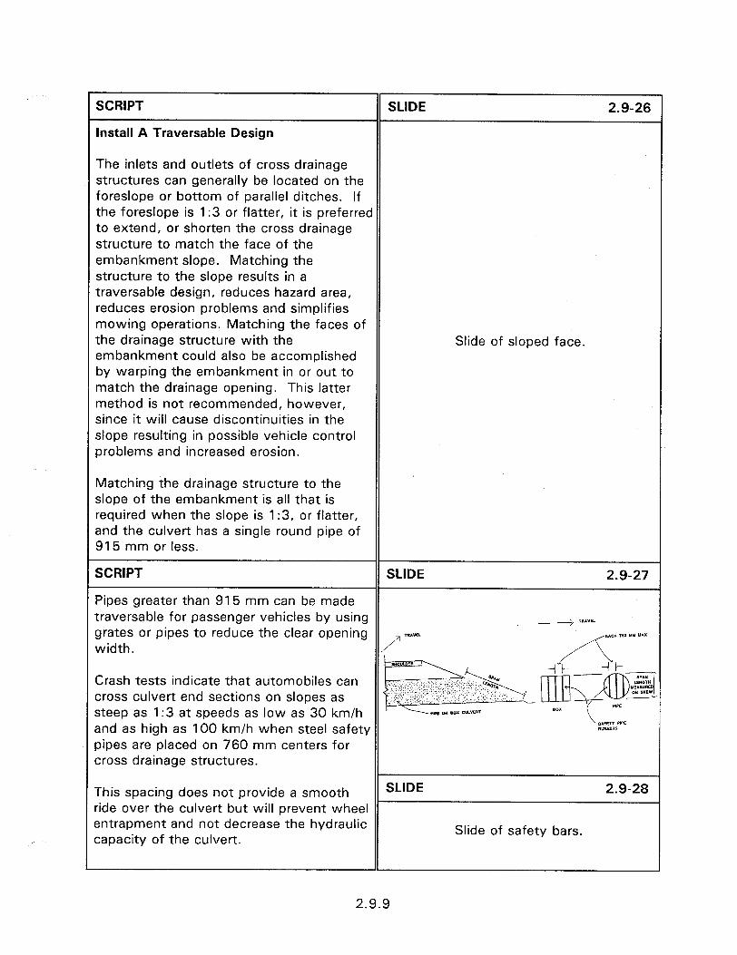
SCRIPT
Install A Traversable Design
SLIDE 2.9-26
The inlets and outlets of cross drainage structures can generally be located on the foreslope or bottom of parallel ditches. If the foreslope is 1 :3 or flatter, it is preferred to extend, or shorten the cross drainage structure to match the face of the embankment slope. Matching the structure to the slope results in a traversable design, reduces hazard area, reduces erosion problems and simplifies mowing operations. Matching the faces of the drainage structure with the embankment could also be accomplished by warping the embankment in or out to match the drainage opening. This latter method is not recommended, however, since it will cause discontinuities in the slope resulting in possible vehicle control problems and increased erosion.
Slide of sloped face.
Matching the drainage structure to the slope of the embankment is all that is required when the slope is 1:3, or flatter, and the culvert has a single round pipe of 915 mm or less.
SCRIPT SLIDE 2.9-27
Pipes greater than 915 mm can be made traversable for passenger vehicles by using __3 TRAYEL grates or pipes to reduce the clear opening SAC” ISI Y” “AX width.
Crash tests indicate that automobiles can cross culvert end sections on slopes as steep as 1:3 at speeds as low as 30 km/h and as high as 100 km/h when steel safety pipes are placed on 760 mm centers for cross drainage structures.
This spacing does not provide a smooth SLIDE 2.9-28 ride over the culvert but will prevent wheel entrapment and not decrease the hydraulic capacity of the culvert.
Slide of safety bars.
2.9.9
r SCRIPT SLIDE 2.9-29
The safety pipes for cross drainage structures should run from top to bottom of the drainage structure. This will orientate the safety pipes so that an errant vehicle, traveling parallel to the roadway, will have its wheel travel from pipe to pipe and not fall between adjacent safety pipes. Stainless steel or galvanized 16 mm Slide of cross drainage with 3 pipes. “Molly” parabolts, or other approved fastening device, should be used if the safety pipes are directly connected to the concrete of the paved slope headwall. For the grated culvert opening to have a significant safety benefit the ditch bottom must be a “abrupt slope change ditch design” or “gradual slope change ditch SLIDE 2.9-30
design.”
The flow capacity can be adversely affected, however, if debris accumulates and causes partial clogging of the inlet. It is important that proper maintenance be performed to keep the inlets free of debris.
Slide of cross drainage with several pipes.
SCRIPT SLIDE 2.9-31
Cross drainage structures through medians can often be made continuous by adding a median drainage inlet.
This is a good alternative at narrow, shallow medians since it can increase the hydraulic efficiency while simultaneously eliminating two end treatments.
Slide showing cross drainage structure in a median.
2.9.10
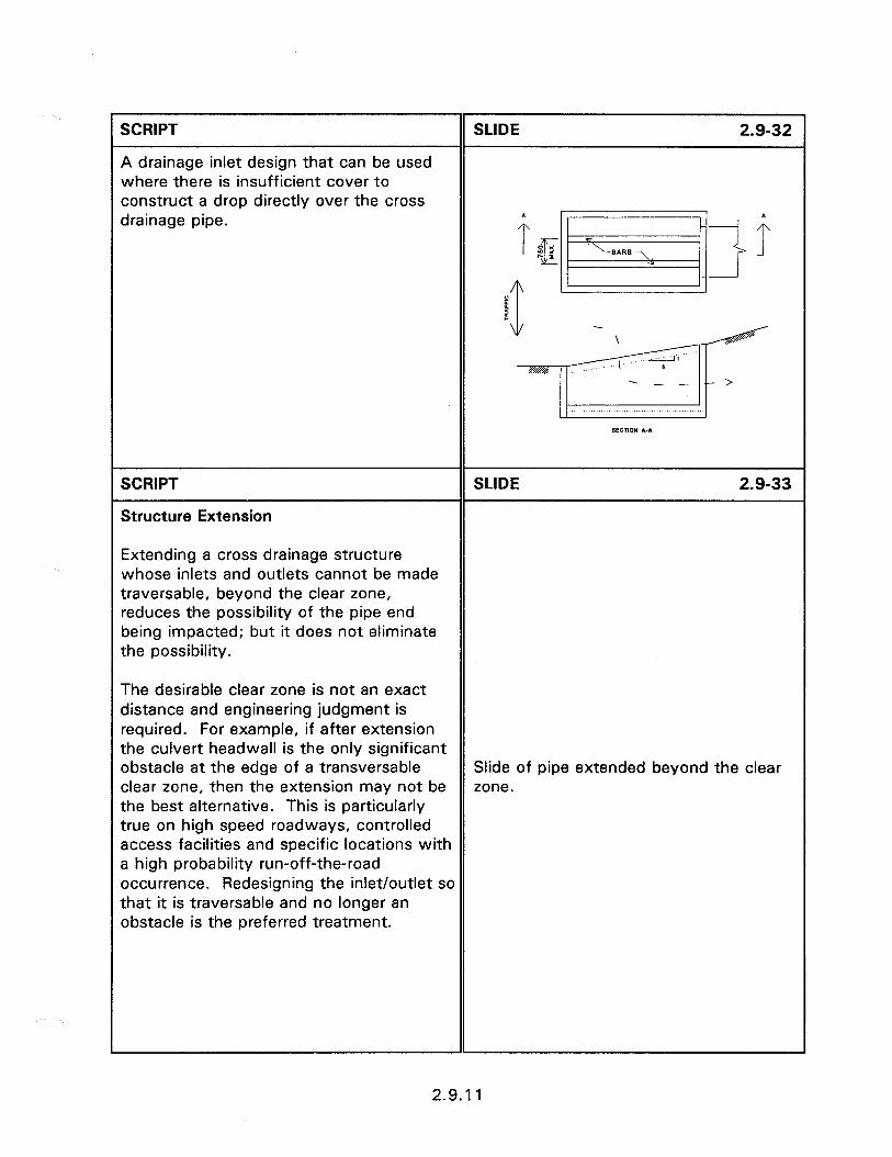
’ SCRIPT
A drainage inlet design that can be used where there is insufficient cover to construct a drop directly over the cross drainage pipe.
SLIDE 2.9-32
SCRIPT
Structure Extension
SLIDE 2.9-33
Extending a cross drainage structure whose inlets and outlets cannot be made traversable, beyond the clear zone, reduces the possibility of the pipe end being impacted; but it does not eliminate the possibility.
The desirable clear zone is not an exact distance and engineering judgment is required. For example, if after extension the culvert headwall is the only significant obstacle at the edge of a transversable Slide of pipe extended beyond the clear clear zone, then the extension may not be zone. the best alternative. This is particularly true on high speed roadways, controlled access facilities and specific locations with a high probability run-off-the-road occurrence. Redesigning the inlet/outlet so that it is traversable and no longer an obstacle is the preferred treatment.
2.9.11
SCRIPT
Shielding
SLIDE 2.9-34
When either making the inlet/outlet of cross drainage structures traversable or extending beyond the clear zone are not possible or cost effective, then shielding is the last alternative.
Shielding with an appropriate traffic barrier can often be the most effective method of decreasing accident severity.
Slide of shield drainage inlet.
SCRIPT SLIDE 2.9-35
Full embedment of the guardrail posts is often not possible when continuing guardrail across a low fill culvert. This difficulty has resulted in the use of shortened wood posts set in concrete and the use of steel posts bolted to the headwall. Slide of damaged steel post bridge
guardrail . Both of these solutions increase installation costs, and often provide insufficient resistance upon impact and can be expensive to repair when impacted.
SCRIPT
Another frequently used solution is to construct a concrete safety shape across the culvert and attach the approach guardrail with an approved transition design.
SLIDE 2.9-36
This solution also significantly increases installation costs.
Slide of a concrete barrier type design.
2.9.12
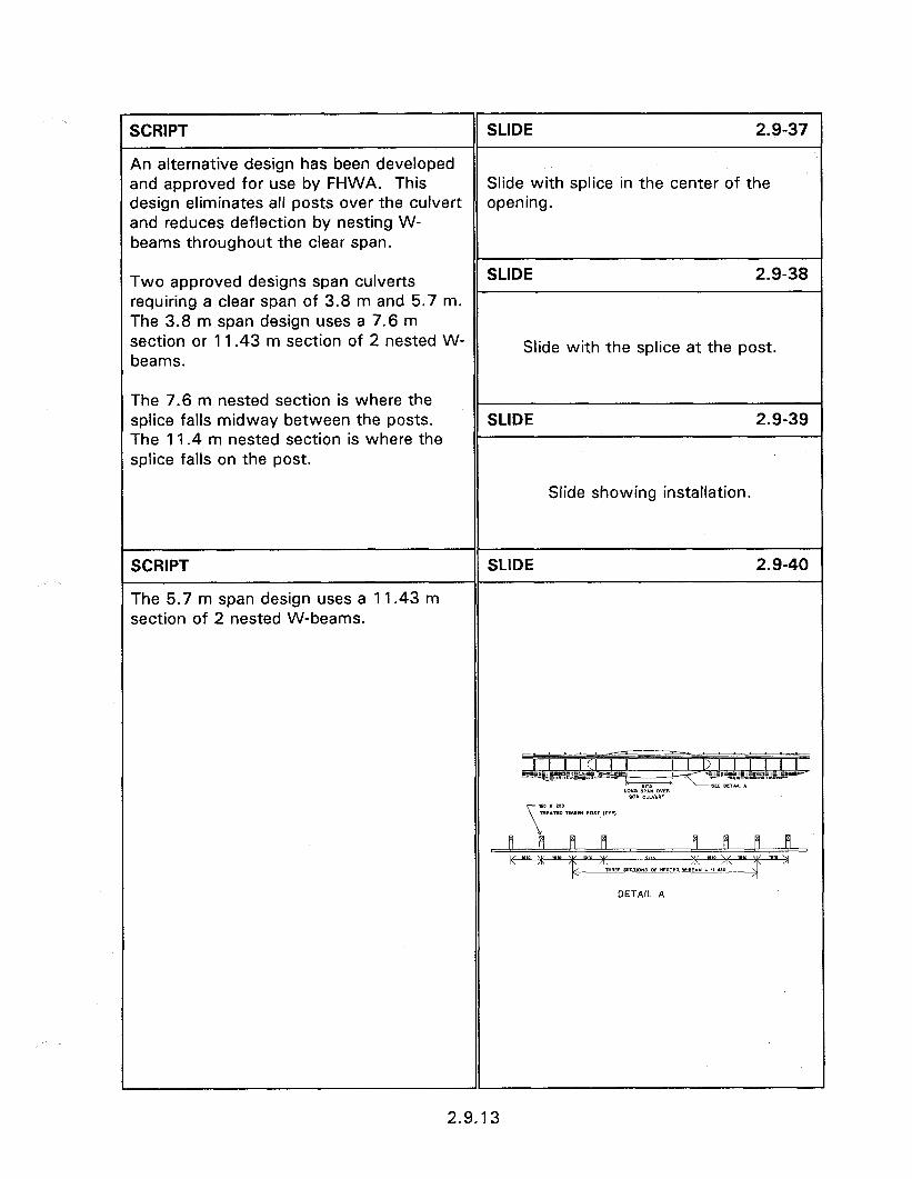
SCRIPT SLIDE 2.9-37
An alternative design has been developed and approved for use by FHWA. This Slide with splice in the center of the design eliminates all posts over the culvert opening. and reduces deflection by nesting W- beams throughout the clear span.
Two approved designs span culverts SLIDE 2.9-38
requiring a clear span of 3.8 m and 5.7 m. The 3.8 m span design uses a 7.6 m section or 1 1.43 m section of 2 nested W- Slide with the splice at the post. beams.
The 7.6 m nested section is where the splice falls midway between the posts. SLIDE 2.9-39 The 11.4 m nested section is where the splice falls on the post.
Slide showing installation.
SCRIPT SLIDE 2.9-40
The 5.7 m span design uses a 11.43 m section of 2 nested W-beams.
T I I ICI I I 1 I u .I,.! ..!, ,,,I” .,I ,,,,,, I, -“---*?~er~,,E~Ew=,,=~lli’ Ul~l~,~,,~l,lillU~lll~,il~‘lli*~, ‘“-~~I,~~~~~~~~~~~~~‘IIp rn5 DEE DLT*l I LOW ,PW OWR sax EULYEIT
[lfl ~ $i
so x 2w mE*M ,vAnm PDlT ,T”P>
1 fl fl iy, K ‘OM x ‘e’o v ‘vre m SZlS m’“X Y TYllE w7KYE OF *ESTW W.BE”U - I‘ 110
DETAIL A
2.9.13
SCRIPT SLIDE 2.9-41
A field installation of a 5.7 m design.
Slide of 5.7 m clear span field installation.
SCRIPT SLIDE 2.9-42
PARALLEL DRAINAGE STRUCTURES
Parallel drainage culverts are those which continue the flow of parallel ditches under driveways, intersecting roadways and median crossovers.
Parallel drainage features present a Slide of parallel drainage structure.
significant safety hazard because they can be struck head on by impacting vehicles.
SCRIPT SLIDE 2.9-43
Effective treatments for improving the safety of parallel drainage features, in order of preference, include:
l Eliminate the structure PARALLEL DRAINAGE
l Installing a traversable design STRUCTURES l Eliminate
l Move the structure away from the l Traversable
traveled way l Move l Shield
l Shield the structure
2.9.14
SCRIPT
Eliminate The Structure
SLIDE 2.9-44
Eliminating parallel drainage structures is the preferred choice for increasing roadside safety. This can be accomplished by developing an overflow section and by converting an open ditch to a storm drain. The overflow section is an alternative that should be exercised with care. It consists of eliminating the parallel pipes by allowing the water from the parallel ditch to flow over the surface of intersecting minor roads, field entrances and driveways.
The treatment is only appropriate at low volume locations and requires lowering the intersecting roadway surface.
One major problem with overflow designs is that they can reduce the sight distance available to drivers entering the major road. Water freezing on the roadway surface and erosion are also potential problems.
The erosion problem can be reduced by paving the overflow section, on gravel roads, and by adding upstream and downstream aprons at locations where water velocities and soil conditions make erosion likely.
ELIMINATE STRUCTURE l Create Overflow Section
- Low volume roads - Sight restriction - Freezing - Erosion
2.9.15
SCRIPT SLIDE 2.9-45
Connecting an open ditch to a storm drain is the ideal solution but is also expensive. 0 Develop Storm Drain The costs can be cost effective at proper - Closely spaced driveways locations. - Outside of curves
Rural roadways with closely spaced residential driveways are good candidates SLIDE 2.9-46
for converting an open ditch to a storm drain.
Similarly, also locations along the outside of curves or where a history of run-off-the- road accidents have occurred.
Slide showing an open ditch.
This treatment eliminates the SLIDE 2.9-47 embankments and ditch bottom as well as the pipe inlets and outlets.
Slide showing turnpike section to eliminate the ditch.
SCRIPT
Traversable Designs
SLIDE 2.9-48
Designers should try to provide the flattest slopes practical. This is especially true in locations with a high probability of head-on accidents with drainage structures.
TRAVERSABLE DESIGN l Flat slopes
Cross slopes of I:6 or flatter are suggested, with slopes of 1: 10 desirable when possible. The pipe inlet and outlet structures should match the selected cross slope.
l Locations with high accident probability
SCRIPT
As a general rule, parallel drainage structures with a single 610 mm, or less, diameter pipe do not require a grate.
SLIDE 2.9-49
Slide of a pipe without the grate.
2.9.16
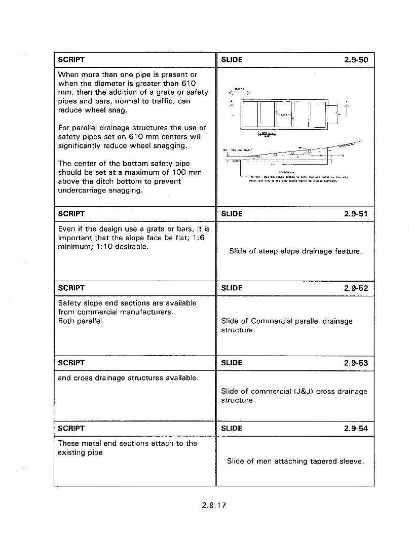
SCRIPT SLIDE 2.9-50
When more than one pipe is present or when the diameter is greater than 610 mm, then the addition of a grate or safety
TRAIFIC
pipes and bars, normal to traffic, can reduce wheel snag.
For parallel drainage structures the use of safety pipes set on 610 mm centers will significantly reduce wheel snagging.
The center of the bottom safety pipe should be set at a maximum of 100 mm above the ditch bottom to prevent undercarriage snagging.
SCRIPT SLIDE 2.9-51
Even if the design use a grate or bars, it is important that the slope face be flat; 1:6 minimum; 1: 10 desirable.
Slide of steep slope drainage feature.
SCRIPT
Safety slope end sections are available from commercial manufacturers. Both parallel
SLIDE 2.9-52
Slide of Commercial parallel drainage structure.
SCRIPT
and cross drainage structures available.
SLIDE 2.9-53
Slide of commercial (J&J) cross drainage structure.
SCRIPT
These metal end sections attach to the existing pipe
SLIDE 2. S-54
Slide of men attaching tapered sleeve.
2.9.17

SCRIPT
and extend the culvert
SLIDE 2.9-55
Slide of extended culvert.
SCRIPT
to achieve a 1:6 slope.
SLIDE 2.9-56
Slide of completed retrofit.
SCRIPT
Workshor,
SLIDE 2.9-57
The following slides show bad and good practice. Have the participants discuss the problems and feasible solutions to each.
WORKSHOP
2.9.18
2.10 - MAINTENANCE OF DRAINAGE FEATURES
0 biectives:
0 To review periodic maintenance and inspection needs of drainage structures.
Heloful Hints:
Contact the appropriate maintenance personnel hydraulic engineering staff to determine the prevalent drainage maintenance needs in the seminar area prior to the seminar.
Visual Aids:
l 10 - 35 mm slides
Estimated Time
l 15 minutes
Handouts:
0 None

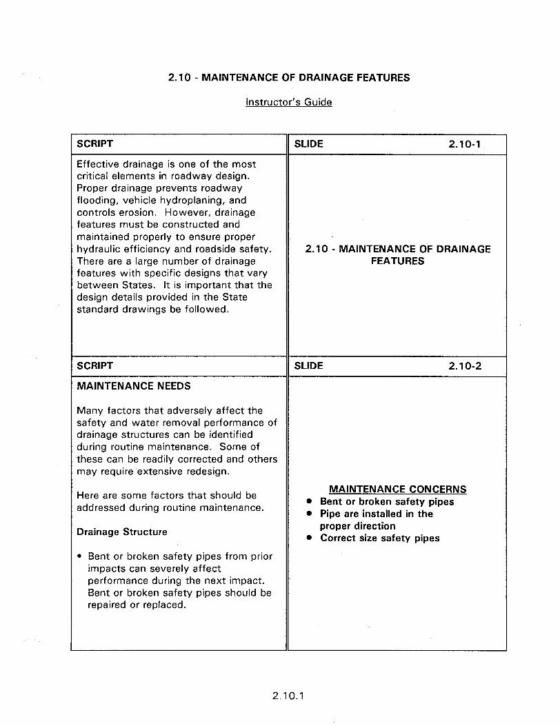
2.10 - MAINTENANCE OF DRAINAGE FEATURES
Instructor’s Guide
SCRIPT
Effective drainage is one of the most critical elements in roadway design. Proper drainage prevents roadway flooding, vehicle hydroplaning, and controls erosion. However, drainage features must be constructed and maintained properly to ensure proper hydraulic efficiency and roadside safety. There are a large number of drainage features with specific designs that vary between States. It is important that the design details provided in the State standard drawings be followed.
SLIDE 2.10-l
2.10 - MAINTENANCE OF DRAINAGE FEATURES
SCRIPT
MAINTENANCE NEEDS
SLIDE 2.10-2
Many factors that adversely affect the safety and water removal performance of drainage structures can be identified during routine maintenance. Some of these can be readily corrected and others may require extensive redesign.
Here are some factors that should be addressed during routine maintenance.
MAINTENANCE CONCERNS l Bent or broken safety pipes l Pipe are installed in the
Drainage Structure proper direction
l Correct size safety pipes
l Bent or broken safety pipes from prior impacts can severely affect performance during the next impact. Bent or broken safety pipes should be repaired or replaced.
2.10.1
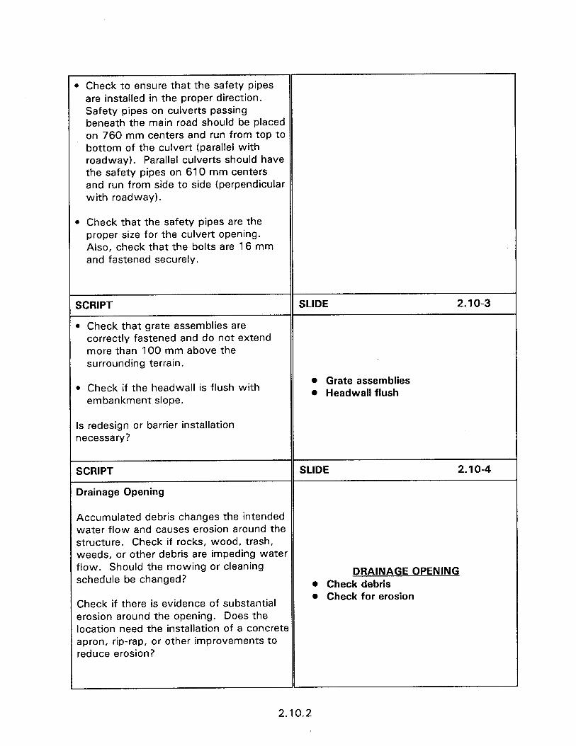
) Check to ensure that the safety pipes are installed in the proper direction. Safety pipes on culverts passing beneath the main road should be placed on 760 mm centers and run from top to bottom of the culvert (parallel with roadway). Parallel culverts should have the safety pipes on 610 mm centers and run from side to side (perpendicular with roadway).
. Check that the safety pipes are the proper size for the culvert opening. Also, check that the bolts are 16 mm and fastened securely.
SCRIPT
l Check that grate assemblies are
SLIDE 2.10-3
correctly fastened and do not extend more than 100 mm above the surrounding terrain.
l Check if the headwall is flush with embankment slope.
Is redesign or barrier installation necessary?
l Grate assemblies l Headwall flush
SCRIPT
Drainage Opening
SLIDE 2.1 o-4
Accumulated debris changes the intended water flow and causes erosion around the structure. Check if rocks, wood, trash, weeds, or other debris are impeding water flow. Should the mowing or cleaning schedule be changed?
Check if there is evidence of substantial erosion around the opening. Does the location need the installation of a concrete apron, rip-rap, or other improvements to reduce erosion?
DRAINAGE OPENING l Check debris l Check for erosion
2.10.2
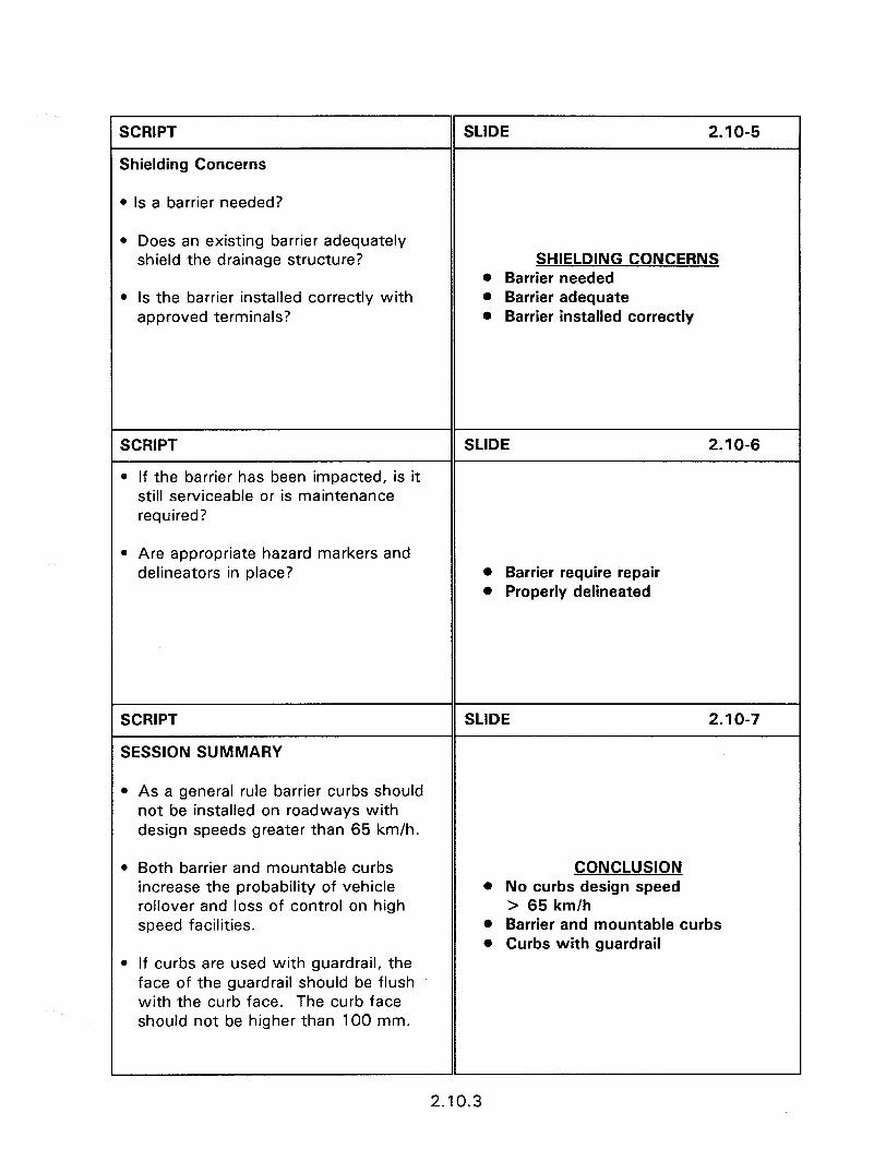
SCRIPT
Shielding Concerns
l Is a barrier needed?
SLIDE 2.10-5
l Does an existing barrier adequately shield the drainage structure? SHIELDING CONCERNS
l Barrier needed l Is the barrier installed correctly with l Barrier adequate
approved terminals? l Barrier installed correctly
SCRIPT
l If the barrier has been impacted, is it still serviceable or is maintenance required?
SLIDE 2.10-6
l Are appropriate hazard markers and delineators in place? l Barrier require repair
l Properly delineated
SCRIPT
SESSION SUMMARY
SLIDE 2.1 o-7
l As a general rule barrier curbs should not be installed on roadways with design speeds greater than 65 km/h.
l Both barrier and mountable curbs increase the probability of vehicle rollover and loss of control on high speed facilities.
CONCLUSION l No curbs design speed
> 65 km/h l Barrier and mountable curbs l Curbs with guardrail
l If curbs are used with guardrail, the face of the guardrail should be flush with the curb face. The curb face should not be higher than 100 mm.
2.10.3
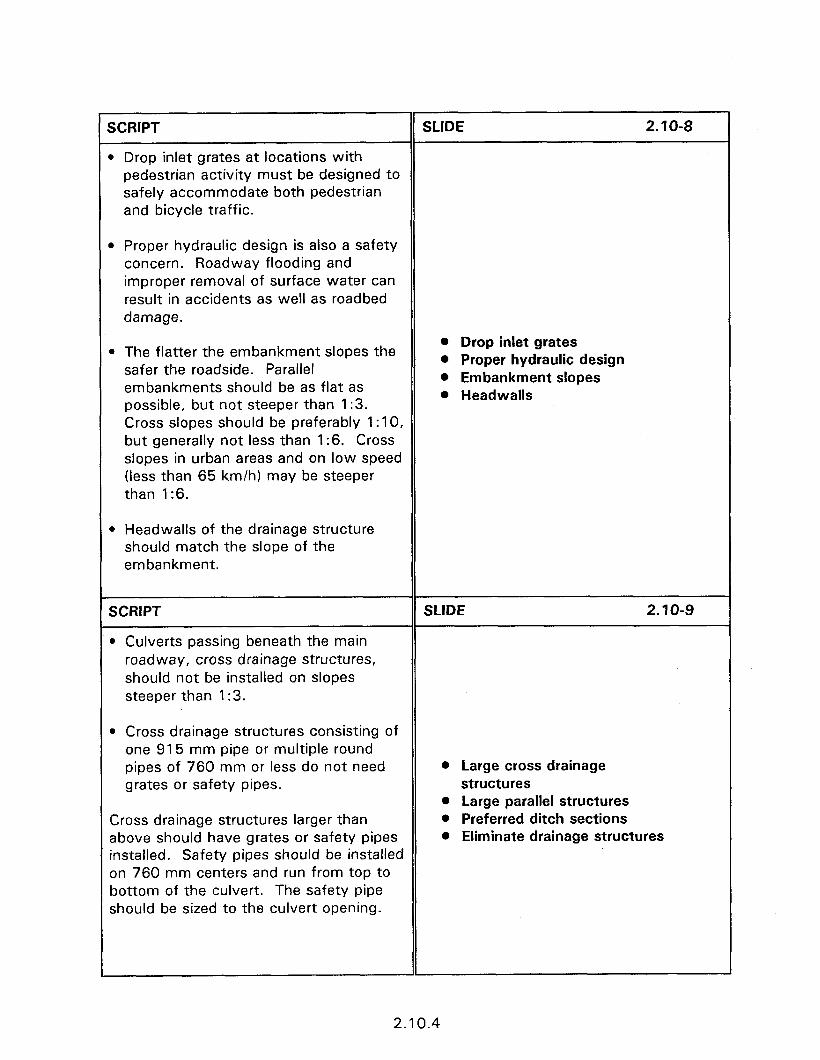
SCRIPT SLIDE 2.10-8
B Drop inlet grates at locations with pedestrian activity must be designed to safely accommodate both pedestrian and bicycle traffic.
b Proper hydraulic design is also a safety concern. Roadway flooding and improper removal of surface water can result in accidents as well as roadbed damage.
. The flatter the embankment slopes the safer the roadside. Parallel embankments should be as flat as possible, but not steeper than 1:3. Cross slopes should be preferably 1: 10, but generally not less than 1:6. Cross slopes in urban areas and on low speed (less than 65 km/h) may be steeper than 1:6.
l Drop inlet grates l Proper hydraulic design l Embankment slopes l Headwalls
l Headwalls of the drainage structure should match the slope of the embankment.
SCRIPT
l Culverts passing beneath the main roadway, cross drainage structures, should not be installed on slopes steeper than 1:3.
SLIDE 2.10-g
l Cross drainage structures consisting of one 915 mm pipe or multiple round pipes of 760 mm or less do not need grates or safety pipes.
Cross drainage structures larger than above should have grates or safety pipes installed. Safety pipes should be installed on 760 mm centers and run from top to bottom of the culvert. The safety pipe should be sized to the culvert opening.
0 Large cross drainage structures
0 Large parallel structures l Preferred ditch sections 0 Eliminate drainage structures
2.10.4
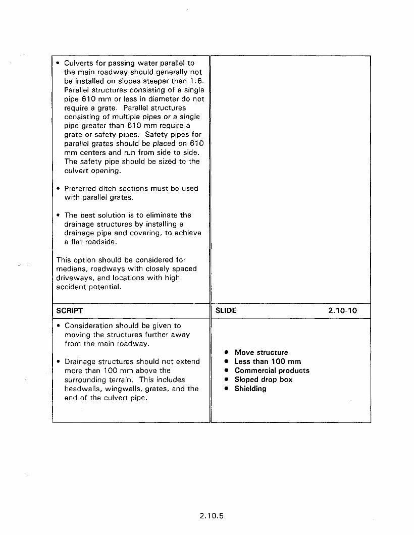
r l Culverts for passing water parallel to
the main roadway should generally not be installed on slopes steeper than 1:6. Parallel structures consisting of a single pipe 610 mm or less in diameter do not require a grate. Parallel structures consisting of multiple pipes or a single pipe greater than 610 mm require a grate or safety pipes. Safety pipes for parallel grates should be placed on 610 mm centers and run from side to side. The safety pipe should be sized to the culvert opening.
l Preferred ditch sections must be used with parallel grates.
l The best solution is to eliminate the drainage structures by installing a drainage pipe and covering, to achieve a flat roadside.
This option should be considered for medians, roadways with closely spaced driveways, and locations with high accident potential.
SCRIPT
l Consideration should be given to moving the structures further away from the main roadway.
SLIDE
0 Move structure
2.10-10
l Drainage structures should not extend more than 100 mm above the surrounding terrain. This includes headwalls, wingwalls, grates, and the end of the culvert pipe.
l Less than 100 mm l Commercial products l Sloped drop box l Shielding
2.10.5

SESSION GUIDE
2.11 - SAFETY CONSIDERATIONS OF LANDSCAPING AND VEGETATION CONTROL
Obiectives:
0 To identify when vegetation causes traffic safety problems.
0 Review the vegetation trimming needs at intersections, clear zones, railroad grade crossings, and roadway approaches.
Heloful Hints:
l
l
Visual Aids:
Refer to the Users Guide when bold page numbers are encountered.
Many of the concepts presented in this session are basic traffic engineering principles. Experienced participants may have their attention wander. Try to have them provide personal experiences and vegetation problems they have encountered.
Slides of the local area should be used if available.
32 - 35 mm slides
Estimated Time
0 30 minutes
Handouts:
l None

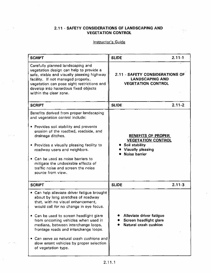
2.11 - SAFETY CONSIDERATIONS OF LANDSCAPING AND VEGETATION CONTROL
Instructor’s Guide
SCRIPT SLIDE 2.11-1
Carefully planned landscaping and vegetation design can help to provide a safe, stable and visually pleasing highway 2. I1 - SAFETY CONSIDERATIONS OF facility. If not managed properly, LANDSCAPING AND vegetation can pose sight restrictions and VEGETATION CONTROL develop into hazardous fixed objects within the clear zone.
SCRIPT
Benefits derived from proper landscaping and vegetation control include:
SLIDE 2.1 I-2
0 Provides soil stability and prevents erosion of the roadbed, roadside, and drainage ditches. BENEFITS OF PROPER
VEGETATION CONTROL * Provides a visually pleasing facility to
roadway users and neighbors. l Soil stability 0 Visually pleasing l Noise barrier
l Can be used as noise barriers to mitigate the undesirable effects of traffic noise and screen the noise source from view.
SCRIPT SLIDE 2.1 l-3
l Can help alleviate driver fatigue brought about by long stretches of roadway that, with no visual enhancement, would call for no change in eye focus.
l Can be used to screen headlight glare from oncoming vehicles when used in medians, between interchange loops, frontage roads and interchange loops.
s Alleviate driver fatigue l Screen headlight glare l Natural crash cushion
l Can serve as natural crash cushions and slow errant vehicles by proper selection of vegetation type.
2.11.1
SCRIPT SLIDE 2.1 l-4
For example, landscape areas such as this help alleviate driver fatigue
Slide of landscaping.
SCRIPT
or planted at horizontal curves reduces headlight glare.
SLIDE 2.11-5
Slide of vegetation at horizontal curve.
SCRIPT SLIDE 2.11-6
It not properly controlled, however, vegetation can cause safety problems.
SAFETY CONCERNS
These problems are related to posing sight l Sight restrictions
obstructions and vegetation developing - TCD’s
into fixed objects. - intersections - horizontal curves
l Fixed objects
SCRIPT
VEGETATION CONTROL GOALS
SLIDE 2.1 l-7
The primary goal of vegetation control is to increase traffic safety. Due to the different characteristics of both the vegetation and traffic, there are different concerns between urban and rural situations. The following discussion presents common vegetation problems, and where appropriate, urban and rural situations.
TRAFFIC CONTROL DEVICES l Regulatory signs l Traffic signs
Traffic Control Devices 0 MUTCD recommendations
A common problem with vegetation is maintaining visibility of traffic control devices. The biggest safety problem occurs when vegetation blocks regulatory signs, warning signs or hazard markers, as presented in figure 2.11.2. (PAGE 2.11.2) However, since all traffic control devices are installed for a purpose, all signs should be visible to motorists. The
2.11.2
tiUTCD provides guidelines on how far :raffic signs should be visible to motorists. The distances presented in table 2.1 1 .I PAGE 2.11.3) provide 3 to 5 seconds to ,ead and react to signs and can be used if IO State guidelines exist.
SCRIPT SLIDE 2.11-8
Sight obstructions to traffic control devices can be identified by drive through nspections, observations of employees, 3nd by complaints of citizens. Vlaintaining visibility requires constant attention during the growing season. Vegetation cut back in the spring can grow back later in the season. Urban sreas often have signs mounted higher than rural areas to allow visibility of signs over parked vehicles. This requires additional attention to ensure that the signs are not blocked by overhanging trees.
Slide of obstructed sign.
SCRIPT SLIDE 2.1 l-9
intersection Sight Distance
Intersections must have sufficient sight distance available to permit safe intersection operation with the type of traffic control devices present. An intersection controlled with a stop sign requires sufficient sight distance to allow the minor roadway vehicle to perform a maneuver across or onto the major roadway. Intersections with no control or yield signs must have sufficient sight distance to ensure that a safe approach speed exists. Sight distance is generally not a concern at intersections controlled with traffic signals since the signal, at least ideally, assigns right-of-way thereby reducing the visibility requirements. Sight distance studies are, however, often performed at signalized intersections to determine if sight restrictions warrant prohibiting right-turn-on-red maneuvers.
INTERSECTIONS l Stop/yield * Right-turn-on-red
2.11.3
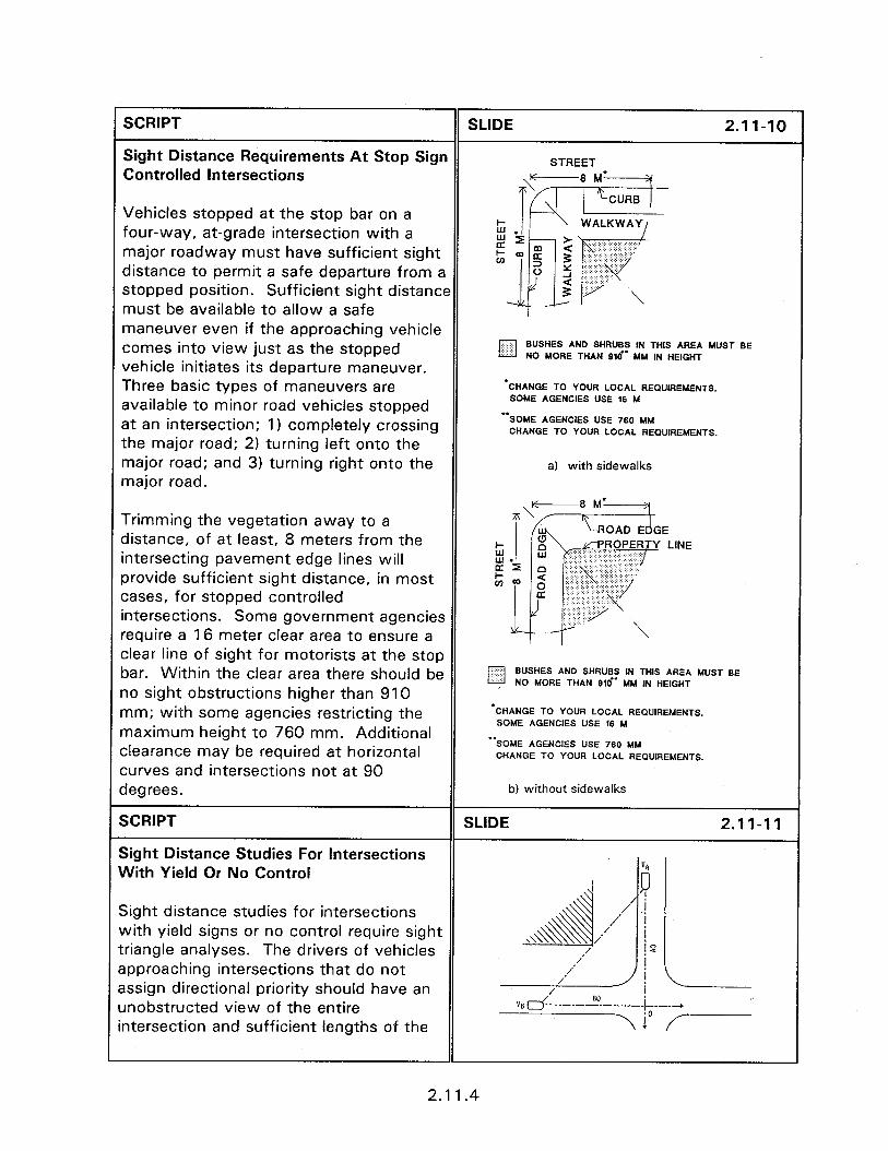
SCRIPT SLIDE 2.11-10
Sight Distance Requirements At Stop Sign Controlled Intersections
STREET
Vehicles stopped at the stop bar on a four-way, at-grade intersection with a major roadway must have sufficient sight distance to permit a safe departure from a stopped position. Sufficient sight distance must be available to allow a safe maneuver even if the approaching vehicle comes into view just as the stopped vehicle initiates its departure maneuver. Three basic types of maneuvers are available to minor road vehicles stopped at an intersection; 1) completely crossing the major road; 2) turning left onto the major road; and 3) turning right onto the major road.
/Q BUSHES AND SHRUBS IN THIS AREA MUST BE NO MORE THAN 810” MM IN HEIGHT
‘CHANGE TO YOUR LOCAL REQUIREMENTS. SOME AGENCIES USE 16 M
“SOME AGENCIES USE 760 MM CHANGE TO YOUR LOCAL REQUIREMENTS.
a) with sidewalks
Trimming the vegetation away to a distance, of at least, 8 meters from the intersecting pavement edge lines will orovide sufficient sight distance, in most cases, for stopped controlled intersections. Some government agencies require a 16 meter clear area to ensure a clear line of sight for motorists at the stop oar. Within the clear area there should be lo sight obstructions higher than 910 nm; with some agencies restricting the naximum height to 760 mm. Additional zlearance may be required at horizontal :urves and intersections not at 90 jegrees.
SCRIPT
sight Distance Studies For Intersections Nith Yield Or No Control
BUSHES AND SHRUBS IN THIS AREA MUST BE NO MORE THAN Olo” MM IN HEIGHT
-CHANGE TO YOUR LOCAL REQUIREMENTS. SOME AGENCIES USE 16 hi
-‘SOME AGENCIES USE 760 MM CHANGE TO YOUR LOCAL REQUIREMENTS.
b) without sidewalks
SLIDE
sight distance studies for intersections Nith yield signs or no control require sight :riangle analyses. The drivers of vehicles approaching intersections that do not tssign directional priority should have an Inobstructed view of the entire ntersection and sufficient lengths of the
2.1 1.4
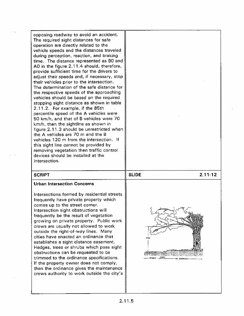
i
opposing roadway to avoid an accident. The required sight distances for safe operation are directly related to the vehicle speeds and the distances traveled during perception, reaction, and braking time. The distance represented as BO and A0 in the figure 2.11.4 should, therefore, provide sufficient time for the drivers to adjust their speeds and, if necessary, stop their vehicles prior to the intersection. The determination of the safe distance for the respective speeds of the approaching vehicles should be based on the required stopping sight distance as shown in table 2.11.2. For example, if the 85th percentile speed of the A vehicles were 50 km/h, and that of B vehicles were 70 km/h, then the sightline as shown in figure 2.1 1.3 should be unrestricted when the A vehicles are 70 m and the B vehicles 120 m from the intersection. If this sight line cannot be provided by removing vegetation then traffic control devices should be installed at the intersection.
SCRIPT
Urban Intersection Concerns
SLIDE 2.11-12
Intersections formed by residential streets frequently have private property which comes up to the street corner. Intersection sight obstructions will frequently be the result of vegetation growing on private property. Public work crews are usually not allowed to work outside the right-of-way lines. Many cities have enacted an ordinance that establishes a sight distance easement. Hedges, trees or shrubs which pose sight obstructions can be requested to be trimmed to the ordinance specifications. If the property owner does not comply, then the ordinance gives the maintenance crews authority to work outside the city’s
2.11.5

right-of-way. Typical ordinances specify SLIDE 2.11-13 that nothing be allowed to grow, within the shaded area of figure 2.1 1.3, between a height of 760 mm and 3 m above the grade of the two street centerlines.
The provision of no lower than 3 m pertains to tree branches not only blocking clear vision, but also to the clearance needs for vehicles, pedestrians and bicyclists. Tree branches should be trimmed so that there is a minimum of 2.75 m to 3 m of clear space above the street and/or sidewalk. Consideration for pedestrians and bicyclists also require that bushes which obstruct sidewalks be trimmed back so that there is 300 mm between bushes and sidewalk.
SCRIPT SLIDE 2.11-14
The site plans of corner developments should be investigated to determine if the planned development will cause intersection sight distance problems. Barrier walls separating the parking lot from sidewalks, low level signs and the building structure can block the clear view of approaching vehicles. When possible these obstructing structures should not be allowed. When such structures will be allowed, as in central business district, Slide of sight restriction due to then the developer can be required to pay development. for any necessary improvements to the intersection traffic control devices.
2.11.6
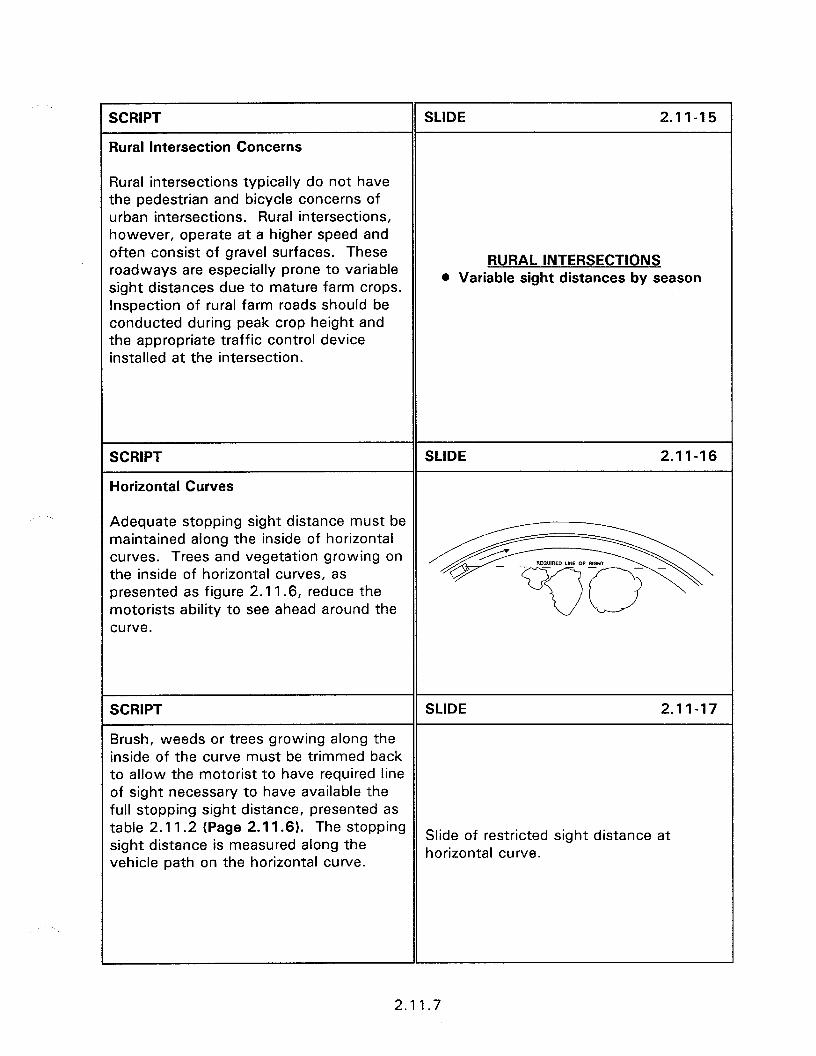
SCRIPT
Qral Intersection Concerns
SLIDE 2.11-15
3ural intersections typically do not have :he pedestrian and bicycle concerns of Jrban intersections. Rural intersections, lowever, operate at a higher speed and Iften consist of gravel surfaces. These ‘oadways are especially prone to variable ;ight distances due to mature farm crops. nspection of rural farm roads should be conducted during peak crop height and :he appropriate traffic control device nstalled at the intersection.
RURAL INTERSECTIONS l Variable sight distances by season
SCRIPT
Horizontal Curves
SLIDE 2.11-16
Adequate stopping sight distance must be naintained along the inside of horizontal xrves. Trees and vegetation growing on the ‘inside of horizontal curves, as sresented as figure 2.11.6, reduce the motorists ability to see ahead around the
+igcI-z@
xrve.
SCRIPT SLIDE 2.11-17
Brush, weeds or trees growing along the inside of the curve must be trimmed back to allow the motorist to have required line of sight necessary to have available the full stopping sight distance, presented as table 2.1 1.2 (Page 2.11.6). The stopping sight distance is measured along the
Slide of restricted sight distance at
vehicle path on the horizontal curve. horizontal curve.
2.1 1.7
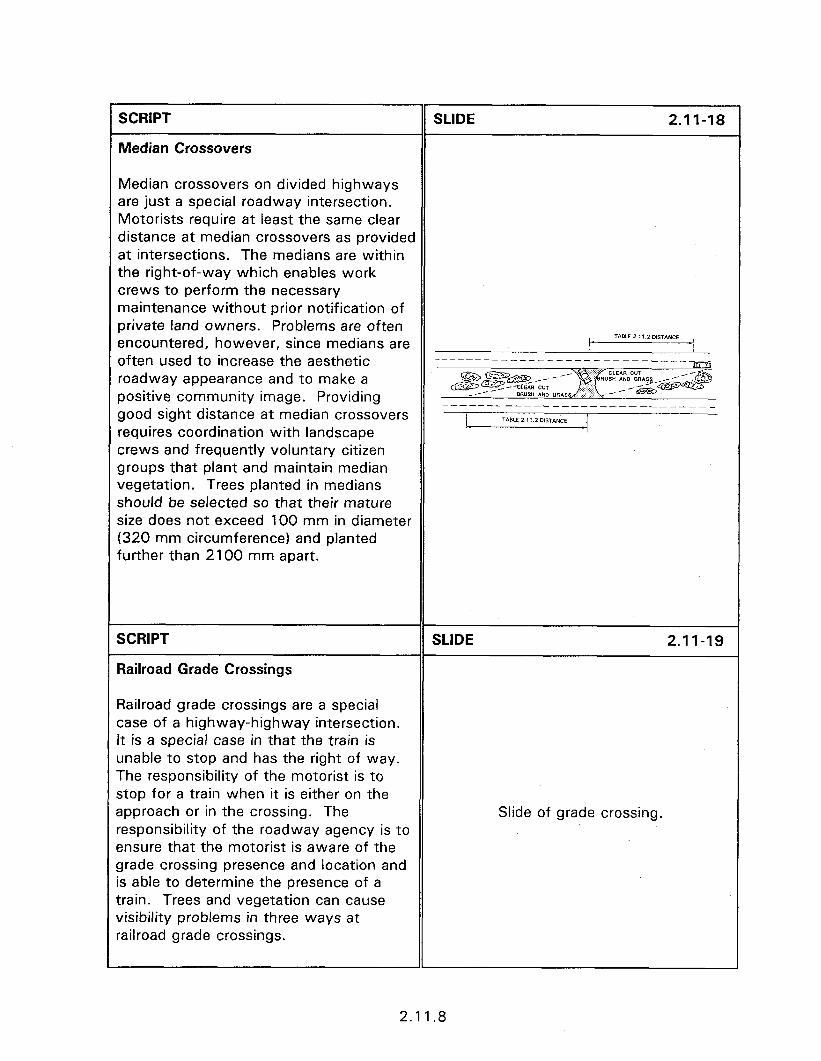
SCRIPT
Median Crossovers
SLIDE 2.11-18
Median crossovers on divided highways are just a special roadway intersection. Motorists require at least the same clear distance at median crossovers as provided at intersections. The medians are within the right-of-way which enables work crews to perform the necessary maintenance without prior notification of private land owners. Problems are often encountered, however, since medians are often used to increase the aesthetic roadway appearance and to make a positive community image. Providing good sight distance at median crossovers requires coordination with landscape crews and frequently voluntary citizen groups that plant and maintain median vegetation. Trees planted in medians should be selected so that their mature size does not exceed 100 mm in diameter (320 mm circumference) and planted further than 2100 mm apart.
SCRIPT
Railroad Grade Crossings
SLIDE 2.11-19
Railroad grade crossings are a special case of a highway-highway intersection. It is a special case in that the train is unable to stop and has the right of way. The responsibility of the motorist is to stop for a train when it is either on the approach or in the crossing. The responsibility of the roadway agency is to ensure that the motorist is aware of the grade crossing presence and location and is able to determine the presence of a train. Trees and vegetation can cause visibility problems in three ways at railroad grade crossings.
Slide of grade crossing.
2.11.8

SCRIPT SLIDE 2.1 l-20
0 The motorist must be able to see the railroad advance warning sign and the warning devices located at the crossing. Trees and vegetation should be removed to allow the clear distance to signs presented as table 2.11.1.
Slide of WlO-1 and no passing pennant.
SCRIPT SLIDE 2.11-21
l The motorist must have a clear view of any train arriving from either side. This required clear view is presented as the approach sight triangles in figure 2.11.8. Brush and vegetation along the road should be trimmed to permit a continuous view, in both directions, of a train on the tracks throughout the Slide of approach sight obstruction. triangle by a motorist on the approach.
SCRIPT SLIDE 2.11-22
l The motorist must have a clear view along both directions of the track when stopped at the grade crossing.
Slide of control cabinet in way.
2.11.9
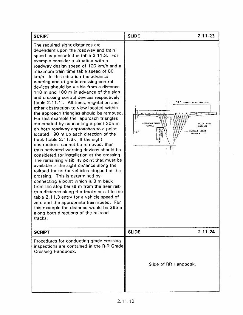
SCRIPT SLIDE 2.1 l-23
The required sight distances are dependent upon the roadway and train speed as presented in table 2.11.3. For example consider a situation with a roadway design speed of 100 km/h and a maximum train time table speed of 80 km/h. In this situation the advance warning and at grade crossing control devices should be visible from a distance 110 m and 180 m in advance of the sign and crossing control devices respectively (table 2.1 1. I). All trees, vegetation and ,TRACK yG”T DISTANCE, _.i other obstruction to view located within the approach triangles should be removed. For this example the approach triangles are created by connecting a point 205 m on both roadway approaches to a point APPROACH SGHT located 190 m up each direction of the track (table 2.1 1.3). If the sight obstructions cannot be removed, then train activated warning devices should be considered for installation at the crossing. The remaining visibility point that must be available is the sight distance along the railroad tracks for vehicles stopped at the crossing. This is determined by connecting a point which is 3 m back from the stop bar (8 m from the near rail) to a distance along the tracks equal to the table 2.11.3 entry for a vehicle speed of zero and the appropriate train speed. For this example the distance would be 365 m along both directions of the railroad tracks.
SCRIPT SLIDE 2.11-24
Procedures for conducting grade crossing inspections are contained in the R-R Grade Crossing Handbook.
Slide of RR Handbook.
2.11.10
SCRIPT SLIDE 2.1 l-25
Vegetation problems along the approach sight triangle can be from foliage located on the highway right-of-way, private property or railroad right-of-way. While the railroad right-of-way can vary, it typically extends 15 m, in both directions from the center of the tracks. The
SIGHT OBSTRUCTIONS
railroad should be contacted if sight l Public row
distance problems are due to vegetation l Private property
within the railroad’s right-of-way. If sight 0 Railroad row
obstructions cannot be removed, then (I 5 m from centerline)
train activated warning devices should be installed at the crossing.
SCRIPT
TREES IN THE CLEAR ZONE
SLIDE 2.1 l-26
In addition to trees obscuring signs, trees pose significant risk to the occupants of impacting vehicles. Trees with diameters greater than 100 mm (315 mm circumference) are rigid fixed objects and should not be located within the clear zone. On curbed roadways trees should be as far removed from the curb as possible and not any closer than 460 mm. Even trees equal to or less than 100 mm in diameter can pose a significant threat when placed closer together than 2100 mm. The following should be considered when removing trees to increase traffic safety.
TREE HAZARDS l Diameters greater than 100 mm l Out of clear zone l Curbed roads no closer than 460 mm
SCRIPT SLIDE 2.11-27
l Cut trees close to the ground or remove the stump so that it does not become a hazard. If the stump is not removed, then trees should be cut flush with the ground.
Slide of protruding tree stump.
2.11.11
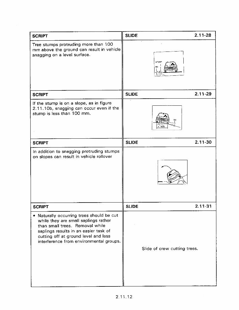
SCRIPT SLIDE 2.11-28
Tree stumps protruding more than 100 nm above the ground can result in vehicle snagging on a level surface.
SCRIPT SLIDE 2.1 l-29
If the stump is on a slope, as in figure 2.11.1 Ob, snagging can occur even if the stump is less than 100 mm.
SCRIPT SLIDE 2.1 I-30
In addition to snagging protruding stumps on slopes can result in vehicle rollover
SCRIPT SLIDE 2.11-31
l Naturally occurring trees should be cut while they are small saplings rather than small trees. Removal while saplings results in an easier task of cutting off at ground level and less interference from environmental groups.
Slide of crew cutting trees.
2.11.12
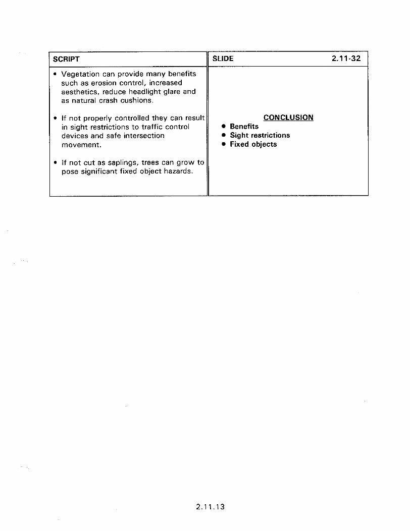
SCRIPT
l Vegetation can provide many benefits such as erosion control, increased aesthetics, reduce headlight glare and as natural crash cushions.
l If not properly controlled they can result in sight restrictions to traffic control devices and safe intersection movement.
l If not cut as saplings, trees can grow to pose significant fixed object hazards.
SLIDE 2.11-32 1
CONCLUSION 0 Benefits 0 Sight restrictions 0 Fixed objects
2.11.13


SESSION GUIDE
3.1 - INTRODUCTION TO BREAKAWAY DEVICES
Obiectives:
l
Understand the impact performance requirements of yielding and breakaway devices.
To introduce the participants to the concept of safe sign, luminaire and mailbox supports.
To discuss the importance of proper device placement and design.
Heloful Hints:
a Local area slides are very helpful in assisting to maintain interest in all of section 3.
Visual Aids:
a 50 - 35 mm slides
Estimated Time
l 60 minutes
Handouts:
0 None

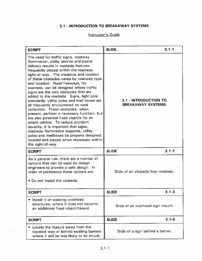
3.1 - INTRODUCTION TO BREAKAWAY SYSTEMS
Instructor’s Guide
SCRIPT SLIDE 3.1-1
The need for traffic signs, roadway illumination, utility service and postal delivery results in roadside features frequently placed within the roadway right-of-way. The presence and location of these obstacles varies by roadway type and location. Rural freeways, for example, can be designed where traffic signs are the only obstacles that are added to the roadside. Signs, light pole standards, utility poles and mail boxes are 3.1 - INTRODUCTION TO all frequently encountered on rural BREAKAWAY SYSTEMS collectors. These obstacles, when present, perform a necessary function, but are also potential fixed objects for an errant vehicle. To reduce accident severity, it is important that signs, roadway illumination supports, utility poles and mailboxes be properly designed, located and placed when necessary within the right-of-way.
SCRIPT
As a general rule, there are a number of options that can be used by design engineers to provide a safe design. In order of preference these options are:
l Do not install the obstacle.
SLIDE 3.1-2
Slide of an obstacle free roadside.
SCRIPT
l Install it on existing overhead
SLIDE 3.1-3
structures, where it does not become an additional fixed object hazard.
Slide of an overhead sign mount.
SCRIPT SLIDE 3.1-4
l Locate the feature away from the traveled way or behind existing barriers Slide of a sign behind a barrier. where it will be less likely to be struck.
3.1.1

SCRIPT
l Reduce impact severity by using appropriate breakaway or yielding design.
SLIDE 3.1-5
Slide of a breakaway mechanism.
SCRIPT
l Shield the feature with a properly designed longitudinal barrier or crash cushion if it cannot be eliminated, relocated or redesigned.
SLIDE 3.1-6
Slide of a barrier in front of sign support.
SCRIPT SLIDE 3.1-7
l Delineate an existing feature if other measures are not practical. Putting up hazard markers is a cost-effective method for alerting motorists to an existing hazard. Obviously, delineators Slide of a hazard marker. will not make any difference if a driver hits the object but they might help a driver avoid running off the road at that spot.
SCRIPT SLIDE 3.1-s
NCHRP Report 350 establishes current testing guidelines for vehicular tests to evaluate the impact performance of permanent and temporary highway features, and supersedes those contained in NCHRP Report 230. These guidelines include a range of test vehicles, impact speeds, impact angle, point of impact on the vehicle and surrounding terrain features for use in evaluating impact performance. Acceptance testing of Slide of NCHRP 350. yielding and breakaway supports require evaluation in terms of the degree of hazard to which occupants of the impacting vehicle are exposed, the structural adequacy of the support, the hazard to workers and pedestrians that may be in the path of debris from the impact, and the behavior of the vehicle after impact.
3.1.2

SCRIPT SLIDE 3.1-9
The guidelines include requirements for:
l The structural adequacy of the device to determine if detached elements, fragments or other debris from the assembly penetrate, or show potential for penetrating, the passenger compartment or present undue hazard to other traffic.
l A range of preferable and maximum vehicle changes in velocity resulting from impact with the support system. The preferable change in vehicle velocity is 3.0 m/s or less. The maximum acceptable change in vehicle velocity is 5.0 m/s. Note that due to conversion to the SI system the limiting velocity changes were rounded and consequently are not precisely the same as those in NCHRP Report 230.
l The impacting vehicle remain upright during and after the collision.
l The vehicle trajectory and final stopping position after impact should intrude a minimum distance, if at all, into adjacent or opposing lanes.
NCHRP 350 0 Structural adequacy 0 Velocity change 3 to 5 m/s 0 Remain upright 0 Trajectory
3.1.3

SCRIPT SLIDE 3.1-10
The sign assembly must be structurally adequate to withstand its own weight and the wind and ice loads subjected to the sign panel. In some northern climates this requirement includes the forces created by snow ejected by snow blowers or the lateral forces resulting from snow plow activity. The majority of the design guides for each State contain
DIRECTION . 2
recommendations on the size, number, and type of support required in different regions of the State. These guides are based on the size of the sign panel and iif
& \ I
# the recurrent wind intensity
al Prior to impact b) Slip plate release
cl Hinge activation
SCRIPT SLIDE 3.1-11
Opposing the need for structural adequacy is the requirement that the sign assembly provide a safe driving environment. This safety requirement necessitates that the complete sign assembly is able to pass rigid testing criteria prior to approval for Jse by the FHWA. Only those devices which have been approved for use by the Slide of traffic on rural road. Federal Highway Administration should be nstalled. The installation of approved assemblies must be performed with proper design and construction to achieve the ?equired performance.
3.1.4
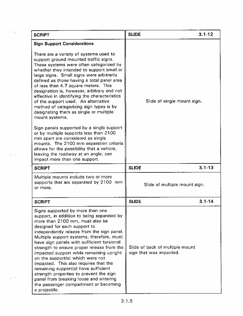
SCRIPT
Sign Support Considerations
SLIDE 3.1-12
There are a variety of systems used to support ground mounted traffic signs. These systems were often categorized by whether they intended to support small or large signs. Small signs were arbitrarily defined as those having a total panel area of less than 4.7 square meters. This designation is, however, arbitrary and not effective in identifying the characteristics of the support used. An alternative method of categorizing sign types is by designating them as single or multiple mount systems.
Slide of single mount sign.
Sign panels supported by a single support or by multiple supports less than 2100 mm apart are considered as single mounts. The 2100 mm separation criteria allows for the possibility that a vehicle, leaving the roadway at an angle, can impact more than one support.
SCRIPT SLIDE 3.1-13
Multiple mounts include two or more supports that are separated by 2100 mm or more.
Slide of multiple mount sign.
SCRIPT SLIDE 3.1-14
Signs supported by more than one support, in addition to being separated by more than 2100 mm, must also be designed for each support to independently release from the sign panel. Multiple support systems, therefore, must have sign panels with sufficient torsional strength to ensure proper release from the Slide of back of multiple mount impacted support while remaining upright sign that was impacted. on the support(s) which were not impacted. This also requires that the remaining support(s) have sufficient strength properties to prevent the sign panel from breaking loose and entering the passenger compartment or becoming a projectile.
1
3.1.5
SCRIPT
Metal supports which yield upon impact have been used for many years to provide effective economical supports for traffic signs. The U-channel post design is the most widely used support for both single and multiple support designs. Yielding supports are designed to bend at the base and have no built-in breakaway or weakened design. Systems in this category include the full length steel U-channel, aluminum shapes, aluminum X-posts and standard steel pipes. For successful impact performance the support must bend and lay down or fracture without causing a change in vehicle velocity of more than 5 m/s. Tests have shown that supports which fracture offer much less impact resistance, especially at high speed impacts, than yielding supports of equal size.
SCRIPT
The impact behavior of base bending supports depends upon a number of complex variables including its cross-sectional shape, mechanical properties, chemical properties.
Its energy absorption capabilities under dynamic loading, the type of embedment and the characteristics of the embedment soil. The wide number of variables related to the properties of the support itself require that full scale crash testing be performed to evaluate the impact behavior of base bending supports. Tests are performed on categories of support types that need to be specified during their purchase. For example, U-channel posts, while of the same shape, will have different impact characteristics depending upon their unit weight and whether they are cold rolled or hot shaped.
SLIDE 3.1-15
Slide of U-channel support.
SLIDE 3.1-16
IMPACT BEHAVIOR 0 X-section shape 0 Mechanical properties a Chemical properties 0 Energy absorption l Type of embedment 0 Type of soil
3.1.6
SCRIPT SLIDE 3.1-17
The impact performance of base bending supports depends upon the interaction between the structure and the soil in which it is embedded. Soil conditions vary drastically with location, even within small geographic locations. Due to this variability NCHRP Report 350 has established standard soil conditions (previously referred to as “strong soil”j and weak soil for testing. Weak soil consists of relatively fine aggregates which provide less resistance to lateral movement than that provided by a standard soil.
The rules on weak soil/strong soil are, however, in question. The FHWA has insisted that yielding supports be qualified in both soils in order to be eligible for Federal-aid. However, recently completed crash testing yielded very few acceptable supports in weak soil. It is considered by FHWA that it may be too restrictive to forbid all use of those supports that failed in weak soil. The standard soil in NCHRP Report 350 is the “strong soil.” If a State has potential sites where the device will be installed in weak soils and believed that the device may not behave as well as in strong soil, then weak soil testing is called for. Otherwise, a device that has only been found acceptable in strong soil may only be used in strong soil.
SOIL CATEGORIES
l Strong (NCHRP 350 - Standard Soil) . Weak
3.1.7
SCRIPT SLIDE 3.1-18
The proper performance of some base bending supports require that they do not pull out of the soil upon low speed. Placing these base bending device in weak soil, when it has only been approved for use in standard soil, or at an improper embedment depth, will not provide acceptable low speed performance. If the device was installed on a narrow median, for example, it can Slide of sign in narrow median.
pull out of the ground upon impact and become a lethal trajectory to opposing traffic. Consideration must be given the soil acceptance criteria of the post planned for use, the soil condition present, sign location, and the safety performance needs of the sign assembly.
SCRIPT SLIDE 3.1-19
Breakaway supports are designed to separate from the anchor base upon impact. Breakaway designs include supports with frangible couplings, supports with weakened sections, bolted sections and slip base designs. Large Slide of breakaway support. signs, requiring multiple supports separated by 2100 mm or more, often use a hinged breakaway mechanism with a horizontal slip base.
SCRIPT
The primary purpose of roadway illumination is to increase safety by enhancing night time visibility. The net safety benefit from increased visibility is influenced by the hazard posed by the roadway lighting or luminaire support acting as a fixed object. If roadway illumination is not warranted, or if it is installed wrong, there is a strong possibility that traffic hazards will be increased rather than reduced by providing illumination.
SLIDE 3.1-20
BREAKAWAY LIGHT SUPPORT SYSTEMS
3.1.8

SCRIPT SLIDE 3.1-21
There are two general types of roadway illumination in common use. The most frequent type is roadside illumination consisting of luminaries suspended at the end of mast arms extending from a
Slide of roadway luminaries.
support pole. This configuration is often termed a “common light standard”,
SCRIPT
it is termed as balanced with two luminaires
SLIDE 3.1-22
Slide of balanced system.
SCRIPT
and unbalanced with one luminaire
SLIDE 3.1-23
Slide of unbalanced system.
SCRIPT SLIDE 3.1-24
The other general type is when the area adjacent to the roadway, in addition to the roadway itself, requires illumination. Area lighting requires high level luminaire Slide of high mast lighting. placement on support structures that are frequently 23 to 46 meters tall.
SCRIPT SLIDE 3.1-25
Luminaries are usually supported by utility poles, high mast structures (for area lighting) and by special luminaire supports. The presence of any of these support structures within the clear zone should be either of breakaway design or properly shielded. Existing utility poles, when located relatively near the roadway,
Slide of luminaire on utility pole.
can often be used for luminaire support. The use of utility poles has the advantage of reducing the need for additional support structures, thereby, increasing safety and reducing cost.
3.1.9
SCRIPT SLIDE 3.1-26
Luminaire supports are usually made of timber, steel, aluminum, fiberglass, or concrete. Recent research has resulted in acceptable breakaway design for timber utility poles. Timber poles, however, due to their large mass present a severe obstacle to impacting vehicles. Timber poles, and prestressed concrete poles, Slide of fiberglass support. should be limited to use behind curbs in urban areas where speeds are relatively low. Wooden and prestressed concrete poles should not be used for luminaire supports where speeds are above 55 km/h.
SCRIPT SLIDE 3.1-27
Breakaway luminaire supports due to their relatively large mass are under separate testing and acceptance criteria per NCHRP Reports 230 and 350. The upper acceptable limit of allowable speed change is 9.1 m/s. Since acceptable
ALLOWABLE VELOCITY
performance is already high, care must be CHANGE = 9.1 M/S
exercised to prevent even minor deviations from what has been tested as acceptable.
SCRIPT SLIDE 3.1-28
The mass of luminaire structures requires careful consideration to placement concerns. The presence of curbs, fill slopes or other features which result in impacts above the design impact point
Slide of properly installed luminaire.
will result in unsatisfactory luminaire performance upon impact.
SCRIPT SLIDE 3.1-29
When installed on top of a median concrete safety shape barrier the base should not be made breakaway. Breakaway design may allow the pole to
Slide of luminaire on top of CSS.
fall into the opposing lane of traffic when hit.
3.1 .lO

SCRIPT SLIDE 3.1-30
Depending on the speed of impact the luminaire structure can come down on top of the vehicle. To minimize the consequences of this secondary impact, assemblies as light as possible, while maintaining structural integrity and required stiffness for proper breakaway LUMINAIRE SUPPORTS action, should be used. The FHWA has established upper limits on the support Mass (kg) Height (m)
mass and height of luminaire supports New 454 18.3 that are applicable even when crash testing of the support system indicates Old 272 15.2 acceptability. The maximum acceptable support mass is 454 kg and the maximum luminaire support height is 18.3 m. These values are increased from the limits of 272 kg and 15.2 m, cited a few years ago.
SCRIPT SLIDE 3.1-31
The close proximity of these poles to the traveled way, at an average spacing of approximately 61 meters, poses a danger to motorists. The necessary mass of the pole results in a rigid object that can inflict severe damage and injury to an impacting vehicle and its occupants. The frequency BREAKAWAY UTILITY POLES of fixed object accidents with utility poles is surpassed only by the frequency of impacts with trees. Approximately 2000 fatalities per year result from impacts with utility poles
SCRIPT SLIDE 3.1-32
It is estimated that there are over 100 million utility poles along the Nation’s highways. These poles are the most cost affective method, at least from a utility concern, of providing telecommunications, electric power and
Slide of utility poles along roadway.
other services essential for a modern society.
3.1.11
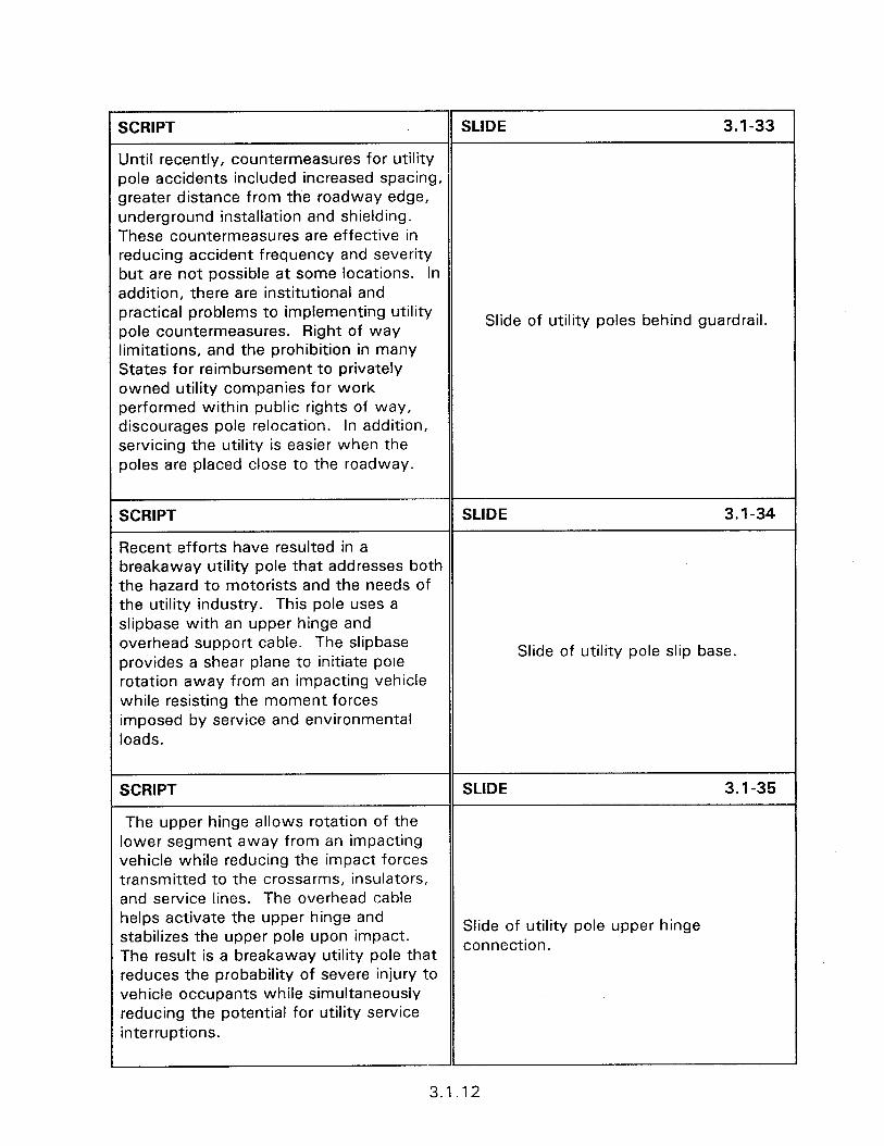
SCRIPT SLIDE 3.1-33
Until recently, countermeasures for utility pole accidents included increased spacing, greater distance from the roadway edge, underground installation and shielding. These countermeasures are effective in reducing accident frequency and severity but are not possible at some locations. In addition, there are institutional and practical problems to implementing utility pole countermeasures. Right of way
Slide of utility poles behind guardrail.
limitations, and the prohibition in many States for reimbursement to privately owned utility companies for work performed within public rights of way, discourages pole relocation. In addition, servicing the utility is easier when the poles are placed close to the roadway.
SCRIPT SLIDE 3.1-34
Recent efforts have resulted in a breakaway utility pole that addresses both the hazard to motorists and the needs of the utility industry. This pole uses a slipbase with an upper hinge and overhead support cable. The slipbase provides a shear plane to initiate pole
Slide of utility pole slip base.
rotation away from an impacting vehicle while resisting the moment forces imposed by service and environmental loads.
SCRIPT SLIDE 3.1-35
The upper hinge allows rotation of the lower segment away from an impacting vehicle while reducing the impact forces transmitted to the crossarms, insulators, and service lines. The overhead cable helps activate the upper hinge and stabilizes the upper pole upon impact.
Slide of utility pole upper hinge
The result is a breakaway utility pole that connection.
reduces the probability of severe injury to vehicle occupants while simultaneously reducing the potential for utility service interruptions.
3.1.12
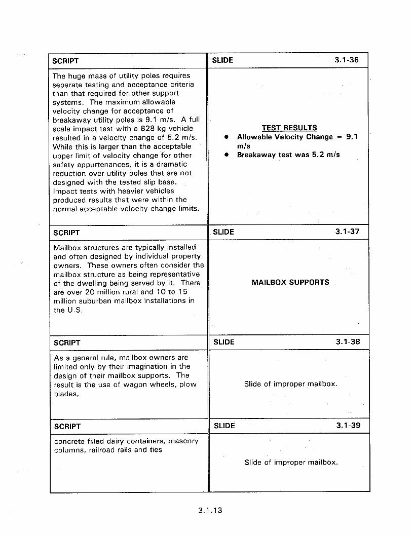
W%IPT SLIDE 3.1-36
The huge mass of utility poles requires separate testing and acceptance criteria :han that required for other support ;ystems. The maximum allowable velocity change for acceptance of 3reakaway utility poles is 9.1 m/s. A full scale impact test with a 828 kg vehicle TEST RESULTS *esulted in a velocity change of 5.2 m/s. @ Allowable Velocity Change = 9.1 Nhile this is larger than the acceptable m/s Jpper limit of velocity change for other safety appurtenances, it is a dramatic ,eduction over utility poles that are not designed with the tested slip base. Impact tests with heavier vehicles oroduced results that were within the normal acceptable velocity change limits.
l Breakaway test was 5.2 m/s
SCRIPT SLIDE 3.1-37
Mailbox structures are typically installed and often designed by individual property owners. These owners often consider the mailbox structure as being representative of the dwelling being served by it. There MAILBOX SUPPORTS are over 20 million rural and 10 to 15 million suburban mailbox installations in the U.S.
SCRIPT
As a general rule, mailbox owners are limited only by their imagination in the design of their mailbox supports. The result is the use of wagon wheels, plow blades,
SLIDE 3.1-38
Slide of improper mailbox.
SCRIPT SLIDE 3.1-39
concrete filled dairy containers, masonry columns, railroad rails and ties
Slide of improper mailbox.
3.1.13
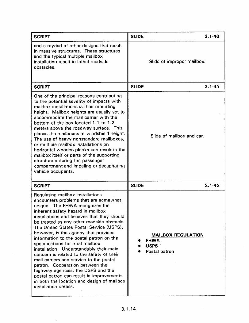
SCRIPT
and a myriad of other designs that result in massive structures. These structures and the typical multiple mailbox installation result in lethal roadside obstacles.
SLIDE 3.1-40
Slide of improper mailbox.
SCRIPT SLIDE 3.1-41
One of the principal reasons contributing to the potential severity of impacts with mailbox installations is their mounting height. Mailbox heights are usually set to accommodate the mail carrier with the bottom of the box located 1.1 to 1.2 meters above the roadway surface. This places the mailboxes at windshield height. The use of heavy nonstandard mailboxes,
Slide of mailbox and car.
or multiple mailbox installations on horizontal wooden planks can result in the mailbox itself or parts of the supporting structure entering the passenger compartment and impaling or decapitating vehicle occupants.
SCRIPT SLIDE 3.1-42
Regulating mailbox installations encounters problems that are somewhat unique. The FHWA recognizes the inherent safety hazard in mailbox installations and believes that they should be treated as any other roadside obstacle. The United States Postal Service (USPS), however, is the agency that provides information to the postal patron on the
MAILBOX REGULATION
specifications for rural mailbox . FHWA
installation. Understandably their main l USPS
concern is related to the safety of their l Postal patron
mail carriers and service to the postal patron. Cooperation between the highway agencies, the USPS and the postal patron can result in improvements in both the location and design of mailbox installation details.
3.1.14
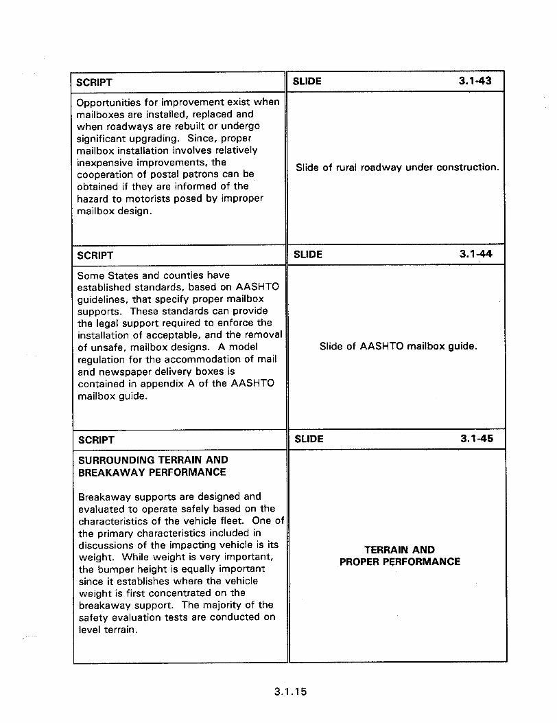
XXIPT SLIDE 3.1-43
Dpportunities for improvement exist when nailboxes are installed, replaced and when roadways are rebuilt or undergo significant upgrading. Since, proper nailbox installation involves relatively nexpensive improvements, the cooperation of postal patrons can be
Slide of rural roadway under construction.
Jbtained if they are informed of the lazard to motorists posed by improper nailbox design.
SCRIPT SLIDE 3.144
Some States and counties have established standards, based on AASHTO guidelines, that specify proper mailbox supports. These standards can provide the legal support required to enforce the installation of acceptable, and the removal of unsafe, mailbox designs. A model Slide of AASHTO mailbox guide. regulation for the accommodation of mail and newspaper delivery boxes is contained in appendix A of the AASHTO mailbox guide.
SCRIPT
SURROUNDING TERRAIN AND BREAKAWAY PERFORMANCE
SLIDE 3.1-45
Breakaway supports are designed and evaluated to operate safely based on the characteristics of the vehicle fleet. One of the primary characteristics included in discussions of the impacting vehicle is its weight. While weight is very important, the bumper height is equally important since it establishes where the vehicle weight is first concentrated on the breakaway support. The majority of the safety evaluation tests are conducted on level terrain.
TERRAIN AND PROPER PERFORMANCE
3.1.15
SCRIPT SLIDE 3.1-46
Supports should not be placed in locations where the terrain features can possibly impede their proper operation. Placing supports in drainage ditches can result in erosion and freezing which can affect the operation of the breakaway support. In addition, vehicles entering the ditch can Slide of sign in ditch. be inadvertently guided into the support.
SCRIPT SLIDE 3.1-47
Supports should not be installed closer than 2100 mm to other fixed objects. If the supports are placed closer than 2100 mm to other objects; which by themselves are considered acceptable, such as a 76 mm diameter tree, then a vehicle will be able to strike both the support and the object simultaneously. The combined Slide of sign near fixed object. effect of both the tree and the support on the change of velocity can be much higher when impacting both objects simultaneously.
SCRIPT SLIDE 3.1-48
Terrain in the vicinity of the support base must be graded to allow vehicles to pass over portions of the support that remain in the ground or that are rigidly attached to a foundation. Remaining portions of the support which protrude more than 100 mm above the ground line over a horizontal span of 1.5 m, as presented in figure 3.1.3, can snag the vehicle undercarriage.
3.1 .I 6
SCRIPT SLIDE 3.1-49
A breakaway device with a high anchor such as this one can snag a vehicle that is designed with low ground clearance or bouncing over uneven terrain.
Slide of high anchor piece.
SCRIPT SLIDE 3.1-50
Every sign, light support, utility pole and mailbox placed on the roadside is a fixed object. Understanding the traffic characteristics and the inherent safety needs is important to maintaining safety. Only install the fixed object when needed, and when needed select the breakaway device which will provide a cost effective CONCLUSION
safety solution. Then install that device 0 Only when needed
so that it will operate as designed. The 0 Safety needs
following sections present the design and l Device operation
construction/maintenance concerns for breakaway devices.
1
3.1.17


3.2 - DESIGN ORIENTATED SINGLE MOUNT SIGN SUPPORTS
Obiectives: To enable the participant to
l Identify the different types of single sign supports.
l Design sign supports to provide acceptable impact performance.
l Recognize hazardous installations.
l List and describe single sign supports approved for installation.
Heloful Hints:
l This session can be shortened by only discussing the types of sign supports used in the seminar area.
l Ask the participants to page through Appendix D which summarizes the approved single sign support types.
Visual Aids:
l 50 - 35 mm slides
Estimated Time
l 60 minutes
Handouts:
l None

l It is also possible to raise or lower the support structure. This requires unpinning the cartridge from the support structure and rolling it out of the way, loosening the wedge tension bolt, and then raising the support structure to the desired height before tightening the tension bolt.
5.3.H.4
SCRIPT SLIDE 3.24
Proper sign installation requires that the sign assembly be able to hold its proper position and give way under impact to minimize severity to an errant vehicle and its occupants. This requires the proper design in sign system selection and placement. Slide of impacted single sign support.
SCRIPT SLIDE 3.2-5
Sign supports are classified as single support and multiple support systems. A single sign support refers to a support that has no other support, or fixed object, within a 2100 mm radius. Multiple supports refer to installations that are
SINGLE SUPPORT
spaced less than 2100 mm from each l No other support or fixed
other, or from other fixed objects. object within 2100 mm radius
SCRIPT SLIDE 3.2-6
With the closer spacing, it is possible for a vehicle leaving the roadway at an angle, to impact more than one fixed object or su’pport at a time. Support systems which provide acceptable performance when struck alone can result in severe occupant injury when struck simultaneously with another support. The discussion of this l Closer than 2100 mm can
session pertains to single sign supports strike more than one support
[i.e. supports installed no closer than a at a time
2100 mm radius to other sign supports or Fixed objects).
3.2.2
SCRIPT
Sign assemblies consist of four components:
SLIDE 3.2-7
l The sign panel on which the message is displayed
SIGN COMPONENTS l Panel
l The sign post . Post l Hardware
l Mounting hardware and fasteners
l The base for the post.
0 Base
SCRIPT
Sign Panels
SLIDE 3.2-8
The majority of sign panels in use today are made from sheet aluminum stock. The thickness of the stock varies depending upon the sign size but is generally not less than 4.0 mm (8 gauge).
Slide of back aluminum sign.
SCRIPT
Plywood is occasionally used by some agencies as the blank material for the reflective sheeting face in areas of frequent vandalism in the form of gunshots.
SLIDE 3.2-9
Slide of plywood sign back.
SCRIPT SLIDE 3.2-10
Wooden sign blanks deform less from gun shots, are easier to repair and are not as attractive a target as aluminum sign blanks. Plywood, however, does not weather as well as aluminum and, if the edges are not sealed correctly, has a relatively short life. More importantly, the
Slide of gunshot aluminum sign.
plywood is heavier than aluminum requiring a stronger post system and increasing the probability of intrusion into the passenger compartment upon impact.
3.2.3
SCRIPT SLIDE 3.2-11
Composites such as fiberglass have also been used as sign blank materials with limited success. Early problems with composites included separation of the material and difficulties with the reflective sheeting adhering to the sign blank.
Slide of composite sign material.
These problems are claimed to have been resolved.
SCRIPT SLIDE 3.2-12
The sign support must be strong enough to resist the wind and other loads, yet safely give way when struck by a vehicle. The loading conditions for which the support must be designed are presented on this slide.
The required size of a sign post is dependent upon the surface area of the sign it is supporting and the prevailing environmental conditions. Each State has a series of tables and/or graphs that specify support post requirements based on prevailing wind and ice loads, sign size, and the height of the sign from the ground. These tables provide the information on the support size, embedment depth and the support type that is required to withstand the environmental loads.
Slide of State wind force graph.
SCRIPT
A general method of categorizing give- way support types is as:
SLIDE 3.2-13
0 Base bending
l Breakaway
l Mechanical
SUPPORT CATEGORIES l Base bending l Breakaway @ Mechanical
3.2.4

SCRIPT
Base Bendina Suooort Tvoes - Base bending supports are designed to bend over, lay down and pass beneath the impacting vehicle. How effectively they perform is dependent upon the type of support and the velocity of impact.
SLIDE 3.2-14
Slide of U-channel.
SCRIPT SLIDE 3.2-l 5
These supports tend to perform better at lower speed impacts which provide sufficient time for them to function as designed. Impacts at high speeds will frequently result in the support partially fracturing or being pulled out of the ground.
The performance of base bending Slide of impacted U-channel support. supports is more difficult to predict than other support types. Their behavior upon impact is influenced by variations in the depth of embedment, the soil resistance, stiffness of the sign support, mounting height of the sign and the method of effecting the yielding action.
SCRIPT
Steel U-Channel
SLIDE 3.2-16
The steel U-channel support is the most common type of single sign support used STEEL U-CHANNEL in the United States. The steel U-channel , l 3, 3.7, 4.5 6.0 kg/m is a uni-directional support available in 0 Rail steel different sizes and stiffness from a variety l Billet steel of manufacturers. The most popular steel U-channel sizes are 3, 3.7, 4.5 and 6.0 kg per meter (weight is prior to making the fastening holes).
3.2.5
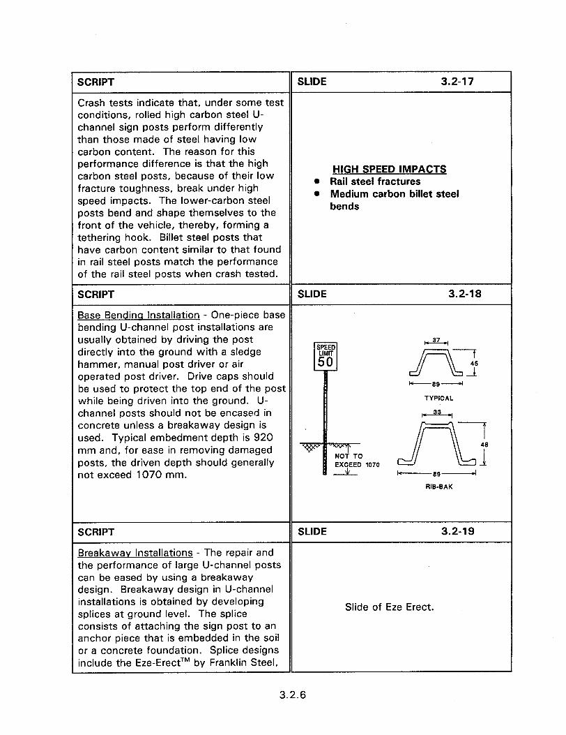
SCRIPT SLIDE 3.2-17
Crash tests indicate that, under some test conditions, rolled high carbon steel U- channel sign posts perform differently than those made of steel having low carbon content. The reason for this performance difference is that the high carbon steel posts, because of their low
HIGH SPEED IMPACTS
fracture toughness, break under high l Rail steel fractures
speed impacts. The lower-carbon steel l Medium carbon billet steel
posts bend and shape themselves to the bends
front of the vehicle, thereby, forming a tethering hook. Billet steel posts that have carbon content similar to that found in rail steel posts match the performance of the rail steel posts when crash tested.
SCRIPT SLIDE 3.2-18
Base Bendina Installation - One-piece base bending U-channel post installations are usually obtained by driving the post ,37_, directly into the ground with a sledge hammer, manual post driver or air operated post driver. Drive caps should rs 2
be used to protect the top end of the post Ic---SSd
while being driven into the ground. U- TYPICAL
channel posts should not be encased in F 33 concrete unless a breakaway design is used. Typical embedment depth is 920 -7 mm and, for ease in removing damaged
J=L
48
posts, the driven depth should generally EXCEED 1070 1
not exceed 1070 mm. k-----89-
RIB-BAK
SCRIPT SLIDE 3.2-l 9
Breakawav Installations - The repair and the performance of large U-channel posts can be eased by using a breakaway design. Breakaway design in U-channel installations is obtained by developing splices at ground level. The splice
Slide of Eze Erect.
consists of attaching the sign post to an anchor piece that is embedded in the soil or a concrete foundation. Splice designs include the Eze-ErectTM by Franklin Steel,
3.2.6
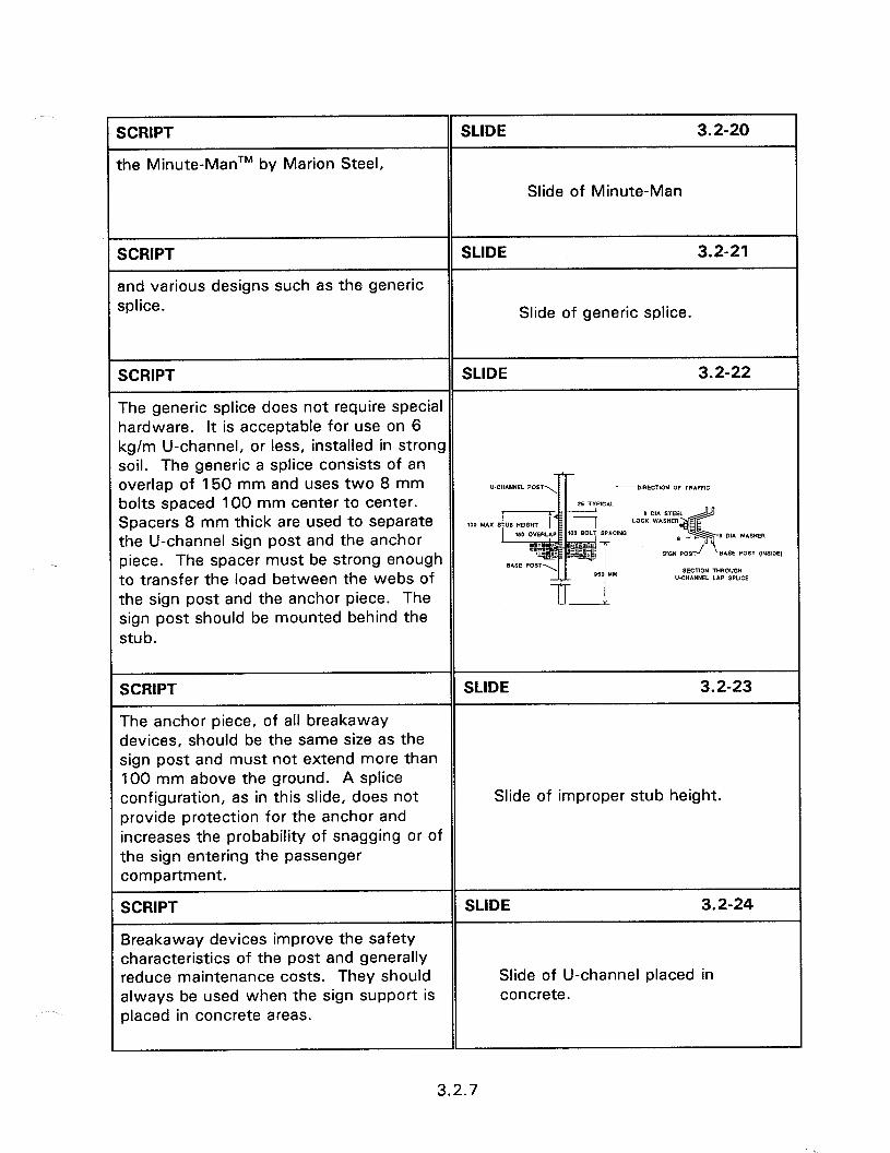
SCRIPT
the Minute-ManTM by Marion Steel,
SLIDE 3.2-20
Slide of Minute-Man
SCRIPT
snd various designs such as the generic splice.
SLIDE 3.2-21
Slide of generic splice.
SCRIPT SLIDE 3.2-22
The generic splice does not require special hardware. It is acceptable for use on 6 kg/m U-channel, or less, installed in strong soil. The generic a splice consists of an overlap of 150 mm and uses two 8 mm “.C”INNEL POST --DIRECTION OF m*FFIC bolts spaced 100 mm center to center. Spacers 8 mm thick are used to separate
8 011 STEEL 100 MAX 5 LOCK WASHER :
the U-channel sign post and the anchor (I d & 8 D1A WISHER
piece. The spacer must be strong enough $ SlGN POST / BASE POST (n4SIDE)
to transfer the load between the webs of SECTION THROUGH U-CHANNEL LAP SPUCE
the sign post and the anchor piece. The sign post should be mounted behind the stub.
SCRIPT SLIDE 3.2-23
The anchor piece, of all breakaway devices, should be the same size as the sign post and must not extend more than 100 mm above the ground. A splice configuration, as in this slide, does not Slide of improper stub height. provide protection for the anchor and increases the probability of snagging or of the sign entering the passenger compartment.
SCRIPT SLIDE 3.2-24
Breakaway devices improve the safety characteristics of the post and generally reduce maintenance costs. They should Slide of U-channel placed in always be used when the sign support is concrete. placed in concrete areas.
3.2.7
directions, then a breakaway device should be used.
Slide of U-channel in narrow median.
Wooden support posts are available in shaped sizes, engineered products and as timber posts. The shaped sizes are described by their nominal dimensions such as 100 mm x 100 mm. This is their size prior to the surfacing required to provide smooth and straight posts. Their actual size is typically 10 mm less than the nominal size. A 100 mm x 100 mm post will therefore, have an actual size of 90 mm x 90 mm. The engineered products are made from laminated or pressure glued wood and nonwood recycled products. Timber posts are
WOODEN SUPPORTS
with the intended fracture of the post near the base and less than 100 mm above the ground. The post features which influence fracture include the size of the post, effective cross section area, embedment depth, type of soil, and the species of wood. The majority of wood post tests have been conducted using grade 2 southern yellow pine posts. Slide of 90 mm x 90 mm wooden
Shaped Wood Posts - The most common size wood post used for single sign installations is the 90 mm x 90 mm support. This support should be buried directly in strong soil to a depth of at least 920 mm. The cross sectional area of the 90 mm x 90 mm post is sufficiently small to not need drilled holes to provide a
3.2.8
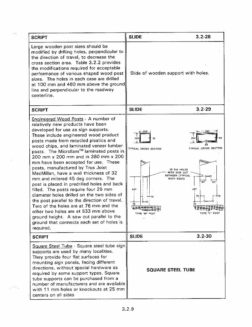
SCRIPT SLIDE 3.2-28
-arge wooden post sizes should be nodified by drilling holes, perpendicular to the direction of travel, to decrease the xoss section area. Table 3.2.2 provides the modifications required for acceptable oerformance of various shaped wood post Slide of wooden support with holes. sizes. The holes in each case are drilled st 100 mm and 460 mm above the ground ine and perpendicular to the roadway centerline.
SCRIPT SLIDE 3.2-29
Enaineered Wood Posts - A number of relatively new products have bean developed for use as sign supports. These include engineered wood product posts made from recycled plastics and wood chips, and laminated veneer lumber posts. The MicrollamTM laminated posts in
TYPICAL CROSS SECTION TYPICAL CROSS SECTION
200 mm x 200 mm and in 380 mm x 200 mm have been accepted for use. These posts, manufactured by Trus Joist 25 DIA HOLES
MacMillan, have a wall thickness of 32 WITH SAW CUT
mm and mitered 45 deg corners. The post is placed in predrilled holes and back filled. The posts require four 25 mm diameter holes drilled on the two sides of the post parallel to the direction of travel. Two of the holes are at 76 mm and the other two holes are at 533 mm above
TYPE ‘M’ POST TYPE ‘L’ POST ground height. A saw cut parallel to the -. ground that connects each set of holes is required.
SCRIPT SLIDE 3.2-30
Square Steel Tube - Square steel tube sign supports are used by many localities. They provide four flat surfaces for mounting sign panels, facing different directions, without special hardware as required by some support types. Square
SQUARE STEEL TUBE
tube supports can be purchased from a number of manufacturers and are available with 1 1 mm holes or knockouts at 25 mm centers on all sides
3.2.9
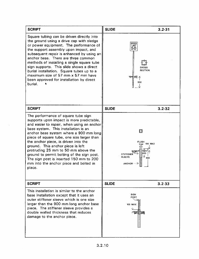
SCRIPT SLIDE 3.2-31
Square tubing can be driven directly into the ground using a drive cap with sledge or power equipment. The performance of slf4:TD the support assembly upon impact, and 50 subsequent repair is enhanced by using an anchor base. There are three common methods of installing a single square tube sign supports. This slide shows a direct burial installation. Square tubes up to a maximum size of 57 mm x 57 mm have been approved for installation by direct burial. C
,5 ;
a CROSS SECTION
.!+a$ T
GO
SCRIPT SLIDE 3.2-32
The performance of square tube sign supports upon impact is more predictable, and easier to repair, when using an anchor base system. This installation is an anchor base system where a 900 mm long lo
piece of square tube, one size larger than the anchor piece, is driven into the FLUSH
ground. This anchor piece is left TOP 100 MAX
43 \1
protruding 25 mm to 50 mm above the ground to permit bolting of the sign post. The sign post is inserted 150 mm to 200 mm into the anchor piece and bolted in place.
SCRIPT
This installation is similar to the anchor base installation except that it uses an
SLIDE
SIGN POST
3.2-33
outer stiffener sleeve which is one size larger than the 900 mm long anchor base piece. The stiffener sleeve provides a double walled thickness that reduces damage to the anchor piece.
3.2.10
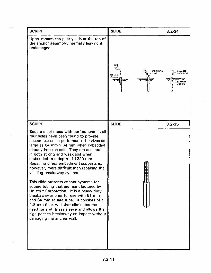
SCRIPT SLIDE 3.2-34
Upon impact, the post yields at the top of the anchor assembly, normally leaving it undamaged.
SCRIPT SLIDE 3.2-35
Square steel tubes with perforations on all four sides have been found to provide acceptable crash performance for sizes as large as 64 mm x 64 mm when imbedded directly into the soil. They are acceptable in both strong and weak soil when embedded to a depth of 1220 mm. Repairing direct embedment supports is, however, more difficult than repairing the yielding breakaway system.
This slide presents anchor systems for square tubing that are manufactured by Unistrut Corporation. It is a heavy duty breakaway anchor for use with 51 mm and 64 mm square tube. It consists of a 4.8 mm thick wall that eliminates the need for a stiffness sleeve and allows the sign post to breakaway on impact without damaging the anchor wall.
3.2.11
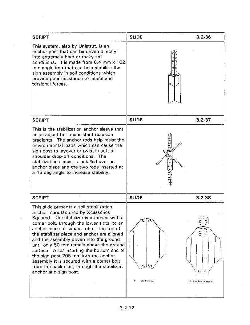
SCRIPT SLIDE 3.2-36
This system, also by Unistrut, is an anchor post that can be driven directly into extremely hard or rocky soil conditions. It is made from 6.4 mm x 102 mm angle iron that can help stabilize the sign assembly in soil conditions which provide poor resistance to lateral and torsional forces.
SCRIPT SLIDE 3.2-37
This is the stabilization anchor sleeve that helps adjust for inconsistent roadside gradients. The anchor rods help resist the environmental loads which can cause the sign post to layover or twist in soft or shoulder drop-off conditions. The stabilization sleeve is installed over an anchor piece and the two rods inserted at a 45 deg angle to increase stability.
SCRIPT SLIDE 3.2-38
This slide presents a soil stabilization anchor manufactured by Xcessories Squared. The stabilizer is attached with a corner bolt, through the lower slots, to an anchor piece of square tube. The top of the stabilizer piece and anchor are aligned and the assembly driven into the ground until only 50 mm remain above the ground surface. After inserting the bottom end of the sign post 205 mm into the anchor assembly it is secured with a corner bolt from the back side, through the stabilizer, anchor and sign post.
a, Soil Stabilizer bl Attached to anchor
3.2.12
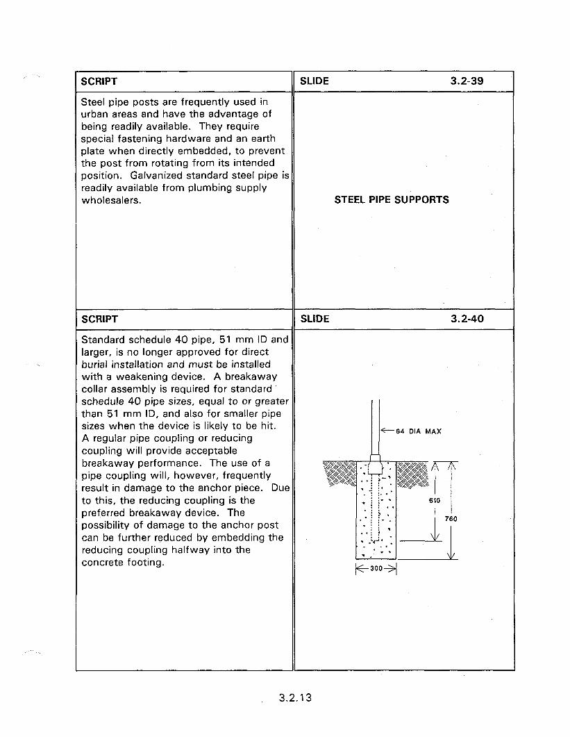
. . I SCRIPT SLIDE 3.2-39
Steel pipe posts are frequently used in urban areas and have the advantage of being readily available. They require special fastening hardware and an earth plate when directly embedded, to prevent the post from rotating from its intended position. Galvanized standard steel pipe is readily available from plumbing supply wholesalers. STEEL PIPE SUPPDRTS
SCRIPT SLIDE 3.2-40
Standard schedule 40 pipe, 51 mm ID and larger, is no longer approved for direct burial installation and must be installed with a weakening device. A breakaway collar assembly is required for standard schedule 40 pipe sizes, equal to or greater than 51 mm ID, and also for smaller pipe sizes when the device is likely to be hit.
t-64 DIA MAX A regular pipe coupling or reducing coupling will provide acceptable breakaway performance. The use of a n pipe coupling will, however, frequently result in damage to the anchor piece. Due to this, the reducing coupling is the preferred breakaway device. The possibility of damage to the anchor post can be further reduced by embedding the reducing coupling halfway into the concrete footing.
3.2.13

SCRIPT SLIDE 3.2-41
Round steel tube, in wall thicknesses of 12 gauge or less, can be used with anchor systems instead of standard schedule 40 pipe. These tubes are available from a number of manufacturers. Southwestern Pipe Inc. is one tubing manufacturer that also markets the Paz-LocTM anchor system. This system consists of a tubular anchor socket which is 64 mm ID and 686 mm long constructed of 12 gauge steel. The socket, is pointed to facilitate driving into the ground and accepts a 51
@
0
mm ID steel round tube as the sign WEDGE
support. The sign support is held in place by driving a post wedge between the socket and support. Should the post be damaged, the wedge can be removed, another post inserted, and the wedge replaced without disturbing the anchor socket. The wedge requires the use of a special puller for removal which reduces vandalism to the sign system.
SCRIPT
Aluminum Shapes
SLIDE 3.2-42
A limited number of single sign supports are constructed of aluminum. These shapes include U-channel, round and square tubing and various X shapes. The aluminum shapes come in various sizes. The U-channel size shown is only appropriate for small or temporary sign installations. The X shape has been tested and found acceptable up to the 76 mm x 79 mm size and is commercially available from different suppliers in slightly different configurations. All of the X shape supports are extruded and have a cross-sectional shape similar to that of back-to-back steel U-channels.
ALUMINUM SHAPES
3.2.14
SCRIPT
Fiberglass Support Posts
SLIDE 3.2-43
Fiberglass reinforced pipe (FRP) support posts are available and have been accepted for use in single sign support systems. The 76 mm outside diameter FRP post, manufactured by Hwycom, consisting of polyester resin and glass fiber reinforcement, is an example of an acceptable support. One method of installing the 3 mm thick walled FRP post is to insert it into a 686 mm long steel tube that has a wall thickness of 1.6 mm to 2.4 mm. The steel anchor tube is coated with ceramic to reduce corrosion and flattened for 305 mm to prevent rotation. Self-tapping screws secure the post in place.
FIBERGLASS SUPPORTS
SCRIPT
Slip Base Designs
SLIDE 3.2-44
Slip base designs for small sign supports consist of two components.
SLIP BASE DESIGNS
SCRIPT SLIDE 3.2-45
These are, 1) the anchor assembly up to the bottom of the slip base, and 2) the sign support, containing the top of the slip base on the lower end, and the sign panel on the upper end.
Slide of close up of slip base.
1
3.2.15

SCRIPT SLIDE 3.2-46
Slip base designs allow the use of stronger sign supports than can safely be achieved by base bending or fracture designs. The anchor piece of slip base designs is fixed into a foundation and should remain immovable during an impact. The sign support is connected to the anchor piece with bolts through a plate, which are attached to a similar plate on the anchor piece. The holes in the plates are slotted. When a vehicle impacts the sign support, the top plate, which is attached to the sign support, slides along the bottom plate until the
Slide of close-up view of multi-
bolts slide free of the slots. Inclined slip directional slip base components.
base designs cause the sign support to move upward to allow the impacting vehicle to pass under the sign without the sign hitting the windshield during high speed impact.
SCRIPT
Unidirectional Slip Bases
SLIDE 3.2-47
Unidirectional slip bases for small sign supports consist of inclined slip bases
Slide of inclined slip base.
3.2.16

r The multi-directional slip base design operates on the same principle as the inclined slip base design. The multi- directional design consists of a triangular slip base employing only three slotted bolt holes, as presented in figure 3.2.25. The bolts are positioned at the flattened corners of the triangular plate. An impact from any direction slides the bolts out of the slots and allows the sign post to separate from the anchor piece. The sign support is tubular and beveled at the top triangular slip plate to help the lift cone push the support off the anchor plate during impact. The anchor piece is encased in concrete to prevent movement.
Slide of multidirectional slip base.
Acceptable single sign support performance can be achieved with the use of frangible couplings and load concentration couplers. The couplers are used as inserts that bolt the support post plate to the anchor piece plate. They present a weak point on the sign support assembly that fractures upon impact. The majority of applications for frangible couplings are for multiple sign supports. These couplings are, therefore, discussed more fully in the module for multiple support systems.
Slide of frangible couplings.
3.2.17

SCRIPT
The proper design of sign supports requires:
The proper selection of support type and size based on State guidelines witr regard to practices, sign size and wind load.
Single sign supports have no other supports or fixed objects within a 210( mm radius.
The selected support must be of an approved design for safe impact performance.
Properly installed with no anchor assembly piece higher than 100 mm above ground level.
SLIDE 3.2-50
CONCLUSIONS l Proper support type and size 0 2100 mm clear radius 0 FHWA approved l Proper installation
3.2.18

SESSION GUIDE
3.3 - DESIGN ORIENTATED MULTIPLE MOUNT SIGN SUPPORTS
Obiectives:
l
l
Introduce the design considerations required for the proper performance of multiple mount sign assemblies.
Describe when two or more supports must simultaneously safely yield upon impact.
Identify the various types of multiple sign support assemblies that are approved for use.
Heloful Hints:
l Stress the separation of 2100 mm as the distance separating supports for the definition of single and multiple sign support systems. The trend is to move away from the ambiguous “small” and “large” sign definitions, based on sign area, that was used in the past. If sign supports are less than 2100 mm apart are called multiple support systems. These systems must be capable of sustaining an impact on more than one support at a time and provide acceptable vehicle deceleration rates.
l Have the participants turn to the approved multiple sign supports of Appendix E.
Visual Aids:
0 19 - 35 mm slides
Estimated Time
a 15 minutes
Handouts:
0 None

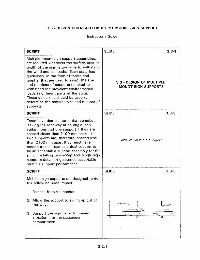
3.3 - DESIGN ORIENTATED MULTIPLE MOUNT SIGN SUPPORT
instructor’s Guide
SCRIPT SLIDE 3.3-l
Multiple mount sign support assemblies, are required whenever the surface area or width of the sign is too large to withstand the wind and ice loads. Each state has guidelines, in the form of tables and graphs, that are used to select the size and numbers of supports required to
3.3 - DESIGN OF MULTIPLE
withstand the prevalent environmental MOUNT SIGN SUPPORTS
loads in different parts of the state. These guidelines should be used to determine the required size and number of supports.
SCRIPT SLIDE 3.3-2
Tests have demonstrated that vehicles, leaving the roadway at an angle, can strike more that one support if they are spaced closer than 2100 mm apart. If two supports are, therefore, spaced less than 2100 mm apart they must have
Slide of multiple support.
passed a crash test as a dual support to be an acceptable support assembly for the sign. Installing two acceptable single sign supports does not guarantee acceptable multiple support performance.
SCRIPT SLIDE 3.3-3
Multiple sign supports are designed to do the following upon impact:
1. Release from the anchor.
2. Allow the support to swing up out of the way.
3. Support the sign panel to prevent intrusion into the passenger compartment.
3.3.1
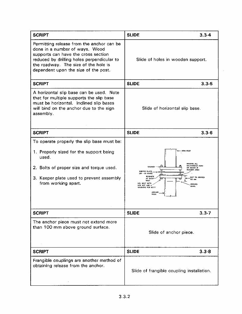
SCRIPT SLIDE 3.3-4
Permitting release from the anchor can be done in a number of ways. Wood supports can have the cross section reduced by drilling holes perpendicular to Slide of holes in wooden support. the roadway. The size of the hole is dependent upon the size of the post.
SCRIPT SLIDE 3.3-5
A horizontal slip base can be used. Note that for multiple supports the slip base must be horizontal. Inclined slip bases will bind on the anchor due to the sign Slide of horizontal slip base. assembly.
SCRIPT SLIDE 3.3-6
To operate properly the slip base must be:
1. Properly sized for the support being -s-- SlGN POST
used.
2. Bolts of proper size and torque used.
3. Keeper plate used to prevent assembly from working apart.
SCRIPT
The anchor piece must not extend more than 100 mm above ground surface.
SLIDE 3.3-7
Slide of anchor piece.
SCRIPT SLIDE 3.3-8
Frangible couplings are another method of obtaining release from the anchor.
Slide of frangible coupling installation.
3.3.2

SCRIPT SLIDE 3.3-9
Frangible couplings come in a number of different designs. Each design is intended to fail at the coupling. These have the THREIDED TO &A- ACCEPT BOLT advantage of not needing critical torque values or separation due to vibration.
bl Frangible coupling
SCRIPT
Release of the support at the top can be obtained by partial cut for wooden supports.
SLIDE 3.3-10
Slide of cut in upper wood post.
SCRIPT
Top release for steel shape supports can be achieved by:
SLIDE 3.3-11
1. Partial cut with a front friction plate. The bottom of the friction plate is slotted to permit release. The performance of this type is not as dependable as other types since the resistance to bending the back flange is dependent upon the depth of cut and support properties. Post also needs to be replaced upon impact.
3.3.3
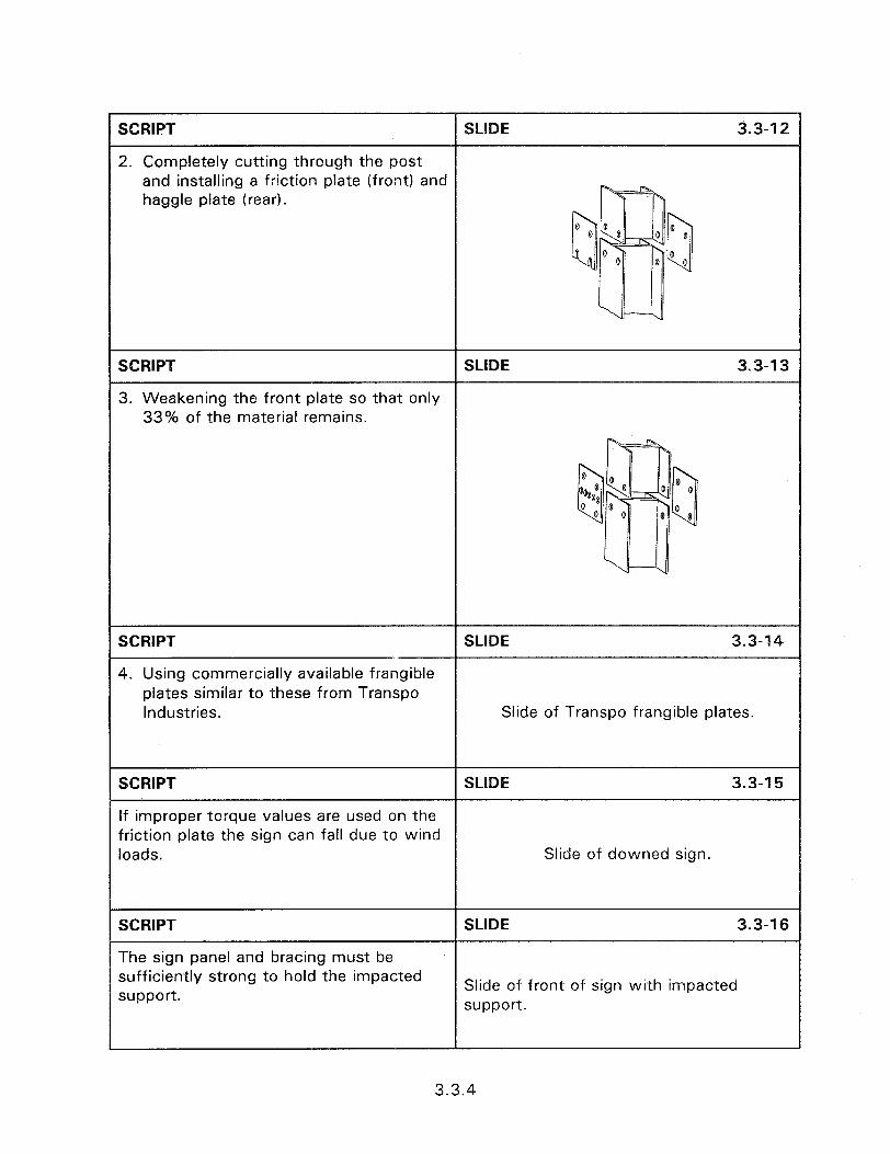
and installing a friction plate (front) and haggle plate (rear).
3. Weakening the front plate so that only 33% of the material remains.
4. Using commercially available fran plates similar to these from Transpo Industries. Slide of Transpo frangible plates.
loads. Slide of downed sign.
SCRIPT
The sign panel and bracing must be sufficiently strong to hold the impacted support.
SLIDE 3.3-l 6
Slide of front of sign with impacted support.
3.3.4
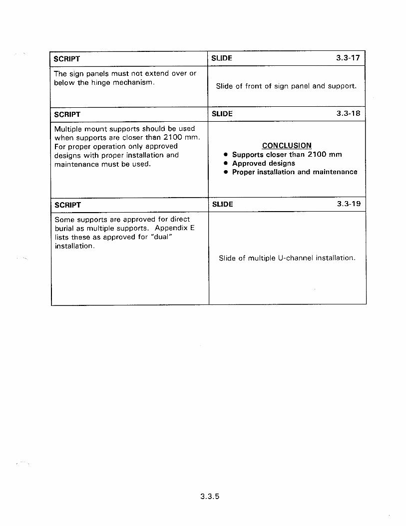
SCRIPT
The sign panels must not extend over or below the hinge mechanism.
SLIDE 3.3-l 7
Slide of front of sign panel and support.
SCRIPT SLIDE 3.3-l 8
Multiple mount supports should be used when supports are closer than 2100 mm. For proper operation only approved CONCLUSION designs with proper installation and l Supports closer than 2100 mm maintenance must be used. 0 Approved designs
l Proper installation and maintenance
SCRIPT
Some supports are approved for direct burial as multiple supports. Appendix E lists these as approved for “dual” installation.
SLIDE 3.3-l 9
Slide of multiple U-channel installation.
3.3.5

3.4 - MAINTENANCE AND CONSTRUCTION OF SINGLE SIGN SUPPORTS
Obiectives:
l Present the proper installation procedures for approved single sign support assemblies.
l Identify common installation problems.
l Discuss sign placement concerns.
Heloful Hints:
l Local examples of both good and bad practice should be used.
Visual Aids:
l 46 - 35 mm slides
Estimated Time
e 40 minutes
Handouts:
l None

3.4 - MAINTENANCE AND CONSTRUCTION OF SINGLE SIGN SUPPORTS
Instructor’s Guide
SCRIPT SLIDE 3.4-l
An important element to a safe highway environment is the proper construction and maintenance of traffic signs. Good designs and the best of materials will not be effective in reducing accident potential or severity if the traffic signs are improperly placed or installed. This 3.4 - MAINTENANCE AND requires that field crews be CONSTRUCTION OF SINGLE knowledgeable of proper installation SIGN SUPPORTS techniques and to report and correct any possible problems instead of merely placing the signs at the roadside.
SCRIPT SLIDE 3.4-2
Signs should be properly placed to provide the required information to the driver and to reduce the probability and severity on impact. Stop and yield signs should be placed at the point where the front of the vehicle is to stop.
Slide of stop sign.
SCRIPT
Warning signs should be placed sufficiently in advance so that the driver has adequate time to perceive, identify, decide and perform any necessary maneuver. A guide for the placement distance of warning signs is contained in the MUTCD.
SLIDE 3.4-3
Slide of warning sign.
3.4.1

SCRIPT SLIDE 3.4-4
The height from the ground to the top of the sign should be a minimum of 2750 mm. In the majority of cases following the minimum of 2100 mm requirement of the MUTCD to the bottom of the sign will achieve the 2750 mm top of the sign requirement. The 2750 mm requirement
Slide of roadside sign.
should, however, be the governing criteria since tests have demonstrated that signs mounted with their tops at this height will hit the roof rather than the windshield upon impact.
SCRIPT
Guidelines on the placement of signs are contained in the MUTCD and should be followed.
SLIDE 3.4-5
Slide of cover of MUTCD.
the field on proper sign placement. If the
LgzI
3
soil is weak a soil plate should be used.
SCRIPT
Sign crews must be aware of what is required for the proper installation of signs. Decisions will need to be made in
SCRIPT
Look at the traffic patterns at the sign location. If a heavy support is required and the sign can only be impacted from one direction then use a unidirectional support.
ye---- --..
SLIDE 3.4-7
Slide of inclined slip base.
SCRIPT SLIDE 3.4-8
Possibility of impacts from more than one direction should use multidirectional bases. Slide of U-channel with frangible coupling.
3.4.2
SCRIPT
Installation of wrong type of support can result in improper performance.
SLIDE 3.4-9
Slide of improper angle bracing.
SCRIPT
Use the existing roadway features to advantage.
SLIDE 3.4-l 0
Slide of sign in front of guardrail
SCRIPT
Do not allow the anchor stub to extend more than 100 mm above the ground.
SLIDE 3.4-l 1
Slide of anchor piece more than 100 mm.
SCRIPT SLIDE 3.4-l 2
The most common method of installing single mount sign supports is by direct burial. They are installed at least 900 mm but no more than 1100 mm into the ground by a sledge hammer
Slide of sledge hammer installation.
3.4.3
Slide of auger.
SCRIPT
or by mechanical post driver
SLIDE 3.4-13
Slide of mechanical driver.
SCRIPT
or by drilling a hole and backfilling.
SLIDE 3.4-14
SCRIPT SLIDE 3.4-15
Single mount sign supports can also be installed as two piece supports. This involves placing an anchor piece and attaching the sign post on to the anchor. Two piece U-channel assemblies can be installed by a generic splice. Slide of generic splice.
SCRIPT SLIDE 3.4-16
The anchor piece is driven 900 mm into the ground or embedded 610 mm in a concrete foundation 200 mm in diameter and 760 mm deep.
Slide of anchor piece.
1
3.4.4
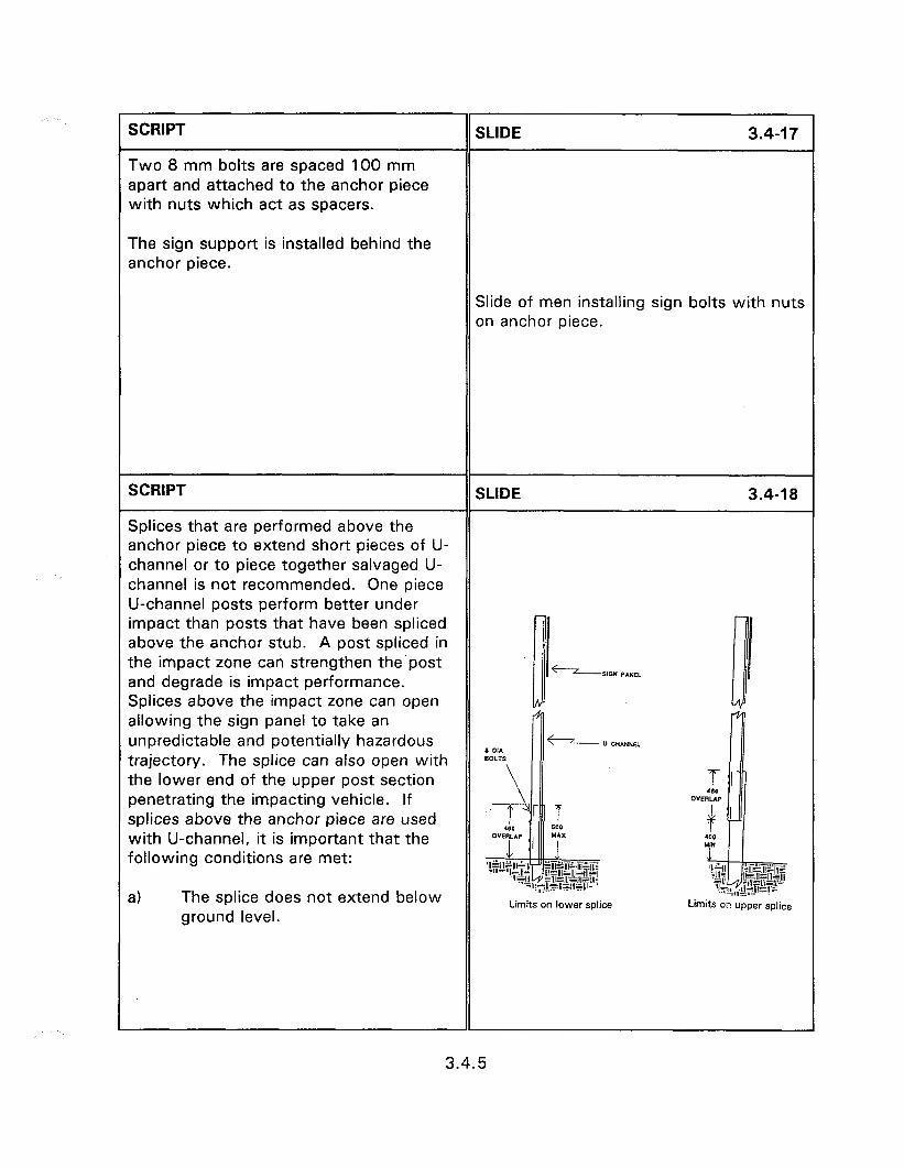
SCRIPT
Two 8 mm bolts are spaced 100 mm apart and attached to the anchor piece with nuts which act as spacers.
SLIDE 3.4-17
The sign support is installed behind the anchor piece.
Slide of men installing sign bolts with nuts on anchor piece.
SCRIPT SLIDE 3.4-l 8
Splices that are performed above the anchor piece to extend short pieces of U- channel or to piece together salvaged U- channel is not recommended. One piece U-channel posts perform better under impact than posts that have been spliced above the anchor stub. A post spliced in the impact zone can strengthen the post and degrade is impact performance. Splices above the impact zone can open allowing the sign panel to take an unpredictable and potentially hazardous trajectory. The splice can also open with the lower end of the upper post section penetrating the impacting vehicle. If splices above the anchor piece are used with U-channel, it is important that the following conditions are met:
a) The splice does not extend below ground level.
Limits on lower splice Limits 03 upper splice
3.4.5
b) The lap splice is approximately 460 mm fastened by four 8 mm bolts with two bolts, through the holes nearest the ends, at each end of the splice. Spacers, 16 mm thick, should be placed over the bolts between the spliced pieces of U-channel.
c) A splice that is mostly below a vehicle bumper height should have a maximum top elevation of 500 mm and a splice that is mostly above the bumper should have a bottom elevation of 400 mm or above.
SCRIPT
This splice is improper because it is not high enough for the upper splice requirements and the sign is in front of the anchor piece.
SLIDE 3.4-19
Slide of improper splice.
SCRIPT
Commercial U-channel splices are also available such as this Eze-Erect from Franklin Steel
SLIDE 3.4-20
Slide of Eze-Erect installation.
3.4.6

SCRIPT
and this Minute-Man from Marion Steel. Follow manufacturer’s instruction when installing commercial devices.
SLIDE 3.4-21
Slide of Minute-Man installation.
SCRIPT SLIDE 3.4-22
Anchor base square steel tube installations provide added support, helps proper performance, and eases repair. The anchor base assembly consists of a 760 mm long anchor piece, one size layer
: :
than the sign post and a 450 mm long stiffening sleeve one size layer that the anchor piece. The anchor piece is driven 200 mm into the ground, removed, and the soil knocked out.
SCRIPT
Reinsert the post into the hole and drive with stiffener sleeve to 50 mm above ground.
SLIDE 3.4-23
3.4.7
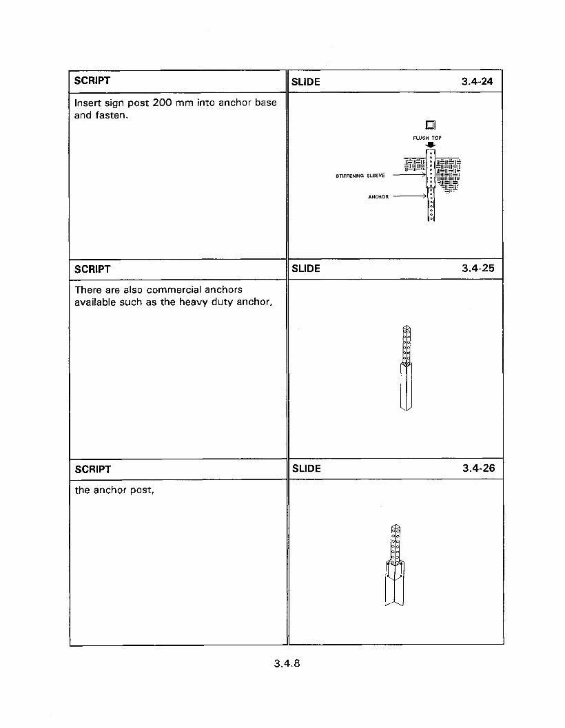
SCRIPT SLIDE 3.4-24
Insert sign post 200 mm into anchor base and fasten.
la FLVSH TOP
u
ST,F.=EN~NG SLEEVE
SCRIPT
There are also commercial anchors available such as the heavy duty anchor,
SLIDE 3.4-25
SCRIPT
the anchor post,
SLIDE 3.4-26
3.4.8

SCRIPT SLIDE 3.4-27
and the stabilization anchor. This anchor is for use in soil conditions that provide poor resistance to lateral and torsional forces. All three of these are manufactured by Unistrut Corporation.
SCRIPT
Another soil stabilization anchor is manufactured by Xcessories Squared.
SLIDE 3.4-28
SCRIPT SLIDE 3.4-29
Wooden posts are directly buried into augered holes and backfilled. Shaped wooden posts layer than 90 mm x 90 mm must have holes drilled, of the size and location of table 3.4.1 to decrease the cross section area.
Slide of single mount 90 mm x 90 mm sign support.
3.4.9
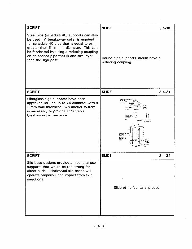
SCRIPT SLIDE 3.4-30
Steel pipe (schedule 40) supports can also be used. A breakaway collar is required for schedule 40 pipe that is equal to or greater than 51 mm in diameter. This can be fabricated by using a reducing coupling on an anchor pipe that is one size layer than the sign post.
Round pipe supports should have a reducing coupling.
SCRIPT SLIDE 3.4-31
Fiberglass sign supports have been approved for use up to 76 diameter with a 3 mm wall thickness. An anchor system
1s l.0 SCYL. .(I PFf is necessary to provide acceptable breakaway performance.
SCRIPT SLIDE 3.4-32
Slip base designs provide a means to use supports that would be too strong for direct burial. Horizontal slip bases will operate properly upon impact from two directions.
Slide of horizontal slip base.
3.4.10
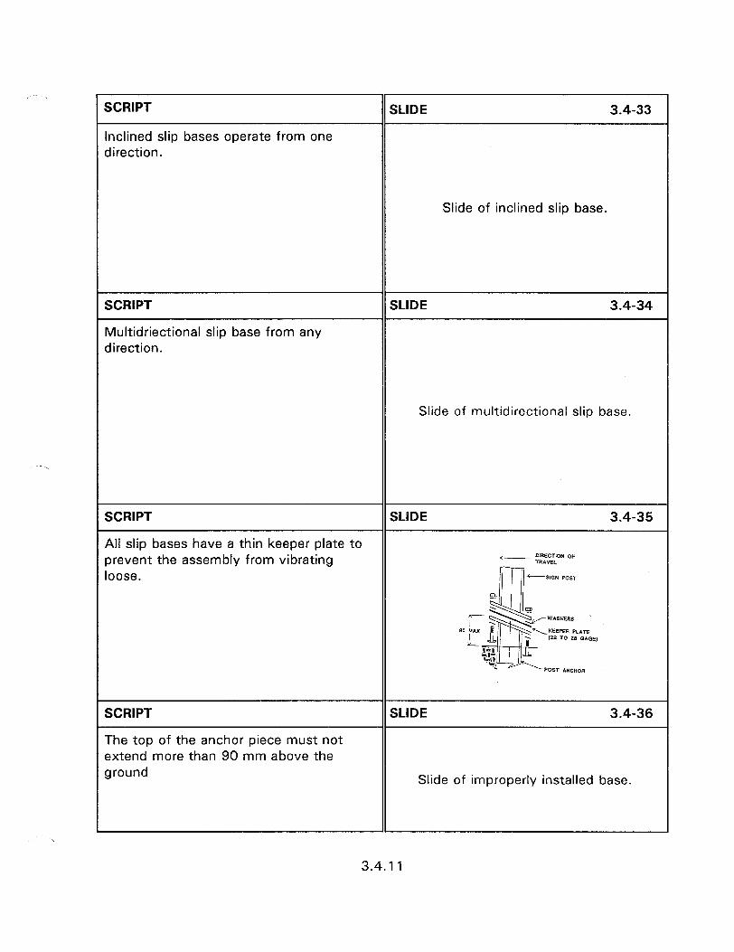
I-
Slide of inclined slip base.
SCRIPT
Inclined slip bases operate from one direction.
SLlDE 3.4-33
SCRIPT
Multidriectional slip base from any direction.
SLIDE 3.4-34
Slide of multidirectional slip base.
SCRIPT
All slip bases have a thin keeper plate to prevent the assembly from vibrating
SLIDE 3.4-35
DlRECTlON OF - TRAVEL loose.
SCRIPT
The top of the anchor piece must not extend more than 90 mm above the ground
SLIDE 3.4-36
Slide of improperly installed base.
3.4.11
1
Slide of loose slip base.
SCRIPT SLIDE 3.4-37
and the bolts must be of the proper size and torque with washers used to prevent loosening (table 3.4.7 and 3.4.8).
SCRIPT SLlDE 3.4-38
Mounting of the sign panel to the support requires that the top of the sign be 2750 mm above the ground to prevent intrusion into passenger compartment.
Slide of sign at proper height.
SCRIPT SLIDE 3.4-39
The sign should be attached with 8 mm diameter bolts sufficiently tight to prevent movement yet not so tight to bend the sign face.
Slide of sign face.
SCRIPT SLIDE 3.4-40
Vandal resistant fasteners can be used to reduce theft.
Close up of vandal proof nut.
3.4.12
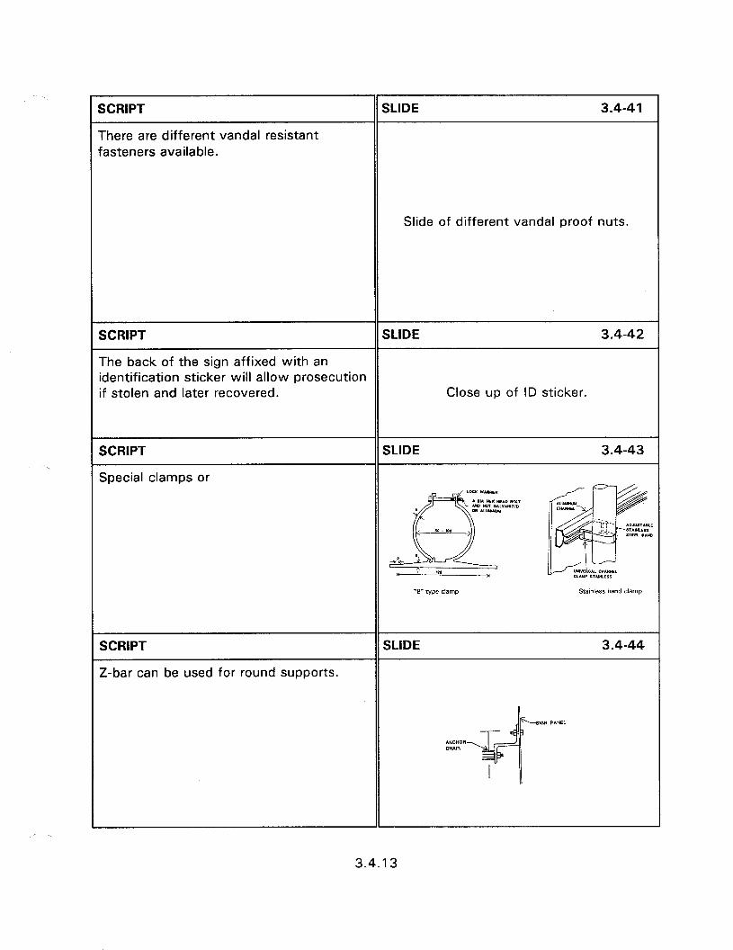
SCRIPT
There are different vandal resistant fasteners available.
SLIDE 3.4-41
Slide of different vandal proof nuts.
SCRIPT SLIDE 3.4-42
The back of the sign affixed with an identification sticker will allow prosecution if stolen and later recovered. Close up of ID sticker.
SCRIPT
Special clamps or
SLIDE 3.4-43
SCRIPT
Z-bar can be used for round supports.
SLIDE 3.4-44
3.4.13
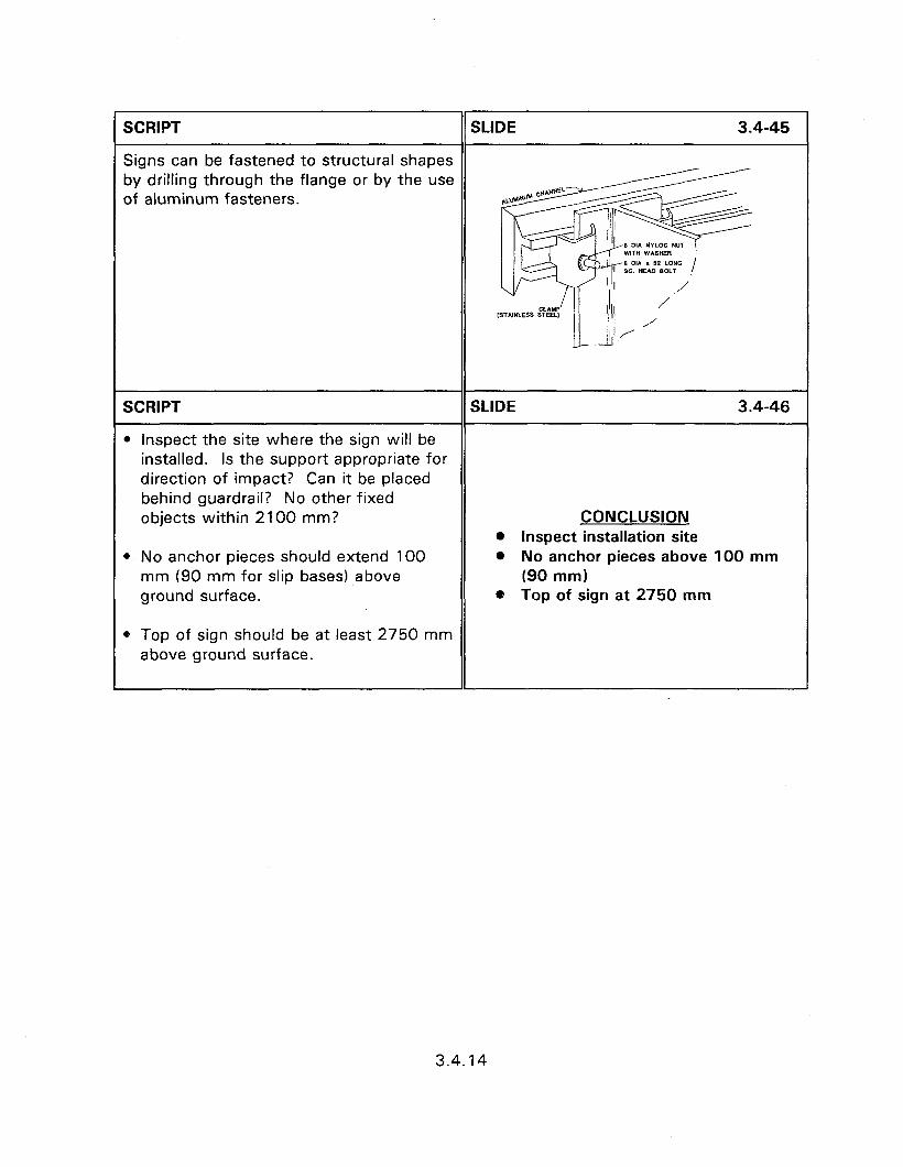
SCRIPT SLIDE 3.4-45
Signs can be fastened to structural shapes by drilling through the flange or by the use of aluminum fasteners.
SCRIPT SLIDE 3.4-46
l inspect the site where the sign will be installed. Is the support appropriate for direction of impact? Can it be placed behind guardrail? No other fixed objects within 2100 mm? CONCLUSION
l Inspect installation site l No anchor pieces should extend 100
mm (90 mm for slip bases) above ground surface.
0 Top of sign should be at least 2750 mm above ground surface.
l No anchor pieces above 100 mm (90 mm)
0 Top of sign at 2750 mm
3.4.14
SESSION GUIDE
3.5 - MAINTENANCE AND CONSTRUCTION OF MULTIMOUNT SIGN SUPPORTS
Obiectives:
l Present the proper installation procedures for approved multiple sign support assemblies.
0 Identify common installation problems and correct procedures.
0 Discuss sign placement concerns.
Helpful Hints:
0 To save time you can present only those support types used in the presentation area.
. Local slides of good and poor practice should be used.
Visual Aids:
l 34 - 35 mm slides
Estimated Time
0 45 minutes
Handouts:
0 None

3.5 - MAINTENANCE AND CONSTRUCTION OF MULTI-MOUNT SIGN SUPPORTS
Instructor’s Guide
SCRIPT SLIDE 3.5-l
Multiple mount sign supports are required to support sign panels that are too large to withstand wind and ice loads with the use of only one support. Multiple mount sign supports are designed to provide acceptable performance upon impact when the supports are placed 2100 mm, or closer, to each other. This close spacing results in the possibility of a vehicle, leaving the roadway at an angle, impacting more than one support
3.5 - MAINTENANCE AND
simultaneously. This possibility means CONSTRUCTION OF MULTI-
that some supports, approved for use as a MOUNT SIGN SUPPORTS
single support system, are not approved for multi-mount designs. Appendix E lists the supports that have been approved for use as multiple mount systems. Support configurations that are not listed in appendix E should not be used for multi- mount sign supports until they have been approved by the FHWA.
SCRIPT
ONE PIECE MULTIPLE-MOUNT SIGN SUPPORTS
SLIDE 3.5-2
The majority of support types approved ONE PIECE MULTIPLE-MOUNT
for use within 2100 m or less of each SIGN SUPPORTS
other require the use of anchor pieces or frangible couplings.
SCRIPT SLIDE 3.5-3
Direct burial assemblies that are approved for use include dual 4.5 kg/m U-channel
Slide of a dual U-channel installation.
SCRIPT
and 90 mm x 90 mm wood posts
SLIDE 3.5-4
Slide of wood post multi-mount.
3.5.1
L
SCRIPT SLIDE 3.5-5
that have been modified with 38 mm holes at 100 mm and 460 mm above the ground line.
Slide of holes in supports.
SCRIPT SLIDE 3.5-6
Other than these exceptions, multiple mount sign supports require the use of anchor pieces, sleeves, slip bases, or frangible couplings for acceptable impact performance. Appendix E contains a list of acceptable multi-mount supports. MULTIPLE MOUNTS Installation details for one piece U- 0 Anchor pieces channel, square tube with sleeve, l Slip bases commercially available breakaway l Sleeves devices, are provided in section 3.4. Only l Frangible couplings those devices listed in Appendix E and configured as indicated, or subsequently approved for use by the FHWA, should be used for multiple mount supports.
SCRIPT SLIDE 3.5-7
Frangible couplings are designed to fail at a weakened point upon impact. They do not have the disadvantages of ensuring a maximum or minimum torque value for proper operation as necessary for slip FRANGIBLE COUPLINGS bases.
SCRIPT SLIDE 3.5-8
Transpo industries manufactures a series of breakaway systems for ground mounted sign supports; marketed under the trade name Break-Safe’“. The Break- Safe’” system uses frangible couplers
Slide of Transpo installation.
3.5.2
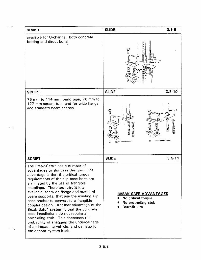
SCRIPT
available for U-channel, both concrete footing and direct burial,
SLIDE 3.5-9
SCRlPT SLIDE 3.5-10
76 mm to 114 mm round pipe, 76 mm to 127 mm square tube and for wide flange and standard beam shapes.
SCRIPT SLIDE 3.5-l 1
The Break-Safe’” has a number of advantages to slip base designs. One advantage is that the critical torque requirements of the slip base bolts are eliminated by the use of frangible couplings. There are retrofit kits available, for wide flange and standard beam supports, that use the existing slip
BREAK-SAFE ADVANTAGES
base anchor to convert to a frangible l No critical torque
coupler design. Another advantage of the @ No protruding stub
Break-Safe’” system is that the concrete l Retrofit kits
base installations do not require a protruding stub. This decreases the probability of snagging the undercarriage of an impacting vehicle, and damage to the anchor system itself.
3.5.3

SCRIPT SLIDE 3.5-l 2
The protruding stub is eliminated by bolting the frangible coupling into anchors placed in the concrete footing. Proper assembly requires that the anchors be accurately placed for each type of support system. Accurate anchor placement requires the use of an installation jig similar to figure 3.5.6b. The dimensions of A and B will vary by the type and size of sign support being installed.
SCRIPT
Slip Base Designs
SLIDE 3.5-l 3
Manufacturers are developing devices that enable the use of heavier single support shapes while providing acceptable impact performance as a multi-sign support system.
SLIP BASE DESIGNS
SCRIPT
This slide presents a schematic of a slip base assembly for square tube supports,
SLIDE 3.5-14
NOTE RECclYYElm)ED Tma manufactured by Unistrut Corporation, that is acceptable for three 64 mm x 64 mm supports within a 2100 mm path. The bottom subassembly is inserted into a 760 mm long anchor piece and placed in a 200 mm diameter, 760 mm deep concrete foundation, figure 3.5.8.
8 d Assembly bl Foundation detail
SCRIPT
Slip base designs for multiple sign supports are usually of horizontal design.
SLIDE 3.5-l 5
Slide of horizontal slip base.
3.5.4
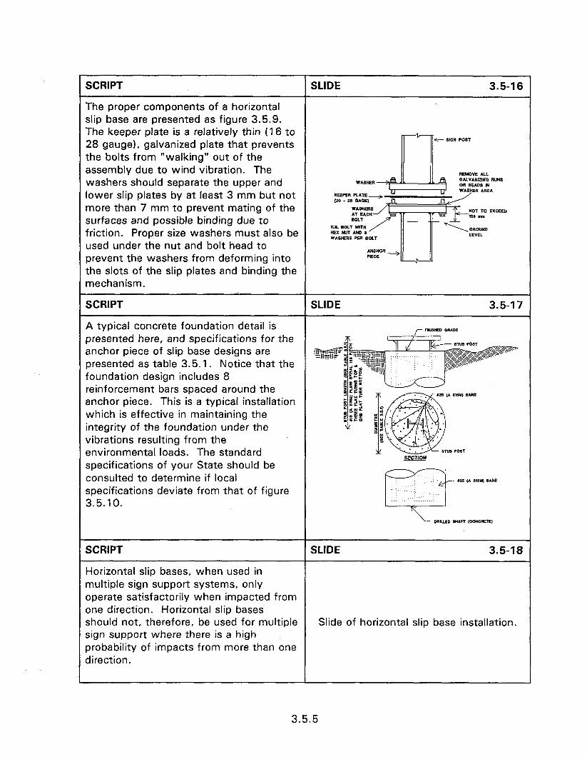
r SCRIPT SLIDE 3.5-l 6
The proper components of a horizontal slip base are presented as figure 3.5.9. The keeper plate is a relatively thin (16 to 28 gauge), galvanized plate that prevents
c S,CN POST
the bolts from “walking” out of the assembly due to wind vibration. The REMOVE Au. washers should separate the upper and lower slip plates by at least 3 mm but not KEEPER PLATE more than 7 mm to prevent mating of the surfaces and possible binding due to friction. Proper size washers must also be
Ms. BOLT WIT” )(EXw*H8 WASHERS pw B used under the nut and bolt head to prevent the washers from deforming into the slots of the slip plates and binding the mechanism.
SCRIPT SLIDE 3.5-l 7
A typical concrete foundation detail is Fwsw WE presented here, and specifications for the anchor piece of slip base designs are presented as table 3.5.1. Notice that the foundation design includes 8 reinforcement bars spaced around the anchor piece. This is a typical installation which is effective in maintaining the integrity of the foundation under the vibrations resulting from the environmental loads. The standard specifications of your State should be consulted to determine if local specifications deviate from that of figure
SCRIPT SLIDE 3.5-18
Horizontal slip bases, when used in multiple sign support systems, only operate satisfactorily when impacted from one direction. Horizontal slip bases should not, therefore, be used for multiple Slide of horizontal slip base installation. sign support where there is a high probability of impacts from more than one direction.
3.5.5
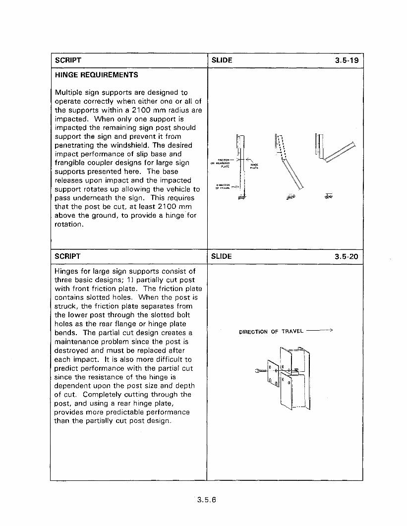
SCRIPT SLIDE 3.5-19
HINGE REQUIREMENTS
Multiple sign supports are designed to operate correctly when either one or all of the supports within a 2100 mm radius are impacted. When only one support is impacted the remaining sign post should support the sign and prevent it from penetrating the windshield. The desired impact performance of slip base and frangible coupler designs for large sign supports presented here. The base releases upon impact and the impacted D,RECT,OH support rotates up allowing the vehicle to 0FTR*YEL pass underneath the sign. This requires -7J-z ,@B?’ .&is that the post be cut, at least 2100 mm above the ground, to provide a hinge for rotation.
SCRIPT SLIDE 3.5-20
Hinges for large sign supports consist of three basic designs; 1) partially cut post with front friction plate. The friction plate contains slotted holes. When the post is struck, the friction plate separates from the lower post through the slotted bolt holes as the rear flange or hinge plate bends. The partial cut design creates a DIRECTION OF TRAVEL -
maintenance problem since the post is destroyed and must be replaced after each impact. It is also more difficult to predict performance with the partial cut since the resistance of the hinge is dependent upon the post size and depth of cut. Completely cutting through the post, and using a rear hinge plate, provides more predictable performance than the partially cut post design.
3.5.6

KRIPT
2) completely cut post with front friction and rear hinge plate,
SLIDE 3.5-21
DIRECTION OF TRAVEL ------+
SCRIPT SLIDE 3.5-22
and 3) completely cut post with weakened front plate and rear hinge plate. weakened front plate designs include shop fabricated and commercially available front plates. Weakened plate designs require that the post be completely cut and the hinge plate used. The shop fabricated plate requires drilling holes, centered on the cut line of the post, so that only 33% of the horizontal plate material remains.
SCRIPT SLIDE 3.5-23
There are commercially available plate designs which use the weakened front plate principle, such as this design by Transpo Industries. The post is cut completely through and a rear plate is also used.
Slide of Transpo system.
3.5.7
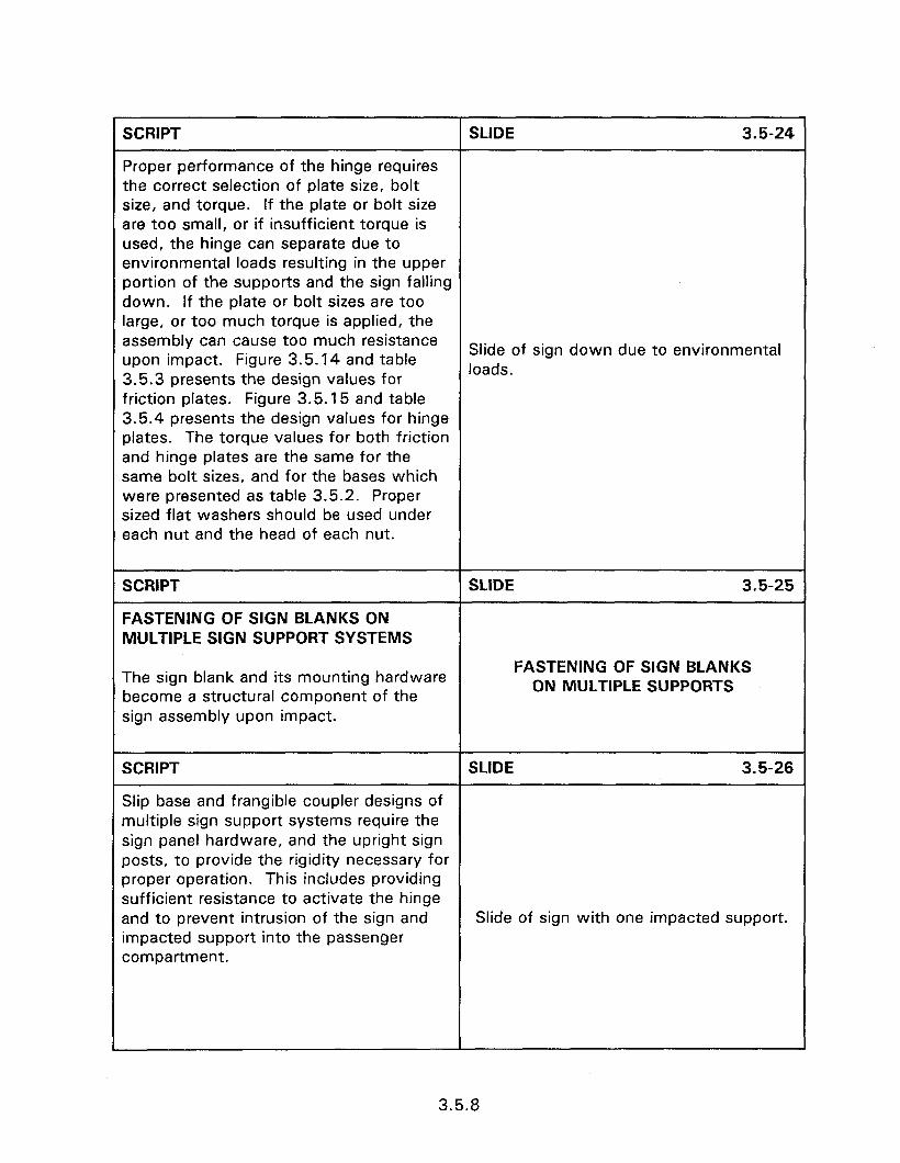
SCRIPT SLIDE 3.5-24
Proper performance of the hinge requires the correct selection of plate size, bolt size, and torque. If the plate or bolt size are too small, or if insufficient torque is used, the hinge can separate due to environmental loads resulting in the upper portion of the supports and the sign falling down. If the plate or bolt sizes are too large, or too much torque is applied, the assembly can cause too much resistance upon impact. Figure 3.5.14 and table
Slide of sign down due to environmental
3.5.3 presents the design values for loads.
friction plates. Figure 3.5.15 and table 3.5.4 presents the design values for hinge plates. The torque values for both friction and hinge plates are the same for the same bolt sizes, and for the bases which were presented as table 3.5.2. Proper sized flat washers should be used under each nut and the head of each nut.
SCRIPT
FASTENING OF SIGN BLANKS ON MULTIPLE SIGN SUPPORT SYSTEMS
SLIDE 3.5-25
The sign blank and its mounting hardware become a structural component of the sign assembly upon impact.
FASTENING OF SIGN BLANKS ON MULTIPLE SUPPORTS
SCRIPT SLIDE 3.5-26
Slip base and frangible coupler designs of multiple sign support systems require the sign panel hardware, and the upright sign posts, to provide the rigidity necessary for proper operation. This includes providing sufficient resistance to activate the hinge and to prevent intrusion of the sign and Slide of sign with one impacted support. impacted support into the passenger compartment.
3.5.8
SCRIPT SLIDE 3.5-27
Proper hinge activation also requires that no portion of the primary sign, or any supplemental signs, are attached to the support posts below the hinge. In addition, no portion of the sign panel should extend lower than 2100 mm above ground level.
Slide of sign above hinge.
SCRIPT SLIDE 3.5-28
Fastening of sign panels to multi support sign systems usually requires the use of stiffeners to provide the required rigidity. The exception to this is for relatively small surface area signs which require multiple supports due to their shape and for wooden signs. Consult your State’s specifications for installation requirements. Clamps are used to fasten Slide of back of large sign. the stiffeners to S or W shaped beam posts which eliminates the need to drill into the post itself.
SCRIPT SLIDE 3.5-29
U-channel posts can also be used as stiffeners for large signs. When U- channel is used, it should be galvanized and should weigh no more than 3.7 kg/m. U-channel of 3 kg/m is sufficiently strong to withstand wind loads of 130 km/h.
Slide of U-channel backing.
3.5.9
SCRIPT
NOTES ON MULTIPLE SIGN SUPPORT CONSTRUCTION
0 Multi-mount sign supports are designed to function properly when more than one support is struck by an errant vehicle. There will, however, be occasions where only one support will be impacted. When this occurs, it is necessary that the sign panel be properly fastened and have sufficient rigidity, so that the post(s) which are not impacted will support the sign panel, preventing intrusion into the vehicle.
0 The hinge should be located at least 2100 mm above the ground to prevent the sign from penetrating the windshield.
l No portion of the primary sign, additional signs, or bracing should be attached to the supports below the hinges. Fastening below the hinge will interfere with the breakaway performance of the support post. Signs which are mounted to the primary sign panel and are less than 2100 mm above the ground can intrude into the passenger compartment even when the hinge operates correctly. Supplemental sign panels should not, therefore, be less than 2.1 m above the ground.
SLIDE 3.5-30
CONCLUSION l Proper fastening of sign panel l Hinge at least 2100 mm 0 Clear hinge
3.5.10
SCRIPT
) Two posts within a 2100 mm path should, each, have a mass that does not exceed 27 kg/m.
SLIDE 3.5-31
m Slip base mechanisms must be constructed with the proper size bolts and washers. Oversized bolts can result in bending between the upper and lower base plates. Washers which are too thin can deform into the slots and bind the plates together.
l The torque specifications must be followed when assembling slip bases and hinges. Insufficient torque can result in wind and ice loads causing the bolts to become loose with subsequent “blow-down” from hinge release or “walking” at the slip base. Applying too much torque can result in binding between the mating surfaces with subsequent improper operation upon impact.
l Mass C 27 kg/m l Proper size bolts l Proper torque
l Crash tests, performed on level terrain, indicate that breakaway designs perform satisfactorily upon impact. When installed on slopes however, there is the possibility that they may not function as planned. This is due to the slope changing the trajectory of the impacting vehicle from the test conditions achieved with level ground. Multiple-mount signs should be installed on level ground when possible and outside of the clear zone; in a location where they will be least likely to be hit. Some State agencies routinely require multi-mount signs to be installed 12 m or more from the edge of the travelled way.
0 Level terrain
3.5.11

SCRIPT
l Follow the installation plans of multiple mount supports for both construction and maintenance. Do not make temporary maintenance repairs using wrong size bolts or shear plates. Temporary repairs often become permanent, and even if corrected at a later time, can be subjected to an impact prior to correction.
l Do not install any sign supports in a ditch line. The water funneled in the ditch will cause premature corrosion, and can freeze, preventing proper operation. The ditch can also channel errant vehicles and guide them into the support.
l Multiple mount sign support systems are often classified as dual and triple installations. This classification refers to the number of posts permitted within a 2100 mm radius. Support types approved for dual installation, for example, indicate that no more than two of these supports are permitted within a 2100 mm radius of each other. Acceptable impact performance can be achieved by reducing, but never increasing, the number of supports. A support type approved for dual use can be installed as a single mount post but not as a triple installation.
l Each post of a hinge design should be fabricated from a continuous piece of material. The holes for the friction and hinge plates should be drilled and sections match marked before cutting and weather proofing. The match marks must be visible after weather proofing.
SLIDE 3.5-32
0 Maintenance l No ditch installation l No support/fixed object within
2100 mm l Continuous support pieces
3.5.12
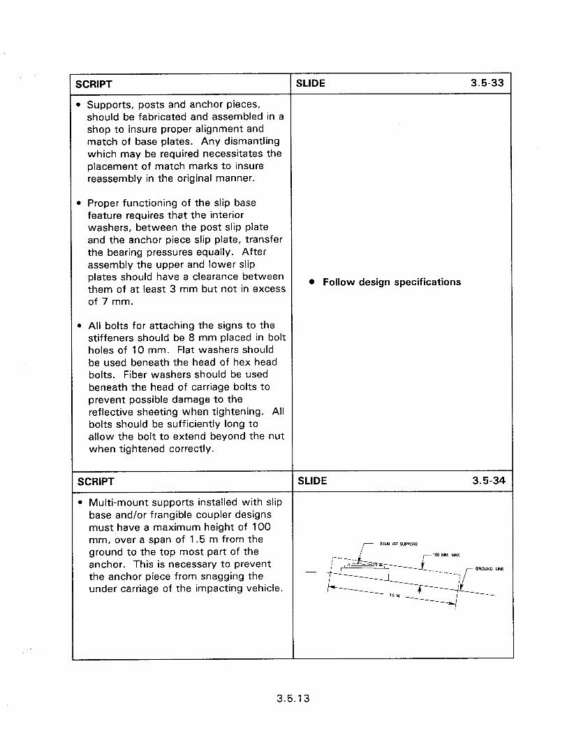
SCRIPT SLIDE 3.5-33
1 Supports, posts and anchor pieces, should be fabricated and assembled in a shop to insure proper alignment and match of base plates. Any dismantling which may be required necessitates the placement of match marks to insure reassembly in the original manner.
D Proper functioning of the slip base feature requires that the interior washers, between the post slip plate and the anchor piece slip plate, transfer the bearing pressures equally. After assembly the upper and lower slip plates should have a clearance between them of at least 3 mm but not in excess of 7 mm.
l Follow design specifications
b All bolts for attaching the signs to the stiffeners should be 8 mm placed in bolt holes of 10 mm. Flat washers should be used beneath the head of hex head bolts. Fiber washers should be used beneath the head of carriage bolts to prevent possible damage to the reflective sheeting when tightening. All bolts should be sufficiently long to allow the bolt to extend beyond the nut when tightened correctly.
SCRIPT SLIDE 3.5-34
l Multi-mount supports installed with slip base and/or frangible coupler designs must have a maximum height of 100 mm, over a span of 1.5 m from the ground to the top most part of the anchor. This is necessary to prevent the anchor piece from snagging the under carriage of the impacting vehicle.
3.5.13

SESSION GUIDE
3.6 - MAINTENANCE OF TRAFFIC SIGN PANELS AND POSTS
Obiectives:
0 To present methods of reducing sign vandalism.
l To review sign rehabilitation techniques.
HelDful Hints:
0 Use slides of signs from the local area if available.
Visual Aids:
a 22 - 35 mm slides
Estimated Time
l 15 minutes
Handouts:
l None

3.6 - MAINTENANCE OF TRAFFIC SIGN PANELS AND POSTS
Instructor’s Guide
SCRIPT SLIDE 3.6-l
Regulatory and warning signs that are missing or in poor condition pose safety hazards to motorists and can result in tort liability. Regulatory and warning signs must be repaired as soon as a defect is noticed. All of the signs on an agency’s 3.6 - MAINTENANCE OF TRAFFIC SIGN roadway system should be inspected PANELS AND POSTS periodically to determine that their orientation and retroreflectivity properties are adequate for nighttime visibility.
SCRIPT
SIGN VANDALISM PROBLEMS AND COUNTERMEASURES
SLIDE 3.6-Z
Sign vandalism causes millions of dollars each year in increased maintenance costs and is a contributing cause to a number of accidents each year. In addition to the accident itself, vandalized signs can expose the roadway agency and municipality to tort liability cases. Surveys of State and local agencies indicate that an average of 30 percent of all sign replacement and repair is due to vandalism and that an average of 30 percent of the sign maintenance budget is required for vandalized signs. Acts of sign vandalism are categorized as destruction, mutilation, and theft.
Slide of missing sign.
3.6.1
SCRIPT
Destruction
Destruction occurs when the sign support or sign face is physically damaged to the extent that it no longer serves its intended purpose. Destruction vandalism includes damage from:
l Gunshot l Thrown projectiles such as rocks and
bricks . Sign bending l Sign or support burning l Deliberate sign or support knock down l Sign cutting with snips or saw l Support twisting that results in
improper orientation support cutting
)E 3.6-3 I SLIC
Slide of sign with gunshot.
SLIDE 3.6-4
Slide of hacked sign.
3.6.2
SCRIPT
Mutilation
SLIDE 3.6-6 81 7
Sign mutilation occurs when the installation is altered or defaced in such a manner that the sign is illegible and loses its nighttime retroreflectivity characteristics. Examples of sign mutilation include:
l Application of paint by spray or brush l Application of unauthorized stickers or
decals
2 slides of painted signs.
l Contamination by caustic substances l Alteration of sign legend by crayon,
lipstick, or ink markers l Reorientation of the sign panel l Scratching the sign surface l Peeling or removing reflective sheeting
SLIDE 3.6-8
Slide of sign with decals.
SLIDE 3.6-9
Slide of sign with egg splatter.
3.6.3
SCRIPT
Theft
SLIDE 3.6-l 0
Theft is the unauthorized removal of a sign assembly or any of its parts. Some common reasons for theft include:
e Home decoration
Slide of missing sign.
l Relationship of the sign legend to an individual’s name or interests
l Construction or scrap value of the wood, aluminum or metal parts
l Firewood
SLIDE 3.6-l 1
l Uniqueness of the sign legend
Slide of theft cartoon.
SLIDE 3.6-l 2
Slide of unique sign.
SCRIPT
Techniques To Reduce Vandalism
SLIDE 3.6-l 3
Techniques to reduce incidents of sign vandalism include steps that address the reasons for vandalism, enable the prosecution of offenders, ease maintenance, and make it more difficult to perform the vandalism. Consider the following to reduce vandalism:
Slide of common personal name sign.
l The theft and damage to many street name signs is due to the similarity to someone’s name.
3.6.4
XRIPT SLIDE 3.6-14
Jandalism to signs, such as this, can Iften be reduced by adding St., Ave., or 3lvd. to the sign.
Same slide with Dr. added.
SCRIPT SLIDE 3.6-l 5
m Use sign blank materials that are less susceptible to specific types of vandalism. Thicker gauge aluminum sign blanks can be used in areas that are subject to damage by bending. Plywood sign blanks are less susceptible to gunshots. Aluminum signs, when struck by gunshot, are indented over a 12.5 mm area per bullet Slide of plywood sign. hole resulting in severe chipping, loss of reflectivity and legibility. Plywood signs remain legible even with numerous bullet holes. Plywood signs are also a less attractive target than aluminum signs since they provide less noise and movement when used for target practice.
SCRIPT SLIDE 3.6-l 6
l Place an agency identification sticker on the back of each sign. This sticker should have a unique number for each sign, the agency name, who to contact if the sign is found, and a warning about the legal consequences of stealing or damaging the sign. The Slide of identification sticker on sign. identification sticker enables law enforcement officials to prosecute individuals stealing or vandalizing the sign. The date of installation can also be placed on the sticker for maintenance information.
3.6.5
c SCRIPT SLIDE 3.6-l 7
l Apply protective coatings to the sign face to ease the removal of foreign substances. Clear coatings, such as product number 711 and 731 from the 3M Company, can be applied by spraying, roll coating, or hand brushing. Transparent overlay film such as “ScotchliteTM” brand graphic overlay (GOFTM) from the 3M Company, are also available. The clear coatings and
Slide of sign in good condition.
overlays allow the removal of crayon, paint, lipstick, and other contaminants with the use of strong solvents that would normally harm uncoated sign face material.
SCRIPT SLIDE 3.6-l 8
0 Support twisting or removal vandalism can be reduced by installing approved supports of a heavier gauge and using anchor plates. Driven sign supports, as opposed to drilling and back filling, are less susceptible to twisting. Slide of square steel support.
SCRIPT
l Use commercially available anti-theft fasteners which make it difficult for vandals to remove signs. These fasteners include TufnetTM, TeenutTM, aluminum fluted nuts, blind aluminum rivets, and VandalgardTM nuts.
SLIDE 3.6-l 9
Slide of vandal proof fastener on sign.
3.6.6
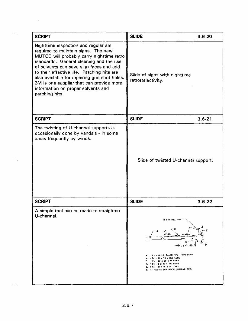
SCRIPT SLIDE 3.6-20
Nighttime inspection and regular are required to maintain signs. The new MUTCD will probably carry nighttime retro standards. General cleaning and the use of solvents can save sign faces and add to their effective life. Patching hits are also available for repairing gun shot holes. Slide of signs with nighttime
3M is one supplier that can provide more retroreflectivity.
information on proper solvents and patching hits.
SCRIPT
The twisting of U-channel supports is occasionally done by vandals - in some areas frequently by winds.
SLIDE 3.6-21
Slide of twisted U-channel support.
SCRIPT
A simple tool can be made to straighten U-channel.
SLIDE 3.6-22
Ll CHlrNNEL POST
*. , po - 38 LO. SLACK PIPE - 1270 LONG 8. , PC . 16 x 75 I 255 LONG 0. 1 PC - eo I 20 x 15 LONG 0. , PC - 8 x 20 x HO LONG
E. , PC - 10 x 10 x 75 LONG p. , _ CLEWS SLIP HOOK (REMOVE EYE)
3.6.7


SESSION GUIDE
3.7 - BREAKAWAY UTILITY POLES
Obiectives:
l Discuss the unique problems associated with utility pole placement and impacts with utility poles.
l Provide a brief history on the development of breakaway utility poles.
l Introduce an acceptable breakaway utility pole design.
Helpful Hints:
0 The use of breakaway utility poles displays great promise for reducing crash severity. There are, however, few installations of these devices.
l There is an available breakout session on the construction of breakaway utility poles.
Visual Aids:
a 17 - 35 mm slides
0 Breakout session Estimated Time
a 15 minutes
Handouts:
# None

3.7 - BREAKAWAY UTILITY POLES
instructor’s Guide
SCRIPT
INTRODUCTION
SLIDE 3.7-I
Fixed object collisions account for approximately 23 percent of all passenger vehicle accidents and one-third of all passenger car occupant fatalities. Utility poles are the second most frequently struck fixed object resulting in approximately 1500 to 2000 fatalities per year. In addition to fatalities it is estimated that 65,000 to 110,000 individuals are injured each year from utility pole collisions.
3.7 - BREAKAWAY UTILITY POLES
Utility poles are massive fixed objects that are frequently placed relatively close to the traveled way. Their huge mass and close proximity to the roadway results in utility pole accidents having the highest probability of injury, over 50 percent of all single vehicle, run-off-road accidents.
SCRIPT
The magnitude of utility pole accidents has resulted in efforts to reduce both the frequency and severity of utility pole accidents.
SLIDE 3.7-2
Slide of vehicle impact with utility pole.
3.7.1
SCRIPT SLIDE 3.7-3
Corrective actions that have been taken to alleviate the problem include:
l Increasing the lateral separation or offset, between poles and traffic flow.
l Placing the utilities carried by the poles underground.
l Placing crash attenuators and longitudinal barriers in the vicinity of utility poles.
CORRECTIVE ACTION 0 Increase separation l Underground utilities
l Reducing the number of poles by l Barriers allowing multiple use and increased 0 Reduce number spacing. 0 Breakaway
l Reducing accident potential by improved roadway alignment, skid resistance pavement, improved delineation, and pole placement on the inside of horizontal curves.
l Make the pole breakaway
SCRIPT SLIDE 3.7-4
Each of the above countermeasures are effective, to at least a certain degree, in reducing the frequency and/or severity of utility pole accidents. There are, however, difficulties in applying some of these countermeasures. Placing crash attenuators and longitudinal barriers in the vicinity of utility pole accidents can reduce the accident severity, but this countermeasure can also be expected to
Slide of barrier in front of pole.
increase accident frequency. This is because the attenuators or barriers occupy more space than that occupied by the utility pole alone.
3.7.2
SCRIPT SLIDE 3.7-5
Replacing overhead service by Jnderground service is effective in removing the utility pole hazard. Underground utilities are, however, Slide of district with no overhead utilities. sxpensive to install and may require added maintenance cost.
SCRIPT SLIDE 3.7-6
Relocating the poles further from the traveled way is encountered by resistance from private utility companies. Some States have laws which prohibit the reimbursement of privately owned utility companies for work performed within the public rights-of-way. This discourages the relocation of non-municipal utility poles. Utility companies also prefer pole installations close to the roadway to facilitate servicing and to avoid the need for easements over private property.
Slide of utilities along rural road.
Reducing the number of poles by increasing their spacing is constrained by the customary industry spacing of 30 to 60 m between poles. This spacing is considered as necessary to adequately support the overhead lines, to provide service to abutting properties, and to follow road curvature.
SCRIPT SLIDE 3.7-7
The constraints associated with the above countermeasures resulted in efforts to develop a forgiving utility pole. A number of difficult problems are encountered in BREAKAWAY DESIGN the design of a forgiving or breakaway PROBLEMS utility pole. Utility poles have such a high l Huge mass mass that it is impractical to provide l Wind and ice loads deceleration limits as low as those l Hazard to workers considered as safe for other roadside l Increased deterioration features. Any weakening of the pole at l Loss of service the base increases the probability of wind and ice loads causing the pole to fall.
3.7.3

L
SCRIPT
Eight sets of spring bolts and nuts are used to position the assembly concentrically around the pole.
The keeper plate and 4 washers are positioned between the upper and lower shear bases.
SLIDE 3.7-A-l 1
IlJEE AND SHE4R %4SE
VOILI TO 8E fllLE0
SCRIPT SLIDE 3.7.A-12
Poleset or its equivalent is poured to fill the void between the upper pipe of the shear base and the pole. The four sets of Slide of upper tube and pole with Poleset bolts, washers and nuts connecting the filling the void between them. lower and upper shear bases are placed and the bolts torqued to 270 Nm.
SCRIPT SLIDE 3.7.A-13
The upper hinge connection is installed approximately 4.6 m to 6 m above the ground line. First, a hole 27 mm in Slide of 2 workers, one in a bucket truck diameter is drilled through the pole parallel and one on pole placing bolt. to the cross arms to accommodate a 25 mm diameter all-thread bolt (A4491 needed for the upper band pole assembly.
3.7.A.4
SCRIPT
HAWKINS BREAKAWAY SYSTEM
SLIDE 3.7-l 0
The HAWKINS BREAKAWAY System (HBS) is a non-proprietary system. The lower connection consists of a lower and upper shear base, a keeper plate, and 6 bolts.
Slide of Hawkins Breakaway System.
SCRIPT SLIDE 3.7-l 1
The upper hinge connection consists of a pole band brackets, bolts to connect the brackets together with the pole, and steel straps. Slide of Hawkins Breakaway System.
SCRIPT
AD-IV SYSTEM
SLIDE 3.7-12
The AD-IV is a proprietary system and is manufactured by SYRO, Inc., a subsidiary of Trinity Industries.
The goal of the AD-IV was to modify the HAWKINS BREAKAWAY System to reduce the cost and improve performance. These concerns resulted in the following changes to the Hawkins design.
l A square base plate is used to reduce the fabrication costs and waste resulting from a circular shape.
Slide of AD-IV lower connection.
l Static pull down tests indicated that the six bolt connection at the base plate was an over design. Four bolts were then used to fasten the upper an lower portions of the slip base together.
3.7.5
SCRIPT
l The steel straps of the upper
SLIDE 3.7-13
connection were redesigned to eliminate the close tolerances required during installation of the Hawkins design.
l The HBS design requires the upper pole to be straightened, usually be some piece of heavy equipment, and then all the bolts in at least one of the pole bands to be loosened, the bands adjusted, and the bolts re-tightened.
Slide of AD-IV upper connection.
SCRIPT SLIDE 3.7-14
A less labor and equipment intensive way to maintain poles in true alignment is provided by the AD-IV System by the use of wind bolts to provide initial bending
Slide of wind bolts.
resistance.
SCRIPT
INSTALLATION LOCATIONS
SLIDE 3.7-15
It is most important to remember that breakaway timber utility poles are intended for use only after preferred mitigation such as pole removal or relocation are investigated and found to be impractical at a given high hazard location.
Identifying specific locations where utility poles potentially present high hazard requires an investigation of accidents, a site review, and input from local agency personnel. In many States, the computerized accident data base can be used directly to identify impacts with utility poles. Other data bases may require the initial selection by using runoff-the-road fixed-object accidents as the initial identifier. In either case copies of the initial accident reports should be
INSTALLATION LOCATIONS 0 Accident review l Site inspection 0 Input from local personnel
1
3.7.6
Dbtained to verify that a utility pole was the object struck and, if possible, which Jtility pole. Single poles, or a number of adjacent poles, struck more than once in a Five year period are candidates for breakaway installation. Contact with the local police departments during the site review can often assist in identifying poles that are a known hazard.
SCRIPT SLIDE 3.7-l 6
Accident severity can be decreased at high accident potential sites by the installation of breakaway poles only if suitable site characteristics exist. This includes a clear recovery area, with no other fixed objects present, to reduce the probability of secondary collisions. The number of pedestrians must also be low to prevent pedestrian injury from the impacting vehicle or the lower portion of SITE CHARACTERISTICS the breakaway pole. Poles which carry FOR INSTALLATION transformers, are attached to service lines 0 Clear recovery area over the roadway or which have heavy l Low pedestrian volume guy wires should not be replaced with a l No transformers breakaway utility pole. It is the policy of the FHWA to encourage the use of breakaway utility poles only at sites which are suitable for proper performance and where pole activation will not create an increased hazard to other motorists or pedestrians.
SCRIPT SLIDE 3.7-I 7
CONCLUSION
Identify utility pole locations with either a history or high probability of vehicle impacts. This identification requires the
CONCLUSION l High pole accidents
inspection of accident summaries, 0 Pole removal or relocation individual accident reports, site review 0 Favorable location and contacts with local personnel.
3.7.7

Site characteristics with a higher than average pole accident history or accident potential are candidates for utility pole accidents. Site characteristics which increase accident potential include poles located on the outside of horizontal curves, along long straight roadway segments, and on the right side of downgrades.
Only consider the installation of a breakaway timber utility pole when preferred alternatives such as pole removal or relocation have been investigated and found to be impractical.
Do not replace poles which provide service across the roadway, have mounted transformers, are in an area of pedestrian activity, do not have sufficient recoverable area, or are adjacent to other fixed objects.
3.7.8
BREAKOUT 3.7.A - INSTALLATION OF THE AD-IV-S
SCRIPT SLIDE 3.7.A-1
installing a new AD-IV-S reinforced timber utility poles or retrofitting existing poles is INSTALLATION OF AD-IV-S a means of achieving increased driver and REINFORCED TIMBER UTILITY POLES lineman safety and increased resistance to wind and ice.
SCRIPT SLIDE 3.7.A-2
35 ft poles are selected for the AD-IV installation. Smaller size poles will not result in a proper fit at the base and bridge connection. THE AD-IV IS USED WITH
A 35 FOOT CLASS 4 POLE
SCRIPT
Specifications for a 35 foot Class 4 Pole.
SLIDE 3.7.A-3
l Volume - 127.1 cf 0 Minimum Top Circumference - 21
inches l Minimum Top Diameter - 6.7 inches l Minimum circumference at 6 feet from
butt - 31.5 inches l Minimum diameter at 6 feet from butt -
10.0 inches
3.7.A. 1
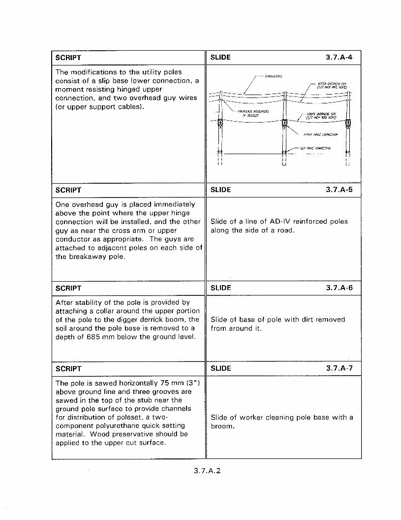
SCRIPT SLIDE 3.7.A-4
The modifications to the utility poles consist of a slip base lower connection, a LQPEE OMRHW, cur moment resisting hinged upper (l/2 m WIRE NUPE)
connection, and two overhead guy wires (or upper support cables).
SCRIPT SLIDE 3.7.A-5
One overhead guy is placed immediately above the point where the upper hinge connection will be installed, and the other Slide of a line of AD-IV reinforced poles guy as near the cross arm or upper along the side of a road. conductor as appropriate. The guys are attached to adjacent poles on each side of the breakaway pole.
SCRIPT SLIDE 3.7.A-6
After stability of the pole is provided by attaching a collar around the upper portion of the pole to the digger derrick boom, the Slide of base of pole with dirt removed soil around the pole base is removed to a from around it. depth of 685 mm below the ground level.
SCRIPT SLIDE 3.7.A-7
The pole is sawed horizontally 75 mm (3”) above ground line and three grooves are sawed in the top of the stub near the ground pole surface to provide channels for distribution of poleset, a two- Slide of worker cleaning pole base with a component polyurethane quick setting broom. material. Wood preservative should be applied to the upper cut surface.
3.7.A.2

SCRIPT
The lower tube and shear base is placed on the in-ground pole section.
SLIDE 3.7.A-8
Note the hole in center of slip plate which will be used to pour poleset through. Slide of lower tube covering the pole stub
and showing hole in slip plate. Also note that the top of the lower slip plate must not be more than 100 mm (4”) above ground level to comply with the AASHTO Roadside Design Guide.
SCRIPT
Poleset or a similar compound is poured through the slip plate hole and the pole surface grooves to fill all voids between the pole and base plate assembly.
SLIDE 3.7.A-9
As recommended by Poleset manufacturer, only a high strength formulation of Poleset is to be used.
Slide of base plate with funnel in center for pouring Poleset.
SCRIPT SLIDE 3.7.A-10
After the upper tube and shear base is placed on the upper pole section, the pole Slide of 3 workers directing pole while section is positioned above the in-ground crane lowers it into place. pole section.
3.7.A.3
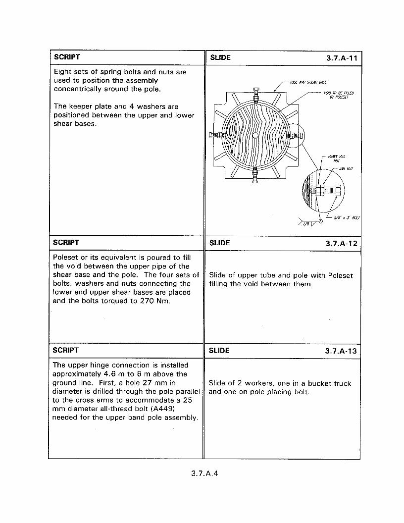
L
SCRIPT
Eight sets of spring bolts and nuts are used to position the assembly concentrically around the pole.
The keeper plate and 4 washers are positioned between the upper and lower shear bases.
SLIDE 3.7-A-l 1
IlJEE AND SHE4R %4SE
VOILI TO 8E fllLE0
SCRIPT SLIDE 3.7.A-12
Poleset or its equivalent is poured to fill the void between the upper pipe of the shear base and the pole. The four sets of Slide of upper tube and pole with Poleset bolts, washers and nuts connecting the filling the void between them. lower and upper shear bases are placed and the bolts torqued to 270 Nm.
SCRIPT SLIDE 3.7.A-13
The upper hinge connection is installed approximately 4.6 m to 6 m above the ground line. First, a hole 27 mm in Slide of 2 workers, one in a bucket truck diameter is drilled through the pole parallel and one on pole placing bolt. to the cross arms to accommodate a 25 mm diameter all-thread bolt (A4491 needed for the upper band pole assembly.
3.7.A.4
r 1 SCRIPT SLIDE 3.7.A-14
In addition to the 8 pole band brackets, 4 Slide of rotation straps and wind bolt rotation straps and 4 wind bolt brackets brackets on ground. are needed for the upper hinge assembly.
SCRIPT
Two pole band brackets, and 2 rotation straps are installed using a 25 mm x 405 mm all thread bolt, 2 lock washers and 2 hex nuts (A449).
SLIDE 3.7.A-15
At this time the nuts should be partially tightened.
Slide of 2 workers installing band brackets on a pole; one worker carried in a bucket truck.
The bolts connecting the pole band brackets are eight 19 mm x 125 mm long all-thread bolts, each bolt requiring 2 jam nuts, 2 hex nuts and 4 lock washers.
Another hole, below the first one will be used to install the opposing pole band brackets, rotation straps and wind bolt brackets.
SCRIPT SLIDE 3.7.A-16
Similar holes using the rotation strap slots should be drilled through the upper end of the lower pole.
Note that the holes should be drilled at Slide of a worker on pole with a bucket the top of the rotation strap slots in order truck with upper and lower pole band to make sure that the wind bolts will not brackets installed. be too short.
The pole bands and wind belt brackets are installed in the same manner as for the top pole.
3.7.A.5
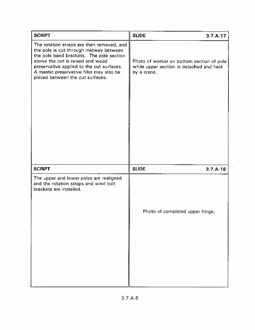
SCRIPT SLIDE 3.7-A-l 7
The rotation straps are then removed, and the pole is cut through midway between the pole band brackets. The pole section above the cut is raised and wood Photo of worker on bottom section of pole preservative applied to the cut surfaces. while upper section is detached and held A mastic preservative filler may also be by a crane. placed between the cut surfaces.
SCRIPT
The upper and lower poles are realigned and the rotation straps and wind bolt brackets are installed.
SLIDE 3.7.A-18
Photo of completed upper hinge.
3.7.A.6
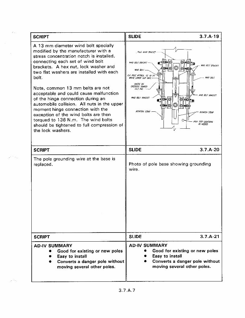
SCRIPT
A 13 mm diameter wind bolt specially modified by the manufacturer with a stress concentration notch is installed, connecting each set of wind bolt brackets. A hex nut, lock washer and two flat washers are installed with each bolt.
SLIDE
POLE EmD e.wKfT
WIND 601 r BRACKfl
cur Pox mm 15’ ro AOOK LOWER SUP @tSl
3.7.A-19
Note, common 13 mm belts are not CRFOSOIF SLLWLO
acceptable and could cause malfunction ~0 eoL r mcKn
of the hinge connection during an WlND ear BR4CKt7
automobile collision. All nuts in the upper moment hinge connection with the exception of the wind bolts are then torqued to 136 N.m. The wind bolts E SEP L‘XWIONS
should be tightened to full compression of the lock washers.
SCRIPT
The pole grounding wire at the base is replaced.
SLIDE 3.7.A-20
Photo of pole base showing grounding wire.
SCRIPT SLIDE 3.7.A-21
AD-IV SUMMARY AD-IV SUMMARY l Good for existing or new poles l Good for existing or new poles l Easy to install l Easy to install l Converts a danger pole without l Converts a danger pole without
moving several other poles. moving several other poles.
3.7.A.7

SESSION GUIDE
3.8 - CRASHWORTHY MAILBOX SUPPORTS
Obiectives:
0 Discuss the characteristics of mailbox ownership and responsibility.
0 Introduce hazards of improper design.
0 Summarize proper mailbox designs and construction methods.
Helpful Hints:
l Stress to the participants that controlling mailbox design can be difficult due to homeowner pride and necessary support from the U.S. Postal Service. Appendix H contains a model regulation that can be adopted to provide the necessary authority to roadway agencies.
Visual Aids:
0 21 - 35 mm slides
Estimated Time
0 15 minutes
Handouts:
e None


3.8 - CRASHWORTHY MAILBOX SUPPORTS
Instructor’s Guide
SCRIPT
INTRODUCTION
SLIDE 3.8-l
Mailboxes are fixed objects placed within the highway right-of-way that present a unique highway safety problem. The problem is unique because the highway agency often has little or no regulatory control over the type of mailbox installed or its placement along the roadway. The problem is made worse by the required height of the box. To enable delivery directly from a vehicle the boxes are mounted at window height, approximately 1 m to 1.2 m, above the road surface. Heavy boxes and boxes not properly fastened to the support can tear loose upon impact and enter the passenger compartment.
3.8 - CRASHWORTHY MAILBOX SUPPORTS
SCRIPT
Mailboxes are typically installed and maintained by the property owner who often considers the mailbox as an extension of their home. The result is masonry,
SLIDE 3.8-2
Slide of masonry mailbox.
SCRIPT
field plows,
SLIDE 3.8-3
Slide of field plow as mailbox.
SCRIPT SLIDE 3.8-4
and any other thing that can be imagined
Slide of tractor wheel mailbox.
3.8.1
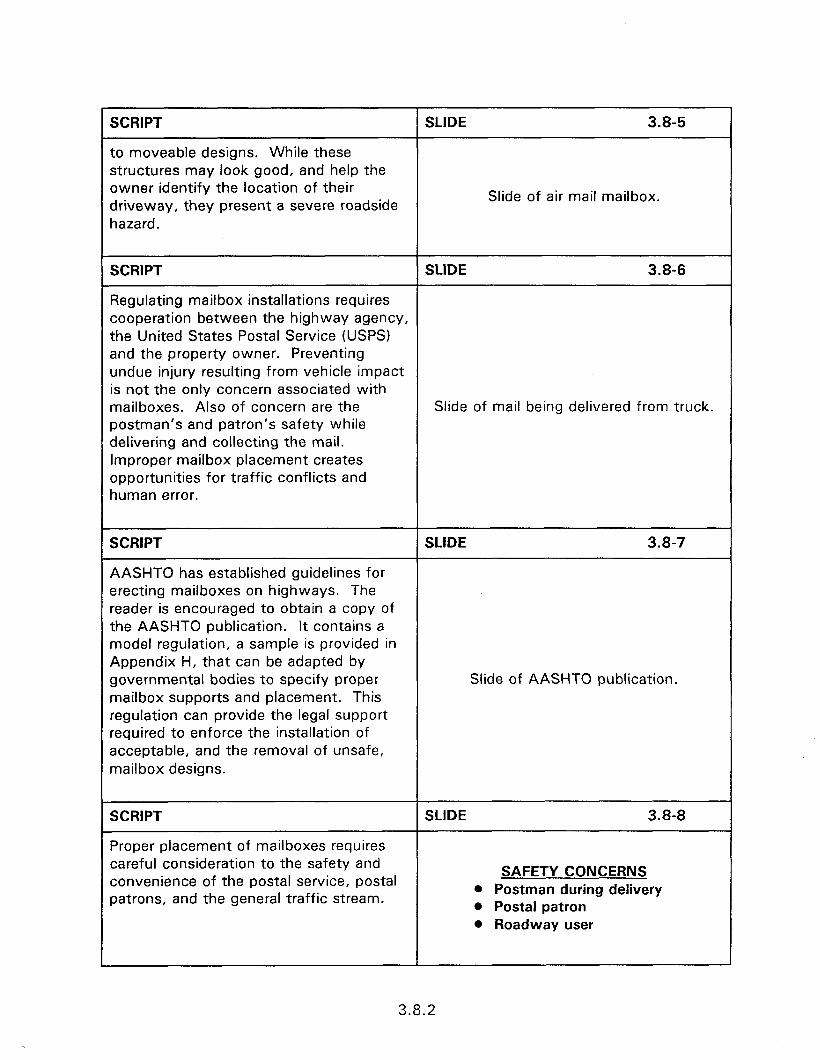
SCRIPT SLIDE 3.8-5
to moveable designs. While these structures may look good, and help the owner identify the location of their driveway, they present a severe roadside
Slide of air mail mailbox.
hazard.
SCRIPT SLIDE 3.8-6
Regulating mailbox installations requires cooperation between the highway agency, the United States Postal Service (USPS) and the property owner. Preventing undue injury resulting from vehicle impact is not the only concern associated with mailboxes. Also of concern are the Slide of mail being delivered from truck. postman’s and patron’s safety while delivering and collecting the mail. Improper mailbox placement creates opportunities for traffic conflicts and human error.
SCRIPT SLIDE 3.8-7
AASHTO has established guidelines for erecting mailboxes on highways. The reader is encouraged to obtain a copy of the AASHTO publication. It contains a model regulation, a sample is provided in Appendix H, that can be adapted by governmental bodies to specify proper Slide of AASHTO publication. mailbox supports and placement. This regulation can provide the legal support required to enforce the installation of acceptable, and the removal of unsafe, mailbox designs.
SCRIPT SLIDE 3.8-8
Proper placement of mailboxes requires careful consideration to the safety and convenience of the postal service, postal
SAFETY CONCERNS
patrons, and the general traffic stream. l Postman during delivery 0 Postal patron 0 Roadway user
1
3.8.2
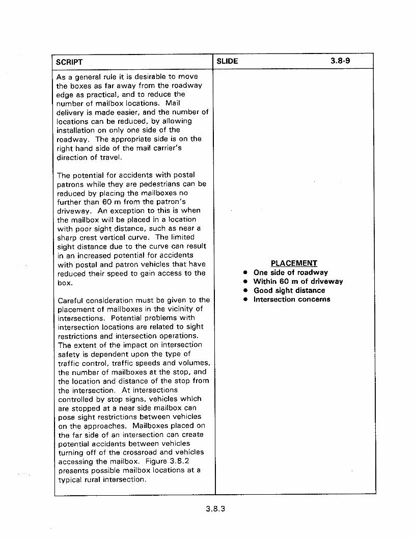
SCRIPT SLIDE 3.8-9
As a general rule it is desirable to move the boxes as far away from the roadway edge as practical, and to reduce the number of mailbox locations. Mail delivery is made easier, and the number of locations can be reduced, by allowing installation on only one side of the roadway. The appropriate side is on the right hand side of the mail carrier’s direction of travel.
The potential for accidents with postal patrons while they are pedestrians can be reduced by placing the mailboxes no further than 60 m from the patron’s driveway. An exception to this is when the mailbox will be placed in a location with poor sight distance, such as near a sharp crest vertical curve. The limited sight distance due to the curve can result in an increased potential for accidents with postal and patron vehicles that have reduced their speed to gain access to the box.
PLACEMENT l One side of roadway 0 Within 60 m of driveway l Good sight distance
Careful consideration must be given to the placement of mailboxes in the vicinity of intersections. Potential problems with intersection locations are related to sight restrictions and intersection operations. The extent of the impact on intersection safety is dependent upon the type of traffic control, traffic speeds and volumes, the number of mailboxes at the stop, and the location and distance of the stop from the intersection. At intersections controlled by stop signs, vehicles which are stopped at a near side mailbox can pose sight restrictions between vehicles on the approaches. Mailboxes placed on the far side of an intersection can create potential accidents between vehicles turning off of the crossroad and vehicles accessing the mailbox. Figure 3.8.2 presents possible mailbox locations at a typical rural intersection.
l intersection concerns
3.8.3
SCRIPT SLIDE 3.8-l 0
Mailboxes should be removed from the edge of the road so that a vehicle stopped at the mailbox is clear of the adjacent traveled way. Table 3.8.1 presents the recommended set back distance for various traffic volume and speed conditions. The importance of providing adequate set back becomes greater as the volume and speed increase. In the majority of situations a vehicle stopped at the box will clear the traveled way when a 2.5 m set back is used. On high volume, l Adequate lateral separation
high speed roadways a 3.1 m to 3.7 m l Setback of 3.1 to 3.7 m
set back is recommended. A paved l Paved turnout
turnout, at least 3.1 m wide, should be provided on high volume, high speed roadways, when a comparable wide paved shoulder does not exist. In all cases the roadside face of the mailbox should be set 200 mm to 300 mm outside the all weather surface of the shoulder or turnout to provide space for opening the mailbox door and for vehicle clearance.
SCRIPT
APPROVED MAILBOX AND SUPPORT STRUCTURES
SLIDE 3.8-l 1
The receptacle for the mail (i.e., the mailbox) should be of light sheet metal or plastic construction. Slide of approved mailbox receptacle.
SCRIPT SLIDE 3.8-l 2
The use of homemade boxes or boxes of heavy construction are not approved for use since they increase the chance of protrusion into the passenger compartment upon impact. Slide of improper receptacle.
3.8.4
SCRIPT SLIDE 3.8-l 3
To further reduce the chance of intrusion, the post to box attachment details should be of sufficient strength to prevent the box from separating from the post if the installation is impacted. Mailbox supports should be directly imbedded into the
TO REDUCE INTRUSION
ground without the use of anchor plates. l Strong post to box attachment
Concrete foundations should not be used l Direct embedment
unless the design has been proven as l No concrete foundation
acceptable by crash tests.
SCRIPT
SINGLE AND DOUBLE WOOD AND ROUND TUBE SUPPORTS
SLIDE 3.8-14
Single 90 mm square or 90 mm diameter wooden or a metal post with a strength no greater than 50 mm diameter standard steel pipe are acceptable for use as mailbox supports. The supports should not be embedded more than 610 mm into the ground. If an anti-twist device is used for the round support, it should be embedded more than 250 mm below the ground surface. Details of acceptable mailbox hardware for wooden and tubular support post are provided as figure 3.8.3. Adequate strength for double mailbox installations is obtained by using 3 kg/m U-channel. The U-channel must have the same orientation to the direction of travel as used for sign installation.
APPROVED SUPPORTS l Single 90 mm square wood l Single 90 mm diameter wood l Standard steel pipe of 50 mm
ID or less 0 U-channel
SCRIPT
Multiple Mailbox Supports
SLIDE 3.8-l 5
Many multiple mailbox supports have been constructed by supporting a horizontal member, usually a timber plank, by two or more posts.
MULTIPLE MAILBOX SUPPORTS
l No horizontal planks
3.8.5

SCRIPT SLIDE 3.8-l 6
When struck, these horizontal members can enter the passenger compartment and decapitate or impale motorists. Mailbox installations that use horizontal members, Slide of car near horizontal plank. such as that presented here, should be removed and replaced by safe alternative designs.
SCRIPT SLIDE 3.8-l 7
An acceptable multiple mailbox design is the V-lot’” Support System produced by Foresight Products Inc. The V-lot system has passed the high and low speed impact tests for single, double, and multiple mailbox installations. The system consists of an anchor piece which is installed flush with the surface of the ground. The post is inserted into the anchor piece and locked in place by driving a wedge between the post and socket of the anchor piece. When the system is impacted, the support tubing deforms around the vehicle bumper and hood allowing the vehicle to pull the mailbox support and wedge out of the anchor piece. The anchor piece is undamaged by the impact and can be reused with a new post.
3.8.6

SCRIPT SLIDE 3.8-18
Minnesota Swing-Away Mailbox Support
The Minnesota Department of Transportation has designed a swing- away mailbox that has been tested as acceptable for use with a single mailbox assembly. The Minnesota mailbox support uses a cantilevered arm for attachment of the mailbox assembly. The cantilever design is used to permit snow plowing operation without damaging the mailbox support. The design allows complete snow removal beyond the shoulder or curbline.
32 DNA LD. STANDARD WIEGHT PIPE
DETAIL A
SEE DETAIL C
SCRIPT
FRIEND INNOVATIONS MAILBOX SUPPORT
SLIDE 3.8-19
A swing-away mailbox support, similar in concept to the Minnesota mailbox support, is manufactured and marketed by Friend Innovations [3 8 31. The Friend L Town and Country mail support yields on impact and permits snow-plow passage beneath the box itself. Slide of Friend mailbox.
3.8.7
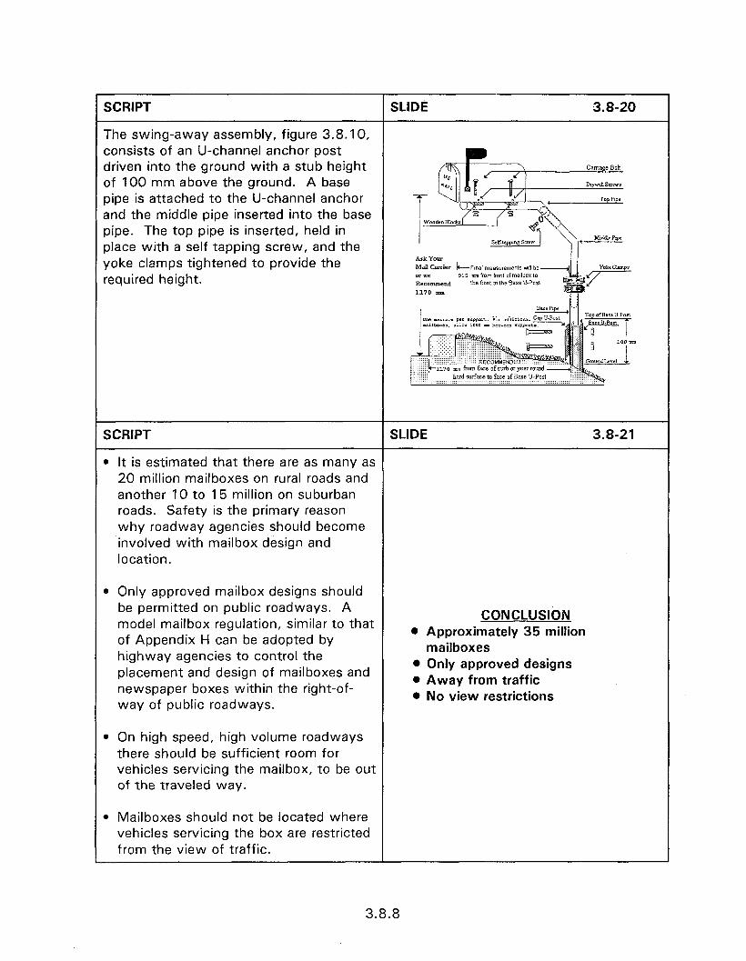
SCRIPT SLIDE 3.8-20
The swing-away assembly, figure 3.8.10, consists of an U-channel anchor post driven into the ground with a stub height of 100 mm above the ground. A base pipe is attached to the U-channel anchor and the middle pipe inserted into the base pipe. The top pipe is inserted, held in place with a self tapping screw, and the yoke clamps tightened to provide the Ark Yom
Mail Cazier k--Final measurements till be
required height. or we 915 mm f‘ml ,mn, ofmallbox 10 RK0lDDXP.d Ihe front ofhe Base U-Post 1170 mm
mm from fact of curb
SCRlPT SLIDE 3.8-21
l It is estimated that there are as many as 20 million mailboxes on rural roads and another 10 to 15 million on suburban roads. Safety is the primary reason why roadway agencies should become involved with mailbox design and location.
. Only approved mailbox designs should be permitted on public roadways. A model mailbox regulation, similar to that of Appendix H can be adopted by highway agencies to control the placement and design of mailboxes and newspaper boxes within the right-of- way of public roadways.
CONCLUSltiN 0 Approximately 35 million
mailboxes l Only approved designs l Away from traffic @ No view restrictions
0 On high speed, high volume roadways there should be sufficient room for vehicles servicing the mailbox, to be out of the traveled way.
l Mailboxes should not be located where vehicles servicing the box are restricted from the view of traffic.
3.8.8
SESSION GUIDE
3.9 - SAFETY CONSIDERATIONS WHEN DESIGNING AND LOCATING TRAFFIC SIGNAL SUPPORTS AND CONTROLLER BOXES
Obiectives:
0 Review the required signal face visibility needs of traffic signal installations.
l Discuss typical problems encountered in locating signal support poles and controller cabinets.
Heloful Hints:
Provide examples of good and poor practices.
l Review the required slides and use local examples.
0 Railroad grade crossing warning devices are covered toward the end of this session.
Visual Aids:
0 28 - 35 mm slides
Estimated Time
l 25 minutes
Handouts:
l None

3.9 - SAFETY CONSIDERATIONS WHEN DESIGNING AND LOCATING TRAFFIC SIGNAL SUPPORTS AND CONTROLLER BOXES
Instructor’s Guide
SCRIPT
INTRODUCTION
SLIDE 3.9-l
The decision to install a traffic signal should be based on established warrants. These warrants are quantitative guidelines that help the traffic engineer determine if the benefits to be obtained by signal installation outweigh the disadvantages. A determination to install prompts the design process including decisions on 3.9 - SAFETY CONSIDERATIONS phasing, type of controller, and installation WHEN DESIGNING AND details. The installation details include LOCATING TRAFFIC SIGNAL SUPPORTS determining the placement of the signal AND CONTROLLER BOXES poles, the controller, and determination of the signal head mounting strategy. The objective of the installation phase is to provide signal head visibility while not creating an undue safety hazard due to the placement of the signal poles and controller.
SCRIPT
Sections 4B-12 and 4B-13 of the Manual on Traffic Control Devices (MUTCD) provide the requirements for signal face placement.
SLIDE 3.9-2
Slide of the MUTCD.
3.9.1
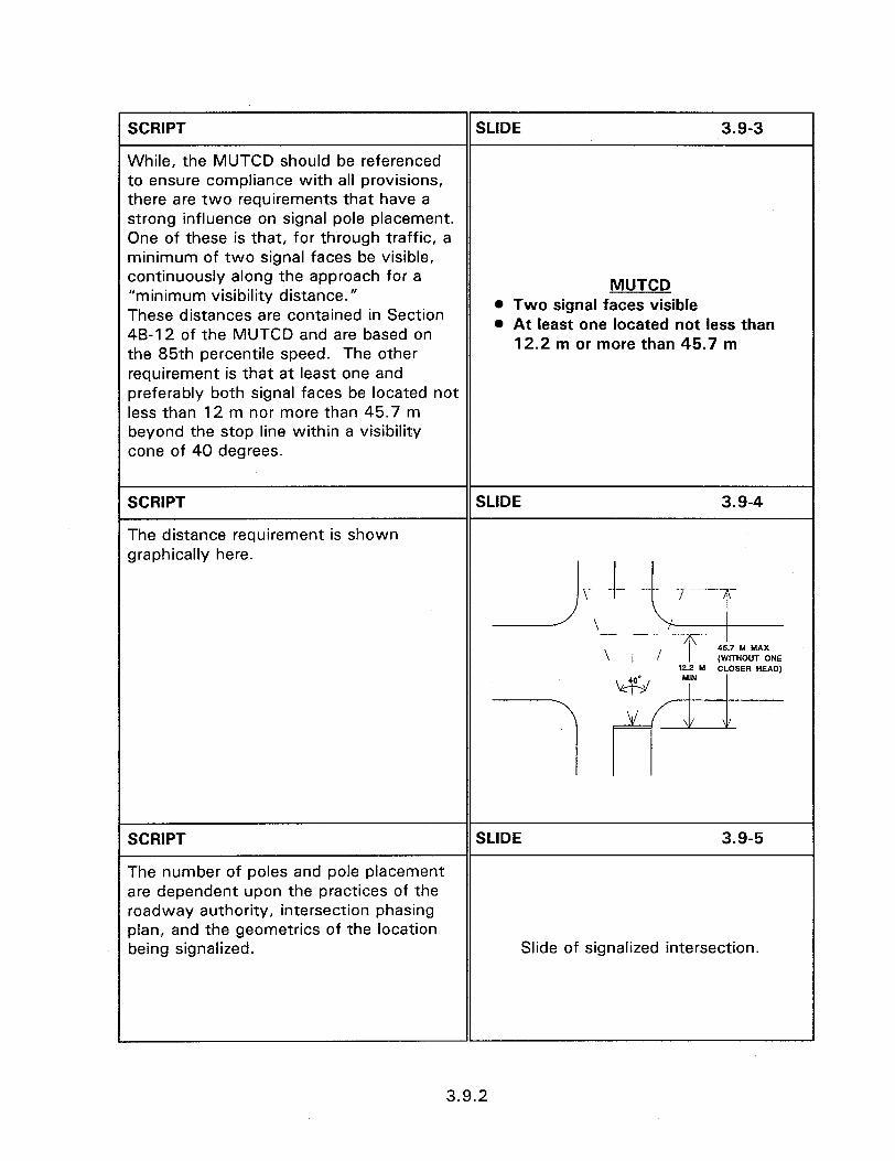
SCRIPT SLIDE 3.9-3
While, the MUTCD should be referenced to ensure compliance with all provisions, there are two requirements that have a strong influence on signal pole placement. One of these is that, for through traffic, a minimum of two signal faces be visible, continuously along the approach for a MUTCD “minimum visibility distance.” These distances are contained in Section
0 Two signal faces visible
48-12 of the MUTCD and are based on l At least one located not less than
the 85th percentile speed. The other 12.2 m or more than 45.7 m
requirement is that at least one and preferably both signal faces be located not less than 12 m nor more than 45.7 m beyond the stop line within a visibility cone of 40 degrees.
SCRIPT SLIDE 3.9-4
The distance requirement is shown graphically here.
2 t-I --
\ I f T 45.7 M MAX (WITHOUT ONE
172 M CLOSER HEAD)
w M’N
7 vfvv
SCRIPT SLIDE 3.9-5
The number of poles and pole placement are dependent upon the practices of the roadway authority, intersection phasing plan, and the geometries of the location being signalized. Slide of signalized intersection.
3.9.2

SCRIPT SLIDE 3.9-6
The primary consideration in the elacement of traffic signals is ensuring the oroper visibility of signal faces to each approach. Drivers must be given a clear Indication of their right-of-way assignment. This requires that the geometry of each location to be analyzed; including vertical grades, horizontal curves, and obstructions to view, such as overpasses, be considered in designing Slide of signal ahead sign. the signal head placement.
SCRIPT SLIDE 3.9-7
Attaining the proper signal face placement while reducing the potential for errant vehicle impacts with the signal support poles and controller cabinet requires consideration of a number of factors. These factors can influence the type of crashworthy supports, support placement, placement of controller cabinet, and future improvements.
Crashworthy Supports BREAKAWAY SIGNAL SUPPORTS
Traffic signal supports are not designed NOT USED
with any breakaway features. This is l Falling traffic signals
because the immediate hazard resulting l Loss of signalization
from a fallen support may create a larger hazard, to more motorists, than that experienced by the single impacting vehicle. In addition to the hazard from the pole falling in the intersection area, there is the danger of falling signal heads as well as the potential hazard created by the temporary loss of full signalization at the intersection.
3.9.3
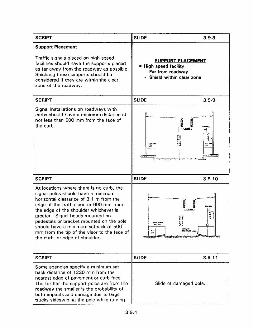
SCRIPT SLIDE 3.9-8
Support Placement
Traffic signals placed on high speed facilities should have the supports placed
SUPPORT PLACEMENT l High speed facility as far away from the roadway as possible.
Shielding those supports should be - Far from roadway - Shield within clear zone considered if they are within the clear
zone of the roadway.
SCRIPT SLIDE 3.9-9
Signal installations on roadways with curbs should have a minimum distance of not less than 600 mm from the face of the curb.
SCRIPT SLIDE 3.9-l 0
At locations where there is no curb, the signal poles should have a minimum horizontal clearance of 3.1 m from the edge of the traffic lane or 600 mm from the edge of the shoulder whichever is greater. Signal heads mounted on pedestals or bracket mounted on the pole should have a minimum setback of 500 mm from the tip of the visor to the face of the curb, or edge of shoulder.
SCRIPT SLIDE 3.9-l 1
Some agencies specify a minimum set back distance of 1220 mm from the nearest edge of pavement or curb face. The further the support poles are from the Slide of damaged pole. roadway the smaller is the probability of both impacts and damage due to large trucks sideswiping the pole while turning.
3.9.4
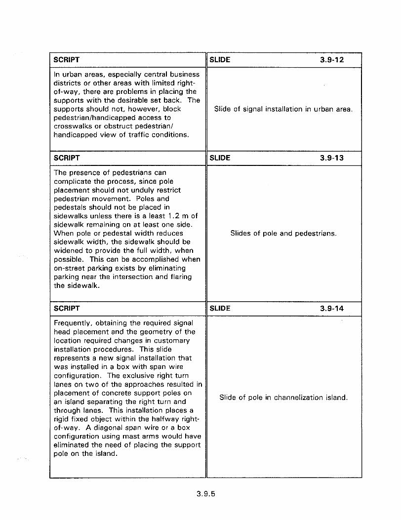
SCRIPT SLIDE 3.9-l 2
In urban areas, especially central business districts or other areas with limited right- of-way, there are problems in placing the supports with the desirable set back. The supports should not, however, block Slide of signal installation in urban area. pedestrian/handicapped access to crosswalks or obstruct pedestrian/ handicapped view of traffic conditions.
SCRIPT SLIDE 3.9-l 3
The presence of pedestrians can complicate the process, since pole placement should not unduly restrict pedestrian movement. Poles and pedestals should not be placed in sidewalks unless there is a least 1.2 m of sidewalk remaining on at least one side. When pole or pedestal width reduces Slides of pole and pedestrians. sidewalk width, the sidewalk should be widened to provide the full width, when possible. This can be accomplished when on-street parking exists by eliminating parking near the intersection and flaring the sidewalk.
SCRIPT SLIDE 3.9-14
Frequently, obtaining the required signal head placement and the geometry of the location required changes in customary installation procedures. This slide represents a new signal installation that was installed in a box with span wire configuration. The exclusive right turn lanes on two of the approaches resulted in placement of concrete support poles on an island separating the right turn and Slide of pole in channelization island.
through lanes. This installation places a rigid fixed object within the halfway right- of-way. A diagonal span wire or a box configuration using mast arms would have eliminated the need of placing the support pole on the island.
1
3.9.5
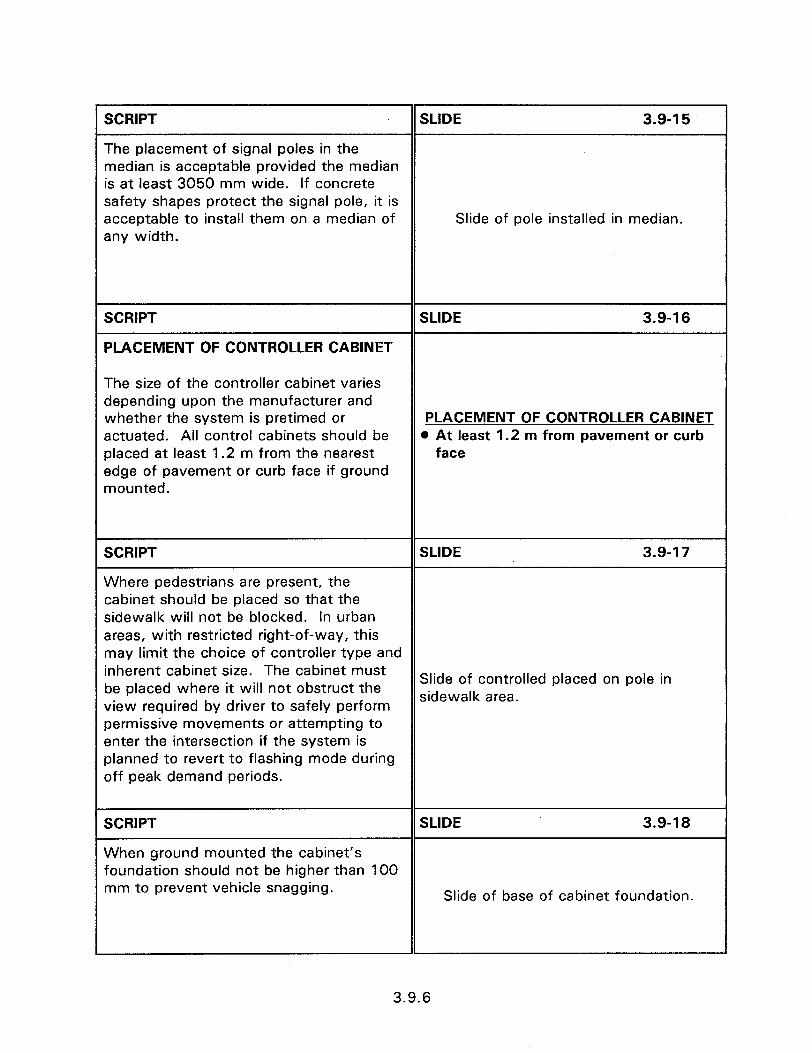
SCRIPT SLIDE 3.9-l 5
The placement of signal poles in the median is acceptable provided the median is at least 3050 mm wide. If concrete safety shapes protect the signal pole, it is acceptable to install them on a median of Slide of pole installed in median. any width.
SCRIPT SLIDE 3.9-l 6
PLACEMENT OF CONTROLLER CABINET
The size of the controller cabinet varies depending upon the manufacturer and whether the system is pretimed or PLACEMENT OF CONTROLLER CABINET actuated. All control cabinets should be 0 At least 1.2 m from pavement or curb placed at least 1.2 m from the nearest face edge of pavement or curb face if ground mounted.
SCRIPT SLIDE 3.9-l 7
Where pedestrians are present, the cabinet should be placed so that the sidewalk will not be blocked. In urban areas, with restricted right-of-way, this may limit the choice of controller type and inherent cabinet size. The cabinet must be placed where it will not obstruct the Slide of controlled placed on pole in
sidewalk area. view required by driver to safely perform permissive movements or attempting to enter the intersection if the system is planned to revert to flashing mode during off peak demand periods.
SCRIPT SLIDE 3.9-18
When ground mounted the cabinet’s foundation should not be higher than 100 mm to prevent vehicle snagging.
Slide of base of cabinet foundation.
3.9.6

SCRIPT SLIDE 3.9-l 9
Consideration to the safety of maintenance workers should be used when placing controller cabinets. Workers should be able to work in the controller cabinet without being exposed to traffic. This often requires a visit to the site in restricted right-of-way locations, to
Slide of cabinet with signal heads visible. select the best controller placement spot. The work of maintenance personnel is made easier if they have an unrestricted view of the signal heads while working at the controller cabinet.
SCRIPT SLIDE 3.9-20
The cabinet should be located in a position which minimizes the probability of being impacted by an errant vehicle.
Slide of good placement.
SCRIPT SLIDE 3.9-21
FUTURE IMPROVEMENTS
Considering probable future improvements at the time of initial signalization can save construction costs and increase safety. For example, flashing beacon operation is frequently installed and operated for a number of years until volumes increase sufficiently to warrant installation of a traffic signal. Designing the pole locations Slide of flashing beacon installation.
for the flashing beacons so that they will also be properly located for traffic signal operation will save the costs of pole relocation.
3.9.7
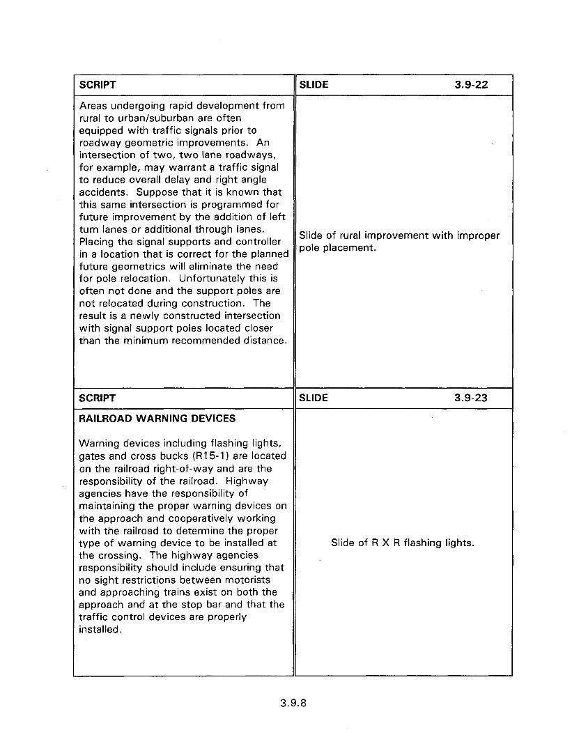
SCRIPT SLIDE 3.9-22
Areas undergoing rapid development from rural to urban/suburban are often equipped with traffic signals prior to roadway geometric improvements. An intersection of two, two lane roadways, for example, may warrant a traffic signal to reduce overall delay and right angle accidents. Suppose that it is known that this same intersection is programmed for future improvement by the addition of left turn lanes or additional through lanes. Placing the signal supports and controller Slide of rural improvement with improper
in a location that is correct for the planned pole placement.
future geometries will eliminate the need for pole relocation. Unfortunately this is often not done and the support poles are not relocated during construction. The result is a newly constructed intersection with signal support poles located closer than the minimum recommended distance.
SCRIPT
RAILROAD WARNING DEVICES
SLIDE 3.9-23
Warning devices including flashing lights, gates and cross bucks (RI 5-I) are located on the railroad right-of-way and are the responsibility of the railroad. Highway agencies have the responsibility of maintaining the proper warning devices on the approach and cooperatively working with the railroad to determine the proper type of warning device to be installed at the crossing. The highway agencies responsibility should include ensuring that no sight restrictions between motorists and approaching trains exist on both the approach and at the stop bar and that the traffic control devices are properly installed.
Slide of R X R flashing lights.
3.9.8
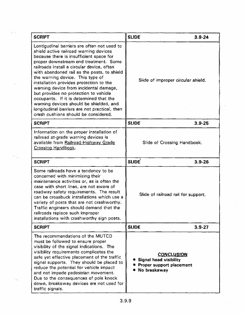
SCRIPT SLIDE 3.9-24
Lontigudinal barriers are often not used to shield active railroad warning devices because there is insufficient space for proper downstream end treatment. Some railroads install a circular device, often with abandoned rail as the posts, to shield the warning device. This type of
Slide of improper circular shield. installation provides protection to the warning device from incidental damage, but provides no protection to vehicle occupants. If it is determined that the warning devices should be shielded, and longitudinal barriers are not practical, then crash cushions should be considered.
SCRIPT SLIDE 3.9-25
Information on the proper installation of railroad at-grade warning devices is available from Railroad-Hiqhwav Grade Slide of Crossing Handbook. Crossinq Handbook.
SCRIPT SLIDE’ 3.9-26
Some railroads have a tendency to be concerned with minimizing their maintenance activities or, as is often the case with short lines, are not aware of roadway safety requirements. The result Slide of railroad rail for support. can be crossbuck installations which use a variety of posts that are not crashworthy. Traffic engineers should demand that the railroads replace such improper installations with crashworthy sign posts.
SCRIPT SLIDE 3.9-27
The recommendations of the MUTCD must be followed to ensure proper visibility of the signal indications. The visibility requirements complicates the
CONCLUSION safe yet effective placement of the traffic signal supports. They should be placed to
l Signal head visibility l Proper support placement reduce the potential for vehicle impact l No breakaway
and not impede pedestrian movement. Due to the consequences of pole knock down, breakaway devices are not used for traffic signals.
3.9.9
1 SCRIPT DDE 3.9-28
Controller cabinets should be placed so as not to present driver sight restrictions, not impede pedestrian movement and to be relatively safe from impact. Worker safety and visibility of the signal heads l Cabinet placement
should be considered in the cabinet 0 Cabinet foundation < 100 mm high
placement decision. l Railroad intersection
3.9.10

Obiectives:
0
l
SESSION GUIDE
3.10 - CRASH TESTED LIGHT SUPPORTS
Introduce different types of luminaire supports.
Identify crashworthy luminaire supports.
Discuss concerns that must be addressed to ensure proper breakaway operation.
Discuss wiring methods that provide a safe breakaway when poles breakaway.
Discuss location of luminaire supports as a safety feature.
Helpful Hints:
0 For the first time, in 1997, there will be crash testing of luminaire supports with connected wiring. Prior testing did not include the effects of the wiring or effectiveness of uncouplers. The relatively large wire size used for luminaire systems can pose a significant resistance to separation and increase vehicle deceleration rate.
Visual Aids:
l 37 - 35 mm slides
Workshop examples of good and bad practice.
Estimated Time
l 45 minutes
Handouts:
. None


3.10 - CRASH TESTED LIGHT SUPPORTS
Instructor’s Guide
SCRIPT
INTRODUCTION
SLIDE 3.10-I
Roadway illumination is installed for a number of reasons, including enhancing road user safety, deterring crime, enhancing business activity, and to establish a community image. While there are socio-economic benefits realized by the installation of roadway lighting they can also pose a hazard to motorists.
3.10 - CRASH TESTED LIGHT SUPPORTS
SCRIPT SLIDE 3.10-Z
Adequate illumination which is designed, installed, and maintained properly has a number of benefits including:
l Supplementing vehicle headlights to increase motorist visibility in complex traffic environments.
l Allowing a motorist to discern a potential hazard in time to recognize it, react, brake and stop or maneuver around it.
l Deterrence to crime.
LIGHTING BENEFITS l Enhance road user safety @ Deter crime l Enhance business activity 0 Community image
* Enhances business activity.
0 Establishes a community image.
3.10.1

SCRIPT
l Increasing visibility by reducing the
SLIDE 3.10-3
amount of eye adaptation required due to varying lighting levels.
0 Reducing the effect of glare from oncoming headlights. e Increases visibility
l Illuminating pedestrians on or along side the roadway.
e Reduces glare @ Pedestrian safety 0 Helps identify roadway features
* Assisting motorists in identifying the placement, and cross traffic use, of intersections and railroad grade crossings.
SCRIPT SLIDE 3.1 o-4
Roadway illumination is usually provided by locating luminaires along the side of the road, in the median area, or offset from the roadway outside the clear zone. Most roadside luminaire assemblies consist of a cobra head type luminaires
Slide of roadside support with cobra head
mounted on a single support bracket with luminaire.
the pole located either behind a curb or preferably 6100 mm from the traveled way.
SCRIPT SLIDE 3.10-S
Current practice at narrow medians is to mount the lighting assembly on a concrete barrier with two cobra head or segmented reflector type luminaires per pole.
Slide of median mounted support.
SCRIPT SLIDE 3.40-6
These median mounted lighting assemblies often include an individual lowering device to allow the luminaires to be lowered one at a time for servicing. This eliminates the need for a bucket
Slide of lowering mechanism.
truck and the required traffic control is significantly reduced.
3.10.2
SCRIPT SLIDE 3.10-7
Offset luminaires are designed to be located well off the roadway and aimed at 40 to 55 degrees (up from straight down or nadir) on poles up to 23 m tall. An individual lowering device is used when an area is inaccessible to a bucket truck.
Slide of offset luminaire
SCRIPT SLIDE 3.10-8
High mast lighting currently employs the traditional high mast type luminaire or the offset type luminaire. What distinguishes the high mast; in addition to the mounting heights being from 23 m to 60 m or more, is the kind of lowering device used. A high mast lowering device incorporates a 2 m to 3 m diameter mounting ring to
Slide of high mast lighting.
which all the luminaires are attached. The ring with up to twelve luminaires is lowered for servicing.
SCRIPT SLIDE 3.10-g
Breakaway devices should be used on all poles for which one is available; except for those installed on median barriers and high mast poles. Poles which are not outside the clear zone but for which no breakaway device is available (usually due to height and weight restrictions) must be shielded with appropriate barriers or crash
Slide of breakaway device on support.
cushions.
3.10.3
SCRIPT
iUMlNAlRE SUPPORTS
SLIDE 3.10-10
The luminaire support includes all structural hardware required to hold the jUppOrt in place. This generally includes the following parts:
LUMINAIRE SUPPORT m Pole (frequently called a mast).
l Pole COMPONENTS
0 Mast arm (frequently called a support arm) which extends the luminaire over the roadway.
l Foundation.
0 Mast arm @ Foundation @ Base 0 Lowering device
. Base (or breakaway device).
l Lowering device.
SCRIPT SLIDE 3.10-l 1
Not all of the above items are included in every lighting system. For example, some decorative lighting systems are of the post top style and do not have a mast arm.
Slide of decorative fixture.
SCRIPT
Other systems are of the davit design where the arm and pole are of one unit.
SLIDE 3.10-12
Slide of davit assembly.
3.10.4
CRIPT SLIDE 3.10-13
ome luminaires are wall mounted, hereby eliminating the entire support. ther systems have the pole directly Jried, thereby eliminating the base and rundation, while still others are mounted rectly to existing utility poles. The rllowing is a description of the common Slide of utility pole mount. srdware parts of luminaires.
CRIPT
last Arms
SLIDE 3.10-14
he purpose of the mast arm is to extend re luminaire over the edge of the badway while permitting the pole to be aced at a distance from the roadway dge. Mast arms can be as short as 1 m Id as long as 9 m. They can be installed rith one arm per pole for roadside stallations
Slide of single mast arm.
CRIPT
r with two masts (balanced design) for ledian installations.
SLIDE 3.10-15
Slide of double mast arm.
3.10.5
SCRIPT
Poles
Poles are available in a number of materials of which the advantages and disadvantages of each are listed below.
Steel - steel poles are available in galvanized, painted, powder coated, and weathering types plus a combination of powder coating over galvanizing. Galvanized is the most popular of the steel types due to the comparatively low cost and extended life. Painted poles are used primarily when a color is desired but requires continual maintenance. The powder coating over galvanizing serves the same purpose and is maintenance free. Weathering steel poles can cause aesthetic problems due to rusty runoff.
Aluminum - aluminum poles are popular due to their resistance to corrosion and the resultant low maintenance cost. They have an added advantage of being lighter in weight than most other types. Aluminum poles operate well as breakaway designs when impacted at the design height. Since they are less rigid than steel posts, however, aluminum poles can result in an increased probability of improper breakaway operation when impacted higher than the design height. Aluminum poles are also considerably more expensive than most other types.
Stainless Steel - stainless steel poles are corrosion resistant and relatively light weight. Their high rigidity results in dependable breakaway operation upon impact. They are, however, considerably more expensive than the other pole types.
SLIDE 3.10-16
LUMINAIRE SUPPORTS @ Steel @ Aluminum 0 Stainless steel
3.10.6

SCRIPT SLIDE 3.10-17
Fiberalass - fiberglass reinforced plastic (FRP) poles are approved for breakaway use both in the anchor base and in the direct burial series. Shaft lengths are currently limited to 14.3 m which means gives 12 m height for the direct burial series and the full 14.3 m height for the anchor base series. Advantages of FRP poles include no rust, no corrosion, no rot, light weight, no additional breakaway device required, no maintenance, no electrical shock, and for the direct burial series no concrete foundation is needed. FRP poles come in many decorative styles and several standard colors.
Wood - wood is perhaps the least expensive of pole types particularly in areas where trees are plentiful. They can be treated to resist deterioration from the environment and damage due to insects. The huge mass of wood poles, however, makes it difficult to design them as @ Fiberglass breakaway. Section 3.7 discusses . Wood breakaway utility pole designs but 0 Concrete wooden poles should not be installed on high speed facilities. The use of existing utility poles for luminaire placement has the advantage of reducing the number of poles on the roadside.
Concrete - Concrete poles are popular in regions where cement and concrete aggregates are plentiful. One advantage to concrete poles is that they can be economical. Concrete poles cannot, however, be designed effectively to safely break away upon impact. They are extremely heavy even when made by prestressing concrete. Impacts with concrete poles result in large damage to vehicles and severe injury to occupants. Prestressed concrete poles, therefore, should not be used within the traversable area, unless shielded, on facilities with design speeds over 50 km/h. Concrete
3.10.7
posts can be a functional and economical type of support on local urban streets if proper consideration is given to placement.
SCRIPT
Foundations
SLIDE 3.10-18
The foundation for a luminaire pole must provide sufficient resistance to overturning moments caused by the static load of the mast arm plus a wind and/or an ice load. It must be capable of maintaining the correct alignment of the luminaire and able to withstand the impact should the pole be struck. For breakaway poles the foundation must be rigid enough to allow the breakaway device to operate while not becoming a hazard itself.
FOUNDATIONS l Resistance to overturning l Maintain correct alignment l Allow breakaway operation
SCRIPT SLIDE 3.10-19
Luminaire foundations are perhaps one of the most dangerous man-made hazards on the right-of-way. This is due to their placement or location, structural design, and unsafe wiring systems. There are many documented deaths of motorist who survived the impact with a luminaire pole only to be subsequently killed from the resulting explosion and fire. The explosion and fire are usually caused by the fuel tank being ruptured, the vehicle being caught on the improperly constructed foundation and the electrical system sparking repeatedly until the fuel
Slide of vehicle on fire.
explodes. In other incidences, medical personnel have been delayed from attending to victims due to risk of electrical shock from exposed conductors near or under a vehicle. All of these consequences can be minimized, if not eliminated, by the use of luminaires that allow more freedom for the designer in selecting their location, by using the smallest diameter foundation available, and eliminating exposure of the wiring system to physical damage.
3.10.8
SCRIPT SLIDE 3.1 O-20
Historically, pole foundations have been poured-in-place concrete with steel reinforcing rods and anchor bolts. The requirement, that upon breakaway nothing shall project more than 100 mm above a chord line drawn between two points 1.5 m apart, has caused redesign of concrete foundations. It has been recognized for several years that a problem exists when a foundation is placed on a slope. As
Slide of foundation exceeding 100 mm.
early as 1985 a memorandum was issued stating that designers should not allow the slope between the travelway and the foundation to be greater than 1:6. This is even more effective when the diameter of the foundation is as small as possible thus limiting the concrete protruding above the grade line.
SCRIPT
Eliminating the transformer base allows the foundation to be sized to accommodate the pole bolt circle; which in most roadway size poles is several inches less than the bolt circle for a transformer base.
SLIDE 3.10-21
Slide of pole sized foundation.
SCRIPT SLIDE 3.1 o-22
In order to do this the electrical circuit elements that were formerly housed in the T-base, i.e., splices in the conductors, fuse holders, and surge arresters, must be relocated underground. This requires that the electrical components be capable of being fully submerged and remain
Slide showing bolts and junction box.
watertight.
3.10.9
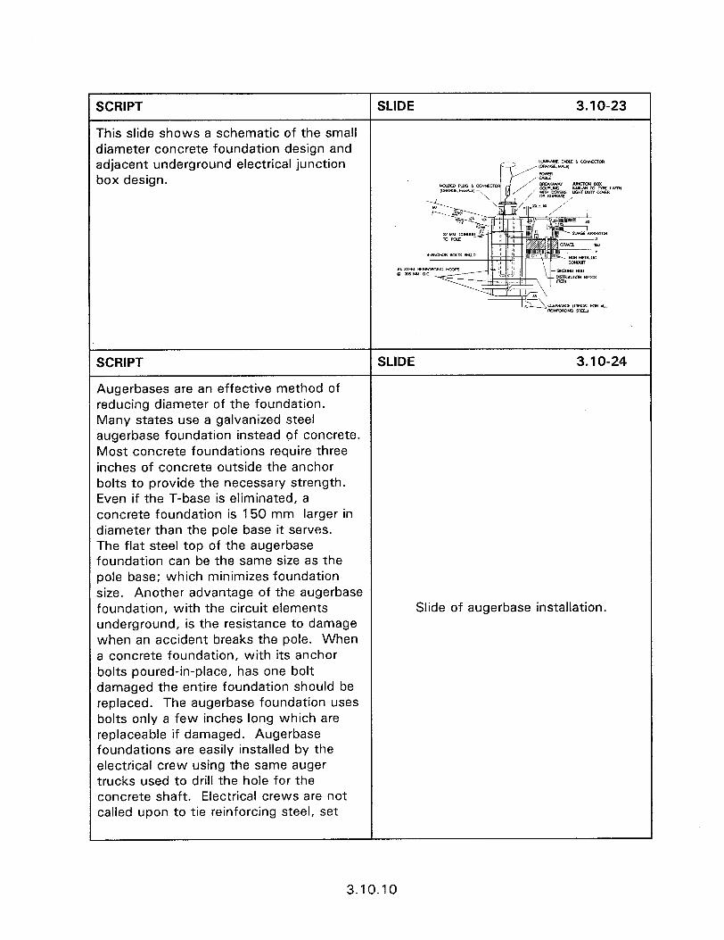
SCRIPT SLIDE 3.10-23
This slide shows a schematic of the small diameter concrete foundation design and adjacent underground electrical junction UUYUWLE c.aLf t. -am
box design.
SCRIPT SLIDE 3.10-24
Augerbases are an effective method of reducing diameter of the foundation. Many states use a galvanized steel augerbase foundation instead of concrete. Most concrete foundations require three inches of concrete outside the anchor bolts to provide the necessary strength. Even if the T-base is eliminated, a concrete foundation is 150 mm larger in diameter than the pole base it serves. The flat steel top of the augerbase foundation can be the same size as the pole base; which minimizes foundation size. Another advantage of the augerbase foundation, with the circuit elements Slide of augerbase installation. underground, is the resistance to damage when an accident breaks the pole. When a concrete foundation, with its anchor bolts poured-in-place, has one bolt damaged the entire foundation should be replaced. The augerbase foundation uses bolts only a few inches long which are replaceable if damaged. Augerbase foundations are easily installed by the electrical crew using the same auger trucks used to drill the hole for the concrete shaft. Electrical crews are not called upon to tie reinforcing steel, set
3.10.10
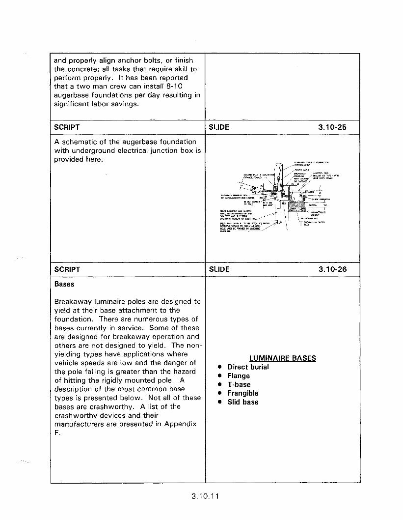
r and properly align anchor bolts, or finish the concrete; all tasks that require skill to perform properly. It has been reported that a two man crew can install 8-l 0 augerbase foundations per day resulting in significant labor savings.
SCRIPT SLIDE 3.1 o-25
A schematic of the augerbase foundation with underground electrical junction box is provided here. c..eu‘-crm
SCRIPT
Bases
SLIDE 3.1 O-26
Breakaway luminaire poles are designed to yield at their base attachment to the foundation. There are numerous types of bases currently in service. Some of these are designed for breakaway operation and others are not designed to yield. The non- yielding types have applications where vehicle speeds are low and the danger of the pole falling is greater than the hazard of hitting the rigidly mounted pole. A description of the most common base types is presented below. Not all of these bases are crashworthy. A list of the crashworthy devices and their manufacturers are presented in Appendix F.
LUMINAIRE BASES 0 Direct burial 0 Flange l T-base l Frangible 0 Slid base
3.10.11

SCRIPT SLIDE 3.10-27
Direct Burial Base - This type of base allows the pole to be directly embedded in the soil. It is the most economical since it eliminates the need for a foundation. It is the common type base for wood and is used frequently with concrete and fiberglass reinforced plastic (FRP) poles. The FRP poles are the only direct bury poles currently approved for breakaway use. The other types are normally limited to low speed facilities or Slide of direct burial. should be located out of the recoverable area.
SCRIPT SLIDE 3.10-28
Flanqe Base - Most steel and aluminum poles are fitted with a plate or flange at the base of the pole. With steel poles this usually involves welding a steel plate to the bottom of the pole. With aluminum poles a cast aluminum shoe base is usually fitted to the bottom of the pole. The use of a flange base implies that the flange is to be fastened directly to the anchor bolts embedded in the foundation or to some type of breakaway device. When a flange is in direct contact with the Slide of flange base. concrete, some method needs to be employed that will allow water to flow out and not be trapped in the base of the pole which can cause premature failure of the pole due to rust on the inside. Flange base designs that do not use breakaway features are not crashworthy and should be restricted to where the hazard of the pole falling is greater than the hazard of impacting the rigidly mounted pole.
3.10.12
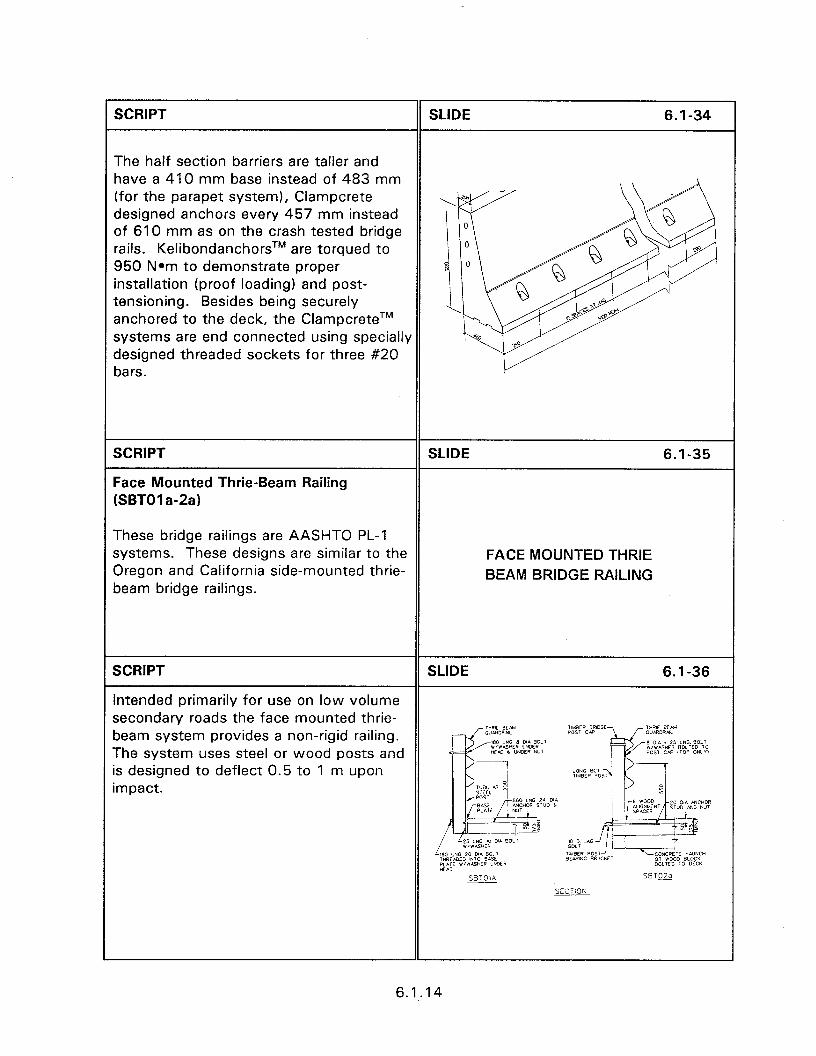
SCRIPT
The half section barriers are taller and have a 410 mm base instead of 483 mm (for the parapet system), Clampcrete designed anchors every 457 mm instead of 610 mm as on the crash tested bridge rails. KelibondanchorsTM are torqued to 950 Nom to demonstrate proper installation (proof loading) and post- tensioning. Besides being securely anchored to the deck, the ClampcreteTM systems are end connected using specially designed threaded sockets for three #20 bars.
SLIDE 6.1-34
SCRIPT
Face Mounted Thrie-Beam Railing [SBTOI a-2a)
These bridge railings are AASHTO PL-1 systems. These designs are similar to the Oregon and California side-mounted thrie- beam bridge railings.
SLIDE 6.1-35
FACE MOUNTED THRIE BEAM BRIDGE RAILING
SCRIPT SLIDE 6.1-36
Intended primarily for use on low volume secondary roads the face mounted thrie- beam system provides a non-rigid railing. The system uses steel or wood posts and is designed to deflect 0.5 to 1 m upon impact.
6.1.14
SCRIPT SLIDE 3.10-31
Slip Base - Luminaire support slip bases are designed to resist the wind and vibration loads while safely releasing upon impact from any direction. A typical base consists of two triangular plates; one welded to the support pole, and the other welded to the foundation attachment. The plates are slotted to allow release upon impact. If installed correctly the foundation part of the slip base will be reusable with minor repairs after impact of the support pole. The following criteria
Slide of slip base.
are necessary to ensure that the slip base operates correctly.
SCRIPT SLIDE 3.1 O-32
BREAKAWAY WIRING SYSTEMS
Past research efforts have concentrated on evaluating the structural breakaway characteristics of luminaire poles. In addition to the pole itself having breakaway ability it is recognized that the underground wiring system also be capable of properly separating. There are a number of reasons for requiring proper separation of the wiring system. One of BREAKAWAY these reasons is that the size, and WIRING SYSTEMS associated tensile strength, of the wire cable is sufficient to significantly increase the deceleration rate of impacting vehicles and to also change the trajectory of the falling pole. Another reason is that improper separation of the electrical cable can result in bare conductors that are still energized; posing an electrical and possible fire hazard at the accident scene.
3.10.14
SCRIPT SLIDE 3.10-33
Early efforts to reduce electrical hazard used line fuses placed in a breakaway device. These widely used “breakaway fuse holders”, that for years have been the standard, have not, however, been certified by testing. Prior experience indicates that they frequently perform improperly during an accident situation. Rather than properly separating; the device frequently pulls off the wire leaving an exposed end that is potentially deadly. The resulting bare electrical conductor Slide of impacted base with bare wire. poses a safety hazard due to the relatively large voltages used in underground roadway illumination systems.
Most luminaire underground wiring systems operate on 480 volts. The reason for using 480 volts is that the voltage drop in the copper conductors that supply a given load is only one-fourth the value of the voltage drop when using 120 volts and one-half that of 240 volts.
SCRIPT SLIDE 3.10-34
A modular cable system initially developed by MG’ Inc. and DuralineTM, eliminates a number of problems presented by the current wiring method. This Cable System is a submersible, modular plug and cable system that allows the circuit components, (i.e., the low amperage, fast acting, current limiting fuses; the surge arrester (where desired) and the conductor splices) to be placed in an underground junction box adjacent to the pole Slide of MG2/DuralineTM wiring system. foundation. The circuit breakaway connector can be positively positioned at the top edge of the conduit inside the pole base. Since the stiff, typically #4 or #6 copper, conducting cables never enter the pole the system unplugs at ground level. The impact that knocks down the pole will not put stress on the electrical cables and
3.10.15
will not weaken splices in adjacent poles. Most importantly, with the modular cable assembly, upon knockdown there is no exposed electrical hazards as can exist with the fuse method. When this system, figure 3.10.13, is combined with a properly installed foundation, the possibility of fire and explosion or electrical shock is significantly reduced if not eliminated.
SCRIPT
IMPACT PERFORMANCE CRITERIA
The following criteria are necessary to ensure satisfactory impact performance of luminaire supports.
l Only use designs that have been approved as crashworthy by the FHWA. A list of approved luminaire assemblies, as of printing date, is provided in Appendix F.
l The FHWA has established upper limits on the support mass and height of luminaire supports. These limits are applicable even when the breakaway characteristics have proven acceptable by crash testing. The maximum acceptable support mass is 454 kg and the maximum luminaire support height is 18.3 m. These values are increased from the limits of 272 kg and 15.2 m, cited a few years ago. Any further increases in these limits will need to be based on full-scale crash testing and an investigation of vehicle characteristics beyond those recommended in NCHRP Report 350.
SLIDE 3.10-35
CONCLUSIONS l Approved designs 0 Maximum mass 454 kg l Maximum height 18.3 m l Level Terrain
3.10.16
) The breakaway devices are designed to operate by being subjected to horizontal forces (device placed in shear). The devices are designed for this to occur when impacted at a typical bumper height of about 510 mm. Locating luminaire supports where they will be impacted at a different height will result in forces being directed parallel to the support and thereby, loading the devices in tension and compression. This results in improper operation of the breakaway device and possibly severe impacts and injuries to vehicle occupants. Side slopes should be limited to 1:6 between the roadway and the luminaire to help ensure that errant vehicles strike the support at an acceptable height.
SCRIPT SLIDE 3.10-36
l Use a wiring system that allows all circuit components to be shielded from impact, preferably underground, and that assures that all electrical energy potentially available at the pole foundation surface is limited by the current-limiting fuses. Conductors protected only by a circuit breaker should not be accessible in the pole base.
l Foundations should be properly sized for surrounding soil conditions. Foundations that move through the soil upon impact places the breakaway mechanisms in bending rather than shear resulting in improper actuation.
@ Proper wiring devices l Foundation size l No breakaway on median
barriers
3.10.17
* Some agencies place luminaire assemblies on top of concrete median barriers. High angle impacts, or impacts by large trucks or buses, can result in a luminaire on top of the barrier being struck. Breakaway design is not recommended for this type of installation due to the risk that a downed pole might pose to opposing traffic.
SCRIPT SLIDE 3.10-37
0 As a general rule the pole will fall in line with the path of an impacting vehicle. The mast arm usually rotates so that it is pointing away from the roadway when resting on the ground. Consideration, however must be given Slide of impacted support.
to the fact that falling poles may endanger pedestrians and may pose a danger to other motorists.
SCRIPT
WORKSHOP
The following slides contain examples of good and bad practice with regard to luminaire support installation. Have the participants identify and discuss the ooints of each slide.
WORKSHOP
3.10.18
SESSION GUIDE
Obiectives:
4.1 - RIGID BARRIER SYSTEMS
0 Basic principles of design and performance.
l Factors in selecting appropriate rigid barriers.
l Installation and design characteristics.
Helpful Hints:
l This long session can be made shorter by dropping the portable concrete barriers not used in your area.
l Rigid barriers are designed to provide no deflection. Have the participants turn to 2.6.5 through 2.6.7 of their manuals to review the deflection distances of semi-rigid and flexible barrier systems.
Visual Aids:
l 68 - 35 mm slides
Estimated Time
0 60 minutes
Handouts:
l None

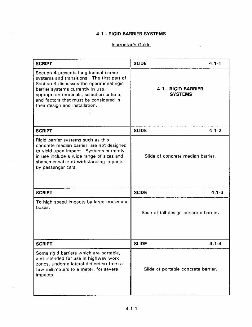
4.1 - RIGID BARRIER SYSTEMS
Instructor’s Guide
SCRIPT SLIDE 4.1-1
Section 4 presents longitudinal barrier systems and transitions. The first part of Section 4 discusses the operational rigid barrier systems currently in use, 4.1 - RIGID BARRIER appropriate terminals, selection criteria, SYSTEMS and factors that must be considered in their design and installation.
SCRIPT SLIDE 4.1-2
Rigid barrier systems such as this concrete median barrier, are not designed to yield upon impact. Systems currently in use include a wide range of sizes and Slide of concrete median barrier. shapes capable of withstanding impacts by passenger cars.
SCRIPT SLIDE 4.1-3
To high speed impacts by large trucks and buses.
Slide of tall design concrete barrier.
SCRIPT
Some rigid barriers which are portable, and intended for use in highway work zones, undergo lateral deflection from a few millimeters to a meter, for severe impacts.
SLIDE 4.1-4
Slide of portable concrete barrier.
4.1 .l
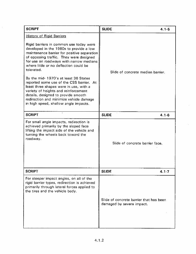
SCRIPT
Historv of Riqid Barriers
SLIDE 4.1-5
Rigid barriers in common use today were developed in the 1960s to provide a low maintenance barrier for positive separation of opposing traffic. They were designed for use on roadways with narrow medians where little or no deflection could be tolerated.
By the mid- 1970’s at least 36 States reported some use of the CSS barrier. At least three shapes were in use, with a variety of heights and reinforcement details, designed to provide smooth redirection and minimize vehicle damage in high speed, shallow angle impacts.
Slide of concrete median barrier.
1 SCRIPT SLIDE 4.1-6
For small angle impacts, redirection is achieved primarily by the sloped face lifting the impact side of the vehicle and turning the wheels back toward the roadway.
Slide of concrete barrier face.
SCRIPT SLIDE 4.1-7
For steeper impact angles, on all of the rigid barrier types, redirection is achieved primarily through lateral forces applied to the tires and the vehicle body.
Slide of concrete barrier that has been damaged by severe impact.
4.1.2
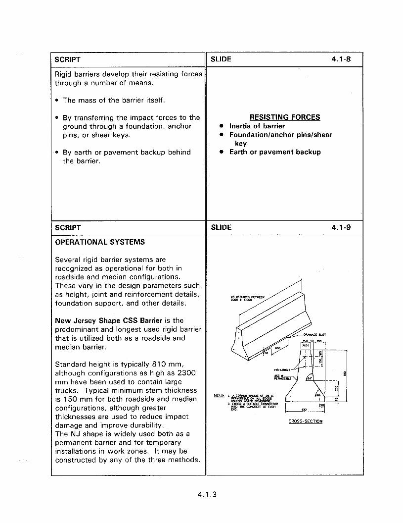
XRIPT SLIDE 4.1-8
%gid barriers develop their resisting forces :hrough a number of means.
1 The mass of the barrier itself.
1 By transferring the impact forces to the ground through a foundation, anchor pins, or shear keys.
RESISTING FORCES @ Inertia of barrier @ Foundation/anchor pins/shear
key ) By earth or pavement backup behind
the barrier. 0 Earth or pavement backup
5CRIPT
3PERATIONAL SYSTEMS
SLIDE 4.1-9
Several rigid barrier systems are .ecognized as operational for both in *oadside and median configurations. These vary in the design parameters such 3s height, joint and reinforcement details, ‘oundation support, and other details.
Uew Jersey Shape CSS Barrier is the xedominant and longest used rigid barrier :hat is utilized both as a roadside and nedian barrier.
Standard height is typically 810 mm, although configurations as high as 2300 nm have been used to contain large :rucks. Typical minimum stem thickness s 150 mm for both roadside and median
NOTE:r A--oF~~~ - ~~S?%E~,,~~~~
configurations, although greater thicknesses are used to reduce impact damage and improve durability. The NJ shape is widely used both as a permanent barrier and for temporary installations in work zones. It may be constructed by any of the three methods.
CROSS-SECTION
4.1.3
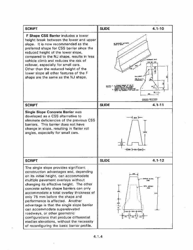
SCRIPT SLIDE 4.1-10
F Shape CSS Barrier includes a lower height break between the lower and upper slope. It is now recommended as the preferred shape for CSS barrier since the reduced height of the lower slope, compared to the NJ shape, results in less vehicle climb and reduces the risk of rollover, especially for small cars. Other than the reduced height of the lower slope all other features of the F shape are the same as the NJ shape.
CROSS-SECTION
SCRIPT SLIDE 4.1-11
Single Slope Concrete Barrier was developed as a CSS alternative to eliminate deficiencies of the previous CSS
--I 203 I---
barriers. This barrier does not have change in slope, resulting in flatter roll angles, especially for small cars.
SCRIPT SLIDE 4.1-12
The single slope provides significant construction advantages and, depending on its initial height, can accommodate k-=--d multiple pavement overlays without changing its effective height. The other concrete safety shape barriers can only accommodate a total overlay thickness of only 75 mm before the shape and performance is affected. Another advantage is that the single slope barrier can accommodate superelevated roadways, or other geometric configurations that produce differential median elevations, without the necessity If reconfiguring the basic barrier profile.
1
4.1.4
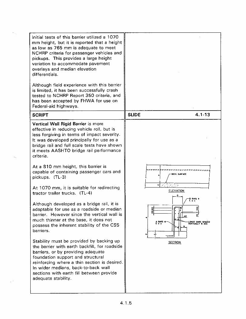
Initial tests of this barrier utilized a 1070 mm height, but it is reported that a height as low as 765 mm is adequate to meet NCHRP criteria for passenger vehicles and pickups. This provides a large height variation to accommodate pavement overlays and median elevation differentials.
Although field experience with this barrier is limited, it has been successfully crash tested to NCHRP Report 350 criteria, and has been accepted by FHWA for use on Federal-aid highways.
SCRIPT SLIDE 4.1-13
Vertical Wall Rigid Barrier is more effective in reducing vehicle roll, but is less forgiving in terms of impact severity. It was developed principally for use as a bridge rail and full scale tests have shown it meets AASHTO bridge rail performance criteria.
At 1070 mm, it is suitable for redirecting tractor trailer trucks. (TL-4)
At a 810 mm height, this barrier is capable of containing passenger cars and pickups. (TL-3)
/ii/
ELEVATION
Although developed as a bridge rail, it is adaptable for use as a roadside or median barrier. However since the vertical wall is much thinner at the base, it does not possess the inherent stability of the CSS barriers.
Stability must be provided by backing up the barrier with earth backfill, for roadside barriers, or by providing adequate foundation support and structural reinforcing where a thin section is desired. In wider medians, back-to-back wall sections with earth fill between provide adequate stability.
SECTION
4.1.5
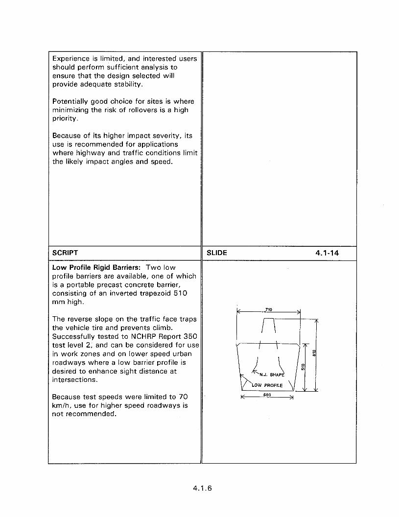
Experience is limited, and interested users should perform sufficient analysis to ensure that the design selected will provide adequate stability.
Potentially good choice for sites is where minimizing the risk of rollovers is a high priority.
Because of its higher impact severity, its use is recommended for applications where highway and traffic conditions limit the likely impact angles and speed.
SCRIPT SLIDE 4.1-14
Low Profile Rigid Barriers: Two low profile barriers are available, one of which is a portable precast concrete barrier, consisting of an inverted trapezoid 510 mm high.
< 710 >
The reverse slope on the traffic face traps the vehicle tire and prevents climb. Successfully tested to NCHRP Report 350 test level 2, and can be considered for use in work zones and on lower speed urban roadways where a low barrier profile is desired to enhance sight distance at intersections.
0 E
LOW PROFILE v ”
Because test speeds were limited to 70 , 660 >I
km/h, use for higher speed roadways is not recommended.
4.1.6
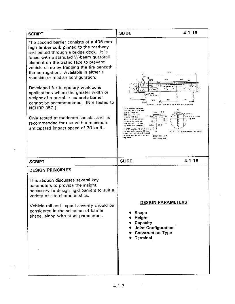
SCRIPT SLIDE 4.1.15
The second barrier consists of a 406 mm ligh timber curb pinned to the roadway snd bolted through a bridge deck. It is iaced with a standard W-beam guardrail slement on the traffic face to prevent vehicle climb by trapping the tire beneath the corrugation. Available in either a roadside or median configuration.
Developed for temporary work zone applications where the greater width or weight of a portable concrete barrier cannot be accommodated. (Not tested to NCHRP 350.1
Only tested at moderate speeds, and is recommended for use with a maximum anticipated impact speed of 70 km/h.
SCRIPT
DESIGN PRINCIPLES
SLIDE 4.1-16
This section discusses several key parameters to provide the insight necessary to design rigid barriers to suit a variety of site characteristics.
Vehicle roll and impact severity should be considered in the selection of barrier shape, along with other parameters.
DESIGN PARAMETERS
@ Shape l Height @ Capacity @ Joint Configuration l Construction Type l Terminal
4.1.7
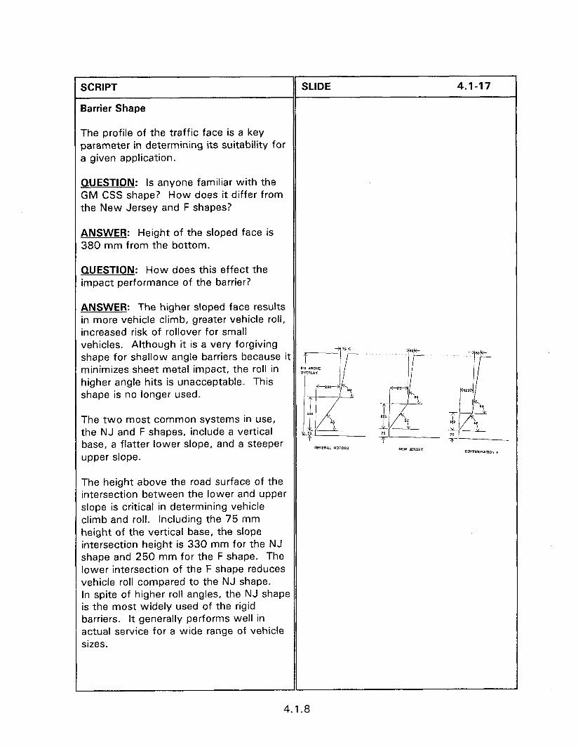
SCRIPT SLIDE 4.1-17
Barrier Shape
The profile of the traffic face is a key parameter in determining its suitability for a given application.
QUESTION: Is anyone familiar with the GM CSS shape? How does it differ from the New Jersey and F shapes?
ANSWER: Height of the sloped face is 380 mm from the bottom.
QUESTION: How does this effect the impact performance of the barrier?
ANSWER: The higher sloped face results in more vehicle climb, greater vehicle roll, increased risk of rollover for small vehicles. Although it is a very forgiving shape for shallow angle barriers because it r ‘. minimizes sheet metal impact, the roll in :&:::; higher angle hits is unacceptable. This shape is no longer used.
The two most common systems in use, the NJ and F shapes, include a vertical 50 base, a flatter lower slope, and a steeper
&a J$
GENERAL MOTORS NEW JERSEY upper slope. CO”FIQ”RATWW F
The height above the road surface of the intersection between the lower and upper slope is critical in determining vehicle climb and roll. Including the 75 mm height of the vertical base, the slope intersection height is 330 mm for the NJ shape and 250 mm for the F shape. The lower intersection of the F shape reduces vehicle roll compared to the NJ shape. In spite of higher roll angles, the NJ shape is the most widely used of the rigid barriers. It generally performs well in actual service for a wide range of vehicle sizes.
4.1.8
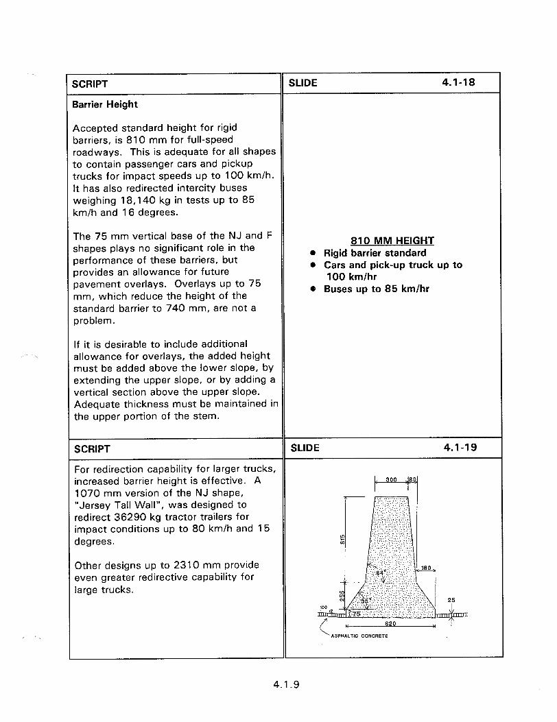
SCRIPT
Barrier Height
SLIDE 4.1-18
Accepted standard height for rigid barriers, is 810 mm for full-speed roadways. This is adequate for all shapes to contain passenger cars and pickup trucks for impact speeds up to 100 km/h. It has also redirected intercity buses weighing 18,140 kg in tests up to 85 km/h and 16 degrees.
The 75 mm vertical base of the NJ and F shapes plays no significant role in the performance of these barriers, but provides an allowance for future pavement overlays. Overlays up to 75 mm, which reduce the height of the standard barrier to 740 mm, are not a problem.
810 MM HEIGHT l Rigid barrier standard l Cars and pick-up truck up to
100 km/hr 0 Buses up to 85 km/hr
If it is desirable to include additional allowance for overlays, the added height must be added above the lower slope, by extending the upper slope, or by adding a vertical section above the upper slope. Adequate thickness must be maintained in the upper portion of the stem.
SCRIPT SLIDE 4.1-19
For redirection capability for larger trucks, increased barrier height is effective. A 1070 mm version of the NJ shape, “Jersey Tall Wall”, was designed to redirect 36290 kg tractor trailers for impact conditions up to 80 km/h and 15 ..: . ..: . degrees.
. . . .._. ..-. _. . . . .:.- ,....._. ,....: : . . .,: . . .
Other designs up to 2310 mm provide even greater redirective capability for large trucks.
4.1.9
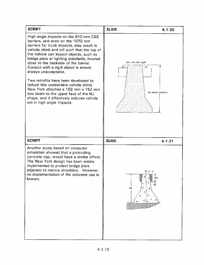
SCRIPT SLIDE 4. I-20
High angle impacts on the 810 mm CSS barriers, and even on the 1070 mm barriers for truck impacts, may result in vehicle climb and roll such that the top of the vehicle can impact objects, such as bridge piers or lighting standards, located close to the backside of the barrier. Contact with a rigid object is almost always unacceptable.
Two retrofits have been developed to reduce this undesirable vehicle climb. New York attaches a 152 mm x 152 mm box beam to the upper face of the NJ shape, and it effectively reduces vehicle roll in high angle impacts.
SCRIPT SLIDE 4.1-21
Another study based on computer simulation showed that a protruding concrete cap, would have a similar effect. The New York design has been widely implemented to protect bridge piers adjacent to narrow shoulders. However, ‘51 t- no implementation of the concrete cap is known.
4.1.10
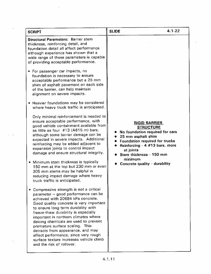
;CRlPT SLIDE 4.1-22
structural Parameters: Barrier stem :hickness, reinforcing detail, and oundation detail all affect performance although experience has shown that a wide range of these parameters is capable If providing acceptable performance.
1 For passenger car impacts, no foundation is necessary to ensure acceptable performance but a 25 mm shim of asphalt pavement on each side of the barrier, can help maintain alignment on severe impacts.
b Heavier foundations may be considered where heavy truck traffic is anticipated.
Only minimal reinforcement is needed to ensure acceptable performance, with good vehicle containment available from as little as four #I 3 (A61 5 m) bars; although some barrier damage can be expected in severe impacts. Additional reinforcing may be added adjacent to expansion joints to control impact damage and ensure structural integrity.
RIGID BARRIER STRUCTURE
0 No foundation required for cars 0 25 mm asphalt shim 0 Foundation required for trucks l Reinforcing - 4 #I 3 bars, more
at joints l Stem thickness - 150 mm
0 Minimum stem thickness is typically 150 mm at the top but 230 mm or ‘even 305 mm stems may be helpful in reducing impact damage where heavy truck traffic is anticipated.
minimum @ Concrete quality - durability
@ Compressive strength is not a critical parameter -- good performance can be achieved with 20684 kPa concrete. Good quality concrete is very important to ensure long term durability with freeze-thaw durability is especially important in northern climates where deicing chemicals are used to prevent premature surface scaling. This detracts from appearance, and may affect performance, since very rough surface texture increases vehicle climb and the risk of rollover.
4.1.11
SCRIPT
Joint Configurations: For permanent barriers, a wide variety of joint configurations have been used.
SLIDE 4.1-23
l Cast-in-place or slip formed barriers and joints are permitted to form uncontrolled depending an state’s policy.
l Expansion joints are rarely provided except at bridge approaches or at other structures where uncontrolled longitudinal movement may be objectionable. Narrow expansion may be left open or filled with a flexible joint compound.
JOINT CONFIGURATION @ Uncontrolled e Expansion joints rare l Open or flexible joint compound 0 Steel plates
l Joint openings more than a few inches in width should be bridged using a steel plate matching the shape of the barrier.
For precast barriers, load transfer across the joint is required.
SCRIPT SLIDE 4.1-24
Concrete barriers are constructed by three methods; precast, cast-in-place, and slipformed.
l Cast-in-place is the most versatile -- forms can be configured to meet the demands of any configuration. However, this is the slowest and most expensive mode of construction.
CONCRETE BARRIER CONSTRUCTION
0 Cast-In-Place - Most versatile - Slow, expensive
l Slipform paving is most cost effective where long runs of barrier are placed without interruption or change in the barrier shape or profile.
o Slip Form - Effective for long runs - Profile changes difficult
l While some shape and profile changes can be accommodated, frequent changes slow down production and affect the quality of the finished product.
4.1.12
XRIPT
vlany Contractors like the single slope larrier because of ease in slip forming.
SLIDE 4.1-25
Slide of single slope side forming.
SCRIPT SLIDE 4.1-26
l Precast barriers offer a good compromise that normally results in better production rates than cast-in- place and can accommodate variations better than slipform. An added advantage of precast barriers is that, since they are manufactured in a factory setting, quality control is improved, in terms of both dimensional tolerances and concrete properties.
l Regardless of the construction mode quality control during construction is critical. Failure to control concrete properties will adversely affect durability. Concrete mix proportions, dimensional tolerances, air entraining characteristics, and curing are all important to quality control. Variations in barrier dimensions detract from appearance, deviations in the surface shape may adversely affect vehicle roll on impact.
0 Pre-Cast - Good production, quality - Versatile
l Quality Control - Dimensional tolerances - Air entraining, curing
l Cover over reinforcing bars is important to prevent deterioration from corrosion of the reinforcement. In locations subject to use of deicers, or in coastal environments, a minimum of 40 mm of cover should be provided.
4.1.13

A number of terminals are available for rigid barriers that provide good impact protection. Since rigid barriers generally do not require end anchorage to develop their strength, the simplest means of providing impact protection for the barrier end may be to terminate the barrier beyond the clear zone. The flare rate used to offset the barrier should not exceed the recommended values provided in Table 4.1.1, page 4.1.16.
TERMINALS
the rigid barrier, wh and terrain are suitable.
sway from the end of the barrier should be provided to reduce the risk of vehicles straddling the barrier.
For terminals buried in the backslope, the ntersection of the barrier with the slope nay present unpredictable performance 3nd the backslope and ditch line should be Jraded to guide vehicles away from this 3rea.
Slide of berm terminal.
4.1.14
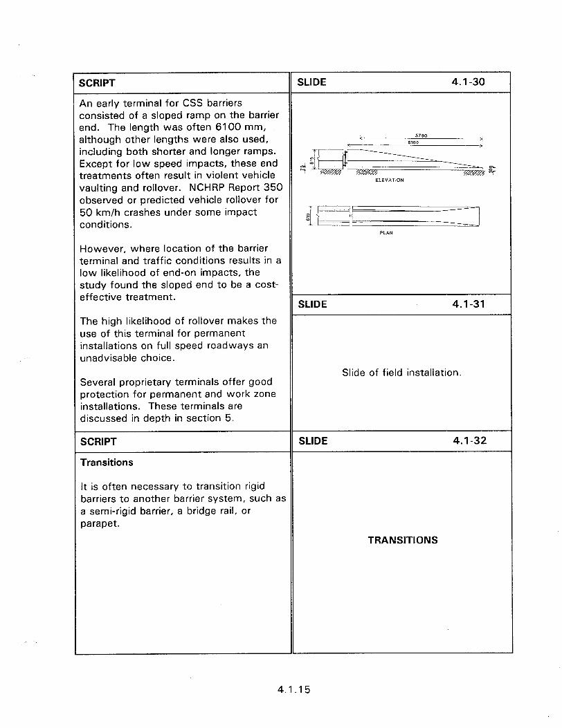
SCRIPT SLIDE 4.1-30
An early terminal for CSS barriers consisted of a sloped ramp on the barrier end. The length was often 6100 mm, although other lengths were also used, k 5790 >i
k 6100 including both shorter and longer ramps.
4
Except for low speed impacts, these end $ 04 treatments often result in violent vehicle 9
vaulting and rollover. NCHRP Report 350 observed or predicted vehicle rollover for 50 km/h crashes under some impact
/ I
conditions. f Ii y I
PLAN
However, where location of the barrier terminal and traffic conditions results in a low likelihood of end-on impacts, the study found the sloped end to be a cost- effective treatment.
SLIDE 4.1-31
The high likelihood of rollover makes the use of this terminal for permanent installations on full speed roadways an unadvisable choice.
Slide of field installation. Several proprietary terminals offer good protection for permanent and work zone installations. These terminals are discussed in depth in section 5.
SCRIPT
Transitions
SLIDE 4.1-32
It is often necessary to transition rigid barriers to another barrier system, such as a semi-rigid barrier, a bridge rail, or parapet.
TRANSITIONS
4.1.15
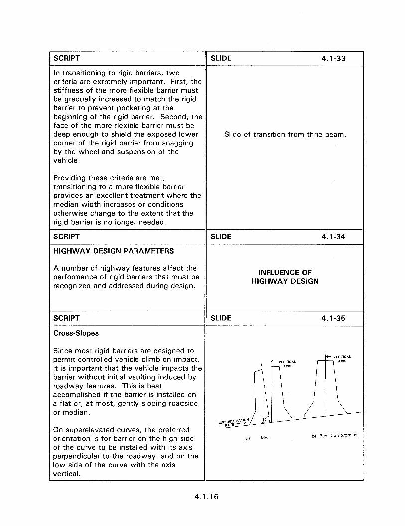
SCRIPT SLIDE 4.1-33
In transitioning to rigid barriers, two criteria are extremely important. First, the stiffness of the more flexible barrier must be gradually increased to match the rigid barrier to prevent pocketing at the beginning of the rigid barrier. Second, the face of the more flexible barrier must be deep enough to shield the exposed lower Slide of transition from thrie-beam. corner of the rigid barrier from snagging by the wheel and suspension of the vehicle.
Providing these criteria are met, transitioning to a more flexible barrier provides an excellent treatment where the median width increases or conditions otherwise change to the extent that the rigid barrier is no ionger needed.
SCRIPT SLIDE 4.1-34
HIGHWAY DESIGN PARAMETERS
A number of highway features affect the performance of rigid barriers that must be recognized and addressed during design.
INFLUENCE OF HIGHWAY DESIGN
SCRIPT
Cross-Slopes
SLIDE 4.1-35
Since most rigid barriers are designed to permit controlled vehicle climb on impact, it is important that the vehicle impacts the barrier without initial vaulting induced by roadway features. This is best accomplished if the barrier is installed on a flat or, at most, gently sloping roadside or median.
On superelevated curves, the preferred orientation is for barrier on the high side of the curve to be installed with its axis perpendicular to the roadway, and on the low side of the curve with the axis vertical.
Ideal
4.1.16

SCRIPT SLIDE 4.6-l 2
l The Type 3 terminal consists of a flared offset with the rail end connected to a concrete anchor buried in the embankment back slope.
For high-speed roadways, Type 1 and Type 2 terminals should be installed beyond the clear zone whenever possible, using the AASHTO suggested flare rates.
Even for low-speed roadways, the maximum possible offset should be provided to reduce the risk of launching vehicles in end-on impacts.
l Whenever practical, the Type 3 terminal, is preferred to reduce the risk of vehicle vaulting and subsequent rollover.
SCRIPT
Stone Masonry Guardwall
SLIDE 4.6-l 3
Native stone walls, dry-laid or mortared, have been used to line roadways for decades. They add to the aesthetics and keep vehicles and pedestrians from entering restricted areas.
Dry-laid stonework, generally does not have sufficient structural capacity or height to contain vehicles in severe impacts.
Slide of stone masonary guardrail.
The stone masonry guardway maintains visual appeal of mortared stone while adding a reinforced concrete core and foundation to ensure structural capacity. A mortared stone wall is built over the core and foundation to meet visual requirements.
4.6.6
SCRIPT
Drainage
SLIDE 4.1-38
Since rigid barriers can result in the retention of both snow and water, consideration of pavement drainage is important.
Free drainage of water along or away from the barrier is essential to prevent ponding and the potential for ice formation in cold weather. In some cases, it may be necessary to provide periodic drainage slots in the bottom of Slide of drainage inlet adjacent to CSS the barrier to permit drainage, especially barrier. for temporary work zone installations where it may not be possible to control drainage through selection of appropriate roadway cross-slopes.
On the high side of superelevated curves adjustment of pavement and shoulder slopes is essential to prevent snow stored against the barrier from melting and running onto the pavement where it may freeze at night.
SCRIPT
Fixed Objects
SLIDE 4.1-39
Objects in the median can be treated by widening the barrier to position the traffic faces of the barrier in front of the object. The same effect can be achieved for roadside barrier by flaring the barrier around the object. It is important to use a flare rate consistent with recommended values.
Slide of barrier widened for columns.
In severe impacts, a vehicle may climb to the top of a CSS barrier and contact objects such as piers or support structures located close to the face of the barrier.
4.1.18
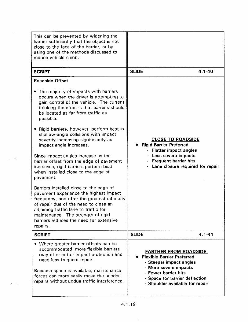
I-
This can be prevented by widening the barrier sufficiently that the object is not close to the face of the barrier, or by dsing one of the methods discussed to reduce vehicle climb.
SCRIPT
Roadside Offset
SLIDE 4. I-40
l The majority of impacts with barriers occurs when the driver is attempting to gain control of the vehicle. The current thinking therefore is that barriers should be located as far from traffic as possible.
l Rigid barriers, however, perform best in shallow-angle collisions with impact severity increasing significantly as impact angle increases.
Since impact angles increase as the barrier offset from the edge of pavement increases, rigid barriers perform best when installed close to the edge of pavement.
CLOSE TO ROADSIDE l Rigid Barrier Preferred
- Flatter impact angles - Less severe impacts - Frequent barrier hits - Lane closure required for repair
Barriers installed close to the edge of pavement experience the highest impact frequency, and offer the greatest difficulty of repair due of the need to close an adjoining traffic lane to traffic for maintenance. The strength of rigid barriers reduces the need for extensive repairs.
SCRIPT SLIDE 4.1-41
l Where greater barrier offsets can be accommodated, more flexible barriers may offer better impact protection and
FARTHER FROM ROADSIDE
need less frequent repair. @ Flexible Barrier Preferred
- Steeper impact angles
Because space is available, maintenance forces can more easily make the needed repairs without undue traffic interference.
- More severe impacts - Fewer barrier hits - Space for barrier deflection - Shoulder available for repair
1
4.1.19
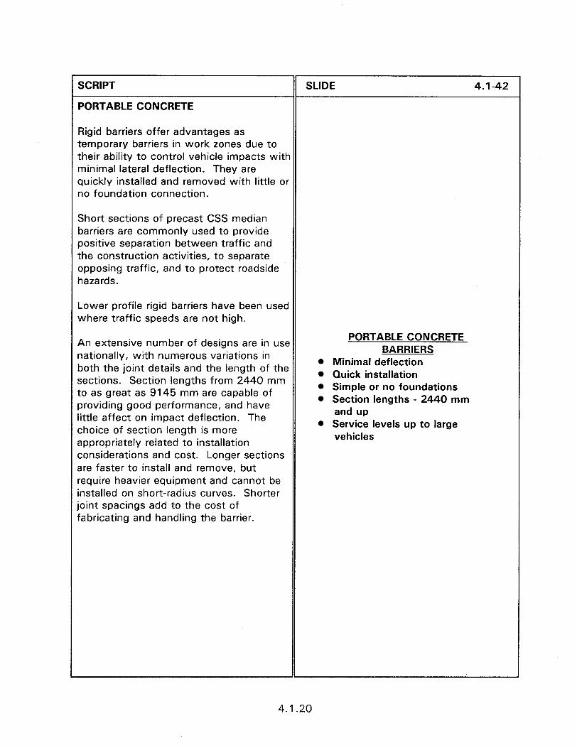
SCRIPT II SLIDE 4.1-42
PORTABLE CONCRETE
Rigid barriers offer advantages as temporary barriers in work zones due to their ability to control vehicle impacts with minimal lateral deflection. They are quickly installed and removed with little or no foundation connection.
Short sections of precast CSS median barriers are commonly used to provide positive separation between traffic and the construction activities, to separate opposing traffic, and to protect roadside hazards.
Lower profile rigid barriers have been used where traffic speeds are not high.
An extensive number of designs are in use nationally, with numerous variations in both the joint details and the length of the sections. Section lengths from 2440 mm to as great as 9145 mm are capable of providing good performance, and have little affect on impact deflection. The choice of section length is more appropriately related to installation considerations and cost. Longer sections are faster to install and remove, but require heavier equipment and cannot be installed on short-radius curves. Shorter joint spacings add to the cost of fabricating and handling the barrier.
PORTABLE CONCRETE BARRIERS
0 Minimal deflection l Quick installation 0 Simple or no foundations l Section lengths - 2440 mm
and up l Service levels up to large
vehicles
4.1.20
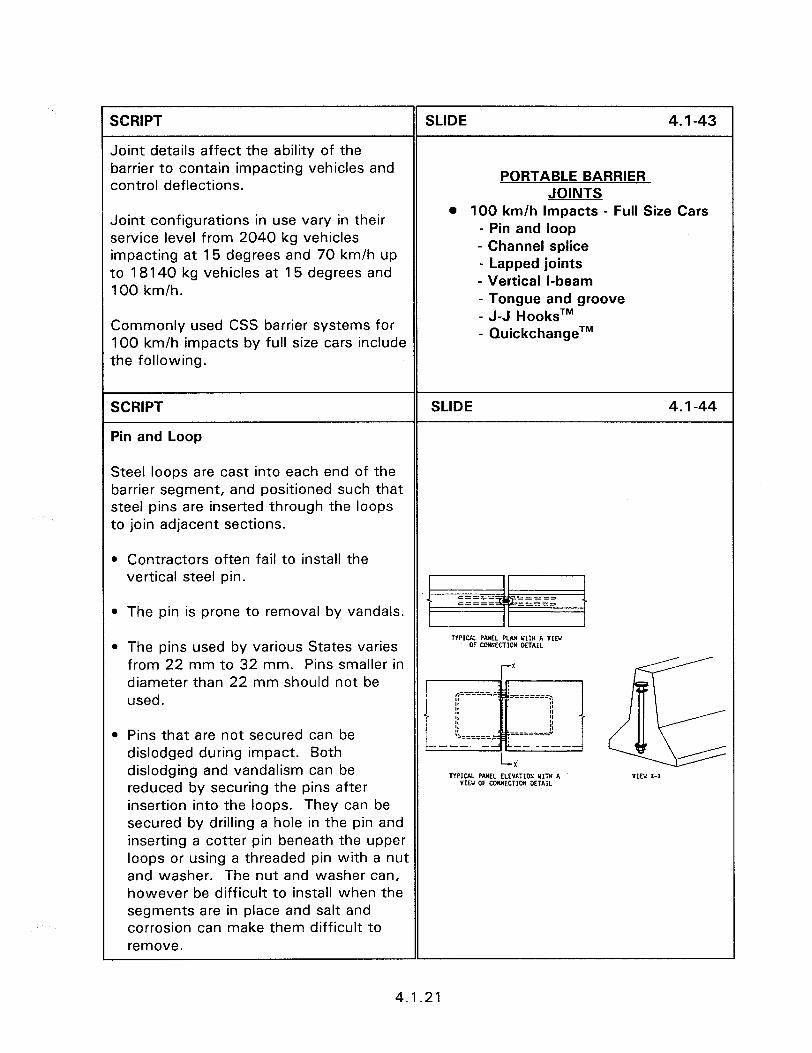
r 1 SCRIPT
Joint details affect the ability of the barrier to contain impacting vehicles and control deflections.
SLIDE 4.1-43
PORTABLE BARRIER JOINTS
Joint configurations in use vary in their service level from 2040 kg vehicles impacting at 15 degrees and 70 km/h up to 18140 kg vehicles at 15 degrees and 100 km/h.
l 100 km/h Impacts - Full Size Cars - Pin and loop - Channel splice - Lapped joints - Vertical l-beam - Tongue and groove
Commonly used CSS barrier systems for 100 km/h impacts by full size cars include the following.
- J-J HooksTM - QuickchangeTM
SCRIPT
Pin and Loop
SLIDE 4.1-44
Steel loops are cast into each end of the barrier segment, and positioned such that steel pins are inserted through the loops to join adjacent sections.
l Contractors often fail to install the vertical steel pin.
l The pin is prone to removal by vandals.
l The pins used by various States varies from 22 mm to 32 mm. Pins smaller in diameter than 22 mm should not be used.
l Pins that are not secured can be dislodged during impact. Both dislodging and vandalism can be reduced by securing the pins after insertion into the loops. They can be secured by drilling a hole in the pin and inserting a cotter pin beneath the upper loops or using a threaded pin with a nut and washer. The nut and washer can, however be difficult to install when the segments are in place and salt and corrosion can make them difficult to remove.
4.1.21
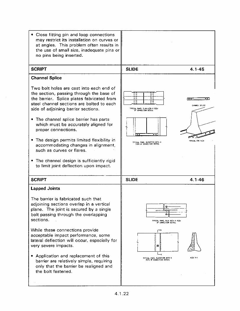
SI
Cl
T1 th th St Sil
l
e
Tt ac Pl bc SE
VL ac la. VE
Close fitting pin and loop connections may restrict its installation on curves or at angles. This problem often results in the use of small size, inadequate pins OI no pins being inserted.
CRIPT
hannel Splice
NO bolt holes are cast into each end of le section, passing through the base of le barrier. Splice plates fabricated from eel channel sections are bolted to each de of adjoining barrier sections.
The channel splice barrier has parts which must be accurately aligned for proper connections.
The design permits limited flexibility in accommodating changes in alignment, such as curves or flares.
The channel design is sufficiently rigid to limit joint deflection upon impact.
CRIPT
rpped Joints
le barrier is fabricated such that ijoining sections overlap in a vertical ane. The joint is secured by a single )It passing through the overlapping ztions.
‘bile these connections provide :ceptable impact performance, some teral deflection will occur, especially for ?ry severe impacts.
Application and replacement of this barrier are relatively simple, requiring only that the barrier be realigned and the bolt fastened.
SLIDE 4.1-45
SLIDE 4.1-46
4.1.22
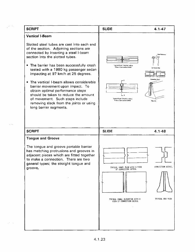
r SCRIPT
Vertical I-Beam
SLIDE 4.1-47
Slotted steel tubes are cast into each end of the section. Adjoining sections are connected by inserting a steel l-beam section into the slotted tubes.
l The barrier has been successfully crash tested with a 1980 kg passenger sedan impacting at 97 km/h at 25 degrees.
l The vertical l-beam allows considerable barrier movement upon impact. To obtain optimal performance steps should be taken to reduce the amount of movement. Such steps include removing slack from the joints or using long barrier segments.
SCRIPT
Tongue and Groove
SLIDE 4.1-48
The tongue and groove portable barrier has matching protrusions and grooves in adjacent pieces which are fitted together to make a connection. There are two general types; the straight tongue and groove, TYPICAL PANEL PLAN WITH A VIEW CONNECTION DETAIL
OF CONNECTION DETAIL
TYPICAL PANEL ELEVATION WITH A VIEW OF CONNECTION DETAIL
TYPICAL EN0 VIEW
1
4.1.23
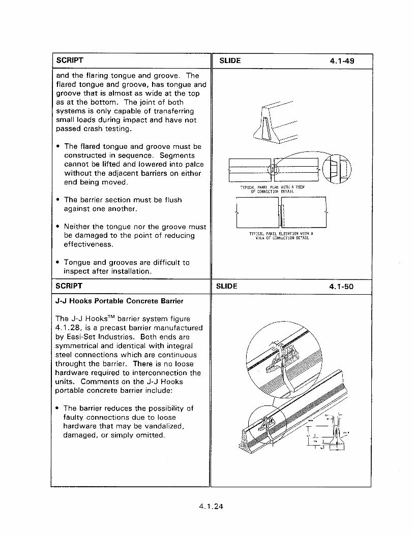
SCRIPT SLIDE 4.1-49
and the flaring tongue and groove. The flared tongue and groove, has tongue and groove that is almost as wide at the top as at the bottom. The joint of both systems is only capable of transferring small loads during impact and have not passed crash testing.
42 IIll l The flared tongue and groove must be
constructed in sequence. Segments cannot be lifted and lowered into palce without the adjacent barriers on either end being moved.
TYPICAL PANEL PLAN WITH A VIEW OF CONNECTION DETAIL
l The barrier section must be flush against one another.
l Neither the tongue nor the groove must be damaged to the point of reducing effectiveness.
TYPICAL PANEL ELEVATION WITH A VIEW OF CONNECTION DETAIL
l Tongue and grooves are difficult to inspect after installation.
SCRIPT
J-J Hooks Portable Concrete Barrier
SLIDE 4.1-50
The J-J HooksTM barrier system figure 4.1.28, is a precast barrier manufactured by Easi-Set Industries. Both ends are symmetrical and identical with integral steel connections which are continuous throught the barrier. There is no loose hardware required to interconnection the units. Comments on the J-J Hooks portable concrete barrier include:
l The barrier reduces the possibility of faulty connections due to loose hardware that may be vandalized, damaged, or simply omitted.
4.1 .24
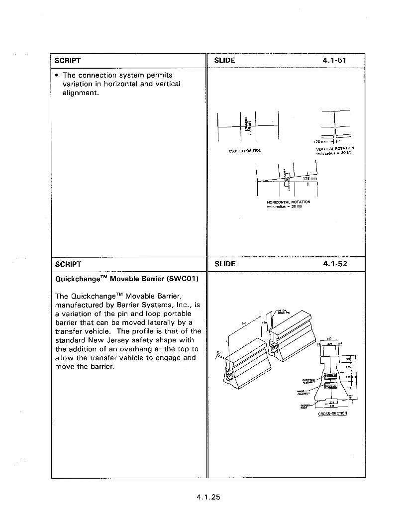
SCRIPT
l The connection system permits variation in horizontal and vertical alignment.
SLIDE 4.1-51
~+bj----j ,,3s
CLOSED POSITION VERTCAL ROTATION (tin radius = 30 M)
;I
w
178 mm
z
HOREONTAL ROTATION (min radius = 30 VI
SCRIPT SLIDE 4.1-52
QuickchangeTM Movable Barrier (SWCOl 1
The QuickchangeTM Movable Barrier, manufactured by Barrier Systems, Inc., is a variation of the pin and loop portable barrier that can be moved laterally by a transfer vehicle. The profile is that of the standard New Jersey safety shape with the addition of an overhang at the top to allow the transfer vehicle to engage and move the barrier.
CROSS-SECTION
4.1.25
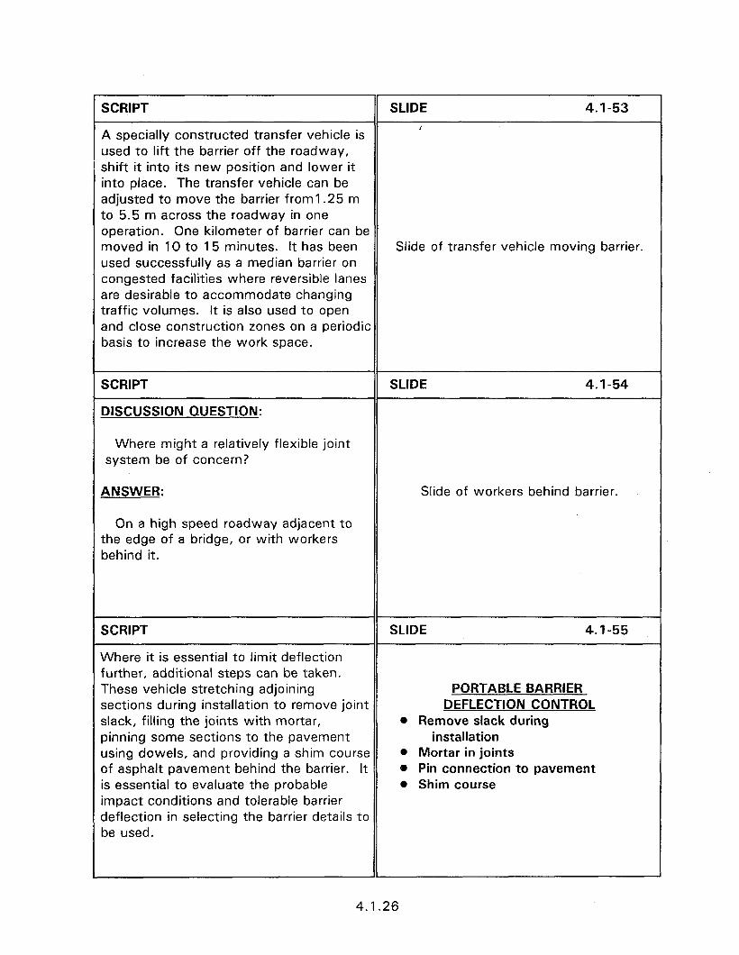
SCRIPT SLIDE 4.1-53
A specially constructed transfer vehicle is /
used to lift the barrier off the roadway, shift it into its new position and lower it into place. The transfer vehicle can be adjusted to move the barrier froml.25 m to 5.5 m across the roadway in one operation. One kilometer of barrier can be moved in 10 to 15 minutes. It has been Slide of transfer vehicle moving barrier. used successfully as a median barrier on congested facilities where reversible lanes are desirable to accommodate changing traffic volumes. It is also used to open and close construction zones on a periodic basis to increase the work space.
SCRIPT
DISCUSSION QUESTION:
SLIDE 4.1-54
Where might a relatively flexible joint system be of concern?
ANSWER:
On a high speed roadway adjacent to
Slide of workers behind barrier.
the edge of a bridge, or with workers behind it.
SCRIPT SLIDE 4.1-55
Where it is essential to limit deflection further, additional steps can be taken. These vehicle stretching adjoining PORTABLE BARRIER sections during installation to remove joint DEFLECTION CONTROL slack, filling the joints with mortar, 0 Remove slack during pinning some sections to the pavement installation using dowels, and providing a shim course 0 Mortar in joints of asphalt pavement behind the barrier. It 0 Pin connection to pavement is essential to evaluate the probable 0 Shim course impact conditions and tolerable barrier deflection in selecting the barrier details to be used.
4.1.26
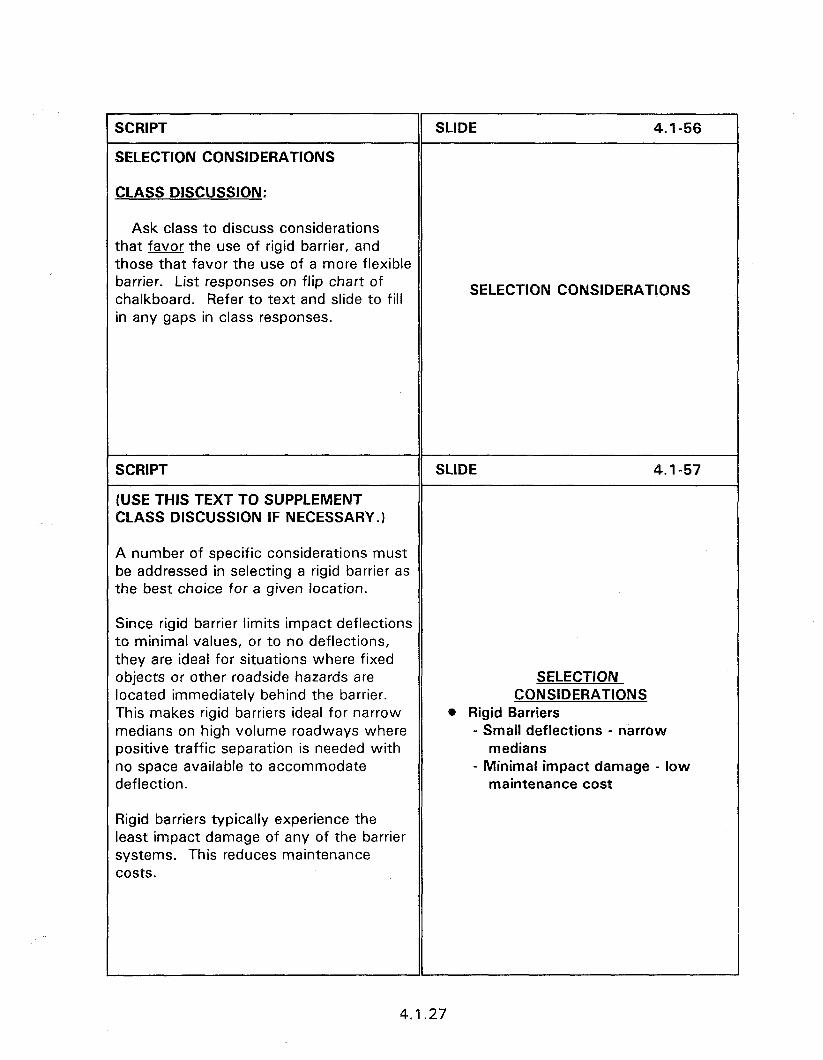
SCRIPT
SELECTION CONSIDERATIONS
SLIDE 4.1-56
CLASS DISCUSSION:
Ask class to discuss considerations that favor the use of rigid barrier, and those that favor the use of a more flexible barrier. List responses on flip chart of chalkboard. Refer to text and slide to fill in any gaps in class responses.
SELECTION CONSIDERATIONS
SCRIPT
(USE THIS TEXT TO SUPPLEMENT CLASS DISCUSSION IF NECESSARY. 1
SLIDE 4.1-57
A number of specific considerations must be addressed in selecting a rigid barrier as the best choice for a given location.
Since rigid barrier limits impact deflections to minimal values, or to no deflections, they are ideal for situations where fixed objects or other roadside hazards are located immediately behind the barrier. This makes rigid barriers ideal for narrow medians on high volume roadways where positive traffic separation is needed with no space available to accommodate deflection.
Rigid barriers typically experience the least impact damage of any of the barrier systems. This reduces maintenance costs.
SELECTION CONSIDERATIONS
@ Rigid Barriers - Small deflections - narrow
medians - Minimal impact damage - low
maintenance cost
4.1.27
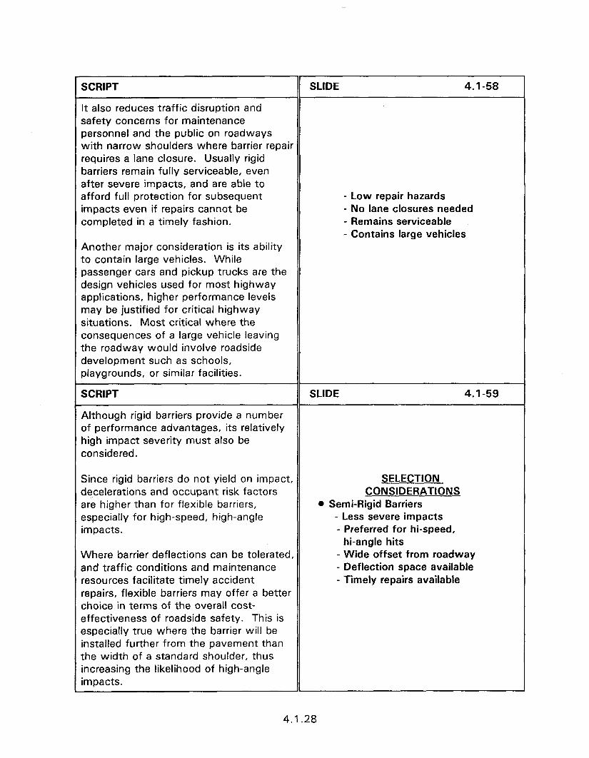
SCRIPT SLIDE 4.1-58
It also reduces traffic disruption and safety concerns for maintenance personnel and the public on roadways with narrow shoulders where barrier repair requires a lane closure. Usually rigid barriers remain fully serviceable, even after severe impacts, and are able to afford full protection for subsequent - Low repair hazards
impacts even if repairs cannot be - No lane closures needed completed in a timely fashion. - Remains serviceable
- Contains large vehicles Another major consideration is its ability to contain large vehicles. While passenger cars and pickup trucks are the design vehicles used for most highway applications, higher performance levels may be justified for critical highway situations. Most critical where the consequences of a large vehicle leaving the roadway would involve roadside development such as schools, playgrounds, or similar facilities.
SCRIPT
Although rigid barriers provide a number of performance advantages, its relatively high impact severity must also be considered.
SLIDE 4.1-59
Since rigid barriers do not yield on impact, decelerations and occupant risk factors are higher than for flexible barriers, especially for high-speed, high-angle impacts.
SELECTION CONSIDERATIONS
l Semi-Rigid Barriers - Less severe impacts - Preferred for hi-speed,
hi-angle hits Where barrier deflections can be tolerated, and traffic conditions and maintenance resources facilitate timely accident repairs, flexible barriers may offer a better choice in terms of the overall cost- effectiveness of roadside safety. This is especially true where the barrier will be installed further from the pavement than the width of a standard shoulder, thus increasing the likelihood of high-angle impacts.
- Wide offset from roadway - Deflection space available - Timely repairs available
4.1.28
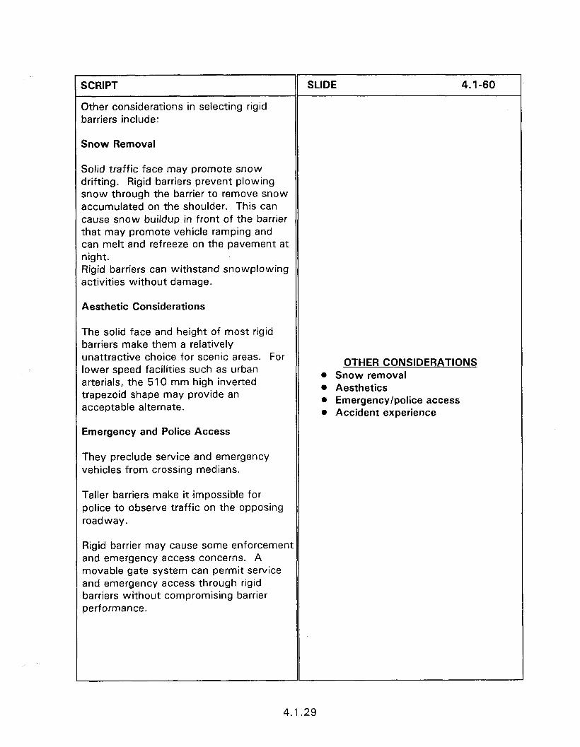
r 1 SCRIPT
Other considerations in selecting rigid barriers include:
SLlDE 4.1-60
Snow Removal
Solid traffic face may promote snow drifting. Rigid barriers prevent plowing snow through the barrier to remove snow accumulated on the shoulder. This can cause snow buildup in front of the barrier that may promote vehicle ramping and can melt and refreeze on the pavement at night. Rigid barriers can withstand snowplowing activities without damage.
Aesthetic Considerations
The solid face and height of most rigid barriers make them a relatively unattractive choice for scenic areas. For lower speed facilities such as urban arterials, the 510 mm high inverted trapezoid shape may provide an acceptable alternate.
OTHER CONSIDERATIONS 0 Snow removal l Aesthetics l Emergency/police access l Accident experience
Emergency and Police Access
They preclude service and emergency vehicles from crossing medians.
Taller barriers make it impossible for police to observe traffic on the opposing roadway.
Rigid barrier may cause some enforcement and emergency access concerns. A movable gate system can permit service and emergency access through rigid barriers without compromising barrier performance.
4.1.29
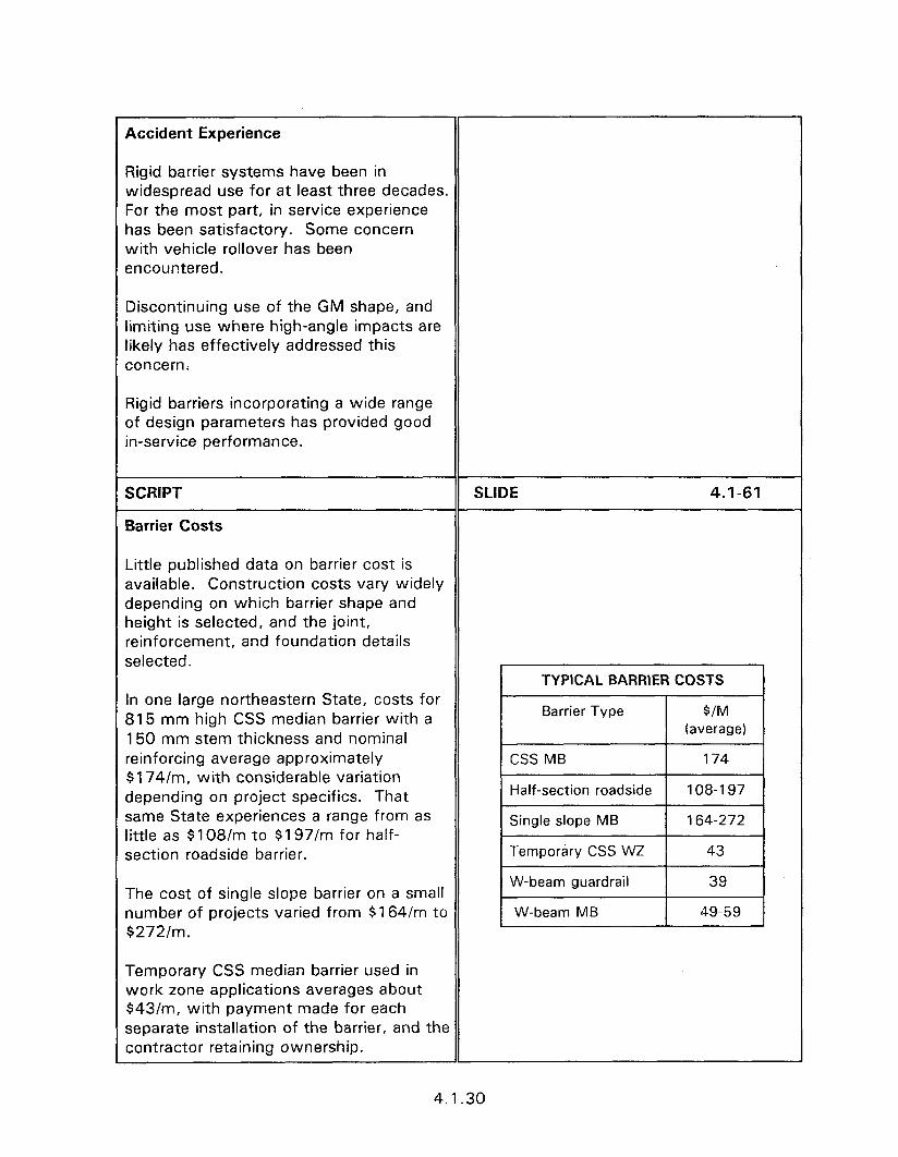
Accident Experience
Rigid barrier systems have been in widespread use for at least three decades. For the most part, in service experience has been satisfactory. Some concern with vehicle rollover has been encountered.
Discontinuing use of the GM shape, and limiting use where high-angle impacts are likely has effectively addressed this concern.
Rigid barriers incorporating a wide range of design parameters has provided good in-service performance.
SCRIPT
Barrier Costs
SLIDE 4.1-61
Little published data on barrier cost is available. Construction costs vary widely depending on which barrier shape and height is selected, and the joint, reinforcement, and foundation details selected.
In one large northeastern State, costs for 815 mm high CSS median barrier with a 150 mm stem thickness and nominal peinforcing average approximately $174/m, with considerable variation depending on project specifics. That same State experiences a range from as ittle as $108/m to $197/m for half- section roadside barrier.
The cost of single slope barrier on a small lumber of projects varied from $164/m to $272/m.
Temporary CSS median barrier used in Yvork zone applications averages about $43/m, with payment made for each separate installation of the barrier, and the contractor retaining ownership.
4.1.30

National average costs are about $39/m for heavy post W-beam roadside barrier and $49/m to $59/m for heavy post W- beam median barrier.
While typical CSS barrier designs cost several times as much as the most popular semi-rigid W-beam barriers, that cost must be weighed against the increased service levels and reduced maintenance costs provided by the CSS barrier.
SCRIPT
EVALUATING EXISTING BARRIERS
SLIDE 4.1-62
Rigid traffic barriers have been in use since the 1960s with many early installations still remaining in service, with little or no change since installation.
0 Review and inspection should be included as part of planning and design for highway reconstruction or repair.
EVALUATING EXISTING BARRIERS
@ Periodic inspection of in-service barriers
l Normal maintenance function 0 Planning and design for
reconstruction l Inspection also triggered by an accident
surveillance report indicating a high severity or incidence of run-off-road accidents.
@ Run-off-road accidents
l Periodic review and inspection is an important function of highway safety management.
SCRIPT
Routine Maintenance Inspections
SLIDE 4.1-63
l Is the barrier generally in good repair, with no significant accident damage or other misalignment?
MAINTENANCE INSPECTION l Significant damage/
misalignment
0 Is the concrete in good condition, with no severe cracking, dislodged pieces, or severe surface spalling?
@ Concrete - severe cracking/ spalling/loose pieces
4.1.31
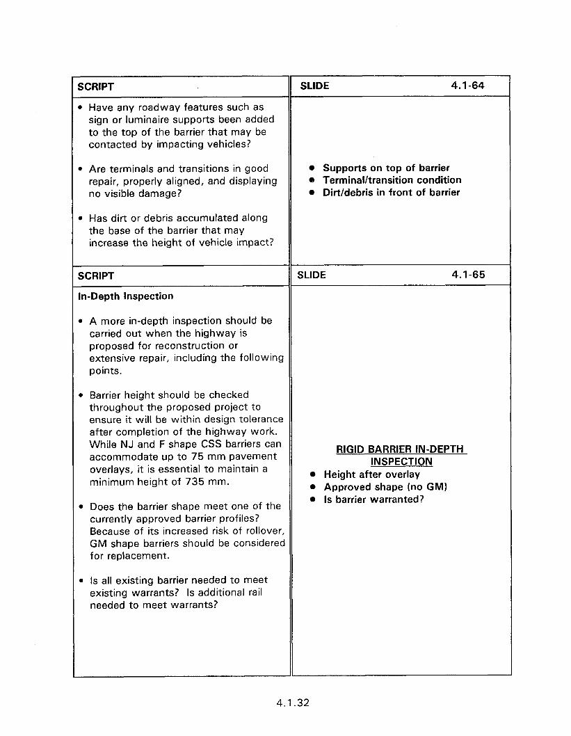
SCRIPT
l Have any roadway features such as sign or luminaire supports been added to the top of the barrier that may be contacted by impacting vehicles?
SLIDE 4.1-64
l Are terminals and transitions in good repair, properly aligned, and displaying no visible damage?
* Has dirt or debris accumulated along the base of the barrier that may increase the height of vehicle impact?
l Supports on top of barrier 0 Terminal/transition condition o Dirt/debris in front of barrier
SCRIPT
In-Depth Inspection
SLIDE 4.1-65
0 A more in-depth inspection should be carried out when the highway is proposed for reconstruction or extensive repair, including the following points.
l Barrier height should be checked throughout the proposed project to ensure it will be within design tolerance after completion of the highway work. While NJ and F shape CSS barriers can accommodate up to 75 mm pavement overlays, it is essential to maintain a minimum height of 735 mm.
RIGID BARRIER IN-DEPTH INSPECTION
0 Height after overlay l Approved shape (no GM)
. Does the barrier shape meet one of the currently approved barrier profiles? Because of its increased risk of rollover, GM shape barriers should be considered for replacement.
l Is barrier warranted?
l Is all existing barrier needed to meet existing warrants? Is additional rail needed to meet warrants?
4.1.32
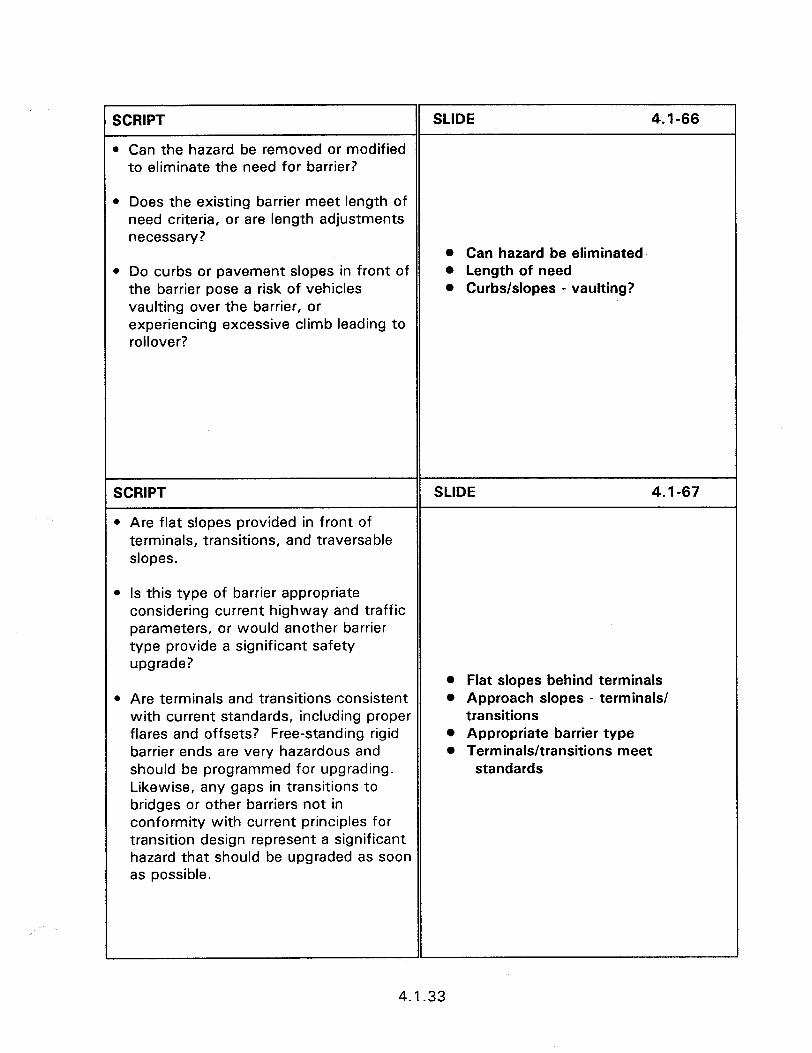
SCRIPT SLIDE 4.1-66
l Can the hazard be removed or modified to eliminate the need for barrier?
l Does the existing barrier meet length of need criteria, or are length adjustments necessary?
l Do curbs or pavement slopes in front of the barrier pose a risk of vehicles vaulting over the barrier, or experiencing excessive climb leading to rollover?
l Can hazard be eliminated l Length of need l Curbs/slopes - vaulting?
SCRIPT
l Are flat slopes provided in front of terminals, transitions, and traversable slopes.
SLIDE 4.1-67
l Is this type of barrier appropriate considering current highway and traffic parameters, or would another barrier type provide a significant safety upgrade?
l Are terminals and transitions consistent with current standards, including proper flares and offsets? Free-standing rigid barrier ends are very hazardous and should be programmed for upgrading. Likewise, any gaps in transitions to bridges or other barriers not in conformity with current principles for transition design represent a significant hazard that should be upgraded as soon as possible.
l Flat slopes behind terminals l Approach slopes - terminals/
transitions 0 Appropriate barrier type l Terminals/transitions meet
standards
4.1.33
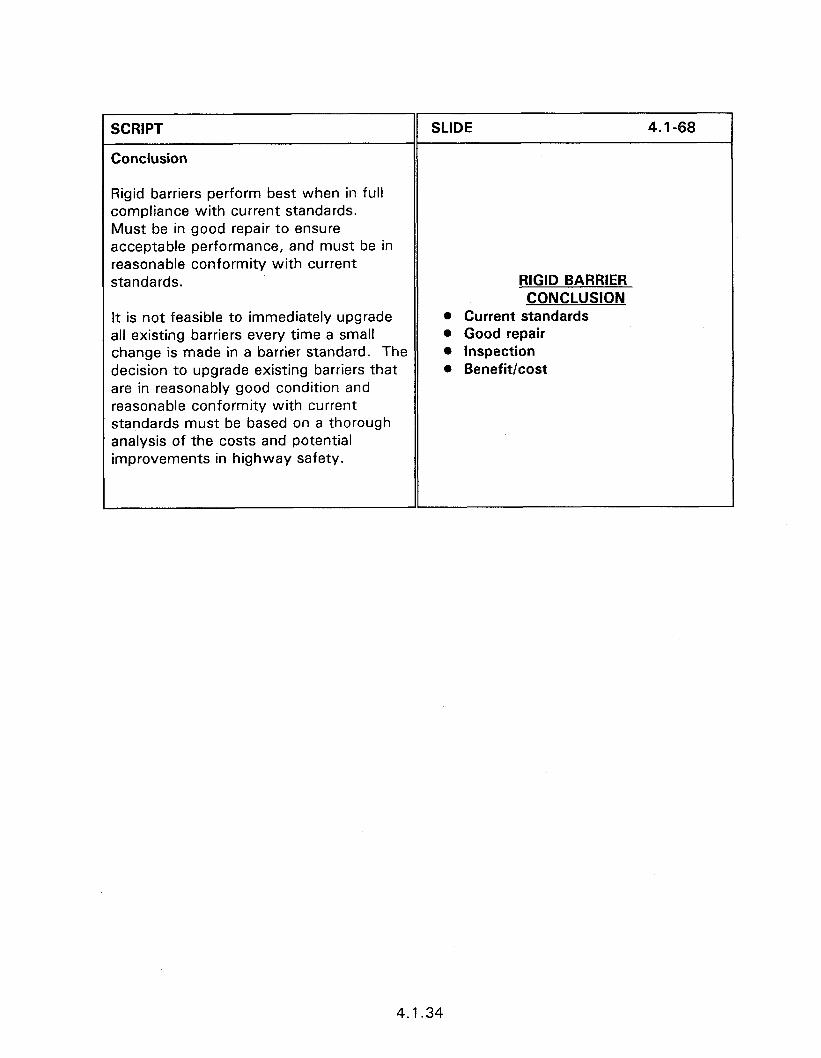
SCRIPT
Conclusion
Rigid barriers perform best when in full compliance with current standards. Must be in good repair to ensure acceptable performance, and must be in reasonable conformity with current standards.
It is not feasible to immediately upgrade all existing barriers every time a small change is made in a barrier standard. The decision to upgrade existing barriers that are in reasonably good condition and reasonable conformity with current standards must be based on a thorough analysis of the costs and potential improvements in highway safety.
SLIDE 4.1-68
RIGID BARRIER CONCLUSION
@ Current standards 0 Good repair l Inspection 0 Benefit/cost
4.1.34
Obiectives:
0
SESSION GUIDE
4.2 - STRONG POST W-BEAM AND THRIE BEAM BARRIERS
Basic principles concerning the design and performance of strong post W- beam and thrie-beam barriers.
Characteristics of operational barriers.
Construction and maintenance.
Helpful Hints:
0 Emphasize how semi-rigid barriers exert forces to restrain impacting vehicles.
0 This session concludes with a workshop consisting of examples of good and bad installations. Supplement these examples with slides from the presentation area.
. Conduct the workshop by displaying the slides and having the participants comment on bad practices.
Visual Aids:
e 49 - 35 mm slides
* Variable number of workshop slides.
Estimated Time
l 60 minutes
Handouts:
e None


4.2 - STRONG POST W-BEAM AND THRIE-BEAM BARRIERS
Instructor’s Guide
SCRIPT
SCRIPT
FUNCTIONAL PRINCIPLES
Strong post systems contain errant vehicles through the development of lateral forces which gradually redirect the vehicle. Lateral resistance develops as the rail, which is restrained by end anchors, deflects laterally. As it deflects and stretches, large tensile forces develop in the rail and redirect the vehicle. The rail, which is supported at regular intervals by the posts, also develops considerable bending resistance.
SCRIPT
The components of this barrier are beams, posts, offset blocks, terminals, beam to post connections, and connecting hardware.
4.2 - STRONG POST W-BEAM AND THRIE-BEAM
SLIDE 4.2-2
SLIDE 4.2-3
STRONG POST (SEMI-RIGID) SYSTEMS 0 Beam rail e Posts - steel, wood l Offset blocks l Terminals l Beam-post connection l Connecting hardware
4.2.1
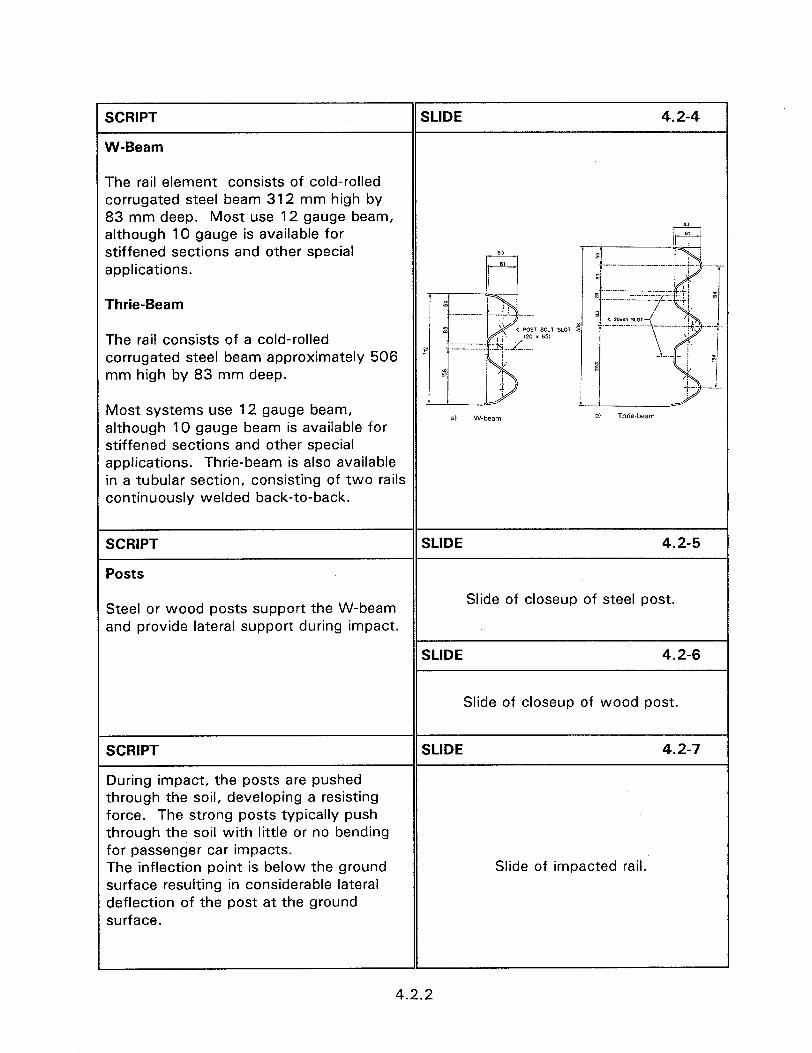
SCRIPT
W-Beam
SLIDE 4.2-4
The rail element consists of cold-rolled corrugated steel beam 312 mm high by 83 mm deep. Most use 12 gauge beam, although 10 gauge is available for stiffened sections and other special applications.
Thrie-Beam
The rail consists of a cold-rolled corrugated steel beam approximately 506 mm high by 83 mm deep.
Most systems use 12 gauge beam, although 10 gauge beam is available for stiffened sections and other special applications. Thrie-beam is also available in a tubular section, consisting of two rails continuously welded back-to-back.
bl Thrie-beam
SCRIPT
Posts
SLIDE 4.2-5
Steel or wood posts support the W-beam and provide lateral support during impact.
Slide of closeup of steel post.
SLIDE 4.2-6
Slide of closeup of wood post.
SCRIPT
During impact, the posts are pushed through the soil, developing a resisting force. The strong posts typically push through the soil with little or no bending for passenger car impacts. The inflection point is below the ground surface resulting in considerable lateral deflection of the post at the ground surface.
SLIDE 4.2-7
Slide of impacted rail.
4.2.2

SCRIPT
Offset blocks
SLIDE 4.2-8
Modern strong post systems include an offset block, or “blockout”, to move the rail forward of the post. Blockouts are usually the same material and cross- section as the post, and slightly taller than the rail. The blockout minimizes wheel snagging, and reduces the likelihood of vehicles vaulting by maintaining rail height as the barrier deflects and rotates downward.
Slide of blockout on W-beam.
SCRIPT
Rail-Post Connections
SLIDE 4.2-9
The connection between the posts and rails must retain the rail at the proper Slide showing bolt head and no washer on height prior to impact, and then maintain face of rail. rail contact with the posts so the posts can provide lateral support. In very severe impacts, in addition to being deflected laterally, the posts may undergo SL’DE 4.2-l 0
plastic deformation near ground level, thus beginning to rotate downward. At this point, the rail must release from the posts without being dragged to the ground in
Slide showing bolt head and washer on face of rail.
order to prevent the vehicle from vaulting the barrier. Two 16 mm diameter hex- head steel bolts connect the steel blockout to steel post. Backup plates are SLIDE 4.2-l 1 required at non-splice steel posts for both the W-beam and thrie-beam systems. Backup plates are not required for wood post systems. The rail to blockout Slide showing bolt head with washer
connection consists of 16 mm steel removed.
button-head bolts; one for each connection for W-beam, two for each connection in the standard thrie-beam SLIDE 4.2-l 2
Slide showing washer and nut on back of post.
4.2.3

systems, and one in the modified thrie- beam system. This relatively strong connection ensures that the rail maintains contact with the post during impact to prevent wheel contact with the post and to take advantage of the lateral support of the post rather than being pushed up and off by the vehicle. However, as the post reaches the outer limits of its lateral deflection and begins to rotate downward, such as occurs in extreme impacts, it is essential for the post and rail separate so the rail height does not decrease to the extent that the vehicle can vault the rail.
SCRIPT
OPERATIONAL SYSTEMS
Two strong post barrier systems (wood post and steel post) are recognized as operational systems for W-beam and thrie- beam.
Post variations are available for each and include both roadside and median configurations.
0 Operational systems have been tested in accordance with nationally accepted evaluation criteria. Prior to 1993, NCHRP Report 230, in 1994, NCHRP Report 350 replaced the previous criteria.
l For Federal Aid highway projects, and highways on the National Highway System, roadside safety hardware systems must be in compliance and it is strongly recommended that the barrier system meet the evaluation criteria for all highway applications.
l These systems are identified by the system and component designators used in “A Guide to Standardized Highway Barrier Hardware”.
SLIDE 4.2-13
CRITERIA FOR OPERATIONAL SYSTEMS
l Tested per accepted criteria l Required-Federal Aid Projects,
NHS l Strongly recommended
elsewhere
4.2.4
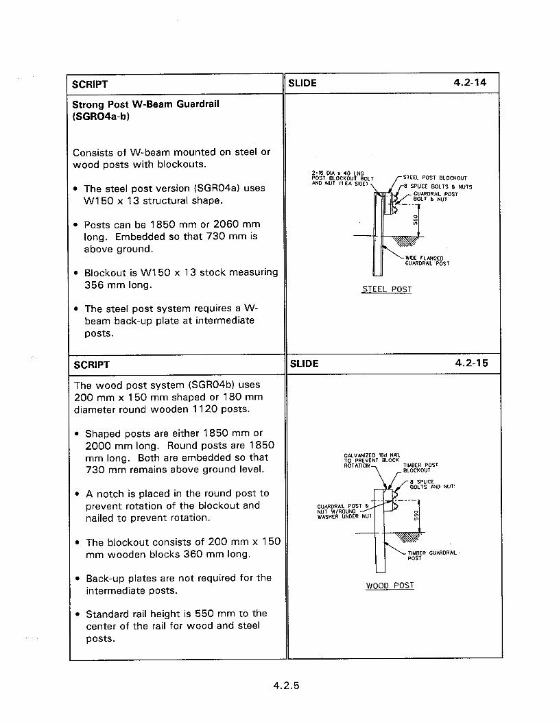
SCRIPT
Strong Post W-Beam Guardrail [SGR04a-b)
SLIDE 4.2-14
Consists of W-beam mounted on steel or wood posts with blockouts.
l The steel post version (SGR04a) uses WI 50 x 13 structural shape.
2-16 OIA x 40 LNC POST BLOCKOUT 8OL AND NUT It EA SIDE)
EEL POST BLOCKOUT
SPLICE BOLTS & NUTS CUARORAJL POST
l Posts can be 1850 mm or 2060 mm long. Embedded so that 730 mm is above ground.
CU~DRN POST
0 Blockout is WI 50 x 13 stock measuring 356 mm long.
l The steel post system requires a W- beam back-up plate at intermediate posts.
STEEL POST
SCRIPT
The wood post system (SGR04b) uses 200 mm x 150 mm shaped or 180 mm diameter round wooden 1120 posts.
SLIDE 4.2-l 5
l Shaped posts are either 1850 mm or 2000 mm long. Round posts are 1850 mm long. Both are embedded so that 730 mm remains above ground level.
GALVANIZED 16d NAJL
l A notch is placed in the round post to prevent rotation of the blockout and nailed to prevent rotation.
GUARDRAlL POS NUT W/ROUND WASHER UNDER
BOLTS AND NUT’
l The blockout consists of 200 mm x 150 mm wooden blocks 360 mm long.
l Back-up plates are not required for the intermediate posts.
l Standard rail height is 550 mm to the center of the rail for wood and steel posts.
WOOD POST
4.2.5

SCRIPT SLIDE 4.2-l 6
Strong Post W-Beam Median Barrier
The median configuration is identical to the roadside systems with another rail and blockout on the back of the barrier. : iMY? LL1W
STEEL POST wcm wsr
SCRIPT
Strong Post W-Beam Median Barrier with Rub Rail
SLIDE 4.2-17
A median configuration that has the W- beam rail installed higher also has a rub rail installed under the W-beam rail.
Slide of median barrier system with a rub rail.
SCRIPT
Strong Post Thrie-Beam Systems
The roadside systems consist of thrie-beam mounted on steel or wood posts with blockouts. The steel post version uses WI50 x 13 steel posts and blockouts. The wood post version uses 150 mm x 200 mm posts and blockouts. Standard rail heights are 550 mm to the center of the rail for both the roadside and median barrier. Both use 550 mm blockouts and 2060 mm posts.
SLIDE 4.2-18
2-w D!A x E4 Low3 SPUCE 8MTS WEEI- wsll
ELEv**oN
THFaE E.4A
4.2.6
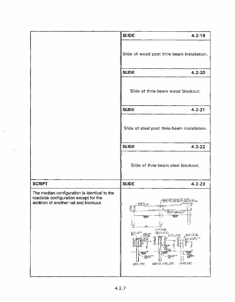
SCRIPT
The median configuration is identical to the roadside configuration except for the addition of another rail and blockout.
SLIDE 4.2-l 9
Slide of wood post thrie-beam installation.
4.2-20
Slide of thrie-beam wood blockout.
SLIDE 4.2-21
Slide of steel post thrie-beam installation.
4.2-22
Slide of thrie-beam steel blockout.
4.2-23
4.2.7
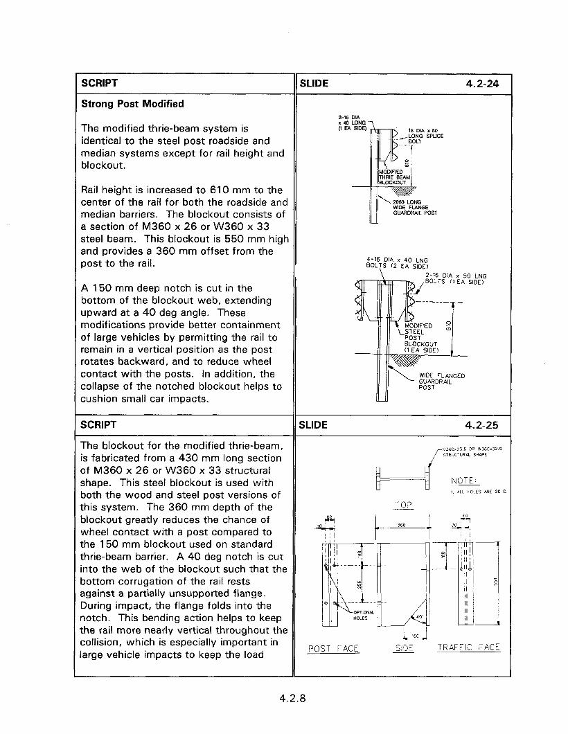
SCRIPT
Strong Post Modified
SLIDE 4.2-24
Z-16 DIA
The modified thrie-beam system is identical to the steel post roadside and median systems except for rail height and blockout.
Rail height is increased to 610 mm to the center of the rail for both the roadside and median barriers. The blockout consists of a section of M360 x 26 or W360 x 33 steel beam. This blockout is 550 mm high and provides a 360 mm offset from the post to the rail. 4-16 DIA x 40 LNG
2-16 DIA x 50 LNG
A 150 mm deep notch is cut in the bottom of the blockout web, extending upward at a 40 deg angle. These modifications provide better containment of large vehicles by permitting the rail to remain in a vertical position as the post rotates backward, and to reduce wheel contact with the posts. In addition, the collapse of the notched blockout helps to
BOLTS (7 EA SIDE)
WOE FLANGED GUARDRAIL POST
cushion small car impacts.
SCRIPT SLIDE 4.2-25
The blockout for the modified thrie-beam, M360rZ5 6 OR W360X32.9 is fabricated from a 430 mm long section SiR”CT”ReL SHWPE
of M360 x 26 or W360 x 33 structural shape. This steel blockout is used with NOTE:
both the wood and steel post versions of 1 ALL HOLES m)E 20 c
this system. The 360 mm depth of the TOP
blockout greatly reduces the chance of wheel contact with a post compared to the 150 mm blockout used on standard thrie-beam barrier. A 40 deg notch is cut into the web of the blockout such that the bottom corrugation of the rail rests against a partially unsupported flange. During impact, the flange folds into the notch. This bending action helps to keep the rail more nearly vertical throughout the collision, which is especially important in arge vehicle impacts to keep the load
POST FACE x TRAFFIC FACE
4.2.8

rplied to the vehicle as high as possible prevent the vehicle from rolling over the
il. This special blockout action provides eatly improved performance in large chicle impacts compared to standard rie-beam or W-beam barriers.
ZRIPT SLIDE 4.2-26
scent experience with steel blockouts dicate that they bend at the web. This
+150 __y
ending results in decreased space :tween the rail and post leading to
T I I
chicle snag and possible vaulting. One F?
blution is to use wooden blockouts with )th wood and steel posts. Rotation of 1 III
I I
“4
e blockout with steel posts can be evented by placing nails in the blockouts Id bending them around the flange of e post. Another method is routing the ockout the width of the post to a depth
10 mm. This results in the post fitting ithin the wooden blockout and ,eventing rotation.
To
r 0 x
1 - 111
0
ZRIPT
xommended Applications
SLIDE 4.2-27
primary consideration is that a barrier ust be installed only where there is lequate room for the barrier to deflect ithout the vehicle contacting the feature :ing protected. Strong post W-beam tflects only 600 mm to 900 mm for rssenger car impacts.
Ideally suited for roadsides and medians where larger deflections cannot be accommodated.
STRONG POST APPLICATIONS/ADVANTAGES
l Deflection space - 600 - 900 mm l Good choice for narrow medians @ More forgiving than rigid barriers
Even this relatively small deflection makes these barriers more forgiving than rigid barriers.
4.2.9
SCRIPT
l They offer a higher level of roadside safety, especially where high-speed, high-angle impacts can be expected.
SLIDE 4.2-28
8 Another important characteristic is their ability to withstand substantial impacts and still remain in serviceable condition. These barriers are especially suited to high volume roadways where frequent impacts make it essential to withstand additional hits before maintenance can be performed.
0 Although the cost and effort to install these barriers is considerably greater than for weak post barriers, the reduced deflection space and maintenance demand make them ideally suited for major facilities carrying high volumes of high speed traffic.
0 Good choice for hi-speed hi-angle hits 0 Withstands impacts, remains
serviceable l Many hits require no maintenance 0 Easy transitions to bridges, etc.
SCRIPT
Deflection Control
SLIDE 4.2-29
Design deflections are based on a 100 km/h, 25 deg impact by a 2040 kg vehicle. To provide a conservative design, 900 mm should be used for all roadside barriers, and 600 mm for median barriers. Because of these low values, additional deflection control is rarely needed for these barriers.
Slide of barrier in front of fixed object.
4.2.10
SCRIPT SLIDE 4.2-30
b However, when transitioning to stiffer barriers or rigid objects, or where fixed objects are located closely behind the barrier, deflections can be reduced by reducing the post spacing and by using heavier posts.
b Spacing of 1270 mm and 950 mm are both used for various applications. The 950 mm achieves deflections of about half those for 1905 mm. Slide of transition to rigid barrier.
SCRIPT
Embankment Slopes
SLIDE 4.2-31
Strong post systems are well suited to protect steep embankments with little risk of the vehicle being trapped between the rail and the embankment. The embankment must provide adequate soil support to develop the strength of the posts of a sustained resistance of 4500 kg or more to a load applied at bumper height in the lateral direction.
l At the top of I:2 slopes, posts should be installed at least 6 m in front of the slope break to develop full post resistance. For embankments steeper than 1:2, the post may not be able to develop the required resistance. For critical locations, a soils analysis should be performed.
Slide of barrier in front of severe slope.
4.2.11
SCRIPT
Roadside Terrain
SLIDE 4.2-32
Barriers are sensitive to terrain effects that can cause a vehicle to impact the rail higher or lower than the design height.
Slide showing vehicle ramping over the rail.
l It is undesirable to install these barriers on slopes steeper than 1: 10 or more than 230 mm behind curbs to guard against vehicle vaulting. Installation on SLIDE 4.2-33 1:6 slopes is of special concern because of the ramping effect produced for vehicle hits high on the rail, combined with the rail element deflecting backward. Installation on 1:6 slopes should be limited to cases where Slide of improperly installed barrier.
it is located at least 3660 mm from the edge of the breakpoint.
SCRIPT
Design Vehicles And Service Levels
SLIDE 4.2-34
l Strong post W-beams were developed using full size passenger cars in the 1960s. They have been tested using the 815 kg sedans, limited tests using vans, pickup trucks, and heavier vehicles including school buses and trucks. They comply with test levels 2 and 3 (basic level) of NCHRP Report 350. The strong steel post design failed the test with the 2000 kg vehicle. Slide of W-beam and large truck.
For test level 4 (8000 kg truck), there has to be adequate strength to prevent penetration by the vehicle. However, because of the higher center-of-gravity of larger vehicles, these barriers cannot prevent vehicle rollover during redirection except for very shallow angle impacts.
4.2.12
SCRIPT
Snow Removal
SLIDE 4.2-35
0 Wide rail may promote snow drifting, and hinder the plowing of snow through the barrier to clear the shoulder of snow accumulation. This may cause snow buildup in front of the barrier that can promote vehicle ramping, or that can melt and refreeze on the pavement at night.
The strong posts and rail-to-post connections withstand snowplowing with relatively little damage.
Slide of rail with snowdrift.
SCRIPT
Aesthetic Considerations
SLIDE 4.2-36
The wide rail and massive appearance of these barriers may make them a less attractive choice for scenic areas.
Use of the wood post and weathering steel versions helps to make these barriers more attractive where the other favorable characteristics of these barriers make them otherwise suited for use in visually sensitive locations.
Slide of weathering W-beam.
4.2.13
SCRIPT
Transitions
SLIDE 4.2-37
Because of their low deflections, these barriers are well suited for transitioning to stiffer barriers or to rigid walls or objects. Transitions must be properly designed to ensure that the increase in barrier stiffness does not result in the vehicle “pocketing” or abrupt decelerating at the transition point.
The geometry must prevent the wheel from intruding under the rail and snagging
Slide of transition from W-beam to thrie-
on the leading corner of the stiffer barrier beam to bridge rail.
or object.
A simple transition from W-beam to thrie- beam can be easily installed when a higher performance barrier or wider rail face is needed. Transitioning first to thrie- beam also offers an excellent approach to the transition to rigid barriers or objects.
SCRIPT
Accomplished by transitioning to thrie- beam, or by adding a second W-beam below the main rail.
SLIDE 4.2-38
Flaring the approach end of the rigid barrier may also be used to prevent wheel snag, thus eliminating the need for a wider rail face.
Because of the potential for extremely violent collisions the use of untested transitions is strongly discouraged. However, the variety of tested transitions available makes it possible to adapt suitable designs to nearly any situation. Transitions details are discussed in other sections.
W-BEAM TRANSITIONS @ Gradual Stiffness Increase
- Reduced post spacing - Add 2nd W-beam - Transition to thrie-beam - No gaps/discontinuities
4.2.14
1 SCRIPT
Rub-Rails
SLIDE 4.2-39
W-beam barriers occasionally include rub rails attached directly to the posts below the main rail. The rub rails are usually steel channel sections, Cl 50 mm x 12 mm and enhance performance by reducing wheel snagging for severe impacts. Slide of W-beam with rub rail at transition.
Rub rail permits the barrier to be installed 75 mm higher to reduce the risk of vaulting, and rollover for larger vehicles. The added beam strength of the rub rail may decrease barrier deflection slightly.
SCRIPT SLIDE 4.2-40
The use of rub rails is not widespread, but limited application to address site-specific situations may be advantageous.
A short section of W-beam is frequently added below the main rail in transitions to increase stiffness and provide rub rail.
Slide of second W-beam at transition.
SCRIPT
ACCIDENT EXPERIENCE
SLIDE 4.2-41
W-beam barrier systems have seen widespread use over 3 decades.
Except for concerns for performance of terminals in some cases, in-service performance is generally reported to be excellent.
Slide of vehicle impact with W-beam.
4.2.15

1 SCRIPT
BARRIER COSTS
SLIDE 4.2-42
Barrier costs vary depending upon location. Figure 4.2.2 provides 1991 costs for heavy-post W-beam barriers, based on recent studies.
l Not necessarily representative of actual costs other than those included in that study. Costs to be used for program estimates should be based on actual current costs for the area where they are to be used.
l Cost of strong post W-beam ranges up to three times the cost of other systems currently in use. These higher costs are offset by the need for less clear space, lower maintenance demand, and potentially better protection against vehicle penetration.
W-BEAM COST
$40 - $60 per meter
SCRIPT SLIDE 4.2-43
Conclude this session with a series of slides that present something wrong with a W-beam installation. Have the Strong post workshop. participants identify what is wrong and comment on what can occur upon impact.
SLIDE 4.2-44
Slide untreated W-beam end.
SCRIPT SLIDE 4.2-45
Slide of guardrail mounted too high.
4.2.16
SCRIPT
Slide of transition to bridge rail that is not fastened.
Slide of transition with curb in front.
SLIDE 4.2-48
Slide of installation with no flare.
4.2-49
Slide of substandard anchor.
4.2.17

SESSION GUIDE
4.3 - CONSTRUCTION AND MAINTENANCE OF SEMI-RIGID SYSTEMS
Obiectives:
* Ensure that strong post systems are properly installed and maintained.
a Evaluate existing strong post systems to ensure that they will perform acceptably.
Helpful Hints:
0 This session presents a procedure for the construction of longitudinal barriers. Slides depicting the equipment and procedures used in the presentation area should be used if available.
Visual Aids:
0 34 - 35 mm slides
Estimated Time
a 45 minutes
Handouts:
e None

4.3 - CONSTRUCTION AND MAINTENANCE OF SEMI-RIGID SYSTEMS
instructor’s Guide
SCRIPT SLIDE 4.3-l
W-beam rail on strong wood and steel posts is the most common barrier system in the United States.
Section 4.2, the previous session, addresses design and performance, terminals, transitions, stiffened sections, selection criteria, and system costs. Construction and maintenance, repair and upgrading, and transitions to bridges are presented in this section.
4.3 - CONSTRUCTION AND MAINTENANCE OF SEMI-
RIGID SYSTEMS
SCRIPT
CONSTRUCTION OF STANDARD BARRIER SECTION
SLIDE 4.3-2
Heavy posts result in construction procedures that are more complex than Slide of hole augur. for weak-post barriers. Mechanized equipment designed to install barrier posts facilitate construction and maintenance. This equipment is not normally owned by SLIDE 4.3-3
small highway agencies, and even larger agencies are often not equipped for large- scale installation to W-beam barriers. Contractors equipped to install and maintain these barriers are available in nearly all areas of every State.
Slide of post driver.
4.3.1
SCRIPT SLIDE 4.3-4
Posts are installed to a preset stringline. Steel posts are normally driven, using a Slide of preset string line. truck or trailer-mounted post driver, except in difficult soil conditions involving boulders or solid rock. SLIDE 4.3-5
Slide of chalk line layout.
SLIDE 4.3-6
Slide of steel post beam driver.
SCRIPT SLIDE 4.3-7
Wood posts are installed in augured holes and backfilled but in good soil conditions, may also be driven. The backfill should Slide of augured hole.
be tamped to ensure that full soil support is developed, prevent excessive deflection and posts pulling out of the ground. SLIDE 4.3-S
Slide of material being tamped in around the post.
SCRIPT SLIDE 4.3-9
Blockouts, for steel post systems are bolted to the posts. The rail elements are next bolted together, normally using power wrenches.
Slide of wood post and blockout without rail.
4.3.2
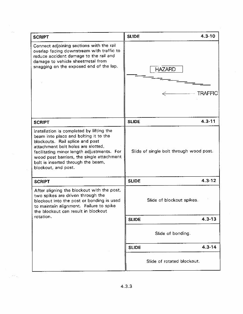
SCRlPT SLIDE 4.3-10
Connect adjoining sections with the rail overlap facing downstream with traffic to reduce accident damage to the rail and damage to vehicle sheetmetal from snagging on the exposed end of the lap.
/I
V TRAFFIC
SCRIPT
Installation is completed by lifting the beam into place and bolting it to the blockouts. Rail splice and post
SLIDE 4.3-11
attachment bolt holes are slotted, facilitating minor length adjustments. For Slide of single bolt through wood post. wood post barriers, the single attachment bolt is inserted through the beam, blockout, and post.
SCRIPT SLIDE 4.3-12
After aligning the blockout with the post, two spikes are driven through the blockout into the post or bonding is used Slide of blockout spikes. to maintain alignment. Failure to spike the blockout can result in blockout rotation.
SLIDE 4.3-13
Slide of bonding.
SLIDE 4.3-14
Slide of rotated blockout.
4.3.3

SCRIPT SLIDE 4.3-15
The entire installation is completed by constructing the terminal and connecting the beam to it.
Slide of terminal.
SCRIPT
Standard beam is produced with splice bolt and post attachment holes at 1980 mm spacings.
SLIDE 4.3-16
Where shorter post spacings are required, rail should be ordered with the required post attachment hole spacing to alleviate field drilling and galvanizing repairs.
All holes should be installed in the posts during manufacture to avoid field drilling. Factory drills are faster, and less expensive, and provide better results than field drilling. In addition, for steel posts, field drilling requires repair of the galvanized coating.
Slide of W-beam rail stock.
For wood posts, the holes extend through the entire posts and blockout and proper alignment is difficult to achieve using hand-held drills.
SCRIPT SLIDE 4.3-17
Strong steel post systems require a back- up plate on intermediate posts to prevent deformation of the W-beam rail at the posts. Slide of backup plate on steel post
system.
4.3.4
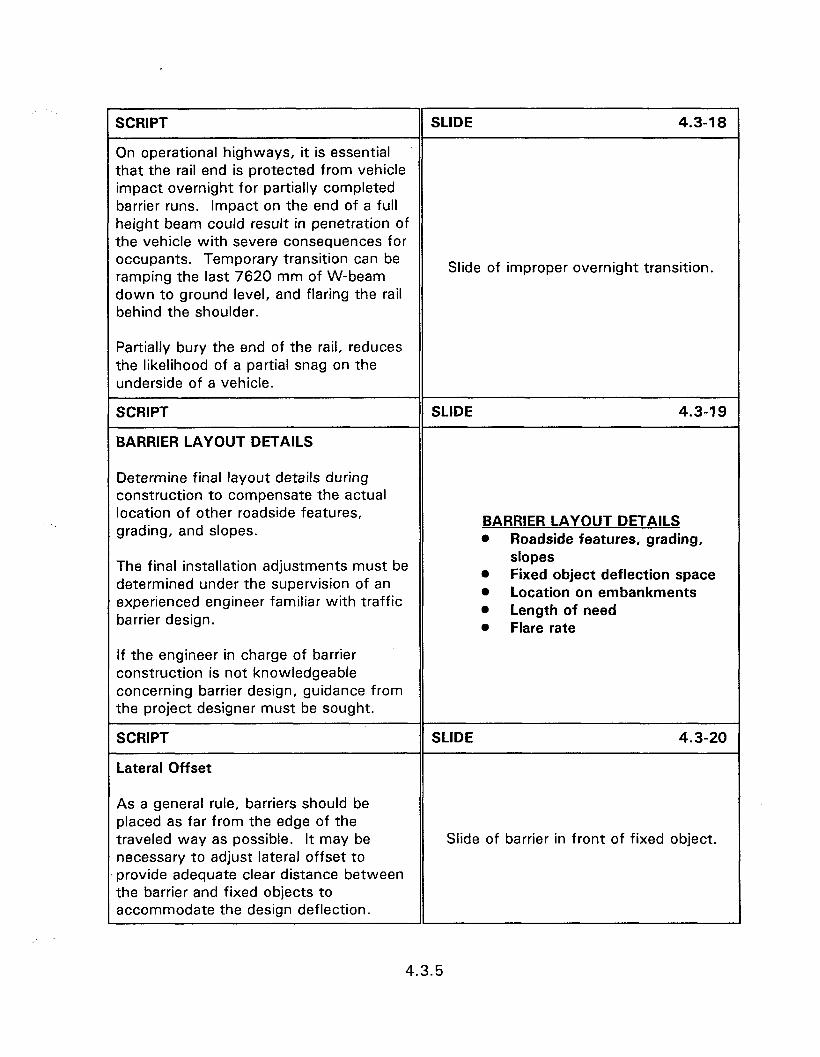
SCRIPT SLIDE 4.3-18
On operational highways, it is essential that the rail end is protected from vehicle impact overnight for partially completed barrier runs. Impact on the end of a full height beam could result in penetration of the vehicle with severe consequences for occupants. Temporary transition can be ramping the last 7620 mm of W-beam
Slide of improper overnight transition.
down to ground level, and flaring the rail behind the shoulder.
Partially bury the end of the rail, reduces the likelihood of a partial snag on the underside of a vehicle.
SCRIPT
BARRIER LAYOUT DETAILS
SLIDE 4.3-19
Determine final layout details during construction to compensate the actual location of other roadside features, grading, and slopes.
The final installation adjustments must be determined under the supervision of an experienced engineer familiar with traffic
BARRIER LAYOUT DETAILS 0 Roadside features, grading,
slopes 0
barrier design.
If the engineer in charge of barrier construction is not knowledgeable concerning barrier design, guidance from the project designer must be sought.
Fixed object deflection space 0 Location on embankments 0 Length of need a Flare rate
SCRIPT
Lateral Offset
SLIDE 4.3-20
As a general rule, barriers should be placed as far from the edge of the traveled way as possible. It may be necessary to adjust lateral offset to provide adequate clear distance between the barrier and fixed objects to accommodate the design deflection.
Slide of barrier in front of fixed object.
4.3.5
SCRIPT SLIDE 4.3-21
A minimum of 610 mm should be maintained from the back of the posts to the slope break to ensure adequate soil support for the posts. If this cannot be achieved, a soil analysis is necessary to determine if longer or heavier posts are needed to compensate for the reduced soil support. Adjustments in offset may also be necessary to accommodate changes in roadside slope.
Slide of barrier in front of steep slope.
SCRIPT
Length Of Need
SLIDE 4.3-22
Final determination of the length need must be determined for each run based on actual field conditions prior to installation. Minor adjustments for the actual location of roadside hazards and slopes to be shielded will impact the appropriate end of barrier need.
This point must be determined based on the procedure suggested in the “Roadside Design Guide”. Other appropriate procedures may be used by individual agencies.
Slide of barrier installation.
4.3.6
SCRIPT
Flare Rate
SLIDE 4.3-23
The rate at which a barrier deviates from the edge of the traveled way effects impact severity and driver reaction to the start of the barrier. Suggested flare rates Slide showing function of the flare. vary from a steep as 7:l to as flat as 30: 1, depending on design speed and lateral offset. Adjustments to flare rate may be necessary to adjust for changes in roadside slopes introduced during construction and to minimize total barrier lengths commensurate with length of SLIDE 4.3-24
need requirements.
Flatter flare rates generally provide better impact results and minimize driver reaction to the start of a barrier. Steeper flares reduce the length of barrier needed, and decrease the risk of vehicles running behind the barrier to impact a hazard, or impacting the end of the terminal.
Slide showing approach flare.
SCRIPT
MAINTENANCE
SLIDE 4.3-25
The primary maintenance requirement is the repair of accident damage.
MAINTENANCE
(Letters over slide of minor guardrail Most minor impact result in only cosmetic damage.) damage, requires no maintenance.
SCRIPT SLIDE 4.3-26
Moderate impact damage is often limited to one or two sections of rail and minor post misalignment. Individual rail sections can be easily replaced, and minor post misalignment corrected by pulling the post
Slide of moderate guardrail damage.
back into alignment and filling or tamping behind it.
4.3.7
SCRIPT SLIDE 4.3-27
For more severe accidents, significant damage requires removing and replacing damaged posts, blockouts, and rail sections. Any damage more severe than minor cosmetic damage should be repaired as soon as possible to ensure that proper performance is achieved in Slide of severe guardrail damage. any subsequent impacts.
SCRIPT SLIDE 4.3-28
For impacts involving the terminals, or on the standard guardrail section near the terminal, it is essential that the terminal is checked for damage.
Because some terminal designs are complex and include a number of critical components, the entire terminal must be carefully inspected for hidden damage.
Slide of severely damaged terminal.
SCRIPT SLIDE 4.3-29
Even apparently superficial damage such as bent or misaligned bolts may have an adverse effect on terminal performance in subsequent impacts.
Slide of minor terminal damage.
4.3.8
SCRIPT SLIDE 4.3-30
Costs to repair accident damage vary widely depending upon impact severity. Based on limited data the repair cost per foot of damaged barrier is about equal for weak and strong post W-beam guardrail. Virginia reported an average cost to repair accident damage of $410, based on an
STRONG POST W-BEAM
average of 18 m repaired per accident at REPAIR COSTS
$23/m; Damage Length - 15-18 m
New York reported average damage lengths of 16.7 and 19.5 m for weak posts and 14.6 m for strong posts. The New York studies further reported an average repair cost of $219 per accident for weak post W-beam and $201 for strong posts, based on late 1960s - early 1970s data. Adjustment for inflation indicates reasonable agreement.
Unit Cost - $23/m
Repair/Accident Cost - $410
SCRIPT
EVALUATING EXISTING BARRIERS
SLIDE 4.3-31
l Strong post W-beam traffic barriers have been in use since the 1960s. Early installations may still remain in service, with little or no change since installation. Periodic review and inspection of in-service traffic barriers is an important part of highway safety management.
EVALUATING EXISTING BARRIERS
l Periodic, routine inspection is a part of normal maintenance function.
l Periodic inspection l Normal maintenance function l Reconstruction
l Review and inspection should be included as part of planning and design for highway reconstruction or repair.
l Run-off-road accidents
l Inspection also triggered by an accident surveillance report indicating a high severity or incidence of run-off-road accidents.
4.3.9
SCRIPT SLIDE 4.3-32
A more in-depth inspection should be carried out when the highway is proposed for reconstruction or extensive repair.
@ Is all existing barrier needed to meet existing warrants? Is additional rail needed to meet warrants? W-BEAM IN-DEPTH
INSPECTION
0 Can the hazard be removed or modified to eliminate the need for barrier?
l Is barrier warranted * Can hazard be eliminated * Appropriate barrier type
l Is this type of barrier appropriate considering current highway and traffic parameters, or would another barrier type provide a significant safety upgrade?
SCRIPT SLIDE 4.3-33
Gaps in transitions to bridges or rigid barriers or other features not in conformity with current principles for transition design represent a significant hazard that
Slides of improper transition.
should be upgraded as soon as possible.
SCRIPT SLIDE 4.3-34
Like other barrier systems, strong post W- beam barriers perform best when in full compliance with current standards. Barriers must be in good repair to ensure acceptable performance and must be in reasonable conformity with current standards. It is not feasible to immediately upgrade all existing barriers every time a small change is made in a
Slide of good W-beam installation.
barrier standard. The decision to upgrade existing barriers in reasonably good condition and reasonable conformity with current standards must be based on costs and potential improvements in highway safety.
4.3.10
Obiectives:
l
l
l
SESSION GUIDE
4.4 - WEAK POST W-BEAM BARRIER SYSTEMS
Basic principles concerning design and performance.
Characteristics of operational systems including terminals, transitions, stiffened sections, and selection criteria.
Factors in the design of barrier installations.
Costs, construction, and maintenance considerations.
Helpful Hints:
e Emphasize that flexible systems redirect impacting vehicles primarily through the development of tensile forces. Due to this, it is important to provide proper anchorages.
l The workshop is designed to help the participants identify when weak post barrier systems are viable.
Visual Aids:
e 38 - 35 mm slides
Estimated Time
l 30 minutes
Handouts:
e Workshop problems H. 0. 4.4/l
l Workshop solutions H. 0. 4.4/2

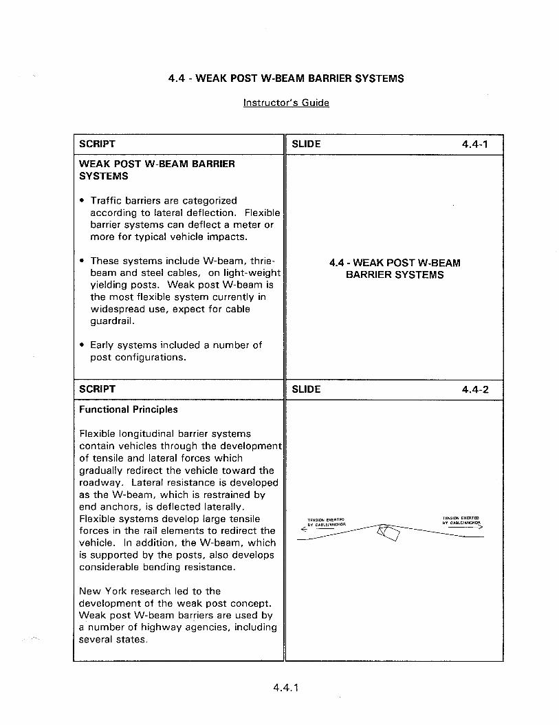
4.4 - WEAK POST W-BEAM BARRIER SYSTEMS
Instructor’s Guide
SCRIPT
WEAK POST W-BEAM BARRIER SYSTEMS
SLIDE 4.4-I
0 Traffic barriers are categorized according to lateral deflection. Flexible barrier systems can deflect a meter or more for typical vehicle impacts.
l These systems include W-beam, thrie- beam and steel cables, on light-weight yielding posts. Weak post W-beam is the most flexible system currently in widespread use, expect for cable guardrail.
4.4 -WEAK POST W-BEAM BARRIER SYSTEMS
l Early systems included a number of post configurations.
SCRIPT
Functional Principles
SLIDE 4.4-2
Flexible longitudinal barrier systems contain vehicles through the development of tensile and lateral forces which gradually redirect the vehicle toward the roadway. Lateral resistance is developed as the W-beam, which is restrained by end anchors, is deflected laterally. Flexible systems develop large tensile forces in the rail elements to redirect the vehicle. In addition, the W-beam, which is supported by the posts, also develops considerable bending resistance.
New York research led to the development of the weak post concept. Weak post W-beam barriers are used by a number of highway agencies, including several states.
4.4.1
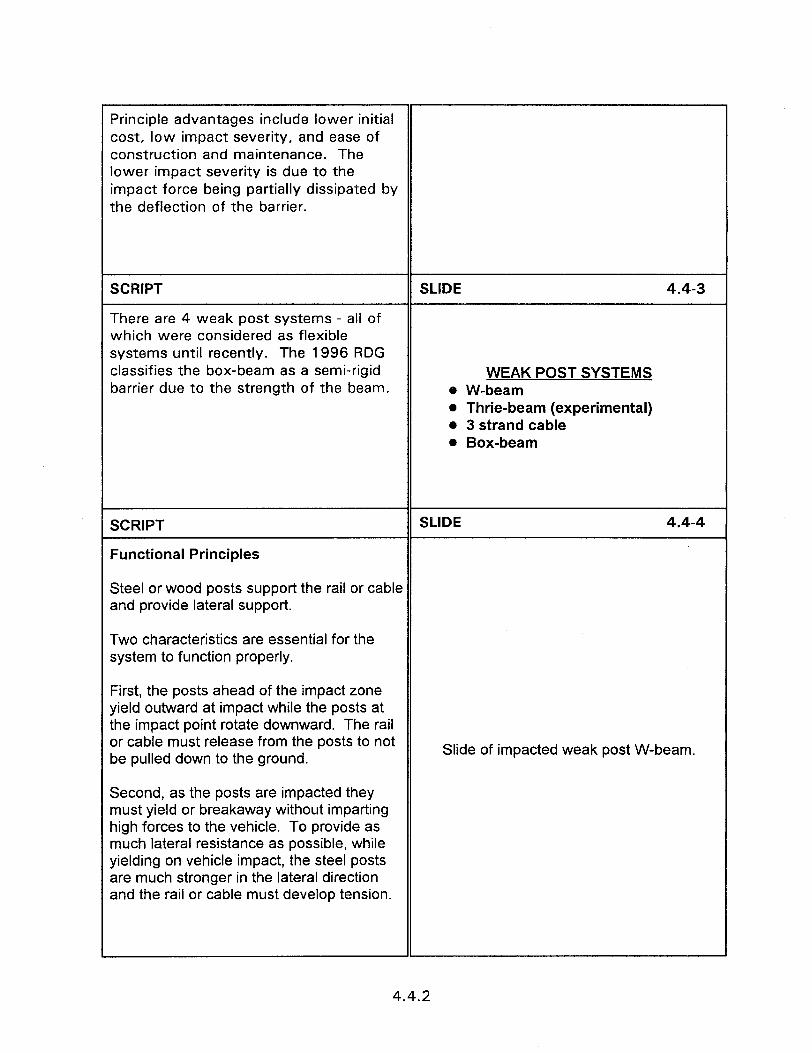
Principle advantages include lower initial cost, low impact severity, and ease of construction and maintenance. The lower impact severity is due to the impact force being partially dissipated by the deflection of the barrier.
SCRIPT
There are 4 weak post systems - all of which were considered as flexible systems until recently. The 1996 RDG classifies the box-beam as a semi-rigid barrier due to the strength of the beam.
SLIDE 4.4-3
WEAK POST SYSTEMS @ W-beam l Thrie-beam (experimental) l 3 strand cable l Box-beam
SCRIPT
Functional Principles
SLIDE 4.4-4
Steel or wood posts support the rail or cable and provide lateral support.
Two characteristics are essential for the system to function properly.
First, the posts ahead of the impact zone yield outward at impact while the posts at the impact point rotate downward. The rail or cable must release from the posts to not be pulled down to the ground.
Slide of impacted weak post W-beam.
Second, as the posts are impacted they must yield or breakaway without imparting high forces to the vehicle. To provide as much lateral resistance as possible, while yielding on vehicle impact, the steel posts are much stronger in the lateral direction and the rail or cable must develop tension.
4.4.2

SCRIPT
Anchors - Concrete Deadmen
SLIDE 4.4-5
Strong steel posts, set in a concrete footing, or another suitable approach are necessary to anchor the ends of the W-beam. Because these barriers depend primarily upon rail tension to redirect the vehicle, these anchors must provide sufficient resistance to develop the strength of the rails without moving.
Anchors must also serve as crashworthy terminals to ensure that vehicle impacts near the barrier ends do not exceed acceptable performance limits. Early W- beam barriers often included freestanding rail ends -- now recognized as extremely hazardous.
Slide of anchor.
SCRIPT
OPERATIONAL SYSTEMS
Weak Post W-Beam
SLIDE 4.4-6
WEAK POST W-BEAM
4.4.3
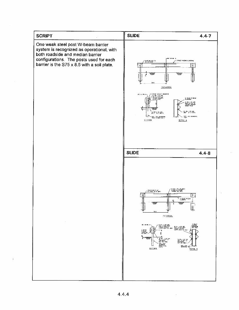
SCRIPT
One weak steel post W-beam barrier system is recognized as operational, with both roadside and median barrier configurations. The posts used for each barrier is the S75 x 8.5 with a soil plate.
4.4-7
SLIDE 4.4-8
4.4.4

SCRIPT
Best Connections
SLIDE 4.4-9
The post must separate from the rail upon mpact. This is accomplished at non-splice costs by the use of small (8 mm) post to rail :onnectors and the use of heavy washers. 4 shelf bolt with two nuts is placed beneath :he rail to help support the snow load. Notice that no backup plate is used as for strong post systems.
SCRIPT
4t splice posts a regular washer is used and the shelf bolts are necessary.
SLIDE 4.4-10
POST ASSEMBLY
SCRIPT
Transition
SLIDE 4.4-l 1
A transition is required when connecting the weak post system to a strong post system.
Slide showing a transition between a weak post system and a strong post system.
4.4.5
SCRIPT SLIDE 6.3-l 1
This slide presents an inadequate bridge railing design. In this design neither the railing or support posts are adequate to withstand an impact and prevent a vehicle from penetrating the system. Not only is the railing system inadequate but the angle shape which comprises the Slide of deficient rail. inadequate rail can penetrate the passenger compartment of an impacting vehicle.
SLIDE 6.3-l 2
ATTACHMENT TO DECK
SCRIPT
0 The rail to post and post to deck attachments must be an approved design.
SCRIPT SLIDE 6.3-l 3
The post to deck attachment details of this slide is inadequate to prevent vehicle penetration of the system when struck.
Slide of bridge rail with broken supports.
SCRIPT SLIDE 6.3-14
l Tests and accident experience have shown that an errant vehicle can impact ROADWAY FEATURES a curb and vault over or penetrate NEAR BRIDGE RAIL through a bridge rail.
6.3.4
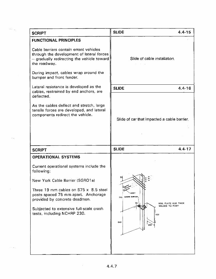
I SCRIPT SLIDE 4.4-l 5
FUNCTIONAL PRINCIPLES
Cable barriers contain errant vehicles through the development of lateral forces -- gradually redirecting the vehicle toward the roadway.
Slide of cable installation.
During impact, cables wrap around the bumper and front fender.
Lateral resistance is developed as the cables, restrained by end anchors, are deflected.
SLIDE 4.4-l 6
As the cables deflect and stretch, large tensile forces are developed, and lateral components redirect the vehicle.
Slide of car that impacted a cable barrier.
SCRIPT
OPERATIONAL SYSTEMS
SLIDE 4.4-l 7
Current operational systems include the following:
New York Cable Barrier (SGROla)
Three 19 mm cables on S75 x 8.5 steel posts spaced 75 mm apart. Anchorage provided by concrete deadmen.
SOlL PLATE 6.35 THICK WELDED TO POST
Subjected to extensive full-scale crash tests, including NCHRP 230.
4.4.7
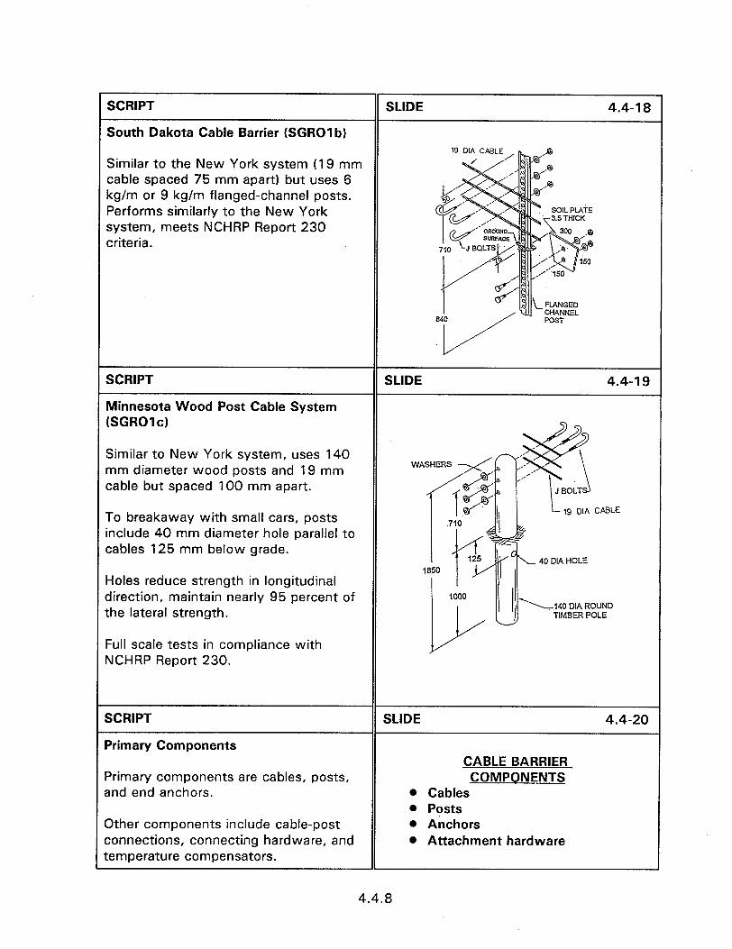
SCRIPT
South Dakota Cable Barrier (SGROI b)
SLIDE 4.4-l 8
Similar to the New York system (19 mm cable spaced 75 mm apart) but uses 6 kg/m or 9 kg/m flanged-channel posts. Performs similarly to the New York system, meets NCHRP Report 230 criteria.
SCRIPT
Minnesota Wood Post Cable System (SGROl c)
SLIDE 4.4-l 9
Similar to New York system, uses 140 mm diameter wood posts and 19 mm cable but spaced 100 mm apart.
To breakaway with small cars, posts include 40 mm diameter hole parallel to cables 125 mm below grade.
Holes reduce strength in longitudinal direction, maintain nearly 95 percent of the lateral strength.
Full scale tests in compliance with NCHRP Report 230.
SCRIPT
Primary Components
Primary components are cables, posts, and end anchors.
3ther components include cable-post connections, connecting hardware, and temperature compensators.
SLIDE
CABLE BARRIER COMPONENTS
l Cables l Posts 0 Anchors l Attachment hardware
4.4-20
4.4.8
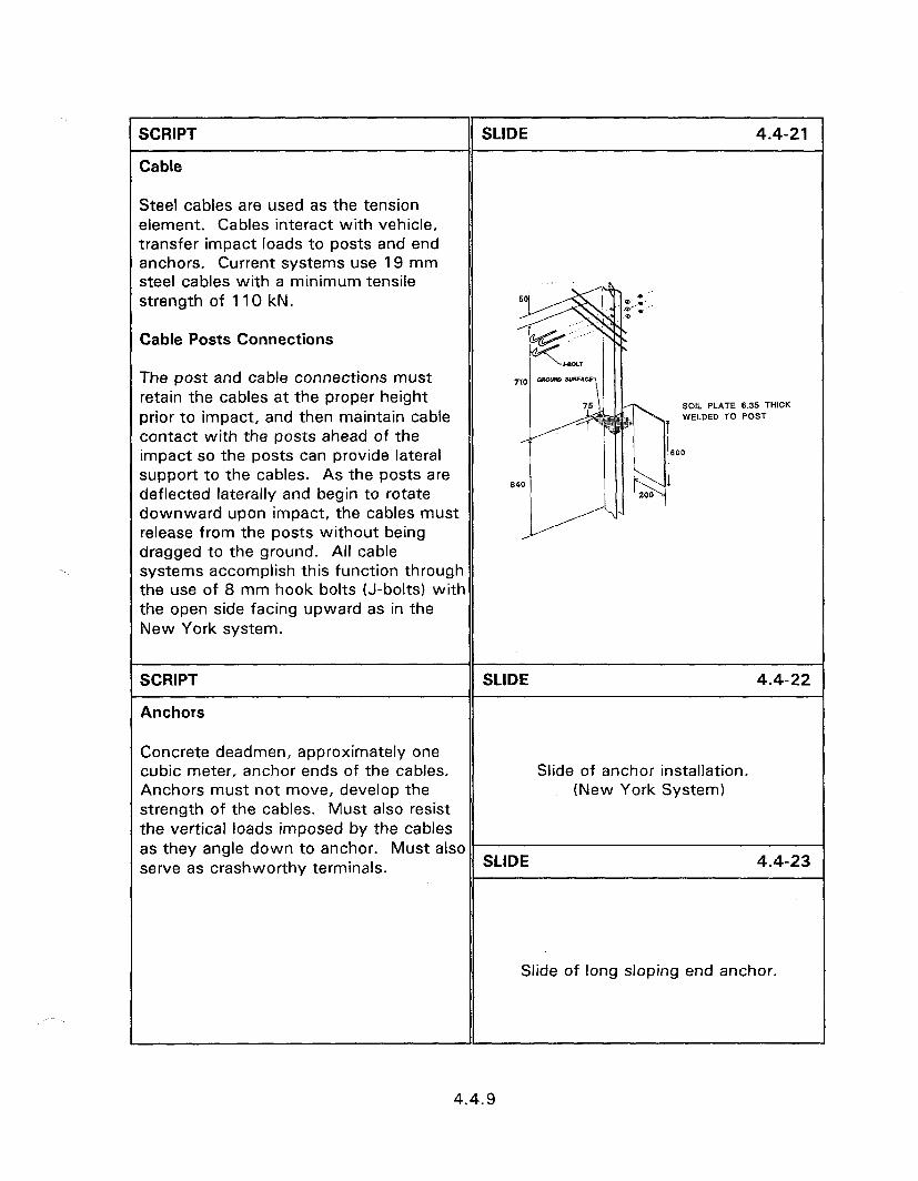
SCRIPT
Cable
SLIDE 4.4-21
Steel cables are used as the tension element. Cables interact with vehicle, transfer impact loads to posts and end anchors. Current systems use 19 mm steel cables with a minimum tensile strength of 110 kN.
Cable Posts Connections
The post and cable connections must retain the cables at the proper height prior to impact, and then maintain cable contact with the posts ahead of the impact so the posts can provide lateral support to the cables. As the posts are deflected laterally and begin to rotate downward upon impact, the cables must release from the posts without being dragged to the ground. All cable systems accomplish this function through the use of 8 mm hook bolts (J-bolts) with the open side facing upward as in the New York system.
SO,L PLATE 6.35 THICK WELDED TO POST
600
SCRIPT
Anchors
SLIDE 4.4-22
Concrete deadmen, approximately one cubic meter, anchor ends of the cables. Slide of anchor installation. Anchors must not move, develop the (New York System) strength of the cables. Must also resist the vertical loads imposed by the cables as they angle down to anchor. Must also serve as crashworthy terminals. SLIDE 4.4-23
Slide of long sloping end anchor.
4.4.9
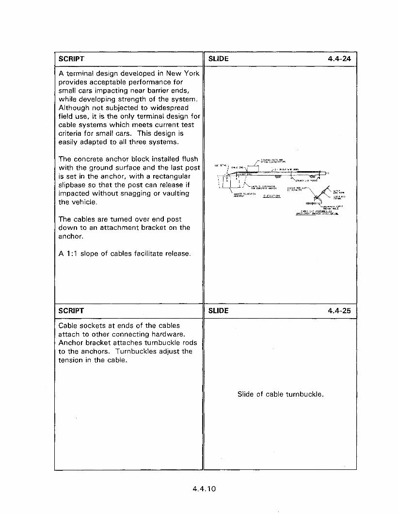
SCRIPT SLIDE 4.4-24
A terminal design developed in New York provides acceptable performance for small cars impacting near barrier ends, while developing strength of the system. Although not subjected to widespread field use, it is the only terminal design for cable systems which meets current test criteria for small cars. This design is easily adapted to all three systems.
The concrete anchor block installed flush with the ground surface and the last post is set in the anchor, with a rectangular slipbase so that the post can release if impacted without snagging or vaulting the vehicle.
The cables are turned over end post down to an attachment bracket on the anchor.
A 1: 1 slope of cables facilitate release.
SCRIPT SLIDE 4.4-25
Cable sockets at ends of the cables attach to other connecting hardware. Anchor bracket attaches turnbuckle rods to the anchors. Turnbuckles adjust the tension in the cable.
Slide of cable turnbuckle.
1
4.4.10
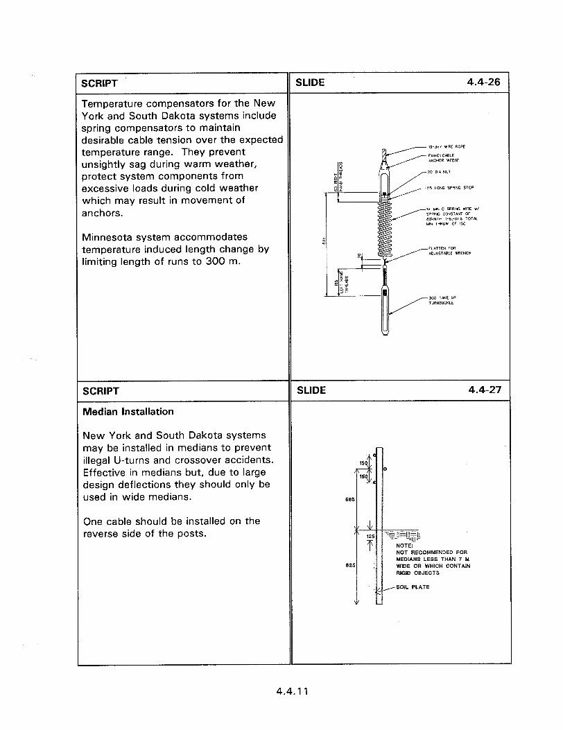
SCRIPT SLIDE 4.4-26
Temperature compensators for the New York and South Dakota systems include spring compensators to maintain desirable cable tension over the expected temperature range. They prevent
19-3.7 WIRE ROPE
Jnsightiy sag during warm weather, orotect system components from excessive loads during cold weather 115 LONG SPRING STOP which may result in movement of anchors.
1* MIN 0 SPRING WlRE r, SPRING CONSIhJdI OF 80kNlrn 1.8.-w L TOT& UIN THROW OF 150
Minnesota system accommodates temperature induced length change by limiting length of runs to 300 m.
SCRIPT
Median Installation
SLIDE 4.4-27
New York and South Dakota systems may be installed in medians to prevent illegal U-turns and crossover accidents. Effective in medians but, due to large design deflections they should only be used in wide medians.
One cable should be installed on the reverse side of the posts.
NOT RECOMMENDED FOR MEDIANS LESS THAN 7 hi WIDE OR WHICH CONTAIN RIGID OBJECTS
4.4.11
SCRIPT
SELECTION AND DESIGN CONSIDERATIONS
SLIDE 4.4-28
Where and when can cable barriers be installed? The answers to this requires a number of considerations. Lets discuss these in context of the characteristics of cable barriers.
SELECTION AND DESIGN CONSIDERATIONS
SCRIPT
Deflection Control
SLIDE 4.4-29
Deflection upon impact is dependent on DEFLECTION RANGE impact severity and post spacing. Table l 2135 mm with 1220 mm post 2.2.7 provides design deflections based spacing on a 100 km/hr, 25 degree impact by a l 3350 mm with 5000 mm post 2000 kg vehicle. spacing
No fixed objects or hazards, except embankments, can be permitted within deflection space. Added posts provide SLIDE 4.4-30
lateral support and reduce barrier deflection in the vicinity of individual features within the deflection space, and transition to other barriers. Slide showing cable too close to the pole.
SCRIPT SLIDE 4.4-31
Added posts are also used for cable barrier installations on the outside of horizontal curves. Table 4.4.1 provides the recommended post spacing for outside horizontal curve installation. The Minnesota system utilizes a 3800 mm post spacing exclusively. Rather than controlling deflection by modifying post spacing, limiting the maximum spacing
Slide of cable installed at horizontal curve.
between anchors is used to control deflection on curves as presented in table 4.4.1. Cable barriers must not be installed on the inside of horizontal curves since the necessary cable tension cannot develop.
4.4.12
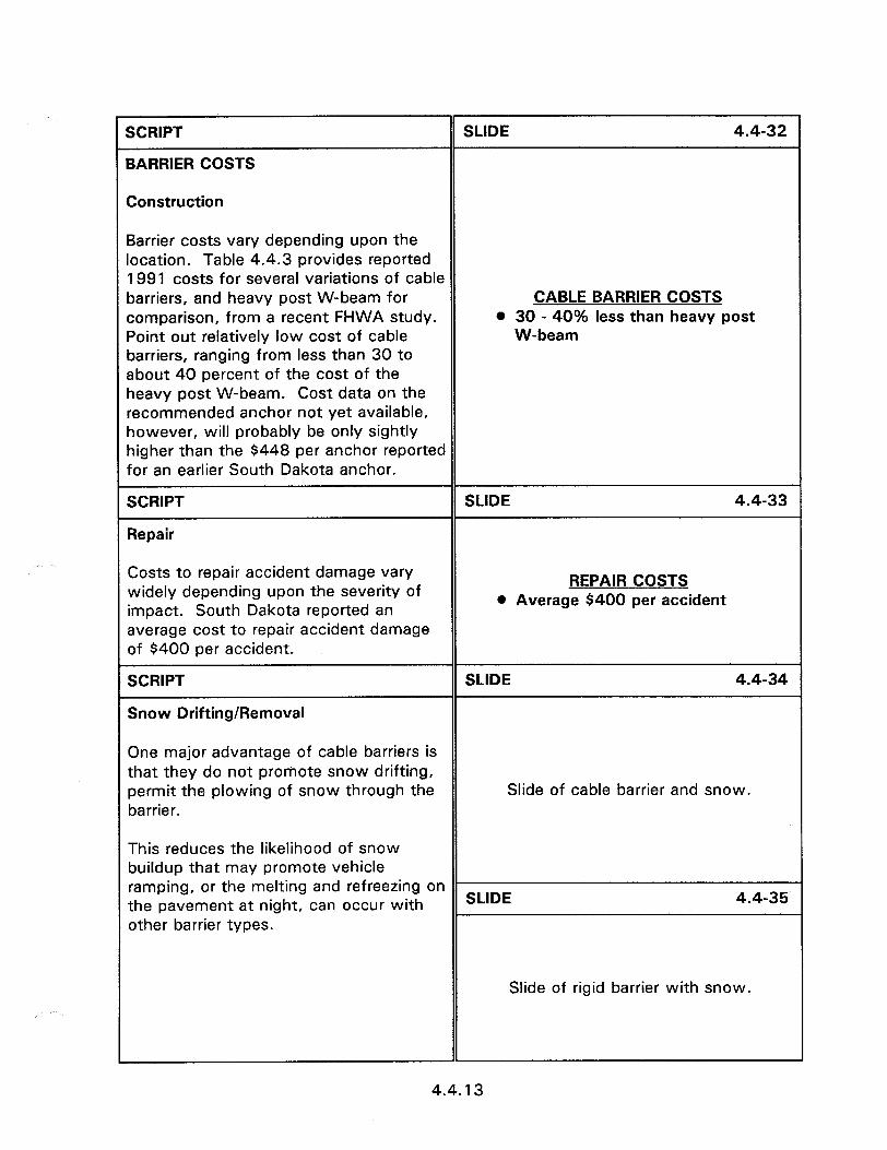
I--
SCRIPT
BARRIER COSTS
SLIDE 4.4-32
Construction
2arrier costs vary depending upon the ocation. Table 4.4.3 provides reported 1991 costs for several variations of cable barriers, and heavy post W-beam for comparison, from a recent FHWA study. Point out relatively low cost of cable barriers, ranging from less than 30 to about 40 percent of the cost of the heavy post W-beam. Cost data on the recommended anchor not yet available, however, will probably be only sightly higher than the $448 per anchor reported for an earlier South Dakota anchor.
CABLE BARRIER COSTS l 30 - 40% less than heavy post
W-beam
SCRIPT
Repair
SLIDE 4.4-33
Costs to repair accident damage vary widely depending upon the severity of impact. South Dakota reported an average cost to repair accident damage of $400 per accident.
SCRIPT
Snow Drifting/Removal
REPAIR COSTS l Average $400 per accident
SLIDE 4.4-34
One major advantage of cable barriers is that they do not promote snow drifting, permit the plowing of snow through the barrier.
Slide of cable barrier and snow.
This reduces the likelihood of snow buildup that may promote vehicle ramping, or the melting and refreezing on the pavement at night, can occur with SLIDE 4.4-35
other barrier types.
Slide of rigid barrier with snow.
1
4.4.13
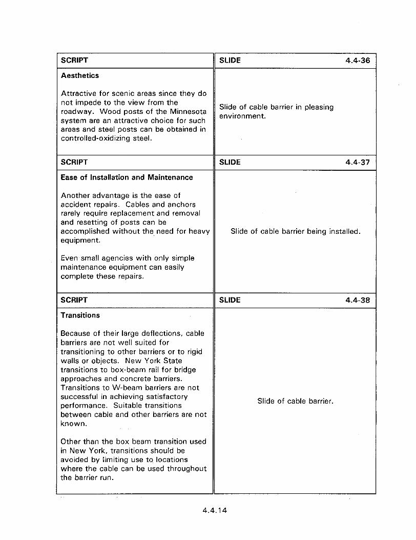
SCRIPT
Aesthetics
SLIDE 4.4-36
Attractive for scenic areas since they do not impede to the view from the roadway. Wood posts of the Minnesota
Slide of cable barrier in pleasing
system are an attractive choice for such environment.
areas and steel posts can be obtained in controlled-oxidizing steel.
SCRIPT
Ease of Installation and Maintenance
SLIDE 4.4-37
Another advantage is the ease of accident repairs. Cables and anchors rarely require replacement and removal and resetting of posts can be accomplished without the need for heavy equipment.
Slide of cable barrier being installed.
Even small agencies with only simple maintenance equipment can easily complete these repairs.
SCRIPT
Transitions
SLIDE 4.4-38
Because of their large deflections, cable barriers are not well suited for transitioning to other barriers or to rigid walls or objects. New York State transitions to box-beam rail for bridge approaches and concrete barriers. Transitions to W-beam barriers are not successful in achieving satisfactory performance. Suitable transitions between cable and other barriers are not known.
Slide of cable barrier.
Other than the box beam transition used in New York, transitions should be avoided by limiting use to locations where the cable can be used throughout the barrier run.
4.4.14
SCRIPT
Break the participants into groups of 4 or 5 and distribute the Session 4.4
Irkshop. wo
SLIDE 4.4-39
WEAK POST BARRIER WORKSHOP
4.4.15

SESSION GUIDE
4.5 - TREATMENT OF WIDE MEDIANS, BARRIER ENVELOPES, CURVED BARRIER SECTIONS, AND OTHER METHODS FOR PROTECTING LARGE AREAS
Obiectives:
0 Enable the identification of roadside and longitudinal barriers installed adjacent to treatment.
median situaitons where the shoulder may not be the best
0 Introduce the alternative treatments that may be more suitable.
Helcful Hints:
e This session can be made shorter by concentrating on the wide area designs used in your area.
Visual Aids:
l 27 - 35 mm slides
Estimated Time
* 25 minutes
Handouts:
0 None

SCRIPT
4ESTHETIC BARRIER SYSTEMS
SLIDE 4.6-5
darious types of aesthetic barriers have oeen used in National parks and other visually sensitive areas for decades. These include various timber barriers and dry-laid stone and masonry walls. While these barriers keep pedestrians and vehicles from intentionally leaving the roadway and entering hazardous areas, they usually were unable to safely redirect errant vehicles.
FHWA sponsored the development of three barrier systems, including terminals, designed to satisfy aesthetic requirements, while providing a high level of roadside safety. Approved for use on Federal Lands Highway projects, and are suitable for other highways.
Slide of aesthetic median barrier.
Terminals developed for conventional barriers can be adapted to the aesthetic barriers. However, considering the special purposes met by these barriers, aesthetic considerations often eliminate that option. Terminals discussed in this session are limited to those developed to match barrier aesthetics.
SCRIPT
QUESTION:
SLIDE 4.6-6
AESTHETIC VERSIONS - Ask class to name conventional barriers CONVENTIONAL BARRIERS that may be revised to improve 0 Cable guardrail - weathering posts aesthetics. l Cable guardrail - wood posts
l W-beam guardrail - weathering Present summary slide after discussion.
SCRIPT
Such as this weathering W-beam guardrail.
rail, wood posts
SLIDE 4.6-7
Slide of weathering W-beam guardrail.
4.6.3
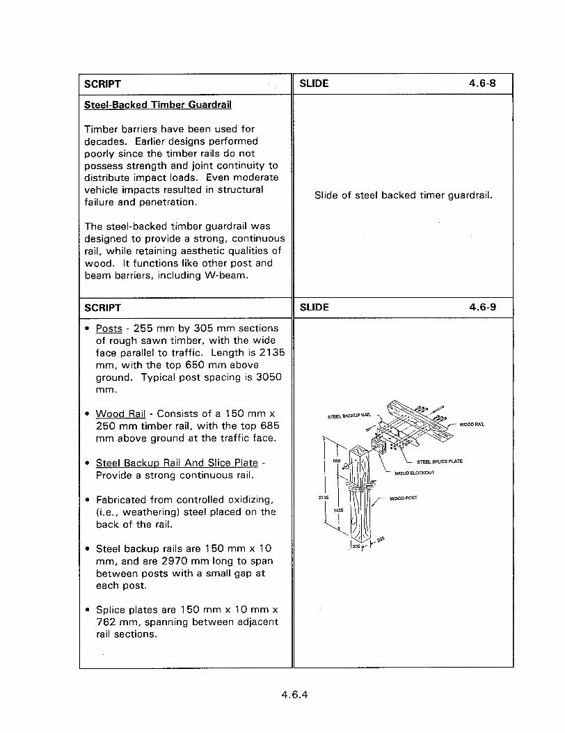
I-
SCRIPT
Steel-Backed Timber Guardrail
SLIDE 4.6-8
Timber barriers have been used for decades. Earlier designs performed poorly since the timber rails do not possess strength and joint continuity to distribute impact loads. Even moderate vehicle impacts resulted in structural failure and penetration.
Slide of steel backed timer guardrail.
The steel-backed timber guardrail was designed to provide a strong, continuous rail, while retaining aesthetic qualities of wood. It functions like other post and beam barriers, including W-beam.
SCRIPT SLIDE 4.6-9
l Posts - 255 mm by 305 mm sections of rough sawn timber, with the wide face parallel to traffic. Length is 2135 mm, with the top 650 mm above ground. Typical post spacing is 3050 mm.
l Wood Rail - Consists of a 150 mm x 250 mm timber rail, with the top 685 mm above ground at the traffic face.
l Steel Backup Rail And Slice Plate - Provide a strong continuous rail.
0 Fabricated from controlled oxidizing, (i.e., weathering) steel placed on the back of the rail.
STEEL SPUCE PLATE
WOOD ELOCKOur
l Steel backup rails are 150 mm x 10 mm, and are 2970 mm long to span between posts with a small gap at each post.
l Splice plates are 150 mm x 10 mm x 762 mm, spanning between adjacent rail sections.
1
4.6.4
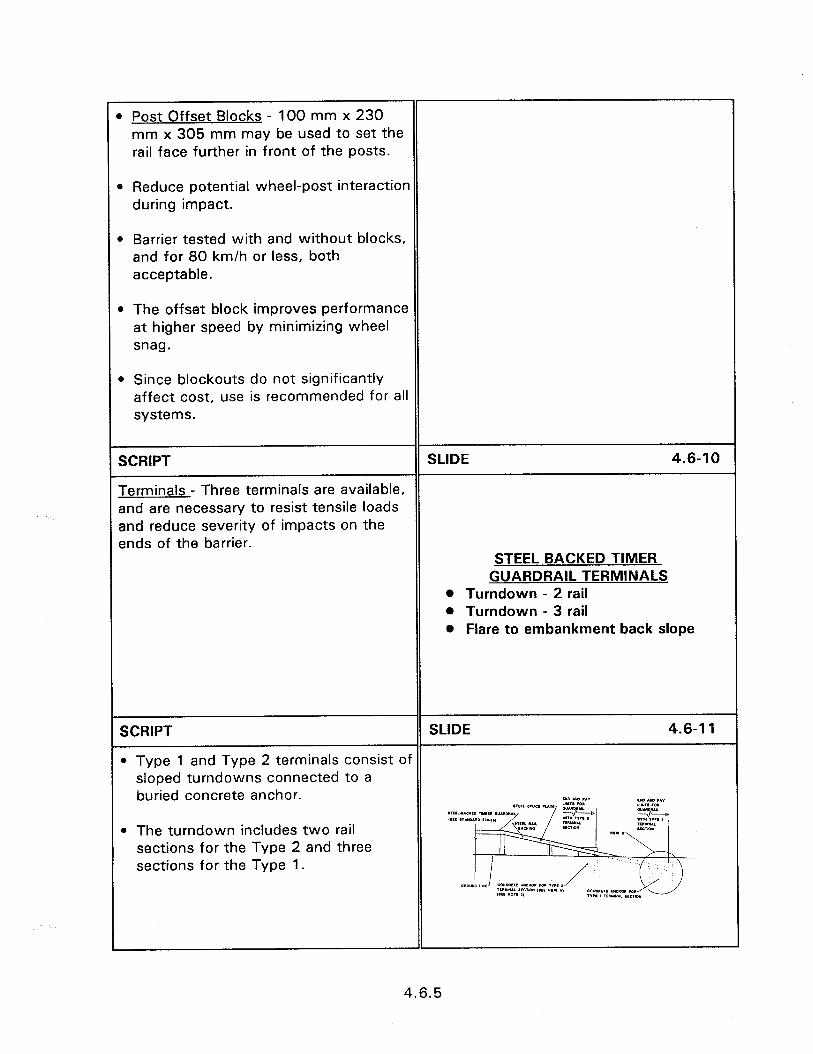
1 Post Offset Blocks - 100 mm x 230 mm x 305 mm may be used to set the rail face further in front of the posts.
1 Reduce potential wheel-post interaction during impact.
) Barrier tested with and without blocks, and for 80 km/h or less, both acceptable.
) The offset block improves performance at higher speed by minimizing wheel snag.
B Since blockouts do not significantly affect cost, use is recommended for all systems.
SCRIPT SLIDE 4.6-l 0
Terminals - Three terminals are available, and are necessary to resist tensile loads and reduce severity of impacts on the ends of the barrier.
STEEL BACKED TIMER GUARDRAIL TERMINALS
l Turndown - 2 rail l Turndown - 3 rail 0 Flare to embankment back slope
SCRIPT SLIDE 4.6-l 1
0 Type 1 and Type 2 terminals consist of sloped turndowns connected to a buried concrete anchor. M uo ,A”
l The turndown includes two rail sections for the Type 2 and three sections for the Type 1.
4.6.5

SCRIPT SLIDE 4.6-l 2
l The Type 3 terminal consists of a flared offset with the rail end connected to a concrete anchor buried in the embankment back slope.
For high-speed roadways, Type 1 and Type 2 terminals should be installed beyond the clear zone whenever possible, using the AASHTO suggested flare rates.
Even for low-speed roadways, the maximum possible offset should be provided to reduce the risk of launching vehicles in end-on impacts.
l Whenever practical, the Type 3 terminal, is preferred to reduce the risk of vehicle vaulting and subsequent rollover.
SCRIPT
Stone Masonry Guardwall
SLIDE 4.6-l 3
Native stone walls, dry-laid or mortared, have been used to line roadways for decades. They add to the aesthetics and keep vehicles and pedestrians from entering restricted areas.
Dry-laid stonework, generally does not have sufficient structural capacity or height to contain vehicles in severe impacts.
Slide of stone masonary guardrail.
The stone masonry guardway maintains visual appeal of mortared stone while adding a reinforced concrete core and foundation to ensure structural capacity. A mortared stone wall is built over the core and foundation to meet visual requirements.
4.6.6

Jse of local stone results in a barrier that :losely matches other features in the area.
Stone masonry guardway functions similar to other rigid barriers, with the mpact forces transmitted into the ground 3y the reinforced core and footing.
SCRIPT SLIDE 4.6-14
Construction Details - The stone masonry guardway consists of four components.
I) A 150 mm thick aggregate base placed 250 mm below final grade (may be omitted on solid rock or suitable rock fill).
2) A 150 mm thick by 990 mm concrete footing.
ROADWAY SECTION
3) 610 mm high concrete core wall placed atop the footing, 150 mm thick at the top and 230 mm at the bottom.
4) Light steel reinforcing consisting of #4 bars included in footing and core wall. The footing and wall may be cast in
. *, . I. I -, . I *,
place, or precast with a tongue and groove joint. 160 MIN. *cJGRE(L*TE BME. GRKIW B.C. OR D PEE NOTE a, t , 1.
Vlortared stone wall is then built over the concrete core.
230 mm thick stone cladding results in Final wall thickness of 610 mm, and final ieight of 685 mm.
4.6.7
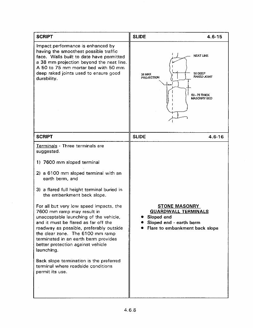
1 SCRIPT SLIDE 4.6-l 5
Impact performance is enhanced by having the smoothest possible traffic face. Walls built to date have permitted NEAT LINE
a 38 mm projection beyond the neat line. A 50 to 75 mm mortar bed with 50 mm deep raked joints used to ensure good 38 hwx 50 DEEP
durability. PROJECTION RAKED JOINT
50 - 75 THICK MASONRY BED
SCRIPT
Terminals - Three terminals are suggested.
SLIDE 4.6-l 6
1) 7600 mm sloped terminal
2) a 6100 mm sloped terminal with an earth berm, and
3) a flared full height terminal buried in the embankment back slope.
For all but very low speed impacts, the 7600 mm ramp may result in unacceptable launching of the vehicle, and it must be flared as far off the roadway as possible, preferably outside the clear zone. The 6100 mm ramp terminated in an earth berm provides better protection against vehicle launching.
STONE MASONRY GUARDWALL TERMINALS
l Sloped end @ Sloped end - earth berm * Flare to embankment back slope
Back slope termination is the preferred terminal where roadside conditions permit its use.
4.6.8
SCRIPT SLIDE 4.6-l 7
Accident Experience - Only limited installations have been completed and no accident experience has been reported. Three full scale crash tests were completed with small and large cars at speeds of approximately 100 km/h. While the barrier passed NCHRP Report ACCIDENT SEVERIT? 230 criteria, impact severity values were 0 Passed NCHRP 230 criteria for high compared to other barriers. 100 km/h While rigid barriers typically result in 0 More severe than other rigid more severe impacts, the higher impact barriers severities experienced by this barrier partly attributable to rough stone face, which causes the vehicle to decelerate more abruptly. The rough face may a.lso result in more vehicle damage, even in very slight impacts.
SCRIPT SLIDE 4.6-18
Potential Uses - Applicability is affected by impact performance and high costs. Recommended for roadways with potential impact speeds of 100 km/h or less. Because of inherently high impact severity, special caution should be used where high angle impacts may occur in combination with speeds approaching 100 km/h.
This barrier was not tested in POTENTIAL USES combination with traffic curbs, and use 0 Speeds of 100 km/h or less behind curbs is not recommended since @ Low impact angles vehicle vaulting may @ No curbs affect performance. l Little deflection
This barrier can be an excellent choice where site geometry makes it difficult to accommodate barrier impact deflection. Where its high cost is acceptable, this barrier provides a good choice for aesthetically sensitive areas, especially where it is desirable to compliment other stonework.
4.6.9
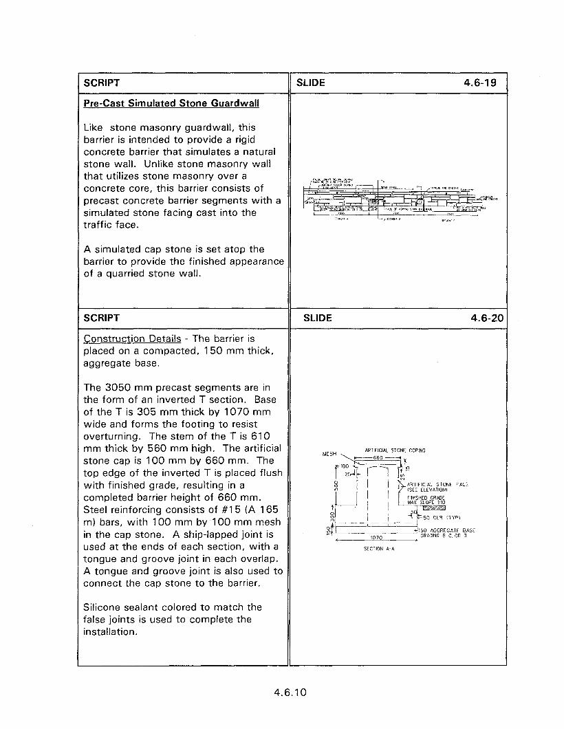
SCRIPT
Pre-Cast Simulated Stone Guardwall
SLIDE 4.6-l 9
Like stone masonry guardwall, this barrier is intended to provide a rigid concrete barrier that simulates a natural stone wall. Unlike stone masonry wall that utilizes stone masonry over a concrete core, this barrier consists of precast concrete barrier segments with a simulated stone facing cast into the traffic face.
A simulated cap stone is set atop the barrier to provide the finished appearance of a quarried stone wall.
SCRIPT SLIDE 4.6-20
Construction Details - The barrier is placed on a compacted, 150 mm thick, aggregate base.
The 3050 mm precast segments are in the form of an inverted T section. Base of the T is 305 mm thick by 1070 mm wide and forms the footing to resist overturning. The stem of the T is 610 mm thick by 560 mm high. The artificial stone cap is 100 mm by 660 mm. The top edge of the inverted T is placed flush with finished grade, resulting in a completed barrier height of 660 mm. Steel reinforcing consists of #15 (A 165 m) bars, with 100 mm by 100 mm mesh in the cap stone. A ship-lapped joint is used at the ends of each section, with a tongue and groove joint in each overlap. A tongue and groove joint is also used to connect the cap stone to the barrier.
““~.~!$-;:;‘“G
24
s ’ / ’ $(SEE ELEVATION) ARTIFICIAL STONE FACE
fINISHE GRADE MAX SLOPE 1:lO
T I 0 2 I j +?“$== 50 CLR CTYP, -------
s t 3150 AGGREGATE BASE 1070 GRADING 8. ‘2. OR 0
SECTION A-A
Silicone sealant colored to match the false joints is used to complete the installation.
4.6.10
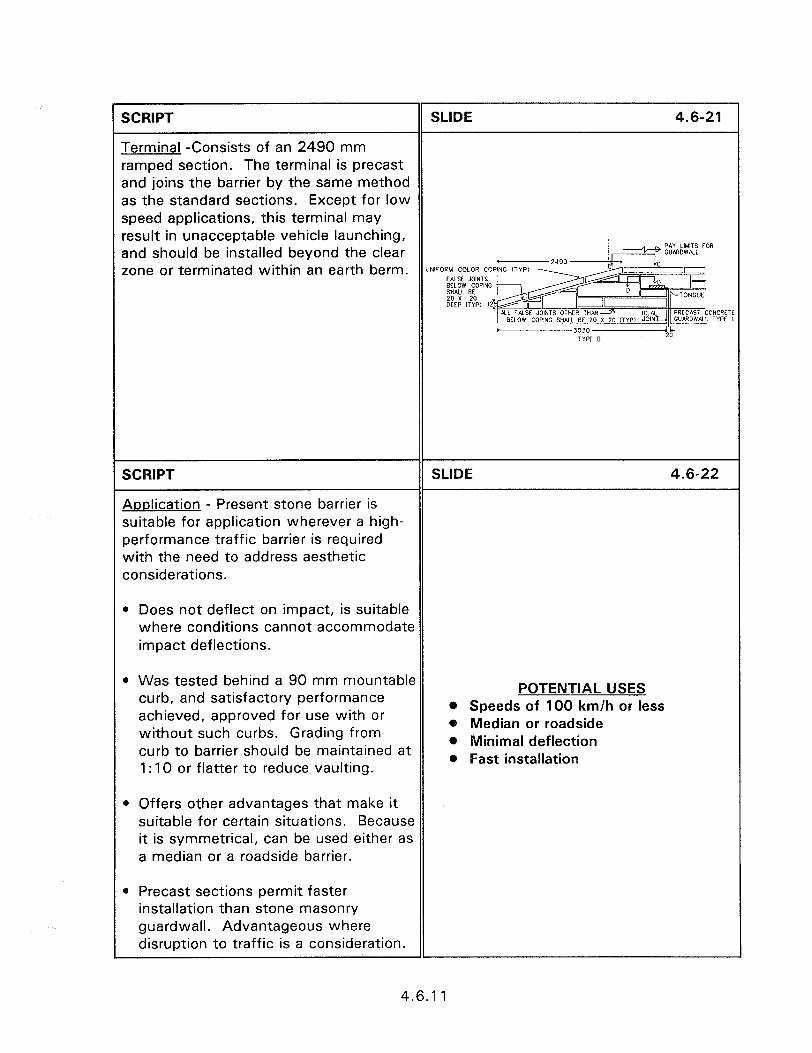
I-
SCRIPT SLIDE 4.6-21
Terminal -Consists of an 2490 mm ramped section. The terminal is precast and joins the barrier by the same method as the standard sections. Except for low speed applications, this terminal may result in unacceptable vehicle launching, and should be installed beyond the clear zone or terminated within an earth berm. “NIFORM COLOR co
FALSE JOINTS &xo~ pwC 20 x 20 OEEP ITYW 12
SCRIPT SLIDE 4.6-22
Aoplication - Present stone barrier is suitable for application wherever a high- performance traffic barrier is required with the need to address aesthetic considerations.
l Does not deflect on impact, is suitable where conditions cannot accommodate impact deflections.
l Was tested behind a 90 mm mountable curb, and satisfactory performance achieved, approved for use with or without such curbs. Grading from curb to barrier should be maintained at 1: 10 or flatter to reduce vaulting.
POTENTIAL USES l Speeds of 100 km/h or less 0 Median or roadside l Minimal deflection l Fast installation
l Offers other advantages that make it suitable for certain situations. Because it is symmetrical, can be used either as a median or a roadside barrier.
l Precast sections permit faster installation than stone masonry guardwall. Advantageous where disruption to traffic is a consideration.
1
4.6.1 1
SCRIPT
Costs are considerably higher than conventual systems.
SLIDE 4.6-23
Svstem Cost (S/m) Steel-backed timber 85 to 164 Stone Masonry 870 to 1640 Pre-cast 338 to 690 N.Y. cable oxidized 20 to 25 Minnesota cable 23 to 28 N.Y. W-beam with WP 40 to 45
SCRIPT
Evaluatinq Existinq Aesthetic Barriers
SLIDE 4.6-24
The aesthetic barrier systems presented are new designs -- only limited service within the last few years. The earlier aesthetic barriers have been in use in parks and other areas for decades. They typically consist of timber post and beam designs, and stone walls. Most are not designed to safely contain and redirect vehicles. Considering their low structural capacity and untreated terminals, it is usually not feasible to upgrade their performance significantly.
Periodic inspection and review of these features should be included in overall safety management where located to ensure acceptable roadside safety.
EVALUATING EXISTING AESTHETIC BARRIERS
0 Timber post/beam, stone walls l In good condition? l Restrict vehicle/pedestrian
movements?
Obsolete systems in good condition still prevent vehicles and pedestrians from entering restricted or hazardous areas. If in a deteriorated condition, however, they may create the additional hazard of loose stones or detached timbers. Barriers in poor condition detract from appearance.
4.6.12

important that existing barriers are maintained in good condition, even when not able to provide a reasonable level of impact performance. Deteriorated posts and beams should be repaired or replaced. Stonework in need of repair should be relaid to provide an acceptable appearance, to reduce snag potential, and to protect against loose pieces that may be a hazard to pedestrians or traffic.
SCRIPT SLIDE 4.6-25
Ensure that the existing barrier is necessary to protect traffic or pedestrians. Scarce resources should not be expended to repair or upgrade barriers that are not warranted. Maybe possible to remove an existing barrier rather than repair it, or to use alternate features such as curbs or fences to achieve desired result.
Untreated vertical barrier ends pose unacceptable hazard even at moderate speeds. It may be possible to upgrade safety by identifying untreated terminals susceptible to moderate speed impacts. Treating those terminals by flaring further 0 Repair or upgrade if warranted from the roadway or terminating in earth 0 Terminals - flare/berm/ berm or embankment back slope can back slope enhance safety. While the safety of the 0 Review if rehabilitation/ barrier itself will not be upgraded, the reconstruction planned overall safety of the installation may be significantly improved by treating the most severe hazard associated with it. Comprehensive examination of barrier needs at a site with obsolete barriers should be triggered by extensive rehabilitation or reconstruction of the facility. Thorough review should also be triggered by pattern of roadside accidents indicating barriers may be contributing to crash severity.
4.6.13

SCRIPT SLIDE 4.6-26
LOW SERVICE LEVEL BARRIER SYSTEMS
Most operational barriers currently in use were developed to contain and redirect 2040 kg vehicle at 100 km/h and 25 deg. These design criteria have resulted in barriers providing a high level of roadside safety but most are relatively LOW SERVICE LEVEL expensive. This has resulted in limited ROADWAYS application of expensive barriers on low 0 Traffic < 2000 AADT service level roadways. Low service l Speeds often < 80 km/h level roadways are generally defined as 0 Low truck volume carrying AADT typically less than 2000 with design and operating speeds of Sb km/h or less, and low truck volume.
SCRIPT SLIDE 4.6-27
2-Strand Cable On Flanaed-Channel Posts
Consists of two 19 mm diameter steel cables on 6 kg/m steel flanged-channel posts. Also referred to as “hat” sections or “U” posts.
Post length is 1600 mm with a 6 mm x 200 mm x 610 mm soil plate to ensure that the full strength of the post is developed.
Barrier height is 685 mm to the center of the top cable.
J-bolts attach the cables and provide controlled release from the during vehicle impact.
Standard post spacing is 4880 mm. Resembles the South Dakota cable barrier with one cable deleted.
4.6.14
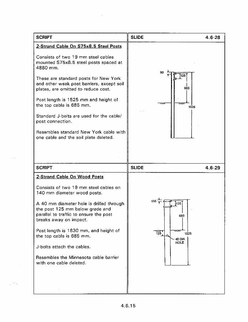
SCRIPT
2-Strand Cable On S75x8.5 Steel Posts
SLIDE 4.6-28
Consists of two 19 mm steel cables mounted S75x8.5 steel posts spaced at 4880 mm.
These are standard posts for New York and other weak post barriers, except soil plates, are omitted to reduce cost.
Post length is 1525 mm and height of the top cable is 685 mm.
Standard J-bolts are used for the cable/ post connection.
Resembles standard New York cable with one cable and the soil plate deleted.
SCRIPT
2-Strand Cable On Wood Posts
SLIDE 4.6-29
Consists of two 19 mm steel cables on 140 mm diameter wood posts.
A 40 mm diameter hole is drilled through the post 125 mm below grade and parallel to traffic to ensure the post breaks away on impact.
Post length is 1830 mm, and height of the top cable is 685 mm.
J-bolts attach the cables.
Resembles the Minnesota cable barrier with one cable deleted.
4.6.15

SCRIPT
W-beam on Flancled-Channel Posts
SLIDE 4.6-30
Consists of W-beam on 6 kg/m flanged- channel post.
The 1600 mm long posts are spaced at 3810 mm, and 6 mm x 200 mm x 610 mm soil plates to ensure that the full strength of the post is developed.
Height to the top of the rail is 685 mm.
Other than lighter posts and reduced height, this system is similar to weak- post W-beam and uses the same connection hardware.
SCRIPT
W-beam on Weak Wood Posts
SLIDE 4.6-31
Consists of steel W-beam on 140 mm diameter wood posts.
Rail height is 685 mm and post spacing is 3810 mm.
Barrier is the same as weak wood post W-beam barrier described in Session 4.4.
Slide of figure 4.6.22.
4.6.16
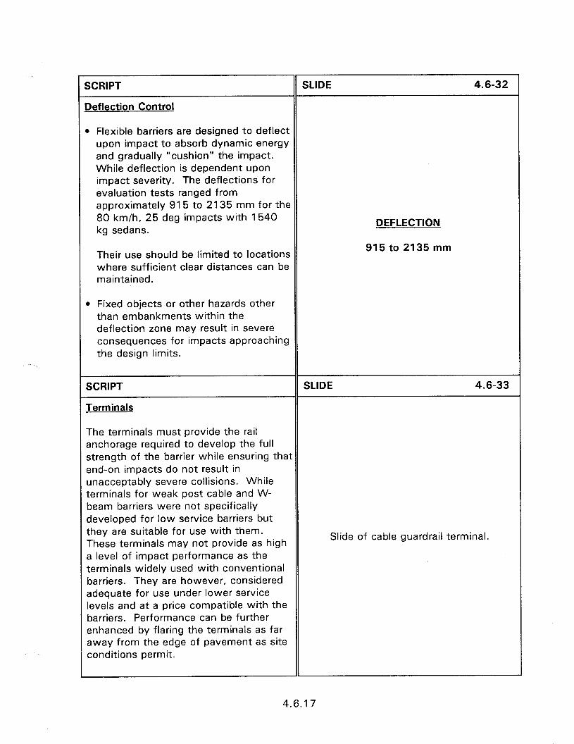
DEFLECTION
915 to 2135 mm
SCRIPT
Deflection Control
SLIDE 4.6-32
m Flexible barriers are designed to deflect upon impact to absorb dynamic energy and gradually “cushion” the impact. While deflection is dependent upon impact severity. The deflections for evaluation tests ranged from approximately 915 to 2135 mm for the 80 km/h, 25 deg impacts with 1540 kg sedans.
Their use should be limited to locations where sufficient clear distances can be maintained.
* Fixed objects or other hazards other than embankments within the deflection zone may result in severe consequences for impacts approaching the design limits.
SCRIPT
Terminals
SLIDE 4.6-33
The terminals must provide the rail anchorage required to develop the full strength of the barrier while ensuring that end-on impacts do not result in unacceptably severe collisions. While terminals for weak post cable and W- beam barriers were not specifically developed for low service barriers but they are suitable for use with them. These terminals may not provide as high a level of impact performance as the terminals widely used with conventional barriers. They are however, considered adequate for use under lower service levels and at a price compatible with the barriers. Performance can be further enhanced by flaring the terminals as far away from the edge of pavement as site conditions permit.
Slide of cable guardrail terminal.
4.6.17
SCRIPT SLIDE 4.6-34
impact Performance and Accident History
l No installations known to date--no known accident history.
l Development tests conducted under NCHRP project demonstrated these barriers capable of meeting NCHRP Report 230 performance criteria for the lower service level impacts.
l Expected that in-service performance will be similar to weak post cable and W-beam barriers.
ACCIDENT SEVERITY e No known accident history o Expect similar to weak post
cable, W-beam
l New York has reported satisfactory performance with those barriers.
SCRIPT
Construction and Maintenance Costs
SLIDE 4.6-35
Projected installation costs for low service level barriers listed in Table 4.6.2 projected terminal costs also shown. Since no in-service experience is available, no actual accident repair cost is available.
Based on similarity to weak post cable and W-beam barriers, it is expected that repair costs will be similar.
Based on very weak posts used in several of these systems, it is anticipated that even relatively moderate vehicle impacts will result in significant barrier damage and leave the barrier unable to resist subsequent impacts.
LOW SERVICE LEVEL COST
$12 to $22 per meter
4.6.18
4.5 - TREATMENT OF WIDE MEDIANS, BARRIER ENVELOPES, CURVED BARRIER SECTIONS, AND OTHER METHODS
FOR PROTECTING LARGE AREAS
Instructor’s Guide
SCRIPT
4n important safety feature of modern lighways is wide, traversable medians Jvhich provide protection against xossover accidents, while providing the opportunity for errant vehicles to regain control.
SCRIPT
when a potential hazard cannot be removed or redesigned, it may be necessary to provide protection by means of a roadside barrier, or if the desired median width cannot be achieved, to provide a median barrier. In many situations, longitudinal barriers are installed immediately adjacent to the shoulder, either because the area beyond the shoulder is nontraversable, or roadside hazards are located near the shoulder.
SCRIPT
When the hazard is further from the edge of the roadway, however, the intervening space can provide a recovery area for errant vehicles. In such cases, it is desirable to locate the barrier further from the roadside and closer to the object to be protected. This is especially true for objects or other hazards located near the outside of the desirable clear zone width or near the center of wide medians.
SLIDE 4.5-l
4.5 - TREATMENT OF WIDE MEDIANS, BARRIER ENVELOPES, CURVED
BARRIER SECTIONS, AND OTHER METHODS FOR PROTECTING LARGE
AREAS
SLIDE 4.5-2
Slide of barrier close to roadway.
SLIDE 4.5-3
Slide of barrier removed from roadway.
4.5.1
SCRlPT SLIDE 4.54
Other situations requiring special concern are roadside hazards, or nontraversable terrain, located at the intersection of two roadways. In such cases, merely providing a standard clear zone from the pavement edge may be inadequate, because vehicles traversing the intersection may depart the roadway at a high angle, proceeding a considerable distance before stopping. In this situation, longitudinal barriers located Slide of barrier at wide opening. along the intersecting roadways may be unable to prevent vehicles from contacting the hazard. In addition, it is frequently difficult to install effective barrier terminals for both runs of barrier at the intersection. This requires special barrier treatments including special barrier layouts, curved barriers, and treatments other than barriers.
SCRIPT SLIDE 4.5-5
For hazards located near the outside edge of the clear zone, or near the middle of wide medians, the barrier length required to provide protection becomes long for barriers installed adjacent to the shoulder. The treatments that are described in the Slide of wide median. sections that follow should be compared to the more conventional practice of placing barriers adjacent to the shoulder.
SCRIPT SLIDE 4.5-6
For fixed objects such as bridge piers or sign structures located near the center of wide medians, earth berms can be used effectively to safely redirect vehicles.
EARTH BERMS
4.5.2
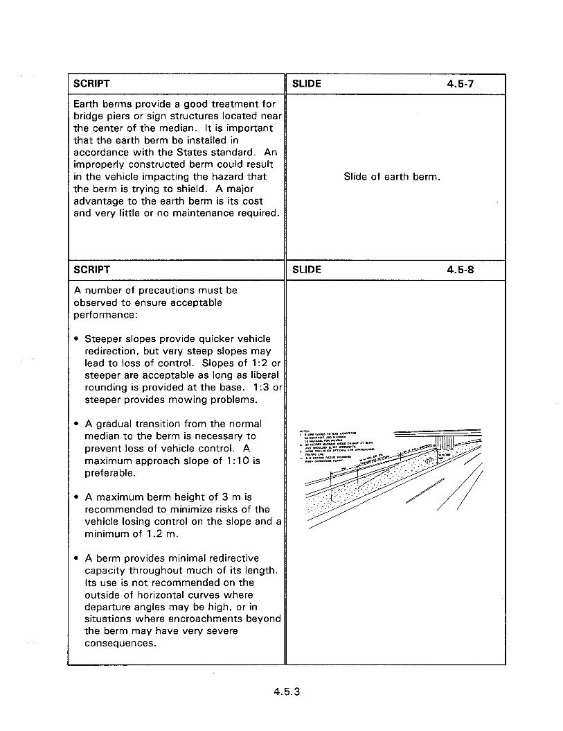
1 SCRIPT SLIDE 4.5-7
Earth berms provide a good treatment for bridge piers or sign structures located near the center of the median. It is important that the earth berm be installed in accordance with the States standard. An improperly constructed berm could result in the vehicle impacting the hazard that Slide of earth berm. the berm is trying to shield. A major advantage to the earth berm is its cost and very little or no maintenance required.
SCRIPT
A number of precautions must be observed to ensure acceptable performance:
SLIDE 4.5-8
0 Steeper slopes provide quicker vehicle redirection, but very steep slopes may lead to loss of control. Slopes of 1:2 or steeper are acceptable as long as liberal rounding is provided at the base. 1:3 or steeper provides mowing problems.
l A gradual transition from the normal median to the berm is necessary to prevent loss of vehicle control. A maximum approach slope of 1: 10 is preferable.
l A maximum berm height of 3 m is recommended to minimize risks of the vehicle losing control on the slope and a minimum of 1.2 m.
l A berm provides minimal redirective capacity throughout much of its length. Its use is not recommended on the outside of horizontal curves where departure angles may be high, or in situations where encroachments beyond the berm may have very severe consequences.
4.5.3
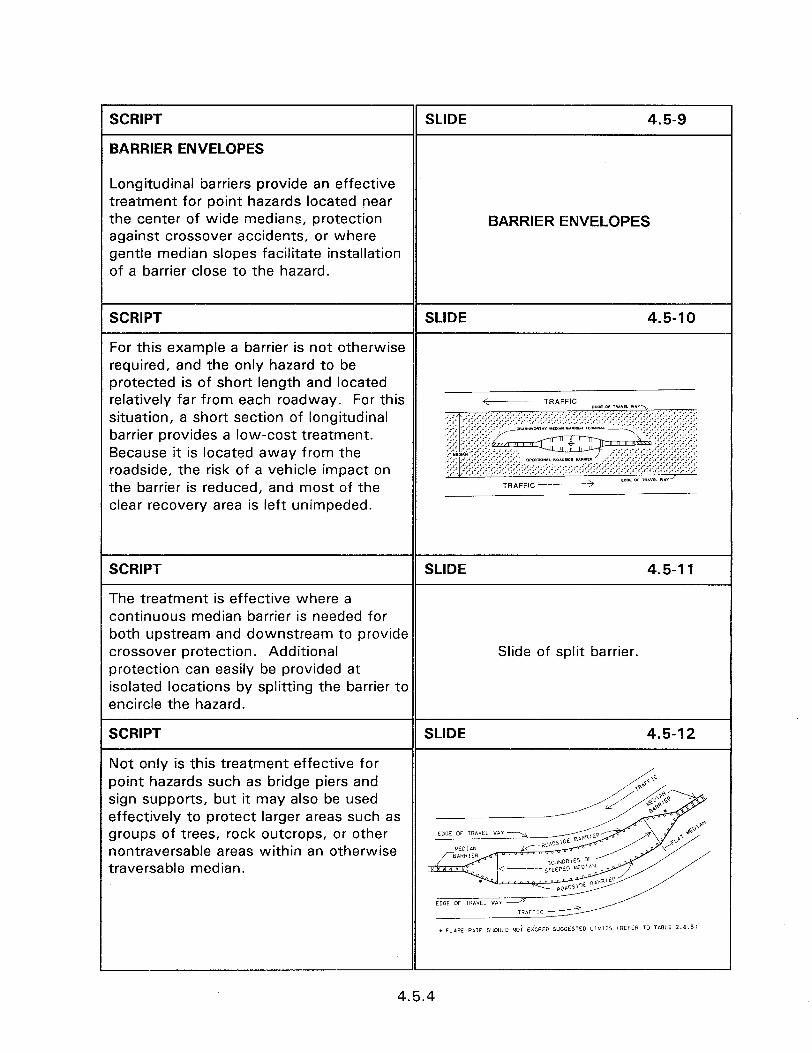
SCRIPT SLIDE 4.5-9
BARRIER ENVELOPES
Longitudinal barriers provide an effective treatment for point hazards located near the center of wide medians, protection against crossover accidents, or where gentle median slopes facilitate installation of a barrier close to the hazard.
BARRIER ENVELOPES
SCRIPT SLIDE 4.5-l 0
For this example a barrier is not otherwise required, and the only hazard to be protected is of short length and located relatively far from each roadway. For this +- -fRAFF’C sDa _ II”Y*L “,A”\ situation, a short section of longitudinal barrier provides a low-cost treatment. Because it is located away from the roadside, the risk of a vehicle impact on the barrier is reduced, and most of the
TRAFF,C > _nE or rnh”I1 W.“/
clear recovery area is left unimpeded.
SCRIPT SLIDE 4.5-l 1
The treatment is effective where a continuous median barrier is needed for both upstream and downstream to provide crossover protection. Additional Slide of split barrier. protection can easily be provided at isolated locations by splitting the barrier to encircle the hazard.
SCRIPT SLIDE 4.5-l 2
Not only is this treatment effective for point hazards such as bridge piers and sign supports, but it may also be used effectively to protect larger areas such as groups of trees, rock outcrops, or other nontraversable areas within an otherwise traversable median.
4.5.4
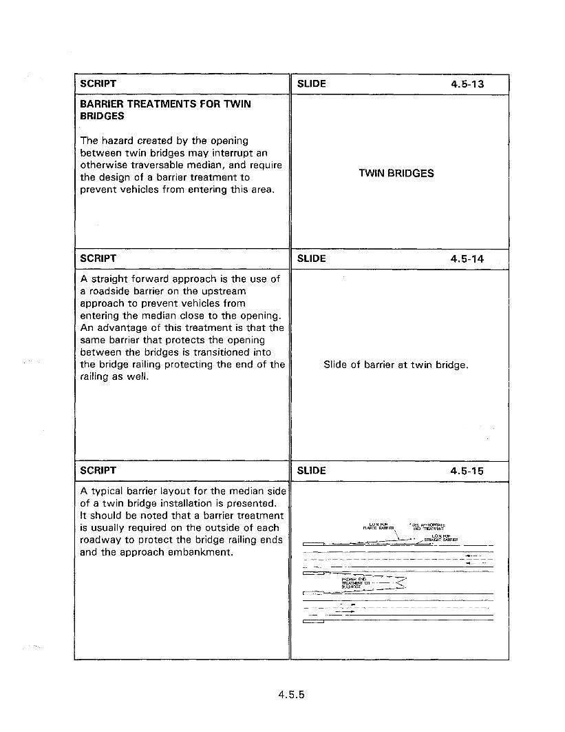
TWIN BRIDGES
SCRIPT
BARRIER TREATMENTS FOR TWIN BRIDGES
SLIDE 4.5-l 3
The hazard created by the opening between twin bridges may interrupt an otherwise traversable median, and require the design of a barrier treatment to prevent vehicles from entering this area.
SCRIPT SLIDE 4.5-14
A straight forward approach is the use of a roadside barrier on the upstream approach to prevent vehicles from entering the median close to the opening. An advantage of this treatment is that the same barrier that protects the opening between the bridges is transitioned into the bridge railing protecting the end of the Slide of barrier at twin bridge. railing as well.
SCRIPT SLIDE 4.5-15
A typical barrier layout for the median side of a twin bridge installation is presented. It should be noted that a barrier treatment is usually required on the outside of each LON FOA FL&x0 EAFIRIER f UESsED Aw.w~tg
roadway to protect the bridge railing ends L O.N. FM( ” ~*,STRRlGmB9RRIEf and the approach embankment.
-
4.5.5
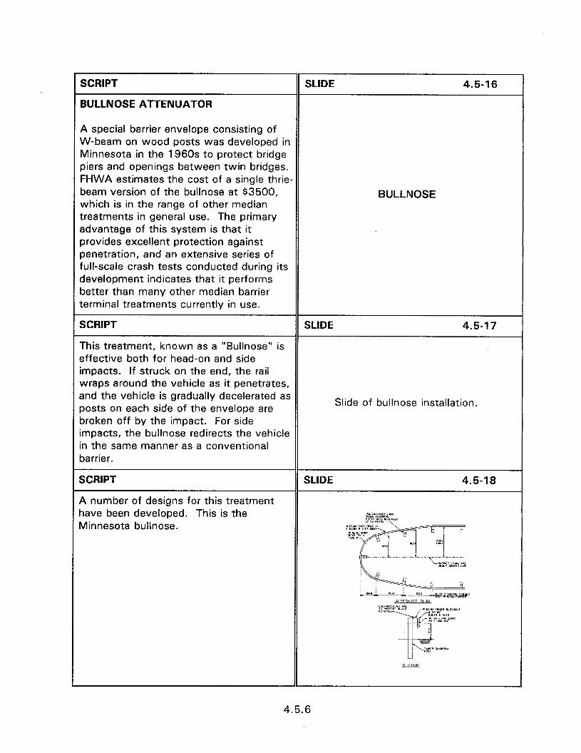
SCRIPT
BULLNOSE ATTENUATOR
SLIDE 4.5-16
A special barrier envelope consisting of W-beam on wood posts was developed in Minnesota in the 1960s to protect bridge piers and openings between twin bridges. FHWA estimates the cost of a single thrie- beam version of the bullnose at $3500, which is in the range of other median treatments in general use. The primary advantage of this system is that it provides excellent protection against penetration, and an extensive series of full-scale crash tests conducted during its development indicates that it performs better than many other median barrier terminal treatments currently in use.
BULLNOSE
SCRIPT SLIDE 4.5-17
This treatment, known as a “Bullnose” is effective both for head-on and side impacts. If struck on the end, the rail wraps around the vehicle as it penetrates, and the vehicle is gradually decelerated as posts on each side of the envelope are
Slide of bullnose installation.
broken off by the impact. For side impacts, the bullnose redirects the vehicle in the same manner as a conventional barrier.
SCRIPT
A number of designs for this treatment have been developed. This is the Minnesota bullnose.
4.5.6
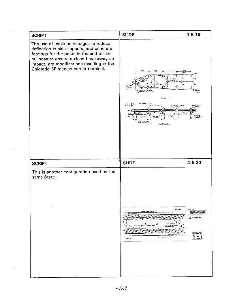
SCRIPT
The use of cable anchorages to reduce deflection in side impacts, and concrete footings for the posts in the end of the xMose to ensure a clean breakaway on mpact, are modifications resulting in the Colorado 3F median barrier terminal.
SLIDE 4.5-l 9
SCRIPT
This is another configuration used by the same State.
SLIDE 4.5-20
4.5.7
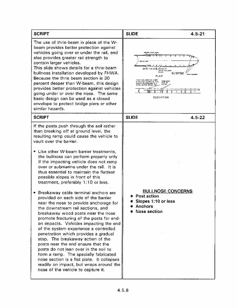
vehicles going over or under the rail, and also provides greater rail strength to contain larger vehicles. This slide shows details for a thrie-beam bullnose installation developed by FHWA. Because the thrie beam section is 30 percent deeper than W-beam, this design provides better protection against vehicles going under or over the nose. The same
PLAN
ELEVATION
than breaking off at ground level, the resulting ramp could cause the vehicle to vault over the barrier.
Like other W-beam barrier treatments, the bullnose can perform properly only if the impacting vehicle does not ramp over or submarine under the rail. It is thus essential to maintain the flattest possible slopes in front of this treatment, preferably 1: IO or less.
Breakaway cable terminal anchors are provided on each side of the barrier near the nose to provide anchorage for the downstream rail sections, and breakaway wood posts near the nose promote fracturing of the posts for end- on impacts. Vehicles impacting the end of the system experience a controlled penetration which provides a gradual stop. The breakaway action of the posts near the end ensure that the posts do not lean over in the soil to form a ramp. The specially fabricated nose section is a flat plate. It collapses readily on impact, but wraps around the nose of the vehicle to capture it.
BULLNOSE CONCERNS 8 Post action 0 Slopes I:1 0 or less @ Anchors @ Nose section
4.5.8

SCRIPT
CURVED W-BEAM BARRIER AT INTERSECTIONS
SLIDE 4.5-23
Hazards such as embankments or fixed objects located in the quadrant formed by intersecting roadways can create special problems for designers.
CURVED BEAM AT INTERSECTIONS
SCRIPT SLIDE 4.5-24
Conventional roadside barriers installed around the resulting short radius have not been effective when the curved barrier was impacted at high speed. Such impacts often result in vaulting or penetration of the barrier, or if contained, the vehicle is subjected to high
Slide of curved beam at intersection.
deceleration.
SCRIPT SLIDE 4.5-25
A family of W-beam installations has been designed and tested by installing the YAW MGHWIY barrier around a short radius and BEOIN STANDIRD WOOD OR STEEL
terminating it on the intersecting road or driveway. Standard designs have been UNNTAWED FREE OF F,XED OBJECTS 2. SLOPE OF w5 OR FLATTER MUST developed for radii of 2.6, 5.2, 7.8 and a maximum of 10.7 m. Designs for other radii can be developed if necessary, as long as they adhere to the design principles, to ensure adequate performance. Layout details for the 10.7 m radius are presented in this slide.
4.5.9
SCRIPT
A number of details, which are required for proper system performance, must be addressed during construction of these curved installations:
l Design details must be followed precisely. Connection bolts, post types and orientation, use of blockouts, and other hardware details must be installed exactly as shown in the plans.
l A flat slope not exceeding 1: 15 must bE maintained in front of the curved section. Any grading changes that affect the height of the vehicle as it approaches the barrier, including roadway cross-slope and superelevation, must be checked with the designer to ensure it will not adversely affect performance.
l Embankment slope behind the barrier must not exceed 1:2, and the posts must be at least 610 mm in front of the slope break to ensure adequate support. If it is necessary to protect steeper slopes, other treatments must be explored.
l Because considerable deflection will result from high speed impacts on the curved rail, adequate clear space must be maintained behind the barrier as shown in figure 4.5.13. The required space ranges from a 4.6 m wide by 7.6 m long area for the 2590 mm radius up to 6.1 m wide by 15.2 m long for the 10.7 m radius. While this clear space is considerably greater than the normal dynamic deflection distance of W-beam roadside barrier, it is much less than the required runout length for a vehicle leaving the roadway at full speed.
SLIDE 4.5-26
CURVEDBEAMCONCERNS l Follow design details 0 Slopes I:15 or less l Embankment behind less
than I:2 a Rear clear space o End anchor not crashworthy
terminal l 90 degrees
4.5.10
l The special end anchor developed for this system is not a crashworthy terminal for high speed highways. It is acceptable for use on service roads, driveways, and other low speed facilities. For intersections on high speed highways, the curved installation should be terminated using a crashworthy terminal or connected to standard guardrail on the intersecting roadway.
l This system does not work well for angles which vary much from 90 degrees.
SCRIPT SLIDE 4.527
There are a number of treatments for separating hazards in wide medians from errant vehicles. The use of berms, crash cushions, envelopes, and bullnose designs, are dependent upon the situation and State practices. Bear in mind that due to the distance from the traveled way CONCLUSION
and the impact angles, the consequent severity of the impact can be severe.
4.5.11

SESSION GUIDE
4.6 - AESTHETIC AND LOWER SERVICE LEVEL BARRIER SYSTEMS
Obiectives:
e Provide a working knowledge of aesthetic and lower service level barriers.
e Enable the identification of highway situations for which these unique barriers offer distinct advantages.
Heloful Hints:
l The aesthetic barrier topic is a primary interest of forest and park service personnel. Reasonable cost and aesthetically pleasing barriers can be obtained by using weatheric steel W-beam or other options to high cost barriers. In the majority of presentation areas this section can be skipped.
Visual Aids:
l 40 - 35 mm slides
e Video Tape
Estimated Time
l 60 minutes
Handouts:
l None

4.6 - AESTHETIC AND LOWER SERVICE LEVEL BARRIER SYSTEMS
Instructor’s Guide
SCRIPT
INTRODUCTION
SLIDE 4.6-l
This session will introduce two new categories of traffic barriers; aesthetic barrier systems and lower service level barriers.
Design and functional characteristics are similar to most other barrier systems. This session does not, therefore, provide as detailed a discussion of the functional principles.
It does provides a general description, and a detailed discussion of the characteristics that make them unique from other barriers.
4.6 AESTHETIC AND LOW SERVICE LEVEL
BARRIERS
As for other barriers, aesthetic and low service level barriers must be capable of providing an acceptable level of protection.
This session discusses traffic barriers that provide impact performance comparable to conventional systems, and visual qualities to complement aesthetically sensitive environments.
SCRIPT
Aesthetic Barriers
SLIDE 4.6-Z
Traffic barriers currently in use provide BARRIER SELECTION an acceptable level of safety, but are Typical Aesthetic designed to provide the best service at l Best Service l Good Service the lowest cost. Most are utilitarian in l Lowest Cost l Cost Less Important appearance, with aesthetics usually not 0 Utilitarian l Visual Qualities a high priority since barriers rarely add to visual qualities and may detract.
4.6.1

SCRIPT SLIDE 4.6-3
In areas such as parks, historical communities, and scenic areas, roads must provide safe, efficient access, and also preserve the aesthetic qualities of the area. Added costs to improve the
AESTHETIC BARRIER
visual qualities of traffic barriers in these APPLICATIONS
areas often represent an acceptable l Parks
investment. 0 Historical communities * Scenic areas
SCRIPT
Lower Service Level Barriers
SLIDE 4.6-4
Traffic barriers serve a wide range of service levels, ranging from impacts by passenger cars, vans and pickups, up through buses and even large semi- trailers. The service level in common use is test level 3. This level subjects barriers to impacts by small cars and full size pickups at speeds of 100 kph and angles of 20 to 25 deg. Test level 3, or similar, has been the basis for most traffic barriers and associated features over the past three decades. It has
BARRIER SERVICE LEVELS
provided an excellent record of 0 NCHRP 350 TL 3 - Standard Level
performance in actual service. - Small car, pickup - 100 km/h -
20-25”
On roadways carrying very low traffic 0 Lower Service Levels
volumes, especially if speeds are also l Lower speeds, low volumes
low, the significant costs of level 3 l Few trucks, low cost
barriers cannot be offset by anticipated benefits since the probability of a severe off-road accident is lower.
Barriers providing a lower level of service, at a reduction in cost may provide cost-effective roadside safety. NCHRP Report 350 provides two test levels below Level 3.
4.6.2

SCRIPT
Aoolication
SLIDE 4.6-36
Based on their low costs and simple designs, these barriers are especially good candidates for sites with one or more of the following characteristics:
l Low traffic volumes, especially 2000 AADT or less.
LOW SERVICE LEVEL @ Operating speeds of 80 km/h or less. APPLICATION
0 Traffic < 2000 AADT . Few heavy trucks and buses. l Speeds < 80 km/h
l Few trucks, buses
SCRIPT SLIDE 4.6-37
l Gentle to moderate roadway alignment and/or terrain, combined with roadside embankment slopes of 1:2 or flatter, further add to the suitability of these barriers.
0 Where frequently necessary to transition to bridges or other rigid roadside obstacles, stiffer conventional barriers are required for the transition. Flexible low service level barriers are usually not a good choice for these situations unless long runs of the low service level barrier are needed upstream of the bridge to protect other hazards.
@ Gentle to moderate alignment/ terrain
@ Slopes I:2 or flatter @ Few bridges, other rigid objects
4.6.19
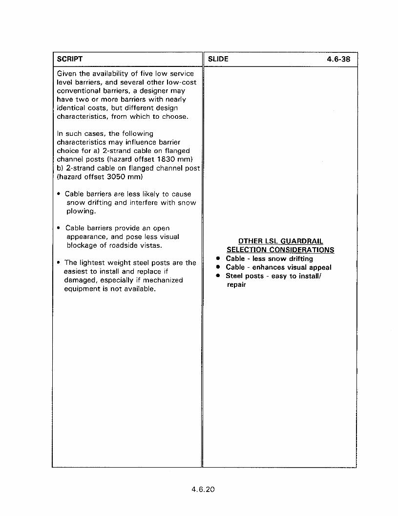
SCRIPT
Given the availability of five low service level barriers, and several other low-cost conventional barriers, a designer may have two or more barriers with nearly identical costs, but different design characteristics, from which to choose.
In such cases, the following characteristics may influence barrier choice for a) 2-strand cable on flanged channel posts (hazard offset 1830 mm) b) 2-strand cable on flanged channel post (hazard offset 3050 mm)
l Cable barriers are less likely to cause snow drifting and interfere with snow plowing.
l Cable barriers provide an open appearance, and pose less visual blockage of roadside vistas.
l The lightest weight steel posts are the easiest to install and replace if damaged, especially if mechanized equipment is not available.
SLIDE 4.6-38
OTHER LSL GUARDRAIL SELECTION CONSIDERATIONS
l Cable - less snow drifting l Cable - enhances visual appeal l Steel posts - easy to install/
repair
4.6.20

SCRIPT SLIDE 4.6-39
l W-beam barrier, especially on the heavier wood posts, may be less prone to accident damage and require less repair.
. W-beam permits easier transitions to bridge rail.
l Wood post systems may be preferable in parks and natural areas where aesthetics is an important consideration.
l In addition current practice of the roadway agency, barrier parts inventory, equipment availability, and personnel training and experience may also affect choice of the most practical barrier system.
l W-beam on wood posts - lower accident damage
0 W-beam - easy transitions l Wood posts - aesthetic appeal l Consider agency experience
Example--it may not be prudent to select a cable barrier if all other barriers currently owned by the agency is W- beam.
l Consider available equipment
Personnel training, experience, and required materials inventory would all support staying with a system similar to that already in use.
Selection of a wood post system may not be a good choice for a small agency without the availability of a power augur to install and replace posts.
SCRIPT SLIDE 4.6-40
Low service level barriers provide a viable alternative to installing expensive barrier systems on low volume, low speed roadways. At the other extreme aesthetic barriers can provide the CONCLUSION requisite safety while maintaining the pleasing effects of the surrounding terrain.
1
4.6.21


SESSION GUIDE
4.7 - COMMERCIALLY AVAILABLE BARRIER SYSTEMS
Obiectives:
0 Present the advantages and disadvantage of commercial barrier systems.
0 Present the primary commercial barriers and their manufacturers.
Helpful Hints:
0 Contact the manufacturers prior to the presentation to obtain handout materials.
0 Breakout sessions, concerning the construction of proprietary devices, are presented at the end of the session. To save time, present only those which are requested.
Visual Aids:
0 20 - 35 mm slides
l Breakout Session:
0 4.7A BARRIERGATE 44 - 35 mm slides a 4.7B TRITON BARRIER 21 - 35 mm slides 0 4.7C GUARDIANTM SAFETY BARRIER SYSTEM 18 - 35 mm slides
Estimated Time
l 20 minutes
a Breakout Session:
* 4.7A BARRIERGATE 30 minutes 0 4.78 TRITON BARRIER 15 minutes 0 4.7C GUARDIANTM SAFETY BARRIER SYSTEM 15 minutes
Handouts:
0 None

4.7 - COMMERCIALLY AVAILABLE BARRIER SYSTEMS
instructor’s Guide
SCRIPT
INTRODUCTION
SLIDE 4.7-l
l The majority of barrier systems in use on our Nation’s roadways can be classified as non-proprietary systems.
l These systems include W-beam, cable, thrie beam, box beam, and other barrier systems that, while manufactured by a limited number of suppliers, are not patented by a specific manufacturer.
l There are also patented, or what will be termed commercially available barrier systems on the market.
4.7 - COMMERCIALLY AVAILABLE BARRIER SYSTEMS
l Commercially available barrier systems have a number of applications, but the majority of barriers have their primary use as temporary or work zone installations.
l This is a general application rule with some barriers designed for permanent installation and the majority of temporary barriers being adaptable to permanent installation.
SCRIPT
COMMERCIALLY AVAILABLE BARRIER SYSTEMS
SLIDE 4.7-2
l Details on commercially available barrier systems provided in this section are intended to provide information on the device configuration and overall dimensions.
COMMERCIAL BARRIER SYSTEMS
l Barrier GateTM l Guardian Safety Barrier System 0 Triton BarrierTM System
l Individual manufacturers should be contacted to obtain additional information for each device.
4.7.1
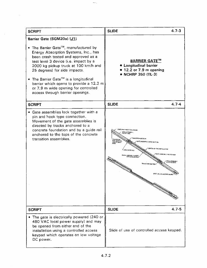
SCRIPT
Barrier Gate (SGM2Qa) tJ11
SLIDE 4.7-3
@ The Barrier GateTM, manufactured by Energy Absorption Systems, inc., has been crash tested and approved as a test level 3 device (i.e. impact by a 2000 kg pickup truck at 100 km/h and 25 degrees) for side impacts.
BARRIER GATETM o Longitudinal barrier 0 12.2 or 7.9 m opening 0 NCHRP 350 (TL-3)
0 The Barrier GateTM is a longitudinal barrier which opens to provide a 12.2 m or 7.9 m wide opening for controlled access through barrier openings.
SCRIPT SLIDE 4.7-4
l Gate assemblies lock together with a pin and hook type connection. Movement of the gate assemblies is directed by tracks anchored to a concrete foundation and by a guide rail anchored to the tops of the concrete transition assemblies.
S~E~~LI.HMKSECT,ON
SCRIPT SLIDE 4.7-5
@ The gate is electrically powered (240 or 480 VAC local power supply) and may be opened from either end of the installation using a controlled access Slide of use of controlled access keypad. keypad which operates on low voltage DC power.
4.7.2

SCRIPT SLIDE 4.7-6
l The Barrier GateTM is equipped with a manual override system in the event of Slide of vehicle passing through barrier. electrical power failure.
SCRIPT
Triton BarrierTM System (SWMOLA) IJ11
SLIDE 4.7-7
l The Triton BarrierTM, manufactured by Energy Absorption Systems, Inc., has been approved for use as a test level 2 device (i.e. impacted by a 2000 kg pick-up truck at 70 km/h).
TRITON BARRIERTM l Portable l Temporary barrier . NCHRP (TL-2)
l It is a portable and crashworthy longitudinal barrier especially suited for use as a temporary barrier in highway construction zones.
SCRIPT SLIDE 4.7-8
l Impacting vehicles are brought to a safe and controlled stop alongside the barrier or redirected at a shallow angle in the vicinity of the impact area thereby reducing the potential for dangerous
Slide of vehicle impacting barrier.
secondary impacts.
SCRIPT
* Each section is constructed of a polyethylene plastic shell designed to accept water ballast.
SLIDE 4.7-9
0 The plastic shell is strengthened by an internal steel frame to provide additional rigidity during handling and impacts.
0 A steel cable along the top of the section resists the tensile forces generated during high severity impacts.
1
4.7.3
SCRIPT SLIDE 4.7-l 0
l Vertically aligned, interlocking knuckles at the end allow the sections to be securely joined with a pin.
l The pin connection allows the Triton Slide of installing barrier. barrier section to swivel and be positioned with an inside radius as small as 11280 mm.
SCRIPT
l Sections are available in white and work-zone-safety orange colors.
SLIDE 4.7-l 1
Slide of stored shells.
SCRIPT
l Triton BarrierTM sections have fork lift ports and may be stacked to reduce shipping and storage space.
SLIDE 4.7-l i
Slide of forklift holes.
SCRIPT SLIDE 4.7-l z
l Water ballast may be quickly added and drained using large fill openings and a gate valve in each section.
Slide of filling with water. l Each section has an easily visible fill
level indicator.
SCRIPT-
l Triton BarrierTM acts as its own end terminal when the front section is left empty of water.
SLIDE 4.7-14
Slide installing barrier.
4.7.4
SCRIPT SLIDE 4.7-l 5
l Manufactured by Safety Barrier Systems, the barrier utilizing the 350 HIGHWAY KIT has been approved for use as a NCHRP Report 350 Test Level 2 device (i.e., impacted by a 2000 kg GUARDIAN SAFETY BARRIER pick-up truck at 70 km/h). l Low speed
l Construction zones l Portable . NCHRP 350 (TL-2)
l The Guardian Safety Barrier is a portable, energy-absorbing, heavy duty polyethylene longitudinal barrier used to provide a safer working environment in low speed (40 km/h) temporary construction zones.
SCRIPT
0 Available in opaque ivory and safety orange.
SLIDE 4.7-l 6
l Constructed of a polyethylene plastic shell designed to accept water or solid ballast.
Slide of Guardian shells.
l Shell is strengthened by internal baffles and gussets.
SCRIPT SLIDE 4.7-l 7
l The 350 HIGHWAY KIT is a fabricated steel assembly designed to easily mount to the Guardian Safety Barrier.
0 Function of the 350 HIGHWAY KIT is to: 1. Provide a strong and resilient outer surface to resist the wheel and bumper of a striking vehicle, and 2. Link the barriers to each other and create a very robust linear system such that the force of a striking vehicle will be distributed over many barriers, minimizing the lateral movement at the point of impact.
Slide of Guardian with 350 kit.
l The 350 HIGHWAY KIT consists of several elements.
l Two inverted U saddles which are placed over the top of each barrier.
4.7.5
SCRIPT SLIDE 4.7-18
l The saddles create an offset mounting point for the side panels, such that the upper longitudinal pipe is 5” from the vertical face of the barrier.
l Pipe assemblies consist of two formed flat bars with two steel pipes welded across at specific elevations.
0 The pipe assemblies are then secured to the saddles and secured to the barrier with steel cables that pass under the barrier.
0 The cable prevents the system from Field Installation of Guardian Safety lifting upon impact from a vehicle. Barrier System.
0 The barrier is connected to the next in line by means of 4 male-female connector lugs welded to the inside of the longitudinal pipe ends.
0 Each lug has a slot to receive the linking bolts.
l The slots allow for some flexibility in the connection, particularly when the barrier line must follow a curve or elevation change in the road surface.
SCRIPT
Additional commercial barriers are discussed in section 4.1.8 - Portable concrete barriers.
SLIDE 4.7-19
CONCLUSIONS
4.7.6
BREAKOUT 4.7.A - INSTALLATION OF THE BARRIERGATETM SYSTEM
SCRIPT
BARRIERGATETM SYSTEM
SLIDE 4.7.A-1
BARRIERGATE
SCRIPT SLIDE 4.7.A-2
The first step in the installation process is to prepare the New Jersey safety shape barrier that the BarrierGateTM will be attached to. A 36.58 +/- .05 m opening PREPARE EXISTING BARRIER is required for the 12.2 m opening version. l 120-foot (36.58 m) opening
SCRIPT
The gate attaches to the existing barrier using 9.14 m custom concrete sections and two 1.52 m concrete transition
SLIDE 4.7.A-3
sections adjacent to each end of the BarrierGateTM.
l Two 30-foot (9.14 m) concrete sections
0 Two 5-foot (I .52 m) concrete sections
SCRIPT SLIDE 4.7.A-4
The BarrierGateTM must be anchored to a concrete pad that is at least 254 mm thick, non-reinforced 27.6 MPa P.C. concrete.
Man drilling through track hole into concrete pad.
4.7.A. 1

SCRIPT SLIDE 4.7.A-5
To determine the location of the barrier on the concrete pad, mark the center line of the barrier and the midpoint of the opening Man marking on concrete pad along on the concrete pad. barrier centerline.
SCRIPT SLIDE 4.7.A-6
Mark two more lines, 305 mm on each side of the center line of the barrier. These lines will be used to position the guide Man marking on concrete pad on each track in a later step. side of centerline.
SCRIPT
The incoming electrical power should be positioned at the center line of the barrier between the custom 9.14 m and 1.52 m sections.
SLIDE 4.7.A-7
The electrical junction box is attached to the 9.14 m custom CMB section used in Electrical junction box between two the installation. First connect the junction concrete barrier sections. box to the incoming electrical power cable, then attach the box to the end of tht? custom 9.14 m section of CMB.
Note the warning that the junction box should be properly grounded.
SCRIPT SLIDE 4.7.A-8
After installing the junction box, anchor both 9.14 m custom CMB sections using 22 mm x 254 mm MP-3 anchors at both ends. Use angle brackets as a template for hole locations. Man anchoring end of concrete barrier to
concrete pad using angle bracket. Note that if the existing barrier is not anchored, it must be attached to the end of the custom 9.14 m barrier splice plates.
4.7.A.2
SCRIPT SLIDE 4.7.A-9
Once the 9.14 m barrier sections are anchored, place both 1.52 m CMB’s in the correct location. Note that the 1.52 m Two adjacent concrete barrier sections. barrier sections have a 1.27 mm gap between them and the 9.14 m sections.
SCRIPT SLIDE 4.7.A-10
Once the 1.52 m barrier sections are in place, use steel splice plates and 28 mm x 559 mm long studs to connect the 9.14 Wrench tightening nut on splice plate m and 1.52 m custom CMB’s together. connecting two concrete barrier sections.
SCRIPT SLIDE 4.7.A-11
The guide rail ramp should be centered on top of the barrier with its bend flush to the end of the 9.14 m CMB section.
Mark and drill the 25 mm x 90 mm deep Man placing guide rail ramp on top of clearance holes before installing the concrete barrier. ramps. Install the guide rail ramp and flat guide rail plate on top of the CMB’s using 19 mm x 165 mm MP-3 anchors.
SCRIPT
Sink the studs flush with the top of the nuts.
SLIDE 4.7.A-12
Man bolting guide rail to top of concrete barrier.
SCRIPT SLIDE 4.7.A-13
The track is positioned on the ground between the two lines marked at 305 mm from the center line of the barrier. The Man placing track on concrete pad track must be centered +/- 3 mm. Verify according to marked lines. that there is 864 +/- 25 mm between the ends of the track and short CMB sections.
4.7.A.3
SCRIPT SLIDE 4.7.A-14
Use the tracks as drilling templates during the anchoring process.
Man drilling through track hole into concrete pad.
SCRIPT
Anchor the track and cable cover using MP-3 anchor bolts.
SLIDE 4.7.A-15
Bolted track onto concrete pad.
SCRIPT SLIDE 4.7.A-16
Attach the tension pulley assembly to the open end of the 1.52 m CMB next to the incoming power supply. Two men placing tension pulley assembly
against concrete barrier.
SCRIPT SLIDE 4.7.A-17
Attach the traction drive assembly to the other 1.52 m CMB.
Man bolting traction drive assembly to concrete barrier.
SCRIPT SLIDE 4.7.A-18
Temporarily place the pin section gate half alongside the tension pulley assembly and the hook section gate half alongside the traction drive assembly so the wiring harnesses will reach the plug connections. Set the gate halves on sections of the shipping pallet or similar blocks. Crane lifting pin section gate half.
Remove the top cover near the bulkhead on both gate halves. Also remove the transition skirts (2 each) and lower bulkhead skirts (2 each) from each gate half.
4.7.A.4
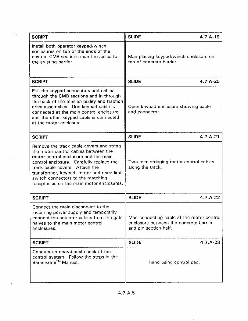
SCRIPT
Install both operator keypad/winch enclosures on top of the ends of the custom CMB sections near the splice to the existing barrier.
SLIDE 4.7.A-19
Man placing keypad/winch enclosure on top of concrete barrier.
SCRIPT SLIDE 4.7.A-20
Pull the keypad connectors and cables through the CMB sections and in through the back of the tension pulley and traction drive assemblies. One keypad cable is Open keypad enclosure showing cable connected at the main control enclosure and connector. and the other keypad cable is connected at the motor enclosure.
SCRIPT SLIDE 4.7.A-21
Remove the track cable covers and string the motor control cables between the motor control enclosure and the main control enclosure. Carefully replace the Two men stringing motor control cables track cable covers. Attach the along the track. transformer, keypad, motor and open limit switch connectors to the matching receptacles on the main motor enclosures.
SCRIPT
Connect the main disconnect to the
SLIDE 4.7.A-22
incoming power supply and temporarily connect the actuator cables from the gate Man connecting cable at the motor contra halves to the main motor control enclosure between the concrete barrier enclosures. and pin section half.
SCRIPT
Conduct an operational check of the control system. Follow the steps in the BarrierGateTM Manual.
SLIDE 4.7.A-23
Hand using control pad.
1
4.7.A.5
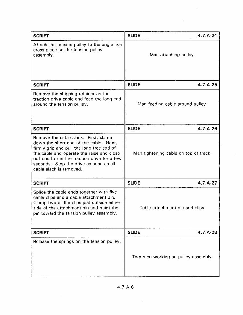
SCRIPT SLIDE 4.7.A-24
Attach the tension pulley to the angle iron cross-piece on the tension pulley assembly. Man attaching pulley.
SCRIPT SLIDE 4.7.A-25
Remove the shipping retainer on the traction drive cable and feed the long end around the tension pulley. Man feeding cable around pulley.
SCRIPT SLIDE 4.7.A-26
Remove the cable slack. First, clamp down the short end of the cable. Next, firmly grip and pull the long free end of the cable and operate the raise and close Man tightening cable on top of track. buttons to run the traction drive for a few seconds. Stop the drive as soon as all cable slack is removed.
SCRIPT SLIDE 4.7.A-27
Splice the cable ends together with five cable clips and a cable attachment pin. Clamp two of the clips just outside either side of the attachment pin and point the Cable attachment pin and clips. pin toward the tension pulley assembly.
SCRIPT SLIDE 4.7.A-28
Release the springs on the tension pulley.
Two men working on pulley assembly.
4.7.A.6
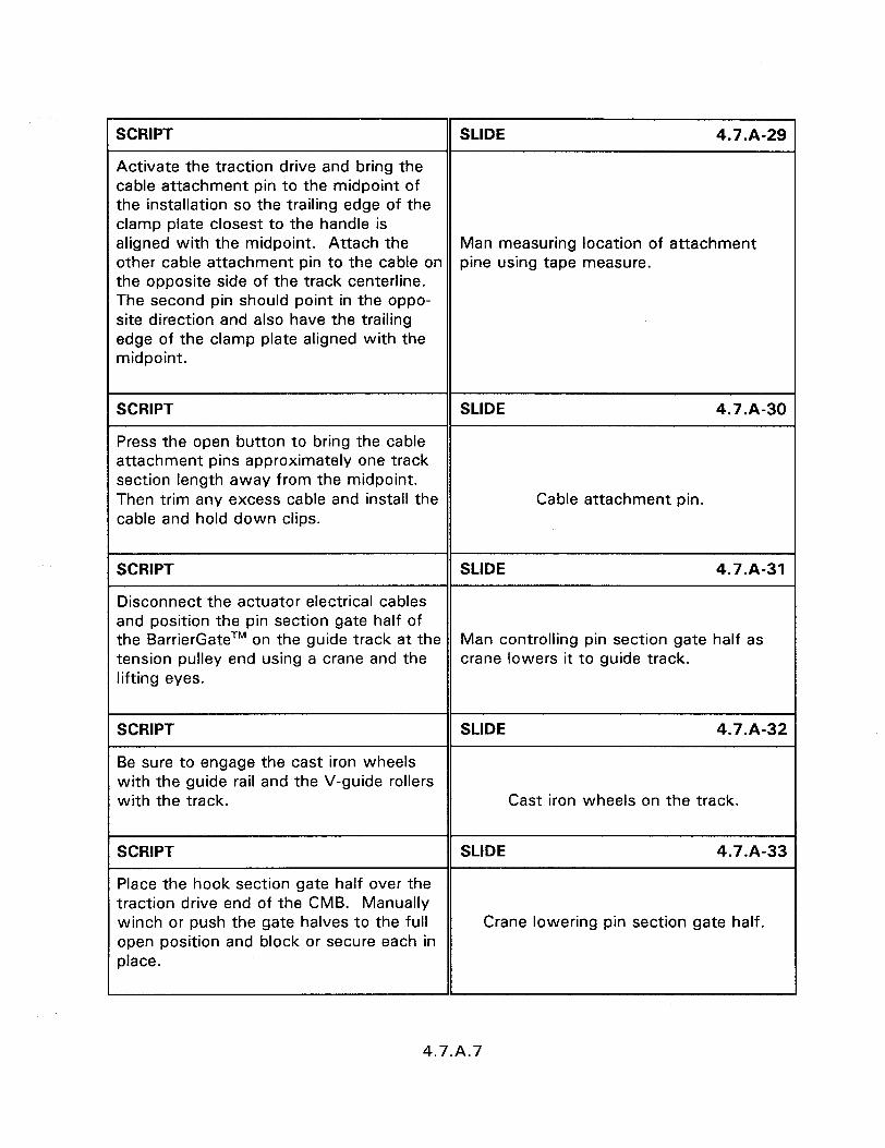
SCRIPT SLIDE 4.7.A-29
Activate the traction drive and bring the cable attachment pin to the midpoint of the installation so the trailing edge of the clamp plate closest to the handle is aligned with the midpoint. Attach the Man measuring location of attachment other cable attachment pin to the cable on pine using tape measure. the opposite side of the track centerline. The second pin should point in the oppo- site direction and also have the trailing edge of the clamp plate aligned with the midpoint.
SCRIPT SLIDE 4.7.A-30
Press the open button to bring the cable attachment pins approximately one track section length away from the midpoint. Then trim any excess cable and install the Cable attachment pin. cable and hold down clips.
SCRIPT SLIDE 4.7.A-31
Disconnect the actuator electrical cables and position the pin section gate half of the BarrierGateTM on the guide track at the Man controlling pin section gate half as tension pulley end using a crane and the crane lowers it to guide track. lifting eyes.
SCRIPT SLIDE 4.7.A-32
Be sure to engage the cast iron wheels with the guide rail and the V-guide rollers with the track. Cast iron wheels on the track.
SCRIPT SLIDE 4.7.A-33
Place the hook section gate half over the traction drive end of the CMB. Manually winch or push the gate halves to the full Crane lowering pin section gate half. open position and block or secure each in place.
4.7.A.7
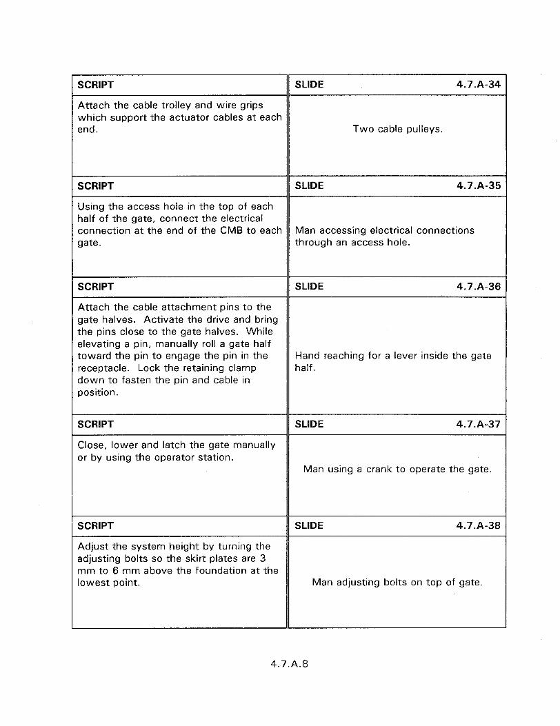
SCRIPT SLIDE 4.7.A-34
Attach the cable trolley and wire grips which support the actuator cables at each end. Two cable pulleys.
SCRIPT SLIDE 4.7-A-35
Using the access hole in the top of each half of the gate, connect the electrical connection at the end of the CMB to each Man accessing electrical connections gate. through an access hole.
SCRIPT SLIDE 4.7.A-36
Attach the cable attachment pins to the gate halves. Activate the drive and bring the pins close to the gate halves. While elevating a pin, manually roll a gate half toward the pin to engage the pin in the Hand reaching for a lever inside the gate receptacle. Lock the retaining clamp half. down to fasten the pin and cable in position.
SCRIPT SLIDE 4.7.A-37
Close, lower and latch the gate manually or by using the operator station.
Man using a crank to operate the gate.
SCRIPT SLIDE 4.7.A-38
Adjust the system height by turning the adjusting bolts so the skirt plates are 3 mm to 6 mm above the foundation at the lowest point. Man adjusting bolts on top of gate.
1
4.7.A.8

. .
SCRIPT SLIDE 4.7.A-39
Insert an appropriate number of shims under the transition top plate to reduce the gap between the transition and guide rail track to less than 3 mm. Operate the Rear end of gate at concrete barrier. gate to verify there are no interference problems.
SCRIPT SLIDE 4.7.A-40
Attach all four anchor plates to the gate halves using two bolts each. These are temporary bolts to hold the anchor plates in place. Man tightening bolts along side of gate
half.
SCRIPT SLIDE 4.7.A-41
Close and lower the gate and temporarily fasten the anchor plates to the CMB with two 16 mm expansion bolts. Remove the bolts holding the anchor plates to the gate A drill bit making hole in concrete barrier halves. Operate the system again to using anchor plate as template. verify there are no interferences and the anchor plates properly engage.
SCRIPT SLIDE 4.7.A-42
Close and lower the gate and permanently attach the anchor plates to the CMB sections. Using the anchor plates as a template, drill a minimum of seven 29 mm diameter by 178 mm deep holes in each. Install the 19 mm MP-3 stud assemblies. Grout being injected into drilled holes. After the grout has cured, remove the 13 mm diameter 3 mm thick shim washers, replace the bolts and flat washers and torque to 163 Nom.
4.7.A.9
SCRIPT
Operate the gate to assure that it is operating properly.
SLIDE 4.7.A-43
Gate with latches exposed.
SCRIPT SLIDE 4.7-A-44
Replace the skirt plates, top and transition covers, and close bulkhead access covers.
Man installing skirt plate.
4.7.A.10
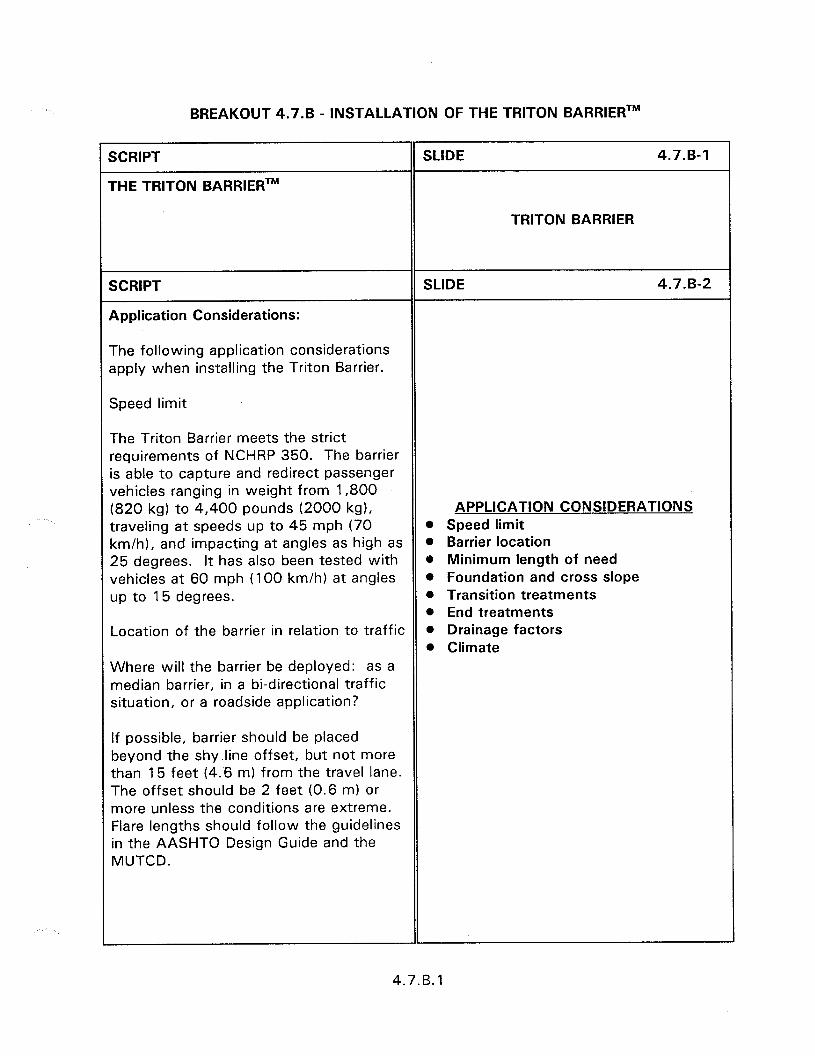
BREAKOUT 4.7.B - INSTALLATION OF THE TRITON BARRIERTM
SCRIPT
THE TRITON BARRIERTM
SLIDE 4.7.B-1
TRITON BARRIER
SCRIPT
Application Considerations:
SLIDE 4.7.B-2
The following application considerations apply when installing the Triton Barrier.
Speed limit
The Triton Barrier meets the strict requirements of NCHRP 350. The barrier is able to capture and redirect passenger vehicles ranging in weight from 1,800 (820 kg) to 4,400 pounds (2000 kg), APPLICATION CONSIDERATIONS traveling at speeds up to 45 mph (70 l Speed limit km/h), and impacting at angles as high as l Barrier location 25 degrees. It has also been tested with e Minimum length of need vehicles at 60 mph (100 km/h) at angles l Foundation and cross slope up to 15 degrees. l Transition treatments
l End treatments Location of the barrier in relation to traffic l Drainage factors
l Climate Where will the barrier be deployed: as a median barrier, in a bi-directional traffic situation, or a roadside application?
If possible, barrier should be placed beyond the shy.line offset, but not more than 15 feet (4.6 m) from the travel lane. The offset should be 2 feet (0.6 m) or more unless the conditions are extreme. Flare lengths should follow the guidelines in the AASHTO Design Guide and the MUTCD.
4.7.B. 1
Length of barrier required
The minimum recommended Triton Barrier length is 100 feet (30 m). The beginning of length of need (BLON) is five sections from the end.
Foundation for barrier and slope
Triton Barrier may be deployed on various surfaces. The existence of curbs or cross slopes greater than 5% may create a vaulting effect on the impacting vehicle.
Transition treatments (when applicable)
If the Triton Barrier is used in conjunction with another barrier of different lateral stiffness, a transition may be required. Contact Energy Absorption Systems, Inc., for approved transition details.
Treatments for the barrier ends
The Triton Barrier end acts as its own non-redirective end treatment. In most cases, a separate end treatment is not necessary. When impacted, the barrier end brings the vehicle to a controlled stop or releases the vehicle behind the barrier end.
Drainage factors
When the time comes to move or dismantle the Triton Barrier, it will normally be drained first. If the water ballast cannot be drained at the site, provisions must be made to either siphon out the water ballast or use a forklift to move full sections to a location where they can be drained.
4.7.B.2
Climate
The performance of the Triton Barrier is ?ot degraded if the water ballast freezes. However, provisions should be made to candle the full weight of the barrier during retrieval if freezing occurs. If desired, an anti-freeze may be added to the water to prevent freezing so the barriers may be siphoned or drained in cold temperatures.
SCRIPT
The Installation Process:
SLIDE 4.7.B-3
Once the site considerations are reviewed, you should determine the number of sections, pins and optional accessories required for the installation.
You should conduct a parts inventory check to make sure all the necessary components are available before proceeding to the site and visually check the barrier sections for damage to ensure that they will hold water.
A complete list of tools required for the barrier installation and complete installation procedures are provided in the Triton Barrier Manual.
Truck load of barriers along shoulder.
A detailed traffic control plan should be prepared and understood by all parties before the Triton Barrier is deployed in a work zone.
Prior to installation, Barrier sections can be manually loaded onto a flatbed or pickup truck, or loaded using the built-in forklift ports. A flatbed truck with a low bed is ideal for transporting the barrier and its accessories.
4.7.B.3

Sections are stackable for easy transport and storage. Do not stack empty sections more than three high. Full sections should not be stacked. Be sure to thoroughly tie down and secure the load. It is best to secure the load thru the forklift ports to prevent damage to the barrier.
SCRIPT SLIDE 4.7.B-4
Begin deployment at the upstream traffic end of the site. Work from the non-traffic side of the installation whenever possible.
Unload the sections and accessories taking care not to damage them.
Unloading proceeds much faster if one person remains on the truck and two people work on the ground.
Workers unloading barriers from back of If site considerations permit, a fourth flat bed truck. person can drive the truck so that sections can be unloaded continuously as the installation is progressing.
Align the sections according to the specified configuration and layout in the traffic control plan.
SCRIPT SLIDE 4.7.B-5
When positioning the Triton Barrier, it is also important to pay careful attention to the location of the Gate Valve Drain. This should be oriented on the side that is preferred for best drainage.
Man reaching for gate valve drain at bottom of barrier.
4.7.B.4
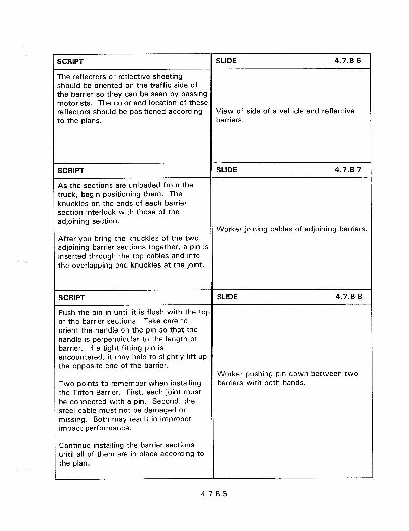
SCRIPT SLIDE 4.7.B-6
The reflectors or reflective sheeting should be oriented on the traffic side of :he barrier so they can be seen by passing notorists. The color and location of these *eflectors should be positioned according View of side of a vehicle and reflective :o the plans. barriers.
SCRIPT
4s the sections are unloaded from the truck, begin positioning them. The muckles on the ends of each barrier section interlock with those of the adjoining section.
SLIDE 4.7.B-7
Worker joining cables of adjoining barriers. After you bring the knuckles of the two adjoining barrier sections together, a pin is inserted through the top cables and into the overlapping end knuckles at the joint.
SCRIPT SLIDE 4.7.B-8
Push the pin in until it is flush with the top of the barrier sections. Take care to orient the handle on the pin so that the handle is perpendicular to the length of barrier. If a tight fitting pin is encountered, it may help to slightly lift up the opposite end of the barrier.
Worker pushing pin down between two Two points to remember when installing barriers with both hands. the Triton Barrier. First, each joint must be connected with a pin. Second, the steel cable must not be damaged or missing. Both may result in improper impact performance.
Continue installing the barrier sections until all of them are in place according to the plan.
4.7.B.5
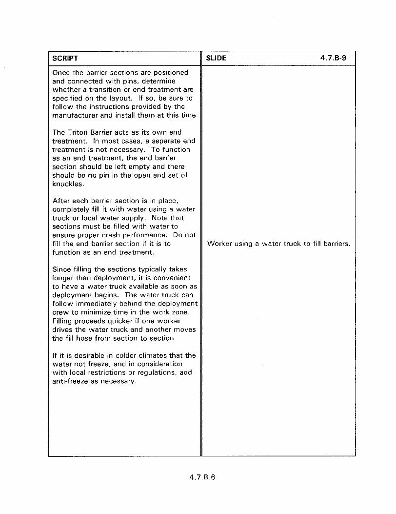
SCRIPT
Once the barrier sections are positioned and connected with pins, determine whether a transition or end treatment are specified on the layout. if so, be sure to follow the instructions provided by the manufacturer and install them at this time.
The Triton Barrier acts as its own end treatment. In most cases, a separate end treatment is not necessary. To function as an end treatment, the end barrier section should be left empty and there should be no pin in the open end set of knuckles.
After each barrier section is in place, completely fill it with water using a water truck or local water supply. Note that sections must be filled with water to ensure proper crash performance. Do not fill the end barrier section if it is to function as an end treatment.
Since filling the sections typically takes longer than deployment, it is convenient to have a water truck available as soon as deployment begins. The water truck can follow immediately behind the deployment crew to minimize time in the work zone. Filling proceeds quicker if one worker drives the water truck and another moves the fill hose from section to section.
If it is desirable in colder climates that the water not freeze, and in consideration with local restrictions or regulations, add anti-freeze as necessary.
SLIDE 4.7.B-9
Worker using a water truck to fill barriers.
4.7.B.6

SCRIPT
Installing Triton Accessories:
SLIDE 4.7.6-10
A number of accessories are available for the Triton Barrier . Most of these accessories fasten to the top of the pins with a twist-lock attachment.
Connect no more than one power source 3er accessory circuit. View of side of a vehicle and reflective
barriers. warning lights and an intrusion detection device can be installed with the Triton Barrier. The remote powered warning lights must be used with the intrusion detection system.
SCRIPT SLIDE 4.7.B-11
Begin by attaching the remote powered (or battery powered) warning lights to the universal support brackets. It is recom- mended that this be done prior to arriving at the work site.
Once at the site and the barrier is installed, attach the universal brackets with the warning lights mounted to them to the top of the pins at the specified Worker attaching battery pack/warning section spacing. light to a cable held receptacle.
Note that when using the intrusion detection system, the maximum spacing for lights is 45.5 feet (13.9 m).
To attach the universal brackets to the pins, insert the tube on the bracket into the receptacle in the pin, twist and lock down so that the tab which holds the light is facing the traffic side of the barrier.
4.7.B.7

SCRIPT SLIDE 4.7.6-l 2
Make sure that the bracket is securely attached to the pin; that the light is bolted tightly so that it will not tilt on the bracket; and that the lens is rotated to the proper position for oncoming traffic.
If remote powered warning lights are used, connect the lights and intrusion detection system together with power cables.
View of 2 lights attached to a barrier.
SCRIPT
The power cables have a male plug on one end and a female on the other to match the panel connectors in the light housing.
SLIDE 4.7.8-l 3
Mate the plugs together and twist the locking ring on to make a secure water- tight connection taking care not to cross Man hooking power plugs to warning thread and damage the locking ring. lights.
Connect the ends of the cables directly together at locations where there are no lights. These connections can be left intact when the cables are retrieved to speed up-the next deployment.
SCRIPT SLIDE 4.7.8-14
Position the power control station on the barrier side away from traffic at a convenient location along the installation.
Note that the control station must be placed near the center of the warning light installation if more than 65 lights are in use.
Power control station.
The maximum capacity of the control station is 135 lights. If more than 135 lights are used, a separate control station and circuit will be necessary. No more
4.7.B.8

than one control station or power source may be used on any circuit.
If the optional support post is available, place it in an unused barrier section beyond the anticipated lateral deflection and attach the control station so that it is upright and away from water, moving equipment, and other hazards.
SCRIPT SLIDE 4.7.B-15
Unplug a connection between two power cables; insert the control station junction box; and connect the cables to the junction box.
Plug the control station power cord into any source providing a minimum of 600 Watts of 115 VAC power.
Man unplugging power cable from junction box.
SCRIPT SLIDE 4.7.B-16
Position the siren station for the intrusion detection system beyond the anticipated lateral deflection and as near to the workers as possible. Place the siren on the ground on the barrier side away from View of Siren Station. traffic, water, moving equipment and other hazards. Be sure to adjust the siren so it faces the workers.
SCRIPT SLIDE 4.7.B-17
Unplug a connection between two power cables; insert the siren station junction box, and connect the cables to the junction box.
Junction box between 2 barriers.
4.7.B.9
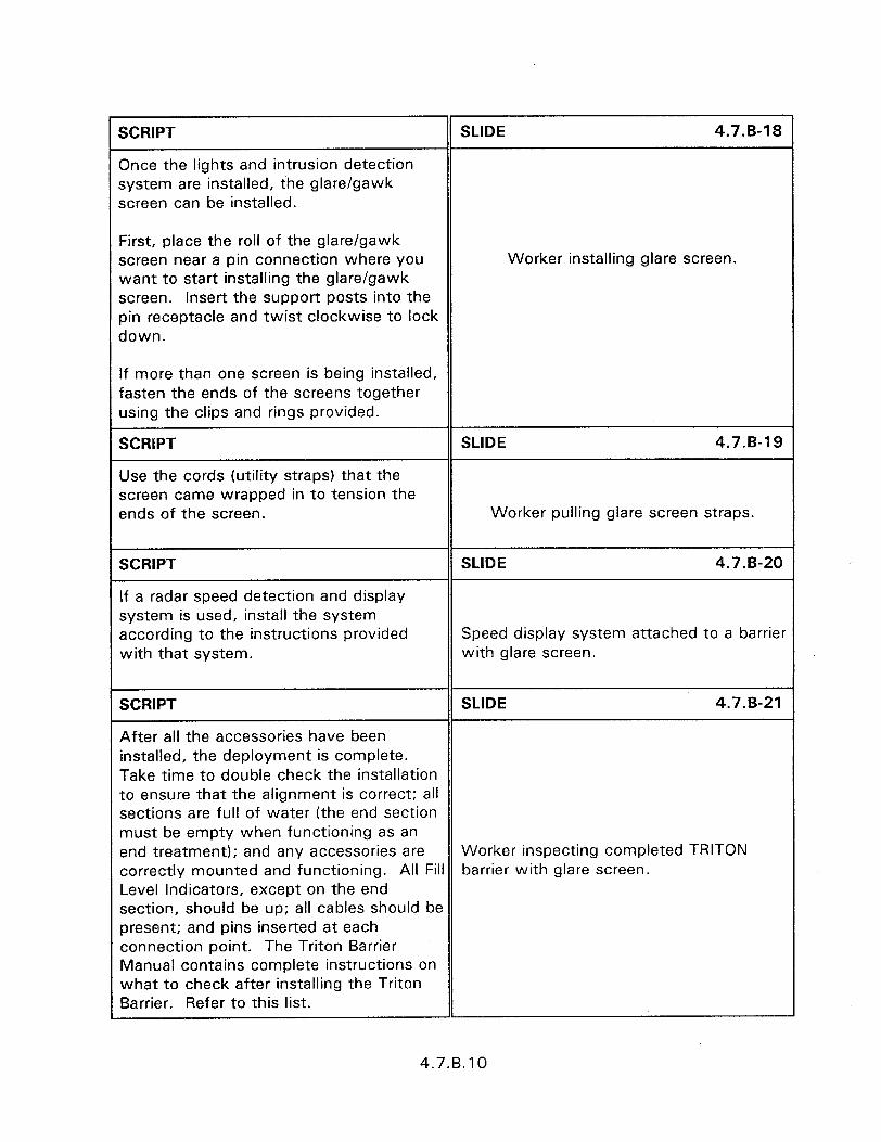
SCRIPT
Once the lights and intrusion detection system are installed, the glare/gawk screen can be installed.
SLIDE 4.7.B-18
First, place the roll of the glare/gawk screen near a pin connection where you want to start installing the glare/gawk screen. Insert the support posts into the pin receptacle and twist clockwise to lock down.
Worker installing glare screen.
If more than one screen is being installed, fasten the ends of the screens together using the clips and rings provided.
SCRIPT
Use the cords (utility straps) that the screen came wrapped in to tension the ends of the screen.
SLIDE 4.7.B-19
Worker pulling glare screen straps.
SCRIPT
If a radar speed detection and display system is used, install the system according to the instructions provided with that system.
SLIDE 4.7.B-20
Speed display system attached to a barrier with glare screen.
SCRIPT SLIDE 4.7.B-21
After all the accessories have been installed, the deployment is complete. Take time to double check the installation to ensure that the alignment is correct; all sections are full of water (the end section must be empty when functioning as an end treatment); and any accessories are Worker inspecting completed TRITON correctly mounted and functioning. All Fill barrier with glare screen. Level Indicators, except on the end section, should be up; all cables should be present; and pins inserted at each connection point. The Triton Barrier Manual contains complete instructions on what to check after installing the Triton Barrier. Refer to this list.
4.7.B.10
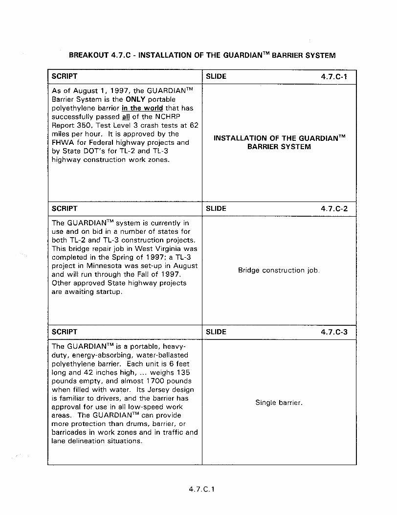
BREAKOUT 4.7.C - INSTALLATION OF THE GUARDIANTM BARRIER SYSTEM
SCRIPT SLIDE 4.7.c-1
As of August 1, 1997, the GUARDIANTM Barrier System is the ONLY portable polyethylene barrier in the world that has successfully passed fl of the NCHRP Report 350, Test Level 3 crash tests at 62 miles per hour. It is approved by the FHWA for Federal highway projects and INSTALLATION OF THE GUARDIANTM
by State DOT’s for TL-2 and TL-3 BARRIER SYSTEM
highway construction work zones.
SCRIPT SLIDE 4.7.C-2
The GUARDIANTM system is currently in use and on bid in a number of states for both TL-2 and TL-3 construction projects. This bridge repair job in West Virginia was completed in the Spring of 1997; a TL-3 project in Minnesota was set-up in August and will run through the Fall of 1997. Bridge construction job.
Other approved State highway projects are awaiting startup.
SCRIPT SLIDE 4.7.c-3
The GUARDIANTM is a portable, heavy- duty, energy-absorbing, water-ballasted polyethylene barrier. Each unit is 6 feet long and 42 inches high, . . . weighs 135 pounds empty, and almost 1700 pounds when filled with water. Its Jersey design is familiar to drivers, and the barrier has approval for use in all low-speed work
Single barrier.
areas. The GUARDIANTM can provide more protection than drums, barrier, or barricades in work zones and in traffic and lane delineation situations.
4.7.c. 1
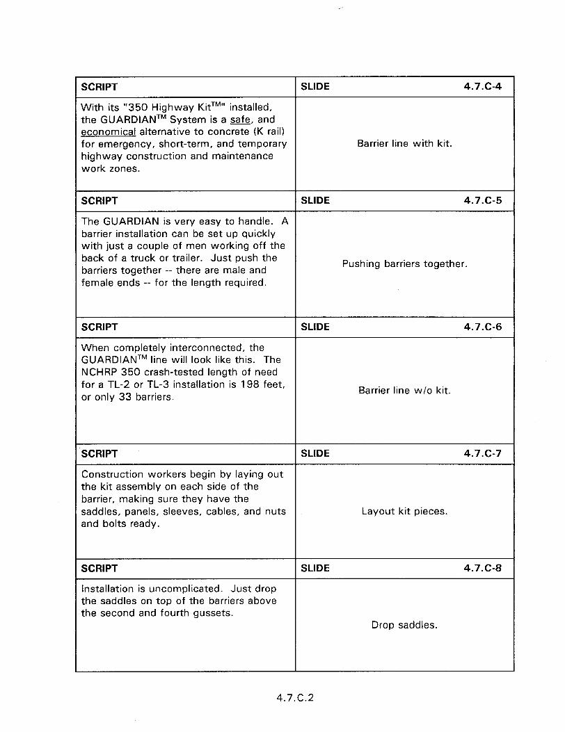
I SCRIPT 1 SLIDE 4.7.c-4 1
With its “350 Highway KitTM” installed, the GUARDIANTM System is a safe, and economical alternative to concrete (K rail) for emergency, short-term, and temporary highway construction and maintenance work zones.
Barrier line with kit.
I SCRIPT I SLIDE 4.7.C5 1
The GUARDIAN is very easy to handle. A barrier installation can be set up quickly with just a couple of men working off the
~ back of a truck or trailer. Just push the barriers together -- there are male and female ends -- for the length required.
Pushing barriers together.
I SCRIPT SLIDE 4.7.C-6 1
When completely interconnected, the GUARDIANTM line will look like this. The NCHRP 350 crash-tested length of need for a TL-2 or TL-3 installation is 198 feet, or only 33 barriers.
Barrier line w/o kit.
SCRIPT I SLIDE 4.7.c-7 1
Construction workers begin by laying out the kit assembly on each side of the barrier, making sure they have the saddles, panels, sleeves, cables, and nuts and bolts ready.
Layout kit pieces.
SCRIPT 1 SLIDE 4.7.C-8 1
Installation is uncomplicated. Just drop the saddles on top of the barriers above the second and fourth gussets.
Drop saddles.
4.7.C.2
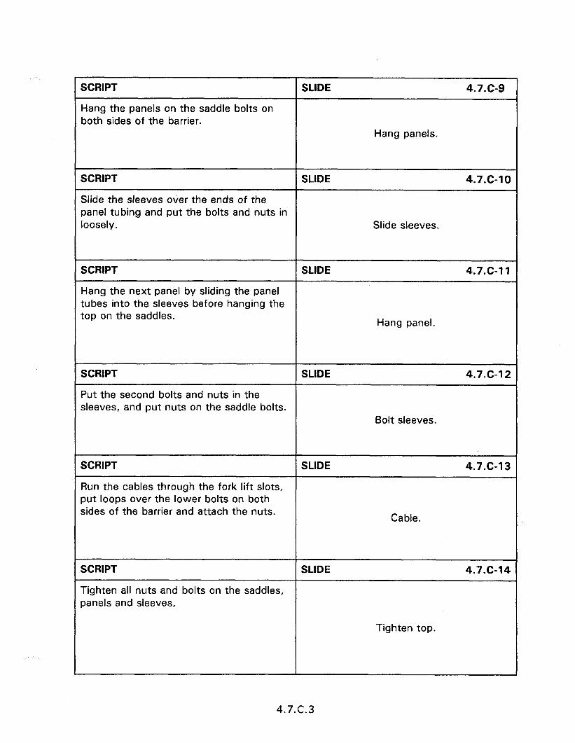
SCRIPT
Hang the panels on the saddle bolts on both sides of the barrier.
SLIDE 4.7.c-9
Hang panels.
SCRIPT SLIDE 4.7.c-10
Slide the sleeves over the ends of the panel tubing and put the bolts and nuts in loosely. Slide sleeves.
SCRIPT SLIDE 4.7.c-11
Hang the next panel by sliding the panel tubes into the sleeves before hanging the top on the saddles. Hang panel.
SCRIPT SLIDE 4.7.c-12
Put the second bolts and nuts in the sleeves, and put nuts on the saddle bolts.
Bolt sleeves.
SCRIPT SLIDE 4.7-G1 3
Run the cables through the fork lift slots, put loops over the lower bolts on both sides of the barrier and attach the nuts. Cable.
SCRIPT SLIDE 4.7.c-14
Tighten all nuts and bolts on the saddles, panels and sleeves,
Tighten top.
4.7.c.3

SCRIPT
and the lower nuts that hold the security cables.
SLIDE 4.7.C15
Tighten cable.
SCRIPT SLIDE 4.7.C-16
When all nuts and bolts are tightened, fill the barriers with water
Fill with water.
SCRIPT SLIDE 4.7.c-17
and you have a strong, safe barrier line that will protect your workers on the job, and help reduce work zone accidents and job site fatalities. In fact, a comparison of NCHRP 350 crash tests shows that a truck hitting the GUARDIANTM line at 62 miles per hour will move the barrier line
Barrier line with kit.
LESS THAN any similar barrier line would move when hit at 45 miles per hour.
SCRIPT SLIDE 4.7.C-18
GUARDIANTM Safety Barrier --- the only portable barrier system in the world that is strong enough to STOP a 62 mile per hour truck.. . . . . and is the only polyethylene barrier approved by the Federal Highway Administration (FHWA) as meeting ALL of the requirements of NCHRP Report 350, Crash photo. Test Level 3 for use on Federally-funded highway projects.
4.7.c.4
5.1 - TERMINALS AND CRASH CUSHIONS
Obiectives:
0 Describe the general uses, characteristics, and impact performance requirements of terminals and crash cushions.
. The design and performance characteristics of terminals and crash cushions are presented in section 2.
. Present construction and maintenance concerns. Identify how drainage features can affect vehicle control and stability.
Heloful Hints:
e This session is a short introduction to an in-depth coverage of terminals and crash cushions. Prior to the presentation of any Session 5 material to host agency should be requested to identify the devices that they desire covered in-depth.
l Some devices can serve as both a terminal and a crash cushion. Have the participants turn to Appendix B to review the categories and applications of terminals and crash cushions.
Visual Aids:
eI 5 - 35 mm slides
Estimated Time
l 5 minutes
Handouts:
0 None


5.1 - TERMINALS AND CRASH CUSHIONS
instructor’s Guide
SCRIPT
INTRODUCTION
SLIDE 5.1-1
Although terminals and crash cushions have different definitions there is not always a distinct difference in the functions that a device can perform. Some devices can perform both as terminals and crash cushions.
5.1 - TERMINALS AND CRASH CUSHIONS
SCRIPT SLIDE 5.1-2
Longitudinal barriers increase safety by redirecting vehicles away from potential hazards. The untreated end of a roadside barrier is particularly hazardous since the barrier rail can spear the impacting vehicle Slide of blunt guardrail end. and penetrate the passenger compartment.
SCRIPT SLIDE 5.1-3
Crashworthy end treatments should not spear, vault, or roll vehicles when struck head-on.
Slide of barrier penetrating vehicle.
SCRIPT
Crash cushions are designed to safely dissipate the energy of an errant vehicle prior to impacting fixed object hazards. This can be accomplished by gradually decelerating a vehicle for head-on impacts.
SLIDE 5.1-4
Slide of sand barrels.
5.1 .l
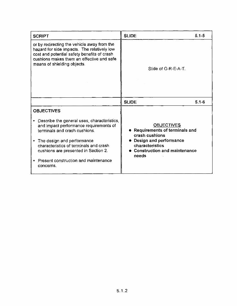
I SCRIPT II SLIDE 5.1-s I
or by redirecting the vehicle away from the hazard for side impacts. The relatively low cost and potential safety benefits of crash cushions makes them an effective and safe means of shielding objects.
Slide of G-R-E-A-T.
I II SLIDE 5.1-6 I
OBJECTIVES /I
l Describe the general uses, characteristics, and impact performance requirements of terminals and crash cushions.
l The design and performance characteristics of terminals and crash cushions are presented in Section 2.
. Present construction and maintenance concerns.
OBJECTIVES o Requirements of terminals and
crash cushions l Design and performance
characteristics o Construction and maintenance
needs
I II 1
5.1.2
SESSION GUIDE
5.2 - CONSTRUCTION AND MAINTENANCE OF TERMINALS
Obiectives:
e To introduce the different types of non-proprietary and proprietary terminals.
. To provide construction and maintenance tips for specific terminal types.
Heloful Hints:
l This session provides a general discussion of all the terminals. It should be noted that the MELT has not passed NCHRP 350 and it is doubtful that FHWA will pursue further testing of the MELT.
l Breakout sections on the construction and maintenance of each device is provide at the end of this session. Time restrictions require that only those devices of interest to the participants be presented. Breakout Session 5.2.A, however, contains installation information that is applicable to the majority of terminals and should be presented prior to the breakout for any specific device.
0 Caution, the participants that detailed installation and maintenance information should be obtained and followed for proprietary devices. This information could be obtained prior to the training course and distributed to the participants.
Visual Aids:
e 44 - 35 mm slides for Session 5.2 e Breakout Sessions
Breakout
5.2.A 5.2.B 5.2.C 5.2.D 5.2.E 5.2.F 5.2.G
Device
General Installation 20 MELT 8 BEST-350TM and SKT-350TM 9 ET-2000 12 SENTRE@ 13 SRT 8 TREND 16
Number of 35 mm slides

SCRIPT SLIDE 5.3-46
The QuadGuardTM CZ is a modular system that can be tailored to different design speeds by increasing the system length from 3 to 9 bays. Each bay consists of an energy absorbing cartridge that crushes upon head on impact. The QUADBEAMTM fender panels redirect vehicles upon side impacts. The QuadGuardTM CZ has passed the NCHRP 350 test criteria as a TL-3 device with the appropriate number of bays. It was also tested at speeds up to 115 km/h.
SCRIPT
HI-DRO’” Cell Cluster System (SClO2)
SLIDE 5.3-47
The HI-DRO’” cell cluster system, manufactured by Energy Absorption Systems, Inc. is specifically designed for areas where space is limited and traffic speeds do not exceed 72 km/h. The variety of cluster configurations is virtually limitless so the unit can be easily adapted to fit a wide range of hazards: toll booths, utility poles, railroad crossing signals, light bases, etc. A similar device tested to NCHRP 350 is planned.
HI-DROTM CELL CLUSTER SYSTEM
l Limited space l Low speed l Wide range of hazards
SCRIPT SLIDE 5.3-48
The HI-DROTM cell is a cylinder 150 mm in diameter by 990 mm long. A vinyl orifice insert with an integral flip-up cap is permanently bonded into the open end at the top. The bottom of the cell is closed. When installed, the cells are filled with water to which a brine solution or Slide of HI-DRO System at a x-ing antifreeze is added in clod climates. signal. The water filled polyvinyl tubes are bolted together in a cluster, then wrapped with a flexible “safety belt”. The dimensions and characteristics of a given site, plus the design specifications required, determine the number of cells required in a unit.
5.3.16

5.2 - CONSTRUCTION AND MAINTENANCE OF TERMINALS
Instructor’s Guide
SCRIPT SLIDE 5.2-l
Terminals must develop the full strength of the barrier and must be able to protect vehicle occupants for both end-on and angle impacts. In addition the terminal must not spear, vault, or roll the vehicle.
CONSTRUCTION AND MAINTENANCE The usual way to terminate a thrie-beam OF TERMINALS barrier is to first transition to W-beam, and then install a standard W-beam terminal. Some terminals can be attached directly to thrie-beam and are noted below.
SCRIPT
On the market are Non-Proprietary Terminals and Proprietary Terminals.
SLIDE 5.2-2
Non-Promietary Terminals l Not Patented
Non-Proprietary Terminals are not patented and can be utilized without payment of a royalty or licensing fee.
Proprietary Terminals are patented and to utilize them requires the payment of a royalty or licensing fee.
l No Royalty or Licensing Fee
Prowietarv Terminals l Patented l Requires a Royalty or
Licensing Fee
SCRIPT SLIDE 5.2-3
Prior to discussing individual terminals let’s discuss location and grading requirements. While the location is specified on the plans, it is important to check actual field conditions. Fixed objects should not be in the terminal area.
Slide of fixed object near terminal.
5.2.1
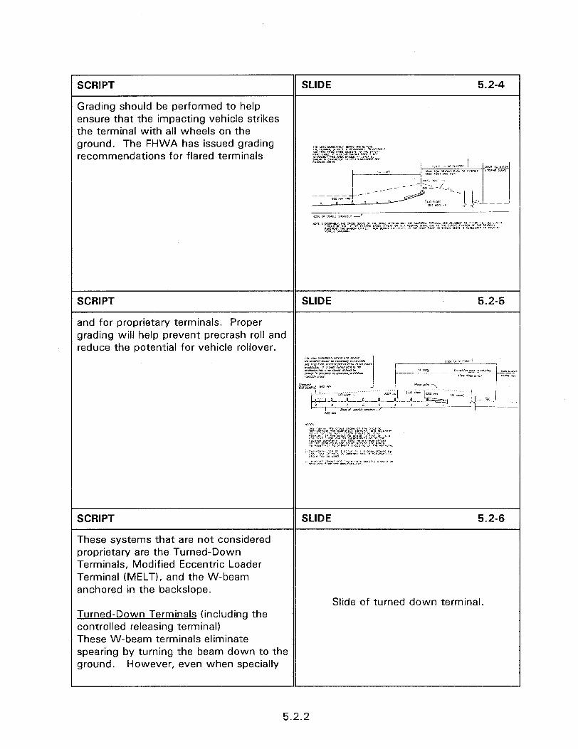
SCRIPT
Grading should be performed to help ensure that the impacting vehicle strikes the terminal with all wheels on the ground. The FHWA has issued grading recommendations for flared terminals
SCRIPT SLIDE 5.2-5
and for proprietary terminals. Proper grading will help prevent precrash roll and reduce the potential for vehicle rollover.
iir CYs i-.wd!O!<(* Mnr om a*rm
SCRIPT
These systems that are not considered proprietary are the Turned-Down Terminals, Modified Eccentric Loader Terminal (MELT), and the W-beam anchored in the backslope.
SLIDE 5.2-S
Turned-Down Terminals (including the controlled releasing terminal) These W-beam terminals eliminate spearing by turning the beam down to the ground. However, even when specially
Slide of turned down terminal.
5.2.2

modified, they can result in violent vaulting/snagging and rollover for high speed impacts. Use should be limited to low volume roadways with operating speeds of 80 km/h or less, or locations where the terminals can be flared outside the clear zone.
SCRIPT
Modified Eccentric Loader Terminal /MELT)
SLIDE 5.2-7
The MELT is an improved version of the widely used breakaway cable terminal (BCT). The basic BCT has been unable to provide consistently acceptable performance for end-on impacts by 820 kg cars, and is very sensitive to minor installation variations. The BCT is no longer approved for use and should be replaced with an approved end treatment; one of which is the MELT. MELT has not passed NCHRP 350.
MELT SYSTEM l Uni-directional l Connects to semi-rigid or
rigid barriers l Install on shoulders or medians
SCRIPT
The MELT looks similar to the BCT but there are some visible differences between the two. The BCT has 2 breakaway posts, no channel strut, no reduced post spacing and frequently no diaphragms inside the end assembly.
SLIDE 5.2-8
Slide of BCT terminal.
SCRIPT SLIDE 5.2-9
The MELT has 8 wooden posts, of which 8 are breakaway, reduced post spacing, a shelf angle to support the rail, a channel Slide of MELT. strut between posts 1 and 2, and a diaphragm inside the end section.
SLIDE 5.2-10
Slide of MELT Layout.
5.2.3

SCRIPT SLIDE 5.2-l 1
A strut is placed between posts 1 and 2 to develop the anchorage for a downstream hit. Slide of strut.
SCRIPT SLIDE 5.2-l 2
Since the rail is not bolted to the post from posts 2 through 6, a shelf clip is installed at post no. 2 to help support the Slide of the shelf clip. rail.
SCRIPT SLIDE 5.2-l 3
A diaphragm is added to the end section.
Slide of the diaphragm.
SCRIPT
W-Beam Anchored In Backsloee
SLIDE 5.2-14
In a cut section where adequate roadside area is available, a satisfactory terminal can be achieved by transitioning to VW beam and anchoring to a concrete anchor buried flush with the ground surface in the backfill.
Slide of backslope terminal.
Proper flare rates and full barrier height as it crosses the ditch line must be provided.
SCRIPT
Trailing End
SLIDE 5.2-l 5
In some cases, downstream ends of roadside barriers may not be subject to head-on impacts, such as when installed on one way roadways. For such cases, the simplest and lowest cost solution may be the installation of a turned down end attached to a concrete anchor
Slide of turned down end.
5.2.4

SCRIPT SLIDE 5.2-l 6
or a standing end with 1) foundation tube option.
BREAKAWAY TIMBER GUARDRAIL BOLT RECTANGULAR WA UNDER HEAD & ROUND WASHER UNDER NUT
SEE DETAIL 8
FOUNDATION TUBE
SCRIPT SLIDE 5.2-17
2) concrete footing option.
RECTANGULAR WASH UNDER HEAD &
SEE DETAIL A
I 1 LJ
FOUNDATION
SCRIPT SLIDE 5.2-l 8
3) anchor block option.
5.2.5
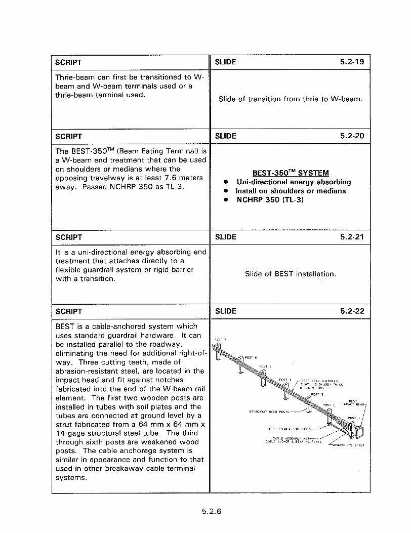
1 SCRIPT SLIDE 5.2-19
Thrie-beam can first be transitioned to W- beam and W-beam terminals used or a thrie-beam terminal used. Slide of transition from thrie to W-beam.
SCRIPT SLIDE 5.2-20
The BEST-350TM (Beam Eating Terminal) is a W-beam end treatment that can be used on shoulders or medians where the opposing travelway is at least 7.6 meters
BEST-350TM SYSTEM
away. Passed NCHRP 350 as TL-3. @ Uni-directional energy absorbing l Install on shoulders or medians a NCHRP 350 (TL-3)
SCRIPT SLIDE 5.2-21
It is a uni-directional energy absorbing end treatment that attaches directly to a flexible guardrail system or rigid barrier with a transition.
Slide of BEST installation.
SCRIPT SLIDE 5.2-22
BEST is a cable-anchored system which uses standard guardrail hardware. It can POST 7 be installed parallel to the roadway, eliminating the need for additional right-of- way. Three cutting teeth, made of abrasion-resistant steel, are located in the impact head and fit against notches DEEP BEAM G”IRDRb,L ‘.61 IHICK fabricated into the end of the W-beam rail element. The first two wooden posts are BEST installed in tubes with soil plates and the 2 ,MPlCT HEA
tubes are connected at ground level by a strut fabricated from a 64 mm x 64 mm x 14 gage structural steel tube. The third
STEEL FDWOATION TUBE
through sixth posts are weakened wood CABLE ASSEMBLY WIT CABLE biNCHLjR d BEm.,N
posts. The cable anchorage system is similar in appearance and function to that used in other breakaway cable terminal systems.
5.2.6
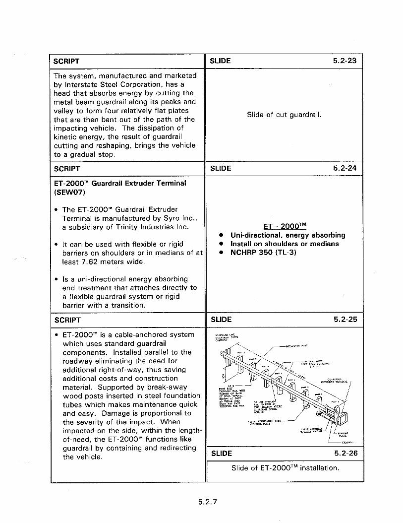
SCRIPT
The system, manufactured and marketed by interstate Steel Corporation, has a head that absorbs energy by cutting the metal beam guardrail along its peaks and valley to form four relatively flat plates that are then bent out of the path of the impacting vehicle. The dissipation of kinetic energy, the result of guardrail cutting and reshaping, brings the vehicle to a gradual stop.
Slide of cut guardrail.
SCRIPT
ET-2000’” Guardrail Extruder Terminal (SEW071
l The ET-2000’” Guardrail Extruder Terminal is manufactured by Syro Inc., a subsidiary of Trinity Industries Inc.
l It can be used with flexible or rigid barriers on shoulders or in medians of at least 7.62 meters wide.
ET - 2000TM 0 Uni-directional, energy absorbing 0 Install on shoulders or medians . NCHRP 350 (TL-3)
l Is a uni-directional energy absorbing end treatment that attaches directly to a flexible guardrail system or rigid barrier with a transition.
SCRIPT
l ET-2000’” is a cable-anchored system which uses standard guardrail components. Installed parallel to the roadway eliminating the need for additional right-of-way, thus saving additional costs and construction material. Supported by break-away wood posts inserted in steel foundation tubes which makes maintenance quick and easy. Damage is proportional to the severity of the impact. When impacted on the side, within the length- of-need, the ET-2000” functions like guardrail by containing and redirecting the vehicle.
5.2.7
SCRIPT SLIDE 5.2-27
l Upon impact the ET-2000’” is designed to travel down the guardrail path. The head contains a feeder chute designed to flatten the W-shaped guardrail. The energy of the impact is used to force the W-shaped guardrail through the feeder chute. The W-shaped guardrail is flattened, curled and extruded out an Slide of impacted ET 2000TM. exit slot on the backside of the terminal away from traffic and the impacting vehicle. The dissipation of kinetic energy due to guardrail reshaping brings the impacting vehicle to a safe gradual stop.
SCRIPT
SENTRE’” System (SEW051
SLIDE 5.2-28
l The SENTRE’” System is a guardrail end treatment manufactured by Energy Absorption Systems, Inc.
l The system provides a protective barrier between motorists and the beginning of the standard guardrail or concrete barrier systems.
SENTRETM l Uni-directional, energy absorbing l Connects to flexible or rigid
barriers l Install on shoulders or medians
l NCHRP 230.
SCRIPT SLIDE 5.2-29
l Consists of telescoping panels plus a redirecting cable which guides
,I _
impacting vehicles away from the rigid 1311 L BLOCYD”i ll000 ox STCCL) end of the downstream guardrail.
ImUIs114N PANEL RtmECiNNt cbac OR EXlENSlON PIWEL
WWNSTREUl clam TtNSnNlNC C*BLL
5.2.8
SCRIPT SLIDE 5.2-30
m The SENTRE” System is made up of the fender panels, support posts with slip bases, and sand-filled containers that help dissipate collision energy. Slide of installation.
SCRIPT
l When impacted head-on, the fender panels telescope to redirect and decelerate the vehicle.
SLIDE 5.2-31
l For angle impacts on the side of the system the vehicle is redirected back onto the roadway and away from the hazard.
Slide of impacted SENTRETM.
l Most major components are reusable after a typical impact.
SCRIPT
Slotted Rail Guardrail terminal (SRT-350) (SEW1 1, SEW1 2)
SLIDE 5.2-32
l The Slotted Rail Terminal (SRT) manufactured by SYRO, Inc., a subsidiary of Trinity Industries Inc., can be used to protect flexible barriers on shoulders or in medians. SRT-350
l Uni-directional l This system is a uni-directional end
treatment that attaches directly on to a flexible guardrail system or a concrete barrier with the appropriate transition.
l Connects to flexible or rigid barriers
l Install on shoulders or medians 0 Requires a flare or offset . NCHRP 350 (TL-3)
l There are two versions of the system. One is the SRT-75, tested at 75 km/h and the other is the SRT-100, tested at 100 km/h.
l Both of these systems require a flare or offset. The SRT-75 requires a offset of 460 mm, the SRT-100 requires a offset of 1220 mm.
5.2.9

SCRIPT
* Upon end-on impact, the system will buckle at the longitudinal slots cut in the guardrail elements.
SLIDE 5.2-33
Slide of SRT field installation.
l The vehicle will pass in behind the system as with other gating systems.
SCRIPT SLIDE 5.2-34
0 The SRT is a cable-anchored system similar to that used in the standard BCT end treatment. Longitudinal slots are cut in the W-beam guardrail to reduce its dynamic buckling strength to an acceptable level for end-on impacts, while maintaining adequate tensile strength for redirectional impacts. Rail buckling in the SRT is controlled by the number, length, and location of the slots.
0 For end-on impacts, the reduced buckling load results in less vehicular yaw, which in turn, minimizes the potential for secondary impacts with bent or kinked rail elements, which could penetrate into the passenger compartment of the vehicle.
* A slot guard is bolted onto the back of the W-beam rail at the downstream end
Slide of slot guard.
of each set of slots to prevent the slots from being extended during side impacts. The slot guard reinforces the W-beam rail element and provides a SLIDE 5.2-36 deflector plate to push the rail element away from any vehicle component that may intrude into the slots.
Slide of backup plate.
l The backup plate is used-to hold the rail element in place.
SCRIPT SLIDE 5.2-37
l When impacted on the side, within the length-of-need, the SRT functions like guardrail by containing and redirecting
Slide of SRT.
the vehicle.
5.2.10
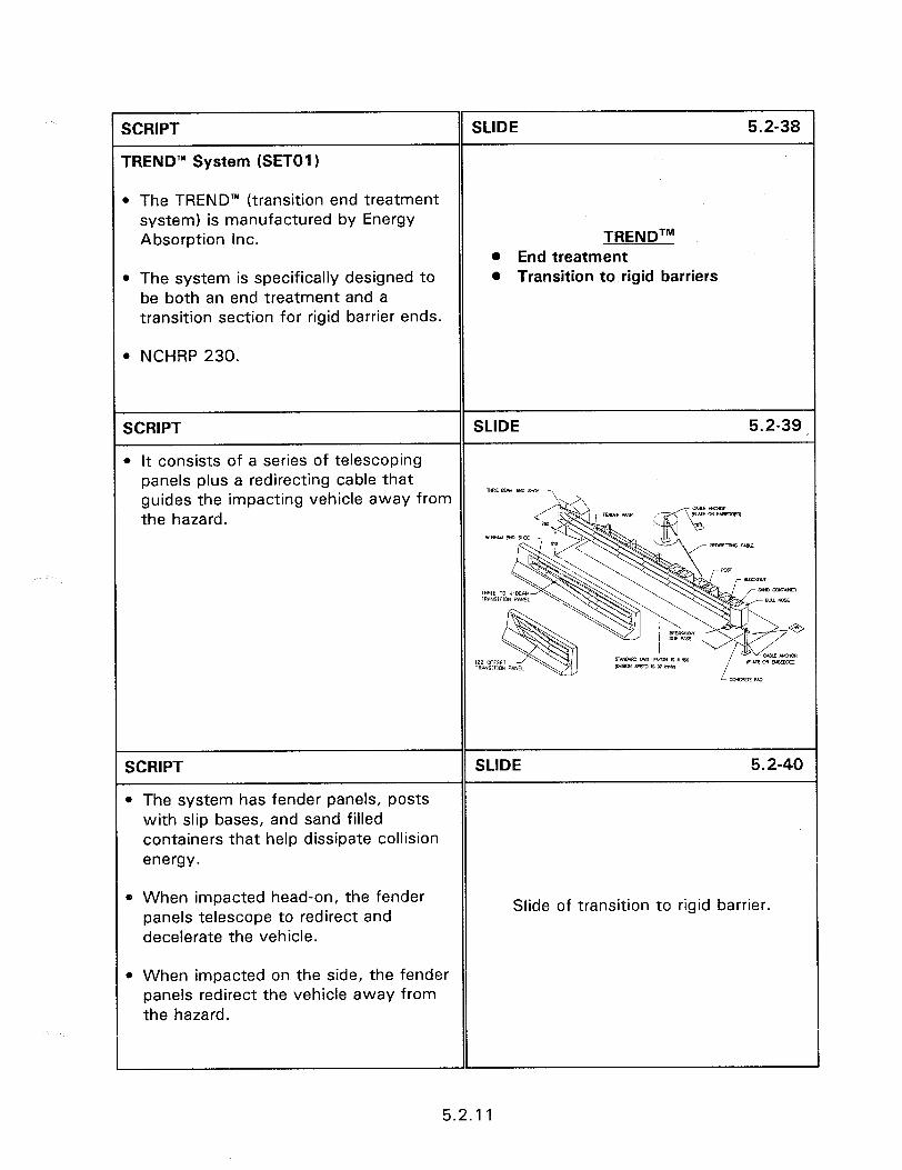
2CRIPT
TREND’” System (SET01 1
SLIDE 5.2-38
m The TREND’” (transition end treatment system) is manufactured by Energy Absorption Inc. TRENDTM
l End treatment m The system is specifically designed to
be both an end treatment and a transition section for rigid barrier ends.
’ NCHRP 230.
@ Transition to rigid barriers
SCRIPT SLIDE 5.2-39
l It consists of a series of telescoping panels plus a redirecting cable that guides the impacting vehicle away from - the hazard.
SCRIPT
l The system has fender panels, posts with slip bases, and sand filled containers that help dissipate collision energy.
SLIDE 5.2-40
0 When impacted head-on, the fender panels telescope to redirect and decelerate the vehicle.
Slide of transition to rigid barrier.
l When impacted on the side, the fender panels redirect the vehicle away from the hazard.
5.2.1 1
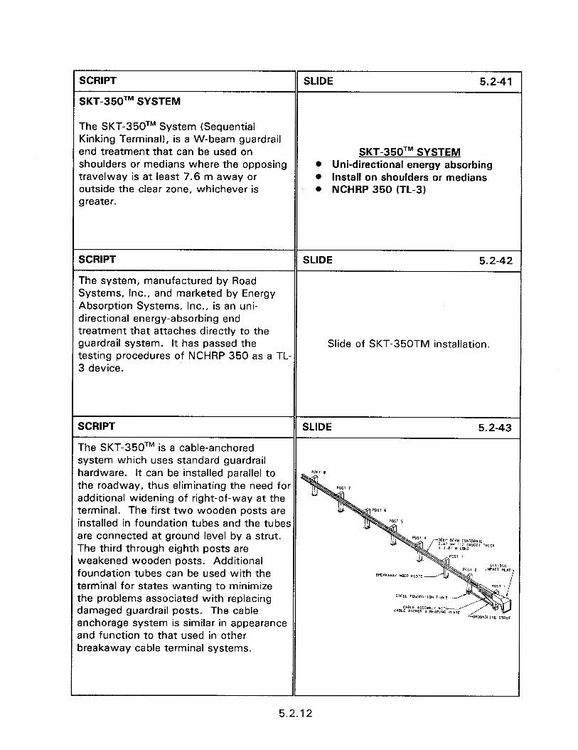
SCRIPT SLIDE 5.2-41
SKT-350TM SYSTEM
The SKT-350TM System (Sequential Kinking Terminal), is a W-beam guardrail end treatment that can be used on SKT-350TM SYSTEM shoulders or medians where the opposing l Uni-directional energy absorbing travelway is at least 7.6 m away or @ Install on shoulders or medians outside the clear zone, whichever is . NCHRP 350 (TL-3) greater.
SCRIPT SLIDE 5.2-42
The system, manufactured by Road Systems, Inc., and marketed by Energy Absorption Systems, Inc., is an uni- directional energy-absorbing end treatment that attaches directly to the guardrail system. It has passed the Slide of SKT-350TM installation. testing procedures of NCHRP 350 as a TL- 3 device.
SCRIPT SLIDE 5.2-43
The SKT-350TM is a cable-anchored system which uses standard guardrail hardware. It can be installed parallel to the roadway, thus eliminating the need for additional widening of right-of-way at the terminal. The first two wooden posts are installed in foundation tubes and the tubes are connected at ground level by a strut. The third through eighth posts are weakened wooden posts. Additional foundation tubes can be used with the terminal for states wanting to minimize the problems associated with replacing damaged guardrail posts. The cable CMLE ASIEWL” *IT CmLE ANWOR d REIR,“[: anchorage system is similar in appearance and function to that used in other breakaway cable terminal systems.
5.2.12
SCRIPT
When struck, the impact head of the SKT- 350TM is designed to be pushed forward by the vehicle and travel down the guardrail path. The impact head contains a deflector plate with angled segments and a kinker beam to sequentially kink the W-beam rail element. The kinked rail then exits on the backside of the terminal away from traffic and the impacting vehicle. Impacting vehicles are brought to a controlled stop through the energy dissipation of the sequential kinking of the W-beam rail. When impacted on the side, within the length-of-need, the SKT-350TM functions like a guardrail by containing and redirecting the impacting vehicle.
SLIDE 5.2-44
Slide of impacted SKT-350TM.
5.2.13

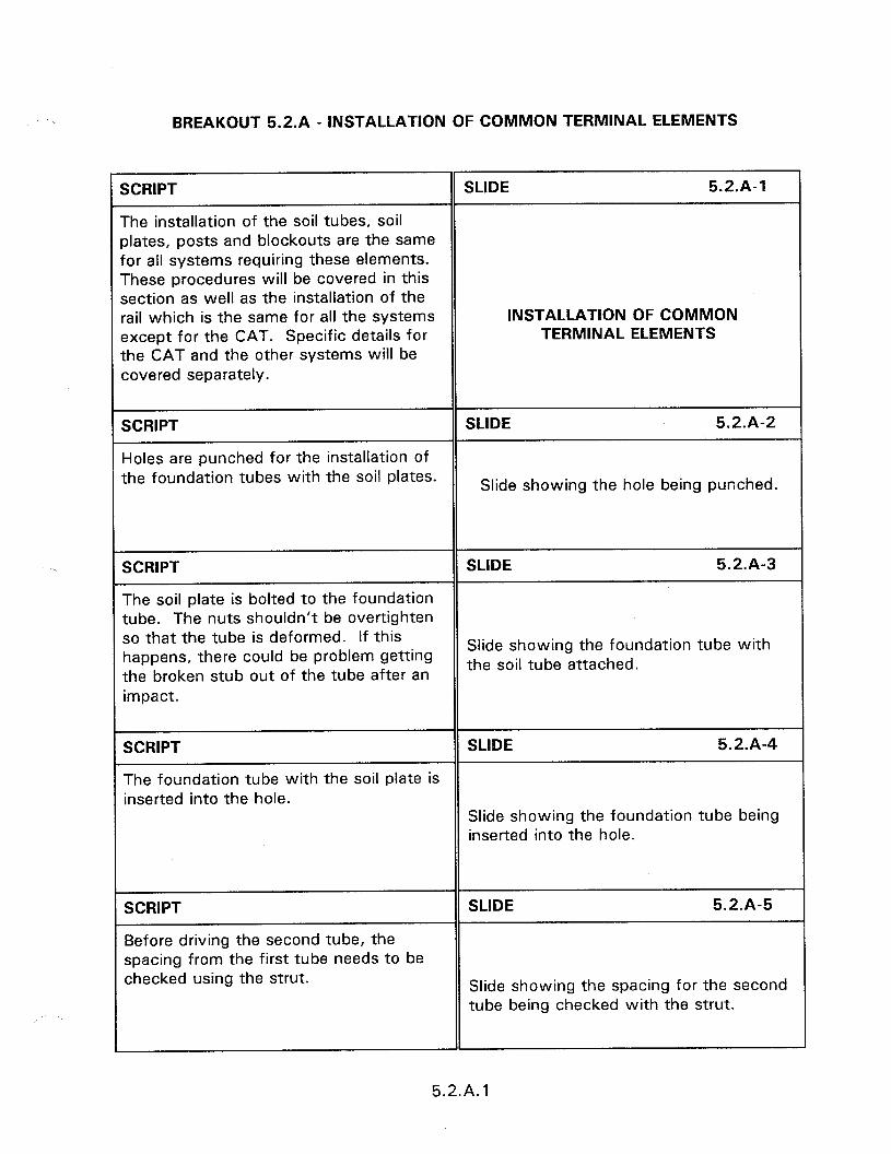
BREAKOUT 5.2.A - INSTALLATION OF COMMON TERMINAL ELEMENTS
SCRIPT SLIDE 5.2.A-1
The installation of the soil tubes, soil elates, posts and blockouts are the same for all systems requiring these elements. These procedures will be covered in this section as well as the installation of the rail which is the same for all the systems INSTALLATION OF COMMON sxcept for the CAT. Specific details for TERMINAL ELEMENTS the CAT and the other systems will be covered separately.
SCRIPT SLIDE 5.2.A-2
Holes are punched for the installation of the foundation tubes with the soil plates. Slide showing the hole being punched.
SCRIPT
The soil plate is bolted to the foundation tube. The nuts shouldn’t be overtighten so that the tube is deformed. If this happens, there could be problem getting the broken stub out of the tube after an impact.
SLIDE 5.2.A-3
Slide showing the foundation tube with the soil tube attached.
SCRIPT SLIDE 5.2.A-4
The foundation tube with the soil plate is inserted into the hole.
Slide showing the foundation tube being inserted into the hole.
SCRIPT
Before driving the second tube, the
SLIDE 5.2.A-5
spacing from the first tube needs to be checked using the strut. Slide showing the spacing for the second
tube being checked with the strut.
5.2.A. 1
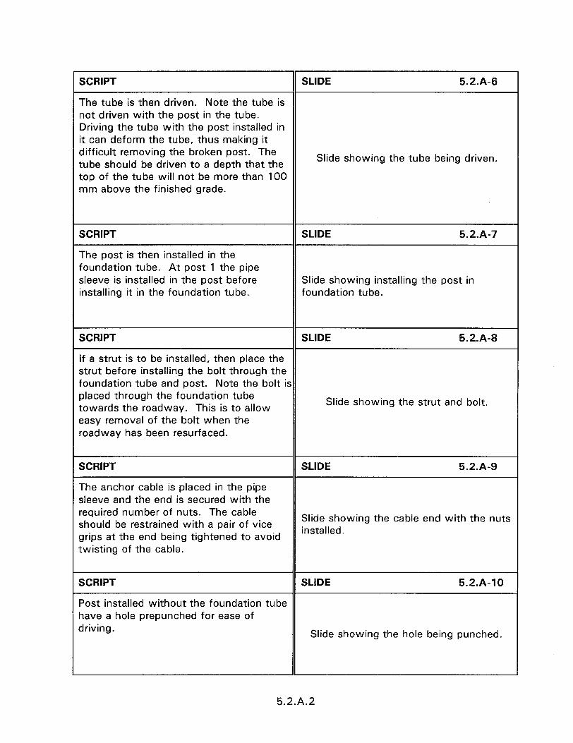
SCRIPT SLIDE 5.2.A-6
The tube is then driven. Note the tube is not driven with the post in the tube. Driving the tube with the post installed in it can deform the tube, thus making it difficult removing the broken post. The tube should be driven to a depth that the
Slide showing the tube being driven.
top of the tube will not be more than 100 mm above the finished grade.
SCRIPT
The post is then installed in the foundation tube. At post 1 the pipe sleeve is installed in the post before installing it in the foundation tube.
SLIDE 5.2.A-7
Slide showing installing the post in foundation tube.
SCRIPT SLIDE 5.2.A-8
If a strut is to be installed, then place the strut before installing the bolt through the foundation tube and post. Note the bolt is placed through the foundation tube towards the roadway. This is to allow Slide showing the strut and bolt.
easy removal of the bolt when the roadway has been resurfaced.
SCRIPT SLIDE 5.2.A-9
The anchor cable is placed in the pipe sleeve and the end is secured with the required number of nuts. The cable should be restrained with a pair of vice
Slide showing the cable end with the nuts
grips at the end being tightened to avoid installed.
twisting of the cable.
SCRIPT SLIDE 5.2.A-10
Post installed without the foundation tube have a hole prepunched for ease of driving.
Slide showing the hole being punched.
5.2.A.2
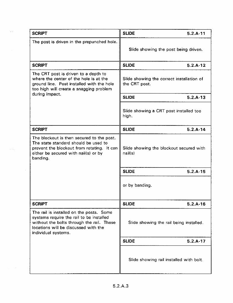
SCRIPT SLIDE 5.2.A-11
The post is driven in the prepunched hole.
Slide showing the post being driven.
SCRIPT
The CRT post is driven to a depth to where the center of the hole is at the ground line. Post installed with the hole too high will create a snagging problem during impact.
SLIDE 5.2.A-12
Slide showing the correct installation of the CRT post.
SLIDE 5.2.A-13
Slide showing a CRT post installed too high.
SCRIPT SLIDE 5.2.A-14
The blockout is then secured to the post. The state standard should be used to prevent the blockout from rotating. It can Slide showing the blockout secured with either be secured with nail(s) or by nail(s) banding.
SLIDE
or by banding.
5.2.A-15
SCRIPT SLIDE 5.2.A-16
The rail is installed on the posts. Some systems require the rail to be installed without the bolts through the rail. These Slide showing the rail being installed. locations will be discussed with the individual systems.
SLIDE 5.2.A-17
Slide showing rail installed with bolt.
5.2.A.3

SCRIPT
The splice bolt holes are aligned.
SLIDE 5.2.A-18
Slide showing the splice bolt holes being aligned.
SCRIPT
The splice bolts are installed.
SLIDE 5.2.A-19
Slide showing the splice bolts installed.
SCRIPT
The finished installation.
SLIDE 5.2.A-20
Slide showing the finished installation.
5.2.A.4
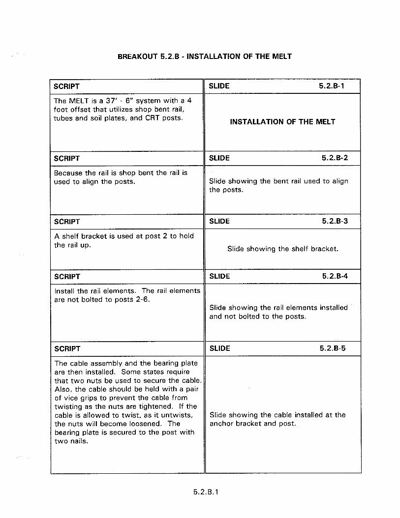
BREAKOUT 5.2.6 - INSTALLATION OF THE MELT
SCRIPT
The MELT is a 37’ - 6” system with a 4 foot offset that utilizes shop bent rail, tubes and soil plates, and CRT posts.
SLIDE 5.2.B-1
INSTALLATION OF THE MELT
SCRIPT
Because the rail is shop bent the rail is used to align the posts.
SLIDE 5.2.B-2
Slide showing the bent rail used to align the posts.
SCRIPT
A shelf bracket is used at post 2 to hold the rail up.
SLIDE 5.2.B-3
Slide showing the shelf bracket.
SCRIPT SLIDE 5.2.B-4
Install the rail elements. The rail elements are not bolted to posts 2-6.
Slide showing the rail elements installed and not bolted to the posts.
SCRIPT SLIDE 5.2.B-5
The cable assembly and the bearing plate are then installed. Some states require that two nuts be used to secure the cable. Also, the cable should be held with a pair of vice grips to prevent the cable from twisting as the nuts are tightened. If the cable is allowed to twist, as it untwists, Slide showing the cable installed at the the nuts will become loosened. The anchor bracket and post. bearing plate is secured to the post with two nails.
5.2.B. 1
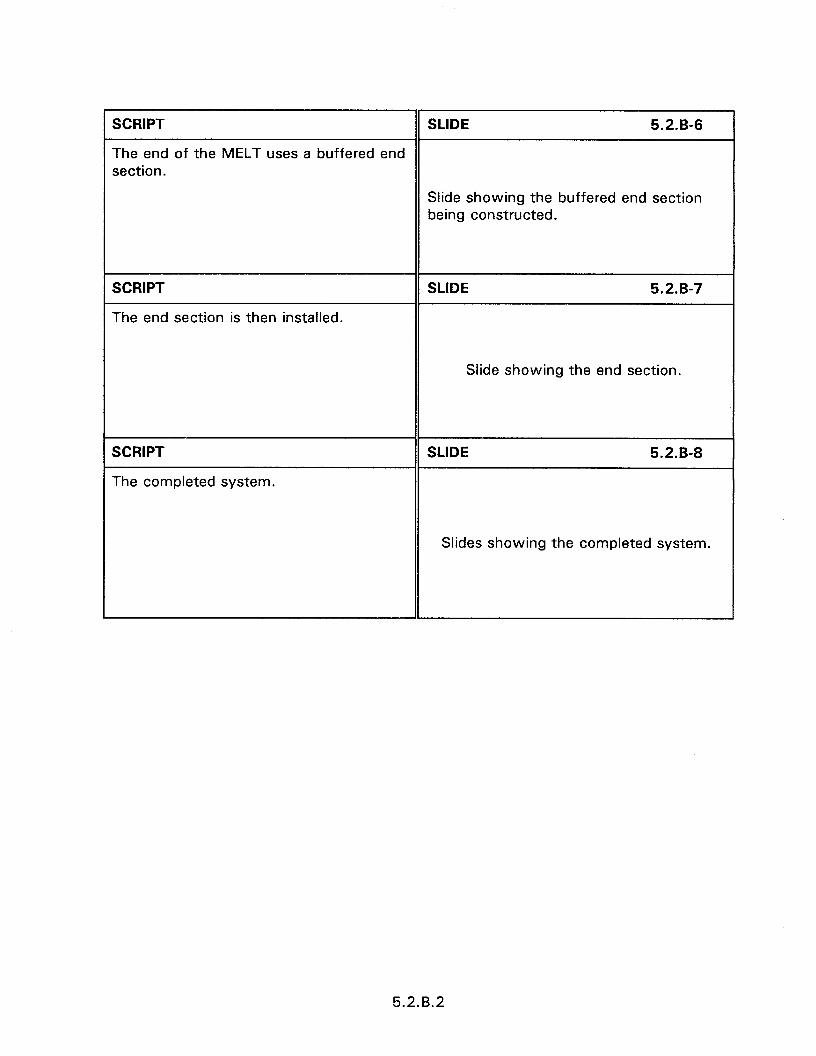
SCRIPT SLIDE 5.2.B-6
The end of the MELT uses a buffered end section.
Slide showing the buffered end section being constructed.
SCRIPT
The end section is then installed.
SLIDE 5.2.B-7
Slide showing the end section.
SCRIPT
The completed system.
SLIDE 5.2.B-8
Slides showing the completed system.
5.2.B.2
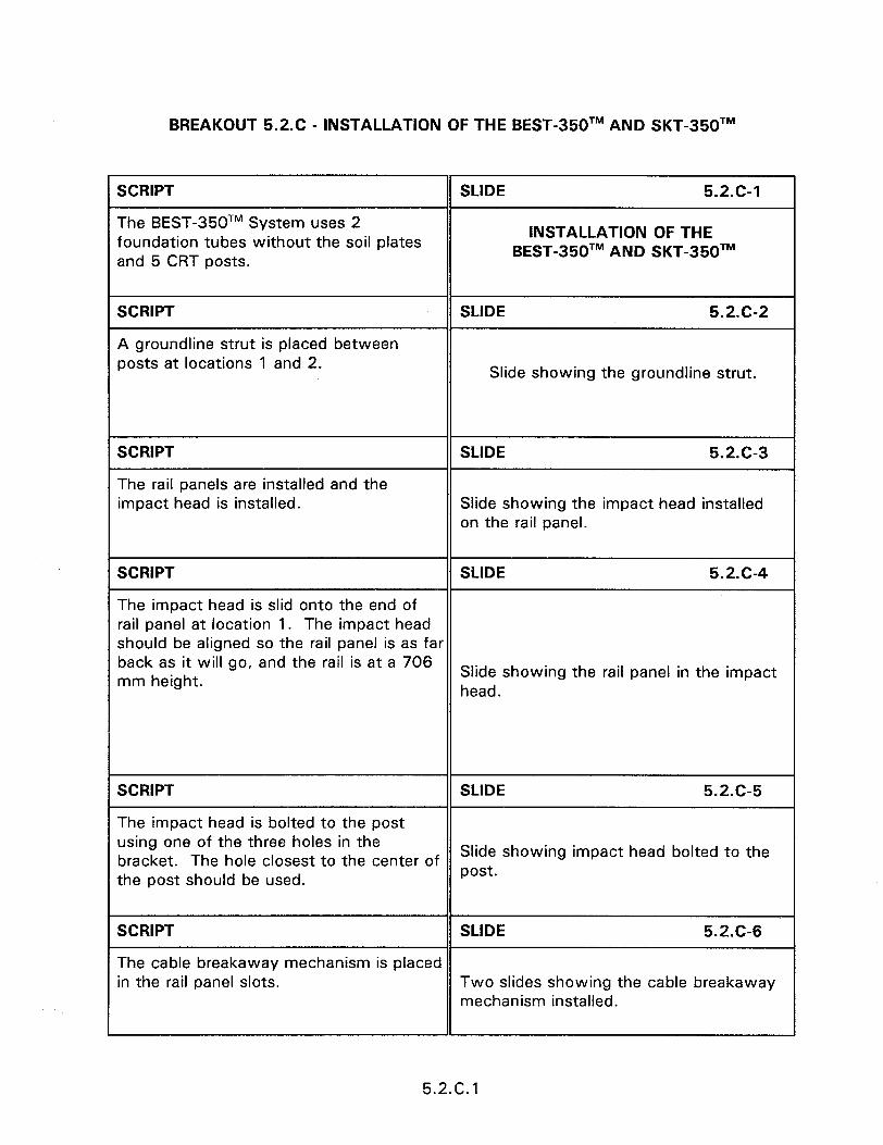
BREAKOUT 5.2.C - INSTALLATION OF THE BEST-350TM AND SKT-350TM
SCRIPT
The BEST-350TM System uses 2 foundation tubes without the soil plates and 5 CRT posts.
SCRIPT
A groundline strut is placed between posts at locations 1 and 2.
SLIDE 5.2.C-1
INSTALLATION OF THE BEST-350TM AND SKT-350TM
SLIDE 5.2.C-2
Slide showing the groundline strut.
SCRIPT
The rail panels are installed and the impact head is installed.
SLIDE 5.2.C-3
Slide showing the impact head installed on the rail panel.
SCRIPT SLIDE 5.2.C-4
The impact head is slid onto the end of rail panel at location 1. The impact head should be aligned so the rail panel is as far back as it will go, and the rail is at a 706 mm height. Slide showing the rail panel in the impact
head.
SCRIPT
The impact head is bolted to the post using one of the three holes in the
SLIDE 5.2.C-5
bracket. The hole closest to the center of Slide showing impact head bolted to the
the post should be used. post.
SCRIPT SLIDE 5.2.C6
The cable breakaway mechanism is placed in the rail panel slots. Two slides showing the cable breakaway
mechanism installed.
5.2.C. 1

SCRIPT
The anchor cable is installed in the cable breakaway mechanism and the post.
SLIDE 5.2.G7
Slide showing the anchor cable installed.
SCRIPT
The bearing plate is installed.
SLIDE 5.2.C-8
Slide showing the bearing plate installed.
SCRIPT
The complete system.
SLIDE 5.2.c9
Slide showing the system completed.
5.2.C.2
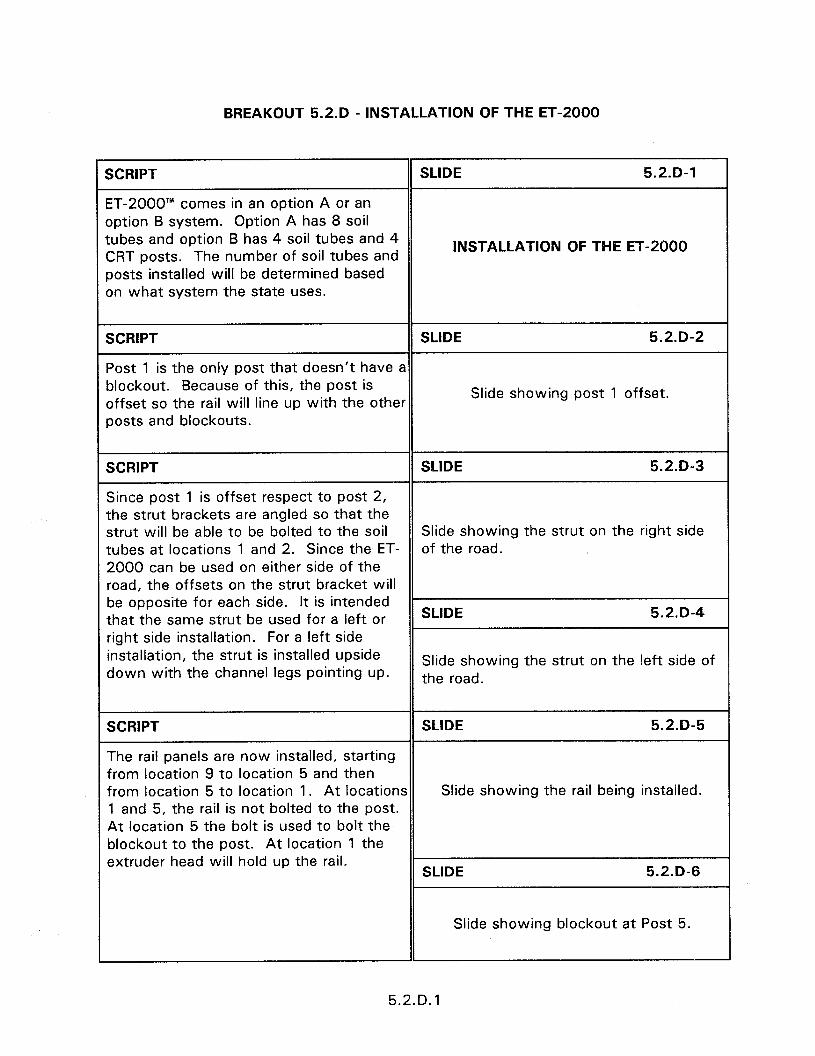
BREAKOUT 5.2.D - INSTALLATION OF THE ET-2000
SCRIPT SLIDE 5.2.D-1
ET-2000’” comes in an option A or an option B system. Option A has 8 soil tubes and option B has 4 soil tubes and 4 CRT posts. The number of soil tubes and
INSTALLATION OF THE ET-2000
posts installed will be determined based on what system the state uses.
SCRIPT SLIDE 5.2.D-2
Post 1 is the only post that doesn’t have a blockout. Because of this, the post is offset so the rail will line up with the other
Slide showing post 1 offset.
posts and blockouts.
SCRIPT SLIDE 5.2.D-3
Since post 1 is offset respect to post 2, the strut brackets are angled so that the strut will be able to be bolted to the soil Slide showing the strut on the right side tubes at locations 1 and 2. Since the ET- of the road. 2000 can be used on either side of the road, the offsets on the strut bracket will be opposite for each side. It is intended that the same strut be used for a left or SLIDE 5.2.D-4
right side installation. For a left side installation, the strut is installed upside down with the channel legs pointing up.
Slide showing the strut on the left side of the road.
SCRIPT SLIDE 5.2.D-5
The rail panels are now installed, starting from location 9 to location 5 and then from location 5 to location 1. At locations Slide showing the rail being installed. 1 and 5, the rail is not bolted to the post. At location 5 the bolt is used to bolt the slockout to the post. At location 1 the 3xtruder head will hold up the rail.
SLIDE 5.2.D-6
Slide showing blockout at Post 5
5.2.D.l

1 SCRIPT SLIDE 5.2.D-7
The extruder head is slid onto the end of the rail panel at location 1. The extruder should be aligned so the rail panel is as far Slide showing the extruder head placed on back as it will go, and the rail is at a 706 the rail panel. mm height.
SCRIPT SLIDE 5.2.D-8
The extruder head is bolted to the post using one of the three holes in the bracket. The hole closest to the center of Slide showing extruder head bolted to the the post should be used. post.
SCRIPT
The anchor bracket is placed in the rail panel slots.
SLIDE 5.2.D-9
Slides showing the anchor bracket installed.
SCRIPT SLIDE 5.2-D-10
The anchor cable is installed in the anchor bracket and the post.
Slide showing the anchor cable installed.
SCRIPT
The bearing plate is installed.
SLIDE 5.2.D-11
Slide showing the bearing plate installed.
SCRIPT SLIDE 5.2.D-12
The delineator is installed to complete the installation.
Slide showing the system completed with the delineator installed.
5.2.D.2
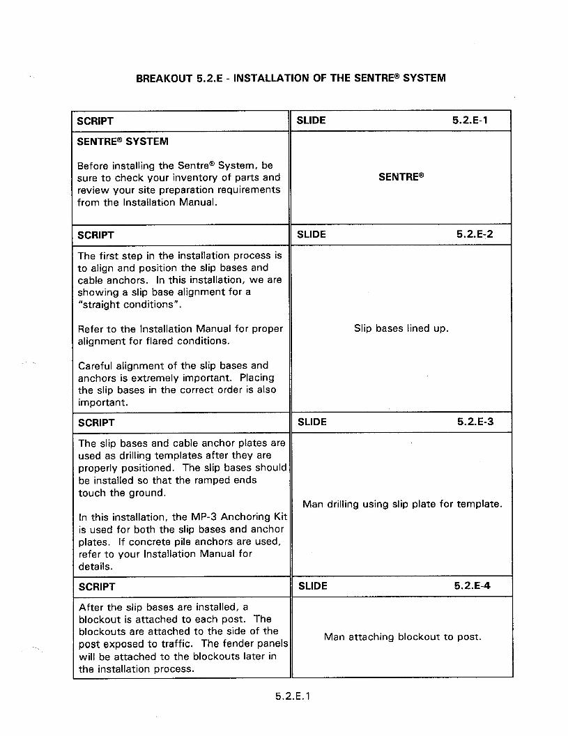
BREAKOUT 5.2.E - INSTALLATION OF THE SENTRE@ SYSTEM
SCRIPT
SENTRE@ SYSTEM
SLIDE 5.2.E-1
Before installing the Sentree System, be sure to check your inventory of parts and review your site preparation requirements from the Installation Manual.
SENTRE@
SCRIPT SLIDE 5.2.E-2
The first step in the installation process is to align and position the slip bases and cable anchors. In this installation, we are showing a slip base alignment for a “straight conditions”.
Refer to the Installation Manual for proper alignment for flared conditions.
Slip bases lined up.
Careful alignment of the slip bases and anchors is extremely important. Placing the slip bases in the correct order is also important.
SCRIPT SLIDE 5.2.E-3
The slip bases and cable anchor plates are used as drilling templates after they are properly positioned. The slip bases should be installed so that the ramped ends touch the ground.
Man drilling using slip plate for template. In this installation, the MP-3 Anchoring Kit is used for both the slip bases and anchor plates. If concrete pile anchors are used, refer to your Installation Manual for details.
SCRIPT SLIDE 5.2.E-4
After the slip bases are installed, a blockout is attached to each post. The blockouts are attached to the side of the post exposed to traffic. The fender panels
Man attaching blockout to post.
will be attached to the blockouts later in the installation process.
5.2.E. 1

SCRIPT SLIDE 5.2.E-5
After the blockouts are attached to the posts, the posts are attached to the slip bases. A keeper plate is placed between the slip base and the post. Man placing plate on template.
SCRIPT
The posts are then attached to the slip bases.
SLIDE 5.2.E-6
Note that posts 1 and 2 are different from posts 3, 4, and 5. They must be positioned accordingly. Post 1 has a welded ring where the redirecting cable will be threaded through it later in the process. Posts 1 and 2 both have flared slots in their base. Posts 3, 4, and 5 have straight slots in their base.
Man attaching post to base.
SCRIPT SLIDE 5.2.E-7
The fender panels are then attached starting at the guardrail end and working forward to the nose end of the unit. The transition treatment from the guardrail end will vary depending on the installation. Refer to the Installation Manual for details. Two men attaching fender panels to
posts. The holes labeled “S” are used when attaching the fender panels to the post blockouts. A mushroom bolt assembly is used in this process.
SCRIPT SLIDE 5.2.E-8
When attaching the last fender panel (at the nose), the plastic nose is positioned over the fender panel and a shared bolt assembly is used to attach both the nose and the fender panel to the blockout.
Guardrail nose.
Both the “S” holes and “G” holes are used for the nose attachment.
5.2.E.2
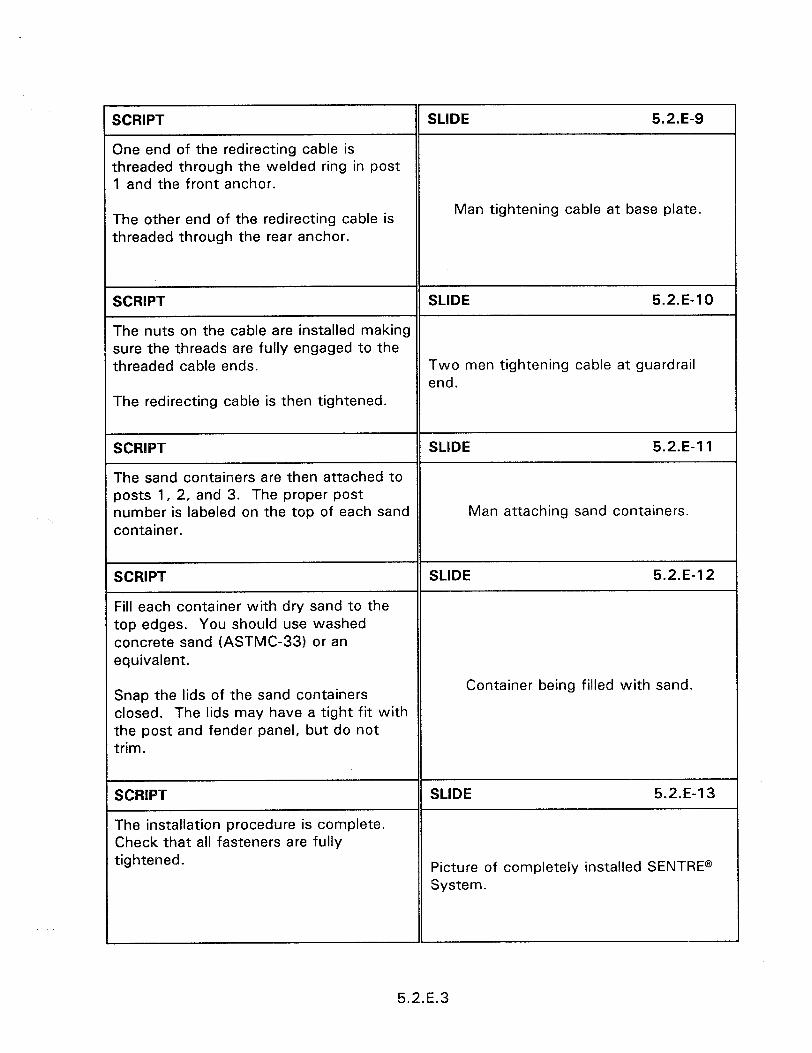
SCRIPT SLIDE 5.2.E-9
One end of the redirecting cable is threaded through the welded ring in post 1 and the front anchor.
The other end of the redirecting cable is threaded through the rear anchor.
Man tightening cable at base plate.
SCRIPT SLIDE 5.2.E-10
The nuts on the cable are installed making sure the threads are fully engaged to the threaded cable ends. Two men tightening cable at guardrail
end. The redirecting cable is then tightened.
SCRIPT SLIDE 5.2.E-‘I 1
The sand containers are then attached to posts 1, 2, and 3. The proper post number is labeled on the top of each sand Man attaching sand containers. container.
SCRIPT
Fill each container with dry sand to the top edges. You should use washed concrete sand (ASTMC-33) or an equivalent.
SLIDE 5.2.E-12
Snap the lids of the sand containers closed. The lids may have a tight fit with the post and fender panel, but do not trim.
Container being filled with sand.
SCRIPT
The installation procedure is complete. Check that all fasteners are fully tightened.
SLIDE 5.2.E-13
Picture of completely installed SENTRE@ System.
5.2.E.3

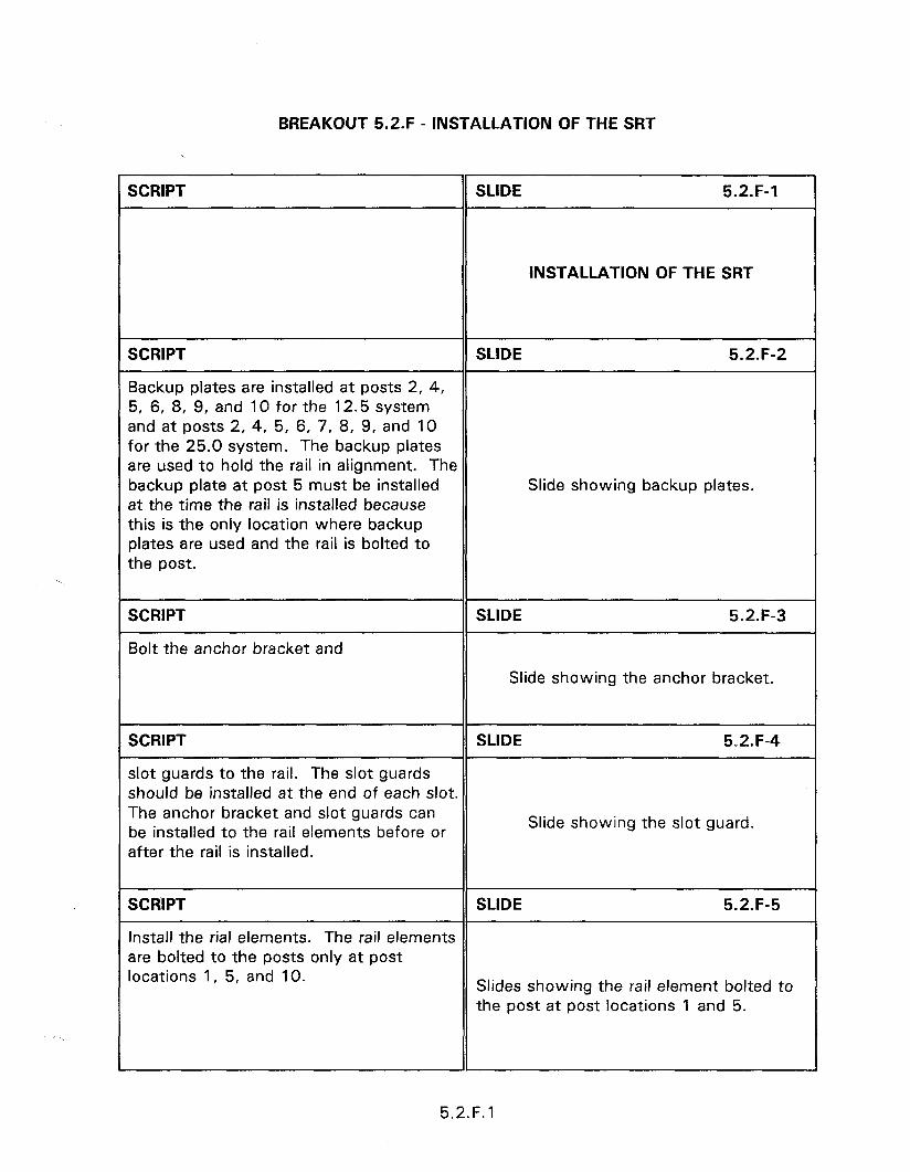
BREAKOUT 5.2.F - INSTALLATION OF THE SRT
SCRIPT SLIDE 5.2.F-1
INSTALLATION OF THE SRT
SCRIPT
Backup plates are installed at posts 2, 4, 5, 6, 8, 9, and IO for the 12.5 system and at posts 2, 4, 5, 6, 7, 8, 9, and 10 for the 25.0 system. The backup plates are used to hold the rail in alignment. The backup plate at post 5 must be installed at the time the rail is installed because this is the only location where backup plates are used and the rail is bolted to the post.
SLIDE 5.2.F-2
Slide showing backup plates.
SCRIPT SLIDE 5.2.F-3
Bolt the anchor bracket and
Slide showing the anchor bracket.
SCRIPT
slot guards to the rail. The slot guards should be installed at the end of each slot. The anchor bracket and slot guards can be installed to the rail elements before or after the rail is installed.
SCRIPT
Install the rial elements. The rail elements are bolted to the posts only at post locations 1, 5, and 10.
SLIDE 5.2.F-4
Slide showing the slot guard.
SLIDE 5.2.F-5
Slides showing the rail element bolted to the post at post locations 1 and 5.
5.2. F. 1
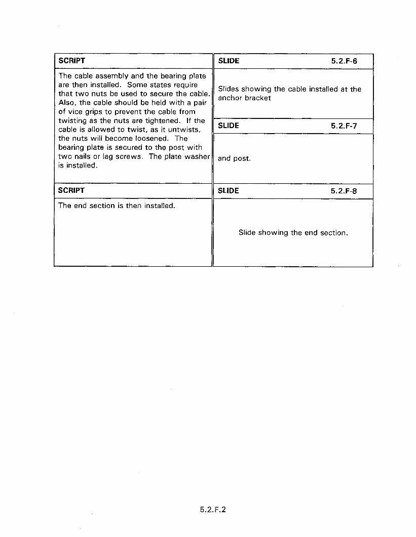
SCRlPT
The cable assembly and the bearing plate are then installed. Some states require that two nuts be used to secure the cable. Also, the cable should be held with a pair of vice grips to prevent the cable from twisting as the nuts are tightened. If the cable is allowed to twist, as it untwists, the nuts will become loosened. The bearing plate is secured to the post with two nails or lag screws. The plate washer is installed.
SCRIPT
The end section is then installed.
SLIDE 5.2.F-6
Slides showing the cable installed at the anchor bracket
SLIDE 5.2.F-7
and post.
SLIDE 5.2.F-8
Slide showing the end section.
5.2.F.2
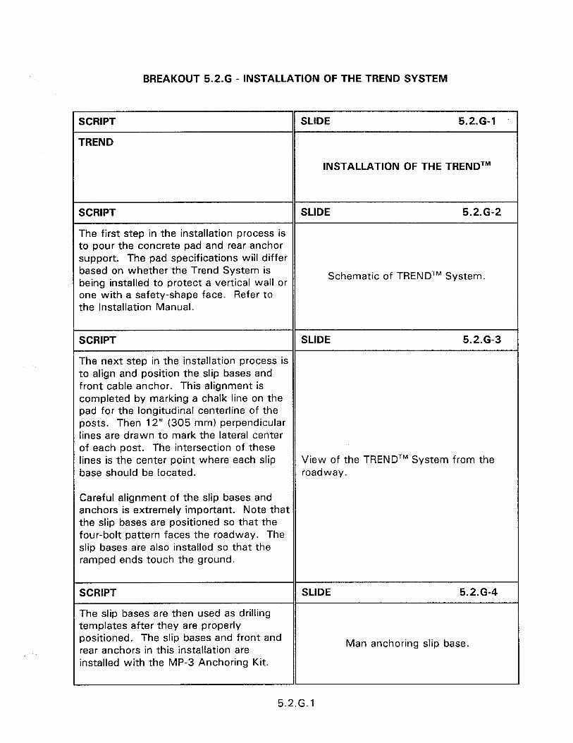
BREAKOUT 5.2.G - INSTALLATION OF THE TREND SYSTEM
SCRIPT
TREND
SLIDE 5.2.G-1
INSTALLATION OF THE TRENDTM
SCRIPT SLIDE 5.2.G-2
The first step in the installation process is to pour the concrete pad and rear anchor support. The pad specifications will differ based on whether the Trend System is being installed to protect a vertical wall or
Schematic of TRENDTM System.
one with a safety-shape face. Refer to the Installation Manual.
SCRIPT SLIDE 5.2.G-3
The next step in the installation process is to align and position the slip bases and front cable anchor. This alignment is completed by marking a chalk line on the pad for the longitudinal centerline of the posts. Then 12” (305 mm) perpendicular lines are drawn to mark the lateral center of each post. The intersection of these lines is the center point where each slip View of the TRENDTM System from the base should be located. roadway.
Careful alignment of the slip bases and anchors is extremely important. Note that the slip bases are positioned so that the four-bolt pattern faces the roadway. The slip bases are also installed so that the ramped ends touch the ground.
SCRIPT
The slip bases are then used as drilling templates after they are properly positioned. The slip bases and front and rear anchors in this installation are installed with the MP-3 Anchoring Kit.
SLIDE 5.2.G-4
Man anchoring slip base.
5.2.G.l
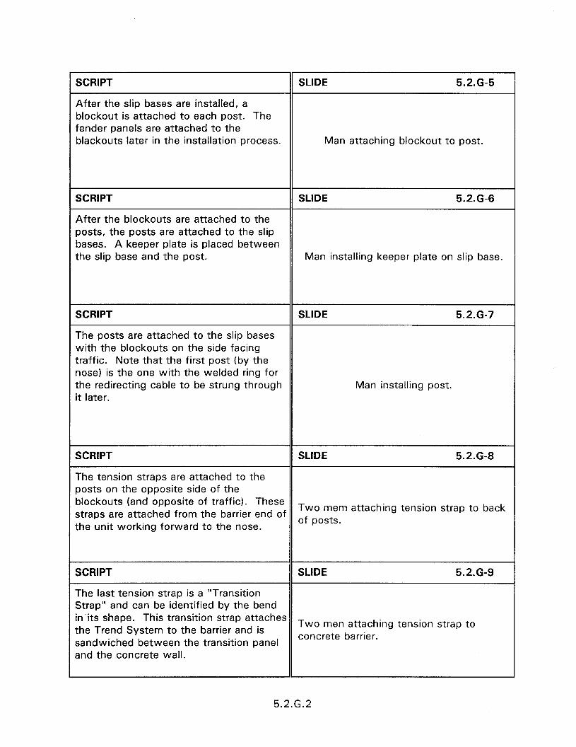
r SCRIPT SLIDE 5.2-G-5
After the slip bases are installed, a blockout is attached to each post. The fender panels are attached to the blackouts later in the installation process. Man attaching blockout to post.
SCRIPT SLIDE 5.2.G-6
After the blockouts are attached to the posts, the posts are attached to the slip bases. A keeper plate is placed between the slip base and the post. Man installing keeper plate on slip base.
SCRIPT SLIDE 5.2.G-7
The posts are attached to the slip bases with the blockouts on the side facing traffic. Note that the first post (by the nose) is the one with the welded ring for the redirecting cable to be strung through Man installing post. it later.
SCRIPT SLIDE 5.2.G-8
The tension straps are attached to the posts on the opposite side of the blockouts (and opposite of traffic). These straps are attached from the barrier end of
Two mem attaching tension strap to back
the unit working forward to the nose. of posts.
SCRIPT SLIDE 5.2.6-9
The last tension strap is a “Transition Strap” and can be identified by the bend in its shape. This transition strap attaches the Trend System to the barrier and is
Two men attaching tension strap to
sandwiched between the transition panel concrete barrier.
and the concrete wall.
5.2.G.2

SCRIPT SLIDE 5.2.G-10
The fender panels are then attached starting at the barrier end and working forward to the nose end of the unit. These are attached with mushroom bolt assemblies. The transition treatment from the barrier end will vary depending on the installation. Refer to the Installation Two men installing fender panel. Manual for details.
When attaching the fender panel transition treatment, the mushroom bolt assembly includes a “mushroom bolt pivot” piece.
SCRIPT SLIDE 5.2.G-11
The remaining fender panels are attached using a mushroom bolt assembly that includes a “fender panel reinforcement plate” (not a mushroom bolt pivot). Be
Man installing fender panels.
sure to use the holes marked “S”.
SCRIPT SLIDE 5.2.G-12
When attaching the last fender panel (at the nose), the plastic Nose is positioned over the fender panel and a shared bolt assembly is used to attach both the nose and the fender panel to the blockout.
Schematic showing nose assembly.
Both the “S” holes and “G” holes are used for the nose attachment.
SCRIPT
One end of the redirecting cable is threaded through the welded ring in post 1 and the front anchor.
SLIDE 5.2.G-13
The other end of the redirecting cable is threaded through the rear anchor. Two men tightening cable.
The nuts on the cable are installed making sure the threads are fully engaged to the threaded cable ends. The redirecting cable is then tightened.
1
5.2.G.3
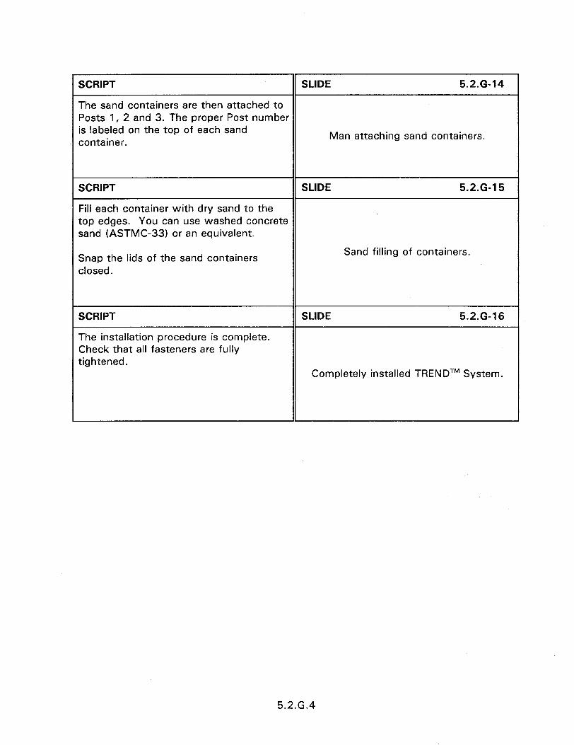
SCRIPT SLIDE 5.2.G-14
The sand containers are then attached to Posts 1, 2 and 3. The proper Post number is labeled on the top of each sand container.
Man attaching sand containers.
SCRIPT SLIDE 5.2.G-15
Fill each container with dry sand to the top edges. You can use washed concrete sand (ASTMC-33) or an equivalent.
Snap the lids of the sand containers closed.
Sand filling of containers.
SCRIPT
The installation procedure is complete. Check that all fasteners are fully tightened.
SLIDE 5.2.G-16
Completely installed TRENDTM System.
5.2.G.4
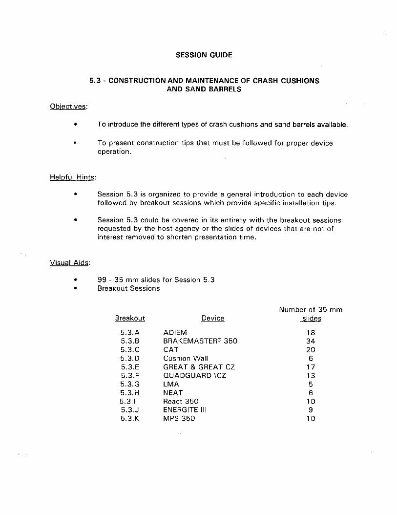
SESSION GUIDE
5.3 - CONSTRUCTION AND MAINTENANCE OF CRASH CUSHIONS AND SAND BARRELS
Obiectives:
0 To introduce the different types of crash cushions and sand barrels available.
. To present construction tips that must be followed for proper device operation.
Helpful Hints:
. Session 5.3 is organized to provide a general introduction to each device followed by breakout sessions which provide specific installation tips.
0 Session 5.3 could be covered in its entirety with the breakout sessions requested by the host agency or the slides of devices that are not of interest removed to shorten presentation time.
Visual Aids:
* 99 - 35 mm slides for Session 5.3 l Breakout Sessions
Breakout
5.3.A 5.3.B 5.3.c 5.3.D 5.3.E 5.3.F 5.3.G 5.3.H 5.3.1 5.3.J 5.3.K
Device
ADIEM 18 BRAKEMASTER@ 350 34 CAT 20 Cushion Wall 6 GREAT & GREAT CZ 17 QUADGUARD \CZ 13 LMA 5 NEAT 6 React 350 10 ENERGITE III 9 MPS 350 10
Number of 35 mm slides

Estimated Time
0 45 minutes for Session 5.3 0 Variable time on breakout sessions
Handouts:
l Manufacturers’ information

5.3 - CONSTRUCTION AND MAINTENANCE OF CRASH CUSHIONS AND SAND BARRELS
Instructor’s Guide
SCRIPT SLIDE 5.3-l
5.3 - CONSTRUCTION AND MAINTENANCE OF CRASH CUSHIONS
AND SAND BARRELS
SCRIPT
OPERATIONAL CRASH CUSHIONS
SLIDE 5.3-2
Connecticut Impact Attenuation System (SC1 07) (CIAS)
Connecticut Impact Attenuation System (CIAS) has satisfied the NCHRP Report 230 crash test matrix for crash cushions.
The system dissipates kinetic energy by plastically deforming the steel cylinders. The CIAS designed for 100 km/h impacts and is 3.7 m wide at the rear and 7.3 m long. The CIAS will trap an errant vehicle under most side impact conditions. The vehicle will be redirected back onto the roadway only when the impact location is so close to the rear of the system that it is impossible to obtain an acceptable vehicle deceleration response because of the proximity of the hazard. There are no current plans for testing under NCHRP 350.
CIAS l Deformation of cylinders l 7.3 m wide a Traps vehicle on side impacts l Speeds up to 100 km/h
5.3.1
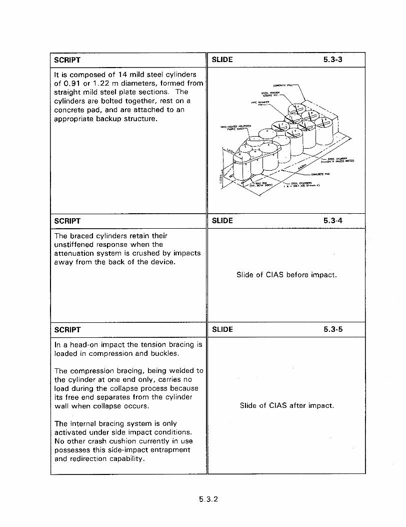
SCRIPT SLIDE 5.3-3
It is composed of 14 mild steel cylinders of 0.91 or 1.22 m diameters, formed from straight mild steel plate sections. The cylinders are bolted together, rest on a concrete pad, and are attached to an appropriate backup structure.
SCRIPT SLIDE 5.3-4
The braced cylinders retain their unstiffened response when the attenuation system is crushed by impacts away from the back of the device.
Slide of CIAS before impact.
SCRIPT SLIDE 5.3-5
In a head-on impact the tension bracing is loaded in compression and buckles.
The compression bracing, being welded to the cylinder at one end only, carries no load during the collapse process because its free end separates from the cylinder wall when collapse occurs. Slide of CIAS after impact.
The internal bracing system is only activated under side impact conditions. No other crash cushion currently in use possesses this side-impact entrapment and redirection capability.
5.3.2
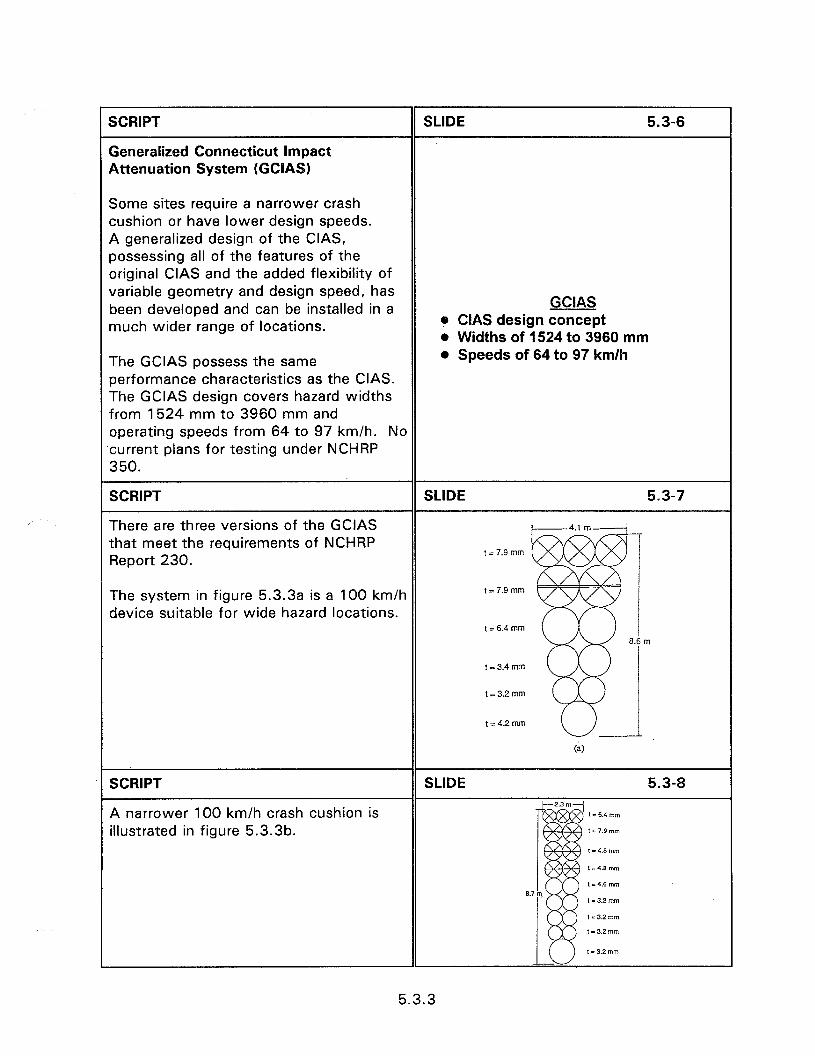
SCRIPT
Generalized Connecticut Impact Attenuation System (GCIAS)
Some sites require a narrower crash cushion or have lower design speeds. A generalized design of the CIAS, possessing all of the features of the original CIAS and the added flexibility of variable geometry and design speed, has been developed and can be installed in a much wider range of locations.
GCIAS e CIAS design concept l Widths of 1524 to 3960 mm
The GCIAS possess the same performance characteristics as the CIAS. The GCIAS design covers hazard widths from 1524 mm to 3960 mm and operating speeds from 64 to 97 km/h. No current plans for testing under NCHRP 350.
SCRIPT
l Speeds of 64 to 97 km/h
There are three versions of the GCIAS that meet the requirements of NCHRP Report 230.
The system in figure 5.3.3a is a 100 km/h device suitable for wide hazard locations.
SCRIPT
A narrower 100 km/h crash cushion is illustrated in figure 5.3.313.
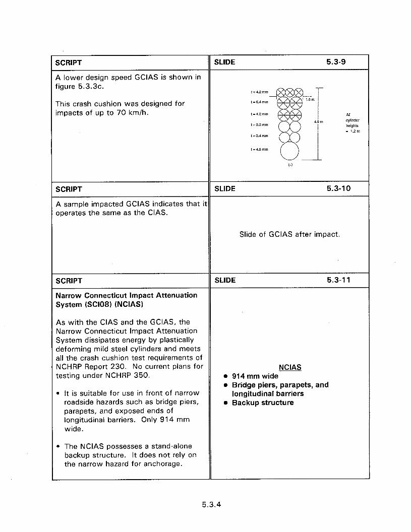
SCRIPT SLIDE 5.3-9
A lower design speed GCIAS is shown in figure 5.3.3c.
t=4.2mm
This crash cushion was designed for impacts of up to 70 km/h.
t = 6.4 mm
t = 4.2 mm
, = 3.2 mm
t = 3.4 mm
An cylinder heights = 1.2m
SCRIPT SLIDE 5.3-l 0
A sample impacted GCIAS indicates that it operates the same as the CIAS.
Slide of GCIAS after impact.
SCRIPT
Narrow Connecticut Impact Attenuation System (SClO8) (NCIAS)
SLIDE 5.3-l 1
As with the CIAS and the GCIAS, the Narrow Connecticut Impact Attenuation System dissipates energy by plastically deforming mild steel cylinders and meets all the crash cushion test requirements of NCHRP Report 230. No current plans for testing under NCHRP 350.
l It is suitable for use in front of narrow roadside hazards such as bridge piers, parapets, and exposed ends of longitudinal barriers. Only 914 mm wide.
NCIAS l 914 mm wide o Bridge piers, parapets, and
longitudinal barriers l Backup structure
l The NCIAS possesses a stand-alone backup structure. It does not rely on the narrow hazard for anchorage.
5.3.4

I SCRIPT
The NCIAS consists of a single row of eight mild steel cylinders of different thicknesses, which are formed from flat plate stock.
l All cylinders are 914 mm diameter and 1,219 mm high. A total of four 25.4 mm. diameter cables (two on each side of the system) provide lateral stability and assist in redirecting errant vehicles under side impact conditions. The NCIAS is 7.3 m long, and requires a concrete pad 3.048 m wide, 9.144 m long, and 305 mm thick.
. A stand-alone concrete-filled steel tubular backup structure, which provides support for the ends of the four cables, permitting them to develop the tension required to redirect vehicles when impacting the system on its side.
l A steel plate cable support at the front of the crash cushion.
. Lateral deflection limiters, which limit the amount of lateral deflection in the system and assist in the redirective process. These deflection limiters are connected to the pavement inside cylinders 5, 6, and 7 and are activated only under side impact conditions.
l Box beam stops (in cylinders 1 and 2) and tension rods (in cylinder 11, which prevent the errant vehicle from vaulting over the crash cushion or submarining under the unit. If the cylinder at the nose of the system is impacted, it will wrap itself vertically around the front end of the impacting vehicle, effectively capturing it.
5.3-l 2
5.3.5

Q Diametrically placed compression pipes (welded at one end and effective only in compression) in cylinders 5, 6, and 7 and a compression-tension pipe in cylinder 8 to further aid in the redirective process under side impact conditions.
SCRIPT
This slide presents the results of a 100 km/h head-on impact with a 2,041 kg automobile.
SLIDE 5.3-l 3
Slide of NCIAS after impact.
SCRIPT
ADIEM 350 (SC1091
SLIDE 5.3-14
l The ADIEM 350 (Advanced Dynamic Impact Extension Module II) manufactured by Syro/Trinity, is comprised of light-weight concrete modules.
l It is a high-performance, bi-directional, energy-absorbing end treatment for temporary and permanent locations.
0 The modules are coated to prevent water penetration.
ADIEM 350 l B-directional 0 Concrete base l Light-weight concrete modules 0 Modules coated @ NCHRP (TL-3)
5.3.6
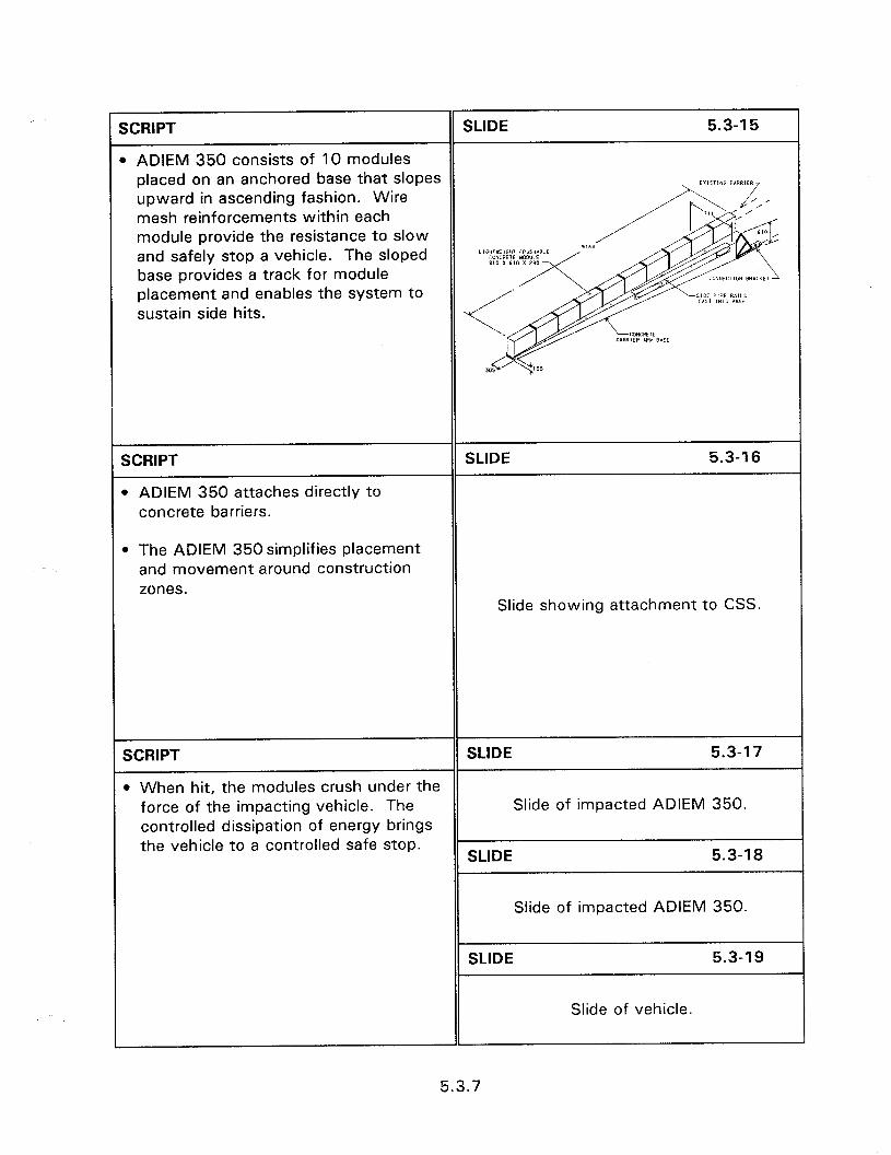
XXIPT SLIDE 5.3-l 5
b ADIEM 350 consists of 10 modules placed on an anchored base that slopes upward in ascending fashion. Wire mesh reinforcements within each module provide the resistance to slow and safely stop a vehicle. The sloped base provides a track for module placement and enables the system to sustain side hits.
SCRIPT
l ADIEM 350 attaches directly to concrete barriers.
SLIDE 5.3-l 6
l The ADIEM 350simplifies placement and movement around construction zones.
Slide showing attachment to CSS.
SCRIPT SLIDE 5.3-l 7
l When hit, the modules crush under the force of the impacting vehicle. The Slide of impacted ADIEM 350. controlled dissipation of energy brings the vehicle to a controlled safe stop.
SLIDE 5.3-18
Slide of impacted ADIEM 350.
SLIDE 5.3-l 9
Slide of vehicle.
5.3.7
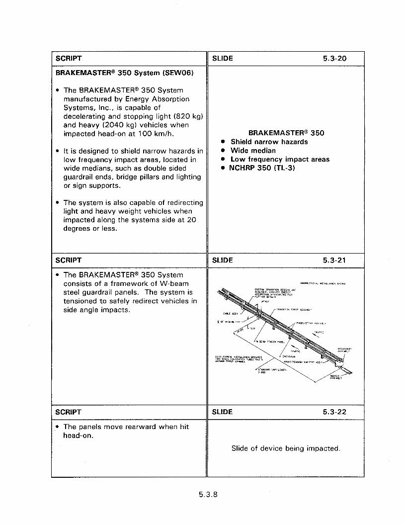
SCRIPT
BRAKEMASTER@ 350 System (SEW061
SLIDE 5.3-20
l The BRAKEMASTER@ 350 System manufactured by Energy Absorption Systems, Inc., is capable of decelerating and stopping light (820 kg) and heavy (2040 kg) vehicles when impacted head-on at 100 km/h.
l It is designed to shield narrow hazards in low frequency impact areas, located in wide medians, such as double sided guardrail ends, bridge pillars and lighting or sign supports.
BRAKEMASTER@ 350 0 Shield narrow hazards @ Wide median l Low frequency impact areas . NCHRP 350 (TL-3)
l The system is also capable of redirecting light and heavy weight vehicles when impacted along the systems side at 20 degrees or less.
SCRIPT
l The BRAKEMASTER@ 350 System consists of a framework of W-beam steel guardrail panels. The system is tensioned to safely redirect vehicles in side angle impacts.
SCRIPT
; The panels move rearward when hit head-on.
SLIDE 5.3-22
Slide of device being impacted.
5.3.8
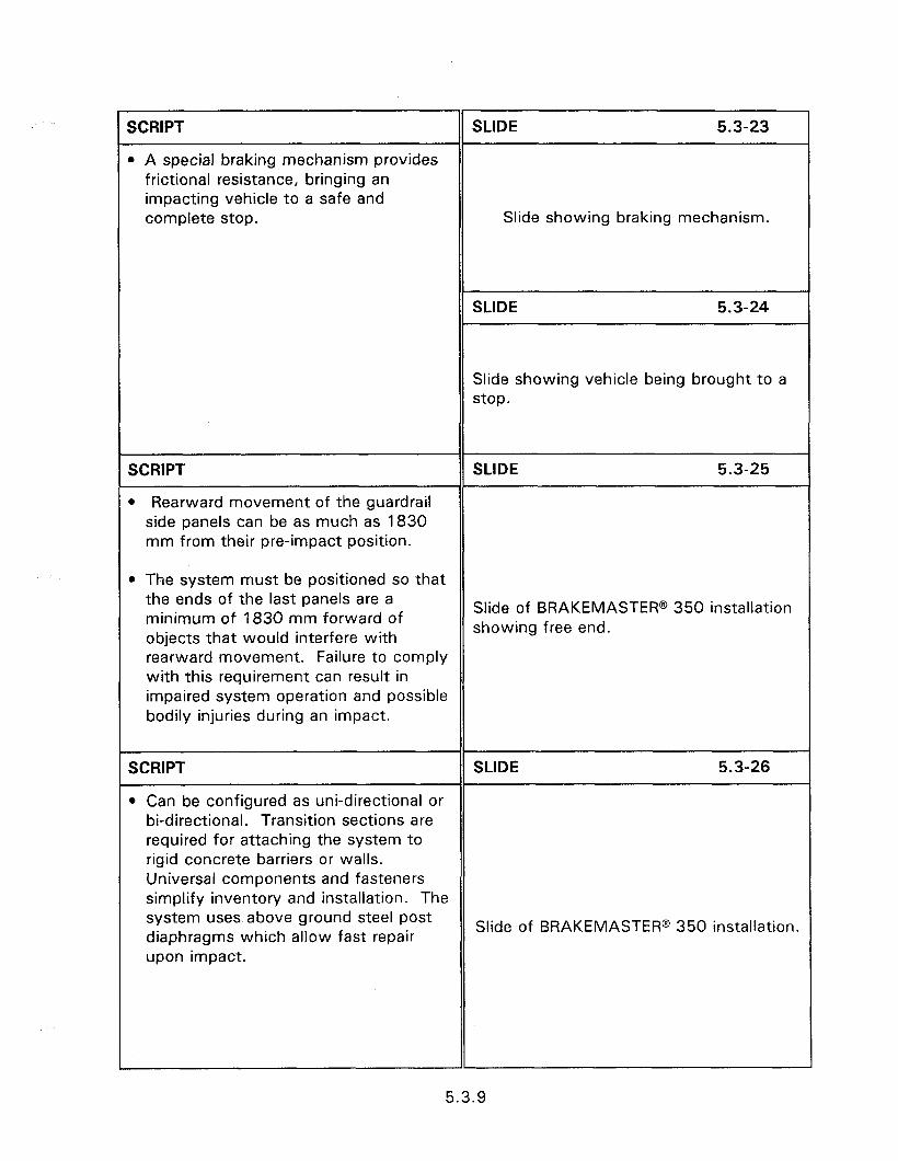
I-
SCRIPT
l A special braking mechanism provides frictional resistance, bringing an impacting vehicle to a safe and complete stop.
SLIDE 5.3-23
Slide showing braking mechanism.
SLIDE 5.3-24
Slide showing vehicle being brought to a stop.
SCRIPT
l Rearward movement of the guardrail side panels can be as much as 1830 mm from their pre-impact position.
SLIDE 5.3-25
l The system must be positioned so that the ends of the last panels are a minimum of 1830 mm forward of
Slide of BRAKEMASTER@ 350 installation
objects that would interfere with showing free end.
rearward movement. Failure to comply with this requirement can result in impaired system operation and possible bodily injuries during an impact.
SCRIPT SLIDE 5.3-26
l Can be configured as uni-directional or bi-directional. Transition sections are required for attaching the system to rigid concrete barriers or walls. Universal components and fasteners simplify inventory and installation. The system uses above ground steel post diaphragms which allow fast repair
Slide of BRAKEMASTER@ 350 installation.
upon impact.
5.3.9
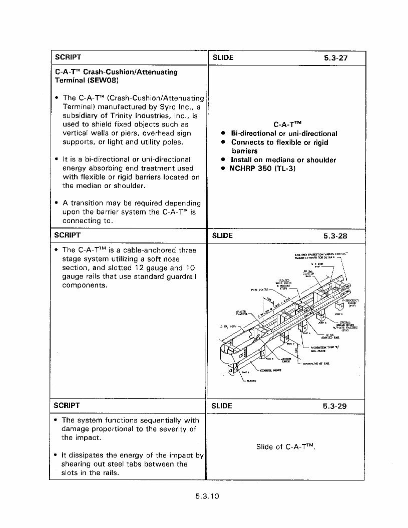
SCRIPT
C-A-T’” Crash-Cushion/Attenuating Terminal (SEWO8)
SLIDE 5.3-27
l The C-A-T’” (Crash-Cushion/Attenuating Terminal) manufactured by Syro Inc., a subsidiary of Trinity Industries, Inc., is used to shield fixed objects such as C-A-TT” vertical walls or piers, overhead sign @ &-directional or uni-directional supports, or light and utility poles. @ Connects to flexible or rigid
barriers l It is a bi-directional or uni-directional @ install on medians or shoulder
energy absorbing end treatment used . NCHRP 350 (TL-3) with flexible or rigid barriers located on the median or shoulder.
0 A transition may be required depending upon the barrier system the C-A-T” is connecting to.
SCRIPT SLIDE 5.3-28
l The C-A-TTM is a cable-anchored three stage system utilizing a soft nose
TAL EN0 ,Rp.NmoIl vm* CONTKT s.baNllF*clWIER Fwl mm
section, and slotted 12 gauge and 10 gauge rails that use standard guardrail components.
SCRIPT SLIDE 5.3-29
B The system functions sequentially with damage proportional to the severity of the impact.
Slide of C-A-TTM. b It dissipates the energy of the impact by
shearing out steel tabs between the slots in the rails.
5.3.10
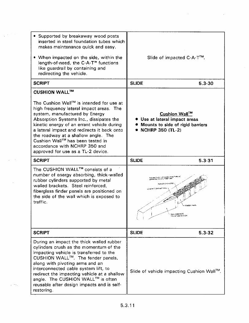
l Supported by breakaway wood posts inserted in steel foundation tubes which makes maintenance quick and easy.
Q When impacted on the side, within the length-of-need, the C-A-T’” functions like guardrail by containing and redirecting the vehicle.
Slide of impacted C-A-TTM.
SCRIPT
CUSHION WALLTM
SLIDE 5.3-30
The Cushion WalITM is intended for use at high frequency lateral impact areas. The system, manufactured by Energy Absorption Systems Inc., dissipates the kinetic energy of an errant vehicle during a lateral impact and redirects it back onto the roadway at a shallow angle. The Cushion WallTM has been tested in accordance with NCHRP 350 and approved for use as a TL-2 device.
Cushion WallTM 0 Use at lateral impact areas @ Mounts to side of rigid barriers . NCHRP 350 (TL-2)
SCRIPT SLIDE 5.3-31
The CUSHION WALLTM consists of a number of energy absorbing, thick-walled ,*cu~,* c+ WE c”I*Kw‘w*~~‘-~~~~ rubber cylinders supported by metal mlfw,ufD 8” l,TE CONoIT’m~
” walled brackets. Steel reinforced, fiberglass finder panels are positioned on the side of the wall which is exposed to traffic.
SCRIPT SLIDE 5.3-32
During an impact the thick walled rubber cylinders crush as the momentum of the impacting vehicle is transferred to the CUSHION WALLTM. The fender panels, along with pivoting arms and an interconnected cable system lift, to redirect the impacting vehicle at a shallow
Slide of vehicle impacting Cushion WalITM.
angle. The CUSHION WALLTM is often reusable after design impacts and is self- restoring.
5.3.1 1
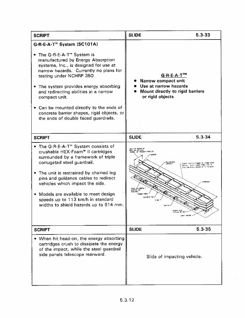
SCRIPT
G-R-E-A-T’” System (SClOlA)
SLIDE 5.3-33
0 The G-R-E-A-T’” System is manufactured by Energy Absorption systems, Inc., is designed for use at narrow hazards. Currently no plans for testing under NCHRP 350 G-R-E-A-TTM
l Narrow compact unit l The system provides energy absorbing
and redirecting abilities in a narrow compact unit.
l Can be mounted directly to the ends of concrete barrier shapes, rigid objects, or the ends of double faced guardrails.
0 Use at narrow hazards 0 Mount directly to rigid barriers
or rigid objects
SCRIPT
l The G-R-E-A-T” System consists of crushable HEX-Foam’” II cartridges surrounded by a framework of triple corrugated steel guardrail.
l The unit is restrained by chained leg pins and guidance cables to redirect vehicles which impact the side.
0 Models are available to meet design speeds up to 1 13 km/h in standard widths to shield hazards up to 914 mm.
SCRIPT SLIDE 5.3-35
l When hit head-on, the energy absorbing cartridges crush to dissipate the energy of the impact, while the steel guardrail side panels telescope rearward. Slide of impacting vehicle.
5.3.12

1 SCRIPT
0 For design speed impacts, only the cartridges and plastic nose cover are destroyed.
SLIDE 5.3-36
Slide of cartridge being inserted.
SCRIPT
G-R-E-A-T CZ’” System
SLIDE 5.3-37
The G-R-E-A-T CZ’” system, manufactured by Energy Absorption Systems, Inc., is a compact portable unit that is
The G-R-E-A-T CZ’” system is designed for temporary placement in construction zones to shield motorists from the ends of unfinished or temporary median barriers, bridge piers, temporary or permanent safety walls, light posts and other hazards. Currently no plans for testing under NCHRP 350.
G-R-E-A-T CZTM l Narrow compact portable unit 0 Construction zones
SCRIPT SLIDE 5.3-38
l The system consists of crushable cartridges surrounded by a framework of triple corrugated steel guardrail. When hit head-on the crushable HEX- ~~S,RUC,,OH ZONC c-II.E-A-7 Sewers *EC I\“LI~~~ IN iiNCT”P FOP E’lHTR ‘2.4 “,“,C i, 589> 01) Ph.5 lirnh 18 3251 FOAM II’” cartridges crush to absorb the energy of the impact while the steel guardrail panels telescope backward.
l When impacted from the side, the system redirects the errant vehicle.
5.3.13
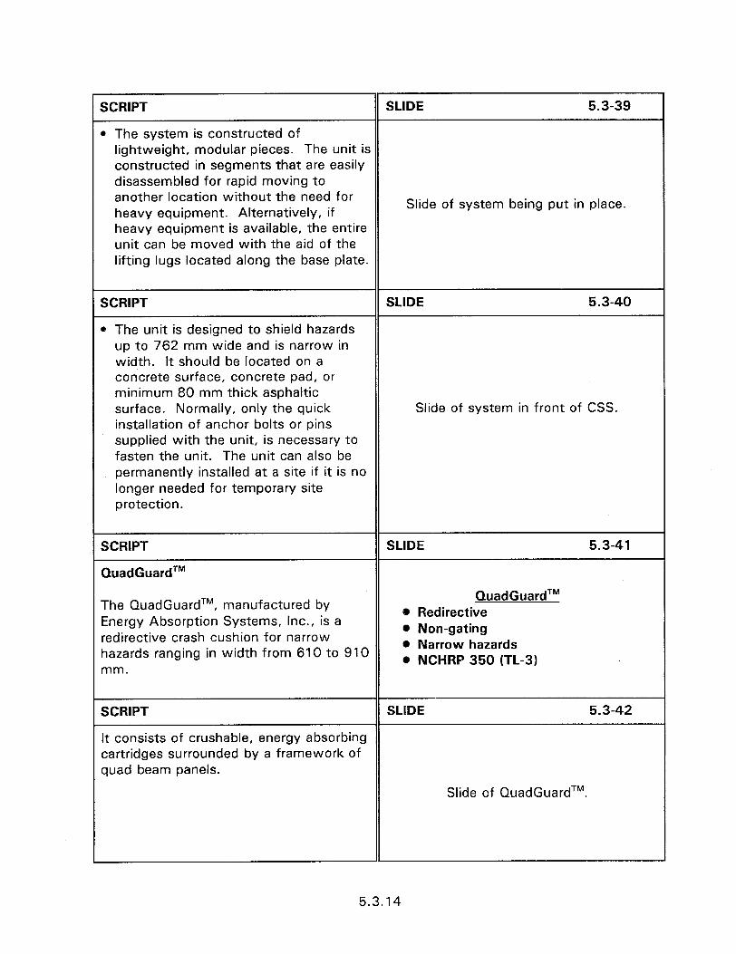
SCRIPT SLIDE 5.3-39
l The system is constructed of lightweight, modular pieces. The unit is constructed in segments that are easily disassembled for rapid moving to another location without the need for heavy equipment. Alternatively, if
Slide of system being put in place.
heavy equipment is available, the entire unit can be moved with the aid of the lifting lugs located along the base plate.
SCRIPT SLIDE 5.3-40
0 The unit is designed to shield hazards up to 762 mm wide and is narrow in width. It should be located on a concrete surface, concrete pad, or minimum 80 mm thick asphaltic surface. Normally, only the quick Slide of system in front of CSS. installation of anchor bolts or pins supplied with the unit, is necessary to fasten the unit. The unit can also be permanently installed at a site if it is no longer needed for temporary site protection.
SCRIPT
QuadGuardTM
SLIDE 5.3-41
The QuadGuardTM, manufactured by Energy Absorption Systems, Inc., is a redirective crash cushion for narrow hazards ranging in width from 610 to 910
QuadGuardTM @ Redirective @ Non-gating 0 Narrow hazards . NCHRP 350 (TL-3)
mm.
SCRIPT SLIDE 5.3-42
It consists of crushable, energy absorbing cartridges surrounded by a framework of quad beam panels.
Slide of QuadGuardTM.
5.3.14
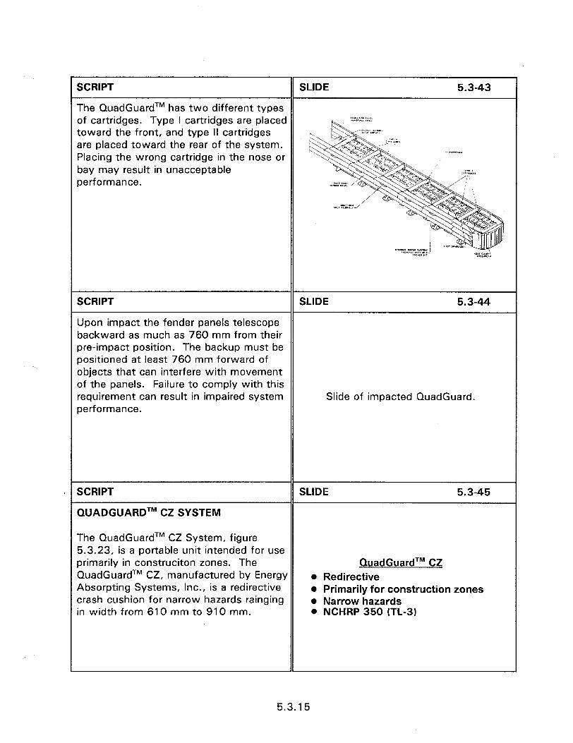
SCRIPT SLIDE 5.3-43
The QuadGuardTM has two different types of cartridges. Type I cartridges are placed toward the front, and type II cartridges are placed toward the rear of the system. Placing the wrong cartridge in the nose or
m.**l.r”
bay may result in unacceptable performance.
SCRIPT SLIDE 5.3-44
Upon impact the fender panels telescope backward as much as 760 mm from their pre-impact position. The backup must be positioned at least 760 mm forward of objects that can interfere with movement of the panels. Failure to comply with this requirement can result in impaired system Slide of impacted QuadGuard. performance.
SCRIPT
QUADGUARDTM CZ SYSTEM
SLIDE 5.3-45
The QuadGuardTM CZ System, figure 5.3.23, is a portable unit intended for use primarily in construciton zones. The QuadGuardTM CZ, manufactured by Energy Absorpting Systems, Inc., is a redirective crash cushion for narrow hazards rainging in width from 610 mm to 910 mm.
QuadGuardTM CZ l Redirective 0 Primarily for construction zones l Narrow hazards . NCHRP 350 (TL-3)
5.3.15
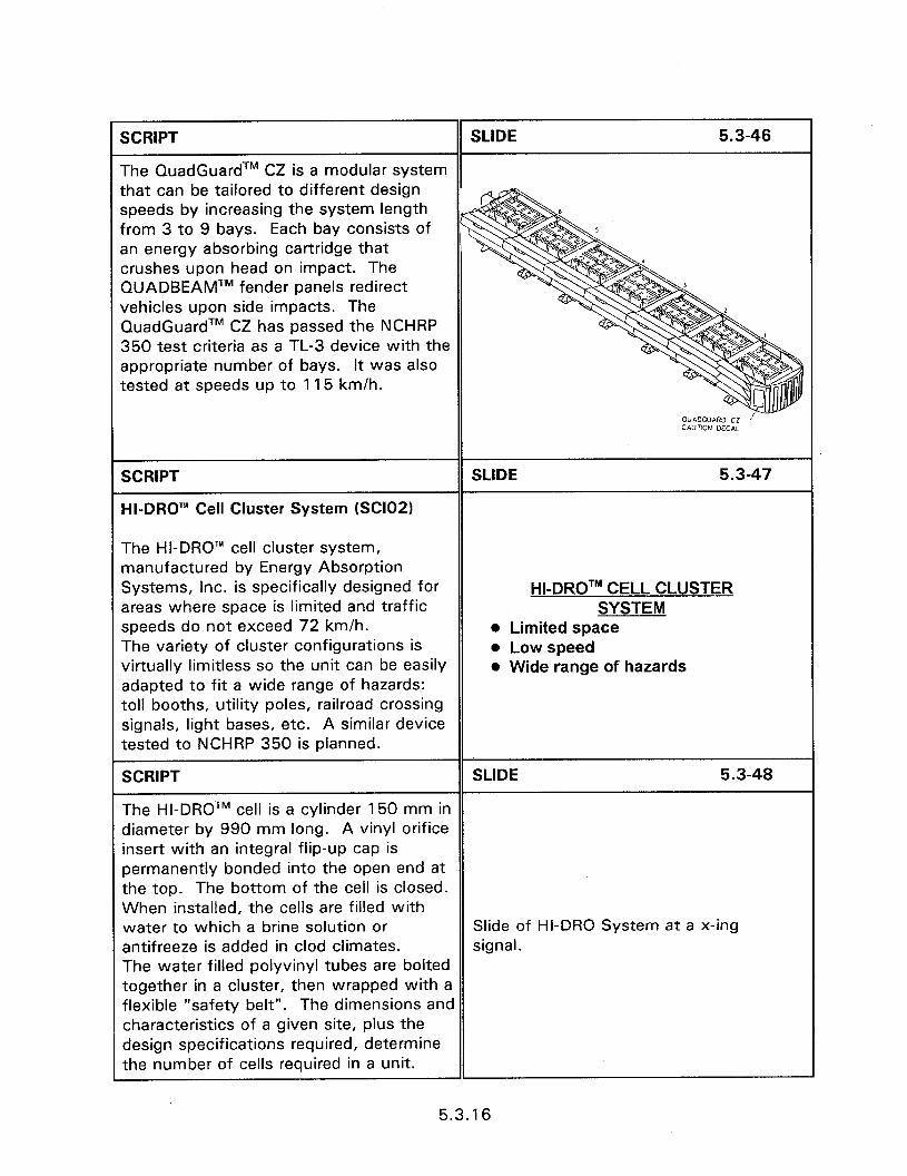
SCRIPT SLIDE 5.3-46
The QuadGuardTM CZ is a modular system that can be tailored to different design speeds by increasing the system length from 3 to 9 bays. Each bay consists of an energy absorbing cartridge that crushes upon head on impact. The QUADBEAMTM fender panels redirect vehicles upon side impacts. The QuadGuardTM CZ has passed the NCHRP 350 test criteria as a TL-3 device with the appropriate number of bays. It was also tested at speeds up to 115 km/h.
SCRIPT
HI-DRO’” Cell Cluster System (SClO2)
SLIDE 5.3-47
The HI-DRO’” cell cluster system, manufactured by Energy Absorption Systems, Inc. is specifically designed for areas where space is limited and traffic speeds do not exceed 72 km/h. The variety of cluster configurations is virtually limitless so the unit can be easily adapted to fit a wide range of hazards: toll booths, utility poles, railroad crossing signals, light bases, etc. A similar device tested to NCHRP 350 is planned.
HI-DROTM CELL CLUSTER SYSTEM
l Limited space l Low speed l Wide range of hazards
SCRIPT SLIDE 5.3-48
The HI-DROTM cell is a cylinder 150 mm in diameter by 990 mm long. A vinyl orifice insert with an integral flip-up cap is permanently bonded into the open end at the top. The bottom of the cell is closed. When installed, the cells are filled with water to which a brine solution or Slide of HI-DRO System at a x-ing antifreeze is added in clod climates. signal. The water filled polyvinyl tubes are bolted together in a cluster, then wrapped with a flexible “safety belt”. The dimensions and characteristics of a given site, plus the design specifications required, determine the number of cells required in a unit.
5.3.16
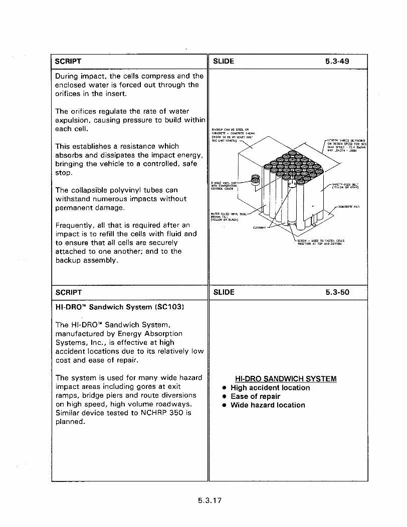
SCRIPT SLIDE 5.3-49
During impact, the cells compress and the enclosed water is forced out through the orifices in the insert.
The orifices regulate the rate of water expulsion, causing pressure to build within each cell. BACKUP CAN BE STEEL WI CcwcRETE - CcNCRElE SHOW MmH TO BE AT LEAST HALF THE “MT LENGM) This establishes a resistance which absorbs and dissipates the impact energy, bringing the vehicle to a controlled, safe stop.
The collapsible polyvinyl tubes can withstand numerous impacts without permanent damage.
Frequently, all that is required after an impact is to refill the cells with fluid and to ensure that all cells are securely attached to one another; and to the backup assembly.
SCRIPT
HI-DRO’” Sandwich System (SC1031
SLIDE 5.3-50
The HI-DRO’” Sandwich System, manufactured by Energy Absorption Systems, Inc., is effective at high accident locations due to its relatively low cost and ease of repair.
The system is used for many wide hazard impact areas including gores at exit ramps, bridge piers and route diversions on high speed, high volume roadways. Similar device tested to NCHRP 350 is planned.
HI-DRO SANDWICH SYSTEM l High accident location e Ease of repair l Wide hazard location
5.3.17
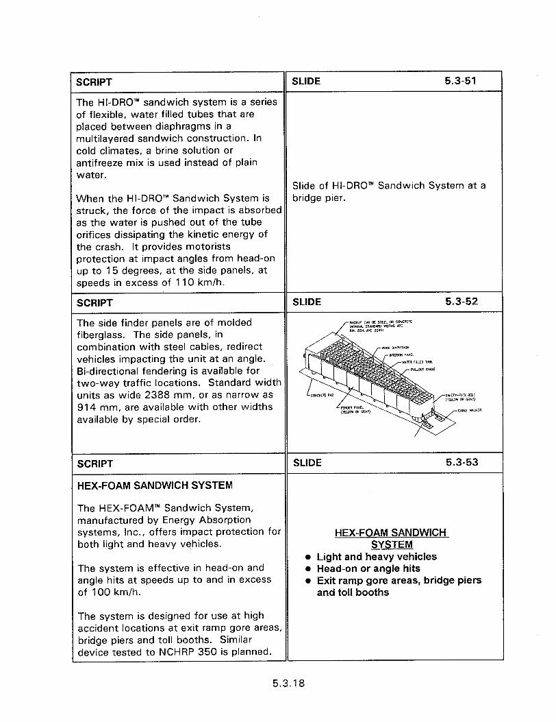
SCRlPT SLIDE 5.3-51
The HI-DRO’” sandwich system is a series of flexible, water filled tubes that are placed between diaphragms in a multilayered sandwich construction. In cold climates, a brine solution or antifreeze mix is used instead of plain water.
Slide of HI-DRO” Sandwich System at a When the HI-DRO’” Sandwich System is bridge pier. struck, the force of the impact is absorbed as the water is pushed out of the tube orifices dissipating the kinetic energy of the crash. It provides motorists protection at impact angles from head-on up to 15 degrees, at the side panels, at speeds in excess of 110 km/h.
SCRIPT
The side finder panels are of molded fiberglass. The side panels, in combination with steel cables, redirect vehicles impacting the unit at an angle. Bi-directional fendering is available for two-way traffic locations. Standard width units as wide 2388 mm, or as narrow as 914 mm, are available with other widths available by special order.
SCRIPT SLIDE 5.3-53
HEX-FOAM SANDWICH SYSTEM
The HEX-FOAM’” Sandwich System, manufactured by Energy Absorption systems, Inc., offers impact protection for both light and heavy vehicles.
HEX-FOAM SANDWICH SYSTEM
e Light and heavy vehicles The system is effective in head-on and angle hits at speeds up to and in excess of 100 km/h.
o Head-on or angle hits o Exit ramp gore areas, bridge piers
and toll booths
The system is designed for use at high accident locations at exit ramp gore areas, bridge piers and toll booths. Similar device tested to NCHRP 350 is planned.
5.3.18
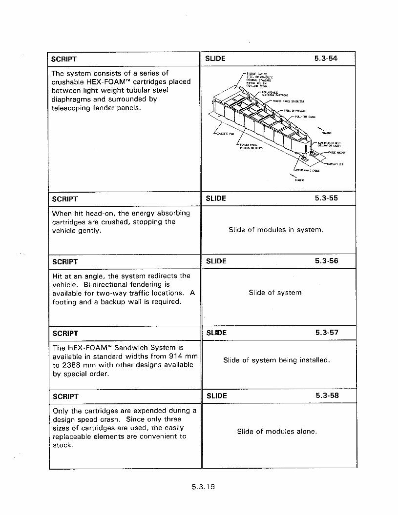
SCRIPT
The system consists of a series of crushable HEX-FOAM’” cartridges placed between light weight tubular steel diaphragms and surrounded by telescoping fender panels.
SLIDE 5.3-54
SCRIPT
When hit head-on, the energy absorbing cartridges are crushed, stopping the vehicle gently.
SLIDE 5.3-55
Slide of modules in system.
SCRIPT SLIDE 5.3-56
Hit at an angle, the system redirects the vehicle. Bi-directional fendering is available for two-way traffic locations. A Slide of system. footing and a backup wall is required.
SCRIPT SLIDE 5.3-57
The HEX-FOAM’” Sandwich System is available in standard widths from 914 mm to 2388 mm with other designs available
Slide of system being installed.
by special order.
SCRIPT SLIDE 5.3-58
Only the cartridges are expended during a design speed crash. Since only three sizes of cartridges are used, the easily replaceable elements are convenient to
Slide of modules alone.
stock.
5.3.19

SCRIPT
LMATM System
SLIDE 5.3-59
The LMA’” (Low Maintenance Attenuator) System, manufactured by Energy Absorption Systems, Inc., impact protection for narrow hazards (up to 3 feet) in high frequency impact areas. The system has low maintenance costs due to highly reusable components. For most impacts the key structural components and energy absorbing materials are reusable and the unit can be placed back into service quickly and easily. The installation requires a backup wall and concrete footing. Similar device tested to NCHRP 350 is planned.
LMATM o Narrow hazards e High frequency impact areas 0 Low maintenance costs l Repair l Backup wail and footing
SCRIPT
The LMA’” system consists of specially formulated elastomeric cylinders surrounded by a framework of triple corrugated steel diaphragms and guardrails. When impacted head-on, the elastometric cylinders compress, absorbing energy of the impact.
SCRIPT
The overlapping thrie-beam panels telescope, allowing the system to move rearward. Lateral movement from side angle impacts is controlled by restraining chains and a restraining cable.
SLIDE 5.3-61
Slide of system.
5.3.20
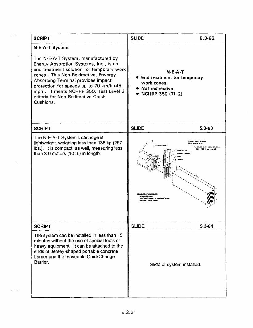
SCRIPT
N-E-A-T System
SLIDE 5.3-62
The N-E-A-T System, manufactured by Energy Absorption Systems, Inc., is an end treatment solution for temporary work
This Non-Reidrective, Envergy- zones. Absorbing Terminal provides impact protection for speeds up to 70 km/h (45 mph). It meets NCHRP 350, Test Level 2 criteria for Non-Redirective Crash Cushions.
N-E-A-T l End treatment for temporary
work zones l Not redirective . NCHRP 350 (TL-2)
SCRIPT
The N-E-A-T System’s cartridge is lightweight, weighing less than 135 kg (297 Ibs.). It is compact, as well, measuring less than 3.0 meters (10 ft.) in length.
SCRIPT
The system can be installed in less than 15 minutes without the use of special tools or heavy equipment. It can be attached to the ends of Jersey-shaped portable concrete barrier and the moveable QuickChange Barrier.
SLIDE 5.3-64
Slide of system installed.
5.3.21
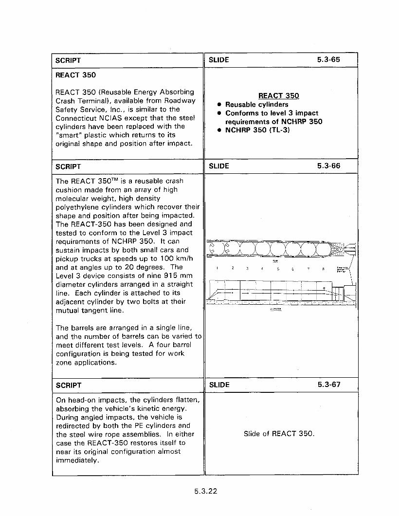
SCRIPT
REACT 350
SLIDE 5.3-65
REACT 350 (Reusable Energy Absorbing Crash Terminal), available from Roadway Safety Service, Inc., is similar to the Connecticut NCIAS except that the steel cylinders have been replaced with the “smart” plastic which returns to its original shape and position after impact.
REACT 350 l Reusable cylinders 0 Conforms to level 3 impact
requirements of NCHRP 350 . NCHRP 350 (TL-3)
SCRIPT SLIDE 5.3-66
The REACT 350TM is a reusable crash cushion made from an array of high molecular weight, high density polyethylene cylinders which recover their shape and position after being impacted. The REACT-350 has been designed and tested to conform to the Level 3 impact requirements of NCHRP 350. It can sustain impacts by both small cars and pickup trucks at speeds up to 100 km/h and at angles up to 20 degrees. The Level 3 device consists of nine 915 mm diameter cylinders arranged in a straight line. Each cylinder is attached to its adjacent cylinder by two bolts at their mutual tangent line.
The barrels are arranged in a single line, and the number of barrels can be varied to meet different test levels. A four barrel configuration is being tested for work zone applications.
SCRIPT SLIDE 5.3-67
On head-on impacts, the cylinders flatten, absorbing the vehicle’s kinetic energy. During angled impacts, the vehicle is redirected by both the PE cylinders and the steel wire rope assemblies. In either Slide of REACT 350. case the REACT-350 restores itself to near its original configuration almost immediately.
5.3.22

SCRIPT
SAND FILLED PLASTIC BARRELS
SLIDE 5.3-68
Crash cushions made up of arrays of sand-filled frangible plastic barrels dissipate kinetic energy in the impacting vehicle by transferring its linear momentum to the sand particles in the barrels.
Sand filled plastic barrel crash cushions are non-redirective devices. Angled impacts near the rear of these devices can result in impalement on the corner of the rigid hazard if the system is not properly designed. The FHWA recommends that the outside modules in the rear row of an inertial barrier overlap (in width) the shielded fixed object by at least 765 mm to reduce the severity of “coffin corner” impacts.
SAND FILLED PLASTIC It is important that the sand employed in BARRELS this type of crash cushion be clean and l Non-redirective have a moisture content of 3 percent or 0 Low moisture less. A higher moisture content can result OJ Variable width in frozen sand in cold weather conditions, producing large blocks of sand that can adversely affect crash cushion performance and create a hazard to surrounding traffic. It has been found that 3 mixing of rock salt with the sand helps to prevent wet sand from freezing under most conditions. The use of sacked sand In these systems is not an acceptable oractice. Also urea can be mixed with the sand to keep it from freezing.
5.3.23
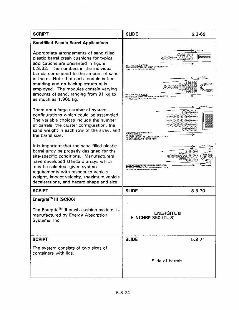
SCRIPT
Sandfilled Plastic Barrel Applications
SLIDE 5.3-69
Appropriate arrangements of sand filled plastic barrel crash cushions for typical applications are presented in figure 5.3.32. The numbers in the individual barrels correspond to the amount of sand in them. Note that each module is free standing and no backup structure is employed. The modules contain varying amounts of sand, ranging from 91 kg to WALL UP TO 1.8 M WlDE BARRlER LENGTH 8.2 4 BARRIER WI0 as much as 1,905 kg. 17 MODULES RATED FOR 97 KMRf
There are a large number of system -> P-
configurations which could be assembled. @@@@
@@@@@@@x&j) The variable choices include the number 90 90 180 320 20 640 40 960 of barrels, the cluster configuration, the
@=dl!l 90 90 180 320 20 540 640 950
sand weight in each row of the array, and @@@@
the barrel size. WOE WALL OR BRlOGE RNL UP TO 3.7 M WOE **RR,ER LENGTH 7.3 M. BARRIER WIDTH 4.6 M 32 MODULES RATED FOR 89 KWH
It is important that the sand-filled plastic - P=-aLw barrel array be properly designed for the site-specific conditions. Manufacturers
(-,g$g@ p m @@@x@@(
have developed standard arrays which @@@@@ Lk
may be selected, given system GOREwlTH OVERPASS PIERS&GUARDRAIL -* L.2 &mRIER LENGTH 7.3 M, BARRER WlDTH 2.7 M requirements with respect to vehicle
16 MODULES RATED FOR 89 Khuli
weight, impact velocity, maximum vehicle decelerations, and hazard shape and size.
SCRIPT SLIDE 5.3-70
EnergiteTM Ill (SC1061
The Energite TM III crash cushion system, is manufactured by Energy Absorption ENERGITE Ill
Systems, Inc. . NCHRP 350 (TL-3)
SCRIPT
The system consists of two sizes of containers with lids.
SLIDE 5.3-71
Slide of barrels.
5.3.24
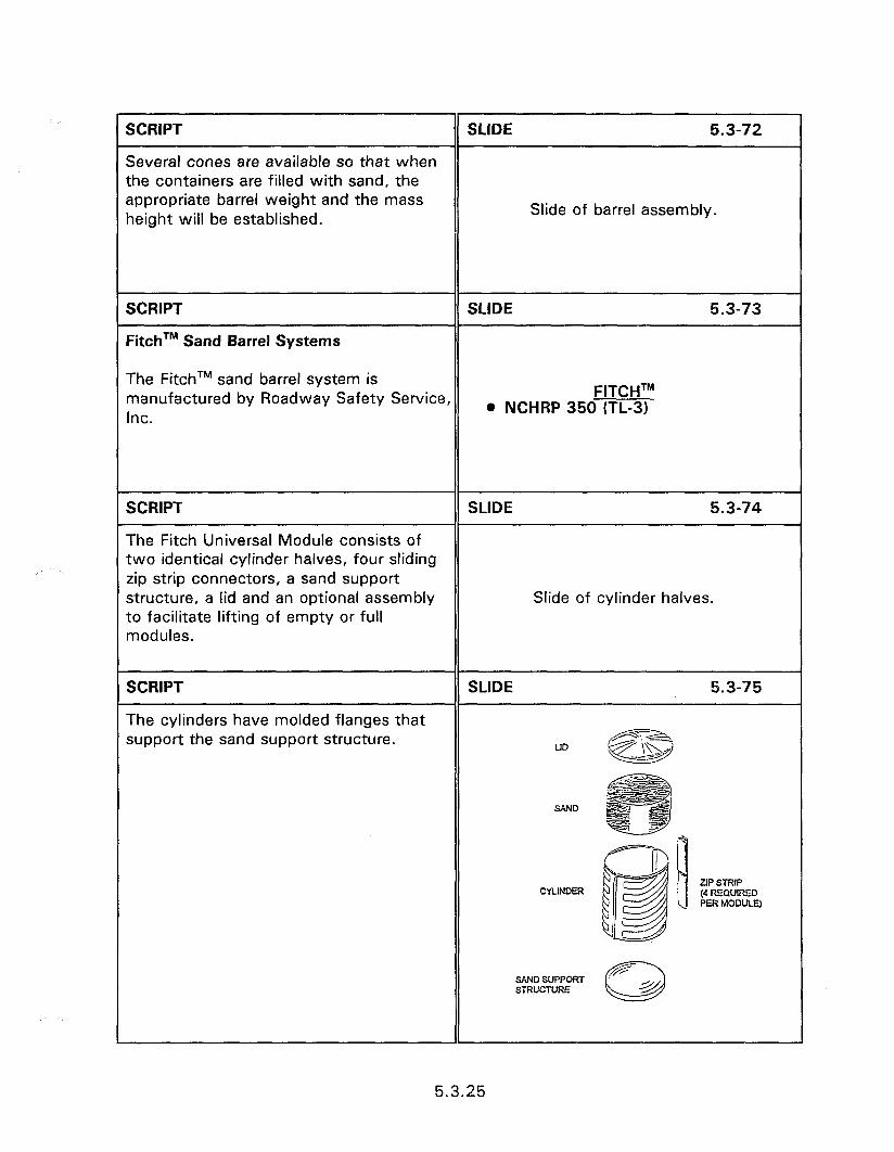
SCRIPT
Several cones are available so that when the containers are filled with sand, the appropriate barrel weight and the mass height will be established.
SLIDE 5.3-72
Slide of barrel assembly.
SCRIPT SLIDE 5.3-73
FitchTM Sand Barrel Systems
The FitchTM sand barrel system is manufactured by Roadway Safety Service, FITCHTM
Inc. . NCHRP 350 (TL-3)
SCRIPT
The Fitch Universal Module consists of two identical cylinder halves, four sliding zip strip connectors, a sand support structure, a lid and an optional assembly to facilitate lifting of empty or full modules.
SLIDE 5.3-74
Slide of cylinder halves.
SCRIPT
The cylinders have molded flanges that support the sand support structure.
SLIDE 5.3-75
ZIP STRIP (4 FEQURED PER MODULE)
SAND SUPPORT SiRucNRE
5.3.25
5.3-76
This is a slide of the Energite III sand barrels being impacted during a test.
Slide of impact test.
SCRIPT
rcle was trapped and the last row of barrels were not needed for the impact speed of the test.
5.3-77
Slide of test finish.
5.3-78
Truck Mounted Attenuators provide protection for maintenance crews, highway construction workers and errant motorists. The primary TMA application is for short term maintenance operations but some agencies also mount a TMA on an old truck :o serve as an intermediate term impact attenuator.
TRUCK MOUNTED ATTENUATORS (TMA)
@ Protection for workers and drivers
5.3-79
The systems prese nanufactured by E Systems, Inc. A TL designation indicates :esting under NCHRP 350. There are no 9ans to test the remaining TMA’s under UCHRP 350.
@ ALPHA 1000 TMA 8 ALPHA 60 MD TMA o ALPHA 2001 MD TMA @ HEX FOAM TMA e ALPHA 70K TMA (TL-2) * ALPHA IOOK TMA (TL-3) @ LS PRO (TL-1)
5.3.26
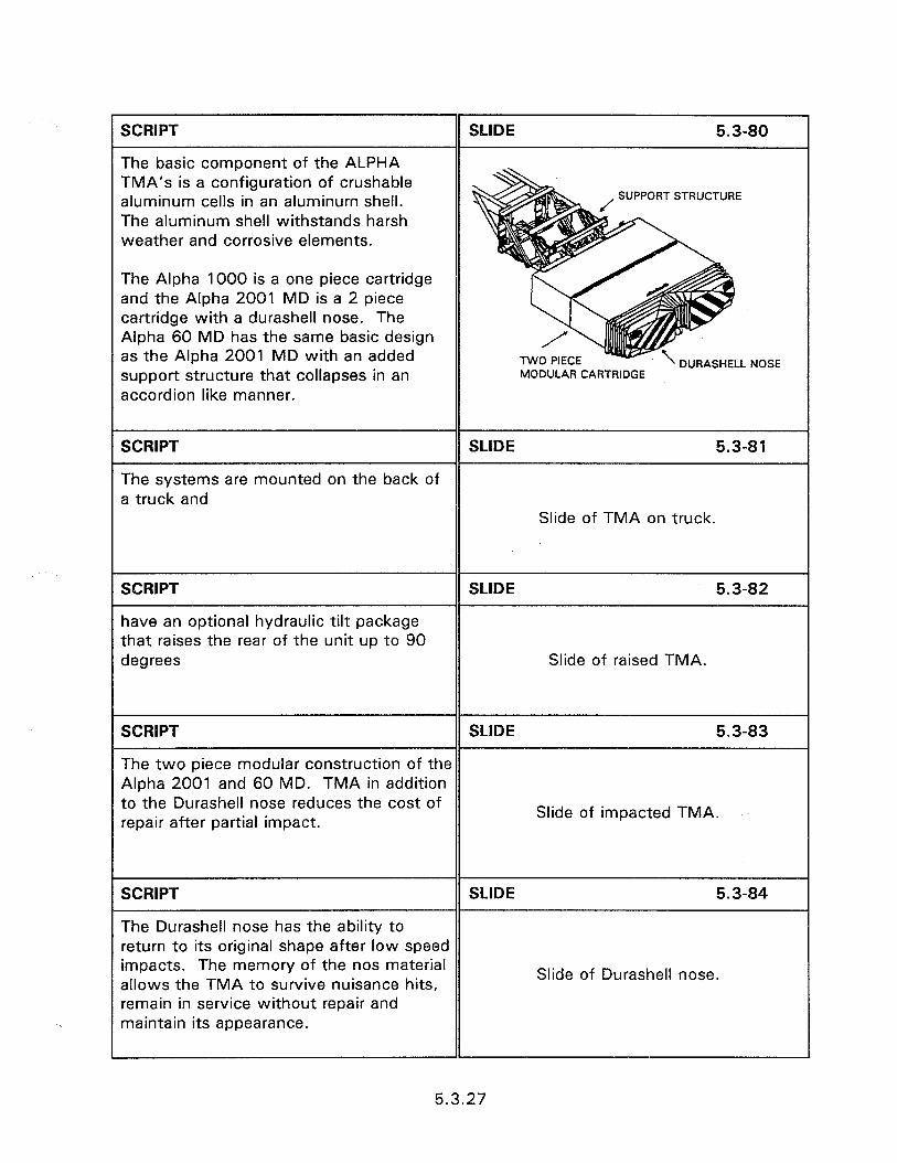
SCRIPT
The basic component of the ALPHA TMA’s is a configuration of crushable aluminum cells in an aluminum shell. The aluminum shell withstands harsh weather and corrosive elements.
SLIDE 5.3-80
SUPPORTSTRUCTURE
The Alpha 1000 is a one piece cartridge and the Alpha 2001 MD is a 2 piece cartridge with a durashell nose. The Alpha 60 MD has the same basic design as the Alpha 2001 MD with an added support structure that collapses in an accordion like manner.
TWO PIECE MODULAR CARTRIDGE
DURASHELL NOSE
SCRIPT SLIDE 5.3-81
The systems are mounted on the back of a truck and
Slide of TMA on truck.
SCRIPT
have an optional hydraulic tilt package that raises the rear of the unit up to 90 degrees
SLIDE 5.3-82
Slide of raised TMA.
SCRIPT SLIDE 5.3-83
The two piece modular construction of the Alpha 2001 and 60 MD. TMA in addition to the Durashell nose reduces the cost of repair after partial impact.
Slide of impacted TMA.
SCRIPT SLIDE 5.3-84
The Durashell nose has the ability to return to its original shape after low speed impacts. The memory of the nos material allows the TMA to survive nuisance hits,
Slide of Durashell nose.
remain in service without repair and maintain its appearance.
5.3.27
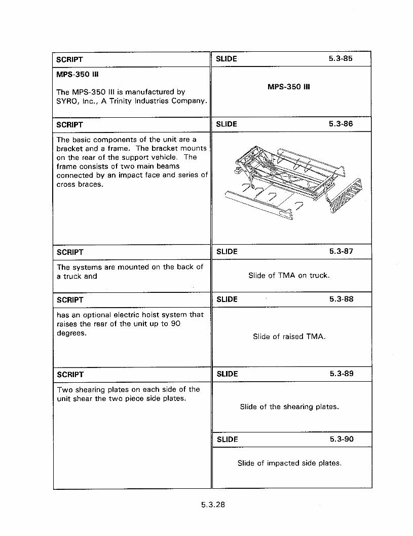
SCRIPT
MPS-350 Ill
SLIDE 5.3-85
The MPS-350 III is manufactured by SYRO, Inc., A Trinity Industries Company.
MPS-350 Ill
SCRIPT SLIDE 5.3-86
The basic components of the unit are a bracket and a frame. The bracket mounts on the rear of the support vehicle. The frame consists of two main beams connected by an impact face and series of cross braces.
SCRIPT SLIDE 5.3-87
The systems are mounted on the back of a truck and Slide of TMA on truck.
SCRIPT SLIDE 5.3-88
has an optional electric hoist system that raises the rear of the unit up to 90 degrees. Slide of raised TMA.
SCRIPT
Two shearing plates on each side of the unit shear the two piece side plates.
SLIDE 5.3-89
Slide of the shearing plates.
SLIDE 5.3-90
Slide of impacted side plates.
5.3.28
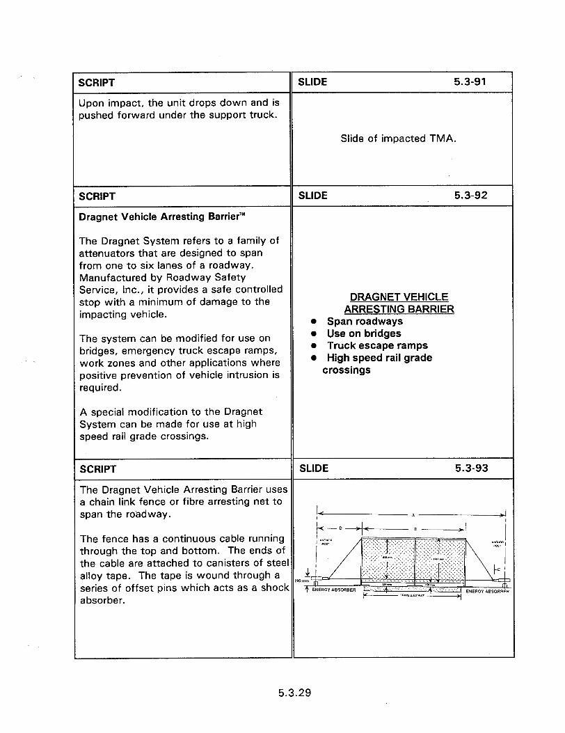
SCRIPT SLIDE 5.3-91
Upon impact, the unit drops down and is pushed forward under the support truck.
Slide of impacted TMA.
SCRIPT
Dragnet Vehicle Arresting BarrierTM
SLIDE 5.3-92
The Dragnet System refers to a family of attenuators that are designed to span from one to six lanes of a roadway. Manufactured by Roadway Safety Service, Inc., it provides a safe controlled stop with a minimum of damage to the impacting vehicle.
The system can be modified for use on bridges, emergency truck escape ramps, work zones and other applications where positive prevention of vehicle intrusion is required.
DRAGNET VEHICLE ARRESTING BARRIER
l Span roadways l Use on bridges l Truck escape ramps l High speed rail grade
crossings
A special modification to the Dragnet System can be made for use at high speed rail grade crossings.
SCRIPT SLIDE 5.3-93
The Dragnet Vehicle Arresting Barrier uses a chain link fence or fibre arresting net to span the roadway.
The fence has a continuous cable running through the top and bottom. The ends of the cable are attached to canisters of steel alloy tape. The tape is wound through a series of offset pins which acts as a shock IW absorber.
1
5.3.29
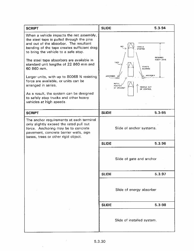
SCRIPT SLIDE 5.3-94
When a vehicle impacts the net assembly, the steel tape is pulled through the pins and out of the absorber. The resultant A bending of the tape creates sufficient drag to bring the vehicle to a safe stop.
REmlIRED The steel tape absorbers are available in standard unit lengths of 22 860 mm and 60 960 mm.
Larger units, with up to 80068 N resisting force are available, or units can be arranged in series.
As a result, the system can be designed to safely stop trucks and other heavy vehicles at high speeds.
SCRIPT SLIDE 5.3-95
The anchor requirements at each terminal only slightly exceed the rated pull out force. Anchoring may be to concrete Slide of anchor systems. pavement, concrete barrier walls, sign bases, trees or other rigid object.
SLIDE 5.3.96
Slide of gate and anchor
SLIDE 5.3.97
Slide of energy absorber
SLIDE 5.3-98
Slide of installed system.
5.3.30
SCRIPT II SLIDE 5.3-99
l In general, very little regular maintenance is required but periodic checks are necessary to ensure that each installed unit remains fully functional. Regular checks are required on the cells of sand and water inertial systems to ensure no material loss through leakage or evaporation.
l The amount of down time after an impact is dependent upon the availability of replacement parts.
l The manufactures should be consulted to determine which parts, and in what quantities, should be stored to maintain an adequate inventory for rapid maintenance response.
CONCLUSION l Follow State standards and
manufacturers guidelines l Know site conditions l Regular maintenance 0 Impact repair l Material storage
5.3.31

BREAKOUT 5.3.A - INSTALLATION OF THE ADIEM
SCRIPT
The ADIEM is an impact attenuator that utilizes a concrete base and light weigh concrete modules.
SLIDE 5.3.A-1
INSTALLATION OF THE ADIEM
SCRIPT SLIDE 5.3.A-2
The ADIEM can be delivered to the job site or to a staging area for installation or Slide showing the system being delivered preparation for installation. If it is to the job site. delivered to the job site, the base can be removed from the truck and placed in position for installation. If it is unloaded SLIDE 5.3.A-3
at a staging area, the system can be put together and then hauled to the job site for installation.
Slide showing the system being unloaded at the job site.
The concrete base can be placed on a soil, asphalt, or concrete surface. SLIDE 5.3.A-4
Slide showing the base.
SLIDE 5.3.A-5
Slide showing the base on the same alignment as the barrier.
SCRIPT SLIDE 5.3.A-6
Install the 12 anchor pins by drilling a hole in the surface and driving the pins so the head is flush with the top of concrete base. Slide showing the holes being drilled and
the pins being driven.
5.3.A. 1
r SCRIPT SLIDE 5.3.A-7
The pins can either be a threaded rod with a nut on it, or with a smooth road with a Slide showing a threaded rod. washer welded on the end of it. The nut or washer has nothing to do with holding the base in place. They are there to help SLIDE 5.3.A-8
remove the pins if the system is to be moved. Slide showing a smooth rod with a
washer welded to it.
SCRIPT
The two brackets are bolted to the base with two bolts.
SLIDE 5.3.A-9
Slides showing the brackets being bolted to the base.
SCRIPT
The brackets are then bolted to the concrete barrier with the use of anchor studs and nuts.
SLIDE 5.3.A-10
Slide showing the bracket bolted to the concrete barrier.
SCRIPT SLIDE 5.3.A-11
The modules are placed on the concrete base. The track can be oiled to aid in the sliding the modules on.
Slide showing the modules being installed on the base.
SCRIPT SLIDE 5.3.A-12
The appropriate delineator is placed on the end of the system.
Slide showing the system installed with the delineator in place.
5.3.A.2
BREAKOUT 5.3.8 - INSTALLATION OF THE BRAKEMASTER@ SYSTEM
SCRIPT
BRAKEMASTER@ SYSTEM
SLIDE 5.3.B-1
BRAKEMASTER@
SCRIPT SLIDE 5.3.B-2
The first step in the installation process is to install the standard embedded anchor (front anchor) for the Brakemaster@. This type of anchor must be installed in strong soil conditions; at least 10 to 60 blow counts per foot ASTM D 1586.
The positioning of the front anchor relative to the guardrail end is important Man using a tape measure to locate front for the ease of installation. To determine anchor from end of guardrail. the embedded anchor position, the rear measurement point is the vertical center line of the 8-hole pattern on the existing guardrail end. From the rear measurement point, measure forward 31’6” ( +/- I”) (9.63 m +/- 25 mm) along the system center line. This point will be the location for the embedded anchor.
SCRIPT SLIDE 5.3.B-3
Once the anchor position is determined, a 2 ft. (610 mm) diameter hole is augered, 5 feet (1524 nim) deep. The excess soil is removed and a 4 ft. (1220 mm) area around the hole is leveled.
1 “x 4” (25 x 102 mm) boards are attached to the sides of the embedded anchor with the hex head screws provided.
Two men positioning front anchor in hole.
The anchor is then positioned over the center of the hole and is aligned with the system center line. During this process, be sure the anchor is facing front. (A decal marks the rear of the anchor.)
5.3.B.l

SCRIPT
After the anchor is in place, the hole is filled with 4000 psi (27,600 kPa) minimum strength concrete. The anchor is cleaned off and the concrete surface is leveled around it.
Be sure the concrete does not interfere with the breakaway rod or cable holes in the front anchor. A small block of wood may be placed in front of the holes to keep them clear. This will make the cable installation easier once the concrete has set.
Let the concrete cure for 3 days before tensioning the system.
SCRIPT
Once the front anchor is installed, the rear cable attachment is prepared by drilling 2” (51 mm) diameter holes through the wood guardrail posts and treating the holes with a wood preservative.
After the anchors are prepared, the Brakemaster@ System can be installed starting at the guardrail end. We are going to review both the uni-directional and bi-directional installations that were shown on the video.
Uni-directional is when the system will be exposed to traffic traveling in one direction. Bi-directional is when the system will be exposed to traffic traveling in two opposing directions.
SLIDE 5.3.B-4
Man leveling concrete around anchor.
SLIDE 5.3.B-5
Schematic showing location of 2” holes to be drilled.
5.3.B.2
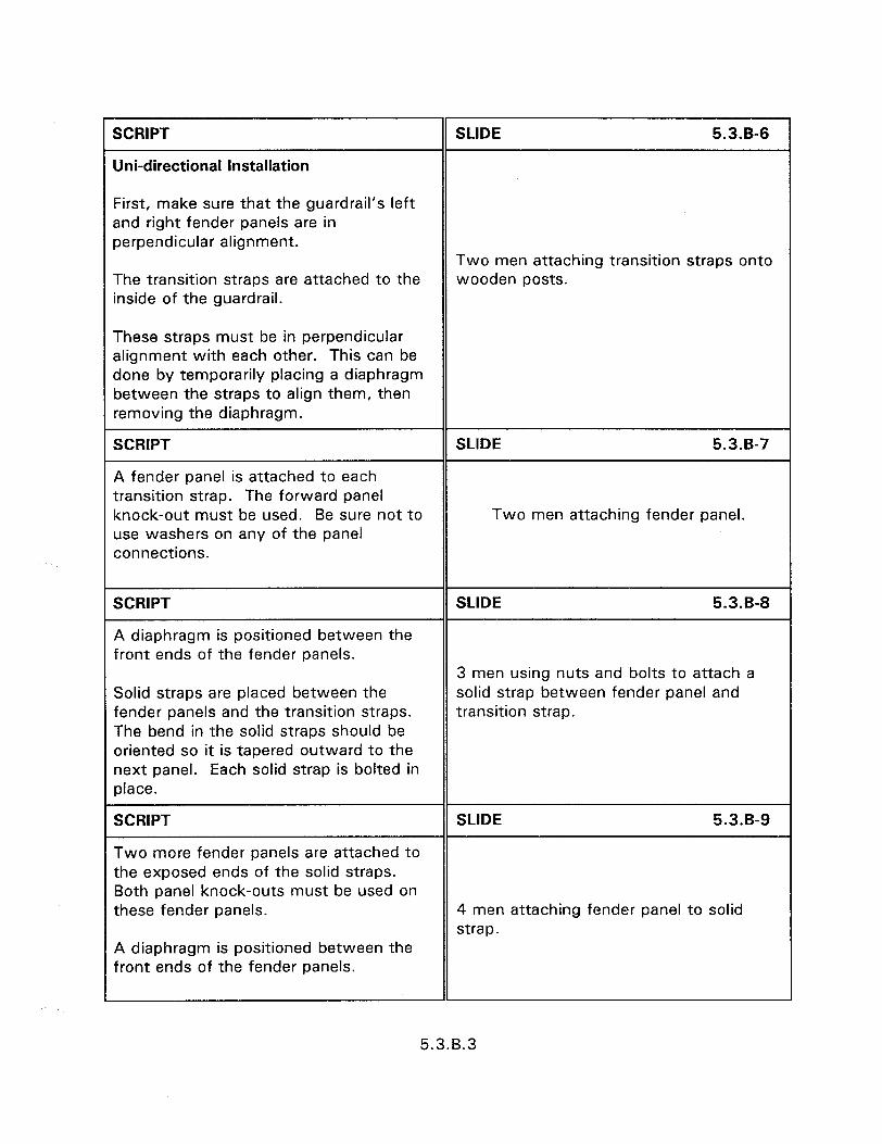
SCRIPT
Uni-directional Installation
SLIDE 5.3.B-6
First, make sure that the guardrail’s left and right fender panels are in perpendicular alignment.
The transition straps are attached to the inside of the guardrail.
Two men attaching transition straps onto wooden posts.
These straps must be in perpendicular alignment with each other. This can be done by temporarily placing a diaphragm between the straps to align them, then removing the diaphragm.
SCRIPT
A fender panel is attached to each transition strap. The forward panel knock-out must be used. Be sure not to use washers on any of the panel connections.
SLIDE 5.3.B-7
Two men attaching fender panel.
SCRIPT
A diaphragm is positioned between the front ends of the fender panels.
SLIDE 5.3.B-8
Solid straps are placed between the fender panels and the transition straps. The bend in the solid straps should be oriented so it is tapered outward to the next panel. Each solid strap is bolted in place.
3 men using nuts and bolts to attach a solid strap between fender panel and transition strap.
SCRIPT
Two more fender panels are attached to the exposed ends of the solid straps. Both panel knock-outs must be used on these fender panels.
SLIDE 5.3.B-9
4 men attaching fender panel to solid strap.
A diaphragm is positioned between the front ends of the fender panels.
5.3.8.3
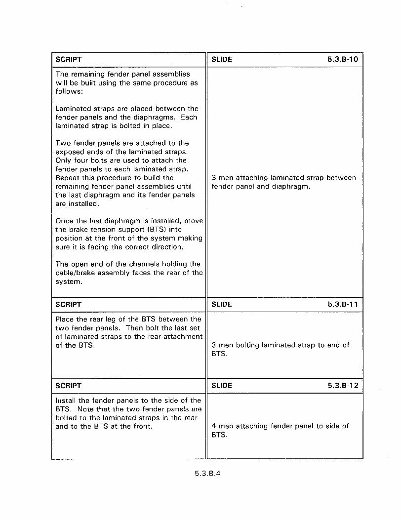
SCRIPT
The remaining fender panel assemblies will be built using the same procedure as follows:
SLIDE 5.3.B-10
Laminated straps are placed between the fender panels and the diaphragms. Each laminated strap is bolted in place.
Two fender panels are attached to the exposed ends of the laminated straps. Only four bolts are used to attach the fender panels to each laminated strap. Repeat this procedure to build the remaining fender panel assemblies until the last diaphragm and its fender panels are installed.
3 men attaching laminated strap between fender panel and diaphragm.
Once the last diaphragm is installed, move the brake tension support (BTS) into position at the front of the system making sure it is facing the correct direction.
The open end of the channels holding the cable/brake assembly faces the rear of the system.
SCRIPT SLIDE 5.3.B-11
Place the rear leg of the BTS between the two fender panels. Then bolt the last set of laminated straps to the rear attachment of the BTS. 3 men bolting laminated strap to end of
BTS.
SCRIPT SLIDE 5.3.B-12
Install the fender panels to the side of the BTS. Note that the two fender panels are bolted to the laminated straps in the rear and to the BTS at the front. 4 men attaching fender panel to side of
BTS.
5.3.B.4
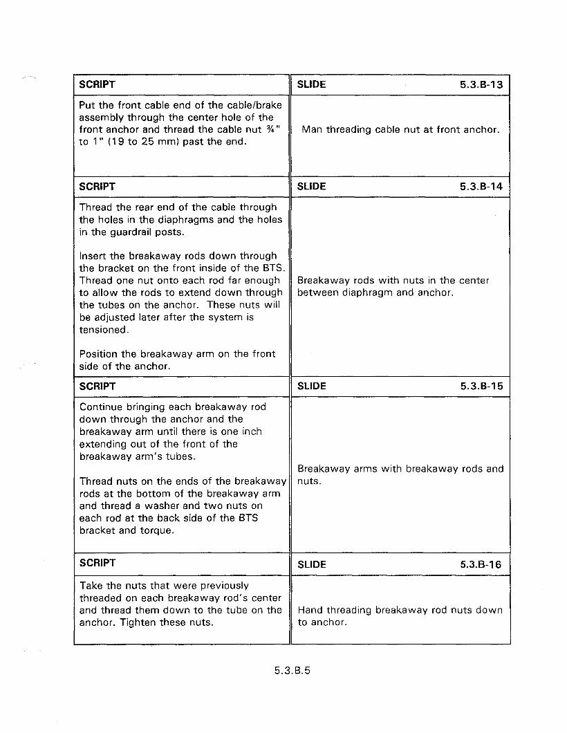
r SCRIPT SLIDE 5.3.B-13
Put the front cable end of the cable/brake assembly through the center hole of the front anchor and thread the cable nut %” Man threading cable nut at front anchor. to 1” (19 to 25 mm) past the end.
SCRIPT SLIDE 5.3.B-14
Thread the rear end of the cable through the holes in the diaphragms and the holes in the guardrail posts.
Insert the breakaway rods down through the bracket on the front inside of the BTS. Thread one nut onto each rod far enough Breakaway rods with nuts in the center to allow the rods to extend down through between diaphragm and anchor. the tubes on the anchor. These nuts will be adjusted later after the system is tensioned.
Position the breakaway arm on the front side of the anchor.
SCRIPT
Continue bringing each breakaway rod down through the anchor and the breakaway arm until there is one inch extending out of the front of the breakaway arm’s tubes.
SLIDE 5.3.B-15
Breakaway arms with breakaway rods and Thread nuts on the ends of the breakaway nuts. rods at the bottom of the breakaway arm and thread a washer and two nuts on each rod at the back side of the BTS bracket and torque.
SCRIPT
Take the nuts that were previously
SLIDE 5.3.B-16
threaded on each breakaway rod’s center and thread them down to the tube on the Hand threading breakaway rod nuts down anchor. Tighten these nuts. to anchor.
5.3.B.5
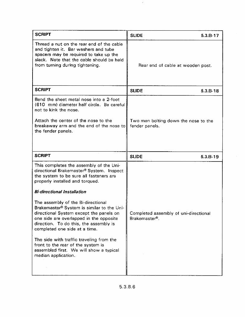
SCRIPT SLIDE 5.3.B-17
Thread a nut on the rear end of the cable and tighten it. Bar washers and tube spacers may be required to take up the slack. Note that the cable should be held from turning during tightening. Rear end of cable at wooden post.
SCRIPT SLIDE 5.3.8-l 8
Bend the sheet metal nose into a 2-foot (610 mm) diameter half circle. Be careful not to kink the nose.
Attach the center of the nose to the Two men bolting down the nose to the breakaway arm and the end of the nose to fender panels. the fender panels.
SCRIPT SLIDE 5.3.B-19
This completes the assembly of the Uni- directional Brakemasters System. Inspect the system to be sure all fasteners are properly installed and torqued.
Bi-direc tional Jns talla tion
The assembly of the Bi-directional Brakemaster@ System is similar to the Uni- directional System except the panels on Completed assembly of uni-directional one side are overlapped in the opposite Brakemaster@. direction. To do this, the assembly is completed one side at a time.
The side with traffic traveling from the front to the rear of the system is assembled first. We will show a typical median application.
5.3.B.6
The right side (when standing in front and facing the rear) is assembled first, starting From the existing guardrail or transition section, and working toward the BTS. The left side is then assembled starting from the BTS and working back to the existing guardrail or transition section.
Be careful during the assembly of the right hand side of the system, as there might be a tendency for the assembly to tip over at this stage.
SCRIPT
The transition strap is attached to the inside of the right guardrail fender panel.
SLIDE 5.3.B-20
A fender panel is attached to the transition strap. The forward panel knock-out must be used. Be sure not to use washers on any of the panel connections.
Left fender panel not attached.
SCRIPT SLIDE 5.3.B-21
A diaphragm is positioned at the front end of the fender panel and a solid strap is placed between the panel and the transition strap. Bolt the strap in place.
Another fender panel is attached to the exposed end of the solid strap. Both panel knock-outs must be used on the fender panel.
Transition strap attached to diaphragm and back of fender panels.
A diaphragm is positioned at the front end of the fender panel.
5.3.B.7
SCRIPT
The remaining fender panels on this side will be built using the same procedure as follows:
A laminated strap is placed between the fender panel and the diaphragm. Each laminated strap is bolted in place.
A fender panel is attached to the exposed end of the laminated strap using four bolts. Repeat this procedure to build the remaining fender panel assemblies until the last diaphragm and one of its panels are installed.
Once the last diaphragm is installed, move the brake tension support (BTS) into position at the front of the system making sure it is facing the correct direction.
The open end of the channels holding the cable/brake assembly faces the rear of the system.
Bolt a laminated strap to the rear attachment on the BTS in the same manner as they were attached to the diaphragms.
Install a fender panel to the right side of the BTS.
Note that the fender panel is bolted to the laminated strap in the rear and to the BTS at the front.
SLIDE 5.3.5-22
5 diaphragms with solid straps bolted to the back of fender panels.
5.3.B.8
SCRIPT SLIDE 5.3.B-23
Now the fender panels will be installed on the left side of the system. Begin at the BTS and work to the rear (guardrail) end.
Install a fender panel to the left side of the BTS.
Note that the fender panel is bolted to the laminated strap in the rear and to the BTS at the front. At the front of the system an 11/,6” (17 mm) diameter hole will need to be drilled in the fender panel to match the hole location in the front of the BTS.
First fender panel in place on left side.
SCRIPT SLIDE 5.3.B-24
Attach the next fender panel to the exposed portion of the laminated strap. A laminated strap is bolted between the rear end of the fender panel and the first Man bolting down second fender panel or diaphragm. left side.
SCRIPT
Attach another fender panel to the exposed portion of the laminated strap. Then bolt a solid strap between the rear end of this fender panel and the next diaphragm. The bend in the solid strap should be oriented so it is tapered outward to the next panel.
SLIDE 5.3.B-25
Attach a fender panel to the exposed portion of the solid strap. Both panel knock-outs must be used with a total of six bolts at this connection. Then bolt a solid strap between the rear end of this fender panel and the next diaphragm.
Side view of man attaching fender panel.
5.3.B.9
SCRIPT SLIDE 5.3.B-26
Bolt the last fender panel to the solid strap. Six bolts are also used here. Locate and match drill an 11/,6” (I 7 mm) Man bolting fender panel to laminated diameter hole through the fender panel at strap. the rear post bolt location.
SCRIPT SLIDE 5.3.B-27
Disassemble the existing guardrail connection point. Then reassemble the guardrail making sure that the last fender panel is under the existing guardrail. After this step is complete, straighten the system. Man assembling last fender panel under
guardrail panel. Then match drill four 11/,6” (17 mm) diameter holes through the existing guardrail and underlying fender panel, and complete the connection.
SCRIPT SLIDE 5.3.B-28
Put the front cable end of the Cable/Brake Assembly through the center hole of the front anchor and thread the cable nut %I” Man threading cable through center hole to 1” (I 9 to 25 mm) past the end. of front anchor.
SCRIPT SLIDE 5.3.8-29
Thread the rear end of the cable through the holes in the diaphragms and the holes in the guardrail posts.
Insert the breakaway rods down through the bracket on the front side of the BTS.
Cable and breakaway rods at the rear end. Thread one nut onto each rod far enough to allow the rods to extend down through the tubes on the anchor. These nuts will be adjusted later after the system is tensioned.
5.3.B.10
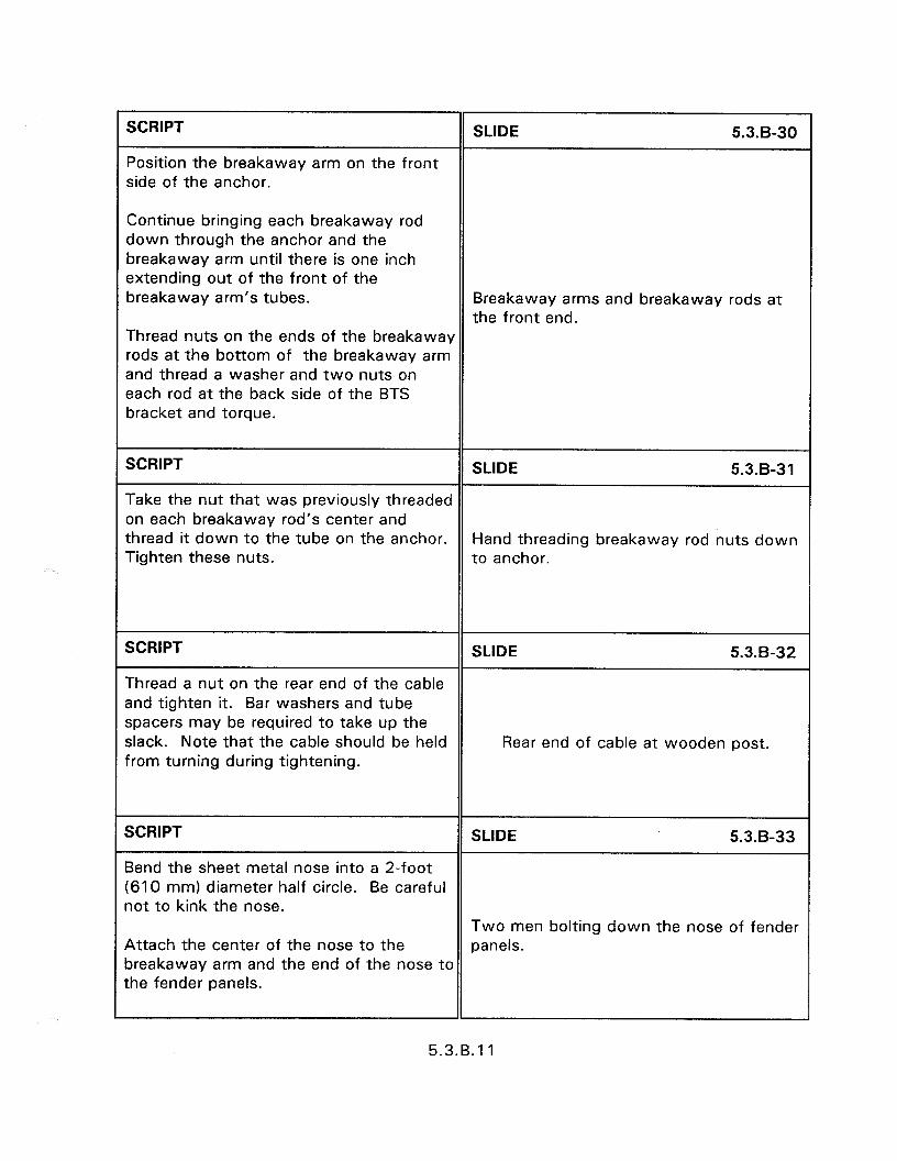
SCRIPT
Position the breakaway arm on the front side of the anchor.
SLIDE 5.3.8-30
Continue bringing each breakaway rod down through the anchor and the breakaway arm until there is one inch extending out of the front of the breakaway arm’s tubes. Breakaway arms and breakaway rods at
the front end. Thread nuts on the ends of the breakaway rods at the bottom of the breakaway arm and thread a washer and two nuts on each rod at the back side of the BTS bracket and torque.
SCRIPT SLIDE 5.3.8-31
Take the nut that was previously threaded on each breakaway rod’s center and thread it down to the tube on the anchor. Hand threading breakaway rod nuts down Tighten these nuts. to anchor.
SCRIPT SLIDE 5.3.B-32
Thread a nut on the rear end of the cable and tighten it. Bar washers and tube spacers may be required to take up the slack. Note that the cable should be held Rear end of cable at wooden post. from turning during tightening.
SCRIPT SLIDE 5.3.B-33
Bend the sheet metal nose into a 2-foot (610 mm) diameter half circle. Be careful not to kink the nose.
Two men bolting down the nose of fender Attach the center of the nose to the panels. breakaway arm and the end of the nose to the fender panels.
5.3.B.l 1
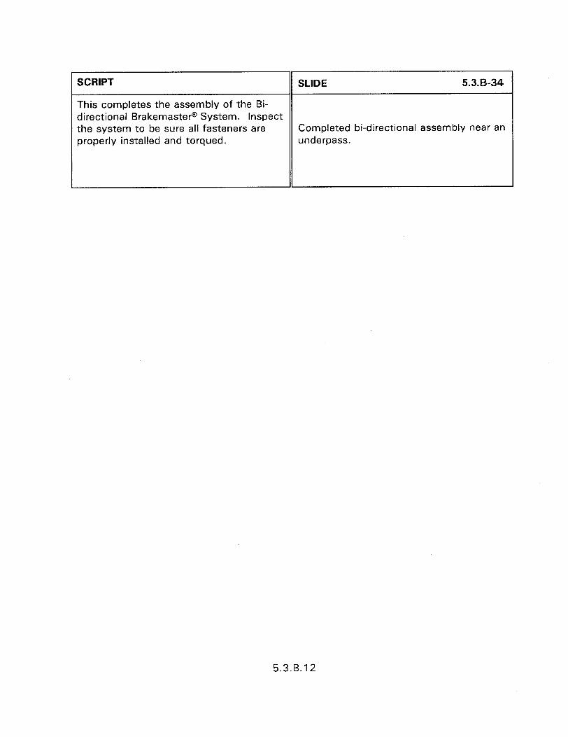
SCRIPT
This completes the assembly of the Bi- directional Brakemaster@ System. Inspect the system to be sure all fasteners are properly installed and torqued.
5.3.6-34 1
Completed bi-directional assembly near an underpass.
i II I
5.3.B.12

BREAKOUT 5.3.C - INSTALLATION OF THE CAT SYSTEM
SCRIPT
The CAT system utilizes 6 soil tubes.
SLIDE 5.3.c-1
INSTALLATION OF THE CAT
SCRIPT SLIDE 5.3.C2
A split post is installed at location 1. Before the post is installed in the soil tube, the pipe sleeve for the anchor cable should be installed. The other posts are installed
Slide showing the post at location 1.
in the soil tubes as did earlier.
SCRIPT SLIDE 5.3.c-3
Blockouts are bolted to the posts at locations 3, 5, and 6. The rail panels are not bolted to the posts at these locations.
Slide showing the blockouts at post locations 3, 5, or 6.
SCRIPT SLIDE 5.3.c-4
Tubes are bolted to the posts at locations 4 and 6. A post plate is bolted to the post at location 4.
Slide showing the tube and post plate.
SCRIPT SLIDE 5.3-c-5
The rail panels are installed next. The 10 gage rail panels are installed first. The panels are installed with the welded plates installed at post location 4. Both rail Slide showing the welded plate on the panels should be installed to the outside of back of the 10 gage rail panel. the approaching rail elements.
5.3.c. 1
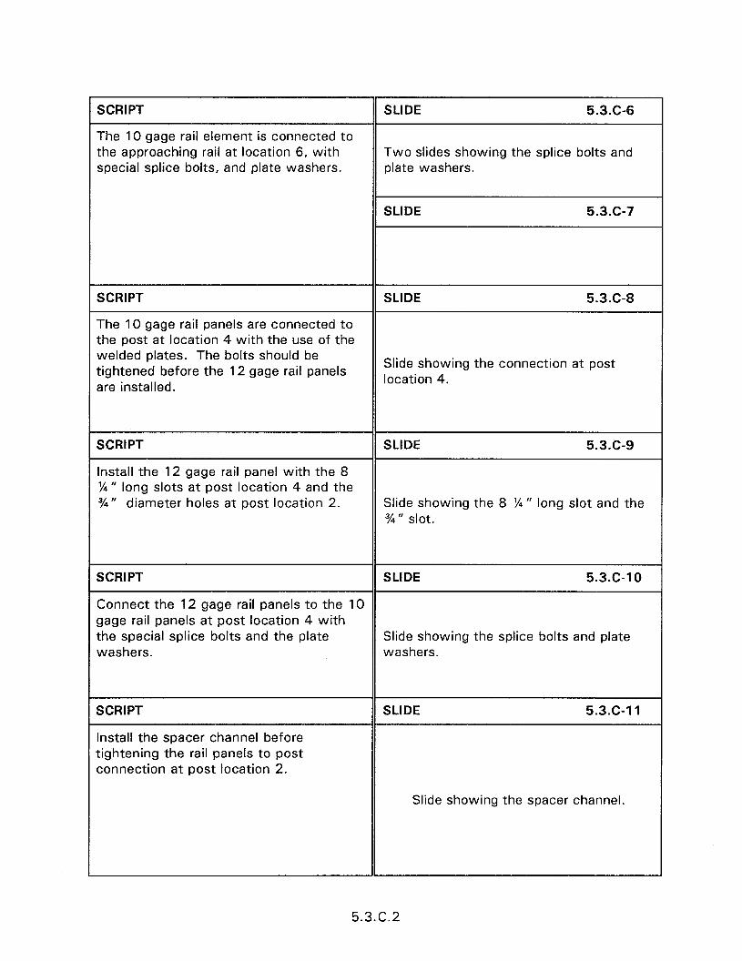
SCRIPT
The 10 gage rail element is connected to the approaching rail at location 6, with special splice bolts, and plate washers.
SLIDE 5.3.C-6
Two slides showing the splice bolts and plate washers.
SLIDE 5.3.G7
SCRIPT
The 10 gage rail panels are connected to the post at location 4 with the use of the welded plates. The bolts should be tightened before the 12 gage rail panels are installed.
SLIDE 5.3.C-8
Slide showing the connection at post location 4.
SCRIPT
Install the 12 gage rail panel with the 8 %” long slots at post location 4 and the %” diameter holes at post location 2.
SLIDE 5.3.c-9
Slide showing the 8 %” long slot and the %I” slot.
SCRIPT SLIDE 5.3.c-10
Connect the 12 gage rail panels to the 10 gage rail panels at post location 4 with the special splice bolts and the plate Slide showing the splice bolts and plate washers. washers.
SCRIPT
Install the spacer channel before tightening the rail panels to post connection at post location 2.
SLIDE 5.3.c-11
Slide showing the spacer channel.
1
5.3.C.2
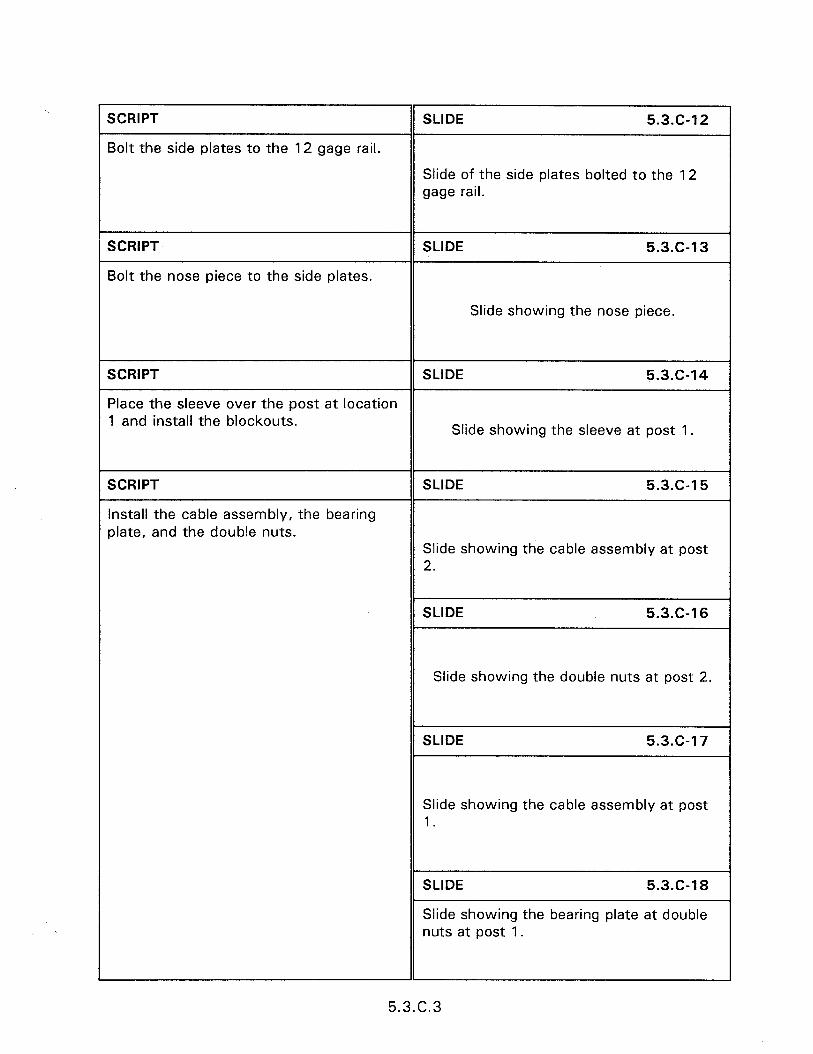
SCRIPT
Bolt the side plates to the 12 gage rail.
SLIDE 5.3.C-12
Slide of the side plates bolted to the 12 gage rail.
SCRIPT
Bolt the nose piece to the side plates.
SLIDE 5.3.c-13
Slide showing the nose piece.
SCRIPT SLIDE 5.3.c-14
Place the sleeve over the post at location 1 and install the blockouts.
Slide showing the sleeve at post 1.
SCRIPT
Install the cable assembly, the bearing plate, and the double nuts.
SLIDE 5.3.c-15
Slide showing the cable assembly at post 2.
SLIDE 5.3.C-16
Slide showing the double nuts at post 2.
SLIDE 5.3.c-17
Slide showing the cable assembly at post 1.
Slide showing the bearing plate at double
SCRIPT
Install the two buckling restraint rods.
SLIDE 5.3.c-19
Slide showing the restraint rods.
SCRIPT
The completed installation.
SLIDE 5.3.c-20
Slide showing the completed installation.
5.3.c.4
BREAKOUT 5.3.D - INSTALLATION OF THE CUSHION WALLTM
SCRIPT
CUSHION WALLTM
SLIDE 5.3.D-1
INSTALLATION OF THE CUSHION WALLTM
SCRIPT SLIDE 5.3.D-2
These instructions assume that a rigid concrete wall with a vertical face a minimum of 991 mm tall and a minimum radius of curvature equal to 116 m is newly formed and fully cured. A rigid concrete transition section with a
Car crashing into Cushion WallTM.
minimum depth of 660 mm and 914 mm tall is also required at the beginning of the LON.
SCRIPT SLIDE 5.3.0-3
Begin installation by locating and drilling the first bay Mounting Bracket holes. Position Bay #l Drill Template so that the left edge of the template is up against the end of the concrete transition. Use a level to assure the template is positioned correctly, and then using a template, drill four holes in the concrete with the roto- hammer. Discard Bay #I Drill Template.
Using the Mounting Bracket Drill Template, insert pine into the rightmost hole recently drilled for the first bay Mounting Bracket and rest the foot of the template on level ground. Proper use of the Mounting Bracket Drill Template will provide the 737 mm bay spacing and the 280 mm Mounting Bracket height required. Drill four holes in the concrete wall with the roto-hammer and repeat process for each successive bay until all Mounting Bracket holes are drilled.
GB and Cushion WallTM.
5.3.0.1
Meanwhile, the second person can begin installing the MP-3 anchors in the holes previously drilled per the instructions which accompany the MP-3 kit. Always leave the rightmost hole clear, until it is used to index the Mounting Bracket Drill Template for the next bay. Note that on the last bay, only the three leftmost holes need to be drilled.
When MP-3 anchors are fully cured, install the Cell and Bracket Assemblies. Locate the loose strap ends which are attached to the Cell and Bracket Assemblies. Bolt the ends of the adjoining bay straps through the Mounting Bracket using the bolts, lock washers, and nuts. After all Cell and Bracket Assemblies are installed on the wall, attach one end of the Belt Assembly to the last Bay Mounting Bracket, and then attach to wall.
SCRIPT SLIDE 5.3.D-4
Starting at the downstream end of the installation, attach one end of the schedule 80 pipe to the Last Bay Mounting Bracket using a clevis pin and retainer pin. Disassemble a Hinge Plate from one Fender Panel Assembly (save the Fender Panel and Panel Bracket to later install in Bay #l). Locate the loose Fender Panel Bracket and attach it and the free end of the Belt Assembly to the Hinge Plate using eight button head socket screws, a 10 ga. bar washer, lock washers, and nuts. Then attach the free Close up of Cushion WallTM.
end of the pipe to the Fender Panel Bracket with another clevis pin and retainer pin.
Located a 6 mm x 540 mm cable and attach one end to the Last Bay Mounting Bracket using a clevis pin and retainer pin. Attach the other end to the Fender Panel Bracket just installed.
5.3.D.2
Attach one end of another schedule 80 oipe to the next Mounting Bracket using a clevis pin and retainer pin. Attach a Fender Panel Assembly to the Hinge Plate iust installed with short pipe spacers, 10 ga. bar washers, and nuts. Then attach the free end of the pipe to the Fender Panel Bracket with another clevis pin and retainer pin. Attach the next cable.
SCRIPT SLIDE 5.3.D-5
Attach the remaining pipes, Fender Panel and Cable Assemblies in the same manner as described above, working toward the first bay. The last Fender Panel to be installed (Bay #l ) will be the one Fender Close up of fender panels. Panel without a Hinge Plate.
SCRIPT SLIDE 5.3.D-6
Locate a 10 mm x 1155 mm cable and attach one end to the first bay Mounting Bracket and the other end to the third bay Fender Panel Bracket using 13 mm chain shackles. Continue this pattern with each successive bay until the last Fender Panel Bracket is reached. There should be no 10 mm cable attached to the last two Mounting Brackets.
Attach one end of the two remaining cables to the Fender Panel Brackets in Bays #l and 2, and the other end to the Transition Bracket. Using the Transition Bracket as a template, locate and drill two holes on top of the concrete transition wall. Position the Transition Bracket so that the first two cables are not excessively slack when attached to the Transition Bracket. Install two MP-3 Anchors and when cured, securely attach the Transition Bracket.
Downstream view of installation.
5.3.D.3

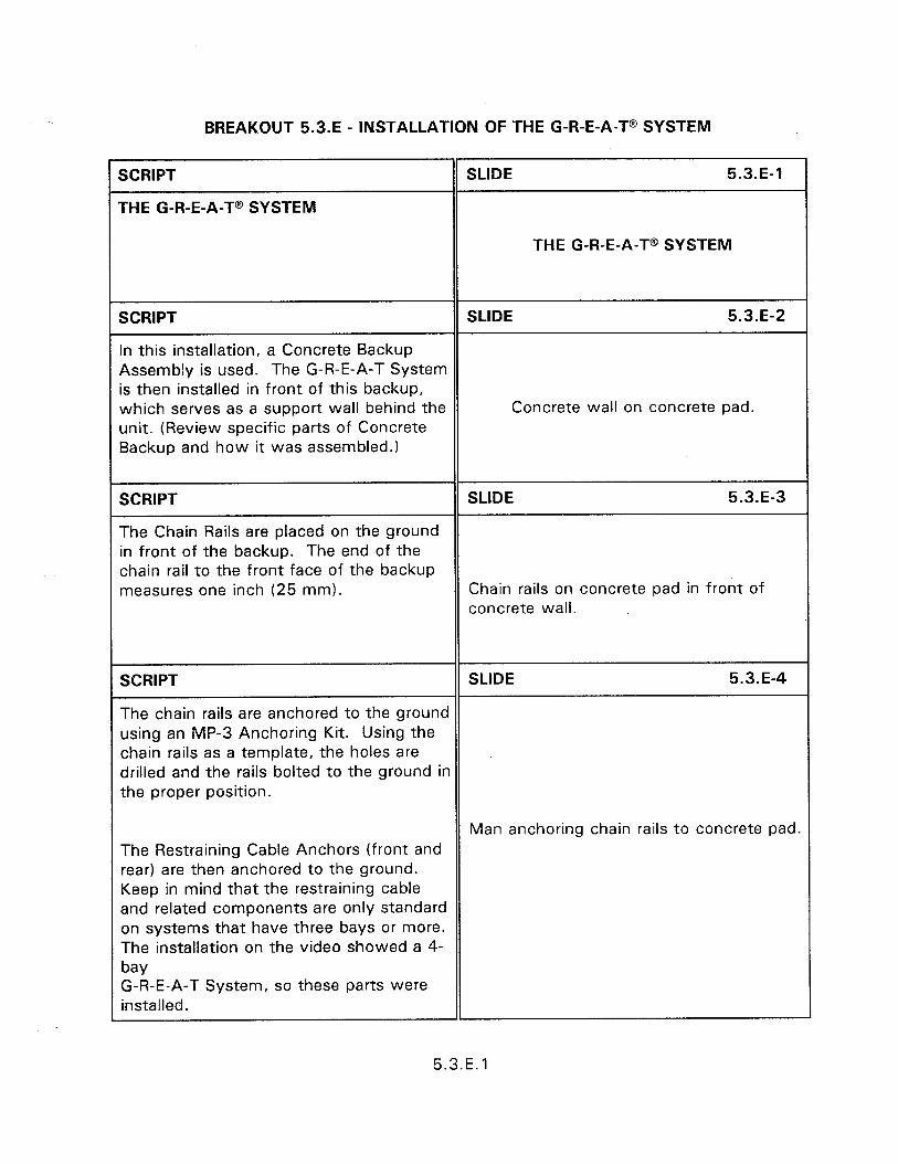
BREAKOUT 5.3.E - INSTALLATION OF THE G-R-E-A-T@ SYSTEM
SCRIPT
THE G-R-E-A-T@ SYSTEM
SLIDE 5.3.E-1
THE G-R-E-A-T@ SYSTEM
SCRIPT SLIDE 5.3.E-2
In this installation, a Concrete Backup Assembly is used. The G-R-E-A-T System is then installed in front of this backup, which serves as a support wall behind the Concrete wall on concrete pad. unit. (Review specific parts of Concrete Backup and how it was assembled.)
SCRIPT SLIDE 5.3.E-3
The Chain Rails are placed on the ground in front of the backup. The end of the chain rail to the front face of the backup measures one inch (25 mm). Chain rails on concrete pad in front of
concrete wall.
SCRIPT SLIDE 5.3.E-4
The chain rails are anchored to the ground using an MP-3 Anchoring Kit. Using the chain rails as a template, the holes are drilled and the rails bolted to the ground in the proper position.
Man anchoring chain rails to concrete pad. The Restraining Cable Anchors (front and rear) are then anchored to the ground. Keep in mind that the restraining cable and related components are only standard on systems that have three bays or more. The installation on the video showed a 4- bay G-R-E.-A-T System, so these parts were installed.
5.3.E. 1
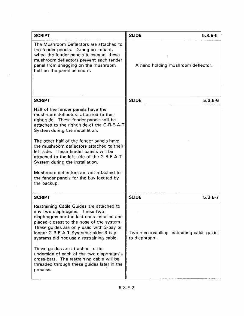
SCRIPT SLIDE 5.3.E-5
The Mushroom Deflectors are attached to the fender panels. During an impact, when the fender panels telescope, these mushroom deflectors prevent each fender panel from snagging on the mushroom A hand holding mushroom deflector. bolt on the panel behind it.
SCRIPT SLIDE 5.3.E-6
Half of the fender panels have the mushroom deflectors attached to their right side. These fender panels will be attached to the right side of the G-R-E-A-T System during the installation.
The other half of the fender panels have the mushroom deflectors attached to their left side. These fender panels will be attached to the left side of the G-R-E-A-T System during the installation.
Mushroom deflectors are not attached to the fender panels for the bay located by the backup.
SCRIPT SLIDE 5.3.E-7
Restraining Cable Guides are attached to any two diaphragms. These two diaphragms are the last ones installed and placed closest to the nose of the system. These guides are only used with 3-bay or longer G-R-E-A-T Systems; older 3-bay Two men installing restraining cable guide systems did not use a restraining cable. to diaphragm.
These guides are attached to the underside of each of the two diaphragm’s cross-bars. The restraining cable will be threaded through these guides later in the process.
5.3.E.2
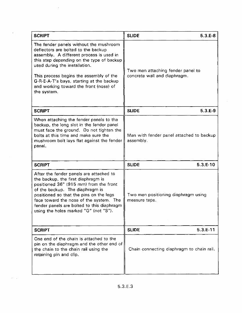
r SCRIPT SLIDE 5.3.E
The fender panels without the mushroom deflectors are bolted to the backup assembly. A different process is used in this step depending on the type of backup used during the installation.
Two men attaching fender panel to This process begins the assembly of the concrete wall and diaphragm. G-R-E-A-T’s bays, starting at the backup and working toward the front (nose) of the system.
SCRIPT SLIDE 5.3.E
When attaching the fender panels to the backup, the long slot in the fender panel must face the ground. Do not tighten the bolts at this time and make sure the Man with fender panel attached to back1 mushroom bolt lays flat against the fender assembly. panel.
SCRIPT SLIDE 5.3.E-1
After the fender panels are attached to the backup, the first diaphragm is positioned 36” (915 mm) from the front of the backup. The diaphragm is positioned so that the pins on the legs Two men positioning diaphragm using face toward the nose of the system. The measure tape. fender panels are bolted to this diaphragm using the holes marked “G” (not “S”).
SCRIPT SLIDE 5.3.E-1
One end of the chain is attached to the pin on the diaphragm and the other end of the chain to the chain rail using the Chain connecting diaphragm to chain ra retaining pin and clip.
5.3.E.3
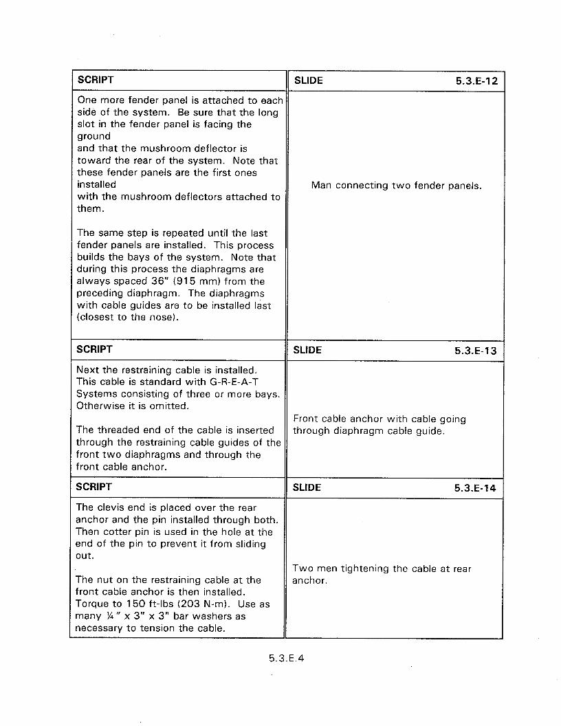
SCRIPT SLIDE 5.3.E-12
One more fender panel is attached to each side of the system. Be sure that the long slot in the fender panel is facing the ground and that the mushroom deflector is toward the rear of the system. Note that these fender panels are the first ones installed Man connecting two fender panels. with the mushroom deflectors attached to them.
The same step is repeated until the last fender panels are installed. This process builds the bays of the system. Note that during this process the diaphragms are always spaced 36” (915 mm) from the preceding diaphragm. The diaphragms with cable guides are to be installed last (closest to the nose).
SCRIPT SLIDE 5.3.E-13
Next the restraining cable is installed. This cable is standard with G-R-E-A-T Systems consisting of three or more bays. Otherwise it is omitted.
Front cable anchor with cable going The threaded end of the cable is inserted through diaphragm cable guide. through the restraining cable guides of the front two diaphragms and through the front cable anchor.
SCRIPT SLIDE 5.3.E-14
The clevis end is placed over the rear anchor and the pin installed through both. Then cotter pin is used in the hole at the end of the pin to prevent it from sliding out.
The nut on the restraining cable at the front cable anchor is then installed. Torque to 150 ft-lbs (203 N-m). Use as many % N x 3” x 3” bar washers as necessary to tension the cable.
Two men tightening the cable at rear anchor.
5.3.E.4
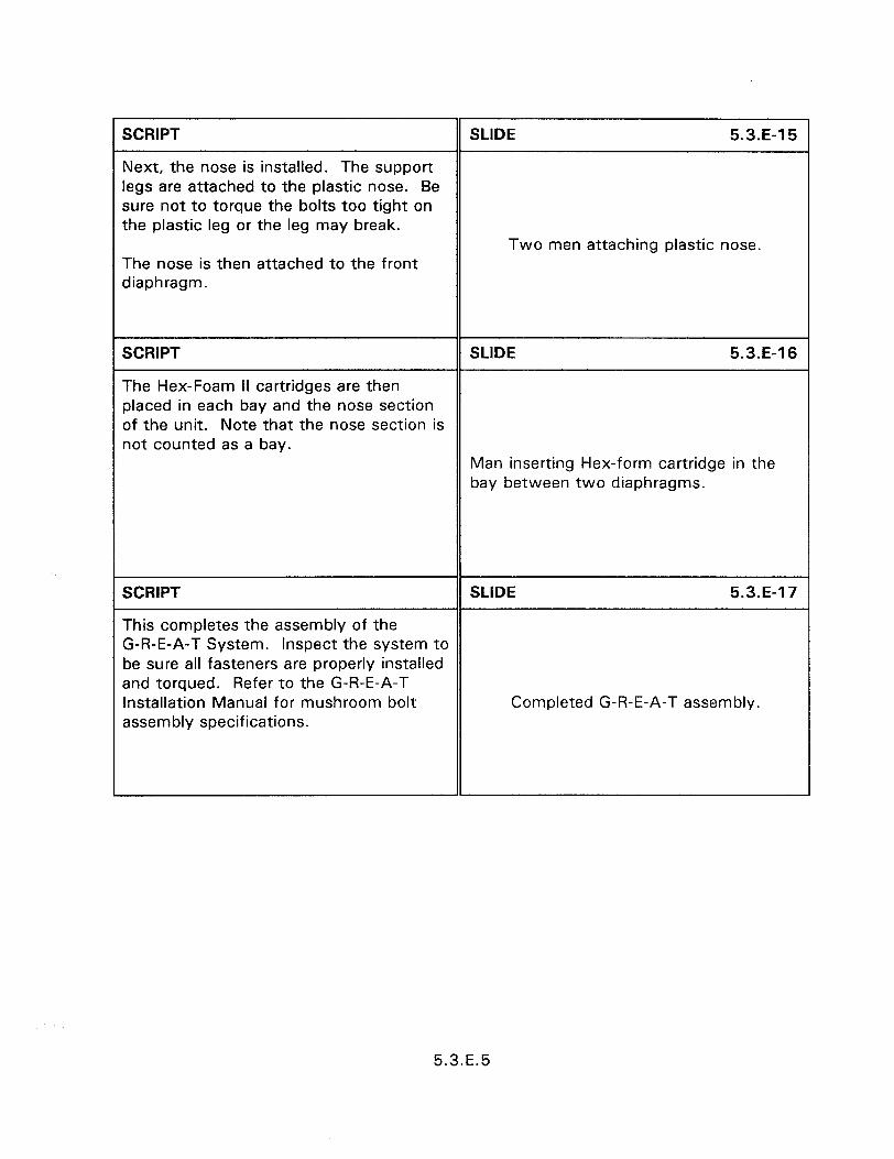
c SCRIPT
Next, the nose is installed. The support legs are attached to the plastic nose. Be sure not to torque the bolts too tight on the plastic leg or the leg may break.
SLIDE 5.3.E-15
The nose is then attached to the front diaphragm.
Two men attaching plastic nose.
SCRIPT SLIDE 5.3.E-16
The Hex-Foam II cartridges are then placed in each bay and the nose section of the unit. Note that the nose section is not counted as a bay.
Man inserting Hex-form cartridge in the bay between two diaphragms.
SCRIPT SLIDE 5.3.E-17
This completes the assembly of the G-R-E-A-T System. Inspect the system to be sure all fasteners are properly installed and torqued. Refer to the G-R-E-A-T Installation Manual for mushroom bolt Completed G-R-E-A-T assembly. assembly specifications.
1
5.3.E.5

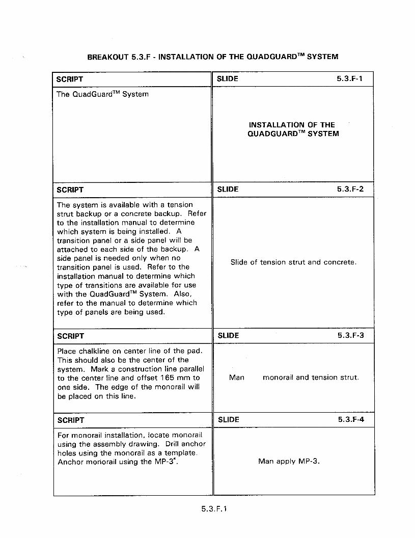
BREAKOUT 5.3.F - INSTALLATION OF THE QUADGUARDTM SYSTEM
SCRIPT
The QuadGuardTM System
SLIDE 5.3.F-1
INSTALLATION OF THE QUADGUARDTM SYSTEM
SCRIPT SLIDE 5.3.F-2
The system is available with a tension strut backup or a concrete backup. Refer to the installation manual to determine which system is being installed. A transition panel or a side panel will be attached to each side of the backup. A side panel is needed only when no transition panel is used. Refer to the
Slide of tension strut and concrete.
installation manual to determine which type of transitions are available for use with the QuadGuardTM System. Also, refer to the manual to determine which type of panels are being used.
SCRIPT SLIDE 5.3.F-3
Place chalkline on center line of the pad. This should also be the center of the system. Mark a construction line parallel to the center line and offset 165 mm to Man monorail and tension strut. one side. The edge of the monorail will be placed on this line.
SCRIPT SLIDE 5.3.F-4
For monorail installation, locate monorail using the assembly drawing. Drill anchor holes using the monorail as a template. Anchor monorail using the MP-3”. Man apply MP-3.
5.3.F. 1

SCRIPT
Attach the transition panel or the side panel as appropriate to each side of the backup. Refer to the installation manual for information.
SLIDE 5.3.F-5
Transition panel.
SCRIPT SLIDE 5.3.F-6
Attach the monorail guides to diaphragms.
Man attaching diaphragms.
SCRIPT SLIDE 5.3.F-7
Orient a diaphragm so that the front face of the quad beam shape faces toward the Nose of the system. Slide the diaphragm onto the monorail. Slide the first diaphragm all the way to the backup to ensure system is able to collapse properly during impact. Once this has been verified then slide the diaphragm forward to approximately 915 nun in front of the backup. Orient and slide all other diaphragms on monorail and position each approximately 915 mm in front of the
Man carrying diaphragm.
previous diaphragm.
5.3.F.2
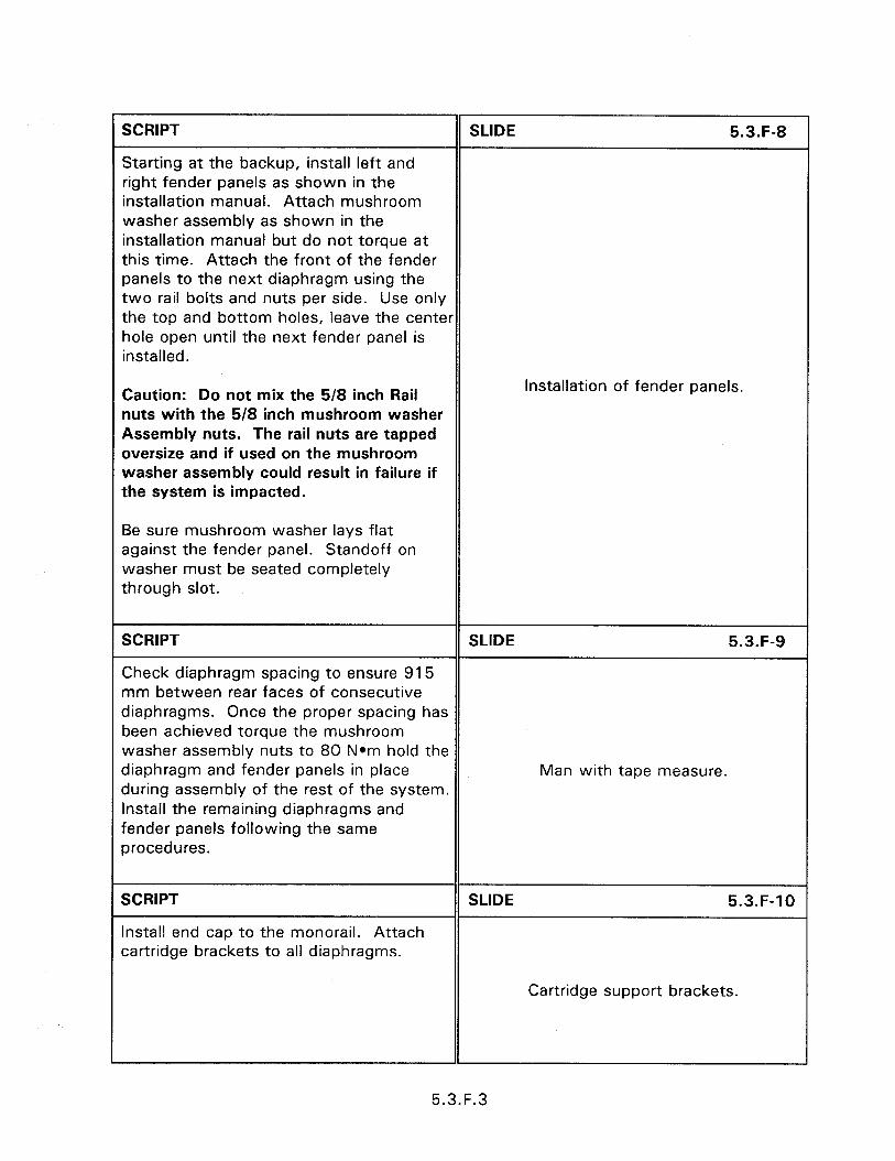
SCRIPT SLIDE 5.3.F-8
Starting at the backup, install left and right fender panels as shown in the installation manual. Attach mushroom washer assembly as shown in the installation manual but do not torque at this time. Attach the front of the fender panels to the next diaphragm using the two rail bolts and nuts per side. Use only the top and bottom holes, leave the center hole open until the next fender panel is installed.
Caution: Do not mix the 5/8 inch Rail nuts with the 518 inch mushroom washer Assembly nuts. The rail nuts are tapped oversize and if used on the mushroom washer assembly could result in failure if the system is impacted.
Installation of fender panels.
Be sure mushroom washer lays flat against the fender panel. Standoff on washer must be seated completely through slot.
SCRIPT SLIDE 5.3.F-9
Check diaphragm spacing to ensure 915 mm between rear faces of consecutive diaphragms. Once the proper spacing has been achieved torque the mushroom washer assembly nuts to 80 Nom hold the diaphragm and fender panels in place Man with tape measure. during assembly of the rest of the system. Install the remaining diaphragms and fender panels following the same procedures.
SCRIPT
Install end cap to the monorail. Attach cartridge brackets to all diaphragms.
SLIDE 5.3.F-10
Cartridge support brackets.
5.3.F.3
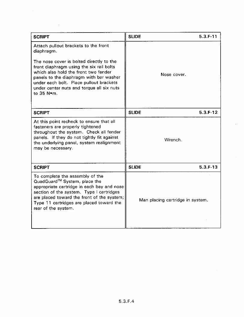
Nose cover.
SCRIPT
Attach pullout brackets to the front diaphragm.
SLIDE 5.3.F-11
The nose cover is bolted directly to the front diaphragm using the six rail bolts which also hold the front two fender panels to the diaphragm with bar washer under each bolt. Place pullout brackets under center nuts and torque all six nuts to 35 Nom.
SCRIPT SLIDE 5.3.F-12
At this point recheck to ensure that all fasteners are properly tightened throughout the system. Check all fender panels. If they do not tightly fit against the underlying panel, system realignment
Wrench.
may be necessary.
SCRIPT SLIDE 5.3.F-13
To complete the assembly of the QuadGuardTM System, place the appropriate cartridge in each bay and nose section of the system. Type I cartridges are placed toward the front of the system; Type 11 cartridges are placed toward the
Man placing cartridge in system.
rear of the system.
5.3.F.4
BREAKOUT 5.3.G - INSTALLATION OF THE LMATM SYSTEM
SCRIPT
THE LMATM SYSTEM
SLIDE 5.3.G-1
INSTALLATION OF THE LMATM SYSTEM
SCRIPT SLIDE 5.3.G-2
The LMATM System should be installed on reinforced concrete base with a minimum compressive strength of 26.6 MPa.
The tension strut backup is a free standing backup structure. Install the side, extension or transition panels on the backup.
LMATM next to warning sign.
Locate, drill, and install the chain rails with the horizontal bolting flange extended toward the sides of the concrete pad.
SCRIPT SLIDE 5.3.G-3
The LMATM System is made up of 12 bays and a nose section. Bay number I is located directly behind the nose section. The bays are progressively numbered toward the backup. Each bay is separated by a diaphragm. There are 12 diaphragms in the system. Diaphragms 1 and 2 have a “restraining cable guide” bolted be the support legs, diaphragms 3
Elevation view.
through 12 do not.
Each bay in the LMA receives a cylinder assembly. There are five different cylinder assemblies, designated Types I through V.
5.3.G. 1
Each cylinder assembly is construct by first attaching two sets of inner and outer clamping plates to the cylinder. Each elastomeric cylinder is stenciled with the cylinder type. Be sure to orient cylinders with the type number on top. (the nose cylinder type number should be in front).
Beginning at the backup, locate and position the cylinder assembly for bay 12. Place the cylinder assembly so that the outer clamping plate rests on the portion of the threaded rod that protrudes through the backup then secure it with flat washers and nuts.
Next position a diaphragm in front of the cylinder assembly so that the pin in the diaphragm leg protrudes forward, then lower the clamping plate of the cylinder assembly over the rod in the diaphragm. Now place an end link of a restraining chain over the 19 mm diaphragm leg pin and secure the other end link to the chain rail. Repeat this procedure on the other leg of the diaphragm, then secure the forward portion of the cylinder assembly to the diaphragm with flat washers and nuts.
Continue attaching the cylinder assemblies to the diaphragms and work forward from the backup to diaphragm number 2. IMPORTANT: Position the correct cylinder assembly in each bay according to the installation manual.
Bolt cable guides to diaphragms 1 and 2. Next install the cylinder assembly between diaphragms 1 and 2.
5.3.G.2
SCRIPT SLIDE 5.3.G-4
After all of the cylinder assemblies are attached to the diaphragms, threaded rods of various lengths are used to connect the cylinder assemblies together through the diaphragm. The correct rod sizes for each diaphragm are listed in the installation manual.
Attach a flat washer and nut to the other ends of the rods and tighten. Repeat this step for the remaining diaphragms and the backup.
Finally, attach the nose cylinder. Secure the nose attachment bolts with flat washer and nuts.
Front view.
ASSEMBLY
Install the restraining cable. Starting at the backup, attach the left and right fender panels (without mushroom deflectors). Attach mushroom deflectors to the fender panels.
Attach the front two fender panels.
SCRIPT SLIDE 5.3.G-5
Install the nose cover to the diaphragm and fender panel assembly. Attach the legs to the nose cylinder and nose cover.
Torque the restraining cable nut on the front cable anchor complete the LMATM System installation.
Check the system according to installation manual.
Workers attaching nose cover.
1
5.3.G.3

BREAKOUT 5.3.H - INSTALLATION OF THE N-E-A-TTM SYSTEM
SCRIPT
N-E-A-TTM SYSTEM
SLIDE 5.3.H-1
INSTALLATION OF THE N-E-A-TTM SYSTEM
SCRIPT SLIDE 5.3.H-2
Begin the installation by lifting the end of the Portland Concrete Moveable Barrier (PCMB) section. This can be accomplished by using a large block of wood and a 2 m long pry bar.
Slide the lower support strap so that its edge is about 305 mm back from the end of the PCMB. Next, straddle the upper half of the support strap over the PCMB and align with the lower support strap. Insert the 19.05 mm diameter bolts starting with the upper strap through to the lower strap and place the nuts on the end of the bolts. HAND TIGHTEN ONLY!
Slide of man placing large pin into support
l Position the support attachment frame on PCMB.
so that the shorter tubes are on top. Place the flat end, that is the side opposite the tubes onto the end of the PCMB such that the PCMB’s loops protrude through the slot.
a Place a bracket over each of the two protruding loops of the PCMB such that the bracket nests into the slot of the support attachment frame, and the bracket’s flanges face outward.
5.3.H.l
l Insert the wedges through the brackets and into the loops. Insert the wedge with the nut welded on the bottom into the bottom loop from below. Insert the wedge with only a hole (no threads) into the top loop from above. Insert the 625 mm long threaded 13 mm diameter bolt through the upper wedge and thread into the lower wedge. Torque to 80 Nom. Align the bottom of the support attachment frame with the bottom and centered left to right on the PCMB section.
SCRIPT SLIDE 5.3.H-3
The backup is attached to the rear of the N-E-A-TTM cartridge. It is attached with the tubes on the side away from the cartridge and the flange with the half- moon shaped cut-out at the bottom. There are three sets of mounting holes on the backup. Choose the set of holes such that the bottom edge of the cartridge will be 100 mm off the ground. In the
Slide of backup from attached to PCMB.
majority of cases, the middle set of holes will result in proper cartridge height. Place the backup onto the rear end of the N-E-A-TTM cartridge, and fasten the eight 13 mm nuts with their flat washers and lockwashers into place. Torque to 122 Nom.
SCRIPT SLIDE 5.3.H-4
Roll the cartridge with the attached backup up against the support structure until the tubes on the backup nest with the tubes on the support structure. It may be necessary to lift the rear end of the cartridge so that the tubes can nest. Place the two large 38 mm diameter by
Slide of two men inserting pins.
900 mm long pins into the two sets of nested tubes to hold the cartridge into place. To get the pins to fall into place, it may be necessary to align the tubes on the backup and support structure.
5.3.H.2
SCRIPT SLIDE 5.3.H-5
The N-E-A-TTM cartridge comes with bi- directional, left-hand, or right-hand chevron markings. Remove the four 10 mm bolts on the front of the cartridge using the 14 mm socket, and depending upon cartridge placement, use whichever
Slide showing chevron on N-E-A-TTM.
chevron markings suit your application. Refer to MUTCD or state traffic control plan. Tighten the 10 mm bolts to 20 Nom.
SCRIPT
Now it is possible to remove the 10 mm thick shim from under the PCMB.
SLIDE 5.3.H-6
CAUTION! NEVER USE THE PRY BAR ON THE CARTRIDGE ITSELF, SEVERE DAMAGE TO THE CARTRlDGE WILL RESULT.
With PCMB resting directly on the ground, measure how high the bottom of the cartridge is from the grade. It should be 100 mm off the ground, and not vary by more than 25 mm over the length of the cartridge.
if height adjustments are necessary, the folio wing changes can be made:
Slide of increasing traffic and N-E-A-TTM attached to PCMB.
0 One of the remaining two hole patterns on the backup can be used to raise or lower the cartridge. The hole patterns are 38 mm apart. This adjustment method requires unpinning the cartridge from the support structure, removing the eight nuts from the backup and repositioning up or down as necessary.
5.3.H.3

l It is also possible to raise or lower the support structure. This requires unpinning the cartridge from the support structure and rolling it out of the way, loosening the wedge tension bolt, and then raising the support structure to the desired height before tightening the tension bolt.
5.3.H.4
BREAKOUT 5.3.1 - INSTALLATION OF THE REACT-350TM
SCRIPT
REACT-350TM
SLIDE 5.3.1-I
The REACT-350TM is a self restraining bi- directional crash cushion that can be designed to meet all test levels.
INSTALLATION OF THE REACT-350TM
SCRIPT
Determine Basepoint Location
SLIDE 5.3.1-2
If the location is not specifically identified on the plans, use the obstacle to be protected as your guide. Find the mid- point of the obstacle and measure out, Slide of measurements being performed. from the base, 125 mm. You will need the five inches for clearance when tightening the cables. Mark this location. It becomes the Basepoint.
SCRIPT
Layout Centerline of Installation
SLIDE 5.3.1-3
Using the Basepoint noted above, extend a chalk line a sufficient distance to clear the end of the unit you are to install. This Centerline of the unit should be parallel and on center with the obstacle so that the installation appears to be an extension of the object it is protecting.
Slide of centerline.
5.3.1.1
SCRIPT
Bolt Rear Anchor Pier to Front Anchor Assembly
SLIDE 5.3.1-4
All models have a common back-up anchor pier and rail assembly which bolts, through the rails, to the various front anchor assemblies. The rails are designed so that they will overlap allowing eight bolts to be inserted fastening the sections together. Remove the tube sections that were bolted beneath of front and rear anchor plates for shipping. Align the overlap and tightly bolt the rails together. (Note: This step is not required for 350.4 model and for some shipping destinations.)
Slide of an anchor pier.
SCRIPT
Place Unit on Site
SLIDE 5.3.1-5
Using the lifting eyes on the middle rail of the rear track assy. (and the hole through the middle rail of the front track assy. on the 350.6 & 350.9) lift the complete device into its final location. For bi- directional installations (refer to project specifications) follow instructions on page 2 relative to the obstacle being protected.
Slide of assembly being lifted.
Using the Basepoint as your guide, position the unit with the back edge of the rear anchor plate five inches from the obstacle. Center the front and rear of the device on the chalk centerline.
5.3.1.2
SCRIPT SLIDE 5.3.1-6
Adjust Cylinders on Steel Tracks and Drill Anchor Holes
Undo straps securing plastic cylinders on tracks. Unscrew and remove threaded thumb screws from the shackles at the bottom of the chains. Remove the four luts that secure the last plastic cylinder to the steel back-up pier. (4 cyl. unit ONLY: loosen the cable tensioning nuts on the rear of the back-up pier). Move the plastic cylinders and cables off to one side as required to provide clearance for Fastening anchor bolts. Slide of men fastening anchor tracks.
Note: The ganged cylinders are heavy and difficult to handle if slid entirely off of the base rails. When moving cylinders to gain anchor bolt clearance, avoid pushing them completely off the rail.
Mark and drill through the holes in the base plates and rails. It may be helpful to drill two anchors up front and two at the rear to provide stability before drilling the rest of the anchors. We suggest that you blow the holes out before setting anchors. Follow manufacturer’s instructions for installation of anchor bolts. Draw all achors tight.
5.3.1.3

SCRIPT
Attach Cylinders to Steel Base
SLIDE 5.3.1-7
After anchor bolt installation is completed, bolt the rear cylinder back to the rear anchor pier and then bolt the two ganged cylinder groups together. Check the numerical order of the cylinders. THE DEVICE WILL NOT PERFORM AS DESIGNED IF THE CYLINDERS ARE NOT Slide of rear cylinder being attached to PLACED IN THE PROPER NUMERICAL pier. ORDER. Shackle chain assemblies to lateral brace rods.
Hint: If shackles don’t reach lateral rods push cylinders toward you to get some slack.
SCRIPT
Connect Cables to Front Plate & Backup
SLIDE 5.3.1-8
Lay cables out and fasten front pin and clevis to the front anchor plate on each side. Thread cables through U bolts and through holes in backup post as shown in photos on page 10. Run the longer cable through the top U bolts on the cylinders Slide of unit being assembled with cables. and attach to the rear holes in the anchor pier. The shorter cable runs through the lower U bolts and fastens to the center of the anchor pier. Attach washers and nuts in the rear and tighten until the cables do not deflect more than 7 mm when pressed down by hand.
5.3.1.4
SCRIPT
Attach Reflective Shield & Delineators
SLIDE 5.3.1-g
Install the reflective chevron on the front cylinder using the hex headed self-tapping screws provided. Chevron must be positioned according the MUTCD direction or as specified by the engineer. Install the reflective delineators by first installing plastic spacers on every other cylinder, beginning with cylinder #2. The plastic spacers should be placed approximately 915 mm above grade on both sides. Then fasten the clear reflectors to the spacers on the left or main line side of the unit with amber reflectors on the right or off ramp side.
Slide of chevron being installed.
SCRIPT
Place Cover Over Unit and Tie Down
SLIDE 5.3.1-I 0
Unpack cover and place over unit with shiny side up. Arrange evenly with an approximate 75 mm overlap on all sides and ends. Beginning at either end, insert bungee cord loops through holes provided in the side of the cylinders, securing the cords with “S” clips on the inside of the cylinders. Slide of completed unit.
Pack up all cartons, packaging material, pick up all tools and traffic control devices and open area to traffic. Carefully review these instructions and any plans that accompany to assure that everything has been completed as per instructions.
5.3.1.5

BREAKOUT 5.3.J - INSTALLATION OF THE ENERGITE@ SYSTEM
SCRIPT
ENERGITE
SLIDE 5.3.5-l
Installation of the Energite System will take a three-worker crew approximately four hours, depending on the application. To install an Energite System, you will need a pickup truck, sand truck, and hand tools.
ENERGITE@ SYSTEM
SCRIPT SLIDE 5.3.J-2
The first step in the installation process is to carefully review the Energite array specifications on the plans.
Remind participants that before installing the Energite, check your inventory of parts and review your site preparation requirements from the Energite Manual.
Two men reviewing plan.
SCRIPT SLIDE 5.3.J-3
Measurements are taken to properly position the first barrels according to the specifications. These barrels must be laterally offset from the hazard by at least 30 inches (762 mm) and be positioned a minimum of one foot in front of the Measuring distance between two barrels. hazard.
The Energite barrels are positioned with approximately six inches (152 mm) of space between them (measured at the top of the barrel) according to the array specifications.
5.3.J.l
r SCRIPT
As each barrel is placed in its proper location, its circumference is traced onto the pavement.
SLIDE 5.3.J-4
The barrels are positioned in relation to each other and according to the array specifications provided by the engineer.
Two men locating and tracing barrels onto pavement.
After the barrels are positioned and their location traced onto the pavement, they are removed to allow for the next step.
SCRIPT SLIDE 5.3.5-5
You should mark the location of each Energite module and its model number or weight of sand. This helps to properly position the array and aids during maintenance and refurbishment when modules need to be replaced.
Pavement chalk marks showing barrel After the location of each Energite module locations and weight of sand. is marked onto the pavement, the barrels can be placed back into their proper positions.
SCRIPT SLIDE 5.3.5-6
Two options are available when installing the Energite modules. The first option involves moving the barrels into position one row at a time while they are empty.
The inner cones are then placed on the ledge for the 700, 400 and 200 pound Sand coming down the chute of a sand (317.5, 181.4 and 90.7 kg) modules. truck into a barrel. The modules are then filled with sand using a sand truck. After the row is filled with sand, the next row of modules can be positioned.
1
5.3.J.2
SCRIPT SLIDE 5.3.5-7
It is important to fill the modules with the proper sand level. Refer to the chart, which shows the sand level requirements.
Note that some models have inner cones that must be in place before filling the A chart showing sand levels pasted on the modules with sand. side of a barrel.
You should mix the sand with 5% rock salt by weight, if the modules are located where freezing temperatures might occur.
SCRIPT SLIDE 5.3.J-8
The second option involves filling the modules at another location, loading them onto a flatbed truck and transporting them to the site. Two men hooking a sand-filled barrel onto
a crane cable. The modules can then be lifted off the truck and positioned using a crane and lifting device.
SCRIPT SLIDE 5.3.5-g
After the Energite modules are positioned, their lids are snapped firmly into place. It is important that the lids are secure to keep out debris and water, which will adversely affect the system’s Complete set-up of barrels in final position performance. with lids on.
The installation of the Energite System is complete.
5.3.J.3

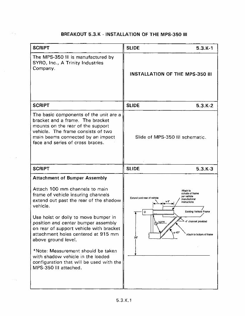
BREAKOUT 5.3.K - INSTALLATION OF THE MPS-350 Ill
SCRIPT
The MPS-350 Ill is manufactured by SYRO, Inc., A Trinity Industries Company.
SLIDE 5.3.K-1
INSTALLATION OF THE MPS-350 Ill
SCRIPT SLIDE 5.3.K-2
The basic components of the unit are a bracket and a frame. The bracket mounts on the rear of the support vehicle. The frame consists of two main beams connected by an impact Slide of MPS-350 III schematic. face and series of cross braces.
SCRIPT
Attachment of Bumper Assembly
SLIDE 5.3.K-3
Attach 100 mm channels to main frame of vehicle insuring channels extend out past the rear of the shadow vehicle.
Mend past reef of vehicle
Attach to calside of frame per vehicle
Use hoist or dolly to move bumper in position and center bumper assembly on rear of support vehicle with bracket attachment holes centered at 915 mm above ground level.
Attach lo bnom of frame
*Note: Measurement should be taken with shadow vehicle in the loaded configuration that will be used with the MPS-350 III attached.
5.3.K. 1
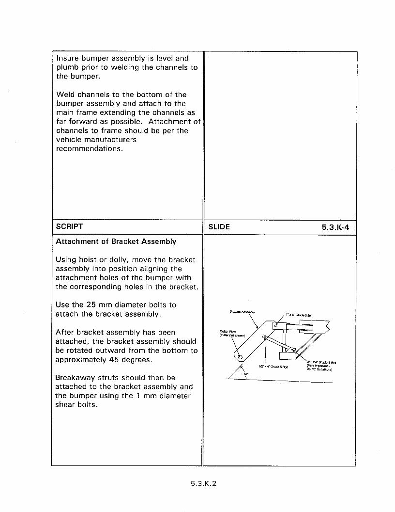
insure bumper assembly is level and plumb prior to welding the channels to the bumper.
Weld channels to the bottom of the bumper assembly and attach to the main frame extending the channels as far forward as possible. Attachment of channels to frame should be per the vehicle manufacturers recommendations.
SCRIPT
Attachment of Bracket Assembly
SLIDE 5.3.K-4
Using hoist or dolly, move the bracket assembly into position aligning the attachment holes of the bumper with the corresponding holes in the bracket.
Use the 25 mm diameter bolts to attach the bracket assembly.
After bracket assembly has been attached, the bracket assembly should be rotated outward from the bottom to approximately 45 degrees.
Breakaway struts should then be attached to the bracket assembly and the bumper using the 1 mm diameter shear bolts.
5.3.K.2
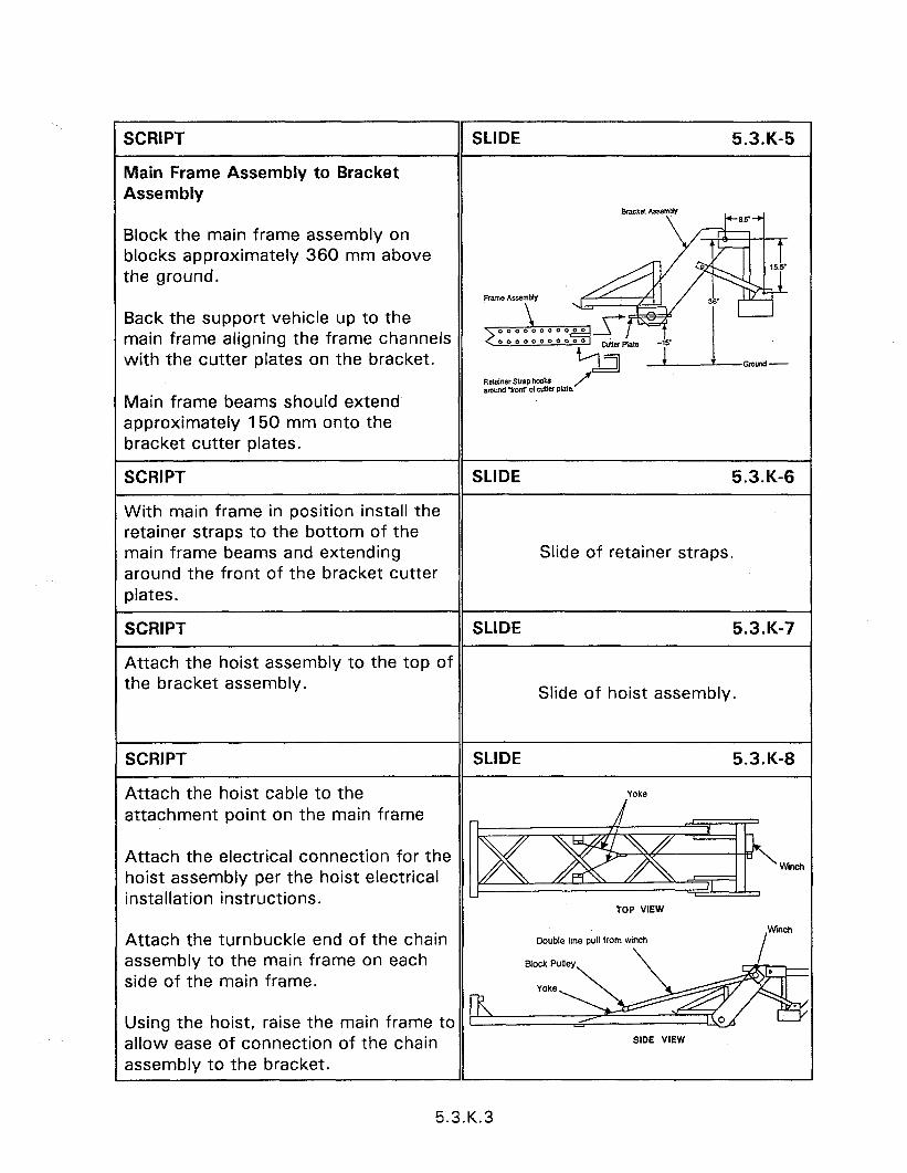
’ SCRIPT
Main Frame Assembly to Bracket Assembly
SLIDE 5.3.K-5
Block the main frame assembly on blocks approximately 360 mm above the ground.
Back the support vehicle up to the main frame aligning the frame channels with the cutter plates on the bracket.
Main frame beams should extend’ approximately 150 mm onto the bracket cutter plates.
SCRIPT SLIDE 5.3.K-6
With main frame in position install the retainer straps to the bottom of the main frame beams and extending Slide of retainer straps. around the front of the bracket cutter plates.
SCRIPT SLIDE 5.3.K-7
Attach the hoist assembly to the top of the bracket assembly.
Slide of hoist assembly.
SCRIPT
Attach the hoist cable to the attachment point on the main frame
SLIDE 5.3-K-8
Attach the electrical connection for the hoist assembly per the hoist electrical installation instructions.
Winch
TOP VIEW
Attach the turnbuckle end of the chain assembly to the main frame on each side of the main frame.
Double line pull lrom winch
Using the hoist, raise the main frame to allow ease of connection of the chain assembly to the bracket.
SIDE VIEW
1
5.3.K.3
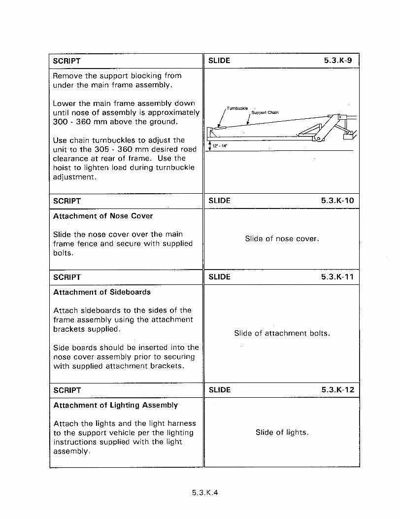
SCRIPT
Remove the support blocking from under the main frame assembly.
SLIDE 5.3.K-9
Lower the main frame assembly down until nose of assembly is approximately 300 - 360 mm above the ground.
Use chain turnbuckles to adjust the unit to the 305 - 360 mm desired road clearance at rear of frame. Use the hoist to lighten load during turnbuckle adjustment.
SCRIPT
Attachment of Nose Cover
SLIDE 5.3.K-10
Slide the nose cover over the main frame fence and secure with supplied bolts.
Slide of nose cover.
SCRIPT
Attachment of Sideboards
SLIDE 5.3.K-11
Attach sideboards to the sides of the frame assembly using the attachment brackets supplied.
Side boards should be inserted into the nose cover assembly prior to securing with supplied attachment brackets.
Slide of attachment bolts.
SCRIPT
Attachment of Lighting Assembly
SLIDE 5.3.K-12
Attach the lights and the light harness to the support vehicle per the lighting instructions supplied with the light assembly.
Slide of lights.
5.3.K.4

SCRIPT
Attachment of Jacks
SLIDE 5.3.K-13
Jack assemblies should be used only for installation and removal of the system from the support vehicle.
Jacks should be mounted to the appropriate attachment brackets using the full requirement of bolts as indicated on the drawing bill of material of the “MPS-350 III” Manual.
CAUTION!!!! All jacks must be removed from unit once attachment to support vehicle is accomplished.
Slide of jacks in place.
5.3.K.5

SESSION GUIDE
6.1 - BRIDGE RAILS
Obiectives:
l Introduce the operational and design characteristics of crashworthy bridge rails.
0 introduce acceptable transitions to bridge rails.
Heloful Hints:
0 the time of this session can be reduced by covering only those bridge rails that are used in the presentation area.
Visual Aids:
0 41 - 35 mm slides
Estimated Time
0 60 minutes
Handouts:
l None

6.1 - BRIDGE RAILS
instructor’s Guide
XRIPT SLIDE 6.1-1
4 bridge railing is a longitudinal structure nstalled to prevent an errant vehicle from unning off the edge of a bridge or culvert. The bridge railings contained in this ;ection are the principal railings in use at :he time of publication. Other railing systems may have been approved since ihe printing date. Appendix C contains a summary of the testing results for the 6.1 - CRASHWORTHY BRIDGE najority of bridge railings accepted for RAILINGS Jse.
SCRIPT
Chicago Barrier Railing (SBAOl a)
SLIDE 6.1-2
This system, manufactured by Valentine & Company, is for use where both artistic merit and structural strength are combined in urban applications. The original design was for the City of Chicago under IDOT/FHWA contract and was first installed in 1991.
CHICAGO BARRIER RAILING
6.1 .I
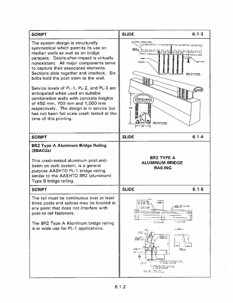
SCRIPT SLIDE 6.1-3
The system design is structurally symmetrical which permits its use on median walls as well as on bridge parapets. Debris-after-impact is virtually nonexistent. All major components serve to capture their associated elements. Sections slide together and interlock. Six *Kc ELEVATION bolts hold the post stem to the wall.
Service levels of PL-1 , PL-2, and PL-3 are anticipated when used on suitable combination walls with concrete heights of 450 mm, 700 mm and 1,000 mm respectively. The design is in service but has not been full scale crash tested at the time of this printing.
SCRIPT
BR2 Type A Aluminum Bridge Railing (SBAO2a)
SLIDE 6.1-4
This crash-tested aluminum post-and- BR2 TYPE A
beam on curb system, is a general ALUMINUM BRIDGE
purpose AASHTO PL-1 bridge railing RAILING
similar to the AASHTO BR2 (aluminum) Type B bridge railing.
SCRIPT SLIDE 6.1-5
The rail must be continuous over at least three posts and splices may be located at any point that does not interfere with post-to-rail fasteners.
The BR2 Type A Aluminum bridge railing is in wide use for PL-1 applications.
6.1.2

BRI TYPE C ALUMINUM BRIDGE RAILING
SCRIPT
BRI Type C Aluminum Bridge Railing (SBA03a)
SLIDE 6.1-6
The BRI Type C Aluminum Bridge Railing, also known as the North Carolina Standard One-bar Bridge Railing, is suitable for AASHTO PL-1 locations.
SCRIPT SLIDE 6.1-7
The system, shown as system 13 of appendix C, can also use galvanized steel i.: . .._..-. .~.._ ---- .;i,
1” -. ii .: in place of aluminum which is placed on
1 22 .~:~~..~~-~~.----- 7. i’iil” top of a 460 mm parapet.
The system, when tested with a school bus, redirected the bus at 100 km/h but caused the bus to roll on its side.
SCRIPT
Tru-Beam Bridge Railing (SBA04a)
SLIDE 6.1-8
The Tru-Beam Aluminum Bridge Railing, also known as the Modified AASHTO BR5, is suitable for AASHTO PL-1 locations. TRU-BEAM
BRIDGE RAILING
6.1.3
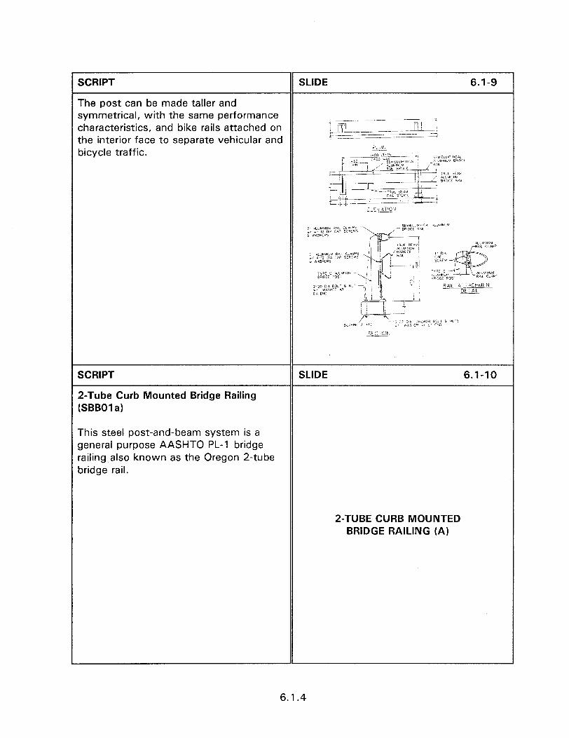
1 SCRIPT SLIDE 6.1-9
The post can be made taller and symmetrical, with the same performance characteristics, and bike rails attached on ?-Gfl -y ~~~~ - ---~-~-- r:’ 1
+ the interior face to separate vehicular and
‘ z!zLzzz~.Z_L----, __..~_ -----
bicycle traffic. I’~% ,380 ,TYi’l r----- 7r-F iLYILI:~P liCil *y*-- _ i:;;;,et3~’ CA. i.‘JU’NJL’ BWJ-~
1 \ J I,‘LR&-_T-- 2
-3-
-----7- ;:;,wy , 9WOCE E&i - F- , _ b-$ -LL-lJ&l
_ _RA. S~.‘Cl & -1 ;L:\ STIOP\
SCRIPT
2-Tube Curb Mounted Bridge Railing (SBBOl a)
SLIDE 6.1-10
This steel post-and-beam system is a general purpose AASHTO PL-1 bridge railing also known as the Oregon 2-tube bridge rail.
2-TUBE CURB MOUNTED BRIDGE RAILING (A)
6.1.4
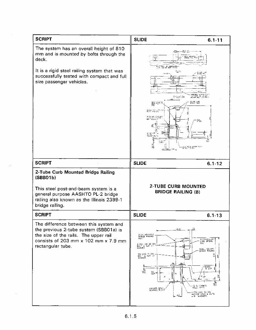
SCRIPT
The system has an overall height of 810 mm and is mounted by bolts through the deck.
It is a rigid steel railing system that was successfully tested with compact and full size passenger vehicles.
SCRIPT
2-Tube Curb Mounted Bridge Railing (SBBOI b)
SLIDE 6.1-12
This steel post-and-beam system is a general purpose AASHTO PL-2 bridge railing also known as the Illinois 2399-l bridge railing.
2-TUBE CURB MOUNTED BRIDGE RAILING (B)
SCRIPT SLIDE 6.1-13
The difference between this system and the previous 2-tube system (SBBOI a) is the size of the rails. The upper rail consists of 203 mm x 102 mm x 7.9 mm rectangular tube.
6.1.5
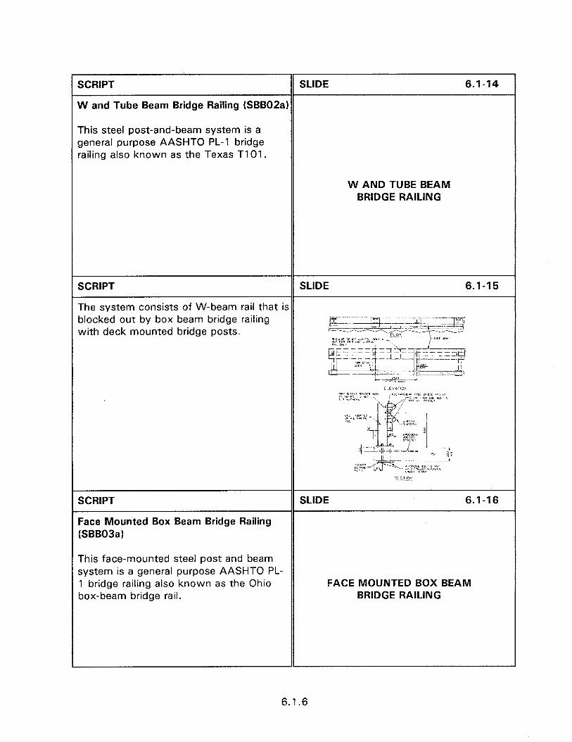
W AND TUBE BEAM BRIDGE RAILING
SCRIPT SLIDE 6.1-14
W and Tube Beam Bridge Railing (SBBOZa)
This steel post-and-beam system is a general purpose AASHTO PL-1 bridge railing also known as the Texas TIOI .
SCRIPT SLIDE 6.1-15
The system consists of W-beam rail that is blocked out by box beam bridge railing with deck mounted bridge posts.
SCRIPT
Face Mounted Box Beam Bridge Railing (SBB03a)
SLIDE 6.1-16
This face-mounted steel post and beam system is a general purpose AASHTO PL- 1 bridge railing also known as the Ohio box-beam bridge rail.
FACE MOUNTED BOX BEAM BRIDGE RAILING
6.1.6
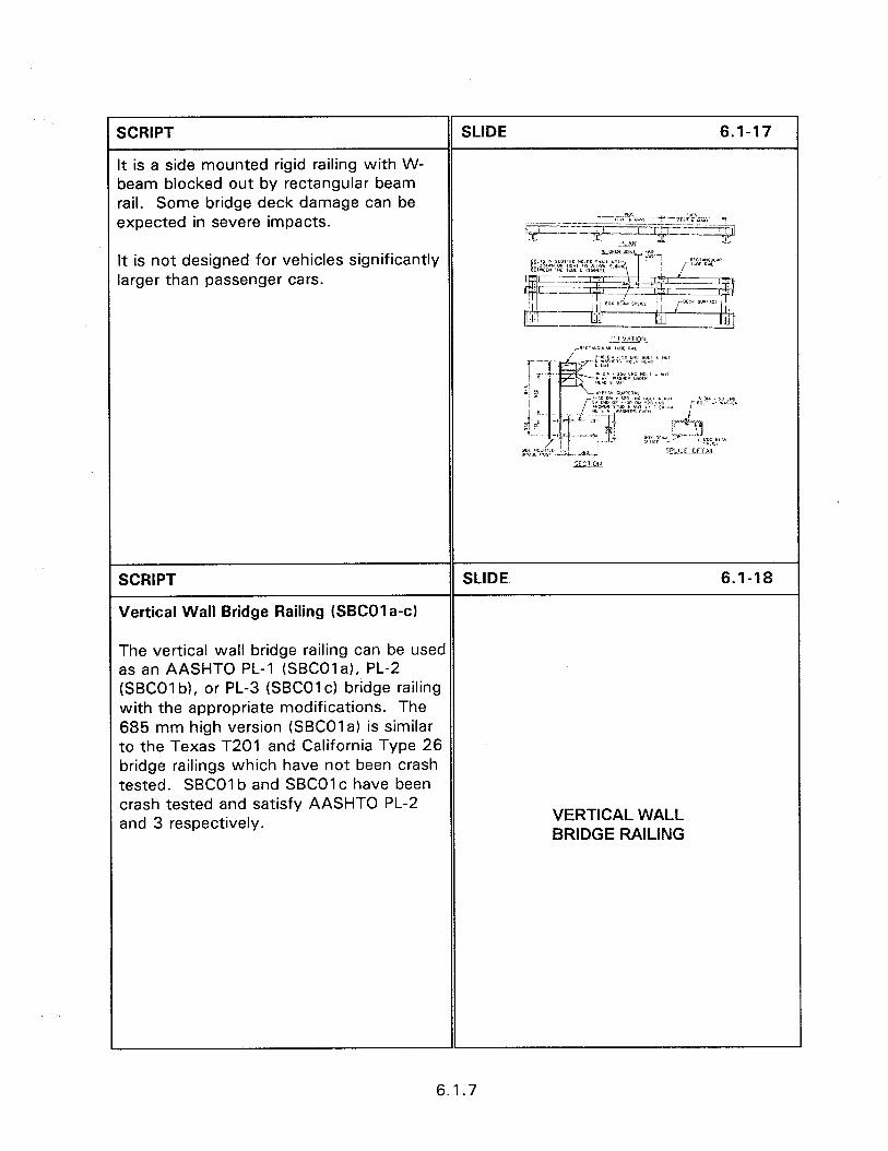
SCRIPT SLIDE 6.1-17
t is a side mounted rigid railing with W- oeam blocked out by rectangular beam ,ail. Some bridge deck damage can be expected in severe impacts.
lSUI c -;i+*“7xi
It is not designed for vehicles significantly arger than passenger cars.
SCRIPT
Vertical Wall Bridge Railing (SK01 a-c)
SLIDE 6.1-18
The vertical wall bridge railing can be used as an AASHTO PL-1 (SBCOla), PL-2 (SBCOl b), or PL-3 (SBCOlc) bridge railing with the appropriate modifications. The 685 mm high version (SBCOla) is similar to the Texas T201 and California Type 26 bridge railings which have not been crash tested. SBCOl b and SBCOI c have been crash tested and satisfy AASHTO PL-2 and 3 respectively.
VERTICAL WALL BRIDGE RAILING
6.1.7
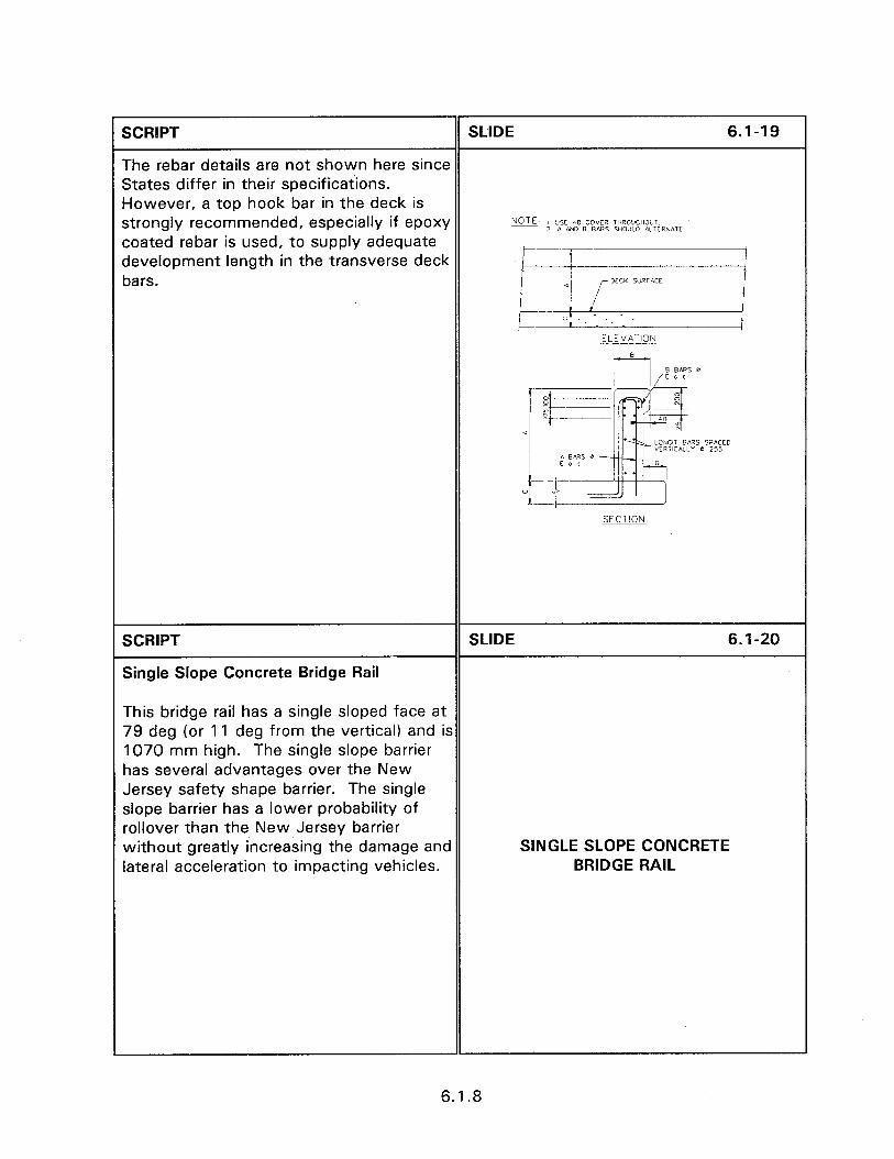
SCRIPT SLIDE 6.1-19
The rebar details are not shown here since States differ in their specifications. However, a top hook bar in the deck is strongly recommended, especially if epoxy NOTE 1 USE 40 COVER THROXHO”l 2 A ma B e,ms SHOULD ILliR?IATE coated rebar is used, to supply adequate development length in the transverse deck bars.
ELEVATION
SECTION
SCRIPT
Single Slope Concrete Bridge Rail
SLIDE 6.1-20
This bridge rail has a single sloped face at 79 deg (or 11 deg from the vertical) and is 1070 mm high. The single slope barrier has several advantages over the New Jersey safety shape barrier. The single slope barrier has a lower probability of rollover than the New Jersey barrier without greatly increasing the damage and lateral acceleration to impacting vehicles.
SINGLE SLOPE CONCRETE BRIDGE RAIL
6.1.8
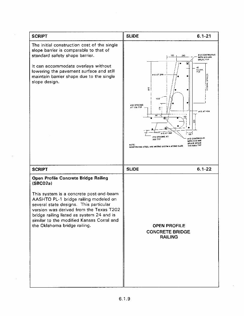
SCRIPT SLIDE 6.1-21
The initial construction cost of the single slope barrier is comparable to that of standard safety shape barrier.
2- 113 CONnNUOUS WITH 610 M1N SPWE NP __-
It can accommodate overlays without lowering the pavement surface and still maintain barrier shape due to the single slope design.
SCRIPT
Open Profile Concrete Bridge Railing (SBC02a)
SLIDE 6.1-22
This system is a concrete post-and-beam AASHTO PL-1 bridge railing modeled on several state designs. This particular version was derived from the Texas T202 bridge railing listed as system 24 and is similar to the modified Kansas Corral and the Oklahoma bridge railing. OPEN PROFILE
CONCRETE BRIDGE RAILING
6.1.9
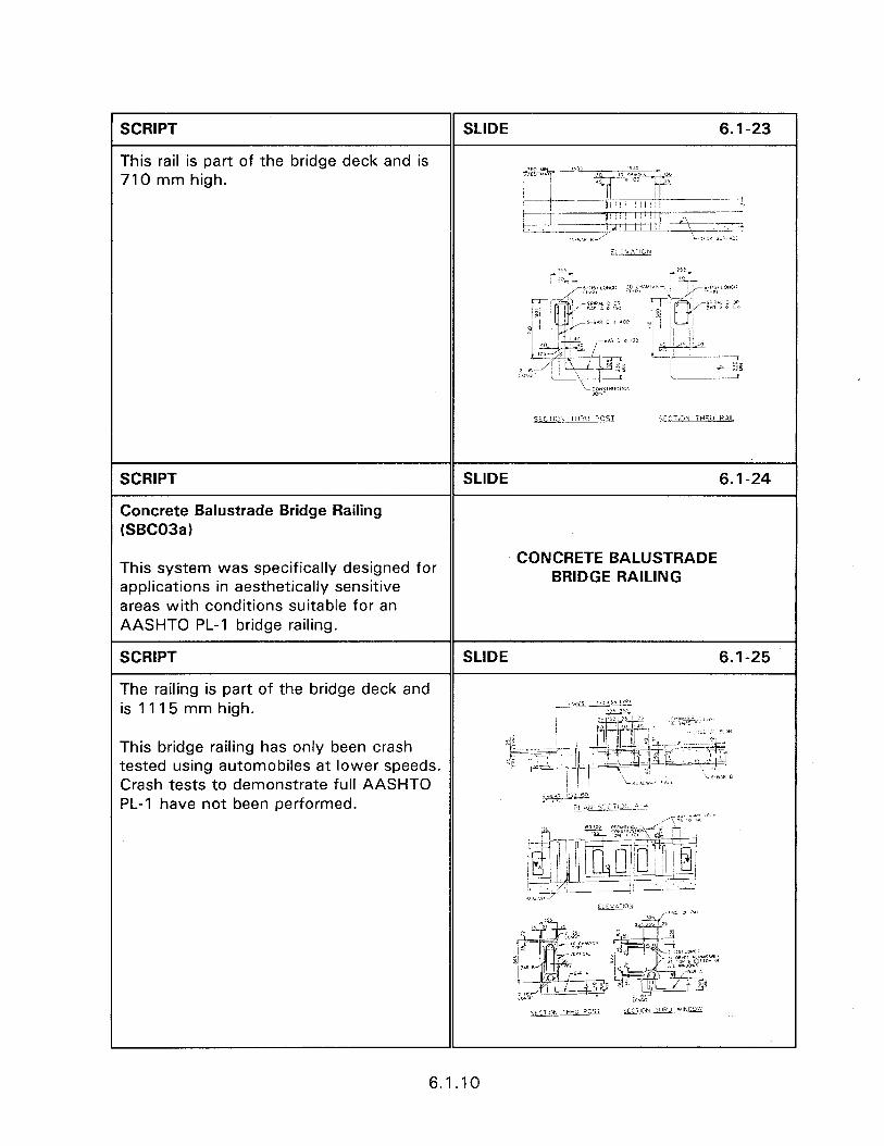
SCRIPT
This rail is part of the bridge deck and is 710 mm high.
SLIDE 6.1-23
__- -.-.+
SCRIPT
Concrete Balustrade Bridge Railing (SBC03a)
This system was specifically designed for CONCRETE BALUSTRADE
applications in aesthetically sensitive BRIDGE RAILING
areas with conditions suitable for an AASHTO PL-1 bridge railing.
SCRIPT SLIDE 6.1-25
The railing is part of the bridge deck and is 11 15 mm high.
This bridge railing has only been crash tested using automobiles at lower speeds. Crash tests to demonstrate full AASHTO PL-1 have not been performed.
6.1.10
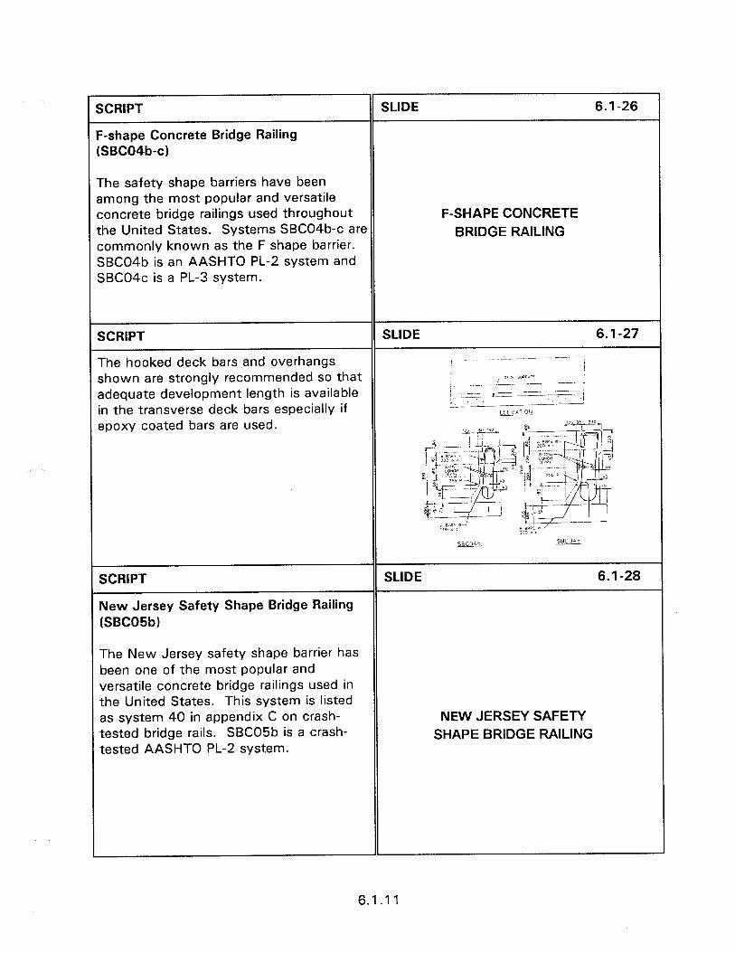
SCRIPT
--shape Concrete Bridge Railing SBCO4b-c)
The safety shape barriers have been among the most popular and versatile concrete bridge railings used throughout ;he United States. Systems SBC04b-c are commonly known as the F shape barrier. SBC04b is an AASHTO PL-2 system and SBC04c is a PL-3 system.
SCRIPT
The hooked deck bars and overhangs shown are strongly recommended so that adequate development length is available in the transverse deck bars especially if epoxy coated bars are used.
SCRIPT
New Jersey Safety Shape Bridge Railing (SBC05b)
The New Jersey safety shape barrier has been one of the most popular and versatile concrete bridge railings used in the United States. This system is listed as system 40 in appendix C on crash- tested bridge rails. SBC05b is a crash- tested AASHTO PL-2 system.
SLIDE 6.1-26
F-SHAPE CONCRETE BRIDGE RAILING
SLIDE 6.1-27
SLIDE 6.1-28
NEW JERSEY SAFETY SHAPE BRIDGE RAILING
6.1.1 1
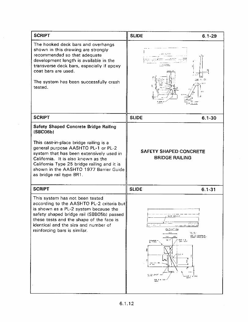
SCRIPT
The hooked deck bars and overhangs shown in this drawing are strongly recommended so that adequate development length is available in the transverse deck bars, especially if epoxy coat bars are used.
The system has been successfully crash tested.
SCRIPT
Safety Shaped Concrete Bridge Railing (SBCOGb)
SLIDE 6.1-30
This cast-in-place bridge railing is a general purpose AASHTO PL-1 or PL-2 system that has been extensively used in California. It is also known as the California Type 25 bridge railing and it is shown in the AASHTO 1977 Barrier Guide as bridge rail type BRI.
SAFETY SHAPED CONCRETE BRIDGE RAILING
SCRIPT SLIDE 6.1-31
This system has not been tested according to the AASHTO PL-2 criteria but is shown as a PL-2 system because the safety shaped bridge rail (SBB05b) passed these tests and the shape of the face is identical and the size and number of
.
reinforcing bars is similar. ELE”A.iON
6.1.12
SCRIPT SLIDE 6.1-32
The safety shaped concrete bridge railing is one of the most common bridge railings used on new construction. The concrete requires little maintenance after most impacts and performs well for low angle hits by passenger sized vehicles.
Slide of field installation.
SCRIPT
Permanent Parapet Half Section Precast Concrete Barrier (SBC17B) (SBCI 8B)
SLIDE 6.1-33
These systems are proprietary systems marketed by Clampcrete Corporation. The Parapet barrier system is designed to emulate cast in place types for strength, load transfer continuity, and overall performance. The 483 mm base affords greater travel width on structures being widened or otherwise retrofitted while still providing lateral deflection of the barrier or barrier tipping and resulting vehicle vaulting. Clampcrete Corporation tall half section barriers (1070 mm to 1220 mm) are currently being used on major turnpikes and interstates. These systems are companions to the shorter barriers (865 mm high) that were crash tested at Texas Transportation Institute in 1989. An advantage of the ClampcreteTM barrier system is its ability to be secured with ClampcreteTM RemovakeITM anchors and used as a temporary work zone barrier. It can then later be reused as a permanent bridge railing.
PERMANENT PRECAST CONCRETE BARRIER
6.1.13

SCRIPT
The half section barriers are taller and have a 410 mm base instead of 483 mm (for the parapet system), Clampcrete designed anchors every 457 mm instead of 610 mm as on the crash tested bridge rails. KelibondanchorsTM are torqued to 950 Nom to demonstrate proper installation (proof loading) and post- tensioning. Besides being securely anchored to the deck, the ClampcreteTM systems are end connected using specially designed threaded sockets for three #20 bars.
SLIDE 6.1-34
SCRIPT
Face Mounted Thrie-Beam Railing [SBTOI a-2a)
These bridge railings are AASHTO PL-1 systems. These designs are similar to the Oregon and California side-mounted thrie- beam bridge railings.
SLIDE 6.1-35
FACE MOUNTED THRIE BEAM BRIDGE RAILING
SCRIPT SLIDE 6.1-36
Intended primarily for use on low volume secondary roads the face mounted thrie- beam system provides a non-rigid railing. The system uses steel or wood posts and is designed to deflect 0.5 to 1 m upon impact.
6.1.14

SCRIPT SLIDE 6.1-37
An approach rail transition is not required since there is no initial rigid point on the bridge railing. The post attachment detail is designed to yield upon impact, thereby, reducing damage to the bridge deck. The Slide of field installation. resultant advantages to using this system are its relatively low initial cost, more forgiving design than a rigid system, and less maintenance after impact.
SCRIPT SLIDE 6.1-38
Tubular W-beam Bridge Railing (SBWOI a)
This bridge railing, based on the Texas T6 bridge railing, is an AASHTO PL-1 deck mounted bridge railing.
TUBULAR W-BEAM BRIDGE RAILING
SCRIPT SLIDE 6.1-39
The tubular member is almost seven times ../L It, “‘6 ,> .NC stiffer than a single W-beam member
I*ry”l** I BiW
which limits deflection and retains an iilErr<< impacting vehicle on the bridge deck.
It is a strong beam and moderately weak post designed to separate at the base plate before damage to the bridge deck can occur.
SCRIPT SLIDE 6.1-40
Deck Mounted W-beam Guardrail (SGR05)
The deck mounted W-beam guardrail, figure 6.1.20 is frequently used to cross box culverts and small bridges. It has an added advantage of reducing the design needs of the transition section from the approach barrier to a rigid bridge wall.
DECK MOUNTED W-BEAM GUARDRAIL
6.1.15
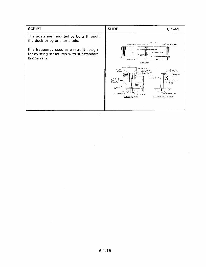
SCRIPT SLIDE 6.1-41
The posts are mounted by bolts through the deck or by anchor studs.
It is frequently used as a retrofit design for existing structures with substandard bridge rails.
6.1.16
SESSION GUIDE
6.2 TRANSITIONS TO BRIDGE RAIL
Obiectives:
l To discuss the design elements necessary for proper transitions.
a To present crashworthy transition designs.
Heloful Hints:
0 Concentrate on the predominant type of transition used in the seminar area.
Visual Aids:
0 34 - 35 mm slides
Estimated Time
0 30 minutes
Handouts:
e None

6.2 TRANSITIONS TO BRIDGE RAIL
Instructor’s Guide
SCRIPT
TRANSITIONS
SLIDE 6.2-l
Transitions are required where relatively flexible approach barriers join a rigid bridge railing or wall.
6.2 TRANSITIONS TO BRIDGE RAIL
SCRIPT SLIDE 6.2-2
The purpose of the transition is to gradually stiffen the flexible approach barrier to prevent an impacting vehicle from laterally deflecting the barrier and impacting or snagging the rigid bridge Slide showing impacted transition. structure. Transitions may not be necessary when flexible bridge railings are used.
SCRIPT SLIDE 6.2-3
In most instances an approach guardrail is used to shield the exposed end of the bridge rail and to prevent errant vehicles from getting behind the railing. These approved guardrails are typically much
Slide of W-beam transition.
more flexible than the bridge rails to which they are attached.
SCRIPT SLIDE 6.24
This flexibility provides the potential for sufficiently deflecting to allow a vehicle to impact the end of the bridge railing. This possibility results in the need for a transition section wherever there is a change in the deflection characteristics
Slide of impacted guardrail at bridge.
between the approach guardrail and bridge rail.
6.2.1
SCRIPT SLIDE 6.2-5
The transition section smoothly increases the stiffness of the approach guardrail from the more flexible to the less flexible system. The resultant decrease in lateral SMOOTH TRANSITION deflection can be achieved by varying one @ Increased beam strength or more key design parameters. These l Reduce post spacing include increasing the guardrail beam l Increase post size strength, reducing post spacing, 0 Increase embedment increasing post size, and post embedment depth.
SCRIPT SLIDE 6.2-6
An effective transition is one that limits deflection and minimizes vehicle pocketing or snagging on the end of the bridge rail. Transitions may not be necessary when
Slide of flexible bridge rail.
flexible bridge railings are used.
SCRIPT SLIDE 6.2-7
Important design details for the transition section include the following.
0 The approach barrier splice to the BARRIER SPLICE bridge rail must be as strong as the approach barrier itself to prevent pulling loose during impact.
SCRIPT SLIDE 6.2-8
l The use of a cast in place concrete anchor, or bolting completely through the concrete wall is recommended.
Slide of concrete anchor.
6.2.2
SCRIPT SLIDE 6.2-9
If an end shoe is used with a W-beam approach rail then four 24 mm through bolts with nuts for each rail, are recommended. When the W-beam is connected directly to the bridge rail then eight 24 mm through bolts with nuts should be placed in the valley of the W- beam with the first hole 50 mm from the Slide of front view of W-beam connection. rail end and the remaining bolts at 100 mm centers.
SLIDE 6.2-10
Slide of back view of W-beam connection.
SCRIPT SLIDE 6.2-l 1
l Strong post systems or a combination of weak post and strong beam systems are normally used on transitions to rigid bridge railings. The rails are usually blocked out to reduce the possibility of WHEEL SNAG wheel snagging.
6.2.3
SCRIPT SLIDE 6.2-l 2
Frequently blocking out is not sufficient to prevent wheel snagging and an additional rail is added beneath the barrier rail. The additional rail, is called a rub rail and is Slide of W-beam rub rail. frequently used with W-beam or box beam transition members.
SLIDE 6.2-l 3
Slide of W-beam with rub rail.
SCRIPT
l The transition section should be sufficiently long to prevent significant changes in deflection within a short distance.
SLIDE 6.2-14
TRANSITION LENGTH
SCRIPT SLIDE 6.2-l 5
As a rule of thumb, the transition length should be 10 to 12 times the difference in lateral deflection between the bridge rail and approach barrier. Slide of transition.
6.2.4
SCRIPT SLIDE 6.2-l 6
l The stiffness of the approach section should increase smoothly to the bridge rail. INCREASED STIFFNESS
SCRIPT SLIDE 6.2-17
This can be accomplished by a combination of decreasing the post Slide of decreasing post spacing. spacing, increasing the post size, or strengthening the rail.
SLIDE 6.2-18
Slide showing increased post sizes.
SLIDE 6.2-19
Slide showing strengthened rail.
SCRIPT
l Curbs, raised drainage inlets or other features that can cause vehicle instability
SLIDE 6.2-20
CURBS-GRADING
SCRIPT SLIDE 6.2-21
should not be placed in front of the barrier or transition section. The grading between the edge of the traveled lane and the barrier should be no steeper than 1:lO.
Slide of curb in front of W-beam rail.
6.2.5
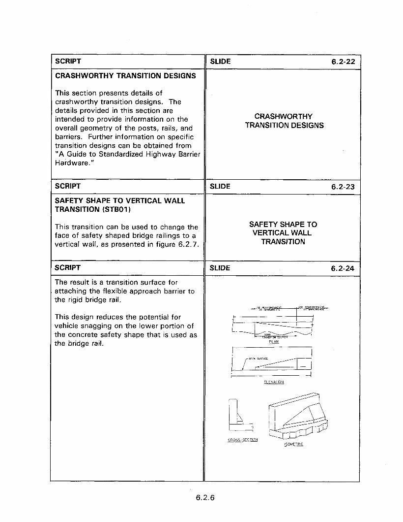
SCRIPT SLIDE 6.2-22
CRASHWORTHY TRANSITION DESIGNS
This section presents details of crashworthy transition designs. The details provided in this section are intended to provide information on the overall geometry of the posts, rails, and barriers. Further information on specific transition designs can be obtained from “A Guide to Standardized Highway Barrier Hardware.”
CRASHWORTHY TRANSITION DESIGNS
SCRIPT
SAFETY SHAPE TO VERTICAL WALL TRANSITION (STBOI )
SLIDE 6.2-23
This transition can be used to change the SAFETY SHAPE TO
face of safety shaped bridge railings to a VERTICAL WALL
vertical wall, as presented in figure 6.2.7. TRANSITION
SCRIPT
The result is a transition surface for attaching the flexible approach barrier to the rigid bridge rail.
SLIDE 6.2-24
This design reduces the potential for vehicle snagging on the lower portion of the concrete safety shape that is used as the bridge rail.
ELEVATION
L@
CROSS-SECTISN ISOMETRIC
6.2.6
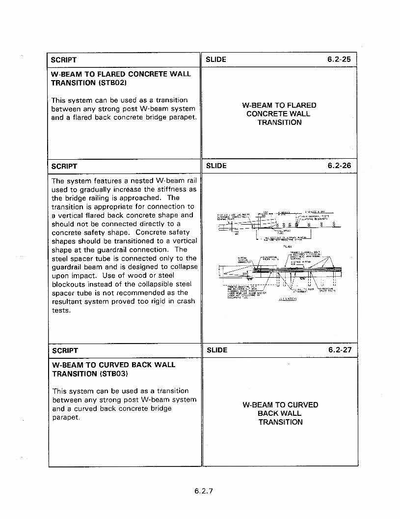
SCRIPT SLIDE 6.2-25
W-BEAM TO FLARED CONCRETE WALL TRANSITION (STBO2)
This system can be used as a transition between any strong post W-beam system and a flared back concrete bridge parapet.
W-BEAM TO FLARED CONCRETE WALL
TRANSITION
SCRIPT SLIDE 6.2-26
The system features a nested W-beam rail used to gradually increase the stiffness as the bridge railing is approached. The transition is appropriate for connection to a vertical flared back concrete shape and should not be connected directly to a concrete safety shape. Concrete safety shapes should be transitioned to a vertical shape at the guardrail connection. The &@
MCD steel spacer tube is connected only to the guardrail beam and is designed to collapse upon impact. Use of wood or steel blockouts instead of the collapsible steel spacer tube is not recommended as the resultant system proved too rigid in crash tests.
SCRIPT
W-BEAM TO CURVED BACK WALL TRANSITION (STBOS)
SLIDE 6.2-27
This system can be used as a transition between any strong post W-beam system and a curved back concrete bridge parapet.
W-BEAM TO CURVED BACK WALL TRANSITION
6.2.7
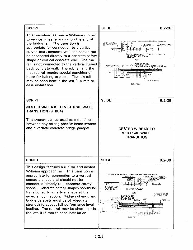
SCRIPT SLIDE 6.2-28
This transition features a W-beam rub rail to reduce wheel snagging on the end of the bridge rail. The transition is appropriate for connection to a vertical curved back concrete wall and should not be connected directly to a concrete safety A,TAC” llld Olr I 150 LNC LAA~go~;$mrcrurwi~ IVASHER shape or vertical concrete wall. The rub rail is not connected to the vertical curved back concrete wall. The rub rail and the first top rail require special punching of holes for bolting to posts. The rub rail may be shop bent in the last 915 mm to ease installation.
SCRIPT
NESTED W-BEAM TO VERTICAL WALL TRANSITION (STB04)
SLIDE 6.2-29
This system can be used as a transition between any strong post W-beam system and a vertical concrete bridge parapet. NESTED W-BEAM TO
VERTICAL WALL TRANSITION
SCRIPT SLIDE 6.2-30
This design features a rub rail and nested W-beam approach rail. This transition is appropriate for connection to a vertical Figure 62.9 -W-beam to cuwed back wall transition (STBOJ)
concrete shape and should not be connected directly to a concrete safety shape. Concrete safety shapes should be transitioned to a vertical shape at the guardrail connection. Bridge rail ends and bridge parapets must be of adequate ; strength to accept full performance level loading. The rub rail may be shop bent in the late 915 mm to ease installation.
6.2.8
I- 1 SCRIPT
NESTED THRIE-BEAM TO VERTICAL WALL TRANSITION (STB05)
SLIDE 6.2-31
This system can be used as a transition between any strong post W-beam or thrie beam system and a vertical concrete bridge parapet
NESTED THRIE-BEAM TO VERTICAL WALL
TRANSITION
SCRIPT SLIDE 6.2-32
The design features a nested thrie-beam approach rail. Bridge rail ends and bridge parapets must be of adequate strength to accept the desired performance level impact loading.
SCRIPT SLIDE 6.2-33
NESTED THRIE-BEAM TO FLARED WALL TRANSITION (STBOG)
This system can be used as a transition between any strong post thrie-beam system and a vertical flared back concrete shape.
NESTED THRIE BEAM TO FLARED WALL
TRANSITION
6.2.9
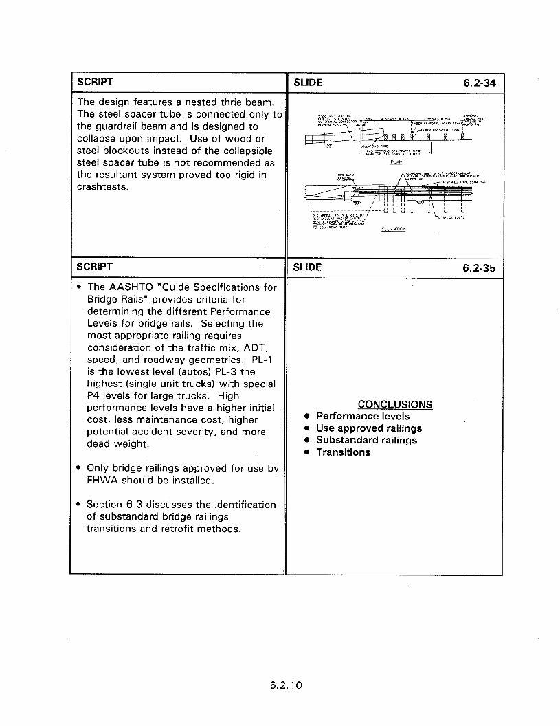
SCRIPT SLIDE 6.2-34
The design features a nested thrie beam. The steel spacer tube is connected only to the guardrail beam and is designed to collapse upon impact. Use of wood or steel blockouts instead of the collapsible steel spacer tube is not recommended as w the resultant system proved too rigid in crashtests.
Av RW
SCRIPT SLIDE 6.2-35
l The AASHTO “Guide Specifications for Bridge Rails” provides criteria for determining the different Performance Levels for bridge rails. Selecting the most appropriate railing requires consideration of the traffic mix, ADT, speed, and roadway geometries. PL-1 is the lowest level (autos) PL-3 the highest (single unit trucks) with special P4 levels for large trucks. High performance levels have a higher initial CONCLUSIONS
cost, less maintenance cost, higher l Performance levels
potential accident severity, and more l Use approved railings
dead weight. l Substandard railings l Transitions
B Only bridge railings approved for use by FHWA should be installed.
) Section 6.3 discusses the identification of substandard bridge railings transitions and retrofit methods.
6.2.10
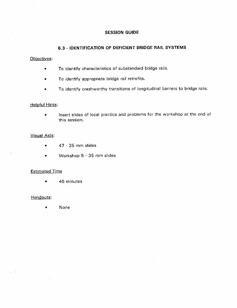
SESSION GUIDE
6.3 - lDENTlFlCATlON OF DEFICIENT BRIDGE RAIL SYSTEMS
Obiectives:
0 To identify characteristics of substandard bridge rails.
0 To identify appropriate bridge rail retrofits.
0 To identify crashworthy transitions of longitudinal barriers to bridge rails.
Heloful Hints:
a Insert slides of local practice and problems for the workshop at the end of this session.
Visual Aids:
l 47 - 35 mm slides
. Workshop 5 - 35 mm slides
Estimated Time
l 45 minutes
Handouts:
0 None


6.3 - IDENTIFICATION OF DEFICIENT BRIDGE RAIL SYSTEMS
Instructor’s Guide
SCRIPT
INTRODUCTION
SLIDE 6.3-l
Summary accident statistics indicate that there were 480 fatalities and approximately 6000 injuries resulting from an estimated 16,000 accidents with bridges during 1992. The results of a study published in 1983 stated, that based on accident data, bridges were approximately six times more hazardous than the average highway section. Since the 1940’s bridge rails have been designed according to prescriptive procedures contained in various editions of the AASHTO Bridge Design Specification. Bridge rails have been required to meet specific geometric criteria and to resist specified static loads without exceeding allowable material stresses. The simplicity of the prescriptive approach has encouraged the development of a large number of unique systems. For over 20 years, the specifications have been continually revised and upgraded to address deficiencies as they become known.
6.3 IDENTIFICATION OF DEFICIENT BRIDGE RAIL SYSTEMS
SCRIPT SLIDE 6.3-2
Adequate bridge railing designs were obtained in most instances by the proper application of the “1989 AASHTO Guide Specifications for Bridge Railings”.
Slide of AASHTO 1989 specification.
6.3.1
SCRIPT SLIDE 6.3-3
Bridges designed to AASHTO specifications prior to 1964 will, in general, have deficient railings. Properly designed railings, when tested, will contain and redirect a 2450 kg passenger car impacting at 70 km/h and 20 degrees Slide of deficient prior 1964 railing. to qualify as a performance level 1 railing. A description of performance levels is provided in section 2.4.
SCRlPT SLIDE 6.3-4
The most common types of bridge rails are reinforced concrete walls or metal rails on concrete parapets. If improperly treated the exposed ends of these railings can pose a rigid fixed object to errant Slide of untreated bridge end. vehicles.
SCRlPT SLIDE 6.3-5
In most instances an approach guardrail is used to shield the exposed end of the bridge rail and to prevent errant vehicles from getting behind the railing. These approved guardrails are typically much Slide of W-beam transition.
more flexible than the bridge rails to which they are attached.
SCRIPT SLIDE 6.3-6
This flexibility provides the potential for deflecting sufficiently to allow a vehicle to impact the end of the bridge railing. This possibility results in the need for a transition section wherever there is a Slide of impacted guardrail at bridge. change in the deflection characteristics between the approach guardrail and bridge rail.
6.3.2
SCRIPT SLIDE 6.3-7
The transition section smoothly increases the stiffness of the approach guardrail from the more flexible to the less flexible system. The resultant decrease in lateral deflection can be achieved by varying one SMOOTH TRANSITION or more key design parameters. These l Increased beam strength include increasing the guardrail beam l Reduce post spacing strength, reducing post spacing and l Increase post size increasing post size and embedment l Increase embedment depth. An effective transition is one that limits deflection and minimizes vehicle pocketing or snagging on the end of the bridge rail.
SCRIPT SLIDE 6.3-8
IDENTIFICATION OF DEFICIENT BRIDGE RAIL SYSTEMS
The remainder to this session discusses how to identify deficient bridge railings and transitions and provides retrofit options that can be used to bring them up to current standards.
!DENTlFlCATlON OF DEFICIENT BRIDGE RAIL SYSTEMS
SCRIPT SLIDE 6.3-9
The rail provides the vehicle restraining capability and must be structurally adequate to prevent a vehicle from tearing
RAILING REQUIREMENTS
through the railing and going off the 0 Keep vehicles on bridge
bridge deck. In addition, bridge railings 0 Redirect vehicle
must be capable of redirecting an l Prevent snagging
impacting vehicle without snagging.
SCRIPT SLIDE 6.3-10
Inspection of existing bridge railings should concentrate on the railing itself and the entrance and exit transitions from the bridge structure to any roadside barriers. The following factors will affect performance of the bridge railing system.
CAPACITY OF POSTS AND RAILINGS
l The capacity of the railing and support posts must be structurally adequate to withstand the impact loads.
6.3.3

SCRIPT SLIDE 6.3-l 1
This slide presents an inadequate bridge railing design. In this design neither the railing or support posts are adequate to withstand an impact and prevent a vehicle from penetrating the system. Not only is the railing system inadequate but the angle shape which comprises the Slide of deficient rail. inadequate rail can penetrate the passenger compartment of an impacting vehicle.
SLIDE 6.3-l 2
ATTACHMENT TO DECK
SCRIPT
0 The rail to post and post to deck attachments must be an approved design.
SCRIPT SLIDE 6.3-l 3
The post to deck attachment details of this slide is inadequate to prevent vehicle penetration of the system when struck.
Slide of bridge rail with broken supports.
SCRIPT SLIDE 6.3-14
l Tests and accident experience have shown that an errant vehicle can impact ROADWAY FEATURES a curb and vault over or penetrate NEAR BRIDGE RAIL through a bridge rail.
6.3.4
SCRIPT SLIDE 6.3-l 5
The bridge rail design of this slide can cause impacting vehicles which first hit the curb to rise and impact the bridge rail at a height higher than the design height. The roadway agency may have recognized the hazard of the curb and Slide of improper curb. placed an object marker next to the curb, but in front of the guardrail. Recommended placement of the object marker is not to create an additional fixed object which compounds the problem.
SCRIPT SLIDE 6.3-l 6
l The face of the bridge rail should be placed at least vertically in line with the curb if the curb cannot be removed. If sidewalks are warranted, then a traffic barrier should be considered between Slide of guardrail blocked out. the traffic and pedestrian areas and a pedestrian/bicycle railing placed at the bridge edge.
SCRIPT SLIDE 6.3-l 7
0 If guardrail is used as the bridge rail it must be installed in accord with APPROACH RAIL approved design specifications. DESIGN
SCRIPT SLIDE 6.3-18
The W-beam installation of this slide has inadequate flare and is mounted too high.
Slide of vehicle in front of guardrail.
6.3.5
1 SCRIPT SLIDE 6.3-l 9
l The bridge rail must have continuity to prevent vehicle snagging. Splices in metal bridge rail should be as strong as the rail itself. Lapped splices should be placed so that the outer rail overlaps in the downstream direction to reduce snagging. Splices in concrete bridge CONTINUITY rail should be smooth.
SCRIPT
This slide presents an improper transition since the approach rail is not attached to the bridge.
SLIDE 6.3-20
Slide of approach rail not attached to bridge.
SCRIPT SLIDE 6.3-21
l Almost all existing W-beam guardrail systems that connect directly to a bridge rail without adequate blockouts or a rub rail near the bridge connection are considered unsatisfactory. These systems can result in vehicle snagging and catastrophic accidents. BLOCKOUTS AND/OR RUB RAIL
6.3.6
SCRIPT SLIDE 6.3-22
Retrofits must be designed with adequate blockouts, rub rails, or other features to prevent snagging.
Slide of installation with rub rail.
SCRIPT
RETROFIT DESIGN CONCERNS
SLIDE 6.3-23
Retrofit designs are intended to increase the strength of the railing, provide longitudinal continuity to the system, eliminate the snagging potential or to reduce the undesirable effects of curbs or narrow walkways. A proper retrofit design should also provide an acceptable transition from the approach rail to the bridge rail itself.
Some retrofit designs may not bring a substandard bridge railing up to full AASHTO standards but can result in significant improvements. In selecting a retrofit design, a proper perspective must be maintained on the priorities of any traffic barrier; first to safety performance, second to economics, and third to aesthetics.
RETROFIT DESIGN CONCERNS l Safety performance l Economics l Aesthetics
6.3.7
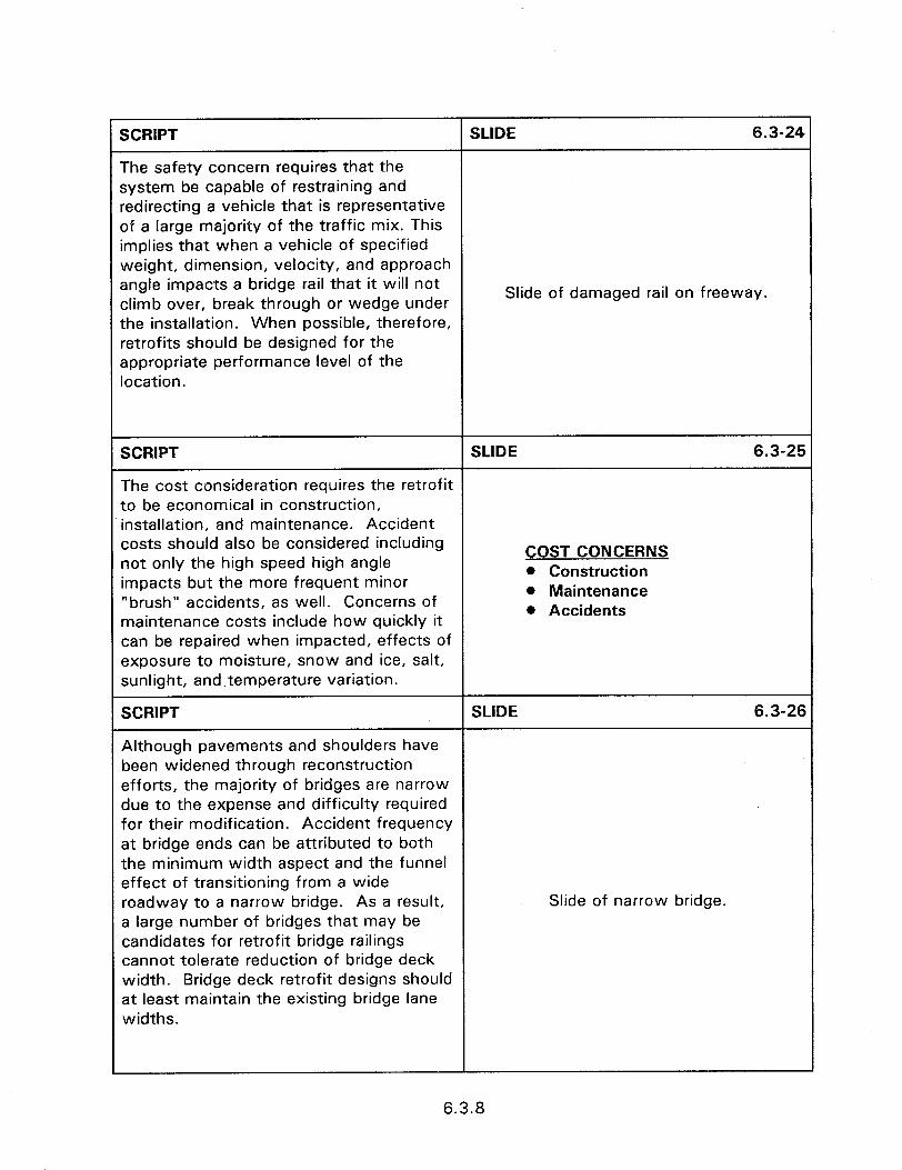
SCRIPT SLIDE 6.3-24
The safety concern requires that the system be capable of restraining and redirecting a vehicle that is representative of a large majority of the traffic mix. This implies that when a vehicle of specified weight, dimension, velocity, and approach angle impacts a bridge rail that it will not climb over, break through or wedge under
Slide of damaged rail on freeway.
the installation. When possible, therefore, retrofits should be designed for the appropriate performance level of the location.
SCRIPT SLIDE 6.3-25
The cost consideration requires the retrofit to be economical in construction, installation, and maintenance. Accident costs should also be considered including not only the high speed high angle
COST CONCERNS
impacts but the more frequent minor l Construction
“brush” accidents, as well. Concerns of l Maintenance
maintenance costs include how quickly it 0 Accidents
can be repaired when impacted, effects of exposure to moisture, snow and ice, salt, sunlight, and,temperature variation.
SCRIPT SLIDE 6.3-26
Although pavements and shoulders have been widened through reconstruction efforts, the majority of bridges are narrow due to the expense and difficulty required for their modification. Accident frequency at bridge ends can be attributed to both the minimum width aspect and the funnel effect of transitioning from a wide roadway to a narrow bridge. As a result, Slide of narrow bridge. a large number of bridges that may be candidates for retrofit bridge railings cannot tolerate reduction of bridge deck width. Bridge deck retrofit designs should at least maintain the existing bridge lane widths.
6.3.8
SCRIPT SLIDE 6.3-27
The complete bridge railing system should be considered when designing a bridge railing retrofit. This includes, 1) the approach guardrail and terminal, 2)bridge railing, and 3) transition from approach guardrail to bridge railing. Consideration COMPLETE SYSTEM must be given to both ends of the bridge l Approach guardrail and terminal railing where two-way traffic conditions l Bridge railing provide the possibility of impacts from l Transitions both directions.
SCRIPT
Retrofit Designs
SLIDE 6.3-28
Some specific retrofit concepts that can be adapted to numerous types of deficient designs are: RETROFIT DESIGNS
l Concrete safety or vertical wall shapes
l W-beamkhrie beam retrofits
l Concrete safety shapes l W-beam and thrie-beam l Metal post and beam * Tubular thrie-beam
l Metal post and beam retrofits
@ Tubular thrie beam retrofits
SCRIPT SLIDE 6.3-29
Concrete Safetv or Vertical Wall Shaoes - The concrete safety or vertical wall shapes that are commonly used for new construction can be added to an existing substandard bridge as an effective retrofit.
CONCRETE SAFETY OR
VERTICAL WALL SHAPES
6.3.9
SCRIPT SLIDE 6.3-30
For this retrofit design to be economical and feasible there must be; 1) the ability of the structure to carry the additional dead load, 2) sufficient deck space to install the retrofit without reducing the width of the traveled way, and 3) the existing curb or railing configuration can meet the anchorage and impact forces needed for the retrofit barrier. Protruding curbs must be avoided to prevent wheel and suspension damage and to reduce the potential for vehicle vaulting in shallow angle impacts.
Slide of concrete retrofit.
SCRIPT SLIDE 6.3-31
W-Beam/thrie Beam Retrofits - Continuing an approach guardrail through the structure is an economical method of upgrading substandard bridge rails. While this treatment may not bring an existing bridge railing into full compliance with AASHTO design criteria, it can significantly improve its safety characteristics.
W-BEAM/THRIE-BEAM RETROFITS
6.3710

SCRIPT SLIDE 6.3-32
This treatment can be particularly sffective on low volume roadways or Nhere the bridge has insufficient strength snd/or width that will not allow the nstailation of a concrete retrofit. Tests lave demonstrated that a bridge railing zan be effective even if it deflects several Feet upon impact. In these instances, a double layer of W-beam or thrie beam, with offset joints, can reduce railing’s Slide of W-beam or thrie-beam retrofit. deflection upon impact. Continuing the approach rail across the bridge has the added advantage of eliminating the need of providing adequate anchorage to orevent the approach rail from pulling out Jpon impact. The transition design slements that remain a concern are oroviding the gradual stiffening and the slimination of snagging potential.
SCRIPT SLIDE 6.3-33
Curb Mounted Bridae Railina Retrofit - Curb mounted retrofits work well when there is a wide walkway between a curb and the bridge rail. It has the advantages
CURB MOUNTED BRIDGE
of moving the rail face to the curb line to RAILING RETROFITS
reduce vaulting and separating pedestrians from vehicular traffic.
SCRIPT SLIDE 6.3-34
This example described is a 2-tube curb mounted bridge railing. Other systems described in SECTION 6.1 which are appropriate for curb mounted retrofits are the tru-beam bridge railing, the W and tube-beam bridge railing, and the tubular W-beam bridge railing.
6.3.11

SCRIPT SLIDE 6.3-35
Thrie beam can be connected to concrete bridge rail in a number of different ways, depending upon whether a bridge curb exists on the bridge. This slide presents a
r-a
thrie beam connection where a bridge curb exists and the traffic is one-way. A cast-in-place anchor block is used to space the thrie beam out to the face of mm the bridge curb to prevent vehicle vaulting. X6%-
-
SCRIPT SLIDE 6.3-36
This slide is a connection used when a curb is present and the traffic is either one-way or two-way. Wood blocks are used as shims to move the thrie beam out to the face of the curb. The wood shims sre tapered at 45 degrees to reduce vehicle snagging for opposite direction ata impacts. 0 27Lzi Fziwes”&ma O*MWPL
@y&y*- - @ -yp_yx&m Y - x -
XRIPT SLIDE 6.3-37
rhis slide presents a connection used Nhen the thrie beam is connected to a zoncrete safety shape bridge rail. A Iridge curb is not used with this rail, and :he direction of traffic is not a factor for :his connection.
“-M- ~j_L Tv.xaw
6.3.12
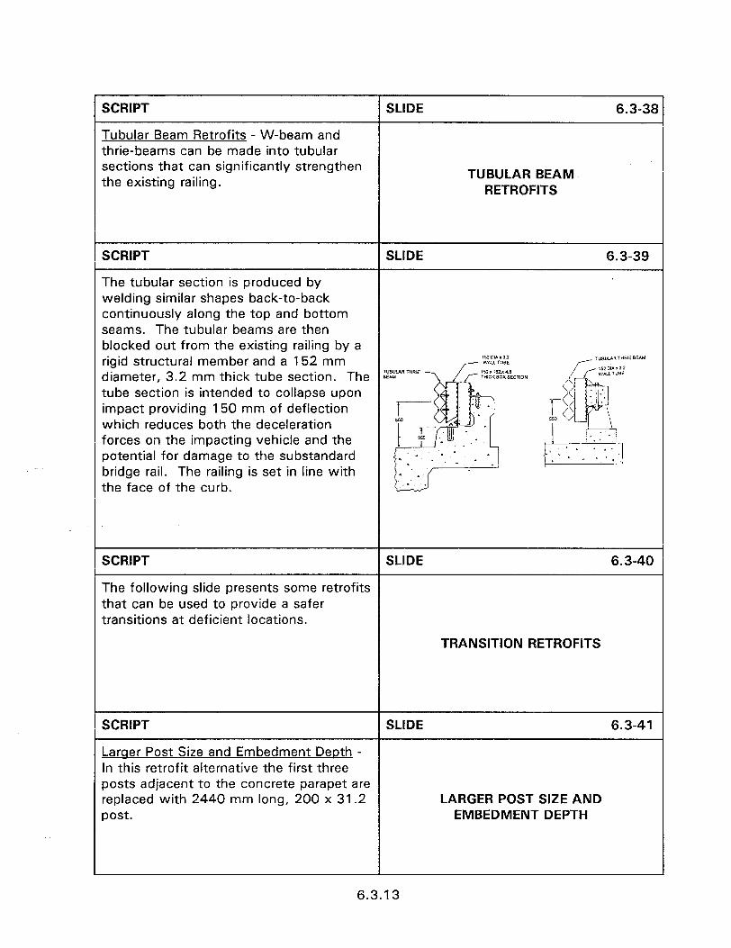
SCRIPT SLIDE 6.3-36
Tubular Beam Retrofits - W-beam and thrie-beams can be made into tubular sections that can significantly strengthen the existing railing. TUBULAR BEAM
RETROFITS
SCRIPT SLIDE 6.3-39
The tubular section is produced by welding similar shapes back-to-back continuously along the top and bottom seams. The tubular beams are then blocked out from the existing railing by a rigid structural member and a 152 mm T”w.AR THRlE BEAU
diameter, 3.2 mm thick tube section. The %:LI\RT”R’E THiCIBOXSECTlON tube section is intended to collapse upon impact providing 150 mm of deflection which reduces both the deceleration forces on the impacting vehicle and the potential for damage to the substandard bridge rail. The railing is set in line with the face of the curb.
SCRlPT SLIDE 6.3-40
The following slide presents some retrofits that can be used to provide a safer transitions at deficient locations.
TRANSITION RETROFITS
SCRIPT SLIDE 6.3-41
Lamer Post Size and Embedment Depth - In this retrofit alternative the first three posts adjacent to the concrete parapet are replaced with 2440 mm long, 200 x 31.2 LARGER POST SIZE AND post. EMBEDMENT DEPTH
6.3.13
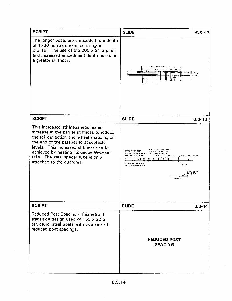
SCRIPT SLIDE 6.3-42
The longer posts are embedded to a depth of 1730 mm as presented in figure 6.3.15. The use of the 200 x 31.2 posts and increased embedment depth results in a greater stiffness.
c 1*20 NESTECI W.BEAII (12 (iAGE, 6 SPA t ~50 d ,,,;I
SCRIPT SLIDE 6.3-43
This increased stiffness requires an increase in the barrier stiffness to reduce the rail deflection and wheel snagging on the end of the parapet to acceptable levels. This increased stiffness can be achieved by nesting 12 gauge W-beam
SIEELIP*OERTVBE w 200 x SI.0 I 2.40 LDN.3 s1 I.D. x *OS LOW3 sTR”CT”R*L SWAPE PDfl SCKDULE 40 OAL”I”,ZEO FIRST THREE PmTs or&y rails. The steel spacer tube is only
PIPE WEE DETNL *l-T w,m~” LOttO i W160 I IO.5 I t*,o LONG
attached to the guardrail. 1 r ,T T, F ,T,
i? 12 OWE BACK-UP PLATE J SPLIDE ON AU *m-SPLICE POSTS (6 cl,* BUTTON
I HEAD BDLT
DETAIL A
SCRIPT
Reduced Post Spacinq - This retrofit transition design uses W 150 x 22.3 structural steel posts with two sets of reduced post spacings.
SLIDE 6.3-44
REDUCED POST SPACING
6.3.14
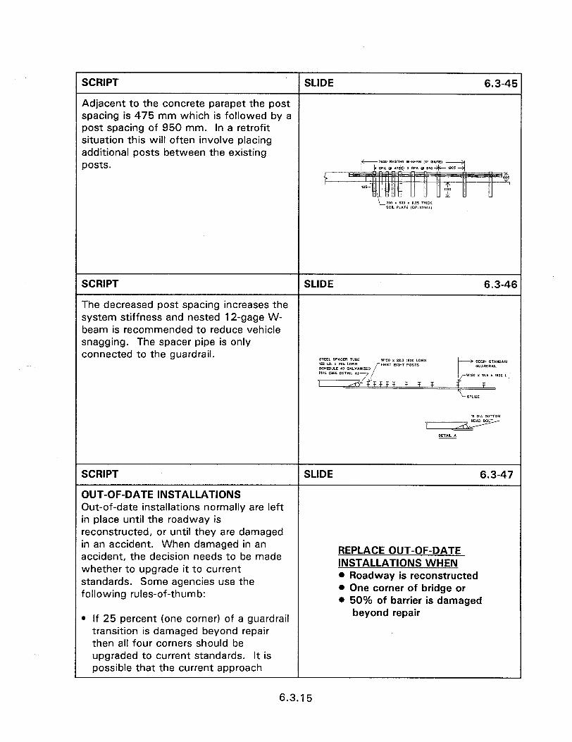
SCRIPT SLIDE 6.3-45
Adjacent to the concrete parapet the post spacing is 475 mm which is followed by a post spacing of 950 mm. In a retrofit situation this will often involve placing additional posts between the existing posts. p- 7520 HESTEO W-BEAM (12 GAGE)
! !d SPA 0 .I& 3 SPA a mu 1905 -;i
SCRIPT SLIDE 6.3-46
The decreased post spacing increases the system stiffness and nested 12-gage W- beam is recommended to reduce vehicle snagging. The spacer pipe is only connected to the guardrail. STEEL w*cwi TUBE w150 x 22.3 11110 LONG w2 m. I 905 LONG BEOM STAMIARI
BCHEllULE 40 ON.YANIZEO [FlW EIGHT POST* G”lRDRAlL PIPE ,SEE DETlfL *, 1 JL! I-+
T F F F d- wm I 13.5 x 11110 L
SPUCE
SCRIPT
OUT-OF-DATE INSTALLATIONS Out-of-date installations normally are left in place until the roadway is
SLIDE 6.3-47
reconstructed, or until they are damaged in an accident. When damaged in an accident, the decision needs to be made whether to upgrade it to current standards. Some agencies use the following rules-of-thumb:
REPLACE OUT-OF-DATE INSTALLATIONS WHEN l Roadway is reconstructed l One corner of bridge or l 50% of barrier is damaged
l If 25 percent (one corner) of a guardrail transition is damaged beyond repair then all four corners should be upgraded to current standards. It is possible that the current approach
beyond repair
1
6.3.15
barrier will not attach to the older bridge rail requiring a more extensive retrofit.
0 If 50 percent of an installation is damaged beyond repair, or less than 30 meters is left undamaged, then the barrier should be upgraded.
l When an upgrade is made notify the appropriate Office within the Agency to enable update of any record systems.
SCRIPT
IDENTIFYING SUBSTANDARD TRANSITIONS
The transition from the approach guardrail to the bridge railing must be sufficiently rigid to prevent impact with the bridge structure. Appropriate transition designs are presented in section 6.2. Design elements to look for on the inspection of existing structures include:
Q The approach rail must be connected to the bridge rail. The approach guardrail to bridge rail connection must be as strong as the approach rail itself to prevent separation upon impact.
a The stiffness of the approach rail should be gradually increased to the more rigid bridge rail. This is usually accomplished by using a strong post system and decreasing the post spacing or increasing the post size and by strengthening the rail element.
l Strong post systems should be blocked out and rub rails used to reduce the possibility of snagging.
The following slides present transitions that may not have problems. Lets see how many problems or good points we can find.
SLIDE 6.3-48
IDENTIFYING SUBSTANDARD TRANSITIONS
WORKSHOP
6.3.16

SCRIPT SLIDE 6.3-49
Slide of improper stiffening of approached rail.
SCRIPT SLIDE 6.3-50
Slide of curb in front of rail.
SCRIPT SLIDE 6.3-51
Slide of improper number of bolts with end shoe.
SCRIPT SLIDE 6.3-52
Slide of no attachment.
SCRIPT SLIDE 6.3-53
Slide of end block behind curb.
I1u.s. ~~“~RNkmrf PRlNTfNG OFFICE: 1998-441-223-90397
6.3.17


