classification of tall building systems. - core
TRANSCRIPT

Lehigh UniversityLehigh Preserve
Theses and Dissertations
1-1-1981
Classification of tall building systems.Daniel W. Falconer
Follow this and additional works at: http://preserve.lehigh.edu/etd
Part of the Civil Engineering Commons
This Thesis is brought to you for free and open access by Lehigh Preserve. It has been accepted for inclusion in Theses and Dissertations by anauthorized administrator of Lehigh Preserve. For more information, please contact [email protected].
Recommended CitationFalconer, Daniel W., "Classification of tall building systems." (1981). Theses and Dissertations. Paper 2391.
brought to you by COREView metadata, citation and similar papers at core.ac.uk
provided by Lehigh University: Lehigh Preserve

CLASSIFICATION OP
TALL BUILDING SYSTEMS
by
Daniel W. Falconer
A Thesis Presented to the Graduate Committee
of Lehigh University in Candidacy for the Degree of
Master of Science in
Civil Engineering
Lehigh University May 1981

ProQuest Number: EP76667
All rights reserved
INFORMATION TO ALL USERS The quality of this reproduction is dependent upon the quality of the copy submitted.
In the unlikely event that the author did not send a complete manuscript and there are missing pages, these will be noted. Also, if material had to be removed,
a note will indicate the deletion.
uest
ProQuest EP76667
Published by ProQuest LLC (2015). Copyright of the Dissertation is held by the Author.
All rights reserved. This work is protected against unauthorized copying under Title 17, United States Code
Microform Edition © ProQuest LLC.
ProQuest LLC. 789 East Eisenhower Parkway
P.O. Box 1346 Ann Arbor, Ml 48106-1346

This thesis is accepted and approved in partial fulfill-
ment of the requirements for the degree of Master of Science.
5*JUu,H?| (date)
Chairman of Civil Engineering Department
ii

ACKNOWLEDGEMENTS
The author wishes to express his deep appreciation
for the supervision, advice, and review of the
manuscript by Dr. Lynn S. Beedle, professor in charge of
this thesis. The help provided by Dr. George
C. Driscoll and Dr. Le-Wu Lu is also sincerely
appreciated.
The library research was conducted at Fritz
Engineering Laboratory and at Mart Science Library, both
at Lehigh University, Bethlehem, Pennsylvania. This
work was carried out as part of a research program at
the Fritz Engineering Laboratory. The thesis research
was a part of the authors civil engineering degree work.
Lynn S. Beedle is the Director of Fritz Engineering
Laboratory and David A. VanHorn is the Chairman of the
Department of Civil Engineering.
The research was supported in part by a National
Science Foundation. The author has drawn upon some of
the ideas contained in the proposals prepared for the
support of the research.
The author also wishes to thank Lois M. Nase, Sharon
L. Seigler, and Jean M. Johnson, Mart Reference
Librarians, for their help in collecting the basic
literature used in this thesis.
The author is indebted to his colleagues at Fritz
Engineering Laboratory, especially Robert J. McDermott
iii

and Daniel Lavanchy. Their many and lively discussions
were of great value.
Special thanks are extended to Ms. Barbara Bryan for
her tremendous effort and help in the preparation and
production of this manuscript.
iv

Table of Contents Page
ABSTRACT
1. INTRODUCTION
2. NEED OF CLASSIFICATION
3. TALL BUILDINGS AND THEIR SYSTEMS
4. STRUCTURAL SYSTEMS
4.1 Alternative Classification Schemes
A. Loading-Oriented Schemes
B. Material-Oriented Schemes
C. Framing-Oriented Schemes
4.2 Proposed Classification Scheme
5. STRUCTURAL MATERIAL SYSTEMS
6. MECHANICAL SYSTEMS
6.1 H.V.A.C.
A. All-Air
B. Air-Water
C. All-Water
6.2 Plumbing
A. Gravity Tank
B. Hydropnuematic Tank
C. Booster Pump
1
2
4
7
12
13
14
16
19
22
27
30
31
32
33
34
35
35
36
37

Table of Contents (Continued) Page
6.3 Vertical Transportation 37
A. Escalators 37
B. Elevators 38
C. Material Movers 38
«i
7. ARCHITECTURAL SYSTEMS 39
7.1 Cladding 39
7.2 Partitions 41
8. UTILIZATION OF CLASSIFICATION SCHEME 43
9. SUMMARY 44
10. TABLES 46
11. FIGURES 61
12. REFERENCES 71
VITA 81
vi

List of Tables
Table - Page
1 STRUCTURAL SYSTEMS (Council, Committee 46 3, 1980)
2 STRUCTURAL SYSTEMS (Lu, 1974) 47
3 HIGH RISE STRUCTURAL SYSTEMS (Khan, 1974) 48
4 FRAMING SYSTEMS FOR TALL BUILDINGS (British 49 Steel Corporation, 1972)
5 MIXED STEEL AND CONCRETE SUBSYSTEMS 49 (Iyengar, 1980)
6 TALL CONCRETE STRUCTURES (Council, 50 Committee 21A, 1978)
7 DATA BASE STRUCTURAL SYSTEMS (Beedle, 50 et.al., 1980)
8 COMMON HIGH RISE STRUCTURES (Schueller, 1975) 51
9 STRUCTURAL SYSTEMS (ATC, 1978) 51
10 STRUCTURAL SCHEMES (Drosdov, Lishak, 1978) 52
11 TALL BUILDING STRUCTURAL CATEGORIZATION 53
12 FRAMING-ORIENTED STRUCTURAL CLASSIFICATION 54
13 STRUCTURAL MATERIAL SYSTEM 57
14 HVAC CLASSIFICATION (ASHRAE, 1976) 58
15 PLUMBING SYSTEM CLASSIFICATION (Council, 58 Committee 2B, 1980)
16 VERTICAL TRANSPORTATION SYSTEMS (Council, 59 Committee 2A, 1980)
17 CLADDING SYSTEM CLASSIFICATION (Council, 60 Committee 12A, 1980)
18 PARTITION SYSTEM CLASSIFICATION (Council, 60 Committee 12B, 1980)
vii

List of Figures
Figure Page
1 TALL BUILDING SYSTEMS 61
2 CONCRETE AND STEEL STRUCTURAL SYSTEMS 62
3 CLASSIFICATION OF STRUCTURAL SYSTEMS OF 63 s MULTI-STORY BUILDINGS
4 BEARING WALL SYSTEMS 64
5 CORE SYSTEMS 65
6 FRAME SYSTEMS 66
7 TUBE SYSTEMS 67
8 SAMPLE CLASSIFICATION CHART 68
9 BRACING TYPES 69
10 SPACE COMPARISON: ALL-AIR VS. AIR-WATER 70
viii

ABSTRACT
As the number of different high-rise structures in
existence expands every year, so also is there an
increase in the possibility of damage due to earthquake
or other hazards. In the event of such damage it is
important to be able to correlate damage intensity with
the particular tall building system used. A
classification scheme for these systems is required, and
this thesis presents such a codification.
The systems selected for study include the structural
systems, the structural materials, selected mechanical
systems, the vertical transportation systems, and
selected architectural systems. Greatest attention is
given to the structural systems.
Of the various alternatives, a framing-oriented
scheme is selected as a means of classifying structural
systems. The fundamental systems within it are bearing
wall, core, tube, and frame, together with the
appropriate mixtures of these systems. A numerical
designation system provides opportunity to catalog the
specific details of the system in a computer data base.
This in turn opens the way to the study of possible
correlation of any observed damage with the system or
subsystem.

1. INTRODUCTION
The object of this thesis is to develop a
classification scheme for some of the more important
tall building -systems. The systems chosen for
classification are the structural system, and selected
mechanical and architectural systems. The major s
emphasis will be placed upon the structural system.
Tall buildings are highly sophisticated engineering
projects. Due to the complexity of the structures, the
most advanced engineering design techniques are needed
in tall buildings. To develop these techniques, new and
existing research and empirical studies need to be
documented in a usable and accessible form.
By definition, a classification system imposes order
on a large body of information. If there were only a
few tall buildings in the world, a classification would
not be needed. However, tall buildings exist all over
the world, and their numbers are increasing every year.
In order to design better tall buildings, information
must be collected on the performance of existing tall
buildings. The classification helps create a structured
order in which to store information collected about
high-rise buildings.
Engineering research, both experimental and
analytical, relies on a consistent method for recording
data and information. The classification of tall

building systems is a logical basis for such research.
In the past, it was not uncommon to totally separate
the structural engineering from the mechanical and
architectural aspects of tall building planning and
design. Today, however, the tall building is more
commonly designed from a "team" approach, with
interaction between the key professionals. In keeping
with this philosophy, the tall building classification
systems are extended beyond the structural
classification to encompass selected mechanical and
architectural systems.

2. NEED OF CLASSIFICATION SCHEME
It is important to realize that a significant amount
of construction will be required in the next 50 years —
enough to service twice the present world population
according to some conservative estimates (Keyfitz) —
and a large percentage of that will be in the high-rise
environment. Since in both present and future buildings
the design load could, in fact, be attained, it is
important to know how the various systems perform and
which ones perform the best.
In the following chapters, fundamentally
representative classification schemes for tall building
systems will be presented. Why are they needed?
Towards what use can these schemes be applied?
The answers to these questions go back to the need to
determine the extent to which present analytical
approaches adequately represent behavior in actual
buildings under normal and extreme loads and under
service situations and use. The basic question is this:
is it possible to establish a correlation between the
particular systems or subsystems used in tall buildings
and the way in which these systems respond under extreme
and service loads?
If the response can be predicted and confirmed in an
appropriate sample of the large number of tall buildings
throughout the world — in other words if a correlation

can be established between a particular system or
subsystem and its behavior in specific applications --
then this information will be of fundamental importance
in new designs.- It will be of equal importance in
assessing the probable performance of other existing
buildings that have not yet encountered such loading and
service conditions. Necessary steps for correction of
any major shortcomings can then be recommended.
This type of research will require as complete an
identification as possible of the tall buildings around
the world and the details of the systems that are used
therein which will be suitable for systems' studies. It
will require documentation of the performance of these
systems. To achieve this, an acurate survey must be
taken of tall buildings and their systems worldwide.
Tall buildings are very complex entities, not easily
separated into obvious distinctions by the casual
observer. In order to create a consistent survey, the
investigators will need to have a format for the
survey's participants to follow. By definition, a
classification lends order and structure to variable
data. Therefore, a classification of major tall
buildings' systems is considered essential before
starting this survey.
Another major potential benefit of acquiring a large
body of information about tall buildings, especially in

earthquake-prone regions, is that a real-life laboratory
is created. When an earthquake strikes, there would be
a wide range of easily accessible information available
to investigators and researchers. The various tall
building systems (structural, mechanical, etc.) could be
compared as to their ability to function during and
after an earthquake. Interaction between different tall
building systems could be studied to determine the
combinations of systems that function well together and
those that do not (Sun, 1979). Responsible authorities
and private assessors could more quickly evaluate
monetary and property losses by having prior knowledge
of the damaged buildings. Projections could be made of
future possible losses. It could assist damage
evaluation teams as they prepare for site visits, and an
inventory that includes the professionals involved will
facilitate procurement of needed supplementary
information.
It is expected that this thesis, in addition to
establishing classification schemes for the essential
tall building systems, will act as a basis for future
tall building research.

3. TALL BUILDINGS AND THEIR SYSTEMS
The term, "high-rise", is defined in Webster's
dictionary as a "building of many stories". This serves
to illustrate the term's subjectivity. Do any clear and
precise definitions exist, and on what basis are they
founded?
Many local fire codes in the USA base their
definition of a tall building on that which is not
attainable with their fire fighting equipment. Some
plumbing engineers would argue that only when a building
has more than 25 stories do design concepts require
modification for plumbing systems; therefore, only
buildings taller than 25 stories are high-rise (Steele,
1975). Other professionals can argue from their
perspective. Who is right?
The definition of a tall building was one of the
first topics to come under discussion by the Council on
Tall Buildings and Urban Habitat, an international group
sponsored by engineering, archictectural, and planning
professionals, that was established to study and report
on all aspects of the planning, design, construction,
and operation of tall buildings.
As described in its Monograph (Council, 1978-1981),
no minimum height is specified. "The important
criterion is whether or not the design is influenced by
some aspect of tallness. A suggested definition, then,

might be "a building in which tallness strongly
influences planning, design and use"; or "a building
whose height creates different conditions in the design,
construction, and use than those that exist in common
buildings of a certain region and period"." (For
purposes of standardization, in connection with its
survey of tall building characteristics, the Council
collects information, on buildings that are nine stories
and more in height.)
For the purpose of research, it is desirable to
categorize the different aspects of tall buildings.
These different aspects are referred to as building
systems. Beedle (1980) defines four distinct building
systems: Loading Systems, Physical Systems, Functional
Systems, and Building Implementation Systems. These are
seen in Fig. 1. Under the "Physical Systems" heading
are such items as foundation systems, structural
framework, mechanical and service systems, and
electrical systems. The building systems this thesis
will classify are the structural systems, and selected
mechanical and architectural systems.
In general, the structural system of a building is a
three dimensional complex assemblage of interconnected
structural elements (Council, Committee 3, 1980). The
primary function of the structural system is to
effectively and safely carry all the loads which act
upon the building, and to resist sway by providing
8

adequate stiffness. The structural system physically
supports the entire building, and with it, all the other
various building systems.
The mechanical systems studied in this thesis are the
heating, ventilation and air conditioning (HVAC),
plumbing and standpipe, and vertical transportation
systems. Among other needs, the HVAC system in a tall
building must be responsive to environmental
requirements, energy consumption, and smoke and fire
management . The plumbing and standpipe system must be
able to meet the water demand of the high-rise under all
service and emergency conditions. The vertical
transportation system must respond to the user promptly,
since its function is that of a time and labor saving
device. By gaining a few seconds for each passenger on
every trip, effective elevator service can save valuable
man-hours over any specified time span (Adler, 1970).
The architectural systems examined in this thesis are
the partition system and the cladding (curtain wall)
system. The function of partitions in a building is the
separation of large space into smaller areas for privacy
or safety. The function of the cladding (curtain wall)
system is to regulate the passage of light, moisture,
temperature transfer, dirt, and, of course, people
through the building's "skin". It must also serve to
provide acoustical control from outside noise and to
assist in fire control (Council, Committee 12A, 1980).
9

These particular mechanical and architectural systems
were chosen because they generally meet the following
criteria: during a natural disaster (earthquake, strong
wind, fire) would the failure of these systems most
likely lead to possible loss of life? The failure of
either a part or of all of the structural system is an
obvious threat to anyone in a tall building at the time
of a disaster, and might also lead to the failure of the
mechanical and architectural systems attached and
supported at those points. These systems, in turn,
might detract from the designed stiffness, flexibility
or strength of the structural systems, thus leading to
failure.
The loss of these mechanical systems in a tall
building may constitute a threat to life. The failure
of the vertical transportation system might trap1people
in possible need of medical attention. A tall
building's ventilation system becomes vital during a
fire, because of large amounts of smoke that must be
expelled Similarly, the standpipe system is also of
great importance in fighting fire in tall buildings
since it delivers water to the sprinklers and fire
hoses.
The failure of the cladding or partition systems
might also constitute a hazard to life. The cladding
system must be able to function during a strong wind to
protect the occupants and contents of the building. In
10

many tall buildings, the partition system is an integral
part of the fire protection system by providing what is
known as "compartmentalization" thus helping to prevent
the spread of anexistingfire (Council, Committee 2B,
1980).
11

4. STRUCTURAL SYSTEMS
This chapter' presents the different types of tall
building structural systems, and the various ways of
classifying them. In Tables 1-11, shortened versions of
work previously done, and available in literature is
presented.
The structural system on a building must resist both
gravity and lateral loads (i.e. wind, earthquake). As
the height of the building increases, the lateral loads
begin to dominate the structural concepts. Most
structural systems have been shown to have optimum
building heights, or rather, optimum height-to-width
ratios. Figure 2 (Khan, 1974) schematically compares
some frequently used steel and concrete systems on the
basis of structural efficiency (as measured by weight
per square foot of the system versus height of the
building).
It is extremely difficult to create a classification
system that succeeds in isolating consistant criteria
for tall building structural systems. This is due to
the large number of possible variables connected with
high-rise structures, such as the number of stories,
building material, framing system, load resistance
properties, etc. Tall buildings themselves are diverse
in nature of usage, location, geometric shape and
12

architectural design. This indicates some in the
difficulties in arriving at a accurate method for
classifying high-rise structures.
4.1 Alternative Classification Schemes
After consideration of the various structural
classification schemes developed and available in
literature, three general approaches can be identified:
loading-oriented classification (a listing of tall
building structural members and subsystems by the load
they resist, i.e., lateral and vertical),
material-oriented classification (a listing of tall
building structural systems by their main structural
material), and framing-oriented classification (listing
tall building structural systems by their framing
method).
The different approaches and the appropriate
classifications are grouped and discussed. General
advantages and disadvantages to each approach are also
presented.
13

A. Loading-Oriented Classification
The loading-oriented classification scheme organizes
the structural components and subsystems according to
the type of loading resisted — whether gravity,
lateral, or energy dissipation. Tables 1 and 2 are
examples of this approach.
The components and members that make up the load
resisting groups can be thought of as structural
"building blocks", from which all tall building
structures are constructed. Although the items within
each group are usually not interchangeable in any
specific structure, they are assumed to perform the same
function (e.g. resist lateral loads).
One way to categorize a structural system is to
define the combination of elementary structural building
blocks that are employed in the structural system. In
fact, this is how to classify a structure by the
loading-oriented approach. These building blocks are,
of course, not arranged haphazardly, but are integrated
in such a way as to provide the most adequate support
and stiffness while conforming to the architectural plan
and maintaining overall economy.
The classification procedure for this type of
approach is to group all of the structural components
and subsystems presently in use in tall buildings
together by load resistance characteristics; and to each
14
building that is to be classified, assign various items
from each group to define that particular structural
system.
The classification that was developed by Committee 3
of the Council on Tall Buildings and Urban Habitat is
such a loading-oriented classification. It groups
"building blocks" based on a listing of vertical load
resisting members, horizontal load resisting subsystems,
and energy dissipation systems (see Table 1). The items
grouped together to form the vertical resisting members
include columns, bearing walls, hangers, and transfer
girders. The items grouped together to form the lateral
load resisting members include moment resisting frame,
braced frame, shear walls, and combination systems.
Items grouped under combination systems are tubes and
core interactive structures, and are called
"combination" because they usually are required to
resist both lateral and vertical loads.
Lu (1974) has presented a classification using the
same basic approach, namely, a listing of vertical load
resisting members, horizontal load resisting subsystems,
and energy dissipation systems. This arrangements is
shown in Table 2. A more detailed listing of lateral
load resisting subsystems is included, which clearly
indicates the myriad of combinations of lateral load
resisting subsystems employed in the design of tall
buildings.
15

Generally, the main advantages of any
loading-oriented classification are:
1. The assistance i^t lends to the structural designer. When designing a tall building structure,' a loading-oriented classification can first tell which structural components and sybsystems are available and which load they generally resist (lateral, vertical, or energy dissapation). s
2. It can be applied to virtually every tall building in the world, providing that the list of "building blocks" is complete. It would appear that no other type of classification can be as universally applied as the loading-oriented classification.
The main disadvantages of this type of classification
are:
1. It cannot render a consistant physical description of the building. This is due to the many and varied ways these building blocks can be integrated to create a particular structural system.
2. It implies that certain structural members resist only one particular loading condition. In reality, the structural designer usually tries to have all members help resist loads from all sources and thus create a more efficient structural system.
B. Material-Oriented Classification
A second method of classifying structures is a
material-oriented classification. This method separates
structural systems on the basis of structural material
(concrete, steel, masonry, wood, mixed). These
distinctions are obvious and valid because many
structural systems differ significantly depending on
16

which structural material is used. The variables
associated with concrete structures might be the
ultimate strength of concrete, the slump of the mix,
curing time, amount of pretension, placement of
reinforcing bars, etc., most of which are not applicable
to steel, masonry, or wood structures. The variables
for a steel or masonry structure are also unique £o that
particular structural material. Tables 3 through 6 list
classification schemes that use this approach.
Khan (1974) uses a material-oriented classification
to discuss the different responses of various steel,
concrete and mixed stuctural systems to lateral loads
(see Table 3).
This approach is also used by the British Steel
Corporation (1972) as seen in Table 4. As their name
would indicate the British Steel Corporation limit their
classification to tall steel structures. In their
article, they discuss lateral load resistance of
different structural systems, relative cost, and the
speed of erection of the various systems.
A classification of tall building structural
subsytems based on the lateral resistance of different
construction material was developed by H.S. Iyengar
(1980) and the subsystems are shown in Table 5.
Iyengar, in his paper, discusses what the function of
the subsystems are, and how to take advantage of the
17

various material (steel, concrete, composite) properties
in each subsystem, and develops a classification chart.
Committee 21A of the Council on Tall Buildings and
Urban Habitat also has developed a material-oriented
classification. Committee 21A limits the classification
to tall concrete structures, and a list of these
structures is shown in Table 6. A major advantage of
this particular classification is that each concrete
structural system is examined in chart form. By doing
this, a logical comparison of the similarities and
differences of each system can be achieved, which helps
to give a "feel" for each type of system. The three
main parameters examined in this chart are the
difficulty of engineering, architecture, and
construction of the various structural systems.
Generally, the main advantages of any
material-oriented classification are:
1. It illustrates the differences that exist between structural systems created from different materials.
2. It identifies structural systems as a whole, not as parts of a whole. This makes it easier to classify a tall building by this approach than by the loading approach, at least preliminarily.
The main disadvantage is:
1. Many geometric structural schemes are not limited to one construction material. For example, a frame structure can be made of concrete, of steel, or a combination of both.
18

C. Framing-Oriented Classification
A third classification system is the framing-oriented
or "descriptive" scheme. This approach attempts to
classify tall building structural systems by a
description of the structural framing system. Tables 7
through 11 give examples of the use of this approach.
The classification scheme shown in Table 7 was used
in an extensive worldwide survey of tall buildings and
their characteristics conducted by the Council (Beedle
et. al., 1980). The system consists of a word or phrase
which (traditionally) represents a certain type of
structural system. These descriptions were then stored
into a computer along with other data pertaining to a
tall building (height, material, location, use).
In Schueller's (1977) classification, primary
emphasis is given to visual and descriptive analysis of
the structural systems (see Table 8). He lists 14
separate tall building structural systems in an attempt
to adequately represent the spectrum of tall building
structures.
The Applied Technology Council (1978) bases its
classification on how well different structural systems
resist an earthquake load (see Table 9). This
classification was developed for application in a
seismic design procedure for all building structures,
and is not restricted to buildings that are tall.
19

Drosdov and Lishak (1978) developed a classification
that categorizes the variety of existing structural
systems into four primary loadbearing systems and six
secondary (combination) loadbearing structures as seen
in Table 10. The six secondary systems are, in fact,
combinations of the four primary structures as shown in
Fig. 3. This classification is part of a study "of the
dynamic response of different tall building structures.
Table 11 contains a structural classification scheme
developed by the author at an early stage of the project
which separated the structure into three categories: the
structural framing system, the "augmentative" structural
subsystem, and the floor framing system. The structural
framing system is defined as the primary load resisting
system of the structure. The augmentative structural
subsystems are the subsystems which were added to the
primary load resisting system to create a stronger
and/or stiffer total structure^. The floor framing
system transmits the occupancy loads to the structural
framing system, and may also serve to transmit lateral
loads along its length between the vertical members.
The basis for classifying structures by this approach
is as follows:
1. There is one and only one primary load resisting system in a tall building.
2. The number of augmentative structural subsystems in a structure vary from case to case.
20

3. There is one floor framing system that can be identified per building.
Generally, the main advantages of any
framing-oriented structural classification scheme are as
follows:
1. It groups together structures that respond similarly to a load (i.e., frame, tube, bearing wall, etc.). This is important when one wants to compare the performance of various systems and their responses to load.
2. It is the least redundant of any of the approaches, therefore, has the potential of being the most efficient. The loading-oriented approach is redundant if one member resists two loads (a very common situation); and the material-oriented approach is redundant if one system is constructed from different materials (also a common situation). The framing-oriented system does not encounter such redundancy.
The main disadvantage of this approach is seen when
attempting to classify structures in great detail. As a
framing-oriented approach begins with a generalized
structure and works toward finer detail, the more
information that is required to classify, the more
complicated the organization of the data becomes.
To list all the various structural systems with their
individual advantages and disadvantages is not within
the scope of this thesis. The advantages and
disadvantages of any system are always dependent on the
individual constraints placed upon it (i.e.
architectural scheme, construction time and money,
21

height desired, loading characteristics, materials
available) .
4.2 Proposed Classification Scheme
After consideration of the various systems identified
in the literature and a consideration of the advantages
and disadvantages of each, the framing-oriented
clasification scheme contained in Table 12 was selected
and further developed to meet the following conditions:
1. The classification scheme must be simple in concept and application, yet detailed enough so that useful comparisons can be made.
2. The classification must be broad in scope in order to be usable in further studies.
3. The classification should be compatible with a computer-oriented system for storing information, retrieving it, and making comparison between the response of similar systems.
This framing-oriented classification scheme is one
that separates the structure into three categories: the
structural framing system, the bracing system, and the
floor framing system.
The structural framing system consists of four major
groups:
1. the bearing wall system
2. the core system
3. the frame system
4. the tube system.
22

As shown in Table 12, the structural systems have
been listed in an organized way under each of the above
four primary structural systems. They are futher
discussed as follows:
1. A bearing wall structure is comprised of planar, vertical elements, which usually form the exterior and interior walls. They usually resist both the vertical and horizontal loads. Examples are shown in Fig. 4.
2. A core structure is comprised of load-bearing walls arranged in a closed form, usually with the mechanical systems (HVAC, elevators, plumbing) concentrated in this vertical shaft, allowing the building flexible space beyond the core. The core resists both vertical and horizontal load. Examples are shown in Fig. 5.
3. A frame structure is usually comprised of columns, girders, and/or beams arranged to resist both horizontal and vertical loads. The frame is perhaps the most adaptable structural form with regard to material and shape, due to the many ways of combining structural elements to adequately support the building. Examples are shown in Fig. 6.
4. A tube structure is usually comprised of closely spaced exterior structural elements, arranged to respond to a lateral load as a whole, rather than separate elements. However, the columns need not be spaced too closely. As long as the building responds similar to a cantilever, it is called a tube. This allows for more flexibility in interior -s* space use, due to the lack of vertical interior structural elements. Examples are shown in Pig. 7.
The bracing subsystems shown as "Level B" in Table 12
define' (1) what type of bracing is employed in a
23

building (e.g. K-bracing, diagonal bracing, etc.), and
(2) how it is relatively situated in the structure (e.g.
frame bracing, core bracing, etc.). Many similar
structures differ only in their bracing system. By
making it a separate subsystem of the framing system, a
more efficient classification scheme is achieved.
The floor framing subsystem is shown as "Level C" in
Table 12. The floor system transmits occupancy loads to
the framing system, and may also serve to transfer
lateral^forces, acting as a diaphram and as an intergral
part of the framing system.
Figure 8 is the classification chart, with some
example buildings classified. The numbers shown in
Figure 8 corresponding to the structural system are
retrieved from Table 12. The numbered designations are
intended to provide a basis for grouping like systems
and subsystems together along the lines shown xn Table
12 and the example structures shown in Figures 4 through
7.
When using the classification tables, it must be
remembered that framing and bracing in a building are
obviously not physically separated. It is a technique
used here to more efficiently classify the structure.
Many structures require identification of both framing
and bracing before the system becomes recognizable (such
as a simple frame with a braced core and hat truss).
24

Under Level B, Bracing Subsystems, there are five
categories. The first two categories (numbers 11-16 and
21-26) refer to in-frame bracing. The next category
(numbers 31-36) refers to core bracing only. The next
category (numbers 41-46) has two uses. If the structure
has a braced core and hat/belt trusses, which are the
same bracing type (e.g. they both are double dxagonal
bracing), this is the category to choose from. The
other use is if a structure has a solid core with
hat/belt trusses, this again is the category to choose
from. The final category is if the structure has a
braced core and hat/belt trusses, but employs two
different bracing types (e.g. single diagonal core and
double diagonal belt/hat truss).
The methodology for arriving at a classification
number for any structure is as follows:
1. Identify which of the four major systems(wall, core, frame, or tube) describes the structure.
2. Scan Table 12, Level A (and the corresponding example figure) for the specific structural system used. (Example: simple frame and solid core)
3. The numbers that correspond to that system are the first two digits of the classification number.
4. Scan Level B in Table 12 (and the illustrations in Fig. 10) for the specific bracing subsystem used. (Example: frame bracing, one plane, double diagonal bracing)
5. The numbers that correspond to that bracing
25

subsystem are the next two digits of the classification number.
6. Scan Level C in Table 12 for the specific floor framing subsystem used. (Example: / concrete beam and slab)
7. The numbers that correspond to that floor subsystem are the final two digits of the structural system classification number.
s
An example of how the generated number might look is
as follows: 3. ss bb ff
where the "ss" represents the structural framing
system, the "bb" represents the bracing subsystem, and
the "ff" represents the floor framing subsystem. For
the purposes of standardization, if a set of digits is
unknown (e.g. the floor framing system if not known),
the space should be filled by two question marks (??).
If a subsystem is known not to exist (i.e. the building
has no bracing), the space should be filled by two zeros
(00).
The "3" in front identifies the tall building system;
the structural system in this case. These "system"
numbers correspond to the Council on Tall Buildings and
Urban Habitat numbering of the committees dealing with
the various systems.
26

5. STRUCTURAL MATERIAL SYSTEMS
This chapter will identify and categorize the main
structural materials employed in high-rise construction.
A preliminary classification scheme is presented in
Table 13, and the characteristics of the materials are
discussed.
Since the beginning of high-rise construction,
structural material concepts have constantly been
changing. In the nineteenth century, the two most
commonly used structural materials were masonry and
iron. It was soon discovered that the type of
structural system that masonry is best suited for (the
bearing wall system) is not very efficient when applied
to tall buildings. The limit of this material became
apparent with the 16-story Monadnock Building (1891) in
Chicago, in which the lower walls were designed, to be
more than six feet thick (Khan, 1973).
Frame systems became more and more prevalent in tall
structures around the turn of the century. This type of
system was first made possible by using iron, and later,
steel. The first example of a tall building' totally
supported by iron frame work was in 1883, with the
construction of the 11-story Home Insurance Building.
Reinforced concrete also had become a common structural
material during this period. In 1903, the 16 story
Ingalls Building was constructed of reinforced concrete
(Schueller, 1975). ,
27

Today, the main high-rise structural materials are
steel, reinforced concrete (prestressed or not), masonry
(reinforced or not), and composite (steel and concrete).
It is recognized that many structures containing
structural cores use a different material for the core
than in the framing. Therefore, when classifying the
material of a structure, two digits are needed. The
first represents the main framing system (wall, core,
frame, or tube), and the second represents the
structural core (if applicable, as in the case of a
frame and core or a tube-in-tube).
The parameters that govern the choice of which
structural material the engineer employs on any one
building are many. This is due to the different
characteristics associated with each material.
Concrete, steel, and masonry have the following general
characteristics:
1. Concrete and masonry have a minimal resistance to tension, while steel is equally strong in tension and compression. In prestressed concrete, an initial compression is provided to offset the effects of tensile stresses.
2. Concrete and masonry are subject to dimensional and property variability with time, while steel properties and dimensions are usually considered constant throughout the life. Creep, shrinkage, and rehydration all play a part in changing concrete and masonry structures' dimensions. Concrete also requires a certain elapsed time to gain designed strength.
28

3. In general, concrete structural members have larger cross-sectional areas than steel members. As a result, dead load tends to be more significant in concrete members. On the other hand, their stiffness also tends to be greater. As a result, sway, vibration and buckling tend to be more significant in steel members than concrete members.
4. Concrete offers almost unlimited flexibility with regard to architectural shape and expressions, while the vast majority of steel members are standard rolled shapes.
5. Concrete and masonry have inherent fire potection, whereas steel requires applied fore protection.
These are just some of the more obvious V
characteristics pertaining to steel, concrete, and
masonry.
Over the past 100 years, the engineer's knowledge of
these materials has increased dramatically. Yet, even
today, research is still being carried out to further
the knowledge of the different structural materials and
their composite interaction (Kato et al, 1980).
29

6. MECHANICAL SYSTEMS
This chapter will identify and categorize the major
factors common to high-rise mechanical systems, the most
important of which are plumbing, HVAC, and vertical
transportation. A preliminary classification scheme is
presented in Tables 14 through 16 for the three
mechanical systems discussed.
The invention and improvement of tall building
mechanical systems (plumbing, HVAC, and vertical
transportation) have made it possible for the high-rise
to become an attractive, livable environment. The
development of the mechanical systems have also freed
the architect and structural engineer from, past
restrictions and enabled them to use their creative
ability in designing the modern, efficient tall
building.
The development of the passenger elevator (1870-1900)
meant that the height of the building was no longer
limited by the occupants' willingness or ability to
climb stairs. The elevator industry played a major role
in setting the stage for the increased size and height
of buildings in the early decades of the twentieth
century. The increasing demand on elevator capacity and
speed brought about further innovations such as multiple
batch systems, local and express elevators, and double
deck elevators (Adler, 1970).
30

In tall buildings erected before the general adoption
of air conditioning, perimeter spaces were necessary for
movable windows and natural ventilation. Dead air
spaces in the interior were possible, and the general
efficiency of total usable space was compromised. After
forced air HVAC systems became accepted, the entire
floor plan became the usable office space, and the
efficiency of the flopr space was improved (ASHRAE,
1976).
Plumbing systems in tall buildings went unchanged
longer than any other mechanical system. The method
used almost exclusively until the late 1950's and early
1960's to increase water pressure was that of single
speed pumps carrying water to various gravity tanks. It
is known as the gravity tank system (Council, Committee
2B, 1980). At that time, variable speed pumps and pump
controls were developed to a point where booster pump
systems started to replace gravity tank systems. Today,
tall building plumbing engineers specify the booster
pump system almost exclusively (Steele, 1975).
6.1 Heating, Ventilation, and Air Conditioning
The primary purpose of a heating, ventilation, and
air conditioning system is to provide a specific set of \
pre-determmed environmental conditions.
Table 14 lists many types of equipment and systems
that are available. Most of the requirements of a
31

particular building can be met by any one of several
equipment/systems combinations. The choice of which
system is most appropriate to any specific building lies
in the evaluation of each systems application and of its
quality.
The four general system categories (all-air,
air-water, all-water, and multiple unit systems) are
presented in Table 13 (number designations are given
there as well). A brief discussion of each of them
follow, together with the advantages and disadvantages
of each system.
A. All-Air Systems
An all-air system is defined as a system providing
complete cooling capacity by a cold air stream supplied
by the system. Heating and ventilation are also usually
accomplished by forced air (ASHRAE, 1976). All-air
systems may be classified into two basic categories:
1. Single path systems -- those which contain the main heating and cooling coils in a series flow path, using common duct distribution to feed all terminals.
2. Dual path systems — those which contain the main heating and cooling coils in a parallel flow path, using one duct for heating and one duct for cooling.
The usually cited advantages of an all-air system are:
1. Centralized location of major equipment
2. Wide choice of placement options
32

- 3. Ready adaptation of heat recovery systems
4. Adaptable to winter humidification
5. Design freedom for optimum air distribution.
The usually cited disadvantages of an all-air system
are:
1. The additional duct clearance requirements s
2. The long hours of fan operation in cold weather required by perimeter heating.
B. Air-Water Systems
In the all-air system, the building space is cooled
solely by air. In contrast, the air-water system is one
in which both air and water are distributed to perform
the cooling and heating functions. Air-water systems
are categorized as follows:
1. The two-pipe system -- systems which consist of one supply pipe and one return pipe, along with conditioned air from a central source.
2. The three-pipe system — systems which consist of one hot supply pipe, one cold supply pipe, and a common return pipe.
3. The four-pipe system — systems which consist of a separate hot loop and cold loop.
The air-and-water system has the following general
advantages:
1. Because of the greater specific heat and much greater density of water compared to air, the cross sectional area required for the distribution pipes is much less for the same cooling task. (See Fig. 10.)
33
J

2. Individual room thermostat control possible.
3. Reduced size of central air conditioning apparatus.
The air-and-water system has the following general
disadvantages:
1. Controls tend to be complex. s
2. System is not applicable to spaces with high exhaust requirements, and/or high dehumidification requirements.
C. \M1-Water Systems
All-water systems accomplish cooling solely by the
distribution of chilled water to terminal units located
throughout the building. All-water systems are
categorized as follows:
1. Two-pipe systems
2. Three-pipe systems
3. Four-pipe systems
The all-water system has the following general
advantages:
1. No ventilation ductwork space is required.
2. Individual room thermostats are possible.
The all-water system has the following general
disadvantages:
1. Total lack of humidity control.
2. Dependence on natural ventilation.
34

6.2 Plumbing Systems
The primary purpose of the plumbing system is to
provide adequate water .pressure at all times in all
parts of the building. This entails delivering the
water at the correct pressure at all locations and
handling the discharge. The classification of plumbing
systems can be separated into four categories; the
gravity tank system, the hydropneumatic tank system, the
booster pump sytem, or a combination of the above three
(see Table 15).
A. Gravity Tank System
The-gravity tank system consists of an elevated tank
of adequate capacity with single speed pumps to raise
the water to fill the tank. When the water level in the
tank drops to a predetermined level, the pumps bring
water up until the tank is full.
Compared to other pressure boosting systems, the
gravity tank system has the following advantages:
1. No sophisticated controls are required
2. It is most reliable in case of power failures
3. There is minimum maintenance associated with this system
4. It provides additional reserve capacity for fire protection
5. Pump head is less than is required in other systems, and therefore uses less energy
6. There are minimum pressure variations in the
35

distribution system.
The gravity tank system has the following disadvantages:
1. The tank must be elevated
2. The weight of the tank and water may increase structural costs
3. The tanks require interior maintenance s
4. If there is a tank failure, large quantities of water will be released.
B. Hydropneumatic Tank System
The hydropneumatic tank system consists of a series
of smaller tanks at various locations in the building
with pumps to raise the water to the tanks. The
hydropneumatic tanks are also known as pressure tanks,
because the tanks use compressed air to achieve the
desired pressure in the line.
Compared to the gravity system, the hydropneumatic
tank system has the following advantages:
1. It does not have to be elevated
2. It can be located anywhere in the building
It has the following disadvantages:
1. There is the possibility of inside corrosion of the tank due to the addition of air in the tank
2. A pressure variation of 20 psi is normal
3. Pumps of a higher head are required.
36

C. Booster Pump System
The booster pump system varies the speed of
continuously running pumps to hold a constant discharge
pressure under varying flow conditions. The advantages
of a booster system are:
1. No large tanks are required ,.
2. Usually, there is a lower initial cost.
The disadvantages of a booster system are:
1. Sophisticated controls are necessary
2. The constantly running pumps can create a noise problem
3. There is no emergency water supply
4. Operating costs are high because the pumps do not operate at maximum efficiency.
6.3 Vertical Transportation
Vertical transportation is approached from the point
of view of the user. Obvious subsystems, such as motor,
counterweight, brake and elevator batch control are not
treated.
Vertical transportation systems can be separated into
three categores: elevators, escalators, and material
movers (see Table 16). Elevators and escalators are
commonly referred to as "people movers".
A. Elevators
Elevators are usually the primary people movers in
37

tall buildings. An elevator system that is referred to
as "single deck" is one that has one elevator per
vertical shaft. A "double deck" has two elevator cars
existing in the same elevator shaft, one atop the other.
A "local" elevator can stop at any floor, while an
"express" will skip a certain number of floors, then
over a certain range behave as a local. The sky-lobby
concept (Council, Committee 2A, 1980) is a shuttle
elevator that goes from ground level to a lobby, where
local elevators are available for access to other
levels.
B. Escalators
Escalators are categorized by the relative
arrangement, either crisscross of parallel. The first
arrangement is more economical of space, the latter is
more impressive in appearance( Adler, 1970). In either
arrangement, escalators may be adjacent or separate.
C. Material Movers
Material movers are separated into two categories;
pnuematic message tubes and tote box selective vertical
conveyors. Delivery of more bulky materials are usually
delegated to service elevators.
38

7. ARCHITECTURAL SYSTEMS
The two architectural systems briefly considered in
this thesis are partition systems and cladding systems.
The development of the metal curtain wall has been
looked upon as the introduction of pre-fabrication
techniques to tall buildings. This ^partial
pre-fabrication concept helped lead to the proliferation
of tall buildings, due to a dramatic savings in both
money and construction time. The building known as the
"first skyscaper" was the Home Life Insurance Building,
in Chicago. One of the major reasons for this title was
that it was the first to employ nonloadbearing exterior
wall (cladding). The cladding systems discussed in.this
thesis will be limited to the nonloadbearing type.
In tall buildings extra consideration is given to
partitions, in particular to acoustics, fire protection
and resistance, covering elevator shafts, and response
to building lateral sway.
7.1 Cladding
The classification of cladding or curtain wall
systems are separated into custom , cladding (designed
specifically for one job) or standard cladding
(components and details are standardized by the
manufacturer). In each, there are five categories which
are based on assembly on-site (Council, Committee 12A,
1980). The five categories are: stick wall system, unit
39

System, unit and mullion system, panel system, and
column-and-spandrel system. (See Table 17.)
In the stick wall system the components are installed
piece by piece, with vertical members (mullions),
horizontal members, and windows as the pieces. The
advantage of this system is its ease of shipping and the
degree of dimensional adjustments to site conditions.
The disadvantage of this system is the necessity of
assembly in the field.
The unit; system is a preassembled module, usually one
floor in height. The unit and mullion system is
installed mullions first, with the preassembled units
placed between them. The advantage of these two systems
is that good quality control can be maintained at the
shop. The disadvantage of these systems is that units
are usually bulky to transport.
The panel installation system is similar to the unit
system, but with the jointing between panels at a
minimum. The advantages and disadvantages are basically
the same as with the unit system.
The cover-column-and-spandrel installation system
consists of column and spandrel cover sections, and
infilled windows or glazed units. The advantages of
this system are relatively easy shipping and latitude of
use with any column and spandrel spacing. The
disadvantage of this system is the large amount of field
40

work involved with its assemblage.
7.2 Partitions
The primary function of the partition system in
high-rise building is the separation of large spaces
into smaller ones for privacy and fire protection.
The classification of partition systems is separated
into movable (demountable) partitions and solid
partitions. All partitions referred to in this section
are nonloadbearing. Some may assist the main structure,
but, nevertheless, are nonloadbearing.
The solid partitions are categorized according to
their construction material, either brick or concrete as
shown in Table 18. The demountable partitions are
categorized according to their support scheme, either
post and infill, post and overlay, or postless. The
postless partitions must reach from ceiling to floor for
support, whereas the post supported partitions can be of
any height. ^
This classification scheme is essentially the same as
the one developed by Committee 12B of the Council on
Tall Buildings and Urban Habitat. This scheme differs
slightly from Timesaver Standards for Architectural
Design Data, 1974. Timesaver groups partitions into the
five following categories:
1. Steel framed walls
2. Solid laminated partitions
41
3. Laminated gypsum strip (stud partitions)
4. Wall furring systems
5. Column fire proofing
This scheme goes into more detail of "nuts and bolts"
of individual types of partitions.
\
42

8. UTILIZATION OF CLASSIFICATION SCHEMES
Over the past 20 years, individual researchers and
engineering damage evauluation teams have studied the
effects of earthquakes, hurricanes and other natural
disasters on particular buildings and regions of the
world. More useful information could be extracted from
these case studies if all the data could be logically
compared. But there is presently no systematic method
of correlating between general building systems and the
performance of those systems.
The classifications presented in previous chapters
can be a used to rationally identify tall building
systems. With this acomplished, a system-by7system
damage evaluation can be carried out for past and future
disasters. The classification of tall building systems
can also serve as a basis for an extensive tall building
survey.
43

9. SUMMARY
A summary of this study is as follows:
1. The tall building systems are identified as the
loading systems, the functional systems, the physical
systems, and the building implementation systems (Fig.
1). The systems that are classified are the structural,
material, mechanical, and architectural systems, all of
which are subsystems to the physical systems.
2. From the literature, many structural
categorizations and classifications were identified.
Three alternative classification approaches were
examined, a loading-oriented approach, a
material-oriented approach, and a framing- oriented
approach.
3. The framing-oriented approach was selected for
use in the structural system classification scheme (See
Table 12).
4. The major systems and subsystems in the
classification scheme are the framing system, the
bracing subsystem, and the floor framing subsystem.
5. A classification number is assigned to each
system and subsystem as a basis for computerizing
specific information about individual buildings. The
numerical designators assist in grouping like systems
together for the purpose of comparisons of the response
44

of the various systems to loading.
6. The material, mechanical, and architectural
systems are catalogued similar manner — albeit in a
preliminary way — and classification numbers are
assigned.
45

Table 1 STRUCTURAL SYSTEMS
(Council, Committee 3, 1980)
Framing Systems to Resist Gravity Loads
1. Horizontal Framing Systems - Floor Structures
2. Vertical Framing Systems a. columns b. bearing walls * c. hangers d. transfer girders e. suspended systems
Framing Systems to Resist Horizontal Loads
1. Moment Resistant Frames 2. Braced Frames 3. Shear Walls 4. Combination Systems
a. Tube Structures b. Multiple Tube System c. Core Interaction Structures
5. New Structural Concepts a. megastructures b. cellular structures c. bridged structure
Energy Dissipation Systems
1. Natural Damping 2. Plasticity of Structural Materials 3. Highly Absorbant Structural Systems 4. Artificially Increased Damping 5. Advanced Foundation Design 6. Aerodynamic Provisions
46

\
Table 2 STRUCTURAL SYSTEMS (Lu, 1974)
Gravity Load Resistant Systems
1. Horizontal (floor) Framing 2. Vertical Framing
a. bearing walls b. hangers * c. load transfer girders
Lateral Load Resistant Systems
1. Moment Resistant Frame 2. Shear Wall or Truss 3. Combined Frame and Shear Wall or Truss 4. Moment Resistant Frame with Stiffening Features 5. Framed Tube 6. Core Structure 7. Combined Framed Tube and Core Structure 8. Framed Tube with Stiffening Features 9. Other Tube Structure
Energy Dissipation Systems
1. Ductile Frame and Wall 2. Damping Systems
47

Table 3 HIGH RISE STRUCTURAL SYSTEMS (Khan, 1974)
Steel Structural Systems
1. Rigid Frame 2. Shear Truss Frame 3. Shear Truss Frame with Belt Trusses 4. Framed Tube 5. Column Diagonal Truss Tube * 6. Bundled Tube 7. Truss Tube without Interior Columns
Concrete Structural Systems
1. Frame 2. Shear Wall 3. Frame-Shear Wall 4. Framed Tube 5. Tube-in-Tube 6. Modular Tube
48

Table 4
FRAMING SYSTEMS FOR TALL BUILDINGS (British Steel Corporation, 1972)
1. Rigid Frame 2. Core Type Structure 3. Shear Wall System 4. Braced Structure * 5. Hull or Tube System 6. Suspended Structure
Three Means of Resisting Lateral Loads in Structures
1. Shear Wall 2. Rigid Connections 3. Diagonal (Truss) Bracing
Table 5
MIXED STEEL AND CONCRETE SUBSYSTEMS (Iyengar, 1980)
Lateral Load Resisting Subsystem
1. Floor Framing 2. Slab 3. Columns 4. Wall Panels 5. Cladding
49

Table 6
TALL CONCRETE STRUCTURES (Council, Committee 21A, 1978)
Lateral Resistance Systems
1. Moment Frame 2. Tube 3. Framed Tube 4. Shear Wall 5. Shear Wall and Frame 6. Staggered Truss (Staggered Wall) 7. Gravity System 8. Diagonal (Braced Frame) 9. Braced from other structures 10. Bridged Systems
Table 7
DATA BASE STRUCTURAL SYSTEMS (Beedle,et.al., 1980)
1. Rigid Frame 2. Braced Frame 3. Staggered Frame 4. Frame With Load Bearing Walls 5. Frame With Central Core 6. Frame With Shear Walls 7. Core With Cantilevered Floors 8. Core With Suspended Floors 9. Framed Tube 10. Braced Tube 11. Tube-in-Tube
50

Table 8
COMMON HIGH RISE STRUCTURES (Schueller, 1975)
1. Bearing Walls 2. Cores and Bearing Walls 3. Self Supporting Boxes 4. Cantilevered Slab 5. Flat Slab « 6. Interspatial 7. Suspended 8. Staggered Truss 9. Rigid Frame 10. Core and Rigid Frame 11. Trussed Frame 12. Belt-Trussed Frame and Framed Core 13. Tube-In-Tube 14. Bundled Tube
Table 9
STRUCTURAL SYSTEMS (Applied Technology Council, 1978)
Type of Structural System
1. Bearing Wall System
2. Building Frame System
3. Moment Resisting Frame System
4. Dual System
5. Inverted Pendulum Structures
Vertical Seismic Resisting System
Light framed walls with shear panels
Shear Walls
Special Moment Frames
Ordinary Moment Frames
Braced Frames
51

Table 10
STRUCTURAL SCHEMES (Drosdov, Lishak, 1978)
Primary Structural Systems
1. Framed systems (Frame) 2. System with Flat Walls (Wall) 3. Core-Trunk System (Core) „ 4. Envelop-Type System (Tube)
Secondary (Combination) Structural Systems
1. Frame-Braced System (Frame & Wall) 2. Frame System (Frame & Core) 3. Frame-Envelop System (Tube & Frame) 4. Trunk-Wall System (Core & Wall) 5. Cellular System (Tube & Wall) 6. Trunk-Envelop System (Tube & Core)
52

Table 11
TALL BUILDING STRUCTURAL CATEGORIZATION
Primary Strucural Framing System
1. Bearing Wall 2. Core 3. Frame 4. Tube
Augmentative Structural Subsystems
1. Structural Wall 2. Structural Core 3. Truss System 4. Repeated Girder 5. Moment Resisting Frame
Floor Framing Subsystem
1. Steel 2. Concrete 3. Composite
53

Table 12 FRAMING-ORIENTED STRUCTURAL CLASSIFICATION
Level A; FRAMING SYSTEMS (PRIME & HYBRID)
1. Bearing Wall
10 Bearing wall 11 Bearing wall & core 12 Bearing wall & frame
2. Core
20 Perimeter core 21 Perimeter core & f-rame 22 Perimeter & central
core 23 Suspended 24 Suspended & Frame 25 Suspended & Shear Walls 26 Cantilevered Floors 27 Cantilever & Frame
3. Frame 4. Tube
30 Simpl 31 Semi- 32 Rigid 33 Simpl
Shear 34 Simpl
Solid 35 Semi-
Shear 36 Semi-
Solid 37 Rigid
Shear 38 Rigid
Solid 39 Exter
e Frame Rigid Frame Frame
e Frame & Walls
e Frame & Core
Rigid Frame & Walls Rigid Frame & Core Frame & Walls Frame & Core ior Truss Frame
40 Framed Tube 41 Trussed Tube 42 Bundled (Modular) Tube 43 Perforated Shell Tube 44 Deep Spandrel Tube 45 Framed Tube-in-Tube 46 Trussed Tube-in-Tube 47 Shell Tube-in-Tube 48 Spandrel Tube-in-Tube 49- Framed w/int. cols. 50 Trussed w/int. cols. 51 Shell w/int. cols. 52 Spandrel w/int. cols.
54

Table 12, Continued
Level Bt Bracing Subsystem
Frame Bracing One Plane
11 Single Diagonal Bracing 12 Double Diagonal Bracing 13 Horizontal K Bracing 14 Vertical K Bracing 15 Knee Bracing 16 Lattice Bracing
Core Braced (Two Directions)
31 Single Diagonal Bracing 32 Double Diagonal Bracing 33 Horizontal K Bracing 34 Vertical K Bracing 35 Knee Bracing 36 Lattice Bracing
Core Braced and Hat/Belt Truss
Frame Bracing Two Planes
21 Single Diagonal Bracing 22 Double Diagonal Bracing 23 Horizontal K Bracing 24 Vertical K Bracing 25 Knee Bracing 26 Lattice Bracing
Core With Hat\Belt Truss
41 Single Diagonal Bracing 42 Double Diagonal Bracing 43 Horizontal K Bracing 44 Vertical K Bracing , 45 Knee Bracing 46 Lattice Bracing
51 Single Diagonal Core/Double Diagonal Belt/Hat 52 Double Diagonal Core/Single Diagonal Belt/Hat 53 K Braced Core/Single Diagonal Belt/Hat 54 K Braced Core/Double Diagonal Belt/Hat 55 Knee Braced Core/Single Diagonal Belt/Hat 56 Knee Braced Core/Double Diagonal Belt/Hat 57 Lattice Braced Core/Signel Diagonal Belt/Hat 58 Lattice Braced Core/Double Diagonal Belt/Hat
55

Table 12, Continued
Level C: Floor Framing Subsystem
Steel Concrete
11 Pre-fabricated 21 Flat Slab
12 Steel Beam 22 Beam and Slab and Deck
13 Steel. Joist and 23 Precast Slab Deck Beam and Slab
24 Joist
Composite
31 Steel Beam and Slab
32 Steel Beam and Slab on Metal Deck
33 Concrete Encased Beam
34 Steel Joist and Slab
Typical Designator:
Level A: Framing System Level B: Bracing Subsystem Level C: Floor Subsystem
35.41.31
j I
^ 56

Table 13
Structural Material System
1. Unreinforced Masonry 2. Reinforced Masonry 3. Reinforced Concrete 4. Prestressed Concrete 5. Structural Steel 6. Composite Concrete and Steel 7. Vertically Mixed 8. Mixed Throughout 9. Wood
57

Table 14
H. V. A. C. CLASSIFICATION (ASHRAE, 1976)
1. All-Air 2. Air-Water 3. All-Water 4. Multiple Unit
1 Single Path 1 Two Pipe 1 Two Pipe 1 Window A\C 2 Dual Path 2 Three Pipe 2 Three Pipe 2 Thru-Wall
3 Four Pipe 3 Four Pipe 3 Rooftop A\C
4 Unitary A\C
5 Direct Expansion, Water-Loop Heat Pumps
Table 15
PLUMBING SYSTEM CLASSIFICATION (Council, Committee 2B, 1980)
1. Gravity Tank 2. Hydropnuematic Tank 3. Booster Pump 4. Mixed
58

Table 16
VERTICAL TRANSPORTATION SYSTEMS (Council, Committee 2A, 1980)
1. Escalators
1 None
2 Criss Cross
3 Parallel
2. Elevators 3. Material Movers
1 None
2 Pneumatic Tubes
1 Single Deck, Local
2 Single Deck, Local and Express
3 Single Deck, Sky 3 Vertical Lobby Concept Box
4 Double Deck, Conveyors Local
5 Double Deck, Local and Express
6 Double Deck, Sky Lobby Concept
59

Table 17
CLADDING SYSTEM CLASSIFICATION (Council, Committee 12A, 1980)
Cladding Type
1. Custom Walls
2. Standard Walls
Instaltion Method
1. Stick Instalation s
2. Unit Instalation
3. Unit and Mullion Instalation
4. Panel instalation
5. Column-Cover-and- Spandrel Instalation
Table 18
PARTITION SYSTEM CLASSIFICATION (Council, Committee 12B, 1980)
Permanent
1. Masonry Brick
2. Concrete Block
Demountable
3. Post and Infill Panels
4. Post and Overlay Panels
5. Postless
60

Loading Systems
Gravity Temperature Earthquake
Wind Fire
Accidental Loading Water and Snow
Functional Systems
Utilization Parking Ecological Ownership, Financing
Site Operation Esthetics Maintenance
Space Cognition Management Access and Evacuation Building Services Infiltration Protection Communication
Environmental Security Transportation Fire Protection Energy Efficiency Urban Services
Physical Systems
Foundation Architectural Structural Framework Fitting and Furnishings Mechanical Systems Contents
Electrical Utilities
Building Implementation Systems
Need Planning Design
Construction Operation Demolition
Fig. 1: Tall Building Systems (Beedle, 1980)
6K_

80
70
60
50
40
30
20
10
/^K 71
~0) S
14-1 1 / /
/
/ rH
/
/ •c=rt / /
/
/
/
/ /
/ /
1 ■:<■
■:■',<
1 /
i I i I 0)
.£>
4J
to rH
o 6
Concrete Structural Systems
Steel Structural Systems
Fig.2 (Khan, 1974)
62 .

frame
tube
wall
' (T) .\wall/
f core \
^Y tube \ \ ( & ) > V core X.
(I 1 \ wall / If core
Classification of Structural Systems of Multi-Story Buildings
Fig. 3 (Drosdov, Lishak, 1978)
63
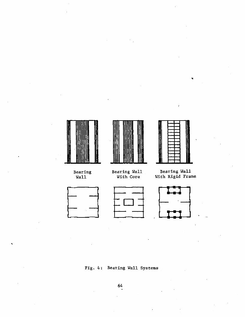
Bearing Wall
Bearing Wall With Core
Bearing Wall With Rigid Frame
1_ I
Fig. 4: Bearing Wall Systems
64

*i *
jJtL Suspended Top Truss
XX
run Suspended
Bottom Truss
I
Cantilever Floors
Cantilever Connected Floors
Corner Core
Corned & Interior Core
Separatee Perimeter
Core
Separatee Perimeter &
Interior Core
o-o
o-o
o—o D
6—6
Fig. 5: Core Systems
65

Frame Frame & Solid Core
Frame & Braced Core
Frame & Shear Walls
Frame & Wing Trusses
h-1 Ml- h-l HN E^*: ■- a ! ! i i
■ i 1
i 1 1
1—1 Hh HH 1—IM 1 1 =HHHF 1 IPH
1 s * AA AA AA AA
A A
A
*:**
Hat Truss & Flat Staggered Braced Hat/Belt Trusses Braced Core Slab Truss Frame & Braced Core
■ ■ I IHH ., n IHH IH-4—I
—II—I-
S< fells
-HI—lh
5Hh=-ilS
-HI—■-
r* 1-1
1 K=H
I—H
n l-H
Fig. 6: Frame Systems
66

re
i *
>
*.
* «
*
;:
b
Framed Tube
Perforated Shell Tube
Deep Spandrel Tube
Trussed Tube
Bundled Tube
II 11—I h
II 11—I h
II 11—I h
«—»-* •—■II
Framed Tube-in-Tube
N ±
i *
\ 7
*
k 4
*
i
VI
* 7
b
Perforated Deep Spandrel Trussed Tube-ln-Tube Tube Tube-in-Tube
w/lnt. Cols.
□
Framed Tube & Hat/Belt
Trusses
11—i ■
Fig. 7: Tube Systems
67

Building Name
Structural
3
Material
9
Framing Bracing Floor
Penzoil Place Frame 38 42 31 Steel 53
MLC Centre \
Tube 47 00 31 Concrete 33
Park Towers Wall 11 00 21 Concrete 30
Collins Place Tube 45 00 31 Steel 53
BHP House Tube 53 42 32 Steel 55
USS Building Frame 36 4? 11 Steel 55
lase Manhattan Frame 33 11 11 Steel 50
^-
See Table 12
See Table 13
Fig. 8: Sample Classification Chart
68

Single Diagonal Bracing
Double Diagonal Bracing
Vertical K-Bracing
Knee Bracing
Horizontal K-Bracing
Lattice Bracing
Fig. 9: Bracing Types (Council, Committee 3, 1980)
69

Fig. 10: Space Comparison: All-Air vs. Air-Water
(ASHRAE, 1976)
70

12. REFERENCES/BIBLIOGRAPHY
ASHRAE ASKRAE HANDBOOK & PRODUCT DIRECTORY, American Society of Heating, Refrigerating and Air Conditioning Engineers, Inc., New York, 1976.
ATC <j
TENTATIVE PROVISIONS FOR THE DEVELOPMENT OF SEISMIC REGULATIONS FOR BUILDINGS, Aplied Technology Council, Washington D.C., 1978.
Abdallah, N. THE M.L.C. CENTRE, Planning and Design of Tall Buildings, (Proceedings of Conference held in Sydney, Australia, August 13-17), Lehigh University, Bethlehem, pp. 316-331, 1973.
Adler, R. R. VERTICAL TRANSPORTATION FOR BUILDINGS, American Elsevier Publishing Co., Inc., New York, 1970.
Bandel, H. STRUCTURAL SYSTEMS FOR VERY TALL BUILDINGS, Planning and Design of Tall Buildings, (Proceedings of Conference held at Lehigh University, August, 1972), Vol. la, ASCE, New York, pp. 627-631, 1973.
Beedle, L. S., Ed. TALL BUILDING SYSTEMS IDENTIFIED, The Times, Vol. 11, No. 2, p. 2, 1980.
Beedle, L. S., Driscoll, G. C, Aydinoglu, N., and Anderson, B. HIGH-RISE BUILDING DATA BASE, Fritz Laboratory Report No. 442.2, Lehigh University, Bethlehem, 1980.
71
.*H^Z

British Steel Corporation FRAMES FOR TALL BUILDINGS/ Building With Steel, Volume 12, pp. 14-18, November, 1972.
Callender, J. H., ed. TIME-SAVER STANDARDS FOR ARCHITECTURAL DESIGN DATA, Fifth Edition, McGraw-Hill Book Company, New York, 1974.
Christiansen, J. CAST IN PLACE REINFORCED CONCRETE SYSTEMS, Planning and Design of Tall Buildings, (Proceedings of Conference held at Lehigh University, August, 1972), Vol. la, ASCE, New York, pp. 437-452, 1973.
Colaco, J. P* and Banavalkar, P. V. STRUCTURAL CONCEPTS FOR MID-RISE STRUCTURES, Pan Pacific Tall Buildings Conference Proceedings, (Conference held in Honolulu, Hawaii, January), University of Hawaii, pp. 136-150, 1975.
Colaco, J. P. and Banavalkar, P. V. PENZOIL PLACE - A NEW SLANT IN STRUCTURAL SYSTEMS, Proceedings of the Regional Conference on Tall Buildings, (Conference held in Bangkok, Thailand, January 23-25), Asian Institute of Technology, Bangkok, pp. 17-32, 1974.
Coull, A. and Subedi, N. K. FRAMED TUBE STRUCTURE FOR HIGH- RISE BUILDINGS, Journal of the Structural Division, ASCE, Vol. 98, No. ST-8, pp. 2097- 2105, August, 1971.
Council on Tall Buildings PLANNING AND DESIGN OF TALL BUILDINGS, A Monograph, 5 volumes, ASCE, New York, 1978-1981.
72

Council on Tall Buildings, Committee 2A VERTICAL AND HORIZONTAL TRANSPORTATION, Chapter SC-4, Volume SC of Monograph on Planning and Design of Tall Buildings, ASCE, New York, 1980.
Council on Tall Buildings, Committee 2B MECHANICAL AND SERVICE SYSTEMS, Chapter SC-2, Volume SC of Monograph on Planning and Design of Tall Buildings, „ ASCE, New York, 1980.
Council on Tall Buildings, Committee 3 STRUCTURAL SYSTEMS, Chapter SC-1, Volume SC of Monograph on Planning and Design of Tall Buildings, ASCE, New York, 1980.
Council on Tall Buildings, Committee 2A CLADDING, Chapter SC-5, Volume SC of Monograph on Planning and Design of Tall Buildings, ASCE, New York, 1980.
Council on Tall Buildings, Committee 2B PARTITIONS, WALLS, AND CEILINGS, Chapter SC-6, Volume SC of Monograph on Planning and Design of Tall Buildings, ASCE. New York, 1980.
Council on Tall Buildings, Committee 2A CONCRETE FRAMING SYSTEMS FOR TALL BUILDINGS, Chapter CB-3, Volume CB of Monograph on Planning and Design of Tall Buildings, ASCE, New York, 1978.
Dowrick, D. J. EARTHQUAKE RESISTANT DESIGN, John Wiley & Sons, Inc., New York, 1977.
Drosdov, P. F. and Lishak, V. I. SPATIAL RIGIDITY & STABILITY OF TALL BUILDINGS OF DIFFERENT STRUCTURAL SCHEMES, Prefabricated Multi-Storey Buildings, (Proceedings of Conference held in Moscow, October 1976), Central Researh and Design Institute for Dwellings, Moscow, pp. 27-35, 1978.
73

Engel, H. STRUCTURE SYSTEMS, Praeger Publishers, New York, 1967.
Fleming, J. F. LATERAL TRUSS SYSTEMS IN HIGH- RISE BUILDINGS, Proceedings of the Regional Conference on Tall Buildings, (Conference held in Bangkok, Thailand, January 23-25), Asian Institute of Technology, Bangkok, pp. 33-48, 1974.
Fowler, J. R. B.H.P. HOUSE, MELBOURNE, Planning and Design of Tall Buildings, (Proceedings of Conference held in Sydney, Australia, August 13-17), Lehigh University, Bethlehem, pp. 363-377, 1973.
Garnett, M. W. A.M.P. CENTRE, SYDNEY, Planning and Design of Tall Buildings (Proceedings of Conference held in Sydney, Australia, August 13-17), Lehigh University, Bethlehem, pp. 394-409, 1973.
Handler, A. B. SYSTEMS APPROACH TO ARCHITECTURE, American Elsevier Publishing Co., Inc., New York, 1970.
Hisatoku, T. and Nishikawa, F. MIXED AND COMPOSITE CONCRETE AND STEEL SYSTEMS, Planning and Design of Tall Buildings, (Proceedings of Conference held at Lehigh University, August, 1972), Vol. la, ASCE, New York, pp. 501-514, 1973.
74

Iyengar, S. H. STRUCTURAL SYSTEM FOR TWO ULTRA HIGH- RISE STRUCTURES, Planning and Design of Tall Buildings, (Proceedings of Conference held in Sydney, Australia, August 13-17), Lehigh University, Bethlehem, pp. 528-543, 1973.
Iyengar, S. H. SYSTEMS CRITERIA FOR MIXED STEEL-CONCRETE « SYSTEMS, Developments in Composite and Mixed Construction, (Proceedings of the USA-Japan Seminar on Composite Structures and Mixed Structure Systems, held in Tokyo, Japan, January 12-14, 1978), Gihado Shuppan Company, Tokyo, pp. 283-307, 1980.
Iyengar, S. H. and Amin, N. R. STEEL-CONCRETE COMPOSITE SYSTEMS FOR TALL BUILDINGS, Proceedings of the Regional Conference on Tall Buildings, (Conference held in Hong Kong, September), Shum Shing Printing Company, Hong Kong, pp. 5-25, 1976.
Joint Committee on Tall Buildings, L. S. Beedle and L. W. Lu, Eds. PLANNING AND DESIGN OF TALL BUILDINGS, (Proceedings of ASCE-IABSE International Conference held at Lehigh University, August, 1972), ASCE, New York, (5 volumes), 1973.
Kato, B. and Lu, L. W., eds. DEVELOPMENTS IN COMPOSITE AND MIXED CONSTRUCTION, (Proceedings of the USA- Japan Seminar on Composite Structures and Mixed Structural Systems held in Tokyo, Japan, January 12-14, 1978), Gihado Shuppan Company, Tokyo, 1980.
Keyfitz, N. POPULATION OF THE WORLD AND ITS REGIONS 1975-2030, Industrial Institute for Applied Systems Analysis, Luxenberg, Austria, in press.
75
~j

Khan, F. R. CURRENT TRENDS IN CONCRETE HIGH-RISE BUILDINGS, Tall Buildings, A. Coull and B. S. Smith, Eds., Pergamon Press, London, pp. 571-590, 1967.
Khan, F. R. RECENT DEVELOPMENT AND FUTURE OF HIGH- RISE BUILDINGS, National Conference on Tall Buildings, (Proceedings of Conference v held in New Delhi, India, January), Indian National Group of the IABSE, New Delhi, pp. 105-128, 1973.
Khan, F. R. NEW STRUCTURAL SYSTEMS FOR TALL BUILDINGS AND THEIR SCALE EFFECTS ON CITIES, Tall Buildings Planning, Design and Construction, (Proceedings of Symposium held at Vanderbilt University, Nashville, Tennessee, November 14-15), Civil Engineering Program, Vander- bilt University, Nashville, pp. 99-129, 1974.
Konig, G. CAST-IN-PLACE REINFORCED CONCRETE SYSTEMS, Planning and Design of Tall Buildings, (Proceedings of Conference held at Lehigh University, August, 1972), Vol. la, ASCE, New York, pp 515-536, 1973.
Kozak, J. STRUCTURAL SYSTEMS OF TALL BUILDINGS WITH CORE STRUCTURES, Planning and Design of Tall Buildings, (Proceedings of Conference held at Lehigh University, August, 1972), Vol. la, ASCE, New York, pp. 537-565, 1973.
Liauw, T. C. EVOLUTION OF NEW STRUCTURAL SYSTEMS FOR TALL BUILDINGS, Proceedings of the Regional Conference on Tall Buildings, (Conference held ;Ln Bangkok, Thailand, January, 23-25), Asian Institute of Tech- nology, Bangkok, pp. 115-126, 1974.
76

Libbey, R. PACIFIC TRADE CENTER - A 30 STORY OFFICE TOWER, Pan Pacific Tall Buildings Confer- ence Proceedings, (Conference held in Honolulu, Hawaii, January), University of Hawaii, Honolulu, pp. 279-290, 1975.
Lu, L. W. STRUCTURAL SYSTEMS, Modern Engineering and Technology Seminar 1974, Vol. IX, Building * and Architecture Session, Modern Engineering and Technology Seminar Committee, Taipei, Taiwan, pp. 15-46, 1974.
McMillan, C. M. AFRICAN EAGLE LIFE CENTRE - A HIGH-RISE PRECAST LOAD BEARING FACADE. Pan Pacific Tall Buildings Conference Proceedings, (Conference held in Honolulu, Hawaii, January), University of Hawaii, Honolulu, pp. 258-266, 1975.
Miller, P. O. QUANTAS CENTRE, Planning and Design of Tall Buildings, (Proceedings of Confer- ence held in Sydney, Australia, August 13-17), Lehigh University, Bethlehem, pp. 410-423, 1973.
Ng, P. K., Chong, S. C., and Rahulan, G. STRUCTURAL SYSTEMS OF SOME OF THE TALL BUILDINGS IN SINGAPORE AND KUALA LUMPUR, Proceedings of the Regional Conference on Tall Buildings, (Conference held in Bangkok, Thailand, January 23-25), Asian Institute of Technology, Bangkok, pp. 97-114, 1974.
Peyton, J. COLLINS PLACE PROJECT, MELBOURNE, Planning and Design of Tall Buildings, (Proceedings of Conference held in Sydney, Australia August 13-17), Lehigh University, Bethlehem, pp. 347-362, 1973.
77

Peyton, J. FLINDERS GATE - A DEVELOPMENT OVER RAILWAYS/ Proceedings, Conference on Tall Buildings, (Conference held in Kuala Lumpur, Malaysia, December 2-5), Institution of Engineers, Kuala Lumpur, pp. 9-21 - 9-26, 1974.
Peyton, J. COLLINS-WALES PROJECT - A 500-FOOT TOWER IN SIMPLE HYBRID CONSTRUCTION, Proceedings, „ Conference on Tall Buildings, (Conference held in Kuala Lumpur, Malaysia, December 2-5), Institution of Engineers, Kuala Lumpur, pp. 9-52 - 9-57, 1974.
Rahulan, G. TUNAS BUILDING - STRUCTURAL DESIGN OF A SLENDER BUILDING, Proceedings, Conference on Tall Buildings, (Conference held in Kuala Lumpur, Malaysia, December 2-5), Institution of Engineers, Kuala Lumpur, pp. 9-15 - 9-20, 1974.
Ranada, B. DESIGN AND CONSTRUCTION OF THE HONOLULU MUNICIPAL BUILDING, Pan Pacific Tall Buildings Conference Proceedings (Conference held in Honolulu, Hawaii, January), University of Hawaii, Honolulu, pp. 161-174, 1975.
Ruderman, J. COMPARING THE HIGH-RISE STRUCTURAL SYSTEMS, Architecture and Engineering News, Vol. 7, pp. 74-79, September, 1965.
Rush, Richard STRUCTURE AND CIRCUMSTANCE, Progressive Architecture, Vol. 61, No. 12, pp. 50-57, December, 1980.
Schueller, W. HIGH-RISE BUILDING STRUCTURES, Wiley- Interscience, New York, 1977.
78

Smith, I. C. BANK OF NEW ZEALAND,CONCEPT AND DESIGN, Planning and Design of Tall Buildings, (Proceedings of Conference held in Sydney, Australia, August 13-17), Lehigh University, Bethlehem, pp. 424- 444, 1973.
Steele, A. HIGHRISE PLUMBING DESIGN, Marimar Publishing Company, Los Angeles, 1975.
Sun, T. MECHANICAL-STRUCTURAL INTERFACE IN BUILDING DESIGN Journal of Structural Division, ASCE, Vol. 105, No. 3, pp. 539-546, March, 1979.
Sung, M. A TRANSFER BOWL OF 20 STORY BLOCK, Proceedings, Conference on Tall Buildings, (Conference held in Kuala Lumpur, Malaysia, December 2-5), Institution of Engineers, Kuala Lumpur, pp. 9-68 - 9-72, 1974.
Taylor, D. PARK TOWERS, MELBOURNE, Planning and Design of Tall Buildings, (Proceedings of Conference held in Sydney, Australia, August 13-17), Lehigh University, Bethlehem, pp. 332-346, 1973.
Thompson, P. O.C.B.C., CENTER, SINGAPORE, Planning and Design of Tall Buildings, (Proceedings of Conference held in Sydney, Australia, August 13-17), Lehigh University, Bethlehem, pp. 379-389, 1973.
79
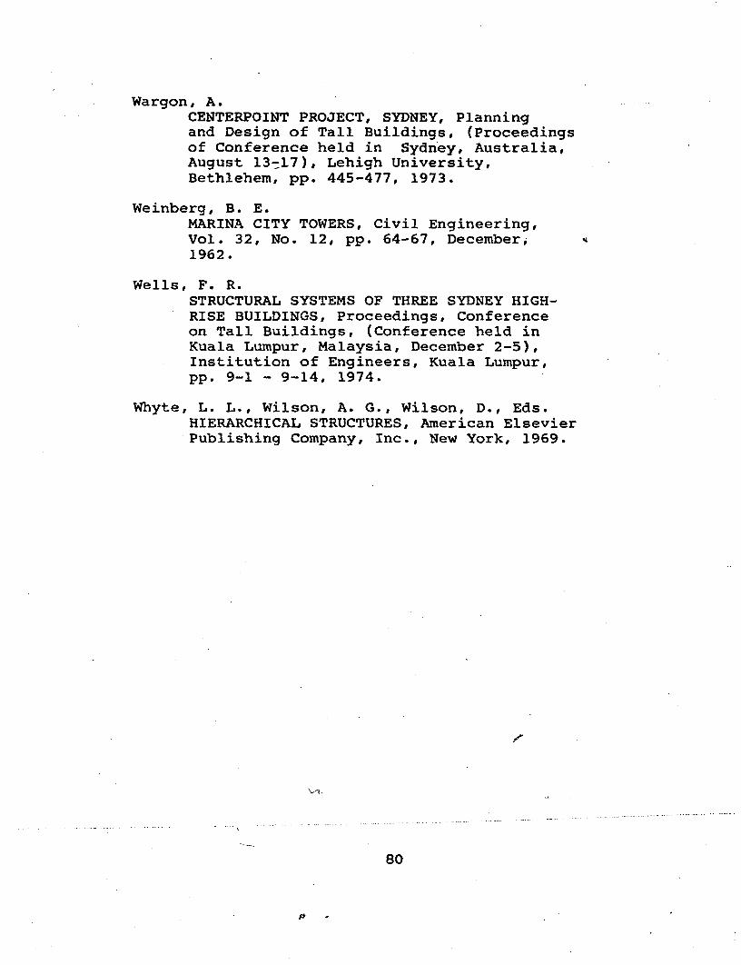
Wargon, A. CENTERPOINT PROJECT, SYDNEY, Planning and Design of Tall Buildings, (Proceedings of Conference held in Sydney, Australia, August 13-17), Lehigh University, Bethlehem, pp. 445-477, 1973.
Weinberg, B. E. MARINA CITY TOWERS, Civil Engineering, Vol. 32, No. 12, pp. 64-67, December, 1962.
Wells, F. R. STRUCTURAL SYSTEMS OF THREE SYDNEY HIGH- RISE BUILDINGS, Proceedings, Conference on Tall Buildings, (Conference held in Kuala Lumpur, Malaysia, December 2-5), Institution of Engineers, Kuala Lumpur, pp. 9-1 - 9-14, 1974.
Whyte, L. L., Wilson, A. G., Wilson, D., Eds. HIERARCHICAL STRUCTURES, American Elsevier Publishing Company, Inc., New York, 1969.
s
80

Vita
The author, son of Frederick Falconer and Julia
(Moody) Falconer, was born in Bay Shore, Long "island,
New York on December 5, 1955.
After graduating from State University of New York at
Buffalo with a Bachelor of Science in Civil Engineering
in June 1978, the author was empoyed for a year with a
consulting engineering firm.
In August 1979, the author entered graduate school in
the Department of Civil Engineering, Lehigh University
where he studied toward a Master of Science Degree.
81