skirt splice methods for tall pressure vessel towers
TRANSCRIPT
SKIRT SPLICE METHODS FOR TALL PRESSURE VESSEL TOWERS
Trevor G. Seipp Becht Engineering Canada Ltd.
110-259 Midpark Way, S.E. Calgary, AB CANADA
Tel: 403-668-7274 Email: [email protected]
Shawn W. Morrison M5 Engineering Inc
Calgary, AB CANADA Email: [email protected]
Alicia C. Avery North West Redwater Partnership
2800, 140-4th Ave S.W. Calgary, AB CANADA
Email: [email protected]
ABSTRACT
The design of tall pressure vessel towers may be affected by transportation limitations on the overall length of the vessel-plus-skirt. Additionally, process considerations set minimum elevations for the pressure vessel, and plant conditions may dictate whether the vessel needs to be set on a foundation or in a structure. Occasionally, these limitations collide, resulting in a requirement for a longer skirt than can be transported. To enable transportation, the vessel skirt may need to be spliced.
There are multiple methods for which the skirt can be spliced: welded or re-welded at site, sleeve-and-bolt, double-sleeve-and-bolt, and flanged. This paper presents these various methods, and presents an overview of the different design methodologies and considerations for the flanged approach. Design considerations and evaluations necessary for the design and consideration of fabrication tolerances are presented. A case study is introduced for context.
INTRODUCTION
Although it is typical for pressure vessel designers to focus solely on the design of a pressure vessel, it is well acknowledged that there are often additional considerations that can impact the design. For many locations around the world that are remote from ocean port facilities, transportation logistics play a significant part in the design considerations. Limitations on inland transportation, such as weight, length, and diameter often govern above even process requirements.
One example of the extraordinary measures required to transport heavy vessels is discussed in Stonehouse et al [21]. This paper focuses on an additional concern: pressure vessel length, or more specifically, the total length of the vessel-plus-skirt. Since process requirements dictate the minimum elevation of the vessel, a tall pressure vessel tower can be made even taller by
the addition of a lengthy skirt. In a recent example, to be discussed as the case study for this paper, the shipping costs were planned to be reduced by introducing a skirt splice.
SKIRT SPLICE OPTIONS
Based on the authors’ experience, there are four available methods for performing the skirt splice:
1) Weld at site or cut and re-weld 2) Sleeve-and-bolt 3) Double sleeve-and-bolt 4) Flanged
COMPARISON TO OTHER INDUSTRIES Since the skirt splice is a non-pressure containing
joint, it is appropriate to compare to experiences and expertise from other industries. The two other industries with experience in large-diameter unpressurized flanged joints are tall steel chimneys and wind turbine towers. The CICIND Model Code for Steel Chimneys [8] provides minimal guidance and was not considered further. However, there is substantial work reported in the literature for wind turbine towers.
In the Licentiate Thesis, Heistermann [12] describes some excellent details for skirt splice options 2) and 4). Figure 1 is a reproduction of Figure 1.1-6 from Heistermann [12], describing how a sleeve-and-bolt configuration would work. Significant other work has been performed for flanged connections in wind turbine towers which will be discussed.
CUT AND RE-WELD (OR ONLY WELD AT SITE)
The cut and re-weld (or only weld at site) of a skirt splice is the most commonly used approach in the pressure vessel industry, based on the authors’ experience. The pressure vessel and skirt are fabricated except for the topmost circumferential weld. An
1 Copyright © 2014 by ASME
Proceedings of the ASME 2014 Pressure Vessels & Piping Conference PVP2014
July 20-24, 2014, Anaheim, California, USA
PVP2014-28957
Downloaded From: http://proceedings.asmedigitalcollection.asme.org/ on 11/25/2014 Terms of Use: http://asme.org/terms

alternative is to weld the complete skirt at the fabrication shop. Then, as a final step in fabrication, the skirt is cut by way of a machined cut that not only separates the skirt into two pieces, but also provides a weld preparation. Once the two pieces are transported separately to the installation site, they are reassembled and welded.
There are several considerations for this approach, all of which may be costly and could add further time to a project schedule. This approach requires facilities at the installation site for welding large diameter circumferential welds including: qualified welders, and appropriate welding and NDE equipment. For site locations with ambient condition challenges, such as rain or cold, this may also require the construction of temporary shelters.
Final alignment or “fit up” is also a concern in that the skirt splice ends must be realigned to perform the final weld. However, if the skirt splice location is appropriately supported during the cutting process, throughout transportation, and during welding then this should be less of a concern.
One additional consideration is that the weld preparation area cannot be painted with typical metal or metal oxide paints, as the high temperatures from weld preheat and welding itself may cause liquid metal embrittlement. This lack of ability to paint and protect the weld in the course of transportation leaves the weld preparation vulnerable to corrosion from (typically transoceanic) conditions during transport. Other alternatives are available to either protect the weld preparation or clean it after transport, but these tend to be either costly or time consuming.
After the splice weld is performed, the skirt is considered essentially returned to its original condition, and there is no ongoing maintenance or inspection required.
Acceptance of the cut and re-weld or only weld at site option is often a cost and schedule decision.
SLEEVE-AND-BOLT
In the sleeve-and-bolt skirt splice option, the lower skirt section is fabricated separately, with an inner diameter equal to the outer diameter of the upper portion of the skirt. The lengths of the top and bottom sections of the skirt are designed to permit a long overlap, as shown in Figure 1. The bottom skirt section is fabricated with slots equal to the length of the overlap, and a column of bolt holes, oriented radially with respect to the vessel, are drilled into the upper skirt section.
At site assembly, the upper skirt is inserted into the lower skirt such that the bolts in the upper skirt line up with the slots in the lower skirt. A separate, thinner, cover plate is attached on the outside of the joint, and the bolts are loaded. Although it is typical to have a small ring to limit the travel of the top and bottom sections, it is not designed to accommodate any operating loads.
The operating loads such as weight and net overturning moment are accommodated completely by the friction generated by the bolt tension.
Figure 1. Slotted sleeve and bolt configuration - from Heistermann [12].
DOUBLE SLEEVE-AND-BOLT
The double sleeve-and-bolt option is similar to the sleeve-and-bolt option. However, instead of designing the upper and lower skirt sections as different diameters, they are fabricated as the same diameter, and an inner and outer cover plate are fabricated as part of the upper skirt section. The lower skirt section remains the slotted section.
Since the upper and lower skirt sections have the same diameter, the upper section can bear on the lower section, and this bearing can accommodate some of the vertical loads. However, the joint is designed identically to the single sleeve-and-bolt so that friction generated by the bolt tension takes the entire operating load.
Both sleeve-and-bolt options have the disadvantage of having high initial fabrication labour costs for the large number of bolt holes and slots. Assuring appropriate radial alignment both during fabrication and transport would be challenging, especially for the lower skirt with the numerous slots.
Assembly at the installation site would require precision to bring the two sections together. There would also be substantial site labour for performing and checking the bolt loads. Heistermann [12] recommends specialty bolts for this application, which may significantly increase the final vessel costs.
2 Copyright © 2014 by ASME
Downloaded From: http://proceedings.asmedigitalcollection.asme.org/ on 11/25/2014 Terms of Use: http://asme.org/terms
FLANGED In flanged skirt splice option, the upper and lower skirt
sections are joined with a bolted flange joint where the bolts are oriented parallel to the vessel longitudinal axis. There are several different ways to accomplish this type of connection, and furthermore, several different design methodologies for accomplishing the same end.
Upon a review of the literature, there appears to be several different design approached to these flanges connections:
A) “Standard” pressure vessel base ring with anchor bolts and chairs
B) Flange per ASME Section VIII, Division 1, Appendix Y
C) Design Using Finite Element Analysis D) Methodology of Peterson [14] Methods A) and B) are based on other pressure
vessel design approaches. In the ASCE (American Society of Civil Engineers) and AWEA (American Wind Energy Association), Recommended Practice for Compliance of Large Land-based Wind Turbine Support Structures [1], method C) is presented as the recommended approach. However, method D) is provided as an alternative.
In the following section, each method is described and discussed.
“Standard” pressure vessel base ring with anchor bolts and chairs
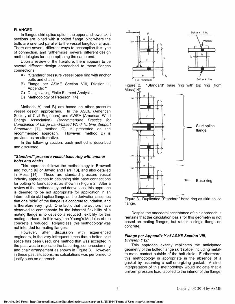
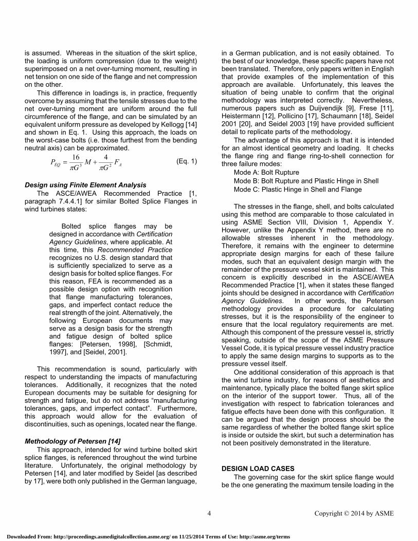
This approach follows the methodology in Brownell and Young [6] or Jawad and Farr [13], and also detailed in Moss [14]. These are standard pressure vessel industry approaches to designing skirt base connections for bolting to foundations, as shown in Figure 2. After a review of the methodology and derivations, this approach is deemed to be not appropriate for application in an intermediate skirt splice flange as the derivation assumes that one “side” of the flange is a concrete foundation, and is therefore very rigid. One tactic that the authors have observed to compensate for the inherent flexibility of a mating flange is to develop a reduced flexibility for this mating surface. In this way, the Young’s Modulus of the concrete is reduced. Regardless, this methodology was not intended for mating flanges.
However, after discussion with experienced engineers, in the very infrequent times that a bolted skirt splice has been used, one method that was accepted in the past was to replicate the base ring, compression ring and chair arrangement as shown in Figure 3. However, in these past situations, no calculations was performed to justify such an approach.
Figure 2. "Standard" base ring with top ring (from Moss[14])
Figure 3. Duplicated "Standard" base ring as skirt splice flange.
Despite the anecdotal acceptance of this approach, it
remains that the calculation basis for this geometry is not based on mating flanges, but rather a single flange on concrete.
Flange per Appendix Y of ASME Section VIII, Division 1 [2]
This approach exactly replicates the anticipated geometry of the bolted flange skirt splice, including metal-to-metal contact outside of the bolt circle. Furthermore, this methodology is appropriate in the absence of a gasket by assuming a self-energizing gasket. A strict interpretation of this methodology would indicate that a uniform pressure load, applied to the interior of the flange,
Skirt splice flange
Base ring
3 Copyright © 2014 by ASME
Downloaded From: http://proceedings.asmedigitalcollection.asme.org/ on 11/25/2014 Terms of Use: http://asme.org/terms
is assumed. Whereas in the situation of the skirt splice, the loading is uniform compression (due to the weight) superimposed on a net over-turning moment, resulting in net tension on one side of the flange and net compression on the other.
This difference in loadings is, in practice, frequently overcome by assuming that the tensile stresses due to the net over-turning moment are uniform around the full circumference of the flange, and can be simulated by an equivalent uniform pressure as developed by Kellogg [14] and shown in Eq. 1. Using this approach, the loads on the worst-case bolts (i.e. those furthest from the bending neutral axis) can be approximated.
AEQ FG
MG
P23
416
(Eq. 1)
Design using Finite Element Analysis
The ASCE/AWEA Recommended Practice [1, paragraph 7.4.4.1] for similar Bolted Splice Flanges in wind turbines states:
Bolted splice flanges may be
designed in accordance with Certification Agency Guidelines, where applicable. At this time, this Recommended Practice recognizes no U.S. design standard that is sufficiently specialized to serve as a design basis for bolted splice flanges. For this reason, FEA is recommended as a possible design option with recognition that flange manufacturing tolerances, gaps, and imperfect contact reduce the real strength of the joint. Alternatively, the following European documents may serve as a design basis for the strength and fatigue design of bolted splice flanges: [Petersen, 1998], [Schmidt, 1997], and [Seidel, 2001].
This recommendation is sound, particularly with
respect to understanding the impacts of manufacturing tolerances. Additionally, it recognizes that the noted European documents may be suitable for designing for strength and fatigue, but do not address “manufacturing tolerances, gaps, and imperfect contact”. Furthermore, this approach would allow for the evaluation of discontinuities, such as openings, located near the flange.
Methodology of Petersen [14]
This approach, intended for wind turbine bolted skirt splice flanges, is referenced throughout the wind turbine literature. Unfortunately, the original methodology by Petersen [14], and later modified by Seidel [as described by 17], were both only published in the German language,
in a German publication, and is not easily obtained. To the best of our knowledge, these specific papers have not been translated. Therefore, only papers written in English that provide examples of the implementation of this approach are available. Unfortunately, this leaves the situation of being unable to confirm that the original methodology was interpreted correctly. Nevertheless, numerous papers such as Duijvendijk [9], Frese [11], Heistermann [12], Pollicino [17], Schaumann [18], Seidel 2001 [20], and Seidel 2003 [19] have provided sufficient detail to replicate parts of the methodology.
The advantage of this approach is that it is intended for an almost identical geometry and loading. It checks the flange ring and flange ring-to-shell connection for three failure modes:
Mode A: Bolt Rupture Mode B: Bolt Rupture and Plastic Hinge in Shell Mode C: Plastic Hinge in Shell and Flange The stresses in the flange, shell, and bolts calculated
using this method are comparable to those calculated in using ASME Section VIII, Division 1, Appendix Y. However, unlike the Appendix Y method, there are no allowable stresses inherent in the methodology. Therefore, it remains with the engineer to determine appropriate design margins for each of these failure modes, such that an equivalent design margin with the remainder of the pressure vessel skirt is maintained. This concern is explicitly described in the ASCE/AWEA Recommended Practice [1], when it states these flanged joints should be designed in accordance with Certification Agency Guidelines. In other words, the Petersen methodology provides a procedure for calculating stresses, but it is the responsibility of the engineer to ensure that the local regulatory requirements are met. Although this component of the pressure vessel is, strictly speaking, outside of the scope of the ASME Pressure Vessel Code, it is typical pressure vessel industry practice to apply the same design margins to supports as to the pressure vessel itself.
One additional consideration of this approach is that the wind turbine industry, for reasons of aesthetics and maintenance, typically place the bolted flange skirt splice on the interior of the support tower. Thus, all of the investigation with respect to fabrication tolerances and fatigue effects have been done with this configuration. It can be argued that the design process should be the same regardless of whether the bolted flange skirt splice is inside or outside the skirt, but such a determination has not been positively demonstrated in the literature.
DESIGN LOAD CASES The governing case for the skirt splice flange would
be the one generating the maximum tensile loading in the
4 Copyright © 2014 by ASME
Downloaded From: http://proceedings.asmedigitalcollection.asme.org/ on 11/25/2014 Terms of Use: http://asme.org/terms
bolts. To arrive at this governing case would require minimizing the weight and maximizing the net over-turning moment.
Unlike in the wind turbine industry, fatigue is not expected to be a governing case. However, a realistic set of fatigue loadings should be developed and evaluated against an appropriate screening criteria. The magnitude and the number of cycles over the design life of the vessel should be developed and explicitly compared to an appropriate screening criteria. Such loadings as wind gusts, vortex shedding, seismic activity and other similar conditions whereby the loading would vary should be included in this screening assessment.
DESIGN METHODOLOGY, ALLOWABLE STRESSES AND DESIGN MARGINS
The chosen design methodology should address the following design issues:
Minimum required flange ring thickness; Maximum permissible bolt spacing; High-strength bolting specifications; Minimum required bolt area; Recommended (or required) design margins;
For lack of a better criteria and to maintain consistency with the rest of the pressure vessel, the authors recommend that the allowable stresses for the flange ring material, per the ASME Pressure Vessel Code, should be used.
An additional consideration in calculating the minimum required flange ring thickness is the subsequent stretch length of the bolt. As described in ASME PCC-1 [5] (articles 8.2.2, P-4.2.1, and P-4.2.2), when the effective bolt length is short, the bolted flange joint is more stiff, and thus is more sensitive to loss of bolt load due to embedment relaxation. For any flange, whether pressure-retaining or skirt splice, ASME PCC-1 [5] (articles 8.2.2, P-4.2.1, and P-4.2.2) recommends a minimum effective bolt length of 5a, where a is the nominal diameter. Per P-4.2.2, the effective stretching length is calculated as the distance between nut contact faces plus one bolt diameter. Thus, the distance between the nut contact faces (equal to the thickness of both flanges in the absence of spacer-washers) should be no shorter than 4a. This translates to a minimum flange thickness equal to 2a less the thickness of through-hardened washers.
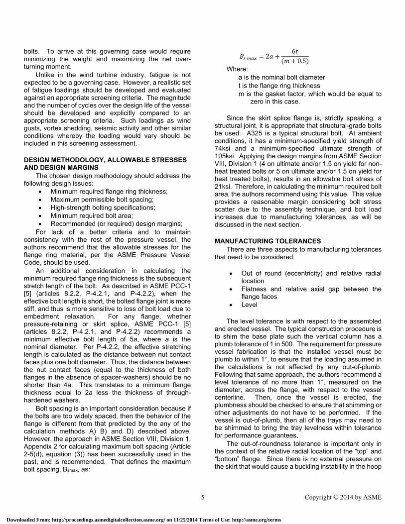
Bolt spacing is an important consideration because if the bolts are too widely spaced, then the behavior of the flange is different from that predicted by the any of the calculation methods A) B) and D) described above. However, the approach in ASME Section VIII, Division 1, Appendix 2 for calculating maximum bolt spacing (Article 2-5(d), equation (3)) has been successfully used in the past, and is recommended. That defines the maximum bolt spacing, Bsmax, as:
260.5
Where: a is the nominal bolt diameter
t is the flange ring thickness m is the gasket factor, which would be equal to
zero in this case. Since the skirt splice flange is, strictly speaking, a
structural joint, it is appropriate that structural-grade bolts be used. A325 is a typical structural bolt. At ambient conditions, it has a minimum-specified yield strength of 74ksi and a minimum-specified ultimate strength of 105ksi. Applying the design margins from ASME Section VIII, Division 1 (4 on ultimate and/or 1.5 on yield for non-heat treated bolts or 5 on ultimate and/or 1.5 on yield for heat treated bolts), results in an allowable bolt stress of 21ksi. Therefore, in calculating the minimum required bolt area, the authors recommend using this value. This value provides a reasonable margin considering bolt stress scatter due to the assembly technique, and bolt load increases due to manufacturing tolerances, as will be discussed in the next section. MANUFACTURING TOLERANCES
There are three aspects to manufacturing tolerances that need to be considered:
Out of round (eccentricity) and relative radial
location Flatness and relative axial gap between the
flange faces Level
The level tolerance is with respect to the assembled
and erected vessel. The typical construction procedure is to shim the base plate such the vertical column has a plumb tolerance of 1 in 500. The requirement for pressure vessel fabrication is that the installed vessel must be plumb to within 1°, to ensure that the loading assumed in the calculations is not affected by any out-of-plumb. Following that same approach, the authors recommend a level tolerance of no more than 1°, measured on the diameter, across the flange, with respect to the vessel centerline. Then, once the vessel is erected, the plumbness should be checked to ensure that shimming or other adjustments do not have to be performed. If the vessel is out-of-plumb, then all of the trays may need to be shimmed to bring the tray levelness within tolerance for performance guarantees.
The out-of-roundness tolerance is important only in the context of the relative radial location of the “top” and “bottom” flange. Since there is no external pressure on the skirt that would cause a buckling instability in the hoop
5 Copyright © 2014 by ASME
Downloaded From: http://proceedings.asmedigitalcollection.asme.org/ on 11/25/2014 Terms of Use: http://asme.org/terms
direction, what remains is the effect of offset centerlines of the skirt above and below the flange. The authors recommend that this tolerance be kept below one half the thickness of the skirt (½t) to minimize any bending stresses in the flange-to-shell/skirt junction that are not otherwise calculated any of the design methodologies. Generally, if typical industry practice is followed for oversizing the bolt holes in the flange, if the bolts can be installed then this criteria will be achieved.
The flatness tolerance is generally with respect to the resultant relative gap between the mating flanges. Since there is no pressure to maintain, it would is likely to be inappropriate to apply a pressure vessel tolerance to this (which are extremely tight, and depend on the gasket as described in ASME PCC-1 [5] Appendix D). Bucher and Ebert [7] describes an evaluation of random imperfections of this type in wind turbine tower skirt splices. The results in Bucher and Ebert [7] indicate that bolt stresses could be as much as 20% more than that calculated using assuming ideal behavior, for gaps as small as 0.6mm. However, in their paper, the gaps were evaluated using finite element analysis. Since it is conceivable that the effects of gaps could be a function of the specific bolted flange skirt splice geometry, it would be unwise to extrapolate from this single paper and arbitrarily apply a particular tolerance.
It may be impractical to specify a flatness tolerance a priori, since the local and cumulative effects of the gaps both have effects. Therefore, the authors recommend to use FEA to evaluate the effects of the as-fabricated gaps. While this approach may appear to result in the application of a tolerance “too late” in the fabrication process, it may actually be more permissive. And, if the tolerances are excessive, then small amounts of machining can be carried out on the mating flanges to reduce the gaps.
AN ALLOWABLE STRESS BASIS FOR BOLTS, INCLUDING CONSIDERATIONS FOR ASSEMBLY METHODS
Structural bolts typically don’t have fabrication tolerances associated with them, beyond those associated with fabrication specifications such as ASME B1.1 [4]. However, in situations where the bolts would be encased in fireproofing, it is typical to assess a “corrosion allowance” on the bolt diameter. This allowance would need to be considered if fireproofing were required. It should be noted that a corrosion allowance such as 3.175 mm (0.125 in) on a nominal 1½ in diameter bolt would result in a reduction of tensile stress area of 17%.
It is typical, and recommended, to assemble the bolted flange skirt splice using the bolt torque method. This method of applying bolt load has a recognized accuracy of ±15%, provided that the bolt, nut, and flange are well lubricated with appropriate anti-seize compound.
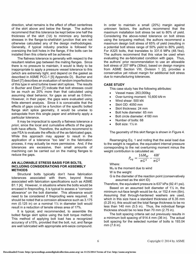
In order to maintain a small (20%) margin against unknown factors, the authors recommend that the maximum installation bolt stress be set to 80% of yield. Considering the above-noted tolerance on bolt stress using the torqueing method, the authors recommend a maximum design bolt stress of 65% of yield (resulting in a potential bolt stress range of 50% yield to 80% yield). For A325 bolts, that translates to 331.6 MPa (48.1ksi). The authors recommend that this value be used when evaluating the as-fabricated condition with gaps. Thus, the authors’ prior recommendation to use an allowable bolt stress of 207 MPa (30ksi), based on design margins from ASME Section VIII, Division 1 [2], provides a conservative yet robust margin for additional bolt stress due to manufacturing tolerances.
CASE STUDY
This case study has the following attributes: Vessel mass: 263,000kg Over-turning moment: 10,600 kN·m Wind shear: 500 kN Skirt OD: 4050 mm Skirt thickness: 24 mm Bolt hole diameter: 65 mm Bolt circle diameter: 4180 mm Number of bolts: 68 Bolt size: 1½ in The geometry of this skirt flange is shown in Figure 4. Rearranging Eq. 1 and noting that the axial load due
to the weight is negative, the equivalent internal pressure corresponding to the net overturning moment minus the weight contribution is calculated as:
16 4
Where: Mw is the moment due to wind W is the weight G is the diameter of the reaction point (conservatively
assumed as the skirt ID) Therefore, the equivalent pressure is 637 kPa (92.41 psi).
Based on an assumed bolt diameter of 1½ in, the minimum nut-face length would be 4a, or 152.4 mm (6in). Assuming that through-hardened washers are used, which in this size have a standard thickness of 6.35 mm (0.25 in), this would set the total flange thickness to be no less than 140 mm (5.5 in). Thus, the individual flange thickness should be no less than 70 mm (2.75 in).
The bolt spacing criteria set out previously results in a minimum bolt spacing of 914.4 mm (36 in). The actual bolt spacing for the selected number of bolts is 193.04 mm (7.6 in).
6 Copyright © 2014 by ASME
Downloaded From: http://proceedings.asmedigitalcollection.asme.org/ on 11/25/2014 Terms of Use: http://asme.org/terms
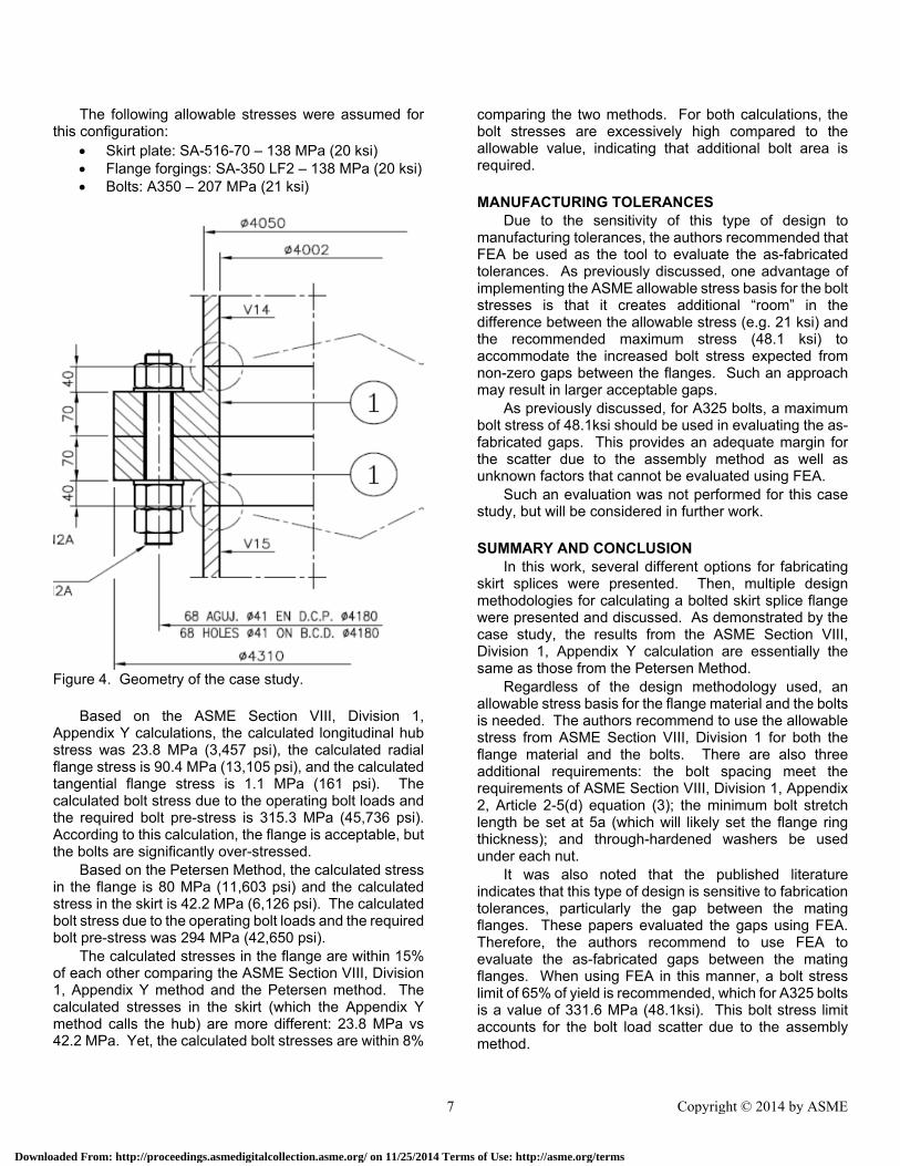
The following allowable stresses were assumed for this configuration:
Skirt plate: SA-516-70 – 138 MPa (20 ksi) Flange forgings: SA-350 LF2 – 138 MPa (20 ksi) Bolts: A350 – 207 MPa (21 ksi)
Figure 4. Geometry of the case study.
Based on the ASME Section VIII, Division 1, Appendix Y calculations, the calculated longitudinal hub stress was 23.8 MPa (3,457 psi), the calculated radial flange stress is 90.4 MPa (13,105 psi), and the calculated tangential flange stress is 1.1 MPa (161 psi). The calculated bolt stress due to the operating bolt loads and the required bolt pre-stress is 315.3 MPa (45,736 psi). According to this calculation, the flange is acceptable, but the bolts are significantly over-stressed.
Based on the Petersen Method, the calculated stress in the flange is 80 MPa (11,603 psi) and the calculated stress in the skirt is 42.2 MPa (6,126 psi). The calculated bolt stress due to the operating bolt loads and the required bolt pre-stress was 294 MPa (42,650 psi).
The calculated stresses in the flange are within 15% of each other comparing the ASME Section VIII, Division 1, Appendix Y method and the Petersen method. The calculated stresses in the skirt (which the Appendix Y method calls the hub) are more different: 23.8 MPa vs 42.2 MPa. Yet, the calculated bolt stresses are within 8%
comparing the two methods. For both calculations, the bolt stresses are excessively high compared to the allowable value, indicating that additional bolt area is required.
MANUFACTURING TOLERANCES
Due to the sensitivity of this type of design to manufacturing tolerances, the authors recommended that FEA be used as the tool to evaluate the as-fabricated tolerances. As previously discussed, one advantage of implementing the ASME allowable stress basis for the bolt stresses is that it creates additional “room” in the difference between the allowable stress (e.g. 21 ksi) and the recommended maximum stress (48.1 ksi) to accommodate the increased bolt stress expected from non-zero gaps between the flanges. Such an approach may result in larger acceptable gaps.
As previously discussed, for A325 bolts, a maximum bolt stress of 48.1ksi should be used in evaluating the as-fabricated gaps. This provides an adequate margin for the scatter due to the assembly method as well as unknown factors that cannot be evaluated using FEA.
Such an evaluation was not performed for this case study, but will be considered in further work.
SUMMARY AND CONCLUSION
In this work, several different options for fabricating skirt splices were presented. Then, multiple design methodologies for calculating a bolted skirt splice flange were presented and discussed. As demonstrated by the case study, the results from the ASME Section VIII, Division 1, Appendix Y calculation are essentially the same as those from the Petersen Method.
Regardless of the design methodology used, an allowable stress basis for the flange material and the bolts is needed. The authors recommend to use the allowable stress from ASME Section VIII, Division 1 for both the flange material and the bolts. There are also three additional requirements: the bolt spacing meet the requirements of ASME Section VIII, Division 1, Appendix 2, Article 2-5(d) equation (3); the minimum bolt stretch length be set at 5a (which will likely set the flange ring thickness); and through-hardened washers be used under each nut.
It was also noted that the published literature indicates that this type of design is sensitive to fabrication tolerances, particularly the gap between the mating flanges. These papers evaluated the gaps using FEA. Therefore, the authors recommend to use FEA to evaluate the as-fabricated gaps between the mating flanges. When using FEA in this manner, a bolt stress limit of 65% of yield is recommended, which for A325 bolts is a value of 331.6 MPa (48.1ksi). This bolt stress limit accounts for the bolt load scatter due to the assembly method.
7 Copyright © 2014 by ASME
Downloaded From: http://proceedings.asmedigitalcollection.asme.org/ on 11/25/2014 Terms of Use: http://asme.org/terms
REFERENCES 1. ASCE (American Society of Civil Engineers) and
AWEA (American Wind Energy Association), ASCE/AWEA RP2011 Recommended Practice for Compliance of Large Land-based Wind Turbine Support Structures, 2011
2. ASME, ASME Boiler and Pressure Vessel Code, Section VIII, Division 1: Rules for Construction of Pressure Vessels, 2013
3. ASME, ASME Boiler and Pressure Vessel Code, Section VIII, Division 2: Rules for Construction of Pressure Vessels – Alternative Rules, 2013
4. ASME, ASME B1.1, Unified Inch Screw Threads (UN
and UNR Thread Form), 1989
5. ASME, PCC-1-2013, Guidelines for Pressure Boundary Bolted Flange Joint Assembly
6. Brownell, Lloyd E. and Edwin H. Young, Process Equipment Design, John Wiley & Sons, New York, NY, 1959
7. Bucher, C, and M. Ebert, “Load Carrying Behavior of Prestressed Bolted Steel Flanges Considering Random Geometrical Imperfections”, presented at 8th ASCE Specialty Conference on Probabilistic Mechanics and Structural Reliability, 2000
8. CICIND (Comité International des Cheminées Industrielles), Model Code For Steel Chimneys, Revision 1 – 1999, Amendment A – March 2002
9. Duijvendijk, M. Van, A. Kalverboer and T.J.D. de Gruiter, “Benchmark of Bolted Bearing Connection Models in Wind Tunnels”, presented at EWEC (European Wind Energy Association) Conference, 2006
10. European Commission, High-strength tower in steel for wind turbines, 2009
11. Frese, Thomas and Peter Dalhoff, “Fatigue Analysis of Bolted and Welded Joints: Practical Experience in Type Certification of Wind Turbines”, presented at NAFEMS Seminar: Fatigue Analysis, 2000
12. Heistermann, Christine, Behavior of Pretensioned Bolts in Friction Connections: Towards the Use of Higher Strength Steels in Wind Towers, Licentiate Thesis, Lulea University of Technology, 2011
13. Jawad, Maan H, and James R. Farr, Structural Analysis and Design of Process Equipment, John Wiley & Sons, New York, NY, 1989
14. Kellogg, M.W., Company, Design of Piping Systems, John Wiley, New York, NY, 1956
15. Moss, Dennis R., Pressure Vessel Design Manual,
Third Edition, Gulf Professional Publishing, 2004
16. Petersen C., “Nachweis der Betriebsfestigkeit exzentrisch beanspruchter Ringflanschverbindungen” (Fatigue Assessment of Eccentrically Loaded Ring Flanges), Stahlbau Volume 67, Issue 3, 1998 (In German)
17. Pollicino, Fabio, “Load Carrying Behavior of Imperfect Ring Flange Connections of Wind Turbine Towers”, English Summary, Germanischer Lloyd WindEnergie
18. Schaumann, P, and M. Seidel, “Failure Analysis of Bolted Steel Flanges”, presented at the 7th International Symposium on Structural Failure and Plasticity (IMPLAST 2000), 2000
19. Seidel, M, “Experiences With Two of the World’s Largest Wind Turbine Towers”, presented at EWEC (European Wind Energy Association) Conference, 2003
20. Seidel, M, and P. Schaumann, “Measuring Fatigue Loads of Bolts in Ring Flange Connections”, presented at EWEC (European Wind Energy Association) Conference, 2001
21. Stonehouse, Mark et al, “A Novel Comparison of
Design-By-Analysis Methods”, Journal of Pressure Vessel Technology, ASME 2012
8 Copyright © 2014 by ASME
Downloaded From: http://proceedings.asmedigitalcollection.asme.org/ on 11/25/2014 Terms of Use: http://asme.org/terms