construction of 3 multi story towers, nerul - sbi
TRANSCRIPT
Construction of 3 Multi story Towers, Nerul
Signature & Seal of Contractor Page 1 of 459
State Bank of India
Estate Dept.,
State Bank Global IT Centre, C.B.D. Belapur, Navi Mumbai.
NOTICE INVITING TENDER
For the work of :
“For the Composite Construction works of Civil, Plumbing, Sanitary, Electrical, Firefighting,, CCTV, Landscaping, STP and Allied Services, etc. for the Proposed
Construction of 3 Multi-Storied
Residential Towers at State Bank of India’s Residential Colony, Sector-13, Nerul, Navi Mumbai.”
Technical Bid
RFP No. SBI/GITC/Estate/2021/2022/834
Tender Submitted By : Name of Vendor : _____________________________________
Address of Vendor : _____________________________________
GSTN No. of Vendor : ______________________________________
Date : ___________________________________
The Dy. General Manager (F & OA), Estate Dept., State Bank Global IT Centre, 1st Floor, “C” Wing, Sector 11, C.B.D. Belapur, Navi Mumbai – 400614.
Architect : M/s VK:a Architecture, 5th floor, Next Gen Avenue, S No. 103 Part, C.T.S No. 2850, Bahiratwadi , Senapati Bapat Road,Near ICC Trade Tower, Pune – 411016.
Construction of 3 Multi story Towers, Nerul
Signature & Seal of Contractor Page 2 of 459
INDEX
Sl.No. Description Page No.
1 Index 2-3
2 Notice inviting e-tender 3-8
General Information
3 Information & instructions for Bidders for e-Bidding 9-40
4 Letter of Transmittal and Bid Security Declaration (ANNEXURE-V ) 41-43
5 General Conditions of Contract 44-85
6 Articles of Agreement 86-91
7 Appendix 92-93
8 Special Conditions of Contract 94-146
9 Technical Specification 146-152
10 Appendix-I: Establishing Site Laboratory and Testing of Materials 153-155
11 Appendix-II: Plant and Equipment required at Site 156-157
12 List of Materials of Civil Works 158- 162
13 Proformas/ Tables of Various Tests, Materials, Pact, Guarantees 163-198
14 Mode of Measurements 199-204
15 Materials Minimum Specifications Requirement 205-226
16 Workmanship 227-258
17 Material Test List 259-259
18 Materials Testing Frequency Chart 260-262
19 Theoretical Consumption of Cement 263-287
PART (MEP WORKS)
20 Plumbing Works 288-391
21 Electrical Work 392-447
22 Fire Fighting Works 448-495
Tender Drawings
23 List of Drawing and Link to Download 496-496
24 Declaration of Contractor 497-498
Construction of 3 Multi story Towers, Nerul
Signature & Seal of Contractor Page 3 of 459
NOTICE INVITING TENDER
Item Rate e-Tenders are invited by M/s VK:a Architecture, Pune for & on behalf of State Bank of India, from Pre-qualified Bidders shortlisted vide RFP No. SBI/GITC/Estate/2021/2022/811 dated 10.12.2021, for the work of Proposed Composite Construction works of Civil, Plumbing, Sanitary, Electrical, Firefighting, CCTV, Landscaping, STP and Allied Services, etc. for the Proposed Construction of 3 Multi-Storied Residential Towers at State Bank of India’s Residential Colony, Sector-13, Nerul, Navi Mumbai.” The Pre-qualified Bidders shortlisted vide RFP No. SBI/GITC/Estate/2021/2022/811 dated 10.12.2021 who receives NIT are only entitled to quote for this tender.
RFP No. SBI/GITC/Estate/2021/2022/834
1 Name of work Composite Construction works of Civil, Plumbing, Sanitary, Electrical, Firefighting, CCTV, Landscaping, STP and Allied Services, etc. for the Proposed Construction of 3 Multi-Storied Residential Towers at State Bank of India’s Residential Colony, Sector-13, Nerul, Navi Mumbai.”
2 Time allowed for Completion of Work
36 Months Including Monsoon from the 15th day of the date of award of work.
3 Earnest Money ₹ 1,64,00,000.00 (Rupees One Crore Sixty Four Lakhs Only) by means of (mode of Transaction) NEFT, RTGS and intra-bank tranfer (SBI to SBI only), as per details mentioned in para 4.6, of Information and Instruction for Bidders
EMD to be deposited on or before the time and last date of submission of the technical bid.
4 Security Deposit (SD) As per Part B - Point 6 of Information and Instruction to Bidders.
5 Date of availability of tender documents on Service Provider’s website
(a) Technical Bid
From 15.03.2022 to 05.04.2022 Available at M/s e-Procurement Technologies Ltd., our Service Provider’s portal https://etender.sbi/
(b) Price Bid (shall be opened of only of those bidders who qualify as per clause no. 15 of Information & Instructions to Bidders.)
From 15.03.2022 to 05.04.2022 Available at M/s e-Procurement Technologies Ltd., our Service Provider’s portal https://etender.sbi/
Construction of 3 Multi story Towers, Nerul
Signature & Seal of Contractor Page 4 of 459
6 Pre – Bid Meeting (Date, time & Place of Meeting)
On 29.03.2022 at 03.00 PM at the following address: The Dy. General Manager (F & OA), Estate Dept., State Bank Global IT Centre, 1st Floor, “C” Wing, Sector 11, C.B.D. Belapur, Navi Mumbai – 400614.
7 Last date & time for submission of EMD of tender document
Up to 3.00 PM on 05.04.2022 Note: It is sole responsibility of the bidder to ensure submission of their EMD by stipulated date and time at specified SBI Account failing which they will not be allowed to participate in E-Tendering. The proof of the same is to be uploaded at https://etender.sbi/, mentioning UTR no. / transaction ID.
8 Place, Time & Address for submission of original integrity pact
up to 3.00 PM on 05.04.2022 Address : The Dy. General Manager (F & OA), Estate Dept., State Bank Global IT Centre, 1st Floor, “C” Wing, Sector 11, C.B.D. Belapur, Navi Mumbai – 400614. Tel. No. 022 27577386, 2753-7412/7439/7411 Email ID : [email protected]
9 Last date & time for submission of Online Technical Bid & Indicative Price Bid
up to 3.00 PM on 05.04.2022 at Service Provider’s portal https://etender.sbi/SBI/
10 Date and Time of opening of Online Technical Bid
3.30 PM on 05.04.2022
11 Date and Time of opening of Online Indicative Price Bid
Will be communicated through email to the technically qualified bidders, as per clause no. 15 of Information & Instructions to Bidders, separately
12 Defects Liability period As per Clause No. 1.1.11 (a) of GCC.
13 Liquidated Damages As per Clause No 8 of GCC.
14 Validity of offer As per Clause No. Part A- Point 5 of Information and Instruction to Bidders.
15 Value of Interim Certificate Minimum 2.5 Crore for first 3 RA Bill and Rs.4.00 Crore, 4th RA Bill onwards and Not More than One Bill Per Month. No advance on materials / plant / machinery or mobilization advance shall be paid under any circumstances.
Construction of 3 Multi story Towers, Nerul
Signature & Seal of Contractor Page 5 of 459
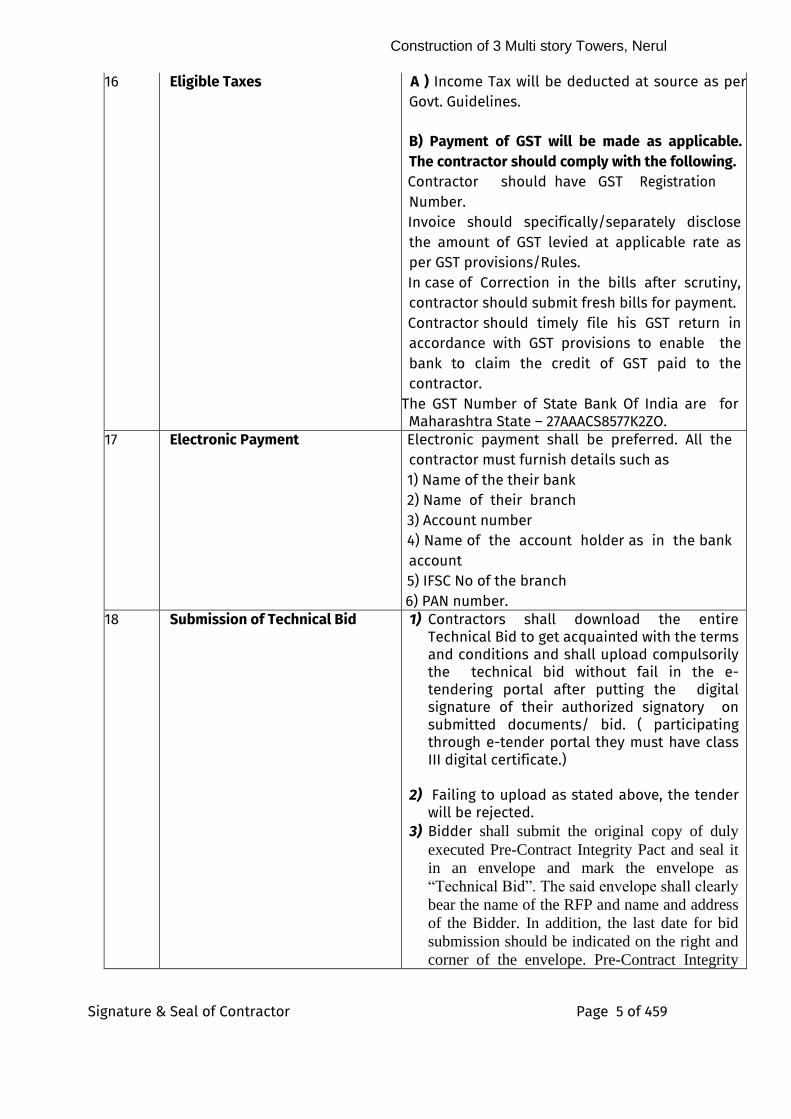
16 Eligible Taxes A ) Income Tax will be deducted at source as per Govt. Guidelines.
B) Payment of GST will be made as applicable. The contractor should comply with the following. Contractor should have GST Registration Number. Invoice should specifically/separately disclose the amount of GST levied at applicable rate as per GST provisions/Rules. In case of Correction in the bills after scrutiny, contractor should submit fresh bills for payment. Contractor should timely file his GST return in accordance with GST provisions to enable the bank to claim the credit of GST paid to the contractor.
1. The GST Number of State Bank Of India are for Maharashtra State – 27AAACS8577K2ZO.
17 Electronic Payment Electronic payment shall be preferred. All the contractor must furnish details such as
1) Name of the their bank
2) Name of their branch
3) Account number 4) Name of the account holder as in the bank account 5) IFSC No of the branch
2. 6) PAN number. 18 Submission of Technical Bid 1) Contractors shall download the entire
Technical Bid to get acquainted with the terms and conditions and shall upload compulsorily the technical bid without fail in the e-tendering portal after putting the digital signature of their authorized signatory on submitted documents/ bid. ( participating through e-tender portal they must have class III digital certificate.)
2) Failing to upload as stated above, the tender will be rejected.
3) Bidder shall submit the original copy of duly
executed Pre-Contract Integrity Pact and seal it
in an envelope and mark the envelope as
“Technical Bid”. The said envelope shall clearly
bear the name of the RFP and name and address
of the Bidder. In addition, the last date for bid
submission should be indicated on the right and
corner of the envelope. Pre-Contract Integrity
Construction of 3 Multi story Towers, Nerul
Signature & Seal of Contractor Page 6 of 459
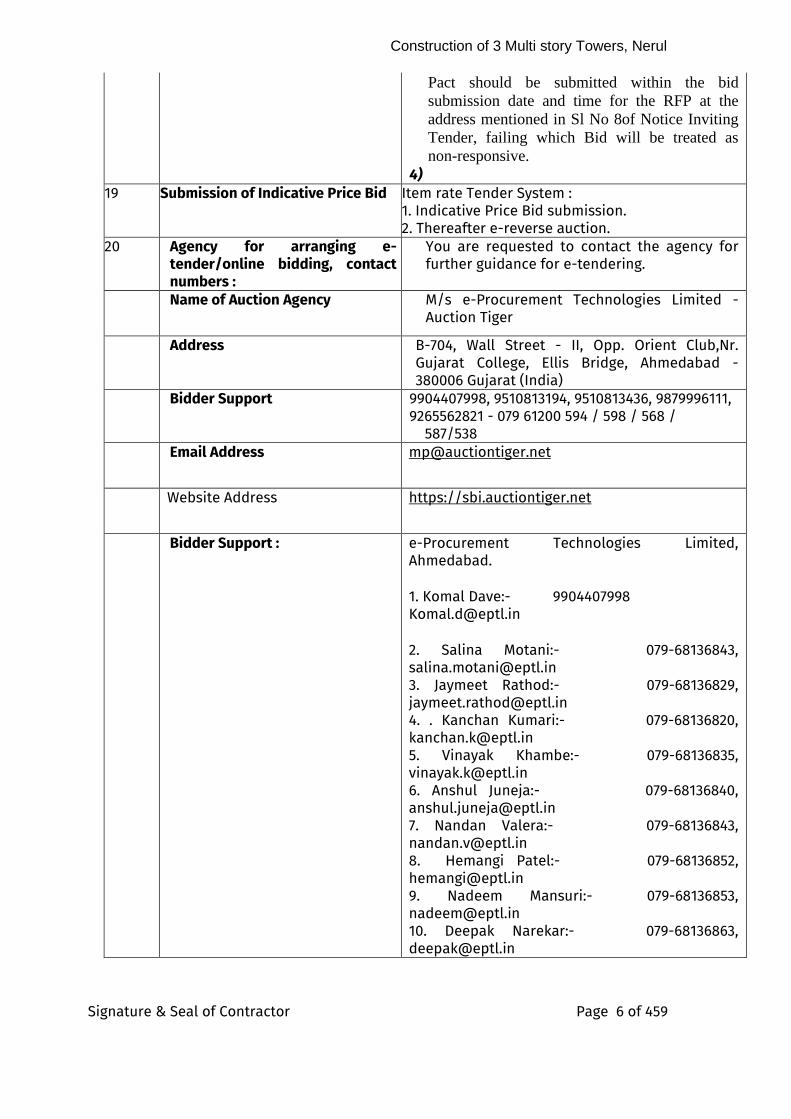
Pact should be submitted within the bid
submission date and time for the RFP at the
address mentioned in Sl No 8of Notice Inviting
Tender, failing which Bid will be treated as
non-responsive. 4)
19 Submission of Indicative Price Bid 5) Item rate Tender System : 6) 1. Indicative Price Bid submission. 7) 2. Thereafter e-reverse auction.
20 Agency for arranging e-tender/online bidding, contact numbers :
You are requested to contact the agency for further guidance for e-tendering.
Name of Auction Agency M/s e-Procurement Technologies Limited -Auction Tiger
Address B-704, Wall Street - II, Opp. Orient Club,Nr. Gujarat College, Ellis Bridge, Ahmedabad - 380006 Gujarat (India)
Bidder Support 9904407998, 9510813194, 9510813436, 9879996111, 9265562821 - 079 61200 594 / 598 / 568 / 587/538
Email Address [email protected]
Website Address https://sbi.auctiontiger.net
Bidder Support : e-Procurement Technologies Limited, Ahmedabad. 1. Komal Dave:- 9904407998 [email protected]
2. Salina Motani:- 079-68136843, [email protected] 3. Jaymeet Rathod:- 079-68136829, [email protected] 4. . Kanchan Kumari:- 079-68136820, [email protected] 5. Vinayak Khambe:- 079-68136835, [email protected] 6. Anshul Juneja:- 079-68136840, [email protected] 7. Nandan Valera:- 079-68136843, [email protected] 8. Hemangi Patel:- 079-68136852, [email protected] 9. Nadeem Mansuri:- 079-68136853, [email protected] 10. Deepak Narekar:- 079-68136863, [email protected]
Construction of 3 Multi story Towers, Nerul
Signature & Seal of Contractor Page 7 of 459
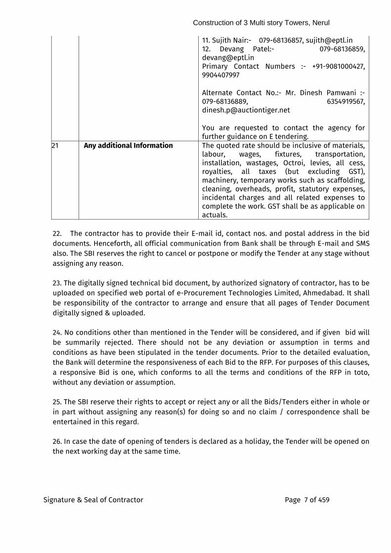
11. Sujith Nair:- 079-68136857, [email protected] 12. Devang Patel:- 079-68136859, [email protected] Primary Contact Numbers :- +91-9081000427, 9904407997
Alternate Contact No.:- Mr. Dinesh Pamwani :- 079-68136889, 6354919567, [email protected] You are requested to contact the agency for further guidance on E tendering.
21 Any additional Information The quoted rate should be inclusive of materials, labour, wages, fixtures, transportation, installation, wastages, Octroi, levies, all cess, royalties, all taxes (but excluding GST), machinery, temporary works such as scaffolding, cleaning, overheads, profit, statutory expenses, incidental charges and all related expenses to complete the work. GST shall be as applicable on actuals.
22. The contractor has to provide their E-mail id, contact nos. and postal address in the bid documents. Henceforth, all official communication from Bank shall be through E-mail and SMS also. The SBI reserves the right to cancel or postpone or modify the Tender at any stage without assigning any reason.
23. The digitally signed technical bid document, by authorized signatory of contractor, has to be uploaded on specified web portal of e-Procurement Technologies Limited, Ahmedabad. It shall be responsibility of the contractor to arrange and ensure that all pages of Tender Document digitally signed & uploaded.
24. No conditions other than mentioned in the Tender will be considered, and if given bid will be summarily rejected. There should not be any deviation or assumption in terms and conditions as have been stipulated in the tender documents. Prior to the detailed evaluation, the Bank will determine the responsiveness of each Bid to the RFP. For purposes of this clauses, a responsive Bid is one, which conforms to all the terms and conditions of the RFP in toto, without any deviation or assumption.
25. The SBI reserve their rights to accept or reject any or all the Bids/Tenders either in whole or in part without assigning any reason(s) for doing so and no claim / correspondence shall be entertained in this regard.
26. In case the date of opening of tenders is declared as a holiday, the Tender will be opened on the next working day at the same time.
Construction of 3 Multi story Towers, Nerul
Signature & Seal of Contractor Page 8 of 459
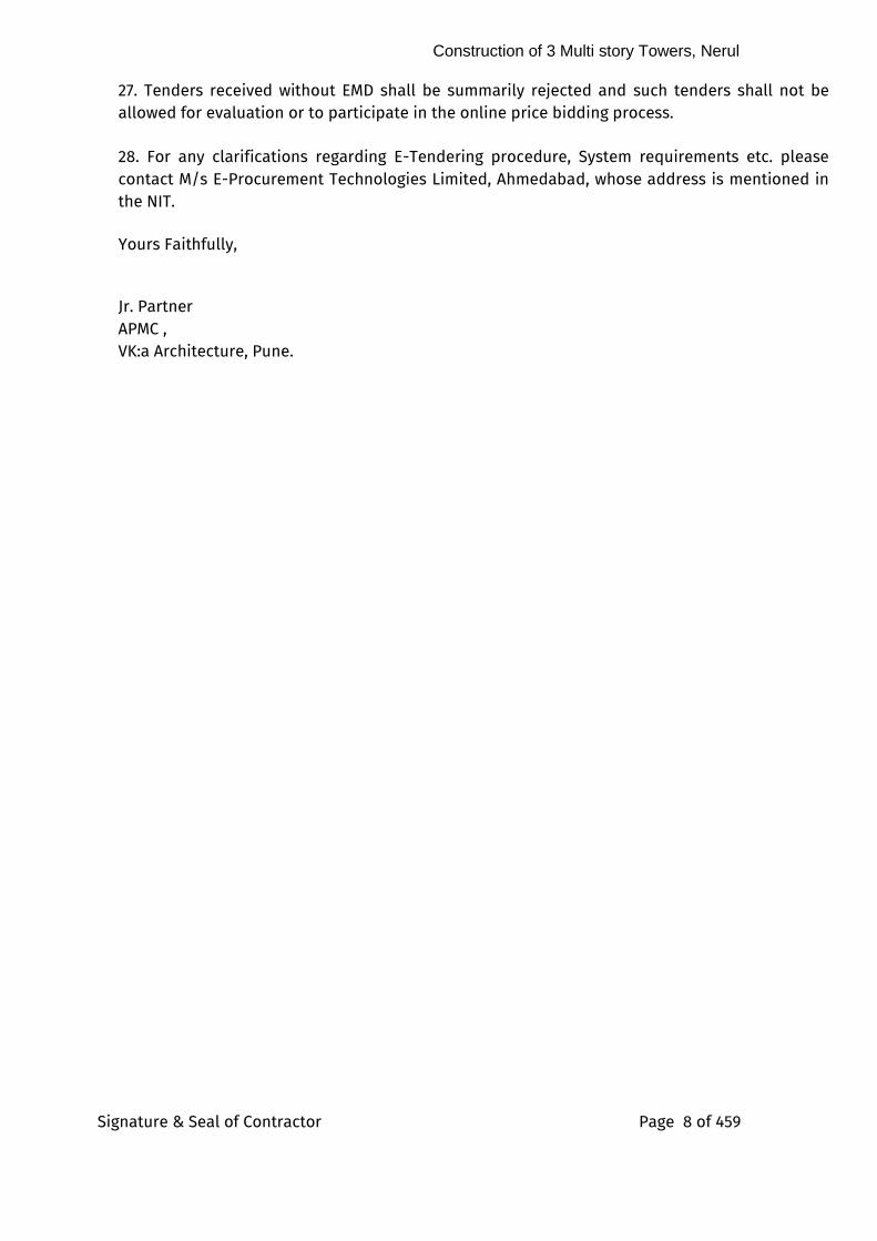
27. Tenders received without EMD shall be summarily rejected and such tenders shall not be allowed for evaluation or to participate in the online price bidding process.
28. For any clarifications regarding E-Tendering procedure, System requirements etc. please contact M/s E-Procurement Technologies Limited, Ahmedabad, whose address is mentioned in the NIT. Yours Faithfully, Jr. Partner APMC , VK:a Architecture, Pune.
Construction of 3 Multi story Towers, Nerul
Signature & Seal of Contractor Page 9 of 459
INFORMATION & INSTRUCTIONS FOR BIDDERS FOR e-BIDDING (IIBeB)
PART-A of INFORMATION & INSTRUCTIONS FOR BIDDERS FOR e-BIDDING: 1. DISCLAIMER:
i. The information contained in this RFP or information provided subsequently to
Bidder(s) whether verbally or in documentary form/email by or on behalf of SBI, is subject to the terms and conditions set out in this RFP.
ii. This RFP is not an offer by State Bank of India, but an invitation to receive responses from the eligible Bidders.
iii. The purpose of this RFP is to provide the Bidder(s) with information to assist
preparation of their Bid proposals. This RFP does not claim to contain all the information each Bidder may require. Each Bidder should conduct its own investigations and analysis and should check the accuracy, reliability and completeness of the information contained in this RFP and where necessary obtain independent advices/clarifications. Bank may in its absolute discretion, but without being under any obligation to do so, update, amend or supplement the information in this RFP.
iv. The Bank, its employees and advisors make no representation or warranty and shall have no liability to any person, including any Bidder under any law, statute, rules or regulations or tort, principles of restitution or unjust enrichment or otherwise for any loss, damages, cost or expense which may arise from or be incurred or suffered on account of anything contained in this RFP or otherwise, including the accuracy, adequacy, correctness, completeness or reliability of the RFP and any assessment, assumption, statement or information contained therein or deemed to form or arising in any way for participation in this bidding process.
v. The Bank also accepts no liability of any nature whether resulting from negligence or otherwise, howsoever caused arising from reliance of any Bidder upon the statements contained in this RFP.
vi. The Bidder is expected to examine all instructions, forms, terms and specifications in this RFP. Failure to furnish all information required under this RFP or to submit a Bid not substantially responsive to this RFP in all respect will be at the Bidder’s risk and may result in rejection of the Bid.
vii. The issue of this RFP does not imply that the Bank is bound to select a Bidder or to award the contract to the Selected Bidder, as the case may be, for the Project and the Bank reserves the right to reject all or any of the Bids or Bidders without assigning any reason whatsoever before issuance of purchase order/LOI and/or its
Construction of 3 Multi story Towers, Nerul
Signature & Seal of Contractor Page 10 of 459
acceptance thereof by the successful Bidder as defined in Award Criteria and Award of Contract in this RFP.
2. COST OF BID DOCUMENT:
The participating Bidders shall bear all the costs associated with or relating to the preparation and submission of their Bids including but not limited to preparation, copying, postage, delivery fees, expenses associated with any demonstration or presentations which may be required by the Bank or any other costs incurred in connection with or relating to their Bid. The Bank shall not be liable in any manner whatsoever for the same or for any other costs or other expenses incurred by a Bidder regardless of the conduct or outcome of the bidding process. 3. The Bidder shall also submit PRE-CONTRACT INTEGRITY PACT along with technical Bid as prescribed in Annexure- XVIII duly signed by the Bidder on each page and witnessed by two persons. The Pre-Contract Integrity Pact shall be stamped as applicable in the State where it is executed. Bid submitted without Pre-Contract Integrity Pact, as per the format provided in the RFP, shall not be considered. 3. 0 CLARIFICATION AND AMENDMENTS ON RFP/PRE-BID MEETING:
i. Bidder requiring any clarification on RFP may notify the Bank in writing strictly as per the format given in Annexure XIX at the address/by e-mail within the date/time mentioned in the Notice Inviting Tender (NIT).
ii. A pre-Bid meeting will be held in person or online on the date and time specified in the Notice Inviting Tender (NIT) which may be attended by the authorized representatives of the Bidders interested to respond to this RFP.
iii. The queries received (without identifying source of query) and response of the Bank thereof will be posted on the Bank’s website or conveyed to the Bidders.
iv. The Bank reserves the right to amend, rescind or reissue the RFP, at any time prior to the deadline for submission of Bids. The Bank, for any reason, whether, on its own initiative or in response to a clarification requested by a prospective Bidder, may modify the RFP, by amendment which will be made available to the Bidders by way of corrigendum/addendum. The interested parties/Bidders are advised to check the Bank’s website regularly till the date of submission of Bid document specified in the Notice Inviting Tender (NIT)/email and ensure that clarifications / amendments issued by the Bank, if any, have been taken into consideration before submitting the Bid. Such amendments/clarifications, if any, issued by the Bank will be binding on the participating Bidders. Bank will not take any responsibility for any such omissions by the Bidder. The Bank, at its own discretion, may extend the deadline for submission of Bids in order to allow prospective Bidders a reasonable time to prepare the Bid, for taking the amendment into account. Nothing in this RFP or any addenda/corrigenda or clarifications issued in connection thereto is
Construction of 3 Multi story Towers, Nerul
Signature & Seal of Contractor Page 11 of 459
intended to relieve Bidders from forming their own opinions and conclusions in respect of the matters addresses in this RFP or any addenda/corrigenda or clarifications issued in connection thereto.
v. No request for change in commercial/legal terms and conditions, other than what has been mentioned in this RFP or any addenda/corrigenda or clarifications issued in connection thereto, will be entertained and queries in this regard, therefore will not be entertained.
vi. Queries received after the scheduled date and time will not be responded/acted upon.
4.0 MODIFICATION AND WITHDRAWAL OF BIDS:
i. The Bidder may modify or withdraw its Bid after the Bid’s submission, provided modification, including substitution or withdrawal of the Bids, is received on e-procurement portal, prior to the deadline prescribed for submission of Bids.
ii. No modification in the Bid shall be allowed, after the deadline for submission of Bids.
iii. No Bid shall be withdrawn in the interval between the deadline for submission of Bids and the expiration of the period of Bid validity specified in this RFP. Withdrawal of a Bid during this interval may result in the forfeiture of EMD submitted by the Bidder and other action as per terms of RFP.
5.0 PERIOD OF BID VALIDITY AND VALIDITY OF PRICE QUOTED IN REVERSE AUCTION (RA):
1. Technical Bid shall remain valid for duration of 180 days from the date of
submission of Bid .
2. Price quoted by the Bidder in Reverse auction shall remain valid for duration of 180 days from the date of submission of Bid
3. 4. In exceptional circumstances, the Bank may solicit the Bidders’ consent to an
extension of the period of validity. The request and the responses thereto shall be made in writing. A Bidder is free to refuse the request. However, in such case, the Bank will not forfeit its EMD. However, any extension of validity of Bids or price will not entitle the Bidder to revise/modify the Bid document.
Construction of 3 Multi story Towers, Nerul
Signature & Seal of Contractor Page 12 of 459
Once Purchase Order or Letter of Intent is issued by the Bank, the said price will remain fixed
for the entire Contract period and shall not be subjected to variation on any account except as
explicitly mentioned in this RFP. A Bid submitted with an adjustable price quotation will be
treated as non-responsive and will be rejected.
6.0 BID INTEGRITY:
Willful misrepresentation of any fact within the Bid will lead to the cancellation of the contract without prejudice to other actions that the Bank may take. All the submissions, including any accompanying documents, will become property of the Bank. The Bidders shall be deemed to license, and grant all rights to the Bank, to reproduce the whole or any portion of their Bid document for the purpose of evaluation and to disclose the contents of submission for regulatory and legal requirements.
7.0 WAIVER OF RIGHTS:
Each Party agrees that any delay or omission on the part of the other Party to exercise any right, power or remedy under this RFP will not automatically operate as a waiver of such right, power or remedy or any other right, power or remedy and no waiver will be effective unless it is in writing and signed by the waiving Party. Further the waiver or the single or partial exercise of any right, power or remedy by either Party hereunder on one occasion will not be construed as a bar to a waiver of any successive or other right, power or remedy on any other occasion.
8.0 BANK’S RIGHT TO ACCEPT ANY BID AND TO REJECT ANY OR ALL BIDS:
The Bank reserves the right to accept or reject any Bid in part or in full or to cancel the bidding process and reject all Bids at any time prior to contract award as specified in Award Criteria and Award of Contract, without incurring any liability to the affected Bidder or Bidders or any obligation to inform the affected Bidder or Bidders of the grounds for the Bank’s action.
9.0 CODE OF INTEGRITY AND DEBARMENT/BANNING:
i. The Bidder and their respective officers, employees, agents and advisers shall observe the highest standard of ethics during the bidding Process. Notwithstanding anything to the contrary contained herein, the Bank shall reject Bid without being liable in any manner whatsoever to the Bidder if it determines that the Bidder has, directly or indirectly or through an agent, engaged in corrupt/fraudulent/coercive/undesirable or restrictive practices in the bidding
Construction of 3 Multi story Towers, Nerul
Signature & Seal of Contractor Page 13 of 459
Process.
ii. Bidders are obliged under code of integrity to Suo-moto proactively declare any conflicts of interest (pre-existing or as and as soon as these arise at any stage) in RFP process or execution of contract. Failure to do so would amount to violation of this code of integrity.
iii. Any Bidder needs to declare any previous transgressions of such a code of integrity
with any entity in any country during the last three years or of being debarred by any other procuring entity. Failure to do so would amount to violation of this code of integrity.
iv. For the purposes of this clause, the following terms shall have the meaning
hereinafter, respectively assigned to them:
(a) “corrupt practice” means making offers, solicitation or acceptance of bribe,
rewards or gifts or any material benefit, in exchange for an unfair advantage in the procurement process or to otherwise influence the procurement process or contract execution.
(b) “Fraudulent practice” means any omission or misrepresentation that may mislead or attempt to mislead so that financial or other benefits may be obtained or an obligation avoided. This includes making false declaration or providing false information for participation in a RFP process or to secure a contract or in execution of the contract;
(c) “Coercive practice” means harming or threatening to harm, persons or their property to influence their participation in the procurement process or affect the execution of a contract;
(d) “Anti-competitive practice” means any collusion, bid rigging or anti-competitive arrangement, or any other practice coming under the purview of the Competition Act, 2002, between two or more bidders, with or without the knowledge of the Bank, that may impair the transparency, fairness and the progress of the procurement process or to establish bid prices at artificial, non-competitive levels;
(e) “Obstructive practice” means materially impede the Bank’s or Government agencies investigation into allegations of one or more of the above mentioned prohibited practices either by deliberately destroying, falsifying, altering; or by concealing of evidence material to the investigation; or by making false statements to investigators and/or by threatening, harassing or intimidating any party to prevent it from disclosing its knowledge of matters relevant to the
Construction of 3 Multi story Towers, Nerul
Signature & Seal of Contractor Page 14 of 459
investigation or from pursuing the investigation; or by impeding the Bank’s rights of audit or access to information;
v. Debarment/Banning
Empanelment/participation of Bidders and their eligibility to participate in the Bank’s procurements is subject to compliance with code of integrity and performance in contracts as per terms and conditions of contracts. Following grades of debarment from empanelment/participation in the Bank’s procurement process shall be considered against delinquent Vendors/Bidders:
(a) Holiday Listing (Temporary Debarment - suspension):
Whenever a Vendor is found lacking in performance, in case of less frequent and less serious misdemeanors, the vendors may be put on a holiday listing (temporary debarment) for a period upto 12 (twelve) months. When a Vendor is on the holiday listing, he is neither invited to bid nor are his bids considered for evaluation during the period of the holiday. The Vendor is, however, not removed from the list of empaneled vendors, if any. Performance issues which may justify holiday listing of the Vendor are: • Vendors who have not responded to requests for quotation/tenders
consecutively three times without furnishing valid reasons, if mandated in the empanelment contract (if applicable);
• Repeated non-performance or performance below specified standards (including after sales services and maintenance services etc.);
• Vendors undergoing process for removal from empanelment/participation in procurement process or banning/debarment may also be put on a holiday listing during such proceedings.
(b) Debarment from participation including removal from empaneled list Debarment of a delinquent Vendor (including their related entities) for a period (one to two years) from the Bank’s procurements including removal from empanelment, wherever such Vendor is empaneled, due to severe deficiencies in performance or other serious transgressions. Reasons which may justify debarment and/or removal of the Vendor from the list of empaneled vendors are: • Without prejudice to the rights of the Bank under Clause 45(i) hereinabove, if a
Bidder is found by the Bank to have directly or indirectly or through an agent, engaged or indulged in any corrupt/fraudulent/coercive/undesirable or restrictive practices during the bidding Process, such Bidder shall not be eligible
Construction of 3 Multi story Towers, Nerul
Signature & Seal of Contractor Page 15 of 459
to participate in any EOI/RFP issued by the Bank during a period of 2 (two) years from the date of debarment.
• The Vendor fails to abide by the terms and conditions or to maintain the required technical/operational staff/equipment or there is change in its production/service line affecting its performance adversely, or fails to cooperate or qualify in the review for empanelment;
• If Vendor ceases to exist or ceases to operate in the category of requirements for which it is empaneled;
• Bankruptcy or insolvency on the part of the vendor as declared by a court of law; or
• Banning by Ministry/Department or any other Government agency;
• Other than in situations of force majeure, technically qualified Bidder withdraws from the procurement process or after being declared as successful bidder: (i) withdraws from the process; (ii) fails to enter into a Contract; or (iii) fails to provide performance guarantee or any other document or security required in terms of the RFP documents;
• If the Central Bureau of Investigation/CVC/C&AG or Vigilance Department of the Bank or any other investigating agency recommends such a course in respect of a case under investigation.
• Employs a Government servant or the Bank’s Officer within two years of his retirement, who has had business dealings with him in an official capacity before retirement; or
• Any other ground, based on which the Bank considers, that continuation of Contract is not in public interest.
• If there is strong justification for believing that the partners/directors/proprietor/agents of the firm/company has been guilty of violation of the code of integrity or Integrity Pact (wherever applicable), evasion or habitual default in payment of any tax levied by law; etc.
(c) Banning from Ministry/Country-wide procurements
For serious transgression of code of integrity, a delinquent Vendor (including their related entities) may be banned/debarred from participation in a procurement process of the Bank including procurement process of any procuring entity of Government of India for a period not exceeding three years commencing from the date of debarment.
PART -B of INFORMATION & INSTRUCTIONS FOR BIDDERS FOR e-BIDDING: 1.0 Scope of work
Construction of 3 Multi story Towers, Nerul
Signature & Seal of Contractor Page 16 of 459
Composite Construction works of Civil, Plumbing, Sanitary, Electrical, Firefighting,, CCTV, Landscaping, STP and Allied Services, etc. for the Proposed Construction of 3 Multi-Storied Residential Towers at State Bank of India’s Residential Colony, Sector-13, Nerul, Navi Mumbai.”
1.1 Site and its location
State Bank of India’s Residential Colony, Sector-13, Nerul, Navi Mumbai.”
2.0 Tender documents
2.1 The work has to be carried out strictly according to the conditions stipulated in the tender consisting of the following documents and the most workmen like manner. • Instructions to Tenderers
• General Conditions of Contract • Special Conditions of Contract . Technical Specifications • Drawings
• Price bid
2.2 The above documents shall be taken as complementary and mutually explanatory of one another but in case of ambiguities or discrepancies, shall take precedence in the order given below: a. Price Bid
b. Technical specifications
c. Special conditions of contract d. General conditions of contract e. Instructions to Tenderers
2.3 The tender documents are not transferable. 3.0 Site Visit 3.1 The tenderer must obtain himself on his own responsibility and his own expenses all information and data that may be required for the purpose of filling this tender document and enter into a contract for the satisfactory performance of the work. The tenderer is requested satisfy himself regarding the availability of water, power, transport and communication facilities, the character quality and quantity of the materials, labour, the law and order situation, climatic conditions, local conditions, local authorities requirement, traffic regulations etc. 3.2 The rates quoted by the Tenderer in the tender will be adequate to complete such work according to the specifications and conditions attached thereto and he has taken into account all conditions and difficulties that may be encountered during its progress and to have quoted labour and material rates, which shall include cost of materials with taxes, octroi, levies, royalties, cess, and other duties, lead, lift, loading and unloading freight for materials, and all other charges including the furnishing of all plant, equipment, tools, scaffolding and other facilities and services necessary or proper for the completion and maintenance of the work, except such as may be otherwise expressly provided in the contract documents for the completion and maintenance of the work to the entire
Construction of 3 Multi story Towers, Nerul
Signature & Seal of Contractor Page 17 of 459
satisfaction of the Architect/ Bank. The TDS amount on prevailing rate shall be deducted from Contractor’s Running Account/ Final bills and paid to the Government. However, GST will be paid extra as actual. 3.3. The successful Tenderer shall make his own arrangements for all materials except as specified in the contract if any. 3.4. The quantities shown if any in the attached schedule are given as a guide and are approximate only and are subject to variation according to the needs of the Employer. The Employer accepts no liability for their accuracy. The Employer does not guarantee work under each item of the schedule. 3.5 The Form of Agreement, Form of Tender, Invitation to Tender, Instruction to Tender, General Conditions of Contract, Special Conditions of Contract, Specifications, Drawings, Time Schedule and the rates and amounts accepted against the items of the Tender Schedule together with the Tender covering letter, and all correspondence entered into between the Architect/Bank and the Tenderer prior to the issue of the Letter of Intent and the Letter of Intent awarding the work and acceptance by tenderer shall form the contract. 3.6 The Security Protocol, Systems & Procedures of Security Department of GITC, SBI, CBD Belapur has to be meticulously followed & complied with during the currency of contract. 4.0 Earnest Money
4.1 The tenderers are requested to submit the Earnest Money of ₹ 1,64,00,000.00 (Rupees One Crore Sixty Four Lakhs Only) by means of (mode of Transaction) NEFT, RTGS and intra-bank transfer (SBI to SBI only), as per details mentioned in para 4.6, of Information and Instruction for Bidders
EMD to be deposited before the last date of submission of the technical bid. 4.2 EMD in any other form other than as specified above will not be accepted. Tender not accompanied by the EMD or Bid Declaration Security Form in accordance with clause 4.1 above shall be rejected. 4.3 No interest will be paid on the EMD. 4.4 EMD of unsuccessful tenderer will be refunded within 30 days of award of Contract. 4.5 EMD of successful tenderer will be retained as a part of security deposit.
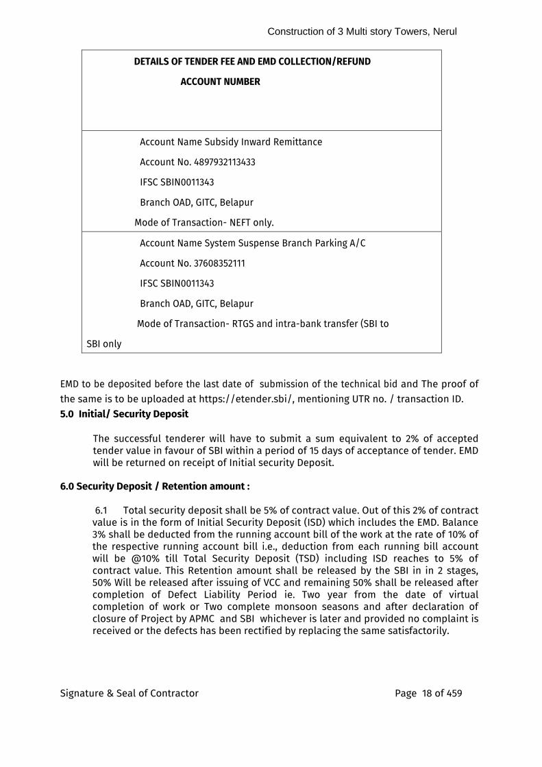
4.6 The bid can only be submitted after deposition of EMD ₹ 1,64,00,000.00 (Rupees One Crore Sixty Four Lakhs Only) by means of (mode of Transaction) NEFT, RTGS and intra-bank tranfer (SBI to SBI only), as per details mentioned below:
Construction of 3 Multi story Towers, Nerul
Signature & Seal of Contractor Page 18 of 459
DETAILS OF TENDER FEE AND EMD COLLECTION/REFUND
ACCOUNT NUMBER
Account Name Subsidy Inward Remittance
Account No. 4897932113433
IFSC SBIN0011343
Branch OAD, GITC, Belapur
Mode of Transaction- NEFT only.
Account Name System Suspense Branch Parking A/C
Account No. 37608352111
IFSC SBIN0011343
Branch OAD, GITC, Belapur
Mode of Transaction- RTGS and intra-bank transfer (SBI to
SBI only
EMD to be deposited before the last date of submission of the technical bid and The proof of the same is to be uploaded at https://etender.sbi/, mentioning UTR no. / transaction ID. 5.0 Initial/ Security Deposit
The successful tenderer will have to submit a sum equivalent to 2% of accepted tender value in favour of SBI within a period of 15 days of acceptance of tender. EMD will be returned on receipt of Initial security Deposit.
6.0 Security Deposit / Retention amount :
6.1 Total security deposit shall be 5% of contract value. Out of this 2% of contract value is in the form of Initial Security Deposit (ISD) which includes the EMD. Balance 3% shall be deducted from the running account bill of the work at the rate of 10% of the respective running account bill i.e., deduction from each running bill account will be @10% till Total Security Deposit (TSD) including ISD reaches to 5% of contract value. This Retention amount shall be released by the SBI in in 2 stages, 50% Will be released after issuing of VCC and remaining 50% shall be released after completion of Defect Liability Period ie. Two year from the date of virtual completion of work or Two complete monsoon seasons and after declaration of closure of Project by APMC and SBI whichever is later and provided no complaint is received or the defects has been rectified by replacing the same satisfactorily.
Construction of 3 Multi story Towers, Nerul
Signature & Seal of Contractor Page 19 of 459
6.2 No interest shall be paid to the amount retained by the Bank as Security Deposit& Additional Security Deposit.
7.0 Signing of contract Documents
The successful tenderer shall be bound to implement the contract by signing an agreement and conditions of contract with the respective Department of SBI within 15 days from the receipt of intimation of acceptance of the tender by the SBI. However, the written acceptance of the tenders by the Bank will constitute a binding agreement between the Bank and successful tenderer whether such formal agreement is subsequently entered into or not.
8.0 Completion Period
Refer Clause No 27 of GCC. 9.0 =
Refer Clause No. Part A- Point 5 of Information and Instruction to Bidders 10.0 Liquidated Damages
Please refer Clause No 8 of GCC. 11.0 Rate and prices: 11.1 In case of item rate tender
11.1.1 The tenderers shall quote their rates for individual items both in words and figure. In case of discrepancy between the rate quoted in words and figures, the unit rate quantity in words will prevail. The amount of each item shall be calculated and the requisite total is given. In case of discrepancy between the unit rate and the total amount calculated from multiplication of unit rate and the quantity the unit rate quoted will govern and the amount will be corrected.
If no rate is quoted for one or more tender items, in such case if these items executed on site no payments shall be done and contractor shall execute those item free of cost. 11.1.2 The tenderers should not change the units as specified in the tender. If any unit is changed the tenders would be evaluated as per the original unit and the Contractor/ Vendor would be paid accordingly.
11.1.3 The tenderer should not change or modify or delete the description of the item. If any discrepancy is observed he should immediately bring to the knowledge of the SBI. 11.1.4 Each page of the BOQ shall be signed by the authorized person and cutting or overwriting shall be duly attested by him.
11.1.5 Each page shall be totaled and the grand total shall be given.
11.1.6 The quoted rate should be firm & inclusive of materials, labour, wages, fixtures, transportation, installation, wastages, Octroi, levies, all cess, royalties, all taxes (but excluding GST), machinery, temporary works such as scaffolding, cleaning, overheads, profit, statutory expenses, incidental charges and all related expenses to complete the work during the currency of contract including authorized extension, if
Construction of 3 Multi story Towers, Nerul
Signature & Seal of Contractor Page 20 of 459
any, but excluding GST, which shall be mentioned in the bills/invoices separately, as applicable. GST shall be as applicable on actuals. 11.1.7 The SBI reserve their rights to accept any tenders, either in whole or in part or may entrust the work in phases or may drop the part scope of work at any stage of the project within its sole discretion without assigning any reason(s) for doing so and no claim / correspondence shall be entertained in this regard.
11.1.8 In case, it is decided by the SBI to drop one or more Items from the scope of work at any stage of the project, the Contractor/ Vendor shall not be entitled to raise any claim /compensation for such deleted scope of work. Also, the SBI may consider issuing work order for various branches/offices in phases but within a reasonable time interval and the Contractor/ Vendor shall be bound to execute the same within the stipulated time period and as per rates quoted by them in this tender without any claim for price escalation.
13.0 Pre-bid conference shall be held at 11:00 Hrs. on 29/03/2022 Offline at the office of Dy.
General Manager (F&OA), SBI, GITC, CBD, Belapur, Navi Mumbai. Bidders should send all queries by email [email protected], [email protected] before pre-bid conference, latest by 11.00 Hrs. on 28/03/2022 Because of pre-bid conference, certain modifications may be issued to all eligible bidders by the APMC /SBI by e-mail, if felt necessary by them. If further pre-bid conferences are required for complete and effective interactions, the date and time of same will be communicated at the end of 1st pre-bid meeting or later. All modifications/addendums/corrigendum issued regarding this bidding process, shall be uploaded on website only and shall not be published in any Newspaper.
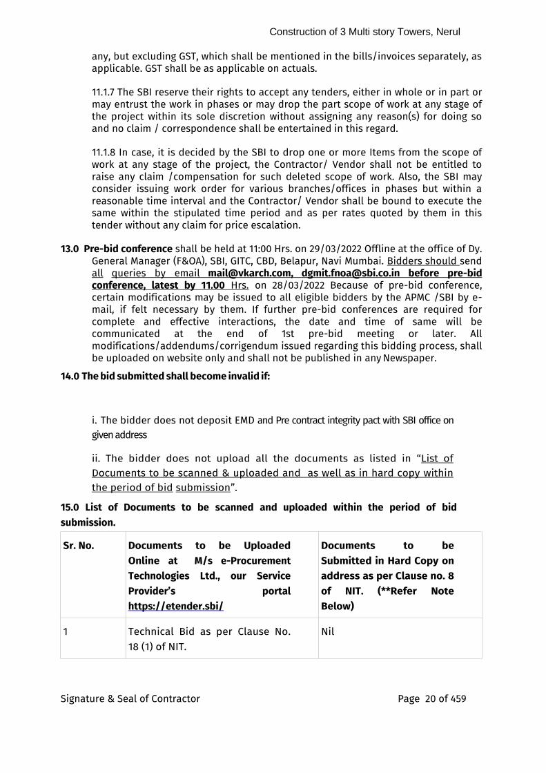
14.0 The bid submitted shall become invalid if:
i. The bidder does not deposit EMD and Pre contract integrity pact with SBI office on given address
ii. The bidder does not upload all the documents as listed in “List of Documents to be scanned & uploaded and as well as in hard copy within the period of bid submission”.
15.0 List of Documents to be scanned and uploaded within the period of bid submission.
Sr. No. Documents to be Uploaded Online at M/s e-Procurement Technologies Ltd., our Service Provider’s portal https://etender.sbi/
Documents to be Submitted in Hard Copy on address as per Clause no. 8 of NIT. (**Refer Note Below)
1 Technical Bid as per Clause No. 18 (1) of NIT.
Nil
Construction of 3 Multi story Towers, Nerul
Signature & Seal of Contractor Page 21 of 459
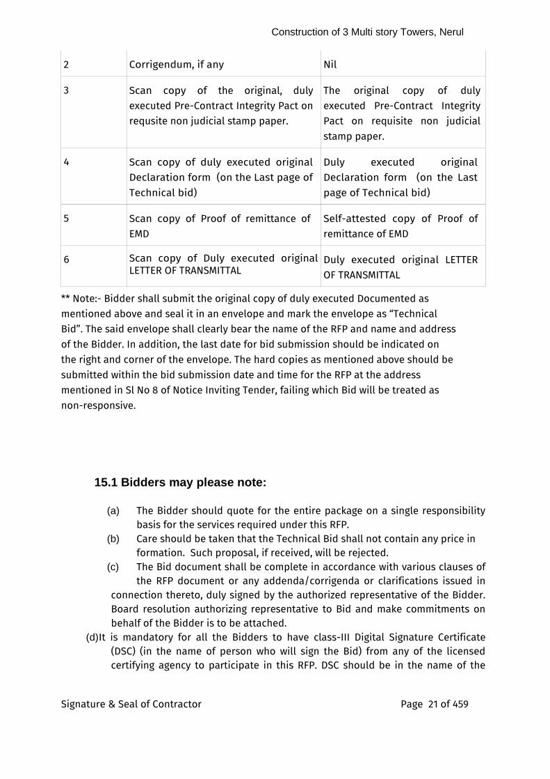
2 Corrigendum, if any Nil
3 Scan copy of the original, duly executed Pre-Contract Integrity Pact on requsite non judicial stamp paper.
The original copy of duly executed Pre-Contract Integrity Pact on requisite non judicial stamp paper.
4 Scan copy of duly executed original Declaration form (on the Last page of Technical bid)
Duly executed original Declaration form (on the Last page of Technical bid)
5 Scan copy of Proof of remittance of EMD
Self-attested copy of Proof of remittance of EMD
6 Scan copy of Duly executed original LETTER OF TRANSMITTAL
Duly executed original LETTER OF TRANSMITTAL
** Note:- Bidder shall submit the original copy of duly executed Documented as mentioned above and seal it in an envelope and mark the envelope as “Technical Bid”. The said envelope shall clearly bear the name of the RFP and name and address of the Bidder. In addition, the last date for bid submission should be indicated on the right and corner of the envelope. The hard copies as mentioned above should be submitted within the bid submission date and time for the RFP at the address mentioned in Sl No 8 of Notice Inviting Tender, failing which Bid will be treated as non-responsive.
15.1 Bidders may please note:
(a) The Bidder should quote for the entire package on a single responsibility basis for the services required under this RFP.
(b) Care should be taken that the Technical Bid shall not contain any price in formation. Such proposal, if received, will be rejected.
(c) The Bid document shall be complete in accordance with various clauses of the RFP document or any addenda/corrigenda or clarifications issued in connection thereto, duly signed by the authorized representative of the Bidder. Board resolution authorizing representative to Bid and make commitments on behalf of the Bidder is to be attached.
(d) It is mandatory for all the Bidders to have class-III Digital Signature Certificate (DSC) (in the name of person who will sign the Bid) from any of the licensed certifying agency to participate in this RFP. DSC should be in the name of the
Construction of 3 Multi story Towers, Nerul
Signature & Seal of Contractor Page 22 of 459
authorized signatory. It should be in corporate capacity (that is in Bidder capacity).
(e) Bids are liable to be rejected if only one Bid (i.e. either Technical Bid or Indicative Price Bid) is received.
(f) If deemed necessary, the Bank may seek clarifications on any aspect from the Bidder. However, that would not entitle the Bidder to change or cause any change in the substances of the Bid already submitted or the price quoted.
(g) The Bidder may also be asked to give presentation at no extra cost to the Bank for the purpose of clarification of the Bid.
(h) The Bidder must provide specific and factual replies to the points raised in the RFP. (i) The Bid shall be typed or written and shall be digitally signed by the Bidder or a
person or persons duly authorized to bind the Bidder to the Contract. (j) All the enclosures (Bid submission) shall be serially numbered. (k) Bidder(s) should prepare and submit their online Bids well in advance before the
prescribed date and time to avoid any delay or problem during the bid submission process. The Bank shall not be held responsible for any sort of delay or the difficulties faced by the Bidder(s) during the submission of online Bids.
(l) Bidder(s) should ensure that the Bid documents submitted should be free from virus and if the documents could not be opened, due to virus or otherwise, during Bid opening, the Bid is liable to be rejected.
The Bank reserves the right to reject Bids not conforming to above.15.2 Evaluation of Technical Bids :
I) The bidders who submit above documents without any conditions shall be treated as technically qualified bidders.
Ii ) Indicative Price Bid shall be opened of only of those bidders who qualify as per clause no. 15 of Information & Instructions to Bidders16.0 Award criteria and Award of contract :
(A) The indicative price bids of technically qualified venders will be opened. There after e-
reverse auction will be conducted. The L1 bidder based on e-reverse auction will be
finalised.(B) BUISNESS RULE DOCUMENT
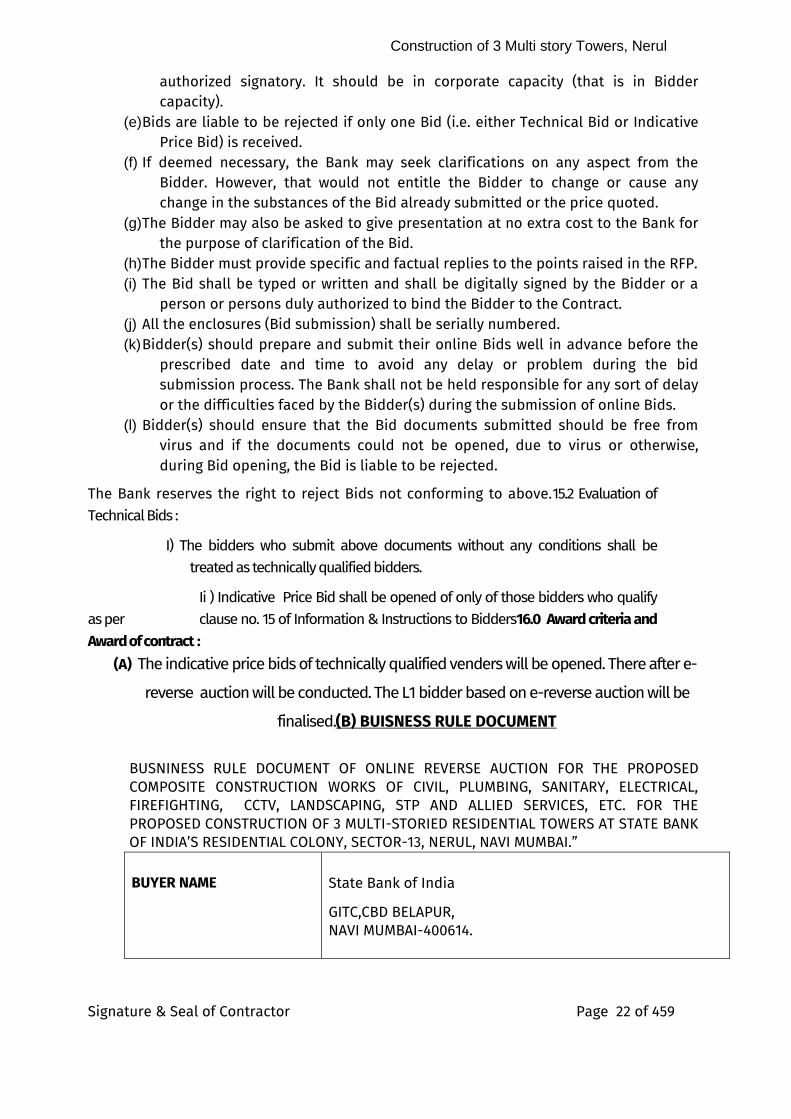
BUSNINESS RULE DOCUMENT OF ONLINE REVERSE AUCTION FOR THE PROPOSED COMPOSITE CONSTRUCTION WORKS OF CIVIL, PLUMBING, SANITARY, ELECTRICAL, FIREFIGHTING, CCTV, LANDSCAPING, STP AND ALLIED SERVICES, ETC. FOR THE PROPOSED CONSTRUCTION OF 3 MULTI-STORIED RESIDENTIAL TOWERS AT STATE BANK OF INDIA’S RESIDENTIAL COLONY, SECTOR-13, NERUL, NAVI MUMBAI.”
BUYER NAME
State Bank of India
GITC,CBD BELAPUR, NAVI MUMBAI-400614.
Construction of 3 Multi story Towers, Nerul
Signature & Seal of Contractor Page 23 of 459
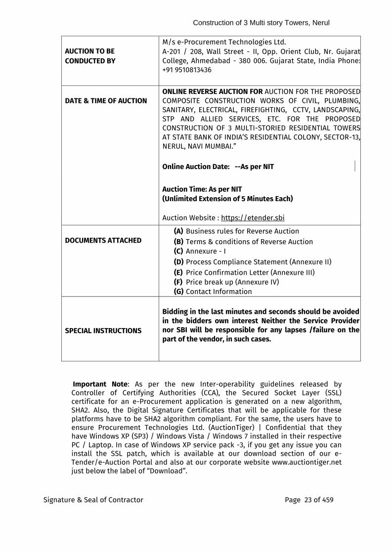
AUCTION TO BE
CONDUCTED BY
M/s e-Procurement Technologies Ltd. A-201 / 208, Wall Street - II, Opp. Orient Club, Nr. Gujarat College, Ahmedabad - 380 006. Gujarat State, India Phone: +91 9510813436
DATE & TIME OF AUCTION
ONLINE REVERSE AUCTION FOR AUCTION FOR THE PROPOSED COMPOSITE CONSTRUCTION WORKS OF CIVIL, PLUMBING, SANITARY, ELECTRICAL, FIREFIGHTING, CCTV, LANDSCAPING, STP AND ALLIED SERVICES, ETC. FOR THE PROPOSED CONSTRUCTION OF 3 MULTI-STORIED RESIDENTIAL TOWERS AT STATE BANK OF INDIA’S RESIDENTIAL COLONY, SECTOR-13, NERUL, NAVI MUMBAI.”
Online Auction Date: --As per NIT
Auction Time: As per NIT
(Unlimited Extension of 5 Minutes Each) Auction Website : https://etender.sbi
DOCUMENTS ATTACHED
(A) Business rules for Reverse Auction
(B) Terms & conditions of Reverse Auction
(C) Annexure - I (D) Process Compliance Statement (Annexure II) (E) Price Confirmation Letter (Annexure III) (F) Price break up (Annexure IV) (G) Contact Information
SPECIAL INSTRUCTIONS
Bidding in the last minutes and seconds should be avoided in the bidders own interest Neither the Service Provider nor SBI will be responsible for any lapses /failure on the part of the vendor, in such cases.
Important Note: As per the new Inter-operability guidelines released by Controller of Certifying Authorities (CCA), the Secured Socket Layer (SSL) certificate for an e-Procurement application is generated on a new algorithm, SHA2. Also, the Digital Signature Certificates that will be applicable for these platforms have to be SHA2 algorithm compliant. For the same, the users have to ensure Procurement Technologies Ltd. (AuctionTiger) | Confidential that they have Windows XP (SP3) / Windows Vista / Windows 7 installed in their respective PC / Laptop. In case of Windows XP service pack -3, if you get any issue you can install the SSL patch, which is available at our download section of our e-Tender/e-Auction Portal and also at our corporate website www.auctiontiger.net just below the label of “Download”.
Construction of 3 Multi story Towers, Nerul
Signature & Seal of Contractor Page 24 of 459
(A) Business rules for Reverse Auction:
Against this Enquiry for the subject item/system with detailed scope of supply as per our specification, SBI may resort to “REVERSE AUCTION PROCEDURE” i.e. ON LINE BIDDING on INTERNET.
1. For the proposed reverse auction, technically and commercially acceptable bidders only shall be eligible to participate. 2. SBI will engage the services of a service provider who will provide all necessary training and assistance before commencement of on line bidding on Internet. 3. SBI will inform the vendor in writing in case reverse auction, the details of service provider to enable them to contact and get trained. 4. Business rules like event date, time, start price, bid decrement, extensions, etc. also will be communicated through service provider for compliance. 5. Vendors have to send the mail the compliance form in the prescribed format (provided by service provider) before start of Reverse auction. Without this the vendor will not be eligible to participate in the event. 6. Reverse auction will be conducted on schedule date & time. 7. At the end of reverse auction event, the lowest bidder value will be known on the network. 8. The lowest bidder has to mail the duly signed filled-in prescribed format as provided on case-to-case basis to SBI through service provider within 24 hours of auction without fail. 9. In case SBI decides not to go for Reverse auction procedure for this tender enquiry, the price bids and price impacts, if any already submitted and available with SBI shall be opened as per SBI standard practice. 10. The reverse auction will be treated as closed only when the bidding process gets closed in all respects for the item listed in the tender.
(B) Terms & conditions of Reverse Auction:
SBI shall finalize the procurement of the item against this Tender through reverse auction mode. SBI has made arrangement with M/s. e-Procurement Technologies Ltd, Ahmedabad (ETL) who shall be SBI’s authorized service provider for the same. Please go through the guidelines given below and submit your acceptance to the same along with your Commercial Bid.
1. Computerized Reverse auction shall be conducted by M/s ETL on
behalf of SBI, on prespecified date, while the vendors shall be quoting from their own offices/ place of their choice. Internet connectivity and other paraphernalia requirements shall have to be ensured by vendors themselves. In the event of failure of their
Construction of 3 Multi story Towers, Nerul
Signature & Seal of Contractor Page 25 of 459
Internet connectivity, (due to any reason whatsoever it may be) it is the bidders’ responsibility. In order to ward-off such contingent situation bidders are requested to make all the necessary arrangements/ alternatives such as back –up power supply whatever required so that they are able to circumvent such situation and still be able to participate in the reverse auction successfully. Failure of power at the premises of vendors during the Reverse auction cannot be the cause for not participating in the reverse auction. On account of this, the time for the auction cannot be extended and SBI and M/s. e-Procurement Technologies Ltd is not responsible for such eventualities.
2. ETL shall arrange to train your nominated person(s), without any cost to you. They shall also explain you all the Rules related to the Reverse Auction. You are required to give your compliance on it before start of bid process.
3. BIDDING CURRENCY AND UNIT OF MEASUREMENT: Bidding will be
conducted in Indian currency & Unit of Measurement will be displayed in Online Auction.
4. BID PRICE: The Bidder has to quote the rate as per the Tender Document provided by State Bank of India.
5. VALIDITY OF BIDS: The Bid price shall be firm for a period specified in
the tender document and shall not be subjected to any change whatsoever.
6. At the end of the reverse auction, bidder has to provide the price confirmation letter & a detail break up for his lowest offer within 24 hour of closing of auction as per the Annexure III & IV respectively.
7. Procedure of Reverse Auction: Online English Reverse (no ties) Auction {Reverse Auction}:
i. OPENING PRICE & BID DECREMENT AMOUNT: SBI will declare its
Opening Price (OP), which shall be visible to the all vendors during the start of the reverse Auction. You will be required to start bidding after announcement of Opening Price and decrement amount. Also, please note that the start price of an item in online reverse auction is open to all the participating bidders. Any bidder can start bidding, in the online reverse auction, from the start price itself. Also, please note that the first online bid that comes in the system during the online reverse auction can be equal to the auction's start price, or lesser than the auction's start price by one decrement, or lesser than the auction's start price by multiples of decrement. The second online bid and onwards will have to be
Construction of 3 Multi story Towers, Nerul
Signature & Seal of Contractor Page 26 of 459
lesser than the L1 rate by one decrement value, or lesser than the L1 rate by multiples of the decrement value.
ii. The bid start price and decrement amount shall be specified by SBI
iii. DURATION OF AUCTION: English Reverse (no ties) shall be for a
period of ONE HOUR. If a bidder places a Bid in the last 5 minutes of Closing of the Auction, the auction shall get extended automatically for another 5 minutes. In case, there is no Bid in the last 5 minutes of closing of Auction, the Auction shall get closed automatically without any extension. Please note that if there are more than one item in a single auction, the auto-extension will be applicable to the entire event i.e. whenever a bidder places an acceptable bid in the last 5 minutes of the closing of the auction, the auction shall get extended automatically for another 5 minutes from the time of this bid for all the items in the auction. There are Unlimited Extensions of 5 Min. each. Vendors are advised not to wait till the last minute or last few seconds to enter their bid during the auto-extension period to avoid complications related with internet connectivity, network problems, system crash down, power failure, etc.
8. Successful vendor shall be required to submit the final prices,
quoted during the English Reverse (no ties) exactly in the format issued by SBI/Service provider after the completion of Auction to SBI, duly signed and stamped as token of acceptance without any new condition other than those already agreed to before start of auction.
9. During English Reverse (no ties), if no bid is received within the
specified time, SBI, at its discretion, may decide to revise Opening price / scrap the reverse auction process / proceed with conventional mode of tendering.
10. Bids once made by you, cannot be cancelled / withdrawn and you
shall be bound to supply as mentioned above at your final bid price. Should you back out and not supply as per the rates quoted, SBI shall take action as appropriate.
11. LOG IN NAME & PASSWORD: Each Bidder is assigned a Unique User
Name & Password by ETL. The Bidders are requested to change the Password after the receipt of initial Password from ETL. All bids made from the Login ID given to the bidder will be deemed to have been made by the bidder.
12. VISIBILITY TO BIDDER: The Bidder shall be able to view the
following on his screen along with the necessary fields during English Reverse – No ties Auction: a Leading Bid in the Auction
Construction of 3 Multi story Towers, Nerul
Signature & Seal of Contractor Page 27 of 459
b Bid Placed by you c Auction Opening Price & bid decrement amount
d Your rank in the auction
13. BIDS PLACED BY BIDDER: The bid of the bidder will be taken to be an offer to execute the work. Bids once made by the bidder cannot be cancelled. The bidder is bound to execute the work as mentioned above at the price that they bid. Should any bidder back out and not make the supplies as per the rates quoted, SBI and / or ETL shall take action as appropriate.
14. LOWEST BID OF A BIDDER: In case the bidder submits more than one bid, the lowest bid will be considered as the bidder’s final offer to execute the work.
15. At the end of the Reverse Auction, SBI will decide upon the winner.
SBI’s decision on award of Contract shall be final and binding on all the Bidders.
16. SBI shall be at liberty to cancel the reverse auction process /
tender at any time, before ordering, without assigning any reason.
17. SBI/ETL shall not have any liability to bidders for any interruption or delay in access to the site irrespective of the cause.
18. Other terms and conditions shall be as per your techno-
commercial offers and other correspondences till date.
19. You are required to submit your acceptance to the terms / conditions / modality given above before participating in the reverse auction.
20. AUCTION TYPE: 1) English Reverse No Ties Auction
21. OTHER TERMS & CONDITIONS: i. The Bidder shall not involve himself or any of his representatives in
Price manipulation of any kind directly or indirectly by communicating with other suppliers / bidders.
ii. The Bidder shall not divulge either his Bids or any other exclusive details of SBI to any other party.
iii. SBI’s decision on award of Contract shall be final and binding on all the Bidders.
iv. SBI along with ETL can decide to extend, reschedule or cancel any Auction. Any changes made by SBI and / or ETL, after the first posting will have to be accepted if the Bidder continues to access the site after that time.
v. ETL shall not have any liability to Bidders for any interruption or
Construction of 3 Multi story Towers, Nerul
Signature & Seal of Contractor Page 28 of 459
delay in access to the site irrespective of the cause. vi. ETL is not responsible for any damages, including damages that
result from, but are not limited to negligence. ETL will not be held responsible for consequential damages, including but not limited to systems problems, inability to use the system, loss of electronic information etc.
N.B.
vii. All the Bidders are required to submit the Process Compliance Statement (Annexure II) duly signed to M/s e-Procurement Technologies Ltd, Ahmedabad.
viii. All the bidders are requested to ensure that they have a valid digital signature certificate well in advance to participate in the online event.
Construction of 3 Multi story Towers, Nerul
Signature & Seal of Contractor Page 29 of 459
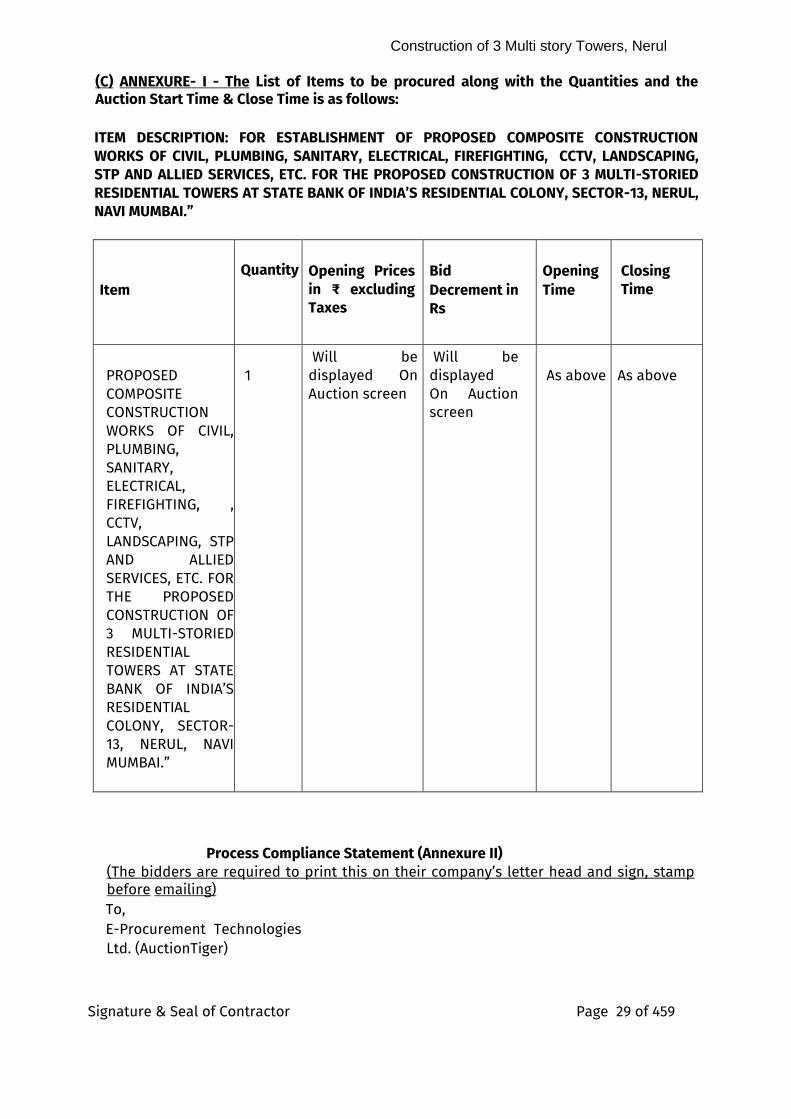
(C) ANNEXURE- I - The List of Items to be procured along with the Quantities and the Auction Start Time & Close Time is as follows:
ITEM DESCRIPTION: FOR ESTABLISHMENT OF PROPOSED COMPOSITE CONSTRUCTION WORKS OF CIVIL, PLUMBING, SANITARY, ELECTRICAL, FIREFIGHTING, CCTV, LANDSCAPING, STP AND ALLIED SERVICES, ETC. FOR THE PROPOSED CONSTRUCTION OF 3 MULTI-STORIED RESIDENTIAL TOWERS AT STATE BANK OF INDIA’S RESIDENTIAL COLONY, SECTOR-13, NERUL, NAVI MUMBAI.”
Item
Quantity
Opening Prices in ₹ excluding Taxes
Bid
Decrement in
Rs
Opening
Time
Closing Time
PROPOSED COMPOSITE CONSTRUCTION WORKS OF CIVIL, PLUMBING, SANITARY, ELECTRICAL, FIREFIGHTING, , CCTV, LANDSCAPING, STP AND ALLIED SERVICES, ETC. FOR THE PROPOSED CONSTRUCTION OF 3 MULTI-STORIED RESIDENTIAL TOWERS AT STATE BANK OF INDIA’S RESIDENTIAL COLONY, SECTOR-13, NERUL, NAVI MUMBAI.”
1
Will be displayed On Auction screen
Will be displayed On Auction screen
As above
As above
Process Compliance Statement (Annexure II) (The bidders are required to print this on their company’s letter head and sign, stamp before emailing) To, E-Procurement Technologies Ltd. (AuctionTiger)
Construction of 3 Multi story Towers, Nerul
Signature & Seal of Contractor Page 30 of 459
A-201 / 208, Wall Street - II, Opp. Orient Club, Nr. Gujarat College, Ahmedabad - 380006. Gujarat State, India
SUB: AGREEMENT TO THE PROCESS RELATED TERMS AND CONDITIONS FOR ONLINE REVERSE AUCTION PROPOSED COMPOSITE CONSTRUCTION WORKS OF CIVIL, PLUMBING, SANITARY, ELECTRICAL, FIREFIGHTING, CCTV, LANDSCAPING, STP AND ALLIED SERVICES, ETC. FOR THE PROPOSED CONSTRUCTION OF 3 MULTI-STORIED RESIDENTIAL TOWERS AT STATE BANK OF INDIA’S RESIDENTIAL COLONY, SECTOR-13, NERUL, NAVI MUMBAI.”
Dear Sir, This has reference to the Terms & Conditions for the Reverse Auction mentioned in the Tender document
This letter is to confirm that: 1) The undersigned is authorized representative of the company.
2) We have read examined and understood the RFP/Technical Bid / e-
Auction documents pertaining to this event and have no reservations to the same.
3) We have studied all the terms & condition, commercial terms, the
Business Rules governing the e-auction as mentioned in RFP (if any) and understood the RFP/Techincal / e-Auction Business Rules documents (if any) pertaining to this event, and confirm our agreement to them.
4) We confirm that before participating in e-Auction event, we will
arrange and check a Minimum System Pre-requisite to e-Auctioning well in advance before starting of the e-Auction. E.g., Operating System, Installation a Valid Digital Signature Certificate (DSC if applicable), Internet Explorer Browser Active-X Control settings to access the e-Auction portal smoothly as per Minimum System requirement which will be available on homepage of the e-Procurement website.
5) We agree that we shall change the password on receipt by us and keep it confidential. We agree that I shall not hold e-Procurement Technologies Limited (EPTL) responsible in any way for any losses that may be suffered by us because of disclosure of the password to any other person.
6) We also confirm that we have taken the training on the e-auction
tool and have understood the entire functionality of the same thoroughly including all scenarios & available features for bidding
Construction of 3 Multi story Towers, Nerul
Signature & Seal of Contractor Page 31 of 459
pertaining to e-auction event.
7) We confirm that Dept. / Tendering Authority and EPTL (Service Provider) shall not be liable & responsible in any manner whatsoever for my/our failure to access & bid on the e-auction platform due to loss of internet connectivity, electricity failure, virus attack, problems with the PC, any other unforeseen circumstances etc. before or during the e-auction event.
8) In case of Digital Signature Certificate (DSC) based login to the e-
Auction/e-Tender/event, we also confirm that we have a valid DSC issued by a valid Certifying Authority (approved by Controller of Certifying Authorities) in INDIA.
9) We take a note as advised by you related not to wait till last minute
or last few seconds to submit valid bid to avoid any complication related to loss of internet connectivity, electricity failure, virus attack, network problems, system crash down, problems with the PC, any other unforeseen circumstances etc…Neither Department / Tendering Authority nor Service Provider (EPTL) are responsible for any unforeseen circumstance.
10) We also confirm that we will e-mail the price confirmation & break
up of our quoted price to the Dept. / EPTL as per Annexures (if applicable) within 24 hours of the completion of the e-auction and the format as requested by Dept. / EPTL.
11) We, hereby confirm that we will honour the Bids placed by us
during the auction process. Bid cannot be cancelled / withdrawn and you shall be bound to collecting / supply at your final bid price. If you back out and or collecting / supply as per the rates quoted, Dept. / Tendering Authority shall take action as appropriate.
12) We confirm that we have not changed or deleted any clauses in this
Process Compliance Form (PCF) and submitting the same to the service provider / Dept. as it is duly stamped and signed. In addition, if any changes found in submitted PCF or in this Business Rules Document (if any) before or after completion of the Sealed Bid (if any) or e-Auction then Dept. / Service provider may take an appropriate action against us.
With regards, Date: Signature with company seal Name: Company / Organization: Designation within Company / Organization: Address of Company / Organization:
Construction of 3 Multi story Towers, Nerul
Signature & Seal of Contractor Page 32 of 459
Scan it and send to this Document on Hitesh | EPTL [email protected]
Construction of 3 Multi story Towers, Nerul
Signature & Seal of Contractor Page 33 of 459
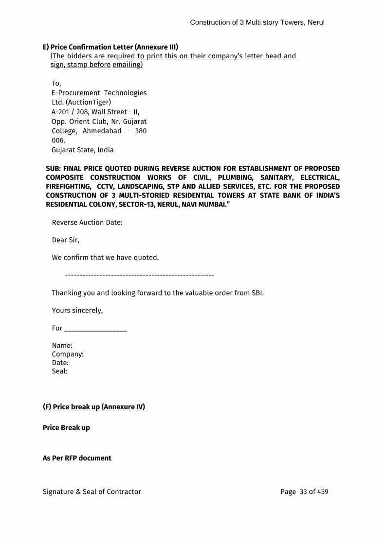
E) Price Confirmation Letter (Annexure III) (The bidders are required to print this on their company’s letter head and sign, stamp before emailing)
To, E-Procurement Technologies Ltd. (AuctionTiger) A-201 / 208, Wall Street - II, Opp. Orient Club, Nr. Gujarat College, Ahmedabad - 380 006. Gujarat State, India
SUB: FINAL PRICE QUOTED DURING REVERSE AUCTION FOR ESTABLISHMENT OF PROPOSED COMPOSITE CONSTRUCTION WORKS OF CIVIL, PLUMBING, SANITARY, ELECTRICAL, FIREFIGHTING, CCTV, LANDSCAPING, STP AND ALLIED SERVICES, ETC. FOR THE PROPOSED CONSTRUCTION OF 3 MULTI-STORIED RESIDENTIAL TOWERS AT STATE BANK OF INDIA’S RESIDENTIAL COLONY, SECTOR-13, NERUL, NAVI MUMBAI.”
Reverse Auction Date:
Dear Sir, We confirm that we have quoted. ---------------------------------------------------- Thanking you and looking forward to the valuable order from SBI. Yours sincerely, For _________________ Name: Company: Date: Seal:
(F) Price break up (Annexure IV)
Price Break up
As Per RFP document

Construction of 3 Multi story Towers, Nerul
Signature & Seal of Contractor Page 34 of 459
Construction of 3 Multi story Towers, Nerul
Signature & Seal of Contractor Page 35 of 459
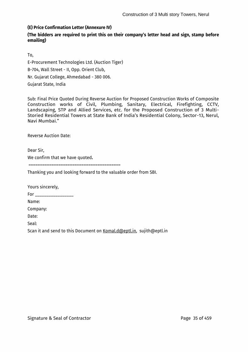
(E) Price Confirmation Letter (Annexure IV)
(The bidders are required to print this on their company’s letter head and sign, stamp before emailing)
To,
E-Procurement Technologies Ltd. (Auction Tiger)
B-704, Wall Street - II, Opp. Orient Club,
Nr. Gujarat College, Ahmedabad - 380 006.
Gujarat State, India
Sub: Final Price Quoted During Reverse Auction for Proposed Construction Works of Composite Construction works of Civil, Plumbing, Sanitary, Electrical, Firefighting, CCTV, Landscaping, STP and Allied Services, etc. for the Proposed Construction of 3 Multi-Storied Residential Towers at State Bank of India’s Residential Colony, Sector-13, Nerul, Navi Mumbai.”
Reverse Auction Date:
Dear Sir,
We confirm that we have quoted.
----------------------------------------------------
Thanking you and looking forward to the valuable order from SBI.
Yours sincerely,
For _________________
Name:
Company:
Date:
Seal:
Scan it and send to this Document on [email protected], [email protected]
Construction of 3 Multi story Towers, Nerul
Signature & Seal of Contractor Page 36 of 459
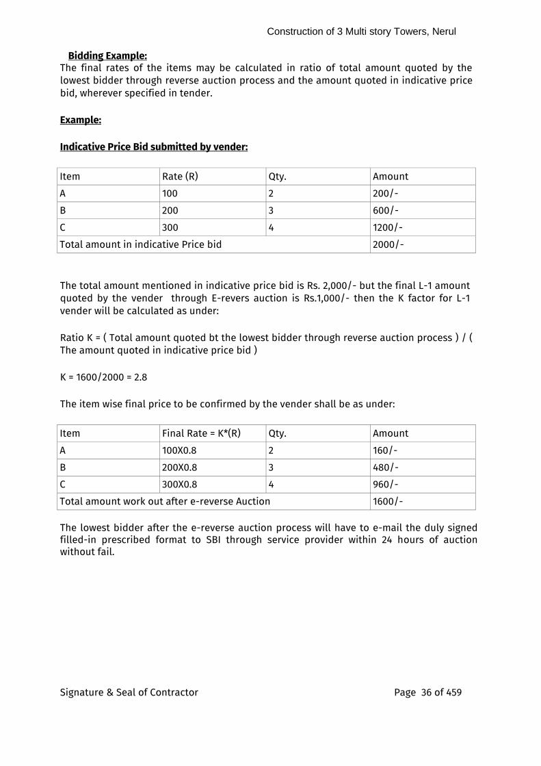
Bidding Example: The final rates of the items may be calculated in ratio of total amount quoted by the lowest bidder through reverse auction process and the amount quoted in indicative price bid, wherever specified in tender.
Example:
Indicative Price Bid submitted by vender:
Item Rate (R) Qty. Amount
A 100 2 200/-
B 200 3 600/-
C 300 4 1200/-
Total amount in indicative Price bid 2000/-
The total amount mentioned in indicative price bid is Rs. 2,000/- but the final L-1 amount quoted by the vender through E-revers auction is Rs.1,000/- then the K factor for L-1 vender will be calculated as under:
Ratio K = ( Total amount quoted bt the lowest bidder through reverse auction process ) / ( The amount quoted in indicative price bid )
K = 1600/2000 = 2.8
The item wise final price to be confirmed by the vender shall be as under:
Item Final Rate = K*(R) Qty. Amount
A 100X0.8 2 160/-
B 200X0.8 3 480/-
C 300X0.8 4 960/-
Total amount work out after e-reverse Auction 1600/- The lowest bidder after the e-reverse auction process will have to e-mail the duly signed filled-in prescribed format to SBI through service provider within 24 hours of auction without fail.
Construction of 3 Multi story Towers, Nerul
Signature & Seal of Contractor Page 37 of 459
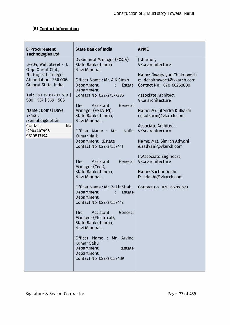
(B) Contact Information
E-Procurement Technologies Ltd.
State Bank of India
APMC
B-704, Wall Street - II, Opp. Orient Club, Nr. Gujarat College, Ahmedabad- 380 006. Gujarat State, India
Tel.: +91 79 61200 579 | 580 | 567 | 569 | 566 Name : Komal Dave E-mail :[email protected] Contact No :9904407998 9510813194
Dy.General Manager (F&OA) State Bank of India Navi Mumbai Officer Name : Mr. A K Singh Department : Estate Department Contact No 022-27577386 The Assistant General Manager (ESTATE1), State Bank of India, Navi Mumbai . Officer Name : Mr. Nalin Kumar Naik Department :Estate Contact No 022-27537411 The Assistant General Manager (Civil), State Bank of India, Navi Mumbai . Officer Name : Mr. Zakir Shah Department : Estate Department Contact No 022-27537412 The Assistant General Manager (Electrical), State Bank of India, Navi Mumbai . Officer Name : Mr. Arvind Kumar Sahu Department :Estate Department Contact No 022-27537439
Jr.Parner, VK:a architecture Name: Dwaipayan Chakraworti e: [email protected] Contact No - 020-66268800 Associate Architect VK:a architecture Name: Mr. Jitendra Kulkarni e:[email protected] Associate Architect VK:a architecture Name: Mrs. Simran Adwani e:[email protected] Jr.Associate Engineers, VK:a architecture Name: Sachin Doshi E: [email protected] Contact no- 020-66268873
Construction of 3 Multi story Towers, Nerul
Signature & Seal of Contractor Page 38 of 459
1. 2.
1.
2.
3. -
-
-
-
-
-
-
-
3.
7.
4.
4.
5.
6.
7.
8.
1.
9.
i.
5.
6.
7.
8.
9.
10.
11.
12.
13.
14. LETTER OF TRANSMITTAL ( Annexure-V) (The bidders are required to print this on their company’s letter head and sign, stamp before emailing) To, The Dy. General Manager (F & OA), Estate Dept., State Bank Global IT Centre, 1st Floor, “C” Wing, Sector 11, C.B.D. Belapur, Navi Mumbai – 400614.
Dear Sir,
Construction of 3 Multi story Towers, Nerul
Signature & Seal of Contractor Page 39 of 459
Having examined the drawings, specification, design and schedule of quantities relating to the works specified in the memorandum hereinafter set out and having visited and examined the site of the works specified in the said memorandum and having acquired the requisite information relating thereto as affecting the tender, I/We hereby offer to execute the works specified in the said memorandum at the rates mentioned in the attached Schedule of Quantities and in accordance in all respects with the specifications, design, drawings and instructions in writing referred to in conditions of tender, the Articles of Agreement, Special Conditions, Schedule of Quantities and Conditions of Contract and with such materials as are provided for by, and in all other respects in accordance with such conditions so far as they may be applicable.
MEMORANDUM
(a) Description of work Composite Construction works of Civil,
Plumbing, Sanitary, Electrical, Firefighting, CCTV, Landscaping, STP and Allied Services, etc. for the Proposed Construction of 3 Multi-Storied Residential Towers at State Bank of India’s Residential Colony, Sector-13, Nerul, Navi Mumbai.”
(b) Earnest Money of ₹ 1,64,00,000.00 (Rupees One Crore Sixty Four Lakhs Only) by means of (mode of Transaction) NEFT, RTGS and intra-bank transfer (SBI to SBI only), as per details mentioned in para 4.6 of Information and Instruction for Bidders,
(c)
Time allowed for completion of the Works from fifteenth day after the date of written Order or date of handing over of the site (Whichever is later) to commence the work
As per Clause No 27 of GCC.
1) Should this tender be accepted, I/we hereby agree to abide by and fulfill the terms and provisions of the said conditions of contract annexed hereto so far as may be applicable or in default thereof to forfeit and pay to SBI, the amount mentioned in the said contract. 2) I / We have deposited a sum of ₹ 1,64,00,000.00 (Rupees One Crore Sixty Four Lakhs Only) of the total tender amount as Earnest Money with the SBI which amount is not to bear any interest. Should I / We fail to execute the Contract when called upon to do so I / We do hereby agree that this sum shall be forfeited by me/us to State Bank of India. 3) I/ We understand that as per terms of this tender, the SBI may consider accepting our tender in part or whole or may entrust the various work proposed in phases. We, therefore,
Construction of 3 Multi story Towers, Nerul
Signature & Seal of Contractor Page 40 of 459
undertake that we shall not raise any claim/ compensation in the eventuality of Bank deciding to drop any of the work from the scope of work of this tender at any stage during the contract period. Further, we also undertake to execute the work entrusted to us in phases on our approved rates and within stipulated time limit without any extra claim for price escalation unless otherwise separately mentioned as also provided for in the clauses of “Instructions to Tenderers” of this tender. 4) I/ We, hereby, also undertake that, we will not raise any claim for any escalation in the prices of any of the material during the contract/execution/completion period including authorized extended contract period, if any. 5) Our Bankers are: I) ii) The names of partners of our firm are: i) ii) Name of the partner of the firm Authorised to sign
Or (Name of person having Power of Attorney to sign the Contract. (Certified true copy of the Power of Attorney should be attached) Yours faithfully, Signature of Contractors. Signature and addresses of Witnesses
i)
ii)
Construction of 3 Multi story Towers, Nerul
Signature & Seal of Contractor Page 41 of 459
GENERAL CONDITIONS OF CONTRACT (GCC) 1.0 Définitions: -
“Contract” means the documents forming the tender and the acceptance thereof and the formal agreement executed between State Bank of India (client) and the contractor, together with the documents referred there in including these conditions, the specifications, designs, drawings and instructions issued from time to time by the Architects/ Bank and all these documents taken together shall be deemed to form one contract and shall be complementary to one another.
1.1 In the contract the following expressions shall, unless the context otherwise
requires, have the meaning hereby respectively assigned to them. 1.1 (a) ‘RFP’ means the documents forming the tender i.e the Technical bid document, Price
bid document, along with its corrigendum and clarification and the acceptance thereof and together with the documents referred there in including these conditions, the specifications, designs, drawings, Pre-Qualifications – Expression of Interest, any correspondence from RFP till work order, etc. Complete.
1.1 (b) ‘Bid’ means the written reply or submission of response to this RFP. 1.1.1 ‘SBI’ shall mean State Bank of India (client) a body Corporate created under State
Bank of India Act 1955, having its Corporate Centre at State Bank Bhavan, Madame Cama Road, Mumbai 400 021 and it’s office at F&OA Department, Estate Dept. SBI GITC, Sector 11 at Navi Mumbai 400706 and includes the client’s representatives, successors and assigns.
1.1.2 ‘APMC’ shall means M/s VK:a Architecture, Pune who are the Project Architect and
Project Management Consultants, hereinafter abbreviated as APMC and their personnel’s like Architects, Engineers, Associates, Site Engineers, Project Engineers, Consulting Engineers, PMC Personnels etc. appointed by the SBI at site as their representative for day-to-day supervision of work and to give instructions to the contractors.
Construction of 3 Multi story Towers, Nerul
Signature & Seal of Contractor Page 42 of 459
1.1.3 ‘The Contractor’ / ‘Service Provider’ shall mean the individual or firm or company
whether incorporate not, undertaking the works and shall include legal personal representative of individual or the composing the firm or company and the permitted assignees of individual or firms of company. The expression ‘works or ‘work’ shall mean the permanent or temporary work description in the “Scope of work” and / or to be executed in accordance with the contract includes materials, apparatus, equipment, temporary supports, fittings and things of kinds to be provided, the obligations of the contractor hereunder and work to be done by the contractor under the contract.
1.1.4 ‘Drawings’ shall mean the drawings prepared by the Architects and issued by the
Engineer and referred to in the specifications and any modifications of such drawings as may be issued by the Engineer from time to time.
1.1.5 Spécifications’ shall mean the specifications referred to in the tender and
modifications thereof as may time to time be furnished or approved by the APMC .
1.1.6 “Month” means calendar month and “Week” means seven consecutive days.
1.1.7 “Contract Value” shall mean value of the entire work as stipulated in the letter of
acceptance of tender subject such additions there to or deductions there from as may be made under the provide herein after contained.
1.1.8 (a) “Week” means seven consecutive days. 1.1.8 (b) “Day” means a calendar day beginning and ending at 00 Hrs. and 24 Hrs.
respectively.
1.1.9 “SBI’s Engineer” shall mean The Civil / Electrical Engineer in - charge of the Project, as nominated by the Dy. General Manager (F & AO), Estate Department, GITC, State Bank of India, CBD Belapur, , Navi Mumbai .
1.1.10 The following shall constitute the Joint Project Committee (herein under referred to as JPC) for assessing and reviewing the progress of the work on the project and to issue instructions or directions from time to time for being observed and followed by the Architects Site Engineer /APMC and other consultants / contractors engaged in the execution of the project.
i) Dy. Gen. Manager (F & OA), ii) Assistant General Manager, Estate Department of SBI iii) SBI Engineer (Civil and Electrical) in-charge of the Project, as may be
nominated by the Estate Department, State Bank of India, Navi Mumbai . iv) Concerned partner / proprietor of the Architects and their Resident Architect
Member.
Construction of 3 Multi story Towers, Nerul
Signature & Seal of Contractor Page 43 of 459
1.1.11 “Complete Project Closure Report” by SBI and APMC means following conditions are satisfied and all works related to it are complete & reports closed after due repairs, replacements, trils, test, etc.
The project shall be considered complete & closed only when :
a. Defect Liability Period (DLP) for all items of work is over : DLP is for two years from the date of virtual completion ( as per para 23 of GCC) of work or Two complete monsoon season, whichever is later, and
b. Acceptance & closure of all queries & works after due rectification/replacements/ tests as referred by Chief Technical Examiner, CVC and
c. Acceptance and closure of all arbitration, court cases, etc. as decided by the Bank
… whichever is later. 1.2 Total Security Deposit
Total Security deposit comprise of
Earnest Money Deposit
Initial security deposit
Retention Money
a) Earnest Money Deposit -
The tenderer shall furnish EMD of ₹ 1,64,00,000.00 (Rupees One Crore Sixty Four Lakhs Only) by means of (mode of Transaction) NEFT, RTGS and intra-bank transfer (SBI to SBI only), as per details mentioned in para 4.6, of Information and Instruction for Bidders .. No tender shall be considered unless the EMD is so deposited in the required form. No interest shall be paid on this EMD. The EMD of the unsuccessful tenderer shall be refunded soon after the decision to award the contract is taken without interest. The EMD shall stand absolutely forfeited if the tenderer revokes his tender at any time the period when he is required to keep his tender open acceptance by the SBI or after it is accepted by the SBI the contractor fails to enter into a formal agreement or fails to pay the initial security deposit as stipulated or fails to commence the work within the stipulated time or if a Bidder makes any statement or encloses any form which turns out to be false / incorrect at any time prior to signing of Contract; or if a technically qualified Bidder do not participate in the auction by not logging in, in the reverse auction tool. EMD of successful tenderer shall also be refunded on receipt of ISD.b) Initial Security Deposit (lSD)
Construction of 3 Multi story Towers, Nerul
Signature & Seal of Contractor Page 44 of 459
The amount of ISD shall be 2% of accepted value of tender in the form of DD/drawn on any scheduled Bank and shall be deposited within 15 days from the date of acceptance of tender.
No interest shall be paid to the amount retained by the Bank as Security Deposit.
c) Retention Money: -
As per Part B - Point 6 of Information and Instruction to Bidders.
2.0 Language
The language in which the contract documents shall be drawn shall be in English.
3.0 Errors, omissions and discrepancies
In case of errors, omissions and/ or disagreement between written and scaled dimensions on the drawings or between the drawings and specifications etc., the following order shall apply.
i) Between scaled and written dimension (or description) on a drawing, the latter shall
be adopted. ii) Between the written or shown description or dimensions in the drawings and the
corresponding one in the specification the former shall be taken as correct. iii) Between written description of the item in the specifications and descriptions in
bills of quantities of the same item, the former shall be adopted: a) In case of difference between rates written in figures and words, the rate in words
shall prevail. b) Between the duplicate / subsequent copies of the tender, the original tender shall
be taken as correct. 4.0 Scope of Work:
The contractor shall carryout complete and maintain the said work in every respect strictly accordance with this contract and with the directions of and to the satisfaction to be communicated through the APMC . The APMC at the directions of the SBI from time to time issue further drawings and / or write instructions, details directions and explanations which are here after collectively references to as APMC ’s/SBI’s instructions in regard to the variation or modification of the design, quality or quantity of any work or the addition or omission or substitution work. Any discrepancy in the drawings or between BOQ and / or drawings and / or specifications. The removal from the site of any material brought thereon by the
Construction of 3 Multi story Towers, Nerul
Signature & Seal of Contractor Page 45 of 459
Contractor and any substitution of any other materials therefore the removal and / or re-executed of any work executed by him. The dismissal from the work of any person engaged thereupon.
5.0 i) Letter of Acceptance:
Within the validity period of the tender the SBI shall issue a letter of acceptance directly or through the Architect by registered post or otherwise depositing at the of the contractor as given in the tender to enter into a Contract for the execution of the work as per the terms of the tender. The letter of acceptance shall constitute a binding contract between the SBI and the contractor.
ii) Contract Agreement:
On receipt of intimation of the acceptance of tender from the SBI/ Architect, the successful tenderer shall be bound to implement the contract and within fifteen days there of shall sign an agreement in a non-judicial stamp paper of appropriate value. All expenses, stamp duty and other charges/ expenses in connection with the execution of the Agreement as a result of this RFP process shall be borne by successful Bidder. The Agreement/ Contract would be stamped as per Maharashtra Stamp Act, 1958 and any amendment thereto.
6.0 Ownership of drawings:
All drawings, specifications and copies thereof furnished by the SBI through its Architect / consultants are the properties of the SBI. They are not to be used on other work.
7.0 Detailed drawings and instructions:
The SBI through its Architects / consultants/APMC shall furnish with reasonable proper additional instructions by means of drawings or otherwise necessary for the execution of the work. All such drawings and instructions shall be consistent with contract documents, true developments thereof and reasonably inferable there.
The work shall be executed in conformity therewith and the contractor prepare a detailed programme schedule indicating therein the date of start and completion of various activities on receipt of the work order and submit the same to the SBI through the Architect/consultant
7.1 Copies of agreement
Two copies of agreement duly signed by both the parties with the drawings shall be prepared by the contractors.
8.0 Liquidated damages:
If the contractor fails to maintain the required progress in terms of clause 28/29 of GCC or to complete the work and clear the site including vacating their office on or before the contracted or extended date or completion, without justification in
Construction of 3 Multi story Towers, Nerul
Signature & Seal of Contractor Page 46 of 459
support of the cause of delay, he may be called upon without prejudice to any other right of remedy available under the law to the SBI on account of such breach to pay a liquidated damage at the rate of 0.50% of the Contract Value for delay of per week or part thereof which subject to a maximum of 5% of the Contract Value.
9.0 Materials, Appliances and Employees
Unless or otherwise specified the contractor shall provide and pay for all materials, labour, water, power, tools, equipment transportation and any other facilities that are required for the satisfactory execution and completion of the work. Unless or otherwise specified all materials shall be new and both workmanship and materials shall be best quality. The contractor shall at all times enforce strict discipline and good order among his employees and shall not employ on the work any unfit person or anyone not skilled in the work assigned to him. Workman whose work or behavior is found to be unsatisfactory by the SBI /APMC he shall be removed from the site immediately.
10.0 Permits, Laws and Regulations:
Permits and licenses required for the execution of the work shall be obtained by the contractor at his own expenses. The contractor shall give notices and comply with the regulations, laws, and ordinances rules, applicable to the contract. If the contractor observes any discrepancy between the drawings and specifications, he shall promptly notify the SBI in writing under intimation of the APMC . If the contractor performs any act, which is against the law, rules and regulations he shall meet all the costs arising there from and shall indemnify the SBI any legal actions arising there from.
11.0 Setting out Work:
The contractor shall set out the work and shall be responsible for the true and perfect setting out of the same and for the correctness of the positions, levels, dimensions, and alignment of all parts thereof and get it approved by the APMC before proceeding with the work. If at any time any error in this respect shall appear during the progress of the works, irrespective of the fact that the layout had been approved by, the APMC the contractor shall be responsible for the same ad shall his own expenses rectify such error, if so, required to satisfaction of the SBI
12.0 Protection of works and property:
The contractor shall continuously maintain adequate protection. of all his work from damage to all SBI’s adjacent properties and shall protect the SBI’s properties from injury or loss arising in connection with contract. He shall make good any such damage, injury, loss, Contractor Shall indemnify this to SBI in format finalised by the SBI at no extra cost. He shall take adequate care and steps for protection of the adjacent properties. The contractor shall take all precautions for safety and protections of his employees on
Construction of 3 Multi story Towers, Nerul
Signature & Seal of Contractor Page 47 of 459
the works and shall comply with all applicable provisions of Govt. and local bodies’ safety laws and building codes to prevent accidents, or injuries to persons or property on about or adjacent to his place of work. The contractor shall take insurance covers as per clause 24.0 at his own cost. The policy may be taken in joint names of the contractor and the SBI and the original policy may be lodged with the SBI
13.0 Inspection of work:
The SBI / APMC or their representatives shall at all reasonable times have free access to the work site and / or to the workshop, factories, or other places where materials are lying or from where they are obtained and the contractor shall give every facility to the SBI/APMC and their representatives necessary for inspection and examination and test of the materials and workmanship. No person unless authorized by the SBI/ APMC except the representative of public authorities shall be allowed on the work at any time. The proposed work either during its construction stage or its completion can also be inspected by the Chief Technical Examiner’s Organization a wing of Central Vigilance commission.
14.0 Assignment and subletting
The whole of work included in the contract shall be executed the contractor and he shall not directly entrust and engage or indirectly transfer, assign or under let the contract or any part or share there of or interest therein without the written consent of the SBI through the Architect and no undertaking shall relieve the contractor from the responsibility of the contractor from active & superintendence of the work during its progress.
15.0 Quality of materials, workmanship & Test
All materials and workmanship shall be best of the respective kinds described in the contract and in accordance with Architect/consultant instructions and shall be subject from time to time to such tests as the APMC may direct at the place of manufacture or fabrication or on the site or an approved testing laboratory. The contractor shall provide such assistance, instruments, machinery, labor, and materials as are normally required for examining measuring sampling and testing any material or part of work before incorporation in the work for testing as may be selected and required by the Architect/consultant.
ii) Samples
All samples of adequate numbers, size, shades & pattern as per specifications shall be supplied by the contractor without any extra charges. If certain items proposed to be used are of such nature that samples cannot be presented or prepared at the site detailed literature / test certificate of the same shall be provided to the satisfaction of the Architect/consultant. Before submitting the sample / literature the contractor shall satisfy himself that the material / equipment for which he is submitting the sample / literature meet with the requirement of tender
Construction of 3 Multi story Towers, Nerul
Signature & Seal of Contractor Page 48 of 459
specification. Only when the samples are approved in writing by the APMC the contractor shall proceed with the procurement and installation of the material / equipment. The approved samples shall be the signed by the APMC for identification and shall be kept on record at site office until the completion of the work for inspection / comparison at any time. The Architect/Consultant shall take reasonable time to approve the sample. Any delay that might occur in approving the samples for reasons of its not meeting the specifications or other discrepancies inadequacy in furnishing samples of best qualities from various manufacturers and such other aspects causing delay on the approval of the materials / equipment etc. shall be to the account of the contractor.
iii) Cost of tests
The cost of making any test shall be borne by the contractor if such test is intended by or provided for in the specification or BOQ.
iv) Costs of tests not provided for
If any test is ordered by the APMC which is either
If so intended by or provided for or (in the cases above mentioned) is not so particularized, or though so intended or provided for but ordered by the APMC to be carried out by an independent person at any place other than the site or the place of manufacture or fabrication of the materials tested or any Government / approved laboratory, then the cost of such test shall be borne by the contractor.
16.0 Obtaining information related to execution of work
No claim by the contractor for additional payment shall be entertained which is consequent upon failure on his part to obtain correct information as to any matter affecting the execution of the work nor any misunderstanding or the obtaining incorrect information or the failure to obtain correct information relieve him from any risks or from the entire responsibility for the fulfillment of contract.
17.0 Contractor’s Superintendence
The contractor shall give necessary personal superintendence during the execution the works and as long, thereafter, as the APMC may consider necessary until the expiry of the defect liability period, stated here to.
18.0 Quantities
i) The bill of quantities (BOQ) unless or otherwise stated shall be deemed to have
been prepared in accordance with the Indian Standard Method of Measurements and quantities. The rate quoted shall remain valid for variation of quantity against individual item . The entire amount paid under Clause 19, 20 hereof as well as amounts of prime cost and provision sums, if any, shall be excluded.
Construction of 3 Multi story Towers, Nerul
Signature & Seal of Contractor Page 49 of 459
19.0 Works to be measured
The Architect/Consultant may from time to time intimate to the contractor that he requires the work to be measured and the contractor shall forthwith attend or send a representative to assist the Architect in taking such measurements and calculation and to furnish all particulars or to give all assistance required by any of them. Such measurements shall be taken in accordance with the Mode of measurements detail in the specifications. The representative of the APMC shall take measurements with the contractor’s representative and the measurements shall be entered in the measurement book. The contractor or his authorized representative shall sign all the pages of the measurement book in which the measurements have been recorded in token of his acceptance. All the corrections shall be duly attested by both representatives. No over writings shall be made in the Measurement Book (M.B.) Should the contractor not attend or neglect or omit to depute his representative to take measurements, the measurements recorded by the representative of the APMC shall be final. All authorized extra work, omissions and all variations made shall be included such measurement. In case there there will not clarity of mode of measurements then IS 27:1987 , IS 1200 with all up to date releases /versions to be followed to finalise the measurements
20.0 Variations
No alteration, omission or variation ordered in writing by the APMC vitiates the contract. In case the SBI / APMC thinks proper at any during the progress of works to make any alteration in, or additions to or omission from the works or any. alteration in the kind or quality of the materials to be used therein, the APMC shall give notice thereof in writing to the contractor shall confirm in writing within seven days of giving such oral instructions the contract shall alter to, add to, or omit from as the case may be in accordance with such but the contractor shall not do any work extra to or make any alterations or additions to or omissions from the works or any deviation from any of the provisions of the contract, stipulations, specifications or contract drawings without previous consent in writing of the APMC and the value of such extras, alterations, additions or omissions shall in all cases be determined by the APMC and the same shall be added to or deducted from the contract value, as the case may be.
21.0 Valuation of Variations
No claim for an extra shall be allowed unless it shall have been executed under the authority of the APMC with the concurrence of the SBI as herein mentioned. Any such extra is herein referred to as authorized extra and shall be made in accordance with the following provisions.
a) (i) The net rates or prices in the contract shall determine the valuation of the extra
work where such extra work is of similar character and executed under similar conditions as the work priced herein.
Construction of 3 Multi story Towers, Nerul
Signature & Seal of Contractor Page 50 of 459
(ii) Rates for all items, wherever possible should be derived out of the rates given in the priced BOQ.
b) The net prices of the original tender shall determine the value of the items omitted,
provided if omissions do not vary the conditions under which any remaining items of Works are carried out, otherwise the prices for the same shall be valued under sub-Clause ‘c’ hereunder.
c) Where the extra works are not of similar character and/or executed under similar
conditions as aforesaid or where the omissions vary the conditions under which any remaining items or works are carried out, then the contractor shall within 7 days of the receipt of the letter of acceptance inform the APMC of the rate which he intends to charge for such items of work, duly supported by analysis of the rate or rates claimed and the APMC shall fix such rate or prices as in the circumstances in his opinion are reasonable and proper, based on the market rate.
d) Where extra work cannot be properly measured or valued the contractor shall be
allowed day work prices at the net rates stated in the tender, of the BOQ or, if not, so stated then in accordance with the local day work rates and wages for the district; provided that in either case, vouchers specifying the daily time (and if required by the Architect/Consultant) the workman’s name and materials employed be delivered for verification to the Architect /consultant at or before the end of the week following that in which the work has been executed.
e) It is further clarified that for all such authorized extra items where rates cannot be
derived from the tender, the Contractor shall submit rates duly supported by rate analysis worked on the ‘market rate basis for material, labour hire / running charges of equipment and wastage etc. plus 15% towards establishment charges, contractor’s overheads, and profit. Such items shall, not be eligible for escalation.
22.0 Final measurement
The measurement and valuation in respect of the contract shall be completed within Six months of the virtual completion of the work, provided all the related documents, test reports, compliance, documentation, as built drawings etc.
23.0 Virtual Completion Certificate (VCC)
On successful completion of entire works covered by the contract to the full satisfaction of the APMC/SBI, the contractor shall ensure that the following works have been completed the satisfaction of the SBI:
a) Clear the site of all scaffolding, wiring, pipes, surplus materials, contractor’s labour
equipment and machinery. b) Demolish, dismantle and remove the contractor’s site office, temporary works,
structure including labour sheds/camps and constructions and other items and things whatsoever brought upon or erected at the site or any land allotted to the contractor by the SBI not incorporated in the permanent works.
Construction of 3 Multi story Towers, Nerul
Signature & Seal of Contractor Page 51 of 459
c) Remove all rubbish, debris etc. from the site and the land allotted to the contractor by the APMC/SBI and shall clear, level and dress, compact the site as required by the APMC/SBI
d) Shall put the SBI in undisputed custody and possession of the site and all land allot
by the SBI e) Shall hand over the work in a peaceful manner to the APMC/SBI f) All defects / imperfections have been attended and rectified as pointed out by the
Architects to the full satisfaction of SBI
Upon the satisfactory fulfillment by the contractor as stated above, the contractor is entitled to apply to the APMC is satisfied of the completion of work. Relative to which the completion certificate has been sought, the APMC shall within fourteen (14) days of the receipt of the application for completion certificate, issue a VCC in respect of the work for which the VCC has applied.
This issuance of a VCC shall not be without prejudice to the SBI’s rights and contractor liabilities under the contract including the contractor’s liability for defects liability nor shall the issuance of VCC in respect of the works or work at any site be construction as a waiver of any right or claim of the SBI against the contractor in respect of or work at the site and in respect of which the VCC has been issued.
24.0 Work by other agencies
The SBI / APMC reserves the rights to use premises and any portion the site for execution of any work not included in the scope of this contract which it may desire to have carried out by other persons simultaneously and the contractor shall not only allow but also extend reasonable facilities for the execution of such work. The contractor however shall not be required to provide any plant or material for the execution of such work except by special arrangement with the SBI. Such work shall be carried out in such manner as not to impede the progress of the works included in the contract.
25.0 Insurance of works 25.1 Without limiting his obligations and responsibilities under the contract the
contractor shall insure in the joint names of the SBI and the contractor against all loss of damages from whatever cause arising other than the excepted risks, for which he is responsible under the terms of contract and in such a manner that the SBI and contractor are covered for the contract period stipulated including vide clause 28 of GCC and are also covered during the period of maintenance for loss or damage arising from a cause, occurring prior to the commencement of the period of maintenance and for any loss or damage occasioned by the contractor in the course of any operations carried out by him for the purpose of complying with his obligations under clause.
Construction of 3 Multi story Towers, Nerul
Signature & Seal of Contractor Page 52 of 459
a) The Works for the time being executed to the estimated current Contract value thereof, or such additional sum as may be specified together with the materials for incorporation in the works at their replacement value.
b) The constructional plant and other things brought on to the site by the contractor to
the replacement value of such constructional plant and other things. c) Such insurance shall be affected with an insurer and in terms approved by the SBI
which approval shall not be unreasonably withheld and the contractor shall whenever require produce to the APMC the policy if insurance and the receipts for payment of the current premiums.
25.2 Damage to persons and property
The contractor shall, except if and so far as the contract provides otherwise indemnify the SBI against all losses and claims in respect of injuries or damages to any person or material or physical damage to any property whatsoever which may arise out of or in consequence of the execution and maintenance of the works and against all claims proceedings, damages, costs, charges and expenses whatsoever in respect of or in relation thereto except any compensation of damages for or with respect to:
a) The permanent use or occupation of land by or any part thereof. b) The right of SBI to execute the works or any part thereof on, over, under, in or
through any lands. c) Injuries or damages to persons or properties which are unavoidable result of the
execution or maintenance of the works in accordance with the contract d) Injuries or damage to persons or property resulting from any act or neglect of the
SBI their agents, employees or other contractors not being employed by the contractor or for or in respect of any claims, proceedings, damages, costs, charges and expenses in respect thereof or in relation thereto or where the injury or damage was contributed to by the contractor, his servants or agents such part of the compensation as may be just and equitable having regard to the extent of the responsibility of the SBI, their employees, or agents or other employees, or agents or other contractors for the damage or injury.
25.3 Contractor to indemnify SBI
The contractor shall indemnify the SBI against all claims, proceedings, damages, costs, charges and expenses in respect of the matters referred to in the provision sub-clause 25.2 of this clause.
25.4 Contractor’s superintendence
The contractor shall fully indemnify and keep indemnified the SBI against any action, claim, or proceeding relating to infringement or use of any patent or design
Construction of 3 Multi story Towers, Nerul
Signature & Seal of Contractor Page 53 of 459
or any alleged patent or design rights and shall pay any royalties which may be payable in respect of any article or part thereof included in the contract. In the event of any claim made under or action brought against SBI in respect of such matters as aforesaid the contractor shall be immediately notified thereof and the contractor shall be at liberty, at his own expenses to settle any dispute or to conduct any litigation that may arise there from, provided that the contractor shall not be liable to indemnify the SBI if the infringement of the patent or design or any alleged patent or design right is the direct result of an order passed by the APMC in this behalf.
25.5 Third Party Insurance
25.5.1 Before commencing the execution of the work the contractor but without limiting his
obligations and responsibilities under clause 24.0 of GCC shall insure against his liability for any material or physical damage, loss, or injury which may occur to any property including that of SBI, or to any person, including any employee of the SBI, by or arising out of the execution of the works or in the carrying out of the contract, otherwise than due to the matters referred to in the provision to clause 24.0 thereof.
25.5.2 Minimum amount of Third-Party Insurance
Such insurance shall be affected with an insurer and in terms approved by the SBI which approval shall not be reasonably withheld and for at least the amount stated below. The contractor shall, whenever required, produce to the. APMC the policy or policies of insurance cover and receipts for payment of the current premiums.
25.6 The minimum insurance cover for physical property, injury, and death is Rs.5 Lakh
per occurrence with the number of occurrences limited to four. After each occurrence contractor will pay additional premium necessary to make insurance valid for four occurrences always.
25.7 Accident or Injury to workman: 25.7.1 The SBI shall not be liable for or in respect of any damages or compensation payable
at law in respect or in consequence of any accident or injury to any workmen or other person in the employment of the contractor or any sub-contractor, save and except an accident or injury resulting from any act or default of the SBI or their agents, or employees. The contractor shall indemnify and keep indemnified SBI against all such damages and compensation, save and except as aforesaid, and against all claims, proceedings, costs, charges and expenses whatsoever in respect thereof or in relation thereto.
25.7.2 Insurance against accidents etc. to workmen
The contractor shall insure against such liability with an insurer approved by the SBI during the whole of the time that any persons are employed by him on the works and shall, when required, produce to the APMC such policy of insurance and receipt for payment of the current premium. Provided always that, in respect of any persons employed by any sub-contractor the contractor’s obligation to insured as aforesaid
Construction of 3 Multi story Towers, Nerul
Signature & Seal of Contractor Page 54 of 459
under this sub-clause shall be satisfied if the sub-contractor shall have insured against the liability in respect of such persons in such manner that SBI is indemnified under the policy but the contractor shall require such sub-contractor to produce to the Architect /consultant when such policy of insurance and the receipt for the payment of the current premium.
25.7.3 Remedy on contractor’s failure to insure
If the contractor fails to effect and keep in force the insurance referred to above or any other insurance which he may be required to effect under the terms of contract, then and in any such case the SBI may effect and keep in force any such insurance and pay such premium or premiums as may be necessary for that purpose and from time to time deduct the amount so paid by the SBI as aforesaid from any amount due or which may become due to the contractor, or recover the same as debt from the contractor.
25.7.4 Without prejudice to the others rights of the SBI against contractors. In respect of
such default, the employer shall be entitled to deduct from any sums payable to the contractor the amount of any damages costs, charges, and other expenses paid by the SBI and which are payable by the contractors under this clause. The contractor shall upon settlement by the Insurer of any claim made against the insurer pursuant to a policy taken under this clause, proceed with due diligence to rebuild or repair the works destroyed or damaged. In this event all the monies received from the Insurer in respect of such damage shall be paid to the contractor and the Contractor shall not be entitled to any further payment in respect of the expenditure incurred for rebuilding or repairing of the materials or goods destroyed or damaged.
25.8 Insurance Policies :
Before commencing the execution of work, the Contractor shall, without in any way limiting his obligations and liabilities, insure at his own cost and expense against any damage or loss or injury, which may be caused to any person or property, at site of work. The Contractor shall obtain and submit to the APMC /SBI proper Contractor All Risk Insurance Policy for an amount 1.25 times the contract amount for this work, with APMC /SBI as the first beneficiary. The insurance shall be obtained in joint names of APMC /SBI and the Contractor (who shall be second beneficiary). Also, he shall indemnify the APMC /SBI from any liability during the execution of the work. Further, he shall obtain and submit to the APMC /SBI/, a third-party insurance policy for maximum Rs. 10 lakhs for each accident, with the APMC /SBI as the first beneficiary. The insurance shall be obtained in joint names of APMC /SBI and the Contractor (who shall be second beneficiary).
The Contractor shall, from time to time, provide documentary evidence as regards payment of premium for all the Insurance Policies for keeping them valid till the completion of the work. The Contractor shall ensure that Insurance Policies are also taken for the workers of his Sub- Contractors / specialized agencies also.
Construction of 3 Multi story Towers, Nerul
Signature & Seal of Contractor Page 55 of 459
Without prejudice to any of its obligations and responsibilities specified above, the Contractor shall within 10 days from the date of letter of acceptance of the
tender and thereafter at the end of each quarter submit a report to the Department giving details of the Insurance Policies along with Certificate of these insurance policies being valid, along with documentary evidences as required by the APMC /SBI. No work shall be commenced by the Contractor unless he obtains the Insurance Policies as mentioned above. Also, no payment shall be made to the Contractor on expiry of insurance policies unless renewed by the Contractor. Nothing extra shall be payable on this account. No claim of hindrance (or any other claim) shall be entertained from the contractor on these accounts. (Refer Annexure XVII ).
26.0 Commencement of Works:
The date of commencement of the work will be reckoned as the date, fifteen days from the date of award of contract letter by the SBI/Architects.
27.0 Time for completion
Time is essence of the contract and shall be strictly observed by the contractor. The entire work shall be completed within a period of 36 (Thirty Six) Months including Monsoon from the date of commencement. If required in the contract or as directed by the Architect / consultant. The contractor shall complete certain portions of work before completion of the entire work. However, the completion date shall be reckoned as the date by which the whole work is completed as per the terms of the contract.
28.0 Extension of time
If, in the opinion of the Architect/consultant, the work be delayed for reasons beyond the control of the contractor, the Architect/consultant may submit a recommendation to the SBI to grant a fair and reasonable extension of time for completion of work as per the terms of contract. If the contractor needs an extension of time for the completion of work or if the completion of work is likely to be delayed for any reasons beyond the due date of completion as stipulated in the contract, the contractor shall apply to the SBI through the Architect’ Consultant in writing at least 30 Days before the expiry of the scheduled time and while applying for extension of time he shall furnish the reason in detail and his justification if any’, for the delays. The Architect/consultant shall submit their recommendations to the SBI in the prescribed format for granting extension of time. While granting extension of time the contractor shall be informed the period extended time which will qualify for levy of liquidated damages. For the balance period in excess of original stipulated period and duly sanctioned extension of time by the provision of liquidated damages as stated under clause 8.0 shall become applicable. Further the contract shall remain in force even for the period beyond the due date of completion irrespective whether the extension is granted or not.
29. Rate of progress
Construction of 3 Multi story Towers, Nerul
Signature & Seal of Contractor Page 56 of 459
Whole of the materials, plant and labour to be provided by the contractor and the mode, manner and speed of execution and maintenance of the works are to be of a kind and conducted in a manner to the satisfaction of the APMC should the rate of progress of the work or any part thereof be at any time be in the opinion the. APMC too Slow to ensure the completion of the whole of the work the prescribed time or extended time for completion the APMC shall thereupon take such steps as considered necessary by the APMC to expedite progress so as to complete the works by the prescribed time or extended time. Such communications from the APMC neither shall relieve the contractor from fulfilling obligations under the contract nor will he be entitled to raise any claims arising out of such directions.
30.0 Work during nights and holidays
Subject to any provision to the contrary contained in the contract no permanent work shall save as herein provided be carried on during the night or on holidays without the permission in writing of the Architect / consultant, save when the work is unavoidable or absolutely necessary for the saving of life or property or for the safety of the work in which case the contractor shall immediately advise the Architect / consultant. However, the provisions of the clause shall not be applicable in the case of any work which becomes essential to carry by rotary or double shifts in order to achieve the progress and quality of the part of the works being technically required / continued with the prior approval of the APMC at no extra cost to the SBI.
All work at night after obtaining approval from competent authorities shall be carried out without unreasonable noise and disturbance.
31.0 No compensation or restrictions of work
If at any time after acceptance of the tender SBI shall decide to abandon or reduce the scope of work for any reason whatsoever and hence not required, the whole or any part of the work to be carried out. The APMC/SBI shall give notice in writing that effect to the contractor and the contractor shall act accordingly in the matter. The contractor shall have no claim to any payment of compensation or otherwise whatsoever on account of any profit or advantage which he might have derived from the execution of the Work fully but which he did not derive in consequence of the foreclosure of the whole or part of the work.
Provided that the contractor shall be paid the charges on the cartage only of materials actually and bona-fide brought to the site of the work by the contractor and rendered surplus as a result of the abandonment, curtailment of the work or any portion thereof and then taken back by the contractor, provided however that the APMC shall have in such cases the option of taking over all or any such materials at their purchase price or a local current rate whichever is less.
“In case of such stores having been issued from SBI stores and returned by the contractor to stores, credit shall be given to him at the rates not exceeding those at which were originally issued to the contractor after taking into consideration and deduction for claims on account of any deterioration or damage while in the custody of the contractor and in this respect the decision of APMC shall be final.
Construction of 3 Multi story Towers, Nerul
Signature & Seal of Contractor Page 57 of 459
32.0 Suspension of work
i) The contractor shall, on receipt of the order in writing of the APMC/SBI whose
decision shall be final and binding on the contractor) suspend the progress of works or any part thereof for such time and in such manner as Architect /consultant may consider necessary so as not to cause any damage or injury to the work already done or endanger the safety thereof for any of following reasons:
a) On account any default on the part of the contractor, or b) For proper execution of the works or part thereof for reasons other than the default
the contractor, or c) For safety of the works or part thereof.
The contractor shall, during such suspension, properly protect and secure the works the extent necessary and carry out the instructions given in that behalf by the Architect / consultant.
i) If the suspension is ordered for reasons (b) and (c) in sub-para (i) above: The contractor shall be entitled to an extension of time equal to the period of every such suspension. No compensation whatsoever shall be paid on this account.
33 Action when the whole security deposit is forfeited
In any case in which under any clause or clauses of this contract, the Contractor shall have rendered himself liable to pay compensation amounting to the whole of his security deposit the APMC shall have the power to adopt any of the following course as they may deem best suited to the interest of the SBI:
a) To rescind the contract (of which rescission notice in writing to the contractor by –
APMC shall be conclusive evidence) and in which case the security, deposit of the contractor shall be forfeited and be absolutely at the disposal of SBI
b) To employ labour paid by the SBI and to supply materials to carry out the work, or
part of the work, debiting the contractor with the cost of the labour and materials cost of such labour and materials as worked out by the Architect/consultant shall final and conclusive against the contractor) and crediting him with the value of the work done, in all respects in the same manner and at the same manner and at the same rates as if it had been carried out by the contractor under the terms of this contract certificate of Architect /consultant as to the value of work done shall be final conclusive against the contractor.
c) To measure up the work of the contractor, and to take such part thereof as shall
unexecuted, out of his hands, and to give it to another contractor to complete in which case any expenses which may be incurred in excess of the sum which would have been paid to the original contractor, if the whole work had been executed by him ( The amount of which excess the certificates in writing of the Architects / consultant shall final and conclusive) shall be borne by original contractor and may
Construction of 3 Multi story Towers, Nerul
Signature & Seal of Contractor Page 58 of 459
be deducted f any money due to him by SBI under the contract or otherwise, or from his security deposit or the proceeds of sale thereof, or sufficient part thereof.
In the event of any of above courses being adopted by the SBI the contractor shall have no claim to compensation for any loss sustained by him by reasons of his having purchased or procured any material or entered into any engagements or make any advances on account of, or with a view to the execution of the work or the performance of the contract and in case the contract shall be rescind under the provision aforesaid, the contractor shall not be entitled to recover or to be paid any sum or any work thereto for actually performed under this contract, unless, and until the APMC will have certified in writing the performance of such work and the value payable in respect thereof, and he shall only be entitled to be paid the value so certified.
34.0 SBI’s right to terminate the contract
If the contractor being an individual or a firm commit any ‘Act of insolvency’ or shall be adjusted an insolvent or being an incorporated company shall have an order for compulsory winding up voluntarily or subject to the supervision of Govt. and of the Official Assignee of the liquidator in such acts of insolvency or winding up shall be unable within seven days after notice to him to do so, to show to the reasonable satisfaction of the APMC that he is able to carry out and fulfill the contract, and to dye security therefore if so required by the APMC or if the contractor (whether an individual firm or incorporated Company) shall suffer execution to be issued or shall suffer any payment under this contract to be attached by or on behalf of any of the creditors of the contractor.
Or shall assign or sublet this contract without the consent in writing of the SBI through the Architect/Consultant or shall charge or encumber this contract or any payment due to which may become due to the contractor there under:
a) has abandoned the contract; or b) has failed to commence the works, or has without any lawful excuse under these
conditions suspended the progress of the works for 14 days after receiving from the SBI through the APMC written notice to proceed, or
c) has failed to proceed with the works with such diligence and failed to make such
due progress as would enable the works to be completed within the time agreed upon, or has failed to remove the materials from the site or to pull down and replace work within seven days after written notice from the SBI through the APMC that the said materials were condemned and rejected by the Architect/consultant under these conditions; or has neglected or failed persistently to observe and perform all or any of the acts matters or things by this contract to be observed and performed by the contractor for seven days after written notice shall have been given to the contractor to observe or perform the same or has to the detriment of good workmanship or in defiance of the SBI or Architect’s / consultant’s instructions to the contrary subject any part of the contract. Then and in any of said cases the SBI and or the Architect / consultant, may not withstanding any previous waiver, after giving seven days’ notice in writing to the contractor, determine the contract,
Construction of 3 Multi story Towers, Nerul
Signature & Seal of Contractor Page 59 of 459
but without thereby affecting the powers of the SBI or the APMC or the obligation and liabilities of the contractor the whole of which shall continue in force as fully as if the contract had not been determined and as if the works subsequently had been executed by or on behalf of the contractor. And, further the SBI through the APMC their agents or employees may enter upon and take possession of the work and all plants, took scaffolding, materials, sheds, machineries lying upon the premises or on the adjoining lands or roads use the same by means of their own employees or workmen in carrying on and completing the work or by engaging any other contractors or persons to the work and the contractor shall not in any was interrupt or do any act, matter or thing to prevent or hinder such other contractor or other persons employed for complement and finishing or using the materials and plant for the works.
When the works shall be completed or as soon thereafter as convenient the SBI or APMC shall give a notice in writing to the contractor to remove his surplus materials and plants and should the contractor fail to do so within 14 days after receive thereof by him the SBI sell the same by publication, and after due publication, and shall, adjust the amount realized by such auction. The contractor shall have no right to question any of the act of the SBI incidental to the sale of the materials etc.
35.0 Certificate of payment The contractor shall be entitled for the certificates to be issued by the APMC within 10 working days from the date of submission provided it is with all required documents, test reports, recording in MB etc. The SBI shall recover the statutory recovering other dues including the retention amount from the certificate of payment. Provided always that the issue of any certificate by the APMC during progress of works or completion shall not have effect as certificate of satisfaction relieve the contractor from his liability under clause.
The APMC shall have power to withhold the certificate if the work or in part thereof is not carried out to their satisfaction.
The APMC may by any certificate make any corrections required previous certificate.
The SBI shall modify the certificate of payment as issued by the APMC from time to time while making the payment
The contractor shall submit interim bills only after taking actual measurements and properly recorded in the Measurement Book (M. B.)
The Contractor shall not submit interim bills when the value of work done by him is less than the limit as prescribed in NIT, Clause No. 15.
The final bill may be submitted by contractor within a period of one month from the date of virtual completion and APMC shall issue the certificate of payment within a period of two months. The SBI shall pay the amount within a period of three months from the date of issue of certificate provided there is no dispute in respect of rates and quantities.
Construction of 3 Multi story Towers, Nerul
Signature & Seal of Contractor Page 60 of 459
The contractor shall submit the interim bills in the prescribed format with all details.
36.0 A. Settlement of Disputes and Arbitration
Except where otherwise provided in the contract all questions and disputes relating to the meaning of the specifications, design, drawings and instructions herein before mentioned and as to the quality of workmanship or materials used on the work or as to any other question, claim, right, matter or thing whatsoever in any way arising out of or relating to the contract, designs, drawings, specifications, estimates, instructions, orders or these conditions or otherwise concerning the work or the execution or failure to execute the same, whether arising during the progress of the work or after the cancellation, termination, completion or abandonment thereof shall be dealt with as mentioned hereinafter :
i. If the contractor considers that he is entitled to any extra payment or compensation in respect of the works over and above the amounts admitted as payable by the Architect or in case the contractor wants to dispute the validity of any deductions or recoveries made or proposed to be made from the contract or raise any dispute, the Contractor shall forthwith give notice in writing of his claim, or dispute to the Assistant General Manager (Estate)/ Dy. General Manager (F & OA ) and endorse a copy of the same to the Architect, within 30 days from the date of disallowance thereof or the date of deduction or recovery. The said notice shall give full particulars of the claim, grounds on which it is based and detailed calculations of the amount claimed and the contractor shall not be entitled to raise any claim nor shall the Bank be in any way liable in respect of any claim by the contractor unless notice of such claim shall have been given by the contractor to the Assistant General Manager ( Estate)/ Dy. General Manager (F & OA) in the manner and within the time as aforesaid. The contractor shall be deemed to have waived and extinguished all his rights in respect of any claim not notified to the Assistant General Manager ( Estate)/ Dy. General Manager (F & OA) in writing in the manner and within the time aforesaid.
ii. The Assistant General Manager ( Estate)/Dy. General Manager (F & OA) shall give his decision in writing on the claims notified by the contractor. The contractor may within 30 days of the receipt of the decision of the Assistant General Manager (Estate)/ Dy. General Manager (F & OA) submit his claims to the conciliating authority namely the Circle Development Officer/General Manager (ITSS) for conciliation along with all details and copies of correspondence exchanged between him and the Assistant General Manager ( Estate)/ Dy. General Manager (F & OA)
iii. If the conciliation proceedings are terminated without settlement of the disputes, the contractor shall, within a period of 30 days of termination thereof shall give a notice to the concerned Chief General Manager/ Dy. Managing Director (HR) & Corporate Development Officer of the Bank for appointment of an arbitrator to adjudicate the
Construction of 3 Multi story Towers, Nerul
Signature & Seal of Contractor Page 61 of 459
notified claims failing which the claims of the contractor shall be deemed to have been considered absolutely barred and waived.
iv. Except where the decision has become final, binding and conclusive in terms of the contract, all disputes or differences arising out of the notified claims of the contractor as aforesaid and all claims of the Bank shall be referred for adjudication through arbitration by the Sole Arbitrator appointed by the Chief General Manager/ Dy. Managing Director (HR) & Corporate Development Officer. It will also be no objection to any such appointment that the Arbitrator so appointed is a Bank Officer and that he had to deal with the matters to which the Contract relates in the course of his duties as Bank Officer. If the arbitrator so appointed is unable or unwilling to act or resigns his appointment or vacates his office due to any reason whatsoever another sole arbitrator shall be appointed in the manner aforesaid by the said Chief General Manager/ Dy. Managing Director (HR) & Corporate Development Officer. Such person shall be entitled to proceed with the reference from the stage at which it was left by his predecessor.
It is a term of this contract that the party invoking arbitration shall give a list of disputes with amounts claimed in respect of each dispute along with the notice for appointment of arbitrator.
It is also a term of this contract that no person other than a person appointed by such Chief General Manager aforesaid should act as arbitrator.
The conciliation and arbitration shall be conducted in accordance with the provisions of the Arbitration & Conciliation Act 1996 or any statutory modification or re- enactment thereof and the rules made there under.
It is also a term of the contract that if any fees are payable to the arbitrator these shall be paid equally by both the parties. However, no fees will be payable to the arbitrator if he is a Bank Officer.
It is also a term of the contract that the arbitrator shall be deemed to have entered on the reference on the date he issues notice to both the parties calling them to submit their statement of claims and counter statement of claims. The venue of the arbitration shall be such place as may be fixed by the arbitrator in his sole discretion. The fees if any, of the arbitrator shall, if required to be paid before the award is made and published, be paid half and half by each of the parties. The cost of the reference and of the award (including the fees, if any of the arbitrator) shall be in the discretion of the arbitrator who may direct to any by whom and in what manner, such costs or any part thereof shall be paid and fix or settle the amount of costs to be so paid.
37.0 Water Supply
Construction of 3 Multi story Towers, Nerul
Signature & Seal of Contractor Page 62 of 459
The contractor shall make his own arrangements for water required for the work and nothing extra will be paid for the same. This will be subject to the following condition.
i) That the water used by the contractor shall be fit for construction purposes to the
satisfaction of the Architect / consultant’s. ii) The contractor shall make alternative arrangements for the supply of water if the
arrangement made by the contractor for procurement of water in the opinion of the APMC is unsatisfactory.
37.1 The contractor shall construct temporary well / tube well in SBI land for taking
water for construction purposes only after obtaining permission in writing from the SBI. The contractor has to make his own arrangements for drawing and distributing the water at his own cost. He has to make necessary arrangements and comply with Environmental Clearance guidelines/NOC. To avoid any accidents or damages caused due to construction and subsequent maintenance of the wells. He has to obtain necessary approvals from local authorities, if required, at his own cost. He shall restore the ground to its original condition after wells are dismantled on completion of work or hand over the well to the SBI without any compensation as directed by the Architect / consultant.
38.0 Power Supply
The contractor shall make his own arrangements for power and supply / distribution system for driving plant or machinery for the work and for lighting purpose.
39.0 Treasure Trove etc.
Any treasure trove, coin or object antique which may be found on the site shall be the property of SBI and shall be handed over to the bank immediately.
40.0 Method of Measurement
Unless otherwise mentioned in the schedule of quantities or in mode of measurement, the measurement will be on the net quantities or work produced in accordance with up-to-date rules laid down by the Bureau of Indian Standards. In the event any dispute / disagreement the decision of the APMC/SBI shall be final and binding on the contractor. Precedence to be followed for measurements is mentioned below; a) As mentioned in Price Bid b) As mentioned in Technical Bid c) As Per IS 1200 updated till date d) As per SP 27 updated till date e) As per sound Engineering Practices or any other relevant standards available
41.0 Maintenance of Registers
Construction of 3 Multi story Towers, Nerul
Signature & Seal of Contractor Page 63 of 459
The contractor shall maintain the following registers as per the enclosed perform at site of work and should produce the same for inspection of SBI /APMC whenever desired by them. The contractor shall also maintain the records / registers as required by the local authorities / Govt. from time to time.
I) Register for secured advance ii) Register for hindrance to work iii) Register for running account bill iv) Register for labour 42.0 Force Majeure
42.1 Neither contractor nor SBI shall be considered in default in performance of the
obligations if such performance is prevented or delayed by events such as but not war, hostilities revolution, riots, civil commotion, strikes, lockout, conflagrations, epidemics, pandemic, accidents, fire, storms, floods, droughts, earthquakes or ordinances or any act of or for any other cause beyond the reasonable control of the party affected or prevents or delayed. However, a notice is required to be given within 30 days from the happening of the event with complete details, to the other party to the contract, if it is not possible to serve a notice, within the shortest possible period without delay.
42.2 As soon as the cause of force majeure has been removed the party whose ability
perform its obligations has been affected, shall notify the other of such cessation and the actual delay incurred in such affected activity adducing necessary evidence in support thereof.
42.3 From the date of occurrence of a case of force majeure obligations of the party
affected shall be suspended during the continuance of any inability so caused. With the caused itself and inability resulting there from having been removed, the agreed time completion of the respective obligations under this agreement shall stand extended a period equal to the period of delay occasioned by such events.
42.4 Should one or both parties be prevented from fulfilling the contractual obligations
by state of force majeure lasting to a period of 6 months or wore the two parties, shall each other to decide regarding the future execution of this agreement.
43.0 Local laws, Acts Regulations:
The contractor shall strictly adhere to all prevailing labour laws inclusive at contract labour (regulation and abolition act of 1970) and other safety regulations. The contractors should comply with the provision of all labour legislation including the latest requirements of the Acts, laws, any other regulations that are applicable to the execution of the project.
i) Minimum wages Act 1948 (Amended) ii) Payment of wages Act 1936 (Amended) iii) Workmen’s compensation Act 1923 (Amended) iv) Contract labour regulation and abolition act 1970 and central rules 1971 (Amended) v) Apprentice act 1961 (amended)
Construction of 3 Multi story Towers, Nerul
Signature & Seal of Contractor Page 64 of 459
vi) Industrial employment (standing order) Act 1946 (Amended) vii) Personal injuries (Compensation insurance) act 1 963 and any other modifications viii) Employees’ provident fund and miscellaneous provisions Act 1952 and amendment
thereof ix) Shop and establishment act x) Any other act or enactment relating thereto and rules framed there under from time
to time. xi) Prevailing Indian Electricity rules & act. 44.0 Accidents
The contractor shall immediately on occurrence of any accident at or about the site or in connection with the execution of the work report such accident to the Architect / consultant. The contractor shall also such report immediately to the competent authority whenever such report is required to be lodged by the law and take appropriate actions thereof.
45.0 The contractor’s shall be bound to comply the following provision in terms of “Restrictions imposed by the Government of India, Ministry of Finance Department of Expenditure under Rule 144 (XI) of General Financial Rules 2017 vide their order no. F. No 6/18/2019/PPD dated 23rd July 2020” as under;
I. Any bidder from a country which shares a land border with India will be eligible to bid in this tender ONLY if the bidder is registered with the Competent Authority (registration committee constituted by the Department for Promotion of Industry and Internal Trade).
II. Bidder’ (including the term ‘tenderer’, ‘consultant’ or ‘service provider’ in certain contexts) means any person or firm or company, including any member of a consortium or joint venture (that is an association of several persons, or firms or companies), every artificial judicial person not falling in any of the descriptions of bidders stated hereinbefore, including any agency branch or Office controlled by such person, participating in a procurement process.
III. ‘Bidder from a country which shares a land border with India (such a country)’
for this purpose means: a. An entity incorporated, established or registered in such a country; or b. A subsidiary of an entity incorporated, established or registered in such a country; or c. An entity substantially controlled through entities incorporated, established or registered in such a country; or d. An entity whose beneficial owner is situated in such a country; or e. An Indian (or other) agent of such an entity; or f. A natural person who is a citizen of such a country; or
g. A consortium or joint venture where any member of the consortium or joint venture falls under any of the above IV. The beneficial owner for the purpose of (iii) above will be as under:
Construction of 3 Multi story Towers, Nerul
Signature & Seal of Contractor Page 65 of 459
1. In case of A Company or Limited Liability Partnership, the beneficial owner is the natural person(s), who, whether acting alone or together, or through one or more judicial person, has a controlling interest or who exercises control through other means. Explanation
a. “Controlling ownership interest” means ownership of or entitlement to more than twenty five percent of shares or capital or profits of the company; b. “Control” shall include the right to appoint majority of the directors or to control the management or policy decisions including by virtue of their shareholding or management rights or shareholders agreements or voting agreements; 2. In case of a partnership firm, the beneficial owner is the natural person(s) who, whether acting alone or together, or through one or more judicial person, has ownership of entitlement to more than fifteen percent of capital or profits of the partnership; 3. In case of an unincorporated association or body of Individuals, the beneficial owner is the natural person(s), who, whether acting alone or together, or through one or more judicial person, has ownership of or entitlement to more than fifteen percent of the property or the capital or profits of such association or body of individuals; 4. Where no natural person is identified under (1) or (2) or (3) above, the beneficial owner is the relevant natural person who holds the position of senior managing official; 5. In case of a trust, the identification of beneficial owner(s) shall include identification of the author of the trust, the trustee, the beneficiaries with fifteen percent or more interest in the trust and any other natural person exercising ultimate effective control over the trust through a chain of control or ownership. V. An Agent is a person to do any act for another, or to represent another in dealings with third person. VI. The successful bidder shall not be allowed to sub-contract works to any contractor from country which shares a land border with India unless such contractor is registered with the Competent Authority. VII. All bidders need to submit a declaration-cum-certificate (along with evidence) in this regard as per “Annexure VI”. Failure to submit such valid declaration-cum-Certificate will make the bid liable for rejection.”
46.0 Extension of time: The time allowed for carrying out the work as entered in the agreement shall be strictly observed by the contractor and shall be reckoned from the date of commencement of work. The work shall throughout the stipulated period of contract be proceeded with care and due diligence (time being the essence of the contract) on the part of the contractor. To ensure good progress of the work during the execution, the contractor
Construction of 3 Multi story Towers, Nerul
Signature & Seal of Contractor Page 66 of 459
shall be bound in all cases, by the time schedule submitted by him. i) If the contractor shall desire an extension of time for completion of work on the grounds that there having been unavoidable hindrances in execution or on any other ground he shall apply in writing in format enclosed at Annexure VII to the architect within 30 days of the hindrance on account of which he desires such extension.
ii) The Site Engineer/APMC shall consider the application with reference to the reasonableness of the grounds cited therein and the recordings in the Hindrance register maintained at site (Proforma enclosed at Annexure VIII). They shall thereafter forward their comments/recommendations to the architects. The architects shall refer the case to the /Estate Department, GITC of the Bank along with their recommendations.
iii) The Estate Department, GITC on being satisfied about the reasonableness of the request of the contractors, in terms of the relevant contract conditions, may recommend a fair and reasonable extension of time as per Bank Guidelines for granting extension of time.
iv) Extension of time shall be granted before expiry of the contract period so that the contract is in force at the time of granting extension of time. Even if the contractor fails to apply for extension of time, the Site Engineer/APMC and architects shall bring the fact to the notice of the Estate Department, GITC.
v) While granting extension of time, it shall be clearly stipulated that the extension of time is being given without prejudice to the Bank's right to recover liquidated damages under relevant contract clause.
vi) The letter granting extension of time is to be issued by the architects as per Bank’s standard format
vii) If the contractors fail to complete the work within the stipulated period, the extended time as above or if the delay in completion of the work is attributable to the contractor in any way whatsoever, liquidated damages shall be recovered from the contractor's dues as stipulated in the contract. The authority to decide as to whether liquidated damages are to be levied or not is as per Bank guidelines.
47.0 Substandard works and materials: The contractors are required to execute all works satisfactorily and according to the specifications. i) If any material or work is found to be unsound, imperfect, or inferior, from what is specified in the contract, the contractor shall be advised to rectify or re-execute the work or remove the material as the case may be within a reasonable time depending upon the nature of work. If the contractor fails to do so, the work shall be got redone or rectified or the material replaced through any other agency at the contractor's risk and cost as per the provisions of the contract. The form of letter to be given to the contractor in regard to rectification of defective work and removal of substandard material is to be issued as per Bank’s Standard Format.
ii) Under certain exceptional circumstances, when the substandard work done cannot be rectified or redone because of structural or other constraints, the matter shall be reported to the architects and Estate Department, GITC and if it is subsequently decided to accept the said work, payment for such work shall be allowed at a reduced
Construction of 3 Multi story Towers, Nerul
Signature & Seal of Contractor Page 67 of 459
rate arrived at keeping in view the nature and extent of deviation from the specifications or drawings.
48.0 DELINQUENCIES
The under noted delinquencies / defaults / misconduct / misdemeanors on the part of tenderer or enlisted contractor will attract disqualification action. ➢ Incorrect information about credentials, about his performance, equipment, resources, technical staff etc. ➢ Non-submission of the fresh / latest income tax clearance certificate
➢ Irregular tendering practice. ➢ Submission of tender containing far too many arithmetical errors and freak rates. ➢ Revoking a tender without any valid reasons. ➢ Tardiness in commencing work
➢ Poor organization at site and lack of his personal supervision
➢ Ignoring Bank’s notices for replacement / rectification of rejected materials, workmanship etc. ➢ Violating any of the important conditions of contract i.e. site facilities, insurance, labour laws, ban on subletting etc. ➢ Lack of promptitude and co-operation in measurement of work and settlement of final account. ➢ Non-submission of vouchers and proof of purchases etc. ➢ Tendency towards putting up false and untenable claims. ➢ Tendency towards suspension of work for frivolous reasons. ➢ Treatment of labour ➢ Bad treatment of sub-contractors (piece workers) and unbusiness like dealings with suppliers of material. ➢ Lack of co-operation with nominated contractors of Bank
➢ Contractors becoming Bankrupt or insolvent. ➢ Contractor’s conviction by a Court of Law. ➢ Failure to satisfactorily rectify defects during Defects Liability Period (DLP) and discovery of latent defects in contractor’s work after the expiry of DLP of his contract. 48.1 DISQUALIFICATION ACTION AGAINST (DELINQUENCIES OF) CONTRACTOR
The award of the under noted disciplinary action shall be considered. ➢ a) Placing embargo on issue of tenders or temporary suspension from the Bank’s approved list. ➢ b) Permanent ban on issue of tenders and removal from the Bank’s approved list. 48.2 PROCEDURE
➢ Correspondence on this subject shall be initiated (marked confidential) by the concerned Engineer in charge of project who discovered the contractor’s misdemeanors / delinquencies etc. ➢ The correspondence shall contain facts and proofs and not mere suspicions. ➢ No disqualification action shall be taken against a contractor by an officer below rank of DGM or the authority who have accorded approval for empanelment of pre-qualification.
Construction of 3 Multi story Towers, Nerul
Signature & Seal of Contractor Page 68 of 459
➢ Record of disqualification action taken against contractors shall be maintained in a separate file as also in the concerned contractor’s dossier.
49.0 SAFETY CODE: Safety code to be followed as per para 81 of GCC -
50.0 Observance of Contract Labour Act 1970
Various provisions of the Contract labour Act 1970 and the rules made there under cast certain obligations on the Bank in respect of Bank’s Projects under construction at various centers. Under the Act, the AGM/DGM of Estate Department, GITC would be considered as the “Principal Employer”, even though the labourers are employed by the building contractor. The Act applies to every establishment in which twenty or more workmen are employed or were employed on any day of the preceding 12 months as contract labour. A workman shall be deemed to be employed as contract labour in connection with the work of an establishment when she/he is hired in connection with such work through a contractor with or without the knowledge of the principal employer.
However, in the cases of package deal agreements, it would not apply until the builder/vendor is deemed to be a contractor after execution of Deed of Conveyance, if so provided in the agreement. The Act also does not apply to the work of gardening, maintenance of residential colonies and services therein. Such arrangements need not be included in the records to be maintained under the Act and rules made thereunder. During the construction of a project the “Principal Employer” shall comply with certain provisions of the Act in so far as they are applicable to the particular case. These provisions relate to-
(i) Registration of Establishment (Section 7).
The principal employer shall make an application to the registering officer in the prescribed manner for registration of establishment. The application for registration shall be made in triplicate in Form No.1 (Ref. Annexure XII) to the registering officer of the area in which the establishment sought to be registered is located. The application shall be accompanied by the Treasury receipt showing payment of fees for the registration of the establishment. The application shall be either personally delivered to the registering officer or sent to him by registered post. The employer can not employ the contract labour in his establishment unless he registers under Section 7 of the Act.
(ii) Maintenance of registers and other records (Section 29).
The following registers and records are required to be maintained by the Principal Employer: a) Register of contractors in Form XII of the Contract Labour (Regulation & Abolition) Control Rules 1971 (Refer Annexure-XIII).
b) Notice showing the rates of wages, hours of work, wage period, dates of payment of wages, names and address of the Inspectors having jurisdiction and date of payment of unpaid wages, shall be displayed in English and in Hindi and in local language, in conspicuous places at the work site.
Construction of 3 Multi story Towers, Nerul
Signature & Seal of Contractor Page 69 of 459
c) Return intimating the actual date of the commencement or completion of each contract work, under each contractor, shall be submitted to the Inspector within 15 days from the commencement or completion of the work as the case may be. The return shall be filed in Form No.VI B (Refer Annexure XIV
d) The annual return in duplicate in Form No. XXV (Annexure XV ) shall be submitted to the Registering Officer concerned so as to reach him not later than the 15th February following the end of the year to which it relates.
All the registers, records and notices shall be produced on demand before the Inspector or any other authority under the Act. (iii)Responsibility of payment of wages of workmen (Section 21). Every principal employer shall nominate a representative duly authorized by him to be present at the time of disbursement of wages by the contractor and it shall be the duty of such representative to certify the amounts paid as wages in the prescribed manner. The authorized representative shall record under his signature, a certificate at the end of the entries in the Register of wages or in the Register of wage and Muster Roll, in the following form. "Certified that the amount shown in Column No. ____ has been paid to the workmen concerned in my presence on ________ at __________________."
The Contractor shall be advised to disburse the wages in the presence of the authorized representative. If the contractor fails to make payment of wages within the prescribed period or makes short payment, the principal employer shall be liable to make payment of wages in full or the unpaid balance due to the contract labour employed by the contractor and recover the amount so paid from amounts payable to the contractors. (iv) Welfare measures (Sections 16 to 19) The welfare measures like canteen, rest rooms and other facilities to the contract labour are required to be provided by the contractor himself, but if any of the facilities is not provided by the contractor, then it shall be provided by the employer within 7 days of the commencement of the employment of contract labour. However, all expenses incurred by the Bank in providing the amenity shall be recovered from the Contractor either by deductions from any amount payable to the contractor or as a debt payable by the contractor. (v)Penalty for contravention (Section 22 to 27). a) Whoever obstructs an Inspector in the discharge of his duties under the Act or refuses or willfully neglects to afford the Inspector any reasonable facility for making any inspection, examination, enquiry or investigation authorised by or under the Act in relation to an establishment, shall be punishable with imprisonment for a term which may extend to 3 months or with fine which may extend to Rs.500/- or with both.
b)The contravention of any provision of the Act or of the rules made thereunder or contravention of any condition of a license granted under the Act is punishable with imprisonment which may extend to 3 months or with fine which may extend upto Rs.1000/- or with both.
The Site Engineer/APMC shall ensure that all the obligations under the relevant provisions of the Act including obtaining licenses by the contractor under Section 12 of the Act are complied with. Before releasing the contractor’s final payment, they shall also ensure that the contractors have paid all dues to their contract labour.Note : The contractor has to

Construction of 3 Multi story Towers, Nerul
Signature & Seal of Contractor Page 70 of 459
meticulously comply with para 50 & Annexures (XII to XV) about the Observance of Contract Labour Act 1970 and its updated version/ amendments time to time.
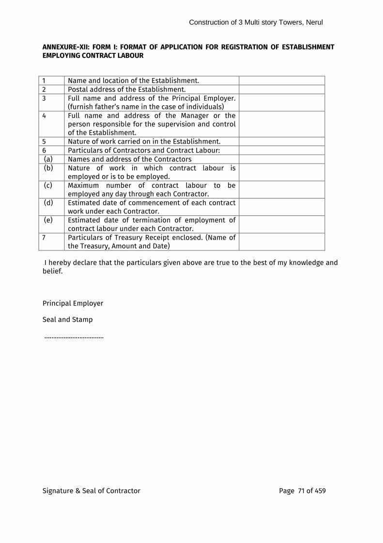
Construction of 3 Multi story Towers, Nerul
Signature & Seal of Contractor Page 71 of 459
ANNEXURE-XII: FORM I: FORMAT OF APPLICATION FOR REGISTRATION OF ESTABLISHMENT EMPLOYING CONTRACT LABOUR
1 Name and location of the Establishment. 2 Postal address of the Establishment. 3 Full name and address of the Principal Employer.
(furnish father’s name in the case of individuals)
4 Full name and address of the Manager or the person responsible for the supervision and control of the Establishment.
5 Nature of work carried on in the Establishment. 6 Particulars of Contractors and Contract Labour: (a) Names and address of the Contractors (b) Nature of work in which contract labour is
employed or is to be employed.
(c) Maximum number of contract labour to be employed any day through each Contractor.
(d) Estimated date of commencement of each contract work under each Contractor.
(e) Estimated date of termination of employment of contract labour under each Contractor.
7 Particulars of Treasury Receipt enclosed. (Name of the Treasury, Amount and Date)
I hereby declare that the particulars given above are true to the best of my knowledge and belief.
Principal Employer
Seal and Stamp
…………………………….

Construction of 3 Multi story Towers, Nerul
Signature & Seal of Contractor Page 72 of 459
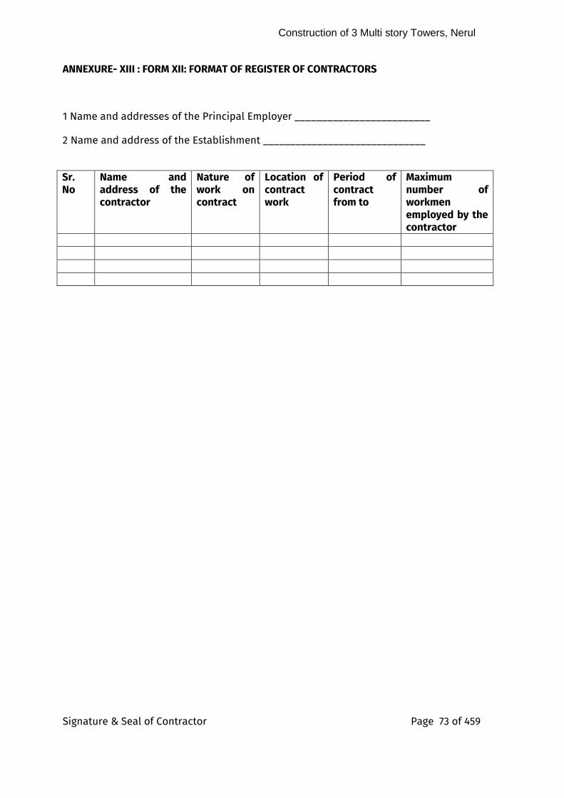
Construction of 3 Multi story Towers, Nerul
Signature & Seal of Contractor Page 73 of 459
ANNEXURE- XIII : FORM XII: FORMAT OF REGISTER OF CONTRACTORS
1 Name and addresses of the Principal Employer _________________________
2 Name and address of the Establishment ______________________________
Sr. No
Name and address of the contractor
Nature of work on contract
Location of contract work
Period of contract from to
Maximum number of workmen employed by the contractor
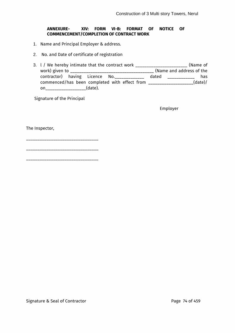
Construction of 3 Multi story Towers, Nerul
Signature & Seal of Contractor Page 74 of 459
ANNEXURE- XIV: FORM VI-B: FORMAT OF NOTICE OF COMMENCEMENT/COMPLETION OF CONTRACT WORK
1. Name and Principal Employer & address.
2. No. and Date of certificate of registration
3. l / We hereby intimate that the contract work _______________________ (Name of work) given to _____________________________________ (Name and address of the contractor) having Licence No._____________ dated ____________ has commenced/has been completed with effect from ____________________(date)/ on__________________(date).
Signature of the Principal
Employer
The Inspector,
________________________________
________________________________
________________________________

Construction of 3 Multi story Towers, Nerul
Signature & Seal of Contractor Page 75 of 459
ANNEXURE- XV : FORM XXV: FORMAT OF ANNUAL RETURN OF THE PRINCIPAL EMPLOYER TO BE SENT TO THE REGISTERING OFFICER Sr. No
Year ending 31st December
1 Full name and address of the Principal employer 2 Name of the Establishment.
( a ) District ( b ) Postal Address
( c ) Nature of operation/industry/work carried on
3 Full name of the Manager or person responsible for supervision control of the Establishment.
4 Number of Contractors who worked in the Establishment during the year (Given details as per proforma below).
5 Nature of work/operations on which contract labour was employed.
6 Total number of days during the year on which contract labour was employed.
7 Total number of man days worked by contract labour during the year.
8 Maximum number of workmen employed directly on any day during the year.
9 Total number of days during the year on which direct labour was employed.
10 Total number of man days worked by directly employed workmen.
11 Changes, if any, in the management of the establishment, its location or any other particulars furnished to the Registering Officer in the application for Registration indicating also the dates.
Place_____________
Date______________
Principal Employer
Name …………………………….
Construction of 3 Multi story Towers, Nerul
Signature & Seal of Contractor Page 76 of 459
51.0 Programme charts and Progress Report: i) As soon as the contract is awarded, a suitable program of work, preferably in the form of a bar / PERT chart shall be drawn up for completion of the different stages of the work, so as to ensure its completion within the allotted period of time. This program shall be submitted by the contractor in consultation with Architect/APMC or Site Engineer.
ii) The monthly progress chart as given in annexure-X indicating there in the programme and progress achieved both physical and financial with reasons for short fall, if any, shall be sent by the Site Engineer/APMC to concerned Department of the Bank before 10th of the following month.
52.0 Co-ordination and Monitoring:
i) It is the prime responsibility of the architects/APMC to ensure that execution of the work progresses smoothly in accordance with the programme and in proper co-ordination among different agencies.
ii) The Architects/APMC shall keep a close watch on the progress of work, the resources position etc. and take suitable timely remedial measures to sort out the bottlenecks in consultation with the concerned Department of the Bank.
iii) Site meetings shall be held at periodical intervals at least once in a month or at closer intervals where Architect/APMC/Site Engineer/Bank’s Engineer and the representatives of various agencies who are involved in the project shall attend and review the progress of work and sort out hindrances, if any.
iv) Concerned Project Engineers/A.G.M./DGM shall attend site meetings as often as possible in the interest of expeditious progress of the work. Minutes of the site meetings shall be prepared by the Architects/APMC and furnished to the concerned Department and others concerned immediately after of holding such meeting.
v) In terms of the contract provisions, the contractors for general building work are required to submit progress photographs (in triplicate) at the beginning of each month. The photographs shall be so taken in such a manner so as to give a fair idea of progress of construction and the date of photographs taken shall be written on the reverse.
vi) As a faster means of coordination and monitoring, the use of advanced technology may be used.
53.0 Testing of materials and approval: i) To ensure use of quality materials and to exercise proper quality control on the works, certain tests are to be undertaken regularly by the contractor during the progress of the work as per the provisions of the contract. Some of the important tests that are to be carried out on the construction materials are such as water, steel, bricks, cement, tiles, timber, particle boards, aggregates, pipes, fittings, concrete, wires/cables, M.S. sheets, conduits, earth pits and these shall be conducted as per the relevant BIS specifications/agreement at the Government approved Technical Institutes/Laboratories. Report on these tests shall be forwarded to the Architects/APMC who shall duly certify the
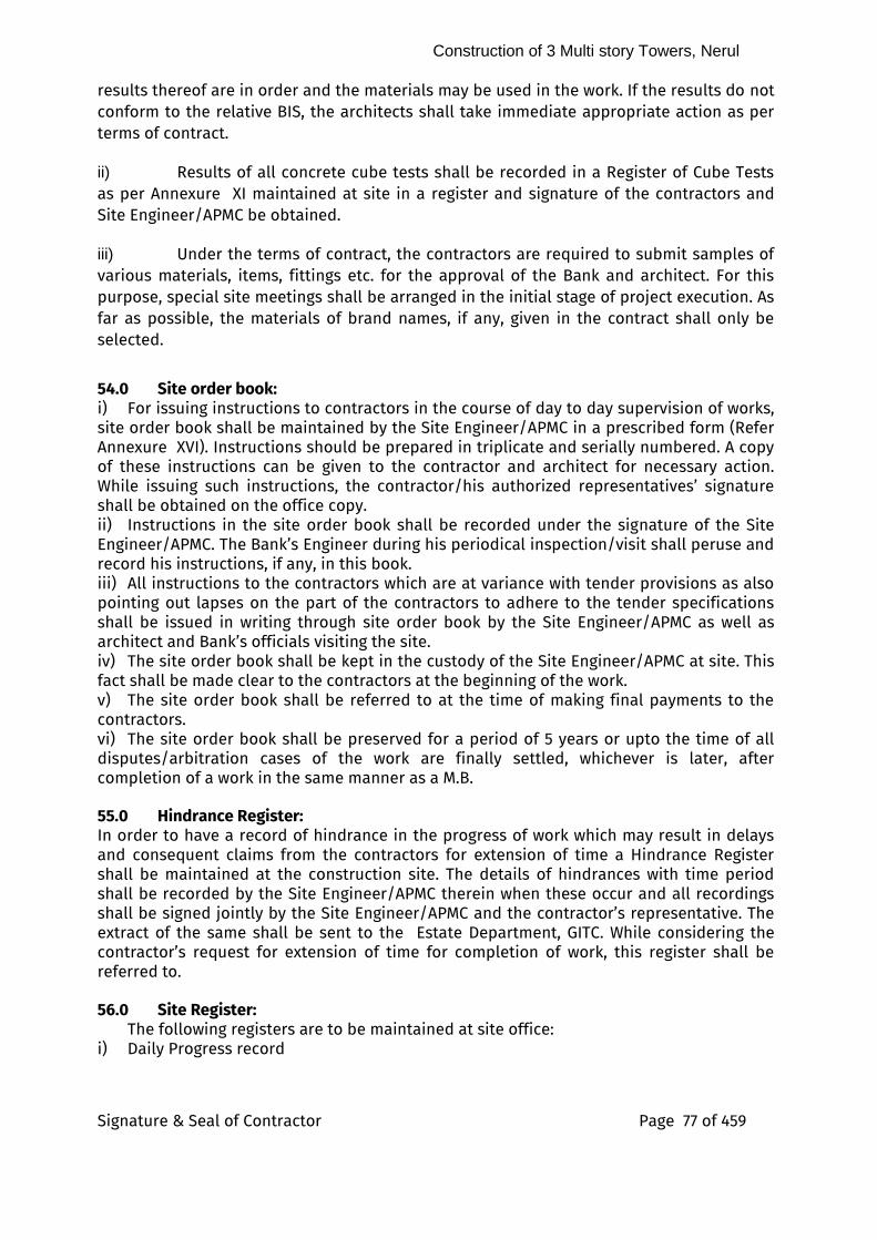
Construction of 3 Multi story Towers, Nerul
Signature & Seal of Contractor Page 77 of 459
results thereof are in order and the materials may be used in the work. If the results do not conform to the relative BIS, the architects shall take immediate appropriate action as per terms of contract.
ii) Results of all concrete cube tests shall be recorded in a Register of Cube Tests as per Annexure XI maintained at site in a register and signature of the contractors and Site Engineer/APMC be obtained.
iii) Under the terms of contract, the contractors are required to submit samples of various materials, items, fittings etc. for the approval of the Bank and architect. For this purpose, special site meetings shall be arranged in the initial stage of project execution. As far as possible, the materials of brand names, if any, given in the contract shall only be selected.
54.0 Site order book: i) For issuing instructions to contractors in the course of day to day supervision of works, site order book shall be maintained by the Site Engineer/APMC in a prescribed form (Refer Annexure XVI). Instructions should be prepared in triplicate and serially numbered. A copy of these instructions can be given to the contractor and architect for necessary action. While issuing such instructions, the contractor/his authorized representatives’ signature shall be obtained on the office copy. ii) Instructions in the site order book shall be recorded under the signature of the Site Engineer/APMC. The Bank’s Engineer during his periodical inspection/visit shall peruse and record his instructions, if any, in this book. iii) All instructions to the contractors which are at variance with tender provisions as also pointing out lapses on the part of the contractors to adhere to the tender specifications shall be issued in writing through site order book by the Site Engineer/APMC as well as architect and Bank’s officials visiting the site. iv) The site order book shall be kept in the custody of the Site Engineer/APMC at site. This fact shall be made clear to the contractors at the beginning of the work. v) The site order book shall be referred to at the time of making final payments to the contractors. vi) The site order book shall be preserved for a period of 5 years or upto the time of all disputes/arbitration cases of the work are finally settled, whichever is later, after completion of a work in the same manner as a M.B. 55.0 Hindrance Register: In order to have a record of hindrance in the progress of work which may result in delays and consequent claims from the contractors for extension of time a Hindrance Register shall be maintained at the construction site. The details of hindrances with time period shall be recorded by the Site Engineer/APMC therein when these occur and all recordings shall be signed jointly by the Site Engineer/APMC and the contractor’s representative. The extract of the same shall be sent to the Estate Department, GITC. While considering the contractor’s request for extension of time for completion of work, this register shall be referred to. 56.0 Site Register: The following registers are to be maintained at site office: i) Daily Progress record
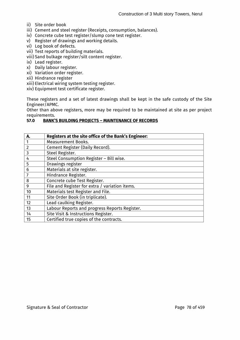
Construction of 3 Multi story Towers, Nerul
Signature & Seal of Contractor Page 78 of 459
ii) Site order book
iii) Cement and steel register (Receipts, consumption, balances). iv) Concrete cube test register/slump cone test register. v) Register of drawings and working details. vi) Log book of defects. vii) Test reports of building materials. viii) Sand bulkage register/silt content register. ix) Lead register. x) Daily labour register. xi) Variation order register. xii) Hindrance register xiii) Electrical wiring system testing register. xiv) Equipment test certificate register. These registers and a set of latest drawings shall be kept in the safe custody of the Site Engineer/APMC. Other than above registers, more may be required to be maintained at site as per project requirements. 57.0 BANK’S BUILDING PROJECTS – MAINTENANCE OF RECORDS
A. Registers at the site office of the Bank’s Engineer: 1 Measurement Books. 2 Cement Register (Daily Record). 3 Steel Register. 4 Steel Consumption Register – Bill wise. 5 Drawings register 6 Materials at site register. 7 Hindrance Register. 8 Concrete cube Test Register. 9 File and Register for extra / variation items. 10 Materials test Register and File. 11 Site Order Book (in triplicate). 12 Lead caulking Register. 13 Labour Reports and progress Reports Register. 14 Site Visit & Instructions Register. 15 Certified true copies of the contracts.
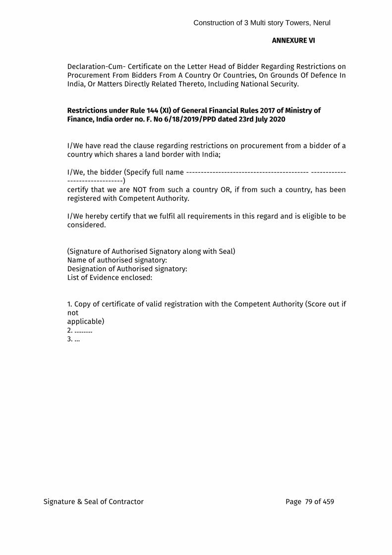
Construction of 3 Multi story Towers, Nerul
Signature & Seal of Contractor Page 79 of 459
ANNEXURE VI Declaration-Cum- Certificate on the Letter Head of Bidder Regarding Restrictions on Procurement From Bidders From A Country Or Countries, On Grounds Of Defence In India, Or Matters Directly Related Thereto, Including National Security. Restrictions under Rule 144 (XI) of General Financial Rules 2017 of Ministry of Finance, India order no. F. No 6/18/2019/PPD dated 23rd July 2020
I/We have read the clause regarding restrictions on procurement from a bidder of a country which shares a land border with India; I/We, the bidder (Specify full name ------------------------------------------ -------------------------------) certify that we are NOT from such a country OR, if from such a country, has been registered with Competent Authority. I/We hereby certify that we fulfil all requirements in this regard and is eligible to be considered. (Signature of Authorised Signatory along with Seal) Name of authorised signatory: Designation of Authorised signatory: List of Evidence enclosed: 1. Copy of certificate of valid registration with the Competent Authority (Score out if not applicable) 2. ………. 3. …
Construction of 3 Multi story Towers, Nerul
Signature & Seal of Contractor Page 80 of 459
ARTICLES OF AGREEMENT
7)
8)
14.1)
9) 10) 11) 12)
Construction of 3 Multi story Towers, Nerul
Signature & Seal of Contractor Page 81 of 459
Agreement for _______________________________________________________ Between
State Bank of India
And
__________________________________
Date of Commencement: ________________________
THIS Agreement is made on ____day of ……………2022 (hereinafter referred to as
“Agreement”) by and between State Bank of India, a corporation incorporated under State
Bank of India Act 1955 having its Global IT Centre at Sector 11, CBD Belapur, Navi Mumbai,
Maharashtra, India 400614 through F&OA Department, EstateDepartment (hereinafter
referred to as the "Bank/SBI”) and which expression shall unless repugnant to the context,
mean and include its successors and assigns,
And
M/s____________ incorporated under the Companies Act 1956 having its registered Office
at____________ <Please provide address of the Service Provider> (hereinafter referred to as
the "Service Provider / Contractor/ Agency“) which expression unless repugnant to the
context shall mean and include its successors and permitted assigns.
SBI and M/s____________ are each sometimes referred to individually as a "Party" and
together as the "Parties."
WHEREAS, the Bank is desirous for__________________________<name of services>. as
described in the Request for Proposal (read with its corrigendum and clarifications) No.
___________________ dated ________________ (hereinafter referred as “RFP” and annexed
as Annexure-A):
(i) Work Order No………..dated _______________________________ (hereinafter
referred as “PO/ Work Order” and annexed as Annexure-B) and the same
shall be part of this Agreement;
(ii) _________________; and
Construction of 3 Multi story Towers, Nerul
Signature & Seal of Contractor Page 82 of 459
Service Provider has agreed to provide the product/services as may be required by the
Bank under the RFP.
NOW THEREFORE, in consideration of the mutual covenants, undertakings and conditions
set forth below, and for other valid consideration the acceptability and sufficiency of
which are hereby acknowledged, the Parties hereby agree as follows:
1 COMMENCEMENT & TERM:
1.1 This Agreement shall commence from its date of execution mentioned above/
deemed to have commenced from _______ (Effective Date).
1.2 This Agreement shall be in force till accepatance and approval of Complete Project
Closure Report as per clause no 1.1.11 of General Conditions of Contract of the RFP
unless terminated by the Bank by notice in writing in accordance with the termination
clauses of the RFP.
1.3 Unless terminated earlier in accordance with this Agreement, the Agreement shall
come to an end on completion of the term specified in the Agreement or on
expiration of the renewed term.
2 SCOPE OF SERVICES:
2.1 The scope is defined in the RFP and PO
3 FEES, TAXES DUTIES & PAYMENTS:
3.1 Service Provider shall be paid fees and charges in the manner detailed in RFP and
PO, the same shall be subject to deduction of income tax thereon wherever required
under the provisions of the Income Tax Act by the Bank. The remittance of amounts
so deducted and issuance of certificate for such deductions shall be made by the
Bank as per the laws and regulations for the time being in force. Nothing in the
Agreement shall relieve Service Provider from his responsibility to pay any tax that
may be levied in India on income and profits made by Service Provider in respect of
this Agreement.
3.1.1 _________________1
3.1.2 ________________
1 Please provide the payment details.
Construction of 3 Multi story Towers, Nerul
Signature & Seal of Contractor Page 83 of 459
3.2 Payments
3.2.1 The payment for the works to be executed under this Agreement shall be made as
described under RFP and PO..
4 MISCELLANEOUS:
4.1 Any provision of this Agreement may be amended or waived, if, and only if such
amendment or waiver is in writing and signed, in the case of an amendment by each
party, or in this case of a waiver, by the Party against whom the waiver is to be
effective.
4.2 No failure or delay by any Party in exercising any right, power or privilege hereunder
shall operate as a waiver thereof nor shall any single or partial exercise of any other
right, power of privilege. The rights and remedies herein provided shall be
cumulative and not exclusive of any rights or remedies provided by law.
4.3 If this Agreement is signed in counterparts, each counterpart shall be deemed to be
an original.
4.4 Service Provider agrees that they shall not use the logo, trademark, copy rights or
other proprietary rights of the Bank in any advertisement or publicity materials or
any other written communication with any other party, without the prior written
consent of the Bank.
5 ENTIRE AGREEMENT
5.1 This Agreement constitutes the entire agreement between the Parties with respect to
the subject matter hereof and supersedes all prior written agreements, undertakings,
understandings and negotiations, both written and oral, between the Parties with
respect to the subject matter of the Agreement, except which are expressly annexed
or attached to this Agreement and saved by this Agreement. No representation,
inducement, promise, understanding, condition or warranty not set forth herein has
been made or relied upon by any Party hereto.
5.2 The following documents along with all addenda issued thereto shall be deemed to
form and be read and construed as integral part of this Agreement and in case of any
contradiction between or among them the priority in which a document would prevail
over another would be as laid down below beginning from the highest priority to the
lowest priority:
5.2.1 This Agreement;
Construction of 3 Multi story Towers, Nerul
Signature & Seal of Contractor Page 84 of 459
5.2.2 RFP
5.2.3 Purchase Order/Work Order
IN WITNESS WHEREOF, the parties hereto have caused this Agreement to be executed by
their duly authorized representatives as of the date and day first mentioned above.
State Bank of India …………………………………………
By____________________________ By______________________________ Authorized Signature Authorized Signature
Name__________________________ Name____________________________ Designation_____________________ Designation_______________________ Date:__________________________ Date:____________________________
Witness:________________________ Witness:__________________________
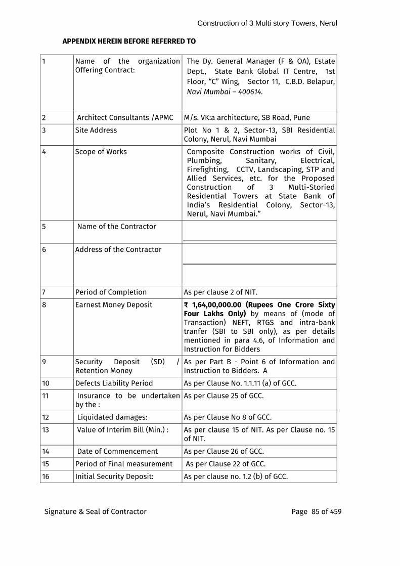
Construction of 3 Multi story Towers, Nerul
Signature & Seal of Contractor Page 85 of 459
APPENDIX HEREIN BEFORE REFERRED TO
1 Name of the organization Offering Contract:
The Dy. General Manager (F & OA), Estate Dept., State Bank Global IT Centre, 1st Floor, “C” Wing, Sector 11, C.B.D. Belapur, Navi Mumbai – 400614.
2 Architect Consultants /APMC M/s. VK:a architecture, SB Road, Pune
3 Site Address Plot No 1 & 2, Sector-13, SBI Residential Colony, Nerul, Navi Mumbai
4 Scope of Works Composite Construction works of Civil, Plumbing, Sanitary, Electrical, Firefighting, CCTV, Landscaping, STP and Allied Services, etc. for the Proposed Construction of 3 Multi-Storied Residential Towers at State Bank of India’s Residential Colony, Sector-13, Nerul, Navi Mumbai.”
5 Name of the Contractor
6 Address of the Contractor
7 Period of Completion As per clause 2 of NIT.
8 Earnest Money Deposit ₹ 1,64,00,000.00 (Rupees One Crore Sixty Four Lakhs Only) by means of (mode of Transaction) NEFT, RTGS and intra-bank tranfer (SBI to SBI only), as per details mentioned in para 4.6, of Information and Instruction for Bidders
9 Security Deposit (SD) / Retention Money
As per Part B - Point 6 of Information and Instruction to Bidders. A
10 Defects Liability Period As per Clause No. 1.1.11 (a) of GCC.
11 Insurance to be undertaken by the :
As per Clause 25 of GCC.
12 Liquidated damages: As per Clause No 8 of GCC.
13 Value of Interim Bill (Min.) : As per clause 15 of NIT. As per Clause no. 15 of NIT.
14 Date of Commencement As per Clause 26 of GCC.
15 Period of Final measurement As per Clause 22 of GCC.
16 Initial Security Deposit: As per clause no. 1.2 (b) of GCC.
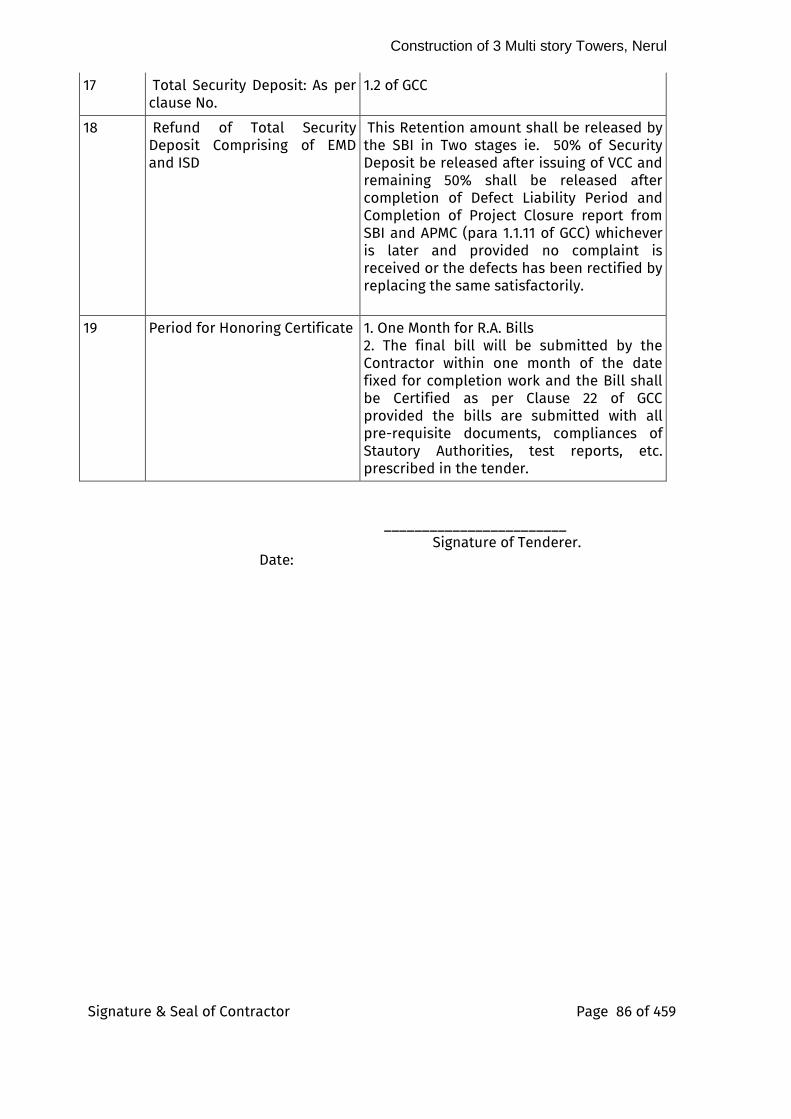
Construction of 3 Multi story Towers, Nerul
Signature & Seal of Contractor Page 86 of 459
17 Total Security Deposit: As per clause No.
1.2 of GCC
18 Refund of Total Security Deposit Comprising of EMD and ISD
This Retention amount shall be released by the SBI in Two stages ie. 50% of Security Deposit be released after issuing of VCC and remaining 50% shall be released after completion of Defect Liability Period and Completion of Project Closure report from SBI and APMC (para 1.1.11 of GCC) whichever is later and provided no complaint is received or the defects has been rectified by replacing the same satisfactorily.
19 Period for Honoring Certificate 1. One Month for R.A. Bills
2. The final bill will be submitted by the Contractor within one month of the date fixed for completion work and the Bill shall be Certified as per Clause 22 of GCC provided the bills are submitted with all pre-requisite documents, compliances of Stautory Authorities, test reports, etc. prescribed in the tender.
________________________
Signature of Tenderer. Date:
Construction of 3 Multi story Towers, Nerul
Signature & Seal of Contractor Page 87 of 459
SPECIAL CONDITIONS OF CONTRACT (SCC)
GENERAL
1) Unless otherwise specified, IS Codes, NBC Guidelines, CPWD Specifications 2019 volume I - II with correction slips up to 28.02.2022 shall be followed. Any additional item of work, if taken up subsequently, shall also conform to the relevant IS Code, CPWD specifications mentioned above. Should there be any difference or discrepancy between the description of items as given in the schedule of quantities, particular specifications for individual items of work and I.S. Codes etc., the following order of preference shall be observed;
i) Minimum specification and standards, Tender Drawings, Schedule of Quantities
ii) Particular Specifications, Special Conditions
iii) CPWD Specifications.
iv)Indian Standard Specifications of BIS
v) National Building Code 2016 with up-to-date amendments
vi) Sound engineering practices as per directions of the APMC/SBI
2) The work shall be carried out in accordance with the Architectural drawings, structural drawings & MEP drawings, relevant codes, specifications etc. before commencement of any item of work, the contractor shall correlate all the relevant architectural and structural drawings issued for the work and satisfy himself that the information available therein is complete, suitable and unambiguous. The discrepancy, if any, shall be brought to the notice of the APMC/SBI before execution of the work, The contractor shall be solely responsible for any loss or damage occurring by the commencement of work on the basis of any erroneous and or incomplete information. The APMC /SBI, in no case, shall be held responsible for the accuracy thereof and/or interpretations or conclusions drawn there from by the Contractor and all consequences shall be borne by the Contractor. It is presumed that the Contractor shall satisfy himself for all possible contingencies, incidental charges, wastage, bottlenecks etc. likely during execution of work and acts of coordination which may be required. Nothing extra shall be payable on this account.
3) The work shall be carried out, all in accordance with true intent and meaning of the specifications and the drawings taken together, regardless of whether the same may or may not be particularly shown on the drawings
Construction of 3 Multi story Towers, Nerul
Signature & Seal of Contractor Page 88 of 459
and/or described in the specifications, provided that the same can be reasonably inferred. There may be several incidental works, which are not
mentioned in the scope of work but will be necessary to complete the item in all respect. All these incidental works/ costs which are not mentioned in specifications / drawings / tender document but are necessary to complete the item shall be deemed to have been included in the rates quoted by the contractor. No adjustment of rates shall be made for any variation in quantum of incidental works due to variation / change in actual working drawings. Also, no adjustment of rates shall be made due to any change in incidental works or any other deviation in such element of work (which is incidental to the items of work and are necessary to complete such items in all respects) on account of the directions of APMC /SBI. Nothing shall be payable on the account of incidental works.
4) If any further details/elaboration or any miscellaneous clarifications etc. to the attached drawings required to the contractor for execution of work, the same may be asked by the contractor at least one month prior to its requirement so that consultant of the work may provide within a month to him. No hindrance shall be given on this account. Requirement of more Elaboration/detailing/Miscellaneous Drawings as required by contractor and provided by the consultant/department shall not mean change of Scope of Work etc. and for that nothing extra shall be payable to contractor.
5) In the event of any variation/ discrepancy in the drawings, specifications and tender Documents etc. the decision of the APMC /SBI shall be final binding and conclusive on the contractor and in the case the contractor
have any doubt and the same should be got clarified immediately from the APMC /SBI and no claim of the contractor shall be entertained thereafter. Moreover, the agency is not allowed to take benefit out of any clerical/ grammatical mistake in the standard clauses/Specifications etc. being used in the agreement.
6) Existing drains, pipes, cables, over-head wires, sewer lines, water lines
and similar services encountered in the course of the execution of work shall be protected against the damage by the contractor, in case any damages to such existing services take place the same shall be rectified by the contractor at his own expense to the satisfaction of the APMC /SBI. The contractor shall not store materials or otherwise occupy any part of the site
in a manner likely to hinder the operation of such services.
7) Existing Storm water drains around periphery of site shall be maintained by the Contractor free of cost by regular cleaning, repairing, protecting, Debris removing, making smooth path for the flow of storm water.
Construction of 3 Multi story Towers, Nerul
Signature & Seal of Contractor Page 89 of 459
8) The contractor shall be responsible for the watch and ward / guard of the buildings, safety of all fittings and fixtures including sanitary and water
supply fittings and fixtures provided by him against theft/ pilferage and breakage during the period of installations and thereafter till the building is physically handed over to the department.
9) The entire work up to the plinth level, as required for obtaining approval up to the plinth (Further commencement certificate after plinth level) from the local authority, shall be completed by the Contractor simultaneously. Work above plinth shall be allowed to be carried out only after obtaining approval from the local body. No delay shall be allowed on this ground and also no claim whatsoever on account of any delay in approval at plinth level by the local body shall be entertained from the Contractor.
10) The rates quoted by the Contractor are deemed to be inclusive of site clearance, setting out work, profile, establishment of reference bench mark(s), taking spot levels, construction of all safety and protection devices, barriers, preparatory works, working during monsoon, working at all depths, height, lead, lift and location and any other incidental works required to complete this work.
11) For works below ground level the contractor shall keep that area free from water. If dewatering or bailing out of water is required, the same shall be responsibility of contractor. Nothing extra shall be paid on this account.
12) Any legal or financial implications resulting out of disposal of earth shall be carried out by the contractor at his own cost. Nothing extra shall be payable on these accounts
13) The Contractor shall keep himself fully informed of all acts and laws of the Central & State Governments, all orders, decrees of statutory bodies, tribunals having any jurisdiction or authority, which in any manner may affect those engaged or employed and anything related to carrying out the work. All the rules & regulations and bye-laws laid down by local body and any other statutory bodies shall be adhered by the contractor, during the execution of work. The Contractor shall also adhere to all traffic restrictions notified by the local authorities.
14) The cost of water for construction and labours (for municipal water connection as well as tanker water) shall be borne by the contractor. Also, if the contractor obtains water connection for the drinking purposes from the municipal authorities or any other statutory body, the consequent charges shall be borne by the contractor. All statutory taxes, levies, charges (including water and sewerage charges, charges for temporary service

Construction of 3 Multi story Towers, Nerul
Signature & Seal of Contractor Page 90 of 459
connections and / or any other charges) payable to such authorities for carrying out the work, shall be borne by the Contractor.
15) The Contractor shall arrange to give all notices as required by any statutory / regulatory authority for labour licenses, registration with EPFO, ESIC and BOCW Welfare Board etc. and shall pay to such authority all the fees, cess, labour cess, etc. that is required to be paid for the execution of work. He shall protect and indemnify the Department and its officials & employees against any claim and /or liability arising out of violations of any such laws, ordinances, orders, decrees, by himself or by his employees or his authorized representatives. Nothing extra shall be payable on these accounts.
16) All payments or fees related to all works shall be payable to Government/ Local Body including statutory payments demanded either in the name of Customs Department Contractor for obtaining the various applicable permissions/ all required and applicable Approvals/licenses like CFO approvals, excavation approval, Certificate and making and getting all permanent civil and E & M service connections, Payments payable to electrical supply company etc. for the scope of this work shall be borne by the Contractor. No extra payment shall be done to Contractor on this account.
17) Royalty at the prevailing rates shall be paid by the Contractor on all materials such as boulders, metals, sand and bajri etc. collected by him for the execution of the work, directly to the revenue authority of the state government concerned.
18) No foreign exchange shall be made available by the Department for importing (purchase) of equipment, plants, machinery, materials of any kind or any other items required to be carried out during execution of the work. No delay and no claim of any kind shall be entertained.
19) The Contractor shall carry out his work so as not to interfere with or hinder the progress of the work being carried out by any other agency. As far as possible, he shall arrange his work and place, so as not to interfere with the operations of other Contractors or shall arrange his work with that of the others, in an acceptable and coordinated manner and shall perform it in proper sequence
20) If the work is carried out in more than one shift or during night, no claim on this account shall be entertained. The agency must take permission from the police authorities etc. if required for work during night hours, no claim / hindrance on this account shall be considered if work is not allowed during
Construction of 3 Multi story Towers, Nerul
Signature & Seal of Contractor Page 91 of 459
night time.
21) The Contractor shall assume all liability, financial or otherwise in connection with this contract and shall protect and indemnify the SBI from any and all damages and claims that may arise on any account. The Contractor shall indemnify the SBI against all claims in respect of patent rights, royalties, design, trademarks of name or other protected rights, damages to adjacent buildings, roads or members of public, residents, visitors, other agencies/vendor’s workers, etc. at SBI Residential Colony at Sector 13, Nerul & their vehicles in course of execution of work or any other reasons whatsoever, and shall himself defend all actions arising from such claims and shall indemnify the SBI in all respect from such actions, costs and expenses. Nothing extra shall be payable on this account.
22) The Contractor shall make all necessary arrangements for protection from rains, the work already executed and for carrying out the further work, during monsoon including providing and fixing temporary shelters, protections etc.
23) In case of flooding of site on account of rain or any other cause and any consequent damage, whatsoever, no claim financially or otherwise shall be entertained not withstanding any other provisions elsewhere in the contract agreement. Also, the Contractor shall make good, at his own cost, the damages caused, if any.
24) The Contractor shall take all necessary precautions to prevent any nuisance or inconvenience to the owners, tenants or occupants of the adjacent properties and to the public in general. The Contractor shall take all care, as not to damage any other adjacent property or other services running adjacent to the plot. If any damage is done, the same shall be made
good by the Contractor at his own cost and to the entire satisfaction of the APMC /SBI. The Contractor shall use such methodology and equipment for
execution of the work, so as to cause minimum environmental pollution of any kind during construction, to have minimum construction time and
minimum inconvenience to road users and to the occupants of the buildings on the adjacent plot and public in general, etc. He shall make good
at his own cost and to the entire satisfaction of the APMC /SBI any damage to roads, paths, cross drainage works or public or private property whatsoever
caused, due to the execution of the work or by traffic brought thereon, by the Contractor. Further, the Contractor shall take all precautions to prevent any pollution of streams and waterways. All waste or superfluous materials shall be carted away by the Contractor, entirely to the satisfaction of the APMC /SBI. Utmost care shall be taken to keep the noise level to the barest
Construction of 3 Multi story Towers, Nerul
Signature & Seal of Contractor Page 92 of 459
minimum so that no disturbance as far as possible is caused to the occupants / users of adjoining buildings. No claim what so ever on account
of site constraints mentioned above or any other site constraints not specifically stated here, shall be entertained from the Contractor. Therefore, the Contractors are advised to visit site and get first-hand information of site constraints. They should quote their rates accordingly.
25) The quoted rates shall also be inclusive of all ancillary/enabling and incidental works required for execution of work like labour camp, stores, fabrication yard, offices, watch and ward, temporary structure for plants and machineries, scaffolds, H frames, Props, Spans, Cup lock system, Safety Platforms, Covering external scaffold with green shade nets, polypropylene sheets to avoid direct fall of any materials from higher side, Safety equipment, watch and ward security, vehicles, labs, water storage tanks,
arrangement for temporary connection for electricity, telephone, water etc. including their consumption charges, protection works, barricading, providing testing facilities / laboratory at site of work for various field and laboratory tests or any other activity which is necessary for execution of work and as directed by APMC /SBI. Before start of the work, the Contractor shall obtain approval of the APMC /SBI, before locating various temporary structures/ site office, positioning of machinery, material yard, cement and other storage, steel fabrication yard, site laboratory, water tank, etc.
26) The Contractor shall display all permissions, licenses, registration certificates, bar charts, other statements etc. under various labour laws and other regulations applicable, at his site office.
27) The Contractor shall cooperate with and provide facilities to the sub- Contractors and other agencies working at site for smooth execution of the work. The Contractor shall
I) Properly co-ordinate his work with the work of other agencies.
ii) Provide control lines and benchmarks to his Sub-Contractors and the other Contractors.
Iii) Provide electricity at mutually agreed rates.
iv) Co-ordinate with other Contractors for leaving inserts, making chases, alignment of services etc. at site.
v) Adjust his work schedule and site activities in consultation with the APMC /SBI and other Contractors to suit the overall completion schedule.
vi) Resolve the disputes with other Contractor amicably and the APMC /SBI shall not be made intermediary or arbitrator. The contractor shall indemnify the SBI against any claim(s) arising out of such disputes.
Construction of 3 Multi story Towers, Nerul
Signature & Seal of Contractor Page 93 of 459
Vii) In case of variation / conflicting provisions is observed in any condition of bid document forming part of contract, the decision of
tender accepting authority shall be final and binding on the contractor
28) As Built Drawings
I) For the drawings issued to the contractor by the APMC . The APMC will issue two sets of drawings to the Contractor for the items for some changes have been made. From the approved drawings as instructed by the SBI / APMC The contractor will make the changes made on these copies and return these copies to the APMC for their approval. In cases revision is required or the corrections are not properly marked the APMC will point out the discrepancies to the contractor. The contractor will have to incorporated these corrections and / or attend to discrepancies either on copies as directed by the APMC and resubmit to him for approval. The APMC will return one copy duly approved by him.
ii) For the drawings prepared by the contractor
The contractor will modify the drawing prepared by him wherever the changes made by the SBI / APMC and submit two copies of such modified drawings to the APMC for approval. The APMC will return one copy of the approved drawing to the contractor.
30) SUFFICIENCY OF TENDER
The Tenderer shall be entirely responsible for sufficiency of rates quoted by him in his tender.
Sufficiency of tender prices: Subject to any provisions laid down in the tender document, the Contractor shall be deemed to have satisfied himself before submitting his tender as to the correctness and sufficiency of the tender and to have taken account of all that is required for the full and proper execution of the contract and to have included in his rates and prices all costs related to the completion of work.
31) PROGRAM /SCHEDULE
The Contractor shall prepare an integrated programme chart within fifteen days of issue of award letter including Civil as well as E & M activities for the execution of work, showing clearly all activities from the start of work to completion, with details of manpower, equipment and machinery required for the fulfillment of the program within the stipulated period and

Construction of 3 Multi story Towers, Nerul
Signature & Seal of Contractor Page 94 of 459
submit the same for approval of the APMC /SBI. These shall be submitted by the contractor through electronic media besides forwarding hard copies of
the same. The integrated programme chart so submitted should not have any discrepancy with the physical milestones attached in the contract agreement. The programme chart should include the following:
i) Descriptive note explaining sequence of various activities.
ii) Construction Programme prepared on PRIMAVERA/MS Project Software, which will indicate resources in financial terms, manpower and specialized equipment for every important stage. One planning engineer should be engaged in project who is familiar in PRIMAVERA/MS Project software. No extra payment shall be made in this regard to the contractor.
Iii) Programme for procurement of materials by the contractor.
iv) Programme for arranging and deployment of manpower both skilled and unskilled so as to achieve targeted progress.
v) Programme of procurement of machinery/equipment having adequate capacity, commensurate with the quantum of work to be done within the stipulated period, by the contractor.
vi) Programme for achieving fortnightly micro milestones and periodic milestones.
32) In case of noncompliance/delay in compliance in this, a recovery amount as specified in Schedule will be imposed which will be recovered from the immediate next R/A Bill of the Contractor.
33) If at any time, it appears to the APMC /SBI that the actual progress of work does not conform to the approved programme referred above, the contractor shall produce a revised program within seven days showing the modifications to the approved program by additional inputs to ensure completion of the work within the stipulated time. A recovery of amount/Penaulty as specified shall be made in case of delay as per
34) The submission for approval by the APMC /SBIof such programme or the furnishing of such particulars shall not relieve the contractor of any of his duties or responsibilities under the contract. This is without prejudice to the right of APMC /SBI to take action against the contractor as per terms and conditions of the agreement.
QUALITY ASSURANCE & TESTING OF MATERIALS
35) The contractor shall establish field laboratory at site including all necessary equipment for field tests as given in tender document. All the relevant and applicable standards and specifications shall be made available by the
Construction of 3 Multi story Towers, Nerul
Signature & Seal of Contractor Page 95 of 459
contractor at his cost in the field laboratory.
Quality Assurance Engineer of the contractor shall be responsible for carrying out
all mandatory field/ laboratory tests. The contractor shall so provide adequate supporting staff as his cost for carrying out field tests, packaging & forwarding of samples for outside laboratory tests and for maintaining test records. All the registers of tests carried out at site or in outside laboratories shall be maintained by the contractor. The test register shall be issued to the contractor by the APMC /SBI. All the entries in the test register will be made by the designated engineer of the contractor and same shall be regularly reviewed by the APMC /SBI or his authorized representatives at site.
36) The Contractor shall procure and provide all the materials from the manufacturers / suppliers as per the list attached with the tender documents, as per the conditions and specifications for the work. The equivalent brand for
any item shall be permitted to be used in the work, when any of the preferred make is not available. This is, however, subject to documentary evidence produced by the contractor regarding non availability of the preferred brand and also subject to independent verification by the APMC /SBI. In exceptional cases, where such approval is required, the decision of APMC /SBI as regards equivalent make of the material shall be final and binding on the Contractor. No claim, whatsoever, of any kind shall be entertained from the Contractor on this account. Also, the sample work/ material shall be procured only after obtaining written approval of the APMC /SBI.
37) All materials shall be got checked by the APMC /SBI or his authorized supervisory staff on receipt of the same at site before use.
38) The Contractor or his authorized representative shall associate in collection, preparation, forwarding and testing of such samples. In case he or his authorized representative is not present or does not associate him, the result of such tests and consequences thereon shall be binding on the Contractor. The Contractor or his authorized representative shall remain in contact with the APMC/SBI or his authorized representative associated for all such operations. No claim of payment or claim of any other kind, whatsoever, shall be entertained from the Contractor.
39) All the hidden/Buried/ Concealed items such as water supply lines, drainage pipes, conduits, sewers etc. are to be properly tested as per the design conditions before covering.
40) Water tanks, taps, sanitary, water supply and drainage pipes, fittings and accessories should conform to bylaws and municipal body/ corporation where Specifications are not available.
Construction of 3 Multi story Towers, Nerul
Signature & Seal of Contractor Page 96 of 459
41) BIS marked materials except otherwise specified shall be subjected to quality test at the discretion of the APMC /SBI besides testing of other materials as per
the specifications described for the item/material. Wherever BIS marked materials are brought to the site of work, the agency shall, if required, by the APMC /SBI, furnish manufacturer’s test certificate or test certificate from approved testing laboratory to establish that the material / procured by the agency for incorporation in the work satisfies the provisions of specifications / BIS codes relevant to the material and / or the work done.
42) The contractor shall procure the required materials in advance so that there is sufficient time to testing of the materials and clearance of the same before use in the work.
43) The contractor shall supply free of charge the materials required for testing including packing and transportation to testing laboratory. The testing of
materials shall be conducted in Govt. Laboratory/ Govt. colleges/ IITs/NITs or from the laboratory approved by APMC/SBI The charges for testing of materials shall be borne by the Contractor.
44) All expenditure to be incurred for testing of samples e.g., packaging, sealing, transportation, loading, unloading etc. including testing charges shall be borne by the contractor in all cases irrespective of testing results.
45) Contractor shall submit minimum “Quality Assurance” plan within 45
days after award of work which shall be consisting of:
46) Lot size, number of required tests and frequency of testing.
47) While deciding these criteria Tender Specifications & Provisions of BIS Codes and Standard Practices may be referred. Volume of work, Practical Difficulties
and Site Conditions etc. may also be kept in view. The lot size, number of tests and frequencies of testing can be altered or modified by the APMC /SBI from the prescribed limits.
48) It should clearly indicate the Machinery and other Tool & Plants required to be deployed at site by the agency. Entire Machinery and T&P may not be
required at the start of work, therefore, a proper time schedule by which each Machinery & T&P is to be brought at site should also be indicated.
49) The Contractor shall allow access to Third Party Quality Assurance (TPQA) Agency if any appointed by APMC/SBI or any other Committee related to
APMC/SBI which required to visit the site to have a control on quality and methodology of execution. Samples of materials including Cement Concrete Cubes shall be taken jointly by Contractor and APMC / APMC /SBI or his authorized representative. All arrangements for transporting and getting them tested shall be made by the Contractor.
Construction of 3 Multi story Towers, Nerul
Signature & Seal of Contractor Page 97 of 459
50) All material received at site shall be entered in MAS Register and copy of Supply order, Manufacturer’s Test Certificate & Bill-invoice shall be maintained
in order.
51) The MAS Registers, Cement Register, Steel Register, Paint and Chemical Register, Bitumen Register, Test Register etc. shall be maintained by a qualified staff of Contractor which may be inspected by APMC /SBI or his/her representative at any time. The daily report of receipt of material shall be sent to Project Manager / Project Architect of APMC or his/her representative.
52) The safe custody of all registers shall be the responsibility of Contractor. Submission of copy of all test registers and Material at Site Register along with each alternate Running Account Bill and Final Bill shall be mandatory.
53) As and when any important item is taken up for execution, the
Contractor shall submit the specifications and develop a checklist and Pour card. This sample checklist should be got approved from the
APMC /SBI and should be used at site. This check list should be shown to the APMC /SBI or his/her representative during inspection. This procedure is to be followed for all hidden items, CC/RCC work, Steel-reinforcement, shuttering,
flooring, doors & windows, plumbing, including water supply pipe lines, roof treatment, earth filling etc.
54) In addition, the contractor shall submit theoretical consumption statements for the items involving use of cement, steel reinforcement, chemical, paints, ready mix concrete , bitumen etc. as directed by the APMC /SBI along with every running account bill for record and reconciliation of material issued, consumed and balance.
55) These measurements shall then be 100% checked & verified by the authorized representatives of the APMC.. Subequently measurements shall be checked by SBI engineer as per SBI guidelines along with APMC. The contractor shall incorporate all such changes or corrections, as may be done during these checks, to his draft computerized measurements and submit the corrected computerized measurement Books with its pages machine numbered to the APMC /SBI.
56) The Computerized Measurement Book shall be allotted a serial number as per the Register of Computerized Measurement Books and processed for
payment.
57) PREPARATION OF SAMPLE FLATS
The contractor shall prepare one sample flat in actual position for each Type of flat comprising of all finishes and fittings included in the scope of this
Construction of 3 Multi story Towers, Nerul
Signature & Seal of Contractor Page 98 of 459
contract for approval of committee consisting of members from each discipline, of APMC and SBI. The work executed in approved sample flat in
actual position will form part of the work. However, any sample not approved will not form part of the main work and the contractor shall have to dismantle and remove the same from the site of work as his cost and shall prepare new sample for approval as per direction of the APMC /SBI. Nothing extra shall be paid on account of this.
58) FACILITIES AT SITE
I) The Contractor shall construct site office ( Permanent/semi-permanent structure) for staff, equipped with all necessary equipment required for functioning of the office. The area of the office shall accommodate pantry,
conference room, office rooms, toilets and other requisite facilities.
ii) The Contractor shall provide 4 number of computers (with minimum specification i5, 8GB RAM, 1 TB hard disc, 256 ssd, integrated graphic card), 1 laptops (with minimum specification i5, 8GB RAM, 1 TB hard disc, 256 ssd, 2GB dedicated graphic card) and 1 Tablets of Samsung or equivalent (with minimum specification 4G, VoLTE, Wi-Fi, Snapdragon 750G or equivalent, 2.2 GHz Processor, 6 GB RAM, 128 GB inbuilt,10000 mAh Battery with Fast Charging, Memory Card Supported, up to 1 TB ) along with two multi function
colour laser printers and two black and white laser printers etc. all new and in working condition with necessary peripherals. One colour printer (inkjet)
for A3 size shall also be provided. It’s O&M too is to be arranged by contractor by own cost.
Iv) The Contractor shall provide one land line with broadband connection.
V) The Contractor shall provide necessary Air Conditioners, lighting and fixtures i/c fans, RO purified drinking water etc. during the whole agreement period. AMC charges, Electricity bill, water supply bills, RO/drinking water bills, telephone charges, internet charges etc. shall be borne by the contractor.
Vi) The contractor shall provide the minimum required file/ Documeent storages and required infrastructure for a site office
vii) Security and watch and ward
viii) The contractor shall be responsible for security and watch and ward of
the office, records, furniture and fixtures.
ix) The contractor shall maintain the site office and its surroundings in a
Construction of 3 Multi story Towers, Nerul
Signature & Seal of Contractor Page 99 of 459
neat and clean condition for the entire duration of the construction. The toilet effluent shall be discharged into sewer line or soak pits without
causing unsanitary conditions in the surroundings. After completion of the work, site office shall be dismantled by the contractor and all the dismantled materials furniture fixtures shall be taken away at his cost.
X) Nothing extra shall be paid on account of this. The quoted rate by the contractor is inclusive of these facilities.
59.0 WATER / ELECTRICITY / TELEPHONE CONNECTION
I) The contractor shall make his own arrangement for water, electricity & telephone etc. for his use at his cost. The Contractor shall abide by the rules/ bye laws applicable in this regard and he shall be solely responsible for any penalty on account of violation
of any of the rules / bye laws in this regard. The Contractor shall indemnify the Department against any claim arising out of pilferage, theft, damage, penalty, non-settlement of bills etc. whatsoever on this account.
ii) The Department shall in no way be responsible for any delay in getting electric and water and telephone connections for execution of the work or not getting connections at all. No claim of any kind, whatsoever, on this account shall be entertained from the Contractor. The Contractor shall arrange electricity and water etc. at his own cost required for testing of the various electrical installations, testing of water supply, sanitary and drainage lines,
water proofing of underground and overhead tanks.
60.0 WATERPROOFING WORKS
The Contractor has to submit 10 Yr Guarantee bond for all Water
proofing works executed on site and in addition to Security Deposit additional 2.5% security deducted for completed work of the respective waterproofing work based on the cost of work executed. This security Deposit shall be released after satisfactory compliance of this 10 Yr Period. BG shall not be entertained for it.
Note : Interest shall not be paid on any security deposit, retention amount, etc., whatsover be the duration of it.
61.0 CLEANLINESS OF SITE
The Contractor shall not stack building material / malba / muck on the land or road of the local development authority or on the land owned by the others. The site of work shall be always kept
Construction of 3 Multi story Towers, Nerul
Signature & Seal of Contractor Page 100 of 459
clean. The Contractor shall take all care to prevent any water- logging at site. The waste water, slush etc. shall not be allowed to be
collected at site. It may be directly pumped out to public drainage system with the prior approval of the concerned authorities at his cost. The work shall be carried out in such a way that the entire area is kept clean and tidy.
62.0 SECURITY & TRAFFIC ARRANGEMENTS
I) In event of any restriction being imposed by the Department, traffic or any other statutory authority having control over the project, on the working or movement of Labour, materials, etc., the Contractor shall strictly follow all such restrictions or instructions
issued regarding the ii) same and nothing extra shall be payable to the Contractor on account of such restrictions or instructions. No delay or claims of any kind shall be entertained from the Contractor on this account.
Iii) The Contractor shall be wholly responsible for security of site and works. The Contractor shall be not permit entry of any unauthorized persons in the Site; and entry shall be limited to the Employees of the Contractor, Sub Contractor or persons authorized by the APMC/SBI
iv) Lighting: The contractor shall provide sufficient lighting at project site, during periods of insufficient natural light, if required.
63.0 PHOTOGRAPHY & VIDEOGRAPHY DOCUMENTATION : The Contractor shall undertake and carry out documenting the total sequences of
this project by way of photography, slides, video recording (including drone
recording after due approval from Local Authorities if required) etc. at his cost.
The original photographs & videos shall be the property of the SBI. No copy shall be
prepared by the contractor without prior approval of the APMC/SBI. The RCC &
RMC works for sub-structure & super- structure has to be photographed &
videographed for every slab level as well as foundation work, for each
important activities like Concreting, Reinforcement laying, Cube Casting etc. In
other cases the photography shall be taken at minimum of 2 weeks interval and
videography at a minimum of 4 weeks interval. The said soft copies shall be
shared by pen drive and also be stored in Hard disc of requisite capacity at site.
The positive of photographs in 4” x 6” size should be sequentially documentted
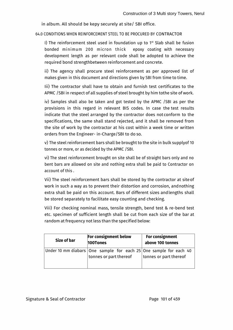
Construction of 3 Multi story Towers, Nerul
Signature & Seal of Contractor Page 101 of 459
in album. All should be kepy securely at site/ SBI office.
64.0 CONDITIONS WHEN REINFORCEMENT STEEL TO BE PROCURED BY CONTRACTOR
I) The reinforcement steel used in foundation up to 1st Slab shall be fusion
bonded minimum 200 micron thick epoxy coating with necessary development length as per relevant code shall be adopted to achieve the
required bond strength between reinforcement and concrete.
ii) The agency shall procure steel reinforcement as per approved list of makes given in this document and directions given by SBI from time to time.
Iii) The contractor shall have to obtain and furnish test certificates to the APMC /SBI in respect of all supplies of steel brought by him to the site of work.
iv) Samples shall also be taken and got tested by the APMC /SBI as per the provisions in this regard in relevant BIS codes. In case the test results indicate that the steel arranged by the contractor does not conform to the specifications, the same shall stand rejected, and it shall be removed from the site of work by the contractor at his cost within a week time or written orders from the Engineer- in-Charge/SBI to do so.
v) The steel reinforcement bars shall be brought to the site in bulk supply of 10 tonnes or more, or as decided by the APMC /SBI.
vi) The steel reinforcement brought on site shall be of straight bars only and no bent bars are allowed on site and nothing extra shall be paid to Contractor on account of this .
Vii) The steel reinforcement bars shall be stored by the contractor at site of work in such a way as to prevent their distortion and corrosion, and nothing extra shall be paid on this account. Bars of different sizes and lengths shall be stored separately to facilitate easy counting and checking.
Viii) For checking nominal mass, tensile strength, bend test & re-bend test etc. specimen of sufficient length shall be cut from each size of the bar at
random at frequency not less than the specified below:
Size of bar For consignment below
100Tones
For consignment above 100 tonnes
Under 10 mm dia bars One sample for each 25 tonnes or part thereof
One sample for each 40 tonnes or part thereof
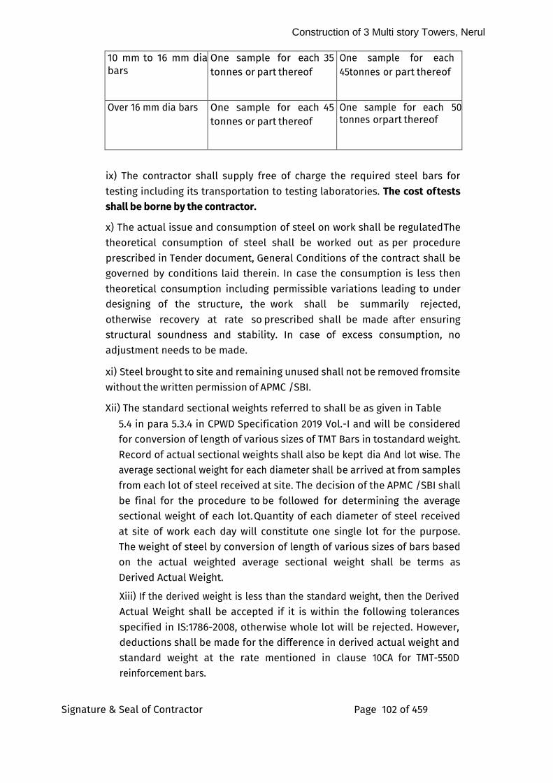
Construction of 3 Multi story Towers, Nerul
Signature & Seal of Contractor Page 102 of 459
10 mm to 16 mm dia bars
One sample for each 35 tonnes or part thereof
One sample for each 45tonnes or part thereof
Over 16 mm dia bars One sample for each 45 tonnes or part thereof
One sample for each 50 tonnes or part thereof
ix) The contractor shall supply free of charge the required steel bars for testing including its transportation to testing laboratories. The cost of tests shall be borne by the contractor.
x) The actual issue and consumption of steel on work shall be regulated The theoretical consumption of steel shall be worked out as per procedure
prescribed in Tender document, General Conditions of the contract shall be governed by conditions laid therein. In case the consumption is less then theoretical consumption including permissible variations leading to under designing of the structure, the work shall be summarily rejected, otherwise recovery at rate so prescribed shall be made after ensuring structural soundness and stability. In case of excess consumption, no adjustment needs to be made.
xi) Steel brought to site and remaining unused shall not be removed from site without the written permission of APMC /SBI.
Xii) The standard sectional weights referred to shall be as given in Table
5.4 in para 5.3.4 in CPWD Specification 2019 Vol.-I and will be considered for conversion of length of various sizes of TMT Bars in to standard weight. Record of actual sectional weights shall also be kept dia And lot wise. The average sectional weight for each diameter shall be arrived at from samples
from each lot of steel received at site. The decision of the APMC /SBI shall be final for the procedure to be followed for determining the average
sectional weight of each lot. Quantity of each diameter of steel received at site of work each day will constitute one single lot for the purpose.
The weight of steel by conversion of length of various sizes of bars based on the actual weighted average sectional weight shall be terms as
Derived Actual Weight.
Xiii) If the derived weight is less than the standard weight, then the Derived
Actual Weight shall be accepted if it is within the following tolerances specified in IS:1786-2008, otherwise whole lot will be rejected. However, deductions shall be made for the difference in derived actual weight and standard weight at the rate mentioned in clause 10CA for TMT-550D reinforcement bars.
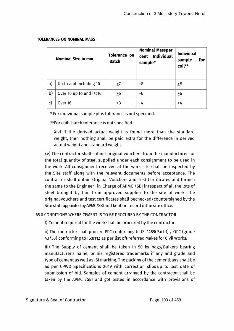
Construction of 3 Multi story Towers, Nerul
Signature & Seal of Contractor Page 103 of 459
TOLERANCES ON NOMINAL MASS
Nominal Size in mm
Tolerance on Batch
Nominal Mass per cent Individual sample*
Individual sample for coil**
a) Up to and including 10 +7 -8 +8
b) Over 10 up to and i/c16 +5 -6 +6
c) Over 16 +3 -4 +4
* For individual sample plus tolerance is not specified.
**For coils batch tolerance is not specified.
Xiv) If the derived actual weight is found more than the standard weight, then nothing shall be paid extra for the difference in derived actual weight and standard weight.
xv) The contractor shall submit original vouchers from the manufacturer for the total quantity of steel supplied under each consignment to be used in the work. All consignment received at the work site shall be inspected by the Site staff along with the relevant documents before acceptance. The contractor shall obtain Original Vouchers and Test Certificates and furnish
the same to the Engineer- in-Charge of APMC /SBI in respect of all the lots of steel brought by him from approved supplier to the site of work. The original vouchers and test certificates shall be checked/countersigned by the Site staff appointed by APMC/SBI and kept on record in the site office.
65.0 CONDITIONS WHERE CEMENT IS TO BE PROCURED BY THE CONTRACTOR
I) Cement required for the work shall be procured by the contractor.
ii) The contractor shall procure PPC conforming to IS: 1489(Part-I) / OPC (grade 43/53) conforming to IS:8112 as per list of Preferred Makes for Civil Works.
Iii) The Supply of cement shall be taken in 50 kg bags/Bulkers bearing manufacturer’s name, or his registered trademarks if any and grade and
type of cement as well as ISI marking. The packing of the cement bags shall be as per CPWD Specifications 2019 with correction slips up to last date of submission of bid. Samples of cement arranged by the contractor shall be taken by the APMC /SBI and got tested in accordance with provisions of
Construction of 3 Multi story Towers, Nerul
Signature & Seal of Contractor Page 104 of 459
relevant BIS codes. In case the test results indicate that the cement arranged by the contractor does not conform to the relevant BIS codes, the
same shall stand rejected, and it shall be removed from the site by the contractor at his own cost within a week’s time of written order from the APMC /SBI/SBI to do so.
iv) The cement shall be brought at site in bulk supply of approximately 20 tones or more as decided by the APMC /SBI.
v) At least 1 no. cement godown of the capacity to store a minimum of 500 bags of cement shall be constructed by the contractor at site for which no extra payment shall be made
vi) The contractor shall be responsible for the watch and ward and safety of the cement godown. The contractor shall facilitate the inspection of the
cement godown by the APMC /SBI at any time.
Vii) The cement shall be got tested by the Contractor and shall be used on the work only after satisfactory test results have been received. The contractor shall supply free of cost the cement required for testing including its transportation cost to testing laboratories. The cost of tests shall be borne by the contractor.
Viii) The actual issue and consumption of cement on work shall be regulated and proper accounts maintained. The theoretical consumption of cement shall be worked out as per standard consumption mentioned in Tender /CPWD manual and shall be governed by conditions laid there in. In case the cement consumption is less than theoretical consumption including permissible variation, work shall liable to be rejected. In case of excess consumption, no adjustment needs to made.
ix) The cement brought to the site and the cement remaining unused after completion of the work shall not be removed from site without the written permission of the APMC /SBI.
x) The damaged cement shall be removed from the site immediately by the contractor on receipt of a notice in writing from the Engineer-in- Charge of APMC. If he does not do so within 3 days of receipt of such notice, the Engineer- in-Charge of APMC shall get it removed at the cost of the contractor.
66.0 CONDITIONS SPECIFIC TO GREEN BUILDING PRACTICE/ENVIRONMENTAL CLEARANCE
It is envisaged to fulfill Environmental Clearance conditions of for various buildings to be constructed under this contract. The contractor shall strictly
adhere to the following conditions as part of his contractual obligation.
Construction of 3 Multi story Towers, Nerul
Signature & Seal of Contractor Page 105 of 459
I) The Contractor should follow the construction plan as proposed by the Architect /APMC /SBI to minimize the site disturbance such as soil pollution
due to spilling. Use staging and spill prevention and control plan to restrict the spilling of the contaminating materials at site. Protect top soil from erosion by collection storage and reapplication of top soil, constructing sediment basin, contour trenching, mulching etc.
ii) No excavated earth shall be removed from the campus unless suggested otherwise by APMC /SBI. All subsoil shall be reused in backfilling/landscape, etc. as per the instructions of the APMC /SBI. The surplus excavated earth shall be disposed of by the contractor for reuse. A certificate of reuse as required by the APMC /SBI shall be submitted by the contractor.
Iii) The contractor shall not change the natural gradient of the ground
unless specifically instructed by the APMC /SBI. This shall cover all-natural features like water bodies, drainage gullies, slopes, mounds, depressions, etc. Existing drainage patterns through or into any preservation area shall not be modified unless specifically directed by the APMC /SBI.
iv) The contractor shall not carry out any work which results in the blockage of natural drainage.
v) The contractor shall ensure that existing grades of soil shall be maintained around existing vegetation and lowering or raising the levels around the vegetation is not allowed unless specifically directed by the APMC /SBI.
vi) Contractor shall reduce pollution and land development impacts from
automobiles used during construction.
Vii) Overloading of trucks is unlawful and creates the erosion and sedimentation problems, especially when loose materials like stone dust, excavated earth, sand etc. are moved. Proper covering must take place. No overloading shall be permitted.
Viii) Preserve and Protect Landscape during Construction
ix) The contractor shall ensure that no trees, existing or otherwise, shall be harmed and damage to roots should be prevented during trenching, placing backfill, driving or parking heavy equipment, dumping of trash, oil, paint, and other materials detrimental to plant health. These activities should be
restricted to the areas outside of the canopy of the tree, or, from a safe distance from the tree/plant by means of barricading. Trees will not be used for support; their trunks shall not be damaged by cutting and carving or by nailing posters, advertisements or other material. Lighting of fires or carrying out heat or gas emitting construction activity within the ground,
Construction of 3 Multi story Towers, Nerul
Signature & Seal of Contractor Page 106 of 459
covered by canopy of the tree is not to be permitted.
x) The contractor shall take steps to protect trees or saplings identified for
preservation within the construction.
xi) Contractor should limit all construction activity within the specified area as per the Construction Management Plan (CMP) approved by APMC /SBI.
Xii) The contractor shall avoid cut and fill in the root zones, through delineating and fencing the drip line (the spread limit of a canopy projected
on the ground) of all the trees or group of trees. Separate the zones of movement of heavy equipment, parking, or excessive foot traffic from the
fenced plant protection zones.
Xiii) The contractor shall ensure that maintenance activities during construction period shall be performed as needed to ensure that the
vegetation remains healthy.
Xiv) The permission for cutting of trees and / or Transplanting of the trees shall be obtained by the Contractor from BMC/NMMC/Local Authorities or any other authority of the State Government, and execution of cutting and transplanting the trees or any other action in this regard will be taken by the contractor for which provision is already available in amount quoted by the contractor. No extra payment will be made on this ground.
xv) Contractor shall collect all construction waste generated on site.
Segregate these wastes based on their utility and examine means of sending such waste to manufacturing units which use them as raw material or other
site which require it for specific purpose. Typical construction debris could be broken bricks, steel bars, broken tiles, spilled concrete and mortar etc.
xvi) The contractor shall provide potable water for all workers.
xvii)The contractor shall provide the minimum level of sanitation and safety facilities for the workers at site. The contractor shall ensure cleanliness of workplace with regard to the disposal of waste and effluent; provide clean drinking water and latrines and urinals as per applicable standard. Adequate toilet facilities shall be provided for the workman within easy access of their place of work. The total no. to be provided shall not be less than 1 per 30 employees in any one shift. Toilet facilities shall be provided from the start of building operations, connection to a sewer shall be made as soon as practicable. Every toilet shall be so constructed that the occupant is sheltered from view and protected from the weather and falling objects. Toilet facilities shall be maintained in a sanitary condition. A sufficient quantity of disinfectant shall be provided. Natural or artificial illumination shall be provided.
Construction of 3 Multi story Towers, Nerul
Signature & Seal of Contractor Page 107 of 459
Xviii) The contractor shall ensure that air pollution due to dust/generators is kept to a minimum, preventing any adverse effects on the workers and other
people in and around the site. The contractor shall ensure proper screening, covering stockpiles, covering brick and loads of dusty materials, wheel-washing facility, gravel pit, and water spraying. Contractor shall ensure the following activities to prevent air pollution during construction:
xix) Clear vegetation only from areas where work will start right away.
xx) Vegetate / mulch areas where vehicles do not ply.
Xxi) Apply gravel / landscaping rock to the areas where mulching /paving is impractical.
Xxii) Identify roads on-site that would be used for vehicular traffic. Upgrade vehicular roads (if these are unpaved) by increasing the surface strength by
improving particle size, shape and mineral types that make up the surface & base. Add surface gravel to reduce source of dust emission. Limit amount of fine particles (smaller than 0.075mm) to 10 - 20%
xxiii) Water spray, through a simple hose for small projects, to keep dust under control. Fine mists should be used to control fine particulate. However, this should be done with care so as not to waste water. Heavy watering can also create mud, which when tracked onto paved public roadways, must be promptly removed. Also, there must be an adequate supply of clean water nearby to ensure that spray nozzles don’t get plugged.
Xxiv) Water spraying shall be done on:
Any dusty materials before transferring, loading and unloading
Area where demolition work is being carried out Any un-paved main haul road
xxv) Areas where excavation or earth moving activities are to be carried out The contractor shall ensure that the speed of vehicles within the site is limited to 10 km/hr.
Xxvi) All material storages should be adequately covered and contained so that they are not exposed to situations where winds on site could lead to dust / particulate emissions.
Xxvii) Spills of dirt or dusty materials will be cleaned up promptly so the
spilled material does not become a source of fugitive dust and also to prevent of seepage of pollutant laden water into the ground aquifers. When
cleaning up the spill, ensure that the clean-up process does not generate additional dust. Similarly, spilled concrete slurries or liquid wastes should
Construction of 3 Multi story Towers, Nerul
Signature & Seal of Contractor Page 108 of 459
be contained / cleaned up immediately before they can infiltrate into the soil / ground or runoff in nearby areas
xxviii) Provide hoardings of not less than 3m high along the site boundary, next to a road or other public area
xxix) Provide dust screens, sheeting or netting to scaffold along the perimeter of the building
xxx) Cover stockpiles of dusty material with impervious sheeting
xxxi) Cover dusty load on vehicles by impervious sheeting before they leave the site
xxxii) The contractor shall ensure that no construction leachate (e.g., cement slurry etc.), is allowed to percolate into the ground. Adequate precautions are to be taken to safeguard against this including, reduction of wasteful curing processes, collection, basic filtering and reuse. The contractor shall follow requisite measures for collecting drainage water run-off from construction areas and material storage sites and diverting water flow away from such polluted areas. Temporary drainage channels, perimeter dike/swale, etc. shall be constructed to carry the pollutant-laden water directly to the treatment device or facility (municipal sewer line).
Xxxiii) The storage of material shall be as per standard good practices as specified in Storage, Stacking and Handling practices, NBC 2016 shall be to the satisfaction of the APMC /SBI to ensure minimum wastage and to prevent any misuse, damage, inconvenience or accident. Watch and ward of the
Contractor is materials shall be his own responsibility. There should be a proper planning of the layout for stacking and storage of different materials,
components and equipment with proper access and proper maneuverability of the vehicles carrying the materials. While planning the layout, the
requirements of various materials, components and equipment at different stages of construction shall be considered.
Xxxiv) The contractor shall ensure the following activities for construction workers safety, among other measures:
Guarding all parts of dangerous machinery.
Precautionary signs for working on machinery
Maintaining hoists and lifts, lifting machines, chains, ropes, and other lifting tackles in good condition.
Durable and reusable form work systems to replace timber form work and ensure that form work where used is properly maintained.
Construction of 3 Multi story Towers, Nerul
Signature & Seal of Contractor Page 109 of 459
Ensuring that walking surfaces or boards and/or working platforms, etc. at height are of sound construction and are
provided with safety rails or belts.
Provide protective equipment; helmets etc. -
Provide measures to prevent fires. Fire extinguishers and buckets of sand to be provided in the fire-prone area and elsewhere.
Provide sufficient and suitable light for working during night time
The contractor shall provide for adequate number of garbage bins around the construction site and the workers facilities and will be responsible for the proper utilization of these bins for any solid waste generated during the construction. The contractor shall ensure that the site and the workers facilities are kept litter free. Separate bins should be provided for plastic, glass, metal, biological and paper waste and labeled in both Hindi and English with suitable symbols.
The contractor shall prepare and submit spill prevention and control plans before the start of construction, clearly stating measures to stop the source of the spill, to contain the spill, to dispose the contaminated material and hazardous wastes, and stating designation of personnel trained to prevent and control spills. Hazardous wastes include pesticides, paints, cleaners, and petroleum products.
Contractor shall collect & submit the relevant material certificates for materials with high recycled (both post-industrial and post-consumer) content, including materials like RMC mix with fly-ash, glass with recycled content, calcium silicate boards etc.
The contractor shall ensure that a flush out of all internal spaces is conducted prior to handover. This shall comprise an opening of all
doors and windows for 14 days to vent out any toxic fumes due to paints, varnishes, polishes, etc.
The providing & fixing Safety nets at various levels of Buildings as per instruction from APMC /SBI. Safety Net shall be of Garware nylon
Ropes made of three layers of (100 mm X 100 mm square with 8 mm thick nylon rope.), net with 2.5 mm nylon rope with 25mm x 25 mm square and mono filament net on top having width of 5.0 mts. horizontal to the periphery of the Building with supporting structure of 50 mm dia MS hollow (40 nb)pipe duly anchored on slab/beam with 10 mm thick base plate and anchor fastner (hilti) 4 Nos. at all
Construction of 3 Multi story Towers, Nerul
Signature & Seal of Contractor Page 110 of 459
corners, and free end of pipe to be tied up with upper floor column with the help of nylon rope 16 mm dia. same supporting system is to
be followed for every 4.5 Mtr. in such a way to have a proper slope during Construction, and removing and re fixing part of the same as and when required/ necessary for smooth progress of the work.
No extra payment shall be done against all such safety measures.
67.0) WATER USE DURING CONSTRUCTION
I) Contractor should spray curing water on concrete structure and shall not allow free flow of water. Concrete structures should be kept covered with thick cloth/gunny bags and water should be sprayed on them. Contractor shall do water poundings on all sunken slabs using cement and sand mortar.
68.0) RESOURCES CONSUMED DURING CONSTRUCTION
I) The contractor shall ensure that the water and electricity is not wasted during construction. The APMC /SBI can bring to the attention any such wastage and the contractor will have to ensure that such bad practices are corrected.
ii) The contractor shall install necessary meters and measuring devices to record the consumption of water, electricity and diesel on a monthly
basis for the entire tenure of the project.
Iii) The contractor shall ensure that all run-off water from the site,
during construction is collected and reused to the maximum.
iv) The contractor shall use treated recycled water of appropriate quality standards for construction, if available.
v) The contractor shall minimize the use of electricity.
69.0) CONSTRUCTION AND DEMOLITION WASTE
I) Contractor shall minimize the generation of construction waste as per
the requirement for Environmental Clearance Perspective.
ii) All construction debris generated during construction shall be carefully segregated and stored in a demarcated waste yard. Clear, identifiable areas shall be provided for each waste type. Employ measures to segregate the waste on site into inert, chemical, or hazardous wastes.
Construction of 3 Multi story Towers, Nerul
Signature & Seal of Contractor Page 111 of 459
Iii) All construction debris shall be used for road preparation, back filling, etc., as per the instructions of the APMC /SBI, with necessary
activities of sorting, crushing, etc.
iv) No construction debris shall be taken away from the site, without the prior approval of the APMC /SBI.
v) The contractor shall recycle the unused chemical/hazardous wastes such as oil, paint, batteries, and asbestos.
vi) If and when construction debris is taken out of the site, after prior permissions from the APMC /SBI, then the contractor shall ensure the safe disposal of all wastes and will only dispose of any such construction waste in approved dumping sites.
70) DOCUMENTATION
I) The contractor shall, during the entire period of the construction, submit the following records to the APMC /SBI on a monthly basis:
ii)Water consumption in liters
iii) Electricity consumption in ‘kwh’ units
iv) Diesel consumption in liters
v) Quantum of waste (volumetric/weight basis) generated at site and the segregated waste. types divided into inert, chemical and hazardous wastes
vi) Digital photo documentation to demonstrate compliance of safety
guidelines as specified in the tender The contractor shall, during the entire tenure of the construction phase, submit the following records to the APMC /SBI on a fortnightly basis:
vii) Quantities of material brought into the site, including the material issued to the contractor by the APMC /SBI.
Viii) Quantities of construction debris (if at all) taken out of the site
ix) Digital photographs of the works at site, the workers facilities, the waste and other material storage yards, pre-fabrication and block making works, etc. as guided by the APMC /SBI
x) The contractor shall submit a document after construction of the
buildings, a brief description along with photographic records to show that other areas have not been disturbed during construction. The document should also include brief explanation and photographic records to show erosion and sedimentation control measures adopted.
Construction of 3 Multi story Towers, Nerul
Signature & Seal of Contractor Page 112 of 459
(Document CAD drawing showing site plan details of existing vegetation, existing buildings, existing slopes and site drainage pattern, staging
and spill prevention measures, erosion and sedimentation control measures and measures adopted for topsoil preservation during construction.
xi) The contractor shall submit to the APMC /SBI after construction of the buildings, a detailed as built quantification of the following:
1) Materials used,
2) Total top soil stacked and total reused
3) Total earth excavated
4) Total waste generated,
5) Total waste reused,
6) Total water used,
7) Total electricity, and
8) Total diesel consumed.
Xii) The contractor shall submit to the APMC /SBI, before the start of construction, a site plan along with a narrative to demarcate areas on site from which topsoil has to be gathered, designate area where it will be stored, measures adopted for top soil preservation and indicate areas where it will be reapplied after construction is complete.
Xiii) The contractor shall submit to the APMC /SBI, a detailed narrative (not more than 250 words) on provision for safe drinking water and sanitation facility for construction workers and site personnel.
Xiv) Provide supporting document from the manufacturer of the Batch mix/ Ready Mix concrete specifying the use of Fly Ash.
xv) Provide supporting document from the manufacturer of the pre-cast building blocks specifying the fly ash content of the blocks used in an infill wall system.
Xvi) Provide total support to APMC /SBII and Environmental Consultants appointed by the APMC /SBI in completing all Environmental clearance related formalities, including signing of forms, providing signed letters in
the contractor’s letterhead whenever required.
71.0 Warning / Caution Boards/Signage
I) All temporary warning / caution boards / glow signage display such as "Construction Work in Progress", "Keep Away”, “No Parking”, Diversions etc.
Construction of 3 Multi story Towers, Nerul
Signature & Seal of Contractor Page 113 of 459
shall be provided and displayed by the Contractor, wherever required and as directed by the APMC /SBI. All signage shall be suitably illuminated during
night also. The Contractor shall be solely responsible for damage and accident caused, if any, due to negligence on his part. Also, he shall ensure that no hindrance, as far as possible, is caused to general traffic during execution of the work.
ii) In addition, the Contractor shall also provide a sign board of approved size, design & pattern at an approved location giving the details of the project, client / SBI, architects, structural consultants, Department etc. besides providing space for names of Contractor/Sub- Contractors.
Iii) All signage shall be dismantled & taken away by the Contractor after completion of the work with the approval of the Engineer – in – Charge of APMC.
72.0 CONDITIONS OF NATIONAL GREEN TRIBUNAL
I) The contractor shall not store/ dump construction material or debris on the metaled road.
ii) The contractor shall get prior approval from APMC /SBI for the area where the construction material or debris can be stored beyond the metaled road. This area shall not cause any obstruction to the free flow of traffic /inconvenience to the pedestrians/public in general. It should be ensured by the contractor that no accidents occur because of such permissible storage.
Iii) The contractor shall take appropriate protection measures like raising
wind breakers of appropriate height on all sides of the plot/area to ensure that no construction material dust fly outside the plot area.
iv) The contractor shall ensure that all the trucks or vehicles of any kind which are used for construction purposes/or are carrying construction material like cement, sand, earth and other allied material are fully covered. The contractor shall take every necessary precaution that the vehicles are properly cleaned and dust free to ensure that enroute their destination, the dust, sand or any other particles are not released in air/contaminate air.
v) The contractor shall provide mask to every worker on the construction site and involved in loading, unloading and carriage of construction material and construction debris to prevent inhalation of dust particles.
vi) The contractor shall provide all medical help, investigation and treatment to the workers involved in the construction of building and carry off construction material and debris relatable to dust emission.
Construction of 3 Multi story Towers, Nerul
Signature & Seal of Contractor Page 114 of 459
Vii) The contractor shall ensure that C&D waste is transported to the C&D waste site only and due records shall be maintained by the contractor
viii) The contractor shall compulsorily use wet jet in grinding and stone cutting.
ix) The contractor shall comply with all the preventive and protective environmental steps as stated in the MoEF guidelines, 2010.
x) The contractor shall carry out on-Road-Inspection for black smoke generating machinery. The contractor shall use cleaner fuel.
xi) The contractor shall ensure that all DG set comply emission norms notified by MoEF.
Xii) The contractor shall use vehicles having pollution under control certificate. The emissions can be reduced by a large extent by reducing the speed of a vehicle to 20 Kmph. Speed bumps shall be used to ensure speed reduction. In case where speed reductions cannot effectively reduce fugitive dust, the contractor shall divert traffic to nearby paved areas.
Xii) The contractor shall ensure that the construction material is covered by tarpaulin. The contractor shall take all other precaution to ensure that no dust particles are permitted to pollute air quality because of such storage.
Xiii) The paving of the path for plying of vehicles carrying construction material is more permanent solution to dust control and suitable for longer duration projects.
Xiv) Any violation of orders of MoEF including guidelines of State
Government, SPCB or any officer of any department shall lead to stoppage of work for which Contractor shall be responsible and no hindrance shall be accounted in this regard.
xv) The contractor shall take appropriate protection measures like raising wind breakers of appropriate height on all sides of the plot/area using CGI sheets or plastic and/or other similar material to ensure that no construction material dust fly outside plot area.
73.0 Make in India Policy
i)The main contractor as well as associate contractor of each discipline shall
comply to Government of India Public Procurement (Preference to Make in India), Order-2017 amended up to last date of submission of bid.
74.0 Training and Awareness:
I) Training:
Construction of 3 Multi story Towers, Nerul
Signature & Seal of Contractor Page 115 of 459
The training shall be in two phases – first induction training and then periodic training / refresher workshop.
Induction Training: All the workers shall have to undergo a training program of 16 hrs (8 hrs for 2 days) and to be declared satisfactorily trained by the Safety Manager before they are allowed to work on site.
ii) Orientation Program:
An orientation program shall be arranged for all people (other than workers) who normally work at or visit the site.
Iii) Workshops:
Refresher workshops shall be arranged in every three months for all the workers on site.
iv) Advance Training:
For workers involved in high-risk activities (to be identified by the APMC) an intensive training shall be kept once in a month. The training modules shall be designed by the Safety Manager and approved by the APMC Methodology: The training methodology shall include both classroom and practical demonstration with audio visual techniques. For greater impact, demonstration with dummies will be done to highlight hazards of not following safe practices.
The training shall be imparted in vernacular language and may include means such as songs, theatre, puppetry etc. for better appreciation and assimilation by workers.
v) Implementation:
The basic responsibility of implementation of safe practices shall be that of the safety manager and safety supervisors of the contractor at the first level and project team APMC on second level. The basic approach of implementation should be towards voluntary acceptability of safe practices by all stakeholders.
The safety arrangement made by the contractor shall be open to inspection by the safety officer or any other representative appointed by the APMC and the observation made by him shall be complied with by the contractor.
All workmen are checked for their suitability before development by the respective Safety Manager and each Safety Supervisor. Workers physical
fitness knowledge about the activity and his previous experience are checked before deployed. Workmen involved in physical activity (such as driver, operators, Height workers, Food handlers at Canteen and Pantries,
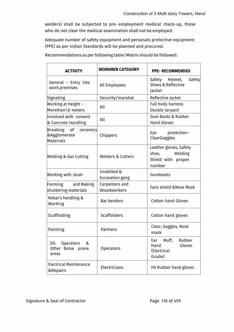
Construction of 3 Multi story Towers, Nerul
Signature & Seal of Contractor Page 116 of 459
welders) shall be subjected to pre- employment medical check-up, those who do not clear the medical examination shall not be employed.
Adequate number of safety equipment and personals protective equipment (PPE) as per Indian Standards will be planned and procured.
Recommendations as per following table/Matrix should be followed:
ACTIVITY WORKMEN CATEGORY PPE- RECOMMENDED
General – Entry into work premises
All Employees
Safety Helmet, Safety Shoes & Reflective
Jacket
Signaling Security/marshal Reflective Jacket Working at Height –
Morethan1.8 meters All
Full body harness
Double lanyard
Involved with cement & Concrete Handling
All Gum Boots & Rubber Hand Gloves
Breaking of ceramics &Agglomerate
Materials
Chippers Eye protection–Clear Goggles
Welding & Gas Cutting Welders & Cutters
Leather gloves, Safety
shoe, Welding Shield with proper number
Working with slush Unskilled &
Excavation gang Gumboots
Forming and Making
shuttering materials
Carpenters and
Woodworkers Face shield &Nose Mask
Rebar’s handling &
Working Bar benders Cotton hand Gloves
Scaffolding Scaffolders Cotton hand gloves
Painting Painters Clear, Goggles, Nose
mask
DG Operators & Other Noise prone areas
Operators
Ear Muff, Rubber Hand Gloves (Electrical Grade)
Electrical Maintenance
&Repairs Electricians HV Rubber hand gloves
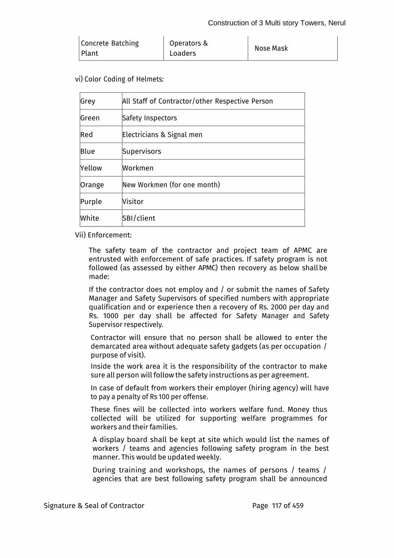
Construction of 3 Multi story Towers, Nerul
Signature & Seal of Contractor Page 117 of 459
Concrete Batching
Plant Operators &
Loaders Nose Mask
vi) Color Coding of Helmets:
Grey All Staff of Contractor/other Respective Person
Green Safety Inspectors
Red Electricians & Signal men
Blue Supervisors
Yellow Workmen
Orange New Workmen (for one month)
Purple Visitor
White SBI/client
Vii) Enforcement:
The safety team of the contractor and project team of APMC are entrusted with enforcement of safe practices. If safety program is not followed (as assessed by either APMC) then recovery as below shall be made:
If the contractor does not employ and / or submit the names of Safety Manager and Safety Supervisors of specified numbers with appropriate qualification and or experience then a recovery of Rs. 2000 per day and Rs. 1000 per day shall be affected for Safety Manager and Safety Supervisor respectively.
Contractor will ensure that no person shall be allowed to enter the demarcated area without adequate safety gadgets (as per occupation / purpose of visit).
Inside the work area it is the responsibility of the contractor to make sure all person will follow the safety instructions as per agreement.
In case of default from workers their employer (hiring agency) will have to pay a penalty of Rs 100 per offense.
These fines will be collected into workers welfare fund. Money thus collected will be utilized for supporting welfare programmes for workers and their families.
A display board shall be kept at site which would list the names of workers / teams and agencies following safety program in the best manner. This would be updated weekly.
During training and workshops, the names of persons / teams / agencies that are best following safety program shall be announced
Construction of 3 Multi story Towers, Nerul
Signature & Seal of Contractor Page 118 of 459
and they shall be felicitated.
On completion of the work, shields for best person / team / agencies following safety program in different categories shall be awarded.
A biometric system/record of attendance will be put in place by the Contractor as per the direction of Engineer- in-Charge of APMC and the Safety Manager and all the Safety Supervisors will record their presence in the system. Recovery as suggested will be made for failure to record such presence / non availability of safety personals.
In case of an accident resulting in death / permanent disability of a worker, a recovery of Rs. 10 Lakh per death / permanent disability will be made for the contract values more than Rs. 20 crores. The recovery for the contracts less than Rs. 20 crores shall be @ 0.5% of the contract amount per death / permanent disability. The money so recovered will be kept in the “Workers Welfare Fund” and will be at the sole discretion of the APMC/SBI for utilizing to support the welfare programs of the workers.
This recovery shall be in addition to recovery (recoveries) or compensation under any other Statute / Act / Provision of Contract. However, the total recovery on this account shall not exceed 2% of the contract value.
75.0 Standard Operating Procedures (SOPs) and Guidelines for Construction Sites for COVID-19 Outbreak
I) The agency shall follow all the COVID 19/Any Epidemic protocols enforced by state / central Government, NMMC / MCGM / NDMA / MHA / MOH&FW etc. from time to time and the guidelines issued by SBI from time to time as per directions of the APMC /SBI and nothing extra payable on this account.
ii) The Agency/contractor shall install inspection lifts of minimum 8–10 person capacity for inspection of officers. Each tower should have independent inspection lift. Agency shall ensure they are in safe working conditions throughout the execution period and safety of the persons.
76.0 PRODUCT DELIVERY, STORAGE AND HANDLING OF CHEMICALS
I) The contractor shall construct storage space for Chemicals materials to ensure that the storage conditions are as recommended by the manufactures.
ii) All the materials shall be procured and delivered in sealed containers with labels legible and intact.
Iii) All the chemicals (polymers, epoxy, water proofing compound, plasticizer, Poly-sulphide, SBR based elastomeric, APP (Atactic iv) Polypropylene Polymer), all exterior and interior paints, polish etc.) shall be procured in convenient packs say 20 liters/kg} capacity packing only or as approved by the APMC /SBI, and not in bigger capacity containers, say 200 liter (kg) drums unless otherwise specifically permitted by the APMC /SBI. One sample from each lot of the chemical procured by the contractor shall be tested in a laboratory as approved by the APMC /SBI.
v) All material required for the execution of the work shall be got approved,
Construction of 3 Multi story Towers, Nerul
Signature & Seal of Contractor Page 119 of 459
procured and deposited with the Departmental supervisory staff. The materials shall be kept in joint custody of the contractor and the Department. The watch and ward of such material shall, however, remain to be the responsibility of the contractor and no claim, whatsoever, on this account shall be entertained. Different containers of each chemical shall be serially numbered on packing and also consumed in that order. Day-to-day account of receipt, issue and balance shall be regulated by the Department and proper account shall be maintained at site of work in the prescribed form as per the standard practice.
vi) All the chemicals shall be procured by the contractor directly from the manufacturer. In exceptional circumstances, the contractor may be allowed to procure the materials from the authorized dealers of the manufacturers, if specifically permitted by the APMC /SBI.
Vii) The original copies of challan /cash memos towards the quantity of various chemicals procured shall be made available by the contractor at the request from the APMC /SBI and a copy of the same shall be kept in record.
Viii) The Name of manufacturers, manufacturer’s product identification, manufacturer’s mixing instructions, warning for handling and toxicity and date of manufacturing and shelf life shall be clearly and legibly mentioned on the labels of each container.
ix) The contractor shall submit for the chemicals procured, manufacturer’s and / or authorized dealer’s certificate regarding supplying and verifying conformance to the material specifications, as specified.
x) All filled containers shall be handled in safe manner and in a way to avoid breaking container seals.
xi) Empty containers of the chemicals should not be removed from site till the completion of work and shall be removed only with the written approval of the APMC /SBI.
Xii) All arrangements for measuring, dosing and mixing of material / chemicals at site have to be made by the contractor.
Xiii) Contractor shall suitably advise his site Engineer and all the workers as regards safe handling of chemicals. Necessary protective and safety equipment in form of hand gloves, goggles etc. shall be provided by the contractor and be also used at site.
Xiv) All incidental charges of any kind including cartage, storage and wastage and safe custody of material etc. shall be borne by the contractor and no claim, whatsoever, shall be entertained on this account.
xv) The chemicals shall be tested in an independent laboratory as approved by the APMC /SBI at the frequency as specified. If required, more samples may have to be tested as per the directions of the Engineer-in- Charge of APMC. Nothing extra shall be payable on this account.
77.0 BASIC RATES/PRICE VARIATION (ESCALATION)/VARIATIONS
A- Basic Rates
For the purpose of quotation, the Basic rates of Cement, Steel, flooring & all
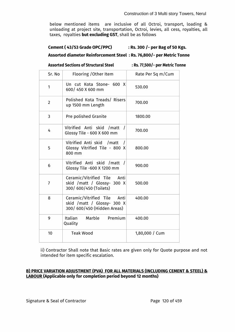
Construction of 3 Multi story Towers, Nerul
Signature & Seal of Contractor Page 120 of 459
below mentioned items are inclusive of all Octroi, transport, loading & unloading at project site, transportation, Octroi, levies, all cess, royalties, all taxes, royalties but excluding GST, shall be as follows
Cement ( 43/53 Grade OPC/PPC) : Rs. 300 /- per Bag of 50 Kgs.
Assorted diameter Reinforcement Steel : Rs. 76,800/- per Metric Tonne
Assorted Sections of Structural Steel : Rs. 77,500/- per Metric Tonne
Sr. No Flooring /Other Item Rate Per Sq m/Cum
1 Un cut Kota Stone- 600 X 600/ 450 X 600 mm
530.00
2 Polished Kota Treads/ Risers up 1500 mm Length
700.00
3 Pre polished Granite 1800.00
4 Vitrified Anti skid /matt / Glossy Tile - 600 X 600 mm
700.00
5
Vitrified Anti skid /matt / Glossy Vitrified Tile - 800 X 800 mm
800.00
6 Vitrified Anti skid /matt / Glossy Tile -600 X 1200 mm
900.00
7
Ceramic/Vitrified Tile Anti skid /matt / Glossy- 300 X 300/ 600/450 (Toilets)
500.00
8 Ceramic/Vitrified Tile Anti skid /matt / Glossy- 300 X 300/ 600/450 (Hidden Areas)
400.00
9 Italian Marble Premium Quality
400.00
10 Teak Wood 1,80,000 / Cum
ii) Contractor Shall note that Basic rates are given only for Quote purpose and not intended for item specific escalation.
B) PRICE VARIATION ADJUSTMENT (PVA) FOR ALL MATERIALS (INCLUDING CEMENT & STEEL) & LABOUR (Applicable only for completion period beyond 12 months)
Construction of 3 Multi story Towers, Nerul
Signature & Seal of Contractor Page 121 of 459
In partial modification of the provisions made elsewhere in this contract regarding rate quoted being not subject to any variations, price adjustments to the value of work payable to the Contractor at tendered rates shall be made towards variations in the prices of materials and labour in the manner specified hereunder:- If, after written order to commence the work and during the operative period of this contract including any authorized extensions of the original stipulated completion period:-
i. There be any variation in the Consumer Price Index- General Index- for industrial workers (Base 1982=100) (source – data published from time to time Indian Labour Journal by the Labour Bureau, Government of India);
OR
ii. There be any variation in the All India Wholesale Price Index for all commodities (Base 1993-94=100) (as published from time to time in the RBI Bulletin based on the date issued by the Office of the Economic Advisor to the Government of India);
Price Variation Adjustment (PVA) towards (1) Labour Component and (2) Material Component shall be calculated in accordance with the formula A and B respectively, given below, subject to stipulations herein under mentioned:- FORMULA (A) FOR LABOUR: VL = 0.85 P x K1 x (C1 – C0)
100 C0
FORMULA (B) FOR MATERIALS: VM = 0.85X (P-Y)X K2 X (I1 – I0) 100 I0
Where- VL = Amount of Price Variation Adjustment Increase or decrease in rupees due to labour component VM = Amount of Price Variation Adjustment Increase or decrease in rupees on account of materials component NOTE: Bill period (noted hereunder) signifies the period of actual execution and not date of measurement or preparation of bill. P = Cost of work done during the period under consideration (bill period)
excluding advances on materials and/or adjustments thereof. Y = Cost of any other materials supplied/ arranged by the Bank at fixed price
during the period under consideration (bill period) K1 = Percentage of labour component calculated as indicated in Note (1) below
Construction of 3 Multi story Towers, Nerul
Signature & Seal of Contractor Page 122 of 459
K2 = Percentage of materials component as indicated in Note (2) below. CO = Consumer Price Index – General Index Number for industrial workers (Base
1982 = 100) referred to at (a) above, ruling on the last due date of receipt of tenders, and as applicable to the centre, nearest to the place of work, for which the index is published)
C1 = Average of above mentioned Consumer Price Index number during the
period under consideration (bill period) I0 = All India Wholesale Price Index number for all commodities referred to at (b)
above, ruling on the last date for receipt of tenders and as applicable to the centre, nearest to the place of work for which the index is published.
I1 = Average of above mentioned monthly all India Wholesale Price Index
numbers during the period under consideration (bill period) NOTE (1) : K1 shall be taken as under:- Component of work K 1 a) Civil work including ancillary works and external work
and RCC / tanks, septic tanks, etc. if any of sanitary and plumbing work 30
b) Sanitary and plumbing works including fittings and fixtures
(internal work only) 20
c) Electrical installations work including fittings and fixtures
(external and internal works) 20
NOTE (2) : K2 shall be taken as under:-
Component of work K 2
1. Civil work including ancillary works as detailed under Note (1) (a) above 70
b) Sanitary and plumbing works including fittings and fixtures
as detailed under Note (1) (b) above 80
c) Electrical installations work including fittings and fixtures as detailed under Note (1) (c) above 80
Stipulations:
I) PVA Clause is operative either way i.e. if the variations in above referred price indices are on the plus side. PVA shall be payable to the contractor and if they are on the negative side PVA shall be recoverable from the contractor for
Construction of 3 Multi story Towers, Nerul
Signature & Seal of Contractor Page 123 of 459
the respective bill period of occurrence of fluctuations.
ii) The rates quoted by the Contractor shall be treated as firm for the value of work required to be done in the first 12 months of the contract period from the date of written order to commence work and no PVA is admissible on the same on any grounds whatsoever. The value of work required to be done during the first 12 months of the contract period shall be taken as 80% of the value of work to be done on pro-rata basis in 12 months as compared to the total stipulated completion period. No PVA is admissible on the value of work required to be done in first 12 months as worked out above, even if this value of work is actually done in a period longer than 12 months. However, in case of any delay in the first 12 months due to genuine reasons which are not attributable to the contractor and which are beyond his control, such period of delay will be deducted from 12 months, and the value of work to be done will be 80% of the pro-rata value of work to be done in such reduced period on pro-rata basis.
Iii) (a) For works where the original stipulated period of completion is not more than 12 months, no PVA whatsoever is permissible under this clause. However, if the period of completion is delayed beyond 12 months on account of genuine reasons which are not attributable to the contractor and which are beyond his control, PVA will be admissible on the value of work done only in excess of value of work required to be done on a pro-rata basis in the first 12 months minus the period of such genuine delay.
Iii) (b) For purpose of admissibility of PVA all the cumulative period of extensions granted for reasons which are solely attributable to the contractor is excluded from the total extended period of the contracts and PVA shall not be admissible on the value of work done during such period of extensions, which are granted for keeping the contract current, but only due to reasons for which the contractor was solely responsible. Periods of extensions granted on account of genuine reasons which are not attributable to the contractor and which are beyond his control will however, be included in the period for which PVA is admissible. Iii) (c) Notwithstanding anything to the contrary mentioned in any other clause/ clauses of the contract, extensions of the contract period shall be granted by the Architect only with prior approval of the Bank. Extensions granted by the Architect without Bank’s prior approval shall not bind the Bank for payment of PVA for work done in the concerned period of extensions. Iv) (a) Where the total cost of work done beyond the value of work required to be done in the first 12 months (vide note (ii) and (iii) above does not exceed Rs.50 lacs the total amount of PVA worked out on the basis of provisions of foregoing stipulations will be limited to an upper ceiling of 10% of such value of work done in excess of value of work required to be done in the first 12 months,
Construction of 3 Multi story Towers, Nerul
Signature & Seal of Contractor Page 124 of 459
minus the cost of any materials issued/arranged by the Bank at fixed prices i.e. P – Y (these terms being as per definitions given formulae A and B above).
Iv) (b) Where the total value of work done beyond the value of work required to be done in the first 12 months exceeds Rs.50 lacs, the PVA on the first Rs.50 lacs will be calculated as provided for in the foregoing para and for the balance value of work done for which PVA is admissible subject to foregoing conditions, the PVA will have the upper ceiling of 10% but it will be worked out at a lower rate i.e. 80% of the amount worked out as per the formulae A and B referred to earlier. V) In working out the amount of PVA as per all the foregoing stipulations, value of such extra items or such portions of extra items the rates of which are derived from the prevailing market rates of materials and labour will not be included in the value of work done . Value of only such extra items or such portions of extra items, rats of which are derived entirely from tendered rates will be included in the value of work on which PVA as calculated. vi) For claiming the payment for PVA the contractor shall keep such books of accounts and other documents, vouchers receipts etc. as may be required by the Bank/Architect, for verification of the increased claims or reduction to be made as the case may be and he shall also allow Engineers and/or other duly authorized representatives of the Bank/Architects and furnish such information as may be required or called for to enable verification of the claim within a week of such request.
Vii) The contractor is required to submit to the Bank, through the Architect, his claims for PVA separately for each running Bill for the individual bill periods for the work paid to him by the Bank. He will also be required to submit detailed calculations in support of the claims.
Viii) No claim will be entertained from the contractor for interest or any other grounds for non-payment or for any delay in payment of PVA due to late publication or non-availability of the necessary price indices or due to delay in preparation of the Running or Final Bills.
ix) In view of adjustments for variations in process of materials and labor which have been covered in this clause no other adjustments for any reason whatsoever like statutory measures, taxes, levies, etc. will be allowed.
C) Valuation of Variations
No claim for an extra Item shall be allowed unless it shall have been executed under the authority of the SBI with the concurrence of the SBI as herein mentioned.
Construction of 3 Multi story Towers, Nerul
Signature & Seal of Contractor Page 125 of 459
Any such extra is herein referred to as authorized extra and shall be made in accordance with the following provisions.
(i) The net rates or prices in the contract shall determine the valuation of the extra work where such extra work is of similar character and executed under similar conditions as the work priced herein.
(ii) Rates for all items, wherever possible should be derived out of the rates given in the priced BOQ.
iii) The net prices of the original tender shall determine the value of the items omitted, provided if omissions do not vary the conditions under which any remaining items of Works are carried out, otherwise the prices for the same shall be valued under sub Clause ‘iv’ hereunder.
iv) Where the extra works are not of similar character and/or executed under similar conditions as aforesaid or where the omissions vary the conditions under which any remaining items or works are carried out, then the Contractor/ Vendor shall within 7 days of the receipt of the letter of acceptance inform the SBI of the rate which he intends to charge for such items of work, duly supported by analysis of the rate or rates claimed and the SBI shall fix such rate or prices as in the circumstances in its opinion are reasonable and proper, based on the market rate.
v) Where extra work cannot be properly measured or valued the Contractor/ Vendor shall be allowed day work prices at the net rates stated in the tender, of the BOQ or, if not, so stated then in accordance with the local day work rates and wages for the district; provided that in either case, vouchers specifying the daily time (and if required by the SBI) the workman’s name and materials employed be delivered for verification to the Architect /consultant at or before the end of the week following that in which the work has been executed.
vi) It is further clarified that for all such authorized extra items where rates cannot be derived from the tender, the Contractor/ Vendor shall submit rates duly supported by rate analysis worked on the ‘market rate basis for material, labour hire / running charges of equipment and wastage etc. plus 15% towards establishment charges, Contractor/ Vendor’s overheads and profit. Such items shall, not be eligible for escalation.
78.0 LABOUR CAMP/LABOUR MOVEMENTS
i) The said work is to be carried out within the existing SBI Housing campus/colony and very rare space is available for Labour Camp. Contractor shall take a note of this while quoting the rates.
ii) Contractor needs to allot space to labour camp outside SBI Colony’s premises at no extra cost to SBI. Daily to and frow movement of the labour shall be carried out at no extra cost to SBI. Required Approval from local governing Authority for labour camp shall be taken by the Contractor of such labour camp.
Iii) In & Out timing of as per shifts to be fixed for Labourers and within that time labour movement to be carried out. In other time no movement of labours shall be permitted except
Construction of 3 Multi story Towers, Nerul
Signature & Seal of Contractor Page 126 of 459
the special permission from the APMC /SBI.
iv) As this project comes under premises of existing SBI Colony utmost care shall be taken to avoid nuisance to Colony peoples from labourers, material/machinery movement. If it is found that some labours are creating nuisance then those labourers shall be removed off the site immediately.
v) No movement of labourers shall be allowed in Colony’s premises except incoming /outgoing route that too in specific given time.
vi) In exceptional /emergency situation minimum number of labours will be allowed to stay at site provided proper permission to be taken by the Contractor from APMC and SBI.
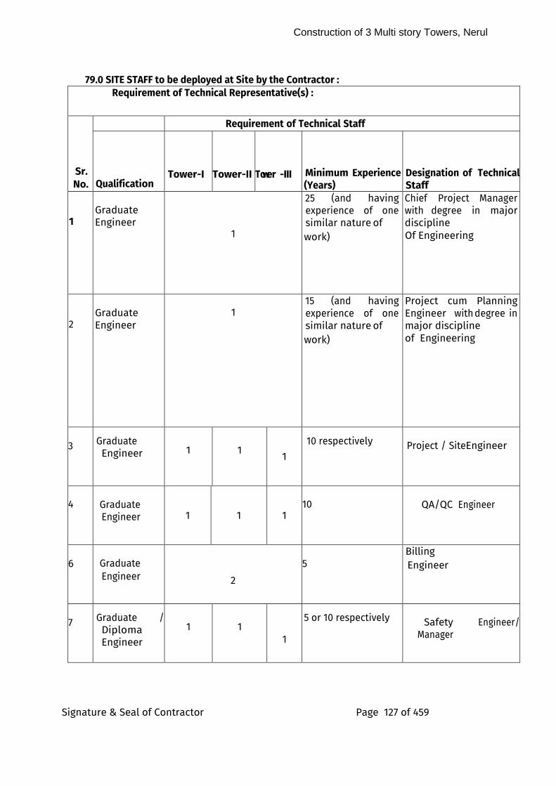
Construction of 3 Multi story Towers, Nerul
Signature & Seal of Contractor Page 127 of 459
79.0 SITE STAFF to be deployed at Site by the Contractor : Requirement of Technical Representative(s) :
Sr. No.
Requirement of Technical Staff
Qualification
Tower-I
Tower-II
Tower -III
Minimum Experience (Years)
Designation of Technical Staff
1
Graduate Engineer
1
25 (and having experience of one similar nature of work)
Chief Project Manager with degree in major discipline
Of Engineering
2
Graduate Engineer
1
15 (and having experience of one similar nature of work)
Project cum Planning Engineer with degree in major discipline
of Engineering
3
Graduate Engineer
1
1
1
10 respective ly Project / Site Engineer
4
Graduate Engineer 1 1 1
10
QA/QC Engineer
6
Graduate Engineer
2
5
Billing
Engineer
7
Graduate / Diploma Engineer
1
1
1
5 or 10 respective ly
Safety Engineer/ Manager
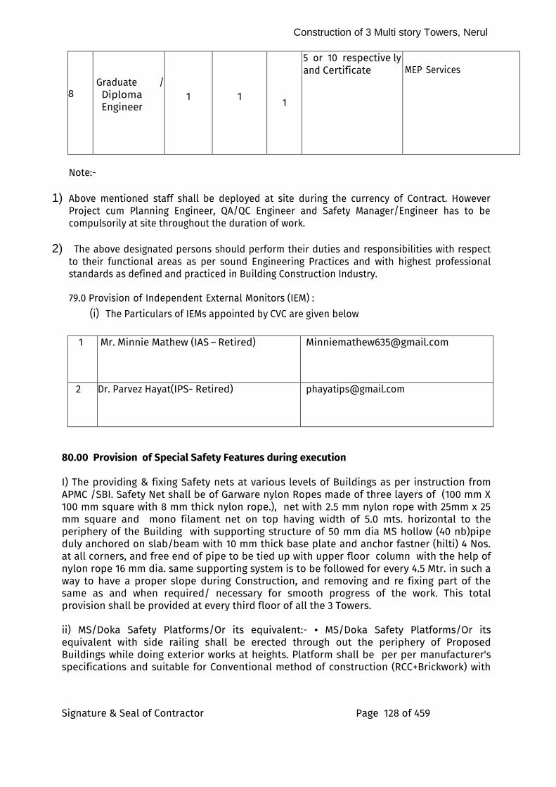
Construction of 3 Multi story Towers, Nerul
Signature & Seal of Contractor Page 128 of 459
8
Graduate / Diploma Engineer
1
1
1
5 or 10 respective ly and Certificate
MEP Services
Note:-
1) Above mentioned staff shall be deployed at site during the currency of Contract. However Project cum Planning Engineer, QA/QC Engineer and Safety Manager/Engineer has to be compulsorily at site throughout the duration of work.
2) The above designated persons should perform their duties and responsibilities with respect to their functional areas as per sound Engineering Practices and with highest professional standards as defined and practiced in Building Construction Industry.
79.0 Provision of Independent External Monitors (IEM) :
(i) The Particulars of IEMs appointed by CVC are given below
1 Mr. Minnie Mathew (IAS – Retired)
2 Dr. Parvez Hayat (IPS- Retired)
80.00 Provision of Special Safety Features during execution
I) The providing & fixing Safety nets at various levels of Buildings as per instruction from APMC /SBI. Safety Net shall be of Garware nylon Ropes made of three layers of (100 mm X 100 mm square with 8 mm thick nylon rope.), net with 2.5 mm nylon rope with 25mm x 25 mm square and mono filament net on top having width of 5.0 mts. horizontal to the periphery of the Building with supporting structure of 50 mm dia MS hollow (40 nb)pipe duly anchored on slab/beam with 10 mm thick base plate and anchor fastner (hilti) 4 Nos. at all corners, and free end of pipe to be tied up with upper floor column with the help of nylon rope 16 mm dia. same supporting system is to be followed for every 4.5 Mtr. in such a way to have a proper slope during Construction, and removing and re fixing part of the same as and when required/ necessary for smooth progress of the work. This total provision shall be provided at every third floor of all the 3 Towers. ii) MS/Doka Safety Platforms/Or its equivalent:- ▪ MS/Doka Safety Platforms/Or its equivalent with side railing shall be erected through out the periphery of Proposed Buildings while doing exterior works at heights. Platform shall be per per manufacturer's specifications and suitable for Conventional method of construction (RCC+Brickwork) with
Construction of 3 Multi story Towers, Nerul
Signature & Seal of Contractor Page 129 of 459
necessary brackets, Supporting system, fasteners, ms Plates etc. The stability and load-bearing capacity of all components and units must be checked and design to be done accordingly during all phases of the construction work. Strict attention to and compliance with the functional instructions, safety instructions and load specifications are required to be followed by the contractor while installation and during Usage. Non-compliance can cause accidents and severe injury (risk of fatality) and considerable damage to property. Contractor must give due consideration to any and all effects of the weather on the equipment and regards both its use and storage (e.g. slippery surfaces, risk of slipping, effects of the wind, etc.) and implement appropriate precautionary measures to secure the equipment and surrounding areas and to protect workers. All connections must be checked at regular intervals to ensure that they are secure and in full working order. In particular threaded connections and wedged connections have to be checked and retightened as necessary in accordance with activity on the job site and especially after out-of-the-ordinary occurrences (e.g. after a storm). Suitable skilled and experienced Safety Manager/Engineer shall ensure installation and usage throughout the duration of Project. Iii) No extra payment shall be done against these works and contractor shall take a note of this while quoting the rates.
81.0 SAFETY CODE ANNEXURE-IX
SAFETY MEASURES AT SITE:
1. All personnel at site should be provided with Helmets and Safety Boots with some Identification Mark. Visitors also should be provided with Helmets. It should be ensured that these are used properly.
2. First Aid Box should be kept at site with all requisite materials.
3. No one should be allowed to inspect / work at a height without Safety Belt.
4. Suitable scaffolds should be provided for workmen for all Works that cannot safely be done from the ground, or from solid construction except such short period Work as can be done safely from ladders. When a ladder is used an extra Mazdoor shall be engaged for holding the ladder and if the ladder is used for carrying materials as well as suitable footholds and handholds shall be provided on the ladder and the ladder shall be given an inclination not steeper than ¼ to 1 (¼ horizontal and 1 vertical).
5. Scaffolding or staging more than 3.5 meters above the ground or floors, swung or suspended from an overhead support or erected with stationary support shall have a guard rail properly attached, bolted, braced and otherwise secured at least 1 Meter high above the floor or platform of such scaffolding or staging and extending along the entire length of the outside and ends thereof with only such openings as may be necessary for the delivery of materials. Such scaffolding or staging shall be so fastened as to prevent it from swaying from the building or structure.
Construction of 3 Multi story Towers, Nerul
Signature & Seal of Contractor Page 130 of 459
6. Working platforms, Gangways, and Stairways should be so constructed that they do not sag unduly or unequally, and if the height of the platform or the Gangway or the Stairway is more than 3-5 Meters above ground level or floor level they should be closely boarded, should have adequate width and should be suitably fenced, as described.
7. Every opening in the floor of a building or in a working platform be provided with suitable means to prevent the fall of persons or materials by providing suitable fencing or railing whose minimum height shall be 1 Meter.
8. Safe means of access shall be provided to all working platforms and other working places. Every ladder shall be securely fixed. No portable single ladder shall be over 9 Meters in length while the width between side rails in rung ladder shall in no case be less than 30cms for ladder upto and including Meters in length. For longer ladders this width should be increased at least 6mm for each additional 30 cms. Uniform step spacing shall not exceed 30 cms.
9. Adequate precautions shall be taken to prevent danger from electrical equipments. For electrical on line works gloves, rubber mats, and rubber shoes shall be used.
10. All trenches 1.2 Meters or more in depth shall at all times be supplied with at least one ladder for each 30 Meters length or fraction thereof. Ladder shall be extended from bottom of the trench to at least 1 Meter above the surface of the ground. The sides of the trenches, which are 1.5 Meters or more in depth shall be stepped back to give suitable slope, or securely held by timber bracing, so as to avoid the danger of sides collapsing. The excavated materials shall not be placed within 1.5 Meters of the edge of the trench or half of the depth of the trench whichever is more cuttings shall be done from top to bottom. Under no circumstances undermining or under cutting shall be done.
11. Before any demolition work is commenced and also during the process of the work :-
a) All roads and open areas adjacent to the Work Site shall either be closed or suitably protected;
b) No electrical cable or apparatus which is liable to be a source of danger over a cable or apparatus used by the operator shall remain electrically charged.
c) All practical steps shall be taken to prevent danger to persons employed from risk or fire or explosion or flooding. No floor, roof or other part of the building shall be so over-loaded with debris or materials as to render it unsafe.
d) All necessary personal safety equipment as considered adequate by the Site Engineer should be kept available for the use of the persons employed on the Site and maintained in a condition suitable for immediate use; and the
Construction of 3 Multi story Towers, Nerul
Signature & Seal of Contractor Page 131 of 459
Contractor should take adequate steps to ensure proper use of equipment by those concerned.
e) Workers employed on mixing Asphaltic materials, cement and lime mortars shall be provided with protective footwear and protective goggles.
f) Those engaged in white washing and mixing or stacking of cement bags or any materials which is injurious to the eyes shall be provided with protective goggles.
g) Those engaged in welding works shall be provided with Welder’s protective eye-shields.
h) Stone breakers shall be provided with protective goggles and protective clothing and seated at sufficiently safe intervals.
i) When workers are employed in sewers and manholes, which are in use, the Contractor shall ensure that the manhole covers are opened and are ventilated at least for an hour before the workers are allowed to get into the manholes and the manholes so opened shall be cordoned off with suitable railing and provided with warning signals and boards to prevent accident to the Public.
12. Use of hoisting machines and tackle including their attachments, anchorage and support shall conform to the following standard or conditions:-
a) These shall be of good mechanical construction, sound material and adequate strength and free from patent defect and shall be kept in good repairs and in good working order.
b) Every rope used in hoisting or lowering materials or as a means of suspension shall be of durable quality and adequate strength, and free from patent defects.
c) Every crane driver or hoisting appliance operator shall be properly qualified and no person under the age of 21 years should be in-charge of any hoisting machine including any scaffold, winch or give signals to the operator.
d) In case of every hoisting machine and of every chain ring hook, shackle swivel and pulley block used in hoisting or lowering or as means of suspension the safe working load shall be ascertained by adequate means.
e) Every hoisting machine and all gear referred to above shall be plainly marked with the safe working load. In case of hoisting machine having a variable safe working load, each safe working load of the conditions under which it is applicable shall be clearly indicated. No part of any machine or of any gear referred to above in this paragraph shall be loaded beyond the safe working load except for the purpose of testing.
Construction of 3 Multi story Towers, Nerul
Signature & Seal of Contractor Page 132 of 459
f) Motor, Gearing, Transmission, Electric wiring and other dangerous parts of hoisting appliances should be provided with efficient safeguards, hoisting appliances should be provided with such means as will reduce to the minimum the risk of accidental descent of the load, adequate precautions should be taken to reduce to the minimum the risk of any part of a suspended load becoming accidentally displaced.
g) When workers are employed on electrical installation, which are already energized, insulating mats, wearing apparel such as gloves, sleeves, and boots as may be necessary should be provided. The workers should not wear any rings, watches and carry keys or other materials, which are good conductors of electricity.
13. All scaffolds, ladders and other safety devices, mentioned or described herein shall be maintained in safe condition and no scaffold, ladder or equipment shall be altered or removed while it is in use. Adequate washing facilities shall be provided at or near places of work.
82.0 Provision of BIS codes, CPWD Manuals, CPWD trade specific guidelines, Catalogues, etc. : Contractor has to arrange all the relevant BIS codes, CPWD Manuals, catalogues, Technical details from manufactures, etc. as mentioned in the Technical bid & Price Bid and has to be kept at site till closure of the project.
83. Conditions specific to Project:
a) In response to the tenders invited by Bank/Architect, the CONTRACTOR have inspected the site and surroundings of the works specified in the tender documents and have before accepting the Contract, satisfied themselves by careful examination about the nature of the work and nature of the site and local conditions, quantities nature and magnitude of work, the availability of labour and material necessary for the execution of work, the means of access to work site, the supply of power and water thereto and the accommodation they may require and have made local and independent enquiries and obtained complete information as to the matters and things referred to, or implied in the Contract or having any connection therewith and have considered the nature and extent of all probable and possible situations, delays, hindrances, or interferences to or with the execution and completion of work to be carried out under the Contract being awarded hereunder and have examined and considered all other matters, conditions, and things and probable and possible contingencies thereto affecting the execution and completion of work and which might have influenced them in accepting the Contract.
b) The CONTRACTORS shall provide, execute and complete all the works mentioned in the CONTRACT and shall do and perform all other acts and things mentioned or described in the CONTRACT or which are to be implied there from or may be reasonably necessary for the completion of the said works and the times and in the manner and subject to the terms and conditions or stipulations mentioned in the CONTRACT.
Construction of 3 Multi story Towers, Nerul
Signature & Seal of Contractor Page 133 of 459
c) It has been understood by the parties hereto that the Bank/Architect will have right to make reasonable changes in the drawings and designs during the progress of the construction works without prejudice to the CONTRACT. Notwithstanding anything to the contrary contained in any of the Annexure hereto the CONTRACTORS shall commence the work and shall complete the same as per stipulated date of Completion
d) The Contractors do hereby agree that the amount of liquidated damages specified in conditions of contract/ special conditions of contract represents a genuine and fair estimate of the loss likely to be suffered by the Bank in the event of the works not being completed in time.
e) It is specifically and distinctly understood and agreed between the Bank and the CONTRACTORS that the CONTRACTORS shall have no right, title or interest in the site made available by the Bank for the execution of the works or in the building, structures or works executed on the said site by the CONTRACTORS in the goods articles, materials etc. brought on the said site (unless the same specifically belongs to the CONTRACTORS) and the CONTRACTORS shall not have or deemed to have any lien or charge whatsoever for unpaid bills and it will not be entitled to assume or retain possession or control of the site or structure and the Bank shall have an absolute and unfettered right to take full possession of the site and to remove the CONTRACTORS, their servants, agents and materials belonging to the CONTRACTORS lying in the site.
f) The CONTRACTORS shall be allowed to enter upon the site for execution of the works only for the purpose of executing the contract work and shall not have any claim, right, title or interest in the site or the structures erected thereon and shall not enter upon at anytime without assigning any reason. g) The Contractor shall afford every reasonable facility for the carrying out of all works relating to civil works, installation of lifts, Telephone, electrical installations, fittings and other ancillary works in the manner laid down in the said Conditions, and shall make good any damages done to walls, floors, etc. after the completion of his work. h) The APMC/SBI reserves to itself the right of altering the drawings and nature of the work by adding to or omitting any items of work or having portions of the same carried out without prejudice to this Contract.
TECHNICAL SPECIFICATIONS
SECTION-1 : Brief Scope of work :
1.0 Brief Scope of work is as follows:
i. The Contractor may have to execute all required works at his own cost, if left
omitted in above scope, for making the building fit for occupation and functional use by the user department. Nothing extra shall be paid on this account.
Construction of 3 Multi story Towers, Nerul
Signature & Seal of Contractor Page 134 of 459
ii. Execution of the works and construction for Projects per approved drawings, design and plans as well as obtaining clearances required for occupation of the
building from the local bodies.
iv. Scope of work, Schedule of Quantities, General Conditions, Additional and other conditions/specifications for Civil, E&M and Horticultural works have been given in detail in respective chapters & schedules of this bid document and same may be referred.
v. All following works and allied work shall be the part of scope of Contractor;
a) Civil Work
b) Plumbing & Sanitary Works
c) Electrical, Fire Alram and CCTV Work
d) Fire Fighting and Fire Protection Work
vi) Execution of work
a) The Contractor should visit/revisit and examine the site of work and satisfy himself as to the nature of the existing roads, municipal drains, supply lines and other means of communication and other details pertaining to the work and local conditions and facilities for obtaining his own information on all matters affecting the execution of work. No extra charge made in consequence of any misunderstanding, incorrect information on any of these points or on ground of insufficient description shall be allowed.
b) The work shall be carried out in conformity with the drawings & design and within the requirements of architectural, electrical, structural and other specialized services drawings.
c) The Contractor shall cooperate with all trades and agencies working on the site. He shall make provision for hangers, sleeves, structural openings and other requirements well in advance to prevent hold up of progress of the construction schedule. All supports to the civil structure shall be provided with dash fasteners.
d) On award of the work, Contractor shall submit a schedule of construction as per clause of the agreement for approval of the APMC /SBI. All dates and time schedule agreed upon shall be strictly adhered to within the stipulated time of completion/ commissioning along with the specified phasing, if any.
ix) Completion drawings
On completion of work, Contractor shall submit six complete set of “As built drawings” to the APMC /SBI. These drawings shall have the following
Construction of 3 Multi story Towers, Nerul
Signature & Seal of Contractor Page 135 of 459
information.
1. Location of all mechanical equipment with layout and piping connections and mechanical equipment.
2. All shop drawings shall be updated from time to time for the purpose of making completion drawings.
3. No completion certificate & occupancy certificate shall be issued unless the above drawings are submitted. Piping and drainage works shall be tested as specified under the relevant clauses of specifications.
4. Contractor or his associate agency engaged to do this work must hold a valid plumbing or any other as required license by the municipal authority or other competent authority under whose jurisdiction the work falls.
x) ALL NOC’s/Permissions/Approvals required before/after completion of any/all Specialised Works like, tree cutting permission/Garden NOC, MSEDCL/Power Supply/Distribution Company’s NOC/Approval, Fire NOC both provisional (if required) and Final, Plumbing, Water Supply, Drainage, Water Meter NOC from the local bodies are to be secured by the contractor. Further Contractor has to complete the work as required by the Local Authorities / NMMC / CIDCO and assist the APMC/Architect in related documentation, if required, for getting the completion certificate and occupancy certificate.
xi) Development works
The work is to be carried out complete in all respect including services. The Agency is required to connect all the external services like Water Supply, Sewerage, Drainage, Electric Supply, LAN/WAN, Telephone Lines etc. to the main lines of the authorities/service providers or any other agency and this shall be considered as integral part of Scope of work and deemed to be included in the quoted price of the agency. The Agency shall supply all documents required in obtaining all mandatory approvals and shall also extend full support to getting all required statutory & Municipal approval “Occupation and Completion” or any other document required to declare all assets eligible for bringing it in use.
Roads and Pathways
a. Approach and peripheral roads & pathways as per fire guidelines and functional requirements, to the building for Construction as per site requirements.
b. The construction of guard rooms, SS gates, wicket gates, dustbins,

Construction of 3 Multi story Towers, Nerul
Signature & Seal of Contractor Page 136 of 459
sign boards, guide maps, location boards, direction boards and numbering etc. All complete as per the approved drawings of
local bodies and direction of APMC/SBI
Storm water drains, sewer lines, rainwater harvesting
c. Construction of storm water drains, sewer line, rainwater harvesting in the external area around the building. i/c connection to the trunk sewer line/STP etc. as per given schedule of Quantities.
d. Execution of the roof top rainwater harvesting system for collection of rainwater including laying of pipelines and construction of substructure / superstructures as per given schedule of Quantities. etc included in the scope of work.
Internal water supply
e. Execution of the Internal water supply system in all building components.
f. Providing and laying of internal water supply grid with external water supply grid network in all building components.
External water supply
g. Execution of water supply system of the whole campus.
h. Providing and laying water supply lines around the building and connection to Concerned Local Authority main water line which is to be connected to underground water tank.
Xii Defects Liability Period: As per Clause No. 1.1.11 (a) of GCC.
Xiii) Facilities for the Site Staff
Facilities for the Site Staff shall be provided as mentioned in special conditions in part . The quoted amount by the contractor shall include these elements also.
Xiv) Health & Safety Manual provisions
a.The Contractor will comply of the provisions contained safety, Health and Environment guidelines failing which he / they will be liable for the penalties on each violation subject to compounding of the same to maximum of such default as mentioned in the various unsafe act / unsafe conditions in this manual. This apart from the other fines/ levies / penalties are mentioned in the documents elsewhere. It is incumbent upon the contractor to ensure in undertaking all health and safety
Construction of 3 Multi story Towers, Nerul
Signature & Seal of Contractor Page 137 of 459
compliance for safety of all concern to generate safety conscious and safety regulatory as his primary statutory duties or responsibilities in the
contract.
b. General pest control, fogging, fumigation etc. should be carried out regularly and adjoining areas.
Xv) SAFETY MEASURES:
The site of construction shall be under surveillance using CCTV cameras and its viewing rights shall be given to SBI officers with backup of data for 30 days. Installation and operation of the same is under the scope of work.
Nothing extra shall be payable on this account.
Before starting of works The permission for cutting of trees and / or Transplanting of the trees shall be obtained by the Contractor from BMC/NMMC/Local Governing Authority or any other authority of the State Government, and execution of cutting and transplanting the trees or any other action in this regard will be taken by the contractor at his own cost. Contractor to take note of this while quoting the rates.
Xvii) Specialized Civil, Electrical & Mechanical works:
The tenderer must associate himself with agencies of the appropriate eligibility for each of specialized nature of items/work listed in Tender Document Such works shall be got executed only through associated
agencies specialized in these fields. The tenderer whose tender is accepted shall indicate the name(s) of his associated specialized agencies those fulfilling the eligibility criteria laid down in Tender Document after award of work and at least 30 days before commencement of such items / work but within 90 days of award of work with their credentials whichever is earlier for the approval of the APMC /SBI of that component, whose decision shall be final and binding.
Xvi Rate Analysis
The L1 contractor shall provide detailed Rate Analysis for all items of works within 3 days of opening of e-reverse Auction Rate analysis shall include break up of materials, labour, wages, fixtures, transportation, installation, wastages, Octroi, levies, all cess, royalties, all taxes (but excluding GST), machinery, enabling works such as scaffolding, cleaning, overheads, profit, statutory expenses,
Construction of 3 Multi story Towers, Nerul
Signature & Seal of Contractor Page 138 of 459
incidental charges Water and Electricity Charges and his overheads and profits for the same and all related expenses to complete the work
Xiv) The Work shall be carried out as per Minimum Specifications, particular specifications and drawings (Architectural, Structural and MEP). Any deviation, extra items & substitute Items shall be dealt as per Clause of General Conditions of Contract.
Note: All works has to be executed as per specifications provided in the bid document, CPWD Specifications-2019 (with updated correction slips) Vol-I &Vol. II, and National Building Codes 2016, Relevant BIS Code (in case of difference, if any, stringent / higher specification of the two shall be followed). In absence of Tender Specification, CPWD, IS Codes, MoRTH Specifications, National Building Code 2016, Specifications, or
sound engineering practices shall be adopted as per order of precedence defined in the contract. ( Refer clause 1 of SCC).
The scope of works & specifications is given in general but they are not exhaustive i.e., does not mention all the incidental works required to be carried out for complete execution of the item of work. The work shall be carried out, all in accordance with true intent and meaning of the specifications and the drawings taken together, regardless of whether the same may or may not be particularly shown on the drawings and/ or described in the specifications, provided that the same can be reasonably inferred there form. There may be several incidental works, which are not mentioned in the contract document/specifications but will be necessary to complete the item in
all respect. All these incidental works/ costs which are not mentioned but are necessary to complete the work shall be deemed to have been included in the overall amount quoted by the contractor for various components of work. No adjustment of rates shall be made for any variation in quantum of incidental works due to variation/change in actual working drawings. Also, no adjustment of rates shall be made due to any change in incidental works or any other deviation in such element of work (which is incidental to the items of work and are necessary to complete such items in all respects) on account of the directions of APMC /SBI. Nothing extra shall be payable on this account.
In case, some of items are missing in the scope of work or specifications in the bidding documents same shall be taken from the specification mentioned in similar type of
items mentioned for similar type of buildings in the scope of work or shall be executed as given in the CPWD Specifications, NBC-2016, IS Codes or according to
sound engineering practices so as to make the building including related services fully functional. No claim whatsoever may be entertained at later stage. All cost of

Construction of 3 Multi story Towers, Nerul
Signature & Seal of Contractor Page 139 of 459
providing and making buildings with services, landscape and horticulture works fully complete in all aspect unless specifically mentioned in the contract document and
making buildings with services fully functional are included in the cost tendered for this work.
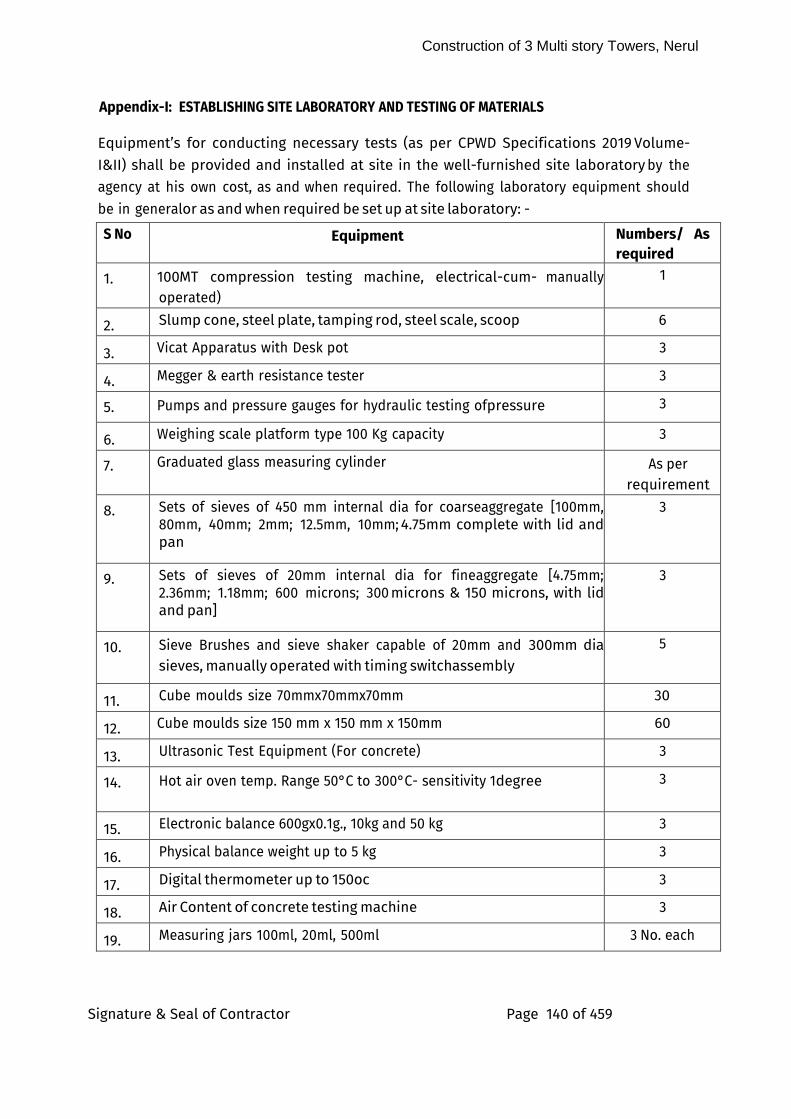
Construction of 3 Multi story Towers, Nerul
Signature & Seal of Contractor Page 140 of 459
Appendix-I: ESTABLISHING SITE LABORATORY AND TESTING OF MATERIALS
Equipment’s for conducting necessary tests (as per CPWD Specifications 2019 Volume-I&II) shall be provided and installed at site in the well-furnished site laboratory by the agency at his own cost, as and when required. The following laboratory equipment should be in general or as and when required be set up at site laboratory: -
S No Equipment Numbers/ As required
1. 100MT compression testing machine, electrical-cum- manually operated)
1
2. Slump cone, steel plate, tamping rod, steel scale, scoop 6
3. Vicat Apparatus with Desk pot 3
4. Megger & earth resistance tester 3
5. Pumps and pressure gauges for hydraulic testing of pressure 3
6. Weighing scale platform type 100 Kg capacity 3
7. Graduated glass measuring cylinder As per requirement
8. Sets of sieves of 450 mm internal dia for coarseaggregate [100mm, 80mm, 40mm; 2mm; 12.5mm, 10mm; 4.75mm complete with lid and pan
3
9. Sets of sieves of 20mm internal dia for fineaggregate [4.75mm; 2.36mm; 1.18mm; 600 microns; 300 microns & 150 microns, with lid and pan]
3
10. Sieve Brushes and sieve shaker capable of 20mm and 300mm dia sieves, manually operated with timing switch assembly
5
11. Cube moulds size 70mmx70mmx70mm 30
12. Cube moulds size 150 mm x 150 mm x 150mm 60
13. Ultrasonic Test Equipment (For concrete) 3
14. Hot air oven temp. Range 50°C to 300°C- sensitivity 1 degree 3
15. Electronic balance 600gx0.1g., 10kg and 50 kg 3
16. Physical balance weight up to 5 kg 3
17. Digital thermometer up to 150oc 3
18. Air Content of concrete testing machine 3
19. Measuring jars 100ml, 20ml, 500ml 3 No. each
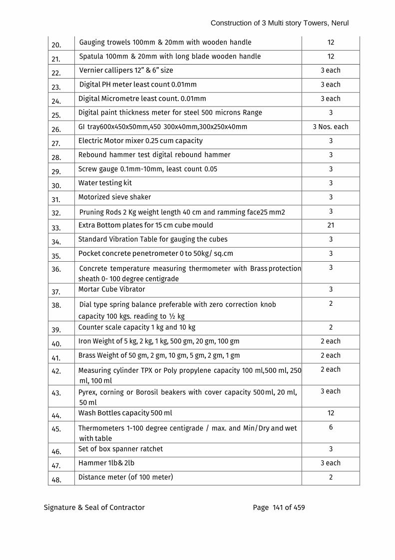
Construction of 3 Multi story Towers, Nerul
Signature & Seal of Contractor Page 141 of 459
20. Gauging trowels 100mm & 20mm with wooden handle 12
21. Spatula 100mm & 20mm with long blade wooden handle 12
22. Vernier callipers 12” & 6” size 3 each
23. Digital PH meter least count 0.01mm 3 each
24. Digital Micrometre least count. 0.01mm 3 each
25. Digital paint thickness meter for steel 500 microns Range 3
26. GI tray600x450x50mm,450 300x40mm,300x250x40mm 3 Nos. each
27. Electric Motor mixer 0.25 cum capacity 3
28. Rebound hammer test digital rebound hammer 3
29. Screw gauge 0.1mm-10mm, least count 0.05 3
30. Water testing kit 3
31. Motorized sieve shaker 3
32. Pruning Rods 2 Kg weight length 40 cm and ramming face 25 mm2 3
33. Extra Bottom plates for 15 cm cube mould 21
34. Standard Vibration Table for gauging the cubes 3
35. Pocket concrete penetrometer 0 to 50kg/ sq.cm 3
36. Concrete temperature measuring thermometer with Brass protection sheath 0- 100 degree centigrade
3
37. Mortar Cube Vibrator 3
38. Dial type spring balance preferable with zero correction knob
capacity 100 kgs. reading to ½ kg
2
39. Counter scale capacity 1 kg and 10 kg 2
40. Iron Weight of 5 kg, 2 kg, 1 kg, 500 gm, 20 gm, 100 gm 2 each
41. Brass Weight of 50 gm, 2 gm, 10 gm, 5 gm, 2 gm, 1 gm 2 each
42. Measuring cylinder TPX or Poly propylene capacity 100 ml, 500 ml, 250 ml, 100 ml
2 each
43. Pyrex, corning or Borosil beakers with cover capacity 500 ml, 20 ml, 50 ml
3 each
44. Wash Bottles capacity 500 ml 12
45. Thermometers 1-100 degree centigrade / max. and Min/ Dry and wet with table
6
46. Set of box spanner ratchet 3
47. Hammer 1lb& 2lb 3 each
48. Distance meter (of 100 meter) 2
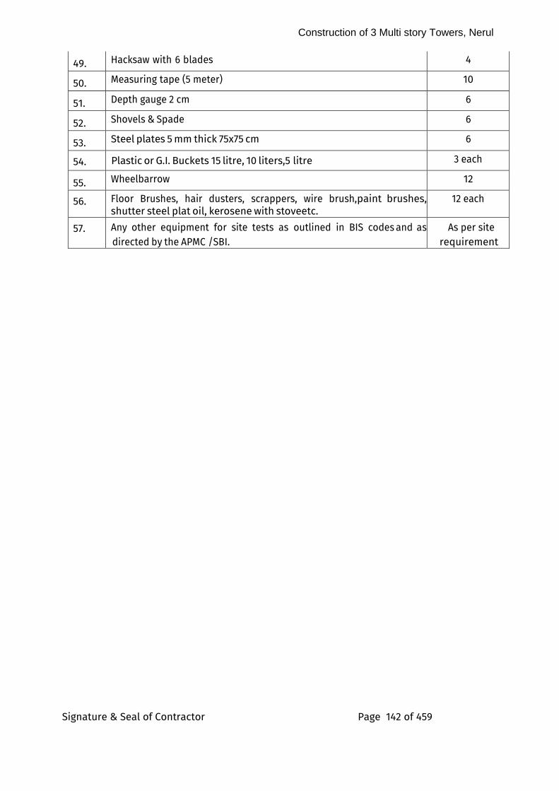
Construction of 3 Multi story Towers, Nerul
Signature & Seal of Contractor Page 142 of 459
49. Hacksaw with 6 blades 4
50. Measuring tape (5 meter) 10
51. Depth gauge 2 cm 6
52. Shovels & Spade 6
53. Steel plates 5 mm thick 75x75 cm 6
54. Plastic or G.I. Buckets 15 litre, 10 liters, 5 litre 3 each
55. Wheelbarrow 12
56. Floor Brushes, hair dusters, scrappers, wire brush,paint brushes, shutter steel plat oil, kerosene with stove etc.
12 each
57. Any other equipment for site tests as outlined in BIS codes and as directed by the APMC /SBI.
As per site requirement
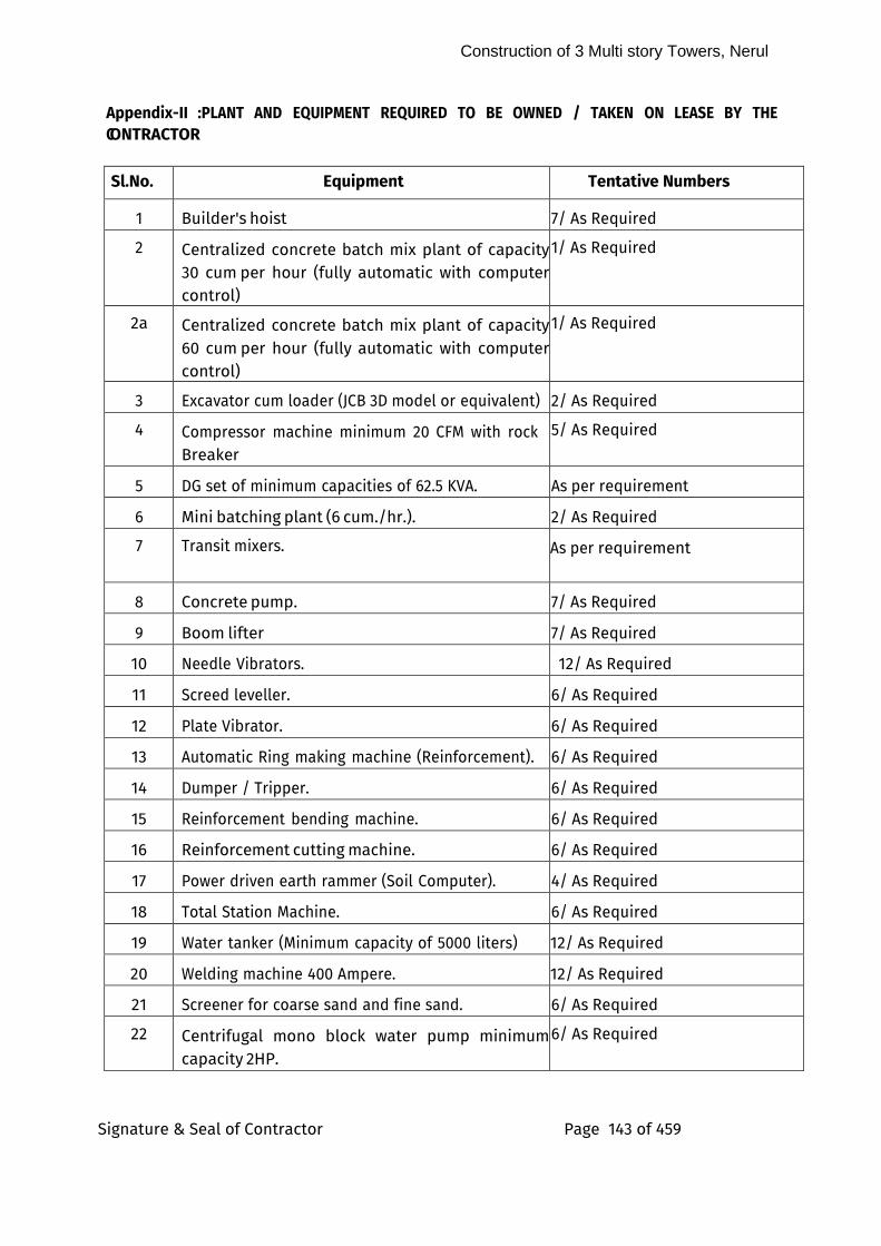
Construction of 3 Multi story Towers, Nerul
Signature & Seal of Contractor Page 143 of 459
Appendix-II :PLANT AND EQUIPMENT REQUIRED TO BE OWNED / TAKEN ON LEASE BY THE CONTRACTOR
Sl.No. Equipment Tentative Numbers
1 Builder's hoist 7/ As Required
2 Centralized concrete batch mix plant of capacity 30 cum per hour (fully automatic with computer control)
1/ As Required
2a Centralized concrete batch mix plant of capacity 60 cum per hour (fully automatic with computer control)
1/ As Required
3 Excavator cum loader (JCB 3D model or equivalent) 2/ As Required
4 Compressor machine minimum 20 CFM with rock Breaker
5/ As Required
5 DG set of minimum capacities of 62.5 KVA. As per requirement
6 Mini batching plant (6 cum./hr.). 2/ As Required
7 Transit mixers. As per requirement
8 Concrete pump. 7/ As Required
9 Boom lifter 7/ As Required
10 Needle Vibrators. 12/ As Required
11 Screed leveller. 6/ As Required
12 Plate Vibrator. 6/ As Required
13 Automatic Ring making machine (Reinforcement). 6/ As Required
14 Dumper / Tripper. 6/ As Required
15 Reinforcement bending machine. 6/ As Required
16 Reinforcement cutting machine. 6/ As Required
17 Power driven earth rammer (Soil Computer). 4/ As Required
18 Total Station Machine. 6/ As Required
19 Water tanker (Minimum capacity of 5000 liters) 12/ As Required
20 Welding machine 400 Ampere. 12/ As Required
21 Screener for coarse sand and fine sand. 6/ As Required
22 Centrifugal mono block water pump minimum capacity 2 HP.
6/ As Required
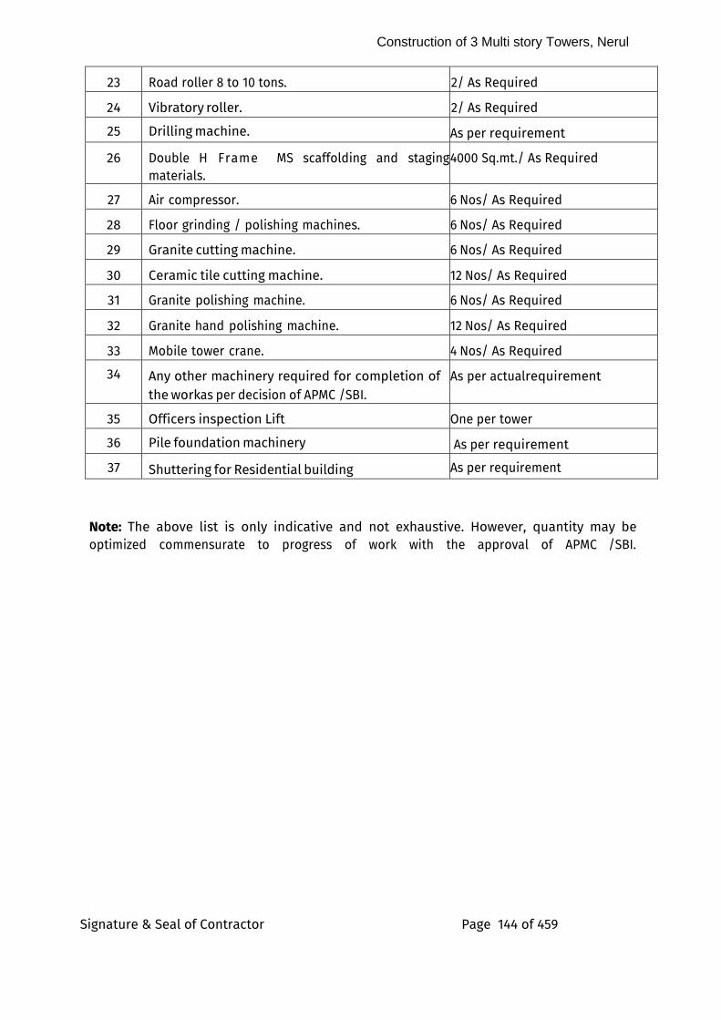
Construction of 3 Multi story Towers, Nerul
Signature & Seal of Contractor Page 144 of 459
23 Road roller 8 to 10 tons. 2/ As Required
24 Vibratory roller. 2/ As Required
25 Drilling machine. As per requirement
26 Double H Frame MS scaffolding and staging materials.
4000 Sq.mt./ As Required
27 Air compressor. 6 Nos/ As Required
28 Floor grinding / polishing machines. 6 Nos/ As Required
29 Granite cutting machine. 6 Nos/ As Required
30 Ceramic tile cutting machine. 12 Nos/ As Required
31 Granite polishing machine. 6 Nos/ As Required
32 Granite hand polishing machine. 12 Nos/ As Required
33 Mobile tower crane. 4 Nos/ As Required
34 Any other machinery required for completion of the work as per decision of APMC /SBI.
As per actual requirement
35 Officers inspection Lift One per tower
36 Pile foundation machinery As per requirement
37 Shuttering for Residential building As per requirement
Note: The above list is only indicative and not exhaustive. However, quantity may be optimized commensurate to progress of work with the approval of APMC /SBI.

Construction of 3 Multi story Towers, Nerul
Signature & Seal of Contractor Page 145 of 459
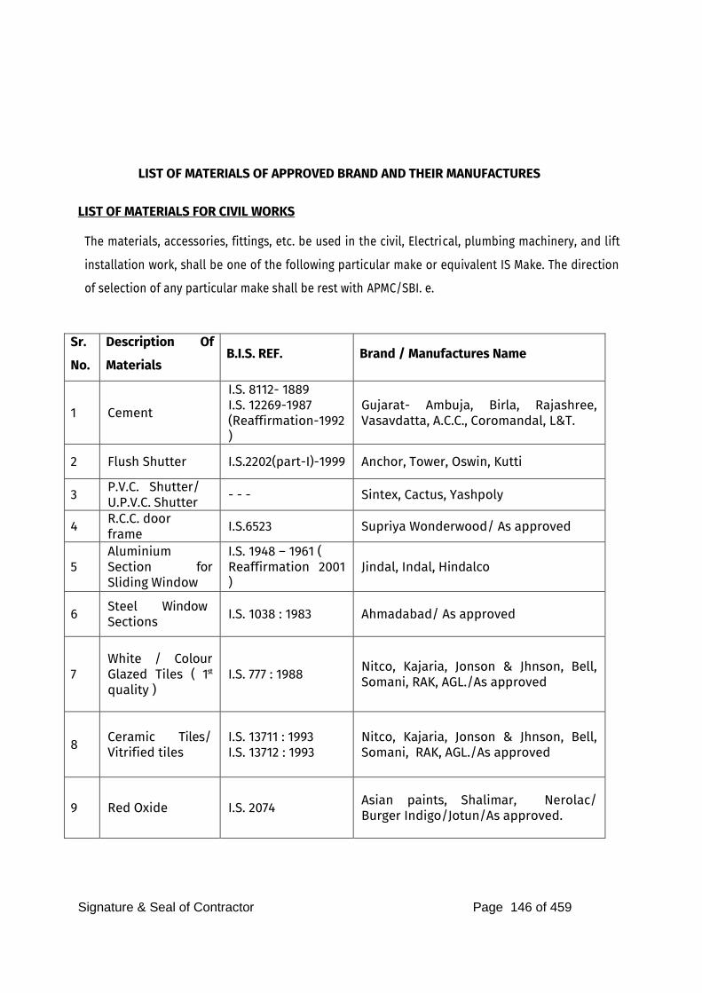
Signature & Seal of Contractor Page 146 of 459
LIST OF MATERIALS OF APPROVED BRAND AND THEIR MANUFACTURES
LIST OF MATERIALS FOR CIVIL WORKS
The materials, accessories, fittings, etc. be used in the civil, Electrical, plumbing machinery, and lift
installation work, shall be one of the following particular make or equivalent IS Make. The direction
of selection of any particular make shall be rest with APMC/SBI. e.
Sr.
No.
Description Of
Materials B.I.S. REF. Brand / Manufactures Name
1 Cement
I.S. 8112- 1889
I.S. 12269-1987
(Reaffirmation-1992 )
Gujarat- Ambuja, Birla, Rajashree, Vasavdatta, A.C.C., Coromandal, L&T.
2 Flush Shutter I.S.2202(part-I)-1999 Anchor, Tower, Oswin, Kutti
3 P.V.C. Shutter/
U.P.V.C. Shutter - - - Sintex, Cactus, Yashpoly
4 R.C.C. door frame
I.S.6523 Supriya Wonderwood/ As approved
5
Aluminium Section for Sliding Window
I.S. 1948 – 1961 ( Reaffirmation 2001 )
Jindal, Indal, Hindalco
6 Steel Window Sections
I.S. 1038 : 1983 Ahmadabad/ As approved
7
White / Colour Glazed Tiles ( 1st quality )
I.S. 777 : 1988 Nitco, Kajaria, Jonson & Jhnson, Bell, Somani, RAK, AGL./As approved
8 Ceramic Tiles/ Vitrified tiles
I.S. 13711 : 1993
I.S. 13712 : 1993
Nitco, Kajaria, Jonson & Jhnson, Bell, Somani, RAK, AGL./As approved
9 Red Oxide I.S. 2074 Asian paints, Shalimar, Nerolac/ Burger Indigo/Jotun/As approved.
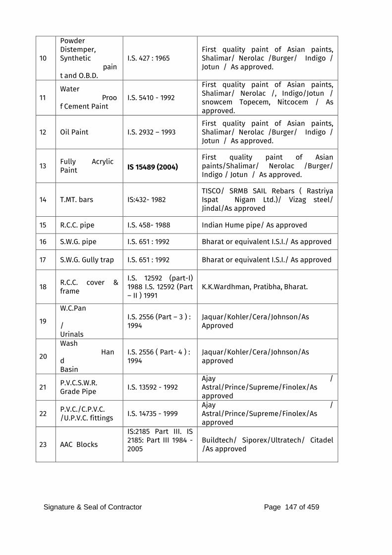
Signature & Seal of Contractor Page 147 of 459
10
Powder Distemper, Synthetic paint and O.B.D.
I.S. 427 : 1965
First quality paint of Asian paints, Shalimar/ Nerolac /Burger/ Indigo / Jotun / As approved.
11
Water Proof Cement Paint
I.S. 5410 - 1992
First quality paint of Asian paints, Shalimar/ Nerolac /, Indigo/Jotun / snowcem Topecem, Nitcocem / As approved.
12 Oil Paint I.S. 2932 – 1993
First quality paint of Asian paints, Shalimar/ Nerolac /Burger/ Indigo / Jotun / As approved.
13 Fully Acrylic Paint IS 15489 (2004)
First quality paint of Asian paints/Shalimar/ Nerolac /Burger/ Indigo / Jotun / As approved.
14 T.MT. bars IS:432- 1982
TISCO/ SRMB SAIL Rebars ( Rastriya Ispat Nigam Ltd.)/ Vizag steel/ Jindal/As approved
15 R.C.C. pipe I.S. 458- 1988 Indian Hume pipe/ As approved
16 S.W.G. pipe I.S. 651 : 1992 Bharat or equivalent I.S.I./ As approved
17 S.W.G. Gully trap I.S. 651 : 1992 Bharat or equivalent I.S.I./ As approved
18 R.C.C. cover & frame
I.S. 12592 (part-I) 1988 I.S. 12592 (Part – II ) 1991
K.K.Wardhman, Pratibha, Bharat.
19
W.C.Pan /
Urinals
I.S. 2556 (Part – 3 ) : 1994
Jaquar/Kohler/Cera/Johnson/As Approved
20
Wash Hand
Basin
I.S. 2556 ( Part- 4 ) : 1994
Jaquar/Kohler/Cera/Johnson/As approved
21 P.V.C.S.W.R. Grade Pipe
I.S. 13592 - 1992
Ajay / Astral/Prince/Supreme/Finolex/As approved
22 P.V.C./C.P.V.C. /U.P.V.C. fittings
I.S. 14735 - 1999
Ajay / Astral/Prince/Supreme/Finolex/As approved
23 AAC Blocks
IS:2185 Part III. IS 2185: Part III 1984 - 2005
Buildtech/ Siporex/Ultratech/ Citadel /As approved
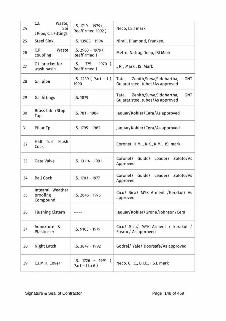
Signature & Seal of Contractor Page 148 of 459
24
C.I. Waste, Soil Pipe, C.I. Fittings
I.S. 1719 – 1979 ( Reaffirmed 1992 ) Neco, I.S.I mark
25 Steel Sink I.S. 13983 - 1994 Nirali, Diamond, Frankee.
26 C.P. Waste coupling
I.S. 2963 – 1979 ( Reaffirmed ) Metro, Natraj, Deep, ISI Mark
27 C.I. bracket for wash basin
I.S. 775 –1970 ( Reaffirmed ) „ R „ Mark , ISI Mark
28 G.I. pipe I.S. 1239 ( Part – I ) 1990
Tata, Zenith,Surya,Siddhartha, GNT Gujarat steel tubes/As approved
29 G.I. fittings I.S. 1879 Tata, Zenith,Surya,Siddhartha, GNT Gujarat steel tubes/As approved
30 Brass bib /Stop
Tap I.S. 781 - 1984 Jaquar/Kohler/Cera/As approved
31 Pillar Tp I.S. 1795 - 1982 Jaquar/Kohler/Cera/As approved
32 Half Turn Flush Cock
Coronet, H.M. , K.K., K.M., ISI mark.
33 Gate Valve I.S. 13114 - 1991 Coronet/ Guide/ Leader/ Zoloto/As Approved
34 Ball Cock I.S. 1703 - 1977 Coronet/ Guide/ Leader/ Zoloto/As Approved
35
Integral Weather proofing Compound
I.S. 2645 - 1975 Cico/ Sica/ MYK Arment /Kerakol/ As approved
36 Flushing Cistern ----- Jaquar/Kohler/Grohe/Johnson/Cera
37 Admixture &
Plasticiser I.S. 9103 - 1979 Cico/ Sica/ MYK Arment / kerakol / Fosroc/ As approved
38 Night Latch I.S. 3847 - 1992 Godrej/ Yale/ Doorsafe/As approved
39 C.I.M.H. Cover I.S. 1726 – 1991 ( Part – I to 6 ) Neco. C.I.C., B.I.C., I.S.I. mark
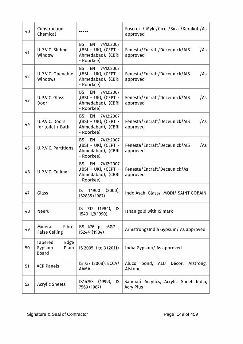
Signature & Seal of Contractor Page 149 of 459
40 Construction
Chemical ----- Foscroc / Myk /Cico /Sica /Kerakol /As approved
41 U.P.V.C. Sliding
Window
BS EN 7412:2007 ,(BSI - UK), (CEPT - Ahmedabad), (CBRI - Roorkee)
Fenesta/Encraft/Deceunick/AIS /As approved
42 U.P.V.C. Openable
Windows
BS EN 7412:2007 ,(BSI - UK), (CEPT - Ahmedabad), (CBRI - Roorkee)
Fenesta/Encraft/Deceunick/AIS /As approved
43 U.P.V.C. Glass
Door
BS EN 7412:2007 ,(BSI - UK), (CEPT - Ahmedabad), (CBRI - Roorkee)
Fenesta/Encraft/Deceunick/AIS /As approved
44 U.P.V.C. Doors
for toilet / Bath
BS EN 7412:2007 ,(BSI - UK), (CEPT - Ahmedabad), (CBRI - Roorkee)
Fenesta/Encraft/Deceunick/AIS /As approved
45 U.P.V.C. Partitions
BS EN 7412:2007 ,(BSI - UK), (CEPT - Ahmedabad), (CBRI - Roorkee)
Fenesta/Encraft/Deceunick/AIS /As approved
46 U.P.V.C. Ceiling
BS EN 7412:2007 ,(BSI - UK), (CEPT - Ahmedabad), (CBRI - Roorkee)
Fenesta/Encraft/Deceunick/As approved
47 Glass IS 14900 (2000), IS2835 (1987)
Indo Asahi Glass/ MODI/ SAINT GOBAIN
48 Neeru IS 712 (1984), IS 1540-1,2(1990) Ishan gold with IS mark
49 Mineral Fibre False Ceiling
BS 476 pt -6&7 , IS2441(1984) Armstrong/India Gypsum/ As approved
50
Tapered Edge Gypsum Plain Board
IS 2095-1 to 3 (2011) India Gypsum/ As approved
51 ACP Panels IS 737 (2008), ECCA/ AAMA
Aluco bond, ALU Décor, Alstrong, Alstone
52 Acrylic Sheets IS14753 (1999), IS 7569 (1987)
Sanmati Acrylics, Acrylic Sheet India, Acry Plus
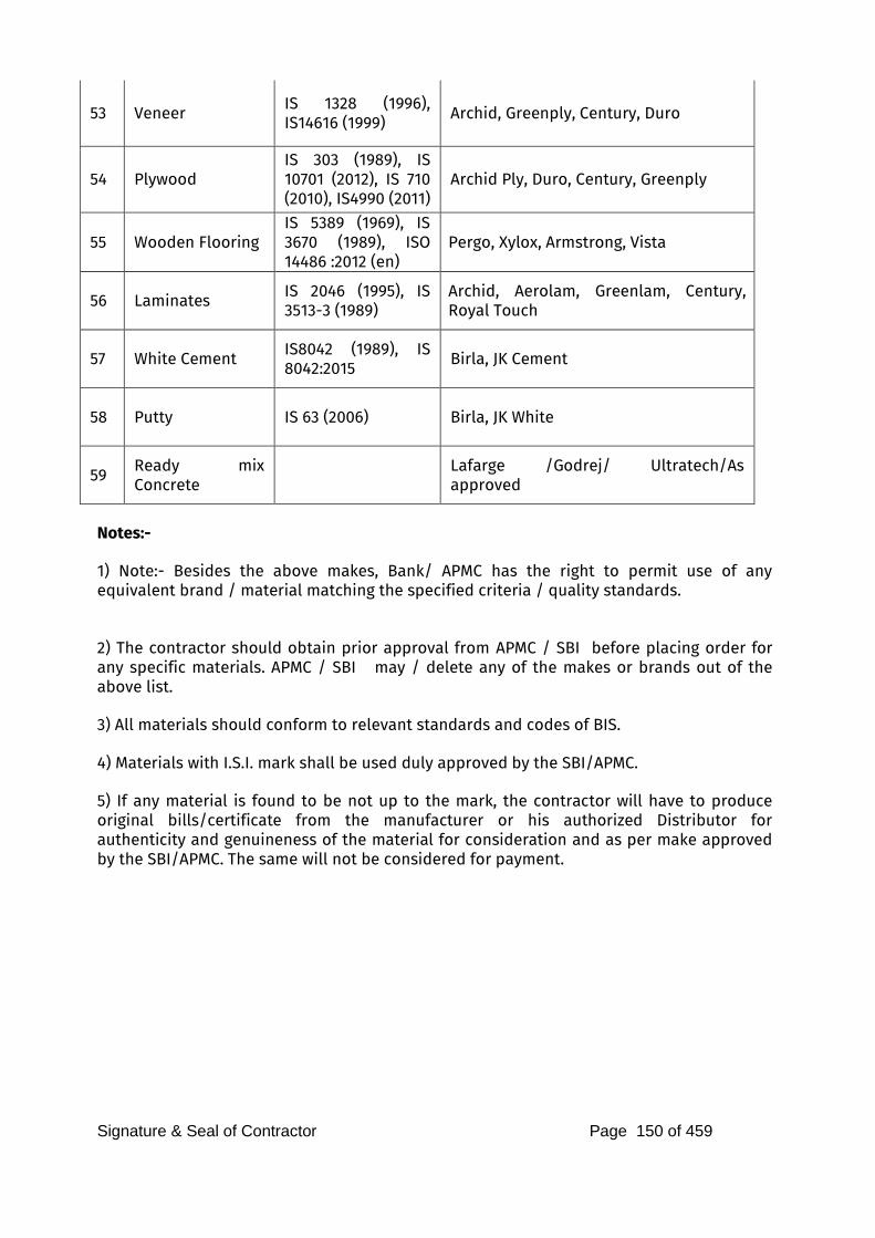
Signature & Seal of Contractor Page 150 of 459
53 Veneer IS 1328 (1996), IS14616 (1999) Archid, Greenply, Century, Duro
54 Plywood
IS 303 (1989), IS 10701 (2012), IS 710 (2010), IS4990 (2011)
Archid Ply, Duro, Century, Greenply
55 Wooden Flooring
IS 5389 (1969), IS 3670 (1989), ISO 14486 :2012 (en)
Pergo, Xylox, Armstrong, Vista
56 Laminates IS 2046 (1995), IS 3513-3 (1989)
Archid, Aerolam, Greenlam, Century, Royal Touch
57 White Cement IS8042 (1989), IS 8042:2015
Birla, JK Cement
58 Putty IS 63 (2006) Birla, JK White
59 Ready mix Concrete
Lafarge /Godrej/ Ultratech/As approved
Notes:- 1) Note:- Besides the above makes, Bank/ APMC has the right to permit use of any equivalent brand / material matching the specified criteria / quality standards. 2) The contractor should obtain prior approval from APMC / SBI before placing order for any specific materials. APMC / SBI may / delete any of the makes or brands out of the above list. 3) All materials should conform to relevant standards and codes of BIS. 4) Materials with I.S.I. mark shall be used duly approved by the SBI/APMC. 5) If any material is found to be not up to the mark, the contractor will have to produce original bills/certificate from the manufacturer or his authorized Distributor for authenticity and genuineness of the material for consideration and as per make approved by the SBI/APMC. The same will not be considered for payment.
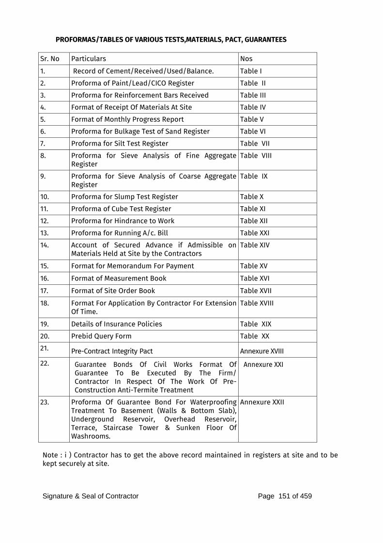
Signature & Seal of Contractor Page 151 of 459
PROFORMAS/TABLES OF VARIOUS TESTS,MATERIALS, PACT, GUARANTEES
Sr. No Particulars Nos
1. Record of Cement/Received/Used/Balance. Table I
2. Proforma of Paint/Lead/CICO Register Table II
3. Proforma for Reinforcement Bars Received Table III
4. Format of Receipt Of Materials At Site Table IV
5. Format of Monthly Progress Report Table V 6. Proforma for Bulkage Test of Sand Register Table VI
7. Proforma for Silt Test Register Table VII
8. Proforma for Sieve Analysis of Fine Aggregate Register
Table VIII
9. Proforma for Sieve Analysis of Coarse Aggregate Register
Table IX
10. Proforma for Slump Test Register Table X
11. Proforma of Cube Test Register Table XI
12. Proforma for Hindrance to Work Table XII
13. Proforma for Running A/c. Bill Table XXI
14. Account of Secured Advance if Admissible on Materials Held at Site by the Contractors
Table XIV
15. Format for Memorandum For Payment Table XV
16. Format of Measurement Book Table XVI
17. Format of Site Order Book Table XVII
18. Format For Application By Contractor For Extension Of Time.
Table XVIII
19. Details of Insurance Policies Table XIX
20. Prebid Query Form Table XX
21. Pre-Contract Integrity Pact Annexure XVIII
22. Guarantee Bonds Of Civil Works Format Of Guarantee To Be Executed By The Firm/ Contractor In Respect Of The Work Of Pre-Construction Anti-Termite Treatment
Annexure XXI
23. Proforma Of Guarantee Bond For Waterproofing Treatment To Basement (Walls & Bottom Slab), Underground Reservoir, Overhead Reservoir, Terrace, Staircase Tower & Sunken Floor Of Washrooms.
Annexure XXII
Note : i ) Contractor has to get the above record maintained in registers at site and to be kept securely at site.

Signature & Seal of Contractor Page 152 of 459
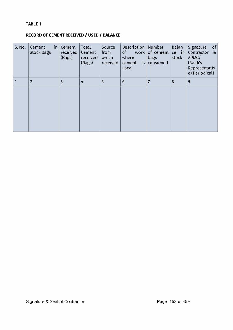
Signature & Seal of Contractor Page 153 of 459
TABLE-I RECORD OF CEMENT RECEIVED / USED / BALANCE
S. No. Cement in stock Bags
Cement received (Bags)
Total Cement received (Bags)
Source from which received
Description of work where cement is used
Number of cement bags consumed
Balance in stock
Signature of Contractor & APMC/ (Bank’s Representative (Periodical)
1 2 3 4 5 6 7 8 9
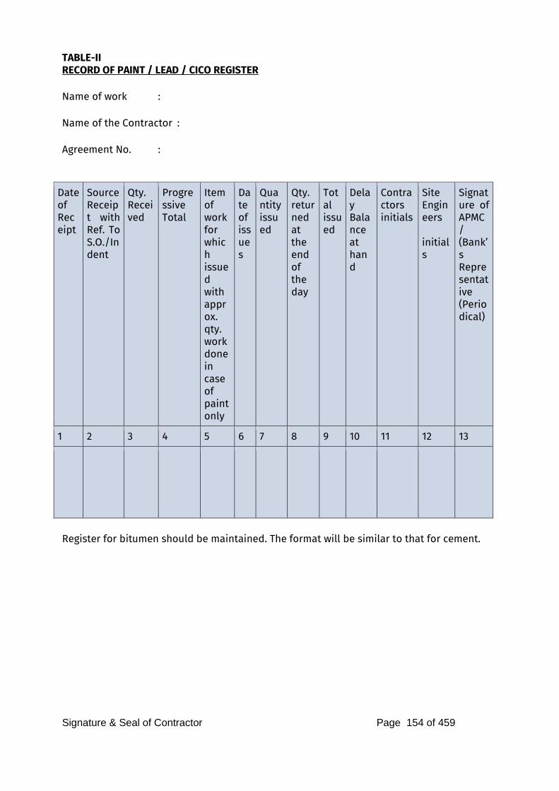
Signature & Seal of Contractor Page 154 of 459
TABLE-II RECORD OF PAINT / LEAD / CICO REGISTER Name of work : Name of the Contractor : Agreement No. :
Date of Receipt
Source Receipt with Ref. To S.O./Indent
Qty. Received
Progressive Total
Item of work for which issued with approx. qty. work done in case of paint only
Date of issues
Quantity issued
Qty. returned at the end of the day
Total issued
Delay Balance at hand
Contractors initials
Site Engineers initials
Signature of APMC/ (Bank’s Representative (Periodical)
1 2 3 4 5 6 7 8 9 10 11 12 13
Register for bitumen should be maintained. The format will be similar to that for cement.
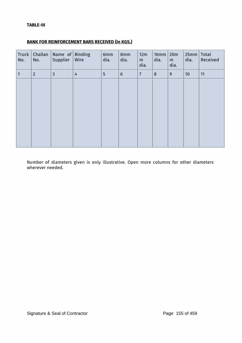
Signature & Seal of Contractor Page 155 of 459
TABLE-III BANK FOR REINFORCEMENT BARS RECEIVED (In KGS.)
Truck No.
Challan No.
Name of Supplier
Binding Wire
6mm dia.
8mm dia.
12mm dia.
16mm dia.
20mm dia.
25mm dia.
Total Received
1 2 3 4 5 6 7 8 9 10 11
Number of diameters given is only illustrative. Open more columns for other diameters wherever needed.
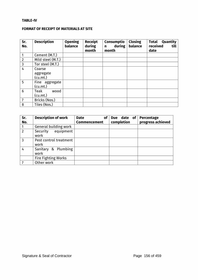
Signature & Seal of Contractor Page 156 of 459
TABLE-IV
FORMAT OF RECEIPT OF MATERIALS AT SITE
Sr. No.
Description Opening balance
Receipt during month
Consumption during month
Closing balance
Total Quantity received till date
1 Cement (M.T.) 2 Mild steel (M.T.) 3 Tor steel (M.T.) 4 Coarse
aggregate (cu.mt.)
5 Fine aggregate (cu.mt.)
6 Teak wood (cu.mt.)
7 Bricks (Nos.) 8 Tiles (Nos.)
Sr. No.
Description of work Date of Commencement
Due date of completion
Percentage progress achieved
1 General building work 2 Security equipment
work
3 Pest control treatment work
4 Sanitary & Plumbing work
Fire Fighting Works 7 Other work
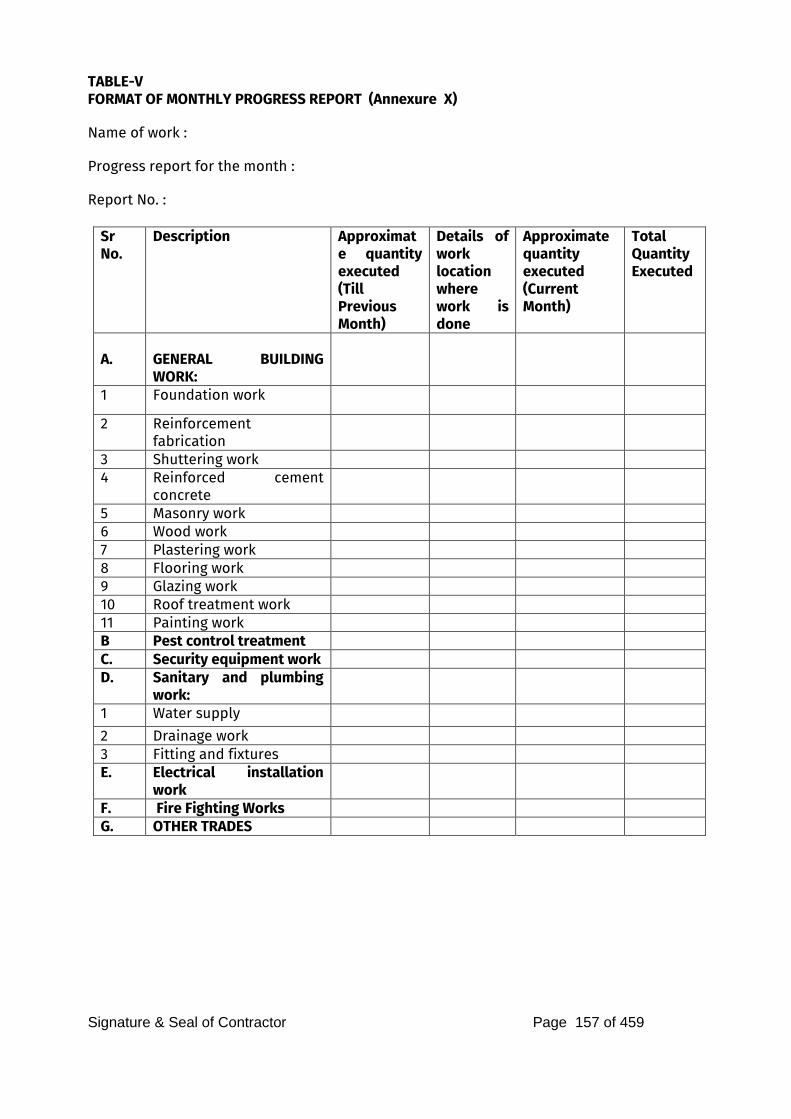
Signature & Seal of Contractor Page 157 of 459
TABLE-V FORMAT OF MONTHLY PROGRESS REPORT (Annexure X)
Name of work :
Progress report for the month :
Report No. :
Sr No.
Description Approximate quantity executed
(Till Previous Month)
Details of work location where work is done
Approximate quantity executed
(Current Month)
Total Quantity Executed
A.
GENERAL BUILDING WORK:
1 Foundation work
2 Reinforcement fabrication
3 Shuttering work 4 Reinforced cement
concrete
5 Masonry work 6 Wood work 7 Plastering work 8 Flooring work 9 Glazing work 10 Roof treatment work 11 Painting work B Pest control treatment C. Security equipment work D. Sanitary and plumbing
work:
1 Water supply
2 Drainage work 3 Fitting and fixtures E. Electrical installation
work
F. Fire Fighting Works G. OTHER TRADES
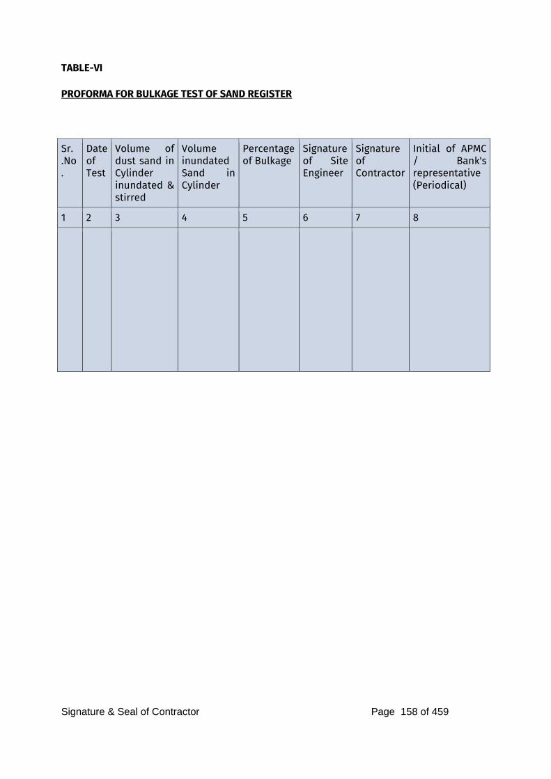
Signature & Seal of Contractor Page 158 of 459
TABLE-VI PROFORMA FOR BULKAGE TEST OF SAND REGISTER
Sr. .No.
Date of Test
Volume of dust sand in Cylinder inundated & stirred
Volume inundated Sand in Cylinder
Percentage of Bulkage
Signature of Site Engineer
Signature of Contractor
Initial of APMC / Bank's representative (Periodical)
1 2 3 4 5 6 7 8
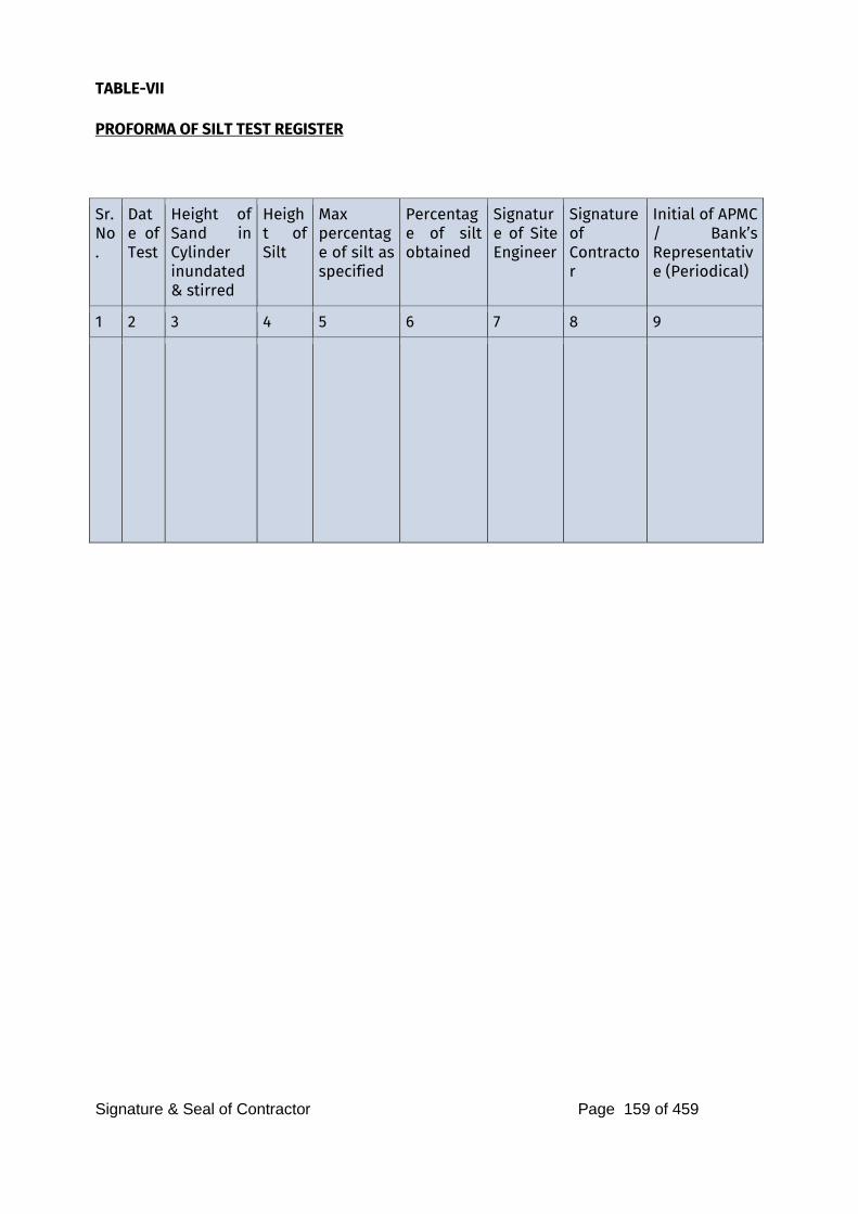
Signature & Seal of Contractor Page 159 of 459
TABLE-VII PROFORMA OF SILT TEST REGISTER
Sr. No.
Date of Test
Height of Sand in Cylinder inundated& stirred
Height of Silt
Max percentage of silt as specified
Percentage of silt obtained
Signature of Site Engineer
Signature of Contractor
Initial of APMC / Bank’s Representative (Periodical)
1 2 3 4 5 6 7 8 9
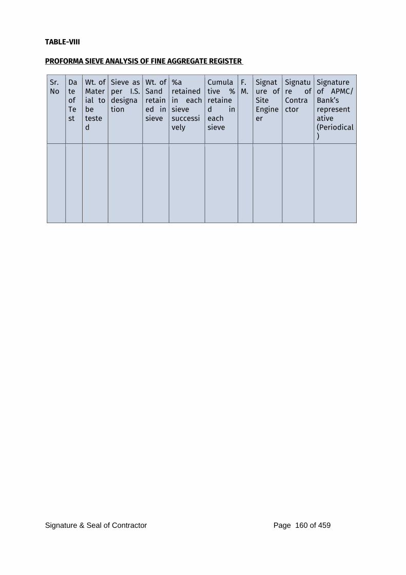
Signature & Seal of Contractor Page 160 of 459
TABLE-VIII PROFORMA SIEVE ANALYSIS OF FINE AGGREGATE REGISTER
Sr.No
Date of Test
Wt. of Material to be tested
Sieve as per I.S. designation
Wt. of Sand retained in sieve
%a retained in each sieve successively
Cumulative % retained in each sieve
F.M.
Signature of Site Engineer
Signature of Contractor
Signature of APMC/ Bank’s representative (Periodical)
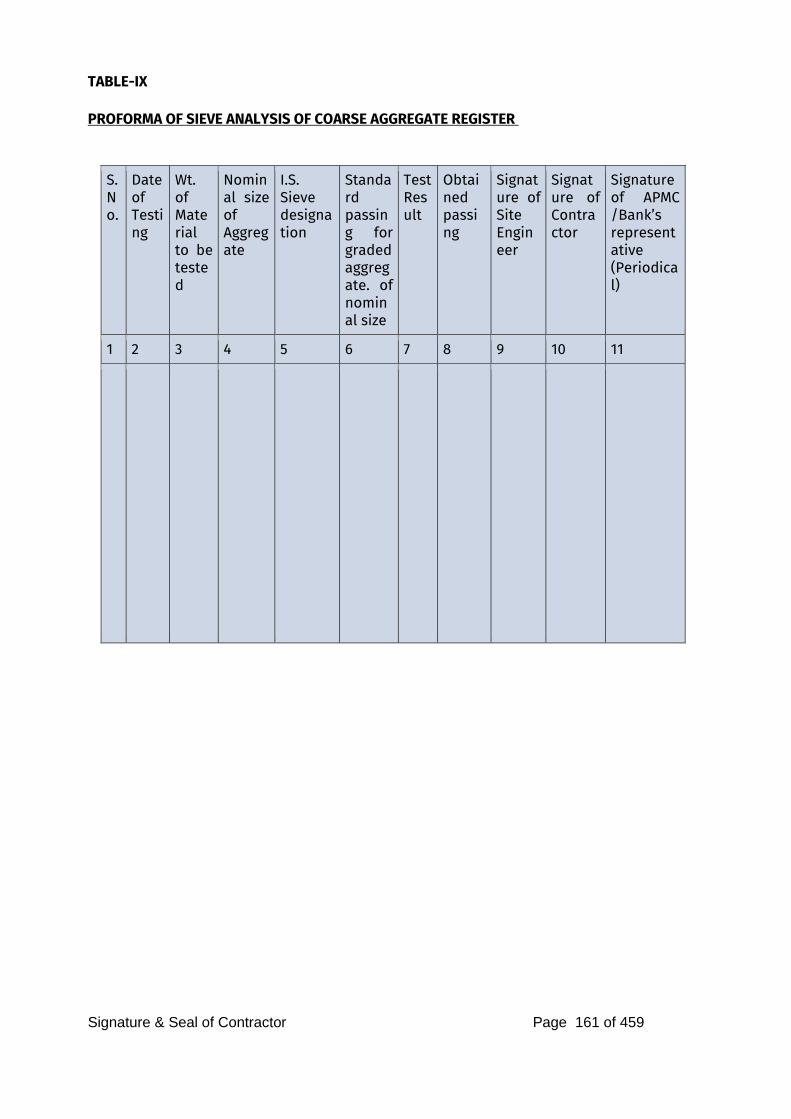
Signature & Seal of Contractor Page 161 of 459
TABLE-IX PROFORMA OF SIEVE ANALYSIS OF COARSE AGGREGATE REGISTER
S. No.
Date of Testing
Wt. of Material to be tested
Nominal size of Aggregate
I.S. Sieve designation
Standard passing for graded aggregate. of nominal size
Test Result
Obtained passing
Signature of Site Engineer
Signature of Contractor
Signature of APMC /Bank’s representative (Periodical)
1 2 3 4 5 6 7 8 9 10 11
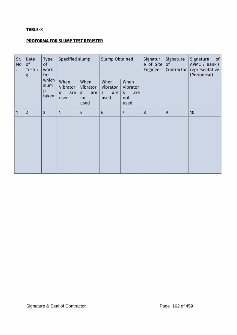
Signature & Seal of Contractor Page 162 of 459
TABLE-X PROFORMA FOR SLUMP TEST REGISTER
Sr. No.
Date of Testing
Type of work for which slump taken
Specified slump Slump Obtained Signature of Site Engineer
Signature of Contractor
Signature of APMC / Bank’s representative (Periodical)
When Vibrators are used
When Vibrators are not used
When Vibrators are used
When Vibrators are not used
1 2 3 4 5 6 7 8 9 10
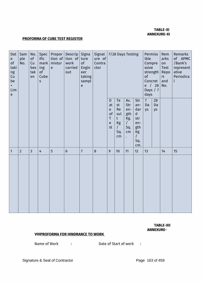
Signature & Seal of Contractor Page 163 of 459
TABLE-XI ANNEXURE-XI PROFORMA OF CUBE TEST REGISTER
Date of taking Cube + Lime
Sample No.
No. of Cubes taken
Specific marking of Cubes
Proportion of mixture
Description of work carried out
Signature of Engineer taking sample
Signature of Contractor
7/28 Days Testing Permissible Compressive strength of Concrete / 28 Days / 7 days
Remarks on Test Report and No.
Remarks of APMC /Bank’s representative Periodical
Date of Test
Test Result Kg/ Sq.cm
Av. Stren-gth Kg. / Sq.cm.
Stran-dard stren-gth Kg / Sq.cm.
7 Days
28 Days
1 2 3 4 5 6 7 8 9 10 11 12 13 14 15
TABLE-XII ANNEXURE-
VIIIPROFORMA FOR HINDRANCE TO WORK
Name of Work : Date of Start of work :
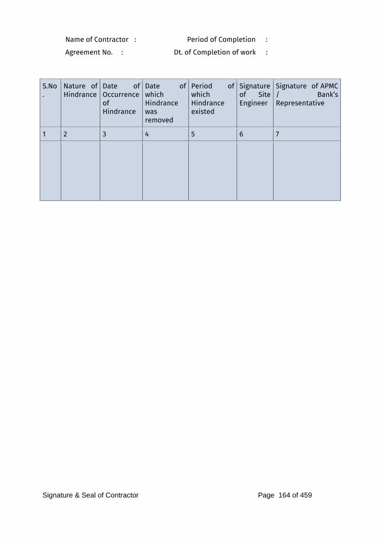
Signature & Seal of Contractor Page 164 of 459
Name of Contractor : Period of Completion :
Agreement No. : Dt. of Completion of work :
S.No.
Nature of Hindrance
Date of Occurrence of Hindrance
Date of which Hindrance was removed
Period of which Hindrance existed
Signature of Site Engineer
Signature of APMC / Bank’s Representative
1 2 3 4 5 6 7
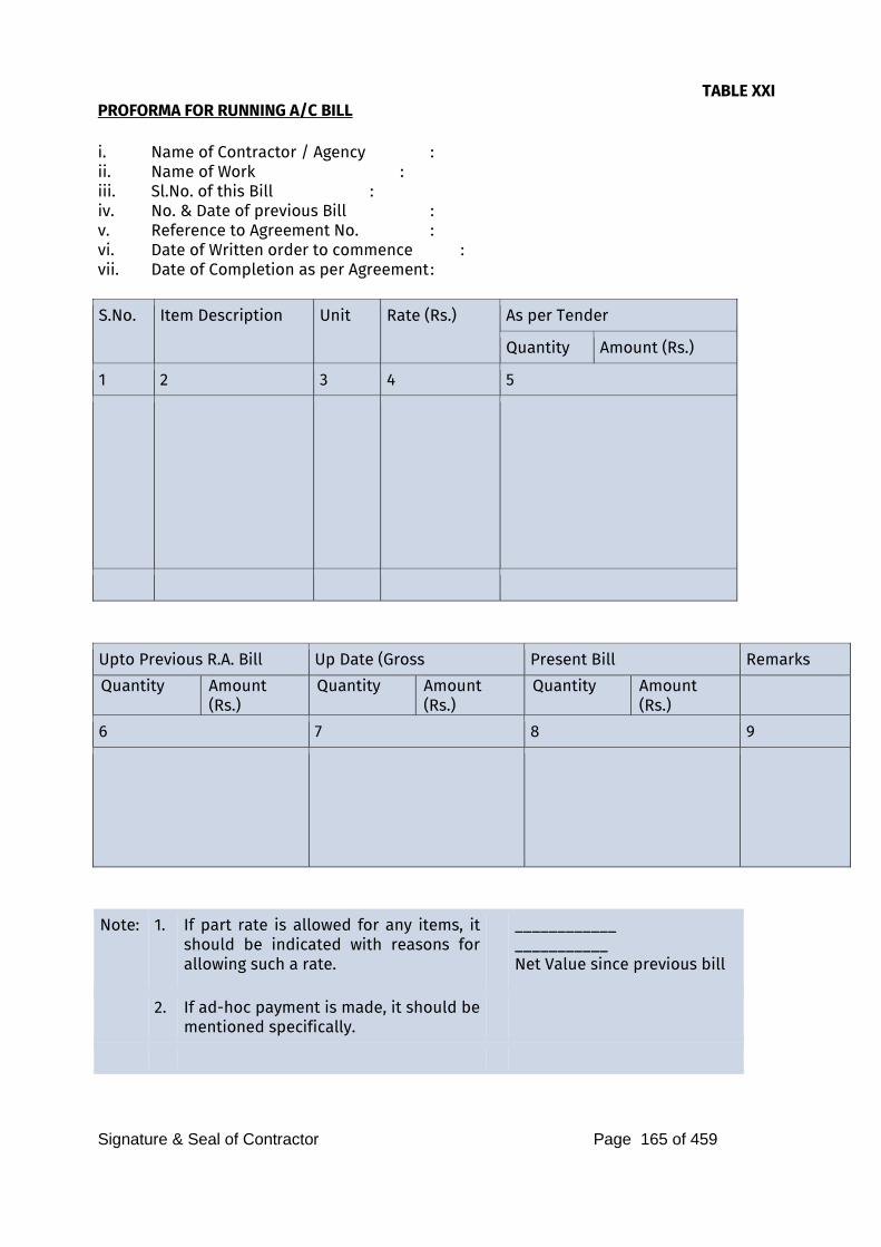
Signature & Seal of Contractor Page 165 of 459
TABLE XXI PROFORMA FOR RUNNING A/C BILL i. Name of Contractor / Agency : ii. Name of Work : iii. Sl.No. of this Bill : iv. No. & Date of previous Bill : v. Reference to Agreement No. : vi. Date of Written order to commence : vii. Date of Completion as per Agreement :
S.No. Item Description Unit Rate (Rs.) As per Tender
Quantity Amount (Rs.)
1 2 3 4 5
Upto Previous R.A. Bill Up Date (Gross Present Bill Remarks
Quantity Amount (Rs.)
Quantity Amount (Rs.)
Quantity Amount (Rs.)
6 7 8 9
Note: 1. If part rate is allowed for any items, it should be indicated with reasons for allowing such a rate.
____________ ___________ Net Value since previous bill
2. If ad-hoc payment is made, it should be mentioned specifically.
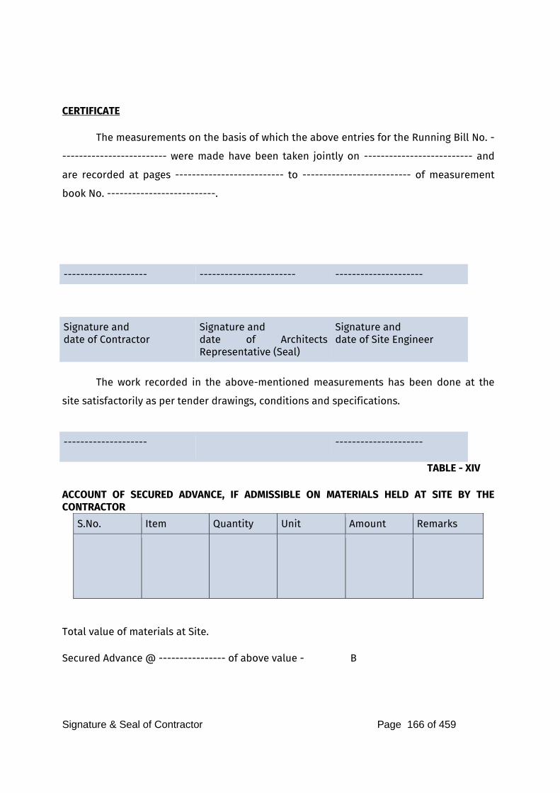
Signature & Seal of Contractor Page 166 of 459
CERTIFICATE The measurements on the basis of which the above entries for the Running Bill No. -
------------------------- were made have been taken jointly on -------------------------- and
are recorded at pages -------------------------- to -------------------------- of measurement
book No. --------------------------.
-------------------- ----------------------- ---------------------
Signature and date of Contractor
Signature and date of Architects Representative (Seal)
Signature and date of Site Engineer
The work recorded in the above-mentioned measurements has been done at the
site satisfactorily as per tender drawings, conditions and specifications.
-------------------- ---------------------
TABLE - XIV ACCOUNT OF SECURED ADVANCE, IF ADMISSIBLE ON MATERIALS HELD AT SITE BY THE CONTRACTOR
S.No. Item Quantity Unit Amount Remarks
Total value of materials at Site. Secured Advance @ ---------------- of above value - B
Signature & Seal of Contractor Page 167 of 459
CERTIFIED: (i) That the materials mentioned above have actually been brought by the Contractor
to the site of the work and on advance on any quantity of any of this item is outstanding on their security.
(ii) That the materials (are of imperishable nature) and are all required by the
Contractor for use in the work in connection with the items for which rates of finished work have been agreed upon.
Dated Signature of Site Engineer Preparing the bill Rank ----------------------------- Date signature of Banks Architects------------------- (Name of the Architects)
--------------------------- Dated Signature of the Contractor
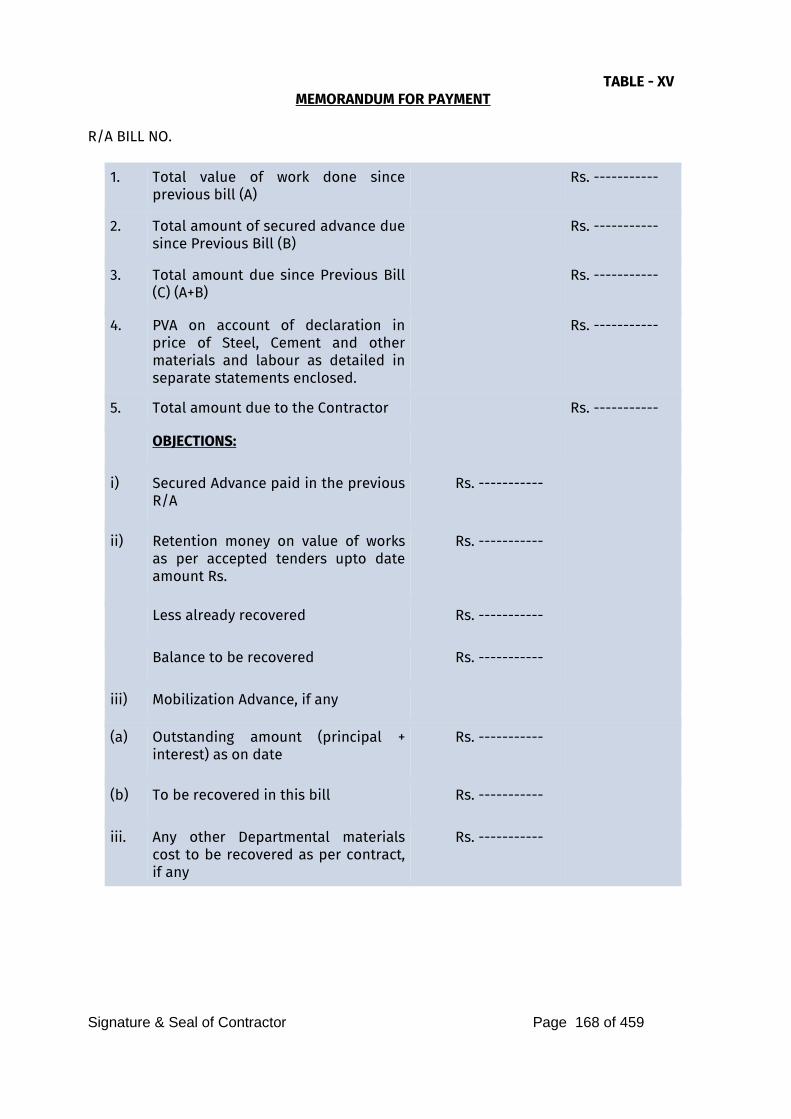
Signature & Seal of Contractor Page 168 of 459
TABLE - XV MEMORANDUM FOR PAYMENT
R/A BILL NO.
1. Total value of work done since previous bill (A)
Rs. -----------
2. Total amount of secured advance due since Previous Bill (B)
Rs. -----------
3. Total amount due since Previous Bill (C) (A+B)
Rs. -----------
4. PVA on account of declaration in price of Steel, Cement and other materials and labour as detailed in separate statements enclosed.
Rs. -----------
5. Total amount due to the Contractor Rs. -----------
OBJECTIONS:
i) Secured Advance paid in the previous R/A
Rs. -----------
ii) Retention money on value of works as per accepted tenders upto date amount Rs.
Rs. -----------
Less already recovered Rs. -----------
Balance to be recovered Rs. -----------
iii) Mobilization Advance, if any
(a) Outstanding amount (principal + interest) as on date
Rs. -----------
(b) To be recovered in this bill Rs. -----------
iii. Any other Departmental materials cost to be recovered as per contract, if any
Rs. -----------
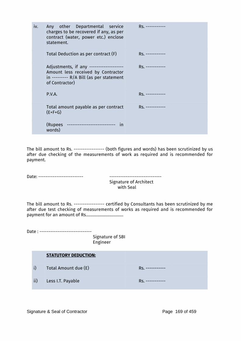
Signature & Seal of Contractor Page 169 of 459
iv. Any other Departmental service charges to be recovered if any, as per contract (water, power etc.) enclose statement.
Rs. -----------
Total Deduction as per contract (F) Rs. -----------
Adjustments, if any ------------------- Amount less received by Contractor in --------- R/A Bill (as per statement of Contractor)
Rs. -----------
P.V.A. Rs. -----------
Total amount payable as per contract (E+F+G)
Rs. -----------
(Rupees --------------------------- in words)
The bill amount to Rs. ----------------- (both figures and words) has been scrutinized by us after due checking of the measurements of work as required and is recommended for payment. Date: ------------------------- ----------------------------- Signature of Architect with Seal The bill amount to Rs. ----------------- certified by Consultants has been scrutinized by me after due test checking of measurements of works as required and is recommended for payment for an amount of Rs................................... Date : ----------------------------- Signature of SBI Engineer
STATUTORY DEDUCTION:
i) Total Amount due (E) Rs. -----------
ii) Less I.T. Payable Rs. -----------

Signature & Seal of Contractor Page 170 of 459
iii) Less S.T. Payable Rs. -----------
Net Payable Rs. -----------
These figures given in the Memorandum for payable has been verified and bill passed for payment ---------------------------------------------------------------- (in words and figures) Date: ---------------------- ---------------------------------- Signature of the Premises Officer
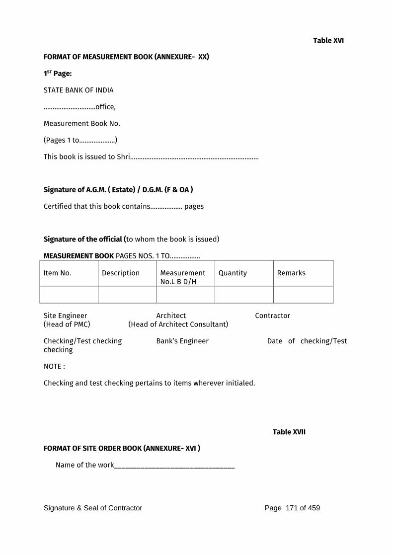
Signature & Seal of Contractor Page 171 of 459
Table XVI
FORMAT OF MEASUREMENT BOOK (ANNEXURE- XX)
1ST Page:
STATE BANK OF INDIA
………………………..office,
Measurement Book No.
(Pages 1 to………………..)
This book is issued to Shri………………………………………………………………
Signature of A.G.M. ( Estate) / D.G.M. (F & OA )
Certified that this book contains……………… pages
Signature of the official (to whom the book is issued)
MEASUREMENT BOOK PAGES NOS. 1 TO……………..
Item No. Description Measurement No.L B D/H
Quantity Remarks
Site Engineer Architect Contractor (Head of PMC) (Head of Architect Consultant)
Checking/Test checking Bank’s Engineer Date of checking/Test checking
NOTE :
Checking and test checking pertains to items wherever initialed.
Table XVII
FORMAT OF SITE ORDER BOOK (ANNEXURE- XVI )
Name of the work________________________________
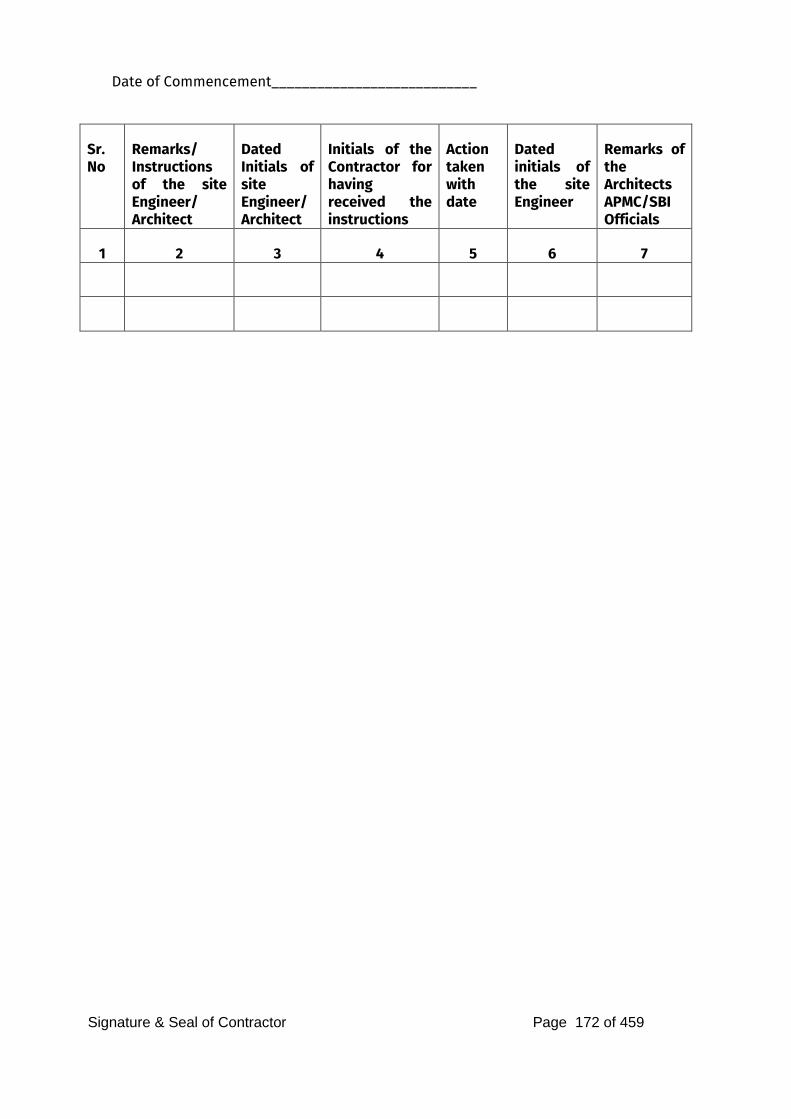
Signature & Seal of Contractor Page 172 of 459
Date of Commencement___________________________
Sr. No
Remarks/ Instructions of the site Engineer/ Architect
Dated Initials of site Engineer/ Architect
Initials of the Contractor for having received the instructions
Action taken with date
Dated initials of the site Engineer
Remarks of the Architects APMC/SBI Officials
1 2 3 4 5 6 7
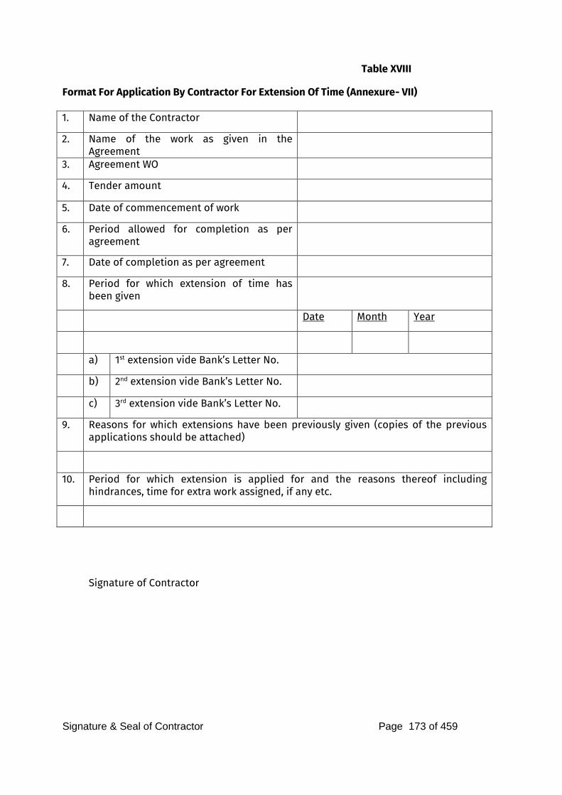
Signature & Seal of Contractor Page 173 of 459
Table XVIII
Format For Application By Contractor For Extension Of Time (Annexure- VII) 1. Name of the Contractor
2. Name of the work as given in the Agreement
3. Agreement WO
4. Tender amount
5. Date of commencement of work
6. Period allowed for completion as per agreement
7. Date of completion as per agreement
8. Period for which extension of time has been given
Date Month Year
a) 1st extension vide Bank’s Letter No.
b) 2nd extension vide Bank’s Letter No.
c) 3rd extension vide Bank’s Letter No.
9. Reasons for which extensions have been previously given (copies of the previous applications should be attached)
10. Period for which extension is applied for and the reasons thereof including hindrances, time for extra work assigned, if any etc.
Signature of Contractor
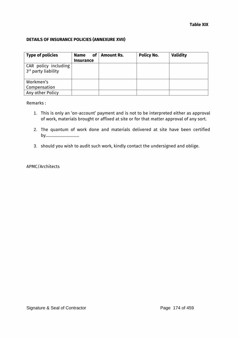
Signature & Seal of Contractor Page 174 of 459
Table XIX
DETAILS OF INSURANCE POLICIES (ANNEXURE XVII)
Type of policies Name of
Insurance
Amount Rs. Policy No. Validity
CAR policy including 3rd party liability
Workmen’s Compensation
Any other Policy
Remarks :
1. This is only an ‘on-account’ payment and is not to be interpreted either as approval of work, materials brought or affixed at site or for that matter approval of any sort.
2. The quantum of work done and materials delivered at site have been certified by………………………….
3. should you wish to audit such work, kindly contact the undersigned and oblige.
APMC/Architects
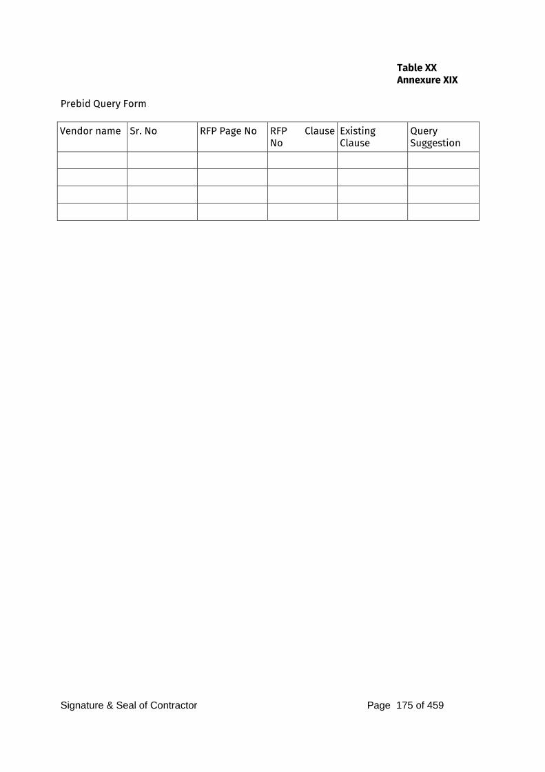
Signature & Seal of Contractor Page 175 of 459
Table XX
Annexure XIX
Prebid Query Form
Vendor name Sr. No RFP Page No RFP Clause
No
Existing Clause
Query Suggestion
Signature & Seal of Contractor Page 176 of 459
Annexure XVIII
PRE-CONTRACT INTEGRITY PACT
General This pre-bid pre-contract Agreement (hereinafter called the Integrity Pact)is made on day of the month of 2022, between, on one hand, the State Bank of India
a body corporate incorporated under the State Bank of India Act, 1955 having its Corporate Centre at State Bank Bhavan, Nariman Point, Mumbai through its Department / Office at , , (hereinafter called the "SELLER", which expression shall mean and include, unless the context otherwise requires, its successors) of the First Part and M/s _ represented by
Shri , Chief Executive Officer (hereinafter called the "BIDDER which expression shall mean and include, unless the context otherwise requires, its / his successors and permitted assigns of the Second Part.
WHEREAS the SELLER proposes to sale (Name of the Stores/Equipment/Item) and the BIDDER is willing to purchase/ acquire and
WHEREAS the BIDDER is a private company/public company/Government undertaking/partnership/registered export agency, constituted in accordance with the relevant law in the matter and the SELLER is an Office / Department of State Bank of India performing its functions on behalf of State Bank of India.
NOW, THEREFORE,
To avoid all forms of corruption by following a system that is fair, transparent and free from any influence/prejudiced dealings prior to, during and subsequent to the currency of the contract to be entered into with a view to:
iii. Enabling the SELLER to sale the desired product at a competitive price in conformity with the defined specifications by avoiding the high cost and the distortionary impact of corruption on public procurement; and
iv. Enabling BIDDERs to abstain from bribing or indulging in any corrupt practice in order to secure the contract by providing assurance to them that their competitors will also abstain from bribing and other corrupt practices and the SELLER will commit to prevent corruption, in any form, by its officials by following transparent procedures.
The parties hereto hereby agree to enter into this Integrity Pact and agree as follows:
Commitments of the SELLER
Signature & Seal of Contractor Page 177 of 459
1.1 The SELLER undertakes that no official of the SELLER, connected directly or indirectly with the contract, will demand, take a promise for or accept, directly or through intermediaries, any bribe, consideration, gift, reward, favour or any material or immaterial benefit or any other advantage from the BIDDER, either for themselves or for any person, organisation or third party related to the contract in exchange for an advantage in the bidding process, bid evaluation, contracting or implementation process related to the contract.
1.2 The SELLER will, during the pre-contract stage, treat all BIDDERs alike, and will provide to all BIDDERs the same information and will not provide any such information to any particular BIDDER which could afford an advantage to that particular BIDDER in comparison to other BIDDERs.
1.3 All the officials of the SELLER will report to the appropriate authority any attempted or completed breaches of the above commitments as well as any substantial suspicion of such a breach.
2.0 In case any such preceding misconduct on the part of such official(s) is reported by the BIDDER to the SELLER with full and verifiable facts and the same is prima facie found to be correct by the SELLER, necessary disciplinary proceedings, or any other action as deemed fit, including criminal proceedings may be initiated by the SELLER and such a person shall be debarred from further dealings related to the contract process. In such a case while an enquiry is being conducted by the SELLER the proceedings under the contract would not be stalled.
3.0 Commitments of BIDDERs
The BIDDER commits itself to take all measures necessary to prevent corrupt practices, unfair means and illegal activities during any stage of its bid or during any pre-contract or post-contract stage in order to secure the contract or in furtherance to secure it and in particular commit itself to the following:
3.1 The BIDDER will not offer, directly or through intermediaries, any bribe, gift, consideration, reward, favour, any material or immaterial benefit or other advantage, commission, fees, brokerage or inducement to any official of the SELLER, connected directly or indirectly with the bidding process, or to any person, organisation or third party related to the contract in exchange for any advantage in the bidding, evaluation, contracting and implementation of the contract.
3.2 The BIDDER further undertakes that it has not given, offered or promised to give, directly or indirectly any bribe, gift, consideration, reward, favour, any material or immaterial benefit or other advantage, commission, fees, brokerage or inducement to any official of the SELLER or otherwise in procuring the Contract or forbearing to do or having
Signature & Seal of Contractor Page 178 of 459
done any act in relation to the obtaining or execution of the contract or any other contract with State Bank of India for showing or forbearing to show favour or disfavour to any person in relation to the contract or any other contract with State Bank of India.
3.3 * Wherever applicable, the BIDDER shall disclose the name and address of agents and representatives permitted by the Bid documents and Indian BIDDERs shall disclose their foreign principals or associates, if any.
3.4 The BIDDER confirms and declares that they have not made any payments to any agents/brokers or any other intermediary, in connection with this bid/contract.
3.5 The BIDDER further confirms and declares to the SELLER that the BIDDER has not engaged any individual or firm or company whether Indian or foreign to intercede, facilitate or in any way to recommend to the SELLER or any of its functionaries, whether officially or unofficially to the award of the contract to the BIDDER, nor has any amount been paid, promised or intended to be paid to any such individual, firm or company in respect of any such intercession, facilitation or recommendation.
3.6 The BIDDER, at the earliest available opportunity, i.e. either while presenting the bid or during pre-contract negotiations and in any case before opening the financial bid and before signing the contract, shall disclose any payments he has made, is committed to or intends to make to officials of the SELLER or their family members, agents, brokers or any other intermediaries in connection with the contract and the details of services agreed upon for such payments.
3.7 The BIDDER will not collude with other parties interested in the contract to impair the transparency, fairness and progress of the bidding process, bid evaluation, contracting and implementation of the contract.
3.8 The BIDDER will not accept any advantage in exchange for any corrupt practice, unfair means and illegal activities.
3.9 The BIDDER shall not use improperly, for purposes of competition or personal gain, or pass. on 'to° others, any -information provided by the SELLER as part of the business relationship, regarding plans, technical proposals and business details, including information contained in any electronic data carrier. The BIDDER also undertakes to exercise due and adequate care lest any such information is divulged.
3.10 The BIDDER commits to refrain from giving any complaint directly or through any other manner without supporting it with full and verifiable facts.
311 The BIDDER shall not instigate or cause to instigate any third person to commit any of the actions mentioned above.
Signature & Seal of Contractor Page 179 of 459
3.12 If the BIDDER or any employee of the BIDDER or any person acting on behalf of the BIDDER, either directly or indirectly, is a relative of any of the officers of the SELLER, or alternatively, if any relative of an officer of the SELLER has financial Interest/stake in the BIDDER's firm, the same shall be disclosed by the BIDDER at the time of filing of EOI - Application Forms. 3.13 The term 'relative' for this purpose would be as defined in Section 6 of the Companies Act 1956.
3.14 The BIDDER shall not lend to or borrow any money from or enter into any monetary dealings or transactions, directly or indirectly, with any employee of the SELLER.
4. Previous Transgression
4.1 The BIDDER declares that no previous transgression occurred in the last three years immediately before signing of this Integrity Pact, with any other company in any country in respect of any corrupt practices envisaged hereunder or with any Public Sector Enterprise / Public Sector Banks in India or any Government Department in India or RBI that could justify BIDDER's exclusion from the Tender / EOI process.
4.2 The BIDDER agrees that if it makes incorrect statement on this subject, BIDDER can be disqualified from the Tender / EOI process or the contract, if already awarded, can be terminated for such reason.
5.0 Earnest Money (Security Deposit)
i. While submitting commercial bid, the BIDDER shall deposit an amount (specified in RFP) as Earnest Money/Security Deposit, with the SELLER through any of the mode mentioned in the RFP / bid document and no such mode is specified, by a Bank Draft or a Pay Order in favour of State Bank of India from a nationalized Bank including SBI. However, payment of any such amount by way of Bank Guarantee, if so, permitted as per bid documents / RFP should be from any nationalized Bank other than SBI and promising payment of the guaranteed sum to the SELLER on demand within three working days without any demur whatsoever and without seeking any reasons whatsoever. The demand for payment by the SELLER shall be treated as conclusive proof for making such payment to the SELLER.
ii. Unless otherwise stipulated in the Bid document / RFP, the Earnest Money/Security Deposit shall be valid up to a period of five years or the complete conclusion of the contractual obligations to the complete satisfaction of both the BIDDER and the SELLER, including warranty period, whichever is later.
Signature & Seal of Contractor Page 180 of 459
iii. In case of the successful BIDDER a clause would also be incorporated in the Article pertaining to Performance Bond in the Sale Contract that the provisions of Sanctions for Violation shall be applicable for forfeiture of Performance Bond in case of a decision by the SELLER to forfeit the same-without assigning any reason for imposing sanction for violation of this Pact.
iv. No interest shall be payable by the SELLER to the BIDDER on Earnest Money/Security Deposit for the period of its currency.
6.0 Sanctions for Violations
i. Any breach of the aforesaid provisions by the BIDDER or any one employed by it or acting on its behalf (whether with or without the knowledge of the BIDDER) shall entitle the SELLER to take all or any one of the following actions, wherever required:
To immediately call off the pre contract negotiations without assigning any reason and without giving any compensation to the BIDDER. However, the proceedings with the other BIDDER(s) would continue, unless the SELLER desires to drop the entire process.
The Earnest Money Deposit (in pre-contract stage) and/or Security Deposit/Performance Bond (after the contract is signed) shall stand forfeited either fully or partially, as decided by the SELLER and the SELLER shall not be required to assign any reason therefore.
To immediately cancel the contract, if already signed, without giving any compensation to the BIDDER.
To recover all sums already paid by the SELLER, and in case of an Indian BIDDER with interest thereon at 2% higher than the prevailing Base Rate of State Bank of India, while in case of a BIDDER from a country other than India with interest thereon at 2% higher than the LIBOR. If any outstanding payment is due to the BIDDER from the SELLER in connection with any other contract for any other stores, such outstanding could also be utilized to recover the aforesaid sum and interest.
To encash the advance bank guarantee and performance bond/warranty bond, if furnished by the BIDDER, in order to recover the payments, already made by the SELLER, along with interest.
To cancel all or any other Contracts with the BIDDER. The BIDDER shall be liable to pay compensation for any loss or damage to the SELLER resulting from such cancellation/rescission and the SELLER shall be entitled to deduct the amount so payable from the money(s) due to the BIDDER.
To debar the BIDDER from participating in future bidding processes of the SELLER or
Signature & Seal of Contractor Page 181 of 459
any of its Subsidiaries for a minimum period of five years, which may be further extended at the discretion of the SELLER.
To recover all sums paid, in violation of this Pact, by BIDDER(s) to any middleman or agent or broker with a view to securing the contract.
Forfeiture of Performance Bond in case of a decision by the SELLER to forfeit the same without assigning any reason for imposing sanction for violation of this Pact. Intimate to the CVC, IBA, RBI, as the SELLER deemed fit the details of such events for appropriate action by such authorities.
ii. The SELLER will be entitled to take all or any of the actions mentioned at para 6 of this Pact also on the Commission by the BIDDER or any one employed by it or acting on its behalf (whether with or without the knowledge of the BIDDER), of an offence as defined in Chapter IX of the Indian Penal code, 1860 or Prevention of Corruption Act, 1988 or any other statute enacted for prevention of corruption.
iii. The decision of the SELLER to the effect that a breach of the provisions of this Pact has been committed by the BIDDER shall be final and conclusive on the BIDDER. However, the BIDDER can approach the Independent Monitor(s) appointed for the purposes of this Pact.
7.0 Fall Clause
The BIDDER undertakes that it has not supplied/is not supplying similar product/systems or subsystems at a price lower than that offered in the present bid in respect of any other Ministry/Department of the Government of India or PSU or any other Bank and if it is found at any stage that similar product/systems or sub systems was supplied by the BIDDER to any other Ministry/Department of the Government of India or a PSU or a Bank at a lower price, then that very price, with due allowance for elapsed time, will be applicable to the present case and the difference in the cost would be refunded by the BIDDER to the SELLER, if the contract has already been concluded.
Independent Monitors
The SELLER has appointed Independent Monitors (hereinafter referred to as Monitors) for this Pact in consultation with the Central Vigilance Commission (Names and email ID’s of the Monitors to be given):
NAME Ms. Minnie Mathew Dr. Parvez Hayat, CADRE IAS (Retd) IPS (Retd) E-MAIL ID [email protected] [email protected]

Signature & Seal of Contractor Page 182 of 459
m
The task of the Monitors shall be to review independently and objectively, whether and to what extent the parties comply with the obligations under this Pact.
The Monitors shall not be subject to instructions by the representatives of the parties and perform their functions neutrally and independently. Both the parties accept that the Monitors have the right to access all the documents relating to the project/procurement, including minutes of meetings.
As soon as the Monitor notices, or has reason to believe, a violation of this Pact, he will so inform the Authority designated by the SELLER.
The BIDDER(s) accepts that the Monitor has the right to access without restriction to all Project documentation of the SELLER including that provided by the BIDDER. The BIDDER will also grant the Monitor, upon his request and demonstration of a valid interest, unrestricted and unconditional access to his project documentation. The same is applicable to Subcontractors. The Monitor shall be under contractual obligation to treat the information and documents of the BIDDER/Subcontractor(s) with confidentiality.
The SELLER will provide to the Monitor sufficient information about all meetings among the parties related to the Project provided such meetings could have an impact on the contractual relations between the parties. The parties will offer to the Monitor the option to participate in such meetings.
The Monitor will submit a written report to the designated Authority of SELLER/Secretary in the Department/ within 8 to 10 weeks from the date of reference or intimation to him by the SELLER / BIDDER and, should the occasion arise, submit proposals for correcting problematic situations. Facilitation of Investigation
In case of any allegation of violation of any provisions of this Pact or payment of commission, the SELLER or its agencies shall be entitled to examine all the documents including the Books of Accounts of the BIDDER and the BIDDER shall provide necessary information and documents in English and shall extend all possible help for the purpose of such examination.
Law and Place of Jurisdiction This Pact is subject to Indian Law. The place of performance and jurisdiction is the seat of the SELLER.
This Pact is subject to Indian Law. The place of performance and jurisdiction is the seat
Signature & Seal of Contractor Page 183 of 459
of the SELLER.
Other Legal Actions
The actions stipulated in this Integrity Pact are without prejudice to any other legal action that may follow in accordance with the provisions of the extant law in force relating to any civil or criminal proceedings.
Validity
The validity of this Integrity Pact shall be from date of its signing and extend up to 5 years or the complete execution of the contract to the satisfaction of both the SELLER and the BIDDER, including warranty period, whichever is later. In case BIDDER is unsuccessful, this Integrity Pact shall expire after six months from the date of the signing of the contract, with the successful bidder by the SELLER. Should one or several provisions of this Pact turn out to be invalid; the remainder of this Pact shall remain valid. In this case, the parties will strive to come to an agreement to their original intentions.
The Parties hereby sign this integrity pact at ----------------------- on ------------------
For BUYER For BIDDER
Name of the Officer. CHIEF EXECUTIVE OFFICER
Designation
Office / Department / Branch
State Bank of India.
Witness Witness 1 1.
2 2.
Signature & Seal of Contractor Page 184 of 459
Annexure- XXI Guarantee Bonds of Civil Works FORMAT OF GUARANTEE TO BE EXECUTED BY THE FIRM/ CONTRACTOR IN RESPECT OF THE WORK OF PRE-CONSTRUCTION ANTI-TERMITE TREATMENT
(On non-judicial Stamp Paper of Rs. 500/- or as per latest Govt. Rules) The agreement made this Day of_________ Two Thousand_______ between Assistant General Manager, Estate Department, GITC, State Bank of India, Navi Mumbai of one part and____________________ (Name of the Firm/ Contractor (hereinafter called the Guarantor) of the other part. WHEREAS THIS AGREEMENT is supplementary to the Contract (hereinafter called the Contract dated made between the Employer of the one part and the Guarantor of the part) whereby the Firm/Contractor interlaid undertook to render the building/ structure completely free of any infestation of termites, and whereas the Guarantors agreed to give guarantee to the effect that the said building/ structure shall remain free from infestation for the period of 10 years from the date of Completion of pre-construction anti-termite treatment as per IS Code. Now the Guarantor hereby agrees to make good all defects and render the building/ structure free from any infestation of termites, during this period of guarantee and to the satisfaction of the employer. The Guarantor also agrees to take up such rectification work at his own cost, and within one week from the date of issue of notice from the Employer, calling upon him to rectify the defects. The decision of the Employer as to the cost by the Guarantor will be final and binding in
the case, the Guarantor fails to commence the work as per the above notice and the work is got done through the other Contractor, that if the Guarantor fails to execute the preconstruction anti-termite treatment or commits breach thereunder then the Guarantor will indemnify the principal and his successors against all loss, damaged caused, expenses otherwise which may be incurred by him by any reason of any default on the part of the Guarantor in performance and observance of this agreement, as to the amount of loss and /or damage and / or cost incurred by the Employer, the decision of the Employer will be final and binding. In witness where of these presents have executed by the obligator and by and for of behalf of the Employer on the day, month and year first above written, Signed and delivered by State Bank of India, by
In the presence of Signed and delivered by the hands of Contractor In presence of Annexure- XXII PROFORMA OF GUARANTEE BOND FOR WATERPROOFING TREATMENT TO BASEMENT (WALLS & BOTTOM SLAB), UNDERGROUND RESERVOIR, OVERHEAD RESERVOIR, TERRACE, STAIRCASE TOWER & SUNKEN FLOOR OF WASHROOMS. (On non-judicial Stamp Paper of Rs. 500/- or as per latest Govt. Rules)
Signature & Seal of Contractor Page 185 of 459
We hereby Guarantee that after completion of the Water Proofing Work mentioned above and before Day of_________ Two Thousand_______ if at any time or times the underground reservoir, overhead reservoir, terrace, staircase tower, Lift Pits, Sumps, Basement rafts, Retaining Walls, podiums, Windows Sills, Lintels & sunken floor of washrooms and any other portion thus treated by M/s ________________________ (Hereinafter called ‘The Contractor’) starts leaking or in any way give way to the influence of water including wet patches, dampness etc. due to inadequacy of the work carried or due to any other reason whatsoever relating to the specification, workmanship etc. including the responsibility for any surface treatment and plumbing etc. works carried out by other agencies, the Contractor should, without any extra cost to Dy. General Manager, (F&OA) State Bank of India or to the occupants, carry out necessary remedial measure to such extent and so often as may be necessary to free the said premises from leakage/ dampness etc. The question of whether there is any leakage or the treatment has given away to water or moisture of the treatment aforesaid and before 5 (Five) years after the completion date, shall be decided by Dy. General Manager, (F&OA), State Bank of India, and the decision made by Employer shall be final and binding on us. We shall reinstate the surface to the original condition after carrying out the rectification work, if necessary, by bringing in new materials at no extra cost to State Bank of India. Signature of witness with address
Signature of Contractor with seal Place: Date: (Note: Guarantee to be submitted by both the Contractors i.e. Main Contractor &
the Water Proofing Specialist Agency)
Mode of Measurements 1.0 EXCAVATION :
1.1.1 Footings : Area of excavation for footing shall be measured equal to area of lowest concrete course as shown on drawing. Depth shall be measured vertically from ground level to bottom of concrete course or dry rubble packing as the case may be.
1.1.2 Plinth beams : Depth of excavation for plinth beam shall be measured from ground level up to bottom of beam and width equal to width of beam.
1.1.3 Where excavation is made, in trenches, measurements for cutting depth shall be taken by means of tape and staff and the width of lowest concrete or rubble packing shall be considered as the width of excavation. When excavation is made for leveling the site, levels shall be taken before start and after completion of work
Signature & Seal of Contractor Page 186 of 459
and the total quantity of excavation in cutting computed from these levels.
1.1.4 Where soil including decomposed or soft rock and hard rock are mixed, hard rock after excavation shall be stacked separately. Measurements of the entire excavation shall be taken as indicated above. Excavation of hard rock shall be measured from stacks of excavated hard rock and reduced by 50% to allow for bulkage and voids. The quantity so arrived at, shall be paid under hard rock. The difference between the quantity of entire excavation and quantity payable for hard rock shall be paid as soil. (including decomposed or soft rock)
1.1.5 Extra width of excavation may be allowed by Clerk of Works / Architects if required as working space due to site conditions such as deep foundations, loose soil etc.
1.1.6 The unit of measure in all the above cases shall be in cubic meters or as specified in the Bill of Quantities.
1.2. EARTH FILLING :
Measurement for filling when it has been stipulated to be separately paid for, shall be, unless otherwise specified, as follows:-
1.2.1 In open spaces : Filling shall be measured from cross sections of embankments, before start of work and after completion of work by means of level taken at suitable places. When it is not possible to measure filling from cross section, it may be measured in loose stacks or lorry measurements with previous written permission of Clerk-of-Works and 20% deduction shall be made from measured quantity to arrive at payable quantity.
1.2.2 In plinth : Consolidated filling shall be measured without any deduction of voids.
The unit of measure in above cases shall be in cubic meters or as specified in the Bill of Quantities.
1.3. BRICK MASONRY :
1.3.1 Walls exceeding 150 mm brick/ thick shall be measured in unit of one cubic meter. Deductions for all openings, lintels, recesses shall be made except for the following :
i) When openings are less than 45 cm in both the directions or less than 45 cm dia on the surfaces. ii) When beams & wall plates do not have bearing over entire thickness of wall. iii) No extra will be paid for providing such openings, recesses etc..
1.3.2 Half brick walls : Net area over one surface shall be measured. Deductions for all openings, lintels, recesses shall be made as in 1.3.1.
Signature & Seal of Contractor Page 187 of 459
1.4. CEMENT CONCRETE ( Plain and Reinforced ) :
1.4.1 Cement concrete items shall be measured exclusive of the steel reinforcement and plaster thickness but shall include necessary cost of shuttering, centering and curing. Items like R.C.C. precast jalis, R. C. pipes and other such articles which are normally manufactured in factories as well as those items which have been so specifically mentioned in schedule of quantities shall be measured inclusive of reinforcement. No deductions will be made when openings are less than 45 cm in both directions or 45 cm in diameter and no extra will be paid for providing such openings.
1.4.2 Foundation concrete : Will be measured in the unit of one cubic meter and to exact dimensions as shown on drawing or as actually laid as per instructions.
1.4.3 Footings, columns, beams, lintels, sills and bed blocks : Shall be measured in cubic meters. Portions of beams and columns embedded in slab shall be paid at the rate of slab. Only projecting rib of beam shall be paid for at the rate of beam. In case of junctions of columns and beams and/or lintels, columns shall be measured between slabs. In case of junction of columns and footings, the footing will be measured in full and the column above the footing.
1.4.4 Slabs and Chajjas : Shall be measured in cubic meters. Slab shall be measured full throughout. Where slabs of different thickness meet, the highest thickness will be taken into account. For chajja only projected portion shall be measured.
1.4.5 Parapet wall, apron wall and drop wall from chajja having drop exceeding 5 cm. Actual cubic contents for portion projecting over slab or beam shall be measured. If drop from chajja is 5 cm or less, the same shall be measured under chajja item.
1.4.6 Projected bands : Projection of 15 cm or less in breadth and thickness shall only be considered as band. The band shall be measured in cubic meters. Deductions will not be made on account of grooves, patties, bands, molds etc. nor will any extra be paid for forming such grooves or features.
1.4.7 Staircase : Measurements shall be per cubic meter comprising of step and soffit slab. All landings, and landing beams shall be paid separately under slab and beam measurements. In the case of soffit slab resting on beams, the portion of beam projecting below landing slab shall be measured and paid as beam. Side parapet walls, railings, finishing of risers and treads and plastering etc. shall be paid separately.
1.4.8 Reinforcement : Shall be measured on standard weight basis for the length and size of bars as shown in drawing. Wastage, rolling margin, spacers, chairs etc. required for construction purpose, and binding wire will not be measured. Lapping of bars shall be provided only as per instructions of the RCC Consultant, and the same shall be paid for. The rate will be inclusive of labour involved in cleaning, cutting, bending & erecting.
Signature & Seal of Contractor Page 188 of 459
The rate will be inclusive of labour involved in cleaning, cutting, bending and erecting in position. The unit of measure shall be in metric tons.
1.5. STRUCTURAL STEEL WORK :
1.5.1 Weight of bolts, nuts, rivets, washers etc. used will not be considered for payment. Only the weight of the main members calculated on length basis at standard weight will be paid to nearest cm. No deduction shall be made for holes, bolts or rivets and wastage involved in cutting, for notching ends of sections or intermediate points for making connections. No additional payment shall be made for welding, riveting and bolting. The units of measure shall be in Kg. or MT as per Schedule of Quantities. Gusset plates shall be actually weighed and paid accordingly.
1.6. DOORS, WINDOWS, ROLLING SHUTTERS AND GATES:
1.6.1 These shall be measured in the unit of Square Meters.
i) Teak wood doors, windows and ventilators : Clear area over one face inclusive of frame shall be measured. Hold fasts and portions embedded in masonry or flooring shall not be measured.
ii) Steel doors, windows and louvers : Clear area over one face inclusive of frame shall be measured. Hold fasts or portions embedded in masonry or flooring shall not be measured.
iii) Steel rolling shutters and rolling grills; Dimensions shall be the clear width between side jambs and clear height between floor and bottom of lintel or beam. Cover will not be measured separately.
1.7. FLOORING, SKIRTING AND DADO :
The net area covered shall be measured in sq. mts.
1.8 PLASTER :
Net area of surface plastered shall be measured in Sq. Mts. No deduction will be made for openings each less than half Sq.Mt. in area. No extras will be payable for any grooves, patties, bands, molds, ( including drip molds ) which are deemed to be included in the internal and external plastering items.
1.9. PAINTING AND COLOUR OR LIME WASH :
NOTE : All wood work and steel items given in Schedule of Quantities are generally inclusive of painting, but if these are required to be measured separately, then the following procedure shall be adopted.
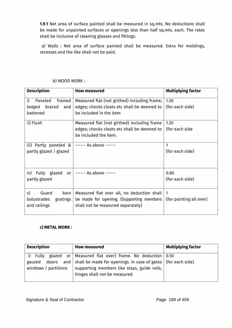
Signature & Seal of Contractor Page 189 of 459
1.9.1 Net area of surface painted shall be measured in sq.mts. No deductions shall be made for unpainted surfaces or openings less than half sq.mts. each. The rates shall be inclusive of cleaning glasses and fittings.
a) Walls : Net area of surface painted shall be measured. Extra for moldings, recesses and the like shall not be paid.
b) WOOD WORK :
Description How measured Multiplying factor
i) Paneled framed ledged braced and battened
Measured flat (not girthed) including frame; edges; chocks cleats etc shall be deemed to be included in the item
1.30 (for each side)
ii) Flush Measured flat (not girthed) including frame edges; chocks cleats etc shall be deemed to be included the item.
1.20 (for each side
iii) Partly paneled & partly glazed / glazed
------ As above ------ 1 (for each side)
iv) Fully glazed or partly glazed
------ As above ------ 0.80 (for each side)
v) Guard bars balustrades gratings and railings
Measured flat over all, no deduction shall be made for opening. (Supporting members shall not be measured separately)
1 (for painting all over)
c) METAL WORK :
Description How measured Multiplying factor
i) Fully glazed or gauzed doors and windows / partitions
Measured flat over) frame. No deduction shall be made for openings. In case of gates supporting members like stays, guide rails, hinges shall not be measured
0.50 (for each side)
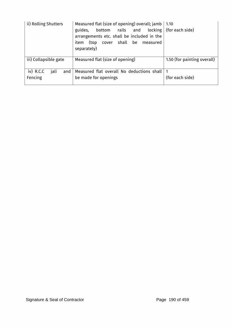
Signature & Seal of Contractor Page 190 of 459
ii) Rolling Shutters Measured flat (size of opening) overall; jamb guides, bottom rails and locking arrangements etc. shall be included in the item (top cover shall be measured separately)
1.10 (for each side)
iii) Collapsible gate Measured flat (size of opening) 1.50 (for painting overall)
iv) R.C.C jali and Fencing
Measured flat overall No deductions shall be made for openings
1 (for each side)
Signature & Seal of Contractor Page 191 of 459
MATERIALS MINIMUM SPECIFICATIONS/ REQUIREMENTS 1) Material shall be of best approved quality obtaining and they shall comply with the respective Indian Standard Specification. 2) Samples of all materials shall be got approved before placing order and the approved sample shall be deposited with the Architect. 3) In case of non-availability of materials in metric sizes the nearest size in FPS units shall be provided with prior approval of the Architects for which neither extra will be paid nor shall any rebates be recovered. 4) If directed, materials shall be tested in any approved Testing Laboratory and the test certificates in original shall be testing including charges for repeated tests, if ordered, shall be borne by the Contractor. 5) It shall be obligatory for the Contractor to furnish certificate, if deemed by the Architects, from manufacturer or the material supplier that the work has been carried out by using their material and as per their recommendations. 6) All materials supplied by the Employer / any other Specialist Firms shall be properly stored and the Contractor shall be responsible for its safe custody until they are required on the works and till the completion of the work. 7) Unless otherwise shown on the Drawings or mentioned in the “Schedule of Quantities” or special specification, the quality of materials, workmanship, dimensions, etc., shall be as specified as hereunder. 8) All equipment and facilities for carrying out field tests on materials shall be provided by the Contractor without any extra cost. a) Cement: Cement shall comply in every respect with the requirements of the latest publications of IS: 269 and unless otherwise specified ordinary Portland Cement shall be used. The weight of ordinary Portland Cement shall be taken as 1440 kg. per cu.m. (90 lbs.per c.ft.). Cement shall be measured by weight and in whole bags, and each undisturbed and sealed 50 kg. bag being considered equivalent to 35 liters (1.2 c.ft.) in volume care should be taken to see that each bag contains full quantity of cement. When part bag is required cement shall be taken by weight or measured in measuring boxes. No other make of cement but that approved by the Architects will be allowed on works and the source of supply will not be changed without approval of Architect in writing. Test certificates to show that cement is fully complying the specifications shall be submitted to the Architects and notwithstanding this, the Architect may at his discretion, order that the cement brought on site and which he may consider damaged or of doubtful quality for any reason whatsoever, shall be re-tested in an approved testing laboratory and fresh certificates of its soundness shall be produced. Cement ordered for re-testing shall not be used for any work pending results of re-test.
Signature & Seal of Contractor Page 192 of 459
Cement shall be stored in weather-proof shed with raised wooden plank flooring to prevent deterioration by dampness or intrusion of foreign matter. It shall be stored in such a way as to allow the removal and use of cement in chronological order of receipt i.e., first received being used first used. Cement deteriorated and or clotted shall not be used on the work but shall be removed at once from the site. However, allowing use of warehouse set cement shall be determined by the Architect. b) Lime: Lime shall comply in every respect with the requirements of IS: 712 and shall be made from approved line stone or kankar and properly burnt. It shall be free from excess of unburnt kankars or lime stone ashes or other extraneous materials and shall be stored in weather-proof sheds. Lime which has damaged by rain, moisture, or air slacking shall not be used but shall be removed from the site of work forthwith. Lime shall be slacked with fresh water and screened through appropriate screens and stored and used within 14 days provided it is protected from drying out. Field tests according to IS: 1624 shall be carried out from time to time to determine the quality of lime. c) River Sand: River sand shall confirm to IS: 383 and relevant portion of IS: 515. It shall pass through pass through a I.S. sieve 4.75 mm. (3/16 B.S.) test sieve, leaving a residue not more than 5%. It shall be from natural source i.e. only river or crushed stone screenings, if allowed, chemically clean, sharp, hard durable, well graded and free from dust, pebbles, clay, shale, salt, organic matter, loam, mica or other deleterious matter. The sum percentages of all deleterious substances to acceptable limits. River sand shall not contain any trace of salt and it shall be tested and river sand containing any trace of salt shall be rejected. The fine aggregate i.e. river sand for concrete shall be graded within limits as specified in IS: 383 and the fineness Modules may range between 2.60 to 3.20. The fine aggregate shall be stacked carefully on a clean hard dry surface so that it will not get mixed up with deleterious foreign materials. If such a surface is not available a platform of planks or corrugated iron sheets or brick floor or a thin layer of lean concrete shall be prepared. d) Fine & Coarse Aggregate: Shall consist of crushed or broken stone 95% of which shall be retained on 4.75 mm. IS tests sieve. It shall be obtained on crushing Granite, Quartzite, Trap, Basalt, or similar approved stones from approved quarry and shall confirm to IS:383 and IS 515. Fine & Coarse aggregate shall be chemically inert when mixed with cement and shall be cubical in shape and be free soft, friable, thin, porous, laminated or flaky pieces. It shall be free from dust and any other foreign matter. Gravel / Shingle of desired grading may be permitted as a substitute in part or full in plain cement concrete if the Architect is otherwise satisfied about the quality of aggregate. For all the R.C.C. works the size of coarse aggregate shall be 20 to 25 mm. and fine aggregate shall be 10 to 15 mm. e) Reinforcement: Reinforcement shall be of mild steel tested quality confirming to I.S.: 432-1966 and any
Signature & Seal of Contractor Page 193 of 459
other I.S. applicable or deformed bar confirming to IS:1786 and Is:1139 or hard drawn Fe 415 (Tor Steel) steel wire fabric confirming to IS:1566;1967. All finished bars shall be free from cracks, surface flaws, laminations, jagged and imperfect edges. f) Bricks : Bricks shall generally comply with IS:1077 except in size which shall be classified as 1st and 2nd class.1st class bricks shall be the best quality locally available table moulded, well burnt but not over burnt, have plain rectangular faces with parallel sides and sharp right-angled edges, have a find compact and uniform texture. The bricks shall be free from cracks, chips, flaws, stones or subsequent to soaking in water. It shall emit a clear ringing sound on being struck and shall not absorb water more than 20% by weight. Common building bricks shall have a compressive strength of 35 kg. / sqm unless otherwise specified for first class bricks. g) Neeru: Shall be made of Class “C” Lime (i.e. pre-fat lime) as mentioned in IS: 712. It shall be slaked with fresh water then sifted and reduced to a thick paste by grinding in a mill. Neeru thus prepared shall be kept moist until used and no more than that can be consumed in 15 days shall be prepared at time. h) Surkhi : Shall be made by grinding well burnt bricks, brick bats, burnt clay balls, etc., the brick etc., to be used shall be prepared from selected clay. The quality shall confirm to IS:1344. Bricks bats, etc., shall be ground in mechanical disintegrator to a find powder passing through IS Sieve No. 9 (2.36 mm.) with a residue not exceeding 10% by weight. Surkhi for lime surkhi plaster shall be ground to fine powder in a mortar mill to pass through IS Sieve 150 micron (No. 100). Surkhi shall be stored in a weather-proof shed on a brick pave platform. i) Water : Water for mixing cement / lime / surkhi mortar or concrete shall not be salty or brackish and shall be clean, reasonably clear and free from objectionable quantities of silt and traces of oil, acid and injurious alkali, salts, organic matter and other deleterious materials which will either weaken the mortar or concrete or cause affluence or attack the steel in reinforced cement concrete. Water shall be obtained from sources approved by the Architect. Potable water is generally considered satisfactory for mixing and curing concrete, mortar masonry, etc., where water other than main source is used this shall be tested in an approved testing laboratory to establish its suitability. All charges connected therewith shall be borne by the Contractor. j) Timber : Timber shall be well seasoned and of the best quality Indian Teak of specified species viz., Dandeli, Balarshah, Melabar, C.P. Timber shall be considered as well seasoned, if its moistures content does not exceed the following limits.
Signature & Seal of Contractor Page 194 of 459
a) Timber for frames 14%
b) Timber for planking, shutters, etc. 12%
The moisture content of timber shall be determined according to method described in paragraphs 4 of IS:287 for Maximum permissible moisture content of timber used for different purpose in different climatic zones. In measuring cross-sectional dimensions of the frame pieces tolerance up to 1.5 mm. shall be allowed for each planed surface. k) Superior quality Indian Teak Wood : Superior quality Indian Teakwood means Dandeli, Balarshah, and Malabar Teak. It shall be of good quality and well-seasoned. It shall have uniform colour, reasonably straight grains, and shall be free from large. Loose, dead knots, cracks, shakes, warp, twists, bends, borer holes, sap-wood or defects of any kind. No individual hard and should knot shall be more than 1 cm. in diameter and aggregate areas of all knots shall not exceed ½% of area of the piece. There shall not be less than 6 growth rings per 2.5 cm. width. l) 1st Class Indian Teakwood : 1st Class Indian Teakwood means C.P. and Bulsar teak of good quality and well seasoned. It shall have uniform colour, reasonably straight grains and shall be free from large. Loose dead knots, cracks, shakes, warp, twists, bends, sap-wood or defects of any kind. No individual hard and should knot shall be more than 2.5 cm. in diameter and aggregate areas of all the knots exceed 1% areas of the piece. There shall not be less than 5 growth tings per 2.5 cm. width. m) 2nd Class Indian Teakwood : Shall be similar to first class Indian teak wood except that knot up to 4 cm. diameter and aggregate area of all knots up to 1 ½% of the area of the piece shall be allowed. There shall not be sapwood up to 15% is allowed. n) Flush Doors : All flush doors shall be solid core exterior grade unless otherwise specified and it shall generally confirm to IS:2202 and shall be fabricated as described under specification. o) Steel Windows and Doors : Steel windows and doors shall be fabricated of steel sections conforming to IS:226. They shall conform to IS 1038. Unless otherwise specified the details of construction etc., shall be as described under specification. p) Floor Tiles : Designer pre-cast concrete tiles and interlocking paver block, plain cement tiles, chequred tiles, mosaic tiles terrazzo tile shall conform to IS:1237. For neutral shade tiles grey cement shall be used. Tiles shall be compacted by mechanical vibration and hydraulically pressed. It shall be of choice shade and shall have desired pattern of chip distribution. The sizes of chips to cement in terrazzo or mosaic floor shall be as specified in IS:1237. The size and thickness of tiles shall be as approved by the Architect. q) Ceramic / Vitrified Tiles :
Signature & Seal of Contractor Page 195 of 459
White or coloured glazed tiles shall comply with IS:777 or relevant or latest I.S. code. It shall be from an approved manufacturer and shall be flat and true to shape. They shall be free cracks, crazing, spots, chipped edges and corners. The glazing and colour shall be uniform shade and unless otherwise specified the tiles shall be 6 mm. thick. r) Marbles : Marble slabs for flooring, dado veneering etc., shall be of kind specified in the item such as white or pink, Makrana, Chittor black, Bhanslana black, Jaisalmer yellow, Baroda green, Patiala (Pepsu) grey, etc., Marble from which slabs are made shall be selected quality, hard, sound dense and homogenous in texture and free from cracks, weathering, decay and flaws. Before starting the work, the contractor shall get the sample of Marble slabs approved by the Architect. The slabs shall be machine cut and machine polished. s) Kotah / Shahbad / Cudappa / Granite : Shall be of selected quality, hard, sound, dense, and of homogeneous texture, free from cracks decay, weathering and flaws. Stone slabs shall be of uniform colour as approved by the Architect. They shall be machine cut and machine polished where specified and shall confirm to the required size. Thickness shall be specified in the respective items. t) Glazing : Glass used for glazing shall be float glass of best quality, free from flaws, specks bubbles and shall be 2.9 mm. thick up to 0.60 x 0.60 mm. size and for larger size it shall be minimum 4 mm. thick unless otherwise specified in the Schedule of Quantities. The following type of glasses shall be used:- 1) For Office Building Clear glass or as specified in the Schedule of Quantities. 2) Office (toilets) Clear or frosted
3) Partitions Frosted
u) Asbestos Roofing & rain Water Pipes : All Asbestos pipes and fittings shall comply with IS:459 and shall be free from cracks, chipped edges of corners and other damages. v) MPI. Sheets : MPI. Sheets shall be of a gauge specified in the description of the item and shall conform to the IS:277. The sheets shall be free from cracks, spilt edges, twists, surface flaws, etc. They shall be clean bright and smooth. Galvanising shall be uninjured and the perfect condition. The sheet shall show no sign of rust or white powdery deposits on the surface. The corrugations shall be uniform in depth and pitch and parallel. w) Paints : Lime for lime wash, dry distemper, oil bound distemper cement primer, oil paint, enamel paint, flat oil paint, plastic emulsion paint, anti-corrosive primer, red lead, water-proof cement paint and exterior grade Acrylic Emulsion paint, cement paint, sand-tex matt shall be from an approved manufacturer and shall conform to the latest Indian Standard for various paints. Ready mixed pains as received from the manufacturer without any admixture shall be used, except for addition of thinner, if recommended by the manufacturer. x) Mortar :
1) Lime Surkhi Mortar : Lime and surkhi shall confirm to the specifications. It shall be composed of approved lime and surkhi in proportion of 1 lime to 2 surkhi mixed
Signature & Seal of Contractor Page 196 of 459
thoroughly. The ingredients shall be accurately gauged by measure and shall be well and evenly mixed together on a platform and water added to make it homogeneous. When large quantities are required the mortar shall be mixed in a mechanical grinder.
2) Cement Mortar : Cement mortar shall be of proportions specified for each type of work in the schedule. It shall be composed of Portland Cement and sand. The ingredients shall be accurately gauged by measure and shall well and evenly mixed together in a mechanical pan mixer, care being taken not to add more water than is required. No mortar that has begun to set shall be used. River sand shall be used unless otherwise specified.
If hand mixing is allowed, then it shall be done on pucca water-proof platform. The gauged materials shall be put on the platform and mixed dry. Water will then be added and the whole mixed again until it is homogenous and of uniform colour. Not more than one bag of cement shall be mixed at one time and which can be consumed within half an hour of its mixing.
3) Composite Lime, Cement, Sand Mortar : The mortar shall be of proportions specified for each type of work in the schedule of quantities. It shall comprise of Portland cement, lime and sand. Lime shall be measured in gauge boxes similar to one used for measuring cement and sand to the proportion specified and sufficient water then added to it to form a thick slurry thus obtained shall then be added to dry cement and sand mixture and thoroughly mixed to make a workable homogenous mortar of uniform colour by adding more water if necessary. Mechanical mixers shall generally be used for mixing such mortars. If hand mixing is allowed it shall be done on pucca platform.
xi) AAC Blocks: AAC (Autoclaved Areated Concrete Blocks All units shall be sound and free of cracks or other defects which interfere with the proper placing of unit or impair the strength or performance of the construction. Minor chipping resulting from the customary methods of handling during delivery, shall not be deemed grounds for rejection. Where units are to be used in exposed wall construction, the face or faces that are to be expelled shall be free of chips, cracks, or other imperfections, except that if not more than 5 percent of a consignment contains slight cracks or small chippings not larger than 25 mm, this shall not be deemed grounds for rejection. The maximum variation in the length of the units shall not be more than 5 mm and the maximum variation in the height and width of unit, not more than ±3 mm The drying shrinkage shall be not more than 095 percent for Grade 1 blocks and @ 10 percent for Grade 2 blocks when tested as per table no 9.4 of IS 2185 -3(1984). xii) UPVC Windows
The cross section of the profile must confirm to the shape and dimensions of the manufacturer’s specification and drawing maximum tolerance on outer surface shall not be more than ±0.5 mm and glazing and seal grooves shall not deviate more than ±0.3 mm. The straightness of the profile as measured on the surface shall not deviate by more than
Signature & Seal of Contractor Page 197 of 459
1.0 mm/meter. The weight of the profile section per meter shall not be less than 3% of normal value. XII) RMC GUIDELINES
1.0 GENERAL REQUIREMENTS OF RMC
1.1 Basis of Supply : All concrete shall be supplied and invoiced in terms of cubic meters (full or part) of compacted fresh concrete as discharged from the transportation unit. The RMC shall be supplied in the quantity and having the quality in accordance with the requirements agreed by the producer or supplier and purchaser or user; however the concrete supplied shall generally comply with the requirements of IS 456/ IS 457 and IS 4926. The volume of fresh concrete in a given batch shall be determined from the total mass of the batch divided by the density of the concrete. The total mass of the batch shall be determined as the mass of the concrete in the batch including the total mixing water. All Batching shall be carried out by mass, except water and admixture, which may be measured by volume.
1.2 Specifying Concrete – Ordering RMC shall be manufactured and supplied on either of the following basis.
a) Performance basis: Specified characteristic strength based on 28 days (or any other specific age) compressive strength in accordance with IS 456/ IS 457.
b) Prescriptive basis: Specified Mix Proportion. When concrete is supplied on the basis of specified strength, responsibility for proportioning of mix rests with the producer/ seller whereas in case of specified mix proportion, the responsibility for proportioning of mix rest with the purchaser and the purchaser accepts the responsibility for concrete strength and its performance. Thus, it is desirable to place the supply order on specified strength basis. This system is based on performance parameters and is best way to order the RMC because RMC producer, who is expert in the field would design an economical mix with desired properties. In all cases the purchaser/user is required to furnish the following information for the guidance of the producer/ seller.
a) Type of cement to be used.
b) The max. Size and type of aggregates to be used.
c) The workability specified by slump or any other requirements.
d) Following additional requirements should be specified to satisfy durability requirements:
i) Minimum and maximum cement content to be used in production of concrete.
ii) Maximum water cement ratio to be kept.
Signature & Seal of Contractor Page 198 of 459
iii) Total chloride content in concrete:- Total chloride content should not exceed 0.15% by mass of cement in case of RCC work (IS:456) . For prestressed concrete work, total chloride content should not exceed 0.06% by mass of cement .(IS: 1343)
iv) Total sulphate content: - It should not exceed by 4% by mass of cement.
v) Permeability test requirements. (if any)
vi) Any special requirements such as pumpability or self compacting concrete (SCC) etc.
1.3 Mixing of Concrete Ready mix concrete is mixed and delivered to the point/site designated by the purchaser/user by means of one of the following combinations of operations.
a) Central Mixed or Stationary mixed Concrete: Concrete that is mixed in a stationary mixer at plant that mixes the concrete completely before it is discharge into either in a truck agitator or truck mixer operating at agitating speed or in non agitating equipments as agreed to by the purchaser/user. Central mix plants are sometimes referred to as wet batch or pre mix plants. When a truck mixer or agitator is used for transporting concrete which has been mixed before leaving the plant, the concrete shall agitated during transit and re-mixed at the site for at least 2 minutes so that the concrete is of the required uniformity.
b) Shrink Mixed Concrete: Concrete that is first partially mixed in a stationary mixer and then mixed completely in a truck mixer. The time of partial mixing shall be minimum required to intermingle the ingredients. After transfer to the truck the amount of mixing at the designated mixing speed will be that necessary to meet the requirements for uniformity of concrete. Generally it is two minutes of mixing in truck drum at mixing speed. This is not being practiced.
c) Truck mixed concrete: Although, truck mixed concrete is also one of the methods of mixing of Ready Mixed Concrete, for the purpose of this chapter , truck mixed concrete shall not be allowed as RMC, as automatic record keeping arrangement such as digital computer slips etc. are not possible in such type of mixing. Regarding mixing whether in a stationary or central mixer it shall be ensured that it complies with performance criteria of mixing efficiency test as per IS 4634:1991.Mixing efficiency test shall be performed at least once in a year.
1.4 Information to be supplied by the purchaser/user of RMC plant The purchaser shall provide the details of the concrete mix or mixes required by him and all pertinent information on the use of the concrete and the specified requirements. Where the purchaser specifies a designed mix to be supplied it is essential that all relevant
Signature & Seal of Contractor Page 199 of 459
information is conveyed to the producer. In order to assist in this, the format given in IS 4926 Annex D may be completed and forwarded to the producer at the time of enquiry. The concrete mix shall be specified by its constituent materials and the properties or quantities of those constituent to produce a concrete with the required performance. The assessment of the mix proportions shall form an essential part of the compliance requirements. The purchaser shall provide the producer with all pertinent information on the use of the concrete and the specified requirements. In order to assist in this, the format given in IS 4926 Annex D may be followed with suitable modifications as applicable to prescribed mixes. Purchaser responsibilities: The purchaser of Ready mix concrete has the following responsibilities
i When placing procedures can potentially alter the characteristics of fresh concrete, it is the responsibility of the purchaser to inform the producer of changes to the mixture requirements to accommodate these effects. An example is pumping concrete in place.
ii When a job uses more than one type of concrete mixture, it is the purchaser’s responsibility to verify the mixture delivered and direct it to the correct placement location.
iii The purchaser should check and sign the delivery ticket and document any special occurrences on the ticket.
iv When strength tests are used for acceptance of concrete, the samples should be obtained at the point of discharge from the transportation unit.
v The purchaser or his representative should ensure that proper facilities are available for curing the test specimens at the jobsite and that standard practices are followed for subsequent curing and testing. Certified personnel should conduct the tests.
vi Test reports should be forwarded to the producer in a timely manner to ensure that deficiencies are rectified.
1.5 Information to be supplied by the producer/owner of RMC plant Upon the request, the producer shall provide the purchaser with the following information before any concrete is supplied:
Signature & Seal of Contractor Page 200 of 459
a) Nature and source of each constituent material.
b) Source of supply of cement, and
c) Proposed proportions or quantity of each constituent/m3 of fresh concrete. d) When requested, the producer shall provide the purchaser the following information of admixtures:
i) Generic type(s) of the main active constituent(s) in the admixture.
ii) Whether or not the admixture contains chloride and if so, the chloride content of the admixture expressed as a percentage of chloride ion by mass of admixture.
iii) Where more than one admixture is used, confirmation of their compatibility. Producer’s responsibilities: The producer of Ready mix concrete has the following responsibilities
i)The concrete producer is responsible for the concrete slump as specified for a period of 30 minutes after the requested time or the time truck arrives at the placement site, whichever is later.
ii) The concrete producer is required to deliver concrete at the requested slump and air content, within the accepted tolerances, as measured at the point of discharge from the transportation unit. Note: The purchaser shall not alter the quality of concrete by any addition or modification at the job site. These include addition of water, admixture, fiber or special products into the ready mix concrete supplied by the producer; in case the purchaser does this, then producer is not responsible.
1.6 GENERAL INFORMATION ABOUT RMC FACILITY
1.6.1 Location of RMC Plant
The RMC plant from where the concrete is being procured by the purchaser/user can be a commercial plant owned/operated by a third party or a captive plant owned and operated by the constructor/user himself.
In case of commercial plant the location is already decided as they are operational plants and the user of RMC has no control on its location. The nearness to the site and availability of good haul roads can be the deciding factors in such cases.
However, when the RMC plants are captive plants and are erected on their site the constructor/user has to see the location of plant is suitable from all the considerations, the factors to be considered while deciding the location of plant can be
1) Availability of land
Signature & Seal of Contractor Page 201 of 459
2) Availability of Raw materials such as sand, aggregates , cements, fly-ash etc. and their leads.
3) Availability of Electric power
4) Availability of water
5) Nearness to site
6) Nearness to village
7) Environmental concerns; waste management, dust and noise control, safety etc. Hence, it is necessary that the owner of captive batching plant takes a judicious decision by considering all the above factors with respect to their technical and financial viability.
1.7 Components of RMC plant RMC plant/facility has in general the following components
1.7.1 PROPERTIES OF FRESH CONCRETE
1.7.1.1 Workability of concrete
Workability is a broad term which encompasses a range of properties of fresh concrete such as consistency (fluidity) , mobility (ability of concrete to move around the reinforcement and in restricted areas), compatibility, finishibility and pumpability (for pumped concrete). The degree of workability varies depending upon the type of construction and method of placing, compacting and finishing. Workability is measured in terms of slump of concrete using the standard procedure laid down in IS 1199:1959. The IS 456 provides guidance on the range of workability requirements for different placing conditions and applications. Consistency of fresh concrete is considered to be a close indication of its workability and slump test has been the most widely used test for ascertaining consistency and hence workability. For applications requiring very high slumps (higher than 150mm) the IS 9103 recommends use of flow table test. For a majority of concrete supplied by RMC producers, slump test is the most commonly used test. The IS 4926 specifies the following tolerance limits of workability as criteria for acceptance.
i) Slump: + 25 mm or + 1/3rd of the specified value whichever is less.
ii) Compacting factor : + 0.03 For specified value > 0.9 + 0.04 For specified value < 0.9> 0.8 + 0.05 For specified value > 0.8
iii) Flow Table Test: Acceptance criteria to be established between the producer and the purchaser.
The test for workability needs to be performed upon discharge from producer’s delivery vehicle on site or upon discharge into the purchaser’s vehicle. On some occasions, lack of preparedness on the part of purchaser at construction site may result in delay of placement. RMC producer will be responsible for maintaining the
Signature & Seal of Contractor Page 202 of 459
slump within the permissible range for a period of 30 minutes starting from arrival of transit mixers at job site. However, after 30 minutes, the IS 4926 clearly states that the responsibility for delay passes on the purchaser. Slump of concrete is quiet sensitive to a variety of environmental and other factors such as concrete temperature, ambient temperature, surface rate of evaporation, changes in grading, batch mass differences, admixture dosage, presence of mineral admixtures or otherwise, variation in air content, variation in testing, etc.
1.7.12 Density of concrete
The plastic density (unit weight) of conventional normal-weight concrete varies depending upon the variation in the density of different ingredients , the amount of entrapped air and entrained air ( if air –entraining agents are used), the maximum size of aggregate and water and cement contents in the mix. Increasing the aggregate volume and reducing the cement paste would increase the density of concrete. Ready Mixed concrete is measured on the basis of volume. The volume of fresh concrete can be determined by dividing the total weight of all batched materials by the unit weight or plastic density of concrete determined in accordance with IS 1199. Sometimes there is likelihood a discrepancy in the concrete ordered and that actually supplied. Also it should be understood that the volume of hardened concrete may be or appear to be less than expected. There could be variety of reasons for this discrepancy. These include wastage and spillage of concrete, over excavation, miscalculation in form volume, deflection or distortions of forms, settlement of wet mixes, loss of entrained air, etc. Such difference can be reconciled if plastic density of concrete is monitored regularly. While carrying out mix Proportioning, the plastic density of designed (Proportioned) mix is measured and tallied with the theoretical density. It would be a good practice to measure the plastic density at regular interval so as that the quantities supplied match orders. The plastic density measurement can be done by filling a container of known volume with fully compacted concrete and taking the mass of concrete in that volume by following procedures detailed in IS 1199. Additionally for concrete of Road and Bridge work the guidelines given in section 1717.7.3 and 1717.7.4 of MORT&H specifications published by IRC (Fifth revision) 2013.
1.7.1.3 Air content of fresh concrete
In most parts of India, tropical weather prevails, necessitating adoption of adequate precautionary measures associated with hot weather concreting practices. Absence of adequate measures may lead to rapid loss of workability, accelerated stiffening of concrete, poor compatibility and finishibility, and cracking of concrete owing to plastic and/or thermal shrinkage. To avoid adverse effect of hot weather, both RMC producer and the purchaser need to take adequate precautionary measures. It shall also be noted that generally retarding effect of retarder is smaller at higher temperatures and sometimes few retarders seem to be in-effective at extremely high temperatures. Thus it is desirable to keep the temperature of concrete as low as possible. Although in the
Signature & Seal of Contractor Page 203 of 459
IS 4926:2003 the requirements of temperature of concrete has been deleted it is advisable that the temperature of concrete produced shall not be less than 50 C and shall not exceed 350 C Additionally for concrete of Road and Bridge work the guidelines given in section 1708.5 and 1715.6 of MORT &H specifications published by IRC (Fifth revision) 2013 shall be referred to.
As far as RMC producer is concerned, he needs to design the concrete mix using a combination of OPC and supplementary cementitious materials or blended cement for reducing the heat of hydration. The aggregate stockpiles in the plant should be covered to avoid direct exposure to sun and water should be sprinkled on the stockpile to bring down the temperature. Some RMC producers use chilled water or ice flakes to bring down the temperature of mixing water during hot summer months. Covering the drum of transit mixer by hazien cloth helps in maintaining the temperature of concrete during transit. The requirements of extreme weather (hot weather conditions) concreting are given in IS 7861(part 1):1975 and shall be referred to.
1.8 PROPERTIES OF HARDENED CONCRETE
1.8.1 Strength of concrete
a. Concrete Cubes:- When strength of concrete is used as a basis for acceptance of concrete, which is generally adopted parameter, the standard specimen shall be made, cured and tested at 28 days in accordance with IS 516.The compliance shall be assessed against the requirements of IS 456. The testing frequencies and sampling shall be as per para 9.0 – sampling and testing of concrete of this guideline. While the strength at 28 days has emerged as a basis for contract specification; in order to get relatively quicker idea of the quality of concrete, compressive strength at 7 days may be carried out; however it is important to establish a relationship between early age and 28 days strength for a particular concrete. But in all cases 28 days compressive strength shall alone be the criteria for acceptance or rejection of concrete.
b. Concrete Cores:- The most widely accepted method of determining the in-place compressive strength of concrete in existing structures, pavements and linings is the testing of core specimens obtained by drilling with a diamond core bit. While core strength tests are more reliable than the less expensive & less tedious non-destructive test methods now in use, the results can be affected by many structure and testing variables which must be controlled or taken into consideration while evaluating the concrete strength. Where possible, a length to diameter ratio L/D of 2 should be used but the diameter of core should be at least three times the nominal maximum size of coarse aggregate (MSA) and in no case shall the diameter of specimen be lower than twice the maximum nominal size of aggregate(MSA). Any specimen intended for strength testing shall not contain embedded reinforcing steel. Testing variables includes considerations such as method of end preparation. Often sawing is necessary, to thin cores so that ends are
Signature & Seal of Contractor Page 204 of 459
perpendicular to the axis of the core, to eliminate reinforcing steel or honeycombed areas or to eliminate surface irregularities. Usually cores shall be capped to produce the required plainness for testing and it shall be ensured that good practices of capping are followed as per IS 516. The capping shall be thin with a strong material. The use of thick caps or ones that are not properly bonded to the specimen or are made with a weak material may cause markedly reduced core strengths specially in short cores of L/D less than 2.0.
Shorter cores with L/D less than 2.0 give a higher indicated strength which increases as L/d decreases, therefore these higher strengths must be corrected by a factor (correction factor) given in IS 516 for each ratio which, on the average, will produce a corrected strength on a parity with the standard L/D = 2.0 specimen. The equivalent cube strength of the concrete shall then be determined by multiplying the corrected cylinder strength by 5/4.
A1.8.2 acceptance criteria for concrete a. Cubes The IS 456:2000 provides guidance on the acceptance criteria of concrete based on compressive strength and shall be adhered to. Accordingly, i. The test results of the sample shall be average of the strength of the three specimens. The individual variation should not be more than + 15% of the average. If more, the test results of the sample are invalid. ii. The concrete shall be deemed to comply with the strength requirements when both the following conditions are met The mean strength determined from any group of four consecutive non overlapping test results complies with appropriate limits in column 2 of Table 1. Any individual test result complies with the appropriate limits in column 3 of Table 1.
Table1: Characteristic compressive strength compliance Requirement
Specified Grade Mean of the group of 4 Non over lapping consecutive test results in N/sq.mm
Individual test results in N/sq. mm
M15 > or equal to fck+ 0.825x established standard deviation ( rounded off to nearest 0.5 N/sq mm) or fck +3 N/sq mm whichever is greater.
> or equal to (fck– 3) N/sq mm
M20 And Above > or equal to fck+ 0.825x established standard deviation ( rounded off to nearest 0.5 N/sq mm) or fck +3 N/sq mm whichever is greater.
> or equal to (fck– 3) N/sq mm
Additionally for concrete of Road and Bridge work the guidelines given in section 1717.7 of MORT &H specifications published by IRC (Fifth revision) 2013 shall be referred to.
Table 2: Assumed Standard deviation.
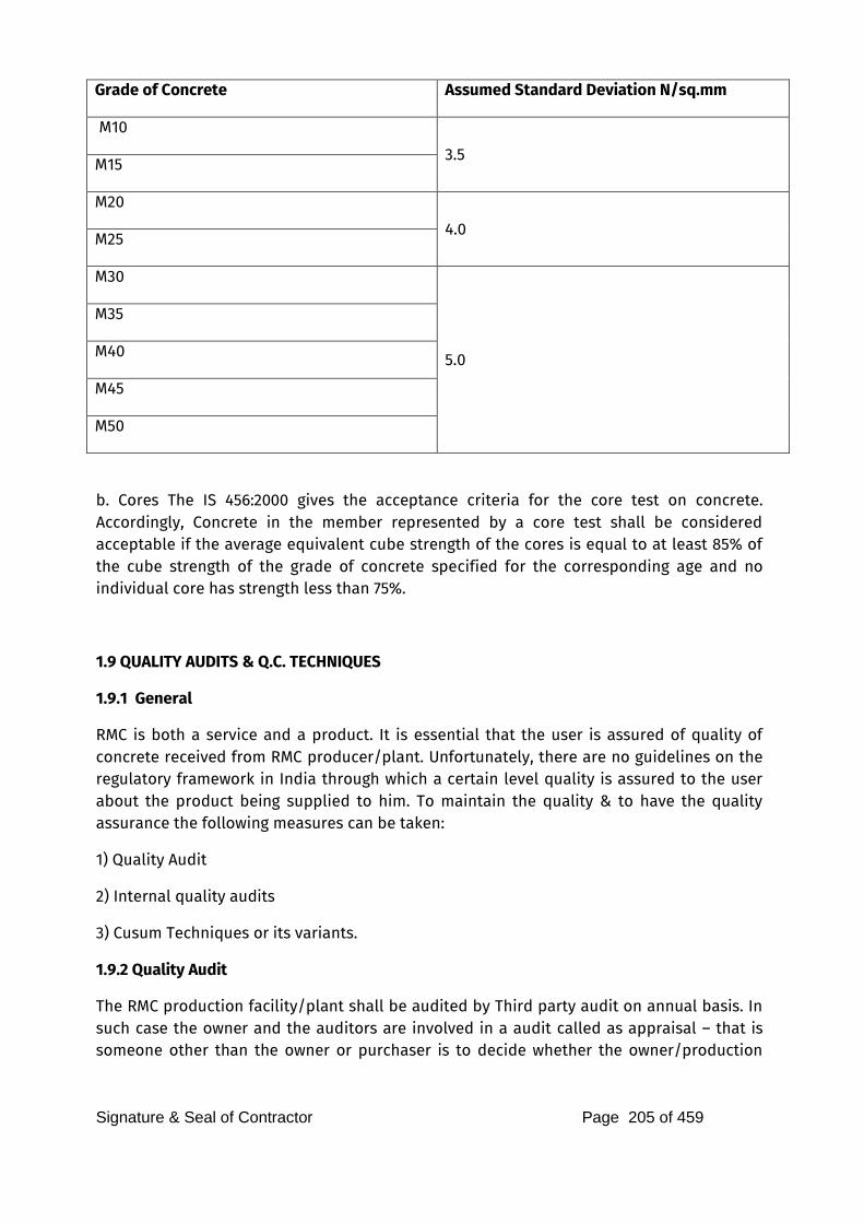
Signature & Seal of Contractor Page 205 of 459
Grade of Concrete Assumed Standard Deviation N/sq.mm
M10
3.5 M15
M20
4.0 M25
M30
5.0
M35
M40
M45
M50
b. Cores The IS 456:2000 gives the acceptance criteria for the core test on concrete. Accordingly, Concrete in the member represented by a core test shall be considered acceptable if the average equivalent cube strength of the cores is equal to at least 85% of the cube strength of the grade of concrete specified for the corresponding age and no individual core has strength less than 75%.
1.9 QUALITY AUDITS & Q.C. TECHNIQUES
1.9.1 General
RMC is both a service and a product. It is essential that the user is assured of quality of concrete received from RMC producer/plant. Unfortunately, there are no guidelines on the regulatory framework in India through which a certain level quality is assured to the user about the product being supplied to him. To maintain the quality & to have the quality assurance the following measures can be taken:
1) Quality Audit
2) Internal quality audits
3) Cusum Techniques or its variants.
1.9.2 Quality Audit
The RMC production facility/plant shall be audited by Third party audit on annual basis. In such case the owner and the auditors are involved in a audit called as appraisal – that is someone other than the owner or purchaser is to decide whether the owner/production
Signature & Seal of Contractor Page 206 of 459
plant can be certified as meeting prescribed quality standards/norms. In India, RMCMA having its office in Mumbai which has developed regulatory framework based on RMC quality schemes in developed countries and which have certified /accredited quality auditors used to carry out the third party audits of RMC and they had audited and certified around 250 RMC plants at 45 locations in India. Recently this scheme was upgraded by RMCMA and scope enlarged by making the scheme truly third party certification scheme. The scheme is owned jointly by Quality Council of India (QCI) and Building Materials & Technology Promotion Council (BMTPC) and they have developed a document – Criteria for RMC production control –Basic level certification for production control of RMC, the draft of which is under wide circulation and finalization. Hence, QCI-BMTPC can be contacted for third party audit of RMC plants. Additionally, there can be external audit called as second party audit, where in the purchaser of RMC or his representative will decide whether the plant/ RMC production facility is well/ enough organized to be able to meet their requirements as per quality standard
1.9.3 Internal quality audits
Internal quality audit also called as First party audit in which the owner of RMC plant or the same group will help the plant meet and improve on its own quality standards. For this, each RMC plant shall preferably develop its own QA-QC plan and documentation. Each plant Owner/producer can develop its own quality norms over and above the provisions in Indian Standards. The RMC producer shall bear in mind that there is always the scope for continuous improvement in quality and should strive for it. There shall be a system for reporting on quality parameters to the organization; for that there shall be norms and well defined practices to monitor and control quality of input and output materials. The QA-QC plan incorporated as internal quality audit shall consists of information such as source & properties of all ingredients of concrete; Mix design; process control; information on fresh and hardened properties of concrete; statistical analysis of results etc.
1.10 ENVIRONMENTAL CONCERNS AND SITE SAFETY
1.10.1 Site Safety
As in all civil engineering constructions, at the RMC plant safety shall be given a paramount importance and “Safety first” rule shall be followed. Ready Mixed Concrete plants are industrial operations relying on heavy equipment and vehicles with potential for accidents. So safety of workers should be a critical objective. All guardrails and machinery guards shall be fixed securely in position and walkways kept clean and with clear access. The facility shall provide suitable communication system between batching plant operator, transit mixer and delivery site. The RMC producer shall provide working conditions which have regard to the health and safety of employees .Plant should adopt a written safety
Signature & Seal of Contractor Page 207 of 459
program that includes formal safety training and provide incentives for workers who maintain safe practices. The following arrangements shall be ensured from safety point of view.
i Earthing arrangement: RMC equipment essentially needs to be earthed in view of abundant use of metal. Necessary earthing facility needs to be created by the owner/producer.
ii Air conditioning: Control unit of the RMC plant needs to be kept air-conditioned for trouble free running of computer systems and to provide good environment to the operators and staff.
iii Plumbing and drainage work: Water supply network needs to be laid at site for availability of water at different locations. Similarly, site drainage for rainwater or spillages need to be provided to keep it workable.
1.10.2 Environmental Considerations
Due regard shall be given to the environment in any RMC production facility. The technologies used shall be such that to reduce the environmental impact to the lowest realistic level at the same time the technologies shall be proven, economic and reasonable. The RMC facility shall endeavor that plant operations are well landscaped and screened from the surrounding residential or rural community such that the impact is minimal. The producer shall ensure that the traffic routes chosen are such as to avoid congested and sensitive areas wherever practicable and to minimize the fuel consumption. Concrete spillage on the public highway roads and pathways shall not be there. On the rural roads the dust menace shall be reduced by watering the pathways/roads near the rural community/site. As concrete producers in RMC plant the producer shall be aware and know the details of responsibilities regarding the environmental regulations such as Air Quality
Permits; Discharge permits; Storm water management, clean water permits, Solids management, Hazardous waste regulations, Dust control, Recycling, reuse and sustainability.
1.10.3 Air and Noise Pollution and Vibration
Particulate matter emissions to air, also known as dust emissions are the major air quality concerns at the ready mixed plant site. These very small particles can pose a health and safety risk to persons who may inhale those particles. The dust emissions can be process (point source) emissions and fugitive emissions. Process or point source emissions occur at discrete and definable locations during various activities such as silo filling; material handling and stacking; truck batching etc. Fugitive dust emissions are difficult to pin point and may arise from onsite vehicle movement, loading/transfer activities. The dust emissions can be reduced by plant enclosures and dust suppression wherein water is sprayed at the source of dust to prevent it from becoming airborne. There are many

Signature & Seal of Contractor Page 208 of 459
techniques and strategies available and the producer shall utilize appropriate technology to prevent or minimize dust emissions in line with local and national regulations. Noise is defined as “unwanted sound’’ and is primarily a concern of surrounding community and plant employees. While sound is inherent to RMC facility there are many areas where noise can be minimized, and the producer should take steps to ensure that plant and vehicle noise are minimized through plant designs, landscaping, berms and sound walls, and through the use of appropriate technology and strategies.
1.10.4 Fuel, Oil and chemical spillage The risk of leaks and spills can be minimized by proper design of storage facilities. The producer shall take appropriate measures and employ best management strategies to prevent leaks and spills and prevent pollution of surrounding areas and ground water by accidental effluent discharges and fuel, oil and chemical spillage.
1.10.5 Waste management Waste is defined as materials disposed of in an unproductive manner for example being land filled or discarded in a quarry or back lot. Comprehensive waste management and programs will reduce environmental burden of waste disposal. Re use of the waste material alleviates the burden of raw materials extraction. Excess concrete and returned concrete mainly forms the solid waste in RMC industry and forms the major waste concern. The producer shall introduce processes, strategies and practices that minimize the production of waste.
1.10.6 Training It is the responsibility of RMC producer to ensure that the employees/workers are properly trained and educated in safe handling of materials, hazardous chemicals and responsibility towards the environment. The producer shall give high priority to site care and good housekeeping along with participation of local community. It is also essential that emergency response procedures be established and employees be made familiar with the procedures. A formal training plan shall be prepared and implemented. Drivers play a key role in fuel management. Training to drivers can improve fleet efficiency and reduce spillage and leaks

Signature & Seal of Contractor Page 209 of 459
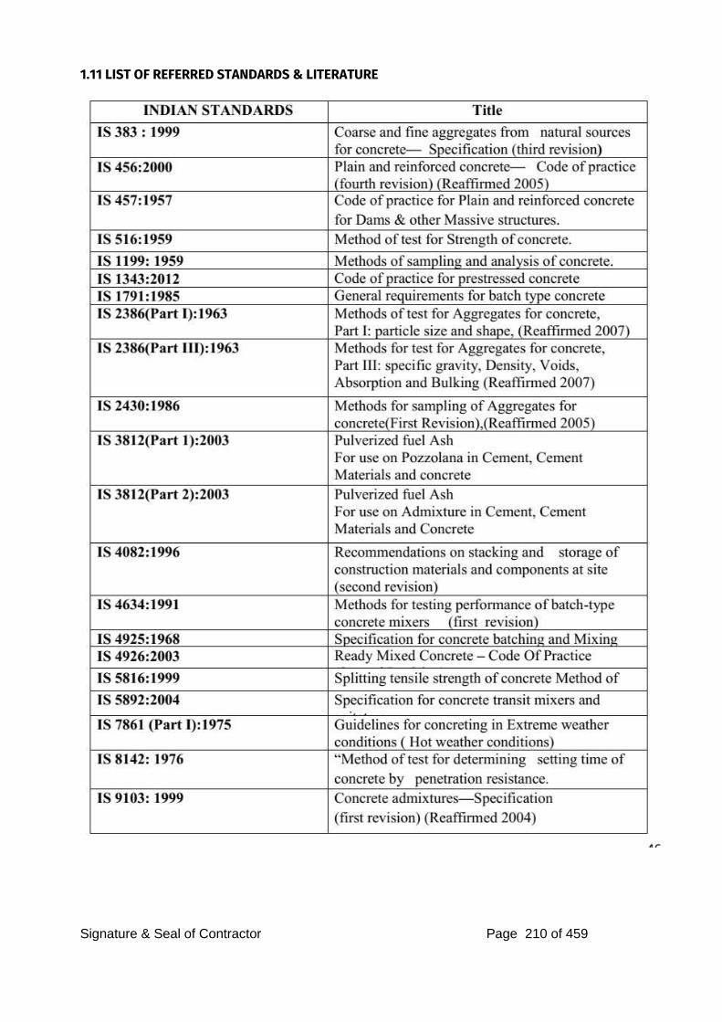
Signature & Seal of Contractor Page 210 of 459
1.11 LIST OF REFERRED STANDARDS & LITERATURE

Signature & Seal of Contractor Page 211 of 459
Signature & Seal of Contractor Page 212 of 459
WORKMANSHIP
CLEARING OF SITE, EXCAVATION AND EARTH FILLING
Note: Workmanship for all items related to the construction work should be as per relevant I.S. Code. General: Trenches for wall foundations, column footings, raft foundations, pile caps, plinth beams, water tanks, cess pits, etc., shall be excavated to the exact length, width and depth shown in the figure on the drawing or as may be directed by the Architect. If taken out to greater length, width or depth than shown or required, the extra work occasioned thereby shall be done at the Contractors own expenses. Extra depth shall be brought up by plain cement concrete filling 1:4:8 proportion and extra length and width filled in by rammed earth or murum or if the Architect thinks it necessary for the stability of the work by 1:4:8 concrete, as may be directed by the Contractors costs. Excavated material shall be used for filling in plinth, or each side of the foundation blocks or trenches or it shall be spread elsewhere on or near the site of work including watering, ramming and consolidating or carted away from site free of charge, as may be ordered. The Contractor shall at his own expenses and without any extra charge, make provision for supporting all utility services, lighting the trenches, separating and stacking, serviceable materials neatly, shoring, timbering, stuttering, bailing out of water either sub-soil or rain water including pumping at any stage of the work. Trenches shall be kept free of water while masonry or any concrete works are in progress and until the Architects consider that concrete is sufficiently set. Excavation excluding in Hard Rock: Excavation shall be carried out in any type of soil, murum (soft or hard), soft rock, boulders, old foundation, concrete asphalt or stone paved surfaces, old masonry or concrete (plain or reinforced). Excavation in Hard Rock: Rock which is in solid beds, which can only remove either by wedging or chiseling shall be treated as hard rock. A boulder or detached rock measuring one cubic meter or more, shall wedging or chiseling. Where hard rock is met with the blasting operations is considered necessary, the Contractor shall intimate about the same to the Architect. The Blasting shall not be permitted in any case and contractor have to carry out hard rock excavation in hard rock by means of Wedging and chiseling only. Excavation shall be done by wedging or chiseling and it shall be restricted to the quantity required to enable the necessary foundation etc. to the put in. In case, the dimension of trenches exceeds those shown in drawings or as directed by the Architect, the excess quantity shall not be paid for, the item also covers bailing out subsoil or rain water including pumping at any stage of work, shoring strutting, etc. Earth Filling: General: Filling shall be done with good earth, murum, stone chips, or disintegrated building debris. It shall be free from salts, organic matter, black cotton or slushy earth and
Signature & Seal of Contractor Page 213 of 459
combustible material. All clods shall be broken.
a) Filling in Plinth : Filling shall be done in layers not exceeding 25 cm., amply watered and consolidated by ramming with iron or wooden rammers weighing 7 to 8 kgs. and having base 20 cm. Square or 20 cm. diameter. When the filling reaches the finished level, surface shall be flooded with water for at least 24 hours, allowed to dry and then rammed and consolidated, after making good any settlement in order to avoid settlement at a later stage. Special care shall be taken to pack earth under plinth beams and column corners. Finished level of filling shall be kept to a slope intended to be given to the floor.
b) Filling in Outdoor portions and for Site Development: Shall be done in layer of 30 cm. Each layer shall be adequately watered. When filling reaches the required level the top most layer shall be dressed to proper section, grade and camber and rolled by 8 to 10 ton’s power roller and adequately watered to aid compaction.
DRY RUBBLE PACKING & LEVELING COURSE. Dry Rubble Packing: Ground shall first be leveled up and thoroughly consolidated by means of heavy log hammer or frog rams. Rubbles of specified thickness shall then be laid and set with hand. It shall be consolidated by either hand roller or wooden log hammer; free use of water being made during consolidation. All hollows and interstices after consolidation shall be filled up with quarry spalls, stone chips etc., and the packing blinded with stone grit and watered and consolidated by log hammer. Rubble packing in Road work shall be thoroughly consolidated by means of power rollers of 8 ton’s capacity instead of log hammers and the surface shall be brought to proper grade and camber. After checking the level, grade and camber the surface will again be watered and rolled to receive road structure. Leveling Course: It shall be either plain cement concrete of leaner mix or lime concrete which shall be proportioned as stipulated in the relevant item and mixed and placed in position confirming to line and level show on the drawing and compacted by approved means and cured adequately. Lime concrete shall be prepared by mixing sand and slaked lime in proportion of three parts of sand and one part of lime and ground in a suitable mill and the mortar so prepared shall be added to six parts of the brick bat passing through 50 mm. mesh, mixed well and placed in position and compacted by approved means. The concrete shall be cured adequately. PLAIN & REINFORCED CEMENT CONCRETE
A) VOLUMETRIC BASIS: - General : Except where they are varied by the requirements of this specification due provision of Indian Standard Specification IS-456-1964 for plain and reinforced concrete and IS-432 part I and II for Mild and Medium Tensile steel Bars and hard drawn steel wire for concrete reinforcement and any other relevant ISS applicable together with the latest amendments shall be held to be incorporated this specifications. It shall be intent of these specifications to ensure that all concrete placed at various location of the job should be durable, strong enough to carry design,
Signature & Seal of Contractor Page 214 of 459
loads, it should wear well and practically be impervious to water. It should be free from such defects as shrinkage, cracking and honeycombing.
Proportioning the Mix : In ordinary concrete, excluding controlled concrete, proportions of cement to fine and coarse aggregate shall be as specified in the respective items and shall be accurately measured as in table “A” below. These proportions are based on assumption that the aggregates are dry. If aggregates are moist allowance shall be made for bulking in accordance with IS:2386/-. Allowance shall also be made for surface water present in aggregate when computing water contents. Surface water present shall be determined by one of the field methods described in IS:2386/- (Part III). In the absence of exact data, the amount of surface water may estimate by the value given in table “B” below (Table “A” and “B” ).
Mixing : Concrete of 1:2:4 or richer mix shall be mixed in an approved mechanical mixer. The mixer and mixing platform shall be suitably protected from wind and rain. Aggregates shall be accurately measured out in boxes and mixed dry along with cement, water shall be then added in measured quantity and mixing shall be continued until there is a uniform distribution of the materials and the mass is uniform in colour and in consistency but in no case shall he mixing be done for less than 2 minutes.
When hand mixing is permitted with the approval of the Architect it shall be carried out on water-tight mixing platform and care shall be taken to ensure that mixing is continued until mass is uniform in colour and consistency. Consistency : Quantity of water for making reinforced concrete shall be sufficient so as to ensure that concrete shall surround and properly grip all the reinforcement. The best consistency shall be that, which will flow sluggishly without flattening out and without separation of coarse aggregates from the mortar. The degree of plasticity shall depend on the nature of work and atmospheric temperature and whether the concrete is vibrated or hand compacted. The slumps shown in table “C” obtained by standard slump test carried out in accordance with the procedure laid down in IS:119-1959 shall be adopted for different types of work.
Admixtures : The usage of admixtures is allowed only if approved by the structural consultant and his decision in this regard shall be final.
Transportation: Concrete shall be conveyed from the place of mixing to the place of final deposit as rapidly as practicable by methods which will prevent segregation or loss of any of the ingredients. If segregation does occur during transport, the concrete shall remix before being placed. In
no case, more than 30 minutes shall elapse between mixing the consolidation in its position. Placing and Compacting : Concrete shall be placed in layers of suitable thickness or in strips and compacted before initial setting commences and should not be subsequently disturbed. Method
Signature & Seal of Contractor Page 215 of 459
of placing shall be such as to preclude segregation and as far as practicable the placing shall be continuous. Special care shall be taken in accordance with IS:456 while laying concrete under extreme weather. Concrete shall be thoroughly compacted during the operation of placing and thoroughly working around the reinforcement, embedded fixtures and spaded against corners of the form work and by punning, rodding, mechanically vibrating or by any other approved means. In addition, form work shall be tapped lightly by using wooden mallet at the pouring head. The number and type of vibrator to be used shall be subject to the approval of the Architects and in general immersion type vibrators shall be used. External vibrators shall also be used whenever directed. The intensity and duration (of vibration shall be sufficient to cause complete settlement and compaction without any stratification of successive layers or separation of ingredients or formation of laitance. Vibrator shall be inserted vertically in the concrete at points not more than 45 cm. apart and withdrawn very slowly when air bubbles no longer come on the surface. Over vibration or vibration of very wet mixes is harmful and should be avoided. Care shall be taken to utilize the vibrator only to compact the concrete and not to spread it, sufficient number of reserve vibrator in good working condition shall be kept on hand at all times, so as to ensure that there is no slackening or interruption in compacting. Construction Joints : Concreting shall be carried out end to end continuously as far as possible and when construction joints are totally unavoidable, it shall be located in a predetermined position approved by the Architect. The joints shall be kept at places where the shear force is the minimum and these shall be straight and at right angles to the direction of main reinforcement. When the work has to be resumed, on a surface which has hardened, such surface shall be roughened. It shall be swept clean, thoroughly wetted and covered with a 13 mm. layer of mortar composed of cement and sand in the same ration as the cement concrete mix. This 13 mm. layer of mortar shall be freshly mixed and placed immediately before the placing of the concrete.
Where the concrete has not fully hardened, all laitance shall be removed by scrubbing the Wet surface with wire or bristle brushes, care being taken to avoid dislodgment of particles of aggregate. The surface shall then be coated with neat cement grout. In horizontal joints the first layer of concrete to be placed on this surface shall not exceed 15 cm. thickness and
shall be well rammed against old work, particular attention being paid to corners.
Expansion Joint: Expansion joint shall be provided where required as shown on the drawings or as directed
by the Architect / Consultant. The joints shall be filled by the approved quality filler. Curing : Concrete shall be carefully protected during first stage of hardening from harmful effects of excessive heat, drying winds, rain or running water. It shall be covered with a layer of sacking, sand canvas, hessian, or similar absorbent materials and kept constantly, wet for ten days from the date of placing of concrete. Alternatively, the concrete being
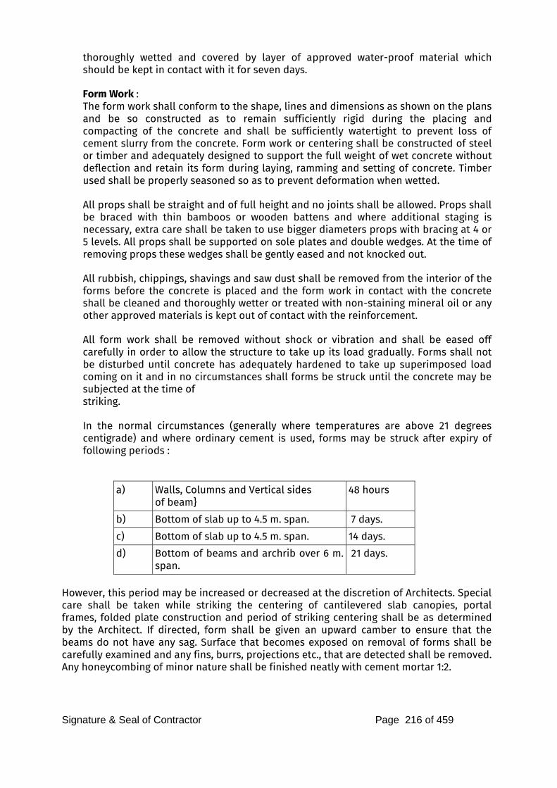
Signature & Seal of Contractor Page 216 of 459
thoroughly wetted and covered by layer of approved water-proof material which should be kept in contact with it for seven days.
Form Work : The form work shall conform to the shape, lines and dimensions as shown on the plans and be so constructed as to remain sufficiently rigid during the placing and compacting of the concrete and shall be sufficiently watertight to prevent loss of cement slurry from the concrete. Form work or centering shall be constructed of steel or timber and adequately designed to support the full weight of wet concrete without deflection and retain its form during laying, ramming and setting of concrete. Timber used shall be properly seasoned so as to prevent deformation when wetted.
All props shall be straight and of full height and no joints shall be allowed. Props shall be braced with thin bamboos or wooden battens and where additional staging is necessary, extra care shall be taken to use bigger diameters props with bracing at 4 or 5 levels. All props shall be supported on sole plates and double wedges. At the time of removing props these wedges shall be gently eased and not knocked out.
All rubbish, chippings, shavings and saw dust shall be removed from the interior of the forms before the concrete is placed and the form work in contact with the concrete shall be cleaned and thoroughly wetter or treated with non-staining mineral oil or any other approved materials is kept out of contact with the reinforcement. All form work shall be removed without shock or vibration and shall be eased off carefully in order to allow the structure to take up its load gradually. Forms shall not be disturbed until concrete has adequately hardened to take up superimposed load coming on it and in no circumstances shall forms be struck until the concrete may be subjected at the time of striking. In the normal circumstances (generally where temperatures are above 21 degrees centigrade) and where ordinary cement is used, forms may be struck after expiry of following periods :
a) Walls, Columns and Vertical sides
of beam} 48 hours
b) Bottom of slab up to 4.5 m. span. 7 days.
c) Bottom of slab up to 4.5 m. span. 14 days.
d) Bottom of beams and archrib over 6 m. span.
21 days.
However, this period may be increased or decreased at the discretion of Architects. Special care shall be taken while striking the centering of cantilevered slab canopies, portal frames, folded plate construction and period of striking centering shall be as determined by the Architect. If directed, form shall be given an upward camber to ensure that the beams do not have any sag. Surface that becomes exposed on removal of forms shall be carefully examined and any fins, burrs, projections etc., that are detected shall be removed. Any honeycombing of minor nature shall be finished neatly with cement mortar 1:2.
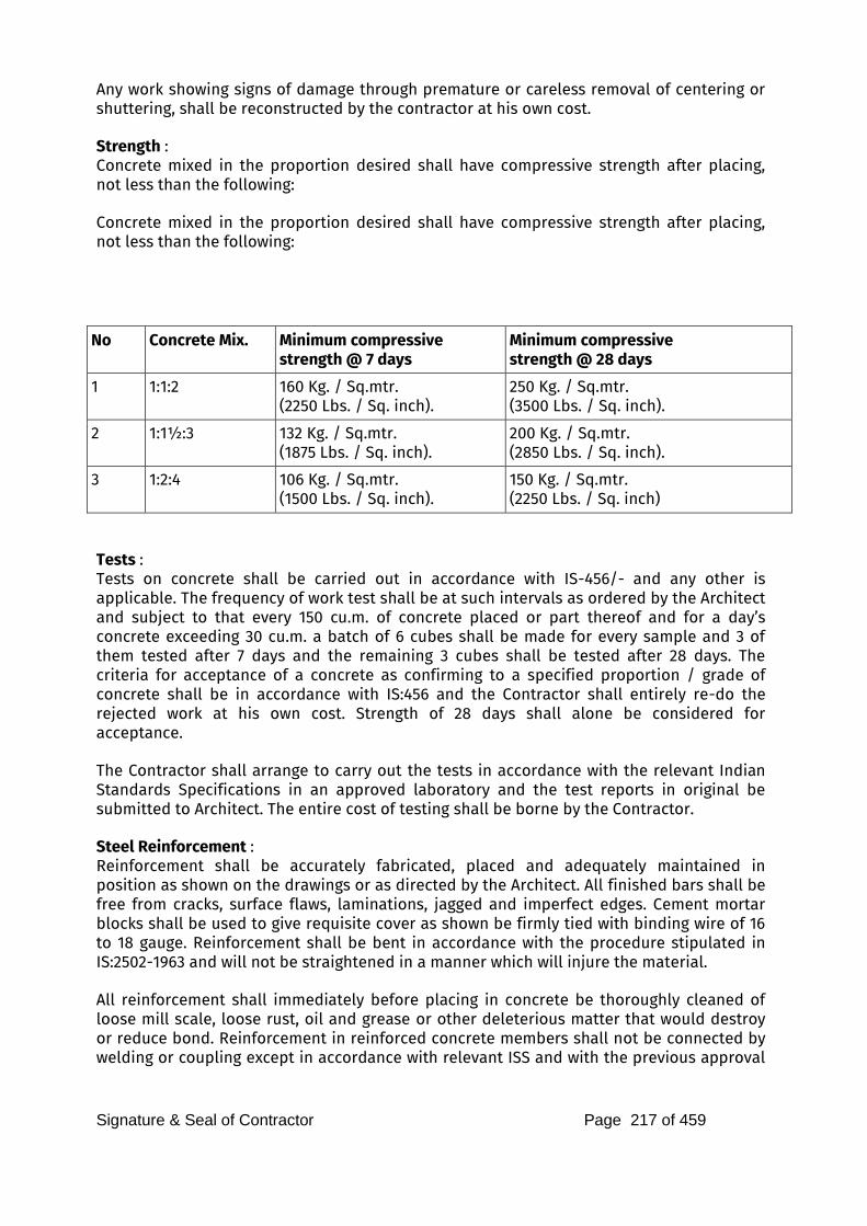
Signature & Seal of Contractor Page 217 of 459
Any work showing signs of damage through premature or careless removal of centering or shuttering, shall be reconstructed by the contractor at his own cost. Strength : Concrete mixed in the proportion desired shall have compressive strength after placing, not less than the following: Concrete mixed in the proportion desired shall have compressive strength after placing, not less than the following:
No Concrete Mix. Minimum compressive
strength @ 7 days
Minimum compressive
strength @ 28 days
1 1:1:2 160 Kg. / Sq.mtr. (2250 Lbs. / Sq. inch).
250 Kg. / Sq.mtr. (3500 Lbs. / Sq. inch).
2 1:1½:3 132 Kg. / Sq.mtr. (1875 Lbs. / Sq. inch).
200 Kg. / Sq.mtr. (2850 Lbs. / Sq. inch).
3 1:2:4 106 Kg. / Sq.mtr. (1500 Lbs. / Sq. inch).
150 Kg. / Sq.mtr. (2250 Lbs. / Sq. inch)
Tests : Tests on concrete shall be carried out in accordance with IS-456/- and any other is applicable. The frequency of work test shall be at such intervals as ordered by the Architect and subject to that every 150 cu.m. of concrete placed or part thereof and for a day’s concrete exceeding 30 cu.m. a batch of 6 cubes shall be made for every sample and 3 of them tested after 7 days and the remaining 3 cubes shall be tested after 28 days. The criteria for acceptance of a concrete as confirming to a specified proportion / grade of concrete shall be in accordance with IS:456 and the Contractor shall entirely re-do the rejected work at his own cost. Strength of 28 days shall alone be considered for acceptance. The Contractor shall arrange to carry out the tests in accordance with the relevant Indian Standards Specifications in an approved laboratory and the test reports in original be submitted to Architect. The entire cost of testing shall be borne by the Contractor. Steel Reinforcement : Reinforcement shall be accurately fabricated, placed and adequately maintained in position as shown on the drawings or as directed by the Architect. All finished bars shall be free from cracks, surface flaws, laminations, jagged and imperfect edges. Cement mortar blocks shall be used to give requisite cover as shown be firmly tied with binding wire of 16 to 18 gauge. Reinforcement shall be bent in accordance with the procedure stipulated in IS:2502-1963 and will not be straightened in a manner which will injure the material. All reinforcement shall immediately before placing in concrete be thoroughly cleaned of loose mill scale, loose rust, oil and grease or other deleterious matter that would destroy or reduce bond. Reinforcement in reinforced concrete members shall not be connected by welding or coupling except in accordance with relevant ISS and with the previous approval
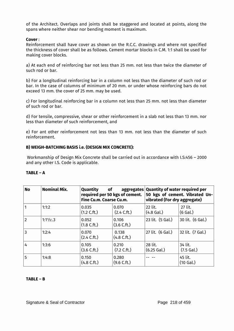
Signature & Seal of Contractor Page 218 of 459
of the Architect. Overlaps and joints shall be staggered and located at points, along the spans where neither shear nor bending moment is maximum. Cover : Reinforcement shall have cover as shown on the R.C.C. drawings and where not specified the thickness of cover shall be as follows. Cement mortar blocks in C.M. 1:1 shall be used for making cover blocks. a) At each end of reinforcing bar not less than 25 mm. not less than twice the diameter of such rod or bar. b) For a longitudinal reinforcing bar in a column not less than the diameter of such rod or bar. In the case of columns of minimum of 20 mm. or under whose reinforcing bars do not exceed 13 mm. the cover of 25 mm. may be used. c) For longitudinal reinforcing bar in a column not less than 25 mm. not less than diameter of such rod or bar. d) For tensile, compressive, shear or other reinforcement in a slab not less than 13 mm. nor less than diameter of such reinforcement, and
e) For ant other reinforcement not less than 13 mm. not less than the diameter of such reinforcement. B) WEIGH-BATCHING BASIS i.e. (DESIGN MIX CONCRETE): Workmanship of Design Mix Concrete shall be carried out in accordance with I.S:456 – 2000 and any other I.S. Code is applicable. TABLE – A
No Nominal Mix. Quantity of aggregates required per 50 kgs of cement. Fine Cu.m. Coarse Cu.m.
Quantity of water required per 50 kgs of cement. Vibrated Un-vibrated (For dry aggregate)
1 1:1:2 0.035
(1.2 C.ft.) 0.070
(2.4 C.ft.) 22 lit. (4.8 Gal.)
27 lit. (6 Gal.)
2 1:1½:.3 0.052
(1.8 C.ft.) 0.106
(3.6 C.ft.) 23 lit. (5 Gal.) 30 lit. (6 Gal.)
3 1:2:4 0.070
(2.4 C.ft.) 0.138
(4.8 C.ft.) 27 lit. (6 Gal.) 32 lit. (7 Gal.)
4 1:3:6 0.105
(3.6 C.ft.) 0.210
(7.2 C.ft.) 28 lit. (6.25 Gal.)
34 lit. (7.5 Gal.)
5 1:4:8 0.150
(4.8 C.ft.) 0.280
(9.6 C.ft.) -- -- 45 lit.
(10 Gal.) TABLE – B
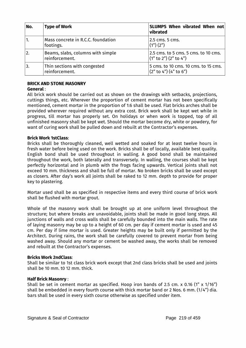
Signature & Seal of Contractor Page 219 of 459
No. Type of Work SLUMPS When vibrated When not vibrated
1. Mass concrete in R.C.C. foundation
footings. 2.5 cms. 5 cms. (1”) (2”)
2. Beams, slabs, columns with simple
reinforcement. 2.5 cms. to 5 cms. 5 cms. to 10 cms. (1” to 2”) (2” to 4”)
3. Thin sections with congested
reinforcement. 5 cms. to 10 cms. 10 cms. to 15 cms. (2” to 4”) (4” to 6”)
BRICK AND STONE MASONRY
General : All brick work should be carried out as shown on the drawings with setbacks, projections, cuttings things, etc. Wherever the proportion of cement mortar has not been specifically mentioned, cement mortar in the proportion of 1:6 shall be used. Flat bricks arches shall be provided wherever required without any extra cost. Brick work shall be kept wet while in progress, till mortar has properly set. On holidays or when work is topped, top of all unfinished masonry shall be kept wet. Should the mortar become dry, white or powdery, for want of curing work shall be pulled down and rebuilt at the Contractor’s expenses. Brick Work 1stClass: Bricks shall be thoroughly cleaned, well wetted and soaked for at least twelve hours in fresh water before being used on the work. Bricks shall be of locally, available best quality. English bond shall be used throughout in walling. A good bond shall be maintained throughout the work, both laterally and transversely. In walling, the courses shall be kept perfectly horizontal and in plumb with the frogs facing upwards. Vertical joints shall not exceed 10 mm. thickness and shall be full of mortar. No broken bricks shall be used except as closers. After day’s work all joints shall be raked to 12 mm. depth to provide for proper key to plastering. Mortar used shall be as specified in respective items and every third course of brick work shall be flushed with mortar grout. Whole of the masonry work shall be brought up at one uniform level throughout the structure; but where breaks are unavoidable, joints shall be made in good long steps. All junctions of walls and cross walls shall be carefully bounded into the main walls. The rate of laying masonry may be up to a height of 60 cm. per day if cement mortar is used and 45 cm. Per day if lime mortar is used. Greater heights may be built only if permitted by the Architect. During rains, the work shall be carefully covered to prevent mortar from being washed away. Should any mortar or cement be washed away, the works shall be removed and rebuilt at the Contractor’s expenses. Bricks Work 2ndClass: Shall be similar to 1st class brick work except that 2nd class bricks shall be used and joints shall be 10 mm. t0 12 mm. thick. Half Brick Masonry : Shall be set in cement mortar as specified. Hoop iron bands of 2.5 cm. x 0.16 (1” x 1/16”) shall be embedded in every fourth course with thick mortar band or 2 Nos. 6 mm. (1/4”) dia. bars shall be used in every sixth course otherwise as specified under item.
Signature & Seal of Contractor Page 220 of 459
RUBBLE MASONRY
General : Stones shall be of the kind specified in the item and shall be from an approved quarry. Stones shall be well wetted before laying in position. The mortar shall be as specified in the item. Face stone shall not be less than in breadth than in height, it shall also tail into the work more than its height. Jambs of doors, windows and openings shall be formed with quoins. In case of battered walls, the courses on battered surface shall be at right angle to the batter. Through stones or headers shall be laid in every course at a distance not exceeding 2 meters part and shall be staggered. They shall be in one piece for walls up to 1.5-meter width and shall be lap jointed in case of wall having thickness more than half meter. The face area of each header shall not be less than 0.50 sqm. 1:2:4 cement concrete may also be allowed where good length headers are not available. Headers shall be marked with oil paint for ready identification. Height of quoins shall be same as that of the course. Length of quoins shall be 0.50 m. and shall be laid header and stretcher alternatively. Faces of quoins shall be fair dressed. No quoins stones shall be less than 0.30 cum. In content. Joints of masonry shall be raked out and unless otherwise stated, shall be raised cement pointed by using cement mortar 1:1 to all exposed surfaces. All masonry work shall be well watered for a period of seven days. a) Coursed Rubble Masonry – First Sort : Height of course shall not be less than 15 cm. and all courses shall be of uniform height. All stones in the course shall be of same height. In no case height of course shall be more than any of the course below it. Bed and sides shall be hammer or chisel dressed back from the face 75 mm. and 35 mm. respectively. Faces of stones shall be hammer dressed and bushing shall not be more than 35 mm. Thickness of joints shall not be more than 10 mm. Stones shall break joints at least half the height of the course. Work on interior face shall be precisely the same, as on exterior face. Quoins shall be at least 0.5 m. long laid square on their beds and shall be fair dressed to a depth of at least 10 cm. b) Uncoursed Rubble Masonry : Stones shall be hammer dressed. Nearly fifty per cent of stones shall not be less than 0.30 cum. in content each, and twenty-five per cent of stone shall tail back in masonry by 40 cm. or more. Stones shall be so arranged as to break joints as much as possible. Long vertical joints shall be carefully avoided. Thickness of joints shall in no case exceed 12 mm. Pillar offsets shall be properly dressed with hammer or chisel to form proper angle. Stones used for the backing shall be of fairly large size. c) Random Rubble Masonry – First Sort : Stones shall be roughly chisel dressed. They shall be solidly bedded in mortar. Height of stone shall not be more than width of face or length of tail. Stones shall be of equal size and so arranged as to break joints as much as possible, avoiding long lines of horizontal or vertical joints. Quoins shall be same as described in Coursed Rubble Masonry – 1st Sort. All stones shall be carefully fitted. Thickness of face joint shall be not exceeded 25 mm. Edges
Signature & Seal of Contractor Page 221 of 459
of stones shall be chisel dressed for fitting in position properly. Timber used shall conform to specifications described under Materials, Doors, Windows, Ventilators, walls, Paneling, False Ceiling, etc., shall be in accordance with Architect’s drawing in every detail and all joiner’s work shall be accurately set out, framed and finished in a proper workman-like manner, frames of doors, windows and ventilators etc. and shutter styles and rails shall be best solid teak of quality specified in the schedule of quantities. The scantlings shall be accurately planed smooth, rebates, rounding and mouldings shall be made as shown on the drawings, patching or plugging of any kind shall not be allowed. Joints shall be simple, neat and strong. Framed joints shall be coated with suitable adhesive like glue or synthetic resin before the frames are put together. All mortise and tenon joints shall be fit and fully and accurately without wedging on filling. The joints shall be pinned with hard wood or bamboo pins of 10 mm. to 12 mm. dia. or rust resisting star shaped metal pins 8 mm. after the frames are put together and pressed in position by means of press. The frames are put together and pressed in progress of work by suitable boxing. All portions of timber abutting against or embedded in masonry or concrete shall be treated against termites by giving a coat of any approved wood preservative. Unless otherwise specified all doors, frames shall have six M.S. flat hold fasts and window frames shall have four hold fasts shall be provided to the ventilators, if directed. Size of hold fasts shall be 30 mm. x 40 mm. x 6 mm. M.S. flat bent to shape worth fish tail end and it shall be fixed to frame with sufficient number of screws as directed. When door / window frames are to be fixed to R.C.C. column or R.C.C. wall, hold fasts shall be substituted by suitable arrangements such as coach crews, rawl bolts etc., to secure frames to R.C.C. column or R.C.C. wall as directed by the Architect. Frames and shutter shall not be painted or erected before being approved by Architect. Paneled Shutter : Panels shall be of pattern and size as shown on the drawings or as directed by Architect. Solid teak wood panels shall be in one piece wherever possible. Where two or more pieces are permitted, they shall be of equal width. Panels shall be framed into grooves made in styles and rails to the full depth of groove and faces shall be closely fitted to sides of groove. Where panels specified are block board, it shall be solid core with teak internal lipping and of approved make. Partly paneled and partly glazed shutter shall be similar to paneled shutters except that such parts as are directed shall be glazed with plain or ground glass as specified. Styles and rails shall be rebated 12 mm. to receive glass. Sash bars shall be moulded and rebated and mitered on sides to receive the glass which shall be fixed with putty and beads. Hardware Fittings : Unless otherwise specified all hardware, fittings and fixtures shall be supplied by the employer free of charge. However, the cost of fixing fittings shall be included in the rate quoted. The fixing shall be done in the best workman-like manner in accordance with the manufactures specifications. The Contractor shall be held responsible for working of all moving parts dependent on proper fixing. He will also be responsible for any breakage due to negligence during fixing or lack of protection before the building is handed over. The
Signature & Seal of Contractor Page 222 of 459
Contractor shall also take delivery of all hardware fittings etc., as and when supplied and arrange for safe storage etc. Hardware required for fixing false ceiling, wall paneling etc., shall be arranged by the Contractor at his cost. Apart from the hardware fittings required for the joinery items, the Contractor shall have to fix all other items of hardware fittings to be supplied by the employer viz. coat / picture hooks, numerical, letters to denote buildings, hanging rods etc., as directed by the Architects. Painting and polishing of wood work shall be as per specifications under respective heads. Flush Doors : All flush doors shall be solid core unless otherwise specified. It shall conform to the relevant specifications of I.S. 2202 and shall be obtained from approved manufactures. The finished thickness of the shutter shall be mentioned in the items. Face veneers shall be of the pattern and colour approved by the Architect and an approved sample shall be deposited with the Architect for reference. The solid core shall be wood laminae prepared from battens of well-seasoned and treated good quality wood having straight grains. The battens shall be of uniform size of about 2.5 cm. width. Theses shall be properly glued and machine pressed together, with grains of each piece reversed from that of adjoining one. The longitudinal joints of the battens shall be staggered and no piece shall be less than 50 cm. in length. Alternatively, the core shall be of solid teak particle board. Edges of the core shall be lipped internally with 1st Class teak wood battens of 4 cm. (1.5”) minimum depth, glued and machine pressed along with the core. The core surface shall then have two or three veneers firmly glued on each face. The first veneer (called cross band) shall be laid with its grains at right angles to those of the core
and the second and the third veneers with their grains parallel to those of the core. The
under veneers shall be of good quality, durable and well-seasoned wood. The face veneers
shall be of minimum 1 mm. thickness and of well-matched and seasoned 1st class teak, laid
along with grains of the core battens. The combined thickness of all the veneers on each
face shall not be less than 4 mm. Thermosetting synthetic resin conforming to I.S. 303 or moisture-proof plywood grade MPF.I. shall be used in manufacture. In addition to internal lipping all doors shall have external lipping all round. STEEL DOORS, WINDOWS, VENTILATORS
ROLLING SHUTTER, M.S. GRILLES ETC. Steel used in the manufacture of rolled steel sections shall not have more than 0.060 per cent of Sulphur and 0.065 per cent of phosphorus. The carbon content shall not exceed 0.30 per cent and shall be of weldable quality. In all other respects, the rolled steel sections shall conform to I.S. 226-1955 and I.S. 1977-1962. Frames shall be square and flat. Both the fixed and openable frames shall be constructed of sections which have been cut to length, mitred and electrically welded at corners. Subdividing bar units shall be tenoned and rivetted into the frames. All frames shall have the corners welded to a true right angle and welds shall be neatly cleaned off. Couplings, mouldings and weather bar shall be provided as directed by the Architects. Outer frames shall be provided with fixing holes centrally in the web of the sections and
Signature & Seal of Contractor Page 223 of 459
fixing screws and lugs shall be used for fixing the frame to masonry. Mastic cement shall be used for making the joints watertight. Hinges shall be strong projecting type. If directed friction type hinges shall be used in which case windows shall not be fitted with peg stays. Projecting type hinged shutter shall be fitted with bronze or brass peg stays, 30 cm. Long with peg and brackets welded / riveted to the frame or as sated under item. All windows shall be provided with handles of brass or bronze or otherwise as stated under them. Top hung ventilators shall be fixed with plain hinges rivetted / welded to the fixed frame. A brass or bronze peg stay 30 cm. long as in windows shall be provided or as stated under item. Center hung ventilators shall be hung on two pairs of brass or leaded tin bronze cup pivots rivetted to the inner and outer frames of the ventilators to permit the ventilators to swing through an angle of approximately 85. The opening position of the ventilator shall be so balanced to keep it open at any desired angle under normal weather conditions. A bronze spring catch shall be fitted in the center of the top bar of the ventilator for the operation of the ventilator. This spring catch shall be secured to the frame with brass screws and shall close into a mild steel malleable iron catch plate rivetted or welded to outside of the outer ventilator frame bar. A brass cord pulley wheel in mild steel or malleable iron brackets shall be provided along with card eye. The windows and ventilators shall be painted. All the steel surfaces shall be thoroughly cleaned free of rust, scale or dirt and mill scale by picking or phosphating and before erection painted with one coat of approved primer and after erection painted with two finishing coats of synthetic enamel paint of approved shade and quality. Glazing of specified thickness shall be provided on the outside of frames and unless otherwise specified, metal beading of approved shape, and section shall be used for fixing glasses. Special metal sash putty of approved make shall be used, if directed. Rolling Shutters: Shall be of approved manufacture suitable for fixing in the position ordered i.e. outside, inside, on or below lintel or between jambs. Shutters up to 12 sqm. (130 Sq.ft.) in area shall be manually operated or Push Up type while bigger sizes shall be of reduction gear type mechanically operated chain or handles. These shall be consisting of 8 gauges or as specified with 75 mm. (3”) M.S. laths of best quality mild steel strips machine rolled and straightened with an effective bridge depth of 16 mm. (5/8”) and shall have convex corrugation. These shall be interlocked together throughout their entire length with end locks. These shall be mounted on specially designed pipe shaft. The spring shall be of approved make coiled type. These shall be manufacture from tested high tensile spring steel wire or strip of adequate strength to balance the shutters in positions. The spring pipe, shaft etc., shall be supported on strong M.S. or malleable cast iron brackets. Both the side guides and bottom rail shall be jointless and of single piece of pressed steel. Top cover of shaft, spring etc., shall be of the same material as that of lath.
Signature & Seal of Contractor Page 224 of 459
For rolling shutter with wicket-gate, night latch shall be provided free of cost. The shutter and cover etc., shall be painted with one coat of anti-corrosive paint and two coats of synthetic enamel paint of approved quality and shade. Collapsible Steel Gate: It shall consist of vertical double channels at 10 cm. centers. The sizes of channels T-Section for top and bottom shall be as approved by the Architects. The gate shall be provided with necessary bolts, nuts, locking arrangements, stoppers and brass handles on both sides. The gate shall be painted with one coat of anti-corrosive paint before erection and two coats of synthetic enamel paint of approved quality and shade. Wrought Iron Grilles: Grilles hall be manufactured as per drawings and the welded joints shall be smooth. The grilles shall be painted with one coat of anti-corrosive paint before fixing and two coats of synthetic enamel paint of approved quality and shade. Aluminum Doors, Windows, Ventilators & Partitions etc.: These shall be obtained from approved and established manufactures and shall be of Aluminum alloy conforming to I.S. 733 and sections shall generally conform to I.S. 1948. Theses shall be fabricated as per the details drawings, Frames for windows, ventilators etc., shall be square and flat. Both fixed and openable frames shall be constructed of section which have been cut to length, mitred and welded at corners. Sub-dividing bars shall be tenoned and rivetted into the frames. All frames shall have corners welded to a true right angle. For side hung shutters, hinges shall normally be of projecting type made of Aluminum alloy and rivetted / welded to frames. Handles, peg stays etc., or approved quality Aluminum or its alloy conforming to IS Specifications. All types of shutters shall be fabricated, supplied and fixed as specified in the IS:1948. The rate shall include supplying and fixing all fittings and fixtures required for proper and safe operation. The doors shall be fabricated by using standard aluminum alloy extruded sections as specified in IS:1948. The rate shall include supplying and fixing all fittings and fixtures including approved locking arrangement as directed. All aluminum fabricated work shall be anodized to the British Standard 1616:1961 to give an
anodized film of 25 micron. The Contractor shall take to stack the fabricated frames etc., on site under cover. They shall be handled with care, stacked on edge on level bearers and supported evenly. Before erecting, the frames coming in contact with concrete, masonry, plaster of dissimilar metals shall be coated with a coat of Zinc Chromate conforming to IS:104-1950. The Contractor shall cover all anodized finish work with a thick layer of clear transparent lacquer based on methacrylate or cellulosebuty rate to protect the surface from wet cement during installation. This coating shall remove on completion. Before handing over, the aluminum work shall be washed with mild solution of non-alkali soap and water. Glazing: Glazing shall be approved especially quality glass of specified thickness and unless
Signature & Seal of Contractor Page 225 of 459
otherwise directed it shall be provided the exterior with metal beading. FLOORING, SKIRTING, DADO AND STONE VENEERING
All flooring, skirting, dado and stone veneering etc., shall be executed strictly as per relevant IS Specification and in workman-like manner. Indian Patent Stone: Selection of materials, method of mixing, placing and compacting shall generally conform to the specifications under plain and reinforced cement concrete described earlier. A stiff mix consistent with workability shall be used. Preparation of Surface: Before the operation for laying topping is started the surface of base concrete shall be thoroughly cleaned of all dirt, loose particles coked mortar droppings and laitance if any, by scrubbing with coir or steel wire brush. Where the concrete has hardened so much that roughening of surface by wire brush is not possible, the surface shall have roughened by chipping or hacking at close intervals. The surface shall then be cleaned with water and kept wet for 12 hours and surplus water shall be removed by mopping before the topping is laid. Laying: The screed strips shall be fixed over the base concrete dividing it into suitable panels. Before placing the concrete for topping, neat cement slurry shall be thoroughly brushed into the prepared surface of the base concrete just ahead of the finish. Concrete of specified proportion and thickness shall be laid in alternate panels to required level and slope and
thoroughly tamped. Finishing the Surface: After the concrete has been fully compacted it shall be finished by troweling or floating with neat cement rendering. Finishing operations shall start shortly after the compaction of concrete and the surface shall be troweled three times at intervals so as to produce a uniform and hard surface. The satisfactory resistance of floor to wear depends largely upon the care with troweling is carried out. The time intervals allowed between successive troweling is very important. Immediately after placing cement rendering, only just sufficient troweling shall be done to give a level surface. Excessive troweling in the earlier stages shall be avoided as this tends to bring a layer rich in cement to the surface. Sometime, after the first troweling, the duration depending upon the temperature, atmospheric conditions and the rate of the set of cement used, the surface shall be re-troweled to close any pores in the surface and to bring to surface and to scrape off any excess water in concrete or laitance. No dry cement shall be used directly on the surface to absorb moistures or to stiffen the mix. The final troweling shall be done well before the concrete has become too hard but at such time that considerable pressure is required to make any impression on the surface. If directed by the Architect, approved mineral pigment shall be added to the rendering to give desired colour and shade to the flooring at no extra cost. When instead of 1:2:3 or 1:2.5:3.5 mix, 1:2:4 is specified the topping shall be rendered with 1:1 cement mortar with a suitable mineral pigment, if directed, instead of cement only. If specified in the Schedule of Quantities, the flooring shall be machine polished as per the
Signature & Seal of Contractor Page 226 of 459
Architect’s instructions. Wherever the patent stone flooring is used as finishing on roof the joints shall be filled with an approved bitumastic filler in workman like manner. Ironite Topping: Instead of finishing the top with rendering coat of 1:1 cement mortar, the top shall be finished with 12 mm. thick ironite topping. Unless otherwise specified, one part of ironite and four parts of ordinary cement by weight shall be mixed dry thoroughly. This dry mixture shall be mixed with stone grit 6 mm. (1/4”) and down size or as otherwise directed in the ratio of 1:2 by volume and well turned over. Just enough water shall be added to this dry mix and mixed thoroughly well and laid to uniform thickness of 12 mm. and compacted. After initial set has started the surface shall be finished as directed. Plain and Coloured Cement Tiles, Marble Mosaic and Terrazzo Tiles Flooring: The tiles shall conform to IS : 1237 having the colour approved the Architect and the rate shall include provision of border tiles and tiles of different colours in pattern if directed. The mosaic topping of lighter shade tiles shall be made of White Cement with an approved shade pigment and neutral shade shall be of Grey cement with an approved shade pigment. The type of tiles shall be as specified in respective items. The sub-grade shall be thoroughly wetted after cleaning of all dirt, laitance, and loose material. A bed of lime mortar consisting of one part of lime and two parts of sand shall be laid and properly leveled to an average thickness of 25 mm. and the surface shall be kept slightly rough to form a satisfactory key for tiles. Neat cement paste of honeylike consistency shall be spread over mortar bed, over such area at a time as would accommodate about 20 tiles. Tiles shall be soaked in water for 15 minutes and allowed to dry for the same duration. Tiles shall then be fixed with a thin coat of cement paste on back of each tile and then each tile being gently tapped with a wooden mallet till it is properly bedded and in level with adjoining tiles. Joints shall be fine and as imperceptible as possible. After tiles have been laid in a room or a day’s fixing work is completed, surplus cement grout that may have come out of the joints may be wiped off gently and joints cleaned. A thin slurry of coloured cement matching to the colour of tiles shall be spread over it and rubbed so as to seal even a thinnest joint between the tiles and make it impervious and the flooring cured for 7 days. The tiles shall be polished and finished according to IS:1443. Dado, Skirting and Risers: Tiles shall conform to IS:1237 and shall be of approved design. The tiles shall be fixed near cement grout on a blacking coat consisting of 1:4 cement sand plaster of 15 mm. thick. The top and bottom junctions of tiles shall be rounded off neatly as directed. The joints shall be filled with matching shade coloured cement slurry. The surface shall be kept wet for 7 days and then polished with carborundum stone to obtain smooth surface and fine polish. Shahabad / Tandur / Kotah / Cuddappa Stone Flooring : The flooring shall be either with rough stone or machine cut and machine polished as specified in respective items and shall be of specified thickness and of approved quality and size, free from cracks and flakes and shall be uniform in colour with straight edges. The sides of machine cut and machine polished stone shall have perfect right angles and surface smooth. The stone slabs shall be laid and finished as described under plain cement
Signature & Seal of Contractor Page 227 of 459
or colour cement tiles on a bedding of 1:2 lime mortar 25 mm. (Average) thickness. The finished stone surface thus laid shall then be polished to the required degree as approved by the Architect. In Dado, Skirting, Risers etc.: Stone slabs shall be laid on backing plaster of cement mortar 1:4 of 15 mm. to 20 mm. thick and finished as described under plain and coloured cement tile dado. Marble mosaic / Terrazzo in situ work in flooring, dado, skirting etc.: The terrazzo / mosaic finish shall be laid on an under layer of thickness as specified in the respective items. The topping shall consist of a layer of marble chips of selected sizes, colour and design approved by Architect, mixed with cement with desire shade of pigment. For lighter shade mosaic. terrazzo white cement shall be used and for neutral shade, grey cement shall be used. The proportion of terrazzo mix shall be three parts of cement one part of marble powder by weight. For every part of cement marble powder mix, the proportion of marble aggregate by volume shall be 1.5 parts unless otherwise specified. The topping shall be mixed and laid in panels as described in IS:2114 and as per decorative designs prepared by Architects. The dividing strips of panels shall be Aluminum or as specified in the Schedule of Quantities. It shall be polished as specified in IS: 2114. Broken Mosaic Flooring: Broken mosaic finish shall be laid on an underlayer of thickness as specified in the item. Pieces of mosaic tiles shall be obtained from broken marble mosaic tiles of approved shade conforming to IS:1257. The sizes of pieces shall be suitable to obtain the desired pattern of flooring as shown on the drawings or as approved by Architect. Broken pieces shall be thoroughly wetted before fixing them. Ordinary or coloured cement grout shall be spread on the bedding. Mosaic tile pieces shall be fixed piece by piece to the desired pattern. The flooring shall be laid to correct level and slopes and compacted by straight screed tamper. The grout shall cream up to the surface. The junctions of the flooring and the wall shall be rounded and the flooring shall be extended along the wall to about 15 cm. (6”). After the day’s work, the surplus cement grout that may have come out of the joints shall be cleaned off. The flooring shall be cured for seven days and then polished with a machine as stipulated in IS:1443. Broken China Mosaic: Broken China Mosaic flooring shall be exactly as per broken mosaic tile flooring except that the broken pieces shall be of China of approved colour and manufacturer and the floor shall not be polished. Marble Flooring: Marble slabs shall be of the best Indian marble of White or other approved colour as specified in the item. They shall be hard, dense, uniform and homogeneous in texture. They shall have even crystalline grain and free from defects and cracks. The surface shall be machine polished to an even and perfectly plane surface and edges machine cut true to square. The rear face shall be rough enough to provide a key for the mortar. No slab thinner than the specified thickness at its thinnest part. The sizes of the slabs shall be as specified in the respective items. The slabs shall be paid as described under mosaic tile flooring in every respect. White Glazed / Ceramic Tiles / Vitrified Tiles in Flooring and Dado:
Signature & Seal of Contractor Page 228 of 459
White Glazed Tiles from an approved manufacturer conforming to IS:777 shall be used. They shall be of specified size and thickness. All specials viz. coves, internal and external angles, corners, beads etc., shall be used wherever directed. Under layer of specified thickness and mortar of stipulated proportion shall be laid as described in marble mosaic flooring. Tiles shall be washed clean and set in cement grout and each tile being gently tapped with a wooden mallet till it is properly bedded and in level with the adjoining tiles. The joints shall be kept as thin as possible and I straight lines or to suit the required pattern. After the tiles have been laid, surplus cement grout shall be cleaned off. The joints shall be cleaned off the grey cement grout with a wire brush or trowel to a depth of 5 mm. (3/16”) and all dust and loose mortar removed. Joints shall then be flush pointed with white cement. The floor shall then be kept wet for seven days. After curing, the surface shall be washed with mild hydrochloric acid and clean water. The finished floor shall not PLASTERING
Scaffolding: Scaffolding for carrying out plastering work shall be double steel scaffolding having two sets of vertical supports so that the scaffolding is independent of the walls. Preparation of surface: All put log holes in brick work and junction between concrete and brick work shall be properly filled in advance. Joints in brick work shall be racked about 10 mm. if not raked out while constructing brick masonry work and concrete surface hacked to provide the grip to the plaster, if not hacked earlier projecting burns of mortar formed due to gaps at joints in shuttering shall be removed. The surface shall be scrubbed clean with wire brush / coir brush to removed dirt, dust etc., and the surface thoroughly washed with clean water to remove efflorescence, grease and oil etc., and shall be kept wet for a minimum of six hours before application of plaster. Neeru Plaster: Cement mortar of specified proportion and thickness shall be prepared in small batches and applied to the wall surface / ceiling. The ensure proper thickness, gauged patches shall be made at 1.5 to 2 m. apart and the surface plastered true to line, level and plumb taking special care to finish jambs of windows, doors, wall returns, corners, junctions etc. A thin layer of neeru shall then be applied and rubbed into surface and finished by means of trowel until the surface is even and smooth. The surface shall be kept moist for seven days and then given a coat of white wash. Sand-faced Plaster: The surface shall be prepared as above. The coat of cement mortar in proportion of 1:4 or as specified, shall be applied uniformly all over the surface to a thickness of 12 mm. and finished true to level and line and keys shall formed on the surface. The surface shall be kept moist till the finishing coat is applied. The finishing coat shall be applied a day or two after. The proportion of mortar for finishing coat shall be one part of cement and three parts of selected, well graded and washed sand, or as specified under item and it shall be applied in a uniform thickness of 6 mm. (1/4”). The surface shall be tapped to uniform grained texture by using sponge pads as directed. Curing shall start after 24 hours and the surface kept wet for seven days.
Signature & Seal of Contractor Page 229 of 459
Rough Cast Plaster: Except for the finishing coat the surface shall be prepared and base coat of plaster applied as under sand-faced plaster. Finishing coat mortar shall be in proportion of one part of cement and one part of specially selected and graded sand and one part of gravel of 3 to 6 mm. size. It shall be flung upon the first coat with large trowel to form an even and decorative coat. The work shall generally conform to clause 16.5 of IS:1661-1960. The thickness of the coat shall be about 12 mm. (1/2”). It shall be cured for seven days. Rough coat plaster with colour finish: This finish shall be similar to Rough cast plaster above except a high-grade mineral pigment of approved shade shall be mixed with white cement instead of ordinary grey cement while preparing the mortar. Water-proofing Treatment : Unless otherwise specified, the Contractor shall carry out waterproofing treatment of basements, terrace and water retaining structures through reputed firms having specialization in the line and approved by the Architects. The Contractor shall also furnish full details of such treatment to the Architects and provide all information / proof etc., regarding the effectiveness of the treatment when called upon to do so. All such treatment shall have to be guaranteed in the form approved by the Employer for a minimum period of ten years. Any defects / leakages noticed during the guarantee period shall have to be rectified free of cost by the Contractor including reinstating the surface to its original condition and finish. Water-proofing of sunk portions of floor slabs for baths, W.C. and kitchen mories etc., in residential buildings, unless otherwise specified, shall be done as specified in the schedule and shall generally comprise of : a) A coat of hot bitumen, min. 6 mm. thick screened with stone grit. b) Min. 20 mm. thick cement plaster in cement mortar 1:3 with approved water-proofing cement compound as per manufactures specifications. The plaster shall be cured by pounding for seven days. The rate for the above treatment shall include drying and cleaning surfaces free of dust etc. and wiping with kerosene before application of bitumen. The vertical faces and returns shall also be treated similarly. The actual area treated including vertical faces and returns shall be measured and paid for. The work should be done in such a way that the finished flooring in bath has a minimum slope of 20 to 25 mm. PAINTING
General: Wherever scaffolding is necessary, it shall be double scaffolding. The surface shall be thoroughly brushed free from mortar droppings and foreign matter. All steel work shall be cleaned of loose rust, mill scales etc. so as to expose the original surface. All broken edges, cracks, loose plaster and wavy surface shall be brought up either
Signature & Seal of Contractor Page 230 of 459
by patch plaster work or by plaster of paris. All materials viz., dry distemper, oil bound distemper, oil paint, flat oil paint, synthetic enamel paint, plastic emulsion paint, cement primer, red lead and other primers and metallic paints shall conform to respective I.S. specifications and shall be obtained from approved manufactures. All paints shall be brought on site in sealed thins in ready mixed form and shall be applied direct with the addition of thinner, if recommended by the manufacturers. White Washing: White was shall be prepared from lime slaked on spot, mixed and stirred with sufficient water to make a thin cream. This shall be allowed to stand for 24 hours and shall be screened through clean cloth. Four kg. gum dissolved in hot water shall be added to each cubic meter of the cream (115 gm. per cft.). Blue shall be added to give required whiteness. The approximate quantity of water to be added in making cream shall be five liters per kg. of lime. White wash shall be applied in specified coats by using flat brushes or spray pumps. Each coat shall be allowed to dry before next coat is applied. If additional coats than what have been specified, are necessary to obtain uniform and smooth finish, it shall be given at no extra cost. The finished dry surface shall not show any signs of cracking and peeling nor shall it come off readily on the hand when rubbed. If directed by the Architects one coat of chalk and glue shall be applied before application of white / colour wash at no extra cost. Colour Wash: Colour wash shall be prepared by adding mineral colours not affected by lime to white wash. No colour wash shall be done until a sample of the colour wash to the required tint or shade has been got approved form the Architects. Colour wash shall be applied as specified under white wash. Dry Distemper: Shade shall be got approved from the Architects before application of distemper. The surface shall be prepared as specified earlier. A primer coat using approved primer or sizing shall be applied. Distemper prepared as per manufacturer’s directions shall be applied and each coat shall be allowed to dry before subsequent coat is applied. The finished surface shall be free form chalking when rubbed, even uniform and shall show not brush marks. If additional coats are necessary, they shall be given at no extra cost. Oil Bound Distemper: The surface shall be prepared as specified above. A primer coat of either cement primer or any approved distemper primer shall be applied. After the primer coat has dried, the surface shall be lightly sand papered and dusted to make to smooth to receive distemper.
Signature & Seal of Contractor Page 231 of 459
Distemper shall be prepared as per the directions of the manufacturer and conforming to shade approved. It shall be applied in specified coats, taking care to allow for drying of each coat before subsequent coats are applied. Water-proof Cement Paint / Sand-tex matt Paint: The surface shall be prepared as specified above and thoroughly wetted with clean water before water-proof cement paint is applied. The paint shall be prepared strictly as per manufacturers specifications and in such quantities as can be used up in an hour of its mixing, as otherwise the mixture will set and thicken, affecting flow and finish. The paint thus prepared shall be applied on clean and wetted surface with brush or spraying machine. The solution shall be kept stirred during the period of application. It shall be applied on the surface which is on the shady side of the building so that the direct heat of the sun on the surface is avoided. The completed surface shall be watered after the days work. Number of coats shall be s specified in the item. Painting – Oil / Enamel / Plastic Emulsion etc.: Ready mixed oil paint, flat oil paint, plastic emulsion paint, ready mixed synthetic enamel paint, etc., shall be brought in original containers and in sealed tins. If for any reason thinner is necessary, the brand and quantity of thinner recommended by the manufacturer or as instructed by the Architect shall be used. The surface shall be prepared as specified above and a coat of approved primer shall be applied. After 24 hours drying approved or specified quality paint shall be applied evenly and smoothly. A filler putty coating may be given to give a smooth finish. Each coat shall be allowed to dry out thoroughly and then lightly rubbed down with sand paper and cleaned of dust before the next cost is applied. Number of coats shall be as specified in the item and if the finish of the surface is not uniform, additional coats as required shall be applied to get good and uniform finish at no extra cost. After completion no hair marks from the brush or clogging of paint puddles in the corners of panels, angles or mouldings etc., shall be left on the work. The glass panes, floor etc. shall be cleaned of stains. When the final coat is applied, if directed, the surface shall be rolled with a roller of if directed,it shall be stippled with a stippling brush. POLISHING AND VARNISHING
French Polishing: French spirit polish shall be of an approved make conforming to IS:348. If it has to be prepared on site, the polish shall be made by dissolving 0.7 kg. of best shellac in 4.5 liters of methylated spirit without heating. To obtain required shade pigment may be added and mixed. Surface shall be cleaned. All unevenness shall be rubbed down smooth with sand paper and well dusted. Knots, if visible, shall be covered with a preparation of red lead and glue. Resinous or loose knots and gaps shall be filled with season timber pieces and make level with rest of the surface. Holes and indentations on surface shall be filled with putty made of whiting and linseed oil. Surface shall be give a coat of filler made of 2.25 kg. of whiting in
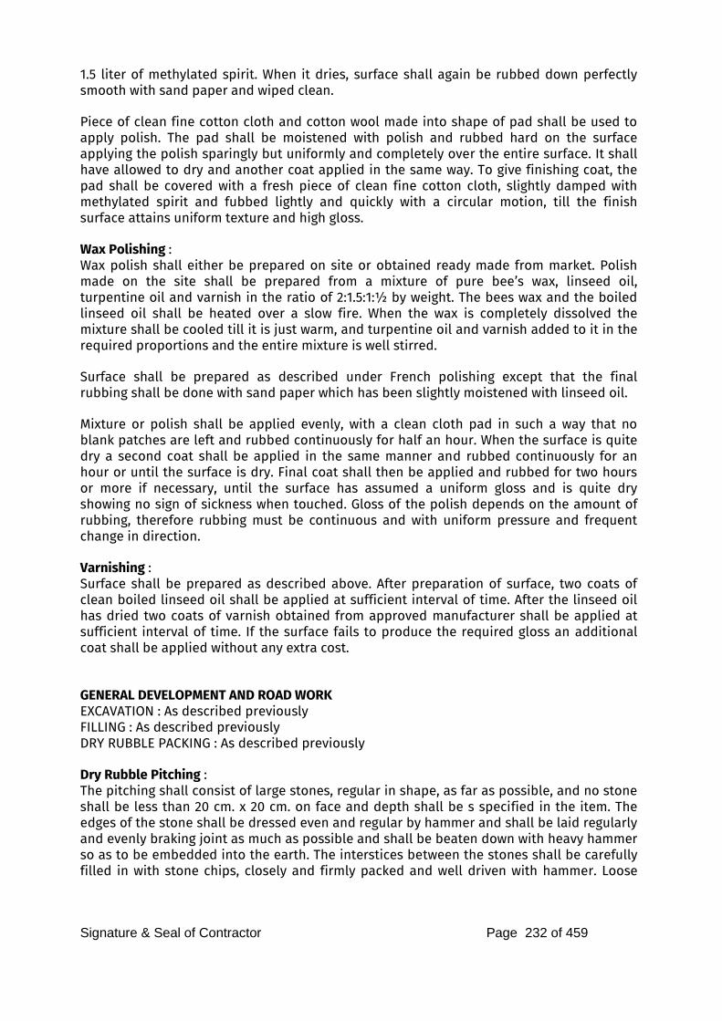
Signature & Seal of Contractor Page 232 of 459
1.5 liter of methylated spirit. When it dries, surface shall again be rubbed down perfectly smooth with sand paper and wiped clean. Piece of clean fine cotton cloth and cotton wool made into shape of pad shall be used to apply polish. The pad shall be moistened with polish and rubbed hard on the surface applying the polish sparingly but uniformly and completely over the entire surface. It shall have allowed to dry and another coat applied in the same way. To give finishing coat, the pad shall be covered with a fresh piece of clean fine cotton cloth, slightly damped with methylated spirit and fubbed lightly and quickly with a circular motion, till the finish surface attains uniform texture and high gloss. Wax Polishing : Wax polish shall either be prepared on site or obtained ready made from market. Polish made on the site shall be prepared from a mixture of pure bee’s wax, linseed oil, turpentine oil and varnish in the ratio of 2:1.5:1:½ by weight. The bees wax and the boiled linseed oil shall be heated over a slow fire. When the wax is completely dissolved the mixture shall be cooled till it is just warm, and turpentine oil and varnish added to it in the required proportions and the entire mixture is well stirred. Surface shall be prepared as described under French polishing except that the final rubbing shall be done with sand paper which has been slightly moistened with linseed oil. Mixture or polish shall be applied evenly, with a clean cloth pad in such a way that no blank patches are left and rubbed continuously for half an hour. When the surface is quite dry a second coat shall be applied in the same manner and rubbed continuously for an hour or until the surface is dry. Final coat shall then be applied and rubbed for two hours or more if necessary, until the surface has assumed a uniform gloss and is quite dry showing no sign of sickness when touched. Gloss of the polish depends on the amount of rubbing, therefore rubbing must be continuous and with uniform pressure and frequent change in direction. Varnishing : Surface shall be prepared as described above. After preparation of surface, two coats of clean boiled linseed oil shall be applied at sufficient interval of time. After the linseed oil has dried two coats of varnish obtained from approved manufacturer shall be applied at sufficient interval of time. If the surface fails to produce the required gloss an additional coat shall be applied without any extra cost. GENERAL DEVELOPMENT AND ROAD WORK
EXCAVATION : As described previously
FILLING : As described previously
DRY RUBBLE PACKING : As described previously
Dry Rubble Pitching : The pitching shall consist of large stones, regular in shape, as far as possible, and no stone shall be less than 20 cm. x 20 cm. on face and depth shall be s specified in the item. The edges of the stone shall be dressed even and regular by hammer and shall be laid regularly and evenly braking joint as much as possible and shall be beaten down with heavy hammer so as to be embedded into the earth. The interstices between the stones shall be carefully filled in with stone chips, closely and firmly packed and well driven with hammer. Loose
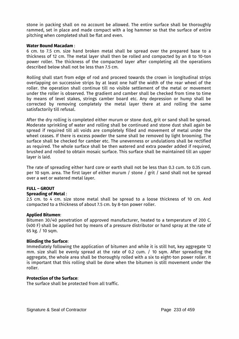
Signature & Seal of Contractor Page 233 of 459
stone in packing shall on no account be allowed. The entire surface shall be thoroughly rammed, set in place and made compact with a log hammer so that the surface of entire pitching when completed shall be flat and even. Water Bound Macadam : 6 cm. to 7.5 cm. size hand broken metal shall be spread over the prepared base to a thickness of 12 cm. The metal layer shall then be rolled and compacted by an 8 to 10-ton power roller. The thickness of the compacted layer after completing all the operations described below shall not be less than 7.5 cm. Rolling shall start from edge of rod and proceed towards the crown in longitudinal strips overlapping on successive strips by at least one half the width of the rear wheel of the roller. the operation shall continue till no visible settlement of the metal or movement under the roller is observed. The gradient and camber shall be checked from time to time by means of level stakes, strings camber board etc. Any depression or hump shall be corrected by removing completely the metal layer there at and rolling the same satisfactorily till refusal. After the dry rolling is completed either murum or stone dust, grit or sand shall be spread. Moderate sprinkling of water and rolling shall be continued and stone dust shall again be spread if required till all voids are completely filled and movement of metal under the wheel ceases. If there is excess powder the same shall be removed by light brooming. The surface shall be checked for camber etc. The unevenness or undulations shall be rectified as required. The whole surface shall be then watered and extra powder added if required, brushed and rolled to obtain mosaic surface. This surface shall be maintained till an upper layer is laid. The rate of spreading either hard core or earth shall not be less than 0.3 cum. to 0.35 cum. per 10 sqm. area. The first layer of either murum / stone / grit / sand shall not be spread over a wet or watered metal layer. FULL – GROUT
Spreading of Metal : 2.5 cm. to 4 cm. size stone metal shall be spread to a loose thickness of 10 cm. And compacted to a thickness of about 7.5 cm. by 8-ton power roller. Applied Bitumen: Bitumen 30/40 penetration of approved manufacturer, heated to a temperature of 200 C. (400 F) shall be applied hot by means of a pressure distributor or hand spray at the rate of 65 kg. / 10 sqm. Blinding the Surface: Immediately following the application of bitumen and while it is still hot, key aggregate 12 mm. size shall be evenly spread at the rate of 0.2 cum. / 10 sqm. After spreading the aggregate, the whole area shall be thoroughly rolled with a six to eight-ton power roller. It is important that this rolling shall be done when the bitumen is still movement under the roller. Protection of the Surface: The surface shall be protected from all traffic.

Signature & Seal of Contractor Page 234 of 459
SEMI – GROUT
Spreading of Metal : 2.5 cm. to 4 cm. size stone metal shall be spread to a loose thickness of 7.5 cm. thick and compacted to a thickness of about 5 cm. by 8 ton power roller. Applied Bitumen: Bitumen 30/40 penetration of approved manufacturer, heated to a temperature of 200 C. (400 F) shall be applied hot by means of a pressure distributor or hand spray at the rate of 25 kg. / 10 sqm. Blinding the Surface : As in Full–Grout. Seal Coat (For Full Grout and Semi Grout Surface) : The surface shall be brushed free of any loose blindage, taking care that the brushing is not so severe as to remove the blindage but of the voids into which it is set. The surface shall then be tested for depression, which shall be made up by painting with bitumen 30/40 penetration and blinding with aggregate of a size, equivalent to the depth of depression. Application of Bitumen: Bitumen 80/100 penetration of approved manufacturer, heated to a temperature of 177 to 190 C. (350 to 375 F) shall than be applied evenly to the road surface by means of a pressure distributor or hand-spray at the rate of 12.5 kg. / 10 sqm. Blinding and Final Consolidation: While the bitumen is still hot the surface shall be blinded evenly with stone aggregate of 6 mm. and down gauge size. The blindage shall be clean and not contain any dust and the rate of application shall be 0.1 cum. per 10 sqm. After spreading of the blindage the road shall be given a final rolling with a eight ton power. Any soft or depressions detected at a later date shall be made up as directed by the Architect without any extra cost. Premix Asphalt Carpet : The rate shall include preparation of surface. Preparation of Surface : Clean the surface with wire brush and dust it with gunny bags. All pot holes, depressions and corrugations shall be made good and applying a tack coat of 80/100 penetration bitumen heated to 177 to 191 C. and the depressions made up with suitable size premix aggregate and consolidated by approved means. The surface shall then be painted with 80/100 penetration bitumen heated to 177 to 191 C. at the rate of 7.5 kgs. Per 10 sqm. Preparation of Premix: Premix shall be prepared as under: 2.5 cm. thick consolidated.
No Item of Work Per 100 Sft. Per 1000 Sft.
1 Stone metal 2 cm. (3/4”) 5 Cft. 15.25 Cum.
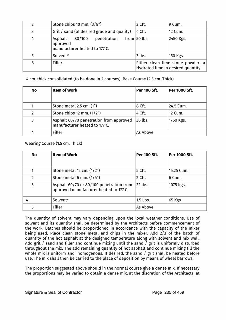
Signature & Seal of Contractor Page 235 of 459
2 Stone chips 10 mm. (3/8”) 3 Cft. 9 Cum.
3 Grit / sand (of desired grade and quality) 4 Cft. 12 Cum.
4 Asphalt 80/100 penetration from approved
manufacturer heated to 177 C.
50 lbs. 2450 Kgs.
5 Solvent* 3 lbs. 150 Kgs.
6 Filler Either clean lime stone powder or Hydrated lime in desired quantity
4 cm. thick consolidated (to be done in 2 courses) Base Course (2.5 cm. Thick)
No Item of Work Per 100 Sft. Per 1000 Sft.
1 Stone metal 2.5 cm. (1”) 8 Cft. 24.5 Cum.
2 Stone chips 12 mm. (1/2”) 4 Cft. 12 Cum.
3 Asphalt 60/70 penetration from approved
manufacturer heated to 177 C. 36 lbs. 1760 Kgs.
4 Filler As Above
Wearing Course (1.5 cm. Thick)
No Item of Work Per 100 Sft. Per 1000 Sft.
1 Stone metal 12 cm. (1/2”) 5 Cft. 15.25 Cum.
2 Stone metal 6 mm. (1/4”) 2 Cft. 6 Cum.
3 Asphalt 60/70 or 80/100 penetration from
approved manufacturer heated to 177 C
22 lbs. 1075 Kgs.
4 Solvent* 1.5 Lbs. 65 Kgs
5 Filler As Above
The quantity of solvent may vary depending upon the local weather conditions. Use of solvent and its quantity shall be determined by the Architects before commencement of the work. Batches should be proportioned in accordance with the capacity of the mixer being used. Place clean stone metal and chips in the mixer. Add 2/3 of the batch of quantity of the hot asphalt at the designed temperature along with solvent and mix well. Add grit / sand and filler and continue mixing until the sand / grit is uniformly disturbed throughout the mix. The add remaining quantity of hot asphalt and continue mixing till the whole mix is uniform and homogenous. If desired, the sand / grit shall be heated before use. The mix shall then be carried to the place of deposition by means of wheel barrows. The proportion suggested above should in the normal course give a dense mix. If necessary the proportions may be varied to obtain a dense mix, at the discretion of the Architects, at
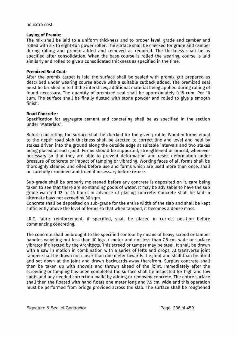
Signature & Seal of Contractor Page 236 of 459
no extra cost. Laying of Premix: The mix shall be laid to a uniform thickness and to proper level, grade and camber and rolled with six to eight-ton power roller. The surface shall be checked for grade and camber during rolling and premix added and removed as required. The thickness shall be as specified after consolidation. When the base course is rolled the wearing, course is laid similarly and rolled to give a consolidated thickness as specified in the time. Premixed Seal Coat: After the premix carpet is laid the surface shall be sealed with premix grit prepared as described under wearing course above with a suitable cutback added. The premixed seal must be brushed in to fill the interstices, additional material being applied during rolling of found necessary. The quantity of premixed seal shall be approximately 0.15 cum. Per 10 cum. The surface shall be finally dusted with stone powder and rolled to give a smooth finish. Road Concrete : Specification for aggregate cement and concreting shall be as specified in the section under “Materials”. Before concreting, the surface shall be checked for the given profile. Wooden forms equal to the depth road slab thickness shall be erected to correct line and level and held by stakes driven into the ground along the outside edge at suitable intervals and two stakes being placed at each joint. Forms should be supported, strengthened or braced, whenever necessary so that they are able to prevent deformation and resist deformation under pressure of concrete or impact of tamping or vibrating. Working faces of all forms shall be thoroughly cleaned and oiled before use and forms which are used more than once, shall be carefully examined and trued if necessary before re-use. Sub-grade shall be properly moistened before any concrete is deposited on it, care being taken to see that there are no standing pools of water. It may be advisable to have the sub grade watered 12 to 24 hours in advance of placing concrete. Concrete shall be laid in alternate bays not exceeding 30 sqm. Concrete shall be deposited on sub-grade for the entire width of the slab and shall be kept sufficiently above the level of forms so that when tamped, it becomes a dense mass. I.R.C. fabric reinforcement, if specified, shall be placed in correct position before commencing concreting. The concrete shall be brought to the specified contour by means of heavy screed or tamper handles weighing not less than 10 kgs. / meter and not less than 7.5 cm. wide or surface vibrator if directed by the Architects. This screed or tamper may be steel. It shall be drawn with a saw in motion in combination with a series of lefts and drops. At transverse joint tamper shall be drawn not closer than one meter towards the joint and shall than be lifted and set down at the joint and drawn backwards away therefrom. Surplus concrete shall then be taken up with shovels and thrown ahead of the joint. Immediately after the screeding or tamping has been completed the surface shall be inspected for high and low spots and any needed correction made by adding or removing concrete. The entire surface shall then the floated with hand floats one meter long and 7.5 cm. wide and this operation must be performed from bridge provided across the slab. The surface shall be roughened
Signature & Seal of Contractor Page 237 of 459
by brooming. The longitudinal and transverse edges of the slab shall be properly formed with suitable tolls and the same should be rounded to 10 mm. radius. The finished surface of the slab must conform to the grade, alignment and contours as directed and cured for fourteen days. After curing period is over the joints shall be filled up with approved bitumastic filler. Unless otherwise specified, the rate shall include filling of joints as specified. STORM WATER DRAINAGE
The work shall be carried out in accordance with rules and regulations of local Drainage Authority. Necessary provision for sight rails, boning staves etc. shall be made. Tests regarding water-tightness of joint and cleanliness of pipes shall be performed before the trenches are covered. Work of laying pipe lines and provided Manholes, Chambers, etc., shall include necessary excavation in any strata including old foundations of any description, refilling the trenches in layers of 20 cm. watering and consolidation. Pipes : All Hume pipes (Reinforced) shall conform to the relevant I.S.S. and shall be new, perfectly sound, free from cracks, cylindrical, straight and of specified nominal diameter. They shall be made of reinforced cement concrete manufactured by centrifugal or spun process and shall have even texture. Trenches : The trenches for laying shall be excavated to lines and levels as directed. The bed of the trench shall be truly and evenly dressed throughout from one change of grade to the next. The gradient is to be set out by means of boning roads and should the required depth be exceeded at any point; the trench shall be brought to proper grade by means of cement or lime concrete of the specification of the bed concrete without any extra cost. The bed of the trench, if in soft or made-up earth, shall be well watered and rammed and depressions thus formed filled with sand or other suitable materials as directed by the Architects. If rock is met with, it will be removed to 15 cm. below the level of the pipe and the trench will be refilled with bed concrete, sand or other suitable material approved by the Architects. The trench shall be kept free from water. Shoring and timbering shall be provided wherever required. The width of trench shall be nominal diameter of the pipe plus 38 cm. but it shall not be less than 52 cm. Laying of Pipes : No concreting is ordinarily necessary. In cases where the soil is made up is very soft,
Signature & Seal of Contractor Page 238 of 459
concreting may be resorted to form the bed of the trench below the pipe, if directed by the Architects at no extra cost. The pipes shall be carefully lid to levels and gradients shown in the plans and sections. Great care shall be taken to prevent sand etc., from entering the pipes. The pipes between two manholes shall be laid truly in straight lines without vertical or horizontal undulations. The body of the pipe shall for its entire length on an even bed in the trench and places shall be excavated to receive the collar for the purpose of jointing. Jointing : A few skeins of spun soaked in neat cement wash shall be inserted in the groove at the end of the pipe and the two adjoining pipes butted against each other. The collar shall then be slipped over the joint, covering equally both the pipes. Spun yarn soaked in neat cement wash shall be passed round the pipes and inserted in the joint by means of caulking tolls from ends of the collar. More skeins of yearn shall be added and well rammed above. The object of the yarn is to center the two ends of the pipes within the collar and to prevent the cement mortar of the joint penetrating into the pipes. Cement mortar with one part of cement and one part of sand shall be slightly moistened and must on no account be soft or sloppy and shall be carefully inserted by hand in to the joint and more cement mortar added until the space of the joint has been filled completely with tightly caulked mortar. The joint shall be finished off neatly outside the collar on both sides at an angle of 45. Any surplus mortar projecting inside the joint is to be removed and to guard against any such projections sack or gunny bag shall be drawn past each joint after completion. Cement mortar joint shall be cured at least for seven days. Testing : All joints shall be tested to a head of 60 cm. of water above the top of the highest pipe between two manholes. The lowest end of the pipe shall be plugged watertight. Water shall then be filled in manhole at the upper end of the line. The depth of water in the manhole shall be 60 cm. plus the diameter of the pipe. The joint shall then be examined. Any joint found leaking or sweating shall be remade and embedded into 15 cm. layer of cement concrete (1:2:4) 30 cm. in length and the joint retested without any extra cost. Manholes: Size of manholes shall be s specified in the item and the sizes specified shall be internal size of the manhole. The work shall be done strictly as per standard drawing and specifications. Bed Concrete : Shall be in 1:4:8 cement concrete 23 cm. (9”) thick. Brick Work: Shall be with best quality local bricks and proportion of mortar shall be 1:4 unless
Signature & Seal of Contractor Page 239 of 459
otherwise specified. Plaster: Inside of the walls shall be plastered with 12 mm. thick cement plaster 1:3 and finished with floating coat of neat cement. The external face shall be pointed with 1:3 cement mortar. Benching: Channels and benching shall be done in cement concrete 1:2:4 rendered smooth with neat cement. Foot Rests: M.S. square rods of 22 mm. (7/8”) diameter or C.I. rungs shall be embedded in masonry where the depth of manhole exceeds one meter and they shall be fixed 35 cm. apart and projecting 11 cm. from the wall. Foot rests shall be painted with bitumen as directed. Manhole Covers: Covers for manhole in the road proper shall not be less than 200 kgs. on footpaths and backyards. Lightweight covers shall be used whose weight for 45 cm. dia. shall not be less than 58 kgs. and that of 90 cm. x 45 cm. or 61 cm. x 45 cm. 90 kgs. Drop Connection: The case of drop connection C.I. pipes shall be provided with heel rest bend at the bottom and bend with access door at the top for cleaning purposes. The pipe shall be encased in 1:3:6 plain concrete. Miscellaneous Items of Work: The rates quoted by the Contractor for all miscellaneous items of work viz. Cooking platforms, mories, built-in cupboards, counters, partitions, railings, electrical meter, switchboard cupboards, etc., shall be for the work as described in the schedule of quantities and as show in detailed drawings and shall be to the entire satisfaction of the Architects.
Signature & Seal of Contractor Page 240 of 459
MATERIAL TEST LIST
The Contractors will have to take necessary material test as per I.S. code which is applicable, at their own cost for the following materials or any other material using in construction work periodically or as and when required by the Architects / Consulting Engineer. The materials should be got tested in an approved Laboratory as per IS standard and test reports in duplicate should be submitted to the Architect’s Office.
Sr. No Material Tests to be Carried out
1 Sand a) Silt Content.
b) Bulking.
c) Particle size distribution.
d) Or as directed.
2 Stone Aggregates a) Soft and deleterious Materail
b) Particle Size Distribution
3 Cement Concrete RCC Mix Design a) Slump
b) Cube Stregnth
c) Or as per IS456-2000
4 Bricks/Blocks a) Dimensions
b) Water absorption and efflorescence.
c) Compressive Strength
5 Timber Moisture
6 Ceramic/Vitrified Floor Tiles a) Transverse Test
b) Water absorption
c) Abrasion Test
7 Steel a) Tensile Stregnth
b) Ductility
Note: The Contractor will have to take necessary material test other than above test as per relevant I.S. code, if required and as directed by APMC / SBI.
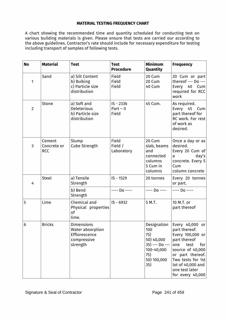
Signature & Seal of Contractor Page 241 of 459
MATERIAL TESTING FREQUENCY CHART
A chart showing the recommended time and quantity scheduled for conducting test on various building materials is given. Please ensure that tests are carried our according to the above guidelines. Contractor’s rate should include for necessary expenditure for testing including transport of samples of following tests.
No Material Test Test Procedure
Minimum
Quantity
Frequency
1
Sand a) Silt Content b) Bulking
c) Particle size
distribution
Field
Field
Field
20 Cum
20 Cum
40 Cum
20 Cum or part thereof --- Do --- Every 40 Cum required for RCC work
2
Stone a) Soft and
Deleterious
b) Particle size
distribution
IS - 2336
Part – II Field
45 Cum. As required. Every 45 Cum part thereof for RC work. For rest of work as
desired.
3
Cement Concrete or RCC
Slump
Cube Strength
Field
Field /
Laboratory
20 Cum
slab, beams
and
connected
columns
5 Cum in
columns
Once a day or as desired. Every 20 Cum of a day’s concrete. Every 5 Cum
column concrete
4
Steel a) Tensile
Strength
IS - 1529 20 tonnes Every 20 tonnes or part.
b) Bend
Strength
---- Do ---- ---- Do ---- ---- Do ----
5 Lime Chemical and
Physical properties of lime.
IS - 6932 5 M.T.
10 M.T. or part thereof
6 Bricks Dimensions
Water absorption
Efflorescence
compressive
strength
Designation
100
75) 50) 40,000
35) --- Do --- 100-40,000
75) 50) 100,000
35)
Every 40,000 or part thereof. Every 100,000 or part thereof one test for source of 40,000 or part thereof. Two tests for 1st lot of 40,000 and
one test later for every 40,000
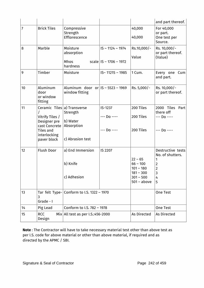
Signature & Seal of Contractor Page 242 of 459
and part thereof.
7 Brick Tiles Compressive
Strength
Efflorescence
40,000
40,000
For 40,000
or part. One test per Source.
8 Marble Moisture absorption
Mhos scale hardness
IS – 1124 – 1974
IS – 1706 – 1972
Rs.10,000/- Value
Rs. 10,000/- or part thereof. (Value)
9 Timber Moisture IS– 11215 – 1985
1 Cum. Every one Cum and part.
10 Aluminum door or window
fitting
Aluminum door or window fitting
IS – 5523 – 1969 Rs. 5,000/- Rs. 10,000/- or part thereof.
11 Ceramic Tiles /
Vitrify Tiles /
Designer pre
cast Concrete
Tiles and
interlocking
paver block
a) Transverse
Strength
b) Water Absorption
c) Abrasion test
IS-1237
--- Do ---- --- Do ----
200 Tiles
200 Tiles
200 Tiles
2000 Tiles Part there off --- Do ---- --- Do ----
12 Flush Door
a) End Immersion
b) Knife
c) Adhesion
IS 2207 22 – 65
66 – 100
101 – 180
181 – 300
301 – 500
501 – above
Destructive tests No. of shutters. 1
2
2
3
4
5
13
Tar felt Type-3
Grade - I
Conform to I.S. 1322 – 1970
One Test
14 Pig Lead Conform to I.S. 782 – 1978 One Test
15 RCC Mix Design
All test as per I.S.:456-2000 As Directed As Directed
Note : The Contractor will have to take necessary material test other than above test as per I.S. code for above material or other than above material, if required and as directed by the APMC / SBI.
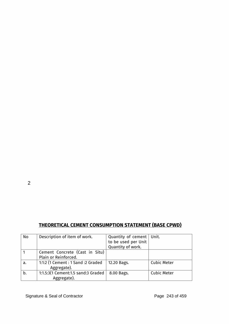
Signature & Seal of Contractor Page 243 of 459
2
THEORETICAL CEMENT CONSUMPTION STATEMENT (BASE CPWD)
No Description of item of work. Quantity of cement to be used per Unit Quantity of work.
Unit.
1 Cement Concrete (Cast in Situ) Plain or Reinforced.
a. 1:1:2 (1 Cement : 1 Sand :2 Graded
Aggregate). 12.20 Bags. Cubic Meter
b. 1:1.5:3(1 Cement:1.5 sand:3 Graded Aggregate).
8.00 Bags. Cubic Meter
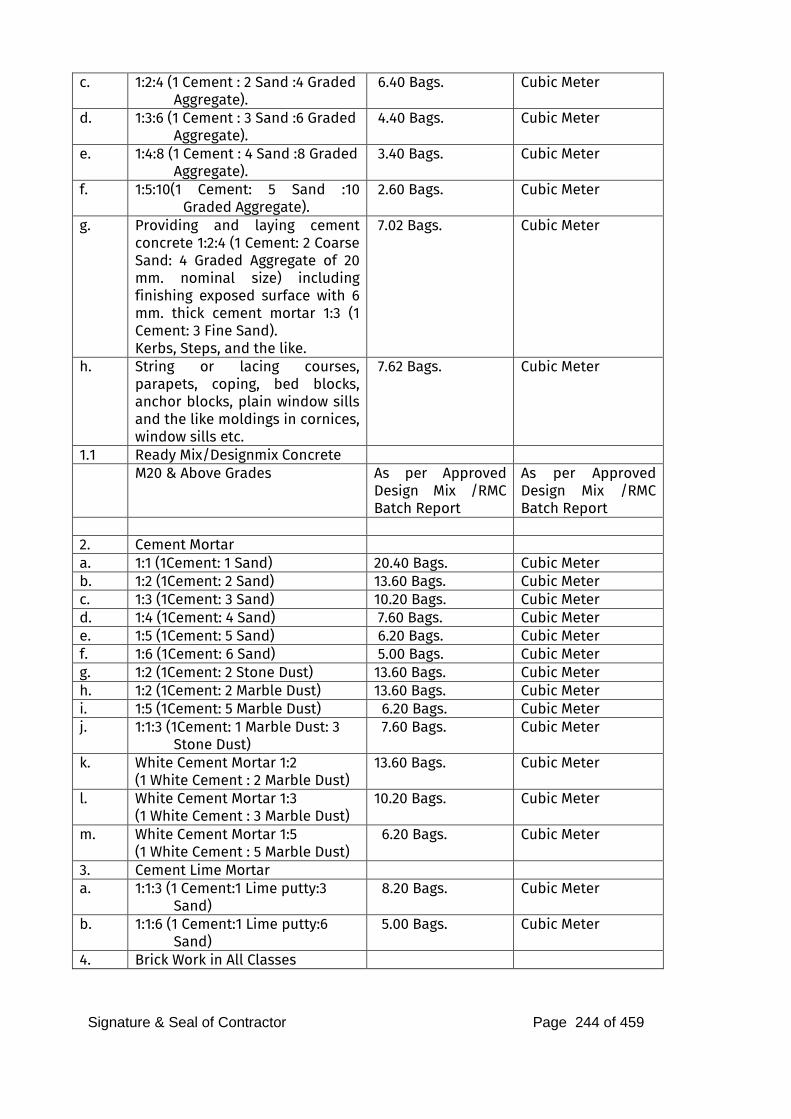
Signature & Seal of Contractor Page 244 of 459
c. 1:2:4 (1 Cement : 2 Sand :4 Graded
Aggregate). 6.40 Bags. Cubic Meter
d. 1:3:6 (1 Cement : 3 Sand :6 Graded
Aggregate). 4.40 Bags. Cubic Meter
e. 1:4:8 (1 Cement : 4 Sand :8 Graded
Aggregate). 3.40 Bags. Cubic Meter
f. 1:5:10(1 Cement: 5 Sand :10 Graded Aggregate).
2.60 Bags. Cubic Meter
g. Providing and laying cement concrete 1:2:4 (1 Cement: 2 Coarse Sand: 4 Graded Aggregate of 20 mm. nominal size) including finishing exposed surface with 6 mm. thick cement mortar 1:3 (1 Cement: 3 Fine Sand). Kerbs, Steps, and the like.
7.02 Bags. Cubic Meter
h. String or lacing courses, parapets, coping, bed blocks, anchor blocks, plain window sills and the like moldings in cornices, window sills etc.
7.62 Bags. Cubic Meter
1.1 Ready Mix/Designmix Concrete M20 & Above Grades As per Approved
Design Mix /RMC Batch Report
As per Approved Design Mix /RMC Batch Report
2. Cement Mortar a. 1:1 (1Cement: 1 Sand) 20.40 Bags. Cubic Meter b. 1:2 (1Cement: 2 Sand) 13.60 Bags. Cubic Meter c. 1:3 (1Cement: 3 Sand) 10.20 Bags. Cubic Meter d. 1:4 (1Cement: 4 Sand) 7.60 Bags. Cubic Meter e. 1:5 (1Cement: 5 Sand) 6.20 Bags. Cubic Meter f. 1:6 (1Cement: 6 Sand) 5.00 Bags. Cubic Meter g. 1:2 (1Cement: 2 Stone Dust) 13.60 Bags. Cubic Meter h. 1:2 (1Cement: 2 Marble Dust) 13.60 Bags. Cubic Meter i. 1:5 (1Cement: 5 Marble Dust) 6.20 Bags. Cubic Meter j. 1:1:3 (1Cement: 1 Marble Dust: 3
Stone Dust) 7.60 Bags. Cubic Meter
k. White Cement Mortar 1:2
(1 White Cement : 2 Marble Dust) 13.60 Bags. Cubic Meter
l. White Cement Mortar 1:3
(1 White Cement : 3 Marble Dust) 10.20 Bags. Cubic Meter
m. White Cement Mortar 1:5
(1 White Cement : 5 Marble Dust) 6.20 Bags. Cubic Meter
3. Cement Lime Mortar a. 1:1:3 (1 Cement:1 Lime putty:3
Sand) 8.20 Bags. Cubic Meter
b. 1:1:6 (1 Cement:1 Lime putty:6
Sand) 5.00 Bags. Cubic Meter
4. Brick Work in All Classes
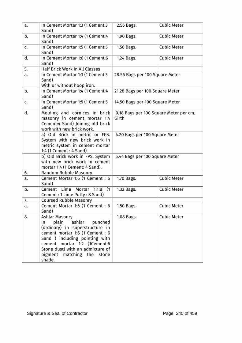
Signature & Seal of Contractor Page 245 of 459
a. In Cement Mortar 1:3 (1 Cement:3
Sand) 2.56 Bags. Cubic Meter
b. In Cement Mortar 1:4 (1 Cement:4
Sand) 1.90 Bags. Cubic Meter
c. In Cement Mortar 1:5 (1 Cement:5
Sand) 1.56 Bags. Cubic Meter
d. In Cement Mortar 1:6 (1 Cement:6
Sand) 1.24 Bags. Cubic Meter
5. Half Brick Work in All Classes a. In Cement Mortar 1:3 (1 Cement:3
Sand) With or without hoop iron.
28.56 Bags per 100 Square Meter
b. In Cement Mortar 1:4 (1 Cement:4
Sand) 21.28 Bags per 100 Square Meter
c. In Cement Mortar 1:5 (1 Cement:5
Sand) 14.50 Bags per 100 Square Meter
d. Molding and cornices in brick masonry in cement mortar 1:4 Cement:4 Sand) Joining old brick work with new brick work.
0.18 Bags per 100 Square Meter per cm. Girth
a) Old Brick in metric or FPS. System with new brick work in metric system in cement mortar 1:4 (1 Cement : 4 Sand).
4.20 Bags per 100 Square Meter
b) Old Brick work in FPS. System with new brick work in cement mortar 1:4 (1 Cement: 4 Sand).
5.44 Bags per 100 Square Meter
6. Random Rubble Masonry a. Cement Mortar 1:6 (1 Cement : 6
Sand) 1.70 Bags. Cubic Meter
b. Cement Lime Mortar 1:1:8 (1 Cement : 1 Lime Putty : 8 Sand)
1.32 Bags. Cubic Meter
7. Coursed Rubble Masonry a. Cement Mortar 1:6 (1 Cement : 6
Sand) 1.50 Bags. Cubic Meter
8. Ashlar Masonry
In plain ashlar punched (ordinary) in superstructure in cement mortar 1:6 (1 Cement : 6 Sand ) including pointing with cement mortar 1:2 (1Cement:6 Stone dust) with an admixture of pigment matching the stone shade.
1.08 Bags. Cubic Meter
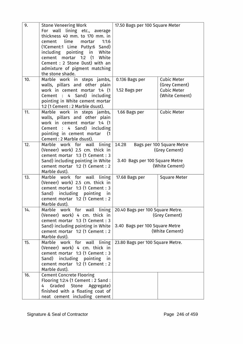
Signature & Seal of Contractor Page 246 of 459
9. Stone Veneering Work
For wall lining etc., average thickness 40 mm. to 170 mm. in cement lime mortar 1:1:6 (1Cement:1 Lime Putty:6 Sand) including pointing in White cement mortar 1:2 (1 White Cement : 2 Stone Dust) with an admixture of pigment matching the stone shade.
17.50 Bags per 100 Square Meter
10. Marble work in steps jambs, walls, pillars and other plain work in cement mortar 1:4 (1 Cement : 4 Sand) including pointing in White cement mortar 1:2 (1 Cement : 2 Marble dsust).
0.136 Bags per 1.52 Bags per
Cubic Meter (Grey Cement) Cubic Meter (White Cement)
11. Marble work in steps jambs, walls, pillars and other plain work in cement mortar 1:4 (1 Cement : 4 Sand) including pointing in cement mortar (1 Cement : 2 Marble dsust).
1.66 Bags per Cubic Meter
12. Marble work for wall lining (Veneer) work) 2.5 cm. thick in cement mortar 1:3 (1 Cement : 3 Sand) including pointing in White cement mortar 1:2 (1 Cement : 2 Marble dust).
14.28 Bags per 100 Square Metre
(Grey Cement) 3.40 Bags per 100 Square Metre
(White Cement)
13. Marble work for wall lining (Veneer) work) 2.5 cm. thick in cement mortar 1:3 (1 Cement : 3 Sand) including pointing in cement mortar 1:2 (1 Cement : 2 Marble dust).
17.68 Bags per Square Meter
14. Marble work for wall lining (Veneer) work) 4 cm. thick in cement mortar 1:3 (1 Cement : 3 Sand) including pointing in White cement mortar 1:2 (1 Cement : 2 Marble dust).
20.40 Bags per 100 Square Metre. (Grey Cement) 3.40 Bags per 100 Square Metre
(White Cement)
15. Marble work for wall lining (Veneer) work) 4 cm. thick in cement mortar 1:3 (1 Cement : 3 Sand) including pointing in cement mortar 1:2 (1 Cement : 2 Marble dust).
23.80 Bags per 100 Square Metre.
16. Cement Concrete Flooring
Flooring 1:2:4 (1 Cement : 2 Sand : 4 Graded Stone Aggregate) finished with a floating coat of neat cement including cement
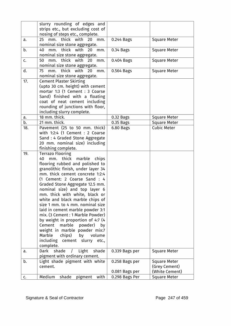
Signature & Seal of Contractor Page 247 of 459
slurry rounding of edges and strips etc., but excluding cost of nosing of steps etc., complete.
a. 25 mm. thick with 20 mm. nominal size stone aggregate.
0.244 Bags Square Meter
b. 40 mm. thick with 20 mm. nominal size stone aggregate.
0.34 Bags Square Meter
c. 50 mm. thick with 20 mm. nominal size stone aggregate.
0.404 Bags Square Meter
d. 75 mm. thick with 20 mm. nominal size stone aggregate.
0.564 Bags Square Meter
17. Cement Plaster Skirting
(upto 30 cm. height) with cement mortar 1:3 (1 Cement : 3 Coarse Sand) finished with a floating coat of neat cement including rounding of junctions with floor, including slurry complete.
a. 18 mm. thick. 0.32 Bags Square Meter b. 21 mm. thick. 0.35 Bags Square Meter 18. Pavement (25 to 50 mm. thick)
with 1:2:4 (1 Cement : 2 Coarse Sand : 4 Graded Stone Aggregate 20 mm. nominal size) including finishing complete.
6.80 Bags Cubic Meter
19. Terrazo Flooring
40 mm. thick marble chips flooring rubbed and polished to granolithic finish, under layer 34 mm. thick cement concrete 1:2:4 (1 Cement: 2 Coarse Sand : 4 Graded Stone Aggregate 12.5 mm. nominal size) and top layer 6 mm. thick with white, black or white and black marble chips of size 1 mm. to 4 mm. nominal size laid in cement marble powder 3:1 mix. (3 Cement : 1 Marble Powder) by weight in proportion of 4:7 (4 Cement marble powder) by weight in marble powder mix:7 Marble chips) by volume including cement slurry etc., complete.
a. Dark shade / Light shade pigment with ordinary cement.
0.339 Bags per Square Meter
b. Light shade pigment with white cement.
0.258 Bags per 0.081 Bags per
Square Meter (Grey Cement) (White Cement)
c. Medium shade pigment with 0.298 Bags Per Square Meter
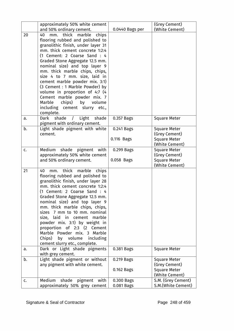
Signature & Seal of Contractor Page 248 of 459
approximately 50% white cement and 50% ordinary cement.
0.0440 Bags per
(Grey Cement) (White Cement)
20 40 mm. thick marble chips flooring rubbed and polished to granolithic finish, under layer 31 mm. thick cement concrete 1:2:4 (1 Cement: 2 Coarse Sand : 4 Graded Stone Aggregate 12.5 mm. nominal size) and top layer 9 mm. thick marble chips, chips, size 4 to 7 mm. size, laid in cement marble powder mix. 3:1) (3 Cement : 1 Marble Powder) by volume in proportion of 4:7 (4 Cement marble powder mix. 7 Marble chips) by volume including cement slurry etc., complete.
a. Dark shade / Light shade pigment with ordinary cement.
0.357 Bags Square Meter
b. Light shade pigment with white cement.
0.241 Bags
0.116 Bags
Square Meter (Grey Cement) Square Meter (White Cement)
c. Medium shade pigment with approximately 50% white cement and 50% ordinary cement.
0.299 Bags
0.058 Bags
Square Meter (Grey Cement) Square Meter (White Cement)
21 40 mm. thick marble chips flooring rubbed and polished to granolithic finish, under layer 28 mm. thick cement concrete 1:2:4 (1 Cement: 2 Coarse Sand : 4 Graded Stone Aggregate 12.5 mm. nominal size) and top layer 9 mm. thick marble chips, chips, sizes 7 mm to 10 mm. nominal size, laid in cement marble powder mix. 3:1) by weight in proportion of 2:3 (2 Cement Marble Powder mix. 3 Marble Chips) by volume including cement slurry etc., complete.
a. Dark or Light shade pigments with grey cement.
0.381 Bags Square Meter
b. Light shade pigment or without any pigment with white cement.
0.219 Bags
0.162 Bags
Square Meter (Grey Cement) Square Meter (White Cement)
c. Medium shade pigment with approximately 50% grey cement
0.300 Bags
0.081 Bags
S.M. (Grey Cement) S.M.(White Cement)
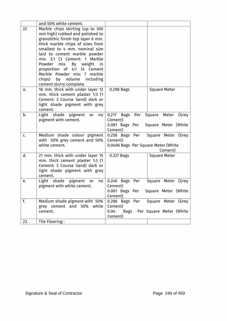
Signature & Seal of Contractor Page 249 of 459
and 50% white cement. 22 Marble chips skirting (up to 300
mm high) rubbed and polished to granolithic finish top layer 6 mm. thick marble chips of sizes from smallest to 4 mm. nominal size laid to cement marble powder mix. 3:1 (3 Cement: 1 Marble Powder mix. By weight in proportion of 4:7 (4 Cement Marble Powder mix: 7 marble chips) by volume including cement slurry complete.
a. 18 mm. thick with under layer 12 mm. thick cement plaster 1:3 (1 Cement: 3 Course Sand) dark or light shade pigment with grey cement.
0.298 Bags Square Meter
b. Light shade pigment or no pigment with cement.
0.217 Bags Per Square Meter (Grey Cement) 0.081 Bags Per Square Meter (White Cement)
c. Medium shade colour pigment with 50% grey cement and 50% white cement.
0.258 Bags Per Square Meter (Grey Cement) 0.0406 Bags Per Square Meter (White
Cement) d. 21 mm. thick with under layer 15
mm. thick cement plaster 1:3 (1 Cement: 3 Course Sand) dark or light shade pigment with grey cement.
0.327 Bags Square Meter
e. Light shade pigment or no pigment with white cement.
0.246 Bags Per Square Meter (Grey Cement) 0.081 Bags Per Square Meter (White Cement)
f. Medium shade pigment with 50% grey cement and 50% white cement.
0.286 Bags Per Square Meter (Grey Cement) 0.04 Bags Per Square Meter (White Cement)
23. Tile Flooring :
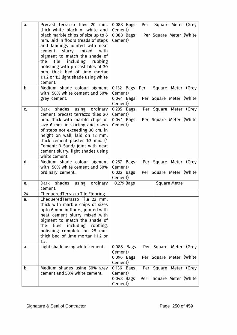
Signature & Seal of Contractor Page 250 of 459
a. Precast terrazzo tiles 20 mm. thick white black or white and black marble chips of size up to 6 mm. laid in floors treads of steps and landings jointed with neat cement slurry mixed with pigment to match the shade of the tile including rubbing polishing with precast tiles of 30 mm. thick bed of lime mortar 1:1.2 or 1:3 light shade using white cement.
0.088 Bags Per Square Meter (Grey Cement) 0.088 Bags Per Square Meter (White Cement)
b. Medium shade colour pigment with 50% white cement and 50% grey cement.
0.132 Bags Per Square Meter (Grey Cement) 0.044 Bags Per Square Meter (White Cement)
c. Dark shades using ordinary cement precast terrazzo tiles 20 mm. thick with marble chips of size 6 mm. in skirting and risers of steps not exceeding 30 cm. in height on wall, laid on 12 mm. thick cement plaster 1:3 mix. (1 Cement: 3 Sand) joint with neat cement slurry, light shades using white cement.
0.235 Bags Per Square Meter (Grey Cement) 0.044 Bags Per Square Meter (White Cement)
d. Medium shade colour pigment with 50% white cement and 50% ordinary cement.
0.257 Bags Per Square Meter (Grey Cement) 0.022 Bags Per Square Meter (White Cement)
e. Dark shades using ordinary cement.
0.279 Bags Square Metre
24. ChequeredTerrazzo Tile Flooring a. ChequeredTerrazzo Tile 22 mm.
thick with marble chips of sizes upto 6 mm. in floors, jointed with neat cement slurry mixed with pigment to match the shade of the tiles including robbing, polishing complete on 28 mm. thick bed of lime mortar 1:1.2 or 1:3.
a. Light shade using white cement. 0.088 Bags Per Square Meter (Grey Cement) 0.096 Bags Per Square Meter (White Cement)
b. Medium shades using 50% grey cement and 50% white cement.
0.136 Bags Per Square Meter (Grey Cement) 0.048 Bags Per Square Meter (White Cement)
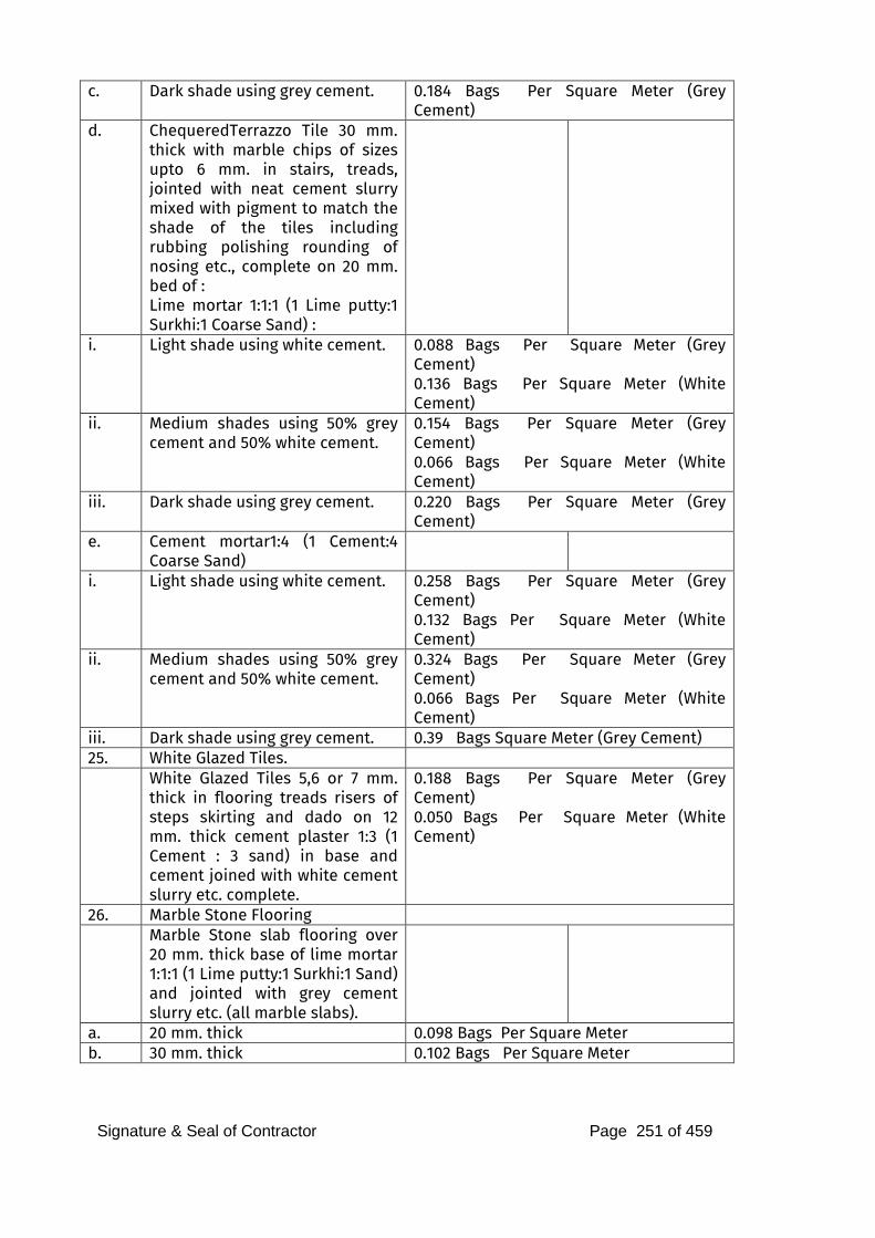
Signature & Seal of Contractor Page 251 of 459
c. Dark shade using grey cement. 0.184 Bags Per Square Meter (Grey Cement)
d. ChequeredTerrazzo Tile 30 mm. thick with marble chips of sizes upto 6 mm. in stairs, treads, jointed with neat cement slurry mixed with pigment to match the shade of the tiles including rubbing polishing rounding of nosing etc., complete on 20 mm. bed of : Lime mortar 1:1:1 (1 Lime putty:1 Surkhi:1 Coarse Sand) :
i. Light shade using white cement. 0.088 Bags Per Square Meter (Grey Cement) 0.136 Bags Per Square Meter (White Cement)
ii. Medium shades using 50% grey cement and 50% white cement.
0.154 Bags Per Square Meter (Grey Cement) 0.066 Bags Per Square Meter (White Cement)
iii. Dark shade using grey cement. 0.220 Bags Per Square Meter (Grey Cement)
e. Cement mortar1:4 (1 Cement:4 Coarse Sand)
i. Light shade using white cement. 0.258 Bags Per Square Meter (Grey Cement) 0.132 Bags Per Square Meter (White Cement)
ii. Medium shades using 50% grey cement and 50% white cement.
0.324 Bags Per Square Meter (Grey Cement) 0.066 Bags Per Square Meter (White Cement)
iii. Dark shade using grey cement. 0.39 Bags Square Meter (Grey Cement) 25. White Glazed Tiles. White Glazed Tiles 5,6 or 7 mm.
thick in flooring treads risers of steps skirting and dado on 12 mm. thick cement plaster 1:3 (1 Cement : 3 sand) in base and cement joined with white cement slurry etc. complete.
0.188 Bags Per Square Meter (Grey Cement) 0.050 Bags Per Square Meter (White Cement)
26. Marble Stone Flooring Marble Stone slab flooring over
20 mm. thick base of lime mortar 1:1:1 (1 Lime putty:1 Surkhi:1 Sand) and jointed with grey cement slurry etc. (all marble slabs).
a. 20 mm. thick 0.098 Bags Per Square Meter b. 30 mm. thick 0.102 Bags Per Square Meter
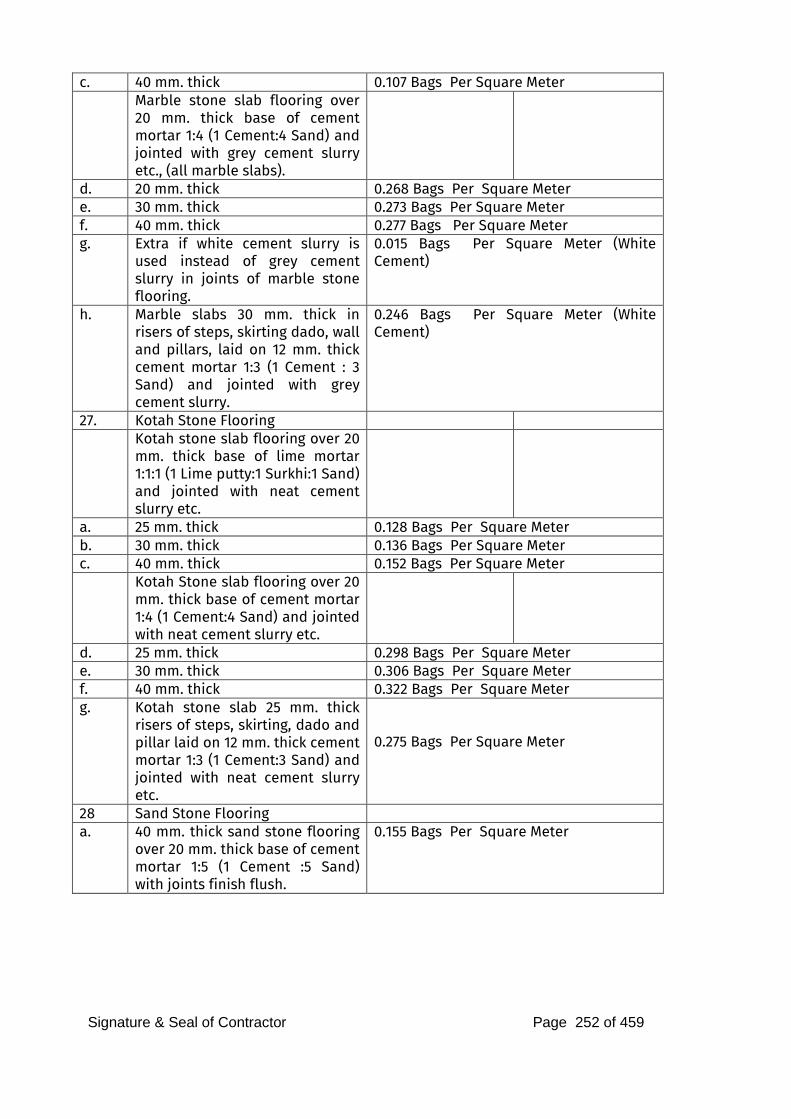
Signature & Seal of Contractor Page 252 of 459
c. 40 mm. thick 0.107 Bags Per Square Meter Marble stone slab flooring over
20 mm. thick base of cement mortar 1:4 (1 Cement:4 Sand) and jointed with grey cement slurry etc., (all marble slabs).
d. 20 mm. thick 0.268 Bags Per Square Meter e. 30 mm. thick 0.273 Bags Per Square Meter f. 40 mm. thick 0.277 Bags Per Square Meter g. Extra if white cement slurry is
used instead of grey cement slurry in joints of marble stone flooring.
0.015 Bags Per Square Meter (White Cement)
h. Marble slabs 30 mm. thick in risers of steps, skirting dado, wall and pillars, laid on 12 mm. thick cement mortar 1:3 (1 Cement : 3 Sand) and jointed with grey cement slurry.
0.246 Bags Per Square Meter (White Cement)
27. Kotah Stone Flooring Kotah stone slab flooring over 20
mm. thick base of lime mortar 1:1:1 (1 Lime putty:1 Surkhi:1 Sand) and jointed with neat cement slurry etc.
a. 25 mm. thick 0.128 Bags Per Square Meter b. 30 mm. thick 0.136 Bags Per Square Meter c. 40 mm. thick 0.152 Bags Per Square Meter Kotah Stone slab flooring over 20
mm. thick base of cement mortar 1:4 (1 Cement:4 Sand) and jointed with neat cement slurry etc.
d. 25 mm. thick 0.298 Bags Per Square Meter e. 30 mm. thick 0.306 Bags Per Square Meter f. 40 mm. thick 0.322 Bags Per Square Meter g. Kotah stone slab 25 mm. thick
risers of steps, skirting, dado and pillar laid on 12 mm. thick cement mortar 1:3 (1 Cement:3 Sand) and jointed with neat cement slurry etc.
0.275 Bags Per Square Meter
28 Sand Stone Flooring a. 40 mm. thick sand stone flooring
over 20 mm. thick base of cement mortar 1:5 (1 Cement :5 Sand) with joints finish flush.
0.155 Bags Per Square Meter
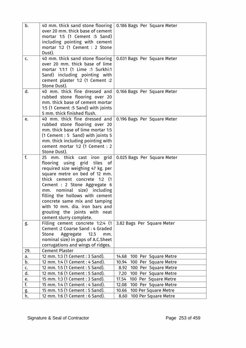
Signature & Seal of Contractor Page 253 of 459
b. 40 mm. thick sand stone flooring over 20 mm. thick base of cement mortar 1:5 (1 Cement :5 Sand) including pointing with cement mortar 1:2 (1 Cement : 2 Stone Dust).
0.186 Bags Per Square Meter
c. 40 mm. thick sand stone flooring over 20 mm. thick base of lime mortar 1:1:1 (1 Lime :1 Surkhi:1 Sand) including pointing with cement plaster 1:2 (1 Cement :2 Stone Dust).
0.031 Bags Per Square Meter
d. 40 mm. thick fine dressed and rubbed stone flooring over 20 mm. thick base of cement mortar 1:5 (1 Cement :5 Sand) with joints 5 mm. thick finished flush.
0.166 Bags Per Square Meter
e. 40 mm. thick fine dressed and rubbed stone flooring over 20 mm. thick base of lime mortar 1:5 (1 Cement : 5 Sand) with joints 5 mm. thick including pointing with cement mortar 1:2 (1 Cement : 2 Stone Dust).
0.196 Bags Per Square Meter
f. 25 mm. thick cast iron grid flooring using grid tiles of required size weighing 47 kg. per square metre on bed of 12 mm. thick cement concrete 1:2 (1 Cement : 2 Stone Aggregate 6 mm. nominal size) including filling the hollows with cement concrete same mix and tamping with 10 mm. dia. iron bars and grouting the joints with neat cement slurry complete.
0.025 Bags Per Square Meter
g. Filling cement concrete 1:2:4 (1 Cement :2 Coarse Sand : 4 Graded Stone Aggregate 12.5 mm. nominal size) in gaps of A.C.Sheet corrugations and wings of ridges.
3.82 Bags Per Square Meter
29. Cement Plaster a. 12 mm. 1:3 (1 Cement : 3 Sand). 14.68 100 Per Square Metre
b. 12 mm. 1:4 (1 Cement : 4 Sand). 10.94 100 Per Square Metre
c. 12 mm. 1:5 (1 Cement : 5 Sand). 8.92 100 Per Square Metre
d. 12 mm. 1:6 (1 Cement : 5 Sand). 7.20 100 Per Square Metre
e. 15 mm. 1:3 (1 Cement : 3 Sand). 17.54 100 Per Square Metre
f. 15 mm. 1:4 (1 Cement : 4 Sand). 12.08 100 Per Square Metre
g. 15 mm. 1:5 (1 Cement : 5 Sand). 10.66 100 Per Square Metre
h. 12 mm. 1:6 (1 Cement : 6 Sand). 8.60 100 Per Square Metre
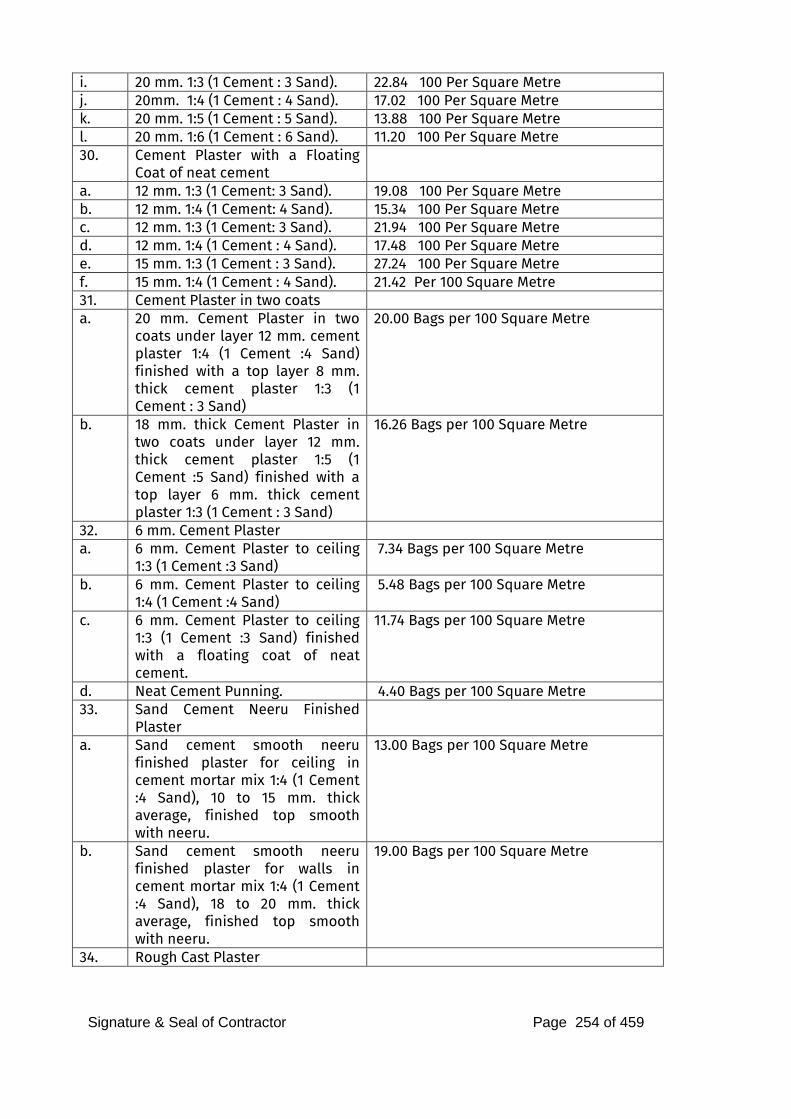
Signature & Seal of Contractor Page 254 of 459
i. 20 mm. 1:3 (1 Cement : 3 Sand). 22.84 100 Per Square Metre
j. 20mm. 1:4 (1 Cement : 4 Sand). 17.02 100 Per Square Metre
k. 20 mm. 1:5 (1 Cement : 5 Sand). 13.88 100 Per Square Metre
l. 20 mm. 1:6 (1 Cement : 6 Sand). 11.20 100 Per Square Metre
30. Cement Plaster with a Floating Coat of neat cement
a. 12 mm. 1:3 (1 Cement: 3 Sand). 19.08 100 Per Square Metre
b. 12 mm. 1:4 (1 Cement: 4 Sand). 15.34 100 Per Square Metre
c. 12 mm. 1:3 (1 Cement: 3 Sand). 21.94 100 Per Square Metre
d. 12 mm. 1:4 (1 Cement : 4 Sand). 17.48 100 Per Square Metre
e. 15 mm. 1:3 (1 Cement : 3 Sand). 27.24 100 Per Square Metre
f. 15 mm. 1:4 (1 Cement : 4 Sand). 21.42 Per 100 Square Metre
31. Cement Plaster in two coats a. 20 mm. Cement Plaster in two
coats under layer 12 mm. cement plaster 1:4 (1 Cement :4 Sand) finished with a top layer 8 mm. thick cement plaster 1:3 (1 Cement : 3 Sand)
20.00 Bags per 100 Square Metre
b. 18 mm. thick Cement Plaster in two coats under layer 12 mm. thick cement plaster 1:5 (1 Cement :5 Sand) finished with a top layer 6 mm. thick cement plaster 1:3 (1 Cement : 3 Sand)
16.26 Bags per 100 Square Metre
32. 6 mm. Cement Plaster a. 6 mm. Cement Plaster to ceiling
1:3 (1 Cement :3 Sand) 7.34 Bags per 100 Square Metre
b. 6 mm. Cement Plaster to ceiling 1:4 (1 Cement :4 Sand)
5.48 Bags per 100 Square Metre
c. 6 mm. Cement Plaster to ceiling 1:3 (1 Cement :3 Sand) finished with a floating coat of neat cement.
11.74 Bags per 100 Square Metre
d. Neat Cement Punning. 4.40 Bags per 100 Square Metre
33. Sand Cement Neeru Finished Plaster
a. Sand cement smooth neeru finished plaster for ceiling in cement mortar mix 1:4 (1 Cement :4 Sand), 10 to 15 mm. thick average, finished top smooth with neeru.
13.00 Bags per 100 Square Metre
b. Sand cement smooth neeru finished plaster for walls in cement mortar mix 1:4 (1 Cement :4 Sand), 18 to 20 mm. thick average, finished top smooth with neeru.
19.00 Bags per 100 Square Metre
34. Rough Cast Plaster
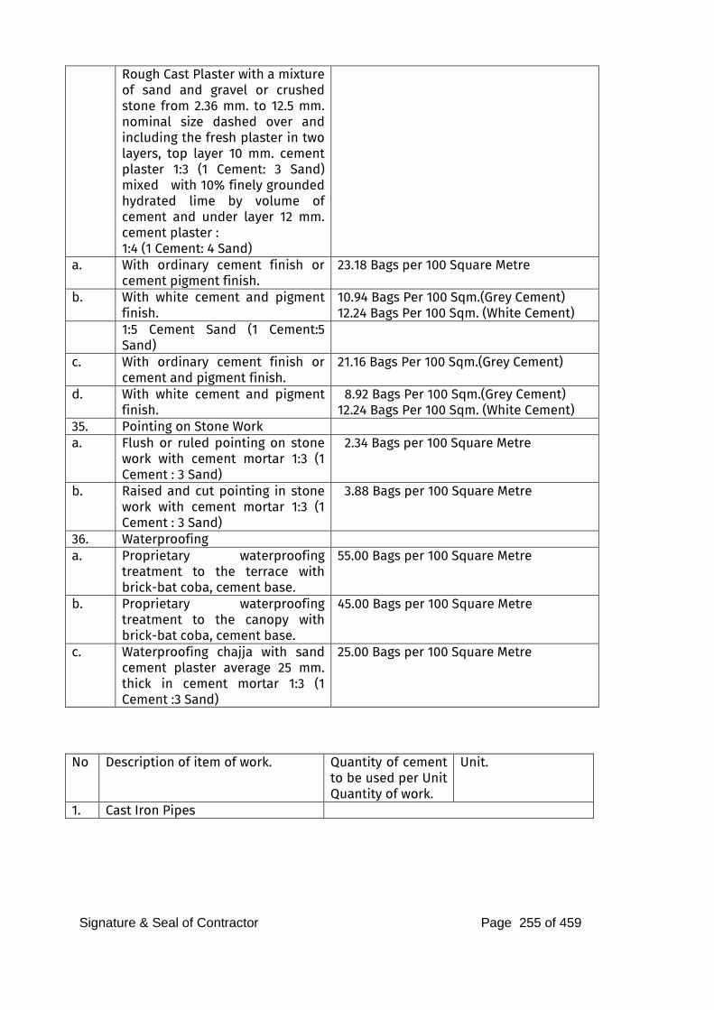
Signature & Seal of Contractor Page 255 of 459
Rough Cast Plaster with a mixture of sand and gravel or crushed stone from 2.36 mm. to 12.5 mm. nominal size dashed over and including the fresh plaster in two layers, top layer 10 mm. cement plaster 1:3 (1 Cement: 3 Sand) mixed with 10% finely grounded hydrated lime by volume of cement and under layer 12 mm. cement plaster : 1:4 (1 Cement: 4 Sand)
a. With ordinary cement finish or cement pigment finish.
23.18 Bags per 100 Square Metre
b. With white cement and pigment finish.
10.94 Bags Per 100 Sqm.(Grey Cement) 12.24 Bags Per 100 Sqm. (White Cement)
1:5 Cement Sand (1 Cement:5 Sand)
c. With ordinary cement finish or cement and pigment finish.
21.16 Bags Per 100 Sqm.(Grey Cement)
d. With white cement and pigment finish.
8.92 Bags Per 100 Sqm.(Grey Cement) 12.24 Bags Per 100 Sqm. (White Cement)
35. Pointing on Stone Work a. Flush or ruled pointing on stone
work with cement mortar 1:3 (1 Cement : 3 Sand)
2.34 Bags per 100 Square Metre
b. Raised and cut pointing in stone work with cement mortar 1:3 (1 Cement : 3 Sand)
3.88 Bags per 100 Square Metre
36. Waterproofing a. Proprietary waterproofing
treatment to the terrace with brick-bat coba, cement base.
55.00 Bags per 100 Square Metre
b. Proprietary waterproofing treatment to the canopy with brick-bat coba, cement base.
45.00 Bags per 100 Square Metre
c. Waterproofing chajja with sand cement plaster average 25 mm. thick in cement mortar 1:3 (1 Cement :3 Sand)
25.00 Bags per 100 Square Metre
No Description of item of work. Quantity of cement
to be used per Unit Quantity of work.
Unit.
1. Cast Iron Pipes
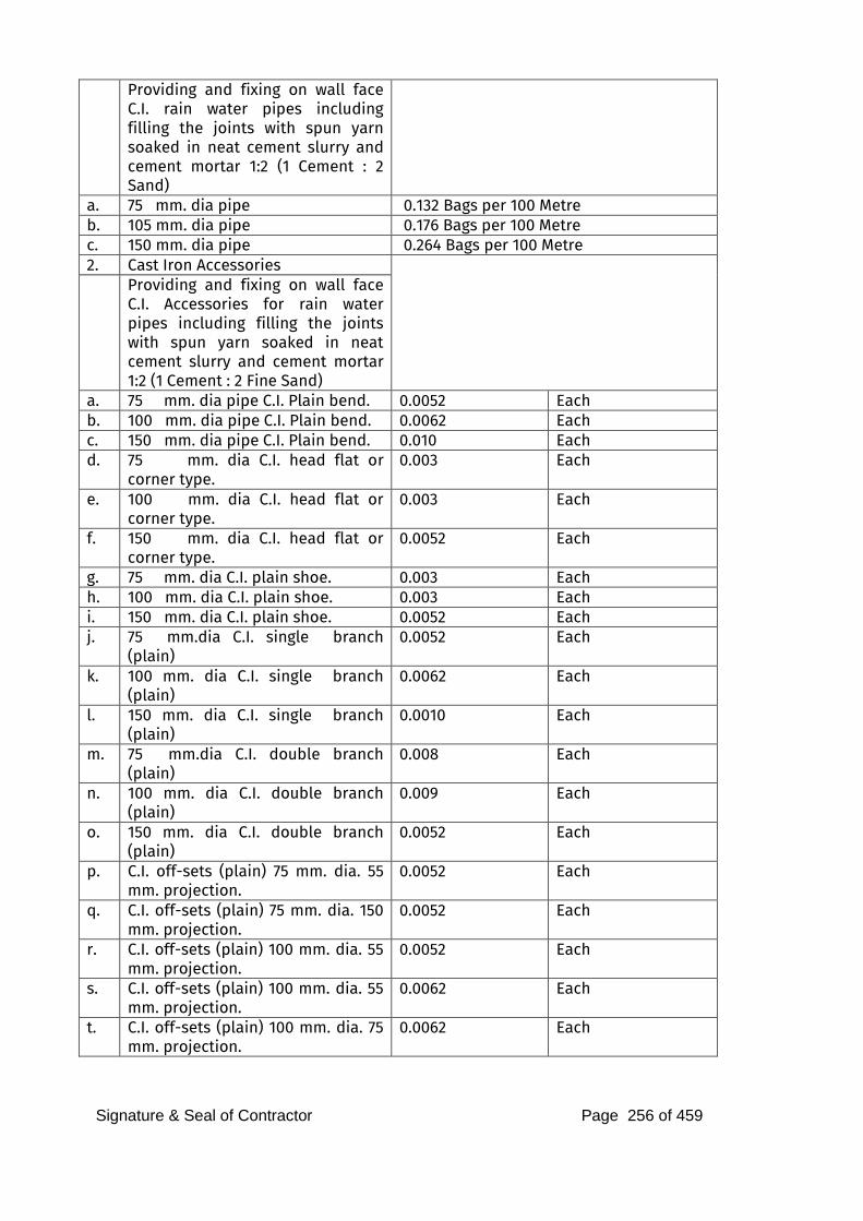
Signature & Seal of Contractor Page 256 of 459
Providing and fixing on wall face C.I. rain water pipes including filling the joints with spun yarn soaked in neat cement slurry and cement mortar 1:2 (1 Cement : 2 Sand)
a. 75 mm. dia pipe 0.132 Bags per 100 Metre b. 105 mm. dia pipe 0.176 Bags per 100 Metre c. 150 mm. dia pipe 0.264 Bags per 100 Metre 2. Cast Iron Accessories Providing and fixing on wall face
C.I. Accessories for rain water pipes including filling the joints with spun yarn soaked in neat cement slurry and cement mortar 1:2 (1 Cement : 2 Fine Sand)
a. 75 mm. dia pipe C.I. Plain bend. 0.0052 Each b. 100 mm. dia pipe C.I. Plain bend. 0.0062 Each c. 150 mm. dia pipe C.I. Plain bend. 0.010 Each d. 75 mm. dia C.I. head flat or
corner type. 0.003 Each
e. 100 mm. dia C.I. head flat or corner type.
0.003 Each
f. 150 mm. dia C.I. head flat or corner type.
0.0052 Each
g. 75 mm. dia C.I. plain shoe. 0.003 Each h. 100 mm. dia C.I. plain shoe. 0.003 Each i. 150 mm. dia C.I. plain shoe. 0.0052 Each j. 75 mm.dia C.I. single branch
(plain) 0.0052 Each
k. 100 mm. dia C.I. single branch (plain)
0.0062 Each
l. 150 mm. dia C.I. single branch (plain)
0.0010 Each
m. 75 mm.dia C.I. double branch (plain)
0.008 Each
n. 100 mm. dia C.I. double branch (plain)
0.009 Each
o.
150 mm. dia C.I. double branch (plain)
0.0052 Each
p. C.I. off-sets (plain) 75 mm. dia. 55 mm. projection.
0.0052 Each
q. C.I. off-sets (plain) 75 mm. dia. 150 mm. projection.
0.0052 Each
r. C.I. off-sets (plain) 100 mm. dia. 55 mm. projection.
0.0052 Each
s. C.I. off-sets (plain) 100 mm. dia. 55 mm. projection.
0.0062 Each
t. C.I. off-sets (plain) 100 mm. dia. 75 mm. projection.
0.0062 Each
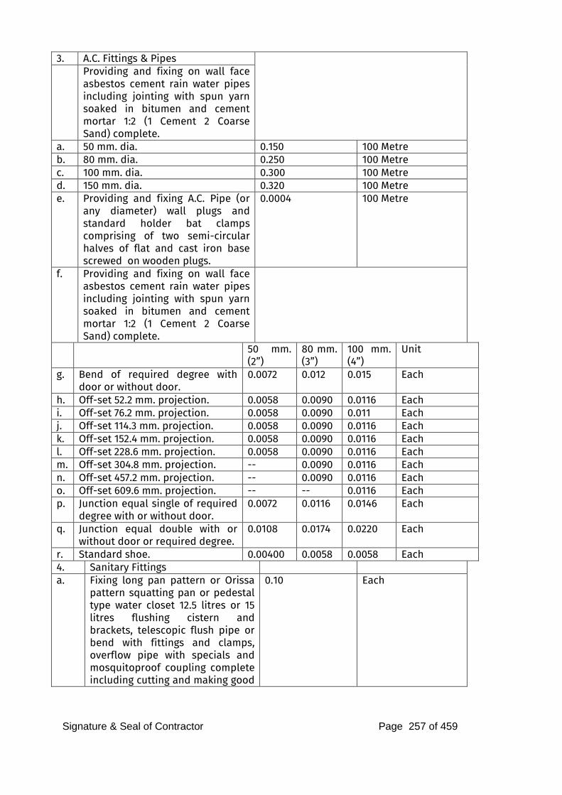
Signature & Seal of Contractor Page 257 of 459
3. A.C. Fittings & Pipes Providing and fixing on wall face
asbestos cement rain water pipes including jointing with spun yarn soaked in bitumen and cement mortar 1:2 (1 Cement 2 Coarse Sand) complete.
a. 50 mm. dia. 0.150 100 Metre b. 80 mm. dia. 0.250 100 Metre c. 100 mm. dia. 0.300 100 Metre d. 150 mm. dia. 0.320 100 Metre e. Providing and fixing A.C. Pipe (or
any diameter) wall plugs and standard holder bat clamps comprising of two semi-circular halves of flat and cast iron base screwed on wooden plugs.
0.0004 100 Metre
f. Providing and fixing on wall face asbestos cement rain water pipes including jointing with spun yarn soaked in bitumen and cement mortar 1:2 (1 Cement 2 Coarse Sand) complete.
50 mm. (2”)
80 mm. (3”)
100 mm. (4”)
Unit
g. Bend of required degree with door or without door.
0.0072 0.012 0.015 Each
h. Off-set 52.2 mm. projection. 0.0058 0.0090 0.0116 Each
i. Off-set 76.2 mm. projection. 0.0058 0.0090 0.011 Each
j. Off-set 114.3 mm. projection. 0.0058 0.0090 0.0116 Each
k. Off-set 152.4 mm. projection. 0.0058 0.0090 0.0116 Each
l. Off-set 228.6 mm. projection. 0.0058 0.0090 0.0116 Each
m. Off-set 304.8 mm. projection. -- 0.0090 0.0116 Each
n. Off-set 457.2 mm. projection. -- 0.0090 0.0116 Each
o. Off-set 609.6 mm. projection. -- -- 0.0116 Each
p. Junction equal single of required degree with or without door.
0.0072 0.0116 0.0146 Each
q. Junction equal double with or without door or required degree.
0.0108 0.0174 0.0220 Each
r. Standard shoe. 0.00400 0.0058 0.0058 Each
4. Sanitary Fittings a. Fixing long pan pattern or Orissa
pattern squatting pan or pedestal type water closet 12.5 litres or 15 litres flushing cistern and brackets, telescopic flush pipe or bend with fittings and clamps, overflow pipe with specials and mosquitoproof coupling complete including cutting and making good
0.10 Each
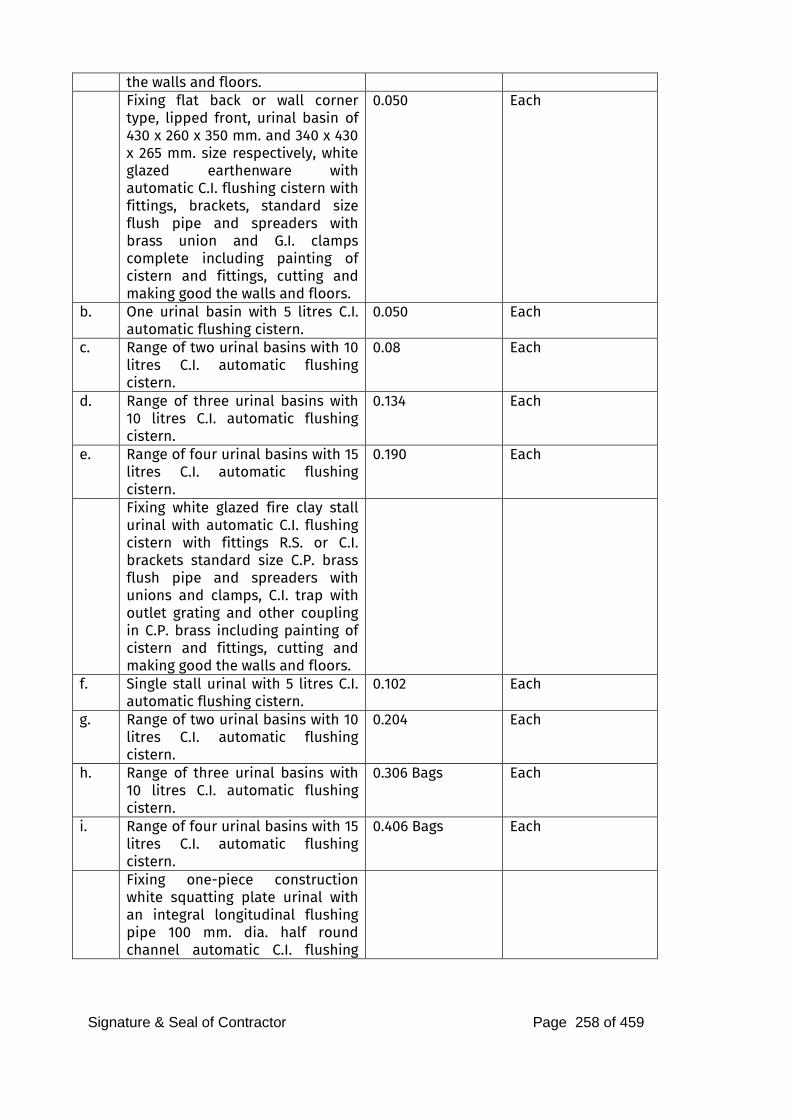
Signature & Seal of Contractor Page 258 of 459
the walls and floors. Fixing flat back or wall corner
type, lipped front, urinal basin of 430 x 260 x 350 mm. and 340 x 430 x 265 mm. size respectively, white glazed earthenware with automatic C.I. flushing cistern with fittings, brackets, standard size flush pipe and spreaders with brass union and G.I. clamps complete including painting of cistern and fittings, cutting and making good the walls and floors.
0.050 Each
b. One urinal basin with 5 litres C.I. automatic flushing cistern.
0.050 Each
c. Range of two urinal basins with 10 litres C.I. automatic flushing cistern.
0.08 Each
d. Range of three urinal basins with 10 litres C.I. automatic flushing cistern.
0.134 Each
e. Range of four urinal basins with 15 litres C.I. automatic flushing cistern.
0.190 Each
Fixing white glazed fire clay stall urinal with automatic C.I. flushing cistern with fittings R.S. or C.I. brackets standard size C.P. brass flush pipe and spreaders with unions and clamps, C.I. trap with outlet grating and other coupling in C.P. brass including painting of cistern and fittings, cutting and making good the walls and floors.
f. Single stall urinal with 5 litres C.I. automatic flushing cistern.
0.102 Each
g. Range of two urinal basins with 10 litres C.I. automatic flushing cistern.
0.204 Each
h. Range of three urinal basins with 10 litres C.I. automatic flushing cistern.
0.306 Bags Each
i. Range of four urinal basins with 15 litres C.I. automatic flushing cistern.
0.406 Bags Each
Fixing one-piece construction white squatting plate urinal with an integral longitudinal flushing pipe 100 mm. dia. half round channel automatic C.I. flushing
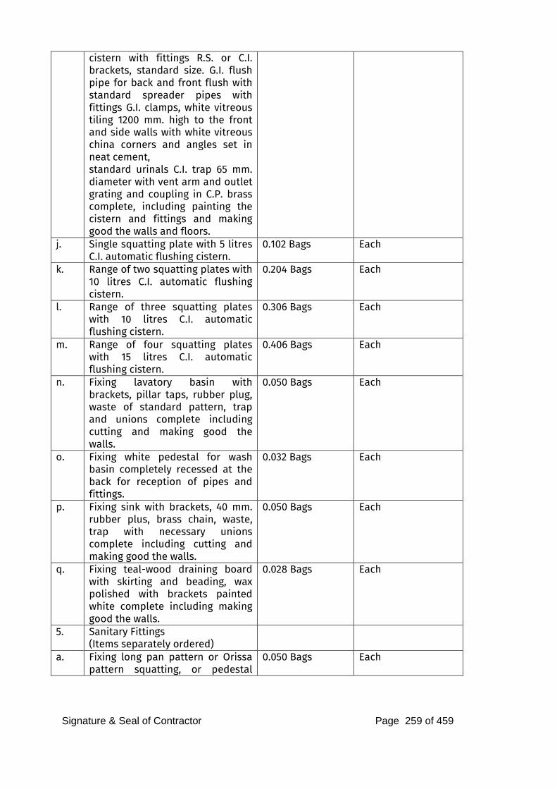
Signature & Seal of Contractor Page 259 of 459
cistern with fittings R.S. or C.I. brackets, standard size. G.I. flush pipe for back and front flush with standard spreader pipes with fittings G.I. clamps, white vitreous tiling 1200 mm. high to the front and side walls with white vitreous china corners and angles set in neat cement, standard urinals C.I. trap 65 mm. diameter with vent arm and outlet grating and coupling in C.P. brass complete, including painting the cistern and fittings and making good the walls and floors.
j. Single squatting plate with 5 litres C.I. automatic flushing cistern.
0.102 Bags Each
k. Range of two squatting plates with 10 litres C.I. automatic flushing cistern.
0.204 Bags Each
l. Range of three squatting plates with 10 litres C.I. automatic flushing cistern.
0.306 Bags Each
m. Range of four squatting plates with 15 litres C.I. automatic flushing cistern.
0.406 Bags Each
n. Fixing lavatory basin with brackets, pillar taps, rubber plug, waste of standard pattern, trap and unions complete including cutting and making good the walls.
0.050 Bags Each
o. Fixing white pedestal for wash basin completely recessed at the back for reception of pipes and fittings.
0.032 Bags Each
p. Fixing sink with brackets, 40 mm. rubber plus, brass chain, waste, trap with necessary unions complete including cutting and making good the walls.
0.050 Bags Each
q. Fixing teal-wood draining board with skirting and beading, wax polished with brackets painted white complete including making good the walls.
0.028 Bags Each
5. Sanitary Fittings
(Items separately ordered)
a. Fixing long pan pattern or Orissa pattern squatting, or pedestal
0.050 Bags Each
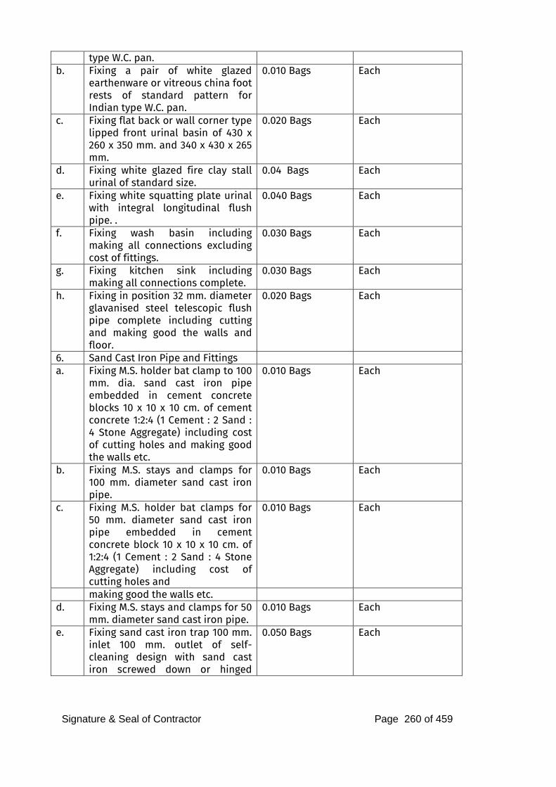
Signature & Seal of Contractor Page 260 of 459
type W.C. pan. b. Fixing a pair of white glazed
earthenware or vitreous china foot rests of standard pattern for Indian type W.C. pan.
0.010 Bags Each
c. Fixing flat back or wall corner type lipped front urinal basin of 430 x 260 x 350 mm. and 340 x 430 x 265 mm.
0.020 Bags Each
d. Fixing white glazed fire clay stall urinal of standard size.
0.04 Bags Each
e. Fixing white squatting plate urinal with integral longitudinal flush pipe. .
0.040 Bags Each
f. Fixing wash basin including making all connections excluding cost of fittings.
0.030 Bags Each
g. Fixing kitchen sink including making all connections complete.
0.030 Bags Each
h. Fixing in position 32 mm. diameter glavanised steel telescopic flush pipe complete including cutting and making good the walls and floor.
0.020 Bags Each
6. Sand Cast Iron Pipe and Fittings a. Fixing M.S. holder bat clamp to 100
mm. dia. sand cast iron pipe embedded in cement concrete blocks 10 x 10 x 10 cm. of cement concrete 1:2:4 (1 Cement : 2 Sand : 4 Stone Aggregate) including cost of cutting holes and making good the walls etc.
0.010 Bags Each
b. Fixing M.S. stays and clamps for 100 mm. diameter sand cast iron pipe.
0.010 Bags Each
c. Fixing M.S. holder bat clamps for 50 mm. diameter sand cast iron pipe embedded in cement concrete block 10 x 10 x 10 cm. of 1:2:4 (1 Cement : 2 Sand : 4 Stone Aggregate) including cost of cutting holes and
0.010 Bags Each
making good the walls etc. d. Fixing M.S. stays and clamps for 50
mm. diameter sand cast iron pipe. 0.010 Bags Each
e. Fixing sand cast iron trap 100 mm. inlet 100 mm. outlet of self-cleaning design with sand cast iron screwed down or hinged
0.050 Bags Each
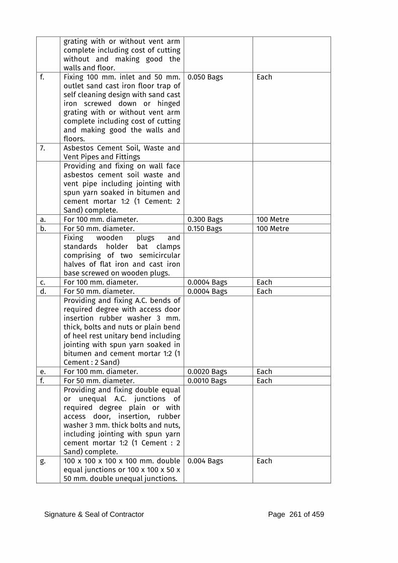
Signature & Seal of Contractor Page 261 of 459
grating with or without vent arm complete including cost of cutting without and making good the walls and floor.
f. Fixing 100 mm. inlet and 50 mm. outlet sand cast iron floor trap of self cleaning design with sand cast iron screwed down or hinged grating with or without vent arm complete including cost of cutting and making good the walls and floors.
0.050 Bags Each
7. Asbestos Cement Soil, Waste and Vent Pipes and Fittings
Providing and fixing on wall face asbestos cement soil waste and vent pipe including jointing with spun yarn soaked in bitumen and cement mortar 1:2 (1 Cement: 2 Sand) complete.
a. For 100 mm. diameter. 0.300 Bags 100 Metre b. For 50 mm. diameter. 0.150 Bags 100 Metre Fixing wooden plugs and
standards holder bat clamps comprising of two semicircular halves of flat iron and cast iron base screwed on wooden plugs.
c. For 100 mm. diameter. 0.0004 Bags Each d. For 50 mm. diameter. 0.0004 Bags Each Providing and fixing A.C. bends of
required degree with access door insertion rubber washer 3 mm. thick, bolts and nuts or plain bend of heel rest unitary bend including jointing with spun yarn soaked in bitumen and cement mortar 1:2 (1 Cement : 2 Sand)
e. For 100 mm. diameter. 0.0020 Bags Each f. For 50 mm. diameter. 0.0010 Bags Each Providing and fixing double equal
or unequal A.C. junctions of required degree plain or with access door, insertion, rubber washer 3 mm. thick bolts and nuts, including jointing with spun yarn cement mortar 1:2 (1 Cement : 2 Sand) complete.
g. 100 x 100 x 100 x 100 mm. double equal junctions or 100 x 100 x 50 x 50 mm. double unequal junctions.
0.004 Bags Each
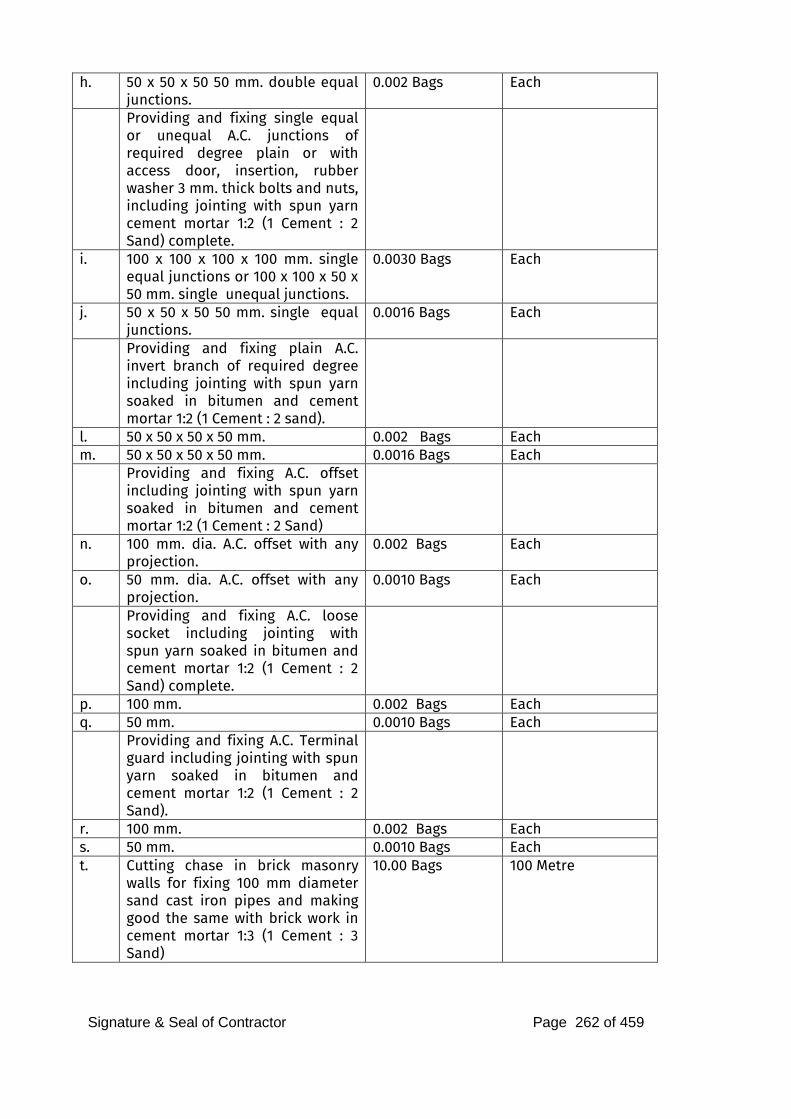
Signature & Seal of Contractor Page 262 of 459
h. 50 x 50 x 50 50 mm. double equal junctions.
0.002 Bags Each
Providing and fixing single equal or unequal A.C. junctions of required degree plain or with access door, insertion, rubber washer 3 mm. thick bolts and nuts, including jointing with spun yarn cement mortar 1:2 (1 Cement : 2 Sand) complete.
i. 100 x 100 x 100 x 100 mm. single equal junctions or 100 x 100 x 50 x 50 mm. single unequal junctions.
0.0030 Bags Each
j. 50 x 50 x 50 50 mm. single equal junctions.
0.0016 Bags Each
Providing and fixing plain A.C. invert branch of required degree including jointing with spun yarn soaked in bitumen and cement mortar 1:2 (1 Cement : 2 sand).
l. 50 x 50 x 50 x 50 mm. 0.002 Bags Each m. 50 x 50 x 50 x 50 mm. 0.0016 Bags Each Providing and fixing A.C. offset
including jointing with spun yarn soaked in bitumen and cement mortar 1:2 (1 Cement : 2 Sand)
n. 100 mm. dia. A.C. offset with any projection.
0.002 Bags Each
o. 50 mm. dia. A.C. offset with any projection.
0.0010 Bags Each
Providing and fixing A.C. loose socket including jointing with spun yarn soaked in bitumen and cement mortar 1:2 (1 Cement : 2 Sand) complete.
p. 100 mm. 0.002 Bags Each q. 50 mm. 0.0010 Bags Each Providing and fixing A.C. Terminal
guard including jointing with spun yarn soaked in bitumen and cement mortar 1:2 (1 Cement : 2 Sand).
r. 100 mm. 0.002 Bags Each s. 50 mm. 0.0010 Bags Each t. Cutting chase in brick masonry
walls for fixing 100 mm diameter sand cast iron pipes and making good the same with brick work in cement mortar 1:3 (1 Cement : 3 Sand)
10.00 Bags 100 Metre
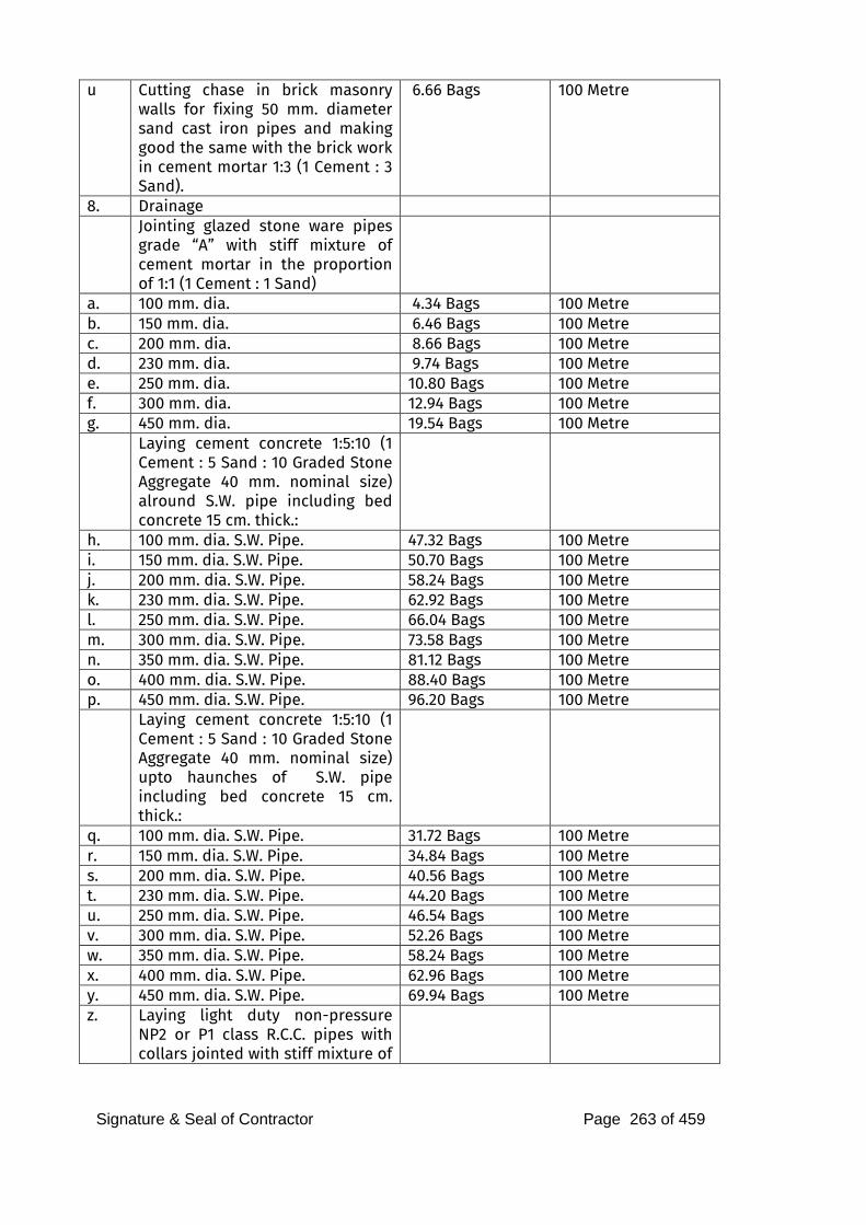
Signature & Seal of Contractor Page 263 of 459
u Cutting chase in brick masonry walls for fixing 50 mm. diameter sand cast iron pipes and making good the same with the brick work in cement mortar 1:3 (1 Cement : 3 Sand).
6.66 Bags 100 Metre
8. Drainage Jointing glazed stone ware pipes
grade “A” with stiff mixture of cement mortar in the proportion of 1:1 (1 Cement : 1 Sand)
a. 100 mm. dia. 4.34 Bags 100 Metre b. 150 mm. dia. 6.46 Bags 100 Metre c. 200 mm. dia. 8.66 Bags 100 Metre d. 230 mm. dia. 9.74 Bags 100 Metre e. 250 mm. dia. 10.80 Bags 100 Metre f. 300 mm. dia. 12.94 Bags 100 Metre g. 450 mm. dia. 19.54 Bags 100 Metre Laying cement concrete 1:5:10 (1
Cement : 5 Sand : 10 Graded Stone Aggregate 40 mm. nominal size) alround S.W. pipe including bed concrete 15 cm. thick.:
h. 100 mm. dia. S.W. Pipe. 47.32 Bags 100 Metre i. 150 mm. dia. S.W. Pipe. 50.70 Bags 100 Metre j. 200 mm. dia. S.W. Pipe. 58.24 Bags 100 Metre k. 230 mm. dia. S.W. Pipe. 62.92 Bags 100 Metre l. 250 mm. dia. S.W. Pipe. 66.04 Bags 100 Metre m. 300 mm. dia. S.W. Pipe. 73.58 Bags 100 Metre n. 350 mm. dia. S.W. Pipe. 81.12 Bags 100 Metre o. 400 mm. dia. S.W. Pipe. 88.40 Bags 100 Metre p. 450 mm. dia. S.W. Pipe. 96.20 Bags 100 Metre Laying cement concrete 1:5:10 (1
Cement : 5 Sand : 10 Graded Stone Aggregate 40 mm. nominal size) upto haunches of S.W. pipe including bed concrete 15 cm. thick.:
q. 100 mm. dia. S.W. Pipe. 31.72 Bags 100 Metre r. 150 mm. dia. S.W. Pipe. 34.84 Bags 100 Metre s. 200 mm. dia. S.W. Pipe. 40.56 Bags 100 Metre t. 230 mm. dia. S.W. Pipe. 44.20 Bags 100 Metre u. 250 mm. dia. S.W. Pipe. 46.54 Bags 100 Metre v. 300 mm. dia. S.W. Pipe. 52.26 Bags 100 Metre w. 350 mm. dia. S.W. Pipe. 58.24 Bags 100 Metre x. 400 mm. dia. S.W. Pipe. 62.96 Bags 100 Metre y. 450 mm. dia. S.W. Pipe. 69.94 Bags 100 Metre z. Laying light duty non-pressure
NP2 or P1 class R.C.C. pipes with collars jointed with stiff mixture of
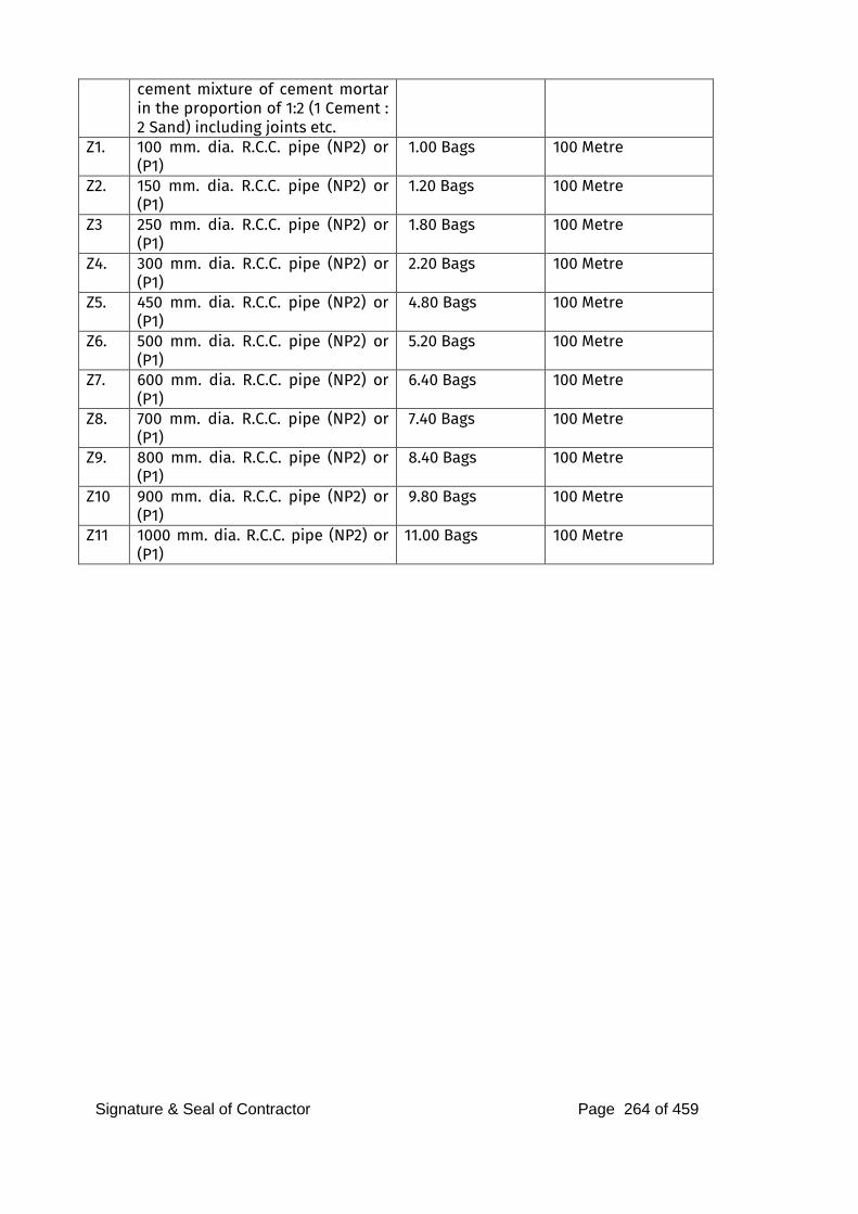
Signature & Seal of Contractor Page 264 of 459
cement mixture of cement mortar in the proportion of 1:2 (1 Cement : 2 Sand) including joints etc.
Z1. 100 mm. dia. R.C.C. pipe (NP2) or (P1)
1.00 Bags 100 Metre
Z2. 150 mm. dia. R.C.C. pipe (NP2) or (P1)
1.20 Bags 100 Metre
Z3 250 mm. dia. R.C.C. pipe (NP2) or (P1)
1.80 Bags 100 Metre
Z4. 300 mm. dia. R.C.C. pipe (NP2) or (P1)
2.20 Bags 100 Metre
Z5. 450 mm. dia. R.C.C. pipe (NP2) or (P1)
4.80 Bags 100 Metre
Z6. 500 mm. dia. R.C.C. pipe (NP2) or (P1)
5.20 Bags 100 Metre
Z7. 600 mm. dia. R.C.C. pipe (NP2) or (P1)
6.40 Bags 100 Metre
Z8. 700 mm. dia. R.C.C. pipe (NP2) or (P1)
7.40 Bags 100 Metre
Z9. 800 mm. dia. R.C.C. pipe (NP2) or (P1)
8.40 Bags 100 Metre
Z10 900 mm. dia. R.C.C. pipe (NP2) or (P1)
9.80 Bags 100 Metre
Z11 1000 mm. dia. R.C.C. pipe (NP2) or (P1)
11.00 Bags 100 Metre
Signature & Seal of Contractor Page 265 of 459
PLUMBING WORK TECHNICAL SPECIFICATIONS
Signature & Seal of Contractor Page 266 of 459
SPECIFICATIONS FOR SANITARY, PLUMBING AND WATER SUPPLY INSTALLATION WORK
SECTION – A : BASIS OF DESIGN
1. BASIS OF DESIGN
The Plumbing, Sanitary and Drainage System for the project is designed keeping in view the following:
i. The project is for proposed residential buildings for SBI, Mumbai.
ii. Requirement of adequate and equal pressure availability of hot and cold-water linesin Toilets, Kitchen and Cold makeup water supply to Water Bodies etc.
iii. Adequate storage of water in underground raw + treated domestic water tanks, preferably for 1.5 days consumption.
iv. Levels of roads / pavements and other services in the area.
v. Landscape layout.
The execution of works and materials used shall be as per the latest relevant I.S. specifications.
The extension of work shall in stick compliance to the Environmental Clearance granted by EIA, Govt. of India & NOC issued by Fire Department.
Wherever reference has been made to Indian Standard or any other specifications, the same shall mean to refer to the latest specification irrespective of any particular edition of such specification being mentioned in the specifications below or Schedule of Quantities.
CONCEPT OF THE SYSTEM
The following services are envisaged for the complex: i. Water Treatment System for meeting the domestic water quality
requirement with chemical parameters in acceptable limits as per SP:35 (S&T) 1987 which is considered safe for human consumption, and other standards such as IS 10500.
ii. Domestic and Flushing water supply through hydro-pneumatic system to individual building over-head water tanks.
iii. Domestic and Flushing water supply through Gravity System for making water available at all user points.
iv. Sewage and Sullage collection system based on IS:1742 and applicable standards for domestic drainage. Single stack drainage system should be use for drainage system.
v. Sewage / Effluent Treatment Plant comprising of preliminary anaerobic digestor, biological and tertiary treatment for recycling of the effluent. The treated effluent shall be used for flushing water required and for gardening / irrigation purpose.
Signature & Seal of Contractor Page 267 of 459
vi. Storm / Rain water drainage system from various levels of the building and disposal to available MIDC storm water disposal. Rainwater harvesting through recharge bore- wells and water bodies is planned.
WATER STORAGE & DISTRIBUTION SYSTEM
i. Water Requirement The water requirement for the project is proposed to be based on the provisions of IS:1172 and prevalent practice. The estimated requirement of fresh water per day for the 3 buildings based on the number of users and other services shall be 1,06,000 liters / day.
ii. Source of Water It is expected that part of the daily domestic water requirement for the building shall be through Municipal mains supply. Provision of tanker water fill point will also be made.
iii. Water Storage The static storage for Fire Protection is at present sized for 600 KL i.e. 400 KL for Tower A & B and 200 KL for Tower C. The total water storage in raw & domestic water tanks is of 1,06,000 ltrs capacity.
iv. Water Quality
Domestic Water Requirement: The total domestic water shall be passed through basic water treatment plant and further specialized treatment shall be done based on the water analysis report and requirement. The basic water treatment plant shall comprise of ACF, MG filter, Softener and Hypo dosing. Treated water quality shall be as per IS:10500.
Disinfected Water: It is proposed to provide localized UV units for water consumption points for direct consumption in Kitchen / Pantry.
Recycled Water from STP: Water recovered from tertiary sewage treatment plant shall be used as flushing water supply through separate storage tank and pumping system and shall also be used for external landscape irrigation.
v. Water Distribution
The water distribution for domestic & flushing water supply for the building shall be through HPS in centrally located pump room & the central risers fed to each OHT through the horizontal distribution within the apartment and designed on principle of zoning to ensure availability of adequate residual head at user outlet. Provision of pressure reducing station and non-return valve shall be made for effective and efficient water distribution in the building within the same plumbing room. Design is such that the domestic & flushing water pressure and flow shall be fairly equal to avoid reversal of flow from one service to another. The main piping ring and headers shall be of uPVC Sch 80 with provision of PEX-b pipe-in-pipe system within toilets.
Signature & Seal of Contractor Page 268 of 459
vi. Appurtenant
Following components shall be included in the water supply system for efficient functioning: 1. Automatic air vent at each of the high point. 2. Drain valve at each of the low point. 3. Pressure Release valve where abnormally high pressure is to be
reduced. 4. Water Hammer Arrestors (as required). 5. Flow meter. 6. Pressure Gauge.
7. Anchor block / thrust block.
2. SEWAGE, SULLAGE AND STORM WATER
The soil and waste shall be carried down in combined pipe. One pipe system shall be adopted as per NBC (Part-IX). One-pipe system — not vented (also called single stack, partially ventilated) — A system in which there is one soil pipe into which all water closets, baths, sinks and no separate vent is provided. However in addition to that separate pipes are considered for kitchen wastes. Waste water from the kitchens will be collected by separate stacks as shown on the drawings and discharge into sewer line through Grease trap.
4.1 Design Limitations
The system is designed considering the following: 1. High thrust developed at soil & water pipe connections. 2. Termination of vent cowl at terrace level. 3. Provision of adequate slope for horizontal header pipes for
achieving self- cleaning velocity in the pipes. 4. Provision of clean-out plug.
3. WORKMANSHIP
The workmanship shall be best of its kind and shall conform to the specifications, as below or Indian Standard Specifications in every respect or latest trade practices and shall be subject to approval of the APMC/SBI . All materials and/or Workmanship which in the opinion of the APMC/SBI / Architect / Consultant is defective or unsuitable shall be removed immediately from the site and shall be substituted with proper materials and/or workmanship forthwith.
4. MATERIALS
2. All materials shall be best of their kind and shall conform to the latest Indian Standards. All materials shall be of approved quality as per samples and origins approved by the APMC/SBI / Architect / Consultants.
As and when required by the APMC/SBI / Consultant, the contractor
Signature & Seal of Contractor Page 269 of 459
shall arrange to test the materials and/or portions of works at his own cost to prove their soundness and efficiency. If after tests any materials, work or portions or work are found defective or unsound by the APMC/SBI / Consultant, the contractor shall remove the defective material from the site, pull down and re-execute the works at his own cost to the satisfaction of the APMC/SBI / Consultant. To prove that the materials used are as specified the contractor shall furnish the APMC/SBI with original vouchers on demand.

Construction of 3 Multitoried Towers, Nerul
Signature & Seal of Contractor Page 270 of 459
Construction of 3 Multi story Towers, Nerul
SECTION – B : SANITARY FIXTURES & FITTINGS
SCOPE
The scope of this section consists of but is not necessarily limited to supply, installation, testing and commissioning of following items: 1. Sanitary appliances and fixtures for toilets. 2. Chromium plated brass fittings
3. Stainless steel sinks
4. Accessories e.g. towel rods, toilet paper holders, soap dish, liquid soap dispensers, towel rails, coat hooks etc.
5. Hand driers, drinking water fountains etc. Whether specifically mentioned or not the Contractor shall provide for all
appliances and fixtures all fixing devices, nuts, bolts, screws, hangers as required.
All exposed pipes within toilets and near appliances/fixtures shall be of chromium plated brass or copper unless otherwise specified.
GENERAL REQUIREMENT
Sanitary appliances and fixtures for toilets, chromium plated brass fittings, stainless steel sinks, bathroom accessories like towel rods, toilet paper holders, soap dish, liquid soap dispensers, towel rails coat hooks etc and mirrors, hand driers, drinking water fountains etc as listed in the relevant items in the Schedule of Quantities shall be arranged by the contractor as per tender/BOQ. Hardware, brackets and accessories required for installation shall also be be arranged by the contractor as per tender/BOQ. All sanitary fixtures and fittings shall received and thereafter be stored under covered roof and handled carefully to prevent any damage by the Contractor.
All appliances, fixtures and fittings shall be provided with all such accessories as are required to complete the item in working condition whether specifically mentioned or not in the Schedule of Quantities, specifications, and drawings. Accessories shall include proper fixing arrangements, brackets, nuts, bolts, washers, screws and required connection pieces.
The sanitary fixtures and fittings shall be installed at the correct assigned position as shown on the drawings and as directed by the APMC/SBI Site Representative and shall fully meet with the aesthetic and symmetrical requirements as demanded by the Architect / Interior Designer
All fixtures and accessories shall be fixed in accordance with a set pattern matching the tiles or interior finish as per Architect requirements. Wherever necessary, the fittings shall be centered to dimensions and pattern as called for.
Fixing screws shall be half round head chromium plated (CP) brass screws, with CP brass washers unless otherwise specified.
Fixtures shall be installed by skilled workman with appropriate tools according to the best trade practice.
Construction of 3 Multi story Towers, Nerul
All appliances, fittings and fixtures shall be fixed in a neat workmanlike manner true to level and to heights shown on the drawings and in accordance with the manufacturer’s recommendations. Care shall be taken to fix all inlet and outlet pipes at correct positions. Faulty locations shall be made good and any damage to the finished floor, tiling, plaster, paint, insulation or terrace shall be made good by the Contractor at his own cost. Fixtures shall be mounted rigid, plumb and true to alignment.
All materials shall be rust proofed; materials in direct or indirect contact shall be compatible to prevent electrolytic or chemical (bimetallic) corrosion.
Wall flanges shall be provided on all walls, floors, columns etc. wherever supply and disposal pipes pierce through them. These wall caps shall be or chromium plated
brass fittings and the receiving pipes and shall be large enough to cover the punctures properly.
Sanitary appliances, subject to the type of appliance and specific requirements, shall be fixed in accordance with the relevant standards and the following: 1. Contractor shall, during the entire period of installation and
afterwards protect the appliances by sealing the sanitary ware and fittings by providing suitable cover or any other protection so as to absolutely prevent any damage or usage of the appliances until handing over (The original protective wrapping shall be left in position for as long as possible)
2. The appliances shall be placed in correct position or marked out in order that pipe work can be fixed or partially fixed first.
3. The appliance shall be fixed in a manner such that it will facilitate subsequent removal if necessary.
4. The appliance shall be securely fixed. Manufacturer's brackets and fixing methods shall be used wherever possible. Compatible rust-proofed fixings shall be used. Fixing shall be done in a manner that minimizes noise transmission.
5. Appliances shall not be bedded (e.g. WC pans, pedestal units) in thick strong mortar that could crack the unit (e.g. ceramic unit)
6. Pipe connections shall be made with demountable unions. Pipe work shall not be fixed in a manner that it supports or partially supports and appliance.
7. Appliances shall be fixed true to level firmly fixed to anchor or supports provided by the manufacturer and additional anchors or supports where necessary.
Sizes of sanitary fixtures given in the Specifications or in the Schedule of Quantities are for identification with reference to the catalogues of make considered. Dimensions of similar models of other makes may very within + 10% and the same shall be provided and no claim
Construction of 3 Multi story Towers, Nerul
for extra payment shall be entertained NOR shall any payment be deducted on this account.
The contractor shall fix all plumbing fittings such as water faucets, shower fittings, mixing valves etc. in accordance with manufacturer’s instructions and connect to piping system. The contractor shall supply all fixing materials such as screws, rawl plugs, unions, collars, compression fittings etc., as required.
Joints / gaps between all sanitary appliances / fixtures and the floor / walls shall be caulked with an approved mildew resistant sealant, having antifungal properties, of colour and shade to match that of the appliances / fixture and the floor / wall to the extent possible. Silicone Sealants of approved colour shall be used for sealing gaps between sanitary ware and wall/floor tiles/stone.
Water Closet Water Closet shall be wash down or symphonic wash down type floor or
wall mounted set, as shown in the drawings, designed for low volume flushing from 3-6 litres of water, flushed by means of a concealed flushing cistern or (as detailed in the drawings or as directed by the APMC/SBI ) or 32 mm size CP brass flush valve with regulator valve. Flush pipe / bend shall be connected to the WC by means of a suitable rubber adaptor. Wall hung WC shall be supported by CI floor mounted chair which shall be fixed in a manner as approved by the Owners Site Representative.
Each WC set shall be provided with approved quality of seat, rubber buffers and chromium plated hinges. Seat shall be so fixed that it remains absolutely stationary in vertical position without falling down on the WC. Each WC shall be provided with 110 mm dia (OD) Poly Propylene Pan connector with Leap Seal connecting the ceramic outlet of WC to CI / Plastic pipe.
Urinals Urinals shall be lipped type full stall with glazed vitreous China of size
as called for in the Bill of Quantities.
Full stall urinals shall be provided with 15mm dia CP spreader, 32mm dia CP domical waste and built-in ceramic P-trap with outlet pipe and wall flange and shall be fixed to wall by CI brackets, CI wall clips and CP brass screws as recommended by manufacturer complete as directed by the APMC/SBI .
Flushing for urinals shall be by means of no hand operation, infrared electric flush valve with complete kit of plumbing, electrical and electronic items, infrared photo cells, solenoid valve transformer and electrical connection. The automatic flush sensor plate shall be flush and press fitted and be of high quality mirror polish finish. Each urinal shall be provided with one flush valve unit.
Urinal’s Flush pipes shall be Connected to Urinal Suction Moulding made of Poly propylene with Quality controlled in accordance with
Construction of 3 Multi story Towers, Nerul
DIN 19541, with leap seal at the flushing pipe connection point with inlet and outlet of dia 50mm x 50mm with water seal of > or = 50mm concealed in wall chase at inlet and outlet. Urinal traps shall be separately connected outside the toilet block to the stack with closed pop-up type grating on floor trap.
Urinal Partitions Urinal partitions shall be white glazed vitreous china of size specified
in the Schedule of Quantities. Porcelain partitions shall be fixed at proper heights with CP brass bolts,
anchor fasteners and MS clips as recommended by the manufacturer and directed by the APMC/SBI .
Flush Valve
Low level flushing valves shall be with dual flushing arrangement, 3ltrs. Small flush and 6 ltrs. Big flush. Where pressure is not adequate as suggested in drawings, concealed cistern are to be provided. Contractor shall install valve / cistern in accordance to the manufacturer’s specification to the satisfaction of the Owner Site Representative.
Wash Basin
Wash basins shall be white glazed vitreous china of size, shape and type specified in the Schedule of Quantities.
Each basin shall be provided with painted MS angle or CI brackets and clips and the basin securely fixed to wall/counter slab. Placing of basins over the brackets without secure fixing shall not be accepted. The MS angle shall be provided with two coats of red oxide primer and two coats of synthetic enamel paint of make , brand and colour as approved by the APMC/SBI . The cost of fixing the basin shall be inclusive of supply and installation of brackets as described above.
Each basin shall be Connected to P-Trap instead of bottle trap made of either Brass chrome plated or Polypropylene (quality controlled in accordance with DIN EN 274) with water seal of > or = 50mm.
Each basin shall be provided with hot and cold water mixing fitting or as specified in the Schedule of Quantities.
Sinks
Sinks shall be stainless steel or any other material as specified in the Schedule of Quantities.
Each sink shall be provided with painted MS or CI brackets and clips and securely fixed. Counter top sinks shall be fixed with suitable painted angle iron brackets or clips as recommended by the manufacturer. Each sink shall be provided with 40mm dia CP waste and rubber plug with CP brass chain as given in the Schedule of Quantities. The
MS angle shall be provided with two coats of red oxide primer and two
Construction of 3 Multi story Towers, Nerul
coats of synthetic enamel paint of make, brand and colour as approved by the APMC/SBI .
Each Sink should be connected to P-Trap instead of bottle trap made of Polypropylene (quality controlled in accordance with DIN EN 274) ) with water seal of > or = 50mm.
Sanitary fittings for sinks shall be deck mounted or wall mounted CP swivel faucets with or without hot and cold water mixing fittings as specified in the Schedule of Quantities. Installation of fittings shall be measured and paid for separately.
Flow Control Device
Approved / rated flow control fitment in brass body, chrome outer cover, rated for flow / discharge of the fixture.
Janitor's Sink
Janitor's sink shall be stainless steel, single bowl type of size as called for in the Schedule of Quantities , provided with painted R.S. or CI brackets and clips and securely fixed. Each sink shall be provided with 40mm dia CP waste. Fixing shall be as directed by the APMC/SBI . The supply fittings for Janitor's sink shall be wall mounted type of size as mentioned in Schedule of Quantities.
Electric Hot water Geyser
The contractor shall provide all equipment, including the necessary
work required for proper installation and adjustment of the electric water heater. The size and quantity of equipment can produce the flow rate of hot water and temperature as required on the drawings.
The contractor shall test and operate the equipment in order to
demonstrate its performance. He shall also instruct the Employer / Owner’s operating personnel in the operation and maintenance of the equipment.
Material and equipment to be supplied shall be the standard
products of manufacturer regularly engaged in manufacturing the products conforming to the Specification.
The contractor shall supply and install the storage type water heater
of approved colour with copper container, glass wool insulation, stove enameled M.S jacket.
The water heaters shall have thermostatically controlled electrical
immersion elements with pilot neon lamps. They shall have a minimum 15mm stop cock valve and CP flexible connection pipe on the inlet connection. The outlet shall be fitted with a relief valve
Construction of 3 Multi story Towers, Nerul
with a setting of minimum of 8 kg/sqcm in addition to a 15mm stop cock valve and a 15mm C.P flexible connection pipe. The relief valve shall be provided with a drain line which shall discharge over a tundish drain in the ceiling void as indicated on the drawings.
The water heaters shall be suitable for operating at a working
pressure of 10 kg/sqcm. The basic components of the electric hot water heater shall include (but not be limited to) the following: 8) glass or ceramic lined steel tanks to protect against corrosion,
9) foam for insulating purposes, Depending on the thickness and density of the insulation foam the R-values shall be between 14.57 to 20 w/mk
10) low watt-density heating elements - single phase, 240-volt power supply. Depending on the load, 10-gauge electrical wiring is the minimum required with a maximum of a thirty-amp fuse. 11) Hot water heaters shall fitted with an anode for cathodic protection inside the tank to attract free radicals preventing corrosion (i.e. sacrificial anode).
3.0 TOILETS FOR THE DISABLED
Where specified, in washroom facilities designed to accommodate physically disabled, accessories shall be provided as directed by the APMC/SBI .
Stainless steel garb brass of required size suitable for concealed or exposed mounting and opened non-slip gripping surface shall be provided in all washroom. Washbasins shall be at 600mm ht.
4.0 MOCKUP AND TRIAL ASSEMBLY
The installation of the Sanitary fixtures and fittings shall be as per the shop drawings approved by the Architect/Consultant.
The contractor shall have to assemble at least one set of each type of sanitary fixtures and fittings in order to determine precisely the required supply and disposal connections. Relevant instructions from manufacturers shall be followed as applicable. This trial assembly shall be developed to determine the location of puncture holes, holding devices etc. which will be required for final installation of all sanitary fixtures and fittings. The above assembly shall be subject to final approval by the Architect / Interior Designer.
The fixtures in the trial assembly can be re-used for final installation without any additional payments for fixing or dismantling of the fixtures.
5.0 SUPPORTING AND FIXING DEVICES
The contractor shall provide all the necessary supporting and fixing
Construction of 3 Multi story Towers, Nerul
devices to install the sanitary fixtures and fittings securely in position. The fixing devices shall be rigidly anchored into the building structure. The devices shall be rust resistant and shall be so fixed that they do not present an unsightly appearance in the final assembly. Where the location demands, the Architect may instruct the contractor to provide chromium plated or other similarly finished fixing devices. In such circumstances the contractor shall arrange to supply the fixing devices and shall be installed complete with appropriate vibration isolating pads, washers and gaskets.
6.0 FINAL INSTALLATION
The contractor shall install all sanitary fixtures and fittings in their final position in accordance with approved trial assemblies and as shown on drawings. The installation shall be complete with all supply and waste connections. The connection between building and piping system and the sanitary fixtures shall be through proper unions and flanges to facilitate removal/replacement of sanitary fixtures without disturbing the built in piping system. All unions and flanges shall match in appearance with other exposed fittings.
Fixtures shall be mounted rigid, plumb and to alignment. The outlets of water closet pans and similar appliances shall be examined to ensure that outlet ends are butting on the receiving pipes before making the joints. It shall be ensured that the receiving pipes are clear of obstruction. When fixtures are being mounted, attention shall be paid to the possibility of movement and settlement by other causes. Overflows shall be made to ensure that necessary anchoring devices have been provided for supporting water closets, wash basins, sinks and other appliances.
7.0 PROTECTION AGAINST DAMAGE AND USAGE
The contractor shall take every precaution to protect all sanitary fixtures against damage, misuse, cracking, staining, breakage and pilferage by providing proper wrapping and locking arrangement till the completion of the installation. At the time of handing over, the contractor shall clean, disinfect and polish all the fixtures and fittings. Any fixtures and fittings found damaged, cracked chipped stained or scratched shall be removed and new fixtures and fittings free from defects shall be installed at his own cost to complete the work.
8.0 MEASUREMENT
8.1. Rate for fixing only of sanitary fixtures accessories, CP fittings shall etc. include all items, and operations stated in the respective specifications and bill of quantities and nothing extra is payable.
8.2 Rates for all items under specifications para above shall be inclusive of cutting holes and chases and making good the same, CP screws, nuts, bolts and any fixing arrangements required and recommended

Construction of 3 Multi story Towers, Nerul
by manufacturers, testing and commissioning and making good to the satisfaction of the APMC/SBI .
9.0 TESTING
All appliances, fixtures and fittings shall be tested before and after installation. Water seals of all appliances shall be tested. The contractor shall block the ends of waste and ventilation pipes and shall conduct hydraulic tests.
Construction of 3 Multi story Towers, Nerul
Signature & Seal of Contractor Page 279 of 459
SECTION – C : WATER SUPPLY
1.0 SCOPE
The scope of this section comprises the supply, installation, testing and commissioning of piping network for water supply for internal & external services as follows:
a MIDC / Tanker Water supply. 4 Domestic Water Supply. 5 Flushing Water Supply
6 Car / Vehicle Washing
7 External water supply to cater for Horticulture from the Treated Sewage Water Tank through an independent pumping System (as required by landscaping agency).
8 Connection to various mechanical equipments to be supplied and installed by the other specialist contractors.
The Contractor shall make all necessary application and arrangements for his work to be inspected by the Local Authorities.
The Contractor shall be solely responsible for obtaining the Authorities approval of his works prior to the handing over of the complete water supply / distribution installation to the Owner.
2.0 PIPING MATERIALS
PPR pipes and fittings
The piping system shall consist of Polypropylene Random
Copolymer Type 3 pipes and fittings conforming to DIN 8078/IS15801:2008. The sizes and makes are specified in the Schedule of Quantities.
For any internal works, the Polypropylene pipes and fittings shall be embedded in the wall chase or run on the floor/ ceiling unless otherwise specified. No unsighted exposed runs shall be permitted. Outside the building the piping shall be installed at least 1.0 meter below the finished grade level.
Cold Water system pipe shall be of following pressure & Class: PN 16 –SDR-7.4 as per IS:15801/manufacturers specifications.
Fusion Welded Polypropylene Pipes and fittings
The pipes shall be 3 – Layered Polypropylene Random Copolymer
whereby the different layers of the pipes shall consist of:-
Construction of 3 Multi story Towers, Nerul
Signature & Seal of Contractor Page 280 of 459
1. The inner-most layer of the pipe to be Anti – bacterial to prevent bacteria growth inside the pipe surface.
2. The middle layer to be of plain PP-R which is neither in contact with
Water and nor under direct effect of the atmospheric conditions.
3. The outer-most layer to be of U.V. stabilized PP-R to prevent the pipe surface from sunlight under exposed atmospheric conditions.
The pipes should be conforming to the requirements of DIN 8078 April
1996 (PPR pipes General Quality requirements and Testing) and DIN 8077 December 1997 (PPR Pipe dimensions). The pipes should have smooth inner surface with Non – contracting diameters. The pipes shall be cleanly finished, free from cracks and other defects.
The pipes shall be clean and well cut along ends after taking into consideration the desired length, using the Pipe scissors.
The fittings shall be as follows:-
5 Plain fittings from sizes 16mm to 160mm
6 Chrome Plated Brass Threaded fittings from sizes 16mm to 75mm. 7 Valves from sizes 20mm to 63mm.
6 The plain fittings shall be Polypropylene Random Copolymer and comply with all the requirements of the pipes. The size of fitting is specified in the schedule of quantities, corresponding to the size of the pipe. The plain fittings shall comprise of Socket, Elbow, Tee, Cross, Unions, Reducer socket, Reduction Tee, End Cap, Crossover, Omega, Threaded plug, and Wall Clamps in available sizes.
7 The Chrome Plated Brass threaded fittings shall be Chrome or Nickel Plated Brass threaded piece molded inside Polypropylene Random copolymer fitting. The Plastic end shall comply with all the requirements of the pipes while the C.P. Brass end shall comply with BSP standards of Threading. The size of the C.P. Brass threaded fitting is specified in the schedule of quantities, corresponding to the pipe size. The Chrome plated Brass threaded fittings shall comprise of Socket, Elbow and Tee (Male & Female) in available sizes. These are the fittings for C.P. connections and for continuations from existing Galvanized Iron Pipes and fittings. Horizontal and Vertical clamp support spacing shall be as per
guidelines in UPC-India 2014.In general a spacing of 900mm is
acceptable for ceiling-hung PPr pipes.
8 The valves shall be Polypropylene Random Copolymer Valves. The valves comprise of Gate Valve, Ball Valve, Concealed Stop Cock and
Construction of 3 Multi story Towers, Nerul
Signature & Seal of Contractor Page 281 of 459
Chrome Coated Valve in available sizes. The size and type of the Valve is specified in the Schedule of quantities.
The Valves sizes availability in Polypropylene Random Copolymer is as follows :-
8.12 Gate Valve - 20 MM & 63 MM
8.13 Ball Valve - 20 MM, 25 MM, 32 MM, 40 MM, 50 MM
8.13.1 Butter fly valve - 63 MM 75 MM 90 MM
8.14 Concealed Stop Cock - 20 MM & 25 MM.
8.15 Chrome Coated Valve - 20 MM & 25 MM.
However, the other Brass/ Bronze Valves can be connected to Polypropylene Random pipes using C.P. Brass threaded fittings of desired sizes.
Training and Supervision of Fusion Jointing
PPr piping is prone to leakage or blockage if fusion jointing is not carried out correctly, therefore, the contractor shall ensure:
All personnel carrying out jointing of PPr are fully trained in the usage of the fusion welding equipment, and
Additional supervision of installation personnel is provided to ensure all joints are made correctly.
Laying and Jointing of Polypropylene Random Pipes and Fittings
The Polypropylene Random Pipes and Fittings shall run in wall chase or ceiling or as specified. The installation of Polypropylene Random Copolymer pipes is similar to that of the metal pipes with the only difference in the Jointing procedure. The jointing of the Fusion welded PP-R pipes and fittings are done by means of a Welding Machine.
The quality of each installation system ultimately depends on the tightness, stability and lifetime of its connections. The homogeneous connection of PP-R pipes by fusion welding gives an absolutely safe pipe connection and guarantees utmost operational safety. It takes only a few seconds to make a connection by fusion welding process. After a couple of minutes, the welded
Construction of 3 Multi story Towers, Nerul
Signature & Seal of Contractor Page 282 of 459
joint cools down sufficiently and can be fully loaded. The pipe to the desired length is cut using the Pipe Scissors. The proper heating piece is taken and mounted on the welding machine. The welding device is switched on – Control lamp and switch lamp will light. When ready, control lamp gets off, which means that welding temperature of 260 Degrees +/- 10 Degrees Celsius has been reached. The Pipe end and the fitting to be welded are heated on the welding machine. Before heating the fitting and the pipe, the dirty welding tools, pipe and fitting is cleaned with a cloth. When heated up (with heating time as per the Table shown below), the pipe and the fitting is removed from the welding machine and the two pieces connected together by applying a little pressure without twisting. The joint is allowed to cool down for a few seconds. The welding process is that safe because the properly heated parts of Polypropylene create a homogeneous connection.
Guidelines for Welding PP-R Pipes and fittings (DVS guideline 2207,
Part 11): Note: welding of PP-r pipe shall be carried out in accordance with the recommendations of the pipe manufacturer.
Outer diameter of pipe (MM)
Heating Time (Seconds) Cooling Period (Minutes)
16 5 2
20 5 2
25 7 2
32 8 4
40 12 4
50 18 4
63 24 6
75 30 8
90 30 8
110 45 10
160 60 12
The same procedure shall be adapted for exposed as well as concealed fittings. The
Crossovers may be used wherever the overlapping of the PP-R pipes is required. The fixing shall be done by means of Wall Support Clamps keeping the pipes about 1.5 cm clears of the wall where to be laid on the surface. Where it is specified to conceal the pipes, chasing may be adopted. For pipes fixed in the shafts, ducts etc. there should be sufficient space to work on the pipes with the usual tools. Where directed by the APMC/SBI, pipe sleeves shall be fixed at a place the pipe is passing, through a wall or floor for reception of the pipe and allow
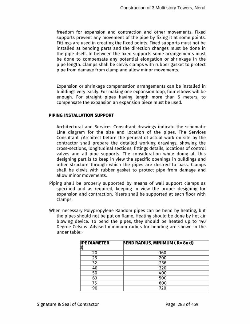
Construction of 3 Multi story Towers, Nerul
Signature & Seal of Contractor Page 283 of 459
freedom for expansion and contraction and other movements. Fixed supports prevent any movement of the pipe by fixing it at some points. Fittings are used in creating the fixed points. Fixed supports must not be installed at bending parts and the direction changes must be done in the pipe itself. In between the fixed supports some arrangements must be done to compensate any potential elongation or shrinkage in the pipe length. Clamps shall be clevis clamps with rubber gasket to protect pipe from damage from clamp and allow minor movements.
Expansion or shrinkage compensation arrangements can be installed in buildings very easily. For making one expansion loop, four elbows will be enough. For straight pipes having length more than 5 meters, to compensate the expansion an expansion piece must be used.
PIPING INSTALLATION SUPPORT
Architectural and Services Consultant drawings indicate the schematic Line diagram for the size and location of the pipes. The Services Consultant /Architect before the perusal of actual work on site by the contractor shall prepare the detailed working drawings, showing the cross-sections, longitudinal sections, fittings details, locations of control valves and all pipe supports. The consideration while doing all this designing part is to keep in view the specific openings in buildings and other structure through which the pipes are desired to pass. Clamps shall be clevis with rubber gasket to protect pipe from damage and allow minor movements.
Piping shall be properly supported by means of wall support clamps as specified and as required, keeping in view the proper designing for expansion and contraction. Risers shall be supported at each floor with Clamps.
When necessary Polypropylene Random pipes can be bend by heating, but
the pipes should not be put on flame. Heating should be done by hot air blowing device. To bend the pipes, they should be heated up to 140 Degree Celsius. Advised minimum radius for bending are shown in the under table:-
PIPE DIAMETER (d)
BEND RADIUS, MINIMUM ( R= 8x d)
20 160 25 200 32 256 40 320 50 400 63 500 75 600 90 720
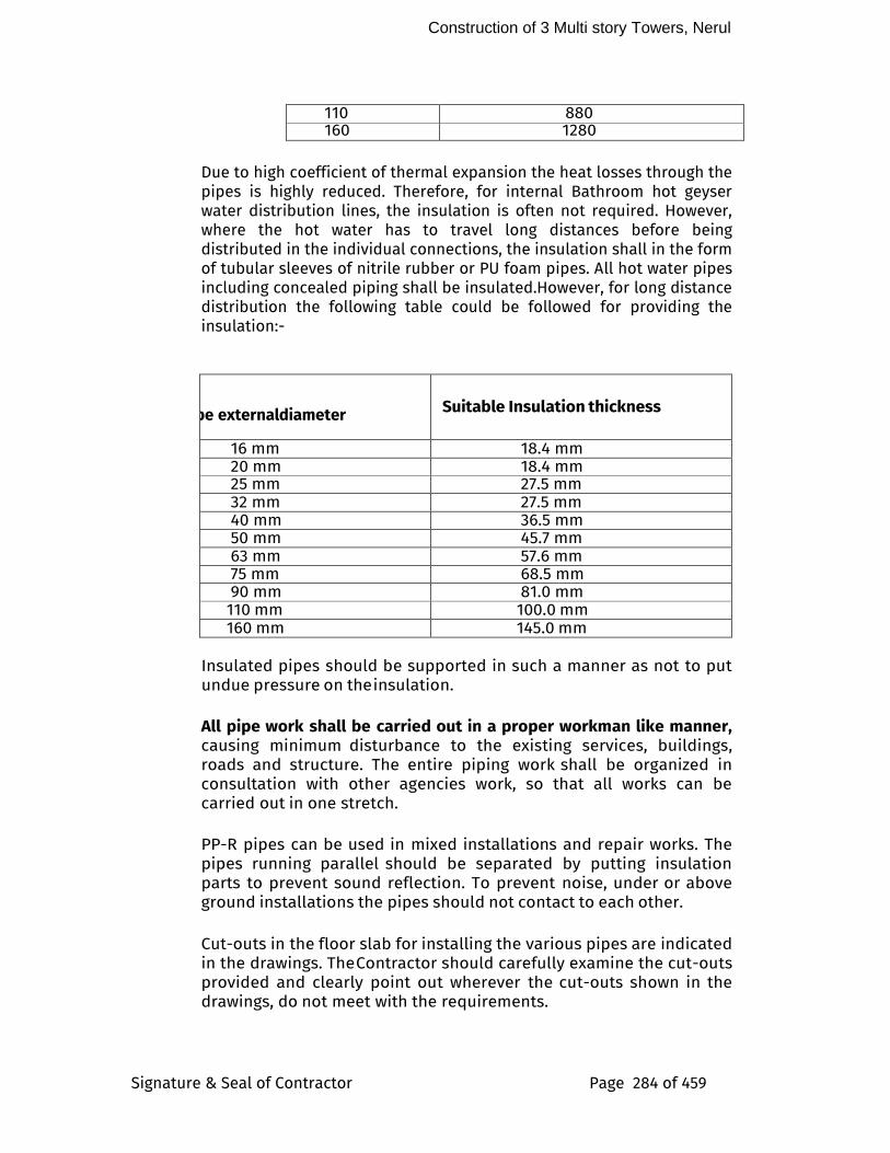
Construction of 3 Multi story Towers, Nerul
Signature & Seal of Contractor Page 284 of 459
110 880 160 1280
Due to high coefficient of thermal expansion the heat losses through the
pipes is highly reduced. Therefore, for internal Bathroom hot geyser water distribution lines, the insulation is often not required. However, where the hot water has to travel long distances before being distributed in the individual connections, the insulation shall in the form of tubular sleeves of nitrile rubber or PU foam pipes. All hot water pipes including concealed piping shall be insulated.However, for long distance distribution the following table could be followed for providing the insulation:-
Pipe external diameter Suitable Insulation thickness
16 mm 18.4 mm 20 mm 18.4 mm 25 mm 27.5 mm 32 mm 27.5 mm 40 mm 36.5 mm 50 mm 45.7 mm 63 mm 57.6 mm 75 mm 68.5 mm 90 mm 81.0 mm 110 mm 100.0 mm 160 mm 145.0 mm
Insulated pipes should be supported in such a manner as not to put
undue pressure on the insulation.
All pipe work shall be carried out in a proper workman like manner, causing minimum disturbance to the existing services, buildings, roads and structure. The entire piping work shall be organized in consultation with other agencies work, so that all works can be carried out in one stretch.
PP-R pipes can be used in mixed installations and repair works. The
pipes running parallel should be separated by putting insulation parts to prevent sound reflection. To prevent noise, under or above ground installations the pipes should not contact to each other.
Cut-outs in the floor slab for installing the various pipes are indicated
in the drawings. The Contractor should carefully examine the cut-outs provided and clearly point out wherever the cut-outs shown in the drawings, do not meet with the requirements.
Construction of 3 Multi story Towers, Nerul
Signature & Seal of Contractor Page 285 of 459
All pipes shall be accurately cut to the required lengths and then cleaned with a clean cloth before fusion welding. Open ends of the pipes where the C.P. Brass threaded fittings are welded for C.P. connections at the later stage should be closed by means of Plugs to avoid the entrance of foreign matter.
Automatic air valves shall be provided at all high points in the piping
system for venting. Automatic air valves shall also be provided on hot water risers. Discharge from the air valves shall be piped to the nearest drain or sump. All pipes shall be pitched towards the drain points.
Pressure gauges and Thermometers shall be provided as per the
approved drawings and included in the Bill of quantities. Care should be taken to prevent these during Pressure testing.
TESTING After installation the piping shall be pressure tested to 1.5 times the
system working pressure in accordance with the requirements of this specification. In addition to this a flow test shall be provided for all pipe sections to ensure that there are blockages/restrictions caused by the fusion joints.
The Contractor shall inform in advance of any test so that the Architect
and consultant or site engineer can witness the tests if he so wishes. All water supply system shall be tested to Hydrostatic pressure test of at least one and a half (1.5) times the maximum working pressure but not less than 12 Kgs/ Sq. Cm for a period of not less than 8 hours.
The pressure test is performed in 3 steps being preliminary test,
main test and final test. For the preliminary test a pressure which is 1.5 times higher than the possible working pressure is applied and this is repeated two times in 30 minutes with intervals of 10 minutes. After a test period of 30 minutes, the test pressure must not be dropped more than 0.6 bars(0.2 bar) and no leak must occur. Main test follows the preliminary test. Test time is two hours, in doing so the test pressure taken from the preliminary test must not have fallen more than 0.2 bars. After completion of these tests, the final test comes which has to be done under a test pressure of 12 bar and 3 bar in the interval of 15 minutes.
Between the respective test courses, pressure has to be removed. All
joints should be manually checked for any dampness/leaks.
All leaks and defects in joints revealed during the testing shall be rectified and got approved at site by retest. Piping required subsequent to the above pressure test shall be retested in the same
Construction of 3 Multi story Towers, Nerul
Signature & Seal of Contractor Page 286 of 459
manner. A record of Pressure test has to prepared and signed by the Client/ Architect and Contractor with statement of place and date.
Above testing is for PPr piping upto Pex manifold. Internal Pexpiping shall be tested for 7bar pressure for 8 hr.
Control Schedule
Start of the test : End
Test Period and Pressure:
Contractor’s Engineer :
Client : Place :
System may be tested in sections and such sections shall be entirely retested on completion to the overhead tanks or pumping system or mains. In case of improper circulation, the contractor shall rectify the defective connections. He shall bear all expenses for carrying out the above rectifications including the tearing up and refinishing of floors and walls as required.
After commissioning of the water supply system, contractor shall test each valve by closing and opening it a number of times to observe if it is working efficiently. Valves which are not working efficiently shall be replaced by new ones, at contractor’s expenditure.
CUTTING CHASES IN MASONRY WALLS
Cold and Hot water distribution pipes to fixtures and equipment’s exposed in the bathrooms, kitchens and sanitary compartments shall be chased into walls or floors. The contractor shall be responsible for cutting all notches, chases and recesses in walls and floors. The maximum size of pipe permitted to be concealed in ceiling shall be 40mm diameter unless otherwise approved by the Architect.
The chases up to 7.5 x 7.5 cm shall be made in the walls for housing
Construction of 3 Multi story Towers, Nerul
Signature & Seal of Contractor Page 287 of 459
uPVC / c-PVC pipes etc. These shall be provided in correct positions as shown in the drawings or directed by the Services consultants. Chases shall be made by chiseling out the masonry to proper line and depth. After the pipes etc. are fixed in chases, the chases shall be filled with cement mortar 1:2:4 or as may be specified, and made flush with the masonry surface. The concrete surface shall be roughened with wire brush to provide a key for plastering.
MEASUREMENTS
The length above ground shall be measured in running meter correct to a cm for the finished work, which shall include pipe and fittings including Plain fittings and Chrome Plated Brass Threaded fittings. Deductions for the length of valves shall be made. Rate quoted shall be inclusive of all fittings, clamps, Plugs, Chase cutting and making good the same and all items mentioned in the specifications and Bill of Quantities.
All pipes below ground shall be measured per linear meters (to the nearest cm) and shall be inclusive of all fittings including Plain fittings and Chrome Plated Brass Threaded fittings. Deductions for the length of valves shall be made. Rates quoted shall be inclusive of all fittings, clamps, excavation, back filling and disposal of surplus earth, cutting holes and making good all items mentioned in the Bill of Quantities.
3.0 PIPING INSTALLATION SUPPORT
Tender drawings indicate schematically the size and location of pipes. The Contractor, on the award of the work, shall prepare detailed working drawings, showing the cross- sections, longitudinal sections, details of fittings, locations of isolating and control valves, drain and air valves, and all pipe supports. He must keep in view the specific openings in buildings and other structure through which pipes are designed to pass. Piping shall be properly supported on, or suspended from, on stands, clamps, as specified and as required. Clamp shall be clevis clamps with rubber gasket. The Contractor shall adequately design all the brackets, saddles, anchor, clamps, U-clips and hangers, and be responsible for their structural stability. Pipe work and fittings shall be supported by hangers or brackets so as to permit free expansion and contraction. All accessories and ancillaries of support system such as brackets, saddles, clamps, hangers etc. shall be hot dip galvanized after fabrication. Further to permit free movement of common piping, support shall be from a common hanger bar, fabricated from galvanised steel sections.
Pipe clamps shall be provided at the following maximum spacing’s:
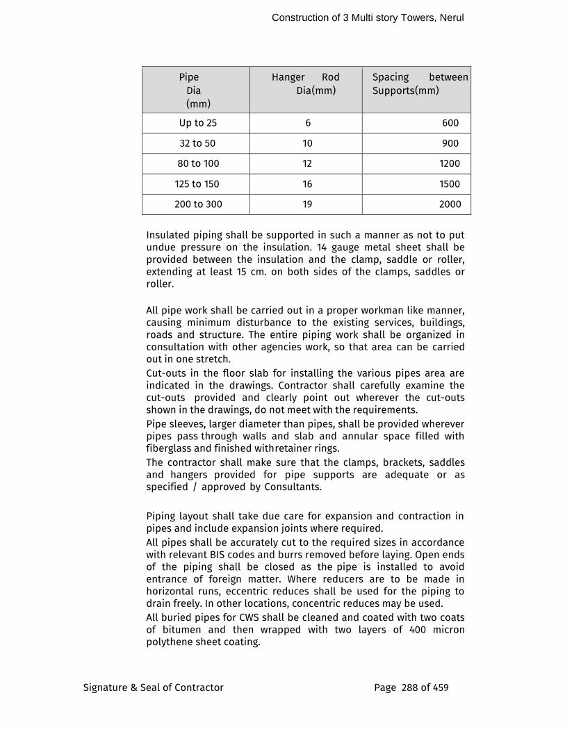
Construction of 3 Multi story Towers, Nerul
Signature & Seal of Contractor Page 288 of 459
Pipe Dia (mm)
Hanger Rod Dia (mm)
Spacing between Supports (mm)
Up to 25 6 600
32 to 50 10 900
80 to 100 12 1200
125 to 150 16 1500
200 to 300 19 2000
Insulated piping shall be supported in such a manner as not to put undue pressure on the insulation. 14 gauge metal sheet shall be provided between the insulation and the clamp, saddle or roller, extending at least 15 cm. on both sides of the clamps, saddles or roller.
All pipe work shall be carried out in a proper workman like manner, causing minimum disturbance to the existing services, buildings, roads and structure. The entire piping work shall be organized in consultation with other agencies work, so that area can be carried out in one stretch. Cut-outs in the floor slab for installing the various pipes area are indicated in the drawings. Contractor shall carefully examine the cut-outs provided and clearly point out wherever the cut-outs shown in the drawings, do not meet with the requirements. Pipe sleeves, larger diameter than pipes, shall be provided wherever pipes pass through walls and slab and annular space filled with fiberglass and finished with retainer rings. The contractor shall make sure that the clamps, brackets, saddles and hangers provided for pipe supports are adequate or as specified / approved by Consultants.
Piping layout shall take due care for expansion and contraction in pipes and include expansion joints where required. All pipes shall be accurately cut to the required sizes in accordance with relevant BIS codes and burrs removed before laying. Open ends of the piping shall be closed as the pipe is installed to avoid entrance of foreign matter. Where reducers are to be made in horizontal runs, eccentric reduces shall be used for the piping to drain freely. In other locations, concentric reduces may be used. All buried pipes for CWS shall be cleaned and coated with two coats of bitumen and then wrapped with two layers of 400 micron polythene sheet coating.
Construction of 3 Multi story Towers, Nerul
Signature & Seal of Contractor Page 289 of 459
Automatic air valves shall be provided at all high points in the piping system for venting. All valves shall be of 15mm pipe size and shall be associated with an equal size isolation ball valve. Automatic air valves shall also be provided on hot water risers. Discharge from the air valves shall be piped through a galvanized steel pipe to the nearest drain or sump. All pipes shall be pitched towards drain points. Pressure gauges shall be provided as shown on the approved drawings and include in Bill of Quantities. Care shall be taken to protect pressure gauges during pressure testing. Temperature gauge as specified shall be provided at the hot water supply and return and as shown on drawings and included in Bill of Quantities.
FERRULES
The ferrules for connection with main shall generally conform to IS:2692. It shall be of non-ferrous materials with a bell mouth cover and shall be of nominal bore as specified. The ferrule shall be fitted with a screw and plug or valve capable of completely shutting of the water supply to the communication pipe, as and when required.
Fixing Ferrules For fixing ferrule in cast iron mains, the empty main shall be drilled and tapped at 45 deg to the vertical and the ferrule screwed in. The ferrule must be so fitted that no portion of the shank shall be left projecting within the main into which it is fitted.
WATER METERS
Water meters of approved make and design shall be supplied for installation at locations as shown. The water meters shall meet with the approval of local supply authorities. Suitable valves and chambers or wall meter box to house the meters shall also the be provided along with the meters. The meters shall conform to Indian Standard IS:779 and IS:2373. Calibration certificate shall be obtained and submitted for each water meter. Provision shall also be made to lock the water meter. The provision shall be such that the lock is conveniently operated from the top. Where the provision is designed for use in conjunction with padlocks, the hole provided for padlocks shall be a diameter not less than 4mm. The casing of water meter from 15 mm. (1/2 inch) to 50 mm. (2 inches) in diameter shall be brass or cast iron and if the size is over 50 mm. (2 inches) in diameter, it shall be cast-iron or steel. The installed water meters shall be suitable for the fluid in the piping system. For the same reading of flow rate at required position, the water
Construction of 3 Multi story Towers, Nerul
Signature & Seal of Contractor Page 290 of 459
meters shall be appropriately designed to be installed in both vertical and horizontal position. The water meters shall be installed in a position which is easy and convenient for reading and maintenance. The unit of measuring fluid flow shall be cubic meter.
Where specified, the water meter shall be the model or type that consists of a pulse transmitter in addition to the local display. The output signal of the transmitter shall be sent to the BAS.
Installation of Water Meter And Stop Cock
The uPVC / cPVC pipelines shall be cut to the required lengths at the position where the meter and stop cock are required to be fixed. Suitable fittings shall be attached to the pipes. The meter and stop cock shall be fixed in a position by means of connecting pipes, jam nut and socket etc. The stop cock shall be fixed near the inlet of the water meter. The paper disc inserted in the ripples of the meter shall be removed. And the meter installed exactly horizontal or vertical in the flow line in the direction shown by the arrow cast on the body of the meter. Care shall be taken that the factory seal of the meter is not disturbed. Wherever the meter shall be fixed to a newly fitted pipe line, the pipe line shall have to be completely washed before fitting the meter.
7.0 DISINFECTION OF PIPING SYSTEM AND STORAGE TANKS Before commissioning the water supply system, the contractor shall arrange to disinfect the entire system as described in the succeeding paragraph. The water storage tanks and pipes shall first be filled with water and thoroughly flushed out. The storage tanks shall then be filled with water again and disinfecting chemical containing chlorine added gradually while tanks are being filled to ensure thorough mixing. Sufficient chemical shall be used to give water a dose of 50 parts of chlorine to one million parts of water. If ordinary bleaching powder is used, the proportions will be 150 gm of power to 1000 liters of water. The power shall be mixed with water in the storage tank. If a proprietary brand of chemical is used, the proportions shall be specified by the manufacturer. When the storage tanks is full, the supply shall be stopped and all the taps on the distributing pipes are opened successively working progressively away from the storage tank. Each tap shall be closed when the water discharged begins to smell of chlorine. The storage tank shall then be filled up with water from supply pipe and added with more disinfecting chemical in the recommended proportions. The storage tank and pipe shall then remain charged at least for three hours. Finally the tank and pipes shall be thoroughly flushed out before any water is used for
Construction of 3 Multi story Towers, Nerul
Signature & Seal of Contractor Page 291 of 459
domestic purpose. The pipe work shall be thoroughly flushed before supply is restored.
8.0 STERILIZATION OF MAIN
After the pipe work has been tested and approved, but before it is coupled, it shall be sterilized with a solution of chloride of lime.
9.0 CUTTING CHASES IN MASONARY WALLS
Cold water distribution pipes to fixtures and equipment exposed to view in the bathrooms, kitchens, and sanitary compartments shall be chased into walls or floors or placed in wall cavities. The Contractor shall be responsible for cutting all notches, chases, and recesses in walls and floors and only a diamond cutter shall be used. The maximum size of conduit or pipe permitted to be concealed in floor slabs shall be 32 mm diameter unless otherwise approved by the Architect. The chases upto 7.5 x 7.5 cm shall be made in the walls for housing GI pipes etc. These shall be provided in correct positions as shown in the drawings or directed by the Architects. Chases shall be made by chiselling out the masonry to proper line and depth. After the pipes etc are fixed in chases, the chases shall be filled with cement mortar 1:2:4 or as may be specified, and made flush with the masonry surface. The concrete surface shall be roughened with wire brush to provide a key for plastering.
Where pipes pass through beams or structural walls, subject to the approval of the Structural Consulting Engineer, the Contractor shall ensure that sizes and locations of openings required are formed in when the relevant beams or walls are cast.
VALVES
All valves (gate, globe, check, safety) shall be of gun metal suitable for the particular service as specified. All valves shall be of the particular duty and design as specified. Valves shall either be of screwed type or flanged type, as specified, with suitable flanges and non-corrosive bolts and gaskets. Tail pieces as required shall be supplied along with valves. Gate, globe and check valves shall conform to Indian Standard IS:776 and non-return valves and swing check type reflux to IS:5312. Sluice valves, where specified shall be flanged sluice valves of cast iron body. The spindle, valve seat and wedge nuts shall be gunmetal. They shall generally have non- rising spindle and shall be of the particular duty and design as specified. The valves shall be supplied with suitable flanges, non-corrosive bolts and asbestos fibre gaskets. Sluice valves shall conform to Indian standard IS:780 and IS:2906. Ball valves with floats to be fixed in storage tanks shall consist of
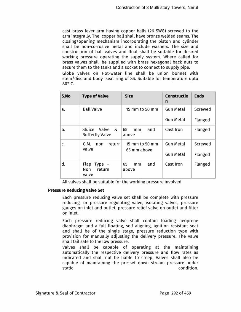
Construction of 3 Multi story Towers, Nerul
Signature & Seal of Contractor Page 292 of 459
cast brass lever arm having copper balls (26 SWG) screwed to the arm integrally. The copper ball shall have bronze welded seams. The closing/opening mechanism incorporating the piston and cylinder shall be non-corrosive metal and include washers. The size and construction of ball valves and float shall be suitable for desired working pressure operating the supply system. Where called for brass valves shall be supplied with brass hexagonal back nuts to secure them to the tanks and a socket to connect to supply pipe. Globe valves on Hot-water line shall be union bonnet with stem/disc and body seat ring of SS. Suitable for temperature upto 80° C.
S.No Type of Valve Size Construction
Ends
a. Ball Valve 15 mm to 50 mm Gun Metal Gun Metal
Screwed
Flanged
b. Sluice Valve & Butterfly Valve
65 mm and above
Cast Iron Flanged
c. G.M. non return valve
15 mm to 50 mm
65 mm above
Gun Metal Gun Metal
Screwed
Flanged
d. Flap Type – Non return valve
65 mm and above
Cast Iron Flanged
All valves shall be suitable for the working pressure involved.
Pressure Reducing Valve Set
Each pressure reducing valve set shall be complete with pressure reducing or pressure regulating valve, isolating valves, pressure gauges on inlet and outlet, pressure relief valve on outlet and filter on inlet.
Each pressure reducing valve shall contain loading neoprene diaphragm and a full floating, self aligning, ignition resistant seat and shall be of the single stage, pressure reduction type with provision for manually adjusting the delivery pressure. The valve shall fail safe to the low pressure. Valves shall be capable of operating at the maintaining automatically the respective delivery pressure and flow rates as indicated and shall not be liable to creep. Valves shall also be capable of maintaining the pre-set down stream pressure under static condition.
Construction of 3 Multi story Towers, Nerul
Signature & Seal of Contractor Page 293 of 459
The filter on each inlet to a pressure reducing valve shall be of replaceable porous sintered metal type.
Pressure Relief Valves
Each pressure relief valve shall be of the fully enclosed type and fitted with hand easing gear. Each pressure relief valve in a pressure reducing station shall have a flow capacity equal to that of the pressure reducing valve. Pressure relief valves in locations other than reducing stations shall have flow capacities equal to that of the associated equipment.
Pressure Gauge
The pressure gauge shall be constructed of die cast aluminium and stove enamelled. It shall be weather proof with an IP 55 enclosure. It shall be a stainless steel Bourden tube type pressure gauge with a scale range from 0 to 16 Kg / cm square and shall be constructed as per IS:3524. Each pressure gauge shall have a siphon tube connection. The shut off arrangement shall be by Ball Valve. Calibration certificate shall be obtained and submitted for each pressure gauge.
Ball Valves
Ball valves shall be ball pattern of the square head type with stainless steel ball conforming to AISI 304. Valves of sizes up to 50 mm (2 inches) in diameter shall be bronze with threaded ends conforming to ASTM B62 and for valves of sizes larger than 50 mm (2 inches) in diameter Valve body shall be carbon steel conforming to ASTM A-216.
Gate Valves
Valves of sizes up to 50 mm shall be bronze where appropriate, with threaded ends, solid wedges and non-rising stems. Valves of sizes 65 mm and larger shall be cast- iron where appropriate, with flanged ends, solid wedges and rising stems.
Lift Check Valve
Lift-check valves or silent-type check valves shall be installed as indicated on the drawings and at the location where noise and water hammer would cause a problem such as pump discharge. The valves shall be of a spring closed type. Seats, discs, and springs shall be bronze or stainless steel, whichever is appropriate. - Valves of sizes up to 50 mm shall be bronze where appropriate, with threaded ends.
Construction of 3 Multi story Towers, Nerul
Signature & Seal of Contractor Page 294 of 459
Butterfly Valves A butterfly valve can be used instead of a gate valve if its size is over 100 mm; it shall have flange bolt centering holes for easy installation and be drilled to suit precisely the piping flange. The body shall be cast-iron with aluminium-bronze disc where appropriate of sufficient rigidity and strength to resist distortion. The stem shall be through-shaft design to provide high strength and positive disc control. Compound rubber seat rings shall have excellent elasticity as well as wear resistance to ensure positive water shut-off under the designed working pressure. Moulded-in "O" rings shall provide positive flange sealing to eliminate need for gaskets. All rubber parts shall be of the type suitable for the specified working fluid. Lever-operated valves shall be used for sizes up to 150 mm. Gear-operated valves shall be used for sizes larger than 150 mm. Position indicators shall be provided to indicate valve disc position.
Diaphragm Valve
Diaphragm valve shall be used for system that required tight shut off such as for the ion exchange and chemicals dosing lines. Soft seat (resin or rubber) shall generally be employed for tight sealing and corrosion protection. The body material of the valves with soft seal shall be of cast iron or steel, lined with suitable synthetic, non-corrosive material, if required.
Modulating Check Valves Modulating check valves shall be installed at the discharge side of all water pumps and shall contain auxiliary controls which permit adjustment of the opening and closing speed. The valves shall be of the modulating diaphragm type.
Pressure Vessel Diaphragm type pressure vessels shall be provided as shown on the drawings. It shall be incorporated into the system so that during excess pressure due to water heater in the apartment can be released in the plumbing room in order to prevent the hammer effect on the fixtures. The pressure vessel shall be of adequate capacity to accommodate a considerable fluctuation in water pressure by the system with minimum start/ stop cycles of the pressure relief valve. The vessel shall be constructed of steel plate built to ASME Standards for Unfired Pressure Vessel.
11.0 WATER FITTINGS
Unless otherwise specified all Gunmetal fittings such as gate, globe, check & safety valves shall be fitted in pipe line in workman like manner. Necessary unions shall be provided on both ends of the valves for easy replacement. The joints between fittings and pipes shall be leak-proof when tested to desired pressure rating. The
Construction of 3 Multi story Towers, Nerul
Signature & Seal of Contractor Page 295 of 459
defective fittings and joints shall be replaced or redone.
12.0 CONNECTIONS TO VARIOUS MECHANICAL EQUIPMENT SUPPLIED BY OTHER AGENCIES
All inlets, outlets, valves, piping and other incidental work connected with installation of mechanical equipment supplied by other agencies all be carried out by the contractor in accordance with the drawings, requirements for proper performance of equipment, manufacturers instructions and the directions of the APMC/SBI. The equipments to be supplied by the other agencies consist mainly for Kitchen, Back-of-the-House area and other similar areas. The work of connections to the various equipments shall be effected through proper unions and isolating valves. The work of effecting connections shall be executed in consultation with and according to the requirement of equipment suppliers, under the directions of the APMC/SBI . The various aspects of connection work shall be executed in a similar way to the work of respective trade mentioned elsewhere in these specifications.
13.0 CONNECTIONS TO RCC WATER TANKS
The contractor shall provide all inlets, outlets, washouts, vents, ball cocks, overflows control valves and all such other piping connections including level indicator to water storage tanks as called for. All pipes crossing through RCC work shall have puddle flanges fabricated from MS/GI pipes of required size and length and welded to 6/8 mm thick MS plate. All puddle flanges must be fixed in true alignment and level to ensure further connection in proper order. Full way gate valves of a approved make shall be provided as near the tank as practicable on every outlet pipe from the storage tank except the overflow pipe. Overflow and vent pipes shall terminate with mosquito proof grating. The overflow pipe shall be so placed to allow the discharge of water being readily seen. The overflow pipe shall be of size as indicated. A stop valve shall also be provided in the inlet water connection to the tank. The outlet pipes shall be fixed approximately 75mm above the bottom of the tank towards which the floor of the tank is sloping to enable the tank to be emptied for cleaning. The floor and the walls of the tank shall be tiled with glazed tiles upto the overflow level. Alternatively food grade epoxy to be applied. Tiling of Walls
The floor and the walls of the tanks shall be tiled with glazed tiles up to the overflow level. Alternatively food grade epoxy to be applied to the floor and the walls of the tanks.
Construction of 3 Multi story Towers, Nerul
Signature & Seal of Contractor Page 296 of 459
14.0 MEASUREMENTS
The length above ground shall be measured in running meter correct to a cm for the finished work, which shall include pipe and fittings such as coupling , bends, tees, elbows, reducers, crosses, plugs, sockets, nipples and nuts, unions. Deductions for length of valves shall be made. Rate quoted shall be inclusive of all fittings, clamps, cutting holes chased and making good the same and all items mentioned in the specifications and Bill of Quantities. All pipes below ground shall be measured per linear meters (to the nearest cm) and shall be inclusive of all fittings e.g. coupling, tees, bends, elbows, unions, deduction for valves shall be made rate quoted shall be inclusive of all fittings, excavation, back filling and disposal of surplus earth, cutting holes and chase and making good all item mentioned in Bill of Quantities.
15.0 LAWN HYDRANTS
Lawn hydrants shall be of 25mm size unless otherwise indicated. All hydrants shall be provided with gate valves and threaded nipple to receive hose pipes. Lawn hydrant valves shall be of approved make and design. Where called for lawn hydrants shall be located in masonry chambers of appropriate size.
16.0 PIPE PROTECTION (FOR COLD WATER PIPES BURIED IN TRENCHES / GROUND / EARTH) All buried pipes shall be cleaned with zinc chromate primer and bitumen paint, wrapped with three layers of fiber glass tissue, each layer laid in bitumen and placed on concrete blocks with PUF saddles dipped in bitumen at every 2 meters. The pipes where laid under floor shall be encased with 100 mm thick jamuna sand all around in addition to protective coating as described above.
Alternatively pypkote / coatek insulation for protection of pipe would also be acceptable as per final approval of project engineer / consultant. pypkote / coatek is a Coal Tar Based Corrosion Protection Tape conforming to AWWAC 203 specification. It comprises of a Coal Tar based mix supported on a fabric of high tensile strength Fiberglass. The mix is specially manufactured to have properties of high softening point, high penetration and high resistance to ageing. Tape is terminated on both exteriors by thermo fusible HMHDPE Film which aids in the installation process.
17.0 THRUST BLOCKS
In case of bigger pipes (80 mm dia and above), thrust blocks of cement concrete 1:2:4 (1 cement: 2 coarse sand : 4 graded stone aggregate of 20 mm nominal size) shall be constructed on all bends as directed by the APMC/SBI .
Construction of 3 Multi story Towers, Nerul
Signature & Seal of Contractor Page 297 of 459
MASONRY CHAMBER
i. All masonry chambers for stop cocks, sluice valves and meter etc. shall be built as per supplied drawings.
ii. The excavation for chambers shall be done true to dimension and level indicated on plans or as directed by the APMC/SBI .
iii. Concrete shall be of cement concrete 1:3:6 (1 cement : 3 coarse sand : 6 graded stone aggregate 40 mm nominal size.
iv. Brick shall be of class designation 75 in cement mortar 1:5 (1 cement : 5 fine sand)
v. Inside Plastering not less than 12 mm thick shall be done in cement mortar 1:3 (1 cement : 3 fine sand) finished with a floating coat of neat cement.
19.0 SHIFTING OF EXCAVATED SURPLUS MATERIAL
Contractor shall make his own arrangement to shift the surplus excavated material within the site limits as directed by APMC/SBI at free of cost within time limit.
20.0 HOT WATER PIPING INSULATION Material
Insulation material for Pipe insulation shall be Closed Cell Elastomeric Nitrile Rubber or closed cell cross linked polyethylene foam. Thermal conductivity of elastomeric nitrile rubber shall not exceed 0.038 W/moK or 0.0313 Kcal / Mhr oC or 0.212 BTU / (Hr- ft2-oF/inch) at an average temperature of 30oC. The product shall have temperature range of –40 oC to 105oC. Density of material shall not be less than 0.06 gm/cm3. The insulation shall have fire performance such that it passes minimum CLASS 1 as per BS476 part 7 for surface spread of flame. Water vapour permeability shall not exceed 0.024 perm inch (3 x 10-14 Kgs / m.sec.Pa). The material shall have approval from the Chief Fire Officer.
Thickness of the insulation shall be as specified for the individual application. Each lot of insulation material delivered at site shall be accompanied with manufacturer test certificate for thermal conductivity values. Samples of insulation material from each lot delivered at site may be selected by APMC/SBI and gotten tested for thermal conductivity and density at Contractor’s cost All joints shall be sealed properly with adhesive, which shall provide similar vapour barrier as the original insulating material.
All hot water piping shall be insulated in the manner specified herein. Before applying insulation, all pipe shall be brushed and cleaned. Thermal insulation shall be applied as follows or as specified in drawings or schedule of quantity:
Construction of 3 Multi story Towers, Nerul
Signature & Seal of Contractor Page 298 of 459
Pipe size (mm) Thickness of Nitrile rubber insulation
15 mm to 25 mm 9 mm
15 mm to 25 mm 9 mm 32 mm to 50 mm 13 mm
65 mm and above 19 mm
Insulation for pipes in wall chase and for pipes in shaft / plant room
Insulating material in tube form shall be sleeved on the pipes. On existing piping, slit opened tube from insulating material shall be placed over the pipe and adhesive (as recommended by the manufacturer) shall be applied as suggested by the manufacturer. Adhesive must be allowed to tack dry and then press surface firmly together starting from butt end and working towards centre.
Wherever flat sheets shall be used it shall be cut out in correct dimension. All longitudinal and transverse joints shall be sealed as per manufacturer recommendations. The insulation shall be continuous over the entire run of piping, fittings and valves. All valves, fittings, joints, strainers etc. in hot water piping shall be insulated to the same thickness as specified for the main run of piping and application shall be same as above. Valves bonnet, yokes and spindles shall be insulated in such a manner as not to cause damage to insulation when the valve is used or serviced. All insulation work shall be carried out by skilled workmen specially trained in this kind of work. All insulated pipes shall be labeled (HWS / HWR / HWRR) and provided with 300 mm wide band of paint along circumference at every 1200 mm for colour coding. Direction of fluid shall also be marked. All painting shall be as per relevant BIS codes.
Measurement of Insulation
Unless otherwise specified measurement for pipe insulation for the project shall be on the basis of centre line measurements described herewith Pipe Insulation shall be measured in units of length along the centre line of the installed pipe, strictly on the same basis as the piping measurements. The linear measurements shall be taken before the application of the insulation. It may be noted that for piping measurement, all valves, orifice plates and strainers shall not be separately measurable by their number and size. It is to be clearly
Construction of 3 Multi story Towers, Nerul
Signature & Seal of Contractor Page 299 of 459
understood that for the insulation measurements, all these accessories including valves, orifice plates and strainers etc. shall be considered strictly by linear measurements along the centre line of pipes and no special rate shall be applicable for insulation of any accessories, fixtures or fittings whatsoever.
SECTION – D : INTERNAL DRAINAGE (SOIL, WASTE, VENT & RAIN WATER PIPES)
1.0 SCOPE The scope of this section comprises the supply, installation, testing and commissioning of internal drainage services. Work under this section shall consist of furnishing all labour, materials, equipments and appliances necessary and required to completely install all soil, waste, vent and rainwater pipes and fittings as required by the drawings, and given in the schedule of quantities.
2.0 BASIC PIPING SYSTEM
Soil, waste and vent pipes in shafts, ducts and in concealed areas i.e. false ceilings etc. shall consist of Polypropylene (PP) acoustic pipe for habitable area only .as called for. The soil pipes shall be circular with a minimum diameter of 100mm. Pipes shall be fixed by means of stout GI clamps in two sections, bolted together, built into the walls, wedged and neatly jointed as directed and approved by the APMC/SBI / Architect. All bends, branches, swan neck and other parts shall conform to the requirement and standards as described for the pipes. Pipes shall be rested against the walls on suitable wooden cradles. Local authority regulations applicable to the installations shall be strictly followed. Where indicated, the soil pipes shall be continued upwards without any reduction in its diameter, without any bend or angle to the height shown in the drawings. Joints throughout shall be made with molten lead as described under jointing of cast iron pipes. Soil pipes shall be painted as provided under `painting'. The soil pipes shall be covered on top with cast iron terminal outlets as directed and approved. All vertical soil pipes shall be firmly fixed to the walls with properly fixed clamps, and shall as far as possible be kept 50mm clear of wall. Pipes shall be fixed, jointed and painted as described in installation of soil, waste & vent pipes. Every waste pipe shall discharge above the grating of properly trapped gully. The contractor will ensure that this requirement is adequately met with. Wherever floor traps are provided, it shall be ensured that atleast one wash is connected to such floor traps to avoid drying of water seal in the trap. Ventilating pipes shall be of uPVC pipes, conforming to the requirements laid down earlier. Anti-syphon vent pipes/relief vent pipes where called for on the drawings shall be of upvc as specified. The pipes shall be of the diameter shown on the drawings.
Construction of 3 Multi story Towers, Nerul
Signature & Seal of Contractor Page 300 of 459
All traps on branch soil and waste pipes shall also be ventilated at a point not less than 75mm or more than 300mm from their highest part and on the side nearest to the soil pipe or waste pipes. Access doors for fittings and clean outs shall be so located that they are easily accessible for repair and maintenance. Any access panel required in the civil structure, false ceiling or marble cladding etc. shall be clearly reported to the Owner in the form of shop drawings so that other agencies are instructed to provide the same. All the fittings used for connections between soil, waste and ventilation pipes and branch pipes shall be made by using pipe fittings with inspection doors for cleaning. The doors shall be provided with 3mm thick rubber insertion packing and when closed and bolted shall be air and water tight. Where soil, waste and ventilating pipes are accommodated in shafts ducts, adequate access to cleaning eyes shall be provided. Head (starting point) of drains and sewage / waste water sumps (as and where applicable) having a length of greater than 4 m upto it connection to the main drain or manhole shall be provided with a 80 / 100 mm vent pipe.
PIPING MATERIALS
1.1. PP pipe system (Noise Insulated Piping System)
11. SOCKET PIPES
Three Layer sound insulated Polypropylene piping system as per ON EN 1451-Part 1-6 & EN 12056 Part 1-5 with 3 layer pipe made of PP-C + PP-MV + PP-C in Blue Ral 5014 (halogen and calcium free) colour, push-fit type, food safe, having high impact and stiffness, offering sound levels of not more than 21 dBA as per DIN 4109 at a flow rate o f 4 l/s and having pipe ring stiffness as per 1S0/DIS 9969 and tightness as per EN 1277/B and C and DIN 19560,density = 1.25gms/cm3, elongation = 0.05mm/m0K and tensile strength > 24 N/mm2, with all necessary fittings in blue colour, fitted with factory fitted lip ring, having 3 layers, pipes to be painted with ordinary cement paint for external installation: Sound-proofing testing should be as per EN 14366. All exposed pipe work shall be UV protected / resistant.
11.1. INTERNAL LAYER: Of PP-C, hot water resistant to 97 degree C,
tested in accordance to ON EN
1451-1 and DIN 19560, good heat and corrosion ageing stability as well as high chemical resistance and a smooth pipe inner-surface.
Construction of 3 Multi story Towers, Nerul
Signature & Seal of Contractor Page 301 of 459
Color: Blue / Black / Grey (halogen and calcium free)
11.2. INTERMEDIATE LAYER: Of PP-MV compound reinforced with mineral aggregate, which guarantees greater stiffness and stability.
Color: Grey.
11.3. EXTERNAL LAYER: Of PP-C. With high impact resistance and good weathering and
UV resistance. Color: Blue / Black / Grey (halogen and calcium
free).
PIPE RING STIFFNESS:
Pipe EPDM rubber ring stiffness would be in accordance with IS0/DIS 9969 and TIGHTNESS as per EN 1277/B and C and DIN 19560.
MARKINGS:
All pipes shall carry the following markings: Batch number; year and week of manufacture; company name; dimension application class; stiffness class, test mark and material details.
FITTINGS:
Single- Layered fitting reinforced with mineral aggregate, made of a Halogen free PP-C- KV synthetic material, a reinforced wall and factory fitted lip ring, hot water resistant upto 95 degree c in accordance to ON EN 1451-PART 1-6 EN 12056 PART 1-5.
Color: Blue / Black (halogen and calcium free).
INSTALLATION:
The piping system must be clamped properly using rubber padded (internally) “flat U clamps”,
pipes passing through walls, beams, slabs, columns should pass through sleeves which are padded with insulation material.
Pipe hangers shall be provided at the following maximum spacing’s:
Construction of 3 Multi story Towers, Nerul
Signature & Seal of Contractor Page 302 of 459
Pipe Dia (mm) Spacing between Supports (mm)
Up to 50 1500
75 mm and above 2000
UPVC Pipes and Fittings The pipes shall be round and shall be supplied in straight lengths with socketed ends. The internal and external surfaces of pipes shall be smooth, clean, free from groovings and other defects. The ends shall be cleanly cut and square with the axis of the pipe. The pipes shall be designed by external diameter and shall conform to IS:4985-2000. The pipes shall be of Class-III, V & VI; 6, 10 & 12.5 Kg/sqm respectively pressure rating.
Fittings
Fittings shall be of the same make as that of pipes, injection molded and shall conform to Indian Standard (IS: 14735).
Laying and Jointing
The pipes shall be laid and clamped to wooden plugs fixed above the surface of the wall. Alternatively plastic clamps of suitable designs shall be preferred. Provision shall be made for the effect of thermal movement by not gripping or disturbing the pipe at supports between the anchors for suspended pipes. The supports shall allow the repeated movements to take place without abrasion. Jointing for uPVC pipes shall be made by means of solvent cement for horizontal lines and ‘O’ rubber ring for vertical line. The type of joint shall be used as per site conditions / direction of the APMC/SBI . Where uPVC pipes are to be used for rain water pipes, the pipe shall be finished with GI adopter for insertion in the RCC slab for a water proof joint complete as directed by APMC/SBI .
Supports
uPVC pipes require supports at close intervals. Recommended support spacing for unplasticised PVC pipes is 1400 mm for pipes 50 mm dia and above. Pipes shall be aligned properly before fixing them on the wooden plugs with clamps. Even if the wooden plugs are fixed using a plumb line, pipe shall also be checked for its alignment before clamping, piping shall be properly supported on, or suspended from clamps, hangers as specified and as required. The Contractor shall adequately design all the brackets, saddles, anchors, clamps and hangers and be responsible for their structural sufficiency. Pipe supports shall be primer coated with rust preventive paint.
Repairs
While temporary or emergency repairs may be made to the damaged
Construction of 3 Multi story Towers, Nerul
Signature & Seal of Contractor Page 303 of 459
pipes, permanent repairs shall be made by replacement of the damaged section. If any split or chip out occur in the wall of the pipe, a short piece of pipe of sufficient length to cover the damaged portion of the pipe is cut. The sleeve is cut longitudinally and heated sufficiently to soften it so that it may be slipped over the damaged hard pipe.
4.0 PIPES HANGERS, SUPPORTS, CLAMPS ETC. All vertical pipes shall be fixed by galvanized clamps and galvanized angle brackets truly vertical. Branch pipes shall be connected to the stack at the same angle as that of the fittings. No collars shall be used on vertical stacks. Each stack shall be terminated at top with a cowl (terminal guard). Horizontal pipes running along ceiling shall be fixed on galvanized structural adjustable clamps of special design shown on the drawings or as directed. Horizontal pipes shall be laid to uniform slope and the clamps adjusted to the proper levels so that the pipes fully reset on them. Clamps for horizontal piping within toilets shall be clevis clamps with rubber gasket with height adjustment arrangement to maintain slopes. Contractor shall provide all sleeves, openings, hangers, inserts during the construction. He shall provide all necessary information to the building contractor for making such provisions in the structure as necessary. All damages shall be made good to restore the surfaces. All pipes clamps, supports and hangers shall be galvanized. Factory made prefabricated clamps shall be preferred. Contractor may fabricate the clamps of special nature and galvanize them after fabrication but before installation. All nuts, bolts, washers and other fasteners shall be factory galvanized. Clamps shall be of approved design and fabricated from MS flats (which shall be galvanized after fabrication) of thickness and sizes as per drawings or contractor’s shop drawings. Clamps shall be fixed in accordance to manufacturer’s details/shop drawings to be submitted by the contractors. When required to be fixed on RCC columns, walls or beam they shall be fixed with approved type of galvanized expansion anchor fasteners (Dash fasteners) of approved design and size according to load. Structural clamps e.g.. trapeze or cluster hangers shall be fabricated by electro-welding from MS structural members e.g. rods, angles, channels flats as per contractors shop drawings shall be galvanized after fabrication. All nuts, bolts and washers shall be galvanized. Galvanized slotted angle/channel of approved sizes supports on walls shall be provided wherever shown on shop drawings. Angles/channels shall be fixed to brick walls with bolts embedded in cement concrete blocks and to RCC walls with anchor fasteners mentioned above. The spacing of support bolts on support members fixed horizontally shall not exceed 1 m.
Construction of 3 Multi story Towers, Nerul
Signature & Seal of Contractor Page 304 of 459
5.1 INSTALLATION OF SOIL, WASTE & VENT PIPES
Soil, waste & vent pipes in shafts under the floors / suspended below slab shall consist of combination of PP and uPVC SWR pipes as described earlier. All Horizontal pipes running below the slab and along the ceiling, shall be fixed on structural adjustable clamps, sturdy hangers of the design as called for in the drawings. The pipes shall be laid in uniform slope and proper levels. All vertical pipes shall be truly vertical fixed by means of stout clamps in two sections, bolted together, built into the walls, wedged and neatly jointed. The branch pipes shall be connected to the stack at the same angle as that of fittings. All connections between soil, waste and ventilating pipes and branch pipes shall be made by using pipe fittings with inspection doors for cleaning. Pipes shall be fixed in a manner as to provide easy accessibility for repair and maintenance and shall not cause obstruction in shafts. Where the horizontal run off the pipe is long or where the pipes cross over building expansion joints etc. suitable allowance shall be provided for any movements in the pipes by means of expansion joint etc. such that any such movement does not damage the installation in any way. The joint shall not be covered till the pipe line has been tested under pressure.
Rainwater Pipes
All open terraces shall be drained by rain water down takes. Rainwater down takes are separate and independent of the soil and waste system and will discharge into the underground storm water drainage system of the complex. Rainwater in open courtyards shall be collected in catch basins and connected to the Storm Water Drains. Any dry weather flow from waste appliances, e.g. AHU’s pump rooms, waste water sumps shall connected to sewers after traps and not in the storm water drainage systems.
Balcony / Planter drainage
Wherever required, all balconies, terraces, planters and other frontal landscape areas will be drained by vertical down takes or other type of drainage system shown on the drawings and directed by the Project Manager.
TRAPS
1.1. Floor Traps
P- traps or floor traps shall be PP, rubber seal with an effective water seal of 50 mm. Traps shall be firmly supported with structural brackets to take vertical impact as well as lateral loads during tamping in case of choking etc.
Construction of 3 Multi story Towers, Nerul
Signature & Seal of Contractor Page 305 of 459
Urinal traps: Urinal traps shall be P traps with or without vent and set in cement concrete block specified in Para above without extra charge. It is preferred tha he urinal P-trap be built-in trap in ceramic body of the urinal itself.
Floor trap inlet: Bath room traps and connections shall ensure free and silent flow of discharging water. Where specified, Contractor shall provide a special type height-riser inlet fitting hoper fabricated from 110 mm OD pipe without or with one, two or three inlet sockets to receive the waste pipe(s). Joint between waste and hopper inlet socket shall be fabricated. Hopper shall be connected to a P- trap with at least 50 mm seal (hopper and traps shall be paid for separately). Floor trap inlet hoppers and the traps shall be supported as specified in Para above without extra charge.
Balcony drainage
Wherever required, all balconies will be drained by horizontal / vertical down takes connected to Balcony drain system suitable for flow of large amount of water with loading capacity of class k=300 kg made of uPVC with square SS grate as directed by the consultant.
Terrace Rainwater drainage
All terraces shall be drained through rainwater khurras. The khurra shall have a CI scupper drain arrangement at 45* angle to the terrace floor. Diameter of uPVC downtake pipes and other details shall be as per drawings provided by the consultants. The khurra shall be 300mm X 300mm in plan with a depression of 25mm from adjacent finished level. An overflow pipe of 110mm dia shall be provided 50mm above the khurra outlet level and discharged in open areas to allow noticing choking of terrace khurras.
Appliance drainage
Wherever required, all appliances (washing machine, or dishwasher) drainage hose will be connected to Concealed or surface appliance traps made of Poly propylene which should be quality controlled in accordance with DIN EN 274 ,with vertical / horizontal drain outlets having water seal of > or = 50mm. This trap shall consist of fixing set including screws, protection cap, elbow hose union ,closing cap and flange made of Stainless Steel.
Floor Trap Inlet /Hopper Bath room traps and connection shall ensure free and silent flow of discharging water. Where specified, contractor shall provide a special type of floor inlet fitting using height riser fitting Or saddle piece fittings, with two or four inlet sockets on sides to connect the waste pipes. Outlet of hopper shall be connected to a PP “P” trap. Floor trap
Construction of 3 Multi story Towers, Nerul
Signature & Seal of Contractor Page 306 of 459
inlet and the traps shall be support with special bracket below slab without extra charge. Floor trap for the shower cubicle shall suit site and as per the approval of APMC/SBI .
Floor Trap Grating
Floor and urinal traps shall be provided with 150 mm square stainless steel gratings with pop-up arrangement, with frame and rim of approved design and shape or as specified in the schedule of quantities approved by the APMC/SBI .
Clean-out Plugs Floor Clean Out Plug
Clean out plug for soil, waste or rain water pipes laid under floors shall be provided near pipe junctions bends, tees, “Y” and on straight runs at such intervals as required as per site conditions. Cleanout plugs shall terminate flush with the floor level. They shall be threaded and provided with key holes for opening. Cleanout plugs shall be cast brass suitable for the pipe dia. With screwed to a GI socket. The socket shall be mechanically coupled to the drain pipes.
Cleanout on Drainage Pipes
Cleanout plugs shall be provided on head of each drain and in between at locations indicated on plans or directed by APMC/SBI . Cleanout plugs shall be of size matching the full bore of the pipe but no exceeding 150 mm dia CO plugs on drains of greater diameters shall be 150 mm dia. Fixed with a suitable reducing adapter. Floor cleanout plugs shall be cast brass. Cleanouts provided at ceiling level pipe shall be fixed to a CI flanged tail piece. The cleanout doors shall be specially fabricated from light weight galvanized sheets and angles with hinged type doors with fly nuts, gasket etc. as per drawing.
7.0 PIPE SLEEVES
Pipe sleeves, next larger diameter than pipes shall be provided wherever pipes pass through walls & slabs and annular space filled with fiberglass & finished with retainer rings. Sleeves shall be of uPVC SWR pipes. All pipes shall be accurately cut to the required sizes in accordance with relevant BIS codes and burrs removed before laying. Open ends of the pipe shall be closed as the pipe is installed to avoid entrance of foreign matter.
Construction of 3 Multi story Towers, Nerul
Signature & Seal of Contractor Page 307 of 459
8.0 CUTTING AND MAKING GOOD
Pipes shall be fixed and tested as building proceeds. The contractor shall provide all necessary holes, cutouts and chases in structural members as building work proceeds. Wherever holes are cut or left originally they shall be made good with cement concrete 1:2:4 (1 cement : 2 coarse sand : 4 stone aggregate 20 mm nominal size) or cement mortar 1:2 (1 cement : 2 coarse sand). Cured and the surface restored to original condition.
9.0 PAINTING
Soil, waste, vent and rain water pipes in exposed location, in shafts and pipe space shall be painted with two or more coats of ready mix oil paint to give an even shade. Before painting all dust and extraneous matter shall be removed. Paint shall be of approved quality and shade. Where directed by the APMC/SBI pipes shall be painted in accordance with approved pipe colour code. Direction of flow and name of the stack shall be mentioned on the pipe with proper signage so that the same is easily visible and known. Concealed piping and pipes berried below ground and covered in cement concrete shall not be painted.
10.0 TESTING
Testing shall be done in accordance with IS:1172 and IS:5329 except as may be modified herein under. Entire drainage system shall be tested for water tightness and smoke tightness during and after completion of the installation. No portion of the system shall remain untested. Contractor must have adequate number of expandable rubber bellow plugs, manometers, smoke testing machines, pipe and fitting work tests, All materials obtained and used on site must have manufacturer’s hydraulic test certificate for each batch of materials used on the site. Before use at site all pipes shall be tested by filling up with water for at least 30 minutes. After filling, pipes shall be struck with a hammer and inspected for blow holes and cracks. All defective pipes shall be rejected and removed from the site within 48 hours. Pipes with minor sweating may be accepted at the discretion of the Project Manager. Soil and waste pipes shall be tested in sections after installation, by filling up the stack with water. All openings and connections shall be suitably plugged as approved by the Project Manager. The total head in the stack shall be 4.5 m at the highest point of the section under test. The period of test shall be minimum for 30 minutes or as directed by the Project Manager. If any leakage is visible, the defective part of the work shall be cut out and made good. On completion of the work the entire installation shall be tested by smoke testing machine. The test shall be conducted after the
Construction of 3 Multi story Towers, Nerul
Signature & Seal of Contractor Page 308 of 459
plumbing fixtures are installed and all traps have water seal or by plugging the outlets with bellow plugs. Apply dense smoke keeping the top of stack open and observe for leakages. Rectify or replace defective sections. After the installation is fully complete, it should be tested by flushing the toilets, running at least 20% of all taps simultaneously and ensuring that the entire system is self draining, has no leakages, blockages etc. rectify and replace where required. A test register shall be maintained and all entries shall be signed and dated by the Contractor and the Project Manager or his representative. All pipes in wall chases shall be hydro tested before the pipe encased or burried.
11.0 GULLY TRAP
Gully trap shall be of PVC with a 50mm water seal conforming to IS:651. These shall be sound and free from visible defects such as bur, hair cracks. Each gully trap shall have one CI grating of square size corresponding to the dimensions of inlet of gully trap. It will also have a water tight FRP cover with frame inside dimensions 300 x 300mm. The grating cover and frame shall be of FRP of medium load class and shall have truly square machined seating faces.
Fixing of Gully Trap
The excavation for gully traps shall be done true to dimensions and levels as indicated on plans or as directed by the Consultant. The gully traps shall be fixed on cement concrete foundation 65cm square and not less than 10cm thick. The mix for the concrete will be 1:4:8. The jointing of gully outlet to the branch drain shall be done with ring-seal joint as described earlier. After fixing and testing gully and branch drain, a brick work of specified class in cement mortar 1:5 shall be built with a half brick masonry work round the gully trap from the top of the bed concrete upto ground level. The space between the chamber and trap shall be filled in with cement concrete 1:3:6. The upper portion of the chamber i.e. above the top level of the trap shall be plastered inside the cement mortar 1:3 finish with a floating coat of neat cement. The corners and bottom of the chamber shall be rounded off so as to slope towards the grating. FRP cover with frame 300 x 300 mm (inside) shall then be fixed on the top of the brick masonry with cement concrete 1:2:4 and rendered smooth. The finished top cover shall be so as to prevent the surface water from entering the gully trap.
Measurements
Gully traps shall be measured by the number and rate which shall include all excavation, foundation, concrete, brick masonry, cement plaster inside and outside, C I grating and sealed FRP cover and frame.

Construction of 3 Multi story Towers, Nerul
Signature & Seal of Contractor Page 309 of 459
Construction of 3 Multi story Towers, Nerul
Signature & Seal of Contractor Page 310 of 459
SECTION – F : PUMPING SYSTEM
1.0 SCOPE
This section of the contract involves the design, supply, installation, testing and commissioning of the complete pumping system complete with all controls and electrical work for domestic water supply, water supply for flushing and for cooling tower make-up. All submersible water re-circulation, drainage and ejector pumps for the project are also included in this contract. It also involves testing and commissioning of the pumping system with the domestic water and flushing water supply & distribution. This specification described the particulars of the contract, designs and systems chosen, and mode of operation. All installation work shall comply with the latest rules and regulations. The work embraced by this specifications covers the design, submission to authorities, supply, delivery on site, installation, testing, commissioning and maintenance of the pumping system installation of the building in accordance with this specification and associated drawings. The scope of work shall include the following (list is indicative and not exhaustive) : 1. domestic water & flushing water supply & distribution. 2. Control panel for pump control complete, circuit breakers,
fusses, pressure transmitters etc. complete with all interconnections to pumps and electrical supply panels.
3. Pump control units complete with pre-programmed micro-processor chip.
4. Pump monitoring units to monitor operation of pumps. 5. Each Pumping unit shall be supplied as a complete set, non-
return valves, isolating valves, pressure transmitters on the discharge side and level electrode at the suction tank. Each unit shall be provided with electronic microprocessors for unit control and all necessary electrical work for the unit.
6. Submersible water re-circulation pump for water fountain, drainage pumps for plant room drainage complete with electrical panels and necessary accessories with automation for pump operation.
7. All the pipework etc. shown in the system drawings is meant for information only and shall be carried out by others. The pumping system supplier shall provide the pumping units in the designated pump rooms as complete units included all necessary piping within plant such that only discharge connections are required to be connected into the unit’s discharge manifolds just inside the plant room, by the Plumbing contractor. The pumping system contractor shall guarantee specified pump performance at various pump
Construction of 3 Multi story Towers, Nerul
Signature & Seal of Contractor Page 311 of 459
speeds and pumps must be able to supply at least 2 bar pressure at the highest/farthest fitting.
8. Electrical equipment and installation work including the PLC in Control panel.
9. Painting and labelling of pipe work and equipment; 10. Provision of all hold down bolts, spigots struts and the like
required to be built in during construction; 11. Provision of dry contacts to BMS indicating the status of the
pumps and pressure vessel in form of hardware interfacing panels inside each pump room and control panels of all pumps.
12. Provision of all level switches, flow switches and other sensing devices for status indication.
13. All interfacing work with other trades. 14. Testing & commissioning and balancing of the Pumping system; 15. Provision of twenty four (24) months operational
maintenance and breakdown services; 16. Provisions of operating instructions and maintenance manuals;
Construction of 3 Multi story Towers, Nerul
Signature & Seal of Contractor Page 312 of 459
17. Provision of spare parts; 18. Training of the employer's staff for proper operation of the entire
systems; 19. Liaison with Local Authorities to obtain all necessary
certificates and approvals, including the completion of all submission drawings, forms and payment of any fees and charges. All the costs for all the tests required by Local Authorities shall be included. To attend to any Authorities inspection regardless of whether this inspection is carried out after the defect liability period;
20. Provisions of the necessary installation which include pumping works, pipe work within the pumping unit up to suction and discharge manifolds, conduit and control wiring, etc. to form a workable system required;
21. All other works and systems as specified in the Contract document and or shown on the drawings.
22. All cutting, patching, framing up, furring in, chasing and making good associated with the building construction for the passage of pipes, conduits and the like including providing GI pipes sleeves of required size corresponding to pipe dia, wherever pipes crossing fire rated walls and floors and sealing with glass wool in between and fire sealant compound on either end. Details on shop drawings shall also be provided.
22.1. Contractor shall provide GA drawing, hydraulic and electrical SLD and shop drawings of pumping system for approval of the consultants before procurement of system.
22.2. Contractor shall submit as-built layouts and SLDs of pumping system after commissioning along with O&M manuals.
2.0 GENERAL
Equipment offered for supply and installation shall include the following: All minor items and incidental work, equipment accessories and materials may not be specifically mentioned but are required for the proper completion of the installations in accordance with the true intent and meaning of this Specification. All necessary safety devices for the protection of personnel against injury and the protection of plant and equipment against damage including relief valves, belt guards, fan inlet and/or discharge guards, safety railing, effective earthing of electrical components, electrical interlocks, warning lights and alarms. Readily accessible, dust-proof lubricating facilities on all moving parts and equipment including provision for cleaning all lubricating
Construction of 3 Multi story Towers, Nerul
Signature & Seal of Contractor Page 313 of 459
lines and bearings and charging same with the correct lubricants after installation but prior to testing and commissioning. Clearly visible and robust manufacturer's name-plates permanently fitted each and every item of equipment and showing the manufacturer's name, type and/or model number, serial number, and all essential operating data such as speed, capacity, voltage, current draw, etc. The Contractor also shall allow provision for the inspection of all plant and equipment by the manufacturer or his licensed representative, at least twice during the course of the installation.
3.0 PIPING
The pipes and fittings in the domestic Water Treatment plant room shall be uPVC SCH 80. All delivery and suction headers from pumpsets shall be in SS 202.
Construction of 3 Multi story Towers, Nerul
Signature & Seal of Contractor Page 314 of 459
PUMPS FOR SUPPLY & DRAINAGE SYSTEM
1. PUMPS
Pumps shall be vertical, centrifugal, multistage directly coupled to motor. Provision of pump with pump head & base of cast iron and other parts in SS 304 shall be made for pumps required in supply System and water fountain re-circulation system. Impeller shall be hydraulically balanced and keyed to shaft. Pump shall be mounted on a concrete foundation, projecting at least 15 CM above finished floor level. The pumps base shall be set on a vibration elimination pad. The pump shall be lubricated in strict accordance with the manufacturer’s instructions and shall be factory aligned prior to shipment. All motors and bases shall be painted with approved finish shop coat of paint. The pump shall be selected for the lowest operating noise level and shall be complete with flexible connections, valves, and pressure gauges. The pumps shall include cost of foundation channel complete. The Contractor shall supply and install pumps of the type and performance as shown on the drawings. All duties of pumps given in the Tender Drawings shall be checked and where necessary corrected before ordering. All the parts of the pumps that are in contact with water e.g. shaft, impeller etc. shall be of stainless steel construction. Pumps shall be so selected that the design duty point is within 5% of the maximum efficiency point. The pump casing so selected shall have ample space to take an impeller one size larger than that capable of performing the design duty. The pump shall have a speed of not more than 1500 rpm. However pumps of 2900 rpm with high efficiency and low noise motor can be selected and noise data submitted for approval. All pumps and motors shall be of minimum vibration and noise level during operation. Vibration isolators shall be provided for all pump sets. Facilities shall be provided to prevent starting of pumps when the water tank is at low water level. An indicator for this low water level alarm shall be provided. Facilities to select which pump to be duty pump and standby pump shall be provided and be interchangeable. Leakage from pump gland shall be drained to the nearest floor waste. Pump curves for all pumps offered shall be submitted. All curve indicating excessive shut-off head will not be approved. Each pump shall be provided with a gate valve at suction and discharge, approved check valve at discharge, approved strainer at suction, flexible connections at pump suction and discharge, eccentric reducer at suction, concentric reducer at discharge, pressure gauges at suction and discharge, circulation relief valve and automatic air relief valve. Appropriate neoprene vibration isolation mountings shall be
Construction of 3 Multi story Towers, Nerul
Signature & Seal of Contractor Page 315 of 459
provided for each pump sets.
PUMPING SYSTEM
Transfer pumping units shall be provided for supply of domestic water, flushing water supply for the project. The units shall be hydro-pneumatic systems selected so as to provide at minimum of 2 bar pressure at the highest/farthest OHT.
System Description
Transfer pump set will lift the raw water from the UGWT to the respective roof tanks of each tower. Pumps shall be Constant speed transfer pump.
The pump starts and stops in response to the pressure in the delivery header. A water level sensor stops a solenoid valve at inlet in the roof tanks. The shutting off of this solenoid valve increases pressure in the delivery header of the pumps and the pump set stops in response to this pressure increase. The cut-in and cut-off pressures shall be 2 bar and 4 bar respectively. This is a simple and reliable system with minimum cabling. The HPS system shall ensure that equatable pressure and flow are ensured at each OHT. The system shall consists of 2 working and one stand-by pump and the stand-by unit shall be different for each operation.
A simple telescoping piping distribution system and a gravity fed distribution system from the elevated storage tanks will serve the building.
At the lower floors far lower from the water elevated storage tanks, pressure reducing valves will be provided to ensure the ‘head' of water will not cause excessively high pressure at the plumbing fixture outlets.
Pump Pressure Vessel
Diaphragm type pressure vessels shall be provided as shown on the drawings. They shall be incorporated into the system so that during normal operation the pump shall not need to be start within 30 seconds of it switching off in order to prevent the pump hunting. The pressure vessel shall be of adequate capacity to accommodate a considerable fluctuation in water demand by the system with minimum start/ stop cycles of the pumps. The vessel shall be constructed of steel plate built to ASME Standards for Unfired Pressure Vessel. A rubber diaphragm shall be provided in the vessel for separating the water and pre-charge nitrogen. The pre-charge pressure shall be adjustable and charging port with non-return
Construction of 3 Multi story Towers, Nerul
Signature & Seal of Contractor Page 316 of 459
device shall be provided. The adjustable cut-in and cut-off pressure unit for the pumps shall be built-in at the vessel to suit the system.
FLOATLESS TYPE LEVEL SWITCH IN WATER TANKS
The Contractor shall supply and install float less type switch probes in the water tanks as indicated below and shown on the drawings. Raw Water Tanks at Basement - High level alarm (over-flow); - Low level alarm; - Low level cut-out for raw water pumps; - Earthing probe. Cooling Tower Make-up
- High level alarm (over-flow); - Low level alarm; - Low level cut-out for cooling tower makeup water supply pumps; - Earthing probe.
Potable Water Tank at Basement Level - High level alarm (over-flow); . Low level alarm; . Low water level cut-out for the domestic transfer pumps; - Earthing probe. Each probe shall be of the correct length for the particular application and tank location. Electrodes shall be of polished stainless steel 20 mm OD. Electrode holders shall be weatherproof in all respect. The earthing probes shall be connected and wired to the building earth systems of the building.
Each set of electrodes shall be installed inside a 230 mm diameter PVC pipe acting as a wave barrier. The level switch set shall operate with a stepped down voltage at 24V maximum. Stepped down transformers shall be provided for each set of control probes and shall be installed inside centralised control cubicles inside pump room. Mechanical steel stuffing boxes shall be used.
SUMP PUMP
1. Submersible
These shall be fully submersible with a fully submersible motor. The pumps shall be provided with an automatic level controller and all interconnecting power and control cabling which shall cause the pumps to operate when the water level in the sump rises to a preset level and stop when the preset low level is reached. Pumps for drainage shall be single stage, single entry.
Construction of 3 Multi story Towers, Nerul
Signature & Seal of Contractor Page 317 of 459
Pump shall be C.I. casing and C.I. two vane open type with a dynamically balanced impeller connected to a common shaft of the motor. The vane for sewage pump will be open type, while for drainage pump, etc. it will be of semi open type. The MOC of the sump shall be in accordance to schedule of quantity. Stuffing box shall be provided with mechanical seals. Each pump shall be provided with a suitably rated induction motor suitable for 415 volts, 3 phase, 50 Hz A.C. power supply. Each pump shall be provided with in built liquid level controller for operating the pump between predetermined levels. The pumping set shall be for stationary application and shall be provided with pump connector unit. The delivery pipe shall be joined to the pump through a rubber diaphragm, and bend and guide pipe for easy installation. Pump shall be provided with all accessories and devices necessary and required for the pump to make it a complete working system. Sump pump shall be complete with level controllers, power and control switch gear, Auto/off/Manual switches, pumps priority selections and control and power cabling upto motor and controller/probes etc. (Including earthing). Level control shall be such that one pump starts on required level, 2nd pump cuts in at high level and alarms is given at extra high level. All level controllers shall be provided with remote level indications.
Motor Design
The pump motor shall be a squirrel cage induction, housed in air filled water-tight enclosure. Oil filled motors are not acceptable. The stator windings shall be Class "F" insulation (155 degree C or 311 degree F) for general usage and class `H' insulation (180 degree C or 317-8 grade 2) for submersible type. The stator shall be heat shrunk fitted into the enclosure and shall not use bolts, pins or other fasteners that penetrate through the stator enclosure. The starter shall be equipped with a thermal switch embedded in series in the coils of the stator windings to protect the stator from wheel. The motors shall be designed for continuous running duty type at 415 volts, 3 phase, 50 Hz power supply and capable of sustaining a minimum of 20 starts/stops per hour. Between stator housing and pump, a tandem seal arrangement will be provided with an oil barrier. Both seals run in oil, allowing dry running without seal damage. Both seals shall be of the rubber bellows or metallic bellow type with positive drive between shaft and rotating seal face.
CONSTANT PRESSURE VARIABLE SPEED DRIVE PUMP SET (HYDRO PNEUMATIC)
Construction of 3 Multi story Towers, Nerul
Signature & Seal of Contractor Page 318 of 459
2. General The water supply pumps shall be constant pressure with continuous running operation sequence and of the low energy consumption. The unit shall be especially selected to meet the project requirements, from reputable manufacturers. Pumps used for the same function shall be of the same manufacturer.
Standard System Features
Centrifugal pumps used shall meet the requirements of the "Pumps". The complete unit shall have the following standard system features.
End Suction Centrifugal Type Pumps shall be of the single-stage horizontal end suction centrifugal type, operating at not over 3000rpm or lower speed as indicated on the drawing/equipment schedule. The pumps shall be designed so that removal of the pump impeller will not interfere with the piping system (back pull-out pump).
Motors Each pump shall be driven by a variable speed drive, 380/3Ø/50 Hz., totally enclosed fan-cooled class F insulation motor and protection class IP 54. The rated kW shall be at least 1.15 times the maximum power required. The motors shall be of a high efficiency design. The contractor shall submit technical data for approval.
Casings Casings of all pumps shall be designed for a working pressure as shown on the drawing or 1.25 times the actual discharge pressure, whichever is greater. Pressure classification of flange connections shall correspond to casing working pressures. Casing material shall be cast-iron, precision-manufactured for best performance and long-term duty.
Wearing Rings All pumps having discharge connections larger than 50 mm (2 inches) and operating at more than 200 kPa (30 psig) total dynamic head shall be provided with casing wearing rings. These rings shall be suitable for an individual application. Rings shall be replaceable, and positively keyed to prevent rotation.
Impellers Impellers shall be one-piece, SS and dynamically balanced. Impellers of

Construction of 3 Multi story Towers, Nerul
Signature & Seal of Contractor Page 319 of 459
pumps having 40 mm (1½ inches) and larger discharge connection shall be fully enclosed and hydraulically balanced. Impellers shall be accurately keyed to the shaft and fixed in an axial position by shaft sleeves and separate snap rings. Impellers shall be fully protected against damage due to reverse rotation.
Construction of 3 Multi story Towers, Nerul
Signature & Seal of Contractor Page 320 of 459
Shafts for pumps with stuffing boxes shall be of stainless steel, (chrome-iron or nickel- iron) extending through the stuffing boxes. Where stuffing boxes are used, shafts shall be provided with water slingers. Shafts shall be designed with high safety precautions to withstand easily the torsional loads with other stresses to which they may be subjected. They shall be so designed that there will be no detrimental vibrational stresses. All shaft threading shall be external to the water passage and stuffing boxes. Shafts sleeves shall be keyed to the shaft and extended through the stuffing box. "O" rings or gaskets shall be provided at sleeve ends to protect the shaft from water corrosion. They shall be so designed that no dismantling of the pump casing is required to replace the sleeves.
Bearings Bearings shall be heavy-duty ball bearings with a minimum average life of 100,000 hours. The bearings shall be self-sealed, and housed in malleable-iron housing aligned to a bearing bracket by means of large precision registers. Bearings shall be removable without dismantling any rotating element inside the pump.
Stuffing Boxes Stuffing boxes shall be deep enough for not less than 4 rings of packing and shall have bronze glands. Packings shall be suitable in all cases for the service required with proper consideration of water pressure, temperature, temperature changes and sediment carried in the water. Mechanical seals shall be provided in lieu of stuffing boxes as specified in pump schedules. Balance type mechanical seals shall be used when the casing working pressure exceeds 2,068 kPa (300 psig). Couplings All pumps, other than close coupled pumps, shall be provided with urethane flexible couplings or steel pins and bushing with a service factor of at least 1.5 for an individual application. The flexible couplings shall be with spacer sleeves to allow dismantling of the entire bearing bracket of the pump including shaft seal and impeller without detaching the motor from the baseplate. Couplings shall impose no restriction on normal end play or expansion. Suitable coupling guards shall also be provided.
Base Plates Each flexible coupled pump shall be provided with a cast-iron or fabricated steel base plate to hold both the pump and the motor in
Construction of 3 Multi story Towers, Nerul
Signature & Seal of Contractor Page 321 of 459
correct alignment. Pumps and motors shall be accurately aligned.
Miscellaneous Fittings High points of pump casings shall be provided with automatic air vent and valve. This vent shall be extended outside of any insulation. Low points of casings shall be provided with valved drains and both inlet and outlet connections with properly located gauge tappings.
Anti-Vibration Each pump shall be mounted on inertia base and spring isolators which are placed on a concrete foundation. The maximum static deflection of spring isolators shall be 25.4 mm (1 inch). They shall be selected and installed in accordance with the manufacturer's recommendations such that no disturbing vibration and noise is being transmitted to the nearby structure.
Factory Prefabrication
The entire booster system shall be manufacturer's factory pre-fabricated on a common structural steel stand (galvanised or powder coated) with all inter-connection piping anti- vibration mounting and wiring completed and operationally tested prior to shipment. Complete package shall also include isolation valves on the suction and discharge at each pump. Complete assembly shall include suction and discharge pipe manifolds as well as copper tubing with shut-off cocks for gauges and pressure switch.
Instrumentation and Control Panel Control panel construction shall be in accordance with the switchboard section of this specification. The booster pump set shall included the following instrument and control features:- Pressure gauge and pressure sensor. Over temperature protection. Flow sequencing. Pump speed modulation with PID control loop to maintain pressure sensor at setpoint Duty / Standby pump sequence and alarm. Automatic sequencing of lead-lag or duty-standby pumps to equalise run-time Lead-lag pump selector switch. Through the door pump disconnect switch. Run and fault lights for each pump External overload reset. Control panel power light and switch. Audible alarm horn. Low suction pressure system shut-down. High pressure system alarm. VSD fault
Pump Installation
Install pumps in accordance with manufacturer's instructions. - Provide access space around pumps for service at not less
Construction of 3 Multi story Towers, Nerul
Signature & Seal of Contractor Page 322 of 459
than minimum as recommended by manufacturer. - Ensure pumps operate at specified system fluid
temperatures without vapor binding and cavitation, are non-overloading in parallel or individual operation.
- Decrease from line size with reducers. Support piping adjacent to pump such that no weight is carried on pump casings. For base- mounted pumps, provide supports under elbows on pump suction and discharge line sizes 100 mm (4 inches) and over.
- Provide line sized shut-off valve and strainer on pump suction, and line-sized soft-seat check valve on pump discharge.
- Provided flexible connections at pump discharge and suction. - Provided air vent and drain connection on horizontal pump
casings. - Provided drains for bases and seals, piped to and discharging
into floor drains. - Provide pre-charged diaphragm type closed pressure tank.
Construction of 3 Multi story Towers, Nerul
Signature & Seal of Contractor Page 323 of 459
- Lubricate pumps before start-up. - Install base-mounted pumps on inertia base, with anchor
bolts, set and level, and mounted on spring isolator which are placed on a concrete foundation.
- Qualified engineer shall check, align, and certify base-mounted pumps before start-up.
Pressure Gauges
Pressure gauges shall be of the bourdon type, stainless steel casing, round type of 100 mm dial and scale range of approximately 150 per cent of the normal operation. Pressure readings shall be in dual scale with kPa or kg/cm² and psig. A shut-off valve and snubber with working pressure corresponding with the piping system shall be provided for each pressure gauge. Pressure gauges, subjected to corrosive liquid, shall be of the chemical type with diaphragm liquid separator.
Pressure Switch
The pressure switches shall be employed for starting and shutting down operation of pumps automatically, dictated by line pressure. The Pressure Switch shall be diaphragm type. The housing shall be die cast aluminum, with SS 316 movement, pressure element and socket. The set pressure shall be adjustable.
The Switch shall be suitable for consistent and repeated operations without change in values. It shall be provided with IP:55 water and environment protection.
“Y”- Strainer, Basket/Pot Strainer
Cast Iron Top Flange Openable Filter Element can be replaced without Disconnecting Pipe Line, Filter Element Stainless Steel – SS-304/Brass/Bronze, A permanent magnet is also provided on demand. Pressure rating 10 kg/cm2 to 21 kg/cm2.
Vertical piping, frequently found at pump inlets, necessitates the use of a Y strainer or a tee type basket strainer. Most basket strainers are intended for horizontal or slightly inclined piping. Special attention must be given to the orientation of the debris collection chamber and drain (blowdown) connection of the strainer. The strainer must be installed such that it is located at the lowest possible position. A Y-strainer in vertical piping must be placed with its screen in the downward position to trap the sediment in the debris collection chamber and Y-strainer body and cover conforming to ASTM A126.
Construction of 3 Multi story Towers, Nerul
Signature & Seal of Contractor Page 324 of 459
Solenoid Valve
The solenoid valve shall have a two-way type with one inlet and one outlet. It is a pack less, internal pilot operated valve, suitable for use in releasing water pressure from the priming chamber. The solenoid valve has floating diaphragm construction, which requires a minimum pressure drop across the valve to operate properly. The valves are available with a voltage rating of 24V DC in a normally closed or normally open configuration, or 110/50-120/60 normally closed configuration. These solenoid valves are for use with system control units. The solenoid valve shall have an internal pilot operated valve with pilot and bleed orifices utilizing line pressure for operation. Normally closed, de-energized valves open when energized. Power is applied to the solenoid coil, causing the solenoid core to lift, opening the pilot orifice to the outlet side of the valve. This relieves pressure on the top side of the diaphragm and allows the line pressure to open the valve. When de- energized, the solenoid core reseals the pilot orifice, allowing the line pressure to build above the diaphragm, closing the valve.
Construction of 3 Multi story Towers, Nerul
Signature & Seal of Contractor Page 325 of 459
SECTION – G : COMMISSIONING &
GUARANTEE SCOPE OF WORK
The Contractor is required to submit detailed system commissioning programmes to the Engineer with copy to the Owner’s Representative prior to the commencement of the commissioning of the MEP plant and equipment. These programmes are to be supported by an overall commissioning strategy supplemented by detailed system commissioning method statements.
The commissioning regime shall be based on a “cause and effect” strategy.
Within the commissioning program the Contractor is to include a series of staff training and demonstration activities for the benefit of the Owner’s Facilities Manager. The Staff Training is to be incorporated in the Works prior completion.
The Contractor shall issue a detailed training schedule prior to the completion date to the Engineer and Owner’s Facilities Manager in conjunction with the commissioning program for the Works.
There shall be a minimum of 4No training sessions for each Leading or group of training activities split as follows:-
- 2Nos. Training Session for Management and Supervision
- 2Nos. Training Session for facilities operations.
The Staff Training shall cover the general operation and maintenance of the materials, plant and equipment.
The Contractor is to allow the Owner’s Facilities Manager to attend the commissioning, testing, calibration and handover sequences for the plant and equipment to permit familiarization of the operation, servicing and maintenance of the plant and equipment installed during the commissioning of the Works.
Work under this section shall be executed without any additional cost. The rates quoted in this tender shall be inclusive of the works given in this section. Contractor shall provide all tools, equipment, metering and testing devices required for the purpose. On award of work, Contractor shall submit a detailed proposal giving
Construction of 3 Multi story Towers, Nerul
Signature & Seal of Contractor Page 326 of 459
methods of testing and gauging the performance of the equipment to be supplied and installed under this contract. All tests shall be made in the presence of the Architect or his representative or any inspecting authority. At least five working days notice in writing shall be given to the inspecting parties before performing any test. Water flow rates of all equipment and in pipe lines through valves shall be adjusted to design conditions. Complete results of adjustments shall be recorded and submitted. Contractor shall ensure proper balancing of the hydraulic system and for the pipes / valves installed in his scope of work by regulating the flow rates in the pipe line by valve operation. The contractor shall also provide permanent Tee connection (with plug) in water supply lines for ease of installing pressure gauge, temperature gauge & rota meters. Contractor shall also supply all required pressure gauge, temperature gauge & rotameter for system commissioning and balancing. The balancing shall be to the satisfaction of Consultant / Project Manager. Three copies of all test results shall be submitted to the Engineer in A4 size sheet paper within two weeks after completion of the tests.
PRECOMMISSIONNIG
On completion of the installation of all pumps, piping, valves, pipe connections, insulation etc. the Contractor shall proceed as follows: - Prior to start-up and hydraulic testing, the Contractor shall
clean the entire installation including all fitments and pipe work and the like after installation and keep them in a new condition. All pumping systems shall be flushed and drained at least once through to get rid of contaminating materials. All pipes shall be rodded to ensure clearance of debris, cleaning and flushing shall be carried out in sections as the installation becomes completed.
- All strainers shall be inspected and cleaned out or replaced. - When the entire systems are reasonably clean, a pre-
treatment chemical shall be introduced and circulated for at least 8 hours. Warning signs shall be provided at all outlets during pre-treatment. The pre-treatment chemical shall: - Remove oil, grease and foreign residue from the pipe work
and fittings; - Pre-condition the metal surfaces to resist reaction with
water or air. - Establish an initial protective film; - After pre-treatment, the system shall be drained and
refilled with fresh water and left until the system is put into operation.
- Details and procedures of the pre-treatment shall
Construction of 3 Multi story Towers, Nerul
Signature & Seal of Contractor Page 327 of 459
be submitted to the Architect for approval. - Check all clamps, supports and hangers provided for the pipes. - Check all the equipment, piping and valves coming under hot
water system and operate each and every valve on the system to see if the valves are functioning properly. Thereafter conduct & hydro test of the system as for (b) above.
- Fill up pipes with water and apply hydrostatic pressure to the system as given in the relevant section of the specification. If any leakage is found, rectify the same and retest the pipes.
3.0 STATUTORY AUTHORITIES' TESTS AND INSPECTIONS
As and when notified in writing or instructed by the Architect, the Contractor shall submit shop drawing and attend all tests and inspections carried out by Local Water Authority and other Statutory Authorities, and shall forthwith execute free of charge any rectification work ordered by the Architect as a result of such tests and inspections where these indicate non-compliance with Statutory Regulations. Some of these tests may take place after the issue of Practical Completion of the Main Contract and the Contractor shall make all allowances in this respect. The Contractor shall be responsible for the submission of all necessary forms and shop drawings to the Statutory Authorities which shall conform in layout to the latest architectural plans submitted to and kept by these Authorities. The submission shall comply with the requirements set forth in the current Codes of Practice and circular letters of the Statutory Authorities. The shop drawings to be submitted shall be forwarded to the Architect for checking before submission. The Contractor shall allow for at least two submissions of complete sets of shop drawings to the Authorities, one to be made within six months after the award of the Contract but not less than six weeks before the inspection. The Architect may at his discretion instruct the Contractor for additional submissions to the Local Authorities whenever necessary.
The Contractor shall notify the Architect at least seven days in advance of his application for local Authority tests and inspections. On receipt of a confirmed date for test and inspection the Contractor shall inform the Architect without delay.
4.0 FINAL ACCEPTANCE TESTS
Following commissioning and inspection of the entire installation, and prior to issue of the Completion Certificate, the Contractor shall carry out final acceptance tests in accordance with a programme to be agreed with the Architect. Should the results of the acceptance tests show that plant, systems
Construction of 3 Multi story Towers, Nerul
Signature & Seal of Contractor Page 328 of 459
and/or equipment fail to perform to the efficiencies or other performance figures as given in this Specification, the Contractor shall adjust, modify and if necessary replace the equipment without further payment in order that the required performance is obtained. Where acceptance tests are required by the relevant Authorities having jurisdiction, these tests shall be carried out by the Contractor prior to the issue of Completion Certificate to the acceptance of the Authorities.
5.0 REJECTION OF INSTALLATION / PLANT
Any item of plant or system or component which fails to comply with the requirements of this Specification in any respect whatsoever at any stage of manufacture, test, erection or on completion at site may be rejected by the Architect either in whole or in part as he considers necessary/appropriate. Adjustment and/or modification work as required by the Architect so as to comply with the Authority's requirements and the intent of the Specification shall be carried out by the Contractor at his own expense and to the satisfaction of the Authority/Architect. After works have been accepted, the Contractor may be required to carry out assist in carrying out additional performance tests as reasonably required by the Architect/Employer.
6.0 WARRANTY AND HANDOVER
The Contractor shall warrant that all plant, materials and equipment supplied and all workmanship performed by him to be free from defects of whatsoever nature before handover to the Owner.
7.0 HANDING OVER OF DOCUMENTS
All testing and commissioning shall be done by the Contractor to the entire satisfaction of the APMC/SBI and all testing and commissioning documents shall be handed over to the APMC/SBI . The Contractor shall also hand over all maintenance and operation manuals, all certificates and all other documentation as per the terms of the contract to the APMC/SBI .
8.0 PIPE COLOUR CODE
S. No. Pipe Lines Base Colour
1 Domestic Cold Water (After treatment) Sea Green
2 Treated Water (Soft Water) Cyan Blue
3 Domestic Hot Water Orange

Construction of 3 Multi story Towers, Nerul
Signature & Seal of Contractor Page 329 of 459
4 Drainage (Storm Water) Navy Blue
5 Drainage (Sewage Water) Black
6 Gas Canary Yellow
7 Fire System Post Office Red
8 Flushing Water Purple
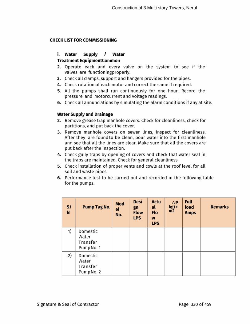
Construction of 3 Multi story Towers, Nerul
Signature & Seal of Contractor Page 330 of 459
CHECK LIST FOR COMMISSIONING
i. Water Supply / Water Treatment Equipment Common
2. Operate each and every valve on the system to see if the valves are functioning properly.
3. Check all clamps, support and hangers provided for the pipes. 4. Check rotation of each motor and correct the same if required. 5. All the pumps shall run continuously for one hour. Record the
pressure and motor current and voltage readings. 6. Check all annunciations by simulating the alarm conditions if any at site.
Water Supply and Drainage
2. Remove grease trap manhole covers. Check for cleanliness, check for partitions, and put back the cover.
3. Remove manhole covers on sewer lines, inspect for cleanliness. After they are found to be clean, pour water into the first manhole and see that all the lines are clear. Make sure that all the covers are put back after the inspection.
4. Check gully traps by opening of covers and check that water seal in the traps are maintained. Check for general cleanliness.
5. Check installation of proper vents and cowls at the roof level for all soil and waste pipes.
6. Performance test to be carried out and recorded in the following table for the pumps.
S/N
Pump Tag No.
Model No.
Design Flow LPS
Actual Flow LPS
△P kg/cm2
Full load Amps
Remarks
1) Domestic Water Transfer Pump No. 1
2) Domestic Water Transfer Pump No. 2
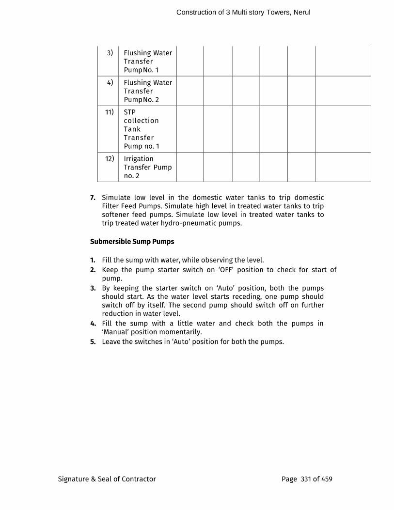
Construction of 3 Multi story Towers, Nerul
Signature & Seal of Contractor Page 331 of 459
3) Flushing Water Transfer Pump No. 1
4) Flushing Water Transfer Pump No. 2
11) STP collection Tank Transfer Pump no. 1
12) Irrigation Transfer Pump no. 2
7. Simulate low level in the domestic water tanks to trip domestic Filter Feed Pumps. Simulate high level in treated water tanks to trip softener feed pumps. Simulate low level in treated water tanks to trip treated water hydro-pneumatic pumps.
Submersible Sump Pumps
1. Fill the sump with water, while observing the level. 2. Keep the pump starter switch on ‘OFF’ position to check for start of
pump. 3. By keeping the starter switch on ‘Auto’ position, both the pumps
should start. As the water level starts receding, one pump should switch off by itself. The second pump should switch off on further reduction in water level.
4. Fill the sump with a little water and check both the pumps in ‘Manual’ position momentarily.
5. Leave the switches in ‘Auto’ position for both the pumps.
Construction of 3 Multi story Towers, Nerul
Signature & Seal of Contractor Page 332 of 459
APPENDIX - I
PROFORMA GUARANTEE PLUMBING / SANITARY INSTALLATION
We hereby guarantee the year round Plumbing, Sanitary & Drainage Which We Have Installed In The Complex Described Below :
Building :
Location :
C L I E N T / S B I / O w n e r :
For a period as Stipulated in Defect Liability Period for total installation, WE AGREE TO repair or replace to the satisfaction of the Owner, any or all such work that may prove defective in workmanship, equipment or materials within that period, ordinary wear and tear and unusual abuse or neglect excluded, together with any other work, which may be damaged or displaced in so doing. In the event of our failure to comply with the above mentioned conditions within a reasonable time, after being notified in writing, we collectively and separately, do hereby authorize the Owner to proceed to have the defects repaired and made good at our expense, and we shall pay the cost and charges thereof, immediately upon demand.
WE ALSO HEREBY UNDERTAKE to test the entire installation in first SUMMER, WINTER AND MONSOON on following the completion of the installation, to check and do everything necessary to ensure that the specified design conditions and functional requirement are met, that all water, sewage, air pollution control systems are properly balanced, that all controls are calibrated accurately, and that all units are functioning satisfactorily.
SIGNATURE OF CONTRACTOR
for PLUMBING / SANITARY SYSTEM
DATE SEAL
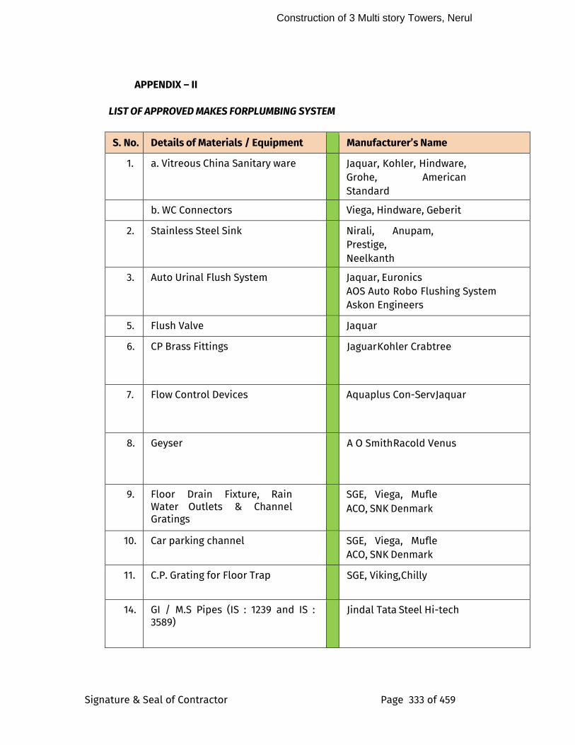
Construction of 3 Multi story Towers, Nerul
Signature & Seal of Contractor Page 333 of 459
APPENDIX – II
LIST OF APPROVED MAKES FOR PLUMBING SYSTEM
S. No. Details of Materials / Equipment Manufacturer’s Name
1. a. Vitreous China Sanitary ware Jaquar, Kohler, Hindware, Grohe, American Standard
b. WC Connectors Viega, Hindware, Geberit
2. Stainless Steel Sink Nirali, Anupam, Prestige, Neelkanth
3. Auto Urinal Flush System Jaquar, Euronics
AOS Auto Robo Flushing System Askon Engineers
5. Flush Valve Jaquar
6. CP Brass Fittings Jaguar Kohler Crabtree
7. Flow Control Devices Aquaplus Con-Serv Jaquar
8. Geyser A O Smith Racold Venus
9. Floor Drain Fixture, Rain Water Outlets & Channel Gratings
SGE, Viega, Mufle ACO, SNK Denmark
10. Car parking channel SGE, Viega, Mufle ACO, SNK Denmark
11. C.P. Grating for Floor Trap SGE, Viking, Chilly
14. GI / M.S Pipes (IS : 1239 and IS : 3589)
Jindal Tata Steel Hi-tech
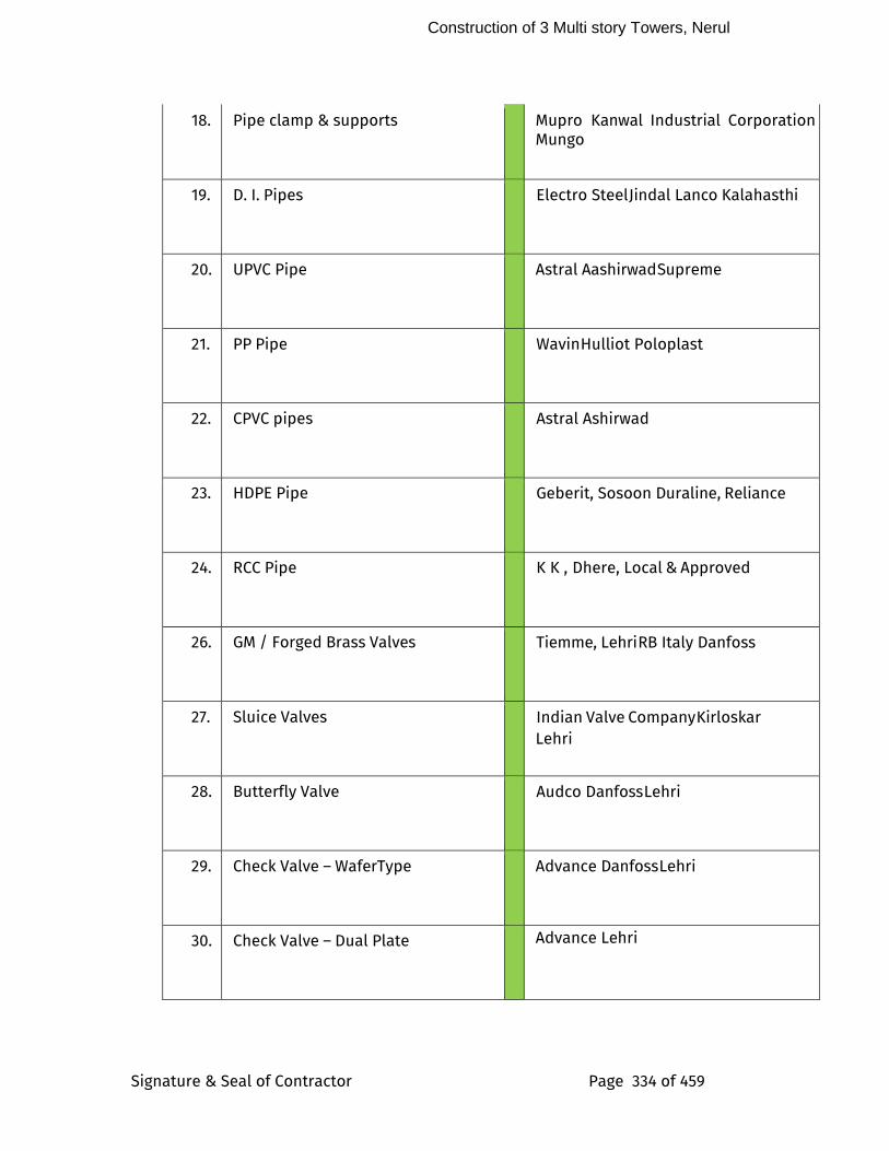
Construction of 3 Multi story Towers, Nerul
Signature & Seal of Contractor Page 334 of 459
18. Pipe clamp & supports Mupro Kanwal Industrial Corporation Mungo
19. D. I. Pipes Electro Steel Jindal Lanco Kalahasthi
20. UPVC Pipe Astral Aashirwad Supreme
21. PP Pipe Wavin Hulliot Poloplast
22. CPVC pipes Astral Ashirwad
23. HDPE Pipe Geberit, Sosoon Duraline, Reliance
24. RCC Pipe K K , Dhere, Local & Approved
26. GM / Forged Brass Valves Tiemme, Lehri RB Italy Danfoss
27. Sluice Valves Indian Valve Company Kirloskar Lehri
28. Butterfly Valve Audco Danfoss Lehri
29. Check Valve – WaferType Advance Danfoss Lehri
30. Check Valve – Dual Plate Advance Lehri
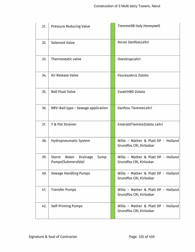
Construction of 3 Multi story Towers, Nerul
Signature & Seal of Contractor Page 335 of 459
31. Pressure Reducing Valve Tiemme RB Italy Honeywell
32. Solenoid Valve Avcon Danfoss Lehri
33. Thermostatic valve Oventrop Lehri
34. Air Release Valve Fouress Arco Zoloto
35. Ball Float Valve Esseti HBD Zoloto
36. NRV–Ball type – Sewage application Danfoss Tiemme Lehri
37. Y & Pot Strainer Emerald Tiemme Zoloto Lehri
38. Hydropneumatic System Willo – Mather & Platt DP - Holland Grundfos CRI, Kirloskar
39. Storm Water Drainage Sump Pumps (Submersible)
Willo – Mather & Platt DP - Holland Grundfos CRI, Kirloskar
40. Sewage Handling Pumps Willo – Mather & Platt DP - Holland Grundfos CRI, Kirloskar
41. Transfer Pumps Willo – Mather & Platt DP - Holland Grundfos CRI, Kirloskar
42. Self-Priming Pumps Willo – Mather & Platt DP - Holland Grundfos CRI, Kirloskar
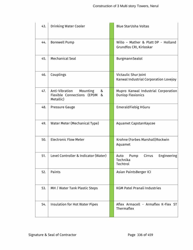
Construction of 3 Multi story Towers, Nerul
Signature & Seal of Contractor Page 336 of 459
43. Drinking Water Cooler Blue Star Usha Voltas
44. Borewell Pump Willo – Mather & Platt DP - Holland Grundfos CRI, Kirloskar
45. Mechanical Seal Burgmann Sealol
46. Couplings Victaulic Shur Joint Kanwal Industrial Corporation Lovejoy
47. Anti-Vibration Mounting & Flexible Connections (EPDM & Metallic)
Mupro Kanwal Industrial Corporation Dunlop Flexionics
48. Pressure Gauge Emerald Fiebig H Guru
49. Water Meter (Mechanical Type) Aquamet Capstan Kaycee
50. Electronic Flow Meter Krohne (Forbes Marshall) Rockwin
Aquamet
51. Level Controller & Indicator (Water) Auto Pump Cirrus Engineering Technika Techtrol
52. Paints Asian Paints Berger ICI
53. MH / Water Tank Plastic Steps KGM Patel Pranali Industries
54. Insulation for Hot Water Pipes Aflex Armacell - Armaflex K-Flex ST Thermaflex
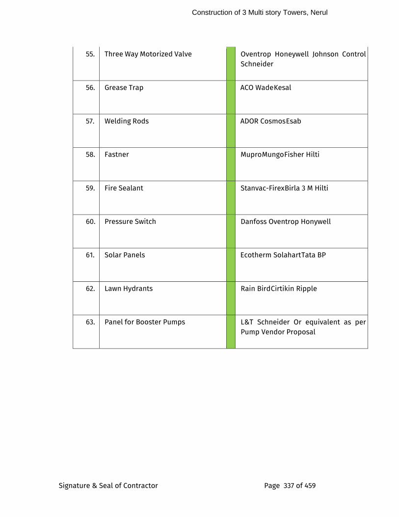
Construction of 3 Multi story Towers, Nerul
Signature & Seal of Contractor Page 337 of 459
55. Three Way Motorized Valve Oventrop Honeywell Johnson Control Schneider
56. Grease Trap ACO Wade Kesal
57. Welding Rods ADOR Cosmos Esab
58. Fastner Mupro Mungo Fisher Hilti
59. Fire Sealant Stanvac-Firex Birla 3 M Hilti
60. Pressure Switch Danfoss Oventrop Honywell
61. Solar Panels Ecotherm Solahart Tata BP
62. Lawn Hydrants Rain Bird Cirtikin Ripple
63. Panel for Booster Pumps L&T Schneider Or equivalent as per Pump Vendor Proposal
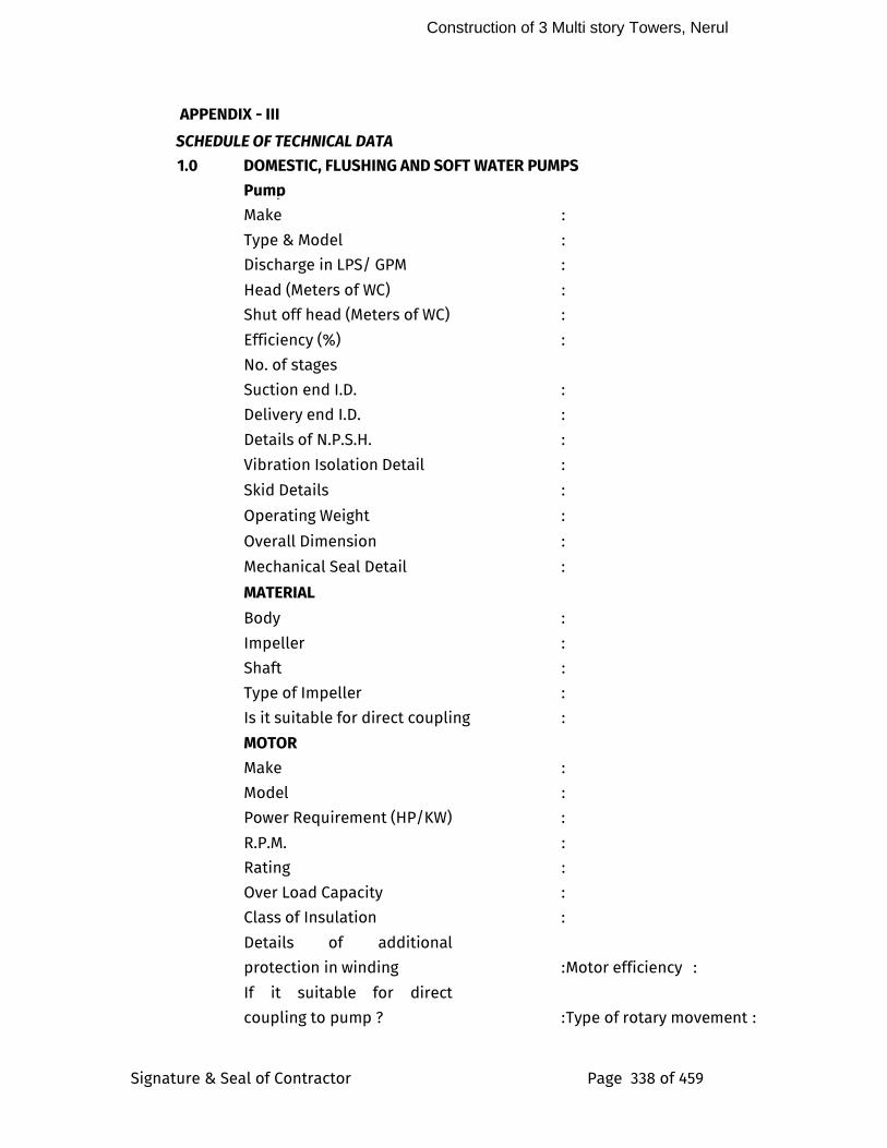
Construction of 3 Multi story Towers, Nerul
Signature & Seal of Contractor Page 338 of 459
APPENDIX - III
SCHEDULE OF TECHNICAL DATA
1.0 DOMESTIC, FLUSHING AND SOFT WATER PUMPS
Pump
Make :
Type & Model :
Discharge in LPS/ GPM :
Head (Meters of WC) :
Shut off head (Meters of WC) :
Efficiency (%) :
No. of stages
Suction end I.D. :
Delivery end I.D. :
Details of N.P.S.H. :
Vibration Isolation Detail :
Skid Details :
Operating Weight :
Overall Dimension :
Mechanical Seal Detail :
MATERIAL
Body :
Impeller :
Shaft :
Type of Impeller :
Is it suitable for direct coupling :
MOTOR
Make :
Model :
Power Requirement (HP/KW) :
R.P.M. :
Rating :
Over Load Capacity :
Class of Insulation :
Details of additional
protection in winding : Motor efficiency :
If it suitable for direct
coupling to pump ? : Type of rotary movement :

Construction of 3 Multi story Towers, Nerul
Signature & Seal of Contractor Page 339 of 459
Method of starting :
Size and type of cable for connections :
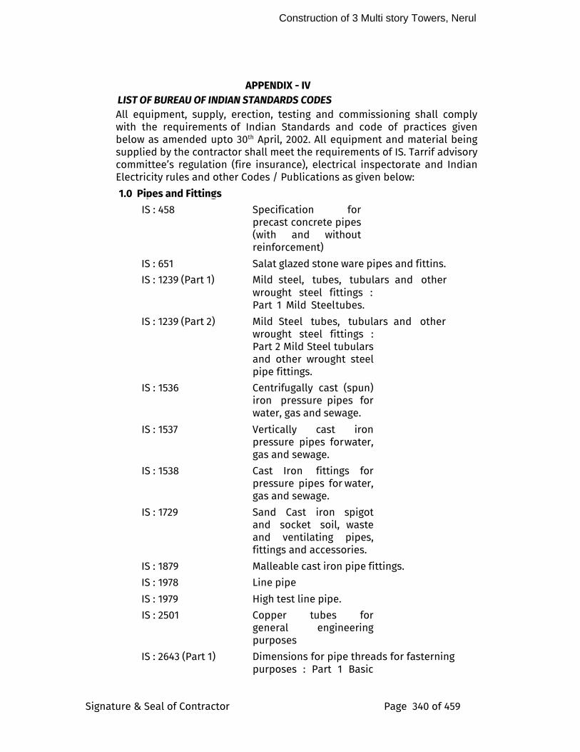
Construction of 3 Multi story Towers, Nerul
Signature & Seal of Contractor Page 340 of 459
APPENDIX - IV LIST OF BUREAU OF INDIAN STANDARDS CODES
All equipment, supply, erection, testing and commissioning shall comply with the requirements of Indian Standards and code of practices given below as amended upto 30th April, 2002. All equipment and material being supplied by the contractor shall meet the requirements of IS. Tarrif advisory committee’s regulation (fire insurance), electrical inspectorate and Indian Electricity rules and other Codes / Publications as given below:
1.0 Pipes and Fittings
IS : 458 Specification for precast concrete pipes (with and without reinforcement)
IS : 651 Salat glazed stone ware pipes and fittins.
IS : 1239 (Part 1) Mild steel, tubes, tubulars and other wrought steel fittings : Part 1 Mild Steel tubes.
IS : 1239 (Part 2) Mild Steel tubes, tubulars and other wrought steel fittings : Part 2 Mild Steel tubulars and other wrought steel pipe fittings.
IS : 1536 Centrifugally cast (spun) iron pressure pipes for water, gas and sewage.
IS : 1537 Vertically cast iron pressure pipes for water, gas and sewage.
IS : 1538 Cast Iron fittings for pressure pipes for water, gas and sewage.
IS : 1729 Sand Cast iron spigot and socket soil, waste and ventilating pipes, fittings and accessories.
IS : 1879 Malleable cast iron pipe fittings.
IS : 1978 Line pipe
IS : 1979 High test line pipe.
IS : 2501 Copper tubes for general engineering purposes
IS : 2643 (Part 1) Dimensions for pipe threads for fasterning purposes : Part 1 Basic
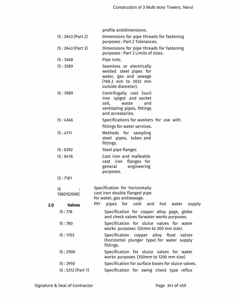
Construction of 3 Multi story Towers, Nerul
Signature & Seal of Contractor Page 341 of 459
profile and dimensions.
IS : 2643 (Part 2) Dimensions for pipe threads for fastening purposes : Part 2 Tolerances.
IS : 2643 (Part 3) Dimensions for pipe threads for fastening purposes : Part 3 Limits of sizes.
IS : 3468 Pipe nuts.
IS : 3589 Seamless or electrically welded steel pipes for water, gas and sewage (168.3 mm to 2032 mm outside diameter).
IS : 3989 Centrifugally cast (sun) iron spigot and socket soil, waste and ventilating pipes, fittings and accessories.
IS : 4346 Specifications for washers for use with
fittings for water services.
IS : 4711 Methods for sampling steel pipes, tubes and fittings.
IS : 6392 Steel pipe flanges
IS : 6418 Cast iron and malleable cast iron flanges for general engineering purposes.
IS : 7181
IS : 15801(2008)
2.0 Valves
Specification for horizontally cast iron double flanged pipe for water, gas and sewage. PPr pipes for cold and hot water supply
IS : 778 Specification for copper alloy gage, globe and check valves for water works purposes.
IS : 780 Specification for sluice valves for water works purposes (50 mm to 300 mm size).
IS : 1703 Specification copper alloy float valves (horizontal plunger type) for water supply fittings.
IS : 2906 Specification for sluice valves for water works purposes (350 mm to 1200 mm size)
IS : 3950 Specification for surface boxes for sluice valves.
IS : 5312 (Part 1) Specification for swing check type reflux
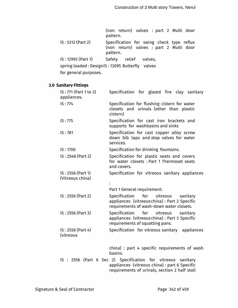
Construction of 3 Multi story Towers, Nerul
Signature & Seal of Contractor Page 342 of 459
(non return) valves : part 2 Multi door pattern.
IS : 5312 (Part 2) Specification for swing check type reflux (non return) valves : part 2 Multi door pattern.
IS : 12992 (Part 1) Safety relief valves,
spring loaded : Design IS : 13095 Butterfly valves
for general purposes.
3.0 Sanitary Fittings
IS : 771 (Part 1 to 3) Specification for glazed fire clay sanitary appliances.
IS : 774 Specification for flushing cistern for water closets and urinals (other than plastic cistern)
IS : 775 Specification for cast iron brackets and supports for wash basins and sinks
IS : 781 Specification for cast copper alloy screw down bib taps and stop valves for water services.
IS : 1700 Specification for drinking fountains.
IS : 2548 (Part 2) Specification for plastic seats and covers for water closets : Part 1 Thermoset seats and covers.
IS : 2556 (Part 1) Specification for vitreous sanitary appliances (Vitreous china)
: Part 1 General requirement.
IS : 2556 (Part 2) Specification for vitreous sanitary appliances (vitreous china) : Part 2 Specific requirements of wash-down water closets.
IS : 2556 (Part 3) Specification for vitreous sanitary appliances (vitreous china) : Part 3 Specific requirements of squatting pans.
IS : 2556 (Part 4) Specification for vitreous sanitary appliances (vitreous
china) : part 4 specific requirements of wash basins.
IS : 2556 (Part 6 Sec 2) Specification for vitreous sanitary appliances (vitreous china) : part 6 Specific requirements of urinals, section 2 half stall
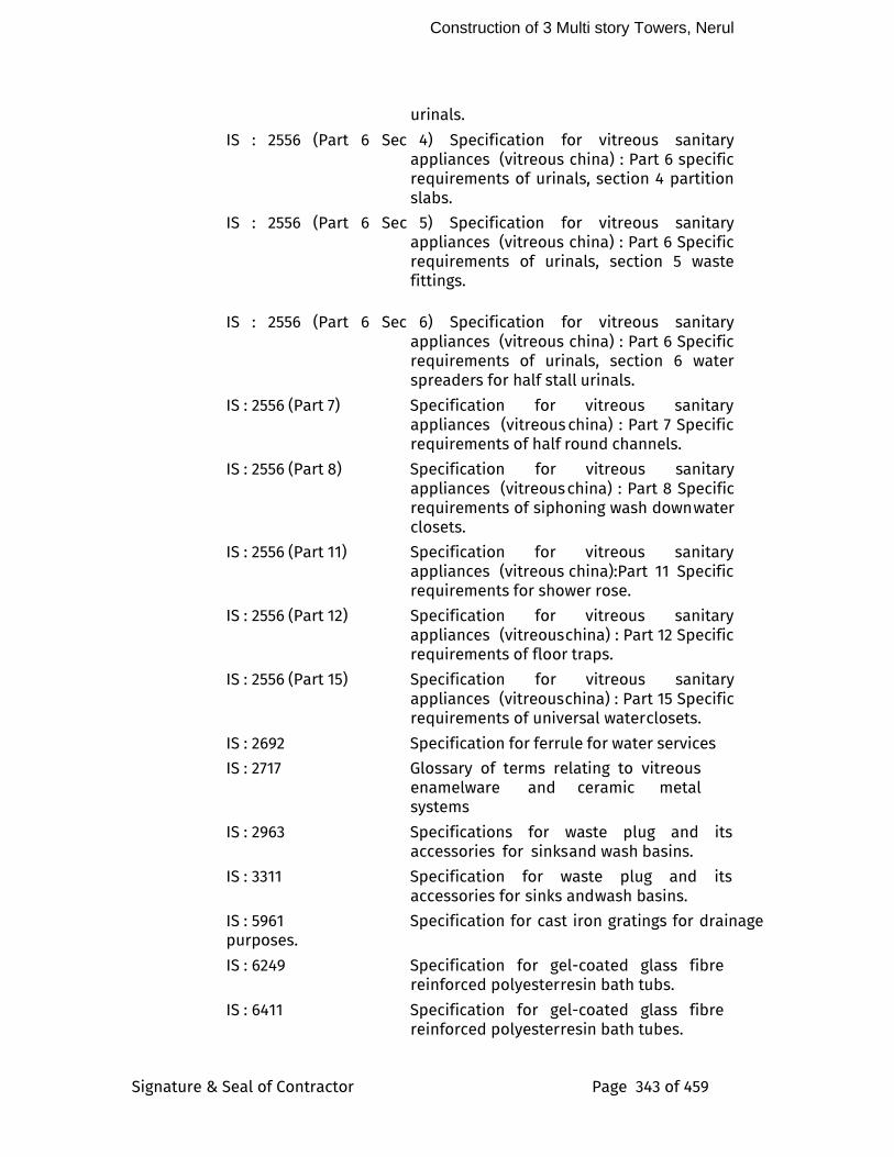
Construction of 3 Multi story Towers, Nerul
Signature & Seal of Contractor Page 343 of 459
urinals.
IS : 2556 (Part 6 Sec 4) Specification for vitreous sanitary appliances (vitreous china) : Part 6 specific requirements of urinals, section 4 partition slabs.
IS : 2556 (Part 6 Sec 5) Specification for vitreous sanitary appliances (vitreous china) : Part 6 Specific requirements of urinals, section 5 waste fittings.
IS : 2556 (Part 6 Sec 6) Specification for vitreous sanitary
appliances (vitreous china) : Part 6 Specific requirements of urinals, section 6 water spreaders for half stall urinals.
IS : 2556 (Part 7) Specification for vitreous sanitary appliances (vitreous china) : Part 7 Specific requirements of half round channels.
IS : 2556 (Part 8) Specification for vitreous sanitary appliances (vitreous china) : Part 8 Specific requirements of siphoning wash down water closets.
IS : 2556 (Part 11) Specification for vitreous sanitary appliances (vitreous china):Part 11 Specific requirements for shower rose.
IS : 2556 (Part 12) Specification for vitreous sanitary appliances (vitreous china) : Part 12 Specific requirements of floor traps.
IS : 2556 (Part 15) Specification for vitreous sanitary appliances (vitreous china) : Part 15 Specific requirements of universal water closets.
IS : 2692 Specification for ferrule for water services
IS : 2717 Glossary of terms relating to vitreous enamelware and ceramic metal systems
IS : 2963 Specifications for waste plug and its accessories for sinks and wash basins.
IS : 3311 Specification for waste plug and its accessories for sinks and wash basins.
IS : 5961 Specification for cast iron gratings for drainage purposes.
IS : 6249 Specification for gel-coated glass fibre reinforced polyester resin bath tubs.
IS : 6411 Specification for gel-coated glass fibre reinforced polyester resin bath tubes.
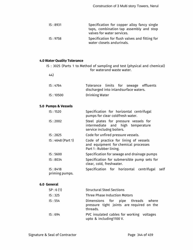
Construction of 3 Multi story Towers, Nerul
Signature & Seal of Contractor Page 344 of 459
IS : 8931 Specification for copper alloy fancy single taps, combination tap assembly and stop valves for water services.
IS : 9758 Specification for flush valves and fitting for water closets and urinals.
4.0 Water Quality Tolerance
IS : 3025 (Parts 1 to Method of sampling and test (physical and chemical) for water and waste water.
44)
IS : 4764 Tolerance limits for sewage effluents discharged into inland surface waters.
IS : 10500 Drinking Water
5.0 Pumps & Vessels
IS : 1520 Specification for horizontal centrifugal pumps for clear cold fresh water.
IS : 2002 Steel plates for pressure vessels for intermediate and high temperature service includng boilers.
IS : 2825 Code for unfired pressure vessels.
IS : 4648 (Part 1) Code of practice for lining of vessels and equipment for chemical processes Part 1 : Rubber lining.
IS : 5600 Specification for sewage and drainage pumps
IS : 8034 Specification for submersible pump sets for clear, cold, fresh water.
IS : 8418 Specification for horizontal centrifugal self priming pumps.
6.0 General
SP : 6 (1) Structural Steel Sections
IS : 325 Three Phase Induction Motors
IS : 554 Dimensions for pipe threads where pressure tight joints are required on the threads.
IS : 694 PVC insulated cables for working voltages upto & including 1100 V.
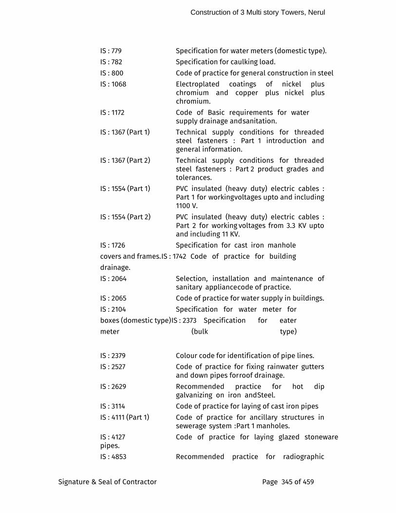
Construction of 3 Multi story Towers, Nerul
Signature & Seal of Contractor Page 345 of 459
IS : 779 Specification for water meters (domestic type).
IS : 782 Specification for caulking load.
IS : 800 Code of practice for general construction in steel
IS : 1068 Electroplated coatings of nickel plus chromium and copper plus nickel plus chromium.
IS : 1172 Code of Basic requirements for water supply drainage and sanitation.
IS : 1367 (Part 1) Technical supply conditions for threaded steel fasteners : Part 1 introduction and general information.
IS : 1367 (Part 2) Technical supply conditions for threaded steel fasteners : Part 2 product grades and tolerances.
IS : 1554 (Part 1) PVC insulated (heavy duty) electric cables : Part 1 for working voltages upto and including 1100 V.
IS : 1554 (Part 2) PVC insulated (heavy duty) electric cables : Part 2 for working voltages from 3.3 KV upto and including 11 KV.
IS : 1726 Specification for cast iron manhole
covers and frames. IS : 1742 Code of practice for building
drainage.
IS : 2064 Selection, installation and maintenance of sanitary appliance code of practice.
IS : 2065 Code of practice for water supply in buildings.
IS : 2104 Specification for water meter for
boxes (domestic type) IS : 2373 Specification for eater
meter (bulk type)
IS : 2379 Colour code for identification of pipe lines.
IS : 2527 Code of practice for fixing rainwater gutters and down pipes for roof drainage.
IS : 2629 Recommended practice for hot dip galvanizing on iron and Steel.
IS : 3114 Code of practice for laying of cast iron pipes
IS : 4111 (Part 1) Code of practice for ancillary structures in sewerage system : Part 1 manholes.
IS : 4127 Code of practice for laying glazed stoneware pipes.
IS : 4853 Recommended practice for radiographic
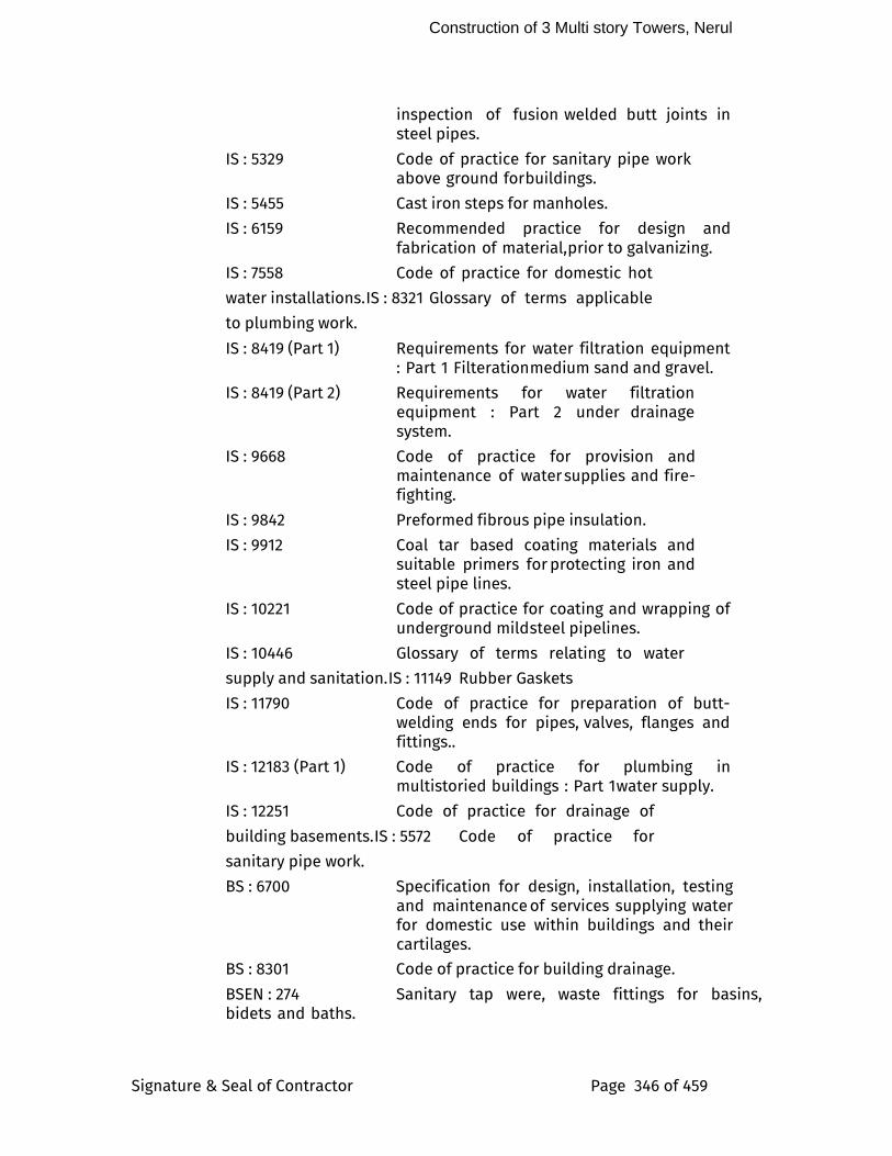
Construction of 3 Multi story Towers, Nerul
Signature & Seal of Contractor Page 346 of 459
inspection of fusion welded butt joints in steel pipes.
IS : 5329 Code of practice for sanitary pipe work above ground for buildings.
IS : 5455 Cast iron steps for manholes.
IS : 6159 Recommended practice for design and fabrication of material, prior to galvanizing.
IS : 7558 Code of practice for domestic hot
water installations. IS : 8321 Glossary of terms applicable
to plumbing work.
IS : 8419 (Part 1) Requirements for water filtration equipment : Part 1 Filteration medium sand and gravel.
IS : 8419 (Part 2) Requirements for water filtration equipment : Part 2 under drainage system.
IS : 9668 Code of practice for provision and maintenance of water supplies and fire-fighting.
IS : 9842 Preformed fibrous pipe insulation.
IS : 9912 Coal tar based coating materials and suitable primers for protecting iron and steel pipe lines.
IS : 10221 Code of practice for coating and wrapping of underground mild steel pipelines.
IS : 10446 Glossary of terms relating to water
supply and sanitation. IS : 11149 Rubber Gaskets
IS : 11790 Code of practice for preparation of butt-welding ends for pipes, valves, flanges and fittings..
IS : 12183 (Part 1) Code of practice for plumbing in multistoried buildings : Part 1 water supply.
IS : 12251 Code of practice for drainage of
building basements. IS : 5572 Code of practice for
sanitary pipe work.
BS : 6700 Specification for design, installation, testing and maintenance of services supplying water for domestic use within buildings and their cartilages.
BS : 8301 Code of practice for building drainage.
BSEN : 274 Sanitary tap were, waste fittings for basins, bidets and baths.

Construction of 3 Multi story Towers, Nerul
Signature & Seal of Contractor Page 347 of 459
General technical specifications.
Construction of 3 Multi story Towers, Nerul
Signature & Seal of Contractor Page 348 of 459
3 – SPECIFIC CONDITIONS OF PLUMBING & SANITARY WORK
1.0 GENERAL
These specific l conditions are intended to amplify the General Conditions of Contract, and shall be read in conjunction with the same. For any discrepancies between the General Conditions and these Specific Conditions, the more stringent shall apply.
SCOPE OF WORK
This specification covers the supply and installation of the Plumbing and Sanitary systems and equipment at project.
The systems to be provided will include, but not be limited to:
i. Raw water storage
ii. Potable water treatment, storage and supply
iii. Flushing water storage and supply
iv. Swimming pools filtration and disinfection systems
v. Hot water system
vi. Soil, waste and vent systems
vii. Rain water collection and harvesting system
viii. Basement drainage system
ASSOCIATED CIVIL WORKS
Following civil works associated with Plumbing / Sanitary installation are excluded from the scope of this contract. These shall be executed by other agencies in accordance with approved shop drawings of, and under direct supervision of the Plumbing / Sanitary contractor. 14.1.1. RCC foundation for machines, pumps & large equipment with
angle iron frame work at the edges to protect these from damage.
14.1.2. RCC work for water tanks
Construction of 3 Multi story Towers, Nerul
Signature & Seal of Contractor Page 349 of 459
14.1.3. PCC foundation blocks with angle iron frame work edging for all motor control centre.
14.1.4. Water proofing of floors. 14.1.5. Masonry drains channels and sumps in plant room.
IMPORTED EQUIPMENT
The successful tenderer shall submit upon award the following to facilitate the Owner in their application for concessional duty for equipment/material proposed to be directly purchased and imported by them. i. Four copies of proforma invoice from Manufacturer/Supplier
drawn in the name of Owner identifying FOB price from the country of origin and Freight cum Insurance up to site.
ii. Four sets of Technical .Literature, high lighting model number and all technical details of the actual equipment/material offered by them.
iii. Successful bidder shall indicate packing specification for imported equipment / material.
iv. Successful bidder shall furnish undertaking from local agents for all imported equipment that they will provide all technical data & engineering information on the product through their principles, all back-up services during detailed engineering testing and commissioning and service during and after the defects liability period.
7.0 PROJECT EXECUTION AND MANAGEMENT
The Contractor shall ensure that senior planning and erection personnel from his organization are assigned exclusively for this project. They shall have minimum 10 years’ experience in this type of installation. The Contractor shall appoint one Project Director holding senior management position in the organization. He shall be assisted on full time basis by a minimum of two erection engineers & three senior supervisors. The entire staff shall be posted at site on full time basis. The project management shall be through modern technique. The Contractor’s office at site shall be fully equipped with fax, modem, computers, plotter and photocopier. Erection engineer and supervisors shall be provided with mobile communication system so that they can always be reached. For quality control & monitoring of workmanship, contractor shall assign at least one full-time engineer who would be exclusively responsible for ensuring strict quality control, adherence to specifications and ensuring top class workmanship for the installation. The Contractor shall arrange to have mechanized & modern facilities
Construction of 3 Multi story Towers, Nerul
Signature & Seal of Contractor Page 350 of 459
of transporting material to place of installation for speedy execution of work.
8.0 PERFORMANCE GUARANTEE
The contractor shall carry out the work in accordance with the Drawings, Specifications, Schedule of Quantities and other documents forming part of the Contract. The contractor shall be fully responsible for the performance of the selected equipment (installed by him) at the specified parameters and for the efficiency of the installation to deliver the required end result. The contractor shall guarantee that the Plumbing / Sanitary system as installed shall maintain the design conditions as described under “Basis of Design” and relevant clauses in the specifications. The guarantee shall be submitted in the proforma given in Appendix - II. Complete set of architectural drawings is available in the Architect/Consultant’s office and reference may be made to same for any details or information. The contractor shall also guarantee that the performance of various equipment individually, shall not
be less than the quoted capacity; also actual power consumption shall not exceed the quoted rating, during testing and commissioning, handing over and guarantee period.
9.0 BYE-LAWS AND REGULATIONS
The installation shall be in conformity with the Bye-laws, Regulations and Standards of the local authorities concerned, in so far as these become applicable to the installation. But if these Specifications and Drawings call for a higher standard of materials and / or workmanship than those required by any of the above regulations and standards, then these Specifications and Drawings shall take precedence over the said regulations and standards. However, if the Drawings and specifications require something which violates the Bye-laws and Regulations, then the Bye-laws and Regulations shall govern the requirement of this installation.
10.0 FEES AND PERMITS
The contractor shall obtain all permits/ licenses and pay for any and all fees required for the inspection, approval and commissioning of their installation.
11.0 DRAWINGS
The Plumbing / Sanitary Drawings listed under Appendix-I, which may be issued with tenders, are diagrammatic only and indicate arrangement of various systems and the extent of work covered in the contract. These Drawings indicate the points of supply and of termination of services and broadly suggest the routes to be
Construction of 3 Multi story Towers, Nerul
Signature & Seal of Contractor Page 351 of 459
followed. Under no circumstances shall dimensions be scaled from these Drawings. The architectural/interiors drawings and details shall be examined for exact location of equipment and water supply / drainage piping etc. The contractor shall follow the tender drawings in preparation of his shop drawings, and for subsequent installation work. He shall check the drawings of other trades to verify spaces in which his work will be installed. Maximum headroom shall be maintained at all points. Where headroom appears inadequate, the contractor shall notify the Architect/Consultant/APMC/SBI before proceeding with the installation. In case installation is carried out without notifying, the work shall be rejected and contractor shall rectify the same at his own cost. The contractor shall examine all architectural, structural, plumbing, electrical and other services drawings and check the as-built works before starting the work, report to the APMC/SBI any discrepancies and obtain clarification. Any changes found essential to coordinate installation of his work with other services and trades, shall be made with prior approval of the Architect/Consultant/APMC/SBI without additional cost to the Owner. The data given in the Drawings and Specifications is as exact as could be procured, but its accuracy is not guaranteed.
12.0 TECHNICAL DATA
Each tenderer shall submit along with his tender, the technical data for all items listed in Appendix-IV in the indicated format. Failure to furnish complete technical data with tenders may result in summary rejection of the tender.
SHOP DRAWINGS
1. All the shop drawings shall be prepared on computer through Autocad System based on Architectural Drawings, site measurements and Interior Designer’s Drawings. Within four weeks of the award of the contract, contractor shall furnish, for the approval of the Architect/Consultant, two sets of detailed shop drawings of all equipment and materials including layouts for Plant room, Pump room, Typical toilets drawings showing exact location of supports, flanges, bends, tee connections, reducers, detailed piping drawings showing exact location and type of supports, valves, fittings etc; external insulation details for pipe insulation etc; electrical panels inside/outside views, power and control wiring schematics, cable trays, supports and terminations. These shop drawings shall contain all information required to complete the Project as per specifications and as required by the Architect/Consultant/APMC/SBI . These Drawings shall contain details of construction, size, arrangement, operating clearances,
Construction of 3 Multi story Towers, Nerul
Signature & Seal of Contractor Page 352 of 459
performance characteristics and capacity of all items of equipment, also the details of all related items of work by other contractors. Each shop drawing shall contain tabulation of all measurable items of equipment/materials/works and progressive cumulative totals from other related drawings to arrive at a variation-in- quantity statement at the completion of all shop drawings. Minimum 12 sets of drawings shall be submitted after final approval along with floppy / CD. Each item of equipment/material proposed shall be a standard catalogue product of an established manufacturer strictly from the manufacturers listed in Appendix-III and quoted by the tenderer in technical data part of Appendix - IV. When the Architect/Consultant makes any amendments in the above drawings, the contractor shall supply two fresh sets of drawings with the amendments duly incorporated along with check prints, for approval. The contractor shall submit further twelve sets of shop drawings to the APMC/SBI for the exclusive use by the APMC/SBI and all other agencies. No material or equipment may be delivered or installed at the job site until the contractor has in his possession, the approved shop drawing for the particular material/equipment/ installation.
2. Shop drawings shall be submitted for approval four weeks in advance of planned delivery and installation of any material to allow Architect/Consultant ample time for scrutiny. No claims for extension of time shall be entertained because of any delay in the work due to his failure to produce shop drawings at the right time, in accordance with the approved programme.
3. Manufacturers drawings, catalogues, pamphlets and other documents submitted for approval shall be in four sets. Each item in each set shall be properly labelled, indicating the specific services for which material or equipment is to be used, giving reference to the governing section and clause number and clearly identifying in ink the items and the operating characteristics. Data of general nature shall not be accepted.
4. Samples of all materials like valves, pipes, insulation, control wires etc shall be submitted to the APMC/SBI prior to procurement. These will be submitted in two sets for approval and retention by APMC/SBI and shall be kept in their site office for reference and verification till the completion of the Project. Wherever directed a mockup or sample installation shall be carried out for approval before proceeding for further installation.
5. Approval of shop drawings shall not be considered as a guarantee of measurements or of building dimensions. Where drawings are approved, said approval does not mean that the drawings supercede the contract requirements, nor does it in any way relieve the contractor of the responsibility or requirement to furnish material and perform work as required by the contract.
Construction of 3 Multi story Towers, Nerul
Signature & Seal of Contractor Page 353 of 459
6. Where the contractor proposes to use an item of equipment, other than that specified or detailed on the drawings, which requires any redesign of the structure, partitions, foundation, piping, wiring or any other part of the mechanical, electrical or architectural layouts; all such re-design, and all new drawings and detailing required therefore, shall be prepared by the contractor at his own expense and gotten approved by the Architect/Consultant/ APMC/SBI . Any delay on such account shall be at the cost of and consequence of the Contractor.
7. Plumbing / Sanitary Contractor shall prepare coordinated services shop drawings based on the drawings prepared by Fire, Electrical, HVAC & Low Voltage Contractors to ensure adequate clearances are available for installation of services for each trade. Where the work of the contractor has to be installed in close proximity to, or will interfere with work of other trades, he shall assist in working out space conditions to make a satisfactory adjustment. If so directed by the APMC/SBI , the contractor shall prepare composite working drawings and sections at a suitable scale, not less than 1:50, clearly showing how his work is to be installed in relation to the work of other trades. If the Contractor installs his work before coordinating with other trades, or so as to cause any interference with work of other trades, he shall make all the necessary changes without extra cost to the Owner.
8. Within four weeks of approval of all the relevant shop drawings, the contractor shall submit four copies of a comprehensive variation in quantity statement, and itemized price list of recommended (by manufacturers) imported and local spare parts and tools, covering all equipment and materials in this contract. The Project Manager shall make recommendation to Owner for acceptance of anticipated variation in contract amounts and also advise Owner to initiate action for procurement of spare parts and tools at the completion of project.
13.09 The Contractor is responsible for bringing all shop drawings up to status approval in the duration of the Contract and prior to completion of the Project. The Contractor will update these drawings periodically to maintain an “as installed” set of record drawings.
13.10 The Contractor shall provide the following number and type of
copies of the As Built drawings:-
Construction of 3 Multi story Towers, Nerul
Signature & Seal of Contractor Page 354 of 459
SBI
2. 3 No full size bound paper copies
3. 3 No A3 bound paper copies. 4. 3 No CD electronic copies
APMC
5. 2 No full size bound paper copies
6. 2 No A3 bound paper copies
7. 2 No CD electronic copies
All full size (i.e. A0, A1, A2, A3) paper copies of the drawings will be provided and bound along the left-hand edge. Each set of drawings will have a cover page containing the “SBI, Nerul – Residential Building” graphic, the project name and the discipline of the drawings. When included in the Bills of Quantities (Preliminaries Section), the Contractor will provide the Owner with A0 / A1 Vista-plan drawing hangers and wheeled racks to allow one set of drawings to be retained by the Owner. The Vista plan racks will remain the property of the Owner.
The A3 copies of the As Built drawings will be bound on the left hand edge with a suitable binding screw bolt device
The electronic copies will be provided in CD formatted in AutoCAD 2010 or suitable version as approved by the Owner along with pdf versions of the same. Where drawings have not been drawn in AutoCAD 2010 the Contractor shall electronically scan these drawings and insert them as PDF files. PDF and
DWF/DWG files should also be published in the relevant folder on the Expedition System. The electronic information is to be logically filed on separate CD’s to provide:
v. Consultants Architectural Drawings.
vi. Consultants Structural Drawings.
vii. Consultants MEP Drawings.
viii. Contractors Shop Drawings.
ix. Sub-Contractors Shop Drawings. x. MIDC / Authority Approval Drawings.
Construction of 3 Multi story Towers, Nerul
Signature & Seal of Contractor Page 355 of 459
14.0 QUIET OPERATION AND VIBRATION ISOLATION
All equipment shall operate under all conditions of load without any sound or vibration which is objectionable in the opinion of the APMC/SBI . In case of rotating machinery sound or vibration noticeable outside the room in which it is installed, or annoyingly noticeable inside its own room, shall be considered objectionable. Such conditions shall be corrected by the Contractor at his own expense. The contractor shall guarantee that the equipment installed shall maintain the desired NC levels.
15.0 ACCESSIBILITY
The Contractor shall verify the sufficiency of the size of the shaft openings, clearances in cavity walls and suspended ceilings for proper installation of his piping and other ancillaries. His failure to communicate insufficiency of any of the above, shall constitute his acceptance of sufficiency of the same. The Contractor shall locate all equipment which must be serviced, operated or maintained in fully accessible positions. The exact location and size of all access panels, required for each concealed, valve or other devices requiring attendance, shall be finalized and communicated in sufficient time, to be provided in the normal course of work. Failing this, the Contractor shall make all the necessary repairs and changes at his own expense. Access panel shall be standardized for each piece of equipment / device / accessory and shall be clearly nomenclatured / marked.
16.0 MATERIALS AND EQUIPMENT
All materials and equipment shall conform to the relevant Indian Standards and shall be of the approved make and design. Makes shall be strictly in conformity with list of approved manufacturers as per Appendix - III.
17.0 MANUFACTURERS INSTRUCTIONS
Where manufacturer has furnished specific instructions, relating to the material and equipment used in this project, covering points not specifically mentioned in these documents, such instructions shall be followed in all cases.
18.0 ELECTRICAL INSTALLATION
The electrical work related to Plumbing / Sanitary services, shall be carried out in full knowledge of, and with the complete coordination. The electrical installation shall be in total conformity with the control wiring drawings prepared by the contractor and approved by the Architect/Consultant. All equipment shall be connected and tested in the presence of an authorized representative of the contractor. The Plumbing / Sanitary system shall be commissioned only after
Construction of 3 Multi story Towers, Nerul
Signature & Seal of Contractor Page 356 of 459
the contractor has certified in writing that the electrical installation work for Plumbing / Sanitary services
has been thoroughly checked, tested and found to be totally satisfactory and in full conformity with the contract Drawings, Specifications and manufacturer’s instructions. It is to be clearly understood that the final responsibility for the sufficiency, adequacy and conformity to the contract requirements, of the electrical installation work for Plumbing / Sanitary services, lies solely with the contractor.
19.0 COMPLETION CERTIFICATE
On completion of the Electrical installation for Plumbing / Sanitary, a certificate shall be furnished by the contractor, counter signed by the licensed supervisor, under whose direct supervision the installation was carried out. This certificate shall be in the prescribed form as required by the local authority. The contractor shall be responsible for getting the entire electrical installation for Plumbing / Sanitary system duly approved by the local authorities concerned, and shall bear expenses if any, in connection with the same.
20.0 BALANCING, TESTING AND COMMISSIONING
Balancing of all water systems and all tests as called for the Specifications shall be carried out by the contractor through a specialist group, in accordance with the Specifications and NBC/ ASPE / ASHRAE Guide lines and Standards. Performance test shall consist of three days of 10 hour each operation of system for each season. Cost of performance witness test of major equipment such as pumps, equipment, panels etc. at factory with two personnel from Owners / Consultant shall be included. The installation shall be tested again after removal of defects and shall be commissioned only after approval by the APMC/SBI . All tests shall be carried out in the presence of the representatives of the Architect/Consultant and APMC/SBI .
21.0 COMPLETION DRAWINGS
Contractor shall periodically submit completion drawings as and when work in all respects is completed in a particular area. These drawings shall be submitted in the form of two sets of floppies / CD’s and four portfolios (300 x 450 mm) each containing complete set of drawings on approved scale indicating the work as - installed. These drawings shall clearly indicate complete plant room layouts, piping layouts, location of wiring and sequencing of automatic controls, location of all concealed piping, valves, controls, wiring and other services. Each portfolio shall also contain consolidated control diagrams and technical literature on all controls. The contractor shall frame under glass, in the plant room,
Construction of 3 Multi story Towers, Nerul
Signature & Seal of Contractor Page 357 of 459
one set of these consolidated control diagrams. 22.0 OPERATING INSTRUCTION & MAINTENANCE MANUAL
Where applicable, the Contractor is responsible for the preparation of fully indexed and cross referenced O&M Manuals from the out-set of the Contract. Refer to the Technical Specifications for the detailed requirements for each O & M Manual.
The Contractor shall update the O&M Manuals periodically to maintain a set of “as installed” record documents.
The Quality Manager’s duty shall include the responsibility for compiling the O&M Manuals for each trade included in the Works incorporating all approved documents relative to the proper operation and maintenance of the building on completion. Refer to the Quality Control requirements (Section 15) set out in this Volume for the information required.
The Contractor shall utilise the above information and provide a Planned Preventative Maintenance Schedule advising the Owner how to operate and maintain the installed plant and equipment following the issue of the Completion Certificate in accordance with a fully indexed set of manufacturer’s instructions that will be designed to allow the Owner to operate, service and maintain the Works whilst observing, protecting and maintaining the warranties issued for such materials, plant and equipment. The Contractor shall provide three paper copies and three CDs (PDF Format) of the O&M Manual. Electronic copies must also be published on the Expedition System in .PDF format.
The paper copies shall be A4 size and bound into loose leaf plastic ring binders with a front pocket. The Contractor will insert the “The Crest” graphic into the pocket, the volume number, the discipline i.e. Architectural, Structural, MEP, other. The O & M Manuals will contain colour copies of all manufacturers’ product and maintenance literature. Black and white copies of these documents will not be accepted. The manuals are to be delivered to the Engineer in new aluminum chests that will remain the property of the Owner. These manuals shall also include basis of design, detailed technical data for each piece of equipment as installed, spare parts manual and recommended spares for 4 year period of maintenance of each equipment.
“Preventive Maintenance Schedule for each equipment / panel shall be submitted along with Operation and Maintenance Manual”.
Construction of 3 Multi story Towers, Nerul
Signature & Seal of Contractor Page 358 of 459
23.0 ON SITE TRAINING
Upon completion of all work and all tests, the Contractor shall furnish necessary operators, labour and helpers for operating the entire installation for a period of fifteen (15) working days of ten (10) hours each, to enable the Owner’s staff to get acquainted with the operation of the system. During this period, the contractor shall train the Owner’s personnel in the operation, adjustment and maintenance of all equipment installed.
MAINTENANCE DURING DEFECTS LIABILITY PERIOD
d) Complaints
The Contractor shall receive calls for any and all problems experienced in the operation of the system under this contract, attend to these within 10 hours of receiving the complaints and shall take steps to immediately correct any deficiencies that may exist.
e) Repairs
All equipment that requires repairing shall be immediately serviced and repaired. Since the period of Mechanical Maintenance runs concurrently with the defects liability period, all replacement parts and labour shall be supplied promptly free-of-charge to the Owner. All equipment that requires repairing shall be immediately serviced and repaired. Since the period of Mechanical Maintenance runs concurrently with the defects liability period, all replacement parts and labour shall be supplied promptly free-of-charge to the Owner.
25.0 UPTIME GUARANTEE The contractor shall guarantee for the installed system an uptime of 98%. In case of shortfall in any month during the defects liability period, the Defects Liability period shall get extended by a month for every month having shortfall. In case of shortfall beyond the defects liability period, the contract for Operation and Maintenance shall get extended by a month for every month having the shortfall and no reimbursement shall be made for the extended period. The Contractor shall provide log in the form of diskettes and bound printed comprehensive log book containing tables for daily record of all pressures, power consumption. Starting and stopping times for various equipment daily services rendered for the system alarms, maintenance and record of unusual observations etc. Contractor shall also submit preventive maintenance schedule. Each tenderer shall submit along with the tender, a detailed operation assistance proposal for the APMC/SBI/Consultant’s review. This shall include the type of service planned to be offered during Defects Liability Period and beyond. The operation assistance proposal shall give the details of the proposed monthly reports to

Construction of 3 Multi story Towers, Nerul
Signature & Seal of Contractor Page 359 of 459
the Management. The tenderer shall include a list of other projects where such an Operation Assistance has been provided.
OPERATION AND MAINTENANCE Contractor may be required to carry out the operation of the Plumbing / Sanitary installation for the defects liability period. Further, he may also be required to carry out operation and all inclusive maintenance of the entire system for a period of three years beyond the defects liability period.
iv. Operation contract
• 24 hours a day, year round. • All stand-by equipment to be operated as per mutually agreed
program. • Proper entry and unkeep of relevant log books. • Maintain complaints register. Submit weekly report. • Proper housekeeping of all areas under the contract. • Prepare daily consumption report and summary of operation.
i. All Inclusive Maintenance Contract
• Routine Preventive Maintenance Schedule to be submitted
(b) Schedule to cover manufacturer’s recommendation and/or common engineering practice (for all plant and machinery under contract).
(c) Plant and machinery history card giving full details of equipment and frequency of checks and overhaul.
(d) Monthly status report. (e) Entire Plumbing / Sanitary installation to be painted
in fourth year (from commissioning) before the expiry of operation and maintenance contract.
Uptime during maintenance contract 1. 98% uptime of all systems under contract. 2. Up time shall be assessed every month and in case of shortfall
during any month the contract shall be extended by a month. 3. There shall be no reimbursement for the extended period. 4. Break-downs shall be attended to within ten hours of reporting. 5. Spare compressor/motor assembly to be made available
within seven calendar days in case of total breakdown/burnout.
Manpower v. Adequate number of persons to the satisfaction of the
APMC/SBI shall be provided including relievers. vi. Statutory requirements of EPF, ESIC and other applicable labour
legislations to be complied with; and monthly certification to
Construction of 3 Multi story Towers, Nerul
Signature & Seal of Contractor Page 360 of 459
that effect to be submitted. vii. Duty allocation and Roaster control shall be contractor’s
responsibility.
viii. No overtime shall be payable by Owner for any reason whatsoever. Shut Downs i. Contractor shall be at liberty to carry out routine
maintenance as and when required but with prior permission of the Owner.
27.0 PARTIAL ORDERING
Owner through the Architect/Consultant/ APMC/SBI reserves the right to order equipment and material from any and all alternates, and /or to order high side and /or low side equipment and materials or parts thereof from one or more tenderers.
28.0 LIST OF MAIN DOCUMENTS AND SUBMITTALS
S. No. Items
Clause No. Remarks
1. 4-Copies of Proforma Invoice 4- sets of Technical Literature Packing Specifications
2. Performance Guarantee
3. All Permits / Licenses
4. Technical Data
5. Manufacturer’s Drawings, Catalogues & Pamphlets & Other Documents
6. Variation in Quantity Statement.
7. Electrical Installation Certificate.
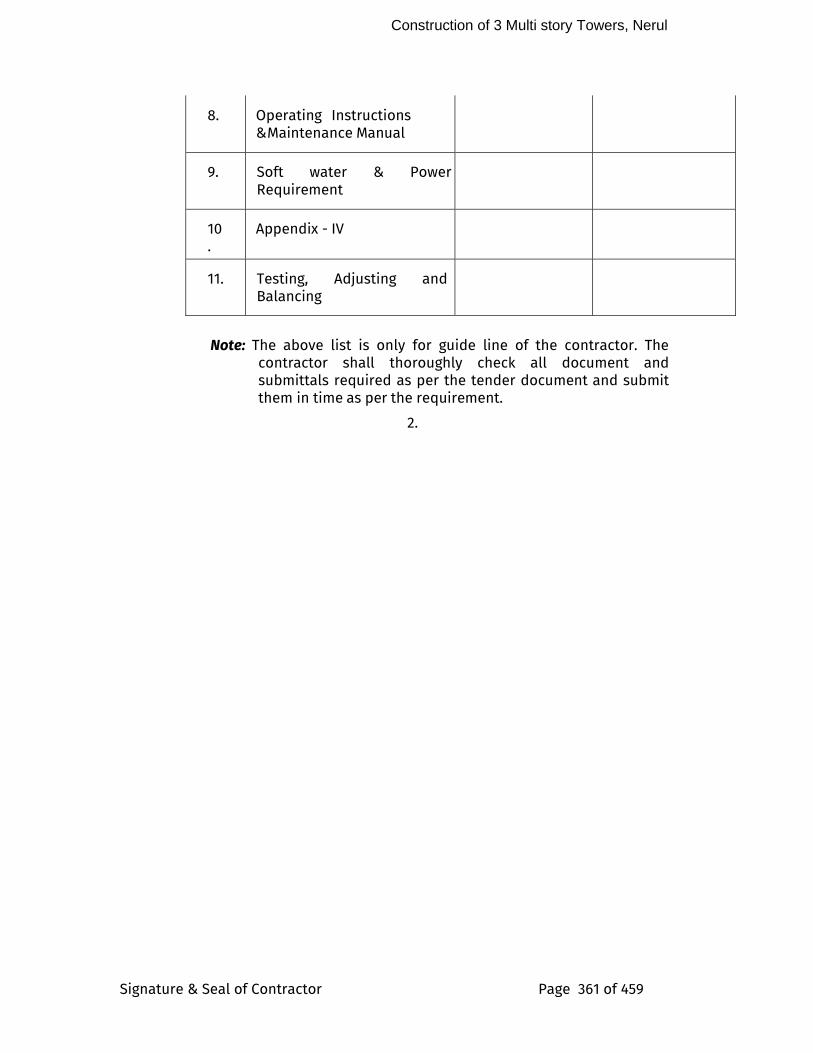
Construction of 3 Multi story Towers, Nerul
Signature & Seal of Contractor Page 361 of 459
8. Operating Instructions & Maintenance Manual
9. Soft water & Power Requirement
10.
Appendix - IV
11. Testing, Adjusting and Balancing
Note: The above list is only for guide line of the contractor. The
contractor shall thoroughly check all document and submittals required as per the tender document and submit them in time as per the requirement.
2.
Construction of 3 Multitoried Towers, Nerul
Signature & Seal of Contractor Page 362 of 459
6.
9
52.1
b.
i.
1.2.
6.
7.
3.

Construction of 3 Multitoried Towers, Nerul
Signature & Seal of Contractor Page 363 of 459
8.
Construction of 3 Multitoried Towers, Nerul
Signature & Seal of Contractor Page 364 of 459
Electrical Work
Construction of 3 Multitoried Towers, Nerul
Signature & Seal of Contractor Page 365 of 459
SECTION – 1.0
LOW VOLTAGE SWITCHGEAR & POWER PANELS
SCOPE
1.1 This scope covers design, manufacture, Installation, inspection and testing at manufacturer’s work of 415V AC Switchgear, packing, transportation and unloading at site.
Vendor shall undertake supervision of erection, testing and commissioning at site.
1.2 The Purchaser reserves the right to add / delete different types of Switchgear cubicles, breakers & accessories if found necessary. Unit prices quoted by bidder shall be binding for this purpose.
All the mounting accessories like base channel bolts etc. are included in the scope of supply.
2.0 CODES AND STANDARDS
2.1 The equipment shall comply in all respects with the requirements of this specification and the latest editions of the Codes and Standards and statutory regulations. In particular, all the breakers shall be in compliance with IEC-60947-2/IS-13947-2.
3.0 DESIGN AND PERFORMANCE REQUIRMENT
3.1.1 The 415V, 3 ph, 4 wire system power supply shall be through transformer/DG set of adequate rating. System neutral shall be solidly grounded.
3.2 The Bidder shall furnish type test certificate for different panels with bus bars of specified ratings, breakers, current transformers, voltage transformers, protective relays, switches, contactors and fuses etc., offered by him. The vendor shall also furnish the details and test certificates for the purity of copper being used for the bus bars in compliance with the India and Internal codes.
3.3 All the 415V AC, devices/equipment like bus support insulators, circuit breakers, VTs, etc. mounted inside the Switchgear shall be suitable for continuous operation and satisfactory performance under the following supply conditions.
i) Variation in supply voltage : +/- 5%
3.4 The Bidder shall furnish calculations along with the bid to establish the adequacy of the bus bar sizes to meet the continuous and short time current ratings specified. Continuous current ratings of the droppers in each vertical section shall be at least equal to the total load on the
Construction of 3 Multitoried Towers, Nerul
Signature & Seal of Contractor Page 366 of 459
complete vertical section. However, short time current rating of bus-bars shall be same as the short time current rating of the main bus bar.
3.5 The breaker ratings indicated in the Schematic diagrams refer to the nominal rating of the breaker. However breaker shall be capable of carrying continuously at least 120% of circuit current at an ambient temperature of 50 deg.C and with breaker mounted inside the panel. If a higher rated breaker is necessary to meet this, the same shall be offered.
3.6 Bus bars shall be made up of Copper and these shall be colour coded for easy identification.
3.7 Switchgear shall be suitable for easy extension on both sides.
3.8 Switchgear cubicles shall have a removable bottom plate of minimum 3-mm thickness.
3.9 All control and selector switches, indicating lamps shall be mounted on the front of the panel at a convenient height for operation.
3.10 Horizontal earth bus of Copper shall provided on all switchgears, which shall run throughout the length of the Switchgear. Vertical earth bus shall be provided in each vertical section.
3.11 System Description:
All Main MV panels and Main Fire Emergency Panels and other panels with a required “BMS” tag as mentioned in the boq/data sheet/drawing shall have a mini-PLC housed in a segregated compartment to provide status of on, off, trip & metering parameters to the Clients Central Monitoring system. The PLC shall take potential free contacts & metering signals from various ACB/MCCB modules and provide interface on RS-485 port with MOD BUS-RTU Protocol for the Client’s Central Monitoring system.
Note: Refer schematics For detailed specifications for individual panels.
3.12 CONSTRUCITON FEATURES
3.12.1 Switchgear shall be:
a) Of the metal enclosed, indoor, floor mounted modular type
b) Made up of the requisite vertical sections
c) Of dust and vermin proof construction with degree of protection, IP-52.
d) Easily extendable on both sides by the addition of vertical sections after removing the end covers
e) Provided with a metal sill frame made of structural steel channel section properly drilled for mounting the Switchgear along with necessary mounting hardware. Hardware shall be zinc plated and passivated.
Construction of 3 Multitoried Towers, Nerul
Signature & Seal of Contractor Page 367 of 459
f) Provided with cable entry facilitate at top/bottom as specified with 3mm thick removable gland plates on breaker panels and 2 mm thick removable gland plates on other panels with necessary cable glands. For 1-core cables, these plates shall be non-magnetic.
g) Provided with gaskets all round the perimeter, adjacent panels, panel and base frame, removable covers and doors.
h) Provided with bus-bars running at the top or bottom, as required, all along the length of the Switchgear in a separate sheet steel enclosure.
i) Fabricated from sheet steel 2mm thick for main body and frame and 1.6mm thick for doors/covers, free standing, flush dead front and of modular construction suitable for 3 phase 415V 4 wire 50 Hertz system. All boards shall be accessible from the front or as shown on Drgs and specified in the equipment data sheet, for the maintenance of switch fuses, busbars, cable terminations, meters etc.
j) Cables shall be capable of entering the board both from top as well as bottom. All panels shall be machine pressed with punched openings for meters etc. All sheet steel shall be rust inhibited through a process of degreasing, acid pickling, phosphating etc. The panels shall be finished with powder coating of approved colour applied over a primer. Labels shall be of anodized Aluminium with white engraving on black background shall be provided for each incoming and outgoing feeder of Main/Sub Distribution Panels.
k) The Panel shall accommodate air insulated bus bars, air circuit breakers, MCCB’s, switch fuse units with HRC fuses, starters, necessary meters, relays, contactors etc. as required and arranged in suitable tiers. All breakers and switch fuses shall be suitably over-rated enough taking into account specified ambient temperature and ruling temperature inside the cubicle.
l) The panel shall be fully compartmentalized in vertical tiers housing the feeder switches in totally enclosed independent compartments. Each compartment shall be self sufficient with switch unit, fuses, contactors, relays, indicating lamps and an inter-locked door with facility for padlocking. Each switch or MCCB or ACB shall have provision for locking in the OFF position for life safety. Each feeder must terminate in an independent labeled terminal block. Strip type terminal block accommodating several
Construction of 3 Multitoried Towers, Nerul
Signature & Seal of Contractor Page 368 of 459
feeders together is not acceptable. Pressure clamp type terminals suitable for copper wires may be used up to switches of 25A and cable lugs for higher ratings. All terminations shall be shrouded in an approved manner. The entire enclosure shall meet with IS: 2147/1962. Feeder connections shall be of solid insulated copper wires or strips with bimetallic clamps wherever required and if insulated, the insulation shall be able to withstand the high temp at the terminals. Internal wiring, bus bar markings etc. shall conform to IS:375/1963. Internal wiring shall have terminal ferrules. The labels shall be of anodized Aluminium with white engraving on black background shall be provided for each and every incoming and outing feeders of the main/sub/downstream distribution panels.
m) Main switch should be at an easily accessible height and the highest switch operating handle should not be over 1.75M from floor level. Cable glands shall form part of the switch board.
3.13 Main Buses & Taps
All bus bars, bus taps shall be insulated with heat shrinkable PVC to provide a permanent high dielectric non-aging and non-tracking protection; impervious to water, tropical conditions and fungi. The insulation shall be non-flammable and self-extinguishing and in fast colour to indicate phases. The joints shall be insulated in such a way as to provide for accessibility of contact bolts for maintenance. Joints shall be covered with removable moulded shrouds made out of fiberglass-reinforced polyester.
Bus bars shall be three phase and neutral and of copper only as specified and shown on drawings and rated for a temperature rise of 30 deg C over the maximum expected ambient temperature specified with last 20 years past history, (IS:8084-1976). Neutral bars may be of one half the size of the phase bars or as shown on drawings. As far as the computer power and UPS power distribution buses are concerned the neutral shall need to be sized for twice the size of phase maximum expected phase current irrespective of what has been mentioned in drawing or anywhere else. The main horizontal bus bars shall be of uniform cross section and rated for the incoming switch. The vertical bus bars for the feeder columns may be rated at 100% of aggregate feeder capacity and shall be uniform in size. Bus bars shall be totally enclosed, shrouded and supported on non-
Construction of 3 Multitoried Towers, Nerul
Signature & Seal of Contractor Page 369 of 459
hygroscopic insulator blocks to withstand thermal and dynamic overloads during system short circuits.
3.14 Auxiliary Buses
Auxiliary buses for control power supply, PT circuits and space heater power supply buses shall be insulated, and adequately sized to suit requirements. The material for auxiliary buses shall be electric grade copper confirming to relevant Indian standard.
3.15 Air Circuit Breakers
3.15.1 The circuit breaker shall be manually operated type but have facility for electrical closing and spring charging motor and shunt trip suitable for 240V A.C supply.
- ACB's shall be of draw out type, mounted along with its operating mechanism on a wheeled carriage moving on guides, designed to align correctly and allow easy movements.
- The following releases with adjustable settings shall be provided:
a) Overload
b) Short Circuit
c) Under voltage (delayed type)
d) Earth fault
ACB's shall be provided with:
15. mechanically operated targets to show ‘open’, ‘closed’, ‘service’ and ‘test’ positions of the circuit breaker.
16. mechanically operated, red ‘trip’ push button, shrouded to prevent accidental operation.
17. locking facilities in the ‘service’, ‘test’ and ‘isolated’, positions. In test position the breaker will be tested without energizing the power circuits. The breaker shall remain fully housed inside the compartment in the test position.
- 6 NO 6 NC potential free auxiliary contacts, rated 6A at 240V AC and 1A (included bearing) at 220V DC.
- ‘red’, ‘green’ and ‘amber’ indicating lamps to show ‘closed’ ‘open’ and ‘auto-trip’ conditions of the circuit breaker when breaker operation is controlled by a control switch.
Facilities shall be provided for blocking the under voltage release if so required at site.
Construction of 3 Multitoried Towers, Nerul
Signature & Seal of Contractor Page 370 of 459
Each of the releases mentioned above shall be provided with potential free alarm contact rated for 0.5A, 220V D.C.
3.15.2 Circuit breakers shall be provided with all necessary interlocks including the following interlocks:
18. It shall not be possible to plug-in a closed circuit breaker, or to draw out a circuit breaker in the closed position.
19. It shall not be possible to operate a circuit breaker unless it is in the fully plugged-in, test, or fully isolated position.
3.16 Moulded Case Circuit Breakers (MCCB):
MCCB’s shall be of four-pole construction arranged for simultaneous pole opening & closing operating mechanism shall be quick make quick break and trip free type. The ON/OFF & TRIP positions of the MCCB shall be clearly indicated and visible to the operator. Operating handle for operating MCCB’s form door of the board shall be provided.
MCCB Terminal shall be shrouded and designed to receive. Cable lugs for cable sizes relevant to circuit ratings.
Icu & Ics rating for the MCCB should be same.
3.17 Air Break Switches
20. Air beak switches shall be of the heavy-duty type, group operated, fault make load break type
21. Switch operating handle shall be suitable for padlocking in ‘off’ position and interlocked with associated compartment door.
3.18 Fuses
Fuses shall be of the HRC fuse link type with rupturing capacity of 80 kA at 440V.
3.19 Miniature Circuit Breakers (MCB)
MCB’s shall comply with the requirements of applicable standards.
3.20 Isolators
Isolators shall be fixed on wall on self-supported angle iron frame work as required and mounted as near to the motor as possible. Where several motors are installed, isolators if required shall be provided at a central location on a common frame work.
Painting, earthing and labels shall be provided as generally indicating for MV Switchgear and shown on drawings.
3.22 Instrument and Current Transformers
Construction of 3 Multitoried Towers, Nerul
Signature & Seal of Contractor Page 371 of 459
Current transformers shall be in conformity with IS: 2705 (Part I, II & III) in all respects. All current transformers used for medium voltage applications shall be rated for 1kv. Current transformers shall have rated primary current, rated burden and class of accuracy as required. However, the rated acceptable minimum class of various applications shall be as given below:
Measuring : Class 0.5 to 1
Protection : Class 5P10.
Current transformers shall be capable of withstanding without damage, magnetic and thermal stresses due to short circuit fault of 50KA on medium voltage system. Terminals of the current transformers shall be marked permanently for easy identification of poles. Separate CT shall be provided for measuring instruments and protection relays. Each C.T. shall be provided with rating plate.
Current transformers shall be mounted such that they are easily accessible for inspection, maintenance and replacement. The wiring for CT's shall be copper conductor, PVC insulated wires with proper termination lugs and wiring shall be bunched with cable straps and fixed to the panel structure in a neat manner.
Current transformers shall be of dry type with short time current rating equal to that of the associated Switchgear for 1.0 secs.for breaker feeders. For feeders with fuse, CTS shall have withstand capacity equal to the through current of associated fuse.
3.23 Voltage Transformers
Voltage transformers shall be of dry type and shall have continuous over voltage factor of 1.2 and short time over voltage factor of 1.5 for 30 seconds.
3.24 Measuring Instruments, Metering & Protection
GENERAL
Direct reading electrical instruments shall be in conformity with IS 1248. The accuracy of direct reading shall be 1.0 for voltmeter and 1.5 for ammeters. Other type of instruments shall have accuracy of 1.5. The errors
Construction of 3 Multitoried Towers, Nerul
Signature & Seal of Contractor Page 372 of 459
due to variations in temperature shall be limited to a minimum. The meter shall be suitable for continuous operation between-10 degree Centigrade to + 50 degree Centigrade. All meters shall be of flush mounting type of 96mm square or circular pattern. The meter shall be enclosed in a dust tight housing. The housing shall be of steel or phenolic mould. The design and manufacture of the meters shall ensure the prevention of fogging of instrument glass. Instruments meters shall be sealed in such a way that access to the measuring element and to the accessories within the case shall not be possible without removal of the seal. The meters shall be provided with white dials and black scale markings.
The pointer shall be black in colour and shall have zero position adjustment device which could be operated from outside. The direction of deflection shall be from left to right.
Suitable selector switches shall be provided for all ammeters and voltmeters intended to be used on three-phase supply.
The specifications herein after laid down shall also cover all the meters, instrument and protective devices required for the electrical work. The ratings type and quantity of meters, instruments and protective devices shall be as per the schedule of quantities.
AMMETERS
Ammeters shall be moving iron or moving coil type. The moving part assembly shall be with jewel bearing. The jewel bearing shall be mounted on a spring to prevent damage to pivot due to vibrations and shocks, the ammeters shall be manufactured and calibrated as per the latest edition of IS:1248. Ammeters shall be instrument transformer operated, and shall be suitable for 5A secondary of instrument transformer. The scales shall be calibrated to indicate primary current, unless otherwise specified. The ammeters shall be capable of carrying sustained overloads during fault conditions without damage or loss of accuracy.
VOLTMETERS
Voltmeter shall be of moving iron or moving coil type. The range for 415 volts, 3 phase voltmeters shall be 0 to 500 volts. Suitable selector switch shall be provided for each voltmeter to read voltage between any two lines of the system. The voltmeter shall be provided with protection fuse of suitable capacity.
Construction of 3 Multitoried Towers, Nerul
Signature & Seal of Contractor Page 373 of 459
4.0 EARTHING
4.1 Protective earthing shall be provided as shown on drawings or as follows:
----------------------------------------------------------------
Phase Protective
conductor conductor
----------------------------------------------------------------
upto 16 sqmm equal size
16 to 35 sqmm 16 sqmm
over 35 sqmm 50% of phase
conductor
In case of dissimilar materials the Protective Earth Conductor shall be suitably sized for equal conductance.
4.2 Protective earthing of each switch shall be connected to the earth bar.
5.0 START-UP AND RECOMMENDED SPARES
5.1 The BIDDER in his offer shall indicate the quantity of the spares. Any additional spares, if required, shall be listed and quoted for, along with the recommended quantities.
5.2 Recommended Spares
5.2.1 These are spares and consumables required for a three-year period based on estimates of the annual average consumption. The tender submission shall include under recommended spares the following:
a) Spares to be stored for three- (3) years operation period.
b) Any strategic spares or consumables, which the Contractor recommends the Purchaser to hold to avoid a delay in return to service following a breakdown. Justification for such holdings shall form part of the Tender submission.
5.2.2 The BIDDER in the “Schedule of Recommended Spares” shall indicate item wise price of each recommended spare.
6.0 SUPERVISION OF ERECTION, TESTING & COMMISSIONING
6.1 The VENDORS shall, if so desired by Purchaser, undertake supervision of erection, testing and commissioning. Charges as indicated against relevant
Construction of 3 Multitoried Towers, Nerul
Signature & Seal of Contractor Page 374 of 459
clause in the price schedule shall be inclusive of incidental expenses at site, lodging, boarding, local transport of Vendor’s engineer.
7 GUARANTEES
The VENDOR shall guarantee that the material and workmanship of the complete Switchgear with all accessories shall be of the best engineering practice and shall meet the requirements of the PURCHASER as indicated in this specification.
In respect of items/parameters guaranteed, should the test results deviate from the guaranteed values, the VENDOR shall correct his equipment at no extra cost to the PURCHASER and repeat the test within a reasonable period as agreed by the PURCHASER/ENGINEER. If the VENDOR is unable to meet the guarantees, the PURCHASER retains the option to reject the equipment and in case of such option of rejection being exercised, the VENDOR shall replace the entire equipment with one which will meet the guaranteed values and the PURCHASER shall have the right to retain the defective equipment in service till it is replaced.
8.0 TENDER EVALUATION
8.1 The BIDDER shall quote for all equipment and services as called for in this enquiry specification. The BIDDER shall comply with the requirements of specification. However if BIDDER is able to offer a more optimum solution which would meet the requirements and insert of specification, the same can be offered as an alternate to the base offer which shall be as per the specification.
8.2 Any and all deviations which the BIDDER have to this specification shall be clearly brought out under the respective schedule enclosed, failing which the offer will be deemed to meet all requirements of this specification. The deviations from the specifications/alternate offer acceptable to PURCHASER insofar as practicable will be converted into rupee value and added to the bid price to compensate deviations from specification, if required.
9.0 MODE OF MEASUREMENT
9.1 Each panel will be considered as one unit for the purpose of measurement and shall include the following:
i) Incoming and Outgoing feeders.
ii) Interconnections and controls and instrument wiring with necessary protective fuses.
iii) Meters, Relays, Indicating lamps, CT’s control fuses etc.
iv) Supporting structure, sheet steel enclosure
Construction of 3 Multitoried Towers, Nerul
Signature & Seal of Contractor Page 375 of 459
v) Installation and testing
9.2 Isolators shall each be measured as one unit complete with:
i) mounting frame
ii) switch/fuse
9.3 Protective earthing of the panel/Isolator from the equipment earthing system will be measured separately and paid at unit rates.
9.4 Outgoing and incoming feeder terminations will be paid at the unit rates separately as specified under cabling.
10.0 SUBMITTALS
Dimensions, Technical catalogue, weight , required clearances around enclosure and detailed wiring and GA diagrams .
a. Mounting and installation Method, Opening details
b. Wiring scheme, System programming
c. Installation procedure recommended by manufacturer.
d. Commissioning procedure recommended by manufacturer.
e. Test certificates of all the components
C. Post Commissioning and Handover
1. O & M Manual.
2. Manufacturer shall supply the following literature-
i. Integration into the panel, operation and Maintenance Instructions. ii. Installation Instructions iii. Field Wiring Diagrams iv. Maintenance manual showing maintenance required on daily,weekly,
monthly, semi-annually and annually basis. v. List of consumable items and recommended spare parts along with its
price list.
11.0 DELIVERY STORAGE AND HANDLING
1. LT switchgear and power panels should be shipped in completely protected package to panel factory for integration.
Construction of 3 Multitoried Towers, Nerul
Signature & Seal of Contractor Page 376 of 459
2. It should be fully covered to protect from dust/water, rust, and Corrosion.
3. It should be free from any sort of physical damage or so.
4. Loading and Unloading, shifting, handling should be done by trained team of experts only.
12.0 INSTALLATION
The installation will be carried out strictly as per the laid down procedure by the manufacturer. All wiring, terminations, installation into the panels as required etc., to be done by as per the Manual of installation practice approved by the manufacturer and relevant codes and standards to ensure the perfect quality and functionality.
All panels shall be supported on MS channels incorporated in the panel during the fabrication. All such supports shall be prime coated with two finish coats after completion of the work. All panels shall be touched up for damaged painting.
All panels shall be meggared phase to phase and phase to neutral using a 1000V meggar with all outgoing feeders in closed position. The meggar value should not be less than 2.5 megohms between phases and 1.5 megohms between phases and neutral.
Fabrication drawings of all panels shall be approved by the Consulting Engineers before fabrication.
13.0 Tests and Certification
All switchgears shall be factory inspected before finishing and dispatch unless waived .Supply price quoted by BIDDER shall be inclusive of all routine tests for the Switchgear and the components. All field tests shall be witnessed by Consultants and recorded unless waived. The PURCHASER reserves the right to witness any or all the tests for which atleast fifteen (15) days advance notice shall be by the vendor.
Certificate for all routine and type tests for circuit breakers in accordance with the IS:2516-1963 shall be furnished.
SECTION - 2.0
DISTRIBUTION BOARDS
1.0 SCOPE
1.1 The scope of work shall cover the supply, installation, testing and commissioning of lighting and power distribution boards. Associated
Construction of 3 Multitoried Towers, Nerul
Signature & Seal of Contractor Page 377 of 459
minor civil works required for the erection of the DB’s such as opening in wall etc. are also included in the scope of this contract.
2.0 STANDARDS
2.1 The following standards and rules shall be applicable:
1) IS:2675-1983 Enclosed distribution fuse boards and cutouts for Voltages not exceeding 1000V.
2) IS:375-1963 Marking and arrangement of Switchgear busbars main connections and auxiliary wiring.
3) IS:8828-1978 Miniature circuit Breakers
4)
IS:2607-1976
Air break Isolators for voltages not exceeding 1000V.
5)
IS:9926-1981
Fuse wire used in Rewirable type Electric fuses up to 650 volts.
6) Indian Electricity Act 1910 and rules issued there under.
7) Indian Electricity Rules 1956, The Electricity Act 2003
8) The Energy Conservation act 2001.
2.2 All codes and standards mean the latest. Where not specified otherwise the installation shall generally follow the Indian Standard Codes of Practice.
3.0 DISTRIBUTION BOARDS
3.1 Distributions boards along with the controlling MCB’s or Isolator as shown shall be fixed in a mild steel Box with hinged lockable door suitable for recessed mounting in wall. Distribution boards shall be made of 16 SWG sheet steel duly rust inhibited through a process of degreasing, acid pickling, phosphating and powder coated to an approved colour over a primer.
3.2 All components shall be mounted on DIN rails and covered totally with a sheet steel cover rendering it finger-safe. Access to the internal connections shall be only through removing the cover sheet.
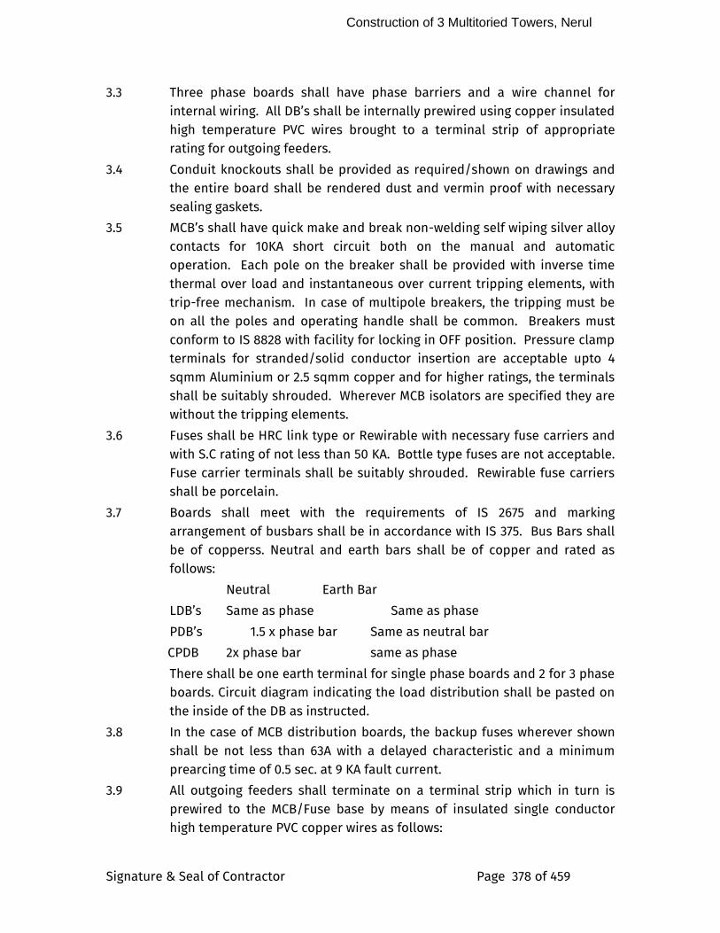
Construction of 3 Multitoried Towers, Nerul
Signature & Seal of Contractor Page 378 of 459
3.3 Three phase boards shall have phase barriers and a wire channel for internal wiring. All DB’s shall be internally prewired using copper insulated high temperature PVC wires brought to a terminal strip of appropriate rating for outgoing feeders.
3.4 Conduit knockouts shall be provided as required/shown on drawings and the entire board shall be rendered dust and vermin proof with necessary sealing gaskets.
3.5 MCB’s shall have quick make and break non-welding self wiping silver alloy contacts for 10KA short circuit both on the manual and automatic operation. Each pole on the breaker shall be provided with inverse time thermal over load and instantaneous over current tripping elements, with trip-free mechanism. In case of multipole breakers, the tripping must be on all the poles and operating handle shall be common. Breakers must conform to IS 8828 with facility for locking in OFF position. Pressure clamp terminals for stranded/solid conductor insertion are acceptable upto 4 sqmm Aluminium or 2.5 sqmm copper and for higher ratings, the terminals shall be suitably shrouded. Wherever MCB isolators are specified they are without the tripping elements.
3.6 Fuses shall be HRC link type or Rewirable with necessary fuse carriers and with S.C rating of not less than 50 KA. Bottle type fuses are not acceptable. Fuse carrier terminals shall be suitably shrouded. Rewirable fuse carriers shall be porcelain.
3.7 Boards shall meet with the requirements of IS 2675 and marking arrangement of busbars shall be in accordance with IS 375. Bus Bars shall be of copperss. Neutral and earth bars shall be of copper and rated as follows:
Neutral Earth Bar
LDB’s Same as phase Same as phase
PDB’s 1.5 x phase bar Same as neutral bar
CPDB 2x phase bar same as phase
There shall be one earth terminal for single phase boards and 2 for 3 phase boards. Circuit diagram indicating the load distribution shall be pasted on the inside of the DB as instructed.
3.8 In the case of MCB distribution boards, the backup fuses wherever shown shall be not less than 63A with a delayed characteristic and a minimum prearcing time of 0.5 sec. at 9 KA fault current.
3.9 All outgoing feeders shall terminate on a terminal strip which in turn is prewired to the MCB/Fuse base by means of insulated single conductor high temperature PVC copper wires as follows:
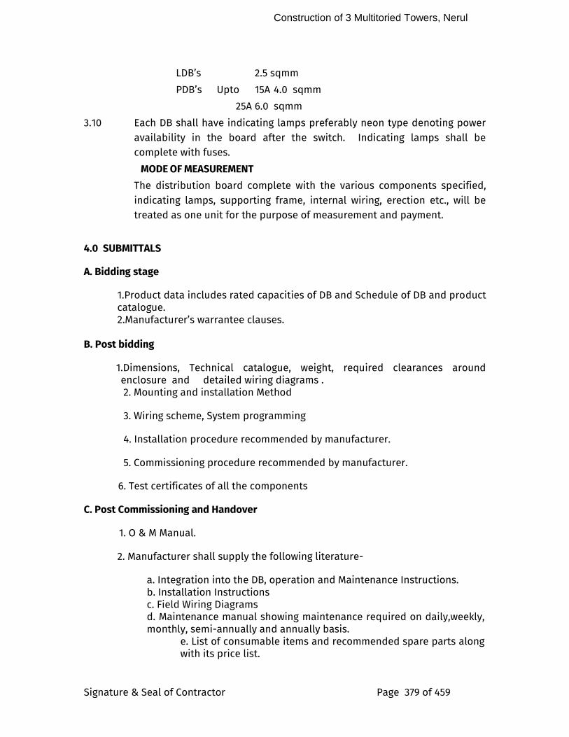
Construction of 3 Multitoried Towers, Nerul
Signature & Seal of Contractor Page 379 of 459
LDB’s 2.5 sqmm
PDB’s Upto 15A 4.0 sqmm
25A 6.0 sqmm
3.10 Each DB shall have indicating lamps preferably neon type denoting power availability in the board after the switch. Indicating lamps shall be complete with fuses.
MODE OF MEASUREMENT
The distribution board complete with the various components specified, indicating lamps, supporting frame, internal wiring, erection etc., will be treated as one unit for the purpose of measurement and payment.
4.0 SUBMITTALS
A. Bidding stage
1.Product data includes rated capacities of DB and Schedule of DB and product catalogue. 2.Manufacturer’s warrantee clauses.
B. Post bidding
1.Dimensions, Technical catalogue, weight, required clearances around enclosure and detailed wiring diagrams . 2. Mounting and installation Method
3. Wiring scheme, System programming
4. Installation procedure recommended by manufacturer.
5. Commissioning procedure recommended by manufacturer.
6. Test certificates of all the components
C. Post Commissioning and Handover
1. O & M Manual.
2. Manufacturer shall supply the following literature-
a. Integration into the DB, operation and Maintenance Instructions. b. Installation Instructions c. Field Wiring Diagrams d. Maintenance manual showing maintenance required on daily,weekly, monthly, semi-annually and annually basis.
e. List of consumable items and recommended spare parts along with its price list.
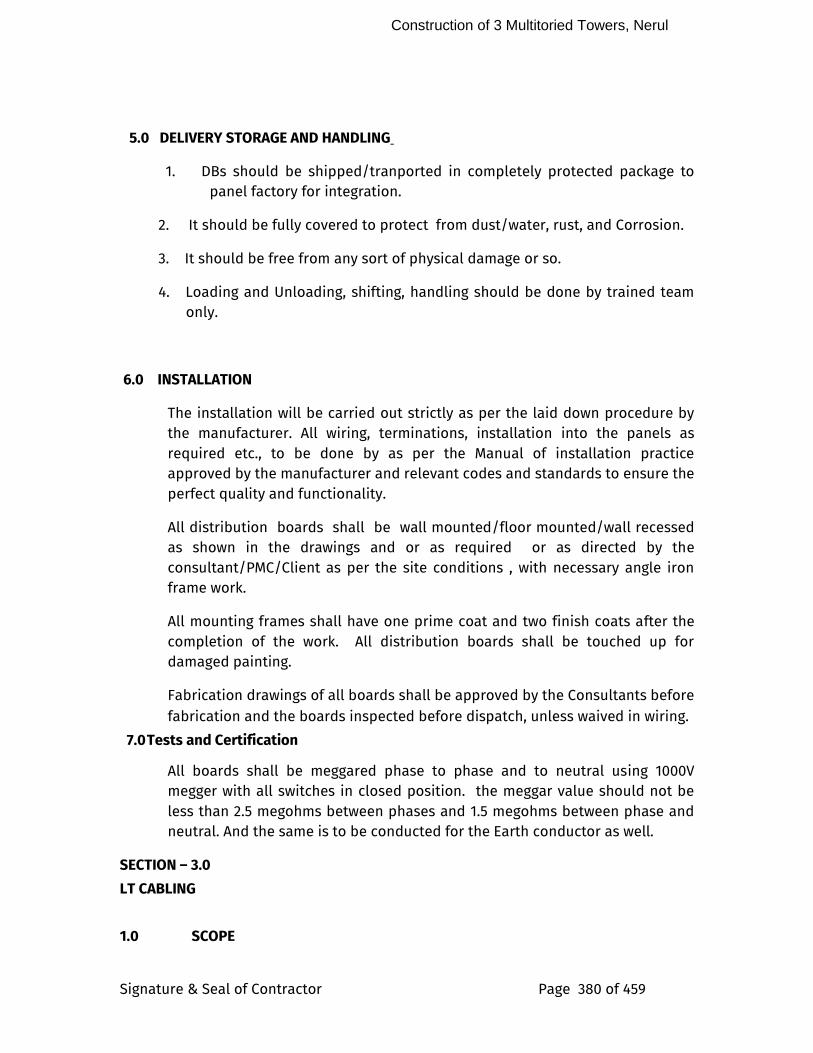
Construction of 3 Multitoried Towers, Nerul
Signature & Seal of Contractor Page 380 of 459
5.0 DELIVERY STORAGE AND HANDLING
1. DBs should be shipped/tranported in completely protected package to panel factory for integration.
2. It should be fully covered to protect from dust/water, rust, and Corrosion.
3. It should be free from any sort of physical damage or so.
4. Loading and Unloading, shifting, handling should be done by trained team only.
6.0 INSTALLATION
The installation will be carried out strictly as per the laid down procedure by the manufacturer. All wiring, terminations, installation into the panels as required etc., to be done by as per the Manual of installation practice approved by the manufacturer and relevant codes and standards to ensure the perfect quality and functionality.
All distribution boards shall be wall mounted/floor mounted/wall recessed as shown in the drawings and or as required or as directed by the consultant/PMC/Client as per the site conditions , with necessary angle iron frame work.
All mounting frames shall have one prime coat and two finish coats after the completion of the work. All distribution boards shall be touched up for damaged painting.
Fabrication drawings of all boards shall be approved by the Consultants before fabrication and the boards inspected before dispatch, unless waived in wiring.
7.0 Tests and Certification
All boards shall be meggared phase to phase and to neutral using 1000V megger with all switches in closed position. the meggar value should not be less than 2.5 megohms between phases and 1.5 megohms between phase and neutral. And the same is to be conducted for the Earth conductor as well.
SECTION – 3.0
LT CABLING
1.0 SCOPE
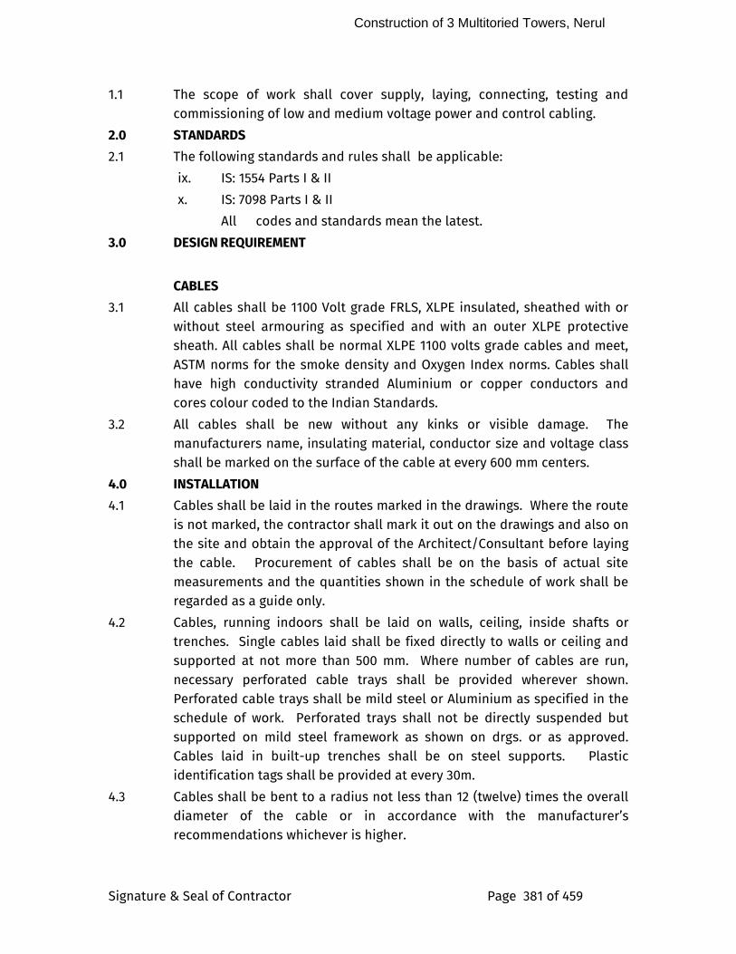
Construction of 3 Multitoried Towers, Nerul
Signature & Seal of Contractor Page 381 of 459
1.1 The scope of work shall cover supply, laying, connecting, testing and commissioning of low and medium voltage power and control cabling.
2.0 STANDARDS
2.1 The following standards and rules shall be applicable:
ix. IS: 1554 Parts I & II
x. IS: 7098 Parts I & II
All codes and standards mean the latest.
3.0 DESIGN REQUIREMENT
CABLES
3.1 All cables shall be 1100 Volt grade FRLS, XLPE insulated, sheathed with or without steel armouring as specified and with an outer XLPE protective sheath. All cables shall be normal XLPE 1100 volts grade cables and meet, ASTM norms for the smoke density and Oxygen Index norms. Cables shall have high conductivity stranded Aluminium or copper conductors and cores colour coded to the Indian Standards.
3.2 All cables shall be new without any kinks or visible damage. The manufacturers name, insulating material, conductor size and voltage class shall be marked on the surface of the cable at every 600 mm centers.
4.0 INSTALLATION
4.1 Cables shall be laid in the routes marked in the drawings. Where the route is not marked, the contractor shall mark it out on the drawings and also on the site and obtain the approval of the Architect/Consultant before laying the cable. Procurement of cables shall be on the basis of actual site measurements and the quantities shown in the schedule of work shall be regarded as a guide only.
4.2 Cables, running indoors shall be laid on walls, ceiling, inside shafts or trenches. Single cables laid shall be fixed directly to walls or ceiling and supported at not more than 500 mm. Where number of cables are run, necessary perforated cable trays shall be provided wherever shown. Perforated cable trays shall be mild steel or Aluminium as specified in the schedule of work. Perforated trays shall not be directly suspended but supported on mild steel framework as shown on drgs. or as approved. Cables laid in built-up trenches shall be on steel supports. Plastic identification tags shall be provided at every 30m.
4.3 Cables shall be bent to a radius not less than 12 (twelve) times the overall diameter of the cable or in accordance with the manufacturer’s recommendations whichever is higher.
Construction of 3 Multitoried Towers, Nerul
Signature & Seal of Contractor Page 382 of 459
4.4 In the case of cables buried directly in ground, the cable route shall be parallel or perpendicular to roadways, walls etc. Cables shall be laid on an excavated, graded trench, over a sand or soft earth cushion to provide protection against abrasion. Cables shall be protected with brick or cement titles as shown on drgs. Width of excavated trenches shall be as per drawings. Backfill over buried cables shall be with a minimum earth cover of 600mm. The cables shall be provided with cable markers at every 35 meters and at all loop points.
4.5 The general arrangement of cable laying is shown on drawings. All cables shall be full runs from panel to panel without any joints or splices. Cables shall be identified at end terminations indicating the feeder number and the Panel/Distribution board from where it is being laid. All cable terminations for conductors upto 4 sq.mm may be insertion type and all higher sizes shall have tinned copper compression lugs. Cable terminations shall have necessary brass glands and all joints shall be double compression type whether so specified or not. The end terminations shall be insulated with a minimum of six half-lapped layers of PVC tape. Cable armouring shall be earthed at both ends.
5.0 CABLE TRAYS
5.1 Cable carrier system shall comprise of fabricated Aluminium painted MS cable trays made out of 2 mm thick perforated sheet metal or as may be specified in SLD/ BOQ/Data sheets.
j. The construction of the cable trays shall be as per the site requirement and generally in line with the drawings enclosed.
k. The cable tray shall be suspended from the ceiling slab with the help of 10mm dia MS rounds or 25mm x 5mm flats at specified spacing as per CPWD General Specification of Electrical Work Part II -1994. Flat type suspenders may be used for channels upto 450mm width bolted to cable trays. Round suspenders shall be threaded and bolted to the cable trays or to independent support angles 50mm x 50mm x 5mm at the bottom end as specified. These shall be grouted to the ceiling slab at the other end through an effective means, as approved by the PMC/Consultant to take the weight of the cable tray with the cables.
6.0 CABLE STORAGE
6.1 Cables should be stored in a dry covered place to prevent exposure to climate conditions and wear and tear of wooden drums and it should be preferably concrete surface.
Construction of 3 Multitoried Towers, Nerul
Signature & Seal of Contractor Page 383 of 459
6.2 All drums should be stored in such a manner as to leave sufficient space between them for air circulation. It is desirable for drums to stand on battens directly placed under the flange. In no case should the drums be stored “on the flat” i.e. flange horizontal.
6.3 Both ends of the cables shall be properly sealed with PVC/Rubber caps so as to prevent ingress of water, moisturisation of cores and armors during transportation, storage and erection.
6.4 On receipt of cable drums visual inspection of drums should be carried out.
6.5 While unloading the cables certain precautions are to be taken to ensure the safety of cables.
6.6 The cable drums should not be dropped or thrown from the trucks/railway wagons etc. during unloading operations as shock may cause serious damage to cable layers.
6.7 A crane may be used for unloading cable drums.
6.8 While lifting the cable drums with crane, it is recommended that the lagging should be left in place to prevent the flanges from crushing on the cables.
6.9 If crane is not available a ramp should be prepared with approximate inclination of 1: 3 or 1: 4. The cable drums should be rolled over the ramp by means of ropes and winches.
6.10 Additionally a sand bed at the foot of the ramp may be prepared to brake the rolling of the cable drum.
6.11 Cable should not be dragged along the earth surface.
v. Drums should be rolled in the direction of arrow only.
7.0 CABLE GLANDS
7.1 All cable glands shall be made out of brass.
7.2 For all out door panels cable glands shall be of double compressions type.
8.0 CABLE LUGS
8.1.0 Termination/ Joining of power and control cables shall be done by means of compression methods using solder less tinned copper or Aluminum terminal lugs.
8.2.0 For control cables terminations, ring tongue or reducer pin type lugs shall be used to suit the purpose.
9.0 CABLE LAYING
9.1 For laying of cables special care is to be taken to prevent sharp bending, kinking, twisting.
Construction of 3 Multitoried Towers, Nerul
Signature & Seal of Contractor Page 384 of 459
9.2 Cable should be unwound from drum by proper mounting the cable drum on a cable wheel making sure the spindle is strong enough to carry the weight without bending and that it is lying horizontally in the bearings, so as to prevent the drum creeping to one side or the other, while it is rotating.
9.3 The maximum safe pulling force (when pulled by pulling eye) proper and safe method of pulling of cable should be used depending upon the site conditions to avoid any kind of damage to the cables. Following pulling forces to be noted.
6. Aluminum Conductor cables : 3.0 Kg/mm2
7. Copper conductor cables : 5 Kg/mm2
9.4 Special care is to be taken while laying cable at bends. Following are the recommended bending radius for power and control cables.
Sr. No.
Voltage rating in KV
PVC/XLPE Cables
Multi Core Single Core
1. Up to 1.1 12 D 15 D
2. Above 1.1 to 33 KV
15 D 15 D
D = D is over all diameter of cable.
9.5 Underground Cable Laying
9.5.1 If the cables are to be buried directly in the ground IS: 1255 is to be followed for code of practice.
9.5.2 Generally cables shall be laid 1200 mm below finished ground level at any point of cable run.
9.5.3 After the cable trench has been properly excavated and straightened, it shall be covered with 100 mm thick layer of sand, the cable is then lifted and placed over the sand cushion. Again the cable shall be covered with a sand layer of 100 mm thick.
9.5.4 Over this sand layer a layer of RCC tiles (450 x 230 x 65-50 mm) shall be laid. RCC tiles shall be as per IS-5820 and with marking of the Client and the rating of the cable.
9.5.5 Cable trenches shall then be back filled with earth, concrete of suitable grade.
9.5.6 Direction of run of the cables shall be installed at 25 meters intervals and marking must be done in all bends.
Construction of 3 Multitoried Towers, Nerul
Signature & Seal of Contractor Page 385 of 459
9.5.7 In loose soil or at all road crossings, concrete pillar or hume pipes shall be provided.
9.6 Laying of Cables in Cable trays
9.6.1 For laying cables, power cables to be placed at the bottom most layer and control cables at the top most layer.
9.6.2 In case of multi core power cables, cables shall be laid side by side with spacing not less than one cable diameter.
9.6.3 Multicore cables shall be clamped by means of mild steel galvanized saddles.
9.6.4 All cables below 1.1 KV single core cables if any should be clamped by means of non-magnetic saddles.
9.6.5 The saddles / clamps shall not be placed at the intervals more than 1500 mm for horizontal and 1200 mm for vertical runs.
9.6.6 Multi core control cables can be laid touching each other in cable racks and wherever required may be taken in two layers. These cables should be clamped by means of PVC straps for horizontal and vertical runs. Fabricated aluminum clamps may be used at regular intervals.
10.0 MODE OF MEASUREMENT
10.1 Cable will be measured on the basis of a common rate per unit length indoor or outdoor and shall include the following:
For cables laid indoors :
i) Cables and clamps
ii) Installation, commissioning and testing
iii) Cable marking
OR
For cable buried underground :
i) Cables and protective bricks & tiles
ii) Installation, commissioning & testing
iii) Cable markers
10.2 Cable trays/racks will be measured on the basis of unit length for individual sizes and shall include
i) Aluminium painted MS cable tray with all supporting structural angles/supports, clamps, anchor fastener etc., shall be in totality measured under Per meter basis and paid.
10.3 Each cable termination will be measured as one unit for payment. Certain cable sizes are grouped together and rates shall be furnished against each group. The item shall include the following:
Construction of 3 Multitoried Towers, Nerul
Signature & Seal of Contractor Page 386 of 459
i) Lugs, glands, bolts, nuts
ii) All jointing materials
iii) Installations, testing and commissioning
iv) Earthing the glands
10.4 For cables buried underground, excavation shall be paid for additionally for the following per unit volume :
i) Excavation and back filling
ii) 6” Soft Earth Cushioning below and above cable
The cost of laying protective tiles shall be part of cable cost as stated above.
11.0 SUBMITTALS
A. Bidding stage
1.Product data includes rated capacities of cables, derating factors, ampacity etc., , 2.Manufacturers warrantee clauses.
B. Post bidding
1.Dimensions, Technical catalogue, weight , required clearances between cables, cable schedule .
2. Mounting and installation Method
3. Cable schedule with feeder details
4. Installation procedure recommended by manufacturer.
5. Commissioning procedure recommended by manufacturer.
6. Test certificates of all the components
C. Post Commissioning and Handover
1. O & M Manual.
2. Manufacturer catalogues, test certificates, cable routing and schedule.
5.0 DELIVERY STORAGE AND HANDLING
1. MV cabling, Cable Trays etc., should be transported in completely protected package to panel factory for integration.
2. It should be fully covered to protect from dust/water, rust, and Corrosion.
3. It should be free from any sort of physical damage or so.
Construction of 3 Multitoried Towers, Nerul
Signature & Seal of Contractor Page 387 of 459
4. Loading and Unloading, shifting, handling should be done by trained team only.
6.0 INSTALLATION
As explained in the respective section above.
7.0 Tests and Certification
MV cables shall be tested upon installation with a 1000V Meggar and the following readings established:
1) Continuity on all phases
2) Insulation Resistance
(a) between conductors
xi. all conductors and ground
xi. Earth test
All test readings shall be recorded and shall form part of the completion documentation.
SECTION: 2.7
POINT WIRING
1.0 SCOPE
The scope of work shall cover supply, installation testing and commissioning of all Point wiring Work. All points shall include necessary circuit mains from distribution boards up to switch boards as specified, point wiring up to points locations from switchboard, switch, switch sockets & boxes with switch plates as specified, Connector, ceiling rose or brass light holder as required at point location.
2.0 STANDARDS
2.1 The following standards and rules shall be applicable
1) IS : 732 Code of Practice for Electrical wiring installation (System voltage not exceeding 650V)
2) IS : 1646 Code of Practice for fire safety of building (General) Electrical Installation.
3) IS : 1653 Rigid steel conduits for electrical wiring
Construction of 3 Multitoried Towers, Nerul
Signature & Seal of Contractor Page 388 of 459
4) IS : 2667 Fittings for rigid steel conduits for electrical wiring
5) IS : 3480 Flexible steel conduits for electrical wiring
6) IS : 3837 Accessories for rigid steel conduit for electrical wiring
7) IS : 694 PVC insulated cables
8) IS : 2509 Rigid non-metallic conduits for Electrical wiring
9) IS : 6946 Flexible (Pliable) non-metallic conduits for electrical installation
10) IS : 1293 3 pin plugs and sockets
11) IS : 8130 Conductors for insulated electric cables and flexible cord
12) IS : 9537 -
1980
Specification for conduits for Electrical installations
13) Indian Electricity Act 1910 and rules issued there-under.
– Regulations for the electrical equipment in buildings issued by the Tariff Advisory Committee of the Insurance Association of India.
– Indian Electricity Rules,1956
2.2 All standards and codes mean the latest.
3.0 CONDUITS; ACCESSORIES & JOINTS: 3.1 SURFACE CONDUITING:
The surface conduits shall be fixed with help of 20 SWG saddles on spacers at every 600mm for vertical run and every 450 mm for horizontal run. The runs shall be straight with pull boxes and inspection type bends as required. Contractors are required to provide suitable sleeves for structural member crossing at the time of casting. No elbows shall be allowed.
In case of false ceilings the conduits shall run on walls/trusses/slabs above false ceiling level as far as possible. The connections between such runs and fixtures shall be made with flexible conduits.
Contractor to use spacers on thermocol for fixing of services. Cutting in under deck insulation is not allowed.
3.2 CONCEALED CONDUITING:
Construction of 3 Multitoried Towers, Nerul
Signature & Seal of Contractor Page 389 of 459
The concealed conduit work shall be carried out along with construction of walls prior to plaster. The work covers chasing walls with wall cutters only if necessary, fixing the conduits, boxes, and accessories, redoing the damaged surface using chicken mesh. All horizontal conduit runs shall be straight at wall point light level to necessary junction/pull boxes and then straight vertical drop to switch box if necessary. Stanted of sets on walls shall be avoided.
The conduits shall be laid such that they are little below the brick level to avoid cracks. Elbow shall not be used and bends shall be avoided as far as possible using offsets. Pull boxes shall be provided at suitable locations. All necessary sleeves shall be provided in beams, columns, prior to casting. Deep junction boxes only shall be used in slabs.
The pull and junction boxes shall not be clustered at one place and shall be so arranged that they should not be easily seen from heavy movement areas. All care shall be taken to secure joints and boxes in place. All vertical runs shall be sealed at top, while masonry civil works going on. Conduit with 25mm dia. minimum shall be used be used for all concealed work.
Generally in areas with false ceiling conduits will not be concealed in slab but will be concealed below false ceiling area. Conduits above false ceiling in such cases shall run with proper supports / suspenders. Conduits shall not be rested on false ceiling grid in any case. Flexible conduits shall not be used in concealed work.
All Mains & Submains Conduit Run in Slab at the time of construction
Maximum number of PVC insulated 650/1100 V grade copper conductor cable conforming to IS : 694 – 1990
-------------------------------------------------------------------------------------- Nominal 25mm 32mm 38mm 51mm 64mm
Cross Sectional area of conductor in Sq mm. S B S B S B S B S B
-------------------------------------------------------------------------------------- 1 4 5 6 7 8 9 10 11 12 13
--------------------------------------------------------------------------------------- 1.5 10 8 18 12 - - - - - - 2.5 8 6 12 10 - - - - - - 4 6 5 10 8 - - - - - -
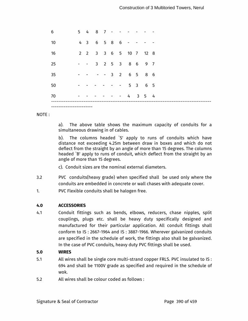
Construction of 3 Multitoried Towers, Nerul
Signature & Seal of Contractor Page 390 of 459
6 5 4 8 7 - - - - - - 10 4 3 6 5 8 6 - - - - 16 2 2 3 3 6 5 10 7 12 8
25 - - 3 2 5 3 8 6 9 7
35 - - - - 3 2 6 5 8 6
50 - - - - - - 5 3 6 5
70 - - - - - - 4 3 5 4
----------------------------------------------------------------------------------------------------------------
NOTE :
a). The above table shows the maximum capacity of conduits for a simultaneous drawing in of cables.
b). The columns headed `S' apply to runs of conduits which have distance not exceeding 4.25m between draw in boxes and which do not deflect from the straight by an angle of more than 15 degrees. The columns headed `B' apply to runs of conduit, which deflect from the straight by an angle of more than 15 degrees.
c). Conduit sizes are the nominal external diameters.
3.2 PVC conduits(heavy grade) when specified shall be used only where the conduits are embedded in concrete or wall chases with adequate cover.
1. PVC Flexible conduits shall be halogen free.
4.0 ACCESSORIES
4.1 Conduit fittings such as bends, elbows, reducers, chase nipples, split couplings, plugs etc. shall be heavy duty specifically designed and manufactured for their particular application. All conduit fittings shall conform to IS : 2667-1964 and IS : 3887-1966. Wherever galvanized conduits are specified in the schedule of work, the fittings also shall be galvanized. In the case of PVC conduits, heavy duty PVC fittings shall be used.
5.0 WIRES
5.1 All wires shall be single core multi-strand copper FRLS. PVC insulated to IS : 694 and shall be 1100V grade as specified and required in the schedule of wok.
5.2 All wires shall be colour coded as follows :
Construction of 3 Multitoried Towers, Nerul
Signature & Seal of Contractor Page 391 of 459
PHASE COLOUR OF WIRE
R Red
Y Yellow
B Blue
N Black
Earth Green (insulated)
Control (if any) Grey
6.0 SWITCHES & SOCKETS
6.1 Switches shall be moulded plate type of modular design with White-plated contacts. Sockets shall be 3/5 pin with switch and plate type cover. All switch & socket mounting boxes shall be 1.4mm thick galvanized steel or PVC specially made for the switches and sockets used. Combination of multiple switch units and sockets should be used in appropriate manner to minimize the switch boxes.
6.2 Weather and water proof switches / sockets of approved make shall be used in all out door situations and bath rooms.
6.3 For heavy duty industrial applications, industrial type of sockets with a pad lockable switch in a suitable galvanized steel box/fire retarded toughened plastic box shall be used.
7.0 INSTALLATION
7.1 The size of conduit shall be selected in accordance with the number of wires permitted under table given below. The minimum size of the conduit shall be 20 mm dia unless otherwise indicated or approved. Size of wires shall be not less than 1.5 mm copper or 2.5 sq. mm Aluminium, but shall be as specified in the schedule of work.
7.2 Conduits shall be kept at a minimum of 100 mm from the pipes of other non-electrical services.
7.3 Separate conduits / raceways shall be used for each of the following :
1) Normal lights and 5A 3 pin sockets on lighting circuit
2) Power outlets - 10A 3 or 16A or 20A industrial outlets.
3) Emergency lighting
4) Telephones
5) Fire alarm system, Public address system
6) Call bell wiring
7.4 Shop drawing for Conduit layout shall be prepared by the contractor taking into account the site conditions and got approved before proceeding with the work. Wiring for short extensions to outlets in hung ceiling or to
Construction of 3 Multitoried Towers, Nerul
Signature & Seal of Contractor Page 392 of 459
vibrating equipments, motors etc., shall be installed in flexible conduits. No flexible extension shall exceed 1.25m in length.
7.5 Conduits run on surfaces shall be supported on galvanized steel 6 mm thick saddles which in turn are properly screwed to the wall or ceiling. Saddles shall be at intervals of not more than 500 mm. Fixing screws shall be with round or cheese head and of cadmium plated brass. Exposed conduits shall be neatly run parallel or at right angles to the walls of the building. Unseemly conduit bends and offsets shall be avoided by using fabricated galvanized steel junction/pull through boxes for better appearances. No cross-over of conduits shall be allowed unless it is necessary and entire conduit installation shall be clean and neat in appearance.
7.6 Conduits embedded into the walls shall be fixed by means of staples at not more than 500 mm intervals. Chases in the walls shall be neatly made and refilled after laying the conduit and brought to the finish of the wall but final finish will be done by the building contractor.
7.7 Conduits buried in concrete structure shall be put in position and securely fastened to the reinforcement and got approved by the Engineer, before the concrete is poured. Proper care shall be taken to ensure that the conduits are neither dislocated nor choked at the time of pouring the concrete. Suitable galvanized steel fish wires of not less than 0.63 mm dia shall be drawn in all conduits before they are embedded. Where conduit passes through expansion joints in the building, adequate expansion fittings shall be used to take care of any relative movement.
7.8 Inspection boxes shall be provided for periodical inspection to facilitate withdrawal and removal of wires. Such inspection boxes shall be flush with the wall or ceiling in the case of concealed conduits. Inspection boxes shall be spaced at not more than 12 meters apart or two 90 degree solid bends or equal. All junction and pull boxes shall be covered by 6mm clear Perspex plate truly cut and fixed with cadmium plated brass screws. These junction boxes shall form part of point wiring or conduit wiring including the cost of removing the Perspex cover for painting and refixing. No separate charges shall be allowed except where specially mentioned.
7.9 Conduits shall be free from sharp edges and burs and the threading free from grease or oil. The entire system of conduits must be completely installed and rendered electrically continuous before the conductors are pulled in. Conduits should terminate in junction boxes of not less than 32mm deep and the termination shall be rigid with check nuts and a smooth bushing. No wires shall be exposed in any part of the installation.
Construction of 3 Multitoried Towers, Nerul
Signature & Seal of Contractor Page 393 of 459
7.10 An insulated earth wire of not less than 2.5 sq.m copper shall be run in each conduit as specified in the schedule of work.
8.0 LIGHTING & POWER WIRING
8.1 All final branch circuits for lighting and appliances shall be single conductor cables run inside conduits. The conduit shall be properly threaded and screwed into sockets, bends, junction boxes. No part of the wiring shall be open without a suitable conduit piping.
8.2 Branch circuit conductor sizes shall be as shown in the schedule of quantities and or drawings.
8.3 Final branch circuits shall preferably be kept in a separate conduit upto the Distribution Board. No other wiring shall be bunched in the same conduit except those belonging to the same phase. Each lighting branch circuit shall be loaded conservatively so that the circuit current is substantially lower than the current carrying capacity of the conductor or as shown on drawings. Each conduit shall not hold more than three branch circuits.
8.4 Flexible cords for connection to appliances, fans and pendants shall be 650/1100V grade (three or four cores i.e. with insulated neutral wire of same size) with tinned stranded copper wires, insulated, twisted and sheathed with strengthening cord. Colour of sheath shall be subject to the Engineer’s approval.
8.5 Looping system of wiring shall be used. Wires shall not be jointed. Where joints are unavoidable, they shall be made through approved mechanical connectors. No such joints shall be made unless the length of the sub circuit, sub main or main is more than the length of the standard coil.
8.6 Control switches shall be connected in the phase conductors only and shall be ‘ON’ when knob is down. Switches shall be fixed in 3 mm thick galvanized steel boxes with cover plates as specified. Cadmium plated brass screws shall be used.
8.7 Power wiring shall be distinctly separate from lighting wiring. Conduits not less than 25 mm and wires not less than 2.5 sqmm copper shall be used as specified in the schedule of work.
8.8 Every conductor shall be provided with identification ferrules at both ends matching the drawings.
9.0 MODE OF MEASUREMENT
9.1 The definition of point wiring shall be in accordance with sketch drawing
Construction of 3 Multitoried Towers, Nerul
Signature & Seal of Contractor Page 394 of 459
9.2 The final sub-circuit wiring commencing from the distribution board till the first switch box or light fitting shall be considered as a Primary circuit point.
9.3 Secondary point should include wiring from Primary circuit point onwards together with all junction boxes, connectors, earth wire, fixing accessories, connection to all light fittings switches etc. as specified and shown on drawings.
9.4 All switches sockets with boxes, inter connections, earthing shall be paid for per unit of 1 switch, 2 switch, 3 switch, 4 switch units, 5A switch-sockets, 20A/30/60A M.C sockets generally as shown in the schedule of work.
9.5 All empty conduit runs, including junction boxes fish wires etc. shall be paid on the basis of unit length.
9.6 Buzzer indicator of the ways specified shall consist of indicating lamps, reset button, electromagnet, Perspex cover plate, chromium plated brass screws etc. shall be considered as one unit for measurement and payment.
9.7 Two way light points shall be classified as separate point and shall consists of 2 Nos 2 way plate type switches, wiring from the 1st 2 way switch to the 2nd 2 way switch to the first light controlled. Subsequent lights, if any, shall be measured as secondary points.
9.8 Wherever specified in the BOQ the sub circuit wiring commencing from the distribution board till the first switch box or light fitting shall be measured on the basis of unit length. In case of buried conduits, the wiring shall be measured before the concreting takes place.
9.9 Wherever specified in the BOQ the definition of point wiring shall be in accordance with sketch drawing and should include wiring from Primary Point onwards together with all junction boxes, connectors, earth wire, fixing accessories, connection to all light fittings switches etc. As specified and shown on drawings. The length of points as specified in drawing & BOQ
Measurements shall be along the conduit and concurrent length of sub circuit wiring shall not form part of the point wiring for purposes of assessment of point length. Wiring to sockets on a switchboard shall not be regarded as a point.
10.0 SUBMITTALS
A. Bidding stage
1.Product data includes rated capacities of Conduit wiring, switches/sockets etc., derating factors, ampacity etc., , catalogue. 2.Manufacturers warrantee clauses.
Construction of 3 Multitoried Towers, Nerul
Signature & Seal of Contractor Page 395 of 459
B. Post bidding
1.Dimensions, Technical catalogue, weight , wiring schedule . 2. Mounting and installation Method
3. Wiring schedule with feeder details
4. Installation procedure recommended by manufacturer.
5. Commissioning procedure recommended by manufacturer.
6. Test certificates of all the components
C. Post Commissioning and Handover
1. O & M Manual.
2. Manufacturer catalogues, test certificates, cable routing and schedule.
11.0 DELIVERY STORAGE AND HANDLING
1. Conduit wiring, switches/sockets etc., should be transported in completely protected package to panel factory for integration.
2. It should be fully covered to protect from dust/water, rust, and Corrosion.
3. It should be free from any sort of physical damage or so.
4. Loading and Unloading, shifting, handling should be done by trained team only without any damage.
12.0 INSTALLATION
As explained in the respective section above.
13.0 Tests and Certification
The entire conduit wiring installation shall be tested for :
a) insulation resistance
i) between phases
ii) between each phase and earth
b) earth continuity
c) polarity of single pole switches
Construction of 3 Multitoried Towers, Nerul
Signature & Seal of Contractor Page 396 of 459
No installation shall be commissioned unless and until the insulation resistance is 2.0 megohms between phases and 1.0 megohms between phase and neutral. All tests shall be witnessed by the Engineer-in-charge and attested.
A test certificate shall be submitted as required
SECTION : 5.0
PROTECTIVE EARTHING-1
1.0 SCOPE
1.1 The scope of work shall cover earthing stations, laying Aluminium/ copper earth strips and connecting transformer, HT panel, power panels, DBs and switch boards. For the type to earthing protection refer the section 2.15.
2.0 STANDARDS
2.1 The following standards and roles shall be applicable:
1) IS:3043 - 1966 Code of Practice for earthing.
2) Indian Electricity Act and Rules
2.2 All codes and standards mean the latest. Where not specified otherwise the installation shall generally follow the Indian Standard Code of Practice..
3.0 PLATE EARTHING STATION
3.1 The substation earthing shall be with copper plate earthing station unless otherwise specified.
3.2 The earthing station shall be as shown on the drawing and to be in compliance with the CPWD General Specifications for Electrical Works –Earthing and relevant IS code as stated above. The earth electrodes shall be 600 x 600 x 3mm copper plate.
3.3 The resistance of each earth station shall not exceed than 1 ohms.
3.4 The earth lead shall be connected to the earth plate through copper/brass bolts as shown on the drawing.
4.0 PIPE EARTHING STATION
4.1 The pipe earth station shall be as shown on the drawing and shall be used for equipment protective earth grid. The earth electrode shall be 2.5m long 50mm dia 5mm thick Galvanized steel pipe. The earth resistance shall be maintained with a suitable soil treatment as shown on drawings and as for plate electrodes.
Construction of 3 Multitoried Towers, Nerul
Signature & Seal of Contractor Page 397 of 459
4.2 The resistance of each earth station should not exceed 5 ohms.
4.3 The earth lead shall be fixed to the pipe with a clamp and safety set screws. The clamps shall be permanently assessable.
5.0 EARTH LEADS AND CONNECTIONS
5.1 Earth lead shall be bare copper or Aluminium or Galvanized steel as specified with sizes shown of drawings. Copper lead shall have a phosphor content of not over 0.15 percent. Aluminium and Galvanized steel buried in ground shall be protected with bitumen and Hessian wrap or polythene faced hessian and bitumen coating. At road crossings necessary hume pipes shall be laid. Earth lead run on surface of wall or ceiling shall be fixed on saddles on wall so that the strip is atleast 6m away from the wall surface.
5.2 All earth strip shall be jointed as follows:
Copper : Copper riveting with 80mm fish plate and brazing
Aluminium : Riveting with 2Nos 100mm long bimetal fish plates using copper rivets
Galvanized Steel : Lap welding with 50mm minimum lap
5.3 All strips shall be run on walls/beams with 6mm thick Galvanized steel earth saddles at 500mm centre to centre as shown on drawings.
6.0 EQUIPMENT EARTHING
6.1 All apparatus and equipment transmitting or utilizing power shall be earthed in the following manner:
Size of phase conductor Copper Aluminium Galvanized steel
Upto 16 < Same > 1.55
Over 16 to 35 < 16 > 32
Over 35 < As shown on drgs. >
Minimum (base) 2.5 4.0 6
Minimum (enclosed) 2.5 2.5 -
The protective earth continuity conductor may be drawn inside the conduit in which case, it should be insulated.
Copper earth wires shall be used where copper wires are specified. Aluminium wires may be used where Aluminium phase wires are specified unless otherwise indicated in the schedule of work and drawings.
6.2 Metallic conduit shall not be accepted as an earth continuity conductor. A separate insulated/bare earth continuity conductor of size related to phase conductor shall be provided. Non-metallic conduit shall have an insulated earth continuity conductor of the same size as above. All metal junction and switch boxes shall have an inside earth stud to which the
Construction of 3 Multitoried Towers, Nerul
Signature & Seal of Contractor Page 398 of 459
earth conductor shall be connected. The earth conductor shall be distinctly coloured (green) for easy identification.
6.3 Armoured cables shall be bonded to the earth by 2 distinct earth connections to the armouring at both the ends and the size of connection being as above. In multiple cables entering a panel/DB, the cable joints shall be bonded together using a bonding wire selected on the basis of the largest size of cable in the group. In the case of unarmoured cable, an earth continuity conductor shall either be run outside along the cable or should form a separate insulated core of the cable. 3 Ph. power panels and distribution boards shall have 2 distinct earth connections of the size correlated to the incoming cable size. In case of 1 Ph. DB’s a single earth connection is adequate. Similarly for 3 Ph and 1 Ph. isolating switches there shall be 2 and 1 earth connections respectively, sizes being correlated to the incoming cable.
6.4 3 Ph. motors and other 3 Ph. apparatus shall have 2 distinct earth connections of size equal to incoming feeder size. For 1 Ph motor and 1 Ph apparatus, the single earth connections shall be provided of the above size.
7.0 ELECTRICAL INSTALLATION
7.1 All work shall be carried out in accordance with local Electrical Inspectorate, and IS Code of Practice 732. Reference to above codes, specifications and regulations shall mean the latest.
7.2 All materials used on the installation shall be new and of approved make. Tenderer should indicate makes of materials proposed to be used on the job.
8.0 MODE OF MEASUREMENTS
8.1 Providing earthing station complete with excavation, electrode, watering pipe, soil treatment, masonry chamber with cast iron cover etc. shall be treated as one unit of measurement.
8.2 The following items of work shall be measured and paid per unit length covering the cost of the earth wires/strips clamps, labour etc.
(a) Main protective earth terminal and connections to the earthing stations
(b) Connections to the switchboard, power panels, distribution boards etc.
8.3 The cost of earthing the following items shall become part of the cost of the item itself and no separate payment for earthing shall be made.
(a) Motors - earthing forming part of the cabling/wiring for the motors.
Construction of 3 Multitoried Towers, Nerul
Signature & Seal of Contractor Page 399 of 459
(b) Isolating switches and starters should form part of mounting frame, switch starter etc.
(c) Light fittings - form part of installation of the light fittings.
(d) Conduit wiring - should form part of the wiring
(e) Cable armouring - should form part of the cable termination.
(f) Street lighting - should form part of the external cable which shall incorporate a protective earth-conductor which shall be used for earthing of the pole etc.
9.0 SUBMITTALS
A. Bidding stage
1.Eathing system code compliance 2.Manufacturer data sheet for all components. 3.Manufacturers warrantee clauses for all components.
B. Post bidding
1. Technical catalogue of components, weight, General arrangement layout, distance between the earth pits, installation showing the connection to junction boxes, further routing of the earth wires/cables/strips to the faciity.
2. Installation procedure recommended by relevant codes and standards.
C. Post Commissioning and Handover
1. O & M Manual.
2. Manufacturer catalogues, test certificates, earthing system components , earthing station schedule, layouts, sections etc.,.
10.0 DELIVERY STORAGE AND HANDLING
1. Earthing system and accessories should be transported in completely protected package to panel factory for integration.
2. It should be fully covered to protect from dust/water, rust, and Corrosion.
3. It should be free from any sort of physical damage or so.
4. Loading and Unloading, shifting, handling should be done by trained team only without any damage.
11.0 INSTALLATION
As explained in the respective section above.
Construction of 3 Multitoried Towers, Nerul
Signature & Seal of Contractor Page 400 of 459
11.0 Tests and Certification
The following earth resistance values shall be measured with an approved earth meggar and recorded.
1) Each earthing station
2) System as a whole
3) Earth continuity
SECTION-6.0
AUTOMATIC TRANSFER SWITCHES(ATS)
3. SCOPE:-
a. This scope covers design, manufacture, Installation, inspection, testing and commissioning of Automatic Transfer Switch System in compliance with Local and International codes and Standards.
b. Furnish and install automatic transfer switches (ATS) with number of poles, amperage, voltage, withstand and close-on ratings as shown on the plans. Each automatic transfer shall consist of an inherently double throw power transfer switch mechanism and a microprocessor controller to provide automatic soperation. All transfer switches and controllers shall be the products of the same manufacturer.
2.0 TYPE
The transfer switch shall be from ATS 7000 Series. The ATS shall be electrically operated and mechanically held type. The electrical operator shall be a momentarily energized, single-solenoid mechanism. Main operators which include over current disconnect devices, linear motors or gears shall not be acceptable. The switch shall be mechanically interlocked to ensure only two possible positions, normal or emergency.
3.0 Design Requirement
3.1 Codes and Standards
The automatic transfer switches and controls shall conform to the requirements of all the below mentioned standards. 3rd party test certificates from independent laboratory should be produced on demand.
Construction of 3 Multitoried Towers, Nerul
Signature & Seal of Contractor Page 401 of 459
A. UL 1008 - Standard for Transfer Switch Equipment
B. IEC 947-6-1 Low-voltage Switchgear and Controlgear; Multifunction equipment; Automatic Transfer Switching Equipment-AC 33A utilization category for Mix Load Application.
C. NFPA 70 - National Electrical Code
D. NFPA 99 - Essential Electrical Systems for Health Care Facilities
E. NFPA 110 - Emergency and Standby Power Systems
F. IEEE Standard 446 - IEEE Recommended Practice for Emergency and Standby Power Systems for Commercial and Industrial Applications
G. NEMA Standard ICS10-1993 (formerly ICS2-447) - AC Automatic Transfer Switches
H. UL 508 Industrial Control Equipment
3.2 PRODUCTS DESCRIPTION
3.2.1 Mechanically Held Transfer Switch
A. The transfer switch shall be electrically operated and mechanically held. The electrical operator shall be a momentarily energized, single-solenoid mechanism. Main operators which include over current disconnect devices, linear motors or gears shall not be acceptable. The switch shall be mechanically interlocked to ensure only two possible positions, normal or emergency.
B. All transfer switch sizes shall use only one type of main operator for ease of maintenance and commonality of parts.
C. The switch shall be positively locked and unaffected by momentary outages, so that contact pressure is maintained at a constant value and contact temperature rise is minimized for maximum reliability and operating life.
D. All main contacts shall be silver composition. Switches rated 600 amperes and above shall have segmented, blow-on construction for high withstand and close-on capability and be protected by separate arcing contacts.
E. Inspection of all contacts shall be possible from the front of the switch without disassembly of operating linkages and without disconnection of power conductors. Switches rated 600 amps and higher shall have front removable and replaceable contacts. All stationary and moveable contacts shall be replaceable without removing power conductors and/or bus bars.
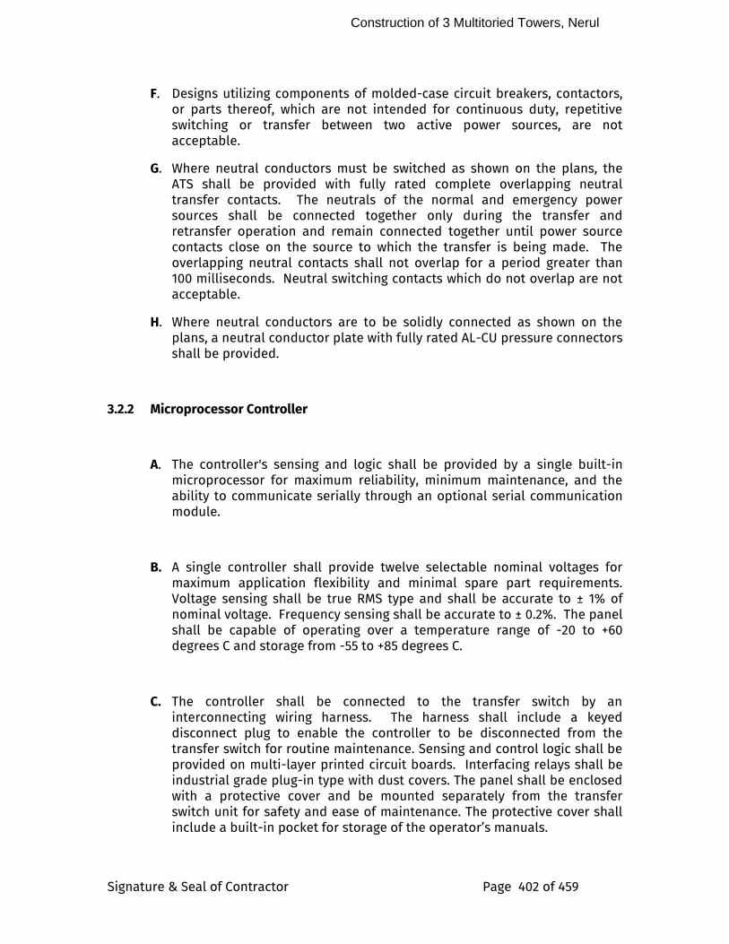
Construction of 3 Multitoried Towers, Nerul
Signature & Seal of Contractor Page 402 of 459
F. Designs utilizing components of molded-case circuit breakers, contactors, or parts thereof, which are not intended for continuous duty, repetitive switching or transfer between two active power sources, are not acceptable.
G. Where neutral conductors must be switched as shown on the plans, the ATS shall be provided with fully rated complete overlapping neutral transfer contacts. The neutrals of the normal and emergency power sources shall be connected together only during the transfer and retransfer operation and remain connected together until power source contacts close on the source to which the transfer is being made. The overlapping neutral contacts shall not overlap for a period greater than 100 milliseconds. Neutral switching contacts which do not overlap are not acceptable.
H. Where neutral conductors are to be solidly connected as shown on the plans, a neutral conductor plate with fully rated AL-CU pressure connectors shall be provided.
3.2.2 Microprocessor Controller
A. The controller's sensing and logic shall be provided by a single built-in microprocessor for maximum reliability, minimum maintenance, and the ability to communicate serially through an optional serial communication module.
B. A single controller shall provide twelve selectable nominal voltages for maximum application flexibility and minimal spare part requirements. Voltage sensing shall be true RMS type and shall be accurate to ± 1% of nominal voltage. Frequency sensing shall be accurate to ± 0.2%. The panel shall be capable of operating over a temperature range of -20 to +60 degrees C and storage from -55 to +85 degrees C.
C. The controller shall be connected to the transfer switch by an interconnecting wiring harness. The harness shall include a keyed disconnect plug to enable the controller to be disconnected from the transfer switch for routine maintenance. Sensing and control logic shall be provided on multi-layer printed circuit boards. Interfacing relays shall be industrial grade plug-in type with dust covers. The panel shall be enclosed with a protective cover and be mounted separately from the transfer switch unit for safety and ease of maintenance. The protective cover shall include a built-in pocket for storage of the operator’s manuals.
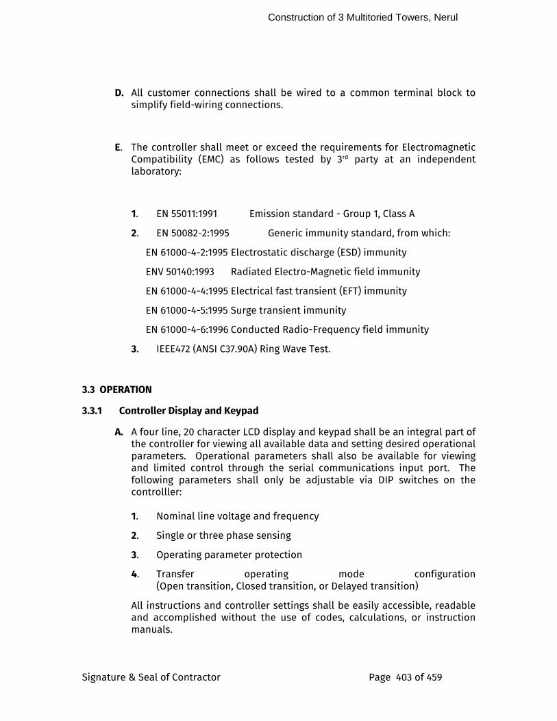
Construction of 3 Multitoried Towers, Nerul
Signature & Seal of Contractor Page 403 of 459
D. All customer connections shall be wired to a common terminal block to simplify field-wiring connections.
E. The controller shall meet or exceed the requirements for Electromagnetic Compatibility (EMC) as follows tested by 3rd party at an independent laboratory:
1. EN 55011:1991 Emission standard - Group 1, Class A
2. EN 50082-2:1995 Generic immunity standard, from which:
EN 61000-4-2:1995 Electrostatic discharge (ESD) immunity
ENV 50140:1993 Radiated Electro-Magnetic field immunity
EN 61000-4-4:1995 Electrical fast transient (EFT) immunity
EN 61000-4-5:1995 Surge transient immunity
EN 61000-4-6:1996 Conducted Radio-Frequency field immunity
3. IEEE472 (ANSI C37.90A) Ring Wave Test.
3.3 OPERATION
3.3.1 Controller Display and Keypad
A. A four line, 20 character LCD display and keypad shall be an integral part of the controller for viewing all available data and setting desired operational parameters. Operational parameters shall also be available for viewing and limited control through the serial communications input port. The following parameters shall only be adjustable via DIP switches on the controlller:
1. Nominal line voltage and frequency
2. Single or three phase sensing
3. Operating parameter protection
4. Transfer operating mode configuration (Open transition, Closed transition, or Delayed transition)
All instructions and controller settings shall be easily accessible, readable and accomplished without the use of codes, calculations, or instruction manuals.
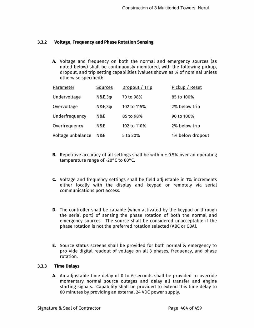
Construction of 3 Multitoried Towers, Nerul
Signature & Seal of Contractor Page 404 of 459
3.3.2 Voltage, Frequency and Phase Rotation Sensing
A. Voltage and frequency on both the normal and emergency sources (as noted below) shall be continuously monitored, with the following pickup, dropout, and trip setting capabilities (values shown as % of nominal unless otherwise specified):
Parameter Sources Dropout / Trip Pickup / Reset
Undervoltage N&E,3φ 70 to 98% 85 to 100%
Overvoltage N&E,3φ 102 to 115% 2% below trip
Underfrequency N&E 85 to 98% 90 to 100%
Overfrequency N&E 102 to 110% 2% below trip
Voltage unbalance N&E 5 to 20% 1% below dropout
B. Repetitive accuracy of all settings shall be within ± 0.5% over an operating temperature range of -20°C to 60°C.
C. Voltage and frequency settings shall be field adjustable in 1% increments either locally with the display and keypad or remotely via serial communications port access.
D. The controller shall be capable (when activated by the keypad or through the serial port) of sensing the phase rotation of both the normal and emergency sources. The source shall be considered unacceptable if the phase rotation is not the preferred rotation selected (ABC or CBA).
E. Source status screens shall be provided for both normal & emergency to pro-vide digital readout of voltage on all 3 phases, frequency, and phase rotation.
3.3.3 Time Delays
A. An adjustable time delay of 0 to 6 seconds shall be provided to override momentary normal source outages and delay all transfer and engine starting signals. Capability shall be provided to extend this time delay to 60 minutes by providing an external 24 VDC power supply.
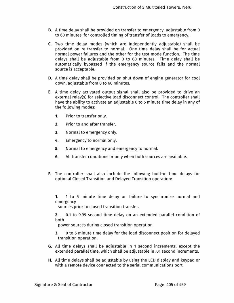
Construction of 3 Multitoried Towers, Nerul
Signature & Seal of Contractor Page 405 of 459
B. A time delay shall be provided on transfer to emergency, adjustable from 0 to 60 minutes, for controlled timing of transfer of loads to emergency.
C. Two time delay modes (which are independently adjustable) shall be provided on re-transfer to normal. One time delay shall be for actual normal power failures and the other for the test mode function. The time delays shall be adjustable from 0 to 60 minutes. Time delay shall be automatically bypassed if the emergency source fails and the normal source is acceptable.
D. A time delay shall be provided on shut down of engine generator for cool down, adjustable from 0 to 60 minutes.
E. A time delay activated output signal shall also be provided to drive an external relay(s) for selective load disconnect control. The controller shall have the ability to activate an adjustable 0 to 5 minute time delay in any of the following modes:
1. Prior to transfer only.
2. Prior to and after transfer.
3. Normal to emergency only.
4. Emergency to normal only.
5. Normal to emergency and emergency to normal.
6. All transfer conditions or only when both sources are available.
F. The controller shall also include the following built-in time delays for optional Closed Transition and Delayed Transition operation:
1. 1 to 5 minute time delay on failure to synchronize normal and emergency sources prior to closed transition transfer.
2. 0.1 to 9.99 second time delay on an extended parallel condition of both power sources during closed transition operation.
3. 0 to 5 minute time delay for the load disconnect position for delayed transition operation.
G. All time delays shall be adjustable in 1 second increments, except the extended parallel time, which shall be adjustable in .01 second increments.
H. All time delays shall be adjustable by using the LCD display and keypad or with a remote device connected to the serial communications port.
Construction of 3 Multitoried Towers, Nerul
Signature & Seal of Contractor Page 406 of 459
3.3.4 Additional Features
A. A three position momentary-type test switch shall be provided for the test / automatic / reset modes. The test position will simulate a normal source failure. The reset position shall bypass the time delays on either transfer to emergency or retransfer to normal.
B. A SPDT contact, rated 5 amps at 30 VDC, shall be provided for a low-voltage engine start signal. The start signal shall prevent dry cranking of the engine by requiring the generator set to reach proper output, and run for the duration of the cool down setting, regardless of whether the normal source restores before the load is transferred.
C. Auxiliary contacts, rated 10 amps, 250 VAC shall be provided consisting of one contact, closed when the ATS is connected to the normal source and one contact closed, when the ATS is connected to the emergency source.
D. LED indicating lights (16 mm industrial grade, type 12) shall be provided; one to indicate when the ATS is connected to the normal source (green) and one to indicate when the ATS is connected to the emergency source (red).
E. LED indicating lights (16 mm industrial grade, type 12) shall be provided and energized by controller outputs. The lights shall provide true source availability of the normal and emergency sources, as determined by the voltage sensing trip and reset settings for each source.
The following features shall be built-in to the controller, but capable of being activated through keypad programming or the serial port only when required by the user:
F. Provide the ability to select “commit/no commit to transfer” to determine whether the load should be transferred to the emergency generator if the normal source restores before the generator is ready to accept the load.
G. Terminals shall be provided for a remote contact which opens to signal the ATS to transfer to emergency and for remote contacts which open to inhibit transfer to emergency and/or retransfer to normal. Both of these inhibit signals can be activated through the keypad or serial port.
H. An Inphase monitor shall be provided in the controller. The monitor shall control transfer so that motor load inrush currents do not exceed normal starting currents, and shall not require external control of power sources. The inphase monitor shall be specifically designed for and be the product of the ATS manufacturer. The inphase monitor shall be equal to ASCO Feature 27.
I. The controller shall be capable of accepting a normally open contact that will allow the transfer switch to function in a non-automatic mode using an external control device.
Construction of 3 Multitoried Towers, Nerul
Signature & Seal of Contractor Page 407 of 459
J. Engine Exerciser - The controller shall provide an internal engine exerciser. The engine exerciser shall allow the user to program up to seven different exercise routines. For each routine, the user shall be able to:
1. Enable or disable the routine.
2. Enable or disable transfer of the load during routine.
3. Set the start time, .
- time of day
- day of week
- week of month (1st, 2nd, 3rd, 4th, alternate or every)
4. Set the duration of the run.
At the end of the specified duration the switch shall transfer the load back to normal and run the generator for the specified cool down period. A 10-year life battery that supplies power to the real time clock in the event of a power loss will maintain all time and date information.
K. System Status - The controller LCD display shall include a “System Status” screen which shall be readily accessible from any point in the menu by depressing the “ESC” key a maximum of two times. This screen shall display a clear description of the active operating sequence and switch position. For example,
Normal Failed
Load on Normal
TD Normal to Emerg
2min15s
Controllers that require multiple screens to determine system status or display “coded” system status messages, which must be explained by references in the operator’s manual, are not permissible.
L. Self Diagnostics - The controller shall contain a diagnostic screen for the purpose of detecting system errors. This screen shall provide information
Construction of 3 Multitoried Towers, Nerul
Signature & Seal of Contractor Page 408 of 459
on the status input signals to the controller which may be preventing load transfer commands from being completed.
M. Communications Interface – The controller shall be capable of interfacing, through an optional serial communication module, with a network of transfer switches, locally (up to 4000 ft.) or remotely through modem serial communications. Standard software specific for transfer switch applications shall be available by the transfer switch manufacturer. This software shall allow for the monitoring, control and setup of parameters.
N. Data Logging – The controller shall have the ability to log data and to maintain the last 99 events, even in the event of total power loss. The following events shall be time and date stamped and maintained in a non-volatile memory:
1. Event Logging
1. Data and time and reason for transfer normal to emergency.
2. Data and time and reason for transfer emergency to normal.
3. Data and time and reason for engine start.
4. Data and time engine stopped.
5. Data and time emergency source available.
6. Data and time emergency source not available.
2. Statistical Data
1. Total number of transfers.
2. Total number of transfers due to source failure.
3. Total number of days controller is energized.
4. Total number of hours both normal and emergency sources are
available.
(b) Communications Module - A full duplex RS485 interface shall be installed in the ATS controller to enable serial communications. The serial communications shall be capable of a direct connect or multi-drop configured network. This module shall allow for the seamless integration of existing or new communication transfer devices. The serial communication interface shall be equal to ASCO Accessory 72.
(c) External DC Power Supply – An optional provision shall be available to connect an external 24 VDC power supply to allow the LCD and the door
Construction of 3 Multitoried Towers, Nerul
Signature & Seal of Contractor Page 409 of 459
mounted control indicators to remain functional when both power sources are dead. This option shall be equivalent to ASCO accessory 1G.
3.4 ADDITIONAL REQUIREMENTS
3.4.1 Withstand and Closing Ratings
A. The ATS shall be rated to close on and withstand the available RMS symmetrical short circuit current at the ATS terminals with the type of overcurrent protection shown on the plans.
B. The ATS shall be UL listed in accordance with UL 1008 and be labeled in accordance with that standard's 1½ and 3 cycle, long-time ratings. ATSs which are not tested and labeled with 1½ and 3 cycle (any breaker) ratings and have series, or specific breaker ratings only, are not acceptable. The ATS upto 600A should be tested for any breaker rating. The ATS from 800A to 4000A should have short time withstand capacity of 36KA to 65KA for 18 to 30 cycles for providing discrimination under fault condition.
3.4.2 Service Representation
A. The ATS manufacturer shall maintain a national service organization of company-employed personnel located throughout the contiguous United States. The service center's personnel must be factory trained and must be on call 24 hours a day, 365 days a year.
B. The manufacturer shall maintain records of each switch, by serial number, for a minimum of 20 years.
4.0 SUBMITTALS
A. Bidding stage
8. Product data includes rated capacities of ATS and Schedule of ATS and product catalogue.
9. Manufacturers warrantee clauses.
B. Post bidding
8. Dimensions, Technical catalogue, weight , required clearances around enclosure and detailed wiring diagrams .
a. Mounting and installation Method
Construction of 3 Multitoried Towers, Nerul
Signature & Seal of Contractor Page 410 of 459
b. Wiring scheme, System programming
c. Installation procedure recommended by manufacturer.
d. Commissioning procedure recommended by manufacturer.
e. Test certificates of all the components
C. Post Commissioning and Handover
1. O & M Manual.
2. Manufacturer shall supply the following literature-
b. Integration into the panel, operation and Maintenance Instructions.
c. Installation Instructions
d. Field Wiring Diagrams
e. Maintenance manual showing maintenance required on daily,weekly, monthly, semi-annually and annually basis.
f. List of consumable items and recommended spare parts along with its price list.
5.0 DELIVERY STORAGE AND HANDLING
1. ATS should be shipped in completely protected package to panel factory for integration.
2. It should be fully covered to protect from dust/water, rust, and Corrosion.
3. It should be free from any sort of physical damage or so.
4. Loading and Unloading, shifting, handling should be done by trained team of experts only.
6.0 INSTALLATION
The installation will be carried out strictly as per the laid down procedure by the manufacturer. All wiring, terminations, installation into the panels as required etc., to be done by as per the Manual of installation practice approved by the manufacturer and relevant codes and standards to ensure the perfect quality and functionality.
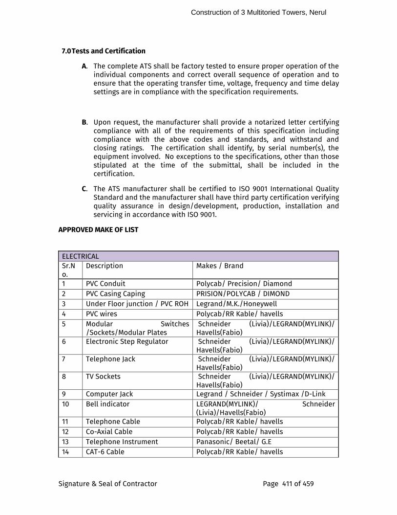
Construction of 3 Multitoried Towers, Nerul
Signature & Seal of Contractor Page 411 of 459
7.0 Tests and Certification
A. The complete ATS shall be factory tested to ensure proper operation of the individual components and correct overall sequence of operation and to ensure that the operating transfer time, voltage, frequency and time delay settings are in compliance with the specification requirements.
B. Upon request, the manufacturer shall provide a notarized letter certifying compliance with all of the requirements of this specification including compliance with the above codes and standards, and withstand and closing ratings. The certification shall identify, by serial number(s), the equipment involved. No exceptions to the specifications, other than those stipulated at the time of the submittal, shall be included in the certification.
C. The ATS manufacturer shall be certified to ISO 9001 International Quality Standard and the manufacturer shall have third party certification verifying quality assurance in design/development, production, installation and servicing in accordance with ISO 9001.
APPROVED MAKE OF LIST
ELECTRICAL
Sr.No.
Description Makes / Brand
1 PVC Conduit Polycab/ Precision/ Diamond
2 PVC Casing Caping PRISION/POLYCAB / DIMOND
3 Under Floor junction / PVC ROH Legrand/M.K./Honeywell 4 PVC wires Polycab/RR Kable/ havells
5 Modular Switches /Sockets/Modular Plates
Schneider (Livia)/LEGRAND(MYLINK)/ Havells(Fabio)
6 Electronic Step Regulator Schneider (Livia)/LEGRAND(MYLINK)/ Havells(Fabio)
7 Telephone Jack Schneider (Livia)/LEGRAND(MYLINK)/ Havells(Fabio)
8 TV Sockets Schneider (Livia)/LEGRAND(MYLINK)/ Havells(Fabio)
9 Computer Jack Legrand / Schneider / Systimax /D-Link
10 Bell indicator LEGRAND(MYLINK)/ Schneider (Livia)/Havells(Fabio)
11 Telephone Cable Polycab/RR Kable/ havells
12 Co-Axial Cable Polycab/RR Kable/ havells
13 Telephone Instrument Panasonic/ Beetal/ G.E
14 CAT-6 Cable Polycab/RR Kable/ havells
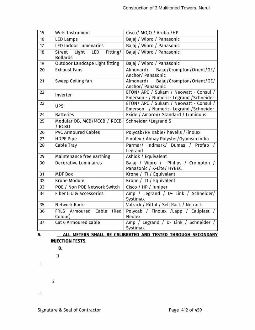
Construction of 3 Multitoried Towers, Nerul
Signature & Seal of Contractor Page 412 of 459
15 Wi-Fi Instrument Cisco/ MOJO / Aruba /HP
16 LED Lamps Bajaj / Wipro / Panasonic
17 LED Indoor Lumenaries Bajaj / Wipro / Panasonic
18 Street Light LED Fitting/ Bollards
Bajaj / Wipro / Panasonic
19 Outdoor Landcape Light fitting Bajaj / Wipro / Panasonic
20 Exhaust Fans Almonard/ Bajaj/Crompton/Orient/GE/ Anchor/ Panasonic
21 Sweep Ceiling fan Almonard/ Bajaj/Crompton/Orient/GE/ Anchor/ Panasonic
22 Inverter ETON/ APC / Sukam / Neowatt - Consul / Emerson - / Numeric- Legrand /Schneider
23 UPS
ETON/ APC / Sukam / Neowatt - Consul / Emerson - / Numeric- Legrand /Schneider
24 Batteries Exide / Amaron/ Standard / Luminous
25 Modular DB, MCB/MCCB / RCCB / RCBO
Schneider /Legrand S
26 PVC Armoured Cables Polycab/RR Kable/ havells /Finolex
27 HDPE Pipe Finolex / Abhay Polyster/Gyamsin India
28 Cable Tray Parmar/ indmark/ Dumas / Profab / Legrand
29 Maintenance free earthing Ashlok / Equivalent
30 Decorative Luminaires Bajaj / Wipro / Philips / Crompton / Panasonic / K-Lite/ HYBEC
31 MDF Box Krone / ITI / Equivalent 32 Krone Module Krone / ITI / Equivalent
33 POE / Non POE Network Switch Cisco / HP / Juniper
34 Fiber LIU & accessories Amp / Legrand / D- Link / Schneider/ Systimax
35 Network Rack Valrack / Rittal / Sell Rack / Netrack
36 FRLS Armoured Cable (Red Colour)
Polycab / Finolex /Lapp / Caliplast / Neolex
37 Cat 6 Armoured cable Amp / Legrand / D- Link / Schneider / Systimax
A. ALL METERS SHALL BE CALIBRATED AND TESTED THROUGH SECONDARY INJECTION TESTS.
B.
2

Construction of 3 Multitoried Towers, Nerul
Signature & Seal of Contractor Page 413 of 459

Construction of 3 Multi story Towers, Nerul
Signature & Seal of Contractor Page 414 of 459

Signature & Seal of Contractor Page 415 of 459
14)
Fire Fighting Works
Signature & Seal of Contractor Page 416 of 459
SECTION – A : BASIS OF DESIGN
1.3. BASIS OF DESIGN
The Fire Protection System for the project is designed keeping in view the following:
1.4. Proposed Residential Buildings at Nerul (SBI Colony), Mumbai.
1.5. Requirement of adequate pressure availability of fire mains, Hydrant points as well as sprinklers head.
1.6. Adequate storage of water in underground fire water tanks, as per the NBC/NOC guidelines.
1.7. Provision of fire fighting appurtenance such as sprinklers, fire hydrants, hose reel, and portable extinguishers.
The execution of works and materials used shall be as per the latest relevant I.S. specifications.
The extension of work shall in strict compliance to the Environmental Clearance granted by EIA, Govt. of India & NOC issued by Fire Department.
Wherever reference has been made to Indian Standard or any other specifications, the same shall mean to refer to the latest specification irrespective of any particular edition of such specification being mentioned in the specifications below or Schedule of Quantities.
REFERENCE STANDARDS The design and planning of Fire Protection System shall be done keeping in view thefollowing criteria:
5. National Building Codes of India – Part IV
6. National Fire Protection Association (NFPA)
7. Rules of Insurance Company & TAC Manual (for reference and guideline).
8. Consultation with local Chief Fire Officer.
9. IS Standards as follows:
xii. IS : 1641 : 1988 Code of practice for fire safety of buildings (general): General principles of fire grading and classification.
xiii. IS : 1642 : 1989 Code of practice for fire safety of buildings (general): Details of construction.
xiv. IS : 1643 : 1988 Code of practice for fire safety of buildings (general): Exposure Hazard.
xv. IS : 1644 : 1988 Code of practice for fire safety of buildings (general): Exit requirements and personal Hazard.
Signature & Seal of Contractor Page 417 of 459
xvi. IS : 2190 : 2010 Selection, Installation and maintenance of first aid fire extinguishers - Code of practice.
xvii. IS : 3884 : 1989 Code of practice for installation and maintenance of internal fire hydrants and hose reels on premises
xviii. IS : 9668 : 1990 Code of practice for provision and maintenance of water supplies for fire fighting.
xix. IS : 12469 : 1988 Specification for Pumps for Fire Fighting System
xx. IS : 13039 : 1991 External hydrant systems - provision and maintenance - Code of practice
xxi. IS : 15105 : 2002 Design and Installation of Fixed Automatic Sprinkler Fire Extinguishing Systems - Code of Practice
Basis/ Concept of Design The fire fighting arrangement shall be designed as per the requirement of local guidelines, NBC & NFPA standard.
The entire fire safety installation shall be compliant with the most stringent codes / standard for the entire Complex to ensure the highest safety standard and uniformity of system. Further, before property is opened to public, the fire protection shall be fully operated and tested under simulated conditions to demonstrate compliance with the most stringent standards, codes and guidelines.
System Description
4. Fire water storage
Static fire water storage tank for Fire Protection System has been provided at ground level of capacity 600 cum fire water storage i.e. 400 Cum for Tower A & B and 200 Cum for Tower C. Also 25 cum at terrace level of each building.
Fire department connection shall also be provided on the external wall of the property near the main entrance of each block. These shall comprise of 4 Nos. 63 mm dia male outlets capable of directly feeding the ring mains through non return valves or directly filling the static fire storage tanks. Also 2-way & 3-way connections shall be provided. These shall be mounted in specially identified boxes.
Fire pumping system
The fire pumping system shall comprise of independent electrical pumps for hydrant and sprinkler system, diesel engine driven pump & jockey pump for hydrant & sprinkler system in Each Pump room.
1. 1 No. Electric Hydrant Pump : Capacity 2850 LPM 125 Mt head
2. 1 No. Electric Sprinkler Pump : Capacity 2850 LPM 125 Mt head
3. 1 No. Diesel Engine Driven Pump : Capacity 2850 LPM 125 Mt head
4. 2 No. Jockey Pump- Hydrant/ Sprinkler : Capacity 285 LPM 125 Mt head
Signature & Seal of Contractor Page 418 of 459
Terrace Level:
Down Comer Pump (Terrace Level) :Capacity 900 LPM 35m Head
Electrical pump shall provide adequate flow for catering requirement of hydrant system. Diesel engine driven fire pumps shall be provided for ensuring operation & performance of the system in case of total electrical power failure. Jockey pumps shall compensate for pressure drop and line leakage in the hydrant and sprinkler installation. Provision of PRS/ orifice plate shall be made in sprinkler riser to restrict pressure on sprinkler system.
Individual suction lines shall be drawn from the fire reserve tanks at the basement level and connected to independent fire suction header. The electric fire pumps, dieselengine driven fire pumps and the jockey pumps shall all draw from this suction header.
Delivery lines from various pumps shall also be connected to a common header in order to ensure that maximum standby capacity is available. The sprinkler pump shall be isolated from the main discharge header by a non-return valve so that the hydrant pump can also act as standby for the sprinkler system. The ring main shall remain pressurized at all times and Jockey pumps shall make up minor line losses. Automation required to make the system fully functional shall be provided.
Fire hydrant system Internal and external standpipe fire hydrant system shall be provided with landing valve, hose reel, first aid hose reels, complete with instantaneous pattern short gunmetal pipe in the Complex.
The internal diameter of inlet connection shall be at least 80/100 mm. The outlet shall be of instant spring lock type gunmetal ferrule coupling of 63 mm dia for connecting to hose pipe. Provision of flow switch on riser shall be made for effective zone monitoring. The flow switch shall be wired to FAP and shall indicate water flow on hydrant of the identified zone.
Recessed cupboard/ fire hydrant cabinet shall be strategically located for firefighting requirement. Location of cabinets shall be accessed as per compart-mentation plan in consultation with the Architect.
External hydrant shall be located within 2 m to 15 m from the building to be protected such that they are accessible and may not be damaged by vehicle movement. A spacing of about 45-50 m between hydrants for the complex shall be adopted.
Sprinkler system
Sprinklers shall be distributed in all blocks of the residential as per the National Building Code requirement, so as to cover 12-21 sqm area within the buildings and 9 sqm area in basement areas from each sprinkler head.
Elaborate automatic sprinkler system shall be provided throughout the
Signature & Seal of Contractor Page 419 of 459
Public areas as explained above. The system shall be suitably zoned for its optimum functional performance.
The maximum floor area on any one floor to be protected by sprinkler supplied by any one sprinkler system riser or combined system riser shall be covered 52,000 sqft area of each control valve, flow and tamper switches at suitable location and shall be connected to control module of the fire alarm system for its monitoring and annunciation in case of activation.
Sprinkler type along with its bulb rating shall be selected based on the requirement of the space and shall be specified accordingly.
Wet pipe sprinkler shall be provided for all habitable spaces such as Apartments, corridors and other public areas.
Two layer of sprinklers at common areas like lift lobby areas, corridors etc. will be done by developer. Pipe sizing should be done by consideration of both the levels of sprinkler system.
Hand held fire extinguishers Portable fire extinguishers of ABC type, Carbon-di-oxide and foam type shall be provided as first aid fire extinguishing appliances. These extinguishers shall be suitably distributed in the entire public as well as service areas. The following extinguisher shall be provided as per local Authorities (CFO).
- One ABC Powder extinguisher of 6 kgs. capacity and two fire buckets filled with clean dry fine sand should be provided for every 8 cars at each common basement parking area and also on the setback parking area (under shelter).
- One Co2 extinguisher of 4.5 kgs. capacity should be provided near the entrance to each main switch board room, inside each lift machine room and inside each kitchen.
b) One ABC Powder extinguisher of 6 kgs. capacity should be provided near the transformer, if installed.
- One ABC powder extinguisher of 9 kgs. capacity should be provided near the entrance to the each D.G. Room.
- Scale of suitable extinguishers for Office area shall be collected before approaching the department for final clearance after finalizing the utility of each area.
3.0 WORKMANSHIP The workmanship shall be best of its kind and shall conform to the specifications, as below or Indian Standard Specifications in every respect
Signature & Seal of Contractor Page 420 of 459
or latest trade practices and shall be subject to approval of the APMC/SBI . All materials and/or Workmanship which in the opinion of the APMC/SBI / Architect / Consultant is defective or unsuitable shall be removed immediately from the site and shall be substituted with proper materials and/or workmanship forthwith.
4.0 MATERIALS
All materials shall be best of their kind and shall conform to the latest Indian Standards.
All materials shall be of approved quality as per samples and origins approved by the APMC/SBI / Architect / Consultants.
As and when required by the APMC/SBI / Consultant, the contractor shall arrange to test the materials and/or portions of works at his own cost to prove their soundness and efficiency. If after tests any materials, work or portions or work are found defective or unsound by the APMC/SBI / Consultant, the contractor shall remove the defective material from the site, pull down and re-execute the works at his own cost to the satisfaction of the APMC/SBI / Consultant. To prove that the materials used are as specified the contractor shall furnish the APMC/SBI with original vouchers on demand.
SECTION – B : FIRE PROTECTION SYSTEM
- SCOPE
The scope of this section consists of but is not necessarily limited to supply, installation, testing and commissioning of the fire protection system. The philosophy of the system is as follows :
- The Fire Suppression System shall comprise the Fire Hydrants
System, the Sprinkler System (Wet type), Hand Appliances. - Water from the underground Fire Water Storage Tanks, each of 200
cum capacity, shall be supplied for the uses listed below. - Fire Hydrant System (Pressurized) both for the external
hydrants, the internal landing valves and the hose reels at landings.
- Sprinkler System (Wet Type) - The Hydrant System and the Sprinkler System, under normal
conditions, shall be lowest pressurized by means of the electric motor driven Jockey Pump.
- The Hydrant System shall be provided with two pump sets, one of which will be diesel engine driven and the other electric motor driven.
- The Sprinkler System shall be provided with an electric motor driven pump set.
- The piping and valve connections shall be done so that the water from the discharge of the Hydrant Pump sets is able to supply water,
Signature & Seal of Contractor Page 421 of 459
automatically to the Sprinkler System whenever, the Sprinkler Pump is unable to maintain the pressure or fails and not vice versa.
- The starting and stopping of the Jockey pump shall be automatic based on the pressure switches at preset low and high pressure.
- The electric motor driven Hydrant Pump starts automatically at a preset pressure by means of a pressure switch. As soon as the Hydrant Pump starts, the Jockey Pump Stops. If for any reason the electric motor driven Hydrant Pump does not start at the preset pressure or is unable to maintain the pressure, the diesel engine driven Hydrant Pump starts at the preset pressure.
- The Hydrant Pump, whether electric motor driven or the diesel engine driven shall be stopped only manually.
- The Sprinkler Pump shall be started automatically at a preset pressure but shall be stopped only manually.
- Contractor shall ensure that all false ceiling voids greater than 800 mm are provided with sprinklers.
- Contractor shall ensure Hydro Testing for the complete system. n The Contractor shall obtain the necessary approval of the drawings
and the schemes from the local authority as called for. The contractor shall also take care of any other requirement so that insurance cover can be obtained, if required at minimum premium at a later date.
- The contractor shall design and after approval of Project Manager display near each staircase landing at floor levels, a glass covered framed floor plan clearly showing the locations of all landing valves, hose reels, hand appliances, as well as the DO’s and DON’T’s for the personnel and the exit direction in case of an emergency. The dimensions of the floor plan, its scale, lettering size, colour scheme etc shall be as directed by the Project Manager.
- The Contractor shall provide labeling tag at each Valve.
PIPE WORK
g. General Requirements
All materials shall be of the best quality conforming to the specifications and subject to the approval of the Consultants.
Pipes shall be fixed in a manner as to provide easy accessibility for repair and maintenance and shall not cause obstruction in shafts, passages etc.
Pipes shall be securely fixed to walls and ceilings by suitable clamps and M.S. supports at intervals specified. Only approved type of anchor fasteners shall be used for RCC slabs and walls / floors etc.
Valves and other appurtenances shall be so located that they are easily accessible for operations, repairs and maintenance.
Pipes and fittings shall be fixed truly vertical, horizontal or in slopes as required in a neat workman like manner.
Pipe accessories such as gauges, meters, control devices, etc. shall have the same/more working pressure rating as per applicable standard the
Signature & Seal of Contractor Page 422 of 459
associated pipe work. All pipe work shall be free from burrs, rust and scale and shall be cleaned before installation. All personnel engaged on welding operations must possess a certificate of competence issued by an acceptable / recognized authority.
Piping Pipes of following types are to be used:
GI pipelines upto 150 mm dia shall be as per IS: 1239, Part-II (heavy grade) while pipelines above 150 mm dia shall be as per I.S.:3589. GI pipes buried below ground shall also be suitably be lagged with layer of anticorrosive treatment with 4mm thick polymer.
Galvanize Iron pipelines Shall be used only for Hydrant-Riser system (inside the building)upto 150 mm dia shall be as per IS: 1239, Part-I (Heavy grade) while pipelines above 150 mm dia shall be as per I.S.:3589. G.I.Heavy class pipe shall be use after deluge valve.
All pipe clamps and supports shall be fabricated from MS steel sections use at site. Welding of galvanized clamps and supports shall not be permitted.
Pipes shall be hung by means of expandable anchor fastener of approved make and design. The hangers and clamps shall be fastened by means of galvanized nuts and bolts. The size/diameter of the anchor fastener and the clamps shall be suitable to carry the weight of water filled pipe and dead load normally encountered.
Hangers and supports shall be thoroughly galvanized after fabrication. The selection and design of the hanger & support shall be capable of carrying the sum of all concurrently acting loads. They shall be designed to provide the required supporting effects and allow pipeline movements as necessary. All guides, anchor braces, dampener, expansion joint and structural steel to be attached to the building/structure trenches etc. shall be provided. Hangers and components for all piping shall be approved by the Consultants.
The piping system shall be tested for leakages at 2 times the operating pressure or 1.5 time shut-off pressure, whichever is highest including testing for water hammer effects.
Flanged joints shall be used for connections for vessels, equipment, flanged valves and also on two straight lengths of pipelines of strategic points to facilitate erection and subsequent maintenance work.
For pipes underground installation the pipes shall be buried at least one meter below ground level and shall have 230 mm x 230 mm masonry or concrete supports at least 300 mm high at 3m intervals. Masonry work to have plain cement concrete foundation (1 cement: 4 coarse sand : 8 stone aggregate) of size 380x380x75 thick resting on firm soil.
Mains below ground level shall be supported at regular intervals not exceeding 3.0 metres and shall be laid at least 2.0 metre away from the building.
PIPING ACCESSORIES
Signature & Seal of Contractor Page 423 of 459
Flexible Connections
Flexible connections at outlets of pumps shall be of stainless steel corrugated inner tube and stainless steel wire braid outside the tube with flanged ends. The flexible connectors shall be designed for excellent vibration and noise protection. Isolated tension members shall be provided to prevent excessive elongation. The end flange connection shall be rated at 20 kg/cm² (300 psi).
Flexible connections shall be suitable for the working fluid and for the working pressure and temperature.
Expansion Joints
Pack-less type expansion connectors shall be used where the expansion and contraction of the pipe is excessive or cannot be compensated for by expansion loops or offsets.
Anchors and pipe guides shall be provided and installed at the recommended locations. All expansion connectors shall have flanged ends with working pressure corresponding with the piping system.
Flexible pipe connections shall be installed at every structural expansion joint.
Strainers
Water strainers shall be of the Y type. Strainers of 50 mm (2 inches) in diameter and smaller shall have bronze or iron bodies with screwed connections while 65 mm (2 ½ inches) in diameter strainers and larger shall have iron bodies and flanged connections. They shall have the same pressure rating as the piping system.
Water strainers shall comply with the requirements of the
ASTM standards. Screens shall be stainless steel with
perforations as follows:-
Strainer
mm (inches)
Perfora
tion
mm
(inches)
20 (¾) to 50 (2) 0.76 (0.03)
65 (2 ½) to 150 (6) 1.52 (0.06)
200 (8) to 300 (12) 3.05 (0.12) Over 300 (12) 6.10 (0.24)
The free area of each screen shall be not less than three times the area of the strainers of 65 mm (2 ½ inches) in diameter and larger shall be provided with 15 mm (½ inch) diameter valve drains. The outlet shall be piped to the nearest drain.
Signature & Seal of Contractor Page 424 of 459
Air Vent and Drain
Manual air vent shall be furnished as required for purging air or other gases from the water circuit during filling. The outlet shall be piped to the nearest drain.
Automatic air vents, conforming to ASA standards, shall be furnished at the top of main risers.
A shut-off valve shall be provided at the inlet of each automatic air vent. The outlet of each vent shall be piped to the nearest drain.
A plug-type drain cock shall be provided at all low points of pipework systems.Drains shall be installed to ensure easy access and convenience for maintenance and removal of all piping, valves, fittings and equipment without undue spillage.
Drainage facilities shall be provided and suitably sized to drain expeditiously the entire system and equipment involved.
Pressure Gauges
Pressure gauges shall be of the bourdon type, stainless steel casing, round type of 100 mm (4 inches) dial and scale range of approximately 150 per cent of the normal operation. Pressure readings shall be in kg/cm² and psig.
A shut-off valves and snubbed with working pressure corresponding with the piping system shall be provided for each pressure gauge.
Oil filled pressure gauges shall be installed where there is excessive vibration.
Flow Measuring Equipment
Flow measuring devices shall be annubar flow measuring stations and a portable meter set complete with master chart for direct conversion of meter readings to m³/h (or gpm), carrying case, two 4-m hoses, equalizer manifold, check seal, installation and operating instructions. Meters shall become the property of the Employer/Owner.
Meters shall be approved factory assembled Eagle Eye flow meters or equal approved. Each station shall be completed with safety shut-off valves and quick connect coupling connections.
Annubar elements shall be made of stainless steel and rated to 20 kg/cm² (300 psig) at 204°C (400°F).
The flow measuring equipment shall be the product of Annubar by Ellison Instrument Division, Dieterich Standard Copr., or approved equivalent.
Each station shall be tagged by means of a brass tag, attached with a chain, that indicates the station number, meter setting and m3/h (or gpm).
Welding sockets shall be supplied by the flow meter manufacturer.
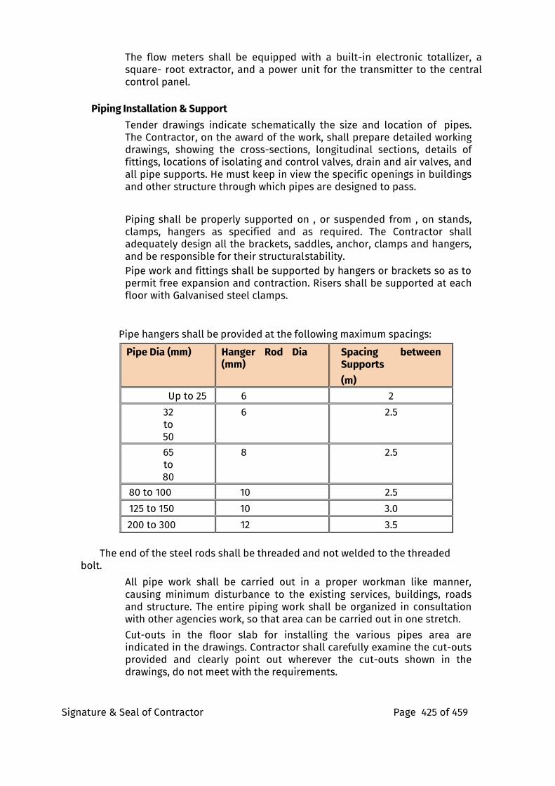
Signature & Seal of Contractor Page 425 of 459
The flow meters shall be equipped with a built-in electronic totallizer, a square- root extractor, and a power unit for the transmitter to the central control panel.
Piping Installation & Support
Tender drawings indicate schematically the size and location of pipes. The Contractor, on the award of the work, shall prepare detailed working drawings, showing the cross-sections, longitudinal sections, details of fittings, locations of isolating and control valves, drain and air valves, and all pipe supports. He must keep in view the specific openings in buildings and other structure through which pipes are designed to pass.
Piping shall be properly supported on , or suspended from , on stands, clamps, hangers as specified and as required. The Contractor shall adequately design all the brackets, saddles, anchor, clamps and hangers, and be responsible for their structural stability. Pipe work and fittings shall be supported by hangers or brackets so as to permit free expansion and contraction. Risers shall be supported at each floor with Galvanised steel clamps.
Pipe hangers shall be provided at the following maximum spacings:
Pipe Dia (mm) Hanger Rod Dia (mm)
Spacing between Supports
(m)
Up to 25 6 2
32 to 50
6 2.5
65 to 80
8 2.5
80 to 100 10 2.5
125 to 150 10 3.0
200 to 300 12 3.5
The end of the steel rods shall be threaded and not welded to the threaded bolt.
All pipe work shall be carried out in a proper workman like manner, causing minimum disturbance to the existing services, buildings, roads and structure. The entire piping work shall be organized in consultation with other agencies work, so that area can be carried out in one stretch.
Cut-outs in the floor slab for installing the various pipes area are indicated in the drawings. Contractor shall carefully examine the cut-outs provided and clearly point out wherever the cut-outs shown in the drawings, do not meet with the requirements.
Signature & Seal of Contractor Page 426 of 459
Pipe sleeves, larger diameter than pipes, shall be provided wherever pipes pass through walls and slab and annular space filled with fiberglass and finished with retainer rings.
The contractor shall make sure that the clamps, brackets, saddles and hangers provided for pipe supports are adequate or as specified / approved by Consultants. Piping layout shall take due care for expansion and contraction in pipes and include expansion joints where required.
All pipes shall be accurately cut to the required sizes in accordance with relevant BIS codes and burrs removed before laying. Open ends of the piping shall be closed as the pipe is installed to avoid entrance of foreign matter. Where reducers are to be made in horizontal runs, eccentric reduces shall be used for the piping to drain freely. In other locations, concentric reduces may be used.
Automatic air valves shall be provided at all high points in the piping system for venting. All valves shall be of 15mm pipe size and shall be associated with an equal size gate valves. Automatic air valves shall be provided on water risers.
Discharge from the air valves shall be piped through a pipe to the nearest drain or sump. All pipes shall be pitched towards drain points.
Pressure gauges shall be provided as shown on the approved drawings. Care shall be taken to protect pressure gauges during pressure testing.
Pipe Fittings
Pipe fittings mean tees, elbows, couplings, unions, flanges, reducers etc and all such connecting devices that are needed to complete the piping work in its totality.
Ductile Iron mechanical coupling (Victaulic) type grooved fitting should be used for pipe. In all common area shafts should have the conventional welded joints up to the 65 mm dia and for pipe 50 mm & below should be threaded.
Fabricated fittings shall not be permitted for pipes diameters 50mm and below in the common areas.
Grooved End Fittings used on pipe, Fittings shall be cast of ductile iron conforming to ASTM A-536, Grade 65-45-12. Fittings provided with an alkyd enamel finish or hot dip galvanized to ASTM A-153. Zinc electroplated fittings and couplings conform to ASTM B633.
Procedure For Pypkote / Coatek Application i. Surface Preparation - The pipe surface shall be cleaned by a wire brush.
ii. Application of Primer - Pypkote / Coatek primer is to be applied on pipes immediately after cleaning. This is to prevent any further accumulation of rust on the pipe. This is a cold applied primer and is applied by brush.
iii. Application of Pypkote / Coatek 4 mm Tape - After the primer is applied on the pipe, it is allowed to dry for about 30 min. till it becomes touch dry. Before adhering the tape to the pipe, it is
Signature & Seal of Contractor Page 427 of 459
advisable to gently heat the primer coated pipe by a run of LPG torch. Remove the bottom polyethylene from the tape & then heat bottom surface of the tape by LPG torch or any heat source & start wrapping the tape to the pipe by heating the primer coated pipe & by removing the bottom polyethylene from the tape before wrapping better adhesion between the tape & pipe is obtained. Overlaps are maintained with a minimum of 12.5 mm.
iv. Tape coating of weld joints - The tape is applied over the weld joints after the necessary welding & testing methods of the joints is completed. The procedure for application of tape shall be the same as bare pipe procedure. Overlaps on each side of the weld joints shall be 50 mm.
v. A final coat of White wash with water based cement paint is done immediately over the entire coated pipe.
vi. “HOLIDAY” Testing must be required for the “External Piping”. The Contractor shall be arrange all testing tools and machines for holiday testing.
h. Jointing
Mechanical Coupling
Mechanical coupling shall be UL listed or FM Global approved for fire protection service, ductile or iron housing, rust inhibiting no-lead painted coating, zinc electroplated heat treated bolts and heavy hex carbon steel nuts meeting ASTM F- 1476
The grooved pipe shall be prepared with a roll groove.
Hangers and pipe supports shall be installed in accordance with the manufacturer’s recommendation.
After the completion of the installation, contractor shall be responsible for arranging an inspection by the technical staff of the supplier of the purchased mechanical couplings and requesting the inspection report from the supplier and submitting to the supervisor for approval.
Welded Joints : Joints between pipes and fittings shall be made with the pipes and fittings having “V” groove and welded with electrical resistance welding in an approved manner. But welding without “V” groove shall not be permitted. 2-3% welding shall be radio- graphically tested or satisfaction of Project engineer.
All joints in the pipe line with screwed fittings shall be seal welded after testing and the weld plus the adjoining portion shall be given two coats of zinc rich primer. (Warranty period 36 month from date of commissioning
Flanged joints ( 65 mm dia and above) Flanged joints with flanges conforming to IS: 6392 shall be provided on
10. Straight runs at intervals not exceeding 25-30m on pipe lines of 50 mm dia and above and as directed by the Project Manager.
Signature & Seal of Contractor Page 428 of 459
11. For jointing all types of valves, appurtenances, pumps, connections with other type of pipes, to water tanks and other places necessary and as required for good engineering practice and as shown/noted on the drawings.
12. Flanges shall be with GI bolts and nuts and 3mm insertion gasket of natural rubber conforming to IS: 11149.
3.0 ROSETTE PLATE Rosette plate should be double recessed escutcheons. It should be selected as per the size i.e., 1/2" or 3/4"fire sprinkler. It should be chrome plated.
4.0 AIR RELEASE VALVE
Air release valve should be suitable for clean or raw water service with pressure up to 740 PSIG (5100 kPa). Air release valve shall be automatic float operated valves designed to release accumulated air from a piping system while the system is in operation and under pressure. The capacity and pressure rating of the valve is dependent on the diameter on the diameter of the precision orifice in the cover. A large inlet connection is required for proper air and water exchange. The valve body shall be threaded with NPT inlets and outlets. The body inlet connection shall be hexagonal for a wrench connection. The valve shall have two additional NPT connections for the addition of gauges, testing and draining.
Design of the valve: The cover shall be bolted to the valve body and seated with a flat gasket. Resilient seats shall be replaceable and provide drop tight shut off to the full valve pressure rating. The floats shall be unconditionally guaranteed against failure including pressure surges. Mechanical linkage shall provide sufficient mechanical advantage so that the valve will open under full operating pressure. Simple lever designs shall consist of a single pivot arm and a resilient orifice button.
Material: The valve body and cover shall be constructed of ASTM A126 Class B cast iron for working pressure upto 300 psig. The higher pressure rated valves shall be constructed of ASTM A536 Grade 65-45-12 ductile iron.
Certification: Valves shall be manufactured and tested in accordance with American Water Works Association Standard C512. The valves shall be UL listed.
5.0 EXHAUST PIPES
The material used for exhaust pipe including all the fixing accessories and hardware shall be Mild steel (Class-‘C’). The exhaust pipes shall be insulated with 75 mm thick mineral wool (density 100 kg/m3) insulation wrapped in chicken mesh and clad with 26 gauge aluminum sheet including all hot dip galvanized support structural. Adequate sized pipes and fittings shall be installed to carry away the
Signature & Seal of Contractor Page 429 of 459
exhaust discharge into the atmosphere at a height as indicated in the drawings & as per the requirement of Center / State Pollution Control Board or Pollution Control Committee as the case may be. The galvanized M.S. structural support and vibration arrestors to specify along with drawing for statutory clearance.
MECHANICAL SEAL
A mechanical seal must contain four functional components, primary sealing surfaces, secondary sealing surfaces, a means of actuation, and a means of drive:
21.1.1. The primary sealing surfaces are the heart of the device. A
common combination consists of a hard material, such as silicon carbide, Ceramic or tungsten carbide, embedded in the pump casing and a softer material, such as carbon in the rotating seal assembly. Many other materials can be used depending on the liquid's chemical properties, pressure, and temperature. These two rings are in intimate contact, one ring rotates with the shaft, the other ring is stationary. These two rings are machined using a machining process called lapping in order to obtain the necessary degree of flatness.
21.1.2. The secondary sealing surfaces (there may be a number of them) are those other points in the seal that require a fluid barrier but are not rotating relative to one another. Usually the secondary sealing elements are ‘O’-rings, PTFE wedges or rubber diaphragms.
21.1.3. In order to keep the two primary sealing surfaces in intimate contact, an actuation force is required and is commonly provided by a spring. In conjunction with the spring, it may also be provided by the pressure of the sealed fluid.
21.1.4. The primary sealing surfaces must be the only parts of the seal that are permitted to rotate relative to one another, they must not rotate relative to the parts of the seal that hold them in place. To maintain this non-rotation a method of drive must be provided.
8.0 LEVEL CONTROLLER/INDICATORS
Water Level Controller should automatically START the pump set as soon as the water level falls below the predetermined level and shall SWITCH OFF the pump set as soon as tank is full or water level in the lower tank is at below minimum level. The level controller should provide the flexibility to the user to decide the water levels for operations of pump set in upper/lower tanks. The built in indications for showing full, empty levels in Upper Tank and Lower Tank Empty Indication. The manual operation switch for special operations like- watering the plants from pump set. The water level controller should ensure no overflows or dry running of pump there by saves electricity and water low AC voltage
Signature & Seal of Contractor Page 430 of 459
sensing circuit to avoid polarization of electrodes in water (requires very rare cleaning of electrode ends). The level controllers shall be provided with special stainless steel conductive electrodes. It should consume very little energy and should be ideal for continuous operation. The rated supply voltage should be 220V AC, 50Hz.
9.0 AIR VESSEL
The air vessel shall be provided to compensate for slight loss of pressure in the system and to provide an air cushion for counter-acting pressure, surges, whenever the pumping sets come into operation. Air vessel shall conform to IS:3844. It shall be normally half full of water, when the system is in normal operation. Air vessel shall be fabricated with 8 mm thick M.S. plate with dished ends and suitable supporting legs. It shall be provided with one 100 mm dia flanged connection from pump, one 25 mm drain with valve, one water level gauge and 25 mm sockets for pressure switches. The air vessel shall be tested to pressure for 12 hours at 2 times the operating pressure or 1.5 times the shut-off. (Warranty period 12 month from date of commissioning)
10.0 AIR CUSHION TANK Every wet riser shall be provided with an air cushion tank at its top most point. The air cushion shall be provided with an automatic air release cock, 20 mm dia drain pipe, drain valve and shut off valve.
11.0 FIRE BRIGADE CONNECTION
The storage tank shall be provided with a 150 mm fire brigade pumping connection to discharge at least 2275 liters / minute into it. This connection shall not be taken directly into the side of the storage tank, but arranged to discharge not less than 150 mm above the top edge of the tank such that the water flow can be seen. The connection shall be fitted with stop valve in a position approved by the Project Manager. An overflow connection discharging to a drain point shall be provided from the storage tank.
The fire brigade connection shall be fitted with four numbers of 63mm instantaneous inlets at a suitable position at street level, so located as to make the inlets accessible from the outside of the building. The size of the wall box shall be adequate to allow hose to be connected to the inlets, even if the door cannot be opened and the glass has to be broken. Each box shall have fall of 25mm towards the front at its base and shall be glassed with wired glass with ”FIRE BRIGADE INLET” painted on the inner face of the glass in 50 mm size block letter. Each such box shall be provided with a steel hammer with chain for breaking the glass.
In addition to the emergency fire brigade connection to the storage tank, a 150mm common connection shall be taken from the four 63mm instantaneous inlets direct to hydrant main so that the fire brigade may pump to the hydrants in the event of the hydrant pumps being out of commission. The connection shall be fitted with a sluice valve and reflux valve. Location of these valve shall be as per the approval of the Project Manager.
Signature & Seal of Contractor Page 431 of 459
Three way collecting head with three numbers 63 mm instantaneous type inlets shall be connected to the Fire water tank (Draw-in). All other details shall be as described above.
Two way collecting head with two numbers 63 mm instantaneous type inlets shall be connected to the Fire Water Tank as (Draw-out). All other details shall be as described above.
12.0 SYSTEM DRAINAGE
The system shall be provided with suitable drainage arrangement with drain valves complete with all accessories.
13.0 VALVE CHAMBERS
Provision of suitable brick masonry chambers in cement mortar 1:5 (1 cement : 5 coarse sand) on cement concrete foundations 150 mm thick 1:5:10 mix (1 cement:5 fine sand : 10 graded stone aggregate 20 mm nominal size ) with 15 mm thick cement plaster inside and outside finished with a plaster inside and outside finished with a floated coat of neat cement inside with cast iron surface box approved by fire brigade including excavation, back-filling complete shall be made.
VALVES c. Sluice Valves
Sluice valves shall be double flanged valves with cast iron body. The spindle, wall seat and wedge nuts shall be of bronze. They shall generally have non-rising spindle and shall be of the particular duty and design called for.
The valves shall be supplied with suitable flanges, non- corrosive bolts and asbestos fibre gaskets. Sluice valves shall conform to Indian Standard IS : 780-1969 and IS : 2906 .
Butterfly Valve
The butterfly valve shall be suitable for waterworks and rated for 300 P.S.I
The body shall be of cast iron to IS:210 in circular shape and of high strength to take the water pressure. The disc shall be heavy duty cast iron with anti-corrosive epoxy or nickel coating.
The valve seat shall be of high grade elastomer or nitrile rubber. The valve is closed position shall have complete contact between the seat and the disc throughout the perimeter. The elastomer rubber shall have a long life and shall not give away on continuous applied water pressure . The shaft shall be EN 8 grade carbon steel. The valve shall be fitted between two flanges on either side of pipe flanges. The valve edge rubber shall be projected outside such that they are wedged within the pipe flanges to prevent leakages.
Ball Valve The ball valve shall be made forged brass and suitable for test pressure of pipe line. The valve shall be internally threaded to receive pipe connections.
The ball shall be made from brass and machined to perfect round shape and subsequently chrome plated. The seat of the valve body-bonnet gasket and gland packing shall be of Teflon.
Signature & Seal of Contractor Page 432 of 459
The handle shall be provided with PVC jacket. The handle shall also indicate the direction of ‘open’ and ‘closed’ situations. The gap between the ball and the Teflon packing shall be sealed to prevent water seeping.
The handle shall also be provided with a lug to keep the movement of the ball valve within 90°. The lever shall be operated smoothly and without application of any unnecessary force.
Gate Valve
The Gate valve ANSI Class 1500, Conforming to API 600, RTJ flanged ends, solid wedge disc; BODY AND BONNET – ASTM A216 WCB cast carbon steel; STEM, DISC, AND SEATS - ASTM A182 F6, 11.5 to 13.5% chromium steel; PACKING - flexible graphite with braided carbon/graphite end rings; Bevel gear operator 150 DN and above, bolted bonnet, OS&Y - rising stem, full port.
i. The gate closure system will not be damaged by the hydrostatic test pressure when the valve is closed.
ii. The pressure-containing components are designed in accordance with ASME B31.3
iii. The seats were tested in accordance with API standard 598, Valve Inspection and Test.
a) The manufacturer shall guarantee that the body and weld ends of gate valves have the required corrosion allowances.
c) Gate valves shall meet the high-pressure closure test requirements of API Standard 598.
d. Gun Metal Valves
Gun metal Valves shall be used for smaller dia pipes, and for threaded connections. The Valves shall bear certification as per IS:778
The body and bonnet shall be of gun metal to IS:318. The stem gland and gland nut shall be of forged brass to IS:6912. The hand wheel shall be of cast iron to IS:210.
The Hand wheel shall be of high quality finish to avoid hand abrasions. Movement shall also be easy. The spindle shall be non-rising type.
Non-Return Valve
Non-Return valves shall be cast iron double flanged with cast iron body and gunmetal internal parts conforming to IS:5312.
Pressure Relief Valve
Each System shall be provided with a Pressure Relief Valves. The Valve shall be spring actuated and set to operate as per field requirement. The Valve shall be constructed of bronze and provided with an open discharge orifice for releasing the water. The Valve shall be open lift type.
“Y”- Strainer, Basket Strainer Cast Iron Top Flange open-able Filter Element can be replaced without Disconnecting Pipe Line, Filter Element Stainless Steel – SS-304/Brass/Bronze, A permanent magnet is also provided on demand. Pressure rating 10 kg/cm2 to 21 kg/cm2.
Signature & Seal of Contractor Page 433 of 459
Vertical piping, frequently found at pump inlets, necessitates the use of a Y strainer or a tee type basket strainer. Most basket strainers are intended for horizontal or slightly inclined piping. Special attention must be given to the orientation of the debris collection chamber and drain (blowdown) connection of the strainer. The strainer must be installed such that it is located at the lowest possible position. A Y-strainer in vertical piping must be placed with its screen in the downward position to trap the sediment in the debris collection chamber and Y-strainer body and cover conforming to ASTM A126.
15.0 PRESSURE SWITCH The pressure switches shall be employed for starting and shutting down operation of pumps automatically, dictated by line pressure. The Pressure Switch shall be diaphragm type. The housing shall be die cast aluminum, with SS 316 movement, pressure element and socket. The set pressure shall be adjustable.
The Switch shall be suitable for consistent and repeated operations without change in values. It shall be provided with IP:55 water and environment protection.
16.0 PRESSURE GAUGE Pressure gauge shall be provided near all individual connections of the hydrant system with isolation valves and near each flow switch assembly of the sprinkler system. Pressure gauge shall be 50 mm dia gunmetal bourdon type with gunmetal isolation ball valve, tapping and connecting pipe and nipple. The gauge shall be installed at appropriate height for easy readability.
17.0 PAINTING All Hydrant and Sprinkler pipes shall be painted with post office red colour paint. All M S pipes shall first be cleaned thoroughly before application of primer coat. After application of primer coat two coats of enamel paint shall be applied. Each coat shall be given minimum 24 hours drying time. No thinners shall be used. Wherever required all pipe headers shall be worded indicating the direction of the pipe and its purpose such as "TO RISER NO.1" etc.
Painting shall be expertly applied, the paint shall not over run on surfaces not requiring painting such as walls, surfaces etc. Nuts and bolts shall be painted black, while valves shall be painted blue/silver.
18.0 EXCAVATION Excavation for pipe lines shall be in open trenches to levels and grades shown on the drawings or as required at site. Pipe lines shall be burried with a minimum cover of 1 meter or as shown on drawings.
Wherever required Contractor shall support all trenches or adjoining structures with adequate timber supports, shoring and strutting.
Signature & Seal of Contractor Page 434 of 459
On completion of testing in the presence of the Project Manager and pipe protection, trenches shall be backfilled in 150 mm layers and consolidated.
Contractor shall dispose off all surplus earth as directed by the Project Manager.
19.0 ANCHOR / THRUST BLOCK Contractor shall provide suitably designed anchor blocks in cement concrete/steel support to cater to the excess thrust due to work hammer and high pressure.
Thrust blocks shall be provided at all bends, tees and such other location as determined by the Project Manager.
Exact location, design, size and mix of the concrete blocks/steel support shall be as shown on the drawings or as directed by the Project Manager prior to execution of work.
FIRE HYDRANTS
a. External Hydrants
i. Contractor shall provide external hydrants. The hydrants shall be controlled by a cast iron sluice valve. Hydrants shall have instantaneous type 63mm dia outlets. The hydrants shall be single Gun metal outlet conforming to IS:908 with CI duck foot bend and flanged riser or required height to bring the hydrant to correct level above ground.
ii. Contractor shall provide for each external fire hydrant two numbers of 63mm dia. 15 m long controlled percolation(RRL)hose pipe with stainless steel male and female instantaneous type couplings machine wound with GI wire (hose to IS:636 type certification) , stainless steel branch pipe with nozzle to IS:903. This shall be measured and paid for separately.
iii. Each external hydrant hose cabinet shall be provided with a drain in the bottom plate.
iv. Each external hydrant hose cabinet containing items as above shall also be provided with a nozzle spanner. This shall be measured and paid for separately.
v. Each hose cabinet shall be conspicuously painted with the letters “FIRE HOSE”.
Internal Hydrants vi. Contractor shall provide on each landing and other locations as
shown on the drawings double headed Gun metal landing valve with 100 mm dia inlet as per IS:5290, with shut off valves having cast iron wheels as shown on the drawings. Landing valve shall have flanged inlet and instantaneous type outlets as shown on the drawings.
Signature & Seal of Contractor Page 435 of 459
vii. Instantaneous outlets for fire hydrants shall be standard pattern and suitable for fire hoses.
viii. Contractor shall provide for each internal fire hydrant station two numbers of 63 mm dia. 15 m long rubberized fabric lined(RRL)hose pipes with SS male and female instantaneous type coupling machine would with GI wire (hose to IS:636 type 2 and couplings to IS:903 with IS certification), fire hose reel, stainless steel branch pipe with nozzle to IS:903. This shall be measured and paid for separately.
ix. Contractor shall provide standard fire hose reels of 25mm dia high pressure rubber hose 40 m long with stainless steel nozzle, all mounted on a circular hose reel of heavy duty mild steel construction having cast iron brackets. Hose
reel shall be connected directly to the wet riser with an isolating valve. Hose reel shall conform to IS:884 and shall be mounted vertically . This shall be measured and paid for separately.
x. Each internal hydrant hose cabinet shall be provided with a drain in the bottom plate. The drain point shall be lead away to the nearest general drain.
xi. Each internal hydrant hose cabinet containing items as above shall also be provided with a nozzle spanner. The cabinet shall be recessed in the wall as directed. This shall be measured and paid for separately.
xii. Each hose cabinet shall be conspicuously painted with the letters “FIRE HOSE”.
Hose Reel Hose reel shall conform to IS : 884, heavy duty, 25 mm dia length shall be 40 meter long fitted with stainless steel chromium plated nozzle, mild steel pressed reel drum which can swing up-to 170 degree with wall brackets of cast iron finished with red and black enamel complete.
Fire Hose
All hose pipes shall be of 63 mm diameter RRL/ CP as required, conforming to IS : 636 or IS : 8423. The hose shall be provided with stainless steel delivery coupling. The hose shall be capable of withstanding a bursting pressure of 35.7 Kg/Sq.cm without undue leakage or sweating. Hose shall be provided with instantaneous spring-lock, type couplings.
Branch Pipe, Nozzle
Branch pipes shall be of stainless steel with loaded tin bronze ring at the discharge and to receive the nozzle and provided at the other with a leaded tin bronze ring to fit into the instantaneous coupling. Nozzle shall be of spray type of diameter of not less than 16 mm and not more than 25 mm. Nozzle shall be of loaded tin bronze branch pipe and nozzle shall be of instantaneous pattern conforming to Indian Standard - 903.
Hose Cabinet
Signature & Seal of Contractor Page 436 of 459
Hose cabinet shall be provided for all internal fire hydrants. Hose cabinets shall be fabricated from 16 gauge MS powder coated sheet of fully welded construction with hinged double front door partially glazed (3 mm glass panel) with locking arrangement, stove enameled fire red paint (shade No. 536 of IS:5) with “FIRE HOSE” written on it prominently (size as given in the schedule of quantities). Cabinet surfaces in contact with the walls shall not be powder coated but instead given two coats of anti- corrosive bitumastic paint.
Internal Hose Cabinet
Hose cabinet shall be of glass fronted with hinged door & lock. The cabinet shall be made of 16 gauge thick MS sheet and spray painted to shade No. 536 of IS:5. The hose cabinet shall be of size to accommodate the following:
– Landing Valves (Single/double headed)
– Hose pipe
– Hose reel (40 mtr.)
– Branch pipes, nozzles (2 sets)
External Hose Cabinet The hose cabinet shall be of size to accommodate the following:
9. Single/Double headed yard hydrant valve
10. Hose pipe (2 length of 15 m)
11. Branch pipes, nozzles (2 sets)
• SPRINKLER SYSTEM
General Specification
The scope of work shall include supply, commissioning, testing of the system as a whole. The sprinkler heads are to be fixed into heavy Grade quality black steel pipes, conforming to IS 1239 or any other approved specification. The size of pipe will vary from 20 mm to 150mm to suit the hydraulics of the system. The System shall conform to CFO Rules for the installation of sprinkler systems in general for 'Low Hazard' category- in respect of design, density and spacing of sprinkler heads.
Two layer or Both type of sprinklers at common areas like lift lobby areas, corridors etc. will be done by developer. Pipe sizing should be done by consideration of both the levels of sprinkler system.
Reduction in pipe sizes shall not be made by use of bushings. All piping shall be done by means of welding, screwed & flanged jointing as per codes.
Due care shall be taken that sprinklers are not applied with paint at the time of applying paint to piping and fittings.
All control, drain, test and alarm valves shall be provided with signs to identify their purposes, functions, direction of flow the satisfaction of the Consultants.
Signature & Seal of Contractor Page 437 of 459
Quartzoid Bulb Automatic Sprinkler Sprinkler heads shall be made of brass/quartzoid bulb sufficiently strong, in compression to withstand any pressure, surge or hammer likely to occur in the system. The yoke & body shall be made of high quality gun metal brass with arms streamlined to ensure minimum interference with the spread of water. The deflector of suitable design shall be fitted to give even distribution of water over the area commanded by the sprinkler.
The bulb shall contain a liquid having a freezing point below any natural climatic figure and a high coefficient of expansion. The temperature rating of the sprinkler shall be stamped on the deflector & the colour of the liquid filled in the bulb shall be according to the temperature rating as per NFPA standard. The sprinkler heads shall be of type & quality approved by the local fire brigade authority. The inlet shall be screwed.
The sprinklers shall have 15mm nominal size of the orifice for
ordinary hazard. The orifice size shall be marked on the body or the
deflector of the sprinkler.
Metal guards for protection of sprinkler against accidental or mechanical damage shall be provided as desired by the Project Manager.
Contractor shall submit detailed submittal and discharge spray pattern for the Sprinkler for the approval of consultant.
• Upright Sprinkler Head
Applicable for ceiling spaces, storage areas, plant rooms, and as specified on the drawings.
Frangible bulb type. Upright style.
13 mm (½ inch) in diameter nominal
orifice. Chrome finish.
Temperature rating as specified on drawings.
68oC temperature rating or same temperature rating as of the existing sprinkler heads.
• Pendent Sprinkler Head
Ceiling sprinkler heads shall be of the semi-
recessed type. Frangible bulb type.
Pendant style.
13 mm (½ inch) in diameter nominal orifice.
Chrome-plated escutcheon around ceiling
penetration. Temperature rating as specified on
drawings.
68oC temperature rating or same temperature rating as of the existing sprinkler heads.
Signature & Seal of Contractor Page 438 of 459
• Sidewall Sprinkler Head
Applicable for ramp areas and the like where ceiling sprinklers cannot be
used. Frangible bulb type.
14 mm (17/32 inch) in diameter nominal
orifice. Chrome finished.
68oC temperature rating or same temperature rating as of the existing sprinkler heads.
Water distribution at pressure 2.1 kg/cm² (30 psi) not less than 6 m (20 ft) length and 4.5 m (15 ft) width.
Extended coverage sidewall sprinkler water distribution at pressure 2.1 kg/cm² (30 psi) not less than 7.3 m (24 ft) length and 4.5 m (15 ft) width.
• Concealed Pendent Sprinkler Head
Applicable for lift lobbies & corridors with in the apartments. Concealed pendent sprinkler heads shall be of the sprinkler heads designed for installation on concealed type system with an aesthetic ceiling appearance. The contractor shall submit colour of the decorative finished plate to approval from the supervisor.
They shall, furthermore, have the following
features:- Pendant style.
Quick response type.
Nominal K-factor shall be 5.6 gpm/(psi)1/2 or 8.1 dm3/min/(kPa)1/2 with 15 mm (1/2 inch NPT) thread size.
Recessed brass sprinkler cup and brass cover plate with Listed cover plate finish.
Fusible link type or Glass bulb type, 68oC – 74oC Sprinkler head temperature rating and 68oC Cover plate temperature rating.
The contractor shall not apply any other paint on the concealed sprinkler cover plate.
• Concealed Side Wall Sprinkler Head
Applicable for bed rooms & living room with in the apartments. Concealed side wall sprinkler heads shall be of the sprinkler heads designed for installation on concealed type system with an aesthetic ceiling appearance. The contractor shall submit colour of the decorative finished plate to approval from the supervisor.
They shall, furthermore, have the following
features:- Quick response type.
14 mm (17/32 inch) in diameter nominal orifice.
Glass bulb type, 68oC – 74oC Sprinkler head temperature rating and 57oC Cover plate temperature rating
Water distribution at pressure 2.1 kg/cm² (30 psi) not less than 6 m (20 ft) length and 4.5 m (15 ft) width.
Extended coverage sidewall sprinkler water distribution at pressure 2.1 kg/cm² (30 psi) not less than 7.3 m (24 ft) length and 4.5 m (15 ft) width.
Recessed brass sprinkler cup and brass cover plate with Listed cover
Signature & Seal of Contractor Page 439 of 459
plate finish. The contractor shall not apply any other paint on the
concealed sprinkler cover plate.
• Spare Sprinkler Heads
Spare sprinkler heads with wrench and cabinet shall be provided in accordance with NFPA 13 and other documents.
The stock of spare sprinklers shall include all types and ratings installed and shall be as follows:
For systems having less than 300 sprinklers, not fewer than
six sprinklers For systems with 300 to 1,000 sprinklers, not
fewer than 12 sprinklers For systems with over 1,000
sprinklers, not fewer than 24 sprinklers
• Sprinkler Installation
Sprinkler heads shall be located in positions shown on the drawings. While slight relocation may result from building construction features or interference from other services, the maximum spacing between sprinkler heads and coverage area shall not exceed those stipulated in the TAC regulations and the NFPA 13-1994 Rules.
Allowance shall be made for such relocations within a radius of 1500 mm of the indicated positions without additional cost. The Fire Protection Services Trade shall co-ordinate with the ceiling Trade to set out the sprinkler locations to suit the site location of the unit grid. In general, all sprinklers shall be located at the centre of the ceiling unit and a provision of about 10% more sprinklers and pipe work than required in TAC and NFPA Rules shall be included in this sub-contract. Chrome plated wire mesh guards shall be used to protect the sprinkler heads which are liable to accidental or mechanical (at no extra cost) damage.
Operating Temperature The Operating temperature at which the quartzoid bulb of the sprinkler head shall actuate, shall be 68 degree C or as specifically mentioned.
Flow Requirements The flow requirement for sprinkler heads shall be specifically approved for the designated area of installation.
Orifice Plates For restricting pressure at lower levels in the sprinkler system, orifice plates of appropriate sizes shall be fitted at different floor levels, at the branching points from Riser Main.
The Diameter of such orifice shall not be less than 50% of the dia of pipe
Signature & Seal of Contractor Page 440 of 459
into which it is to be fitted, which shall not be less than 50mm dia. These orifice plates must be of stainless steel with plain central hole without burrs, and the thickness shall be 3mm for pipe size up to 80 mm, 6 mm for pipes from 80 to 125 mm dia and 9 mm for pipes greater than 125 mm dia. Such orifice plate must have a projecting identification tag.
The orifice plate shall fitted not less than two pipe internal diameters down-stream of the outlet from any elbow or brand.
Contractor shall submit the design and identify location on drawing before installation. And the design of orifice size should be as per the building height.
Installation Control Valves Each installation shall be provided with a set of installation control valves comprising:-
2. An Alarm Valve.
3. A Water Motor Alarm & Gong.
4. Installation valves shall be installed on the sprinkler circuits as shown on the drawings.
5. Contractor shall submit detailed shop drawings showing the exact location, details of installation of the valves/alarm in all respects.
6. Installation valve shall comprise of a cast iron body with gunmetal trim, and double seated clapper check valves, pressure gauges, test valve and orifice assembly and drain valve with pressure gauges, turbine water gong including all accessories necessary and required and as supplied by original equipment manufacturer and required for full and satisfactory performance of the system. A cast iron isolation valve with lock and chain at the inlet of the installation valve shall be provided.
Inspection And Test Valve Assembly Inspection and testing of the automatic starting of the sprinkler system shall be done by providing an assembly consisting of gunmetal valves, gunmetal sight glass, bye-pass valve and orifice assembly as per approved drawing.
Flow Switch Flow switch shall have a paddle made of flexible and sturdy material of the width to fit within the pipe bore. The terminal box shall be mounted over the paddle/ pipe through a connecting socket. The Switch shall be potential free in either N O or N C position as required. The switch shall be able to trip and make / break contact on the operation of a single sprinkler head. The terminal box shall have connections for wiring to the Annunciation Panel. The flow switch shall have connections for wiring the seat shall be of S.S to the Annunciation Panel. The flow switch shall have IP: 55 protection.
The flow switch work at a triggering threshold bandwidth (flow rate) of 4 to 10 GPM. Further, it shall have a ‘Retard’ to compensate for line leakage or intermitted flows.
Signature & Seal of Contractor Page 441 of 459
f) Deluge Valve
A Deluge System shall have a fixed fire protection system in which the pipe system is empty until the deluge valve operates to distribute pressurized water from open nozzles or sprinklers. Deluge systems are more complex than wet pipe and dry systems because they contain more components and equipment. The deluge valve is activated by operation of a fire detection system installed in the same area as the sprinklers. Various types of detection systems may be used, including smoke, heat, ultraviolet (UV), or infrared (IR) detection. The Viking deluge system can be activated by a hydraulic, pneumatic, electric, or manual release system or any combination of these release systems. But, in all cases, the deluge valve itself is activated hydraulically. When the detection device is activated, the deluge valve is tripped and water flows into the piping system, discharging through all spray nozzles or sprinklers simultaneously. There are a number of arrangements that can be used for operating the deluge system. The simplest of these is to use sprinklers in a pilot line under system water pressure. The pilot line is piped from the priming chamber to the area protected with connections to the PORV and emergency release. When a pilot head operates, pressure in the priming chamber is relieved faster than it can be replenished through the restricted orifice. Supply pressure overcomes the clapper differential, forcing the clapper off its seat, allowing water to flow to the system outlets and sound the water flow alarm.G.I.Medium class pipe shall be use after deluge valve.
Solenoid Valve
The solenoid valve shall have a two-way type with one inlet and one outlet. It is a packless, internal pilot operated valve, suitable for use in releasing water pressure from the priming chamber. The solenoid valve has floating diaphragm construction, which requires a minimum pressure drop across the valve to operate properly. The valves are available with a voltage rating of 24V DC in a normally closed or normally open configuration, or 110/50-120/60 normally closed configuration. These solenoid valves are for use with system control units that are listed and/or approved for releasing service for water based fire protection systems.
The solenoid valve shall have an internal pilot operated valve with pilot and bleed orifices utilizing line pressure for operation. Normally closed, de-energized valves open when energized. Power is applied to the solenoid coil, causing the solenoid core to lift, opening the pilot orifice to the outlet side of the valve. This relieves pressure on the top side of the diaphragm and allows the line pressure to open the valve. When de- energized, the solenoid core reseals the pilot orifice, allowing the line pressure to build above the diaphragm, closing the valve.
Fire Sealant
ASTM C-834-00 specification for latex sealing compounds. USDA acceptance for use in meat and poultry processing plants, ASTM C-919 standard practice per use of sealants in acoustical applications, and ASTM E-90-09. Fire Rated System: Two-hour Fire and Temperature Rated wall and floor joint systems
Signature & Seal of Contractor Page 442 of 459
up to 7" (178mm) wide and four-hour systems up to 4" Ultra Block fire blocking material in fire-rated walls and floors. Reference: ANSI/UL 263, ASTM E-119, NFPA No. 251. The guarantee of flow measuring assembly shall not be less than the Defect Liability Period specified in the Tender/RFP
Flow Meter
Flow meters shall be primarily used for measuring instantaneous flow rate and volume of water or similar liquids passed through the meter. Measurements shall be done in both flow directions, with high measurement accuracy over a wide range of flow rates 0.1 to 10 m/s. The minimum required conductivity of the measured medium is 20μS/cm. The measurement evaluation electronic unit includes a two-line alphanumeric display to show the measured values where various operational parameters of the meter can be selected by means of an associated keyboard. The Flow Meters and the accessories shall be suitable for continuous operation under an ambient temperature of 0-55°C and Relative Humidity of 0-95% unless specified otherwise in volume IIB Section-B or Section-C. All accessories required for mounting/erection of these instruments shall be furnished as necessary for completeness of the system.
The Main Stop Valve
These shall be of cast iron body of requisite size. When closed, these will shut off supply of water to the installation.
A location plate must be fixed on the outside or an external wall, as near to the main stop valve as possible, bearing the following words on raised letters or other approved type letter.
i. Sprinkler Stop Valve Inside : The word `sprinkler stop valve' shall be in letters of at least 35mm and the word "INSIDE" at least25mm in height. The words shall be painted white on black back ground.
ii. All stop valves shall be right handed i.e. they shall be so constructed that in order to shut the valve the spindle shall turn from left to right. There shall be an indicator which will show whether the valve is open or shut.
Pipes For Drainage Sprinkler pipes shall be so installed that the system can be thoroughly drained. As far as possible all pipes shall be arranged to drain to the installation drain valve as shown in the drawing for ordinary hazard system.
In the case of basement & other areas where sprinkler pipe-work is below the installation drain valve & in other trapped points in the system, auxiliary valves of the following sizes shall be provided.
-20 mm valves for pipes upto 50mm dia.
-25 mm valves for 80mm dia pipe.
-50 mm valves for pipes larger than 80mm dia.
System Design The entire sprinkler installation shall be designed to make it a hydraulically
Signature & Seal of Contractor Page 443 of 459
balanced system. The pressure requirement at typical floors shall be designed between 2.5 bar and 3.5 bar.
Supervisory Switch (Monitor Switch) Supervisory switch or monitor switch are designed for mounting to most Outside Screw and Yoke (O.S. & Y) gate valves. The monitor switch are intended to be used for the supervision of the open position of O.S. & Y gate valves which control water supplies to automatic sprinkler or stand pipe fire protection system.
Supervision of the open position of a main control valve is required to indicate a condition closing of the valve, that could prevent the required operation of the fire protection system.
Supervision switches or monitor switches are operated by movement of the trip rod or by removal of the cover. The trip rod is spring loaded and double action, consequently, lateral movement of the trip rod, in either direction from its normally installed position will result in operation of the switching components.
The monitor switch has one single pole, double throw snap-action switch.
The switching components shall be enclosed in NEMA type 1 general purpose-indoor rated housing. The electrical switch contacts are rated at 220 VAC, 15 A.
The monitor switches shall be used in conjunction with proprietary and central station alarm systems to provide a supervisory signal indicating unauthorized closing of the O.S. & Y gate valve, as well as removal of the monitor switch from the gate valve. A supervisory signal shall also be initiated by the unauthorized removal of a monitor switch cover, due to the release of the cover tamper tab which is linked to the switching components and normally held depressed by the cover.
HAND HELD FIRE EXTINGUISHERS
l. Hand Appliances
Scope Work under this section shall consist of furnishing all labour, materials, appliances and equipment necessary and required to install fire extinguishing hand appliances as per relevant specification of various authorities.
Without restricting to the generality of the foregoing, the work shall consists of the following:
Installation of fully charged and tested fire extinguishing hand appliances of A B C powder type as required and specified in the drawings and schedule of rates. Fire Extinguishers installed as per latest IS standards.
General Requirements
Hand appliances shall be installed in easily accessible locations with the brackets fixed to the wall by suitable anchor fasteners.
Signature & Seal of Contractor Page 444 of 459
Each appliance shall be provided with an inspection card indicating the date of inspection, testing, change of charge and other relevant data.
All appliances shall be fixed in a true workmanlike manner truly vertical and at correct locations.
Distribution / installation of fire extinguisher to be in accordance to IS:2190. Measurement
Fire extinguishers shall be counted in numbers and include installation of all necessary items required as given in the specifications.
ABC Type Dry Powder Extinguisher The Extinguisher shall be filled with ABC, Mono Ammonium Phosphate 40% from any approved manufacturer.
The capacity of the extinguisher when filled with Dry Chemical Powder (First filling) as per IS 4308, Part II, shall be 6 Kg +/-2% or 9 Kg +/- 3%.
The distribution of fire extinguishers to be as per IS 2190 – 1992.
It shall be operated upright, with a squeeze grip valve to control discharge. The plunger neck shall have a safety clip, fitted with a pin, to prevent accidental discharge. It shall be pressurized with Dry Nitrogen, as expellant. The Nitrogen to be charged at a pressure of 15 Kg/cm2
Body shall be of mild steel conforming to relevant IS Standards. The neck ring shall be also mild steel and welded to the body. The discharge valve body, shall be forged brass or leaded bronze, while the spindle, spring and siphon tube shall be of brass. The nozzle shall be of brass, while the hose shall be braided nylon. The body shall be cylindrical in shape, with the dish and dome welded to it. Sufficient space for Nitrogen gas shall be provided inside the body, above the powder filling.
The Neck Ring shall be externally threaded - the threading portion being 1.6 cm. The filler opening in the neck ring shall not less than 50 mm. Discharge nozzle shall be screwed to the hose. The design of the nozzle shall meet the performance requirement, so as to discharge at least 85% of contents upto a throw of 4 mtrs, continuously, at least for 15 seconds. The hose, forming part of discharge nozzle, shall be 500 mm long, with 10 mm dia internally for 5 Kg capacity and 12 mm for 10 Kg capacity. It shall have a pressure gauge fitted to the valve assembly or the cylinder to indicate pressure available inside. The extinguisher shall be treated with anti-corrosive paint, and it shall be labelled with words ABC 2.5 cm long, within a triangle of 5 cm on each face. The extinguisher body and valve assembly shall withstand internal pressure of 30 Kg/cm2 for a minimum period of 2 minutes. The pressure gauge shall be imported and suited for the purpose.
Carbon Dioxide Extinguisher
The Carbon Dioxide Extinguisher shall be as per IS: 2878
The body shall be constructed of seamless tube conforming to IS:7285 and having a convex dome and flat base. Its dia shall be maximum 140 mm, and the overall height shall not exceed 720 mm.
The discharge mechanism shall be through a control valve conforming to
Signature & Seal of Contractor Page 445 of 459
IS:3224. The internal syphon tube shall be of copper aluminium conforming to relevant specifications.
Hose Pipe shall be high pressure braided Rubber hose with a minimum burst pressure of 140 Kg/cm2 and shall be approximately 1.0 meter in length having internal dia of 10 mm. The discharge horn shall be of high quality unbreakable plastic with gradually expanding shape, to convert liquid carbon dioxide into gas form. The hand grip of Discharge horn shall be insulated with Rubber of appropriate thickness.
The gas shall be conforming to IS:307 and shall be stored at about 85 Kg/cm2. The expansion ratio between stored liquid carbon dioxide to expanded gas shall be 1:9 times and the total discharge time (effective) shall be minimum 10 secs and maximum 25 secs.
The extinguisher shall fulfill the following test pressures:
Cylinder: 236 Kg/cm2 Control Valve: 125 Kg/cm2
Burst Pressure of Hose: 140 Kg/cm2 minimum
It shall be an Upright type. The cylinder, including the control valve and high pressure Discharge Hose must comply with relevant Statutory Regulations, and be approved by Chief Controller of Explosives, Nagpur and also bear IS marking.
The Extinguisher including components shall be IS marked.
m. Kitchen Portable Fire Extinguishers
Kitchen portable fire extinguisher shall be provided and installed in the kitchen that has fryers, griddles, range tops, char broilers or woks. The agent shall be aqueous solution of inorganic salts that can put out fires that involve combustible cooking vegetable or animal fats in commercial cooking equipment or class K fire.
The extinguisher body shall be constructed of stainless steel. The unit shall have stainless steel bourdon tube pressure gauge and bar code name plate. The extinguishers shall comply to the latest NFPA 10 or have at least UL rating 2A : K.
MECHANICAL FOAM TYPE FIRE EXTINGUISHER Mechanical foam fire extinguisher shall be provided and installed in the DG & Transformer room, plant room & in the basement, that is suitable for Class A & Class B fire. In addition to this, these mechanical foam type fire extinguishers offered by us are known to extinguish wood, paper, cloth, textile, stationery & very special blanket effect on flammable & volatile liquids like oil, petrol, kerosene, solvent & chemical, wax, resins and allied.
These products are suitably utilized for:
• Flammable and volatile liquid
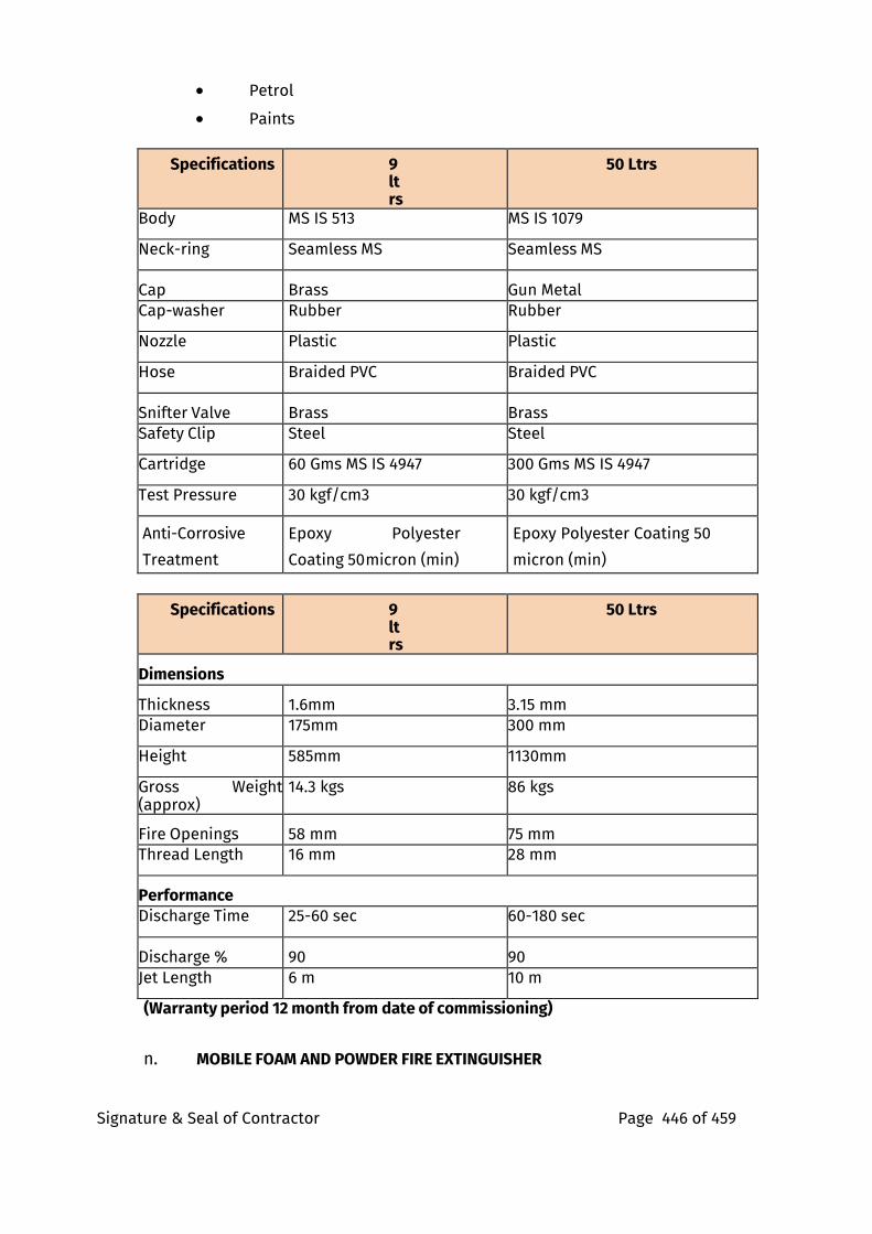
Signature & Seal of Contractor Page 446 of 459
• Petrol
• Paints
Specifications 9 ltrs
50 Ltrs
Body MS IS 513 MS IS 1079
Neck-ring Seamless MS Seamless MS
Cap Brass Gun Metal Cap-washer Rubber Rubber
Nozzle Plastic Plastic
Hose Braided PVC Braided PVC
Snifter Valve Brass Brass
Safety Clip Steel Steel
Cartridge 60 Gms MS IS 4947 300 Gms MS IS 4947
Test Pressure 30 kgf/cm3 30 kgf/cm3
Anti-Corrosive
Treatment
Epoxy Polyester
Coating 50 micron (min)
Epoxy Polyester Coating 50
micron (min)
Specifications 9 ltrs
50 Ltrs
Dimensions
Thickness 1.6mm 3.15 mm
Diameter 175mm 300 mm
Height 585mm 1130mm
Gross Weight (approx)
14.3 kgs 86 kgs
Fire Openings 58 mm 75 mm
Thread Length 16 mm 28 mm
Performance
Discharge Time 25-60 sec 60-180 sec
Discharge % 90 90
Jet Length 6 m 10 m
(Warranty period 12 month from date of commissioning)
n. MOBILE FOAM AND POWDER FIRE EXTINGUISHER
Signature & Seal of Contractor Page 447 of 459
The Mobile Foam and Powder Fire Extinguisher with nitrogen propellant cylinder. All the components of form and powder fire extinguisher shall be in compliance with the ISO 2859-1 standard.
Component’s Constructions
22.10.2Trolley The trolley structure should be made of steel sections, with rubber wheels. The foam cylinder, the nitrogen cylinder and the accessories should be fixed by saddles on a sturdy hand pulled trolley. The arrangement of the individual equipment should be designed for maximum ease of handling
Extinguisher Unit
The foam cylinder should be made of Mild steel, while the one containing the powder is made of Mild steel, both tested at 35 kgf/cm2. A large-diameter threaded ring nut should be welded at the top of the cylinders for easy charging and internal inspection during periodic testing. The rear part of the trolley should be fixed with the pressurization, control and discharge unit consisting of a nitrogen cylinder tested at 250 bars 6.8 Ltr. charged at 200 bars and having a rapid opening valve for quick pressurization of the powder and foam cylinders. The discharge of nitrogen for the pressurization is controlled by an intermediate pressure reducer calibrated at 12 bars, so, as to obtain a uniform discharge at constant pressure. Two on-off valves placed between the reducer and the cylinders can allow independent pressurization of the two cylinders. The discharge should be controlled by means of two spray nozzles made of light alloy/plastic with ergonomically designed handgrip for an easy and rapid grip. The spray nozzles should be fed by two plastic hoses, each of 19mm diameter and 5m long and should offer maximum agility and ease of handling to the operator. The unit is charged with ABC 50% powder, compatible with the AFFF 6% film-forming foam
Use
The mobile fire extinguisher is used in large fires of any class A, B, or C type, of vertically stored goods and of inflammable liquids that can spread on the surface. Normally it is used by first discharging the foam to knock down the high flames and then if necessary using the powder, compatible with the foam, to immediately put out already reduced flames MAINTENANCE: Maintenance should be done in compliance with IS: 2190 standard (Warranty period 12 month from date of commissioning)
Signature & Seal of Contractor Page 448 of 459
FIRE PUMPS AND ALLIED EQUIPMENTS
I. Scope
Work under this section shall consist of furnishing all labour, materials, equipment and appliances necessary and required to completely install electrically operated and diesel driven pumps and as required by drawings and specified hereinafter or given in the schedule of rates.
1. Electrically operated pumps with motors and diesel engine driven pumps with diesel engine, common base plates, coupling, coupling guard and accessories.
2. Automatic starting system with all accessories, wiring and connections and pressure switches.
3. Motor control centre.
4. Annunciation system with all accessories wiring and connections.
5. Pressure gauges with isolation valves and piping, bleed and block valves.
6. Suction strainers and accessories.
7. Vibration eliminator pads and foundation bolts.
8. Leak-off drain shall be led to the nearest floor drain.
General Requirements Pumps shall be installed true to levels on suitable concrete foundations. Base plate shall be firmly fixed by properly grouted foundation bolts.
Pumps and motors shall be truly aligned by suitably instruments. Record of such alignment shall be furnished to the Project Manager.
All pump connections shall be standard flanged type with number of bolts as per relevant standard requirement for the working pressure. Companion flanges shall be provided with the pumps.
Manufacturers’ instructions regarding installation, connections and commissioning shall be strictly followed.
Contractor shall provide necessary test certificates, type test certificates, performance curves and NPSH curves of the pumps from the manufacturer when called for. The contractor shall provide facilities to the Project Manager & Consultant for inspection of equipment during manufacturing and also to witness various tests at the manufacturer’s works without any cost to the Project Manager or Consultant.
Seismic isolation and clamping for each pump and flexible connection on the suction as well as the discharge side shall be provided and spacing of pumps as per latest standards and all pumps shall be installed in positive suction. The contractor shall submit with this tender a list of recommended spare parts for two years of normal operation and quote the prices for the same as a separate submittal / annexure. Flow direction tagging shall be provided to each line.
Signature & Seal of Contractor Page 449 of 459
Electric Fire Pump General
The electric fire pump shall be suitable for automatic operation complete with necessary electric motor and automatic starting gear, suitable for operation on 415 volts, 3 phase, 50 Hz. A.C. system. Both the motor and the pump shall be assembled on a common base plate, fabricated M.S. channel type or cast iron type. Drive
The pump shall be direct driven by means of a flexible coupling. Coupling guard shall also be provided.
Fire Pump The fire pump shall be horizontally mounted Split Casing centrifugal type (Multistage). It shall have a capacity to deliver 2850 lpm as specified, and developing adequate head so as to ensure a minimum pressure of 3.5 Kg/Sq.cm at the highest and the farthest outlet.
The pump shall be capable of giving a discharge of not less than 150 per cent of the rated discharge, at a head of not less than 65 per cent of the rated head. The shut off head shall be within 120 per cent of the rated head.
The pump casing shall be of cast iron to grade FG 200 to IS: 210 and parts like impeller, shaft sleeve, wearing ring etc. shall be of non-corrosive metal like bronze/brass/gun metal. The shaft shall be of stainless steel (SS 410). Provision of factory fitted mechanical seal shall also be made.
Bearings of the pump shall be effectively sealed to prevent loss of lubricant or entry of dust or water. The pump shall be provided with a plate indicating the suction lift, delivery head, discharge, speed and number of stages. The pump casing shall be designed to withstand 1.5 times the working pressure.
Provision of Jockey Pump for low and high zone shall be made. The pump shall be vertical SS type and of detail as in schedule of quantity. Contractor shall verify that the capacity of the Jockey pump shall not be less than 3% (Minimum 180 LPM) and not more than 10% of the installed pump capacity.
Motor
The motor shall be squirrel cage A.C. induction type suitable for operation on 415 volts 3 phase 50 Hz. system. The motor shall be totally enclosed fan cooled type conforming to protection clause IP 55. The class of insulation shall be F. The synchronous speed shall be 1500 RPM as specified. The motor shall be rated for continuous duty and shall have a horse power rating necessary to drive the pump at 150 per cent of its rated discharge with at least 65 per cent rated head. The motor shall conform to I.S.325-1978.
Motor Starter
The motor starter shall be as per detail in MCC. The unit shall include suitable current transformer and ammeter of suitable range on one line to indicate the current. The starter shall not incorporate under voltage, no
Signature & Seal of Contractor Page 450 of 459
voltage trip overload or SPP. The starter assembly shall be suitably integrated in the power and control panel for the wet riser system & sprinkler system.
Diesel Fire Pump General
The diesel pump set shall be suitable for automatic operation complete with necessary automatic starting gear, for starting on wet battery system and shall be complete with all accessories. Both engine and pump shall be assembled on a common base plate.
Drive
The pump shall be only direct driven by means of a flexible coupling. Coupling guard shall also be provided. The speed shall be 1500 RPM as specified.
Fire Pump
The fire pump shall be horizontally mounted Split Casing centrifugal type (Multistage). It shall have a capacity to deliver 2850 lpm as specified, and developing adequate head so as to ensure a minimum pressure of 3.5 Kg/Sq.cm at the highest and the farthest outlet.
The pump shall be capable of giving a discharge of not less than 150 per cent of the rated discharge, at a head of not less than 65 per cent of the rated head. The shut off head shall be within 120 per cent of the rated head.
The pump casing shall be of cast iron to grade FG 200 to IS: 210 and parts like impeller, shaft sleeve, wearing ring etc. shall be of non-corrosive metal like bronze/brass/gun metal. The shaft shall be of stainless steel (SS 410). Provision of factory fitted mechanical seal shall also be made.
Bearings of the pump shall be effectively sealed to prevent loss of lubricant or entry of dust or water. The pump shall be provided with a plate indicating the suction lift, delivery head, discharge, speed and number of stages. The pump casing shall be designed to withstand 1.5 times the working pressure.
Diesel Engine
Engine Rating - The engine shall be cold starting type without the necessity of preliminary heating of the engine cylinders or combustion chamber (for example, by wicks, cartridge, heater, plugs etc.). The engine shall be multi cylinder/vertical 4 stroke cycle, air-cooled, diesel engine, developing suitable HP at the operating speed specified to drive the fire pump. Continuous capacity available for the load shall be exclusive of the power requirement of auxiliaries of the diesel engine, and the after correction for altitude, ambient temperature and humidity for the specified environmental conditions. This shall be at least 20% greater than the maximum HP required to drive the pump at its duty point. It shall also be capable of driving the pump at 150% of the rated discharge at 65% of rated head. The engine shall be capable of continuous non-stop operation for 8 hours and major overhaul shall not be required before 3000 hours of operation. The engine shall have 10% overload capacity for one hour in any period of 12 hours continuous run. The engine shall accept full load within 15 seconds from the receipt of signal to start. The diesel engine shall conform to BS
Signature & Seal of Contractor Page 451 of 459
649/IS 1601/IS 10002, all amended up to date. 9. Engine Accessories - The engine shall be complete with the following
accessories:-
Fly wheel dynamically balanced.
Direct coupling for pump and coupling guard. Corrosion Resistor.
Air cleaner.
Fuel service tank support, and fuel oil filter with necessary
pipe work. Elect. starting battery (2X24 v).
Exhaust silencer with necessary
pipe work. Governor.
Instrument panel housing all the gauges, including Tachometer, hour meter and starting switch with key (for manual starting).
Necessary safety controls.
10. Fuel System - The fuel shall be gravity fed from the engine fuel tank to the engine driven fuel pump. The engine fuel tank shall be mounted either over or adjacent to the engine itself or suitably wall mounted on bracket. The fuel filter shall be suitably located to permit easy servicing.
All fuel tubing to the engine shall be with copper, with flexible hose connections where required. Plastic tubing shall not be permitted.
The fuel tank shall be of welded steel construction (3 mm. thick) and of capacity sufficient to allow the engine to run on full load for at least 8 hours. The tank shall be complete with necessary wall mounted supports, level indicator (protected against mechanical injury) inlet, outlet, overflow connections and drain plug and piping to the engine fuel tank. The outlet shall be so located as to avoid entry of any sediments into the fuel line to the engine.
As semi rotary hand pump for filling the daily service tank together with hose pipe 5 mtr. long with a foot valve etc. shall also form part of the scope of supply.
11. Lubricating Oil System- Forced feed Lub. Oil system shall be employed for positive lubrication. Necessary Lub. oil filters shall be provided, located suitably for convenient servicing.
12. Starting System- The starting system shall comprise necessary batteries (2x24v), 24 volts starter motor of adequate capacity and axle type gear to match with the toothed ring on the fly wheel. Bi metallic relay protection to protect starting motor from excessively long cranking runs suitably integrated with engine protection system shall be included within the scope of the work.
The capacity of the battery shall be suitable for meeting the needs of the starting system.
The battery capacity shall be adequate for 10 consecutive starts without recharging with cold engine under full compression.
The scope shall cover all cabling, terminals, initial charging etc.
13. Exhaust System - The exhaust system shall be complete with silencer
Signature & Seal of Contractor Page 452 of 459
suitable for outdoor installation and silencer piping including bends and accessories needed for a run of 15 metre from the engine manifold.(Adjustment rates for extra lengths shall also be given). The total back pressure shall not exceed the engine manufacture's recommendation. The exhaust piping shall be suitably supported and cover with insulation sheet.
14. Engine shut down mechanism- This shall be auto/ manually operated and shall return automatically to the starting position after use.
15. Governing System- The engine shall be provided with an adjustable governor to control the engine speed within 5% of its rated speed under all conditions of load up to full load. The governor shall be set to maintain rated pump speed at maximum pump load.
16. Engine Instrumentation- Engine instrumentation shall include the following:-
(i) Lub. oil pressure gauge. (ii) Lub. oil temperature gauge.
(iii) Water pressure gauge.
(iv) Water temperature gauge.
(v) Tachometer.
(vi) Hour meter.
The instrumentation panel shall be suitably resident mounted on the engine.
Engine Protection Devices- Following engine protection and automatic shut- down facilities shall be provided:-
xxii. Low lub.oil pressure.
xxiii. High cooling water temp.
xxiv. High lub.oil temperature.
xxv. Over speed shut down.
17. Pipe Work - All pipe lines with fittings and accessories required shall be provided for fuel oil, lub.oil and exhaust systems, copper piping of adequate sizes, shall be used for Lub.oil and fuel oil. M.S. piping will be permitted for exhaust.
18. Anti-Vibration Mounting- Suitable vibration mounting duly approved by Project Manager shall be employed for mounting the unit so as to minimize transmission of vibration to the structure. The isolation efficiency achievable shall be clearly indicated.
19. Battery Charger-Necessary float and boost charger shall be incorporated in the control section of the power and control panel, to keep the battery in trim condition. Voltmeter to indicate the state of charge of the batteries shall be provided.
Pump Sets Assembly
On the main fire sprinkler and hydrant headers near pump sets a 150 mm dia by-pass valve located in an accessible location shall be provided along
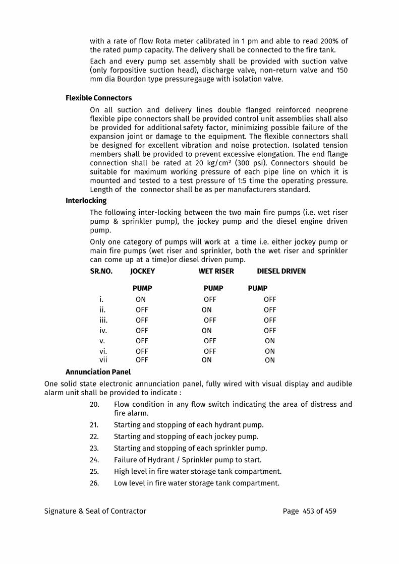
Signature & Seal of Contractor Page 453 of 459
with a rate of flow Rota meter calibrated in 1 pm and able to read 200% of the rated pump capacity. The delivery shall be connected to the fire tank.
Each and every pump set assembly shall be provided with suction valve (only forpositive suction head), discharge valve, non-return valve and 150 mm dia Bourdon type pressure gauge with isolation valve.
Flexible Connectors
On all suction and delivery lines double flanged reinforced neoprene flexible pipe connectors shall be provided control unit assemblies shall also be provided for additional safety factor, minimizing possible failure of the expansion joint or damage to the equipment. The flexible connectors shall be designed for excellent vibration and noise protection. Isolated tension members shall be provided to prevent excessive elongation. The end flange connection shall be rated at 20 kg/cm² (300 psi). Connectors should be suitable for maximum working pressure of each pipe line on which it is mounted and tested to a test pressure of 1:5 time the operating pressure. Length of the connector shall be as per manufacturers standard.
Interlocking The following inter-locking between the two main fire pumps (i.e. wet riser pump & sprinkler pump), the jockey pump and the diesel engine driven pump.
Only one category of pumps will work at a time i.e. either jockey pump or main fire pumps (wet riser and sprinkler, both the wet riser and sprinkler can come up at a time) or diesel driven pump.
SR.NO. JOCKEY WET RISER DIESEL DRIVEN
PUMP PUMP PUMP
i. ON OFF OFF
ii. OFF ON OFF
iii. OFF OFF OFF
iv. OFF ON OFF
v. OFF OFF ON
vi. OFF OFF ON vii OFF ON ON
Annunciation Panel One solid state electronic annunciation panel, fully wired with visual display and audible alarm unit shall be provided to indicate :
20. Flow condition in any flow switch indicating the area of distress and fire alarm.
21. Starting and stopping of each hydrant pump.
22. Starting and stopping of each jockey pump.
23. Starting and stopping of each sprinkler pump.
24. Failure of Hydrant / Sprinkler pump to start.
25. High level in fire water storage tank compartment.
26. Low level in fire water storage tank compartment.
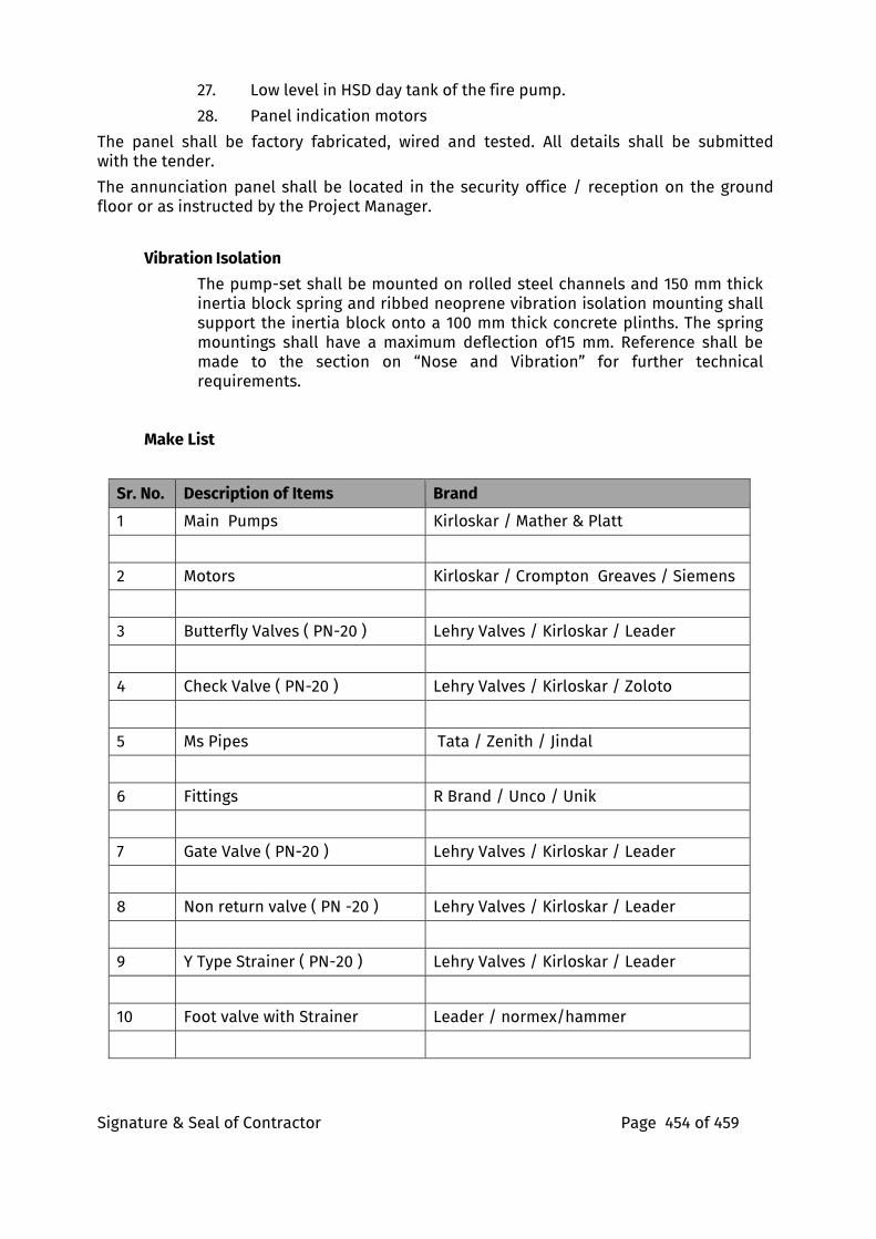
Signature & Seal of Contractor Page 454 of 459
27. Low level in HSD day tank of the fire pump.
28. Panel indication motors
The panel shall be factory fabricated, wired and tested. All details shall be submitted with the tender.
The annunciation panel shall be located in the security office / reception on the ground floor or as instructed by the Project Manager.
Vibration Isolation The pump-set shall be mounted on rolled steel channels and 150 mm thick inertia block spring and ribbed neoprene vibration isolation mounting shall support the inertia block onto a 100 mm thick concrete plinths. The spring mountings shall have a maximum deflection of15 mm. Reference shall be made to the section on “Nose and Vibration” for further technical requirements.
Make List
Sr. No. Description of Items Brand
1 Main Pumps Kirloskar / Mather & Platt
2 Motors Kirloskar / Crompton Greaves / Siemens
3 Butterfly Valves ( PN-20 ) Lehry Valves / Kirloskar / Leader
4 Check Valve ( PN-20 ) Lehry Valves / Kirloskar / Zoloto
5 Ms Pipes Tata / Zenith / Jindal
6 Fittings R Brand / Unco / Unik
7 Gate Valve ( PN-20 ) Lehry Valves / Kirloskar / Leader
8 Non return valve ( PN -20 ) Lehry Valves / Kirloskar / Leader
9 Y Type Strainer ( PN-20 ) Lehry Valves / Kirloskar / Leader
10 Foot valve with Strainer Leader / normex/hammer
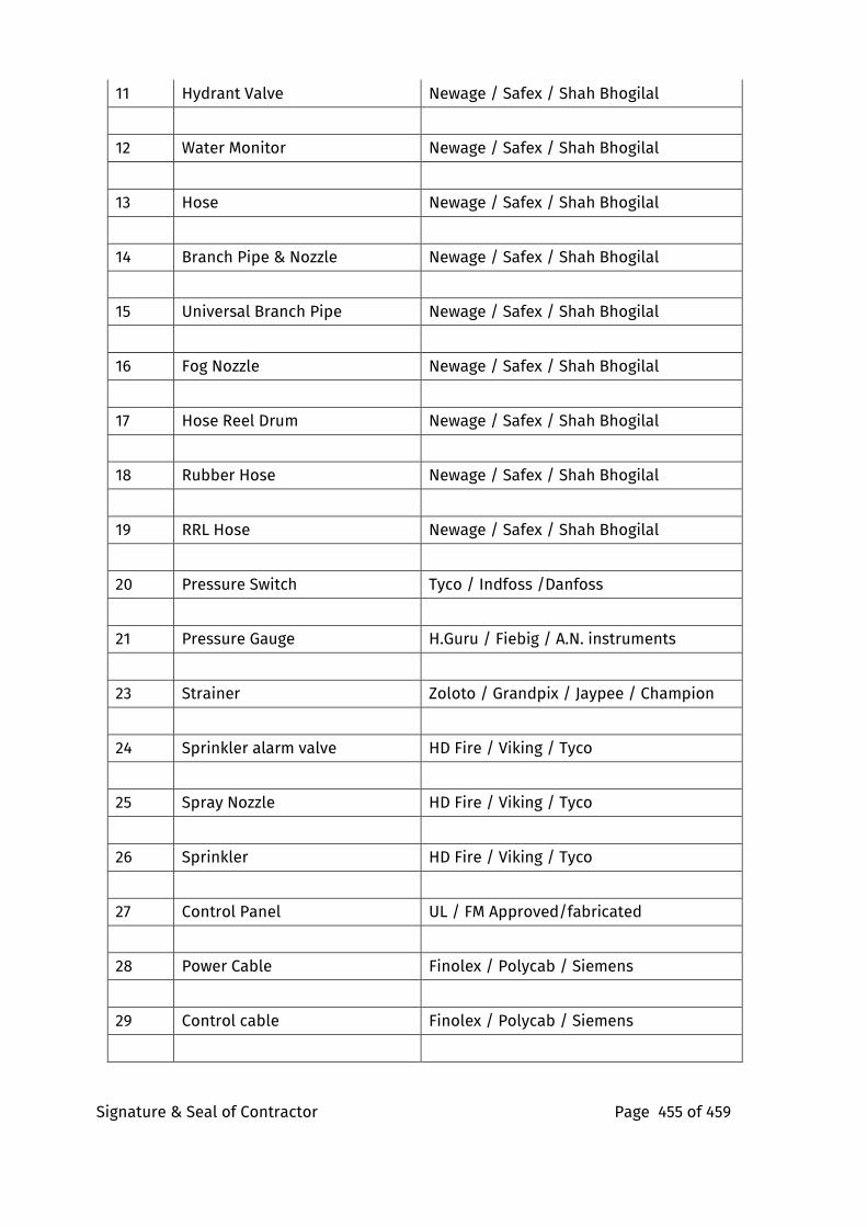
Signature & Seal of Contractor Page 455 of 459
11 Hydrant Valve Newage / Safex / Shah Bhogilal
12 Water Monitor Newage / Safex / Shah Bhogilal
13 Hose Newage / Safex / Shah Bhogilal
14 Branch Pipe & Nozzle Newage / Safex / Shah Bhogilal
15 Universal Branch Pipe Newage / Safex / Shah Bhogilal
16 Fog Nozzle Newage / Safex / Shah Bhogilal
17 Hose Reel Drum Newage / Safex / Shah Bhogilal
18 Rubber Hose Newage / Safex / Shah Bhogilal
19 RRL Hose Newage / Safex / Shah Bhogilal
20 Pressure Switch Tyco / Indfoss /Danfoss
21 Pressure Gauge H.Guru / Fiebig / A.N. instruments
23 Strainer Zoloto / Grandpix / Jaypee / Champion
24 Sprinkler alarm valve HD Fire / Viking / Tyco
25 Spray Nozzle HD Fire / Viking / Tyco
26 Sprinkler HD Fire / Viking / Tyco
27 Control Panel UL / FM Approved/fabricated
28 Power Cable Finolex / Polycab / Siemens
29 Control cable Finolex / Polycab / Siemens
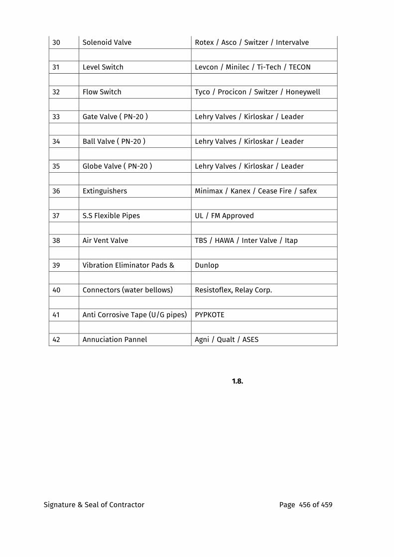
Signature & Seal of Contractor Page 456 of 459
30 Solenoid Valve Rotex / Asco / Switzer / Intervalve
31 Level Switch Levcon / Minilec / Ti-Tech / TECON
32 Flow Switch Tyco / Procicon / Switzer / Honeywell
33 Gate Valve ( PN-20 ) Lehry Valves / Kirloskar / Leader
34 Ball Valve ( PN-20 ) Lehry Valves / Kirloskar / Leader
35 Globe Valve ( PN-20 ) Lehry Valves / Kirloskar / Leader
36 Extinguishers Minimax / Kanex / Cease Fire / safex
37 S.S Flexible Pipes UL / FM Approved
38 Air Vent Valve TBS / HAWA / Inter Valve / Itap
39 Vibration Eliminator Pads & Dunlop
40 Connectors (water bellows) Resistoflex, Relay Corp.
41 Anti Corrosive Tape (U/G pipes) PYPKOTE
42 Annuciation Pannel Agni / Qualt / ASES
1.8.

Construction of 3 Multi story Towers, Nerul
Signature & Seal of Contractor Page 457 of 459
Construction of 3 Multi story Towers, Nerul
Signature & Seal of Contractor Page 458 of 459
DECLARATION
(To be typed and given on the letter – head of the Vendor)
I/We have inspected all the sites of the Proposed Construction of 3 Multi-Storied Residential Towers at State Bank of India’s Residential Colony, Sector-13, Nerul, Navi Mumbai, of State Bank of India and I/We have made me/ us fully acquainted with the local conditions in and around the sites of works and proposed layout drawings of works, drawings of each items, RFP, Technical bid & Price bid, etc. complete.
I/We hereby declare that I/ We have carefully gone through the conditions laid down in the Notice Inviting Tender, General notes, General Conditions of Contract, Special conditions, Schedule of approximate quantities and rates , Form of Agreement, General Specification, Approved manufacturers/ natural source of materials (i.e. all parts of Technical bid), Technical Specifications of schedule of quantities (i.e. all parts of Price bid), and clearly understood all the same and on the basis of the same I/ We have quoted our rates in the Schedule of Quantities/ Price Bid attached with the tender documents.
We accept all the terms and conditions of tender documents. We will abide by the technical specification mentioned in the tender. We here by undertake to use only specified material/ make as per the tender schedule.
I/ We hereby declare that, in particular during execution of all works at site; it will be my/ our sole responsibility to strictly adhere to/ meticulously follow the General Specification, Approved manufacturers/ natural source of materials; Safety, Health and Environmental (SHE) guidelines; Labour Laws; Technical Specifications of schedule of quantities, all drawings of layout and items.
For any type of deviation (to any of above or subsequent instructions), it will be my/our responsibility to obtain the written instruction of the APMC/SBI, appropriate Government Authorities, local bodies for the same failing which it shall be deemed that I have carried out any such deviations at my own and I shall be duty bound to replace all the deviated material/ works from the site at my/ our cost as well as I shall be liable to penalized by the employer as deemed fit and for all such loses made thereof, I/ we shall not have any right to arbitrate in any manner.
I/ We hereby declare that I/ We shall obtain necessary clarifications, drawings of items from APMC/SBI in time and also shall uniformly maintain such progress as may be directed by the APMC/SBI to ensure completion of same within the target date/ time as mentioned in the tender document.
Construction of 3 Multi story Towers, Nerul
Signature & Seal of Contractor Page 459 of 459
Date: Signature and seal of Contractor/Tenderer
Witness:
1.
2.