ball 2001. drilled wells.pdf - sswm.info
TRANSCRIPT

First edition: 2001, 1000 copies
Author: Peter Ball
Illustrations: Matthew Holmes
Published by: SKAT, Swiss Centre for Development Cooperationin Technology and Management
Copyright: © SKAT, 2001
Comments: Please send any comments concerning this publication to:
SKATVadianstrasse 42CH-9000 St.Gallen, Switzerland
Tel: +41 71 228 54 54Fax: +41 71 228 54 55e-mail: [email protected]
Photos: Peter BallCover photo: Crispin Hughes / Oxfam
Printed by: Niedermann Druck, St.Gallen, Switzerland
ISBN: 3-908001-98-6
Impressum
ContextAccess to adequate water, sanitation, drainage and solid waste disposal are four in-ter-related basic needs which impact significantly on socio-economic development andquality of life. The number of people around the world who still do not have accessto these basic facilities, despite enormous global effort over more than two decades,provides sufficient evidence that conventional approaches and solutions alone areunable to make a sufficient dent in the service backlog which still exists. Numerousinitiatives are ongoing at different levels to improve strategies, technologies, institu-tional arrangements, socio-cultural anchorage, and cost effectiveness, all to enhanceefficiency and, eventually, to have an impact on the sector's goals. In addition, theever-increasing scarcity of water brings policymakers together to find solutions to thechallenge of water resource management. This series of manuals is intended as acontribution to these efforts.
BackgroundThe decision to produce this series of manual was prompted by the positive experi-ence gained with a practical manual based on the experience of Helvetas (a SwissNGO) during the 1970s in Cameroon, which has become outdated with the pas-sage of time. SDC (the Swiss Agency for Development and Co-operation) supportedSKAT's initiative to produce this series, working with professionals with longstandingpractical experience in the implementation of rural water supply projects. Lessonslearnt during the workshops held by AGUASAN (an interdisciplinary working groupof water and sanitation professionals from Swiss development and research organi-sations) over the last 14 years have been included where appropriate. In particular,there is an emphasis on documenting and illustrating practical experiences from allregions of the world.
The ManualsAs can be seen from the table on the back cover, this series of manuals is prima-rily aimed at project managers, engineers and technicians. However, given the widerange of subjects covered, it is also an important working tool for all actors in thesector, ranging from those involved with policy development to those constructingsystems at village level. The series has a clear focus on water supply in rural set-tings. It proposes technologies with due consideration for socio-cultural, economic,institutional and regulatory requirements. This approach is in keeping with the SDCwater and sanitation policy, emphasising the balanced development approach lead-ing to sustainable programmes and projects.
It should be noted that the present series deals almost exclusively with water sup-ply. The importance of sanitation is however clearly established in Volume 1, whichdeals predominantly with the software aspects necessary to achieve an impact. Itincludes some proposals for optional tools, approaches and institutional arrangementsand is intended as an overall introduction to the other, more technical, volumes ofthe series.
Some final commentsThe water and sanitation sector is constantly evolving. We would welcome any que-ries, comments or suggestions you might have. Your feedback will be made avail-able to other interested users of the manuals.
Finally, we hope that these manuals will be useful for the practitioner in the fieldas well as for the planner in the office. If the series can be a contribution to provid-ing water to more people in need on a sustainable basis, we will have achievedour goal.
The production of this series has only been possible through the continuous sup-port of colleagues from all over the world. Our sincere thanks to all of them.
Armon Hartmann Karl WehrleHead of Water & Infrastructure Division Head of Water & Construction DivisionSwiss Agency for Development Co-operation SKAT
Foreword
Acknowledgments
It is hoped that the following text will be found to be a practical text of useto those that drill holes in the ground for water, the people who are engaged inefforts to provide clean water to the poorest corners of the world.
The text is based on my experiences of travelling to various corners of the worldworking with various bits of equipment and people to drill holes in the ground.I also have the opportunity of standing up in front of questioning postgraduate stu-dents finding myself trying to explain the ‘methodology of drilling’. Simply this bookwould not have been possible without those opportunities and experiences, acknowl-edgment is made to some of those organisations that made it possible.
� Oxfam GB� Concern Universal� Cranfield Institute of Technology� RedR� Tear Fund� Concern Worldwide� WEDC – at Loughborough University� Southampton University
Many thanks to Jacqui Morris whose editorial skills changed the rambling prose ofa ‘driller’ into the resemblance of good English.
Contents
Contents
Introduction ............................................................................................. 1
1. Drilling machines – The essential ingredients .................................. 3
1.1 Rotation.....................................................................................................................3
1.2 Torque & drill bits ....................................................................................................3
1.3 Hard Rock drilling ....................................................................................................3
1.4 Ground types ...........................................................................................................3
1.5 Drill pipe hoist ..........................................................................................................4
1.6 Avoiding bent holes .................................................................................................4
1.7 Lightweight rotary rigs ...........................................................................................4
2. Drilling with fluids ............................................................................ 7
2.1 Adequate pump flow for diameter of well being drilled ....................................7
2.2 Fluid circulating pumps: ‘mud pumps’ .................................................................8
2.3 Flow and friction ......................................................................................................8
2.4 Preventing hole collapse – ‘hydrostatic head’ .....................................................9
2.5 Hole Cleaning ......................................................................................................... 10
2.6 Adequate settling pits .......................................................................................... 11
2.7 Drill fluid additives .................................................................................................132.7.1 Bentonite ..................................................................................................................... 132.7.2 Polymers ..................................................................................................................... 13
2.8 Viscosity measurement ........................................................................................132.8.1 Mixing volumes........................................................................................................... 142.8.2 Correct viscosity ......................................................................................................... 14
2.9 Tips on the use of polymers ................................................................................14
2.10 Ability to biodegrade ............................................................................................. 14
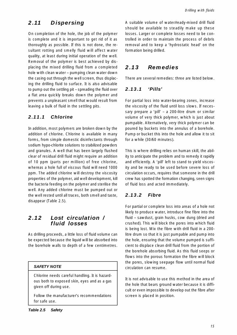
2.11 Dispersing ...............................................................................................................152.11.1 Chlorine ....................................................................................................................... 15
2.12 Lost circulation /fluid losses ...............................................................................15
2.13 Remedies................................................................................................................. 152.13.1 ‘Pills’ ........................................................................................................................... 152.13.2 Fibre ............................................................................................................................ 152.13.3 Liquid Cement ............................................................................................................. 16
2.14 Drilling Clay .............................................................................................................16
2.15 Collaring .................................................................................................................. 16
2.16 Polymer....................................................................................................................16
2.17 Summary................................................................................................................. 16
Drilled Wells
3. Drilling with compressed air .......................................................... 19
3.1 Air volume required ...............................................................................................193.1.1 Air Pressure ............................................................................................................... 213.1.2 Safety ......................................................................................................................... 21
3.2 Hole stability ..........................................................................................................21
3.3 Hole completion .....................................................................................................21
3.4 Down-the-hole hammers ......................................................................................22
3.5 Drag blade drill bits ...............................................................................................22
3.6 Power to crush ....................................................................................................... 22
3.7 Hammer types ........................................................................................................ 22
3.8 Non return valve .....................................................................................................23
3.9 General tips for reliable hammer operation.......................................................233.9.1 Lubrication .................................................................................................................. 233.9.2 Rotation speed ........................................................................................................... 233.9.3 Maintenance of drill bits ............................................................................................. 233.9.4 Hammer stripping....................................................................................................... 24
3.10 Precautions with other parts of the drilling operation ....................................243.10.1 Shock absorbers ......................................................................................................... 243.10.2 Correct adaptors ......................................................................................................... 24
3.11 Energy Efficiency ....................................................................................................25
3.12 Difficult drilling – ‘boulders’ .................................................................................253.12.1 Solutions..................................................................................................................... 26
4. Drilling with foam ........................................................................... 27
4.1 High velocity foam – air misting ......................................................................... 27
4.2 Low velocity foam – stable foam column ..........................................................27
4.3 Poor hole stability and a very messy operation ................................................27
4.4 Non-return valve sub adapter ..............................................................................28
4.5 Where can it be used? ..........................................................................................28
4.6 Well dippers ............................................................................................................28
4.7 Foam pump types ..................................................................................................284.7.1 Hand Pump ................................................................................................................ 294.7.2 Barrel Type Pump ....................................................................................................... 294.7.3 Piston Pumps ............................................................................................................. 29
4.8 Foam inlet manifold ...............................................................................................29
4.9 Mixing method ....................................................................................................... 29
4.10 Adequate foam supply ..........................................................................................30
5. Logging of samples ........................................................................ 31
5.1 Introduction ............................................................................................................31
5.2 Fluid drilled holes ...................................................................................................31
5.3 Drilling with compressed air ................................................................................31
5.4 Sample collection ..................................................................................................32
5.5 ‘Chalking’ the drill pipe .........................................................................................32
Contents
5.6 Writing up of a log .................................................................................................32
5.7 Getting it right ....................................................................................................... 32
6. Borehole design .............................................................................. 35
6.1 Hand pumps ...........................................................................................................356.1.1 Sustainability .............................................................................................................. 35
6.2 Electric Submersible pumps ................................................................................366.2.1 Installation depth ........................................................................................................ 366.2.2 Diameter of installation .............................................................................................. 36
6.3 Spindle-driven pumps ...........................................................................................36
6.4 Suction pumps ....................................................................................................... 38
6.5 Hydrogeology .........................................................................................................396.5.1 Catchment area .......................................................................................................... 396.5.2 Well-sorted sedimentary deposits .............................................................................. 396.5.3 Poorly sorted sedimentary deposit ............................................................................. 396.5.4 Porous rock................................................................................................................. 396.5.5 Fractured rock ............................................................................................................. 406.5.6 Confined and unconfined aquifers............................................................................... 40
6.6 Borehole siting near latrines ................................................................................41
6.7 Well-lining materials .............................................................................................. 416.7.1 Well casing................................................................................................................. 416.7.2 uPVC pipe ................................................................................................................... 416.7.3 Well screen ................................................................................................................ 416.7.4 Polyester ‘Geotextile’ Stocking ................................................................................... 436.7.5 Use of fine slot well screens ..................................................................................... 436.7.6 Telescopic casing & screen ....................................................................................... 436.7.7 uPVC casing and storage ........................................................................................... 43
7. Well completion .............................................................................. 45
7.1 Designing the well construction.......................................................................... 45
7.2 Volume ....................................................................................................................45
7.3 Geology and Sampling ..........................................................................................45
7.4 Depth to water ....................................................................................................... 45
7.5 Pump insertion depth ...........................................................................................45
7.6 Rough sketches ...................................................................................................... 46
7.7 Check depth and diameter of hole ......................................................................46
7.8 Preparation of materials........................................................................................46
7.9 Forming points on uPVC pipe ..............................................................................47
7.10 Lowering uPVC pipe into a drilled hole-flotation effect ....................................48
7.11 Clamping pipe ........................................................................................................ 48
7.12 Completion of boreholes in hard rock ................................................................ 48
7.13 Cementing ...............................................................................................................497.13.1 Displacement ............................................................................................................. 497.13.2 Foot ............................................................................................................................ 497.13.3 Backfilling ................................................................................................................... 49
7.14 Sanitary seal ...........................................................................................................49
7.15 Bentonite pellets ....................................................................................................49
Drilled Wells
7.16 Completion of boreholes in unconsolidated formations .................................. 507.16.1 Step 1................................................................................................................... ........507.16.2 Step 2......................................................................................................................... 5 07.16.3 Step 3......................................................................................................................... 507.16.4 Step 4......................................................................................................................... 507.16.5 Step 5......................................................................................................................... 50
7.17 Surge block development .....................................................................................50
7.18 Compressed air development ..............................................................................50
7.19 Step 6 Final hole cleaning.....................................................................................50
7.20 Step 7 Sealing ........................................................................................................ 50
7.21 Water level measurement .....................................................................................50
7.22 Well monitoring ...................................................................................................... 54
7.23 Use of gravel pack .................................................................................................547.23.1 Type of gravel ............................................................................................................. 557.23.2 Preparation of gravel .................................................................................................. 557.23.3 Annular space ............................................................................................................ 557.23.4 Gravel placement ....................................................................................................... 557.23.5 Do it right or don’t bother ........................................................................................... 55
7.24 Rudimentary test pumping .................................................................................. 597.24.1 Step 1......................................................................................................................... 597.24.2 Step 2......................................................................................................................... 597.24.3 Step 3......................................................................................................................... 597.24.4 Step 4......................................................................................................................... 60
7.25 A basic pump test .................................................................................................60
8. Use of drilling technology with hand-dug wells ............................ 61
8.1 Hand-dug wells have many advantages .............................................................61
8.2 Disadvantages of hand-dug wells........................................................................ 61
8.3 Health aspects........................................................................................................ 61
8.4 Prospecting wet sites ...........................................................................................61
8.5 Sub-Artesian - confined aquifer ...........................................................................61
8.6 Hard rock ................................................................................................................ 62
8.7 Multiple holes .........................................................................................................62
8.8 Economy of hole size ............................................................................................ 63
9. Social responsibilities of the drilling operation ............................. 65
10. When things go wrong ................................................................... 67
10.1 Stuck drill pipe ....................................................................................................... 6710.1.1 By and large these are the steps to follow................................................................ 67
10.2 Fishing .....................................................................................................................6810.2.1 Magnet ....................................................................................................................... 6810.2.2 Threaded pipes ........................................................................................................... 68
10.3 Borehole cameras ..................................................................................................68
Index ...................................................................................................... 71

Contents
Figure 1.1 Dragblade drill bit ................................................................................................................ 3Figure 1.2 Down-the-hole-hammer tungsten button drill bit .................................................................. 4Figure 2.1 Progressive cavity pumping method ................................................................................... 8Figure 2.2 Fluid drilling – Effect of eroding diameter ............................................................................. 9Figure 2.3 Hydrostatic head................................................................................................................ 10Figure 2.4 Recommended arrangements for surface settling pits ....................................................... 12Figure 2.5 Well proportioned mud pits ready for filling ........................................................................ 12Figure 2.6 Functioning mud pits – slow moving flow for good settlement ........................................... 12Figure 2.7 Marsh funnel & jug ............................................................................................................ 13Figure 2.8 Mixing polymer .................................................................................................................. 14Figure 2.9 Individual clay cuttings washed to the surface................................................................... 16Figure 2.10 Clay collar ......................................................................................................................... 16Figure 2.11 Effects of a clay collar in a hole ......................................................................................... 17Figure 3.1 Compressed Air Drilling Schematic ................................................................................... 20Figure 3.2 Drilling with compressed air – having "struck" water ......................................................... 21Figure 3.3 Down-the-hole hammer – with stripping clamp and spanner ............................................ 22Figure 3.4 Difficulties of drilling boulder-filled ground .......................................................................... 25Figure 3.5 Boulder-filled formation ..................................................................................................... 26Figure 4.1 Drilling with stable foam ................................................................................................... 27Figure 4.2 Semi rotary hand pump .................................................................................................... 28Figure 4.3 Typical foam injection manifold ......................................................................................... 29Figure 5.1 1m samples laid out for view ........................................................................................... 31Figure 5.2 Chalking pipe at datum ..................................................................................................... 33Figure 5.3 Chalking pipe at 1.3m depth .............................................................................................. 33Figure 6.1 Lever Action Hand Pump / Direct Action Hand Pump ....................................................... 35Figure 6.2 Direct Acting hand pump .................................................................................................. 36Figure 6.3 Incorrect installation of electric submersible pump ........................................................... 37Figure 6.4 Correct installation of electric submersible pump.............................................................. 37Figure 6.5 Suction pump installation .................................................................................................. 38Figure 6.6 Centrifugal pump drawing water from a 100mm (4") tubewell ........................................... 38Figure 6.7 Sedimentary formation ..................................................................................................... 39Figure 6.8 Rock types ....................................................................................................................... 40Figure 6.9 Steel Slotted pipe .............................................................................................................. 42Figure 6.10 Placement of telescopic screen using simple bayonet tool ............................................... 43Figure 7.1 Construction of hollow weighted dummy – ready for filling for weight with cement.......... 46Figure 7.2 Heating up pipe end to form points ................................................................................... 47Figure 7.3 Casing points.................................................................................................................... 47Figure 7.4 Threading uPVC casing held securely on rope wraps ........................................................ 48Figure 7.5 Well development with a surge block – Downstroke ......................................................... 51Figure 7.6 Well development with a surge block – Upstroke .............................................................. 51Figure 7.7 Airlift development Step 1 ................................................................................................. 52Figure 7.8 Airlift development Step 2 ................................................................................................. 52Figure 7.9 Airlift development Step 3 ................................................................................................. 53Figure 7.10 Airlift development Step 4 ................................................................................................. 53Figure 7.11 Air development manifold – Allowing discharge to atmosphere ........................................ 54Figure 7.12 Final stages of developing with compressed air ............................................................... 54
Figures

Drilled Wells
Figure 7.13 Fluid drilled hole naturally developed ................................................................................. 56Figure 7.14 Fluid drilled hole before development ................................................................................ 56Figure 7.15 Fluid drilled hole with placed gravel pack before development .......................................... 57Figure 7.16 Fluid drilled hole packed and developed ............................................................................ 57Figure 7.17 Use of small diameter pipe as centralisers ....................................................................... 59Figure 7.18 Gravel packing being added by funnel note water overflowing casing –
gravel dropping below screened layer ............................................................................... 59Figure 7.19 Gravel packing – note water flow up has stopped – gravel landed abobe screen level ...... 59Figure 7.20 Machine test pump – discharged water being disposed of ................................................ 60Figure 8.1 Drilled hole either through bottom of existing well or drilled first
then a dug shaft sunk around it ......................................................................................... 62Figure 8.2 Drilled holes "radiating" out to intersect rock fissures ........................................................ 63Figure 9.1 Something gone wrong ..................................................................................................... 65Figure 9.2 Borehole inadequately developed and left for user to sort out ............................................ 66Figure 9.3 Borehole properly developed and sealed ready for handover to user ................................. 66Figure 10.1 Borehole camera .............................................................................................................. 69Figure 10.2 Camera shot of rock hole .................................................................................................. 69
Table 1.1 How to calculate hoist capacity for a drilling machine......................................................... 5Table 1.2 Cross sectional area of holes.............................................................................................. 5Table 2.1 Formula to calculate required fluid circulation pump flow .................................................... 7Table 2.2 Fluid Flow in litres per minute required to drill holes of various diameters ........................... 7Table 2.3 Recommended settling pit dimensions & borehole volumes .............................................. 11Table 2.4 Typical viscosities used for drilling ..................................................................................... 14Table 2.5 Safety ................................................................................................................................ 15Table 3.1 Formula to calculate required Air Compressor capacity ..................................................... 19Table 3.2 Maximum drillbit size for specific compressors ................................................................. 19Table 6.1 Comparison between Metric & English uPVC pipe sizes ................................................... 41Table 6.2 Minimum screen opening for a range of anticipated flows ................................................ 42Table 6.3 Formula to calculate screen open area .............................................................................. 42Table 7.1 Various hole volumes – in litres ........................................................................................ 58
Tables
1
Introduction
“Give a man a fish, and you feed him for a day.Teach a man to fish, and you feed him for alifetime”.
For too many years provision of ground-watersupplies to ‘developing’ countries has been thepreserve of imported experts, who have boughtwith them construction technology designed andsuited for use in ‘developed’ countries. It is timeto replace this practice with training and moreappropriate equipment so that the ability to extractwater from boreholes becomes a permanently avail-able skill in rural communities. In this waycommunities in the developing world will be ableto meet their own demand for water at a cost theycan afford to pay.
Extremely light and portable equipment can be usedto drill holes into the ground to some quite appreci-able depths. Drilling equipment is really very simplebut its application requires sound common senseto achieve good results. To open a hole, an adequatemethod of spoil removal is essential. This needs tobe suitable both for soft ground formation, which
needs supporting, through to hard dense rock, whichmust be cut or smashed. Once a hole is opened,it needs a final construction that will allow cleanwater to be produced. All the operations mustadhere to some basic operational rules definedby existing field experience, together with acceptedengineering theories, if the drilling and well construc-tion are to succeed.
The skill of drilling and providing water is a talentavailable only to some. A drilling operation can seemto be an endless, dirty monotony of watching a drill-pipe rotate round and round, interspersed with boutsof effort to lift repeatedly pipe after pipe from a hole.However, a skilled driller is forever analysing therumbles, rattles, surges and gurgles and trying towork out what in the earth is happening.
This manual explains in practical terms the basicdrilling techniques. It describes the use of fluidcirculation in soft ground formations, and com-pressed air and hammers for hard rock. It discusseswell design, types of pump and their installation,screen selection, and testing.
Introduction

2
Drilled Wells
3
1.Drilling machines – The essentialingredients
Drilling machines – The essential ingredients
A rotary drilling machine does two essential jobs ofwork: it rotates the cutting head – ‘drill bit’, andhoists and feeds the drill pipe into and out of theground. The capacity of a particular machine toaccomplish these tasks will define its practical limi-tations. There are many other methods of drillingholes other than rotating drill bits. The most signifi-cant is the cable tool percussion method, whichuses tools oscillating up and down on a cable to drilla hole. This manual does not address this methodand restricts itself to rotating drilling machines.
1.1 Rotation
Drill bits, the tools that cut the ground, need to berotated to cut or clear a round hole. Suitable poweris required to rotate the drill bit providing the cuttingforce and to overcome any friction losses caused
by the drill-pipe dragging on the walls of theborehole. A perfectly straight hole drilled in sandrequires virtually no power because the sand offerslittle cutting resistance; stiff clay requires a drill bitwith a sharp cutting edge and sufficient power tocut the clay; considerable force is needed to cut,crush or abrade hard rock.
1.2 Torque & drill bits
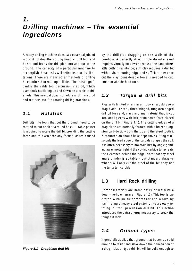
Rigs with limited or minimum power would use adrag blade: a steel, three-winged, tungsten-edgeddrill bit for sand, clays and any material that is cutinto small pieces with little or no down force placedon the drill bit (Figure 1.1). The cutting edges of adrag blade are normally formed with a brazed tung-sten carbide tip – both the tip and the steel tooth itis mounted on should have a ‘positive cutting rake’so only the lead edge of the carbide scrapes the soil.It is often necessary to maintain bits by angle grind-ing away metal behind the cutting carbide to recreatethe clearance behind the edge. Note that any steelangle grinder is suitable – but standard abrasivewheels will only cut the steel of the bit body notthe tungsten carbide.
1.3 Hard Rock drilling
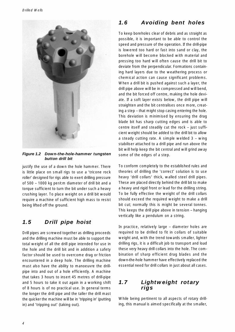
Harder materials are more easily drilled with adown-the-hole hammer (Figure 1.2). This tool is op-erated with an air compressor and works byhammering a heavy steel piston on to a slowly ro-tating ‘button’ percussion drill bit. This actionintroduces the extra energy necessary to break thetoughest rock.
1.4 Ground types
It generally applies that ground that becomes solidenough to resist and slow down the penetration ofa drag – blade - type drill bit will be solid enough toFigure 1.1 Dragblade drill bit
4
Drilled Wells
justify the use of a down the hole hammer. Thereis little place on small rigs to use a ‘tricone rockroller’ designed for rigs able to exert drilling pressureof 500 – 1000 kg per/cm diameter of drill bit and atorque sufficient to turn the bit under such a heavycrushing layer. To place weight on a drill bit wouldrequire a machine of sufficient high mass to resistbeing lifted off the ground.
1.5 Drill pipe hoist
Drill pipes are screwed together as drilling proceedsand the drilling machine must be able to support thetotal weight of all the drill pipe intended for use inthe hole and the drill bit and in addition a safetyfactor should be used to overcome drag or frictionencountered in a deep hole. The drilling machinemust also have the ability to manoeuvre the drill-pipe into and out of a hole efficiently. A machinethat takes 3 hours to insert 45 metres of drill-pipeand 5 hours to take it out again in a working shiftof 8 hours is of no practical use. In general termsthe longer the drill pipe and the taller the drill mastthe quicker the machine will be in ‘tripping in’ (puttingin) and ‘tripping out’ (taking out).
1.6 Avoiding bent holes
To keep boreholes clear of debris and as straight aspossible, it is important to be able to control thespeed and pressure of the operation. If the drill-pipeis lowered too hard or fast into sand or clay, theborehole will become blocked with material andpressing too hard will often cause the drill bit todeviate from the perpendicular. Formations contain-ing hard layers due to the weathering process orchemical action can cause significant problems.When a drill bit is pushed against such a layer, thedrill pipe above will be in compressed and will bend,and the bit forced off centre, making the hole devi-ate. If a soft layer exists below, the drill pipe willstraighten and the bit centralises once more, creat-ing a step – that might stop casing entering the hole.This deviation is minimised by ensuring the dragblade bit has sharp cutting edges and is able tocentre itself and steadily cut the rock – just suffi-cient weight should be added to the drill bit to allowa steady cutting rate. A simple welded 3 – wingstabiliser attached to a drill pipe and run above thebit will help keep the bit central and will grind awaysome of the edges of a step.
To conform completely to the established rules andtheories of drilling the ‘correct’ solution is to useheavy ‘drill collars’ thick, walled steel drill pipes.These are placed directly behind the drill bit to makea heavy and rigid front or lead for the drilling string.To be fully effective the weight of the drill collarsshould exceed the required weight to make a drillbit cut; normally this is might be several tonnes.This keeps the drill pipe above in tension – hangingvertically like a pendulum on a string.
In practice, relatively large – diameter holes arerequired to be drilled to fit in collars of suitableweight and, with the trend towards smaller, lighterdrilling rigs, it is a difficult job to transport and loadthese very heavy drill collars into the hole. The com-bination of sharp efficient drag blades and thedown-the-hole hammer have effectively replaced theessential need for drill collars in just about all cases.
1.7 Lightweight rotaryrigs
While being pertinent to all aspects of rotary drill-ing, this manual is aimed specifically at the smaller,
Figure 1.2 Down-the-hole-hammer tungstenbutton drill bit
5
lighter drilling rigs designed and specified to be assimple to operate and as light as feasible.
Reducing the overall weight and some of the com-plexity of a set of equipment, means that lesscapital is required to purchase the equipment. It alsoreduces the infrastructure and budget to maintainequipment. As, example, by making a pick-up truckfully laden at 3 tonnes the heaviest vehicle used ina drilling operation, rather than a 6 - wheel off - roadtruck at 20 tonnes, has a huge impact on where andhow a drilling operation can be carried out by whom.
Smaller equipment will be limited by power but cangenerally construct water-supply holes of the sameor similar construction as larger machines. To keepequipment small and light, however, it makes senseto design holes to take full advantage of these fac-ets.
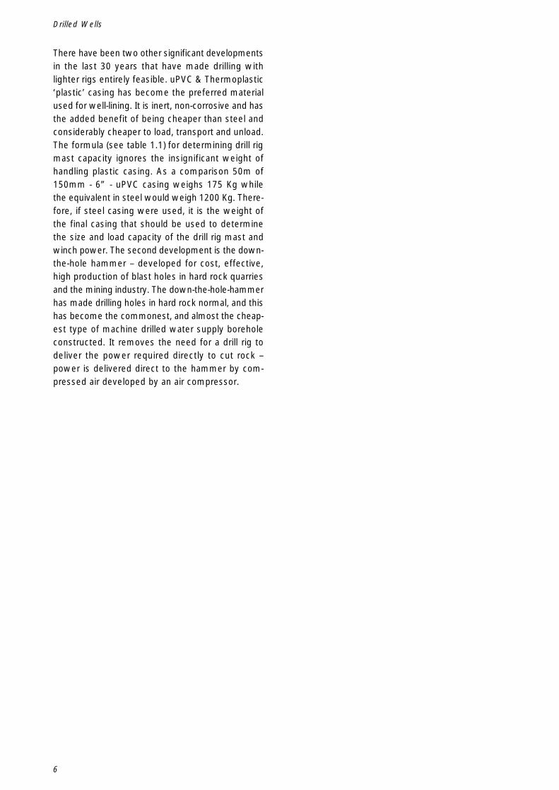
The most significant feature of a hole, and the workinvolved in creating it, is the diameter. The differ-ence between hole diameters looks insignificantwhen looking at them side by side, but it is the dif-ference in area that needs to be accounted for andthat makes a huge difference. Very broadly a 150mm - (6”) - diameter hole 6” is twice the area of a100 mm - (4”) - diameter hole. This means thattwice the volume of spoil has to be removed froma 6” hole than a 4” hole and means that twice asmuch energy is needed and the cost is raised (seetable 1.2).
Any drilling programme aiming to be cost-effectiveand efficient is advised to consider the minimumdiameter required to meet a particular requirement– even if it moves away from the normal construc-tion that has been practiced for years.
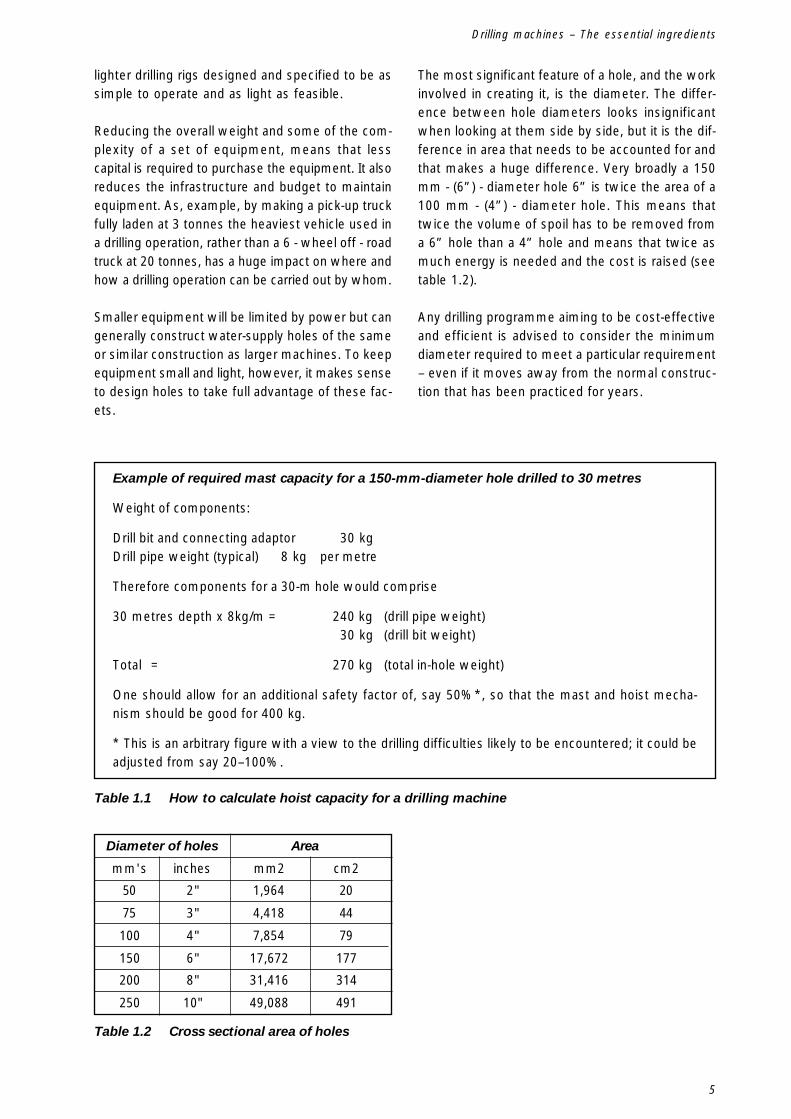
Table 1.1 How to calculate hoist capacity for a drilling machine
Table 1.2 Cross sectional area of holes
Example of required mast capacity for a 150-mm-diameter hole drilled to 30 metres
Weight of components:
Drill bit and connecting adaptor 30 kgDrill pipe weight (typical) 8 kg per metre
Therefore components for a 30-m hole would comprise
30 metres depth x 8kg/m = 240 kg (drill pipe weight)30 kg (drill bit weight)
Total = 270 kg (total in-hole weight)
One should allow for an additional safety factor of, say 50%*, so that the mast and hoist mecha-nism should be good for 400 kg.
* This is an arbitrary figure with a view to the drilling difficulties likely to be encountered; it could beadjusted from say 20–100%.
Diameter of holes Area
mm's inches mm2 cm2
50 2" 1,964 20
75 3" 4,418 44
100 4" 7,854 79
150 6" 17,672 177
200 8" 31,416 314
250 10" 49,088 491
Drilling machines – The essential ingredients
6
Drilled Wells
There have been two other significant developmentsin the last 30 years that have made drilling withlighter rigs entirely feasible. uPVC & Thermoplastic‘plastic’ casing has become the preferred materialused for well-lining. It is inert, non-corrosive and hasthe added benefit of being cheaper than steel andconsiderably cheaper to load, transport and unload.The formula (see table 1.1) for determining drill rigmast capacity ignores the insignificant weight ofhandling plastic casing. As a comparison 50m of150mm - 6” - uPVC casing weighs 175 Kg whilethe equivalent in steel would weigh 1200 Kg. There-fore, if steel casing were used, it is the weight ofthe final casing that should be used to determinethe size and load capacity of the drill rig mast andwinch power. The second development is the down-the-hole hammer – developed for cost, effective,high production of blast holes in hard rock quarriesand the mining industry. The down-the-hole-hammerhas made drilling holes in hard rock normal, and thishas become the commonest, and almost the cheap-est type of machine drilled water supply boreholeconstructed. It removes the need for a drill rig todeliver the power required directly to cut rock –power is delivered direct to the hammer by com-pressed air developed by an air compressor.
7
Fluid – plain water or water with additives – is forcedby a pump down the centre of the drill pipe throughthe drill bit and back in the annular space formedbetween drill bit and the drill pipe to the surfaceinto a ‘mud’-settling pit. The fluid does a number ofkey jobs, which each need to be properly understoodto keep the hole under construction under the con-trol of the drillers.
2.Drilling with fluids
2.1 Adequate pump flowfor diameter of wellbeing drilled
As the fluid flows through the drill bit it picks uploose debris cut by the drill bit and carries it to thesurface. It is only able to do this effectively if thewater flow is sufficiently rapid to carry the particles
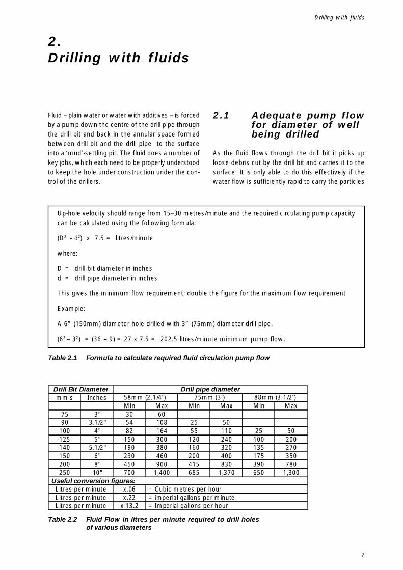
Table 2.1 Formula to calculate required fluid circulation pump flow
Table 2.2 Fluid Flow in litres per minute required to drill holesof various diameters
Up-hole velocity should range from 15–30 metres/minute and the required circulating pump capacitycan be calculated using the following formula:
(D2 - d2) x 7.5 = litres/minute
where:
D = drill bit diameter in inchesd = drill pipe diameter in inches
This gives the minimum flow requirement; double the figure for the maximum flow requirement
Example:
A 6” (150mm) diameter hole drilled with 3” (75mm) diameter drill pipe.
(62 – 32) = (36 – 9) = 27 x 7.5 = 202.5 litres/minute minimum pump flow.
mm's InchesMin Max Min Max Min Max
75 3" 30 6090 3.1/2" 54 108 25 50
100 4" 82 164 55 110 25 50125 5" 150 300 120 240 100 200140 5.1/2" 190 380 160 320 135 270150 6" 230 460 200 400 175 350200 8" 450 900 415 830 390 780250 10" 700 1,400 685 1,370 650 1,300
x.06x.22
x 13.2
Drill pipe diameter
Litres per minuteLitres per minute
Drill Bit Diameter58mm (2.1/4") 75mm (3") 88mm (3.1/2")
= Imperial gallons per hourLitres per minute
Useful conversion figures: = Cubic metres per hour = imperial gallons per minute
Drilling with fluids
8
Drilled Wells
from the bottom of the hole to the top. This speeddepends on the flow capacity of the pump and thediameter of the hole and needs to be within a spe-cific range. If it is too slow, debris will clog the holeabove the drill bit and if it is too fast it will erodethe wall of the hole and create problems with steadymaterial removal as the drilling is deepened. Table2.1& 2.2 gives examples of fluid flow speeds re-quired for various hole diameters.
2.2 Fluid circulatingpumps: ‘mud pumps’
Large, deep-hole drilling equipment invariably usesbig and powerful piston pumps of the ‘fixed displace-ment’ type. This means that they are capable ofdelivering a steady flow rate at a given piston speedno matter what pressure restrictions are placed indrill-pipe and borehole. Lighter equipment invariablyuses ‘centrifugal’ impeller pumps. These are capa-ble of delivering large volumes (flows) of water withminimal power but they have very limited capacityto develop pressure (head). Any obstructions to thefree flow of water through small, diameter hoses orfittings, or friction loss in long lengths of drill pipesincreases the pressure head and this means thatthe flow drops off.
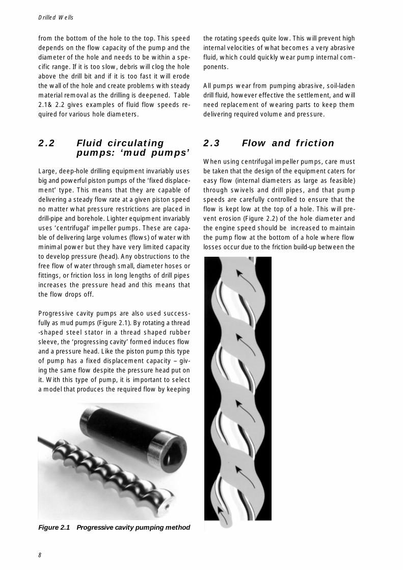
Progressive cavity pumps are also used success-fully as mud pumps (Figure 2.1). By rotating a thread-shaped steel stator in a thread shaped rubbersleeve, the ‘progressing cavity’ formed induces flowand a pressure head. Like the piston pump this typeof pump has a fixed displacement capacity – giv-ing the same flow despite the pressure head put onit. With this type of pump, it is important to selecta model that produces the required flow by keeping
Figure 2.1 Progressive cavity pumping method
the rotating speeds quite low. This will prevent highinternal velocities of what becomes a very abrasivefluid, which could quickly wear pump internal com-ponents.
All pumps wear from pumping abrasive, soil-ladendrill fluid, however effective the settlement, and willneed replacement of wearing parts to keep themdelivering required volume and pressure.
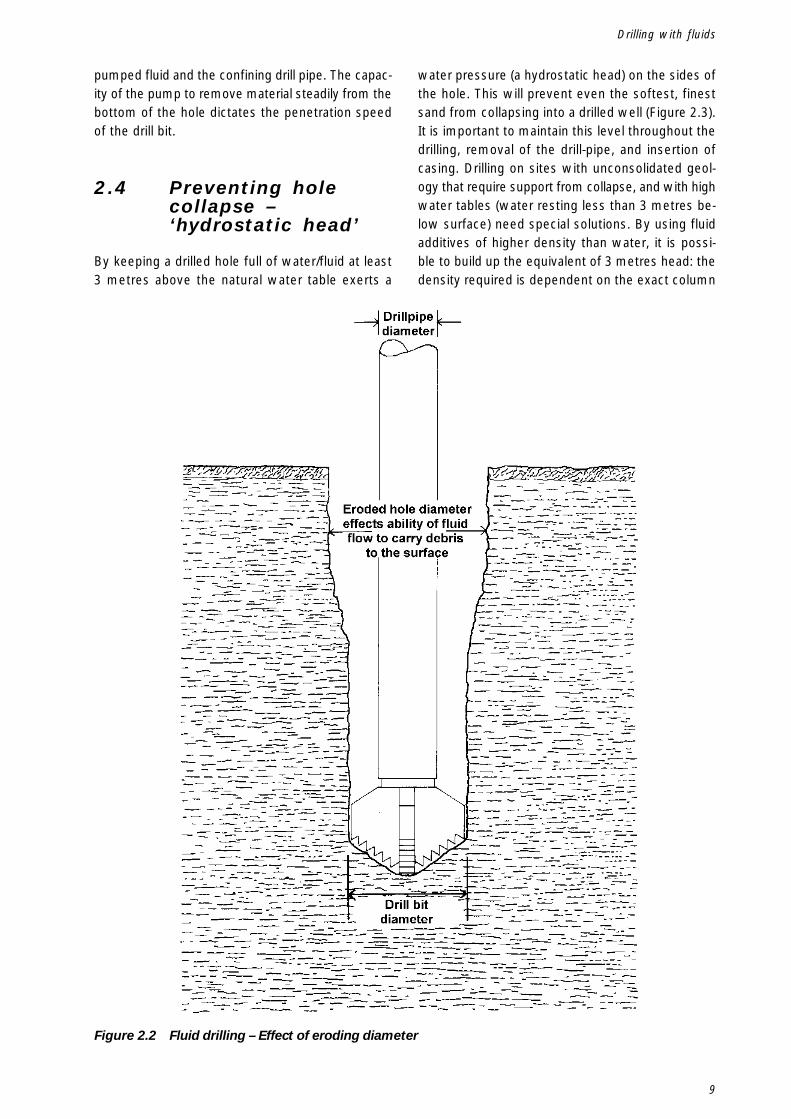
2.3 Flow and friction
When using centrifugal impeller pumps, care mustbe taken that the design of the equipment caters foreasy flow (internal diameters as large as feasible)through swivels and drill pipes, and that pumpspeeds are carefully controlled to ensure that theflow is kept low at the top of a hole. This will pre-vent erosion (Figure 2.2) of the hole diameter andthe engine speed should be increased to maintainthe pump flow at the bottom of a hole where flowlosses occur due to the friction build-up between the
9
Figure 2.2 Fluid drilling – Effect of eroding diameter
pumped fluid and the confining drill pipe. The capac-ity of the pump to remove material steadily from thebottom of the hole dictates the penetration speedof the drill bit.
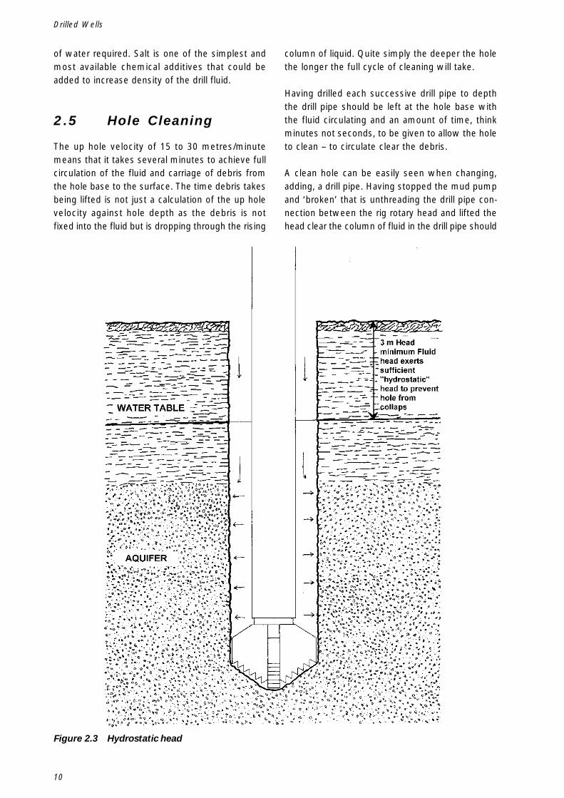
2.4 Preventing holecollapse –‘hydrostatic head’
By keeping a drilled hole full of water/fluid at least3 metres above the natural water table exerts a
water pressure (a hydrostatic head) on the sides ofthe hole. This will prevent even the softest, finestsand from collapsing into a drilled well (Figure 2.3).It is important to maintain this level throughout thedrilling, removal of the drill-pipe, and insertion ofcasing. Drilling on sites with unconsolidated geol-ogy that require support from collapse, and with highwater tables (water resting less than 3 metres be-low surface) need special solutions. By using fluidadditives of higher density than water, it is possi-ble to build up the equivalent of 3 metres head: thedensity required is dependent on the exact column
Drilling with fluids
10
Drilled Wells
of water required. Salt is one of the simplest andmost available chemical additives that could beadded to increase density of the drill fluid.
2.5 Hole Cleaning
The up hole velocity of 15 to 30 metres/minutemeans that it takes several minutes to achieve fullcirculation of the fluid and carriage of debris fromthe hole base to the surface. The time debris takesbeing lifted is not just a calculation of the up holevelocity against hole depth as the debris is notfixed into the fluid but is dropping through the rising
Figure 2.3 Hydrostatic head
column of liquid. Quite simply the deeper the holethe longer the full cycle of cleaning will take.
Having drilled each successive drill pipe to depththe drill pipe should be left at the hole base withthe fluid circulating and an amount of time, thinkminutes not seconds, to be given to allow the holeto clean – to circulate clear the debris.
A clean hole can be easily seen when changing,adding, a drill pipe. Having stopped the mud pumpand ‘broken’ that is unthreading the drill pipe con-nection between the rig rotary head and lifted thehead clear the column of fluid in the drill pipe should
11
quickly drop the short distance to the level of thefluid resting in the borehole. A hole still full of de-bris or with a blockage will result in fluid flowing outof the drill pipe. Why? It is the manifestation of dif-ferent density that is being seen – if the fluid in theannulus of the borehole has a load of debris in sus-pension it is heavier or denser than the clean‘settled’ fluid in the centre of the drill pipe so whenleft open to atmosphere – when the drill pipe con-nection is broken and lifted clear - the heavier fluidin the annulus will displace the lighter fluid in thecentre of the drill pipe.
The more ‘out of balance’, the bigger the flow outof the drill pipe the more debris is being left in thehole. Seen early a little more time can be given tohole cleaning and the problem solved – left unre-solved will mean debris could flow back into therestricted drill pipe bore and this will result in aphysical blockage that simply cannot be cleared bythe pressure head of the fluid.
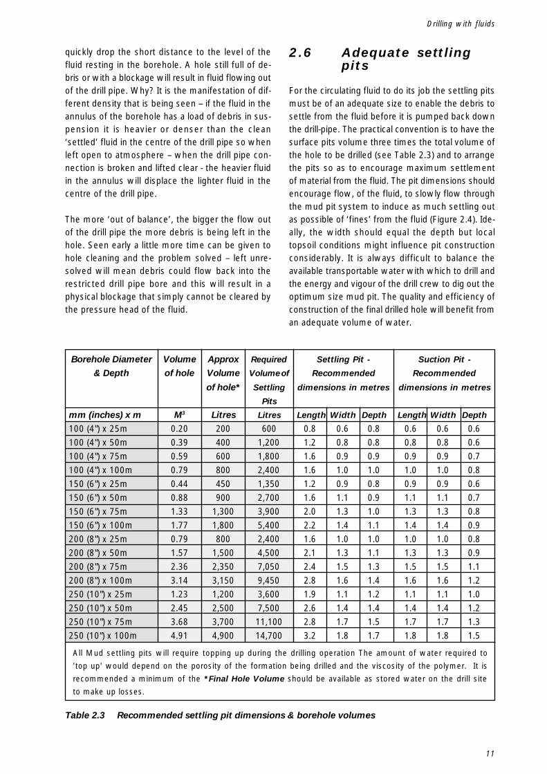
2.6 Adequate settlingpits
For the circulating fluid to do its job the settling pitsmust be of an adequate size to enable the debris tosettle from the fluid before it is pumped back downthe drill-pipe. The practical convention is to have thesurface pits volume three times the total volume ofthe hole to be drilled (see Table 2.3) and to arrangethe pits so as to encourage maximum settlementof material from the fluid. The pit dimensions shouldencourage flow, of the fluid, to slowly flow throughthe mud pit system to induce as much settling outas possible of ‘fines’ from the fluid (Figure 2.4). Ide-ally, the width should equal the depth but localtopsoil conditions might influence pit constructionconsiderably. It is always difficult to balance theavailable transportable water with which to drill andthe energy and vigour of the drill crew to dig out theoptimum size mud pit. The quality and efficiency ofconstruction of the final drilled hole will benefit froman adequate volume of water.
Table 2.3 Recommended settling pit dimensions & borehole volumes
Drilling with fluids
Borehole Diameter
& Depth
mm (inches) x m
100 (4") x 25m100 (4") x 50m100 (4") x 75m100 (4") x 100m150 (6") x 25m150 (6") x 50m150 (6") x 75m150 (6") x 100m200 (8") x 25m200 (8") x 50m200 (8") x 75m200 (8") x 100m250 (10") x 25m250 (10") x 50m250 (10") x 75m250 (10") x 100m
Volume
of hole
M3
0.200.390.590.790.440.881.331.770.791.572.363.141.232.453.684.91
Approx
Volume
of hole*
Litres
200400600800450900
1,3001,800800
1,5002,3503,1501,2002,5003,7004,900
Required
Volume of
Settling
Pits
Litres
6001,2001,8002,4001,3502,7003,9005,4002,4004,5007,0509,4503,6007,50011,10014,700
Settling Pit -
Recommended
dimensions in metres
Length Width Depth
0.8 0.6 0.81.2 0.8 0.81.6 0.9 0.91.6 1.0 1.01.2 0.9 0.81.6 1.1 0.92.0 1.3 1.02.2 1.4 1.11.6 1.0 1.02.1 1.3 1.12.4 1.5 1.32.8 1.6 1.41.9 1.1 1.22.6 1.4 1.42.8 1.7 1.53.2 1.8 1.7
Suction Pit -
Recommended
dimensions in metres
Length Width Depth
0.6 0.6 0.60.8 0.8 0.60.9 0.9 0.71.0 1.0 0.80.9 0.9 0.61.1 1.1 0.71.3 1.3 0.81.4 1.4 0.91.0 1.0 0.81.3 1.3 0.91.5 1.5 1.11.6 1.6 1.21.1 1.1 1.01.4 1.4 1.21.7 1.7 1.31.8 1.8 1.5
All Mud settling pits will require topping up during the drilling operation The amount of water required to
'top up' would depend on the porosity of the formation being drilled and the viscosity of the polymer. It is
recommended a minimum of the *Final Hole Volume should be available as stored water on the drill site
to make up losses.
12
Drilled Wells
In most cases, surface topsoil will be stable enoughto construct settling pits – clay being absolutely idealmaterial. If the pits are in soft permeable soil theycan often be satisfactorily plastered with neat ce-ment & water or possibly sand & cement to sealand strengthen the sides (Figure 2.5). Alternativelylocal clay could be used to line the pits or plastic
sheets used – take care to ensure water cannot flowbehind any sheet.
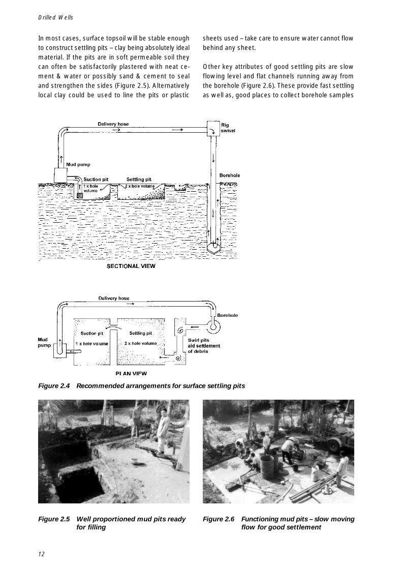
Other key attributes of good settling pits are slowflowing level and flat channels running away fromthe borehole (Figure 2.6). These provide fast settlingas well as, good places to collect borehole samples
Figure 2.4 Recommended arrangements for surface settling pits
Figure 2.5 Well proportioned mud pits readyfor filling
Figure 2.6 Functioning mud pits – slow movingflow for good settlement
13
and shovel clear a great deal of the bulk of debrisbeing drilled. The pump suction line needs to be hungon a support, lifting it from the settling pit bottombut ensuring that it is sufficiently below the pit levelso the pump is fed with as clean and settled fluidas possible.
By planning the design of mud settling pit in ad-vance, the major construction can be accomplishedbefore the main drilling equipment is taken to thesite. Mud pit construction can often use labour pro-vided by the local community.
2.7 Drill fluid additives
Drilling performance is much improved by usingadditives mixed with water. Broadly two main typesof additives are used: bentonite and polymers.
2.7.1 Bentonite
Bentonite is a natural clay, which, when mixed insufficient volume, will increase viscosity. Bentoniteproduces a ‘solids-based fluid’ that works extremelywell but will line the borehole with a ‘wall cake’ ofbentonite clay. This is impervious to water and willneed dispersal on completion of the hole with spe-cific chemical or mechanical methods. Bentonitealso needs to be left for 12 hours after initial mixingto build sufficient viscosity. For these two reasons,bentonite is not normally recommended for con-struction of water wells.
2.7.2 Polymers
The best water-well additives are natural polymers,which, when mixed with water, thicken into a vis-cous fluid. This fluid can carry debris at muchslower pumping flow rates and will also line theborehole walls to prevent heavy seepage of fluid intothe formation. It thus helps to maintain the ‘hydro-static head’ of fluid above the natural water table,keeping the borehole from collapse. It also preventspermeable water-bearing layers from contaminationby the invasion of fine ‘silty’ particles. Most poly-mers are natural products used as stabilisers andthickeners in the processed food industry and arebiodegradable, so the viscous properties will disap-pear naturally in a few days. Alternatively,introducing chlorine solutions can accelerate theirdispersal.
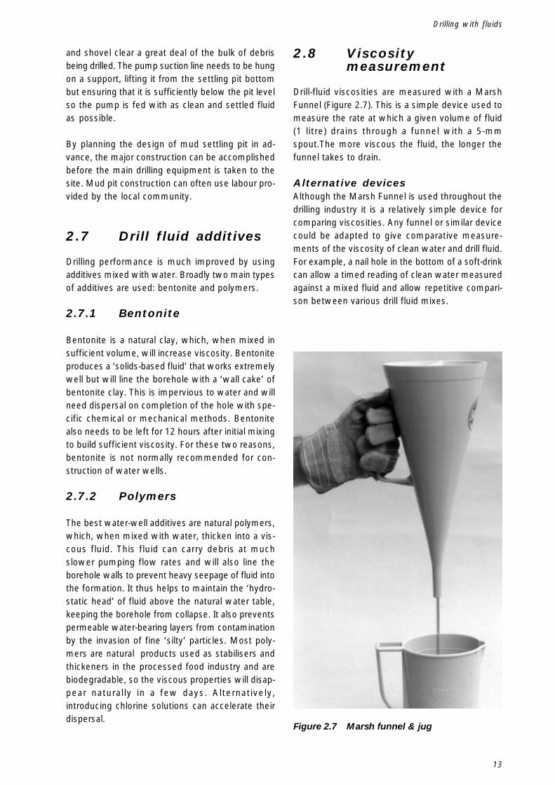
2.8 Viscositymeasurement
Drill-fluid viscosities are measured with a MarshFunnel (Figure 2.7). This is a simple device used tomeasure the rate at which a given volume of fluid(1 litre) drains through a funnel with a 5-mmspout.The more viscous the fluid, the longer thefunnel takes to drain.
Alternative devicesAlthough the Marsh Funnel is used throughout thedrilling industry it is a relatively simple device forcomparing viscosities. Any funnel or similar devicecould be adapted to give comparative measure-ments of the viscosity of clean water and drill fluid.For example, a nail hole in the bottom of a soft-drinkcan allow a timed reading of clean water measuredagainst a mixed fluid and allow repetitive compari-son between various drill fluid mixes.
Figure 2.7 Marsh funnel & jug
Drilling with fluids
14
Drilled Wells
2.8.1 Mixing volumes
At the start of drilling a hole, it is relatively easy tomatch the mud pit volume with the fluid additivebeing used. However, as drilling continues and pitsneed topping up it is easy to lose control of the vis-cosity of the drill fluid. This can lead directly to somevery specific difficulties discussed below.
2.8.2 Correct viscosity
It is important to get the viscosity just right for thejob in hand. If a fluid is too viscous (‘thick andheavy’) for the formation being drilled, it becomesladen with borehole debris. This gets re-circulatedthrough the pump, rig swivel, drill-pipe and drill bitand will cause considerable wear to components aswell as stop the ability of the fluid to pick up moredebris.
If a fluid is too light (‘runny’) it can soak into theformation being drilled, resulting in a loss of fluid inthe pits. This could lead to borehole collapse andwill also potentially damage water-bearing layers byblocking the pores with fine borehole debris carriedinto the formation by the fluid (Table 2.4).
2.9 Tips on the use ofpolymers
Polymers are quite expensive and to use more thanis required is a waste of money.
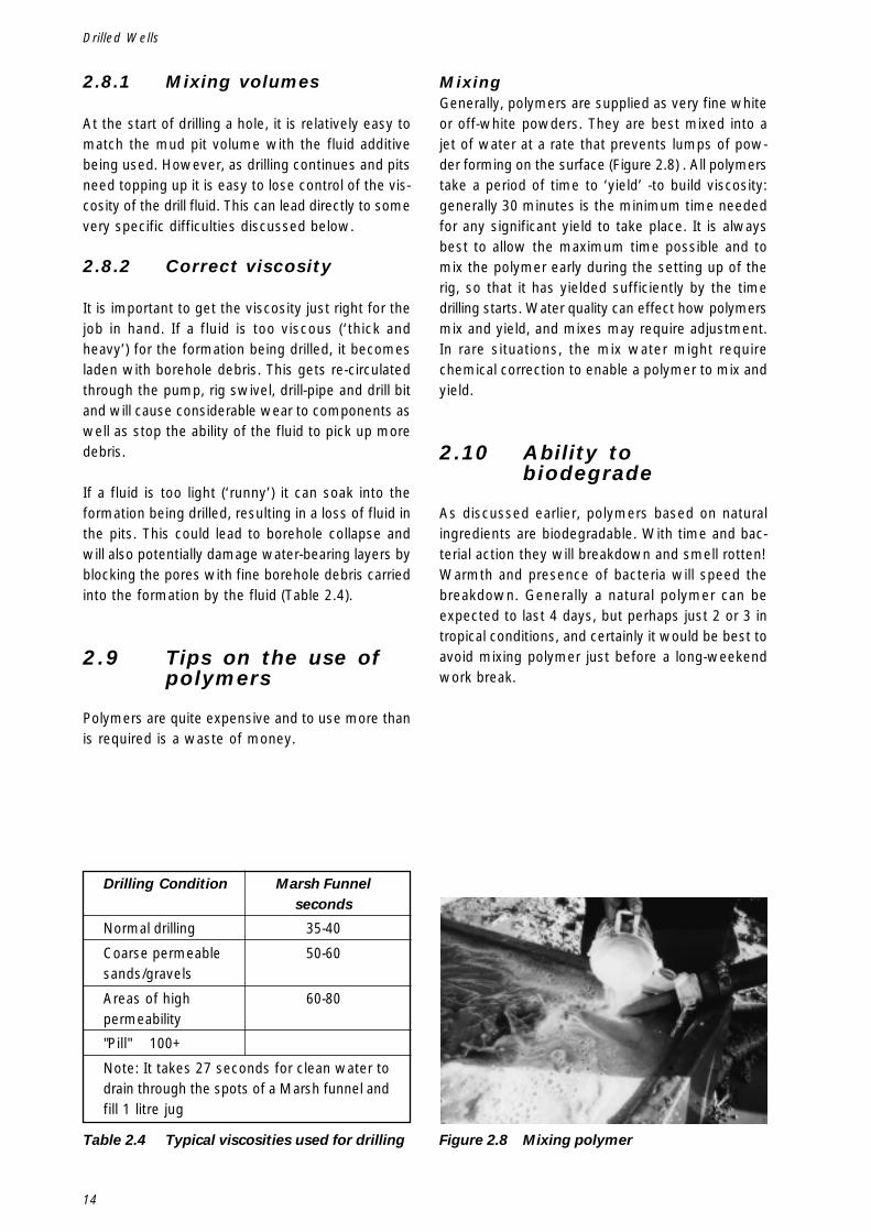
MixingGenerally, polymers are supplied as very fine whiteor off-white powders. They are best mixed into ajet of water at a rate that prevents lumps of pow-der forming on the surface (Figure 2.8) . All polymerstake a period of time to ‘yield’ -to build viscosity:generally 30 minutes is the minimum time neededfor any significant yield to take place. It is alwaysbest to allow the maximum time possible and tomix the polymer early during the setting up of therig, so that it has yielded sufficiently by the timedrilling starts. Water quality can effect how polymersmix and yield, and mixes may require adjustment.In rare situations, the mix water might requirechemical correction to enable a polymer to mix andyield.
2.10 Ability tobiodegrade
As discussed earlier, polymers based on naturalingredients are biodegradable. With time and bac-terial action they will breakdown and smell rotten!Warmth and presence of bacteria will speed thebreakdown. Generally a natural polymer can beexpected to last 4 days, but perhaps just 2 or 3 intropical conditions, and certainly it would be best toavoid mixing polymer just before a long-weekendwork break.
Table 2.4 Typical viscosities used for drilling Figure 2.8 Mixing polymer
Drilling Condition Marsh Funnelseconds
Normal drilling 35-40
Coarse permeable 50-60sands/gravels
Areas of high 60-80permeability
"Pill" 100+
Note: It takes 27 seconds for clean water todrain through the spots of a Marsh funnel andfill 1 litre jug
15
2.11 Dispersing
On completion of the hole, the job of the polymeris complete and it is important to get rid of it asthoroughly as possible. If this is not done, the re-sultant rotting and smelly fluid will affect waterquality, at least during initial operation of the well.Removal of the polymer is best achieved by dis-placing the mixed drilling fluid from a completedhole with clean water – pumping clean water downthe casing out through the well screen, thus displac-ing the drilling fluid to surface. It is also advisableto pump out the settling pit – spreading the fluid overa flat area quickly breaks down the polymer andprevents a unpleasant smell that would result fromleaving a bulk of fluid in the settling pits.
2.11.1 Chlorine
In addition, most polymers are broken down by theaddition of chlorine. Chlorine is available in manyforms, from simple domestic disinfectants throughsodium hypo-chlorite solutions to stabilized powdersand granules. A well that has been largely flushedclear of residual drill fluid might require an additionof 10 ppm (parts per million) of free chlorine,whereas a hole full of viscous fluid will need 1000ppm. The added chlorine will destroy the viscosityproperties of the polymer, aid well development, killthe bacteria feeding on the polymer and sterilise thewell. Any added chlorine must be pumped out orthe well rested until all traces, both smell and taste,disappear (Table 2.5).
2.12 Lost circulation /fluid losses
As drilling proceeds, a little loss of fluid volume canbe expected because the liquid will be absorbed intothe borehole walls to depth of a few centimetres.
A suitable volume of water/ready-mixed drill fluidshould be available to steadily make up theselosses. Larger or complete losses need to be con-trolled in order to maintain the process of debrisremoval and to keep a ‘hydrostatic head’ on theformation being drilled.
2.13 Remedies
There are several remedies: three are listed below.
2.13.1 ‘Pills’
For partial loss into water-bearing zones, increasethe viscosity of the fluid until loss slows. If neces-sary prepare a ‘pill’ – a 200-litre drum or similarvolume of very thick polymer, which is just aboutpumpable. Alternatively, very thick polymer can bepoured by buckets into the annulus of a borehole.Pump or bucket this into the hole and allow it to sitfor a while (30/60 minutes).
This is where drilling relies on human skill, the abil-ity to anticipate the problem and to remedy it rapidlyand efficiently. A ‘pill’ left to stand to yield viscos-ity and be ready to be used before severe loss ofcirculation occurs, requires that someone in the drillcrew has spotted the formation changing, seen signsof fluid loss and acted immediately.
2.13.2 Fibre
For partial or complete loss into areas of a hole notlikely to produce water, introduce fine fibre into thefluid – sawdust, grain husks, cow dung (dried andcrushed). This will block the pores into which fluidis being lost. Mix the fibre with drill fluid in a 200-litre drum so that it is just pumpable and pump intothe hole, ensuring that the volume pumped is suffi-cient to displace clean drill fluid from the portion ofthe borehole absorbing fluid. As this fluid seeps orflows into the porous formation the fibre will blockthe pores, slowing seepage flow until normal fluidcirculation can resume.
It is not advisable to use this method in the area ofthe hole that bears ground water because it is diffi-cult or even impossible to develop out the fibre afterscreen is placed in position.
Table 2.5 Safety
Drilling with fluids
SAFETY NOTE
Chlorine needs careful handling. It is hazard-ous both to exposed skin, eyes and as a gasgiven off during use.
Follow the manufacturer’s recommendationsfor safe use.
16
Drilled Wells
2.13.3 Liquid Cement
For losses uncontrollable by the first two methodsliquid cement can be used as a last resort to sealoff a specific zone permanently, particularly a fis-sure or similar formation that fibre alone is unlikelyto block.
2.14 Drilling Clay
Thick, solid bands of clay are frequently encounteredduring drilling. The key to the efficient drilling of clay is:
To drill with a sharp-toothed drag blade drill bit, whichpenetrates slowly and steadily to encourage smallcurls of clay to be steadily washed to the surface(Figure 2.9). If the bit is pushed too fast or too hard,clay will begin to clog the hole above the drill bit.Constantly monitor the returning flow to see thatflow is maintained correctly and cuttings are beingremoved in proportion to the drilling penetration.
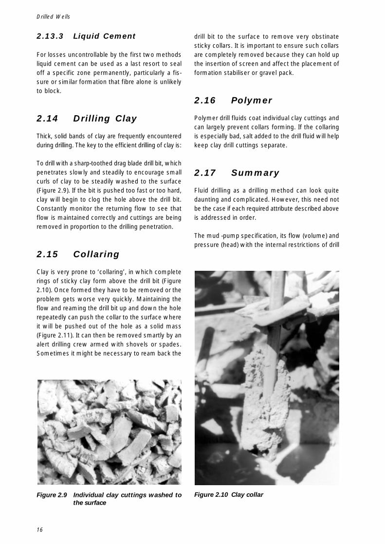
2.15 Collaring
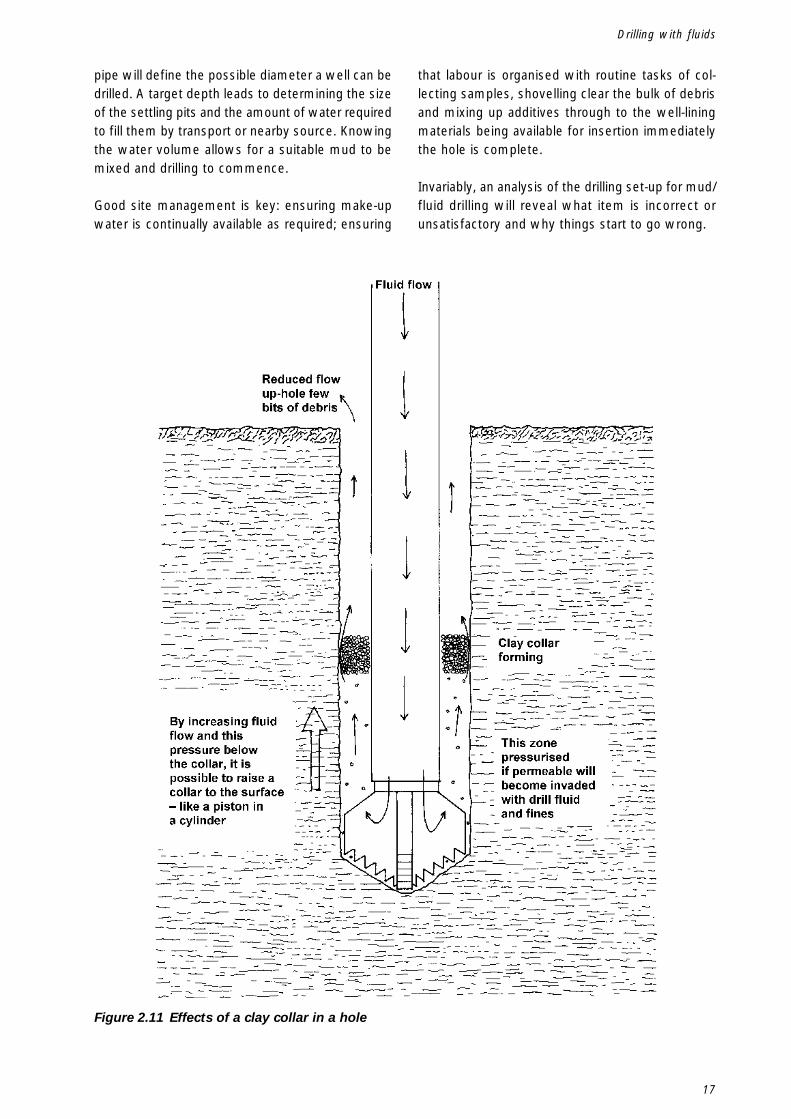
Clay is very prone to ‘collaring’, in which completerings of sticky clay form above the drill bit (Figure2.10). Once formed they have to be removed or theproblem gets worse very quickly. Maintaining theflow and reaming the drill bit up and down the holerepeatedly can push the collar to the surface whereit will be pushed out of the hole as a solid mass(Figure 2.11). It can then be removed smartly by analert drilling crew armed with shovels or spades.Sometimes it might be necessary to ream back the
drill bit to the surface to remove very obstinatesticky collars. It is important to ensure such collarsare completely removed because they can hold upthe insertion of screen and affect the placement offormation stabiliser or gravel pack.
2.16 Polymer
Polymer drill fluids coat individual clay cuttings andcan largely prevent collars forming. If the collaringis especially bad, salt added to the drill fluid will helpkeep clay drill cuttings separate.
2.17 Summary
Fluid drilling as a drilling method can look quitedaunting and complicated. However, this need notbe the case if each required attribute described aboveis addressed in order.
The mud -pump specification, its flow (volume) andpressure (head) with the internal restrictions of drill
Figure 2.9 Individual clay cuttings washed tothe surface
Figure 2.10 Clay collar
17
pipe will define the possible diameter a well can bedrilled. A target depth leads to determining the sizeof the settling pits and the amount of water requiredto fill them by transport or nearby source. Knowingthe water volume allows for a suitable mud to bemixed and drilling to commence.
Good site management is key: ensuring make-upwater is continually available as required; ensuring
that labour is organised with routine tasks of col-lecting samples, shovelling clear the bulk of debrisand mixing up additives through to the well-liningmaterials being available for insertion immediatelythe hole is complete.
Invariably, an analysis of the drilling set-up for mud/fluid drilling will reveal what item is incorrect orunsatisfactory and why things start to go wrong.
Figure 2.11 Effects of a clay collar in a hole
Drilling with fluids

18
Drilled Wells
19
Drilling with compressed air uses an air compres-sor, invariably a diesel-engine-powered piece ofconstruction plant, to produce and blow compressedair down through the centre of the drill-pipe and upthrough the annular space formed between thelarger drill bit diameter and smaller drill pipe diam-eter. The rising column of air carries borehole debristo the surface and when matched with a down-the-hole hammer introduces energy directly to the holebottom to smash the hardest of rocks.
3.Drilling with compressed air
3.1 Air volume required
The size of an air compressor is linked to the possi-ble borehole diameter; it is essential to the drillingprocess that the air travels up the hole fast enoughto carry debris with it. Note that this speed is consid-erably faster than water/fluid circulation because airis less able to support material than water (Tables 3.1& 3.2). Air Volume is specified by compressor manu-factures in units of free air delivered M3/Minute
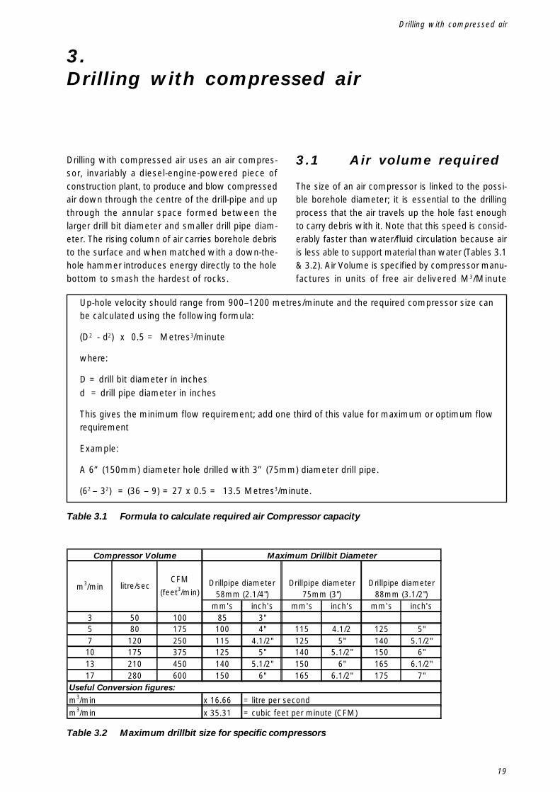
Table 3.2 Maximum drillbit size for specific compressors
Table 3.1 Formula to calculate required air Compressor capacity
Up-hole velocity should range from 900–1200 metres/minute and the required compressor size canbe calculated using the following formula:
(D2 - d2) x 0.5 = Metres3/minute
where:
D = drill bit diameter in inchesd = drill pipe diameter in inches
This gives the minimum flow requirement; add one third of this value for maximum or optimum flowrequirement
Example:
A 6” (150mm) diameter hole drilled with 3” (75mm) diameter drill pipe.
(62 – 32) = (36 – 9) = 27 x 0.5 = 13.5 Metres3/minute.
mm's inch's mm's inch's mm's inch's3 50 100 85 3"5 80 175 100 4" 115 4.1/2 125 5"7 120 250 115 4.1/2" 125 5" 140 5.1/2"
10 175 375 125 5" 140 5.1/2" 150 6"13 210 450 140 5.1/2" 150 6" 165 6.1/2"17 280 600 150 6" 165 6.1/2" 175 7"
x 16.66x 35.31
Compressor Volume
Drillpipe diameter 58mm (2.1/4")
Drillpipe diameter 75mm (3")
Drillpipe diameter 88mm (3.1/2")
Maximum Drillbit Diameter
m3/min litre/secCFM
(feet3/min)
Useful Conversion figures:
m3/minm3/min
= litre per second= cubic feet per minute (CFM)
Drilling with compressed air
20
Drilled Wells
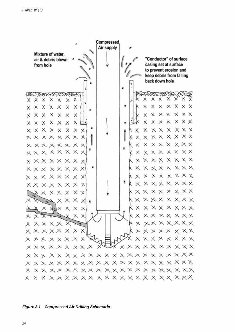
Figure 3.1 Compressed Air Drilling Schematic
21
( Cubic Metres delivered per minute) Litres/sec orCFM – Cubic Feet per minute. All these are unitsof flow or volume and not pressure or force.
3.1.1 Air Pressure
The other attribute specified by compressor manu-facturers is the pressure a unit can develop inBar or psi (pounds per sq inch). Most industrial unitswill develop a minimum of 6 bar (100psi) with spe-cialist units able to develop pressures of 20 Bar(300psi). It is the air volume that cleans the holeand is the most essential requirement of a drillingcompressor. Pressure allows more energy to bedelivered to the piston of a down-the-hole hammer– thus imparting more energy to the drill bit andallowing a faster penetration rate. Pressure is alsorequired to lift clear any resting column of water froma borehole – A 6 Bar compressor will just about lifta 60 m column of water from the base of a hole.Therefore reasonably deep holes in rock with a highgroundwater rest level might require deployment ofa high-pressure air supply just to be able to lift clearstored columns of water.
3.1.2 Safety
Compressed air (pressurised air), particularly whenavailable in high volumes as on drilling operationscan be and has proven to be lethal. Typically a hosebursting or an end-fitting breaking will cause thebroken hose end to snake around with considerablerandom force and speed. Ensure all connectinghoses and fittings are of adequate pressure rating –most good quality hose will have a pressure ratingwritten on its outer sheath. In Europe, safety lawinsists hose are ‘whip checked’ that is fitted withsafety chains or steel cable fastened independentlyto the connected machine and hose outer sheath.Look after flexible hose that joins a compressor toa drilling rig – avoid mechanical damage such assquashing or kinking – check hose couplings arefitted tightly and that bolts remain tight. Replace anyhose that has become visually weakened by useand age, for example by having a cracked outersheath.
3.2 Hole stability
Unlike water/fluid drilling, air provides no protectionfrom collapse of borehole walls. Indeed, if air is used
in soft formations the walls easily erode andthe drilling process has to stop. It is importantto protect the top lip of the hole from erosion andensure the diameter of the hole is evenly maintainedfrom the base to the top. A short piece of casingpipe with bore just a few mm larger than the drillbit should be set as a ‘conductor casing’ at the topof the hole it should be set at a depth of 500mmand protrude 100-300mm above the ground. Byhaving a lip protruding allows debris to blow clearbut not drop down the hole when airflow is turnedoff. Much longer lengths of casing are, of course,required when the top surface is soft for some depth(Figure 3.1).
3.3 Hole completion
It is often said the harder the geology – the rock -the easier the drilling construction is – this is trueassuming the correct tools are used.
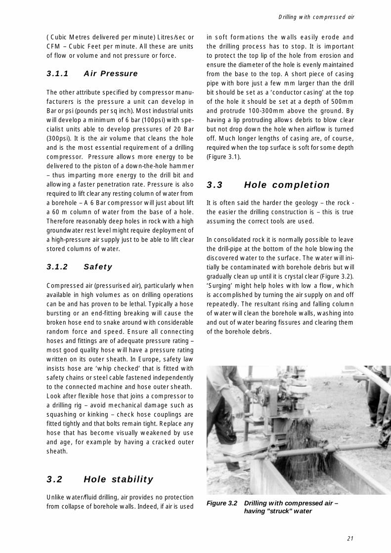
In consolidated rock it is normally possible to leavethe drill-pipe at the bottom of the hole blowing thediscovered water to the surface. The water will ini-tially be contaminated with borehole debris but willgradually clean up until it is crystal clear (Figure 3.2).‘Surging’ might help holes with low a flow, whichis accomplished by turning the air supply on and offrepeatedly. The resultant rising and falling columnof water will clean the borehole walls, washing intoand out of water bearing fissures and clearing themof the borehole debris.
Figure 3.2 Drilling with compressed air –having "struck" water
Drilling with compressed air
22
Drilled Wells
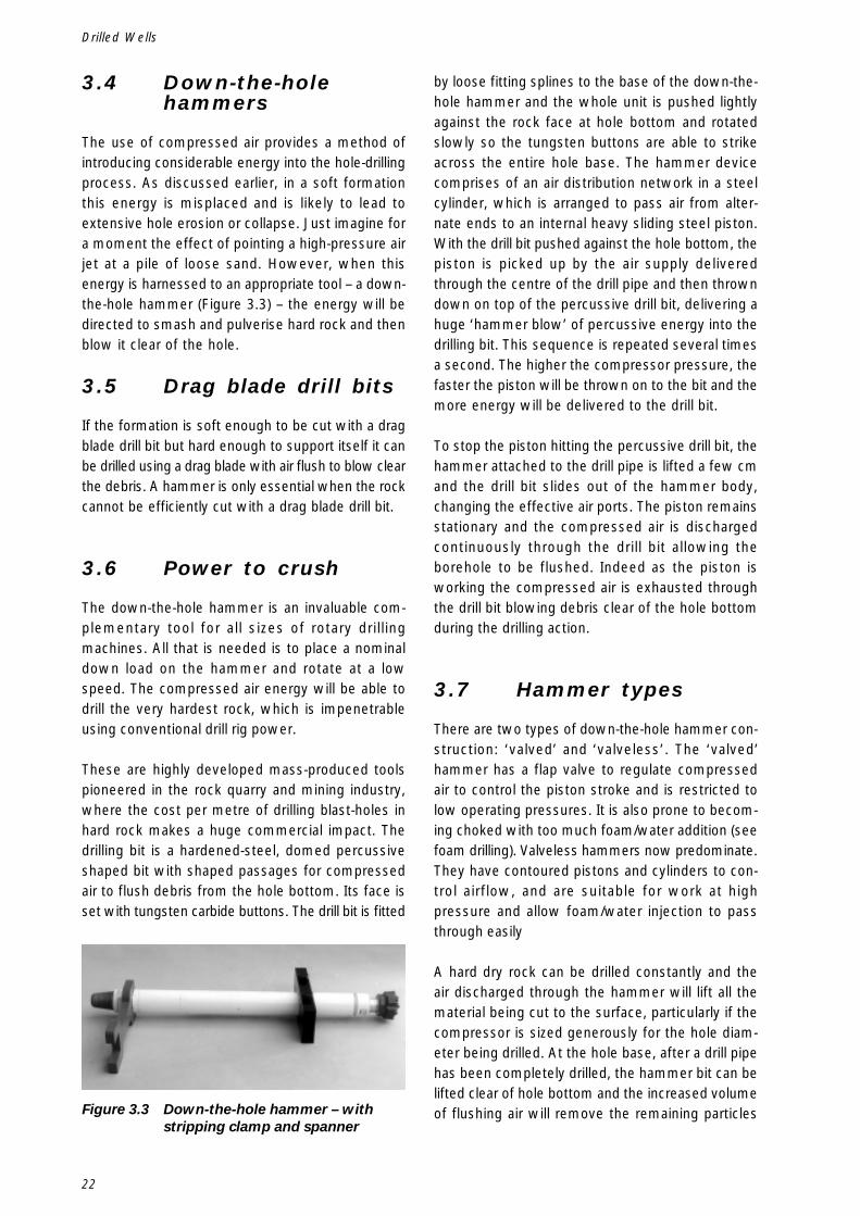
3.4 Down-the-holehammers
The use of compressed air provides a method ofintroducing considerable energy into the hole-drillingprocess. As discussed earlier, in a soft formationthis energy is misplaced and is likely to lead toextensive hole erosion or collapse. Just imagine fora moment the effect of pointing a high-pressure airjet at a pile of loose sand. However, when thisenergy is harnessed to an appropriate tool – a down-the-hole hammer (Figure 3.3) – the energy will bedirected to smash and pulverise hard rock and thenblow it clear of the hole.
3.5 Drag blade drill bits
If the formation is soft enough to be cut with a dragblade drill bit but hard enough to support itself it canbe drilled using a drag blade with air flush to blow clearthe debris. A hammer is only essential when the rockcannot be efficiently cut with a drag blade drill bit.
3.6 Power to crush
The down-the-hole hammer is an invaluable com-plementary tool for all sizes of rotary drillingmachines. All that is needed is to place a nominaldown load on the hammer and rotate at a lowspeed. The compressed air energy will be able todrill the very hardest rock, which is impenetrableusing conventional drill rig power.
These are highly developed mass-produced toolspioneered in the rock quarry and mining industry,where the cost per metre of drilling blast-holes inhard rock makes a huge commercial impact. Thedrilling bit is a hardened-steel, domed percussiveshaped bit with shaped passages for compressedair to flush debris from the hole bottom. Its face isset with tungsten carbide buttons. The drill bit is fitted
by loose fitting splines to the base of the down-the-hole hammer and the whole unit is pushed lightlyagainst the rock face at hole bottom and rotatedslowly so the tungsten buttons are able to strikeacross the entire hole base. The hammer devicecomprises of an air distribution network in a steelcylinder, which is arranged to pass air from alter-nate ends to an internal heavy sliding steel piston.With the drill bit pushed against the hole bottom, thepiston is picked up by the air supply deliveredthrough the centre of the drill pipe and then throwndown on top of the percussive drill bit, delivering ahuge ‘hammer blow’ of percussive energy into thedrilling bit. This sequence is repeated several timesa second. The higher the compressor pressure, thefaster the piston will be thrown on to the bit and themore energy will be delivered to the drill bit.
To stop the piston hitting the percussive drill bit, thehammer attached to the drill pipe is lifted a few cmand the drill bit slides out of the hammer body,changing the effective air ports. The piston remainsstationary and the compressed air is dischargedcontinuously through the drill bit allowing theborehole to be flushed. Indeed as the piston isworking the compressed air is exhausted throughthe drill bit blowing debris clear of the hole bottomduring the drilling action.
3.7 Hammer types
There are two types of down-the-hole hammer con-struction: ‘valved’ and ‘valveless’. The ‘valved’hammer has a flap valve to regulate compressedair to control the piston stroke and is restricted tolow operating pressures. It is also prone to becom-ing choked with too much foam/water addition (seefoam drilling). Valveless hammers now predominate.They have contoured pistons and cylinders to con-trol airflow, and are suitable for work at highpressure and allow foam/water injection to passthrough easily
A hard dry rock can be drilled constantly and theair discharged through the hammer will lift all thematerial being cut to the surface, particularly if thecompressor is sized generously for the hole diam-eter being drilled. At the hole base, after a drill pipehas been completely drilled, the hammer bit can belifted clear of hole bottom and the increased volumeof flushing air will remove the remaining particlesFigure 3.3 Down-the-hole hammer – with
stripping clamp and spanner
23
in a few seconds. When a hole is meeting waterand becoming sticky, or the ground is broken or soft,the regular removal of spoil will stop. In this situa-tion addition of foam or water injection might help,but the driller might have to lift clear the hammereach half metre to use the increased air flush toclean the hole.
However powerful a down-the-hole hammer iscapable at smashing into hard rock, it can takea very insignificant rock particle or damp collared layerof fine dust above the hammer to jam it tight in a hole.
3.8 Non return valve
When drilling ‘under water’ after water has beenstruck it is essential that the hammer is fitted witha non-return valve. This allows air to be deliveredthrough the drill pipe to the hammer but does notallow air to pass through the hammer back into thedrill pipe. This allows drill pipe to be disconnectedto add further pipes, and prevents water dirty withborehole debris from entering the hammer piston andvalve mechanism. Most modern hammers alwayshave these valves fitted but they need to be kept ingood working order.
3.9 General tips forreliable hammeroperation
3.9.1 Lubrication
Hammer manufactures universally like to see theirproducts continually lubricated with a mist of spe-cial fine lubricant added into the air supply. Airlinelubricators are often part of modern drilling packages.In practice, down-the-hole hammers continue tooperate reliably without the special oil required,which can be difficult to obtain means that it iscommon to see a hammer operation without thebenefit of continual lubrication particularly in remotelocations. Invariably the water-well driller will likeand prefer to use water/foam injection to keep thehole being drilled clean and non-sticky and in partthe water injection provides some lubrication.
One common practice, in place of a functioning air-line lubricator, is for the drill crew to pour a smallcapful of clean oil into the centre of the drill pipe each
time a new drill pipe is added – this helps maintainsome lubrication and quickly becomes an estab-lished drill crew routine.
The compressed air needs to be delivered clean tothe hammer. Ideally drill pipe used for mud drillingshould be kept separate from drill pipe used forhammer drilling. If this is unavoidable and the samedrill pipe has to be used for both types of drilling, itwill help to keep the pipe as clean as possible in-ternally – using threaded plastic end caps help a lot.Often drill crew adopt the routine of blowing througheach new pipe added to the drill string . This is doneby adding a drill pipe to the rotary head first and thencovering the drill pipe already in the hole at the rigtable. A blast of a few seconds of compressed airwill blow through the worst of any contamination inthe new drill pipe.
On completion of a hole and when the hammer hasbeen bought back to surface a small cupful of oilshould be poured into it and air blown through tolubricate the sliding parts this is particularly neces-sary when it has been used with water/foaminjection. As the hammer is removed or added tothe rig it can be turned over end to end by hand tocheck the piston is able to freely slide up and downthe inside the hammer body it will make a dull thunkas it moves up and down – choose a moment whenengines are turned off! Many drill crews will checkthe hammer is operating correctly before insertinginto the hole by connecting it to the rotary head andhammering a few blows against a short stout pieceof timber -never use steel because it will break thetungsten buttons.
3.9.2 Rotation speed
Rotation speed should be from 20/30 revs/minuteon most small hammers. Rotation is required onlyto allow the tungsten carbide buttons to strike thehole bottom uniformly. Rotating too fast adds noth-ing to the drilling performance. Evidence of runningto fast can be seen by looking at the outer row ofbuttons of a worked button bit will show wear andflattening significantly before the inner buttons.
3.9.3 Maintenance of drill bits
The tungsten buttons can lose their specific shape– and be reshaped using diamond cutting shoes andbit regrinding tools. This procedure is often more ap-
Drilling with compressed air
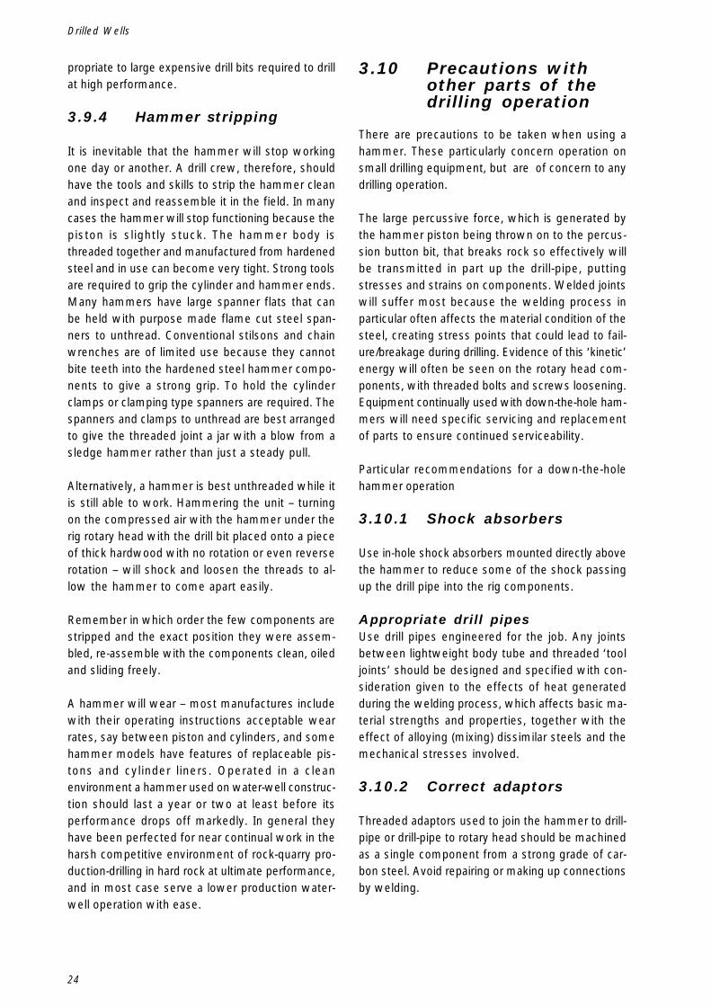
24
Drilled Wells
propriate to large expensive drill bits required to drillat high performance.
3.9.4 Hammer stripping
It is inevitable that the hammer will stop workingone day or another. A drill crew, therefore, shouldhave the tools and skills to strip the hammer cleanand inspect and reassemble it in the field. In manycases the hammer will stop functioning because thepiston is slightly stuck. The hammer body isthreaded together and manufactured from hardenedsteel and in use can become very tight. Strong toolsare required to grip the cylinder and hammer ends.Many hammers have large spanner flats that canbe held with purpose made flame cut steel span-ners to unthread. Conventional stilsons and chainwrenches are of limited use because they cannotbite teeth into the hardened steel hammer compo-nents to give a strong grip. To hold the cylinderclamps or clamping type spanners are required. Thespanners and clamps to unthread are best arrangedto give the threaded joint a jar with a blow from asledge hammer rather than just a steady pull.
Alternatively, a hammer is best unthreaded while itis still able to work. Hammering the unit – turningon the compressed air with the hammer under therig rotary head with the drill bit placed onto a pieceof thick hardwood with no rotation or even reverserotation – will shock and loosen the threads to al-low the hammer to come apart easily.
Remember in which order the few components arestripped and the exact position they were assem-bled, re-assemble with the components clean, oiledand sliding freely.
A hammer will wear – most manufactures includewith their operating instructions acceptable wearrates, say between piston and cylinders, and somehammer models have features of replaceable pis-tons and cylinder liners. Operated in a cleanenvironment a hammer used on water-well construc-tion should last a year or two at least before itsperformance drops off markedly. In general theyhave been perfected for near continual work in theharsh competitive environment of rock-quarry pro-duction-drilling in hard rock at ultimate performance,and in most case serve a lower production water-well operation with ease.
3.10 Precautions withother parts of thedrilling operation
There are precautions to be taken when using ahammer. These particularly concern operation onsmall drilling equipment, but are of concern to anydrilling operation.
The large percussive force, which is generated bythe hammer piston being thrown on to the percus-sion button bit, that breaks rock so effectively willbe transmitted in part up the drill-pipe, puttingstresses and strains on components. Welded jointswill suffer most because the welding process inparticular often affects the material condition of thesteel, creating stress points that could lead to fail-ure/breakage during drilling. Evidence of this ‘kinetic’energy will often be seen on the rotary head com-ponents, with threaded bolts and screws loosening.Equipment continually used with down-the-hole ham-mers will need specific servicing and replacementof parts to ensure continued serviceability.
Particular recommendations for a down-the-holehammer operation
3.10.1 Shock absorbers
Use in-hole shock absorbers mounted directly abovethe hammer to reduce some of the shock passingup the drill pipe into the rig components.
Appropriate drill pipesUse drill pipes engineered for the job. Any jointsbetween lightweight body tube and threaded ‘tooljoints’ should be designed and specified with con-sideration given to the effects of heat generatedduring the welding process, which affects basic ma-terial strengths and properties, together with theeffect of alloying (mixing) dissimilar steels and themechanical stresses involved.
3.10.2 Correct adaptors
Threaded adaptors used to join the hammer to drill-pipe or drill-pipe to rotary head should be machinedas a single component from a strong grade of car-bon steel. Avoid repairing or making up connectionsby welding.
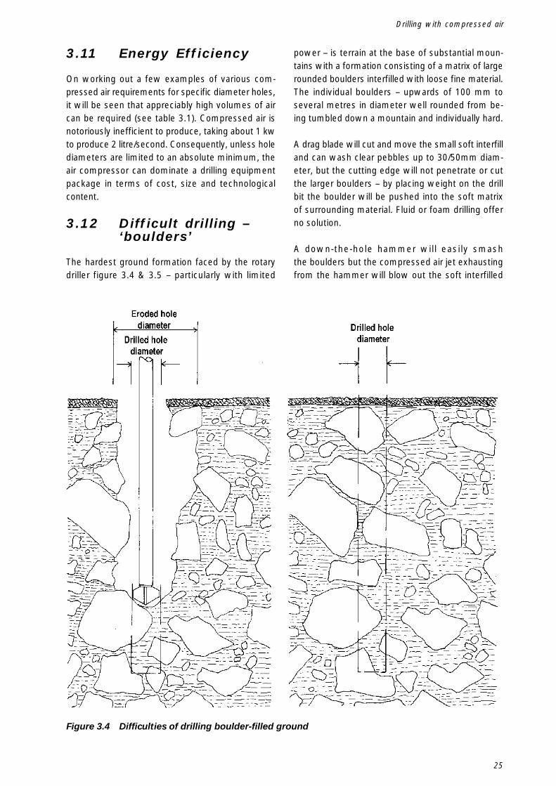
25
3.11 Energy Efficiency
On working out a few examples of various com-pressed air requirements for specific diameter holes,it will be seen that appreciably high volumes of aircan be required (see table 3.1). Compressed air isnotoriously inefficient to produce, taking about 1 kwto produce 2 litre/second. Consequently, unless holediameters are limited to an absolute minimum, theair compressor can dominate a drilling equipmentpackage in terms of cost, size and technologicalcontent.
3.12 Difficult drilling –‘boulders’
The hardest ground formation faced by the rotarydriller figure 3.4 & 3.5 – particularly with limited
power – is terrain at the base of substantial moun-tains with a formation consisting of a matrix of largerounded boulders interfilled with loose fine material.The individual boulders – upwards of 100 mm toseveral metres in diameter well rounded from be-ing tumbled down a mountain and individually hard.
A drag blade will cut and move the small soft interfilland can wash clear pebbles up to 30/50mm diam-eter, but the cutting edge will not penetrate or cutthe larger boulders – by placing weight on the drillbit the boulder will be pushed into the soft matrixof surrounding material. Fluid or foam drilling offerno solution.
A down-the-hole hammer will easily smashthe boulders but the compressed air jet exhaustingfrom the hammer will blow out the soft interfilled
Figure 3.4 Difficulties of drilling boulder-filled ground
Drilling with compressed air
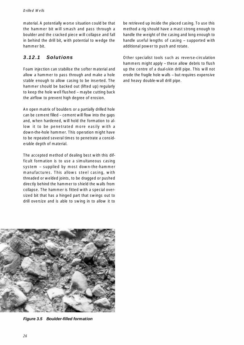
26
Drilled Wells
material. A potentially worse situation could be thatthe hammer bit will smash and pass through aboulder and the cracked piece will collapse and fallin behind the drill bit, with potential to wedge thehammer bit.
3.12.1 Solutions
Foam injection can stabilise the softer material andallow a hammer to pass through and make a holestable enough to allow casing to be inserted. Thehammer should be backed out (lifted up) regularlyto keep the hole well flushed – maybe cutting backthe airflow to prevent high degree of erosion.
An open matrix of boulders or a partially drilled holecan be cement filled – cement will flow into the gapsand, when hardened, will hold the formation to al-low it to be penetrated more easily with adown-the-hole hammer. This operation might haveto be repeated several times to penetrate a consid-erable depth of material.
The accepted method of dealing best with this dif-ficult formation is to use a simultaneous casingsystem – supplied by most down-the-hammermanufactures. This allows steel casing, withthreaded or welded joints, to be dragged or pusheddirectly behind the hammer to shield the walls fromcollapse. The hammer is fitted with a special over-sized bit that has a hinged part that swings out todrill oversize and is able to swing in to allow it to
Figure 3.5 Boulder-filled formation
be retrieved up inside the placed casing. To use thismethod a rig should have a mast strong enough tohandle the weight of the casing and long enough tohandle useful lengths of casing – supported withadditional power to push and rotate.
Other specialist tools such as reverse-circulationhammers might apply – these allow debris to flushup the centre of a dual-skin drill pipe. This will noterode the fragile hole walls – but requires expensiveand heavy double-wall drill pipe.
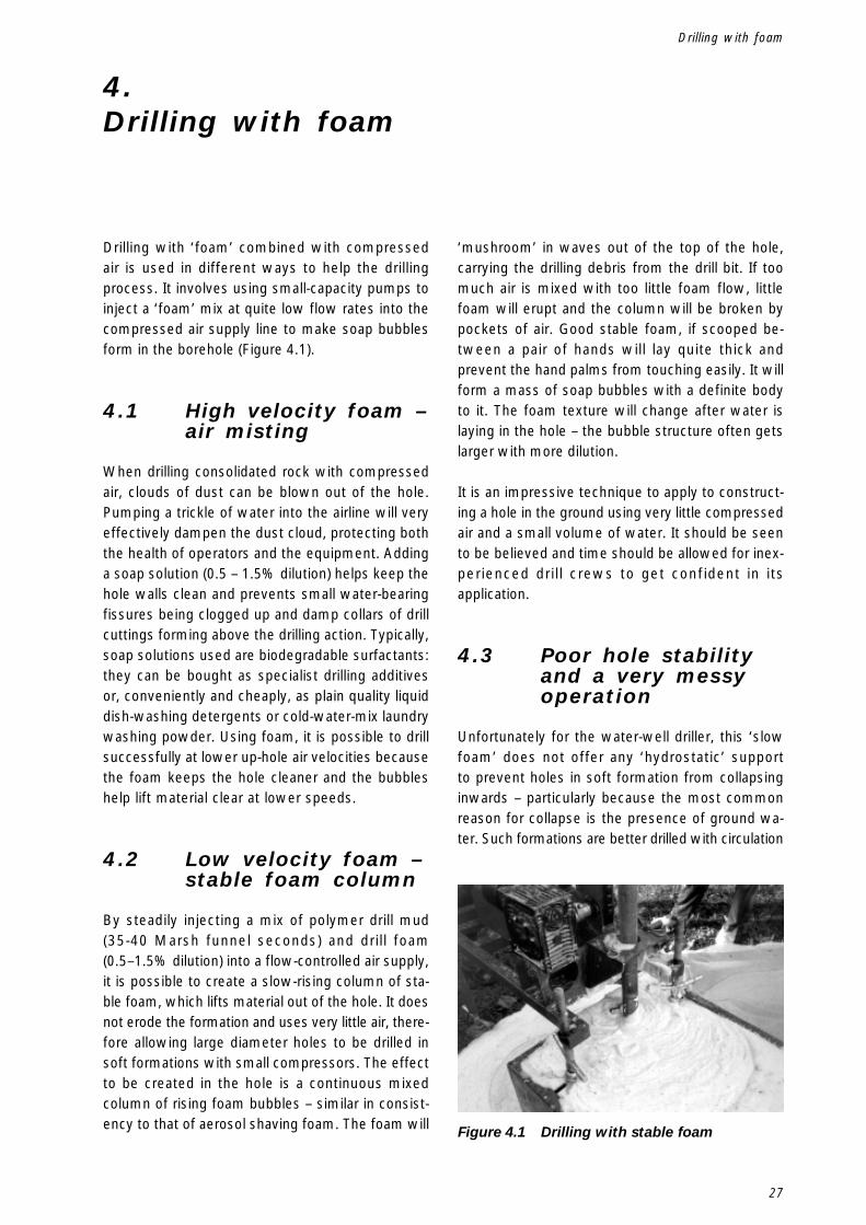
27
4.Drilling with foam
Drilling with ‘foam’ combined with compressedair is used in different ways to help the drillingprocess. It involves using small-capacity pumps toinject a ‘foam’ mix at quite low flow rates into thecompressed air supply line to make soap bubblesform in the borehole (Figure 4.1).
4.1 High velocity foam –air misting
When drilling consolidated rock with compressedair, clouds of dust can be blown out of the hole.Pumping a trickle of water into the airline will veryeffectively dampen the dust cloud, protecting boththe health of operators and the equipment. Addinga soap solution (0.5 – 1.5% dilution) helps keep thehole walls clean and prevents small water-bearingfissures being clogged up and damp collars of drillcuttings forming above the drilling action. Typically,soap solutions used are biodegradable surfactants:they can be bought as specialist drilling additivesor, conveniently and cheaply, as plain quality liquiddish-washing detergents or cold-water-mix laundrywashing powder. Using foam, it is possible to drillsuccessfully at lower up-hole air velocities becausethe foam keeps the hole cleaner and the bubbleshelp lift material clear at lower speeds.
4.2 Low velocity foam –stable foam column
By steadily injecting a mix of polymer drill mud(35-40 Marsh funnel seconds) and drill foam(0.5–1.5% dilution) into a flow-controlled air supply,it is possible to create a slow-rising column of sta-ble foam, which lifts material out of the hole. It doesnot erode the formation and uses very little air, there-fore allowing large diameter holes to be drilled insoft formations with small compressors. The effectto be created in the hole is a continuous mixedcolumn of rising foam bubbles – similar in consist-ency to that of aerosol shaving foam. The foam will
‘mushroom’ in waves out of the top of the hole,carrying the drilling debris from the drill bit. If toomuch air is mixed with too little foam flow, littlefoam will erupt and the column will be broken bypockets of air. Good stable foam, if scooped be-tween a pair of hands will lay quite thick andprevent the hand palms from touching easily. It willform a mass of soap bubbles with a definite bodyto it. The foam texture will change after water islaying in the hole – the bubble structure often getslarger with more dilution.
It is an impressive technique to apply to construct-ing a hole in the ground using very little compressedair and a small volume of water. It should be seento be believed and time should be allowed for inex-perienced drill crews to get confident in itsapplication.
4.3 Poor hole stabilityand a very messyoperation
Unfortunately for the water-well driller, this ‘slowfoam’ does not offer any ‘hydrostatic’ supportto prevent holes in soft formation from collapsinginwards – particularly because the most commonreason for collapse is the presence of ground wa-ter. Such formations are better drilled with circulation
Figure 4.1 Drilling with stable foam
Drilling with foam
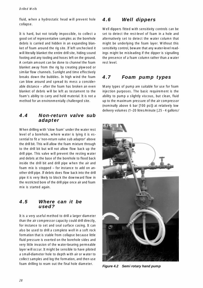
28
Drilled Wells
fluid, when a hydrostatic head will prevent holecollapse.
It is hard, but not totally impossible, to collect agood set of representative samples as the boreholedebris is carried and hidden in an expanding blan-ket of foam around the rig site. If left unchecked itwill literally blanket the entire drill site, hiding soundfooting and any tooling and hoses left on the ground.A certain amount can be done to channel the foamblanket away from the rig by creating plywood orsimilar flow channels. Sunlight and time effectivelybreaks down the bubbles. In high wind the foamcan blow around and spread its mess a consider-able distance – after the foam has broken an evenblanket of debris will be left as testament to thefoam’s ability to carry and hold material. It is not amethod for an environmentally challenged site.
4.4 Non-return valve subadapter
When drilling with ‘slow foam’ under the water restlevel of a borehole, where water is lying it is es-sential to fit a ‘non-return valve sub adaptor’ abovethe drill bit. This will allow the foam mixture throughto the drill bit but will not allow flow back up thedrill pipe. This valve will prevent the resting waterand debris at the base of the borehole to flood backinside the drill bit and drill pipe when the air andfoam mix is stopped – for instance to add on an-other drill pipe. If debris does flow back into the drillpipe it is very likely to block the downward flow inthe restricted bore of the drill pipe once air and foammix is started again.
4.5 Where can it beused?
It is a very useful method to drill a larger diameterthan the air compressor capacity could drill directly,for instance to set and seal surface casing. It canalso be used to drill a complete well in a soft rockformation that is stable from collapse because littlefluid pressure is exerted on the borehole sides andvery little invasion of the water-bearing permeablelayer will occur. It might be sensible to have piloteda small-diameter hole to depth with air or water tocollect samples and log the formation, and then usefoam drilling to ream out the final hole diameter.
4.6 Well dippers
Well dippers fitted with sensitivity controls can beset to detect the rest-level of foam in a hole andalternatively set to detect the water column thatmight be underlying the foam layer. Without thissensitivity control, beware that any water-level read-ings might be misleading if the dipper is signallingthe presence of a foam column rather than a waterrest level.
4.7 Foam pump types
Many types of pump are suitable for use for foaminjection purposes. The basic requirement is theability to pump a slightly viscous, but clean, fluidup to the maximum pressure of the air compressor(nominally above 6 bar [100 psi]) at relatively lowdelivery volumes (1–20 litres/minute [.25 - 4 gallons/
Figure 4.2 Semi rotary hand pump

29
minute]). This will meet most foam drilling require-ments. The following types of pump can be used:
4.7.1 Hand Pump
Semi rotary or piston ‘pressure testing’ pump;(figure 4.2)
4.7.2 Barrel Type Pump
Air- or electric-powered typical product transferpumps designed to work from standard 200-litre(45 gallon) drum;
4.7.3 Piston Pumps
Duplex or triplex high-pressure pumps – typically‘water-pressure wash’ duties. These are readilyavailable as electric-, petrol-, or diesel-powered.
The most significant attribute of any foam pump isbeing able to control the injection flow rate to justthe minimum required – over-injecting does not of-ten cause many problems other than wasting waterand making more mess on the surface. In remotelocations, where water is being carried long dis-tances, it helps to conserve its use to the bareessentials.
4.8 Foam inlet manifold
A simple pipe manifold (figure 4.3) is required toallow injection of foam – standard fittings as foundin most plumbers can be used. Both the foam pumpand the compressor require protection from beingback-filled with each other’s medium by fitting non-return valves. For low-velocity foam a suitable gatevalve fitted to the air supply helps regulate the air-flow to give the correct air/foam mix.
4.9 Mixing method
In both foam drilling methods a good mixing methodis to use two, or possibly even three, 200-litre (45-gallon) open-topped barrels. In each drum mix therequired foam formula, first mixing the polymer (onlyfor slow foam) arriving at a convenient volumetricaddition for the required viscosity, 35–40 Marsh fun-nel seconds (i.e. – 1 litre jug of polymer powder =40 sec mix in 200 litres of water). Allow time forthis mixture to yield viscosity. Add the foam .5 tono more than 1.5% dilution i.e. 1-3 litres of liquidsoap or drill foam to a 200-litre barrel at the lastminute, using just a few stirs with a clean spadeor shovel to mix. Use water as clean as possibleto mix to prevent fines and dirt from damaging or
Figure 4.3 Typical foam injection manifold
Drilling with foam
30
Drilled Wells
blocking suction-line filters of the small parts andpassages of the foam pump.
4.10 Adequate foamsupply
Use the first barrel until empty and then switch thefoam pump suction to the second barrel. Whileusing this barrel, re-mix the first barrel. In this way,it will be possible to have a continuous foam sup-ply available to the drilling operation. High foamconsumption might dictate introducing a third barrelinto the system to ensure that a mixed barrel of fully"yielded" polymer is always available.
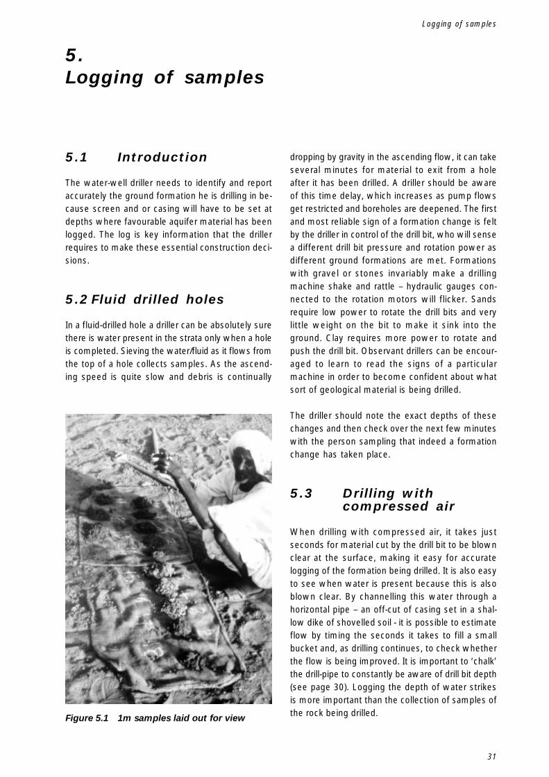
31
5.Logging of samples
5.1 Introduction
The water-well driller needs to identify and reportaccurately the ground formation he is drilling in be-cause screen and or casing will have to be set atdepths where favourable aquifer material has beenlogged. The log is key information that the drillerrequires to make these essential construction deci-sions.
5.2 Fluid drilled holes
In a fluid-drilled hole a driller can be absolutely surethere is water present in the strata only when a holeis completed. Sieving the water/fluid as it flows fromthe top of a hole collects samples. As the ascend-ing speed is quite slow and debris is continually
dropping by gravity in the ascending flow, it can takeseveral minutes for material to exit from a holeafter it has been drilled. A driller should be awareof this time delay, which increases as pump flowsget restricted and boreholes are deepened. The firstand most reliable sign of a formation change is feltby the driller in control of the drill bit, who will sensea different drill bit pressure and rotation power asdifferent ground formations are met. Formationswith gravel or stones invariably make a drillingmachine shake and rattle – hydraulic gauges con-nected to the rotation motors will flicker. Sandsrequire low power to rotate the drill bits and verylittle weight on the bit to make it sink into theground. Clay requires more power to rotate andpush the drill bit. Observant drillers can be encour-aged to learn to read the signs of a particularmachine in order to become confident about whatsort of geological material is being drilled.
The driller should note the exact depths of thesechanges and then check over the next few minuteswith the person sampling that indeed a formationchange has taken place.
5.3 Drilling withcompressed air
When drilling with compressed air, it takes justseconds for material cut by the drill bit to be blownclear at the surface, making it easy for accuratelogging of the formation being drilled. It is also easyto see when water is present because this is alsoblown clear. By channelling this water through ahorizontal pipe – an off-cut of casing set in a shal-low dike of shovelled soil - it is possible to estimateflow by timing the seconds it takes to fill a smallbucket and, as drilling continues, to check whetherthe flow is being improved. It is important to ‘chalk’the drill-pipe to constantly be aware of drill bit depth(see page 30). Logging the depth of water strikesis more important than the collection of samples ofthe rock being drilled.Figure 5.1 1m samples laid out for view
Logging of samples
32
Drilled Wells
5.4 Sample collection
Collected samples, whether drilled by fluid or com-pressed air, should be laid out on a cleaned,flattened area of the drill site, convenient plank,sacking or board or an open sample box clearlymarked with the depth they have come from (Fig-ure 5.1). It is a good idea to keep the samples fullyin sight and accessible during the drilling operationso that constant comparisons of colour, consistencyand material type can be made. A balanced practi-cal judgement of where best to screen and case ahole can then be made easily and quickly.
5.5 ‘Chalking’ the drillpipe
To log properly, the driller needs to know the exactdepth of the drill bit at any given moment. This isbest achieved by ‘chalking’ the drill-pipe. With thedrilling rig set up with the first length of drill-pipeand drill bit fitted, the drill bit should be lowered toground level. Mark the drill-pipe ‘0’ at a convenientadjacent visual point – for example, at the table thatcentralises the drill-pipe – and then make chalkmarks at 0.5 metre intervals up the drill-pipe, num-bering the marks from 0 upwards. Measured chalkmarks can be made on subsequent drill pipes tobe added. If this procedure is followed, the drilleror indeed anyone on the drill crew will know at aglance the exact depth of the drill bit from the groundsurface (Figures 5.2 & 5.3).
5.6 Writing up of a log
Most organised drilling programmes settle on theproduction of a borehole log, being a pro-forma typeform used to record the details of a hole drilled. Withgood fortune these are collated, copied and filed, andbecome a useful resource when planning furtherdrilling operations or well-rehabilitation programmes.The key is accuracy and consistency, deciding onthe minimum critical information required to recordaccurately. For perpetuity the information aboutdepth to water table, well yield and materials usedto line the well are more important than the detailsof how the hole was constructed.
From the drillers perspective, the person who is busywith the equipment on a daily basis the preparation
of detailed logs can be very time consuming. Insuf-ficient time is often allocated to this task becauseit is seen as ‘non-production’.
At very least the driller or one of the drill crew shouldbe encouraged to scribble notes in a rough notebook to record the essential data securely. Havingobtained a sound record of data attention can begiven later to how it finally gets presented as aborehole log, perhaps by using staff other than thedriller.
There is also considerable value in involving the localcommunity in showing and explaining how theborehole has been constructed. Often written logsare not available and there is only a voice in a crowdgiving his or her best explanation of what he or shesaw years before when a hole was drilled.
5.7 Getting it right
The importance of undertaking proper logging andmeasurement of hole depth cannot be overstated.Accurate logging can be the difference between awell that produces water and one that does not.
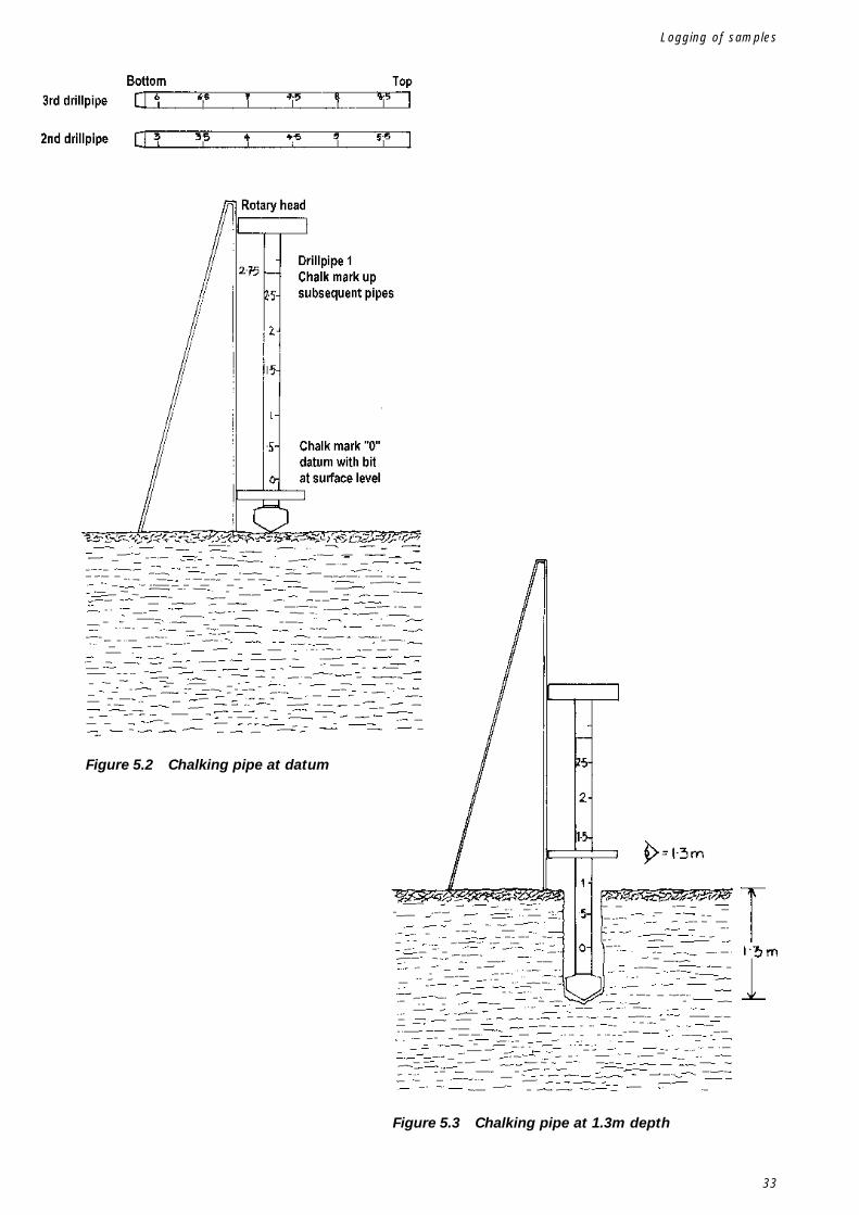
33
Figure 5.2 Chalking pipe at datum
Figure 5.3 Chalking pipe at 1.3m depth
Logging of samples

34
Drilled Wells
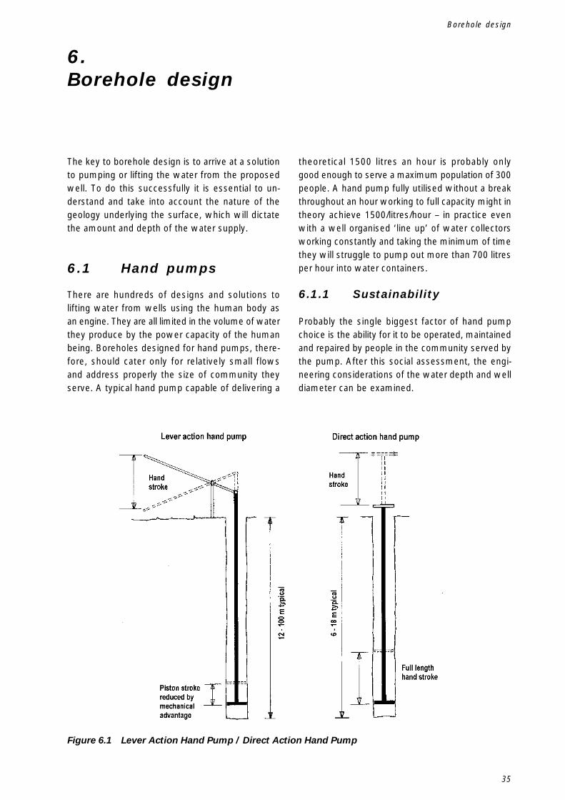
35
6.Borehole design
The key to borehole design is to arrive at a solutionto pumping or lifting the water from the proposedwell. To do this successfully it is essential to un-derstand and take into account the nature of thegeology underlying the surface, which will dictatethe amount and depth of the water supply.
6.1 Hand pumps
There are hundreds of designs and solutions tolifting water from wells using the human body asan engine. They are all limited in the volume of waterthey produce by the power capacity of the humanbeing. Boreholes designed for hand pumps, there-fore, should cater only for relatively small flowsand address properly the size of community theyserve. A typical hand pump capable of delivering a
theoretical 1500 litres an hour is probably onlygood enough to serve a maximum population of 300people. A hand pump fully utilised without a breakthroughout an hour working to full capacity might intheory achieve 1500/litres/hour – in practice evenwith a well organised ‘line up’ of water collectorsworking constantly and taking the minimum of timethey will struggle to pump out more than 700 litresper hour into water containers.
6.1.1 Sustainability
Probably the single biggest factor of hand pumpchoice is the ability for it to be operated, maintainedand repaired by people in the community served bythe pump. After this social assessment, the engi-neering considerations of the water depth and welldiameter can be examined.
Figure 6.1 Lever Action Hand Pump / Direct Action Hand Pump
Borehole design
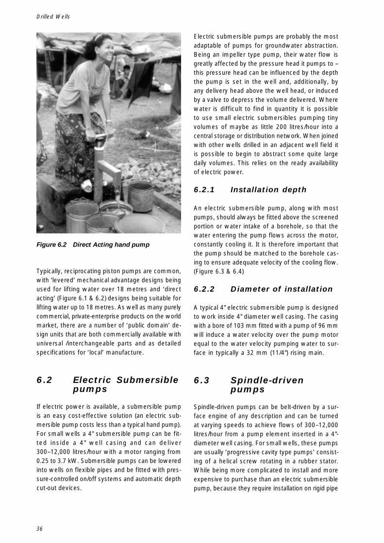
36
Drilled Wells
Typically, reciprocating piston pumps are common,with ‘levered’ mechanical advantage designs beingused for lifting water over 18 metres and ‘directacting’ (Figure 6.1 & 6.2) designs being suitable forlifting water up to 18 metres. As well as many purelycommercial, private-enterprise products on the worldmarket, there are a number of ‘public domain’ de-sign units that are both commercially available withuniversal /interchangeable parts and as detailedspecifications for ‘local’ manufacture.
6.2 Electric Submersiblepumps
If electric power is available, a submersible pumpis an easy cost-effective solution (an electric sub-mersible pump costs less than a typical hand pump).For small wells a 4" submersible pump can be fit-ted inside a 4" well casing and can deliver300–12,000 litres/hour with a motor ranging from0.25 to 3.7 kW. Submersible pumps can be loweredinto wells on flexible pipes and be fitted with pres-sure-controlled on/off systems and automatic depthcut-out devices.
Figure 6.2 Direct Acting hand pump
Electric submersible pumps are probably the mostadaptable of pumps for groundwater abstraction.Being an impeller type pump, their water flow isgreatly affected by the pressure head it pumps to –this pressure head can be influenced by the depththe pump is set in the well and, additionally, byany delivery head above the well head, or inducedby a valve to depress the volume delivered. Wherewater is difficult to find in quantity it is possibleto use small electric submersibles pumping tinyvolumes of maybe as little 200 litres/hour into acentral storage or distribution network. When joinedwith other wells drilled in an adjacent well field itis possible to begin to abstract some quite largedaily volumes. This relies on the ready availabilityof electric power.
6.2.1 Installation depth
An electric submersible pump, along with mostpumps, should always be fitted above the screenedportion or water intake of a borehole, so that thewater entering the pump flows across the motor,constantly cooling it. It is therefore important thatthe pump should be matched to the borehole cas-ing to ensure adequate velocity of the cooling flow.(Figure 6.3 & 6.4)
6.2.2 Diameter of installation
A typical 4" electric submersible pump is designedto work inside 4" diameter well casing. The casingwith a bore of 103 mm fitted with a pump of 96 mmwill induce a water velocity over the pump motorequal to the water velocity pumping water to sur-face in typically a 32 mm (11/4") rising main.
6.3 Spindle-drivenpumps
Spindle-driven pumps can be belt-driven by a sur-face engine of any description and can be turnedat varying speeds to achieve flows of 300–12,000litres/hour from a pump element inserted in a 4"-diameter well casing. For small wells, these pumpsare usually ‘progressive cavity type pumps’ consist-ing of a helical screw rotating in a rubber stator.While being more complicated to install and moreexpensive to purchase than an electric submersiblepump, because they require installation on rigid pipe
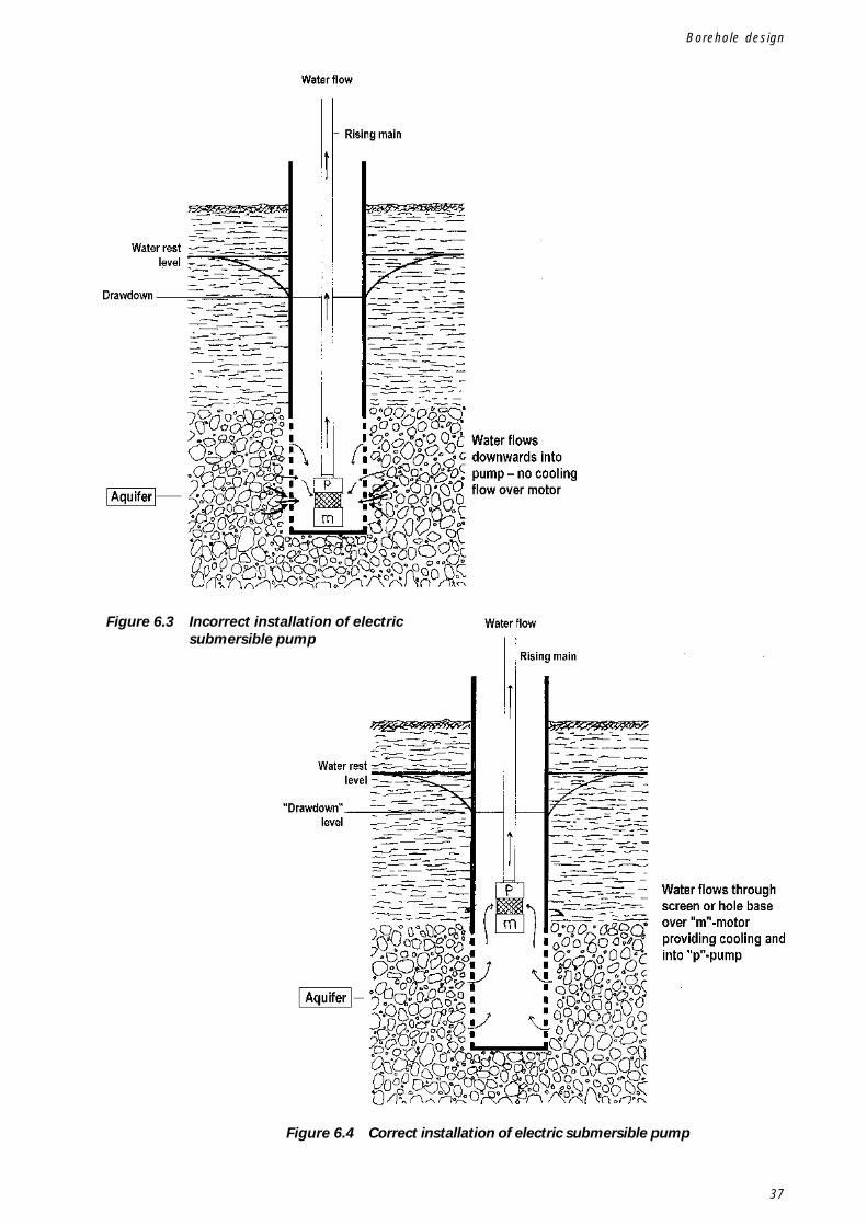
37
Figure 6.3 Incorrect installation of electricsubmersible pump
Figure 6.4 Correct installation of electric submersible pump
Borehole design
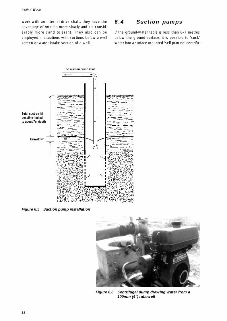
38
Drilled Wells
work with an internal drive shaft, they have theadvantage of rotating more slowly and are consid-erably more sand tolerant. They also can beemployed in situations with suctions below a wellscreen or water intake section of a well.
6.4 Suction pumps
If the ground-water table is less than 6–7 metresbelow the ground surface, it is possible to ‘suck’water into a surface-mounted ‘self priming’ centrifu-
Figure 6.5 Suction pump installation
Figure 6.6 Centrifugal pump drawing water from a100mm (4") tubewell
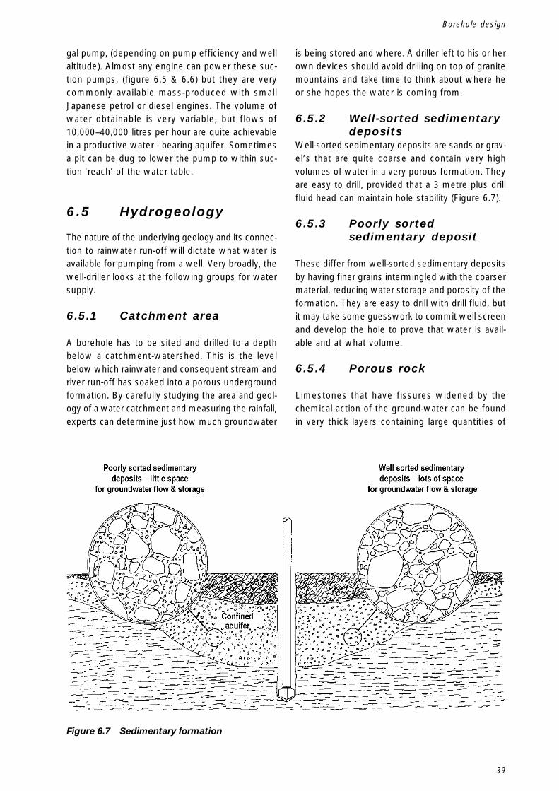
39
gal pump, (depending on pump efficiency and wellaltitude). Almost any engine can power these suc-tion pumps, (figure 6.5 & 6.6) but they are verycommonly available mass-produced with smallJapanese petrol or diesel engines. The volume ofwater obtainable is very variable, but flows of10,000–40,000 litres per hour are quite achievablein a productive water - bearing aquifer. Sometimesa pit can be dug to lower the pump to within suc-tion ‘reach’ of the water table.
6.5 Hydrogeology
The nature of the underlying geology and its connec-tion to rainwater run-off will dictate what water isavailable for pumping from a well. Very broadly, thewell-driller looks at the following groups for watersupply.
6.5.1 Catchment area
A borehole has to be sited and drilled to a depthbelow a catchment-watershed. This is the levelbelow which rainwater and consequent stream andriver run-off has soaked into a porous undergroundformation. By carefully studying the area and geol-ogy of a water catchment and measuring the rainfall,experts can determine just how much groundwater
is being stored and where. A driller left to his or herown devices should avoid drilling on top of granitemountains and take time to think about where heor she hopes the water is coming from.
6.5.2 Well-sorted sedimentarydeposits
Well-sorted sedimentary deposits are sands or grav-el’s that are quite coarse and contain very highvolumes of water in a very porous formation. Theyare easy to drill, provided that a 3 metre plus drillfluid head can maintain hole stability (Figure 6.7).
6.5.3 Poorly sortedsedimentary deposit
These differ from well-sorted sedimentary depositsby having finer grains intermingled with the coarsermaterial, reducing water storage and porosity of theformation. They are easy to drill with drill fluid, butit may take some guesswork to commit well screenand develop the hole to prove that water is avail-able and at what volume.
6.5.4 Porous rock
Limestones that have fissures widened by thechemical action of the ground-water can be foundin very thick layers containing large quantities of
Figure 6.7 Sedimentary formation
Borehole design
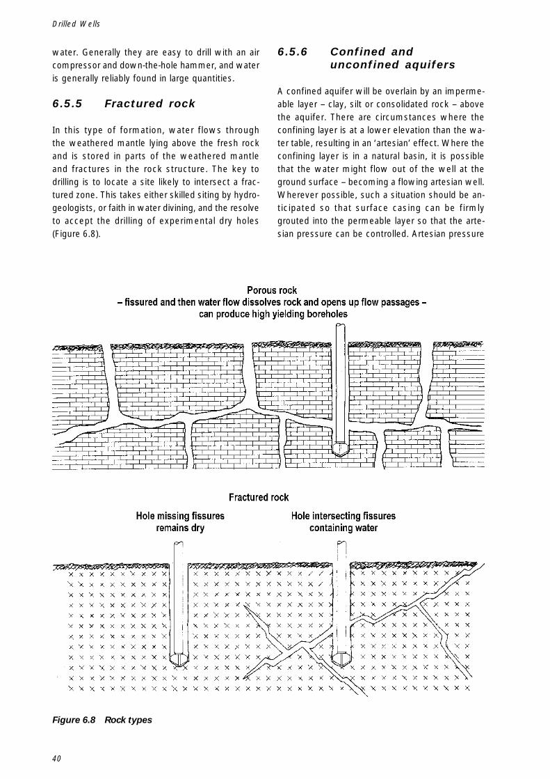
40
Drilled Wells
water. Generally they are easy to drill with an aircompressor and down-the-hole hammer, and wateris generally reliably found in large quantities.
6.5.5 Fractured rock
In this type of formation, water flows throughthe weathered mantle lying above the fresh rockand is stored in parts of the weathered mantleand fractures in the rock structure. The key todrilling is to locate a site likely to intersect a frac-tured zone. This takes either skilled siting by hydro-geologists, or faith in water divining, and the resolveto accept the drilling of experimental dry holes(Figure 6.8).
6.5.6 Confined andunconfined aquifers
A confined aquifer will be overlain by an imperme-able layer – clay, silt or consolidated rock – abovethe aquifer. There are circumstances where theconfining layer is at a lower elevation than the wa-ter table, resulting in an ‘artesian’ effect. Where theconfining layer is in a natural basin, it is possiblethat the water might flow out of the well at theground surface – becoming a flowing artesian well.Wherever possible, such a situation should be an-ticipated so that surface casing can be firmlygrouted into the permeable layer so that the arte-sian pressure can be controlled. Artesian pressure
Figure 6.8 Rock types
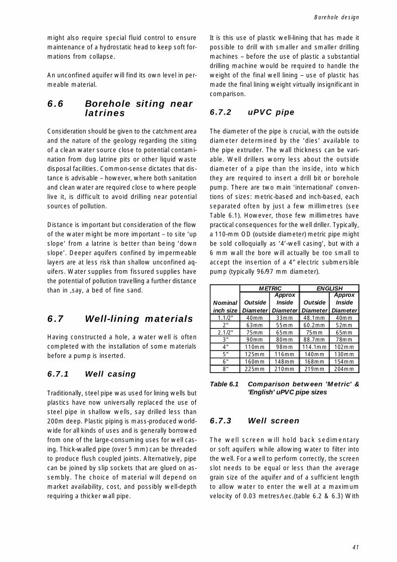
41
might also require special fluid control to ensuremaintenance of a hydrostatic head to keep soft for-mations from collapse.
An unconfined aquifer will find its own level in per-meable material.
6.6 Borehole siting nearlatrines
Consideration should be given to the catchment areaand the nature of the geology regarding the sitingof a clean water source close to potential contami-nation from dug latrine pits or other liquid wastedisposal facilities. Common-sense dictates that dis-tance is advisable – however, where both sanitationand clean water are required close to where peoplelive it, is difficult to avoid drilling near potentialsources of pollution.
Distance is important but consideration of the flowof the water might be more important – to site ‘upslope’ from a latrine is better than being ‘downslope’. Deeper aquifers confined by impermeablelayers are at less risk than shallow unconfined aq-uifers. Water supplies from fissured supplies havethe potential of pollution travelling a further distancethan in ,say, a bed of fine sand.
6.7 Well-lining materials
Having constructed a hole, a water well is oftencompleted with the installation of some materialsbefore a pump is inserted.
6.7.1 Well casing
Traditionally, steel pipe was used for lining wells butplastics have now universally replaced the use ofsteel pipe in shallow wells, say drilled less than200m deep. Plastic piping is mass-produced world-wide for all kinds of uses and is generally borrowedfrom one of the large-consuming uses for well cas-ing. Thick-walled pipe (over 5 mm) can be threadedto produce flush coupled joints. Alternatively, pipecan be joined by slip sockets that are glued on as-sembly. The choice of material will depend onmarket availability, cost, and possibly well-depthrequiring a thicker wall pipe.
It is this use of plastic well-lining that has made itpossible to drill with smaller and smaller drillingmachines – before the use of plastic a substantialdrilling machine would be required to handle theweight of the final well lining – use of plastic hasmade the final lining weight virtually insignificant incomparison.
6.7.2 uPVC pipe
The diameter of the pipe is crucial, with the outsidediameter determined by the ‘dies’ available tothe pipe extruder. The wall thickness can be vari-able. Well drillers worry less about the outsidediameter of a pipe than the inside, into whichthey are required to insert a drill bit or boreholepump. There are two main ‘international’ conven-tions of sizes: metric-based and inch-based, eachseparated often by just a few millimetres (seeTable 6.1). However, those few millimetres havepractical consequences for the well driller. Typically,a 110-mm OD (outside diameter) metric pipe mightbe sold colloquially as ‘4’-well casing’, but with a6 mm wall the bore will actually be too small toaccept the insertion of a 4" electric submersiblepump (typically 96/97 mm diameter).
Borehole design
Outside Diameter
Approx Inside
DiameterOutside
Diameter
Approx Inside
Diameter1.1/2" 40mm 33mm 48.1mm 40mm
2" 63mm 55mm 60.2mm 52mm2.1/2" 75mm 65mm 75mm 65mm
3" 90mm 80mm 88.7mm 78mm4" 110mm 98mm 114.1mm 102mm5" 125mm 116mm 140mm 130mm6" 160mm 148mm 168mm 154mm8" 225mm 210mm 219mm 204mm
METRIC ENGLISH
Nominal inch size
Table 6.1 Comparison between 'Metric' &'English' uPVC pipe sizes
6.7.3 Well screen
The well screen will hold back sedimentaryor soft aquifers while allowing water to filter intothe well. For a well to perform correctly, the screenslot needs to be equal or less than the averagegrain size of the aquifer and of a sufficient lengthto allow water to enter the well at a maximumvelocity of 0.03 metres/sec.(table 6.2 & 6.3) With
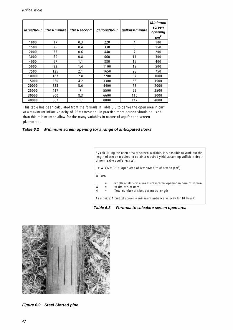
42
Drilled Wells
Figure 6.9 Steel Slotted pipe
By calculating the open area of screen available, it is possible to work out thelength of screen required to obtain a required yield (assuming sufficient depthof permeable aquifer exists).
L x W x N x 0.1 = Open area of screen/metre of screen (cm2)
Where:
L = length of slot (cm) - measure internal opening in bore of screenW = Width of slot (mm)N = Total number of slots per metre length
As a guide: 1 cm2 of screen = minimum entrance velocity for 10 litres/h
Table 6.2 Minimum screen opening for a range of anticipated flows
Table 6.3 Formula to calculate screen open area
litres/hour litres/minute litres/second gallons/hour gallons/minute
Minimum screen
opening
cm2
1000 17 0.3 220 4 1001500 25 0.4 330 6 1502000 33 0.6 440 7 2003000 50 0.8 660 11 3004000 67 1.1 880 15 4005000 83 1.4 1100 18 5007500 125 2.1 1650 28 750
10000 167 2.8 2200 37 100015000 250 4.2 3300 55 150020000 333 5.6 4400 73 200025000 417 7 5500 92 250030000 500 8.3 6600 110 300040000 667 11.1 8800 147 4000
This table has been calculated from the formula in Table 6.3 to derive the open area in cm2
at a maximum inflow velocity of .03metres/sec. In practice more screen should be used than this minimum to allow for the many variables in nature of aquifer and screen placement.
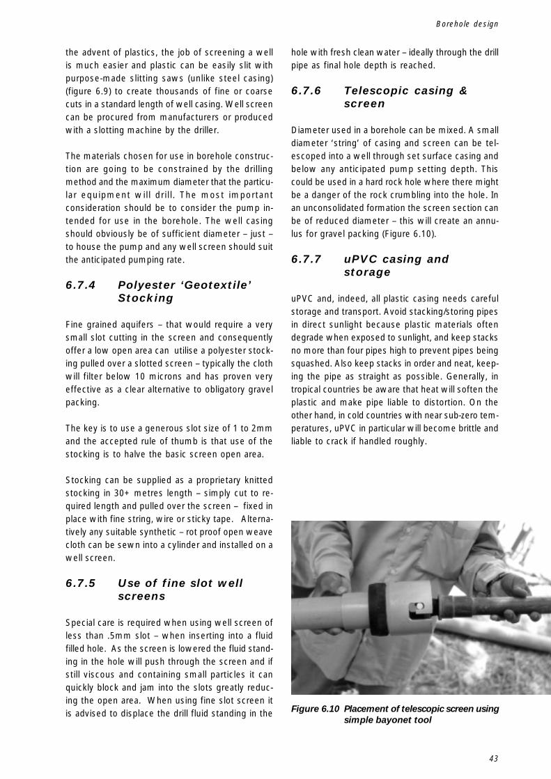
43
Figure 6.10 Placement of telescopic screen usingsimple bayonet tool
Borehole design
the advent of plastics, the job of screening a wellis much easier and plastic can be easily slit withpurpose-made slitting saws (unlike steel casing)(figure 6.9) to create thousands of fine or coarsecuts in a standard length of well casing. Well screencan be procured from manufacturers or producedwith a slotting machine by the driller.
The materials chosen for use in borehole construc-tion are going to be constrained by the drillingmethod and the maximum diameter that the particu-lar equipment will drill. The most importantconsideration should be to consider the pump in-tended for use in the borehole. The well casingshould obviously be of sufficient diameter – just –to house the pump and any well screen should suitthe anticipated pumping rate.
6.7.4 Polyester ‘Geotextile’Stocking
Fine grained aquifers – that would require a verysmall slot cutting in the screen and consequentlyoffer a low open area can utilise a polyester stock-ing pulled over a slotted screen – typically the clothwill filter below 10 microns and has proven veryeffective as a clear alternative to obligatory gravelpacking.
The key is to use a generous slot size of 1 to 2mmand the accepted rule of thumb is that use of thestocking is to halve the basic screen open area.
Stocking can be supplied as a proprietary knittedstocking in 30+ metres length – simply cut to re-quired length and pulled over the screen – fixed inplace with fine string, wire or sticky tape. Alterna-tively any suitable synthetic – rot proof open weavecloth can be sewn into a cylinder and installed on awell screen.
6.7.5 Use of fine slot wellscreens
Special care is required when using well screen ofless than .5mm slot – when inserting into a fluidfilled hole. As the screen is lowered the fluid stand-ing in the hole will push through the screen and ifstill viscous and containing small particles it canquickly block and jam into the slots greatly reduc-ing the open area. When using fine slot screen itis advised to displace the drill fluid standing in the
hole with fresh clean water – ideally through the drillpipe as final hole depth is reached.
6.7.6 Telescopic casing &screen
Diameter used in a borehole can be mixed. A smalldiameter ‘string’ of casing and screen can be tel-escoped into a well through set surface casing andbelow any anticipated pump setting depth. Thiscould be used in a hard rock hole where there mightbe a danger of the rock crumbling into the hole. Inan unconsolidated formation the screen section canbe of reduced diameter – this will create an annu-lus for gravel packing (Figure 6.10).
6.7.7 uPVC casing andstorage
uPVC and, indeed, all plastic casing needs carefulstorage and transport. Avoid stacking/storing pipesin direct sunlight because plastic materials oftendegrade when exposed to sunlight, and keep stacksno more than four pipes high to prevent pipes beingsquashed. Also keep stacks in order and neat, keep-ing the pipe as straight as possible. Generally, intropical countries be aware that heat will soften theplastic and make pipe liable to distortion. On theother hand, in cold countries with near sub-zero tem-peratures, uPVC in particular will become brittle andliable to crack if handled roughly.

44
Drilled Wells
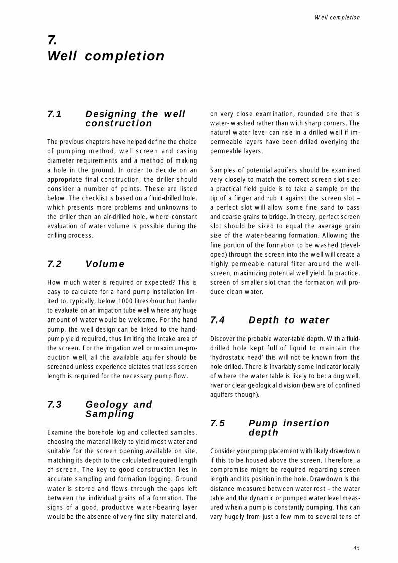
45
7.Well completion
7.1 Designing the wellconstruction
The previous chapters have helped define the choiceof pumping method, well screen and casingdiameter requirements and a method of makinga hole in the ground. In order to decide on anappropriate final construction, the driller shouldconsider a number of points. These are listedbelow. The checklist is based on a fluid-drilled hole,which presents more problems and unknowns tothe driller than an air-drilled hole, where constantevaluation of water volume is possible during thedrilling process.
7.2 Volume
How much water is required or expected? This iseasy to calculate for a hand pump installation lim-ited to, typically, below 1000 litres/hour but harderto evaluate on an irrigation tube well where any hugeamount of water would be welcome. For the handpump, the well design can be linked to the hand-pump yield required, thus limiting the intake area ofthe screen. For the irrigation well or maximum-pro-duction well, all the available aquifer should bescreened unless experience dictates that less screenlength is required for the necessary pump flow.
7.3 Geology andSampling
Examine the borehole log and collected samples,choosing the material likely to yield most water andsuitable for the screen opening available on site,matching its depth to the calculated required lengthof screen. The key to good construction lies inaccurate sampling and formation logging. Groundwater is stored and flows through the gaps leftbetween the individual grains of a formation. Thesigns of a good, productive water-bearing layerwould be the absence of very fine silty material and,
on very close examination, rounded one that iswater- washed rather than with sharp corners. Thenatural water level can rise in a drilled well if im-permeable layers have been drilled overlying thepermeable layers.
Samples of potential aquifers should be examinedvery closely to match the correct screen slot size:a practical field guide is to take a sample on thetip of a finger and rub it against the screen slot –a perfect slot will allow some fine sand to passand coarse grains to bridge. In theory, perfect screenslot should be sized to equal the average grainsize of the water-bearing formation. Allowing thefine portion of the formation to be washed (devel-oped) through the screen into the well will create ahighly permeable natural filter around the well-screen, maximizing potential well yield. In practice,screen of smaller slot than the formation will pro-duce clean water.
7.4 Depth to water
Discover the probable water-table depth. With a fluid-drilled hole kept full of liquid to maintain the‘hydrostatic head’ this will not be known from thehole drilled. There is invariably some indicator locallyof where the water table is likely to be: a dug well,river or clear geological division (beware of confinedaquifers though).
7.5 Pump insertiondepth
Consider your pump placement with likely drawdownif this to be housed above the screen. Therefore, acompromise might be required regarding screenlength and its position in the hole. Drawdown is thedistance measured between water rest – the watertable and the dynamic or pumped water level meas-ured when a pump is constantly pumping. This canvary hugely from just a few mm to several tens of
Well completion
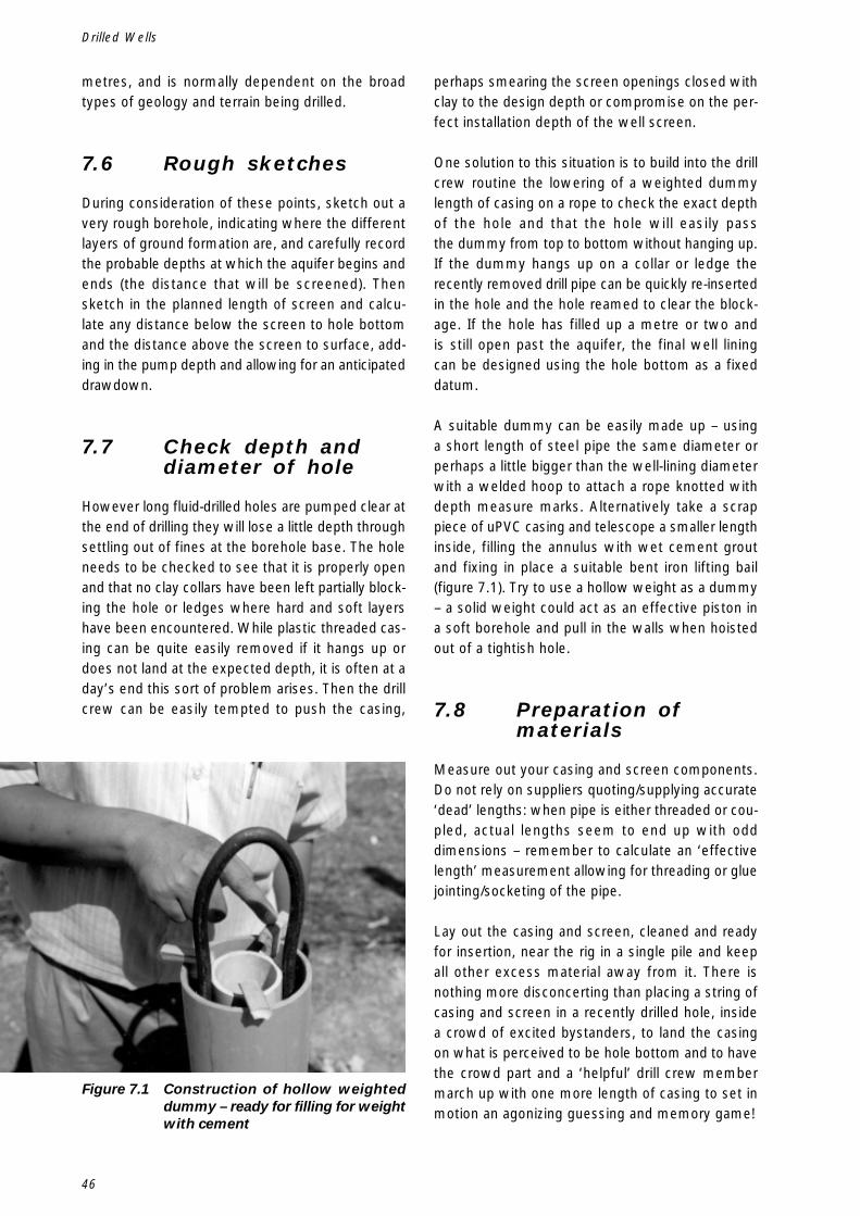
46
Drilled Wells
metres, and is normally dependent on the broadtypes of geology and terrain being drilled.
7.6 Rough sketches
During consideration of these points, sketch out avery rough borehole, indicating where the differentlayers of ground formation are, and carefully recordthe probable depths at which the aquifer begins andends (the distance that will be screened). Thensketch in the planned length of screen and calcu-late any distance below the screen to hole bottomand the distance above the screen to surface, add-ing in the pump depth and allowing for an anticipateddrawdown.
7.7 Check depth anddiameter of hole
However long fluid-drilled holes are pumped clear atthe end of drilling they will lose a little depth throughsettling out of fines at the borehole base. The holeneeds to be checked to see that it is properly openand that no clay collars have been left partially block-ing the hole or ledges where hard and soft layershave been encountered. While plastic threaded cas-ing can be quite easily removed if it hangs up ordoes not land at the expected depth, it is often at aday’s end this sort of problem arises. Then the drillcrew can be easily tempted to push the casing,
perhaps smearing the screen openings closed withclay to the design depth or compromise on the per-fect installation depth of the well screen.
One solution to this situation is to build into the drillcrew routine the lowering of a weighted dummylength of casing on a rope to check the exact depthof the hole and that the hole will easily passthe dummy from top to bottom without hanging up.If the dummy hangs up on a collar or ledge therecently removed drill pipe can be quickly re-insertedin the hole and the hole reamed to clear the block-age. If the hole has filled up a metre or two andis still open past the aquifer, the final well liningcan be designed using the hole bottom as a fixeddatum.
A suitable dummy can be easily made up – usinga short length of steel pipe the same diameter orperhaps a little bigger than the well-lining diameterwith a welded hoop to attach a rope knotted withdepth measure marks. Alternatively take a scrappiece of uPVC casing and telescope a smaller lengthinside, filling the annulus with wet cement groutand fixing in place a suitable bent iron lifting bail(figure 7.1). Try to use a hollow weight as a dummy– a solid weight could act as an effective piston ina soft borehole and pull in the walls when hoistedout of a tightish hole.
7.8 Preparation ofmaterials
Measure out your casing and screen components.Do not rely on suppliers quoting/supplying accurate‘dead’ lengths: when pipe is either threaded or cou-pled, actual lengths seem to end up with odddimensions – remember to calculate an ‘effectivelength’ measurement allowing for threading or gluejointing/socketing of the pipe.
Lay out the casing and screen, cleaned and readyfor insertion, near the rig in a single pile and keepall other excess material away from it. There isnothing more disconcerting than placing a string ofcasing and screen in a recently drilled hole, insidea crowd of excited bystanders, to land the casingon what is perceived to be hole bottom and to havethe crowd part and a ‘helpful’ drill crew membermarch up with one more length of casing to set inmotion an agonizing guessing and memory game!
Figure 7.1 Construction of hollow weighteddummy – ready for filling for weightwith cement
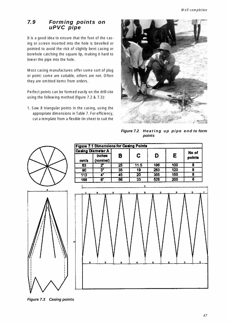
47
7.9 Forming points onuPVC pipe
It is a good idea to ensure that the foot of the cas-ing or screen inserted into the hole is bevelled orpointed to avoid the risk of slightly bent casing orborehole catching the square lip, making it hard tolower the pipe into the hole.
Most casing manufactures offer some sort of plugor point: some are suitable, others are not. Oftenthey are omitted items from orders.
Perfect points can be formed easily on the drill siteusing the following method (figure 7.2 & 7.3):
1. Saw 8 triangular points in the casing, using theappropriate dimensions in Table 7. For efficiency,cut a template from a flexible tin sheet to suit the
Figure 7.3 Casing points
Figure 7.2 H e a t i n g u p p i p e e n d to formpoints
Well completion
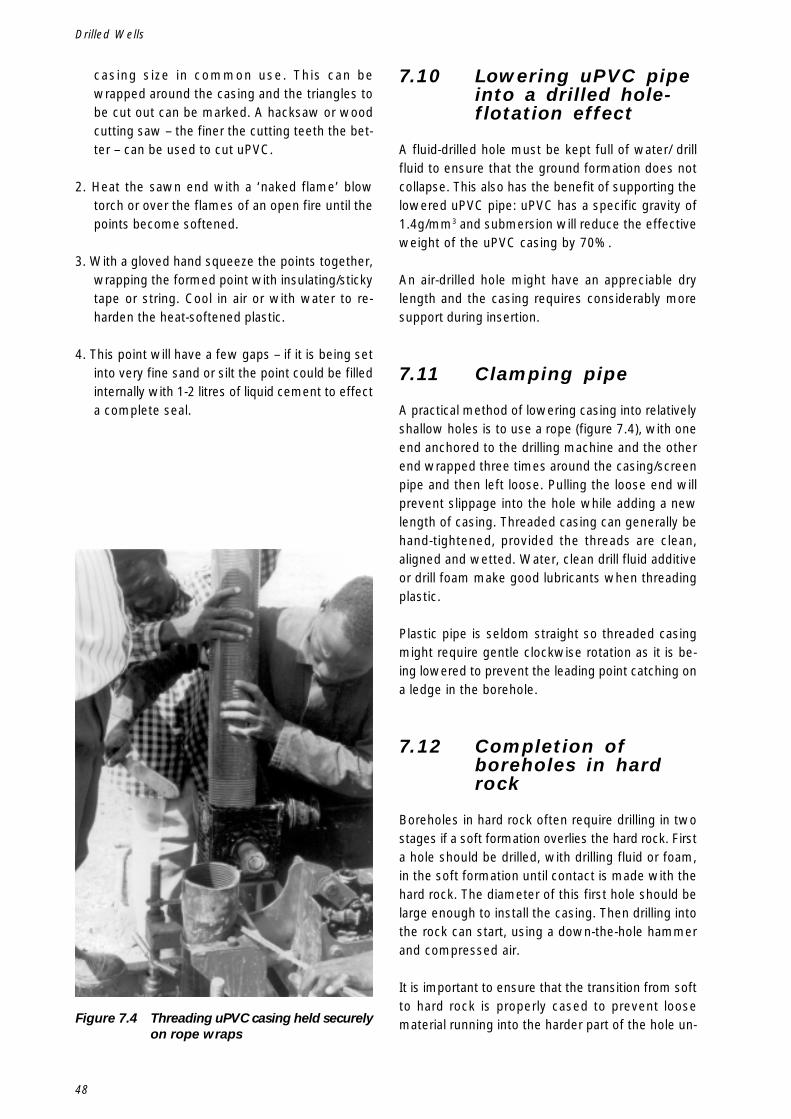
48
Drilled Wells
casing size in common use. This can bewrapped around the casing and the triangles tobe cut out can be marked. A hacksaw or woodcutting saw – the finer the cutting teeth the bet-ter – can be used to cut uPVC.
2. Heat the sawn end with a ‘naked flame’ blowtorch or over the flames of an open fire until thepoints become softened.
3. With a gloved hand squeeze the points together,wrapping the formed point with insulating/stickytape or string. Cool in air or with water to re-harden the heat-softened plastic.
4. This point will have a few gaps – if it is being setinto very fine sand or silt the point could be filledinternally with 1-2 litres of liquid cement to effecta complete seal.
7.10 Lowering uPVC pipeinto a drilled hole-flotation effect
A fluid-drilled hole must be kept full of water/ drillfluid to ensure that the ground formation does notcollapse. This also has the benefit of supporting thelowered uPVC pipe: uPVC has a specific gravity of1.4g/mm3 and submersion will reduce the effectiveweight of the uPVC casing by 70%.
An air-drilled hole might have an appreciable drylength and the casing requires considerably moresupport during insertion.
7.11 Clamping pipe
A practical method of lowering casing into relativelyshallow holes is to use a rope (figure 7.4), with oneend anchored to the drilling machine and the otherend wrapped three times around the casing/screenpipe and then left loose. Pulling the loose end willprevent slippage into the hole while adding a newlength of casing. Threaded casing can generally behand-tightened, provided the threads are clean,aligned and wetted. Water, clean drill fluid additiveor drill foam make good lubricants when threadingplastic.
Plastic pipe is seldom straight so threaded casingmight require gentle clockwise rotation as it is be-ing lowered to prevent the leading point catching ona ledge in the borehole.
7.12 Completion ofboreholes in hardrock
Boreholes in hard rock often require drilling in twostages if a soft formation overlies the hard rock. Firsta hole should be drilled, with drilling fluid or foam,in the soft formation until contact is made with thehard rock. The diameter of this first hole should belarge enough to install the casing. Then drilling intothe rock can start, using a down-the-hole hammerand compressed air.
It is important to ensure that the transition from softto hard rock is properly cased to prevent loosematerial running into the harder part of the hole un-Figure 7.4 Threading uPVC casing held securely
on rope wraps
49
der the lip of the casing. It is always good to beable to drill into a soft weathered layer of rock intowhich to place the casing – this is not always pos-sible where transition from a soft to a hard formationis sudden.
The drilled hole and casing should be measuredcarefully to ensure that the casing is placed at thecorrect depth. Having installed the casing, it shouldbe cemented in place both to prevent loose mate-rial falling into the rock section of the hole andsurface drainage water contaminating ground-water.
Holes in firm rock can be further lined or left unlined.If the rock is hard and relatively strong it is a goodidea to leave the hole unlined because this allowswater to flow from available fissures without impedi-ment by well screen or introduced sand or gravelpack. Where the rock is soft, and by its nature likelyto crumble and collapse, the well should be lined.
7.13 Cementing
There are many different methods of cementing.Below are described Three standard methods.
7.13.1 Displacement
This ensures a good footing for casing. Blank thecasing with cement or a drillable plastic plug, andlower it into the hole partially filled with cement-grout. This will displace the cement upwards in theannulus. Careful calculation of the annulus is re-quired to ensure the correct volume of grout is usedto fill the required height. The casing centre mightneed weighting with clean sand to drill out later oralternatively being held down under the drilling rigrotary head until the cement sets.
7.13.2 Foot
Insert the open casing to the hole bottom and thenpour a small volume – a few buckets- of cementgrout into and around casing and allow to dry (12hours plus).
7.13.3 Backfilling
If the casing is inserted open ended and landed andembedded into an impermeable clay layer, the to-tal annulus can be back-filled with cement.
Alternatively land the casing then fill the centre withuniform fine building type sand – this will preventthe cement flowing up into the centre of the casingand dry sand can be quickly displaced with air orwater after cement has sealed.
In a hole making a transition from a soft to hardformation, it is important to ensure that the entiresoft layer is indeed cased off and the base wherethe casing lands is sealed – loose stones or rocksrolling in can jam pumps – and the casing shouldbe sealed to prevent surface water entering thelower part of the well.
Cement grout is best made up to a specific con-sistency that will make it liquid – but not so liquidit will crack on setting. A 50-kg bag mixed with27 litres of water will make 33 litres of cement grout(see various hole volumes, Table 7.1, page 58).Cement takes time to cure: allow a minimum of12 hours before recommencing any sort of drillingor completion operation. An organised drill crew willanticipate and plan a cementing operation towardsthe end of a working shift so that cement will hardenovernight. Do not use ‘accelerators’ to speed upthe setting time because this process works byraising the temperature of the set and this can behigh enough to deform uPVC casing.
7.14 Sanitary seal
All holes should at some point of their constructionhave a cement or bentonite seal to prevent surfacewater draining into the hole and passing directly intoand contaminating the aquifer. The essential andideal position is to place a seal in a logged depth ofimpermeable formation; this curtains the aquiferfrom surface contamination.
Shallow holes with high water table with no imper-meable layers should still be sealed but additionallycare taken not to introduce contamination by mini-mising wastewater being spilt on the surface.
7.15 Bentonite pellets
An alternative to cement is to use granulated ben-tonite, which is a natural clay with enormousswelling properties. The dry granules should bepoured into the annulus or hole to be sealed: any
Well completion
50
Drilled Wells
water present will soak into the granules, swellingthem so they jam into a tight, impermeable seal.
Having placed the casing and sealed it on to con-solidated rock, it should be possible to drill securelywith compressed air. It is quite probable that therock will be solid enough to insert a well pumpwithout requiring any further screen or casing instal-lation.
7.16 Completion ofboreholes inunconsolidatedformations
Boreholes in unconsolidated formations will requirelining with casing and screen: the screen set againstpotential water-bearing layers and casing in all otherareas.
To complete a hole the following procedure shouldbe followed:
7.16.1 Step 1
Remove the drill-pipe, keeping the hole topped upwith fluid to prevent collapse of the formation.
7.16.2 Step 2
Plumb the hole to check hole depth and that is clearfrom obstructions.
7.16.3 Step 3
Maintain hydrostatic headSelect areas for screening carefully measure out thecasing and screen, and insert string in hole as de-scribed earlier page 40. Continue to keep the holefull of fluid – how many times has this been said!
7.16.4 Step 4
Pump clean water into the casing, sealing the pumphose in the annulus between casing and pump hosetemporarily with a cloth or similar material and al-low mud/fluid to be displaced from the hole in theannulus between casing and borehole.Start development of the hole.
7.16.5 Step 5
7.17 Surge blockdevelopment
Figures 7.5 & 7.6
Use a surge block to force water gently out into theformation beyond the well screen on the downstroke and pull water through the screen on theupstroke. This surging action pulls fines into the welland gently sorts a natural filter bed around thescreen.
7.18 Compressed airdevelopment
Figures 7.7, 7.8, 7.9, 7.10 & 7.11
To create a surging action, an air compressor canbe used to airlift a column of water upwards andthen by closing the air valve and venting to atmos-phere the built up air pressure in the pipe, will allowsthe water column to drop downwards into the for-mation. To create the important surging actionproperly, it is important to arrange the air inlet pipework to rapidly bleed off air pressure built up in theair pipe submerged below the water.
7.19 Step 6 Final holecleaning
Place a small bore pipe and move any accumula-tion of fine debris at the bottom of the hole to thesurface using a water flush or compressed air lift.
7.20 Step 7 Sealing
Backfill the annulus between the casing and the holewith gravel to stabilize the formation to a depthwhere a cement grout seal can be placed – ideallyat a depth of a logged impermeable layer.
7.21 Water levelmeasurement
The water level is best checked with a ‘dip tape’,which is a simple weighted metal probe that is low-ered into a hole on a graduated electric cable. Whenthe probe touches water an electric circuit is made
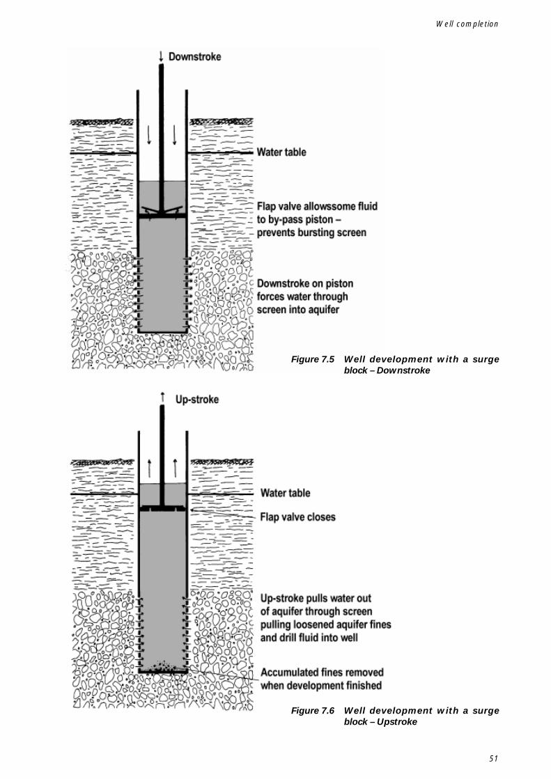
51
Figure 7.5 Well development with a surgeblock – Downstroke
Figure 7.6 Well development with a surgeblock – Upstroke
Well completion
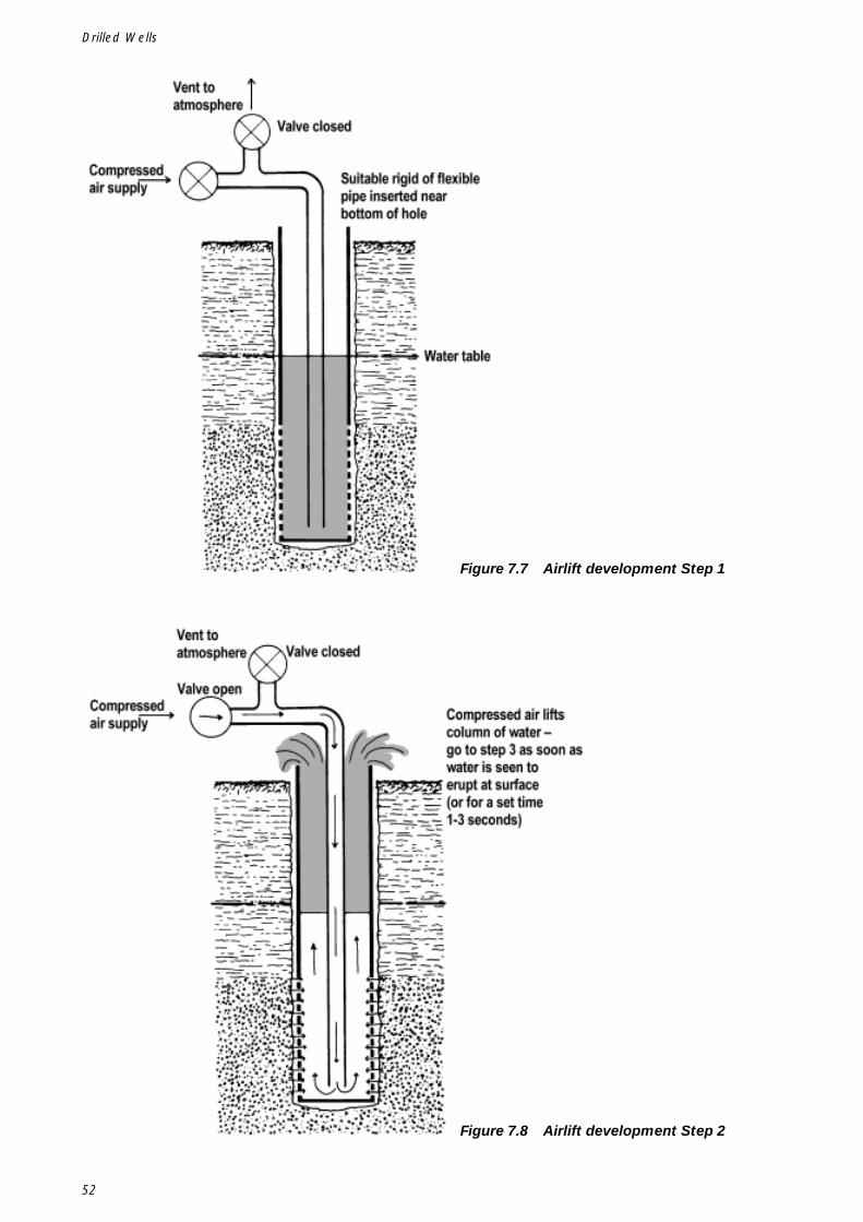
52
Drilled Wells
Figure 7.7 Airlift development Step 1
Figure 7.8 Airlift development Step 2
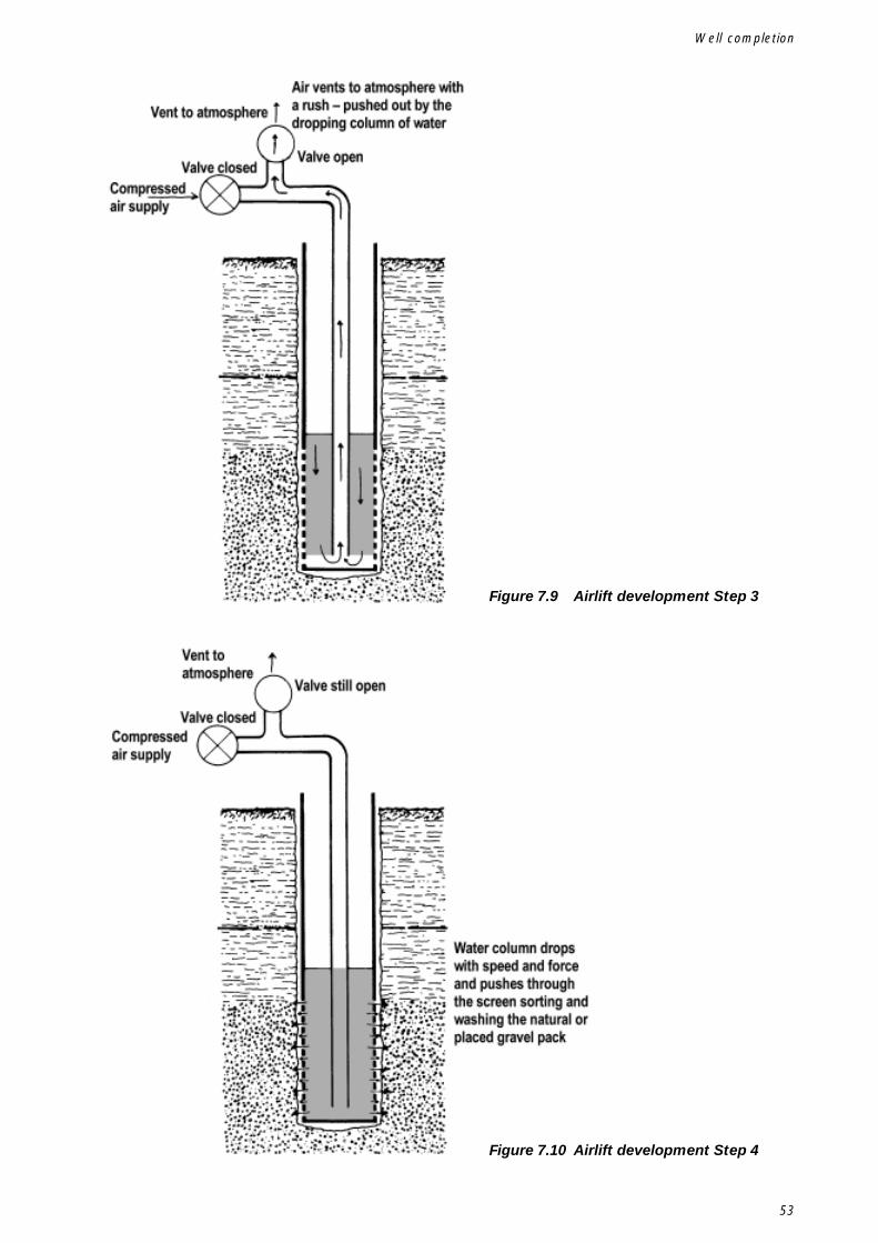
53
Figure 7.9 Airlift development Step 3
Figure 7.10 Airlift development Step 4
Well completion
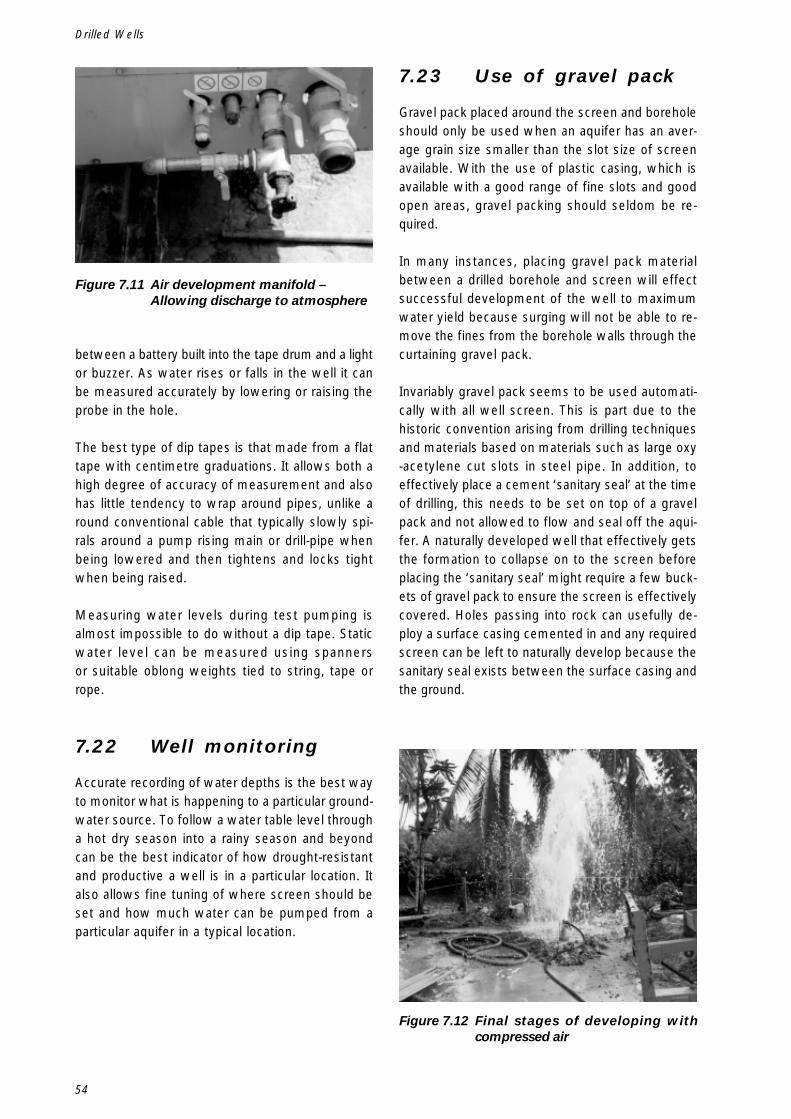
54
Drilled Wells
between a battery built into the tape drum and a lightor buzzer. As water rises or falls in the well it canbe measured accurately by lowering or raising theprobe in the hole.
The best type of dip tapes is that made from a flattape with centimetre graduations. It allows both ahigh degree of accuracy of measurement and alsohas little tendency to wrap around pipes, unlike around conventional cable that typically slowly spi-rals around a pump rising main or drill-pipe whenbeing lowered and then tightens and locks tightwhen being raised.
Measuring water levels during test pumping isalmost impossible to do without a dip tape. Staticwater level can be measured using spannersor suitable oblong weights tied to string, tape orrope.
7.22 Well monitoring
Accurate recording of water depths is the best wayto monitor what is happening to a particular ground-water source. To follow a water table level througha hot dry season into a rainy season and beyondcan be the best indicator of how drought-resistantand productive a well is in a particular location. Italso allows fine tuning of where screen should beset and how much water can be pumped from aparticular aquifer in a typical location.
7.23 Use of gravel pack
Gravel pack placed around the screen and boreholeshould only be used when an aquifer has an aver-age grain size smaller than the slot size of screenavailable. With the use of plastic casing, which isavailable with a good range of fine slots and goodopen areas, gravel packing should seldom be re-quired.
In many instances, placing gravel pack materialbetween a drilled borehole and screen will effectsuccessful development of the well to maximumwater yield because surging will not be able to re-move the fines from the borehole walls through thecurtaining gravel pack.
Invariably gravel pack seems to be used automati-cally with all well screen. This is part due to thehistoric convention arising from drilling techniquesand materials based on materials such as large oxy-acetylene cut slots in steel pipe. In addition, toeffectively place a cement ‘sanitary seal’ at the timeof drilling, this needs to be set on top of a gravelpack and not allowed to flow and seal off the aqui-fer. A naturally developed well that effectively getsthe formation to collapse on to the screen beforeplacing the ‘sanitary seal’ might require a few buck-ets of gravel pack to ensure the screen is effectivelycovered. Holes passing into rock can usefully de-ploy a surface casing cemented in and any requiredscreen can be left to naturally develop because thesanitary seal exists between the surface casing andthe ground.
Figure 7.11 Air development manifold –Allowing discharge to atmosphere
Figure 7.12 Final stages of developing withcompressed air
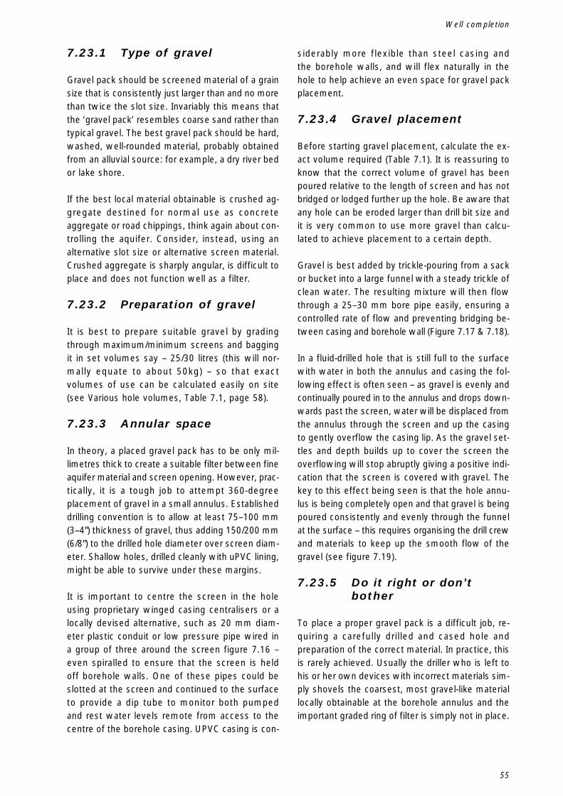
55
7.23.1 Type of gravel
Gravel pack should be screened material of a grainsize that is consistently just larger than and no morethan twice the slot size. Invariably this means thatthe ‘gravel pack’ resembles coarse sand rather thantypical gravel. The best gravel pack should be hard,washed, well-rounded material, probably obtainedfrom an alluvial source: for example, a dry river bedor lake shore.
If the best local material obtainable is crushed ag-gregate destined for normal use as concreteaggregate or road chippings, think again about con-trolling the aquifer. Consider, instead, using analternative slot size or alternative screen material.Crushed aggregate is sharply angular, is difficult toplace and does not function well as a filter.
7.23.2 Preparation of gravel
It is best to prepare suitable gravel by gradingthrough maximum/minimum screens and baggingit in set volumes say – 25/30 litres (this will nor-mally equate to about 50kg) – so that exactvolumes of use can be calculated easily on site(see Various hole volumes, Table 7.1, page 58).
7.23.3 Annular space
In theory, a placed gravel pack has to be only mil-limetres thick to create a suitable filter between fineaquifer material and screen opening. However, prac-tically, it is a tough job to attempt 360-degreeplacement of gravel in a small annulus. Establisheddrilling convention is to allow at least 75–100 mm(3–4") thickness of gravel, thus adding 150/200 mm(6/8") to the drilled hole diameter over screen diam-eter. Shallow holes, drilled cleanly with uPVC lining,might be able to survive under these margins.
It is important to centre the screen in the holeusing proprietary winged casing centralisers or alocally devised alternative, such as 20 mm diam-eter plastic conduit or low pressure pipe wired ina group of three around the screen figure 7.16 –even spiralled to ensure that the screen is heldoff borehole walls. One of these pipes could beslotted at the screen and continued to the surfaceto provide a dip tube to monitor both pumpedand rest water levels remote from access to thecentre of the borehole casing. UPVC casing is con-
siderably more flexible than steel casing andthe borehole walls, and will flex naturally in thehole to help achieve an even space for gravel packplacement.
7.23.4 Gravel placement
Before starting gravel placement, calculate the ex-act volume required (Table 7.1). It is reassuring toknow that the correct volume of gravel has beenpoured relative to the length of screen and has notbridged or lodged further up the hole. Be aware thatany hole can be eroded larger than drill bit size andit is very common to use more gravel than calcu-lated to achieve placement to a certain depth.
Gravel is best added by trickle-pouring from a sackor bucket into a large funnel with a steady trickle ofclean water. The resulting mixture will then flowthrough a 25–30 mm bore pipe easily, ensuring acontrolled rate of flow and preventing bridging be-tween casing and borehole wall (Figure 7.17 & 7.18).
In a fluid-drilled hole that is still full to the surfacewith water in both the annulus and casing the fol-lowing effect is often seen – as gravel is evenly andcontinually poured in to the annulus and drops down-wards past the screen, water will be displaced fromthe annulus through the screen and up the casingto gently overflow the casing lip. As the gravel set-tles and depth builds up to cover the screen theoverflowing will stop abruptly giving a positive indi-cation that the screen is covered with gravel. Thekey to this effect being seen is that the hole annu-lus is being completely open and that gravel is beingpoured consistently and evenly through the funnelat the surface – this requires organising the drill crewand materials to keep up the smooth flow of thegravel (see figure 7.19).
7.23.5 Do it right or don’tbother
To place a proper gravel pack is a difficult job, re-quiring a carefully drilled and cased hole andpreparation of the correct material. In practice, thisis rarely achieved. Usually the driller who is left tohis or her own devices with incorrect materials sim-ply shovels the coarsest, most gravel-like materiallocally obtainable at the borehole annulus and theimportant graded ring of filter is simply not in place.
Well completion
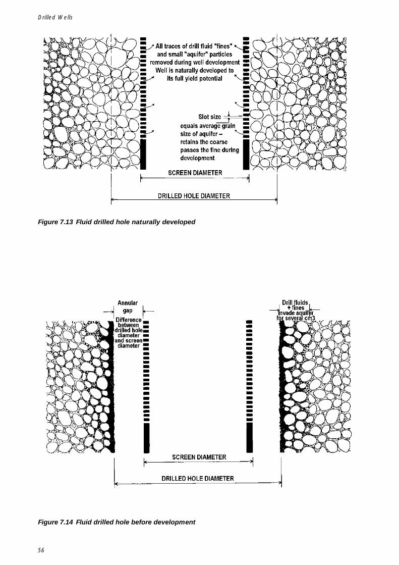
56
Drilled Wells
Figure 7.13 Fluid drilled hole naturally developed
Figure 7.14 Fluid drilled hole before development
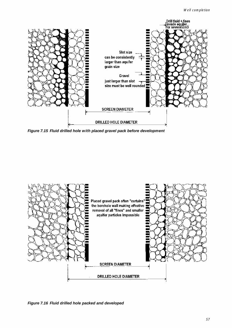
57
Figure 7.15 Fluid drilled hole with placed gravel pack before development
Figure 7.16 Fluid drilled hole packed and developed
Well completion

58
Drilled Wells
Table 7.1 Various hole volumes – in litres
mm's inches 1 1.5 2 3 10 20 30 40 5050 2" 2 3 4 6 20 39 59 79 9875 3" 4 7 9 13 44 88 133 177 22185 3.1/4" 6 9 11 17 57 113 170 227 28490 3.1/2" 6 10 13 19 64 127 191 254 318
100 4" 8 12 16 24 79 157 236 314 393115 4.1/2" 10 16 21 31 104 208 312 415 519125 5" 12 18 25 37 123 245 368 491 614140 5.1/2" 15 23 31 46 154 308 462 616 770150 6" 18 27 35 53 177 353 530 707 884165 6.1/2" 21 32 43 64 214 428 641 855 1,069200 8" 31 47 63 94 314 628 942 1,257 1,571250 10" 49 74 98 147 491 982 1,473 1,964 2,454
mm's inches 1 1.5 2 3 10 20 30 40 50100 4" 48 2" 6 9 12 18 60 121 181 242 302100 4" 63 2.1/2" 5 7 9 14 47 95 142 189 237100 4" 75 3" 3 5 7 10 34 69 103 137 172100 4" 90 3.1/2" 1 2 3 4 15 30 45 60 75115 4.1/2" 48 2" 9 13 17 26 86 172 257 343 429115 4.1/2" 63 2.1/2" 7 11 15 22 73 145 218 291 363115 4.1/2" 75 3" 6 9 12 18 60 119 179 239 298115 4.1/2" 90 3.1/2" 4 6 8 12 40 81 121 161 201125 5" 48 2" 10 16 21 31 105 209 314 418 523125 5" 63 2.1/2" 9 14 18 27 92 183 275 366 458125 5" 75 3" 8 12 16 24 79 157 236 314 393125 5" 90 3.1/2" 6 9 12 18 59 118 177 236 296125 5" 115 4.1/2" 2 3 4 6 19 38 57 75 94140 5.1/2" 48 2" 14 20 27 41 136 272 408 543 679140 5.1/2" 63 2.1/2" 12 18 25 37 123 246 368 491 614140 5.1/2" 75 3" 11 16 22 33 110 220 329 439 549140 5.1/2" 90 3.1/2" 9 14 18 27 90 181 271 361 452140 5.1/2" 115 4.1/2" 5 8 10 15 50 100 150 200 250140 5.1/2" 125 5" 3 5 6 9 31 62 94 125 156150 6" 48 2" 16 24 32 48 159 317 476 634 793150 6" 63 2.1/2" 15 22 29 44 146 291 437 582 728150 6" 75 3" 13 20 27 40 133 265 398 530 663150 6" 90 3.1/2" 11 17 23 34 113 226 339 452 565150 6" 115 4.1/2" 7 11 15 22 73 146 219 291 364150 6" 125 5" 5 8 11 16 54 108 162 216 270150 6" 140 5.1/2" 2 3 5 7 23 46 68 91 114165 6.1/2" 48 2" 20 29 39 59 196 391 587 783 979165 6.1/2" 63 2.1/2" 18 27 37 55 183 365 548 731 913165 6.1/2" 75 3" 17 25 34 51 170 339 509 679 848165 6.1/2" 90 3.1/2" 15 23 30 45 150 300 451 601 751165 6.1/2" 115 4.1/2" 11 16 22 33 110 220 330 440 550165 6.1/2" 125 5" 9 14 18 27 91 182 273 364 456165 6.1/2" 140 5.1/2" 6 9 12 18 60 120 180 240 299200 8" 90 3.1/2" 25 38 50 75 251 501 752 1,002 1,253200 8" 115 4.1/2" 21 32 42 63 210 421 631 841 1,051200 8" 125 5" 19 29 38 57 191 383 574 766 957200 8" 140 5.1/2" 16 24 32 48 160 320 481 641 801200 8" 165 6.1/2" 10 15 20 30 100 201 301 401 502250 10" 115 4.1/2" 39 58 77 116 387 774 1,161 1,548 1,935250 10" 125 5" 37 55 74 110 368 736 1,104 1,473 1,841250 10" 140 5.1/2" 34 51 67 101 337 674 1,011 1,348 1,685250 10" 165 6.1/2" 28 42 55 83 277 554 831 1,108 1,385250 10" 200 8" 18 27 35 53 177 353 530 707 884
Hole Diameter
Pipe Diameter
Depth of Hole - in metres
Annular volume formed between the borehole and a column of pipe inserted inside the holeDepth of Hole - in metres
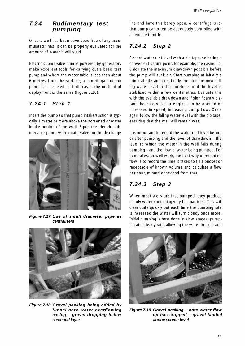
59
Figure 7.17 Use of small diameter pipe ascentralisers
Figure 7.18 Gravel packing being added byfunnel note water overflowingcasing – gravel dropping belowscreened layer
Figure 7.19 Gravel packing – note water flowup has stopped – gravel landedabobe screen level
Well completion
7.24 Rudimentary testpumping
Once a well has been developed free of any accu-mulated fines, it can be properly evaluated for theamount of water it will yield.
Electric submersible pumps powered by generatorsmake excellent tools for carrying out a basic testpump and where the water table is less than about6 metres from the surface; a centrifugal suctionpump can be used. In both cases the method ofdeployment is the same (Figure 7.20).
7.24.1 Step 1
Insert the pump so that pump intake/suction is typi-cally 1 metre or more above the screened or waterintake portion of the well. Equip the electric sub-mersible pump with a gate valve on the discharge
line and have this barely open. A centrifugal suc-tion pump can often be adequately controlled withan engine throttle.
7.24.2 Step 2
Record water rest-level with a dip tape, selecting aconvenient datum point, for example, the casing lip.Calculate the maximum drawdown possible beforethe pump will suck air. Start pumping at initially aminimal rate and constantly monitor the now fall-ing water level in the borehole until the level isstabilised within a few centimetres. Evaluate thiswith the available drawdown and if significantly dis-tant the gate valve or engine can be opened orincreased in speed, increasing pump flow. Onceagain follow the falling water level with the dip tape,ensuring that the well will remain wet.
It is important to record the water rest-level beforeor after pumping and the level of drawdown – thelevel to which the water in the well falls duringpumping – and the flow of water being pumped. Forgeneral water-well work, the best way of recordingflow is to record the time it takes to fill a bucket orreceptacle of known volume and calculate a flowper hour, minute or second from that.
7.24.3 Step 3
When most wells are first pumped, they producecloudy water containing very fine particles. This willclear quite quickly but each time the pumping rateis increased the water will turn cloudy once more.Initial pumping is best done in slow stages: pump-ing at a steady rate, allowing the water to clear and
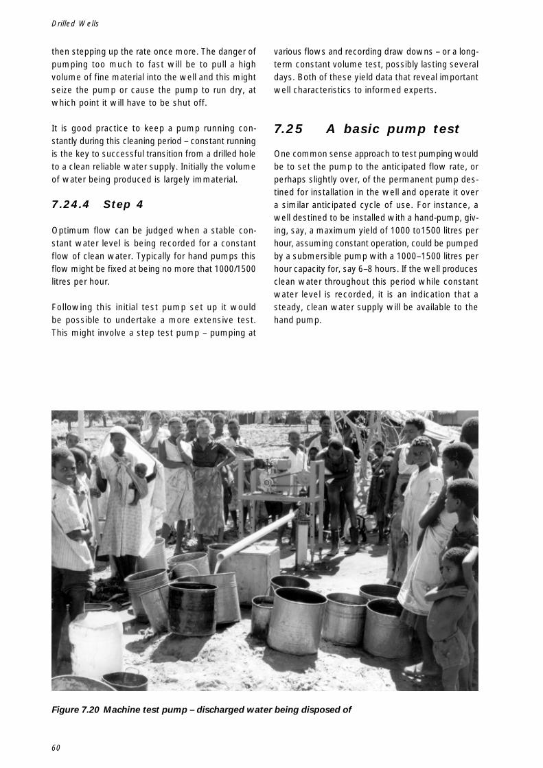
60
Drilled Wells
then stepping up the rate once more. The danger ofpumping too much to fast will be to pull a highvolume of fine material into the well and this mightseize the pump or cause the pump to run dry, atwhich point it will have to be shut off.
It is good practice to keep a pump running con-stantly during this cleaning period – constant runningis the key to successful transition from a drilled holeto a clean reliable water supply. Initially the volumeof water being produced is largely immaterial.
7.24.4 Step 4
Optimum flow can be judged when a stable con-stant water level is being recorded for a constantflow of clean water. Typically for hand pumps thisflow might be fixed at being no more that 1000/1500litres per hour.
Following this initial test pump set up it wouldbe possible to undertake a more extensive test.This might involve a step test pump – pumping at
various flows and recording draw downs – or a long-term constant volume test, possibly lasting severaldays. Both of these yield data that reveal importantwell characteristics to informed experts.
7.25 A basic pump test
One common sense approach to test pumping wouldbe to set the pump to the anticipated flow rate, orperhaps slightly over, of the permanent pump des-tined for installation in the well and operate it overa similar anticipated cycle of use. For instance, awell destined to be installed with a hand-pump, giv-ing, say, a maximum yield of 1000 to1500 litres perhour, assuming constant operation, could be pumpedby a submersible pump with a 1000–1500 litres perhour capacity for, say 6–8 hours. If the well producesclean water throughout this period while constantwater level is recorded, it is an indication that asteady, clean water supply will be available to thehand pump.
Figure 7.20 Machine test pump – discharged water being disposed of
61
8.Use of drilling technologywith hand-dug wells
If water is available under the ground and peopleneed it, they invariably dig for it. This has alwaysbeen the case worldwide and until tapped, pipedwater is universally available, people will continueto dig wells by hand. There are many situationswhere drilling technology and materials can usefullycombine with traditional hand-dug well construction.
8.1 Hand-dug wells havemany advantages
� They can be constructed within a community’sown resources;
� They can be technically improved with nominalinputs from outside to line and cap them;
� Water is obtained by a bucket and rope, one ofthe few completely sustainable water-liftingmethods used with ground water;
� By nature of their large diameters they providevaluable storage, which allows exploitation ofvery small ground-water sources.
8.2 Disadvantages ofhand-dug wells
� They can be expensive to construct in compari-son with a modest drilled well;
� They are able to reach ground-water but are dif-ficult to dig deep into an aquifer to provide adrought-resistant water supply;
� They are a major commitment in labour andcommunity resources;
� To dig deep shafts and fail to reach water is adisappointing set back.
8.3 Health aspects
A lot has been written about the relative merits, asfar as hygiene is concerned, between an open orcapped open dug well and a sealed borehole with adedicated hand pump. However, in communities
where water distribution, understanding of health andthe ability to store water hygienically is rudimentary,surely it makes little difference if contaminationtakes place in the well, bucket or water storage jar.The answer lies in overall health education rather thanin insisting that sealed boreholes are the only an-swer.
There are uses for modest drilling programmes inconjunction with hand-dug well construction.
8.4 Prospecting wetsites
A drilling programme allows a quick feasibility as-sessment for a community water supply. It isadvantageous to have the water supply in the vil-lage centre but it may have to be on a geologicalfault line 500 m away. Drilling rapidly at both thebest social and hydrogeological sites can demon-strate the depth to water, the difficulty of digging,the relative volumes available and the relativechemical analyses.
8.5 Sub-Artesian -confined aquifer
Where the aquifer is confined by an overlyingimpervious formation there is an opportunity to com-bine a drilled hole with a dug shaft. It is possibleto construct a small demonstration well by drillinga small diameter hole, say 80 mm, through theconfining layer into the water bearing layer. Casing,say 60 mm (2"), and screen, can then be installed,taking care to seal the casing above the screenwith cement or bentonite, and the well developed(Figure 8.1).
The water yield can be evaluated with hand bailersor an air compressor yield test, hand pump, orcheap 2" 12 volt submersible pump. A dug shaft canthen be sunk around the 2" casing, keeping the pipe
Use of drilling technology with hand-dug wells
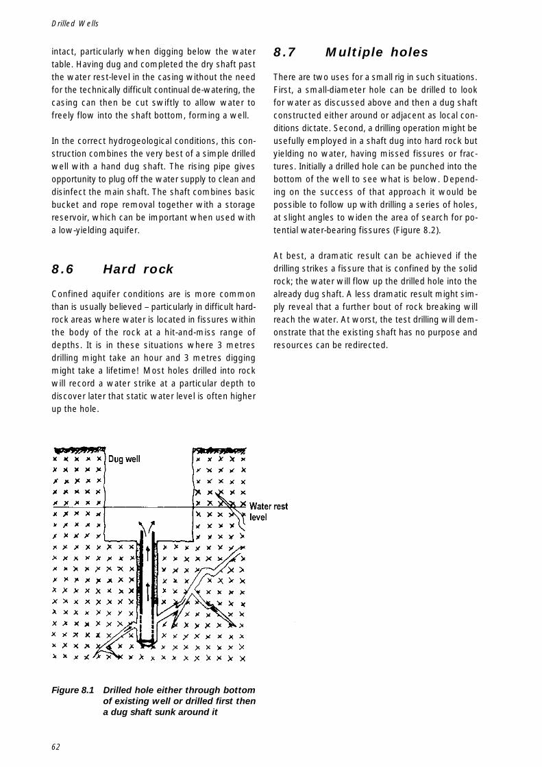
62
Drilled Wells
intact, particularly when digging below the watertable. Having dug and completed the dry shaft pastthe water rest-level in the casing without the needfor the technically difficult continual de-watering, thecasing can then be cut swiftly to allow water tofreely flow into the shaft bottom, forming a well.
In the correct hydrogeological conditions, this con-struction combines the very best of a simple drilledwell with a hand dug shaft. The rising pipe givesopportunity to plug off the water supply to clean anddisinfect the main shaft. The shaft combines basicbucket and rope removal together with a storagereservoir, which can be important when used witha low-yielding aquifer.
8.6 Hard rock
Confined aquifer conditions are is more commonthan is usually believed – particularly in difficult hard-rock areas where water is located in fissures withinthe body of the rock at a hit-and-miss range ofdepths. It is in these situations where 3 metresdrilling might take an hour and 3 metres diggingmight take a lifetime! Most holes drilled into rockwill record a water strike at a particular depth todiscover later that static water level is often higherup the hole.
8.7 Multiple holes
There are two uses for a small rig in such situations.First, a small-diameter hole can be drilled to lookfor water as discussed above and then a dug shaftconstructed either around or adjacent as local con-ditions dictate. Second, a drilling operation might beusefully employed in a shaft dug into hard rock butyielding no water, having missed fissures or frac-tures. Initially a drilled hole can be punched into thebottom of the well to see what is below. Depend-ing on the success of that approach it would bepossible to follow up with drilling a series of holes,at slight angles to widen the area of search for po-tential water-bearing fissures (Figure 8.2).
At best, a dramatic result can be achieved if thedrilling strikes a fissure that is confined by the solidrock; the water will flow up the drilled hole into thealready dug shaft. A less dramatic result might sim-ply reveal that a further bout of rock breaking willreach the water. At worst, the test drilling will dem-onstrate that the existing shaft has no purpose andresources can be redirected.
Figure 8.1 Drilled hole either through bottomof existing well or drilled first thena dug shaft sunk around it
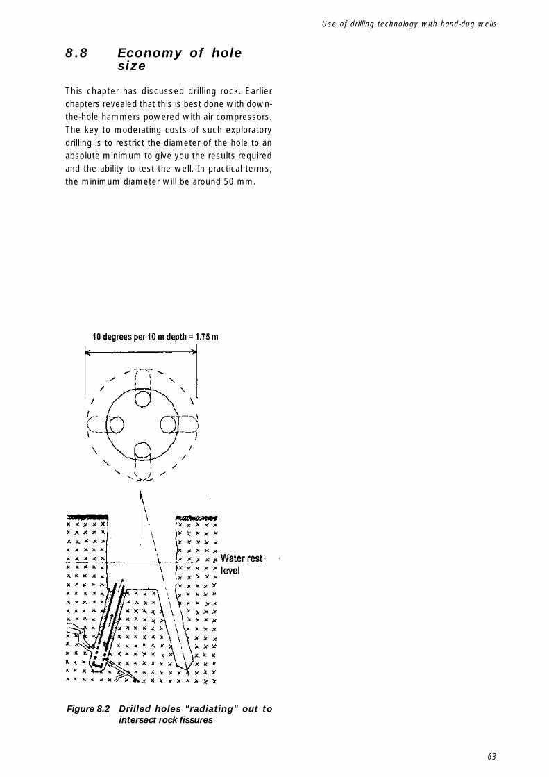
63
Figure 8.2 Drilled holes "radiating" out tointersect rock fissures
Use of drilling technology with hand-dug wells
8.8 Economy of holesize
This chapter has discussed drilling rock. Earlierchapters revealed that this is best done with down-the-hole hammers powered with air compressors.The key to moderating costs of such exploratorydrilling is to restrict the diameter of the hole to anabsolute minimum to give you the results requiredand the ability to test the well. In practical terms,the minimum diameter will be around 50 mm.

64
Drilled Wells
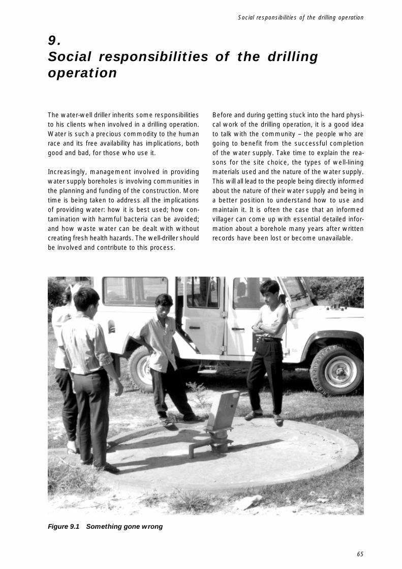
65
9.Social responsibilities of the drillingoperation
The water-well driller inherits some responsibilitiesto his clients when involved in a drilling operation.Water is such a precious commodity to the humanrace and its free availability has implications, bothgood and bad, for those who use it.
Increasingly, management involved in providingwater supply boreholes is involving communities inthe planning and funding of the construction. Moretime is being taken to address all the implicationsof providing water: how it is best used; how con-tamination with harmful bacteria can be avoided;and how waste water can be dealt with withoutcreating fresh health hazards. The well-driller shouldbe involved and contribute to this process.
Before and during getting stuck into the hard physi-cal work of the drilling operation, it is a good ideato talk with the community – the people who aregoing to benefit from the successful completionof the water supply. Take time to explain the rea-sons for the site choice, the types of well-liningmaterials used and the nature of the water supply.This will all lead to the people being directly informedabout the nature of their water supply and being ina better position to understand how to use andmaintain it. It is often the case that an informedvillager can come up with essential detailed infor-mation about a borehole many years after writtenrecords have been lost or become unavailable.
Figure 9.1 Something gone wrong
Social responsibilities of the drilling operation
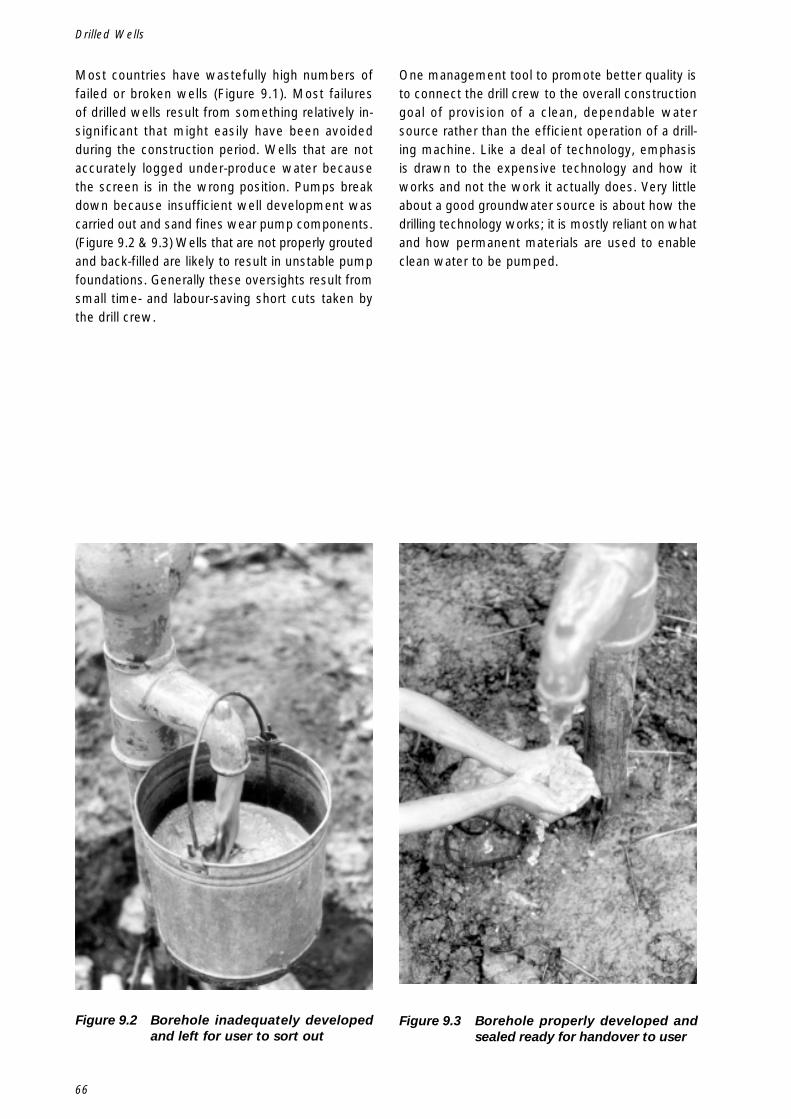
66
Drilled Wells
Figure 9.2 Borehole inadequately developedand left for user to sort out
Figure 9.3 Borehole properly developed andsealed ready for handover to user
Most countries have wastefully high numbers offailed or broken wells (Figure 9.1). Most failuresof drilled wells result from something relatively in-significant that might easily have been avoidedduring the construction period. Wells that are notaccurately logged under-produce water becausethe screen is in the wrong position. Pumps breakdown because insufficient well development wascarried out and sand fines wear pump components.(Figure 9.2 & 9.3) Wells that are not properly groutedand back-filled are likely to result in unstable pumpfoundations. Generally these oversights result fromsmall time- and labour-saving short cuts taken bythe drill crew.
One management tool to promote better quality isto connect the drill crew to the overall constructiongoal of provision of a clean, dependable watersource rather than the efficient operation of a drill-ing machine. Like a deal of technology, emphasisis drawn to the expensive technology and how itworks and not the work it actually does. Very littleabout a good groundwater source is about how thedrilling technology works; it is mostly reliant on whatand how permanent materials are used to enableclean water to be pumped.
67
There is a dark side to working with drilling equip-ment and constructing water supply holes.Numerous projects can be sited worldwide wherehuge amounts of resources have been swallowedup by ‘drilling programme’s for seemingly little con-struction impact. It is essential to select the rightequipment for all the aspects of the operation – thecorrect sized and powered rig complemented by aborehole design that minimises diameters and leadsto selection of drill bit sizes and to mud pump andcompressor selection.
When things go wrong, situations often develop frombad to worse very quickly. The driller and his creware at some remote location with little opportunityof getting technical assistance in the form of peo-ple or equipment to get them out of trouble. Mostchapters of this manual have been positive andwritten with all the goals of good theory and goodpractice based on years of opportunity and hindsight.This chapter deals with things when they have gonewrong.
10.1 Stuck drill pipe
The drill pipe does not rotate freely and it is impos-sible to raise or lower it in the hole.
First the obvious, for drill pipe to get stuck some-thing must have been fundamentally wrong with thedrilling method in the geology being drilled. Insuffi-cient hole cleaning capacity with air or fluid – whatwas it that went wrong and why? Try and avoidwhatever it was in the future.
It is commonsense for a driller to expect that foreach metre he drills into the ground he should ex-pect to see at the surface an equivalent volumetricamount of spoil at the surface – they should worryif no spoil is being transported and indeed if toomuch is being delivered to the surface. In the lattercase a cavern may be being created into which thehole might slump and take the rig in with it!
10.1.1 By and large these arethe steps to follow
Step 1
Regain circulation through the drill pipe and up thehole whether it be air, fluid or foam or even maybeintroducing one or other new to the hole. If usingair flush in soft ground that has partially collapsedor fragments of rock have jammed between theborehole walls and drill pipe, introduce foam. Thiscan be very basic addition of a bucketful of soapywater down the centre of the drill pipe or even theborehole annulus if a foam pump is not plumbed in.The foam will help lift clear large particles and willlubricate and dilute debris at the hole bottom. Theaction of breaking a drill pipe connection and lettingthe backed-up air or fluid pressure escape can al-low a pressure surge to develop when drill pipe isre-connected to break through the blockage. If us-ing fluid try and increase both or either the viscosityand pumping rate of the fluid – if using centrifugalpumps it can be possible to couple a pair of pumpsinline – pushing the delivery of one pump into thesuction port of a second – this will double the pres-sure head and might clear the blockage.
Step 2
Preferably in conjunction with Step 1 – regain therotation. Use the machine power to try and jerk thedrill pipe into constant rotation, perhaps simultane-ously with a small up or down movement to attemptto release the drill pipe. On light- powered equipmentit might be necessary to put a strong wrench anduse a lever to induce the drill pipe into rotationmanually. Resist the temptation to try reverse-rotat-ing the drill pipe because you will not be sure if youare simply unthreading a pipe joint.
Step 3
Having regained both circulation and rotation pa-tiently raise the drill pipe – back drilling until the drill
10.When things go wrong
When things go wrong
68
Drilled Wells
bit is completely free once more. Sometimes a drillbit can be raised by only millimetres a minute – butall movement is good and patience is required.
Step 4
Only proceed back down the hole after the originalfault that caused the drill pipe to jam has been cor-rected and the drilling operation adjusted for.What rarely works is pure force by hoisting the drillpipe upwards by using powerful jacks or a crane –this normally wedges the jammed pipe even tighteruntil it breaks.
10.2 Fishing
This is the descriptive term given to retrieving any-thing that has fallen down a borehole, one hopes byaccident.
The very first step is to give sufficient space to thinkclearly and not make things worse by pre-emptiveaction of the wrong sort. Determine exactly whathas been dropped, where it has landed, and whatdevices will first couple with it if lowered and thenbe strong enough to hold on to it while it be lifted.If you have the wrong device to catch the droppeditem take time to adapt or make a device that willcatch hold securely. A few ideas help at this stageto refine a device to get the desired result.
10.2.1 Magnet
A magnet on a rope can retrieve odd bits of steelor a spanner inadvertently dropped into a hole. Agood drill crew get into the habit of always cover-ing an open hole with a bucket, spade or plankwhenever it is left open to prevent anything inad-vertently dropping down.
10.2.2 Threaded pipes
A threaded pipe can be retrieved by the correspond-ing threaded end – if a pipe has damaged threads ora broken coupling it can be retrieved by a special ‘tap’or ‘overshot’ – these are made from carbon steel andhardened with fine tapered threads to match insidefor the ‘tap’ or to the outside of a tube in case of an‘overshot’ – these have to be available in advancebecause there is little chance of rustling up manufac-ture of these in small machine shops.
In all these cases the method of fishing is thesame. Dip the hole with a dipper or a weight on ameasuring tape and chalk up a string of drill pipeshowing the depth the fish will be made. Insert thefishing thread or tool into the hole and try and makea connection by jiggling the pipe up and down. Markthe pipe with a bit of chalk adjacent to the rig tableor something similar – with maybe another mark 50mm above. Thread the pipe up by hand – with luckyou might feel the threads making up – becomingtighter- and, importantly, the chalk marks dropping,showing the threads are indeed steadily couplingtogether. If the chalk mark does not move down-wards pick and re-jiggle to try and make theconnection align. Once the connection has beenmade lift out the pipe – take care to be gentle withthe pipe handling as the ‘fish’ might only be lightlycaught and or cross threaded and a sudden jar mightget it to drop off again.
Plastic pipe can be retrieved by a steel spear withsharp angle barbs or spikes that will spring into theinside of the pipe and dig in and bite into the borewhen raised.
Galvanised pipe (pump rising main) with couplingscan be retrieved by sliding larger diameter steel pipeover the fish with some internal strips cut and bentinwards as barbs. These can be pushed or sprungover a coupling and then the fish hoisted upwards.
10.3 Borehole cameras
Inexpensive borehole cameras are available that cangive a quick view of what is below ground, an in-valuable ‘eye in the ground’ (Figures 10.1 & 10.2).
Camera systems can be very sophisticated withmotorised winches and with automatic depth – re-cording, allowing detailed analysis of a borehole topto bottom – a simpler camera held by hand on acable or tape can quickly be lowered to give theessential view of a problem or to seek information.
In a regular drilling operation cameras can quicklydetermine the competence of landing and cement-ing casing where a hole has been drilled through setcasing into firm rock – they will positively confirmthe fissures drilled through and the occurrence offurther underlying fissures. It is easy to spot the firstmajor water strike in a rock hole drilled with com-
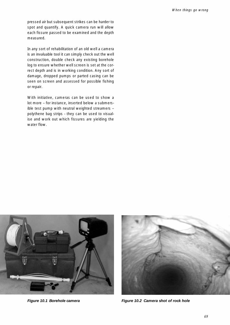
69
pressed air but subsequent strikes can be harder tospot and quantify. A quick camera run will alloweach fissure passed to be examined and the depthmeasured.
In any sort of rehabilitation of an old well a camerais an invaluable tool it can simply check out the wellconstruction, double check any existing boreholelog to ensure whether well screen is set at the cor-rect depth and is in working condition. Any sort ofdamage, dropped pumps or parted casing can beseen on screen and assessed for possible fishingor repair.
With initiative, cameras can be used to show alot more – for instance, inserted below a submers-ible test pump with neutral weighted streamers –polythene bag strips - they can be used to visual-ise and work out which fissures are yielding thewater flow.
When things go wrong
Figure 10.1 Borehole camera Figure 10.2 Camera shot of rock hole

70
Drilled Wells

71
A
Air compressor 19Air Pressure 21Air volume 19
B
Barrel Type Pump 29Bent holes 4Borehole cameras 68Borehole design 35Borehole diameter 19Borehole log 32
C
Catchment area 39‘chalk’ the drill-pipe 31Compressed air 19Conductor casing 21
D
Difficult drilling – ‘boulders’ 25Direct acting 36Down-the-hole hammer 3, 19, 22Drag blade 3, 22Drill collars 4Drill pipes 4Drilling with compressed air 31Dummy 46
E
Economy of hole size 63Electric Submersible pumps 36
F
Fishing 68Fluid drilled holes 31Foam 27Foam inlet manifold 29Foam pump types 28Fractured rock 40
G
Galvanised pipe (pump rising main) 68Geotextile 43
H
Hammer Maintenance 23Hammer stripping 24Hand Pump 29Hand pumps 35Hand-dug wells 61Hard rock 62Health aspects 61High velocity foam – air misting 27Hole stability 21, 27Hydrogeologists 40Hydrogeology 39
K
‘kinetic’ energy 24
L
Latrines 41Levered 36Logging of samples 31Low velocity foam – stable foam column 27Lubrication 23
M
Magnet 68Multiple holes 62
N
Non return valve 23Non- return valve sub adapter 28
P
Perpendicular 4Piston Pumps 29Polyester stocking 43Porous rock 39
R
Reverse-circulation hammers 26Rotation speed 23
Index
Index

72
Drilled Wells
S
Sample collection 32Sedimentary deposits 39Shock absorbers 24Spindle-driven pumps 36Stabiliser 4Steel spear 68Stuck drill pipe 67Sub-Artesian - confined aquifer 61Suction pumps 38Sustainability 35
T
Telescopic casing & screen 43Threaded pipes 68
U
uPVC pipe 41
V
‘valved’ 22‘valveless’ 22
W
Water strikes 31Well casing 41Well dippers 28Well screen 41Well-lining materials 41Well-rehabilitation 32