an energy efficient and balanced energy consumption cluster based routing protocol for underwater...
TRANSCRIPT
Seediscussions,stats,andauthorprofilesforthispublicationat:https://www.researchgate.net/publication/292035815
Anenergyefficientandbalancedenergyconsumptionclusterbasedroutingprotocolforunderwaterwirelesssensornetworks
CONFERENCEPAPER·JANUARY2016
READS
4
8AUTHORS,INCLUDING:
NadeemJavaid
COMSATSInstituteofInformationTechnology
283PUBLICATIONS1,132CITATIONS
SEEPROFILE
Allin-textreferencesunderlinedinbluearelinkedtopublicationsonResearchGate,
lettingyouaccessandreadthemimmediately.
Availablefrom:NadeemJavaid
Retrievedon:27January2016

An energy efficient and balanced energy
consumption cluster based routing protocol for
underwater wireless sensor networks
Abdul Majid1, Irfan Azam1, Abdul Waheed1, Muhammad Zain-ul-Abidin1,
Taimur Hafeez1, Zahoor Ali Khan2,3, Umar Qasim4, Nadeem Javaid1,∗
1COMSATS Institute of Information Technology, Islamabad 44000, Pakistan2Faculty of Engineering, Dalhousie University, Halifax, NS, B3J 4R2 Canada3CIS Higher Colleges of Technology, Fujairah 4114, United Arab Emirates4Cameron Library, University of Alberta, Edmonton, AB, T6G 2J8 Canada∗Corresponding author: [email protected], www.njavaid.com
Abstract—In Underwater Wireless Sensor Networks (UWSNs)nodes are equipped with limited battery power and batteryreplacement is expensive due to underwater harsh environment.Therefore, we propose EBECRP an energy Efficient and BalancedEnergy consumption Cluster based Routing Protocol for UWSNs.In depth base routing protocols nodes near the sink (low depthnodes) die in no time because of high load. We avoid depth baserouting in our proposed scheme and use mobile sinks to balanceload on all nodes. We also use the concept of clustering to reducemulti hoping which results in more energy consumption. Theselected Cluster Heads (CHs) collect data from one hope neighbornodes to reduce global communication into locally compressedcommunication. Simulation results show that EBECRP achievesmaximum stability period and network life time.
Index Terms—Underwater wireless sensor networks, Energyconsumption, Cluster head, Sink mobility.
I. INTRODUCTION
From the last few years UWSNs have gained popularity in
research area because of their applications like environmental
monitoring for scientific exploration, pollution monitoring,
military surveillance, disaster prevention, resource investiga-
tion, oil extraction etc [1]. The UWSNs consist of sink(s)
and acoustic sensor nodes. Acoustic sensor nodes collect data
of interest from the environment and follow routing path to
forward that data to the sink. The acoustic sensor nodes have
limited battery power where no energy constraint on sink [2].
Many routing protocols are proposed for terrestrial Wireless
Sensor Networks (WSNs). These existing routing protocols
may not be suitable for underwater environment [3]. WSNs use
radio waves for communication where UWSNs use acoustic
channels for communication. Radio signals do not work well in
water because of rapid attenuation. The acoustic signals have
unique characteristics: long propagation delay, high signal to
noise ratio, low bandwidth etc. Due to these characteristics
developing efficient and scalable routing protocol for UWSNs
is very challenging [4].
Underwater sensor nodes have limited resources: battery
power, memory capacity, processing capability, bandwidth etc.
Battery replacement in aquatic environment is difficult [5].
Aquatic environment needs an energy efficient routing proto-
col. Efficient energy consumption is defined as, we achieve
more work load with less energy consumption [10]. Efficient
energy consumption is in direct relation with network life time.
In addition network life time is improved with balanced energy
consumption of nodes in the network by dividing equally load
on nodes.
In [4–9], involve static sink(s) which are deployed on water
surface. However, in static sink(s) the sensor nodes which are
closed to the sink die earlier because low depth nodes have
unbalanced load and forward more packets than high depth
nodes. This unbalanced load on sensor nodes creates routing
holes in the network, result in hotspot problem. Hence, it
is better to use mobile sinks for collecting information from
sensor nodes [2] [11]. Therefore, we propose EBECRP which
avoids depth base routing and performs cluster based routing
with sinks mobility. In depth based routing low depth nodes
die in no time because of unbalanced load on the nodes near
the sink(s). In order to tackle this we use mobile sinks in
EBECRP, which change their position frequently. To reduce
the number of transmissions we use the concept of clustering.
In clustering each node is responsible to communicate with
its respective CH. Each CH collects data from the nodes in
its vicinity and forwards collected data to sink. Thus, cluster
formation saves energy by performing data compression at
CH and reduces global communication to locally compressed
communication [12]. By using sink mobility and clustering
the balanced energy consumption is achieved in the network,
result in improved stability period and network life time.
The rest of the paper is organized as follows. Related work
is discussed in section II. Section III deals with motivation
and the detail work of our proposed scheme EBECRP is
shown in section IV. In section V we present the performance
of EBECRP. Conclusion is given in section VI and finally
references are given at the end of paper.

II. RELATED WORK
LEACH [13] is the first cluster based routing protocol for
terrestrial WSNs. The main purpose of LEACH is to reduce
global communication into locally compressed communication
by using the concept of clustering. Cluster formation is based
on the minimum distance and received signal strength. In each
cluster there is one CH; responsible for collection of data
from nodes and forward to Base Station (BS). In LEACH CH
selection is randomly rotated over time to balance load on the
nodes in term of energy consumption. For CH selection each
node generates a random number and compare with Threshold
value; Th(i), given in [13] as:
Th(i) =
{
p1−p(mod(r,1/p)) , if i ∈ G
0, otherwise(1)
Where i is the current node and p is its probability to be
selected as CH which is defined initially, G shows the set
of nodes which are eligible for CHs selection, R shows the
round number and mod(r, 1/p) return modulus after division
of r by 1/p. Node is selected as CH when threshold value is
greater than the random number. In LEACH, clusters are of
different sizes and this phenomena leads to unbalanced energy
consumption of CHs.
In [14], authors proposed energy balanced routing algorithm
for WSNs based on virtual MIMO technique. The proposed al-
gorithm has three improvements over the conventional LEACH
routing algorithm in term of better cluster head selection,
energy consumption and mitigates the different size cluster
head distributions. For cluster head selection, the algorithm
considers the residual and most recent energy expenditure
of the nodes and the whole network, in order to balance
the energy consumption among different sensors nodes. The
propose algorithm shows better performance over the conven-
tional LEACH algorithm in term of energy consumption and
network life time.
Ashfaq et al. proposed cluster based routing scheme [10] to
maximize lifetime and throughput of WSNs. The CHs selec-
tion is similar to that of LEACH where each node generates
a random number and compares with threshold value. Node
is elected as CH if the generated random number is less than
the threshold value and is not selected for the last 1/p rounds.
After election, natural selection mechanism is used to choose
optimal number and distant CHs in the network. If the selected
CHs is less than the optimal number of CHs (ten percent of the
total nodes in network) the Away Cluster Heads (ACH)2carried
out re-election. If the selected CHs are greater than the optimal
number, CHs are minimized in number. Otherwise scheme
operation is carried out. In this way (ACH)2 has clustered
of almost same size which results in uniform load on CHs.
(ACH)2 avoids back transmission; where node associates with
the CH which increases over all distance of the node from BS.
Authors discuss localization free Depth Based Routing
protocol (DBR) In [4] for UWSNs. DBR uses the depth of
the sensor node as forwarding metric for sending data to the
BS. The data from source to destination is forwarded in multi
hop fashion. Sender node includes its depth information in the
data packet and broadcast to the nodes in its threshold range.
The receiver node compares its depth with the depth of the
forwarder node. If the depth of the receiver node is greater than
the forwarder node the receiver node just discard the packet.
Otherwise, holds the data packet for certain time. The node
with smaller depth has less holding time and is selected as
next eligible forwarder for data packet. Thus, the nodes having
smaller depth always involve in data forwarding due to which
their energy deplete very quickly and create hotspot problem
in network. In DBR the nodes with low depth have more loads
as compared to high depth nodes, due to this unbalanced load
the low depth nodes die very quickly.
For efficient energy cunsumption, an Energy Efficient Depth
Based Routing protocol (EEDBR) [5] is presented for UWSNs.
EEDBR is a localization free depth based routing protocol for
UWSNs. It uses depth as well as residual energy of the sensor
node as forwarding metric for sending data to sink. The sender
node selects the node with high residual energy in its neighbor
as next forwarder and data is forwarded from source to sink
in multi hop fashion. In EEDBR nodes which are near to sink
have more load than those nodes which are far away from
the sink. Due to this unbalanced load nodes near the sink die
earlier and create hotspot problem in network.
Ayaz et al. proposed H2-DAB (Hop-by-hop Dynamic Ad-
dressing Based) [6] routing protocol for UWSNs. In H2-DAB
each sensor node is assigned a unique HopID based on the
hop count from the sink. The procedure for assigning HopID
to each sensor node is as follows. Sink broadcast hello packet
to one hop away sensor nodes. The nodes which receive hello
packet is assigned HopID. The receiver nodes increment the
HopID and re-broadcast the hello packet to their one hop
neighbor nodes with updated HopID. The HopID is updated
hop by hop. Therefore, nodes near the sink are assigned a
smaller HopID than the nodes which are far away from sink.
During data forwarding nodes with smaller HopID are always
selected for data forwarding, similar to that of DBR. Due to
frequent data transferring the nodes with smaller HopID die
earlier than the other nodes in network. During data forwarding
H2-DBR also uses request and replay inquiry packet which is
not suitable in resource-constrained environment as UWSNs
[5].
To maximize the network lifetime, an Adaptive mobility
of Courier nodes in Threshold-optimized Depth based routing
(AMCTD) [9] is proposed for UWSNs. AMCTD uses the
weight function not only to balance load on the nodes in
network but also gives optimal holding time for the neighbors
of source node. On the basis of weight function source node
selects the next best possible forwarder of data packet in its
threshold-based neighbors. Furthermore, adaptive movement
of courier nodes in sparse condition uphold the network
throughput.
In [7], authors proposed localization-free and flooding based
routing protocol; Improved Adaptive Mobility of Courier
nodes in Threshold-optimized depth-based-routing (IAMCTD)
for UWSNs. IAMCTD uses Forwarding-Function (FF); to cal-

TABLE ICOMPARISON OF DIFFERENT ROUTING PROTOCOLS.
Protocol name Features Flaws/Deficiency Advantages achieved
LEACH [13] Cluster based routing. CHs are randomly selected; result in dif-ferent size cluster and imbalanced energyconsumption.Election probabilities are the same for alleligible nodes.
Reduce global communication into locallycompressed communication
Energy balancerouting algorithm[14].
Cluster based routing algorithm based onVirtual MIMO.
Computational overhead involved.Not consider end to end delay.
Increased network life time and reducedenergy consumption.
(ACH)2 [10] Cluster based routing with optimal CHsselection mechanism.
Computation overhead involved. Optimal number of cluster with same size.Removed back transmission
DBR [4] Localization free depth based routing.Receiver based approach where, next for-warder of data is selected on the basis ofdepth.
Imbalanced energy consumption.In efficient for sparse and dense network.Least depth nodes die earlier.
High data delivery and low end to end delay.
EEDBR [5] Localization free depth based routing.Sender based approach where, sender nodedecides next forwarder of data on the basisof depth and residual energy.
Imbalanced energy consumption and ineffi-cient for dense network.Nodes with medium depth die earlier.
Efficient energy consumption and decreasedend to end delay.High data delivery
H2-DAB [6] Localization free depth based routing pro-tocol with multiple sink structural design.
Imbalanced energy consumption.Nodes with smaller hop ID deplete energyearlier.Request and replay inquiry act as overhead.
Does not require full- dimension informa-tionHigh data delivery
IAMCTD [7] Localization free depth based routing fortime critical applications along with couriernodes.Courier nodes collect data from sensorsnode.
Overhead involved in term of control packetexchange.
Improved network life time and minimizedend to end delay.
AMCTD [9] Localization free depth based routing withcourier nodes.Courier nodes collect data from sensorsnode.
Not suitable for data-sensitive applications.High transmission loss.
Improved network life time.
CoDBR [8] Localization free depth based routing alongwith cooperation.
High energy consumption and increased endto end delay.
Increased reliability and throughput effi-ciency.Reduced packet drop and increased packetacceptance ratio.
R-ERP2R [15] Localization free routing based on physicaldistance and residual energy.Forwarder node is selected on the basis ofdistance, link quality and residual energy.
Computational overhead in term of multiplemetrics.
Reduced energy consumption and end-to-end delay.Increased network lifetime and delivery ra-tio.
AURP [16] Multiple AUSs collect data from sensornodes through gateway nodes.
Increased delay. Minimized energy expenditure and maxi-mized packet delivery ratio.
Delay-sensitiverouting schemes[21]
Localization free depth based routing.Courier nodes collect data from sensornodes and forward to sink.
Reduced throughput. Minimized total energy expenditure, trans-mission loss and average end to end delay.
SPARCO [24] Cluster based routing protocol. More forwarding nodes and energy con-sumption.
Enhanced stability period, network life time,packet delivery ratio.
Mobicast [17] The AUV travels on user defined route andcollects data from a series of 3-D ZORs.Mechanism to wake up sensor nodes fornext 3-D ZOR.Able to cover the drift distance of node.
Increased energy consumption and result inmessage overhead.
Improved throughput and packets deliveryratio, minimized end to end delay.
AEDG [18] AUV follows elliptical path for data col-lection from sensor nodes through gatewaynodes.Mechanism to balanced load on gatewaynodes.
High packets delivery ratio, reduced energyconsumption and transmission loss.
Increased end to end delay.
DEADs [2] Single and multiple relay cooperative rout-ing along with sinks mobility (elliptical,linear).
High energy expenditure and short stabilityperiod.Control and processing overhead.
Increased throughput efficiency and reducedpacket drop.
Chain based [19] Application oriented routing protocol forfinding local optimum and global optimumsolution for data collection in cylindricalnetworks.
High routing overhead. Increased network lifetime and packet send-ing rate. Decreased end-to-end delay, pathloss, and transmission loss.
Co-UWSN [20] Cooperative communication. Beneficial fordelay-sensitive and time-critical applica-tions
Increased end to end delay and more for-warding nodes.
Improved stability period, network life timeand packet delivery ratio.
Link expiration[23]
Link expiration time, handles node mobilityand probability technique selects next for-warder.
Acknowledgment packet acts as overhead.Increased end to end delay.
Improved network life time and data deliv-ery ratio.
LAFR [22] Link-State Based Adaptive Feedback Rout-ing with asymmetric link.
Computational overhead in term of Asym-metric link.
Minimized energy consumption and averageend to end delay.Increased packet delivery ratio.
culate optimal holding time by using routing metrics (LSNR,
SQI, ECF and DDF), which tackle flooding, path loss, and
propagation latency. Furthermore, optimized mobility pattern
of courier nodes reduces end to end delay in later rounds. In
IAMCTD nodes near the surface deplete energy earlier, which
results in hotspot problem. Furthermore, their depth threshold
change according to network density, which require exchange
of control packet on regular basis. This exchange of control
packet acts as overhead and waste network resources [2].
For reliable data delivery authors propose Cooperative
Depth Based Routing (CoDBR) [8] for UWSNs. Cooperation
is performed at network layer, in order to increase reliability
and throughput efficiency of the network. Source node selects
two relay nodes on the basis of depth information. Source
node forwards its data to relay nodes and destination. The
relay nodes then forward that data to the destination node by
using Amplify and Forward (AF) technique. The three received
copies of data at the destination are combined using diversity
combining technique.
Authors propose R-ERP2R (Reliable Energy-efficient Rout-
ing Protocol based on physical distance and residual energy)
[15] for UWSNs. R-ERP2R employs multiple routing metrics
into account, that is, physical distances, link quality and
residual energy to selects forwarder node. It exercises to
accomplish higher throughput on the basis of physical distance
as a routing metric. It also provides efficient energy solution
with better link quality for data forwarding. furthermore, There
is no holding time in R-ERP2R, which results in short end to
end delay.
In [21], authors proposed three routing protocols as an
improvement to localization-free depth based routing proto-
cols: DBR, EEDBR, and AMCTD. Delay-Sensitive Depth-
Based Routing (DSDBR) is an improved version of DBR
which performs routing on basis of depth information, holding
time and depth threshold. DSDBR uses Fi and WF for better
forwarder selection and minimizes end-to-end delay, in order
to make DBR adaptable for time-critical applications. The
improved version of EEDBR that is, DSEEDBR (Delay-
Sensitive Energy Efficient Depth-Based Routing) uses depth
threshold (dth) variation for sensor nodes and provide an
analysis to estimate DSHT (Delay-Sensitive Holding time).
DSHT removes the inadequacy of multiple retransmissions in
the low-depth, in order to tackle high propagation delays. The
improved version of AMCTD that is, DSAMCTD (Delay-
Sensitive Adaptive Mobility of Courier nodes in Threshold-
optimized Depth-based routing) uses PF formulae for selecting
a sensor node with higher neighbors as an optimal forwarder
for data packets. It provides minimal end-to-end delay with
adaptive mobility of courier nodes allowing a slight decrease
in network throughput.
AEDG ((AUV)-Aided Efficient Data-Gathering) [18],
presents an Autonomous Underwater Vehicle (AUV) based
routing protocol for efficient data-gathering and reliable data
delivery in UWSNs. AUV collects data from gateway nodes.
Sensor nodes use a shortest path tree (SPT) algorithm for
association with gateway node. The AEDG protocol limits
the number of nodes associate with gateway node and rotate
it with the passage of time to minimize the network energy
consumption and prevent it from overloading. Furthermore,
AEDG improves network throughput with elliptical trajectory
of AUV by using a connected dominating set (CDS).
First time multiple AUVs are used in AURP [16]; An AUV-
Aided Underwater Routing Protocol for underwater Acoustic
Sensor Networks. AUVs act as relay nodes, which collect data
from sensor nodes through gateway nodes and forward to sink.
Moreover, controlled mobility of AUVs make it possible to
achieve high data delivery ratio and low energy consumption.
Authors propose mobicast [17], also called a mobile geo-
cast, routing protocol to minimize energy consumption while
maximizing the data collection for three dimensional UWSNs.
Sensor nodes near the AUV form 3-D ZOR. The AUV travels
on user defined route and collects data from a series of 3-D
ZORs. As sensor nodes are usually in sleep mode. Therefore,
the routing protocol operates in two phases: in first phase AUV
collects data from sensor noses within 3-D ZOR and in second
phase those sensor nodes are waked up for the next 3-D ZOR.
Amara et al. [2], propose DEADs (Depth and Energy Aware
Dominating Set based algorithm) to improve reliability and
efficiency by using dominating set based cooperative routing
with sink mobility. They discuss two mobility pattern of
mobile sink: elliptical mobility pattern and linear mobility
pattern. The linear mobility pattern performs better than the
elliptical mobility pattern. DEADs works in three phases:
neighbor selection, DS and CC set formation, and threshold
based data sensing and routing. In neighbor selection phase
each node finds its one hop neighbor nodes and stores their
depth and residual energy information. On the basis of this
information, source node selects its respective DS and CC
nodes for cooperative routing. In last phase source nodes
sense data on the basis of pre-defined threshold and perform
cooperative routing.
Authors proposed SPARCO (Stochastic Performance Anal-
ysis with Reliability and COoperation) [24], cooperative based
routing protocol for UWSNs. SPARCO uses cooperation and
signal to noise ratio to enhance the stability period, net-
work life time, packet delivery ratio and reduces the energy
consumption; particularly in sparse condition. It considers
optimal weight calculation, features of multi-hop and single-
hop communication to lower path loss and provides load
balancing in the network. Furthermore it also takes relay
selection into account for reliable data delivery.
Co-UWSN [20] increases the network lifetime and reduces
the energy consumption of UWSNs by using cooperative
strategy and signal-to-noise ratio. Relay selection is based on
link conditions and distance among neighboring nodes to suc-
cessfully relay packets to destination. Furthermore, variation
in depth threshold increase the number of eligible neighbors
which results in minimal data loss. Thus Co-UWSN is useful
for delay-sensitive and time-critical applications.
For application oriented networks specifically for cylindri-
cal networks authors propose chain-based routing schemes
[19] and formulate mathematical models for finding global

optimum path. In 4-chain based routing scheme, network
is divided into four groups of sensor nodes. These four
interconnected chains of sensor nodes in cylindrical network
are used for data routing. Where, first of all chain is created
and then interconnected to achieve global optimum paths from
the local optimum paths for data routing. In 2-chain based
routing scheme, network is divided into two groups of sensor
nodes. Data routing is performed by using two interconnected
chains of sensor nodes to achieve a global optimum solution
for data transmission. In Single-Chain Based Routing scheme,
data routing is performed by using a single chain of sensor
nodes in a cylindrical network. The performance of 4-chain-
based scheme is better than the other two chain-based schemes
because it selects optimal number of neighbors and balances
load on sensor nodes.
Zhang et al. [22], propose Link-state based Adaptive Feed-
back Routing protocol (LAFR) for UWSNs. LAFR tackles
the impact of the beam width and three-dimensional direction
of UWSNs. It makes smooth routing feedback in UWSNs
with high proportion of asymmetric links. Furthermore, it uses
a credit-based dynamic routing update mechanism to reduce
energy consumption of regularly update routing table.
Authors [23], propose Link Expiration Time-Aware Routing
Protocol for UWSNs. This protocol uses link expiration time
to handle node mobility and probability technique to select
forwarder node. Furthermore, it uses Acknowledgment packet
for reliable data delivery to forwarder node.
The comparison of the protocols discuss in related work are
listed in table I.
III. MOTIVATION
DBR is a localization free depth based routing protocol for
UWSNs. In which route selection is based on selecting the
neighbor with least depth. Source node selects the neighbor
with least depth as next forwarder to transfers data to the sink.
The data from source to BS is forwarded in multi hope fashion.
Due to this multi hop fashion and selecting the neighbor with
least depth, the nodes near the sink die in no time. In depth
based routing nodes near the sink die very quickly. To reduce
the load on the nodes near the sink is become our motivation
to propose EBECRP. Which avoid depth based routing and
solves the problem with sink mobility. Furthermore, we also
use clustering to reduce global communication into locally
compressed communication in UWSNs.
IV. EBECRP: PROPOSED SCHEME
Network model :In underwater environments sensor nodes
collect data of interest from their surrounding and forward
to BS. In our propose scheme EBECRP, nodes are of four
types: CHs (Type C), non CHs (Type S, Type N) and BS
(Sink1, Sink2). Type S nodes are those nodes which are near
the sink and transmit directly data to sink. Type N nodes are
far away from the sink and transfer data to sink through CHs.
Type C nodes are selected as CHs, these nodes collect data
from normal nodes (Type N) and transfer locally gather and
compressed data to nearest sink. In our propose scheme BS
R 1 R 2 R 3 R 4
R 5 R 6 R 7 R 8
R 9 R 10 R 11 R 12
R 13 R 14 R 15 R 16
(125 , 0)(0 , 0) (250 , 0) (375 , 0) (500 , 0)
(125 , 125) (250 , 125) (375 , 125)
(50
0 , 1
25
)
(125 , 250) (250 , 250) (375 , 250)
(50
0 , 2
50
)
(125 , 375) (250 , 375) (375 , 375)
(50
0 , 3
75
)
(125, 500) (250 , 500) (375 , 500) (500 , 500)
(0 ,
12
5)
(0 ,
25
0)
(0 ,
37
5)
(0 , 500)
500
500
Fig. 1. Regions formation in our propose EBECRP
are two mobile sink, which change their position frequently
in order to balanced load on nodes in network. We describe
our propose scheme in detail by dividing them into four
sections.
A. Sink mobility
B. Network initialization and configuration
C. CH formation
D. Data transmission
The first section (A), deals with region formation and
sink mobility. Node deployment, network initialization and
configuration are discussed in section two (B). Section three
(C) describes the procedure for optimal number of CHs
selection and last section (D) describes node association and
data transferring to the sink.
A. Sink mobility and region formation
In our proposed scheme EBECRP we implement two mobile
sinks (sink1,sink2), in such a way that we divide the whole
network into sixteen regions of equal size (as shown in fig. 1)
and check the density of nodes in each region. Mobile sink1
covers the most nine dense regions while mobile sink2 covers
the remaining seven sparse regions. We assume that sinks
are aware of sparse and dense regions. Mobility of sink1 is
managed in such way that it moves from most dense region
to less dense region and so on. Whenever, sink1 visit all the
nine dense regions it returns to the most dense region again
from where it starts. This process is continued till the end of
network. While sink2 moves from the sparse region to less
sparse region and so on. The rest of the process of sink2 is
similar to sink1. When sink remain in certain region the nodes
in that region send data directly to sink, while nodes in other
region send data to the nearest sink through clustering. When
all the nodes in certain region die both the mobile sinks stop
visit that region and it only covers those region where nodes
are alive. As in sparse region nodes die earlier than dense
region. When all the nodes of sparse regions die. The mobile

Algorithm 1 Sparse regions search algorithm
1: procedure SPARSE REGIONS
2: for Each region r ∈ R do
3: i ← 1
4: for Each node n ∈ N do
5: if n ∈ r then
6: r(i) ← n7: Increment i8: end if
9: end for
10: R(r) ← r11: end for
12: R ← Ascending sort(R)
13: Sparse regions ← {r | r ∈ R ∧ r < R/2}14: end procedure
sink2 stars covering the dense regions where nodes are alive,
which improves the network life time and packet delivery ratio
of our propose scheme in later rounds. We also assume that
both the sink does not visit the same region at the same time.
The whole scenario is shown in fig. 2.
Mobile sink 1
Region with
dead nodes
Mobile sink 2 Sensor node Data packet flow CH
No sink movementSink ,s movement Cluster
Fig. 2. System model of our proposed scheme
B. Network initialization and configuration
After deployment nodes are unaware of reliable infrastruc-
ture for communication, so information sharing is impossible
for UWSNs. Network initialization starts with sink moment.
Whenever, sink moves into certain region network initializa-
tion starts with basic aim to upgrade the UWSNs. When
nodes are aware of one hop neighbors and position of sink
the chance of successful communication increase. For this
purpose we use hello packet (as shown in fig. 3) consists of
Algorithm 2 Dense regions search algorithm
1: procedure DENSE REGIONS
2: for Each region r ∈ R do
3: i ← 1
4: for Each node n ∈ N do
5: if n ∈ r then
6: r(i) ← n7: Increment i8: end if
9: end for
10: R(r) ← r11: end for
12: R ← Ascending sort(R)
13: Dense regions ← {r | r ∈ R ∧ r >= R/2}14: end procedure
Algorithm 3 CH selection algorithm
1: procedure CH–SELECTION
2: E − avg ← Average energy of network
3: E − r ← Residual energy
4: K − opt ← Optimal distance between CH
5: Flag ← True
6: for Each node i ∈ N do
7: Rand ← Generate random number
8: if Rand ≤ Th then
9: if Epoc condition then
10: if E − r ≤ E − avg then
11: if Cluster exist then
12: for Each node j ∈ CH do
13: Min − dist ← Find CH with
minmum distance
14: if Min− dist<K − opt then
15: Flag ← False
16: end if
17: end for
18: if Flag == True then
19: Broadcast hello message to its
neighbor
20: end if
21: end if
22: end if
23: end if
24: end if
25: end for
26: end procedure
node id, Coordinate of other nodes and coordinate of sink1
and sink2. In the EBECRP hello packet exchanges only when
sink change its position and moves from one region to other
region. The node which receives hello packet, identifies the
position of both the sinks in network and associates with
the nearest one; node transfers data to the nearest sink with
them. Whenever, node receives a hello packet it looks for the
position of sinks, which the node already stores. If the position

of any sink is changed, node stores the update information
otherwise, it discard the hello packet. When node stores the
update information it share this information with one hop
neighbor nodes.
C. CHs formation
As we divide the whole network into sixteen regions.
Sink1 covers dense regions while sink2 covers sparse regions.
When sink visits certain region nodes in that region send data
directly to sink while other regions nodes send data to sink
through clustering. For CHs selection each node generate a
random number and compare with Th value. There are two
possible cases:
Case 1: When the value of random number is greater
than Th value, the node is selected as normal and marked as
type N.
Case 2: When the value of random number is less than or
equal to Th value and node is not selected as CH for the last
(1/p) rounds. The node nominates for CHs selection.
Hello message
packet
Node idCoordinates of
other nodesCoordinates of
sink2
Coordinates of
sink1
Fig. 3. Hello message packet
CH1
CH2
Mobile sink
Sensor node
No data transfer by
sensor node to CH2
Data transfer from
sensor node to CH1
Data transfer from CH1
to mobile sink
Fig. 4. Association of a node with CH.
Current node
aliveNo
Switch to
next node
Sink in
TX_Range
Yes
Mark
as type
S
Yes
Generate
RNDNO
RND<=Th?Mark as
type NNo
CH
exist?
Yes
For i=1:CH
�nd one with
lest dist
Yes
Dist
found?
NO
Dist>=opt_Di
st?
Yes
No
Mark as
type C
Yes
No
Broadcast
messageSelected CH
Sink in
TX_Range
Packet to BS
Yes
Packet to CH
No
End
Divide the
whole network
into regions
Find number of
element in each
region
Find sparse and
dense regions
Sparse
region
Dense
region
Start
Fig. 5. Flow chart
After nomination node compares its energy with average
energy of the network. Now again there are two possible cases:
Case 1: When the energy of nominated node is less
than the average energy of network. the nominated node is
marked as type N.
Case 2: otherwise it remain as nominated node.
For balanced energy consumption the CHs in network
must be optimal in number. When node is nominated it
lookes in its vicinity for already selected node. If found
it calculates the distance with them, and compares with
the optimal distance which is initially defined. Now if the
calculated distance is greater than or equal to the optimal
distance. The node is selected as CHs and is marked as
type C, otherwise it is marked as type N. The selected node
broadcast a hello message to its one hop neighbor nodes
about their selection. In this way we have optimal nouber of
CHs in our propose scheme.
D. Data transmission
Soon after CHs selection data transferring phase starts. As
nodes knows the position of sink and coordinates of one hop
neighbor nodes. Each N type node sends data to CH in such
way that no back transmission occurre; which increases the
over all distance of the node from the sink (as shwon in fig. 4).
The type C nodes collect data from associated normal nodes
and perform data aggregation. CH Transfers data directly to
sink if sink in his transmission range or through multi hoping
(CH transfers data to other CH which is in its transmission
range and is near to sink) to the nearest sink. The nodes which
are marked as type S transfer data directly to sink. The working
flow of our proposed scheme is shown in fig. 5.
V. SIMULATION AND RESULTS
We validate our propose scheme via simulations by compar-
ing with DBR and EEDBR. For the sake of fair comparison,
we use the same number of nodes in our propose scheme as
that of DBR and EEDBR that is, 200 nodes. The 200 sensor
nodes are randomly deployed in a 500m X 500m X 500m 3-
D area. Each sensor node is equipped with initial energy of
5 joules. Transmission range of each sensor node is 100m (in
all direction). Size of data packet and hello message packet is
200 byte and 8 byte respectively. The LinkQuest UWM1000
[25] acoustic modem(s) are used, having a bit rate of 10k bps.
Power consumption of node in sending and receiving of data
is 2W and 0.1W respectively. Simulation parameters are given
in table II.
A. Performance parameters: Definition
We use the following parameters for the performance eval-
uation.
1) Stability period: Stability period is the duration till the
first node dies in a network.
2) Instability period: Instability period is the duration after
the death of first node till the death of all nodes in a network.
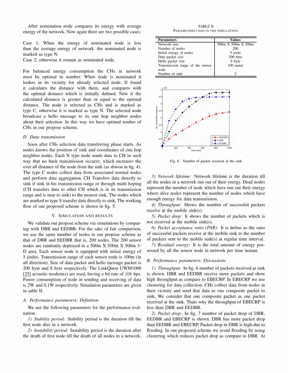
TABLE IIPARAMETERS USED IN THE SIMULATION.
Parameters Values
Network size 500m X 500m X 500mNumber of nodes 200Initial energy of nodes 5 jouleData packet size 200 byteHello packet size 8 byteTransmission range of the sensornode
100 meter
Number of sink 2
0 200 400 600 800 10000
0.5
1
1.5
2
2.5
3
3.5
4x 10
4
Time (sec)
No.
of p
acke
ts r
ecei
ved
EBECRPDBREEDBR
Fig. 6. Number of packet received at the sink
3) Network lifetime: Network lifetime is the duration till
all the nodes in a network run out of their energy. Dead nodes
represent the number of node which have run out their energy
where alive nodes represent the number of nodes which have
enough energy for data transmission.
4) Throughput: Shows the number of successful packets
receive at the mobile sink(s).
5) Packet drop: It shows the number of packets which is
not received at the mobile sink(s).
6) Packet acceptance ratio (PAR): It is define as the ratio
of successful packets receive at the mobile sink to the number
of packets sent to the mobile sink(s) at regular time interval.
7) Residual energy: It is the total amount of energy pos-
sessed by all the sensor node in network per time instant.
B. Performance parameters: Discussions
1) Throughput: In fig. 6 number of packets received at sink
is shown. DBR and EEDBR receive more packets and show
high throughput as compare to EBECRP. In EBECRP we use
clustering for data collection. CHs collect data from nodes in
their vicinity and send that data as one composite packet to
sink. We consider that one composite packet as one packet
received at the sink. Thats why the throughput of EBECRP is
less than DBR and EEDBR.
2) Packet drop: In fig. 7 number of packet drop of DBR,
EEDBR and EBECRP is shown. DBR has more packet drop
than EEDBR and EBECRP. Packet drop in DBR is high due to
flooding. In our proposed scheme we avoid flooding by using
clustering which reduces packet drop as compare to DBR. At

TABLE IIIPERFORMANCE TRADE-OFFS MADE BY THE ROUTING PROTOCOLS.
Protocol Mechanism Advantages achieved Price paid/at the cost of
DBR No mechanism to balanced energy con-sumption.Node with least depth die earlier.
High throughput (fig. 6). Low stability period and network life time(fig. 9)and (fig. 8).High energy consumption (fig. 10).High packet drop (fig. 7).
EEDBR Efficient energy consumption Mechanism.Nodes near the sink die earlier.
High throughput (fig. 6).Less packet drop (Fig. 7).
Low stability period and network life time(fig. 9)and (fig. 8).High energy consumption (fig. 10).
EBECRP Mechanism to balanced energy consump-tion and load on the nodes near the sink.
Improved stability period and network lifetime (fig. 9)and (fig. 8).Less packet drop (fig. 7).Less energy consumption (fig. 10).
Less throughput (fig. 6).
0 200 400 600 800 10000
0.5
1
1.5
2
2.5
3x 10
4
Time (sec)
No.
of p
acke
ts d
ropp
ed
EBECRPDBREEDBR
Fig. 7. Number of packet dropped
the start EEDBR and EBECRP have same packet drop. In
EEDBR sensor nodes die very quickly which creates routing
holes in network thus in later rounds its packet drop increases.
3) Network lifetime: Stability period of EBECRP is more
than DBR and EEDBR (as shown in fig. 8). DBR and EEDBR
perform multi hoping and depth base routing due to which
load on sensor nodes with least depth or near the sink is high.
These snsor nodes die earlier than other sensor nodes of the
network. By using mobile sinks and clustering the network
life time of our proposed scheme is improved as compare to
DBR and EEDBR as shown in fig. 9.
4) Network residual energy: Network residual energy of
EBECRP is much better than the DBR and EEDBR. We use
mobile sinks and clustering in EBECRP to balance load on
all the nodes in network which results in balanced energy
consumption as shwon in fig. 10. In DBR and EEDBR multi
hoping and flooding are involved which result in high energy
consumption of network.
C. Performance trade-offs
In this section, we validate and evaluate the performance
of our proposed protocol with DBR and EEDBR in terms
of achievements and drawbacks. The performance trad offs
of our proposed protocol with DBR and EEDBR are listed
in table III. In DBR flooding is involved which results in
high throughput and high packet drop. DBR uses depth based
0 200 400 600 800 10000
20
40
60
80
100
120
140
160
180
200
Time (sec)
Num
ber
of d
ead
Nod
es
EBECRPDBREEDBR
Fig. 8. Number of dead nodes
0 200 400 600 800 10000
20
40
60
80
100
120
140
160
180
200
Time (sec)
Num
ber
of a
live
node
s
EBECRPDBREEDBR
Fig. 9. Number of alive nodes
routing and multi hoping to transfer data to sink, which
results in high load on low depth nodes. Thus low depth
nodes die very quickly result in sharp stability period (fig. 8)
and low network life time (fig. 9). DBR shows unbalanced
energy consumption mechanism (fig. 10), which results in high
throughput (fig. 6) at the cost of high packet drop (fig. 7), sharp
stability period (fig. 8) and low network life time (fig. 9).
EEDBR is depth based routing protocol and perform multi
hoping for data transmission to sink, which results in high load
on nodes near the sink. These nodes die very quickly showing
sharp stability period and low network life time as shown in

0 200 400 600 800 10000
100
200
300
400
500
600
700
800
900
1000
Time (sec)
Ene
rgy
per
roun
d
EBECRPDBREEDBR
Fig. 10. Energy consumption per round
fig. 8 and fig. 9. EEDBR shows efficient energy consumption
mechanism which results in high throughput (fig. 6) and less
packet drop (fig. 7) at the cost of sharp stability period and
low network life time. In EBECRP we avoid depth based
routing in order to balance loads on nodes, which results in
improve stability period and network life time as shown in
fig. 8 and fig. 9. EBECRP shows efficient and balanced energy
consumption (fig. 10) which results in low packet drop (fig. 7),
high stability period (fig. 8) and improved network life time
(fig. 9) at the cost of less throughput (fig. 6).
VI. CONCLUSION
In this paper, we presented a routing protocol EBECRP, to
improve the stability period and network life time of UWSNs.
The beauty of our proposed protocol is that it reduced load
on the nodes near the mobile sink to achieve balanced energy
consumption. As nodes consume more energy in transmitting
than in receiving (in case of multi hoping) to reduce the
number of transmissions we used the concept of clustering
where CHs collect data from their one hop neighbor nodes and
forward compressed data to the sink. Simulation results shown
improved performance of EBECRP compared with DBR and
EEDBR in terms of balanced energy consumption and network
life time.
REFERENCES
[1] Akyildiz IF, Pompili D, Melodia T. Underwater acoustic sensor networks:research challenges. Ad hoc networks. 2005 May 31;3(3):257-79.
[2] Umar A, Javaid N, Ahmad A, Khan ZA, Qasim U, Alrajeh N, HayatA. DEADS: Depth and Energy Aware Dominating Set Based Algorithmfor Cooperative Routing along with Sink Mobility in Underwater WSNs.Sensors. 2015 Jun 18;15(6):14458-86.
[3] Chang H. Underwater wireless sensor networks. InOceans, 2012 2012Oct 14 (pp. 1-5). IEEE.
[4] Yan H, Shi ZJ, Cui JH. DBR: depth-based routing for underwatersensor networks. InNETWORKING 2008 Ad Hoc and Sensor Networks,Wireless Networks, Next Generation Internet 2008 Jan 1 (pp. 72-86).Springer Berlin Heidelberg.
[5] Wahid A, Kim D. An energy efficient localization-free routing protocolfor underwater wireless sensor networks. International journal of dis-tributed sensor networks. 2012 Apr 9;2012.
[6] Ayaz M, Abdullah A. Hop-by-hop dynamic addressing based (H2-DAB)routing protocol for underwater wireless sensor networks. InInformationand Multimedia Technology, 2009. ICIMT’09. International Conferenceon 2009 Dec 16 (pp. 436-441). IEEE.
[7] Javaid N, Jafri MR, Khan ZA, Qasim U, Alghamdi TA, Ali M. Iamctd:Improved adaptive mobility of courier nodes in threshold-optimized dbrprotocol for underwater wireless sensor networks. International Journalof Distributed Sensor Networks. 2014 Jul 20;2014.
[8] Nasir H, Javaid N, Ashraf H, Manzoor S, Khan ZA, Qasim U, SherM. CoDBR: Cooperative Depth Based Routing for Underwater WirelessSensor Networks. InBroadband and Wireless Computing, Communicationand Applications (BWCCA), 2014 Ninth International Conference on2014 Nov 8 (pp. 52-57). IEEE.
[9] Jafri MR, Ahmed S, Javaid N, Ahmad Z, Qureshi RJ. Amctd: Adaptivemobility of courier nodes in threshold-optimized dbr protocol for under-water wireless sensor networks. InBroadband and Wireless Computing,Communication and Applications (BWCCA), 2013 Eighth InternationalConference on 2013 Oct 28 (pp. 93-99). IEEE.
[10] Ahmad A, Javaid N, Khan ZA, Qasim U, Alghamdi TA. : RoutingScheme to Maximize Lifetime and Throughput of Wireless SensorNetworks. Sensors Journal, IEEE. 2014 Oct;14(10):3516-32.
[11] Al-Bzoor M, Zhu Y, Liu J, Ammar R, Cui JH, Rajasekaran S. An adap-tive surface sink redeployment strategy for Underwater Sensor Networks.InComputers and Communications (ISCC), 2013 IEEE Symposium on2013 Jul 7 (pp. 000801-000806). IEEE.
[12] Javaid N, Waseem M, Khan ZA, Qasim U, Latif K, Javaid A. ACH:Away cluster heads scheme for energy efficient clustering protocolsin WSNs. InElectronics, Communications and Photonics Conference(SIECPC), 2013 Saudi International 2013 Apr 27 (pp. 1-4). IEEE.
[13] Heinzelman WR, Chandrakasan A, Balakrishnan H. Energy-efficientcommunication protocol for wireless microsensor networks. InSystemsciences, 2000. Proceedings of the 33rd annual Hawaii internationalconference on 2000 Jan 4 (pp. 10-pp). IEEE.
[14] Li J, Jiang X, Lu IT. Energy Balance Routing Algorithm Based onVirtual MIMO Scheme for Wireless Sensor Networks. Journal of Sensors.2014 Jan 2;2014.
[15] Wahid A, Lee S, Kim D. A reliable and energyefficient routing pro-tocol for underwater wireless sensor networks. International Journal ofCommunication Systems. 2014 Oct 1;27(10):2048-62.
[16] Yoon S, Azad AK, Oh H, Kim S. AURP: An AUV-aided underwaterrouting protocol for underwater acoustic sensor networks. Sensors. 2012Feb 9;12(2):1827-45.
[17] Chen YS, Lin YW. Mobicast routing protocol for underwater sensornetworks. Sensors Journal, IEEE. 2013 Feb;13(2):737-49.
[18] Javaid N, Ilyas N, Ahmad A, Alrajeh N, Qasim U, Khan ZA, Liaqat T,Khan MI. An Efficient Data-Gathering Routing Protocol for UnderwaterWireless Sensor Networks. Sensors. 2015 Nov 17;15(11):29149-81.
[19] Javaid N, Jafri MR, Khan ZA, Alrajeh N, Imran M, Vasilakos A. Chain-based communication in cylindrical underwater wireless sensor networks.Sensors. 2015 Feb 4;15(2):3625-49.
[20] Ahmed S, Javaid N, Khan FA, Durrani MY, Ali A, Shaukat A, SandhuMM, Khan ZA, Qasim U. Co-UWSN: Cooperative Energy-EfficientProtocol for Underwater WSNs. International Journal of DistributedSensor Networks. 2015 Apr 7;2015.
[21] Javaid N, Jafri MR, Ahmed S, Jamil M, Khan ZA, Qasim U, Al-SalehSS. Delay-Sensitive Routing Schemes for Underwater Acoustic SensorNetworks. International Journal of Distributed Sensor Networks. 2015Mar 25;2015.
[22] Zhang S, Li D, Chen J. A link-state based adaptive feedback routingfor underwater acoustic sensor networks. Sensors Journal, IEEE. 2013Nov;13(11):4402-12.
[23] Uddin MA. Link Expiration Time-Aware Routing Protocol for UWSNs.Journal of Sensors. 2013 Feb 24;2013.
[24] Ahmed S, Javaid N, Ahmed A, Ahmed I, Durrani MY, Ali A, HaiderSB, Ilahi M. SPARCO: Stochastic Performance Analysis with Reliabilityand COoperation for Underwater Wireless Sensor Networks.
[25] Wills J, Ye W, Heidemann J. Low-power acoustic modem for denseunderwater sensor networks. InProceedings of the 1st ACM internationalworkshop on Underwater networks 2006 Sep 25 (pp. 79-85). ACM.