a review of recent developments in carbon capture utilizing oxy-fuel combustion in conventional and...
TRANSCRIPT

INTERNATIONAL JOURNAL OF ENERGY RESEARCH
Int. J. Energy Res. 2011; 35:741–764
Published online 13 December 2010 in Wiley Online Library (wileyonlinelibrary.com). DOI: 10.1002/er.1798
REVIEW
A review of recent developments in carbon captureutilizing oxy-fuel combustion in conventional and iontransport membrane systems
M. A. Habib1, H. M. Badr1,�,y, S. F. Ahmed1, R. Ben-Mansour1, K. Mezghani1, S. Imashuku2,G. J. la O’2, Y. Shao-Horn2, N. D. Mancini2, A. Mitsos2, P. Kirchen2 and A. F. Ghoneim2
1Mechanical Engineering Department, King Fahd University of Petroleum and Minerals, Dhahran, Saudi Arabia2Mechanical Engineering Department, Massachusetts Institute of Technology, Cambridge, U.S.A.
SUMMARY
Fossil fuels provide a significant fraction of the global energy resources, and this is likely to remain so for severaldecades. Carbon dioxide (CO2) emissions have been correlated with climate change, and carbon capture is essentialto enable the continuing use of fossil fuels while reducing the emissions of CO2 into the atmosphere therebymitigating global climate changes. Among the proposed methods of CO2 capture, oxyfuel combustion technologyprovides a promising option, which is applicable to power generation systems. This technology is based oncombustion with pure oxygen (O2) instead of air, resulting in flue gas that consists mainly of CO2 and water (H2O),that latter can be separated easily via condensation, while removing other contaminants leaving pure CO2 forstorage. However, fuel combustion in pure O2 results in intolerably high combustion temperatures. In order toprovide the dilution effect of the absent nitrogen (N2) and to moderate the furnace/combustor temperatures, partof the flue gas is recycled back into the combustion chamber. An efficient source of O2 is required to make oxy-combustion a competitive CO2 capture technology. Conventional O2 production utilizing the cryogenic distillationprocess is energetically expensive. Ceramic membranes made from mixed ion-electronic conducting oxides havereceived increasing attention because of their potential to mitigate the cost of O2 production, thus helping topromote these clean energy technologies. Some effort has also been expended in using these membranes to improvethe performance of the O2 separation processes by combining air separation and high-temperature oxidation into asingle chamber. This paper provides a review of the performance of combustors utilizing oxy-fuel combustionprocess, materials utilized in ion-transport membranes and the integration of such reactors in power cycles. Thereview is focused on carbon capture potential, developments of oxyfuel applications and O2 separation andcombustion in membrane reactors. The recent developments in oxyfuel power cycles are discussed focusing on themain concepts of manipulating exergy flows within each cycle and the reported thermal efficiencies. Copyright r2010 John Wiley & Sons, Ltd.
KEY WORDS
carbon capture; oxy-fuel combustion; ion transport membrane; environment; global warming
Correspondence
*H.M. Badr, Mechanical Engineering Department, King Fahd University of Petroleum and Minerals, Dhahran, Saudi Arabia.yE-mail: [email protected]
Received 3 May 2010; Revised 29 September 2010; Accepted 30 September 2010
1. INTRODUCTION
Greenhouse gas emissions and carbon dioxide (CO2) in
particular have become an increasing concern in the
power generation industry. Energy production from
fossil fuel combustion results in the emission of
greenhouse gases, the dominant contributor being
CO2. Public awareness and the potential threat of
climate change have led to proposing policies for
reducing greenhouse gas emissions, with the regula-
tions partially driven by (international) initiatives
such as the Kyoto protocol and more recently the
Copenhagen summit [1]. Greenhouse gas emissions
from energy production can be reduced by the use
of alternative energy sources such as nuclear power
and renewable energy as well as through efficiency
Copyright r 2010 John Wiley & Sons, Ltd.

improvements. Until alternative energy sources can
reliably and cost effectively produce significant
amounts of energy, immediate energy demands are
likely to continue to be met by combustion of
conventional fossil fuels.
To reduce greenhouse gas emissions from fossil fuel-
fired power generation, carbon capture technologies
are being investigated. CO2 capture technologies that
are being developed for combustion and gasification
include, among others, oxyfuel technology. The de-
velopment of CO2 capture technologies for hydro-
carbon-fired power plants can be divided into three
broad categories, see Figure 1 which also shows the
components of this review article. The first is separa-
tion of CO2 from waste gas, that is, post-combustion
decarbonization. The second is combustion in oxygen
(O2) instead of air, oxyfuel combustion, and the third is
production of a carbon-free fuel as proposed in pre-
combustion decarbonization. Each of these approa-
ches has some advantages and disadvantages, while all
technologies decrease the power generation efficiency
and increase the production cost. Post-combustion
decarbonization separates CO2 from the flue gases and
thus requires minimal modifications to the power cycle,
but large gas quantities must be treated because CO2 is
diluted by the nitrogen that entered with the combus-
tion air. The O2 for oxyfuel combustion is typically
produced by a conventional (cryogenic) air separation
unit. Fuel combustion in pure O2 results in very high
combustion temperatures. In order to reduce these
temperatures, part of the flue gas is recycled back to
the combustion chamber. Oxyfuel cycles are typically
based on near-stoichiometric combustion, where the
fuel is burned in O2 produced in an air separation unit
diluted by recycled flue gas. Thus, combustion takes
place in the absence of nitrogen. Oxyfuel combustion
produces only CO2 and H2O. The CO2 separation is
accomplished by condensing water (H2O) from the flue
gas, providing a byproduct of high-purity H2O, while
other impurities are removed from the CO2 stream
before compression and storage. However, a relatively
large amount of energy is needed for the O2 produc-
tion. Based on a quantitative comparison of the three
carbon capture strategies, those based on oxyfuel
combustion generally have higher thermodynamic ef-
ficiencies than those based pre- or post-combustion
decarbonization [2].
Several technologies have been developed for O2
production. Currently, the most common is the cryo-
genic technique that is expensive and energy intensive.
An alternative method is to separate O2 using mem-
brane technology either at ambient or at high tem-
peratures. For ambient-temperature O2 separation,
polymer membranes have been developed, but their
stability and production rate are very limited. For
high-temperature applications, ceramic membranes are
generally considered and used because of their high
selectivity and thermochemical stability under harsh
conditions. The high-temperature O2 separation, using
ceramic membranes, has received increasing interest
because of the possibility to reduce the O2 production
cost and energy penalty. These membranes can be
integrated into the oxyfuel reactor where simulta-
neously O2 will be separated from air at one side of the
membrane and react with fuel at the opposite side. The
separation of O2 molecules from air at high tempera-
tures is based on a dense ceramic layer where each O2
molecule, in contact with the ceramic surface, is
decomposed into two ions that are integrated in the
ceramic structure. The formation and stability of these
ions require pair of electrons, supplied by the ceramic
surface. These O2 ions are driven from the higher-
O2-pressure (air side), to the lower-O2-pressure (fuel
side) of the membrane whereas electrons are driven
in the opposite direction. The transport of these ions
in the dense membrane is accomplished by vacancy
diffusion. These ceramic membranes are known as
ion-transport membranes (ITM) or sometimes as
mixed-conducting membranes (MCMs) because of
their involvement of ions and electrons in the electric
conductivity. At the fuel side of the dense layer of the
ITM, each pair of O2 ions is joined together to form O2
molecules leaving extra electrons, which will travel
toward the air side of the ITM. The selectivity of an
ITM is generally optimized for a target separation by
choosing a certain microstructure and chemical com-
position suitable for the operating conditions. Among
the MCMs, perovskite ITMs exhibit relatively high O2
permeation fluxes [3]. These perovskite membranes
can selectively separate O2 from the air at elevated
temperatures in the range of 700–9001C. In addition,
these ITMs can be fabricated in tubular or planar
configurations, which enable compact and efficient gas
separator equipment designs. These ITMs are pro-
mising for use in many industrial processes that requireFigure 1. Elements of the present review.
A review of recent developments in carbon captureM. A. Habib et al.
Int. J. Energy Res. 2011; 35:741–764 r 2010 John Wiley & Sons, Ltd.
DOI: 10.1002/er
742

a continuous supply of pure O2. A limiting factor for
the implementation of ITMs for power plant applica-
tions is the O2 flux through the membrane, which must
be increased considerably. One very promising means
of doing this is by coupling the O2 separation and fuel
conversion in an ITM reactor.
To illustrate the suitability of the oxy-fuel combus-
tion process for clean power generation, this review
will present an overview and comparison of potential
CCS power cycles, followed by a review of works
considering the oxy-fuel combustion process itself,
with a particular regard for those using ITMs for O2
separation. Because of new challenges presented by
oxy-fuel combustion, as opposed to air-fuel combus-
tion, works pertaining to the analysis of oxy-fuel
combustion in real systems are also discussed. Finally,
a detailed discussion focusing on the use ITMs for O2
separation will be presented, including the current state
of the art for the material selection, as well as mem-
brane design and characterization. This paper is in-
tended to provide a review of previous work done on
the performance of combustors utilizing oxyfuel with
special emphasis on potential for carbon capture and
combustion in membrane reactors. It also includes a
review of key oxyfuel power cycles operating on
natural gas together with a discussion of the thermo-
dynamic implications of the overall design strategies
implemented in each.
2. CO2 CAPTURE
Numerous different power plant structures are avail-
able for CO2 capture from power plants, with the
dominant approaches being those based on decarbo-
nization of the fuel, post-combustion carbon removal,
and oxy-fuel combustion. An overview of the state of
the art for CO2 capture is presented below with
consideration of both coal and natural gas fuels.
Examples of relevant quantitative analyses of Inte-
grated Gasification Combined Cycles (IGCC), and
Chemical Looping Combustion (CLC) are also briefly
presented as these have a significant presence in the
literature. A particular focus will be placed on oxy-
combustion in a subsequent section.
2.1. Previous reviews on carbon capture
Many research investigations have been performed in
the area of CO2 capture [4,5]. A review of the
technologies used and proposed during the last two
decades for coal-based power generation closest to
commercial application and involving carbon capture
was presented by Wall [6]. Most carbon capture and
storage (CCS) technologies are based on adaptations
of conventional combustion systems, with one or more
additional unit operations for O2 supply or CO2
capture by absorbents, and CO2 compression and
storage. The research and development challenges were
identified to be those of design, optimization and
operational aspects of new combustion and gasifica-
tion plants, controlling the gas quality required by
CCS units. Our review indicates the need for funda-
mental research that includes fuel reactions at pres-
sures higher than that used in IGCC, and in O2/CO2
atmospheres, as few studies have been carried out in
these areas.
Currently, technologies proposed have significantly
lower power generation efficiencies due to the added
processes required for carbon capture. Therefore, the
challenges involved with the design and operation of,
e.g. IGCC, and CCS should be considered. Wall [6]
identified the need for new designs of combustion
equipment for the next generation of technologies and
concluded that there are significant challenges involved
with the design and operation of these integrated sys-
tems. The impact of capture of CO2 from fossil fuel
power plants on the emissions of nitrogen oxides and
sulfur oxides has been studied by Tzimas et al. [7].
They estimated the emissions from natural gas com-
bined cycle (CC) and pulverized coal plants, equipped
with post-combustion carbon capture technology, and
compared them with the emissions of similar plants
without CO2 capture. Moreover, the reduced efficiency
of power plants with CCS is likely to result in an
increase in Nox emissions from the power generation
sector [7].
Armor [8] discussed the global problem of increasing
emission of CO2 as a result of the expanding use of
hydrocarbons as a source of energy. Based on the
available figures, hydrocarbons will provide much of
the fuel needs for the next 20 years and will meet more
than 60% of the world’s energy demand. A further
increase in atmospheric CO2 levels will result from the
growth of both power generation and the size of the
transportation fleet since renewable sources cannot
cover the entire energy demand. Various means for
reduced CO2 emissions by improving process efficien-
cies have been discussed. These include lowering
operating temperatures and pressures, reducing
energy-intensive separation steps, reducing the number
of unit operations, and improving chemical selectivities
for separation [8]. Accordingly, the CO2 capture and
storage technologies require further developments.
Catalysis is expected to play an important role in
developing such technologies, e.g. due to the low
temperature limitation of ceramic membranes. Armor
also emphasized that the problem of excessive CO2
emissions will not be solved with one approach but
rather that multiple solutions should be developed.
Moreover, the solution suitable for a particular geo-
graphical region will be influenced by the available
resources.
Different CO2 capture techniques have been studied
and evaluated recently. Bolland and Undrum [9]
evaluated three concepts for capturing CO2 from
A review of recent developments in carbon capture M. A. Habib et al.
743Int. J. Energy Res. 2011; 35:741–764 r 2010 John Wiley & Sons, Ltd.
DOI: 10.1002/er

natural gas-fired combined gas/steam turbine power
plants, namely (1) post-combustion separation of CO2
from exhaust gas of a standard gas turbine power plant
using chemical absorption; (2) gas turbine CC using a
semi-closed gas turbine using O2 as an oxidizing agent,
resulting in CO2 and H2O vapor as combustion pro-
ducts (the gas turbine working fluid is mainly CO2);
and (3) decarbonization, which consists of a reforming
reactor for air-blown catalytic partial oxidation of
natural gas, a H2O-gas-shift reaction and a high-
pressure CO2 capture process. In the last concept, the
hydrogen-rich reformed fuel gas was combusted in a
gas turbine CC, which was integrated with the de-
carbonization process. A novel approach that takes
into consideration CO2 capture and compression was
used to evaluate the fuel-to-electricity conversion effi-
ciency for each of the three concepts. In comparison
with the conventional combined gas/steam turbine
power plant (giving 58% total fuel-to-electricity effi-
ciency without CO2 capture), Bolland and Undrum
estimated efficiencies of (1) 49.6; (2) 47.2; and (3)
45.3%, respectively. They indicated that the plant
efficiency may not be the major decisive factor due to
the very high investment costs, predicted to be more
than double that of a standard CC power plant
without CCS. Moreover, they noted that increased
operating costs are expected as well as a decreased
availability.
A simplified model of a power plant with two
methodologies of CO2 capture has been developed [10]
with the aim of defining second law efficiency targets
for CO2 separation technologies. Their study has
demonstrated the effect of CO2 separation and se-
questration on a hydrocarbon-based power plant using
the two most prevalent separation techniques, oxyfuel
combustion and post-combustion separation. A com-
parison between these two separation techniques was
carried out based on an exergy analysis, performed
using black-box models of the various components.
They analyzed multiple scenarios to determine the
impact of plant configuration and separation unit
efficiency on the overall plant performance. Based on
their results, they concluded that the approach can be
used to determine the most efficient investments for
separation technology. In another study, the exergic
performance of a high-temperature solid oxide fuel cell
(SOFC) combined with a conventional recuperative
gas turbine plant has been investigated [11]. Individual
component models (for the SOFC CC and a down-
stream combustor) were developed. In addition, an
actual system has been assessed and the results were
compared with previously published data. They indi-
cated that increasing the turbine inlet temperature
results in decreasing the exergy and thermal efficiencies
of the cycle, whereas it improves the total specific
power output. Furthermore, an increase in either
turbine inlet temperature or compression ratio leads
to a higher rate of exergy destruction of the plant.
A comparison between the proposed combined gas
turbine and fuel cell plant and a conventional gas tur-
bine cycle, based on identical operating conditions, was
also conducted. It was found that the proposed cycle had
superior performance, in terms of thermal and exergy
efficiencies, over a conventional gas turbine cycle [11].
2.2. System level analysis of CO2 capturecycles
Various means of CO2 capture from IGCC systems
have been developed to reduce costs and energy
penalties. These include membrane reactors and gas
separation processes. Different models of IGCC pro-
cesses were presented [12]. They first considered an
IGCC process without CO2 capture and then presented
different types of gasifiers and performance data of the
existing power stations. Second, the concept of an
IGCC process with an integrated O2 transport mem-
brane reactor and CO2 capture was proposed. Process
simulations of the stand-alone O2 transport membrane
reactor and the same reactor as part of the IGCC
process were carried out. The results showed that the
operating conditions of the membrane reactor affect the
overall performance of the IGCC process tremendously.
A change in pressure from 2 to 15bar on the permeate
side of the O2 transport membrane was found to
increase the efficiency by 5%. The concept of the
integrated gasification zero emission plant was pre-
sented [13]. The objective of the study was to use O2
produced in a MCM reactor in an integrated gasifica-
tion zero emission plant. The core of the membrane
reactor was a ceramic membrane, which separates O2
from air exiting the gas turbine compressor. The reactor
was operated at temperatures around 9001C and is
driven by a difference in O2 partial pressure. Integration
of membranes into an IGCC process was investigated
[14], where computational simulations of an O2 trans-
port membrane were carried out. The operating
conditions of the membrane were varied and their
impact on the membrane performance with respect to
O2 permeation flow as well as implications regarding the
steam power cycle were discussed. In this process,
indirect combustion takes place with no mixing of
fuel and air so that CO2 can be easily obtained for
sequestration. Two separate reactors were used; one for
air and the other for fuel. O2 transfer between the
reactors occurs by a metal oxide. A preliminary reactor
design was carried out in order to demonstrate the
feasibility of the process. It was found that the
temperature in the reactors can be kept below 9001C.
Besides CO2 capture, the proposed process was found to
have the potential to achieve higher selectivity toward
H2 than conventional steam reforming plants because of
the low temperature in the reactors and the high heat-
transfer coefficient on the outside of the reformer tubes.
A pre-combustion natural gas-fired power plant
concept with an O2 transfer membrane reactor and a
A review of recent developments in carbon captureM. A. Habib et al.
Int. J. Energy Res. 2011; 35:741–764 r 2010 John Wiley & Sons, Ltd.
DOI: 10.1002/er
744

H2-fired CC was developed [15]. The ITM reactor
consisted of three channels: one steam reformer chan-
nel that produces synthesis gas, one combustion
channel that supplies heat to the steam reforming
channel, and an air channel with the ITM that feeds
the combustion channel with pure O2 through the
ITM. A pressure swing adsorption separated a shifted
synthesis gas into a hydrogen fuel stream and a purge
gas, which was fed to the combustion channel in the
ITM reactor. The hydrogen fuel was diluted with
nitrogen in a catalytic pre-burner by reacting partially
with the O2 lean air from the air channel. After the pre-
burner, the hydrogen was fed to a H2-fired CC. It was
indicated that an efficiency of 50% can be achieved by
increasing the pressure swing adsorption purge gas
pressure and implementing an even higher degree of
heat integration.
Sander et al. [16] presented modeling of an ITM
together with the integration of the membrane model
into power cycle models. Two different power pro-
duction processes were discussed in this work, where
an ITM reactor was integrated. First, an IGCC pro-
cess, where CO2 can be separated from a syngas before
combustion, was proposed. Hard coal was gasified in
the presence of O2 and steam. After gas treatment, CO2
capture was allowed to take place before the synthesis
gas is supplied to the burner. Besides the IGCC pro-
cess, a lignite-fired oxyfuel boiler cycle was proposed
with an integrated ITM reactor where CO2 is captured
by cooling the cleaned exhaust gases. A part of the
CO2 rich stream was re-circulated to the boiler to
control temperature; the excess CO2 was compressed
for sequestration. The ITM model considered heat and
mass transfer through the membrane for different op-
erating pressures, temperatures, pressure differences,
and partial pressure differences. The membrane was
modeled by using the finite difference method. The
performance of the membrane and its impact on dif-
ferent power cycles were presented and various con-
figurations of the membrane were analyzed.
2.3. Chemical looping technology
A potentially attractive alternative to ITM-based
systems for carbon capture is chemical looping
technology, in which a metal oxide is used to transfer
O2 extracted from air to the fuel, as shown in Figure 2.
In chemical-looping combustion (CLC), direct contact
between air and fuel is avoided and the power loss
inherent in CO2 separation is reduced [17,18]. The
advantages of using CLC include the high CO2 capture
efficiency and the absence of NOx formation. The
authors indicated that some companies such as
ALSTOM and CES are currently building power
plants using CLC technology. In a study by Naqvi
and Bolland [19], an application for utilizing the CLC
technology in natural gas-fired CCs for power genera-
tion with CO2 capture is presented. The CC consisted
of a single CLC-reactor system that includes an air
turbine, a CO2-turbine together with a steam cycle that
was designated as the base–case cycle (introduced by
Naqvi et al. [20]). They found that the base–case cycle
could achieve a net plant efficiency of about 52% at an
oxidation temperature of 12001C. In order to achieve a
reasonable efficiency at lower oxidation temperatures,
they proposed to introduce reheating into the air
turbine by employing multi CLC-reactors. The results
indicated that the single reheat CLC-CC could achieve
a net plant efficiency of above 51% at oxidation
temperature of 10001C and above 53% at the
oxidation temperature of 12001C including CO2
compression. They concluded that a marginal effi-
ciency improvement could be attained by utilizing the
double re-heat cycle. The CLC-cycles were also
compared with a conventional CC with and without
post-combustion capture in amine solution. It was
concluded that all CLC-cycles show higher net plant
efficiencies with close to 100% CO2 capture as
compared to a conventional CC with post-combustion
capture.
3. OXYFUEL POWER CYCLES
Oxyfuel combustion of fossil fuels for CCS has been
developed with a multitude of potential power cycle
concepts, each having distinct operating conditions,
components and thermodynamic design philosophy.
The method used to obtain the required pure O2 varies
depending on the cycle as some concepts use a more
Figure 2. Schematic of CLC using a metal that is oxidized to uptake O2 and reduced under hydrocarbon atmospheric conditions for
combustion with the fuel (http://www.wku.edu/ICSET/chemloop.htm).
A review of recent developments in carbon capture M. A. Habib et al.
745Int. J. Energy Res. 2011; 35:741–764 r 2010 John Wiley & Sons, Ltd.
DOI: 10.1002/er
conventional cryogenic air separation unit; whereas
others use new separation technology such as the ITM
reactor that combines separation and combustion.
Each of the concepts has unique ways of manipulating
the exergy flows within the system under a variety of
operating conditions resulting in a wide spectrum of
reported thermal efficiencies.
Kvamsdal et al. [2] compared various natural gas-
fired power cycle concepts including six oxyfuel cycles
(oxyfuel CC, H2O cycle, Graz cycle, advanced zero-
emission power plant, SOFC/gas turbine and CLC) in
addition to one post-combustion (amine absorption)
and two pre-combustion cycles (auto-thermal reform-
ing and hydrogen membrane reactor). They concluded
that the oxyfuel with cryogenic O2 production shows
the lowest efficiency, while the SOFC/gas turbine
SOFC/GT has the highest efficiency, followed by the
membrane-based cycles giving the second best, al-
though the technology availability of the SOFC/GT
will be considered in the future.
In the following, a review of key oxyfuel power cy-
cles operating primarily on natural gas is presented and
the thermodynamic implications of the overall design
strategies implemented in each are discussed.
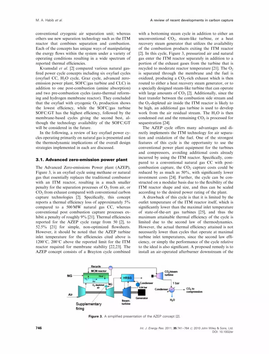
3.1. Advanced zero-emission power plant
The Advanced Zero-emissions Power plant (AZEP),
Figure 3, is an oxyfuel cycle using methane or natural
gas that essentially replaces the traditional combustor
with an ITM reactor, resulting in a much smaller
penalty for the separation processes of O2 from air, or
CO2 from exhaust compared with conventional carbon
capture technologies [2]. Specifically, this concept
reports a thermal efficiency loss of approximately 5%
compared to a 500MW natural gas CC, whereas
conventional post combustion capture processes ex-
hibit a penalty of roughly 9% [21]. Thermal efficiencies
reported for the AZEP cycle range from 50 [2], to
52.5% [21] for simple, non-optimized flowsheets.
However, it should be noted that the AZEP turbine
inlet temperature for the efficiencies cited above is
12001C, 2001C above the reported limit for the ITM
reactor required for membrane stability [22,23]. The
AZEP concept consists of a Brayton cycle combined
with a bottoming steam cycle in addition to either an
unconventional CO2, steam-like turbine, or a heat
recovery steam generator that utilizes the availability
of the combustion products exiting the ITM reactor
[2]. In this cycle, Figure 3, pressurized air and natural
gas enter the ITM reactor separately in addition to a
portion of the exhaust gases from the turbine that is
recycled to moderate reactor temperature [21]. The O2
is separated through the membrane and the fuel is
oxidized, producing a CO2-rich exhaust which is then
routed to either a heat recovery steam generator, or to
a specially designed steam-like turbine that can operate
with large amounts of CO2 [2]. Additionally, since the
heat transfer between the combustion side stream and
the O2-depleted air inside the ITM reactor is likely to
be high, an additional gas turbine is used to develop
work from the air residual stream. The H2O is then
condensed out and the remaining CO2 is processed for
sequestration [24].
The AZEP cycle offers many advantages and di-
rectly implements the ITM technology for air separa-
tion and oxidation of the fuel. One of the strongest
features of this cycle is the opportunity to use the
conventional power plant equipment for the turbines
and compressors, avoiding additional costs already
incurred by using the ITM reactor. Specifically, com-
pared to a conventional natural gas CC with post-
combustion capture, the CO2 capture costs could be
reduced by as much as 50%, with significantly lower
investment costs [24]. Further, the cycle can be con-
structed on a modular basis due to the flexibility of the
ITM reactor shape and size, and thus can be scaled
according to the desired power rating of the plant.
A drawback of this cycle is that it is limited by the
outlet temperature of the ITM reactor itself, which is
significantly lower than the maximal inlet temperature
of state-of-the-art gas turbines [25], and thus the
maximum attainable thermal efficiency of the cycle is
limited due to the second law of thermodynamics.
However, the actual thermal efficiency attained is not
necessarily lower than cycles that operate at maximal
turbine inlet temperatures, since the second law effi-
ciency, or simply the performance of the cycle relative
to the ideal is also significant. A proposed remedy is to
install an air-operated afterburner downstream of the
Figure 3. A simplified presentation of the AZEP concept [2].
A review of recent developments in carbon captureM. A. Habib et al.
Int. J. Energy Res. 2011; 35:741–764 r 2010 John Wiley & Sons, Ltd.
DOI: 10.1002/er
746

ITM reactor, resulting in net CO2 emissions, but still
giving the plant flexibility between emissions avoidance
costs and operational costs associated with the reduc-
tion in efficiency [2]. Further, fabrication, testing and
modeling of key ITM components under practical
operating conditions has bolstered support for the
feasibility of the plant [21]. Overall, the AZEP cycle is a
promising concept that both mitigates the penalty
associated with O2 and CO2 separation, but also pro-
vides a simple and cost-effective integration of the ITM
reactor with a highly efficient traditional CC.
3.2. Graz and water cycle
The Graz cycle, Figure 4, is a unique oxyfuel concept
developed over that last decade at the Graz University
of Technology that offers a high efficiency, zero-
emission plant using natural gas, syngas, or even coal
[26]. The Graz cycle consists of a high-temperature
Brayton cycle integrated with a low-temperature
Rankine-like cycle. Various designs have been pre-
sented with power production in the range of
400–600MW, and efficiencies ranging from 54.1 [26]
to 60.1% [27]. Sanz et al. [28] presented a modified
Graz concept called the S-Graz cycle that achieved a
thermal efficiency of 57% with syngas. As shown in
Figure 4, high-pressure O2 supplied by a cryogenic air
separation unit and fuel are fed to a combustor
operating at typically 40 bar, with a turbine inlet
temperature of 14001C along with recycled CO2 and
H2O to moderate the temperature [26]. The H2O- and
CO2-rich combustion products are expanded in a high-
temperature turbine with recycled steam injection,
cooled by the bottoming Rankine cycle via regenera-
tion, and then the H2O is condensed where the CO2
separation process occurs [2]. The separated H2O is
then pumped at a high pressure, typically 200 bar,
heated by the Brayton cycle before being expanded in a
high-pressure steam turbine, and then ultimately is
recycled back into the Brayton cycle through the
combustor and high-pressure turbine [26]. A net
amount of H2O and CO2 is then removed from the
cycle for make-up steam and storage, respectively.
Variations of this concept have been presented, but the
key characteristic of this cycle is the thermodynami-
cally effective heat integration scheme between the
Brayton-like and Rankine-like cycles that is primarily
responsible for the high efficiencies.
It should be noted that there exists a related, more
basic concept called the Water Cycle that is quite
similar to the bottoming Rankine cycle of the Graz
concept [2]. The only difference is that the heat is
added directly to the Rankine-like cycle at a signi-
ficantly lower turbine inlet temperature of 9001C in-
stead of to a topping Brayton cycle ranging from 1200
to 15001C. Consequently, the thermal efficiencies
reported are relatively low, i.e. 44.6% compared to the
other oxyfuel cycles analyzed, illustrating the impor-
tance of a well-designed heat integration scheme and
heat addition at a maximal temperature. There are
many advantages of using the Graz cycle for oxyfuel
carbon capture and sequestration. Specifically, heat is
added to the cycle at an overall high average tem-
perature [26], resulting in low entropy transfer into the
cycle and consequently a higher potential for work.
Additionally, since the bottoming Rankine cycle
pumps the H2O up to high pressure in the liquid
form, the work requirements are relatively small [29].
Further, most of the components, except for the tur-
bines, are standard power plant equipment and thus
the component development can be focused on the
unconventional high-pressure turbine operating with
primarily CO2 and H2O as the working fluid [26].
Though the developers of the cycle claim to have
significant research experience pertaining to this novel
turbine [29], the costs and implementation feasibility
are still relatively unknown. Further, the Graz cycle
requires O2 production via a cryogenic air separation
unit, implying higher capital costs compared with the
AZEP [2]. Additionally, the cycle has relatively high
pressures throughout, i.e. 40 bar in the combustor and
180 bar in the Rankine cycle, which has materials and
operating implications for the plant [24]. Finally, the
turbine inlet temperature exceeds the limit of an ITM
reactor, and thus the cycle would need significant
modification to be integrated with this air separation
technology.
3.3. MATIANT and Feher supercritical CO2
cycles
The MATIANT cycle named for the two inventors of
the concept, Mathieu and Iantovski, is a novel oxyfuel
cycle comprised of a Rankine-like CO2 supercritical
cycle feeding a bottoming regenerative Brayton-like
CO2 cycle [30]. The cycle uses mainly CO2 as the
working fluid, with natural gas as the fuel, and pure O2
Figure 4. A simplified presentation of the principle scheme of
Graz Cycle power plant [2].
A review of recent developments in carbon capture M. A. Habib et al.
747Int. J. Energy Res. 2011; 35:741–764 r 2010 John Wiley & Sons, Ltd.
DOI: 10.1002/er

is provided by a cryogenic air separation unit. CO2
sequestration is performed by injecting high pressure,
supercritical CO2 into the ground. The flow rate of the
circulating CO2 was varied to maintain a high-pressure
turbine inlet temperature of 13001C. The cycle employs
both regeneration and reheating to enhance its
efficiency, and CO2 compression is conducted by a
staged, inter-cooled compressor train that serves as
both the primary compressor of the cycle and the CO2
delivery system. Additionally, a net amount of
condensed H2O is delivered by the cycle. A sensitivity
analysis and optimization study by Mathieu indicates
that the cycle could achieve nearly 50% thermal
efficiency [31] compared with the initial value of
44.3% given in the original proposal by Mathieu and
Nihart [30].
The MATIANT cycle appears to be based on the
much older Feher supercritical CO2 cycle. In this
concept, a supercritical cycle was proposed that sought
to capture the advantages of conventional Brayton and
Rankine cycles without their associated disadvantages
[32]. Specifically, supercritical cycles offer high thermal
efficiency, a low power to volume ratio that is im-
portant for plant sizing, no blade erosion in the tur-
bines or cavitation in the pumps, and relative
insensitivity to the compression process. The pseudo-
supercritical cycle proposed by Feher shows high effi-
ciencies due to low pumping work requirements, along
with the opportunity for significant regeneration as in
the MATIANT cycle. Finally, CO2 was chosen as the
working fluid since the critical pressure is reasonably
low compared with H2O, considerable property data
exists for thermodynamic design, and CO2 is relatively
inexpensive and abundant, especially in light of carbon
capture and sequestration applications as it is a pri-
mary component of fossil fuel combustion products.
The relatively low efficiency of the MATIANT
concept compared with some of the cycles described
previously should not be taken to mean that it is ne-
cessarily inferior to them. Ultimately, the distinction of
a superior power cycle concept depends on many
considerations in addition to the thermal efficiency.
Some advantages of the MATIANT cycle are due to
the unique properties of CO2, namely the non-ideal
compressibility characteristics near the saturation line
resulting in far less work for compression compared
with that of an ideal gas [30]. Additionally, since the
working fluid is almost entirely CO2, separation and
sequestration become far easier than traditional post
combustion capture processes, and possibly relative to
alternative oxyfuel cycles as well. However, a dis-
advantage of this cycle is that it would need significant
modification to be integrated with an ITM reactor in
order to reduce the air separation thermodynamic
penalty and costs. Furthermore, the high pressures
required for the cycle, namely up to 300 bar for the
high-pressure turbine, could have severe implications
for materials and design considerations. Additionally,
components that can handle the negative properties of
supercritical fluids, namely the corrosion issues, or
simply that can handle concentrated CO2 streams in
general, would need significant research and develop-
ment before implementation in an actual power plant.
In conclusion, the possible benefits of utilizing super-
critical CO2 as the main working fluid in an oxyfuel
cycle for carbon capture and sequestration should not
be overlooked, as this concept provides unique advan-
tages that conventional working fluids in the usual
thermodynamic states simply cannot offer.
3.4. The zero-emission power plant and thezero-emissions ITM oxyfuel plant
The zero-emissions power plant (ZEPP), Figure 5, a
term coined by Yantovski et al. [33], has been
developed by different researchers working indepen-
dently. The term covers a broad range of oxyfuel
power cycles [24,26,30,33–36]. The difference between
the ZEPP and a conventional post-combustion capture
plant is that the combustion products exit the plant in
the liquid form rather than as flue gases to be scrubbed
[33]. Yantovski et al. [33] presented a history of ZEPP
plants reviewing some of the early developments of the
cycles by tracking the changes in concept design and
the resulting increases in thermal efficiency. Further,
they presented a zero-emission ITM oxyfuel plant
(ZEITMOP) with thermal efficiencies ranging from 46
to 55% and corresponding turbine inlet temperatures
between 1300 to 15001C. In this cycle, as shown in
Figure 5, the ITM is used as an air separation unit
exclusively using re-circulated CO2 as a sweep gas to
maintain a low partial pressure on the permeate side.
Air is preheated after compression using exhaust gas
regeneration to between 800 and 9001C in order to
provide sufficient O2 flux for the combustion process
downstream. H2O is condensed from the CO2-rich
exhaust gases and then removed from the cycle. The
remaining CO2 is compressed to high pressure for
sequestration, executing a quasi-CC, whereas the air
stream forms a simple Brayton cycle. Overall, this cycle
Figure 5. A simplified presentation of the ZEPP concept [35].
A review of recent developments in carbon captureM. A. Habib et al.
Int. J. Energy Res. 2011; 35:741–764 r 2010 John Wiley & Sons, Ltd.
DOI: 10.1002/er
748

is quite similar to the AZEP concept [2], except that it
uses the ITM to separate O2 only, rather than simul-
taneously oxidize the fuel as in a manner similar to the
cycle presented by Anantharaman et al. [36]. While
combining the fuel conversion and O2 processes in an
ITM reactor increases the O2 flux through the
membrane, the maximum membrane outlet tempera-
ture (900–10001C) is considerably lower than typical
turbine inlet temperatures (approximately 12001C),
resulting in a potential loss in cycle efficiency.
Another ZEPP cycle was proposed [35] where a
simple Rankine-like cycle is utilized with an external
cryogenic air separation unit. This relatively simple
cycle, in terms of plant components, is designed using
more accurate manufacturers’ steam turbine data,
severely limiting the operating temperatures and pres-
sures. H2O is condensed out from the system, resulting
in easy CO2 capture, as well as producing H2O.
Additionally, a detailed second law analysis was
performed to identify the effects of using a cryogenic
air separation unit and also implementing turbine
blade cooling. The thermal efficiency for a 400MWe
cycle with a high-pressure turbine inlet temperature of
8171C was 46.5%, a value on par with the MATIANT
cycle [30], despite the lower turbine inlet temperature,
and more conventional plant design [35]. An additional
advantage to this cycle is that other fuels besides
natural gas could be used such as syngas, coal, or
biomass [35]. In essence, this concept provides a sim-
ple, cost-effective cycle that could be used to demon-
strate the feasibility of oxyfuel carbon capture and
sequestration systems. Further, the irreversibility ana-
lysis indicates significant exergy destruction due to the
external cryogenic air separation unit, second only to
the combustion process itself, thus substantiating the
need to develop ITM technology.
3.5. Other novel cycles
Additional cycles have been proposed in the literature
that attempt to combine advantageous aspects of
various concepts in order to obtain higher overall
thermal efficiencies. In one such cycle proposed by
Gabbrielli and Singh [34], a bottoming Rankine cycle
is combined with a topping Brayton cycle incorporat-
ing novel aspects such as chemical recuperation and
steam compression and injection. This concept uses
natural gas as the fuel to form syngas, which is
subsequently combusted with pure O2 produced by an
external cryogenic air separation unit with recycled
steam to moderate the combustion temperature. The
cycle offers the same advantages for CO2 separation as
the previous cycles, and also produces relatively pure
H2O. Alternative flow-sheets following the same design
philosophy were analyzed by Gabbrielli and Singh [34],
and the highest thermal efficiency reported was 52.3%
with a turbine inlet temperature of 13751C. Overall, the
penalty associated with the compression of saturated
steam, as well as the exergetic losses during the syngas
production process conspire to make this cycle as
efficient as the AZEP cycle [2], despite the higher
turbine inlet temperature, and less efficient than the
optimized Graz cycle [27]. However, the chemical
recuperation and steam injection processes could prove
to be valuable design modifications for other oxyfuel
concepts.
Another novel cycle was proposed by Anantharaman
et al. [36] that utilizes the ITM reactor as an O2 se-
parator only with a separate combustor, along with
auto-thermal reforming and a sequential burner to
reach maximum turbine inlet temperatures. The design
philosophy is quite similar to the AZEP, with important
subtle differences, namely that combustion takes place
in a separate unit. In this concept, the ITM reactor is
comprised of a high and low temperature heat ex-
changer along with a separation section that transports
O2 across the membrane to a secondary sweep gas loop,
where fuel is then mixed in and combusted. The turbine
inlet temperature is assumed to be limited to 12751C,
and thus the authors proposed a sequential burner to
obtain an overall turbine inlet temperature of 14251C.
A bottoming steam cycle is used to develop additional
work from the exhaust gases, and the CO2 separation
process is conducted via H2O condensation as in the
usual oxyfuel cycle. Since the sequential air-burner
scheme proposed results in net CO2 emissions of 15%,
an auto-thermal reformer is installed as an alternative to
avoid emissions. Results of the various flow-sheets
proposed give cycles with thermal efficiencies ranging
from 49.3% to 55.1%. This demonstrates the flexibility
of the ITM reactor and shows that it can be used as a
separation unit without simultaneous combustion.
Two system configurations for oxyfuel (natural gas)
turbine systems with integrated steam reforming and
CO2 capture and separation units have been developed
[37]. The heat required for steam reforming was ob-
tained from the available turbine exhaust heat, and the
produced syngas was used as fuel with O2 as the oxi-
dizer. H2O was used as the main working fluid and the
turbine exhaust was mainly a mixture of H2O and CO2.
Combustion in this case resulted in a very high tem-
perature. A thermodynamic simulation was performed
and the efficiency was predicted to be approximately
50%, taking into account the energy needed for O2
separation. In addition, Zhang and Lior [37] predicted
a near 100% CO2 capture. Normann et al. [38] investi-
gated new possibilities and synergy effects for an
oxyfuel-fired polygeneration scheme (transportation
fuel and electricity) with carbon capture and co-firing
of biomass. A process scheme of a polygeneration
plant for sub-stoichiometric oxyfuel combustion with
co-production of electricity and dimethylether was
presented and synergy effects with the scheme were
discussed in relation to a reference process. Moreover,
a process simulation of the proposed power plant was
performed and compared to the literature references
A review of recent developments in carbon capture M. A. Habib et al.
749Int. J. Energy Res. 2011; 35:741–764 r 2010 John Wiley & Sons, Ltd.
DOI: 10.1002/er

with respect to the oxyfuel technology and the
dimethylether process. It was concluded that the pro-
posed process resulted in a more effective oxyfuel
process through a sub-stoichiometric combustion
between normal combustion and gasification. In
addition, the proposed O2 lean combustion process
constitutes an improved oxyfuel carbon capture pro-
cesses with production of dimethylether in a poly-
generation process.
In their overview of oxyfuel technologies for CO2
capture, Simmonds et al. [39] examined the potential
application of oxyfuel technologies to both heat
and power production systems. Oxyfuel combustion
resulted in a 30% cost savings, compared with post
combustion separation using amine scrubbing. They
also found that a boiler utilizing oxyfuel with OTR
would be 40% more expensive than a conventional
unit and excluded commercialization before 2010.
Using a cryogenic O2 separation, the cost of CO2
capture is expected to lie in the range of $35–40/ton
(equivalent to CO2 avoided cost in the range of
$40–45/ton). Sho-Kobayashi and Van-Hassel [40] have
shown that standalone O2 generation plant consumes
10–20% of the power plant output. Oxyfuel combus-
tion without expensive O2 separation penalty, e.g.
cryogenic, appears promising for CO2 sequestration
A comparison of a boiler using oxyfuel combustion
with one using air combustion was carried out by Shah
and Christie [41]. For the same net power output of
452MW, they found that oxyfuel combustion resulted
in a doubling in capital cost, an efficiency reduction
from 44 to 35% and a reduction of the CO2 emissions
from 8.6 to 1.1 ktons per day. They also found that
increasing the O2 purity results in an increase in both
power consumption and capital costs.
4. OXY-FUEL COMBUSTION INCOMBUSTION SYSTEMS
While the preceding discussion has demonstrated
the promise of oxy-fuel-based power cycles, there
are considerable differences between air and O2-
CO2-based combustion processes, most notably the
influence of the CO2 on the radiative heat transfer and
combustion process. Numerous experimental and
numerical works have focused on elucidating the
difference between the two combustion types, both
quantitatively and qualitatively. Presented below is a
summary of these works, first by considering the
general difference between air and oxy-fuel combus-
tion and then the more detailed numerical and
experimental analyses.
4.1. Oxyfuel combustion studies
There are many features that affect the efficiency of
oxyfuel combustion [42], including air separation unit
load, compression of CO2 and air, working fluid
temperature and turbine cooling load. Buhre et al. [40]
provided a comprehensive review of the existing
research on oxyfuel combustion technology. They
mainly investigated oxyfuel combustion of pulverized
coal with the production of relatively pure CO2 for
enhanced oil recovery. They indicated that oxyfuel
combustion research should include the development
of new plants with the advantage of smaller flue
gas cleaning equipment, as well as retrofits of the
existing plants.
The interest in oxyfuel combustion has led to many
laboratory-scale and pilot-scale studies by various
groups that covered many scientific and engineering
fundamental issues. Buhre et al. [43] identified four
issues, namely heat transfer, gaseous emissions, ash-
related issues, and ignition and flame stability of the
combustion process. They also identified the research
needed for a more fundamental understanding of the
changes from conventional air-fired combustion to
oxyfuel combustion. These include the heat transfer
performance of new and retrofitted plants and the
impact of O2 feed concentration and CO2 recycle ratio,
assessment of retrofits for electricity cost and cost of
CO2 capture, the combustion of coal in an O2/CO2
atmosphere, including ignition, burn-out, and emis-
sions. They concluded that oxyfuel combustion is a
cost-effective method of CO2 capture. More impor-
tantly, the studies indicated that oxyfuel combustion is
technically feasible with current technologies, reducing
the risks associated with the implementation of new
technologies.
There are several differences between regular
combustion (using air) and oxyfuel combustion. In
order to achieve the same mass fraction of O2 in a
O2/CO2 mixture as in atmospheric air, the O2 and CO2
volume fractions must be 30 and 70%, respectively. In
addition, the CO2 and H2O combustion products have
higher emissivity that produces more radiation if the
temperature is held constant. Also, CO2 and H2O
vapor have high heat capacities compared to nitrogen.
This increase in heat capacity increases heat transfer in
the convection sections. In a recent study, Kakaras
et al. [44] investigated the issue of the radiative heat
transfer in oxyfuel combustion for low-grade quality
fuels. The same thermodynamic H2O/steam para-
meters and similar combustion temperatures were
maintained in both cases. Owing to the absence of N2,
flue gas recirculation was required in the combustion
process to moderate the furnace temperature. In their
study of the design requirements of the heat exchange
surfaces for the oxyfuel steam boiler, Kakaras et al.
found that the dominant factors for dimensioning the
oxyfuel boiler are the higher radiative heat transfer
(due to the high concentrations of CO2 and H2O in the
flue gas) and the flue gas mass flow rate. They for-
mulated a modified design of heat exchange surfaces of
the oxyfuel boiler and compared it to a conventional
A review of recent developments in carbon captureM. A. Habib et al.
Int. J. Energy Res. 2011; 35:741–764 r 2010 John Wiley & Sons, Ltd.
DOI: 10.1002/er
750

air-fired boiler in a typical modern air-fired power
plant. For the determination of the thermodynamic
cycle characteristics, they used a thermodynamic-cycle
calculation software and found that the oxyfuel con-
cepts resulted in higher gross power output, but lower
net power output due to the power consumption of
auxiliary equipment. The total efficiency decreased
by 8.5% compared to the air-fired unit. Moreover,
Kakaras et al. concluded that the capital cost of the
oxyfuel power plant would be significantly higher than
the reference plant.
Most of the previous work was focused on coal
fuels. Andersson et al. [45] carried out a comparison of
the radiative heat transfer in oxyfuel flames to corre-
sponding conditions in air-fuel flames during com-
bustion of lignite in the Chalmers 100 kW oxyfuel test
facility. They used the same stoichiometry for all cases,
by adjusting the flue gas-recycling rate in the oxyfuel
combustion processes. They carried out measurements
of the radial profiles of gas concentration, temperature
and total radiation intensity in the furnace. In another
study, Andersson et al. [46] presented their findings on
the differences in soot-related radiation intensity be-
tween two different oxyfuel flames and an air-fired
flame. The study was conducted in a 100 kW oxyfuel
test unit firing propane while keeping an O2-to-fuel
ratio of 1.15, relative to stoichiometric. They indicated
that CO2 not only increases the gas radiation, it can
also drastically change the radiation originating from
soot during oxyfuel combustion. Yamada [47] made a
direct comparison between air and oxy-firing of coals
through pilot-scale experiments, keeping the same heat
transfer in oxyfuel and air combustion. He found that
the flame with oxyfuel combustion mode was blown
out at a lower load and resulted in reduced NOx
emissions by 60–70% as well as reduced SO2 emissions
by 30%. Finally, Yamada found that the carbon-
in-ash content is 30% lower in oxyfuel combustion
compared to air combustion.
The fundamentals of the oxyfuel combustion for gas
and coal firing have been studied experimentally and
theoretically in a Chalmers 100 kW oxyfuel test facility
(Figure 6) [48]. Results showed that the temperature of
the flame (using 27% O2 and 73% CO2 and a swirl
number of 0.79) drops drastically and leads to a
delayed burn-out compared to the normal flame with
air. However, despite the lower flame temperature, the
radiation intensity of this flame increases by approxi-
mately 20–30%. This was attributed to the increase in
gas band radiation as well as the increase in soot
volume fraction. Moreover, small differences in CO
emissions were found between air and oxy-cases and
significantly reduced SO2 and NOx. de-Jager [49] in-
vestigated combustion and noise phenomena in tur-
bulent alkane flames and found that dilution with
steam strongly diminishes the formation of both CO
and NO. It was concluded that a global reaction me-
chanism predicts the same CO2, CO and NO emissions
as the detailed reaction mechanism for various oper-
ating conditions. Another study was carried out by
Monckert et al. [50] for combustion with lignite under
both air and oxyfuel conditions including (wet) flue-gas
recirculation in a modified 500 kW-pulverized fuel
combustion facility. The facility was tested toward safe
handling and continuous operation, and optimized
toward minimum air in-leakage. The experiments were
carried out under continuous oxyfuel operation with
an O2 concentration of 27% (dry basis) and under flue
Figure 6. CHALMERS 100 kW oxy-fuel test facility [48].
A review of recent developments in carbon capture M. A. Habib et al.
751Int. J. Energy Res. 2011; 35:741–764 r 2010 John Wiley & Sons, Ltd.
DOI: 10.1002/er

gas recirculation conditions. Moreover, switching from
single-pass combustion to recirculation mode has been
performed. The combustion behavior and ignition of
individual particles of coal (106–125mm) in 6–36% O2
in N2 and in CO2 at 1400–1800K have also been in-
vestigated [51]. It was found that for combustion in
CO2 environments, flame temperatures were reduced
significantly (from 2226 to 1783K). Both O2 and CO2
concentrations have been observed to affect single-
particle ignition, devolatilization, and char combustion
processes, with O2 resulting in much stronger effects.
Furthermore, the O2/CO2 effects on ignition and
devolatilization approximately balance each other for a
30% O2 mass fraction. It has been concluded that CO2
appeared to decrease char burning rate. Similar results
have been found in other experimental and theoretical
investigations of ignition of oxyfuel flames [52].
In oxyfuel combustion, the high concentration of O2
in the vicinity of the burner can enhance flame stabi-
lity, which is advantageous in high velocity burners.
Sarofim [53], using laboratory- and pilot-scale studies,
concluded that the near-term commercial implemen-
tation of oxy-combustion for CO2 capture is feasible.
Moreover, it has been indicated that the required
percentage of recirculated flue gases depends on the
furnace size, O2 purity, fuel type and temperature of
recycle. In another work, the thermo-acoustic in-
stabilities were studied in a CO2-diluted oxyfuel com-
bustor [54]. It was observed that additional control of
CO2 dilution/O2 enrichment allowed more possibilities
for ‘zoning’ the flame. It was also found that the in-
crease in burner stability by O2 enrichment can lead to
an increase in dynamic instability. Therefore, staging
O2 to enhance combustor performance should be per-
formed carefully. It was also concluded that knowledge
of flame properties in CO2/O2 system was necessary
to predict the flame structure. Investigation of the
feasibility of hydroxyl-fuel combustion for the
oxyfuel systems was performed by Zanganeh et al. [55].
Modeling and pilot-scale experiments, Figure 7, were
carried out in order to study the reduction in size and
capital cost of equipment of such systems. In addition,
the possibility of using H2O/steam to moderate the
flame temperature was considered.
4.2. CFD Calculations of oxyfuel combustion
CFD-based combustion models include sub-models
such as turbulence, combustion and radiation. CFD
calculations typically provide detailed results including
velocity, temperature and concentrations fields that are
not easily obtained through experimental measure-
ments. Mahesh et al. [56] studied the numerical tools
required to perform large-eddy simulation (LES) of
turbulent flows in realistic engineering configurations
with particular interest in flow inside gas-turbine
combustors. They discussed the progress made in
developing numerical algorithms and solvers for this
purpose, and validated their solver for a variety of
steady and unsteady flows. Eriksson [57] adapted air-
combustion CFD software packages for studying
oxyfuel combustion with the objective of developing
gas phase reaction schemes, measurement of soot in
oxyfuel combustion and development of soot models
and coal characterization under oxyfuel conditions. He
indicated that the development and validation of the
sub models were necessary for oxyfuel applications and
that detailed measurements in well-defined flames at
different scales are needed for the purpose of model
validation.
CFD calculations for fuel-air mixtures were con-
ducted by Mahesh et al. [56] Mohanraj et al. [58],
Habib et al. [59,60]. Mahesh et al. [56] developed a
numerical method using LES for simulating turbulent
Figure 7. Oxyfuel pilot-scale experiments performed by Zanganeh [55].
A review of recent developments in carbon captureM. A. Habib et al.
Int. J. Energy Res. 2011; 35:741–764 r 2010 John Wiley & Sons, Ltd.
DOI: 10.1002/er
752

flows in complex geometries. They investigated the
performance of Reynolds turbulence models for the
numerical simulation of non-reacting gas turbine
combustor swirl flow. Mean velocities and Reynolds
shear stresses and their distributions in the computa-
tional domain were presented. Mahesh et al. [56]
presented LES simulations of gas turbine chambers.
Mohanraj et al. [58] provided simulations of swirl
stabilized liquid fuel model gas turbine combustion
system. Mongia [61] presented progress in compre-
hensive modeling of gas turbine combustion. Compu-
tational Combustion Dynamics (CCD) codes were
developed to construct empirical/analytical design
methodology for low-emission combustion systems.
4.3. Measurements in gas turbine combustors
Many investigations have studied the combustion
process in gas turbine combustors. Yaga et al. [62]
performed a number of experiments inside a furnace of
diameter of 0.2m and a length of 0.8m. Methane was
burned at a flow rate of 0.2Nm3 h�1 with air at a rate
of 1.9Nm3h�1 at stoichiometric equivalence ratio.
They presented axial and radial mole fraction and
temperature distribution measurement, as well as
simulated results obtained using large-scale eddy
simulation. Tan et al. [63] carried out experimental
studies investigating the combustion of natural gas in
air and in mixtures of recirculated flue gas and O2. The
main objective was to enrich the flue gas with CO2 to
simplify its capture and sequestration. In this study,
gas composition, flame temperature and heat flux
profiles were measured inside a down-fired vertical
combustor fitted with a pilot-scale burner. The effect of
various parameters controlling burner operation on
the flame characteristics and NOx emission was also
investigated. The results indicated that the oxy-
combustion techniques based on O2/CO2 combustion
with recycled flue gas have excellent potential for use in
conventional boilers with simple processes of CO2
capture and the elimination of NOx emissions. Other
benefits include improved plant efficiency due to lower
gas volume and better operational flexibility. The
experimental data can be used for CFD modeling
validation.
An experimental study on O2/CO2 flame character-
istics with a focus on the radiation and the burn-out
behavior was presented by Andersson and Johnsson
[64,65]. An 80-kW test unit that facilitates O2/CO2
combustion with flue gas recycle was considered in this
investigation. The tests consisted of a reference test in
air and two O2/CO2 test cases with different recycle
feed gas mixture concentrations of O2 (case A: 21% O2
and 79% CO2, by volume and case B: 27% O2 and
73% CO2, by volume). In-furnace gas concentration,
temperature and total radiation profiles were presented
and discussed. The results showed that the fuel burn-
out was delayed for the case in which O2 concentration
was 21% (by volume) compared to air-fired conditions,
as a consequence of reduced temperature levels.
However, the 27% O2 case resulted in similar com-
bustion behavior to the reference conditions in terms
of in-flame temperature and gas concentration levels,
but with significantly increased flame radiation inten-
sity. The information obtained from the radiation and
temperature profiles showed that the flame emissivity
for case A and case B both differ from air-fired con-
ditions. The results showed that the 27% O2 flame
yields a higher radiative contribution from in-flame
soot compared to the air-fired flame in addition to the
known contribution from the elevated CO2 partial
pressure and its associated higher emissivity. The
measurements showed that the temperature levels of
the 21% O2/CO2 flame were significantly lower than
that in the reference conditions (in air) due to the
dilution by the recycled CO2. Compared to the 21% O2
case, the fuel burn-out of the 27% O2 case was favored
by the increased temperature level and improved
mixing conditions between fuel and O2. The 27% O2
case exhibited similar overall combustion behavior as
the air-fired reference case in terms of gas concentra-
tion and temperature profiles. In a study using a 20kW,
coal fired once-through reactor, the NOx and SO2
emissions were seen to be similar for air and 27% O2
cases [66].
Another work done by Maier and co-workers [67,68]
presented results of experiments carried out during
oxyfuel combustion in a once through, electrically
heated 20 kW test facility with flue-gas recirculation.
Investigations were carried out for combustion with air
as well as oxy-coal combustion with different con-
centrations of O2. Emissions at the end of the furnace
with different concentration of O2 during O2/CO2
firing were compared with air-firing. In-flame profile
measurements during air combustion and oxy-coal
combustion with 27% O2/73% CO2 were performed to
investigate and compare the combustion progress and
emission formation of the different technologies.
Another research topic addressed in the paper was the
fuel NOx reduction potential during oxy-coal com-
bustion with the application of oxidant-staging by
utilizing over-fire oxidant. The results showed that
oxidant staging during oxy-coal combustion with 27%
O2/73% CO2 demonstrated higher effectiveness in
terms of NOx reduction when compared to air-staged
combustion.
5. OXY-FUEL COMBUSTION INMEMBRANE REACTORS
Several authors consider oxyfuel combustion to be the
most effective way of capturing CO2 in power plants
[69,70]. However, due to the high cost of O2 produc-
tion by cryogenic processes [71], new technologies to
separate O2 from air with reduced cost are needed for
A review of recent developments in carbon capture M. A. Habib et al.
753Int. J. Energy Res. 2011; 35:741–764 r 2010 John Wiley & Sons, Ltd.
DOI: 10.1002/er
oxyfuel technologies [72–74]. One of these technologies
is the ITM. These are dense, mixed-ionic electronic
conducting (MIEC) ceramic membranes with typical
operating temperatures in the range of 700–9001C. The
crystalline structure of the ITM incorporates O2 ion
vacancies through which O2 ions diffuse. Armstrong
and Fogash [75] pointed out that ITMs enable a step-
change reduction in the cost of O2 production
compared to other methods like cryogenic air separa-
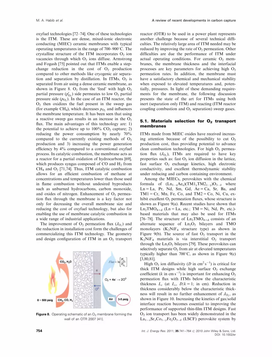
tion and separation by distillation. In ITMs, O2 is
separated from air using a dense ceramic membrane, as
shown in Figure 8. O2 from the ‘feed’ with high O2
partial pressure (p0O2) side permeates to low O2 partial
pressure side (pO2). In the case of an ITM reactor, the
O2 then oxidizes the fuel present in the sweep gas
(for example CH4), which decreases pO2and influences
the membrane temperature. It has been seen that using
a reactive sweep gas results in an increase in the O2
flux. The main advantages of this technology are: 1)
the potential to achieve up to 100% CO2 capture; 2)
reducing the power consumption by nearly 70%
compared to the currently existing methods of O2
production and 3) increasing the power generation
efficiency by 4% compared to a conventional oxyfuel
process. In catalytic combustion, the membrane acts as
a reactor for a partial oxidation of hydrocarbons [69],
which produces syngas composed of CO and H2 from
CH4 and O2 [71,74]. Thus, ITM catalytic combustion
allows for an efficient combustion of methane at
concentrations and temperatures lower than those used
in flame combustion without undesired byproducts
such as unburned hydrocarbons, carbon monoxide,
and oxides of nitrogen. Enhancement of O2 permea-
tion flux through the membrane is a key factor not
only for decreasing the overall membrane size and
reducing the cost of oxyfuel technology, but also for
enabling the use of membrane catalytic combustion in
a wide range of industrial applications.
The improvement of O2 permeation flux (JO2) and
the reduction in installation cost form the challenges of
commercializing this ITM technology. The geometry
and design configuration of ITM in an O2 transport
reactor (OTR) to be used in a power plant represents
another challenge because of several technical diffi-
culties. The relatively large area of ITM needed may be
reduced by improving the rate of O2 permeation. Other
difficulties are due the performance of ITM under
actual operating conditions. For ceramic O2 mem-
branes, the membrane thickness and the interfacial
processes are key parameters for achieving high O2
permeation rates. In addition, the membrane must
have a satisfactory chemical and mechanical stability
when exposed to elevated temperatures and, poten-
tially, pressures. In light of these demanding require-
ments for the membrane, the following discussion
presents the state of the art for ITMs using both
inert (separation only ITM) and reacting (ITM reactor
coupling combustion and O2 separation) sweep gases.
5.1. Materials selection for O2 transportmembranes
ITMs made from MIEC oxides have received increas-
ing attention because of the possibility to cut O2
production cost, thus providing potential to advance
clean combustion technologies. For high O2 permea-
tion flux ðJO2Þ, ITMs are required to have key
properties such as: fast O2 ion diffusion in the lattice,
fast surface O2 exchange kinetics, high electronic
conductivity, and excellent thermodynamic stability
under reducing and carbon containing environment.
Among the MIECs, perovskites with the chemical
formula of (Ln1�xAex)(TM1yTM21�y)O3�d where
Ln5La, Pr, Nd, Sm, Gd, Ae5Ca, Sr, Ba, and
TM15Cr, Mn, Fe, Co, and TM25Co, Ni, Cu, ex-
hibit excellent O2 permeation fluxes, whose structure is
shown as Figure 9(a). Recent studies have shown that
Ln2TMO41d (Ln5La, etc.; TM5Ni, Nd, Pr, etc.)-
based materials that may also be used for ITMs
[76–78]. The structure of Ln2TMO41d consists of an
alternate sequence of Ln2O2 bilayers and TMO
monolayers (K2NiF4 structure type) as shown in
Figure 9(b). The source of fast O2 transport in the
K2NiF4 materials is via interstitial O2 transport
through the Ln2O2 bilayers [79]. These perovskites can
selectively separate O2 from air at elevated temperatures
typically higher than 7001C, as shown in Figure 9(c)
[3,80,81].
High O2 ion diffusivity (D in cm2 s�1) is critical for
thick ITM designs while high surface O2 exchange
coefficient (k in cm s�1) is important for enhancing O2
permeation flux with ITMs below the characteristic
thickness Lc (at Lc, D/k5 1; in cm). Reduction in
thickness considerably below the characteristic thick-
ness will result in no further enhancement of JO2, as
shown in Figure 10. Increasing the kinetics of gas/solid
interface reaction becomes essential to improving the
performance of supported thin-film ITM designs. Fast
O2 ion transport has been widely demonstrated in the
La1�xSrxCo1�yFeyO3�d (LSCF) perovskite system byFigure 8. Operating schematic of an O2 membrane forming the
wall of an OTR 2007 [41].
A review of recent developments in carbon captureM. A. Habib et al.
Int. J. Energy Res. 2011; 35:741–764 r 2010 John Wiley & Sons, Ltd.
DOI: 10.1002/er
754

numerous researchers and is frequently used as an ITM
material with composition of La0.6Sr0.4Co0.2Fe0.8O3�d
(LSCF6428) [82–88]; recently, a novel perovskite
compound Ba1-xSrxCo1-yFeyO3�d (BSCF), in parti-
cular the composition Ba0.5Sr0.5Co0.8Fe0.2O3�d
(BSCF5582), was reported to have significantly im-
proved O2 permeation flux [89,90].
To compare the performance of these two perovskite
structures, we summarized the reported properties of
LSCF6428, BSCF5582 and La2NiO41d (LNO) for
membranes with 1–1.85mm thickness in Figure 11.
The values for JO2[81,89,91] and tracer O2 diffusion
coefficients (D�) [92–94] are plotted in Figures 11(a)
and (b), respectively for LSCF6428, BSCF5582 and
LNO. JO2values for these three materials are found to
be in the order of BSCF55824LNO4LSCF6428 and
follows the same trends for D�. This result indicates
that bulk diffusion is the rate-limiting step for JO2and
the thickness of these ITMs are above Lc. Calculating
the Lc for these three compounds using the tracer
surface exchange coefficient (k�) at �5501C reveals
values ranging from 300 mm, 100 mm and 3 mm for
BSCF5582, LNO, and LSCF6428, respectively. The
nature of the surface O2 exchange is currently not well
understood and insights into the rate-limiting step for
surface exchange will be critical to improving JO2with
thin membranes. On the other hand, electronic con-
ductivity is found to have negligible effect on JO2as
this is significantly much faster than the rates of all
other reaction steps, as shown in Figure 11(d).
Figure 9. (a) Structure of the perovskite crystal (ABO3). (b) Structure of the double perovskite crystal (A2BO4) and (c) O2 permeation
flux for ABO3 and A2BO4 materials as a function of temperature and varying composition.
Figure 10. Schematic of O2 permeation flux as a function of
membrane thickness.
A review of recent developments in carbon capture M. A. Habib et al.
755Int. J. Energy Res. 2011; 35:741–764 r 2010 John Wiley & Sons, Ltd.
DOI: 10.1002/er

Although JO2is a key factor in selection of ITM
materials, the ITM must also show robustness and
stability under large O2 partial pressure (pO2) gradients.
During operation, ceramic membranes are subjected to
pO2gradients ranging from 1 bar on the ‘feed’ or high
p0O2side to 10�6 bar along the ‘permeate’ or low pO2
side. For LSCF and BSCF, stability has been demon-
strated at pO2gradients as much as p0O2
43004300pO2of
1 bar//10�6 bar at 9501C [89,95]. In addition to varying
pO2, the O2 permeation membrane may also be exposed
to significant concentrations of nitrogen, carbon and
hydrogen containing gases in the permeate. For ex-
ample, during oxyfuel combustion, the pO2side of the
membrane is exposed to CO2, H2O vapor, and CH4
[96]. The combination of two or more gases, such as
H2O and CO2 can have a catalytic effect on membrane
degradation and hence render the O2 membrane im-
permeable to oxide ions, thereby cutting off O2 flux
[97]. LSCF6428 has been shown to have negligible
degradation under 1 bar of CO2 at 7501C for 1wk [93].
In contrast, BSCF5582 reacts readily with CO2 at
concentrations 410 000 ppm above 4001C [98]. This
makes BSCF5582 unsuitable for direct exposure to the
permeate side during oxyfuel combustion because CO2
is produced when hydrocarbon reacts with O2. Also,
La2NiO4 has been found to be fairly stable against
CO2, as the formation of lanthanum carbonates or
oxycarbonates was observed to be minimal [79].
5.2. Microstructure of oxygen transportmembranes
The ability to fabricate thin membranes to achieve high
oxygen permeation rates, typically 10–50mm, on
porous mechanical supports is thereby often of vital
importance. The fabrication and O2 permeation rates
of mixed conducting CaTi0.9Fe0.1O3�d membranes
were reported by Fontaine et al. [99]. Submicron
powder of CaTi0.9Fe0.1O3�d was prepared by spray
pyrolysis, and shaped into symmetrical membranes,
using conventional powder pressing with sintering, and
asymmetric membranes, using tape casting. The O2
permeation rates of a 30mm membrane were char-
acterized as a function of operating temperature
(800–10501C).
When ITM thickness is considerably smaller than
Lc, surface morphology has been found to be an im-
portant factor in improving JO2, as the surface ex-
change reaction depends on surface area of the ITM.
Tan et al. [74] have demonstrated that addition of
porous layers of silver or LSCF6428 on the high
pO2side of the LSCF6428 membrane can increase
Figure 11. Comparison of BSCF5582, LSCF6428 and LNO (a) O2 permeation flux JO2[81,89,91], (b) tracer diffusion coefficient D�
[81,92,94], (c) tracer surface exchange coefficient k� [92–94] and (d) electronic conductivity sel [95,96]. In (a), O2 permeation flux of
LSCF6428 and LNO were measured under p0O2==p00O2
gradient of 0.2//10�3 bar and that of BSCF5582 was measured under p0O2==p00O2
gradient of 0.2//10�5 bar. The unit d indicates the thickness of the samples in mm.
A review of recent developments in carbon captureM. A. Habib et al.
Int. J. Energy Res. 2011; 35:741–764 r 2010 John Wiley & Sons, Ltd.
DOI: 10.1002/er
756

permeation flux of LSCF6428 membranes by 2–20
times due to a combination of higher surface area and
enhanced surface exchange kinetics. They concluded
that the O2 dissociation on the high pO2side could play
an important role in determining O2 flux through un-
modified membranes. In another study, Jin et al. [100]
have reported an asymmetric ITM of LSCF6428 was
successfully prepared by coating a slurry containing
LSCF6428 powder dispersed in H2O together with a
nitric acid dispersant, and exhibited�3–4 times higher
an O2 permeation flux in comparison to dense sintered
LSCF6428 discs. It is evident that altering membrane
surface morphology porosity and roughness provides
enhancement of O2 permeation flux.
To enable the use of high-flux materials such as
BSCF in oxy-combustion applications, the addition of
a thin surface layer, such as LSCF6428, on the
permeate side of the ITM to prevent direct contact
with CO2 containing environment may be a feasible
approach, as shown in Figure 12.
5.3. Experimental methods for measuringO2 flux, surface exchange coefficient andbulk O2 ion conductivity
Conventional techniques for measurement of ITM
require a two-chamber setup with a p0O2side containing
air or pure O2 and pO2side, typically containing
a majority of helium (He) or N2 gas, as shown in
Figure 13. To measure the O2 flux JO2, gases are
pumped in the two chambers at known flow rates and
ceramic glass sealant is used between membrane and
tube enclosure to prevent leaking. However, ITM
experiments are never leak-free, therefore it is neces-
sary to compensate for O2 leakage into the two
chambers. To compensate for this, the O2 permeation
flux can be expressed [70] as:
JO2¼
FpermeationyO2� Fleakage
Að1Þ
where Fpermeation is the total flow rate of the permeate
side (cm3 s�1), yO2is the O2 concentration in permeate
side measured by gas chromatography (GC), Fleakage is
the O2 flow rate of the leakage, and A is membrane
surface area (cm2). Fleakage can be determined by
measurements that flow only argon (Ar) and He gases
in the feed and permeate sides, respectively. Once the
leakage rate is known, it is then necessary to determine
whether the O2 permeation is limited by either bulk
diffusion or surface exchange, as shown in Figure 12.
In the case where the membrane is above the
characteristic thickness, O2 permeation flux is limited
by bulk diffusion and can be determined by the
following equation [101]:
JO2¼
RT
42F2L
Z ln p00O2
ln p0O2
si d½ln pO2�
JO2¼
RT
42F2Lsi ln
p0O2
p00O2
ð2Þ
where L and s are sample thickness and O2 ionic
conductivity, respectively. Thus, when bulk diffusion
limits the O2 permeation flux, the O2 permeation flux
Figure 12. Addition of a second ITM layer (dark blue region on
right side) on the low p00O2side or permeate side to prevent
material decomposition and exposure gas atmospheres con-
taining CO2. This second layer is critical for BSCF materials to
prevent reaction with CO2.
Figure 13. Typical two-chamber configuration for measure-
ment of O2 permeation flux (JO2) using a dense ceramic disk for
the ITM at the center, mass flow controllers (MFCs) to deliver
gases and gas chromatograph to monitor JO2. The entire two-
chamber configuration is placed inside a furnace to control
temperature.
A review of recent developments in carbon capture M. A. Habib et al.
757Int. J. Energy Res. 2011; 35:741–764 r 2010 John Wiley & Sons, Ltd.
DOI: 10.1002/er

has linear dependence on sample thickness and
temperature and an exponential dependence on O2
partial pressure.
On the other hand, in the case where the membrane
is considerably below the characteristic thickness, the
O2 permeation flux becomes [95]
JO2¼
k0exkr
kf
p0O2
p00O2
!0:5
�1
24
35 ð3Þ
or
JO2¼
k00exkr
kf1�
p00O2
p0O2
!0:524
35 ð4Þ
where k0ex and k00ex are surface exchange coefficient at
feed side and permeation side, respectively. Also,
kf and kr are the forward and reverse reaction rate
constants for the following reaction:
12O21V��O ,
kf=krOx
O12h� ð5Þ
The nature of the surface exchange is currently not
well understood. However, its magnitude and pO2
dependence, can been measured using techniques such
as 18O2 tracer based on ex-situ secondary-ion mass
spectrometry (SIMS) analysis [102,103], EIS at varying
O2 partial pressures and temperatures [89,104,105],
conductivity relaxation methods following a sudden
change in pO2[42,106], and direct measurements of
permeation through a dense membrane [107,108].
5.4. Performance of O2 separation mem-branes
Recently, there has been increasing interest in using the
ITM to improve the performance of CH4 conversion
processes by enhancing O2 permeation through per-
ovskite hollow fiber membranes utilizing methane
activation. Liu et al. [3] manufactured hollow fiber
membranes of mixed conducting perovskite via the
combined phase inversion and sintering technique. The
fibers were tested for air separation with a custom-built
reactor under the O2 partial pressure gradient gener-
ated by the air/He streams. Some fibers were activated
in situ by introducing methane in the He sweeping gas
at high temperatures. The activated membranes with
new morphology were created by transforming the
inner densified surface layer to a porous structure
causing a decrease in the O2 ionic transport resistance.
Compared to the original membranes, the activated
membranes were found to give appreciable higher O2
fluxes. At 8001C, the O2 fluxes were increased by a
factor of 10 times after activation was carried out at
10001C for 1 h. During the permeation process under
O2 gradient provided by air/He, it was observed, that
the O2 fluxes through the prepared perovskite hollow
fiber membranes were greatly improved by introducing
methane inside the sweep gas for a short activation.
Perovskite LSCF6428 hollow fibers were synthesized
via a modified phase inversion and sintering technique.
The prepared membrane had multi-densified layer
structure. O2 permeation through the fibers was
measured under O2 concentration gradient of air/He
with He as sweep gas in the fiber lumen. However, as
indicated by Liu et al. [3], these membrane reactor
performances are not ideal because of the following
two disadvantages: (i) perovskite materials are apt to
deteriorate due to the unstable phase structure under
reducing CO2 containing or low O2 partial pressure
atmospheres and (ii) the disk-shaped membranes with
symmetric structure usually suffer high ion-transport
resistance.
Oxyfuel combustion using a catalytic ceramic
membrane reactor was investigated by Tan et al. [73].
It was indicated that membrane catalytic combustion is
an environmentally friendly technique for heat and
power generation from methane. LSCF6428 hollow
fiber membranes were prepared by the phase-inversion
spinning/sintering technique. The prepared hollow
fiber membranes packed with catalysts were assembled
in reactors, which were suitable for the catalytic com-
bustion of methane. The work demonstrated the per-
formances of a perovskite hollow fiber membrane
reactor for the catalytic combustion of methane.
A simple mathematical model that combined the local
O2 permeation rate with approximate catalytic reac-
tion kinetics was developed and was used to predict the
performance of the membrane reactor for methane
combustion. The effects of operating temperature and
the flow rates of methane and air feed flow rates on the
performance of the membrane reactor were investi-
gated both experimentally and theoretically. It was
found that both the methane conversion and O2 per-
meation rate can be improved by coating platinum on
the air side of the hollow fiber membranes. It was
concluded that during operation, both the methane
and the air feed flow rates should be chosen carefully in
order to control the product composition and to im-
prove combustion efficiency.
6. CONCLUSIONS
Carbon capture enables the use of fossil fuels while
reducing the emissions of CO2 into the atmosphere.
The oxyfuel technology provides a promising CCS
option applicable in power and steam generation
systems. One of the problems of oxyfuel combustion
is the need for O2 that is expensive when obtained
using cryogenic separation from air. Ceramic mem-
branes have received increasing attention because of
the possibility to reduce O2 production costs, thus
providing potential to advance the clean oxyfuel
energy technology. Major advances in ITMs have
been made in the past decade and this technology
has the strong potential to reduce greenhouse gas
A review of recent developments in carbon captureM. A. Habib et al.
Int. J. Energy Res. 2011; 35:741–764 r 2010 John Wiley & Sons, Ltd.
DOI: 10.1002/er
758

emissions in a wide range of conventional combustion
systems and improve energy generation efficiency.
The development of mixed-ionic electronic-conducting
materials, in particular with the perovskite material
system such as LSCF and BSCF, has shown large
enhancement in O2 permeation flux and catalytic
combustion. Next generation ITMs will require
significantly higher permeation flux at reduced operat-
ing temperatures to lower the cost of the technology
and increase the probability of commercialization
success. This paper reviews research on the develop-
ment of oxyfuel combustion membranes, reactors and
systems. The review includes work done on carbon
capture potential, developments of oxyfuel applica-
tions and O2 separation and combustion in membrane
reactors. The recent developments in oxyfuel power
cycles have been discussed focusing on the main
concepts of manipulating exergy flows within each
cycle and the reported thermal efficiencies.
7. SUGGESTED RESEARCH NEEDS
Most of the previous work done in the area of oxyfuel
combustion has focused on coal combustion and,
hence, it is recommended that more efforts are needed
for the characterization of the oxycombustion of
natural gas. Extensive efforts are also required to
improve the performance of fuel gas conversion
processes through combining air separation and
oxyfuel combustion into a single step. In order to
improve O2 permeation in O2 transport membranes,
one promising approach is to fabricate supported
submicron thickness ITMs on porous substrates to
eliminate bulk O2 transport loss. This approach will
limit O2 permeation at the solid/gas interface. Recent
studies have also shown significant enhancement of
surface exchange kinetics via modified surface chemis-
tries and/or microstructures that may pave the way for
increased permeation flux in these submicron mem-
branes. Recently, Sase et al. [109] have reported
�1000� improvement in surface exchange at the
interface of La0.6Sr0.4CoO3 and LaSrCoO4 although
the mechanism for enhancement is not clearly under-
stood yet. These improvements in k with surface
modification signal a novel approach for increasing O2
permeation flux in thin-film membranes below the Lc.
In addition, this development will allow for reduced
operating temperature for O2 membranes. Another
approach to improving O2 permeation flux is to utilize
double-perovskite (i.e. La2NiO41d) materials that have
higher O2 transport properties and surface exchange
kinetics. The successful development of these new
approaches for ITMs will make commercial O2
separation systems a reality. At present, oxyfuel
combustion using membrane reactors is still in the
stage of early development. Extensive research is
currently ongoing for possible solution of technical
difficulties facing this new technology. It may be too
early for a complete evaluation of the feasibility of
using this technology for carbon capture. Finally,
integration of this new technology into the power
generation sector requires detailed systems-level stu-
dies that assess the impact of ITM operational
requirements and costs.
NOMENCLATURE
A 5membrane surface area
ASU 5 air separation unit
AZEP 5 advanced zero emissions power plant
BSCF 5Ba1�xSrxCo1�yFeyO3�d
BSCF5582 5Ba0.5Sr0.5Co0.8Fe0.2O3�d
CLC 5 chemical-looping combustion
D 5 bulk oxygen ion diffusivity
D* 5 tracer oxygen diffusion coefficient
Fleakage 5 oxygen flow rate of the leakage
Fpermeation 5 total flow rate of the permeation side
HAT 5 humid air turbine
HRSG 5 heat recovery steam generator
IGCC 5 integrated gasification combined
cycle
JO25 oxygen permeation flux
k0ex 5 surface exchange coefficient at feed
side
k00ex 5 surface exchange coefficient at
permeation side
k 5 surface oxygen exchange coefficient
k* 5 tracer surface exchange coefficient
kf 5 forward reaction rate constant
kr 5 reverse reaction rate constant
L 5 sample thickness
Lc 5 characteristic thickness
Ln 5 lanthanoid
LNO 5La2NiO41dLSCF 5La1�xSrxCo1�yFeyO3�d
LSCF6428 5La0:6Sr0:4Co0:2Fe0:8O3�d
MAST 5moist air steam turbine
MCM 5mixed conducting membrane
MFCs 5mass flow controllers
MIEC 5mixed ionic and electronic conducting
oxides
NG 5 natural gas
p0O25 oxygen partial pressure on feed side
p00O25oxygen partial pressure on permeation
side
SIMS 5 secondary-ion mass spectrometry
SOFC 5 solid oxide fuel-cell
SR 5 steam Reforming
STIG 5 steam injected gas turbine
TM 5 transition metal
yO25oxygen concentration in permeation
side measured by gas chromatograph
ZEITMOP 5 zero-emission ITM oxyfuel plant
A review of recent developments in carbon capture M. A. Habib et al.
759Int. J. Energy Res. 2011; 35:741–764 r 2010 John Wiley & Sons, Ltd.
DOI: 10.1002/er
ZEPP 5 zero-emission power plant
sel 5 electronic conductivity
ACKNOWLEDGEMENTS
The financial support of KFUPM under the KFUPM-MIT collaboration program during the course of thiswork is greatly appreciated. The support and colla-boration of MIT mechanical engineering department isalso appreciated.
REFERENCES
1. Copenhagen summit 2009, United Nations Cli-
mate Change Conference (COPIS), Copenhagen,
6–18, December 2009.
2. Kvamsdal H, Jordal K, Bolland O. A quantitative
comparison of gas turbine cycles with CO2
capture. Energy 2007; 32(1):10–24.
3. Liu H, Pang Z, Tan X, Shao Z, Sunarso J, Ding
R, Liu S. Enhanced oxygen permeation through
perovskite hollow fiber membranes by methane
activation. Ceramics International 2009;
35(4):1435–1439.
4. Desideri M, Arcioni L, Tozzi M. Feasibility study
for a carbon capture and storage project in
northern Italy. International Journal of Energy
Research 2008; 32:1175–1183.
5. Xu G, Jin HG, Yang YP, Xu XJ, Lin H, Duan L. A
comprehensive techno-economic analysis method for
power generation systems with CO2 capture. Interna-
tional Journal of Energy Research 2010; 34:321–332.
6. Wall TF. Combustion processes for carbon
capture Terry F. Wall. Proceedings of the
Combustion Institute 2007; 31:31–47.
7. Tzimas E, Mercier A, Cormos CC, Peteves SD.
Trade-off in emissions of acid gas pollutants and of
carbon dioxide in fossil fuel power plants with
carbon capture. Energy Policy 2007; 35:3991–3998.
8. Armor JN. Addressing the CO2 dilemma. Cata-
lysis Letters 2007; 114:(3–4):115–121.
9. Bolland O, Undrum H. A novel methodology for
comparing CO2 capture options for natural gas-
fired combined cycle plants. Advances in Environ-
mental Research 2002; 7:901–911.
10. Simpson AP, Simon AJ. Second law comparison
of oxy-fuel combustion and post-combustion
carbon dioxide separation. Energy Conversion
and Management 2007; 48:3034–3045.
11. Haseli Y, Dincer I, Naterer GF. Thermodynamic
analysis of a combined gas turbine power system
with a solid oxide fuel cell through exergy.
Thermochimica Acta 2008; 480(1–2):1–9.
12. Sander F, Span R. Modeling of an oxygen
transport membrane for an IGCC process with
CO2 capture. Proceedings of the 8th International
Conference on Greenhouse Gas Control Technolo-
gies, Trondheim, Norway, 19–22 June, 2006.
13. Lindfeldt EG, Westermark MO. An integrated
gasification zero emission plant using oxygen
produced in a mixed conducting membrane
reactor. Proceedings of ASME Turboexpo 2006,
GT-2006 90183, Barcelona, May, 2006.
14. Sander F, Foeste S, Span R. Model of an oxygen
transport membrane for coal fired power cycles.
Proceedings of the 9th International Conference on
Inorganic Membranes, Lillehammer, Norway,
25–29 June 2006.
15. de Koeijer G, Gjerset M, Aasland S, Kobro H,
Sivertsen B, Rytter E. Natural gas fired power
plant concept with oxygen transfer membrane
reactor and H2 fired combined cycle. Proceedings
of GHGT-8, Trondheim, June 2006.
16. Sander F, Foeste S, Span R. Model of an oxygen
transport membrane for coal fired power cycles
with CO2 capture. Proceedings of the ASME
Turbo Expo 2007, GT-2007 27788, Montreal,
14–17 May 2007.
17. Mattisson T. Chemical-looping combustion using
gaseous and solid fuels. The 2nd Workshop on
International Oxy-Combustion Research Network,
Windsor, CT, U.S.A., 25–26 January 2007.
18. Noorman S, Van Sint Annaland M, Kuipers
JAM, Ten Asbroek NAM, Feron PHM. Packed
bed reactor technology for chemical-looping
combustion. The 2nd Workshop on International
Oxy-Combustion Research Network, Windsor,
CT, U.S.A., 25–26 January 2007.
19. Naqvi R, Bolland O. Multi-stage chemical
looping combustion (CLC) for combined cycles
with CO2 capture. International Journal of Green-
house Gas Control 2007; 1:19–30.
20. Naqvi R, Bolland O, Wolf J. Part-load analysis of
a chemical looping combustion (CLC) combined
cycle with CO2 capture. The International Journal
of Energy Research 2007; 32(4):360–370.
21. Sundkvist SG, Julsrud S, Vigeland B, Naas T,
Budd M, Leistner H, Winkler D. Development
and testing of AZEP reactor components. Inter-
national Journal of Green-house Gas Control 2007;
1(2):180–187, 8th International Conference on
Greenhouse Gas Control Technologies—GHGT-8.
22. Smith JB, Norby T. On the steady-state oxygen
permeation through La2NiO41membranes. Journal
A review of recent developments in carbon captureM. A. Habib et al.
Int. J. Energy Res. 2011; 35:741–764 r 2010 John Wiley & Sons, Ltd.
DOI: 10.1002/er
760

of the Electrochemical Society 2006; 153(2):
A233–A238.
23. Smith JB, Fontaine ML, Larring Y, Bredesen R.
On the performance of mixed conducting
CaTi0.9Fe0.1O3�d solid state ionics, August 2006.
24. Sundkvist SG, Griffin T, Thorshaug NP. AZEP—
development of an integrated air separation
membrane—gas turbine. Technical Report,
Second Nordic Minisymposium on Carbon Dioxide
Capture and Storage, Alstom Power, Gotenberg,
Sweden, October 2001.
25. Bejan A. Advanced Thermodynamics (3rd edn).
Wiley: New York, U.S.A., 2005.
26. Heitmeir F, Sanz W, Gottlich E, Jericha H. The
graz cycle: a zero emission power plant of highest
efficiency. XXXV Kraftwerkstechnisches Kollo-
quium. Graz University of Technology, Dresden:
vol. 17, 2003; 1–10.
27. Alexander B, Ghoniem AF. Analysis and optimi-
zation of the coupled parameters of the Graz
cycle. Proceedings of ASME Turbo Expo 2008:
Power for Land, Sea and Air GT2008, Berlin,
Germany, 9–13 June 2008.
28. Sanz W, Jericha H, Luckel F, Gottlich E,
Heitmeir F. A further step towards a graz cycle
power plant for a CO2 capture. Proceedings of
GT2005 ASME Turbo Expo 2005: Power for
Land, Sea and Air June 6–9, 2005, Reno-Tahoe,
NE, U.S.A., GT2005-68456, 2005.
29. Jericha H, Sanz W, Gottlich E, Neumayer F.
Design details of a 600MW graz cycle thermal
power plant for CO2 capture. Proceedings of
ASME Turbo Expo 2008: Power for Land, Sea and
Air GT2008, Berlin, Germany, 9–13 June 2008.
30. Mathieu P, Nihart R. Zero-emission MATIANT
cycle. Journal of Engineering for Gas Turbines and
Power 1999; 121(1):116–120.
31. Mathieu P, Nihart R. Sensitivity analysis of the
MATIANT cycle. Energy Conversion and Man-
agement 1999; 40(15–16):1687–1700.
32. Feher EG. The supercritical thermodynamic
power cycle. Energy Conversion 1968; 8(2):85–90.
33. Yantovski E, Gorski J, Smyth B, Elshof J. Zero-
emission fuel—red power plants with ion transport
membrane. Energy 2004; 29(12–15):2077–2088.
34. Gabbrielli R, Singh R. Thermodynamic perfor-
mance analysis of new gas turbine combined
cycles with no emissions of carbon dioxide.
Journal of Engineering for Gas Turbines and Power
2003; 125(4):940–946.
35. Martinez-Frias J, Aceves SM, Ray Smith J,
Brandt H. Thermodynamic analysis of zero-
atmospheric emissions power plant. Journal of
Engineering for Gas Turbines and Power 2004;
126(1):2–8.
36. Anantharaman R, Bolland O, Asen K. Novel
cycles for power generation with CO2 capture
using OMCM technology. Energy Procedia 2009;
1(1):335–342.
37. Zhang N, Lior N. Two novel oxy-fuel power
cycles integrated with natural gas reforming and
CO2 capture. Energy 2008; 33(2):340–351.
38. Normann F, Thunman H, Johnsson F. Process
analysis of an oxygen lean oxy-fuel power plant
with co-production of synthesis gas. Energy
Conversion and Management 2009; 50:279–286.
39. Simmonds M, Miracca I, Gerdes K. 2003.
Oxyfuel technologies for CO2 capture. A Techno-
economic Overview.
40. Sho-Kobayashi H, Van-Hassel B. GCEP advance
coal workshop provo, Utah, March 15, 2005.
41. Shah MM, Christie M. Oxyfuel combustion using
OTM for CO2 capture from coal power plants.
The 2nd Workshop on International Oxy-combus-
tion Research Network, Windsor, CT, U.S.A.,
25–26 January 2007.
42. Elshof JE, Lankhorst MHR, Bouwmeester HJM.
Oxygen exchange and diffusion coefficients of
strontium-doped lanthanum ferrites by electrical
conductivity relaxation. Journal of the Electro-
chemical Society 1997; 144(3):1060–1067.
43. Buhre BJP, Elliott LK, Sheng CD, Gupta RP,
Wall TF. Oxy-fuel combustion technology for
coal-fired power generation. Progress in Energy
and Combustion Science 1997; 31:283–307.
44. Kakaras E, Koumanakos A, Doukelis A,
Giannakopoulos D, Vorrias I. Oxyfuel boiler
design in a lignite-fired power plant. Fuel 2007;
86:2144–2150.
45. Andersson K, Johansson R, Johnsson F, Leckner
B, Hjartstam S. Radiation intensity of lignite-fired
oxy-fuel flames. Experimental Thermal and Fluid
Science 2008; 33(1):67–76.
46. Andersson K, Johansson R, Johnsson F, Leckner
B. Radiation intensity of propane-fired oxy-fuel
flames: implications for soot formation. Energy
and Fuels 2008; 22(3):1535–1541.
47. Yamada T. Pilot scale experiments giving direct
comparison between air and oxy firing of coals
and implication of large scale plant design. The
2nd Workshop on International Oxy-combustion
Research Network, Windsor, CT, U.S.A., 25–26
January 2007.
48. Andersson K. Combustion tests and modeling of
the oxy-fuel process. The 2nd Workshop on
A review of recent developments in carbon capture M. A. Habib et al.
761Int. J. Energy Res. 2011; 35:741–764 r 2010 John Wiley & Sons, Ltd.
DOI: 10.1002/er

International Oxy-combustion Research Network,
Windsor, CT, U.S.A., 2007.
49. de Jager B. Combustion and noise phenomena in
turbulent alkane flames. Ph.D. Thesis, University
of Twenta, The Netherlands, March 2007.
50. Monckert P, Reber D, Maier J, Scheffknecht G.
Operation of a retrofitted 0.5MWth PF combus-
tion facility under oxyfuel conditions—an experi-
ence report. Proceedings of Clearwater Clean Coal
Conference, Clearwater, FL, June 2007.
51. Shaddix C. Coal particle ignition, devolatilisation
and char combustion kinetics during oxy-
combustion. The 2nd Workshop on International
Oxy-combustion Research Network, Windsor, CT,
U.S.A., 25–26 January 2007.
52. Wall TF, Khare S, Farida Z, Liu Y. Ignition of
oxy-fuel flames. The 2nd Workshop on Interna-
tional Oxy-combustion Research Network, Wind-
sor, CT, U.S.A., 25–26 January 2007.
53. Sarofim A. Oxy-fuel combustion: progress and
remaining issues. The 2nd Workshop on Interna-
tional Oxy-combustion Research Network, Wind-
sor, CT, U.S.A., 25–26 January 2007.
54. Ditaranto M, Hals J. Thermo-acoustic instabil-
ities in a CO2 diluted oxy-fuel combustor. The 2nd
Workshop on International Oxy-combustion Re-
search Network, Windsor, CT, U.S.A., 25–26
January 2007.
55. Zanganeh K, Salvador C, Mitrovic M. Modelling,
design, and pilot-scale experiments of CAN-
MET’s advanced oxy-fuel/stream burner. The
2nd Workshop on International Oxy-combustion
Research Network, Windsor, CT, U.S.A., 25–26
January 2007.
56. Mahesh K, Constantinescu G, Moin P. Large-
eddy simulation of gas turbine combustors.
Annual Research Briefs, Center for Turbulence
Research, Stanford University and NASA-Ames,
2000; 219–228.
57. Eriksson K. CFD modeling for oxyfuel combus-
tion. The 2nd Workshop on International Oxy-
combustion Research Network, Windsor, CT,
U.S.A., 25–26 January 2007.
58. Mohanraj R, Sekar B, Zelina J. Simulation of
swirl stabilized, liquid fueled model gas turbine
combustion systems. The 46th AIAA Aerospace
Sciences Meeting and Exhibit, Reno, NE, 7–10
January 2008.
59. Habib MA, Ben-Mansour R, Abualhamayel HI.
Thermal and emission characteristics in a tangen-
tially fired boiler model furnace. International
Journal of Energy Research 2010, Published On-
line: Dec 14 2009 6:19AM, DOI: 10.1002/er.1667.
60. Habib MA, Emara-Shabaik HE, Al-Zaharnah I,
Ayinde T. A thermal nonlinear dynamic model
for water tube drum boilers. International Journal
of Energy Research 2010; 34(1):20–35.
61. Mongia HC. Recent progress in comprehensive
modeling of gas turbine combustion. AIAA Paper
2008-1445, 2008.
62. YagaM, Sasada K, Yamamoto T, Aoki H,Miura T.
An eddy characteristic time modeling in LES for gas
turbine combustor Mitsuru. Proceedings of 2000
International Joint Power Generation Conference
Miami Beach, FL, July 23–26, 2000; 1–6.
63. Tan Y, Douglas MA, Thambimuthu KV. CO2
capture using oxygen enhanced combustion stra-
tegies for natural gas power plant. Fuel 2002;
81:1007–1016.
64. Andersson K, Johnsson F. Radiative properties
of a 100 kW oxy-fuel flame experiments and
modeling of the Chalmers test facility. Proceedings
of Clearwater Clean Coal Conference, Florida,
May 2006.
65. Andersson K, Johnsson F. Flame and radiation
characteristics of gas-fired O2/CO2 combustion.
Fuel 2007; 86:656–668.
66. Andersson K, Monckert P, Maier J, Scheffknecht
G, Johnsson F. Combustion and flame character-
istics of oxy-fuel combustion—experimental
activities within the ENCAP project. Proceedings
of GHGT-8, Trondheim, 2006.
67. Maier J, Dhungel B, Monckert P, Scheffknecht
G. Coal combustion and emission behavior under
oxyfuel condition. Proceedings of Clearwater Clean
Coal Conference, Clearwater FL, May 2006.
68. Maier J, Dhungel B, Monckert P, Scheffknecht G.
Combustion and Emission Behavior under Oxyfuel
Condition. Kraftwerks Kollquium, Dresden, 2007.
69. Zeng PY, Chen Z, Zhou W, Gu H, Shao Z, Liu S.
Re-evaluation of Ba0.5Sr0.5Co0.8Fe0.2O3�d perovs-
kite as oxygen semi-permeable membrane. Jour-
nal of Membrane Science 2007; 291(1–2):148–156.
70. Park JH, Do Park S. Oxygen permeability and
structural stability of La06Sr0.4Co0.2Fe0.8O3�d
membrane. Korean Journal of Chemical Engineer-
ing 2007; 24(5):897–905.
71. Tong JH, Yang W, Cai R, Zhu B, Lin L. Novel
and ideal zirconium-based dense membrane re-
actors for partial oxidation of methane to syngas.
Catalysis Letters 2002; 78(1–4):129–137.
72. Tan XY, Wang Z, Liu H, Liu S. Enhancement of
oxygen permeation through La0.6Sr0.4Co0.2Fe0.8O3�d
hollow fibre membranes by surface modifications.
Journal of Membrane Science 2008; 324(1–2):
128–135.
A review of recent developments in carbon captureM. A. Habib et al.
Int. J. Energy Res. 2011; 35:741–764 r 2010 John Wiley & Sons, Ltd.
DOI: 10.1002/er
762

73. Tan X, Li K, Thursfield A, Metcalfe IS. Oxyfuel
combustion using a catalytic ceramic membrane
reactor. Catalysis Today 2008; 131:292–304.
74. Hendriksen PV, Larsen PH, Mogensen M,
Poulsen FW, Wiik K. Prospects and problems
of dense oxygen permeable membranes. Catalysis
Today 2000; 56(1–3):283–295.
75. Armstrong P, Fogash K. Oxygen production
technologies: cryogenic and ITM. The 2nd Work-
shop on International Oxy-combustion Research
Network, Windsor, CT, U.S.A., 2007.
76. Boehm E, Bassat JM, Dordor P, Mauvy F,
Grenier JC, Stevens Ph. Oxygen diffusion and
transport properties in non-stoichiometric Ln2�xNiO41d oxides. Solid State Ionics 2005;
176(37–38):2717–2725.
77. Boehm E, Bassat JM, Steil MC, Dordor P,
Mauvy F, Grenier JC. Oxygen transport proper-
ties of La2Ni1�xCuxO41d mixed conducting oxi-
des. Solid State Sciences 2003; 5(7):973–981.
78. Grenier JC. Mixed ionic electronic conducting
oxides: advanced materials for intermediate tem-
perature solid oxide fuel cells. Ionics 2007,
Nantes, France, 2007.
79. Efimov K, Arnold M, Martynczuk J, Feldhoff A.
Crystalline intermediate phases in the sol–gel-
based synthesis of La2NiO41d. Journal of the
American Ceramic Society 2009; 92(4):876–880.
80. Foy K, McGovern J. Comparison of ion transport
membranes. Fourth Annual Conference on Carbon
Capture and Sequestration DOE/NETL, 2005.
81. Dong XL, Wu Z, Chang X, Jin W, XUN. One-step
synthesis and characterization of La2NiO41d mixed-
conductive oxide for oxygen permeation. American
Chemical Society 2007; 46(21):6910–6915.
82. Teraoka Y, Zhang HM, Okamoto K, Yamazoe N.
Mixed ionic-electronic conductivity of
La1�xSrxCO1�yFeyO3�d perovskite-type oxides.
Materials Research Bulletin 1988; 23(1):51–58.
83. Esquirol A, Brandon NP, Kilner JA, Mogensen
M. Electrochemical characterization of La0.6Sr0.4-Co0.2Fe0.8O3 cathodes for intermediate-tempera-
ture SOFCs. Journal of the Electrochemical
Society 2004; 151(11):A1847–A1855.
84. Teraoka Y, Zhang HM, Furukawa S, Yamazoe
N. Oxygen permeation through perovskite-type
oxides. Chemistry Letters 1985;11:1743–1746.
85. Huijsmans JPP, van Berkel FPF, Christie GM.
Intermediate temperature SOFC—a promise for
the 21st century. Journal of Power Sources 1998;
71(1–2):107–110.
86. Ralph JM, Rossignol C, Kumar R. Cathode
materials for reduced-temperature SOFCs.
Journal of the Electrochemical Society 2003;
150(11):A1518–A1522.
87. Gauckler LJ, Beckel D, Buergler BE, Jud E,
Muecke UP, Prestat M, Rupp JLM, Richter J.
Solid oxide fuel cells: systems and materials.
Chimia 2004; 58(12):837–850.
88. Sunarso J, Baumann S, Serra JM, Meulenberg WA,
Liu S, Lin YS, Diniz da Costa JC.
Mixed ionic-electronic conducting (MIEC) cera-
mic-based membranes for oxygen separation.
Journal of Membrane Science 2008; 320(1–2):
13–41.
89. Shao ZP, Yang W, Cong Y, Dong H, Tong J,
Xiong G. Investigation of the permeation beha-
vior and stability of a Ba0.5Sr0.5Co0.8Fe0.2O3�d
oxygen membrane. Journal of Membrane Science
2000; 172(1–2):177–188.
90. Wang HH, Cong Y, Yang WS. Oxygen permea-
tion study in a tubular Ba0.5Sr0.5Co0.8Fe0.2O3�d
oxygen permeable membrane. Journal of Mem-
brane Science 2002; 210(2):259–271.
91. Zeng Y, Lin YS, Swartz SL. Perovskite-type
ceramic membrane: synthesis, oxygen permeation
and membrane reactor performance for oxidative
coupling of methane. Journal of Membrane
Science 1998; 150(1):87–98.
92. Wang L, Merkle R, Maier J, Acarturk T, Starke
U. Oxygen tracer diffusion in dense
Ba0.5Sr0.5Co0.8Fe0.2O3�d films. Applied Physics
Letters 2009; 94(7):071908(1–3).
93. Benson SJ, Waller D, Kilner JA. Degradation of
La0.6Sr0.4Fe0.8Co0.2O3�d in carbon dioxide and
water atmospheres. Journal of the Electrochemical
Society 1999; 146(4):1305–1309.
94. Bassat JM, Odier P, Villesuzanne A, Marin C,
Pouchard M. Anisotropic ionic transport proper-
ties in La2NiO41d single crystals. Solid State
Ionics 2004; 167(3–4):341–347.
95. Xu SJ, Thomson WJ. Stability of
La0.6Sr0.4Co0.2Fe0.8O3�d perovskite membranes
in reducing and nonreducing environments.
Industrial and Engineering Chemistry Research
1998; 37(4):1290–1299.
96. McIntosh S, Vente JF, Haije WG, Blank DHA,
Bouwmeester HJM. Structure and oxygen
stoichiometry of SrCo0.8Fe0.2O3�d and
Ba0.5Sr0.5Co0.8Fe0.2O3�d. Solid State Ionics 2006;
177(19–25):1737–1742.
97. Arnold M, Wang HH, Feldhoff A. Influence of
CO2 on the oxygen permeation performance and
the microstructure of perovskite-type
(Ba0.5Sr0.5)(Co0.8Fe0.2)O3�d membranes. Journal
of Membrane Science 2007; 293(1–2):44–52.
A review of recent developments in carbon capture M. A. Habib et al.
763Int. J. Energy Res. 2011; 35:741–764 r 2010 John Wiley & Sons, Ltd.
DOI: 10.1002/er

98. Yan AY, Liu B, Dong Y, Tian Z, Wang D,
Cheng M. A temperature programmed de-
sorption investigation on the interaction of
Ba0.5Sr0.5Co0.8Fe0.2O3�d perovskite oxides with
CO2 in the absence and presence of H2O and O2.
Applied Catalysis B—Environmental 2008;
80(1–2):24–31.
99. Fontaine ML, Smith JB, Larring Y, Bredesen R.
On the preparation of asymmetric
CaTi09Fe01O3�d membranes by tape-casting and
co-sintering process. Journal of Membrane Science
2009; 326(2):310–315.
100. Jin WQ, Li S, Huang P, Xu N, Shi J. Preparation
of an asymmetric perovskite-type membrane and
its oxygen permeability. Journal of Membrane
Science 2001; 185(2):237–243.
101. Wagner C. Equations for transport in solid oxides
and sulfides of transition metals. Progress in Solid
State Chemistry 1975; 10(Part 1):3–16.
102. Kilner JA, De Souza RA, Fullarton IC. Surface
exchange of oxygen in mixed conducting perovs-
kite oxides. Solid State Ionics 1996; 86–88(2):
703–709.
103. Carter S, Selcuk A, Chater RJ, Kajda J, Kilner JA,
Steele BCH. Oxygen-transport in selected nonstoi-
chiometric perovskite-structure oxides. Solid State
Ionics 1992; 53(6):597–605.
104. Yuemei LY, Jacobson AJ, Chen CL, Luo GP,
Ross KD, Chu CW. Oxygen exchange kinetics on a
highly oriented La0.5Sr0.5CoO3�d thin film pre-
pared by pulsed-laser deposition. Applied Physics
Letters 2001; 79(6):776–778.
105. Kim S, Wang S, Chen X, Yang YL, Wu N,
Ignatiev A, Jacobson AJ, Abeles B. Oxygen surface
exchange in mixed ionic electronic conductors:
application La05Sr05Fe08Ga02O3�d. Journal of the
Electrochemical Society 2000; 147(6):2398–2406.
106. Lane JA, Benson SJ, Waller D, Kilner JA. Oxygen
transport in La0.6Sr0.4Co0.2Fe0.8O3�d. Solid State
Ionics 1999; 121(1–4):201–208.
107. Ten Elshof JE, Bouwmeester HJM, Verweij H.
Oxygen transport through La1�xSrxFeO3�d mem-
branes. I. Permeation in air/He gradients. Solid
State Ionics 1995; 81(1–2):97–109.
108. Ten Elshof JE, Bouwmeester HJM, Verweij H.
Oxygen transport through La1�xSrxFeO3�d mem-
branes II. Permeation in air/CO, CO2 gradients.
Solid State Ionics 1996; 89(1–2):81–92.
109. Sase M, Yashiro K, Sato K, Mizusaki J, Kawada
T, Sakai N, Yamaji K, Horita T, Yokokawa H.
Enhancement of oxygen exchange at the hetero
interface of (La,Sr)CoO3/(La,Sr)2CoO4 in compo-
site ceramics. Solid State Ionics 2008; 178
(35–36):1843–1852.
A review of recent developments in carbon captureM. A. Habib et al.
Int. J. Energy Res. 2011; 35:741–764 r 2010 John Wiley & Sons, Ltd.
DOI: 10.1002/er
764