characteristics of air and oxy-fuel combustion in micro-channels
TRANSCRIPT
HEFAT2012 9th International Conference on Heat Transfer, Fluid Mechanics and Thermodynamics
16 – 18 July 2012 Malta
CHARACTERISTICS OF AIR AND OXY-FUEL COMBUSTION IN MICRO-CHANNELS
Pervez Ahmed, M.A.Habib, Rached Ben-Mansour Department of Mechanical Engineering
King Fahd University of Petroleum and Minerals Dhahran, Saudi Arabia
Emails: [email protected], [email protected], [email protected]
ABSTRACT: With the fast development of MEMS (micro electro mechanical systems) devices the demand for miniaturized power source is increasing quickly. A micro-combustor is one of the key components of these devices in which the fuel-air mixture is burnt. In the past few years, intense research efforts have been made on catalytic micro-reactors using hydrocarbons as fuel for a variety of portable power production systems. The applications of these micro-reactors include scaled-down thermal engines, wherein a catalytic micro-burner is used for the direct conversion of chemical energy to thermal energy, catalytic micro-thrusters for space applications, and micro-reactors used for fuel reforming in micro solid oxide fuel cells. The present work is aimed at developing Computational Fluid Dynamics (CFD) approach for the investigation of characteristics of air and oxy-fuel combustion in micro-channels. The simulations are based on the numerical solution of the conservation of mass, momentum, energy and species equations of two dimensional flows. The present work as being related to micro-channels will provide a basis for development of new technologies such as carbon-free combustors for use in gas turbines and boilers in order to reduce carbon dioxide emissions. INTRODUCTION: Emission reduction of carbon dioxide has become one of the important concerns in the past few years as there seem to exist a direct connection between global temperature increase and anthropogenic greenhouse gases emission. Figure 1 shows the world’s net electricity generation by fuel from the year 2007 which clearly indicates that coal contributes to the maximum fuel being consumed. Carbon dioxide emission cannot be avoided during combustion of any fuel containing carbon. To separate this specie from flue gases, which mainly contains nitrogen, to underground storage of CO2 (a process named sequestration), is an expensive process. One of the best ways to sequestrate CO2 is to perform combustion in the absence of nitrogen in the oxidizer (oxy-fuel combustion). However, the combustion in pure oxygen leads to dangerous temperature and flame speeds. In order to keep these two quantities at similar levels to air, a mixing of oxygen with part
of flue gases is performed, thus, a mixture containing mostly O2/CO2 is used as an oxidizer.
With the fast development of MEMS (micro electro mechanical systems) devices the demand for miniaturized power source is increasing quickly. A micro-combustor is one of the key components of these devices in which the fuel-air mixture is burnt [1]. In the past few years, intense research efforts have been made on catalytic micro-reactors using hydrocarbons as fuel for a variety of portable power production systems [2–4]. The obtained energy densities with these micro-reactors have proven to be considerably higher than the state-of the- art Li-ion batteries. The applications of these micro-reactors include scaled-down thermal engines, wherein a catalytic micro-burner is used for the direct conversion of chemical energy to thermal energy [5, 6], catalytic micro-thrusters for space applications [7], and micro-reactors used for fuel reforming in micro solid oxide fuel cells [8]. Due to their superior energy density compared to that of state-of-the-art lithium batteries, these micro-reactors utilizing hydrocarbons as fuel have received increased attention as energy sources for electrical power generation in portable consumer electronics [9]. With appropriately annealed walls to mitigate radical quenching, pure gas-phase methane combustion can be sustained at the sub-millimeter scale in reactors [10]. Moreover, small channel width burners up to 3.5mm configurations such as the meso-scale heat recirculating ‘‘Swiss-roll’’ burner have proven to stabilize near-stoichiometric propane/ air flames [11].
Technologies: Carbon capture and sequestration (CCS):
Power cycles currently working on CCS technology have efficiencies typically on the order of 35% [2], with a penalty ranging from 7-11 percentage points [8]. There are three promising methods for capturing CO2 for low-emission coal-fired power generation namely post-combustion capture, pre-combustion capture, and oxy-fuel combustion. Figure 2 shows the block diagram of these three processes. Post-combustion capture is the most conventional method to scrub CO2 directly from the exhaust using chemical absorption/desorption processes with amines [2]. However, post-combustion capture is energy-intensive and expensive

due to the low CO2 concentration typical of hydrocarbon oxidation in air [9] and the thermal energy requirements for the chemical scrubbing processes [2]. Pre-combustion capture is an alternative CCS technology that uses processes such as steam reforming, partial oxidation, or auto-thermal reforming to eliminate carbon from fuel prior to combustion [10]. This method requires complex process equipment and incurs exergetic losses for each conversion into another chemical form, thus making it both economically and thermodynamically expensive [2]. In oxy-fuel combustion, coal is burned in pure oxygen instead of air, which results in a significantly higher concentration of CO2 in the flue gas. The flue gas thus contains mostly CO2 and H2O, where H2O can be removed easily via simple condensation process leaving behind CO2 for sequestration. Thus Oxy-fuel combustion provides a favorable solution to significantly mitigate the penalties that occur due to carbon-dioxide separation.
Figure 1: world net electricity generation by fuel Source: IEA. International Energy Outlook 2010
Motivation:
Oxy-fuel combustion of fossil fuels for carbon capture and sequestration (CCS) has been developed with a multitude of potential power cycle concepts, each having distinct operating conditions, components and thermodynamic design philosophy. The motivation for using oxy-fuel instead of conventional combustion for CCS is the relative ease of separation of the CO2 from the flue gases via simple water condensation, as the exhaust products consist mainly of water and CO2. Some of the other reasons for opting oxy-fuel combustion are
CO2 levels in the atmosphere stand at 389 ppm Source: US National Oceanic & Atmospheric Administration. 2011/January
Carbon Capture and Sequestration (CCS) offers a favorable solution.
Computational Fluid Dynamics (CFD) can be used to facilitate development, however :
models may require adaption to oxy-fuel conditions
validation of these by reliable and extensive measurements is necessary
Figure 2: Block diagram illustrating the three systems Ref :[3]
NOMENCLATURE:
x [m] Cartesian axis direction y [m] Cartesian axis direction z [m] Cartesian axis direction T [K] Temperature Vx Vy Vz [m/s] Velocities in respective directions P [pa] Pressure t [sec] Time ρ [kg/m3] Density µ [kg/m-sec] Viscosity k [w/m-K] Thermal conductivity Di,m Diffusion coefficient for species ‘i’ in the mixture C [j/kg-K] specific heat h [j/kg] Enthalpy Yi Mass fraction of species ‘i’ Ri Net rate of production of species ‘i’ by chemical reaction
Subscipts
f - fluid w - wall m - mass
NUMERICAL MODELING: A premixed, stoichiometric methane/air mixture is fed to a micro-burner. The two-dimensional (2D) continuity, momentum, energy and species conservation equations in the fuel-air mixture are discretized using a finite volume method. In addition the conduction heat equation is descritized across the reactor wall. Radiative heat transfer has not been accounted for in the present calculations. Steady-steady laminar flow simulations are performed to study the combustion characteristics in microchannels. The density of the fluid is calculated using the ideal gas law, while the fluid viscosity, specific heat, and thermal conductivity are calculated from a mass fraction weighted average of species. A piecewise polynomial fit of the species specific heat as a function of temperature has been used. The chemical kinetics has been modeled using the single step fast reaction model. This one-step irreversible reaction mechanism is determined by Westbrook and Dryer [12]:
rCH4 = 2.119 × 10¹¹exp [(−2.027 × 10⁸)/RT × [CH4]0.2[O2]1.3;
where the concentrations are in units of kgmol/m3.
Modeling Equations:
The continuity, momemtum, species and energy equations [15] are given below.
Continuity equation:
yxx y
VVV Vt x y x yρ ρ ρ ρ
∂ ∂∂ ∂ ∂= − + + + ∂ ∂ ∂ ∂ ∂
(1)
Momentum:
( ) ( ) ( ) x y yxx x xx
x
V VV V pVt x y x x y
ρ τρ τρ ∂ ∂∂ ∂∂ ∂
= − + − + + ∂ ∂ ∂ ∂ ∂ ∂
(2)
( ) ( ) ( )x y y y xy yyy
V V V V pVt x y y x y
ρ ρ τ τρ
∂ ∂ ∂ ∂∂ ∂= − + − + +
∂ ∂ ∂ ∂ ∂ ∂
(3)
Species:( ) ( ) ( )
,,
i yi xi
iii mi m
i
YVYVY
t x y
YY DDyx R
x y
ρρρ
ρρ
∂∂∂= − + +
∂ ∂ ∂ ∂∂ ∂∂ ∂∂ + +
∂ ∂
(4)
Fluid Energy:
( ) ( ) ( ) ffyx
TT kkhVhV yxht x y x y
ρρρ
∂∂ ∂∂ ∂∂ ∂∂ ∂ = − + + + ∂ ∂ ∂ ∂ ∂
,,ii
i i mi i m
i ii i
YY h Dh Dyx h R
x y
ρρ ∂∂ ∂∂ ∂∂ + + − ∂ ∂
∑ ∑ (4)
Wall energy:
( )2 2
2 2wT TCT k
t x yρ
∂ ∂ ∂= + ∂ ∂ ∂
(5)
Properties: Mass averaged viscosity, specific heat and thermal conductivity:
, ,, ,i i p f i p i f i ii i i
Y C YC k Y kµ µ= = =∑ ∑ ∑
Binary diffusivities:
1/2
3
, ,
2
1 1
0.0188 w i w jij
ij D
TM M
Dpσ
+ =Ω
(6)
Thermal conductivies:
1/2
3
, ,
2
1 1
0.0188 w i w jij
ij D
TM M
Dpσ
+ =Ω
(7)
Viscosities:
622.67 10 W
i
M T
µ
µσ
−= ×Ω
(8)
Here σ is in Angstrom , μi is in kg/m/s, T is in K.
The conservation equations are solved using a segregated solution solver with an under-relaxation method. The segregated solver first solves the momentum equations followed by the continuity equation, and updates the pressure and mass flow rate. The energy and species equations are subsequently solved and convergence is checked. VERIFICATION: The present work investigates the reaction and transport of methane/air mixtures in micro-burners through 2D fully elliptic simulations by treating explicitly heat transfer through the wall. The present work has been verified numerically with the work done by Norton et al [16].
Geometry:
Mass flow Inlet
Symmetry line
Pressure outlet
Height L/2
Wall, Heat Flux = 0
Lw
Figure 3: 2D Micro-channel
Figure 3 shows the geometry of the micro-burner for the present study. It consists of two parallel, infinitely wide plates of distance (L) 0.6 cm apart and length of 1 cm. The plates have finite thickness (Lw) of 0.2 mm each. Boundary Conditions: The case is modeled as 2D symmetric as the gravity effects are neglected. The top and side walls are insulated with no heat flux boundary condition. At the inlet “mass flow inlet” boundary condition is applied and at the outlet a known pressure is specified. At the interface between the wall and the fluid, no-slip boundary condition and no-species flux normal to the wall surface are employed. Fourier’s law is used to compute the heat flux at the wall fluid interface and continuity in temperature and heat flux links the fluid and solid phases. Newton’s law of cooling is used at the outer edge of the wall w, ext a , extq h (T – T )= (9) where h is the convective heat transfer coefficient, Tw,ext is the temperature at the outer wall surface, and Ta,ext is the ambient temperature (i.e. 300 K). The parameters used are V0 = 0.5 m/s, kw = 7.5 W/m/K, h = 0 W/m2/K, L = 0.6 mm, and Lw = 0.2 mm. The case is initiated by patching a high temperature of 2000K in the solid as well as fluid zones and is iterated until convergence is achieved. Grid Independence Test and Validation: A non-uniform grid has been used with more nodes concentrated around the reaction zone for the present simulations. Computations were performed with varying nodal density meshes to optimize node spacing that would provide the desired accuracy and reduce computation time. Figure 4 shows the centre line temperatures for three different meshes used. Taking 12800 nodes grid as the base case the percentage error is calculated. The coarsest mesh, comprising of 800 nodes, was inadequate to capture results accurately. Solutions obtained with high density meshes are reasonably accurate. Meshes with high nodal densities, up to 20,000 nodes (not

shown), were found to provide no obvious advantage. The error between the meshes with nodes 5400 and 12800 is less than 1%. So an optimal nodal density mesh consisting of 5400 nodes were used for the present calculations. Figure 5 shows the comparison of the centre line temperatures for present calculations and the solutions presented by Norton et al [16].
RESULTS AND DISCUSSIONS: The functional requirements of a micro combustor are similar to those of a conventional combustor such as conversion of chemical energy efficiently into thermal and kinetic energy with low total pressure loss, high flame stability and low pollutant emissions. However, the reduction in scale size creates many new obstacles to overcome. Therefore micro combustion chambers are highly restrained by the requirement for a sufficient residence time to allow complete combustion and by high heat loss rates.
Residence time constraints
A high mass flow rate per volume is needed for the combustor to achieve high power density which in turn depends on whether combustion can be completed efficiently within a shorter combustor through flow time or not. In fact, a complete combustion can only occur if the residence time is higher than the required reaction time.
Figure 4 : Centre line temperature comparison for three
different computational meshes
Limitations on the time available The relation for the residence time is given below
.res
V
mRTP
τ = (10)
Equation 11 clearly indicates that the residence time can only be increased either by lowering the volumetric flow rate or by using a long combustor. This flow rate reduction is possible through a decrease in mass flow. Thus without compromising this power density the residence time cannot be increased. However, the residence time can be increased by increasing
the path of the gasses, by incorporating flow recirculation in the combustion chamber, which results in a longer residence time without affecting the power density.
Figure 5: Centre line temperature verification with previous
numerical work
Limitations on the time required The residence time can also be increased by reducing the chemical reaction time to ensure a complete combustion. The equation below gives an approximation for the chemical reaction time by an Arrhenius type expression [9]
[ ]
[ ] [ ] .2. . .
areac Ea b R T
f
A f O eτ −= (11)
It is clear from the equation that the order of magnitude of the reaction time is determined mainly by the activation energy. The lower the energy needed, the lower is the reaction time.
Heat loss effect Heat loss effects are typically neglected for a conventional gas turbine. However it is one of the fundamental factors to be considered in micro-channel combustors due to the increased surface to volume ratio which results from scaling down the chamber. As the heat generated by the combustion is almost proportional to the volume of the combustor and the heat lost approximately proportional to its surface area, the increase in surface to volume ratio leads to a substantial increase in relative heat loss.
Combustion characteristics of Air-fuel and oxy-fuel processes in microchannels: The temperature contours for both air-fuel (CH4+O2+N2) and oxy-fuel (CH4+O2+CO2) cases are shown in Figure 14. It is important to mention that the contour levels are presented on the same scale and the color bar at the end of the contour highlights the temperature variations. Integer values of the corresponding color are incorporated into the contour in order to have a better analysis of the variation of temperature. The maximum temperature obtained is approximately 2318 K with air-fuel combustion case whereas with oxy-fuel combustion
Axial Distance (m)
Tem
pera
ture
(K)
0 0.0025 0.005 0.0075 0.01
500
1000
1500
2000
2500
800 nodes3200 nodes5400 nodes
Axial Distance (m)
Tem
pera
ture
(K)
0.0025 0.005 0.0075 0.01
500
1000
1500
2000
2500
Norton et al [15]Present calculations
case it is slightly less (2258 K). The average temperature at the outlet is approximately 1800 K for both the cases.
The present results confirm the observations by shaddix et al [20] who studied the ignition and combustion behavior of individual particles of coal and found that, for combustion in CO2 environments, flame temperatures were reduced significantly (from 2226 K to 1783 K). Similar results have been found in other experimental and theoretical investigations of ignition of oxy-fuel flames [21].
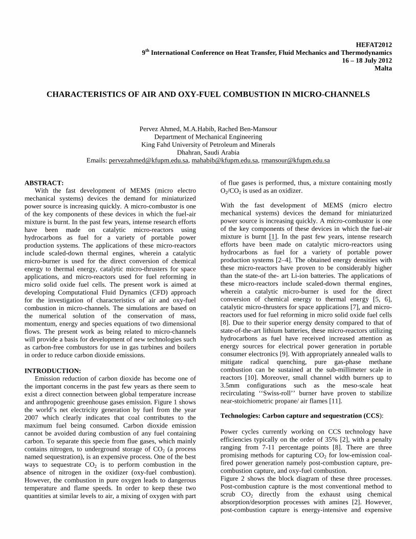
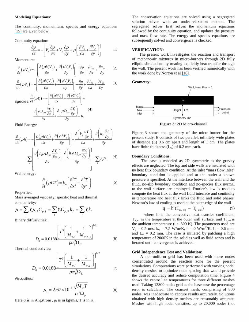
Figure 15 shows a comparison between the temperature contours and reaction rates of the air-fuel case and the oxy-fuel combustion case. It is important to mention that the temperature contour levels are presented on the same scale and the color bar at the end of the contour highlights the temperature variations while the reaction rate contour levels (right) are different, and the color bar is adjusted in each figure to highlight the reaction rate variations. Unlike temperature contours, as shown in Figure 14, the reaction rates shown in Figure 15, at different positions are indicated by integers and the corresponding reaction rate values are shown under them. Figure 6 show that the temperature levels are close in both cases of air-fuel and Oxy-fuel combustion processes. However the rate of reaction is lower in oxy-fuel case when compared to the air-fuel case which is clear from the plots shown in Figure6
Figure 6 : Temperature at the centre line
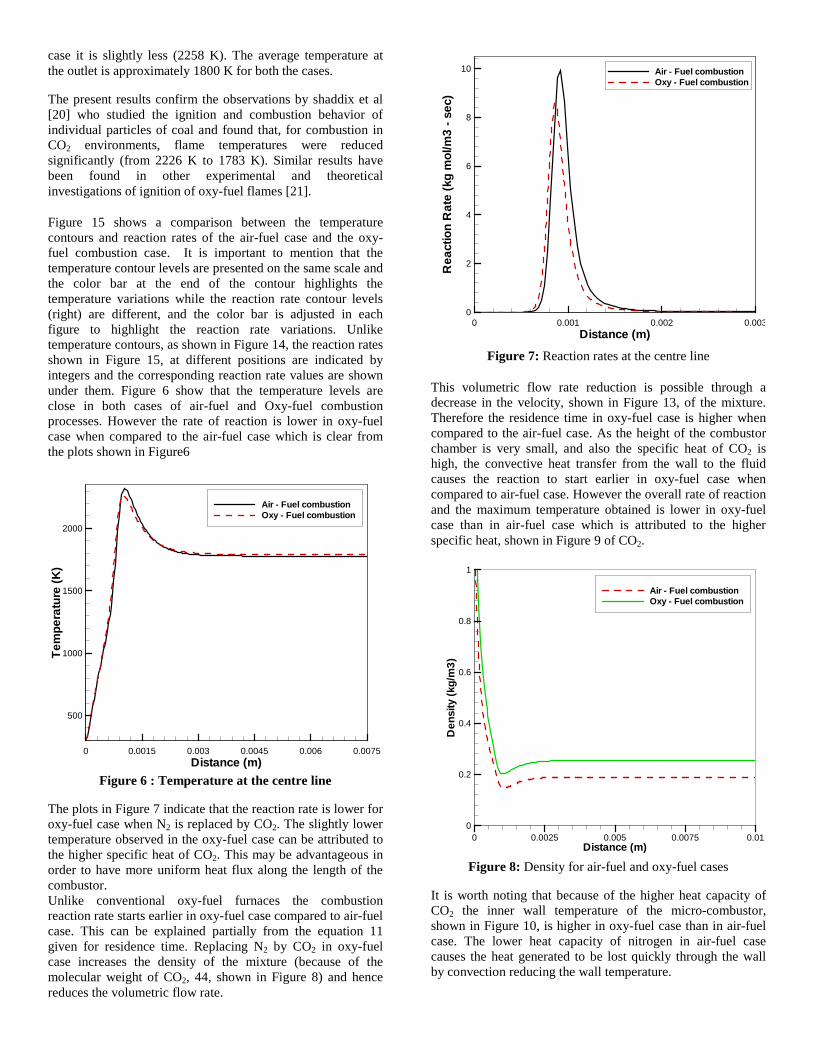
The plots in Figure 7 indicate that the reaction rate is lower for oxy-fuel case when N2 is replaced by CO2. The slightly lower temperature observed in the oxy-fuel case can be attributed to the higher specific heat of CO2. This may be advantageous in order to have more uniform heat flux along the length of the combustor. Unlike conventional oxy-fuel furnaces the combustion reaction rate starts earlier in oxy-fuel case compared to air-fuel case. This can be explained partially from the equation 11 given for residence time. Replacing N2 by CO2 in oxy-fuel case increases the density of the mixture (because of the molecular weight of CO2, 44, shown in Figure 8) and hence reduces the volumetric flow rate.
Figure 7: Reaction rates at the centre line
This volumetric flow rate reduction is possible through a decrease in the velocity, shown in Figure 13, of the mixture. Therefore the residence time in oxy-fuel case is higher when compared to the air-fuel case. As the height of the combustor chamber is very small, and also the specific heat of CO2 is high, the convective heat transfer from the wall to the fluid causes the reaction to start earlier in oxy-fuel case when compared to air-fuel case. However the overall rate of reaction and the maximum temperature obtained is lower in oxy-fuel case than in air-fuel case which is attributed to the higher specific heat, shown in Figure 9 of CO2.
Figure 8: Density for air-fuel and oxy-fuel cases
It is worth noting that because of the higher heat capacity of CO2 the inner wall temperature of the micro-combustor, shown in Figure 10, is higher in oxy-fuel case than in air-fuel case. The lower heat capacity of nitrogen in air-fuel case causes the heat generated to be lost quickly through the wall by convection reducing the wall temperature.
Distance (m)
Tem
pera
ture
(K)
0 0.0015 0.003 0.0045 0.006 0.0075
500
1000
1500
2000
Air - Fuel combustionOxy - Fuel combustion
Distance (m)
Rea
ctio
nR
ate
(kg
mol
/m3
-sec
)
0 0.001 0.002 0.0030
2
4
6
8
10 Air - Fuel combustionOxy - Fuel combustion
Distance (m)
Den
sity
(kg/
m3)
0 0.0025 0.005 0.0075 0.010
0.2
0.4
0.6
0.8
1
Air - Fuel combustionOxy - Fuel combustion

Figure 9: Specific heat, for air-fuel and oxy-fuel cases
Figure 10 : Inner wall Temperatures
The presence of CO2, having higher specific thermal capacity, moves the higher temperature region downstream. The plots in Figure 11 show that all the methane is consumed in the region near to the inlet i.e., burnt with oxygen and converted to CO2 and H2O. The high mass fractions of CO2 in oxy-fuel case reduce the maximum temperature and lower the reaction rate. The mass fraction contours, shown in Figure 16, shows clear distribution of each species. Combustion at the micro-scale can offer advantages. Besides larger radial heat transfers, faster ignition can happen, and low temperatures could be envisioned.
CONCLUSIONS:
The characteristics of oxy-fuel (CH4+O2+CO2) combustion were investigated and compared to those of conventional air-fuel (CH4+O2+N2) combustion in a microchannel with the channel height of 600μm and a length of 100mm. Results indicate that the temperature levels are reduced in the case of oxy-fuel combustion. It was also observed that the rate of
reaction in O2/CO2 environment is lower than that in O2/N2, which was attributed to the higher heat capacity of CO2 in comparison to that of N2.
Figure 11 : Mass fractions of reactants snd products along the centre line for air-fuel case
Figure 12: Mass fractions of reactants snd products along the centre line for oxy-fuel case
Acknowledgements The authors wish to acknowlegde the support received from King Abdulaziz City for Science and Technology (KASCT) through the Science and Technology Unit at King Fahd University of Petroleum and Minerals (KFUPM) for funding this work through Project No. 09-ENE755- 04 as part of National Science, Technology and Innovation plan.
Distance (m)
Spe
cific
heat
(J/k
g-K
)
0 0.0025 0.005 0.0075 0.011100
1200
1300
1400
1500
1600
Air - Fuel combustionOxy - Fuel combustion
Distance (m)
Tem
pera
ture
(K)
0 0.0025 0.005 0.0075 0.01
1300
1400
1500
1600
1700
1800
Air - Fuel combustionOxy - Fuel combustion
Axial Distance (m)0 0.001 0.002 0.003 0.004 0.005
0
0.05
0.1
0.15
0.2 CH4O2CO2H2O
Air - Fuel combustionMass Fraction
Axial Distance (m)0 0.001 0.002 0.003 0.004 0.005
0
0.1
0.2
0.3
0.4
0.5
0.6
0.7
0.8
0.9
CH4O2CO2H2O
Oxy - Fuel combustion
Mass Fraction
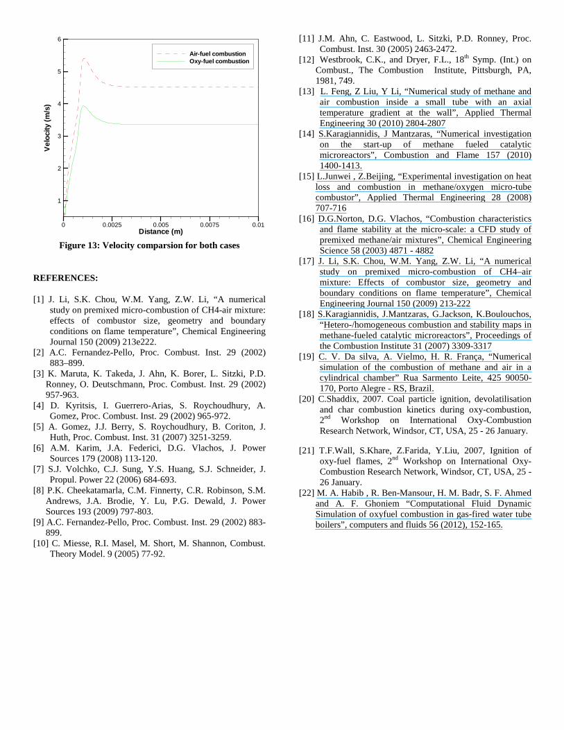
Figure 13: Velocity comparsion for both cases
REFERENCES:
[1] J. Li, S.K. Chou, W.M. Yang, Z.W. Li, “A numerical study on premixed micro-combustion of CH4-air mixture: effects of combustor size, geometry and boundary conditions on flame temperature”, Chemical Engineering Journal 150 (2009) 213e222.
[2] A.C. Fernandez-Pello, Proc. Combust. Inst. 29 (2002) 883–899.
[3] K. Maruta, K. Takeda, J. Ahn, K. Borer, L. Sitzki, P.D. Ronney, O. Deutschmann, Proc. Combust. Inst. 29 (2002) 957-963.
[4] D. Kyritsis, I. Guerrero-Arias, S. Roychoudhury, A. Gomez, Proc. Combust. Inst. 29 (2002) 965-972.
[5] A. Gomez, J.J. Berry, S. Roychoudhury, B. Coriton, J. Huth, Proc. Combust. Inst. 31 (2007) 3251-3259.
[6] A.M. Karim, J.A. Federici, D.G. Vlachos, J. Power Sources 179 (2008) 113-120.
[7] S.J. Volchko, C.J. Sung, Y.S. Huang, S.J. Schneider, J. Propul. Power 22 (2006) 684-693.
[8] P.K. Cheekatamarla, C.M. Finnerty, C.R. Robinson, S.M. Andrews, J.A. Brodie, Y. Lu, P.G. Dewald, J. Power Sources 193 (2009) 797-803.
[9] A.C. Fernandez-Pello, Proc. Combust. Inst. 29 (2002) 883-899.
[10] C. Miesse, R.I. Masel, M. Short, M. Shannon, Combust. Theory Model. 9 (2005) 77-92.
[11] J.M. Ahn, C. Eastwood, L. Sitzki, P.D. Ronney, Proc. Combust. Inst. 30 (2005) 2463-2472.
[12] Westbrook, C.K., and Dryer, F.L., 18th Symp. (Int.) on Combust., The Combustion Institute, Pittsburgh, PA, 1981, 749.
[13] L. Feng, Z Liu, Y Li, “Numerical study of methane and air combustion inside a small tube with an axial temperature gradient at the wall”, Applied Thermal Engineering 30 (2010) 2804-2807
[14] S.Karagiannidis, J Mantzaras, “Numerical investigation on the start-up of methane fueled catalytic microreactors”, Combustion and Flame 157 (2010) 1400-1413.
[15] L.Junwei , Z.Beijing, “Experimental investigation on heat loss and combustion in methane/oxygen micro-tube combustor”, Applied Thermal Engineering 28 (2008) 707-716
[16] D.G.Norton, D.G. Vlachos, “Combustion characteristics and flame stability at the micro-scale: a CFD study of premixed methane/air mixtures”, Chemical Engineering Science 58 (2003) 4871 - 4882
[17] J. Li, S.K. Chou, W.M. Yang, Z.W. Li, “A numerical study on premixed micro-combustion of CH4–air mixture: Effects of combustor size, geometry and boundary conditions on flame temperature”, Chemical Engineering Journal 150 (2009) 213-222
[18] S.Karagiannidis, J.Mantzaras, G.Jackson, K.Boulouchos, “Hetero-/homogeneous combustion and stability maps in methane-fueled catalytic microreactors”, Proceedings of the Combustion Institute 31 (2007) 3309-3317
[19] C. V. Da silva, A. Vielmo, H. R. França, “Numerical simulation of the combustion of methane and air in a cylindrical chamber” Rua Sarmento Leite, 425 90050-170, Porto Alegre - RS, Brazil.
[20] C.Shaddix, 2007. Coal particle ignition, devolatilisation and char combustion kinetics during oxy-combustion, 2nd Workshop on International Oxy-Combustion Research Network, Windsor, CT, USA, 25 - 26 January.
[21] T.F.Wall, S.Khare, Z.Farida, Y.Liu, 2007, Ignition of oxy-fuel flames, 2nd Workshop on International Oxy-Combustion Research Network, Windsor, CT, USA, 25 - 26 January.
[22] M. A. Habib , R. Ben-Mansour, H. M. Badr, S. F. Ahmed and A. F. Ghoniem “Computational Fluid Dynamic Simulation of oxyfuel combustion in gas-fired water tube boilers”, computers and fluids 56 (2012), 152-165.
Distance (m)
Vel
ocity
(m/s
)
0 0.0025 0.005 0.0075 0.01
1
2
3
4
5
6
Air-fuel combustionOxy-fuel combustion
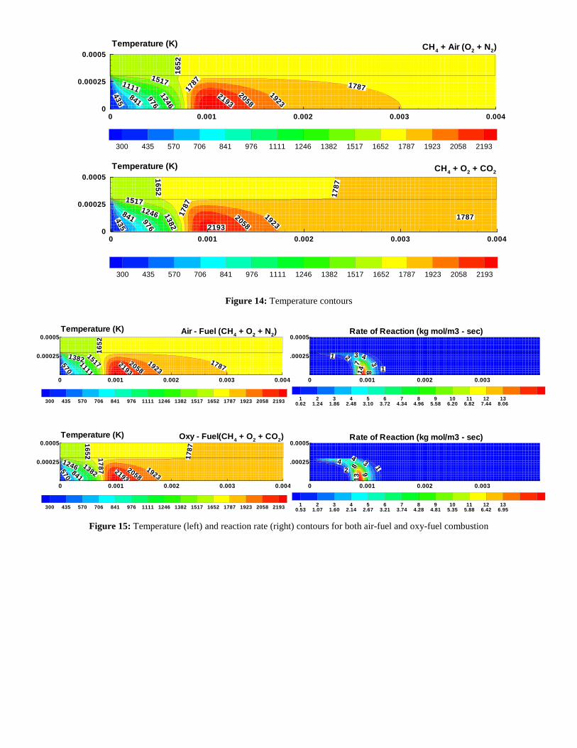
Figure 14: Temperature contours
Figure 15: Temperature (left) and reaction rate (right) contours for both air-fuel and oxy-fuel combustion
435
11112193
841
1246
976
15171923
17871787
1652
2058
0 0.001 0.002 0.003 0.0040
0.00025
0.0005
300 435 570 706 841 976 1111 1246 1382 1517 1652 1787 1923 2058 2193
Temperature (K) CH4 + Air (O2 + N2)
435
2058841 976
17871246 1382
1517
1652
1787
1787
192321930 0.001 0.002 0.003 0.004
0
0.00025
0.0005
300 435 570 706 841 976 1111 1246 1382 1517 1652 1787 1923 2058 2193
Temperature (K) CH4 + O2 + CO2
570
1111
1382 1517
1652
17871923
20582193
0 0.001 0.002 0.003 0.004
0.00025
0.0005
300 435 570 706 841 976 1111 1246 1382 1517 1652 1787 1923 2058 2193
Temperature (K) Air - Fuel (CH4 + O2 + N2)
570 841
1246
1787
1382
1652 1787 19232058
21930 0.001 0.002 0.003 0.004
0.00025
0.0005
300 435 570 706 841 976 1111 1246 1382 1517 1652 1787 1923 2058 2193
Temperature (K) Oxy - Fuel(CH4 + O2 + CO2)
1 2
3
3 4
18
714
0 0.001 0.002 0.003
.00025
0.0005
10.62
21.24
31.86
42.48
53.10
63.72
74.34
84.96
95.58
106.20
116.82
127.44
138.06
Rate of Reaction (kg mol/m3 - sec)
132
44
9813
0 0.001 0.002 0.003
.00025
0.0005
10.53
21.07
31.60
42.14
52.67
63.21
73.74
84.28
94.81
105.35
115.88
126.42
136.95
Rate of Reaction (kg mol/m3 - sec)
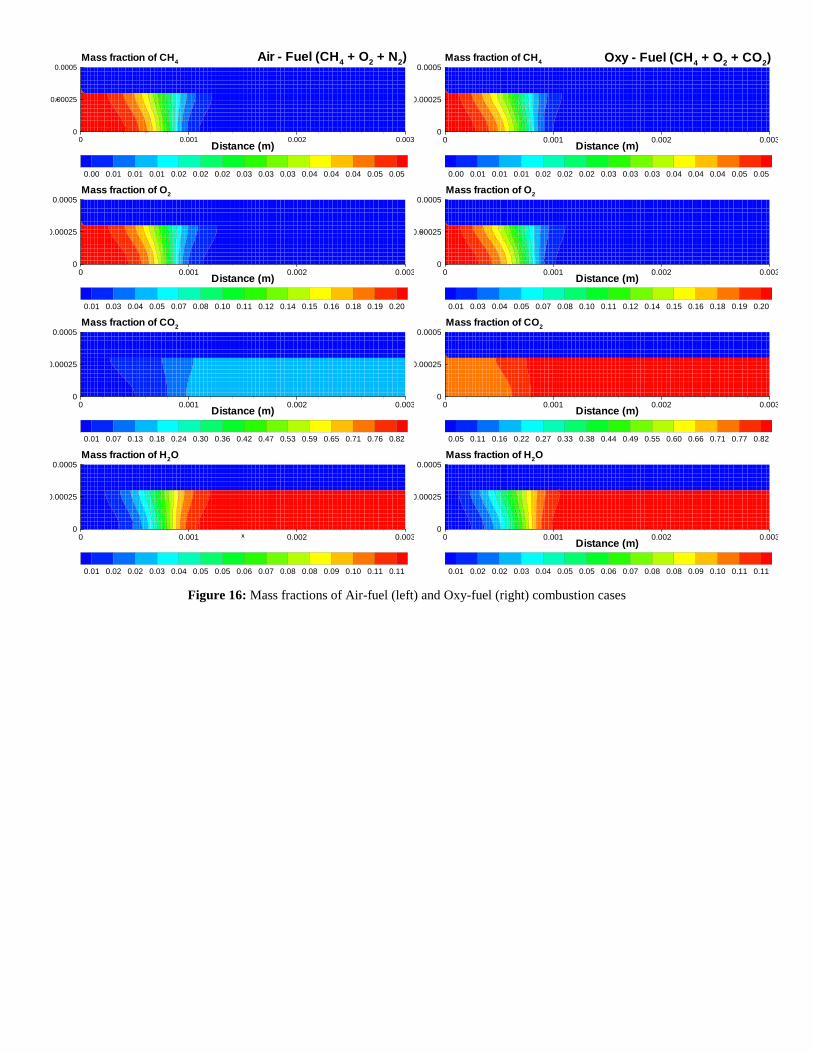
Figure 16: Mass fractions of Air-fuel (left) and Oxy-fuel (right) combustion cases
X0 0.001 0.002 0.0030
0.00025
0.0005
0.01 0.02 0.02 0.03 0.04 0.05 0.05 0.06 0.07 0.08 0.08 0.09 0.10 0.11 0.11
Mass fraction of H2O
Distance (m)
Y
0 0.001 0.002 0.0030
0.00025
0.0005
0.01 0.03 0.04 0.05 0.07 0.08 0.10 0.11 0.12 0.14 0.15 0.16 0.18 0.19 0.20
Mass fraction of O2
Distance (m)0 0.001 0.002 0.0030
0.00025
0.0005
0.01 0.02 0.02 0.03 0.04 0.05 0.05 0.06 0.07 0.08 0.08 0.09 0.10 0.11 0.11
Mass fraction of H2O
Distance (m)
Y
0 0.001 0.002 0.0030
0.00025
0.0005
0.00 0.01 0.01 0.01 0.02 0.02 0.02 0.03 0.03 0.03 0.04 0.04 0.04 0.05 0.05
Air - Fuel (CH4 + O2 + N2)Mass fraction of CH4
Distance (m)0 0.001 0.002 0.0030
0.00025
0.0005
0.01 0.03 0.04 0.05 0.07 0.08 0.10 0.11 0.12 0.14 0.15 0.16 0.18 0.19 0.20
Mass fraction of O2
Distance (m)0 0.001 0.002 0.0030
0.00025
0.0005
0.00 0.01 0.01 0.01 0.02 0.02 0.02 0.03 0.03 0.03 0.04 0.04 0.04 0.05 0.05
Oxy - Fuel (CH4 + O2 + CO2)Mass fraction of CH4
Distance (m)0 0.001 0.002 0.0030
0.00025
0.0005
0.05 0.11 0.16 0.22 0.27 0.33 0.38 0.44 0.49 0.55 0.60 0.66 0.71 0.77 0.82
Mass fraction of CO2
Distance (m)0 0.001 0.002 0.0030
0.00025
0.0005
0.01 0.07 0.13 0.18 0.24 0.30 0.36 0.42 0.47 0.53 0.59 0.65 0.71 0.76 0.82
Mass fraction of CO2