6310-dx user guide - digi international
TRANSCRIPT

6310-DXUser Guide
User GuideFirmware version 22.2

Revision history—90002313
Revision Date Description
F March 2021 Release of Digi 6310-DX firmware version 21.2:
n Location services added, including:l The ability to define a static latitude and longitude
as a location for the device.l GNSS support through the cellular modem
(requires the CM07 CORE modem).l Reporting location information as health metrics to
Digi Remote Manager.l Geo-fencing: Allow you to define one or more
circular or polygonal geo-fence areas and thenperform a set of actions when the device enters orleaves that area.
l Python support for location information throughthe digidevice.location python module.
n Cellular modem carrier scanning and locking:l New modem scan CLI command for listing
available carriers for the current modem and SIM.l Manual carrier selection option to allow you to lock
the SIM to a specific carrier.n Enhanced serial support:
l Certificate management control for TCP andautoconnect serial port setups.
l Autoconnect.n Local REST API for automated configuration of the
device.n Support for remote CLI commands through Digi
Remote Manager.n Support for automatically checking for device and
modem firmware updates.
G June 2021 Release of Digi 6310-DX firmware version 21.5:
n Wi-Fi enhancements:l Added support for WPA3 Wi-Fi encryption:
o WPA2/WPA3 Personalo WPA3 Enhanced Openo WPA3 Personal
l Added support for WPA and WPA/WPA2 mised
6310-DX User Guide 2

Revision Date Description
mode with TKIP.n Cellular enhancements:
l Added support for modem firmware update to theAdmin CLI.
l Added support for over-the-air (OTA) modemfirmware update to check, list, and update to newmodem firmware from the Digi firmware server.
l Added the ability to scan for cellular carriers on theModem status page and the ability select aparticular PLMN/network to use.
n Added commands for over-the-air (OTA) systemfirmware update to check, list, and update to newfirmware from the Digi firmware server.
n Added a show dns command to the Admin CLI todisplay active DNS servers and their associatedinterface.
n Added a show ntp command to the Admin CLI todisplay the status of the NTP service.
n Expanded Port forwarding option to support a range ofports, including one-to-one and many-to-one portmappings.
n Added options to control packet filtering for thenetwork analyzer.
n VPN enhancements:l IPsec enhancements:
o Added support for multiple remote endpointsand the ability to use round-robin or torandomly select an endpoint to establish atunnel to.
o Added configurable options to control IKEtransmit interval, tunnel retry interval, andtunnel retry timeout.
l LDAP enhancements:o Added a login attribute to provide the ability to
match the attribute set on an Active Directoryserver.
n SureLink enhancementsl Added the ability to configure how many times a
SureLink test must run, and must fail, before theinterface is restarted or the device is rebooted.
l Added the ability to configure how many times aSureLink test must pass before an interface is
6310-DX User Guide 3
Revision Date Description
considered to be working.l Added the ability to test another interface's status.
n SNMPv2 supported added.n Simple Certificate Enrollment Protocol (SCEP)
supported added.n Updated python to version 3.6.13.n Added the default digi.device local domain.
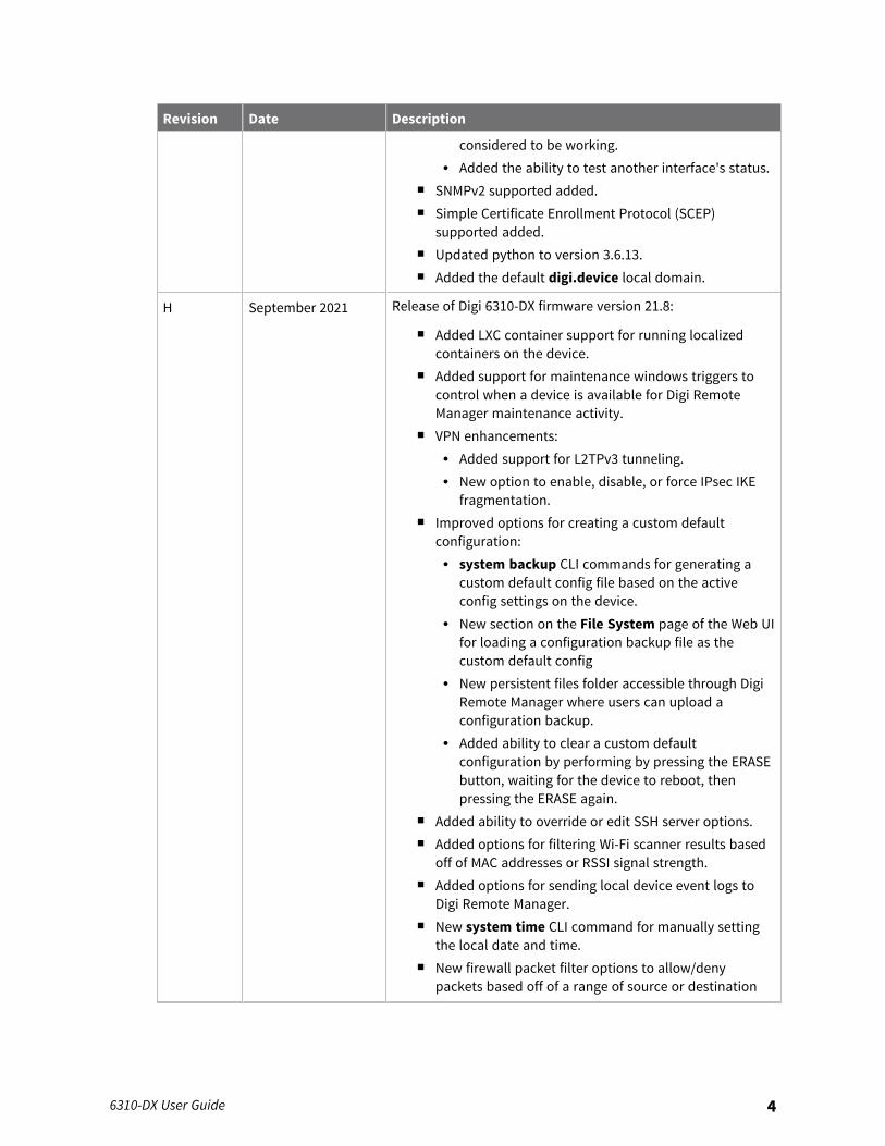
H September 2021 Release of Digi 6310-DX firmware version 21.8:
n Added LXC container support for running localizedcontainers on the device.
n Added support for maintenance windows triggers tocontrol when a device is available for Digi RemoteManager maintenance activity.
n VPN enhancements:l Added support for L2TPv3 tunneling.l New option to enable, disable, or force IPsec IKE
fragmentation.n Improved options for creating a custom default
configuration:l system backup CLI commands for generating a
custom default config file based on the activeconfig settings on the device.
l New section on the File System page of the Web UIfor loading a configuration backup file as thecustom default config
l New persistent files folder accessible through DigiRemote Manager where users can upload aconfiguration backup.
l Added ability to clear a custom defaultconfiguration by performing by pressing the ERASEbutton, waiting for the device to reboot, thenpressing the ERASE again.
n Added ability to override or edit SSH server options.n Added options for filtering Wi-Fi scanner results based
off of MAC addresses or RSSI signal strength.n Added options for sending local device event logs to
Digi Remote Manager.n New system time CLI command for manually setting
the local date and time.n New firewall packet filter options to allow/deny
packets based off of a range of source or destination
6310-DX User Guide 4
Revision Date Description
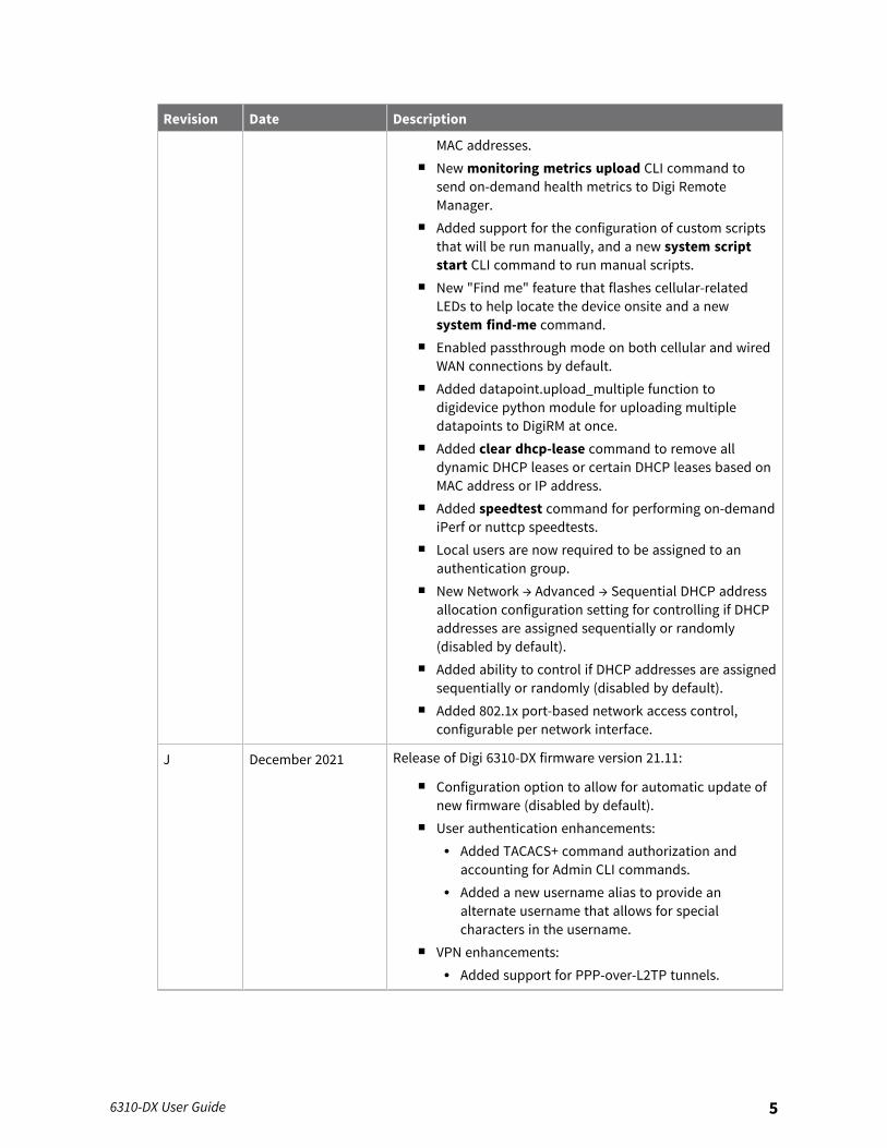
MAC addresses.n New monitoring metrics upload CLI command to
send on-demand health metrics to Digi RemoteManager.
n Added support for the configuration of custom scriptsthat will be run manually, and a new system scriptstart CLI command to run manual scripts.
n New "Find me" feature that flashes cellular-relatedLEDs to help locate the device onsite and a newsystem find-me command.
n Enabled passthrough mode on both cellular and wiredWAN connections by default.
n Added datapoint.upload_multiple function todigidevice python module for uploading multipledatapoints to DigiRM at once.
n Added clear dhcp-lease command to remove alldynamic DHCP leases or certain DHCP leases based onMAC address or IP address.
n Added speedtest command for performing on-demandiPerf or nuttcp speedtests.
n Local users are now required to be assigned to anauthentication group.
n New Network → Advanced → Sequential DHCP addressallocation configuration setting for controlling if DHCPaddresses are assigned sequentially or randomly(disabled by default).
n Added ability to control if DHCP addresses are assignedsequentially or randomly (disabled by default).
n Added 802.1x port-based network access control,configurable per network interface.
J December 2021 Release of Digi 6310-DX firmware version 21.11:
n Configuration option to allow for automatic update ofnew firmware (disabled by default).
n User authentication enhancements:l Added TACACS+ command authorization and
accounting for Admin CLI commands.l Added a new username alias to provide an
alternate username that allows for specialcharacters in the username.
n VPN enhancements:l Added support for PPP-over-L2TP tunnels.
6310-DX User Guide 5
Revision Date Description
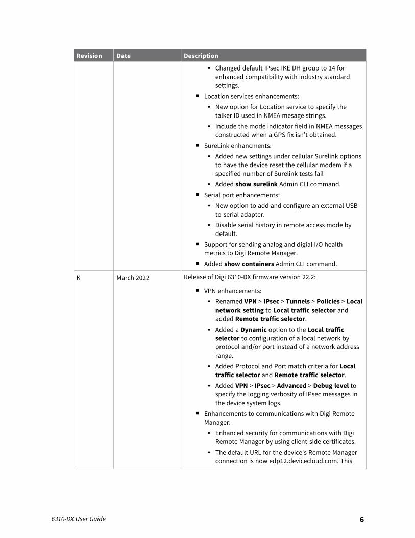
l Changed default IPsec IKE DH group to 14 forenhanced compatibility with industry standardsettings.
n Location services enhancements:l New option for Location service to specify the
talker ID used in NMEA mesage strings.l Include the mode indicator field in NMEA messages
constructed when a GPS fix isn’t obtained.n SureLink enhancments:
l Added new settings under cellular Surelink optionsto have the device reset the cellular modem if aspecified number of Surelink tests fail
l Added show surelink Admin CLI command.n Serial port enhancements:
l New option to add and configure an external USB-to-serial adapter.
l Disable serial history in remote access mode bydefault.
n Support for sending analog and digial I/O healthmetrics to Digi Remote Manager.
n Added show containers Admin CLI command.
K March 2022 Release of Digi 6310-DX firmware version 22.2:
n VPN enhancements:l Renamed VPN > IPsec > Tunnels > Policies > Local
network setting to Local traffic selector andadded Remote traffic selector.
l Added a Dynamic option to the Local trafficselector to configuration of a local network byprotocol and/or port instead of a network addressrange.
l Added Protocol and Port match criteria for Localtraffic selector and Remote traffic selector.
l Added VPN > IPsec > Advanced > Debug level tospecify the logging verbosity of IPsec messages inthe device system logs.
n Enhancements to communications with Digi RemoteManager:l Enhanced security for communications with Digi
Remote Manager by using client-side certificates.l The default URL for the device's Remote Manager
connection is now edp12.devicecloud.com. This
6310-DX User Guide 6
Revision Date Description
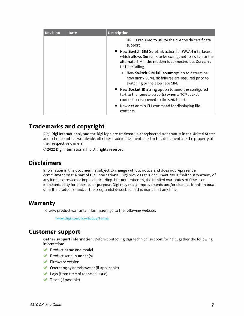
URL is required to utilize the client-side certificatesupport.
n New Switch SIM SureLink action for WWAN interfaces,which allows SureLink to be configured to switch to thealternate SIM if the modem is connected but SureLinktest are failing.l New Switch SIM fail count option to determine
how many SureLink failures are required prior toswitching to the alternate SIM.
n New Socket ID string option to send the configuredtext to the remote server(s) when a TCP socketconnection is opened to the serial port.
n New cat Admin CLI command for displaying filecontents.
Trademarks and copyrightDigi, Digi International, and the Digi logo are trademarks or registered trademarks in the United Statesand other countries worldwide. All other trademarks mentioned in this document are the property oftheir respective owners.© 2022 Digi International Inc. All rights reserved.
DisclaimersInformation in this document is subject to change without notice and does not represent acommitment on the part of Digi International. Digi provides this document “as is,” without warranty ofany kind, expressed or implied, including, but not limited to, the implied warranties of fitness ormerchantability for a particular purpose. Digi may make improvements and/or changes in this manualor in the product(s) and/or the program(s) described in this manual at any time.
WarrantyTo view product warranty information, go to the following website:
www.digi.com/howtobuy/terms
Customer supportGather support information: Before contacting Digi technical support for help, gather the followinginformation: Product name and model Product serial number (s) Firmware version Operating system/browser (if applicable) Logs (from time of reported issue) Trace (if possible)
6310-DX User Guide 7

Description of issue Steps to reproduceContact Digi technical support: Digi offers multiple technical support plans and service packages.Contact us at +1 952.912.3444 or visit us at www.digi.com/support.
FeedbackTo provide feedback on this document, email your comments to
Include the document title and part number (6310-DX User Guide, 90002313 H) in the subject line ofyour email.
6310-DX User Guide 8
Contents
Revision history—90002313 2
What's new in Digi 6310-DX version 22.2
Digi 6310-DX Quick startStep 1: What's in the box 21Step 2: Connect 23Step 3: Power up 24Step 4: Configure 24
Digi 6310-DX hardware referenceHardware features 26Device status LEDs 27
Signal quality indicators 28Signal quality bars explained 28
LTE status indicators 29QR code definition 30
Hardware setupSite survey 32
Site survey troubleshooting 32Physical installation 32
Connecting to the site network with local power 32Install SIM cards in the Plug-in LTE modem 33
Apply Dielectric Grease over SIM Contacts 33Tips for improving cellular signal strength 34
Mount the 6310-DX device 34Network integration 35Enable router mode 35
Configuration and managementReview 6310-DX default settings 39
Local WebUI 39Digi Remote Manager 39Default interface configuration 39
6310-DX User Guide 9

6310-DX User Guide 10
Change the default password for the admin user 40Enable router mode 42Configuration methods 44Using Digi Remote Manager 45Access Digi Remote Manager 45Configure the device to use aView for central management 45Using the web interface 49
Log out of the web interface 51Use the local REST API to configure the 6310-DX device 51
Use the GET method to return device configuration information 51Use the POST method to modify device configuration parameters and list arrays 53Use the DELETE method to remove items from a list array 54
Using the command line 56Access the command line interface 56Log in to the command line interface 56Exit the command line interface 57
InterfacesWide Area Networks (WANs) 59
Wide Area Networks (WANs) and Wireless Wide Area Networks (WWANs) 60Configure WAN/WWAN priority and default route metrics 60WAN/WWAN failover 63Configure SureLink active recovery to detect WAN/WWAN failures 64Configure the device to reboot when a failure is detected 75Disable SureLink 83Example: Use a ping test for WAN failover from Ethernet to cellular 87Using Ethernet devices in a WAN 91Using cellular modems in a Wireless WAN (WWAN) 91Configure a Wide Area Network (WAN) 115Configure a Wireless Wide Area Network (WWAN) 124Show WAN and WWAN status and statistics 134Delete a WAN or WWAN 136Default outbound WAN/WWAN ports 137
Local Area Networks (LANs) 138About Local Area Networks (LANs) 139Configure a LAN 139Show LAN status and statistics 147Delete a LAN 149DHCP servers 151Create a Virtual LAN (VLAN) route 167Default services listening on LAN ports 170
Bridging 171Configure a bridge 172
Show Surelink status and statistics 175Show Surelink status for all interfaces 175Show Surelink status for a specific interface 176Show Surelink status for all IPsec tunnels 176Show Surelink status for a specific IPsec tunnel 177Show Surelink status for all OpenVPN clients 177Show Surelink status for a specific OpenVPN client 178
6310-DX User Guide 11
RoutingIP routing 180
Configure a static route 181Delete a static route 184Policy-based routing 186Configure a routing policy 187Example: Dual WAN policy-based routing 195Example: Route traffic to a specific WAN interface based on the client MAC address 198Routing services 203Configure routing services 204
Show the routing table 207Dynamic DNS 208
Configure dynamic DNS 208Virtual Router Redundancy Protocol (VRRP) 214
VRRP+ 214Configure VRRP 215Configure VRRP+ 218Example: VRRP/VRRP+ configuration 226Configure device one (master device) 227Configure device two (backup device) 231Show VRRP status and statistics 237
Virtual Private Networks (VPN)IPsec 240
IPsec data protection 240IPsec mode 240IPsec modes 240Internet Key Exchange (IKE) settings 240Authentication 241Configure an IPsec tunnel 241Configure IPsec failover 268Configure SureLink active recovery for IPsec 271Show IPsec status and statistics 278Debug an IPsec configuration 279Configure a Simple Certificate Enrollment Protocol client 281Example: SCEP client configuration with Fortinet SCEP server 286Disable hardware cryptographic acceleration 290
OpenVPN 293Configure an OpenVPN server 294Configure an OpenVPN Authentication Group and User 303Configure an OpenVPN client by using an .ovpn file 308Configure an OpenVPN client without using an .ovpn file 311Configure SureLink active recovery for OpenVPN 315Show OpenVPN server status and statistics 323Show OpenVPN client status and statistics 324
Generic Routing Encapsulation (GRE) 326Configuring a GRE tunnel 326Show GRE tunnels 331Example: GRE tunnel over an IPSec tunnel 332
L2TP 347Configure a PPP-over-L2TP tunnel 347Configure SureLink active recovery for PPP-over-L2TP 357

6310-DX User Guide 12
L2TP with IPsec 365Show L2TP tunnel status 365
L2TPv3 Ethernet 367Configure an L2TPv3 tunnel 367Show L2TPV3 tunnel status 372
NEMO 373Configure a NEMO tunnel 373Show NEMO status 379
ServicesAllow remote access for web administration and SSH 382Configure the web administration service 385Configure SSH access 395Use SSH with key authentication 402
Generating SSH key pairs 402Configure telnet access 405Configure DNS 410
Show DNS server 416Simple Network Management Protocol (SNMP) 417
SNMP Security 417Configure Simple Network Management Protocol (SNMP) 417Download MIBs 422
Location information 423Configure the location service 424Enable or disable modem GNSS support 426Configure the device to use a user-defined static location 428Configure the device to accept location messages from external sources 430Forward location information to a remote host 435Configure geofencing 442Show location information 454
Modbus gateway 455Configure the Modbus gateway 456Show Modbus gateway status and statistics 469
System time 472Configure the system time 472Manually set the system date and time 476
Network Time Protocol 476Configure the device as an NTP server 477Show status and statistics of the NTP server 482
Configure a multicast route 483Ethernet network bonding 486Enable service discovery (mDNS) 488Use the iPerf service 492
Example performance test using iPerf3 496Configure the ping responder service 497
Example performance test using iPerf3 501
ApplicationsConfigure scripts to run automatically 503
Task one: Upload the application 503Task two: Configure the application to run automatically 505
Configure scripts to run manually 509
6310-DX User Guide 13
Task one: Upload the application 510Task two: Configure the application to run automatically 511
Start a manual script 514Stop a script that is currently running 515Show script information 516Run a Python application at the shell prompt 517Start an interactive Python session 519Digidevice module 521
Use digidevice.cli to execute CLI commands 522Use digidevice.datapoint to upload custom datapoints to Digi Remote Manager 523Use digidevice.config for device configuration 526Use Python to respond to Digi Remote Manager SCI requests 528Use digidevice runtime to access the runtime database 537Use Python to upload the device name to Digi Remote Manager 539Use Python to access the device location data 541Use Python to set the maintenance window 545Use Python to send and receive SMS messages 547
Use the Paho MQTT python library 549
User authentication6310-DX user authentication 555User authentication methods 555
Add a new authentication method 557Delete an authentication method 559Rearrange the position of authentication methods 561
Authentication groups 563Change the access rights for a predefined group 564Add an authentication group 566Delete an authentication group 570
Local users 572Change a local user's password 573Configure a local user 575Delete a local user 583
Terminal Access Controller Access-Control System Plus (TACACS+) 586TACACS+ user configuration 587TACACS+ server failover and fallback to local authentication 588Configure your 6310-DX device to use a TACACS+ server 588
Remote Authentication Dial-In User Service (RADIUS) 593RADIUS user configuration 594RADIUS server failover and fallback to local configuration 594Configure your 6310-DX device to use a RADIUS server 595
LDAP 598LDAP user configuration 600LDAP server failover and fallback to local configuration 601Configure your 6310-DX device to use an LDAP server 601
Configure serial authentication 606Disable shell access 608Set the idle timeout for 6310-DX users 610Example user configuration 613
Example 1: Administrator user with local authentication 613Example 2: RADIUS, TACACS+, and local authentication for one user 615
6310-DX User Guide 14
FirewallFirewall configuration 623
Create a custom firewall zone 623Configure the firewall zone for a network interface 625Delete a custom firewall zone 627
Port forwarding rules 628Configure port forwarding 628Delete a port forwarding rule 633
Packet filtering 636Configure packet filtering 636Enable or disable a packet filtering rule 640Delete a packet filtering rule 642
Configure custom firewall rules 644Configure Quality of Service options 645
System administrationReview device status 658Configure system information 659Update system firmware 661
Manage firmware updates using Digi Remote Manager 661Certificate management for firmware images 662Downgrading 662Dual boot behavior 666
Update cellular module firmware 667Update modem firmware over the air (OTA) 668Update modem firmware by using a local firmware file 669
Reboot your 6310-DX device 670Reboot your device immediately 670Schedule reboots of your device 671
Erase device configuration and reset to factory defaults 673Configure the 6310-DX device to use custom factory default settings 677
Locate the device by using the Find Me feature 679Configuration files 681
Save configuration changes 681Save configuration to a file 682Restore the device configuration 683
Schedule system maintenance tasks 686Disable device encryption 691
Re-enable cryptography after it has been disabled. 692Configure the speed of your Ethernet ports 693
MonitoringintelliFlow 697
Enable intelliFlow 697Use intelliFlow to display average CPU and RAM usage 700Use intelliFlow to display top data usage information 701Use intelliFlow to display data usage by host over time 703
Configure NetFlow Probe 704
6310-DX User Guide 15
Central managementDigi Remote Manager support 710Certificate-based enhanced security 710Configure Digi Remote Manager 710Collect device health data and set the sample interval 717Enable event log upload to Digi Remote Manager 720Log into Digi Remote Manager 722Use Digi Remote Manager to view and manage your device 723Add a device to Digi Remote Manager 724View Digi Remote Manager connection status 724Configure multiple devices using profiles 726Learn more 726
File systemThe 6310-DX local file system 728Display directory contents 728Create a directory 729Display file contents 730Copy a file or directory 730Move or rename a file or directory 731Delete a file or directory 732Upload and download files 733
Upload and download files by using the WebUI 733Upload and download files by using the Secure Copy command 734Upload and download files using SFTP 735
DiagnosticsPerform a speedtest 738Generate a support report 738View system and event logs 740
View System Logs 740View Event Logs 742
Configure syslog servers 744Configure options for the event and system logs 746Analyze network traffic 751
Configure packet capture for the network analyzer 752Example filters for capturing data traffic 761Capture packets from the command line 762Stop capturing packets 763Show captured traffic data 764Save captured data traffic to a file 765Download captured data to your PC 766Clear captured data 767
Use the ping command to troubleshoot network connections 769Ping to check internet connection 769Stop ping commands 769
Use the traceroute command to diagnose IP routing problems 769
6310-DX User Guide 16
Regulatory guide
Safety warningsEnglish 773Bulgarian--български 774Croatian--Hrvatski 775French--Français 776Greek--Ε λληνικά 777Hungarian--Magyar 778Italian--Italiano 779Latvian--Latvietis 780Lithuanian--Lietuvis 781Polish--Polskie 782Portuguese--Português 783Slovak--Slovák 784Slovenian--Esloveno 785Spanish--Español 786
End user license agreement
Command line interfaceAccess the command line interface 788Log in to the command line interface 788Exit the command line interface 789Execute a command from the web interface 789Display help for commands and parameters 790
The help command 790The question mark (?) command 790Display help for individual commands 791Use the Tab key or the space bar to display abbreviated help 792
Auto-complete commands and parameters 792Available commands 793Use the scp command 794Display status and statistics using the show command 795
show config 795show system 796show network 796
Device configuration using the command line interface 796Execute configuration commands at the root Admin CLI prompt 797
Display help for the config command from the root Admin CLI prompt 797Configuration mode 799
Enable configuration mode 799Enter configuration commands in configuration mode 799Save changes and exit configuration mode 800Exit configuration mode without saving changes 800Configuration actions 800Display command line help in configuration mode 801Move within the configuration schema 803Manage elements in lists 804The revert command 806Enter strings in configuration commands 808
6310-DX User Guide 17
Example: Create a new user by using the command line 808Command line reference 811
analyzer clear 812analyzer save 813analyzer start 813analyzer stop 813clear dhcp-lease ip-address 813clear dhcp-lease mac 813container create 814container delete 814cp 814help 814ls 816mkdir 817modem at 817modem at-interactive 817modem firmware check 817modem firmware list 817modem firmware ota check 818modem firmware ota list 818modem firmware ota update 818modem firmware update 818modem pin change 819modem pin disable 819modem pin enable 819modem pin status 820modem pin unlock 820modem puk status 820modem puk unlock 820modem reset 821modem scan 821modem sim-slot 821monitoring 821monitoring metrics upload 822more 822mv 822ping 822reboot 824rm 825scp 826show analyzer 826show arp 826show cloud 826show config 827show containers 827show dhcp-lease 827show dns 827show event 827show hotspot 828show ipsec 828show l2tp lac 828show l2tp lns 828show l2tpeth 829show location 829show log 829
6310-DX User Guide 18
show manufacture 829show modbus-gateway 829show modem 830show nemo 830show network 830show ntp 830show openvpn client 831show openvpn server 831show route 831show serial 831show scripts 832show surelink interface 832show surelink ipsec 832show surelink openvpn 832show system 833show usb 833show version 833show vrrp 833show web-filter 833speedtest 834ssh 834system backup 834system disable-cryptography 835system duplicate-firmware 835system factory-erase 835system find-me 835system firmware ota check 836system firmware ota list 836system firmware ota update 836system firmware update 836system power ignition off_delay 836system restore 837system script start 837system script stop 837system serial clear 837system serial save 838system serial show 838system serial start 838system serial stop 838system support-report 838system time set 839system time sync 839system time test 839telnet 839traceroute 840
Antenna notes and solutionsAntenna terminology 842Physical specifications 842Antennas tested by Digi 842
Extra-small IoT paddle antennas 843Large external MIMO antenna (outdoor rated) 843Flat MIMO antenna #1 844Flat MIMO antenna #2 844

6310-DX User Guide 19
Paddle extender 845
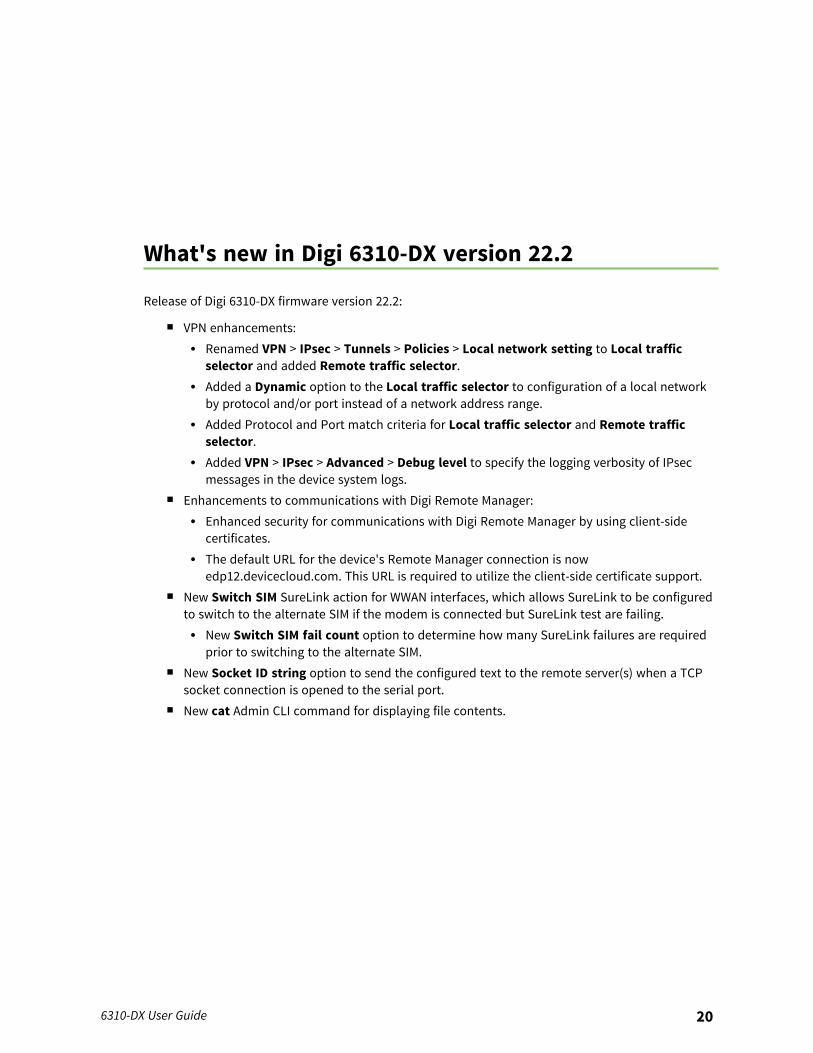
What's new in Digi 6310-DX version 22.2
Release of Digi 6310-DX firmware version 22.2:
n VPN enhancements:l Renamed VPN > IPsec > Tunnels > Policies > Local network setting to Local traffic
selector and added Remote traffic selector.l Added a Dynamic option to the Local traffic selector to configuration of a local network
by protocol and/or port instead of a network address range.l Added Protocol and Port match criteria for Local traffic selector and Remote traffic
selector.l Added VPN > IPsec > Advanced > Debug level to specify the logging verbosity of IPsec
messages in the device system logs.n Enhancements to communications with Digi Remote Manager:
l Enhanced security for communications with Digi Remote Manager by using client-sidecertificates.
l The default URL for the device's Remote Manager connection is nowedp12.devicecloud.com. This URL is required to utilize the client-side certificate support.
n New Switch SIM SureLink action for WWAN interfaces, which allows SureLink to be configuredto switch to the alternate SIM if the modem is connected but SureLink test are failing.l New Switch SIM fail count option to determine how many SureLink failures are required
prior to switching to the alternate SIM.n New Socket ID string option to send the configured text to the remote server(s) when a TCP
socket connection is opened to the serial port.n New cat Admin CLI command for displaying file contents.
6310-DX User Guide 20
Digi 6310-DX Quick start
Thank you for purchasing the Digi 6310-DX.
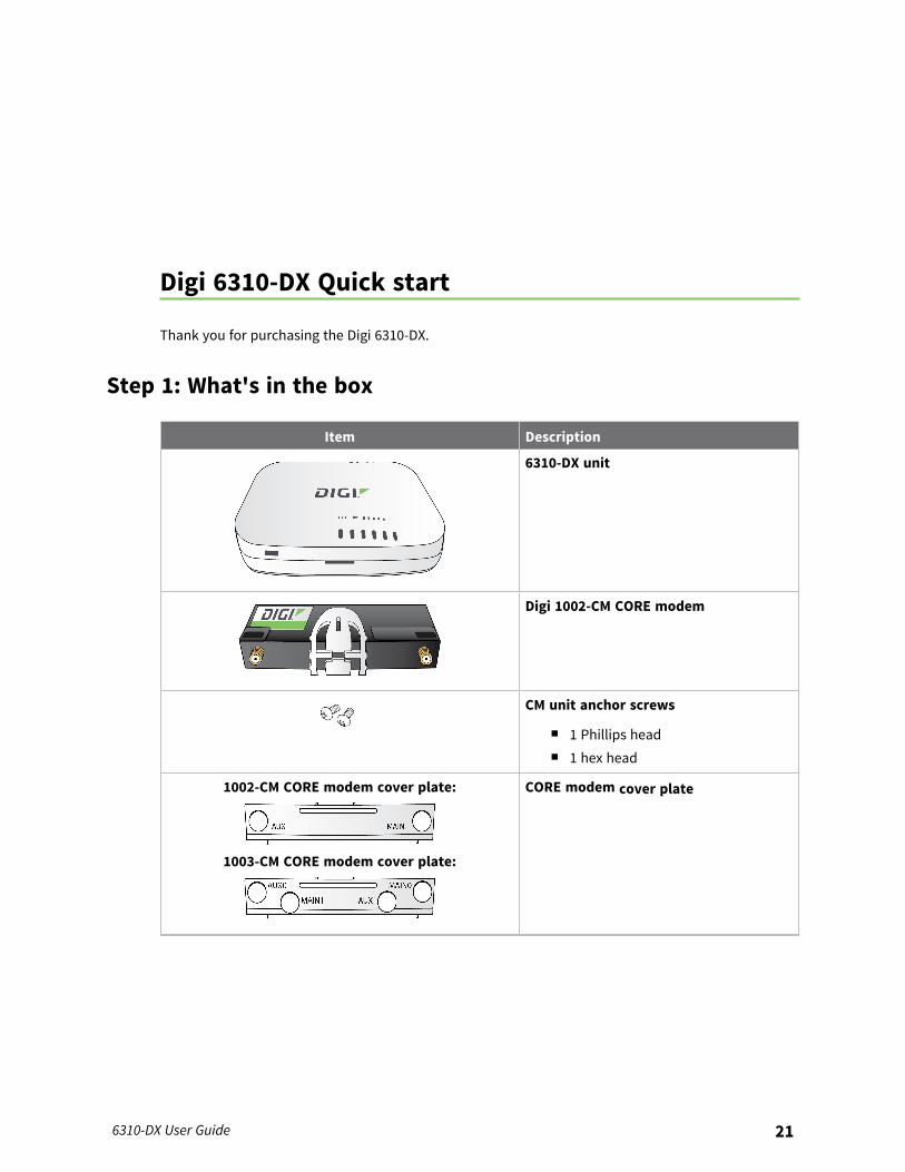
Step 1: What's in the box
Item Description
6310-DX unit
Digi 1002-CM CORE modem
CM unit anchor screws
n 1 Phillips headn 1 hex head
1002-CM CORE modem cover plate:
1003-CM CORE modem cover plate:
CORE modem cover plate
6310-DX User Guide 21
Digi 6310-DX Quick start Step 1: What's in the box
6310-DX User Guide 22
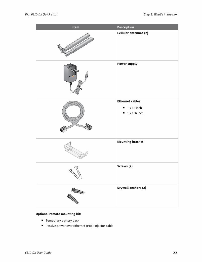
Item Description
Cellular antennas (2)
Power supply
Ethernet cables:
n 1 x 18 inchn 1 x 156 inch
Mounting bracket
Screws (2)
Drywall anchors (2)
Optional remote mounting kit:
n Temporary battery packn Passive power over Ethernet (PoE) injector cable

Digi 6310-DX Quick start Step 2: Connect
6310-DX User Guide 23
n Rail clipsn Zip ties
Step 2: Connect1. Insert your activated SIMs provided by your cellular carrier into the Digi 1002-CM
CORE modem.
2. Insert the CORE modem into the 6310-DX by aligning the white clip. Press the modem in andthen push the white clip in until it locks firmly in place.
3. Secure the CORE modem with one of the CM unit anchor screws.4. Cover the installed CORE modem with the cover plate. The cover plate will snap into place.
5. Attach antenna(s).6. If you intend to configure Ethernet WAN access at this time, use an Ethernet cable to connect
the 6310-DX's 2/WAN port to a hub with access to the Internet.7. Use an Ethernet cable to connect the 6310-DX 1/PoE port to your PC.
Digi 6310-DX Quick start Step 3: Power up
6310-DX User Guide 24
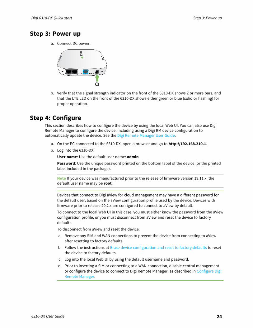
Step 3: Power upa. Connect DC power.
b. Verify that the signal strength indicator on the front of the 6310-DX shows 2 or more bars, andthat the LTE LED on the front of the 6310-DX shows either green or blue (solid or flashing) forproper operation.
Step 4: ConfigureThis section describes how to configure the device by using the local Web UI. You can also use DigiRemote Manager to configure the device, including using a Digi RM device configuration toautomatically update the device. See the Digi Remote Manager User Guide.
a. On the PC connected to the 6310-DX, open a browser and go to http://192.168.210.1.b. Log into the 6310-DX:
User name: Use the default user name: admin.Password: Use the unique password printed on the bottom label of the device (or the printedlabel included in the package).
Note If your device was manufactured prior to the release of firmware version 19.11.x, thedefault user name may be root.
Devices that connect to Digi aView for cloud management may have a different password forthe default user, based on the aView configuration profile used by the device. Devices withfirmware prior to release 20.2.x are configured to connect to aView by default.To connect to the local Web UI in this case, you must either know the password from the aViewconfiguration profile, or you must disconnect from aView and reset the device to factorydefaults.To disconnect from aView and reset the device:a. Remove any SIM and WAN connections to prevent the device from connecting to aView
after resetting to factory defaults.b. Follow the instructions at Erase device configuration and reset to factory defaults to reset
the device to factory defaults.c. Log into the local Web UI by using the default username and password.d. Prior to inserting a SIM or connecting to a WAN connection, disable central management
or configure the device to connect to Digi Remote Manager, as described in Configure DigiRemote Manager.
Digi 6310-DX Quick start Step 4: Configure
6310-DX User Guide 25
Ethernet port default configurationn Port 1 is configured as a LAN port and will issue a single passthrough IP Address using DHCP
based on the IP received from the cellular connection.
Note By default, the 6310-DX device is in cellular passthrough mode. This prevents clients thatattach to the device's LAN port from using the device's WAN internet connection. See Enablerouter mode for instructions regarding how to configure the 6310-DX device to provide internetconnectivity to more than one connected device at a time.
n Port 2 is configured as a WAN port and will accept an IP Address from an existing local networkrouter.

Digi 6310-DX hardware reference
Hardware features
1. LAN/PoE Port2. WAN Port3. SIM Button
The SIM button is used to manually toggle between the two SIM slots included in the CMmodule.
4. ERASE ButtonThe ERASE button is used to perform a device reset, and it has three modes:a. Configuration reset: Pressing the ERASE button one time will reset the device
configurations to the factory default. It will not remove any automatically generatedcertificates and keys.
b. Full device reset: After the device reboots from the first button press, press the ERASEbutton again before the device is connected to the internet to also remove generatedcertificates/keys.
c. Firmware reversion: Press and hold the ERASE button and then power on the device toboot to the version of firmware that was used prior to the current version. Continueholding the button until the cellular service LED starts flashing.
5. Power Socket
6310-DX User Guide 26

Digi 6310-DX hardware reference Device status LEDs
6310-DX User Guide 27
6. LTE connection indicator7. LTE signal strength
8. LAN/WAN indicator9. SIM 1/2 indicator
For a detailed list of 6310-DX hardware specifications, see Digi 6310DX specifications.
Device status LEDsOnce power has been established, your device will initialize and attempt to connect to the network.Device initialization may take 30-60 seconds. By default your 6310-DX will attempt to use DHCP toestablish an Internet connection either through its cellular modem or the ethernet port .
1. Cellular connectivity status is indicated by the color-coded LTE light.2. Indicator lights on the Wireless Strength Indicator show you the cellular network signal
strength.3. Ethernet connections are confirmed via the light corresponding to the 6310-DX port number.

Digi 6310-DX hardware reference Device status LEDs
6310-DX User Guide 28
Signal quality indicators
Signal bars Weighted dBm Signal strength % Quality
-113 to -99 0% to 23% Bad
-98 to -87 24% to 42% Marginal
-86 to -76 43% to 61% OK
-75 to -64 62% to 80% Good
-63 to -51 81% to 100% Excellent
The weighted dBm measurements are negative numbers, meaning values closer to zero denote alarger number. For example, a -85 is a better signal than -90.
Note See Signal quality bars explained for more information regarding how signal strength iscalculated and subsequently displayed via the LED indicators.
Signal quality bars explainedThe signal status bars for the Digi 6310-DX measure more than simply signal strength. The valuereported by the signal bars is calculated using an algorithm that takes into consideration theReference Signals Received Power (RSRP), the Signal-to-noise ratio (SNR), and the Received SignalStrength Indication (RSSI) to provide an accurate indicator of the quality of the signal that the deviceis receiving.For 3G networks (including HSPA+) and 2G networks, the signal strength bars are determined by theRSSI value.
4G LTE algorithmsFor 4G LTE, the 6310-DX device determines the RSRP, SNR, and RSSI values separately and uses thefollowing algorithms to display the signal quality:
Digi 6310-DX hardware reference LTE status indicators
6310-DX User Guide 29
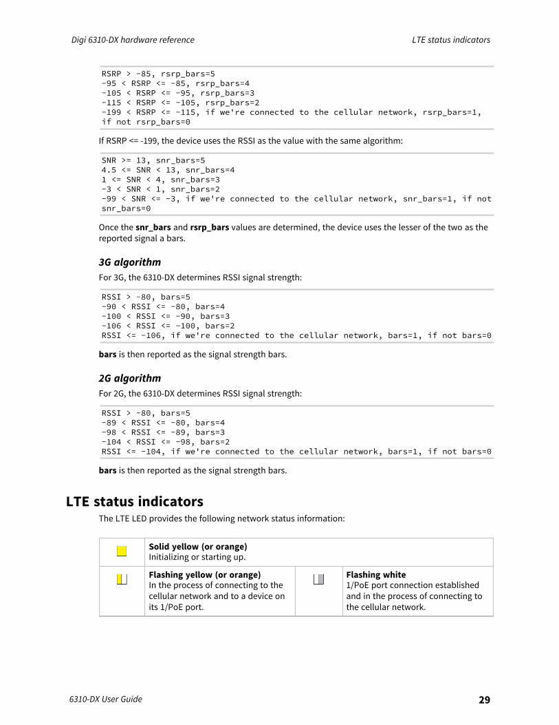
RSRP > -85, rsrp_bars=5-95 < RSRP <= -85, rsrp_bars=4-105 < RSRP <= -95, rsrp_bars=3-115 < RSRP <= -105, rsrp_bars=2-199 < RSRP <= -115, if we're connected to the cellular network, rsrp_bars=1,if not rsrp_bars=0
If RSRP <= -199, the device uses the RSSI as the value with the same algorithm:
SNR >= 13, snr_bars=54.5 <= SNR < 13, snr_bars=41 <= SNR < 4, snr_bars=3-3 < SNR < 1, snr_bars=2-99 < SNR <= -3, if we're connected to the cellular network, snr_bars=1, if notsnr_bars=0
Once the snr_bars and rsrp_bars values are determined, the device uses the lesser of the two as thereported signal a bars.
3G algorithmFor 3G, the 6310-DX determines RSSI signal strength:
RSSI > -80, bars=5-90 < RSSI <= -80, bars=4-100 < RSSI <= -90, bars=3-106 < RSSI <= -100, bars=2RSSI <= -106, if we're connected to the cellular network, bars=1, if not bars=0
bars is then reported as the signal strength bars.
2G algorithmFor 2G, the 6310-DX determines RSSI signal strength:
RSSI > -80, bars=5-89 < RSSI <= -80, bars=4-98 < RSSI <= -89, bars=3-104 < RSSI <= -98, bars=2RSSI <= -104, if we're connected to the cellular network, bars=1, if not bars=0
bars is then reported as the signal strength bars.
LTE status indicatorsThe LTE LED provides the following network status information:
Solid yellow (or orange)Initializing or starting up.
Flashing yellow (or orange)In the process of connecting to thecellular network and to a device onits 1/PoE port.
Flashing white1/PoE port connection establishedand in the process of connecting tothe cellular network.
Digi 6310-DX hardware reference QR code definition
6310-DX User Guide 30
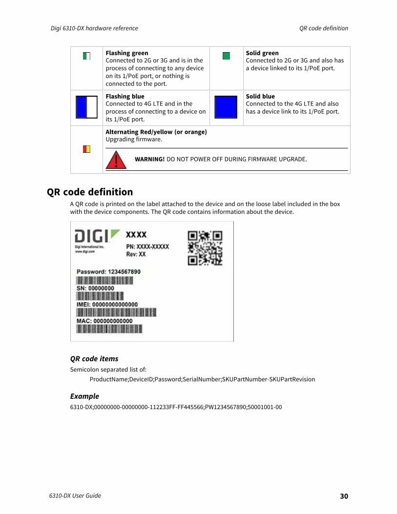
Flashing greenConnected to 2G or 3G and is in theprocess of connecting to any deviceon its 1/PoE port, or nothing isconnected to the port.
Solid greenConnected to 2G or 3G and also hasa device linked to its 1/PoE port.
Flashing blueConnected to 4G LTE and in theprocess of connecting to a device onits 1/PoE port.
Solid blueConnected to the 4G LTE and alsohas a device link to its 1/PoE port.
Alternating Red/yellow (or orange)Upgrading firmware.
WARNING! DO NOT POWER OFF DURING FIRMWARE UPGRADE.
QR code definitionA QR code is printed on the label attached to the device and on the loose label included in the boxwith the device components. The QR code contains information about the device.
QR code itemsSemicolon separated list of:
ProductName;DeviceID;Password;SerialNumber;SKUPartNumber-SKUPartRevision
Example6310-DX;00000000-00000000-112233FF-FF445566;PW1234567890;50001001-00
Hardware setup
This chapter contains the following topics:
Site survey 32Physical installation 32Install SIM cards in the Plug-in LTE modem 33Mount the 6310-DX device 34Network integration 35Enable router mode 35
6310-DX User Guide 31
Hardware setup Site survey
6310-DX User Guide 32
Site surveyA cellular site survey is not necessary if your anticipated installation location is known to have strongcellular signal strength. If you are unsure of available cellular signal strength or are choosing betweenseveral installation locations, follow the below instructions to perform a site survey to determine yourbest possible installation location. After the optimal location has been determined, set up the 6310-DXwith either the power supply unit or the PoE injector cable.
1. LTE requires at least two antennas.2. Move the 6310-DX to different locations within your site to determine the best compromise
between signal strength and installation constraints. Since cellular signal strength mayfluctuate, it is important to wait at each location for 1 minute while observing the signalstrength indicator on the front of the device. Minimum cellular signal strength for properoperation is 2 bars.
3. After the optimal location has been determined, remove the battery pack and connect eitherthe main power supply unit or the PoE injector cable (see Physical installation).
Site survey troubleshootingIf you are unable to verify a location with a strong cellular signal:
n Verify your SIM has been activated with your cellular operator.n If you do not get a cellular signal when the 6310-DX is located indoors, then take the device
outdoors to verify that your cellular network operator has coverage in your location.n If the outdoor cellular signal strength is less than 2 bars, it may be necessary to connect using
a different cellular network operator. This requires an activated SIM from the alternate cellularnetwork operator.
n Try the device/antennas in different orientations and away from other nearby electronicequipment at each test location.
Note LTE requires at least two antennas. Antennas will usually give better performance whenvertical.
n Refer to Device status LEDs to use the 6310-DX indicator lights to aid in diagnosis.
Physical installation
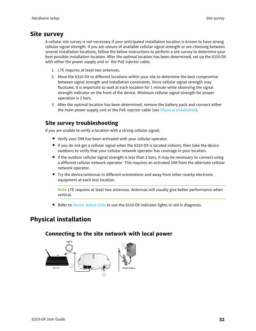
Connecting to the site network with local power

Hardware setup Install SIM cards in the Plug-in LTE modem
6310-DX User Guide 33
1. Plug the power supply unit into an AC power outlet2. Connect the PSU to the 6310-DX.3. Connect the 6310-DX to a networking device.
Install SIM cards in the Plug-in LTE modemThere is a label on the bottom of the CORE modem that indicates the plug-in modem IMEI number.The modem is referred to as 1002-CM.To install SIM cards:
1. Identify the SIM 1 and SIM 2 slots on the CORE modem. If using only one SIM card, insert it intoSIM 1. A second SIM may be inserted into slot SIM 2 for an alternate wireless carrier.
2. Insert the SIM cards into the CORE modem.
Note If the 6310-DX device is used in an environment with high vibration levels, SIM cardcontact fretting may cause unexpected SIM card failures. To protect the SIM cards, Digistrongly recommends that you apply a thin layer of dielectric grease to the SIM contacts priorto installing the SIM cards. See Apply Dielectric Grease over SIM ContactsApply DielectricGrease over SIM Contacts for instructions.
3. With the antennas SMA connectors pointing outward, slide the CORE modem into the 6310-DXdevice. A clicking sound will indicate it is properly inserted.
4. Secure the CORE modem with an anchor screw.5. Affix the cellular antennas to the two connectors protruding from the device.
Apply Dielectric Grease over SIM Contacts
Note Digi recommends using either …the Loctite® LB 8423 Dielectric Grease or Synco Lube® SiliconeDielectric Grease.
1. Use a sheet of paper or cardboard over the area where you intend to work.2. Use isopropyl alcohol and a cotton-tipped applicator to gently clean the SIM contacts. Using
isopropyl alcohol requires a well vented environment. Demineralized water can also be used asan alternative.
Hardware setup Mount the 6310-DX device
6310-DX User Guide 34
3. Once the surface is clean and dry, apply a small amount of dielectric grease in a thin layer overthe contacts. Use a new cotton-tipped applicator to work the grease smoothy over thecontacts. Apply gentle pressure.
4. When the dielectric grease has been applied, insert the SIM into the SIM slot as describedabove.
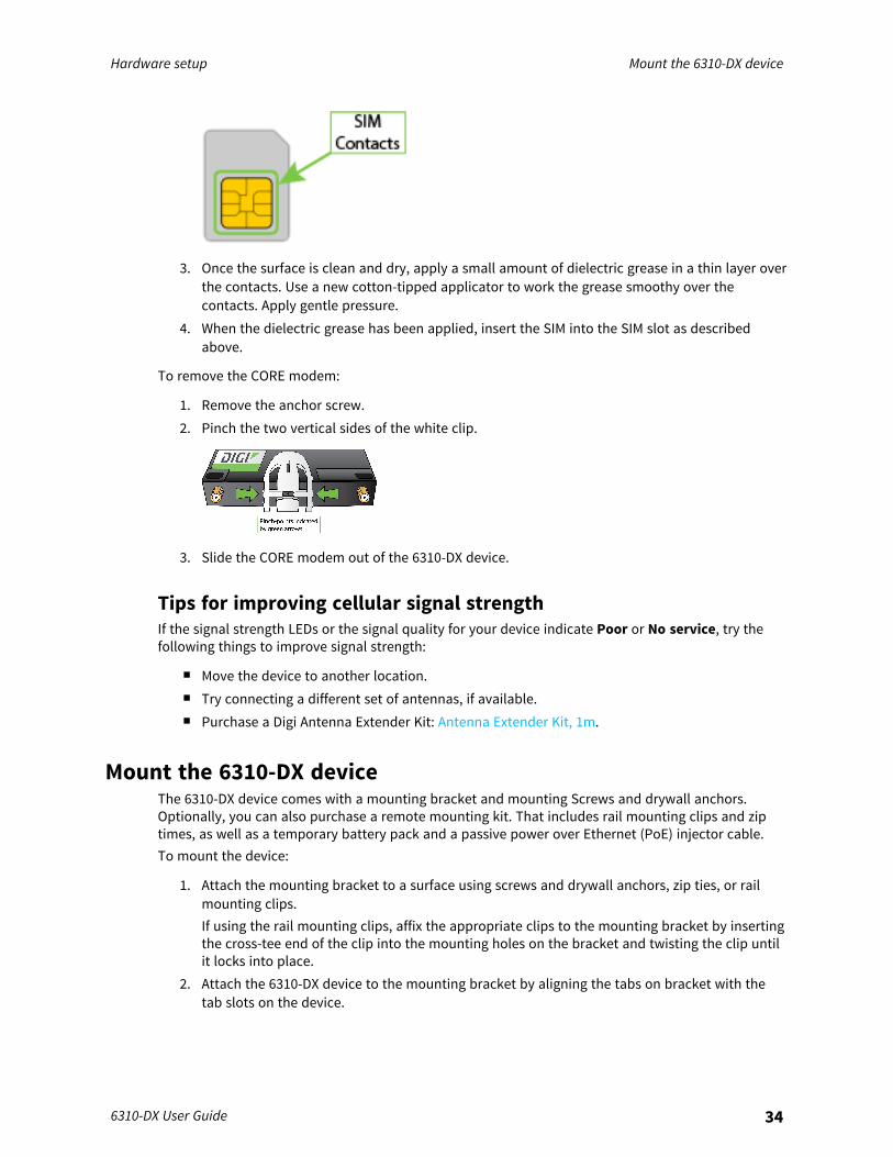
To remove the CORE modem:
1. Remove the anchor screw.2. Pinch the two vertical sides of the white clip.
3. Slide the CORE modem out of the 6310-DX device.
Tips for improving cellular signal strengthIf the signal strength LEDs or the signal quality for your device indicate Poor or No service, try thefollowing things to improve signal strength:
n Move the device to another location.n Try connecting a different set of antennas, if available.n Purchase a Digi Antenna Extender Kit: Antenna Extender Kit, 1m.
Mount the 6310-DX deviceThe 6310-DX device comes with a mounting bracket and mounting Screws and drywall anchors.Optionally, you can also purchase a remote mounting kit. That includes rail mounting clips and ziptimes, as well as a temporary battery pack and a passive power over Ethernet (PoE) injector cable.To mount the device:
1. Attach the mounting bracket to a surface using screws and drywall anchors, zip ties, or railmounting clips.If using the rail mounting clips, affix the appropriate clips to the mounting bracket by insertingthe cross-tee end of the clip into the mounting holes on the bracket and twisting the clip untilit locks into place.
2. Attach the 6310-DX device to the mounting bracket by aligning the tabs on bracket with thetab slots on the device.
Hardware setup Network integration
6310-DX User Guide 35
Network integration
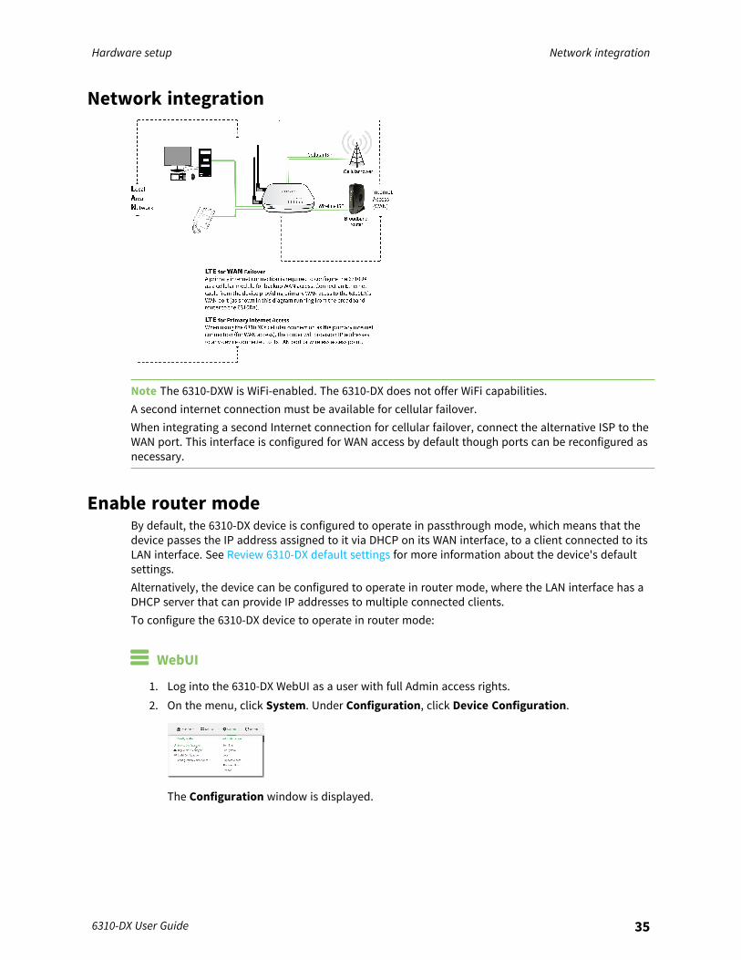
Note The 6310-DXW is WiFi-enabled. The 6310-DX does not offer WiFi capabilities.A second internet connection must be available for cellular failover.When integrating a second Internet connection for cellular failover, connect the alternative ISP to theWAN port. This interface is configured for WAN access by default though ports can be reconfigured asnecessary.
Enable router modeBy default, the 6310-DX device is configured to operate in passthrough mode, which means that thedevice passes the IP address assigned to it via DHCP on its WAN interface, to a client connected to itsLAN interface. See Review 6310-DX default settings for more information about the device's defaultsettings.Alternatively, the device can be configured to operate in router mode, where the LAN interface has aDHCP server that can provide IP addresses to multiple connected clients.To configure the 6310-DX device to operate in router mode:
WebUI
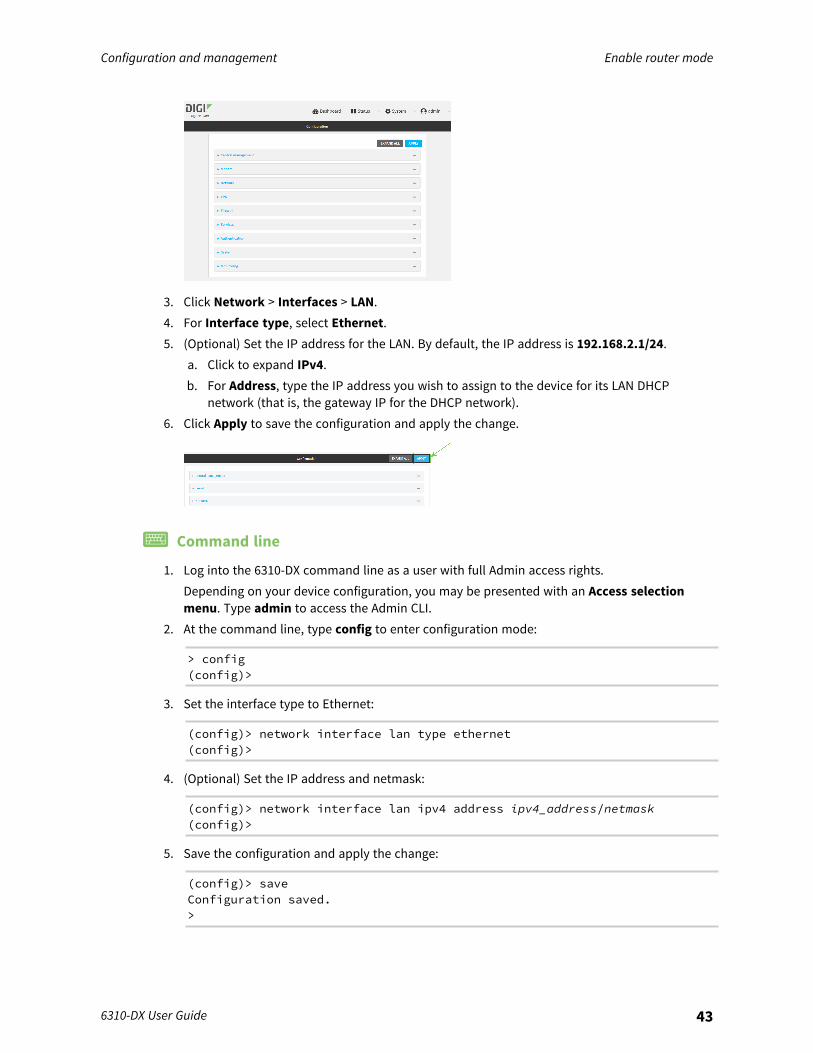
1. Log into the 6310-DX WebUI as a user with full Admin access rights.2. On the menu, click System. Under Configuration, click Device Configuration.
The Configuration window is displayed.

Hardware setup Enable router mode
6310-DX User Guide 36
3. Click Network > Interfaces > LAN.4. For Interface type, select Ethernet.5. (Optional) Set the IP address for the LAN. By default, the IP address is 192.168.2.1/24.
a. Click to expand IPv4.b. For Address, type the IP address you wish to assign to the device for its LAN DHCP
network (that is, the gateway IP for the DHCP network).6. Click Apply to save the configuration and apply the change.
Command line
1. Log into the 6310-DX command line as a user with full Admin access rights.Depending on your device configuration, you may be presented with an Access selectionmenu. Type admin to access the Admin CLI.
2. At the command line, type config to enter configuration mode:
> config(config)>
3. Set the interface type to Ethernet:
(config)> network interface lan type ethernet(config)>
4. (Optional) Set the IP address and netmask:
(config)> network interface lan ipv4 address ipv4_address/netmask(config)>
5. Save the configuration and apply the change:
(config)> saveConfiguration saved.>

Hardware setup Enable router mode
6310-DX User Guide 37
6. Type exit to exit the Admin CLI.Depending on your device configuration, you may be presented with an Access selectionmenu. Type quit to disconnect from the device.
Configuration and management
This chapter contains the following topics:
Review 6310-DX default settings 39Change the default password for the admin user 40Enable router mode 42Configuration methods 44Using Digi Remote Manager 45Access Digi Remote Manager 45Configure the device to use aView for central management 45Using the web interface 49Use the local REST API to configure the 6310-DX device 51Using the command line 56Access the command line interface 56Log in to the command line interface 56Exit the command line interface 57
6310-DX User Guide 38
Configuration and management Review 6310-DX default settings
6310-DX User Guide 39
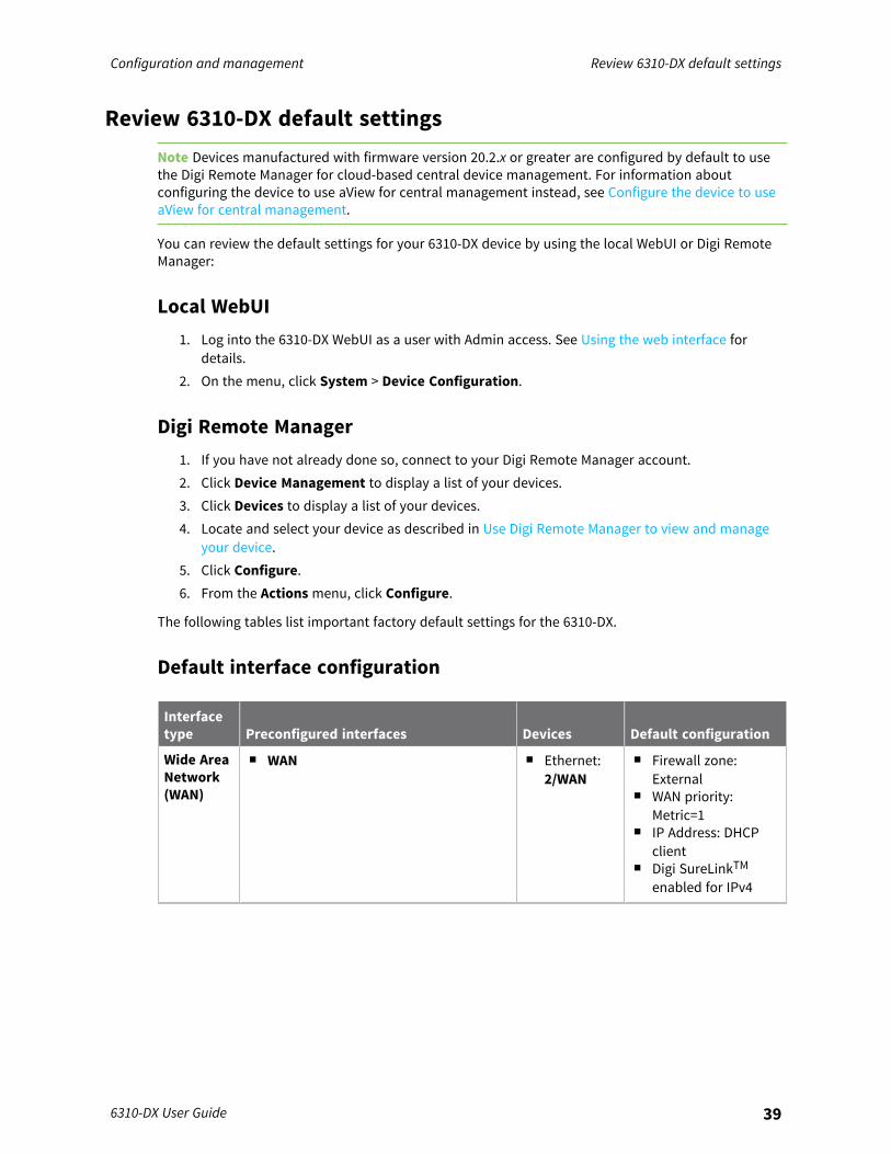
Review 6310-DX default settingsNote Devices manufactured with firmware version 20.2.x or greater are configured by default to usethe Digi Remote Manager for cloud-based central device management. For information aboutconfiguring the device to use aView for central management instead, see Configure the device to useaView for central management.
You can review the default settings for your 6310-DX device by using the local WebUI or Digi RemoteManager:
Local WebUI1. Log into the 6310-DX WebUI as a user with Admin access. See Using the web interface for
details.2. On the menu, click System > Device Configuration.
Digi Remote Manager1. If you have not already done so, connect to your Digi Remote Manager account.2. Click Device Management to display a list of your devices.3. Click Devices to display a list of your devices.4. Locate and select your device as described in Use Digi Remote Manager to view and manage
your device.5. Click Configure.6. From the Actions menu, click Configure.
The following tables list important factory default settings for the 6310-DX.
Default interface configuration
Interfacetype Preconfigured interfaces Devices Default configuration
Wide AreaNetwork(WAN)
n WAN n Ethernet:2/WAN
n Firewall zone:External
n WAN priority:Metric=1
n IP Address: DHCPclient
n Digi SureLinkTMenabled for IPv4
Configuration and management Change the default password for the admin user
6310-DX User Guide 40
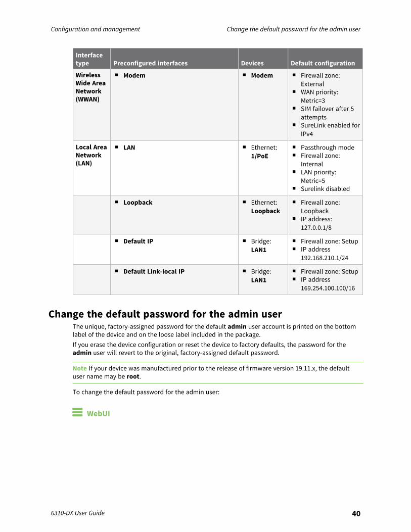
Interfacetype Preconfigured interfaces Devices Default configuration
WirelessWide AreaNetwork(WWAN)
n Modem n Modem n Firewall zone:External
n WAN priority:Metric=3
n SIM failover after 5attempts
n SureLink enabled forIPv4
Local AreaNetwork(LAN)
n LAN n Ethernet:1/PoE
n Passthrough moden Firewall zone:
Internaln LAN priority:
Metric=5n Surelink disabled
n Loopback n Ethernet:Loopback
n Firewall zone:Loopback
n IP address:127.0.0.1/8
n Default IP n Bridge:LAN1
n Firewall zone: Setupn IP address
192.168.210.1/24
n Default Link-local IP n Bridge:LAN1
n Firewall zone: Setupn IP address
169.254.100.100/16
Change the default password for the admin userThe unique, factory-assigned password for the default admin user account is printed on the bottomlabel of the device and on the loose label included in the package.If you erase the device configuration or reset the device to factory defaults, the password for theadmin user will revert to the original, factory-assigned default password.
Note If your device was manufactured prior to the release of firmware version 19.11.x, the defaultuser name may be root.
To change the default password for the admin user:
WebUI
Configuration and management Change the default password for the admin user
6310-DX User Guide 41
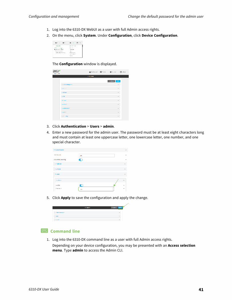
1. Log into the 6310-DX WebUI as a user with full Admin access rights.2. On the menu, click System. Under Configuration, click Device Configuration.
The Configuration window is displayed.
3. Click Authentication > Users > admin.4. Enter a new password for the admin user. The password must be at least eight characters long
and must contain at least one uppercase letter, one lowercase letter, one number, and onespecial character.
5. Click Apply to save the configuration and apply the change.
Command line
1. Log into the 6310-DX command line as a user with full Admin access rights.Depending on your device configuration, you may be presented with an Access selectionmenu. Type admin to access the Admin CLI.
Configuration and management Enable router mode
6310-DX User Guide 42
2. At the command line, type config to enter configuration mode:
> config(config)>
3. Set a new password for the admin user. The password must be at least eight characters longand must contain at least one uppercase letter, one lowercase letter, one number, and onespecial character.
(config)> auth user admin password new-password(config)>
4. Save the configuration and apply the change:
(config)> saveConfiguration saved.>
5. Type exit to exit the Admin CLI.Depending on your device configuration, you may be presented with an Access selectionmenu. Type quit to disconnect from the device.
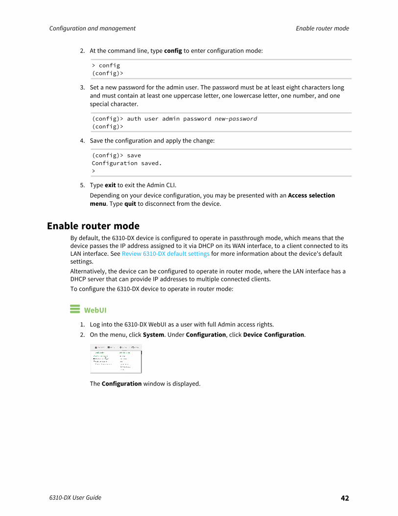
Enable router modeBy default, the 6310-DX device is configured to operate in passthrough mode, which means that thedevice passes the IP address assigned to it via DHCP on its WAN interface, to a client connected to itsLAN interface. See Review 6310-DX default settings for more information about the device's defaultsettings.Alternatively, the device can be configured to operate in router mode, where the LAN interface has aDHCP server that can provide IP addresses to multiple connected clients.To configure the 6310-DX device to operate in router mode:
WebUI
1. Log into the 6310-DX WebUI as a user with full Admin access rights.2. On the menu, click System. Under Configuration, click Device Configuration.
The Configuration window is displayed.
Configuration and management Enable router mode
6310-DX User Guide 43
3. Click Network > Interfaces > LAN.4. For Interface type, select Ethernet.5. (Optional) Set the IP address for the LAN. By default, the IP address is 192.168.2.1/24.
a. Click to expand IPv4.b. For Address, type the IP address you wish to assign to the device for its LAN DHCP
network (that is, the gateway IP for the DHCP network).6. Click Apply to save the configuration and apply the change.
Command line
1. Log into the 6310-DX command line as a user with full Admin access rights.Depending on your device configuration, you may be presented with an Access selectionmenu. Type admin to access the Admin CLI.
2. At the command line, type config to enter configuration mode:
> config(config)>
3. Set the interface type to Ethernet:
(config)> network interface lan type ethernet(config)>
4. (Optional) Set the IP address and netmask:
(config)> network interface lan ipv4 address ipv4_address/netmask(config)>
5. Save the configuration and apply the change:
(config)> saveConfiguration saved.>
Configuration and management Configuration methods
6310-DX User Guide 44
6. Type exit to exit the Admin CLI.Depending on your device configuration, you may be presented with an Access selectionmenu. Type quit to disconnect from the device.
Configuration methodsThere are two primary methods for configuring your 6310-DX device:
n Web interface.The web interface can be accessed in two ways:l Central management using the Digi Remote Manager, a cloud-based device management
and data enablement platform that allows you to connect any device to any application,anywhere. With the Remote Manager, you can configure your 6310-DX device and use theconfiguration as a basis for a profile which can be applied to other similar devices. SeeUsing Digi Remote Manager for more information about using the Remote Manager tomanage and configure your 6310-DX device.
l The local web interface. See Using the web interface for more information about using thelocal web interface to manage and configure your 6310-DX device.
Note Changes made to the device's configuration by using the local web interface will notbe automatically reflected in Digi Remote Manager. You must manually refresh RemoteManager for the changes to be displayed.
Web-based instructions in this guide are applicable to both the Remote Manager and the localweb interface.
n Command line.A robust command line allows you to perform all configuration and management tasks fromwithin a command shell. Both the Remote Manager and the local web interface also have theoption to open a terminal emulator for executing commands on your 6310-DX device. SeeUsing the command line for more information about using the command line to manage andconfigure your 6310-DX device.
In this guide, task topics show how to perform tasks:
WebUIShows how to perform a task by using the local web interface.
Command lineShows how to perform a task by using the command line interface.
Configuration and management Using Digi Remote Manager
6310-DX User Guide 45
Using Digi Remote ManagerNote Devices manufactured with firmware version 20.2.x or greater are configured by default to usethe Digi Remote Manager for cloud-based central device management. For information aboutconfiguring the device to use aView for central management instead, see Configure the device to useaView for central management.
By default, your 6310-DX device is configured to use Digi Remote Manager as its central managementserver. No configuration changes are required to begin using the Remote Manager.For information about configuring central management for your 6310-DX device, see Centralmanagement.
Access Digi Remote ManagerTo access Digi Remote Manager:
1. If you have not already done so, go to https://myaccount.digi.com/ to sign up for a DigiRemote Manager account.Check your email for Digi Remote Manager login instructions.
2. Go to remotemanager.digi.com.1. Enter your username and password.
The Digi Remote Manager Dashboard appears.
Configure the device to use aView for central management6310-DX devices manufactured with firmware version 20.2.x or greater are configured by default touse Digi Remote Manager for cloud-based central device management. Use this procedure toconfigure the device to connect to the aView central management tool instead.
Note 6310-DX devices upgraded from a firmware version prior to 20.2.x to firmware version 20.2.x orgreater will retain their central management configuration. Therefore, if the device was previouslyconfigured to use aView for central management, it will continue to use aView after upgrading to20.2.x or greater.However, if you erase the configuration of a device that was upgraded from a firmware version priorto 20.2.x, it will default to using Digi Remote Manager for cloud-based central device management.
To configure the 6310-DX device to use aView rather than Digi Remote Manager for centralmanagement:
WebUI
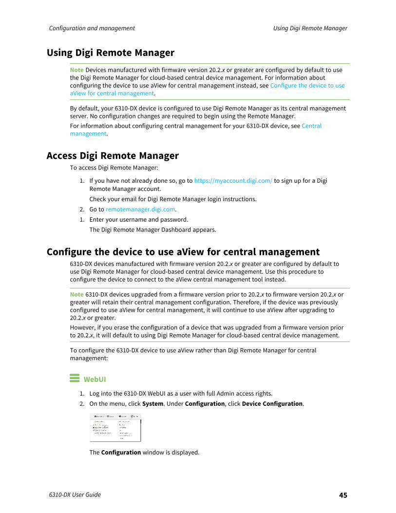
1. Log into the 6310-DX WebUI as a user with full Admin access rights.2. On the menu, click System. Under Configuration, click Device Configuration.
The Configuration window is displayed.
Configuration and management Configure the device to use aView for central management
6310-DX User Guide 46
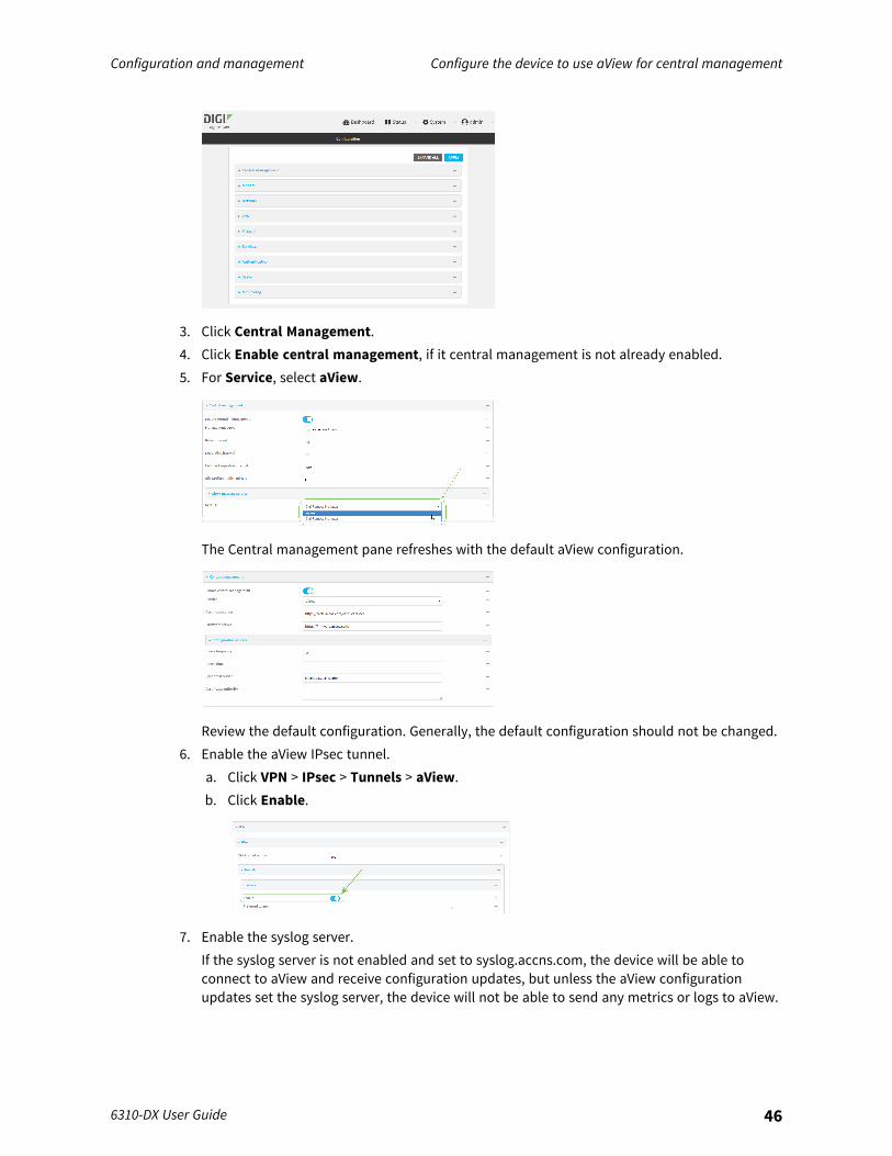
3. Click Central Management.4. Click Enable central management, if it central management is not already enabled.5. For Service, select aView.
The Central management pane refreshes with the default aView configuration.
Review the default configuration. Generally, the default configuration should not be changed.6. Enable the aView IPsec tunnel.
a. Click VPN > IPsec > Tunnels > aView.b. Click Enable.
7. Enable the syslog server.If the syslog server is not enabled and set to syslog.accns.com, the device will be able toconnect to aView and receive configuration updates, but unless the aView configurationupdates set the syslog server, the device will not be able to send any metrics or logs to aView.
Configuration and management Configure the device to use aView for central management
6310-DX User Guide 47
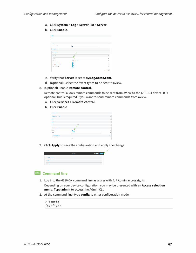
a. Click System > Log > Server list > Server.b. Click Enable.
c. Verify that Server is set to syslog.accns.com.d. (Optional) Select the event types to be sent to aView.
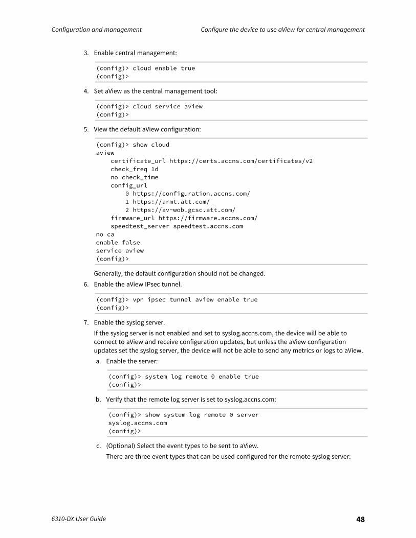
8. (Optional) Enable Remote control.Remote control allows remote commands to be sent from aView to the 6310-DX device. It isoptional, but is required if you want to send remote commands from aView.a. Click Services > Remote control.b. Click Enable.
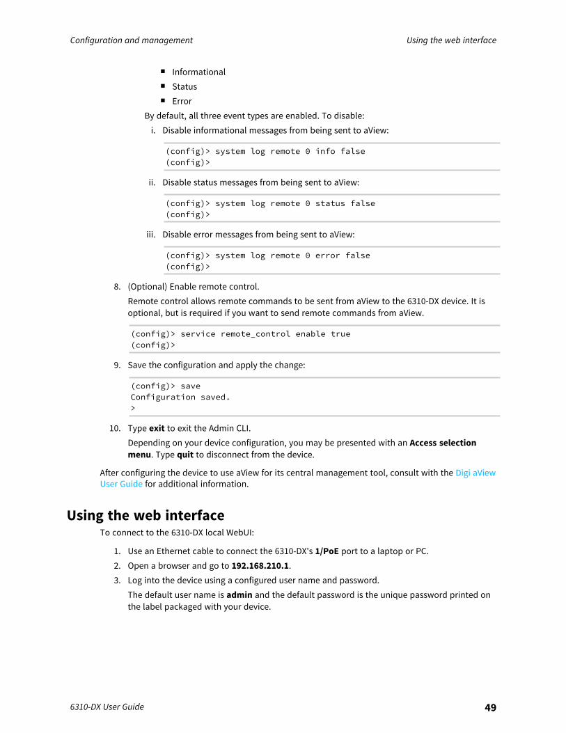
9. Click Apply to save the configuration and apply the change.
Command line
1. Log into the 6310-DX command line as a user with full Admin access rights.Depending on your device configuration, you may be presented with an Access selectionmenu. Type admin to access the Admin CLI.
2. At the command line, type config to enter configuration mode:
> config(config)>
Configuration and management Configure the device to use aView for central management
6310-DX User Guide 48
3. Enable central management:
(config)> cloud enable true(config)>
4. Set aView as the central management tool:
(config)> cloud service aview(config)>
5. View the default aView configuration:
(config)> show cloudaview
certificate_url https://certs.accns.com/certificates/v2check_freq 1dno check_timeconfig_url
0 https://configuration.accns.com/1 https://armt.att.com/2 https://av-wob.gcsc.att.com/
firmware_url https://firmware.accns.com/speedtest_server speedtest.accns.com
no caenable falseservice aview(config)>
Generally, the default configuration should not be changed.6. Enable the aView IPsec tunnel.
(config)> vpn ipsec tunnel aview enable true(config)>
7. Enable the syslog server.If the syslog server is not enabled and set to syslog.accns.com, the device will be able toconnect to aView and receive configuration updates, but unless the aView configurationupdates set the syslog server, the device will not be able to send any metrics or logs to aView.a. Enable the server:
(config)> system log remote 0 enable true(config)>
b. Verify that the remote log server is set to syslog.accns.com:
(config)> show system log remote 0 serversyslog.accns.com(config)>
c. (Optional) Select the event types to be sent to aView.There are three event types that can be used configured for the remote syslog server:
Configuration and management Using the web interface
6310-DX User Guide 49
n Informationaln Statusn Error
By default, all three event types are enabled. To disable:i. Disable informational messages from being sent to aView:
(config)> system log remote 0 info false(config)>
ii. Disable status messages from being sent to aView:
(config)> system log remote 0 status false(config)>
iii. Disable error messages from being sent to aView:
(config)> system log remote 0 error false(config)>
8. (Optional) Enable remote control.Remote control allows remote commands to be sent from aView to the 6310-DX device. It isoptional, but is required if you want to send remote commands from aView.
(config)> service remote_control enable true(config)>
9. Save the configuration and apply the change:
(config)> saveConfiguration saved.>
10. Type exit to exit the Admin CLI.Depending on your device configuration, you may be presented with an Access selectionmenu. Type quit to disconnect from the device.
After configuring the device to use aView for its central management tool, consult with the Digi aViewUser Guide for additional information.
Using the web interfaceTo connect to the 6310-DX local WebUI:
1. Use an Ethernet cable to connect the 6310-DX's 1/PoE port to a laptop or PC.2. Open a browser and go to 192.168.210.1.3. Log into the device using a configured user name and password.
The default user name is admin and the default password is the unique password printed onthe label packaged with your device.
Configuration and management Using the web interface
6310-DX User Guide 50
Note If your device was manufactured prior to firmware version 19.11.x, the default user forlogging into the device may be root, rather than admin.
n The default user is root:l If the device is at a firmware level 19.8.x or older.l If the device has been upgraded from 19.8.x or older to 19.11.x or newer.
n The default user is admin:l If the device is at 19.11.x or newer when manufactured.l If the device has been upgraded from 19.8.x or older to 19.11.x or newer and has
been factory reset after the upgrade.n Devices that connect to Digi aView for cloud management may have a different
password for the default user, based on the aView configuration profile used by thedevice. Devices with firmware prior to release 20.2.x are configured to connect to aViewby default.To connect to the local Web UI in this case, you must either know the password fromthe aView configuration profile, or you must disconnect from aView and reset the deviceto factory defaults.To disconnect from aView and reset the device:a. Remove any SIM and WAN connections to prevent the device from connecting to
aView after resetting to factory defaults.b. Follow the instructions at Erase device configuration and reset to factory defaults
to reset the device to factory defaults.c. Log into the local Web UI by using the default username and password.d. Prior to inserting a SIM or connecting to a WAN connection, disable central
management or configure the device to connect to Digi Remote Manager, asdescribed in Configure Digi Remote Manager.
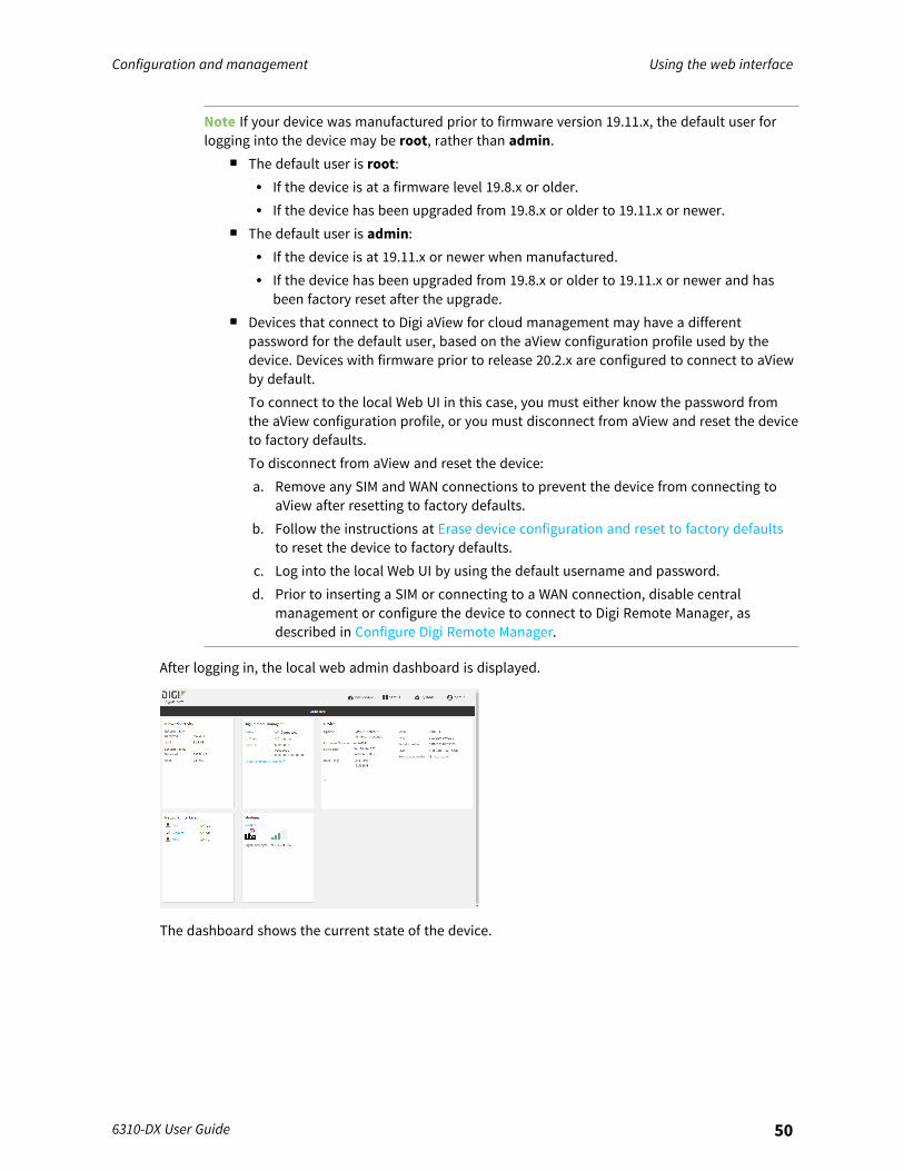
After logging in, the local web admin dashboard is displayed.
The dashboard shows the current state of the device.
Configuration and management Use the local REST API to configure the 6310-DX device
6310-DX User Guide 51
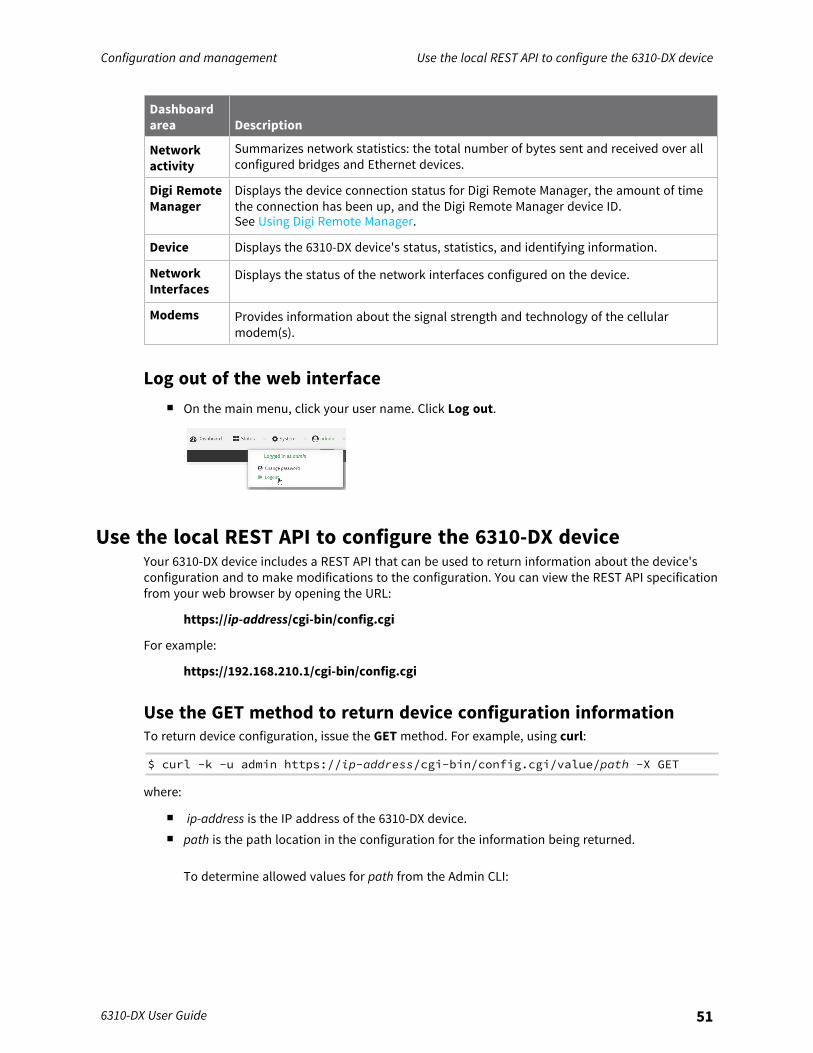
Dashboardarea Description
Networkactivity
Summarizes network statistics: the total number of bytes sent and received over allconfigured bridges and Ethernet devices.
Digi RemoteManager
Displays the device connection status for Digi Remote Manager, the amount of timethe connection has been up, and the Digi Remote Manager device ID.See Using Digi Remote Manager.
Device Displays the 6310-DX device's status, statistics, and identifying information.
NetworkInterfaces
Displays the status of the network interfaces configured on the device.
Modems Provides information about the signal strength and technology of the cellularmodem(s).
Log out of the web interfacen On the main menu, click your user name. Click Log out.
Use the local REST API to configure the 6310-DX deviceYour 6310-DX device includes a REST API that can be used to return information about the device'sconfiguration and to make modifications to the configuration. You can view the REST API specificationfrom your web browser by opening the URL:
https://ip-address/cgi-bin/config.cgi
For example:
https://192.168.210.1/cgi-bin/config.cgi
Use the GET method to return device configuration informationTo return device configuration, issue the GET method. For example, using curl:
$ curl -k -u admin https://ip-address/cgi-bin/config.cgi/value/path -X GET
where:
n ip-address is the IP address of the 6310-DX device.n path is the path location in the configuration for the information being returned.
To determine allowed values for path from the Admin CLI:

Configuration and management Use the local REST API to configure the 6310-DX device
6310-DX User Guide 52
1. Log into the 6310-DX command line as a user with full Admin access rights.Depending on your device configuration, you may be presented with an Accessselection menu. Type admin to access the Admin CLI.
2. At the command line, type config to enter configuration mode:
> config(config)>
3. At the config prompt, type ? (question mark):
(config)> ?auth Authenticationcloud Central managementfirewall Firewallmonitoring Monitoringnetwork Networkserial Serialservice Servicessystem Systemvpn VPN
(config)>
The allowed values for path are listed in the first (left) column.4. To determine further allowed path location values by using the ? (question mark) with
the path name:
(config> service ?
Services
Additional Configuration-------------------------------------------------------------------------------dns DNSiperf IPerflocation Locationmdns Service Discovery (mDNS)modbus_gateway Modbus Gatewaymulticast Multicastntp NTPping Ping respondersnmp SNMPssh SSHtelnet Telnetweb_admin Web administration
(config)> service
For example, to use curl to return the ssh configuration:
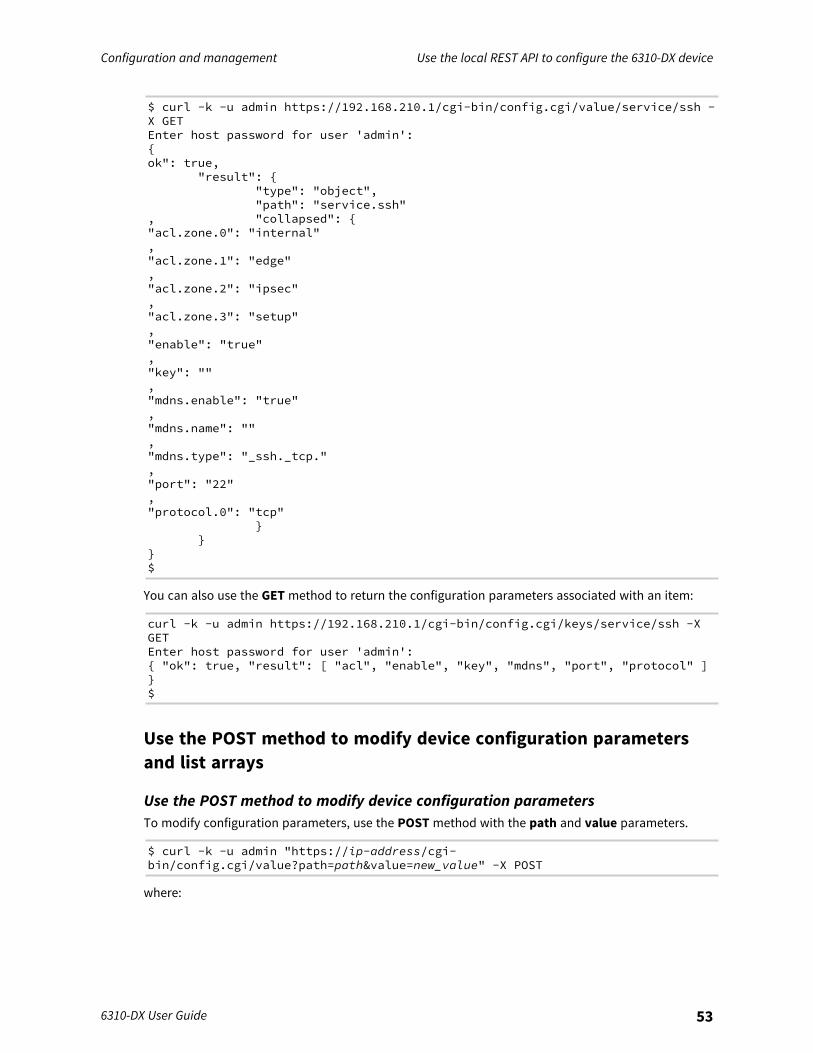
Configuration and management Use the local REST API to configure the 6310-DX device
6310-DX User Guide 53
$ curl -k -u admin https://192.168.210.1/cgi-bin/config.cgi/value/service/ssh -X GETEnter host password for user 'admin':{ok": true,
"result": {"type": "object","path": "service.ssh"
, "collapsed": {"acl.zone.0": "internal","acl.zone.1": "edge","acl.zone.2": "ipsec","acl.zone.3": "setup","enable": "true","key": "","mdns.enable": "true","mdns.name": "","mdns.type": "_ssh._tcp.","port": "22","protocol.0": "tcp"
}}
}$
You can also use the GET method to return the configuration parameters associated with an item:
curl -k -u admin https://192.168.210.1/cgi-bin/config.cgi/keys/service/ssh -XGETEnter host password for user 'admin':{ "ok": true, "result": [ "acl", "enable", "key", "mdns", "port", "protocol" ]}$
Use the POST method to modify device configuration parametersand list arrays
Use the POST method to modify device configuration parametersTo modify configuration parameters, use the POST method with the path and value parameters.
$ curl -k -u admin "https://ip-address/cgi-bin/config.cgi/value?path=path&value=new_value" -X POST
where:

Configuration and management Use the local REST API to configure the 6310-DX device
6310-DX User Guide 54
n path is the path to the configuration parameter, in dot notation (for example,ssh.service.enable).
n new_value is the new value for the parameter.
For example, to disable the ssh service using curl:
$ curl -k -u admin "https://192.168.210.1/cgi-bin/config.cgi/value?path=service.ssh.enable&value=false" -X POSTEnter host password for user 'admin':{ "ok": true }$
Use the POST method to add items to a list arrayTo add items to a list array, use the POST method with the path and append parameters. Forexample, to add the external firewall zone to the ssh service:
$ curl -k -u admin "https://192.168.210.1/cgi-bin/config.cgi/value?path=service.ssh.acl.zone&append=true&value=external" -XPOSTEnter host password for user 'admin':{ "ok": true, "result": "service.ssh.acl.zone.4" }$
Use the POST method to add objects to a list arrayObjects in an array that require one or more underlying values can be set using the collapsed URIparameter. We recommend including the -g option as well, to instruct curl to turn off globbing. Thebelow example would add a new static route for the WAN interface for the 1.2.4.0/24 destinationnetwork:
$ curl -g -k -u admin "https://192.168.210.1/cgi-bin/config.cgi/value?path=network.route.static&append=true&collapsed[dst]=1.2.4.0/24&collapsed[interface]=/network/interface/wan" -X POSTEnter host password for user 'admin':{ "ok": true, "result": "network.route.static.1" }$
Use the DELETE method to remove items from a list arrayTo remove items from a list array, use the DELETE method. For example, using curl:
$ curl -k -u admin "https://192.168.210.1/cgi-bin/config.cgi/value?path=path
where path is the path to the list item, including the list number, in dot notation (for example,service.ssh.acl.zone.4).For example, to remove the external firewall zone to the ssh service:
1. Use the GET method to determine the SSH service's list number for the external zone:
$ curl -k -u admin "https://192.168.210.1/cgi-bin/config.cgi/value/service/ssh/acl/zone -X GET{
"ok": true,

Configuration and management Use the local REST API to configure the 6310-DX device
6310-DX User Guide 55
"result": {"type": "array","path": "service.ssh.acl.zone"
, "collapsed": {"0": "internal","1": "edge","2": "ipsec","3": "setup","4": "external"
}}
}$
2. Use the DELETE method to remove the external zone (list item 4).
$ curl -k -u admin https://192.168.210.1/cgi-bin/config.cgi/value?path=service.ssh.acl.zone.4 -X DELETEEnter host password for user 'admin':{ "ok": true }$
Configuration and management Using the command line
6310-DX User Guide 56
Using the command lineThe Digi 6310-DX device provides a command-line interface that you can use to configure the device,display status and statistics, update firmware, and manage device files.See Command line interface for detailed instructions on using the command line interface and seeCommand line reference for information on available commands.
Access the command line interfaceYou can access the 6310-DX command line interface using an SSH connection, a telnet connection, ora serial connection. You can use an open-source terminal software, such as PuTTY or TeraTerm, toaccess the device through one of these mechanisms.You can also access the command line interface in the WebUI by using the Terminal, or the DigiRemote Manager by using the Console.To access the command line, your device must be configured to allow access, and you must log in asa user who has been configured for the appropriate access. For further information about configuringaccess to these services, see:
n WebUI: Configure the web administration servicen SSH: Configure SSH accessn Telnet: Configure telnet access
Log in to the command line interface
Command line
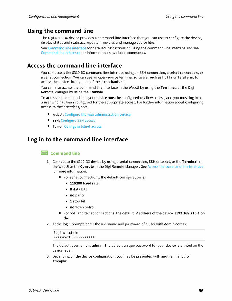
1. Connect to the 6310-DX device by using a serial connection, SSH or telnet, or the Terminal inthe WebUI or the Console in the Digi Remote Manager. See Access the command line interfacefor more information.
n For serial connections, the default configuration is:l 115200 baud ratel 8 data bitsl no parityl 1 stop bitl no flow control
n For SSH and telnet connections, the default IP address of the device is192.168.210.1 onthe .
2. At the login prompt, enter the username and password of a user with Admin access:
login: adminPassword: **********
The default username is admin. The default unique password for your device is printed on thedevice label.
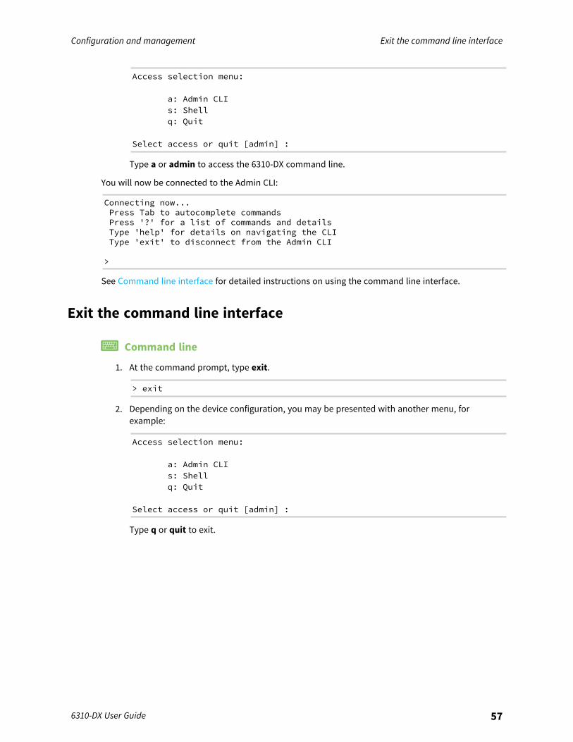
3. Depending on the device configuration, you may be presented with another menu, forexample:
Configuration and management Exit the command line interface
6310-DX User Guide 57
Access selection menu:
a: Admin CLIs: Shellq: Quit
Select access or quit [admin] :
Type a or admin to access the 6310-DX command line.
You will now be connected to the Admin CLI:
Connecting now...Press Tab to autocomplete commandsPress '?' for a list of commands and detailsType 'help' for details on navigating the CLIType 'exit' to disconnect from the Admin CLI
>
See Command line interface for detailed instructions on using the command line interface.
Exit the command line interface
Command line
1. At the command prompt, type exit.
> exit
2. Depending on the device configuration, you may be presented with another menu, forexample:
Access selection menu:
a: Admin CLIs: Shellq: Quit
Select access or quit [admin] :
Type q or quit to exit.
Interfaces
6310-DX devices have several physical communications interfaces. These interfaces can be bridged ina Local Area Network (LAN) or assigned to a Wide Area Network (WAN).This chapter contains the following topics:
Wide Area Networks (WANs) 59Local Area Networks (LANs) 138Bridging 171Show Surelink status and statistics 175
6310-DX User Guide 58
Interfaces Wide Area Networks (WANs)
6310-DX User Guide 59
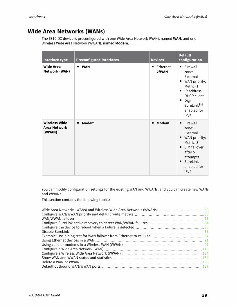
Wide Area Networks (WANs)The 6310-DX device is preconfigured with one Wide Area Network (WAN), named WAN, and oneWireless Wide Area Network (WWAN), named Modem.
Interface type Preconfigured interfaces DevicesDefaultconfiguration
Wide AreaNetwork (WAN)
n WAN n Ethernet:2/WAN
n Firewallzone:External
n WAN priority:Metric=1
n IP Address:DHCP client
n DigiSureLinkTMenabled forIPv4
Wireless WideArea Network(WWAN)
n Modem n Modem n Firewallzone:External
n WAN priority:Metric=3
n SIM failoverafter 5attempts
n SureLinkenabled forIPv4
You can modify configuration settings for the existing WAN and WWANs, and you can create new WANsand WWANs.This section contains the following topics:
Wide Area Networks (WANs) and Wireless Wide Area Networks (WWANs) 60Configure WAN/WWAN priority and default route metrics 60WAN/WWAN failover 63Configure SureLink active recovery to detect WAN/WWAN failures 64Configure the device to reboot when a failure is detected 75Disable SureLink 83Example: Use a ping test for WAN failover from Ethernet to cellular 87Using Ethernet devices in a WAN 91Using cellular modems in a Wireless WAN (WWAN) 91Configure a Wide Area Network (WAN) 115Configure a Wireless Wide Area Network (WWAN) 124Show WAN and WWAN status and statistics 134Delete a WAN or WWAN 136Default outbound WAN/WWAN ports 137
Interfaces Wide Area Networks (WANs)
6310-DX User Guide 60
Wide Area Networks (WANs) and Wireless Wide Area Networks(WWANs)A Wide Area Network (WAN) provides connectivity to the internet or a remote network. A WANconfiguration consists of the following:
n A physical device, such as an Ethernet device or a cellular modem.n Several networking parameters for the WAN, such as firewall configuration and IPv4 and IPv6
support.n Several parameters controlling failover.
Configure WAN/WWAN priority and default route metricsThe 6310-DX device is preconfigured with one Wide Area Network (WAN), named WAN, and oneWireless Wide Area Network (WWAN), named Modem. You can also create additional WANs andWWANs.When a WAN is initialized, the 6310-DX device automatically adds a default IP route for the WAN. Thepriority of the WAN is based on the metric of the default route, as configured in the WAN's IPv4 andIPv6 metric settings.
Assigning priority to WANsBy default, the 6310-DX device's WAN (WAN) is configured with the lowest metric (1), and is thereforthe highest priority WAN. By default, the Wireless WAN (Modem) is configured with a metric of 3,which means it has a lower priority than WAN. You can assign priority to WANs based on the behavioryou want to implement for primary and backup WAN interfaces. For example, if you want a cellularconnection to be your primary WAN, with an Ethernet interface as backup, configure the metric of theWWAN to be lower than the metric of the WAN.
Example: Configure cellular connection as the primary WAN, and the Ethernetconnection as backup
Required configuration items
n Configured WAN and WWAN interfaces. This example uses the preconfigured WAN and Modeminterfaces.
n The metric for each WAN.
WebUI
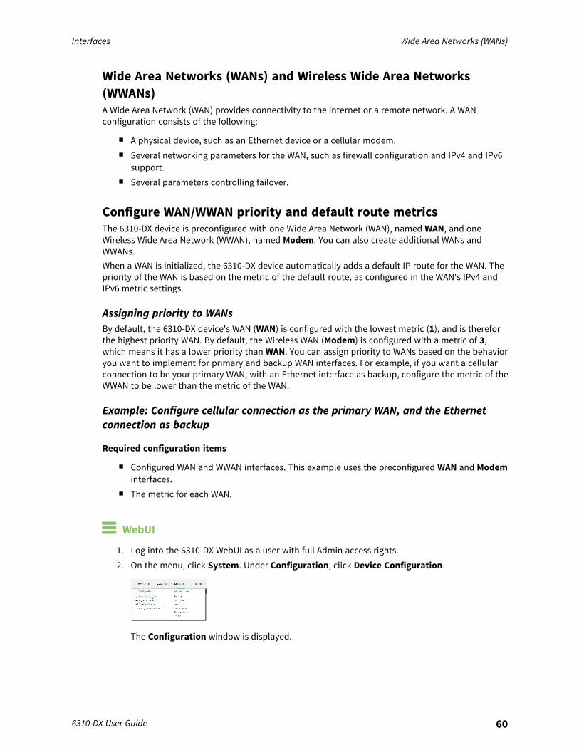
1. Log into the 6310-DX WebUI as a user with full Admin access rights.2. On the menu, click System. Under Configuration, click Device Configuration.
The Configuration window is displayed.
Interfaces Wide Area Networks (WANs)
6310-DX User Guide 61
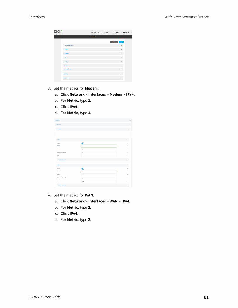
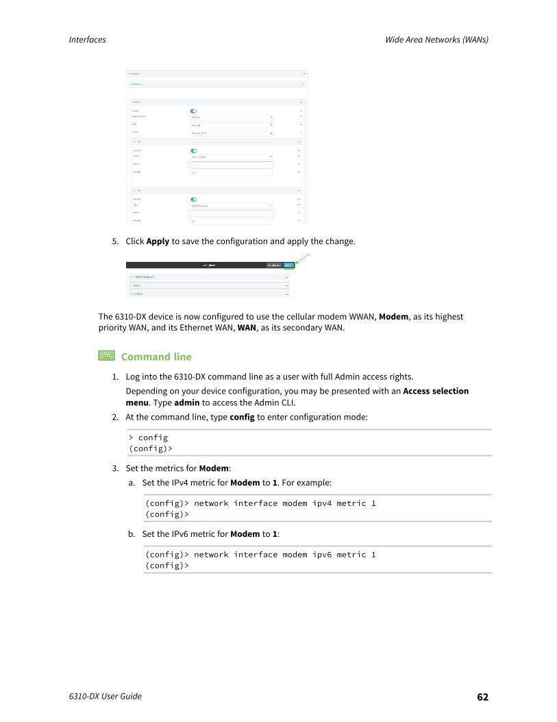
3. Set the metrics for Modem:a. Click Network > Interfaces > Modem > IPv4.b. For Metric, type 1.c. Click IPv6.d. For Metric, type 1.
4. Set the metrics for WAN:a. Click Network > Interfaces > WAN > IPv4.b. For Metric, type 2.c. Click IPv6.d. For Metric, type 2.
Interfaces Wide Area Networks (WANs)
6310-DX User Guide 62
5. Click Apply to save the configuration and apply the change.
The 6310-DX device is now configured to use the cellular modem WWAN, Modem, as its highestpriority WAN, and its Ethernet WAN, WAN, as its secondary WAN.
Command line
1. Log into the 6310-DX command line as a user with full Admin access rights.Depending on your device configuration, you may be presented with an Access selectionmenu. Type admin to access the Admin CLI.
2. At the command line, type config to enter configuration mode:
> config(config)>
3. Set the metrics for Modem:a. Set the IPv4 metric for Modem to 1. For example:
(config)> network interface modem ipv4 metric 1(config)>
b. Set the IPv6 metric for Modem to 1:
(config)> network interface modem ipv6 metric 1(config)>
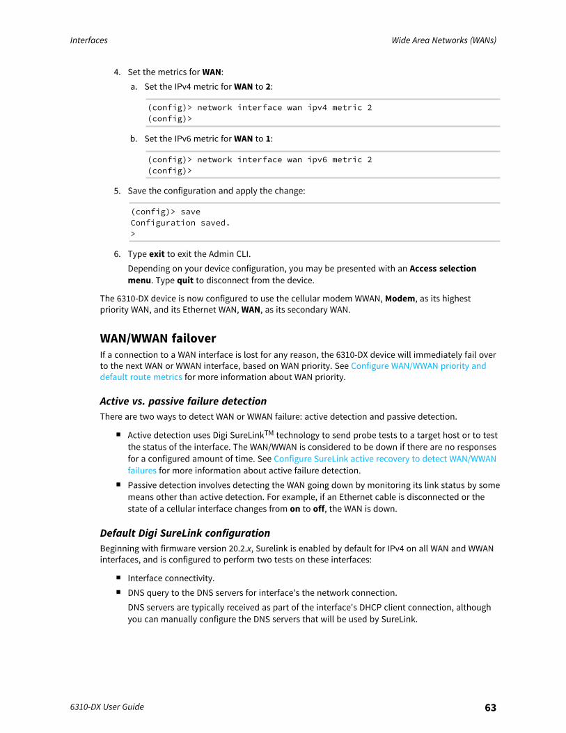
Interfaces Wide Area Networks (WANs)
6310-DX User Guide 63
4. Set the metrics for WAN:a. Set the IPv4 metric for WAN to 2:
(config)> network interface wan ipv4 metric 2(config)>
b. Set the IPv6 metric for WAN to 1:
(config)> network interface wan ipv6 metric 2(config)>
5. Save the configuration and apply the change:
(config)> saveConfiguration saved.>
6. Type exit to exit the Admin CLI.Depending on your device configuration, you may be presented with an Access selectionmenu. Type quit to disconnect from the device.
The 6310-DX device is now configured to use the cellular modem WWAN, Modem, as its highestpriority WAN, and its Ethernet WAN, WAN, as its secondary WAN.
WAN/WWAN failoverIf a connection to a WAN interface is lost for any reason, the 6310-DX device will immediately fail overto the next WAN or WWAN interface, based on WAN priority. See Configure WAN/WWAN priority anddefault route metrics for more information about WAN priority.
Active vs. passive failure detectionThere are two ways to detect WAN or WWAN failure: active detection and passive detection.
n Active detection uses Digi SureLinkTM technology to send probe tests to a target host or to testthe status of the interface. The WAN/WWAN is considered to be down if there are no responsesfor a configured amount of time. See Configure SureLink active recovery to detect WAN/WWANfailures for more information about active failure detection.
n Passive detection involves detecting the WAN going down by monitoring its link status by somemeans other than active detection. For example, if an Ethernet cable is disconnected or thestate of a cellular interface changes from on to off, the WAN is down.
Default Digi SureLink configurationBeginning with firmware version 20.2.x, Surelink is enabled by default for IPv4 on all WAN and WWANinterfaces, and is configured to perform two tests on these interfaces:
n Interface connectivity.n DNS query to the DNS servers for interface's the network connection.
DNS servers are typically received as part of the interface's DHCP client connection, althoughyou can manually configure the DNS servers that will be used by SureLink.
Interfaces Wide Area Networks (WANs)
6310-DX User Guide 64
Note If your device is operating on a private APN or on wired network with firewall restrictions,ensure that the DNS servers on your private network allow DNS lookups formy.devicecloud.com; otherwise, the SureLink DNS query test will fail and the 6310-DX devicewill determine that the interface is down.
By default, these tests will be performed every 15 minutes, with a response timeout of 15 seconds. Ifthe tests fail three consecutive times, the device will reset the network interface to attempt to recoverthe connection.
Configure SureLink active recovery to detect WAN/WWAN failuresProblems can occur beyond the immediate WAN/WWAN connection that prevent some IP traffic fromreaching its destination. Normally this kind of problem does not cause the 6310-DX device to detectthat the WAN has failed, because the connection continues to work while the core problem existssomewhere else in the network.Using Digi SureLink, you can configure the 6310-DX device to regularly probe connections through theWAN to determine if the WAN has failed.
Required configuration items
n Enable SureLink.SureLink can be enabled for both IPv4 and IPv6 configurations. By default, SureLink is enabledfor IPv4 for the preconfigured WAN (WAN) and WWAN (Modem). It is disabled for IPv6.When SureLink is configured for Wireless WANs, SureLink tests are only run if the cellularmodem is connected and has an IP address. Use the SIM failover options to configure the6310-DX device to automatically recover the modem in the event that it cannot obtain an IPaddress. See Configure a Wireless Wide Area Network (WWAN) for details about SIM failover.
n The type of probe test to be performed, one of:l Test another interface's status: Used to create a failover or coupled relationship between
two interfaces. Requires the name of the alternate interface, the IP version to be tested,and the expected status of the alternate interface (either up or down).
l Ping: Requires the hostname or IP address of the host to be pinged.l DNS query: You can perform a DNS query to a named DNS server, or to the DNS servers
configured for the WAN.l HTTP test: Requires the URL of the host to be tested.l Test DNS servers configured for this interface: Tests communication with this interface's
DNS servers that are either provided by DHCP, or statically configured.l Interface status: Determines if the interface has an IP address assigned to it, that the
physical link is up, and that a route is present to send traffic out of the network interface.The preconfigured WAN is configured by default to use SureLink to both test the interfacestatus and perform a test DNS query.
Additional configuration items
n The behavior of the 6310-DX device upon test failure:l The default behavior, which is to restart the interface and fail over to the next priority
WAN/WWAN.l For WWANs, SIM switching (also enabled by default).

Interfaces Wide Area Networks (WANs)
6310-DX User Guide 65
l For WWANs, reset the modem.l Reboot the device.
n The interval between connectivity tests.n The number of probe attempts before the WAN is considered to have failed.n The amount of time that the device should wait for a response to a probe attempt before
considering it to have failed.n If the type of probe test is:
l Ping: Configure the number of bytes in the ping packet.l Interface status: Configure the amount of time that the interface is down before it is
considered to have failed, and the amount of time it takes to make an initial connectionbefore it is considered down.
n Additional test targets.n If more than one test target is configured, determine whether the interface should fail over
based on the failure of one of the test targets, or all of the test targets.
Order of precedence for SureLink actionsIf multiple SureLink actions, such as restarting the interface and rebooting the device, are enabled,the following order of precedence is used:
1. Restart interface2. Switch to the alternate SIM (for WWANs)3. Reset the modem (for WWANs)4. Reboot the device
For example, if SureLink is configured as follows:
n Restart interface:l Enabledl Restart fail count: 2
n Reset modem:l Enabledl Reset mode fail count: 3
n Switch SIM:l Enabledl Switch SIM fail count: 5
n Reboot device:l Enabledl Reboot fail count: 7
SureLink will: The device will:
1. First SureLink failure: Nothing will happen.2. Second SureLink failure: The interface will restart.3. Third SureLink failure: The modem will reset.4. Fourth SureLink failure: The interface will restart again.
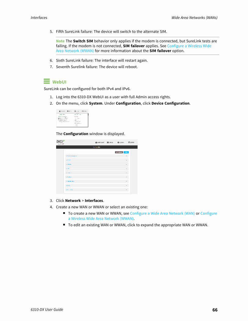
Interfaces Wide Area Networks (WANs)
6310-DX User Guide 66
5. Fifth SureLink failure: The device will switch to the alternate SIM.
Note The Switch SIM behavior only applies if the modem is connected, but SureLink tests arefailing. If the modem is not connected, SIM failover applies. See Configure a Wireless WideArea Network (WWAN) for more information about the SIM failover option.
6. Sixth SureLink failure: The interface will restart again.7. Seventh Surelink failure: The device will reboot.
WebUISureLink can be configured for both IPv4 and IPv6.
1. Log into the 6310-DX WebUI as a user with full Admin access rights.2. On the menu, click System. Under Configuration, click Device Configuration.
The Configuration window is displayed.
3. Click Network > Interfaces.4. Create a new WAN or WWAN or select an existing one:
n To create a new WAN or WWAN, see Configure a Wide Area Network (WAN) or Configurea Wireless Wide Area Network (WWAN).
n To edit an existing WAN or WWAN, click to expand the appropriate WAN or WWAN.
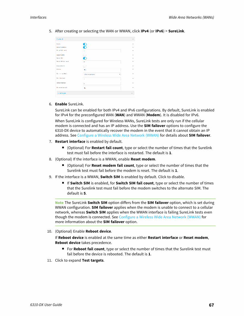
Interfaces Wide Area Networks (WANs)
6310-DX User Guide 67
5. After creating or selecting the WAN or WWAN, click IPv4 (or IPv6) > SureLink.
6. Enable SureLink.SureLink can be enabled for both IPv4 and IPv6 configurations. By default, SureLink is enabledfor IPv4 for the preconfigured WAN (WAN) and WWAN (Modem). It is disabled for IPv6.When SureLink is configured for Wireless WANs, SureLink tests are only run if the cellularmodem is connected and has an IP address. Use the SIM failover options to configure the6310-DX device to automatically recover the modem in the event that it cannot obtain an IPaddress. See Configure a Wireless Wide Area Network (WWAN) for details about SIM failover.
7. Restart interface is enabled by default.n (Optional) For Restart fail count, type or select the number of times that the Surelink
test must fail before the interface is restarted. The default is 1.8. (Optional) If the interface is a WWAN, enable Reset modem.
n (Optional) For Reset modem fail count, type or select the number of times that theSurelink test must fail before the modem is reset. The default is 1.
9. If the interface is a WWAN, Switch SIM is enabled by default. Click to disable.n If Switch SIM is enabled, for Switch SIM fail count, type or select the number of times
that the Surelink test must fail before the modem switches to the alternate SIM. Thedefault is 5.
Note The SureLink Switch SIM option differs from the SIM failover option, which is set duringWWAN configuration. SIM failover applies when the modem is unable to connect to a cellularnetwork, whereas Switch SIM applies when the WWAN interface is failing SureLink tests eventhough the modem is connected. See Configure a Wireless Wide Area Network (WWAN) formore information about the SIM failover option.
10. (Optional) Enable Reboot device.If Reboot device is enabled at the same time as either Restart interface or Reset modem,Reboot device takes precedence.
n For Reboot fail count, type or select the number of times that the Surelink test mustfail before the device is rebooted. The default is 1.
11. Click to expand Test targets.
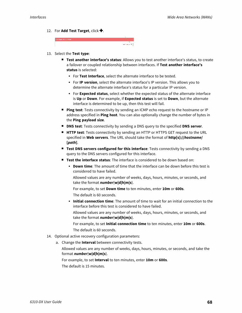
Interfaces Wide Area Networks (WANs)
6310-DX User Guide 68
12. For Add Test Target, click .
13. Select the Test type:n Test another interface's status: Allows you to test another interface's status, to create
a failover or coupled relationship between interfaces. If Test another interface'sstatus is selected:l For Test Interface, select the alternate interface to be tested.l For IP version, select the alternate interface's IP version. This allows you to
determine the alternate interface's status for a particular IP version.l For Expected status, select whether the expected status of the alternate interface
is Up or Down. For example, if Expected status is set to Down, but the alternateinterface is determined to be up, then this test will fail.
n Ping test: Tests connectivity by sending an ICMP echo request to the hostname or IPaddress specified in Ping host. You can also optionally change the number of bytes inthe Ping payload size.
n DNS test: Tests connectivity by sending a DNS query to the specified DNS server.n HTTP test: Tests connectivity by sending an HTTP or HTTPS GET request to the URL
specified in Web servers. The URL should take the format of http[s]://hostname/[path].
n Test DNS servers configured for this interface: Tests connectivity by sending a DNSquery to the DNS servers configured for this interface.
n Test the interface status: The interface is considered to be down based on:l Down time: The amount of time that the interface can be down before this test is
considered to have failed.Allowed values are any number of weeks, days, hours, minutes, or seconds, andtake the format number{w|d|h|m|s}.For example, to set Down time to ten minutes, enter 10m or 600s.The default is 60 seconds.
l Initial connection time: The amount of time to wait for an initial connection to theinterface before this test is considered to have failed.Allowed values are any number of weeks, days, hours, minutes, or seconds, andtake the format number{w|d|h|m|s}.For example, to set Initial connection time to ten minutes, enter 10m or 600s.The default is 60 seconds.
14. Optional active recovery configuration parameters:a. Change the Interval between connectivity tests.
Allowed values are any number of weeks, days, hours, minutes, or seconds, and take theformat number{w|d|h|m|s}.For example, to set Interval to ten minutes, enter 10m or 600s.The default is 15 minutes.
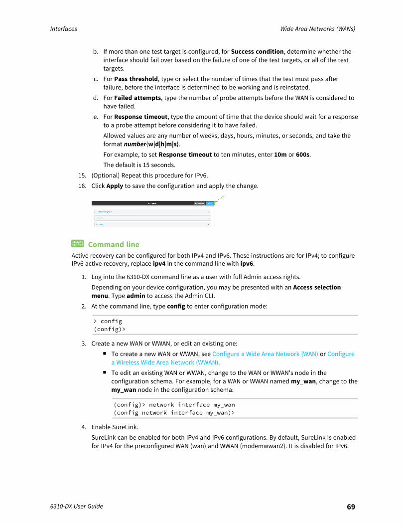
Interfaces Wide Area Networks (WANs)
6310-DX User Guide 69
b. If more than one test target is configured, for Success condition, determine whether theinterface should fail over based on the failure of one of the test targets, or all of the testtargets.
c. For Pass threshold, type or select the number of times that the test must pass afterfailure, before the interface is determined to be working and is reinstated.
d. For Failed attempts, type the number of probe attempts before the WAN is considered tohave failed.
e. For Response timeout, type the amount of time that the device should wait for a responseto a probe attempt before considering it to have failed.Allowed values are any number of weeks, days, hours, minutes, or seconds, and take theformat number{w|d|h|m|s}.For example, to set Response timeout to ten minutes, enter 10m or 600s.The default is 15 seconds.
15. (Optional) Repeat this procedure for IPv6.16. Click Apply to save the configuration and apply the change.
Command lineActive recovery can be configured for both IPv4 and IPv6. These instructions are for IPv4; to configureIPv6 active recovery, replace ipv4 in the command line with ipv6.
1. Log into the 6310-DX command line as a user with full Admin access rights.Depending on your device configuration, you may be presented with an Access selectionmenu. Type admin to access the Admin CLI.
2. At the command line, type config to enter configuration mode:
> config(config)>
3. Create a new WAN or WWAN, or edit an existing one:n To create a new WAN or WWAN, see Configure a Wide Area Network (WAN) or Configure
a Wireless Wide Area Network (WWAN).n To edit an existing WAN or WWAN, change to the WAN or WWAN's node in the
configuration schema. For example, for a WAN or WWAN named my_wan, change to themy_wan node in the configuration schema:
(config)> network interface my_wan(config network interface my_wan)>
4. Enable SureLink.SureLink can be enabled for both IPv4 and IPv6 configurations. By default, SureLink is enabledfor IPv4 for the preconfigured WAN (wan) and WWAN (modemwwan2). It is disabled for IPv6.
Interfaces Wide Area Networks (WANs)
6310-DX User Guide 70
When SureLink is configured for Wireless WANs, SureLink tests are only run if the cellularmodem is connected and has an IP address. Use the SIM failover options to configure the6310-DX device to automatically recover the modem in the event that it cannot obtain an IPaddress. See Configure a Wireless Wide Area Network (WWAN) for details about SIM failover.
(config network interface my_wan> ipv4 surelink enable true(config network interface my_wan)>
5. By default, the device is configured to restart the interface when its connection is consideredto have failed.To disable:
(config network interface my_wan ipv4 surelink)> restart false(config network interface my_wan ipv4 surelink>
n (Optional) Set the number of times that the Surelink test must fail before the interfaceis restarted:
(config network interface my_wan ipv4 surelink)> restart_attemptsint(config network interface my_wan ipv4 surelink>
where int is any number greater than 0. The default is 1.6. (Optional) If the interface is a WWAN, set the device to reset the modem:
(config network interface my_wan ipv4 surelink)> reset_modem true(config network interface my_wan ipv4 surelink>
n If reset_modem is enabled, set the number of times that Surelink tests must fail priorto resetting the modem:
(config network interface my_wan ipv4 surelink)> reset_modem_attempts int(config network interface my_wan ipv4 surelink>
where int is an integer between 1 through 5. The default is 1.7. If the interface is a WWAN, SIM switching is enabled by default. To disable:
(config network interface my_wan ipv4 surelink)> switch_sim false(config network interface my_wan ipv4 surelink>
Note The SureLink switch_sim option differs from the sim_failover option, which is setduring WWAN configuration. sim_failover applies when the modem is unable to connect to acellular network, whereas switch_sim applies when the WWAN interface is failing SureLinktests even though the modem is connected. See Configure a Wireless Wide Area Network(WWAN) for more information about the sim_failover option.
n If switch_sim is enabled, set the number of times that Surelink tests must fail prior toswitching SIMS:
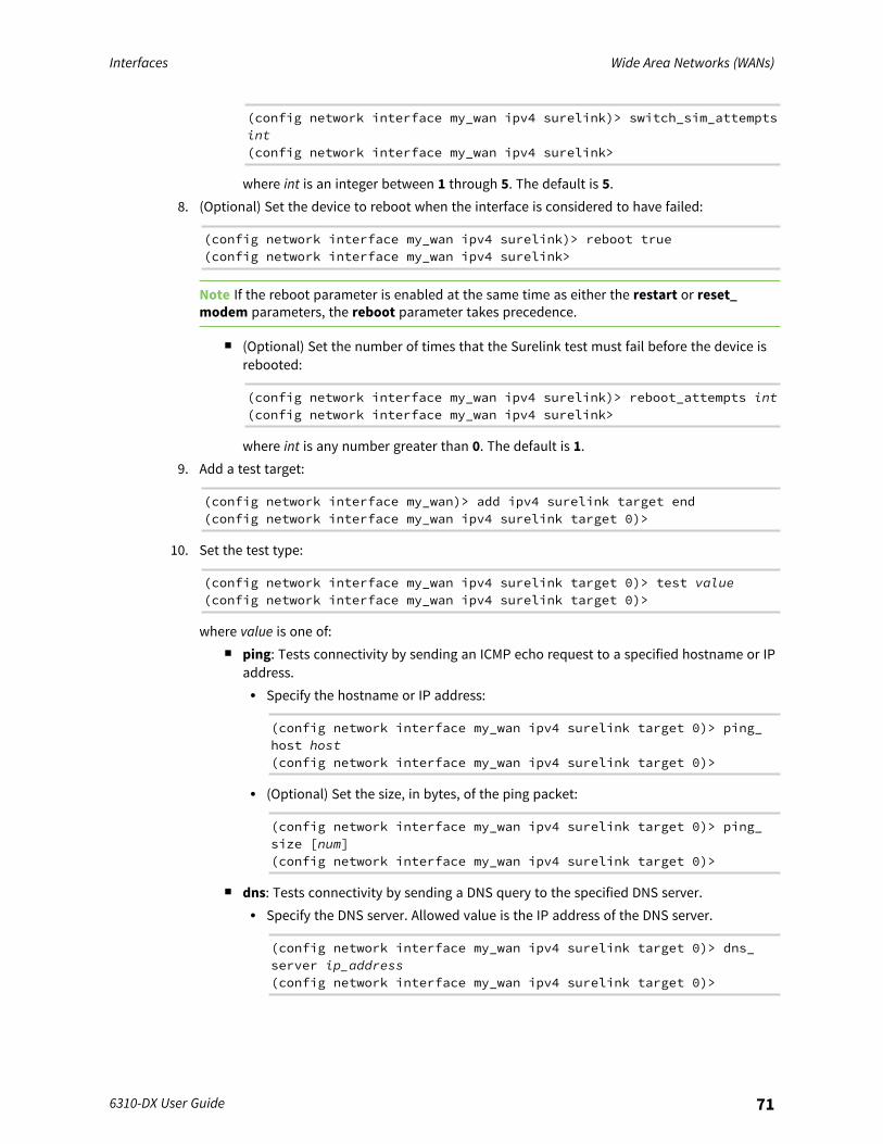
Interfaces Wide Area Networks (WANs)
6310-DX User Guide 71
(config network interface my_wan ipv4 surelink)> switch_sim_attemptsint(config network interface my_wan ipv4 surelink>
where int is an integer between 1 through 5. The default is 5.8. (Optional) Set the device to reboot when the interface is considered to have failed:
(config network interface my_wan ipv4 surelink)> reboot true(config network interface my_wan ipv4 surelink>
Note If the reboot parameter is enabled at the same time as either the restart or reset_modem parameters, the reboot parameter takes precedence.
n (Optional) Set the number of times that the Surelink test must fail before the device isrebooted:
(config network interface my_wan ipv4 surelink)> reboot_attempts int(config network interface my_wan ipv4 surelink>
where int is any number greater than 0. The default is 1.9. Add a test target:
(config network interface my_wan)> add ipv4 surelink target end(config network interface my_wan ipv4 surelink target 0)>
10. Set the test type:
(config network interface my_wan ipv4 surelink target 0)> test value(config network interface my_wan ipv4 surelink target 0)>
where value is one of:n ping: Tests connectivity by sending an ICMP echo request to a specified hostname or IP
address.l Specify the hostname or IP address:
(config network interface my_wan ipv4 surelink target 0)> ping_host host(config network interface my_wan ipv4 surelink target 0)>
l (Optional) Set the size, in bytes, of the ping packet:
(config network interface my_wan ipv4 surelink target 0)> ping_size [num](config network interface my_wan ipv4 surelink target 0)>
n dns: Tests connectivity by sending a DNS query to the specified DNS server.l Specify the DNS server. Allowed value is the IP address of the DNS server.
(config network interface my_wan ipv4 surelink target 0)> dns_server ip_address(config network interface my_wan ipv4 surelink target 0)>

Interfaces Wide Area Networks (WANs)
6310-DX User Guide 72
n dns_configured: Tests connectivity by sending a DNS query to the DNS serversconfigured for this interface.
n http: Tests connectivity by sending an HTTP or HTTPS GET request to the specified URL.l Specify the url:
(config network interface my_wan ipv4 surelink target 0)> http_url value(config network interface my_wan ipv4 surelink target 0)>
where value uses the format http[s]://hostname/[path]n interface_up: The interface is considered to be down based on the interfaces down
time, and the amount of time an initial connection to the interface takes before this testis considered to have failed.l (Optional) Set the amount of time that the interface can be down before this test is
considered to have failed:
(config network interface my_wan ipv4 surelink target 0)>interface_down_time value(config network interface my_wan ipv4 surelink target 0)>
where value is any number of weeks, days, hours, minutes, or seconds, and takesthe format number{w|d|h|m|s}.For example, to set interface_down_time to ten minutes, enter either 10m or 600s:
(config network interface my_wan ipv4 surelink target 0)>interface_down_time 600s(config network interface my_wan ipv4 surelink target 0)>
The default is 60 seconds.l (Optional) Set the amount of time to wait for an initial connection to the interface
before this test is considered to have failed:
(config network interface my_wan ipv4 surelink target 0)>interface_timeout value(config network interface my_wan ipv4 surelink target 0)>
where value is any number of weeks, days, hours, minutes, or seconds, and takesthe format number{w|d|h|m|s}.For example, to set interface_timeout to ten minutes, enter either 10m or 600s:
(config network interface my_wan ipv4 surelink target 0)>interface_timeout 600s(config network interface my_wan ipv4 surelink target 0)>
The default is 60 seconds.l other: Allows you to test another interface's status, to create a failover or coupled
relationship between interfaces:

Interfaces Wide Area Networks (WANs)
6310-DX User Guide 73
(config network interface my_wan ipv4 surelink target 0)> othervalue(config network interface my_wan ipv4 surelink target 0)>
If other is set:o Set the alternate interface to be tested:
i. Use the ? to determine available interfaces:
(config network interface my_wan ipv4 surelink target0)> other_interface ?
Interface: The network interface.Format:/network/interface/defaultip/network/interface/defaultlinklocal/network/interface/lan/network/interface/loopback/network/interface/modem/network/interface/wan
Current value:
(config network interface my_wan ipv4 surelink target0)> other_interface
ii. Set the interface. For example:
(config network interface my_wan ipv4 surelink target0)> other_interface /network/interface/wan(config network interface my_wan ipv4 surelink target0)>
o Set the alternate interface's IP version. This allows you to determine thealternate interface's status for a particular IP version.
(config network interface my_wan ipv4 surelink target 0)>other_ip_version value(config network interface my_wan ipv4 surelink target 0)>
where value is one of: any, both, ipv4, or ipv6.o Set the expected status of the alternate interface:
(config network interface my_wan ipv4 surelink target 0)>other_status value(config network interface my_wan ipv4 surelink target 0)>
where value is either up or down. For example, if other_status is set to down,but the alternate interface is determined to be up, then this test will fail.
(Optional) Repeat to add additional test targets.11. Optional active recovery configuration parameters:
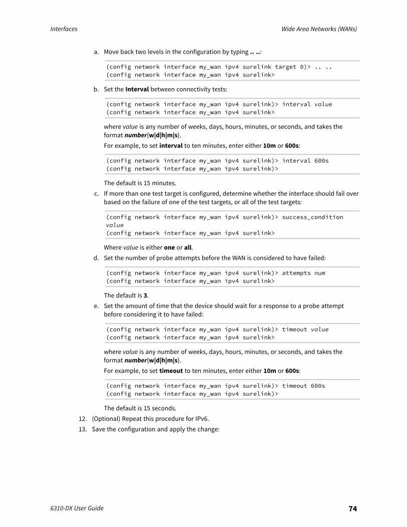
Interfaces Wide Area Networks (WANs)
6310-DX User Guide 74
a. Move back two levels in the configuration by typing .. ..:
(config network interface my_wan ipv4 surelink target 0)> .. ..(config network interface my_wan ipv4 surelink>
b. Set the Interval between connectivity tests:
(config network interface my_wan ipv4 surelink)> interval value(config network interface my_wan ipv4 surelink>
where value is any number of weeks, days, hours, minutes, or seconds, and takes theformat number{w|d|h|m|s}.For example, to set interval to ten minutes, enter either 10m or 600s:
(config network interface my_wan ipv4 surelink)> interval 600s(config network interface my_wan ipv4 surelink)>
The default is 15 minutes.c. If more than one test target is configured, determine whether the interface should fail over
based on the failure of one of the test targets, or all of the test targets:
(config network interface my_wan ipv4 surelink)> success_conditionvalue(config network interface my_wan ipv4 surelink>
Where value is either one or all.d. Set the number of probe attempts before the WAN is considered to have failed:
(config network interface my_wan ipv4 surelink)> attempts num(config network interface my_wan ipv4 surelink>
The default is 3.e. Set the amount of time that the device should wait for a response to a probe attempt
before considering it to have failed:
(config network interface my_wan ipv4 surelink)> timeout value(config network interface my_wan ipv4 surelink>
where value is any number of weeks, days, hours, minutes, or seconds, and takes theformat number{w|d|h|m|s}.For example, to set timeout to ten minutes, enter either 10m or 600s:
(config network interface my_wan ipv4 surelink)> timeout 600s(config network interface my_wan ipv4 surelink)>
The default is 15 seconds.12. (Optional) Repeat this procedure for IPv6.13. Save the configuration and apply the change:
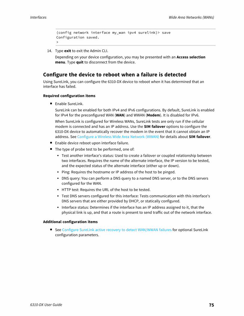
Interfaces Wide Area Networks (WANs)
6310-DX User Guide 75
(config network interface my_wan ipv4 surelink)> saveConfiguration saved.>
14. Type exit to exit the Admin CLI.Depending on your device configuration, you may be presented with an Access selectionmenu. Type quit to disconnect from the device.
Configure the device to reboot when a failure is detectedUsing SureLink, you can configure the 6310-DX device to reboot when it has determined that aninterface has failed.
Required configuration items
n Enable SureLink.SureLink can be enabled for both IPv4 and IPv6 configurations. By default, SureLink is enabledfor IPv4 for the preconfigured WAN (WAN) and WWAN (Modem). It is disabled for IPv6.When SureLink is configured for Wireless WANs, SureLink tests are only run if the cellularmodem is connected and has an IP address. Use the SIM failover options to configure the6310-DX device to automatically recover the modem in the event that it cannot obtain an IPaddress. See Configure a Wireless Wide Area Network (WWAN) for details about SIM failover.
n Enable device reboot upon interface failure.n The type of probe test to be performed, one of:
l Test another interface's status: Used to create a failover or coupled relationship betweentwo interfaces. Requires the name of the alternate interface, the IP version to be tested,and the expected status of the alternate interface (either up or down).
l Ping: Requires the hostname or IP address of the host to be pinged.l DNS query: You can perform a DNS query to a named DNS server, or to the DNS servers
configured for the WAN.l HTTP test: Requires the URL of the host to be tested.l Test DNS servers configured for this interface: Tests communication with this interface's
DNS servers that are either provided by DHCP, or statically configured.l Interface status: Determines if the interface has an IP address assigned to it, that the
physical link is up, and that a route is present to send traffic out of the network interface.
Additional configuration items
n See Configure SureLink active recovery to detect WAN/WWAN failures for optional SureLinkconfiguration parameters.
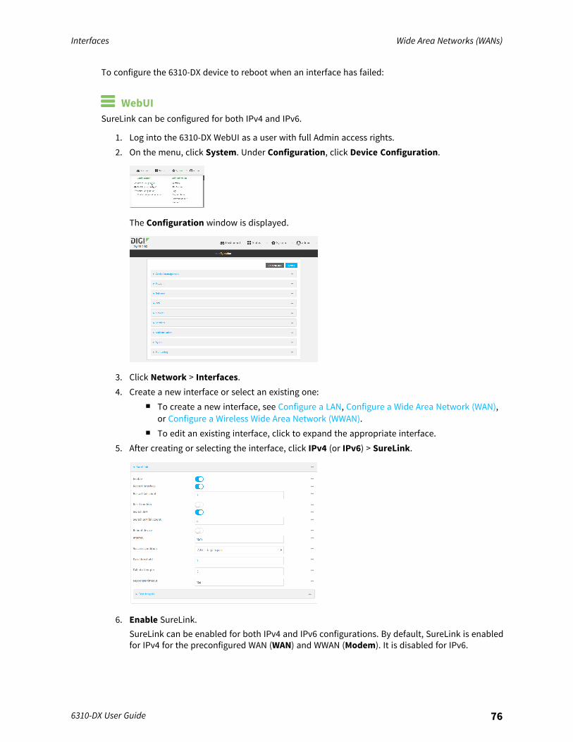
Interfaces Wide Area Networks (WANs)
6310-DX User Guide 76
To configure the 6310-DX device to reboot when an interface has failed:
WebUISureLink can be configured for both IPv4 and IPv6.
1. Log into the 6310-DX WebUI as a user with full Admin access rights.2. On the menu, click System. Under Configuration, click Device Configuration.
The Configuration window is displayed.
3. Click Network > Interfaces.4. Create a new interface or select an existing one:
n To create a new interface, see Configure a LAN, Configure a Wide Area Network (WAN),or Configure a Wireless Wide Area Network (WWAN).
n To edit an existing interface, click to expand the appropriate interface.5. After creating or selecting the interface, click IPv4 (or IPv6) > SureLink.
6. Enable SureLink.SureLink can be enabled for both IPv4 and IPv6 configurations. By default, SureLink is enabledfor IPv4 for the preconfigured WAN (WAN) and WWAN (Modem). It is disabled for IPv6.
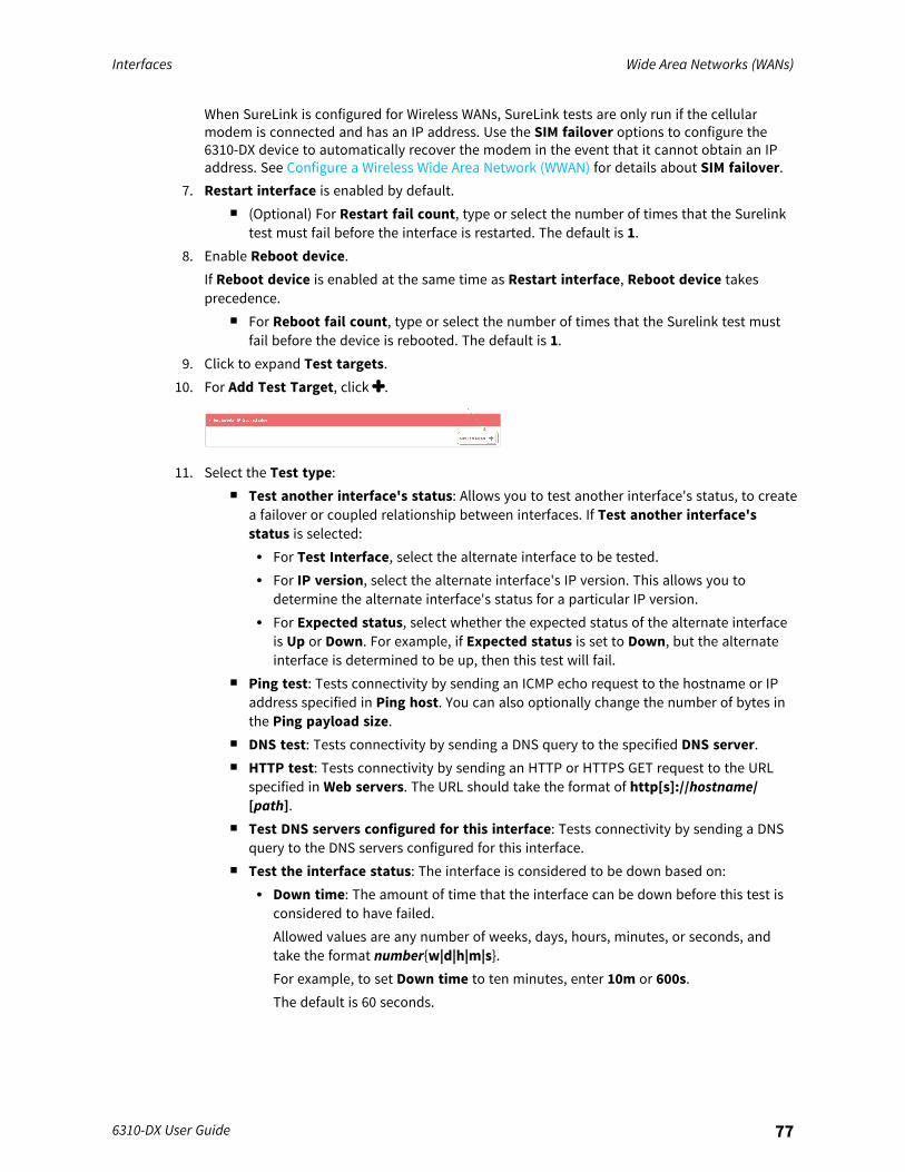
Interfaces Wide Area Networks (WANs)
6310-DX User Guide 77
When SureLink is configured for Wireless WANs, SureLink tests are only run if the cellularmodem is connected and has an IP address. Use the SIM failover options to configure the6310-DX device to automatically recover the modem in the event that it cannot obtain an IPaddress. See Configure a Wireless Wide Area Network (WWAN) for details about SIM failover.
7. Restart interface is enabled by default.n (Optional) For Restart fail count, type or select the number of times that the Surelink
test must fail before the interface is restarted. The default is 1.8. Enable Reboot device.
If Reboot device is enabled at the same time as Restart interface, Reboot device takesprecedence.
n For Reboot fail count, type or select the number of times that the Surelink test mustfail before the device is rebooted. The default is 1.
9. Click to expand Test targets.10. For Add Test Target, click .
11. Select the Test type:n Test another interface's status: Allows you to test another interface's status, to create
a failover or coupled relationship between interfaces. If Test another interface'sstatus is selected:l For Test Interface, select the alternate interface to be tested.l For IP version, select the alternate interface's IP version. This allows you to
determine the alternate interface's status for a particular IP version.l For Expected status, select whether the expected status of the alternate interface
is Up or Down. For example, if Expected status is set to Down, but the alternateinterface is determined to be up, then this test will fail.
n Ping test: Tests connectivity by sending an ICMP echo request to the hostname or IPaddress specified in Ping host. You can also optionally change the number of bytes inthe Ping payload size.
n DNS test: Tests connectivity by sending a DNS query to the specified DNS server.n HTTP test: Tests connectivity by sending an HTTP or HTTPS GET request to the URL
specified in Web servers. The URL should take the format of http[s]://hostname/[path].
n Test DNS servers configured for this interface: Tests connectivity by sending a DNSquery to the DNS servers configured for this interface.
n Test the interface status: The interface is considered to be down based on:l Down time: The amount of time that the interface can be down before this test is
considered to have failed.Allowed values are any number of weeks, days, hours, minutes, or seconds, andtake the format number{w|d|h|m|s}.For example, to set Down time to ten minutes, enter 10m or 600s.The default is 60 seconds.
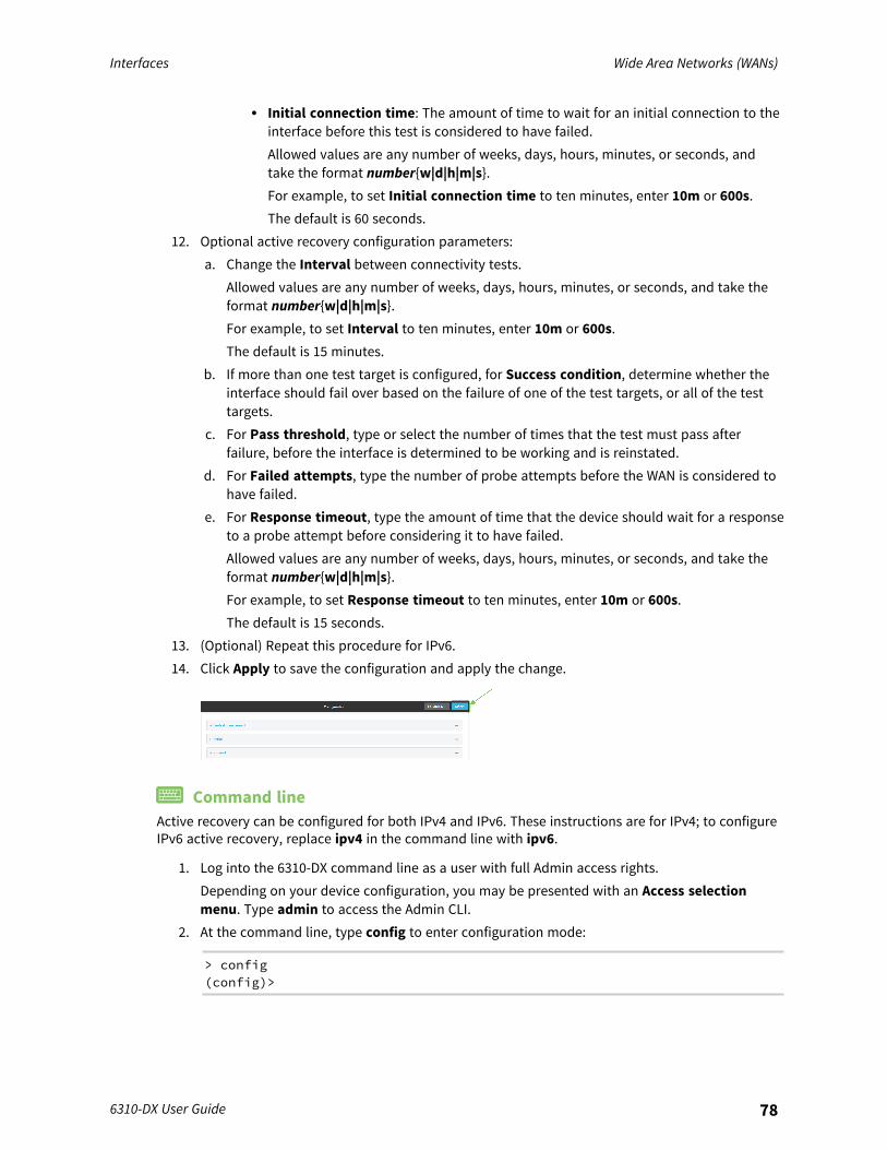
Interfaces Wide Area Networks (WANs)
6310-DX User Guide 78
l Initial connection time: The amount of time to wait for an initial connection to theinterface before this test is considered to have failed.Allowed values are any number of weeks, days, hours, minutes, or seconds, andtake the format number{w|d|h|m|s}.For example, to set Initial connection time to ten minutes, enter 10m or 600s.The default is 60 seconds.
12. Optional active recovery configuration parameters:a. Change the Interval between connectivity tests.
Allowed values are any number of weeks, days, hours, minutes, or seconds, and take theformat number{w|d|h|m|s}.For example, to set Interval to ten minutes, enter 10m or 600s.The default is 15 minutes.
b. If more than one test target is configured, for Success condition, determine whether theinterface should fail over based on the failure of one of the test targets, or all of the testtargets.
c. For Pass threshold, type or select the number of times that the test must pass afterfailure, before the interface is determined to be working and is reinstated.
d. For Failed attempts, type the number of probe attempts before the WAN is considered tohave failed.
e. For Response timeout, type the amount of time that the device should wait for a responseto a probe attempt before considering it to have failed.Allowed values are any number of weeks, days, hours, minutes, or seconds, and take theformat number{w|d|h|m|s}.For example, to set Response timeout to ten minutes, enter 10m or 600s.The default is 15 seconds.
13. (Optional) Repeat this procedure for IPv6.14. Click Apply to save the configuration and apply the change.
Command lineActive recovery can be configured for both IPv4 and IPv6. These instructions are for IPv4; to configureIPv6 active recovery, replace ipv4 in the command line with ipv6.
1. Log into the 6310-DX command line as a user with full Admin access rights.Depending on your device configuration, you may be presented with an Access selectionmenu. Type admin to access the Admin CLI.
2. At the command line, type config to enter configuration mode:
> config(config)>
Interfaces Wide Area Networks (WANs)
6310-DX User Guide 79
3. Create a new interface, or edit an existing one:n To create a new interface, see Configure a LAN, Configure a Wide Area Network (WAN),
or Configure a Wide Area Network (WAN) or Configure a Wireless Wide Area Network(WWAN).
n To edit an existing interface, change to the interface's node in the configurationschema. For example, for a interface named my_wan, change to the my_wan node inthe configuration schema:
(config)> network interface my_wan(config network interface my_wan)>
4. Enable SureLink.SureLink can be enabled for both IPv4 and IPv6 configurations. By default, SureLink is enabledfor IPv4 for the preconfigured WAN (wan) and WWAN (modemwwan2). It is disabled for IPv6.When SureLink is configured for Wireless WANs, SureLink tests are only run if the cellularmodem is connected and has an IP address. Use the SIM failover options to configure the6310-DX device to automatically recover the modem in the event that it cannot obtain an IPaddress. See Configure a Wireless Wide Area Network (WWAN) for details about SIM failover.
(config network interface my_wan> ipv4 surelink enable true(config network interface my_wan)>
5. By default, the device is configured to restart the interface when its connection is consideredto have failed.To disable:
(config network interface my_wan ipv4 surelink)> restart false(config network interface my_wan ipv4 surelink>
n (Optional) Set the number of times that the Surelink test must fail before the interfaceis restarted:
(config network interface my_wan ipv4 surelink)> restart_attemptsint(config network interface my_wan ipv4 surelink>
where int is any number greater than 0. The default is 1.6. Set the device to reboot when the interface is considered to have failed:
(config network interface my_wan ipv4 surelink)> reboot true(config network interface my_wan ipv4 surelink>
Note If the reboot parameter is enabled at the same time as the restart parameter, the rebootparameter takes precedence.
n (Optional) Set the number of times that the Surelink test must fail before the device isrebooted:
Interfaces Wide Area Networks (WANs)
6310-DX User Guide 80
(config network interface my_wan ipv4 surelink)> reboot_attempts int(config network interface my_wan ipv4 surelink>
where int is any number greater than 0. The default is 1.7. Add a test target:
(config network interface my_wan)> add ipv4 surelink target end(config network interface my_wan ipv4 surelink target 0)>
8. Set the test type:
(config network interface my_wan ipv4 surelink target 0)> test value(config network interface my_wan ipv4 surelink target 0)>
where value is one of:n ping: Tests connectivity by sending an ICMP echo request to a specified hostname or IP
address.l Specify the hostname or IP address:
(config network interface my_wan ipv4 surelink target 0)> ping_host host(config network interface my_wan ipv4 surelink target 0)>
l (Optional) Set the size, in bytes, of the ping packet:
(config network interface my_wan ipv4 surelink target 0)> ping_size [num](config network interface my_wan ipv4 surelink target 0)>
n dns: Tests connectivity by sending a DNS query to the specified DNS server.l Specify the DNS server. Allowed value is the IP address of the DNS server.
(config network interface my_wan ipv4 surelink target 0)> dns_server ip_address(config network interface my_wan ipv4 surelink target 0)>
n dns_configured: Tests connectivity by sending a DNS query to the DNS serversconfigured for this interface.
n http: Tests connectivity by sending an HTTP or HTTPS GET request to the specified URL.l Specify the url:
(config network interface my_wan ipv4 surelink target 0)> http_url value(config network interface my_wan ipv4 surelink target 0)>
where value uses the format http[s]://hostname/[path]n interface_up: The interface is considered to be down based on the interfaces down
time, and the amount of time an initial connection to the interface takes before this testis considered to have failed.
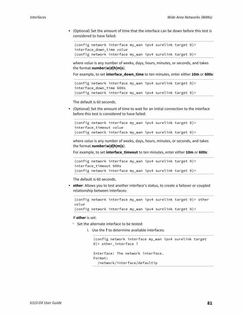
Interfaces Wide Area Networks (WANs)
6310-DX User Guide 81
l (Optional) Set the amount of time that the interface can be down before this test isconsidered to have failed:
(config network interface my_wan ipv4 surelink target 0)>interface_down_time value(config network interface my_wan ipv4 surelink target 0)>
where value is any number of weeks, days, hours, minutes, or seconds, and takesthe format number{w|d|h|m|s}.For example, to set interface_down_time to ten minutes, enter either 10m or 600s:
(config network interface my_wan ipv4 surelink target 0)>interface_down_time 600s(config network interface my_wan ipv4 surelink target 0)>
The default is 60 seconds.l (Optional) Set the amount of time to wait for an initial connection to the interface
before this test is considered to have failed:
(config network interface my_wan ipv4 surelink target 0)>interface_timeout value(config network interface my_wan ipv4 surelink target 0)>
where value is any number of weeks, days, hours, minutes, or seconds, and takesthe format number{w|d|h|m|s}.For example, to set interface_timeout to ten minutes, enter either 10m or 600s:
(config network interface my_wan ipv4 surelink target 0)>interface_timeout 600s(config network interface my_wan ipv4 surelink target 0)>
The default is 60 seconds.l other: Allows you to test another interface's status, to create a failover or coupled
relationship between interfaces:
(config network interface my_wan ipv4 surelink target 0)> othervalue(config network interface my_wan ipv4 surelink target 0)>
If other is set:o Set the alternate interface to be tested:
i. Use the ? to determine available interfaces:
(config network interface my_wan ipv4 surelink target0)> other_interface ?
Interface: The network interface.Format:/network/interface/defaultip
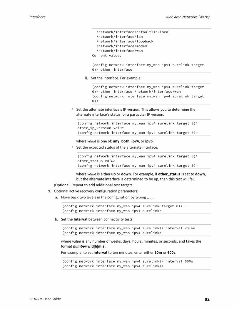
Interfaces Wide Area Networks (WANs)
6310-DX User Guide 82
/network/interface/defaultlinklocal/network/interface/lan/network/interface/loopback/network/interface/modem/network/interface/wan
Current value:
(config network interface my_wan ipv4 surelink target0)> other_interface
ii. Set the interface. For example:
(config network interface my_wan ipv4 surelink target0)> other_interface /network/interface/wan(config network interface my_wan ipv4 surelink target0)>
o Set the alternate interface's IP version. This allows you to determine thealternate interface's status for a particular IP version.
(config network interface my_wan ipv4 surelink target 0)>other_ip_version value(config network interface my_wan ipv4 surelink target 0)>
where value is one of: any, both, ipv4, or ipv6.o Set the expected status of the alternate interface:
(config network interface my_wan ipv4 surelink target 0)>other_status value(config network interface my_wan ipv4 surelink target 0)>
where value is either up or down. For example, if other_status is set to down,but the alternate interface is determined to be up, then this test will fail.
(Optional) Repeat to add additional test targets.9. Optional active recovery configuration parameters:
a. Move back two levels in the configuration by typing .. ..:
(config network interface my_wan ipv4 surelink target 0)> .. ..(config network interface my_wan ipv4 surelink>
b. Set the Interval between connectivity tests:
(config network interface my_wan ipv4 surelink)> interval value(config network interface my_wan ipv4 surelink>
where value is any number of weeks, days, hours, minutes, or seconds, and takes theformat number{w|d|h|m|s}.For example, to set interval to ten minutes, enter either 10m or 600s:
(config network interface my_wan ipv4 surelink)> interval 600s(config network interface my_wan ipv4 surelink)>
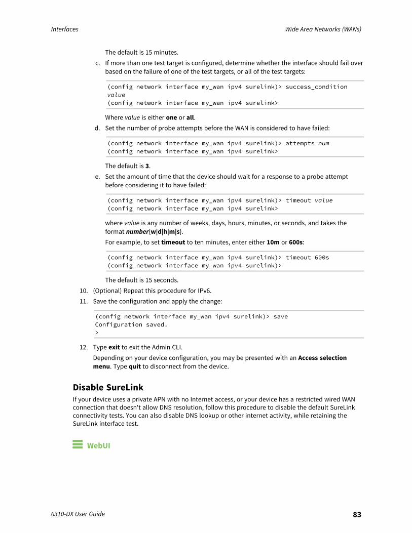
Interfaces Wide Area Networks (WANs)
6310-DX User Guide 83
The default is 15 minutes.c. If more than one test target is configured, determine whether the interface should fail over
based on the failure of one of the test targets, or all of the test targets:
(config network interface my_wan ipv4 surelink)> success_conditionvalue(config network interface my_wan ipv4 surelink>
Where value is either one or all.d. Set the number of probe attempts before the WAN is considered to have failed:
(config network interface my_wan ipv4 surelink)> attempts num(config network interface my_wan ipv4 surelink>
The default is 3.e. Set the amount of time that the device should wait for a response to a probe attempt
before considering it to have failed:
(config network interface my_wan ipv4 surelink)> timeout value(config network interface my_wan ipv4 surelink>
where value is any number of weeks, days, hours, minutes, or seconds, and takes theformat number{w|d|h|m|s}.For example, to set timeout to ten minutes, enter either 10m or 600s:
(config network interface my_wan ipv4 surelink)> timeout 600s(config network interface my_wan ipv4 surelink)>
The default is 15 seconds.10. (Optional) Repeat this procedure for IPv6.11. Save the configuration and apply the change:
(config network interface my_wan ipv4 surelink)> saveConfiguration saved.>
12. Type exit to exit the Admin CLI.Depending on your device configuration, you may be presented with an Access selectionmenu. Type quit to disconnect from the device.
Disable SureLinkIf your device uses a private APN with no Internet access, or your device has a restricted wired WANconnection that doesn't allow DNS resolution, follow this procedure to disable the default SureLinkconnectivity tests. You can also disable DNS lookup or other internet activity, while retaining theSureLink interface test.
WebUI
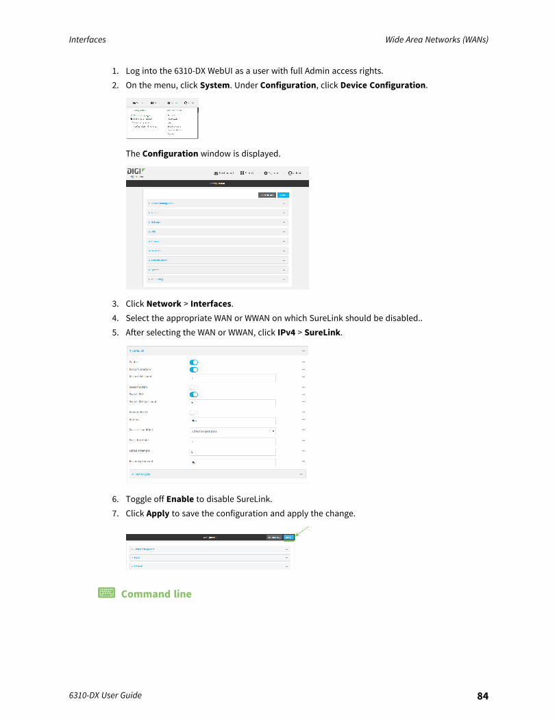
Interfaces Wide Area Networks (WANs)
6310-DX User Guide 84
1. Log into the 6310-DX WebUI as a user with full Admin access rights.2. On the menu, click System. Under Configuration, click Device Configuration.
The Configuration window is displayed.
3. Click Network > Interfaces.4. Select the appropriate WAN or WWAN on which SureLink should be disabled..5. After selecting the WAN or WWAN, click IPv4 > SureLink.
6. Toggle off Enable to disable SureLink.7. Click Apply to save the configuration and apply the change.
Command line
Interfaces Wide Area Networks (WANs)
6310-DX User Guide 85
1. Log into the 6310-DX command line as a user with full Admin access rights.Depending on your device configuration, you may be presented with an Access selectionmenu. Type admin to access the Admin CLI.
2. At the command line, type config to enter configuration mode:
> config(config)>
3. Change to the WAN or WWAN's node in the configuration schema. For example, to disableSureLink for the Modem interface:
(config)> network interface modem(config network interface modem)>
4. Disable SureLink:
(config network interface modem> ipv4 surelink enable false(config network interface modem)>
5. Save the configuration and apply the change:
(config network interface my_wwan ipv4 surelink)> saveConfiguration saved.>
6. Type exit to exit the Admin CLI.Depending on your device configuration, you may be presented with an Access selectionmenu. Type quit to disconnect from the device.
Disable DNS lookupAlternatively, you can disable DNS lookup or other internet activity for device that use a private APNwith no Internet access, or that have restricted wired WAN connections that do not allow DNSresolution, while retaining the SureLink interface test. The SureLink interface test determines if theinterface has an IP address assigned to it, that the physical link is up, and that a route is present tosend traffic out of the network interface.
WebUI
1. Log into the 6310-DX WebUI as a user with full Admin access rights.2. On the menu, click System. Under Configuration, click Device Configuration.
The Configuration window is displayed.

Interfaces Wide Area Networks (WANs)
6310-DX User Guide 86
3. Click Network > Interfaces.4. Select the appropriate WAN or WWAN on which SureLink should be disabled..5. After selecting the WAN or WWAN, click IPv4 > SureLink.
6. Click to expand Test targets.7. Click to expand the second test target. This test target has its Test type set to Test DNS
servers configured for this interface.
8. Click the menu icon (...) next to the target and select Delete.
9. Click Apply to save the configuration and apply the change.
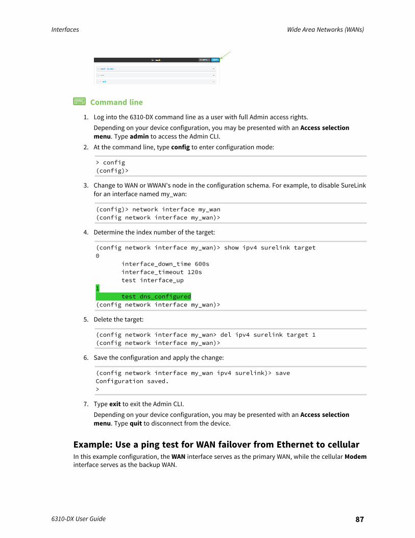
Interfaces Wide Area Networks (WANs)
6310-DX User Guide 87
Command line
1. Log into the 6310-DX command line as a user with full Admin access rights.Depending on your device configuration, you may be presented with an Access selectionmenu. Type admin to access the Admin CLI.
2. At the command line, type config to enter configuration mode:
> config(config)>
3. Change to WAN or WWAN's node in the configuration schema. For example, to disable SureLinkfor an interface named my_wan:
(config)> network interface my_wan(config network interface my_wan)>
4. Determine the index number of the target:
(config network interface my_wan)> show ipv4 surelink target0
interface_down_time 600sinterface_timeout 120stest interface_up
1test dns_configured
(config network interface my_wan)>
5. Delete the target:
(config network interface my_wan> del ipv4 surelink target 1(config network interface my_wan)>
6. Save the configuration and apply the change:
(config network interface my_wan ipv4 surelink)> saveConfiguration saved.>
7. Type exit to exit the Admin CLI.Depending on your device configuration, you may be presented with an Access selectionmenu. Type quit to disconnect from the device.
Example: Use a ping test for WAN failover from Ethernet to cellularIn this example configuration, the WAN interface serves as the primary WAN, while the cellular Modeminterface serves as the backup WAN.
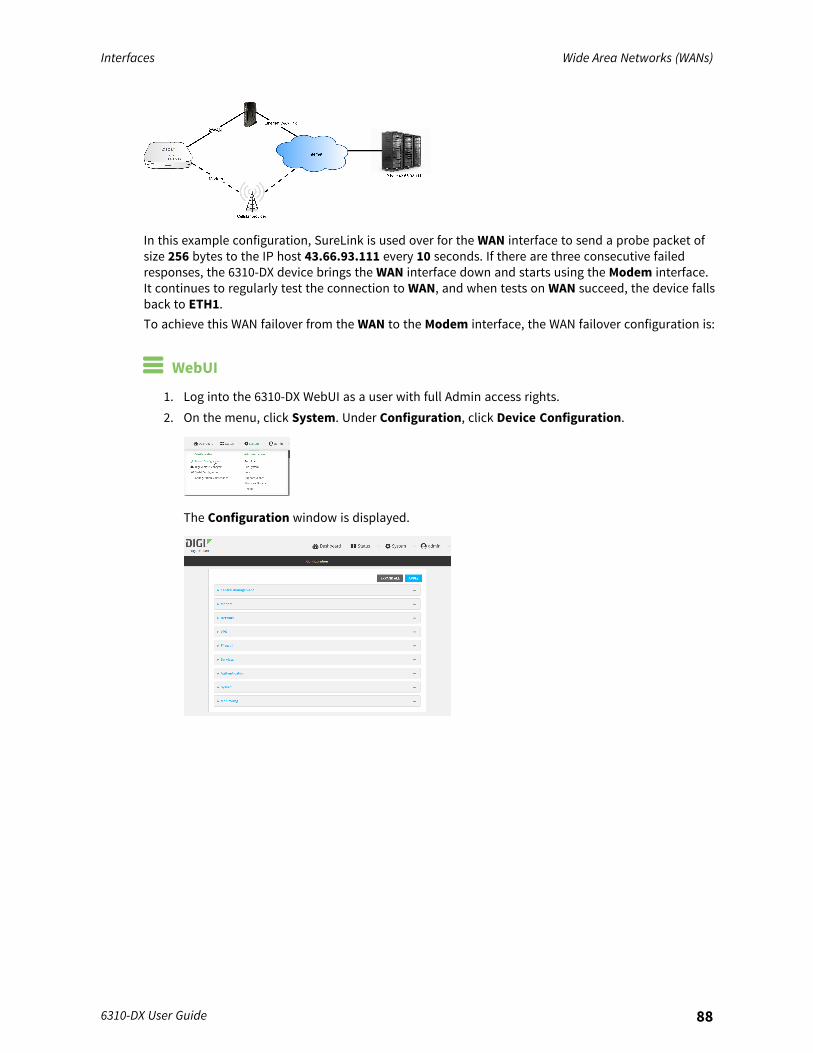
Interfaces Wide Area Networks (WANs)
6310-DX User Guide 88
In this example configuration, SureLink is used over for the WAN interface to send a probe packet ofsize 256 bytes to the IP host 43.66.93.111 every 10 seconds. If there are three consecutive failedresponses, the 6310-DX device brings the WAN interface down and starts using the Modem interface.It continues to regularly test the connection to WAN, and when tests on WAN succeed, the device fallsback to ETH1.To achieve this WAN failover from the WAN to the Modem interface, the WAN failover configuration is:
WebUI
1. Log into the 6310-DX WebUI as a user with full Admin access rights.2. On the menu, click System. Under Configuration, click Device Configuration.
The Configuration window is displayed.
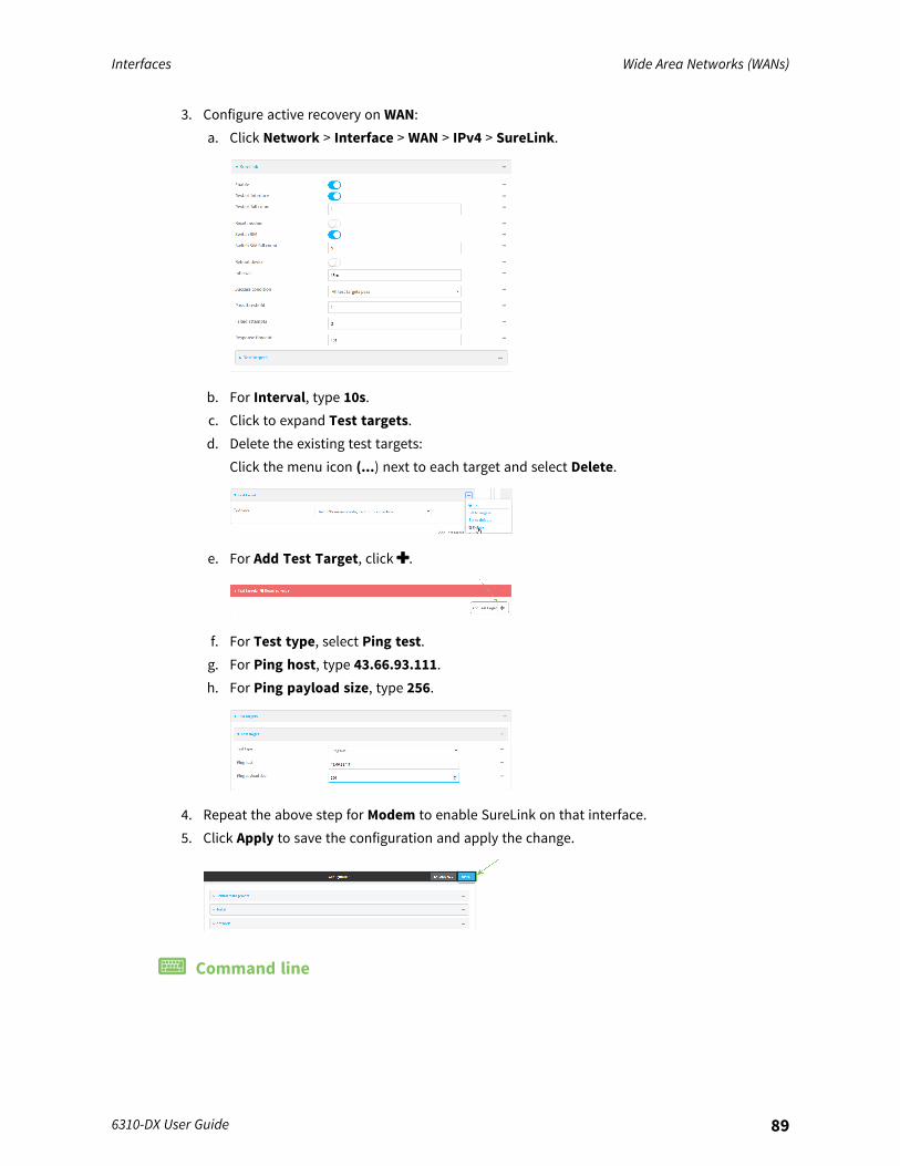
Interfaces Wide Area Networks (WANs)
6310-DX User Guide 89
3. Configure active recovery on WAN:a. Click Network > Interface > WAN > IPv4 > SureLink.
b. For Interval, type 10s.c. Click to expand Test targets.d. Delete the existing test targets:
Click the menu icon (...) next to each target and select Delete.
e. For Add Test Target, click .
f. For Test type, select Ping test.g. For Ping host, type 43.66.93.111.h. For Ping payload size, type 256.
4. Repeat the above step for Modem to enable SureLink on that interface.5. Click Apply to save the configuration and apply the change.
Command line

Interfaces Wide Area Networks (WANs)
6310-DX User Guide 90
1. Log into the 6310-DX command line as a user with full Admin access rights.Depending on your device configuration, you may be presented with an Access selectionmenu. Type admin to access the Admin CLI.
2. At the command line, type config to enter configuration mode:
> config(config)>
3. Configure SureLink on WAN:a. Set the interval to ten seconds:
(config)> network interface wan ipv4 surelink interval 10s(config)>
b. Delete the existing test targets:
(config network interface wan> del ipv4 surelink target 0(config network interface wan> del ipv4 surelink target 1(config network interface wan)>
c. Add a test target:
(config)> add network interface wan ipv4 surelink target end(config network interface wan ipv4 surelink target 0)>
d. Set the probe type to ping:
(config network interface wan ipv4 surelink target 0)> test ping(config network interface wan ipv4 surelink target 0)>
e. Set the packet size to 256 bytes:
(config network interface wan ipv4 surelink target 0)> ping_size 256(config network interface wan ipv4 surelink target 0)>
f. Set the host to ping:
(config network interface wan ipv4 surelink target 0)> ping_host43.66.93.111(config network interface wan ipv4 surelink target 0)>
1. Repeat the above step for the cellular Modem (modem) interface to enable SureLink on thatinterface.
4. Save the configuration and apply the change:
(config)> saveConfiguration saved.>
5. Type exit to exit the Admin CLI.Depending on your device configuration, you may be presented with an Access selectionmenu. Type quit to disconnect from the device.
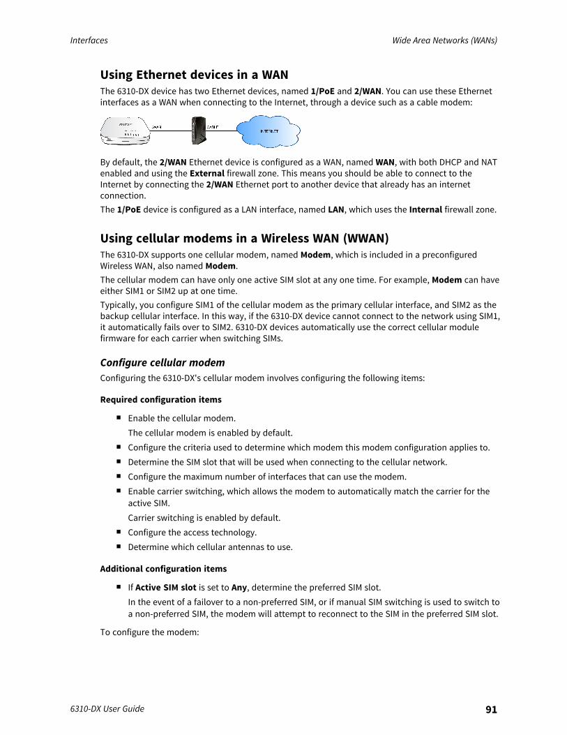
Interfaces Wide Area Networks (WANs)
6310-DX User Guide 91
Using Ethernet devices in a WANThe 6310-DX device has two Ethernet devices, named 1/PoE and 2/WAN. You can use these Ethernetinterfaces as a WAN when connecting to the Internet, through a device such as a cable modem:
By default, the 2/WAN Ethernet device is configured as a WAN, named WAN, with both DHCP and NATenabled and using the External firewall zone. This means you should be able to connect to theInternet by connecting the 2/WAN Ethernet port to another device that already has an internetconnection.The 1/PoE device is configured as a LAN interface, named LAN, which uses the Internal firewall zone.
Using cellular modems in a Wireless WAN (WWAN)The 6310-DX supports one cellular modem, named Modem, which is included in a preconfiguredWireless WAN, also named Modem.The cellular modem can have only one active SIM slot at any one time. For example, Modem can haveeither SIM1 or SIM2 up at one time.Typically, you configure SIM1 of the cellular modem as the primary cellular interface, and SIM2 as thebackup cellular interface. In this way, if the 6310-DX device cannot connect to the network using SIM1,it automatically fails over to SIM2. 6310-DX devices automatically use the correct cellular modulefirmware for each carrier when switching SIMs.
Configure cellular modemConfiguring the 6310-DX's cellular modem involves configuring the following items:
Required configuration items
n Enable the cellular modem.The cellular modem is enabled by default.
n Configure the criteria used to determine which modem this modem configuration applies to.n Determine the SIM slot that will be used when connecting to the cellular network.n Configure the maximum number of interfaces that can use the modem.n Enable carrier switching, which allows the modem to automatically match the carrier for the
active SIM.Carrier switching is enabled by default.
n Configure the access technology.n Determine which cellular antennas to use.
Additional configuration items
n If Active SIM slot is set to Any, determine the preferred SIM slot.In the event of a failover to a non-preferred SIM, or if manual SIM switching is used to switch toa non-preferred SIM, the modem will attempt to reconnect to the SIM in the preferred SIM slot.
To configure the modem:
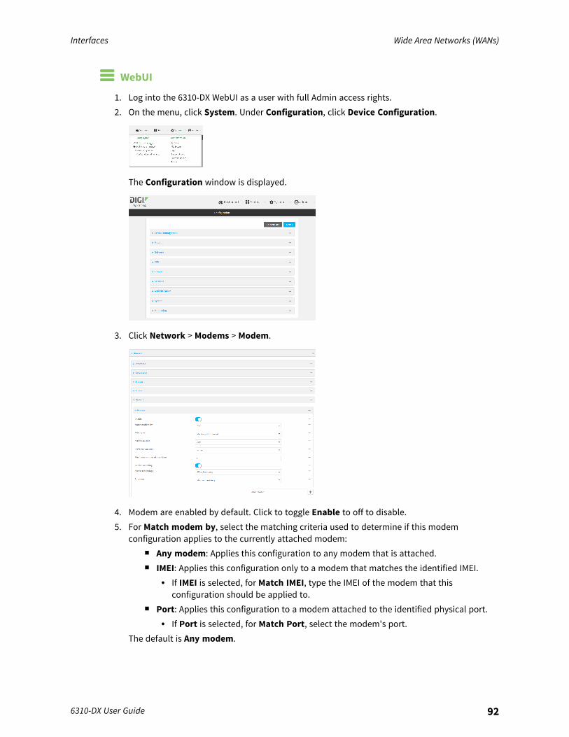
Interfaces Wide Area Networks (WANs)
6310-DX User Guide 92
WebUI
1. Log into the 6310-DX WebUI as a user with full Admin access rights.2. On the menu, click System. Under Configuration, click Device Configuration.
The Configuration window is displayed.
3. Click Network > Modems > Modem.
4. Modem are enabled by default. Click to toggle Enable to off to disable.5. For Match modem by, select the matching criteria used to determine if this modem
configuration applies to the currently attached modem:n Any modem: Applies this configuration to any modem that is attached.n IMEI: Applies this configuration only to a modem that matches the identified IMEI.
l If IMEI is selected, for Match IMEI, type the IMEI of the modem that thisconfiguration should be applied to.
n Port: Applies this configuration to a modem attached to the identified physical port.l If Port is selected, for Match Port, select the modem's port.
The default is Any modem.
Interfaces Wide Area Networks (WANs)
6310-DX User Guide 93
6. For Active SIM slot, select the SIM slot that should be used by the modem, or select Any to useany SIM slot. The default is Any.
7. If Active SIM slot is set to Any, for Preferred SIM slot, select the SIM slot that should beconsidered the preferred slot for this modem, or select None. In the event of a failover to anon-preferred SIM, or if manual SIM switching is used to switch to a non-preferred SIM, themodem will attempt to reconnect to the SIM in the preferred SIM slot. None is the default.
8. For Maximum number of interfaces, type the number of interfaces that can be configured touse this modem. This is used when using dual-APN SIMs. The default is 1.
9. Enable Carrier switching to allow the modem to automatically match the carrier for the activeSIM. Carrier switching is enabled by default.
10. For Access technology, select the type of cellular technology that this modem should use toaccess the cellular network, or select All technologies to configure the modem to use the bestavailable technology. The default is All technologies.
11. For Antennas, select whether the modem should use the main antenna, the auxiliary antenna,or both the main and auxiliary antennas.
12. Click Apply to save the configuration and apply the change.
Command line
1. Log into the 6310-DX command line as a user with full Admin access rights.Depending on your device configuration, you may be presented with an Access selectionmenu. Type admin to access the Admin CLI.
2. At the command line, type config to enter configuration mode:
> config(config)>
3. Modem configurations are enabled by default. To disable:
(config)> network modem modem enable false(config)>
4. Set the matching criteria used to determine if this modem configuration applies to thecurrently attached modem:
(config)> network modem modem match value(config)>
where value is one of the following:n any: Applies this configuration to any modem that is attached.n imei: Applies this configuration only to a modem that matches the identified IMEI.
l If imei is used, set the IMEI of the modem that this configuration should be appliedto:
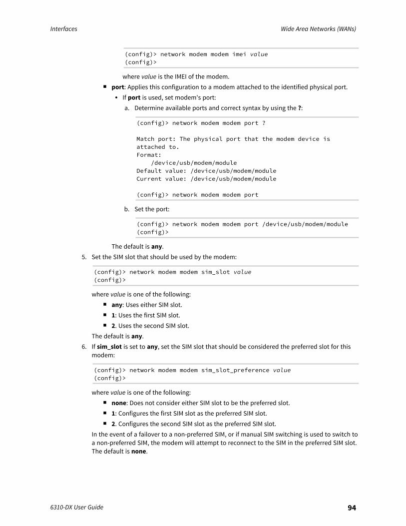
Interfaces Wide Area Networks (WANs)
6310-DX User Guide 94
(config)> network modem modem imei value(config)>
where value is the IMEI of the modem.n port: Applies this configuration to a modem attached to the identified physical port.
l If port is used, set modem's port:a. Determine available ports and correct syntax by using the ?:
(config)> network modem modem port ?
Match port: The physical port that the modem device isattached to.Format:
/device/usb/modem/moduleDefault value: /device/usb/modem/moduleCurrent value: /device/usb/modem/module
(config)> network modem modem port
b. Set the port:
(config)> network modem modem port /device/usb/modem/module(config)>
The default is any.5. Set the SIM slot that should be used by the modem:
(config)> network modem modem sim_slot value(config)>
where value is one of the following:n any: Uses either SIM slot.n 1: Uses the first SIM slot.n 2. Uses the second SIM slot.
The default is any.6. If sim_slot is set to any, set the SIM slot that should be considered the preferred slot for this
modem:
(config)> network modem modem sim_slot_preference value(config)>
where value is one of the following:n none: Does not consider either SIM slot to be the preferred slot.n 1: Configures the first SIM slot as the preferred SIM slot.n 2. Configures the second SIM slot as the preferred SIM slot.
In the event of a failover to a non-preferred SIM, or if manual SIM switching is used to switch toa non-preferred SIM, the modem will attempt to reconnect to the SIM in the preferred SIM slot.The default is none.
Interfaces Wide Area Networks (WANs)
6310-DX User Guide 95
7. Set the maximum number of interfaces. This is used when using dual-APN SIMs. The default is1.
(config)> network modem modem max_intfs int(config)>
8. Carrier switching allows the modem to automatically match the carrier for the active SIM.Carrier switching is enabled by default. To disable:
(config)> network modem modem carrier_switch false(config)>
9. Set the type of cellular technology that this modem should use to access the cellular network:
(config)> network modem modem access_tech value(config)>
Available options for value vary depending on the modem type. To determine availableoptions:
(config)> network modem modem access_tech ?
Access technology: The cellular network technology that the modem mayuse.Format:
2G3G4G4GM4GTall
Default value: allCurrent value: all
(config)>
The default is all, which uses the best available technology.10. Set whether the modem should use the main antenna, the auxiliary antenna, or both the main
and auxiliary antennas:
(config)> network modem modem antenna value(config)>
where value is one of the following:n mainn auxn both
11. Save the configuration and apply the change:
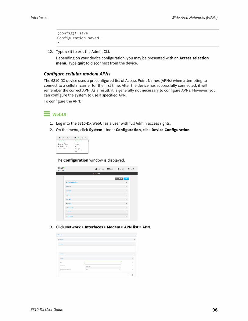
Interfaces Wide Area Networks (WANs)
6310-DX User Guide 96
(config)> saveConfiguration saved.>
12. Type exit to exit the Admin CLI.Depending on your device configuration, you may be presented with an Access selectionmenu. Type quit to disconnect from the device.
Configure cellular modem APNsThe 6310-DX device uses a preconfigured list of Access Point Names (APNs) when attempting toconnect to a cellular carrier for the first time. After the device has successfully connected, it willremember the correct APN. As a result, it is generally not necessary to configure APNs. However, youcan configure the system to use a specified APN.To configure the APN:
WebUI
1. Log into the 6310-DX WebUI as a user with full Admin access rights.2. On the menu, click System. Under Configuration, click Device Configuration.
The Configuration window is displayed.
3. Click Network > Interfaces > Modem > APN list > APN.

Interfaces Wide Area Networks (WANs)
6310-DX User Guide 97
4. For APN, type the Access Point Name (APN) to be used when connecting to the cellular carrier.5. (Optional) IP version:
For IP version, select one of the following:n Automatic: Requests both IPv4 and IPv6 address.n IPv4: Requests only an IPv4 address.n IPv6: Requests only an IPv6 address.
The default is Automatic.6. (Optional) For Authentication method, select one of the following:
n None: No authentication is required.n Automatic: The device will attempt to connect using CHAP first, and then PAP.n CHAP: Uses the Challenge Handshake Authentication Profile (CHAP) to authenticate.n PAP: Uses the Password Authentication Profile (PAP) to authenticate.
If Automatic, CHAP, or PAP is selected, enter the Username and Password required toauthenticate.The default is None.
7. To add additional APNs, for Add APN, click and repeat the preceding instructions.8. (Optional) To configure the device to bypass its preconfigured APN list and only use the
configured APNs, enable APN list only.
9. Click Apply to save the configuration and apply the change.
Command line
1. Log into the 6310-DX command line as a user with full Admin access rights.Depending on your device configuration, you may be presented with an Access selectionmenu. Type admin to access the Admin CLI.
2. At the command line, type config to enter configuration mode:
> config(config)>

Interfaces Wide Area Networks (WANs)
6310-DX User Guide 98
3. At the config prompt, type:
(config)> network interface modem modem apn 0 apn value(config)>
where value is the APN for the SIM card.4. (Optional) To add additional APNs:
a. Use the add command to add a new APN entry. For example:
(config)> add network interface modem modem apn end(config network interface modem modem apn 1)>
b. Set the value of the APN:
(config network interface modem modem apn 1)> apn value(config network interface modem modem apn 1)>
where value is the APN for the SIM card.5. (Optional) Set the IP version:
(config)> network interface modem modem apn 0 ip_version version(config)>
where version is one of the following:n auto: Requests both IPv4 and IPv6 address.n ipv4: Requests only an IPv4 address.n ipv6: Requests only an IPv6 address.
The default is auto.6. (Optional) Set the authentication method:
(config)> network interface modem modem apn 0 auth method(config)>
where method is one of the following:n none: No authentication is required.n auto: The device will attempt to connect using CHAP first, and then PAP.n chap: Uses the Challenge Handshake Authentication Profile (CHAP) to authenticate.n pap: Uses the Password Authentication Profile (PAP) to authenticate.
If auto, chap, or pap is selected, enter the Username and Password required to authenticate:
(config)> network interface modem modem apn 0 username name(config)> network interface modem modem apn 0 password pwd(config)>
The default is none.7. (Optional) To configure the device to bypass its preconfigured APN list and only use the
configured APNs:
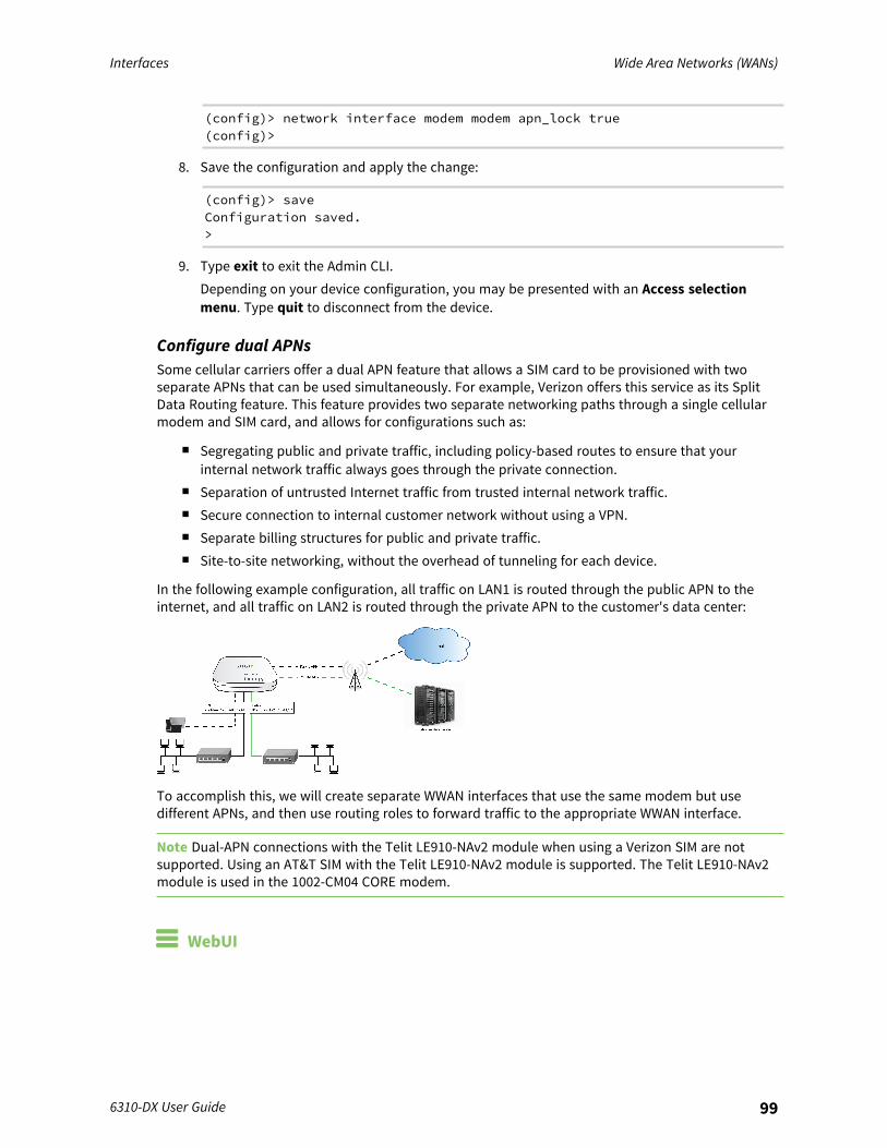
Interfaces Wide Area Networks (WANs)
6310-DX User Guide 99
(config)> network interface modem modem apn_lock true(config)>
8. Save the configuration and apply the change:
(config)> saveConfiguration saved.>
9. Type exit to exit the Admin CLI.Depending on your device configuration, you may be presented with an Access selectionmenu. Type quit to disconnect from the device.
Configure dual APNsSome cellular carriers offer a dual APN feature that allows a SIM card to be provisioned with twoseparate APNs that can be used simultaneously. For example, Verizon offers this service as its SplitData Routing feature. This feature provides two separate networking paths through a single cellularmodem and SIM card, and allows for configurations such as:
n Segregating public and private traffic, including policy-based routes to ensure that yourinternal network traffic always goes through the private connection.
n Separation of untrusted Internet traffic from trusted internal network traffic.n Secure connection to internal customer network without using a VPN.n Separate billing structures for public and private traffic.n Site-to-site networking, without the overhead of tunneling for each device.
In the following example configuration, all traffic on LAN1 is routed through the public APN to theinternet, and all traffic on LAN2 is routed through the private APN to the customer's data center:
To accomplish this, we will create separate WWAN interfaces that use the same modem but usedifferent APNs, and then use routing roles to forward traffic to the appropriate WWAN interface.
Note Dual-APN connections with the Telit LE910-NAv2 module when using a Verizon SIM are notsupported. Using an AT&T SIM with the Telit LE910-NAv2 module is supported. The Telit LE910-NAv2module is used in the 1002-CM04 CORE modem.
WebUI
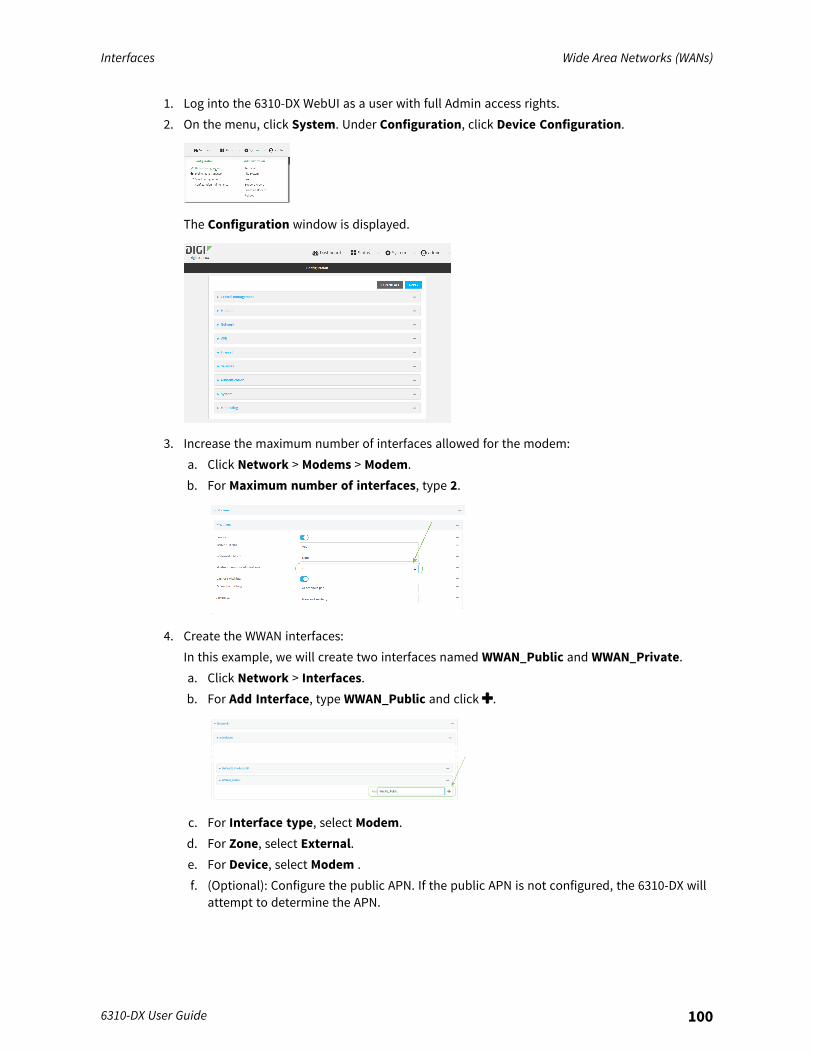
Interfaces Wide Area Networks (WANs)
6310-DX User Guide 100
1. Log into the 6310-DX WebUI as a user with full Admin access rights.2. On the menu, click System. Under Configuration, click Device Configuration.
The Configuration window is displayed.
3. Increase the maximum number of interfaces allowed for the modem:a. Click Network > Modems > Modem.b. For Maximum number of interfaces, type 2.
4. Create the WWAN interfaces:In this example, we will create two interfaces named WWAN_Public and WWAN_Private.a. Click Network > Interfaces.b. For Add Interface, type WWAN_Public and click .
c. For Interface type, select Modem.d. For Zone, select External.e. For Device, select Modem .f. (Optional): Configure the public APN. If the public APN is not configured, the 6310-DX will
attempt to determine the APN.
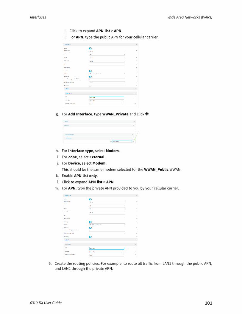
Interfaces Wide Area Networks (WANs)
6310-DX User Guide 101
i. Click to expand APN list > APN.ii. For APN, type the public APN for your cellular carrier.
g. For Add Interface, type WWAN_Private and click .
h. For Interface type, select Modem.i. For Zone, select External.j. For Device, select Modem .
This should be the same modem selected for the WWAN_Public WWAN.k. Enable APN list only.l. Click to expand APN list > APN.
m. For APN, type the private APN provided to you by your cellular carrier.
5. Create the routing policies. For example, to route all traffic from LAN1 through the public APN,and LAN2 through the private APN:
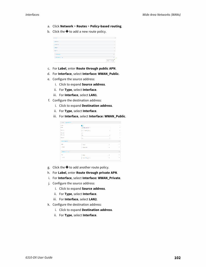
Interfaces Wide Area Networks (WANs)
6310-DX User Guide 102
a. Click Network > Routes > Policy-based routing.b. Click the to add a new route policy.
c. For Label, enter Route through public APN.d. For Interface, select Interface: WWAN_Public.e. Configure the source address:
i. Click to expand Source address.ii. For Type, select Interface.iii. For Interface, select LAN1.
f. Configure the destination address:i. Click to expand Destination address.ii. For Type, select Interface.iii. For Interface, select Interface: WWAN_Public.
g. Click the to add another route policy.h. For Label, enter Route through private APN.i. For Interface, select Interface: WWAN_Private.j. Configure the source address:
i. Click to expand Source address.ii. For Type, select Interface.iii. For Interface, select LAN2.
k. Configure the destination address:i. Click to expand Destination address.ii. For Type, select Interface.
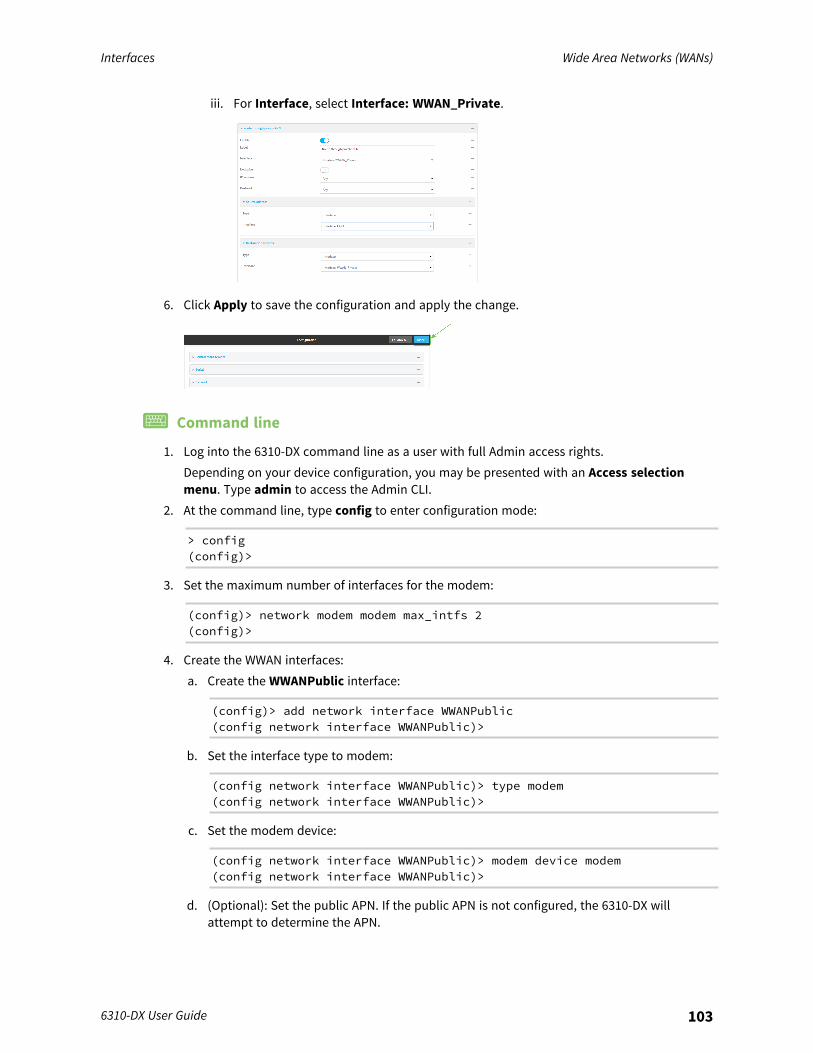
Interfaces Wide Area Networks (WANs)
6310-DX User Guide 103
iii. For Interface, select Interface: WWAN_Private.
6. Click Apply to save the configuration and apply the change.
Command line
1. Log into the 6310-DX command line as a user with full Admin access rights.Depending on your device configuration, you may be presented with an Access selectionmenu. Type admin to access the Admin CLI.
2. At the command line, type config to enter configuration mode:
> config(config)>
3. Set the maximum number of interfaces for the modem:
(config)> network modem modem max_intfs 2(config)>
4. Create the WWAN interfaces:a. Create the WWANPublic interface:
(config)> add network interface WWANPublic(config network interface WWANPublic)>
b. Set the interface type to modem:
(config network interface WWANPublic)> type modem(config network interface WWANPublic)>
c. Set the modem device:
(config network interface WWANPublic)> modem device modem(config network interface WWANPublic)>
d. (Optional): Set the public APN. If the public APN is not configured, the 6310-DX willattempt to determine the APN.
Interfaces Wide Area Networks (WANs)
6310-DX User Guide 104
(config network interface WWANPublic)> modem apn public_apn(config network interface WWANPublic)>
e. Use to periods (..) to move back one level in the configuration:
(config network interface WWANPublic)> ..(config network interface)>
f. Create the WWANPrivate interface:
(config network interface)> add WWANPrivate(config network interface WWANPrivate)>
g. Set the interface type to modem:
(config network interface WWANPrivate)> type modem(config network interface WWANPrivate)>
h. Set the modem device:
(config network interface WWANPrivate)> modem device modem(config network interface WWANPrivate)>
i. Enable APN list only:
(config network interface WWANPrivate)> apn_lock true(config network interface WWANPrivate)>
j. Set the private APN:
(config network interface WWANPublic)> modem apn private_apn(config network interface WWANPublic)>
5. Create the routing policies. For example, to route all traffic from LAN1 through the public APN,and LAN2 through the private APN:a. Add a new routing policy:
(config)> add network route policy end(config network route policy 0)>
b. Set the label that will be used to identify this route policy:
(config network route policy 0)> label "Route through public apn"(config network route policy 0)>
c. Set the interface:
(config network route policy 0)> interface/network/interface/WWANPublic(config network route policy 0)>
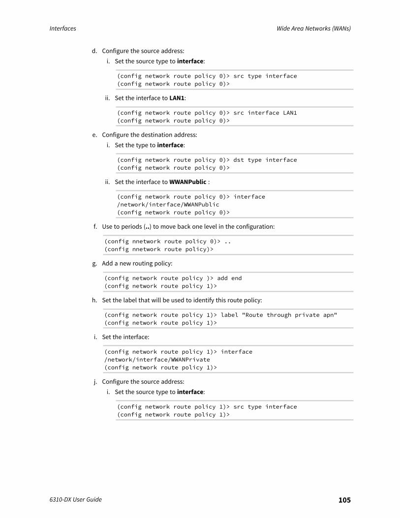
Interfaces Wide Area Networks (WANs)
6310-DX User Guide 105
d. Configure the source address:i. Set the source type to interface:
(config network route policy 0)> src type interface(config network route policy 0)>
ii. Set the interface to LAN1:
(config network route policy 0)> src interface LAN1(config network route policy 0)>
e. Configure the destination address:i. Set the type to interface:
(config network route policy 0)> dst type interface(config network route policy 0)>
ii. Set the interface to WWANPublic :
(config network route policy 0)> interface/network/interface/WWANPublic(config network route policy 0)>
f. Use to periods (..) to move back one level in the configuration:
(config nnetwork route policy 0)> ..(config nnetwork route policy)>
g. Add a new routing policy:
(config network route policy )> add end(config network route policy 1)>
h. Set the label that will be used to identify this route policy:
(config network route policy 1)> label "Route through private apn"(config network route policy 1)>
i. Set the interface:
(config network route policy 1)> interface/network/interface/WWANPrivate(config network route policy 1)>
j. Configure the source address:i. Set the source type to interface:
(config network route policy 1)> src type interface(config network route policy 1)>

Interfaces Wide Area Networks (WANs)
6310-DX User Guide 106
ii. Set the interface to LAN2:
(config network route policy 1)> src interface LAN2(config network route policy 1)>
k. Configure the destination address:i. Set the type to interface:
(config network route policy 1)> dst type interface(config network route policy 1)>
ii. Set the interface to WWANPrivate :
(config network route policy 1)> interface/network/interface/WWANPrivate(config network route policy 1)>
6. Save the configuration and apply the change:
(config network route policy 1)> saveConfiguration saved.>
7. Type exit to exit the Admin CLI.Depending on your device configuration, you may be presented with an Access selectionmenu. Type quit to disconnect from the device.
Configure manual carrier selectionBy default, your 6310-DX automatically selects the most appropriate cellular carrier based on theSIM that is in use and the status of available carriers in your area.Alternately, you can configure the devices to manually select the carrier, based on the Network PLMNID. You can also configure the device to use manual carrier selection and fall back to automatic carrierselection if connecting to the manually-configured carrier fails.You can use also use the modem scan command at the command line to scan for available carriersand determine their PLMN ID.
Required configuration items
n Select Manual or Manual/Automatic carrier selection mode.n The Network PLMN ID.
WebUI
1. Log into the 6310-DX WebUI as a user with full Admin access rights.2. On the menu, click System. Under Configuration, click Device Configuration.

Interfaces Wide Area Networks (WANs)
6310-DX User Guide 107
The Configuration window is displayed.
3. Click Network > Interfaces > Modem.4. For Carrier selection mode, select one of the following:
n Automatic—The device automatically selects the carrier based on your SIM and cellularnetwork status.
n Manual—The device will only connect to the carrier identified in the Network PLMN ID.If the carrier is not available, no cellular connection will be established.
n Manual/Automatic—The device will attempt to connect to the carrier identified in theNetwork PLMN ID. If the carrier is not available, the device will fall back to usingautomatic carrier selection.
5. If Manual or Manual/Automatic are selected for Carrier section mode, enter the NetworkPLMN ID.
Note You can use themodem scan command at the Admin CLI to scan for available carriersand determine their PLMN ID. See Scan for available cellular carriers for details.
6. Click Apply to save the configuration and apply the change.

Interfaces Wide Area Networks (WANs)
6310-DX User Guide 108
Command line
1. Log into the 6310-DX command line as a user with full Admin access rights.Depending on your device configuration, you may be presented with an Access selectionmenu. Type admin to access the Admin CLI.
2. At the command line, type config to enter configuration mode:
> config(config)>
3. At the config prompt, type:
(config)> network interface modem modem operator_mode value(config)>
where value is one of:n automatic—The device automatically selects the carrier based on your SIM and cellular
network status.n manual—The device will only connect to the carrier identified in the Network PLMN ID.
If the carrier is not available, no cellular connection will be established.n manual_automatic—The device will attempt to connect to the carrier identified in the
Network PLMN ID. If the carrier is not available, the device will fall back to usingautomatic carrier selection.
4. If carrier section mode is set to manual or manual_automatic, set the network PLMN ID:
(config)> network interface modem modem operator plmn_ID(config)>
Note You can use the modem scan command at the Admin CLI to scan for available carriersand determine their PLMN ID. See Scan for available cellular carriers for details.
5. Save the configuration and apply the change:
(config)> saveConfiguration saved.>
6. Type exit to exit the Admin CLI.Depending on your device configuration, you may be presented with an Access selectionmenu. Type quit to disconnect from the device.
Scan for available cellular carriersYou can scan for available carriers and determine their network PLMN ID by using the modem scancommand at the Admin CLI.
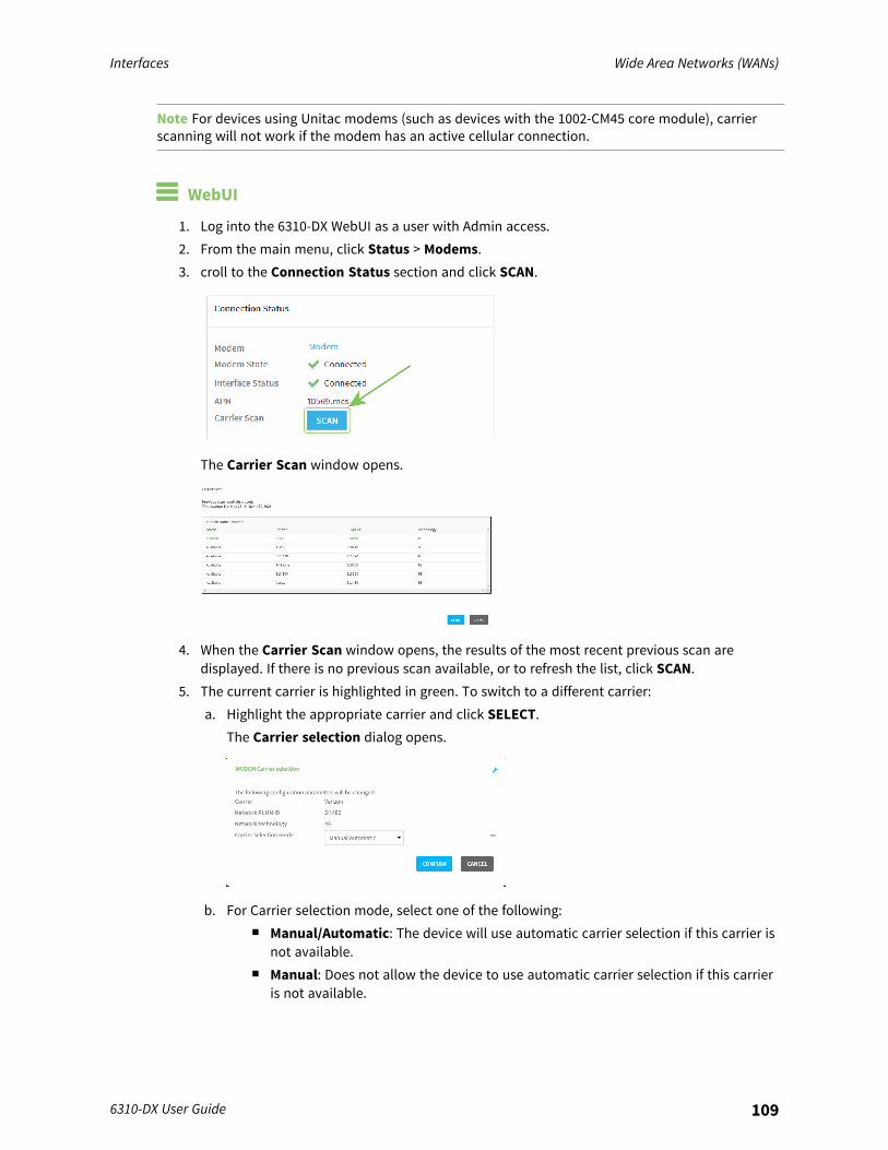
Interfaces Wide Area Networks (WANs)
6310-DX User Guide 109
Note For devices using Unitac modems (such as devices with the 1002-CM45 core module), carrierscanning will not work if the modem has an active cellular connection.
WebUI
1. Log into the 6310-DX WebUI as a user with Admin access.2. From the main menu, click Status > Modems.3. croll to the Connection Status section and click SCAN.
The Carrier Scan window opens.
4. When the Carrier Scan window opens, the results of the most recent previous scan aredisplayed. If there is no previous scan available, or to refresh the list, click SCAN.
5. The current carrier is highlighted in green. To switch to a different carrier:a. Highlight the appropriate carrier and click SELECT.
The Carrier selection dialog opens.
b. For Carrier selection mode, select one of the following:n Manual/Automatic: The device will use automatic carrier selection if this carrier is
not available.n Manual: Does not allow the device to use automatic carrier selection if this carrier
is not available.
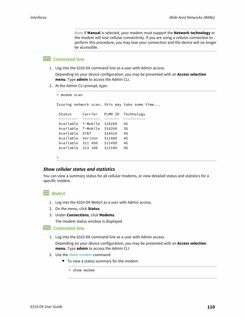
Interfaces Wide Area Networks (WANs)
6310-DX User Guide 110
Note If Manual is selected, your modem must support the Network technology orthe modem will lose cellular connectivity. If you are using a cellular connection toperform this procedure, you may lose your connection and the device will no longerbe accessible.
Command line
1. Log into the 6310-DX command line as a user with Admin access.Depending on your device configuration, you may be presented with an Access selectionmenu. Type admin to access the Admin CLI.
2. At the Admin CLI prompt, type:
> modem scan
Issuing network scan, this may take some time...
Status Carrier PLMN ID Technology--------- -------- ------- ----------Available T-Mobile 310260 4GAvailable T-Mobile 310260 3GAvailable AT&T 310410 4GAvailable Verizon 311480 4GAvailable 311 490 311490 4GAvailable 313 100 313100 4G
>
Show cellular status and statisticsYou can view a summary status for all cellular modems, or view detailed status and statistics for aspecific modem.
WebUI
1. Log into the 6310-DX WebUI as a user with Admin access.2. On the menu, click Status.3. Under Connections, click Modems.
The modem status window is displayed
Command line
1. Log into the 6310-DX command line as a user with Admin access.Depending on your device configuration, you may be presented with an Access selectionmenu. Type admin to access the Admin CLI.
2. Use the show modem command:n To view a status summary for the modem:
> show modem
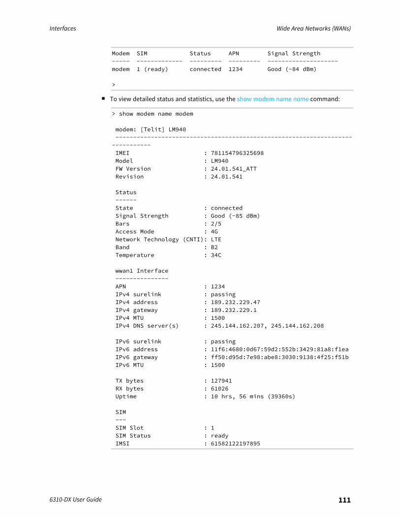
Interfaces Wide Area Networks (WANs)
6310-DX User Guide 111
Modem SIM Status APN Signal Strength----- ------------- --------- --------- --------------------modem 1 (ready) connected 1234 Good (-84 dBm)
>
n To view detailed status and statistics, use the show modem name name command:
> show modem name modem
modem: [Telit] LM940------------------------------------------------------------------------------IMEI : 781154796325698Model : LM940FW Version : 24.01.541_ATTRevision : 24.01.541
Status------State : connectedSignal Strength : Good (-85 dBm)Bars : 2/5Access Mode : 4GNetwork Technology (CNTI): LTEBand : B2Temperature : 34C
wwan1 Interface---------------APN : 1234IPv4 surelink : passingIPv4 address : 189.232.229.47IPv4 gateway : 189.232.229.1IPv4 MTU : 1500IPv4 DNS server(s) : 245.144.162.207, 245.144.162.208
IPv6 surelink : passingIPv6 address : 11f6:4680:0d67:59d2:552b:3429:81a8:f1eaIPv6 gateway : ff50:d95d:7e98:abe8:3030:9138:4f25:f51bIPv6 MTU : 1500
TX bytes : 127941RX bytes : 61026Uptime : 10 hrs, 56 mins (39360s)
SIM---SIM Slot : 1SIM Status : readyIMSI : 61582122197895
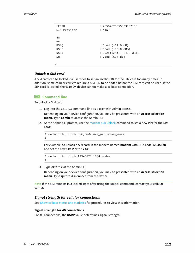
Interfaces Wide Area Networks (WANs)
6310-DX User Guide 112
ICCID : 26587628655003992180SIM Provider : AT&T
4G--RSRQ : Good (-11.0 dB)RSRP : Good (-93.0 dBm)RSSI : Excellent (-64.0 dBm)SNR : Good (6.4 dB)
>
Unlock a SIM cardA SIM card can be locked if a user tries to set an invalid PIN for the SIM card too many times. Inaddition, some cellular carriers require a SIM PIN to be added before the SIM card can be used. If theSIM card is locked, the 6310-DX device cannot make a cellular connection.
Command lineTo unlock a SIM card:
1. Log into the 6310-DX command line as a user with Admin access.Depending on your device configuration, you may be presented with an Access selectionmenu. Type admin to access the Admin CLI.
2. At the Admin CLI prompt, use the modem puk unlock command to set a new PIN for the SIMcard:
> modem puk unlock puk_code new_pin modem_name>
For example, to unlock a SIM card in the modem named modem with PUK code 12345678,and set the new SIM PIN to 1234:
> modem puk unlock 12345678 1234 modem>
3. Type exit to exit the Admin CLI.Depending on your device configuration, you may be presented with an Access selectionmenu. Type quit to disconnect from the device.
Note If the SIM remains in a locked state after using the unlock command, contact your cellularcarrier.
Signal strength for cellular connectionsSee Show cellular status and statistics for procedures to view this information.
Signal strength for 4G connectionsFor 4G connections, the RSRP value determines signal strength.
Interfaces Wide Area Networks (WANs)
6310-DX User Guide 113
n Excellent: > -90 dBmn Good: -90 dBm to -105 dBmn Fair: -106 dBm to -115 dBmn Poor: -116 dBm to -120 dBmn No service: < -120 dBm
Signal strength for 3G and 2G connectionsFor 3G and 2G cellular connections, the current RSSI value determines signal strength.
n Excellent: > -70 dBmn Good: -70 dBm to -85 dBmn Fair: -86 dBm to -100 dBmn Poor: < -100 dBm to -109 dBmn No service: -110 dBm
Tips for improving cellular signal strengthIf the signal strength LEDs or the signal quality for your device indicate Poor or No service, try thefollowing things to improve signal strength:
n Move the 6310-DX device to another location.n Try connecting a different set of antennas, if available.n Purchase a Digi Antenna Extender Kit:
l Antenna Extender Kit, 1ml Antenna Extender Kit, 3m
AT command accessTo run AT commands from the 6310-DX command line:
Command line
1. Log into the 6310-DX command line as a user with Admin access.Depending on your device configuration, you may be presented with an Access selectionmenu. Type admin to access the Admin CLI.
2. At the Admin CLI prompt, type modem at-interactive and press Enter. Type n if you do notwant exclusive access. This allows you to send AT commands to the device while still allowingthe device to connect, disconnect, and/or reconnect to the cellular network.
3. At the Admin CLI prompt, use the modem at-interactive command to begin an interactive ATcommand session:
> modem at-interactive
Do you want exclusive access to the modem? (y/n) [y]:
4. Type n if you do not want exclusive access. This allows you to send AT commands to thedevice while still allowing the device to connect, disconnect, and/or reconnect to the cellular
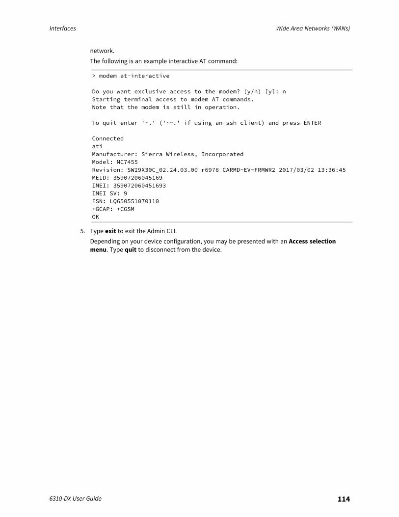
Interfaces Wide Area Networks (WANs)
6310-DX User Guide 114
network.The following is an example interactive AT command:
> modem at-interactive
Do you want exclusive access to the modem? (y/n) [y]: nStarting terminal access to modem AT commands.Note that the modem is still in operation.
To quit enter '~.' ('~~.' if using an ssh client) and press ENTER
ConnectedatiManufacturer: Sierra Wireless, IncorporatedModel: MC7455Revision: SWI9X30C_02.24.03.00 r6978 CARMD-EV-FRMWR2 2017/03/02 13:36:45MEID: 35907206045169IMEI: 359072060451693IMEI SV: 9FSN: LQ650551070110+GCAP: +CGSMOK
5. Type exit to exit the Admin CLI.Depending on your device configuration, you may be presented with an Access selectionmenu. Type quit to disconnect from the device.
Interfaces Wide Area Networks (WANs)
6310-DX User Guide 115
Configure a Wide Area Network (WAN)Configuring a Wide Area Network (WAN) involves configuring the following items:
Required configuration items
n The interface type: Ethernet.n The firewall zone: External.n The network device or bridge that is used by the WAN.n Configure the WAN as a DHCP client.
Additional configuration items
n Additional IPv4 configuration:l The metric for IPv4 routes associated with the WAN.l The relative weight for IPv4 routes associated with the WAN.l The IPv4 management priority of the WAN. The active interface with the highest
management priority will have its address reported as the preferred contact address forcentral management and direct device access.
l The IPv4 Maximum Transmission Unit (MTU) of the WAN.l When to use DNS: always, never, or only when this interface is the primary default route.l When to use DNS servers for this interface.l Whether to include the 6310-DX device's hostname in DHCP requests.l SureLink active recovery configuration. See Configure SureLink active recovery to detect
WAN/WWAN failures for further information.n IPv6 configuration:
l The metric for IPv6 routes associated with the WAN.l The relative weight for IPv6 routes associated with the WAN.l The IPv6 management priority of the WAN. The active interface with the highest
management priority will have its address reported as the preferred contact address forcentral management and direct device access.
l The IPv6 Maximum Transmission Unit (MTU) of the WAN.l When to use DNS: always, never, or only when this interface is the primary default route.l When to use DNS servers for this interface.l Whether to include the 6310-DX device's hostname in DHCP requests.l Active recovery configuration. See Configure SureLink active recovery to detect
WAN/WWAN failures for further information.n MAC address denylist and allowlist.
To create a new WAN or edit an existing WAN:
WebUI
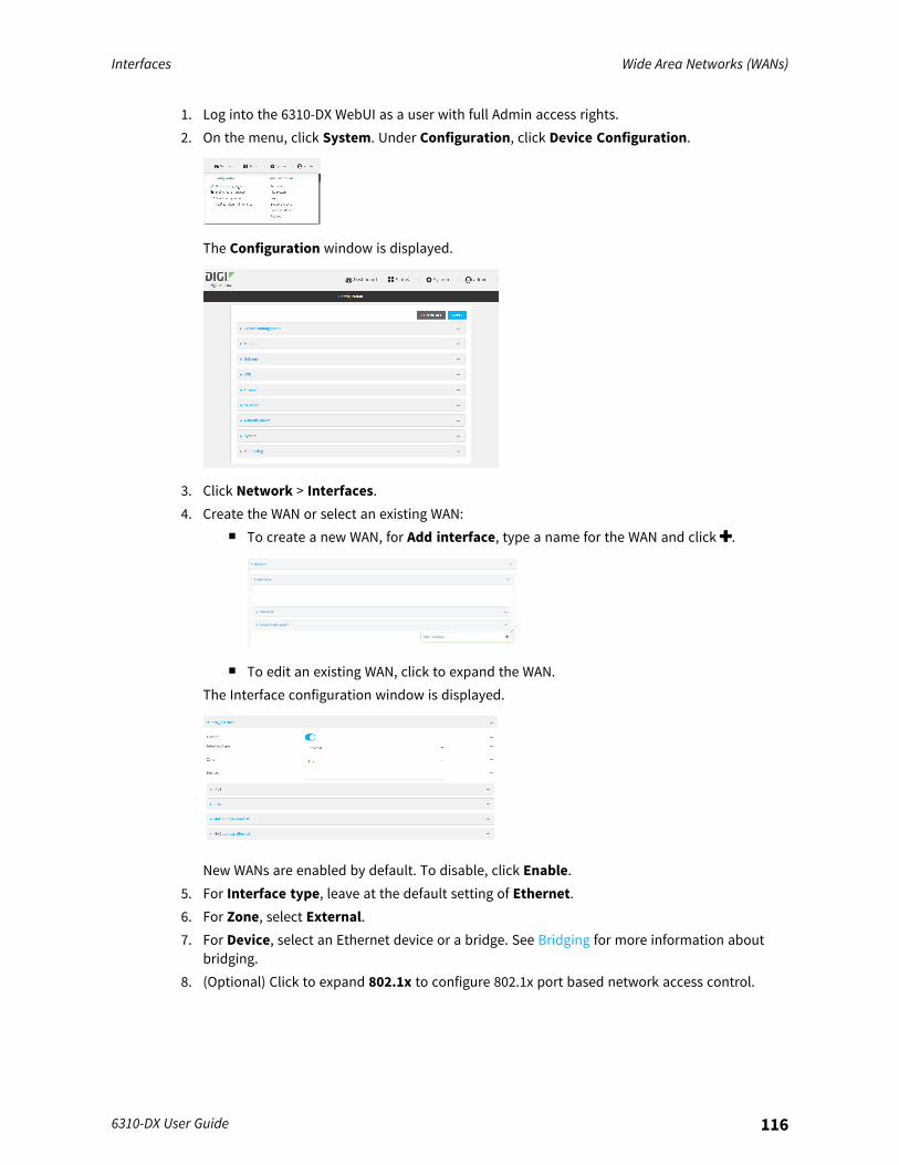
Interfaces Wide Area Networks (WANs)
6310-DX User Guide 116
1. Log into the 6310-DX WebUI as a user with full Admin access rights.2. On the menu, click System. Under Configuration, click Device Configuration.
The Configuration window is displayed.
3. Click Network > Interfaces.4. Create the WAN or select an existing WAN:
n To create a new WAN, for Add interface, type a name for the WAN and click .
n To edit an existing WAN, click to expand the WAN.The Interface configuration window is displayed.
New WANs are enabled by default. To disable, click Enable.5. For Interface type, leave at the default setting of Ethernet.6. For Zone, select External.7. For Device, select an Ethernet device or a bridge. See Bridging for more information about
bridging.8. (Optional) Click to expand 802.1x to configure 802.1x port based network access control.
Interfaces Wide Area Networks (WANs)
6310-DX User Guide 117
The 6310-DX can function as an 802.1x authenticator; it does not function as an 802.1xsupplicant.a. Click to expand Authentication.b. Click Enable server to enable the 802.1x authenticator on the 6310-DX device.c. Type the Server IP address of the authentication server.d. Server Port number defaults to 1812. Type a new port number for the authentication
server if different than the default.e. Type the Server Password for the authentication server.f. Set the Reauth period.g. (Optional) Click to expand Accounting.h. Click Enable server to enable 802.1x authentication auditing on the 6310-DX device.i. Type the Server IP address of the auditing server.j. Server Port number defaults to 1813. Type a new port number for the auditing server if
different than the default.k. Type the Server Password for the auditing server.
9. Configure IPv4 settings:a. Click to expand IPv4.
IPv4 support is enabled by default.b. For Type, select DHCP address.c. Optional IPv4 configuration items:
i. Set the Metric.See Configure WAN/WWAN priority and default route metrics for further informationabout metrics.
ii. For Weight, type the relative weight for default routes associated with this interface.For multiple active interfaces with the same metric, Weight is used to load balancetraffic to the interfaces.
iii. Set the Management priority. This determines which interface will have priority forcentral management activity. The interface with the highest number will be used.
iv. Set the MTU.v. For Use DNS, select one of the following:
n Always: DNS will always be used for this WAN; when multiple interfaces havethe same DNS server, the interface with the lowest metric will be used for DNSrequests.
n When primary default route: Only use the DNS servers provided for thisinterface when the interface is the primary route.
n Never: Never use DNS servers for this interface.vi. Enable DHCP Hostname to instruct the 6310-DX device to include the device's system
name with DHCP requests as the Client FQDN option. The DHCP server can then beconfigured to register the device's hostname and IP address with an associated DNSserver.
n See RFC4702 for further information about DHCP server support for the ClientFQDN option.

Interfaces Wide Area Networks (WANs)
6310-DX User Guide 118
n See Configure system information for information about setting the 6310-DXdevice's system name.
d. See Configure SureLink active recovery to detect WAN/WWAN failures for informationabout configuring Active recovery.
10. (Optional) Configure IPv6 settings:a. Click to expand IPv6.b. Enable IPv6 support.c. For Type, select DHCPv6 address.d. For Prefix length, type the minimum length of the prefix to assign to this LAN. If the
minimum length is not available, then a longer prefix will be used.e. For Prefix ID, type the identifier used to extend the prefix to the assigned length. Leave
blank to use a random identifier.f. Set the Metric.
See Configure WAN/WWAN priority and default route metrics for further information aboutmetrics.
g. For Weight, type the relative weight for default routes associated with this interface. Formultiple active interfaces with the same metric, Weight is used to load balance traffic tothe interfaces.
h. Set the Management priority. This determines which interface will have priority forcentral management activity. The interface with the highest number will be used.
i. Set the MTU.j. For Use DNS:
n Always: DNS will always be used for this WAN; when multiple interfaces have thesame DNS server, the interface with the lowest metric will be used for DNSrequests.
n When primary default route: Only use the DNS servers provided for this interfacewhen the interface is the primary route.
n Never: Never use DNS servers for this interface.k. Enable DHCP Hostname to instruct the 6310-DX device to include the device's system
name with DHCP requests as the Client FQDN option. The DHCP server can then beconfigured to register the device's hostname and IP address with an associated DNSserver.
n See RFC4702 for further information about DHCP server support for the ClientFQDN option.
n See Configure system information for information about setting the 6310-DXdevice's system name.
11. (Optional) Click to expand MAC address denylist.Incoming packets will be dropped from any devices whose MAC addresses is included in theMAC address denylist.a. Click to expand MAC address denylist.b. For Add MAC address, click .c. Type the MAC address.
12. (Optional) Click to expand MAC address allowlist.
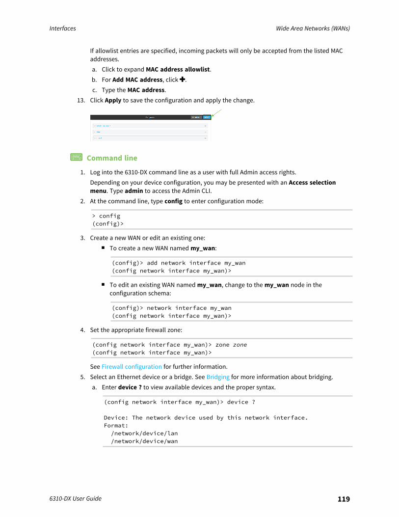
Interfaces Wide Area Networks (WANs)
6310-DX User Guide 119
If allowlist entries are specified, incoming packets will only be accepted from the listed MACaddresses.a. Click to expand MAC address allowlist.b. For Add MAC address, click .c. Type the MAC address.
13. Click Apply to save the configuration and apply the change.
Command line
1. Log into the 6310-DX command line as a user with full Admin access rights.Depending on your device configuration, you may be presented with an Access selectionmenu. Type admin to access the Admin CLI.
2. At the command line, type config to enter configuration mode:
> config(config)>
3. Create a new WAN or edit an existing one:n To create a new WAN named my_wan:
(config)> add network interface my_wan(config network interface my_wan)>
n To edit an existing WAN named my_wan, change to the my_wan node in theconfiguration schema:
(config)> network interface my_wan(config network interface my_wan)>
4. Set the appropriate firewall zone:
(config network interface my_wan)> zone zone(config network interface my_wan)>
See Firewall configuration for further information.5. Select an Ethernet device or a bridge. See Bridging for more information about bridging.
a. Enter device ? to view available devices and the proper syntax.
(config network interface my_wan)> device ?
Device: The network device used by this network interface.Format:/network/device/lan/network/device/wan
Interfaces Wide Area Networks (WANs)
6310-DX User Guide 120
/network/device/loopbackCurrent value:
(config network interface my_wan)> device
b. Set the device for the LAN:
(config network interface my_wan)> device device(config network interface my_wan)>
6. Configure IPv4 settings:n IPv4 support is enabled by default. To disable:
(config network interface my_wan)> ipv4 enable false(config network interface my_wan)>
n Configure the WAN to be a DHCP client:
(config network interface my_wan)> ipv4 type dhcp(config network interface my_wan)>
a. Optional IPv4 configuration items:i. Set the IP metric:
(config network interface my_wan)> ipv4 metric num(config network interface my_wan)>
See Configure WAN/WWAN priority and default route metrics for further informationabout metrics.
ii. Set the relative weight for default routes associated with this interface. For multipleactive interfaces with the same metric, the weight is used to load balance traffic tothe interfaces.
(config network interface my_wan)> ipv4 weight num(config network interface my_wan)>
iii. Set the management priority. This determines which interface will have priority forcentral management activity. The interface with the highest number will be used.
(config network interface my_wan)> ipv4 mgmt num(config network interface my_wan)>
iv. Set the MTU:
(config network interface my_wan)> ipv4 mtu num(config network interface my_wan)>
v. Configure how to use DNS:
(config network interface my_wan)> ipv4 use_dns value(config network interface my_wan)>
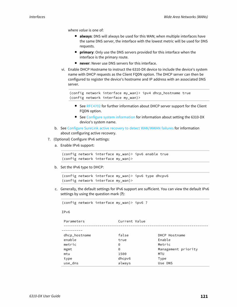
Interfaces Wide Area Networks (WANs)
6310-DX User Guide 121
where value is one of:n always: DNS will always be used for this WAN; when multiple interfaces have
the same DNS server, the interface with the lowest metric will be used for DNSrequests.
n primary: Only use the DNS servers provided for this interface when theinterface is the primary route.
n never: Never use DNS servers for this interface.vi. Enable DHCP Hostname to instruct the 6310-DX device to include the device's system
name with DHCP requests as the Client FQDN option. The DHCP server can then beconfigured to register the device's hostname and IP address with an associated DNSserver.
(config network interface my_wan)> ipv4 dhcp_hostname true(config network interface my_wan)>
n See RFC4702 for further information about DHCP server support for the ClientFQDN option.
n See Configure system information for information about setting the 6310-DXdevice's system name.
b. See Configure SureLink active recovery to detect WAN/WWAN failures for informationabout configuring active recovery.
7. (Optional) Configure IPv6 settings:a. Enable IPv6 support:
(config network interface my_wan)> ipv6 enable true(config network interface my_wan)>
b. Set the IPv6 type to DHCP:
(config network interface my_wan)> ipv6 type dhcpv6(config network interface my_wan)>
c. Generally, the default settings for IPv6 support are sufficient. You can view the default IPv6settings by using the question mark (?):
(config network interface my_wan)> ipv6 ?
IPv6
Parameters Current Value-------------------------------------------------------------------------------dhcp_hostname false DHCP Hostnameenable true Enablemetric 0 Metricmgmt 0 Management prioritymtu 1500 MTUtype dhcpv6 Typeuse_dns always Use DNS
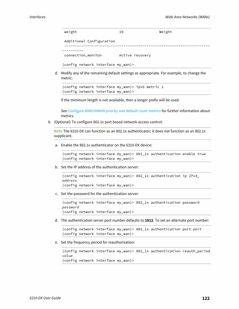
Interfaces Wide Area Networks (WANs)
6310-DX User Guide 122
weight 10 Weight
Additional Configuration-------------------------------------------------------------------------------connection_monitor Active recovery
(config network interface my_wan)>
d. Modify any of the remaining default settings as appropriate. For example, to change themetric:
(config network interface my_wan)> ipv6 metric 1(config network interface my_wan)>
If the minimum length is not available, then a longer prefix will be used.
See Configure WAN/WWAN priority and default route metrics for further information aboutmetrics.
8. (Optional) To configure 802.1x port based network access control:
Note The 6310-DX can function as an 802.1x authenticator; it does not function as an 802.1xsupplicant.
a. Enable the 802.1x authenticator on the 6310-DX device:
(config network interface my_wan)> 802_1x authentication enable true(config network interface my_wan)>
b. Set the IP address of the authentication server:
(config network interface my_wan)> 802_1x authentication ip IPv4_address(config network interface my_wan)>
c. Set the password for the authentication server:
(config network interface my_wan)> 802_1x authentication passwordpassword(config network interface my_wan)>
d. The authentication server port number defaults to 1812. To set an alternate port number:
(config network interface my_wan)> 802_1x authentication port port(config network interface my_wan)>
e. Set the frequency period for reauthorization:
(config network interface my_wan)> 802_1x authentication reauth_periodvalue(config network interface my_wan)>

Interfaces Wide Area Networks (WANs)
6310-DX User Guide 123
where value is an integer between 0 and 86400. The default is 3600.f. (Optional) Configure 802.1x authentication auditing:
i. Enable authentication auditing on the 6310-DX device:
(config network interface my_wan)> 802_1x accounting enable true(config network interface my_wan)>
ii. Set the IP address of the accounting server:
(config network interface my_wan)> 802_1x accounting ip IPv4_address(config network interface my_wan)>
iii. Set the password for the accounting server:
(config network interface my_wan)> 802_1x accounting passwordpassword(config network interface my_wan)>
iv. The accounting server port number defaults to 1813. To set an alternate port number:
(config network interface my_wan)> 802_1x accounting port port(config network interface my_wan)>
9. (Optional) Configure the MAC address deny list.Incoming packets will be dropped from any devices whose MAC addresses is included in theMAC address denylist.a. Add a MAC address to the denylist:
(config network interface my_wan)> add mac_denylist end mac_address(config network interface my_wan)>
where mac_address is a hyphen-separated MAC address, for example, 32-A6-84-2E-81-58.b. Repeat for each additional MAC address.
10. (Optional) Configure the MAC address allowlist.If allowlist entries are specified, incoming packets will only be accepted from the listed MACaddresses.a. Add a MAC address to the allowlist:
(config network interface my_wan)> add mac_allowlist end mac_address(config network interface my_wan)>
where mac_address is a hyphen-separated MAC address, for example, 32-A6-84-2E-81-58.b. Repeat for each additional MAC address.
11. Save the configuration and apply the change:
(config network interface my_wan)> saveConfiguration saved.>
Interfaces Wide Area Networks (WANs)
6310-DX User Guide 124
12. Type exit to exit the Admin CLI.Depending on your device configuration, you may be presented with an Access selectionmenu. Type quit to disconnect from the device.
Configure a Wireless Wide Area Network (WWAN)Configuring a Wireless Wide Area Network (WWAN) involves configuring the following items:
Required configuration items
n The interface type: Modem.n The firewall zone: External.n The cellular modem that is used by the WWAN.
Additional configuration items
n SIM selection for this WWAN.n The SIM PIN.n The SIM phone number for SMS connections.n Enable or disable roaming.n SIM failover configuration.n APN configuration.n The custom gateway/netmask.n IPv4 configuration:
l The metric for IPv4 routes associated with the WAN.l The relative weight for IPv4 routes associated with the WAN.l The IPv4 management priority of the WAN. The active interface with the highest
management priority will have its address reported as the preferred contact address forcentral management and direct device access.
l The IPv4 Maximum Transmission Unit (MTU) of the WAN.l When to use DNS: always, never, or only when this interface is the primary default route.l SureLink active recovery configuration. See Configure SureLink active recovery to detect
WAN/WWAN failures for further information.n IPv6 configuration:
l The metric for IPv6 routes associated with the WAN.l The relative weight for IPv6 routes associated with the WAN.l The IPv6 management priority of the WAN. The active interface with the highest
management priority will have its address reported as the preferred contact address forcentral management and direct device access.
l The IPv6 Maximum Transmission Unit (MTU) of the WAN.l When to use DNS: always, never, or only when this interface is the primary default route.l SureLink active recovery configuration. See Configure SureLink active recovery to detect
WAN/WWAN failures for further information.
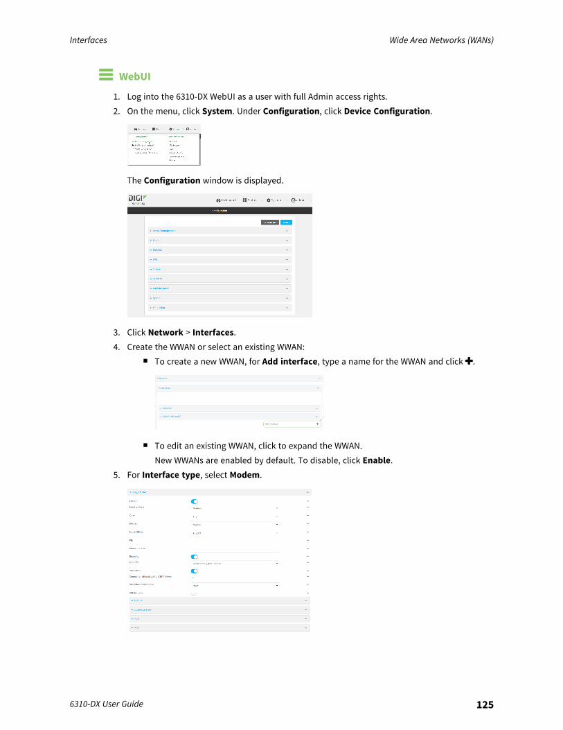
Interfaces Wide Area Networks (WANs)
6310-DX User Guide 125
WebUI
1. Log into the 6310-DX WebUI as a user with full Admin access rights.2. On the menu, click System. Under Configuration, click Device Configuration.
The Configuration window is displayed.
3. Click Network > Interfaces.4. Create the WWAN or select an existing WWAN:
n To create a new WWAN, for Add interface, type a name for the WWAN and click .
n To edit an existing WWAN, click to expand the WWAN.New WWANs are enabled by default. To disable, click Enable.
5. For Interface type, select Modem.
Interfaces Wide Area Networks (WANs)
6310-DX User Guide 126
6. The WWAN is enabled by default. Click Enable to disable, or to enable if it has been disabled.7. Interface type defaults to Modem.8. For Zone, select External.9. For Device, select the cellular modem.
10. For Match SIM by, select a SIM matching criteria to determine when this WWAN should beused:
n If SIM slot is selected, for Match SIM slot, select which SIM slot must be in active forthis WWAN to be used.
n If Carrier is selected, for Match SIM carrier, select which cellular carrier must be inactive for this WWAN to be used.
n If PLMN identifier is selected, for Match PLMN identifier, type the PLMN id that mustbe in active for this WWAN to be used.
n If IMSI is selected, for Match IMSI, type the International Mobile Subscriber Identity(IMSI) that must be in active for this WWAN to be used.
n If ICCID is selected, for Match ICCID, type the unique SIM card ICCID that must be inactive for this WWAN to be used.
11. Type the PIN for the SIM. Leave blank if no PIN is required.12. Type the Phone number for the SIM, for SMS connections.
Normally, this should be left blank. It is only necessary to complete this field if the SIM doesnot have a phone number or if the phone number is incorrect.
13. Roaming is enabled by default. Click to disable.14. For Carrier selection mode, select one of the following:
n Automatic: The cellular carrier is selected automatically by the device.n Manual: The cellular carrier must be manually configured. If the configured network is
not available, no cellular connection will be established.n Manual/Automatic: The carrier is manually configured. If the configured network is not
available, automatic carrier selection is used.If Manual or Manual/Automatic is selected:a. For Network PLMN ID, type the PLMN ID for the cellular network.b. For Network technology, select the technology that should be used. The default is All
technologies, which means that the best available technology will be used.
Note If Manual is configured for Carrier selection mode and a specific networktechnology is selected for the Network technology, your modem must support theselected technology or no cellular connection will be established. If you are using a cellularconnection to perform this procedure, you may lose your connection and the device willno longer be accessible.
15. SIM failover is enabled by default, which means that the modem will automatically fail overfrom the active SIM to the next available SIM when the active SIM fails to connect. If enabled:a. For Connection attempts before SIM failover, type the number of times that the device
should attempt to connect to the active SIM before failing over to the next available SIM.b. For SIM failover alternative, configure how SIM failover will function if automatic SIM
switching is unavailable:
Interfaces Wide Area Networks (WANs)
6310-DX User Guide 127
n None: The device will perform no alternative action if automatic SIM switching isunavailable.
n Reset modem: The device will reset the modem if automatic SIM switching isunavailable.
n Reboot device: The device will reboot if automatic SIM switching is unavailable.16. For APN list and APN list only, the 6310-DX device uses a preconfigured list of Access Point
Names (APNs) when attempting to connect to a cellular carrier for the first time. After thedevice has successfully connected, it will remember the correct APN. As a result, it is generallynot necessary to configure APNs. See Configure cellular modem APNs for further informationand instructions for setting an APN.
17. (Optional) To configure the IP address of a custom gateway or a custom netmask:a. Click Custom gateway to expand.b. Click Enable.c. For Gateway/Netmask, enter the IP address and netmask of the custom gateway. To
override only the gateway netmask, but not the gateway IP address, use all zeros for the IPaddress. For example, 0.0.0.0./32 will use the network-provided gateway, but with a /32netmask.
18. Optional IPv4 configuration items:a. Click IPv4 to expand.b. IPv4 support is Enabled by default. Click to disable.c. Set the Metric.
See Configure WAN/WWAN priority and default route metrics for further information aboutmetrics.
d. For Weight, type the relative weight for default routes associated with this interface. Formultiple active interfaces with the same metric, Weight is used to load balance traffic tothe interfaces.
e. Set the Management priority. This determines which interface will have priority forcentral management activity. The interface with the highest number will be used.
f. Set the MTU.g. For Use DNS:
n Always: DNS will always be used for this WWAN; when multiple interfaces have thesame DNS server, the interface with the lowest metric will be used for DNSrequests.
n When primary default route: Only use the DNS servers provided for this WWANwhen the WWAN is the primary route.
n Never: Never use DNS servers for this WWAN.The default setting is When primary default route.
19. Optional IPv6 configuration items:a. Click IPv6 to expand.b. IPv6 support is Enabled by default. Click to disable.c. Set the Metric.
See Configure WAN/WWAN priority and default route metrics for further information aboutmetrics.
Interfaces Wide Area Networks (WANs)
6310-DX User Guide 128
d. For Weight, type the relative weight for default routes associated with this interface. Formultiple active interfaces with the same metric, Weight is used to load balance traffic tothe interfaces.
e. Set the Management priority. This determines which interface will have priority forcentral management activity. The interface with the highest number will be used.
f. Set the MTU.g. For Use DNS:
n Always: DNS will always be used for this WWAN; when multiple interfaces have thesame DNS server, the interface with the lowest metric will be used for DNSrequests.
n When primary default route: Only use the DNS servers provided for this WWANwhen the WWAN is the primary route.
n Never: Never use DNS servers for this WWAN.The default setting is When primary default route.
1. See Configure SureLink active recovery to detect WAN/WWAN failures for information aboutconfiguring SureLink.
Command line
1. Log into the 6310-DX command line as a user with full Admin access rights.Depending on your device configuration, you may be presented with an Access selectionmenu. Type admin to access the Admin CLI.
2. At the command line, type config to enter configuration mode:
> config(config)>
3. Create a new WWAN or edit an existing one:n To create a new WWAN named my_wwan:
(config)> add network interface my_wwan(config network interface my_wwan)>
n To edit an existing WWAN named my_wwan, change to the my_wwan node in theconfiguration schema:
(config)> network interface my_wwan(config network interface my_wwan)>
4. Set the appropriate firewall zone:
(config network interface my_wwan)> zone zone(config network interface my_wwan)>
See Firewall configuration for further information.
Interfaces Wide Area Networks (WANs)
6310-DX User Guide 129
5. Select a cellular modem:a. Enter modem device ? to view available modems and the proper syntax.
(config network interface my_wwan)> modem device ?
Device: The modem used by this network interface.Format:modem
Current value:
(config network interface my_wwan)> device
b. Set the device:
(config network interface my_wwan)> modem device modem(config network interface my_wwan)>
6. Set theSIM matching criteria to determine when this WWAN should be used:
(config network interface my_wwan)> modem match value(config network interface my_wwan)>
Where value is one of:n anyn carrier
Set the cellular carrier must be in active for this WWAN to be used:a. Use ? to determine available carriers:
(config network interface my_wwan)> modem carrier
Match SIM carrier: The SIM carrier match criteria. Thisinterface is applied when the SIM card isprovisioned from the carrier.Format:AT&TRogersSprintT-MobileTelstraVerizonVodafoneother
Default value: AT&TCurrent value: AT&T
(config network interface my_wwan)>
b. Set the carrier:
(config network interface my_wwan)> modem carrier value(config network interface my_wwan)>
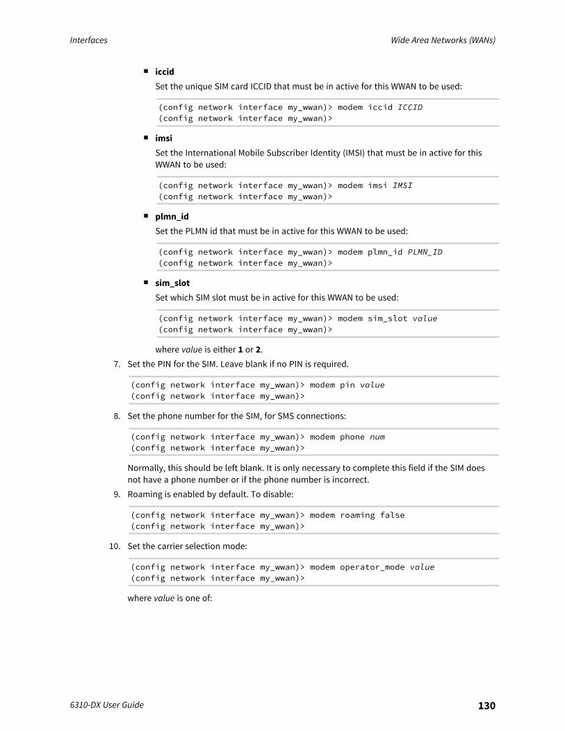
Interfaces Wide Area Networks (WANs)
6310-DX User Guide 130
n iccidSet the unique SIM card ICCID that must be in active for this WWAN to be used:
(config network interface my_wwan)> modem iccid ICCID(config network interface my_wwan)>
n imsiSet the International Mobile Subscriber Identity (IMSI) that must be in active for thisWWAN to be used:
(config network interface my_wwan)> modem imsi IMSI(config network interface my_wwan)>
n plmn_idSet the PLMN id that must be in active for this WWAN to be used:
(config network interface my_wwan)> modem plmn_id PLMN_ID(config network interface my_wwan)>
n sim_slotSet which SIM slot must be in active for this WWAN to be used:
(config network interface my_wwan)> modem sim_slot value(config network interface my_wwan)>
where value is either 1 or 2.7. Set the PIN for the SIM. Leave blank if no PIN is required.
(config network interface my_wwan)> modem pin value(config network interface my_wwan)>
8. Set the phone number for the SIM, for SMS connections:
(config network interface my_wwan)> modem phone num(config network interface my_wwan)>
Normally, this should be left blank. It is only necessary to complete this field if the SIM doesnot have a phone number or if the phone number is incorrect.
9. Roaming is enabled by default. To disable:
(config network interface my_wwan)> modem roaming false(config network interface my_wwan)>
10. Set the carrier selection mode:
(config network interface my_wwan)> modem operator_mode value(config network interface my_wwan)>
where value is one of:
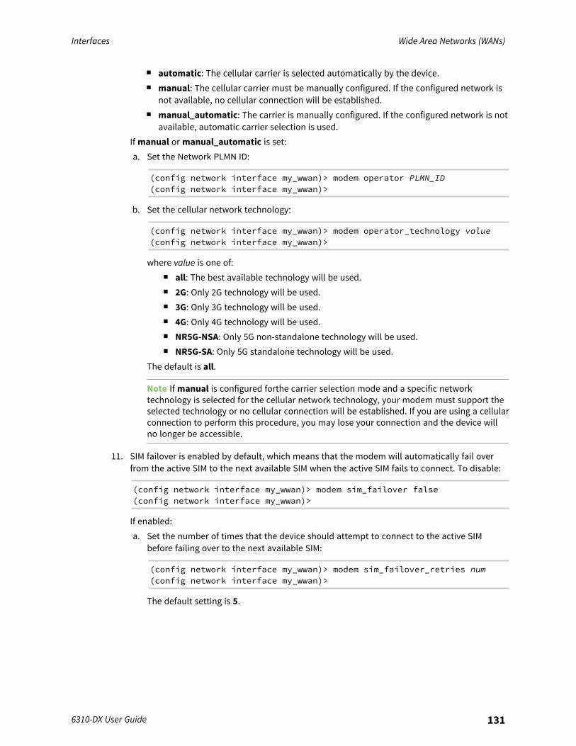
Interfaces Wide Area Networks (WANs)
6310-DX User Guide 131
n automatic: The cellular carrier is selected automatically by the device.n manual: The cellular carrier must be manually configured. If the configured network is
not available, no cellular connection will be established.n manual_automatic: The carrier is manually configured. If the configured network is not
available, automatic carrier selection is used.If manual or manual_automatic is set:a. Set the Network PLMN ID:
(config network interface my_wwan)> modem operator PLMN_ID(config network interface my_wwan)>
b. Set the cellular network technology:
(config network interface my_wwan)> modem operator_technology value(config network interface my_wwan)>
where value is one of:n all: The best available technology will be used.n 2G: Only 2G technology will be used.n 3G: Only 3G technology will be used.n 4G: Only 4G technology will be used.n NR5G-NSA: Only 5G non-standalone technology will be used.n NR5G-SA: Only 5G standalone technology will be used.
The default is all.
Note If manual is configured forthe carrier selection mode and a specific networktechnology is selected for the cellular network technology, your modem must support theselected technology or no cellular connection will be established. If you are using a cellularconnection to perform this procedure, you may lose your connection and the device willno longer be accessible.
11. SIM failover is enabled by default, which means that the modem will automatically fail overfrom the active SIM to the next available SIM when the active SIM fails to connect. To disable:
(config network interface my_wwan)> modem sim_failover false(config network interface my_wwan)>
If enabled:a. Set the number of times that the device should attempt to connect to the active SIM
before failing over to the next available SIM:
(config network interface my_wwan)> modem sim_failover_retries num(config network interface my_wwan)>
The default setting is 5.
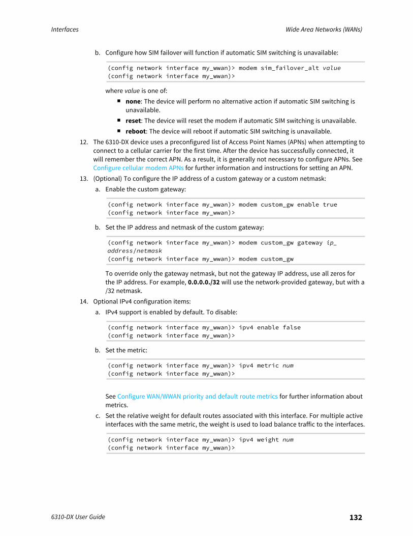
Interfaces Wide Area Networks (WANs)
6310-DX User Guide 132
b. Configure how SIM failover will function if automatic SIM switching is unavailable:
(config network interface my_wwan)> modem sim_failover_alt value(config network interface my_wwan)>
where value is one of:n none: The device will perform no alternative action if automatic SIM switching is
unavailable.n reset: The device will reset the modem if automatic SIM switching is unavailable.n reboot: The device will reboot if automatic SIM switching is unavailable.
12. The 6310-DX device uses a preconfigured list of Access Point Names (APNs) when attempting toconnect to a cellular carrier for the first time. After the device has successfully connected, itwill remember the correct APN. As a result, it is generally not necessary to configure APNs. SeeConfigure cellular modem APNs for further information and instructions for setting an APN.
13. (Optional) To configure the IP address of a custom gateway or a custom netmask:a. Enable the custom gateway:
(config network interface my_wwan)> modem custom_gw enable true(config network interface my_wwan)>
b. Set the IP address and netmask of the custom gateway:
(config network interface my_wwan)> modem custom_gw gateway ip_address/netmask(config network interface my_wwan)> modem custom_gw
To override only the gateway netmask, but not the gateway IP address, use all zeros forthe IP address. For example, 0.0.0.0./32 will use the network-provided gateway, but with a/32 netmask.
14. Optional IPv4 configuration items:a. IPv4 support is enabled by default. To disable:
(config network interface my_wwan)> ipv4 enable false(config network interface my_wwan)>
b. Set the metric:
(config network interface my_wwan)> ipv4 metric num(config network interface my_wwan)>
See Configure WAN/WWAN priority and default route metrics for further information aboutmetrics.
c. Set the relative weight for default routes associated with this interface. For multiple activeinterfaces with the same metric, the weight is used to load balance traffic to the interfaces.
(config network interface my_wwan)> ipv4 weight num(config network interface my_wwan)>
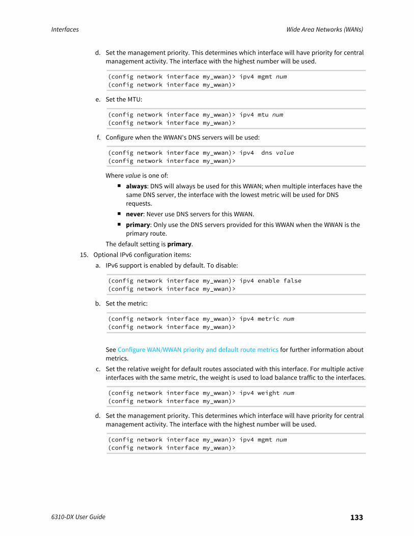
Interfaces Wide Area Networks (WANs)
6310-DX User Guide 133
d. Set the management priority. This determines which interface will have priority for centralmanagement activity. The interface with the highest number will be used.
(config network interface my_wwan)> ipv4 mgmt num(config network interface my_wwan)>
e. Set the MTU:
(config network interface my_wwan)> ipv4 mtu num(config network interface my_wwan)>
f. Configure when the WWAN's DNS servers will be used:
(config network interface my_wwan)> ipv4 dns value(config network interface my_wwan)>
Where value is one of:n always: DNS will always be used for this WWAN; when multiple interfaces have the
same DNS server, the interface with the lowest metric will be used for DNSrequests.
n never: Never use DNS servers for this WWAN.n primary: Only use the DNS servers provided for this WWAN when the WWAN is the
primary route.The default setting is primary.
15. Optional IPv6 configuration items:a. IPv6 support is enabled by default. To disable:
(config network interface my_wwan)> ipv4 enable false(config network interface my_wwan)>
b. Set the metric:
(config network interface my_wwan)> ipv4 metric num(config network interface my_wwan)>
See Configure WAN/WWAN priority and default route metrics for further information aboutmetrics.
c. Set the relative weight for default routes associated with this interface. For multiple activeinterfaces with the same metric, the weight is used to load balance traffic to the interfaces.
(config network interface my_wwan)> ipv4 weight num(config network interface my_wwan)>
d. Set the management priority. This determines which interface will have priority for centralmanagement activity. The interface with the highest number will be used.
(config network interface my_wwan)> ipv4 mgmt num(config network interface my_wwan)>
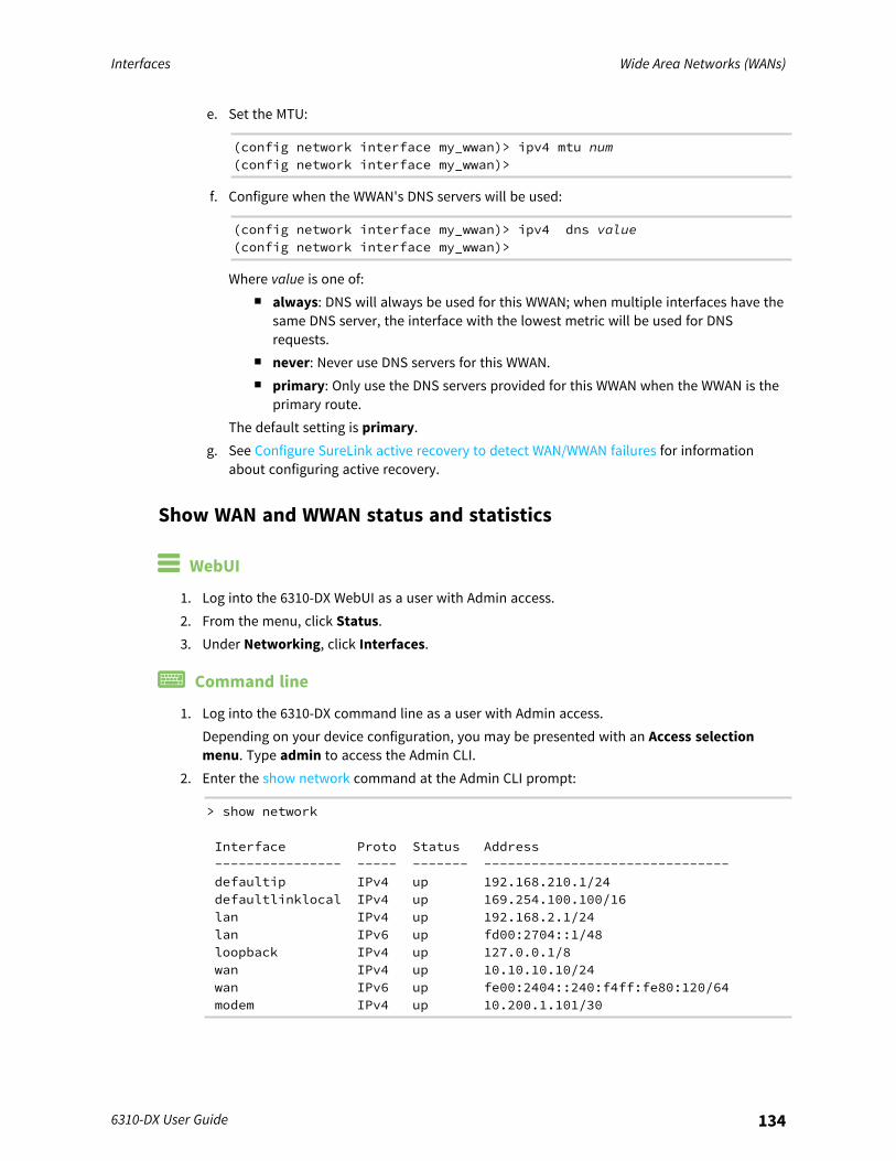
Interfaces Wide Area Networks (WANs)
6310-DX User Guide 134
e. Set the MTU:
(config network interface my_wwan)> ipv4 mtu num(config network interface my_wwan)>
f. Configure when the WWAN's DNS servers will be used:
(config network interface my_wwan)> ipv4 dns value(config network interface my_wwan)>
Where value is one of:n always: DNS will always be used for this WWAN; when multiple interfaces have the
same DNS server, the interface with the lowest metric will be used for DNSrequests.
n never: Never use DNS servers for this WWAN.n primary: Only use the DNS servers provided for this WWAN when the WWAN is the
primary route.The default setting is primary.
g. See Configure SureLink active recovery to detect WAN/WWAN failures for informationabout configuring active recovery.
Show WAN and WWAN status and statistics
WebUI
1. Log into the 6310-DX WebUI as a user with Admin access.2. From the menu, click Status.3. Under Networking, click Interfaces.
Command line
1. Log into the 6310-DX command line as a user with Admin access.Depending on your device configuration, you may be presented with an Access selectionmenu. Type admin to access the Admin CLI.
2. Enter the show network command at the Admin CLI prompt:
> show network
Interface Proto Status Address---------------- ----- ------- -------------------------------defaultip IPv4 up 192.168.210.1/24defaultlinklocal IPv4 up 169.254.100.100/16lan IPv4 up 192.168.2.1/24lan IPv6 up fd00:2704::1/48loopback IPv4 up 127.0.0.1/8wan IPv4 up 10.10.10.10/24wan IPv6 up fe00:2404::240:f4ff:fe80:120/64modem IPv4 up 10.200.1.101/30
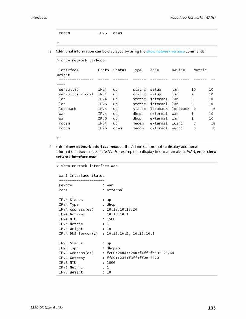
Interfaces Wide Area Networks (WANs)
6310-DX User Guide 135
modem IPv6 down
>
3. Additional information can be displayed by using the show network verbose command:
> show network verbose
Interface Proto Status Type Zone Device MetricWeight---------------- ----- ------- ------ -------- -------- ------ ------defaultip IPv4 up static setup lan 10 10defaultlinklocal IPv4 up static setup lan 0 10lan IPv4 up static internal lan 5 10lan IPv6 up static internal lan 5 10loopback IPv4 up static loopback loopback 0 10wan IPv4 up dhcp external wan 1 10wan IPv6 up dhcp external wan 1 10modem IPv4 up modem external wwan1 3 10modem IPv6 down modem external wwan1 3 10
>
4. Enter show network interface name at the Admin CLI prompt to display additionalinformation about a specific WAN. For example, to display information about WAN, enter shownetwork interface wan:
> show network interface wan
wan1 Interface Status---------------------Device : wanZone : external
IPv4 Status : upIPv4 Type : dhcpIPv4 Address(es) : 10.10.10.10/24IPv4 Gateway : 10.10.10.1IPv4 MTU : 1500IPv4 Metric : 1IPv4 Weight : 10IPv4 DNS Server(s) : 10.10.10.2, 10.10.10.3
IPv6 Status : upIPv6 Type : dhcpv6IPv6 Address(es) : fe00:2404::240:f4ff:fe80:120/64IPv6 Gateway : ff80::234:f3ff:ff0e:4320IPv6 MTU : 1500IPv6 Metric : 1IPv6 Weight : 10
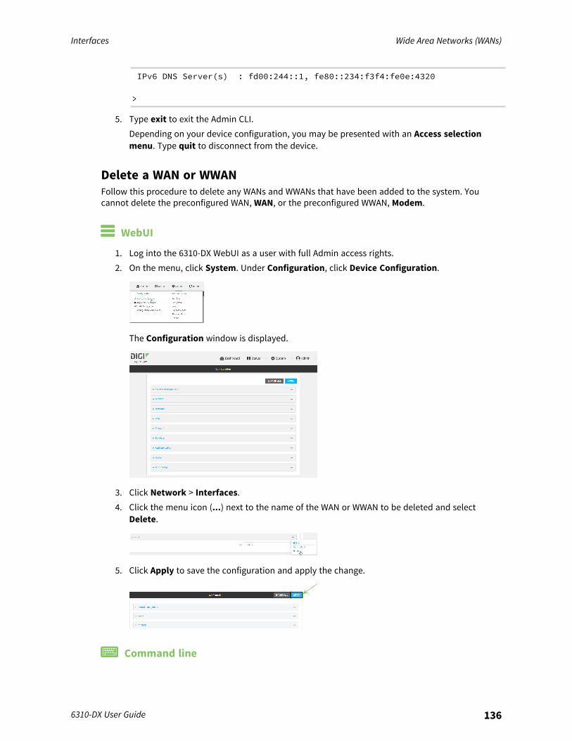
Interfaces Wide Area Networks (WANs)
6310-DX User Guide 136
IPv6 DNS Server(s) : fd00:244::1, fe80::234:f3f4:fe0e:4320
>
5. Type exit to exit the Admin CLI.Depending on your device configuration, you may be presented with an Access selectionmenu. Type quit to disconnect from the device.
Delete a WAN or WWANFollow this procedure to delete any WANs and WWANs that have been added to the system. Youcannot delete the preconfigured WAN, WAN, or the preconfigured WWAN, Modem.
WebUI
1. Log into the 6310-DX WebUI as a user with full Admin access rights.2. On the menu, click System. Under Configuration, click Device Configuration.
The Configuration window is displayed.
3. Click Network > Interfaces.4. Click the menu icon (...) next to the name of the WAN or WWAN to be deleted and select
Delete.
5. Click Apply to save the configuration and apply the change.
Command line
Interfaces Wide Area Networks (WANs)
6310-DX User Guide 137
1. Log into the 6310-DX command line as a user with full Admin access rights.Depending on your device configuration, you may be presented with an Access selectionmenu. Type admin to access the Admin CLI.
2. At the command line, type config to enter configuration mode:
> config(config)>
3. Use the del command to delete the WAN or WWAN. For example, to delete a WWAN namedmy_wwan:
(config)> del network interface my_wwan
4. Save the configuration and apply the change:
(config)> saveConfiguration saved.>
5. Type exit to exit the Admin CLI.Depending on your device configuration, you may be presented with an Access selectionmenu. Type quit to disconnect from the device.
Default outbound WAN/WWAN portsThe following table lists the default outbound network communications for 6310-DX WAN/WWANinterfaces:
Description TCP/UDP Port number
Digi Remote Manager connection to my.devicecloud.com TCP 3199
NTP date/time sync to time.devicecloud.com UDP 123
DNS resolution using WAN-provided DNS servers UDP 53
HTTPS for modem firmware downloads from firmware.accns.com TCP 443

Interfaces Local Area Networks (LANs)
6310-DX User Guide 138
Local Area Networks (LANs)The 6310-DX device is preconfigured with the following Local Area Networks (LANs):
Interfacetype Preconfigured interfaces Devices Default configuration
Local AreaNetwork(LAN)
n LAN n Ethernet:1/PoE
n Passthrough moden Firewall zone:
Internaln LAN priority:
Metric=5n Surelink disabled
n Loopback n Ethernet:Loopback
n Firewall zone:Loopback
n IP address:127.0.0.1/8
n Default IP n Bridge:LAN1
n Firewall zone: Setupn IP address
192.168.210.1/24
n Default Link-local IP n Bridge:LAN1
n Firewall zone: Setupn IP address
169.254.100.100/16
You can modify configuration settings for LAN, and you can create new LANs.This section contains the following topics:
About Local Area Networks (LANs) 139Configure a LAN 139Show LAN status and statistics 147Delete a LAN 149DHCP servers 151Create a Virtual LAN (VLAN) route 167Default services listening on LAN ports 170
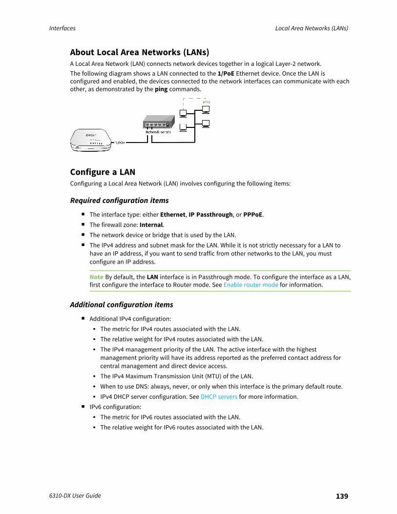
Interfaces Local Area Networks (LANs)
6310-DX User Guide 139
About Local Area Networks (LANs)A Local Area Network (LAN) connects network devices together in a logical Layer-2 network.The following diagram shows a LAN connected to the 1/PoE Ethernet device. Once the LAN isconfigured and enabled, the devices connected to the network interfaces can communicate with eachother, as demonstrated by the ping commands.
Configure a LANConfiguring a Local Area Network (LAN) involves configuring the following items:
Required configuration items
n The interface type: either Ethernet, IP Passthrough, or PPPoE.n The firewall zone: Internal.n The network device or bridge that is used by the LAN.n The IPv4 address and subnet mask for the LAN. While it is not strictly necessary for a LAN to
have an IP address, if you want to send traffic from other networks to the LAN, you mustconfigure an IP address.
Note By default, the LAN interface is in Passthrough mode. To configure the interface as a LAN,first configure the interface to Router mode. See Enable router mode for information.
Additional configuration items
n Additional IPv4 configuration:l The metric for IPv4 routes associated with the LAN.l The relative weight for IPv4 routes associated with the LAN.l The IPv4 management priority of the LAN. The active interface with the highest
management priority will have its address reported as the preferred contact address forcentral management and direct device access.
l The IPv4 Maximum Transmission Unit (MTU) of the LAN.l When to use DNS: always, never, or only when this interface is the primary default route.l IPv4 DHCP server configuration. See DHCP servers for more information.
n IPv6 configuration:l The metric for IPv6 routes associated with the LAN.l The relative weight for IPv6 routes associated with the LAN.
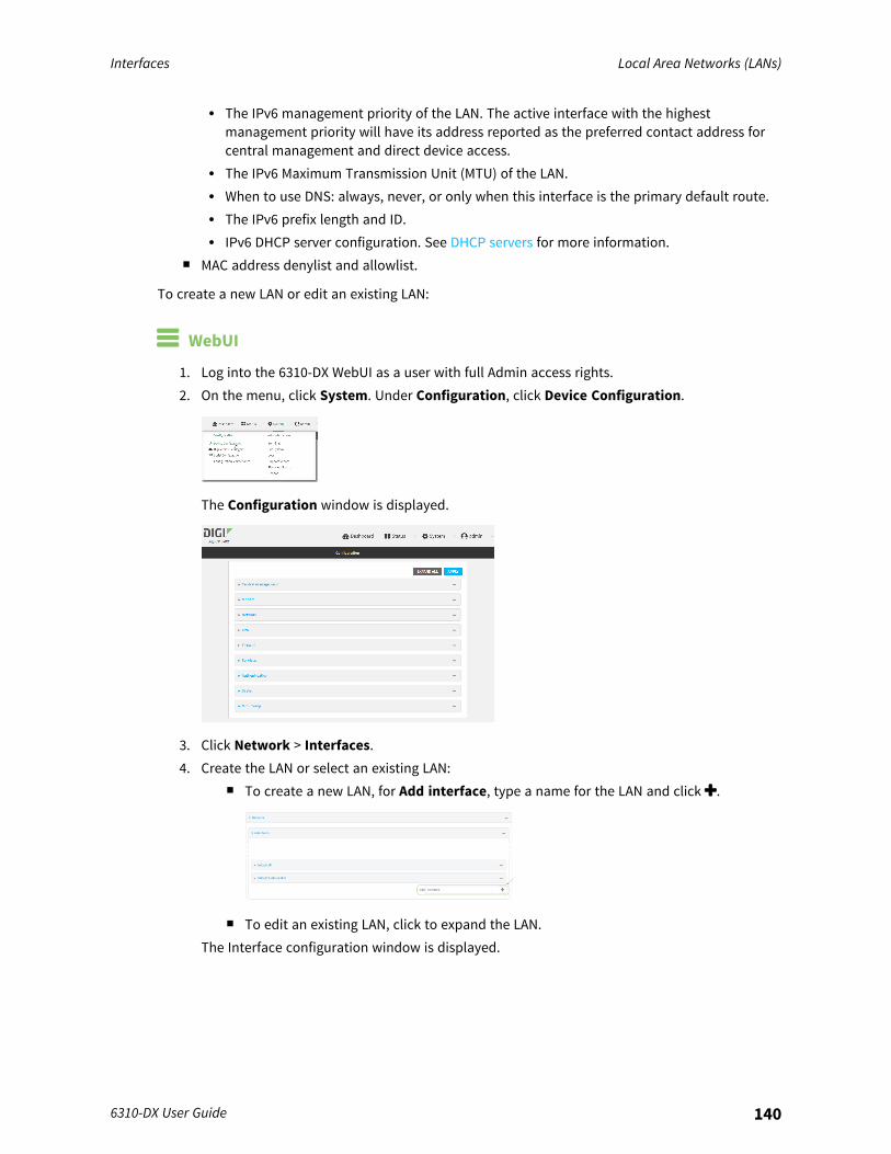
Interfaces Local Area Networks (LANs)
6310-DX User Guide 140
l The IPv6 management priority of the LAN. The active interface with the highestmanagement priority will have its address reported as the preferred contact address forcentral management and direct device access.
l The IPv6 Maximum Transmission Unit (MTU) of the LAN.l When to use DNS: always, never, or only when this interface is the primary default route.l The IPv6 prefix length and ID.l IPv6 DHCP server configuration. See DHCP servers for more information.
n MAC address denylist and allowlist.
To create a new LAN or edit an existing LAN:
WebUI
1. Log into the 6310-DX WebUI as a user with full Admin access rights.2. On the menu, click System. Under Configuration, click Device Configuration.
The Configuration window is displayed.
3. Click Network > Interfaces.4. Create the LAN or select an existing LAN:
n To create a new LAN, for Add interface, type a name for the LAN and click .
n To edit an existing LAN, click to expand the LAN.The Interface configuration window is displayed.
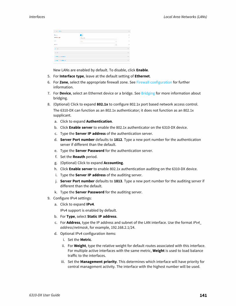
Interfaces Local Area Networks (LANs)
6310-DX User Guide 141
New LANs are enabled by default. To disable, click Enable.5. For Interface type, leave at the default setting of Ethernet.6. For Zone, select the appropriate firewall zone. See Firewall configuration for further
information.7. For Device, select an Ethernet device or a bridge. See Bridging for more information about
bridging.8. (Optional) Click to expand 802.1x to configure 802.1x port based network access control.
The 6310-DX can function as an 802.1x authenticator; it does not function as an 802.1xsupplicant.a. Click to expand Authentication.b. Click Enable server to enable the 802.1x authenticator on the 6310-DX device.c. Type the Server IP address of the authentication server.d. Server Port number defaults to 1812. Type a new port number for the authentication
server if different than the default.e. Type the Server Password for the authentication server.f. Set the Reauth period.g. (Optional) Click to expand Accounting.h. Click Enable server to enable 802.1x authentication auditing on the 6310-DX device.i. Type the Server IP address of the auditing server.j. Server Port number defaults to 1813. Type a new port number for the auditing server if
different than the default.k. Type the Server Password for the auditing server.
9. Configure IPv4 settings:a. Click to expand IPv4.
IPv4 support is enabled by default.b. For Type, select Static IP address.c. For Address, type the IP address and subnet of the LAN interface. Use the format IPv4_
address/netmask, for example, 192.168.2.1/24.d. Optional IPv4 configuration items:
i. Set the Metric.ii. For Weight, type the relative weight for default routes associated with this interface.
For multiple active interfaces with the same metric, Weight is used to load balancetraffic to the interfaces.
iii. Set the Management priority. This determines which interface will have priority forcentral management activity. The interface with the highest number will be used.

Interfaces Local Area Networks (LANs)
6310-DX User Guide 142
iv. Set the MTU.e. Enable the DHCP server:
i. Click to expand DHCP server.ii. Click Enable.
See DHCP servers for information about configuring the DHCP server.10. See Configure DHCP relay for information about configuring DHCP relay.11. (Optional) Configure IPv6 settings:
a. Click to expand IPv6.b. Enable IPv6 support.c. For Type, select IPv6 prefix delegration.d. For Prefix length, type the minimum length of the prefix to assign to this LAN. If the
minimum length is not available, then a longer prefix will be used.e. For Prefix ID, type the identifier used to extend the prefix to the assigned length. Leave
blank to use a random identifier.f. Set the Metric.g. For Weight, type the relative weight for default routes associated with this interface. For
multiple active interfaces with the same metric, Weight is used to load balance traffic tothe interfaces.
h. Set the Management priority. This determines which interface will have priority forcentral management activity. The interface with the highest number will be used.
i. Set the MTU.12. (Optional) Click to expand MAC address denylist.
Incoming packets will be dropped from any devices whose MAC addresses is included in theMAC address denylist.a. Click to expand MAC address denylist.b. For Add MAC address, click .c. Type the MAC address.
13. (Optional) Click to expand MAC address allowlist.If allowlist entries are specified, incoming packets will only be accepted from the listed MACaddresses.a. Click to expand MAC address allowlist.b. For Add MAC address, click .c. Type the MAC address.
14. Click Apply to save the configuration and apply the change.
Command line

Interfaces Local Area Networks (LANs)
6310-DX User Guide 143
1. Log into the 6310-DX command line as a user with full Admin access rights.Depending on your device configuration, you may be presented with an Access selectionmenu. Type admin to access the Admin CLI.
2. At the command line, type config to enter configuration mode:
> config(config)>
3. Create a new LAN or edit an existing one:n To create a new LAN named my_lan:
(config)> add network interface my_lan(config network interface my_lan)>
n To edit an existing LAN named my_lan, change to the my_lan node in the configurationschema:
(config)> network interface my_lan(config network interface my_lan)>
4. Set the appropriate firewall zone:
(config network interface my_lan)> zone zone(config network interface my_lan)>
See Firewall configuration for further information.5. Select an Ethernet device or a bridge. See Bridging for more information about bridging.
a. Enter device ? to view available devices and the proper syntax.
(config network interface my_lan)> device ?
Device: The network device used by this network interface.Format:/network/device/lan/network/device/wan/network/device/loopback
Current value:
(config network interface my_lan)> device
b. Set the device for the LAN:
(config network interface my_lan)> device device(config network interface my_lan)>
6. Configure IPv4 settings:n IPv4 support is enabled by default. To disable:
(config network interface my_lan)> ipv4 enable false(config network interface my_lan)>
Interfaces Local Area Networks (LANs)
6310-DX User Guide 144
n The LAN is configured by default to use a static IP address for its IPv4 configuration. Toconfigure the LAN to be a DHCP client, rather than using a static IP addres:
(config network interface my_lan)> ipv4 type dhcp(config network interface my_lan)>
These instructions assume that the LAN will use a static IP address for its IPv4configuration.
a. Set the IPv4 address and subnet of the LAN interface. Use the format IPv4_address/netmask, for example, 192.168.2.1/24.
(config network interface my_lan)> ipv4 address ip_address/netmask(config network interface my_lan)>
b. Optional IPv4 configuration items:i. Set the IP metric:
(config network interface my_lan)> ipv4 metric num(config network interface my_lan)>
ii. Set the relative weight for default routes associated with this interface. For multipleactive interfaces with the same metric, the weight is used to load balance traffic tothe interfaces.
(config network interface my_lan)> ipv4 weight num(config network interface my_lan)>
iii. Set the management priority. This determines which interface will have priority forcentral management activity. The interface with the highest number will be used.
(config network interface my_lan)> ipv4 mgmt num(config network interface my_lan)>
iv. Set the MTU:
(config network interface my_lan)> ipv4 mtu num(config network interface my_lan)>
c. Enable the DHCP server:
(config network interface my_lan)> ipv4 dhcp_server enable true
See DHCP servers for information about configuring the DHCP server.7. (Optional) Configure IPv6 settings:
a. Enable IPv6 support:
(config network interface my_lan)> ipv6 enable true(config network interface my_lan)>
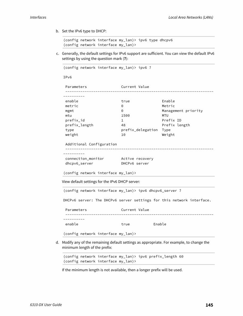
Interfaces Local Area Networks (LANs)
6310-DX User Guide 145
b. Set the IPv6 type to DHCP:
(config network interface my_lan)> ipv6 type dhcpv6(config network interface my_lan)>
c. Generally, the default settings for IPv6 support are sufficient. You can view the default IPv6settings by using the question mark (?):
(config network interface my_lan)> ipv6 ?
IPv6
Parameters Current Value-------------------------------------------------------------------------------enable true Enablemetric 0 Metricmgmt 0 Management prioritymtu 1500 MTUprefix_id 1 Prefix IDprefix_length 48 Prefix lengthtype prefix_delegation Typeweight 10 Weight
Additional Configuration-------------------------------------------------------------------------------connection_monitor Active recoverydhcpv6_server DHCPv6 server
(config network interface my_lan)>
View default settings for the IPv6 DHCP server:
(config network interface my_lan)> ipv6 dhcpv6_server ?
DHCPv6 server: The DHCPv6 server settings for this network interface.
Parameters Current Value-------------------------------------------------------------------------------enable true Enable
(config network interface my_lan)>
d. Modify any of the remaining default settings as appropriate. For example, to change theminimum length of the prefix:
(config network interface my_lan)> ipv6 prefix_length 60(config network interface my_lan)>
If the minimum length is not available, then a longer prefix will be used.
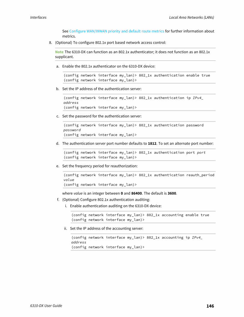
Interfaces Local Area Networks (LANs)
6310-DX User Guide 146
See Configure WAN/WWAN priority and default route metrics for further information aboutmetrics.
8. (Optional) To configure 802.1x port based network access control:
Note The 6310-DX can function as an 802.1x authenticator; it does not function as an 802.1xsupplicant.
a. Enable the 802.1x authenticator on the 6310-DX device:
(config network interface my_lan)> 802_1x authentication enable true(config network interface my_lan)>
b. Set the IP address of the authentication server:
(config network interface my_lan)> 802_1x authentication ip IPv4_address(config network interface my_lan)>
c. Set the password for the authentication server:
(config network interface my_lan)> 802_1x authentication passwordpassword(config network interface my_lan)>
d. The authentication server port number defaults to 1812. To set an alternate port number:
(config network interface my_lan)> 802_1x authentication port port(config network interface my_lan)>
e. Set the frequency period for reauthorization:
(config network interface my_lan)> 802_1x authentication reauth_periodvalue(config network interface my_lan)>
where value is an integer between 0 and 86400. The default is 3600.f. (Optional) Configure 802.1x authentication auditing:
i. Enable authentication auditing on the 6310-DX device:
(config network interface my_lan)> 802_1x accounting enable true(config network interface my_lan)>
ii. Set the IP address of the accounting server:
(config network interface my_lan)> 802_1x accounting ip IPv4_address(config network interface my_lan)>
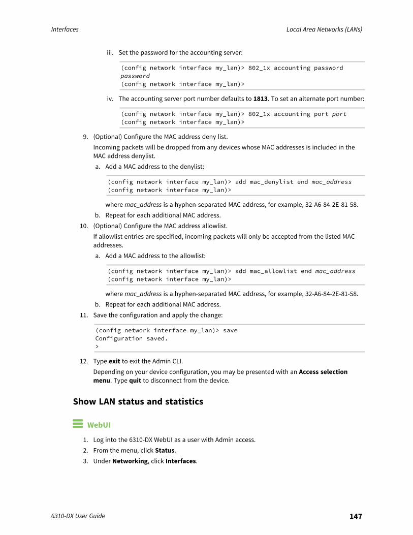
Interfaces Local Area Networks (LANs)
6310-DX User Guide 147
iii. Set the password for the accounting server:
(config network interface my_lan)> 802_1x accounting passwordpassword(config network interface my_lan)>
iv. The accounting server port number defaults to 1813. To set an alternate port number:
(config network interface my_lan)> 802_1x accounting port port(config network interface my_lan)>
9. (Optional) Configure the MAC address deny list.Incoming packets will be dropped from any devices whose MAC addresses is included in theMAC address denylist.a. Add a MAC address to the denylist:
(config network interface my_lan)> add mac_denylist end mac_address(config network interface my_lan)>
where mac_address is a hyphen-separated MAC address, for example, 32-A6-84-2E-81-58.b. Repeat for each additional MAC address.
10. (Optional) Configure the MAC address allowlist.If allowlist entries are specified, incoming packets will only be accepted from the listed MACaddresses.a. Add a MAC address to the allowlist:
(config network interface my_lan)> add mac_allowlist end mac_address(config network interface my_lan)>
where mac_address is a hyphen-separated MAC address, for example, 32-A6-84-2E-81-58.b. Repeat for each additional MAC address.
11. Save the configuration and apply the change:
(config network interface my_lan)> saveConfiguration saved.>
12. Type exit to exit the Admin CLI.Depending on your device configuration, you may be presented with an Access selectionmenu. Type quit to disconnect from the device.
Show LAN status and statistics
WebUI
1. Log into the 6310-DX WebUI as a user with Admin access.2. From the menu, click Status.3. Under Networking, click Interfaces.
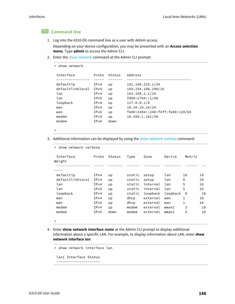
Interfaces Local Area Networks (LANs)
6310-DX User Guide 148
Command line
1. Log into the 6310-DX command line as a user with Admin access.Depending on your device configuration, you may be presented with an Access selectionmenu. Type admin to access the Admin CLI.
2. Enter the show network command at the Admin CLI prompt:
> show network
Interface Proto Status Address---------------- ----- ------- -------------------------------defaultip IPv4 up 192.168.210.1/24defaultlinklocal IPv4 up 169.254.100.100/16lan IPv4 up 192.168.2.1/24lan IPv6 up fd00:2704::1/48loopback IPv4 up 127.0.0.1/8wan IPv4 up 10.10.10.10/24wan IPv6 up fe00:2404::240:f4ff:fe80:120/64modem IPv4 up 10.200.1.101/30modem IPv6 down
>
3. Additional information can be displayed by using the show network verbose command:
> show network verbose
Interface Proto Status Type Zone Device MetricWeight---------------- ----- ------- ------ -------- -------- ------ ------defaultip IPv4 up static setup lan 10 10defaultlinklocal IPv4 up static setup lan 0 10lan IPv4 up static internal lan 5 10lan IPv6 up static internal lan 5 10loopback IPv4 up static loopback loopback 0 10wan IPv4 up dhcp external wan 1 10wan IPv6 up dhcp external wan 1 10modem IPv4 up modem external wwan1 3 10modem IPv6 down modem external wwan1 3 10
>
4. Enter show network interface name at the Admin CLI prompt to display additionalinformation about a specific LAN. For example, to display information about LAN, enter shownetwork interface lan:
> show network interface lan
lan1 Interface Status---------------------
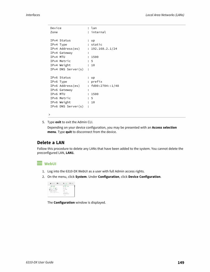
Interfaces Local Area Networks (LANs)
6310-DX User Guide 149
Device : lanZone : internal
IPv4 Status : upIPv4 Type : staticIPv4 Address(es) : 192.168.2.1/24IPv4 Gateway :IPv4 MTU : 1500IPv4 Metric : 5IPv4 Weight : 10IPv4 DNS Server(s) :
IPv6 Status : upIPv6 Type : prefixIPv6 Address(es) : fd00:2704::1/48IPv6 Gateway :IPv6 MTU : 1500IPv6 Metric : 5IPv6 Weight : 10IPv6 DNS Server(s) :
>
5. Type exit to exit the Admin CLI.Depending on your device configuration, you may be presented with an Access selectionmenu. Type quit to disconnect from the device.
Delete a LANFollow this procedure to delete any LANs that have been added to the system. You cannot delete thepreconfigured LAN, LAN1.
WebUI
1. Log into the 6310-DX WebUI as a user with full Admin access rights.2. On the menu, click System. Under Configuration, click Device Configuration.
The Configuration window is displayed.

Interfaces Local Area Networks (LANs)
6310-DX User Guide 150
3. Click Network > Interfaces.4. Click the menu icon (...) next to the name of the LAN to be deleted and select Delete.
5. Click Apply to save the configuration and apply the change.
Interfaces Local Area Networks (LANs)
6310-DX User Guide 151
Command line
1. Log into the 6310-DX command line as a user with full Admin access rights.Depending on your device configuration, you may be presented with an Access selectionmenu. Type admin to access the Admin CLI.
2. At the command line, type config to enter configuration mode:
> config(config)>
3. Use the del command to delete the LAN. For example, to delete a LAN named my_lan:
(config)> del network interface my_lan
4. Save the configuration and apply the change:
(config)> saveConfiguration saved.>
5. Type exit to exit the Admin CLI.Depending on your device configuration, you may be presented with an Access selectionmenu. Type quit to disconnect from the device.
DHCP serversYou can enable DHCP on your 6310-DX device to assign IP addresses to clients, using either:
n The DHCP server for the device's local network, which assigns IP addresses to clients on thedevice's local network. Addresses are assigned from a specified pool of IP addresses. For alocal network, the device uses the DHCP server that has the IP address pool in the sameIP subnet as the local network.When a host receives an IP configuration, the configuration is valid for a particular amount oftime, known as the lease time. After this lease time expires, the configuration must berenewed. The host renews the lease time automatically.
n A DHCP relay server, which forwards DHCP requests from clients to a DHCP server that isrunning on a separate device.
Configure a DHCP server
Note These instructions assume you are configuring the device to use its local DHCP server. Forinstructions about configuring the device to use a DHCP relay server, see Configure DHCP relay.
Required configuration items
n Enable the DHCP server.
Additional configuration items
n The lease address pool: the range of IP addresses issued by the DHCP server to clients.n Lease time: The length, in minutes, of the leases issued by the DHCP server.
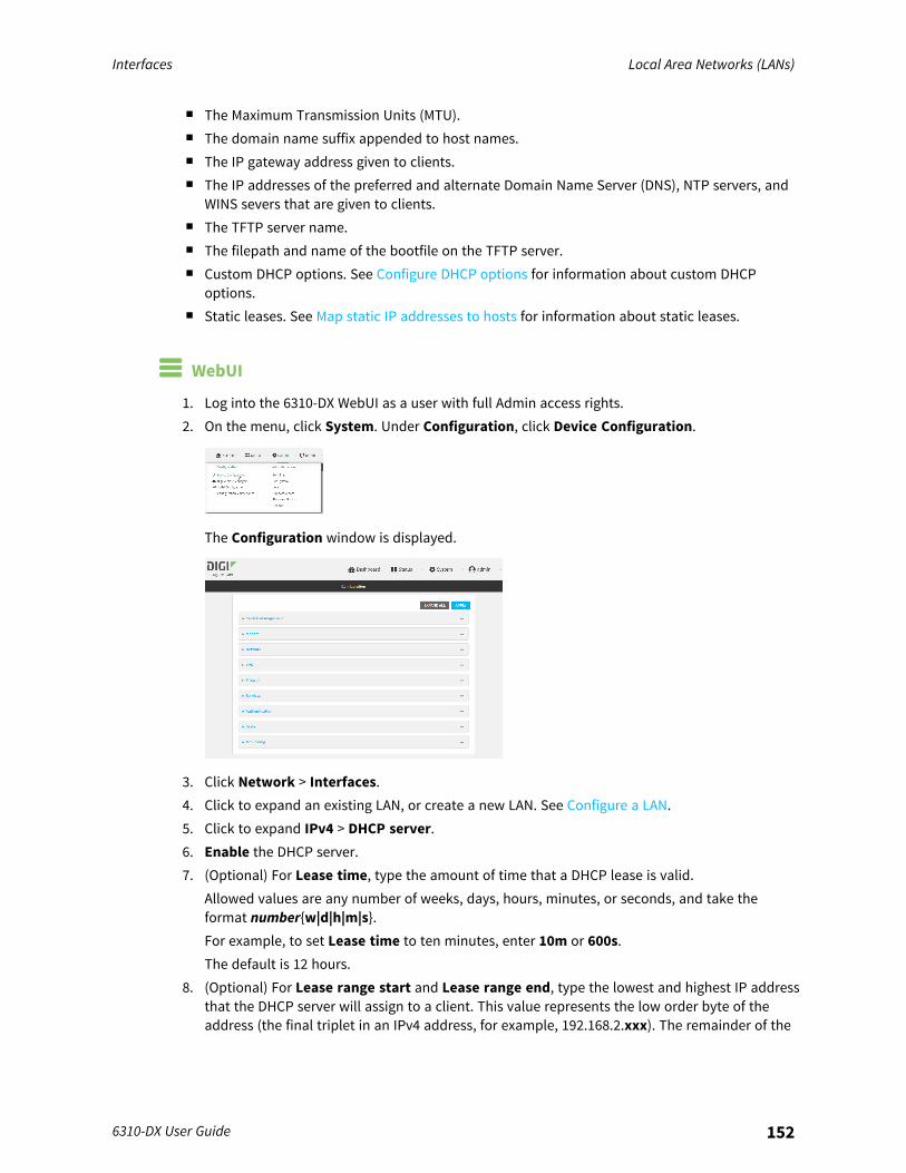
Interfaces Local Area Networks (LANs)
6310-DX User Guide 152
n The Maximum Transmission Units (MTU).n The domain name suffix appended to host names.n The IP gateway address given to clients.n The IP addresses of the preferred and alternate Domain Name Server (DNS), NTP servers, and
WINS severs that are given to clients.n The TFTP server name.n The filepath and name of the bootfile on the TFTP server.n Custom DHCP options. See Configure DHCP options for information about custom DHCP
options.n Static leases. See Map static IP addresses to hosts for information about static leases.
WebUI
1. Log into the 6310-DX WebUI as a user with full Admin access rights.2. On the menu, click System. Under Configuration, click Device Configuration.
The Configuration window is displayed.
3. Click Network > Interfaces.4. Click to expand an existing LAN, or create a new LAN. See Configure a LAN.5. Click to expand IPv4 > DHCP server.6. Enable the DHCP server.7. (Optional) For Lease time, type the amount of time that a DHCP lease is valid.
Allowed values are any number of weeks, days, hours, minutes, or seconds, and take theformat number{w|d|h|m|s}.For example, to set Lease time to ten minutes, enter 10m or 600s.The default is 12 hours.
8. (Optional) For Lease range start and Lease range end, type the lowest and highest IP addressthat the DHCP server will assign to a client. This value represents the low order byte of theaddress (the final triplet in an IPv4 address, for example, 192.168.2.xxx). The remainder of the

Interfaces Local Area Networks (LANs)
6310-DX User Guide 153
IP address will be based on the LAN's static IP address as defined in the Address field.Allowed values are between 1 and 254, and the default is 100 for Lease range start and 250for Lease range end.
9. Optional DHCP server settings:a. Click to expand Advanced settings.b. For Gateway, select either:
n None: No gateway is broadcast by the DHCP server. Client destinations must beresolvable without a gateway.
n Automatic: Broadcasts the 6310-DX device's gateway.n Custom: Allows you to identify the IP address of a Custom gateway to be
broadcast.The default is Automatic.
c. For MTU,n None: An MTU of length 0 is broadcast. This is not recommended.n Automatic: No MTU is broadcast and clients will determine their own MTU.n Custom: Allows you to identify a Custom MTU to be broadcast.
The default is Automatic.d. For Domain name suffix, type the domain name that should be appended to host names.e. For Primary and Secondary DNS, Primary and Secondary NTP server, and Primary and
Secondary WINS server, select either:n None: No server is broadcast.n Automatic: Broadcasts the 6310-DX device's server.n Custom: Allows you to identify the IP address of the server.
f. For Bootfile name, type the relative path and file name of the bootfile on the TFTP server.g. For TFTP server name, type the IP address or host name of the TFTP server.
10. See Configure DHCP options for information about Custom DHCP options.11. See Map static IP addresses to hosts for information about Static leases.12. Click Apply to save the configuration and apply the change.
Command line
1. Log into the 6310-DX command line as a user with full Admin access rights.Depending on your device configuration, you may be presented with an Access selectionmenu. Type admin to access the Admin CLI.
2. At the command line, type config to enter configuration mode:
> config(config)>
Interfaces Local Area Networks (LANs)
6310-DX User Guide 154
3. Enable the DHCP server for an existing LAN. For example, to enable the DHCP server for a LANnamed my_lan:
(config)> network interface my_lan ipv4 dhcp_server enable true(config)>
See Configure a LAN for information about creating a LAN.4. (Optional) Set the amount of time that a DHCP lease is valid:
(config)> network interface my_lan ipv4 dhcp_server lease_time value(config)>
where value is any number of weeks, days, hours, minutes, or seconds, and takes the formatnumber{w|d|h|m|s}.For example, to set network interface my_lan ipv4 dhcp_server lease_time to ten minutes,enter either 10m or 600s:
(config)> network interface my_lan ipv4 dhcp_server lease_time 600s(config)>
5. (Optional) Set the lowest IP address that the DHCP server will assign to a client. This valuerepresents the low order byte of the address (the final triplet in an IPv4 address, for example,192.168.2.xxx). The remainder of the IP address will be based on the LAN's static IP address asdefined in the address parameter.
(config)> network interface my_lan ipv4 dhcp_server lease_start num(config)>
Allowed values are between 1 and 254, and the default is 100.6. (Optional) Set the highest IP address that the DHCP server will assign to a client:
(config)> network interface my_lan ipv4 dhcp_server lease_end num(config)>
Allowed values are between 1 and 254, and the default is 250.7. Optional DHCP server settings:
a. Click to expand Advanced settings.b. Determine how the DHCP server should broadcast the gateway server:
(config)> network interface my_lan ipv4 dhcp_server advanced gatewayvalue(config)>
where value is one of:n none: No gateway is broadcast by the DHCP server. Client destinations must be
resolvable without a gateway.n auto: Broadcasts the 6310-DX device's gateway.

Interfaces Local Area Networks (LANs)
6310-DX User Guide 155
n custom: Allows you to identify the IP address of a custom gateway to be broadcast:
(config)> network interface my_lan ipv4 dhcp_server advancedgateway_custom ip_address(config)>
The default is auto.c. Determine how the DHCP server should broadcast the the MTU:
(config)> network interface my_lan ipv4 dhcp_server advanced mtu value(config)>
where value is one of:n none: An MTU of length 0 is broadcast. This is not recommended.n auto: No MTU is broadcast and clients will determine their own MTU.n custom: Allows you to identify a custom MTU to be broadcast:
(config)> network interface my_lan ipv4 dhcp_server advancedmtu_custom mtu(config)>
The default is auto.d. Set the domain name that should be appended to host names:
(config)> network interface my_lan ipv4 dhcp_server advanced domain_suffix name(config)>
e. Set the IP address or host name of the primary and secondary DNS, the primary andsecondary NTP server, and the primary and secondary WINS servers:
(config)> network interface my_lan ipv4 dhcp_server advanced primary_dns value(config)> network interface my_lan ipv4 dhcp_server advancedsecondary_dns value(config)> network interface my_lan ipv4 dhcp_server advanced primary_ntp value(config)> network interface my_lan ipv4 dhcp_server advancedsecondary_ntp value(config)> network interface my_lan ipv4 dhcp_server advanced primary_wins value(config)> network interface my_lan ipv4 dhcp_server advancedsecondary_wins value(config)>
where value is one of:n none: No server is broadcast.n auto: Broadcasts the 6310-DX device's server.

Interfaces Local Area Networks (LANs)
6310-DX User Guide 156
n custom: Allows you to identify the IP address of the server. For example:
(config)> network interface my_lan ipv4 dhcp_server advancedprimary_dns_custom ip_address(config)>
The default is auto.f. Set the IP address or host name of the TFTP server:
(config)> network interface my_lan ipv4 dhcp_server advanced nftp_server ip_address(config)>
g. Set the relative path and file name of the bootfile on the TFTP server:
(config)> network interface my_lan ipv4 dhcp_server advanced bootfilefilename(config)>
8. See Configure DHCP options for information about custom DHCP options.9. See Map static IP addresses to hosts for information about static leases.
10. Save the configuration and apply the change:
(config network interface my_lan ipv4 dhcp_server advanced static_lease0)> saveConfiguration saved.>
11. Type exit to exit the Admin CLI.Depending on your device configuration, you may be presented with an Access selectionmenu. Type quit to disconnect from the device.
Map static IP addresses to hostsYou can configure the DHCP server to assign static IP addresses to specific hosts.
Required configuration items
n IP address that will be mapped to the device.n MAC address of the device.
Additional configuration items
n A label for this instance of the static lease.
To map static IP addresses:
WebUI
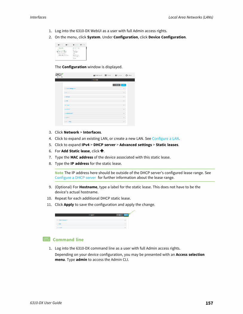
Interfaces Local Area Networks (LANs)
6310-DX User Guide 157
1. Log into the 6310-DX WebUI as a user with full Admin access rights.2. On the menu, click System. Under Configuration, click Device Configuration.
The Configuration window is displayed.
3. Click Network > Interfaces.4. Click to expand an existing LAN, or create a new LAN. See Configure a LAN.5. Click to expand IPv4 > DHCP server > Advanced settings > Static leases.6. For Add Static lease, click .7. Type the MAC address of the device associated with this static lease.8. Type the IP address for the static lease.
Note The IP address here should be outside of the DHCP server's configured lease range. SeeConfigure a DHCP server for further information about the lease range.
9. (Optional) For Hostname, type a label for the static lease. This does not have to be thedevice's actual hostname.
10. Repeat for each additional DHCP static lease.11. Click Apply to save the configuration and apply the change.
Command line
1. Log into the 6310-DX command line as a user with full Admin access rights.Depending on your device configuration, you may be presented with an Access selectionmenu. Type admin to access the Admin CLI.
Interfaces Local Area Networks (LANs)
6310-DX User Guide 158
2. At the command line, type config to enter configuration mode:
> config(config)>
3. Add a static lease to the DHCP server configuration for an existing LAN. For example, to addstatic lease to a LAN named my_lan:
(config)> add network interface my_lan ipv4 dhcp_server advanced static_lease end(config network interface my_lan ipv4 dhcp_server advanced static_lease0)>
See Configure a LAN for information about creating a LAN.4. Set the MAC address of the device associated with this static lease, using the colon-separated
format:
(config network interface my_lan ipv4 dhcp_server advanced static_lease0)> mac 00:40:D0:13:35:36(config network interface my_lan ipv4 dhcp_server advanced static_lease0)>
5. Set the IP address for the static lease:
(config network interface my_lan ipv4 dhcp_server advanced static_lease0)> ip 10.01.01.10(network interface my_lan ipv4 dhcp_server advanced static_lease 0)>
Note The IP address here should be outside of the DHCP server's configured lease range. SeeConfigure a DHCP server for further information about the lease range.
6. (Optional) Set a label for this static lease:
(config network interface my_lan ipv4 dhcp_server advanced static_lease0)> name label(config network interface my_lan ipv4 dhcp_server advanced static_lease0)>
7. Save the configuration and apply the change:
(config network interface my_lan ipv4 dhcp_server advanced static_lease0)> saveConfiguration saved.>
8. Type exit to exit the Admin CLI.Depending on your device configuration, you may be presented with an Access selectionmenu. Type quit to disconnect from the device.
Show current static IP mappingTo view your current static IP mapping:
WebUI
Interfaces Local Area Networks (LANs)
6310-DX User Guide 159
1. Log into the 6310-DX WebUI as a user with Admin access.2. On the main menu, click Status3. Under Networking, click DHCP Leases.
Command line
1. Log into the 6310-DX command line as a user with full Admin access rights.Depending on your device configuration, you may be presented with an Access selectionmenu. Type admin to access the Admin CLI.
2. At the command line, type config to enter configuration mode:
> config(config)>
3. Show the static lease configuration. For example, to show the static leases for a lan namedmy_lan:
(config)> show network interface my_lan ipv4 dhcp_server advanced static_lease0
ip 192.168.2.10mac BF:C3:46:24:0E:D9no name
1ip 192.168.2.11mac E3:C1:1F:65:C3:0Eno name
(config)>
4. Type cancel to exit configuration mode:
(config)> cancel>
5. Type exit to exit the Admin CLI.Depending on your device configuration, you may be presented with an Access selectionmenu. Type quit to disconnect from the device.
Delete static IP mapping entriesTo delete a static IP entry:
WebUI
1. Log into the 6310-DX WebUI as a user with full Admin access rights.2. On the menu, click System. Under Configuration, click Device Configuration.

Interfaces Local Area Networks (LANs)
6310-DX User Guide 160
The Configuration window is displayed.
3. Click Network > Interfaces.4. Click to expand an existing LAN.5. Click to expand IPv4 > DHCP server > Advanced settings > Static leases.6. Click the menu icon (...) next to the name of the static lease to be deleted and select Delete.
7. Click Apply to save the configuration and apply the change.
Command line
1. Log into the 6310-DX command line as a user with full Admin access rights.Depending on your device configuration, you may be presented with an Access selectionmenu. Type admin to access the Admin CLI.
2. At the command line, type config to enter configuration mode:
> config(config)>
3. Show the static lease configuration. For example, to show the static leases for a lan namedmy_lan:
(config)> show network interface my_lan ipv4 dhcp_server advanced static_lease0
ip 192.168.2.10mac BF:C3:46:24:0E:D9no name
1ip 192.168.2.11mac E3:C1:1F:65:C3:0E
Interfaces Local Area Networks (LANs)
6310-DX User Guide 161
no name(config)>
4. Use the del index_number command to delete a static lease. For example, to delete the staticlease for the device listed in the above output with a mac address of BF:C3:46:24:0E:D9 (indexnumber 0):
(config)> del network interface lan1 ipv4 dhcp_server advanced static_lease 0(config)>
5. Save the configuration and apply the change:
(config)> saveConfiguration saved.>
6. Type exit to exit the Admin CLI.Depending on your device configuration, you may be presented with an Access selectionmenu. Type quit to disconnect from the device.
Configure DHCP optionsYou can configure DHCP servers running on your 6310-DX device to send certain specified DHCPoptions to DHCP clients. You can also set the user class, which enables you to specify which specificDHCP clients will receive the option. You can also force the command to be sent to the clients.DHCP options can be set on a per-LAN basis, or can be set for all LANs. A total of 32 DHCP options canbe configured.
Required configuration items
n DHCP option number.n Value for the DHCP option.
Additional configuration items
n The data type of the value.n Force the option to be sent to the DHCP clients.n A label for the custom option.
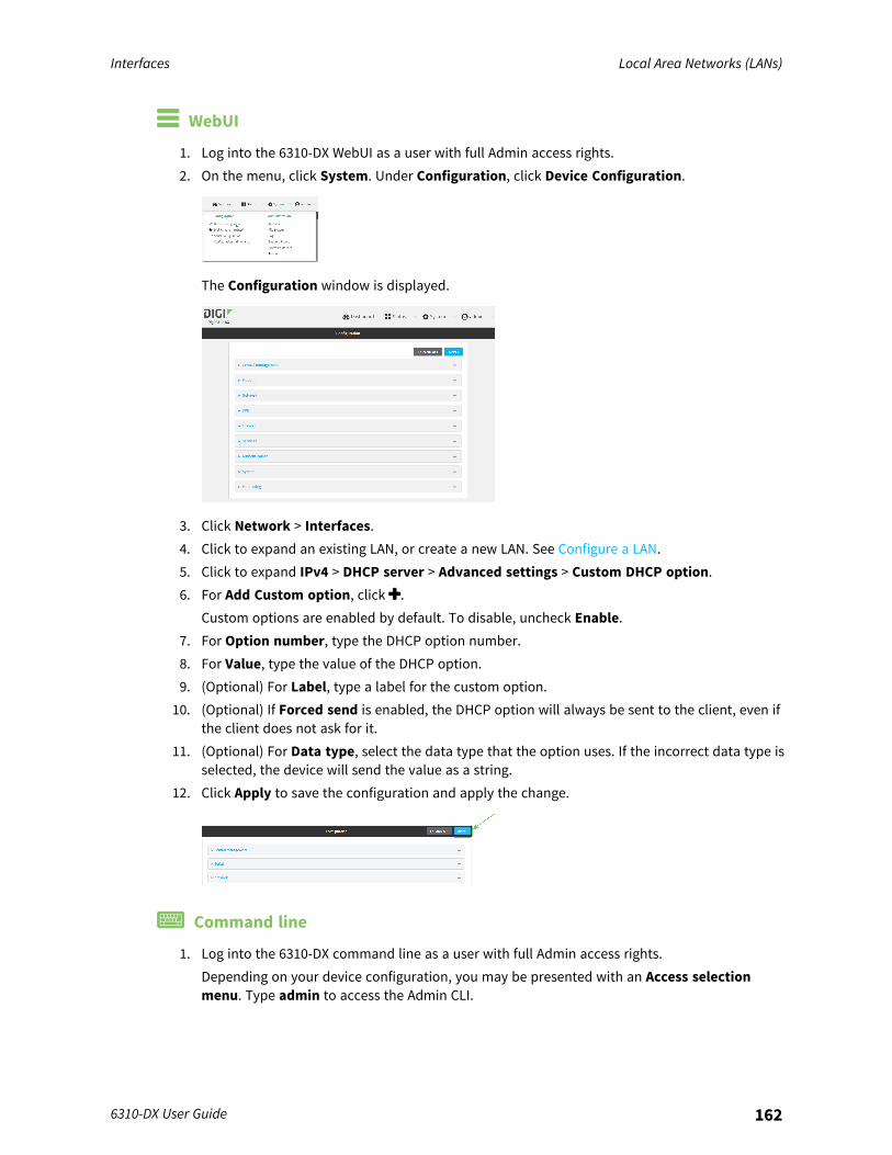
Interfaces Local Area Networks (LANs)
6310-DX User Guide 162
WebUI
1. Log into the 6310-DX WebUI as a user with full Admin access rights.2. On the menu, click System. Under Configuration, click Device Configuration.
The Configuration window is displayed.
3. Click Network > Interfaces.4. Click to expand an existing LAN, or create a new LAN. See Configure a LAN.5. Click to expand IPv4 > DHCP server > Advanced settings > Custom DHCP option.6. For Add Custom option, click .
Custom options are enabled by default. To disable, uncheck Enable.7. For Option number, type the DHCP option number.8. For Value, type the value of the DHCP option.9. (Optional) For Label, type a label for the custom option.
10. (Optional) If Forced send is enabled, the DHCP option will always be sent to the client, even ifthe client does not ask for it.
11. (Optional) For Data type, select the data type that the option uses. If the incorrect data type isselected, the device will send the value as a string.
12. Click Apply to save the configuration and apply the change.
Command line
1. Log into the 6310-DX command line as a user with full Admin access rights.Depending on your device configuration, you may be presented with an Access selectionmenu. Type admin to access the Admin CLI.
Interfaces Local Area Networks (LANs)
6310-DX User Guide 163
2. At the command line, type config to enter configuration mode:
> config(config)>
3. Add a custom DHCP option to the DHCP server configuration for an existing LAN. For example,to add static lease to a LAN named my_lan:
(config)> add network interface my_lan ipv4 dhcp_server advanced custom_option end(config network interface my_lan ipv4 dhcp_server advanced custom_option0)>
See Configure a LAN for information about creating a LAN.4. Custom options are enabled by default. To disable:
(config network interface my_lan ipv4 dhcp_server advanced custom_option0)> enable false(config network interface my_lan ipv4 dhcp_server advanced custom_option0)>
5. Set the option number for the DHCP option:
(config network interface my_lan ipv4 dhcp_server advanced custom_option0)> option 210(config network interface my_lan ipv4 dhcp_server advanced custom_option0)>
6. Set the value for the DHCP option:
(config network interface my_lan ipv4 dhcp_server advanced custom_option0)> value_str value(network interface my_lan ipv4 dhcp_server advanced custom_option 0)>
7. (Optional) Set a label for this custom option:
(config network interface my_lan ipv4 dhcp_server advanced custom_option0)> name label(config network interface my_lan ipv4 dhcp_server advanced custom_option0)>
8. (Optional) To force the DHCP option to always be sent to the client, even if the client does notask for it:
(config network interface my_lan ipv4 dhcp_server advanced custom_option0)> force true(config network interface my_lan ipv4 dhcp_server advanced custom_option0)>
9. (Optional) Set the data type that the option uses.If the incorrect data type is selected, the device will send the value as a string.
Interfaces Local Area Networks (LANs)
6310-DX User Guide 164
(config network interface my_lan ipv4 dhcp_server advanced custom_option0)> datatype value(config network interface my_lan ipv4 dhcp_server advanced custom_option0)>
where value is one of:n 1byten 2byten 4byten hexn ipv4n str
The default is str.10. Save the configuration and apply the change:
(config network interface my_lan ipv4 dhcp_server advanced custom_option0)> saveConfiguration saved.>
11. Type exit to exit the Admin CLI.Depending on your device configuration, you may be presented with an Access selectionmenu. Type quit to disconnect from the device.
Configure DHCP relayDHCP relay allows a router to forward DHCP requests from one LAN to a separate DHCP server,typically connected to a different LAN.For the 6310-DX device, DHCP relay is configured by providing the IP address of a DHCP relay server,rather than an IP address range. If both the DHCP relay server and an IP address range are specified,DHCP relay is used, and the specified IP address range is ignored.Multiple DHCP relay servers can be provided for each LAN. If multiple relay servers are provided, DHCPrequests are forwarded to all servers without waiting for a response. Clients will typically use the IPaddress from the first DHCP response received.Configuring DHCP relay involves the following items:
Required configuration items
n Disable the DHCP server, if it is enabled.n IP address of the primary DHCP relay server, to define the relay server that will respond to
DHCP requests.
Additional configuration items
n IP address of additional DHCP relay servers.
WebUI
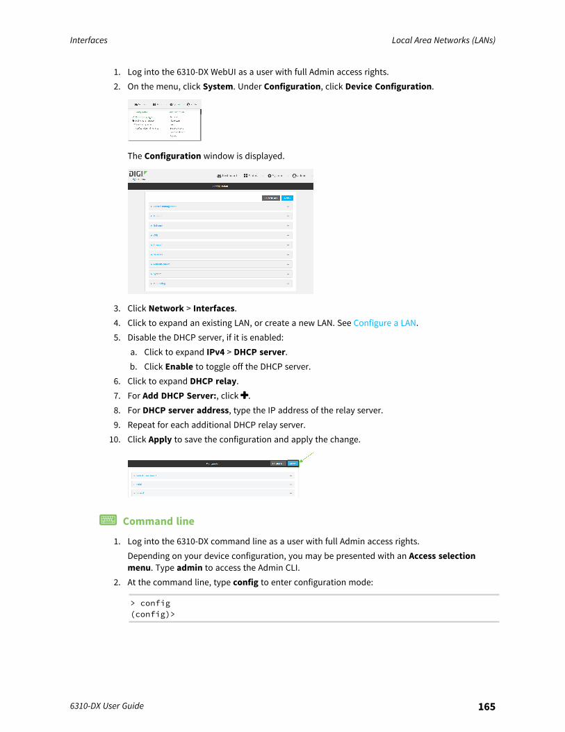
Interfaces Local Area Networks (LANs)
6310-DX User Guide 165
1. Log into the 6310-DX WebUI as a user with full Admin access rights.2. On the menu, click System. Under Configuration, click Device Configuration.
The Configuration window is displayed.
3. Click Network > Interfaces.4. Click to expand an existing LAN, or create a new LAN. See Configure a LAN.5. Disable the DHCP server, if it is enabled:
a. Click to expand IPv4 > DHCP server.b. Click Enable to toggle off the DHCP server.
6. Click to expand DHCP relay.7. For Add DHCP Server:, click .8. For DHCP server address, type the IP address of the relay server.9. Repeat for each additional DHCP relay server.
10. Click Apply to save the configuration and apply the change.
Command line
1. Log into the 6310-DX command line as a user with full Admin access rights.Depending on your device configuration, you may be presented with an Access selectionmenu. Type admin to access the Admin CLI.
2. At the command line, type config to enter configuration mode:
> config(config)>
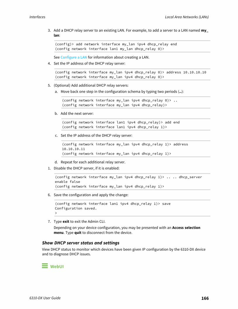
Interfaces Local Area Networks (LANs)
6310-DX User Guide 166
3. Add a DHCP relay server to an existing LAN. For example, to add a server to a LAN named my_lan:
(config)> add network interface my_lan ipv4 dhcp_relay end(config network interface lan1 my_lan dhcp_relay 0)>
See Configure a LAN for information about creating a LAN.4. Set the IP address of the DHCP relay server:
(config network interface my_lan ipv4 dhcp_relay 0)> address 10.10.10.10(config network interface my_lan ipv4 dhcp_relay 0)>
5. (Optional) Add additional DHCP relay servers:a. Move back one step in the configuration schema by typing two periods (..):
(config network interface my_lan ipv4 dhcp_relay 0)> ..(config network interface my_lan ipv4 dhcp_relay)>
b. Add the next server:
(config network interface lan1 ipv4 dhcp_relay)> add end(config network interface lan1 ipv4 dhcp_relay 1)>
c. Set the IP address of the DHCP relay server:
(config network interface my_lan ipv4 dhcp_relay 1)> address10.10.10.11(config network interface my_lan ipv4 dhcp_relay 1)>
d. Repeat for each additional relay server.1. Disable the DHCP server, if it is enabled:
(config network interface my_lan ipv4 dhcp_relay 1)> .. .. dhcp_serverenable false(config network interface my_lan ipv4 dhcp_relay 1)>
6. Save the configuration and apply the change:
(config network interface lan1 ipv4 dhcp_relay 1)> saveConfiguration saved.>
7. Type exit to exit the Admin CLI.Depending on your device configuration, you may be presented with an Access selectionmenu. Type quit to disconnect from the device.
Show DHCP server status and settingsView DHCP status to monitor which devices have been given IP configuration by the 6310-DX deviceand to diagnose DHCP issues.
WebUI
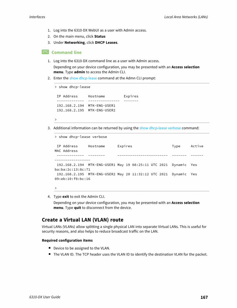
Interfaces Local Area Networks (LANs)
6310-DX User Guide 167
1. Log into the 6310-DX WebUI as a user with Admin access.2. On the main menu, click Status3. Under Networking, click DHCP Leases.
Command line
1. Log into the 6310-DX command line as a user with Admin access.Depending on your device configuration, you may be presented with an Access selectionmenu. Type admin to access the Admin CLI.
2. Enter the show dhcp-lease command at the Admn CLI prompt:
> show dhcp-lease
IP Address Hostname Expires------------- --------------- -------192.168.2.194 MTK-ENG-USER1192.168.2.195 MTK-ENG-USER2
>
3. Additional information can be returned by using the show dhcp-lease verbose command:
> show dhcp-lease verbose
IP Address Hostname Expires Type ActiveMAC Address------------- -------- ------------------------ ------- -----------------------192.168.2.194 MTK-ENG-USER1 May 19 08:25:11 UTC 2021 Dynamic Yesba:ba:2c:13:8c:71192.168.2.195 MTK-ENG-USER2 May 20 11:32:12 UTC 2021 Dynamic Yes09:eb:10:f0:bc:16
>
4. Type exit to exit the Admin CLI.Depending on your device configuration, you may be presented with an Access selectionmenu. Type quit to disconnect from the device.
Create a Virtual LAN (VLAN) routeVirtual LANs (VLANs) allow splitting a single physical LAN into separate Virtual LANs. This is useful forsecurity reasons, and also helps to reduce broadcast traffic on the LAN.
Required configuration items
n Device to be assigned to the VLAN.n The VLAN ID. The TCP header uses the VLAN ID to identify the destination VLAN for the packet.
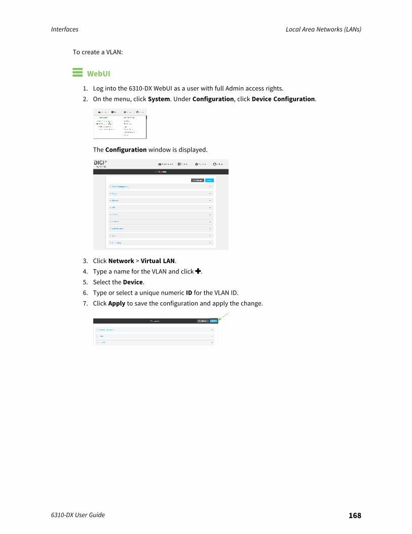
Interfaces Local Area Networks (LANs)
6310-DX User Guide 168
To create a VLAN:
WebUI
1. Log into the 6310-DX WebUI as a user with full Admin access rights.2. On the menu, click System. Under Configuration, click Device Configuration.
The Configuration window is displayed.
3. Click Network > Virtual LAN.4. Type a name for the VLAN and click .5. Select the Device.6. Type or select a unique numeric ID for the VLAN ID.7. Click Apply to save the configuration and apply the change.
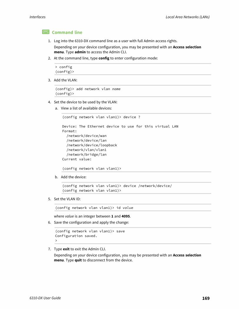
Interfaces Local Area Networks (LANs)
6310-DX User Guide 169
Command line
1. Log into the 6310-DX command line as a user with full Admin access rights.Depending on your device configuration, you may be presented with an Access selectionmenu. Type admin to access the Admin CLI.
2. At the command line, type config to enter configuration mode:
> config(config)>
3. Add the VLAN:
(config)> add network vlan name(config)>
4. Set the device to be used by the VLAN:a. View a list of available devices:
(config network vlan vlan1)> device ?
Device: The Ethernet device to use for this virtual LANFormat:/network/device/wan/network/device/lan/network/device/loopback/network/vlan/vlan1/network/bridge/lan
Current value:
(config network vlan vlan1)>
b. Add the device:
(config network vlan vlan1)> device /network/device/(config network vlan vlan1)>
5. Set the VLAN ID:
(config network vlan vlan1)> id value
where value is an integer between 1 and 4095.6. Save the configuration and apply the change:
(config network vlan vlan1)> saveConfiguration saved.>
7. Type exit to exit the Admin CLI.Depending on your device configuration, you may be presented with an Access selectionmenu. Type quit to disconnect from the device.

Interfaces Local Area Networks (LANs)
6310-DX User Guide 170
Default services listening on LAN portsThe following table lists the default services listening on the specified ports on the 6310-DX LANinterfaces:
Description TCP/UDP Port numbers
DNS server UDP 53
DHCP server UDP 67 and 68
SSH server TCP 22
Web UI TCP 443 (also listens on port 80, then redirects to port 443

Interfaces Bridging
6310-DX User Guide 171
BridgingBridging is a mechanism to create a single network consisting of multiple devices, such as Ethernetdevices and wireless access points.This section contains the following topics:
Configure a bridge 172
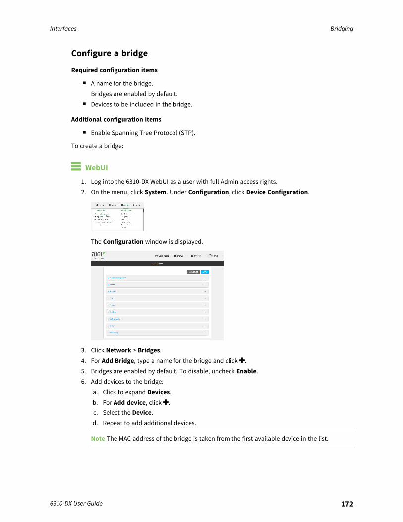
Interfaces Bridging
6310-DX User Guide 172
Configure a bridge
Required configuration items
n A name for the bridge.Bridges are enabled by default.
n Devices to be included in the bridge.
Additional configuration items
n Enable Spanning Tree Protocol (STP).
To create a bridge:
WebUI
1. Log into the 6310-DX WebUI as a user with full Admin access rights.2. On the menu, click System. Under Configuration, click Device Configuration.
The Configuration window is displayed.
3. Click Network > Bridges.4. For Add Bridge, type a name for the bridge and click .5. Bridges are enabled by default. To disable, uncheck Enable.6. Add devices to the bridge:
a. Click to expand Devices.b. For Add device, click .c. Select the Device.d. Repeat to add additional devices.
Note The MAC address of the bridge is taken from the first available device in the list.
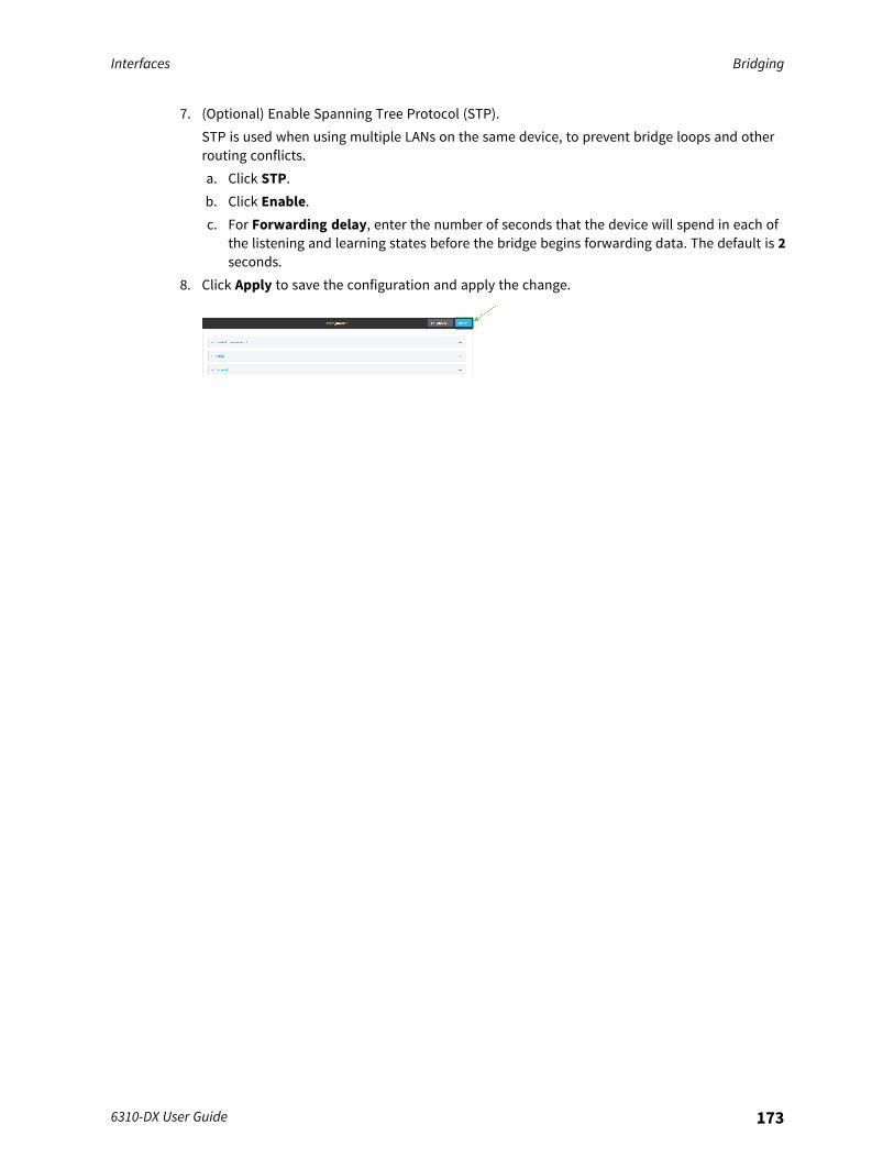
Interfaces Bridging
6310-DX User Guide 173
7. (Optional) Enable Spanning Tree Protocol (STP).STP is used when using multiple LANs on the same device, to prevent bridge loops and otherrouting conflicts.a. Click STP.b. Click Enable.c. For Forwarding delay, enter the number of seconds that the device will spend in each of
the listening and learning states before the bridge begins forwarding data. The default is 2seconds.
8. Click Apply to save the configuration and apply the change.
Interfaces Bridging
6310-DX User Guide 174
Command line
1. Log into the 6310-DX command line as a user with full Admin access rights.Depending on your device configuration, you may be presented with an Access selectionmenu. Type admin to access the Admin CLI.
2. At the command line, type config to enter configuration mode:
> config(config)>
3. Create the bridge:
(config)> add network bridge my_bridge(config network bridge my_bridge)>
4. Bridges are enabled by default.n To disable:
(config network bridge my_bridge)> enable false(config network bridge my_bridge)>
n To enable if it has been disabled:
(config network bridge my_bridge)> enable true(config network bridge my_bridge)>
5. Add devices to the bridge:a. Determine available devices:
(config network bridge my_bridge)> .. .. interface lan device ?
Device: The network device used by this network interface.Format:/network/device/lan/network/device/wan/network/device/loopback
Default value: /network/lanCurrent value: /network/lan
(config network bridge my_bridge)>
b. Add the appropriate device.
Note The MAC address of the bridge is taken from the first available device in the list.
6. (Optional) Enable Spanning Tree Protocol (STP).STP is used when using multiple LANs on the same device, to prevent bridge loops and otherrouting conflicts.
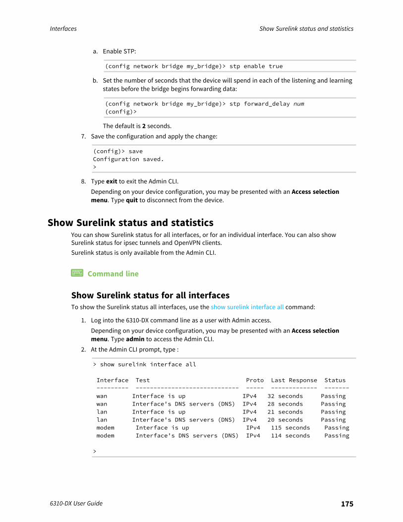
Interfaces Show Surelink status and statistics
6310-DX User Guide 175
a. Enable STP:
(config network bridge my_bridge)> stp enable true
b. Set the number of seconds that the device will spend in each of the listening and learningstates before the bridge begins forwarding data:
(config network bridge my_bridge)> stp forward_delay num(config)>
The default is 2 seconds.7. Save the configuration and apply the change:
(config)> saveConfiguration saved.>
8. Type exit to exit the Admin CLI.Depending on your device configuration, you may be presented with an Access selectionmenu. Type quit to disconnect from the device.
Show Surelink status and statisticsYou can show Surelink status for all interfaces, or for an individual interface. You can also showSurelink status for ipsec tunnels and OpenVPN clients.Surelink status is only available from the Admin CLI.
Command line
Show Surelink status for all interfacesTo show the Surelink status all interfaces, use the show surelink interface all command:
1. Log into the 6310-DX command line as a user with Admin access.Depending on your device configuration, you may be presented with an Access selectionmenu. Type admin to access the Admin CLI.
2. At the Admin CLI prompt, type :
> show surelink interface all
Interface Test Proto Last Response Status--------- ----------------------------- ----- ------------- -------wan Interface is up IPv4 32 seconds Passingwan Interface's DNS servers (DNS) IPv4 28 seconds Passinglan Interface is up IPv4 21 seconds Passinglan Interface's DNS servers (DNS) IPv4 20 seconds Passingmodem Interface is up IPv4 115 seconds Passingmodem Interface's DNS servers (DNS) IPv4 114 seconds Passing
>
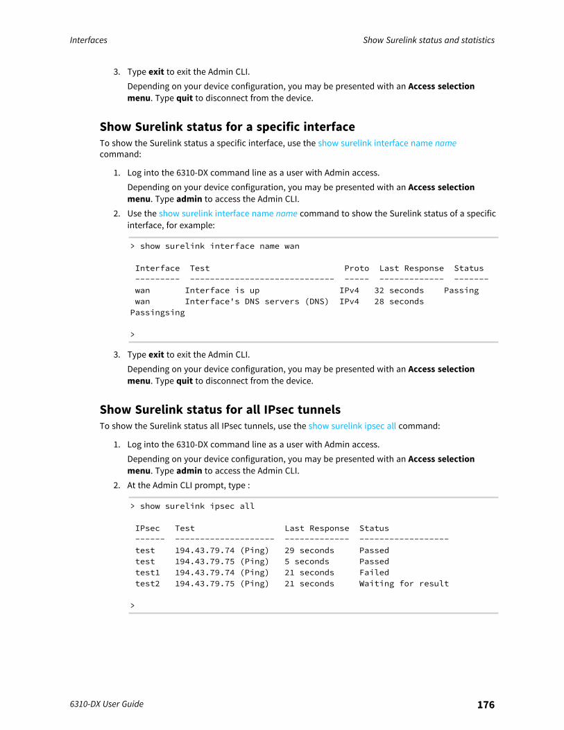
Interfaces Show Surelink status and statistics
6310-DX User Guide 176
3. Type exit to exit the Admin CLI.Depending on your device configuration, you may be presented with an Access selectionmenu. Type quit to disconnect from the device.
Show Surelink status for a specific interfaceTo show the Surelink status a specific interface, use the show surelink interface name namecommand:
1. Log into the 6310-DX command line as a user with Admin access.Depending on your device configuration, you may be presented with an Access selectionmenu. Type admin to access the Admin CLI.
2. Use the show surelink interface name name command to show the Surelink status of a specificinterface, for example:
> show surelink interface name wan
Interface Test Proto Last Response Status--------- ----------------------------- ----- ------------- -------wan Interface is up IPv4 32 seconds Passingwan Interface's DNS servers (DNS) IPv4 28 secondsPassingsing
>
3. Type exit to exit the Admin CLI.Depending on your device configuration, you may be presented with an Access selectionmenu. Type quit to disconnect from the device.
Show Surelink status for all IPsec tunnelsTo show the Surelink status all IPsec tunnels, use the show surelink ipsec all command:
1. Log into the 6310-DX command line as a user with Admin access.Depending on your device configuration, you may be presented with an Access selectionmenu. Type admin to access the Admin CLI.
2. At the Admin CLI prompt, type :
> show surelink ipsec all
IPsec Test Last Response Status------ -------------------- ------------- ------------------test 194.43.79.74 (Ping) 29 seconds Passedtest 194.43.79.75 (Ping) 5 seconds Passedtest1 194.43.79.74 (Ping) 21 seconds Failedtest2 194.43.79.75 (Ping) 21 seconds Waiting for result
>
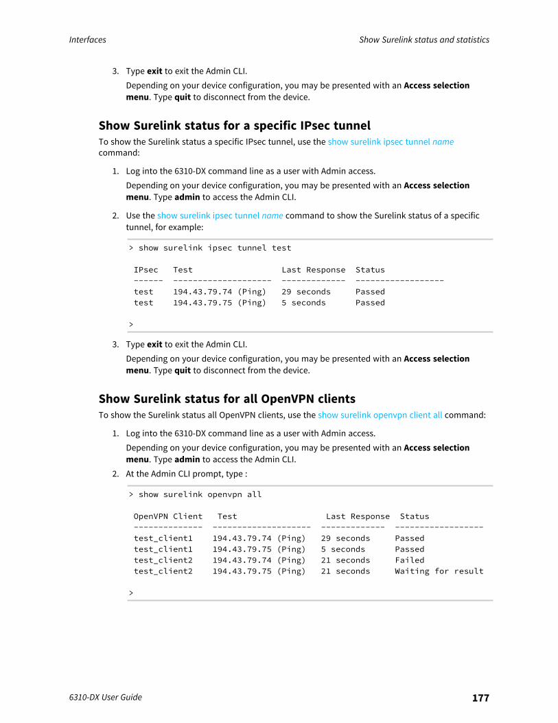
Interfaces Show Surelink status and statistics
6310-DX User Guide 177
3. Type exit to exit the Admin CLI.Depending on your device configuration, you may be presented with an Access selectionmenu. Type quit to disconnect from the device.
Show Surelink status for a specific IPsec tunnelTo show the Surelink status a specific IPsec tunnel, use the show surelink ipsec tunnel namecommand:
1. Log into the 6310-DX command line as a user with Admin access.Depending on your device configuration, you may be presented with an Access selectionmenu. Type admin to access the Admin CLI.
2. Use the show surelink ipsec tunnel name command to show the Surelink status of a specifictunnel, for example:
> show surelink ipsec tunnel test
IPsec Test Last Response Status------ -------------------- ------------- ------------------test 194.43.79.74 (Ping) 29 seconds Passedtest 194.43.79.75 (Ping) 5 seconds Passed
>
3. Type exit to exit the Admin CLI.Depending on your device configuration, you may be presented with an Access selectionmenu. Type quit to disconnect from the device.
Show Surelink status for all OpenVPN clientsTo show the Surelink status all OpenVPN clients, use the show surelink openvpn client all command:
1. Log into the 6310-DX command line as a user with Admin access.Depending on your device configuration, you may be presented with an Access selectionmenu. Type admin to access the Admin CLI.
2. At the Admin CLI prompt, type :
> show surelink openvpn all
OpenVPN Client Test Last Response Status-------------- -------------------- ------------- ------------------test_client1 194.43.79.74 (Ping) 29 seconds Passedtest_client1 194.43.79.75 (Ping) 5 seconds Passedtest_client2 194.43.79.74 (Ping) 21 seconds Failedtest_client2 194.43.79.75 (Ping) 21 seconds Waiting for result
>
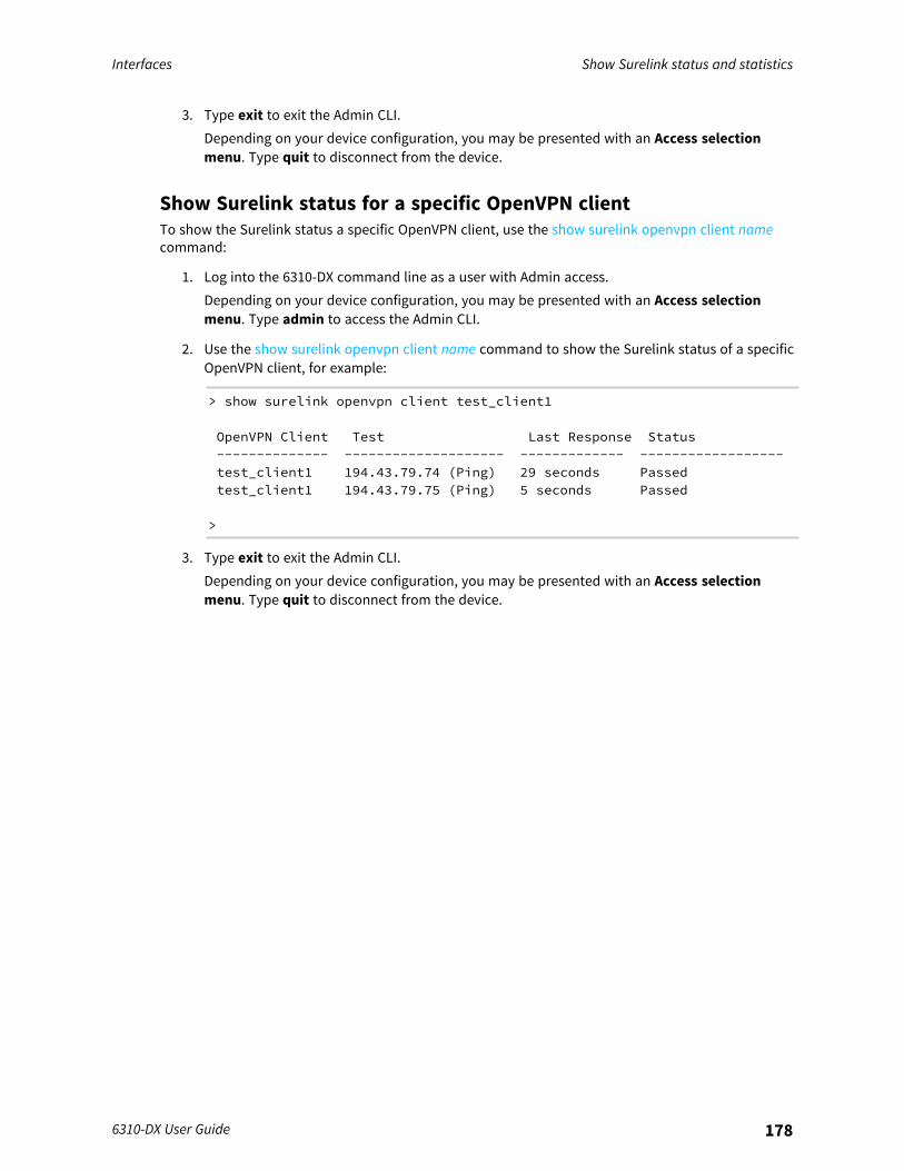
Interfaces Show Surelink status and statistics
6310-DX User Guide 178
3. Type exit to exit the Admin CLI.Depending on your device configuration, you may be presented with an Access selectionmenu. Type quit to disconnect from the device.
Show Surelink status for a specific OpenVPN clientTo show the Surelink status a specific OpenVPN client, use the show surelink openvpn client namecommand:
1. Log into the 6310-DX command line as a user with Admin access.Depending on your device configuration, you may be presented with an Access selectionmenu. Type admin to access the Admin CLI.
2. Use the show surelink openvpn client name command to show the Surelink status of a specificOpenVPN client, for example:
> show surelink openvpn client test_client1
OpenVPN Client Test Last Response Status-------------- -------------------- ------------- ------------------test_client1 194.43.79.74 (Ping) 29 seconds Passedtest_client1 194.43.79.75 (Ping) 5 seconds Passed
>
3. Type exit to exit the Admin CLI.Depending on your device configuration, you may be presented with an Access selectionmenu. Type quit to disconnect from the device.
Routing
This chapter contains the following topics:
IP routing 180Show the routing table 207Dynamic DNS 208Virtual Router Redundancy Protocol (VRRP) 214
6310-DX User Guide 179
Routing IP routing
6310-DX User Guide 180
IP routingThe 6310-DX device uses IP routes to decide where to send a packet it receives for a remote network.The process for deciding on a route to send the packet is as follows:
1. The device examines the destination IP address in the IP packet, and looks through the IProuting table to find a match for it.
2. If it finds a route for the destination, it forwards the IP packet to the configured IP gateway orinterface.
3. If it cannot find a route for the destination, it uses a default route.4. If there are two or more routes to a destination, the device uses the route with the longest
mask.5. If there are two or more routes to a destination with the same mask, the device uses the route
with the lowest metric.
This section contains the following topics:
Configure a static route 181Delete a static route 184Policy-based routing 186Configure a routing policy 187Example: Dual WAN policy-based routing 195Example: Route traffic to a specific WAN interface based on the client MAC address 198Routing services 203Configure routing services 204
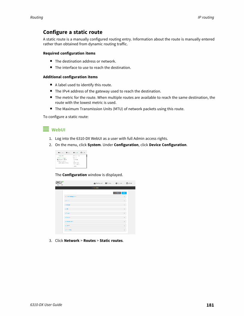
Routing IP routing
6310-DX User Guide 181
Configure a static routeA static route is a manually configured routing entry. Information about the route is manually enteredrather than obtained from dynamic routing traffic.
Required configuration items
n The destination address or network.n The interface to use to reach the destination.
Additional configuration items
n A label used to identify this route.n The IPv4 address of the gateway used to reach the destination.n The metric for the route. When multiple routes are available to reach the same destination, the
route with the lowest metric is used.n The Maximum Transmission Units (MTU) of network packets using this route.
To configure a static route:
WebUI
1. Log into the 6310-DX WebUI as a user with full Admin access rights.2. On the menu, click System. Under Configuration, click Device Configuration.
The Configuration window is displayed.
3. Click Network > Routes > Static routes.
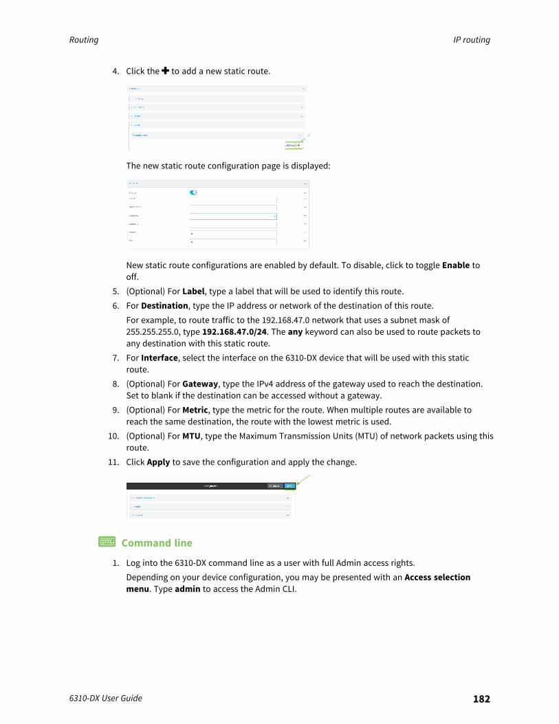
Routing IP routing
6310-DX User Guide 182
4. Click the to add a new static route.
The new static route configuration page is displayed:
New static route configurations are enabled by default. To disable, click to toggle Enable tooff.
5. (Optional) For Label, type a label that will be used to identify this route.6. For Destination, type the IP address or network of the destination of this route.
For example, to route traffic to the 192.168.47.0 network that uses a subnet mask of255.255.255.0, type 192.168.47.0/24. The any keyword can also be used to route packets toany destination with this static route.
7. For Interface, select the interface on the 6310-DX device that will be used with this staticroute.
8. (Optional) For Gateway, type the IPv4 address of the gateway used to reach the destination.Set to blank if the destination can be accessed without a gateway.
9. (Optional) For Metric, type the metric for the route. When multiple routes are available toreach the same destination, the route with the lowest metric is used.
10. (Optional) For MTU, type the Maximum Transmission Units (MTU) of network packets using thisroute.
11. Click Apply to save the configuration and apply the change.
Command line
1. Log into the 6310-DX command line as a user with full Admin access rights.Depending on your device configuration, you may be presented with an Access selectionmenu. Type admin to access the Admin CLI.
Routing IP routing
6310-DX User Guide 183
2. At the command line, type config to enter configuration mode:
> config(config)>
3. Add a new static route:
(config)> add network route static end(config network route static 0)>
New static route instances are enabled by default. To disable:
(config network route static 0)> enable false(config network route static 0)>
4. (Optional) set a label that will be used to identify this route. For example:
(config network route static 0)> label "route to accounting network"(config network route static 0)>
5. Set the IP address or network of the destination of this route. For example:
(config network route static 0)> destination ip_address[/netmask](config network route static 0)>
For example, to route traffic to the 192.168.47.0 network that uses a subnet mask of255.255.255.0:
(config network route static 0)> dst 192.168.47.0/24(config network route static 0)>
The any keyword can also be used to route packets to any destination with this static route.6. Set the interface on the 6310-DX device that will be used with this static route:
a. Use the ? to determine available interfaces:
(config network route static 0)> interface ?
Interface: The network interface to use to reach the destination.Format:/network/interface/defaultip/network/interface/defaultlinklocal/network/interface/lan/network/interface/loopback/network/interface/modem/network/interface/wan
Current value:
(config network route static 0)> interface
Routing IP routing
6310-DX User Guide 184
b. Set the interface. For example:
(config network route static 0)> interface /network/interface/wan(config network route static 0)>
7. (Optional) Set the IPv4 address of the gateway used to reach the destination. Set to blank ifthe destination can be accessed without a gateway.
(config network route static 0)> gateway IPv4_address(config network route static 0)>
8. (Optional) Set the metric for the route. When multiple routes are available to reach the samedestination, the route with the lowest metric is used.
(config network route static 0)> metric value(config network route static 0)>
where value is an interger between 0 and 65535. The default is 0.9. (Optional) Set the Maximum Transmission Units (MTU) of network packets using this route:
(config network route static 0)> mtu integer(config network route static 0)>
10. Save the configuration and apply the change:
(config)> saveConfiguration saved.>
11. Type exit to exit the Admin CLI.Depending on your device configuration, you may be presented with an Access selectionmenu. Type quit to disconnect from the device.
Delete a static route
WebUI
1. Log into the 6310-DX WebUI as a user with full Admin access rights.2. On the menu, click System. Under Configuration, click Device Configuration.
The Configuration window is displayed.
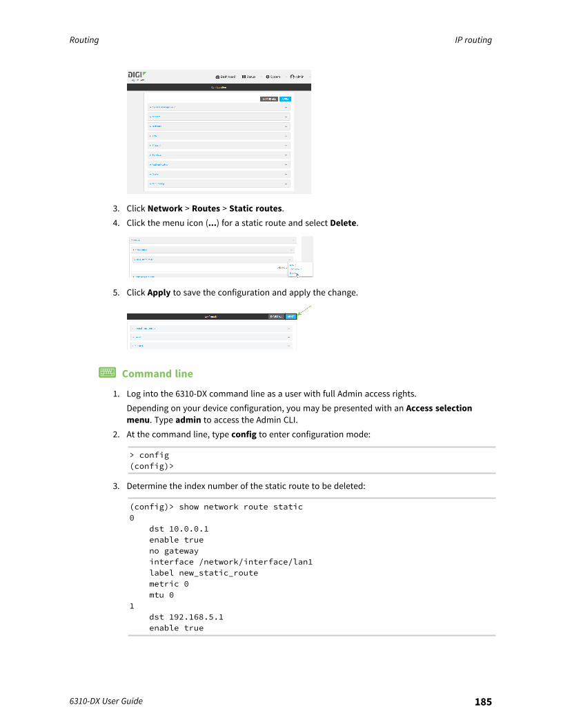
Routing IP routing
6310-DX User Guide 185
3. Click Network > Routes > Static routes.4. Click the menu icon (...) for a static route and select Delete.
5. Click Apply to save the configuration and apply the change.
Command line
1. Log into the 6310-DX command line as a user with full Admin access rights.Depending on your device configuration, you may be presented with an Access selectionmenu. Type admin to access the Admin CLI.
2. At the command line, type config to enter configuration mode:
> config(config)>
3. Determine the index number of the static route to be deleted:
(config)> show network route static0
dst 10.0.0.1enable trueno gatewayinterface /network/interface/lan1label new_static_routemetric 0mtu 0
1dst 192.168.5.1enable true

Routing IP routing
6310-DX User Guide 186
gateway 192.168.5.1interface /network/interface/lan2label new_static_route_1metric 0mtu 0
(config)>
4. Use the index number to delete the static route:
(config)> del network route static 0(config)>
5. Save the configuration and apply the change:
(config)> saveConfiguration saved.>
6. Type exit to exit the Admin CLI.Depending on your device configuration, you may be presented with an Access selectionmenu. Type quit to disconnect from the device.
Policy-based routingNormally, a routing device determines how to route a network packet based on its destinationaddress. However, you can use policy-based routing to forward the packet based on other criteria,such as the source of the packet. For example, you can configure the 6310-DX device so that high-priority traffic is routed through the cellular connection, while all other traffic is routed through anEthernet (WAN) connection.Policy-based routing for the 6310-DX device uses the following criteria to determine how to routetraffic:
n Firewall zone (for example, internal/outbound traffic, external/inbound traffic, or IPSec tunneltraffic).
n Network interface (for example, the cellular connection, the WAN, or the LAN).n IPv4 address.n IPv6 address.n MAC address.n Domain.n Protocol type (TCP, UDP, ICMP, or all).
The order of the policies is important. Routing policies are processed sequentially; as a result, if apacket matches an earlier policy, it will be routed using that policy’s rules. It will not be processed byany subsequent rules.

Routing IP routing
6310-DX User Guide 187
Configure a routing policy
Required configuration items
n The packet matching parameters. It can any combination of the following:l Source interface.l Source address. This can be a firewall zone, an interface, a single IPv4/IPv6 address or
network, or a MAC address.l Destination address. This can be a firewall zone, an interface, a single IPv4/IPv6 address or
network, or a domain.l Protocol. This can be any, tcp, udp or icmp.l Source port. This is only used if the protocol is set to tcp or udp.l Destination port. This is only used if protocol is set to tcp or udp.
n The network interface used to reach the destination.
Additional configuration items
n A label for the routing policy.n Whether packets that match this policy should be dropped when the gateway interface is
disconnected, rather than forwarded through other interfaces.
To configure a routing policy:
WebUI
1. Log into the 6310-DX WebUI as a user with full Admin access rights.2. On the menu, click System. Under Configuration, click Device Configuration.
The Configuration window is displayed.
3. Click Network > Routes > Policy-based routing.

Routing IP routing
6310-DX User Guide 188
4. Click the to add a new route policy.
The new route policy page is displayed:New route policies are enabled by default. To disable, click to toggle Enable to off.
5. (Optional) For Label, type a label that will be used to identify this route policy.6. For Interface, select the interface on the 6310-DX device that will be used with this route
policy.7. (Optional) Enable Exclusive to configure the policy to drop packets that match the policy
when the gateway interface is disconnected, rather than forwarded through other interfaces.8. For IP version, select Any, IPv4, or IPv6.9. For Protocol, select Any, TCP, UDP, or ICMP.
n If TCP or UDP is selected for Protocol, type the port numbers of the Source port andDestination port, or set to any to match for any port.
n If ICMP is selected for Protocol, type the ICMP type and optional code, or set to any tomatch for any ICMP type.
10. For DSCP, type the 6-bit hexadecimal Differentiated Services Code Point (DSCP) field matchcriteria. This will match packets based on the DHCP field within the ToS field of the IP header.
11. Configure source address information:a. Click to expand Source address.b. For Type, select one of the following:
n Zone: Matches the source IP address to the selected firewall zone. See Firewallconfiguration for more information about firewall zones.
n Interface: Matches the source IP address to the selected interface's networkaddress.
n IPv4 address: Matches the source IP address to the specified IP address ornetwork. Use the format IPv4_address[/netmask], or use any to match any IPv4address.
n IPv6 address: Matches the source IP address to the specified IP address ornetwork. Use the format IPv6_address[/prefix_length], or use any to match anyIPv6 address.
n MAC address: Matches the source MAC address to the specified MAC address.12. Configure the destination address information:
a. Click to expand Destination address.b. For Type, select one of the following:
n Zone: Matches the destination IP address to the selected firewall zone. See Firewallconfiguration for more information about firewall zones.
Routing IP routing
6310-DX User Guide 189
n Interface: Matches the destination IP address to the selected interface's networkaddress.
n IPv4 address: Matches the destination IP address to the specified IP address ornetwork. Use the format IPv4_address/[netmask], or use any to match any IPv4address.
n IPv6 address: Matches the destination IP address to the specified IP address ornetwork. Use the format IPv6_address/[prefix_length], or use any to match any IPv6address.
n Domain: Matches the destination IP address to the specified domain names. Tospecify domains:i. Click to expand Domains.ii. Click the to add a domain.iii. For Domain, type the domain name.iv. Repeat to add additional domains.
n Default route: Matches packets destined for the default route, excluding routes forlocal networks.
13. Click Apply to save the configuration and apply the change.
Command line
1. Log into the 6310-DX command line as a user with full Admin access rights.Depending on your device configuration, you may be presented with an Access selectionmenu. Type admin to access the Admin CLI.
2. At the command line, type config to enter configuration mode:
> config(config)>
3. Add a new routing policy:
(config)> add network route policy end(config network route policy 0)>
New route policies are enabled by default. To disable:
(config network route policy 0)> enable false(config network route policy 0)>
4. (Optional) Set the label that will be used to identify this route policy:
(config network route policy 0)> label "New route policy"(config network route policy 0)>
Routing IP routing
6310-DX User Guide 190
5. Set the interface on the 6310-DX device that will be used with this route policy:a. Use the ? to determine available interfaces:
(config network route policy 0)> interface ?
Interface: The network interface used to reach the destination.Packets that satisfy the matching criteria will be routed through thisinterface. If the interface has a gateway then it will be used as thenext hop.Format:/network/interface/defaultip/network/interface/defaultlinklocal/network/interface/lan/network/interface/loopback/network/interface/modem/network/interface/wan
Current value:
(config network route policy 0)> interface
b. Set the interface. For example:
(config network route policy 0)> interface /network/interface/wan(config network route policy 0)>
6. (Optional) Enable exclusive to configure the policy to drop packets that match the policy whenthe gateway interface is disconnected, rather than forwarded through other interfaces:
(config network route policy 0)> exclusive true(config network route policy 0)>
7. Select the IP version:
(config network route policy 0)> ip_version value(config network route policy 0)>
where value is one of any, ipv4, or ipv6.8. Set the protocol:
(config network route policy 0)> protocol value(config network route policy 0)>
where value is one of:n any: All protocols are matched.n tcp: Source and destination ports are matched:
a. Set the source port:
(config network route policy 0)> src_port value(config network route policy 0)>
where value is the port number, or the keyword any to match any port as thesource port.
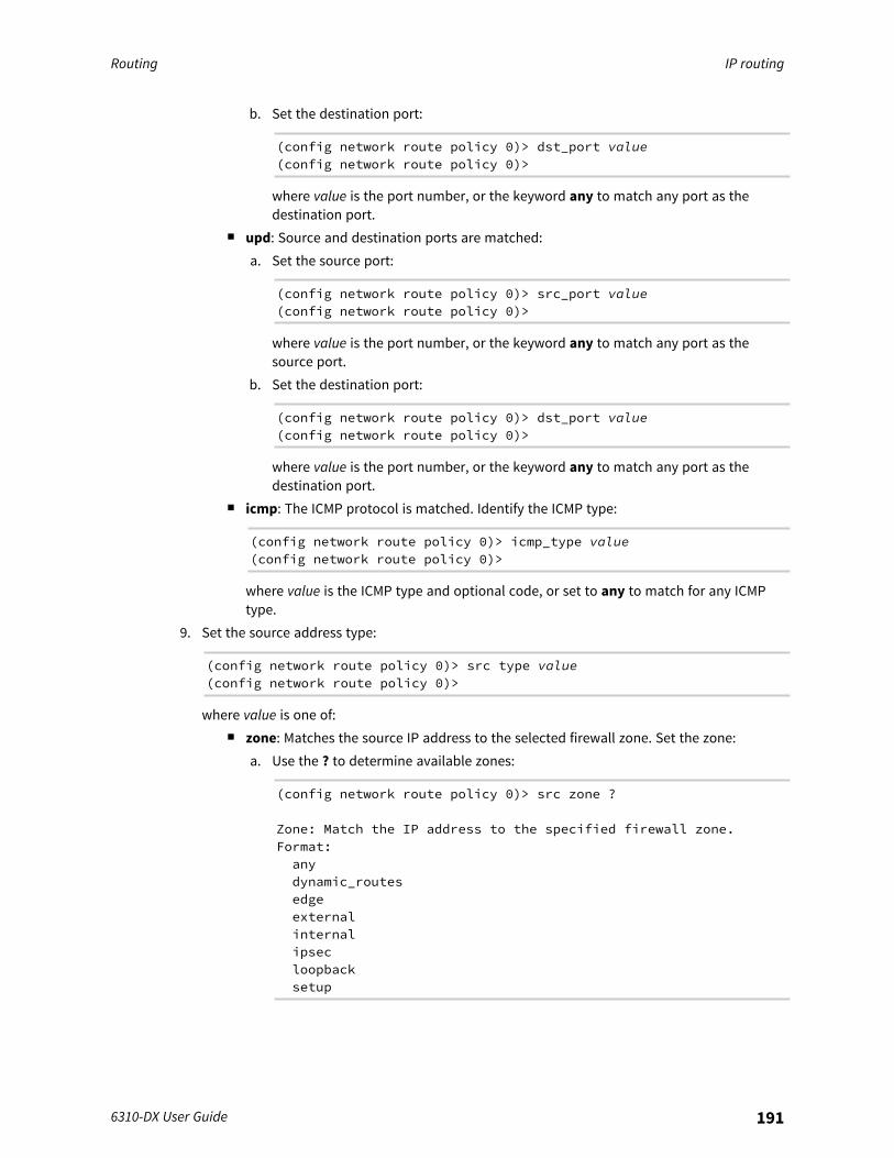
Routing IP routing
6310-DX User Guide 191
b. Set the destination port:
(config network route policy 0)> dst_port value(config network route policy 0)>
where value is the port number, or the keyword any to match any port as thedestination port.
n upd: Source and destination ports are matched:a. Set the source port:
(config network route policy 0)> src_port value(config network route policy 0)>
where value is the port number, or the keyword any to match any port as thesource port.
b. Set the destination port:
(config network route policy 0)> dst_port value(config network route policy 0)>
where value is the port number, or the keyword any to match any port as thedestination port.
n icmp: The ICMP protocol is matched. Identify the ICMP type:
(config network route policy 0)> icmp_type value(config network route policy 0)>
where value is the ICMP type and optional code, or set to any to match for any ICMPtype.
9. Set the source address type:
(config network route policy 0)> src type value(config network route policy 0)>
where value is one of:n zone: Matches the source IP address to the selected firewall zone. Set the zone:
a. Use the ? to determine available zones:
(config network route policy 0)> src zone ?
Zone: Match the IP address to the specified firewall zone.Format:anydynamic_routesedgeexternalinternalipsecloopbacksetup

Routing IP routing
6310-DX User Guide 192
Default value: anyCurrent value: any
(config network route policy 0)> src zone
b. Set the zone. For example:
(config network route policy 0)> src zone external(config network route policy 0)>
See Firewall configuration for more information about firewall zones.n interface: Matches the source IP address to the selected interface's network address.
Set the interface:a. Use the ? to determine available interfaces:
(config network route policy 0)> src interface ?
Interface: The network interface.Format:/network/interface/defaultip/network/interface/defaultlinklocal/network/interface/lan/network/interface/loopback/network/interface/modem/network/interface/wan
Current value:
(config network route policy 0)> src interface
b. Set the interface. For example:
(config network route policy 0)> src interface/network/interface/wan(config network route policy 0)>
n address: Matches the source IPv4 address to the specified IP address or network. Setthe address that will be matched:
(config network route policy 0)> src address value(config network route policy 0)>
where value uses the format IPv4_address[/netmask], or any to match any IPv4address.
n address6: Matches the source IPv6 address to the specified IP address or network. Setthe address that will be matched:
(config network route policy 0)> src address6 value(config network route policy 0)>
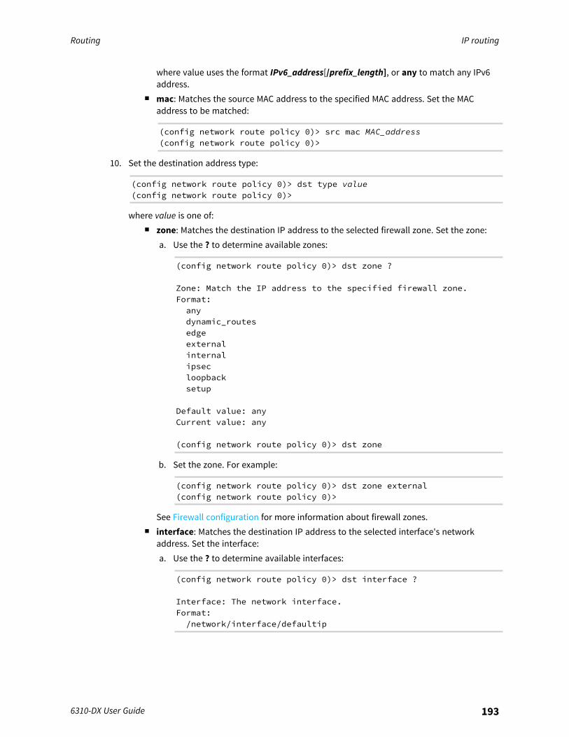
Routing IP routing
6310-DX User Guide 193
where value uses the format IPv6_address[/prefix_length], or any to match any IPv6address.
n mac: Matches the source MAC address to the specified MAC address. Set the MACaddress to be matched:
(config network route policy 0)> src mac MAC_address(config network route policy 0)>
10. Set the destination address type:
(config network route policy 0)> dst type value(config network route policy 0)>
where value is one of:n zone: Matches the destination IP address to the selected firewall zone. Set the zone:
a. Use the ? to determine available zones:
(config network route policy 0)> dst zone ?
Zone: Match the IP address to the specified firewall zone.Format:anydynamic_routesedgeexternalinternalipsecloopbacksetup
Default value: anyCurrent value: any
(config network route policy 0)> dst zone
b. Set the zone. For example:
(config network route policy 0)> dst zone external(config network route policy 0)>
See Firewall configuration for more information about firewall zones.n interface: Matches the destination IP address to the selected interface's network
address. Set the interface:a. Use the ? to determine available interfaces:
(config network route policy 0)> dst interface ?
Interface: The network interface.Format:/network/interface/defaultip
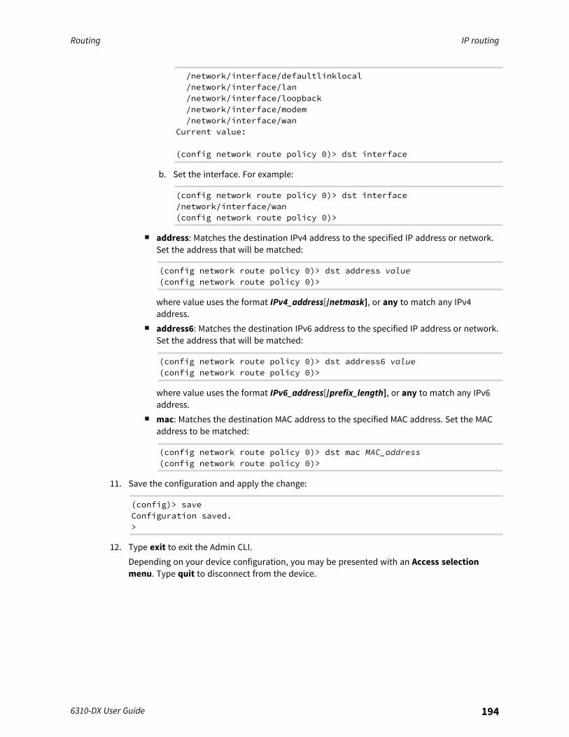
Routing IP routing
6310-DX User Guide 194
/network/interface/defaultlinklocal/network/interface/lan/network/interface/loopback/network/interface/modem/network/interface/wan
Current value:
(config network route policy 0)> dst interface
b. Set the interface. For example:
(config network route policy 0)> dst interface/network/interface/wan(config network route policy 0)>
n address: Matches the destination IPv4 address to the specified IP address or network.Set the address that will be matched:
(config network route policy 0)> dst address value(config network route policy 0)>
where value uses the format IPv4_address[/netmask], or any to match any IPv4address.
n address6: Matches the destination IPv6 address to the specified IP address or network.Set the address that will be matched:
(config network route policy 0)> dst address6 value(config network route policy 0)>
where value uses the format IPv6_address[/prefix_length], or any to match any IPv6address.
n mac: Matches the destination MAC address to the specified MAC address. Set the MACaddress to be matched:
(config network route policy 0)> dst mac MAC_address(config network route policy 0)>
11. Save the configuration and apply the change:
(config)> saveConfiguration saved.>
12. Type exit to exit the Admin CLI.Depending on your device configuration, you may be presented with an Access selectionmenu. Type quit to disconnect from the device.
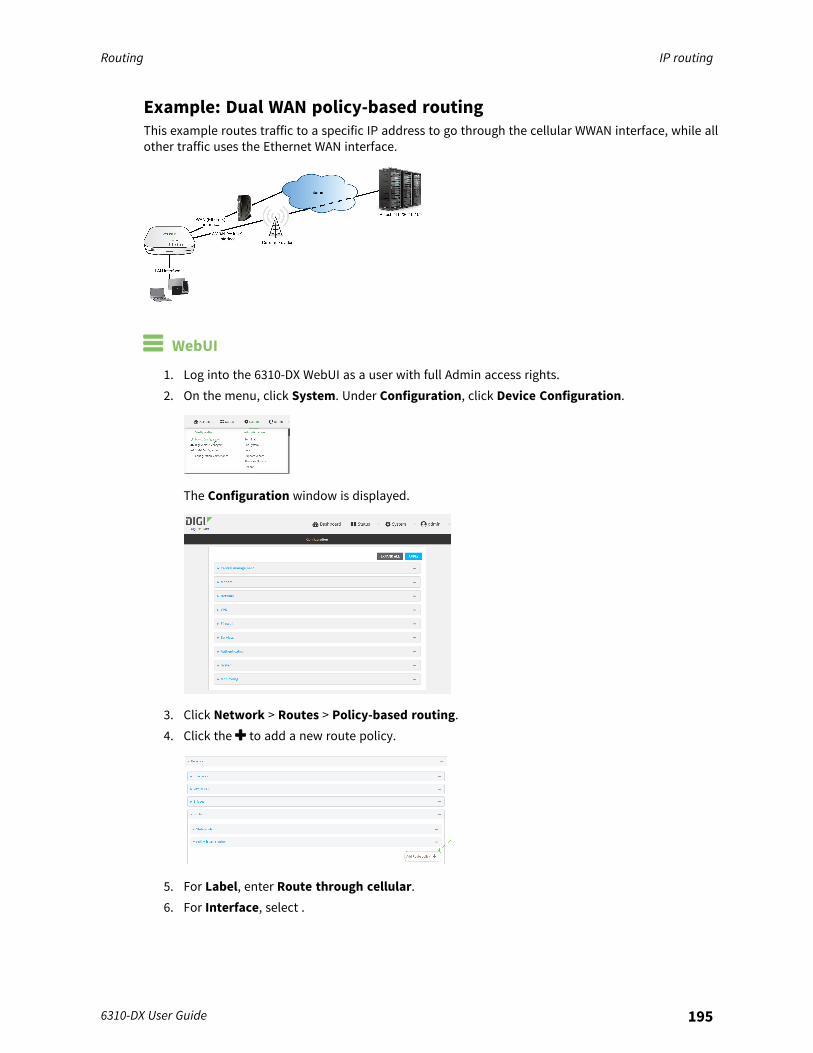
Routing IP routing
6310-DX User Guide 195
Example: Dual WAN policy-based routingThis example routes traffic to a specific IP address to go through the cellular WWAN interface, while allother traffic uses the Ethernet WAN interface.
WebUI
1. Log into the 6310-DX WebUI as a user with full Admin access rights.2. On the menu, click System. Under Configuration, click Device Configuration.
The Configuration window is displayed.
3. Click Network > Routes > Policy-based routing.4. Click the to add a new route policy.
5. For Label, enter Route through cellular.6. For Interface, select .

Routing IP routing
6310-DX User Guide 196
7. Configure the source address:a. Click to expand Source address.b. For Type, select Zone.c. For Zone, select Internal.
8. Configure the destination address:a. Click to expand Destination address.b. For Type, select IPv4 address.c. For IPv4 address, type the IP address that will be the destination for outgoing traffic
routed through the WWAN interface. In the above example, this is 241.236.162.59.
9. Click Apply to save the configuration and apply the change.
Command line
1. Log into the 6310-DX command line as a user with full Admin access rights.Depending on your device configuration, you may be presented with an Access selectionmenu. Type admin to access the Admin CLI.
2. At the command line, type config to enter configuration mode:
> config(config)>
3. Create the route policy:a. Add a new routing policy:
(config)> add network route policy end(config network route policy 0)>
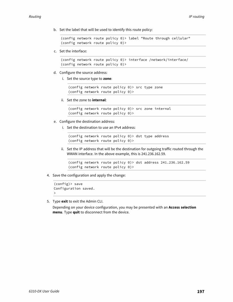
Routing IP routing
6310-DX User Guide 197
b. Set the label that will be used to identify this route policy:
(config network route policy 0)> label "Route through cellular"(config network route policy 0)>
c. Set the interface:
(config network route policy 0)> interface /network/interface/(config network route policy 0)>
d. Configure the source address:i. Set the source type to zone:
(config network route policy 0)> src type zone(config network route policy 0)>
ii. Set the zone to internal:
(config network route policy 0)> src zone internal(config network route policy 0)>
e. Configure the destination address:i. Set the destination to use an IPv4 address:
(config network route policy 0)> dst type address(config network route policy 0)>
ii. Set the IP address that will be the destination for outgoing traffic routed through theWWAN interface. In the above example, this is 241.236.162.59.
(config network route policy 0)> dst address 241.236.162.59(config network route policy 0)>
4. Save the configuration and apply the change:
(config)> saveConfiguration saved.>
5. Type exit to exit the Admin CLI.Depending on your device configuration, you may be presented with an Access selectionmenu. Type quit to disconnect from the device.
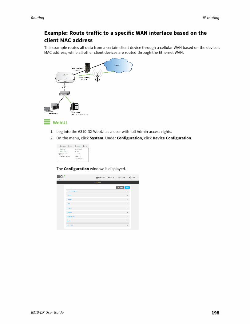
Routing IP routing
6310-DX User Guide 198
Example: Route traffic to a specific WAN interface based on theclient MAC addressThis example routes all data from a certain client device through a cellular WAN based on the device'sMAC address, while all other client devices are routed through the Ethernet WAN.
WebUI
1. Log into the 6310-DX WebUI as a user with full Admin access rights.2. On the menu, click System. Under Configuration, click Device Configuration.
The Configuration window is displayed.

Routing IP routing
6310-DX User Guide 199
3. Create new firewall zones:a. Create a firewall zone named CellularWAN with Source NAT enabled:
i. Click Firewall > Zones.ii. For Add Zone, type CellularWAN and click .
iii. Enable Source NAT.
b. Create second firewall zone named EthernetWAN with Source NAT enabled:i. For Add Zone, type EthernetWAN and click .ii. Enable Source NAT.
4. Configure the WAN interfaces to use the new zones:a. Configure the cellular WAN interface:
i. Click Network > Interfaces > .ii. For Zone, select CellularWAN.
b. Configure the Ethernet WAN interface:i. Click Network > Interfaces > .ii. For Zone, select EthernetWAN.
5. Configure the policy-based route for traffic from the client device that will be sent over thecellular WAN:a. Click Network > Routes > Policy-based routing.b. Click the to add a new route policy.

Routing IP routing
6310-DX User Guide 200
c. For Label, type VoIP phone.d. For Interface, select .e. Configure the source as the MAC address of the VoIP phone:
i. Click to expand Source address.ii. For Type, select MAC address.iii. For MAC address, type 26:88:0E:23:50:C2.
f. Configure the destination zone:i. Click to expand Destination address.ii. For Type, select Zone.iii. For Zone, select CellularWAN.
6. Create a packet filtering rule that rejects all other LAN packets on the cellular WAN interface.a. Click Firewall > Packet filtering.b. Click the to add a new packet filtering rule.
c. For Label, type Reject LAN traffic to cellular WAN.d. For Action, select Drop.e. For Source zone, select Internal.f. For Destination zone, select CellularWAN.
7. Click Apply to save the configuration and apply the change.
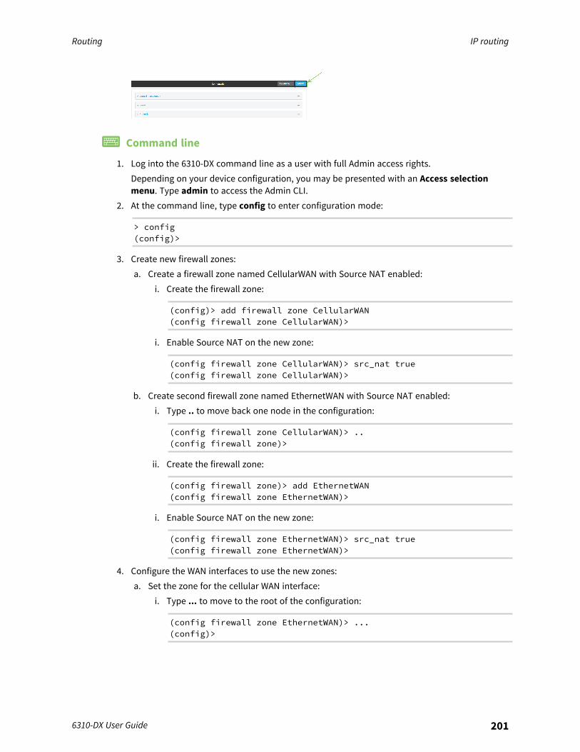
Routing IP routing
6310-DX User Guide 201
Command line
1. Log into the 6310-DX command line as a user with full Admin access rights.Depending on your device configuration, you may be presented with an Access selectionmenu. Type admin to access the Admin CLI.
2. At the command line, type config to enter configuration mode:
> config(config)>
3. Create new firewall zones:a. Create a firewall zone named CellularWAN with Source NAT enabled:
i. Create the firewall zone:
(config)> add firewall zone CellularWAN(config firewall zone CellularWAN)>
i. Enable Source NAT on the new zone:
(config firewall zone CellularWAN)> src_nat true(config firewall zone CellularWAN)>
b. Create second firewall zone named EthernetWAN with Source NAT enabled:i. Type .. to move back one node in the configuration:
(config firewall zone CellularWAN)> ..(config firewall zone)>
ii. Create the firewall zone:
(config firewall zone)> add EthernetWAN(config firewall zone EthernetWAN)>
i. Enable Source NAT on the new zone:
(config firewall zone EthernetWAN)> src_nat true(config firewall zone EthernetWAN)>
4. Configure the WAN interfaces to use the new zones:a. Set the zone for the cellular WAN interface:
i. Type ... to move to the root of the configuration:
(config firewall zone EthernetWAN)> ...(config)>
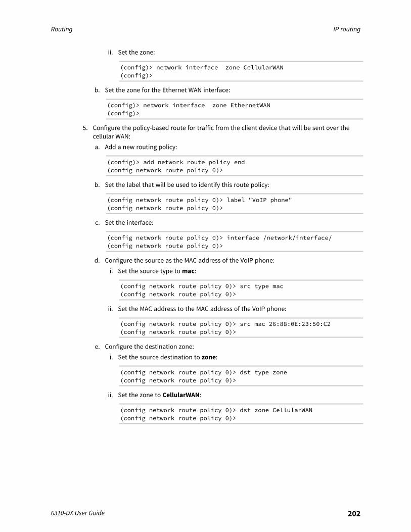
Routing IP routing
6310-DX User Guide 202
ii. Set the zone:
(config)> network interface zone CellularWAN(config)>
b. Set the zone for the Ethernet WAN interface:
(config)> network interface zone EthernetWAN(config)>
5. Configure the policy-based route for traffic from the client device that will be sent over thecellular WAN:a. Add a new routing policy:
(config)> add network route policy end(config network route policy 0)>
b. Set the label that will be used to identify this route policy:
(config network route policy 0)> label "VoIP phone"(config network route policy 0)>
c. Set the interface:
(config network route policy 0)> interface /network/interface/(config network route policy 0)>
d. Configure the source as the MAC address of the VoIP phone:i. Set the source type to mac:
(config network route policy 0)> src type mac(config network route policy 0)>
ii. Set the MAC address to the MAC address of the VoIP phone:
(config network route policy 0)> src mac 26:88:0E:23:50:C2(config network route policy 0)>
e. Configure the destination zone:i. Set the source destination to zone:
(config network route policy 0)> dst type zone(config network route policy 0)>
ii. Set the zone to CellularWAN:
(config network route policy 0)> dst zone CellularWAN(config network route policy 0)>
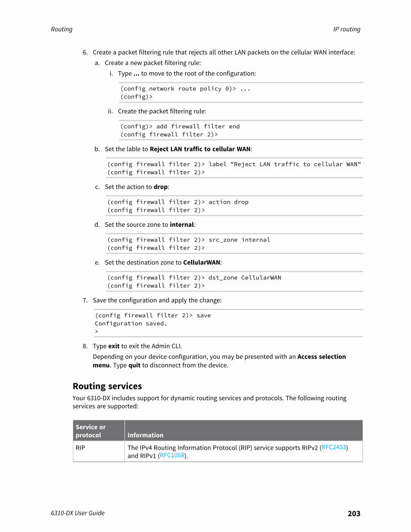
Routing IP routing
6310-DX User Guide 203
6. Create a packet filtering rule that rejects all other LAN packets on the cellular WAN interface:a. Create a new packet filtering rule:
i. Type ... to move to the root of the configuration:
(config network route policy 0)> ...(config)>
ii. Create the packet filtering rule:
(config)> add firewall filter end(config firewall filter 2)>
b. Set the lable to Reject LAN traffic to cellular WAN:
(config firewall filter 2)> label "Reject LAN traffic to cellular WAN"(config firewall filter 2)>
c. Set the action to drop:
(config firewall filter 2)> action drop(config firewall filter 2)>
d. Set the source zone to internal:
(config firewall filter 2)> src_zone internal(config firewall filter 2)>
e. Set the destination zone to CellularWAN:
(config firewall filter 2)> dst_zone CellularWAN(config firewall filter 2)>
7. Save the configuration and apply the change:
(config firewall filter 2)> saveConfiguration saved.>
8. Type exit to exit the Admin CLI.Depending on your device configuration, you may be presented with an Access selectionmenu. Type quit to disconnect from the device.
Routing servicesYour 6310-DX includes support for dynamic routing services and protocols. The following routingservices are supported:
Service orprotocol Information
RIP The IPv4 Routing Information Protocol (RIP) service supports RIPv2 (RFC2453)and RIPv1 (RFC1058).
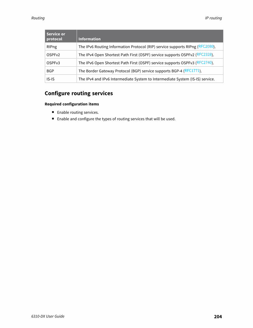
Routing IP routing
6310-DX User Guide 204
Service orprotocol Information
RIPng The IPv6 Routing Information Protocol (RIP) service supports RIPng (RFC2080).
OSPFv2 The IPv4 Open Shortest Path First (OSPF) service supports OSPFv2 (RFC2328).
OSPFv3 The IPv6 Open Shortest Path First (OSPF) service supports OSPFv3 (RFC2740).
BGP The Border Gateway Protocol (BGP) service supports BGP-4 (RFC1771).
IS-IS The IPv4 and IPv6 Intermediate System to Intermediate System (IS-IS) service.
Configure routing services
Required configuration items
n Enable routing services.n Enable and configure the types of routing services that will be used.
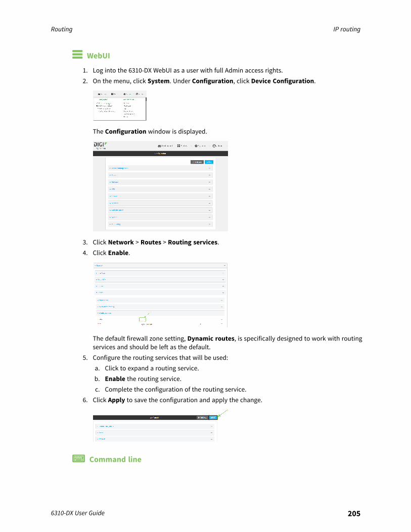
Routing IP routing
6310-DX User Guide 205
WebUI
1. Log into the 6310-DX WebUI as a user with full Admin access rights.2. On the menu, click System. Under Configuration, click Device Configuration.
The Configuration window is displayed.
3. Click Network > Routes > Routing services.4. Click Enable.
The default firewall zone setting, Dynamic routes, is specifically designed to work with routingservices and should be left as the default.
5. Configure the routing services that will be used:a. Click to expand a routing service.b. Enable the routing service.c. Complete the configuration of the routing service.
6. Click Apply to save the configuration and apply the change.
Command line

Routing IP routing
6310-DX User Guide 206
1. Log into the 6310-DX command line as a user with full Admin access rights.Depending on your device configuration, you may be presented with an Access selectionmenu. Type admin to access the Admin CLI.
2. At the command line, type config to enter configuration mode:
> config(config)>
3. Enable routing services:
(config)> network route service enable true(config)>
4. Configure routing services that will be used:a. Use the ? to display available routing services:
(config)> network route service ?
Routing services: Settings for dynamic routing services and protocols.
Parameters Current Value-------------------------------------------------------------------------------enable true Enablezone dynamic_routes Zone
Additional Configuration-------------------------------------------------------------------------------bgp BGPisis IS-ISospfv2 OSPFv2ospfv3 OSPFv3rip RIPripng RIPng
(config)>
b. Enable a routing service that will be used. For example, to enable the RIP service:
(config)> network route service rip enable true(config)>
c. Complete the configuration of the routing service. For example, use the ? to view theavailable parameters for the RIP service:
(config)> network route service rip ?
Parameters Current Value-------------------------------------------------------------------------------
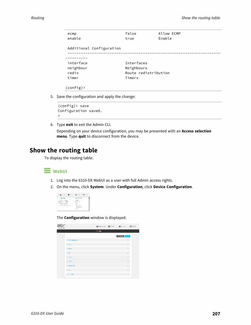
Routing Show the routing table
6310-DX User Guide 207
ecmp false Allow ECMPenable true Enable
Additional Configuration-------------------------------------------------------------------------------interface Interfacesneighbour Neighboursredis Route redistributiontimer Timers
(config)>
5. Save the configuration and apply the change:
(config)> saveConfiguration saved.>
6. Type exit to exit the Admin CLI.Depending on your device configuration, you may be presented with an Access selectionmenu. Type quit to disconnect from the device.
Show the routing tableTo display the routing table:
WebUI
1. Log into the 6310-DX WebUI as a user with full Admin access rights.2. On the menu, click System. Under Configuration, click Device Configuration.
The Configuration window is displayed.
Routing Dynamic DNS
6310-DX User Guide 208
3. Click Status > Routes.The Network Routing window is displayed.
4. Click IPv4 Load Balance to view IPv4 load balancing.5. Click IPv6 Load Balance to view IPv6 load balancing.
Command line
1. Log into the 6310-DX command line as a user with Admin access.Depending on your device configuration, you may be presented with an Access selectionmenu. Type admin to access the Admin CLI.
2. At the Admin CLI prompt, type show route:You can limit the display to only IPv4 entries by using show route ipv4, or to IPv6 entries byusing show route ipv6. You can also display more information by adding the verbose optionto the show route and show route ip_type commands.
3. Type exit to exit the Admin CLI.Depending on your device configuration, you may be presented with an Access selectionmenu. Type quit to disconnect from the device.
Dynamic DNSThe Domain Name System (DNS) uses name servers to provide a mapping between computer-readable IP addresses and human-readable hostnames. This allows users to access websites andpersonal networks with easy-to-remember URLs. Unfortunately, IP addresses change frequently,invalidating these mappings when they do. Dynamic DNS has become the standard method ofaddressing this problem, allowing devices to update name servers with their new IP addresses.By providing the 6310-DX device with the domain name and credentials obtained from a dynamic DNSprovider, the router can automatically update the remote nameserver whenever your WAN or publicIP address changes.Your 6310-DX device supports a number of Dynamic DNS providers as well as the ability to provide acustom provider that is not included on the list of providers.
Configure dynamic DNSThis section describes how to cofigure dynamic DNS on a 6310-DX device.
Required configuration items
n Add a new Dynamic DNS service.n The interface that has its IP address registered with the Dynamic DNS provider.n The name of a Dynamic DNS provider.n The domain name that is linked to the interface's IP address.n The username and password to authenticate with the Dynamic DNS provider.
Additional configuration items
n If the Dynamic DNS service provider is set to custom, identify the URL that should be used toupdate the IP address with the Dynamic DNS provider.
n The amount of time to wait to check if the interface's IP address needs to be updated.

Routing Dynamic DNS
6310-DX User Guide 209
n The amount of time to wait to force an update of the interface's IP address.n The amount of time to wait for an IP address update to succeed before retrying the update.n The number of times to retry a failed IP address update.
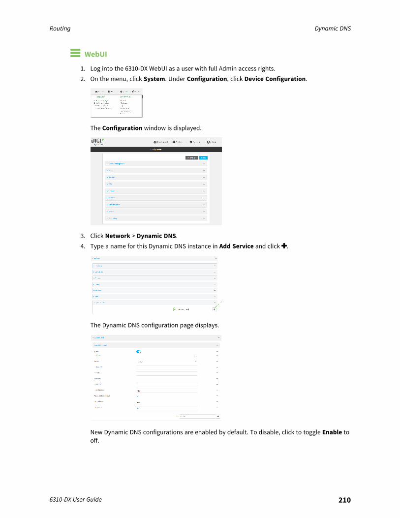
Routing Dynamic DNS
6310-DX User Guide 210
WebUI
1. Log into the 6310-DX WebUI as a user with full Admin access rights.2. On the menu, click System. Under Configuration, click Device Configuration.
The Configuration window is displayed.
3. Click Network > Dynamic DNS.4. Type a name for this Dynamic DNS instance in Add Service and click .
The Dynamic DNS configuration page displays.
New Dynamic DNS configurations are enabled by default. To disable, click to toggle Enable tooff.
Routing Dynamic DNS
6310-DX User Guide 211
5. For Interface, select the interface that has its IP address registered with the Dynamic DNSprovider.
6. For Service, select the Dynamic DNS provider, or select custom to enter a custom URL for theDynamic DNS provider.
7. If custom is selected for Service, type the Custom URL that should be used to update the IPaddress with the Dynamic DNS provider.
8. Type the Domain name that is linked to the interface's IP address.9. Type the Username and Password used to authenticate with the Dynamic DNS provider.
10. (Optional) For Check Interval, type the amount of time to wait to check if the interface's IPaddress needs to be updated.Allowed values are any number of weeks, days, hours, minutes, or seconds, and take theformat number{w|d|h|m|s}.For example, to set Check interval to ten minutes, enter 10m or 600s.
11. (Optional) For Forced update interval, type the amount of time to wait to force an update ofthe interface's IP address.Allowed values are any number of weeks, days, hours, minutes, or seconds, and take theformat number{w|d|h|m|s}.For example, to set Forced update interval to ten minutes, enter 10m or 600s.The setting for Forced update interval must be larger than the setting for Check Interval.
12. (Optional) For Retry interval, type the amount of time to wait for an IP address update tosucceed before retrying the update.Allowed values are any number of weeks, days, hours, minutes, or seconds, and take theformat number{w|d|h|m|s}.For example, to set Retry interval to ten minutes, enter 10m or 600s.
13. (Optional) For Retry count, type the number of times to retry a failed IP address update.14. Click Apply to save the configuration and apply the change.
Command line
1. Log into the 6310-DX command line as a user with full Admin access rights.Depending on your device configuration, you may be presented with an Access selectionmenu. Type admin to access the Admin CLI.
2. At the command line, type config to enter configuration mode:
> config(config)>
3. Add a new Dynamic DNS instance. For example, to add an instance named new_ddns_instance:
Routing Dynamic DNS
6310-DX User Guide 212
(config)> add network ddns new_ddns_instance(config network ddns new_ddns_instance)>
New Dynamic DNS instances are enabled by default. To disable:
(config network ddns new_ddns_instance)> enable false(config network ddns new_ddns_instance)>
4. Set the interface for the Dynamic DNS instance:a. Use the ? to determine available interfaces:
(config network ddns new_ddns_instance)> interface ?
Interface: The network interface from which to obtain the IP addressto register with the dynamic DNS service.Format:defaultipdefaultlinklocallanloopbackmodemwan
Current value:
(config network ddns new_ddns_instance)> interface
b. Set the interface. For example:
(config network ddns new_ddns_instance)> interface wan(config network ddns new_ddns_instance)>
5. Set the Dynamic DNS provider service:a. Use the ? to determine available services:
(config network ddns new_ddns_instance)> service ?
Service: The provider of the dynamic DNS service.Format:custom3322.orgchangeip.comddns.com.brdnsdynamic.org...
Default value: customCurrent value: custom
(config network ddns new_ddns_instance)> service
Routing Dynamic DNS
6310-DX User Guide 213
b. Set the service:
(config network ddns new_ddns_instance)> service service_name(config network ddns new_ddns_instance)>
6. If custom is configured for service, set the custom URL that should be used to update the IPaddress with the Dynamic DNS provider:
(config network ddns new_ddns_instance)> custom url(config network ddns new_ddns_instance)>
7. Set the domain name that is linked to the interface's IP address:
(config network ddns new_ddns_instance)> domain domain_name(config network ddns new_ddns_instance)>
8. Set the username to authenticate with the Dynamic DNS provider:
(config network ddns new_ddns_instance)> username name(config network ddns new_ddns_instance)>
9. Set the password to authenticate with the Dynamic DNS provider:
(config network ddns new_ddns_instance)> password pwd(config network ddns new_ddns_instance)>
10. (Optional) Set the amount of time to wait to check if the interface's IP address needs to beupdated:
(config network ddns new_ddns_instance)> check_interval value(config network ddns new_ddns_instance)>
where value is any number of weeks, days, hours, minutes, or seconds, and takes the formatnumber{w|d|h|m|s}.For example, to set check_interval to ten minutes, enter either 10m or 600s:
(config network ddns new_ddns_instance)> check_interval 600s(config network ddns new_ddns_instance)>
The default is 10m.11. (Optional) Set the amount of time to wait to force an update of the interface's IP address:
(config network ddns new_ddns_instance)> force_interval value(config network ddns new_ddns_instance)>
where value is any number of weeks, days, hours, minutes, or seconds, and takes the formatnumber{w|d|h|m|s}.For example, to set force_interval to ten minutes, enter either 10m or 600s:
(config network ddns new_ddns_instance)> force_interval 600s(config network ddns new_ddns_instance)>
The default is 3d.
Routing Virtual Router Redundancy Protocol (VRRP)
6310-DX User Guide 214
12. (Optional) Set the amount of time to wait for an IP address update to succeed before retryingthe update:
(config network ddns new_ddns_instance)> retry_interval value(config network ddns new_ddns_instance)>
where value is any number of weeks, days, hours, minutes, or seconds, and takes the formatnumber{w|d|h|m|s}.For example, to set retry_interval to ten minutes, enter either 10m or 600s:
(config network ddns new_ddns_instance)> retry_interval 600s(config network ddns new_ddns_instance)>
The default is 60s.13. (Optional) Set the number of times to retry a failed IP address update:
(config network ddns new_ddns_instance)> retry_count value(config network ddns new_ddns_instance)>
where value is any interger. The default is 5.14. Save the configuration and apply the change:
(config)> saveConfiguration saved.>
15. Type exit to exit the Admin CLI.Depending on your device configuration, you may be presented with an Access selectionmenu. Type quit to disconnect from the device.
Virtual Router Redundancy Protocol (VRRP)Virtual Router Redundancy Protocol (VRRP) is a standard for gateway device redundancy and failoverthat creates a "virtual router" with a floating IP address. Devices connected to the LAN then use thisvirtual router as their default gateway. Responsibility for the virtual router is assigned to one of theVRRP-enabled devices on a LAN (the "master router"), and this responsibility transparently fails overto backup VRRP devices if the master router fails. This prevents the default gateway from being asingle point of failure, without requiring configuration of dynamic routing or router discoveryprotocols on every host.Multiple 6310-DX devices can be configured as VRRP devices and assigned a priority. The router withthe highest priority will be used as the master router. If the master router fails, then the IP address ofthe virtual router is mapped to the backup device with the next highest priority. Each VRRP router isconfigured with a unique LAN IP address, and the same shared VRRP address.
VRRP+VRRP+ is an extension to the VRRP standard that uses network probing to monitor connectionsthrough VRRP-enabled devices and can dynamically change the priority of the devices, includingchanging devices from master to backup, and from backup to master, even if the device has notfailed. For example, if a host becomes unreachable on the far end of a network link, then the physicaldefault gateway can be changed by adjusting the VRRP priority of the 6310-DX device connected tothe failing link. This provides failover capabilities based on the status of connections behind the
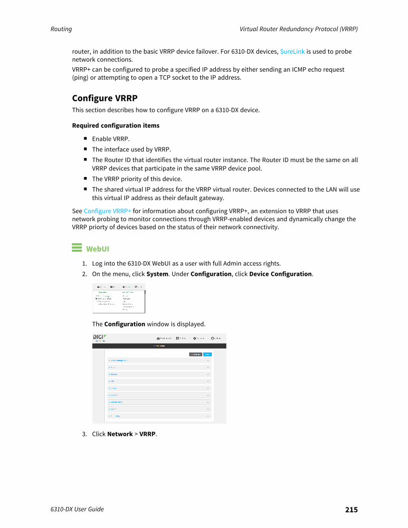
Routing Virtual Router Redundancy Protocol (VRRP)
6310-DX User Guide 215
router, in addition to the basic VRRP device failover. For 6310-DX devices, SureLink is used to probenetwork connections.VRRP+ can be configured to probe a specified IP address by either sending an ICMP echo request(ping) or attempting to open a TCP socket to the IP address.
Configure VRRPThis section describes how to configure VRRP on a 6310-DX device.
Required configuration items
n Enable VRRP.n The interface used by VRRP.n The Router ID that identifies the virtual router instance. The Router ID must be the same on all
VRRP devices that participate in the same VRRP device pool.n The VRRP priority of this device.n The shared virtual IP address for the VRRP virtual router. Devices connected to the LAN will use
this virtual IP address as their default gateway.
See Configure VRRP+ for information about configuring VRRP+, an extension to VRRP that usesnetwork probing to monitor connections through VRRP-enabled devices and dynamically change theVRRP priorty of devices based on the status of their network connectivity.
WebUI
1. Log into the 6310-DX WebUI as a user with full Admin access rights.2. On the menu, click System. Under Configuration, click Device Configuration.
The Configuration window is displayed.
3. Click Network > VRRP.
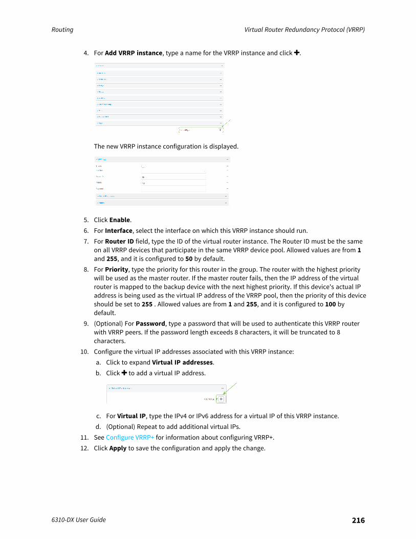
Routing Virtual Router Redundancy Protocol (VRRP)
6310-DX User Guide 216
4. For Add VRRP instance, type a name for the VRRP instance and click .
The new VRRP instance configuration is displayed.
5. Click Enable.6. For Interface, select the interface on which this VRRP instance should run.7. For Router ID field, type the ID of the virtual router instance. The Router ID must be the same
on all VRRP devices that participate in the same VRRP device pool. Allowed values are from 1and 255, and it is configured to 50 by default.
8. For Priority, type the priority for this router in the group. The router with the highest prioritywill be used as the master router. If the master router fails, then the IP address of the virtualrouter is mapped to the backup device with the next highest priority. If this device's actual IPaddress is being used as the virtual IP address of the VRRP pool, then the priority of this deviceshould be set to 255 . Allowed values are from 1 and 255, and it is configured to 100 bydefault.
9. (Optional) For Password, type a password that will be used to authenticate this VRRP routerwith VRRP peers. If the password length exceeds 8 characters, it will be truncated to 8characters.
10. Configure the virtual IP addresses associated with this VRRP instance:a. Click to expand Virtual IP addresses.b. Click to add a virtual IP address.
c. For Virtual IP, type the IPv4 or IPv6 address for a virtual IP of this VRRP instance.d. (Optional) Repeat to add additional virtual IPs.
11. See Configure VRRP+ for information about configuring VRRP+.12. Click Apply to save the configuration and apply the change.
Routing Virtual Router Redundancy Protocol (VRRP)
6310-DX User Guide 217
Command line
1. Log into the 6310-DX command line as a user with full Admin access rights.Depending on your device configuration, you may be presented with an Access selectionmenu. Type admin to access the Admin CLI.
2. At the command line, type config to enter configuration mode:
> config(config)>
3. Add a VRRP instance. For example:
(config)> add network vrrp VRRP_test(config network vrrp VRRP_test)>
4. Enable the VRRP instance:
(config network vrrp VRRP_test)> enable true(config network vrrp VRRP_test)>
5. Set the interface on which this VRRP instance should run:a. Use the ? to determine available interfaces:
(config network vrrp VRRP_test)> interface ?
Interface: The network interface to communicate with VRRP peers on andlisten for traffic to virtual IP addresses.Format:/network/interface/defaultip/network/interface/defaultlinklocal/network/interface/lan/network/interface/loopback/network/interface/modem/network/interface/wan
Current value:
(config network vrrp VRRP_test)> interface
b. Set the interface, for example:
(config network vrrp VRRP_test)> interface /network/interface/lan(config network vrrp VRRP_test)>
c. Repeat for additional interfaces.6. Set the router ID. The Router ID must be the same on all VRRP devices that participate in the
same VRRP device pool. Allowed values are from 1 and 255, and it is configured to 50 by
Routing Virtual Router Redundancy Protocol (VRRP)
6310-DX User Guide 218
default.
(config network vrrp VRRP_test)> router_id int(config network vrrp VRRP_test)>
7. Set the priority for this router in the group. The router with the highest priority will be used asthe master router. If the master router fails, then the IP address of the virtual router is mappedto the backup device with the next highest priority. If this device's actual IP address is beingused as the virtual IP address of the VRRP pool, then the priority of this device should be set to255 . Allowed values are from 1 and 255, and it is configured to 100 by default.
(config network vrrp VRRP_test)> priority int(config network vrrp VRRP_test)>
8. (Optional) Set a password that will be used to authenticate this VRRP router with VRRP peers.If the password length exceeds 8 characters, it will be truncated to 8 characters.
(config network vrrp VRRP_test)> password pwd(config network vrrp VRRP_test)>
9. Add a virtual IP address associated with this VRRP instance. This can be an IPv4 or IPv6address.
(config network vrrp VRRP_test)> add virtual_address end ip_address(config network vrrp VRRP_test)>
Additional virtual IP addresses can be added by repeating this step with different values for ip_address.
10. Save the configuration and apply the change:
(config network vrrp new_vrrp_instance)> saveConfiguration saved.>
11. Type exit to exit the Admin CLI.Depending on your device configuration, you may be presented with an Access selectionmenu. Type quit to disconnect from the device.
Configure VRRP+VRRP+ is an extension to the VRRP standard that uses SureLink network probing to monitorconnections through VRRP-enabled devices and adjust devices' VRRP priority based on the status ofthe SureLink tests.This section describes how to configure VRRP+ on a 6310-DX device.
Required configuration items
n Both master and backup devices:l A configured and enabled instance of VRRP. See Configure VRRP for information.l Enable VRRP+.
Routing Virtual Router Redundancy Protocol (VRRP)
6310-DX User Guide 219
l WAN interfaces to be monitored by using VRRP+.
Note SureLink is enabled by default on all WAN interfaces, and should not be disabled onthe WAN interfaces that are being monitored by VRRP+.If multiple WAN interfaces are being monitored on the same device, the VRRP priority willbe adjusted only if all WAN interfaces fail SureLink tests.
l The amount that the VRRP priority will be modified when SureLink determines that theVRRP interface is not functioning correctly.
l Configure the VRRP interface's DHCP server to use a custom gateway that corresponds toone of the VRRP virtual IP addresses.
n Backup devices only:l Enable and configure SureLink on the VRRP interface.l Set the IP gateway to the IP address of the VRRP interface on the master device.
Additional configuration items
n For backup VRRP devices, enable the ability to monitor the VRRP master, so that a backupdevice can increase its priority when the master device fails SureLink tests.
WebUI
1. Log into the 6310-DX WebUI as a user with full Admin access rights.2. On the menu, click System. Under Configuration, click Device Configuration.
The Configuration window is displayed.
3. Click Network > VRRP.4. Create a new VRRP instance, or click to expand an existing VRRP instance.
See Configure VRRP for information about creating a new VRRP instance.

Routing Virtual Router Redundancy Protocol (VRRP)
6310-DX User Guide 220
5. Click to expand VRRP+.
6. Click Enable.7. Add interfaces to monitor:
a. Click to expand Monitor interfaces.b. Click to add an interface for monitoring.
c. For Interface, select the local interface to monitor. Generally, this will be a cellular or WANinterface.
d. (Optional) Click again to add additional interfaces.8. (Optional) For backup devices, click to enable Monitor VRRP+ master.
This parameter allows a backup VRRP device to monitor the master device, and increase itspriority when the master device is failing SureLink tests. This can allow a device functioning asa backup device to promote itself to master.
9. For Priority modifier, type or select the amount that the device's priority should be decreaseddue to SureLink connectivity failure, and increased when SureLink succeeds again.Along with the priority settings for devices in this VRRP pool, the amount entered here shouldbe large enough to automatically demote a master device when SureLink connectivity fails. Forexample, if the VRRP master device has a priority of 100 and the backup device has a priorityof 80, then the Priority modifier should be set to an amount greater than 20 so that ifSureLink fails on the master, it will lower its priority to below 80, and the backup device willassume the master role.
10. Configure the VRRP interface. The VRRP interface is defined in the Interface parameter of theVRRP configuration, and generally should be a LAN interface:
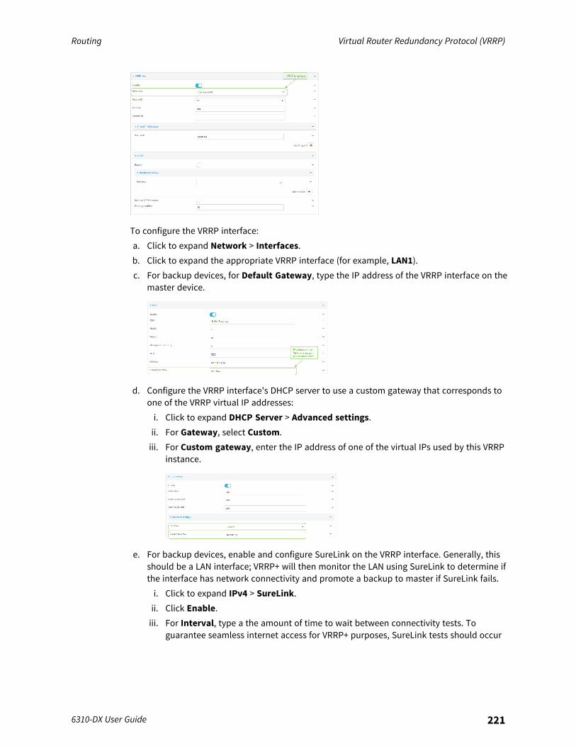
Routing Virtual Router Redundancy Protocol (VRRP)
6310-DX User Guide 221
To configure the VRRP interface:a. Click to expand Network > Interfaces.b. Click to expand the appropriate VRRP interface (for example, LAN1).c. For backup devices, for Default Gateway, type the IP address of the VRRP interface on the
master device.
d. Configure the VRRP interface's DHCP server to use a custom gateway that corresponds toone of the VRRP virtual IP addresses:i. Click to expand DHCP Server > Advanced settings.ii. For Gateway, select Custom.iii. For Custom gateway, enter the IP address of one of the virtual IPs used by this VRRP
instance.
e. For backup devices, enable and configure SureLink on the VRRP interface. Generally, thisshould be a LAN interface; VRRP+ will then monitor the LAN using SureLink to determine ifthe interface has network connectivity and promote a backup to master if SureLink fails.i. Click to expand IPv4 > SureLink.ii. Click Enable.iii. For Interval, type a the amount of time to wait between connectivity tests. To
guarantee seamless internet access for VRRP+ purposes, SureLink tests should occur
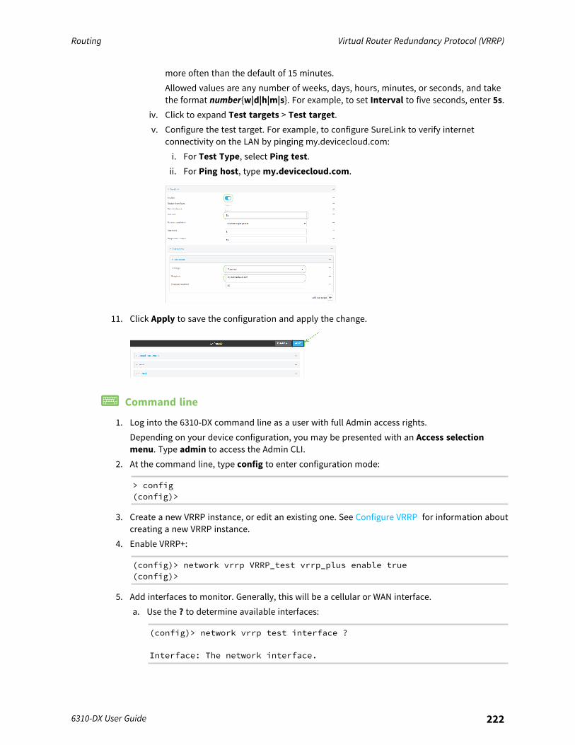
Routing Virtual Router Redundancy Protocol (VRRP)
6310-DX User Guide 222
more often than the default of 15 minutes.Allowed values are any number of weeks, days, hours, minutes, or seconds, and takethe format number{w|d|h|m|s}. For example, to set Interval to five seconds, enter 5s.
iv. Click to expand Test targets > Test target.v. Configure the test target. For example, to configure SureLink to verify internet
connectivity on the LAN by pinging my.devicecloud.com:i. For Test Type, select Ping test.ii. For Ping host, type my.devicecloud.com.
11. Click Apply to save the configuration and apply the change.
Command line
1. Log into the 6310-DX command line as a user with full Admin access rights.Depending on your device configuration, you may be presented with an Access selectionmenu. Type admin to access the Admin CLI.
2. At the command line, type config to enter configuration mode:
> config(config)>
3. Create a new VRRP instance, or edit an existing one. See Configure VRRP for information aboutcreating a new VRRP instance.
4. Enable VRRP+:
(config)> network vrrp VRRP_test vrrp_plus enable true(config)>
5. Add interfaces to monitor. Generally, this will be a cellular or WAN interface.a. Use the ? to determine available interfaces:
(config)> network vrrp test interface ?
Interface: The network interface.

Routing Virtual Router Redundancy Protocol (VRRP)
6310-DX User Guide 223
Format:/network/interface/defaultip/network/interface/defaultlinklocal/network/interface/lan/network/interface/loopback/network/interface/modem/network/interface/wan
Current value:
(config)> network vrrp test interface
b. Set the interface, for example:
(config)> add network vrrp VRRP_test vrrp_plus monitor_interface end/network/interface/modem(config)>
c. (Optional) Repeat for additional interfaces.6. Set the amount that the device's priority should be decreased or increased due to SureLink
connectivity failure or success:
(config)> network vrrp VRRP_test vrrp_plus weight value(config)>
where value is an integer between 1 and 254. The default is 10.Along with the priority settings for devices in this VRRP pool, the amount entered here shouldbe large enough to automatically demote a master device when SureLink connectivity fails. Forexample, if the VRRP master device has a priority of 100 and the backup device has a priorityof 80, then weight should be set to an amount greater than 20 so that if SureLink fails on themaster, it will lower its priority to below 80, and the backup device will assume the masterrole.
7. (Optional) For backup devices, enable the ability for the device to monitor the master device.This allows a backup VRRP device to monitor the master device, and increase its priority whenthe master device is failing SureLink tests. This can allow a device functioning as a backupdevice to promote itself to master.
(config)> network vrrp VRRP_test vrrp_plus monitor_master true(config)>
8. Configure the VRRP interface:a. Configure the VRRP interface's DHCP server to use a custom gateway that corresponds to
one of the VRRP virtual IP addresses:i. Set the DHCP server gateway type to custom:
(config)> network interface lan ipv4 dhcp_server advanced gatewaycustom(config)>
Routing Virtual Router Redundancy Protocol (VRRP)
6310-DX User Guide 224
ii. Determine the VRRP virtual IP addresses:
(config)> show network vrrp VRRP_test virtual_address0 192.168.3.31 10.10.10.1
(config)>
iii. Set the custom gateway to one of the VRRP virtual IP addresses. For example:
(config)> network interface lan ipv4 dhcp_server advanced gateway_custom 192.168.3.3(config)>
b. For backup devices, set the default gateway to the IP address of the VRRP interface on themaster device. For example:
(config)> network interface lan ipv4 gateway 192.168.3.1(config)>
c. For backup devices, enable and configure SureLink on the VRRP interface.i. Determine the VRRP interface. Generally, this should be a LAN interface; VRRP+ will
then monitor the LAN using SureLink to determine if the interface has networkconnectivity and promote a backup to master if SureLink fails.
(config)> show network vrrp VRRP_test interface/network/interface/lan(config)>
ii. Enable SureLink on the interface:
(config)> network interface lan ipv4 surelink enable true(config)>
iii. Set the amount of time to wait between connectivity tests:
(config)> network interface lan ipv4 surelink interval value(config)>
where value is any number of weeks, days, hours, minutes, or seconds, and takes theformat number{w|d|h|m|s}.For example, to set interval to ten minutes, enter 5s:
(config)> network interface lan ipv4 surelink interval 5s(config)>
iv. Create a SureLink test target:
(config)> add network interface lan ipv4 surelink target end(config network interface lan ipv4 surelink target 0)>
Routing Virtual Router Redundancy Protocol (VRRP)
6310-DX User Guide 225
v. Configure the type of test for the test target:
(config network interface lan ipv4 surelink target 0)> test value(config network interface lan ipv4 surelink target 0)>
where value is one of:n ping: Tests connectivity by sending an ICMP echo request to a specified
hostname or IP address.l Specify the hostname or IP address:
(config network interface lan ipv4 surelink target 0)>ping_host host(config network interface lan ipv4 surelink target 0)>
l (Optional) Set the size, in bytes, of the ping packet:
(config network interface lan ipv4 surelink target 0)>ping_size [num](config network interface lan ipv4 surelink target 0)>
n dns: Tests connectivity by sending a DNS query to the specified DNS server.l Specify the DNS server. Allowed value is the IP address of the DNS server.
(config network interface lan ipv4 surelinktarget 0)> dns_server ip_address(config network interface lan ipv4 surelinktarget 0)>
n dns_configured: Tests connectivity by sending a DNS query to the DNS serversconfigured for this interface.
n http: Tests connectivity by sending an HTTP or HTTPS GET request to thespecified URL.l Specify the url:
(config network interface lan ipv4 surelink target 0)>http_url value(config network interface lan ipv4 surelink target 0)>
where value uses the format http[s]://hostname/[path]n interface_up: The interface is considered to be down based on the interfaces
down time, and the amount of time an initial connection to the interface takesbefore this test is considered to have failed.l (Optional) Set the amount of time that the interface can be down before
this test is considered to have failed:
(config network interface lan ipv4 surelink target 0)>interface_down_time value(config network interface lan ipv4 surelink target 0)>
where value is any number of weeks, days, hours, minutes, or seconds, andtakes the format number{w|d|h|m|s}.
Routing Virtual Router Redundancy Protocol (VRRP)
6310-DX User Guide 226
For example, to set interface_down_time to ten minutes, enter either10m or 600s:
(config network interface lan ipv4 surelink target 0)>interface_down_time 600s(config network interface lan ipv4 surelink target 0)>
The default is 60 seconds.l (Optional) Set the amount of time to wait for an initial connection to the
interface before this test is considered to have failed:
(config network interface lan ipv4 surelink target 0)>interface_timeout value(config network interface lan ipv4 surelink target 0)>
where value is any number of weeks, days, hours, minutes, or seconds, andtakes the format number{w|d|h|m|s}.For example, to set interface_timeout to ten minutes, enter either 10m or600s:
(config network interface lan ipv4 surelink target 0)>interface_timeout 600s(config network interface lan ipv4 surelink target 0)>
The default is 60 seconds.9. Save the configuration and apply the change:
(config)> saveConfiguration saved.>
10. Type exit to exit the Admin CLI.Depending on your device configuration, you may be presented with an Access selectionmenu. Type quit to disconnect from the device.
Example: VRRP/VRRP+ configurationThis example configuration creates a VRRP pool containing two 6310-DX devices:
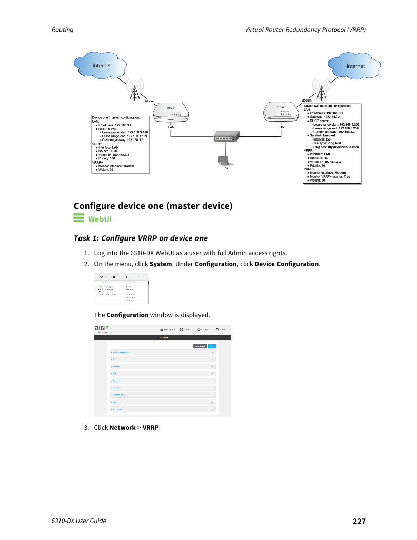
Routing Virtual Router Redundancy Protocol (VRRP)
6310-DX User Guide 227
Configure device one (master device) WebUI
Task 1: Configure VRRP on device one
1. Log into the 6310-DX WebUI as a user with full Admin access rights.2. On the menu, click System. Under Configuration, click Device Configuration.
The Configuration window is displayed.
3. Click Network > VRRP.
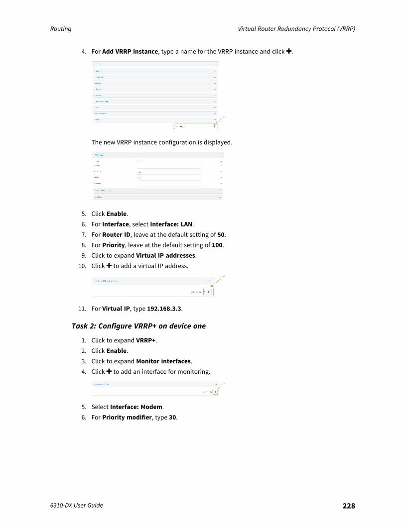
Routing Virtual Router Redundancy Protocol (VRRP)
6310-DX User Guide 228
4. For Add VRRP instance, type a name for the VRRP instance and click .
The new VRRP instance configuration is displayed.
5. Click Enable.6. For Interface, select Interface: LAN.7. For Router ID, leave at the default setting of 50.8. For Priority, leave at the default setting of 100.9. Click to expand Virtual IP addresses.
10. Click to add a virtual IP address.
11. For Virtual IP, type 192.168.3.3.
Task 2: Configure VRRP+ on device one
1. Click to expand VRRP+.2. Click Enable.3. Click to expand Monitor interfaces.4. Click to add an interface for monitoring.
5. Select Interface: Modem.6. For Priority modifier, type 30.
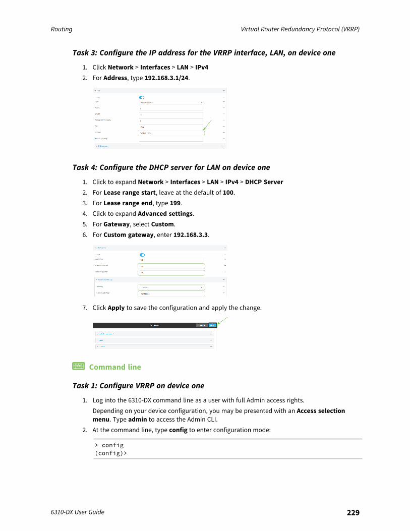
Routing Virtual Router Redundancy Protocol (VRRP)
6310-DX User Guide 229
Task 3: Configure the IP address for the VRRP interface, LAN, on device one
1. Click Network > Interfaces > LAN > IPv42. For Address, type 192.168.3.1/24.
Task 4: Configure the DHCP server for LAN on device one
1. Click to expand Network > Interfaces > LAN > IPv4 > DHCP Server2. For Lease range start, leave at the default of 100.3. For Lease range end, type 199.4. Click to expand Advanced settings.5. For Gateway, select Custom.6. For Custom gateway, enter 192.168.3.3.
7. Click Apply to save the configuration and apply the change.
Command line
Task 1: Configure VRRP on device one
1. Log into the 6310-DX command line as a user with full Admin access rights.Depending on your device configuration, you may be presented with an Access selectionmenu. Type admin to access the Admin CLI.
2. At the command line, type config to enter configuration mode:
> config(config)>
Routing Virtual Router Redundancy Protocol (VRRP)
6310-DX User Guide 230
3. Create the VRRP instance:
(config)> add network vrrp VRRP_test(config network vrrp VRRP_test)>
4. Enable the VRRP instance:
(config network vrrp VRRP_test)> enable true(config network vrrp VRRP_test)>
5. Set the VRRP interface to LAN:
(config network vrrp VRRP_test)> interface /network/interface/lan(config network vrrp VRRP_test)>
6. Add the virtual IP address associated with this VRRP instance.
(config network vrrp VRRP_test)> add virtual_address end 192.168.3.3(config network vrrp VRRP_test)>
Task 2: Configure VRRP+ on device one
1. Enable VRRP+:
(config network vrrp VRRP_test)> vrrp_plus enable true(config network vrrp VRRP_test )>
2. Add the interface to monitor:
(config network vrrp VRRP_test)> add vrrp_plus monitor_interface end/network/interface/modem(config network vrrp VRRP_test)>
3. Set the amount that the device's priority should be decreased or increased due to SureLinkconnectivity failure or success to 30:
(config network vrrp VRRP_test )> network vrrp VRRP_test vrrp_plus weight30(config network vrrp VRRP_test )>
Task 3: Configure the IP address for the VRRP interface, LAN, on device one
1. Type ... to return to the root of the config prompt:
(config network vrrp VRRP_test )> ...(config)>
2. Set the IP address for LAN:
(config)> network interface lan ipv4 address 192.168.3.1/24(config)>

Routing Virtual Router Redundancy Protocol (VRRP)
6310-DX User Guide 231
Task 4: Configure the DHCP server for LAN on device one
1. Set the start and end addresses of the DHCP pool to use to assign DHCP addresses to clients:a. Set the start address to 100:
(config)> network interface lan ipv4 dhcp_server lease_start 100(config)>
b. Set the end address to 199:
(config)> network interface lan ipv4 dhcp_server lease_end 199(config)>
2. Set the DHCP server gateway type to custom:
(config)> network interface lan ipv4 dhcp_server advanced gateway custom(config)>
3. Set the custom gateway to 192.168.3.3:
(config)> network interface lan ipv4 dhcp_server advanced gateway_custom192.168.3.3(config)>
4. Save the configuration and apply the change:
(config)> saveConfiguration saved.>
5. Type exit to exit the Admin CLI.Depending on your device configuration, you may be presented with an Access selectionmenu. Type quit to disconnect from the device.
Configure device two (backup device) WebUI
Task 1: Configure VRRP on device two
1. Log into the 6310-DX WebUI as a user with full Admin access rights.2. On the menu, click System. Under Configuration, click Device Configuration.
The Configuration window is displayed.
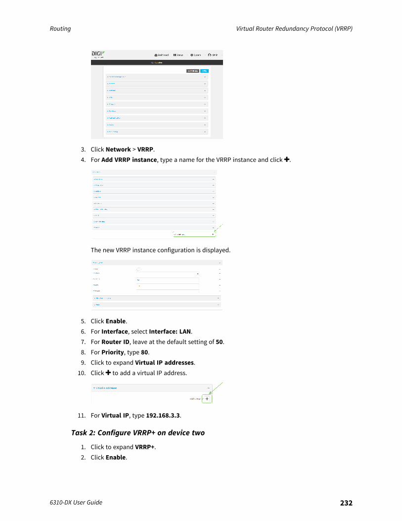
Routing Virtual Router Redundancy Protocol (VRRP)
6310-DX User Guide 232
3. Click Network > VRRP.4. For Add VRRP instance, type a name for the VRRP instance and click .
The new VRRP instance configuration is displayed.
5. Click Enable.6. For Interface, select Interface: LAN.7. For Router ID, leave at the default setting of 50.8. For Priority, type 80.9. Click to expand Virtual IP addresses.
10. Click to add a virtual IP address.
11. For Virtual IP, type 192.168.3.3.
Task 2: Configure VRRP+ on device two
1. Click to expand VRRP+.2. Click Enable.
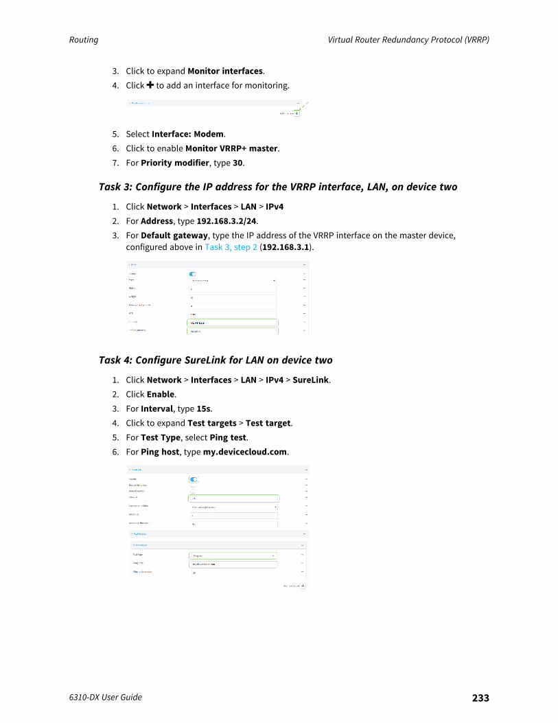
Routing Virtual Router Redundancy Protocol (VRRP)
6310-DX User Guide 233
3. Click to expand Monitor interfaces.4. Click to add an interface for monitoring.
5. Select Interface: Modem.6. Click to enable Monitor VRRP+ master.7. For Priority modifier, type 30.
Task 3: Configure the IP address for the VRRP interface, LAN, on device two
1. Click Network > Interfaces > LAN > IPv42. For Address, type 192.168.3.2/24.3. For Default gateway, type the IP address of the VRRP interface on the master device,
configured above in Task 3, step 2 (192.168.3.1).
Task 4: Configure SureLink for LAN on device two
1. Click Network > Interfaces > LAN > IPv4 > SureLink.2. Click Enable.3. For Interval, type 15s.4. Click to expand Test targets > Test target.5. For Test Type, select Ping test.6. For Ping host, type my.devicecloud.com.
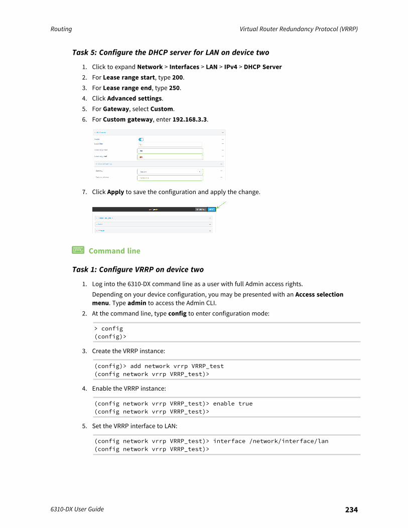
Routing Virtual Router Redundancy Protocol (VRRP)
6310-DX User Guide 234
Task 5: Configure the DHCP server for LAN on device two
1. Click to expand Network > Interfaces > LAN > IPv4 > DHCP Server2. For Lease range start, type 200.3. For Lease range end, type 250.4. Click Advanced settings.5. For Gateway, select Custom.6. For Custom gateway, enter 192.168.3.3.
7. Click Apply to save the configuration and apply the change.
Command line
Task 1: Configure VRRP on device two
1. Log into the 6310-DX command line as a user with full Admin access rights.Depending on your device configuration, you may be presented with an Access selectionmenu. Type admin to access the Admin CLI.
2. At the command line, type config to enter configuration mode:
> config(config)>
3. Create the VRRP instance:
(config)> add network vrrp VRRP_test(config network vrrp VRRP_test)>
4. Enable the VRRP instance:
(config network vrrp VRRP_test)> enable true(config network vrrp VRRP_test)>
5. Set the VRRP interface to LAN:
(config network vrrp VRRP_test)> interface /network/interface/lan(config network vrrp VRRP_test)>
Routing Virtual Router Redundancy Protocol (VRRP)
6310-DX User Guide 235
6. Add the virtual IP address associated with this VRRP instance.
(config network vrrp VRRP_test)> add virtual_address end 192.168.3.3(config network vrrp VRRP_test)>
Task 2: Configure VRRP+ on device two
1. Enable VRRP+:
(config network vrrp VRRP_test)> vrrp_plus enable true(config network vrrp VRRP_test )>
2. Add the interface to monitor:
(config network vrrp VRRP_test)> add vrrp_plus monitor_interface end/network/interface/modem(config network vrrp VRRP_test)>
3. Enable the ability to monitor the master device:
(config network vrrp VRRP_test)> vrrp_plus monitor_master true(config network vrrp VRRP_test)>
4. Set the amount that the device's priority should be decreased or increased due to SureLinkconnectivity failure or success to 30:
(config network vrrp VRRP_test )> network vrrp VRRP_test vrrp_plus weight30(config network vrrp VRRP_test )>
Task 3: Configure the IP address for the VRRP interface, LAN, on device two
1. Type ... to return to the root of the config prompt:
(config network vrrp VRRP_test )> ...(config)>
2. Set the IP address for LAN:
(config)> network interface lan ipv4 address 192.168.3.2(config)>
3. Set the default gateway to the IP address of the VRRP interface on the master device,configured above in Task 3, step 2 (192.168.3.1).
(config)> network interface lan ipv4 gateway 192.168.3.1(config)>
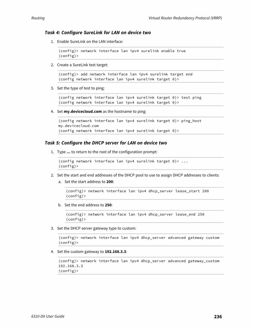
Routing Virtual Router Redundancy Protocol (VRRP)
6310-DX User Guide 236
Task 4: Configure SureLink for LAN on device two
1. Enable SureLink on the LAN interface:
(config)> network interface lan ipv4 surelink enable true(config)>
2. Create a SureLink test target:
(config)> add network interface lan ipv4 surelink target end(config network interface lan ipv4 surelink target 0)>
3. Set the type of test to ping:
(config network interface lan ipv4 surelink target 0)> test ping(config network interface lan ipv4 surelink target 0)>
4. Set my.devicecloud.com as the hostname to ping:
(config network interface lan ipv4 surelink target 0)> ping_hostmy.devicecloud.com(config network interface lan ipv4 surelink target 0)>
Task 5: Configure the DHCP server for LAN on device two
1. Type ... to return to the root of the configuration prompt:
(config network interface lan ipv4 surelink target 0)> ...(config)>
2. Set the start and end addresses of the DHCP pool to use to assign DHCP addresses to clients:a. Set the start address to 200:
(config)> network interface lan ipv4 dhcp_server lease_start 200(config)>
b. Set the end address to 250:
(config)> network interface lan ipv4 dhcp_server lease_end 250(config)>
3. Set the DHCP server gateway type to custom:
(config)> network interface lan ipv4 dhcp_server advanced gateway custom(config)>
4. Set the custom gateway to 192.168.3.3:
(config)> network interface lan ipv4 dhcp_server advanced gateway_custom192.168.3.3(config)>
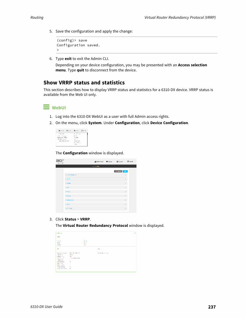
Routing Virtual Router Redundancy Protocol (VRRP)
6310-DX User Guide 237
5. Save the configuration and apply the change:
(config)> saveConfiguration saved.>
6. Type exit to exit the Admin CLI.Depending on your device configuration, you may be presented with an Access selectionmenu. Type quit to disconnect from the device.
Show VRRP status and statisticsThis section describes how to display VRRP status and statistics for a 6310-DX device. VRRP status isavailable from the Web UI only.
WebUI
1. Log into the 6310-DX WebUI as a user with full Admin access rights.2. On the menu, click System. Under Configuration, click Device Configuration.
The Configuration window is displayed.
3. Click Status > VRRP.The Virtual Router Redundancy Protocol window is displayed.
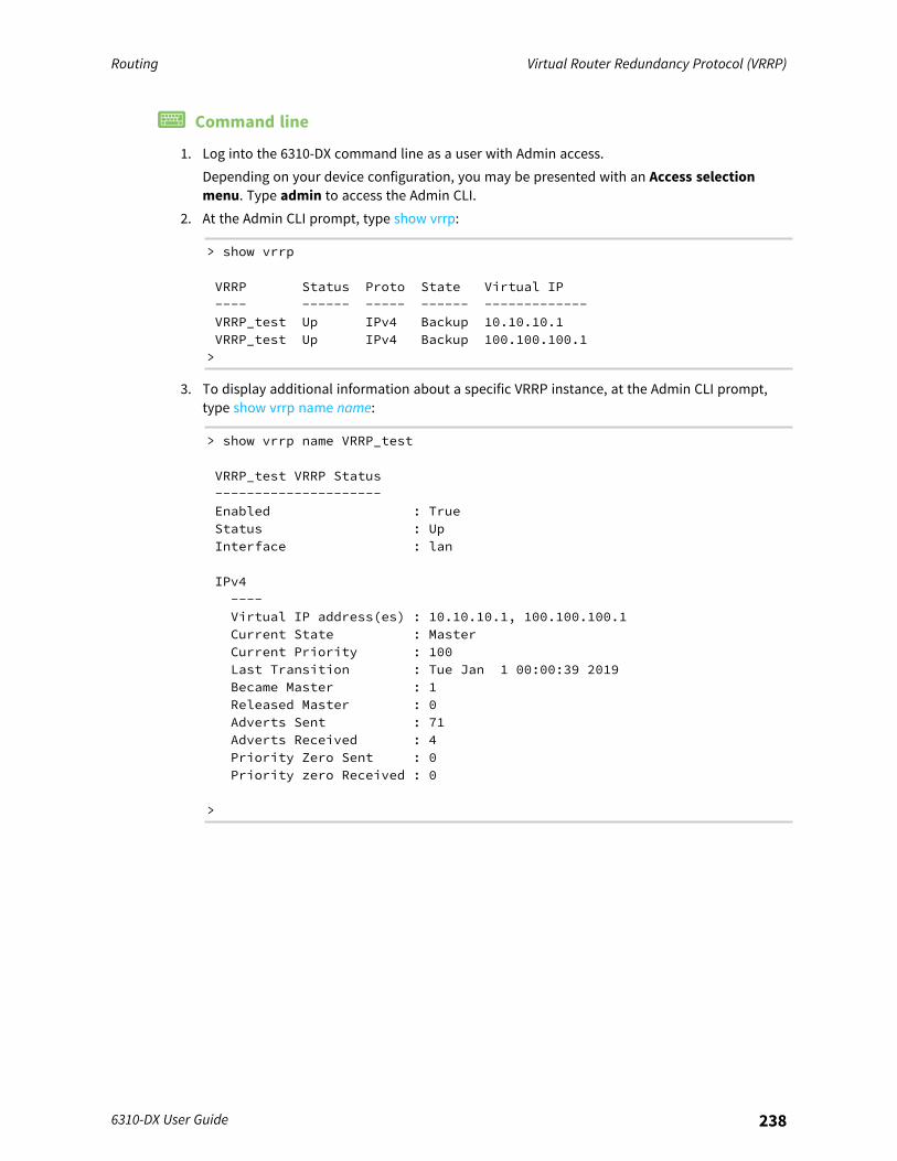
Routing Virtual Router Redundancy Protocol (VRRP)
6310-DX User Guide 238
Command line
1. Log into the 6310-DX command line as a user with Admin access.Depending on your device configuration, you may be presented with an Access selectionmenu. Type admin to access the Admin CLI.
2. At the Admin CLI prompt, type show vrrp:
> show vrrp
VRRP Status Proto State Virtual IP---- ------ ----- ------ -------------VRRP_test Up IPv4 Backup 10.10.10.1VRRP_test Up IPv4 Backup 100.100.100.1>
3. To display additional information about a specific VRRP instance, at the Admin CLI prompt,type show vrrp name name:
> show vrrp name VRRP_test
VRRP_test VRRP Status---------------------Enabled : TrueStatus : UpInterface : lan
IPv4----Virtual IP address(es) : 10.10.10.1, 100.100.100.1Current State : MasterCurrent Priority : 100Last Transition : Tue Jan 1 00:00:39 2019Became Master : 1Released Master : 0Adverts Sent : 71Adverts Received : 4Priority Zero Sent : 0Priority zero Received : 0
>

Virtual Private Networks (VPN)
Virtual Private Networks (VPNs) are used to securely connect two private networks together so thatdevices can connect from one network to the other using secure channels.This chapter contains the following topics:
IPsec 240OpenVPN 293Generic Routing Encapsulation (GRE) 326L2TP 347L2TPv3 Ethernet 367NEMO 373
6310-DX User Guide 239
Virtual Private Networks (VPN) IPsec
6310-DX User Guide 240
IPsecIPsec is a suite of protocols for creating a secure communication link—an IPsec tunnel—between ahost and a remote IP network or between two IP networks across a public network such as theInternet.
IPsec data protectionIPsec protects the data being sent across a public network by providing the following:
Data origin authenticationAuthentication of data to validate the origin of data when it is received.Data integrityAuthentication of data to ensure it has not been modified during transmission.Data confidentialityEncryption of data sent across the IPsec tunnel to ensure that an unauthorized device cannot readthe data.Anti-ReplayAuthentication of data to ensure an unauthorized device has not injected it into the IPsec tunnel.
IPsec modeThe 6310-DX supports the Tunnel mode. With the Tunnel mode, the entire IP packet is encryptedand/or authenticated and then encapsulated as the payload in a new IP packet. Transport mode isnot currently supported.
IPsec modesIPsec can run in two different modes: Tunnel and Transport.
TunnelThe entire IP packet is encrypted and/or authenticated and then encapsulated as the payload in anew IP packet.TransportOnly the payload of the IP packet is encrypted and/or authenticated. The IP header is leftuntouched. This mode has limitations when using an authentication header, because the IPaddresses in the IP header cannot be translated (for example, with Network Address Translation(NAT), as it would invalidate the authentication hash value.
Internet Key Exchange (IKE) settingsIKE is a key management protocol that allows IPsec to negotiate the security associations (SAs) thatare used to create the secure IPsec tunnel. Both IKEv1 and IKEv2 are supported.SA negotiations are performed in two phases, known as phase 1 and phase 2.
Phase 1In phase 1, IKE creates a secure authenticated communication channel between the device and thepeer (the remote device which is at the other end of the IPsec tunnel) using the configured pre-sharedkey and the Diffie-Hellman key exchange. This creates the IKE SAs that are used to encrypt further IKEcommunications.For IKEv1, there are two modes for the phase 1 negotiation: Main mode and Aggressive mode. IKEv2does not use these modes.

Virtual Private Networks (VPN) IPsec
6310-DX User Guide 241
Main modeMain mode is the default mode. It is slower than aggressive mode, but more secure, in that allsensitive information sent between the device and its peer is encrypted.Aggressive modeAggressive mode is faster than main mode, but is not as secure as main mode, because the deviceand its peer exchange their IDs and hash information in clear text instead of being encrypted.Aggressive mode is usually used when one or both of the devices have a dynamic external IPaddress.
Phase 2In phase 2, IKE negotiates the SAs for IPsec. This creates two unidirectional SAs, one for eachdirection. Once the phase 2 negotiation is complete, the IPsec tunnel should be fully functional.
IPsec and IKE renegotiationTo reduce the chances of an IPsec tunnel being compromised, the IPsec SAs and IKE SA arerenegotiated at a regular interval. This results in different encryption keys being used in the IPsectunnel.
Authentication
Client authenticatonXAUTH (extended authentication) pre-shared key authentication mode provides additional security byusing client authentication credentials in addition to the standard pre-shared key. The 6310-DX devicecan be configured to authenticate with the remote peer as an XAUTH client.
RSA SignaturesWith RSA signatures authentication, the 6310-DX device uses a private RSA key to authenticate with aremote peer that is using a corresponding public key.
Certificate-based AuthenticationX.509 certificate-based authentication makes use of private keys on both the server and client whichare secured and never shared. Both the server and client have a certificate which is generated withtheir respective private key and signed by a Certificate Authority (CA).The 6310-DX implementation of IPsec can be configured to use X.509 certificate-based authenticationusing the private keys and certificates, along with a root CA certificate from the signing authority and,if available, a Certificate Revocation List (CRL).
Configure an IPsec tunnelConfiguring an IPsec tunnel with a remote device involves configuring the following items:
Required configuration items
n IPsec tunnel configuration items:l The mode: either tunnel or transport.l Enable the IPsec tunnel.
The IPsec tunnel is enabled by default.
Virtual Private Networks (VPN) IPsec
6310-DX User Guide 242
l The firewall zone of the IPsec tunnel.l The routing metric for routes associated with this IPsec tunnel.l The authentication type and pre-shared key or other applicable keys and certificates.
If SCEP certificates will be selected as the Authentication type, create the SCEP client priorto configuring the IPsec tunnel. See Configure a Simple Certificate Enrollment Protocolclient for instructions.
l The local endpoint type and ID values, and the remote endpoint host and ID values.n IKE configuration items
l The IKE version, either IKEv1 or IKEv2.l Whether to initiate a key exchange or wait for an incoming request.l The IKE mode, either main aggressive.l The IKE authentication protocol to use for the IPsec tunnel negotiation during phase 1 and
phase 2.l The IKE encryption protocol to use for the IPsec tunnel negotiation during phase 1 and
phase 2.l The IKE Diffie-Hellman group to use for the IPsec tunnel negotiation during phase 1 and
phase 2.n Enable dead peer detection and configure the delay and timeout.n Destination networks that require source NAT.n Active recovery configuration. See Configure SureLink active recovery for IPsec for information
about IPsec active recovery.
Additional configuration itemsThe following additional configuration settings are not typically configured to get an IPsec tunnelworking, but can be configured as needed:
n Determine whether the device should use UDP encapsulation even when it does not detectthat NAT is being used.
n If using IPsec failover, identify the primary tunnel during configuration of the backup tunnel.n The Network Address Translation (NAT) keep alive time.n The protocol, either Encapsulating Security Payload (ESP) or Authentication Header (AH).n The management priority for the IPsec tunnel interface. The active interface with the highest
management priority will have its address reported as the preferred contact address forcentral management and direct device access.
n Enable XAUTH client authentication, and the username and password to be used toauthenticate with the remote peer.
n Enable Mode-configuration (MODECFG) to receive configuration information, such as theprivate IP address, from the remote peer.
n Disable the padding of IKE packets. This should normally not be done except for compatibilitypurposes.
n Destination networks that require source NAT.n Depending on your network and firewall configuration, you may need to add a packet filtering
rule to allow incoming IPsec traffic.
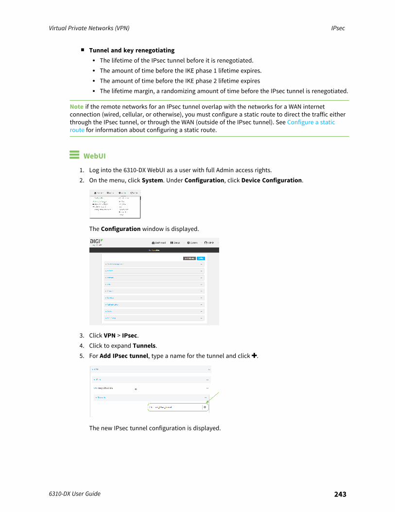
Virtual Private Networks (VPN) IPsec
6310-DX User Guide 243
n Tunnel and key renegotiatingl The lifetime of the IPsec tunnel before it is renegotiated.l The amount of time before the IKE phase 1 lifetime expires.l The amount of time before the IKE phase 2 lifetime expiresl The lifetime margin, a randomizing amount of time before the IPsec tunnel is renegotiated.
Note if the remote networks for an IPsec tunnel overlap with the networks for a WAN internetconnection (wired, cellular, or otherwise), you must configure a static route to direct the traffic eitherthrough the IPsec tunnel, or through the WAN (outside of the IPsec tunnel). See Configure a staticroute for information about configuring a static route.
WebUI
1. Log into the 6310-DX WebUI as a user with full Admin access rights.2. On the menu, click System. Under Configuration, click Device Configuration.
The Configuration window is displayed.
3. Click VPN > IPsec.4. Click to expand Tunnels.5. For Add IPsec tunnel, type a name for the tunnel and click .
The new IPsec tunnel configuration is displayed.
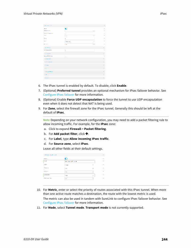
Virtual Private Networks (VPN) IPsec
6310-DX User Guide 244
6. The IPsec tunnel is enabled by default. To disable, click Enable.7. (Optional) Preferred tunnel provides an optional mechanism for IPsec failover behavior. See
Configure IPsec failover for more information.8. (Optional) Enable Force UDP encapsulation to force the tunnel to use UDP encapsulation
even when it does not detect that NAT is being used.9. For Zone, select the firewall zone for the IPsec tunnel. Generally this should be left at the
default of IPsec.
Note Depending on your network configuration, you may need to add a packet filtering rule toallow incoming traffic. For example, for the IPsec zone:a. Click to expand Firewall > Packet filtering.b. For Add packet filter, click .c. For Label, type Allow incoming IPsec traffic.d. For Source zone, select IPsec.Leave all other fields at their default settings.
10. For Metric, enter or select the priority of routes associated with this IPsec tunnel. When morethan one active route matches a destination, the route with the lowest metric is used.The metric can also be used in tandem with SureLink to configure IPsec failover behavior. SeeConfigure IPsec failover for more information.
11. For Mode, select Tunnel mode. Transport mode is not currently supported.
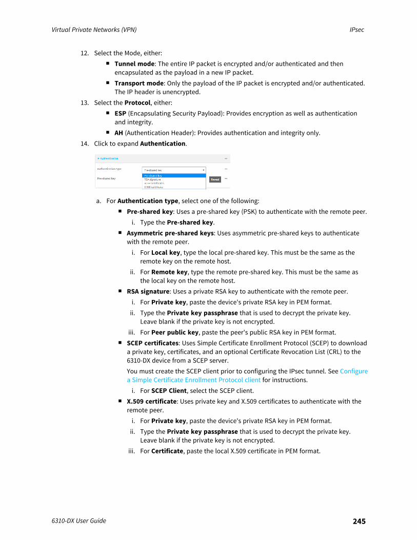
Virtual Private Networks (VPN) IPsec
6310-DX User Guide 245
12. Select the Mode, either:n Tunnel mode: The entire IP packet is encrypted and/or authenticated and then
encapsulated as the payload in a new IP packet.n Transport mode: Only the payload of the IP packet is encrypted and/or authenticated.
The IP header is unencrypted.13. Select the Protocol, either:
n ESP (Encapsulating Security Payload): Provides encryption as well as authenticationand integrity.
n AH (Authentication Header): Provides authentication and integrity only.14. Click to expand Authentication.
a. For Authentication type, select one of the following:n Pre-shared key: Uses a pre-shared key (PSK) to authenticate with the remote peer.
i. Type the Pre-shared key.n Asymmetric pre-shared keys: Uses asymmetric pre-shared keys to authenticate
with the remote peer.i. For Local key, type the local pre-shared key. This must be the same as the
remote key on the remote host.ii. For Remote key, type the remote pre-shared key. This must be the same as
the local key on the remote host.n RSA signature: Uses a private RSA key to authenticate with the remote peer.
i. For Private key, paste the device's private RSA key in PEM format.ii. Type the Private key passphrase that is used to decrypt the private key.
Leave blank if the private key is not encrypted.iii. For Peer public key, paste the peer's public RSA key in PEM format.
n SCEP certificates: Uses Simple Certificate Enrollment Protocol (SCEP) to downloada private key, certificates, and an optional Certificate Revocation List (CRL) to the6310-DX device from a SCEP server.You must create the SCEP client prior to configuring the IPsec tunnel. See Configurea Simple Certificate Enrollment Protocol client for instructions.i. For SCEP Client, select the SCEP client.
n X.509 certificate: Uses private key and X.509 certificates to authenticate with theremote peer.i. For Private key, paste the device's private RSA key in PEM format.ii. Type the Private key passphrase that is used to decrypt the private key.
Leave blank if the private key is not encrypted.iii. For Certificate, paste the local X.509 certificate in PEM format.

Virtual Private Networks (VPN) IPsec
6310-DX User Guide 246
iv. For Peer verification, select either:l Peer certificate: For Peer certificate, paste the peer's X.509 certificate in
PEM format.l Certificate Authority: For Certificate Authority chain, paste the
Certificate Authority (CA) certificates. These must include all peercertificates in the chain up to the root CA certificate, in PEM format.
15. (Optional) For Management Priority, set the management priority for this IPsec tunnel. Atunnel that is up and has the highest priority will be used for central management and directdevice access.
16. (Optional) To configure the device to connect to its remote peer as an XAUTH client:a. Click to expand XAUTH client.
b. Click Enable.c. Type the Username and Password that the device will use to authenticate as an
XAUTH client with the peer.17. (Optional) Click Enable MODECFG client to receive configuration information, such as the
private IP address, from the remote peer.18. Click to expand Local endpoint.
a. For Type, select either:n Default route: Uses the same network interface as the default route.n Interface: Select the Interface to be used as the local endpoint.
b. Click to expand ID.i. Select the ID type:
n Auto: The ID will be automatically determined from the value of the tunnelsendpoints.
n Raw: Enter an ID and have it passed unmodified to the underlying IPsec stack.For Raw ID value, type the ID that will be passed.
n Any: Any ID will be accepted.n IPv4: The ID will be interpreted as an IP address and sent as an ID_IPV4_ADDR
IKE identity.For IPv4 ID value, type an IPv4 formatted ID. This can be a fully-qualifieddomain name or an IPv4 address.
n IPv6: The ID will be interpreted as an IP address and sent as an ID_IPV6_ADDRIKE identity.For IPv6 ID value, type an IPv6 formatted ID. This can be a fully-qualifieddomain name or an IPv6 address.
n RFC822/Email: The ID will be interpreted as an RFC822 (email address).For RFC822 ID value, type the ID in internet email address format.
Virtual Private Networks (VPN) IPsec
6310-DX User Guide 247
n FQDN: The ID will be interpreted as FQDN (Fully Qualified Domain Name) andsent as an ID_FQDN IKE identity.For FQDN ID value, type the ID as an FQDN.
n KeyID: The ID will be interpreted as a Key ID and sent as an ID_KEY_ID IKEidentity.For KEYID ID value, type the key ID.
n MAC address: The device's primary MAC address will be used as the ID andsent as a ID_KEY_ID IKE identity.
n Serial number: The device's serial number will be used as the ID and sent as aID_KEY_ID IKE identity.
19. Click to expand Remote endpoint.a. For IP version, select either IPv4 or IPv6.b. For Hostname list selection, select one of the following:
n Round robin: Attempts to connect to hostnames sequentially based on the listorder.
n Random: Randomly selects an IPsec peer to connect to from the hostname list.n Priority ordered: Selects the first hostname in the list that is resolvable.
c. Click to expand Hostname.i. Click next to Add Hostname.ii. For Hostname, type a hostname or IPv4 address. If your device is not configured to
initiate the IPsec connection (see IKE > Initiate connection), you can also use thekeyword any, which means that the hostname is dynamic or unknown.
iii. Click again to add additional hostnames.d. Click to expand ID.
i. Select the ID type:n Auto: The ID will be automatically determined from the value of the tunnels
endpoints.n Raw: Enter an ID and have it passed unmodified to the underlying IPsec stack.
For Raw ID value, type the ID that will be passed.n Any: Any ID will be accepted.n IPv4: The ID will be interpreted as an IPv4 address and sent as an ID_IPV4_
ADDR IKE identity.For IPv4 ID value, type an IPv4 formatted ID. This can be a fully-qualifieddomain name or an IPv4 address.
n IPv6: The ID will be interpreted as an IPv6 address and sent as an ID_IPV6_ADDR IKE identity.For IPv6 ID value, type an IPv6 formatted ID. This can be a fully-qualifieddomain name or an IPv6 address.
n RFC822/Email: The ID will be interpreted as an RFC822 (email address).For RFC822 ID value, type the ID in internet email address format.
n FQDN: The ID will be interpreted as FQDN (Fully Qualified Domain Name) andsent as an ID_FQDN IKE identity.
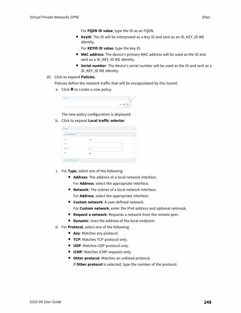
Virtual Private Networks (VPN) IPsec
6310-DX User Guide 248
For FQDN ID value, type the ID as an FQDN.n KeyID: The ID will be interpreted as a Key ID and sent as an ID_KEY_ID IKE
identity.For KEYID ID value, type the key ID.
n MAC address: The device's primary MAC address will be used as the ID andsent as a ID_KEY_ID IKE identity.
n Serial number: The device's serial number will be used as the ID and sent as aID_KEY_ID IKE identity.
20. Click to expand Policies.Policies define the network traffic that will be encapsulated by this tunnel.a. Click to create a new policy.
The new policy configuration is displayed.b. Click to expand Local traffic selector.
c. For Type, select one of the following:n Address: The address of a local network interface.
For Address, select the appropriate interface.n Network: The subnet of a local network interface.
For Address, select the appropriate interface.n Custom network: A user-defined network.
For Custom network, enter the IPv4 address and optional netmask.n Request a network: Requests a network from the remote peer.n Dynamic: Uses the address of the local endpoint.
d. For Protocol, select one of the following:n Any: Matches any protocol.n TCP: Matches TCP protocol only.n UDP: Matches UDP protocol only.n ICMP: Matches ICMP requests only.n Other protocol: Matches an unlisted protocol.
If Other protocol is selected, type the number of the protocol.
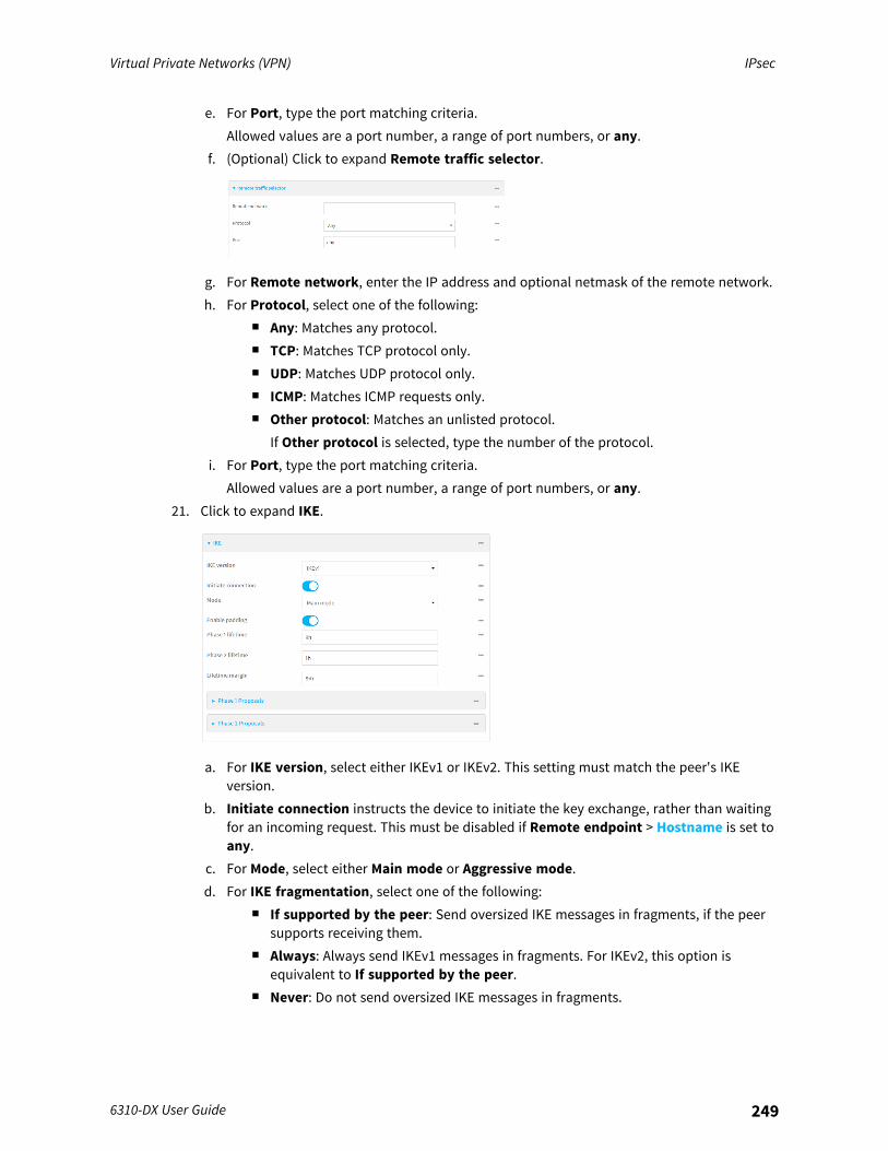
Virtual Private Networks (VPN) IPsec
6310-DX User Guide 249
e. For Port, type the port matching criteria.Allowed values are a port number, a range of port numbers, or any.
f. (Optional) Click to expand Remote traffic selector.
g. For Remote network, enter the IP address and optional netmask of the remote network.h. For Protocol, select one of the following:
n Any: Matches any protocol.n TCP: Matches TCP protocol only.n UDP: Matches UDP protocol only.n ICMP: Matches ICMP requests only.n Other protocol: Matches an unlisted protocol.
If Other protocol is selected, type the number of the protocol.i. For Port, type the port matching criteria.
Allowed values are a port number, a range of port numbers, or any.21. Click to expand IKE.
a. For IKE version, select either IKEv1 or IKEv2. This setting must match the peer's IKEversion.
b. Initiate connection instructs the device to initiate the key exchange, rather than waitingfor an incoming request. This must be disabled if Remote endpoint > Hostname is set toany.
c. For Mode, select either Main mode or Aggressive mode.d. For IKE fragmentation, select one of the following:
n If supported by the peer: Send oversized IKE messages in fragments, if the peersupports receiving them.
n Always: Always send IKEv1 messages in fragments. For IKEv2, this option isequivalent to If supported by the peer.
n Never: Do not send oversized IKE messages in fragments.
Virtual Private Networks (VPN) IPsec
6310-DX User Guide 250
n Accept: Do not send oversized IKE messages in fragments, but announce supportfor fragmentation to the peer.
The default is Always.e. For Enable padding, click to disable the padding of IKE packets. This should normally not
be disabled except for compatibility purposes.f. For Phase 1 lifetime, enter the amount of time that the IKE security association expires
after a successful negotiation and must be re-authenticated.Allowed values are any number of weeks, days, hours, minutes, or seconds, and take theformat number{w|d|h|m|s}.For example, to set Phase 1 lifetime to ten minutes, enter 10m or 600s.
g. For Phase 2 lifetime, enter the amount of time that the IKE security association expiresafter a successful negotiation and must be rekeyed.Allowed values are any number of weeks, days, hours, minutes, or seconds, and take theformat number{w|d|h|m|s}.For example, to set Phase 2 lifetime to ten minutes, enter 10m or 600s.
h. For Lifetime margin, enter a randomizing amount of time before the IPsec tunnel isrenegotiated.Allowed values are any number of weeks, days, hours, minutes, or seconds, and take theformat number{w|d|h|m|s}.For example, to set Lifetime margin to ten minutes, enter 10m or 600s.
i. Click to expand Phase 1 Proposals.i. Click to create a new phase 1 proposal.ii. For Cipher, select the type of encryption.iii. For Hash, select the type of hash to use to verify communication integrity.iv. For Diffie-Hellman group, select the type of Diffie-Hellman group to use for key
exchange.v. You can add additional Phase 1 proposals by clicking next to Add Phase 1
Proposal.j. Click to expand Phase 2 Proposals.
i. Click to create a new phase 2 proposal.ii. For Cipher, select the type of encryption.iii. For Hash, select the type of hash to use to verify communication integrity.iv. For Diffie-Hellman group, select the type of Diffie-Hellman group to use for key
exchange.v. You can add additional Phase 2 proposals by clicking next to Add Phase 2
Proposal.22. (Optional) Click to expand Dead peer detection. Dead peer detection is enabled by default.
Dead peer detection uses periodic IKE transmissions to the remote endpoint to detect whethertunnel communications have failed, allowing the tunnel to be automatically restarted whenfailure occurs.
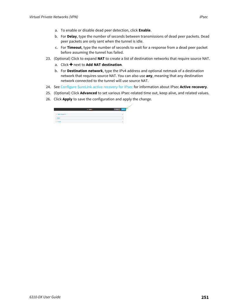
Virtual Private Networks (VPN) IPsec
6310-DX User Guide 251
a. To enable or disable dead peer detection, click Enable.b. For Delay, type the number of seconds between transmissions of dead peer packets. Dead
peer packets are only sent when the tunnel is idle.c. For Timeout, type the number of seconds to wait for a response from a dead peer packet
before assuming the tunnel has failed.23. (Optional) Click to expand NAT to create a list of destination networks that require source NAT.
a. Click next to Add NAT destination.b. For Destination network, type the IPv4 address and optional netmask of a destination
network that requires source NAT. You can also use any, meaning that any destinationnetwork connected to the tunnel will use source NAT.
24. See Configure SureLink active recovery for IPsec for information about IPsec Active recovery.25. (Optional) Click Advanced to set various IPsec-related time out, keep alive, and related values.26. Click Apply to save the configuration and apply the change.
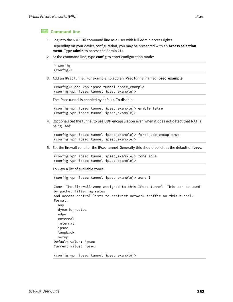
Virtual Private Networks (VPN) IPsec
6310-DX User Guide 252
Command line
1. Log into the 6310-DX command line as a user with full Admin access rights.Depending on your device configuration, you may be presented with an Access selectionmenu. Type admin to access the Admin CLI.
2. At the command line, type config to enter configuration mode:
> config(config)>
3. Add an IPsec tunnel. For example, to add an IPsec tunnel named ipsec_example:
(config)> add vpn ipsec tunnel ipsec_example(config vpn ipsec tunnel ipsec_example)>
The IPsec tunnel is enabled by default. To disable:
(config vpn ipsec tunnel ipsec_example)> enable false(config vpn ipsec tunnel ipsec_example)>
4. (Optional) Set the tunnel to use UDP encapsulation even when it does not detect that NAT isbeing used:
(config vpn ipsec tunnel ipsec_example)> force_udp_encap true(config vpn ipsec tunnel ipsec_example)>
5. Set the firewall zone for the IPsec tunnel. Generally this should be left at the default of ipsec.
(config vpn ipsec tunnel ipsec_example)> zone zone(config vpn ipsec tunnel ipsec_example)>
To view a list of available zones:
(config vpn ipsec tunnel ipsec_example)> zone ?
Zone: The firewall zone assigned to this IPsec tunnel. This can be usedby packet filtering rulesand access control lists to restrict network traffic on this tunnel.Format:anydynamic_routesedgeexternalinternalipsecloopbacksetup
Default value: ipsecCurrent value: ipsec
(config vpn ipsec tunnel ipsec_example)>
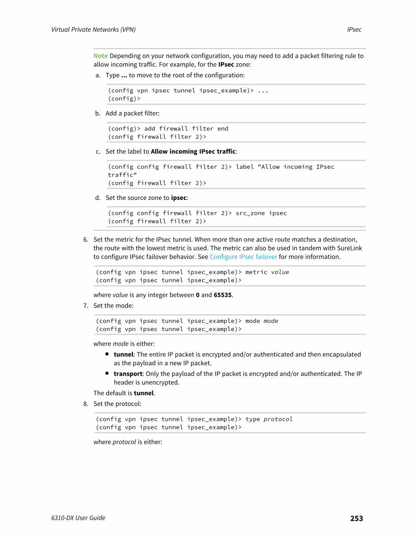
Virtual Private Networks (VPN) IPsec
6310-DX User Guide 253
Note Depending on your network configuration, you may need to add a packet filtering rule toallow incoming traffic. For example, for the IPsec zone:a. Type ... to move to the root of the configuration:
(config vpn ipsec tunnel ipsec_example)> ...(config)>
b. Add a packet filter:
(config)> add firewall filter end(config firewall filter 2)>
c. Set the label to Allow incoming IPsec traffic:
(config config firewall filter 2)> label "Allow incoming IPsectraffic"(config firewall filter 2)>
d. Set the source zone to ipsec:
(config config firewall filter 2)> src_zone ipsec(config firewall filter 2)>
6. Set the metric for the IPsec tunnel. When more than one active route matches a destination,the route with the lowest metric is used. The metric can also be used in tandem with SureLinkto configure IPsec failover behavior. See Configure IPsec failover for more information.
(config vpn ipsec tunnel ipsec_example)> metric value(config vpn ipsec tunnel ipsec_example)>
where value is any integer between 0 and 65535.7. Set the mode:
(config vpn ipsec tunnel ipsec_example)> mode mode(config vpn ipsec tunnel ipsec_example)>
where mode is either:n tunnel: The entire IP packet is encrypted and/or authenticated and then encapsulated
as the payload in a new IP packet.n transport: Only the payload of the IP packet is encrypted and/or authenticated. The IP
header is unencrypted.The default is tunnel.
8. Set the protocol:
(config vpn ipsec tunnel ipsec_example)> type protocol(config vpn ipsec tunnel ipsec_example)>
where protocol is either:
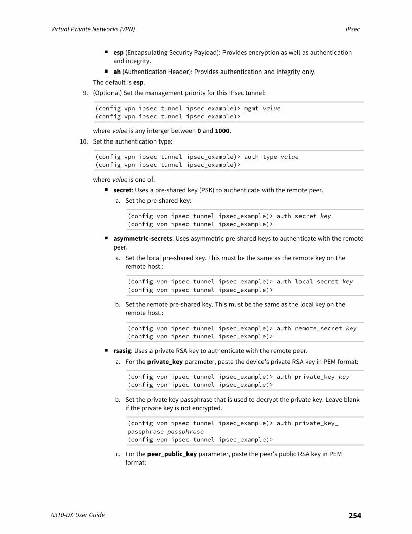
Virtual Private Networks (VPN) IPsec
6310-DX User Guide 254
n esp (Encapsulating Security Payload): Provides encryption as well as authenticationand integrity.
n ah (Authentication Header): Provides authentication and integrity only.The default is esp.
9. (Optional) Set the management priority for this IPsec tunnel:
(config vpn ipsec tunnel ipsec_example)> mgmt value(config vpn ipsec tunnel ipsec_example)>
where value is any interger between 0 and 1000.10. Set the authentication type:
(config vpn ipsec tunnel ipsec_example)> auth type value(config vpn ipsec tunnel ipsec_example)>
where value is one of:n secret: Uses a pre-shared key (PSK) to authenticate with the remote peer.
a. Set the pre-shared key:
(config vpn ipsec tunnel ipsec_example)> auth secret key(config vpn ipsec tunnel ipsec_example)>
n asymmetric-secrets: Uses asymmetric pre-shared keys to authenticate with the remotepeer.a. Set the local pre-shared key. This must be the same as the remote key on the
remote host.:
(config vpn ipsec tunnel ipsec_example)> auth local_secret key(config vpn ipsec tunnel ipsec_example)>
b. Set the remote pre-shared key. This must be the same as the local key on theremote host.:
(config vpn ipsec tunnel ipsec_example)> auth remote_secret key(config vpn ipsec tunnel ipsec_example)>
n rsasig: Uses a private RSA key to authenticate with the remote peer.a. For the private_key parameter, paste the device's private RSA key in PEM format:
(config vpn ipsec tunnel ipsec_example)> auth private_key key(config vpn ipsec tunnel ipsec_example)>
b. Set the private key passphrase that is used to decrypt the private key. Leave blankif the private key is not encrypted.
(config vpn ipsec tunnel ipsec_example)> auth private_key_passphrase passphrase(config vpn ipsec tunnel ipsec_example)>
c. For the peer_public_key parameter, paste the peer's public RSA key in PEMformat:

Virtual Private Networks (VPN) IPsec
6310-DX User Guide 255
(config vpn ipsec tunnel ipsec_example)> auth peer_public_keykey(config vpn ipsec tunnel ipsec_example)>
n x509: Uses private key and X.509 certificates to authenticate with the remote peer.a. For the private_key parameter, paste the device's private RSA key in PEM format:
(config vpn ipsec tunnel ipsec_example)> auth private_key key(config vpn ipsec tunnel ipsec_example)>
b. Set the private key passphrase that is used to decrypt the private key. Leave blankif the private key is not encrypted.
(config vpn ipsec tunnel ipsec_example)> auth private_key_passphrase passphrase(config vpn ipsec tunnel ipsec_example)>
c. For the cert parameter, paste the local X.509 certificate in PEM format:
(config vpn ipsec tunnel ipsec_example)> auth cert certificate(config vpn ipsec tunnel ipsec_example)>
d. Set the method for verifying the peer's X.509 certificate:
(config vpn ipsec tunnel ipsec_example)> auth peer_verify value(config vpn ipsec tunnel ipsec_example)>
where value is either:l cert: Uses the peer's X.509 certificate in PEM format for verification.
o For the peer_cert parameter, paste the peer's X.509 certificate in PEMformat:
(config vpn ipsec tunnel ipsec_example)> auth peer_certcertificate(config vpn ipsec tunnel ipsec_example)>
l ca: Uses the Certificate Authority chain for verification.o For the ca_cert parameter, paste the Certificate Authority (CA) certificates.
These must include all peer certificates in the chain up to the rootCA certificate, in PEM format.
(config vpn ipsec tunnel ipsec_example)> auth ca_cert cert_chain(config vpn ipsec tunnel ipsec_example)>
11. (Optional) Configure the device to connect to its remote peer as an XAUTH client:a. Enable XAUTH client functionality:
(config vpn ipsec tunnel ipsec_example)> xauth_client enable true(config vpn ipsec tunnel ipsec_example)>
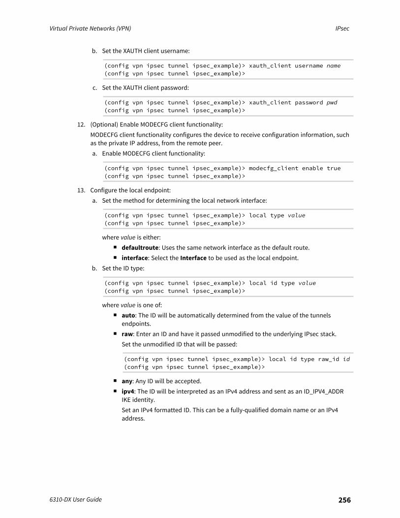
Virtual Private Networks (VPN) IPsec
6310-DX User Guide 256
b. Set the XAUTH client username:
(config vpn ipsec tunnel ipsec_example)> xauth_client username name(config vpn ipsec tunnel ipsec_example)>
c. Set the XAUTH client password:
(config vpn ipsec tunnel ipsec_example)> xauth_client password pwd(config vpn ipsec tunnel ipsec_example)>
12. (Optional) Enable MODECFG client functionality:MODECFG client functionality configures the device to receive configuration information, suchas the private IP address, from the remote peer.a. Enable MODECFG client functionality:
(config vpn ipsec tunnel ipsec_example)> modecfg_client enable true(config vpn ipsec tunnel ipsec_example)>
13. Configure the local endpoint:a. Set the method for determining the local network interface:
(config vpn ipsec tunnel ipsec_example)> local type value(config vpn ipsec tunnel ipsec_example)>
where value is either:n defaultroute: Uses the same network interface as the default route.n interface: Select the Interface to be used as the local endpoint.
b. Set the ID type:
(config vpn ipsec tunnel ipsec_example)> local id type value(config vpn ipsec tunnel ipsec_example)>
where value is one of:n auto: The ID will be automatically determined from the value of the tunnels
endpoints.n raw: Enter an ID and have it passed unmodified to the underlying IPsec stack.
Set the unmodified ID that will be passed:
(config vpn ipsec tunnel ipsec_example)> local id type raw_id id(config vpn ipsec tunnel ipsec_example)>
n any: Any ID will be accepted.n ipv4: The ID will be interpreted as an IPv4 address and sent as an ID_IPV4_ADDR
IKE identity.Set an IPv4 formatted ID. This can be a fully-qualified domain name or an IPv4address.
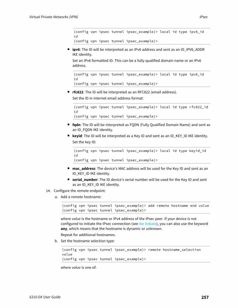
Virtual Private Networks (VPN) IPsec
6310-DX User Guide 257
(config vpn ipsec tunnel ipsec_example)> local id type ipv4_idid(config vpn ipsec tunnel ipsec_example)>
n ipv6: The ID will be interpreted as an IPv6 address and sent as an ID_IPV6_ADDRIKE identity.Set an IPv6 formatted ID. This can be a fully-qualified domain name or an IPv6address.
(config vpn ipsec tunnel ipsec_example)> local id type ipv6_idid(config vpn ipsec tunnel ipsec_example)>
n rfc822: The ID will be interpreted as an RFC822 (email address).Set the ID in internet email address format:
(config vpn ipsec tunnel ipsec_example)> local id type rfc822_idid(config vpn ipsec tunnel ipsec_example)>
n fqdn: The ID will be interpreted as FQDN (Fully Qualified Domain Name) and sent asan ID_FQDN IKE identity.
n keyid: The ID will be interpreted as a Key ID and sent as an ID_KEY_ID IKE identity.Set the key ID:
(config vpn ipsec tunnel ipsec_example)> local id type keyid_idid(config vpn ipsec tunnel ipsec_example)>
n mac_address: The device's MAC address will be used for the Key ID and sent as anID_KEY_ID IKE identity.
n serial_number: The ID device's serial number will be used for the Key ID and sentas an ID_KEY_ID IKE identity.
14. Configure the remote endpoint:a. Add a remote hostname:
(config vpn ipsec tunnel ipsec_example)> add remote hostname end value(config vpn ipsec tunnel ipsec_example)>
where value is the hostname or IPv4 address of the IPsec peer. If your device is notconfigured to initiate the IPsec connection (see ike initiate), you can also use the keywordany, which means that the hostname is dynamic or unknown.Repeat for additional hostnames.
b. Set the hostname selection type:
(config vpn ipsec tunnel ipsec_example)> remote hostname_selectionvalue(config vpn ipsec tunnel ipsec_example)>
where value is one of:
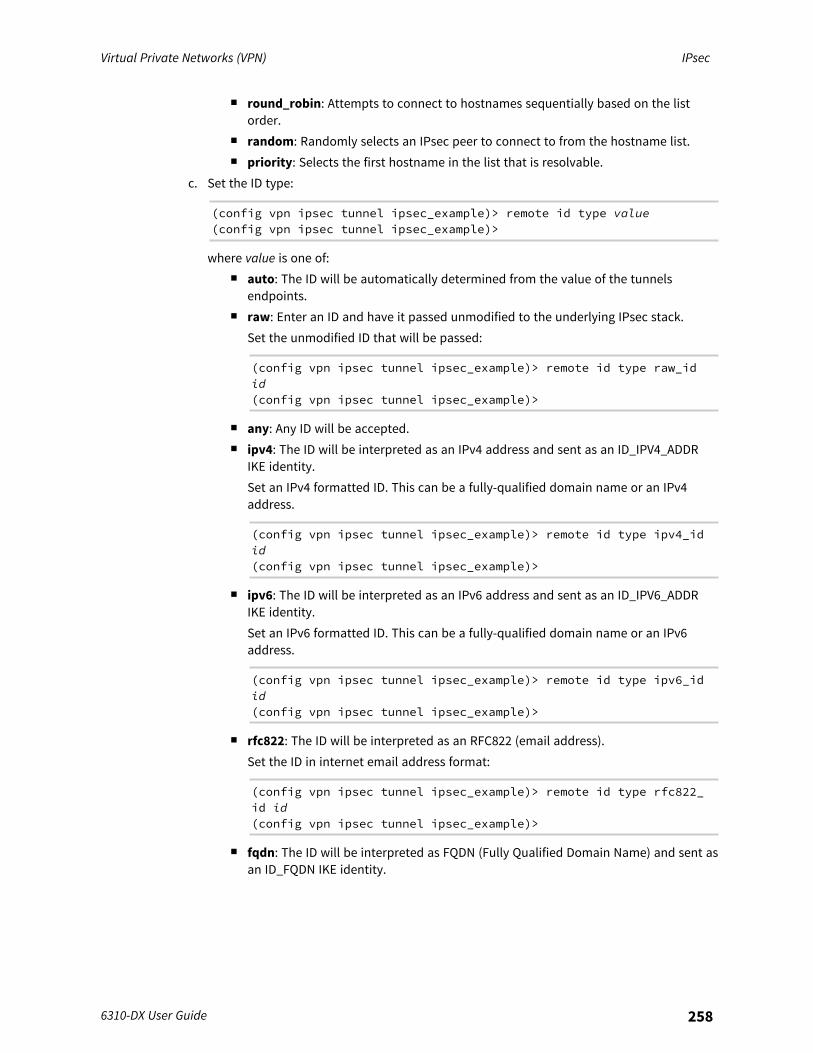
Virtual Private Networks (VPN) IPsec
6310-DX User Guide 258
n round_robin: Attempts to connect to hostnames sequentially based on the listorder.
n random: Randomly selects an IPsec peer to connect to from the hostname list.n priority: Selects the first hostname in the list that is resolvable.
c. Set the ID type:
(config vpn ipsec tunnel ipsec_example)> remote id type value(config vpn ipsec tunnel ipsec_example)>
where value is one of:n auto: The ID will be automatically determined from the value of the tunnels
endpoints.n raw: Enter an ID and have it passed unmodified to the underlying IPsec stack.
Set the unmodified ID that will be passed:
(config vpn ipsec tunnel ipsec_example)> remote id type raw_idid(config vpn ipsec tunnel ipsec_example)>
n any: Any ID will be accepted.n ipv4: The ID will be interpreted as an IPv4 address and sent as an ID_IPV4_ADDR
IKE identity.Set an IPv4 formatted ID. This can be a fully-qualified domain name or an IPv4address.
(config vpn ipsec tunnel ipsec_example)> remote id type ipv4_idid(config vpn ipsec tunnel ipsec_example)>
n ipv6: The ID will be interpreted as an IPv6 address and sent as an ID_IPV6_ADDRIKE identity.Set an IPv6 formatted ID. This can be a fully-qualified domain name or an IPv6address.
(config vpn ipsec tunnel ipsec_example)> remote id type ipv6_idid(config vpn ipsec tunnel ipsec_example)>
n rfc822: The ID will be interpreted as an RFC822 (email address).Set the ID in internet email address format:
(config vpn ipsec tunnel ipsec_example)> remote id type rfc822_id id(config vpn ipsec tunnel ipsec_example)>
n fqdn: The ID will be interpreted as FQDN (Fully Qualified Domain Name) and sent asan ID_FQDN IKE identity.
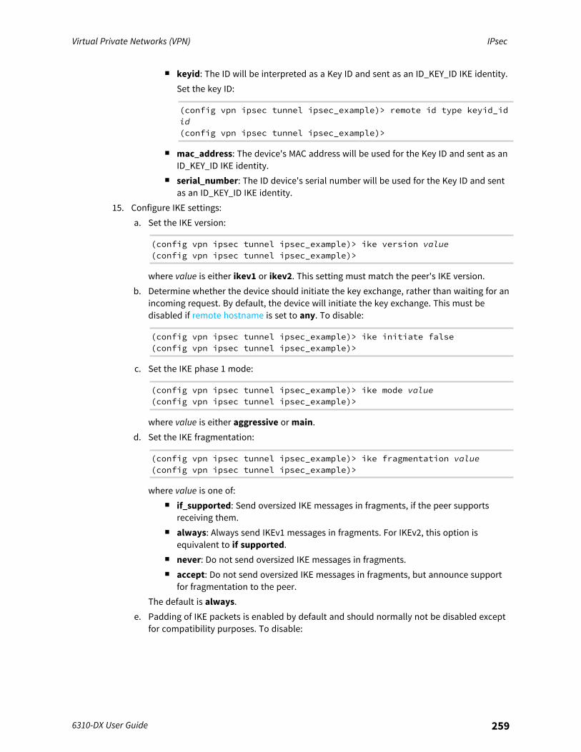
Virtual Private Networks (VPN) IPsec
6310-DX User Guide 259
n keyid: The ID will be interpreted as a Key ID and sent as an ID_KEY_ID IKE identity.Set the key ID:
(config vpn ipsec tunnel ipsec_example)> remote id type keyid_idid(config vpn ipsec tunnel ipsec_example)>
n mac_address: The device's MAC address will be used for the Key ID and sent as anID_KEY_ID IKE identity.
n serial_number: The ID device's serial number will be used for the Key ID and sentas an ID_KEY_ID IKE identity.
15. Configure IKE settings:a. Set the IKE version:
(config vpn ipsec tunnel ipsec_example)> ike version value(config vpn ipsec tunnel ipsec_example)>
where value is either ikev1 or ikev2. This setting must match the peer's IKE version.b. Determine whether the device should initiate the key exchange, rather than waiting for an
incoming request. By default, the device will initiate the key exchange. This must bedisabled if remote hostname is set to any. To disable:
(config vpn ipsec tunnel ipsec_example)> ike initiate false(config vpn ipsec tunnel ipsec_example)>
c. Set the IKE phase 1 mode:
(config vpn ipsec tunnel ipsec_example)> ike mode value(config vpn ipsec tunnel ipsec_example)>
where value is either aggressive or main.d. Set the IKE fragmentation:
(config vpn ipsec tunnel ipsec_example)> ike fragmentation value(config vpn ipsec tunnel ipsec_example)>
where value is one of:n if_supported: Send oversized IKE messages in fragments, if the peer supports
receiving them.n always: Always send IKEv1 messages in fragments. For IKEv2, this option is
equivalent to if supported.n never: Do not send oversized IKE messages in fragments.n accept: Do not send oversized IKE messages in fragments, but announce support
for fragmentation to the peer.The default is always.
e. Padding of IKE packets is enabled by default and should normally not be disabled exceptfor compatibility purposes. To disable:

Virtual Private Networks (VPN) IPsec
6310-DX User Guide 260
(config vpn ipsec tunnel ipsec_example)> ike pad false(config vpn ipsec tunnel ipsec_example)>
f. Set the amount of time that the IKE security association expires after a successfulnegotiation and must be re-authenticated:
(config vpn ipsec tunnel ipsec_example)> ike phase1_lifetime value(config vpn ipsec tunnel ipsec_example)>
where value is any number of weeks, days, hours, minutes, or seconds, and takes theformat number{w|d|h|m|s}.For example, to set phase1_lifetime to ten minutes, enter either 10m or 600s:
(config vpn ipsec tunnel ipsec_example)> ike phase1_lifetime 600s(config vpn ipsec tunnel ipsec_example)>
The default is three hours.g. Set the amount of time that the IKE security association expires after a successful
negotiation and must be rekeyed.
(config vpn ipsec tunnel ipsec_example)> ike phase2_lifetime value(config vpn ipsec tunnel ipsec_example)>
where value is any number of weeks, days, hours, minutes, or seconds, and takes theformat number{w|d|h|m|s}.For example, to set phase2_lifetime to ten minutes, enter either 10m or 600s:
(config vpn ipsec tunnel ipsec_example)> ike phase2_lifetime 600s(config vpn ipsec tunnel ipsec_example)>
The default is one hour.h. Set a randomizing amount of time before the IPsec tunnel is renegotiated:
(config vpn ipsec tunnel ipsec_example)> ike lifetime_margin value(config vpn ipsec tunnel ipsec_example)>
where value is any number of weeks, days, hours, minutes, or seconds, and takes theformat number{w|d|h|m|s}.For example, to set lifetime_margin to ten minutes, enter either 10m or 600s:
(config vpn ipsec tunnel ipsec_example)> ike lifetime_margin 600s(config vpn ipsec tunnel ipsec_example)>
The default is nine minutes.i. Configure the types of encryption, hash, and Diffie-Hellman group to use during phase 1:
i. Add a phase 1 proposal:
(config vpn ipsec tunnel ipsec_example)> add ike phase1_proposalend(config vpn ipsec tunnel ipsec_example ike phase1_proposal 0)>
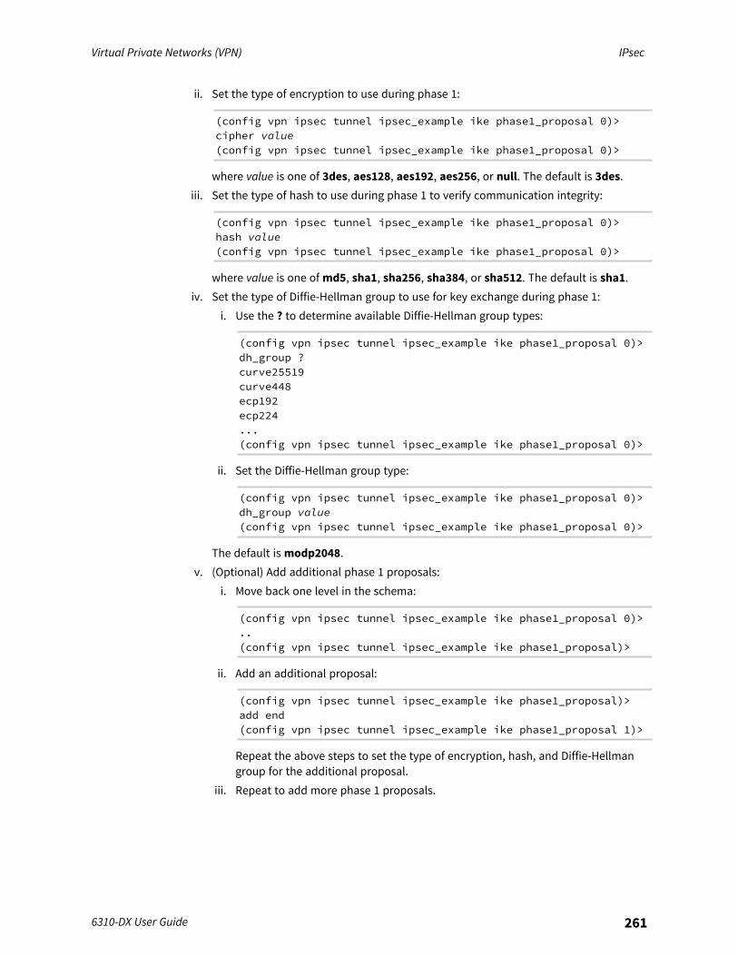
Virtual Private Networks (VPN) IPsec
6310-DX User Guide 261
ii. Set the type of encryption to use during phase 1:
(config vpn ipsec tunnel ipsec_example ike phase1_proposal 0)>cipher value(config vpn ipsec tunnel ipsec_example ike phase1_proposal 0)>
where value is one of 3des, aes128, aes192, aes256, or null. The default is 3des.iii. Set the type of hash to use during phase 1 to verify communication integrity:
(config vpn ipsec tunnel ipsec_example ike phase1_proposal 0)>hash value(config vpn ipsec tunnel ipsec_example ike phase1_proposal 0)>
where value is one of md5, sha1, sha256, sha384, or sha512. The default is sha1.iv. Set the type of Diffie-Hellman group to use for key exchange during phase 1:
i. Use the ? to determine available Diffie-Hellman group types:
(config vpn ipsec tunnel ipsec_example ike phase1_proposal 0)>dh_group ?curve25519curve448ecp192ecp224...(config vpn ipsec tunnel ipsec_example ike phase1_proposal 0)>
ii. Set the Diffie-Hellman group type:
(config vpn ipsec tunnel ipsec_example ike phase1_proposal 0)>dh_group value(config vpn ipsec tunnel ipsec_example ike phase1_proposal 0)>
The default is modp2048.v. (Optional) Add additional phase 1 proposals:
i. Move back one level in the schema:
(config vpn ipsec tunnel ipsec_example ike phase1_proposal 0)>..(config vpn ipsec tunnel ipsec_example ike phase1_proposal)>
ii. Add an additional proposal:
(config vpn ipsec tunnel ipsec_example ike phase1_proposal)>add end(config vpn ipsec tunnel ipsec_example ike phase1_proposal 1)>
Repeat the above steps to set the type of encryption, hash, and Diffie-Hellmangroup for the additional proposal.
iii. Repeat to add more phase 1 proposals.
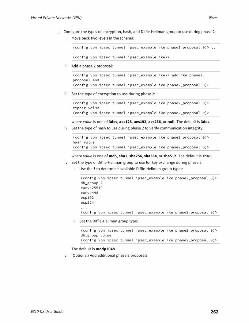
Virtual Private Networks (VPN) IPsec
6310-DX User Guide 262
j. Configure the types of encryption, hash, and Diffie-Hellman group to use during phase 2:i. Move back two levels in the schema:
(config vpn ipsec tunnel ipsec_example ike phase1_proposal 0)> ....(config vpn ipsec tunnel ipsec_example ike)>
ii. Add a phase 2 proposal:
(config vpn ipsec tunnel ipsec_example ike)> add ike phase2_proposal end(config vpn ipsec tunnel ipsec_example ike phase2_proposal 0)>
iii. Set the type of encryption to use during phase 2:
(config vpn ipsec tunnel ipsec_example ike phase2_proposal 0)>cipher value(config vpn ipsec tunnel ipsec_example ike phase2_proposal 0)>
where value is one of 3des, aes128, aes192, aes256, or null. The default is 3des.iv. Set the type of hash to use during phase 2 to verify communication integrity:
(config vpn ipsec tunnel ipsec_example ike phase2_proposal 0)>hash value(config vpn ipsec tunnel ipsec_example ike phase2_proposal 0)>
where value is one of md5, sha1, sha256, sha384, or sha512. The default is sha1.v. Set the type of Diffie-Hellman group to use for key exchange during phase 2:
i. Use the ? to determine available Diffie-Hellman group types:
(config vpn ipsec tunnel ipsec_example ike phase2_proposal 0)>dh_group ?curve25519curve448ecp192ecp224...(config vpn ipsec tunnel ipsec_example ike phase2_proposal 0)>
ii. Set the Diffie-Hellman group type:
(config vpn ipsec tunnel ipsec_example ike phase2_proposal 0)>dh_group value(config vpn ipsec tunnel ipsec_example ike phase2_proposal 0)>
The default is modp2048.vi. (Optional) Add additional phase 2 proposals:
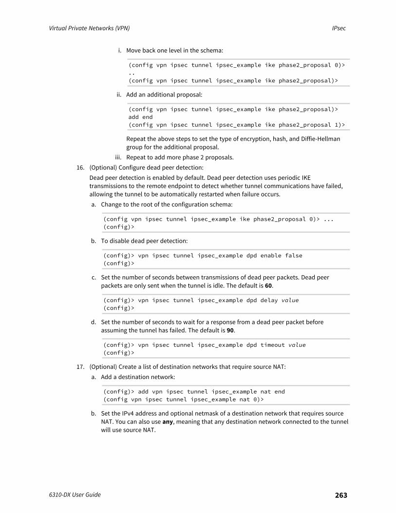
Virtual Private Networks (VPN) IPsec
6310-DX User Guide 263
i. Move back one level in the schema:
(config vpn ipsec tunnel ipsec_example ike phase2_proposal 0)>..(config vpn ipsec tunnel ipsec_example ike phase2_proposal)>
ii. Add an additional proposal:
(config vpn ipsec tunnel ipsec_example ike phase2_proposal)>add end(config vpn ipsec tunnel ipsec_example ike phase2_proposal 1)>
Repeat the above steps to set the type of encryption, hash, and Diffie-Hellmangroup for the additional proposal.
iii. Repeat to add more phase 2 proposals.16. (Optional) Configure dead peer detection:
Dead peer detection is enabled by default. Dead peer detection uses periodic IKEtransmissions to the remote endpoint to detect whether tunnel communications have failed,allowing the tunnel to be automatically restarted when failure occurs.a. Change to the root of the configuration schema:
(config vpn ipsec tunnel ipsec_example ike phase2_proposal 0)> ...(config)>
b. To disable dead peer detection:
(config)> vpn ipsec tunnel ipsec_example dpd enable false(config)>
c. Set the number of seconds between transmissions of dead peer packets. Dead peerpackets are only sent when the tunnel is idle. The default is 60.
(config)> vpn ipsec tunnel ipsec_example dpd delay value(config)>
d. Set the number of seconds to wait for a response from a dead peer packet beforeassuming the tunnel has failed. The default is 90.
(config)> vpn ipsec tunnel ipsec_example dpd timeout value(config)>
17. (Optional) Create a list of destination networks that require source NAT:a. Add a destination network:
(config)> add vpn ipsec tunnel ipsec_example nat end(config vpn ipsec tunnel ipsec_example nat 0)>
b. Set the IPv4 address and optional netmask of a destination network that requires sourceNAT. You can also use any, meaning that any destination network connected to the tunnelwill use source NAT.
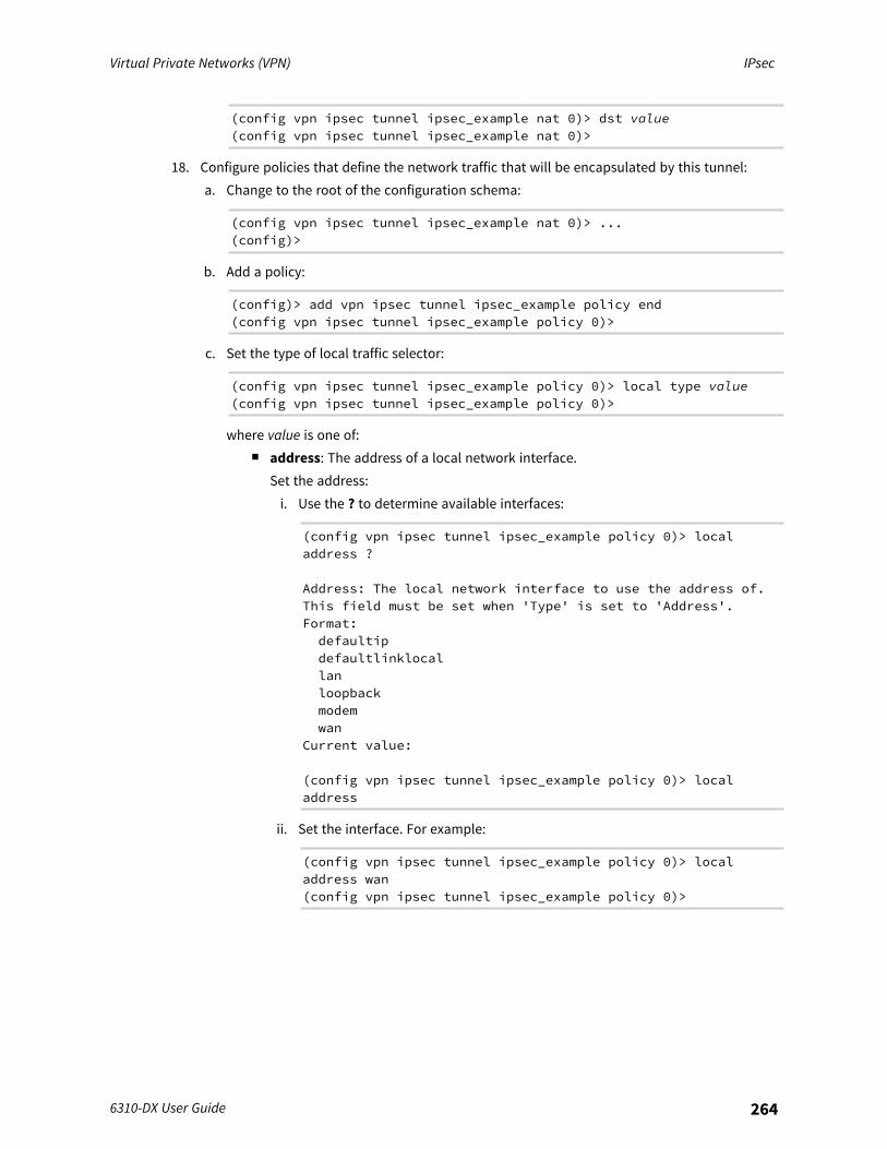
Virtual Private Networks (VPN) IPsec
6310-DX User Guide 264
(config vpn ipsec tunnel ipsec_example nat 0)> dst value(config vpn ipsec tunnel ipsec_example nat 0)>
18. Configure policies that define the network traffic that will be encapsulated by this tunnel:a. Change to the root of the configuration schema:
(config vpn ipsec tunnel ipsec_example nat 0)> ...(config)>
b. Add a policy:
(config)> add vpn ipsec tunnel ipsec_example policy end(config vpn ipsec tunnel ipsec_example policy 0)>
c. Set the type of local traffic selector:
(config vpn ipsec tunnel ipsec_example policy 0)> local type value(config vpn ipsec tunnel ipsec_example policy 0)>
where value is one of:n address: The address of a local network interface.
Set the address:i. Use the ? to determine available interfaces:
(config vpn ipsec tunnel ipsec_example policy 0)> localaddress ?
Address: The local network interface to use the address of.This field must be set when 'Type' is set to 'Address'.Format:defaultipdefaultlinklocallanloopbackmodemwan
Current value:
(config vpn ipsec tunnel ipsec_example policy 0)> localaddress
ii. Set the interface. For example:
(config vpn ipsec tunnel ipsec_example policy 0)> localaddress wan(config vpn ipsec tunnel ipsec_example policy 0)>
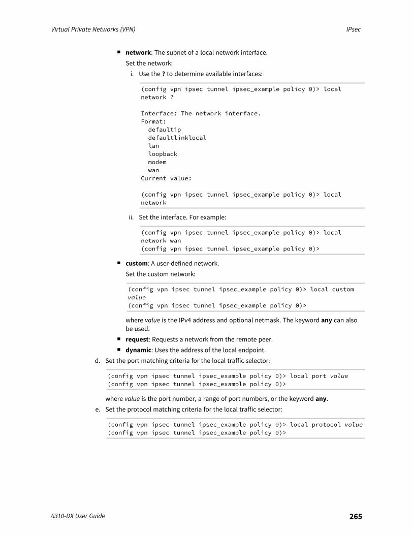
Virtual Private Networks (VPN) IPsec
6310-DX User Guide 265
n network: The subnet of a local network interface.Set the network:i. Use the ? to determine available interfaces:
(config vpn ipsec tunnel ipsec_example policy 0)> localnetwork ?
Interface: The network interface.Format:defaultipdefaultlinklocallanloopbackmodemwan
Current value:
(config vpn ipsec tunnel ipsec_example policy 0)> localnetwork
ii. Set the interface. For example:
(config vpn ipsec tunnel ipsec_example policy 0)> localnetwork wan(config vpn ipsec tunnel ipsec_example policy 0)>
n custom: A user-defined network.Set the custom network:
(config vpn ipsec tunnel ipsec_example policy 0)> local customvalue(config vpn ipsec tunnel ipsec_example policy 0)>
where value is the IPv4 address and optional netmask. The keyword any can alsobe used.
n request: Requests a network from the remote peer.n dynamic: Uses the address of the local endpoint.
d. Set the port matching criteria for the local traffic selector:
(config vpn ipsec tunnel ipsec_example policy 0)> local port value(config vpn ipsec tunnel ipsec_example policy 0)>
where value is the port number, a range of port numbers, or the keyword any.e. Set the protocol matching criteria for the local traffic selector:
(config vpn ipsec tunnel ipsec_example policy 0)> local protocol value(config vpn ipsec tunnel ipsec_example policy 0)>
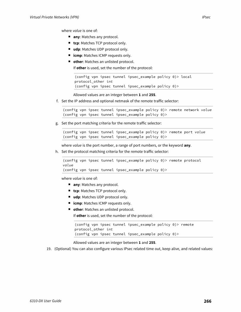
Virtual Private Networks (VPN) IPsec
6310-DX User Guide 266
where value is one of:n any: Matches any protocol.n tcp: Matches TCP protocol only.n udp: Matches UDP protocol only.n icmp: Matches ICMP requests only.n other: Matches an unlisted protocol.
If other is used, set the number of the protocol:
(config vpn ipsec tunnel ipsec_example policy 0)> localprotocol_other int(config vpn ipsec tunnel ipsec_example policy 0)>
Allowed values are an integer between 1 and 255.f. Set the IP address and optional netmask of the remote traffic selector:
(config vpn ipsec tunnel ipsec_example policy 0)> remote network value(config vpn ipsec tunnel ipsec_example policy 0)>
g. Set the port matching criteria for the remote traffic selector:
(config vpn ipsec tunnel ipsec_example policy 0)> remote port value(config vpn ipsec tunnel ipsec_example policy 0)>
where value is the port number, a range of port numbers, or the keyword any.h. Set the protocol matching criteria for the remote traffic selector:
(config vpn ipsec tunnel ipsec_example policy 0)> remote protocolvalue(config vpn ipsec tunnel ipsec_example policy 0)>
where value is one of:n any: Matches any protocol.n tcp: Matches TCP protocol only.n udp: Matches UDP protocol only.n icmp: Matches ICMP requests only.n other: Matches an unlisted protocol.
If other is used, set the number of the protocol:
(config vpn ipsec tunnel ipsec_example policy 0)> remoteprotocol_other int(config vpn ipsec tunnel ipsec_example policy 0)>
Allowed values are an integer between 1 and 255.19. (Optional) You can also configure various IPsec related time out, keep alive, and related values:
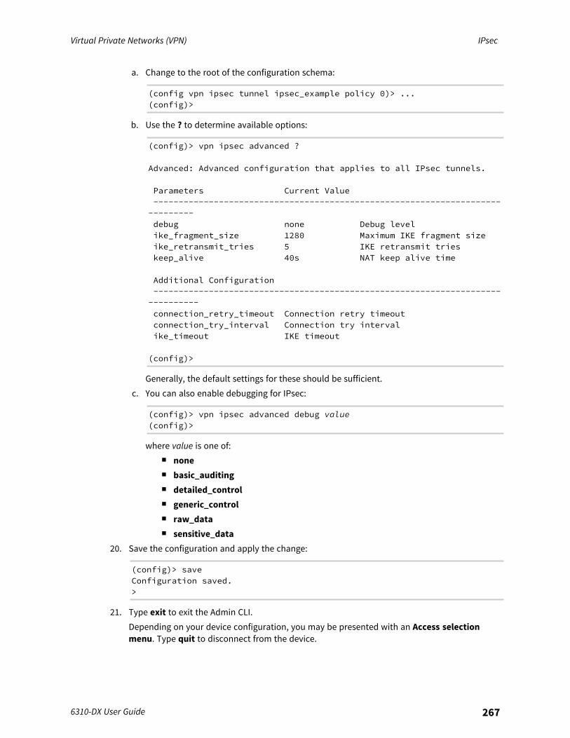
Virtual Private Networks (VPN) IPsec
6310-DX User Guide 267
a. Change to the root of the configuration schema:
(config vpn ipsec tunnel ipsec_example policy 0)> ...(config)>
b. Use the ? to determine available options:
(config)> vpn ipsec advanced ?
Advanced: Advanced configuration that applies to all IPsec tunnels.
Parameters Current Value------------------------------------------------------------------------------debug none Debug levelike_fragment_size 1280 Maximum IKE fragment sizeike_retransmit_tries 5 IKE retransmit trieskeep_alive 40s NAT keep alive time
Additional Configuration-------------------------------------------------------------------------------connection_retry_timeout Connection retry timeoutconnection_try_interval Connection try intervalike_timeout IKE timeout
(config)>
Generally, the default settings for these should be sufficient.c. You can also enable debugging for IPsec:
(config)> vpn ipsec advanced debug value(config)>
where value is one of:n nonen basic_auditingn detailed_controln generic_controln raw_datan sensitive_data
20. Save the configuration and apply the change:
(config)> saveConfiguration saved.>
21. Type exit to exit the Admin CLI.Depending on your device configuration, you may be presented with an Access selectionmenu. Type quit to disconnect from the device.
Virtual Private Networks (VPN) IPsec
6310-DX User Guide 268
Configure IPsec failoverThere are two methods to configure the 6310-DX device to fail over from a primary IPsec tunnel to abackup tunnel:
n SureLink active recovery—You can use SureLink along with the IPsec tunnel's metric toconfigure two or more tunnels so that when the primary tunnel is determined to be inactive bySureLink, a secondary tunnel can begin serving traffic that the primary tunnel was serving.
n Preferred tunnel—When multiple IPsec tunnels are configured, one tunnel can be configuredas a backup to another tunnel by defining a preferred tunnel for the backup device.
Required configuration items
n Two or more configured IPsec tunnels: The primary tunnel, and one or more backup tunnels.n Either:
l SureLink configured on the primary tunnel with Restart Interface enabled, and the metricfor all tunnels set appropriately to determine which IPsec tunnel has priority. With thisfailover configuration, both tunnels are active simultaneously, and there is minimaldowntime due to failover.
l Identify the preferred tunnel during configuration of the backup tunnel. In this scenario,the backup tunnel is not active until the preferred tunnel fails.
IPsec failover using SureLinkWith this configuration, when two IPsec tunnels are configured with the same local and remoteendpoints but different metrics, traffic addressed to the remote endpoint will be routed through theIPsec tunnel with the lower metric.If SureLink > Restart Interface is enabled for the tunnel with the lower metric, and SureLinkdetermines that the tunnel is not functioning properly (for example, pings to a host at the other endof the tunnel are failing), then:
1. SureLink will shut down the tunnel and renegotiate its IPsec connection.2. While the tunnel with the lower metric is down, traffic addressed to the remote endpoint will
be routed through the tunnel with the higher metric.
For example:
n Tunnel_1:l Metric: 10l Local endpoint > Interface: LANl Remote endpoint > Hostname: 192.168.10.1l SureLink configuration:
o Restart Interface enabledo Test target:
o Test type: Ping testo Ping host: 192.168.10.2
n Tunnel_2:
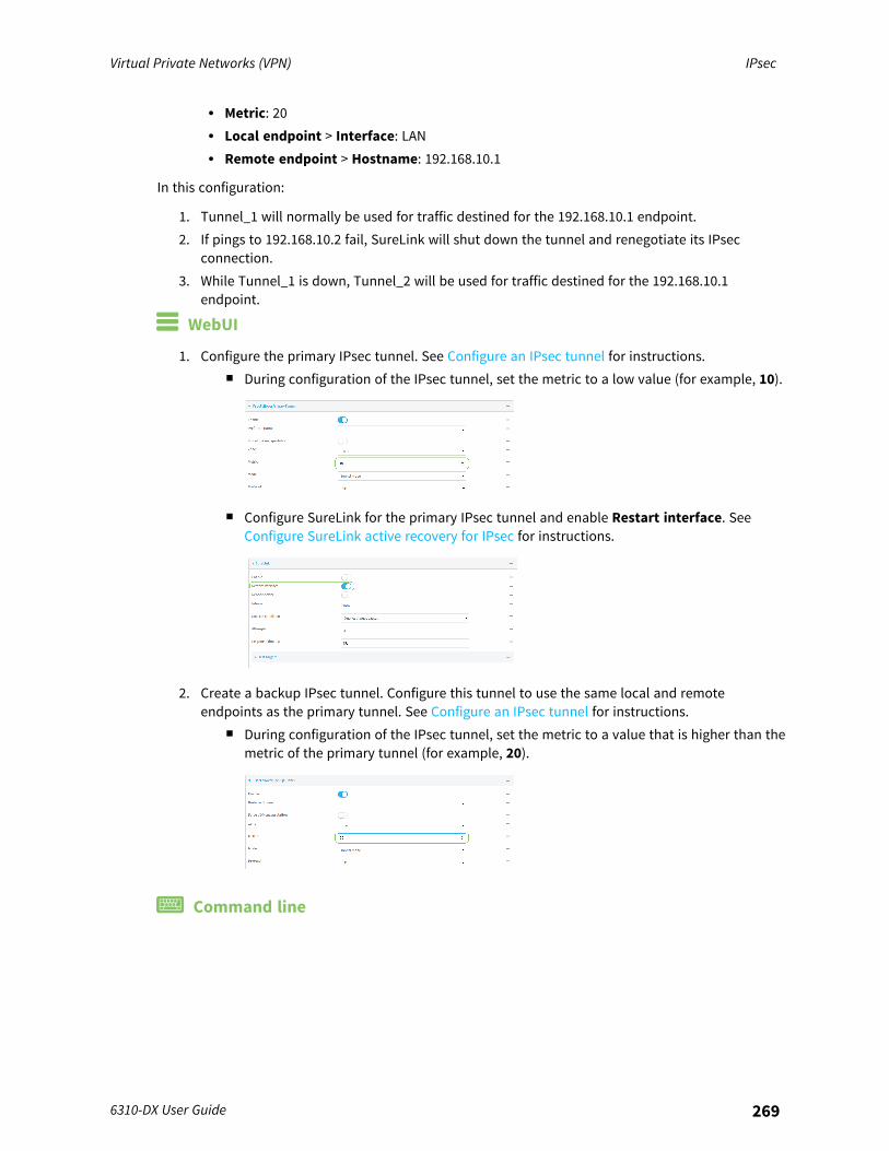
Virtual Private Networks (VPN) IPsec
6310-DX User Guide 269
l Metric: 20l Local endpoint > Interface: LANl Remote endpoint > Hostname: 192.168.10.1
In this configuration:
1. Tunnel_1 will normally be used for traffic destined for the 192.168.10.1 endpoint.2. If pings to 192.168.10.2 fail, SureLink will shut down the tunnel and renegotiate its IPsec
connection.3. While Tunnel_1 is down, Tunnel_2 will be used for traffic destined for the 192.168.10.1
endpoint.
WebUI
1. Configure the primary IPsec tunnel. See Configure an IPsec tunnel for instructions.n During configuration of the IPsec tunnel, set the metric to a low value (for example, 10).
n Configure SureLink for the primary IPsec tunnel and enable Restart interface. SeeConfigure SureLink active recovery for IPsec for instructions.
2. Create a backup IPsec tunnel. Configure this tunnel to use the same local and remoteendpoints as the primary tunnel. See Configure an IPsec tunnel for instructions.
n During configuration of the IPsec tunnel, set the metric to a value that is higher than themetric of the primary tunnel (for example, 20).
Command line
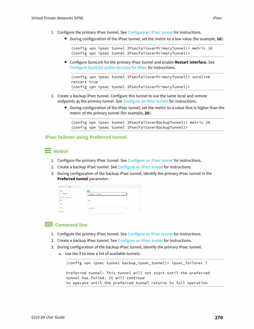
Virtual Private Networks (VPN) IPsec
6310-DX User Guide 270
1. Configure the primary IPsec tunnel. See Configure an IPsec tunnel for instructions.n During configuration of the IPsec tunnel, set the metric to a low value (for example, 10):
(config vpn ipsec tunnel IPsecFailoverPrimaryTunnel)> metric 10(config vpn ipsec tunnel IPsecFailoverPrimaryTunnel)>
n Configure SureLink for the primary IPsec tunnel and enable Restart interface. SeeConfigure SureLink active recovery for IPsec for instructions.
(config vpn ipsec tunnel IPsecFailoverPrimaryTunnel)> surelinkrestart true(config vpn ipsec tunnel IPsecFailoverPrimaryTunnel)>
2. Create a backup IPsec tunnel. Configure this tunnel to use the same local and remoteendpoints as the primary tunnel. See Configure an IPsec tunnel for instructions.
n During configuration of the IPsec tunnel, set the metric to a value that is higher than themetric of the primary tunnel (for example, 20):
(config vpn ipsec tunnel IPsecFailoverBackupTunnel)> metric 20(config vpn ipsec tunnel IPsecFailoverBackupTunnel)>
IPsec failover using Preferred tunnel
WebUI
1. Configure the primary IPsec tunnel. See Configure an IPsec tunnel for instructions.2. Create a backup IPsec tunnel. See Configure an IPsec tunnel for instructions.3. During configuration of the backup IPsec tunnel, identify the primary IPsec tunnel in the
Preferred tunnel parameter:
Command line
1. Configure the primary IPsec tunnel. See Configure an IPsec tunnel for instructions.2. Create a backup IPsec tunnel. See Configure an IPsec tunnel for instructions.3. During configuration of the backup IPsec tunnel, identify the primary IPsec tunnel:
a. Use the ? to view a list of available tunnels:
(config vpn ipsec tunnel backup_ipsec_tunnel)> ipsec_failover ?
Preferred tunnel: This tunnel will not start until the preferredtunnel has failed. It will continueto operate until the preferred tunnel returns to full operation
Virtual Private Networks (VPN) IPsec
6310-DX User Guide 271
status.Format:primary_ipsec_tunnelbackup_ipsec_tunnelOptional: yesCurrent value:
(config vpn ipsec tunnel backup_ipsec_tunnel)> ipsec_failover
b. Set the primary IPsec tunnel:
(config vpn ipsec tunnel backup_ipsec_tunnel)> ipsec_failover primary_ipsec_tunnel(config vpn ipsec tunnel backup_ipsec_tunnel)>
Configure SureLink active recovery for IPsecYou can configure the 6310-DX device to regularly probe IPsec tunnels to determine if the connectionhas failed and take remedial action.You can also configure the IPsec tunnel to fail over to a backup tunnel. See Configure IPsec failover forfurther information.
Required configuration items
n A valid IPsec configuration. See Configure an IPsec tunnel for configuration instructions.n Enable IPsec active recovery.n The behavior of the 6310-DX device upon IPsec failure: either
l Restart the IPsec interfacel Reboot the device.
Additional configuration items
n The interval between connectivity tests.n Whether the interface should be considered to have failed if one of the test targets fails, or all
of the test targets fail.n The number of probe attempts before the IPsec connection is considered to have failed.n The amount of time that the device should wait for a response to a probe attempt before
considering it to have failed.
To configure the 6310-DX device to regularly probe the IPsec connection:
WebUI
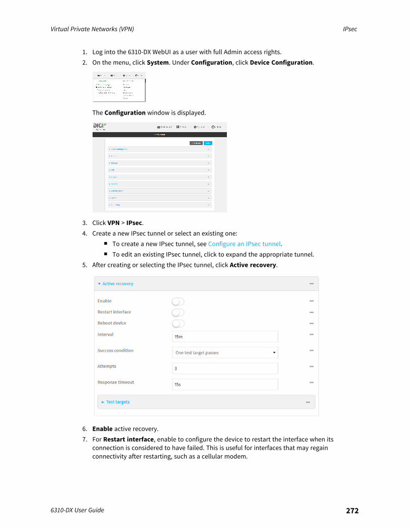
Virtual Private Networks (VPN) IPsec
6310-DX User Guide 272
1. Log into the 6310-DX WebUI as a user with full Admin access rights.2. On the menu, click System. Under Configuration, click Device Configuration.
The Configuration window is displayed.
3. Click VPN > IPsec.4. Create a new IPsec tunnel or select an existing one:
n To create a new IPsec tunnel, see Configure an IPsec tunnel.n To edit an existing IPsec tunnel, click to expand the appropriate tunnel.
5. After creating or selecting the IPsec tunnel, click Active recovery.
6. Enable active recovery.7. For Restart interface, enable to configure the device to restart the interface when its
connection is considered to have failed. This is useful for interfaces that may regainconnectivity after restarting, such as a cellular modem.
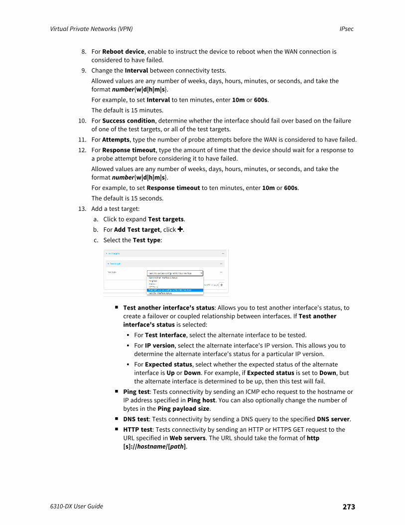
Virtual Private Networks (VPN) IPsec
6310-DX User Guide 273
8. For Reboot device, enable to instruct the device to reboot when the WAN connection isconsidered to have failed.
9. Change the Interval between connectivity tests.Allowed values are any number of weeks, days, hours, minutes, or seconds, and take theformat number{w|d|h|m|s}.For example, to set Interval to ten minutes, enter 10m or 600s.The default is 15 minutes.
10. For Success condition, determine whether the interface should fail over based on the failureof one of the test targets, or all of the test targets.
11. For Attempts, type the number of probe attempts before the WAN is considered to have failed.12. For Response timeout, type the amount of time that the device should wait for a response to
a probe attempt before considering it to have failed.Allowed values are any number of weeks, days, hours, minutes, or seconds, and take theformat number{w|d|h|m|s}.For example, to set Response timeout to ten minutes, enter 10m or 600s.The default is 15 seconds.
13. Add a test target:a. Click to expand Test targets.b. For Add Test target, click .c. Select the Test type:
n Test another interface's status: Allows you to test another interface's status, tocreate a failover or coupled relationship between interfaces. If Test anotherinterface's status is selected:l For Test Interface, select the alternate interface to be tested.l For IP version, select the alternate interface's IP version. This allows you to
determine the alternate interface's status for a particular IP version.l For Expected status, select whether the expected status of the alternate
interface is Up or Down. For example, if Expected status is set to Down, butthe alternate interface is determined to be up, then this test will fail.
n Ping test: Tests connectivity by sending an ICMP echo request to the hostname orIP address specified in Ping host. You can also optionally change the number ofbytes in the Ping payload size.
n DNS test: Tests connectivity by sending a DNS query to the specified DNS server.n HTTP test: Tests connectivity by sending an HTTP or HTTPS GET request to the
URL specified in Web servers. The URL should take the format of http[s]://hostname/[path].
Virtual Private Networks (VPN) IPsec
6310-DX User Guide 274
n Test DNS servers configured for this interface: Tests connectivity by sending aDNS query to the DNS servers configured for this interface.
n Test the interface status: The interface is considered to be down based on:l Down time: The amount of time that the interface can be down before this test
is considered to have failed.Allowed values are any number of weeks, days, hours, minutes, or seconds, andtake the format number{w|d|h|m|s}.For example, to set Down time to ten minutes, enter 10m or 600s.The default is 60 seconds.
l Initial connection time: The amount of time to wait for an initial connection tothe interface before this test is considered to have failed.Allowed values are any number of weeks, days, hours, minutes, or seconds, andtake the format number{w|d|h|m|s}.For example, to set Initial connection time to ten minutes, enter 10m or 600s.The default is 60 seconds.
14. Click Apply to save the configuration and apply the change.
Command line
1. Log into the 6310-DX command line as a user with full Admin access rights.Depending on your device configuration, you may be presented with an Access selectionmenu. Type admin to access the Admin CLI.
2. At the command line, type config to enter configuration mode:
> config(config)>
3. Create a new IPsec tunnel, or edit an existing one:n To create a new IPsec tunnel, see Configure an IPsec tunnel.n To edit an existing IPsec tunnel, change to the IPsec tunnel's node in the configuration
schema. For example, for an IPsec tunnel named ipsec_example, change to the ipsec_example node in the configuration schema:
(config)> vpn ipsec tunnel ipsec_example(config vpn ipsec tunnel ipsec_example)>
4. Enable active recovery:
(config vpn ipsec tunnel ipsec_example)> surelink enable true(config vpn ipsec tunnel ipsec_example)>
Virtual Private Networks (VPN) IPsec
6310-DX User Guide 275
5. To configure the device to restart the interface when its connection is considered to havefailed:
(config vpn ipsec tunnel ipsec_example)> surelink restart true(config vpn ipsec tunnel ipsec_example)>
This is useful for interfaces that may regain connectivity after restarting, such as a cellularmodem.
6. To configure the device to reboot when the interface is considered to have failed:
(config vpn ipsec tunnel ipsec_example)> surelink reboot enable(config vpn ipsec tunnel ipsec_example)>
7. Set the Interval between connectivity tests:
(config vpn ipsec tunnel ipsec_example)> surelink interval value(config vpn ipsec tunnel ipsec_example)>
where value is any number of weeks, days, hours, minutes, or seconds, and takes the formatnumber{w|d|h|m|s}.For example, to set interval to ten minutes, enter either 10m or 600s:
(config vpn ipsec tunnel ipsec_example)> surelink interval 600s(config vpn ipsec tunnel ipsec_example)>
The default is 15 minutes.8. Determine whether the interface should fail over based on the failure of one of the test targets,
or all of the test targets:
(config vpn ipsec tunnel ipsec_example)> surelink success_condition value(config vpn ipsec tunnel ipsec_example)>
Where value is either one or all.9. Set the number of probe attempts before the WAN is considered to have failed:
(config vpn ipsec tunnel ipsec_example)> surelink attempts num(config vpn ipsec tunnel ipsec_example)>
The default is 3.10. Set the amount of time that the device should wait for a response to a probe attempt before
considering it to have failed:
(config vpn ipsec tunnel ipsec_example)> surelink timeout value(config vpn ipsec tunnel ipsec_example)>
where value is any number of weeks, days, hours, minutes, or seconds, and takes the formatnumber{w|d|h|m|s}.For example, to set timeout to ten minutes, enter either 10m or 600s:
(config vpn ipsec tunnel ipsec_example)> surelink timeout 600s(config vpn ipsec tunnel ipsec_example)>
Virtual Private Networks (VPN) IPsec
6310-DX User Guide 276
The default is 15 seconds.11. Configure test targets:
a. Add a test target:
(config vpn ipsec tunnel ipsec_example)> add surelink target end(config vpn ipsec tunnel ipsec_example surelink target 0)>
b. Set the test type:
(config vpn ipsec tunnel ipsec_example surelink target 0)> test value(config vpn ipsec tunnel ipsec_example surelink target 0)>
where value is one of:n ping: Tests connectivity by sending an ICMP echo request to a specified hostname
or IP address.l Specify the hostname or IP address:
(config vpn ipsec tunnel ipsec_example surelink target 0)>ping_host host(config vpn ipsec tunnel ipsec_example surelink target 0)>
l (Optional) Set the size, in bytes, of the ping packet:
(config vpn ipsec tunnel ipsec_example surelink target 0)>ping_size [num](config vpn ipsec tunnel ipsec_example surelink target 0)>
n dns: Tests connectivity by sending a DNS query to the specified DNS server.l Specify the DNS server. Allowed value is the IP address of the DNS server.
(config vpn ipsec tunnel ipsec_example surelink target 0)>dns_server ip_address(config vpn ipsec tunnel ipsec_example surelink target 0)>
n dns_configured: Tests connectivity by sending a DNS query to the DNS serversconfigured for this interface.
n http: Tests connectivity by sending an HTTP or HTTPS GET request to the specifiedURL.l Specify the url:
(config vpn ipsec tunnel ipsec_example surelink target 0)>http_url value(config vpn ipsec tunnel ipsec_example surelink target 0)>
where value uses the format http[s]://hostname/[path]n interface_up: The interface is considered to be down based on the interfaces down
time, and the amount of time an initial connection to the interface takes before thistest is considered to have failed.l (Optional) Set the amount of time that the interface can be down before this
test is considered to have failed:
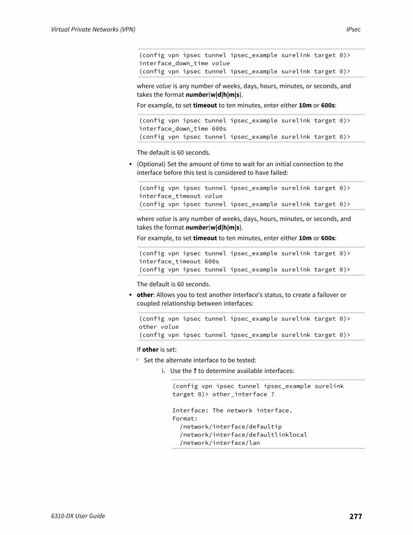
Virtual Private Networks (VPN) IPsec
6310-DX User Guide 277
(config vpn ipsec tunnel ipsec_example surelink target 0)>interface_down_time value(config vpn ipsec tunnel ipsec_example surelink target 0)>
where value is any number of weeks, days, hours, minutes, or seconds, andtakes the format number{w|d|h|m|s}.For example, to set timeout to ten minutes, enter either 10m or 600s:
(config vpn ipsec tunnel ipsec_example surelink target 0)>interface_down_time 600s(config vpn ipsec tunnel ipsec_example surelink target 0)>
The default is 60 seconds.l (Optional) Set the amount of time to wait for an initial connection to the
interface before this test is considered to have failed:
(config vpn ipsec tunnel ipsec_example surelink target 0)>interface_timeout value(config vpn ipsec tunnel ipsec_example surelink target 0)>
where value is any number of weeks, days, hours, minutes, or seconds, andtakes the format number{w|d|h|m|s}.For example, to set timeout to ten minutes, enter either 10m or 600s:
(config vpn ipsec tunnel ipsec_example surelink target 0)>interface_timeout 600s(config vpn ipsec tunnel ipsec_example surelink target 0)>
The default is 60 seconds.l other: Allows you to test another interface's status, to create a failover or
coupled relationship between interfaces:
(config vpn ipsec tunnel ipsec_example surelink target 0)>other value(config vpn ipsec tunnel ipsec_example surelink target 0)>
If other is set:o Set the alternate interface to be tested:
i. Use the ? to determine available interfaces:
(config vpn ipsec tunnel ipsec_example surelinktarget 0)> other_interface ?
Interface: The network interface.Format:/network/interface/defaultip/network/interface/defaultlinklocal/network/interface/lan

Virtual Private Networks (VPN) IPsec
6310-DX User Guide 278
/network/interface/loopback/network/interface/modem/network/interface/wan
Current value:
(config vpn ipsec tunnel ipsec_example surelinktarget 0)> other_interface
ii. Set the interface. For example:
(config vpn ipsec tunnel ipsec_example surelinktarget 0)> other_interface /network/interface/wan(config vpn ipsec tunnel ipsec_example surelinktarget 0)>
o Set the alternate interface's IP version. This allows you to determine thealternate interface's status for a particular IP version.
(config vpn ipsec tunnel ipsec_example surelink target 0)>other_ip_version value(config vpn ipsec tunnel ipsec_example surelink target 0)>
where value is one of: any, both, ipv4, or ipv6.o Set the expected status of the alternate interface:
(config vpn ipsec tunnel ipsec_example surelink target 0)>other_status value(config vpn ipsec tunnel ipsec_example surelink target 0)>
where value is either up or down. For example, if other_status is set todown, but the alternate interface is determined to be up, then this test willfail.
12. Save the configuration and apply the change:
(config vpn ipsec tunnel ipsec_example connection_monitor target 0)> saveConfiguration saved.>
13. Type exit to exit the Admin CLI.Depending on your device configuration, you may be presented with an Access selectionmenu. Type quit to disconnect from the device.
Show IPsec status and statistics
WebUI
1. Log into the 6310-DX WebUI as a user with Admin access.2. On the menu, select Status > IPsec.
The IPsec page appears.
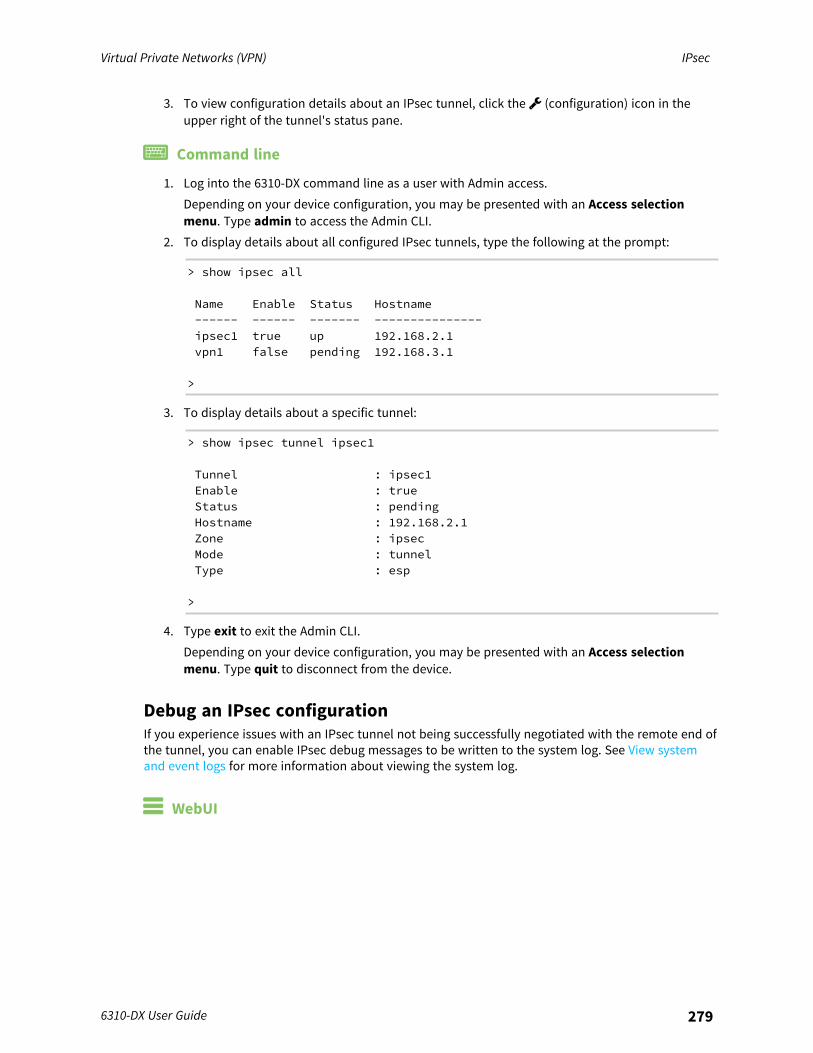
Virtual Private Networks (VPN) IPsec
6310-DX User Guide 279
3. To view configuration details about an IPsec tunnel, click the (configuration) icon in theupper right of the tunnel's status pane.
Command line
1. Log into the 6310-DX command line as a user with Admin access.Depending on your device configuration, you may be presented with an Access selectionmenu. Type admin to access the Admin CLI.
2. To display details about all configured IPsec tunnels, type the following at the prompt:
> show ipsec all
Name Enable Status Hostname------ ------ ------- ---------------ipsec1 true up 192.168.2.1vpn1 false pending 192.168.3.1
>
3. To display details about a specific tunnel:
> show ipsec tunnel ipsec1
Tunnel : ipsec1Enable : trueStatus : pendingHostname : 192.168.2.1Zone : ipsecMode : tunnelType : esp
>
4. Type exit to exit the Admin CLI.Depending on your device configuration, you may be presented with an Access selectionmenu. Type quit to disconnect from the device.
Debug an IPsec configurationIf you experience issues with an IPsec tunnel not being successfully negotiated with the remote end ofthe tunnel, you can enable IPsec debug messages to be written to the system log. See View systemand event logs for more information about viewing the system log.
WebUI

Virtual Private Networks (VPN) IPsec
6310-DX User Guide 280
1. Log into the 6310-DX WebUI as a user with full Admin access rights.2. On the menu, click System. Under Configuration, click Device Configuration.
The Configuration window is displayed.
3. Click VPN > IPsec.4. Click to expand Advanced.5. For Debug level, select one of the following:
n Disable debug messages.n Basic auditing debug: Logs basic auditing information, (for example, SA up/SA down).n Generic control flow : Select this for basic debugging information.n Detailed control flow : More detailed debugging control flow.n Raw data: Includes raw data dumps in hexadecimal format.n Sensitive material: Also includes sensitive material in dumps (for example, encryption
keys).6. Click Apply to save the configuration and apply the change.
Command line
1. Log into the 6310-DX command line as a user with full Admin access rights.Depending on your device configuration, you may be presented with an Access selectionmenu. Type admin to access the Admin CLI.
2. At the command line, type config to enter configuration mode:
> config(config)>

Virtual Private Networks (VPN) IPsec
6310-DX User Guide 281
3. Set the IPsec debug value:
config> vpn ipsec advanced debug valueconfig>
where value is one of:n none. (Default) No debug messages are written.n basic_auditing: Logs basic auditing information, (for example, SA up/SA down).n generic_control: Select this for basic debugging information.n detailed_control: More detailed debugging control flow.n raw_data: Includes raw data dumps in hexadecimal format.n sensitive_data: Also includes sensitive material in dumps (for example, encryption
keys).4. Save the configuration and apply the change:
(config)> saveConfiguration saved.>
5. Type exit to exit the Admin CLI.Depending on your device configuration, you may be presented with an Access selectionmenu. Type quit to disconnect from the device.
Configure a Simple Certificate Enrollment Protocol clientSimple Certificate Enrollment Protocol (SCEP) is a mechanism that allows for large-scale X.509certificate deployment. You can configure 6310-DX device to function as a SCEP client that willconnect to a SCEP server that is used to sign Certificate Signing Requests (CSRs), provide CertificateRevocation Lists (CRLs), and distribute valid certificates from a Certificate Authority (CA).
Required configuration
n Enable the SCEP client.n The fully-qualified domain name of the SCEP server to be used for certificate requests.n The challenge password provided by the SCEP server that the SCEP client will use when
making SCEP requests.n The distinguished name to be used for the CSR.n The file name of the Certificate Revocation List (CRL) from the Certificate Authority (CA).
Additional configuration
n The number of days that the certificate enrollment can be renewed, prior to the requestexpiring.
WebUI

Virtual Private Networks (VPN) IPsec
6310-DX User Guide 282
1. Log into the 6310-DX WebUI as a user with full Admin access rights.2. On the menu, click System. Under Configuration, click Device Configuration.
The Configuration window is displayed.
3. Click Network > SCEP Client.4. For Add clients, enter a name for the SCEP client and click .
The new SCEP client configuration is displayed.
5. Click Enable to enable the SCEP client.6. For Renewable Time, type the number of days that the certificate enrollment can be renewed,
prior to the request expiring. This value is configured on the SCEP server, and is used by the6310-DX device to determine when to start attempting to auto-renew an existing certificate.The default is 7.
7. (Optional) For CRL file name, type the filename of the Certificate Revocation List (CRL) from theCA.The CRL is stored on the 6310-DX device in the /etc/config/scep_client/client_name directory.
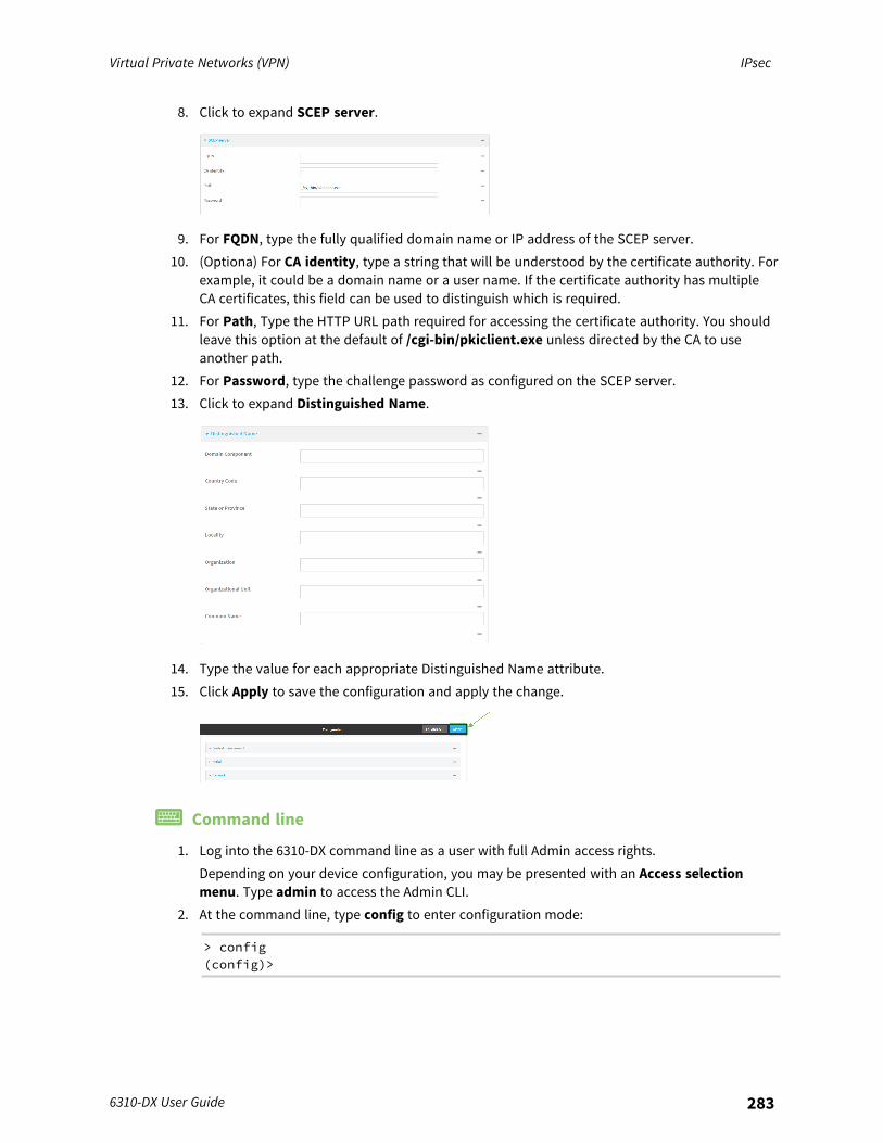
Virtual Private Networks (VPN) IPsec
6310-DX User Guide 283
8. Click to expand SCEP server.
9. For FQDN, type the fully qualified domain name or IP address of the SCEP server.10. (Optiona) For CA identity, type a string that will be understood by the certificate authority. For
example, it could be a domain name or a user name. If the certificate authority has multipleCA certificates, this field can be used to distinguish which is required.
11. For Path, Type the HTTP URL path required for accessing the certificate authority. You shouldleave this option at the default of /cgi-bin/pkiclient.exe unless directed by the CA to useanother path.
12. For Password, type the challenge password as configured on the SCEP server.13. Click to expand Distinguished Name.
14. Type the value for each appropriate Distinguished Name attribute.15. Click Apply to save the configuration and apply the change.
Command line
1. Log into the 6310-DX command line as a user with full Admin access rights.Depending on your device configuration, you may be presented with an Access selectionmenu. Type admin to access the Admin CLI.
2. At the command line, type config to enter configuration mode:
> config(config)>
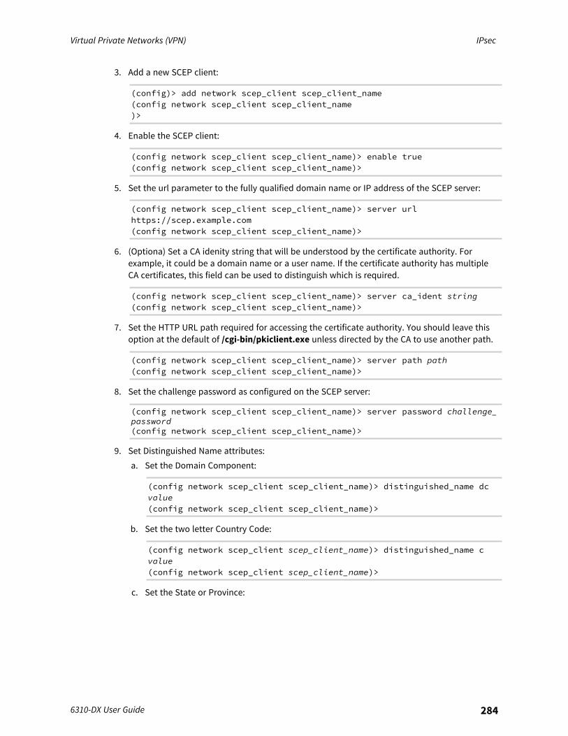
Virtual Private Networks (VPN) IPsec
6310-DX User Guide 284
3. Add a new SCEP client:
(config)> add network scep_client scep_client_name(config network scep_client scep_client_name)>
4. Enable the SCEP client:
(config network scep_client scep_client_name)> enable true(config network scep_client scep_client_name)>
5. Set the url parameter to the fully qualified domain name or IP address of the SCEP server:
(config network scep_client scep_client_name)> server urlhttps://scep.example.com(config network scep_client scep_client_name)>
6. (Optiona) Set a CA idenity string that will be understood by the certificate authority. Forexample, it could be a domain name or a user name. If the certificate authority has multipleCA certificates, this field can be used to distinguish which is required.
(config network scep_client scep_client_name)> server ca_ident string(config network scep_client scep_client_name)>
7. Set the HTTP URL path required for accessing the certificate authority. You should leave thisoption at the default of /cgi-bin/pkiclient.exe unless directed by the CA to use another path.
(config network scep_client scep_client_name)> server path path(config network scep_client scep_client_name)>
8. Set the challenge password as configured on the SCEP server:
(config network scep_client scep_client_name)> server password challenge_password(config network scep_client scep_client_name)>
9. Set Distinguished Name attributes:a. Set the Domain Component:
(config network scep_client scep_client_name)> distinguished_name dcvalue(config network scep_client scep_client_name)>
b. Set the two letter Country Code:
(config network scep_client scep_client_name)> distinguished_name cvalue(config network scep_client scep_client_name)>
c. Set the State or Province:
Virtual Private Networks (VPN) IPsec
6310-DX User Guide 285
(config network scep_client scep_client_name)> distinguished_name stvalue(config network scep_clientscep_client_name )>
d. Set the Locality:
(config network scep_client scep_client_name)> distinguished_name lvalue(config network scep_client scep_client_name)>
e. Set the Organization:
(config network scep_client scep_client_name)> distinguished_name ovalue(config network scep_client scep_client_name)>
f. Set the Organizational Unit:
(config network scep_client scep_client_name)> distinguished_name ouvalue(config network scep_client scep_client_name)>
g. Set the Common Name:
(config network scep_client scep_client_name)> distinguished_name cnvalue(config network scep_client scep_client_name)>
10. Set the number of days that the certificate enrollment can be renewed, prior to the requestexpiring. This value is configured on the SCEP server, and is used by the 6310-DX device todetermine when to start attempting to auto-renew an existing certificate. The default is 7.
(config network scep_client scep_client_name)> renewable_time integer(config network scep_client scep_client_name)>
11. (Optional) Set the filename of the Certificate Revocation List (CRL) from the CA.The CRL is stored on the 6310-DX device in the /etc/config/scep_client/client_name directory.
(config network scep_client scep_client_name)> crl_name name(config network scep_client scep_client_name)>
12. Save the configuration and apply the change:
(config network scep_client scep_client_name)> saveConfiguration saved.>
13. Type exit to exit the Admin CLI.Depending on your device configuration, you may be presented with an Access selectionmenu. Type quit to disconnect from the device.
Virtual Private Networks (VPN) IPsec
6310-DX User Guide 286
Example: SCEP client configuration with Fortinet SCEP serverIn this example configuration, we will configure the 6310-DX device as a SCEP client that will connectto a Fortinet SCEP server.
Fortinet configurationOn the Fortinet server:
1. Enable ports for SCEP services:a. From the menu, select Network > Interfaces.b. Select the appopriate port and click Edit.c. For Access Rights > Services, enable the following services:
n HTTPS > SCEPn HTTPS > CRL Downloadsn HTTP > SCEPn HTTP > CRL Downloads
d. The remaining fields can be left at their defaults or changed as appropriate.e. Click OK.
2. Create a Certificate Authority (CA):a. From the menu, click Certificate Authorities > Local CAs.b. Click Create New.c. Type a Certificate ID for the CA, for example, fortinet_example_ca.d. Complete the Subject Information fields.e. The remaining fields can be left at their defaults or changed as appropriate.f. Click OK.
3. Edit SCEP settings:a. From the menu, click SCEP > General.b. Click Enable SCEP if it is not enabled.c. For Default enrollment password, enter a password. The password entered here must
correspond to the challenge password configured for the SCEP client on the 6310-DXdevice.
d. The remaining fields can be left at their defaults or changed as appropriate.e. Click OK.
4. Create an Enrollment Request:a. From the menu, click SCEP > Enrollment Requests.b. Click Create New.c. For Automatic request type, select Wildcard.d. For Certificate authority, select the CA created in step 1, above.e. Complete the Subject Information fields. The Distinguished Name (DN) attributes entered
here must correspond to the Distinguished Name attributes configured for the SCEP clienton the 6310-DX device.
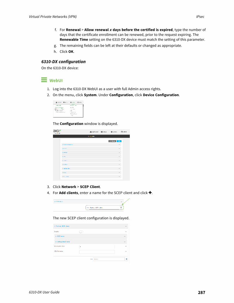
Virtual Private Networks (VPN) IPsec
6310-DX User Guide 287
f. For Renewal > Allow renewal x days before the certified is expired, type the number ofdays that the certificate enrollment can be renewed, prior to the request expiring. TheRenewable Time setting on the 6310-DX device must match the setting of this parameter.
g. The remaining fields can be left at their defaults or changed as appropriate.h. Click OK.
6310-DX configurationOn the 6310-DX device:
WebUI
1. Log into the 6310-DX WebUI as a user with full Admin access rights.2. On the menu, click System. Under Configuration, click Device Configuration.
The Configuration window is displayed.
3. Click Network > SCEP Client.4. For Add clients, enter a name for the SCEP client and click .
The new SCEP client configuration is displayed.
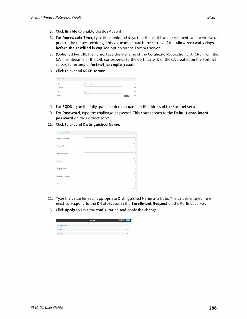
Virtual Private Networks (VPN) IPsec
6310-DX User Guide 288
5. Click Enable to enable the SCEP client.6. For Renewable Time, type the number of days that the certificate enrollment can be renewed,
prior to the request expiring. This value must match the setting of the Allow renewal x daysbefore the certified is expired option on the Fortinet server.
7. (Optional) For CRL file name, type the filename of the Certificate Revocation List (CRL) from theCA. The filename of the CRL corresponds to the Certificate ID of the CA created on the Fortinetserver, for example, fortinet_example_ca.crl.
8. Click to expand SCEP server.
9. For FQDN, type the fully qualified domain name or IP address of the Fortinet server.10. For Password, type the challenge password. This corresponds to the Default enrollment
password on the Fortinet server.11. Click to expand Distinguished Name.
12. Type the value for each appropriate Distinguished Name attribute. The values entered heremust correspond to the DN attributes in the Enrollment Request on the Fortinet server.
13. Click Apply to save the configuration and apply the change.
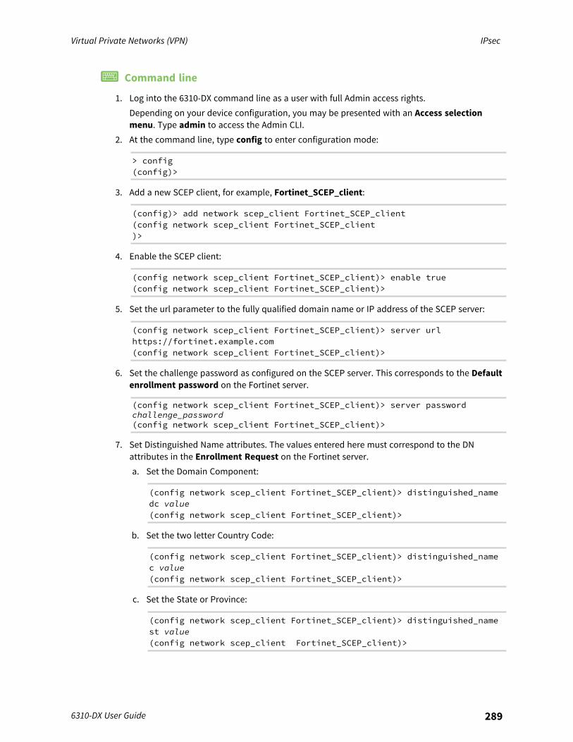
Virtual Private Networks (VPN) IPsec
6310-DX User Guide 289
Command line
1. Log into the 6310-DX command line as a user with full Admin access rights.Depending on your device configuration, you may be presented with an Access selectionmenu. Type admin to access the Admin CLI.
2. At the command line, type config to enter configuration mode:
> config(config)>
3. Add a new SCEP client, for example, Fortinet_SCEP_client:
(config)> add network scep_client Fortinet_SCEP_client(config network scep_client Fortinet_SCEP_client)>
4. Enable the SCEP client:
(config network scep_client Fortinet_SCEP_client)> enable true(config network scep_client Fortinet_SCEP_client)>
5. Set the url parameter to the fully qualified domain name or IP address of the SCEP server:
(config network scep_client Fortinet_SCEP_client)> server urlhttps://fortinet.example.com(config network scep_client Fortinet_SCEP_client)>
6. Set the challenge password as configured on the SCEP server. This corresponds to the Defaultenrollment password on the Fortinet server.
(config network scep_client Fortinet_SCEP_client)> server passwordchallenge_password(config network scep_client Fortinet_SCEP_client)>
7. Set Distinguished Name attributes. The values entered here must correspond to the DNattributes in the Enrollment Request on the Fortinet server.a. Set the Domain Component:
(config network scep_client Fortinet_SCEP_client)> distinguished_namedc value(config network scep_client Fortinet_SCEP_client)>
b. Set the two letter Country Code:
(config network scep_client Fortinet_SCEP_client)> distinguished_namec value(config network scep_client Fortinet_SCEP_client)>
c. Set the State or Province:
(config network scep_client Fortinet_SCEP_client)> distinguished_namest value(config network scep_client Fortinet_SCEP_client)>
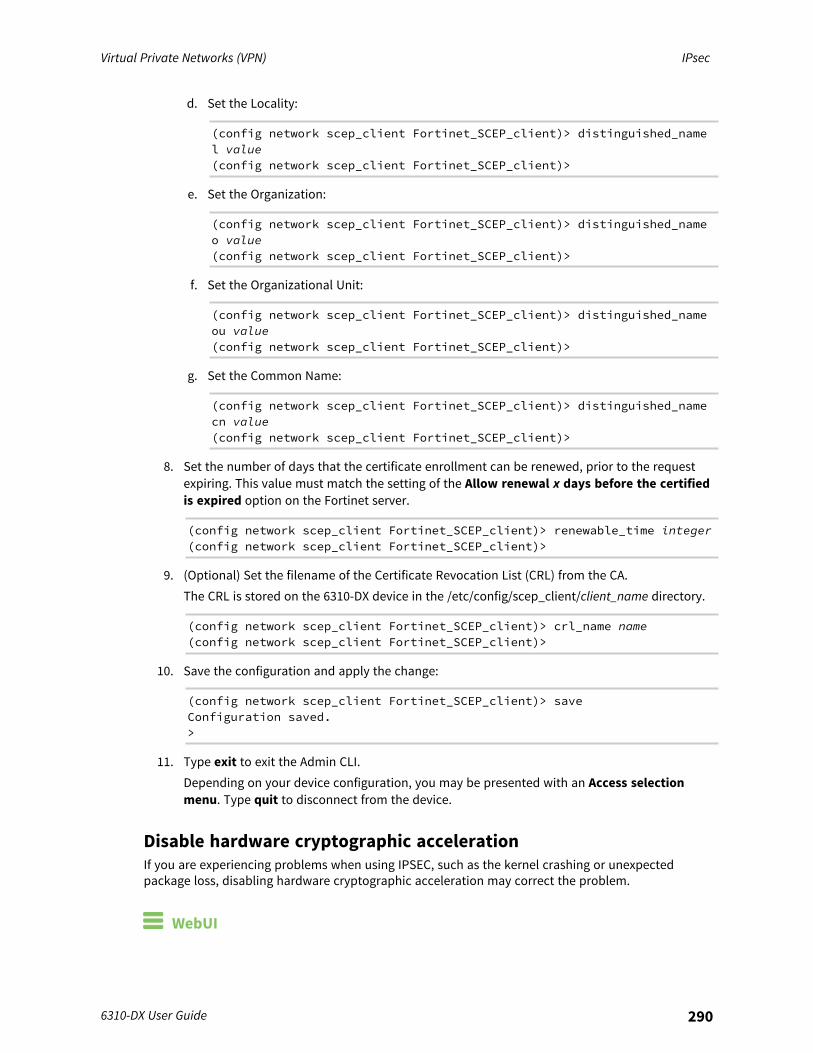
Virtual Private Networks (VPN) IPsec
6310-DX User Guide 290
d. Set the Locality:
(config network scep_client Fortinet_SCEP_client)> distinguished_namel value(config network scep_client Fortinet_SCEP_client)>
e. Set the Organization:
(config network scep_client Fortinet_SCEP_client)> distinguished_nameo value(config network scep_client Fortinet_SCEP_client)>
f. Set the Organizational Unit:
(config network scep_client Fortinet_SCEP_client)> distinguished_nameou value(config network scep_client Fortinet_SCEP_client)>
g. Set the Common Name:
(config network scep_client Fortinet_SCEP_client)> distinguished_namecn value(config network scep_client Fortinet_SCEP_client)>
8. Set the number of days that the certificate enrollment can be renewed, prior to the requestexpiring. This value must match the setting of the Allow renewal x days before the certifiedis expired option on the Fortinet server.
(config network scep_client Fortinet_SCEP_client)> renewable_time integer(config network scep_client Fortinet_SCEP_client)>
9. (Optional) Set the filename of the Certificate Revocation List (CRL) from the CA.The CRL is stored on the 6310-DX device in the /etc/config/scep_client/client_name directory.
(config network scep_client Fortinet_SCEP_client)> crl_name name(config network scep_client Fortinet_SCEP_client)>
10. Save the configuration and apply the change:
(config network scep_client Fortinet_SCEP_client)> saveConfiguration saved.>
11. Type exit to exit the Admin CLI.Depending on your device configuration, you may be presented with an Access selectionmenu. Type quit to disconnect from the device.
Disable hardware cryptographic accelerationIf you are experiencing problems when using IPSEC, such as the kernel crashing or unexpectedpackage loss, disabling hardware cryptographic acceleration may correct the problem.
WebUI
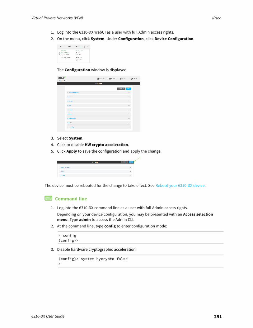
Virtual Private Networks (VPN) IPsec
6310-DX User Guide 291
1. Log into the 6310-DX WebUI as a user with full Admin access rights.2. On the menu, click System. Under Configuration, click Device Configuration.
The Configuration window is displayed.
3. Select System.4. Click to disable HW crypto acceleration.5. Click Apply to save the configuration and apply the change.
The device must be rebooted for the change to take effect. See Reboot your 6310-DX device.
Command line
1. Log into the 6310-DX command line as a user with full Admin access rights.Depending on your device configuration, you may be presented with an Access selectionmenu. Type admin to access the Admin CLI.
2. At the command line, type config to enter configuration mode:
> config(config)>
3. Disable hardware cryptographic acceleration:
(config)> system hycrypto false>
Virtual Private Networks (VPN) IPsec
6310-DX User Guide 292
4. Save the configuration and apply the change:
(config)> saveConfiguration saved.>
5. Type exit to exit the Admin CLI.Depending on your device configuration, you may be presented with an Access selectionmenu. Type quit to disconnect from the device.
The device must be rebooted for the change to take effect. See Reboot your 6310-DX device.

Virtual Private Networks (VPN) OpenVPN
6310-DX User Guide 293
OpenVPNOpenVPN is an open-source Virtual Private Network (VPN) technology that creates secure point-to-point or site-to-site connections in routed or bridged configurations. OpenVPN uses a custom securityprotocol that is Secure Socket Layer (SSL) / Transport Layer Security (TLS) for key exchange. It usesstandard encryption and authentication algorithms for data privacy and authentication over TCP orUDP.The OpenVPN server can push the network configuration, such as the topology and IP routes, toOpenVPN clients. This makes OpenVPN simpler to configure as it reduces the chances of aconfiguration mismatch between the client and server. OpenVPN also supports cipher negotiationbetween the client and server. This means you can configure the OpenVPN server and clients with arange of different cipher options and the server will negotiate with the client on the cipher to use forthe connection.For more information on OpenVPN, see www.openvpn.net.
OpenVPN modes:There are two modes for running OpenVPN:
n Routing mode, also known as TUN.n Bridging mode, also known as TAP.
Routing (TUN) modeIn routing mode, each OpenVPN client is assigned a different IP subnet from the OpenVPN server andother OpenVPN clients. OpenVPN clients use Network Address Translation (NAT) to route traffic fromdevices connected on its LAN interfaces to the OpenVPN server.The manner in which the IP subnets are defined depends on the OpenVPN topology in use. The 6310-DX device supports two types of OpenVPN topology:
OpenVPN Topology Subnet definition method
net30 Each OpenVPN client is assigned a /30 subnet within the IP subnet specifiedin the OpenVPN server configuration. With net30 topology, pushed routesare used, with the exception of the default route. Automatic route pushing(exec) is not allowed, because this would not inform the firewall and wouldbe blocked.
subnet Each OpenVPN client connected to the OpenVPN server is assigned an IPaddress within the IP subnet specified in the OpenVPN server configuration.For the 6310-DX device, pushed routes are not allowed; you will need tomanually configure routes on the device.
For more information on OpenVPN topologies, see OpenVPN topology.
Bridging (TAP) modeIn bridging mode, a LAN interface on the OpenVPN server is assigned to OpenVPN. The LAN interfacesof the OpenVPN clients are on the same IP subnet as the OpenVPN server’s LAN interface. This meansthat devices connected to the OpenVPN client’s LAN interface are on the same IP subnet as devices.The 6310-DX device supports two mechanisms for configuring an OpenVPN server in TAP mode:
Virtual Private Networks (VPN) OpenVPN
6310-DX User Guide 294
n OpenVPN managed—The 6310-DX device creates the interface and then uses its standardconfiguration to set up the connection (for example, its standard DHCP server configuration).
n Device only—IP addressing is controlled by the system, not by OpenVPN.
Additional OpenVPN informationFor more information on OpenVPN, see these resources:Bridging vs. routingOpenVPN/Routing
Configure an OpenVPN server
Required configuration items
n Enable the OpenVPN server.The OpenVPN server is enabled by default.
n The mode used by the OpenVPN server, one of:l TUN (OpenVPN managed)—Also known as routing mode. Each OpenVPN client is assigned
a different IP subnet from the OpenVPN server and other OpenVPN clients. OpenVPNclients use Network Address Translation (NAT) to route traffic from devices connected onits LAN interfaces to the OpenVPN server.
l TAP - OpenVPN managed—Also know as bridging mode. A more advancedimplementation of OpenVPN. The 6310-DX device creates an OpenVPN interface and usesstandard interface configuration (for example, a standard DHCP server configuration).
l TAP - Device only—An alternate form of OpenVPN bridging mode, in which the device,rather than OpenVPN, controls the interface configuration. If this method is is, theOpenVPN server must be included as a device in either an interface or a bridge.
n The firewall zone to be used by the OpenVPN server.n The IP network and subnet mask of the OpenVPN server.n The server's Certificate authority (CA) certificate, and public, private and Diffie-Hellman (DH)
keys.n An OpenVPN authentication group and an OpenVPN user.n Determine the method of certificate management:
l Certificates managed by the server.l Certificates created externally and added to the server.
n If certificates are created and added to the server, determine the level of authentication:l Certificate authentication only.l Username and password authentication only.l Certificate and username and password authentication.
If username and password authentication is used, you must create an OpenVPN authenticationgroup and user. See Configure an OpenVPN Authentication Group and User for instructions.
n Certificates and keys:l The CA certificate (usually in a ca.crt file).l The Public key (for example, server.crt)

Virtual Private Networks (VPN) OpenVPN
6310-DX User Guide 295
l The Private key (for example, server.key).l The Diffie Hellman key (usually in dh2048.pem).
n Active recovery configuration. See Configure SureLink active recovery for OpenVPN forinformation about OpenVPN active recovery.
Additional configuration items
n The route metric for the OpenVPN server.n The range of IP addresses that the OpenVPN server will provide to clients.n The TCP/UDP port to use. By default, the 6310-DX device uses port 1194.n Access control list configuration to restrict access to the OpenVPN server through the firewall.n Additional OpenVPN parameters.
WebUI
1. Log into the 6310-DX WebUI as a user with full Admin access rights.2. On the menu, click System. Under Configuration, click Device Configuration.
The Configuration window is displayed.
3. Click VPN > OpenVPN > Servers.4. For Add, type a name for the OpenVPN server and click .
The new OpenVPN server configuration is displayed.

Virtual Private Networks (VPN) OpenVPN
6310-DX User Guide 296
The OpenVPN server is enabled by default. To disable, click Enable.5. For Device type, select the mode used by the OpenVPN server, either:
n TUN (OpenVPN managed)n TAP - OpenVPN managedn TAP - Device only
See OpenVPN for information about OpenVPN server modes.6. If TUN (OpenVPN managed) or TAP - OpenVPN managed is selected for Device type:
a. For Zone, select the firewall zone for the OpenVPN server. For TUN device types, thisshould be set to Internal to treat clients as LAN devices.
b. (Optional) Select the Metric for the OpenVPN server. If multiple active routes match adestination, the route with the lowest metric will be used. The default setting is 0.
c. For Address, type the IP address and subnet mask of the OpenVPN server.d. (Optional) For First IP address and Last IP address, set the range of IP addresses that the
OpenVPN server will use when providing IP addresses to clients. The default is from 80 to99.
7. (Optional) Set the VPN port that the OpenVPN server will use. The default is 1194.8. For Server managed certificates, determine the method of certificate management. If
enabled, the server will manage certificates. If not enabled, certificates must be createdexternally and added to the server.
9. If Server managed certificates is not enabled:a. Select the Authentication type:
n Certificate only: Uses only certificates for client authentication. Each clientrequires a public and private key.
n Username/password only: Uses a username and password for clientauthentication. You must create an OpenVPN authentication group and user. SeeConfigure an OpenVPN Authentication Group and User for instructions.
n Certificate and username/password: Uses both certificates and a username andpassword for client authentication. Each client requires a public and private key,and you must create an OpenVPN authentication group and user. See Configure anOpenVPN Authentication Group and User for instructions.
Virtual Private Networks (VPN) OpenVPN
6310-DX User Guide 297
b. Paste the contents of the CA certificate (usually in a ca.crt file), the Public key (forexample, server.crt), the Private key (for example, server.key), and the Diffie Hellmankey (usually in dh2048.pem) into their respective fields. The contents will be hidden whenthe configuration is saved.
10. (Optional) Click to expand Access control list to restrict access to the OpenVPN server:n To limit access to specified IPv4 addresses and networks:
a. Click IPv4 Addresses.b. For Add Address, click .c. For Address, enter the IPv4 address or network that can access the device's
service-type. Allowed values are:l A single IP address or host name.l A network designation in CIDR notation, for example, 192.168.1.0/24.l any: No limit to IPv4 addresses that can access the service-type.
d. Click again to list additional IP addresses or networks.n To limit access to specified IPv6 addresses and networks:
a. Click IPv6 Addresses.b. For Add Address, click .c. For Address, enter the IPv6 address or network that can access the device's
service-type. Allowed values are:l A single IP address or host name.l A network designation in CIDR notation, for example, 2001:db8::/48.l any: No limit to IPv6 addresses that can access the service-type.
d. Click again to list additional IP addresses or networks.n To limit access to hosts connected through a specified interface on the 6310-DX device:
a. Click Interfaces.b. For Add Interface, click .c. For Interface, select the appropriate interface from the dropdown.d. Click again to allow access through additional interfaces.
n To limit access based on firewall zones:a. Click Zones.b. For Add Zone, click .c. For Zone, select the appropriate firewall zone from the dropdown.
See Firewall configuration for information about firewall zones.d. Click again to allow access through additional firewall zones.
11. (Optional) Click to expand Advanced Options to manually set additional OpenVPNparameters.a. Click Enable to enable the use of additional OpenVPN parameters.b. Click Override if the additional OpenVPN parameters should override default options.c. For OpenVPN parameters, type the additional OpenVPN parameters.
12. Click Apply to save the configuration and apply the change.
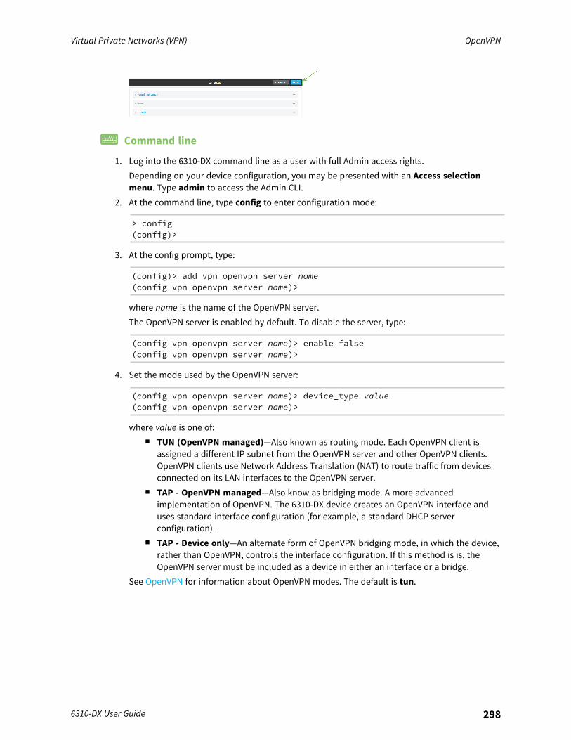
Virtual Private Networks (VPN) OpenVPN
6310-DX User Guide 298
Command line
1. Log into the 6310-DX command line as a user with full Admin access rights.Depending on your device configuration, you may be presented with an Access selectionmenu. Type admin to access the Admin CLI.
2. At the command line, type config to enter configuration mode:
> config(config)>
3. At the config prompt, type:
(config)> add vpn openvpn server name(config vpn openvpn server name)>
where name is the name of the OpenVPN server.The OpenVPN server is enabled by default. To disable the server, type:
(config vpn openvpn server name)> enable false(config vpn openvpn server name)>
4. Set the mode used by the OpenVPN server:
(config vpn openvpn server name)> device_type value(config vpn openvpn server name)>
where value is one of:n TUN (OpenVPN managed)—Also known as routing mode. Each OpenVPN client is
assigned a different IP subnet from the OpenVPN server and other OpenVPN clients.OpenVPN clients use Network Address Translation (NAT) to route traffic from devicesconnected on its LAN interfaces to the OpenVPN server.
n TAP - OpenVPN managed—Also know as bridging mode. A more advancedimplementation of OpenVPN. The 6310-DX device creates an OpenVPN interface anduses standard interface configuration (for example, a standard DHCP serverconfiguration).
n TAP - Device only—An alternate form of OpenVPN bridging mode, in which the device,rather than OpenVPN, controls the interface configuration. If this method is is, theOpenVPN server must be included as a device in either an interface or a bridge.
See OpenVPN for information about OpenVPN modes. The default is tun.

Virtual Private Networks (VPN) OpenVPN
6310-DX User Guide 299
5. If tap or tun are set for device_type:a. Set the IP address and subnet mask of the OpenVPN server.
(config vpn openvpn server name)> address ip_address/netmask(config vpn openvpn server name)>
b. Set the firewall zone for the OpenVPN server. For TUN device types, this should be set tointernal to treat clients as LAN devices.
(config vpn openvpn server name)> zone value(config vpn openvpn server name)>
To view a list of available zones:
(config vpn openvpn server name)> firewall zone ?
Zone: The zone for the local TUN interface. To treat clients as LANdevices this would usually beset to internal.Format:anydynamic_routesedgeexternalinternalipsecloopbacksetup
Current value:
(config vpn openvpn server name)>
c. (Optional) Set the route metric for the OpenVPN server. If multiple active routes match adestination, the route with the lowest metric will be used.
(config vpn openvpn server name)> metric value(config vpn openvpn server name)>
where value is an interger between 0 and 65535. The default is 0.d. (Optional) Set the range of IP addresses that the OpenVPN server will use when providing
IP addresses to clients:i. Set the first address in the range limit:
(config vpn openvpn server name)> server_first_ip value(config vpn openvpn server name)>
where value is a number between 1 and 255. The number entered here will representthe first client IP address. For example, if address is set to 192.168.1.1/24 andserver_first_ip is set to 80, the first client IP address will be 192.168.1.80.The default is from 80.
Virtual Private Networks (VPN) OpenVPN
6310-DX User Guide 300
ii. Set the last address in the range limit:
(config vpn openvpn server name)> server_last_ip value(config vpn openvpn server name)>
where value is a number between 1 and 255. The number entered here will representthe last client IP address. For example, if address is set to 192.168.1.1/24 andserver_last_ip is set to 99, the last client IP address will be 192.168.1.80.The default is from 80.
6. (Optional) Set the port that the OpenVPN server will use:
(config vpn openvpn server name)> port port(config vpn openvpn server name)>
The default is 1194.7. Determine the method of certificate management:
a. To allow the server to manage certificates:
(config vpn openvpn server name)> autogenerate true(config vpn openvpn server name)>
b. To create certificates externally and add them to the server
(config vpn openvpn server name)> autogenerate false(config vpn openvpn server name)>
The default setting is false.c. If autogenerate is set to false:
i. Set the authentication type:
(config vpn openvpn server name)> authentication value(config vpn openvpn server name)>
where value is one of:n cert: Uses only certificates for client authentication. Each client requires a
public and private key.n passwd: Uses a username and password for client authentication. You must
create an OpenVPN authentication group and user. See Configure an OpenVPNAuthentication Group and User for instructions.
n cert_passwd: Uses both certificates and a username and password for clientauthentication. Each client requires a public and private key, and you mustcreate an OpenVPN authentication group and user. See Configure an OpenVPNAuthentication Group and User for instructions.
ii. Paste the contents of the CA certificate (usually in a ca.crt file) into the value of thecacert parameter:
(config vpn openvpn server name)> cacert value(config vpn openvpn server name)>

Virtual Private Networks (VPN) OpenVPN
6310-DX User Guide 301
iii. Paste the contents of the public key (for example, server.crt) into the value of theserver_cert parameter:
(config vpn openvpn server name)> server_cert value(config vpn openvpn server name)>
iv. Paste the contents of the private key (for example, server.key) into the value of theserver_key parameter:
(config vpn openvpn server name)> server_key value(config vpn openvpn server name)>
v. Paste the contents of the Diffie Hellman key (usually in dh2048.pem) into the value ofthe diffie parameter:
(config vpn openvpn server name)> diffie value(config vpn openvpn server name)>
8. (Optional) Set the access control list to restrict access to the OpenVPN server:n To limit access to specified IPv4 addresses and networks:
(config vpn openvpn server name)> add acl address end value(config vpn openvpn server name)>
Where value can be:l A single IP address or host name.l A network designation in CIDR notation, for example, 192.168.1.0/24.l any: No limit to IPv4 addresses that can access the service-type.
Repeat this step to list additional IP addresses or networks.n To limit access to specified IPv6 addresses and networks:
(config vpn openvpn server name)> add acl address6 end value(config vpn openvpn server name)>
Where value can be:l A single IP address or host name.l A network designation in CIDR notation, for example, 2001:db8::/48.l any: No limit to IPv6 addresses that can access the service-type.
Repeat this step to list additional IP addresses or networks.n To limit access to hosts connected through a specified interface on the 6310-DX device:
(config vpn openvpn server name)> add acl interface end value(config vpn openvpn server name)>
Where value is an interface defined on your device.
Display a list of available interfaces:
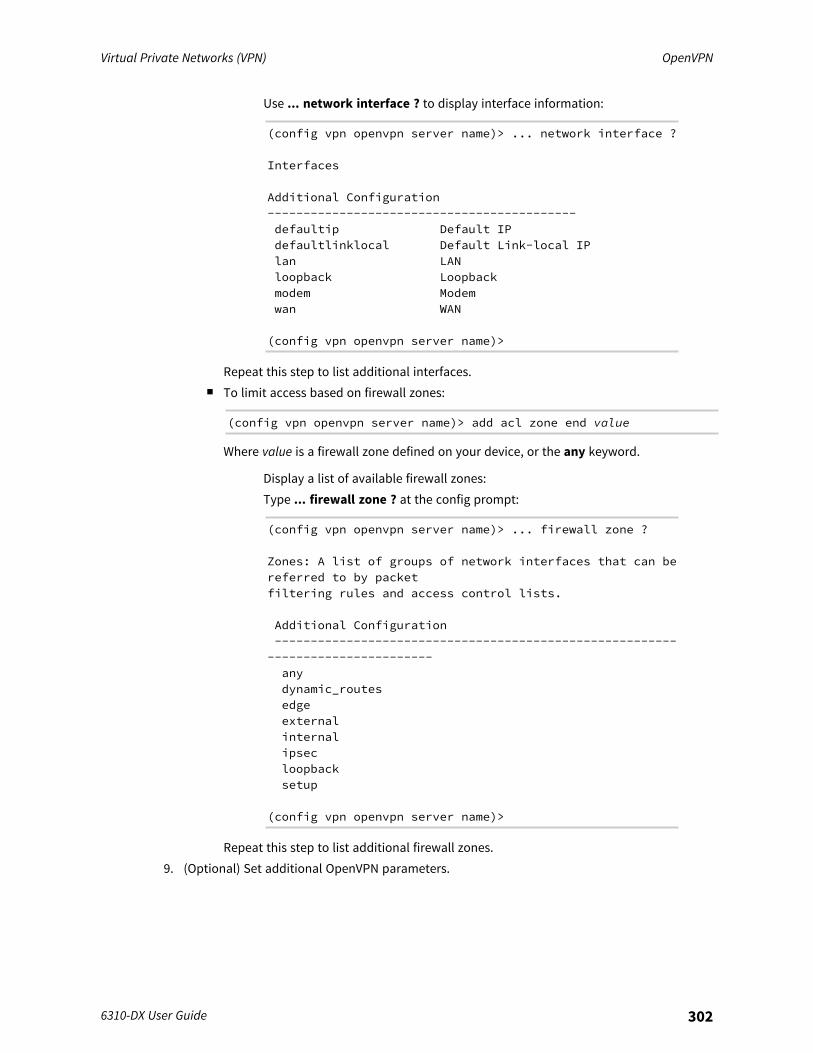
Virtual Private Networks (VPN) OpenVPN
6310-DX User Guide 302
Use ... network interface ? to display interface information:
(config vpn openvpn server name)> ... network interface ?
Interfaces
Additional Configuration-------------------------------------------defaultip Default IPdefaultlinklocal Default Link-local IPlan LANloopback Loopbackmodem Modemwan WAN
(config vpn openvpn server name)>
Repeat this step to list additional interfaces.n To limit access based on firewall zones:
(config vpn openvpn server name)> add acl zone end value
Where value is a firewall zone defined on your device, or the any keyword.
Display a list of available firewall zones:Type ... firewall zone ? at the config prompt:
(config vpn openvpn server name)> ... firewall zone ?
Zones: A list of groups of network interfaces that can bereferred to by packetfiltering rules and access control lists.
Additional Configuration--------------------------------------------------------
-----------------------anydynamic_routesedgeexternalinternalipsecloopbacksetup
(config vpn openvpn server name)>
Repeat this step to list additional firewall zones.9. (Optional) Set additional OpenVPN parameters.
Virtual Private Networks (VPN) OpenVPN
6310-DX User Guide 303
a. Enable the use of additional OpenVPN parameters:
(config vpn openvpn server name)> advanced_options enable true(config vpn openvpn server name)>
b. Configure whether the additional OpenVPN parameters should override default options:
(config vpn openvpn server name)> advanced_options override true(config vpn openvpn server name)>
c. Set the additional OpenVPN parameters:
(config vpn openvpn server name)> extra parameters(config vpn openvpn server name)>
10. Save the configuration and apply the change:
(config)> saveConfiguration saved.>
11. Type exit to exit the Admin CLI.Depending on your device configuration, you may be presented with an Access selectionmenu. Type quit to disconnect from the device.
Configure an OpenVPN Authentication Group and UserIf username and password authentication is used for the OpenVPN server, you must create anOpenVPN authentication group and user.See Configure an OpenVPN server for information about configuring an OpenVPN server to useusername and password authentication. See 6310-DX user authentication for more information aboutcreating authentication groups and users.
WebUI
1. Log into the 6310-DX WebUI as a user with full Admin access rights.2. On the menu, click System. Under Configuration, click Device Configuration.
The Configuration window is displayed.

Virtual Private Networks (VPN) OpenVPN
6310-DX User Guide 304
3. Add an OpenVPN authentication group:a. Click Authentication > Groups.b. For Add Group, type a name for the group (for example, OpenVPN_Group) and click .
The new authentication group configuration is displayed.
c. Click OpenVPN access to enable OpenVPN access rights for users of this group.d. Click to expand the OpenVPN node.e. Click to add a tunnel.
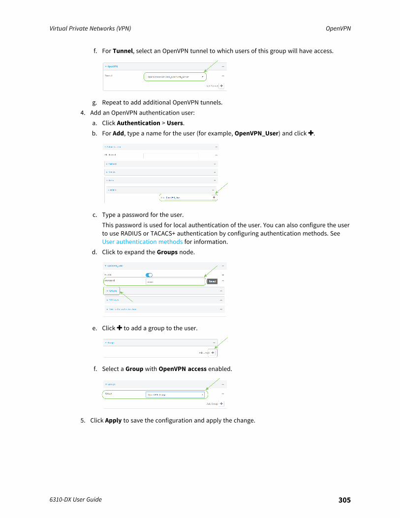
Virtual Private Networks (VPN) OpenVPN
6310-DX User Guide 305
f. For Tunnel, select an OpenVPN tunnel to which users of this group will have access.
g. Repeat to add additional OpenVPN tunnels.4. Add an OpenVPN authentication user:
a. Click Authentication > Users.b. For Add, type a name for the user (for example, OpenVPN_User) and click .
c. Type a password for the user.This password is used for local authentication of the user. You can also configure the userto use RADIUS or TACACS+ authentication by configuring authentication methods. SeeUser authentication methods for information.
d. Click to expand the Groups node.
e. Click to add a group to the user.
f. Select a Group with OpenVPN access enabled.
5. Click Apply to save the configuration and apply the change.

Virtual Private Networks (VPN) OpenVPN
6310-DX User Guide 306
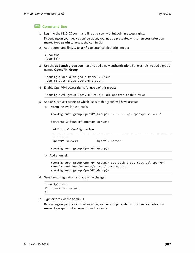
Virtual Private Networks (VPN) OpenVPN
6310-DX User Guide 307
Command line
1. Log into the 6310-DX command line as a user with full Admin access rights.Depending on your device configuration, you may be presented with an Access selectionmenu. Type admin to access the Admin CLI.
2. At the command line, type config to enter configuration mode:
> config(config)>
3. Use the add auth group command to add a new authentication. For example, to add a groupnamed OpenVPN_Group:
(config)> add auth group OpenVPN_Group(config auth group OpenVPN_Group)>
4. Enable OpenVPN access rights for users of this group:
(config auth group OpenVPN_Group)> acl openvpn enable true
5. Add an OpenVPN tunnel to which users of this group will have access:a. Determine available tunnels:
(config auth group OpenVPN_Group)> .. .. .. vpn openvpn server ?
Servers: A list of openvpn servers
Additional Configuration-------------------------------------------------------------------------------OpenVPN_server1 OpenVPN server
(config auth group OpenVPN_Group)>
b. Add a tunnel:
(config auth group OpenVPN_Group)> add auth group test acl openvpntunnels end /vpn/openvpn/server/OpenVPN_server1(config auth group OpenVPN_Group)>
6. Save the configuration and apply the change:
(config)> saveConfiguration saved.>
7. Type exit to exit the Admin CLI.Depending on your device configuration, you may be presented with an Access selectionmenu. Type quit to disconnect from the device.
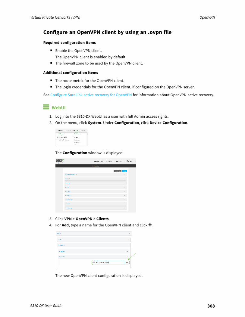
Virtual Private Networks (VPN) OpenVPN
6310-DX User Guide 308
Configure an OpenVPN client by using an .ovpn file
Required configuration items
n Enable the OpenVPN client.The OpenVPN client is enabled by default.
n The firewall zone to be used by the OpenVPN client.
Additional configuration items
n The route metric for the OpenVPN client.n The login credentials for the OpenVPN client, if configured on the OpenVPN server.
See Configure SureLink active recovery for OpenVPN for information about OpenVPN active recovery.
WebUI
1. Log into the 6310-DX WebUI as a user with full Admin access rights.2. On the menu, click System. Under Configuration, click Device Configuration.
The Configuration window is displayed.
3. Click VPN > OpenVPN > Clients.4. For Add, type a name for the OpenVPN client and click .
The new OpenVPN client configuration is displayed.
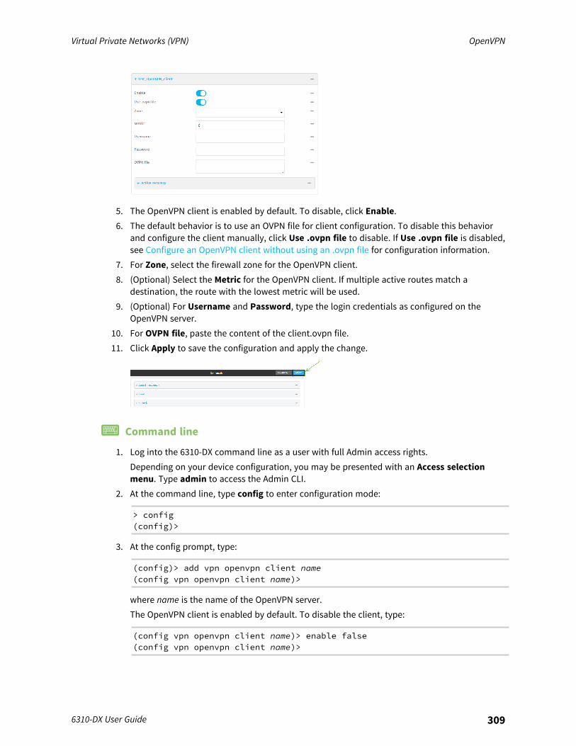
Virtual Private Networks (VPN) OpenVPN
6310-DX User Guide 309
5. The OpenVPN client is enabled by default. To disable, click Enable.6. The default behavior is to use an OVPN file for client configuration. To disable this behavior
and configure the client manually, click Use .ovpn file to disable. If Use .ovpn file is disabled,see Configure an OpenVPN client without using an .ovpn file for configuration information.
7. For Zone, select the firewall zone for the OpenVPN client.8. (Optional) Select the Metric for the OpenVPN client. If multiple active routes match a
destination, the route with the lowest metric will be used.9. (Optional) For Username and Password, type the login credentials as configured on the
OpenVPN server.10. For OVPN file, paste the content of the client.ovpn file.11. Click Apply to save the configuration and apply the change.
Command line
1. Log into the 6310-DX command line as a user with full Admin access rights.Depending on your device configuration, you may be presented with an Access selectionmenu. Type admin to access the Admin CLI.
2. At the command line, type config to enter configuration mode:
> config(config)>
3. At the config prompt, type:
(config)> add vpn openvpn client name(config vpn openvpn client name)>
where name is the name of the OpenVPN server.The OpenVPN client is enabled by default. To disable the client, type:
(config vpn openvpn client name)> enable false(config vpn openvpn client name)>
Virtual Private Networks (VPN) OpenVPN
6310-DX User Guide 310
4. Set the firewall zone for the OpenVPN client:
(config vpn openvpn client name)> zone value(config vpn openvpn client name)>
To view a list of available zones:
(config vpn openvpn client name)> zone ?
Zone: The zone for the openvpn client interface.Format:anydynamic_routesedgeexternalinternalipsecloopbacksetup
Current value:
(config vpn openvpn client name)>
5. (Optional) Set the route metric for the OpenVPN server. If multiple active routes match adestination, the route with the lowest metric will be used.
(config vpn openvpn client name)> metric value(config vpn openvpn client name)>
where value is an interger between 0 and 65535. The default is 0.6. (Optional) Set the login credentials as configured on the OpenVPN server:
(config vpn openvpn client name)> username value(config vpn openvpn client name)> password value(config vpn openvpn client name)>
7. Paste the content of the client.ovpn file into the value of the config_file parameter:
(config vpn openvpn client name)> config_file value(config vpn openvpn client name)>
8. Save the configuration and apply the change:
(config)> saveConfiguration saved.>
9. Type exit to exit the Admin CLI.Depending on your device configuration, you may be presented with an Access selectionmenu. Type quit to disconnect from the device.
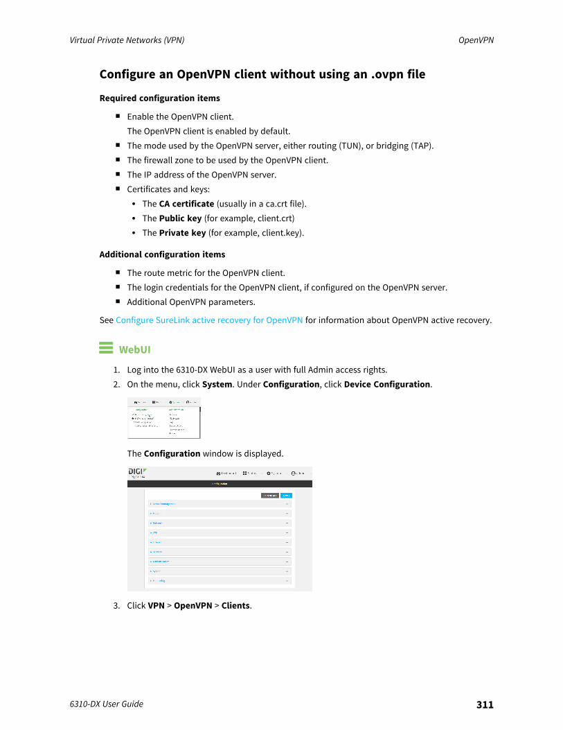
Virtual Private Networks (VPN) OpenVPN
6310-DX User Guide 311
Configure an OpenVPN client without using an .ovpn file
Required configuration items
n Enable the OpenVPN client.The OpenVPN client is enabled by default.
n The mode used by the OpenVPN server, either routing (TUN), or bridging (TAP).n The firewall zone to be used by the OpenVPN client.n The IP address of the OpenVPN server.n Certificates and keys:
l The CA certificate (usually in a ca.crt file).l The Public key (for example, client.crt)l The Private key (for example, client.key).
Additional configuration items
n The route metric for the OpenVPN client.n The login credentials for the OpenVPN client, if configured on the OpenVPN server.n Additional OpenVPN parameters.
See Configure SureLink active recovery for OpenVPN for information about OpenVPN active recovery.
WebUI
1. Log into the 6310-DX WebUI as a user with full Admin access rights.2. On the menu, click System. Under Configuration, click Device Configuration.
The Configuration window is displayed.
3. Click VPN > OpenVPN > Clients.
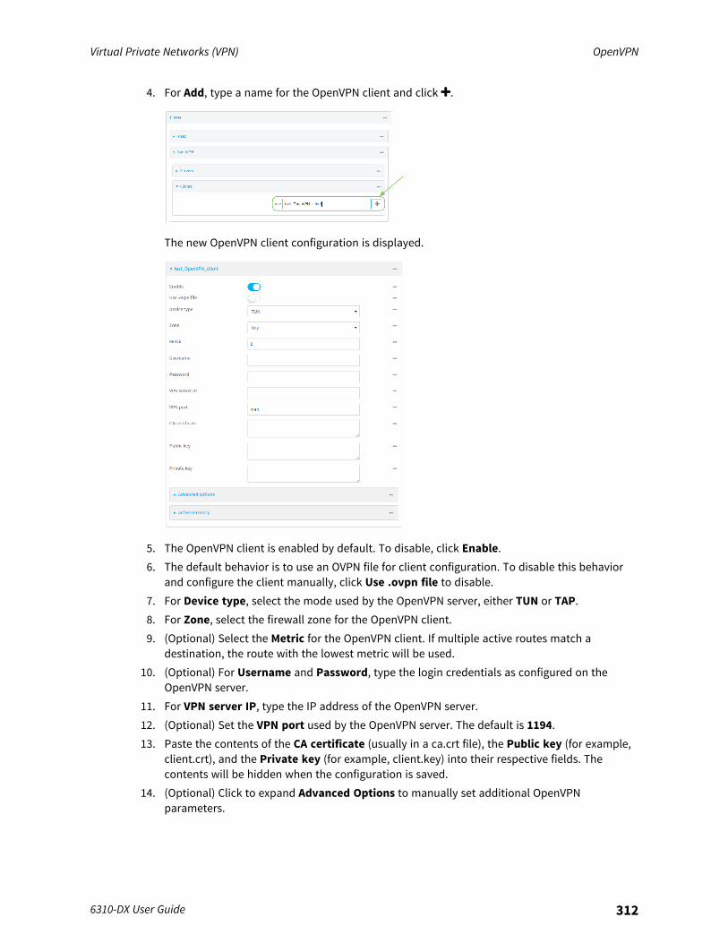
Virtual Private Networks (VPN) OpenVPN
6310-DX User Guide 312
4. For Add, type a name for the OpenVPN client and click .
The new OpenVPN client configuration is displayed.
5. The OpenVPN client is enabled by default. To disable, click Enable.6. The default behavior is to use an OVPN file for client configuration. To disable this behavior
and configure the client manually, click Use .ovpn file to disable.7. For Device type, select the mode used by the OpenVPN server, either TUN or TAP.8. For Zone, select the firewall zone for the OpenVPN client.9. (Optional) Select the Metric for the OpenVPN client. If multiple active routes match a
destination, the route with the lowest metric will be used.10. (Optional) For Username and Password, type the login credentials as configured on the
OpenVPN server.11. For VPN server IP, type the IP address of the OpenVPN server.12. (Optional) Set the VPN port used by the OpenVPN server. The default is 1194.13. Paste the contents of the CA certificate (usually in a ca.crt file), the Public key (for example,
client.crt), and the Private key (for example, client.key) into their respective fields. Thecontents will be hidden when the configuration is saved.
14. (Optional) Click to expand Advanced Options to manually set additional OpenVPNparameters.

Virtual Private Networks (VPN) OpenVPN
6310-DX User Guide 313
a. Click Enable to enable the use of additional OpenVPN parameters.b. Click Override if the additional OpenVPN parameters should override default options.c. For OpenVPN parameters, type the additional OpenVPN parameters. For example, to
override the configuration by using a configuration file, enter --config filename, forexample, --config /etc/config/openvpn_config.
15. Click Apply to save the configuration and apply the change.
Command line
1. Log into the 6310-DX command line as a user with full Admin access rights.Depending on your device configuration, you may be presented with an Access selectionmenu. Type admin to access the Admin CLI.
2. At the command line, type config to enter configuration mode:
> config(config)>
3. At the config prompt, type:
(config)> add vpn openvpn client name(config vpn openvpn client name)>
where name is the name of the OpenVPN server.The OpenVPN client is enabled by default. To disable the client, type:
(config vpn openvpn client name)> enable false(config vpn openvpn client name)>
4. The default behavior is to use an OVPN file for client configuration. To disable this behaviorand configure the client manually:
(config vpn openvpn client name)> use_file false(config vpn openvpn client name)>
5. Set the mode used by the OpenVPN server:
(config vpn openvpn client name)> device_type value(config vpn openvpn client name)>
where value is either tun or tap. The default is tun.6. Set the firewall zone for the OpenVPN client:
(config vpn openvpn client name)> zone value(config vpn openvpn client name)>
To view a list of available zones:
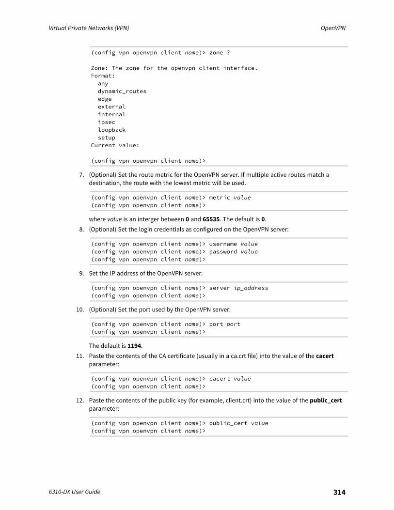
Virtual Private Networks (VPN) OpenVPN
6310-DX User Guide 314
(config vpn openvpn client name)> zone ?
Zone: The zone for the openvpn client interface.Format:anydynamic_routesedgeexternalinternalipsecloopbacksetup
Current value:
(config vpn openvpn client name)>
7. (Optional) Set the route metric for the OpenVPN server. If multiple active routes match adestination, the route with the lowest metric will be used.
(config vpn openvpn client name)> metric value(config vpn openvpn client name)>
where value is an interger between 0 and 65535. The default is 0.8. (Optional) Set the login credentials as configured on the OpenVPN server:
(config vpn openvpn client name)> username value(config vpn openvpn client name)> password value(config vpn openvpn client name)>
9. Set the IP address of the OpenVPN server:
(config vpn openvpn client name)> server ip_address(config vpn openvpn client name)>
10. (Optional) Set the port used by the OpenVPN server:
(config vpn openvpn client name)> port port(config vpn openvpn client name)>
The default is 1194.11. Paste the contents of the CA certificate (usually in a ca.crt file) into the value of the cacert
parameter:
(config vpn openvpn client name)> cacert value(config vpn openvpn client name)>
12. Paste the contents of the public key (for example, client.crt) into the value of the public_certparameter:
(config vpn openvpn client name)> public_cert value(config vpn openvpn client name)>
Virtual Private Networks (VPN) OpenVPN
6310-DX User Guide 315
13. Paste the contents of the private key (for example, client.key) into the value of the private_keyparameter:
(config vpn openvpn client name)> private_key value(config vpn openvpn client name)>
14. (Optional) Set additional OpenVPN parameters.a. Enable the use of additional OpenVPN parameters:
(config vpn openvpn client name)> advanced_options enable true(config vpn openvpn client name)>
b. Configure whether the additional OpenVPN parameters should override default options:
(config vpn openvpn client name)> advanced_options override true(config vpn openvpn client name)>
c. Set the additional OpenVPN parameters:
(config vpn openvpn client name)> advanced_options extra parameters(config vpn openvpn client name)>
15. Save the configuration and apply the change:
(config)> saveConfiguration saved.>
16. Type exit to exit the Admin CLI.Depending on your device configuration, you may be presented with an Access selectionmenu. Type quit to disconnect from the device.
Configure SureLink active recovery for OpenVPNYou can configure the 6310-DX device to regularly probe OpenVPN client connections to determine ifthe connection has failed and take remedial action.
Required configuration items
n A valid OpenVPN client configuration. See Configure an OpenVPN client by using an .ovpn fileor Configure an OpenVPN client without using an .ovpn file for configuration instructions.
n Enable OpenVPN active recovery.n The behavior of the 6310-DX device upon OpenVPN failure: either
l Restart the OpenVPN interfacel Reboot the device.
Additional configuration items
n The interval between connectivity tests.n Whether the interface should be considered to have failed if one of the test targets fails, or all
of the test targets fail.n The number of probe attempts before the OpenVPN connection is considered to have failed.
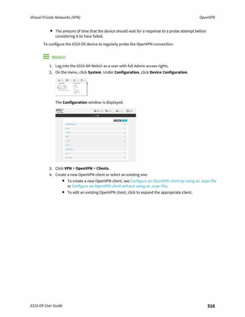
Virtual Private Networks (VPN) OpenVPN
6310-DX User Guide 316
n The amount of time that the device should wait for a response to a probe attempt beforeconsidering it to have failed.
To configure the 6310-DX device to regularly probe the OpenVPN connection:
WebUI
1. Log into the 6310-DX WebUI as a user with full Admin access rights.2. On the menu, click System. Under Configuration, click Device Configuration.
The Configuration window is displayed.
3. Click VPN > OpenVPN > Clients.4. Create a new OpenVPN client or select an existing one:
n To create a new OpenVPN client, see Configure an OpenVPN client by using an .ovpn fileor Configure an OpenVPN client without using an .ovpn file.
n To edit an existing OpenVPN client, click to expand the appropriate client.
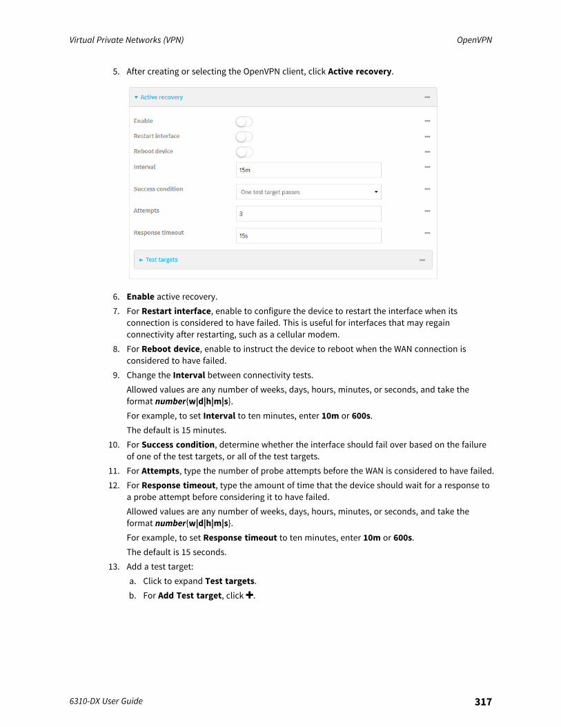
Virtual Private Networks (VPN) OpenVPN
6310-DX User Guide 317
5. After creating or selecting the OpenVPN client, click Active recovery.
6. Enable active recovery.7. For Restart interface, enable to configure the device to restart the interface when its
connection is considered to have failed. This is useful for interfaces that may regainconnectivity after restarting, such as a cellular modem.
8. For Reboot device, enable to instruct the device to reboot when the WAN connection isconsidered to have failed.
9. Change the Interval between connectivity tests.Allowed values are any number of weeks, days, hours, minutes, or seconds, and take theformat number{w|d|h|m|s}.For example, to set Interval to ten minutes, enter 10m or 600s.The default is 15 minutes.
10. For Success condition, determine whether the interface should fail over based on the failureof one of the test targets, or all of the test targets.
11. For Attempts, type the number of probe attempts before the WAN is considered to have failed.12. For Response timeout, type the amount of time that the device should wait for a response to
a probe attempt before considering it to have failed.Allowed values are any number of weeks, days, hours, minutes, or seconds, and take theformat number{w|d|h|m|s}.For example, to set Response timeout to ten minutes, enter 10m or 600s.The default is 15 seconds.
13. Add a test target:a. Click to expand Test targets.b. For Add Test target, click .
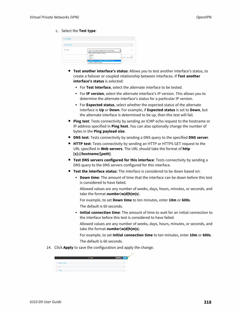
Virtual Private Networks (VPN) OpenVPN
6310-DX User Guide 318
c. Select the Test type:
n Test another interface's status: Allows you to test another interface's status, tocreate a failover or coupled relationship between interfaces. If Test anotherinterface's status is selected:l For Test Interface, select the alternate interface to be tested.l For IP version, select the alternate interface's IP version. This allows you to
determine the alternate interface's status for a particular IP version.l For Expected status, select whether the expected status of the alternate
interface is Up or Down. For example, if Expected status is set to Down, butthe alternate interface is determined to be up, then this test will fail.
n Ping test: Tests connectivity by sending an ICMP echo request to the hostname orIP address specified in Ping host. You can also optionally change the number ofbytes in the Ping payload size.
n DNS test: Tests connectivity by sending a DNS query to the specified DNS server.n HTTP test: Tests connectivity by sending an HTTP or HTTPS GET request to the
URL specified in Web servers. The URL should take the format of http[s]://hostname/[path].
n Test DNS servers configured for this interface: Tests connectivity by sending aDNS query to the DNS servers configured for this interface.
n Test the interface status: The interface is considered to be down based on:l Down time: The amount of time that the interface can be down before this test
is considered to have failed.Allowed values are any number of weeks, days, hours, minutes, or seconds, andtake the format number{w|d|h|m|s}.For example, to set Down time to ten minutes, enter 10m or 600s.The default is 60 seconds.
l Initial connection time: The amount of time to wait for an initial connection tothe interface before this test is considered to have failed.Allowed values are any number of weeks, days, hours, minutes, or seconds, andtake the format number{w|d|h|m|s}.For example, to set Initial connection time to ten minutes, enter 10m or 600s.The default is 60 seconds.
14. Click Apply to save the configuration and apply the change.
Virtual Private Networks (VPN) OpenVPN
6310-DX User Guide 319
Command line
1. Log into the 6310-DX command line as a user with full Admin access rights.Depending on your device configuration, you may be presented with an Access selectionmenu. Type admin to access the Admin CLI.
2. At the command line, type config to enter configuration mode:
> config(config)>
3. Create a new OpenVPN client, or edit an existing one:n To create a new OpenVPN client, see Configure an OpenVPN client by using an .ovpn file
or Configure an OpenVPN client without using an .ovpn file.n To edit an existing OpenVPN client, change to the OpenVPN client's node in the
configuration schema. For example, for an OpenVPN client named openvpn_client1,change to the openvpn_client1 node in the configuration schema:
(config)> vpn openvpn client openvpn_client1(config vpn openvpn client openvpn_client1)>
4. Enable active recovery:
(config vpn openvpn client openvpn_client1)> surelink enable true(config vpn openvpn client openvpn_client1)>
5. To configure the device to restart the interface when its connection is considered to havefailed:
(config vpn openvpn client openvpn_client1)> surelink restart true(config vpn openvpn client openvpn_client1)>
This is useful for interfaces that may regain connectivity after restarting, such as a cellularmodem.
6. To configure the device to reboot when the interface is considered to have failed:
(config vpn openvpn client openvpn_client1)> surelink reboot enable(config vpn openvpn client openvpn_client1)>
7. Set the Interval between connectivity tests:
(config vpn openvpn client openvpn_client1)> surelink interval value(config vpn openvpn client openvpn_client1)>
where value is any number of weeks, days, hours, minutes, or seconds, and takes the formatnumber{w|d|h|m|s}.For example, to set interval to ten minutes, enter either 10m or 600s:
(config vpn openvpn client openvpn_client1)> surelink interval 600s(config vpn openvpn client openvpn_client1)>
The default is 15 minutes.
Virtual Private Networks (VPN) OpenVPN
6310-DX User Guide 320
8. Determine whether the interface should fail over based on the failure of one of the test targets,or all of the test targets:
(config vpn openvpn client openvpn_client1)> surelink success_conditionvalue(config vpn openvpn client openvpn_client1)>
Where value is either one or all.9. Set the number of probe attempts before the WAN is considered to have failed:
(config vpn openvpn client openvpn_client1)> surelink attempts num(config vpn openvpn client openvpn_client1)>
The default is 3.10. Set the amount of time that the device should wait for a response to a probe attempt before
considering it to have failed:
(config vpn openvpn client openvpn_client1)> surelink timeout value(config vpn openvpn client openvpn_client1)>
where value is any number of weeks, days, hours, minutes, or seconds, and takes the formatnumber{w|d|h|m|s}.For example, to set timeout to ten minutes, enter either 10m or 600s:
(config vpn openvpn client openvpn_client1)> surelink timeout 600s(config vpn openvpn client openvpn_client1)>
The default is 15 seconds.11. Configure test targets:
a. Add a test target:
(config vpn openvpn client openvpn_client1)> add surelink target end(config vpn openvpn client openvpn_client1 surelink target 0)>
b. Set the test type:
(config vpn openvpn client openvpn_client1 surelink target 0)> testvalue(config vpn openvpn client openvpn_client1 surelink target 0)>
where value is one of:n ping: Tests connectivity by sending an ICMP echo request to a specified hostname
or IP address.l Specify the hostname or IP address:
(config vpn openvpn client openvpn_client1 surelink target0)> ping_host host(config vpn openvpn client openvpn_client1 surelink target0)>

Virtual Private Networks (VPN) OpenVPN
6310-DX User Guide 321
l (Optional) Set the size, in bytes, of the ping packet:
(config vpn openvpn client openvpn_client1 surelink target0)> ping_size [num](config vpn openvpn client openvpn_client1 surelink target0)>
n dns: Tests connectivity by sending a DNS query to the specified DNS server.l Specify the DNS server. Allowed value is the IP address of the DNS server.
(config vpn openvpn client openvpn_client1 surelink target0)> dns_server ip_address(config vpn openvpn client openvpn_client1 surelink target0)>
n dns_configured: Tests connectivity by sending a DNS query to the DNS serversconfigured for this interface.
n http: Tests connectivity by sending an HTTP or HTTPS GET request to the specifiedURL.l Specify the url:
(config vpn openvpn client openvpn_client1 surelink target0)> http_url value(config vpn openvpn client openvpn_client1 surelink target0)>
where value uses the format http[s]://hostname/[path]n interface_up: The interface is considered to be down based on the interfaces down
time, and the amount of time an initial connection to the interface takes before thistest is considered to have failed.l (Optional) Set the amount of time that the interface can be down before this
test is considered to have failed:
(config vpn openvpn client openvpn_client1 surelink target0)> interface_down_time value(config vpn openvpn client openvpn_client1 surelink target0)>
where value is any number of weeks, days, hours, minutes, or seconds, andtakes the format number{w|d|h|m|s}.For example, to set timeout to ten minutes, enter either 10m or 600s:
(config vpn openvpn client openvpn_client1 surelink target0)> interface_down_time 600s(config vpn openvpn client openvpn_client1 surelink target0)>
The default is 60 seconds.
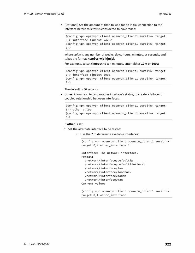
Virtual Private Networks (VPN) OpenVPN
6310-DX User Guide 322
l (Optional) Set the amount of time to wait for an initial connection to theinterface before this test is considered to have failed:
(config vpn openvpn client openvpn_client1 surelink target0)> interface_timeout value(config vpn openvpn client openvpn_client1 surelink target0)>
where value is any number of weeks, days, hours, minutes, or seconds, andtakes the format number{w|d|h|m|s}.For example, to set timeout to ten minutes, enter either 10m or 600s:
(config vpn openvpn client openvpn_client1 surelink target0)> interface_timeout 600s(config vpn openvpn client openvpn_client1 surelink target0)>
The default is 60 seconds.l other: Allows you to test another interface's status, to create a failover or
coupled relationship between interfaces:
(config vpn openvpn client openvpn_client1 surelink target0)> other value(config vpn openvpn client openvpn_client1 surelink target0)>
If other is set:o Set the alternate interface to be tested:
i. Use the ? to determine available interfaces:
(config vpn openvpn client openvpn_client1 surelinktarget 0)> other_interface ?
Interface: The network interface.Format:/network/interface/defaultip/network/interface/defaultlinklocal/network/interface/lan/network/interface/loopback/network/interface/modem/network/interface/wan
Current value:
(config vpn openvpn client openvpn_client1 surelinktarget 0)> other_interface
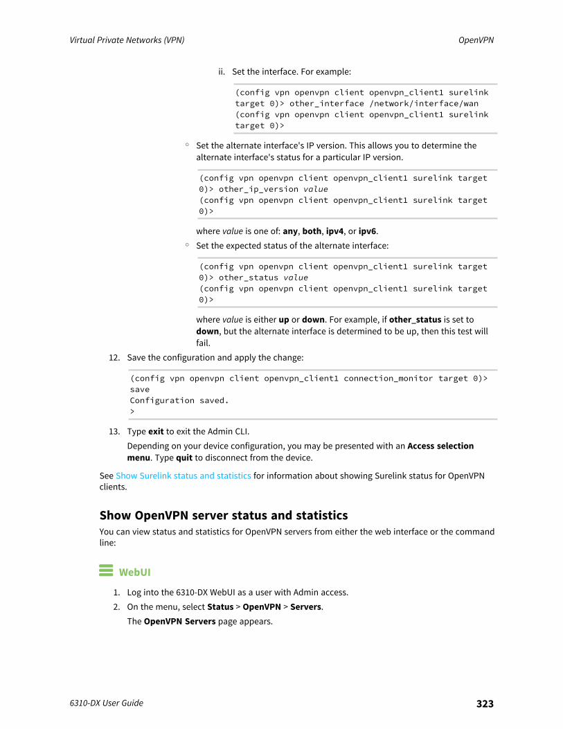
Virtual Private Networks (VPN) OpenVPN
6310-DX User Guide 323
ii. Set the interface. For example:
(config vpn openvpn client openvpn_client1 surelinktarget 0)> other_interface /network/interface/wan(config vpn openvpn client openvpn_client1 surelinktarget 0)>
o Set the alternate interface's IP version. This allows you to determine thealternate interface's status for a particular IP version.
(config vpn openvpn client openvpn_client1 surelink target0)> other_ip_version value(config vpn openvpn client openvpn_client1 surelink target0)>
where value is one of: any, both, ipv4, or ipv6.o Set the expected status of the alternate interface:
(config vpn openvpn client openvpn_client1 surelink target0)> other_status value(config vpn openvpn client openvpn_client1 surelink target0)>
where value is either up or down. For example, if other_status is set todown, but the alternate interface is determined to be up, then this test willfail.
12. Save the configuration and apply the change:
(config vpn openvpn client openvpn_client1 connection_monitor target 0)>saveConfiguration saved.>
13. Type exit to exit the Admin CLI.Depending on your device configuration, you may be presented with an Access selectionmenu. Type quit to disconnect from the device.
See Show Surelink status and statistics for information about showing Surelink status for OpenVPNclients.
Show OpenVPN server status and statisticsYou can view status and statistics for OpenVPN servers from either the web interface or the commandline:
WebUI
1. Log into the 6310-DX WebUI as a user with Admin access.2. On the menu, select Status > OpenVPN > Servers.
The OpenVPN Servers page appears.
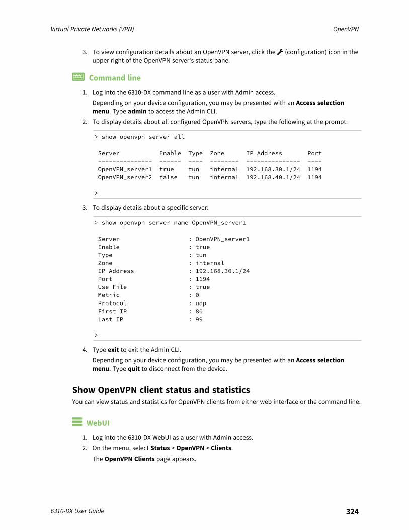
Virtual Private Networks (VPN) OpenVPN
6310-DX User Guide 324
3. To view configuration details about an OpenVPN server, click the (configuration) icon in theupper right of the OpenVPN server's status pane.
Command line
1. Log into the 6310-DX command line as a user with Admin access.Depending on your device configuration, you may be presented with an Access selectionmenu. Type admin to access the Admin CLI.
2. To display details about all configured OpenVPN servers, type the following at the prompt:
> show openvpn server all
Server Enable Type Zone IP Address Port--------------- ------ ---- -------- --------------- ----OpenVPN_server1 true tun internal 192.168.30.1/24 1194OpenVPN_server2 false tun internal 192.168.40.1/24 1194
>
3. To display details about a specific server:
> show openvpn server name OpenVPN_server1
Server : OpenVPN_server1Enable : trueType : tunZone : internalIP Address : 192.168.30.1/24Port : 1194Use File : trueMetric : 0Protocol : udpFirst IP : 80Last IP : 99
>
4. Type exit to exit the Admin CLI.Depending on your device configuration, you may be presented with an Access selectionmenu. Type quit to disconnect from the device.
Show OpenVPN client status and statisticsYou can view status and statistics for OpenVPN clients from either web interface or the command line:
WebUI
1. Log into the 6310-DX WebUI as a user with Admin access.2. On the menu, select Status > OpenVPN > Clients.
The OpenVPN Clients page appears.
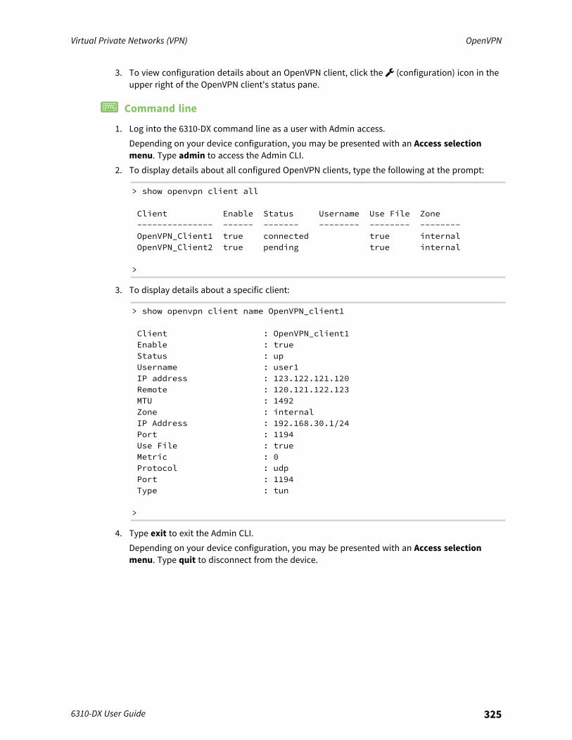
Virtual Private Networks (VPN) OpenVPN
6310-DX User Guide 325
3. To view configuration details about an OpenVPN client, click the (configuration) icon in theupper right of the OpenVPN client's status pane.
Command line
1. Log into the 6310-DX command line as a user with Admin access.Depending on your device configuration, you may be presented with an Access selectionmenu. Type admin to access the Admin CLI.
2. To display details about all configured OpenVPN clients, type the following at the prompt:
> show openvpn client all
Client Enable Status Username Use File Zone--------------- ------ ------- -------- -------- --------OpenVPN_Client1 true connected true internalOpenVPN_Client2 true pending true internal
>
3. To display details about a specific client:
> show openvpn client name OpenVPN_client1
Client : OpenVPN_client1Enable : trueStatus : upUsername : user1IP address : 123.122.121.120Remote : 120.121.122.123MTU : 1492Zone : internalIP Address : 192.168.30.1/24Port : 1194Use File : trueMetric : 0Protocol : udpPort : 1194Type : tun
>
4. Type exit to exit the Admin CLI.Depending on your device configuration, you may be presented with an Access selectionmenu. Type quit to disconnect from the device.
Virtual Private Networks (VPN) Generic Routing Encapsulation (GRE)
6310-DX User Guide 326
Generic Routing Encapsulation (GRE)Generic Routing Encapsulation (GRE) is an IP packet encapsulation protocol that allow for networksand routes to be advertized from one network device to another. You can use GRE to encapsulate awide variety of network layer protocols inside virtual point-to-point links over an IP network.
Configuring a GRE tunnelConfiguring a GRE tunnel involves the following items:
Required configuration items
n A GRE loopback endpoint interface.n GRE tunnel configuration:
l Enable the GRE tunnel.The GRE tunnels are enabled by default.
l The local endpoint interface.l The IP address of the remote device/peer.
Additional configuration items
n A GRE key.n Enable the device to respond to keepalive packets.
Task One: Create a GRE loopback endpoint interface
WebUI
1. Log into the 6310-DX WebUI as a user with full Admin access rights.2. On the menu, click System. Under Configuration, click Device Configuration.
The Configuration window is displayed.
Virtual Private Networks (VPN) Generic Routing Encapsulation (GRE)
6310-DX User Guide 327
3. Click Network > Interfaces.4. For Add Interface, type a name for the GRE loopback endpoint interface and click .5. Enable the interface.
New interfaces are enabled by default. To disable, or to enable if it has been disabled, clickEnable.
6. For Interface type, select Ethernet.7. For Zone, select Internal.8. For Device, select Ethernet: Loopback.9. Click to expand IPv4.
10. For Address, enter the IP address and subnet mask of the local GRE endpoint, for example10.10.1.1/24.
11. Click Apply to save the configuration and apply the change.
Command line
1. Log into the 6310-DX command line as a user with full Admin access rights.Depending on your device configuration, you may be presented with an Access selectionmenu. Type admin to access the Admin CLI.
2. At the command line, type config to enter configuration mode:
> config(config)>
3. Add the GRE endpoint interface. For example, to add an interface named gre_endpoint:
(config)> add network interface gre_interface(config network interface gre_interface)>
Virtual Private Networks (VPN) Generic Routing Encapsulation (GRE)
6310-DX User Guide 328
4. Set the interface zone to internal:
(config network interface gre_interface)> zone internal(config network interface gre_interface)>
5. Set the interface device to loopback:
(config network interface gre_interface)> device /network/device/loopback(config network interface gre_interface)>
6. Set the IP address and subnet mask of the local GRE endpoint. For example, to set the localGRE endpoint's IP address and subnet mask to 10.10.1.1/24:
(config network interface gre_interface)> ipv4 address 10.10.1.1/24(config network interface gre_interface)>
7. Save the configuration and apply the change:
(config network interface gre_interface)> saveConfiguration saved.>
8. Type exit to exit the Admin CLI.Depending on your device configuration, you may be presented with an Access selectionmenu. Type quit to disconnect from the device.
Task Two: Configure the GRE tunnel
WebUI
1. Log into the 6310-DX WebUI as a user with full Admin access rights.2. On the menu, click System. Under Configuration, click Device Configuration.
The Configuration window is displayed.
Virtual Private Networks (VPN) Generic Routing Encapsulation (GRE)
6310-DX User Guide 329
3. Click VPN > IP Tunnels.4. For Add IP tunnel, type a name for the GRE tunnel and click .5. Enable the tunnel.
New tunnels are enabled by default. To disable, or to enable if it has been disabled, clickEnable.
6. For Local endpoint, select the GRE endpoint interface created in Task One.7. For Remote endpoint, type the IP address of the GRE endpoint on the remote peer.8. (Optional) For Key, enter a key that will be inserted in GRE packets created by this tunnel. It
must match the key set by the remote endpoint. Allowed value is an interger between 0 and4294967295, or an IP address.
9. (Optional) Enable keepalive reply to enable the device to reply to Cisco GRE keepalivepackets.
10. Click Apply to save the configuration and apply the change.
Command line
1. Log into the 6310-DX command line as a user with full Admin access rights.Depending on your device configuration, you may be presented with an Access selectionmenu. Type admin to access the Admin CLI.
2. At the command line, type config to enter configuration mode:
> config(config)>
3. Add the GRE endpoint tunnel. For example, to add a tunnel named gre_example:
(config)> add vpn iptunnel gre_example(config vpn iptunnel gre_example)>
GRE tunnels are enabled by default. To disable:
(config vpn iptunnel gre_example)> enable false(config vpn iptunnel gre_example)>
4. Set the local endpoint to the GRE endpoint interface created in Task One, for example:
(config vpn iptunnel gre_example)> local /network/interface/gre_endpoint(config vpn iptunnel gre_example)>
5. Set the IP address of the GRE endpoint on the remote peer:
(config vpn iptunnel gre_example)> remote ip_address(config vpn iptunnel gre_example)>

Virtual Private Networks (VPN) Generic Routing Encapsulation (GRE)
6310-DX User Guide 330
6. (Optional) Set a key that will be inserted in GRE packets created by this tunnel.The key must match the key set by the remote endpoint.
(config vpn iptunnel gre_example)> key value(config vpn iptunnel gre_example)>
where value is an interger between 0 and 4294967295, or an IP address.7. (Optional) Enable the device to reply to Cisco GRE keepalive packets:
(config vpn iptunnel gre_example)> keepalive true(config vpn iptunnel gre_example)>
8. Save the configuration and apply the change:
(config vpn iptunnel gre_example)> saveConfiguration saved.>
9. Type exit to exit the Admin CLI.Depending on your device configuration, you may be presented with an Access selectionmenu. Type quit to disconnect from the device.
Virtual Private Networks (VPN) Generic Routing Encapsulation (GRE)
6310-DX User Guide 331
Show GRE tunnelsTo view information about currently configured GRE tunnels:
WebUI
1. Log into the 6310-DX WebUI as a user with Admin access.2. On the menu, click Status > IP tunnels.
The IP Tunnelspage appears.3. To view configuration details about a GRE tunnel, click the (configuration) icon in the upper
right of the tunnel's status pane.
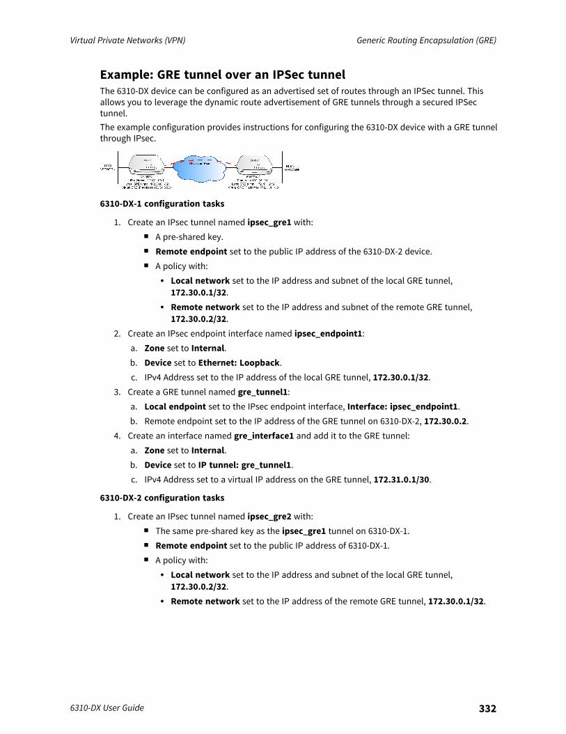
Virtual Private Networks (VPN) Generic Routing Encapsulation (GRE)
6310-DX User Guide 332
Example: GRE tunnel over an IPSec tunnelThe 6310-DX device can be configured as an advertised set of routes through an IPSec tunnel. Thisallows you to leverage the dynamic route advertisement of GRE tunnels through a secured IPSectunnel.The example configuration provides instructions for configuring the 6310-DX device with a GRE tunnelthrough IPsec.
6310-DX-1 configuration tasks
1. Create an IPsec tunnel named ipsec_gre1 with:n A pre-shared key.n Remote endpoint set to the public IP address of the 6310-DX-2 device.n A policy with:
l Local network set to the IP address and subnet of the local GRE tunnel,172.30.0.1/32.
l Remote network set to the IP address and subnet of the remote GRE tunnel,172.30.0.2/32.
2. Create an IPsec endpoint interface named ipsec_endpoint1:a. Zone set to Internal.b. Device set to Ethernet: Loopback.c. IPv4 Address set to the IP address of the local GRE tunnel, 172.30.0.1/32.
3. Create a GRE tunnel named gre_tunnel1:a. Local endpoint set to the IPsec endpoint interface, Interface: ipsec_endpoint1.b. Remote endpoint set to the IP address of the GRE tunnel on 6310-DX-2, 172.30.0.2.
4. Create an interface named gre_interface1 and add it to the GRE tunnel:a. Zone set to Internal.b. Device set to IP tunnel: gre_tunnel1.c. IPv4 Address set to a virtual IP address on the GRE tunnel, 172.31.0.1/30.
6310-DX-2 configuration tasks
1. Create an IPsec tunnel named ipsec_gre2 with:n The same pre-shared key as the ipsec_gre1 tunnel on 6310-DX-1.n Remote endpoint set to the public IP address of 6310-DX-1.n A policy with:
l Local network set to the IP address and subnet of the local GRE tunnel,172.30.0.2/32.
l Remote network set to the IP address of the remote GRE tunnel, 172.30.0.1/32.
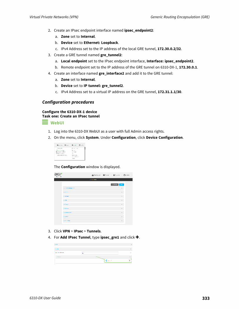
Virtual Private Networks (VPN) Generic Routing Encapsulation (GRE)
6310-DX User Guide 333
2. Create an IPsec endpoint interface named ipsec_endpoint2:a. Zone set to Internal.b. Device set to Ethernet: Loopback.c. IPv4 Address set to the IP address of the local GRE tunnel, 172.30.0.2/32.
3. Create a GRE tunnel named gre_tunnel2:a. Local endpoint set to the IPsec endpoint interface, Interface: ipsec_endpoint2.b. Remote endpoint set to the IP address of the GRE tunnel on 6310-DX-1, 172.30.0.1.
4. Create an interface named gre_interface2 and add it to the GRE tunnel:a. Zone set to Internal.b. Device set to IP tunnel: gre_tunnel2.c. IPv4 Address set to a virtual IP address on the GRE tunnel, 172.31.1.1/30.
Configuration procedures
Configure the 6310-DX-1 deviceTask one: Create an IPsec tunnel
WebUI
1. Log into the 6310-DX WebUI as a user with full Admin access rights.2. On the menu, click System. Under Configuration, click Device Configuration.
The Configuration window is displayed.
3. Click VPN > IPsec > Tunnels.4. For Add IPsec Tunnel, type ipsec_gre1 and click .

Virtual Private Networks (VPN) Generic Routing Encapsulation (GRE)
6310-DX User Guide 334
5. Click to expand Authentication.6. For Pre-shared key, type testkey.
7. Click to expand Remote endpoint.8. For Hostname, type public IP address of the 6310-DX-2 device.
9. Click to expand Policies.10. For Add Policy, click to add a new policy.
11. Click to expand Local network.12. For Type, select Custom network.13. For Address, type the IP address and subnet of the local GRE tunnel, 172.30.0.1/32.14. For Remote network, type the IP address and subnet of the remote GRE tunnel,
172.30.0.2/32.
15. Click Apply to save the configuration and apply the change.
Command line
1. Log into the 6310-DX command line as a user with full Admin access rights.Depending on your device configuration, you may be presented with an Access selectionmenu. Type admin to access the Admin CLI.
2. At the command line, type config to enter configuration mode:
> config(config)>
Virtual Private Networks (VPN) Generic Routing Encapsulation (GRE)
6310-DX User Guide 335
3. Add an IPsec tunnel named ipsec_gre1:
(config)> add vpn ipsec tunnel ipsec_gre1(config vpn ipsec tunnel ipsec_gre1)>
4. Set the pre-shared key to testkey:
(config vpn ipsec tunnel ipsec_gre1)> auth secret testkey(config vpn ipsec tunnel ipsec_gre1)>
5. Set the remote endpoint to public IP address of the 6310-DX-2 device:
(config vpn ipsec tunnel ipsec_gre1)> remote hostname 192.168.101.1(config vpn ipsec tunnel ipsec_gre1)>
6. Add a policy:
(config vpn ipsec tunnel ipsec_gre1)> add policy end(config vpn ipsec tunnel ipsec_gre1 policy 0)>
7. Set the local network policy type to custom:
(config vpn ipsec tunnel ipsec_gre1 policy 0)> local type custom(config vpn ipsec tunnel ipsec_gre1 policy 0)>
8. Set the local network address to the IP address and subnet of the local GRE tunnel,172.30.0.1/32:
(config vpn ipsec tunnel ipsec_gre1 policy 0)> local custom 172.30.0.1/32(config vpn ipsec tunnel ipsec_gre1 policy 0)>
9. Set the remote network address to the IP address and subnet of the remote GRE tunnel,172.30.0.2/32:
(config vpn ipsec tunnel ipsec_gre1 policy 0)> remote network172.30.0.2/32(config vpn ipsec tunnel ipsec_gre1 policy 0)>
10. Save the configuration and apply the change:
(config ipsec tunnel ipsec_gre1 policy 0)> saveConfiguration saved.>

Virtual Private Networks (VPN) Generic Routing Encapsulation (GRE)
6310-DX User Guide 336
Task two: Create an IPsec endpoint interface
WebUI
1. Click Network > Interface.2. For Add Interface, type ipsec_endpoint1 and click .
3. For Zone, select Internal.4. For Device, select Ethernet: loopback.
5. Click to expand IPv4.6. For Address, type the IP address of the local GRE tunnel, 172.30.0.1/32.
7. Click Apply to save the configuration and apply the change.
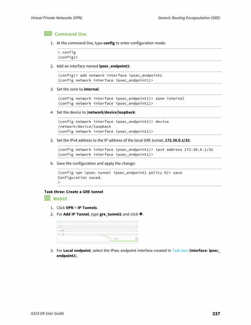
Virtual Private Networks (VPN) Generic Routing Encapsulation (GRE)
6310-DX User Guide 337
Command line
1. At the command line, type config to enter configuration mode:
> config(config)>
2. Add an interface named ipsec_endpoint1:
(config)> add network interface ipsec_endpoint1(config network interface ipsec_endpoint1)>
3. Set the zone to internal:
(config network interface ipsec_endpoint1)> zone internal(config network interface ipsec_endpoint1)>
4. Set the device to /network/device/loopback:
(config network interface ipsec_endpoint1)> device/network/device/loopback(config network interface ipsec_endpoint1)>
5. Set the IPv4 address to the IP address of the local GRE tunnel, 172.30.0.1/32:
(config network interface ipsec_endpoint1)> ipv4 address 172.30.0.1/32(config network interface ipsec_endpoint1)>
6. Save the configuration and apply the change:
(config vpn ipsec tunnel ipsec_endpoint1 policy 0)> saveConfiguration saved.>
Task three: Create a GRE tunnel
WebUI
1. Click VPN > IP Tunnels.2. For Add IP Tunnel, type gre_tunnel1 and click .
3. For Local endpoint, select the IPsec endpoint interface created in Task two (Interface: ipsec_endpoint1).
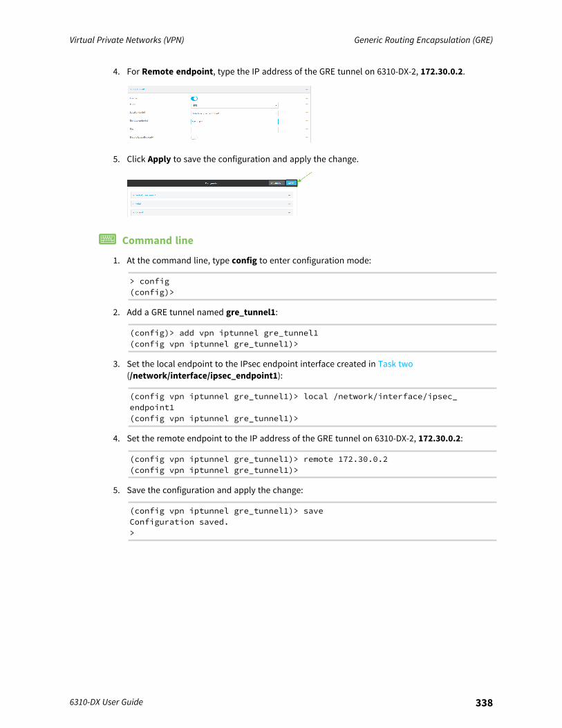
Virtual Private Networks (VPN) Generic Routing Encapsulation (GRE)
6310-DX User Guide 338
4. For Remote endpoint, type the IP address of the GRE tunnel on 6310-DX-2, 172.30.0.2.
5. Click Apply to save the configuration and apply the change.
Command line
1. At the command line, type config to enter configuration mode:
> config(config)>
2. Add a GRE tunnel named gre_tunnel1:
(config)> add vpn iptunnel gre_tunnel1(config vpn iptunnel gre_tunnel1)>
3. Set the local endpoint to the IPsec endpoint interface created in Task two(/network/interface/ipsec_endpoint1):
(config vpn iptunnel gre_tunnel1)> local /network/interface/ipsec_endpoint1(config vpn iptunnel gre_tunnel1)>
4. Set the remote endpoint to the IP address of the GRE tunnel on 6310-DX-2, 172.30.0.2:
(config vpn iptunnel gre_tunnel1)> remote 172.30.0.2(config vpn iptunnel gre_tunnel1)>
5. Save the configuration and apply the change:
(config vpn iptunnel gre_tunnel1)> saveConfiguration saved.>
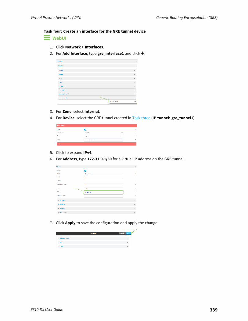
Virtual Private Networks (VPN) Generic Routing Encapsulation (GRE)
6310-DX User Guide 339
Task four: Create an interface for the GRE tunnel device
WebUI
1. Click Network > Interfaces.2. For Add Interface, type gre_interface1 and click .
3. For Zone, select Internal.4. For Device, select the GRE tunnel created in Task three (IP tunnel: gre_tunnel1).
5. Click to expand IPv4.6. For Address, type 172.31.0.1/30 for a virtual IP address on the GRE tunnel.
7. Click Apply to save the configuration and apply the change.
Virtual Private Networks (VPN) Generic Routing Encapsulation (GRE)
6310-DX User Guide 340
Command line
1. At the command line, type config to enter configuration mode:
> config(config)>
2. Add an interface named gre_interface1:
(config)> add network interface gre_interface1(config network interface gre_interface1)>
3. Set the zone to internal:
(config network interface gre_interface1)> zone internal(config network interface gre_interface1)>
4. Set the device to the GRE tunnel created in Task three (/vpn/iptunnel/gre_tunnel1):
(config network interface gre_interface1)> device /vpn/iptunnel/gre_tunnel1(config network interface gre_interface1)>
5. Set 172.31.0.1/30 as the virtual IP address on the GRE tunnel:
(config network interface gre_interface1)> ipv4 address 172.31.0.1/30(config network interface gre_interface1)>
6. Save the configuration and apply the change:
(config network interface gre_interface1)> saveConfiguration saved.>
7. Type exit to exit the Admin CLI.Depending on your device configuration, you may be presented with an Access selectionmenu. Type quit to disconnect from the device.
Configure the 6310-DX-2 deviceTask one: Create an IPsec tunnel
WebUI
1. Log into the 6310-DX WebUI as a user with full Admin access rights.2. On the menu, click System. Under Configuration, click Device Configuration.
The Configuration window is displayed.
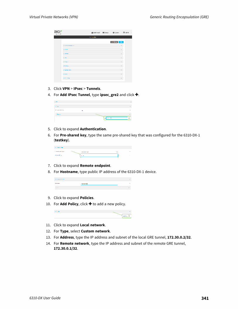
Virtual Private Networks (VPN) Generic Routing Encapsulation (GRE)
6310-DX User Guide 341
3. Click VPN > IPsec > Tunnels.4. For Add IPsec Tunnel, type ipsec_gre2 and click .
5. Click to expand Authentication.6. For Pre-shared key, type the same pre-shared key that was configured for the 6310-DX-1
(testkey).
7. Click to expand Remote endpoint.8. For Hostname, type public IP address of the 6310-DX-1 device.
9. Click to expand Policies.10. For Add Policy, click to add a new policy.
11. Click to expand Local network.12. For Type, select Custom network.13. For Address, type the IP address and subnet of the local GRE tunnel, 172.30.0.2/32.14. For Remote network, type the IP address and subnet of the remote GRE tunnel,
172.30.0.1/32.
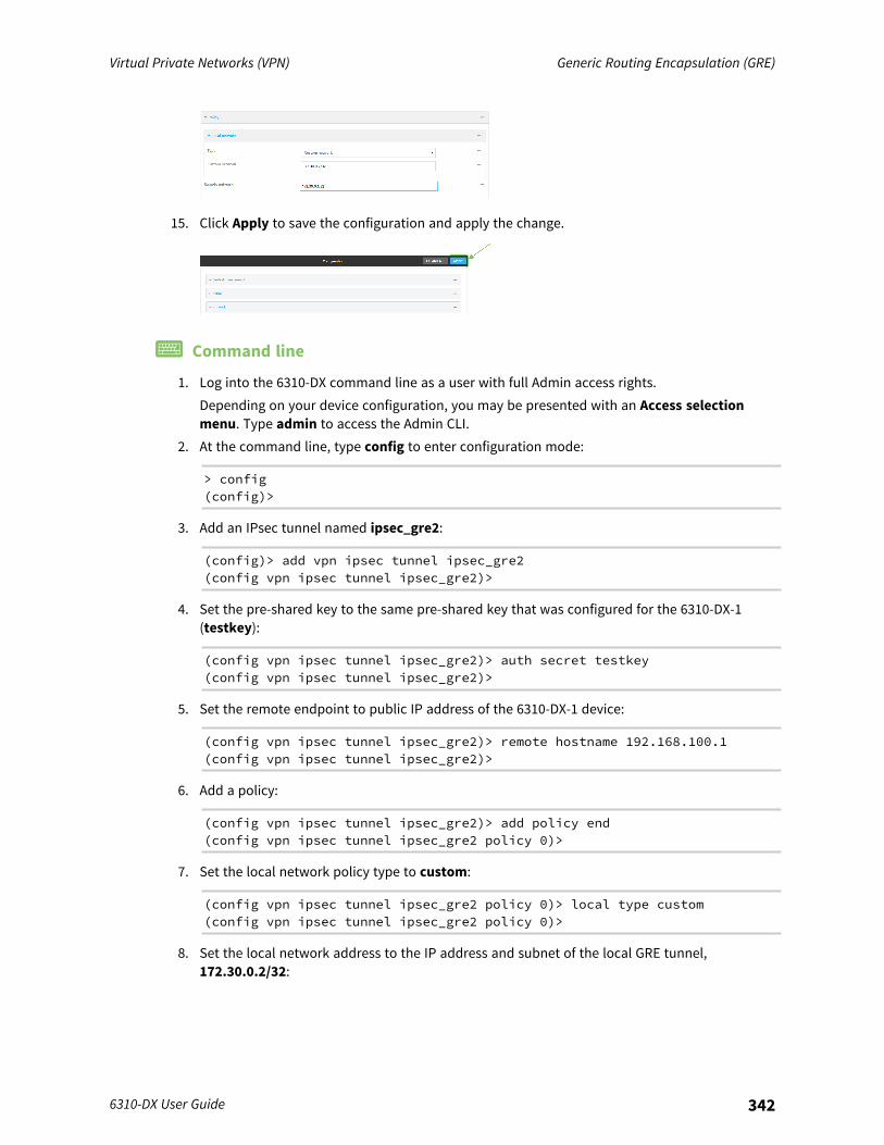
Virtual Private Networks (VPN) Generic Routing Encapsulation (GRE)
6310-DX User Guide 342
15. Click Apply to save the configuration and apply the change.
Command line
1. Log into the 6310-DX command line as a user with full Admin access rights.Depending on your device configuration, you may be presented with an Access selectionmenu. Type admin to access the Admin CLI.
2. At the command line, type config to enter configuration mode:
> config(config)>
3. Add an IPsec tunnel named ipsec_gre2:
(config)> add vpn ipsec tunnel ipsec_gre2(config vpn ipsec tunnel ipsec_gre2)>
4. Set the pre-shared key to the same pre-shared key that was configured for the 6310-DX-1(testkey):
(config vpn ipsec tunnel ipsec_gre2)> auth secret testkey(config vpn ipsec tunnel ipsec_gre2)>
5. Set the remote endpoint to public IP address of the 6310-DX-1 device:
(config vpn ipsec tunnel ipsec_gre2)> remote hostname 192.168.100.1(config vpn ipsec tunnel ipsec_gre2)>
6. Add a policy:
(config vpn ipsec tunnel ipsec_gre2)> add policy end(config vpn ipsec tunnel ipsec_gre2 policy 0)>
7. Set the local network policy type to custom:
(config vpn ipsec tunnel ipsec_gre2 policy 0)> local type custom(config vpn ipsec tunnel ipsec_gre2 policy 0)>
8. Set the local network address to the IP address and subnet of the local GRE tunnel,172.30.0.2/32:

Virtual Private Networks (VPN) Generic Routing Encapsulation (GRE)
6310-DX User Guide 343
(config vpn ipsec tunnel ipsec_gre2 policy 0)> local custom 172.30.0.2/32(config vpn ipsec tunnel ipsec_gre2 policy 0)>
9. Set the remote network address to the IP address and subnet of the remote GRE tunnel,172.30.0.1/32:
(config vpn ipsec tunnel ipsec_gre2 policy 0)> remote network172.30.0.1/32(config vpn ipsec tunnel ipsec_gre2 policy 0)>
10. Save the configuration and apply the change:
(config vpn ipsec tunnel ipsec_gre2 policy 0)> saveConfiguration saved.>
Task two: Create an IPsec endpoint interface
WebUI
1. Click Network > Interfaces.2. For Add Interface, type ipsec_endpoint2 and click .
3. For Zone, select Internal.4. For Device, select Ethernet: loopback.
5. Click to expand IPv4.
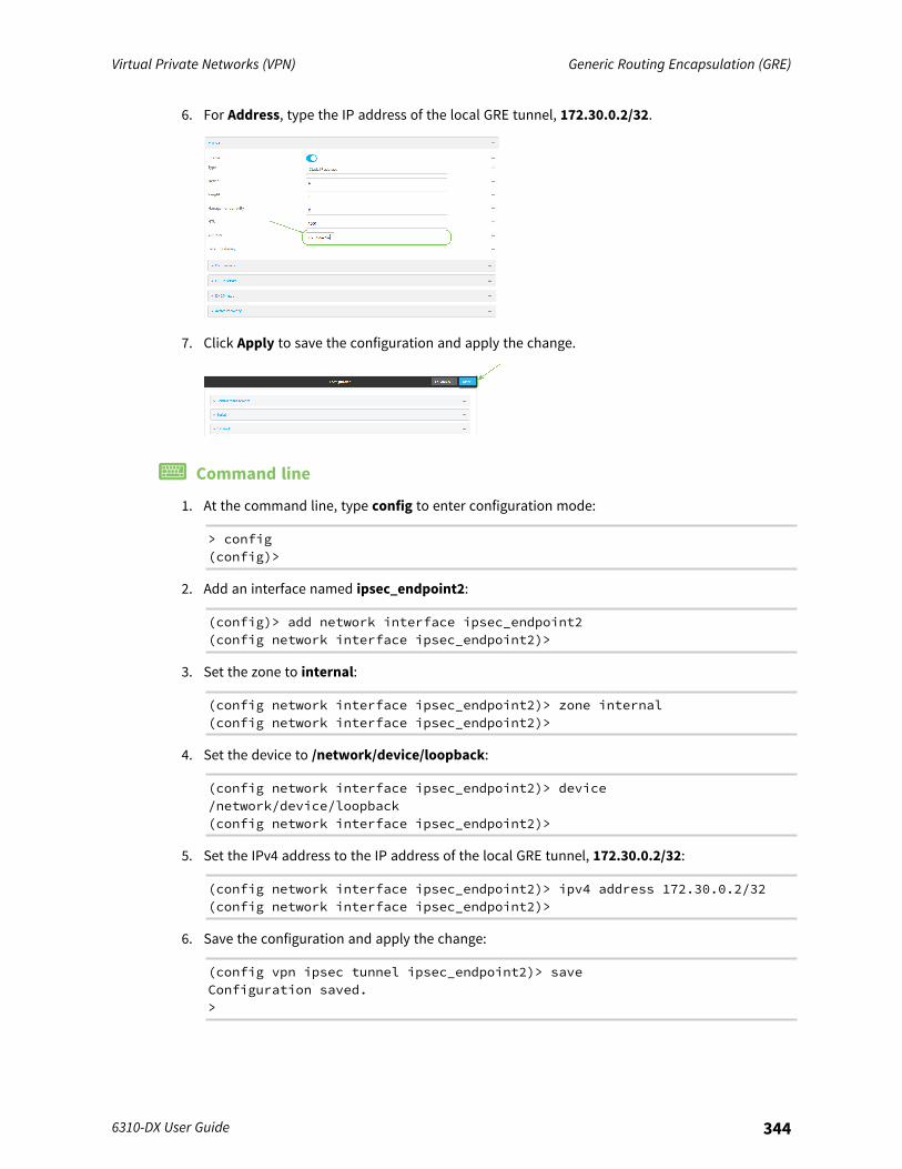
Virtual Private Networks (VPN) Generic Routing Encapsulation (GRE)
6310-DX User Guide 344
6. For Address, type the IP address of the local GRE tunnel, 172.30.0.2/32.
7. Click Apply to save the configuration and apply the change.
Command line
1. At the command line, type config to enter configuration mode:
> config(config)>
2. Add an interface named ipsec_endpoint2:
(config)> add network interface ipsec_endpoint2(config network interface ipsec_endpoint2)>
3. Set the zone to internal:
(config network interface ipsec_endpoint2)> zone internal(config network interface ipsec_endpoint2)>
4. Set the device to /network/device/loopback:
(config network interface ipsec_endpoint2)> device/network/device/loopback(config network interface ipsec_endpoint2)>
5. Set the IPv4 address to the IP address of the local GRE tunnel, 172.30.0.2/32:
(config network interface ipsec_endpoint2)> ipv4 address 172.30.0.2/32(config network interface ipsec_endpoint2)>
6. Save the configuration and apply the change:
(config vpn ipsec tunnel ipsec_endpoint2)> saveConfiguration saved.>
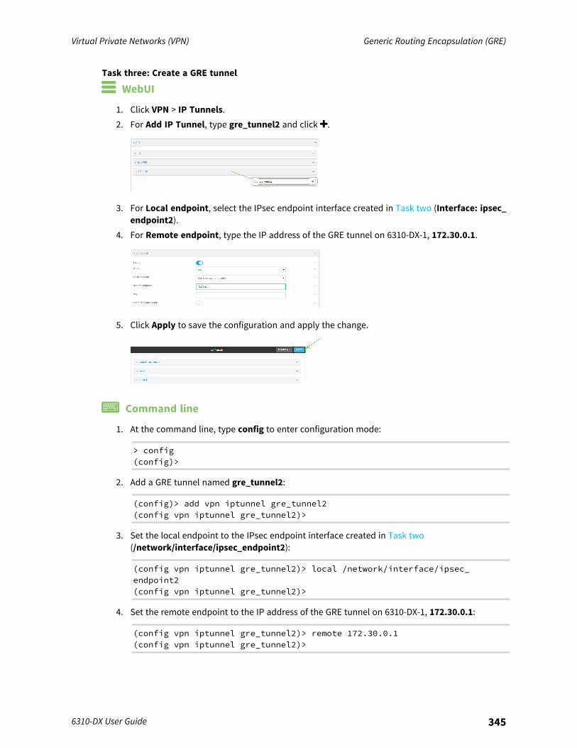
Virtual Private Networks (VPN) Generic Routing Encapsulation (GRE)
6310-DX User Guide 345
Task three: Create a GRE tunnel
WebUI
1. Click VPN > IP Tunnels.2. For Add IP Tunnel, type gre_tunnel2 and click .
3. For Local endpoint, select the IPsec endpoint interface created in Task two (Interface: ipsec_endpoint2).
4. For Remote endpoint, type the IP address of the GRE tunnel on 6310-DX-1, 172.30.0.1.
5. Click Apply to save the configuration and apply the change.
Command line
1. At the command line, type config to enter configuration mode:
> config(config)>
2. Add a GRE tunnel named gre_tunnel2:
(config)> add vpn iptunnel gre_tunnel2(config vpn iptunnel gre_tunnel2)>
3. Set the local endpoint to the IPsec endpoint interface created in Task two(/network/interface/ipsec_endpoint2):
(config vpn iptunnel gre_tunnel2)> local /network/interface/ipsec_endpoint2(config vpn iptunnel gre_tunnel2)>
4. Set the remote endpoint to the IP address of the GRE tunnel on 6310-DX-1, 172.30.0.1:
(config vpn iptunnel gre_tunnel2)> remote 172.30.0.1(config vpn iptunnel gre_tunnel2)>
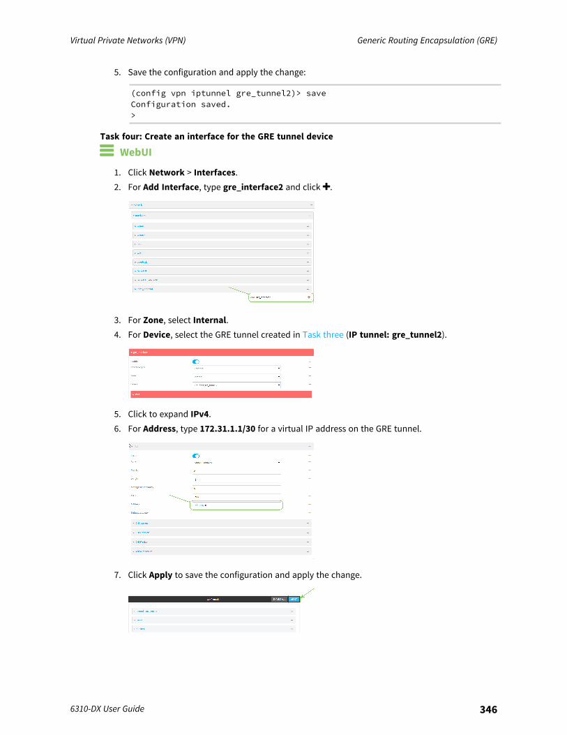
Virtual Private Networks (VPN) Generic Routing Encapsulation (GRE)
6310-DX User Guide 346
5. Save the configuration and apply the change:
(config vpn iptunnel gre_tunnel2)> saveConfiguration saved.>
Task four: Create an interface for the GRE tunnel device
WebUI
1. Click Network > Interfaces.2. For Add Interface, type gre_interface2 and click .
3. For Zone, select Internal.4. For Device, select the GRE tunnel created in Task three (IP tunnel: gre_tunnel2).
5. Click to expand IPv4.6. For Address, type 172.31.1.1/30 for a virtual IP address on the GRE tunnel.
7. Click Apply to save the configuration and apply the change.
Virtual Private Networks (VPN) L2TP
6310-DX User Guide 347
Command line
1. At the command line, type config to enter configuration mode:
> config(config)>
2. Add an interface named gre_interface2:
(config)> add network interface gre_interface2(config network interface gre_interface2)>
3. Set the zone to internal:
(config network interface gre_interface2)> zone internal(config network interface gre_interface2)>
4. Set the device to the GRE tunnel created in Task three (/vpn/iptunnel/gre_tunnel2):
(config network interface gre_interface2)> device /vpn/iptunnel/gre_tunnel2(config network interface gre_interface2)>
5. Set 172.31.0.1/30 as the virtual IP address on the GRE tunnel:
(config network interface gre_interface2)> ipv4 address 172.31.1.1/30(config network interface gre_interface2)>
6. Save the configuration and apply the change:
(config network interface gre_interface2)> saveConfiguration saved.>
7. Type exit to exit the Admin CLI.Depending on your device configuration, you may be presented with an Access selectionmenu. Type quit to disconnect from the device.
L2TPYour 6310-DX device supports PPP-over-L2TP (Layer 2 Tunneling Protocol).
Configure a PPP-over-L2TP tunnelYour 6310-DX device supports PPP-over-L2TP (Layer 2 Tunneling Protocol). The tunnel endpoints areknown as L2TP Access Concentrators (LAC) and L2TP Network Servers (LNS). Each endpointterminates the PPP session.
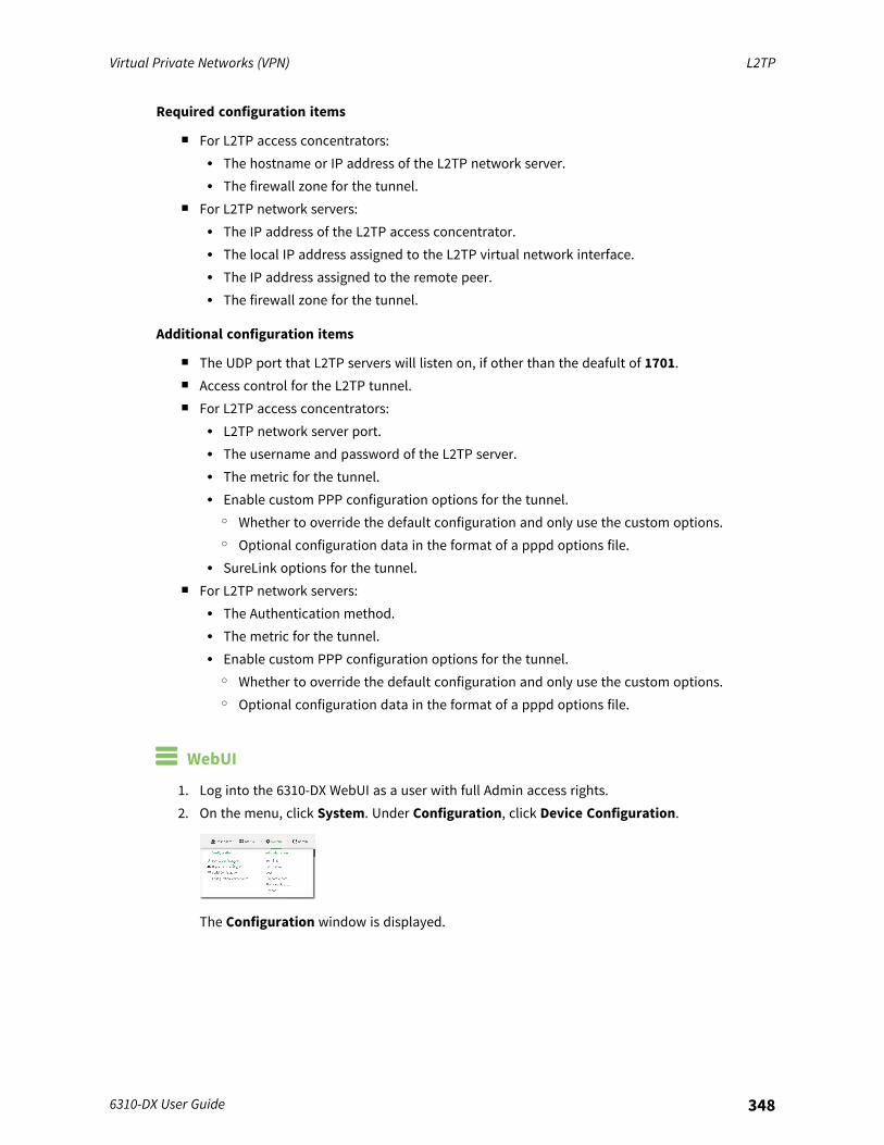
Virtual Private Networks (VPN) L2TP
6310-DX User Guide 348
Required configuration items
n For L2TP access concentrators:l The hostname or IP address of the L2TP network server.l The firewall zone for the tunnel.
n For L2TP network servers:l The IP address of the L2TP access concentrator.l The local IP address assigned to the L2TP virtual network interface.l The IP address assigned to the remote peer.l The firewall zone for the tunnel.
Additional configuration items
n The UDP port that L2TP servers will listen on, if other than the deafult of 1701.n Access control for the L2TP tunnel.n For L2TP access concentrators:
l L2TP network server port.l The username and password of the L2TP server.l The metric for the tunnel.l Enable custom PPP configuration options for the tunnel.
o Whether to override the default configuration and only use the custom options.o Optional configuration data in the format of a pppd options file.
l SureLink options for the tunnel.n For L2TP network servers:
l The Authentication method.l The metric for the tunnel.l Enable custom PPP configuration options for the tunnel.
o Whether to override the default configuration and only use the custom options.o Optional configuration data in the format of a pppd options file.
WebUI
1. Log into the 6310-DX WebUI as a user with full Admin access rights.2. On the menu, click System. Under Configuration, click Device Configuration.
The Configuration window is displayed.
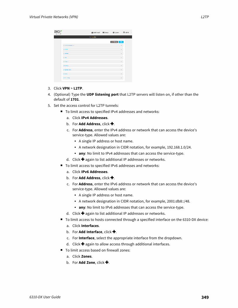
Virtual Private Networks (VPN) L2TP
6310-DX User Guide 349
3. Click VPN > L2TP.4. (Optional) Type the UDP listening port that L2TP servers will listen on, if other than the
default of 1701.5. Set the access control for L2TP tunnels:
n To limit access to specified IPv4 addresses and networks:a. Click IPv4 Addresses.b. For Add Address, click .c. For Address, enter the IPv4 address or network that can access the device's
service-type. Allowed values are:l A single IP address or host name.l A network designation in CIDR notation, for example, 192.168.1.0/24.l any: No limit to IPv4 addresses that can access the service-type.
d. Click again to list additional IP addresses or networks.n To limit access to specified IPv6 addresses and networks:
a. Click IPv6 Addresses.b. For Add Address, click .c. For Address, enter the IPv6 address or network that can access the device's
service-type. Allowed values are:l A single IP address or host name.l A network designation in CIDR notation, for example, 2001:db8::/48.l any: No limit to IPv6 addresses that can access the service-type.
d. Click again to list additional IP addresses or networks.n To limit access to hosts connected through a specified interface on the 6310-DX device:
a. Click Interfaces.b. For Add Interface, click .c. For Interface, select the appropriate interface from the dropdown.d. Click again to allow access through additional interfaces.
n To limit access based on firewall zones:a. Click Zones.b. For Add Zone, click .
Virtual Private Networks (VPN) L2TP
6310-DX User Guide 350
c. For Zone, select the appropriate firewall zone from the dropdown.See Firewall configuration for information about firewall zones.
d. Click again to allow access through additional firewall zones.6. To add an L2TP access concentrator:
a. Click to expand L2TP access concentrators.b. For Add L2TP access concentrator, type a name for the LAC and click .c. LACs are enabled by default. To disable, click to toggle off Enable.d. For L2TP network server, type the hostname or IP address of the L2TP network server.e. (Optional) Type the L2TP network server port to use to connect to the server, if other
than the default of 1701.f. (Optional) Type the Username to use to log into the server.g. (Optional) Type the Password to use to log into the server.h. (Optional) Type the Metric for the tunnel, if other than the default of 1.i. Select a firewall Zone for the tunnel. This is used by packet filtering rules and access
control lists to restrict network traffic on the tunnel.j. (Optional): Custom PPP configuration:
i. Enable custom PPP configuration.ii. Enable Override if the custom configuration should override the default configuration
and only use the custom options.iii. For Configuration file, paste or type the configuration data in the format of a pppd
options file.k. For SureLink, see Configure SureLink active recovery for PPP-over-L2TP.
7. To add an L2TP network server:a. Click to expand L2TP network servers.b. For Add L2TP network server, type a name for the LNS and click .c. LNSs are enabled by default. To disable, click to toggle off Enable.d. For L2TP access concentrator, type the IP addressof the L2TP access concentrator that
this server will allow connections from. This can also be:n A range of IP addresses, using the format x.x.x.x-y.y.y.y, for example 192.168.188.1-
192.168.188.254.n The keyword any, which means that the server will accept connections from any IP
address.e. For Local IP address, type the IP address of the L2TP virtual network interface.f. For Remote IP address, type the IP address to assign to the remote peer.g. (Optional) For Authentication method, select one of the following:
n None: No authentication is required.n Automatic: The device will attempt to connect using CHAP first, and then PAP.n CHAP: Uses the Challenge Handshake Authentication Profile (CHAP) to
authenticate.n PAP: Uses the Password Authentication Profile (PAP) to authenticate.
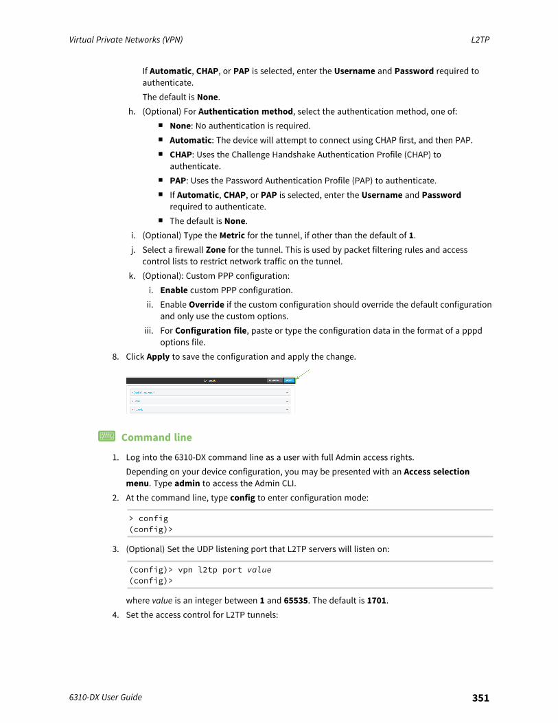
Virtual Private Networks (VPN) L2TP
6310-DX User Guide 351
If Automatic, CHAP, or PAP is selected, enter the Username and Password required toauthenticate.The default is None.
h. (Optional) For Authentication method, select the authentication method, one of:n None: No authentication is required.n Automatic: The device will attempt to connect using CHAP first, and then PAP.n CHAP: Uses the Challenge Handshake Authentication Profile (CHAP) to
authenticate.n PAP: Uses the Password Authentication Profile (PAP) to authenticate.n If Automatic, CHAP, or PAP is selected, enter the Username and Password
required to authenticate.n The default is None.
i. (Optional) Type the Metric for the tunnel, if other than the default of 1.j. Select a firewall Zone for the tunnel. This is used by packet filtering rules and access
control lists to restrict network traffic on the tunnel.k. (Optional): Custom PPP configuration:
i. Enable custom PPP configuration.ii. Enable Override if the custom configuration should override the default configuration
and only use the custom options.iii. For Configuration file, paste or type the configuration data in the format of a pppd
options file.8. Click Apply to save the configuration and apply the change.
Command line
1. Log into the 6310-DX command line as a user with full Admin access rights.Depending on your device configuration, you may be presented with an Access selectionmenu. Type admin to access the Admin CLI.
2. At the command line, type config to enter configuration mode:
> config(config)>
3. (Optional) Set the UDP listening port that L2TP servers will listen on:
(config)> vpn l2tp port value(config)>
where value is an integer between 1 and 65535. The default is 1701.4. Set the access control for L2TP tunnels:
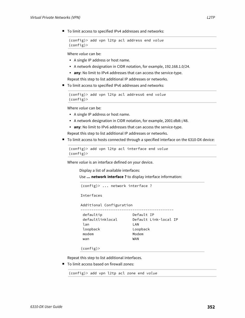
Virtual Private Networks (VPN) L2TP
6310-DX User Guide 352
n To limit access to specified IPv4 addresses and networks:
(config)> add vpn l2tp acl address end value(config)>
Where value can be:l A single IP address or host name.l A network designation in CIDR notation, for example, 192.168.1.0/24.l any: No limit to IPv4 addresses that can access the service-type.
Repeat this step to list additional IP addresses or networks.n To limit access to specified IPv6 addresses and networks:
(config)> add vpn l2tp acl address6 end value(config)>
Where value can be:l A single IP address or host name.l A network designation in CIDR notation, for example, 2001:db8::/48.l any: No limit to IPv6 addresses that can access the service-type.
Repeat this step to list additional IP addresses or networks.n To limit access to hosts connected through a specified interface on the 6310-DX device:
(config)> add vpn l2tp acl interface end value(config)>
Where value is an interface defined on your device.
Display a list of available interfaces:Use ... network interface ? to display interface information:
(config)> ... network interface ?
Interfaces
Additional Configuration-------------------------------------------defaultip Default IPdefaultlinklocal Default Link-local IPlan LANloopback Loopbackmodem Modemwan WAN
(config)>
Repeat this step to list additional interfaces.n To limit access based on firewall zones:
(config)> add vpn l2tp acl zone end value
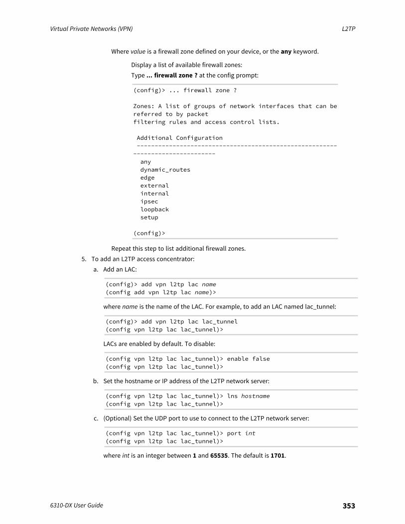
Virtual Private Networks (VPN) L2TP
6310-DX User Guide 353
Where value is a firewall zone defined on your device, or the any keyword.
Display a list of available firewall zones:Type ... firewall zone ? at the config prompt:
(config)> ... firewall zone ?
Zones: A list of groups of network interfaces that can bereferred to by packetfiltering rules and access control lists.
Additional Configuration--------------------------------------------------------
-----------------------anydynamic_routesedgeexternalinternalipsecloopbacksetup
(config)>
Repeat this step to list additional firewall zones.5. To add an L2TP access concentrator:
a. Add an LAC:
(config)> add vpn l2tp lac name(config add vpn l2tp lac name)>
where name is the name of the LAC. For example, to add an LAC named lac_tunnel:
(config)> add vpn l2tp lac lac_tunnel(config vpn l2tp lac lac_tunnel)>
LACs are enabled by default. To disable:
(config vpn l2tp lac lac_tunnel)> enable false(config vpn l2tp lac lac_tunnel)>
b. Set the hostname or IP address of the L2TP network server:
(config vpn l2tp lac lac_tunnel)> lns hostname(config vpn l2tp lac lac_tunnel)>
c. (Optional) Set the UDP port to use to connect to the L2TP network server:
(config vpn l2tp lac lac_tunnel)> port int(config vpn l2tp lac lac_tunnel)>
where int is an integer between 1 and 65535. The default is 1701.
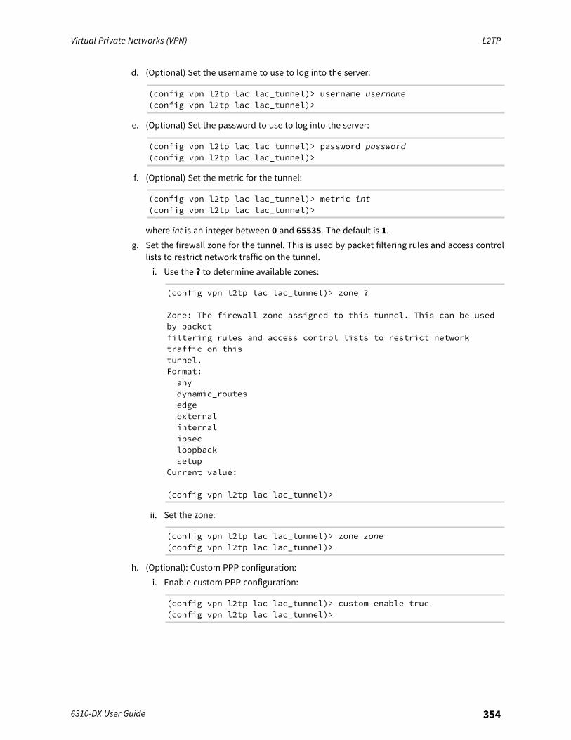
Virtual Private Networks (VPN) L2TP
6310-DX User Guide 354
d. (Optional) Set the username to use to log into the server:
(config vpn l2tp lac lac_tunnel)> username username(config vpn l2tp lac lac_tunnel)>
e. (Optional) Set the password to use to log into the server:
(config vpn l2tp lac lac_tunnel)> password password(config vpn l2tp lac lac_tunnel)>
f. (Optional) Set the metric for the tunnel:
(config vpn l2tp lac lac_tunnel)> metric int(config vpn l2tp lac lac_tunnel)>
where int is an integer between 0 and 65535. The default is 1.g. Set the firewall zone for the tunnel. This is used by packet filtering rules and access control
lists to restrict network traffic on the tunnel.i. Use the ? to determine available zones:
(config vpn l2tp lac lac_tunnel)> zone ?
Zone: The firewall zone assigned to this tunnel. This can be usedby packetfiltering rules and access control lists to restrict networktraffic on thistunnel.Format:anydynamic_routesedgeexternalinternalipsecloopbacksetup
Current value:
(config vpn l2tp lac lac_tunnel)>
ii. Set the zone:
(config vpn l2tp lac lac_tunnel)> zone zone(config vpn l2tp lac lac_tunnel)>
h. (Optional): Custom PPP configuration:i. Enable custom PPP configuration:
(config vpn l2tp lac lac_tunnel)> custom enable true(config vpn l2tp lac lac_tunnel)>
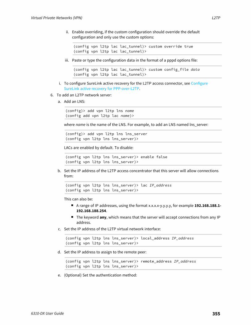
Virtual Private Networks (VPN) L2TP
6310-DX User Guide 355
ii. Enable overriding, if the custom configuration should override the defaultconfiguration and only use the custom options:
(config vpn l2tp lac lac_tunnel)> custom override true(config vpn l2tp lac lac_tunnel)>
iii. Paste or type the configuration data in the format of a pppd options file:
(config vpn l2tp lac lac_tunnel)> custom config_file data(config vpn l2tp lac lac_tunnel)>
i. To configure SureLink active recovery for the L2TP access connector, see ConfigureSureLink active recovery for PPP-over-L2TP.
6. To add an L2TP network server:a. Add an LNS:
(config)> add vpn l2tp lns name(config add vpn l2tp lac name)>
where name is the name of the LNS. For example, to add an LNS named lns_server:
(config)> add vpn l2tp lns lns_server(config vpn l2tp lns lns_server)>
LACs are enabled by default. To disable:
(config vpn l2tp lns lns_server)> enable false(config vpn l2tp lns lns_server)>
b. Set the IP address of the L2TP access concentrator that this server will allow connectionsfrom:
(config vpn l2tp lns lns_server)> lac IP_address(config vpn l2tp lns lns_server)>
This can also be:n A range of IP addresses, using the format x.x.x.x-y.y.y.y, for example 192.168.188.1-
192.168.188.254.n The keyword any, which means that the server will accept connections from any IP
address.c. Set the IP address of the L2TP virtual network interface:
(config vpn l2tp lns lns_server)> local_address IP_address(config vpn l2tp lns lns_server)>
d. Set the IP address to assign to the remote peer:
(config vpn l2tp lns lns_server)> remote_address IP_address(config vpn l2tp lns lns_server)>
e. (Optional) Set the authentication method:
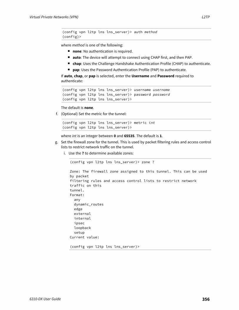
Virtual Private Networks (VPN) L2TP
6310-DX User Guide 356
(config vpn l2tp lns lns_server)> auth method(config)>
where method is one of the following:n none: No authentication is required.n auto: The device will attempt to connect using CHAP first, and then PAP.n chap: Uses the Challenge Handshake Authentication Profile (CHAP) to authenticate.n pap: Uses the Password Authentication Profile (PAP) to authenticate.
If auto, chap, or pap is selected, enter the Username and Password required toauthenticate:
(config vpn l2tp lns lns_server)> username username(config vpn l2tp lns lns_server)> password password(config vpn l2tp lns lns_server)>
The default is none.f. (Optional) Set the metric for the tunnel:
(config vpn l2tp lns lns_server)> metric int(config vpn l2tp lns lns_server)>
where int is an integer between 0 and 65535. The default is 1.g. Set the firewall zone for the tunnel. This is used by packet filtering rules and access control
lists to restrict network traffic on the tunnel.i. Use the ? to determine available zones:
(config vpn l2tp lns lns_server)> zone ?
Zone: The firewall zone assigned to this tunnel. This can be usedby packetfiltering rules and access control lists to restrict networktraffic on thistunnel.Format:anydynamic_routesedgeexternalinternalipsecloopbacksetup
Current value:
(config vpn l2tp lns lns_server)>
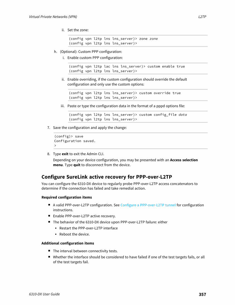
Virtual Private Networks (VPN) L2TP
6310-DX User Guide 357
ii. Set the zone:
(config vpn l2tp lns lns_server)> zone zone(config vpn l2tp lns lns_server)>
h. (Optional): Custom PPP configuration:i. Enable custom PPP configuration:
(config vpn l2tp lac lns lns_server)> custom enable true(config vpn l2tp lns lns_server)>
ii. Enable overriding, if the custom configuration should override the defaultconfiguration and only use the custom options:
(config vpn l2tp lns lns_server)> custom override true(config vpn l2tp lns lns_server)>
iii. Paste or type the configuration data in the format of a pppd options file:
(config vpn l2tp lns lns_server)> custom config_file data(config vpn l2tp lns lns_server)>
7. Save the configuration and apply the change:
(config)> saveConfiguration saved.>
8. Type exit to exit the Admin CLI.Depending on your device configuration, you may be presented with an Access selectionmenu. Type quit to disconnect from the device.
Configure SureLink active recovery for PPP-over-L2TPYou can configure the 6310-DX device to regularly probe PPP-over-L2TP access concatenators todetermine if the connection has failed and take remedial action.
Required configuration items
n A valid PPP-over-L2TP configuration. See Configure a PPP-over-L2TP tunnel for configurationinstructions.
n Enable PPP-over-L2TP active recovery.n The behavior of the 6310-DX device upon PPP-over-L2TP failure: either
l Restart the PPP-over-L2TP interfacel Reboot the device.
Additional configuration items
n The interval between connectivity tests.n Whether the interface should be considered to have failed if one of the test targets fails, or all
of the test targets fail.
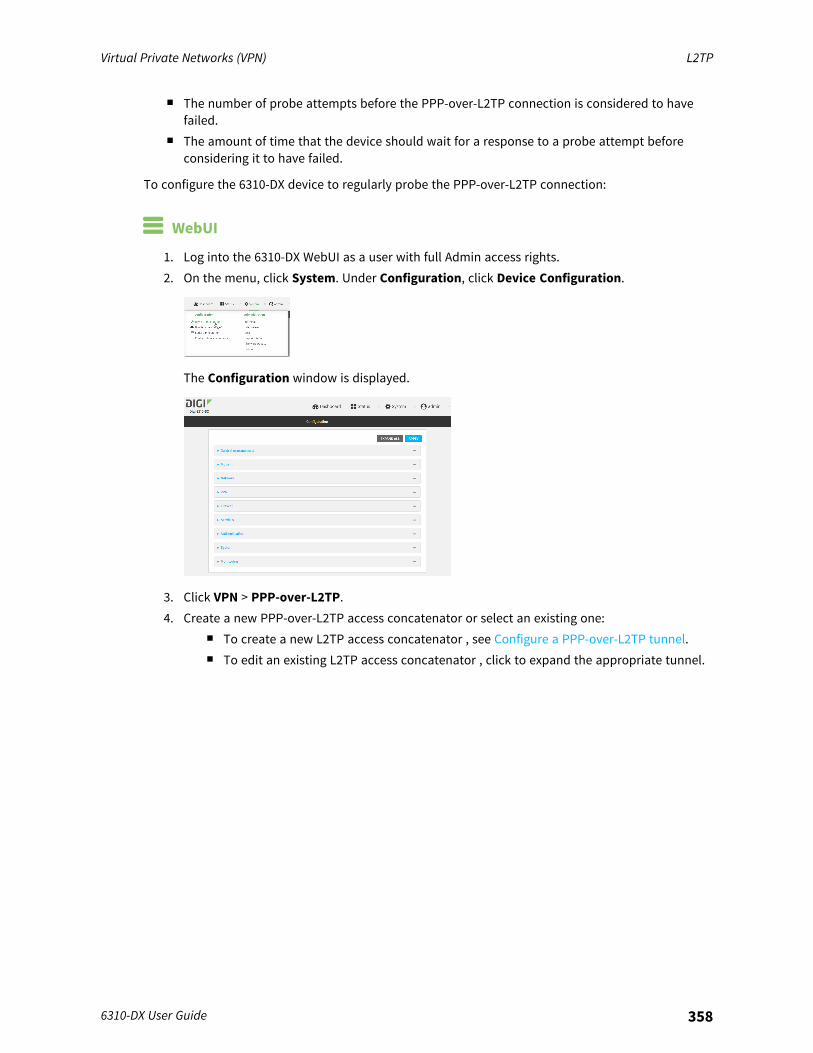
Virtual Private Networks (VPN) L2TP
6310-DX User Guide 358
n The number of probe attempts before the PPP-over-L2TP connection is considered to havefailed.
n The amount of time that the device should wait for a response to a probe attempt beforeconsidering it to have failed.
To configure the 6310-DX device to regularly probe the PPP-over-L2TP connection:
WebUI
1. Log into the 6310-DX WebUI as a user with full Admin access rights.2. On the menu, click System. Under Configuration, click Device Configuration.
The Configuration window is displayed.
3. Click VPN > PPP-over-L2TP.4. Create a new PPP-over-L2TP access concatenator or select an existing one:
n To create a new L2TP access concatenator , see Configure a PPP-over-L2TP tunnel.n To edit an existing L2TP access concatenator , click to expand the appropriate tunnel.
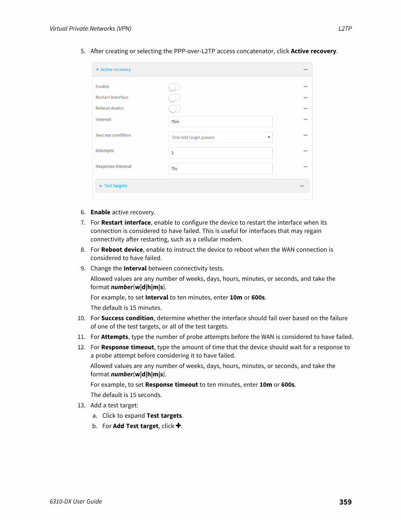
Virtual Private Networks (VPN) L2TP
6310-DX User Guide 359
5. After creating or selecting the PPP-over-L2TP access concatenator, click Active recovery.
6. Enable active recovery.7. For Restart interface, enable to configure the device to restart the interface when its
connection is considered to have failed. This is useful for interfaces that may regainconnectivity after restarting, such as a cellular modem.
8. For Reboot device, enable to instruct the device to reboot when the WAN connection isconsidered to have failed.
9. Change the Interval between connectivity tests.Allowed values are any number of weeks, days, hours, minutes, or seconds, and take theformat number{w|d|h|m|s}.For example, to set Interval to ten minutes, enter 10m or 600s.The default is 15 minutes.
10. For Success condition, determine whether the interface should fail over based on the failureof one of the test targets, or all of the test targets.
11. For Attempts, type the number of probe attempts before the WAN is considered to have failed.12. For Response timeout, type the amount of time that the device should wait for a response to
a probe attempt before considering it to have failed.Allowed values are any number of weeks, days, hours, minutes, or seconds, and take theformat number{w|d|h|m|s}.For example, to set Response timeout to ten minutes, enter 10m or 600s.The default is 15 seconds.
13. Add a test target:a. Click to expand Test targets.b. For Add Test target, click .

Virtual Private Networks (VPN) L2TP
6310-DX User Guide 360
c. Select the Test type:
n Test another interface's status: Allows you to test another interface's status, tocreate a failover or coupled relationship between interfaces. If Test anotherinterface's status is selected:l For Test Interface, select the alternate interface to be tested.l For IP version, select the alternate interface's IP version. This allows you to
determine the alternate interface's status for a particular IP version.l For Expected status, select whether the expected status of the alternate
interface is Up or Down. For example, if Expected status is set to Down, butthe alternate interface is determined to be up, then this test will fail.
n Ping test: Tests connectivity by sending an ICMP echo request to the hostname orIP address specified in Ping host. You can also optionally change the number ofbytes in the Ping payload size.
n DNS test: Tests connectivity by sending a DNS query to the specified DNS server.n HTTP test: Tests connectivity by sending an HTTP or HTTPS GET request to the
URL specified in Web servers. The URL should take the format of http[s]://hostname/[path].
n Test DNS servers configured for this interface: Tests connectivity by sending aDNS query to the DNS servers configured for this interface.
n Test the interface status: The interface is considered to be down based on:l Down time: The amount of time that the interface can be down before this test
is considered to have failed.Allowed values are any number of weeks, days, hours, minutes, or seconds, andtake the format number{w|d|h|m|s}.For example, to set Down time to ten minutes, enter 10m or 600s.The default is 60 seconds.
l Initial connection time: The amount of time to wait for an initial connection tothe interface before this test is considered to have failed.Allowed values are any number of weeks, days, hours, minutes, or seconds, andtake the format number{w|d|h|m|s}.For example, to set Initial connection time to ten minutes, enter 10m or 600s.The default is 60 seconds.
14. Click Apply to save the configuration and apply the change.

Virtual Private Networks (VPN) L2TP
6310-DX User Guide 361
Command line
1. Log into the 6310-DX command line as a user with full Admin access rights.Depending on your device configuration, you may be presented with an Access selectionmenu. Type admin to access the Admin CLI.
2. At the command line, type config to enter configuration mode:
> config(config)>
3. Create a new PPP-over-L2TP access concatenator , or edit an existing one:n To create a new PPP-over-L2TP access concatenator , see Configure a PPP-over-L2TP
tunnel.n To edit an existing PPP-over-L2TP access concatenator , change to the PPP-over-L2TP
access concatenator node in the configuration schema. For example, for an PPP-over-L2TP access concatenator named lac_tunnel, change to the lac_tunnel node in theconfiguration schema:
(config)> vpn l2tp lac lac_tunnel(config vpn l2tp lac lac_tunnel)>
4. Enable active recovery:
(config vpn l2tp lac lac_tunnel)> surelink enable true(config vpn l2tp lac lac_tunnel)>
5. To configure the device to restart the interface when its connection is considered to havefailed:
(config vpn l2tp lac lac_tunnel)> surelink restart true(config vpn l2tp lac lac_tunnel)>
This is useful for interfaces that may regain connectivity after restarting, such as a cellularmodem.
6. To configure the device to reboot when the interface is considered to have failed:
(config vpn l2tp lac lac_tunnel)> surelink reboot enable(config vpn l2tp lac lac_tunnel)>
7. Set the Interval between connectivity tests:
(config vpn l2tp lac lac_tunnel)> surelink interval value(config vpn l2tp lac lac_tunnel)>
where value is any number of weeks, days, hours, minutes, or seconds, and takes the formatnumber{w|d|h|m|s}.For example, to set interval to ten minutes, enter either 10m or 600s:
(config vpn l2tp lac lac_tunnel)> surelink interval 600s(config vpn l2tp lac lac_tunnel)>
The default is 15 minutes.
Virtual Private Networks (VPN) L2TP
6310-DX User Guide 362
8. Determine whether the interface should fail over based on the failure of one of the test targets,or all of the test targets:
(config vpn l2tp lac lac_tunnel)> surelink success_condition value(config vpn l2tp lac lac_tunnel)>
Where value is either one or all.9. Set the number of probe attempts before the WAN is considered to have failed:
(config vpn l2tp lac lac_tunnel)> surelink attempts num(config vpn l2tp lac lac_tunnel)>
The default is 3.10. Set the amount of time that the device should wait for a response to a probe attempt before
considering it to have failed:
(config vpn l2tp lac lac_tunnel)> surelink timeout value(config vpn l2tp lac lac_tunnel)>
where value is any number of weeks, days, hours, minutes, or seconds, and takes the formatnumber{w|d|h|m|s}.For example, to set interval to ten minutes, enter either 10m or 600s:
(config vpn l2tp lac lac_tunnel)> surelink timeout 600s(config vpn l2tp lac lac_tunnel)>
The default is 15 seconds.11. Configure test targets:
a. Add a test target:
(config vpn l2tp lac lac_tunnel)> add surelink target end(config vpn l2tp lac lac_tunnel surelink target 0)>
b. Set the test type:
(config vpn l2tp lac lac_tunnel surelink target 0)> test value(config vpn l2tp lac lac_tunnel surelink target 0)>
where value is one of:n ping: Tests connectivity by sending an ICMP echo request to a specified hostname
or IP address.l Specify the hostname or IP address:
(config vpn l2tp lac lac_tunnel surelink target 0)> ping_hosthost(config vpn l2tp lac lac_tunnel surelink target 0)>
l (Optional) Set the size, in bytes, of the ping packet:

Virtual Private Networks (VPN) L2TP
6310-DX User Guide 363
(config vpn l2tp lac lac_tunnel surelink target 0)> ping_size[num](config vpn l2tp lac lac_tunnel surelink target 0)>
n dns: Tests connectivity by sending a DNS query to the specified DNS server.l Specify the DNS server. Allowed value is the IP address of the DNS server.
(config vpn l2tp lac lac_tunnel surelink target 0)> dns_server ip_address(config vpn l2tp lac lac_tunnel surelink target 0)>
n dns_configured: Tests connectivity by sending a DNS query to the DNS serversconfigured for this interface.
n http: Tests connectivity by sending an HTTP or HTTPS GET request to the specifiedURL.l Specify the url:
(config vpn l2tp lac lac_tunnel surelink target 0)> http_urlvalue(config vpn l2tp lac lac_tunnel surelink target 0)>
where value uses the format http[s]://hostname/[path]n interface_up: The interface is considered to be down based on the interfaces down
time, and the amount of time an initial connection to the interface takes before thistest is considered to have failed.l (Optional) Set the amount of time that the interface can be down before this
test is considered to have failed:
(config vpn l2tp lac lac_tunnel surelink target 0)>interface_down_time value(config vpn l2tp lac lac_tunnel surelink target 0)>
where value is any number of weeks, days, hours, minutes, or seconds, andtakes the format number{w|d|h|m|s}.For example, to set interval to ten minutes, enter either 10m or 600s:
(config vpn l2tp lac lac_tunnel surelink target 0)>interface_down_time 600s(config vpn l2tp lac lac_tunnel surelink target 0)>
The default is 60 seconds.l (Optional) Set the amount of time to wait for an initial connection to the
interface before this test is considered to have failed:
(config vpn l2tp lac lac_tunnel surelink target 0)>interface_timeout value(config vpn l2tp lac lac_tunnel surelink target 0)>
Virtual Private Networks (VPN) L2TP
6310-DX User Guide 364
where value is any number of weeks, days, hours, minutes, or seconds, andtakes the format number{w|d|h|m|s}.For example, to set interval to ten minutes, enter either 10m or 600s:
(config vpn l2tp lac lac_tunnel surelink target 0)>interface_timeout 600s(config vpn l2tp lac lac_tunnel surelink target 0)>
The default is 60 seconds.l other: Allows you to test another interface's status, to create a failover or
coupled relationship between interfaces:
(config vpn l2tp lac lac_tunnel surelink target 0)> othervalue(config vpn l2tp lac lac_tunnel surelink target 0)>
If other is set:o Set the alternate interface to be tested:
i. Use the ? to determine available interfaces:
(config vpn l2tp lac lac_tunnel surelink target 0)>other_interface ?
Interface: The network interface.Format:/network/interface/defaultip/network/interface/defaultlinklocal/network/interface/lan/network/interface/loopback/network/interface/modem/network/interface/wan
Current value:
(config vpn l2tp lac lac_tunnel surelink target 0)>other_interface
ii. Set the interface. For example:
(config vpn l2tp lac lac_tunnel surelink target 0)>other_interface /network/interface/wan(config vpn l2tp lac lac_tunnel surelink target 0)>
o Set the alternate interface's IP version. This allows you to determine thealternate interface's status for a particular IP version.
(config vpn l2tp lac lac_tunnel surelink target 0)> other_ip_version value(config vpn l2tp lac lac_tunnel surelink target 0)>
where value is one of: any, both, ipv4, or ipv6.

Virtual Private Networks (VPN) L2TP
6310-DX User Guide 365
o Set the expected status of the alternate interface:
(config vpn l2tp lac lac_tunnel surelink target 0)> other_status value(config vpn l2tp lac lac_tunnel surelink target 0)>
where value is either up or down. For example, if other_status is set todown, but the alternate interface is determined to be up, then this test willfail.
See Show Surelink status and statistics for information about showing Surelink status for IPsectunnels.
L2TP with IPsecL2TP is commonly used in conjunction with IPsec in transport mode (to provide security).Your 6310-DX supoorts L2TP with IPsec by configuring a transport-mode IPsec tunnel between the twoendpoints, and then an L2TP tunnel with its LNS and LAC configured the same as the IPsec tunnel’sendpoints. See Configure an IPsec tunnel for information about configuring an IPsec tunnel.
Note The 6310-DX does not currently support the configuration of IPsec protocol/port traffic selectors.This means that you cannot restrict traffic on the IPsec tunnel to L2TP traffic (typically UDP port1701).While multiple L2TP clients are supported on the 6310-DX by configuring a separate LNS for eachclient, multiple clients behind a Network Address Translation (NAT) device are not supported, becausethey will all appear to have the same IP address.
Show L2TP tunnel status
WebUI
Show the status of L2TP access connectors from the WebUI
1. Log into the 6310-DX WebUI as a user with Admin access.2. On the menu, select Status. Under VPN, select L2TP > Access Connectors.
The L2TP Access Connectors page appears.3. To view configuration details about an L2TP access connector, click the (configuration) icon
in the upper right of the tunnel's status pane.
Show the status of L2TP network servers from the WebUI
1. Log into the 6310-DX WebUI as a user with Admin access.2. On the menu, select Status. Under VPN, select L2TP > Network Servers.
The L2TP Network Servers page appears.3. To view configuration details about an L2TP network server, click the (configuration) icon in
the upper right of the tunnel's status pane.
Command line
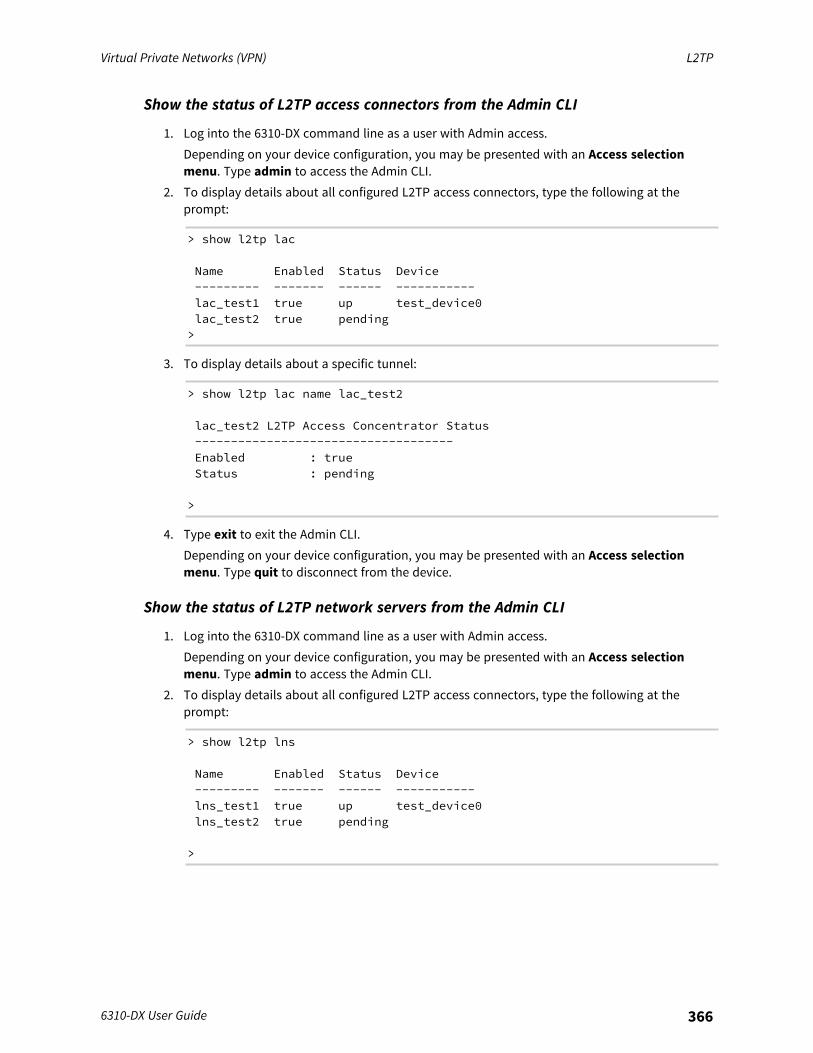
Virtual Private Networks (VPN) L2TP
6310-DX User Guide 366
Show the status of L2TP access connectors from the Admin CLI
1. Log into the 6310-DX command line as a user with Admin access.Depending on your device configuration, you may be presented with an Access selectionmenu. Type admin to access the Admin CLI.
2. To display details about all configured L2TP access connectors, type the following at theprompt:
> show l2tp lac
Name Enabled Status Device--------- ------- ------ -----------lac_test1 true up test_device0lac_test2 true pending>
3. To display details about a specific tunnel:
> show l2tp lac name lac_test2
lac_test2 L2TP Access Concentrator Status------------------------------------Enabled : trueStatus : pending
>
4. Type exit to exit the Admin CLI.Depending on your device configuration, you may be presented with an Access selectionmenu. Type quit to disconnect from the device.
Show the status of L2TP network servers from the Admin CLI
1. Log into the 6310-DX command line as a user with Admin access.Depending on your device configuration, you may be presented with an Access selectionmenu. Type admin to access the Admin CLI.
2. To display details about all configured L2TP access connectors, type the following at theprompt:
> show l2tp lns
Name Enabled Status Device--------- ------- ------ -----------lns_test1 true up test_device0lns_test2 true pending
>

Virtual Private Networks (VPN) L2TPv3 Ethernet
6310-DX User Guide 367
3. To display details about a specific tunnel:
> show l2tp lns name lns_test2
lns_test2 L2TP Access Concentrator Status------------------------------------Enabled : trueStatus : pending
>
4. Type exit to exit the Admin CLI.Depending on your device configuration, you may be presented with an Access selectionmenu. Type quit to disconnect from the device.
L2TPv3 EthernetYour 6310-DX device supports Layer 2 Tunneling Protocol Version 3 (L2TPv3) static unmanagedEthernet tunnels.
Configure an L2TPv3 tunnelYour 6310-DX device supports Layer 2 Tunneling Protocol Version 3 (L2TPv3) static unmanagedEthernet tunnels.
Required configuration items
n A name for the L2TPv3 tunnel.n Enable the tunnel.n The remote endpoint IP address.n The local endpoint IP address.n The session ID.n The peer session ID.
Additional configuration items
n Encapsulation type. If UDP is selected:l The ID for the tunnel.l The ID of the peer's tunnel.l Determine whether to enable UDP checksum.
n The session cookie.n The peer session cookie.n The Layer2SpecificHeader type.n The Sequence numbering control.
WebUI
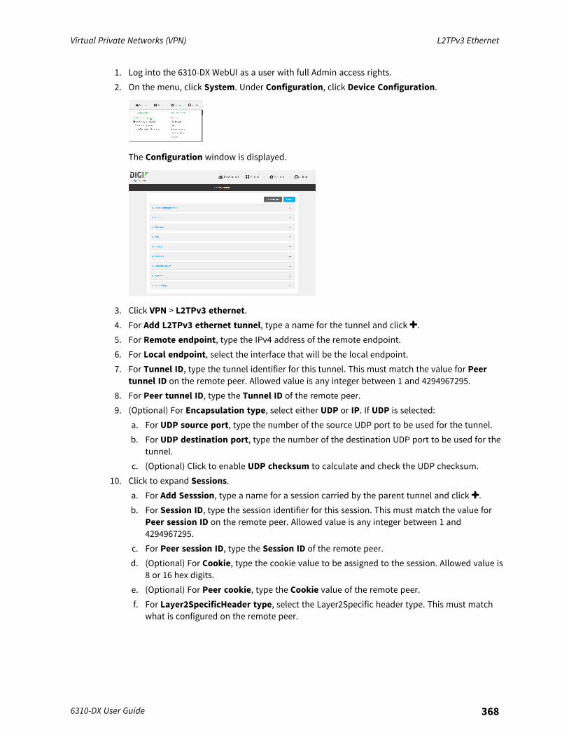
Virtual Private Networks (VPN) L2TPv3 Ethernet
6310-DX User Guide 368
1. Log into the 6310-DX WebUI as a user with full Admin access rights.2. On the menu, click System. Under Configuration, click Device Configuration.
The Configuration window is displayed.
3. Click VPN > L2TPv3 ethernet.4. For Add L2TPv3 ethernet tunnel, type a name for the tunnel and click .5. For Remote endpoint, type the IPv4 address of the remote endpoint.6. For Local endpoint, select the interface that will be the local endpoint.7. For Tunnel ID, type the tunnel identifier for this tunnel. This must match the value for Peer
tunnel ID on the remote peer. Allowed value is any integer between 1 and 4294967295.8. For Peer tunnel ID, type the Tunnel ID of the remote peer.9. (Optional) For Encapsulation type, select either UDP or IP. If UDP is selected:
a. For UDP source port, type the number of the source UDP port to be used for the tunnel.b. For UDP destination port, type the number of the destination UDP port to be used for the
tunnel.c. (Optional) Click to enable UDP checksum to calculate and check the UDP checksum.
10. Click to expand Sessions.a. For Add Sesssion, type a name for a session carried by the parent tunnel and click .b. For Session ID, type the session identifier for this session. This must match the value for
Peer session ID on the remote peer. Allowed value is any integer between 1 and4294967295.
c. For Peer session ID, type the Session ID of the remote peer.d. (Optional) For Cookie, type the cookie value to be assigned to the session. Allowed value is
8 or 16 hex digits.e. (Optional) For Peer cookie, type the Cookie value of the remote peer.f. For Layer2SpecificHeader type, select the Layer2Specific header type. This must match
what is configured on the remote peer.
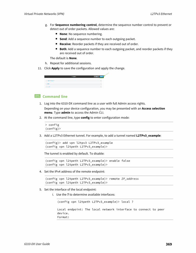
Virtual Private Networks (VPN) L2TPv3 Ethernet
6310-DX User Guide 369
g. For Sequence numbering control, determine the sequence number control to prevent ordetect out of order packets. Allowed values are:
n None: No sequence numbering.n Send: Add a sequence number to each outgoing packet.n Receive: Reorder packets if they are received out of order.n Both: Add a sequence number to each outgoing packet, and reorder packets if they
are received out of order.The default is None.
h. Repeat for additional sessions.11. Click Apply to save the configuration and apply the change.
Command line
1. Log into the 6310-DX command line as a user with full Admin access rights.Depending on your device configuration, you may be presented with an Access selectionmenu. Type admin to access the Admin CLI.
2. At the command line, type config to enter configuration mode:
> config(config)>
3. Add a L2TPv3 Ethernet tunnel. For example, to add a tunnel named L2TPv3_example:
(config)> add vpn l2tpv3 L2TPv3_example(config vpn l2tpeth L2TPv3_example)>
The tunnel is enabled by default. To disable:
(config vpn l2tpeth L2TPv3_example)> enable false(config vpn l2tpeth L2TPv3_example)>
4. Set the IPv4 address of the remote endpoint:
(config vpn l2tpeth L2TPv3_example)> remote IP_address(config vpn l2tpeth L2TPv3_example)>
5. Set the interface of the local endpoint:i. Use the ? to determine available interfaces:
(config vpn l2tpeth L2TPv3_example)> local ?
Local endpoint: The local network interface to connect to peerdevice.Format:
Virtual Private Networks (VPN) L2TPv3 Ethernet
6310-DX User Guide 370
/network/interface/defaultip/network/interface/defaultlinklocal/network/interface/lan/network/interface/loopback/network/interface/modem/network/interface/wan
Current value:
(config vpn l2tpeth L2TPv3_example)> local
ii. Set the interface. For example:
(config vpn l2tpeth L2TPv3_example)> local /network/interface/wan(config vpn l2tpeth L2TPv3_example)>
6. Set the tunnel identifier for this tunnel. This must match the value for peer tunnel ID on theremote peer.
(config vpn l2tpeth L2TPv3_example)> tunnel_id value(config vpn l2tpeth L2TPv3_example)>
where value is any integer between 1 and 4294967295.7. Set the tunnel ID of the remote peer:
(config vpn l2tpeth L2TPv3_example)> peer_tunnel_id value(config vpn l2tpeth L2TPv3_example)>
where value is any integer between 1 and 4294967295.8. (Optional) Set the encapsulation type:
(config vpn l2tpeth L2TPv3_example)> encapsulation value(config vpn l2tpeth L2TPv3_example)>
where value is either udp or ip. The default is upd.If udp is set:a. Set the source UDP port to be used for the tunnel:
(config vpn l2tpeth L2TPv3_example)> udp_source_port port(config vpn l2tpeth L2TPv3_example)>
b. Set the destination UDP port to be used for the tunnel.
(config vpn l2tpeth L2TPv3_example)> udp_destination_port port(config vpn l2tpeth L2TPv3_example)>
c. (Optional) To calculate and check the UDP checksum:
(config vpn l2tpeth L2TPv3_example)> udp_checksum true(config vpn l2tpeth L2TPv3_example)>
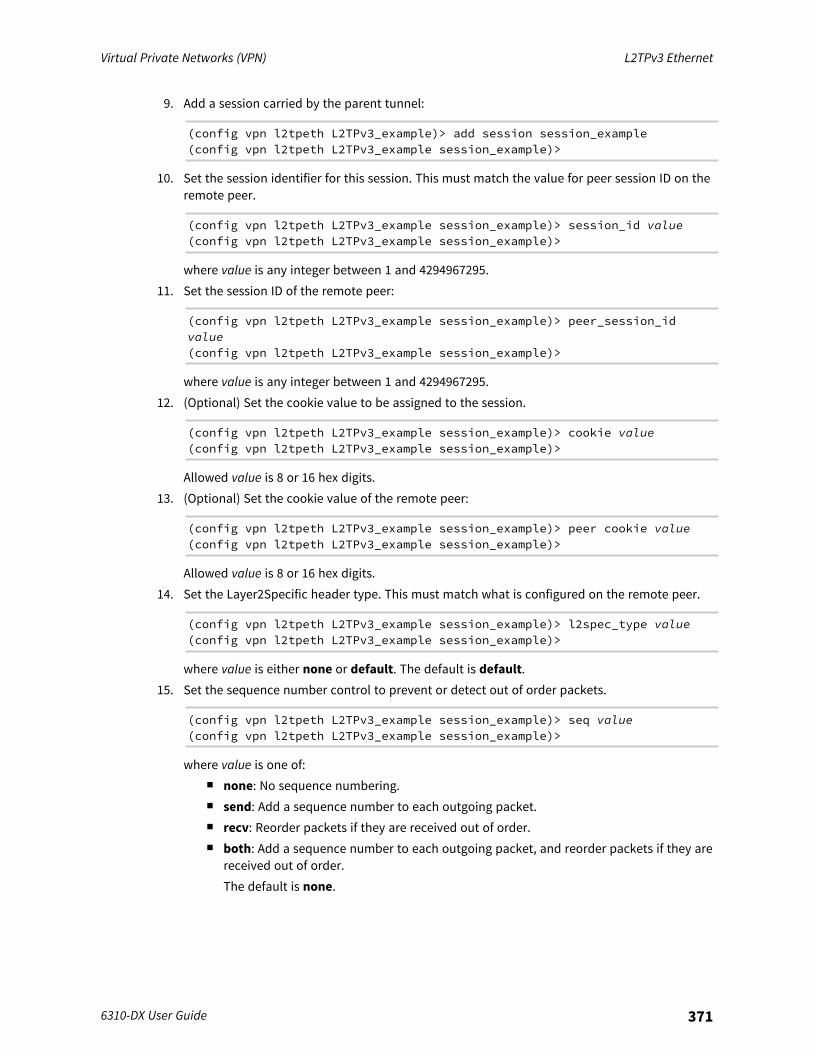
Virtual Private Networks (VPN) L2TPv3 Ethernet
6310-DX User Guide 371
9. Add a session carried by the parent tunnel:
(config vpn l2tpeth L2TPv3_example)> add session session_example(config vpn l2tpeth L2TPv3_example session_example)>
10. Set the session identifier for this session. This must match the value for peer session ID on theremote peer.
(config vpn l2tpeth L2TPv3_example session_example)> session_id value(config vpn l2tpeth L2TPv3_example session_example)>
where value is any integer between 1 and 4294967295.11. Set the session ID of the remote peer:
(config vpn l2tpeth L2TPv3_example session_example)> peer_session_idvalue(config vpn l2tpeth L2TPv3_example session_example)>
where value is any integer between 1 and 4294967295.12. (Optional) Set the cookie value to be assigned to the session.
(config vpn l2tpeth L2TPv3_example session_example)> cookie value(config vpn l2tpeth L2TPv3_example session_example)>
Allowed value is 8 or 16 hex digits.13. (Optional) Set the cookie value of the remote peer:
(config vpn l2tpeth L2TPv3_example session_example)> peer cookie value(config vpn l2tpeth L2TPv3_example session_example)>
Allowed value is 8 or 16 hex digits.14. Set the Layer2Specific header type. This must match what is configured on the remote peer.
(config vpn l2tpeth L2TPv3_example session_example)> l2spec_type value(config vpn l2tpeth L2TPv3_example session_example)>
where value is either none or default. The default is default.15. Set the sequence number control to prevent or detect out of order packets.
(config vpn l2tpeth L2TPv3_example session_example)> seq value(config vpn l2tpeth L2TPv3_example session_example)>
where value is one of:n none: No sequence numbering.n send: Add a sequence number to each outgoing packet.n recv: Reorder packets if they are received out of order.n both: Add a sequence number to each outgoing packet, and reorder packets if they are
received out of order.The default is none.
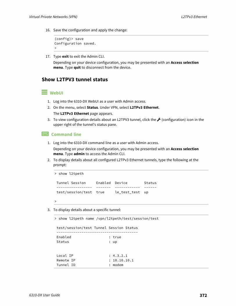
Virtual Private Networks (VPN) L2TPv3 Ethernet
6310-DX User Guide 372
16. Save the configuration and apply the change:
(config)> saveConfiguration saved.>
17. Type exit to exit the Admin CLI.Depending on your device configuration, you may be presented with an Access selectionmenu. Type quit to disconnect from the device.
Show L2TPV3 tunnel status
WebUI
1. Log into the 6310-DX WebUI as a user with Admin access.2. On the menu, select Status. Under VPN, select L2TPv3 Ethernet.
The L2TPv3 Ethernet page appears.3. To view configuration details about an L2TPV3 tunnel, click the (configuration) icon in the
upper right of the tunnel's status pane.
Command line
1. Log into the 6310-DX command line as a user with Admin access.Depending on your device configuration, you may be presented with an Access selectionmenu. Type admin to access the Admin CLI.
2. To display details about all configured L2TPv3 Ethernet tunnels, type the following at theprompt:
> show l2tpeth
Tunnel Session Enabled Device Status----------------- ------- ------------ ------test/session/test true le_test_test up
>
3. To display details about a specific tunnel:
> show l2tpeth name /vpn/l2tpeth/test/session/test
test/session/test Tunnel Session Status---------------------------------------Enabled : trueStatus : up
Local IP : 4.3.2.1Remote IP : 10.10.10.1Tunnel ID : modem
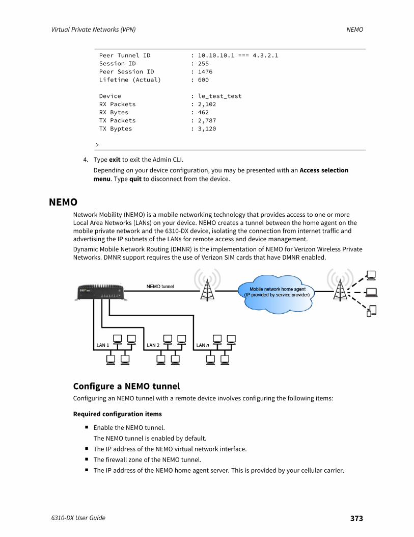
Virtual Private Networks (VPN) NEMO
6310-DX User Guide 373
Peer Tunnel ID : 10.10.10.1 === 4.3.2.1Session ID : 255Peer Session ID : 1476Lifetime (Actual) : 600
Device : le_test_testRX Packets : 2,102RX Bytes : 462TX Packets : 2,787TX Byptes : 3,120
>
4. Type exit to exit the Admin CLI.Depending on your device configuration, you may be presented with an Access selectionmenu. Type quit to disconnect from the device.
NEMONetwork Mobility (NEMO) is a mobile networking technology that provides access to one or moreLocal Area Networks (LANs) on your device. NEMO creates a tunnel between the home agent on themobile private network and the 6310-DX device, isolating the connection from internet traffic andadvertising the IP subnets of the LANs for remote access and device management.Dynamic Mobile Network Routing (DMNR) is the implementation of NEMO for Verizon Wireless PrivateNetworks. DMNR support requires the use of Verizon SIM cards that have DMNR enabled.
Configure a NEMO tunnelConfiguring an NEMO tunnel with a remote device involves configuring the following items:
Required configuration items
n Enable the NEMO tunnel.The NEMO tunnel is enabled by default.
n The IP address of the NEMO virtual network interface.n The firewall zone of the NEMO tunnel.n The IP address of the NEMO home agent server. This is provided by your cellular carrier.

Virtual Private Networks (VPN) NEMO
6310-DX User Guide 374
n The home agent's authentication key. This is provided by your cellular carrier.n Home agent registration lifetime. This is provided by your cellular carrier.n The local network interfaces that will be advertised on NEMO.
Additional configuration items
n The home agent Software Parameter Index (SPI).n Path MTU discovery.
Path MTU discovery is enabled by default. If it is disabled, identify the MTU.n Care of address: the local network interface that is used to communicate with the peer.
l If set to Interface, identify the local interface to be used. Generally, this will be theWirelesss WAN (Modem).
l If set to IP address, enter the IP address.n The local network of the GRE endpoint negotiated by NEMO.
l If the local network is set to Interface, identify the local interface to be used.
WebUI
1. Log into the 6310-DX WebUI as a user with full Admin access rights.2. On the menu, click System. Under Configuration, click Device Configuration.
The Configuration window is displayed.
3. Click VPN > NEMO.The NEMO tunnel is enabled by default. To disable, click to toggle off Enable.
4. For Home IP address, type the IPv4 address of the NEMO virtual network interface.5. For Zone, select Internal.
The Internal firewall zone configures the 6310-DX device to trust traffic going to the tunnel andallows it through the network.
6. For Home agent server IP address, type the IPv4 address of the NEMO home agent. This isprovided by your cellular carrier.
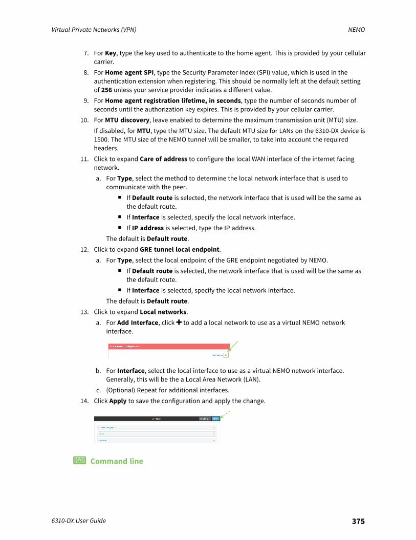
Virtual Private Networks (VPN) NEMO
6310-DX User Guide 375
7. For Key, type the key used to authenticate to the home agent. This is provided by your cellularcarrier.
8. For Home agent SPI, type the Security Parameter Index (SPI) value, which is used in theauthentication extension when registering. This should be normally left at the default settingof 256 unless your service provider indicates a different value.
9. For Home agent registration lifetime, in seconds, type the number of seconds number ofseconds until the authorization key expires. This is provided by your cellular carrier.
10. For MTU discovery, leave enabled to determine the maximum transmission unit (MTU) size.If disabled, for MTU, type the MTU size. The default MTU size for LANs on the 6310-DX device is1500. The MTU size of the NEMO tunnel will be smaller, to take into account the requiredheaders.
11. Click to expand Care of address to configure the local WAN interface of the internet facingnetwork.a. For Type, select the method to determine the local network interface that is used to
communicate with the peer.n If Default route is selected, the network interface that is used will be the same as
the default route.n If Interface is selected, specify the local network interface.n If IP address is selected, type the IP address.
The default is Default route.12. Click to expand GRE tunnel local endpoint.
a. For Type, select the local endpoint of the GRE endpoint negotiated by NEMO.n If Default route is selected, the network interface that is used will be the same as
the default route.n If Interface is selected, specify the local network interface.
The default is Default route.13. Click to expand Local networks.
a. For Add Interface, click to add a local network to use as a virtual NEMO networkinterface.
b. For Interface, select the local interface to use as a virtual NEMO network interface.Generally, this will be the a Local Area Network (LAN).
c. (Optional) Repeat for additional interfaces.14. Click Apply to save the configuration and apply the change.
Command line
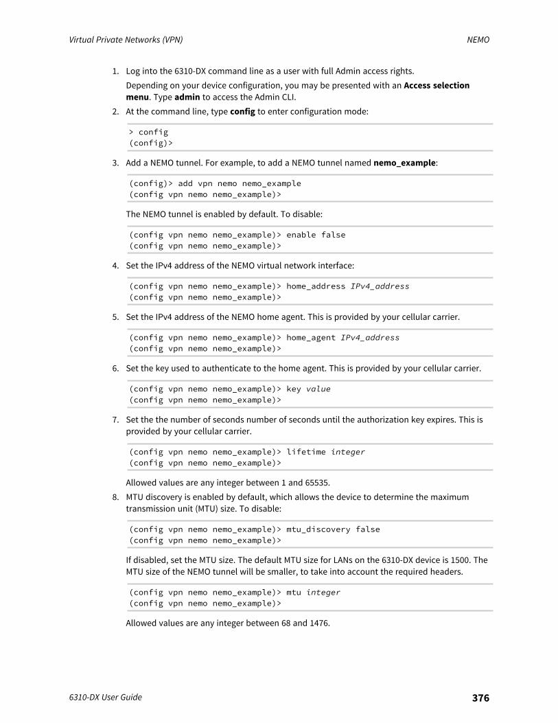
Virtual Private Networks (VPN) NEMO
6310-DX User Guide 376
1. Log into the 6310-DX command line as a user with full Admin access rights.Depending on your device configuration, you may be presented with an Access selectionmenu. Type admin to access the Admin CLI.
2. At the command line, type config to enter configuration mode:
> config(config)>
3. Add a NEMO tunnel. For example, to add a NEMO tunnel named nemo_example:
(config)> add vpn nemo nemo_example(config vpn nemo nemo_example)>
The NEMO tunnel is enabled by default. To disable:
(config vpn nemo nemo_example)> enable false(config vpn nemo nemo_example)>
4. Set the IPv4 address of the NEMO virtual network interface:
(config vpn nemo nemo_example)> home_address IPv4_address(config vpn nemo nemo_example)>
5. Set the IPv4 address of the NEMO home agent. This is provided by your cellular carrier.
(config vpn nemo nemo_example)> home_agent IPv4_address(config vpn nemo nemo_example)>
6. Set the key used to authenticate to the home agent. This is provided by your cellular carrier.
(config vpn nemo nemo_example)> key value(config vpn nemo nemo_example)>
7. Set the the number of seconds number of seconds until the authorization key expires. This isprovided by your cellular carrier.
(config vpn nemo nemo_example)> lifetime integer(config vpn nemo nemo_example)>
Allowed values are any integer between 1 and 65535.8. MTU discovery is enabled by default, which allows the device to determine the maximum
transmission unit (MTU) size. To disable:
(config vpn nemo nemo_example)> mtu_discovery false(config vpn nemo nemo_example)>
If disabled, set the MTU size. The default MTU size for LANs on the 6310-DX device is 1500. TheMTU size of the NEMO tunnel will be smaller, to take into account the required headers.
(config vpn nemo nemo_example)> mtu integer(config vpn nemo nemo_example)>
Allowed values are any integer between 68 and 1476.

Virtual Private Networks (VPN) NEMO
6310-DX User Guide 377
9. Set the Security Parameter Index (SPI) value, which is used in the authentication extensionwhen registering. This should be normally left at the default setting of 256 unless your serviceprovider indicates a different value.
(config vpn nemo nemo_example)> spi integer(config vpn nemo nemo_example)>
Allowed values are any integer between 256 and 4294967295.10. Set the firewall zone for the NEMO tunnel to internal:
(config vpn nemo nemo_example)> zone internal(config vpn nemo nemo_example)>
The Internal firewall zone configures the 6310-DX device to trust traffic going to the tunnel andallows it through the network.
11. Configure the Care-of-Address, the local WAN interface of the internet facing network.a. Set the method to determine the Care-of-Address:
(config vpn nemo nemo_example)> coaddress type value(config vpn nemo nemo_example)>
where value is one of:n defaultroute: Uses the same network interface as the default route.n interface
If interface is used, set the interface:i. Use the ? to determine available interfaces:
(config vpn nemo nemo_example)> coaddress interface ?
Interface: Use the IP address of this network interface asthis node's Care-of-Address.Format:defaultipdefaultlinklocallanloopbackmodemwan
Current value:
(config vpn nemo nemo_example)> coaddress interface
ii. Set the interface. For example:
(config vpn nemo nemo_example)> coaddress interface wan(config vpn nemo nemo_example)>
n ipIf ip is used, set the IP address:
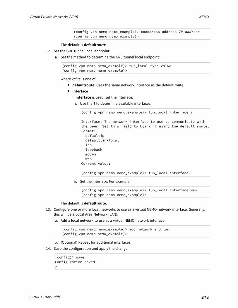
Virtual Private Networks (VPN) NEMO
6310-DX User Guide 378
(config vpn nemo nemo_example)> coaddress address IP_address(config vpn nemo nemo_example)>
The default is defaultroute.12. Set the GRE tunnel local endpoint:
a. Set the method to determine the GRE tunnel local endpoint:
(config vpn nemo nemo_example)> tun_local type value(config vpn nemo nemo_example)>
where value is one of:n defaultroute: Uses the same network interface as the default route.n interface
If interface is used, set the interface.i. Use the ? to determine available interfaces:
(config vpn nemo nemo_example)> tun_local interface ?
Interface: The network interface to use to communicate withthe peer. Set this field to blank if using the default route.Format:defaultipdefaultlinklocallanloopbackmodemwan
Current value:
(config vpn nemo nemo_example)> tun_local interface
ii. Set the interface. For example:
(config vpn nemo nemo_example)> tun_local interface wan(config vpn nemo nemo_example)>
The default is defaultroute.13. Configure one or more local networks to use as a virtual NEMO network interface. Generally,
this will be a Local Area Network (LAN):a. Add a local network to use as a virtual NEMO network interface:
(config vpn nemo nemo_example)> add network end lan(config vpn nemo nemo_example)>
b. (Optional) Repeat for additional interfaces.14. Save the configuration and apply the change:
(config)> saveConfiguration saved.>
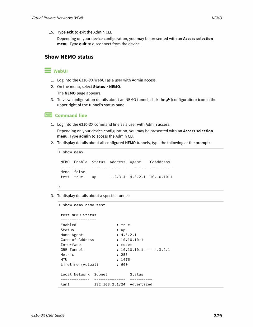
Virtual Private Networks (VPN) NEMO
6310-DX User Guide 379
15. Type exit to exit the Admin CLI.Depending on your device configuration, you may be presented with an Access selectionmenu. Type quit to disconnect from the device.
Show NEMO status
WebUI
1. Log into the 6310-DX WebUI as a user with Admin access.2. On the menu, select Status > NEMO.
The NEMO page appears.3. To view configuration details about an NEMO tunnel, click the (configuration) icon in the
upper right of the tunnel's status pane.
Command line
1. Log into the 6310-DX command line as a user with Admin access.Depending on your device configuration, you may be presented with an Access selectionmenu. Type admin to access the Admin CLI.
2. To display details about all configured NEMO tunnels, type the following at the prompt:
> show nemo
NEMO Enable Status Address Agent CoAddress---- ------ ------ ------- ------- ----------demo falsetest true up 1.2.3.4 4.3.2.1 10.10.10.1
>
3. To display details about a specific tunnel:
> show nemo name test
test NEMO Status----------------Enabled : trueStatus : upHome Agent : 4.3.2.1Care of Address : 10.10.10.1Interface : modemGRE Tunnel : 10.10.10.1 === 4.3.2.1Metric : 255MTU : 1476Lifetime (Actual) : 600
Local Network Subnet Status------------- -------------- ----------lan1 192.168.2.1/24 Advertized

Virtual Private Networks (VPN) NEMO
6310-DX User Guide 380
LAN2 192.168.3.1/24 Advertized
>
4. Type exit to exit the Admin CLI.Depending on your device configuration, you may be presented with an Access selectionmenu. Type quit to disconnect from the device.
Services
This chapter contains the following topics:
Allow remote access for web administration and SSH 382Configure the web administration service 385Configure SSH access 395Use SSH with key authentication 402Configure telnet access 405Configure DNS 410Simple Network Management Protocol (SNMP) 417Location information 423Modbus gateway 455System time 472Network Time Protocol 476Configure a multicast route 483Ethernet network bonding 486Enable service discovery (mDNS) 488Use the iPerf service 492Configure the ping responder service 497
6310-DX User Guide 381
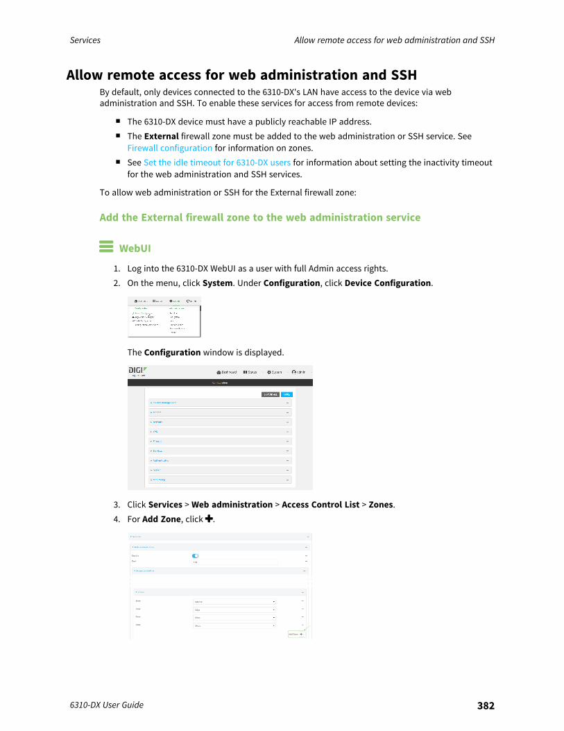
Services Allow remote access for web administration and SSH
6310-DX User Guide 382
Allow remote access for web administration and SSHBy default, only devices connected to the 6310-DX's LAN have access to the device via webadministration and SSH. To enable these services for access from remote devices:
n The 6310-DX device must have a publicly reachable IP address.n The External firewall zone must be added to the web administration or SSH service. See
Firewall configuration for information on zones.n See Set the idle timeout for 6310-DX users for information about setting the inactivity timeout
for the web administration and SSH services.
To allow web administration or SSH for the External firewall zone:
Add the External firewall zone to the web administration service
WebUI
1. Log into the 6310-DX WebUI as a user with full Admin access rights.2. On the menu, click System. Under Configuration, click Device Configuration.
The Configuration window is displayed.
3. Click Services > Web administration > Access Control List > Zones.4. For Add Zone, click .
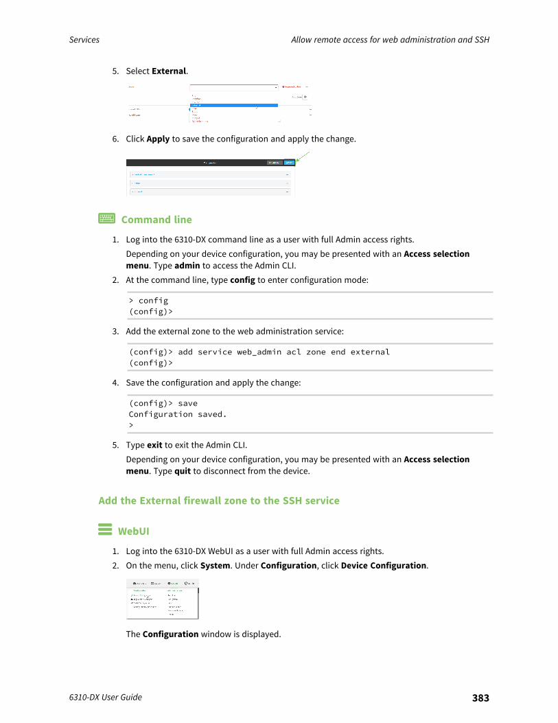
Services Allow remote access for web administration and SSH
6310-DX User Guide 383
5. Select External.
6. Click Apply to save the configuration and apply the change.
Command line
1. Log into the 6310-DX command line as a user with full Admin access rights.Depending on your device configuration, you may be presented with an Access selectionmenu. Type admin to access the Admin CLI.
2. At the command line, type config to enter configuration mode:
> config(config)>
3. Add the external zone to the web administration service:
(config)> add service web_admin acl zone end external(config)>
4. Save the configuration and apply the change:
(config)> saveConfiguration saved.>
5. Type exit to exit the Admin CLI.Depending on your device configuration, you may be presented with an Access selectionmenu. Type quit to disconnect from the device.
Add the External firewall zone to the SSH service
WebUI
1. Log into the 6310-DX WebUI as a user with full Admin access rights.2. On the menu, click System. Under Configuration, click Device Configuration.
The Configuration window is displayed.
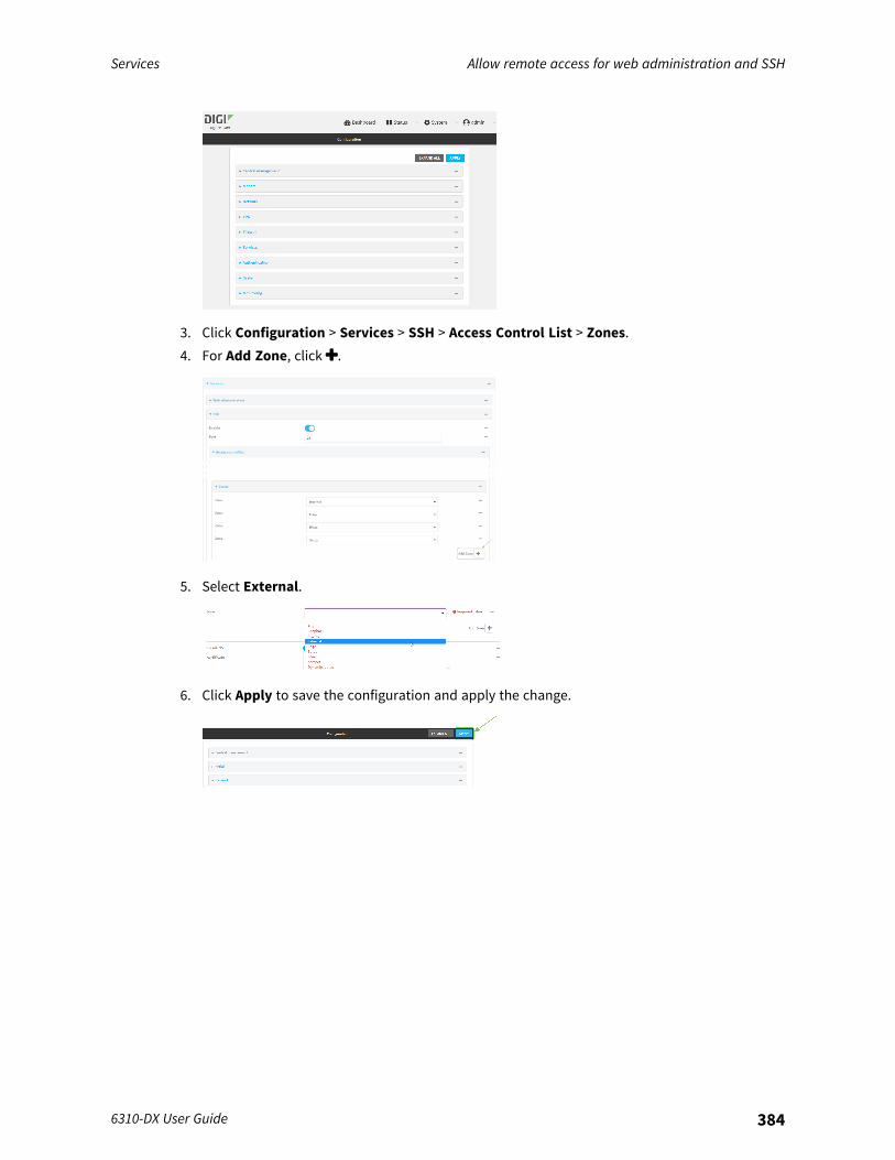
Services Allow remote access for web administration and SSH
6310-DX User Guide 384
3. Click Configuration > Services > SSH > Access Control List > Zones.4. For Add Zone, click .
5. Select External.
6. Click Apply to save the configuration and apply the change.
Services Configure the web administration service
6310-DX User Guide 385
Command line
1. Log into the 6310-DX command line as a user with full Admin access rights.Depending on your device configuration, you may be presented with an Access selectionmenu. Type admin to access the Admin CLI.
2. At the command line, type config to enter configuration mode:
> config(config)>
3. Add the External zone to the SSH service:
(config)> add service ssh acl zone end external(config)>
4. Save the configuration and apply the change:
(config)> saveConfiguration saved.>
5. Type exit to exit the Admin CLI.Depending on your device configuration, you may be presented with an Access selectionmenu. Type quit to disconnect from the device.
Configure the web administration serviceThe web administration service allows you to monitor and configure the 6310-DX device by using theWebUI, a browser-based interface.By default, the web administration service is enabled and uses the standard HTTPS port, 443. Thedefault access control for the service uses the Internal firewall zone, which means that only devicesconnected to the 6310-DX's LAN can access the WebUI. If this configuration is sufficient for your needs,no further configuration is required. See Allow remote access for web administration and SSH forinformation about configuring the web administration service to allow access from remote devices.
Required configuration items
n The web administration service is enabled by default.n Configure access control for the service.
Additional configuration items
n Port to use for web administration service communication.n Multicast DNS (mDNS) support.n An SSL certificate to use for communications with the service.n Support for legacy encryption protocols.
See Set the idle timeout for 6310-DX users for information about setting the inactivity timeout for theweb administration services.
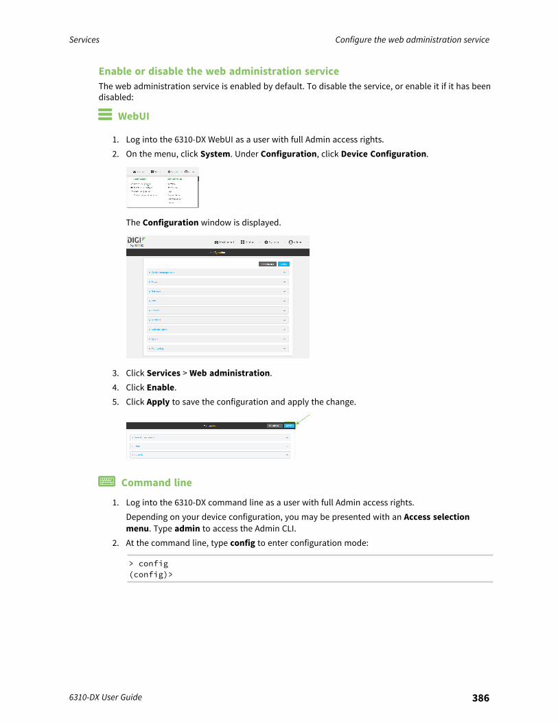
Services Configure the web administration service
6310-DX User Guide 386
Enable or disable the web administration serviceThe web administration service is enabled by default. To disable the service, or enable it if it has beendisabled:
WebUI
1. Log into the 6310-DX WebUI as a user with full Admin access rights.2. On the menu, click System. Under Configuration, click Device Configuration.
The Configuration window is displayed.
3. Click Services > Web administration.4. Click Enable.5. Click Apply to save the configuration and apply the change.
Command line
1. Log into the 6310-DX command line as a user with full Admin access rights.Depending on your device configuration, you may be presented with an Access selectionmenu. Type admin to access the Admin CLI.
2. At the command line, type config to enter configuration mode:
> config(config)>
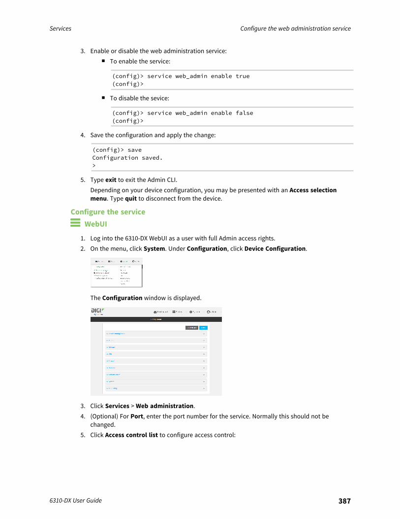
Services Configure the web administration service
6310-DX User Guide 387
3. Enable or disable the web administration service:n To enable the service:
(config)> service web_admin enable true(config)>
n To disable the sevice:
(config)> service web_admin enable false(config)>
4. Save the configuration and apply the change:
(config)> saveConfiguration saved.>
5. Type exit to exit the Admin CLI.Depending on your device configuration, you may be presented with an Access selectionmenu. Type quit to disconnect from the device.
Configure the service WebUI
1. Log into the 6310-DX WebUI as a user with full Admin access rights.2. On the menu, click System. Under Configuration, click Device Configuration.
The Configuration window is displayed.
3. Click Services > Web administration.4. (Optional) For Port, enter the port number for the service. Normally this should not be
changed.5. Click Access control list to configure access control:
Services Configure the web administration service
6310-DX User Guide 388
n To limit access to specified IPv4 addresses and networks:a. Click IPv4 Addresses.b. For Add Address, click .c. For Address, enter the IPv4 address or network that can access the device's web
administration service. Allowed values are:l A single IP address or host name.l A network designation in CIDR notation, for example, 192.168.1.0/24.l any: No limit to IPv4 addresses that can access the web administration service.
d. Click again to list additional IP addresses or networks.n To limit access to specified IPv6 addresses and networks:
a. Click IPv6 Addresses.b. For Add Address, click .c. For Address, enter the IPv6 address or network that can access the device's web
administration service. Allowed values are:l A single IP address or host name.l A network designation in CIDR notation, for example, 2001:db8::/48.l any: No limit to IPv6 addresses that can access the web administration service.
d. Click again to list additional IP addresses or networks.n To limit access to hosts connected through a specified interface on the 6310-DX device:
a. Click Interfaces.b. For Add Interface, click .c. For Interface, select the appropriate interface from the dropdown.d. Click again to allow access through additional interfaces.
n To limit access based on firewall zones:a. Click Zones.b. For Add Zone, click .c. For Zone, select the appropriate firewall zone from the dropdown.
See Firewall configuration for information about firewall zones.d. Click again to allow access through additional firewall zones.
6. Multicast DNS (mDNS) is enabled by default. mDNS is a protocol that resolves host names insmall networks that do not have a DNS server. To disable mDNS, or enable it if it has beendisabled, click Enable mDNS.
7. For SSL certificate, if you have your own signed SSL certificate, paste the certificate andprivate key. If SSL certificate is blank, the device will use an automatically-generated, self-signed certificate.
n The SSL certificate and private key must be in PEM format.n The private key can use one of the following algorithms:
l RSAl DSAl ECDSA
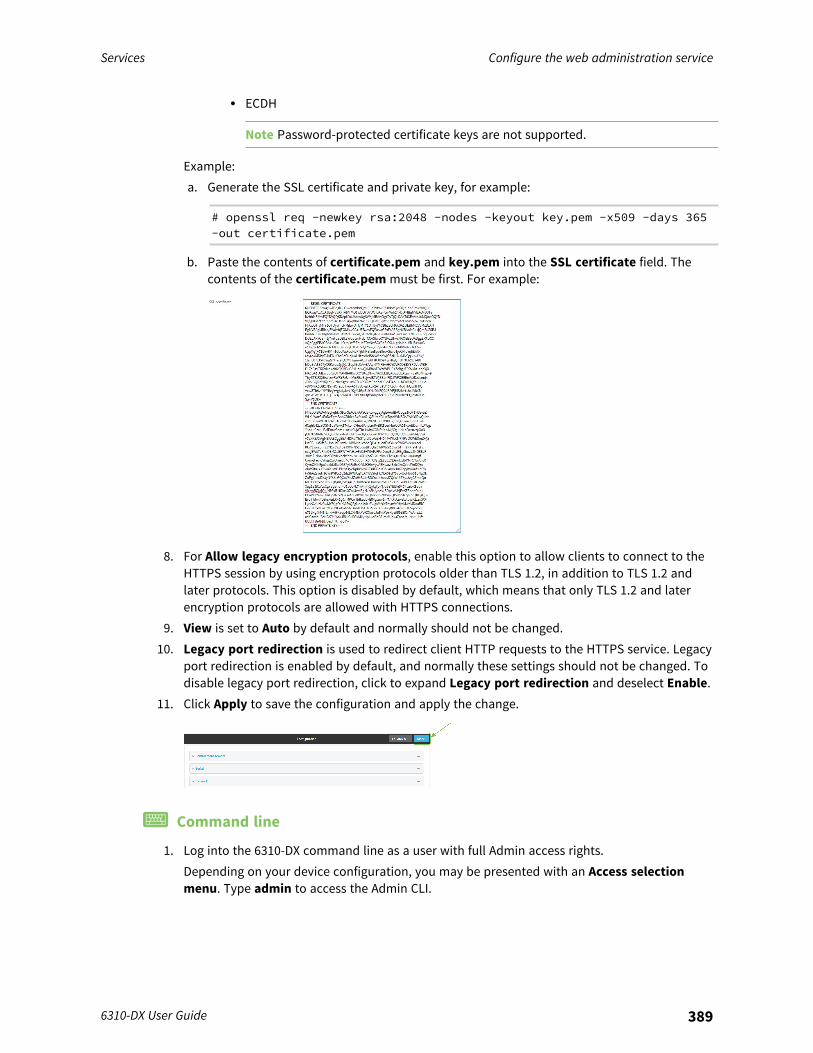
Services Configure the web administration service
6310-DX User Guide 389
l ECDH
Note Password-protected certificate keys are not supported.
Example:a. Generate the SSL certificate and private key, for example:
# openssl req -newkey rsa:2048 -nodes -keyout key.pem -x509 -days 365-out certificate.pem
b. Paste the contents of certificate.pem and key.pem into the SSL certificate field. Thecontents of the certificate.pem must be first. For example:
8. For Allow legacy encryption protocols, enable this option to allow clients to connect to theHTTPS session by using encryption protocols older than TLS 1.2, in addition to TLS 1.2 andlater protocols. This option is disabled by default, which means that only TLS 1.2 and laterencryption protocols are allowed with HTTPS connections.
9. View is set to Auto by default and normally should not be changed.10. Legacy port redirection is used to redirect client HTTP requests to the HTTPS service. Legacy
port redirection is enabled by default, and normally these settings should not be changed. Todisable legacy port redirection, click to expand Legacy port redirection and deselect Enable.
11. Click Apply to save the configuration and apply the change.
Command line
1. Log into the 6310-DX command line as a user with full Admin access rights.Depending on your device configuration, you may be presented with an Access selectionmenu. Type admin to access the Admin CLI.
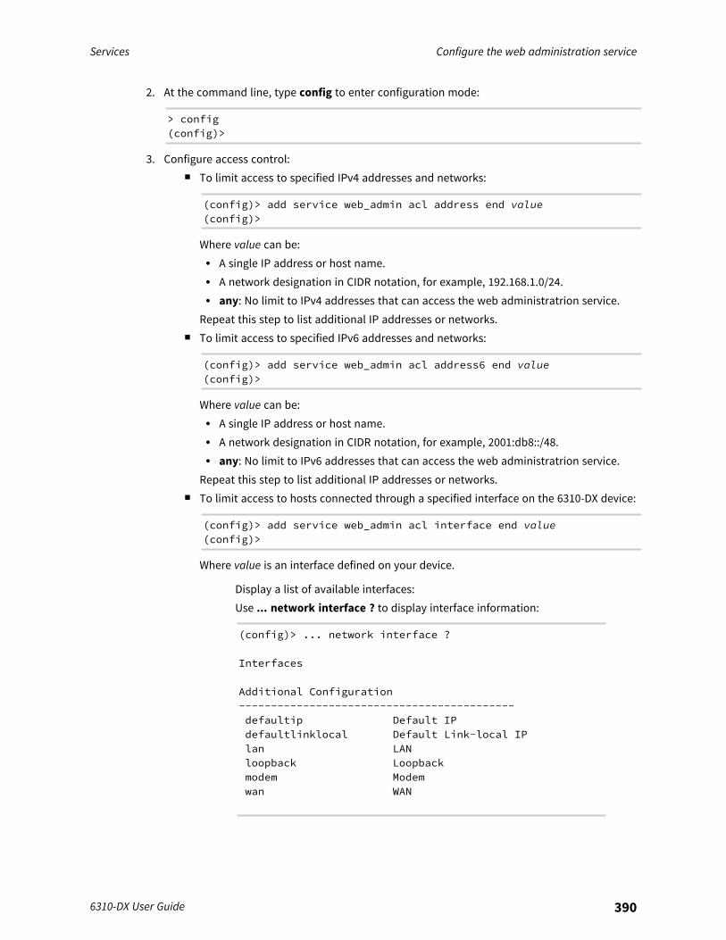
Services Configure the web administration service
6310-DX User Guide 390
2. At the command line, type config to enter configuration mode:
> config(config)>
3. Configure access control:n To limit access to specified IPv4 addresses and networks:
(config)> add service web_admin acl address end value(config)>
Where value can be:l A single IP address or host name.l A network designation in CIDR notation, for example, 192.168.1.0/24.l any: No limit to IPv4 addresses that can access the web administratrion service.
Repeat this step to list additional IP addresses or networks.n To limit access to specified IPv6 addresses and networks:
(config)> add service web_admin acl address6 end value(config)>
Where value can be:l A single IP address or host name.l A network designation in CIDR notation, for example, 2001:db8::/48.l any: No limit to IPv6 addresses that can access the web administratrion service.
Repeat this step to list additional IP addresses or networks.n To limit access to hosts connected through a specified interface on the 6310-DX device:
(config)> add service web_admin acl interface end value(config)>
Where value is an interface defined on your device.
Display a list of available interfaces:Use ... network interface ? to display interface information:
(config)> ... network interface ?
Interfaces
Additional Configuration-------------------------------------------defaultip Default IPdefaultlinklocal Default Link-local IPlan LANloopback Loopbackmodem Modemwan WAN
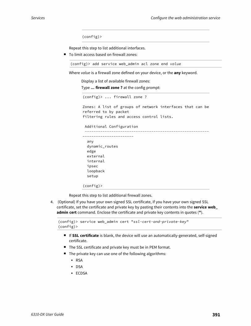
Services Configure the web administration service
6310-DX User Guide 391
(config)>
Repeat this step to list additional interfaces.n To limit access based on firewall zones:
(config)> add service web_admin acl zone end value
Where value is a firewall zone defined on your device, or the any keyword.
Display a list of available firewall zones:Type ... firewall zone ? at the config prompt:
(config)> ... firewall zone ?
Zones: A list of groups of network interfaces that can bereferred to by packetfiltering rules and access control lists.
Additional Configuration--------------------------------------------------------
-----------------------anydynamic_routesedgeexternalinternalipsecloopbacksetup
(config)>
Repeat this step to list additional firewall zones.4. (Optional) If you have your own signed SSL certificate, if you have your own signed SSL
certificate, set the certificate and private key by pasting their contents into the service web_admin cert command. Enclose the certificate and private key contents in quotes (").
(config)> service web_admin cert "ssl-cert-and-private-key"(config)>
n If SSL certificate is blank, the device will use an automatically-generated, self-signedcertificate.
n The SSL certificate and private key must be in PEM format.n The private key can use one of the following algorithms:
l RSAl DSAl ECDSA
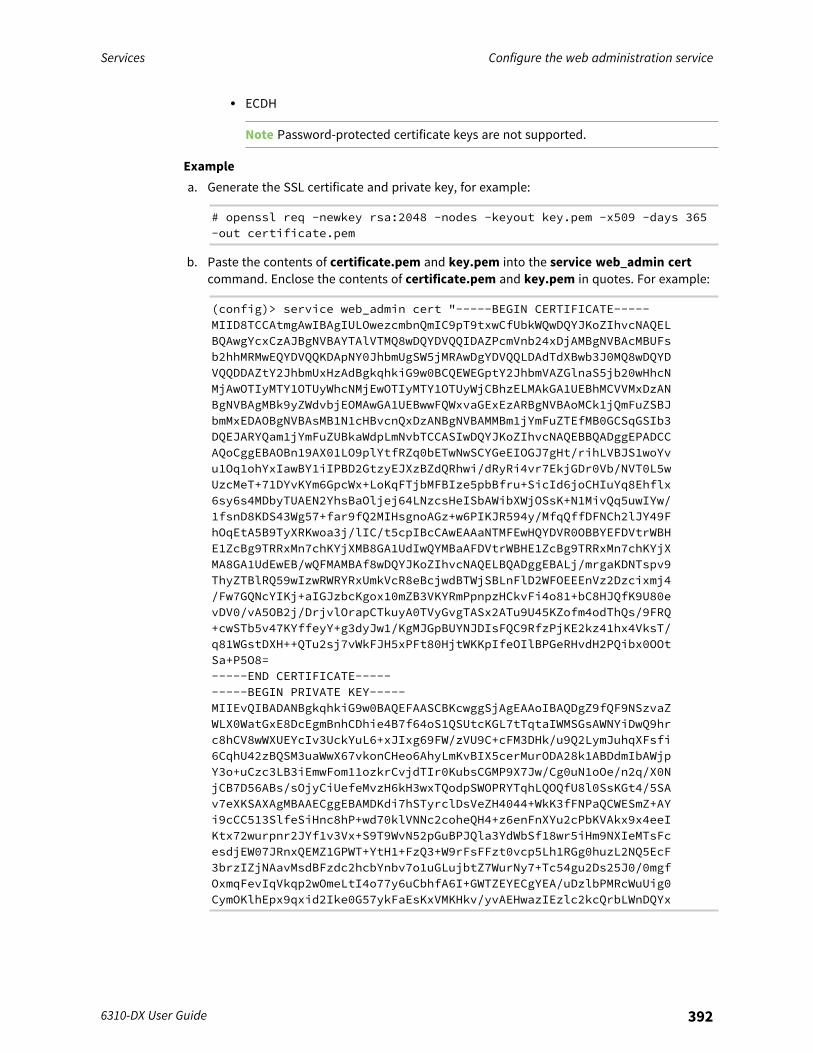
Services Configure the web administration service
6310-DX User Guide 392
l ECDH
Note Password-protected certificate keys are not supported.
Examplea. Generate the SSL certificate and private key, for example:
# openssl req -newkey rsa:2048 -nodes -keyout key.pem -x509 -days 365-out certificate.pem
b. Paste the contents of certificate.pem and key.pem into the service web_admin certcommand. Enclose the contents of certificate.pem and key.pem in quotes. For example:
(config)> service web_admin cert "-----BEGIN CERTIFICATE-----MIID8TCCAtmgAwIBAgIULOwezcmbnQmIC9pT9txwCfUbkWQwDQYJKoZIhvcNAQELBQAwgYcxCzAJBgNVBAYTAlVTMQ8wDQYDVQQIDAZPcmVnb24xDjAMBgNVBAcMBUFsb2hhMRMwEQYDVQQKDApNY0JhbmUgSW5jMRAwDgYDVQQLDAdTdXBwb3J0MQ8wDQYDVQQDDAZtY2JhbmUxHzAdBgkqhkiG9w0BCQEWEGptY2JhbmVAZGlnaS5jb20wHhcNMjAwOTIyMTY1OTUyWhcNMjEwOTIyMTY1OTUyWjCBhzELMAkGA1UEBhMCVVMxDzANBgNVBAgMBk9yZWdvbjEOMAwGA1UEBwwFQWxvaGExEzARBgNVBAoMCk1jQmFuZSBJbmMxEDAOBgNVBAsMB1N1cHBvcnQxDzANBgNVBAMMBm1jYmFuZTEfMB0GCSqGSIb3DQEJARYQam1jYmFuZUBkaWdpLmNvbTCCASIwDQYJKoZIhvcNAQEBBQADggEPADCCAQoCggEBAOBn19AX01LO9plYtfRZq0bETwNwSCYGeEIOGJ7gHt/rihLVBJS1woYvu1Oq1ohYxIawBY1iIPBD2GtzyEJXzBZdQRhwi/dRyRi4vr7EkjGDr0Vb/NVT0L5wUzcMeT+71DYvKYm6GpcWx+LoKqFTjbMFBIze5pbBfru+SicId6joCHIuYq8Ehflx6sy6s4MDbyTUAEN2YhsBaOljej64LNzcsHeISbAWibXWjOSsK+N1MivQq5uwIYw/1fsnD8KDS43Wg57+far9fQ2MIHsgnoAGz+w6PIKJR594y/MfqQffDFNCh2lJY49FhOqEtA5B9TyXRKwoa3j/lIC/t5cpIBcCAwEAAaNTMFEwHQYDVR0OBBYEFDVtrWBHE1ZcBg9TRRxMn7chKYjXMB8GA1UdIwQYMBaAFDVtrWBHE1ZcBg9TRRxMn7chKYjXMA8GA1UdEwEB/wQFMAMBAf8wDQYJKoZIhvcNAQELBQADggEBALj/mrgaKDNTspv9ThyZTBlRQ59wIzwRWRYRxUmkVcR8eBcjwdBTWjSBLnFlD2WFOEEEnVz2Dzcixmj4/Fw7GQNcYIKj+aIGJzbcKgox10mZB3VKYRmPpnpzHCkvFi4o81+bC8HJQfK9U80evDV0/vA5OB2j/DrjvlOrapCTkuyA0TVyGvgTASx2ATu9U45KZofm4odThQs/9FRQ+cwSTb5v47KYffeyY+g3dyJw1/KgMJGpBUYNJDIsFQC9RfzPjKE2kz41hx4VksT/q81WGstDXH++QTu2sj7vWkFJH5xPFt80HjtWKKpIfeOIlBPGeRHvdH2PQibx0OOtSa+P5O8=-----END CERTIFICATE----------BEGIN PRIVATE KEY-----MIIEvQIBADANBgkqhkiG9w0BAQEFAASCBKcwggSjAgEAAoIBAQDgZ9fQF9NSzvaZWLX0WatGxE8DcEgmBnhCDhie4B7f64oS1QSUtcKGL7tTqtaIWMSGsAWNYiDwQ9hrc8hCV8wWXUEYcIv3UckYuL6+xJIxg69FW/zVU9C+cFM3DHk/u9Q2LymJuhqXFsfi6CqhU42zBQSM3uaWwX67vkonCHeo6AhyLmKvBIX5cerMurODA28k1ABDdmIbAWjpY3o+uCzc3LB3iEmwFom11ozkrCvjdTIr0KubsCGMP9X7Jw/Cg0uN1oOe/n2q/X0NjCB7D56ABs/sOjyCiUefeMvzH6kH3wxTQodpSWOPRYTqhLQOQfU8l0SsKGt4/5SAv7eXKSAXAgMBAAECggEBAMDKdi7hSTyrclDsVeZH4044+WkK3fFNPaQCWESmZ+AYi9cCC513SlfeSiHnc8hP+wd70klVNNc2coheQH4+z6enFnXYu2cPbKVAkx9x4eeIKtx72wurpnr2JYf1v3Vx+S9T9WvN52pGuBPJQla3YdWbSf18wr5iHm9NXIeMTsFcesdjEW07JRnxQEMZ1GPWT+YtH1+FzQ3+W9rFsFFzt0vcp5Lh1RGg0huzL2NQ5EcF3brzIZjNAavMsdBFzdc2hcbYnbv7o1uGLujbtZ7WurNy7+Tc54gu2Ds25J0/0mgfOxmqFevIqVkqp2wOmeLtI4o77y6uCbhfA6I+GWTZEYECgYEA/uDzlbPMRcWuUig0CymOKlhEpx9qxid2Ike0G57ykFaEsKxVMKHkv/yvAEHwazIEzlc2kcQrbLWnDQYx

Services Configure the web administration service
6310-DX User Guide 393
oKmXf87Y1T5AXs+ml1PlepXgveKpKrWwORsdDBd+OS34lyNJ0KCqqIzwAaf8lcSWtyShAZzvuH9GW9WlCc8g3ifp9WUCgYEA4WSSfqFkQLA09sI76VLvUqMbb31bNgOkZuPg7uxuDk3yNY58LGQCoV8tUZuHtBJdrBDCtcJa5sasJZQrWUlZ8y/5zgCZmqQnMzTD062xaqTenL0jKgKQrWig4DpUUhfc4BFJmHyeitosDPG98oCxuh6HfuMOeM1vXag6Z391VcsCgYBgBnpfFU1JoC+L7m+lIPPZykWbPT/qBeYBBki5+0lhzebR9StnVicrmROjojQk/sRGxR7fDixaGZolUwcRg7N7SH/y3zA7SDp4WvhjFeKFR8b6O1d4PFnWO2envUUiE/50ZoPFWsv1o8eK2XT67Qbn56t9NB5a7QPvzSSR7jG77QKBgD/wBrqTT9wl4DBrsxEiLK+1g0/iMKCm8dkaJbHBMgsuw1m7/K+fAzwBwtpWk21alGX+Ly3eX2j9zNGwMYfXjgO1hViRxQEgNdqJyk9fA2gsMtYltTbymVYHyzMweMD88fRCEy2FlHfxIfPeE7MaHNCeXnN5N56/MCtSUJcRihh3AoGAey0BGi4xLqSJESqZZ58pe71JHg4M46rLlrxi+4FXaop64LCxM8kPpROfasJJu5nlPpYHye959BBQnYcAheZZ0siGswIauBd8BrZMIWf8JBUIC5EGkMiIyNpLJqPbGEImMUXk4Zane/cL7e06U8ftBUtOtMefbBDDxpP+E+iIiuM=-----END PRIVATE KEY-----"(config)>
5. (Optional) Configure Multicast DNS (mDNS):mDNS is a protocol that resolves host names in small networks that do not have a DNS server.mDNS is enabled by default. To disable mDNS, or enable it if it has been disabled:
n To enable the mDNS protocol:
(config)> service web_admin mdns enable true(config>
n To disable the mDNS protocl:
(config)> service web_admin mdns enable false(config)>
6. (Optional) Set the port number for this service.The default setting of 443 normally should not be changed.
(config)> service web_admin port 444(config)>
7. (Optional) Configure the device to allow legacy encryption protocols.Legacy encryption protocols allow clients to connect to the HTTPS session by using encryptionprotocols older than TLS 1.2, in addition to TLS 1.2 and later protocols. This option is disabledby default, which means that only TLS 1.2 and later encryption protocols are allowed withHTTPS connections.To enable legacy encryption protocols:
(config)> service web_admin legacy_encryption true(config)>
8. (Optional) Disable legacy port redirection.Legacy port redirection is used to redirect client HTTP requests to the HTTPS service. Legacyport redirection is enabled by default, and normally these settings should not be changed.
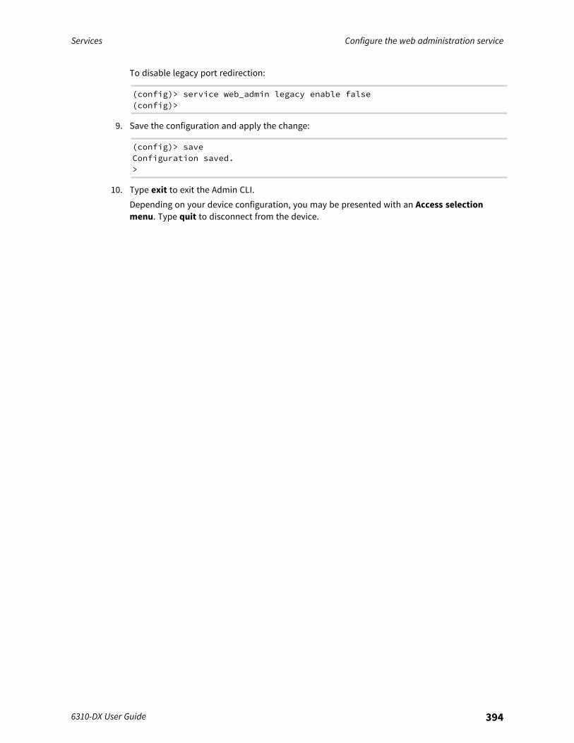
Services Configure the web administration service
6310-DX User Guide 394
To disable legacy port redirection:
(config)> service web_admin legacy enable false(config)>
9. Save the configuration and apply the change:
(config)> saveConfiguration saved.>
10. Type exit to exit the Admin CLI.Depending on your device configuration, you may be presented with an Access selectionmenu. Type quit to disconnect from the device.
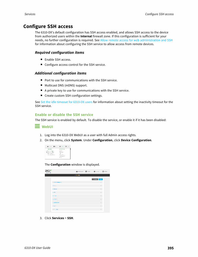
Services Configure SSH access
6310-DX User Guide 395
Configure SSH accessThe 6310-DX's default configuration has SSH access enabled, and allows SSH access to the devicefrom authorized users within the Internal firewall zone. If this configuration is sufficient for yourneeds, no further configuration is required. See Allow remote access for web administration and SSHfor information about configuring the SSH service to allow access from remote devices.
Required configuration items
n Enable SSH access.n Configure access control for the SSH service.
Additional configuration items
n Port to use for communications with the SSH service.n Multicast DNS (mDNS) support.n A private key to use for communications with the SSH service.n Create custom SSH configuration settings.
See Set the idle timeout for 6310-DX users for information about setting the inactivity timeout for theSSH service.
Enable or disable the SSH serviceThe SSH service is enabled by default. To disable the service, or enable it if it has been disabled:
WebUI
1. Log into the 6310-DX WebUI as a user with full Admin access rights.2. On the menu, click System. Under Configuration, click Device Configuration.
The Configuration window is displayed.
3. Click Services > SSH.
Services Configure SSH access
6310-DX User Guide 396
4. Click Enable.5. Click Apply to save the configuration and apply the change.
Command line
1. Log into the 6310-DX command line as a user with full Admin access rights.Depending on your device configuration, you may be presented with an Access selectionmenu. Type admin to access the Admin CLI.
2. At the command line, type config to enter configuration mode:
> config(config)>
3. Enable or disable the SSH service:n To enable the service:
(config)> service ssh enable true(config)>
n To disable the sevice:
(config)> service ssh enable false(config)>
4. Save the configuration and apply the change:
(config)> saveConfiguration saved.>
5. Type exit to exit the Admin CLI.Depending on your device configuration, you may be presented with an Access selectionmenu. Type quit to disconnect from the device.
Configure the service WebUI
1. Log into the 6310-DX WebUI as a user with full Admin access rights.2. On the menu, click System. Under Configuration, click Device Configuration.
The Configuration window is displayed.

Services Configure SSH access
6310-DX User Guide 397
3. Click Services > SSH.4. (Optional) For Port, enter the port number for the service. Normally this should not be
changed.5. Click Access control list to configure access control:
n To limit access to specified IPv4 addresses and networks:a. Click IPv4 Addresses.b. For Add Address, click .c. For Address, enter the IPv4 address or network that can access the device's SSH
service. Allowed values are:l A single IP address or host name.l A network designation in CIDR notation, for example, 192.168.1.0/24.l any: No limit to IPv4 addresses that can access the SSH service.
d. Click again to list additional IP addresses or networks.n To limit access to specified IPv6 addresses and networks:
a. Click IPv6 Addresses.b. For Add Address, click .c. For Address, enter the IPv6 address or network that can access the device's SSH
service. Allowed values are:l A single IP address or host name.l A network designation in CIDR notation, for example, 2001:db8::/48.l any: No limit to IPv6 addresses that can access the SSH service.
d. Click again to list additional IP addresses or networks.n To limit access to hosts connected through a specified interface on the 6310-DX device:
a. Click Interfaces.b. For Add Interface, click .c. For Interface, select the appropriate interface from the dropdown.d. Click again to allow access through additional interfaces.
n To limit access based on firewall zones:a. Click Zones.b. For Add Zone, click .
Services Configure SSH access
6310-DX User Guide 398
c. For Zone, select the appropriate firewall zone from the dropdown.See Firewall configuration for information about firewall zones.
d. Click again to allow access through additional firewall zones.6. Multicast DNS (mDNS) is enabled by default. mDNS is a protocol that resolves host names in
small networks that do not have a DNS server. To disable mDNS, or enable it if it has beendisabled, click Enable mDNS.
7. For Private key, type the private key in PEM format. If Private key is blank, the device will usean automatically-generated key.
8. To create custom SSH configuration settings:a. Click to expand Custom configuration.b. Click Enable.c. For Override:
n If Override is enabled, entries in Configuration file will be used in place of thestandard SSH configuration.
n If Override is not enabled, entries in Configuration file will be added to thestandard SSH configuration.
d. For Configuration file, type configuration settings in the form of an OpenSSH sshd_configfile.For example, to enable the diffie-helman-group-sha-14 key exchange algorithm:i. Click Enable to enable SSH custom configuration.ii. Leave Override disabled.iii. For Configuration file, type the following:
KexAlgorithms +diffie-hellman-group14-sha1
9. Click Apply to save the configuration and apply the change.
Command line
1. Log into the 6310-DX command line as a user with full Admin access rights.Depending on your device configuration, you may be presented with an Access selectionmenu. Type admin to access the Admin CLI.
2. At the command line, type config to enter configuration mode:
> config(config)>
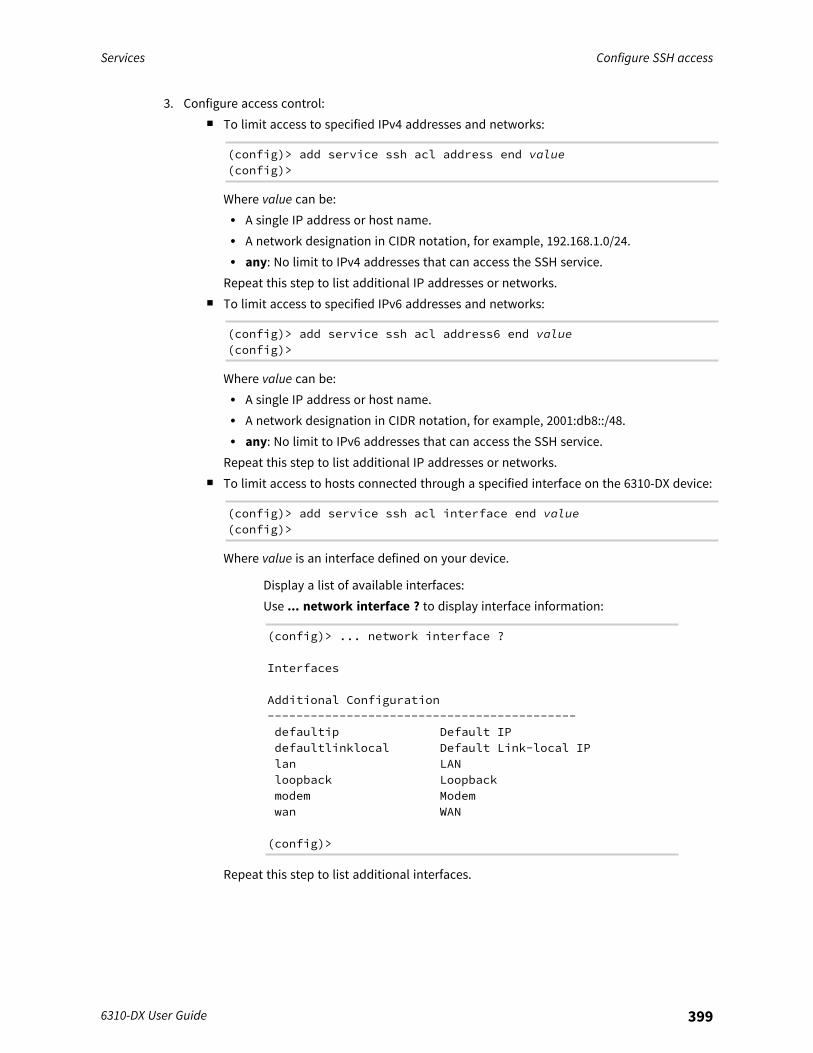
Services Configure SSH access
6310-DX User Guide 399
3. Configure access control:n To limit access to specified IPv4 addresses and networks:
(config)> add service ssh acl address end value(config)>
Where value can be:l A single IP address or host name.l A network designation in CIDR notation, for example, 192.168.1.0/24.l any: No limit to IPv4 addresses that can access the SSH service.
Repeat this step to list additional IP addresses or networks.n To limit access to specified IPv6 addresses and networks:
(config)> add service ssh acl address6 end value(config)>
Where value can be:l A single IP address or host name.l A network designation in CIDR notation, for example, 2001:db8::/48.l any: No limit to IPv6 addresses that can access the SSH service.
Repeat this step to list additional IP addresses or networks.n To limit access to hosts connected through a specified interface on the 6310-DX device:
(config)> add service ssh acl interface end value(config)>
Where value is an interface defined on your device.
Display a list of available interfaces:Use ... network interface ? to display interface information:
(config)> ... network interface ?
Interfaces
Additional Configuration-------------------------------------------defaultip Default IPdefaultlinklocal Default Link-local IPlan LANloopback Loopbackmodem Modemwan WAN
(config)>
Repeat this step to list additional interfaces.
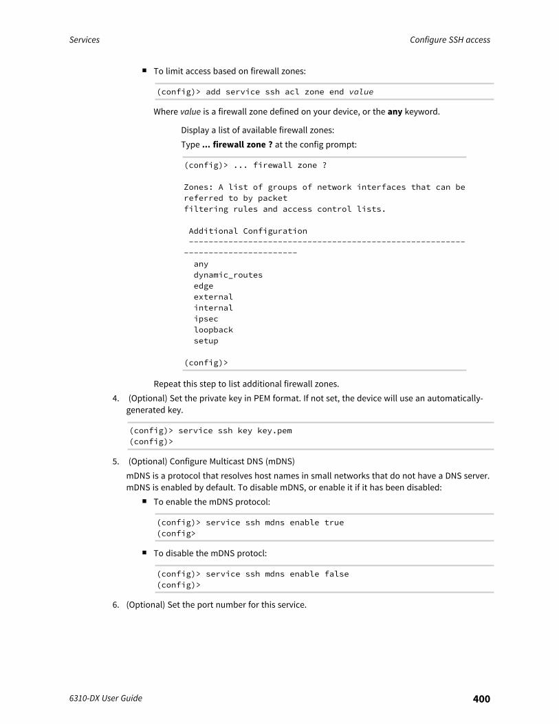
Services Configure SSH access
6310-DX User Guide 400
n To limit access based on firewall zones:
(config)> add service ssh acl zone end value
Where value is a firewall zone defined on your device, or the any keyword.
Display a list of available firewall zones:Type ... firewall zone ? at the config prompt:
(config)> ... firewall zone ?
Zones: A list of groups of network interfaces that can bereferred to by packetfiltering rules and access control lists.
Additional Configuration--------------------------------------------------------
-----------------------anydynamic_routesedgeexternalinternalipsecloopbacksetup
(config)>
Repeat this step to list additional firewall zones.4. (Optional) Set the private key in PEM format. If not set, the device will use an automatically-
generated key.
(config)> service ssh key key.pem(config)>
5. (Optional) Configure Multicast DNS (mDNS)mDNS is a protocol that resolves host names in small networks that do not have a DNS server.mDNS is enabled by default. To disable mDNS, or enable it if it has been disabled:
n To enable the mDNS protocol:
(config)> service ssh mdns enable true(config>
n To disable the mDNS protocl:
(config)> service ssh mdns enable false(config)>
6. (Optional) Set the port number for this service.
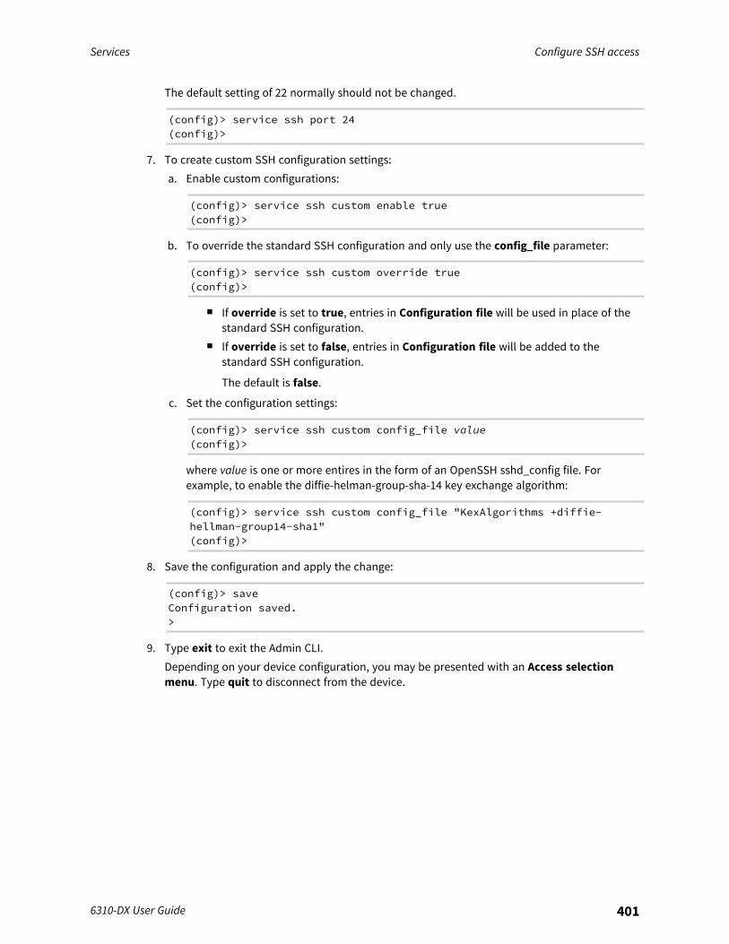
Services Configure SSH access
6310-DX User Guide 401
The default setting of 22 normally should not be changed.
(config)> service ssh port 24(config)>
7. To create custom SSH configuration settings:a. Enable custom configurations:
(config)> service ssh custom enable true(config)>
b. To override the standard SSH configuration and only use the config_file parameter:
(config)> service ssh custom override true(config)>
n If override is set to true, entries in Configuration file will be used in place of thestandard SSH configuration.
n If override is set to false, entries in Configuration file will be added to thestandard SSH configuration.
The default is false.
c. Set the configuration settings:
(config)> service ssh custom config_file value(config)>
where value is one or more entires in the form of an OpenSSH sshd_config file. Forexample, to enable the diffie-helman-group-sha-14 key exchange algorithm:
(config)> service ssh custom config_file "KexAlgorithms +diffie-hellman-group14-sha1"(config)>
8. Save the configuration and apply the change:
(config)> saveConfiguration saved.>
9. Type exit to exit the Admin CLI.Depending on your device configuration, you may be presented with an Access selectionmenu. Type quit to disconnect from the device.
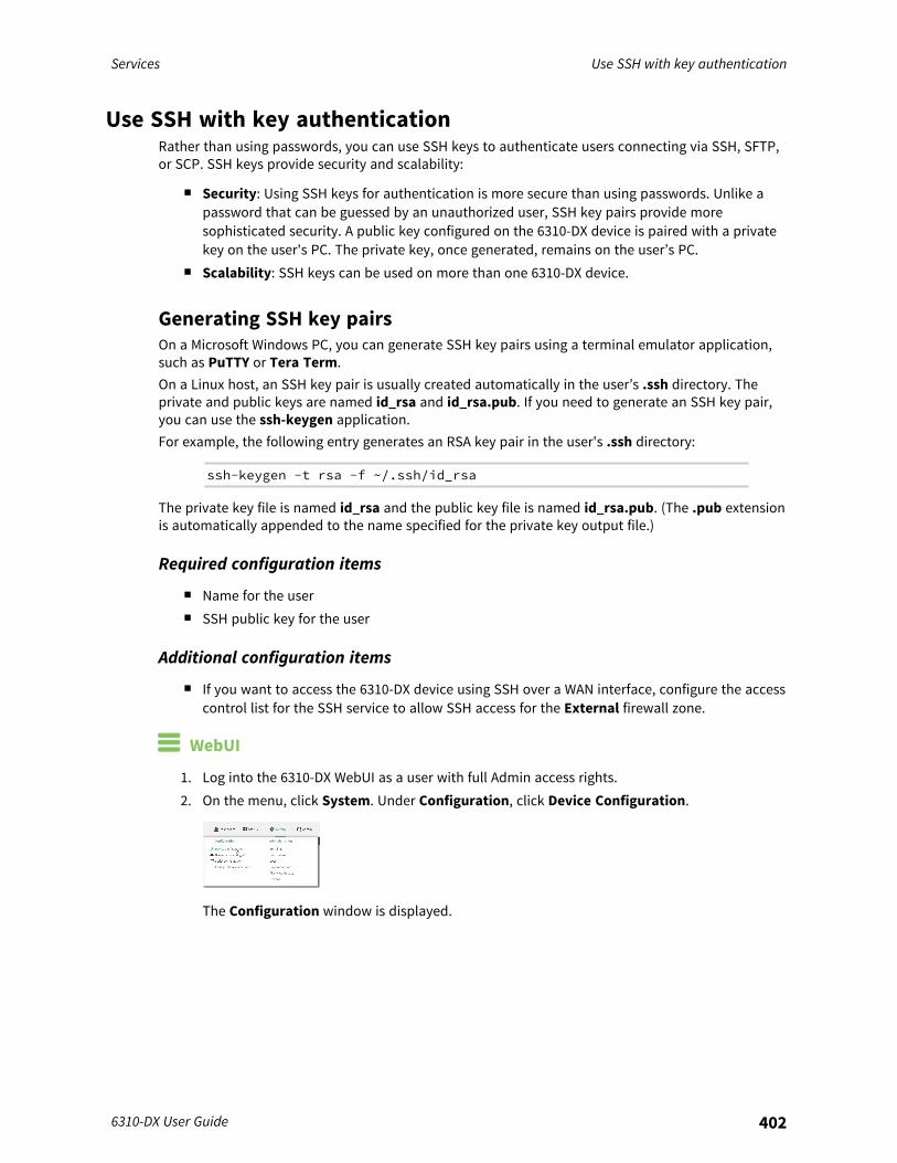
Services Use SSH with key authentication
6310-DX User Guide 402
Use SSH with key authenticationRather than using passwords, you can use SSH keys to authenticate users connecting via SSH, SFTP,or SCP. SSH keys provide security and scalability:
n Security: Using SSH keys for authentication is more secure than using passwords. Unlike apassword that can be guessed by an unauthorized user, SSH key pairs provide moresophisticated security. A public key configured on the 6310-DX device is paired with a privatekey on the user's PC. The private key, once generated, remains on the user’s PC.
n Scalability: SSH keys can be used on more than one 6310-DX device.
Generating SSH key pairsOn a Microsoft Windows PC, you can generate SSH key pairs using a terminal emulator application,such as PuTTY or Tera Term.On a Linux host, an SSH key pair is usually created automatically in the user’s .ssh directory. Theprivate and public keys are named id_rsa and id_rsa.pub. If you need to generate an SSH key pair,you can use the ssh-keygen application.For example, the following entry generates an RSA key pair in the user's .ssh directory:
ssh-keygen -t rsa -f ~/.ssh/id_rsa
The private key file is named id_rsa and the public key file is named id_rsa.pub. (The .pub extensionis automatically appended to the name specified for the private key output file.)
Required configuration items
n Name for the usern SSH public key for the user
Additional configuration items
n If you want to access the 6310-DX device using SSH over a WAN interface, configure the accesscontrol list for the SSH service to allow SSH access for the External firewall zone.
WebUI
1. Log into the 6310-DX WebUI as a user with full Admin access rights.2. On the menu, click System. Under Configuration, click Device Configuration.
The Configuration window is displayed.
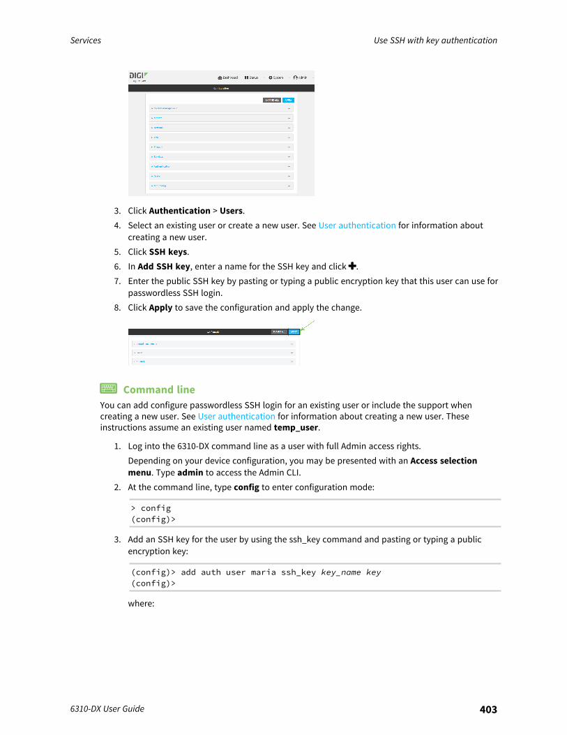
Services Use SSH with key authentication
6310-DX User Guide 403
3. Click Authentication > Users.4. Select an existing user or create a new user. See User authentication for information about
creating a new user.5. Click SSH keys.6. In Add SSH key, enter a name for the SSH key and click .7. Enter the public SSH key by pasting or typing a public encryption key that this user can use for
passwordless SSH login.8. Click Apply to save the configuration and apply the change.
Command lineYou can add configure passwordless SSH login for an existing user or include the support whencreating a new user. See User authentication for information about creating a new user. Theseinstructions assume an existing user named temp_user.
1. Log into the 6310-DX command line as a user with full Admin access rights.Depending on your device configuration, you may be presented with an Access selectionmenu. Type admin to access the Admin CLI.
2. At the command line, type config to enter configuration mode:
> config(config)>
3. Add an SSH key for the user by using the ssh_key command and pasting or typing a publicencryption key:
(config)> add auth user maria ssh_key key_name key(config)>
where:
Services Use SSH with key authentication
6310-DX User Guide 404
n key_name is a name for the key.n key is a public SSH key, which you can enter by pasting or typing a public encryption
key that this user can use for passwordless SSH login4. Save the configuration and apply the change:
(config)> saveConfiguration saved.>
5. Type exit to exit the Admin CLI.Depending on your device configuration, you may be presented with an Access selectionmenu. Type quit to disconnect from the device.
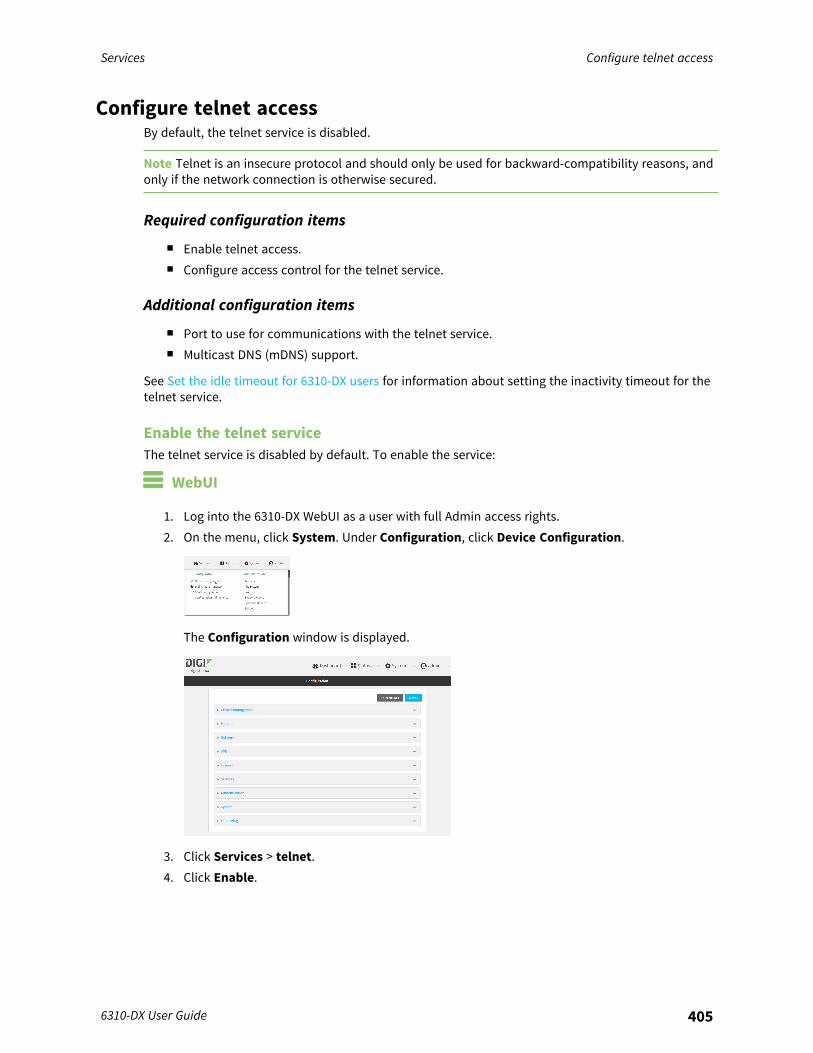
Services Configure telnet access
6310-DX User Guide 405
Configure telnet accessBy default, the telnet service is disabled.
Note Telnet is an insecure protocol and should only be used for backward-compatibility reasons, andonly if the network connection is otherwise secured.
Required configuration items
n Enable telnet access.n Configure access control for the telnet service.
Additional configuration items
n Port to use for communications with the telnet service.n Multicast DNS (mDNS) support.
See Set the idle timeout for 6310-DX users for information about setting the inactivity timeout for thetelnet service.
Enable the telnet serviceThe telnet service is disabled by default. To enable the service:
WebUI
1. Log into the 6310-DX WebUI as a user with full Admin access rights.2. On the menu, click System. Under Configuration, click Device Configuration.
The Configuration window is displayed.
3. Click Services > telnet.4. Click Enable.
Services Configure telnet access
6310-DX User Guide 406
5. Click Apply to save the configuration and apply the change.
Command line
1. Log into the 6310-DX command line as a user with full Admin access rights.Depending on your device configuration, you may be presented with an Access selectionmenu. Type admin to access the Admin CLI.
2. At the command line, type config to enter configuration mode:
> config(config)>
3. Enable the telnet service:
(config)> service telnet enable true(config)>
4. Save the configuration and apply the change:
(config)> saveConfiguration saved.>
5. Type exit to exit the Admin CLI.Depending on your device configuration, you may be presented with an Access selectionmenu. Type quit to disconnect from the device.
Configure the service WebUI
1. Log into the 6310-DX WebUI as a user with full Admin access rights.2. On the menu, click System. Under Configuration, click Device Configuration.
The Configuration window is displayed.
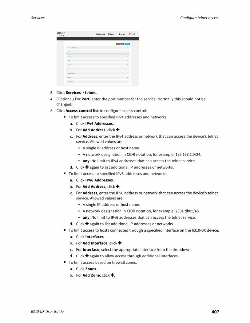
Services Configure telnet access
6310-DX User Guide 407
3. Click Services > telnet.4. (Optional) For Port, enter the port number for the service. Normally this should not be
changed.5. Click Access control list to configure access control:
n To limit access to specified IPv4 addresses and networks:a. Click IPv4 Addresses.b. For Add Address, click .c. For Address, enter the IPv4 address or network that can access the device's telnet
service. Allowed values are:l A single IP address or host name.l A network designation in CIDR notation, for example, 192.168.1.0/24.l any: No limit to IPv4 addresses that can access the telnet service.
d. Click again to list additional IP addresses or networks.n To limit access to specified IPv6 addresses and networks:
a. Click IPv6 Addresses.b. For Add Address, click .c. For Address, enter the IPv6 address or network that can access the device's telnet
service. Allowed values are:l A single IP address or host name.l A network designation in CIDR notation, for example, 2001:db8::/48.l any: No limit to IPv6 addresses that can access the telnet service.
d. Click again to list additional IP addresses or networks.n To limit access to hosts connected through a specified interface on the 6310-DX device:
a. Click Interfaces.b. For Add Interface, click .c. For Interface, select the appropriate interface from the dropdown.d. Click again to allow access through additional interfaces.
n To limit access based on firewall zones:a. Click Zones.b. For Add Zone, click .
Services Configure telnet access
6310-DX User Guide 408
c. For Zone, select the appropriate firewall zone from the dropdown.See Firewall configuration for information about firewall zones.
d. Click again to allow access through additional firewall zones.6. Multicast DNS (mDNS) is disabled by default. mDNS is a protocol that resolves host names in
small networks that do not have a DNS server. To enable mDNS, click Enable mDNS.7. Click Apply to save the configuration and apply the change.
Command line
1. Log into the 6310-DX command line as a user with full Admin access rights.Depending on your device configuration, you may be presented with an Access selectionmenu. Type admin to access the Admin CLI.
2. At the command line, type config to enter configuration mode:
> config(config)>
3. Configure access control:n To limit access to specified IPv4 addresses and networks:
(config)> add service telnet acl address end value(config)>
Where value can be:l A single IP address or host name.l A network designation in CIDR notation, for example, 192.168.1.0/24.l any: No limit to IPv4 addresses that can access the telnet service.
Repeat this step to list additional IP addresses or networks.n To limit access to specified IPv6 addresses and networks:
(config)> add service telnet acl address6 end value(config)>
Where value can be:l A single IP address or host name.l A network designation in CIDR notation, for example, 2001:db8::/48.l any: No limit to IPv6 addresses that can access the telnet service.
Repeat this step to list additional IP addresses or networks.n To limit access to hosts connected through a specified interface on the 6310-DX device:
(config)> add service telnet acl interface end value(config)>
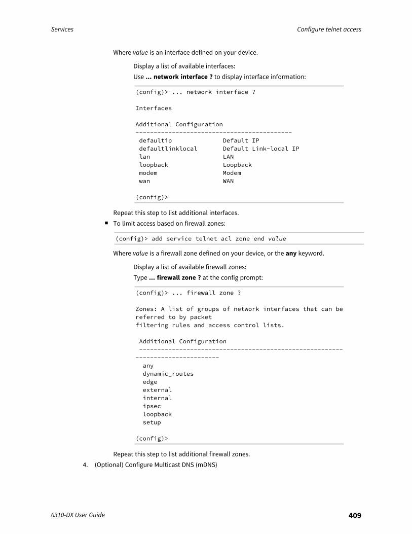
Services Configure telnet access
6310-DX User Guide 409
Where value is an interface defined on your device.
Display a list of available interfaces:Use ... network interface ? to display interface information:
(config)> ... network interface ?
Interfaces
Additional Configuration-------------------------------------------defaultip Default IPdefaultlinklocal Default Link-local IPlan LANloopback Loopbackmodem Modemwan WAN
(config)>
Repeat this step to list additional interfaces.n To limit access based on firewall zones:
(config)> add service telnet acl zone end value
Where value is a firewall zone defined on your device, or the any keyword.
Display a list of available firewall zones:Type ... firewall zone ? at the config prompt:
(config)> ... firewall zone ?
Zones: A list of groups of network interfaces that can bereferred to by packetfiltering rules and access control lists.
Additional Configuration--------------------------------------------------------
-----------------------anydynamic_routesedgeexternalinternalipsecloopbacksetup
(config)>
Repeat this step to list additional firewall zones.4. (Optional) Configure Multicast DNS (mDNS)

Services Configure DNS
6310-DX User Guide 410
mDNS is a protocol that resolves host names in small networks that do not have a DNS server.mDNS is disabled by default. To enable:
(config)> service telnet mdns enable true(config>
5. (Optional) Set the port number for this service.The default setting of 23 normally should not be changed.
(config)> service telnet port 25(config)>
6. Save the configuration and apply the change:
(config)> saveConfiguration saved.>
7. Type exit to exit the Admin CLI.Depending on your device configuration, you may be presented with an Access selectionmenu. Type quit to disconnect from the device.
Configure DNSThe 6310-DX device includes a caching DNS server which forwards queries to the DNS servers that areassociated with the network interfaces, and caches the results. This server is used within the device,and cannot be disabled. Use the access control list to restrict external access to this server.
Required configuration items
n Configure access control for the DNS service.
Additional configuration items
n Whether the device should cache negative responses.n Whether the device should always perform DNS queries to all available DNS servers.n Whether to prevent upstream DNS servers from returning private IP addresses.n Additional DNS servers, in addition to the ones associated with the device's network interfaces.n Specific host names and their IP addresses.
The device is configured by default with the hostname digi.device, which corresponds to the192.168.210.1 IP address.
To configure the DNS server:
WebUI
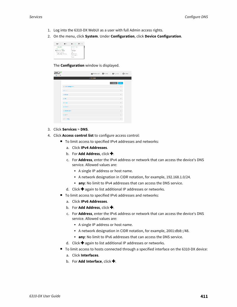
Services Configure DNS
6310-DX User Guide 411
1. Log into the 6310-DX WebUI as a user with full Admin access rights.2. On the menu, click System. Under Configuration, click Device Configuration.
The Configuration window is displayed.
3. Click Services > DNS.4. Click Access control list to configure access control:
n To limit access to specified IPv4 addresses and networks:a. Click IPv4 Addresses.b. For Add Address, click .c. For Address, enter the IPv4 address or network that can access the device's DNS
service. Allowed values are:l A single IP address or host name.l A network designation in CIDR notation, for example, 192.168.1.0/24.l any: No limit to IPv4 addresses that can access the DNS service.
d. Click again to list additional IP addresses or networks.n To limit access to specified IPv6 addresses and networks:
a. Click IPv6 Addresses.b. For Add Address, click .c. For Address, enter the IPv6 address or network that can access the device's DNS
service. Allowed values are:l A single IP address or host name.l A network designation in CIDR notation, for example, 2001:db8::/48.l any: No limit to IPv6 addresses that can access the DNS service.
d. Click again to list additional IP addresses or networks.n To limit access to hosts connected through a specified interface on the 6310-DX device:
a. Click Interfaces.b. For Add Interface, click .
Services Configure DNS
6310-DX User Guide 412
c. For Interface, select the appropriate interface from the dropdown.d. Click again to allow access through additional interfaces.n To limit access based on firewall zones:
a. Click Zones.b. For Add Zone, click .c. For Zone, select the appropriate firewall zone from the dropdown.
See Firewall configuration for information about firewall zones.d. Click again to allow access through additional firewall zones.
5. (Optional) Cache negative responses is enabled by default. Disabling this option may improveperformance on networks with transient DNS results, when one or more DNS servers may havepositive results. To disable, click Cache negative responses.
6. (Optional) Query all servers is enabled by default. This option is useful when only some DNSservers will be able to resolve hostnames. To disable, click Query all servers.
7. (Optional) Rebind protection, if enabled, prevents upstream DNS servers from returningprivate IP addresses. To enable, click Rebind protection.
8. (Optional) Allow localhost rebinding is enabled by default if Rebind protection is enabled.This is useful for Real-time Black List (RBL) servers.
9. (Optional) To add additional DNS servers:a. Click DNS servers.b. For Add Server, click .c. (Optional) Enter a label for the DNS server.d. For DNS server, enter the IP address of the DNS server.e. Domain restricts the device's use of this DNS server based on the domain. If no domain
are listed, then all queries may be sent to this server.10. (Optional) To add host names and their IP addresses that the device's DNS server will resolve:
a. Click Additional DNS hostnames.b. For Add Host, click .c. Type the IP address of the host.d. For Name, type the hostname.
11. Click Apply to save the configuration and apply the change.
Command line
1. Log into the 6310-DX command line as a user with full Admin access rights.Depending on your device configuration, you may be presented with an Access selectionmenu. Type admin to access the Admin CLI.

Services Configure DNS
6310-DX User Guide 413
2. At the command line, type config to enter configuration mode:
> config(config)>
3. Configure access control:n To limit access to specified IPv4 addresses and networks:
(config)> add service dns acl address end value(config)>
Where value can be:l A single IP address or host name.l A network designation in CIDR notation, for example, 192.168.1.0/24.l any: No limit to IPv4 addresses that can access the DNS service.
Repeat this step to list additional IP addresses or networks.n To limit access to specified IPv6 addresses and networks:
(config)> add service dns acl address6 end value(config)>
Where value can be:l A single IP address or host name.l A network designation in CIDR notation, for example, 2001:db8::/48.l any: No limit to IPv6 addresses that can access the DNS service.
Repeat this step to list additional IP addresses or networks.n To limit access to hosts connected through a specified interface on the 6310-DX device:
(config)> add service dns acl interface end value(config)>
Where value is an interface defined on your device.
Display a list of available interfaces:Use ... network interface ? to display interface information:
(config)> ... network interface ?
Interfaces
Additional Configuration-------------------------------------------defaultip Default IPdefaultlinklocal Default Link-local IPlan LANloopback Loopbackmodem Modemwan WAN
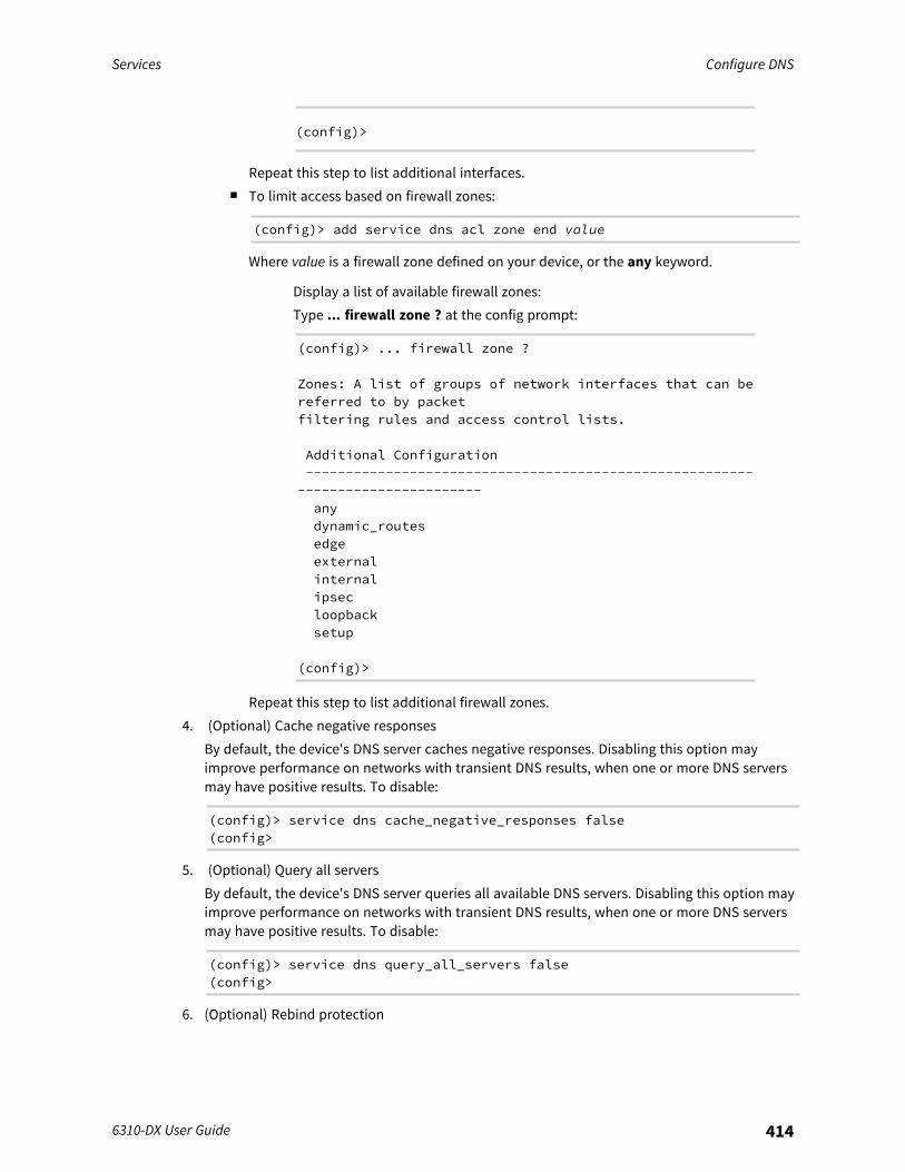
Services Configure DNS
6310-DX User Guide 414
(config)>
Repeat this step to list additional interfaces.n To limit access based on firewall zones:
(config)> add service dns acl zone end value
Where value is a firewall zone defined on your device, or the any keyword.
Display a list of available firewall zones:Type ... firewall zone ? at the config prompt:
(config)> ... firewall zone ?
Zones: A list of groups of network interfaces that can bereferred to by packetfiltering rules and access control lists.
Additional Configuration--------------------------------------------------------
-----------------------anydynamic_routesedgeexternalinternalipsecloopbacksetup
(config)>
Repeat this step to list additional firewall zones.4. (Optional) Cache negative responses
By default, the device's DNS server caches negative responses. Disabling this option mayimprove performance on networks with transient DNS results, when one or more DNS serversmay have positive results. To disable:
(config)> service dns cache_negative_responses false(config>
5. (Optional) Query all serversBy default, the device's DNS server queries all available DNS servers. Disabling this option mayimprove performance on networks with transient DNS results, when one or more DNS serversmay have positive results. To disable:
(config)> service dns query_all_servers false(config>
6. (Optional) Rebind protection
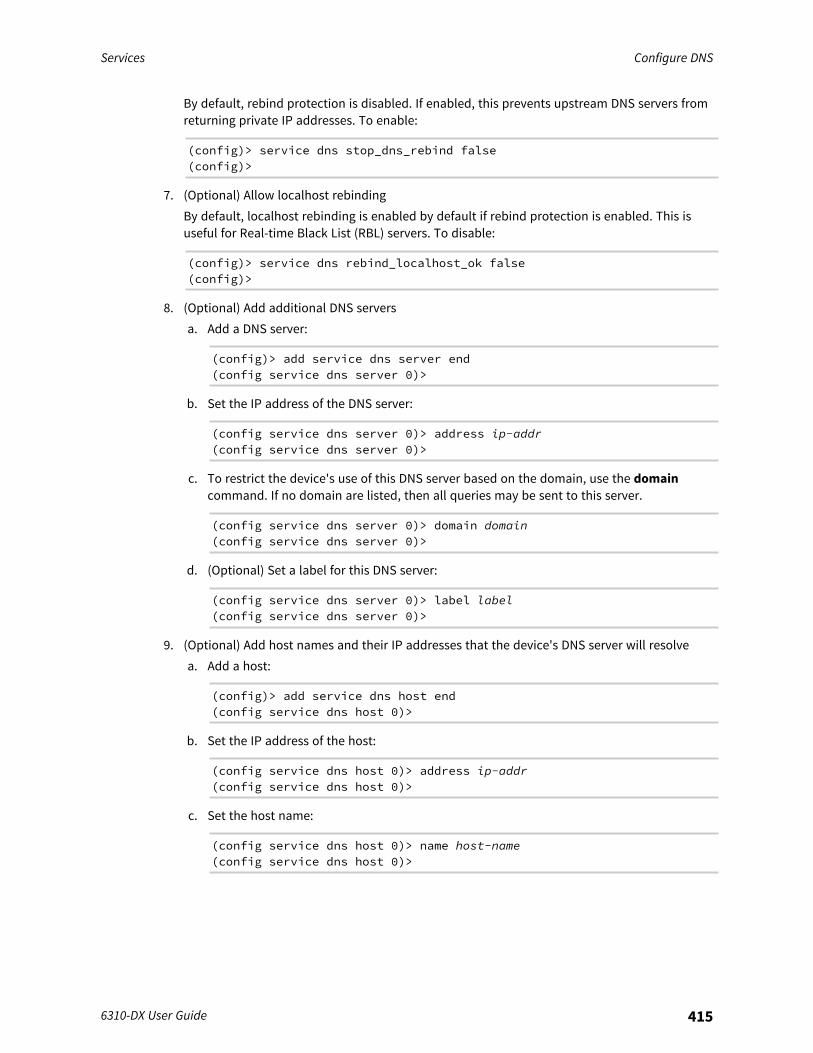
Services Configure DNS
6310-DX User Guide 415
By default, rebind protection is disabled. If enabled, this prevents upstream DNS servers fromreturning private IP addresses. To enable:
(config)> service dns stop_dns_rebind false(config)>
7. (Optional) Allow localhost rebindingBy default, localhost rebinding is enabled by default if rebind protection is enabled. This isuseful for Real-time Black List (RBL) servers. To disable:
(config)> service dns rebind_localhost_ok false(config)>
8. (Optional) Add additional DNS serversa. Add a DNS server:
(config)> add service dns server end(config service dns server 0)>
b. Set the IP address of the DNS server:
(config service dns server 0)> address ip-addr(config service dns server 0)>
c. To restrict the device's use of this DNS server based on the domain, use the domaincommand. If no domain are listed, then all queries may be sent to this server.
(config service dns server 0)> domain domain(config service dns server 0)>
d. (Optional) Set a label for this DNS server:
(config service dns server 0)> label label(config service dns server 0)>
9. (Optional) Add host names and their IP addresses that the device's DNS server will resolvea. Add a host:
(config)> add service dns host end(config service dns host 0)>
b. Set the IP address of the host:
(config service dns host 0)> address ip-addr(config service dns host 0)>
c. Set the host name:
(config service dns host 0)> name host-name(config service dns host 0)>
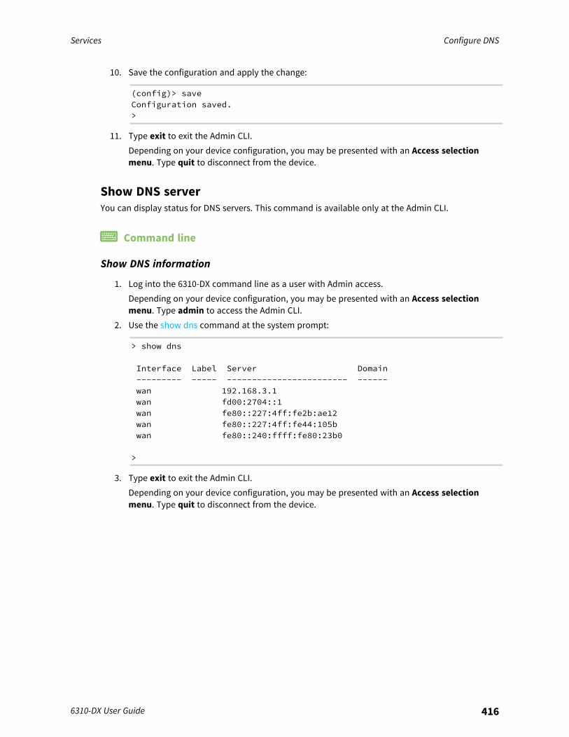
Services Configure DNS
6310-DX User Guide 416
10. Save the configuration and apply the change:
(config)> saveConfiguration saved.>
11. Type exit to exit the Admin CLI.Depending on your device configuration, you may be presented with an Access selectionmenu. Type quit to disconnect from the device.
Show DNS serverYou can display status for DNS servers. This command is available only at the Admin CLI.
Command line
Show DNS information
1. Log into the 6310-DX command line as a user with Admin access.Depending on your device configuration, you may be presented with an Access selectionmenu. Type admin to access the Admin CLI.
2. Use the show dns command at the system prompt:
> show dns
Interface Label Server Domain--------- ----- ------------------------ ------wan 192.168.3.1wan fd00:2704::1wan fe80::227:4ff:fe2b:ae12wan fe80::227:4ff:fe44:105bwan fe80::240:ffff:fe80:23b0
>
3. Type exit to exit the Admin CLI.Depending on your device configuration, you may be presented with an Access selectionmenu. Type quit to disconnect from the device.

Services Simple Network Management Protocol (SNMP)
6310-DX User Guide 417
Simple Network Management Protocol (SNMP)Simple Network Management Protocol (SNMP) is a protocol for remotely managing and monitoringnetwork devices. Network administrators can use the SNMP architecture to manage nodes, includingservers, workstations, routers, switches, hubs, and other equipment on an IP network, managenetwork performance, find and solve network problems, and plan for network growth.The 6310-DX device supports both SNMPv3 and SNMPv2c in read-only mode. Both are disabled bydefault. SNMPv1 is not supported.
SNMP SecurityBy default, the 6310-DX device automatically blocks SNMP packets from being received over WAN andLAN interfaces. As a result, if you want a 6310-DX device to receive SNMP packets, you must configurethe SNMP access control list to allow the device to receive the packets. See Configure Simple NetworkManagement Protocol (SNMP).
Configure Simple Network Management Protocol (SNMP)
Required configuration items
n Enable SNMP.n Firewall configuration using access control to allow remote connections to the SNMP agent.n The user name and password used to connect to the SNMP agent.
Additional configuration items
n The port used by the SNMP agent.n Authentication type (either MD5 or SHA).n Privacy protocol (either DES or AES).n Privacy passphrase, if different that the SNMP user password.n Enable Multicast DNS (mDNS) support.
To configure the SNMP agent on your 6310-DX device:
WebUI
1. Log into the 6310-DX WebUI as a user with full Admin access rights.2. On the menu, click System. Under Configuration, click Device Configuration.
The Configuration window is displayed.
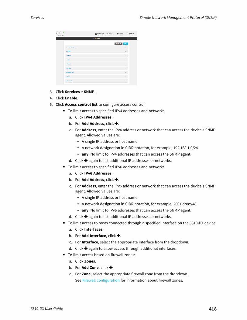
Services Simple Network Management Protocol (SNMP)
6310-DX User Guide 418
3. Click Services > SNMP.4. Click Enable.5. Click Access control list to configure access control:
n To limit access to specified IPv4 addresses and networks:a. Click IPv4 Addresses.b. For Add Address, click .c. For Address, enter the IPv4 address or network that can access the device's SNMP
agent. Allowed values are:l A single IP address or host name.l A network designation in CIDR notation, for example, 192.168.1.0/24.l any: No limit to IPv4 addresses that can access the SNMP agent.
d. Click again to list additional IP addresses or networks.n To limit access to specified IPv6 addresses and networks:
a. Click IPv6 Addresses.b. For Add Address, click .c. For Address, enter the IPv6 address or network that can access the device's SNMP
agent. Allowed values are:l A single IP address or host name.l A network designation in CIDR notation, for example, 2001:db8::/48.l any: No limit to IPv6 addresses that can access the SNMP agent.
d. Click again to list additional IP addresses or networks.n To limit access to hosts connected through a specified interface on the 6310-DX device:
a. Click Interfaces.b. For Add Interface, click .c. For Interface, select the appropriate interface from the dropdown.d. Click again to allow access through additional interfaces.
n To limit access based on firewall zones:a. Click Zones.b. For Add Zone, click .c. For Zone, select the appropriate firewall zone from the dropdown.
See Firewall configuration for information about firewall zones.
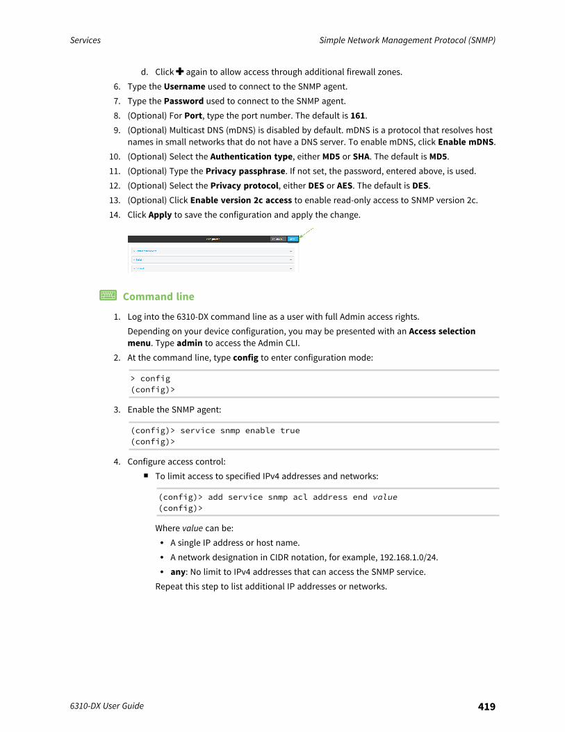
Services Simple Network Management Protocol (SNMP)
6310-DX User Guide 419
d. Click again to allow access through additional firewall zones.6. Type the Username used to connect to the SNMP agent.7. Type the Password used to connect to the SNMP agent.8. (Optional) For Port, type the port number. The default is 161.9. (Optional) Multicast DNS (mDNS) is disabled by default. mDNS is a protocol that resolves host
names in small networks that do not have a DNS server. To enable mDNS, click Enable mDNS.10. (Optional) Select the Authentication type, either MD5 or SHA. The default is MD5.11. (Optional) Type the Privacy passphrase. If not set, the password, entered above, is used.12. (Optional) Select the Privacy protocol, either DES or AES. The default is DES.13. (Optional) Click Enable version 2c access to enable read-only access to SNMP version 2c.14. Click Apply to save the configuration and apply the change.
Command line
1. Log into the 6310-DX command line as a user with full Admin access rights.Depending on your device configuration, you may be presented with an Access selectionmenu. Type admin to access the Admin CLI.
2. At the command line, type config to enter configuration mode:
> config(config)>
3. Enable the SNMP agent:
(config)> service snmp enable true(config)>
4. Configure access control:n To limit access to specified IPv4 addresses and networks:
(config)> add service snmp acl address end value(config)>
Where value can be:l A single IP address or host name.l A network designation in CIDR notation, for example, 192.168.1.0/24.l any: No limit to IPv4 addresses that can access the SNMP service.
Repeat this step to list additional IP addresses or networks.
Services Simple Network Management Protocol (SNMP)
6310-DX User Guide 420
n To limit access to specified IPv6 addresses and networks:
(config)> add service snmp acl address6 end value(config)>
Where value can be:l A single IP address or host name.l A network designation in CIDR notation, for example, 2001:db8::/48.l any: No limit to IPv6 addresses that can access the SNMP service.
Repeat this step to list additional IP addresses or networks.n To limit access to hosts connected through a specified interface on the 6310-DX device:
(config)> add service snmp acl interface end value(config)>
Where value is an interface defined on your device.
Display a list of available interfaces:Use ... network interface ? to display interface information:
(config)> ... network interface ?
Interfaces
Additional Configuration-------------------------------------------defaultip Default IPdefaultlinklocal Default Link-local IPlan LANloopback Loopbackmodem Modemwan WAN
(config)>
Repeat this step to list additional interfaces.n To limit access based on firewall zones:
(config)> add service snmp acl zone end value
Where value is a firewall zone defined on your device, or the any keyword.
Display a list of available firewall zones:Type ... firewall zone ? at the config prompt:
(config)> ... firewall zone ?
Zones: A list of groups of network interfaces that can bereferred to by packetfiltering rules and access control lists.

Services Simple Network Management Protocol (SNMP)
6310-DX User Guide 421
Additional Configuration--------------------------------------------------------
-----------------------anydynamic_routesedgeexternalinternalipsecloopbacksetup
(config)>
Repeat this step to list additional firewall zones.5. Set the name of the user that will be used to connect to the SNMP agent.
(config)> service snmp username name(config)>
6. Set the password for the user that will be used to connect to the SNMP agent:
(config)> service snmp password pwd(config)>
7. (Optional) Set the port number for the SNMP agent. The default is 161.
(config)> service snmp port port(config)>
8. (Optional) Configure Multicast DNS (mDNS)mDNS is a protocol that resolves host names in small networks that do not have a DNS server.For the SNMP agent, mDNS is disabled by default. To enable:
(config)> service snmp mdns enable true(config>
9. (Optional) Set the authentication type. Allowed values are MD5 or SHA. The default is MD5.
(config)> service snmp auth_type SHA(config)>
10. (Optional) Set the privacy passphrase. If not set, the password, entered above, is used.
(config)> service snmp privacy pwd(config)>
11. (Optional) Set the privacy protocol, either DES or AES. The default is DES.
(config)> service snmp privacy_protocol AES(config)>
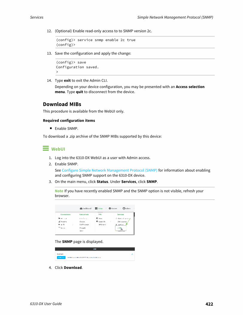
Services Simple Network Management Protocol (SNMP)
6310-DX User Guide 422
12. (Optional) Enable read-only access to to SNMP version 2c.
(config)> service snmp enable 2c true(config)>
13. Save the configuration and apply the change:
(config)> saveConfiguration saved.>
14. Type exit to exit the Admin CLI.Depending on your device configuration, you may be presented with an Access selectionmenu. Type quit to disconnect from the device.
Download MIBsThis procedure is available from the WebUI only.
Required configuration items
n Enable SNMP.
To download a .zip archive of the SNMP MIBs supported by this device:
WebUI
1. Log into the 6310-DX WebUI as a user with Admin access.2. Enable SNMP.
See Configure Simple Network Management Protocol (SNMP) for information about enablingand configuring SNMP support on the 6310-DX device.
3. On the main menu, click Status. Under Services, click SNMP.
Note If you have recently enabled SNMP and the SNMP option is not visible, refresh yourbrowser.
The SNMP page is displayed.
4. Click Download.
Services Location information
6310-DX User Guide 423
Location informationYour 6310-DX device can be configured to use the following location sources:
n In conjunction with the with the CM07 CORE modem, the modem's internal Global NavigationSatellite System (GNSS) module that provides information about the current location of thedevice.
n The modem's internal Global Navigation Satellite System (GNSS) module that providesinformation about the current location of the device.
n User-defined static location.n Location messages forwarded to the device from other location-enabled devices.
By default, the modem's internal GNSS module is enabled.You can also configure your 6310-DX device to forward location messages, either from the 6310-DXdevice or from external sources, to a remote host. Additionally, the device can be configured to use ageofence, to allow you to determine actions that will be taken based on the physical location of thedevice.This section contains the following topics:
Configure the location service 424Enable or disable modem GNSS support 426Configure the device to use a user-defined static location 428Configure the device to accept location messages from external sources 430Forward location information to a remote host 435Configure geofencing 442Show location information 454
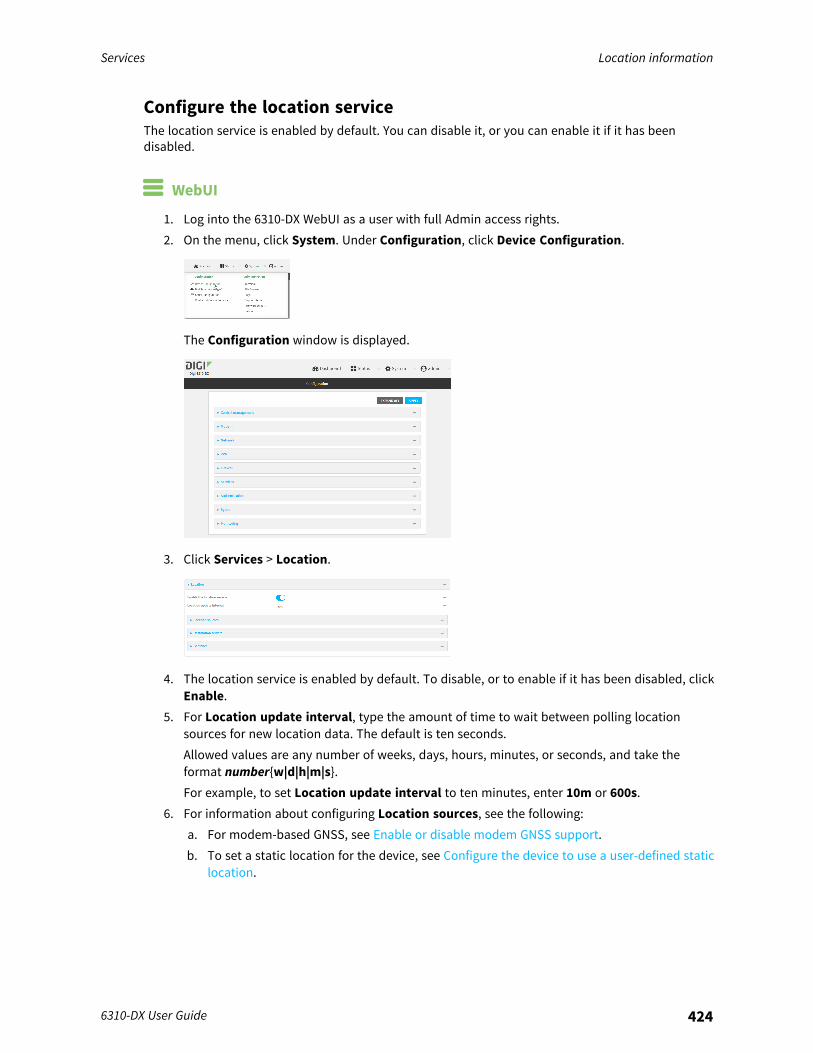
Services Location information
6310-DX User Guide 424
Configure the location serviceThe location service is enabled by default. You can disable it, or you can enable it if it has beendisabled.
WebUI
1. Log into the 6310-DX WebUI as a user with full Admin access rights.2. On the menu, click System. Under Configuration, click Device Configuration.
The Configuration window is displayed.
3. Click Services > Location.
4. The location service is enabled by default. To disable, or to enable if it has been disabled, clickEnable.
5. For Location update interval, type the amount of time to wait between polling locationsources for new location data. The default is ten seconds.Allowed values are any number of weeks, days, hours, minutes, or seconds, and take theformat number{w|d|h|m|s}.For example, to set Location update interval to ten minutes, enter 10m or 600s.
6. For information about configuring Location sources, see the following:a. For modem-based GNSS, see Enable or disable modem GNSS support.b. To set a static location for the device, see Configure the device to use a user-defined static
location.
Services Location information
6310-DX User Guide 425
c. To accept location information from an external location-enabled server, see Configure thedevice to accept location messages from external sources.
If multiple location sources are enabled at the same time, the device's location will bedetermined based on the order that the location sources are listed here.
7. For information about configuring Destination servers, see Forward location information to aremote host.
8. For information about configuring Geofence, see Configure geofencing.9. Click Apply to save the configuration and apply the change.
Command line
1. Log into the 6310-DX command line as a user with full Admin access rights.Depending on your device configuration, you may be presented with an Access selectionmenu. Type admin to access the Admin CLI.
2. At the command line, type config to enter configuration mode:
> config(config)>
3. Enable or disable the GNSS module:n To enable the module:
(config)> service location gnss true(config)>
n To disable the module:
(config)> service location gnss false(config)>
4. Set the amount of time that the 6310-DX device will wait before polling location sources forupdated location data:
(config)> service location interval value(config)>
where value is any number of hours, minutes, or seconds, and takes the format number{h|m|s}.For example, to set interval to ten minutes, enter either 10m or 600s:
(config)> service location interval 600s(config)>
The default is 10 seconds.
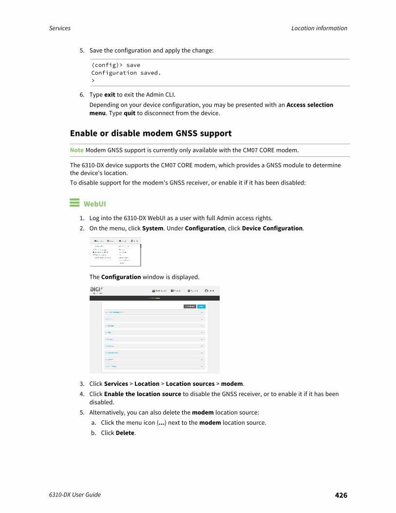
Services Location information
6310-DX User Guide 426
5. Save the configuration and apply the change:
(config)> saveConfiguration saved.>
6. Type exit to exit the Admin CLI.Depending on your device configuration, you may be presented with an Access selectionmenu. Type quit to disconnect from the device.
Enable or disable modem GNSS support
Note Modem GNSS support is currently only available with the CM07 CORE modem.
The 6310-DX device supports the CM07 CORE modem, which provides a GNSS module to determinethe device's location.To disable support for the modem's GNSS receiver, or enable it if it has been disabled:
WebUI
1. Log into the 6310-DX WebUI as a user with full Admin access rights.2. On the menu, click System. Under Configuration, click Device Configuration.
The Configuration window is displayed.
3. Click Services > Location > Location sources > modem.4. Click Enable the location source to disable the GNSS receiver, or to enable it if it has been
disabled.5. Alternatively, you can also delete the modem location source:
a. Click the menu icon (...) next to the modem location source.b. Click Delete.
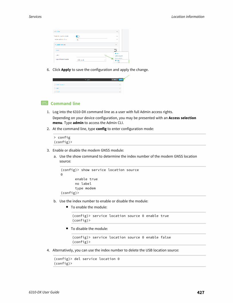
Services Location information
6310-DX User Guide 427
6. Click Apply to save the configuration and apply the change.
Command line
1. Log into the 6310-DX command line as a user with full Admin access rights.Depending on your device configuration, you may be presented with an Access selectionmenu. Type admin to access the Admin CLI.
2. At the command line, type config to enter configuration mode:
> config(config)>
3. Enable or disable the modem GNSS module:a. Use the show command to determine the index number of the modem GNSS location
source:
(config)> show service location source0
enable trueno labeltype modem
(config)>
b. Use the index number to enable or disable the module:n To enable the module:
(config)> service location source 0 enable true(config)>
n To disable the module:
(config)> service location source 0 enable false(config)>
4. Alternatively, you can use the index number to delete the USB location source:
(config)> del service location 0(config)>
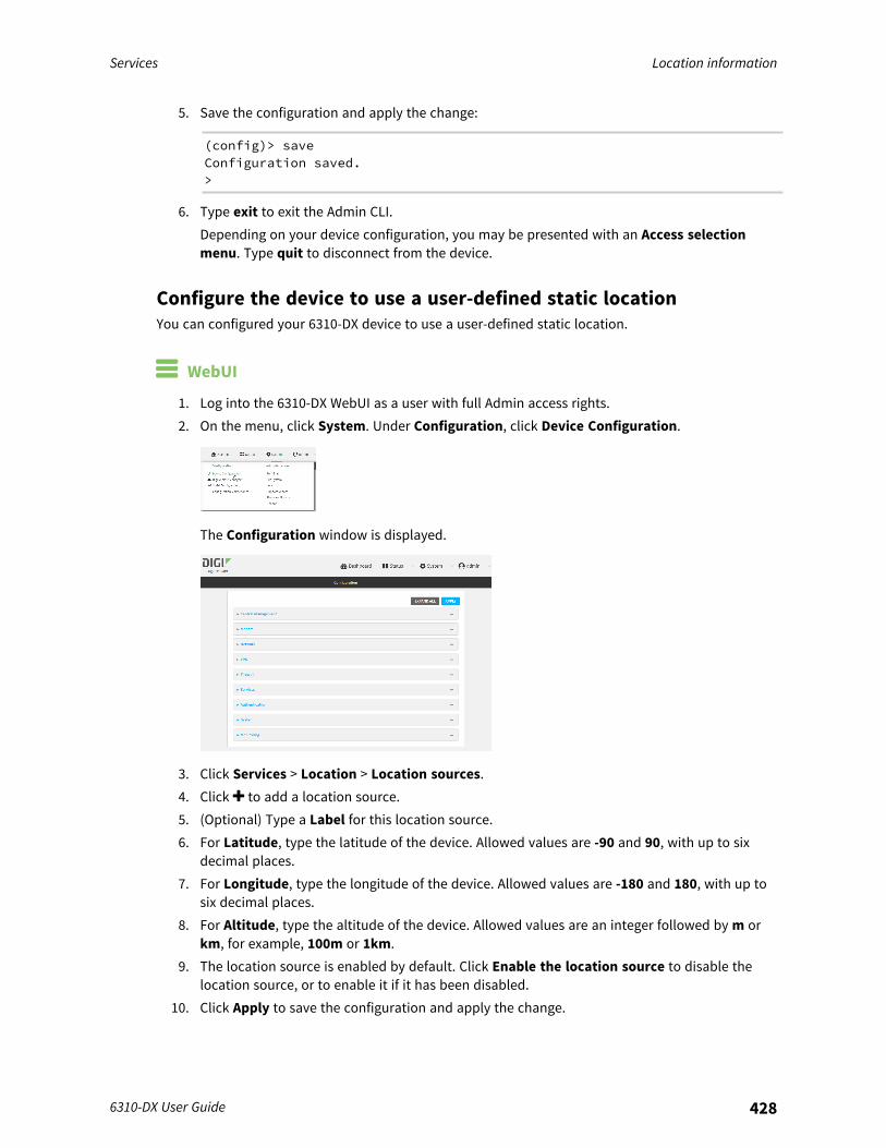
Services Location information
6310-DX User Guide 428
5. Save the configuration and apply the change:
(config)> saveConfiguration saved.>
6. Type exit to exit the Admin CLI.Depending on your device configuration, you may be presented with an Access selectionmenu. Type quit to disconnect from the device.
Configure the device to use a user-defined static locationYou can configured your 6310-DX device to use a user-defined static location.
WebUI
1. Log into the 6310-DX WebUI as a user with full Admin access rights.2. On the menu, click System. Under Configuration, click Device Configuration.
The Configuration window is displayed.
3. Click Services > Location > Location sources.4. Click to add a location source.5. (Optional) Type a Label for this location source.6. For Latitude, type the latitude of the device. Allowed values are -90 and 90, with up to six
decimal places.7. For Longitude, type the longitude of the device. Allowed values are -180 and 180, with up to
six decimal places.8. For Altitude, type the altitude of the device. Allowed values are an integer followed by m or
km, for example, 100m or 1km.9. The location source is enabled by default. Click Enable the location source to disable the
location source, or to enable it if it has been disabled.10. Click Apply to save the configuration and apply the change.
Services Location information
6310-DX User Guide 429
Command line
1. Log into the 6310-DX command line as a user with full Admin access rights.Depending on your device configuration, you may be presented with an Access selectionmenu. Type admin to access the Admin CLI.
2. At the command line, type config to enter configuration mode:
> config(config)>
3. Add a location source:
(config)> add service location source end(config service location source 01)>
4. (Optional) Set a label for this location source:
(config service location source 01)> label "label"(config)>
5. Set the type of location source to server:
(config service location source 01)> type user_defined(config service location source 01)>
6. Set the latitude of the device:
(config service location source 01 coordinates latitude int(config service location source 01)>
where int is any integer between -90 and 90, with up to six decimal places.7. Set the longitude of the device:
(config service location source 01 coordinates longitude int(config service location source 01)>
where int is any integer between -180 and 180, with up to six decimal places.8. Set the altitude of the device:
(config service location source 01 coordinates altitude alt(config service location source 01)>
Where alt is an integer followed by m or km, for example, 100m or 1km.

Services Location information
6310-DX User Guide 430
9. Save the configuration and apply the change:
(config)> saveConfiguration saved.>
10. Type exit to exit the Admin CLI.Depending on your device configuration, you may be presented with an Access selectionmenu. Type quit to disconnect from the device.
Configure the device to accept location messages from externalsourcesYou can configure the 6310-DX device to accept NMEA and TAIP messages from external sources. Forexample, location-enabled devices connected to the 6310-DX device can forward their locationinformation to the device, and then the 6310-DX device can serve as a central repository for thislocation information and forward it to a remote host. See Forward location information to a remotehost for information about configuring the 6310-DX device to forward location messages.This procedure configures a UDP port on the 6310-DX device that will be used to listen for incomingmessages.
Required configuration items
n The location server must be enabled.n UDP port that the 6310-DX device will listen to for incoming location messages.n Access control list configuration to provide access to the port through the firewall.
To configure the device to accept location messages from external sources:
WebUI
1. Log into the 6310-DX WebUI as a user with full Admin access rights.2. On the menu, click System. Under Configuration, click Device Configuration.
The Configuration window is displayed.
Services Location information
6310-DX User Guide 431
3. Click Services > Location > Location sources.4. Click to add a location source.5. (Optional) Type a Label for this location source.6. For Type of location source, select Server.7. For Location server port, type the number of the UDP port that will receive incoming location
messages.8. Click Access control list to configure access control:
n To limit access to specified IPv4 addresses and networks:a. Click IPv4 Addresses.b. For Add Address, click .c. For Address, enter the IPv4 address or network that can access the device's
location server UDP port. Allowed values are:l A single IP address or host name.l A network designation in CIDR notation, for example, 192.168.1.0/24.l any: No limit to IPv4 addresses that can access the location server UDP port.
d. Click again to list additional IP addresses or networks.n To limit access to specified IPv6 addresses and networks:
a. Click IPv6 Addresses.b. For Add Address, click .c. For Address, enter the IPv6 address or network that can access the device's
location server UDP port. Allowed values are:l A single IP address or host name.l A network designation in CIDR notation, for example, 2001:db8::/48.l any: No limit to IPv6 addresses that can access the location server UDP port.
d. Click again to list additional IP addresses or networks.n To limit access to hosts connected through a specified interface on the 6310-DX device:
a. Click Interfaces.b. For Add Interface, click .c. For Interface, select the appropriate interface from the dropdown.d. Click again to allow access through additional interfaces.
n To limit access based on firewall zones:a. Click Zones.b. For Add Zone, click .c. For Zone, select the appropriate firewall zone from the dropdown.
See Firewall configuration for information about firewall zones.d. Click again to allow access through additional firewall zones.
9. Click Apply to save the configuration and apply the change.

Services Location information
6310-DX User Guide 432
Command line
1. Log into the 6310-DX command line as a user with full Admin access rights.Depending on your device configuration, you may be presented with an Access selectionmenu. Type admin to access the Admin CLI.
2. At the command line, type config to enter configuration mode:
> config(config)>
3. Add a location source:
(config)> add service location source end(config service location source 01)>
4. (Optional) Set a label for this location source:
(config service location source 01)> label "label"(config service location source 01)>
5. Set the type of location source to server:
(config service location source 01)> type server(config service location source 01)>
6. Set the UDP port that will receive incoming location messages.
(config service location source 01)> server port port(config service location source 01)>
7. Click Access control list to configure access control:n To limit access to specified IPv4 addresses and networks:
(config)> add service location source 1 acl address end value(config)>
Where value can be:l A single IP address or host name.l A network designation in CIDR notation, for example, 192.168.1.0/24.l any: No limit to IPv4 addresses that can access the location server UDP port.
Repeat this step to list additional IP addresses or networks.n To limit access to specified IPv6 addresses and networks:
(config)> add service location source 1 acl address6 end value(config)>
Where value can be:
Services Location information
6310-DX User Guide 433
l A single IP address or host name.l A network designation in CIDR notation, for example, 2001:db8::/48.l any: No limit to IPv6 addresses that can access the location server UDP port.
Repeat this step to list additional IP addresses or networks.n To limit access to hosts connected through a specified interface on the 6310-DX device:
(config)> add service location source 1 acl interface end value(config)>
Where value is an interface defined on your device.
Display a list of available interfaces:Use ... network interface ? to display interface information:
(config)> ... network interface ?
Interfaces
Additional Configuration-------------------------------------------defaultip Default IPdefaultlinklocal Default Link-local IPlan LANloopback Loopbackmodem Modemwan WAN
(config)>
Repeat this step to list additional interfaces.n To limit access based on firewall zones:
(config)> add service location source 1 acl zone end value
Where value is a firewall zone defined on your device, or the any keyword.
Display a list of available firewall zones:Type ... firewall zone ? at the config prompt:
(config)> ... firewall zone ?
Zones: A list of groups of network interfaces that can bereferred to by packetfiltering rules and access control lists.
Additional Configuration--------------------------------------------------------
-----------------------anydynamic_routes

Services Location information
6310-DX User Guide 434
edgeexternalinternalipsecloopbacksetup
(config)>
Repeat this step to list additional firewall zones.n To limit access to specified IPv4 addresses and networks:
(config)> add service location source 1 acl address end value(config)>
Where value can be:l A single IP address or host name.l A network designation in CIDR notation, for example, 192.168.1.0/24.l any: No limit to IPv4 addresses that can access the location server UDP port.
Repeat this step to list additional IP addresses or networks.n To limit access to specified IPv6 addresses and networks:
(config)> add service location source 1 acl address6 end value(config)>
Where value can be:l A single IP address or host name.l A network designation in CIDR notation, for example, 2001:db8::/48.l any: No limit to IPv6 addresses that can access the location server UDP port.
Repeat this step to list additional IP addresses or networks.n To limit access to hosts connected through a specified interface on the 6310-DX device:
(config)> add service location source 1 acl interface end value(config)>
Where value is an interface defined on your device.
Display a list of available interfaces:Use ... network interface ? to display interface information:
(config)> ... network interface ?
Interfaces
Additional Configuration-------------------------------------------defaultip Default IPdefaultlinklocal Default Link-local IP
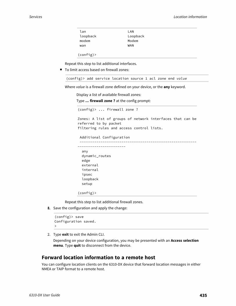
Services Location information
6310-DX User Guide 435
lan LANloopback Loopbackmodem Modemwan WAN
(config)>
Repeat this step to list additional interfaces.n To limit access based on firewall zones:
(config)> add service location source 1 acl zone end value
Where value is a firewall zone defined on your device, or the any keyword.
Display a list of available firewall zones:Type ... firewall zone ? at the config prompt:
(config)> ... firewall zone ?
Zones: A list of groups of network interfaces that can bereferred to by packetfiltering rules and access control lists.
Additional Configuration--------------------------------------------------------
-----------------------anydynamic_routesedgeexternalinternalipsecloopbacksetup
(config)>
Repeat this step to list additional firewall zones.8.1. Save the configuration and apply the change:
(config)> saveConfiguration saved.>
2. Type exit to exit the Admin CLI.Depending on your device configuration, you may be presented with an Access selectionmenu. Type quit to disconnect from the device.
Forward location information to a remote hostYou can configure location clients on the 6310-DX device that forward location messages in eitherNMEA or TAIP format to a remote host.
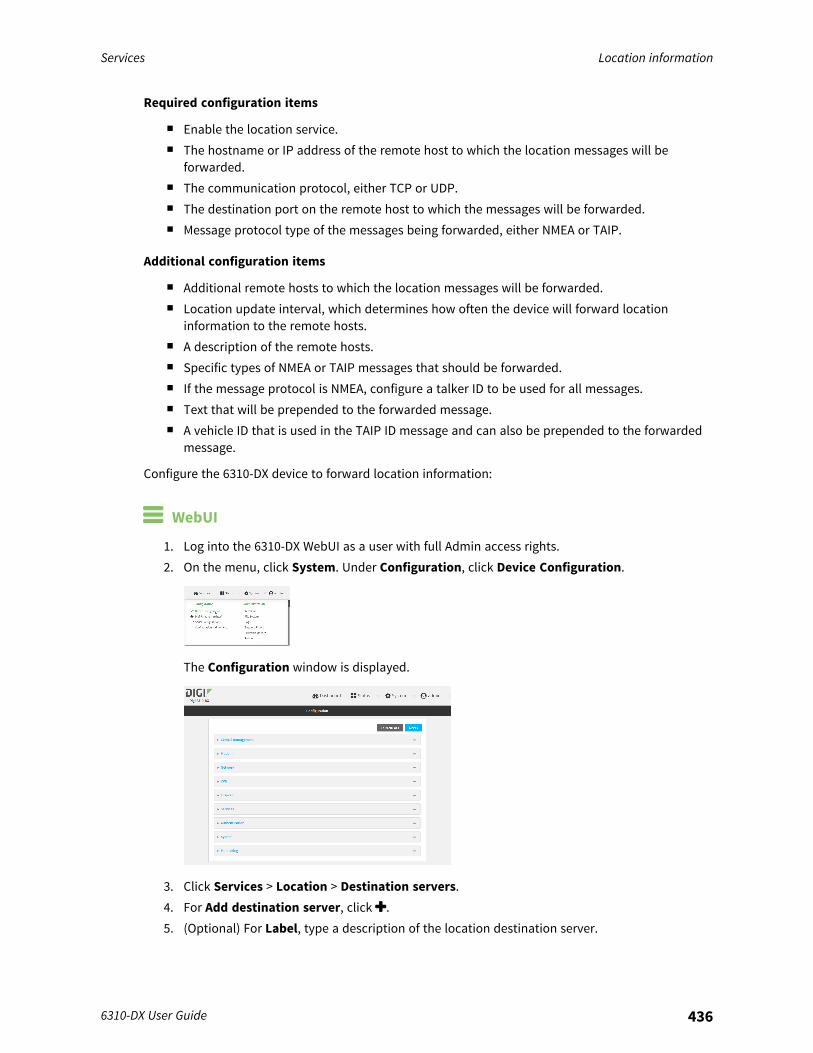
Services Location information
6310-DX User Guide 436
Required configuration items
n Enable the location service.n The hostname or IP address of the remote host to which the location messages will be
forwarded.n The communication protocol, either TCP or UDP.n The destination port on the remote host to which the messages will be forwarded.n Message protocol type of the messages being forwarded, either NMEA or TAIP.
Additional configuration items
n Additional remote hosts to which the location messages will be forwarded.n Location update interval, which determines how often the device will forward location
information to the remote hosts.n A description of the remote hosts.n Specific types of NMEA or TAIP messages that should be forwarded.n If the message protocol is NMEA, configure a talker ID to be used for all messages.n Text that will be prepended to the forwarded message.n A vehicle ID that is used in the TAIP ID message and can also be prepended to the forwarded
message.
Configure the 6310-DX device to forward location information:
WebUI
1. Log into the 6310-DX WebUI as a user with full Admin access rights.2. On the menu, click System. Under Configuration, click Device Configuration.
The Configuration window is displayed.
3. Click Services > Location > Destination servers.4. For Add destination server, click .5. (Optional) For Label, type a description of the location destination server.
Services Location information
6310-DX User Guide 437
6. For Destination server, enter the hostname or IP address of the remote host to which locationmessages will be sent.
7. For Destination server port, enter the UDP or TCP port on the remote host to which locationmessages will be sent.
8. For Communication protocol, select either UDP or TCP.9. For Forward interval multiplier, select the number of Location update intervals to wait
before forwarding location data to this server. See Configure the location service for moreinformation about setting the Location update interval.
10. For NMEA filters, select the filters that represent the types of messages that will be forwarded.By default, all message types are forwarded.
n To remove a filter:a. Click the down arrow () next to the appropriate message type.b. Click Delete.
n To add a message type:a. For Add NMEA filter or Add TAIP filter, click .b. Select the filter type. Allowed values are:
l GGA: Reports time, position, and fix related data.l GLL: Reports position data: position fix, time of position fix, and status.l GSA: Reports GPS DOP and active satellites.l GSV: Reports the number of SVs in view, PRN, elevation, azimuth, and SNR.l RMC: Reports position, velocity, and time.l VTG: Reports direction and speed over ground.
11. For TAIP filters, select the filters that represent the types of messages that will be forwarded.By default, all message types are forwarded.
n To remove a filter:a. Click the down arrow () next to the appropriate message type.b. Click Delete.
n To add a message type:a. For Add NMEA filter or Add TAIP filter, click .b. Select the filter type. Allowed values are:
l AL: Reports altitude and vertical velocity.l CP: Compact position: reports time, latitude, and longitude.l ID: Reports the vehicle ID.l LN: Long navigation: reports the latitude, longitude, and altitude, the horizontal
and vertical speed, and heading.l PV: Position/velocity: reports the latitude, longitude, and heading.
12. For Outgoing message type, select either NMEA or TAIP for the type of message that thedevice will forward to a remote host.
n (Optional) If NMEA is selected, select a Talker ID.The talker ID is a two-character prefix in the NMEA message that identifies the sourcetype. The talker ID set here will override the talker ID from all sources, and all

Services Location information
6310-DX User Guide 438
forwarded sentences will use the configured ID. The default setting is Default, whichmeans that the talker ID provided by the source will be used.
13. (Optional) For Prepend text, enter text to prepend to the forwarded message. Two variablescan be included in the prepended text:
n %s: Includes the 6310-DX device's serial number in the prepended text.n %v: Includes the vehicle ID in the prepended text.
For example, to include both the device's serial number and vehicle ID in the prependmessage, you can enter the following in the Prepend field:
__|%s|__|%v|__
14. Type a four-digit alphanumeric Vehicle ID that will be included with to location messages. Ifno vehicle ID is configured, this setting defaults to 0000.
15. Click Apply to save the configuration and apply the change.
Command line
1. Log into the 6310-DX command line as a user with full Admin access rights.Depending on your device configuration, you may be presented with an Access selectionmenu. Type admin to access the Admin CLI.
2. At the command line, type config to enter configuration mode:
> config(config)>
3. Add a remote host to which location messages will be sent:
(config)> add service location forward end(config service location forward 0)>
4. Set the hostname or IP address of the remote host to which location messages will be sent:
(config service location forward 0)> server host(config service location forward 0)>
5. Set the communication protocol to either upd or tcp:
(config service location forward 0)> protocol protocol(config service location forward 0)>
6. Set the TCP or UDP port on the remote host to which location messages will be sent:
(config service location forward 0)> server_port 8000(config service location forward 0)>
7. Set the number of Location update intervals to wait before forwarding location data to thisserver. See Configure the location service for more information about setting the Location
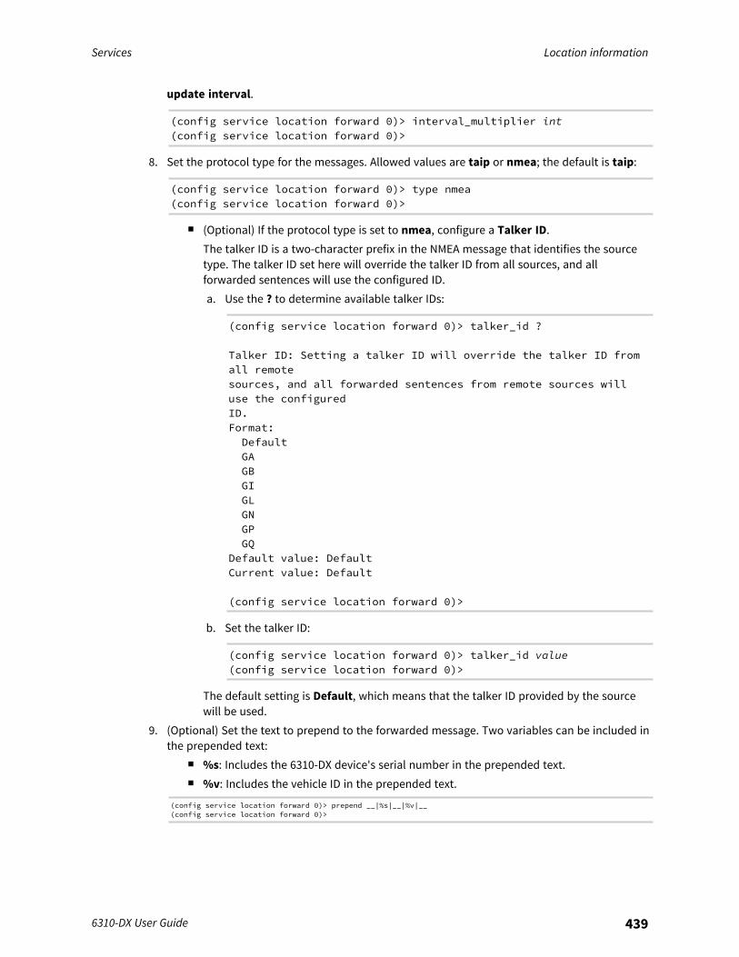
Services Location information
6310-DX User Guide 439
update interval.
(config service location forward 0)> interval_multiplier int(config service location forward 0)>
8. Set the protocol type for the messages. Allowed values are taip or nmea; the default is taip:
(config service location forward 0)> type nmea(config service location forward 0)>
n (Optional) If the protocol type is set to nmea, configure a Talker ID. The talker ID is a two-character prefix in the NMEA message that identifies the sourcetype. The talker ID set here will override the talker ID from all sources, and allforwarded sentences will use the configured ID.a. Use the ? to determine available talker IDs:
(config service location forward 0)> talker_id ?
Talker ID: Setting a talker ID will override the talker ID fromall remotesources, and all forwarded sentences from remote sources willuse the configuredID.Format:DefaultGAGBGIGLGNGPGQ
Default value: DefaultCurrent value: Default
(config service location forward 0)>
b. Set the talker ID:
(config service location forward 0)> talker_id value(config service location forward 0)>
The default setting is Default, which means that the talker ID provided by the sourcewill be used.
9. (Optional) Set the text to prepend to the forwarded message. Two variables can be included inthe prepended text:
n %s: Includes the 6310-DX device's serial number in the prepended text.n %v: Includes the vehicle ID in the prepended text.
(config service location forward 0)> prepend __|%s|__|%v|__(config service location forward 0)>
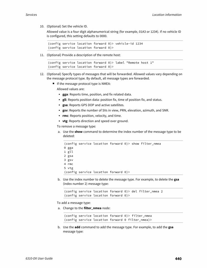
Services Location information
6310-DX User Guide 440
10. (Optional) Set the vehicle ID.Allowed value is a four digit alphanumerical string (for example, 01A3 or 1234). If no vehicle IDis configured, this setting defaults to 0000.
(config service location forward 0)> vehicle-id 1234(config service location forward 0)>
11. (Optional) Provide a description of the remote host:
(config service location forward 0)> label "Remote host 1"(config service location forward 0)>
12. (Optional) Specify types of messages that will be forwarded. Allowed values vary depending onthe message protocol type. By default, all message types are forwarded.
n If the message protocol type is NMEA:Allowed values are:l gga: Reports time, position, and fix related data.l gll: Reports position data: position fix, time of position fix, and status.l gsa: Reports GPS DOP and active satellites.l gsv: Reports the number of SVs in view, PRN, elevation, azimuth, and SNR.l rmc: Reports position, velocity, and time.l vtg: Reports direction and speed over ground.
To remove a message type:a. Use the show command to determine the index number of the message type to be
deleted:
(config service location forward 0)> show filter_nmea0 gga1 gll2 gsa3 gsv4 rmc5 vtg(config service location forward 0)>
b. Use the index number to delete the message type. For example, to delete the gsa(index number 2) message type:
(config service location forward 0)> del filter_nmea 2(config service location forward 0)>
To add a message type:a. Change to the filter_nmea node:
(config service location forward 0)> filter_nmea(config service location forward 0 filter_nmea)>
b. Use the add command to add the message type. For example, to add the gsamessage type:
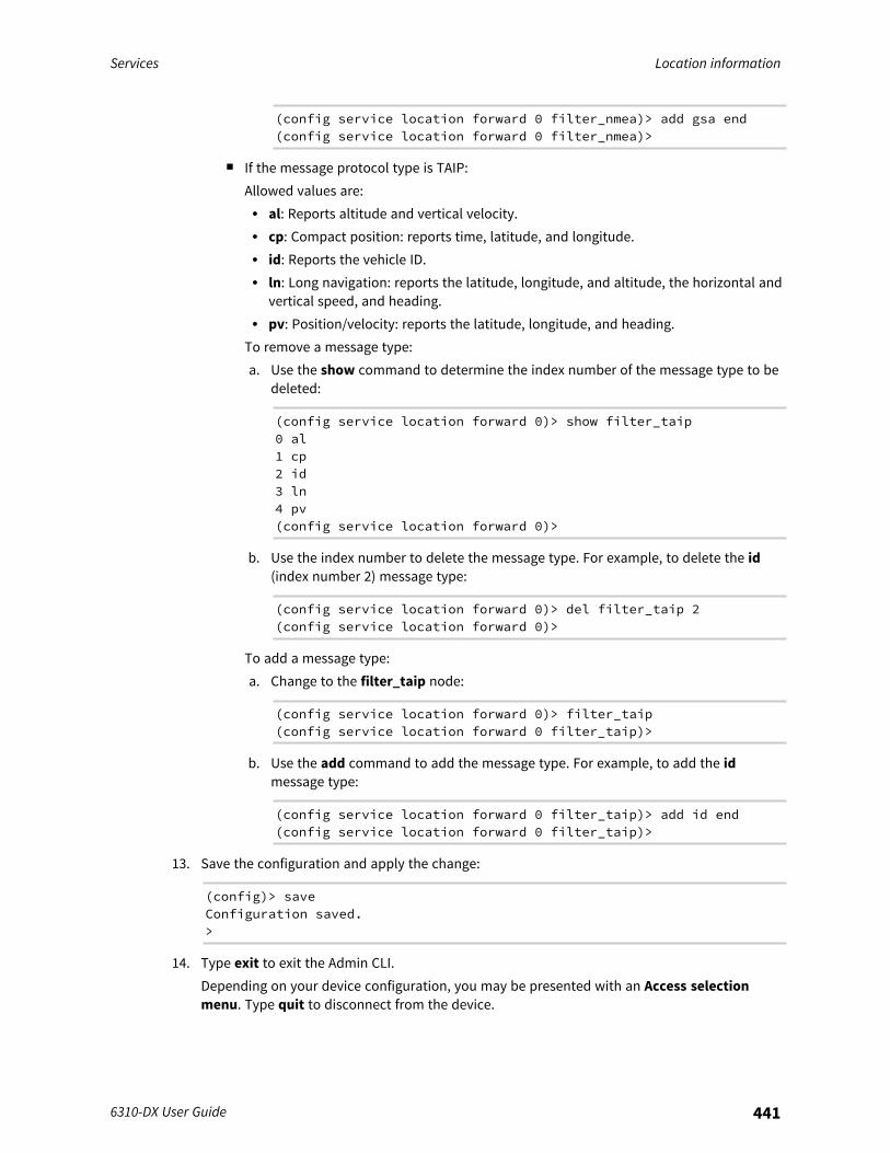
Services Location information
6310-DX User Guide 441
(config service location forward 0 filter_nmea)> add gsa end(config service location forward 0 filter_nmea)>
n If the message protocol type is TAIP:Allowed values are:l al: Reports altitude and vertical velocity.l cp: Compact position: reports time, latitude, and longitude.l id: Reports the vehicle ID.l ln: Long navigation: reports the latitude, longitude, and altitude, the horizontal and
vertical speed, and heading.l pv: Position/velocity: reports the latitude, longitude, and heading.
To remove a message type:a. Use the show command to determine the index number of the message type to be
deleted:
(config service location forward 0)> show filter_taip0 al1 cp2 id3 ln4 pv(config service location forward 0)>
b. Use the index number to delete the message type. For example, to delete the id(index number 2) message type:
(config service location forward 0)> del filter_taip 2(config service location forward 0)>
To add a message type:a. Change to the filter_taip node:
(config service location forward 0)> filter_taip(config service location forward 0 filter_taip)>
b. Use the add command to add the message type. For example, to add the idmessage type:
(config service location forward 0 filter_taip)> add id end(config service location forward 0 filter_taip)>
13. Save the configuration and apply the change:
(config)> saveConfiguration saved.>
14. Type exit to exit the Admin CLI.Depending on your device configuration, you may be presented with an Access selectionmenu. Type quit to disconnect from the device.
Services Location information
6310-DX User Guide 442
Configure geofencingGeofencing is a mechanism to create a virtual perimeter that allows you configure your 6310-DXdevice to perform actions when entering or exiting the perimeter. For example, you can configure adevice to factory default if its location service indicates that it has been moved outside of thegeofence.Multiple geofences can be defined for one device, allowing for a complex configuration in whichdifferent actions are taken depending on the physical location of the device.
Required configuration items
n Location services must be enabled.n The geofence must be enabled.n The boundary type of the geofence, either circular or polygonal.
l If boundary type is circular, the latitude and longitude of the center point of the circle, andthe radius.
l If boundary type is polygonal, the latitude and longitude of the polygon's vertices (a vertexis the point at which two sides of a polygon meet). Three vertices will create a triangularpolygon; four will create a square, etc. Complex polygons can be defined.
n Actions that will be taken when the device's location triggers a geofence event. You can defineactions for two types of events:l Actions taken when the device enters the boundary of the geofence, or is inside the
boundary when the device boots.l Actions taken when the device exits the boundary of the geofence, or is outside the
boundary when the device boots.For each event type:l Determine if the action(s) associated with the event type should be performed when the
device boots inside or outside of the geofence boundary.l The number of update intervals that should take place before the action(s) are taken.
Multiple actions can be configured for each type of event. For each action:l The type of action, either a factory erase or executing a custom script.l If a custom script is used:
o The script that will be executed.o Whether to log output and errors from the script.o The maximum memory that the script will have available.o Whether the script should be executed within a sandbox that will prevent the script from
affecting the system itself.
Additional configuration items
n Update interval, which determines the amount of time that the geofence should wait betweenpolling for updated location data.
WebUI
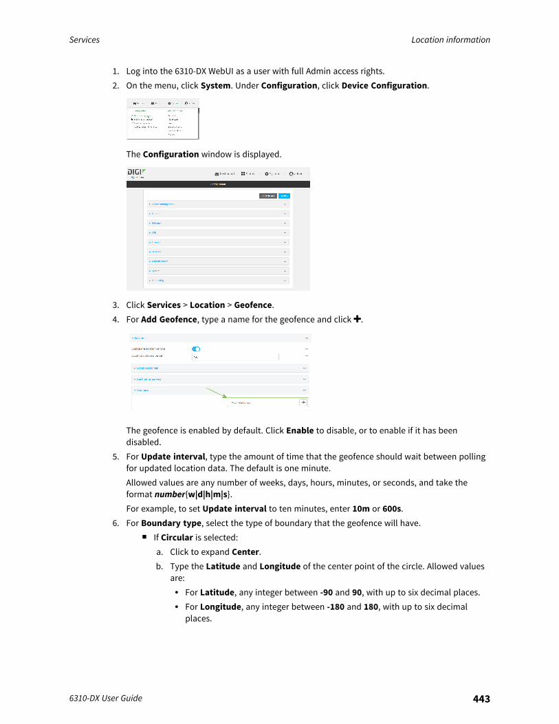
Services Location information
6310-DX User Guide 443
1. Log into the 6310-DX WebUI as a user with full Admin access rights.2. On the menu, click System. Under Configuration, click Device Configuration.
The Configuration window is displayed.
3. Click Services > Location > Geofence.4. For Add Geofence, type a name for the geofence and click .
The geofence is enabled by default. Click Enable to disable, or to enable if it has beendisabled.
5. For Update interval, type the amount of time that the geofence should wait between pollingfor updated location data. The default is one minute.Allowed values are any number of weeks, days, hours, minutes, or seconds, and take theformat number{w|d|h|m|s}.For example, to set Update interval to ten minutes, enter 10m or 600s.
6. For Boundary type, select the type of boundary that the geofence will have.n If Circular is selected:
a. Click to expand Center.b. Type the Latitude and Longitude of the center point of the circle. Allowed values
are:l For Latitude, any integer between -90 and 90, with up to six decimal places.l For Longitude, any integer between -180 and 180, with up to six decimal
places.

Services Location information
6310-DX User Guide 444
c. For Radius, type the radius of the circle. Allowed values are an integer followed bym or km, for example, 100m or 1km.
n If Polygonal is selected:a. Click to expand Coordinates.b. Click to add a point that represents a vertex of the polygon. A vertex is the point
at which two sides of a polygon meet.c. Type the Latitude and Longitude of one of the vertices of the polygon. Allowed
values are:l For Latitude, any integer between -90 and 90, with up to six decimal places.l For Longitude, any integer between -180 and 180, with up to six decimal
places.d. Click again to add an additional point, and continue adding points to create the
desired polygon.For example, to configure a square polygon around the Digi headquarters, configure apolygon with four points:
This defines a square-shaped polygon equivalent to the following:
7. Define actions to be taken when the device's location triggers a geofence event:n To define actions that will be taken when the device enters the geofence, or is inside
the geofence when it boots:
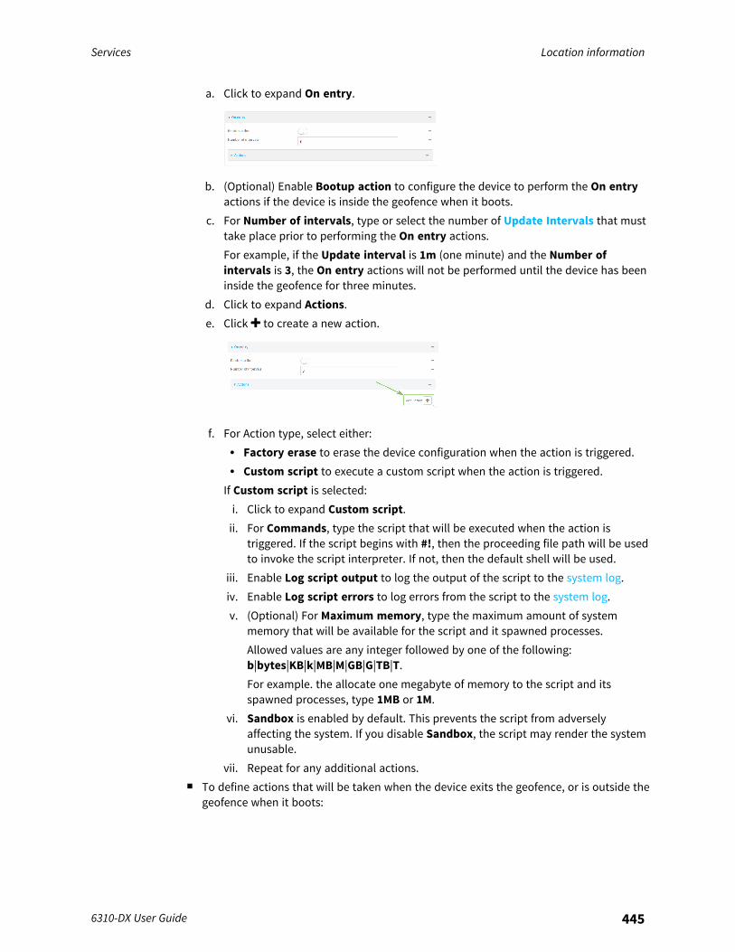
Services Location information
6310-DX User Guide 445
a. Click to expand On entry.
b. (Optional) Enable Bootup action to configure the device to perform the On entryactions if the device is inside the geofence when it boots.
c. For Number of intervals, type or select the number of Update Intervals that musttake place prior to performing the On entry actions.For example, if the Update interval is 1m (one minute) and the Number ofintervals is 3, the On entry actions will not be performed until the device has beeninside the geofence for three minutes.
d. Click to expand Actions.e. Click to create a new action.
f. For Action type, select either:l Factory erase to erase the device configuration when the action is triggered.l Custom script to execute a custom script when the action is triggered.
If Custom script is selected:i. Click to expand Custom script.ii. For Commands, type the script that will be executed when the action is
triggered. If the script begins with #!, then the proceeding file path will be usedto invoke the script interpreter. If not, then the default shell will be used.
iii. Enable Log script output to log the output of the script to the system log.iv. Enable Log script errors to log errors from the script to the system log.v. (Optional) For Maximum memory, type the maximum amount of system
memory that will be available for the script and it spawned processes.Allowed values are any integer followed by one of the following:b|bytes|KB|k|MB|M|GB|G|TB|T.For example. the allocate one megabyte of memory to the script and itsspawned processes, type 1MB or 1M.
vi. Sandbox is enabled by default. This prevents the script from adverselyaffecting the system. If you disable Sandbox, the script may render the systemunusable.
vii. Repeat for any additional actions.n To define actions that will be taken when the device exits the geofence, or is outside the
geofence when it boots:
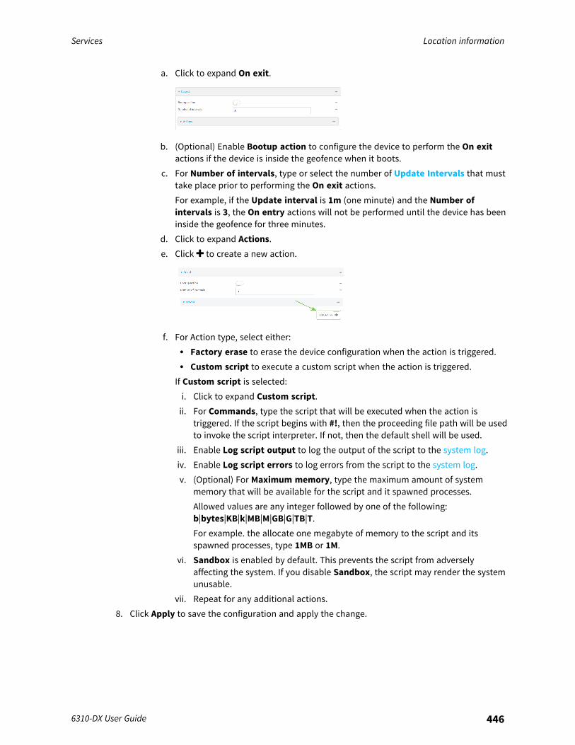
Services Location information
6310-DX User Guide 446
a. Click to expand On exit.
b. (Optional) Enable Bootup action to configure the device to perform the On exitactions if the device is inside the geofence when it boots.
c. For Number of intervals, type or select the number of Update Intervals that musttake place prior to performing the On exit actions.For example, if the Update interval is 1m (one minute) and the Number ofintervals is 3, the On entry actions will not be performed until the device has beeninside the geofence for three minutes.
d. Click to expand Actions.e. Click to create a new action.
f. For Action type, select either:l Factory erase to erase the device configuration when the action is triggered.l Custom script to execute a custom script when the action is triggered.
If Custom script is selected:i. Click to expand Custom script.ii. For Commands, type the script that will be executed when the action is
triggered. If the script begins with #!, then the proceeding file path will be usedto invoke the script interpreter. If not, then the default shell will be used.
iii. Enable Log script output to log the output of the script to the system log.iv. Enable Log script errors to log errors from the script to the system log.v. (Optional) For Maximum memory, type the maximum amount of system
memory that will be available for the script and it spawned processes.Allowed values are any integer followed by one of the following:b|bytes|KB|k|MB|M|GB|G|TB|T.For example. the allocate one megabyte of memory to the script and itsspawned processes, type 1MB or 1M.
vi. Sandbox is enabled by default. This prevents the script from adverselyaffecting the system. If you disable Sandbox, the script may render the systemunusable.
vii. Repeat for any additional actions.8. Click Apply to save the configuration and apply the change.
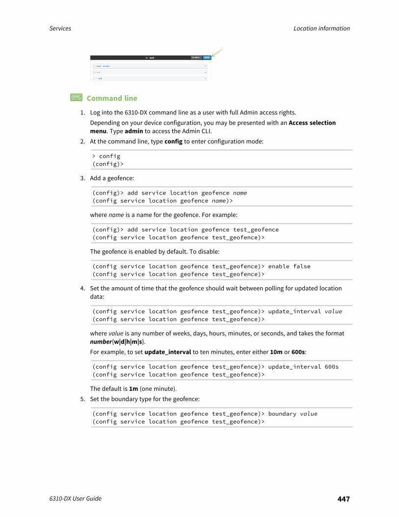
Services Location information
6310-DX User Guide 447
Command line
1. Log into the 6310-DX command line as a user with full Admin access rights.Depending on your device configuration, you may be presented with an Access selectionmenu. Type admin to access the Admin CLI.
2. At the command line, type config to enter configuration mode:
> config(config)>
3. Add a geofence:
(config)> add service location geofence name(config service location geofence name)>
where name is a name for the geofence. For example:
(config)> add service location geofence test_geofence(config service location geofence test_geofence)>
The geofence is enabled by default. To disable:
(config service location geofence test_geofence)> enable false(config service location geofence test_geofence)>
4. Set the amount of time that the geofence should wait between polling for updated locationdata:
(config service location geofence test_geofence)> update_interval value(config service location geofence test_geofence)>
where value is any number of weeks, days, hours, minutes, or seconds, and takes the formatnumber{w|d|h|m|s}.For example, to set update_interval to ten minutes, enter either 10m or 600s:
(config service location geofence test_geofence)> update_interval 600s(config service location geofence test_geofence)>
The default is 1m (one minute).5. Set the boundary type for the geofence:
(config service location geofence test_geofence)> boundary value(config service location geofence test_geofence)>

Services Location information
6310-DX User Guide 448
where value is either circular or polygonal.n If boundary is set to circular :
a. Set the latitude and longitude of the center point of the circle:
(config service location geofence test_geofence)> centerlatitude int(config service location geofence test_geofence)> centerlongitude int(config service location geofence test_geofence)>
where int is:l For latitude, any integer between -90 and 90, with up to six decimal places.l For longitude, any integer between -180 and 180, with up to six decimal
places.b. Set the radius of the circle:
(config service location geofence test_geofence)> radius radius(config service location geofence test_geofence)>
where radius is an integer followed by m or km, for example, 100m or 1km.n If boundary is set to polygonal:
a. Set the coordinates of one vertex of the polygon. A vertex is the point at which twosides of a polygon meet.i. Add a vertex:
(config service location geofence test_geofence)> addcoordinates end(config service location geofence test_geofence coordinates0)>
ii. Set the latitude and longitude of the vertex:
(config service location geofence test_geofence coordinates0)> latitude int(config service location geofence test_geofence coordinates0)> longitude int(config service location geofence test_geofence coordinates0)>
where int is:l For latitude, any integer between -90 and 90, with up to six decimal
places.l For longitude, any integer between -180 and 180, with up to six decimal
places.

Services Location information
6310-DX User Guide 449
iii. Configure additional vortices:
(config service location geofence test_geofence coordinates0)> ..(config service location geofence test_geofence coordinates)>add end(config service location geofence test_geofence coordinates1)> latitude int(config service location geofence test_geofence coordinates1)> longitude int(config service location geofence test_geofence coordinates1)>
where int is:l For latitude, any integer between -90 and 90, with up to six decimal
places.l For longitude, any integer between -180 and 180, with up to six decimal
places.Repeat for each vortex of the polygon.For example, to configure a square polygon around the Digi headquarters,configure a polygon with four points:
(config service location geofence test_geofence)> addcoordinates end(config service location geofence test_geofence coordinates0)> latitude 44.927220(config service location geofence test_geofence coordinates0)> longitude -93.399200(config service location geofence test_geofence coordinates0)> ..(config service location geofence test_geofence coordinates)>add end(config service location geofence test_geofence coordinates1)> latitude 44.927220(config service location geofence test_geofence coordinates1)> longitude -93.39589(config service location geofence test_geofence coordinates1)> ..(config service location geofence test_geofence coordinates)>add end(config service location geofence test_geofence coordinates2)> latitude 44.925161(config service location geofence test_geofence coordinates2)> longitude -93.39589(config service location geofence test_geofence coordinates2)> ..(config service location geofence test_geofence coordinates)>add end
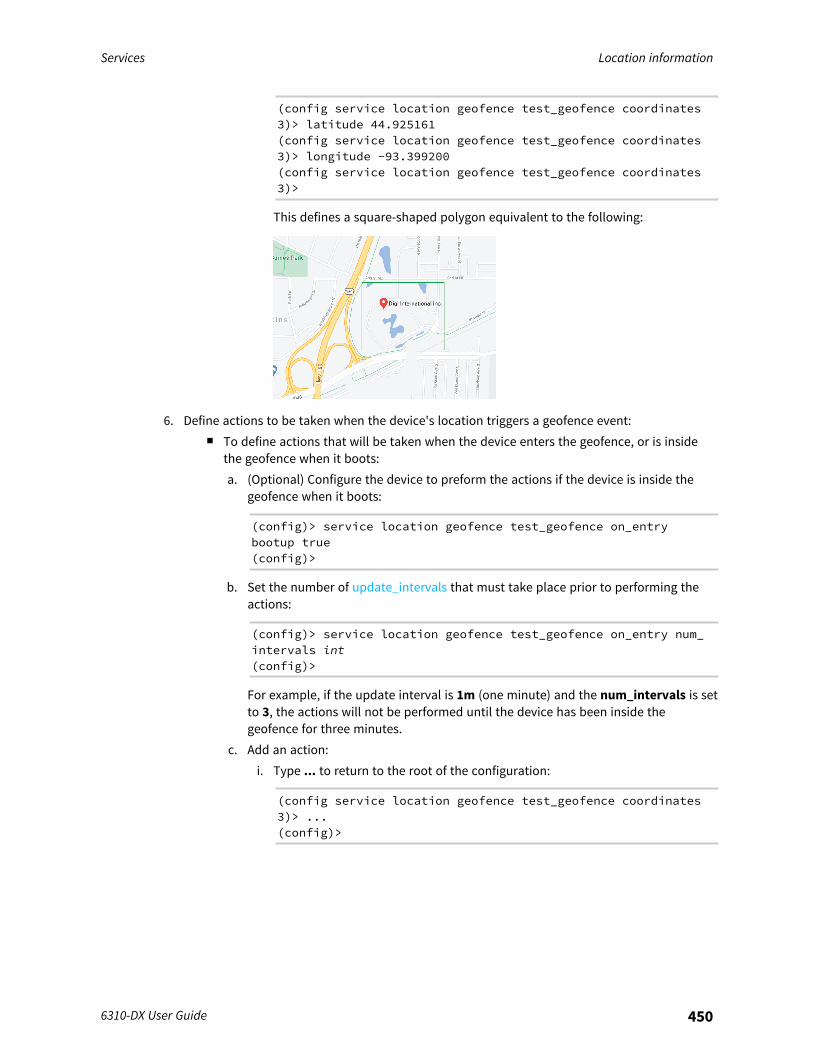
Services Location information
6310-DX User Guide 450
(config service location geofence test_geofence coordinates3)> latitude 44.925161(config service location geofence test_geofence coordinates3)> longitude -93.399200(config service location geofence test_geofence coordinates3)>
This defines a square-shaped polygon equivalent to the following:
6. Define actions to be taken when the device's location triggers a geofence event:n To define actions that will be taken when the device enters the geofence, or is inside
the geofence when it boots:a. (Optional) Configure the device to preform the actions if the device is inside the
geofence when it boots:
(config)> service location geofence test_geofence on_entrybootup true(config)>
b. Set the number of update_intervals that must take place prior to performing theactions:
(config)> service location geofence test_geofence on_entry num_intervals int(config)>
For example, if the update interval is 1m (one minute) and the num_intervals is setto 3, the actions will not be performed until the device has been inside thegeofence for three minutes.
c. Add an action:i. Type ... to return to the root of the configuration:
(config service location geofence test_geofence coordinates3)> ...(config)>

Services Location information
6310-DX User Guide 451
ii. Add the action:
(config)> add service location geofence test_geofence on_entry action end(config service location geofence test_geofence on_entryaction 0)>
d. Set the type of action:
(config service location geofence test_geofence on_entry action0)> type value(config service location geofence test_geofence on_entry action0)>
where value is either:l factory_erase—Erases the device configuration when the action is triggered.l script—Executes a custom script when the action is triggered.factory_erase or script.If type is set to script:i. Type or paste the script, closed in quote marks:
(config service location geofence test_geofence on_entryaction 0)> commands "script"(config service location geofence test_geofence on_entryaction 0)>
If the script begins with #!, then the proceeding file path will be used to invokethe script interpreter. If not, then the default shell will be used.
ii. To log the output of the script to the system log:
(config service location geofence test_geofence on_entryaction 0)> syslog_stdout true(config service location geofence test_geofence on_entryaction 0)>
iii. To log the errors from the script to the system log:
(config service location geofence test_geofence on_entryaction 0)> syslog_stderr true(config service location geofence test_geofence on_entryaction 0)>
iv. (Optional) Set the maximum amount of system memory that will be availablefor the script and it spawned processes:
(config service location geofence test_geofence on_entryaction 0)> max_memory value(config service location geofence test_geofence on_entryaction 0)>
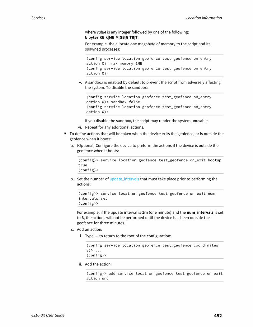
Services Location information
6310-DX User Guide 452
where value is any integer followed by one of the following:b|bytes|KB|k|MB|M|GB|G|TB|T.For example. the allocate one megabyte of memory to the script and itsspawned processes:
(config service location geofence test_geofence on_entryaction 0)> max_memory 1MB(config service location geofence test_geofence on_entryaction 0)>
v. A sandbox is enabled by default to prevent the script from adversely affectingthe system. To disable the sandbox:
(config service location geofence test_geofence on_entryaction 0)> sandbox false(config service location geofence test_geofence on_entryaction 0)>
If you disable the sandbox, the script may render the system unusable.vi. Repeat for any additional actions.
n To define actions that will be taken when the device exits the geofence, or is outside thegeofence when it boots:a. (Optional) Configure the device to preform the actions if the device is outside the
geofence when it boots:
(config)> service location geofence test_geofence on_exit bootuptrue(config)>
b. Set the number of update_intervals that must take place prior to performing theactions:
(config)> service location geofence test_geofence on_exit num_intervals int(config)>
For example, if the update interval is 1m (one minute) and the num_intervals is setto 3, the actions will not be performed until the device has been outside thegeofence for three minutes.
c. Add an action:i. Type ... to return to the root of the configuration:
(config service location geofence test_geofence coordinates3)> ...(config)>
ii. Add the action:
(config)> add service location geofence test_geofence on_exitaction end
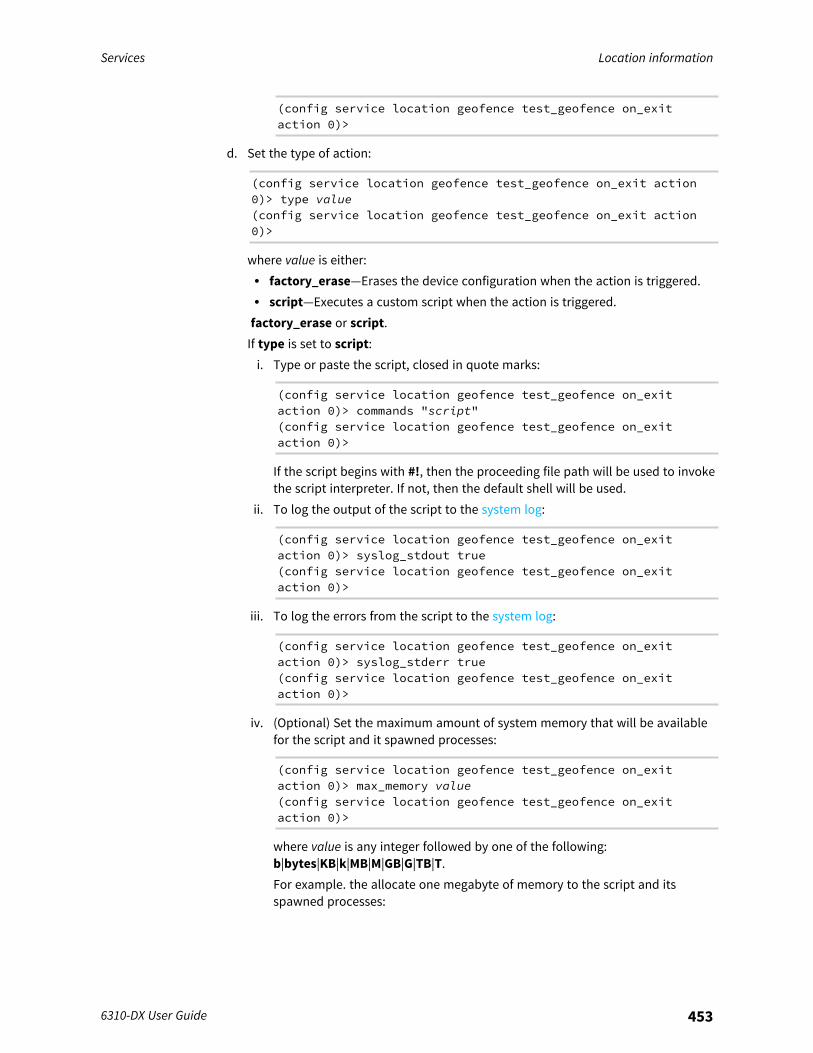
Services Location information
6310-DX User Guide 453
(config service location geofence test_geofence on_exitaction 0)>
d. Set the type of action:
(config service location geofence test_geofence on_exit action0)> type value(config service location geofence test_geofence on_exit action0)>
where value is either:l factory_erase—Erases the device configuration when the action is triggered.l script—Executes a custom script when the action is triggered.factory_erase or script.If type is set to script:i. Type or paste the script, closed in quote marks:
(config service location geofence test_geofence on_exitaction 0)> commands "script"(config service location geofence test_geofence on_exitaction 0)>
If the script begins with #!, then the proceeding file path will be used to invokethe script interpreter. If not, then the default shell will be used.
ii. To log the output of the script to the system log:
(config service location geofence test_geofence on_exitaction 0)> syslog_stdout true(config service location geofence test_geofence on_exitaction 0)>
iii. To log the errors from the script to the system log:
(config service location geofence test_geofence on_exitaction 0)> syslog_stderr true(config service location geofence test_geofence on_exitaction 0)>
iv. (Optional) Set the maximum amount of system memory that will be availablefor the script and it spawned processes:
(config service location geofence test_geofence on_exitaction 0)> max_memory value(config service location geofence test_geofence on_exitaction 0)>
where value is any integer followed by one of the following:b|bytes|KB|k|MB|M|GB|G|TB|T.For example. the allocate one megabyte of memory to the script and itsspawned processes:
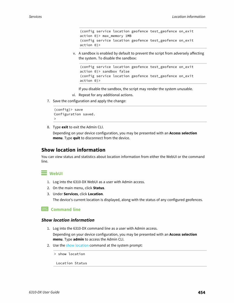
Services Location information
6310-DX User Guide 454
(config service location geofence test_geofence on_exitaction 0)> max_memory 1MB(config service location geofence test_geofence on_exitaction 0)>
v. A sandbox is enabled by default to prevent the script from adversely affectingthe system. To disable the sandbox:
(config service location geofence test_geofence on_exitaction 0)> sandbox false(config service location geofence test_geofence on_exitaction 0)>
If you disable the sandbox, the script may render the system unusable.vi. Repeat for any additional actions.
7. Save the configuration and apply the change:
(config)> saveConfiguration saved.>
8. Type exit to exit the Admin CLI.Depending on your device configuration, you may be presented with an Access selectionmenu. Type quit to disconnect from the device.
Show location informationYou can view status and statistics about location information from either the WebUI or the commandline.
WebUI
1. Log into the 6310-DX WebUI as a user with Admin access.2. On the main menu, click Status.3. Under Services, click Location.
The device's current location is displayed, along with the status of any configured geofences.
Command line
Show location information
1. Log into the 6310-DX command line as a user with Admin access.Depending on your device configuration, you may be presented with an Access selectionmenu. Type admin to access the Admin CLI.
2. Use the show location command at the system prompt:
> show location
Location Status
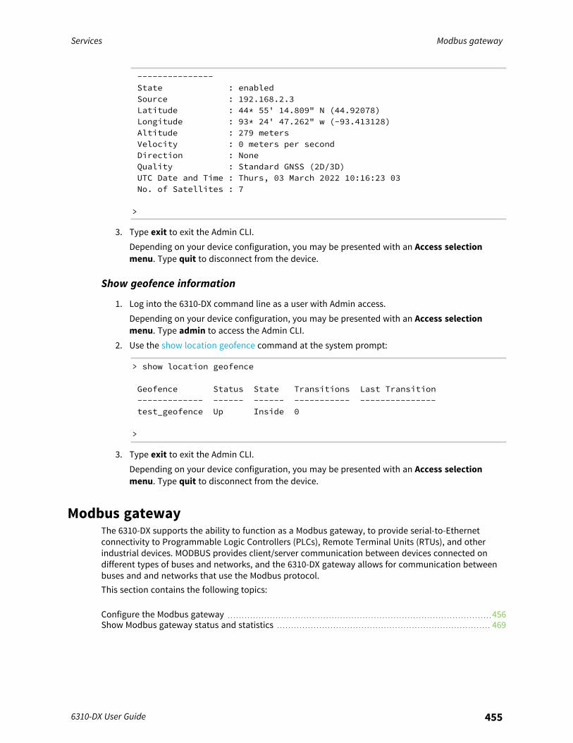
Services Modbus gateway
6310-DX User Guide 455
---------------State : enabledSource : 192.168.2.3Latitude : 44* 55' 14.809" N (44.92078)Longitude : 93* 24' 47.262" w (-93.413128)Altitude : 279 metersVelocity : 0 meters per secondDirection : NoneQuality : Standard GNSS (2D/3D)UTC Date and Time : Thurs, 03 March 2022 10:16:23 03No. of Satellites : 7
>
3. Type exit to exit the Admin CLI.Depending on your device configuration, you may be presented with an Access selectionmenu. Type quit to disconnect from the device.
Show geofence information
1. Log into the 6310-DX command line as a user with Admin access.Depending on your device configuration, you may be presented with an Access selectionmenu. Type admin to access the Admin CLI.
2. Use the show location geofence command at the system prompt:
> show location geofence
Geofence Status State Transitions Last Transition------------- ------ ------ ----------- ---------------test_geofence Up Inside 0
>
3. Type exit to exit the Admin CLI.Depending on your device configuration, you may be presented with an Access selectionmenu. Type quit to disconnect from the device.
Modbus gatewayThe 6310-DX supports the ability to function as a Modbus gateway, to provide serial-to-Ethernetconnectivity to Programmable Logic Controllers (PLCs), Remote Terminal Units (RTUs), and otherindustrial devices. MODBUS provides client/server communication between devices connected ondifferent types of buses and networks, and the 6310-DX gateway allows for communication betweenbuses and and networks that use the Modbus protocol.This section contains the following topics:
Configure the Modbus gateway 456Show Modbus gateway status and statistics 469
Services Modbus gateway
6310-DX User Guide 456
Configure the Modbus gateway
Required configuration items
n Server configuration:l Enable the server.l Connection type, either socket or serial.
o If the connection type is socket, the IP protocol to be used.o If the connection type is serial, the serial port to be used.
n Client configuration:l Enable the client.l Connection type, either socket or serial.
o If the connection type is socket:o The IP protocol to be used.o The hostname or IPv4 address of the remote host on which the Modbus server is
running.o If the connection type is serial:
o The serial port to be used.l Modbus address or addresses to determine if messages should be forwarded to a
destination device.
Additional configuration items
n Server configuration:l The packet mode.l The maximum time between bytes in a packet.l If the connection type is set to socket:
o The port to use.o The inactivity timeout.o Access control list.
l If the connection type is set to serial:o Whether to use half duplex (two wire) mode.
n Client configuration:l The packet mode.l The maximum time between bytes in a packets.l Whether to send broadcast messages.l Response timeoutl If connection type is set to socket:
o The port to use.o The inactivity timeout.
l If connection type is set to serial:o Whether to use half duplex (two wire) mode.
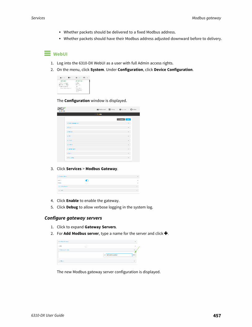
Services Modbus gateway
6310-DX User Guide 457
l Whether packets should be delivered to a fixed Modbus address.l Whether packets should have their Modbus address adjusted downward before to delivery.
WebUI
1. Log into the 6310-DX WebUI as a user with full Admin access rights.2. On the menu, click System. Under Configuration, click Device Configuration.
The Configuration window is displayed.
3. Click Services > Modbus Gateway.
4. Click Enable to enable the gateway.5. Click Debug to allow verbose logging in the system log.
Configure gateway servers
1. Click to expand Gateway Servers.2. For Add Modbus server, type a name for the server and click .
The new Modbus gateway server configuration is displayed.
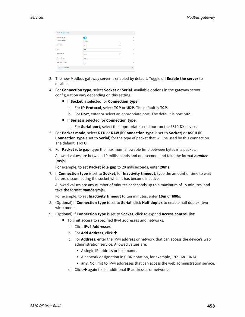
Services Modbus gateway
6310-DX User Guide 458
3. The new Modbus gateway server is enabled by default. Toggle off Enable the server todisable.
4. For Connection type, select Socket or Serial. Available options in the gateway serverconfiguration vary depending on this setting.
n If Socket is selected for Connection type:a. For IP Protocol, select TCP or UDP. The default is TCP.b. For Port, enter or select an appropriate port. The default is port 502.
n If Serial is selected for Connection type:a. For Serial port, select the appropriate serial port on the 6310-DX device.
5. For Packet mode, select RTU or RAW (if Connection type is set to Socket) or ASCII (ifConnection typeis set to Serial) for the type of packet that will be used by this connection.The default is RTU.
6. For Packet idle gap, type the maximum allowable time between bytes in a packet.Allowed values are between 10 milliseconds and one second, and take the format number{ms|s}.For example, to set Packet idle gap to 20 milliseconds, enter 20ms.
7. If Connection type is set to Socket, for Inactivity timeout, type the amount of time to waitbefore disconnecting the socket when it has become inactive.Allowed values are any number of minutes or seconds up to a maximum of 15 minutes, andtake the format number{m|s}.For example, to set Inactivity timeout to ten minutes, enter 10m or 600s.
8. (Optional) If Connection type is set to Serial, click Half duplex to enable half duplex (twowire) mode.
9. (Optional) If Connection type is set to Socket, click to expand Access control list:n To limit access to specified IPv4 addresses and networks:
a. Click IPv4 Addresses.b. For Add Address, click .c. For Address, enter the IPv4 address or network that can access the device's web
administration service. Allowed values are:l A single IP address or host name.l A network designation in CIDR notation, for example, 192.168.1.0/24.l any: No limit to IPv4 addresses that can access the web administration service.
d. Click again to list additional IP addresses or networks.
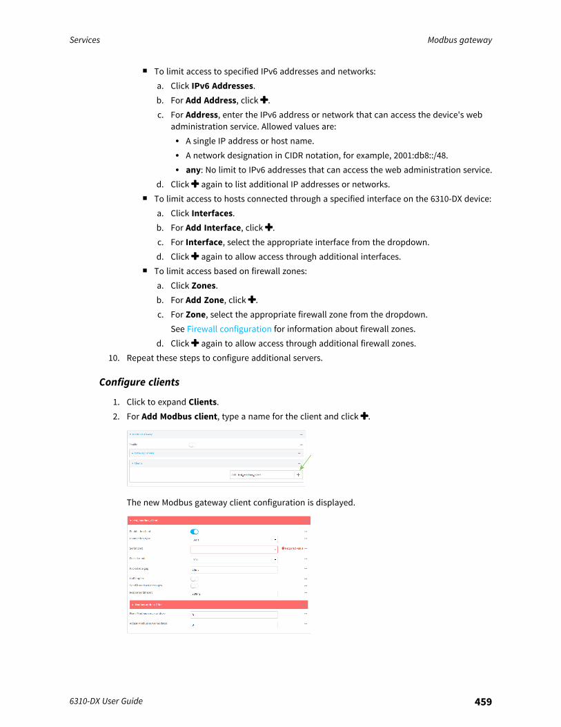
Services Modbus gateway
6310-DX User Guide 459
n To limit access to specified IPv6 addresses and networks:a. Click IPv6 Addresses.b. For Add Address, click .c. For Address, enter the IPv6 address or network that can access the device's web
administration service. Allowed values are:l A single IP address or host name.l A network designation in CIDR notation, for example, 2001:db8::/48.l any: No limit to IPv6 addresses that can access the web administration service.
d. Click again to list additional IP addresses or networks.n To limit access to hosts connected through a specified interface on the 6310-DX device:
a. Click Interfaces.b. For Add Interface, click .c. For Interface, select the appropriate interface from the dropdown.d. Click again to allow access through additional interfaces.
n To limit access based on firewall zones:a. Click Zones.b. For Add Zone, click .c. For Zone, select the appropriate firewall zone from the dropdown.
See Firewall configuration for information about firewall zones.d. Click again to allow access through additional firewall zones.
10. Repeat these steps to configure additional servers.
Configure clients
1. Click to expand Clients.2. For Add Modbus client, type a name for the client and click .
The new Modbus gateway client configuration is displayed.
Services Modbus gateway
6310-DX User Guide 460
3. The new Modbus gateway client is enabled by default. Toggle off Enable the client to disable.4. For Connection type, select Socket or Serial. Available options in the gateway server
configuration vary depending on this setting.n If Socket is selected for Connection type:
a. For IP Protocol, select TCP or UDP. The default is TCP.b. For Port, enter or select an appropriate port. The default is port 502.c. For Remote host, type the hostname or IP address of the remote host on which the
Modbus server is running.n If Serial is selected for Connection type:
a. For Serial port, select the appropriate serial port on the 6310-DX device.5. For Packet mode, select RTU or RAW (if Connection type is set to Socket) or ASCII (if
Connection typeis set to Serial) for the type of packet that will be used by this connection.The default is RTU.
6. For Packet idle gap, type the maximum allowable time between bytes in a packet.Allowed values are between 10 milliseconds and one second, and take the format number{ms|s}.For example, to set Packet idle gap to 20 milliseconds, enter 20ms.
7. If Connection type is set to Socket, for Inactivity timeout, type the amount of time to waitbefore disconnecting the socket when it has become inactive.Allowed values are any number of minutes or seconds up to a maximum of 15 minutes, andtake the format number{m|s}.For example, to set Inactivity timeout to ten minutes, enter 10m or 600s.
8. (Optional) If Connection type is set to Serial, click Half duplex to enable half duplex (twowire) mode.
9. (Optional) If Connection type is set to Socket, click to expand Access control list:n To limit access to specified IPv4 addresses and networks:
a. Click IPv4 Addresses.b. For Add Address, click .c. For Address, enter the IPv4 address or network that can access the device's web
administration service. Allowed values are:l A single IP address or host name.l A network designation in CIDR notation, for example, 192.168.1.0/24.l any: No limit to IPv4 addresses that can access the web administration service.
d. Click again to list additional IP addresses or networks.n To limit access to specified IPv6 addresses and networks:
a. Click IPv6 Addresses.b. For Add Address, click .c. For Address, enter the IPv6 address or network that can access the device's web
administration service. Allowed values are:l A single IP address or host name.l A network designation in CIDR notation, for example, 2001:db8::/48.
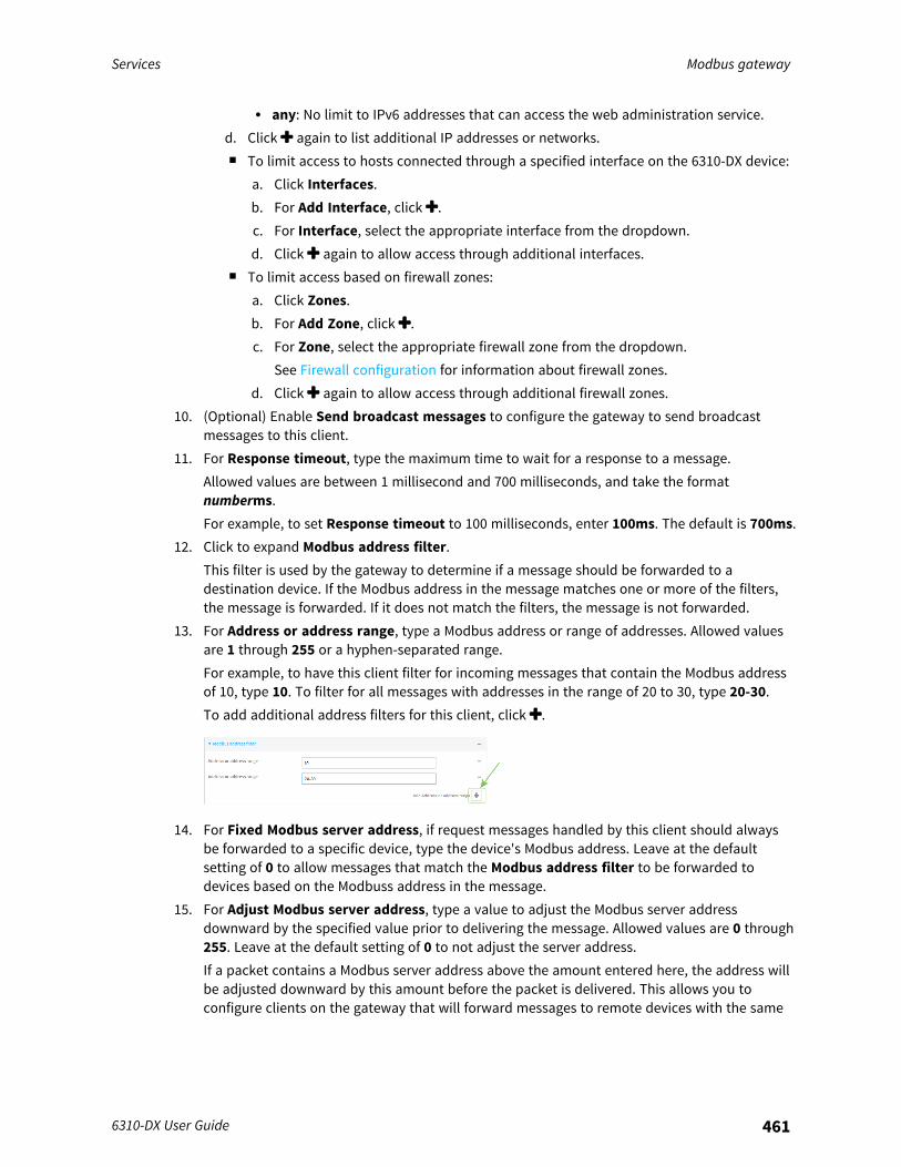
Services Modbus gateway
6310-DX User Guide 461
l any: No limit to IPv6 addresses that can access the web administration service.d. Click again to list additional IP addresses or networks.n To limit access to hosts connected through a specified interface on the 6310-DX device:
a. Click Interfaces.b. For Add Interface, click .c. For Interface, select the appropriate interface from the dropdown.d. Click again to allow access through additional interfaces.
n To limit access based on firewall zones:a. Click Zones.b. For Add Zone, click .c. For Zone, select the appropriate firewall zone from the dropdown.
See Firewall configuration for information about firewall zones.d. Click again to allow access through additional firewall zones.
10. (Optional) Enable Send broadcast messages to configure the gateway to send broadcastmessages to this client.
11. For Response timeout, type the maximum time to wait for a response to a message.Allowed values are between 1 millisecond and 700 milliseconds, and take the formatnumberms.For example, to set Response timeout to 100 milliseconds, enter 100ms. The default is 700ms.
12. Click to expand Modbus address filter.This filter is used by the gateway to determine if a message should be forwarded to adestination device. If the Modbus address in the message matches one or more of the filters,the message is forwarded. If it does not match the filters, the message is not forwarded.
13. For Address or address range, type a Modbus address or range of addresses. Allowed valuesare 1 through 255 or a hyphen-separated range.For example, to have this client filter for incoming messages that contain the Modbus addressof 10, type 10. To filter for all messages with addresses in the range of 20 to 30, type 20-30.To add additional address filters for this client, click .
14. For Fixed Modbus server address, if request messages handled by this client should alwaysbe forwarded to a specific device, type the device's Modbus address. Leave at the defaultsetting of 0 to allow messages that match the Modbus address filter to be forwarded todevices based on the Modbuss address in the message.
15. For Adjust Modbus server address, type a value to adjust the Modbus server addressdownward by the specified value prior to delivering the message. Allowed values are 0 through255. Leave at the default setting of 0 to not adjust the server address.If a packet contains a Modbus server address above the amount entered here, the address willbe adjusted downward by this amount before the packet is delivered. This allows you toconfigure clients on the gateway that will forward messages to remote devices with the same

Services Modbus gateway
6310-DX User Guide 462
Modbus address on different buses. For example, if there are two devices on two differentbuses that have the same Modbus address of 10, you can create two clients on the gateway:
n Client one:l Modbus address filter set to 10.
This will configure the gateway to deliver all messages that have the Modbus serveraddress of 10 to this device.
n Client two:l Modbus address filter set to 20.l Adjust Modbus server address set to 10.
This will configure the gateway to deliver all messages that have the Modbus serveraddress address of 20 to the device with address 10.
16. Repeat these steps to configure additional clients.17. Click Apply to save the configuration and apply the change.
Command line
1. Log into the 6310-DX command line as a user with full Admin access rights.Depending on your device configuration, you may be presented with an Access selectionmenu. Type admin to access the Admin CLI.
2. At the command line, type config to enter configuration mode:
> config(config)>
3. Enable the Modbus gateway:
(config)> service modbus_gateway enable true(config)>
4. Configure servers:a. Add a server:
(config)> add service modbus_gateway server name(config service modbus_gateway server name)>
where name is a name for the server, for example:
(config)> add service modbus_gateway server test_modbus_server(config service modbus_gateway server test_modbus_server)>
The Modbus server is enabled by default. To disable:
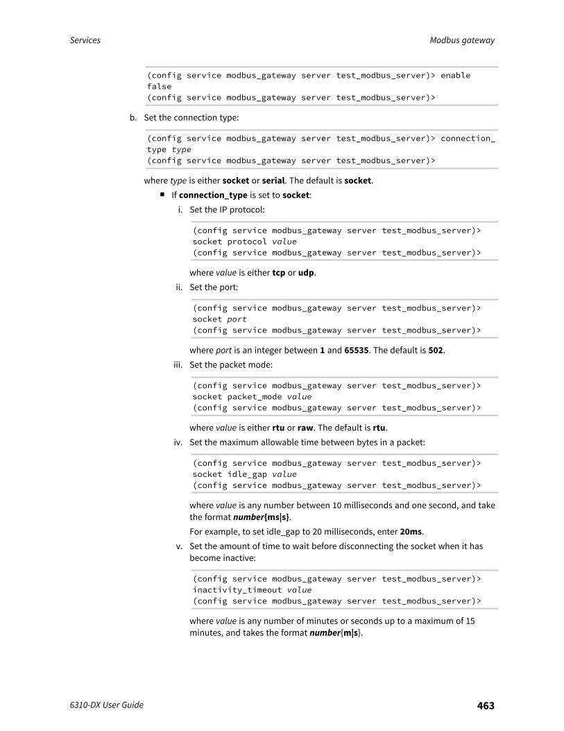
Services Modbus gateway
6310-DX User Guide 463
(config service modbus_gateway server test_modbus_server)> enablefalse(config service modbus_gateway server test_modbus_server)>
b. Set the connection type:
(config service modbus_gateway server test_modbus_server)> connection_type type(config service modbus_gateway server test_modbus_server)>
where type is either socket or serial. The default is socket.n If connection_type is set to socket:
i. Set the IP protocol:
(config service modbus_gateway server test_modbus_server)>socket protocol value(config service modbus_gateway server test_modbus_server)>
where value is either tcp or udp.ii. Set the port:
(config service modbus_gateway server test_modbus_server)>socket port(config service modbus_gateway server test_modbus_server)>
where port is an integer between 1 and 65535. The default is 502.iii. Set the packet mode:
(config service modbus_gateway server test_modbus_server)>socket packet_mode value(config service modbus_gateway server test_modbus_server)>
where value is either rtu or raw. The default is rtu.iv. Set the maximum allowable time between bytes in a packet:
(config service modbus_gateway server test_modbus_server)>socket idle_gap value(config service modbus_gateway server test_modbus_server)>
where value is any number between 10 milliseconds and one second, and takethe format number{ms|s}.For example, to set idle_gap to 20 milliseconds, enter 20ms.
v. Set the amount of time to wait before disconnecting the socket when it hasbecome inactive:
(config service modbus_gateway server test_modbus_server)>inactivity_timeout value(config service modbus_gateway server test_modbus_server)>
where value is any number of minutes or seconds up to a maximum of 15minutes, and takes the format number{m|s}.
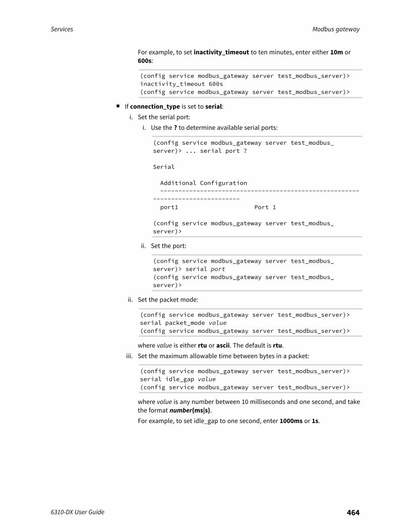
Services Modbus gateway
6310-DX User Guide 464
For example, to set inactivity_timeout to ten minutes, enter either 10m or600s:
(config service modbus_gateway server test_modbus_server)>inactivity_timeout 600s(config service modbus_gateway server test_modbus_server)>
n If connection_type is set to serial:i. Set the serial port:
i. Use the ? to determine available serial ports:
(config service modbus_gateway server test_modbus_server)> ... serial port ?
Serial
Additional Configuration-------------------------------------------------------
------------------------port1 Port 1
(config service modbus_gateway server test_modbus_server)>
ii. Set the port:
(config service modbus_gateway server test_modbus_server)> serial port(config service modbus_gateway server test_modbus_server)>
ii. Set the packet mode:
(config service modbus_gateway server test_modbus_server)>serial packet_mode value(config service modbus_gateway server test_modbus_server)>
where value is either rtu or ascii. The default is rtu.iii. Set the maximum allowable time between bytes in a packet:
(config service modbus_gateway server test_modbus_server)>serial idle_gap value(config service modbus_gateway server test_modbus_server)>
where value is any number between 10 milliseconds and one second, and takethe format number{ms|s}.For example, to set idle_gap to one second, enter 1000ms or 1s.
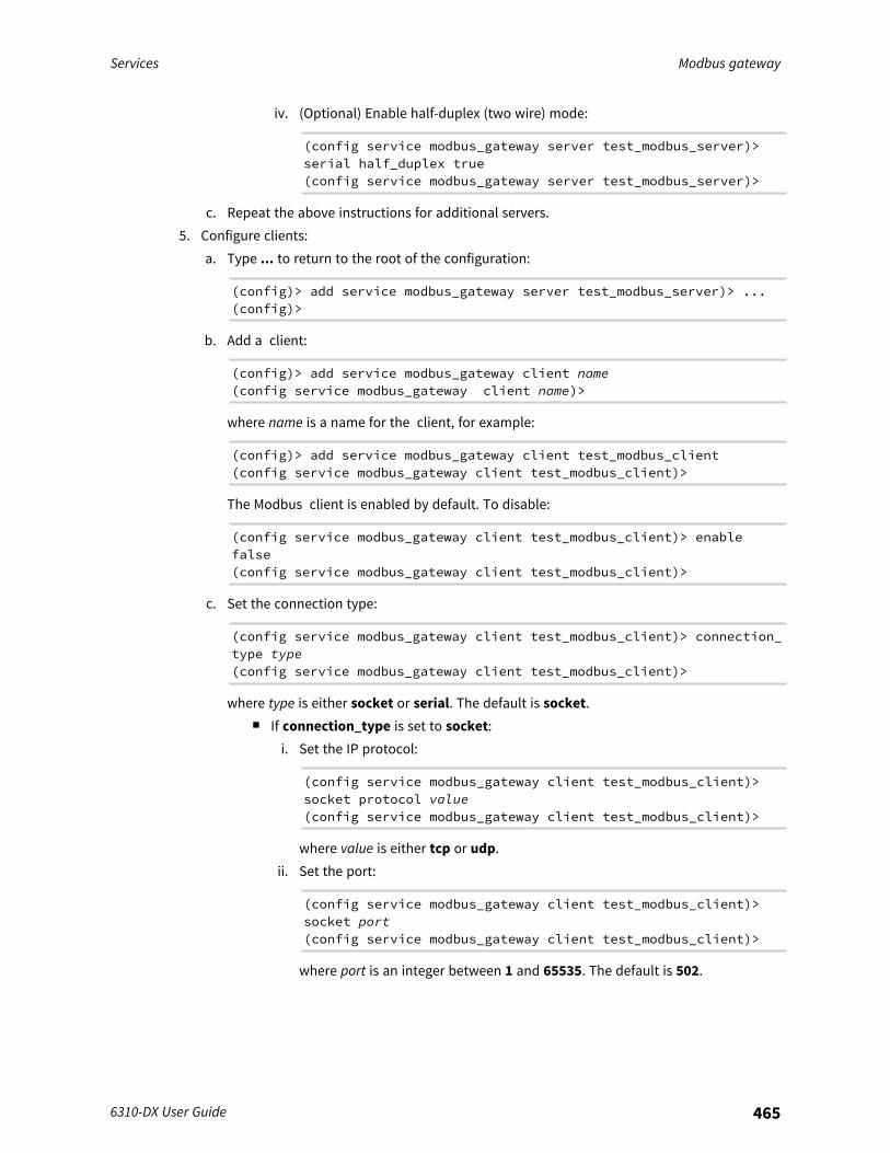
Services Modbus gateway
6310-DX User Guide 465
iv. (Optional) Enable half-duplex (two wire) mode:
(config service modbus_gateway server test_modbus_server)>serial half_duplex true(config service modbus_gateway server test_modbus_server)>
c. Repeat the above instructions for additional servers.5. Configure clients:
a. Type ... to return to the root of the configuration:
(config)> add service modbus_gateway server test_modbus_server)> ...(config)>
b. Add a client:
(config)> add service modbus_gateway client name(config service modbus_gateway client name)>
where name is a name for the client, for example:
(config)> add service modbus_gateway client test_modbus_client(config service modbus_gateway client test_modbus_client)>
The Modbus client is enabled by default. To disable:
(config service modbus_gateway client test_modbus_client)> enablefalse(config service modbus_gateway client test_modbus_client)>
c. Set the connection type:
(config service modbus_gateway client test_modbus_client)> connection_type type(config service modbus_gateway client test_modbus_client)>
where type is either socket or serial. The default is socket.n If connection_type is set to socket:
i. Set the IP protocol:
(config service modbus_gateway client test_modbus_client)>socket protocol value(config service modbus_gateway client test_modbus_client)>
where value is either tcp or udp.ii. Set the port:
(config service modbus_gateway client test_modbus_client)>socket port(config service modbus_gateway client test_modbus_client)>
where port is an integer between 1 and 65535. The default is 502.
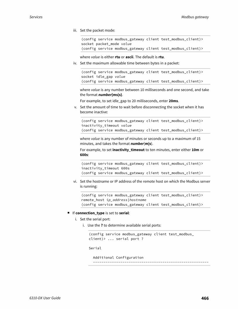
Services Modbus gateway
6310-DX User Guide 466
iii. Set the packet mode:
(config service modbus_gateway client test_modbus_client)>socket packet_mode value(config service modbus_gateway client test_modbus_client)>
where value is either rtu or ascii. The default is rtu.iv. Set the maximum allowable time between bytes in a packet:
(config service modbus_gateway client test_modbus_client)>socket idle_gap value(config service modbus_gateway client test_modbus_client)>
where value is any number between 10 milliseconds and one second, and takethe format number{ms|s}.For example, to set idle_gap to 20 milliseconds, enter 20ms.
v. Set the amount of time to wait before disconnecting the socket when it hasbecome inactive:
(config service modbus_gateway client test_modbus_client)>inactivity_timeout value(config service modbus_gateway client test_modbus_client)>
where value is any number of minutes or seconds up to a maximum of 15minutes, and takes the format number{m|s}.For example, to set inactivity_timeout to ten minutes, enter either 10m or600s:
(config service modbus_gateway client test_modbus_client)>inactivity_timeout 600s(config service modbus_gateway client test_modbus_client)>
vi. Set the hostname or IP address of the remote host on which the Modbus serveris running:
(config service modbus_gateway client test_modbus_client)>remote_host ip_address|hostname(config service modbus_gateway client test_modbus_client)>
n If connection_type is set to serial:i. Set the serial port:
i. Use the ? to determine available serial ports:
(config service modbus_gateway client test_modbus_client)> ... serial port ?
Serial
Additional Configuration-------------------------------------------------------
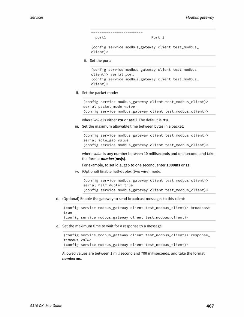
Services Modbus gateway
6310-DX User Guide 467
------------------------port1 Port 1
(config service modbus_gateway client test_modbus_client)>
ii. Set the port:
(config service modbus_gateway client test_modbus_client)> serial port(config service modbus_gateway client test_modbus_client)>
ii. Set the packet mode:
(config service modbus_gateway client test_modbus_client)>serial packet_mode value(config service modbus_gateway client test_modbus_client)>
where value is either rtu or ascii. The default is rtu.iii. Set the maximum allowable time between bytes in a packet:
(config service modbus_gateway client test_modbus_client)>serial idle_gap value(config service modbus_gateway client test_modbus_client)>
where value is any number between 10 milliseconds and one second, and takethe format number{ms|s}.For example, to set idle_gap to one second, enter 1000ms or 1s.
iv. (Optional) Enable half-duplex (two wire) mode:
(config service modbus_gateway client test_modbus_client)>serial half_duplex true(config service modbus_gateway client test_modbus_client)>
d. (Optional) Enable the gateway to send broadcast messages to this client:
(config service modbus_gateway client test_modbus_client)> broadcasttrue(config service modbus_gateway client test_modbus_client)>
e. Set the maximum time to wait for a response to a message:
(config service modbus_gateway client test_modbus_client)> response_timeout value(config service modbus_gateway client test_modbus_client)>
Allowed values are between 1 millisecond and 700 milliseconds, and take the formatnumberms.
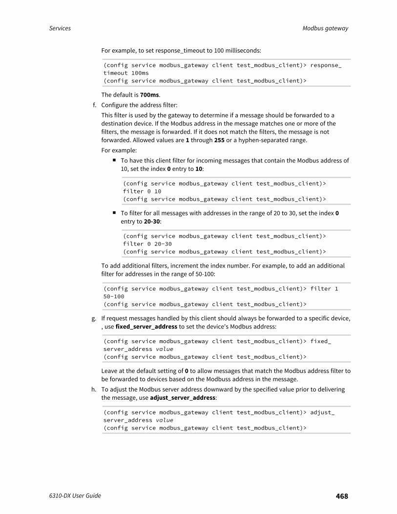
Services Modbus gateway
6310-DX User Guide 468
For example, to set response_timeout to 100 milliseconds:
(config service modbus_gateway client test_modbus_client)> response_timeout 100ms(config service modbus_gateway client test_modbus_client)>
The default is 700ms.f. Configure the address filter:
This filter is used by the gateway to determine if a message should be forwarded to adestination device. If the Modbus address in the message matches one or more of thefilters, the message is forwarded. If it does not match the filters, the message is notforwarded. Allowed values are 1 through 255 or a hyphen-separated range.For example:
n To have this client filter for incoming messages that contain the Modbus address of10, set the index 0 entry to 10:
(config service modbus_gateway client test_modbus_client)>filter 0 10(config service modbus_gateway client test_modbus_client)>
n To filter for all messages with addresses in the range of 20 to 30, set the index 0entry to 20-30:
(config service modbus_gateway client test_modbus_client)>filter 0 20-30(config service modbus_gateway client test_modbus_client)>
To add additional filters, increment the index number. For example, to add an additionalfilter for addresses in the range of 50-100:
(config service modbus_gateway client test_modbus_client)> filter 150-100(config service modbus_gateway client test_modbus_client)>
g. If request messages handled by this client should always be forwarded to a specific device,, use fixed_server_address to set the device's Modbus address:
(config service modbus_gateway client test_modbus_client)> fixed_server_address value(config service modbus_gateway client test_modbus_client)>
Leave at the default setting of 0 to allow messages that match the Modbus address filter tobe forwarded to devices based on the Modbuss address in the message.
h. To adjust the Modbus server address downward by the specified value prior to deliveringthe message, use adjust_server_address:
(config service modbus_gateway client test_modbus_client)> adjust_server_address value(config service modbus_gateway client test_modbus_client)>
Services Modbus gateway
6310-DX User Guide 469
where value is an integer from 0 to 255. Leave at the default setting of 0 to not adjust theserver address.If a packet contains a Modbus server address above the amount entered here, the addresswill be adjusted downward by this amount before the packet is delivered. This allows youto configure clients on the gateway that will forward messages to remote devices with thesame Modbus address on different buses. For example, if there are two devices on twodifferent buses that have the same Modbus address of 10, you can create two clients onthe gateway:
n Client one:l filter set to 10.
This will configure the gateway to deliver all messages that have the Modbus serveraddress of 10 to this device.
n Client two:l filter set to 20.l adjust_server_address set to 10.
This will configure the gateway to deliver all messages that have the Modbus serveraddress address of 20 to the device with address 10.
i. Repeat the above instructions for additional clients.6. Save the configuration and apply the change:
(config)> saveConfiguration saved.>
7. Type exit to exit the Admin CLI.Depending on your device configuration, you may be presented with an Access selectionmenu. Type quit to disconnect from the device.
Show Modbus gateway status and statisticsYou can view status and statistics about location information from either the WebUI or the commandline.
WebUI
1. Log into the 6310-DX WebUI as a user with Admin access.2. On the menu, select Status > Modbus Gateway.
The Modbus Gateway page appears.Statistics related to the Modbus gateway server are displayed. If the message Serverconnections not available is displayed, this indicates that there are no connected clients.
n To view information about Modbus gateway clients, click Clients.n To view statistics that are common to both the clients and server, click Common
Statistics.n To view configuration details about the gateway, click the (configuration) icon in the
upper right of the gateway's status pane.
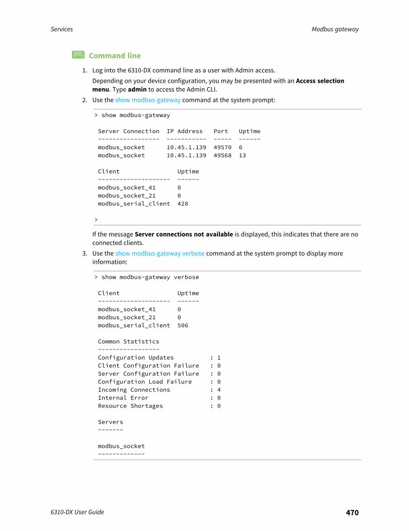
Services Modbus gateway
6310-DX User Guide 470
Command line
1. Log into the 6310-DX command line as a user with Admin access.Depending on your device configuration, you may be presented with an Access selectionmenu. Type admin to access the Admin CLI.
2. Use the show modbus-gateway command at the system prompt:
> show modbus-gateway
Server Connection IP Address Port Uptime----------------- ----------- ----- ------modbus_socket 10.45.1.139 49570 6modbus_socket 10.45.1.139 49568 13
Client Uptime-------------------- ------modbus_socket_41 0modbus_socket_21 0modbus_serial_client 428
>
If the message Server connections not available is displayed, this indicates that there are noconnected clients.
3. Use the show modbus-gateway verbose command at the system prompt to display moreinformation:
> show modbus-gateway verbose
Client Uptime-------------------- ------modbus_socket_41 0modbus_socket_21 0modbus_serial_client 506
Common Statistics-----------------Configuration Updates : 1Client Configuration Failure : 0Server Configuration Failure : 0Configuration Load Failure : 0Incoming Connections : 4Internal Error : 0Resource Shortages : 0
Servers-------
modbus_socket-------------
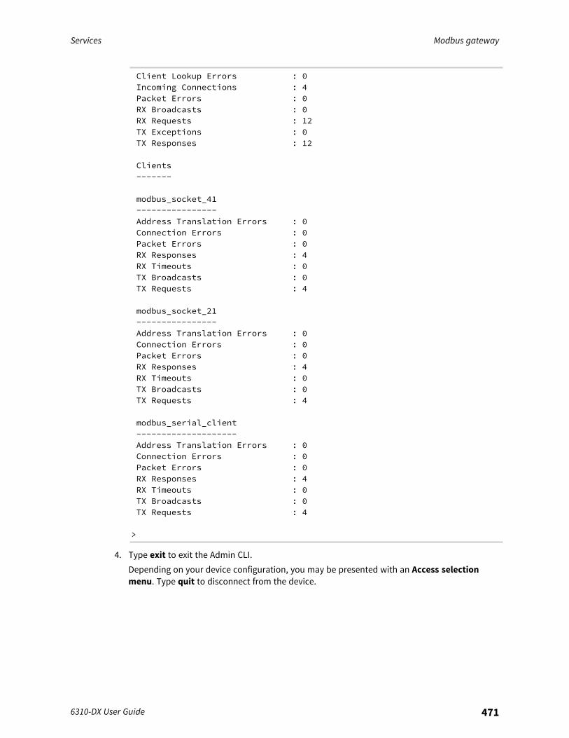
Services Modbus gateway
6310-DX User Guide 471
Client Lookup Errors : 0Incoming Connections : 4Packet Errors : 0RX Broadcasts : 0RX Requests : 12TX Exceptions : 0TX Responses : 12
Clients-------
modbus_socket_41----------------Address Translation Errors : 0Connection Errors : 0Packet Errors : 0RX Responses : 4RX Timeouts : 0TX Broadcasts : 0TX Requests : 4
modbus_socket_21----------------Address Translation Errors : 0Connection Errors : 0Packet Errors : 0RX Responses : 4RX Timeouts : 0TX Broadcasts : 0TX Requests : 4
modbus_serial_client--------------------Address Translation Errors : 0Connection Errors : 0Packet Errors : 0RX Responses : 4RX Timeouts : 0TX Broadcasts : 0TX Requests : 4
>
4. Type exit to exit the Admin CLI.Depending on your device configuration, you may be presented with an Access selectionmenu. Type quit to disconnect from the device.
Services System time
6310-DX User Guide 472
System timeBy default, the 6310-DX device synchronizes the system time by periodically connecting to the DigiNTP server, time.devicecloud.com. In this mode, the device queries the time server based onfollowing events and schedule:
n At boot time.n Once a day.
The default configuration has the system time zone set to UTC. No additional configuration is requiredfor the system time if the default configuration is sufficient. However, you can change the default timezone and the default NTP server, as well as configuring additional NTP servers. If multiple servers areconfigured, a number of time samples are obtained from each of the servers and a subset of the NTPclock filter and selection algorithms are applied to select the best of these. See Configure the systemtime for details about changing the default configuration.The 6310-DX device can also be configured to serve as an NTP server, providing NTP services todownstream devices. See Network Time Protocol for more information about NTP server support.You can also set the local date and time manually, if there is no access to NTP servers. See Manuallyset the system date and time for information
Configure the system timeThis procedure is optional.The 6310-DX device's default system time configuration uses the Digi NTP server,time.devicecloud.com, and has the time zone set to UTC. You can change the default NTP server andthe default time zone. You can also set the local date and time without using an upstream NTP server,as well as configuring additional NTP servers.
Required Configuration Items
n The time zone for the 6310-DX device.n If t least one upstream NTP server for synchronization.
Additional Configuration Options
n Additional upstream NTP servers.
WebUI
1. Log into the 6310-DX WebUI as a user with full Admin access rights.2. On the menu, click System. Under Configuration, click Device Configuration.
The Configuration window is displayed.

Services System time
6310-DX User Guide 473
3. Click System > Time4. (Optional) For Timezone, select either UTC or select the location nearest to your current
location to set the timezone for your 6310-DX device. The default is UTC.5. (Optional) Add upstream NTP servers that the device will use to synchronize its time. The
default setting is time.devicecloud.com.n To change the default value of the NTP server:
a. Click NTP servers.b. For Server, type a new server name.
n To add an NTP server:a. Click NTP servers.b. For Add Server, click .c. For Server, enter the hostname of the upstream NTP server that the device will use
to synchronize its time.d. Click to add additional NTP servers. If multiple servers are included, servers are
tried in the order listed until one succeeds.
Note This list is synchronized with the list of servers included with NTP server configuration,and changes made to one will be reflected in the other. See Configure the device as an NTPserver for more information about NTP server configuration.
6. Click Apply to save the configuration and apply the change.
Command line
1. Log into the 6310-DX command line as a user with full Admin access rights.Depending on your device configuration, you may be presented with an Access selectionmenu. Type admin to access the Admin CLI.
Services System time
6310-DX User Guide 474
2. At the command line, type config to enter configuration mode:
> config(config)>
3. (Optional) Set the timezone for the location of your 6310-DX device. The default is UTC.
(config)> system time timezone value(config)>
Where value is the timezone using the format specified with the following command:
(config)> system time timezone ?
Timezone: The timezone for the location of this device. This is used toadjust the time for logmessages. It also affects actions that occur at a specific time of day.Format:Africa/AbidjanAfrica/AccraAfrica/Addis_Ababa...
(config)>
4. (Optional) Add an upstream NTP server that the device will use to synchronize its time to theappropriate location in the list of NTP servers. The default setting is time.devicecloud.com.
n To delete the default NTP server, time.devicecloud.com:
(config)> del service ntp server 0(config)>
n To add the NTP server to the beginning of the list, use the index value of 0 to indicatethat it should be added as the first server:
(config)> add service ntp server 0 time.server.com(config)>
n To add the NTP server to the end of the list, use the index keyword end:
(config)> add service ntp server end time.server.com(config)>
n To add the NTP server in another location in the list, use an index value to indicate theappropriate position. For example:
(config)> add service ntp server 1 time.server.com(config)>
Note This list is synchronized with the list of servers included with NTP server configuration,and changes made to one will be reflected in the other. See Configure the device as an NTPserver for more information about NTP server configuration.

Services System time
6310-DX User Guide 475
5. Save the configuration and apply the change:
(config)> saveConfiguration saved.>
6. Type exit to exit the Admin CLI.Depending on your device configuration, you may be presented with an Access selectionmenu. Type quit to disconnect from the device.
Test the connection to the NTP serversThe following procedure tests the configured NTP servers for connectivity. This test does not affectthe device's current local date and time.
Command line
1. Log into the 6310-DX command line as a user with Admin access.Depending on your device configuration, you may be presented with an Access selectionmenu. Type admin to access the Admin CLI.
2. Test the configured NTP servers for connectivity:
> system time testTesting NTP server time.devicecloud.com on UDP port 123...server 52.2.40.158, stratum 2, offset -0.000216, delay 0.05800server 35.164.164.69, stratum 2, offset -0.000991, delay 0.0718824 Aug 22:01:20 ntpdate[28496]: adjust time server 52.2.40.158 offset -0.000216 secNTP test sync successful
Testing NTP server time.accns.com on UDP port 123...server 128.136.167.120, stratum 3, offset -0.001671, delay 0.0845524 Aug 22:01:20 ntpdate[28497]: adjust time server 128.136.167.120 offset-0.001671 secNTP test sync successful>
3. Type exit to exit the Admin CLI.Depending on your device configuration, you may be presented with an Access selectionmenu. Type quit to disconnect from the device.
Manually synchronize with the NTP serverThe following procedure perform a NTP query to the configured servers and set the local time to thefirst server that responds.
1. Log into the 6310-DX command line as a user with Admin access.Depending on your device configuration, you may be presented with an Access selectionmenu. Type admin to access the Admin CLI.
Services Network Time Protocol
6310-DX User Guide 476
2. Synchronize the device's local date and time:
> system time synch24 Aug 22:03:55 ntpdate[2520]: step time server 52.2.40.158 offset -0.000487 secNTP sync to time.devicecloud.com successful>
3. Type exit to exit the Admin CLI.Depending on your device configuration, you may be presented with an Access selectionmenu. Type quit to disconnect from the device.
Manually set the system date and timeIf your network restricts access to NTP servers, use this procedure to set the local date and time.This procedure is available at the Admin CLI only.
Command line
1. Log into the 6310-DX command line as a user with Admin access.Depending on your device configuration, you may be presented with an Access selectionmenu. Type admin to access the Admin CLI.
2. Set the device's local date and time:
> system time set value>
where value is the The date in year-month-day hour:minute:second format. For example:
> system time set 2022-03-03 10:16:23>
3. Type exit to exit the Admin CLI.Depending on your device configuration, you may be presented with an Access selectionmenu. Type quit to disconnect from the device.
Network Time ProtocolNetwork Time Protocol (NTP) enables devices connected on local and worldwide networks tosynchronize their internal software and hardware clocks to the same time source. The 6310-DX devicecan be configured as an NTP server, allowing downstream hosts that are attached to the device'sLocal Area Networks to synchronize with the device.When the device is configured as an NTP server, it also functions as an NTP client. The NTP client willbe consistently synchronized with one or more upstream NTP servers, which means that NTP packetsare transferred every few seconds. A minimum of one upstream NTP server is required. Additional NTPservers can be configured. If multiple servers are configured, a number of time samples are obtainedfrom each of the servers and a subset of the NTP clock filter and selection algorithms are applied toselect the best of these.See Configure the device as an NTP server for information about configuring your device as an NTPserver.
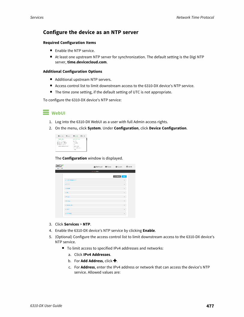
Services Network Time Protocol
6310-DX User Guide 477
Configure the device as an NTP server
Required Configuration Items
n Enable the NTP service.n At least one upstream NTP server for synchronization. The default setting is the Digi NTP
server, time.devicecloud.com.
Additional Configuration Options
n Additional upstream NTP servers.n Access control list to limit downstream access to the 6310-DX device's NTP service.n The time zone setting, if the default setting of UTC is not appropriate.
To configure the 6310-DX device's NTP service:
WebUI
1. Log into the 6310-DX WebUI as a user with full Admin access rights.2. On the menu, click System. Under Configuration, click Device Configuration.
The Configuration window is displayed.
3. Click Services > NTP.4. Enable the 6310-DX device's NTP service by clicking Enable.5. (Optional) Configure the access control list to limit downstream access to the 6310-DX device's
NTP service.n To limit access to specified IPv4 addresses and networks:
a. Click IPv4 Addresses.b. For Add Address, click .c. For Address, enter the IPv4 address or network that can access the device's NTP
service. Allowed values are:
Services Network Time Protocol
6310-DX User Guide 478
l A single IP address or host name.l A network designation in CIDR notation, for example, 192.168.1.0/24.l any: No limit to IPv4 addresses that can access the NTP service.
d. Click again to list additional IP addresses or networks.n To limit access to specified IPv6 addresses and networks:
a. Click IPv6 Addresses.b. For Add Address, click .c. For Address, enter the IPv6 address or network that can access the device's NTP
service. Allowed values are:l A single IP address or host name.l A network designation in CIDR notation, for example, 2001:db8::/48.l any: No limit to IPv6 addresses that can access the NTP service.
d. Click again to list additional IP addresses or networks.n To limit access to hosts connected through a specified interface on the 6310-DX device:
a. Click Interfaces.b. For Add Interface, click .c. For Interface, select the appropriate interface from the dropdown.d. Click again to allow access through additional interfaces.
n To limit access based on firewall zones:a. Click Zones.b. For Add Zone, click .c. For Zone, select the appropriate firewall zone from the dropdown.
See Firewall configuration for information about firewall zones.d. Click again to allow access through additional firewall zones.
Note By default, the access control list for the NTP service is empty, which means that alldownstream hosts connected to the 6310-DX device can use the NTP service.
6. Enable Fall back to local clock to allow the device's local system clock to be used as backuptime source.
7. (Optional) Add upstream NTP servers that the device will use to synchronize its time. Thedefault setting is time.devicecloud.com.
n To change the default value of the NTP server:a. Click NTP servers.b. For Server, type a new server name.
n To add an NTP server:a. Click NTP servers.b. For Add Server, click .c. For Server, enter the hostname of the upstream NTP server that the device will use
to synchronize its time.d. Click to add additional NTP servers. If multiple servers are included, servers are
tried in the order listed until one succeeds.
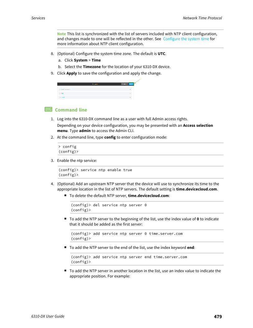
Services Network Time Protocol
6310-DX User Guide 479
Note This list is synchronized with the list of servers included with NTP client configuration,and changes made to one will be reflected in the other. See Configure the system time formore information about NTP client configuration.
8. (Optional) Configure the system time zone. The default is UTC.a. Click System > Timeb. Select the Timezone for the location of your 6310-DX device.
9. Click Apply to save the configuration and apply the change.
Command line
1. Log into the 6310-DX command line as a user with full Admin access rights.Depending on your device configuration, you may be presented with an Access selectionmenu. Type admin to access the Admin CLI.
2. At the command line, type config to enter configuration mode:
> config(config)>
3. Enable the ntp service:
(config)> service ntp enable true(config)>
4. (Optional) Add an upstream NTP server that the device will use to synchronize its time to theappropriate location in the list of NTP servers. The default setting is time.devicecloud.com.
n To delete the default NTP server, time.devicecloud.com:
(config)> del service ntp server 0(config)>
n To add the NTP server to the beginning of the list, use the index value of 0 to indicatethat it should be added as the first server:
(config)> add service ntp server 0 time.server.com(config)>
n To add the NTP server to the end of the list, use the index keyword end:
(config)> add service ntp server end time.server.com(config)>
n To add the NTP server in another location in the list, use an index value to indicate theappropriate position. For example:

Services Network Time Protocol
6310-DX User Guide 480
(config)> add service ntp server 1 time.server.com(config)>
Note This list is synchronized with the list of servers included with NTP client configuration,and changes made to one will be reflected in the other. See Configure the system time formore information about NTP client configuration.
5. Allow the device's local system clock to be used as backup time source:
(config)> service ntp local true(config)>
6. (Optional) Configure the access control list to limit downstream access to the 6310-DX device'sNTP service.
n To limit access to specified IPv4 addresses and networks:
(config)> add service ntp acl address end value(config)>
Where value can be:l A single IP address or host name.l A network designation in CIDR notation, for example, 192.168.1.0/24.l any: No limit to IPv4 addresses that can access the NTP server agent.
Repeat this step to list additional IP addresses or networks.n To limit access to specified IPv6 addresses and networks:
(config)> add service ntp acl address6 end value(config)>
Where value can be:l A single IP address or host name.l A network designation in CIDR notation, for example, 2001:db8::/48.l any: No limit to IPv6 addresses that can access the NTP server agent.
Repeat this step to list additional IP addresses or networks.n To limit access to hosts connected through a specified interface on the 6310-DX device:
(config)> add service ntp acl interface end value(config)>
Where value is an interface defined on your device.
Display a list of available interfaces:Use ... network interface ? to display interface information:
(config)> ... network interface ?
Interfaces
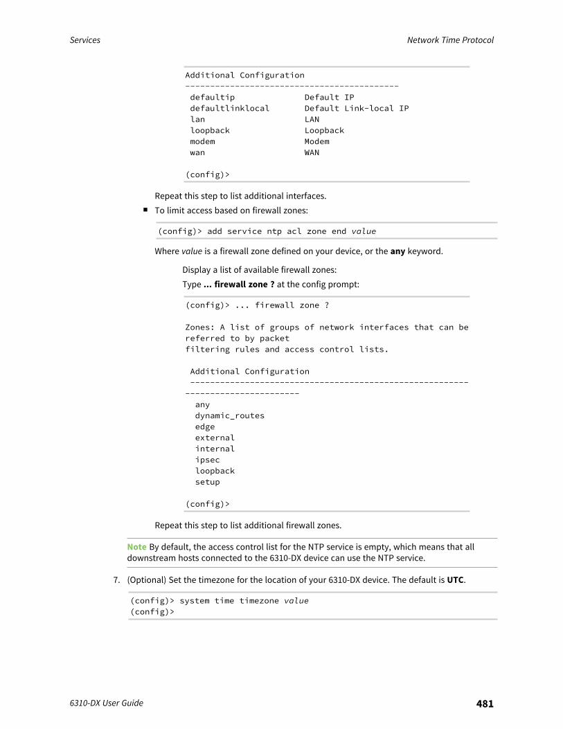
Services Network Time Protocol
6310-DX User Guide 481
Additional Configuration-------------------------------------------defaultip Default IPdefaultlinklocal Default Link-local IPlan LANloopback Loopbackmodem Modemwan WAN
(config)>
Repeat this step to list additional interfaces.n To limit access based on firewall zones:
(config)> add service ntp acl zone end value
Where value is a firewall zone defined on your device, or the any keyword.
Display a list of available firewall zones:Type ... firewall zone ? at the config prompt:
(config)> ... firewall zone ?
Zones: A list of groups of network interfaces that can bereferred to by packetfiltering rules and access control lists.
Additional Configuration--------------------------------------------------------
-----------------------anydynamic_routesedgeexternalinternalipsecloopbacksetup
(config)>
Repeat this step to list additional firewall zones.
Note By default, the access control list for the NTP service is empty, which means that alldownstream hosts connected to the 6310-DX device can use the NTP service.
7. (Optional) Set the timezone for the location of your 6310-DX device. The default is UTC.
(config)> system time timezone value(config)>
Services Network Time Protocol
6310-DX User Guide 482
Where value is the timezone using the format specified with the following command:
(config)> system time timezone ?
Timezone: The timezone for the location of this device. This is used toadjust the time for logmessages. It also affects actions that occur at a specific time of day.Format:Africa/AbidjanAfrica/AccraAfrica/Addis_Ababa...
(config)>
8. Save the configuration and apply the change:
(config)> saveConfiguration saved.>
9. Type exit to exit the Admin CLI.Depending on your device configuration, you may be presented with an Access selectionmenu. Type quit to disconnect from the device.
Show status and statistics of the NTP serverYou can display status and statistics for active NTP servers
WebUI
1. Log into the 6310-DX WebUI as a user with Admin access.2. On the main menu, click Status.3. Under Services, click NTP.
The NTP server status page is displayed.
Command line
Show NTP information
1. Log into the 6310-DX command line as a user with Admin access.Depending on your device configuration, you may be presented with an Access selectionmenu. Type admin to access the Admin CLI.
2. Use the show ntp command at the system prompt:
> show ntp
NTP Status Status-----------------

Services Configure a multicast route
6310-DX User Guide 483
Status : UpSync Status : Up
Remote Refid ST T When Poll Reach DelayOffset Jitter---------------- ------------- -- - ---- ---- ----- ------ ------ ------*ec2-52-2-40-158 129.6.15.32 2 u 191 1024 377 33.570+1.561 0.991128.136.167.120 128.227.205.3 3 u 153 1024 1 43.583 -1.895 0.382
>
3. Type exit to exit the Admin CLI.Depending on your device configuration, you may be presented with an Access selectionmenu. Type quit to disconnect from the device.
Configure a multicast routeMulticast routing allows a device to transmit data to a single multicast address, which is thendistributed to a group of devices that are configured to be members of that group.To configure a multicast route:
WebUI
1. Log into the 6310-DX WebUI as a user with full Admin access rights.2. On the menu, click System. Under Configuration, click Device Configuration.
The Configuration window is displayed.
3. Click Services > Multicast.4. For Add Multicast route, type a name for the route and click .5. The new route is enabled by default. To disable, uncheck Enable.
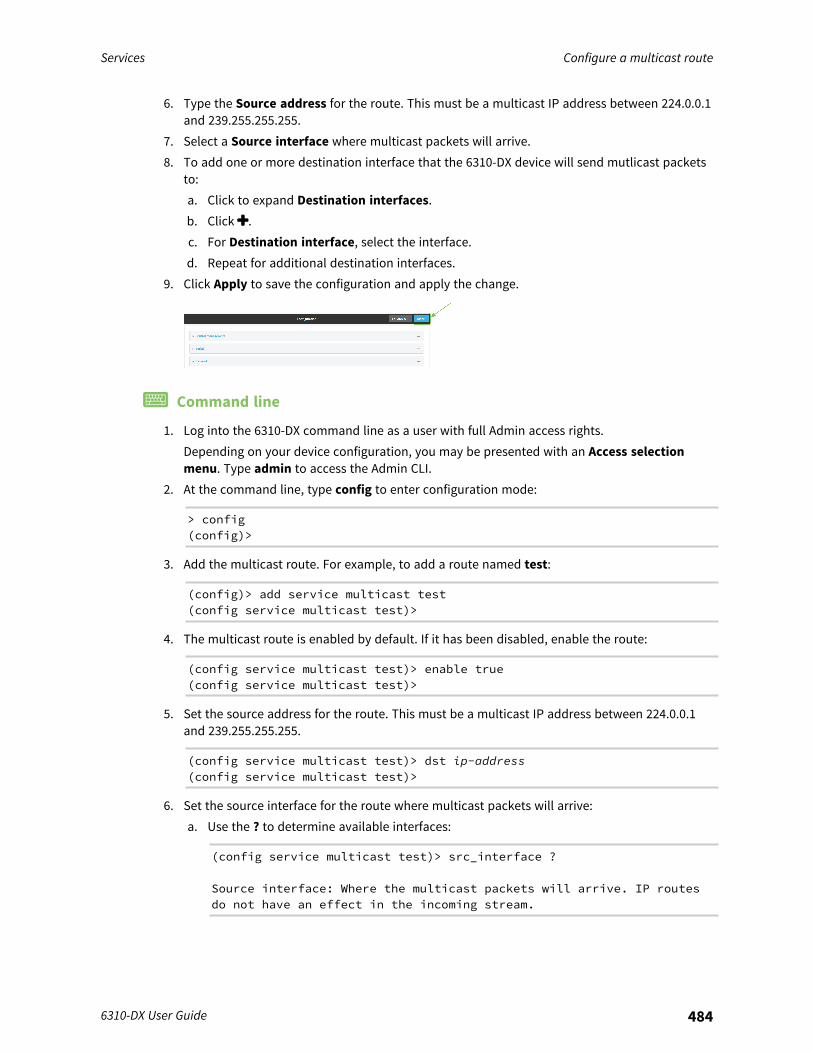
Services Configure a multicast route
6310-DX User Guide 484
6. Type the Source address for the route. This must be a multicast IP address between 224.0.0.1and 239.255.255.255.
7. Select a Source interface where multicast packets will arrive.8. To add one or more destination interface that the 6310-DX device will send mutlicast packets
to:a. Click to expand Destination interfaces.b. Click .c. For Destination interface, select the interface.d. Repeat for additional destination interfaces.
9. Click Apply to save the configuration and apply the change.
Command line
1. Log into the 6310-DX command line as a user with full Admin access rights.Depending on your device configuration, you may be presented with an Access selectionmenu. Type admin to access the Admin CLI.
2. At the command line, type config to enter configuration mode:
> config(config)>
3. Add the multicast route. For example, to add a route named test:
(config)> add service multicast test(config service multicast test)>
4. The multicast route is enabled by default. If it has been disabled, enable the route:
(config service multicast test)> enable true(config service multicast test)>
5. Set the source address for the route. This must be a multicast IP address between 224.0.0.1and 239.255.255.255.
(config service multicast test)> dst ip-address(config service multicast test)>
6. Set the source interface for the route where multicast packets will arrive:a. Use the ? to determine available interfaces:
(config service multicast test)> src_interface ?
Source interface: Where the multicast packets will arrive. IP routesdo not have an effect in the incoming stream.
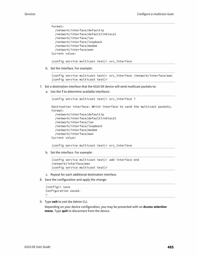
Services Configure a multicast route
6310-DX User Guide 485
Format:/network/interface/defaultip/network/interface/defaultlinklocal/network/interface/lan/network/interface/loopback/network/interface/modem/network/interface/wan
Current value:
(config service multicast test)> src_interface
b. Set the interface. For example:
(config service multicast test)> src_interface /network/interface/wan(config service multicast test)>
7. Set a destination interface that the 6310-DX device will send mutlicast packets to:a. Use the ? to determine available interfaces:
(config service multicast test)> src_interface ?
Destination interface: Which interface to send the multicast packets.Format:/network/interface/defaultip/network/interface/defaultlinklocal/network/interface/lan/network/interface/loopback/network/interface/modem/network/interface/wan
Current value:
(config service multicast test)> src_interface
b. Set the interface. For example:
(config service multicast test)> add interface end/network/interface/wan(config service multicast test)>
c. Repeat for each additional destination interface.8. Save the configuration and apply the change:
(config)> saveConfiguration saved.>
9. Type exit to exit the Admin CLI.Depending on your device configuration, you may be presented with an Access selectionmenu. Type quit to disconnect from the device.
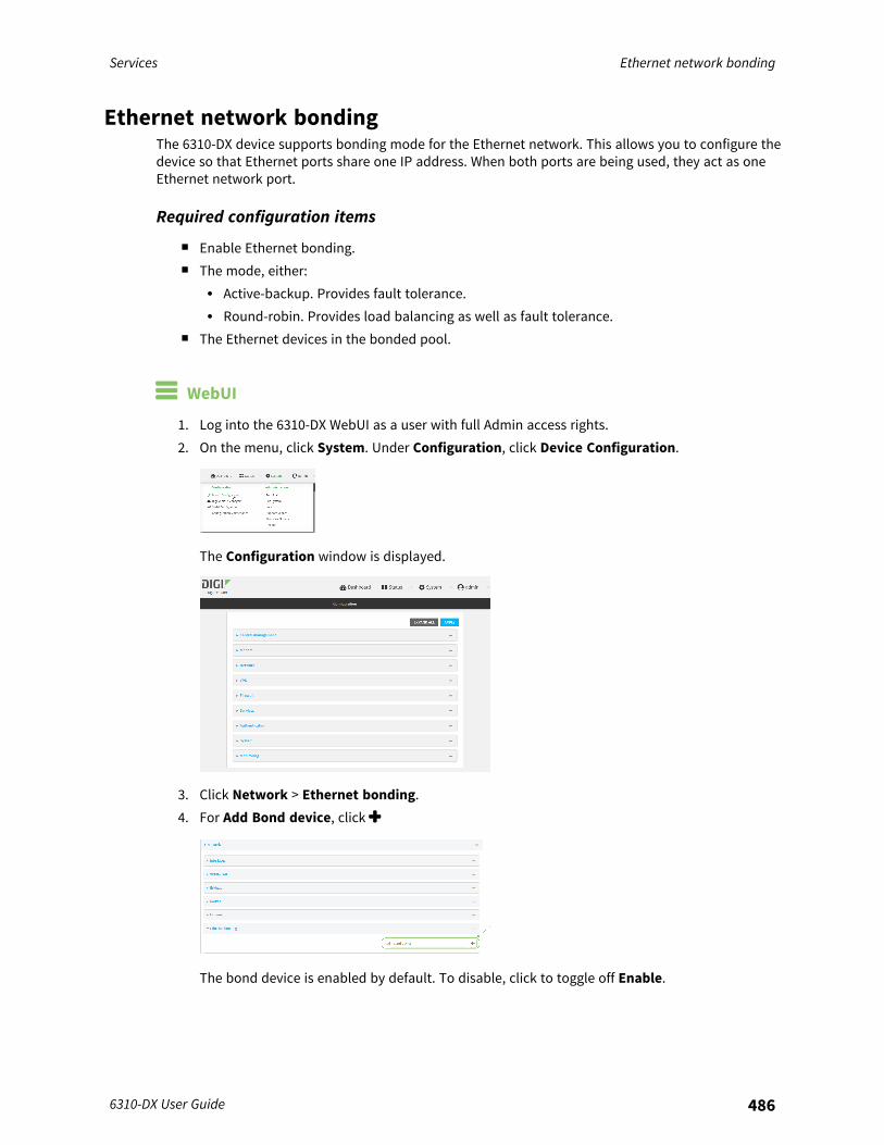
Services Ethernet network bonding
6310-DX User Guide 486
Ethernet network bondingThe 6310-DX device supports bonding mode for the Ethernet network. This allows you to configure thedevice so that Ethernet ports share one IP address. When both ports are being used, they act as oneEthernet network port.
Required configuration items
n Enable Ethernet bonding.n The mode, either:
l Active-backup. Provides fault tolerance.l Round-robin. Provides load balancing as well as fault tolerance.
n The Ethernet devices in the bonded pool.
WebUI
1. Log into the 6310-DX WebUI as a user with full Admin access rights.2. On the menu, click System. Under Configuration, click Device Configuration.
The Configuration window is displayed.
3. Click Network > Ethernet bonding.4. For Add Bond device, click
The bond device is enabled by default. To disable, click to toggle off Enable.
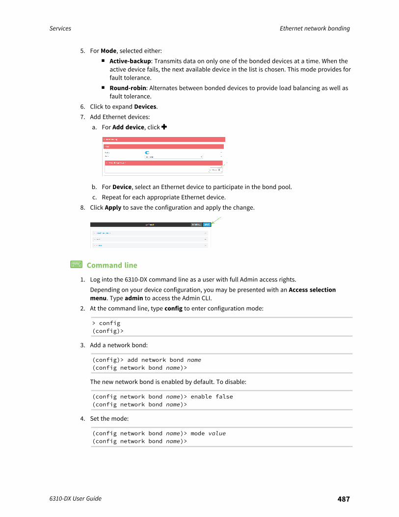
Services Ethernet network bonding
6310-DX User Guide 487
5. For Mode, selected either:n Active-backup: Transmits data on only one of the bonded devices at a time. When the
active device fails, the next available device in the list is chosen. This mode provides forfault tolerance.
n Round-robin: Alternates between bonded devices to provide load balancing as well asfault tolerance.
6. Click to expand Devices.7. Add Ethernet devices:
a. For Add device, click
b. For Device, select an Ethernet device to participate in the bond pool.c. Repeat for each appropriate Ethernet device.
8. Click Apply to save the configuration and apply the change.
Command line
1. Log into the 6310-DX command line as a user with full Admin access rights.Depending on your device configuration, you may be presented with an Access selectionmenu. Type admin to access the Admin CLI.
2. At the command line, type config to enter configuration mode:
> config(config)>
3. Add a network bond:
(config)> add network bond name(config network bond name)>
The new network bond is enabled by default. To disable:
(config network bond name)> enable false(config network bond name)>
4. Set the mode:
(config network bond name)> mode value(config network bond name)>
Services Enable service discovery (mDNS)
6310-DX User Guide 488
where value is either:n active-backup: Transmits data on only one of the bonded devices at a time. When the
active device fails, the next available device in the list is chosen. This mode provides forfault tolerance.
n round-robin: Alternates between bonded devices to provide load balancing as well asfault tolerance.
5. Add Ethernet devices:a. Use the ? to determine available devices:
(config network bond name)> ... network device ?
Additional Configuration----------------------------------------------------------------------------lanloopbackwan
(config network bond name)>
b. Add a device:
(config network bond name)> add device /network/device/lan(config network bond name)>
c. Repeat to add additional devices.6. Save the configuration and apply the change:
(config)> saveConfiguration saved.>
7. Type exit to exit the Admin CLI.Depending on your device configuration, you may be presented with an Access selectionmenu. Type quit to disconnect from the device.
Enable service discovery (mDNS)Multicast DNS mDNS is a protocol that resolves host names in small networks that do not have a DNSserver. You can enable the 6310-DX device to use mDNS.
WebUI
1. Log into the 6310-DX WebUI as a user with full Admin access rights.2. On the menu, click System. Under Configuration, click Device Configuration.
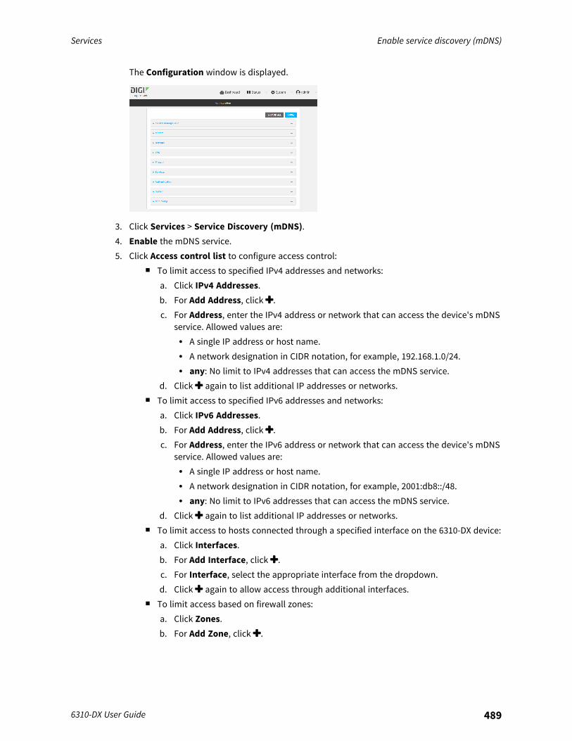
Services Enable service discovery (mDNS)
6310-DX User Guide 489
The Configuration window is displayed.
3. Click Services > Service Discovery (mDNS).4. Enable the mDNS service.5. Click Access control list to configure access control:
n To limit access to specified IPv4 addresses and networks:a. Click IPv4 Addresses.b. For Add Address, click .c. For Address, enter the IPv4 address or network that can access the device's mDNS
service. Allowed values are:l A single IP address or host name.l A network designation in CIDR notation, for example, 192.168.1.0/24.l any: No limit to IPv4 addresses that can access the mDNS service.
d. Click again to list additional IP addresses or networks.n To limit access to specified IPv6 addresses and networks:
a. Click IPv6 Addresses.b. For Add Address, click .c. For Address, enter the IPv6 address or network that can access the device's mDNS
service. Allowed values are:l A single IP address or host name.l A network designation in CIDR notation, for example, 2001:db8::/48.l any: No limit to IPv6 addresses that can access the mDNS service.
d. Click again to list additional IP addresses or networks.n To limit access to hosts connected through a specified interface on the 6310-DX device:
a. Click Interfaces.b. For Add Interface, click .c. For Interface, select the appropriate interface from the dropdown.d. Click again to allow access through additional interfaces.
n To limit access based on firewall zones:a. Click Zones.b. For Add Zone, click .
Services Enable service discovery (mDNS)
6310-DX User Guide 490
c. For Zone, select the appropriate firewall zone from the dropdown.See Firewall configuration for information about firewall zones.
d. Click again to allow access through additional firewall zones.6. Click Apply to save the configuration and apply the change.
Command line
1. Log into the 6310-DX command line as a user with full Admin access rights.Depending on your device configuration, you may be presented with an Access selectionmenu. Type admin to access the Admin CLI.
2. At the command line, type config to enter configuration mode:
> config(config)>
3. Enable the mDNS service:
(config)> service mdns enable true(config)>
4. Configure access control:n To limit access to specified IPv4 addresses and networks:
(config)> add service mdns acl address end value(config)>
Where value can be:l A single IP address or host name.l A network designation in CIDR notation, for example, 192.168.1.0/24.l any: No limit to IPv4 addresses that can access the mDNS service.
Repeat this step to list additional IP addresses or networks.n To limit access to specified IPv6 addresses and networks:
(config)> add service mdns acl address6 end value(config)>
Where value can be:l A single IP address or host name.l A network designation in CIDR notation, for example, 2001:db8::/48.l any: No limit to IPv6 addresses that can access the mDNS service.
Repeat this step to list additional IP addresses or networks.
Services Enable service discovery (mDNS)
6310-DX User Guide 491
n To limit access to hosts connected through a specified interface on the 6310-DX device:
(config)> add service mdns acl interface end value(config)>
Where value is an interface defined on your device.
Display a list of available interfaces:Use ... network interface ? to display interface information:
(config)> ... network interface ?
Interfaces
Additional Configuration-------------------------------------------defaultip Default IPdefaultlinklocal Default Link-local IPlan LANloopback Loopbackmodem Modemwan WAN
(config)>
Repeat this step to list additional interfaces.n To limit access based on firewall zones:
(config)> add service mdns acl zone end value
Where value is a firewall zone defined on your device, or the any keyword.
Display a list of available firewall zones:Type ... firewall zone ? at the config prompt:
(config)> ... firewall zone ?
Zones: A list of groups of network interfaces that can bereferred to by packetfiltering rules and access control lists.
Additional Configuration--------------------------------------------------------
-----------------------anydynamic_routesedgeexternalinternalipsecloopback
Services Use the iPerf service
6310-DX User Guide 492
setup
(config)>
Repeat this step to list additional firewall zones.5. Save the configuration and apply the change:
(config)> saveConfiguration saved.>
6. Type exit to exit the Admin CLI.Depending on your device configuration, you may be presented with an Access selectionmenu. Type quit to disconnect from the device.
Use the iPerf serviceYour 6310-DX device includes an iPerf3 server that you can use to test the performance of yournetwork.iPerf3 is a command-line tool that measures the maximum network throughput an interface canhandle. This is useful when diagnosing network speed issues, to determine, for example, whether acellular connection is providing expected throughput.The 6310-DX implementation of iPerf3 supports testing with both TCP and UDP.
Note Using iPerf clients that are at a version earlier than iPerf3 to connect to the 6310-DX device'siPerf3 server may result in unpredictable results. As a result, Digi recommends using an iPerf client atversion 3 or newer to connect to the 6310-DX device's iPerf3 server.
Required configuration items
n Enable the iPerf server on the 6310-DX device.n An iPerf3 client installed on a remote host. iPerf3 software can be downloaded at
https://iperf.fr/iperf-download.php.
Additional configuration Items
n The port that the 6310-DX device's iPerf server will use to listen for incoming connections.n The access control list for the iPerf server.
When the iPerf server is enabled, the 6310-DX device will automatically configure its firewallrules to allow incoming connections on the configured listening port. You can restrict access byconfiguring the access control list for the iPerf server.
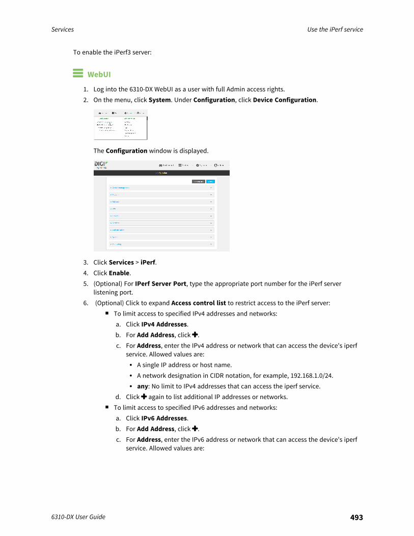
Services Use the iPerf service
6310-DX User Guide 493
To enable the iPerf3 server:
WebUI
1. Log into the 6310-DX WebUI as a user with full Admin access rights.2. On the menu, click System. Under Configuration, click Device Configuration.
The Configuration window is displayed.
3. Click Services > iPerf.4. Click Enable.5. (Optional) For IPerf Server Port, type the appropriate port number for the iPerf server
listening port.6. (Optional) Click to expand Access control list to restrict access to the iPerf server:
n To limit access to specified IPv4 addresses and networks:a. Click IPv4 Addresses.b. For Add Address, click .c. For Address, enter the IPv4 address or network that can access the device's iperf
service. Allowed values are:l A single IP address or host name.l A network designation in CIDR notation, for example, 192.168.1.0/24.l any: No limit to IPv4 addresses that can access the iperf service.
d. Click again to list additional IP addresses or networks.n To limit access to specified IPv6 addresses and networks:
a. Click IPv6 Addresses.b. For Add Address, click .c. For Address, enter the IPv6 address or network that can access the device's iperf
service. Allowed values are:
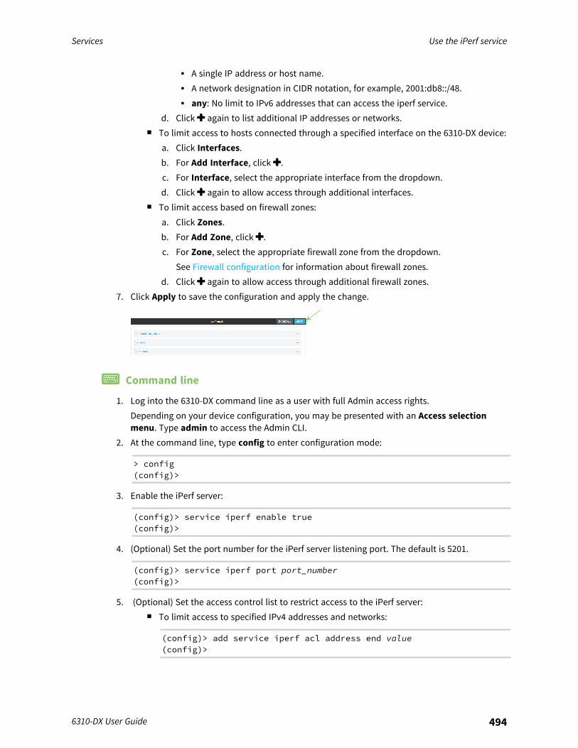
Services Use the iPerf service
6310-DX User Guide 494
l A single IP address or host name.l A network designation in CIDR notation, for example, 2001:db8::/48.l any: No limit to IPv6 addresses that can access the iperf service.
d. Click again to list additional IP addresses or networks.n To limit access to hosts connected through a specified interface on the 6310-DX device:
a. Click Interfaces.b. For Add Interface, click .c. For Interface, select the appropriate interface from the dropdown.d. Click again to allow access through additional interfaces.
n To limit access based on firewall zones:a. Click Zones.b. For Add Zone, click .c. For Zone, select the appropriate firewall zone from the dropdown.
See Firewall configuration for information about firewall zones.d. Click again to allow access through additional firewall zones.
7. Click Apply to save the configuration and apply the change.
Command line
1. Log into the 6310-DX command line as a user with full Admin access rights.Depending on your device configuration, you may be presented with an Access selectionmenu. Type admin to access the Admin CLI.
2. At the command line, type config to enter configuration mode:
> config(config)>
3. Enable the iPerf server:
(config)> service iperf enable true(config)>
4. (Optional) Set the port number for the iPerf server listening port. The default is 5201.
(config)> service iperf port port_number(config)>
5. (Optional) Set the access control list to restrict access to the iPerf server:n To limit access to specified IPv4 addresses and networks:
(config)> add service iperf acl address end value(config)>

Services Use the iPerf service
6310-DX User Guide 495
Where value can be:l A single IP address or host name.l A network designation in CIDR notation, for example, 192.168.1.0/24.l any: No limit to IPv4 addresses that can access the service-type.
Repeat this step to list additional IP addresses or networks.n To limit access to specified IPv6 addresses and networks:
(config)> add service iperf acl address6 end value(config)>
Where value can be:l A single IP address or host name.l A network designation in CIDR notation, for example, 2001:db8::/48.l any: No limit to IPv6 addresses that can access the service-type.
Repeat this step to list additional IP addresses or networks.n To limit access to hosts connected through a specified interface on the 6310-DX device:
(config)> add service iperf acl interface end value(config)>
Where value is an interface defined on your device.
Display a list of available interfaces:Use ... network interface ? to display interface information:
(config)> ... network interface ?
Interfaces
Additional Configuration-------------------------------------------defaultip Default IPdefaultlinklocal Default Link-local IPlan LANloopback Loopbackmodem Modemwan WAN
(config)>
Repeat this step to list additional interfaces.n To limit access based on firewall zones:
(config)> add service iperf acl zone end value
Where value is a firewall zone defined on your device, or the any keyword.
Display a list of available firewall zones:
Services Use the iPerf service
6310-DX User Guide 496
Type ... firewall zone ? at the config prompt:
(config)> ... firewall zone ?
Zones: A list of groups of network interfaces that can bereferred to by packetfiltering rules and access control lists.
Additional Configuration--------------------------------------------------------
-----------------------anydynamic_routesedgeexternalinternalipsecloopbacksetup
(config)>
Repeat this step to list additional firewall zones.6. Save the configuration and apply the change:
(config)> saveConfiguration saved.>
7. Type exit to exit the Admin CLI.Depending on your device configuration, you may be presented with an Access selectionmenu. Type quit to disconnect from the device.
Example performance test using iPerf3On a remote host with iPerf3 installed, enter the following command:
$ iperf3 -c device_ip
where device_ip is the IP address of the 6310-DX device. For example:
$ iperf3 -c 192.168.2.1Connecting to host 192.168.2.1, port 5201[ 4] local 192.168.3.100 port 54934 connected to 192.168.1.1 port 5201[ ID] Interval Transfer Bandwidth Retr Cwnd[ 4] 0.00-1.00 sec 26.7 MBytes 224 Mbits/sec 8 2.68 MBytes[ 4] 1.00-2.00 sec 28.4 MBytes 238 Mbits/sec 29 1.39 MBytes[ 4] 2.00-3.00 sec 29.8 MBytes 250 Mbits/sec 0 1.46 MBytes[ 4] 3.00-4.00 sec 31.2 MBytes 262 Mbits/sec 0 1.52 MBytes[ 4] 4.00-5.00 sec 32.1 MBytes 269 Mbits/sec 0 1.56 MBytes[ 4] 5.00-6.00 sec 32.5 MBytes 273 Mbits/sec 0 1.58 MBytes[ 4] 6.00-7.00 sec 33.9 MBytes 284 Mbits/sec 0 1.60 MBytes[ 4] 7.00-8.00 sec 33.7 MBytes 282 Mbits/sec 0 1.60 MBytes[ 4] 8.00-9.00 sec 33.5 MBytes 281 Mbits/sec 0 1.60 MBytes

Services Configure the ping responder service
6310-DX User Guide 497
[ 4] 9.00-10.00 sec 33.2 MBytes 279 Mbits/sec 0 1.60 MBytes- - - - - - - - - - - - - - - - - - - - - - - - -[ ID] Interval Transfer Bandwidth Retr[ 4] 0.00-10.00 sec 315 MBytes 264 Mbits/sec 37 sender[ 4] 0.00-10.00 sec 313 MBytes 262 Mbits/sec receiver
iperf Done.$
Configure the ping responder serviceYour 6310-DX device's ping responder service replies to ICMP and ICMPv6 echo requests. The service isenabled by default. You can disable the service, or you can configure the service to use an accesscontrol list to limit the service to specified IP address, interfaces, and/or zones.To enable the iPerf3 server:
WebUI
1. Log into the 6310-DX WebUI as a user with full Admin access rights.2. On the menu, click System. Under Configuration, click Device Configuration.
The Configuration window is displayed.
3. Click Services > Ping responder.The ping responder service is enabled by default. Click Enable to disable all ping responses.
4. Click to expand Access control list to restrict ping responses to specified IP address,interfaces, and/or zones:
n To limit access to specified IPv4 addresses and networks:a. Click IPv4 Addresses.b. For Add Address, click .c. For Address, enter the IPv4 address or network that can access the device's ping
responder. Allowed values are:
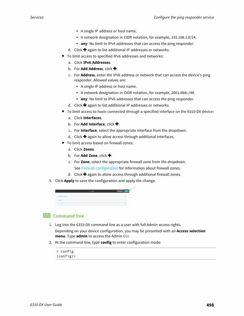
Services Configure the ping responder service
6310-DX User Guide 498
l A single IP address or host name.l A network designation in CIDR notation, for example, 192.168.1.0/24.l any: No limit to IPv4 addresses that can access the ping responder.
d. Click again to list additional IP addresses or networks.n To limit access to specified IPv6 addresses and networks:
a. Click IPv6 Addresses.b. For Add Address, click .c. For Address, enter the IPv6 address or network that can access the device's ping
responder. Allowed values are:l A single IP address or host name.l A network designation in CIDR notation, for example, 2001:db8::/48.l any: No limit to IPv6 addresses that can access the ping responder.
d. Click again to list additional IP addresses or networks.n To limit access to hosts connected through a specified interface on the 6310-DX device:
a. Click Interfaces.b. For Add Interface, click .c. For Interface, select the appropriate interface from the dropdown.d. Click again to allow access through additional interfaces.
n To limit access based on firewall zones:a. Click Zones.b. For Add Zone, click .c. For Zone, select the appropriate firewall zone from the dropdown.
See Firewall configuration for information about firewall zones.d. Click again to allow access through additional firewall zones.
5. Click Apply to save the configuration and apply the change.
Command line
1. Log into the 6310-DX command line as a user with full Admin access rights.Depending on your device configuration, you may be presented with an Access selectionmenu. Type admin to access the Admin CLI.
2. At the command line, type config to enter configuration mode:
> config(config)>
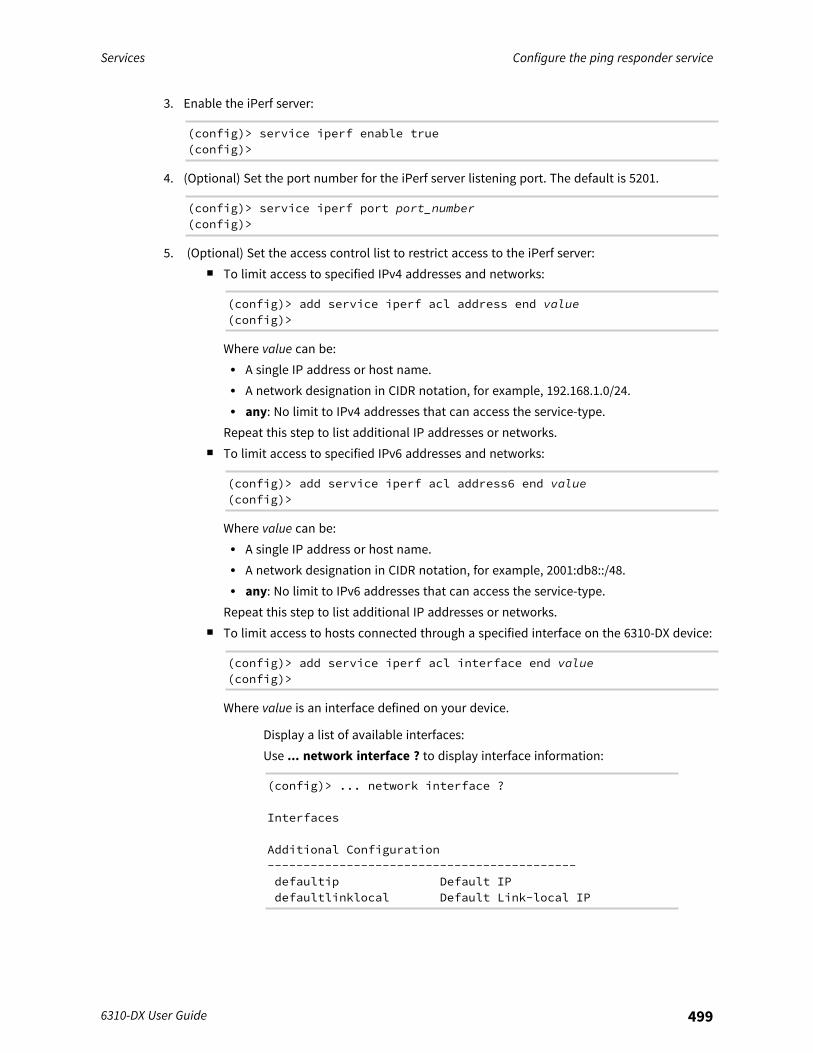
Services Configure the ping responder service
6310-DX User Guide 499
3. Enable the iPerf server:
(config)> service iperf enable true(config)>
4. (Optional) Set the port number for the iPerf server listening port. The default is 5201.
(config)> service iperf port port_number(config)>
5. (Optional) Set the access control list to restrict access to the iPerf server:n To limit access to specified IPv4 addresses and networks:
(config)> add service iperf acl address end value(config)>
Where value can be:l A single IP address or host name.l A network designation in CIDR notation, for example, 192.168.1.0/24.l any: No limit to IPv4 addresses that can access the service-type.
Repeat this step to list additional IP addresses or networks.n To limit access to specified IPv6 addresses and networks:
(config)> add service iperf acl address6 end value(config)>
Where value can be:l A single IP address or host name.l A network designation in CIDR notation, for example, 2001:db8::/48.l any: No limit to IPv6 addresses that can access the service-type.
Repeat this step to list additional IP addresses or networks.n To limit access to hosts connected through a specified interface on the 6310-DX device:
(config)> add service iperf acl interface end value(config)>
Where value is an interface defined on your device.
Display a list of available interfaces:Use ... network interface ? to display interface information:
(config)> ... network interface ?
Interfaces
Additional Configuration-------------------------------------------defaultip Default IPdefaultlinklocal Default Link-local IP

Services Configure the ping responder service
6310-DX User Guide 500
lan LANloopback Loopbackmodem Modemwan WAN
(config)>
Repeat this step to list additional interfaces.n To limit access based on firewall zones:
(config)> add service iperf acl zone end value
Where value is a firewall zone defined on your device, or the any keyword.
Display a list of available firewall zones:Type ... firewall zone ? at the config prompt:
(config)> ... firewall zone ?
Zones: A list of groups of network interfaces that can bereferred to by packetfiltering rules and access control lists.
Additional Configuration--------------------------------------------------------
-----------------------anydynamic_routesedgeexternalinternalipsecloopbacksetup
(config)>
Repeat this step to list additional firewall zones.6. Save the configuration and apply the change:
(config)> saveConfiguration saved.>
7. Type exit to exit the Admin CLI.Depending on your device configuration, you may be presented with an Access selectionmenu. Type quit to disconnect from the device.
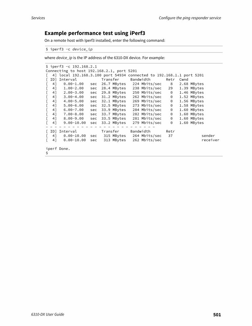
Services Configure the ping responder service
6310-DX User Guide 501
Example performance test using iPerf3On a remote host with Iperf3 installed, enter the following command:
$ iperf3 -c device_ip
where device_ip is the IP address of the 6310-DX device. For example:
$ iperf3 -c 192.168.2.1Connecting to host 192.168.2.1, port 5201[ 4] local 192.168.3.100 port 54934 connected to 192.168.1.1 port 5201[ ID] Interval Transfer Bandwidth Retr Cwnd[ 4] 0.00-1.00 sec 26.7 MBytes 224 Mbits/sec 8 2.68 MBytes[ 4] 1.00-2.00 sec 28.4 MBytes 238 Mbits/sec 29 1.39 MBytes[ 4] 2.00-3.00 sec 29.8 MBytes 250 Mbits/sec 0 1.46 MBytes[ 4] 3.00-4.00 sec 31.2 MBytes 262 Mbits/sec 0 1.52 MBytes[ 4] 4.00-5.00 sec 32.1 MBytes 269 Mbits/sec 0 1.56 MBytes[ 4] 5.00-6.00 sec 32.5 MBytes 273 Mbits/sec 0 1.58 MBytes[ 4] 6.00-7.00 sec 33.9 MBytes 284 Mbits/sec 0 1.60 MBytes[ 4] 7.00-8.00 sec 33.7 MBytes 282 Mbits/sec 0 1.60 MBytes[ 4] 8.00-9.00 sec 33.5 MBytes 281 Mbits/sec 0 1.60 MBytes[ 4] 9.00-10.00 sec 33.2 MBytes 279 Mbits/sec 0 1.60 MBytes- - - - - - - - - - - - - - - - - - - - - - - - -[ ID] Interval Transfer Bandwidth Retr[ 4] 0.00-10.00 sec 315 MBytes 264 Mbits/sec 37 sender[ 4] 0.00-10.00 sec 313 MBytes 262 Mbits/sec receiver
iperf Done.$
Applications
The 6310-DX supports Python 3.6 and provides you with the ability to run Python applications on thedevice interactively or from a file. You can also specify Python applications and other scripts to be runeach time the device system restarts, at specific intervals, or at a specified time.This chapter contains the following topics:
Configure scripts to run automatically 503Configure scripts to run manually 509Start a manual script 514Stop a script that is currently running 515Show script information 516Run a Python application at the shell prompt 517Start an interactive Python session 519Digidevice module 521Use the Paho MQTT python library 549
6310-DX User Guide 502
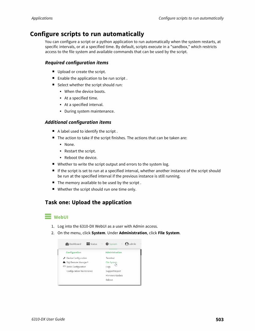
Applications Configure scripts to run automatically
6310-DX User Guide 503
Configure scripts to run automaticallyYou can configure a script or a python application to run automatically when the system restarts, atspecific intervals, or at a specified time. By default, scripts execute in a "sandbox," which restrictsaccess to the file system and available commands that can be used by the script.
Required configuration items
n Upload or create the script.n Enable the application to be run script .n Select whether the script should run:
l When the device boots.l At a specified time.l At a specified interval.l During system maintenance.
Additional configuration items
n A label used to identify the script .n The action to take if the script finishes. The actions that can be taken are:
l None.l Restart the script.l Reboot the device.
n Whether to write the script output and errors to the system log.n If the script is set to run at a specified interval, whether another instance of the script should
be run at the specified interval if the previous instance is still running.n The memory available to be used by the script .n Whether the script should run one time only.
Task one: Upload the application
WebUI
1. Log into the 6310-DX WebUI as a user with Admin access.2. On the menu, click System. Under Administration, click File System.

Applications Configure scripts to run automatically
6310-DX User Guide 504
The File System page appears.
3. Highlight the scripts directory and click to open the directory.4. Click (upload).5. Browse to the location of the script on your local machine. Select the file and click Open to
upload the file.
The uploaded file is uploaded to the /etc/config/scripts directory.
Command line
1. Log into the 6310-DX command line as a user with Admin access.Depending on your device configuration, you may be presented with an Access selectionmenu. Type admin to access the Admin CLI.
2. At the command line, use the scp command to upload the Python application script to the6310-DX device:
> scp host hostname-or-ip user username remote remote-path local local-path to local
where:n hostname-or-ip is the hostname or ip address of the remote host.n username is the name of the user on the remote host.n remote-path is the path and filename of the file on the remote host that will be copied
to the 6310-DX device.n local-path is the location on the 6310-DX device where the copied file will be placed.
For example:To upload a script from a remote host with an IP address of 192.168.4.1 to the/etc/config/scripts directory on the 6310-DX device, issue the following command:
> scp host 192.168.4.1 user admin remote /home/admin/bin/test.py local/etc/config/scripts/ to [email protected]'s password: adminpwdtest.py 100% 36MB 11.1MB/s 00:03>
3. Type exit to exit the Admin CLI.Depending on your device configuration, you may be presented with an Access selectionmenu. Type quit to disconnect from the device.
Note You can also create scripts by using the vi command when logged in with shell access.
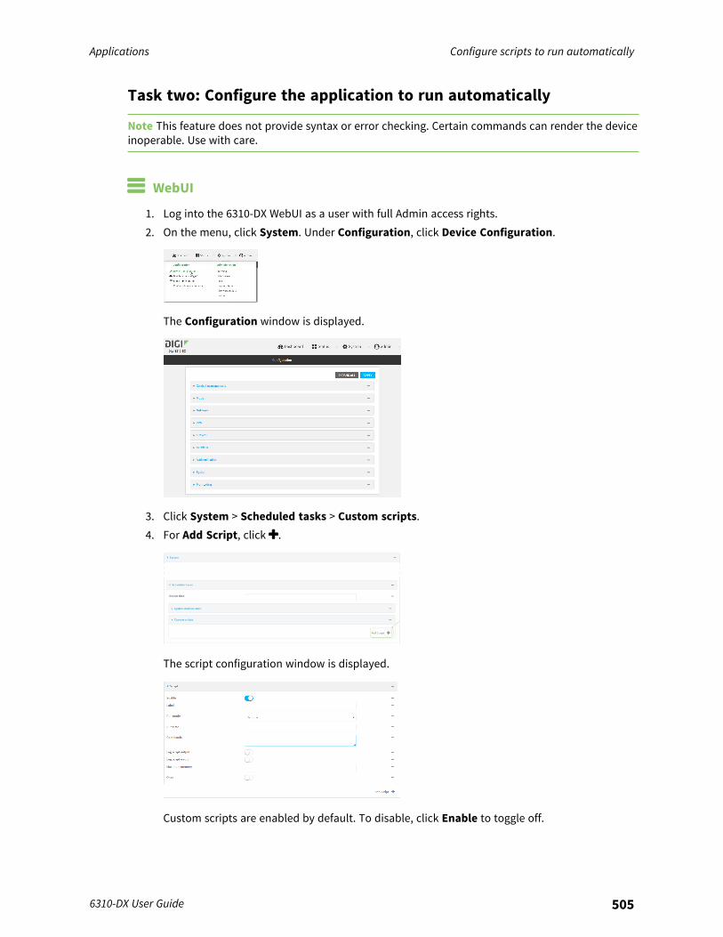
Applications Configure scripts to run automatically
6310-DX User Guide 505
Task two: Configure the application to run automatically
Note This feature does not provide syntax or error checking. Certain commands can render the deviceinoperable. Use with care.
WebUI
1. Log into the 6310-DX WebUI as a user with full Admin access rights.2. On the menu, click System. Under Configuration, click Device Configuration.
The Configuration window is displayed.
3. Click System > Scheduled tasks > Custom scripts.4. For Add Script, click .
The script configuration window is displayed.
Custom scripts are enabled by default. To disable, click Enable to toggle off.
Applications Configure scripts to run automatically
6310-DX User Guide 506
5. (Optional) For Label, provide a label for the script.6. For Run mode, select the mode that will be used to run the script. Available options are:
n On boot: The script will run once each time the device boots.l If On boot is selected, select the action that will be taken when the script completes
in Exit action. Available options are:o None: Action taken when the script exits.o Restart script: Runs the script repeatedly.o Reboot: The device will reboot when the script completes.
n Interval: The script will start running at the specified interval, within 30 seconds afterthe configuration change is saved.l If Interval is selected, in Interval, type the interval.
Allowed values are any number of weeks, days, hours, minutes, or seconds, andtake the format number{w|d|h|m|s}.For example, to set Interval to ten minutes, enter 10m or 600s.
l Click to enable Run single to run only a single instance of the script at a time.If Run single is not enabled, a new instance of the script will be started at everyinterval, regardless of whether the script is still running from a previous interval.
n Set time: Runs the script at a specified time of the day.l If Set Time is selected, specify the time that the script should run in Run time,
using the format HH:MM.n During system maintenance: The script will run during the system maintenance time
window.7. For Commands, enter the commands that will execute the script.
If the script begins with #!, then the script will be invoked in the location specified by the pathfor the script command. Otherwise, the default shell will be used (equivalent to #!/bin/sh).
8. Script logging options:a. Click to enable Log script output to log the script's output to the system log.b. Click to enable Log script errors to log script errors to the system log.If neither option is selected, only the script's exit code is written to the system log.
9. For Maximum memory, enter the maximum amount of memory available to be used by thescript and its subprocesses, using the format number{b|bytes|KB|k|MB|MB|M|GB|G|TB|T}.
10. Sandbox is enabled by default, which restricts access to the file system and availablecommands that can be used by the script. This option protects the script from accidentallydestroying the system it is running on.
11. Click to enable Once to configure the script to run only once at the specified time.If Once is enabled, rebooting the device will cause the script to not run again. The only way tore-run the script is to:
n Remove the script from the device and add it again.n Make a change to the script.n Uncheck Once.
12. Click Apply to save the configuration and apply the change.

Applications Configure scripts to run automatically
6310-DX User Guide 507
Command line
1. Log into the 6310-DX command line as a user with full Admin access rights.Depending on your device configuration, you may be presented with an Access selectionmenu. Type admin to access the Admin CLI.
2. At the command line, type config to enter configuration mode:
> config(config)>
3. Add a script:
(config)> add system schedule script end(config system schedule script 0)>
Scheduled scripts are enabled by default. To disable:
(config system schedule script 0)> enable false(config system schedule script 0)>
4. (Optional) Provide a label for the script.
(config system schedule script 0)> label value(config system schedule script 0)>
where value is any string. if spaces are used, enclose value within double quotes.5. Set the mode that will be used to run the script:
(config system schedule script 0)> when mode(config system schedule script 0)>
where mode is one of the following:n boot: The script will run once each time the device boots.
l If boot is selected, set the action that will be taken when the script completes:
(config system schedule script 0)> exit_action action(config system schedule script 0)>
where action is one of the following:o none: Action taken when the script exits.o restart: Runs the script repeatedly.o reboot: The device will reboot when the script completes.
n interval: The script will start running at the specified interval, within 30 seconds afterthe configuration change is saved. If interval is selected:
Applications Configure scripts to run automatically
6310-DX User Guide 508
l Set the interval:
(config system schedule script 0)> on_interval value(config system schedule script 0)>
where value is any number of weeks, days, hours, minutes, or seconds, and takesthe format number{w|d|h|m|s}.For example, to set on_interval to ten minutes, enter either 10m or 600s:
(config system schedule script 0)> on_interval 600s(config system schedule script 0)>
l (Optional) Configure the script to run only a single instance at a time:
(config system schedule script 0)> once true(config system schedule script 0)>
If once is set to false, a new instance of the script will be started at every interval,regardless of whether the script is still running from a previous interval.
n set_time: Runs the script at a specified time of the day.l If set_time is set, set the time that the script should run, using the format HH:MM:
(config system schedule script 0)> run_time HH:MM(config system schedule script 0)>
n maintenance_time: The script will run during the system maintenance time window.6. Set the commands that will execute the script:
(config system schedule script 0)> commands filename(config system schedule script 0)>
where filename is the path and filename of the script, and any related command lineinformation.If the script begins with #!, then the script will be invoked in the location specified by the pathfor the script command. Otherwise, the default shell will be used (equivalent to #!/bin/sh).
7. Script logging options:n To log the script's output to the system log:
(config system schedule script 0)> syslog_stdout true(config system schedule script 0)>
n To log script errors to the system log:
(config system schedule script 0)> syslog_stderr true(config system schedule script 0)>
If syslog_stdout and syslog_stderr are not enabled, only the script's exit code is written to thesystem log.
Applications Configure scripts to run manually
6310-DX User Guide 509
8. Set the maximum amount of memory available to be used by the script and its subprocesses:
(config system schedule script 0)> max_memory value(config system schedule script 0)>
where value uses the syntax number{b|bytes|KB|k|MB|MB|M|GB|G|TB|T}.9. To run the script only once at the specified time:
(config system schedule script 0)> once true(config system schedule script 0)>
If once is enabled, rebooting the device will cause the script to run again. The only way to re-run the script is to:
n Remove the script from the device and add it again.n Make a change to the script.n Disable once.
10. Sandbox is enabled by default. This option protects the script from accidentally destroying thesystem it is running on.
(config system schedule script 0)> sandbox true(config system schedule script 0)>
11. Save the configuration and apply the change:
(config)> saveConfiguration saved.>
12. Type exit to exit the Admin CLI.Depending on your device configuration, you may be presented with an Access selectionmenu. Type quit to disconnect from the device.
Configure scripts to run manuallyYou can configure an scripts to be manually run.
Required configuration items
n Upload or create the script.n Enable the script.n Set the script to run manually.
Additional configuration items
n A label used to identify the script.n The arguments for the script.n Whether to write the script output and errors to the system log.n The memory available to be used by the script.n Whether the script should run one time only.
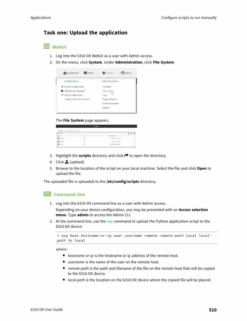
Applications Configure scripts to run manually
6310-DX User Guide 510
Task one: Upload the application
WebUI
1. Log into the 6310-DX WebUI as a user with Admin access.2. On the menu, click System. Under Administration, click File System.
The File System page appears.
3. Highlight the scripts directory and click to open the directory.4. Click (upload).5. Browse to the location of the script on your local machine. Select the file and click Open to
upload the file.
The uploaded file is uploaded to the /etc/config/scripts directory.
Command line
1. Log into the 6310-DX command line as a user with Admin access.Depending on your device configuration, you may be presented with an Access selectionmenu. Type admin to access the Admin CLI.
2. At the command line, use the scp command to upload the Python application script to the6310-DX device:
> scp host hostname-or-ip user username remote remote-path local local-path to local
where:n hostname-or-ip is the hostname or ip address of the remote host.n username is the name of the user on the remote host.n remote-path is the path and filename of the file on the remote host that will be copied
to the 6310-DX device.n local-path is the location on the 6310-DX device where the copied file will be placed.
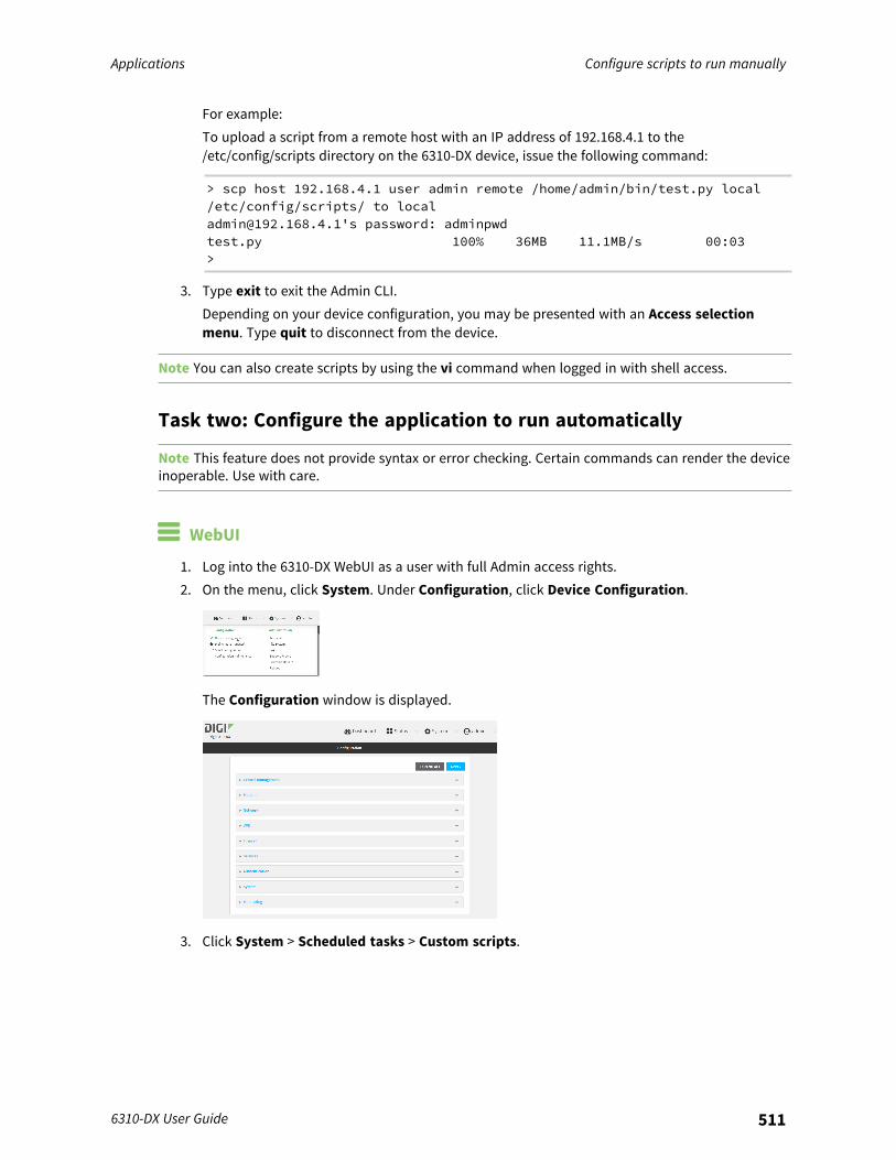
Applications Configure scripts to run manually
6310-DX User Guide 511
For example:To upload a script from a remote host with an IP address of 192.168.4.1 to the/etc/config/scripts directory on the 6310-DX device, issue the following command:
> scp host 192.168.4.1 user admin remote /home/admin/bin/test.py local/etc/config/scripts/ to [email protected]'s password: adminpwdtest.py 100% 36MB 11.1MB/s 00:03>
3. Type exit to exit the Admin CLI.Depending on your device configuration, you may be presented with an Access selectionmenu. Type quit to disconnect from the device.
Note You can also create scripts by using the vi command when logged in with shell access.
Task two: Configure the application to run automatically
Note This feature does not provide syntax or error checking. Certain commands can render the deviceinoperable. Use with care.
WebUI
1. Log into the 6310-DX WebUI as a user with full Admin access rights.2. On the menu, click System. Under Configuration, click Device Configuration.
The Configuration window is displayed.
3. Click System > Scheduled tasks > Custom scripts.
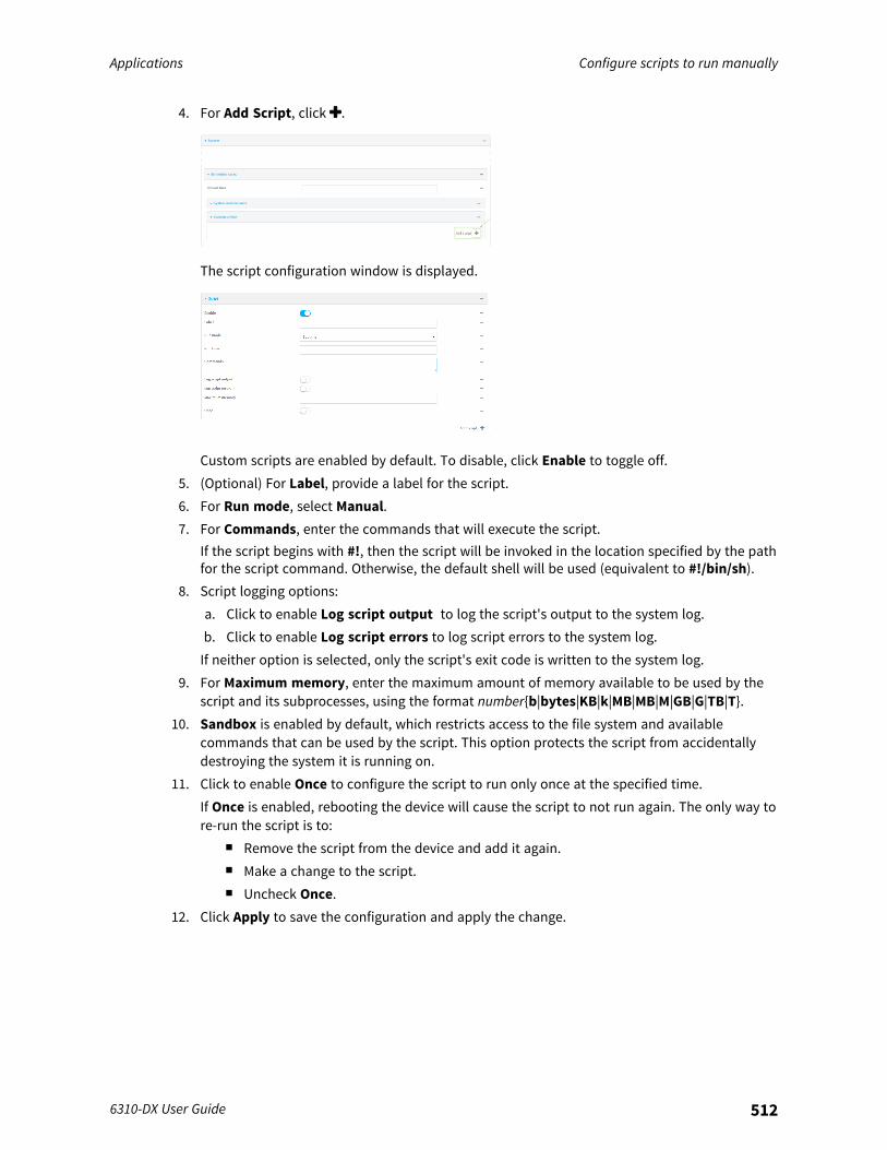
Applications Configure scripts to run manually
6310-DX User Guide 512
4. For Add Script, click .
The script configuration window is displayed.
Custom scripts are enabled by default. To disable, click Enable to toggle off.5. (Optional) For Label, provide a label for the script.6. For Run mode, select Manual.7. For Commands, enter the commands that will execute the script.
If the script begins with #!, then the script will be invoked in the location specified by the pathfor the script command. Otherwise, the default shell will be used (equivalent to #!/bin/sh).
8. Script logging options:a. Click to enable Log script output to log the script's output to the system log.b. Click to enable Log script errors to log script errors to the system log.If neither option is selected, only the script's exit code is written to the system log.
9. For Maximum memory, enter the maximum amount of memory available to be used by thescript and its subprocesses, using the format number{b|bytes|KB|k|MB|MB|M|GB|G|TB|T}.
10. Sandbox is enabled by default, which restricts access to the file system and availablecommands that can be used by the script. This option protects the script from accidentallydestroying the system it is running on.
11. Click to enable Once to configure the script to run only once at the specified time.If Once is enabled, rebooting the device will cause the script to not run again. The only way tore-run the script is to:
n Remove the script from the device and add it again.n Make a change to the script.n Uncheck Once.
12. Click Apply to save the configuration and apply the change.
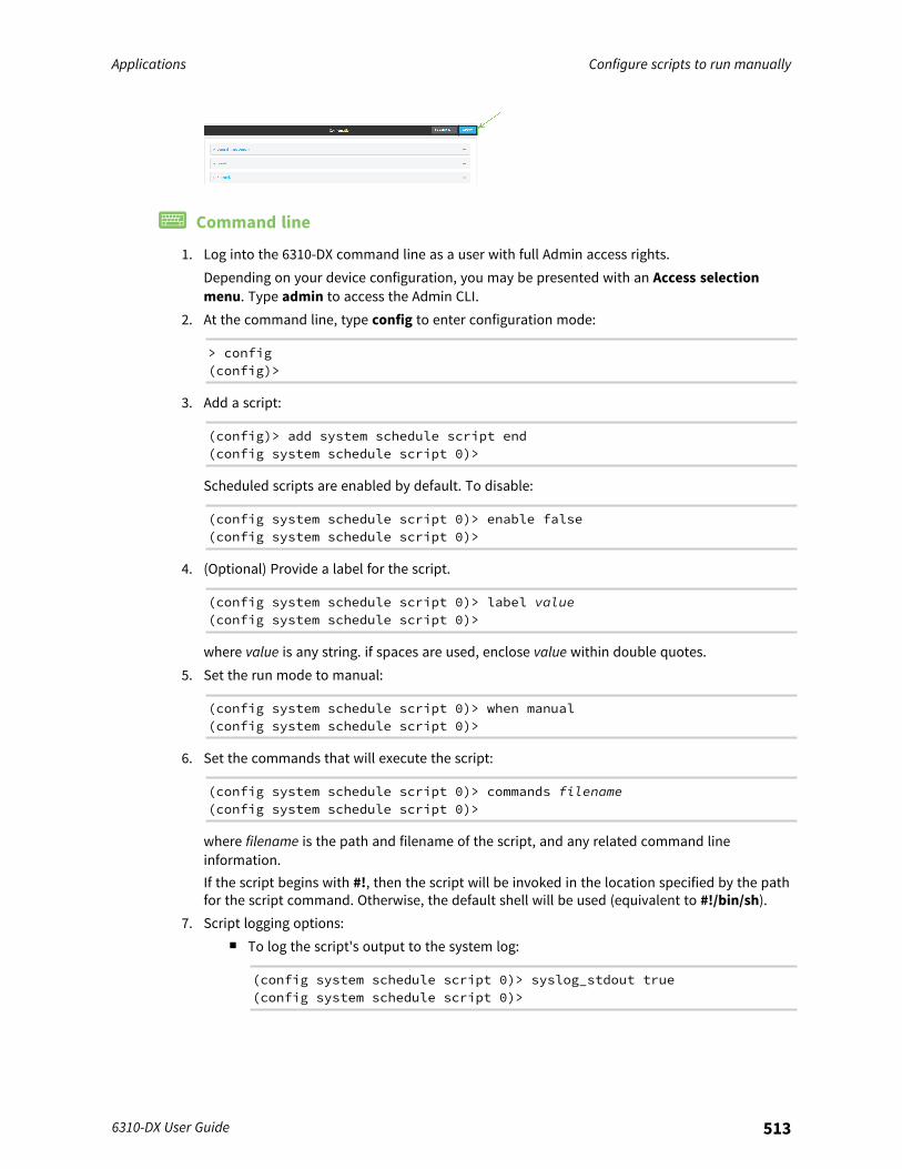
Applications Configure scripts to run manually
6310-DX User Guide 513
Command line
1. Log into the 6310-DX command line as a user with full Admin access rights.Depending on your device configuration, you may be presented with an Access selectionmenu. Type admin to access the Admin CLI.
2. At the command line, type config to enter configuration mode:
> config(config)>
3. Add a script:
(config)> add system schedule script end(config system schedule script 0)>
Scheduled scripts are enabled by default. To disable:
(config system schedule script 0)> enable false(config system schedule script 0)>
4. (Optional) Provide a label for the script.
(config system schedule script 0)> label value(config system schedule script 0)>
where value is any string. if spaces are used, enclose value within double quotes.5. Set the run mode to manual:
(config system schedule script 0)> when manual(config system schedule script 0)>
6. Set the commands that will execute the script:
(config system schedule script 0)> commands filename(config system schedule script 0)>
where filename is the path and filename of the script, and any related command lineinformation.If the script begins with #!, then the script will be invoked in the location specified by the pathfor the script command. Otherwise, the default shell will be used (equivalent to #!/bin/sh).
7. Script logging options:n To log the script's output to the system log:
(config system schedule script 0)> syslog_stdout true(config system schedule script 0)>
Applications Start a manual script
6310-DX User Guide 514
n To log script errors to the system log:
(config system schedule script 0)> syslog_stderr true(config system schedule script 0)>
If syslog_stdout and syslog_stderr are not enabled, only the script's exit code is written to thesystem log.
8. Set the maximum amount of memory available to be used by the script and its subprocesses:
(config system schedule script 0)> max_memory value(config system schedule script 0)>
where value uses the syntax number{b|bytes|KB|k|MB|MB|M|GB|G|TB|T}.9. To run the script only once at the specified time:
(config system schedule script 0)> once true(config system schedule script 0)>
If once is enabled, rebooting the device will cause the script to run again. The only way to re-run the script is to:
n Remove the script from the device and add it again.n Make a change to the script.n Disable once.
10. Sandbox is enabled by default. This option protects the script from accidentally destroying thesystem it is running on.
(config system schedule script 0)> sandbox true(config system schedule script 0)>
11. Save the configuration and apply the change:
(config)> saveConfiguration saved.>
12. Type exit to exit the Admin CLI.Depending on your device configuration, you may be presented with an Access selectionmenu. Type quit to disconnect from the device.
Start a manual scriptYou can start a script that is enabled and configured to have a run mode of Manual. See
WebUI
1. Log into the 6310-DX WebUI as a user with Admin access.2. At the Status page, click Scripts.
The Scripts page displays:

Applications Stop a script that is currently running
6310-DX User Guide 515
3. For scripts that are enabled and configured to have a run mode of Manual, click Start Scriptto start the script.
Command line
1. Log into the 6310-DX command line as a user with Admin access.Depending on your device configuration, you may be presented with an Access selectionmenu. Type admin to access the Admin CLI.
2. Determine the name of scripts that are currently running:
> show scripts
Index Label Enabled Status Run time----- ----------- ------- ------ --------0 script1 true active1 script2 true idle 01:00>
3. Start the script:
)> system script start script1>
4. Save the configuration and apply the change:
(config)> saveConfiguration saved.>
5. Type exit to exit the Admin CLI.Depending on your device configuration, you may be presented with an Access selectionmenu. Type quit to disconnect from the device.
Stop a script that is currently runningYou can stop a script that is currently running.
WebUI

Applications Show script information
6310-DX User Guide 516
1. Log into the 6310-DX WebUI as a user with Admin access.2. At the Status page, click Scripts.
The Scripts page displays:
3. For scripts that are currently running, click Stop Script to stop the script.
Command line
1. Log into the 6310-DX command line as a user with Admin access.Depending on your device configuration, you may be presented with an Access selectionmenu. Type admin to access the Admin CLI.
2. Determine the name of scripts that are currently running:
> show scripts
Index Label Enabled Status Run time----- ----------- ------- ------ --------0 script1 true active1 script2 true idle 01:00>
Scripts that are currently running have the status of active.3. Stop the appropriate script:
)> system script stop script1>
4. Save the configuration and apply the change:
(config)> saveConfiguration saved.>
5. Type exit to exit the Admin CLI.Depending on your device configuration, you may be presented with an Access selectionmenu. Type quit to disconnect from the device.
Show script informationYou can view status and statistics about location information from either the WebUI or the commandline.
Applications Run a Python application at the shell prompt
6310-DX User Guide 517
WebUI
1. Log into the 6310-DX WebUI as a user with Admin access.2. At the Status page, click Scripts.
The Scripts page displays:
Command line
1. Log into the 6310-DX command line as a user with Admin access.Depending on your device configuration, you may be presented with an Access selectionmenu. Type admin to access the Admin CLI.
2. Use the show scripts command at the system prompt:
> show scripts
Index Label Enabled Status Run time----- ----------- ------- ------ --------0 script1 true active1 script2 true idle 01:00>
3. Type exit to exit the Admin CLI.Depending on your device configuration, you may be presented with an Access selectionmenu. Type quit to disconnect from the device.
Run a Python application at the shell promptPython applications can be run from a file at the shell prompt. The Python application will run until itcompletes, displaying output and prompting for additional user input if needed. To interrupt theapplication, enter CTRL-C.
Note Python applications cannot be run from the Admin CLI. You must access the device shell in orderto run Python applications from the command line. See Authentication groups for information aboutconfiguring authentication groups that include shell access.
1. Upload the Python application to the 6310-DX device:
WebUI

Applications Run a Python application at the shell prompt
6310-DX User Guide 518
a. Log into the 6310-DX WebUI as a user with Admin access.b. On the menu, click System. Under Administration, click File System.
The File System page appears.
c. Highlight the scripts directory and click to open the directory.d. Click (upload).e. Browse to the location of the script on your local machine. Select the file and click Open
to upload the file.The uploaded file is uploaded to the /etc/config/scripts directory.
Command linea. Log into the 6310-DX command line as a user with Admin access.
Depending on your device configuration, you may be presented with an Access selectionmenu. Type admin to access the Admin CLI.
b. At the command line, use the scp command to upload the Python application script to the6310-DX device:
> scp host hostname-or-ip user username remote remote-path locallocal-path to local
where:n hostname-or-ip is the hostname or ip address of the remote host.n username is the name of the user on the remote host.n remote-path is the path and filename of the file on the remote host that will be
copied to the 6310-DX device.n local-path is the location on the 6310-DX device where the copied file will be
placed.For example:To upload a script from a remote host with an IP address of 192.168.4.1 to the/etc/config/scripts directory on the 6310-DX device, issue the following command:
Applications Start an interactive Python session
6310-DX User Guide 519
> scp host 192.168.4.1 user admin remote /home/admin/bin/test.py local/etc/config/scripts/ to [email protected]'s password: adminpwdtest.py 100% 36MB 11.1MB/s 00:03>
c. Type exit to exit the Admin CLI.Depending on your device configuration, you may be presented with an Access selectionmenu. Type quit to disconnect from the device.
Note You can also create scripts by using the vi command when logged in with shell access.
2. Log into the 6310-DX command line as a user with shell access.Depending on your device configuration, you may be presented with an Access selectionmenu. Type shell to access the device shell.
3. Use the python command to run the Python application. In the following example, the Pythonapplication, test.py, takes 3 parameters: 120, ports and storage:
# python /etc/config/scripts/test.py 120 ports storage
Start an interactive Python sessionUse the python command without specifying any parameters to start an interactive Python session.The Python session operates interactively using REPL (Read Evaluate Print Loop) to allow you to writePython code on the command line.
Note The Python interactive session is not available from the Admin CLI. You must access the deviceshell in order to run Python applications from the command line. See Authentication groups forinformation about configuring authentication groups that include shell access.
1. Log into the 6310-DX command line as a user with shell access.Depending on your device configuration, you may be presented with an Access selectionmenu. Type shell to access the device shell.
2. At the shell prompt, use the python command with no parameters to enter an interactivePython session:
# pythonPython 3.6.13 (default, May 9 2021, 22:49:59)[GCC 8.3.0] on linuxType "help", "copyright", "credits" or "license" for more information.>>>
3. Type Python commands at the Python prompt. For example, to view help for the digidevicemodule, type:
>>> help("digidevice")Help on package digidevice:
NAME

Applications Start an interactive Python session
6310-DX User Guide 520
digidevice - Digi device python extensions
DESCRIPTIONThis module includes various extensions that allow Pythonto interact with additional features offered by the device.
...
4. Use Ctrl-D to exit the Python session. You can also exit the session using exit() or quit().
Applications Digidevice module
6310-DX User Guide 521
Digidevice moduleThe Python digidevice module provides platform-specific extensions that allow you to interact withthe device’s configuration and interfaces. The following submodules are included with the digidevicemodule:This section contains the following topics:
Use digidevice.cli to execute CLI commands 522Use digidevice.datapoint to upload custom datapoints to Digi Remote Manager 523Use digidevice.config for device configuration 526Use Python to respond to Digi Remote Manager SCI requests 528Use digidevice runtime to access the runtime database 537Use Python to upload the device name to Digi Remote Manager 539Use Python to access the device location data 541Use Python to set the maintenance window 545Use Python to send and receive SMS messages 547
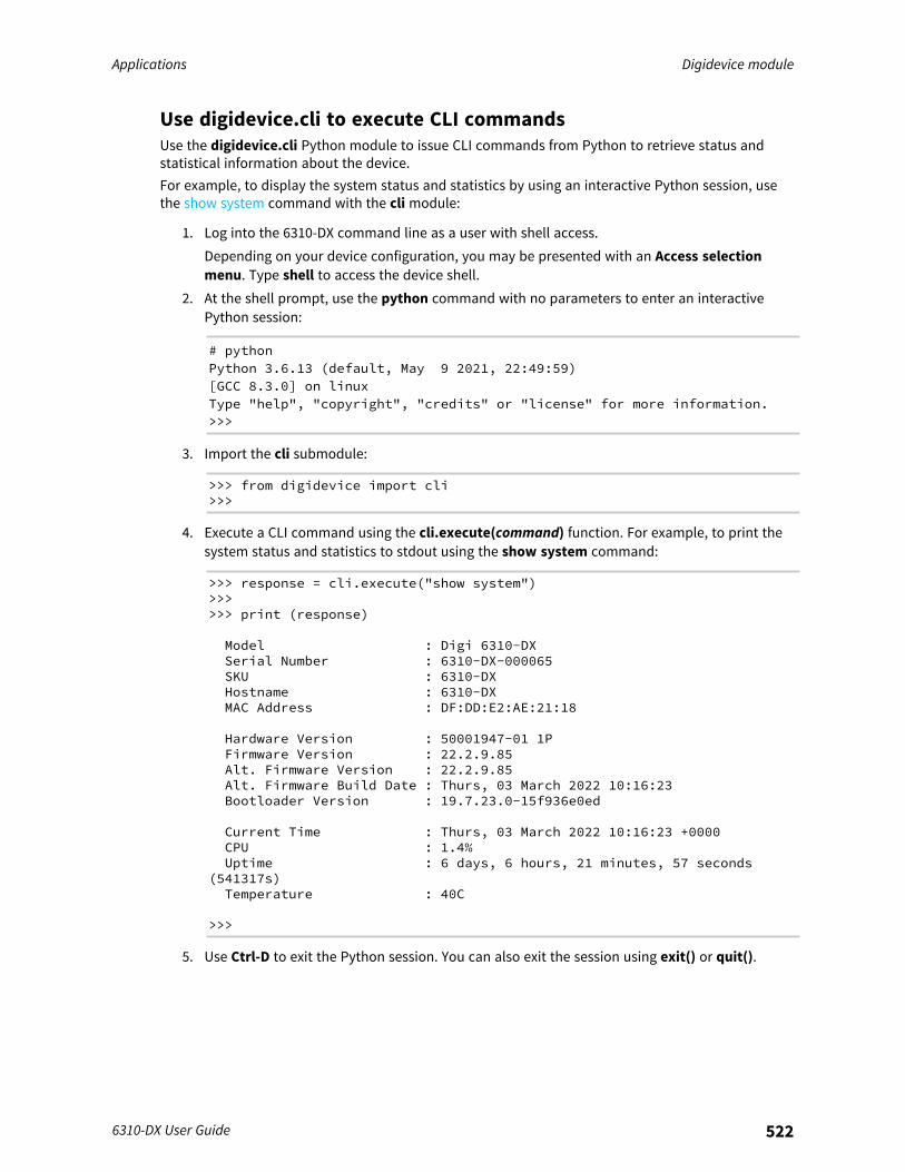
Applications Digidevice module
6310-DX User Guide 522
Use digidevice.cli to execute CLI commandsUse the digidevice.cli Python module to issue CLI commands from Python to retrieve status andstatistical information about the device.For example, to display the system status and statistics by using an interactive Python session, usethe show system command with the cli module:
1. Log into the 6310-DX command line as a user with shell access.Depending on your device configuration, you may be presented with an Access selectionmenu. Type shell to access the device shell.
2. At the shell prompt, use the python command with no parameters to enter an interactivePython session:
# pythonPython 3.6.13 (default, May 9 2021, 22:49:59)[GCC 8.3.0] on linuxType "help", "copyright", "credits" or "license" for more information.>>>
3. Import the cli submodule:
>>> from digidevice import cli>>>
4. Execute a CLI command using the cli.execute(command) function. For example, to print thesystem status and statistics to stdout using the show system command:
>>> response = cli.execute("show system")>>>>>> print (response)
Model : Digi 6310-DXSerial Number : 6310-DX-000065SKU : 6310-DXHostname : 6310-DXMAC Address : DF:DD:E2:AE:21:18
Hardware Version : 50001947-01 1PFirmware Version : 22.2.9.85Alt. Firmware Version : 22.2.9.85Alt. Firmware Build Date : Thurs, 03 March 2022 10:16:23Bootloader Version : 19.7.23.0-15f936e0ed
Current Time : Thurs, 03 March 2022 10:16:23 +0000CPU : 1.4%Uptime : 6 days, 6 hours, 21 minutes, 57 seconds
(541317s)Temperature : 40C
>>>
5. Use Ctrl-D to exit the Python session. You can also exit the session using exit() or quit().
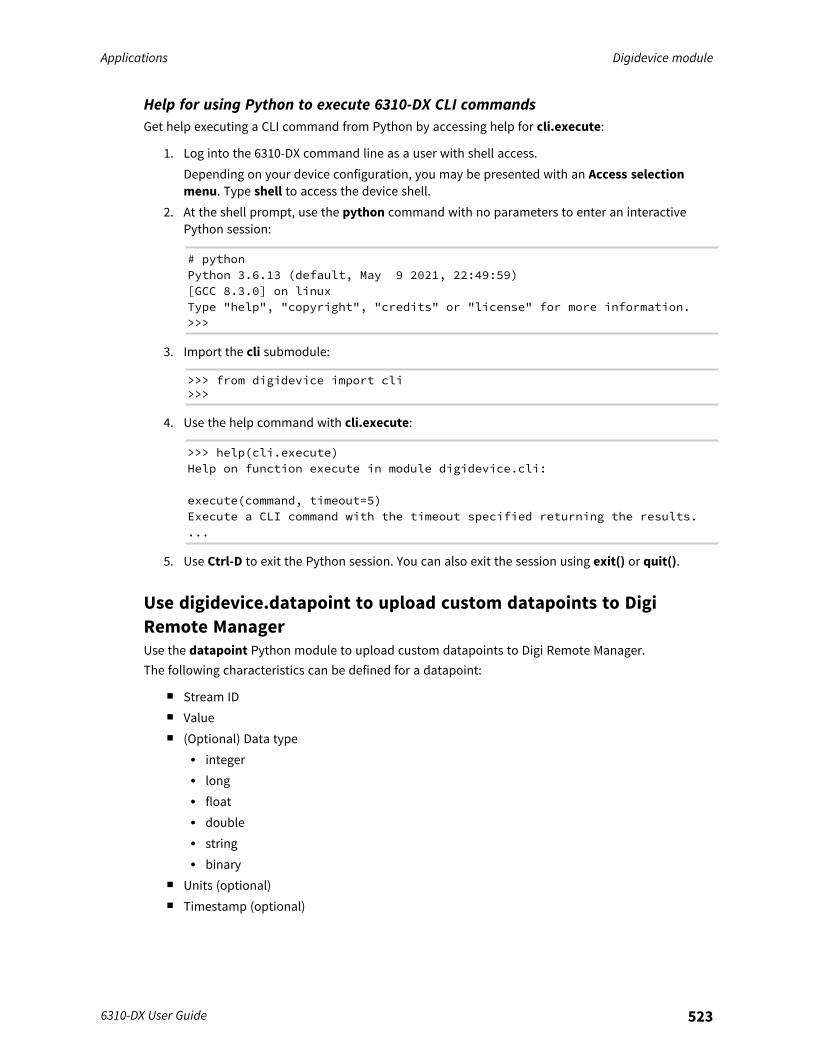
Applications Digidevice module
6310-DX User Guide 523
Help for using Python to execute 6310-DX CLI commandsGet help executing a CLI command from Python by accessing help for cli.execute:
1. Log into the 6310-DX command line as a user with shell access.Depending on your device configuration, you may be presented with an Access selectionmenu. Type shell to access the device shell.
2. At the shell prompt, use the python command with no parameters to enter an interactivePython session:
# pythonPython 3.6.13 (default, May 9 2021, 22:49:59)[GCC 8.3.0] on linuxType "help", "copyright", "credits" or "license" for more information.>>>
3. Import the cli submodule:
>>> from digidevice import cli>>>
4. Use the help command with cli.execute:
>>> help(cli.execute)Help on function execute in module digidevice.cli:
execute(command, timeout=5)Execute a CLI command with the timeout specified returning the results....
5. Use Ctrl-D to exit the Python session. You can also exit the session using exit() or quit().
Use digidevice.datapoint to upload custom datapoints to DigiRemote ManagerUse the datapoint Python module to upload custom datapoints to Digi Remote Manager.The following characteristics can be defined for a datapoint:
n Stream IDn Valuen (Optional) Data type
l integerl longl floatl doublel stringl binary
n Units (optional)n Timestamp (optional)
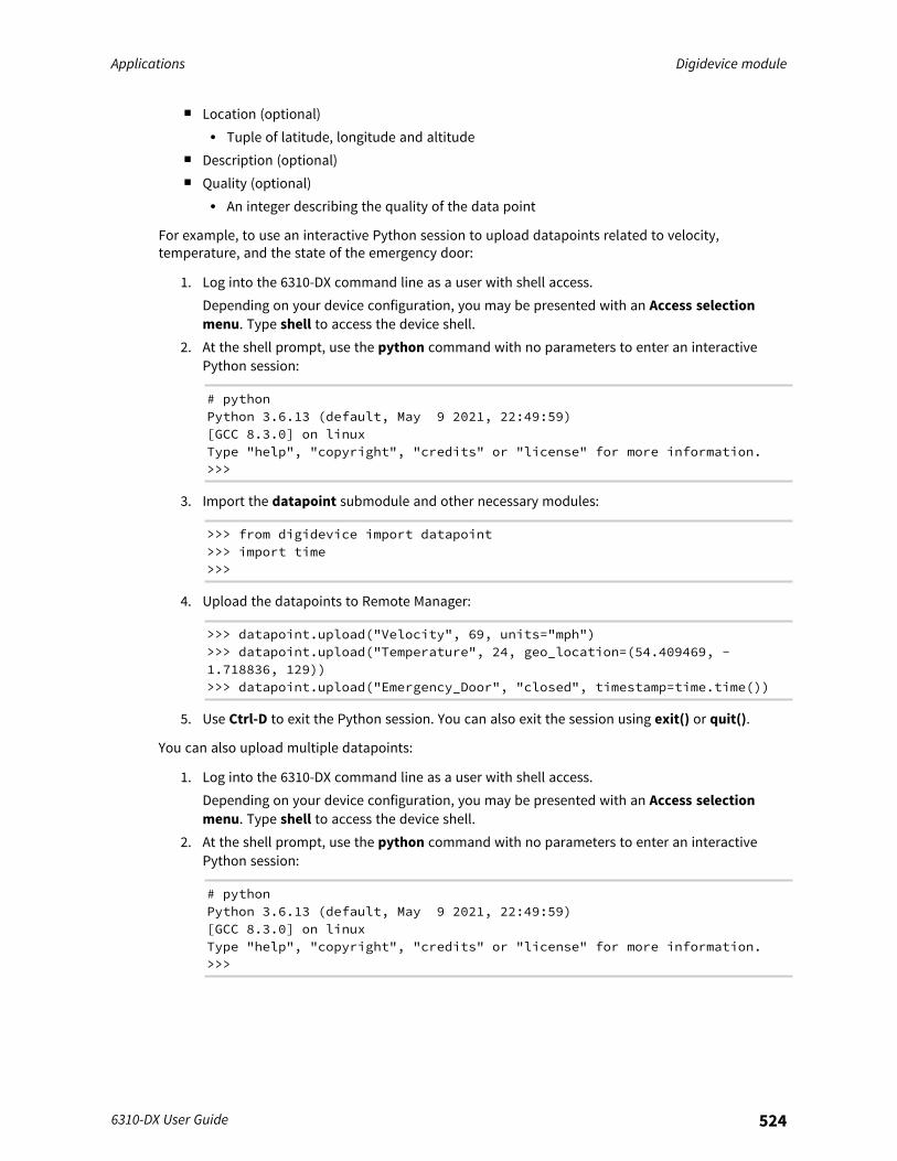
Applications Digidevice module
6310-DX User Guide 524
n Location (optional)l Tuple of latitude, longitude and altitude
n Description (optional)n Quality (optional)
l An integer describing the quality of the data point
For example, to use an interactive Python session to upload datapoints related to velocity,temperature, and the state of the emergency door:
1. Log into the 6310-DX command line as a user with shell access.Depending on your device configuration, you may be presented with an Access selectionmenu. Type shell to access the device shell.
2. At the shell prompt, use the python command with no parameters to enter an interactivePython session:
# pythonPython 3.6.13 (default, May 9 2021, 22:49:59)[GCC 8.3.0] on linuxType "help", "copyright", "credits" or "license" for more information.>>>
3. Import the datapoint submodule and other necessary modules:
>>> from digidevice import datapoint>>> import time>>>
4. Upload the datapoints to Remote Manager:
>>> datapoint.upload("Velocity", 69, units="mph")>>> datapoint.upload("Temperature", 24, geo_location=(54.409469, -1.718836, 129))>>> datapoint.upload("Emergency_Door", "closed", timestamp=time.time())
5. Use Ctrl-D to exit the Python session. You can also exit the session using exit() or quit().
You can also upload multiple datapoints:
1. Log into the 6310-DX command line as a user with shell access.Depending on your device configuration, you may be presented with an Access selectionmenu. Type shell to access the device shell.
2. At the shell prompt, use the python command with no parameters to enter an interactivePython session:
# pythonPython 3.6.13 (default, May 9 2021, 22:49:59)[GCC 8.3.0] on linuxType "help", "copyright", "credits" or "license" for more information.>>>
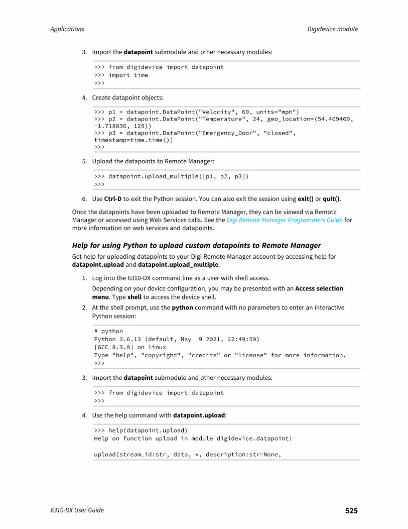
Applications Digidevice module
6310-DX User Guide 525
3. Import the datapoint submodule and other necessary modules:
>>> from digidevice import datapoint>>> import time>>>
4. Create datapoint objects:
>>> p1 = datapoint.DataPoint("Velocity", 69, units="mph")>>> p2 = datapoint.DataPoint("Temperature", 24, geo_location=(54.409469,-1.718836, 129))>>> p3 = datapoint.DataPoint("Emergency_Door", "closed",timestamp=time.time())>>>
5. Upload the datapoints to Remote Manager:
>>> datapoint.upload_multiple([p1, p2, p3])>>>
6. Use Ctrl-D to exit the Python session. You can also exit the session using exit() or quit().
Once the datapoints have been uploaded to Remote Manager, they can be viewed via RemoteManager or accessed using Web Services calls. See the Digi Remote Manager Programmers Guide formore information on web services and datapoints.
Help for using Python to upload custom datapoints to Remote ManagerGet help for uploading datapoints to your Digi Remote Manager account by accessing help fordatapoint.upload and datapoint.upload_multiple:
1. Log into the 6310-DX command line as a user with shell access.Depending on your device configuration, you may be presented with an Access selectionmenu. Type shell to access the device shell.
2. At the shell prompt, use the python command with no parameters to enter an interactivePython session:
# pythonPython 3.6.13 (default, May 9 2021, 22:49:59)[GCC 8.3.0] on linuxType "help", "copyright", "credits" or "license" for more information.>>>
3. Import the datapoint submodule and other necessary modules:
>>> from digidevice import datapoint>>>
4. Use the help command with datapoint.upload:
>>> help(datapoint.upload)Help on function upload in module digidevice.datapoint:
upload(stream_id:str, data, *, description:str=None,
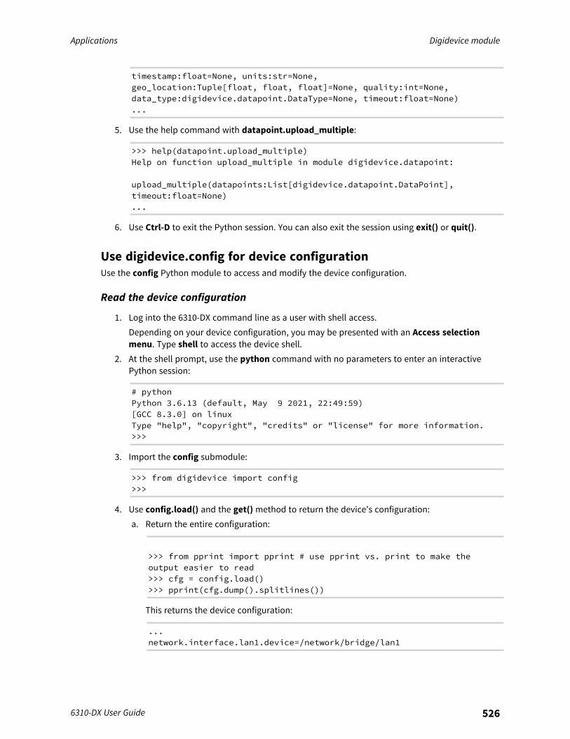
Applications Digidevice module
6310-DX User Guide 526
timestamp:float=None, units:str=None,geo_location:Tuple[float, float, float]=None, quality:int=None,data_type:digidevice.datapoint.DataType=None, timeout:float=None)...
5. Use the help command with datapoint.upload_multiple:
>>> help(datapoint.upload_multiple)Help on function upload_multiple in module digidevice.datapoint:
upload_multiple(datapoints:List[digidevice.datapoint.DataPoint],timeout:float=None)...
6. Use Ctrl-D to exit the Python session. You can also exit the session using exit() or quit().
Use digidevice.config for device configurationUse the config Python module to access and modify the device configuration.
Read the device configuration
1. Log into the 6310-DX command line as a user with shell access.Depending on your device configuration, you may be presented with an Access selectionmenu. Type shell to access the device shell.
2. At the shell prompt, use the python command with no parameters to enter an interactivePython session:
# pythonPython 3.6.13 (default, May 9 2021, 22:49:59)[GCC 8.3.0] on linuxType "help", "copyright", "credits" or "license" for more information.>>>
3. Import the config submodule:
>>> from digidevice import config>>>
4. Use config.load() and the get() method to return the device's configuration:a. Return the entire configuration:
>>> from pprint import pprint # use pprint vs. print to make theoutput easier to read>>> cfg = config.load()>>> pprint(cfg.dump().splitlines())
This returns the device configuration:
...network.interface.lan1.device=/network/bridge/lan1
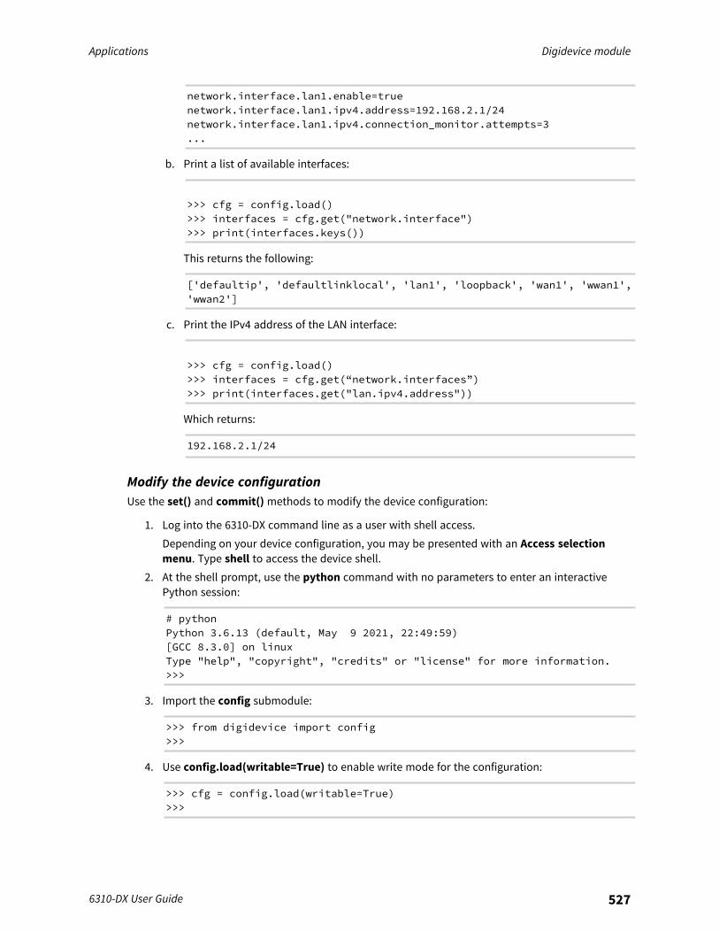
Applications Digidevice module
6310-DX User Guide 527
network.interface.lan1.enable=truenetwork.interface.lan1.ipv4.address=192.168.2.1/24network.interface.lan1.ipv4.connection_monitor.attempts=3...
b. Print a list of available interfaces:
>>> cfg = config.load()>>> interfaces = cfg.get("network.interface")>>> print(interfaces.keys())
This returns the following:
['defaultip', 'defaultlinklocal', 'lan1', 'loopback', 'wan1', 'wwan1','wwan2']
c. Print the IPv4 address of the LAN interface:
>>> cfg = config.load()>>> interfaces = cfg.get(“network.interfaces”)>>> print(interfaces.get("lan.ipv4.address"))
Which returns:
192.168.2.1/24
Modify the device configurationUse the set() and commit() methods to modify the device configuration:
1. Log into the 6310-DX command line as a user with shell access.Depending on your device configuration, you may be presented with an Access selectionmenu. Type shell to access the device shell.
2. At the shell prompt, use the python command with no parameters to enter an interactivePython session:
# pythonPython 3.6.13 (default, May 9 2021, 22:49:59)[GCC 8.3.0] on linuxType "help", "copyright", "credits" or "license" for more information.>>>
3. Import the config submodule:
>>> from digidevice import config>>>
4. Use config.load(writable=True) to enable write mode for the configuration:
>>> cfg = config.load(writable=True)>>>
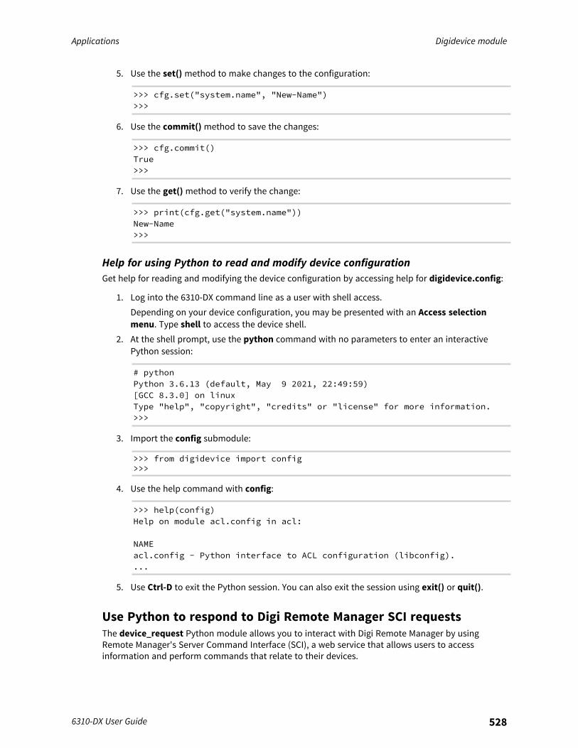
Applications Digidevice module
6310-DX User Guide 528
5. Use the set() method to make changes to the configuration:
>>> cfg.set("system.name", "New-Name")>>>
6. Use the commit() method to save the changes:
>>> cfg.commit()True>>>
7. Use the get() method to verify the change:
>>> print(cfg.get("system.name"))New-Name>>>
Help for using Python to read and modify device configurationGet help for reading and modifying the device configuration by accessing help for digidevice.config:
1. Log into the 6310-DX command line as a user with shell access.Depending on your device configuration, you may be presented with an Access selectionmenu. Type shell to access the device shell.
2. At the shell prompt, use the python command with no parameters to enter an interactivePython session:
# pythonPython 3.6.13 (default, May 9 2021, 22:49:59)[GCC 8.3.0] on linuxType "help", "copyright", "credits" or "license" for more information.>>>
3. Import the config submodule:
>>> from digidevice import config>>>
4. Use the help command with config:
>>> help(config)Help on module acl.config in acl:
NAMEacl.config - Python interface to ACL configuration (libconfig)....
5. Use Ctrl-D to exit the Python session. You can also exit the session using exit() or quit().
Use Python to respond to Digi Remote Manager SCI requestsThe device_request Python module allows you to interact with Digi Remote Manager by usingRemote Manager's Server Command Interface (SCI), a web service that allows users to accessinformation and perform commands that relate to their devices.

Applications Digidevice module
6310-DX User Guide 529
Use Remote Manager's SCI interface to create SCI requests that are sent to your 6310-DX device, anduse the device_request module to send responses to those requests to Remote Manager.See the Digi Remote Manager Programmers Guide for more information on SCI.
Task one: Use the device_request module on your 6310-DX device to create aresponse
1. Log into the 6310-DX command line as a user with shell access.Depending on your device configuration, you may be presented with an Access selectionmenu. Type shell to access the device shell.
2. At the shell prompt, use the python command with no parameters to enter an interactivePython session:
# pythonPython 3.6.13 (default, May 9 2021, 22:49:59)[GCC 8.3.0] on linuxType "help", "copyright", "credits" or "license" for more information.>>>
3. Import the device_request module:
>>> from digidevice import device_request>>>
4. Create a function to handle the request from Remote Manager:
>>> def handler(target, request):print ("received request %s for target %s" % (request, target))return "OK"
>>>
5. Register a callbackup function that will be called when the device receives a SCI request fromRemote Manager:
>>> device_request.register("myTarget", handler)>>>
Note Leave the interactive Python session active while completing task two, below. Once you havecompleted task two, exit the interactive session by using Ctrl-D. You can also exit the session usingexit() or quit().
Task two: Create and send an SCI request from Digi Remote ManagerThe second step in using the device_request module is to create an SCI request that Remote Managerwill forward to the device. For example, you can create in SCI request a the Remote Manager APIexplorer:
1. In Remote Manager, click Documentation > API Explorer.2. Select the device to use as the SCI target:
a. Click SCI Targets.b. Click Add Targets.

Applications Digidevice module
6310-DX User Guide 530
c. Enter or select the device ID of the device.d. Click Add.e. Click OK.
3. Click Examples > SCI > Data Service > Send Request.Code similar to the following will be displayed in the HTTP message body text box:
<sci_request version="1.0"><data_service><targets>
<device id="00000000-00000000-0000FFFF-A83CF6A3"/></targets>
<requests><device_request target_name="myTarget">
my payload string</device_request>
</requests></data_service>
</sci_request>
Note The value of the target_name parameter in the device_request element mustcorrespond to the target parameter of the device_request.register function in the Pythonscript. In this example, the two are the same.
4. Click Send.Once that the request has been sent to the device, the handler on the device is executed.
n On the device, you will receive the following output:
>>> received requestmy payload stringfor target myTarget
>>>
n In Remote Manager, you will receive a response similar to the following:
<sci_reply version="1.0"><data_service>
<device id="00000000-00000000-0000FFFF-A83CF6A3"/><requests><device_request target_name="myTarget"
status="0">OK</device_request></requests>
</device></data_service>
</sci_request>
Example: Use digidevice.cli with digidevice.device_requestIn this example, we will use the digidevice.cli module in conjunction with the digidevice.device_request module to return information about multiple devices to Remote Manager.
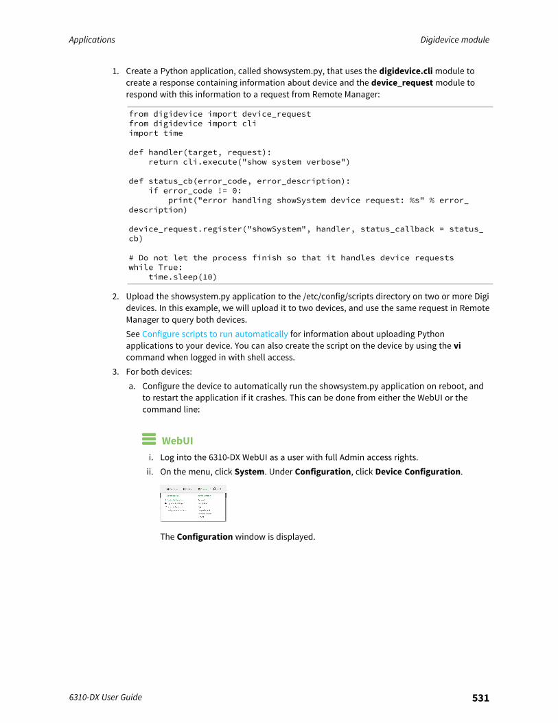
Applications Digidevice module
6310-DX User Guide 531
1. Create a Python application, called showsystem.py, that uses the digidevice.cli module tocreate a response containing information about device and the device_request module torespond with this information to a request from Remote Manager:
from digidevice import device_requestfrom digidevice import cliimport time
def handler(target, request):return cli.execute("show system verbose")
def status_cb(error_code, error_description):if error_code != 0:
print("error handling showSystem device request: %s" % error_description)
device_request.register("showSystem", handler, status_callback = status_cb)
# Do not let the process finish so that it handles device requestswhile True:
time.sleep(10)
2. Upload the showsystem.py application to the /etc/config/scripts directory on two or more Digidevices. In this example, we will upload it to two devices, and use the same request in RemoteManager to query both devices.See Configure scripts to run automatically for information about uploading Pythonapplications to your device. You can also create the script on the device by using the vicommand when logged in with shell access.
3. For both devices:a. Configure the device to automatically run the showsystem.py application on reboot, and
to restart the application if it crashes. This can be done from either the WebUI or thecommand line:
WebUIi. Log into the 6310-DX WebUI as a user with full Admin access rights.ii. On the menu, click System. Under Configuration, click Device Configuration.
The Configuration window is displayed.
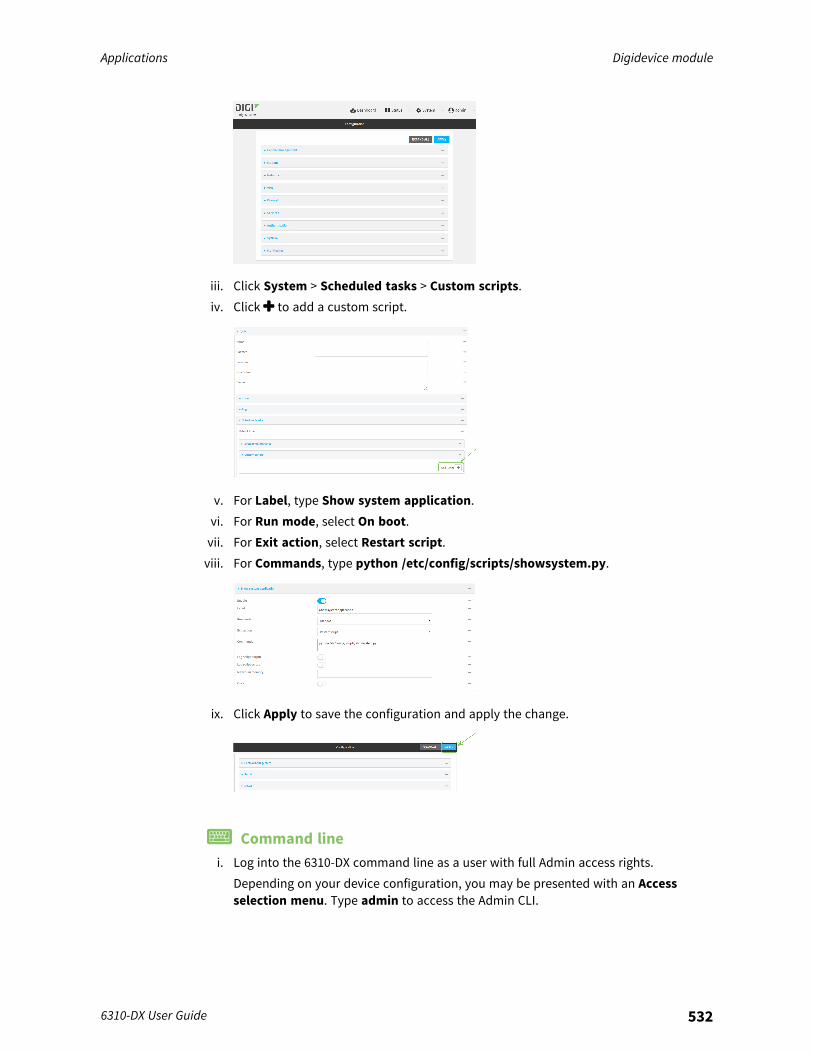
Applications Digidevice module
6310-DX User Guide 532
iii. Click System > Scheduled tasks > Custom scripts.iv. Click to add a custom script.
v. For Label, type Show system application.vi. For Run mode, select On boot.vii. For Exit action, select Restart script.viii. For Commands, type python /etc/config/scripts/showsystem.py.
ix. Click Apply to save the configuration and apply the change.
Command linei. Log into the 6310-DX command line as a user with full Admin access rights.
Depending on your device configuration, you may be presented with an Accessselection menu. Type admin to access the Admin CLI.
Applications Digidevice module
6310-DX User Guide 533
ii. At the command line, type config to enter configuration mode:
> config(config)>
iii. Add an application entry:
(config)> add system schedule script end(config system schedule script 0)>
Scheduled scripts are enabled by default. To disable:
(config system schedule script 0)> enable false(config system schedule script 0)>
iv. Provide a label for the script:
(config system schedule script 0)> label "Show system application"
v. Configure the application to run automatically when the device reboots:
(config system schedule script 0)> when boot(config system schedule script 0)>
vi. Configure the application to restart if it crashes:
(config system schedule script 0)> exit_action restart(config system schedule script 0)>
vii. Set the command that will execute the application:
(config system schedule script 0)> commands "python/etc/config/scripts/showsystem.py"(config system schedule script 0)>
viii. Save the configuration and apply the change:
(config)> saveConfiguration saved.>
b. Run the showsystem.py application. You can run the application by either rebooting thedevice, or by running it from the shell prompt.
n To reboot the device:i. From the WebUI:
i. From the main menu, click System.ii. Click Reboot.
i. From the command line, at the Admin CLI prompt, type:
> reboot
Applications Digidevice module
6310-DX User Guide 534
n To run the application from the shell prompt:i. Log into the 6310-DX command line as a user with shell access.
Depending on your device configuration, you may be presented with an Accessselection menu. Type shell to access the device shell.
ii. Type the following at the shell prompt:
# python /etc/config/scripts/showsystem.py &#
iii. Exit the shell:
# exit
4. In Remote Manager, click Documentation > API Explorer.5. Select the devices to use as the SCI targest:
a. Click SCI Targets.b. Click Add Targets.c. Enter or select the device ID of one of the devices.d. Click Add.e. Enter or select the device ID of the second device and click Add.f. Click OK.
6. Click Examples > SCI > Data Service > Send Request.Code similar to the following will be displayed in the HTTP message body text box:
<sci_request version="1.0"><data_service><targets>
<device id="00000000-00000000-0000FFFF-A83CF6A3"/><device id="00000000-00000000-0000FFFF-485740BC"/>
</targets><requests>
<device_request target_name="myTarget">my payload string
</device_request></requests>
</data_service></sci_request>
7. For the device_request element, replace the value of target_name with showSystem. Thismatches the target parameter of the device_request.register function in the showsystem.pyapplication.
<device_request target_name="showSystem">
8. Click Send.You should receive a response similar to the following:
<sci_reply version="1.0"><data_service>
Applications Digidevice module
6310-DX User Guide 535
<device id="00000000-00000000-0000FFFF-A83CF6A3"/><requests>
<device_request target_name="showSystem" status="0">Model: Digi 6310-DXSerial Number : 6310-DX-000068Hostname : 6310-DXMAC : 00:40:D0:13:35:36
Hardware Version : 50001959-01 AFirmware Version : 22.2.9.85Bootloader Version : 1Firmware Build Date : Thurs, 03 March 2022 10:16:23Schema Version : 461
Timezone : UTCCurrent Time : Thurs, 03 March 2022 10:16:23CPU : 1.1Uptime : 1 day, 21 hours, 49 minutes, 47
seconds (164987s)Temperature : 39C
Contact : Jane Smith
Disk----Load Average : 0.10, 0.05, 0.00RAM Usage : 85.176MB/250.484MB(34%)Disk /etc/config Usage : 0.068MB/13.416MB(1%)Disk /opt Usage : 47.724MB/5309.752MB(1%)Disk /overlay Usage : MB/MB(%)Disk /tmp Usage : 0.004MB/40.96MB(0%)Disk /var Usage : 0.820MB/32.768MB(3%)</device_
request></requests>
</device><device id="00000000-00000000-0000FFFF-485740BC"/>
<requests><device_request target_name="showSystem" status="0">Model
: Digi 6310-DXSerial Number : 6310-DX-000023Hostname : 6310-DXMAC : 00:40:D0:26:79:1C
Hardware Version : 50001959-01 AFirmware Version : 22.2.9.85Bootloader Version : 1Firmware Build Date : Thurs, 03 March 2022 10:16:23Schema Version : 461
Timezone : UTCCurrent Time : Thurs, 03 March 2022 10:16:23CPU : 1.1Uptime : 4 day, 13 hours, 43 minutes, 22
seconds (395002s)Temperature : 37C
Contact : Omar Ahmad
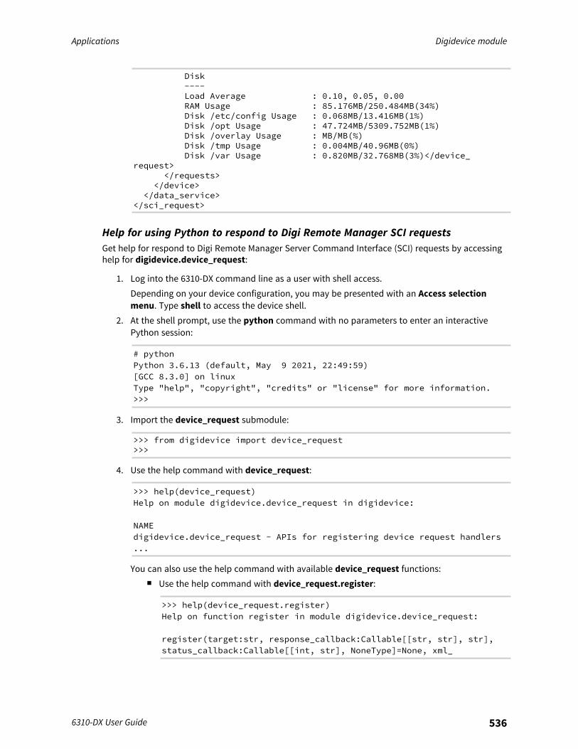
Applications Digidevice module
6310-DX User Guide 536
Disk----Load Average : 0.10, 0.05, 0.00RAM Usage : 85.176MB/250.484MB(34%)Disk /etc/config Usage : 0.068MB/13.416MB(1%)Disk /opt Usage : 47.724MB/5309.752MB(1%)Disk /overlay Usage : MB/MB(%)Disk /tmp Usage : 0.004MB/40.96MB(0%)Disk /var Usage : 0.820MB/32.768MB(3%)</device_
request></requests>
</device></data_service>
</sci_request>
Help for using Python to respond to Digi Remote Manager SCI requestsGet help for respond to Digi Remote Manager Server Command Interface (SCI) requests by accessinghelp for digidevice.device_request:
1. Log into the 6310-DX command line as a user with shell access.Depending on your device configuration, you may be presented with an Access selectionmenu. Type shell to access the device shell.
2. At the shell prompt, use the python command with no parameters to enter an interactivePython session:
# pythonPython 3.6.13 (default, May 9 2021, 22:49:59)[GCC 8.3.0] on linuxType "help", "copyright", "credits" or "license" for more information.>>>
3. Import the device_request submodule:
>>> from digidevice import device_request>>>
4. Use the help command with device_request:
>>> help(device_request)Help on module digidevice.device_request in digidevice:
NAMEdigidevice.device_request - APIs for registering device request handlers...
You can also use the help command with available device_request functions:n Use the help command with device_request.register:
>>> help(device_request.register)Help on function register in module digidevice.device_request:
register(target:str, response_callback:Callable[[str, str], str],status_callback:Callable[[int, str], NoneType]=None, xml_
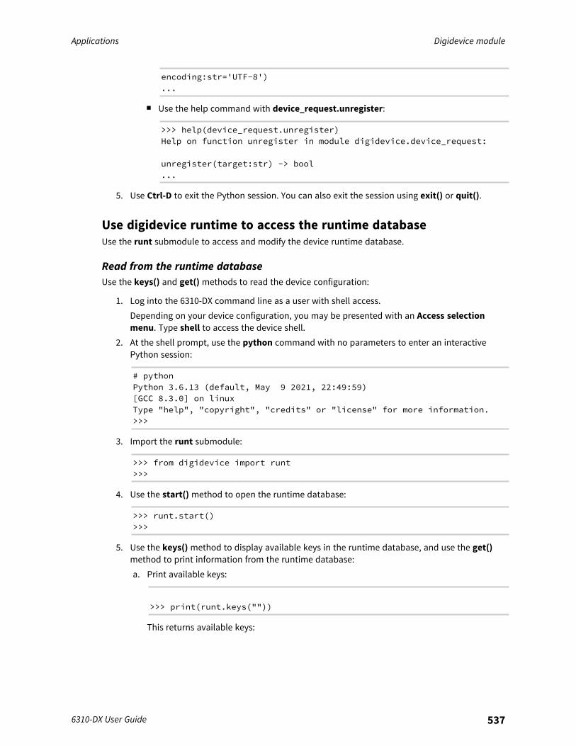
Applications Digidevice module
6310-DX User Guide 537
encoding:str='UTF-8')...
n Use the help command with device_request.unregister:
>>> help(device_request.unregister)Help on function unregister in module digidevice.device_request:
unregister(target:str) -> bool...
5. Use Ctrl-D to exit the Python session. You can also exit the session using exit() or quit().
Use digidevice runtime to access the runtime databaseUse the runt submodule to access and modify the device runtime database.
Read from the runtime databaseUse the keys() and get() methods to read the device configuration:
1. Log into the 6310-DX command line as a user with shell access.Depending on your device configuration, you may be presented with an Access selectionmenu. Type shell to access the device shell.
2. At the shell prompt, use the python command with no parameters to enter an interactivePython session:
# pythonPython 3.6.13 (default, May 9 2021, 22:49:59)[GCC 8.3.0] on linuxType "help", "copyright", "credits" or "license" for more information.>>>
3. Import the runt submodule:
>>> from digidevice import runt>>>
4. Use the start() method to open the runtime database:
>>> runt.start()>>>
5. Use the keys() method to display available keys in the runtime database, and use the get()method to print information from the runtime database:a. Print available keys:
>>> print(runt.keys(""))
This returns available keys:
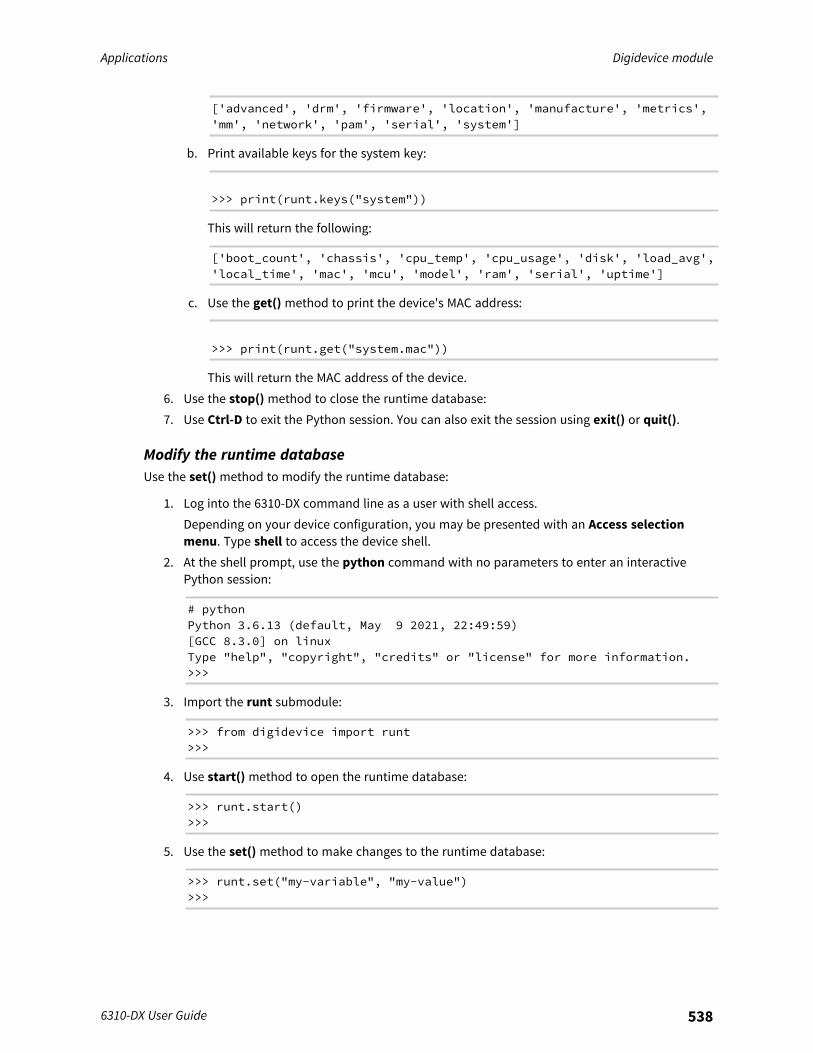
Applications Digidevice module
6310-DX User Guide 538
['advanced', 'drm', 'firmware', 'location', 'manufacture', 'metrics','mm', 'network', 'pam', 'serial', 'system']
b. Print available keys for the system key:
>>> print(runt.keys("system"))
This will return the following:
['boot_count', 'chassis', 'cpu_temp', 'cpu_usage', 'disk', 'load_avg','local_time', 'mac', 'mcu', 'model', 'ram', 'serial', 'uptime']
c. Use the get() method to print the device's MAC address:
>>> print(runt.get("system.mac"))
This will return the MAC address of the device.6. Use the stop() method to close the runtime database:7. Use Ctrl-D to exit the Python session. You can also exit the session using exit() or quit().
Modify the runtime databaseUse the set() method to modify the runtime database:
1. Log into the 6310-DX command line as a user with shell access.Depending on your device configuration, you may be presented with an Access selectionmenu. Type shell to access the device shell.
2. At the shell prompt, use the python command with no parameters to enter an interactivePython session:
# pythonPython 3.6.13 (default, May 9 2021, 22:49:59)[GCC 8.3.0] on linuxType "help", "copyright", "credits" or "license" for more information.>>>
3. Import the runt submodule:
>>> from digidevice import runt>>>
4. Use start() method to open the runtime database:
>>> runt.start()>>>
5. Use the set() method to make changes to the runtime database:
>>> runt.set("my-variable", "my-value")>>>

Applications Digidevice module
6310-DX User Guide 539
6. Use the get() method to verify the change:
>>> print(runt.get("my-variable"))my-variable>>>
7. Close the runtime database:
>>> runt.stop()>>>
8. Use Ctrl-D to exit the Python session. You can also exit the session using exit() or quit().
Help for using Python to access the runtime databaseGet help for reading and modifying the device runtime database by accessing help fordigidevice.runt:
1. Log into the 6310-DX command line as a user with shell access.Depending on your device configuration, you may be presented with an Access selectionmenu. Type shell to access the device shell.
2. At the shell prompt, use the python command with no parameters to enter an interactivePython session:
# pythonPython 3.6.13 (default, May 9 2021, 22:49:59)[GCC 8.3.0] on linuxType "help", "copyright", "credits" or "license" for more information.>>>
3. Import the runt submodule:
>>> from digidevice import runt>>>
4. Use the help command with runt:
>>> help(runt)
Help on module acl.runt in digidevice:
NAMEacl.runt - Python interface to ACL runtime database (runtd)....
5. Use Ctrl-D to exit the Python session. You can also exit the session using exit() or quit().
Use Python to upload the device name to Digi Remote ManagerThe name submodule can be used to upload a custom name for your device to Digi Remote Manager.When you use the name submodule to upload a custom device name to Remote Manager, thefollowing issues apply:

Applications Digidevice module
6310-DX User Guide 540
n If the name is being used by to another device in your Remote Manager account, the name willbe removed from the previous device and added to the new device.
n If Remote Manager is configured to apply a profile to a device based on the device name,changing the name of the device may cause Remote Manager to automatically push a profileonto the device.
Together, these two features allow you to swap one device for another by using the name submoduleto change the device name, while guaranteeing that the new device will have the same configurationas the previous one.
Note Because causing a profile to be automatically pushed from Remote Manager may change thebehavior of the device, including overwriting existing usernames and passwords, the namesubmodule should be used with caution. As a result, support for this functionality is disabled bydefault on Remote Manager.
Enable support on Digi Remote Manager for uploading custom device names
1. In Remote Manager, click API Explorer.2. For the HTTP method, select PUT.3. For Enter and API or select an example, type
/ws/v1/settings/inventory/AllowDeviceToSetOwnNameEnabled.4. In the HTTP message body text box, type the following:
{"name" : "AllowDeviceToSetOwnNameEnabled","value" : "true"
}
5. Click Send.
Upload a custom name
1. Log into the 6310-DX command line as a user with shell access.Depending on your device configuration, you may be presented with an Access selectionmenu. Type shell to access the device shell.
2. At the shell prompt, use the python command with no parameters to enter an interactivePython session:
# pythonPython 3.6.13 (default, May 9 2021, 22:49:59)[GCC 8.3.0] on linuxType "help", "copyright", "credits" or "license" for more information.>>>
3. Import the name submodule:
>>> from digidevice import name
4. Upload the name to Remote Manager:
>>> name.upload("my_name")
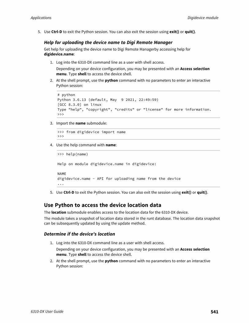
Applications Digidevice module
6310-DX User Guide 541
5. Use Ctrl-D to exit the Python session. You can also exit the session using exit() or quit().
Help for uploading the device name to Digi Remote ManagerGet help for uploading the device name to Digi Remote Managerby accessing help fordigidevice.name:
1. Log into the 6310-DX command line as a user with shell access.Depending on your device configuration, you may be presented with an Access selectionmenu. Type shell to access the device shell.
2. At the shell prompt, use the python command with no parameters to enter an interactivePython session:
# pythonPython 3.6.13 (default, May 9 2021, 22:49:59)[GCC 8.3.0] on linuxType "help", "copyright", "credits" or "license" for more information.>>>
3. Import the name submodule:
>>> from digidevice import name>>>
4. Use the help command with name:
>>> help(name)
Help on module digidevice.name in digidevice:
NAMEdigidevice.name - API for uploading name from the device...
5. Use Ctrl-D to exit the Python session. You can also exit the session using exit() or quit().
Use Python to access the device location dataThe location submodule enables access to the location data for the 6310-DX device.The module takes a snapshot of location data stored in the runt database. The location data snapshotcan be subsequently updated by using the update method.
Determine if the device's location
1. Log into the 6310-DX command line as a user with shell access.Depending on your device configuration, you may be presented with an Access selectionmenu. Type shell to access the device shell.
2. At the shell prompt, use the python command with no parameters to enter an interactivePython session:
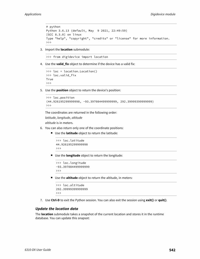
Applications Digidevice module
6310-DX User Guide 542
# pythonPython 3.6.13 (default, May 9 2021, 22:49:59)[GCC 8.3.0] on linuxType "help", "copyright", "credits" or "license" for more information.>>>
3. Import the location submodule:
>>> from digidevice import location
4. Use the valid_fix object to determine if the device has a valid fix:
>>> loc = location.Location()>>> loc.valid_fixTrue>>>
5. Use the position object to return the device's position:
>>> loc.position(44.926195299999998, -93.397084499999999, 292.39999399999999)>>>
The coordinates are returned in the following order:latitude, longitude, altitudealtitude is in meters.
6. You can also return only one of the coordinate positions:n Use the latitude object to return the latitude:
>>> loc.latitude44.926195299999998>>>
n Use the longitude object to return the longitude:
>>> loc.longitude-93.397084499999999>>>
n Use the altitude object to return the altitude, in meters:
>>> loc.altitude292.39999399999999>>>
7. Use Ctrl-D to exit the Python session. You can also exit the session using exit() or quit().
Update the location dataThe location submodule takes a snapshot of the current location and stores it in the runtimedatabase. You can update this snapsot:
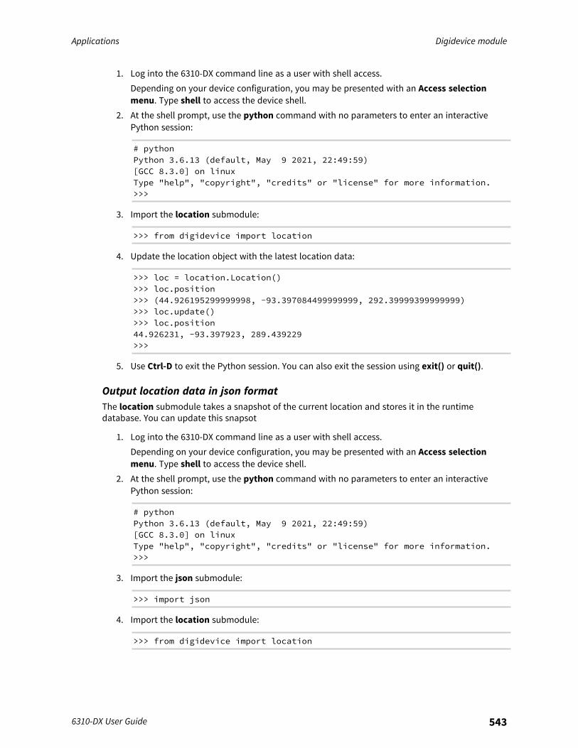
Applications Digidevice module
6310-DX User Guide 543
1. Log into the 6310-DX command line as a user with shell access.Depending on your device configuration, you may be presented with an Access selectionmenu. Type shell to access the device shell.
2. At the shell prompt, use the python command with no parameters to enter an interactivePython session:
# pythonPython 3.6.13 (default, May 9 2021, 22:49:59)[GCC 8.3.0] on linuxType "help", "copyright", "credits" or "license" for more information.>>>
3. Import the location submodule:
>>> from digidevice import location
4. Update the location object with the latest location data:
>>> loc = location.Location()>>> loc.position>>> (44.926195299999998, -93.397084499999999, 292.39999399999999)>>> loc.update()>>> loc.position44.926231, -93.397923, 289.439229>>>
5. Use Ctrl-D to exit the Python session. You can also exit the session using exit() or quit().
Output location data in json formatThe location submodule takes a snapshot of the current location and stores it in the runtimedatabase. You can update this snapsot
1. Log into the 6310-DX command line as a user with shell access.Depending on your device configuration, you may be presented with an Access selectionmenu. Type shell to access the device shell.
2. At the shell prompt, use the python command with no parameters to enter an interactivePython session:
# pythonPython 3.6.13 (default, May 9 2021, 22:49:59)[GCC 8.3.0] on linuxType "help", "copyright", "credits" or "license" for more information.>>>
3. Import the json submodule:
>>> import json
4. Import the location submodule:
>>> from digidevice import location
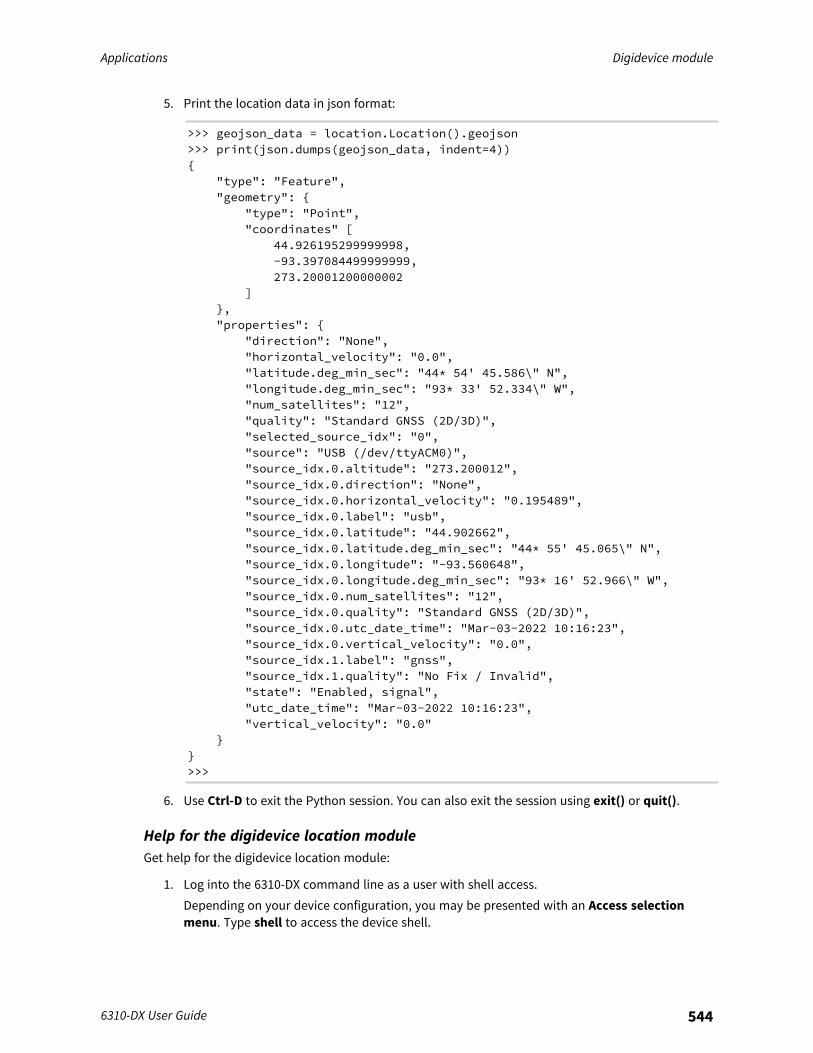
Applications Digidevice module
6310-DX User Guide 544
5. Print the location data in json format:
>>> geojson_data = location.Location().geojson>>> print(json.dumps(geojson_data, indent=4)){
"type": "Feature","geometry": {
"type": "Point","coordinates" [
44.926195299999998,-93.397084499999999,273.20001200000002
]},"properties": {
"direction": "None","horizontal_velocity": "0.0","latitude.deg_min_sec": "44* 54' 45.586\" N","longitude.deg_min_sec": "93* 33' 52.334\" W","num_satellites": "12","quality": "Standard GNSS (2D/3D)","selected_source_idx": "0","source": "USB (/dev/ttyACM0)","source_idx.0.altitude": "273.200012","source_idx.0.direction": "None","source_idx.0.horizontal_velocity": "0.195489","source_idx.0.label": "usb","source_idx.0.latitude": "44.902662","source_idx.0.latitude.deg_min_sec": "44* 55' 45.065\" N","source_idx.0.longitude": "-93.560648","source_idx.0.longitude.deg_min_sec": "93* 16' 52.966\" W","source_idx.0.num_satellites": "12","source_idx.0.quality": "Standard GNSS (2D/3D)","source_idx.0.utc_date_time": "Mar-03-2022 10:16:23","source_idx.0.vertical_velocity": "0.0","source_idx.1.label": "gnss","source_idx.1.quality": "No Fix / Invalid","state": "Enabled, signal","utc_date_time": "Mar-03-2022 10:16:23","vertical_velocity": "0.0"
}}>>>
6. Use Ctrl-D to exit the Python session. You can also exit the session using exit() or quit().
Help for the digidevice location moduleGet help for the digidevice location module:
1. Log into the 6310-DX command line as a user with shell access.Depending on your device configuration, you may be presented with an Access selectionmenu. Type shell to access the device shell.
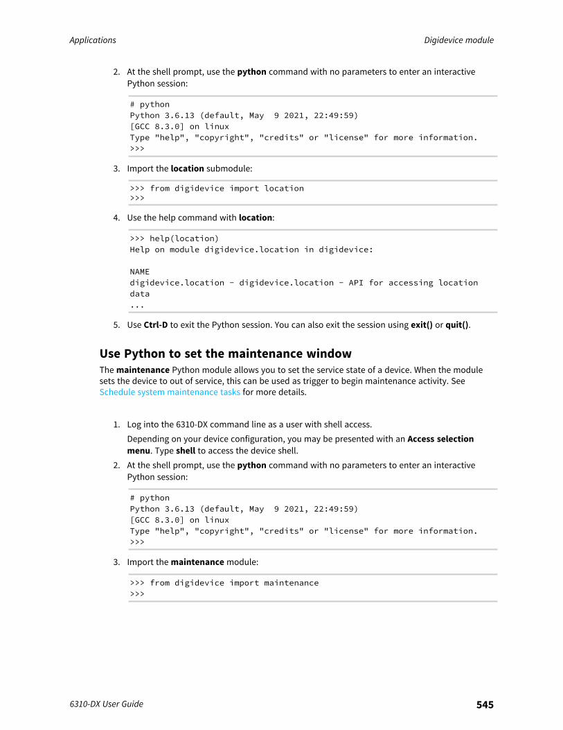
Applications Digidevice module
6310-DX User Guide 545
2. At the shell prompt, use the python command with no parameters to enter an interactivePython session:
# pythonPython 3.6.13 (default, May 9 2021, 22:49:59)[GCC 8.3.0] on linuxType "help", "copyright", "credits" or "license" for more information.>>>
3. Import the location submodule:
>>> from digidevice import location>>>
4. Use the help command with location:
>>> help(location)Help on module digidevice.location in digidevice:
NAMEdigidevice.location - digidevice.location - API for accessing locationdata...
5. Use Ctrl-D to exit the Python session. You can also exit the session using exit() or quit().
Use Python to set the maintenance windowThe maintenance Python module allows you to set the service state of a device. When the modulesets the device to out of service, this can be used as trigger to begin maintenance activity. SeeSchedule system maintenance tasks for more details.
1. Log into the 6310-DX command line as a user with shell access.Depending on your device configuration, you may be presented with an Access selectionmenu. Type shell to access the device shell.
2. At the shell prompt, use the python command with no parameters to enter an interactivePython session:
# pythonPython 3.6.13 (default, May 9 2021, 22:49:59)[GCC 8.3.0] on linuxType "help", "copyright", "credits" or "license" for more information.>>>
3. Import the maintenance module:
>>> from digidevice import maintenance>>>
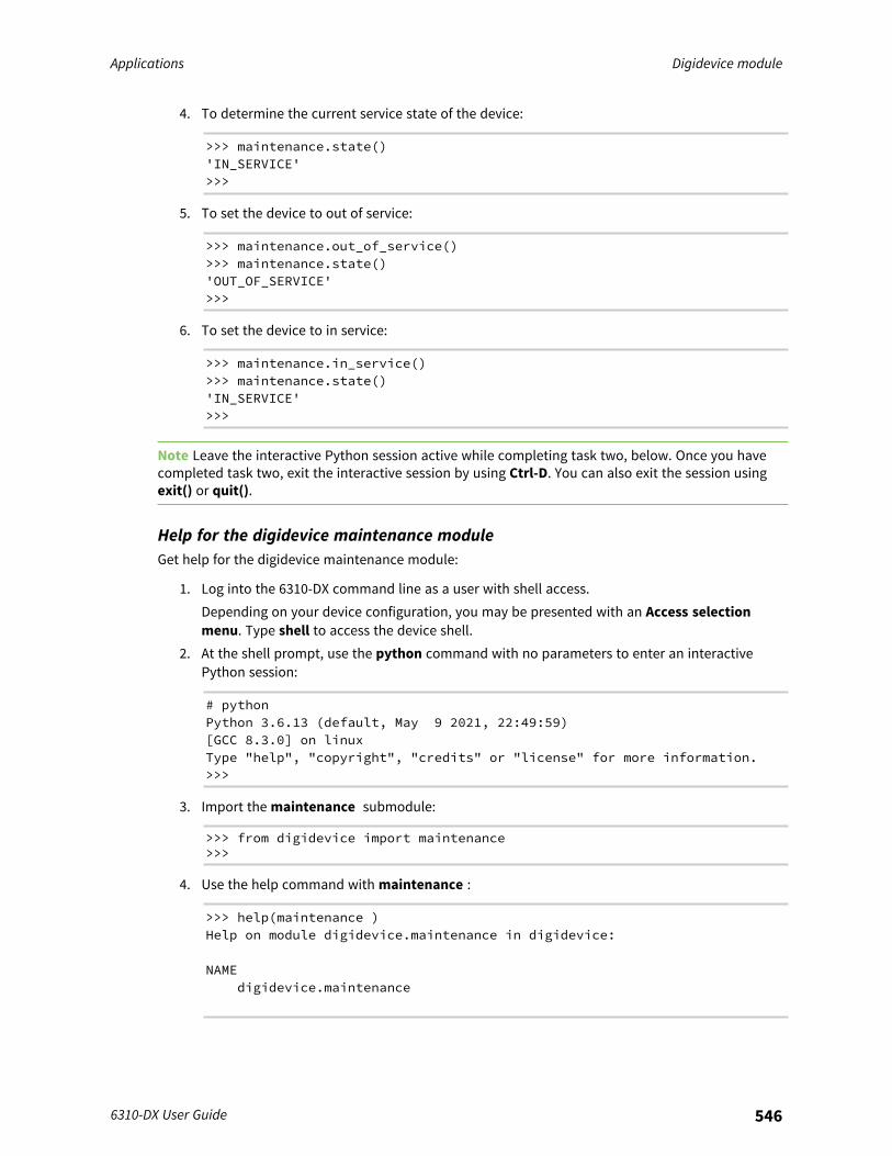
Applications Digidevice module
6310-DX User Guide 546
4. To determine the current service state of the device:
>>> maintenance.state()'IN_SERVICE'>>>
5. To set the device to out of service:
>>> maintenance.out_of_service()>>> maintenance.state()'OUT_OF_SERVICE'>>>
6. To set the device to in service:
>>> maintenance.in_service()>>> maintenance.state()'IN_SERVICE'>>>
Note Leave the interactive Python session active while completing task two, below. Once you havecompleted task two, exit the interactive session by using Ctrl-D. You can also exit the session usingexit() or quit().
Help for the digidevice maintenance moduleGet help for the digidevice maintenance module:
1. Log into the 6310-DX command line as a user with shell access.Depending on your device configuration, you may be presented with an Access selectionmenu. Type shell to access the device shell.
2. At the shell prompt, use the python command with no parameters to enter an interactivePython session:
# pythonPython 3.6.13 (default, May 9 2021, 22:49:59)[GCC 8.3.0] on linuxType "help", "copyright", "credits" or "license" for more information.>>>
3. Import the maintenance submodule:
>>> from digidevice import maintenance>>>
4. Use the help command with maintenance :
>>> help(maintenance )Help on module digidevice.maintenance in digidevice:
NAMEdigidevice.maintenance
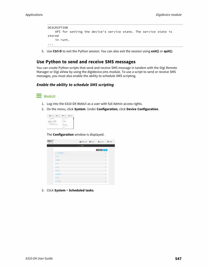
Applications Digidevice module
6310-DX User Guide 547
DESCRIPTIONAPI for setting the device's service state. The service state is
storedin runt.
...
5. Use Ctrl-D to exit the Python session. You can also exit the session using exit() or quit().
Use Python to send and receive SMS messagesYou can create Python scripts that send and receive SMS message in tandem with the Digi RemoteManager or Digi aView by using the digidevice.sms module. To use a script to send or receive SMSmessages, you must also enable the ability to schedule SMS scripting.
Enable the ability to schedule SMS scripting
WebUI
1. Log into the 6310-DX WebUI as a user with full Admin access rights.2. On the menu, click System. Under Configuration, click Device Configuration.
The Configuration window is displayed.
3. Click System > Scheduled tasks.
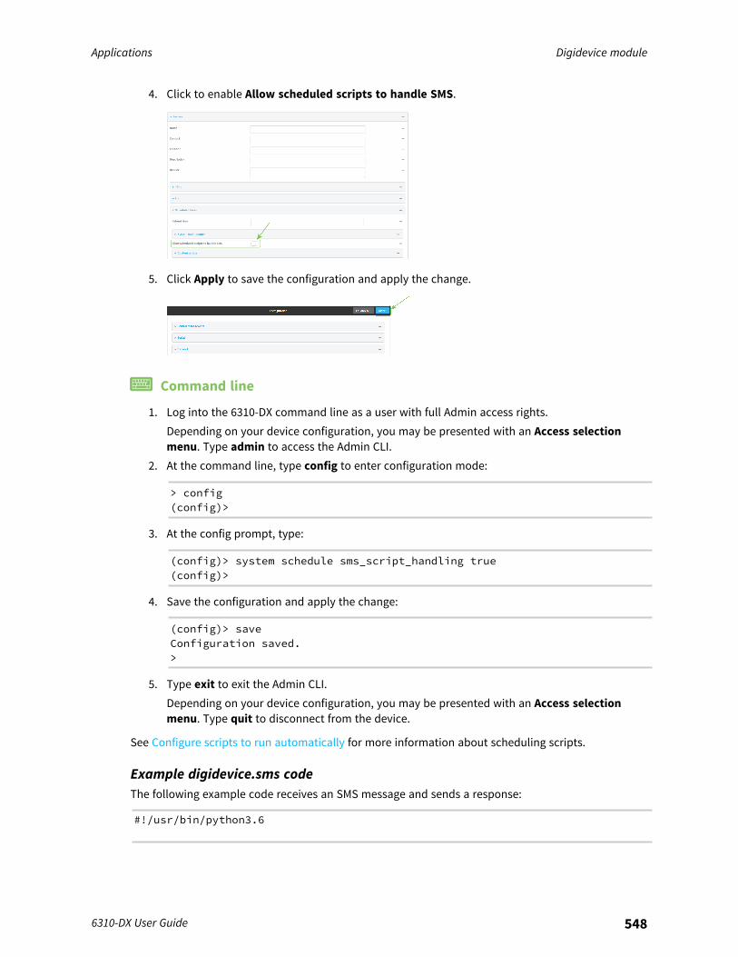
Applications Digidevice module
6310-DX User Guide 548
4. Click to enable Allow scheduled scripts to handle SMS.
5. Click Apply to save the configuration and apply the change.
Command line
1. Log into the 6310-DX command line as a user with full Admin access rights.Depending on your device configuration, you may be presented with an Access selectionmenu. Type admin to access the Admin CLI.
2. At the command line, type config to enter configuration mode:
> config(config)>
3. At the config prompt, type:
(config)> system schedule sms_script_handling true(config)>
4. Save the configuration and apply the change:
(config)> saveConfiguration saved.>
5. Type exit to exit the Admin CLI.Depending on your device configuration, you may be presented with an Access selectionmenu. Type quit to disconnect from the device.
See Configure scripts to run automatically for more information about scheduling scripts.
Example digidevice.sms codeThe following example code receives an SMS message and sends a response:
#!/usr/bin/python3.6
Applications Use the Paho MQTT python library
6310-DX User Guide 549
import osimport threadingimport sysfrom digidevice.sms import Callback, sendCOND = threading.Condition()
def sms_test_callback(sms, info):print(f"SMS message from {info['content.number']} received")print(sms)print(info)COND.acquire()COND.notify()COND.release()
def send_sms(destination, msg):print("sending SMS message", msg)if len(destination) == 10:
destination = "+1" + destinationsend(destination, msg)
if __name__ == '__main__':if len(sys.argv) > 1:
dest = sys.argv[1]else:
dest = '+15005550006'my_callback = Callback(sms_test_callback, metadata=True)send_sms(dest, 'Hello World!')print("Please send an SMS message now.")print("Execution halted until a message is received or 60 seconds have
passed.")# acquire the semaphore and wait until a callback occursCOND.acquire()try:
COND.wait(60.0)except Exception as err:
print("exception occured while waiting")print(err)
COND.release()my_callback.unregister_callback()
Use the Paho MQTT python libraryYour 6310-DX device includes support for the Paho MQTT python library. MQTT is a lightweightmessaging protocol used to communicate with various applications including cloud-basedapplications such as Amazon Web Services and Microsoft Azure. The following is example code thatreads CPU and RAM usage on the device, updates the device firmware, then publishes informationabout DHCP clients and system information to the MQTT server at 192.168.1.100. The MQTT server IPis configurable.
"""MQTT client example:- Reporting some device metrics from runt- Reporting DHCP clients- Firmware update feature (simple implementation, read TODO in cmd_fwupdate)"""
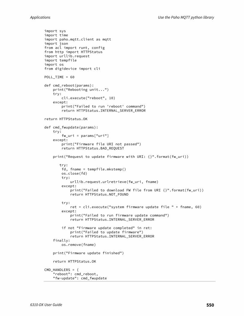
Applications Use the Paho MQTT python library
6310-DX User Guide 550
import sysimport timeimport paho.mqtt.client as mqttimport jsonfrom acl import runt, configfrom http import HTTPStatusimport urllib.requestimport tempfileimport osfrom digidevice import cli
POLL_TIME = 60
def cmd_reboot(params):print("Rebooting unit...")try:
cli.execute("reboot", 10)except:
print("Failed to run 'reboot' command")return HTTPStatus.INTERNAL_SERVER_ERROR
return HTTPStatus.OK
def cmd_fwupdate(params):try:
fw_uri = params["uri"]except:
print("Firmware file URI not passed")return HTTPStatus.BAD_REQUEST
print("Request to update firmware with URI: {}".format(fw_uri))
try:fd, fname = tempfile.mkstemp()os.close(fd)try:
urllib.request.urlretrieve(fw_uri, fname)except:
print("Failed to download FW file from URI {}".format(fw_uri))return HTTPStatus.NOT_FOUND
try:ret = cli.execute("system firmware update file " + fname, 60)
except:print("Failed to run firmware update command")return HTTPStatus.INTERNAL_SERVER_ERROR
if not "Firmware update completed" in ret:print("Failed to update firmware")return HTTPStatus.INTERNAL_SERVER_ERROR
finally:os.remove(fname)
print("Firmware update finished")
return HTTPStatus.OK
CMD_HANDLERS = {"reboot": cmd_reboot,"fw-update": cmd_fwupdate
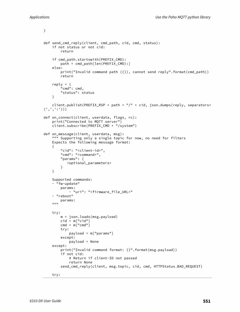
Applications Use the Paho MQTT python library
6310-DX User Guide 551
}
def send_cmd_reply(client, cmd_path, cid, cmd, status):if not status or not cid:
return
if cmd_path.startswith(PREFIX_CMD):path = cmd_path[len(PREFIX_CMD):]
else:print("Invalid command path ({}), cannot send reply".format(cmd_path))return
reply = {"cmd": cmd,"status": status
}
client.publish(PREFIX_RSP + path + "/" + cid, json.dumps(reply, separators=(',',':')))
def on_connect(client, userdata, flags, rc):print("Connected to MQTT server")client.subscribe(PREFIX_CMD + "/system")
def on_message(client, userdata, msg):""" Supporting only a single topic for now, no need for filtersExpects the following message format:{
"cid": "<client-id>","cmd": "<command>","params": {
<optional_parameters>}
}
Supported commands:- "fw-update"
params:- "uri": "<firmware_file_URL>"
- "reboot"params:
"""
try:m = json.loads(msg.payload)cid = m["cid"]cmd = m["cmd"]try:
payload = m["params"]except:
payload = Noneexcept:
print("Invalid command format: {}".format(msg.payload))if not cid:
# Return if client-ID not passedreturn None
send_cmd_reply(client, msg.topic, cid, cmd, HTTPStatus.BAD_REQUEST)
try:
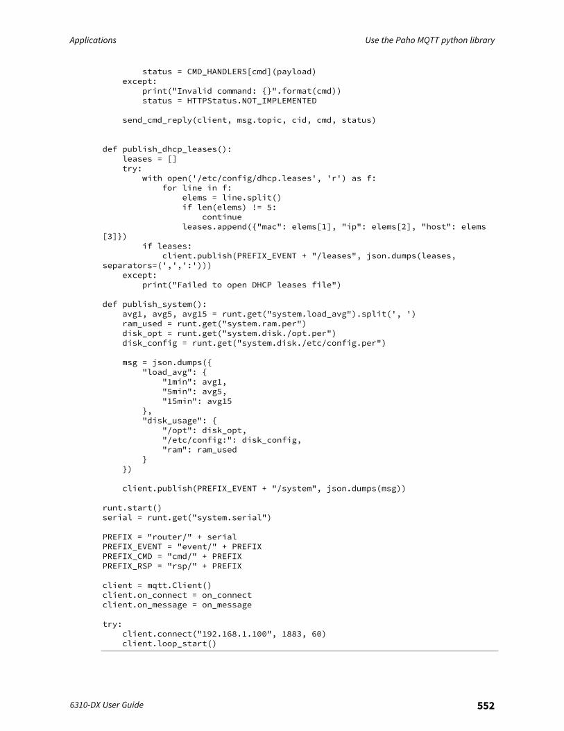
Applications Use the Paho MQTT python library
6310-DX User Guide 552
status = CMD_HANDLERS[cmd](payload)except:
print("Invalid command: {}".format(cmd))status = HTTPStatus.NOT_IMPLEMENTED
send_cmd_reply(client, msg.topic, cid, cmd, status)
def publish_dhcp_leases():leases = []try:
with open('/etc/config/dhcp.leases', 'r') as f:for line in f:
elems = line.split()if len(elems) != 5:
continueleases.append({"mac": elems[1], "ip": elems[2], "host": elems
[3]})if leases:
client.publish(PREFIX_EVENT + "/leases", json.dumps(leases,separators=(',',':')))
except:print("Failed to open DHCP leases file")
def publish_system():avg1, avg5, avg15 = runt.get("system.load_avg").split(', ')ram_used = runt.get("system.ram.per")disk_opt = runt.get("system.disk./opt.per")disk_config = runt.get("system.disk./etc/config.per")
msg = json.dumps({"load_avg": {
"1min": avg1,"5min": avg5,"15min": avg15
},"disk_usage": {
"/opt": disk_opt,"/etc/config:": disk_config,"ram": ram_used
}})
client.publish(PREFIX_EVENT + "/system", json.dumps(msg))
runt.start()serial = runt.get("system.serial")
PREFIX = "router/" + serialPREFIX_EVENT = "event/" + PREFIXPREFIX_CMD = "cmd/" + PREFIXPREFIX_RSP = "rsp/" + PREFIX
client = mqtt.Client()client.on_connect = on_connectclient.on_message = on_message
try:client.connect("192.168.1.100", 1883, 60)client.loop_start()
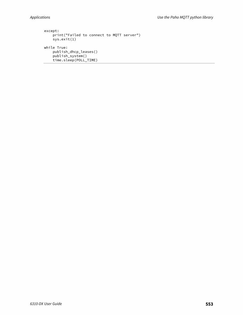
Applications Use the Paho MQTT python library
6310-DX User Guide 553
except:print("Failed to connect to MQTT server")sys.exit(1)
while True:publish_dhcp_leases()publish_system()time.sleep(POLL_TIME)
User authentication
This chapter contains the following topics:
6310-DX user authentication 555User authentication methods 555Authentication groups 563Local users 572Terminal Access Controller Access-Control System Plus (TACACS+) 586Remote Authentication Dial-In User Service (RADIUS) 593LDAP 598Configure serial authentication 606Disable shell access 608Set the idle timeout for 6310-DX users 610Example user configuration 613
6310-DX User Guide 554
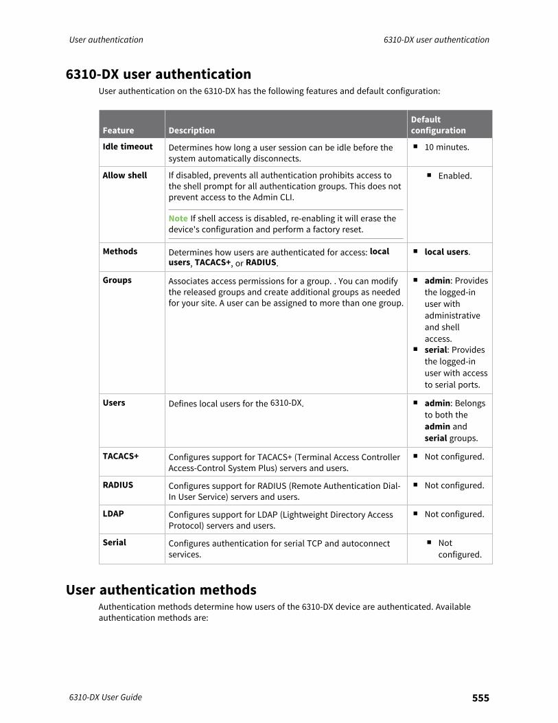
User authentication 6310-DX user authentication
6310-DX User Guide 555
6310-DX user authenticationUser authentication on the 6310-DX has the following features and default configuration:
Feature DescriptionDefaultconfiguration
Idle timeout Determines how long a user session can be idle before thesystem automatically disconnects.
n 10 minutes.
Allow shell If disabled, prevents all authentication prohibits access tothe shell prompt for all authentication groups. This does notprevent access to the Admin CLI.
Note If shell access is disabled, re-enabling it will erase thedevice's configuration and perform a factory reset.
n Enabled.
Methods Determines how users are authenticated for access: localusers, TACACS+, or RADIUS.
n local users.
Groups Associates access permissions for a group. . You can modifythe released groups and create additional groups as neededfor your site. A user can be assigned to more than one group.
n admin: Providesthe logged-inuser withadministrativeand shellaccess.
n serial: Providesthe logged-inuser with accessto serial ports.
Users Defines local users for the 6310-DX. n admin: Belongsto both theadmin andserial groups.
TACACS+ Configures support for TACACS+ (Terminal Access ControllerAccess-Control System Plus) servers and users.
n Not configured.
RADIUS Configures support for RADIUS (Remote Authentication Dial-In User Service) servers and users.
n Not configured.
LDAP Configures support for LDAP (Lightweight Directory AccessProtocol) servers and users.
n Not configured.
Serial Configures authentication for serial TCP and autoconnectservices.
n Notconfigured.
User authentication methodsAuthentication methods determine how users of the 6310-DX device are authenticated. Availableauthentication methods are:
User authentication User authentication methods
6310-DX User Guide 556
n Local users: User are authenticated on the local device.n RADIUS: Users authenticated by using a remote RADIUS server for authentication.
See Remote Authentication Dial-In User Service (RADIUS) for information about configuringRADIUS authentication.
n TACACS+: Users authenticated by using a remote TACACS+ server for authentication.See Terminal Access Controller Access-Control System Plus (TACACS+) for information aboutconfiguring TACACS+ authentication.
n LDAP: Users authenticated by using a remote LDAP server for authentication.See LDAP for information about configuring LDAP authentication.
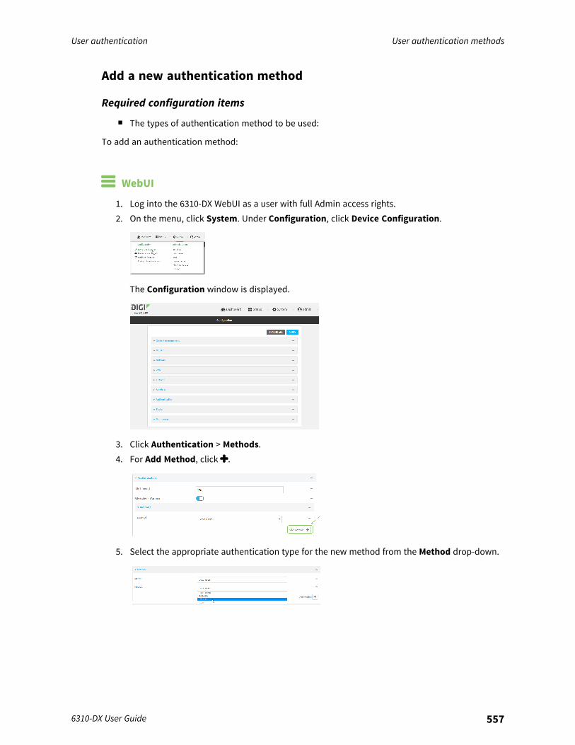
User authentication User authentication methods
6310-DX User Guide 557
Add a new authentication method
Required configuration items
n The types of authentication method to be used:
To add an authentication method:
WebUI
1. Log into the 6310-DX WebUI as a user with full Admin access rights.2. On the menu, click System. Under Configuration, click Device Configuration.
The Configuration window is displayed.
3. Click Authentication > Methods.4. For Add Method, click .
5. Select the appropriate authentication type for the new method from the Method drop-down.
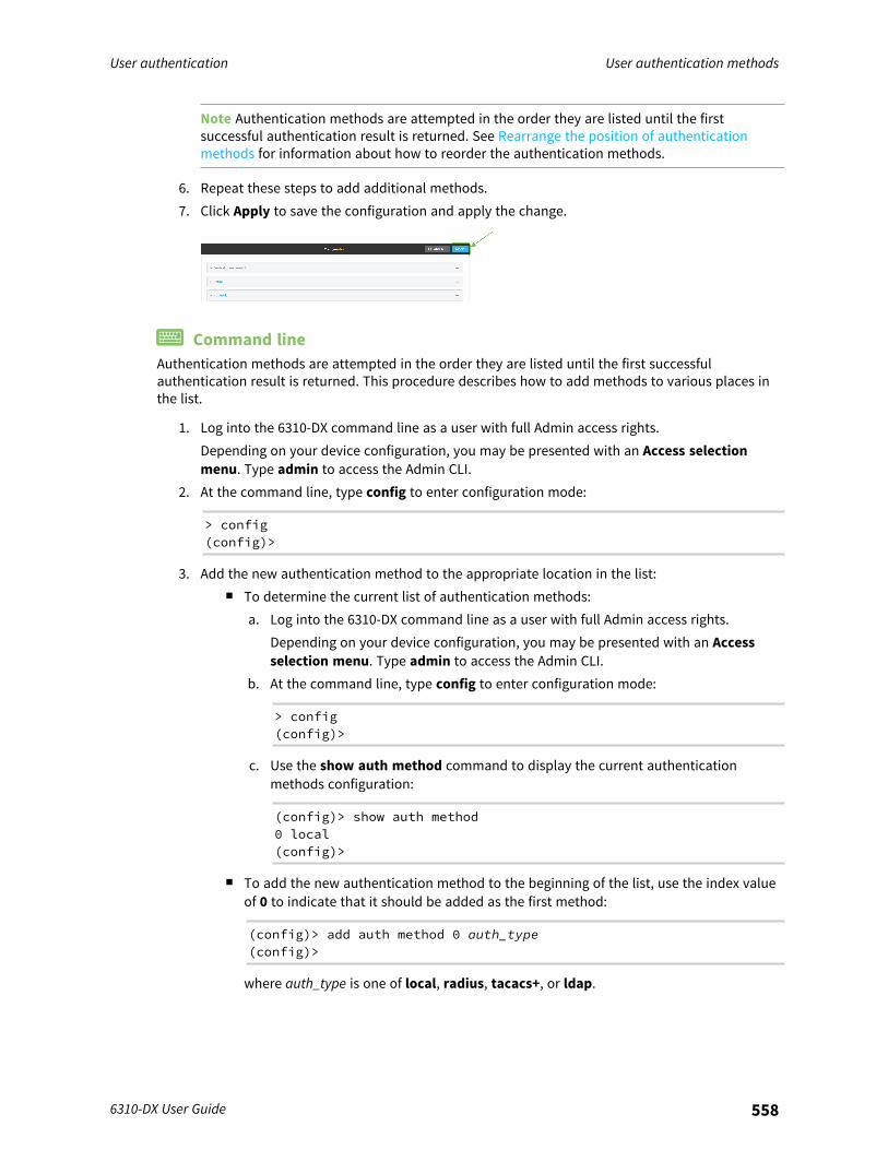
User authentication User authentication methods
6310-DX User Guide 558
Note Authentication methods are attempted in the order they are listed until the firstsuccessful authentication result is returned. See Rearrange the position of authenticationmethods for information about how to reorder the authentication methods.
6. Repeat these steps to add additional methods.7. Click Apply to save the configuration and apply the change.
Command lineAuthentication methods are attempted in the order they are listed until the first successfulauthentication result is returned. This procedure describes how to add methods to various places inthe list.
1. Log into the 6310-DX command line as a user with full Admin access rights.Depending on your device configuration, you may be presented with an Access selectionmenu. Type admin to access the Admin CLI.
2. At the command line, type config to enter configuration mode:
> config(config)>
3. Add the new authentication method to the appropriate location in the list:n To determine the current list of authentication methods:
a. Log into the 6310-DX command line as a user with full Admin access rights.Depending on your device configuration, you may be presented with an Accessselection menu. Type admin to access the Admin CLI.
b. At the command line, type config to enter configuration mode:
> config(config)>
c. Use the show auth method command to display the current authenticationmethods configuration:
(config)> show auth method0 local(config)>
n To add the new authentication method to the beginning of the list, use the index valueof 0 to indicate that it should be added as the first method:
(config)> add auth method 0 auth_type(config)>
where auth_type is one of local, radius, tacacs+, or ldap.

User authentication User authentication methods
6310-DX User Guide 559
n To add the new authentication method to the end of the list, use the index keywordend:
(config)> add auth method end auth_type(config)>
where auth_type is one of local, radius, tacacs+, or ldap.n To add the new authentication in another location in the list, use an index value to
indicate the appropriate position. For example:
(config)> add auth method 1 auth_type(config)>
where auth_type is one of local, radius, tacacs+, or ldap.n You can also use the move command to rearrange existing methods. See Rearrange the
position of authentication methods for information about how to reorder theauthentication methods.
4. Save the configuration and apply the change:
(config)> saveConfiguration saved.>
5. Type exit to exit the Admin CLI.Depending on your device configuration, you may be presented with an Access selectionmenu. Type quit to disconnect from the device.
Delete an authentication method
WebUI
1. Log into the 6310-DX WebUI as a user with full Admin access rights.2. On the menu, click System. Under Configuration, click Device Configuration.
The Configuration window is displayed.
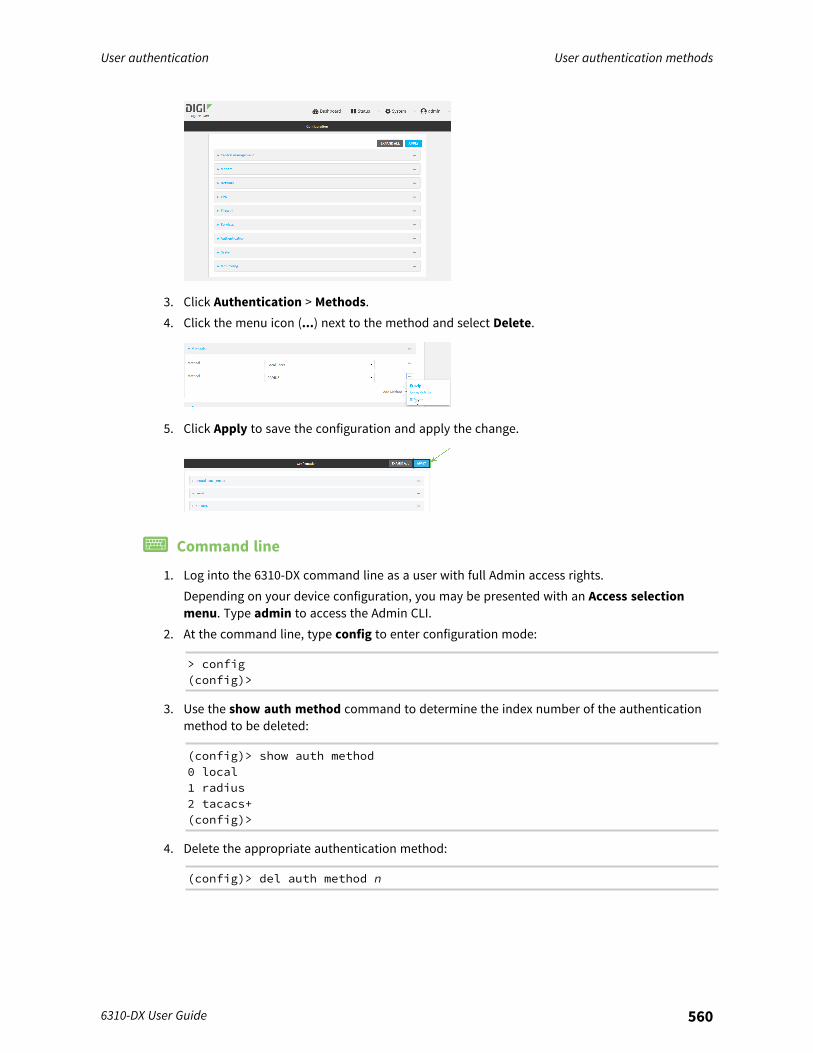
User authentication User authentication methods
6310-DX User Guide 560
3. Click Authentication > Methods.4. Click the menu icon (...) next to the method and select Delete.
5. Click Apply to save the configuration and apply the change.
Command line
1. Log into the 6310-DX command line as a user with full Admin access rights.Depending on your device configuration, you may be presented with an Access selectionmenu. Type admin to access the Admin CLI.
2. At the command line, type config to enter configuration mode:
> config(config)>
3. Use the show auth method command to determine the index number of the authenticationmethod to be deleted:
(config)> show auth method0 local1 radius2 tacacs+(config)>
4. Delete the appropriate authentication method:
(config)> del auth method n

User authentication User authentication methods
6310-DX User Guide 561
Where n is index number of the authentication method to be deleted. For example, to deletethe TACACS+ authentication method as displayed by the example show command, above:
(config)> del auth method 2
5. Save the configuration and apply the change:
(config)> saveConfiguration saved.>
6. Type exit to exit the Admin CLI.Depending on your device configuration, you may be presented with an Access selectionmenu. Type quit to disconnect from the device.
Rearrange the position of authentication methods
WebUIAuthentication methods are reordered by changing the method type in the Method drop-down foreach authentication method to match the appropriate order.For example, the following configuration has Local users as the first method, and RADIUS as thesecond.
To reorder these so that RADIUS is first and Local users is second:
1. Log into the 6310-DX WebUI as a user with full Admin access rights.2. On the menu, click System. Under Configuration, click Device Configuration.
The Configuration window is displayed.
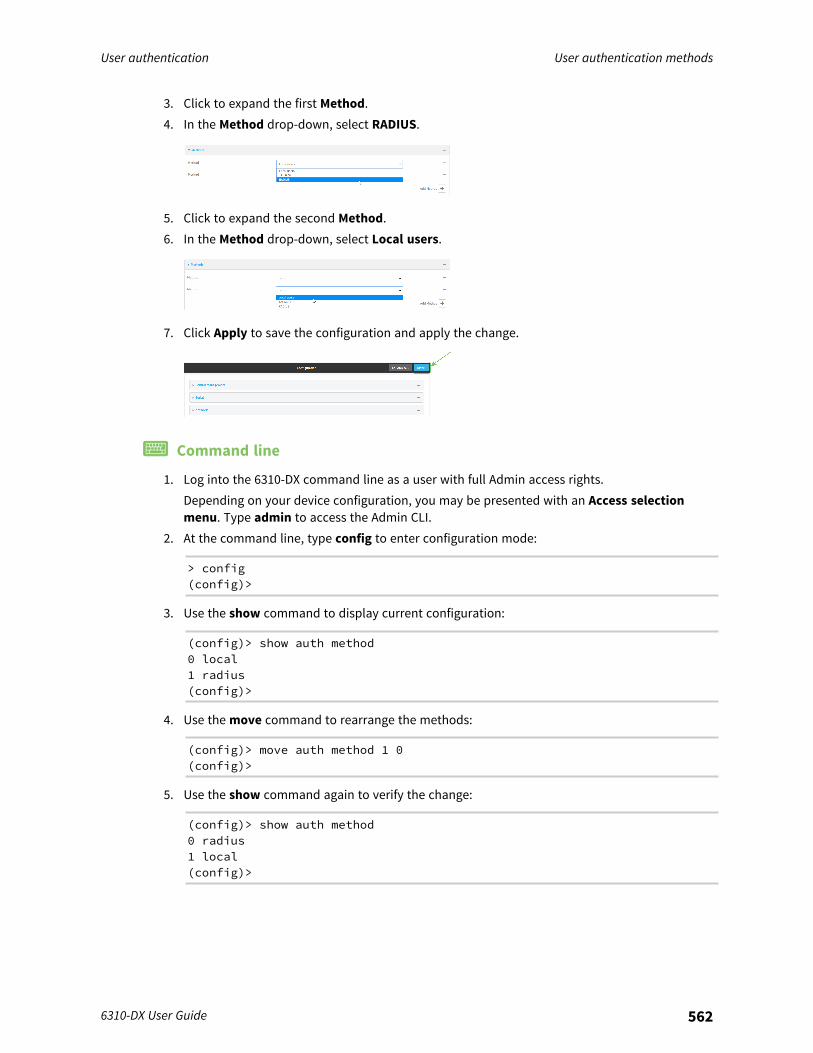
User authentication User authentication methods
6310-DX User Guide 562
3. Click to expand the first Method.4. In the Method drop-down, select RADIUS.
5. Click to expand the second Method.6. In the Method drop-down, select Local users.
7. Click Apply to save the configuration and apply the change.
Command line
1. Log into the 6310-DX command line as a user with full Admin access rights.Depending on your device configuration, you may be presented with an Access selectionmenu. Type admin to access the Admin CLI.
2. At the command line, type config to enter configuration mode:
> config(config)>
3. Use the show command to display current configuration:
(config)> show auth method0 local1 radius(config)>
4. Use the move command to rearrange the methods:
(config)> move auth method 1 0(config)>
5. Use the show command again to verify the change:
(config)> show auth method0 radius1 local(config)>
User authentication Authentication groups
6310-DX User Guide 563
6. Save the configuration and apply the change:
(config)> saveConfiguration saved.>
7. Type exit to exit the Admin CLI.Depending on your device configuration, you may be presented with an Access selectionmenu. Type quit to disconnect from the device.
Authentication groupsAuthentication groups are used to assign access rights to 6310-DX users. Three types of access rightscan be assigned:
n Admin access: Users with Admin access can be configured to have either:l The ability to manage the 6310-DX device by using the WebUI or the Admin CLI.l Read-only access to the WebUI and Admin CLI.
n Shell access: Users with Shell access have the ability to access the shell when logging into the6310-DX via ssh, telnet, or the serial console.Shell access is not available if the Allow shell parameter has been disabled. See Disable shellaccess for more information about the Allow shell parameter.
n Serial access: Users with Serial access have the ability to log into the 6310-DX device by usingthe serial console.
Preconfigured authentication groupsThe 6310-DX device has two preconfigured authentication groups:
n The admin group is configured by default to have full Admin access.n The serial group is configured by default to have Serial access.
The preconfigured authentication groups cannot be deleted, but the access rights defined for thegroup are configurable.This section contains the following topics:
Change the access rights for a predefined group 564Add an authentication group 566Delete an authentication group 570
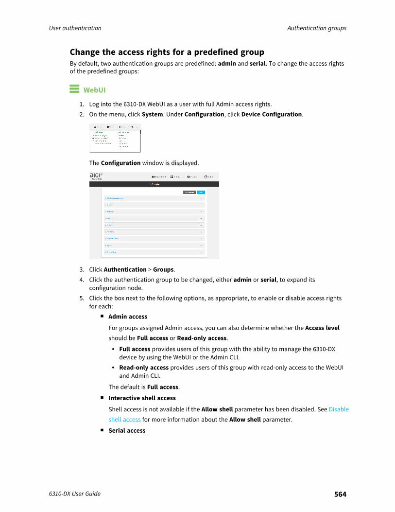
User authentication Authentication groups
6310-DX User Guide 564
Change the access rights for a predefined groupBy default, two authentication groups are predefined: admin and serial. To change the access rightsof the predefined groups:
WebUI
1. Log into the 6310-DX WebUI as a user with full Admin access rights.2. On the menu, click System. Under Configuration, click Device Configuration.
The Configuration window is displayed.
3. Click Authentication > Groups.4. Click the authentication group to be changed, either admin or serial, to expand its
configuration node.5. Click the box next to the following options, as appropriate, to enable or disable access rights
for each:n Admin access
For groups assigned Admin access, you can also determine whether the Access levelshould be Full access or Read-only access.l Full access provides users of this group with the ability to manage the 6310-DX
device by using the WebUI or the Admin CLI.l Read-only access provides users of this group with read-only access to the WebUI
and Admin CLI.
The default is Full access.n Interactive shell access
Shell access is not available if the Allow shell parameter has been disabled. See Disableshell access for more information about the Allow shell parameter.
n Serial access
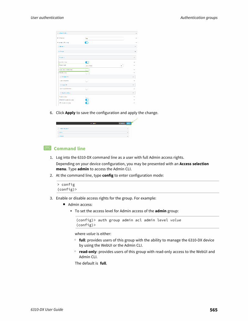
User authentication Authentication groups
6310-DX User Guide 565
6. Click Apply to save the configuration and apply the change.
Command line
1. Log into the 6310-DX command line as a user with full Admin access rights.Depending on your device configuration, you may be presented with an Access selectionmenu. Type admin to access the Admin CLI.
2. At the command line, type config to enter configuration mode:
> config(config)>
3. Enable or disable access rights for the group. For example:n Admin access:
l To set the access level for Admin access of the admin group:
(config)> auth group admin acl admin level value(config)>
where value is either:o full: provides users of this group with the ability to manage the 6310-DX device
by using the WebUI or the Admin CLI.o read-only: provides users of this group with read-only access to the WebUI and
Admin CLI.The default is full.
User authentication Authentication groups
6310-DX User Guide 566
l To disable Admin access for the admin group:
(config)> auth group admin acl admin enable false(config)>
n Shell access:l To enable Shell access for the serial group:
(config)> auth group serial acl shell enable true(config)>
Shell access is not available if the Allow shell parameter has been disabled. SeeDisable shell access for more information about the Allow shell parameter.
n Serial access:l To enable Serial access for the admin group:
(config)> auth group admin acl serial enable true(config)>
4. Save the configuration and apply the change:
(config)> saveConfiguration saved.>
5. Type exit to exit the Admin CLI.Depending on your device configuration, you may be presented with an Access selectionmenu. Type quit to disconnect from the device.
Add an authentication group
Required configuration items
n The access rights to be assigned to users that are assigned to this group.
Additional configuration items
n Access rights to OpenVPN tunnels, and the tunnels to which they have access.n Access rights to captive portals, and the portals to which they have access.n Access rights to query the device for Nagios monitoring.
To add an authentication group:
WebUI
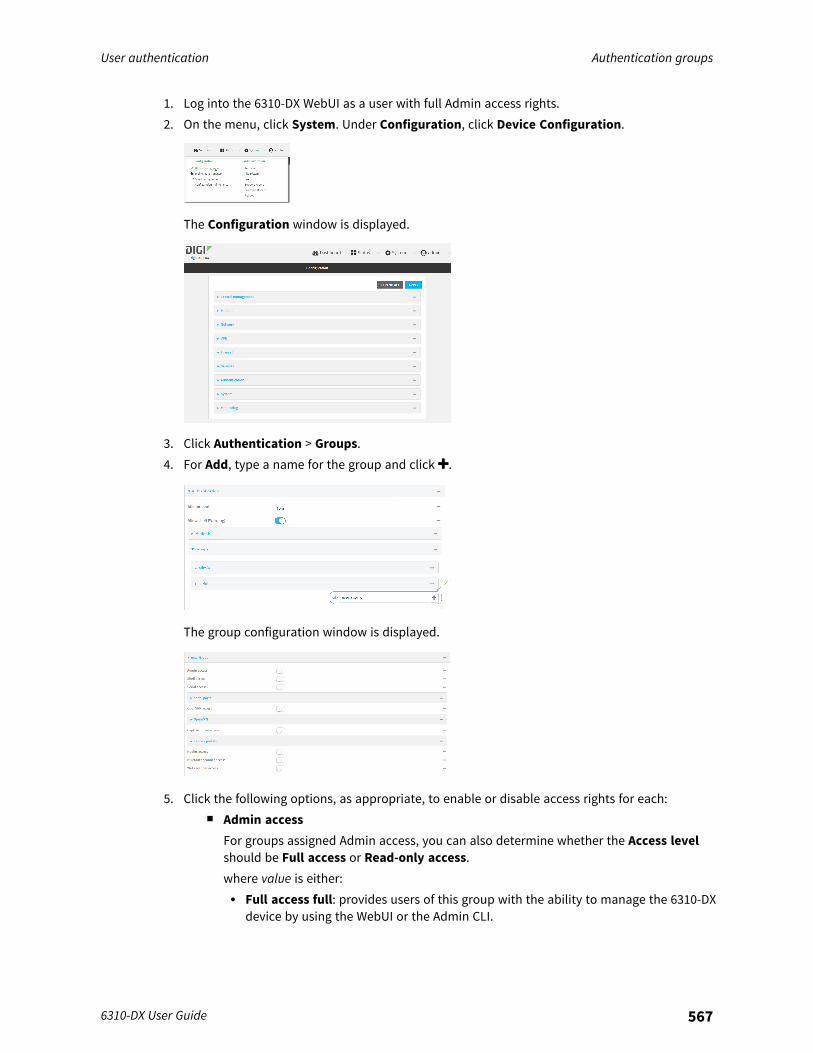
User authentication Authentication groups
6310-DX User Guide 567
1. Log into the 6310-DX WebUI as a user with full Admin access rights.2. On the menu, click System. Under Configuration, click Device Configuration.
The Configuration window is displayed.
3. Click Authentication > Groups.4. For Add, type a name for the group and click .
The group configuration window is displayed.
5. Click the following options, as appropriate, to enable or disable access rights for each:n Admin access
For groups assigned Admin access, you can also determine whether the Access levelshould be Full access or Read-only access.where value is either:l Full access full: provides users of this group with the ability to manage the 6310-DX
device by using the WebUI or the Admin CLI.

User authentication Authentication groups
6310-DX User Guide 568
l Read-only access read-only: provides users of this group with read-only access tothe WebUI and Admin CLI.
The default is Full access full.n Shell access
Shell access is not available if the Allow shell parameter has been disabled. See Disableshell access for more information about the Allow shell parameter.
n Serial access6. (Optional) Configure the serial ports to which users of this group have access:
a. Click Serial ports to expand the Serial ports node.b. For Add Port, click .c. In the Port dropdown, select a port.d. Click again to add additional serial ports.
7. (Optional) Configure OpenVPN access. See for further information.8. (Optional) Configure captive portal access:
a. Enable captive portal access rights for users of this group by checking the box next toCaptive portal access.
b. Click Captive portals to expand the Captive portal node.c. For Add Captive portal, click .d. In the Captive portal dropdown, select a captive portal to which users of this group will
have access.e. Click again to add additional captive portals.
9. (Optional) Enable users that belong to this group to query the device for Nagios monitoring bychecking the box next to Nagios access.
10. (Optional) Enable users that belong to this group to access the Bluetooth scanning service bychecking the box next to Bluetooth scanner access.
11. Click Apply to save the configuration and apply the change.
Command line
1. Log into the 6310-DX command line as a user with full Admin access rights.Depending on your device configuration, you may be presented with an Access selectionmenu. Type admin to access the Admin CLI.
2. At the command line, type config to enter configuration mode:
> config(config)>
3. Use the add auth group command to add a new authentication. For example, to add a groupnamed test:

User authentication Authentication groups
6310-DX User Guide 569
(config)> add auth group test(config auth group test)>
4. Enable access rights for the group:n Admin access:
(config auth group test)> acl admin enable true(config)>
n Set the access level for Admin access:
(config)> auth group admin acl admin level value(config)>
where value is either:l full: provides users of this group with the ability to manage the 6310-DX device by
using the WebUI or the Admin CLI.l read-only: provides users of this group with read-only access to the WebUI and
Admin CLI.The default is full.
n Shell access:
(config auth group test)> acl shell enable true(config)>
Shell access is not available if the Allow shell parameter has been disabled. See Disableshell access for more information about the Allow shell parameter.
n Serial access:
(config auth group test)> acl serial enable true(config)>
5. (Optional) Configure captive portal access:a. Return to the config prompt by typing three periods (...):
(config auth group test)> ...(config)>
b. Enable captive portal access rights for users of this group:
(config)> auth group test acl portal enable true(config)>
c. Add a captive portal to which users of this group will have access:i. Determine available portals:
(config)> show firewall portalportal1
auth noneenable true
User authentication Authentication groups
6310-DX User Guide 570
http redirectno interfaceno messageno redirect_urlno termstimeout 24hno title
(config)>
ii. Add a captive portal:
(config)> add auth group test acl portal portals end portal1(config)>
6. (Optional) Configure Nagios monitoring:
(config)> auth group test acl nagios enable true(config)>
7. (Optional) Enable users that belong to this group to access the Bluetooth scanning service:
(config)> auth group test acl bluetooth_scanner enable true(config)>
8. Save the configuration and apply the change:
(config)> saveConfiguration saved.>
9. Type exit to exit the Admin CLI.Depending on your device configuration, you may be presented with an Access selectionmenu. Type quit to disconnect from the device.
Delete an authentication groupBy default, the 6310-DX device has two preconfigured authentication groups: admin and serial. Thesegroups cannot be deleted.To delete an authentication group that you have created:
WebUI
1. Log into the 6310-DX WebUI as a user with full Admin access rights.2. On the menu, click System. Under Configuration, click Device Configuration.
The Configuration window is displayed.
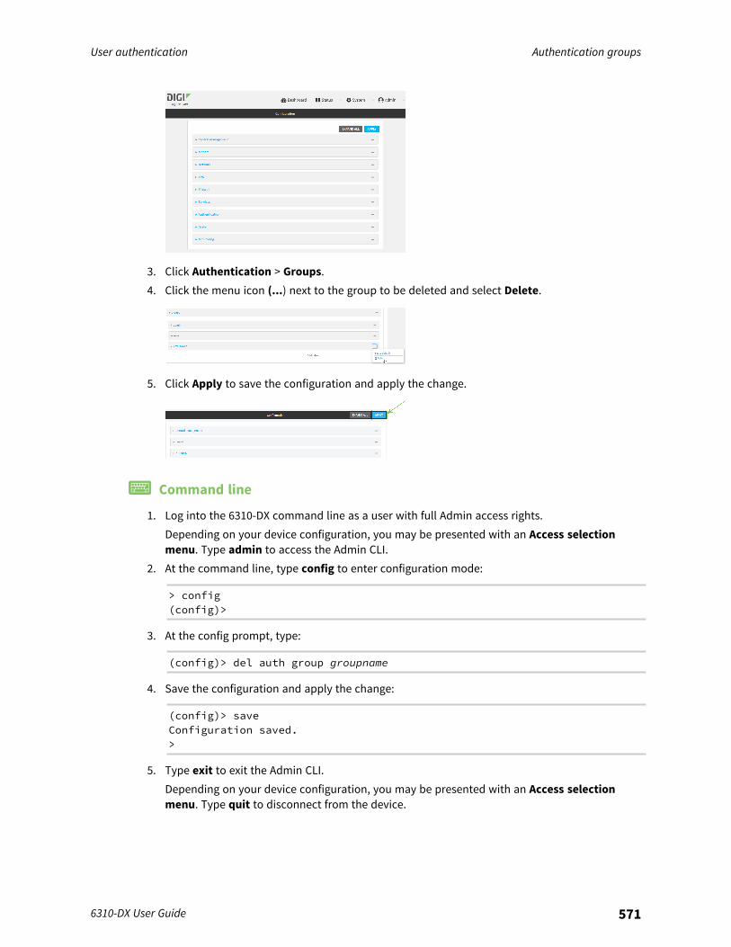
User authentication Authentication groups
6310-DX User Guide 571
3. Click Authentication > Groups.4. Click the menu icon (...) next to the group to be deleted and select Delete.
5. Click Apply to save the configuration and apply the change.
Command line
1. Log into the 6310-DX command line as a user with full Admin access rights.Depending on your device configuration, you may be presented with an Access selectionmenu. Type admin to access the Admin CLI.
2. At the command line, type config to enter configuration mode:
> config(config)>
3. At the config prompt, type:
(config)> del auth group groupname
4. Save the configuration and apply the change:
(config)> saveConfiguration saved.>
5. Type exit to exit the Admin CLI.Depending on your device configuration, you may be presented with an Access selectionmenu. Type quit to disconnect from the device.

User authentication Local users
6310-DX User Guide 572
Local usersLocal users are authenticated on the device without using an external authentication mechanism suchas TACACS+ or RADIUS. Local user authentication is enabled by default, with one preconfiged defaultuser.
Default userAt manufacturing time, each 6310-DX device comes with a default user configured as follows:
n Username: admin.n Password: The default password is displayed on the label on the bottom of the device.
Note The default password is a unique password for the device, and is the most criticalsecurity feature for the device. If you reset the device to factory defaults, you must log in usingthe default user and password, and you should immediately change the password to a custompassword. Before deploying or mounting the 6310-DX device, record the default password, soyou have the information available when you need it even if you cannot physically access thelabel on the bottom of the device.
The default admin user is preconfigured with both Admin and Serial access. You can configure theadmin user account to fit with the needs of your environment.This section contains the following topics:
Change a local user's password 573Configure a local user 575Delete a local user 583
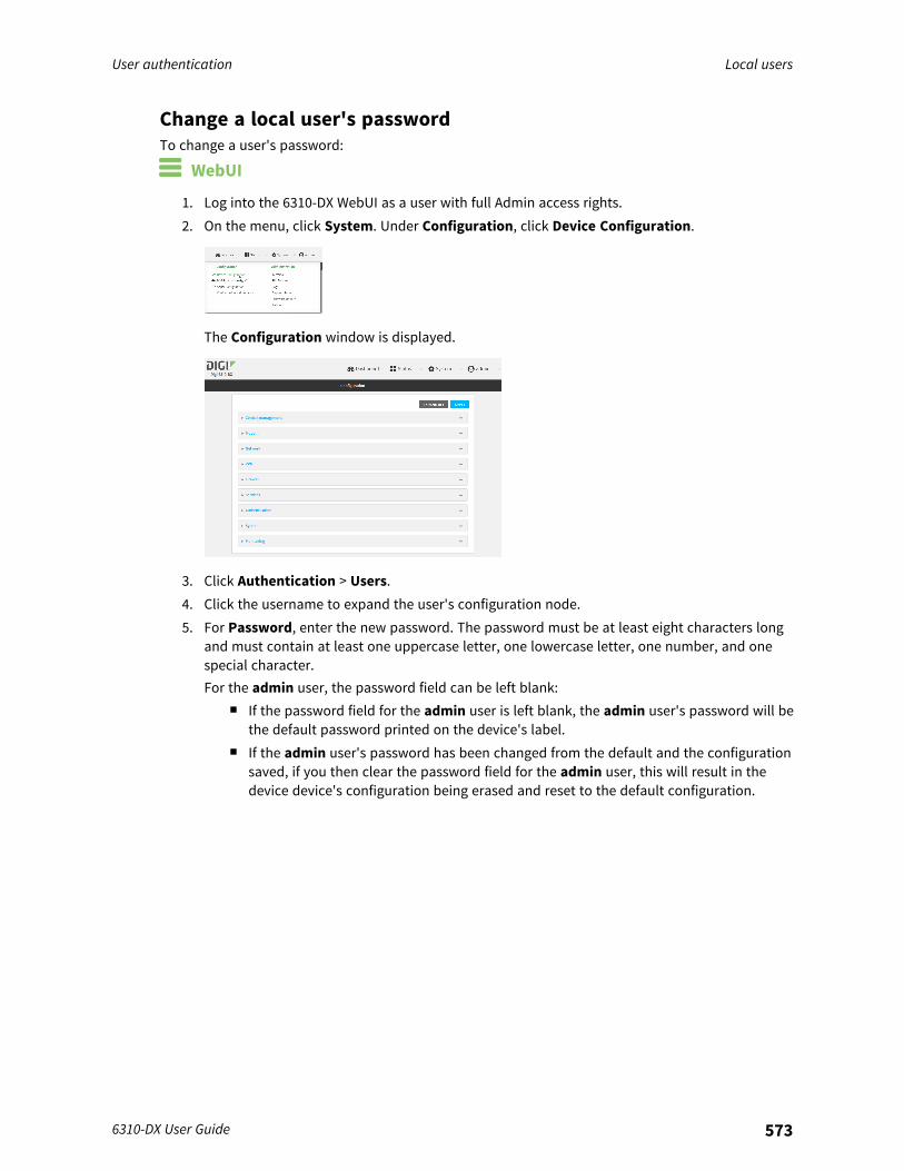
User authentication Local users
6310-DX User Guide 573
Change a local user's passwordTo change a user's password:
WebUI
1. Log into the 6310-DX WebUI as a user with full Admin access rights.2. On the menu, click System. Under Configuration, click Device Configuration.
The Configuration window is displayed.
3. Click Authentication > Users.4. Click the username to expand the user's configuration node.5. For Password, enter the new password. The password must be at least eight characters long
and must contain at least one uppercase letter, one lowercase letter, one number, and onespecial character.For the admin user, the password field can be left blank:
n If the password field for the admin user is left blank, the admin user's password will bethe default password printed on the device's label.
n If the admin user's password has been changed from the default and the configurationsaved, if you then clear the password field for the admin user, this will result in thedevice device's configuration being erased and reset to the default configuration.
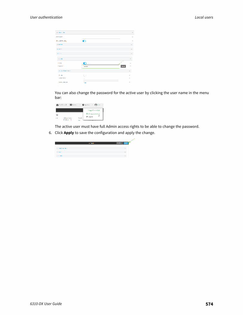
User authentication Local users
6310-DX User Guide 574
You can also change the password for the active user by clicking the user name in the menubar:
The active user must have full Admin access rights to be able to change the password.6. Click Apply to save the configuration and apply the change.
User authentication Local users
6310-DX User Guide 575
Command line
1. Log into the 6310-DX command line as a user with full Admin access rights.Depending on your device configuration, you may be presented with an Access selectionmenu. Type admin to access the Admin CLI.
2. At the command line, type config to enter configuration mode:
> config(config)>
3. At the config prompt, type:
(config)> auth user username password pwd
Where:n username is the name of the user.n pwd is the new password for the user. The password must be at least eight characters
long and must contain at least one uppercase letter, one lowercase letter, one number,and one special character.
4. Save the configuration and apply the change:
(config)> saveConfiguration saved.>
5. Type exit to exit the Admin CLI.Depending on your device configuration, you may be presented with an Access selectionmenu. Type quit to disconnect from the device.
Configure a local user
Required configuration items
n A username.n A password. The password must be at least eight characters long and must contain at least
one uppercase letter, one lowercase letter, one number, and one special character. Forsecurity reasons, passwords are stored in hash form. There is no way to get or displaypasswords in clear-text form, although prior to saving the configuration, the password can beshown by clicking Reveal.
n The authentication group or groups from which the user will inherit access rights. SeeAuthentication groups for information about configuring groups.
Additional configuration items
n An alias for the user. Because the username cannot contain any special characters, such ashyphens (-) or periods (.), an alias allows the user to log in using a name that contains specialcharacters.
n The number of unsuccessful login attempts before the user is locked out of the system.
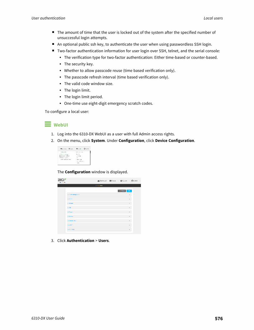
User authentication Local users
6310-DX User Guide 576
n The amount of time that the user is locked out of the system after the specified number ofunsuccessful login attempts.
n An optional public ssh key, to authenticate the user when using passwordless SSH login.n Two-factor authentication information for user login over SSH, telnet, and the serial console:
l The verification type for two-factor authentication: Either time-based or counter-based.l The security key.l Whether to allow passcode reuse (time based verification only).l The passcode refresh interval (time based verification only).l The valid code window size.l The login limit.l The login limit period.l One-time use eight-digit emergency scratch codes.
To configure a local user:
WebUI
1. Log into the 6310-DX WebUI as a user with full Admin access rights.2. On the menu, click System. Under Configuration, click Device Configuration.
The Configuration window is displayed.
3. Click Authentication > Users.
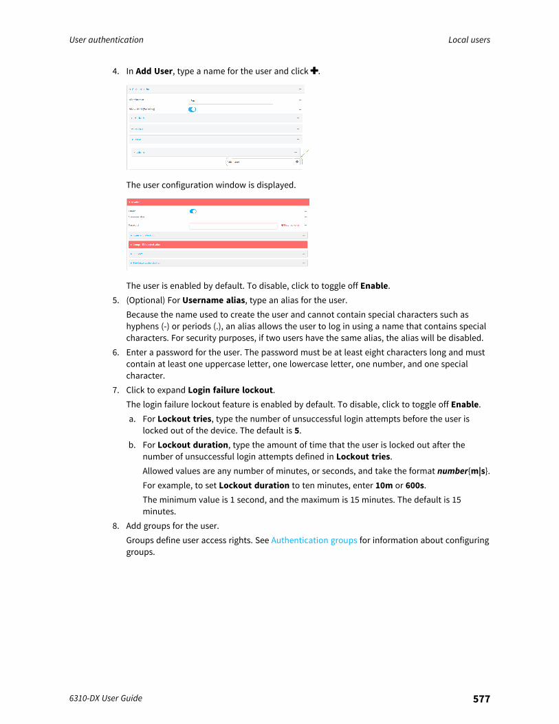
User authentication Local users
6310-DX User Guide 577
4. In Add User, type a name for the user and click .
The user configuration window is displayed.
The user is enabled by default. To disable, click to toggle off Enable.5. (Optional) For Username alias, type an alias for the user.
Because the name used to create the user and cannot contain special characters such ashyphens (-) or periods (.), an alias allows the user to log in using a name that contains specialcharacters. For security purposes, if two users have the same alias, the alias will be disabled.
6. Enter a password for the user. The password must be at least eight characters long and mustcontain at least one uppercase letter, one lowercase letter, one number, and one specialcharacter.
7. Click to expand Login failure lockout.The login failure lockout feature is enabled by default. To disable, click to toggle off Enable.a. For Lockout tries, type the number of unsuccessful login attempts before the user is
locked out of the device. The default is 5.b. For Lockout duration, type the amount of time that the user is locked out after the
number of unsuccessful login attempts defined in Lockout tries.Allowed values are any number of minutes, or seconds, and take the format number{m|s}.For example, to set Lockout duration to ten minutes, enter 10m or 600s.The minimum value is 1 second, and the maximum is 15 minutes. The default is 15minutes.
8. Add groups for the user.Groups define user access rights. See Authentication groups for information about configuringgroups.
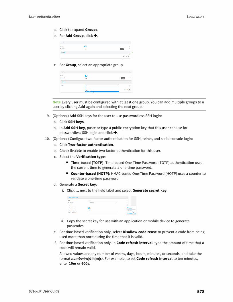
User authentication Local users
6310-DX User Guide 578
a. Click to expand Groups.b. For Add Group, click .
c. For Group, select an appropriate group.
Note Every user must be configured with at least one group. You can add multiple groups to auser by clicking Add again and selecting the next group.
9. (Optional) Add SSH keys for the user to use passwordless SSH login:a. Click SSH keys.b. In Add SSH key, paste or type a public encryption key that this user can use for
passwordless SSH login and click .10. (Optional) Configure two-factor authentication for SSH, telnet, and serial console login:
a. Click Two-factor authentication.b. Check Enable to enable two-factor authentication for this user.c. Select the Verification type:
n Time-based (TOTP): Time-based One-Time Password (TOTP) authentication usesthe current time to generate a one-time password.
n Counter-based (HOTP): HMAC-based One-Time Password (HOTP) uses a counter tovalidate a one-time password.
d. Generate a Secret key:i. Click ... next to the field label and select Generate secret key.
ii. Copy the secret key for use with an application or mobile device to generatepasscodes.
e. For time-based verification only, select Disallow code reuse to prevent a code from beingused more than once during the time that it is valid.
f. For time-based verification only, in Code refresh interval, type the amount of time that acode will remain valid.Allowed values are any number of weeks, days, hours, minutes, or seconds, and take theformat number{w|d|h|m|s}. For example, to set Code refresh interval to ten minutes,enter 10m or 600s.
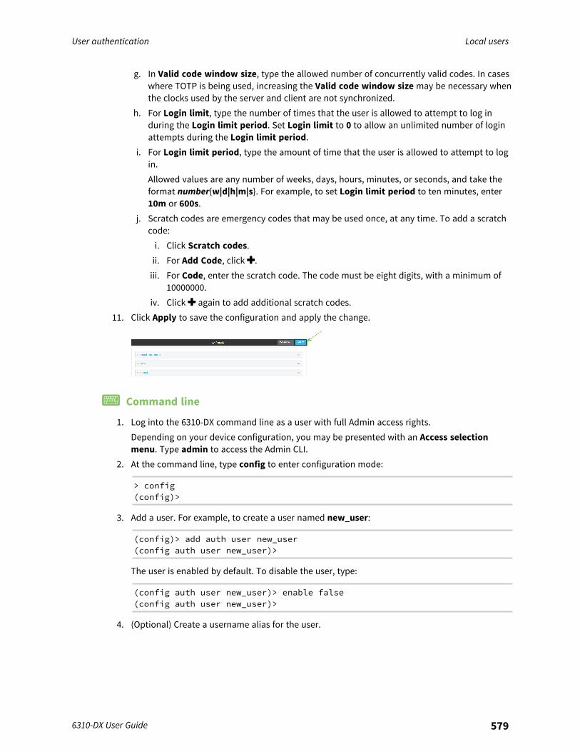
User authentication Local users
6310-DX User Guide 579
g. In Valid code window size, type the allowed number of concurrently valid codes. In caseswhere TOTP is being used, increasing the Valid code window size may be necessary whenthe clocks used by the server and client are not synchronized.
h. For Login limit, type the number of times that the user is allowed to attempt to log induring the Login limit period. Set Login limit to 0 to allow an unlimited number of loginattempts during the Login limit period.
i. For Login limit period, type the amount of time that the user is allowed to attempt to login.Allowed values are any number of weeks, days, hours, minutes, or seconds, and take theformat number{w|d|h|m|s}. For example, to set Login limit period to ten minutes, enter10m or 600s.
j. Scratch codes are emergency codes that may be used once, at any time. To add a scratchcode:i. Click Scratch codes.ii. For Add Code, click .iii. For Code, enter the scratch code. The code must be eight digits, with a minimum of
10000000.iv. Click again to add additional scratch codes.
11. Click Apply to save the configuration and apply the change.
Command line
1. Log into the 6310-DX command line as a user with full Admin access rights.Depending on your device configuration, you may be presented with an Access selectionmenu. Type admin to access the Admin CLI.
2. At the command line, type config to enter configuration mode:
> config(config)>
3. Add a user. For example, to create a user named new_user:
(config)> add auth user new_user(config auth user new_user)>
The user is enabled by default. To disable the user, type:
(config auth user new_user)> enable false(config auth user new_user)>
4. (Optional) Create a username alias for the user.
User authentication Local users
6310-DX User Guide 580
Because the name to create the user cannot contain special characters such as hyphens (-) orperiods (.), an alias allows the user to log in using a name that contains special characters. Forsecurity purposes, if two users have the same alias, the alias will be disabled.
(config auth user new_user> username username_alias(config auth user new_user)>
5. Set the user's password. The password must be at least eight characters long and mustcontain at least one uppercase letter, one lowercase letter, one number, and one specialcharacter.
(config auth user new_user> password pwd(config auth user new_user)>
6. Configure login failure lockout settings:The login failure lockout feature is enabled by default. To disable:
(config auth user new_user> lockout enable false(config auth user new_user)>
a. Set the number of unsuccessful login attempts before the user is locked out of the device.where value is any integer. The minimum value is 1, and the default value is 5.
b. Set the amount of time that the user is locked out after the number of unsuccessful loginattempts defined in lockout tries:
(config auth user new_user> lockout duration value(config auth user new_user)>
where value is any number of minutes, or seconds, and takes the format number{m|s}.For example, to set duration to ten minutes, enter either 10m or 600s:
(config auth user new_user)> lockout duration 600s(config auth user new_user)>
The minimum value is 1 second, and the maximum is 15 minutes. The default is 15minutes.
7. Add groups for the user.Groups define user access rights. See Authentication groups for information about configuringgroups.a. Add a group to the user. For example, to add the admin group to the user:
(config auth user new_user> add group end admin(config auth user new_user)>
Note Every user must be configured with at least one group.
b. (Optional) Add additional groups by repeating the add group command:
(config auth user new_user> add group end serial(config auth user new_user)>
User authentication Local users
6310-DX User Guide 581
To remove a group from a user:a. Use the show command to determine the index number of the group to be deleted:
(config auth user new_user> show group0 admin1 serial(config auth user new_user>
b. Type the following:
(config auth user new_user)> del group n(config auth user new_user)>
Where n is index number of the authentication method to be deleted. For example, todelete the serial group as displayed by the example show command, above:
(config auth user new_user)> del group 1(config auth user new_user)>
8. (Optional) Add SSH keys for the user to use passwordless SSH login:a. Change to the user's ssh_key node:
(config auth user new_user)> ssh_key(config auth user new_user ssh_key)>
b. Add the key by using the ssh_key command and pasting or typing a public encryption keythat this user can use for passwordless SSH login:
(config auth user new_user ssh_key)> ssh_key key(config auth user new_user ssh_key)>
9. (Optional) Configure two-factor authentication for SSH, telnet, and serial console login:a. Change to the user's two-factor authentication node:
(config auth user new_user)> 2fa(config auth user new_user 2fa)>
b. Enable two-factor authentication for this user:
(config auth user new_user 2fa)> enable true(config auth user new_user 2fa)>
c. Configure the verification type. Allowed values are:n totp: Time-based One-Time Password (TOTP) authentication uses the current time
to generate a one-time password.n hotp: HMAC-based One-Time Password (HOTP) uses a counter to validate a one-
time password.The default value is totp.
(config auth user new_user 2fa)> type totp(config auth user new_user 2fa)>

User authentication Local users
6310-DX User Guide 582
d. Add a secret key:
(config auth user new_user 2fa)> secret key(config auth user new_user 2fa)>
This key should be used by an application or mobile device to generate passcodes.e. For time-based verification only, enable disallow_reuse to prevent a code from being
used more than once during the time that it is valid.
(config auth user new_user 2fa)> disallow_reuse true(config auth user new_user 2fa)>
f. For time-based verification only, configure the code refresh interval. This is the amount oftime that a code will remain valid.
(config auth user new_user 2fa)> refresh_interval value(config auth user new_user 2fa)>
where value is any number of weeks, days, hours, minutes, or seconds, and takes theformat number{w|d|h|m|s}.For example, to set refresh_interval to ten minutes, enter either 10m or 600s:
(config auth user name 2fa)> refresh_interval 600s(config auth user name 2fa)>
The default is 30s.g. Configure the valid code window size. This represents the allowed number of concurrently
valid codes. In cases where TOTP is being used, increasing the valid code window size maybe necessary when the clocks used by the server and client are not synchronized.
(config auth user new_user 2fa)> window_size 3(config auth user new_user 2fa)>
h. Configure the login limit. This represents the number of times that the user is allowed toattempt to log in during the Login limit period. Set to 0 to allow an unlimited number oflogin attempts during the Login limit period
(config auth user new_user 2fa)> login_limit 3(config auth user new_user 2fa)>
i. Configure the login limit period. This is the amount of time that the user is allowed toattempt to log in.
(config auth user new_user 2fa)> login_limit_period value(config auth user new_user 2fa)>
where value is any number of weeks, days, hours, minutes, or seconds, and takes theformat number{w|d|h|m|s}.For example, to set login_limit_period to ten minutes, enter either 10m or 600s:

User authentication Local users
6310-DX User Guide 583
(config auth user name 2fa)> login_limit_period 600s(config auth user name 2fa)>
The default is 30s.j. Scratch codes are emergency codes that may be used once, at any time. To add a scratch
code:i. Change to the user's scratch code node:
(config auth user new_user 2fa)> scratch_code(config auth user new_user 2fa scratch_code)>
ii. Add a scratch code:
(config auth user new_user 2fa scratch_code)> add end code(config auth user new_user 2fa scratch_code)>
Where code is an digit number, with a minimum of 10000000.iii. To add additional scratch codes, use the add end code command again.
10. Save the configuration and apply the change:
(config auth user new 2fa scratch_code)> saveConfiguration saved.>
11. Type exit to exit the Admin CLI.Depending on your device configuration, you may be presented with an Access selectionmenu. Type quit to disconnect from the device.
Delete a local userTo delete a user from your 6310-DX:
WebUI
1. Log into the 6310-DX WebUI as a user with full Admin access rights.2. On the menu, click System. Under Configuration, click Device Configuration.
The Configuration window is displayed.
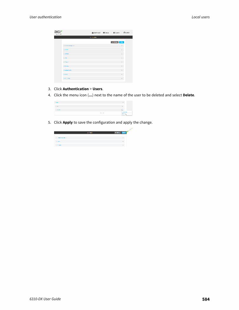
User authentication Local users
6310-DX User Guide 584
3. Click Authentication > Users.4. Click the menu icon (...) next to the name of the user to be deleted and select Delete.
5. Click Apply to save the configuration and apply the change.
User authentication Local users
6310-DX User Guide 585
Command line
1. Log into the 6310-DX command line as a user with full Admin access rights.Depending on your device configuration, you may be presented with an Access selectionmenu. Type admin to access the Admin CLI.
2. At the command line, type config to enter configuration mode:
> config(config)>
3. At the config prompt, type:
(config)> del auth user username
4. Save the configuration and apply the change:
(config)> saveConfiguration saved.>
5. Type exit to exit the Admin CLI.Depending on your device configuration, you may be presented with an Access selectionmenu. Type quit to disconnect from the device.

User authentication Terminal Access Controller Access-Control System Plus (TACACS+)
6310-DX User Guide 586
Terminal Access Controller Access-Control System Plus(TACACS+)
Your 6310-DX device supports Terminal Access Controller Access-Control System Plus (TACACS+), anetworking protocol that provides centralized authentication and authorization management forusers who connect to the device. With TACACS+ support, the 6310-DX device acts as a TACACS+ client,which sends user credentials and connection parameters to a TACACS+ server over TCP. The TACACS+server then authenticates the TACACS+ client requests and sends back a response message to thedevice.When you are using TACACS+ authentication, you can have both local users and TACACS+ users ableto log in to the device. To use TACACS+ authentication, you must set up a TACACS+ server that isaccessible by the 6310-DX device prior to configuration. The process of setting up a TACACS+ servervaries by the server environment.This section contains the following topics:
TACACS+ user configuration 587TACACS+ server failover and fallback to local authentication 588Configure your 6310-DX device to use a TACACS+ server 588

User authentication Terminal Access Controller Access-Control System Plus (TACACS+)
6310-DX User Guide 587
TACACS+ user configurationWhen configured to use TACACS+ support, the 6310-DX device uses a remote TACACS+ server for userauthentication (password verification) and authorization (assigning the access level of the user).Additional TACACS+ servers can be configured as backup servers for user authentication.This section outlines how to configure a TACACS+ server to be used for user authentication on your6310-DX device.
Example TACACS+ configurationWith TACACS+, users are defined in the server configuration file. On Ubuntu, the default location andfilename for the server configuration file is /etc/tacacs+/tac_plus.conf.
Note TACACS+ configuration, including filenames and locations, may vary depending on yourplatform and installation. This example assumes a Ubuntu installation.
To define users:
1. Open the TACACS+ server configuration file in a text editor. For example:
$ sudo gedit /etc/tacacs+/tac_plus.conf
2. Add users to the file using the following format. This example will create two users, one withadmin and serial access, and one with only serial access.
user = user1 {name ="User1 for 6310-DX"pap = cleartext password1service = system {
groupname = admin,serial}
}user = user2 {
name ="User2 for 6310-DX"pap = cleartext password2service = system {
groupname = serial}
}
The groupname attribute is optional. If used, the value must correspond to authenticationgroups configured on your 6310-DX. Alternatively, if the user is also configured as a local useron the 6310-DX device and the LDAP server authenticates the user but does not return anygroups, the local configuration determines the list of groups. See Authentication groups formore information about authentication groups. The groupname attribute can contain onegroup or multiple groups in a comma-separated list.
3. Save and close the file.4. Verify that your changes did not introduce any syntax errors:
$ sudo tac_plus -C /etc/tacacs+/tac_plus.conf -P
If successful, this command will echo the configuration file to standard out. If the commandencounters any syntax errors, a message similar to this will display:

User authentication Terminal Access Controller Access-Control System Plus (TACACS+)
6310-DX User Guide 588
Error: Unrecognised token on line 1
5. Restart the TACACS+ server:
$ sudo /etc/init.d/tacacs_plus restart
TACACS+ server failover and fallback to local authenticationIn addition to the primary TACACS+ server, you can also configure your 6310-DX device to use backupTACACS+ servers. Backup TACACS+ servers are used for authentication requests when the primaryTACACS+ server is unavailable.
Falling back to local authenticationWith user authentication methods, you can configure your 6310-DX device to use multiple types ofauthentication. For example, you can configure both TACACS+ authentication and localauthentication, so that local authentication can be used as a fallback mechanism if the primary andbackup TACACS+ servers are unavailable. Additionally, users who are configured locally but are notconfigured on the TACACS+ server are still able to log into the device. Authentication methods areattempted in the order they are listed until the first successful authentication result is returned;therefore if you want to ensure that users are authenticated first through the TACACS+ server, andonly authenticated locally if the TACACS+ server is unavailable or if the user is not defined on theTACACS+ server, then you should list the TACACS+ authentication method prior to the Local usersauthentication method.See User authentication methods for more information about authentication methods.If the TACACS+ servers are unavailable and the 6310-DX device falls back to local authentication, onlyusers defined locally on the device are able to log in. TACACS+ users cannot log in until the TACACS+servers are brought back online.
Configure your 6310-DX device to use a TACACS+ serverThis section describes how to configure a 6310-DX device to use a TACACS+ server for authenticationand authorization.
Required configuration items
n Define the TACACS+ server IP address or domain name.n Define the TACACS+ server shared secret.n The group attribute configured in the TACACS+ server configuration.n The service field configured in the TACACS+ server configuration.n Add TACACS+ as an authentication method for your 6310-DX device.
Additional configuration items
n Whether other user authentication methods should be used in addition to the TACACS+ server,or if the TACACS+ server should be considered the authoritative login method.
n Enable command authorization, so that the device will communicate with the TACACS+ serverto determine if the user is authorized to execute a specific command.
n Enable command accounting, so that the device will communicate with the TACACS+ server tolog commands that the user executes.
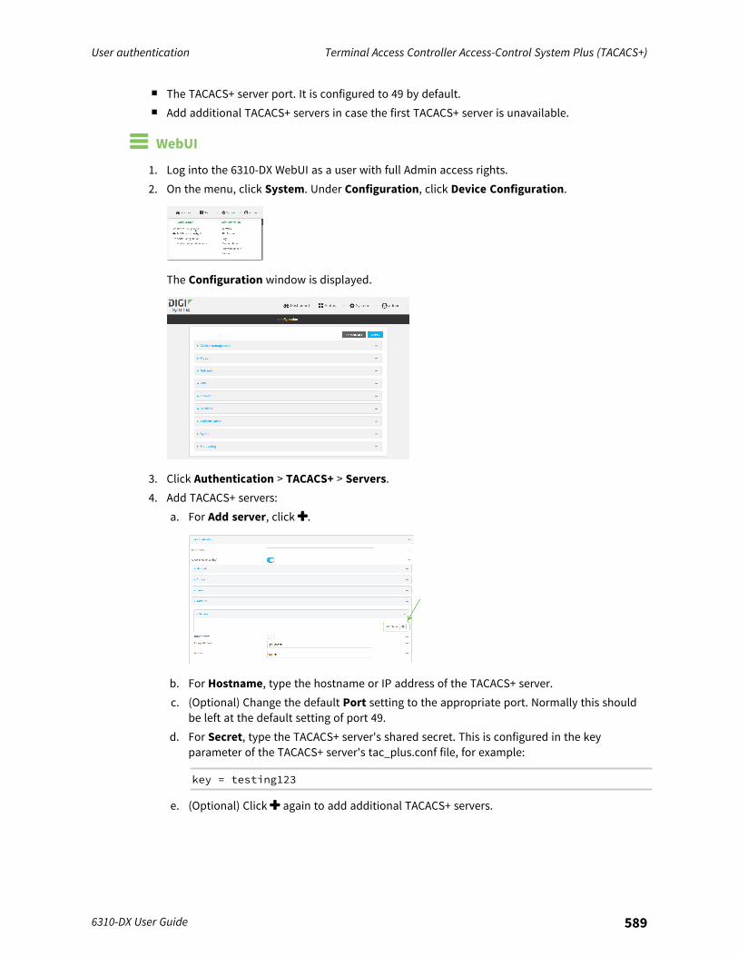
User authentication Terminal Access Controller Access-Control System Plus (TACACS+)
6310-DX User Guide 589
n The TACACS+ server port. It is configured to 49 by default.n Add additional TACACS+ servers in case the first TACACS+ server is unavailable.
WebUI
1. Log into the 6310-DX WebUI as a user with full Admin access rights.2. On the menu, click System. Under Configuration, click Device Configuration.
The Configuration window is displayed.
3. Click Authentication > TACACS+ > Servers.4. Add TACACS+ servers:
a. For Add server, click .
b. For Hostname, type the hostname or IP address of the TACACS+ server.c. (Optional) Change the default Port setting to the appropriate port. Normally this should
be left at the default setting of port 49.d. For Secret, type the TACACS+ server's shared secret. This is configured in the key
parameter of the TACACS+ server's tac_plus.conf file, for example:
key = testing123
e. (Optional) Click again to add additional TACACS+ servers.
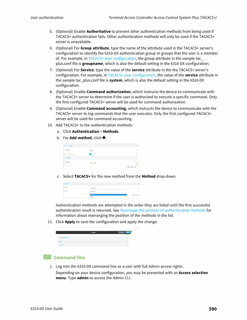
User authentication Terminal Access Controller Access-Control System Plus (TACACS+)
6310-DX User Guide 590
5. (Optional) Enable Authoritative to prevent other authentication methods from being used ifTACACS+ authentication fails. Other authentication methods will only be used if the TACACS+server is unavailable.
6. (Optional) For Group attribute, type the name of the attribute used in the TACACS+ server'sconfiguration to identify the 6310-DX authentication group or groups that the user is a memberof. For example, in TACACS+ user configuration, the group attribute in the sample tac_plus.conf file is groupname, which is also the default setting in the 6310-DX configuration.
7. (Optional) For Service, type the value of the service attribute in the the TACACS+ server'sconfiguration. For example, in TACACS+ user configuration, the value of the service attribute inthe sample tac_plus.conf file is system, which is also the default setting in the 6310-DXconfiguration.
8. (Optional) Enable Command authorization, which instructs the device to communicate withthe TACACS+ server to determine if the user is authorized to execute a specific command. Onlythe first configured TACACS+ server will be used for command authorization.
9. (Optional) Enable Command accounting, which instructs the device to communicate with theTACACS+ server to log commands that the user executes. Only the first configured TACACS+server will be used for command accounting.
10. Add TACACS+ to the authentication methods:a. Click Authentication > Methods.b. For Add method, click .
c. Select TACACS+ for the new method from the Method drop-down.
Authentication methods are attempted in the order they are listed until the first successfulauthentication result is returned. See Rearrange the position of authentication methods forinformation about rearranging the position of the methods in the list.
11. Click Apply to save the configuration and apply the change.
Command line
1. Log into the 6310-DX command line as a user with full Admin access rights.Depending on your device configuration, you may be presented with an Access selectionmenu. Type admin to access the Admin CLI.
User authentication Terminal Access Controller Access-Control System Plus (TACACS+)
6310-DX User Guide 591
2. At the command line, type config to enter configuration mode:
> config(config)>
3. (Optional) Prevent other authentication methods from being used if TACACS+ authenticationfails. Other authentication methods will only be used if the TACACS+ server is unavailable.
(config)> auth tacacs+ authoritative true(config)>
4. (Optional) Configure the group_attribute. This is the name of the attribute used in the TACACS+server's configuration to identify the 6310-DX authentication group or groups that the user is amember of. For example, in TACACS+ user configuration, the group attribute in the sampletac_plus.conf file is groupname, which is also the default setting for the group_attribute in the6310-DX configuration.
(config)> auth tacacs+ group_attribute attribute-name(config)>
5. (Optional) Configure the type of service. This is the value of the service attribute in the theTACACS+ server's configuration. For example, in TACACS+ user configuration, the value of theservice attribute in the sample tac_plus.conf file is system, which is also the default setting inthe 6310-DX configuration.
(config)> auth tacacs+ service service-name(config)>
6. (Optional) Enable command authorization, which instructs the device to communicate with theTACACS+ server to determine if the user is authorized to execute a specific command. Only thefirst configured TACACS+ server will be used for command authorization.
(config)> auth tacacs+ command_authorization true(config)>
7. (Optional) Enable command accounting, which instructs the device to communicate with theTACACS+ server to log commands that the user executes. Only the first configured TACACS+server will be used for command accounting.
(config)> auth tacacs+ command_accounting true(config)>
8. Add a TACACS+ server:a. Add the server:
(config)> add auth tacacs+ server end(config auth tacacs+ server 0)>
b. Enter the TACACS+ server's IP address or hostname:
(config auth tacacs+ server 0)> hostname hostname|ip-address(config auth tacacs+ server 0)>

User authentication Terminal Access Controller Access-Control System Plus (TACACS+)
6310-DX User Guide 592
c. (Optional) Change the default port setting to the appropriate port:
(config auth tacacs+ server 0)> port port(config auth tacacs+ server 0)>
d. (Optional) Repeat the above steps to add additional TACACS+ servers.9. Add TACACS+ to the authentication methods. Authentication methods are attempted in the
order they are listed until the first successful authentication result is returned. This examplewill add TACACS+ to the end of the list. See User authentication methods for information aboutadding methods to the beginning or middle of the list.
(config)> add auth method end tacacs+(config)>
10. Save the configuration and apply the change:
(config)> saveConfiguration saved.>
11. Type exit to exit the Admin CLI.Depending on your device configuration, you may be presented with an Access selectionmenu. Type quit to disconnect from the device.
User authentication Remote Authentication Dial-In User Service (RADIUS)
6310-DX User Guide 593
Remote Authentication Dial-In User Service (RADIUS)Your 6310-DX device supports Remote Authentication Dial-In User Service (RADIUS), a networkingprotocol that provides centralized authentication and authorization management for users whoconnect to the device. With RADIUS support, the 6310-DX device acts as a RADIUS client, which sendsuser credentials and connection parameters to a RADIUS server over UDP. The RADIUS server thenauthenticates the RADIUS client requests and sends back a response message to the device.When you are using RADIUS authentication, you can have both local users and RADIUS users able tolog in to the device. To use RADIUS authentication, you must set up a RADIUS server that is accessibleby the 6310-DX device prior to configuration. The process of setting up a RADIUS server varies by theserver environment. An example of a RADIUS server is FreeRADIUS.This section contains the following topics:
RADIUS user configuration 594RADIUS server failover and fallback to local configuration 594Configure your 6310-DX device to use a RADIUS server 595
User authentication Remote Authentication Dial-In User Service (RADIUS)
6310-DX User Guide 594
RADIUS user configurationWhen configured to use RADIUS support, the 6310-DX device uses a remote RADIUS server for userauthentication (password verification) and authorization (assigning the access level of the user).Additional RADIUS servers can be configured as backup servers for user authentication.This section outlines how to configure a RADIUS server to be used for user authentication on your6310-DX device.
Example FreeRADIUS configurationWith FreeRADIUS, users are defined in the users file in your FreeRADIUS installation. To define users:
1. Open the FreeRadius user file in a text editor. For example:
$ sudo gedit /etc/freeradius/3.0/users
2. Add users to the file using the following format:
user1 Cleartext-Password := "user1"Unix-FTP-Group-Names := "admin"
user2 Cleartext-Password := "user2"Unix-FTP-Group-Names := "serial"
The Unix-FTP-Group-Names attribute is optional. If used, the value must correspond toauthentication groups configured on your 6310-DX. Alternatively, if the user is also configuredas a local user on the 6310-DX device and the RADIUS server authenticates the user but doesnot return any groups, the local configuration determines the list of groups. See Authenticationgroups for more information about authentication groups. The Unix-FTP-Group-Namesattribute can contain one group or multiple groups in a comma-separated list.
3. Save and close the file.4. Verify that your changes did not introduce any syntax errors:
$ sudo freeradius -CX
This should return a message that completes similar to:
...Configuration appears to be OK
5. Restart the FreeRADIUS server:
$ sudo /etc/init.d/freeradius restart
RADIUS server failover and fallback to local configurationIn addition to the primary RADIUS server, you can also configure your 6310-DX device to use backupRADIUS servers. Backup RADIUS servers are used for authentication requests when the primaryRADIUS server is unavailable.
Falling back to local authenticationWith user authentication methods, you can configure your 6310-DX device to use multiple types ofauthentication. For example, you can configure both RADIUS authentication and local authentication,so that local authentication can be used as a fallback mechanism if the primary and backup RADIUS
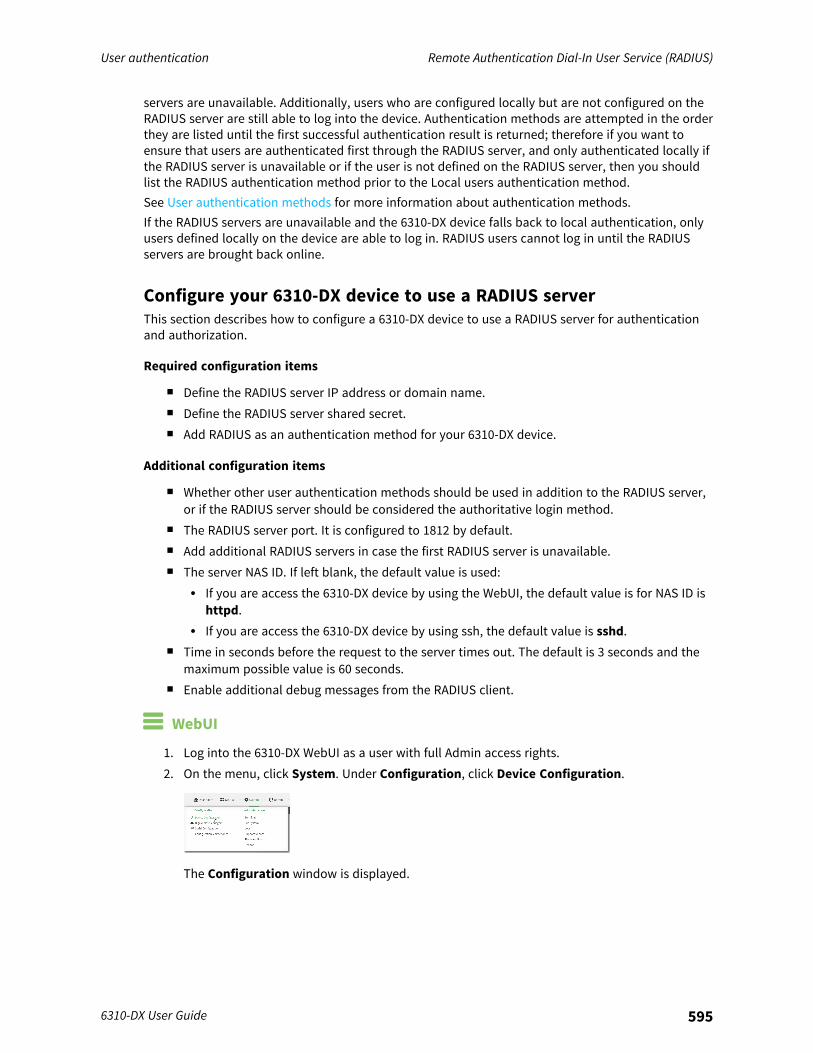
User authentication Remote Authentication Dial-In User Service (RADIUS)
6310-DX User Guide 595
servers are unavailable. Additionally, users who are configured locally but are not configured on theRADIUS server are still able to log into the device. Authentication methods are attempted in the orderthey are listed until the first successful authentication result is returned; therefore if you want toensure that users are authenticated first through the RADIUS server, and only authenticated locally ifthe RADIUS server is unavailable or if the user is not defined on the RADIUS server, then you shouldlist the RADIUS authentication method prior to the Local users authentication method.See User authentication methods for more information about authentication methods.If the RADIUS servers are unavailable and the 6310-DX device falls back to local authentication, onlyusers defined locally on the device are able to log in. RADIUS users cannot log in until the RADIUSservers are brought back online.
Configure your 6310-DX device to use a RADIUS serverThis section describes how to configure a 6310-DX device to use a RADIUS server for authenticationand authorization.
Required configuration items
n Define the RADIUS server IP address or domain name.n Define the RADIUS server shared secret.n Add RADIUS as an authentication method for your 6310-DX device.
Additional configuration items
n Whether other user authentication methods should be used in addition to the RADIUS server,or if the RADIUS server should be considered the authoritative login method.
n The RADIUS server port. It is configured to 1812 by default.n Add additional RADIUS servers in case the first RADIUS server is unavailable.n The server NAS ID. If left blank, the default value is used:
l If you are access the 6310-DX device by using the WebUI, the default value is for NAS ID ishttpd.
l If you are access the 6310-DX device by using ssh, the default value is sshd.n Time in seconds before the request to the server times out. The default is 3 seconds and the
maximum possible value is 60 seconds.n Enable additional debug messages from the RADIUS client.
WebUI
1. Log into the 6310-DX WebUI as a user with full Admin access rights.2. On the menu, click System. Under Configuration, click Device Configuration.
The Configuration window is displayed.
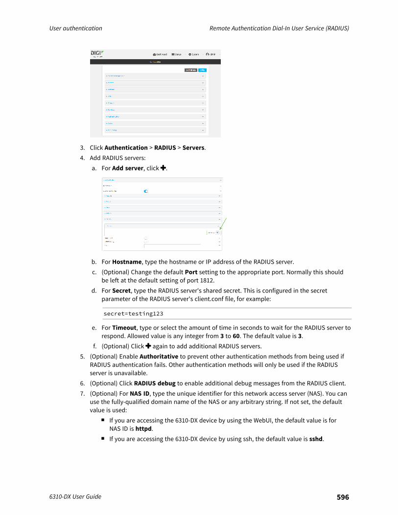
User authentication Remote Authentication Dial-In User Service (RADIUS)
6310-DX User Guide 596
3. Click Authentication > RADIUS > Servers.4. Add RADIUS servers:
a. For Add server, click .
b. For Hostname, type the hostname or IP address of the RADIUS server.c. (Optional) Change the default Port setting to the appropriate port. Normally this should
be left at the default setting of port 1812.d. For Secret, type the RADIUS server's shared secret. This is configured in the secret
parameter of the RADIUS server's client.conf file, for example:
secret=testing123
e. For Timeout, type or select the amount of time in seconds to wait for the RADIUS server torespond. Allowed value is any integer from 3 to 60. The default value is 3.
f. (Optional) Click again to add additional RADIUS servers.5. (Optional) Enable Authoritative to prevent other authentication methods from being used if
RADIUS authentication fails. Other authentication methods will only be used if the RADIUSserver is unavailable.
6. (Optional) Click RADIUS debug to enable additional debug messages from the RADIUS client.7. (Optional) For NAS ID, type the unique identifier for this network access server (NAS). You can
use the fully-qualified domain name of the NAS or any arbitrary string. If not set, the defaultvalue is used:
n If you are accessing the 6310-DX device by using the WebUI, the default value is forNAS ID is httpd.
n If you are accessing the 6310-DX device by using ssh, the default value is sshd.
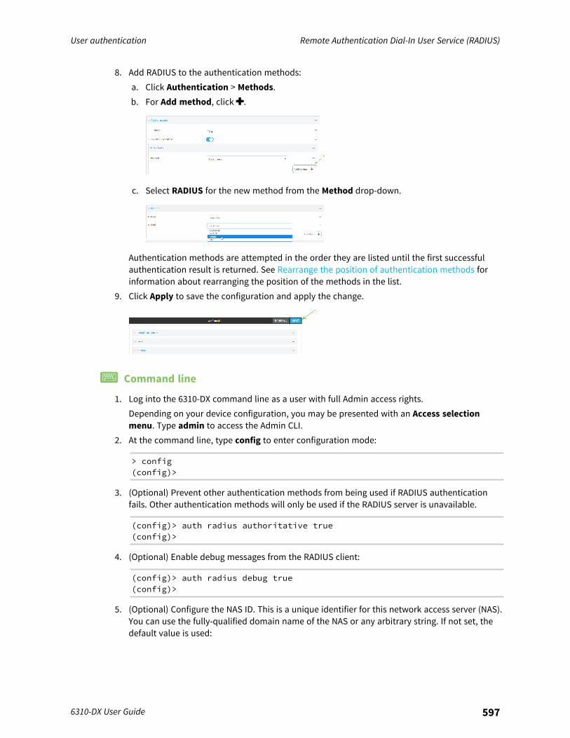
User authentication Remote Authentication Dial-In User Service (RADIUS)
6310-DX User Guide 597
8. Add RADIUS to the authentication methods:a. Click Authentication > Methods.b. For Add method, click .
c. Select RADIUS for the new method from the Method drop-down.
Authentication methods are attempted in the order they are listed until the first successfulauthentication result is returned. See Rearrange the position of authentication methods forinformation about rearranging the position of the methods in the list.
9. Click Apply to save the configuration and apply the change.
Command line
1. Log into the 6310-DX command line as a user with full Admin access rights.Depending on your device configuration, you may be presented with an Access selectionmenu. Type admin to access the Admin CLI.
2. At the command line, type config to enter configuration mode:
> config(config)>
3. (Optional) Prevent other authentication methods from being used if RADIUS authenticationfails. Other authentication methods will only be used if the RADIUS server is unavailable.
(config)> auth radius authoritative true(config)>
4. (Optional) Enable debug messages from the RADIUS client:
(config)> auth radius debug true(config)>
5. (Optional) Configure the NAS ID. This is a unique identifier for this network access server (NAS).You can use the fully-qualified domain name of the NAS or any arbitrary string. If not set, thedefault value is used:
User authentication LDAP
6310-DX User Guide 598
n If you are accessing the 6310-DX device by using the WebUI, the default value is forNAS ID is httpd.
n If you are accessing the 6310-DX device by using ssh, the default value is sshd.
(config)> auth radius nas_id id(config)>
6. Add a RADIUS server:a. Add the server:
(config)> add auth radius server end(config auth radius server 0)>
b. Enter the RADIUS server's IP address or hostname:
(config auth radius server 0)> hostname hostname|ip-address(config auth radius server 0)>
c. (Optional) Change the default port setting to the appropriate port:
(config auth radius server 0)> port port(config auth radius server 0)>
d. Configure the amount of time in seconds to wait for the RADIUS server to respond. Allowedvalue is any integer from 3 to 60. The default value is 3.
(config auth radius server 0)> timeout value(config auth radius server 0)>
e. (Optional) Repeat the above steps to add additional RADIUS servers.7. Add RADIUS to the authentication methods. Authentication methods are attempted in the
order they are listed until the first successful authentication result is returned. This examplewill add RADIUS to the end of the list. See User authentication methods for information aboutadding methods to the beginning or middle of the list.
(config)> add auth method end radius(config)>
8. Save the configuration and apply the change:
(config)> saveConfiguration saved.>
9. Type exit to exit the Admin CLI.Depending on your device configuration, you may be presented with an Access selectionmenu. Type quit to disconnect from the device.
LDAPYour 6310-DX device supports LDAP (Lightweight Directory Access Protocol), a protocol used fordirectory information services over an IP network. LDAP can be used with your 6310-DX device forcentralized authentication and authorization management for users who connect to the device. With
User authentication LDAP
6310-DX User Guide 599
LDAP support, the 6310-DX device acts as an LDAP client, which sends user credentials andconnection parameters to an LDAP server. The LDAP server then authenticates the LDAP clientrequests and sends back a response message to the device.When you are using LDAP authentication, you can have both local users and LDAP users able to log into the device. To use LDAP authentication, you must set up a LDAP server that is accessible by the6310-DX device prior to configuration. The process of setting up a LDAP server varies by the serverenvironment.This section contains the following topics:
LDAP user configuration 600LDAP server failover and fallback to local configuration 601Configure your 6310-DX device to use an LDAP server 601
User authentication LDAP
6310-DX User Guide 600
LDAP user configurationWhen configured to use LDAP support, the 6310-DX device uses a remote LDAP server for userauthentication (password verification) and authorization (assigning the access level of the user).Additional LDAP servers can be configured as backup servers for user authentication.This section outlines how to configure a LDAP server to be used for user authentication on your 6310-DX device.There are several different implementations of LDAP, including Microsoft Active Directory. This sectionuses OpenLDAP as an example configuration. Other implementations of LDAP will have differentconfiguration methods.
Example OpenLDAP configurationWith OpenLDAP, users can be configured in a text file using the LDAP Data Interchange Format (LDIF).In this case, we will be using a file called add_user.ldif.
1. Create the add_user.ldif file in a text editor. For example:
$ gedit ./add_user.ldif
2. Add users to the file using the following format:
dn: uid=john,dc=example,dc=comobjectClass: inetOrgPersoncn: John Smithsn: Smithuid: johnuserPassword: passwordou: admin serial
n The value of uid and userPassword must correspond to the username and passwordused to log into the 6310-DX device.
n The ou attribute is optional. If used, the value must correspond to authenticationgroups configured on your 6310-DX. Alternatively, if the user is also configured as a localuser on the 6310-DX device and the LDAP server authenticates the user but does notreturn any groups, the local configuration determines the list of groups. SeeAuthentication groups for more information about authentication groups.
Other attributes may be required by the user’s objectClass. Any objectClass may be used aslong it allows the uid, userPassword, and ou attributes.
3. Save and close the file.4. Add the user to the OpenLDAP server:
$ ldapadd -x -H 'ldap:///' -D 'cn=admin,dc=example,dc=com' -W -f add_user.ldifadding new entry "uid=john,dc=example,dc=com"
5. Verify that the user has been added by performing an LDAP search:
$ ldapsearch -x -LLL -H 'ldap:///' -b 'dc=example,dc=com'uid=johndn: uid=john,dc=example,dc=comobjectClass: inetOrgPerson
User authentication LDAP
6310-DX User Guide 601
cn: John Smithsn: Smithuid: johnou: admin serial
LDAP server failover and fallback to local configurationIn addition to the primary LDAP server, you can also configure your 6310-DX device to use backupLDAP servers. Backup LDAP servers are used for authentication requests when the primary LDAPserver is unavailable.
Falling back to local authenticationWith user authentication methods, you can configure your 6310-DX device to use multiple types ofauthentication. For example, you can configure both LDAP authentication and local authentication, sothat local authentication can be used as a fallback mechanism if the primary and backup LDAPservers are unavailable. Additionally, users who are configured locally but are not configured on theLDAP server are still able to log into the device. Authentication methods are attempted in the orderthey are listed until the first successful authentication result is returned; therefore if you want toensure that users are authenticated first through the LDAP server, and only authenticated locally if theLDAP server is unavailable or if the user is not defined on the LDAP server, then you should list theLDAP authentication method prior to the Local users authentication method.See User authentication methods for more information about authentication methods.If the LDAP servers are unavailable and the 6310-DX device falls back to local authentication, onlyusers defined locally on the device are able to log in. LDAP users cannot log in until the LDAP serversare brought back online.
Configure your 6310-DX device to use an LDAP serverThis section describes how to configure a 6310-DX device to use an LDAP server for authentication andauthorization.
Required configuration items
n Define the LDAP server IP address or domain name.n Add LDAP as an authentication method for your 6310-DX device.
Additional configuration items
n Whether other user authentication methods should be used in addition to the LDAP server, or ifthe LDAP server should be considered the authoritative login method.
n The LDAP server port. It is configured to 389 by default.n Whether to use Transport Layer Security (TLS) when communicating with the LDAP server.n The distinguished name (DN) and password used to communicate with the server.n The distinguished name used to search to user base.n The group attribute.n The number of seconds to wait to receive a message from the server.n Add additional LDAP servers in case the first LDAP server is unavailable.
WebUI
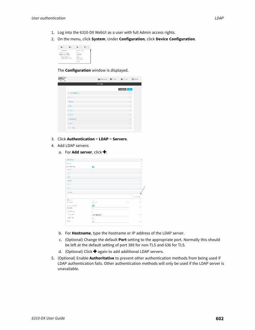
User authentication LDAP
6310-DX User Guide 602
1. Log into the 6310-DX WebUI as a user with full Admin access rights.2. On the menu, click System. Under Configuration, click Device Configuration.
The Configuration window is displayed.
3. Click Authentication > LDAP > Servers.4. Add LDAP servers:
a. For Add server, click .
b. For Hostname, type the hostname or IP address of the LDAP server.c. (Optional) Change the default Port setting to the appropriate port. Normally this should
be left at the default setting of port 389 for non-TLS and 636 for TLS.d. (Optional) Click again to add additional LDAP servers.
5. (Optional) Enable Authoritative to prevent other authentication methods from being used ifLDAP authentication fails. Other authentication methods will only be used if the LDAP server isunavailable.
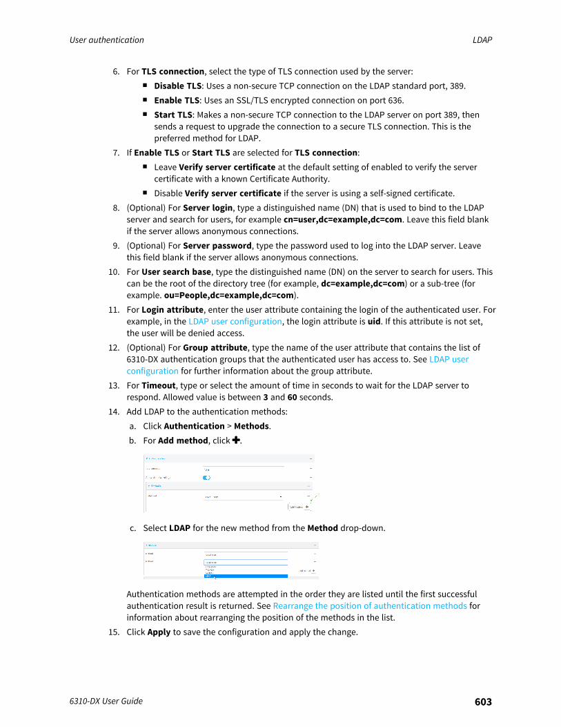
User authentication LDAP
6310-DX User Guide 603
6. For TLS connection, select the type of TLS connection used by the server:n Disable TLS: Uses a non-secure TCP connection on the LDAP standard port, 389.n Enable TLS: Uses an SSL/TLS encrypted connection on port 636.n Start TLS: Makes a non-secure TCP connection to the LDAP server on port 389, then
sends a request to upgrade the connection to a secure TLS connection. This is thepreferred method for LDAP.
7. If Enable TLS or Start TLS are selected for TLS connection:n Leave Verify server certificate at the default setting of enabled to verify the server
certificate with a known Certificate Authority.n Disable Verify server certificate if the server is using a self-signed certificate.
8. (Optional) For Server login, type a distinguished name (DN) that is used to bind to the LDAPserver and search for users, for example cn=user,dc=example,dc=com. Leave this field blankif the server allows anonymous connections.
9. (Optional) For Server password, type the password used to log into the LDAP server. Leavethis field blank if the server allows anonymous connections.
10. For User search base, type the distinguished name (DN) on the server to search for users. Thiscan be the root of the directory tree (for example, dc=example,dc=com) or a sub-tree (forexample. ou=People,dc=example,dc=com).
11. For Login attribute, enter the user attribute containing the login of the authenticated user. Forexample, in the LDAP user configuration, the login attribute is uid. If this attribute is not set,the user will be denied access.
12. (Optional) For Group attribute, type the name of the user attribute that contains the list of6310-DX authentication groups that the authenticated user has access to. See LDAP userconfiguration for further information about the group attribute.
13. For Timeout, type or select the amount of time in seconds to wait for the LDAP server torespond. Allowed value is between 3 and 60 seconds.
14. Add LDAP to the authentication methods:a. Click Authentication > Methods.b. For Add method, click .
c. Select LDAP for the new method from the Method drop-down.
Authentication methods are attempted in the order they are listed until the first successfulauthentication result is returned. See Rearrange the position of authentication methods forinformation about rearranging the position of the methods in the list.
15. Click Apply to save the configuration and apply the change.
User authentication LDAP
6310-DX User Guide 604
Command line
1. Log into the 6310-DX command line as a user with full Admin access rights.Depending on your device configuration, you may be presented with an Access selectionmenu. Type admin to access the Admin CLI.
2. At the command line, type config to enter configuration mode:
> config(config)>
3. (Optional) Prevent other authentication methods from being used if LDAP authentication fails.Other authentication methods will only be used if the LDAP server is unavailable.
(config)> auth ldap authoritative true(config)>
4. Set the type of TLS connection used by the LDAP server:
(config)> auth ldap tls value(config)>
where value is one of:n off: Uses a non-secure TCP connection on the LDAP standard port, 389.n on: Uses an SSL/TLS encrypted connection on port 636.n start_tls: Makes a non-secure TCP connection to the LDAP server on port 389, then
sends a request to upgrade the connection to a secure TLS connection. This is thepreferred method for LDAP.
The default is off.5. If tls is set to on or start_tls, configure whether to verify the server certificate:
(config)> auth ldap verify_server_cert value(config)>
where value is either:n true: Verifies the server certificate with a known Certificate Authority.n false: Does not verify the certificate. Use this option if the server is using a self-signed
certificate.The default is true.
6. Set the distinguished name (DN) that is used to bind to the LDAP server and search for users.Leave this option unset if the server allows anonymous connections.
(config)> auth ldap bind_dn dn_value(config)>
User authentication LDAP
6310-DX User Guide 605
For example:
(config)> auth ldap bind_dn cn=user,dc=example,dc=com(config)>
7. Set the password used to log into the LDAP server. Leave this option unset if the server allowsanonymous connections.
(config)> auth ldap bind_password password(config)>
8. Set the distinguished name (DN) on the server to search for users. This can be the root of thedirectory tree (for example, dc=example,dc=com) or a sub-tree (for example.ou=People,dc=example,dc=com).
(config)> auth ldap base_dn value(config)>
9. Set the login attribute:
(config)> auth ldap login_attribute value(config)>
where value is the user attribute containing the login of the authenticated user. For example,in the LDAP user configuration, the login attribute is uid. . If this attribute is not set, the userwill be denied access.
10. (Optional) Set the name of the user attribute that contains the list of 6310-DX authenticationgroups that the authenticated user has access to. See LDAP user configuration for furtherinformation about the group attribute.
(config)> auth ldap group_attribute value(config)>
For example:
(config)> auth ldap group_attribute ou(config)>
11. Configure the amount of time in seconds to wait for the LDAP server to respond.
(config)> auth ldap timeout value(config)>
where value is any integer from 3 to 60. The default value is 3.12. Add an LDAP server:
a. Add the server:
(config)> add auth ldap server end(config auth ldap server 0)>
User authentication Configure serial authentication
6310-DX User Guide 606
b. Enter the LDAP server's IP address or hostname:
(config auth ldap server 0)> hostname hostname|ip-address(config auth ldap server 0)>
c. (Optional) Change the default port setting to the appropriate port:
(config auth ldap server 0)> port port(config auth ldap server 0)>
d. (Optional) Repeat the above steps to add additional LDAP servers.13. Add LDAP to the authentication methods. Authentication methods are attempted in the order
they are listed until the first successful authentication result is returned. This example will addLDAP to the end of the list. See User authentication methods for information about addingmethods to the beginning or middle of the list.
(config)> add auth method end ldap(config)>
14. Save the configuration and apply the change:
(config)> saveConfiguration saved.>
15. Type exit to exit the Admin CLI.Depending on your device configuration, you may be presented with an Access selectionmenu. Type quit to disconnect from the device.
Configure serial authenticationThis section describes how to configure authentication for serial access.
WebUI
1. Log into the 6310-DX WebUI as a user with full Admin access rights.2. On the menu, click System. Under Configuration, click Device Configuration.
The Configuration window is displayed.
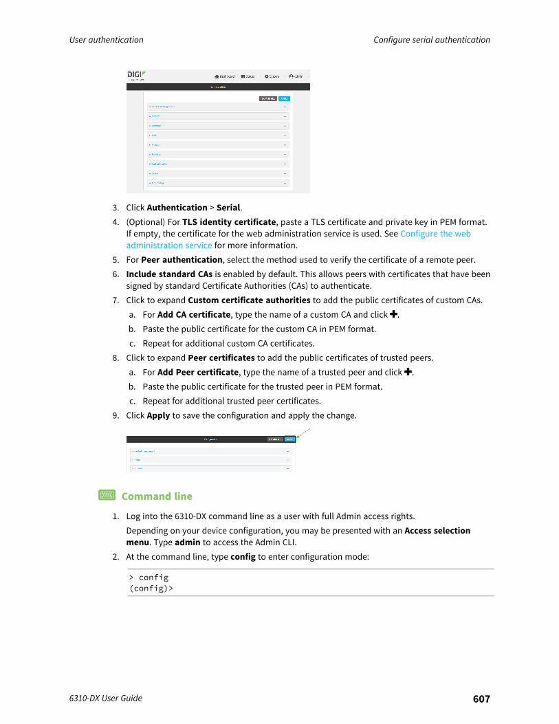
User authentication Configure serial authentication
6310-DX User Guide 607
3. Click Authentication > Serial.4. (Optional) For TLS identity certificate, paste a TLS certificate and private key in PEM format.
If empty, the certificate for the web administration service is used. See Configure the webadministration service for more information.
5. For Peer authentication, select the method used to verify the certificate of a remote peer.6. Include standard CAs is enabled by default. This allows peers with certificates that have been
signed by standard Certificate Authorities (CAs) to authenticate.7. Click to expand Custom certificate authorities to add the public certificates of custom CAs.
a. For Add CA certificate, type the name of a custom CA and click .b. Paste the public certificate for the custom CA in PEM format.c. Repeat for additional custom CA certificates.
8. Click to expand Peer certificates to add the public certificates of trusted peers.a. For Add Peer certificate, type the name of a trusted peer and click .b. Paste the public certificate for the trusted peer in PEM format.c. Repeat for additional trusted peer certificates.
9. Click Apply to save the configuration and apply the change.
Command line
1. Log into the 6310-DX command line as a user with full Admin access rights.Depending on your device configuration, you may be presented with an Access selectionmenu. Type admin to access the Admin CLI.
2. At the command line, type config to enter configuration mode:
> config(config)>
User authentication Disable shell access
6310-DX User Guide 608
3. (Optional) Paste a TLS certificate and private key in PEM format:
(config)> auth serial identiy "cert-and-private-key"(config)>
4. Set the method used to verify the certificate of a remote peer:
(config)> auth serial verify value(config)>
where value is either:n ca: Uses certificate authorities (CAs) to verify.n peer: Uses the remote peer's public certificate to verify.
5. By default, peers with certificates that have been signed by standard Certificate Authorities(CAs) are allowed to authenticate. To disable:
(config)> auth serial ca_standard false(config)>
6. Add the public certificate for a custom certificate authority:
(config)> add auth serial ca_certs CA-cert-name "cert-and-private-key"(config)>
where:n CA-cert-name is the name of the certificate for the custom certificate authority.n cert-and-private-key is the certificate and private key for the custom certificate
authority.Repeat for additional custom certificate authorities.
7. Save the configuration and apply the change:
(config)> saveConfiguration saved.>
8. Type exit to exit the Admin CLI.Depending on your device configuration, you may be presented with an Access selectionmenu. Type quit to disconnect from the device.
Disable shell accessTo prohibit access to the shell prompt for all authentication groups, disable the Allow shellparameter.. This does not prevent access to the Admin CLI.
Note If shell access is disabled, re-enabling it will erase the device's configuration and perform afactory reset.
WebUI

User authentication Disable shell access
6310-DX User Guide 609
1. Log into the 6310-DX WebUI as a user with full Admin access rights.2. On the menu, click System. Under Configuration, click Device Configuration.
The Configuration window is displayed.
3. Click Authentication.4. Click to disable Allow shell.
Note If shell access is disabled, re-enabling it will erase the device's configuration and performa factory reset.
5. Click Apply to save the configuration and apply the change.
Command line
1. Log into the 6310-DX command line as a user with full Admin access rights.Depending on your device configuration, you may be presented with an Access selectionmenu. Type admin to access the Admin CLI.
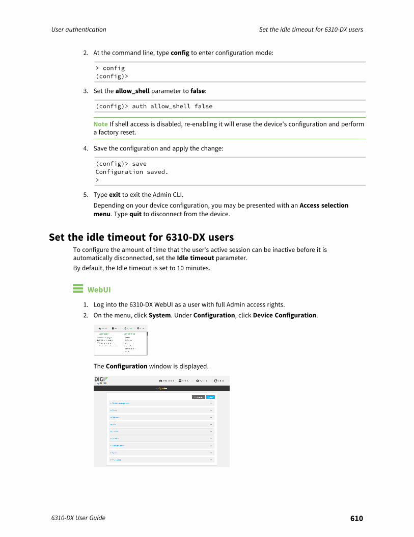
User authentication Set the idle timeout for 6310-DX users
6310-DX User Guide 610
2. At the command line, type config to enter configuration mode:
> config(config)>
3. Set the allow_shell parameter to false:
(config)> auth allow_shell false
Note If shell access is disabled, re-enabling it will erase the device's configuration and performa factory reset.
4. Save the configuration and apply the change:
(config)> saveConfiguration saved.>
5. Type exit to exit the Admin CLI.Depending on your device configuration, you may be presented with an Access selectionmenu. Type quit to disconnect from the device.
Set the idle timeout for 6310-DX usersTo configure the amount of time that the user's active session can be inactive before it isautomatically disconnected, set the Idle timeout parameter.By default, the Idle timeout is set to 10 minutes.
WebUI
1. Log into the 6310-DX WebUI as a user with full Admin access rights.2. On the menu, click System. Under Configuration, click Device Configuration.
The Configuration window is displayed.
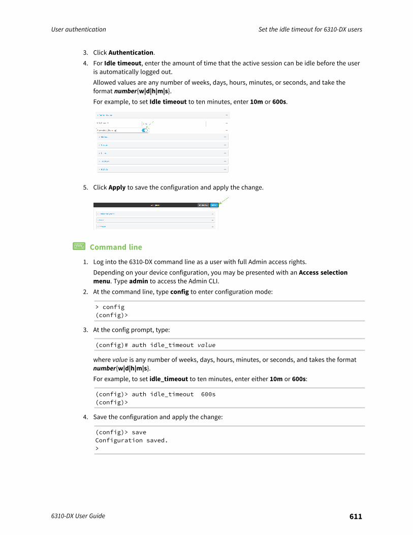
User authentication Set the idle timeout for 6310-DX users
6310-DX User Guide 611
3. Click Authentication.4. For Idle timeout, enter the amount of time that the active session can be idle before the user
is automatically logged out.Allowed values are any number of weeks, days, hours, minutes, or seconds, and take theformat number{w|d|h|m|s}.For example, to set Idle timeout to ten minutes, enter 10m or 600s.
5. Click Apply to save the configuration and apply the change.
Command line
1. Log into the 6310-DX command line as a user with full Admin access rights.Depending on your device configuration, you may be presented with an Access selectionmenu. Type admin to access the Admin CLI.
2. At the command line, type config to enter configuration mode:
> config(config)>
3. At the config prompt, type:
(config)# auth idle_timeout value
where value is any number of weeks, days, hours, minutes, or seconds, and takes the formatnumber{w|d|h|m|s}.For example, to set idle_timeout to ten minutes, enter either 10m or 600s:
(config)> auth idle_timeout 600s(config)>
4. Save the configuration and apply the change:
(config)> saveConfiguration saved.>

User authentication Set the idle timeout for 6310-DX users
6310-DX User Guide 612
5. Type exit to exit the Admin CLI.Depending on your device configuration, you may be presented with an Access selectionmenu. Type quit to disconnect from the device.
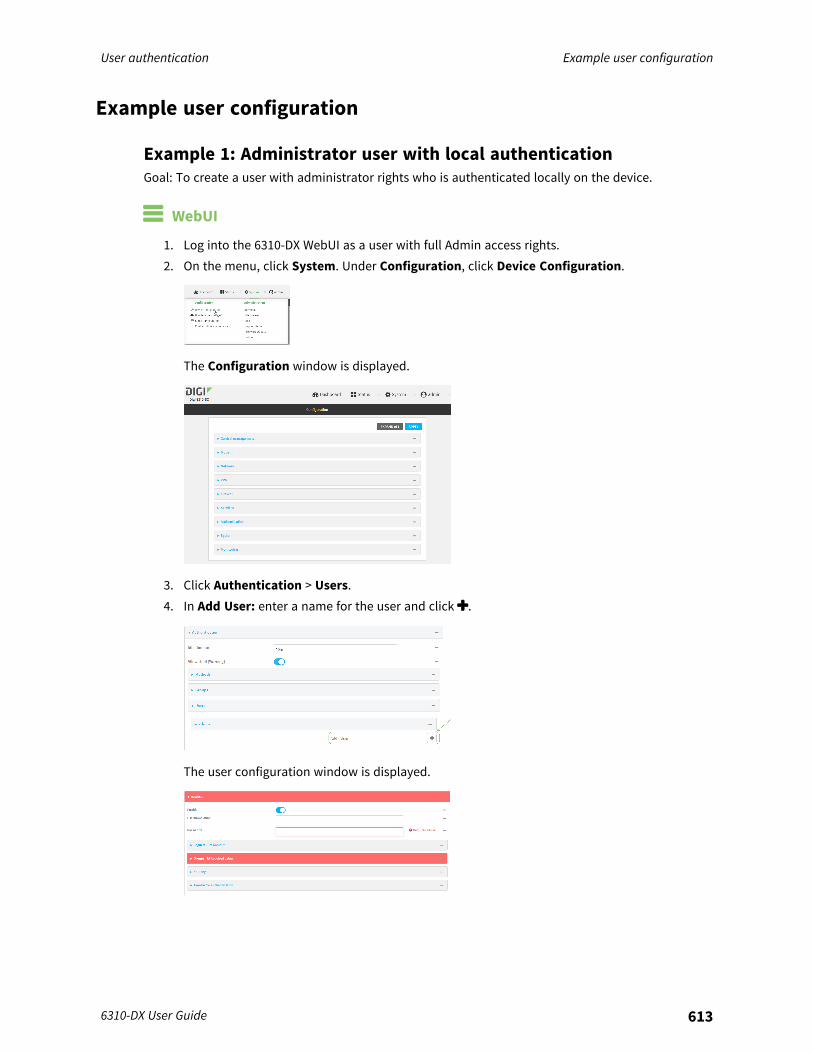
User authentication Example user configuration
6310-DX User Guide 613
Example user configuration
Example 1: Administrator user with local authenticationGoal: To create a user with administrator rights who is authenticated locally on the device.
WebUI
1. Log into the 6310-DX WebUI as a user with full Admin access rights.2. On the menu, click System. Under Configuration, click Device Configuration.
The Configuration window is displayed.
3. Click Authentication > Users.4. In Add User: enter a name for the user and click .
The user configuration window is displayed.

User authentication Example user configuration
6310-DX User Guide 614
5. Enter a Password for the user.6. Assign the user to the admin group:
a. Click Groups.b. For Add Group, click .c. For Group, select the admin group.d. Verify that the admin group has full administrator rights:
i. Click Authentication > Groups.ii. Click admin.iii. Verify that the admin group has Admin access enabled. If not, click Admin access to
enable.iv. Verify that Access level is set to Full access. If not, select Full access.
e. Verify that Local users is one of the configured authentication methods:i. Click Authentication > Methods.ii. Verify that Local users is one of the methods listed in the list. If not:
i. For Add Method, click .ii. For Method, select Local users.
7. Click Apply to save the configuration and apply the change.
Command line
1. Log into the 6310-DX command line as a user with full Admin access rights.Depending on your device configuration, you may be presented with an Access selectionmenu. Type admin to access the Admin CLI.
2. At the command line, type config to enter configuration mode:
> config(config)>
3. Verify that the admin group has full administrator rights:
(config)> show auth group admin acladmin
enable truelevel full
...(config)>
If admin > enable is set to false:
(config)> auth group admin acl admin enable true(config)>

User authentication Example user configuration
6310-DX User Guide 615
If admin > level is set to read-only:
(config)> auth group admin acl admin level full(config)>
4. Verify that local is one of the configured authentication methods:
(config)> show auth method0 local(config)>
If local is not listed:
(config)> add auth method end local(config)>
5. Create the user. In this example, the user is being created with the username adminuser:
(config)> add auth user adminuser(config auth user adminuser)>
6. Assign a password to the user:
(config auth user adminuser)> password pwd(config auth user adminuser)>
7. Assign the user to the admin group:
(config auth user adminuser)> add group end admin(config auth user adminuser)>
8. Save the configuration and apply the change:
(config auth user adminuser)> saveConfiguration saved.>
9. Type exit to exit the Admin CLI.Depending on your device configuration, you may be presented with an Access selectionmenu. Type quit to disconnect from the device.
Example 2: RADIUS, TACACS+, and local authentication for one userGoal: To create a user with administrator rights who is authenticated by using all three authenticationmethods.In this example, when the user attempts to log in to the 6310-DX device, user authentication will occurin the following order:
1. The user is authenticated by the RADIUS server. If the RADIUS server is unavailable,2. The user is authenticated by the TACACS+ server. If both the RADIUS and TACACS+ servers are
unavailable,3. The user is authenticated by the 6310-DX device using local authentication.

User authentication Example user configuration
6310-DX User Guide 616
This example uses a FreeRadius 3.0 server running on ubuntu, and a TACACS+ server running onubuntu. Server configuration may vary depending on the platforms or type of servers used in yourenvironment.

User authentication Example user configuration
6310-DX User Guide 617
WebUI
1. Configure a user on the RADIUS server:a. On the ubuntu machine hosting the FreeRadius server, open the /etc/freeradius/3.0/users
file:
$ sudo gedit /etc/freeradius/3.0/users
b. Add a RADIUS user to the users file:
admin1 Cleartext-Password := "password1"Unix-FTP-Group-Names := "admin"
In this example:n The user's username is admin1.n The user's password is password1.n The authentication group on the 6310-DX device, admin, is identified in the Unix-
FTP-Group-Names parameter.c. Save and close the users file.
2. Configure a user on the TACACS+ server:a. On the ubuntu machine hosting the TACACS+ server, open the /etc/tacacs+/tac_plus.conf
file:
$ sudo gedit /etc/tacacs+/tac_plus.conf
b. Add a TACACS+ user to the tac_plus.conf file:
user = admin1 {name ="Admin1 for TX64"pap = cleartext password1service = system {
groupname = admin}
}}
In this example:n The user's username is admin1.n The user's password is password1.n The authentication group on the 6310-DX device, admin, is identified in the
groupname parameter.c. Save and close the tac_plus.conf file.
3. Log into the 6310-DX WebUI as a user with full Admin access rights.4. On the menu, click System. Under Configuration, click Device Configuration.
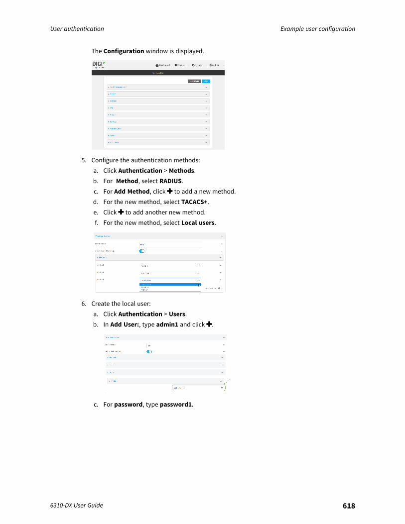
User authentication Example user configuration
6310-DX User Guide 618
The Configuration window is displayed.
5. Configure the authentication methods:a. Click Authentication > Methods.b. For Method, select RADIUS.c. For Add Method, click to add a new method.d. For the new method, select TACACS+.e. Click to add another new method.f. For the new method, select Local users.
6. Create the local user:a. Click Authentication > Users.b. In Add User:, type admin1 and click .
c. For password, type password1.

User authentication Example user configuration
6310-DX User Guide 619
d. Assign the user to the admin group:i. Click Groups.ii. For Add Group, click .
iii. For Group, select the admin group.
a. Verify that the admin group has full administrator rights:i. Click Authentication > Groups.ii. Click admin.iii. Verify that the admin group has Admin access enabled. If not, click Admin access to
enable.iv. Verify that Access level is set to Full access. If not, select Full access.
7. Click Apply to save the configuration and apply the change.
Command line
1. Configure a user on the RADIUS server:a. On the ubuntu machine hosting the FreeRadius server, open the /etc/freeradius/3.0/users
file:
$ sudo gedit /etc/freeradius/3.0/users
b. Add a RADIUS user to the users file:
admin1 Cleartext-Password := "password1"Unix-FTP-Group-Names := "admin"
In this example:n The user's username is admin1.n The user's password is password1.n The authentication group on the 6310-DX device, admin, is identified in the Unix-
FTP-Group-Names parameter.c. Save and close the users file.
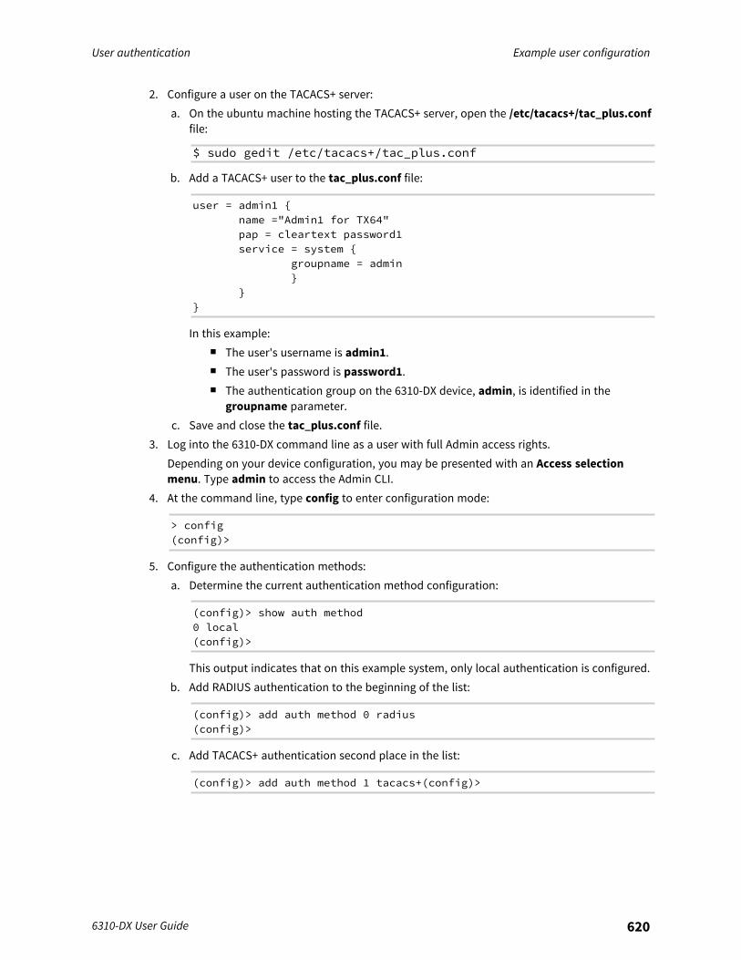
User authentication Example user configuration
6310-DX User Guide 620
2. Configure a user on the TACACS+ server:a. On the ubuntu machine hosting the TACACS+ server, open the /etc/tacacs+/tac_plus.conf
file:
$ sudo gedit /etc/tacacs+/tac_plus.conf
b. Add a TACACS+ user to the tac_plus.conf file:
user = admin1 {name ="Admin1 for TX64"pap = cleartext password1service = system {
groupname = admin}
}}
In this example:n The user's username is admin1.n The user's password is password1.n The authentication group on the 6310-DX device, admin, is identified in the
groupname parameter.c. Save and close the tac_plus.conf file.
3. Log into the 6310-DX command line as a user with full Admin access rights.Depending on your device configuration, you may be presented with an Access selectionmenu. Type admin to access the Admin CLI.
4. At the command line, type config to enter configuration mode:
> config(config)>
5. Configure the authentication methods:a. Determine the current authentication method configuration:
(config)> show auth method0 local(config)>
This output indicates that on this example system, only local authentication is configured.b. Add RADIUS authentication to the beginning of the list:
(config)> add auth method 0 radius(config)>
c. Add TACACS+ authentication second place in the list:
(config)> add auth method 1 tacacs+(config)>
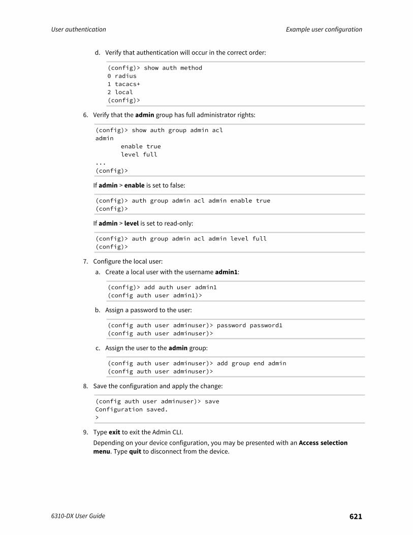
User authentication Example user configuration
6310-DX User Guide 621
d. Verify that authentication will occur in the correct order:
(config)> show auth method0 radius1 tacacs+2 local(config)>
6. Verify that the admin group has full administrator rights:
(config)> show auth group admin acladmin
enable truelevel full
...(config)>
If admin > enable is set to false:
(config)> auth group admin acl admin enable true(config)>
If admin > level is set to read-only:
(config)> auth group admin acl admin level full(config)>
7. Configure the local user:a. Create a local user with the username admin1:
(config)> add auth user admin1(config auth user admin1)>
b. Assign a password to the user:
(config auth user adminuser)> password password1(config auth user adminuser)>
c. Assign the user to the admin group:
(config auth user adminuser)> add group end admin(config auth user adminuser)>
8. Save the configuration and apply the change:
(config auth user adminuser)> saveConfiguration saved.>
9. Type exit to exit the Admin CLI.Depending on your device configuration, you may be presented with an Access selectionmenu. Type quit to disconnect from the device.
Firewall
This chapter contains the following topics:
Firewall configuration 623Port forwarding rules 628Packet filtering 636Configure custom firewall rules 644Configure Quality of Service options 645
6310-DX User Guide 622
Firewall Firewall configuration
6310-DX User Guide 623
Firewall configurationFirewall configuration includes the following configuration options:
n Zones: A zone is a firewall access group to which network interfaces can be added. You thenuse zones to configure packet filtering and access control lists for interfaces that are includedin the zone. Preconfigured zones include:l Any: Matches any network interface, even if they are not assigned to this zone.l Loopback: Zone for interfaces that are used for communication between processes
running on the device.l Internal: Used for interfaces connected to trusted networks. By default, the firewall will
allow most access from this zone.l External: Used for interfaces to connect to untrusted zones, such as the internet. This zone
has Network Address Translation (NAT) enabled by default. By default, the firewall willblock most access from this zone.
l Edge: Used for interfaces connected to trusted networks, where the device is a client onthe edge of the network rather than a router or gateway.
l Setup: Used for interfaces involved in the initial setup of the device. By default, the firewallwill only allow this zone to access administration services.
l IPsec: The default zone for IPsec tunnels.l Dynamic routes: Used for routes learned using routing services.
n Port forwarding: A list of rules that allow network connections to the 6310-DX to be forwardedto other servers by translating the destination address.
n Packet filtering: A list of packet filtering rules that determine whether to accept or rejectnetwork connections that are forwarded through the 6310-DX.
n Custom rules: A script that is run to install advanced firewall rules beyond thescope/capabilities of the standard device configuration.
n Quality Of Service: Quality of Service (QOS) options for bandwidth allocation and policy-based traffic shaping and prioritizing.
Create a custom firewall zoneIn addition to the preconfigured zones, you can create your custom zones that can be used toconfigure packet filtering and access control lists for network interfaces.To create a zone:
WebUI
1. Log into the 6310-DX WebUI as a user with full Admin access rights.2. On the menu, click System. Under Configuration, click Device Configuration.
The Configuration window is displayed.

Firewall Firewall configuration
6310-DX User Guide 624
3. Click Firewall > Zones.4. In Add Zone, enter a name for the zone and click .
The firewall configuration window is displayed.
5. (Optional) If traffic on this zone will be forwarded from a private network to the internet,enable Network Address Translation (NAT).
6. Click Apply to save the configuration and apply the change.
See Configure the firewall zone for a network interface for information about how to configurenetwork interfaces to use a zone.
Command line
1. Log into the 6310-DX command line as a user with full Admin access rights.Depending on your device configuration, you may be presented with an Access selectionmenu. Type admin to access the Admin CLI.
2. At the command line, type config to enter configuration mode:
> config(config)>
Firewall Firewall configuration
6310-DX User Guide 625
3. Add the new zone. For example, to add a zone named my_zone:
(config)> add firewall zone my_zone(config firewall zone my_zone)>
4. (Optional) Enable Network Address Translation (NAT):
(config firewall zone my_zone)> src_nat true(config firewall zone my_zone)>
5. Save the configuration and apply the change:
(config firewall zone my_zone)> saveConfiguration saved.>
6. Type exit to exit the Admin CLI.Depending on your device configuration, you may be presented with an Access selectionmenu. Type quit to disconnect from the device.
See Configure the firewall zone for a network interface for information about how to configurenetwork interfaces to use a zone.
Configure the firewall zone for a network interfaceFirewall zones allow you to group network interfaces for the purpose of packet filtering and accesscontrol. There are several preconfigured firewall zones, and you can create custom zones as well. Thefirewall zone that a network interfaces uses is selected during interface configuration.This example procedure uses an existing network interface named LAN and changes the firewall zonefrom the default zone, Internal, to External.
WebUI
1. Log into the 6310-DX WebUI as a user with full Admin access rights.2. On the menu, click System. Under Configuration, click Device Configuration.
The Configuration window is displayed.
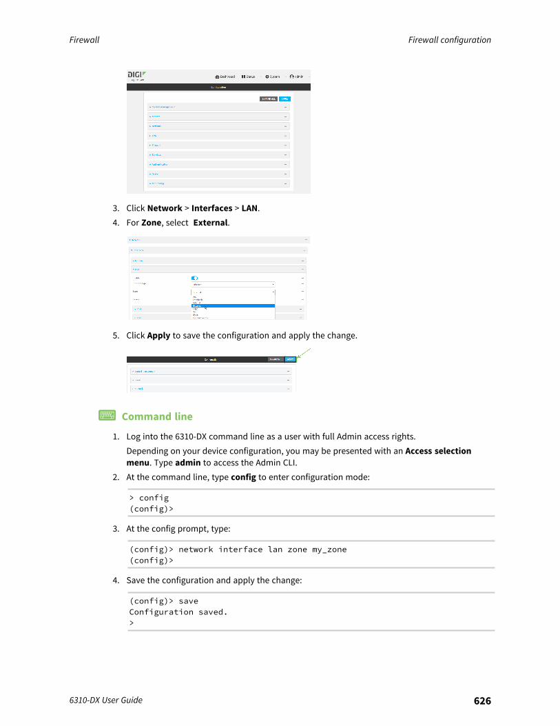
Firewall Firewall configuration
6310-DX User Guide 626
3. Click Network > Interfaces > LAN.4. For Zone, select External.
5. Click Apply to save the configuration and apply the change.
Command line
1. Log into the 6310-DX command line as a user with full Admin access rights.Depending on your device configuration, you may be presented with an Access selectionmenu. Type admin to access the Admin CLI.
2. At the command line, type config to enter configuration mode:
> config(config)>
3. At the config prompt, type:
(config)> network interface lan zone my_zone(config)>
4. Save the configuration and apply the change:
(config)> saveConfiguration saved.>
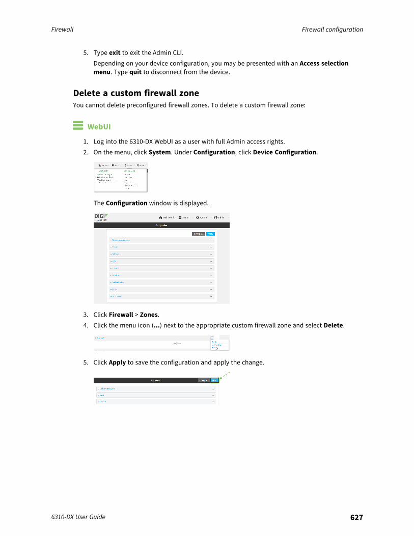
Firewall Firewall configuration
6310-DX User Guide 627
5. Type exit to exit the Admin CLI.Depending on your device configuration, you may be presented with an Access selectionmenu. Type quit to disconnect from the device.
Delete a custom firewall zoneYou cannot delete preconfigured firewall zones. To delete a custom firewall zone:
WebUI
1. Log into the 6310-DX WebUI as a user with full Admin access rights.2. On the menu, click System. Under Configuration, click Device Configuration.
The Configuration window is displayed.
3. Click Firewall > Zones.4. Click the menu icon (...) next to the appropriate custom firewall zone and select Delete.
5. Click Apply to save the configuration and apply the change.

Firewall Port forwarding rules
6310-DX User Guide 628
Command line
1. Log into the 6310-DX command line as a user with full Admin access rights.Depending on your device configuration, you may be presented with an Access selectionmenu. Type admin to access the Admin CLI.
2. At the command line, type config to enter configuration mode:
> config(config)>
3. Use the del command to delete a custom firewall rule. For example:
(config)> del firewall zone my_zone
4. Save the configuration and apply the change:
(config)> saveConfiguration saved.>
5. Type exit to exit the Admin CLI.Depending on your device configuration, you may be presented with an Access selectionmenu. Type quit to disconnect from the device.
Port forwarding rulesMost computers are protected by a firewall that prevents users on a public network from accessingservers on the private network. To allow a computer on the Internet to connect to a specific server ona private network, set up one or more port forwarding rules. Port forwarding rules provide mappinginstructions that direct incoming traffic to the proper device on a LAN.
Configure port forwarding
Required configuration items
n The network interface for the rule.Network connections will only be forwarded if their destination address matches the IPaddress of the selected network interface.
n The public-facing port number that network connections must use for their traffic to beforwarded.
n The IP address of the server to which traffic should be forwarded.n The port or range of ports to which traffic should be forwarded.
Additional configuration items
n A label for the port forwarding rule.n The IP version (either IPv4 or IPv6) that incoming network connections must match.n The protocols that incoming network connections must match.
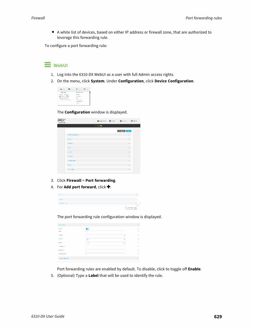
Firewall Port forwarding rules
6310-DX User Guide 629
n A white list of devices, based on either IP address or firewall zone, that are authorized toleverage this forwarding rule.
To configure a port forwarding rule:
WebUI
1. Log into the 6310-DX WebUI as a user with full Admin access rights.2. On the menu, click System. Under Configuration, click Device Configuration.
The Configuration window is displayed.
3. Click Firewall > Port forwarding.4. For Add port forward, click .
The port forwarding rule configuration window is displayed.
Port forwarding rules are enabled by default. To disable, click to toggle off Enable.5. (Optional) Type a Label that will be used to identify the rule.
Firewall Port forwarding rules
6310-DX User Guide 630
6. For Interface, select the network interface for the rule.Network connections will only be forwarded if their destination address matches the IPaddress of the selected network interface.
7. For IP version, select either IPv4 or IPv6.Network connections will only be forwarded if they match the selected IP version.
8. For Protocol, select the type of internet protocol.Network connections will only be forwarded if they match the selected protocol.
9. For Incoming port(s), type the public-facing port number that network connections must usefor their traffic to be forwarded.
10. For To Address, type the IP address of the server to which traffic should be forwarded.11. For Destination Port(s), type the port number, comma-separated list of port numbers, or
range of port numbers on the server to which traffic should be forwarded. For example, toforward traffic to ports one, three, and five through ten, enter: 1, 3, 5-10.
12. (Optional) Click Access control list to create a white list of devices that are authorized toleverage this forwarding rule, based on either the IP address or firewall zone:
n To white list IP addresses:a. Click Addresses.b. For Add Address, enter an IP address and click .c. Repeat for each additional IP address that should be white listed.
n To specify firewall zones for white listing:a. Click Zones.b. For Add zone, click .c. For Zone, select the appropriate zone.d. Repeat for each additional zone.
13. Click Apply to save the configuration and apply the change.
Command line
1. Log into the 6310-DX command line as a user with full Admin access rights.Depending on your device configuration, you may be presented with an Access selectionmenu. Type admin to access the Admin CLI.
2. At the command line, type config to enter configuration mode:
> config(config)>
3. At the config prompt, type:
(config)> add firewall dnat end(config firewall dnat 0)>
Firewall Port forwarding rules
6310-DX User Guide 631
Port forwarding rules are enabled by default. To disable the rule:
(config firewall dnat 0)> enable false(config firewall dnat 0)>
4. Set the network interface for the rule.
(config firewall dnat 0)> interface(config firewall dnat 0)>
Network connections will only be forwarded if their destination address matches the IPaddress of this network interface.
a. Use the ? to determine available interfaces:
(config firewall dnat 0)> interface ?
Interface: Network connections will only be forwarded if theirdestination address matches the IP address of this network interface.Format:defaultipdefaultlinklocallanloopbackmodemwan
Current value:
(config firewall dnat 0)> interface
b. Set the interface. For example:
(config firewall dnat 0)> interface wan(config firewall dnat 0)>
5. Set the IP version. Allowed values are ipv4 and ipv6. The default is ipv4.
(config firewall dnat 0)> ip_version ipv6(config firewall dnat 0)>
6. Set the public-facing port number that network connections must use for their traffic to beforwarded.
(config firewall dnat 0)> port port(config firewall dnat 0)>
7. Set the type of internet protocol .
(config firewall dnat 0)> protocol value(config firewall dnat 0)>
Network connections will only be forwarded if they match the selected protocol. Allowedvalues are custom, tcp, tcpudp, or upd. The default is tcp.
Firewall Port forwarding rules
6310-DX User Guide 632
8. Set the IP address of the server to which traffic should be forwarded:n For IPv4 addresses:
(config firewall dnat 0)> to_address ip-address(config firewall dnat 0)>
n For IPv6 addresses:
(config firewall dnat 0)> to_address6 ip-address(config firewall dnat 0)>
9. Set the public-facing port number(s) that network connections must use for their traffic to beforwarded.
(config firewall dnat 0)> to_port value(config firewall dnat 0)>
where value is the port number, comma-separated list of port numbers, or range of portnumbers on the server to which traffic should be forwarded. For example, to forward traffic toports one, three, and five through ten, enter 1, 3, 5-10.
10. (Optional) To create a white list of devices that are authorized to leverage this forwarding rule,based on either the IP address or firewall zone, change to the acl node:
(config firewall dnat 0)> acl(config firewall dnat 0 acl)>
n To white list an IP address:l For IPv4 addresses:
(config firewall dnat 0 acl> add address end ip-address(config firewall dnat 0 acl)>
l For IPv6 addresses:
(config firewall dnat 0 acl> add address6 end ip-address(config firewall dnat 0 acl)>
Repeat for each appropriate IP address.n To specify the firewall zone for white listing:
(config firewall dnat 0 acl)> add zone end zone
Repeat for each appropriate zone.
To view a list of available zones:
(config firewall dnat 0 acl)> .. .. .. zone ?
Zones: A list of groups of network interfaces that can be referredto by packet filtering rulesand access control lists.
Firewall Port forwarding rules
6310-DX User Guide 633
Additional Configuration------------------------------------------------------------------------------anydynamic_routesedgeexternalinternalipsecloopbacksetup
(config firewall dnat 0 acl)>
11. Save the configuration and apply the change:
(config)> saveConfiguration saved.>
12. Type exit to exit the Admin CLI.Depending on your device configuration, you may be presented with an Access selectionmenu. Type quit to disconnect from the device.
Delete a port forwarding ruleTo delete a port forwarding rule:
WebUI
1. Log into the 6310-DX WebUI as a user with full Admin access rights.2. On the menu, click System. Under Configuration, click Device Configuration.
The Configuration window is displayed.

Firewall Port forwarding rules
6310-DX User Guide 634
3. Click Firewall > Port forwarding.4. Click the menu icon (...) next to the appropriate port forwarding rule and select Delete.
5. Click Apply to save the configuration and apply the change.
Command line
1. Log into the 6310-DX command line as a user with full Admin access rights.Depending on your device configuration, you may be presented with an Access selectionmenu. Type admin to access the Admin CLI.
2. At the command line, type config to enter configuration mode:
> config(config)>
3. Determine the index number of the port forwarding rule you want to delete:
(config)> show firewall dnat0
aclno addressno zone
enable trueinterfaceip_version ipv4label IPv4 port forwarding ruleport 10000protocol tcpto_address6 10.10.10.10
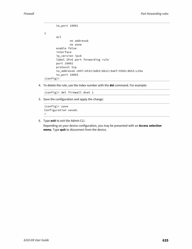
Firewall Port forwarding rules
6310-DX User Guide 635
to_port 10001
1acl
no address6no zone
enable falseinterfaceip_version ipv6label IPv6 port forwarding ruleport 10002protocol tcpto_address6 c097:4533:bd63:bb12:9a6f:5569:4b53:c29ato_port 10003
(config)>
4. To delete the rule, use the index number with the del command. For example:
(config)> del firewall dnat 1
5. Save the configuration and apply the change:
(config)> saveConfiguration saved.>
6. Type exit to exit the Admin CLI.Depending on your device configuration, you may be presented with an Access selectionmenu. Type quit to disconnect from the device.
Firewall Packet filtering
6310-DX User Guide 636
Packet filteringBy default, one preconfigured packet filtering rule, Allow all outgoing traffic, is enabled andmonitors traffic going to and from the 6310-DX device. The predefined settings are intended to blockunauthorized inbound traffic while providing an unrestricted flow of outgoing data. You can modifythe default packet filtering rule and create additional rules to define how the device accepts or rejectstraffic that is forwarded through the device.
Configure packet filtering
Required configuration items
n The action that the packet filtering rule will perform, either Accept, Reject, or Drop.n The source firewall zone: Packets originating from interfaces on this zone will be monitored by
this rule.n The destination firewall zone: Packets destined for interfaces on this zone will be accepted,
rejected, or dropped by this rule.
Additional configuration requirements
n A label for the rule.n The IP version to be matched, either IPv4, IPv6, or Any.n The protocol to be matched, one of:
l TCPl UDPl ICMPl ICMP6l Any
To configure a packet filtering rule:
WebUI
1. Log into the 6310-DX WebUI as a user with full Admin access rights.2. On the menu, click System. Under Configuration, click Device Configuration.
The Configuration window is displayed.
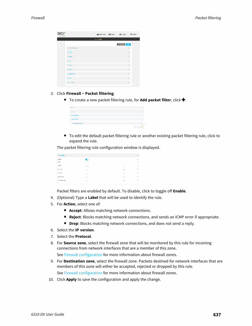
Firewall Packet filtering
6310-DX User Guide 637
3. Click Firewall > Packet filtering.n To create a new packet filtering rule, for Add packet filter, click .
n To edit the default packet filtering rule or another existing packet filtering rule, click toexpand the rule.
The packet filtering rule configuration window is displayed.
Packet filters are enabled by default. To disable, click to toggle off Enable.4. (Optional) Type a Label that will be used to identify the rule.5. For Action, select one of:
n Accept: Allows matching network connections.n Reject: Blocks matching network connections, and sends an ICMP error if appropriate.n Drop: Blocks matching network connections, and does not send a reply.
6. Select the IP version.7. Select the Protocol.8. For Source zone, select the firewall zone that will be monitored by this rule for incoming
connections from network interfaces that are a member of this zone.See Firewall configuration for more information about firewall zones.
9. For Destination zone, select the firewall zone. Packets destined for network interfaces that aremembers of this zone will either be accepted, rejected or dropped by this rule.See Firewall configuration for more information about firewall zones.
10. Click Apply to save the configuration and apply the change.
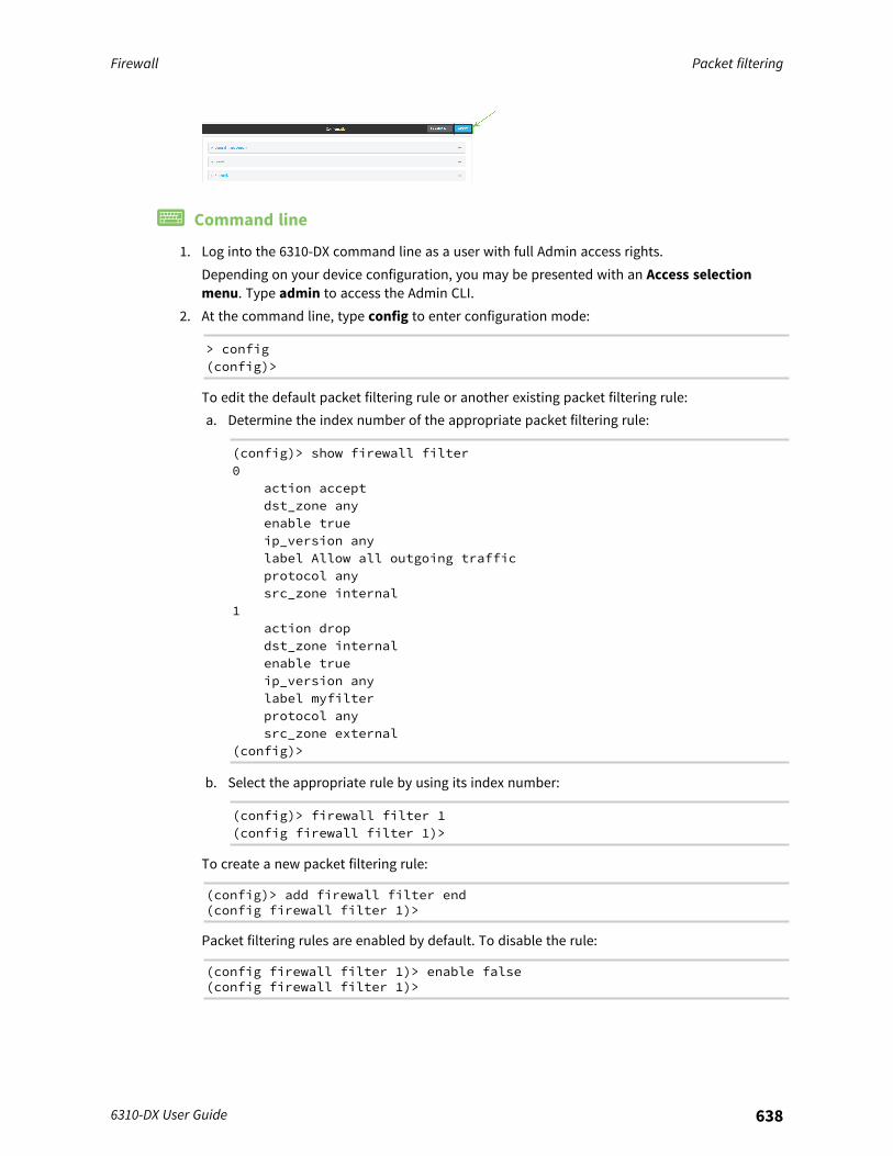
Firewall Packet filtering
6310-DX User Guide 638
Command line
1. Log into the 6310-DX command line as a user with full Admin access rights.Depending on your device configuration, you may be presented with an Access selectionmenu. Type admin to access the Admin CLI.
2. At the command line, type config to enter configuration mode:
> config(config)>
To edit the default packet filtering rule or another existing packet filtering rule:a. Determine the index number of the appropriate packet filtering rule:
(config)> show firewall filter0
action acceptdst_zone anyenable trueip_version anylabel Allow all outgoing trafficprotocol anysrc_zone internal
1action dropdst_zone internalenable trueip_version anylabel myfilterprotocol anysrc_zone external
(config)>
b. Select the appropriate rule by using its index number:
(config)> firewall filter 1(config firewall filter 1)>
To create a new packet filtering rule:
(config)> add firewall filter end(config firewall filter 1)>
Packet filtering rules are enabled by default. To disable the rule:
(config firewall filter 1)> enable false(config firewall filter 1)>
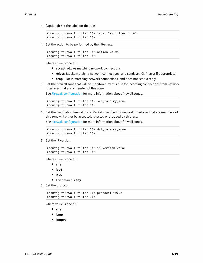
Firewall Packet filtering
6310-DX User Guide 639
3. (Optional) Set the label for the rule.
(config firewall filter 1)> label "My filter rule"(config firewall filter 1)>
4. Set the action to be performed by the filter rule.
(config firewall filter 1)> action value(config firewall filter 1)>
where value is one of:n accept: Allows matching network connections.n reject: Blocks matching network connections, and sends an ICMP error if appropriate.n drop: Blocks matching network connections, and does not send a reply.
5. Set the firewall zone that will be monitored by this rule for incoming connections from networkinterfaces that are a member of this zone:See Firewall configuration for more information about firewall zones.
(config firewall filter 1)> src_zone my_zone(config firewall filter 1)>
6. Set the destination firewall zone. Packets destined for network interfaces that are members ofthis zone will either be accepted, rejected or dropped by this rule.See Firewall configuration for more information about firewall zones.
(config firewall filter 1)> dst_zone my_zone(config firewall filter 1)>
7. Set the IP version.
(config firewall filter 1)> ip_version value(config firewall filter 1)>
where value is one of:n anyn ipv4n ipv6n The default is any.
8. Set the protocol.
(config firewall filter 1)> protocol value(config firewall filter 1)>
where value is one of:n anyn icmpn icmpv6
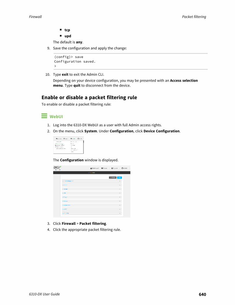
Firewall Packet filtering
6310-DX User Guide 640
n tcpn upd
The default is any.9. Save the configuration and apply the change:
(config)> saveConfiguration saved.>
10. Type exit to exit the Admin CLI.Depending on your device configuration, you may be presented with an Access selectionmenu. Type quit to disconnect from the device.
Enable or disable a packet filtering ruleTo enable or disable a packet filtering rule:
WebUI
1. Log into the 6310-DX WebUI as a user with full Admin access rights.2. On the menu, click System. Under Configuration, click Device Configuration.
The Configuration window is displayed.
3. Click Firewall > Packet filtering.4. Click the appropriate packet filtering rule.

Firewall Packet filtering
6310-DX User Guide 641
5. Click Enable to toggle the rule between enabled and disabled.
6. Click Apply to save the configuration and apply the change.
Command line
1. Log into the 6310-DX command line as a user with full Admin access rights.Depending on your device configuration, you may be presented with an Access selectionmenu. Type admin to access the Admin CLI.
2. At the command line, type config to enter configuration mode:
> config(config)>
3. Determine the index number of the appropriate port forwarding rule:
(config)> show firewall filter0
action acceptdst_zone anyenable trueip_version anylabel Allow all outgoing trafficprotocol anysrc_zone internal
1action dropdst_zone internalenable trueip_version anylabel My packet filterprotocol anysrc_zone external
(config)>
4. To enable a packet filtering rule, use the index number with the enable true command. Forexample:
(config)> firewall filter 1 enable true

Firewall Packet filtering
6310-DX User Guide 642
5. To disable a packet filtering rule, use the index number with the enable false command. Forexample:
(config)> firewall filter 1 enable false
6. Save the configuration and apply the change:
(config)> saveConfiguration saved.>
7. Type exit to exit the Admin CLI.Depending on your device configuration, you may be presented with an Access selectionmenu. Type quit to disconnect from the device.
Delete a packet filtering ruleTo delete a packet filtering rule:
WebUI
1. Log into the 6310-DX WebUI as a user with full Admin access rights.2. On the menu, click System. Under Configuration, click Device Configuration.
The Configuration window is displayed.
3. Click Firewall > Packet filtering.4. Click the menu icon (...) next to the appropriate packet filtering rule and select Delete.
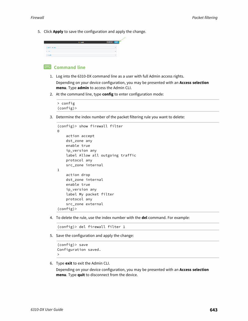
Firewall Packet filtering
6310-DX User Guide 643
5. Click Apply to save the configuration and apply the change.
Command line
1. Log into the 6310-DX command line as a user with full Admin access rights.Depending on your device configuration, you may be presented with an Access selectionmenu. Type admin to access the Admin CLI.
2. At the command line, type config to enter configuration mode:
> config(config)>
3. Determine the index number of the packet filtering rule you want to delete:
(config)> show firewall filter0
action acceptdst_zone anyenable trueip_version anylabel Allow all outgoing trafficprotocol anysrc_zone internal
1action dropdst_zone internalenable trueip_version anylabel My packet filterprotocol anysrc_zone external
(config)>
4. To delete the rule, use the index number with the del command. For example:
(config)> del firewall filter 1
5. Save the configuration and apply the change:
(config)> saveConfiguration saved.>
6. Type exit to exit the Admin CLI.Depending on your device configuration, you may be presented with an Access selectionmenu. Type quit to disconnect from the device.
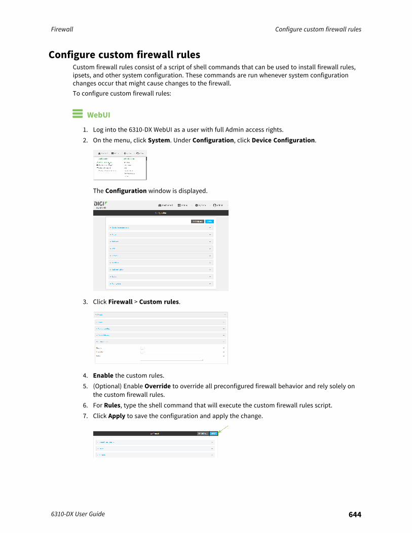
Firewall Configure custom firewall rules
6310-DX User Guide 644
Configure custom firewall rulesCustom firewall rules consist of a script of shell commands that can be used to install firewall rules,ipsets, and other system configuration. These commands are run whenever system configurationchanges occur that might cause changes to the firewall.To configure custom firewall rules:
WebUI
1. Log into the 6310-DX WebUI as a user with full Admin access rights.2. On the menu, click System. Under Configuration, click Device Configuration.
The Configuration window is displayed.
3. Click Firewall > Custom rules.
4. Enable the custom rules.5. (Optional) Enable Override to override all preconfigured firewall behavior and rely solely on
the custom firewall rules.6. For Rules, type the shell command that will execute the custom firewall rules script.7. Click Apply to save the configuration and apply the change.
Firewall Configure Quality of Service options
6310-DX User Guide 645
Command line
1. Log into the 6310-DX command line as a user with full Admin access rights.Depending on your device configuration, you may be presented with an Access selectionmenu. Type admin to access the Admin CLI.
2. At the command line, type config to enter configuration mode:
> config(config)>
3. Enable custom firewall rules:
(config)> firewall custom enable true(config)>
4. (Optional) Instruct the device to override all preconfigured firewall behavior and rely solely onthe custom firewall rules:
(config)> firewall custom override true(config)>
5. Set the shell command that will execute the custom firewall rules script:
(config)> firewall custom rules "shell-command"(config)>
6. Save the configuration and apply the change:
(config)> saveConfiguration saved.>
7. Type exit to exit the Admin CLI.Depending on your device configuration, you may be presented with an Access selectionmenu. Type quit to disconnect from the device.
Configure Quality of Service optionsQuality of Service (QoS) options allow you to manage the traffic performance of various services, suchas Voice over IP (VoIP), cloud computing, traffic shaping, traffic prioritizing, and bandwidth allocation.When configuring QOS, you can only control the queue for outgoing packets on each interface (egresspackets), not what is received on the interface (packet ingress).A QoS binding contains the policies and rules that apply to packets exiting the 6310-DX device on thebinding's interface. By default, the 6310-DX device has two preconfigured QoS bindings, Outboundand Inbound. These bindings are an example configuration designed for a typical VoIP site:
n Outbound provides an example of matching packets as they are routed from the device ontothe WAN interface.
n Inbound provides an example of matching packets as they are routed from the device onto aLAN interface.
These example bindings are disabled by default.
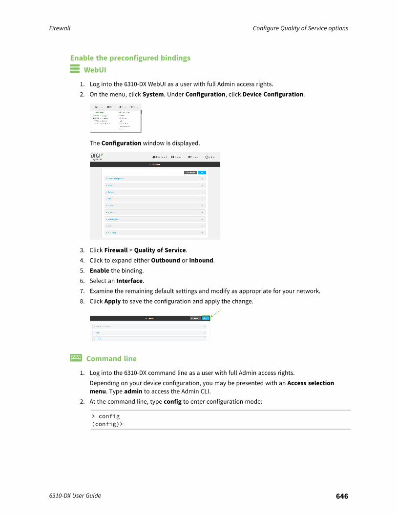
Firewall Configure Quality of Service options
6310-DX User Guide 646
Enable the preconfigured bindings WebUI
1. Log into the 6310-DX WebUI as a user with full Admin access rights.2. On the menu, click System. Under Configuration, click Device Configuration.
The Configuration window is displayed.
3. Click Firewall > Quality of Service.4. Click to expand either Outbound or Inbound.5. Enable the binding.6. Select an Interface.7. Examine the remaining default settings and modify as appropriate for your network.8. Click Apply to save the configuration and apply the change.
Command line
1. Log into the 6310-DX command line as a user with full Admin access rights.Depending on your device configuration, you may be presented with an Access selectionmenu. Type admin to access the Admin CLI.
2. At the command line, type config to enter configuration mode:
> config(config)>
Firewall Configure Quality of Service options
6310-DX User Guide 647
3. Enable one of the preconfiged bindings:n To enable the Outbound binding:
(config)> firewall qos 0 enable true(config)>
n To enable the Inbound binding:
(config)> firewall qos 1 enable true(config)>
4. Set the interface for the binding. Use the index number of the binding; for example, to set theinterface for the Outbound binding:a. Use the ? to determine available interfaces:
(config)> firewall qos 0 interface ?
Interface: The network interface.Format:/network/interface/defaultip/network/interface/defaultlinklocal/network/interface/lan/network/interface/loopback/network/interface/modem/network/interface/wan
Current value:
(config)> firewall qos 0 interface
b. Set the interface. For example:
(config)> firewall qos 0 interface /network/interface/wan(config)>
5. Examine the remaining default settings and modify as appropriate for your network.6. Save the configuration and apply the change:
(config)> saveConfiguration saved.>
7. Type exit to exit the Admin CLI.Depending on your device configuration, you may be presented with an Access selectionmenu. Type quit to disconnect from the device.
Create a new binding WebUI
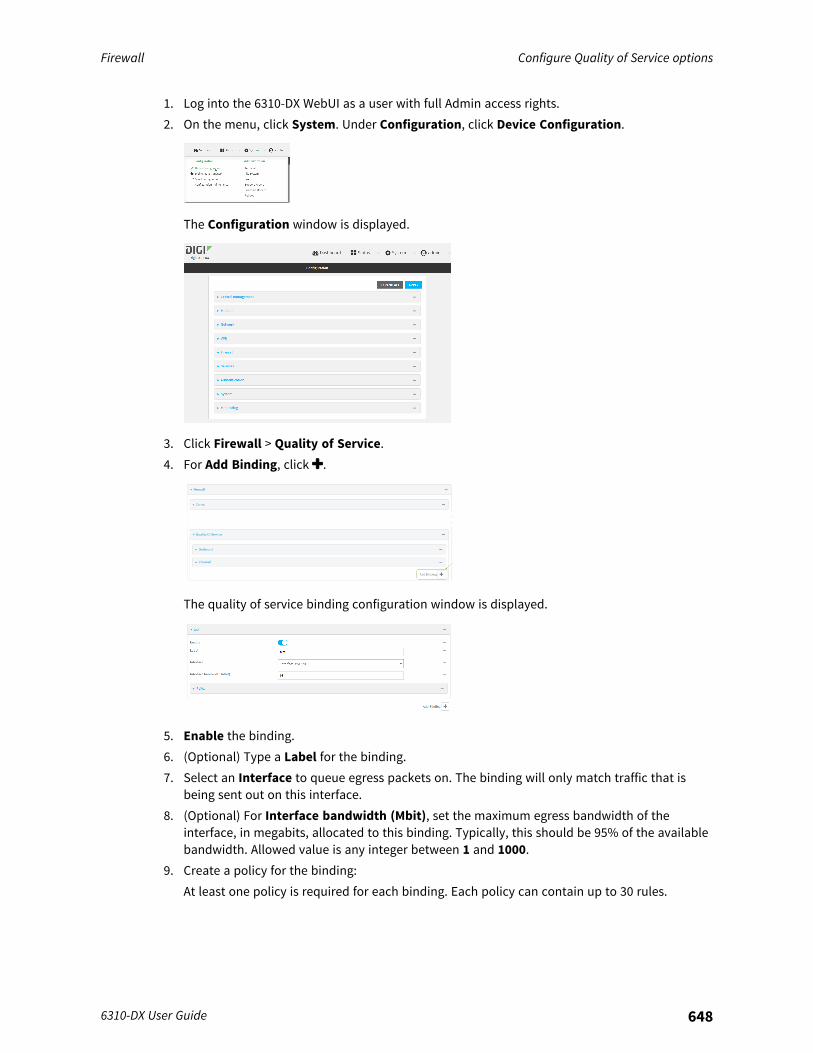
Firewall Configure Quality of Service options
6310-DX User Guide 648
1. Log into the 6310-DX WebUI as a user with full Admin access rights.2. On the menu, click System. Under Configuration, click Device Configuration.
The Configuration window is displayed.
3. Click Firewall > Quality of Service.4. For Add Binding, click .
The quality of service binding configuration window is displayed.
5. Enable the binding.6. (Optional) Type a Label for the binding.7. Select an Interface to queue egress packets on. The binding will only match traffic that is
being sent out on this interface.8. (Optional) For Interface bandwidth (Mbit), set the maximum egress bandwidth of the
interface, in megabits, allocated to this binding. Typically, this should be 95% of the availablebandwidth. Allowed value is any integer between 1 and 1000.
9. Create a policy for the binding:At least one policy is required for each binding. Each policy can contain up to 30 rules.
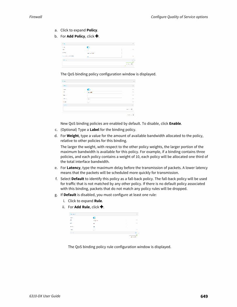
Firewall Configure Quality of Service options
6310-DX User Guide 649
a. Click to expand Policy.b. For Add Policy, click .
The QoS binding policy configuration window is displayed.
New QoS binding policies are enabled by default. To disable, click Enable.c. (Optional) Type a Label for the binding policy.d. For Weight, type a value for the amount of available bandwidth allocated to the policy,
relative to other policies for this binding.The larger the weight, with respect to the other policy weights, the larger portion of themaximum bandwidth is available for this policy. For example, if a binding contains threepolicies, and each policy contains a weight of 10, each policy will be allocated one third ofthe total interface bandwidth.
e. For Latency, type the maximum delay before the transmission of packets. A lower latencymeans that the packets will be scheduled more quickly for transmission.
f. Select Default to identify this policy as a fall-back policy. The fall-back policy will be usedfor traffic that is not matched by any other policy. If there is no default policy associatedwith this binding, packets that do not match any policy rules will be dropped.
g. If Default is disabled, you must configure at least one rule:i. Click to expand Rule.ii. For Add Rule, click .
The QoS binding policy rule configuration window is displayed.
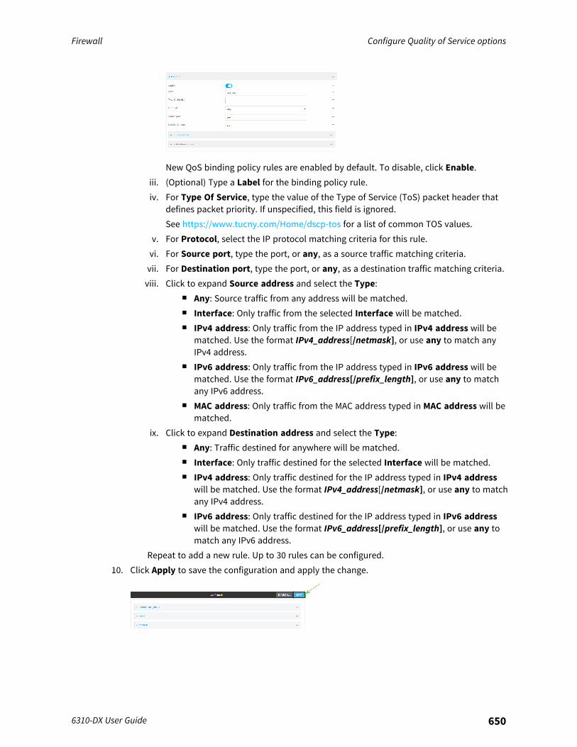
Firewall Configure Quality of Service options
6310-DX User Guide 650
New QoS binding policy rules are enabled by default. To disable, click Enable.iii. (Optional) Type a Label for the binding policy rule.iv. For Type Of Service, type the value of the Type of Service (ToS) packet header that
defines packet priority. If unspecified, this field is ignored.See https://www.tucny.com/Home/dscp-tos for a list of common TOS values.
v. For Protocol, select the IP protocol matching criteria for this rule.vi. For Source port, type the port, or any, as a source traffic matching criteria.vii. For Destination port, type the port, or any, as a destination traffic matching criteria.viii. Click to expand Source address and select the Type:
n Any: Source traffic from any address will be matched.n Interface: Only traffic from the selected Interface will be matched.n IPv4 address: Only traffic from the IP address typed in IPv4 address will be
matched. Use the format IPv4_address[/netmask], or use any to match anyIPv4 address.
n IPv6 address: Only traffic from the IP address typed in IPv6 address will bematched. Use the format IPv6_address[/prefix_length], or use any to matchany IPv6 address.
n MAC address: Only traffic from the MAC address typed in MAC address will bematched.
ix. Click to expand Destination address and select the Type:n Any: Traffic destined for anywhere will be matched.n Interface: Only traffic destined for the selected Interface will be matched.n IPv4 address: Only traffic destined for the IP address typed in IPv4 address
will be matched. Use the format IPv4_address[/netmask], or use any to matchany IPv4 address.
n IPv6 address: Only traffic destined for the IP address typed in IPv6 addresswill be matched. Use the format IPv6_address[/prefix_length], or use any tomatch any IPv6 address.
Repeat to add a new rule. Up to 30 rules can be configured.10. Click Apply to save the configuration and apply the change.
Firewall Configure Quality of Service options
6310-DX User Guide 651
Command line
1. Log into the 6310-DX command line as a user with full Admin access rights.Depending on your device configuration, you may be presented with an Access selectionmenu. Type admin to access the Admin CLI.
2. At the command line, type config to enter configuration mode:
> config(config)>
3. Add a binding:
(config)> add firewall qos end(config firewall qos 2)>
New binding are enabled by default. To disable:
(config firewall qos 2)> enable false(config firewall qos 2)>
4. (Optional) Set a label for the new binding:
(config firewall qos 2)> label my_binding(config firewall qos 2)>
5. Set the interface to queue egress packets on. The binding will only match traffic that is beingsent out on this interface:a. Use the ? to determine available interfaces:
(config firewall qos 2)> interface ?
Interface: The network interface.Format:/network/interface/defaultip/network/interface/defaultlinklocal/network/interface/lan/network/interface/loopback/network/interface/modem/network/interface/wan
Current value:
(config firewall qos 2)> interface
b. Set the interface. For example:
(config firewall qos 2)> interface /network/interface/wan(config firewall qos 2)>
6. (Optional) Set the maximum egress bandwidth of the interface, in megabits, allocated to thisbinding.
Firewall Configure Quality of Service options
6310-DX User Guide 652
(config firewall qos 2)> bandwidth int(config firewall qos 2)>
where int is an integer between 1 and 1000. Typically, this should be 95% of the availablebandwidth. The default is 95.
7. Create a policy for the binding:At least one policy is required for each binding. Each policy can contain up to 30 rules.a. Change to the policy node of the configuration:
(config firewall qos 2)> policy(config firewall qos 2 policy)>
b. Add a policy:
(config firewall qos 2 policy)> add end(config firewall qos 2 policy 0)>
New QoS binding policies are enabled by default. To disable:
(config firewall qos 2 policy 0)> enable false(config firewall qos 2 policy 0)>
c. (Optional) Set a label for the new binding policy:
(config firewall qos 2 policy 0)> label my_binding_policy(config firewall qos 2 policy 0)>
d. Set a value for the amount of available bandwidth allocated to the policy, relative to otherpolicies for this binding.The larger the weight, with respect to the other policy weights, the larger portion of themaximum bandwidth is available for this policy. For example, if a binding contains threepolicies, and each policy contains a weight of 10, each policy will be allocated one third ofthe total interface bandwidth.
(config firewall qos 2 policy 0)> weight int(config firewall qos 2 policy 0)>
where int is any integer between 1 and 65535. The default is 10.e. Set the maximum delay before the transmission of packets. A lower number means that
the packets will be scheduled more quickly for transmission.
(config firewall qos 2 policy 0)> latency int(config firewall qos 2 policy 0)>
where int is any integer, 1 or greater. The default is 100.f. To identify this policy as a fall-back policy:
(config firewall qos 2 policy 0)> default true(config firewall qos 2 policy 0)>
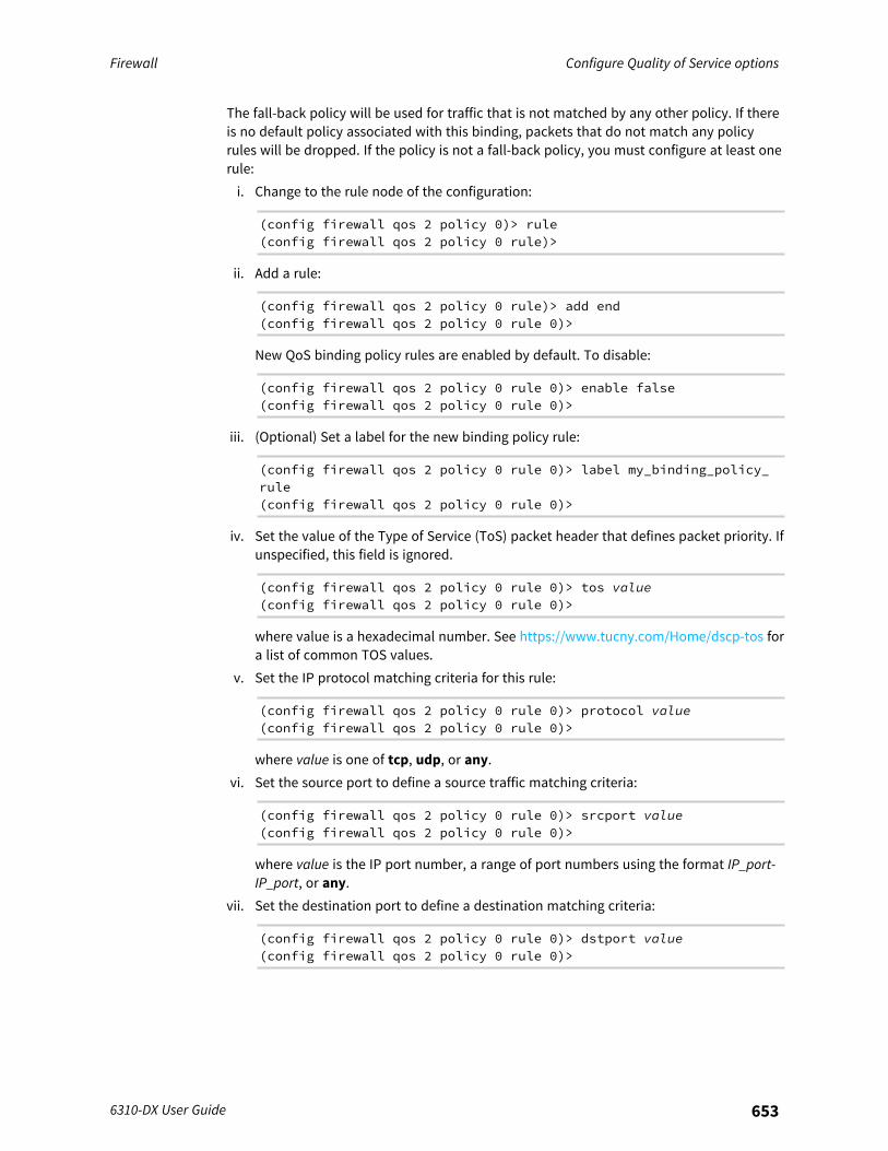
Firewall Configure Quality of Service options
6310-DX User Guide 653
The fall-back policy will be used for traffic that is not matched by any other policy. If thereis no default policy associated with this binding, packets that do not match any policyrules will be dropped. If the policy is not a fall-back policy, you must configure at least onerule:i. Change to the rule node of the configuration:
(config firewall qos 2 policy 0)> rule(config firewall qos 2 policy 0 rule)>
ii. Add a rule:
(config firewall qos 2 policy 0 rule)> add end(config firewall qos 2 policy 0 rule 0)>
New QoS binding policy rules are enabled by default. To disable:
(config firewall qos 2 policy 0 rule 0)> enable false(config firewall qos 2 policy 0 rule 0)>
iii. (Optional) Set a label for the new binding policy rule:
(config firewall qos 2 policy 0 rule 0)> label my_binding_policy_rule(config firewall qos 2 policy 0 rule 0)>
iv. Set the value of the Type of Service (ToS) packet header that defines packet priority. Ifunspecified, this field is ignored.
(config firewall qos 2 policy 0 rule 0)> tos value(config firewall qos 2 policy 0 rule 0)>
where value is a hexadecimal number. See https://www.tucny.com/Home/dscp-tos fora list of common TOS values.
v. Set the IP protocol matching criteria for this rule:
(config firewall qos 2 policy 0 rule 0)> protocol value(config firewall qos 2 policy 0 rule 0)>
where value is one of tcp, udp, or any.vi. Set the source port to define a source traffic matching criteria:
(config firewall qos 2 policy 0 rule 0)> srcport value(config firewall qos 2 policy 0 rule 0)>
where value is the IP port number, a range of port numbers using the format IP_port-IP_port, or any.
vii. Set the destination port to define a destination matching criteria:
(config firewall qos 2 policy 0 rule 0)> dstport value(config firewall qos 2 policy 0 rule 0)>
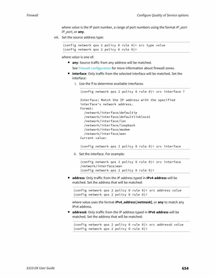
Firewall Configure Quality of Service options
6310-DX User Guide 654
where value is the IP port number, a range of port numbers using the format IP_port-IP_port, or any.
viii. Set the source address type:
(config network qos 2 policy 0 rule 0)> src type value(config network qos 2 policy 0 rule 0)>
where value is one of:n any: Source traffic from any address will be matched.
See Firewall configuration for more information about firewall zones.n interface: Only traffic from the selected interface will be matched. Set the
interface:i. Use the ? to determine available interfaces:
(config network qos 2 policy 0 rule 0)> src interface ?
Interface: Match the IP address with the specifiedinterface's network address.Format:/network/interface/defaultip/network/interface/defaultlinklocal/network/interface/lan/network/interface/loopback/network/interface/modem/network/interface/wan
Current value:
(config network qos 2 policy 0 rule 0)> src interface
ii. Set the interface. For example:
(config network qos 2 policy 0 rule 0)> src interface/network/interface/wan(config network qos 2 policy 0 rule 0)>
n address: Only traffic from the IP address typed in IPv4 address will bematched. Set the address that will be matched:
(config network qos 2 policy 0 rule 0)> src address value(config network qos 2 policy 0 rule 0)>
where value uses the format IPv4_address[/netmask], or any to match anyIPv4 address.
n address6: Only traffic from the IP address typed in IPv6 address will bematched. Set the address that will be matched:
(config network qos 2 policy 0 rule 0)> src address6 value(config network qos 2 policy 0 rule 0)>

Firewall Configure Quality of Service options
6310-DX User Guide 655
where value uses the format IPv6_address[/prefix_length], or any to matchany IPv6 address.
n mac: Only traffic from the MAC address typed in MAC address will be matched.Set the MAC address to be matched:
(config network qos 2 policy 0 rule 0)> src mac MAC_address(config network qos 2 policy 0 rule 0)>
ix. Set the destination address type:
(config network qos 2 policy 0 rule 0)> dst type value(config network qos 2 policy 0 rule 0)>
where value is one of:n any: Traffic destined for anywhere will be matched.
See Firewall configuration for more information about firewall zones.n interface: Only traffic destined for the selected Interface will be matched. Set
the interface:i. Use the ? to determine available interfaces:
(config network qos 2 policy 0 rule 0)> dst interface ?
Interface: Match the IP address with the specifiedinterface's network address.Format:/network/interface/defaultip/network/interface/defaultlinklocal/network/interface/lan/network/interface/loopback/network/interface/modem/network/interface/wan
Current value:
(config network qos 2 policy 0 rule 0)> dst interface
ii. Set the interface. For example:
(config network qos 2 policy 0 rule 0)> dst interface/network/interface/wan(config network qos 2 policy 0 rule 0)>
n address: Only traffic destined for the IP address typed in IPv4 address will bematched. Set the address that will be matched:
(config network qos 2 policy 0 rule 0)> src address value(config network qos 2 policy 0 rule 0)>
where value uses the format IPv4_address[/netmask], or any to match anyIPv4 address.
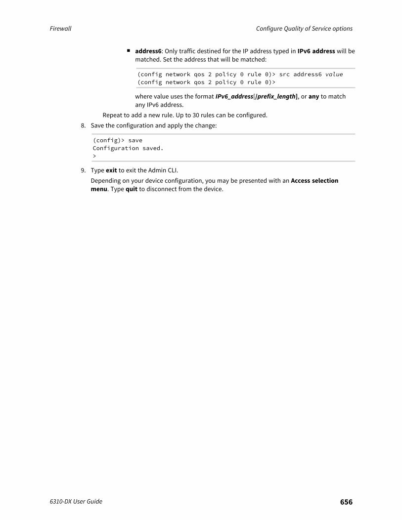
Firewall Configure Quality of Service options
6310-DX User Guide 656
n address6: Only traffic destined for the IP address typed in IPv6 address will bematched. Set the address that will be matched:
(config network qos 2 policy 0 rule 0)> src address6 value(config network qos 2 policy 0 rule 0)>
where value uses the format IPv6_address[/prefix_length], or any to matchany IPv6 address.
Repeat to add a new rule. Up to 30 rules can be configured.8. Save the configuration and apply the change:
(config)> saveConfiguration saved.>
9. Type exit to exit the Admin CLI.Depending on your device configuration, you may be presented with an Access selectionmenu. Type quit to disconnect from the device.
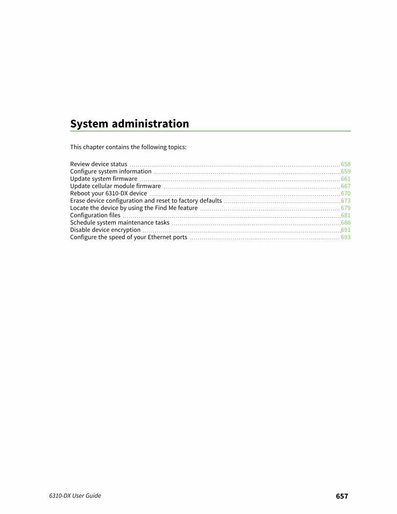
System administration
This chapter contains the following topics:
Review device status 658Configure system information 659Update system firmware 661Update cellular module firmware 667Reboot your 6310-DX device 670Erase device configuration and reset to factory defaults 673Locate the device by using the Find Me feature 679Configuration files 681Schedule system maintenance tasks 686Disable device encryption 691Configure the speed of your Ethernet ports 693
6310-DX User Guide 657
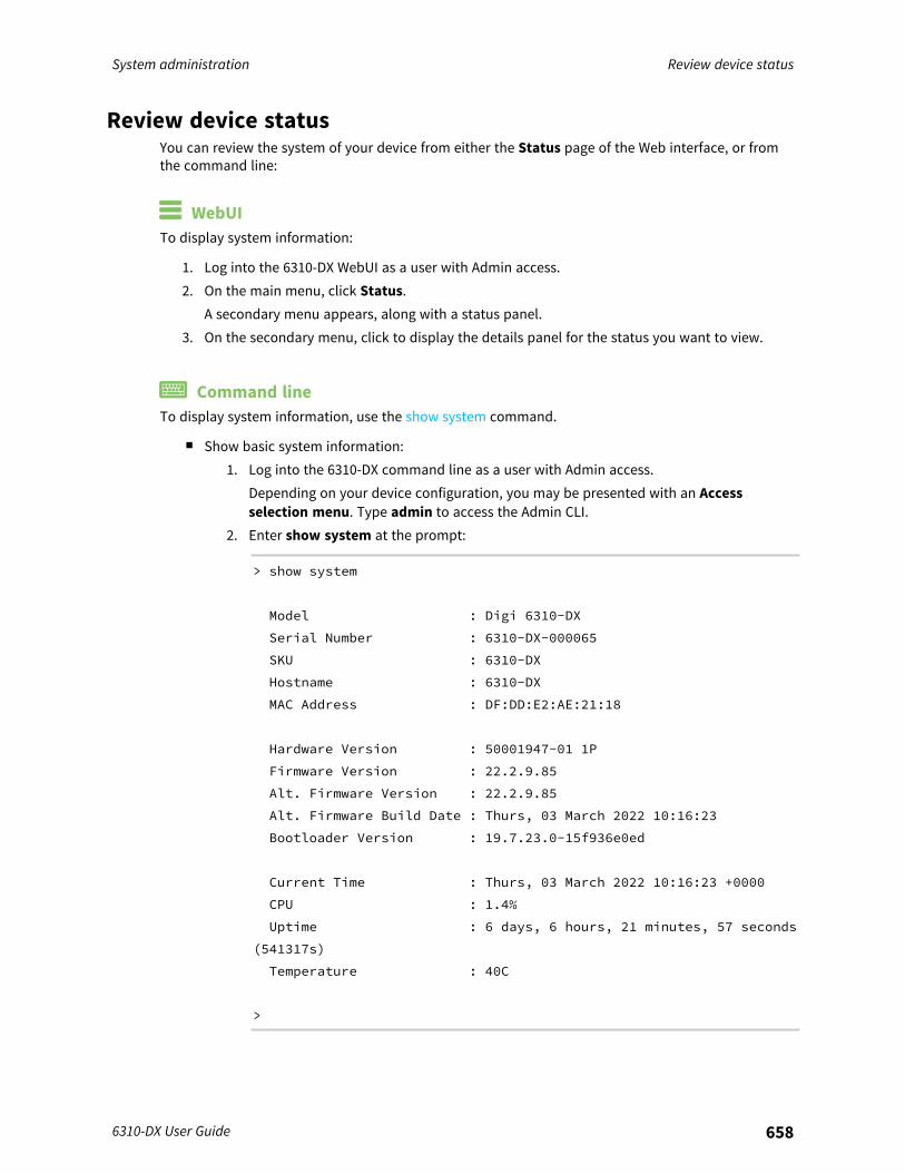
System administration Review device status
6310-DX User Guide 658
Review device statusYou can review the system of your device from either the Status page of the Web interface, or fromthe command line:
WebUITo display system information:
1. Log into the 6310-DX WebUI as a user with Admin access.2. On the main menu, click Status.
A secondary menu appears, along with a status panel.3. On the secondary menu, click to display the details panel for the status you want to view.
Command lineTo display system information, use the show system command.
n Show basic system information:1. Log into the 6310-DX command line as a user with Admin access.
Depending on your device configuration, you may be presented with an Accessselection menu. Type admin to access the Admin CLI.
2. Enter show system at the prompt:
> show system
Model : Digi 6310-DX
Serial Number : 6310-DX-000065
SKU : 6310-DX
Hostname : 6310-DX
MAC Address : DF:DD:E2:AE:21:18
Hardware Version : 50001947-01 1P
Firmware Version : 22.2.9.85
Alt. Firmware Version : 22.2.9.85
Alt. Firmware Build Date : Thurs, 03 March 2022 10:16:23
Bootloader Version : 19.7.23.0-15f936e0ed
Current Time : Thurs, 03 March 2022 10:16:23 +0000
CPU : 1.4%
Uptime : 6 days, 6 hours, 21 minutes, 57 seconds
(541317s)
Temperature : 40C
>
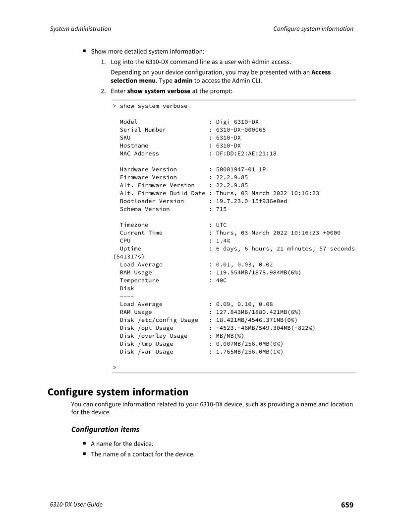
System administration Configure system information
6310-DX User Guide 659
n Show more detailed system information:1. Log into the 6310-DX command line as a user with Admin access.
Depending on your device configuration, you may be presented with an Accessselection menu. Type admin to access the Admin CLI.
2. Enter show system verbose at the prompt:
> show system verbose
Model : Digi 6310-DXSerial Number : 6310-DX-000065SKU : 6310-DXHostname : 6310-DXMAC Address : DF:DD:E2:AE:21:18
Hardware Version : 50001947-01 1PFirmware Version : 22.2.9.85Alt. Firmware Version : 22.2.9.85Alt. Firmware Build Date : Thurs, 03 March 2022 10:16:23Bootloader Version : 19.7.23.0-15f936e0edSchema Version : 715
Timezone : UTCCurrent Time : Thurs, 03 March 2022 10:16:23 +0000CPU : 1.4%Uptime : 6 days, 6 hours, 21 minutes, 57 seconds
(541317s)Load Average : 0.01, 0.03, 0.02RAM Usage : 119.554MB/1878.984MB(6%)Temperature : 40CDisk----Load Average : 0.09, 0.10, 0.08RAM Usage : 127.843MB/1880.421MB(6%)Disk /etc/config Usage : 18.421MB/4546.371MB(0%)Disk /opt Usage : -4523.-46MB/549.304MB(-822%)Disk /overlay Usage : MB/MB(%)Disk /tmp Usage : 0.007MB/256.0MB(0%)Disk /var Usage : 1.765MB/256.0MB(1%)
>
Configure system informationYou can configure information related to your 6310-DX device, such as providing a name and locationfor the device.
Configuration items
n A name for the device.n The name of a contact for the device.
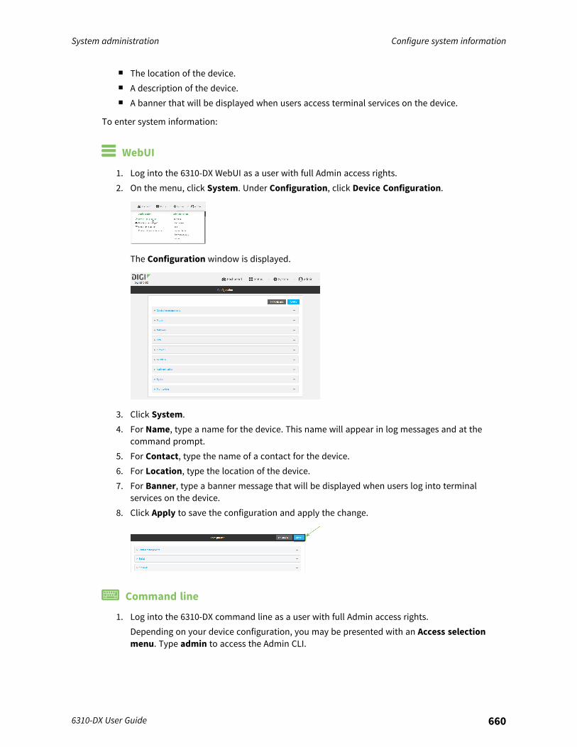
System administration Configure system information
6310-DX User Guide 660
n The location of the device.n A description of the device.n A banner that will be displayed when users access terminal services on the device.
To enter system information:
WebUI
1. Log into the 6310-DX WebUI as a user with full Admin access rights.2. On the menu, click System. Under Configuration, click Device Configuration.
The Configuration window is displayed.
3. Click System.4. For Name, type a name for the device. This name will appear in log messages and at the
command prompt.5. For Contact, type the name of a contact for the device.6. For Location, type the location of the device.7. For Banner, type a banner message that will be displayed when users log into terminal
services on the device.8. Click Apply to save the configuration and apply the change.
Command line
1. Log into the 6310-DX command line as a user with full Admin access rights.Depending on your device configuration, you may be presented with an Access selectionmenu. Type admin to access the Admin CLI.
System administration Update system firmware
6310-DX User Guide 661
2. At the command line, type config to enter configuration mode:
> config(config)>
3. Set a name for the device. This name will appear in log messages and at the commandprompt.
(config)> system name 192.168.3.1192.168.3.1(config)>
4. Set the contact for the device:
192.168.3.1(config)> system contact "Jane User"192.168.3.1(config)>
5. Set the location for the device:
192.168.3.1(config)> system location "9350 Excelsior Blvd., Suite 700,Hopkins, MN"192.168.3.1(config)>
6. Set the banner for the device. This is displayed when users access terminal services on thedevice.
192.168.3.1(config)> system banner "Welcome to the Digi 6310-DX."192.168.3.1(config)>
7. Save the configuration and apply the change:
192.168.3.1(config)> saveConfiguration saved.192.168.3.1>
8. Type exit to exit the Admin CLI.Depending on your device configuration, you may be presented with an Access selectionmenu. Type quit to disconnect from the device.
Update system firmwareThe 6310-DX operating system firmware images consist of a single file with the following namingconvention:
platform-version.bin
For example, 6310-DX-22.2.9.85.bin.
Manage firmware updates using Digi Remote ManagerIf you have a network of many devices, you can use Digi Remote Manager Profiles to managefirmware updates. Profiles ensure all your devices are running the correct firmware version and thatall newly installed devices are updated to that same version. For more information, see the Profilessection of the Digi Remote Manager User Guide.

System administration Update system firmware
6310-DX User Guide 662
Certificate management for firmware imagesThe system firmware files are signed to ensure that only Digi-approved firmware load onto the device.The 6310-DX device validates the system firmware image as part of the update process and onlysuccessfully updates if the system firmware image can be authenticated.
DowngradingDowngrading to an earlier release of the firmware may result in the device configuration being erased.
Downgrading from firmware version 22.2.9.xBeginning with firmware version 22.2.9.x, the 6310-DX device uses certificate-based communicationfor enhanced security when connecting to Digi Remote Manager. If you downgrade your firmwarefrom version 22.2.9.x to version 21.11.x or previous, your device will no longer be able tocommunicate with Remote Manager.To remedy this issue, select the device in Remote Manager and select Actions > Reset DeviceCertificate.
Update firmware over the air (OTA) from the Digi firmware server WebUI
1. Log into the 6310-DX WebUI as a user with Admin access.2. On the main menu, click System. Under Administration, click Firmware Update.
3. Click Download from server.
4. For Version:, select the appropriate version of the device firmware.5. Click Update Firmware.
Command line
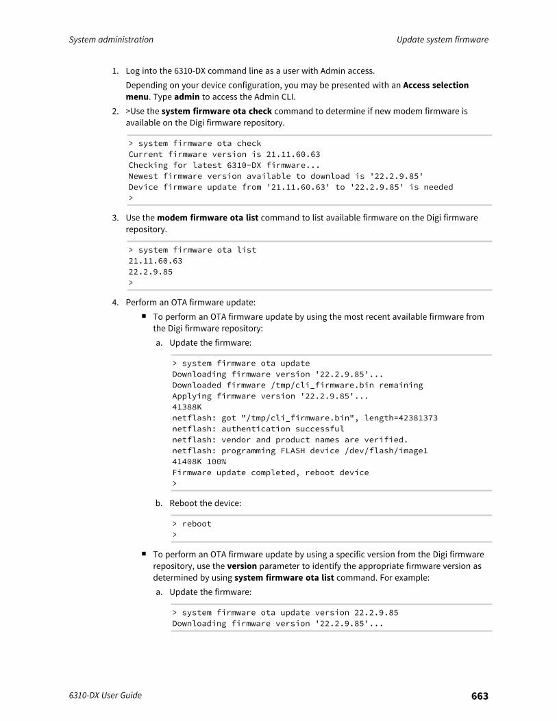
System administration Update system firmware
6310-DX User Guide 663
1. Log into the 6310-DX command line as a user with Admin access.Depending on your device configuration, you may be presented with an Access selectionmenu. Type admin to access the Admin CLI.
2. >Use the system firmware ota check command to determine if new modem firmware isavailable on the Digi firmware repository.
> system firmware ota checkCurrent firmware version is 21.11.60.63Checking for latest 6310-DX firmware...Newest firmware version available to download is '22.2.9.85'Device firmware update from '21.11.60.63' to '22.2.9.85' is needed>
3. Use the modem firmware ota list command to list available firmware on the Digi firmwarerepository.
> system firmware ota list21.11.60.6322.2.9.85>
4. Perform an OTA firmware update:n To perform an OTA firmware update by using the most recent available firmware from
the Digi firmware repository:a. Update the firmware:
> system firmware ota updateDownloading firmware version '22.2.9.85'...Downloaded firmware /tmp/cli_firmware.bin remainingApplying firmware version '22.2.9.85'...41388Knetflash: got "/tmp/cli_firmware.bin", length=42381373netflash: authentication successfulnetflash: vendor and product names are verified.netflash: programming FLASH device /dev/flash/image141408K 100%Firmware update completed, reboot device>
b. Reboot the device:
> reboot>
n To perform an OTA firmware update by using a specific version from the Digi firmwarerepository, use the version parameter to identify the appropriate firmware version asdetermined by using system firmware ota list command. For example:a. Update the firmware:
> system firmware ota update version 22.2.9.85Downloading firmware version '22.2.9.85'...
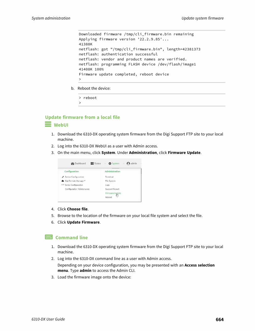
System administration Update system firmware
6310-DX User Guide 664
Downloaded firmware /tmp/cli_firmware.bin remainingApplying firmware version '22.2.9.85'...41388Knetflash: got "/tmp/cli_firmware.bin", length=42381373netflash: authentication successfulnetflash: vendor and product names are verified.netflash: programming FLASH device /dev/flash/image141408K 100%Firmware update completed, reboot device>
b. Reboot the device:
> reboot>
Update firmware from a local file WebUI
1. Download the 6310-DX operating system firmware from the Digi Support FTP site to your localmachine.
2. Log into the 6310-DX WebUI as a user with Admin access.3. On the main menu, click System. Under Administration, click Firmware Update.
4. Click Choose file.5. Browse to the location of the firmware on your local file system and select the file.6. Click Update Firmware.
Command line
1. Download the 6310-DX operating system firmware from the Digi Support FTP site to your localmachine.
2. Log into the 6310-DX command line as a user with Admin access.Depending on your device configuration, you may be presented with an Access selectionmenu. Type admin to access the Admin CLI.
3. Load the firmware image onto the device:
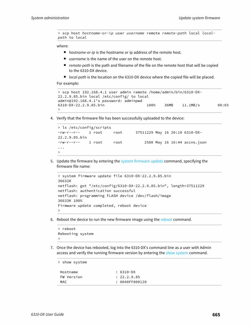
System administration Update system firmware
6310-DX User Guide 665
> scp host hostname-or-ip user username remote remote-path local local-path to local
where:n hostname-or-ip is the hostname or ip address of the remote host.n username is the name of the user on the remote host.n remote-path is the path and filename of the file on the remote host that will be copied
to the 6310-DX device.n local-path is the location on the 6310-DX device where the copied file will be placed.
For example:
> scp host 192.168.4.1 user admin remote /home/admin/bin/6310-DX-22.2.9.85.bin local /etc/config/ to [email protected]'s password: adminpwd6310-DX-22.2.9.85.bin 100% 36MB 11.1MB/s 00:03>
4. Verify that the firmware file has been successfully uploaded to the device:
> ls /etc/config/scripts-rw-r--r-- 1 root root 37511229 May 16 20:10 6310-DX-22.2.9.85.bin-rw-r--r-- 1 root root 2580 May 16 16:44 accns.json...>
5. Update the firmware by entering the system firmware update command, specifying thefirmware file name:
> system firmware update file 6310-DX-22.2.9.85.bin36632Knetflash: got "/etc/config/6310-DX-22.2.9.85.bin", length=37511229netflash: authentication successfulnetflash: programming FLASH device /dev/flash/image36633K 100%Firmware update completed, reboot device>
6. Reboot the device to run the new firmware image using the reboot command.
> rebootRebooting system>
7. Once the device has rebooted, log into the 6310-DX's command line as a user with Adminaccess and verify the running firmware version by entering the show system command.
> show system
Hostname : 6310-DXFW Version : 22.2.9.85MAC : 0040FF800120
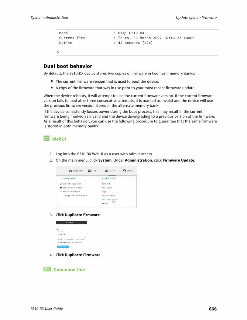
System administration Update system firmware
6310-DX User Guide 666
Model : Digi 6310-DXCurrent Time : Thurs, 03 March 2022 10:16:23 +0000Uptime : 42 seconds (42s)
>
Dual boot behaviorBy default, the 6310-DX device stores two copies of firmware in two flash memory banks:
n The current firmware version that is used to boot the device.n A copy of the firmware that was in use prior to your most recent firmware update.
When the device reboots, it will attempt to use the current firmware version. If the current firmwareversion fails to load after three consecutive attempts, it is marked as invalid and the device will usethe previous firmware version stored in the alternate memory bank.If the device consistently looses power during the boot process, this may result in the currentfirmware being marked as invalid and the device downgrading to a previous version of the firmware.As a result of this behavior, you can use the following procedure to guarantee that the same firmwareis stored in both memory banks:
WebUI
1. Log into the 6310-DX WebUI as a user with Admin access.2. On the main menu, click System. Under Administration, click Firmware Update.
3. Click Duplicate firmware.
4. Click Duplicate Firmware.
Command line
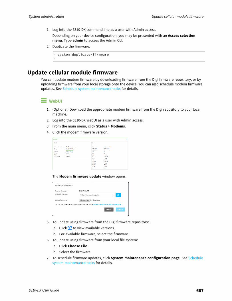
System administration Update cellular module firmware
6310-DX User Guide 667
1. Log into the 6310-DX command line as a user with Admin access.Depending on your device configuration, you may be presented with an Access selectionmenu. Type admin to access the Admin CLI.
2. Duplicate the firmware:
> system duplicate-firmware>
Update cellular module firmwareYou can update modem firmware by downloading firmware from the Digi firmware repository, or byuploading firmware from your local storage onto the device. You can also schedule modem firmwareupdates. See Schedule system maintenance tasks for details.
WebUI
1. (Optional) Download the appropriate modem firmware from the Digi repository to your localmachine.
2. Log into the 6310-DX WebUI as a user with Admin access.3. From the main menu, click Status > Modems.4. Click the modem firmware version.
The Modem firmware update window opens.
5. To update using firmware from the Digi firmware repository:a. Click to view available versions.b. For Available firmware, select the firmware.
6. To update using firmware from your local file system:a. Click Choose File.b. Select the firmware.
7. To schedule firmware updates, click System maintenance configuration page. See Schedulesystem maintenance tasks for details.
System administration Update cellular module firmware
6310-DX User Guide 668
8. Click Update.
Command line
Update modem firmware over the air (OTA)You can update your modem firmware by querying the Digi firmware repository to determine if thereis new firmware available for your modem and performing an OTA modem firmware update:
1. Log into the 6310-DX command line as a user with Admin access.Depending on your device configuration, you may be presented with an Access selectionmenu. Type admin to access the Admin CLI.
2. Use the modem firmware ota check command to determine if new modem firmware isavailable on the Digi firmware repository.
> modem firmware ota check
Checking for latest ATT firmware ...Retrieving modem firmware list ...Newest firmware version available to download is '24.01.5x4_ATT'Modem firmware update from '24.01.544_ATT' to '24.01.5x4_ATT' is needed24.01.5x4_ATT24.01.544_ATT
>
3. Use the modem firmware ota list command to list available firmware on the Digi firmwarerepository.
> modem firmware ota list
Retrieving modem firmware list ...25.20.664_CUST_044_325.20.666_CUST_067_125.20.663_CUST_040
>
4. Perform an OTA firmware update:n To perform an OTA firmware update by using the most recent available modem
firmware from the Digi firmware repository, type:
> modem firmware ota update
Checking for latest Generic firmware ...Retrieving modem firmware list ...Newest firmware version available to download is '25.20.666_CUST_067_1'Retrieving download location for modem firmware '25.20.666_CUST_067_1' ...
System administration Update cellular module firmware
6310-DX User Guide 669
>
n To perform an OTA firmware update by using a specific version from the Digi firmwarerepository, use the version parameter to identify the appropriate firmware version asdetermined by using modem firmware ota list command. For example::
> modem firmware ota update version 24.01.5x4_ATT
Retrieving download location for modem firmware '24.01.5x4_ATT' ...Downloading modem firmware '24.01.5x4_ATT' to '/opt/LE910C4_NF/Custom_Firmware' ...Modem firmware '24.01.5x4_ATT' downloadedUpdating modem firmware ...Programming modem firmware ...
Found modem ...Validate modem firmware ...Getting ready for update ...Stopping services ...Running update pass 1 of 3 ...Restarting services ...-----------------------------Successfully updated firmwareModem firmware update complete
>
5. Type exit to exit the Admin CLI.Depending on your device configuration, you may be presented with an Access selectionmenu. Type quit to disconnect from the device.
Update modem firmware by using a local firmware fileYou can update your modem firmware by uploading a modem firmware file to your 6310-DX device.Firmware should be uploaded to /opt/MODEM_MODEL/Custom_Firmware, for example,/opt/LM940/Custom_Firmware.Modem firmware can be downloaded from Digi here. Follow instructions on this page to determinethe cellular module used by your device. After downloading, use tar or a similar unzipping tool toextract the firmware prior to uploading to the device. Note that the firmware file may not have atar.gz extension, but it is a tar file and can be unzipped with tar or a similar tool. See Use the scpcommand for information about uploading files to the 6310-DX device.
1. Log into the 6310-DX command line as a user with Admin access.Depending on your device configuration, you may be presented with an Access selectionmenu. Type admin to access the Admin CLI.
2. Use the modem firmware check command to determine if new modem firmware is availableon local device.
System administration Reboot your 6310-DX device
6310-DX User Guide 670
> modem firmware check
Checking for latest ATT firmware in flash ...Newest firmware version available in flash is '05.05.58.00_ATT_005.026_000'Modem firmware up to date05.05.58.00_ATT_005.026_000
> modem firmware check
3. Use the modem firmware list command to list available firmware on the 6310-DX device.
> modem firmware list
ATT, 24.01.544_ATT, currentGeneric, 24.01.514_Generic, imageVerizon, 24.01.524_Verizon, imageATT, 24.01.544_ATT, imageSprint, 24.01.531-B003_Sprint, image
>
4. To perform an firmware update by using a local file, use the version parameter to identify theappropriate firmware version as determined using the modem firmware check or modemfirmware list command. For example::
> modem firmware update version 24.01.5x4_ATT
Updating modem firmware ...
-----------------------------Successfully updated firmwareModem firmware update complete
>
5. Type exit to exit the Admin CLI.Depending on your device configuration, you may be presented with an Access selectionmenu. Type quit to disconnect from the device.
Reboot your 6310-DX deviceYou can reboot the 6310-DX device immediately or schedule a reboot for a specific time every day.
Note You may want to save your configuration settings to a file before rebooting. See Saveconfiguration to a file.
Reboot your device immediately
WebUI
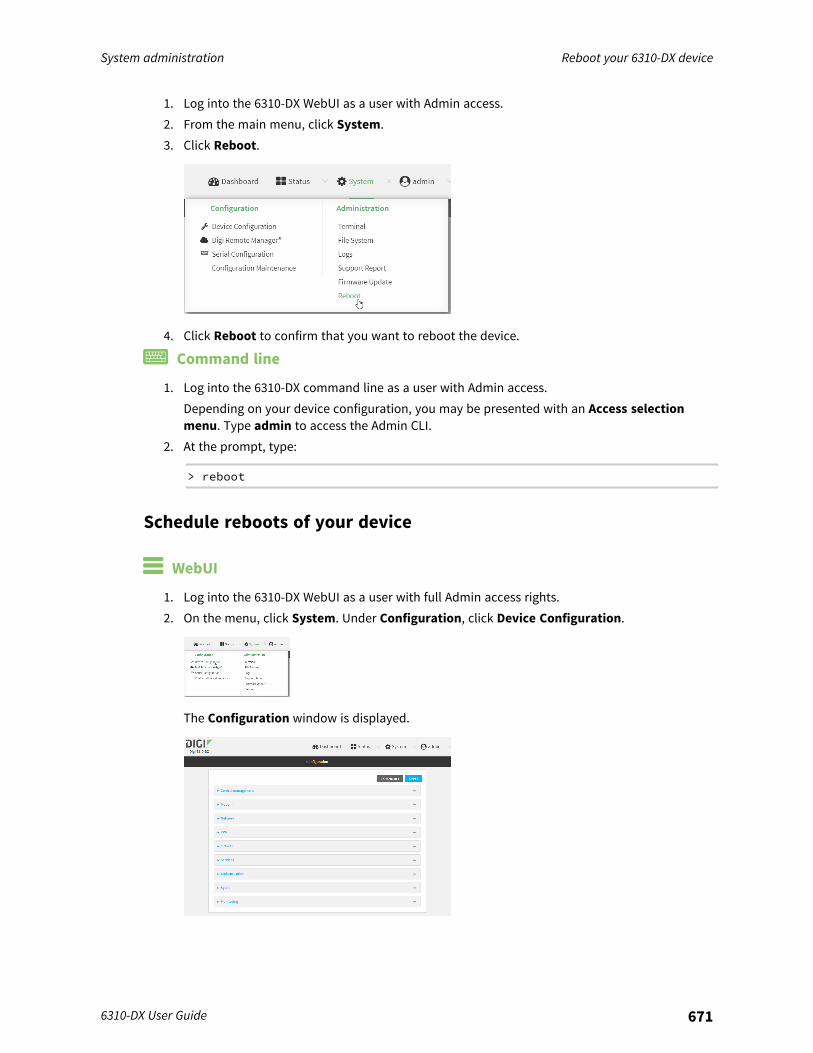
System administration Reboot your 6310-DX device
6310-DX User Guide 671
1. Log into the 6310-DX WebUI as a user with Admin access.2. From the main menu, click System.3. Click Reboot.
4. Click Reboot to confirm that you want to reboot the device.
Command line
1. Log into the 6310-DX command line as a user with Admin access.Depending on your device configuration, you may be presented with an Access selectionmenu. Type admin to access the Admin CLI.
2. At the prompt, type:
> reboot
Schedule reboots of your device
WebUI
1. Log into the 6310-DX WebUI as a user with full Admin access rights.2. On the menu, click System. Under Configuration, click Device Configuration.
The Configuration window is displayed.
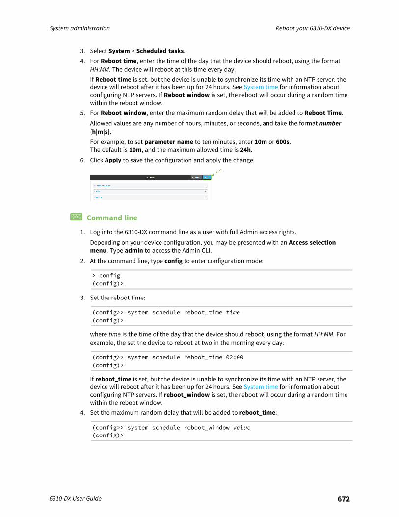
System administration Reboot your 6310-DX device
6310-DX User Guide 672
3. Select System > Scheduled tasks.4. For Reboot time, enter the time of the day that the device should reboot, using the format
HH:MM. The device will reboot at this time every day.If Reboot time is set, but the device is unable to synchronize its time with an NTP server, thedevice will reboot after it has been up for 24 hours. See System time for information aboutconfiguring NTP servers. If Reboot window is set, the reboot will occur during a random timewithin the reboot window.
5. For Reboot window, enter the maximum random delay that will be added to Reboot Time.Allowed values are any number of hours, minutes, or seconds, and take the format number{h|m|s}.For example, to set parameter name to ten minutes, enter 10m or 600s.The default is 10m, and the maximum allowed time is 24h.
6. Click Apply to save the configuration and apply the change.
Command line
1. Log into the 6310-DX command line as a user with full Admin access rights.Depending on your device configuration, you may be presented with an Access selectionmenu. Type admin to access the Admin CLI.
2. At the command line, type config to enter configuration mode:
> config(config)>
3. Set the reboot time:
(config>> system schedule reboot_time time(config)>
where time is the time of the day that the device should reboot, using the format HH:MM. Forexample, the set the device to reboot at two in the morning every day:
(config>> system schedule reboot_time 02:00(config)>
If reboot_time is set, but the device is unable to synchronize its time with an NTP server, thedevice will reboot after it has been up for 24 hours. See System time for information aboutconfiguring NTP servers. If reboot_window is set, the reboot will occur during a random timewithin the reboot window.
4. Set the maximum random delay that will be added to reboot_time:
(config>> system schedule reboot_window value(config)>
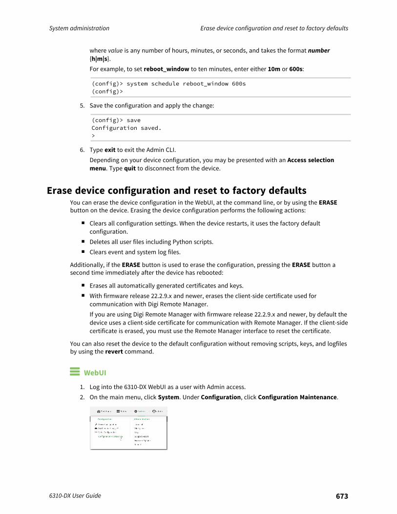
System administration Erase device configuration and reset to factory defaults
6310-DX User Guide 673
where value is any number of hours, minutes, or seconds, and takes the format number{h|m|s}.For example, to set reboot_window to ten minutes, enter either 10m or 600s:
(config)> system schedule reboot_window 600s(config)>
5. Save the configuration and apply the change:
(config)> saveConfiguration saved.>
6. Type exit to exit the Admin CLI.Depending on your device configuration, you may be presented with an Access selectionmenu. Type quit to disconnect from the device.
Erase device configuration and reset to factory defaultsYou can erase the device configuration in the WebUI, at the command line, or by using the ERASEbutton on the device. Erasing the device configuration performs the following actions:
n Clears all configuration settings. When the device restarts, it uses the factory defaultconfiguration.
n Deletes all user files including Python scripts.n Clears event and system log files.
Additionally, if the ERASE button is used to erase the configuration, pressing the ERASE button asecond time immediately after the device has rebooted:
n Erases all automatically generated certificates and keys.n With firmware release 22.2.9.x and newer, erases the client-side certificate used for
communication with Digi Remote Manager.If you are using Digi Remote Manager with firmware release 22.2.9.x and newer, by default thedevice uses a client-side certificate for communication with Remote Manager. If the client-sidecertificate is erased, you must use the Remote Manager interface to reset the certificate.
You can also reset the device to the default configuration without removing scripts, keys, and logfilesby using the revert command.
WebUI
1. Log into the 6310-DX WebUI as a user with Admin access.2. On the main menu, click System. Under Configuration, click Configuration Maintenance.
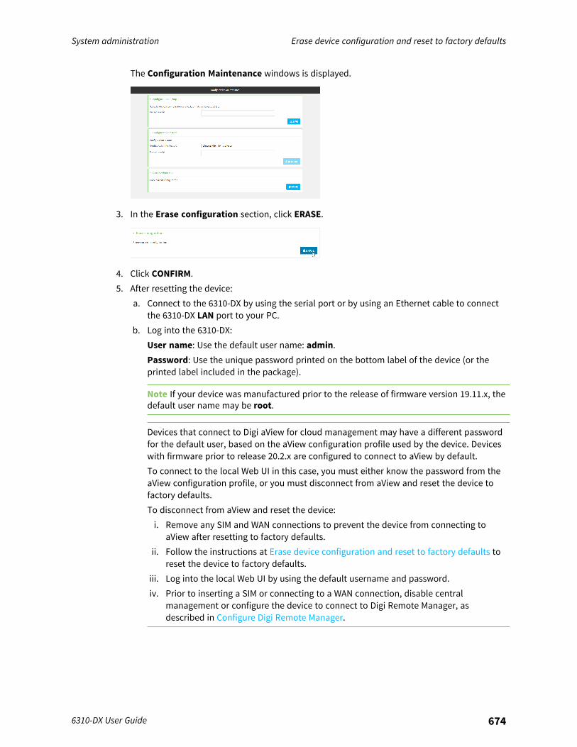
System administration Erase device configuration and reset to factory defaults
6310-DX User Guide 674
The Configuration Maintenance windows is displayed.
3. In the Erase configuration section, click ERASE.
4. Click CONFIRM.5. After resetting the device:
a. Connect to the 6310-DX by using the serial port or by using an Ethernet cable to connectthe 6310-DX LAN port to your PC.
b. Log into the 6310-DX:User name: Use the default user name: admin.Password: Use the unique password printed on the bottom label of the device (or theprinted label included in the package).
Note If your device was manufactured prior to the release of firmware version 19.11.x, thedefault user name may be root.
Devices that connect to Digi aView for cloud management may have a different passwordfor the default user, based on the aView configuration profile used by the device. Deviceswith firmware prior to release 20.2.x are configured to connect to aView by default.To connect to the local Web UI in this case, you must either know the password from theaView configuration profile, or you must disconnect from aView and reset the device tofactory defaults.To disconnect from aView and reset the device:i. Remove any SIM and WAN connections to prevent the device from connecting to
aView after resetting to factory defaults.ii. Follow the instructions at Erase device configuration and reset to factory defaults to
reset the device to factory defaults.iii. Log into the local Web UI by using the default username and password.iv. Prior to inserting a SIM or connecting to a WAN connection, disable central
management or configure the device to connect to Digi Remote Manager, asdescribed in Configure Digi Remote Manager.
System administration Erase device configuration and reset to factory defaults
6310-DX User Guide 675
c. (Optional) Reset the default password for the admin account. See Change the defaultpassword for the admin user for further information.
Command line
1. Log into the 6310-DX command line as a user with Admin access.Depending on your device configuration, you may be presented with an Access selectionmenu. Type admin to access the Admin CLI.
2. Enter the following:
> system factory-erase
3. After resetting the device:a. Connect to the 6310-DX by using the serial port or by using an Ethernet cable to connect
the 6310-DX LAN port to your PC.b. Log into the 6310-DX:
User name: Use the default user name: admin.Password: Use the unique password printed on the bottom label of the device (or theprinted label included in the package).
Note If your device was manufactured prior to the release of firmware version 19.11.x, thedefault user name may be root.
Devices that connect to Digi aView for cloud management may have a different passwordfor the default user, based on the aView configuration profile used by the device. Deviceswith firmware prior to release 20.2.x are configured to connect to aView by default.To connect to the local Web UI in this case, you must either know the password from theaView configuration profile, or you must disconnect from aView and reset the device tofactory defaults.To disconnect from aView and reset the device:i. Remove any SIM and WAN connections to prevent the device from connecting to
aView after resetting to factory defaults.ii. Follow the instructions at Erase device configuration and reset to factory defaults to
reset the device to factory defaults.iii. Log into the local Web UI by using the default username and password.iv. Prior to inserting a SIM or connecting to a WAN connection, disable central
management or configure the device to connect to Digi Remote Manager, asdescribed in Configure Digi Remote Manager.
c. (Optional) Reset the default password for the admin account. See Change the defaultpassword for the admin user for further information.
Reset the device by using the ERASE button.

System administration Erase device configuration and reset to factory defaults
6310-DX User Guide 676
1. Locate the ERASE button on your device.
2. Press the ERASE button perform a device reset. The ERASE button has the following modes:n Configuration reset:
l Press and release the ERASE button .l The device reboots automatically and resets to factory defaults. This does not
remove any automatically generated certificates and keys.n Full device reset:
l After the device reboots from the first button press, immediately press and releasethe ERASE button again.
l The device reboots again and resets to factory defaults, as well as also removinggenerated certificates and keys.
3. After resetting the device:a. Connect to the 6310-DX by using the serial port or by using an Ethernet cable to connect
the 6310-DX LAN port to your PC.b. Log into the 6310-DX:
User name: Use the default user name: admin.Password: Use the unique password printed on the bottom label of the device (or theprinted label included in the package).
Note If your device was manufactured prior to the release of firmware version 19.11.x, thedefault user name may be root.
Devices that connect to Digi aView for cloud management may have a different passwordfor the default user, based on the aView configuration profile used by the device. Deviceswith firmware prior to release 20.2.x are configured to connect to aView by default.To connect to the local Web UI in this case, you must either know the password from theaView configuration profile, or you must disconnect from aView and reset the device tofactory defaults.To disconnect from aView and reset the device:i. Remove any SIM and WAN connections to prevent the device from connecting to
aView after resetting to factory defaults.ii. Follow the instructions at Erase device configuration and reset to factory defaults to
reset the device to factory defaults.

System administration Erase device configuration and reset to factory defaults
6310-DX User Guide 677
iii. Log into the local Web UI by using the default username and password.iv. Prior to inserting a SIM or connecting to a WAN connection, disable central
management or configure the device to connect to Digi Remote Manager, asdescribed in Configure Digi Remote Manager.
c. (Optional) Reset the default password for the admin account. See Change the defaultpassword for the admin user for further information.
Reset the device with the revert commandYou can reset the device to the default configuration without removing scripts, keys, and logfiles byusing the revert command:
1. Log into the 6310-DX command line as a user with full Admin access rights.Depending on your device configuration, you may be presented with an Access selectionmenu. Type admin to access the Admin CLI.
2. At the command line, type config to enter configuration mode:
> config(config)>
3. At the config prompt, enter revert:
(config)> revert(config)>
4. Set the password for the admin user prior to saving the changes:
(config)> auth user admin password pwd(config)>
5. Save the configuration and apply the change:
(config)> saveConfiguration saved.>
6. Type exit to exit the Admin CLI.Depending on your device configuration, you may be presented with an Access selectionmenu. Type quit to disconnect from the device.
Configure the 6310-DX device to use custom factory default settingsYou can configure your 6310-DX device to use custom factory default settings. This way, when youerase the device's configuration, the device will reset to your custom configuration rather than to theoriginal factory defaults.
Note To clear the custom default configuration, press the ERASE button, wait for the device to reboot,then press the ERASE button again.
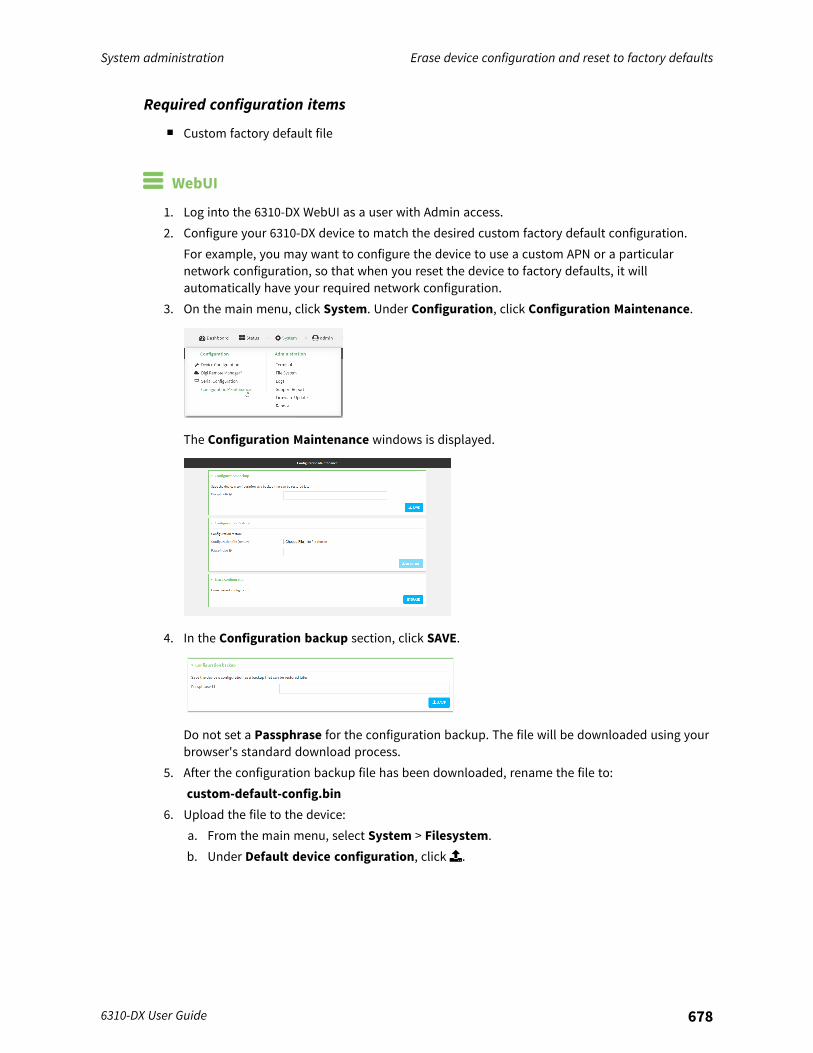
System administration Erase device configuration and reset to factory defaults
6310-DX User Guide 678
Required configuration items
n Custom factory default file
WebUI
1. Log into the 6310-DX WebUI as a user with Admin access.2. Configure your 6310-DX device to match the desired custom factory default configuration.
For example, you may want to configure the device to use a custom APN or a particularnetwork configuration, so that when you reset the device to factory defaults, it willautomatically have your required network configuration.
3. On the main menu, click System. Under Configuration, click Configuration Maintenance.
The Configuration Maintenance windows is displayed.
4. In the Configuration backup section, click SAVE.
Do not set a Passphrase for the configuration backup. The file will be downloaded using yourbrowser's standard download process.
5. After the configuration backup file has been downloaded, rename the file to:custom-default-config.bin
6. Upload the file to the device:a. From the main menu, select System > Filesystem.b. Under Default device configuration, click.
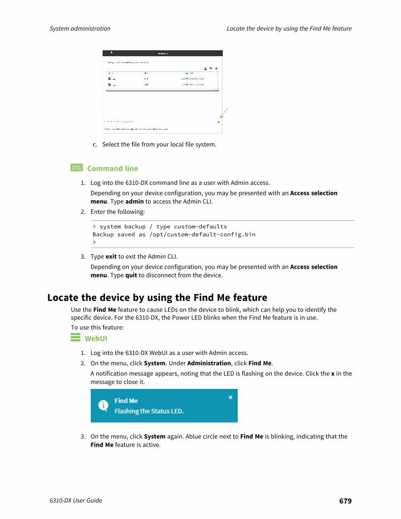
System administration Locate the device by using the Find Me feature
6310-DX User Guide 679
c. Select the file from your local file system.
Command line
1. Log into the 6310-DX command line as a user with Admin access.Depending on your device configuration, you may be presented with an Access selectionmenu. Type admin to access the Admin CLI.
2. Enter the following:
> system backup / type custom-defaultsBackup saved as /opt/custom-default-config.bin>
3. Type exit to exit the Admin CLI.Depending on your device configuration, you may be presented with an Access selectionmenu. Type quit to disconnect from the device.
Locate the device by using the Find Me featureUse the Find Me feature to cause LEDs on the device to blink, which can help you to identify thespecific device. For the 6310-DX, the Power LED blinks when the Find Me feature is in use.To use this feature:
WebUI
1. Log into the 6310-DX WebUI as a user with Admin access.2. On the menu, click System. Under Administration, click Find Me.
A notification message appears, noting that the LED is flashing on the device. Click the x in themessage to close it.
3. On the menu, click System again. Ablue circle next to Find Me is blinking, indicating that theFind Me feature is active.
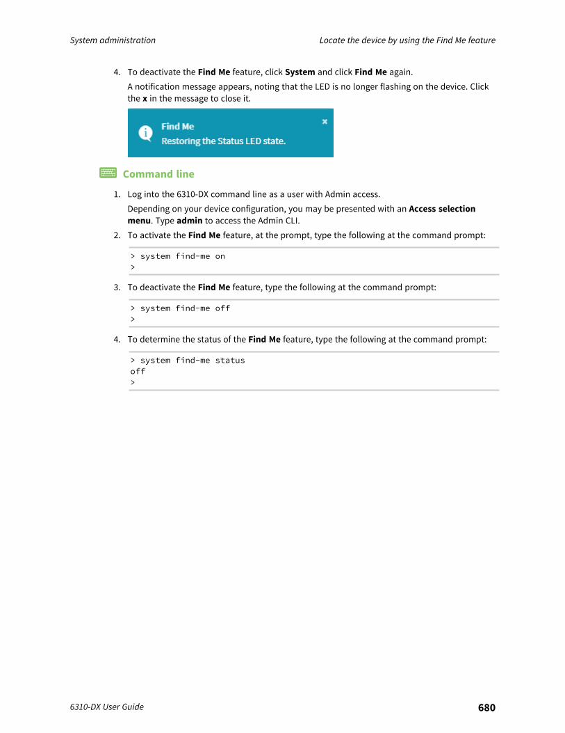
System administration Locate the device by using the Find Me feature
6310-DX User Guide 680
4. To deactivate the Find Me feature, click System and click Find Me again.A notification message appears, noting that the LED is no longer flashing on the device. Clickthe x in the message to close it.
Command line
1. Log into the 6310-DX command line as a user with Admin access.Depending on your device configuration, you may be presented with an Access selectionmenu. Type admin to access the Admin CLI.
2. To activate the Find Me feature, at the prompt, type the following at the command prompt:
> system find-me on>
3. To deactivate the Find Me feature, type the following at the command prompt:
> system find-me off>
4. To determine the status of the Find Me feature, type the following at the command prompt:
> system find-me statusoff>
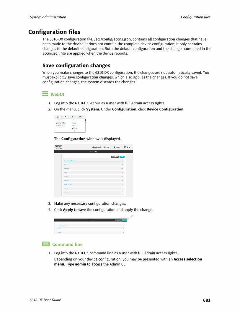
System administration Configuration files
6310-DX User Guide 681
Configuration filesThe 6310-DX configuration file, /etc/config/accns.json, contains all configuration changes that havebeen made to the device. It does not contain the complete device configuration; it only containschanges to the default configuration. Both the default configuration and the changes contained in theaccns.json file are applied when the device reboots.
Save configuration changesWhen you make changes to the 6310-DX configuration, the changes are not automatically saved. Youmust explicitly save configuration changes, which also applies the changes. If you do not saveconfiguration changes, the system discards the changes.
WebUI
1. Log into the 6310-DX WebUI as a user with full Admin access rights.2. On the menu, click System. Under Configuration, click Device Configuration.
The Configuration window is displayed.
3. Make any necessary configuration changes.4. Click Apply to save the configuration and apply the change.
Command line
1. Log into the 6310-DX command line as a user with full Admin access rights.Depending on your device configuration, you may be presented with an Access selectionmenu. Type admin to access the Admin CLI.
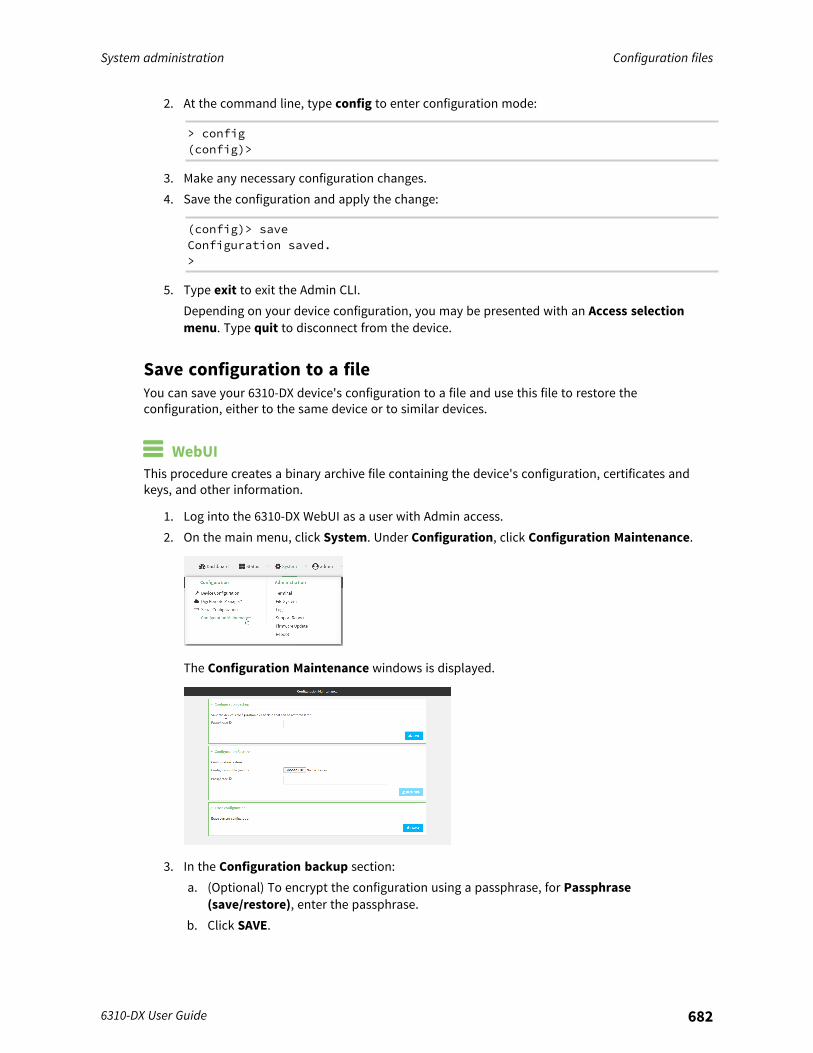
System administration Configuration files
6310-DX User Guide 682
2. At the command line, type config to enter configuration mode:
> config(config)>
3. Make any necessary configuration changes.4. Save the configuration and apply the change:
(config)> saveConfiguration saved.>
5. Type exit to exit the Admin CLI.Depending on your device configuration, you may be presented with an Access selectionmenu. Type quit to disconnect from the device.
Save configuration to a fileYou can save your 6310-DX device's configuration to a file and use this file to restore theconfiguration, either to the same device or to similar devices.
WebUIThis procedure creates a binary archive file containing the device's configuration, certificates andkeys, and other information.
1. Log into the 6310-DX WebUI as a user with Admin access.2. On the main menu, click System. Under Configuration, click Configuration Maintenance.
The Configuration Maintenance windows is displayed.
3. In the Configuration backup section:a. (Optional) To encrypt the configuration using a passphrase, for Passphrase
(save/restore), enter the passphrase.b. Click SAVE.
System administration Configuration files
6310-DX User Guide 683
The file will be downloaded using your browser's standard download process.
Command line
1. Log into the 6310-DX command line as a user with Admin access.Depending on your device configuration, you may be presented with an Access selectionmenu. Type admin to access the Admin CLI.
2. Enter the following:
> system backup path [passphrase passphrase] type type
wheren path is the location on the 6310-DX's filesystem where the configuration backup file
should be saved.n passphrase (optional) is a passphrase used to encrypt the configuration backup.n type is the type of backup, either:
l archive: Creates a binary archive file containing the device's configuration,certificates and keys, and other information.
l cli-config: Creates a text file containing only the configuration changes.For example:
> system backup /etc/config/scripts/ type archive
3. (Optional) Use scp to copy the file from your device to another host:
> scp host hostname-or-ip user username remote remote-path local local-path to remote
where:n hostname-or-ip is the hostname or ip address of the remote host.n username is the name of the user on the remote host.n remote-path is the location on the remote host where the file will be copied.n local-path is the path and filename on the 6310-DX device.
For example:
> scp host 192.168.4.1 user admin remote /home/admin/bin/ local/etc/config/backup-archive-0040FF800120-19.05.17-19.01.17.bin to remote
Restore the device configurationYou can restore a configuration file to your 6310-DX device by using a backup from the device, or abackup from a similar device.
WebUI
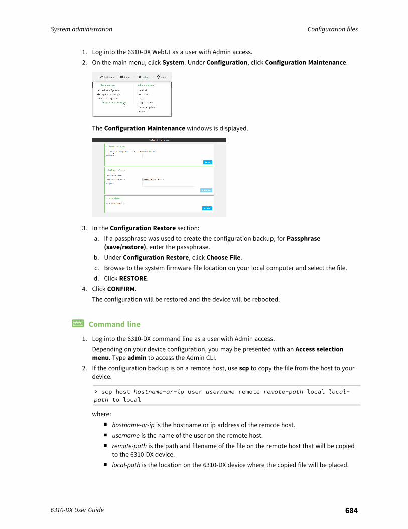
System administration Configuration files
6310-DX User Guide 684
1. Log into the 6310-DX WebUI as a user with Admin access.2. On the main menu, click System. Under Configuration, click Configuration Maintenance.
The Configuration Maintenance windows is displayed.
3. In the Configuration Restore section:a. If a passphrase was used to create the configuration backup, for Passphrase
(save/restore), enter the passphrase.b. Under Configuration Restore, click Choose File.c. Browse to the system firmware file location on your local computer and select the file.d. Click RESTORE.
4. Click CONFIRM.The configuration will be restored and the device will be rebooted.
Command line
1. Log into the 6310-DX command line as a user with Admin access.Depending on your device configuration, you may be presented with an Access selectionmenu. Type admin to access the Admin CLI.
2. If the configuration backup is on a remote host, use scp to copy the file from the host to yourdevice:
> scp host hostname-or-ip user username remote remote-path local local-path to local
where:n hostname-or-ip is the hostname or ip address of the remote host.n username is the name of the user on the remote host.n remote-path is the path and filename of the file on the remote host that will be copied
to the 6310-DX device.n local-path is the location on the 6310-DX device where the copied file will be placed.
System administration Configuration files
6310-DX User Guide 685
For example:
> scp host 192.168.4.1 user admin remote /home/admin/bin/backup-archive-0040FF800120-22.2.9.85-19.23.42.bin local /opt to local
3. Enter the following:
> system restore filepath [passphrase passphrase]
wheren filepath is the the path and filename of the configuration backup file on the 6310-DX's
filesystem (local-path in the previous step).n passphrase (optional) is the passphrase to restore the configuration backup, if a
passphrase was used when the backup was created.For example:
> system restore /opt/backup-archive-0040FF800120-22.2.9.85-19.23.42.bin
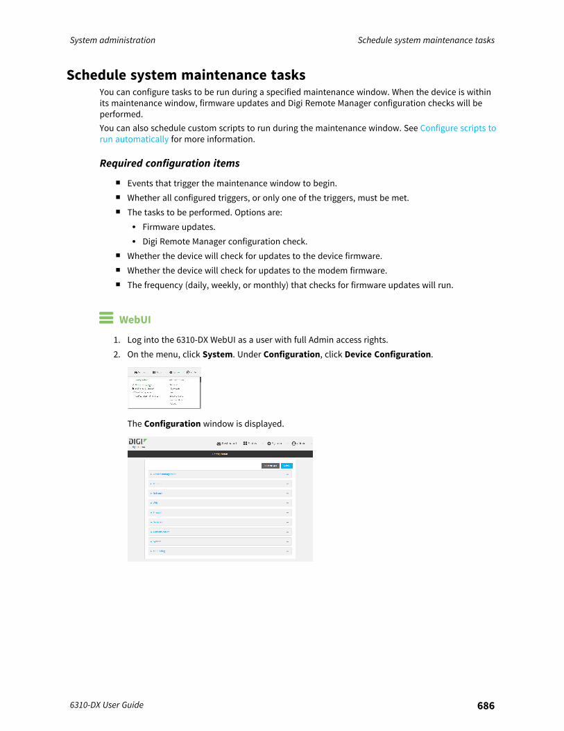
System administration Schedule system maintenance tasks
6310-DX User Guide 686
Schedule system maintenance tasksYou can configure tasks to be run during a specified maintenance window. When the device is withinits maintenance window, firmware updates and Digi Remote Manager configuration checks will beperformed.You can also schedule custom scripts to run during the maintenance window. See Configure scripts torun automatically for more information.
Required configuration items
n Events that trigger the maintenance window to begin.n Whether all configured triggers, or only one of the triggers, must be met.n The tasks to be performed. Options are:
l Firmware updates.l Digi Remote Manager configuration check.
n Whether the device will check for updates to the device firmware.n Whether the device will check for updates to the modem firmware.n The frequency (daily, weekly, or monthly) that checks for firmware updates will run.
WebUI
1. Log into the 6310-DX WebUI as a user with full Admin access rights.2. On the menu, click System. Under Configuration, click Device Configuration.
The Configuration window is displayed.
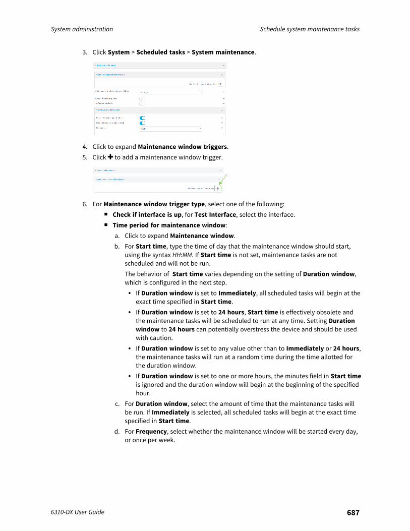
System administration Schedule system maintenance tasks
6310-DX User Guide 687
3. Click System > Scheduled tasks > System maintenance.
4. Click to expand Maintenance window triggers.5. Click to add a maintenance window trigger.
6. For Maintenance window trigger type, select one of the following:n Check if interface is up, for Test Interface, select the interface.n Time period for maintenance window:
a. Click to expand Maintenance window.b. For Start time, type the time of day that the maintenance window should start,
using the syntax HH:MM. If Start time is not set, maintenance tasks are notscheduled and will not be run.The behavior of Start time varies depending on the setting of Duration window,which is configured in the next step.l If Duration window is set to Immediately, all scheduled tasks will begin at the
exact time specified in Start time.l If Duration window is set to 24 hours, Start time is effectively obsolete and
the maintenance tasks will be scheduled to run at any time. Setting Durationwindow to 24 hours can potentially overstress the device and should be usedwith caution.
l If Duration window is set to any value other than to Immediately or 24 hours,the maintenance tasks will run at a random time during the time allotted forthe duration window.
l If Duration window is set to one or more hours, the minutes field in Start timeis ignored and the duration window will begin at the beginning of the specifiedhour.
c. For Duration window, select the amount of time that the maintenance tasks willbe run. If Immediately is selected, all scheduled tasks will begin at the exact timespecified in Start time.
d. For Frequency, select whether the maintenance window will be started every day,or once per week.
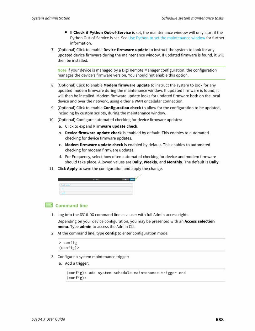
System administration Schedule system maintenance tasks
6310-DX User Guide 688
n If Check if Python Out-of-Service is set, the maintenance window will only start if thePython Out-of-Service is set. See Use Python to set the maintenance window for furtherinformation.
7. (Optional) Click to enable Device firmware update to instruct the system to look for anyupdated device firmware during the maintenance window. If updated firmware is found, it willthen be installed.
Note If your device is managed by a Digi Remote Manager configuration, the configurationmanages the device's firmware version. You should not enable this option.
8. (Optional) Click to enable Modem firmware update to instruct the system to look for anyupdated modem firmware during the maintenance window. If updated firmware is found, itwill then be installed. Modem firmware update looks for updated firmware both on the localdevice and over the network, using either a WAN or cellular connection.
9. (Optional) Click to enable Configuration check to allow for the configuration to be updated,including by custom scripts, during the maintenance window.
10. (Optional) Configure automated checking for device firmware updates:a. Click to expand Firmware update check.b. Device firmware update check is enabled by default. This enables to automated
checking for device firmware updates.c. Modem firmware update check is enabled by default. This enables to automated
checking for modem firmware updates.d. For Frequency, select how often automated checking for device and modem firmware
should take place. Allowed values are Daily, Weekly, and Monthly. The default is Daily.11. Click Apply to save the configuration and apply the change.
Command line
1. Log into the 6310-DX command line as a user with full Admin access rights.Depending on your device configuration, you may be presented with an Access selectionmenu. Type admin to access the Admin CLI.
2. At the command line, type config to enter configuration mode:
> config(config)>
3. Configure a system maintenance trigger:a. Add a trigger:
(config)> add system schedule maintenance trigger end(config)>

System administration Schedule system maintenance tasks
6310-DX User Guide 689
b. Set the type of trigger:
(config add system schedule maintenance trigger)> type value(config)>
where value is one of:n interface_up: If interface_up is set:
i. Set the interface:
(config add system schedule maintenance trigger)> interfacevalue(config)>
ii. i. Use the ? to determine available interfaces:
(config system schedule maintenance trigger 0)> interface?
Test interface: Test the status of this interface to seeif it is up.Format:/network/interface/defaultip/network/interface/defaultlinklocal/network/interface/lan/network/interface/loopback/network/interface/modem/network/interface/wan
Current value:
(config system schedule maintenance trigger 0)> interface
ii. Set the interface. For example:
(config system schedule maintenance trigger 0)> interface/network/interface/wan(config system schedule maintenance trigger 0)>
n out_of_service: The maintenance window will only start if the Python Out-of-Service is set. See Use Python to set the maintenance window for furtherinformation.
n time: Configure a time period for the maintenance window:i. Configure the time of day that the maintenance window should start, using the
syntax HH:MM. If the start time is not set, maintenance tasks are not scheduledand will not be run.
(config system schedule maintenance trigger 0)> time fromHH:MM(config system schedule maintenance trigger 0)>
The behavior of the start time varies depending on the setting of the durationlength, which is configured in the next step.

System administration Schedule system maintenance tasks
6310-DX User Guide 690
l If the duration length is set to 0, all scheduled tasks will begin at the exacttime specified in the start time.
l If the duration length is set to 24 hours, the start time is effectivelyobsolete and the maintenance tasks will be scheduled to run at any time.Setting the duration length to 24 hours can potentially overstress thedevice and should be used with caution.
l If the duration length is set to any value other than to 0 or 24 hours, themaintenance tasks will run at a random time during the time allotted forthe duration window.
l If the duration length is set to one or more hours, the minutes field in thestart time is ignored and the duration window will begin at the beginningof the specified hour.
ii. Configure the duration length (the amount of time that the maintenance taskswill be run). If 0 is used, all scheduled tasks will begin at the start time, definedin the previous step.
(config system schedule maintenance trigger 0)> length num(config system schedule maintenance trigger 0)>
where num is any whole number between 0 and 24.iii. Configure the frequency that the maintenance tasks should be run:
(config system schedule maintenance trigger 0)> frequencyvalue(config system schedule maintenance trigger 0)>
where value is either daily or weekly. Daily is the default.4. (Optional) ) Configure the device to look for any updated device firmware during the
maintenance window. If updated firmware is found, it will then be installed. The device willlook for updated firmware both on the local device and over the network, using either a WANor cellular connection.
(config)> system schedule maintenance device_fw_update value(config)>
where value is either true or false. yes or no, and 1 or 0 are also allowed.
Note If your device is managed by a Digi Remote Manager configuration, the configurationmanages the device's firmware version. You should not enable this option.
5. (Optional) Configure the device to look for any updated modem firmware during themaintenance window. If updated firmware is found, it will then be installed. The device willlook for updated firmware both on the local device and over the network, using either a WANor cellular connection.
(config)> system schedule maintenance modem_fw_update value(config)>
where value is either true or false. yes or no, and 1 or 0 are also allowed.6. (Optional) Configure automated checking for device firmware updates:
System administration Disable device encryption
6310-DX User Guide 691
a. Device firmware update check is enabled by default. This enables to automatedchecking for device firmware updates. To disable:
(config)> system schedule maintenance firmware_update_check devicefalse(config)>
b. Set how often automated checking for device firmware should take place:
(config)> system schedule maintenance frequency value(config)>
where value is either daily, weekly, or monthly. daily is the default.7. Save the configuration and apply the change:
(config)> saveConfiguration saved.>
8. Type exit to exit the Admin CLI.Depending on your device configuration, you may be presented with an Access selectionmenu. Type quit to disconnect from the device.
Disable device encryptionYou can disable the cryptography on your 6310-DX device. This can be used to ship unused devicesfrom overseas without needing export licenses from the country from which the device is beingshipped.When device encryption is disabled, the following occurs:
n The device is reset to the default configuration and rebooted.n After the reboot:
l Access to the device via the WebUI and SSH are disabled.l All internet connectivity is disabled, including WAN and WWAN. Connectivity to central
management software is also disabled.l All IP networks and addresses are disabled except for the default 192.168.210.1/24 network
on the local LAN Ethernet port. DHCP server is also disabled.The device can only be accessed by using telnet from a local machine connecting to the192.168.210.1/24 network.
Disabling device encryption is not available in the WebUI. It can only be performed from the AdminCLI.
Command line
1. Log into the 6310-DX command line as a user with Admin access.Depending on your device configuration, you may be presented with an Access selectionmenu. Type admin to access the Admin CLI.

System administration Disable device encryption
6310-DX User Guide 692
2. Disable encryption with the following command:
> system disable-cryptography>
3. Type exit to exit the Admin CLI.Depending on your device configuration, you may be presented with an Access selectionmenu. Type quit to disconnect from the device.
Re-enable cryptography after it has been disabled.To re-enable cryptography:
1. Configure your PC network to connect to the 192.168.210 subnet. For example, on a WindowsPC:a. Select the Properties of the relevant network connection on the Windows PC.
b. Click the Internet Protocol Version 4 (TCP/IPv4) parameter.c. Click Properties. The Internet Protocol Version 4 (TCP/IPv4) Properties dialog appears.d. Configure with the following details:
n IP address for PC: 192.168.210.2n Subnet: 255.255.255.0
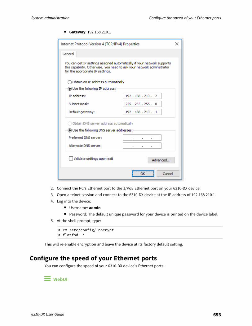
System administration Configure the speed of your Ethernet ports
6310-DX User Guide 693
n Gateway: 192.168.210.1
2. Connect the PC's Ethernet port to the 1/PoE Ethernet port on your 6310-DX device.3. Open a telnet session and connect to the 6310-DX device at the IP address of 192.168.210.1.4. Log into the device:
n Username: adminn Password: The default unique password for your device is printed on the device label.
5. At the shell prompt, type:
# rm /etc/config/.nocrypt# flatfsd -i
This will re-enable encryption and leave the device at its factory default setting.
Configure the speed of your Ethernet portsYou can configure the speed of your 6310-DX device's Ethernet ports.
WebUI
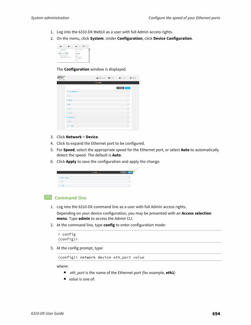
System administration Configure the speed of your Ethernet ports
6310-DX User Guide 694
1. Log into the 6310-DX WebUI as a user with full Admin access rights.2. On the menu, click System. Under Configuration, click Device Configuration.
The Configuration window is displayed.
3. Click Network > Device.4. Click to expand the Ethernet port to be configured.5. For Speed, select the appropriate speed for the Ethernet port, or select Auto to automatically
detect the speed. The default is Auto.6. Click Apply to save the configuration and apply the change.
Command line
1. Log into the 6310-DX command line as a user with full Admin access rights.Depending on your device configuration, you may be presented with an Access selectionmenu. Type admin to access the Admin CLI.
2. At the command line, type config to enter configuration mode:
> config(config)>
3. At the config prompt, type:
(config)> network device eth_port value
where:n eth_port is the name of the Ethernet port (for example, eth1)n value is one of:

System administration Configure the speed of your Ethernet ports
6310-DX User Guide 695
l 10—Sets the speed to 10 Mbps.l 100—Sets the speed to 100 Mbps.l 1000—Sets the speed to 1 Gbps. Available only for devices with Gigabit Ethernet
ports.auto—Configures the device to automatically determine the best speed for theEthernet port.
The default is auto.4. Save the configuration and apply the change:
(config)> saveConfiguration saved.>
5. Type exit to exit the Admin CLI.Depending on your device configuration, you may be presented with an Access selectionmenu. Type quit to disconnect from the device.
Monitoring
This chapter contains the following topics:
intelliFlow 697Configure NetFlow Probe 704
6310-DX User Guide 696
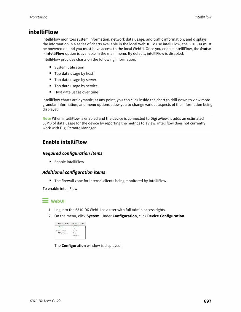
Monitoring intelliFlow
6310-DX User Guide 697
intelliFlowintelliFlow monitors system information, network data usage, and traffic information, and displaysthe information in a series of charts available in the local WebUI. To use intelliFlow, the 6310-DX mustbe powered on and you must have access to the local WebUI. Once you enable intelliFlow, the Status> intelliFlow option is available in the main menu. By default, intelliFlow is disabled.intelliFlow provides charts on the following information:
n System utilisationn Top data usage by hostn Top data usage by servern Top data usage by servicen Host data usage over time
intelliFlow charts are dymanic; at any point, you can click inside the chart to drill down to view moregranular information, and menu options allow you to change various aspects of the information beingdisplayed.
Note When intelliFlow is enabled and the device is connected to Digi aView, it adds an estimated50MB of data usage for the device by reporting the metrics to aView. intelliflow does not currentlywork with Digi Remote Manager.
Enable intelliFlow
Required configuration items
n Enable intelliFlow.
Additional configuration items
n The firewall zone for internal clients being monitored by intelliFlow.
To enable intelliFlow:
WebUI
1. Log into the 6310-DX WebUI as a user with full Admin access rights.2. On the menu, click System. Under Configuration, click Device Configuration.
The Configuration window is displayed.
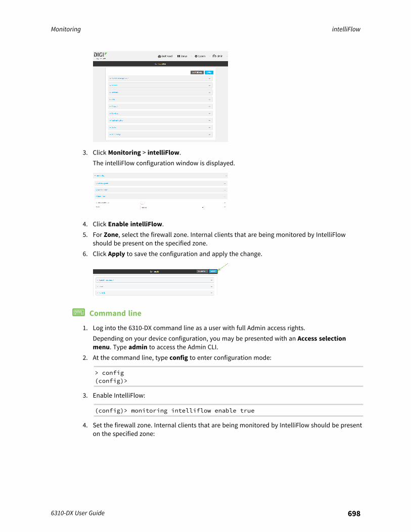
Monitoring intelliFlow
6310-DX User Guide 698
3. Click Monitoring > intelliFlow.The intelliFlow configuration window is displayed.
4. Click Enable intelliFlow.5. For Zone, select the firewall zone. Internal clients that are being monitored by IntelliFlow
should be present on the specified zone.6. Click Apply to save the configuration and apply the change.
Command line
1. Log into the 6310-DX command line as a user with full Admin access rights.Depending on your device configuration, you may be presented with an Access selectionmenu. Type admin to access the Admin CLI.
2. At the command line, type config to enter configuration mode:
> config(config)>
3. Enable IntelliFlow:
(config)> monitoring intelliflow enable true
4. Set the firewall zone. Internal clients that are being monitored by IntelliFlow should be presenton the specified zone:
Monitoring intelliFlow
6310-DX User Guide 699
a. Determine available zones:
(config)> monitoring intelliflow zone ?
Zone: The firewall zone which is assigned to the network interface(s)thatintelliFlow will see as internal clients. intelliFlow relies on aninternal toexternal relationship, where the internal clients are present on thezone specified.Format:anydynamic_routesedgeexternalinternalipsecloopbacksetup
Default value: internalCurrent value: internal
(config)>
b. Set the zone to be used by IntelliFlow:
(config)> monitoring intelliflow zone my_zone
5. Save the configuration and apply the change:
(config)> saveConfiguration saved.>
6. Type exit to exit the Admin CLI.Depending on your device configuration, you may be presented with an Access selectionmenu. Type quit to disconnect from the device.
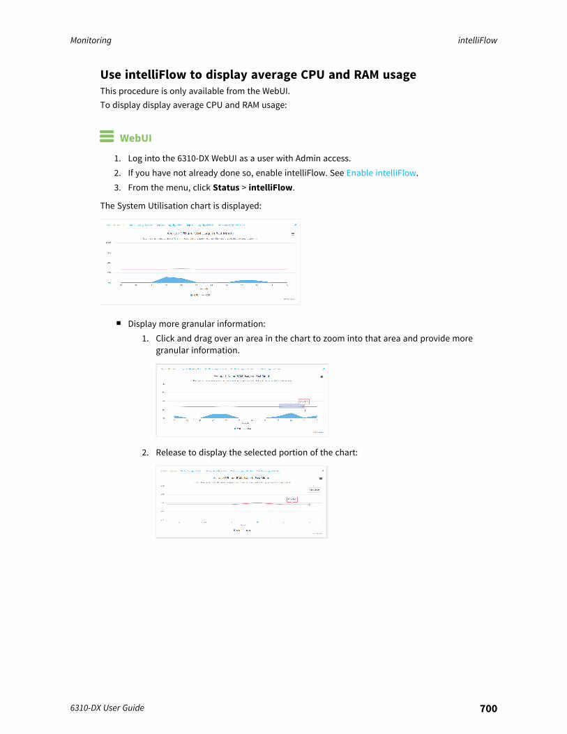
Monitoring intelliFlow
6310-DX User Guide 700
Use intelliFlow to display average CPU and RAM usageThis procedure is only available from the WebUI.To display display average CPU and RAM usage:
WebUI
1. Log into the 6310-DX WebUI as a user with Admin access.2. If you have not already done so, enable intelliFlow. See Enable intelliFlow.3. From the menu, click Status > intelliFlow.
The System Utilisation chart is displayed:
n Display more granular information:1. Click and drag over an area in the chart to zoom into that area and provide more
granular information.
2. Release to display the selected portion of the chart:

Monitoring intelliFlow
6310-DX User Guide 701
3. Click Reset zoom to return to the original display:
n Change the time period displayed by the chart.By default, the System utilisation chart displays the average CPU and RAM usage over the lastminute. You can change this to display the average CPU and RAM usage:l Over the last hour.l Over the last day.l Over the last 30 days.l Over the last 180 days.
1. Click the menu icon ().2. Select the time period to be displayed.
n Save or print the chart.1. Click the menu icon ().2. To save the chart to your local filesystem, select Export to PNG.3. To print the chart, select Print chart.
Use intelliFlow to display top data usage informationWith intelliFlow, you can display top data usage information based on the following:
n Top data usage by hostn Top data usage by servern Top data usage by service
To generate a top data usage chart:
WebUI
1. Log into the 6310-DX WebUI as a user with Admin access.2. If you have not already done so, enable intelliFlow. See Enable intelliFlow.3. From the menu, click Status > intelliFlow.
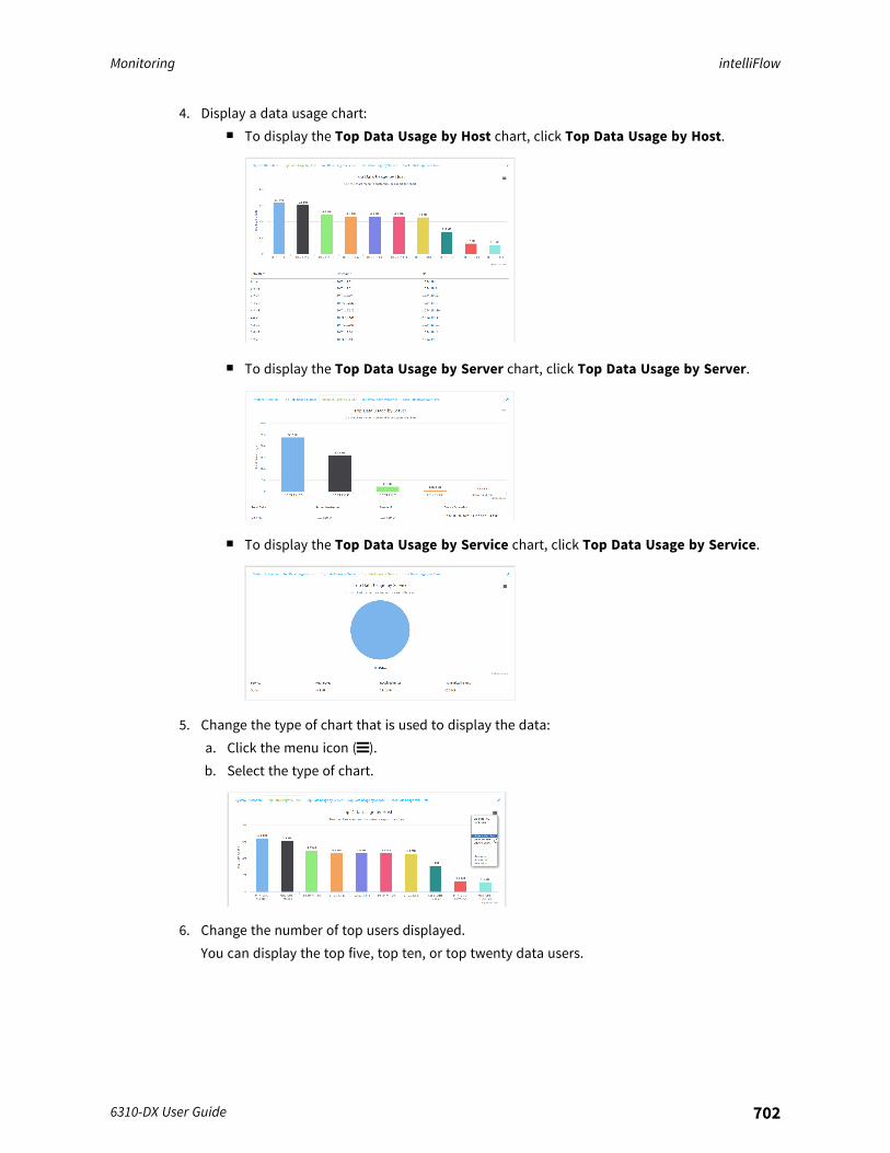
Monitoring intelliFlow
6310-DX User Guide 702
4. Display a data usage chart:n To display the Top Data Usage by Host chart, click Top Data Usage by Host.
n To display the Top Data Usage by Server chart, click Top Data Usage by Server.
n To display the Top Data Usage by Service chart, click Top Data Usage by Service.
5. Change the type of chart that is used to display the data:a. Click the menu icon ().b. Select the type of chart.
6. Change the number of top users displayed.You can display the top five, top ten, or top twenty data users.
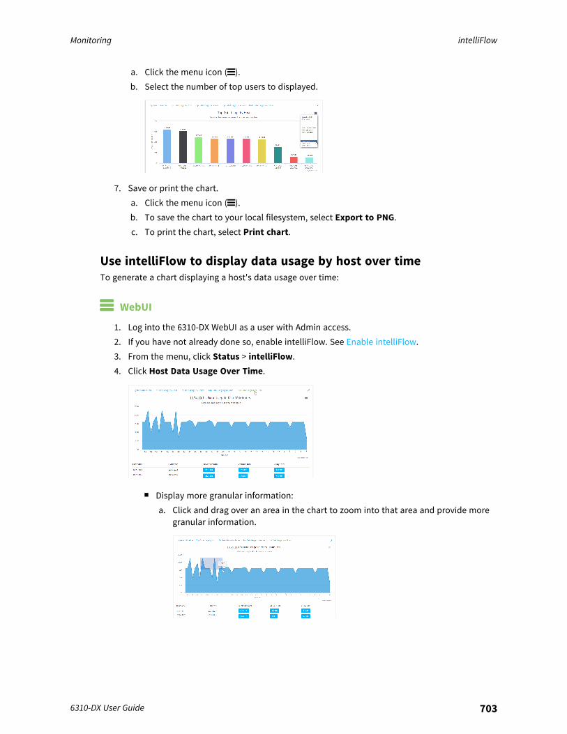
Monitoring intelliFlow
6310-DX User Guide 703
a. Click the menu icon ().b. Select the number of top users to displayed.
7. Save or print the chart.a. Click the menu icon ().b. To save the chart to your local filesystem, select Export to PNG.c. To print the chart, select Print chart.
Use intelliFlow to display data usage by host over timeTo generate a chart displaying a host's data usage over time:
WebUI
1. Log into the 6310-DX WebUI as a user with Admin access.2. If you have not already done so, enable intelliFlow. See Enable intelliFlow.3. From the menu, click Status > intelliFlow.4. Click Host Data Usage Over Time.
n Display more granular information:a. Click and drag over an area in the chart to zoom into that area and provide more
granular information.
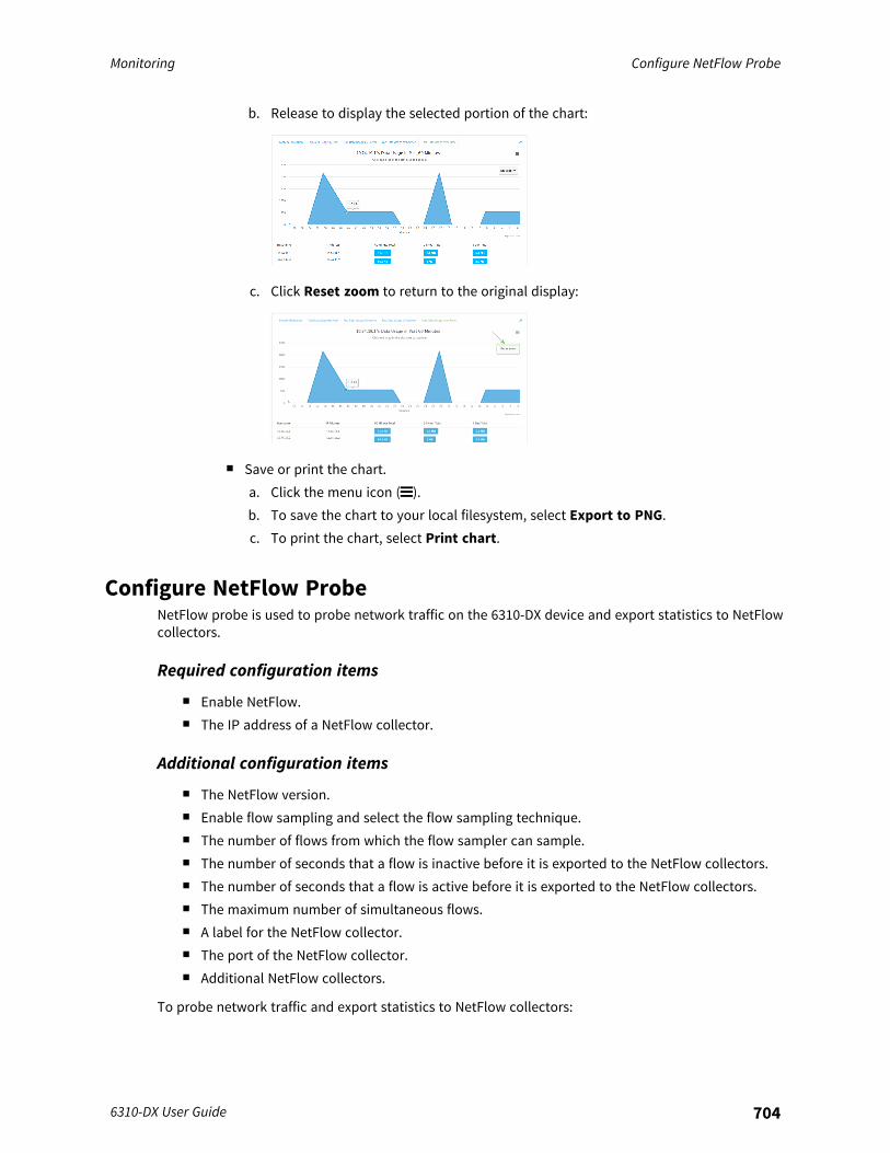
Monitoring Configure NetFlow Probe
6310-DX User Guide 704
b. Release to display the selected portion of the chart:
c. Click Reset zoom to return to the original display:
n Save or print the chart.a. Click the menu icon ().b. To save the chart to your local filesystem, select Export to PNG.c. To print the chart, select Print chart.
Configure NetFlow ProbeNetFlow probe is used to probe network traffic on the 6310-DX device and export statistics to NetFlowcollectors.
Required configuration items
n Enable NetFlow.n The IP address of a NetFlow collector.
Additional configuration items
n The NetFlow version.n Enable flow sampling and select the flow sampling technique.n The number of flows from which the flow sampler can sample.n The number of seconds that a flow is inactive before it is exported to the NetFlow collectors.n The number of seconds that a flow is active before it is exported to the NetFlow collectors.n The maximum number of simultaneous flows.n A label for the NetFlow collector.n The port of the NetFlow collector.n Additional NetFlow collectors.
To probe network traffic and export statistics to NetFlow collectors:
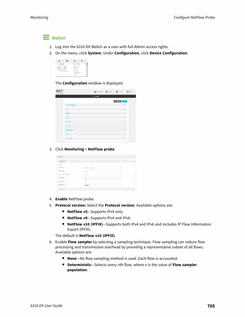
Monitoring Configure NetFlow Probe
6310-DX User Guide 705
WebUI
1. Log into the 6310-DX WebUI as a user with full Admin access rights.2. On the menu, click System. Under Configuration, click Device Configuration.
The Configuration window is displayed.
3. Click Monitoring > NetFlow probe.
4. Enable NetFlow probe.5. Protocol version: Select the Protocol version. Available options are:
n NetFlow v5—Supports IPv4 only.n NetFlow v9—Supports IPv4 and IPv6.n NetFlow v10 (IPFIX)—Supports both IPv4 and IPv6 and includes IP Flow Information
Export (IPFIX).The default is NetFlow v10 (IPFIX).
6. Enable Flow sampler by selecting a sampling technique. Flow sampling can reduce flowprocessing and transmission overhead by providing a representative subset of all flows.Available options are:
n None—No flow sampling method is used. Each flow is accounted.n Deterministic—Selects every nth flow, where n is the value of Flow sampler
population.
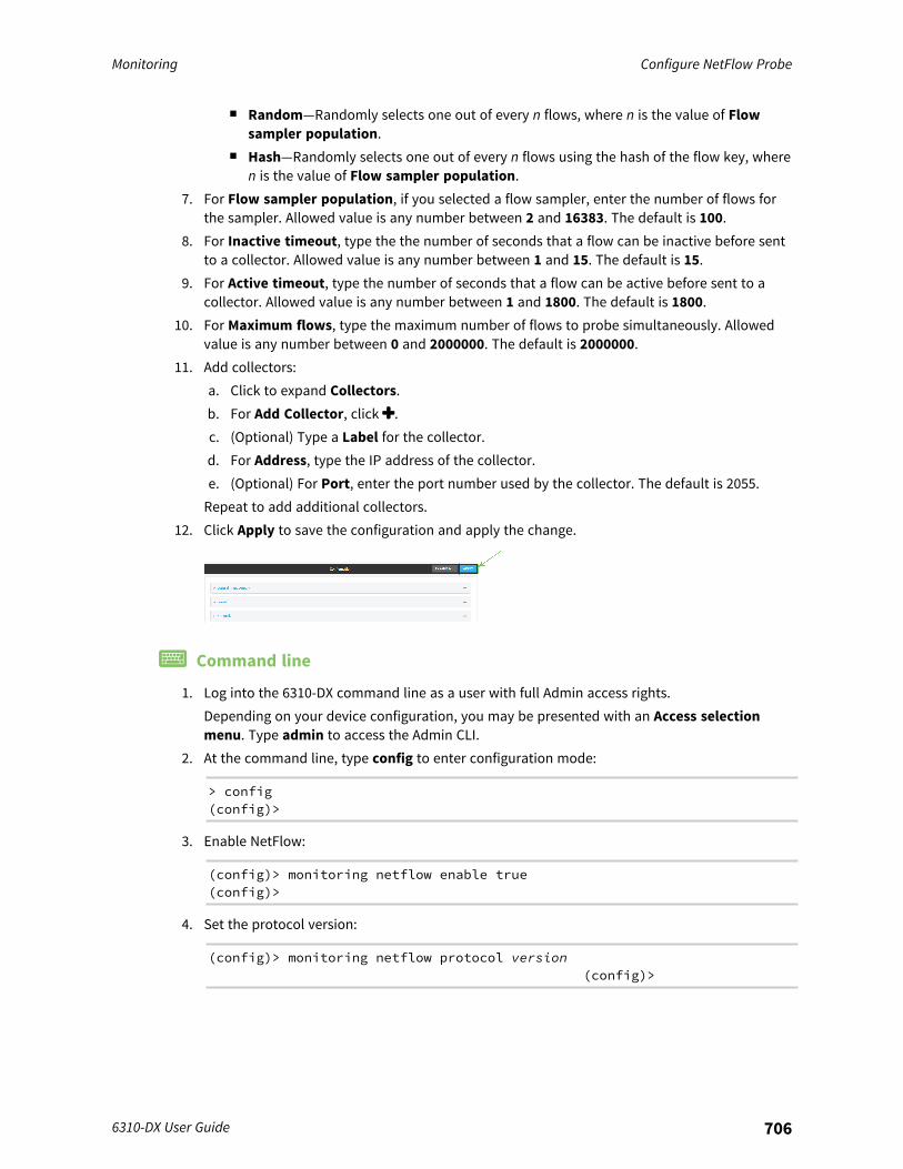
Monitoring Configure NetFlow Probe
6310-DX User Guide 706
n Random—Randomly selects one out of every n flows, where n is the value of Flowsampler population.
n Hash—Randomly selects one out of every n flows using the hash of the flow key, wheren is the value of Flow sampler population.
7. For Flow sampler population, if you selected a flow sampler, enter the number of flows forthe sampler. Allowed value is any number between 2 and 16383. The default is 100.
8. For Inactive timeout, type the the number of seconds that a flow can be inactive before sentto a collector. Allowed value is any number between 1 and 15. The default is 15.
9. For Active timeout, type the number of seconds that a flow can be active before sent to acollector. Allowed value is any number between 1 and 1800. The default is 1800.
10. For Maximum flows, type the maximum number of flows to probe simultaneously. Allowedvalue is any number between 0 and 2000000. The default is 2000000.
11. Add collectors:a. Click to expand Collectors.b. For Add Collector, click .c. (Optional) Type a Label for the collector.d. For Address, type the IP address of the collector.e. (Optional) For Port, enter the port number used by the collector. The default is 2055.Repeat to add additional collectors.
12. Click Apply to save the configuration and apply the change.
Command line
1. Log into the 6310-DX command line as a user with full Admin access rights.Depending on your device configuration, you may be presented with an Access selectionmenu. Type admin to access the Admin CLI.
2. At the command line, type config to enter configuration mode:
> config(config)>
3. Enable NetFlow:
(config)> monitoring netflow enable true(config)>
4. Set the protocol version:
(config)> monitoring netflow protocol version(config)>
Monitoring Configure NetFlow Probe
6310-DX User Guide 707
where version is one of:n v5—NetFlow v5 supports IPv4 only.n v9—NetFlow v9 supports IPv4 and IPv6.n v10—NetFlow v10 (IPFIX) supports both IPv4 and IPv6 and includes IP Flow Information
Export (IPFIX).The default is v10.
1. Enable flow sampling by selecting a sampling technique. Flow sampling can reduce flowprocessing and transmission overhead by providing a representative subset of all flows.
(config)> monitoring netflow sampler type(config)>
where type is one of:n none—No flow sampling method is used. Each flow is accounted.n deterministic—Selects every nth flow, where n is the value of the flow sample
population.n random—Randomly selects one out of every n flows, where n is the value of the flow
sample population.n hash—Randomly selects one out of every n flows using the hash of the flow key, where
n is the value of the flow sample population.5. If you are using a flow sampler, set the number of flows for the sampler:
(config)> monitoring netflow sampler_population value(config)>
where value is any number between 2 and 16383. The default is 100.6. Set the number of seconds that a flow can be inactive before sent to a collector:
(config)> monitoring netflow inactive_timeout value(config)>
where value is any is any number between 1 and 15. The default is 15.7. Set the number of seconds that a flow can be active before sent to a collector:
(config)> monitoring netflow active_timeout value(config)>
where value is any is any number between 1 and 1800. The default is 1800.8. Set the maximum number of flows to probe simultaneously:
(config)> monitoring netflow max_flows value(config)>
where value is any is any number between 0 and 2000000. The default is 2000000.
Monitoring Configure NetFlow Probe
6310-DX User Guide 708
9. Add collectors:a. Add a collector:
(config)> add monitoring netflow collector end(config monitoring netflow collector 0)>
b. Set the IP address of the collector:
(config monitoring netflow collector 0)> address ip_address(config monitoring netflow collector 0)>
c. (Optional) Set the port used by the collector:
(config monitoring netflow collector 0)> port port(config monitoring netflow collector 0)>
d. (Optional) Set a label for the collector:
(config monitoring netflow collector 0)> label "This is a collector."(config monitoring netflow collector 0)>
Repeat to add additional collectors.10. Save the configuration and apply the change:
(config monitoring netflow collector 0)> saveConfiguration saved.>
11. Type exit to exit the Admin CLI.Depending on your device configuration, you may be presented with an Access selectionmenu. Type quit to disconnect from the device.
Central management
This chapter contains the following topics:
Digi Remote Manager support 710Certificate-based enhanced security 710Configure Digi Remote Manager 710Collect device health data and set the sample interval 717Enable event log upload to Digi Remote Manager 720Log into Digi Remote Manager 722Use Digi Remote Manager to view and manage your device 723Add a device to Digi Remote Manager 724View Digi Remote Manager connection status 724Configure multiple devices using profiles 726Learn more 726
6310-DX User Guide 709
Central management Digi Remote Manager support
6310-DX User Guide 710
Digi Remote Manager supportDigi Remote Manager is a hosted remote configuration and management system that allows you toremotely manage a large number of devices. Remote Manager includes a web-based interface thatyou can use to perform device operations, such as viewing and changing device configurations andperforming firmware updates. Remote Manager servers also provide a data storage facility. The DigiRemote Manager is the default cloud-based management system, and is enabled by default. You canalso select to use Digi aView as the cloud-based management system. See Digi aView User Guide forinformation about aView.To use Remote Manager, you must set up a Remote Manager account. To set up a Remote Manageraccount and learn more about Digi Remote Manager, go to www.digi.com/products/cloud/digi-remote-manager.To learn more about Remote Manager features and functions, see the Digi Remote Manager UserGuide.
Certificate-based enhanced securityBeginning with firmware version 22.2.9.x, the default URL for the device's Remote Manager connectionis edp12.devicecloud.com. This URL is required to utilize the client-side certificate support. Prior torelease 22.2.9.x, the default URL was my.devicecloud.com.
n If your Digi device is configured to use a non-default URL to connect to Remote Manager,updating the firmware will not change your configuration. However, if you erase the device'sconfiguration, the Remote Manager URL will change to the default of edp12.devicecloud.com.
n If you perform a factory reset by pressing the ERASE twice, the client-side certificate will beerased and you must use the Remote Manager interface to reset the certificate. Select thedevice in Remote Manager and select Actions > Reset Device Certificate.
The new URL of edp12.devicecloud.com is for device communication only. Use my.devicecloud.comfor user interaction with remote manager.
Firewall issuesTo utilize the certificate-based security, you may need to open a port through your firewall for egressconnectivity to edp12.devicecloud.com. TCP port 3199 is used for communication with RemoteManager.
Configure Digi Remote ManagerBy default, your 6310-DX device is configured to use central management using Digi Remote Manager.
Additional configuration optionsThese additional configuration settings are not typically configured, but you can set them as needed:
n Disable the Digi Remote Manager connection if it is not required. You can also configure analternate cloud-based central management application.
n Change the reconnection timer.n The non-cellular keepalive timeout.n The cellular keepalive timeout.n The keepalive count before the Remote Manager connection is dropped.
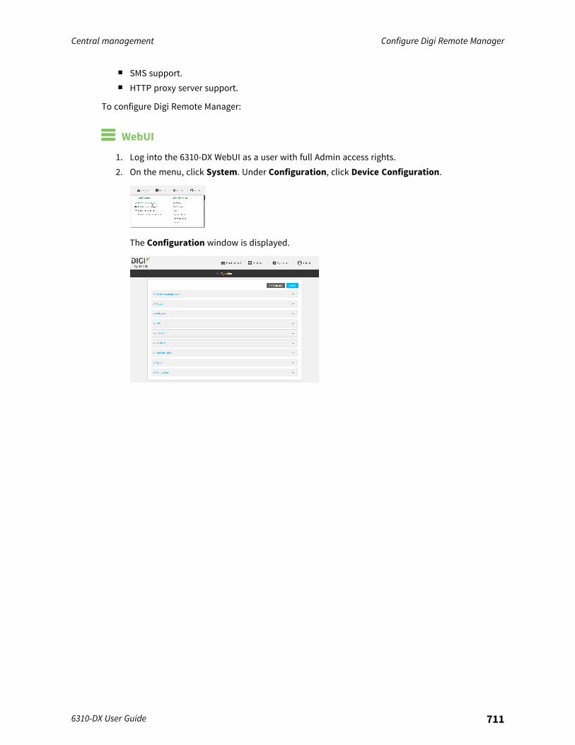
Central management Configure Digi Remote Manager
6310-DX User Guide 711
n SMS support.n HTTP proxy server support.
To configure Digi Remote Manager:
WebUI
1. Log into the 6310-DX WebUI as a user with full Admin access rights.2. On the menu, click System. Under Configuration, click Device Configuration.
The Configuration window is displayed.
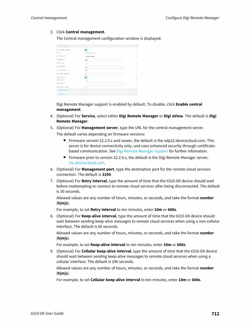
Central management Configure Digi Remote Manager
6310-DX User Guide 712
3. Click Central management.The Central management configuration window is displayed.
Digi Remote Manager support is enabled by default. To disable, click Enable centralmanagement.
4. (Optional) For Service, select either Digi Remote Manager or Digi aView. The default is DigiRemote Manager.
5. (Optional) For Management server, type the URL for the central management server.The default varies depending on firmware versions:
n Firmware version 22.2.9.x and newer, the default is the edp12.devicecloud.com. Thisserver is for device-connectivity only, and uses enhanced security through certificate-based communication. See Digi Remote Manager support for further infomation.
n Firmware prior to version 22.2.9.x, the default is the Digi Remote Manager server,my.devicecloud.com.
6. (Optional) For Management port, type the destination port for the remote cloud servicesconnection. The default is 3199.
7. (Optional) For Retry interval, type the amount of time that the 6310-DX device should waitbefore reattempting to connect to remote cloud services after being disconnected. The defaultis 30 seconds.Allowed values are any number of hours, minutes, or seconds, and take the format number{h|m|s}.For example, to set Retry interval to ten minutes, enter 10m or 600s.
8. (Optional) For Keep-alive interval, type the amount of time that the 6310-DX device shouldwait between sending keep-alive messages to remote cloud services when using a non-cellularinterface. The default is 60 seconds.Allowed values are any number of hours, minutes, or seconds, and take the format number{h|m|s}.For example, to set Keep-alive interval to ten minutes, enter 10m or 600s.
9. (Optional) For Cellular keep-alive interval, type the amount of time that the 6310-DX deviceshould wait between sending keep-alive messages to remote cloud services when using acellular interface. The default is 290 seconds.Allowed values are any number of hours, minutes, or seconds, and take the format number{h|m|s}.For example, to set Cellular keep-alive interval to ten minutes, enter 10m or 600s.
Central management Configure Digi Remote Manager
6310-DX User Guide 713
10. (Optional) For Allowed keep-alive misses, type the number of allowed keep-alive misses. Thedefault is 3.
11. Enable watchdog is used to monitor the connection to remote cloud services. If theconnection is down, you can configure the device to restart the connection, or to reboot. Thewatchdog is enabled by default.
12. If Enable watchdog is enabled:a. (Optional) For Restart Timeout, type the amount of time to wait before restarting the
connection to the remote cloud services, once the connection is down.Allowed values are any number of hours, minutes, or seconds, and take the formatnumber{h|m|s}.For example, to set Restart Timeout to ten minutes, enter 10m or 600s.The minimum value is 30 minutes and the maximum is 48 hours. If not set, this option isdisabled. The default is 30 minutes.
b. (Optional) For Reboot Timeout, type the amount of time to wait before rebooting thedevice, once the connection to the remote cloud servicesis down. By default, this option isnot set, which means that the option is disabled.Allowed values are any number of hours, minutes, or seconds, and take the formatnumber{h|m|s}.For example, to set Reboot Timeout to ten minutes, enter 10m or 600s.The minimum value is 30 minutes and the maximum is 48 hours. If not set, this option isdisabled. The default is disabled.
13. (Optional) Enable Locally authenticate CLI to require a login and password to authenticatethe user from the remote cloud services CLI. If disabled, no login prompt will be presented andthe user will be logged in as admin. The default is disabled.
14. (Optional) Configure the 6310-DX device to communicate with remote cloud services by usingSMS:a. Click to expand Short message service.b. Enable SMS messaging.c. For Destination phone number, type the phone number for the remote cloud services.d. (Optional) Type the Service identifier.
15. (Optional) Configure the 6310-DX device to communicate with remote cloud services by usingan HTTP proxy server:a. Click to expand HTTP Proxy.b. Enable the use of an HTTP proxy server.c. For Server, type the hostname of the HTTP proxy server.d. For Port, type or select the port number on the HTTP proxy server that the device should
connect to. The default is 2138.16. Click Apply to save the configuration and apply the change.
Command line
Central management Configure Digi Remote Manager
6310-DX User Guide 714
1. Log into the 6310-DX command line as a user with full Admin access rights.Depending on your device configuration, you may be presented with an Access selectionmenu. Type admin to access the Admin CLI.
2. At the command line, type config to enter configuration mode:
> config(config)>
3. Digi Remote Manager support is enabled by default. To disable Digi Remote Manager support:
(config)> cloud enable false(config)>
4. (Optional) Set the service:
(config)> cloud service value(config)>
where value is either:n drm: Digi Remote Managern aview: Digi aView
The default is Digi Remote Manager.5. (Optional) Set the URL for the central management server. The default is the Digi Remote
Manager server, my.devicecloud.com.
(config)> cloud drm drm_url url(config)>
6. (Optional) Set the amount of time that the 6310-DX device should wait before reattempting toconnect to the remote cloud services after being disconnected. The minimum value is tenseconds. The default is 30 seconds.
(config)> cloud drm retry_interval value
where value is any number of hours, minutes, or seconds, and takes the format number{h|m|s}.For example, to set the retry interval to ten minutes, enter either 10m or 600s:
(config)> cloud drm retry_interval 600s(config)>
7. (Optional) Set the amount of time that the 6310-DX device should wait between sending keep-alive messages to the Digi Remote Manager when using a non-cellular interface. Allowedvalues are from 30 seconds to two hours. The default is 60 seconds.
(config)> cloud drm keep_alive value(config)>
where value is any number of hours, minutes, or seconds, and takes the format number{h|m|s}.For example, to set the keep-alive interval to ten minutes, enter either 10m or 600s:
Central management Configure Digi Remote Manager
6310-DX User Guide 715
(config)> cloud drm keep_alive 600s(config)>
8. (Optional) Set the amount of time that the 6310-DX device should wait between sending keep-alive messages to the Digi Remote Manager when using a cellular interface. Allowed values arefrom 30 seconds to two hours. The default is 290 seconds.
(config)> cloud drm cellular_keep_alive value(config)>
where value is any number of hours, minutes, or seconds, and takes the format number{h|m|s}.For example, to set the cellular keep-alive interval to ten minutes, enter either 10m or 600s:
(config)> cloud drm cellular_keep_alive 600s(config)>
9. Set the number of allowed keep-alive misses. Allowed values are any integer between 2 and64. The default is 3.
(config)> cloud drm keep_alive_misses integer(config)>
10. The watchdog is used to monitor the connection to remote cloud services. If the connection isdown, you can configure the device to restart the connection, or to reboot. The watchdog isenabled by default. To disable:
(config)> cloud drm watchdog false(config)>
11. If watchdog is enabled:a. (Optional) Set the amount of time to wait before restarting the connection to the remote
cloud services, once the connection is down.where value is any number of hours, minutes, or seconds, and takes the format number{h|m|s}.For example, to set restart_timeout to ten minutes, enter either 10m or 600s:
(config)> cloud drm restart_timeout 600s(config)>
The minimum value is 30 minutes and the maximum is 48 hours. If not set, this option isdisabled. The default is 30 minutes.
b. (Optional) Set the amount of time to wait before rebooting the device, once theconnection to the remote cloud servicesis down. By default, this option is not set, whichmeans that the option is disabled.where value is any number of hours, minutes, or seconds, and takes the format number{h|m|s}.For example, to set reboot_timeout to ten minutes, enter either 10m or 600s:
Central management Configure Digi Remote Manager
6310-DX User Guide 716
(config)> cloud drm reboot_timeout 600s(config)>
The minimum value is 30 minutes and the maximum is 48 hours. If not set, this option isdisabled. The default is disabled.
12. (Optional) Determine whether to require a login and password to authenticate the user fromthe remote cloud services CLI:
(config)> cloud drm cli_local_auth true(config)>
If set to false, no login prompt will be presented and the user will be logged in as admin. Thedefault is false.
13. (Optional) Configure the 6310-DX device to communicate with remote cloud services by usingSMS:a. Enable SMS messaging:
(config)> cloud drm sms enable true(config)>
b. Set the phone number for Digi Remote Manager:
(config)> cloud drm sms destination drm_phone_number(config)>
c. (Optional) Set the service identifier:
(config)> cloud drm sms sercice_id id(config)>
1. (Optional) Configure the 6310-DX device to communicate with remote cloud services by usingan HTTP proxy server:a. Enable the use of an HTTP proxy server:
(config)> cloud drm proxy enable true(config)>
b. Set the hostname of the proxy server:
(config)> cloud drm proxy host hostname(config)>
c. (Optional) Set the port number on the proxy server that the device should connect to. Thedefault is 2138.
(config)> cloud drm proxy port integer(config)>

Central management Collect device health data and set the sample interval
6310-DX User Guide 717
14. Save the configuration and apply the change:
(config)> saveConfiguration saved.>
15. Type exit to exit the Admin CLI.Depending on your device configuration, you may be presented with an Access selectionmenu. Type quit to disconnect from the device.
Collect device health data and set the sample intervalYou can enable or disable the collection of device health data to upload to Digi Remote Manager, andconfigure the interval between health sample uploads. By default, device health data upload isenabled, and the health sample interval is set to 60 minutes.To avoid a situation where several devices are uploading health metrics information to RemoteManager at the same time, the 6310-DX device includes a preconfigured randomization of twominutes for uploading metrics. For example, if Health sample interval is set to five minutes, themetrics will be uploaded to Remote Manager at a random time between five and seven minutes.To disable the collection of device health data or enable it if it has been disabled, or to change thehealth sample interval:
WebUI
1. Log into the 6310-DX WebUI as a user with full Admin access rights.2. On the menu, click System. Under Configuration, click Device Configuration.
The Configuration window is displayed.
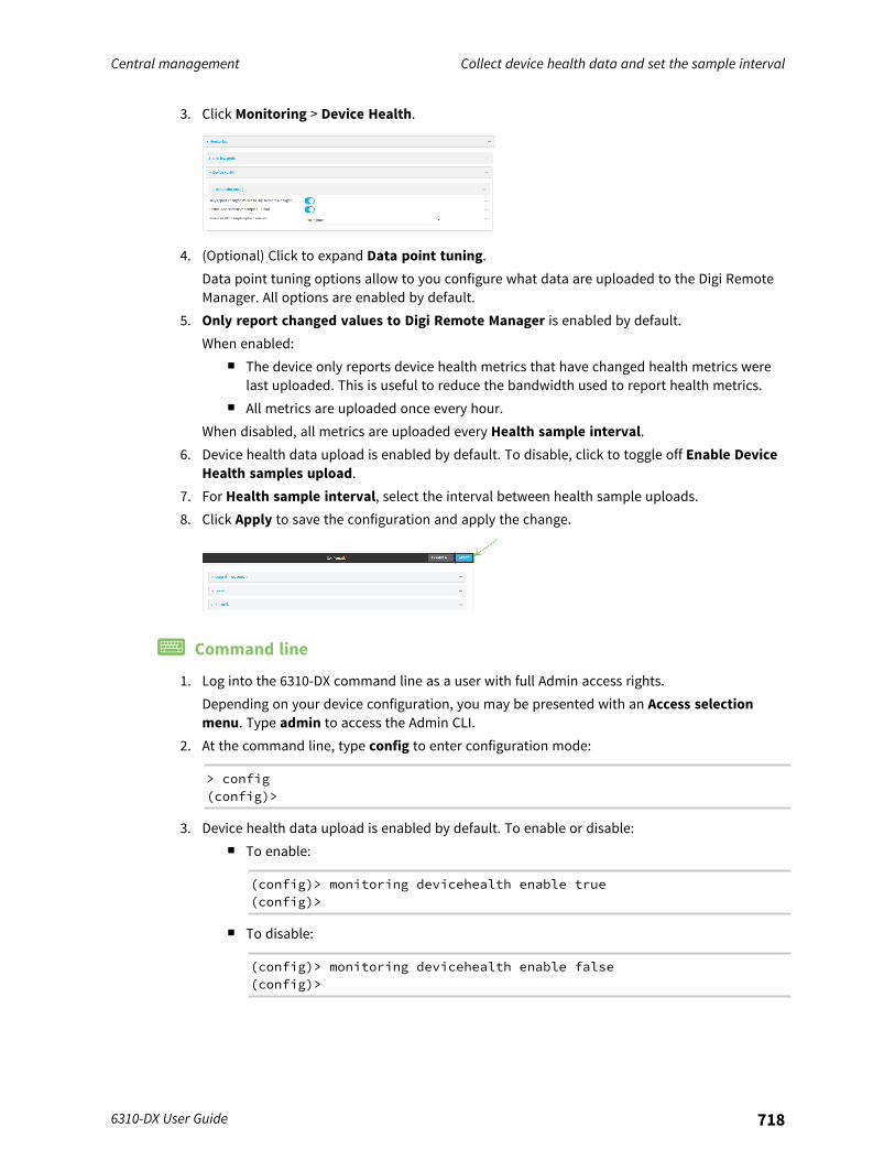
Central management Collect device health data and set the sample interval
6310-DX User Guide 718
3. Click Monitoring > Device Health.
4. (Optional) Click to expand Data point tuning.Data point tuning options allow to you configure what data are uploaded to the Digi RemoteManager. All options are enabled by default.
5. Only report changed values to Digi Remote Manager is enabled by default.When enabled:
n The device only reports device health metrics that have changed health metrics werelast uploaded. This is useful to reduce the bandwidth used to report health metrics.
n All metrics are uploaded once every hour.When disabled, all metrics are uploaded every Health sample interval.
6. Device health data upload is enabled by default. To disable, click to toggle off Enable DeviceHealth samples upload.
7. For Health sample interval, select the interval between health sample uploads.8. Click Apply to save the configuration and apply the change.
Command line
1. Log into the 6310-DX command line as a user with full Admin access rights.Depending on your device configuration, you may be presented with an Access selectionmenu. Type admin to access the Admin CLI.
2. At the command line, type config to enter configuration mode:
> config(config)>
3. Device health data upload is enabled by default. To enable or disable:n To enable:
(config)> monitoring devicehealth enable true(config)>
n To disable:
(config)> monitoring devicehealth enable false(config)>

Central management Collect device health data and set the sample interval
6310-DX User Guide 719
4. The interval between health sample uploads is set to 60 minutes by default. To change:
(config)> monitoring devicehealth interval value(config)>
where value is one of 1, 5, 15, 30, or 60, and represents the number of minutes betweenuploads of health sample data.
5. By default, the device will only report health metrics values to Digi Remote Manager that havechanged health metrics were last uploaded. This is useful to reduce the bandwidth used toreport health metrics. This is useful to reduce the bandwidth used to report health metrics.Even if enabled, all metrics are uploaded once every hour.To disable:
(config)> monitoring devicehealth only_send_deltas false(config)>
When disabled, all metrics are uploaded every Health sample interval.6. (Optional) Tuning parameters allow to you configure what data are uploaded to the Digi
Remote Manager. By default, all tuning parameters are enabled.To view a list of all available tuning parameters, use the show command:
(config)> show monitoring devicehealth tuningall
cellularrx
bytesenable true
txbytes
enable trueeth
rxbytes
enable truetx
bytesenable true
serialrx
bytesenable true
txbytes
enable truecellular
1rx
bytesenable true
packets

Central management Enable event log upload to Digi Remote Manager
6310-DX User Guide 720
enable true...
(config)>
To disable a tuning parameter, set its value to false. For example, to turn off all reporting forthe serial port:
(config)> monitoring devicehealth tuning all serial rx bytes enabledfalse(config)> monitoring devicehealth tuning all serial tx bytes enabledfalse(config)>
7. Save the configuration and apply the change:
(config)> saveConfiguration saved.>
8. Type exit to exit the Admin CLI.Depending on your device configuration, you may be presented with an Access selectionmenu. Type quit to disconnect from the device.
Enable event log upload to Digi Remote ManagerYou can configure your device to upload the event log to Digi Remote Manager, and configure theinterval between event log uploads.To enable the event log upload, or disable it if it has been disabled, and to change the uploadinterval:
WebUI
1. Log into the 6310-DX WebUI as a user with full Admin access rights.2. On the menu, click System. Under Configuration, click Device Configuration.
The Configuration window is displayed.
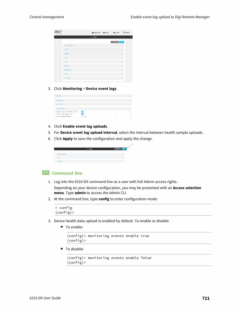
Central management Enable event log upload to Digi Remote Manager
6310-DX User Guide 721
3. Click Monitoring > Device event logs.
4. Click Enable event log uploads.5. For Device event log upload interval, select the interval between health sample uploads.6. Click Apply to save the configuration and apply the change.
Command line
1. Log into the 6310-DX command line as a user with full Admin access rights.Depending on your device configuration, you may be presented with an Access selectionmenu. Type admin to access the Admin CLI.
2. At the command line, type config to enter configuration mode:
> config(config)>
3. Device health data upload is enabled by default. To enable or disable:n To enable:
(config)> monitoring events enable true(config)>
n To disable:
(config)> monitoring events enable false(config)>

Central management Log into Digi Remote Manager
6310-DX User Guide 722
4. The interval between event log uploads is set to 60 minutes by default. To change:
(config)> monitoring events interval value(config)>
where value is one of 1, 5, 15, 30, or 60, and represents the number of minutes betweenuploads of health sample data.
5. Save the configuration and apply the change:
(config)> saveConfiguration saved.>
6. Type exit to exit the Admin CLI.Depending on your device configuration, you may be presented with an Access selectionmenu. Type quit to disconnect from the device.
Log into Digi Remote ManagerTo start Digi Remote Manager
1. If you have not already done so, click here to sign up for a Digi Remote Manager account.2. Check your email for Digi Remote Manager login instructions.3. Go to remotemanager.digi.com.4. Log into your Digi Remote Manager account.
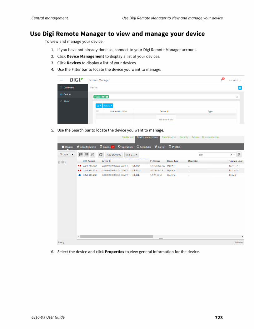
Central management Use Digi Remote Manager to view and manage your device
6310-DX User Guide 723
Use Digi Remote Manager to view and manage your deviceTo view and manage your device:
1. If you have not already done so, connect to your Digi Remote Manager account.2. Click Device Management to display a list of your devices.3. Click Devices to display a list of your devices.4. Use the Filter bar to locate the device you want to manage.
5. Use the Search bar to locate the device you want to manage.
6. Select the device and click Properties to view general information for the device.
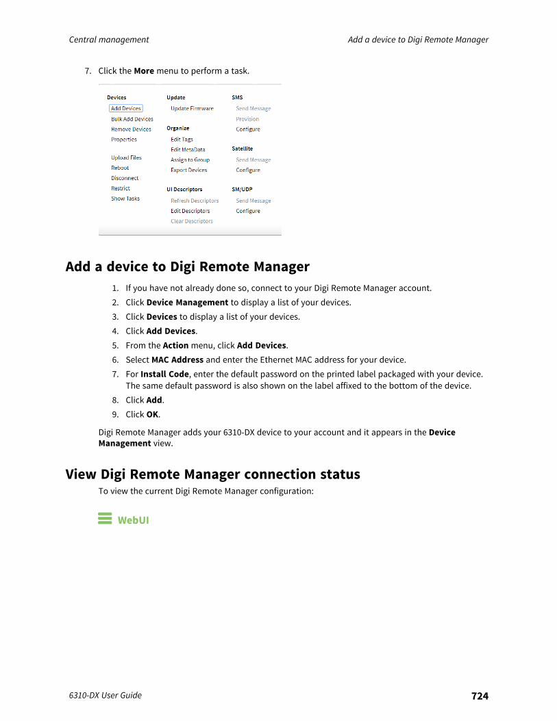
Central management Add a device to Digi Remote Manager
6310-DX User Guide 724
7. Click the More menu to perform a task.
Add a device to Digi Remote Manager1. If you have not already done so, connect to your Digi Remote Manager account.2. Click Device Management to display a list of your devices.3. Click Devices to display a list of your devices.4. Click Add Devices.5. From the Action menu, click Add Devices.6. Select MAC Address and enter the Ethernet MAC address for your device.7. For Install Code, enter the default password on the printed label packaged with your device.
The same default password is also shown on the label affixed to the bottom of the device.8. Click Add.9. Click OK.
Digi Remote Manager adds your 6310-DX device to your account and it appears in the DeviceManagement view.
View Digi Remote Manager connection statusTo view the current Digi Remote Manager configuration:
WebUI
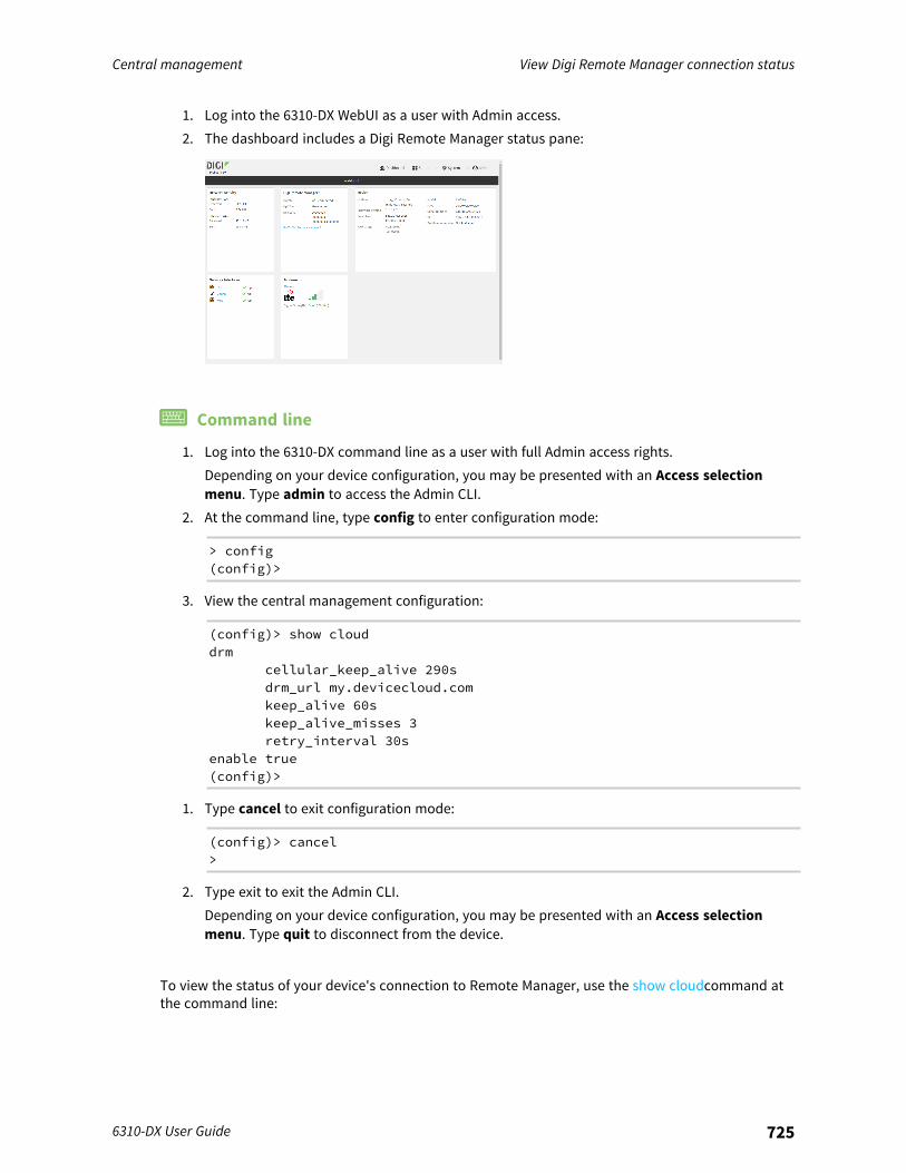
Central management View Digi Remote Manager connection status
6310-DX User Guide 725
1. Log into the 6310-DX WebUI as a user with Admin access.2. The dashboard includes a Digi Remote Manager status pane:
Command line
1. Log into the 6310-DX command line as a user with full Admin access rights.Depending on your device configuration, you may be presented with an Access selectionmenu. Type admin to access the Admin CLI.
2. At the command line, type config to enter configuration mode:
> config(config)>
3. View the central management configuration:
(config)> show clouddrm
cellular_keep_alive 290sdrm_url my.devicecloud.comkeep_alive 60skeep_alive_misses 3retry_interval 30s
enable true(config)>
1. Type cancel to exit configuration mode:
(config)> cancel>
2. Type exit to exit the Admin CLI.Depending on your device configuration, you may be presented with an Access selectionmenu. Type quit to disconnect from the device.
To view the status of your device's connection to Remote Manager, use the show cloudcommand atthe command line:
Central management Configure multiple devices using profiles
6310-DX User Guide 726
Command line
> show cloud
Device Cloud Status-------------------
Status : ConnectedServer : my.devicecloud.comDevice ID : 00000000-00000000-0040FFFF-FF0F4594>
The Device ID is the unique identifier for the device, as used by the Remote Manager.
Configure multiple devices using profilesDigi recommends you take advantage of Digi Remote Manager profiles to manage multiple 6310-DXrouters. Typically, if you want to provision multiple 6310-DX routers:
1. Using the 6310-DX local WebUI, configure one 6310-DX router to use as the model configurationfor all subsequent 6310-DXs you need to manage.
2. Register the configured 6310-DX device in your Digi Remote Manager account.3. In Digi Remote Manager, create a profile based on the configured 6310-DX.4. Apply the profile to the 6310-DX devices you need to configure.
Digi Remote Manager provides multiple methods for applying profiles to registered devices. You canalso include site-specific settings with a profile to override settings on a device-by-device basis.
Learn moren For information on using Digi Remote Manager to configure and manage 6310-DX routers, see
the Digi Remote Manager User Guide.n For information on using Digi Remote Manager APIs to develop custom applications, see the
Digi Remote Manager Programmer Guide.
File system
This chapter contains the following topics:
The 6310-DX local file system 728Display directory contents 728Create a directory 729Display file contents 730Copy a file or directory 730Move or rename a file or directory 731Delete a file or directory 732Upload and download files 733
6310-DX User Guide 727
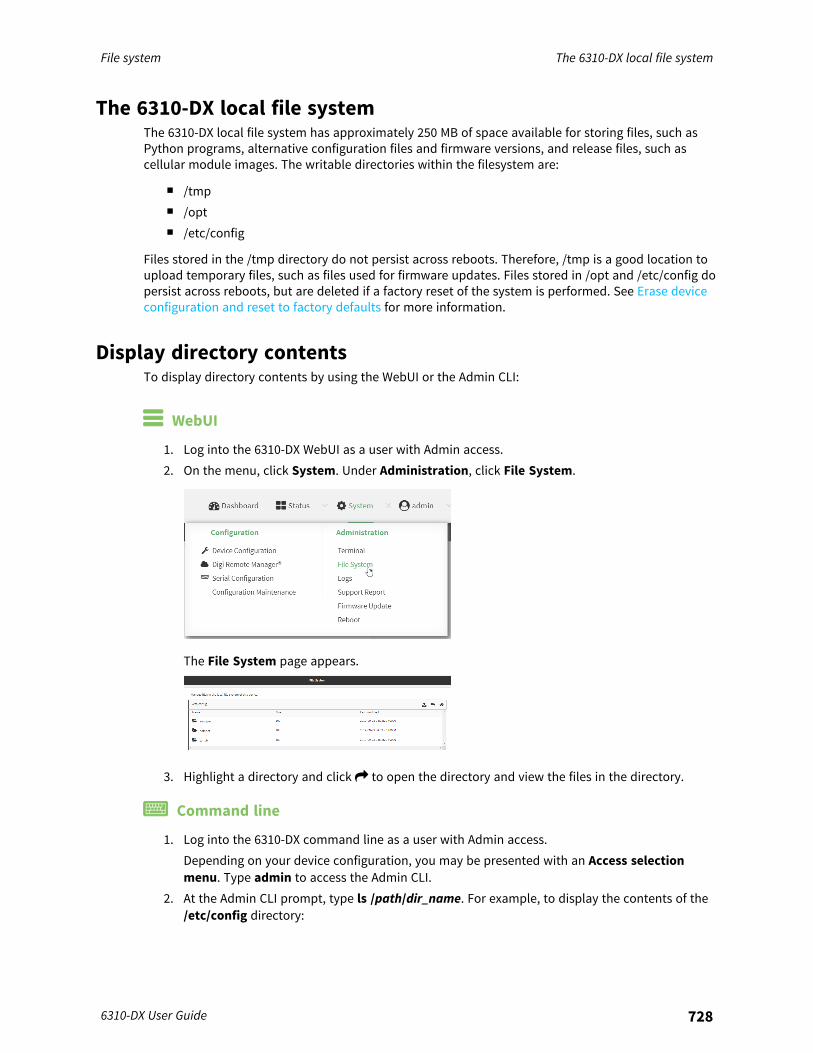
File system The 6310-DX local file system
6310-DX User Guide 728
The 6310-DX local file systemThe 6310-DX local file system has approximately 250 MB of space available for storing files, such asPython programs, alternative configuration files and firmware versions, and release files, such ascellular module images. The writable directories within the filesystem are:
n /tmpn /optn /etc/config
Files stored in the /tmp directory do not persist across reboots. Therefore, /tmp is a good location toupload temporary files, such as files used for firmware updates. Files stored in /opt and /etc/config dopersist across reboots, but are deleted if a factory reset of the system is performed. See Erase deviceconfiguration and reset to factory defaults for more information.
Display directory contentsTo display directory contents by using the WebUI or the Admin CLI:
WebUI
1. Log into the 6310-DX WebUI as a user with Admin access.2. On the menu, click System. Under Administration, click File System.
The File System page appears.
3. Highlight a directory and click to open the directory and view the files in the directory.
Command line
1. Log into the 6310-DX command line as a user with Admin access.Depending on your device configuration, you may be presented with an Access selectionmenu. Type admin to access the Admin CLI.
2. At the Admin CLI prompt, type ls /path/dir_name. For example, to display the contents of the/etc/config directory:

File system Create a directory
6310-DX User Guide 729
> ls /etc/config-rw-r--r-- 1 root root 856 Nov 20 20:12 accns.jsondrw------- 2 root root 160 Sep 23 04:02 analyzerdrwxr-xr-x 3 root root 224 Sep 23 04:02 cc_acl-rw-r--r-- 1 root root 47 Sep 23 04:02 dhcp.leases...>
3. Type exit to exit the Admin CLI.Depending on your device configuration, you may be presented with an Access selectionmenu. Type quit to disconnect from the device.
Create a directory
Command lineThis procedure is not available through the WebUI. To make a new directory, use the mkdir command,specifying the name of the directory.For example:
1. Log into the 6310-DX command line as a user with Admin access.Depending on your device configuration, you may be presented with an Access selectionmenu. Type admin to access the Admin CLI.
2. At the Admin CLI prompt, type mkdir /path/dir_name. For example, to create a directorynamed temp in /etc/config:
> mkdir /etc/config/temp>
3. Verify that the directory was created:
> ls /etc/config...-rw-r--r-- 1 root root 1436 Aug 12 21:36 ssl.crt-rw------- 1 root root 3895 Aug 12 21:36 ssl.pem-rw-r--r-- 1 root root 10 Aug 5 06:41 startdrwxr-xr-x 2 root root 160 Aug 25 17:49 temp>
4. Type exit to exit the Admin CLI.Depending on your device configuration, you may be presented with an Access selectionmenu. Type quit to disconnect from the device.
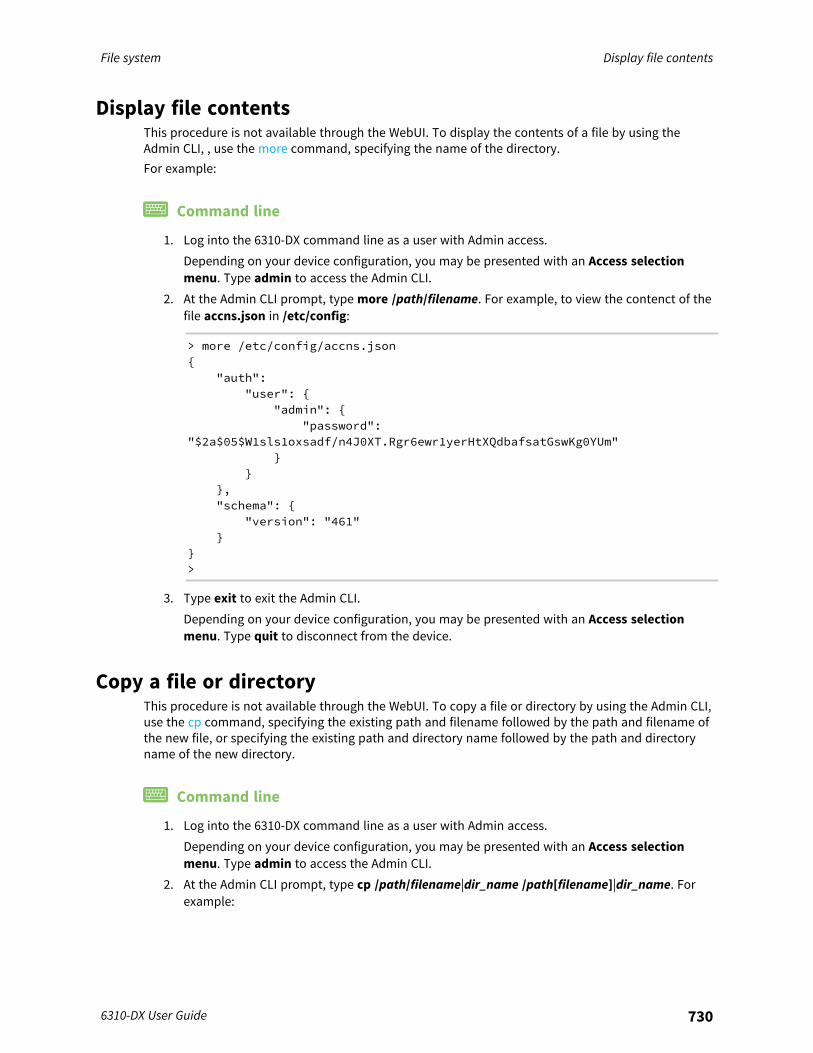
File system Display file contents
6310-DX User Guide 730
Display file contentsThis procedure is not available through the WebUI. To display the contents of a file by using theAdmin CLI, , use the more command, specifying the name of the directory.For example:
Command line
1. Log into the 6310-DX command line as a user with Admin access.Depending on your device configuration, you may be presented with an Access selectionmenu. Type admin to access the Admin CLI.
2. At the Admin CLI prompt, type more /path/filename. For example, to view the contenct of thefile accns.json in /etc/config:
> more /etc/config/accns.json{
"auth":"user": {
"admin": {"password":
"$2a$05$W1sls1oxsadf/n4J0XT.Rgr6ewr1yerHtXQdbafsatGswKg0YUm"}
}},"schema": {
"version": "461"}
}>
3. Type exit to exit the Admin CLI.Depending on your device configuration, you may be presented with an Access selectionmenu. Type quit to disconnect from the device.
Copy a file or directoryThis procedure is not available through the WebUI. To copy a file or directory by using the Admin CLI,use the cp command, specifying the existing path and filename followed by the path and filename ofthe new file, or specifying the existing path and directory name followed by the path and directoryname of the new directory.
Command line
1. Log into the 6310-DX command line as a user with Admin access.Depending on your device configuration, you may be presented with an Access selectionmenu. Type admin to access the Admin CLI.
2. At the Admin CLI prompt, type cp /path/filename|dir_name /path[filename]|dir_name. Forexample:
File system Move or rename a file or directory
6310-DX User Guide 731
n To copy the file /etc/config/accns.json to a file named backup_cfg.json in a directorynamed /etc/config/test, enter the following:
> cp /etc/config/accns.json /etc/config/test/backup_cfg.json>
n To copy a directory named /etc/config/test to /opt:
> cp /etc/config/test/ /opt/>
3. Type exit to exit the Admin CLI.Depending on your device configuration, you may be presented with an Access selectionmenu. Type quit to disconnect from the device.
Move or rename a file or directoryThis procedure is not available through the WebUI. To move or rename a file or directory by using theAdmin CLI, use the mv command.
Command lineTo rename a file named test.py in /etc/config/scripts to final.py:
1. Log into the 6310-DX command line as a user with Admin access.Depending on your device configuration, you may be presented with an Access selectionmenu. Type admin to access the Admin CLI.
2. At the Admin CLI prompt, type:
> mv /etc/config/scripts/test.py /etc/config/scripts/final.py>
3. Type exit to exit the Admin CLI.Depending on your device configuration, you may be presented with an Access selectionmenu. Type quit to disconnect from the device.
To move test.py from /etc/config/scripts to /opt:
1. Log into the 6310-DX command line as a user with Admin access.Depending on your device configuration, you may be presented with an Access selectionmenu. Type admin to access the Admin CLI.
2. At the Admin CLI prompt, type:
> mv /etc/config/scripts/test.py /opt/>
3. Type exit to exit the Admin CLI.Depending on your device configuration, you may be presented with an Access selectionmenu. Type quit to disconnect from the device.

File system Delete a file or directory
6310-DX User Guide 732
Delete a file or directoryTo delete a file or directory by using the WebUI or the Admin CLI:
WebUI
1. Log into the 6310-DX WebUI as a user with Admin access.2. On the menu, click System. Under Administration, click File System.
The File System page appears.
3. Highlight the directory containing the file to be deleted and click to open the directory.4. Highlight the file to be deleted and click .5. Click OK to confirm.
Command lineTo delete a file named test.py in /etc/config/scripts:
1. Log into the 6310-DX command line as a user with Admin access.Depending on your device configuration, you may be presented with an Access selectionmenu. Type admin to access the Admin CLI.
2. At the Admin CLI prompt, type:
> rm /etc/config/scripts/test.pyrm: remove '/etc/config/scripts/test.py'? yes>
3. Type exit to exit the Admin CLI.Depending on your device configuration, you may be presented with an Access selectionmenu. Type quit to disconnect from the device.
To delete a directory named temp from /opt:
1. Log into the 6310-DX command line as a user with Admin access.Depending on your device configuration, you may be presented with an Access selectionmenu. Type admin to access the Admin CLI.

File system Upload and download files
6310-DX User Guide 733
2. At the Admin CLI prompt, type:
> rm /opt/temp/rm: descend into directory '/opt/temp'? yesrm: remove directory '/opt/temp'? yes>
3. Type exit to exit the Admin CLI.Depending on your device configuration, you may be presented with an Access selectionmenu. Type quit to disconnect from the device.
Upload and download filesYou can download and upload files by using the WebUI or from the command line by using the scpSecure Copy command, or by using a utility such as SSH File Transfer Protocol (SFTP) or an SFTPapplication like FileZilla.
Upload and download files by using the WebUI
Upload files
1. Log into the 6310-DX WebUI as a user with Admin access.2. On the menu, click System. Under Administration, click File System.
The File System page appears.
3. Highlight the directory to which the file will be uploaded and click to open the directory.4. Click (upload).5. Browse to the location of the file on your local machine. Select the file and click Open to
upload the file.
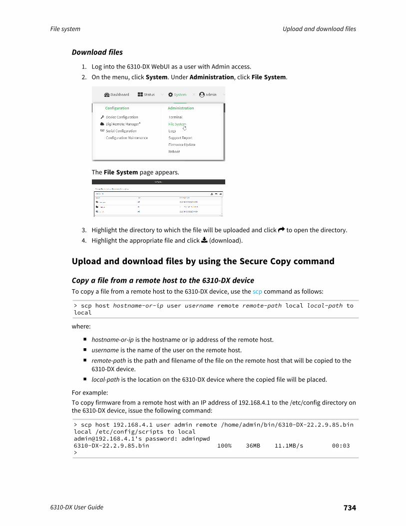
File system Upload and download files
6310-DX User Guide 734
Download files
1. Log into the 6310-DX WebUI as a user with Admin access.2. On the menu, click System. Under Administration, click File System.
The File System page appears.
3. Highlight the directory to which the file will be uploaded and click to open the directory.4. Highlight the appropriate file and click (download).
Upload and download files by using the Secure Copy command
Copy a file from a remote host to the 6310-DX deviceTo copy a file from a remote host to the 6310-DX device, use the scp command as follows:
> scp host hostname-or-ip user username remote remote-path local local-path tolocal
where:
n hostname-or-ip is the hostname or ip address of the remote host.n username is the name of the user on the remote host.n remote-path is the path and filename of the file on the remote host that will be copied to the
6310-DX device.n local-path is the location on the 6310-DX device where the copied file will be placed.
For example:To copy firmware from a remote host with an IP address of 192.168.4.1 to the /etc/config directory onthe 6310-DX device, issue the following command:
> scp host 192.168.4.1 user admin remote /home/admin/bin/6310-DX-22.2.9.85.binlocal /etc/config/scripts to [email protected]'s password: adminpwd6310-DX-22.2.9.85.bin 100% 36MB 11.1MB/s 00:03>

File system Upload and download files
6310-DX User Guide 735
Transfer a file from the 6310-DX device to a remote hostTo copy a file from the 6310-DX device to a remote host, use the scp command as follows:
> scp host hostname-or-ip user username remote remote-path local local-path toremote
where:
n hostname-or-ip is the hostname or ip address of the remote host.n username is the name of the user on the remote host.n remote-path is the location on the remote host where the file will be copied.n local-path is the path and filename on the 6310-DX device.
For example:To copy a support report from the 6310-DX device to a remote host at the IP address of 192.168.4.1:
1. Use the system support-report command to generate the report:
> system support-report /var/log/Saving support report to /var/log/support-report-0040D0133536-22-03-03-10:16:23.binSupport report saved.>
2. Use the scp command to transfer the report to a remote host:
> scp host 192.168.4.1 user admin remote /home/admin/temp/ local/var/log/support-report-00:40:D0:13:35:36-22-03-03-10:16:23.bin to [email protected]'s password: adminpwdsupport-report-0040D0133536-22-03-03-10:16:23.bin>
Upload and download files using SFTP
Transfer a file from a remote host to the 6310-DX deviceThis example uploads firmware from a remote host to the 6310-DX device with an IP address of192.168.2.1, using the username ahmed:
$ sftp [email protected]:Connected to 192.168.2.1sftp> put 6310-DX-22.2.9.85Uploading 6310-DX-22.2.9.85 to 6310-DX-22.2.9.856310-DX-22.2.9.85
100% 24M 830.4KB/s 00:00sftp> exit$
Transfer a file from the 6310-DX device to a remote hostThis example downloads a file named test.py from the 6310-DX device at the IP address of192.168.2.1 with a username of ahmed to the local directory on the remote host:

File system Upload and download files
6310-DX User Guide 736
$ sftp [email protected]:Connected to 192.168.2.1sftp> get test.pyFetching test.py to test.pytest.py
100% 254 0.3KB/s 00:00sftp> exit$
Diagnostics
This chapter contains the following topics:
Perform a speedtest 738Generate a support report 738View system and event logs 740Configure syslog servers 744Configure options for the event and system logs 746Analyze network traffic 751Use the ping command to troubleshoot network connections 769Use the traceroute command to diagnose IP routing problems 769
6310-DX User Guide 737
Diagnostics Perform a speedtest
6310-DX User Guide 738
Perform a speedtestTo perform a speedtest:
Command line
1. Log into the 6310-DX command line as a user with Admin access.Depending on your device configuration, you may be presented with an Access selectionmenu. Type admin to access the Admin CLI.
2. Use the speedtest command to generate the report:
> speedtest host
where host is the hostname or IP address of a speedtest host. For example:
> speedtest speedtest.accns.comTx (upload) average: 50.1110 MbpsTx latency: 31.45 msRx (download) average: 44.7588 MbpsRx latency: 30.05 ms>
3. To output the result in json format, use the output parameter:
> speedtest host output json{"tx_avg": "51.8510", "tx_avg_units": "Mbps", "tx_latency": "31.07","tx_latency_units": "ms", "rx_avg": "39.5770", "rx_avg_units": "Mbps","rx_latency": "34.19", "rx_latency_units": "ms" }>
4. To change the size of the speedtest packet, use the size parameter:
> speedtest host size int
5. By default, the speedtest uses nuttcp for the mode. You can change this to iperf with the modeparameter:
> speedtest host mode iperf
6. Type exit to exit the Admin CLI.Depending on your device configuration, you may be presented with an Access selectionmenu. Type quit to disconnect from the device.
Generate a support reportTo generate and download a support report:
WebUI
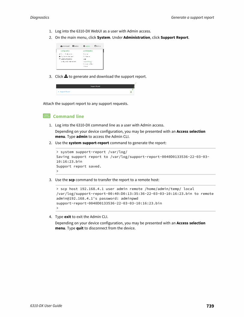
Diagnostics Generate a support report
6310-DX User Guide 739
1. Log into the 6310-DX WebUI as a user with Admin access.2. On the main menu, click System. Under Administration, click Support Report.
3. Click to generate and download the support report.
Attach the support report to any support requests.
Command line
1. Log into the 6310-DX command line as a user with Admin access.Depending on your device configuration, you may be presented with an Access selectionmenu. Type admin to access the Admin CLI.
2. Use the system support-report command to generate the report:
> system support-report /var/log/Saving support report to /var/log/support-report-0040D0133536-22-03-03-10:16:23.binSupport report saved.>
3. Use the scp command to transfer the report to a remote host:
> scp host 192.168.4.1 user admin remote /home/admin/temp/ local/var/log/support-report-00:40:D0:13:35:36-22-03-03-10:16:23.bin to [email protected]'s password: adminpwdsupport-report-0040D0133536-22-03-03-10:16:23.bin>
4. Type exit to exit the Admin CLI.Depending on your device configuration, you may be presented with an Access selectionmenu. Type quit to disconnect from the device.
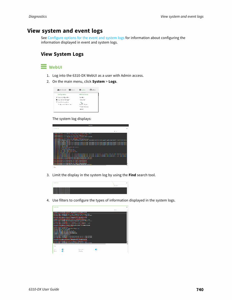
Diagnostics View system and event logs
6310-DX User Guide 740
View system and event logsSee Configure options for the event and system logs for information about configuring theinformation displayed in event and system logs.
View System Logs
WebUI
1. Log into the 6310-DX WebUI as a user with Admin access.2. On the main menu, click System > Logs.
The system log displays:
3. Limit the display in the system log by using the Find search tool.
4. Use filters to configure the types of information displayed in the system logs.

Diagnostics View system and event logs
6310-DX User Guide 741
5. Click to download the system log.
Command line
1. Log into the 6310-DX command line as a user with Admin access.Depending on your device configuration, you may be presented with an Access selectionmenu. Type admin to access the Admin CLI.
2. Use the show log command at the Admin CLI prompt:
> show log
Timestamp Message-------------- -------------------------------------------------------------Nov 26 21:54:34 6310-DX netifd: Interface 'interface_wan' is setting upnowNov 26 21:54:35 6310-DX firewalld[621]: reloading status...>
3. (Optional) Use the show log number num command to limit the number of lines that aredisplayed. For example, to limit the log to the most recent ten lines:
> show log number 10
Timestamp Message-------------- -------------------------------------------------------------Nov 26 21:54:34 6310-DX netifd: Interface 'interface_wan' is setting upnowNov 26 21:54:35 6310-DX firewalld[621]: reloading status...>
4. (Optional) Use the show log filter value command to limit the number of lines that aredisplayed. Allowed values are critical, warning, info, and debug. For example, to limit theevent list to only info messages:
> show log filter info
Timestamp Type Category Message---------------- ------- --------- -------------------------------------------Nov 26 22:01:26 info username=admin~service=cli~state=opened~remote=192.168.1.2Nov 26 22:01:25 info username=admin~service=cli~state=closed~remote=192.168.1.2
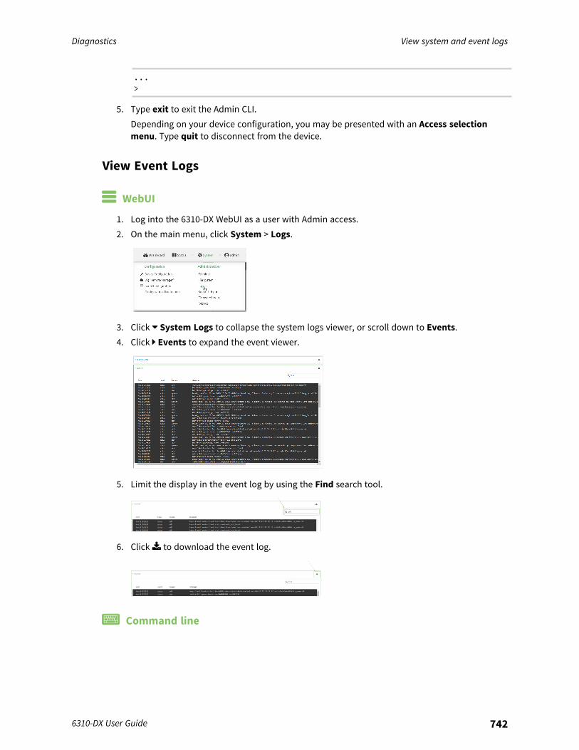
Diagnostics View system and event logs
6310-DX User Guide 742
...>
5. Type exit to exit the Admin CLI.Depending on your device configuration, you may be presented with an Access selectionmenu. Type quit to disconnect from the device.
View Event Logs
WebUI
1. Log into the 6310-DX WebUI as a user with Admin access.2. On the main menu, click System > Logs.
3. Click System Logs to collapse the system logs viewer, or scroll down to Events.4. Click Events to expand the event viewer.
5. Limit the display in the event log by using the Find search tool.
6. Click to download the event log.
Command line
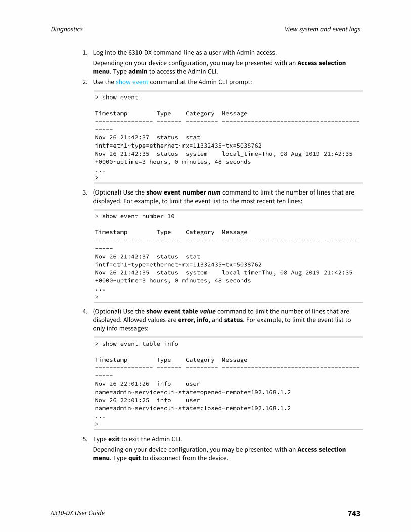
Diagnostics View system and event logs
6310-DX User Guide 743
1. Log into the 6310-DX command line as a user with Admin access.Depending on your device configuration, you may be presented with an Access selectionmenu. Type admin to access the Admin CLI.
2. Use the show event command at the Admin CLI prompt:
> show event
Timestamp Type Category Message---------------- ------- --------- -------------------------------------------Nov 26 21:42:37 status statintf=eth1~type=ethernet~rx=11332435~tx=5038762Nov 26 21:42:35 status system local_time=Thu, 08 Aug 2019 21:42:35+0000~uptime=3 hours, 0 minutes, 48 seconds...>
3. (Optional) Use the show event number num command to limit the number of lines that aredisplayed. For example, to limit the event list to the most recent ten lines:
> show event number 10
Timestamp Type Category Message---------------- ------- --------- -------------------------------------------Nov 26 21:42:37 status statintf=eth1~type=ethernet~rx=11332435~tx=5038762Nov 26 21:42:35 status system local_time=Thu, 08 Aug 2019 21:42:35+0000~uptime=3 hours, 0 minutes, 48 seconds...>
4. (Optional) Use the show event table value command to limit the number of lines that aredisplayed. Allowed values are error, info, and status. For example, to limit the event list toonly info messages:
> show event table info
Timestamp Type Category Message---------------- ------- --------- -------------------------------------------Nov 26 22:01:26 info username=admin~service=cli~state=opened~remote=192.168.1.2Nov 26 22:01:25 info username=admin~service=cli~state=closed~remote=192.168.1.2...>
5. Type exit to exit the Admin CLI.Depending on your device configuration, you may be presented with an Access selectionmenu. Type quit to disconnect from the device.

Diagnostics Configure syslog servers
6310-DX User Guide 744
Configure syslog serversYou can configure remote syslog servers for storing event and system logs.
WebUI
1. Log into the 6310-DX WebUI as a user with full Admin access rights.2. On the menu, click System. Under Configuration, click Device Configuration.
The Configuration window is displayed.
3. Click System > Log.
4. Add and configure a remote syslog server:a. Click to expand Server list.b. For Add Server, click .
The log server configuration window is displayed.
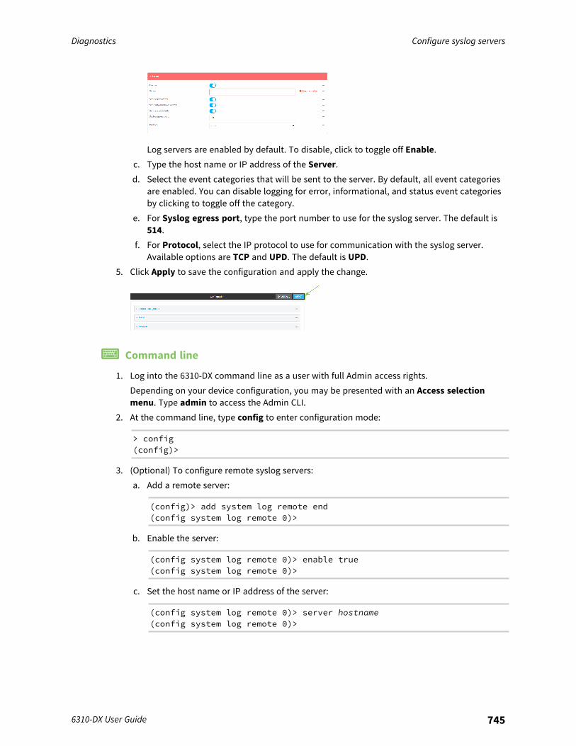
Diagnostics Configure syslog servers
6310-DX User Guide 745
Log servers are enabled by default. To disable, click to toggle off Enable.c. Type the host name or IP address of the Server.d. Select the event categories that will be sent to the server. By default, all event categories
are enabled. You can disable logging for error, informational, and status event categoriesby clicking to toggle off the category.
e. For Syslog egress port, type the port number to use for the syslog server. The default is514.
f. For Protocol, select the IP protocol to use for communication with the syslog server.Available options are TCP and UPD. The default is UPD.
5. Click Apply to save the configuration and apply the change.
Command line
1. Log into the 6310-DX command line as a user with full Admin access rights.Depending on your device configuration, you may be presented with an Access selectionmenu. Type admin to access the Admin CLI.
2. At the command line, type config to enter configuration mode:
> config(config)>
3. (Optional) To configure remote syslog servers:a. Add a remote server:
(config)> add system log remote end(config system log remote 0)>
b. Enable the server:
(config system log remote 0)> enable true(config system log remote 0)>
c. Set the host name or IP address of the server:
(config system log remote 0)> server hostname(config system log remote 0)>
Diagnostics Configure options for the event and system logs
6310-DX User Guide 746
d. The event categories that will be sent to the server are automatically enabled when theserver is enabled.
n To disable informational event messages:
(config system log remote 0)> info false(config system log remote 0)>
n To disable status event messages:
(config system log remote 0)> status false(config system log remote 0)>
n To disable informational event messages:
(config system log remote 0)> error false(config system log remote 0)>
4. Set the port number to use for the syslog server:
(config system log remote 0)> port value(config system log remote 0)>
where value is any integer between 1 and 65535. The default is 514.5. Set the IP protocol to use for communication with the syslog server:
(config system log remote 0)> protocol value(config system log remote 0)>
where value is either tcp or udp. The default is udp.6. Save the configuration and apply the change:
(config)> saveConfiguration saved.>
7. Type exit to exit the Admin CLI.Depending on your device configuration, you may be presented with an Access selectionmenu. Type quit to disconnect from the device.
Configure options for the event and system logsThe default configuration for event and system logging is:
n The heartbeat interval, which determines the amount of time to wait before sending aheartbeat event if no other events have been sent, is set to 30 minutes.
n All event categories are enabled.
To change or disable the heartbeat interval, or to disable event categories, and to perform other logconfiguration:
WebUI
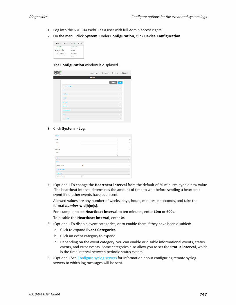
Diagnostics Configure options for the event and system logs
6310-DX User Guide 747
1. Log into the 6310-DX WebUI as a user with full Admin access rights.2. On the menu, click System. Under Configuration, click Device Configuration.
The Configuration window is displayed.
3. Click System > Log.
4. (Optional) To change the Heartbeat interval from the default of 30 minutes, type a new value.The heartbeat interval determines the amount of time to wait before sending a heartbeatevent if no other events have been sent.Allowed values are any number of weeks, days, hours, minutes, or seconds, and take theformat number{w|d|h|m|s}.For example, to set Heartbeat interval to ten minutes, enter 10m or 600s.To disable the Heartbeat interval, enter 0s.
5. (Optional) To disable event categories, or to enable them if they have been disabled:a. Click to expand Event Categories.b. Click an event category to expand.c. Depending on the event category, you can enable or disable informational events, status
events, and error events. Some categories also allow you to set the Status interval, whichis the time interval between periodic status events.
6. (Optional) See Configure syslog servers for information about configuring remote syslogservers to which log messages will be sent.
Diagnostics Configure options for the event and system logs
6310-DX User Guide 748
7. Enable Preserve system logs to save the current session's system log after a reboot.By default, the 6310-DX device erases system logs each time the device is powered off orrebooted.
Note You should only enable Preserve system logs temporarily to debug issues. Once you arefinished debugging, immediately disable Preserve system logs to avoid unnecessary wear tothe flash memory.
8. Click Apply to save the configuration and apply the change.
Command line
1. Log into the 6310-DX command line as a user with full Admin access rights.Depending on your device configuration, you may be presented with an Access selectionmenu. Type admin to access the Admin CLI.
2. At the command line, type config to enter configuration mode:
> config(config)>
3. (Optional) To change the heartbeat interval from the default of 30 minutes, set a new value.The heartbeat interval determines the amount of time to wait before sending a heartbeatevent if no other events have been sent.
(config)> system log heartbeat_interval value(config)>
where value is any number of weeks, days, hours, minutes, or seconds, and takes the formatnumber{w|d|h|m|s}.For example, to set the heartbeat interval to ten minutes, enter either 10m or 600s:
(config)> system log heartbeat_interval 600s(config)>
To disable the heartbeat interval, set the value to 0s4. Enable preserve system logs functionality to save the current session's system log after a
reboot. By default, the 6310-DX device erases system logs each time the device is powered offor rebooted.
Note You should only enable Preserve system logs temporarily to debug issues. Once you arefinished debugging, immediately disable Preserve system logs to avoid unnecessary wear tothe flash memory.
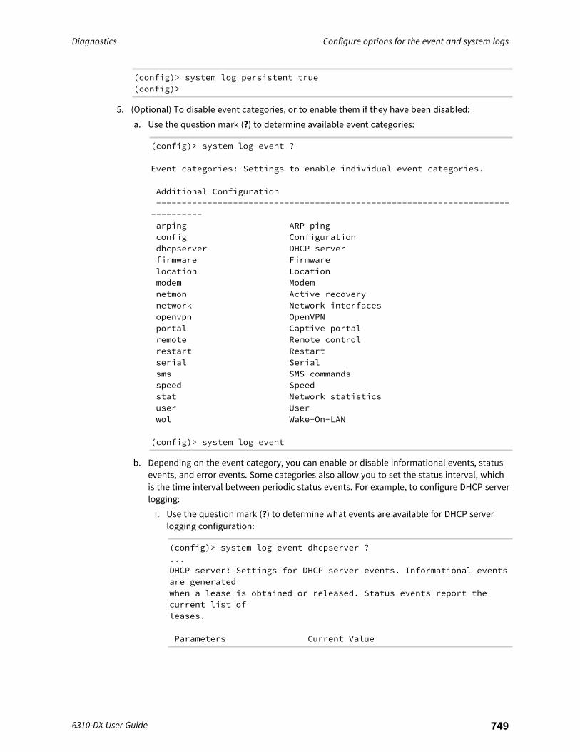
Diagnostics Configure options for the event and system logs
6310-DX User Guide 749
(config)> system log persistent true(config)>
5. (Optional) To disable event categories, or to enable them if they have been disabled:a. Use the question mark (?) to determine available event categories:
(config)> system log event ?
Event categories: Settings to enable individual event categories.
Additional Configuration-------------------------------------------------------------------------------arping ARP pingconfig Configurationdhcpserver DHCP serverfirmware Firmwarelocation Locationmodem Modemnetmon Active recoverynetwork Network interfacesopenvpn OpenVPNportal Captive portalremote Remote controlrestart Restartserial Serialsms SMS commandsspeed Speedstat Network statisticsuser Userwol Wake-On-LAN
(config)> system log event
b. Depending on the event category, you can enable or disable informational events, statusevents, and error events. Some categories also allow you to set the status interval, whichis the time interval between periodic status events. For example, to configure DHCP serverlogging:i. Use the question mark (?) to determine what events are available for DHCP server
logging configuration:
(config)> system log event dhcpserver ?...DHCP server: Settings for DHCP server events. Informational eventsare generatedwhen a lease is obtained or released. Status events report thecurrent list ofleases.
Parameters Current Value
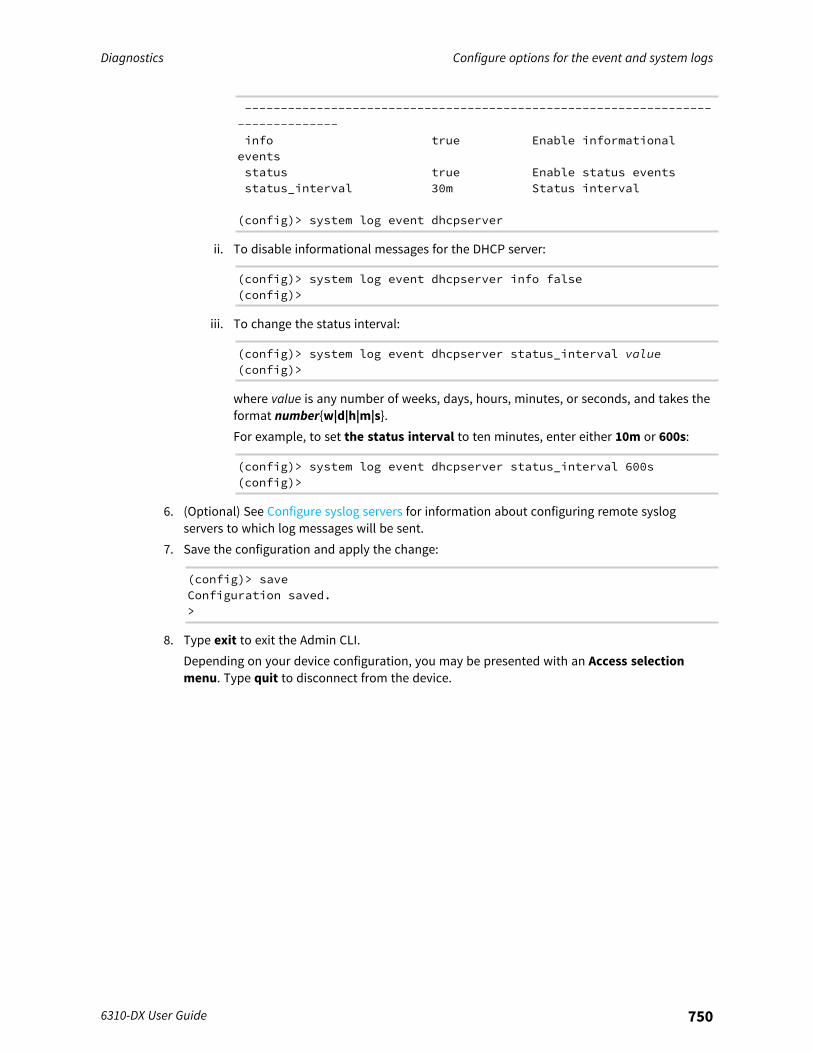
Diagnostics Configure options for the event and system logs
6310-DX User Guide 750
-------------------------------------------------------------------------------info true Enable informationaleventsstatus true Enable status eventsstatus_interval 30m Status interval
(config)> system log event dhcpserver
ii. To disable informational messages for the DHCP server:
(config)> system log event dhcpserver info false(config)>
iii. To change the status interval:
(config)> system log event dhcpserver status_interval value(config)>
where value is any number of weeks, days, hours, minutes, or seconds, and takes theformat number{w|d|h|m|s}.For example, to set the status interval to ten minutes, enter either 10m or 600s:
(config)> system log event dhcpserver status_interval 600s(config)>
6. (Optional) See Configure syslog servers for information about configuring remote syslogservers to which log messages will be sent.
7. Save the configuration and apply the change:
(config)> saveConfiguration saved.>
8. Type exit to exit the Admin CLI.Depending on your device configuration, you may be presented with an Access selectionmenu. Type quit to disconnect from the device.
Diagnostics Analyze network traffic
6310-DX User Guide 751
Analyze network trafficThe 6310-DX device includes a network analyzer tool that captures data traffic on any interface anddecodes the captured data traffic for diagnostics. You can capture data traffic on multiple interfacesat the same time and define capture filters to reduce the captured data. You can capture up to 10 MBof data traffic in two 5 MB files per interface.To perform a more detailed analysis, you can download the captured data traffic from the device andview it using a third-party application.
Note Data traffic is captured to RAM and the captured data is lost when the device reboots unless yousave the data to a file. See Save captured data traffic to a file.
This section contains the following topics:
Configure packet capture for the network analyzer 752Example filters for capturing data traffic 761Capture packets from the command line 762Stop capturing packets 763Show captured traffic data 764Save captured data traffic to a file 765Download captured data to your PC 766Clear captured data 767
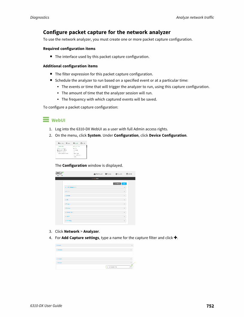
Diagnostics Analyze network traffic
6310-DX User Guide 752
Configure packet capture for the network analyzerTo use the network analyzer, you must create one or more packet capture configuration.
Required configuration items
n The interface used by this packet capture configuration.
Additional configuration items
n The filter expression for this packet capture configuration.n Schedule the analyzer to run based on a specified event or at a particular time:
l The events or time that will trigger the analyzer to run, using this capture configuration.l The amount of time that the analyzer session will run.l The frequency with which captured events will be saved.
To configure a packet capture configuration:
WebUI
1. Log into the 6310-DX WebUI as a user with full Admin access rights.2. On the menu, click System. Under Configuration, click Device Configuration.
The Configuration window is displayed.
3. Click Network > Analyzer.4. For Add Capture settings, type a name for the capture filter and click .
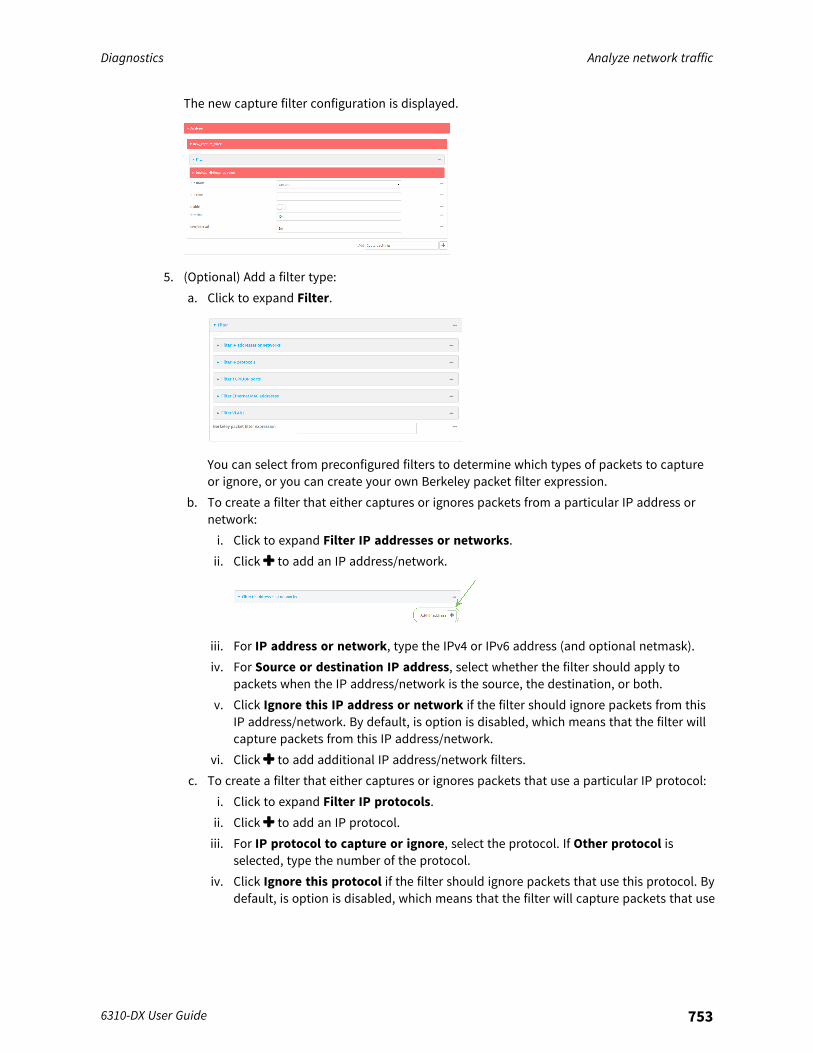
Diagnostics Analyze network traffic
6310-DX User Guide 753
The new capture filter configuration is displayed.
5. (Optional) Add a filter type:a. Click to expand Filter.
You can select from preconfigured filters to determine which types of packets to captureor ignore, or you can create your own Berkeley packet filter expression.
b. To create a filter that either captures or ignores packets from a particular IP address ornetwork:i. Click to expand Filter IP addresses or networks.ii. Click to add an IP address/network.
iii. For IP address or network, type the IPv4 or IPv6 address (and optional netmask).iv. For Source or destination IP address, select whether the filter should apply to
packets when the IP address/network is the source, the destination, or both.v. Click Ignore this IP address or network if the filter should ignore packets from this
IP address/network. By default, is option is disabled, which means that the filter willcapture packets from this IP address/network.
vi. Click to add additional IP address/network filters.c. To create a filter that either captures or ignores packets that use a particular IP protocol:
i. Click to expand Filter IP protocols.ii. Click to add an IP protocol.iii. For IP protocol to capture or ignore, select the protocol. If Other protocol is
selected, type the number of the protocol.iv. Click Ignore this protocol if the filter should ignore packets that use this protocol. By
default, is option is disabled, which means that the filter will capture packets that use
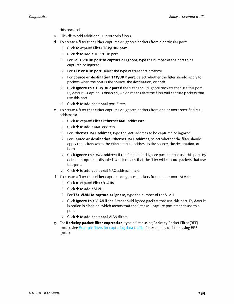
Diagnostics Analyze network traffic
6310-DX User Guide 754
this protocol.v. Click to add additional IP protocols filters.d. To create a filter that either captures or ignores packets from a particular port:
i. Click to expand Filter TCP/UDP port.ii. Click to add a TCP /UDP port.iii. For IP TCP/UDP port to capture or ignore, type the number of the port to be
captured or ingored.iv. For TCP or UDP port, select the type of transport protocol.v. For Source or destination TCP/UDP port, select whether the filter should apply to
packets when the port is the source, the destination, or both.vi. Click Ignore this TCP/UDP port if the filter should ignore packets that use this port.
By default, is option is disabled, which means that the filter will capture packets thatuse this port.
vii. Click to add additional port filters.e. To create a filter that either captures or ignores packets from one or more specified MAC
addresses:i. Click to expand Filter Ethernet MAC addresses.ii. Click to add a MAC address.iii. For Ethernet MAC address, type the MAC address to be captured or ingored.iv. For Source or destination Ethernet MAC address, select whether the filter should
apply to packets when the Ethernet MAC address is the source, the destination, orboth.
v. Click Ignore this MAC address if the filter should ignore packets that use this port. Bydefault, is option is disabled, which means that the filter will capture packets that usethis port.
vi. Click to add additional MAC address filters.f. To create a filter that either captures or ignores packets from one or more VLANs:
i. Click to expand Filter VLANs.ii. Click to add a VLAN.iii. For The VLAN to capture or ignore, type the number of the VLAN.iv. Click Ignore this VLAN if the filter should ignore packets that use this port. By default,
is option is disabled, which means that the filter will capture packets that use thisport.
v. Click to add additional VLAN filters.g. For Berkeley packet filter expression, type a filter using Berkeley Packet Filter (BPF)
syntax. See Example filters for capturing data traffic for examples of filters using BPFsyntax.
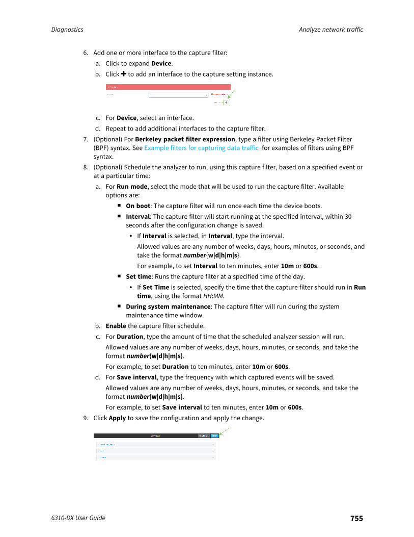
Diagnostics Analyze network traffic
6310-DX User Guide 755
6. Add one or more interface to the capture filter:a. Click to expand Device.b. Click to add an interface to the capture setting instance.
c. For Device, select an interface.d. Repeat to add additional interfaces to the capture filter.
7. (Optional) For Berkeley packet filter expression, type a filter using Berkeley Packet Filter(BPF) syntax. See Example filters for capturing data traffic for examples of filters using BPFsyntax.
8. (Optional) Schedule the analyzer to run, using this capture filter, based on a specified event orat a particular time:a. For Run mode, select the mode that will be used to run the capture filter. Available
options are:n On boot: The capture filter will run once each time the device boots.n Interval: The capture filter will start running at the specified interval, within 30
seconds after the configuration change is saved.l If Interval is selected, in Interval, type the interval.
Allowed values are any number of weeks, days, hours, minutes, or seconds, andtake the format number{w|d|h|m|s}.For example, to set Interval to ten minutes, enter 10m or 600s.
n Set time: Runs the capture filter at a specified time of the day.l If Set Time is selected, specify the time that the capture filter should run in Run
time, using the format HH:MM.n During system maintenance: The capture filter will run during the system
maintenance time window.b. Enable the capture filter schedule.c. For Duration, type the amount of time that the scheduled analyzer session will run.
Allowed values are any number of weeks, days, hours, minutes, or seconds, and take theformat number{w|d|h|m|s}.For example, to set Duration to ten minutes, enter 10m or 600s.
d. For Save interval, type the frequency with which captured events will be saved.Allowed values are any number of weeks, days, hours, minutes, or seconds, and take theformat number{w|d|h|m|s}.For example, to set Save interval to ten minutes, enter 10m or 600s.
9. Click Apply to save the configuration and apply the change.
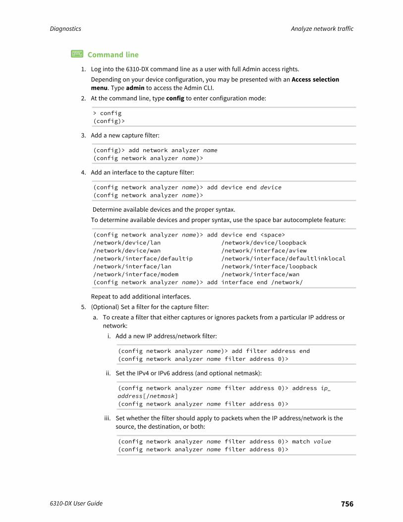
Diagnostics Analyze network traffic
6310-DX User Guide 756
Command line
1. Log into the 6310-DX command line as a user with full Admin access rights.Depending on your device configuration, you may be presented with an Access selectionmenu. Type admin to access the Admin CLI.
2. At the command line, type config to enter configuration mode:
> config(config)>
3. Add a new capture filter:
(config)> add network analyzer name(config network analyzer name)>
4. Add an interface to the capture filter:
(config network analyzer name)> add device end device(config network analyzer name)>
Determine available devices and the proper syntax.To determine available devices and proper syntax, use the space bar autocomplete feature:
(config network analyzer name)> add device end <space>/network/device/lan /network/device/loopback/network/device/wan /network/interface/aview/network/interface/defaultip /network/interface/defaultlinklocal/network/interface/lan /network/interface/loopback/network/interface/modem /network/interface/wan(config network analyzer name)> add interface end /network/
Repeat to add additional interfaces.5. (Optional) Set a filter for the capture filter:
a. To create a filter that either captures or ignores packets from a particular IP address ornetwork:i. Add a new IP address/network filter:
(config network analyzer name)> add filter address end(config network analyzer name filter address 0)>
ii. Set the IPv4 or IPv6 address (and optional netmask):
(config network analyzer name filter address 0)> address ip_address[/netmask](config network analyzer name filter address 0)>
iii. Set whether the filter should apply to packets when the IP address/network is thesource, the destination, or both:
(config network analyzer name filter address 0)> match value(config network analyzer name filter address 0)>
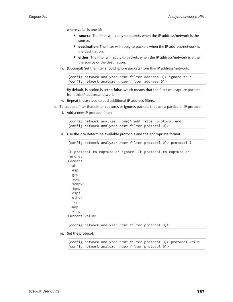
Diagnostics Analyze network traffic
6310-DX User Guide 757
where value is one of:n source: The filter will apply to packets when the IP address/network is the
source.n destination: The filter will apply to packets when the IP address/network is
the destination.n either: The filter will apply to packets when the IP address/network is either
the source or the destination.iv. (Optional) Set the filter should ignore packets from this IP address/network:
(config network analyzer name filter address 0)> ignore true(config network analyzer name filter address 0)>
By default, is option is set to false, which means that the filter will capture packetsfrom this IP address/network.
v. Repeat these steps to add additional IP address filters.b. To create a filter that either captures or ignores packets that use a particular IP protocol:
i. Add a new IP protocol filter:
(config network analyzer name)> add filter protocol end(config network analyzer name filter protocol 0)>
ii. Use the ? to determine available protocols and the appropriate format:
(config network analyzer name filter protocol 0)> protocol ?
IP protocol to capture or ignore: IP protocol to capture orignore.Format:ahespgreicmpicmpv6igmpospfothertcpudpvrrp
Current value:
(config network analyzer name filter protocol 0)>
iii. Set the protocol:
(config network analyzer name filter protocol 0)> protocol value(config network analyzer name filter protocol 0)>
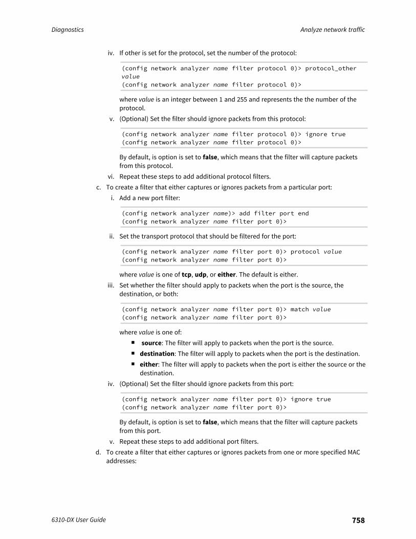
Diagnostics Analyze network traffic
6310-DX User Guide 758
iv. If other is set for the protocol, set the number of the protocol:
(config network analyzer name filter protocol 0)> protocol_othervalue(config network analyzer name filter protocol 0)>
where value is an integer between 1 and 255 and represents the the number of theprotocol.
v. (Optional) Set the filter should ignore packets from this protocol:
(config network analyzer name filter protocol 0)> ignore true(config network analyzer name filter protocol 0)>
By default, is option is set to false, which means that the filter will capture packetsfrom this protocol.
vi. Repeat these steps to add additional protocol filters.c. To create a filter that either captures or ignores packets from a particular port:
i. Add a new port filter:
(config network analyzer name)> add filter port end(config network analyzer name filter port 0)>
ii. Set the transport protocol that should be filtered for the port:
(config network analyzer name filter port 0)> protocol value(config network analyzer name filter port 0)>
where value is one of tcp, udp, or either. The default is either.iii. Set whether the filter should apply to packets when the port is the source, the
destination, or both:
(config network analyzer name filter port 0)> match value(config network analyzer name filter port 0)>
where value is one of:n source: The filter will apply to packets when the port is the source.n destination: The filter will apply to packets when the port is the destination.n either: The filter will apply to packets when the port is either the source or the
destination.iv. (Optional) Set the filter should ignore packets from this port:
(config network analyzer name filter port 0)> ignore true(config network analyzer name filter port 0)>
By default, is option is set to false, which means that the filter will capture packetsfrom this port.
v. Repeat these steps to add additional port filters.d. To create a filter that either captures or ignores packets from one or more specified MAC
addresses:

Diagnostics Analyze network traffic
6310-DX User Guide 759
i. Add a new MAC address filter:
(config network analyzer name)> add filter mac_address end(config network analyzer name filter mac_address 0)>
ii. Set the MAC address that should be be captured or ignored:
(config network analyzer name filter mac_address 0)> address value(config network analyzer name filter mac_address 0)>
where value is the MAC address to be filtered, using colon-hexadecimal notation withlower case, for example, 00:aa:11:bb:22:cc.
iii. Set whether the filter should apply to packets when the MAC address is the source,the destination, or both:
(config network analyzer name filter mac_address 0)> match value(config network analyzer name filter mac_address 0)>
where value is one of:n source: The filter will apply to packets when the MAC address is the source.n destination: The filter will apply to packets when the MAC address is the
destination.n either: The filter will apply to packets when the MAC address is either the
source or the destination.iv. (Optional) Set the filter should ignore packets from this port:
(config network analyzer name filter mac_address 0)> ignore true(config network analyzer name filter mac_address 0)>
By default, is option is set to false, which means that the filter will capture packetsfrom this MAC address.
v. Repeat these steps to add additional MAC addresses.e. To create a filter that either captures or ignores packets from one or more specified VLANs:
i. Add a new VLAN filter:
(config network analyzer name)> add filter vlan end(config network analyzer name filter vlan 0)>
ii. Set the VLAN that should be be captured or ignored:
(config network analyzer name filter vlan 0)> vlan value(config network analyzer name filter vlan 0)>
where value is number o the VLAN.iii. (Optional) Set the filter should ignore packets from this VLAN:
(config network analyzer name filter vlan 0)> ignore true(config network analyzer name filter vlan 0)>
By default, is option is set to false, which means that the filter will capture packetsfrom this MAC address.
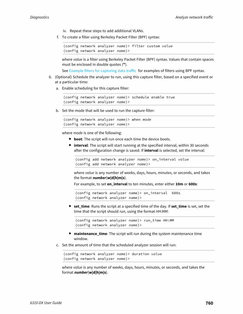
Diagnostics Analyze network traffic
6310-DX User Guide 760
iv. Repeat these steps to add additional VLANs.f. To create a filter using Berkeley Packet Filter (BPF) syntax:
(config network analyzer name)> filter custom value(config network analyzer name)>
where value is a filter using Berkeley Packet Filter (BPF) syntax. Values that contain spacesmust be enclosed in double quotes (").See Example filters for capturing data traffic for examples of filters using BPF syntax.
6. (Optional) Schedule the analyzer to run, using this capture filter, based on a specified event orat a particular time:a. Enable scheduling for this capture filter:
(config network analyzer name)> schedule enable true(config network analyzer name)>
b. Set the mode that will be used to run the capture filter:
(config network analyzer name)> when mode(config network analyzer name)>
where mode is one of the following:n boot: The script will run once each time the device boots.n interval: The script will start running at the specified interval, within 30 seconds
after the configuration change is saved. If interval is selected, set the interval:
(config add network analyzer name)> on_interval value(config add network analyzer name)>
where value is any number of weeks, days, hours, minutes, or seconds, and takesthe format number{w|d|h|m|s}.For example, to set on_interval to ten minutes, enter either 10m or 600s:
(config network analyzer name)> on_interval 600s(config network analyzer name)>
n set_time: Runs the script at a specified time of the day. If set_time is set, set thetime that the script should run, using the format HH:MM:
(config network analyzer name)> run_time HH:MM(config network analyzer name)>
n maintenance_time: The script will run during the system maintenance timewindow.
c. Set the amount of time that the scheduled analyzer session will run:
(config network analyzer name)> duration value(config network analyzer name)>
where value is any number of weeks, days, hours, minutes, or seconds, and takes theformat number{w|d|h|m|s}.

Diagnostics Analyze network traffic
6310-DX User Guide 761
For example, to set duration to ten minutes, enter either 10m or 600s:
(config network analyzer name)> save_interval 600s(config network analyzer name)>
d. Set the frequency with which captured events will be saved:
(config network analyzer name)> save_interval value(config network analyzer name)>
where value is any number of weeks, days, hours, minutes, or seconds, and takes theformat number{w|d|h|m|s}.For example, to set save_interval to ten minutes, enter either 10m or 600s:
(config network analyzer name)> save_interval 600s(config network analyzer name)>
7. Save the configuration and apply the change:
(config)> saveConfiguration saved.>
8. Type exit to exit the Admin CLI.Depending on your device configuration, you may be presented with an Access selectionmenu. Type quit to disconnect from the device.
Example filters for capturing data trafficThe following are examples of filters using Berkeley Packet Filter (BPF) syntax for capturing severaltypes of network data. See https://biot.com/capstats/bpf.html for detailed information about BPFsyntax.
Example IPv4 capture filters
n Capture traffic to and from IP host 192.168.1.1:
ip host 192.168.1.1
n Capture traffic from IP host 192.168.1.1:
ip src host 192.168.1.1
n Capture traffic to IP host 192.168.1.1:
ip dst host 192.168.1.1
n Capture traffic for a particular IP protocol:
ip proto protocol
where protocol is a number in the range of 1 to 255 or one of the following keywords: icmp,icmp6, igmp, pim, ah, esp, vrrp, udp, or tcp.

Diagnostics Analyze network traffic
6310-DX User Guide 762
n Capture traffic to and from a TCP port 80:
ip proto tcp and port 80
n Capture traffic to UDP port 53:
ip proto udp and dst port 53
n Capture traffic from UDP port 53:
ip proto udp and src port 53
n Capture to and from IP host 10.0.0.1 but filter out ports 22 and 80:
ip host 10.0.0.1 and not (port 22 or port 80)
Example Ethernet capture filters
n Capture Ethernet packets to and from a host with a MAC address of 00:40:D0:13:35:36:
ether host 00:40:D0:13:35:36
n Capture Ethernet packets from host 00:40:D0:13:35:36:
ether src 00:40:D0:13:35:36:
n Capture Ethernet packets to host 00:40:D0:13:35:36:
ether dst 00:40:D0:13:35:36
Capture packets from the command lineYou can start packet capture at the command line with the analyzer start command. Alternatively, youcan schedule the network analyzer to run based on a specified event or at a particular time. SeeConfigure packet capture for the network analyzer for information about scheduling packet capturing.Additional analyzer commands allow you to:
n Stop capturing packets.n Save captured data traffic to a file.n Clear captured data.
Required configuration items
n A configured packet capture. See Configure packet capture for the network analyzer for packetcapture configuration information.
To start packet capture from the command line:
Command line

Diagnostics Analyze network traffic
6310-DX User Guide 763
1. Log into the 6310-DX command line as a user with Admin access.Depending on your device configuration, you may be presented with an Access selectionmenu. Type admin to access the Admin CLI.
2. Type the following at the Admin CLI prompt:
> analyzer start name capture_filter>
where capture_filter is the name of a packet capture configuration. See Configure packetcapture for the network analyzer for more information.To determine available packet capture configurations, use the ?:
> analyzer start name ?
name: Name of the capture filter to use.Format:test_capturecapture_ping
> analyzer start name
You can capture up to 10 MB of data traffic in two 5 MB files per interface.
Note Data traffic is captured to RAM and the captured data is lost when the device reboots unless yousave the data to a file. See Save captured data traffic to a file.
Stop capturing packetsYou can stop packet capture at the command line with the analyzer stop command.To stop packet capture from the command line:
Command line
1. Log into the 6310-DX command line as a user with Admin access.Depending on your device configuration, you may be presented with an Access selectionmenu. Type admin to access the Admin CLI.
2. Type the following at the Admin CLI prompt:
> analyzer stop name capture_filter>
where capture_filter is the name of a packet capture configuration. See Configure packetcapture for the network analyzer for more information.To determine available packet capture configurations, use the ?:
> analyzer stop name ?
name: Name of the capture filter to use.Format:
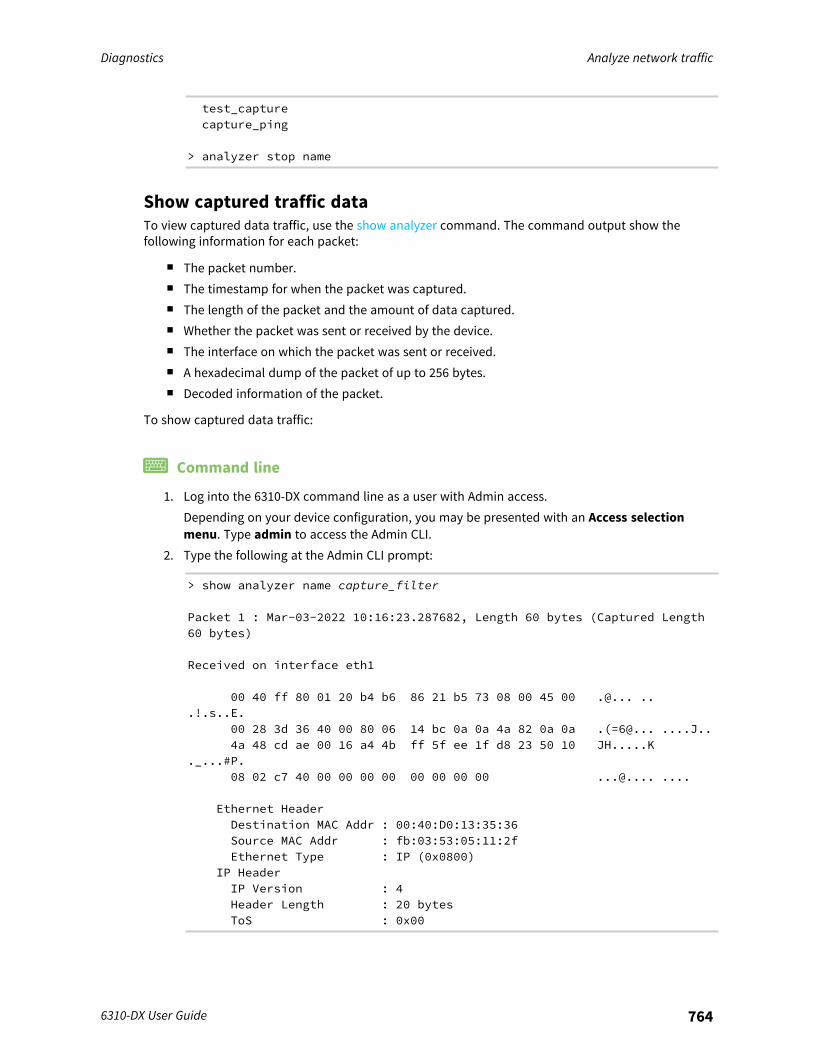
Diagnostics Analyze network traffic
6310-DX User Guide 764
test_capturecapture_ping
> analyzer stop name
Show captured traffic dataTo view captured data traffic, use the show analyzer command. The command output show thefollowing information for each packet:
n The packet number.n The timestamp for when the packet was captured.n The length of the packet and the amount of data captured.n Whether the packet was sent or received by the device.n The interface on which the packet was sent or received.n A hexadecimal dump of the packet of up to 256 bytes.n Decoded information of the packet.
To show captured data traffic:
Command line
1. Log into the 6310-DX command line as a user with Admin access.Depending on your device configuration, you may be presented with an Access selectionmenu. Type admin to access the Admin CLI.
2. Type the following at the Admin CLI prompt:
> show analyzer name capture_filter
Packet 1 : Mar-03-2022 10:16:23.287682, Length 60 bytes (Captured Length60 bytes)
Received on interface eth1
00 40 ff 80 01 20 b4 b6 86 21 b5 73 08 00 45 00 .@... ...!.s..E.
00 28 3d 36 40 00 80 06 14 bc 0a 0a 4a 82 0a 0a .(=6@... ....J..4a 48 cd ae 00 16 a4 4b ff 5f ee 1f d8 23 50 10 JH.....K
._...#P.08 02 c7 40 00 00 00 00 00 00 00 00 ...@.... ....
Ethernet HeaderDestination MAC Addr : 00:40:D0:13:35:36Source MAC Addr : fb:03:53:05:11:2fEthernet Type : IP (0x0800)
IP HeaderIP Version : 4Header Length : 20 bytesToS : 0x00

Diagnostics Analyze network traffic
6310-DX User Guide 765
Total Length : 40 bytesID : 15670 (0x3d36)Flags : Do not fragmentFragment Offset : 0 (0x0000)TTL : 128 (0x80)Protocol : TCP (6)Checksum : 0x14bcSource IP Address : 10.10.74.130Dest. IP Address : 10.10.74.72
TCP HeaderSource Port : 52654Destination Port : 22Sequence Number : 2756443999Ack Number : 3995064355Data Offset : 5Flags : ACKWindow : 2050Checksum : 0xc740Urgent Pointer : 0
TCP Data00 00 00 00 00 00 ......
>
where capture_filter is the name of a packet capture configuration. See Configure packetcapture for the network analyzer for more information.To determine available packet capture configurations, use the ?:
> show anaylzer name ?
name: Name of the capture filter to use.Format:test_capturecapture_ping
> show anaylzer name
Save captured data traffic to a fileData traffic is captured to RAM and when the device reboots, the data is lost. To retain the captureddata, first save the data to a file and then upload the file to a PC.To save captured traffic data to a file, use the analyzer save command:
Command line
1. Log into the 6310-DX command line as a user with Admin access.Depending on your device configuration, you may be presented with an Access selectionmenu. Type admin to access the Admin CLI.
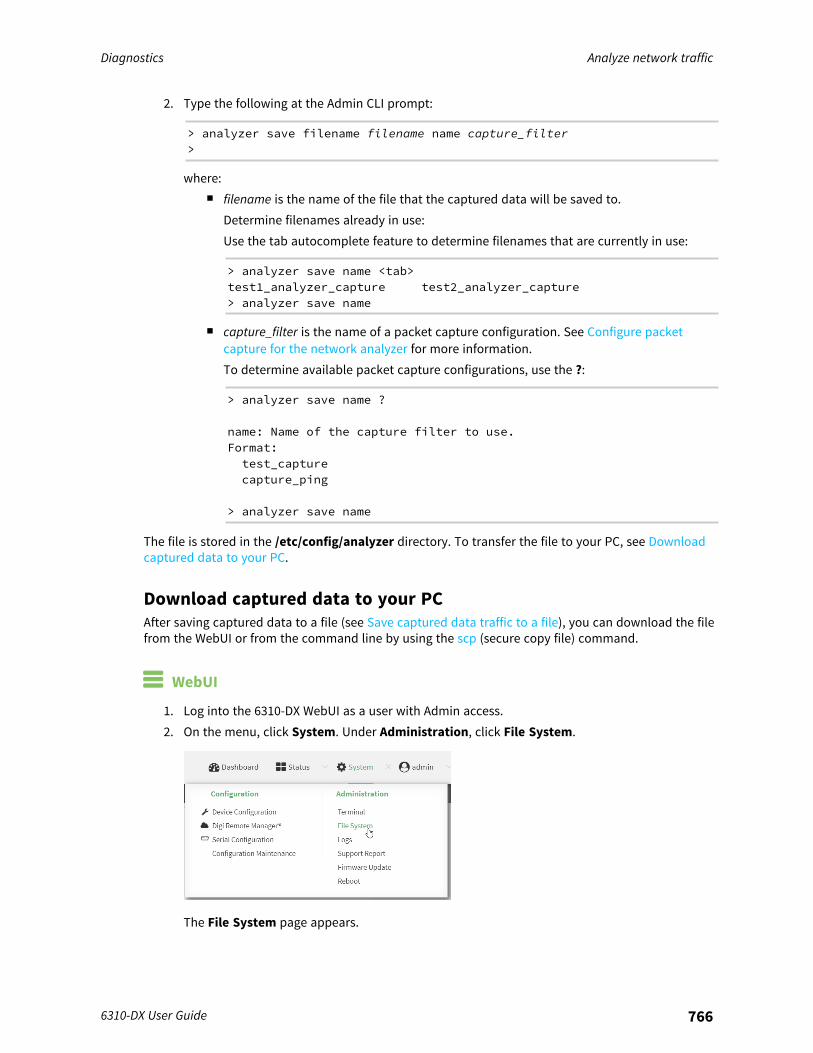
Diagnostics Analyze network traffic
6310-DX User Guide 766
2. Type the following at the Admin CLI prompt:
> analyzer save filename filename name capture_filter>
where:n filename is the name of the file that the captured data will be saved to.
Determine filenames already in use:Use the tab autocomplete feature to determine filenames that are currently in use:
> analyzer save name <tab>test1_analyzer_capture test2_analyzer_capture> analyzer save name
n capture_filter is the name of a packet capture configuration. See Configure packetcapture for the network analyzer for more information.To determine available packet capture configurations, use the ?:
> analyzer save name ?
name: Name of the capture filter to use.Format:test_capturecapture_ping
> analyzer save name
The file is stored in the /etc/config/analyzer directory. To transfer the file to your PC, see Downloadcaptured data to your PC.
Download captured data to your PCAfter saving captured data to a file (see Save captured data traffic to a file), you can download the filefrom the WebUI or from the command line by using the scp (secure copy file) command.
WebUI
1. Log into the 6310-DX WebUI as a user with Admin access.2. On the menu, click System. Under Administration, click File System.
The File System page appears.

Diagnostics Analyze network traffic
6310-DX User Guide 767
3. Highlight the analyzer directory and click to open the directory.4. Select the saved analyzer report you want to download and click (download).
Command line
1. Log into the 6310-DX command line as a user with Admin access.Depending on your device configuration, you may be presented with an Access selectionmenu. Type admin to access the Admin CLI.
2. Type scp to use the Secure Copy program to copy the file to your PC:
> scp host hostname-or-ip user username remote remote-path local local-path to remote
where:n hostname-or-ip is the hostname or ip address of the remote host.n username is the name of the user on the remote host.n remote-path is the location on the remote host where the file will be copied.n local-path is the path and filename on the 6310-DX device.
For example:To download the traffic saved in the file /etc/config/analyzer/eth0.pcpng to a PC with the IP192.168.210.2, for a user named maria, to the /home/maria directory:
> scp host 192.168.210.2 user maria remote /home/maria local/etc/config/analyzer/eth0.pcpng to remote
[email protected]'s password:eth0.pcpng 100% 11KB 851.3KB/s00:00
Clear captured dataTo clear captured data traffic in RAM, use the analyzer clear command:
Command line
1. Log into the 6310-DX command line as a user with Admin access.Depending on your device configuration, you may be presented with an Access selectionmenu. Type admin to access the Admin CLI.
2. Type the following at the Admin CLI prompt:
> analyzer clear name capture_filter>
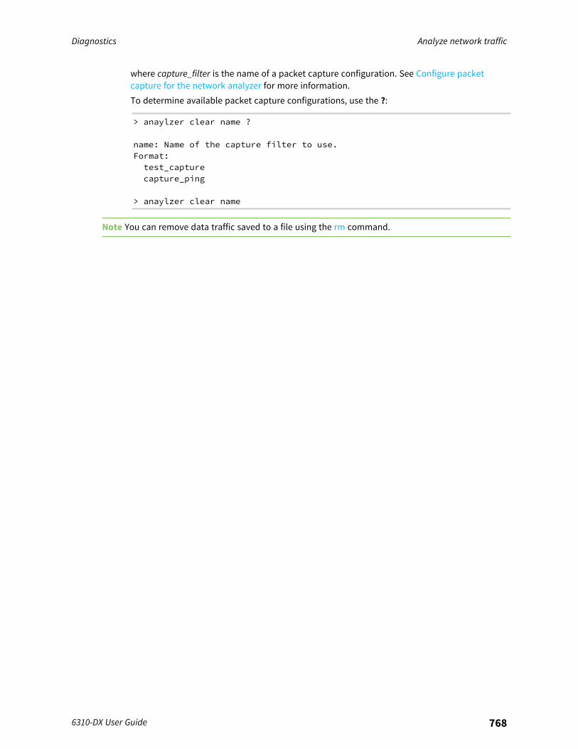
Diagnostics Analyze network traffic
6310-DX User Guide 768
where capture_filter is the name of a packet capture configuration. See Configure packetcapture for the network analyzer for more information.To determine available packet capture configurations, use the ?:
> anaylzer clear name ?
name: Name of the capture filter to use.Format:test_capturecapture_ping
> anaylzer clear name
Note You can remove data traffic saved to a file using the rm command.
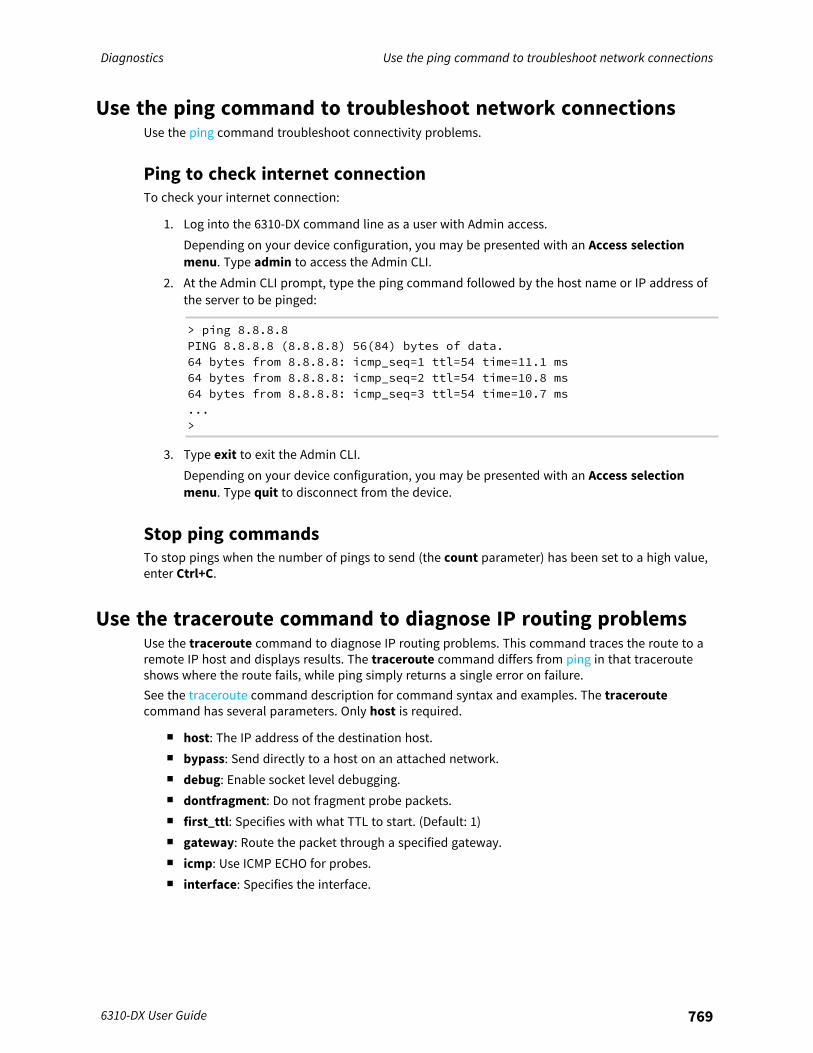
Diagnostics Use the ping command to troubleshoot network connections
6310-DX User Guide 769
Use the ping command to troubleshoot network connectionsUse the ping command troubleshoot connectivity problems.
Ping to check internet connectionTo check your internet connection:
1. Log into the 6310-DX command line as a user with Admin access.Depending on your device configuration, you may be presented with an Access selectionmenu. Type admin to access the Admin CLI.
2. At the Admin CLI prompt, type the ping command followed by the host name or IP address ofthe server to be pinged:
> ping 8.8.8.8PING 8.8.8.8 (8.8.8.8) 56(84) bytes of data.64 bytes from 8.8.8.8: icmp_seq=1 ttl=54 time=11.1 ms64 bytes from 8.8.8.8: icmp_seq=2 ttl=54 time=10.8 ms64 bytes from 8.8.8.8: icmp_seq=3 ttl=54 time=10.7 ms...>
3. Type exit to exit the Admin CLI.Depending on your device configuration, you may be presented with an Access selectionmenu. Type quit to disconnect from the device.
Stop ping commandsTo stop pings when the number of pings to send (the count parameter) has been set to a high value,enter Ctrl+C.
Use the traceroute command to diagnose IP routing problemsUse the traceroute command to diagnose IP routing problems. This command traces the route to aremote IP host and displays results. The traceroute command differs from ping in that tracerouteshows where the route fails, while ping simply returns a single error on failure.See the traceroute command description for command syntax and examples. The traceroutecommand has several parameters. Only host is required.
n host: The IP address of the destination host.n bypass: Send directly to a host on an attached network.n debug: Enable socket level debugging.n dontfragment: Do not fragment probe packets.n first_ttl: Specifies with what TTL to start. (Default: 1)n gateway: Route the packet through a specified gateway.n icmp: Use ICMP ECHO for probes.n interface: Specifies the interface.
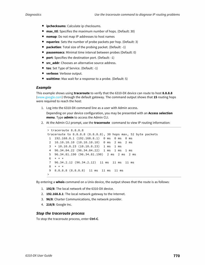
Diagnostics Use the traceroute command to diagnose IP routing problems
6310-DX User Guide 770
n ipchecksums: Calculate ip checksums.n max_ttl: Specifies the maximum number of hops. (Default: 30)n nomap: Do not map IP addresses to host namesn nqueries: Sets the number of probe packets per hop. (Default: 3)n packetlen: Total size of the probing packet. (Default: -1)n pausemsecs: Minimal time interval between probes (Default: 0)n port: Specifies the destination port. (Default: -1)n src_addr: Chooses an alternative source address.n tos: Set Type of Service. (Default: -1)n verbose: Verbose output.n waittime: Max wait for a response to a probe. (Default: 5)
ExampleThis example shows using traceroute to verify that the 6310-DX device can route to host 8.8.8.8(www.google.com) through the default gateway. The command output shows that 15 routing hopswere required to reach the host:
1. Log into the 6310-DX command line as a user with Admin access.Depending on your device configuration, you may be presented with an Access selectionmenu. Type admin to access the Admin CLI.
2. At the Admin CLI prompt, use the traceroute command to view IP routing information:
> traceroute 8.8.8.8traceroute to 8.8.8.8 (8.8.8.8), 30 hops max, 52 byte packets1 192.168.8.1 (192.168.8.1) 0 ms 0 ms 0 ms2 10.10.10.10 (10.10.10.10) 0 ms 2 ms 2 ms3 * 10.10.8.23 (10.10.8.23) 1 ms 1 ms4 96.34.84.22 (96.34.84.22) 1 ms 1 ms 1 ms5 96.34.81.190 (96.34.81.190) 2 ms 2 ms 2 ms6 * * *7 96.34.2.12 (96.34.2.12) 11 ms 11 ms 11 ms8 * * *9 8.8.8.8 (8.8.8.8) 11 ms 11 ms 11 ms>
By entering a whois command on a Unix device, the output shows that the route is as follows:
1. 192/8: The local network of the 6310-DX device.2. 192.168.8.1: The local network gateway to the Internet.3. 96/8: Charter Communications, the network provider.4. 216/8: Google Inc.
Stop the traceroute processTo stop the traceroute process, enter Ctrl-C.
Regulatory guide Use the traceroute command to diagnose IP routing problems
6310-DX User Guide 771
Regulatory guide
FCCTHIS EQUIPMENT HAS BEEN TESTED AND FOUND TO COMPLY WITH THE LIMITS FOR A CLASS ADIGITAL DEVICE, PURSUANT TO PART 15 OF THE FCC RULES. THESE LIMITS ARE DESIGNED TOPROVIDE REASONABLE PROTECTION AGAINST HARMFUL INTERFERENCE WHEN THE EQUIPMENT ISOPERATED IN A COMMERCIAL ENVIRONMENT. THIS EQUIPMENT GENERATES, USES, AND CAN RADIATERADIO FREQUENCY ENERGY AND, IF NOT INSTALLED AND USED IN ACCORDANCE WITH THEINSTRUCTION MANUAL, MAY CAUSE HARMFUL INTERFERENCE TO RADIO COMMUNICATIONS.OPERATION OF THIS EQUIPMENT IN A RESIDENTIAL AREA IS LIKELY TO CAUSE HARMFULINTERFERENCE IN WHICH CASE THE USER WILL BE REQUIRED TO CORRECT THE INTERFERENCE ATHIS OWN EXPENSE. INDUSTRY CANADA - CAN ICES-3(A)/NMB-3(A) THIS PRODUCT IS INTENDED FOROPERATION IN A COMMERCIAL OR INDUSTRIAL ENVIRONMENT AND SHOULD NOT BE USED IN ARESIDENTIAL ENVIRONMENT. THIS PRODUCT HAS BEEN TESTED AND FOUND TO COMPLY WITH THEREQUIREMENTS OF: ICES-003 - INFORMATION TECHNOLOGY EQUIPMENT - LIMITS AND METHODS OFMEASUREMENT ISSUE 5, AUGUST 2012.
European UnionTHIS PRODUCT MAY CAUSE INTERFERENCE IF USED IN RESIDENTIAL AREAS. SUCH USE MUST BEAVOIDED UNLESS THE USER TAKES SPECIAL MEASURES TO REDUCE ELECTROMAGNETIC EMISSIONSTO PREVENT INTERFERENCE TO THE RECEPTION OF RADIO AND TELEVISION BROADCASTS.
Supported CountriesFOR A FULL LIST OF CERTIFIED COUNTRIES GO VISIT: www.digi.com/legal/terms

Safety warnings
EnglishBulgarian--българскиCroatian--HrvatskiFrench--FrançaisGreek--Ε λληνικάHungarian--MagyarItalian--ItalianoLatvian--LatvietisLithuanian--LietuvisPolish--PolskiePortuguese--PortuguêsSlovak--SlovákSlovenian--EslovenoSpanish--Español
6310-DX User Guide 772
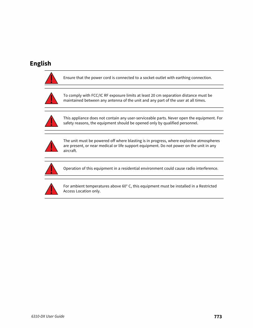
English
Ensure that the power cord is connected to a socket-outlet with earthing connection.
To comply with FCC/IC RF exposure limits at least 20 cm separation distance must bemaintained between any antenna of the unit and any part of the user at all times.
This appliance does not contain any user-serviceable parts. Never open the equipment. Forsafety reasons, the equipment should be opened only by qualified personnel.
The unit must be powered off where blasting is in progress, where explosive atmospheresare present, or near medical or life support equipment. Do not power on the unit in anyaircraft.
Operation of this equipment in a residential environment could cause radio interference.
For ambient temperatures above 60° C, this equipment must be installed in a RestrictedAccess Location only.
6310-DX User Guide 773

Bulgarian--българс ки
У верете се , че захранващият кабел е свързан към контакт съ сза земителна връ зка .
З а да се спази FCC / IC границите на изла гане на радиочес тота , трябва да сеподдържа поне 20 cm разс тояние на разделяне между която и да е антенана ус тройството и която и да е час т от потребителя по всяко време .
Т ози уред не съдържа час ти , които обслужват потребителя . Никога неотваряйте оборудването . О т съображения за безопасност оборудванетотрябва да се отваря само от квалиф ициран персонал .
У редъ т трябва да се изключи там , където се извършва взривяване , къдетоима експлозивна а тмосф ера или в близос т до медицинско оборудване илиоборудване за поддържане на живота . Н е включвайте ус тройството всамолет .
Р абота та с това оборудване в жилищна среда може да причинирадиосмущения .
З а околни температури над 60 ° C, това оборудване трябва да се инсталирасамо на място с ограничен достъп .
6310-DX User Guide 774
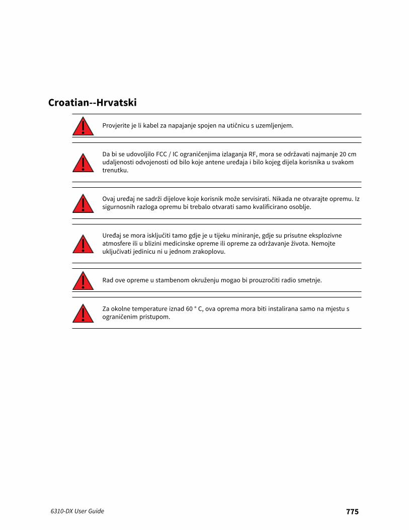
Croatian--Hrvatski
Provjerite je li kabel za napajanje spojen na utičnicu s uzemljenjem.
Da bi se udovoljilo FCC / IC ograničenjima izlaganja RF, mora se održavati najmanje 20 cmudaljenosti odvojenosti od bilo koje antene uređaja i bilo kojeg dijela korisnika u svakomtrenutku.
Ovaj uređaj ne sadrži dijelove koje korisnik može servisirati. Nikada ne otvarajte opremu. Izsigurnosnih razloga opremu bi trebalo otvarati samo kvalificirano osoblje.
Uređaj se mora isključiti tamo gdje je u tijeku miniranje, gdje su prisutne eksplozivneatmosfere ili u blizini medicinske opreme ili opreme za održavanje života. Nemojteuključivati jedinicu ni u jednom zrakoplovu.
Rad ove opreme u stambenom okruženju mogao bi prouzročiti radio smetnje.
Za okolne temperature iznad 60 ° C, ova oprema mora biti instalirana samo na mjestu sograničenim pristupom.
6310-DX User Guide 775
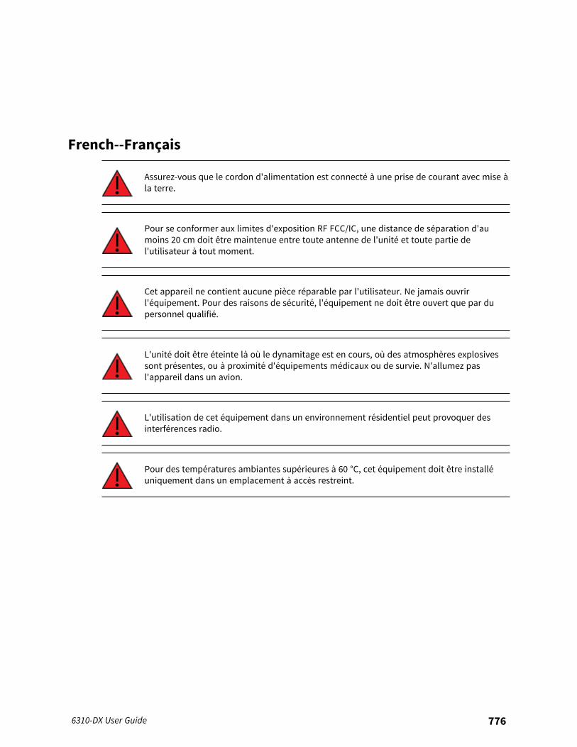
French--Français
Assurez-vous que le cordon d'alimentation est connecté à une prise de courant avec mise àla terre.
Pour se conformer aux limites d'exposition RF FCC/IC, une distance de séparation d'aumoins 20 cm doit être maintenue entre toute antenne de l'unité et toute partie del'utilisateur à tout moment.
Cet appareil ne contient aucune pièce réparable par l'utilisateur. Ne jamais ouvrirl'équipement. Pour des raisons de sécurité, l'équipement ne doit être ouvert que par dupersonnel qualifié.
L'unité doit être éteinte là où le dynamitage est en cours, où des atmosphères explosivessont présentes, ou à proximité d'équipements médicaux ou de survie. N'allumez pasl'appareil dans un avion.
L'utilisation de cet équipement dans un environnement résidentiel peut provoquer desinterférences radio.
Pour des températures ambiantes supérieures à 60 °C, cet équipement doit être installéuniquement dans un emplacement à accès restreint.
6310-DX User Guide 776
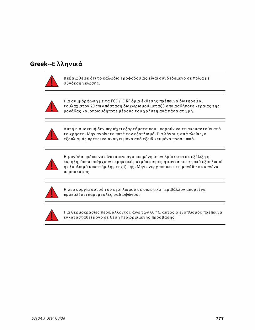
Greek--Ε λληνικά
Β εβαιωθείτ ε ότ ι τ ο καλώδιο τ ροφοδοσίας είναι συνδεδεμένο σε πρ ίζ α μεσύνδεση γ είωσης .
Γ ια συμμόρφωση με τ α FCC / IC RF όρ ια έκθεσης πρέπει να διατ ηρείτ αιτ ουλάχ ιστ ον 20 cm απόστ αση διαχωρισμού μετ αξ ύ οποιασδήποτ ε κεραίας τ ηςμονάδας και οποιουδήποτ ε μέρους τ ου χ ρήστ η ανά πάσα στ ιγ μή .
Αυτ ή η συσκευή δεν περ ιέχ ει εξ αρτ ήματ α που μπορούν να επισκευαστ ούν απότ ο χ ρήστ η . Μην ανοίγ ετ ε ποτ έ τ ον εξ οπλισμό . Γ ια λόγους ασφαλείας , οεξ οπλισμός πρέπει να ανοίγ ει μόνο από εξ ειδικευμένο προσωπικό .
Η μονάδα πρέπει να είναι απενεργοποιημένη ότ αν βρ ίσκετ αι σε εξ έλιξ η ηέκρηξ η , όπου υπάρχουν εκρηκτ ικές ατ μόσφαιρες ή κοντ ά σε ιατ ρ ικό εξ οπλισμόή εξ οπλισμό υποστ ήρ ιξ ης τ ης ζ ωής . Μην ενεργοποιείτ ε τ η μονάδα σε κανένααεροσκάφος .
Η λειτ ουργ ία αυτ ού τ ου εξ οπλισμού σε οικιστ ικό περ ιβάλλον μπορεί ναπροκαλέσει παρεμβολές ραδιοφώνου.
Γ ια θερμοκρασίες περ ιβάλλοντ ος άνω των 60 ° C, αυτ ός ο εξ οπλισμός πρέπει ναεγ κατ αστ αθεί μόνο σε θέση περ ιορ ισμένης πρόσβασης
6310-DX User Guide 777
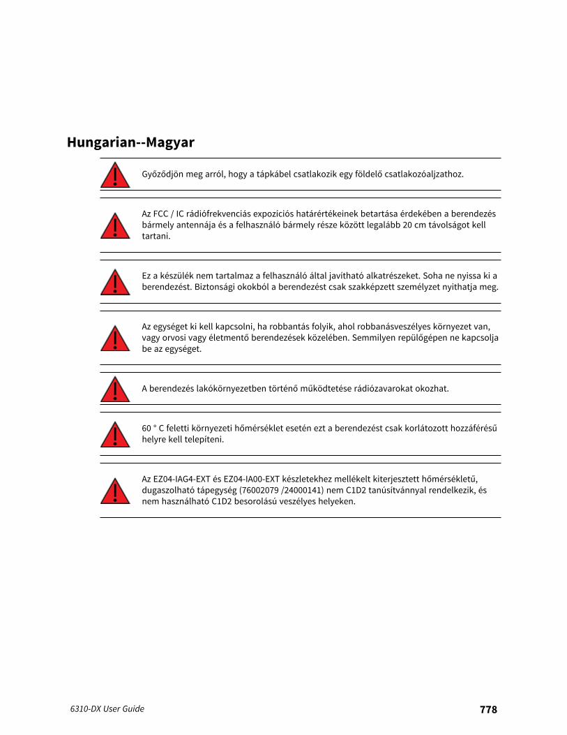
Hungarian--Magyar
Győződjön meg arról, hogy a tápkábel csatlakozik egy földelő csatlakozóaljzathoz.
Az FCC / IC rádiófrekvenciás expozíciós határértékeinek betartása érdekében a berendezésbármely antennája és a felhasználó bármely része között legalább 20 cm távolságot kelltartani.
Ez a készülék nem tartalmaz a felhasználó által javítható alkatrészeket. Soha ne nyissa ki aberendezést. Biztonsági okokból a berendezést csak szakképzett személyzet nyithatja meg.
Az egységet ki kell kapcsolni, ha robbantás folyik, ahol robbanásveszélyes környezet van,vagy orvosi vagy életmentő berendezések közelében. Semmilyen repülőgépen ne kapcsoljabe az egységet.
A berendezés lakókörnyezetben történő működtetése rádiózavarokat okozhat.
60 ° C feletti környezeti hőmérséklet esetén ezt a berendezést csak korlátozott hozzáférésűhelyre kell telepíteni.
Az EZ04-IAG4-EXT és EZ04-IA00-EXT készletekhez mellékelt kiterjesztett hőmérsékletű,dugaszolható tápegység (76002079 /24000141) nem C1D2 tanúsítvánnyal rendelkezik, ésnem használható C1D2 besorolású veszélyes helyeken.
6310-DX User Guide 778
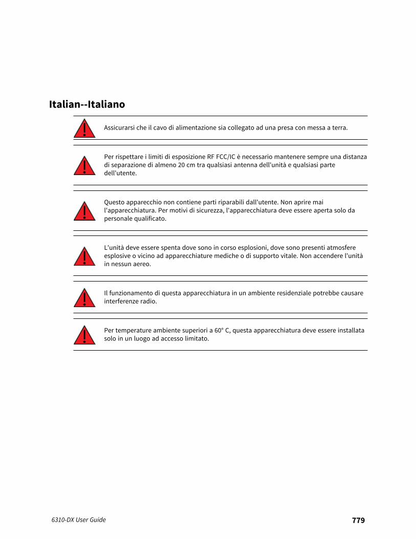
Italian--Italiano
Assicurarsi che il cavo di alimentazione sia collegato ad una presa con messa a terra.
Per rispettare i limiti di esposizione RF FCC/IC è necessario mantenere sempre una distanzadi separazione di almeno 20 cm tra qualsiasi antenna dell'unità e qualsiasi partedell'utente.
Questo apparecchio non contiene parti riparabili dall'utente. Non aprire mail'apparecchiatura. Per motivi di sicurezza, l'apparecchiatura deve essere aperta solo dapersonale qualificato.
L'unità deve essere spenta dove sono in corso esplosioni, dove sono presenti atmosfereesplosive o vicino ad apparecchiature mediche o di supporto vitale. Non accendere l'unitàin nessun aereo.
Il funzionamento di questa apparecchiatura in un ambiente residenziale potrebbe causareinterferenze radio.
Per temperature ambiente superiori a 60° C, questa apparecchiatura deve essere installatasolo in un luogo ad accesso limitato.
6310-DX User Guide 779
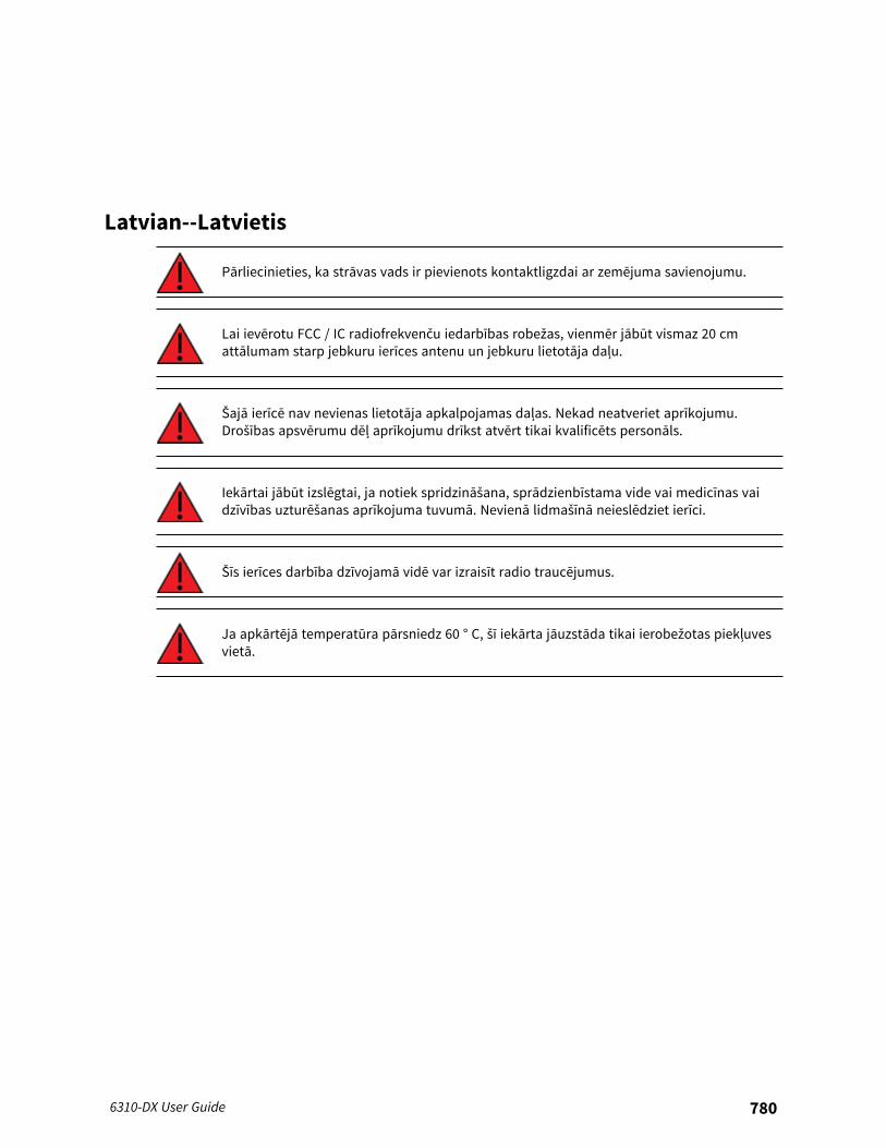
Latvian--Latvietis
Pārliecinieties, ka strāvas vads ir pievienots kontaktligzdai ar zemējuma savienojumu.
Lai ievērotu FCC / IC radiofrekvenču iedarbības robežas, vienmēr jābūt vismaz 20 cmattālumam starp jebkuru ierīces antenu un jebkuru lietotāja daļu.
Šajā ierīcē nav nevienas lietotāja apkalpojamas daļas. Nekad neatveriet aprīkojumu.Drošības apsvērumu dēļ aprīkojumu drīkst atvērt tikai kvalificēts personāls.
Iekārtai jābūt izslēgtai, ja notiek spridzināšana, sprādzienbīstama vide vai medicīnas vaidzīvības uzturēšanas aprīkojuma tuvumā. Nevienā lidmašīnā neieslēdziet ierīci.
Šīs ierīces darbība dzīvojamā vidē var izraisīt radio traucējumus.
Ja apkārtējā temperatūra pārsniedz 60 ° C, šī iekārta jāuzstāda tikai ierobežotas piekļuvesvietā.
6310-DX User Guide 780
Lithuanian--Lietuvis
Įsitikinkite, kad maitinimo laidas yra prijungtas prie lizdo su įžeminimu.
Kad būtų laikomasi FCC / IC radijo dažnių apšvitos ribų, tarp bet kurios įrenginio antenos irbet kurios vartotojo dalies visada turi būti išlaikytas bent 20 cm atstumas.
Šiame prietaise nėra naudotojui prižiūrimų dalių. Niekada neatidarykite įrangos. Saugumosumetimais įrangą turėtų atidaryti tik kvalifikuotas personalas.
Įrenginys turi būti išjungtas ten, kur vyksta sprogdinimas, sprogi aplinka arba šaliamedicinos ar gyvybės palaikymo įrangos. Neįjunkite įrenginio jokiuose orlaiviuose.
Naudojant šią įrangą gyvenamojoje aplinkoje, gali kilti radijo trukdžių.
Esant aukštesnei nei 60 ° C aplinkos temperatūrai, ši įranga turi būti montuojama tik ribotopatekimo vietoje.
6310-DX User Guide 781

Polish--Polskie
Upewnij się, że przewód zasilający jest podłączony do gniazdka z uziemieniem.
Aby zachować zgodność z limitami ekspozycji FCC/IC RF, między anteną urządzenia ajakąkolwiek częścią użytkownika musi być zachowana odległość co najmniej 20 cm.
To urządzenie nie zawiera żadnych części, które mogą być naprawiane przez użytkownika.Nigdy nie otwieraj urządzenia. Ze względów bezpieczeństwa urządzenie powinno byćotwierane wyłącznie przez wykwalifikowany personel.
Urządzenie musi być wyłączone w miejscach, w których trwają prace wybuchowe, watmosferze wybuchowej lub w pobliżu sprzętu medycznego lub podtrzymującego życie. Niewłączaj urządzenia w żadnym samolocie.
Praca tego sprzętu w środowisku mieszkalnym może powodować zakłócenia radiowe.
W przypadku temperatur otoczenia powyżej 60°C urządzenie to należy instalowaćwyłącznie w miejscach o ograniczonym dostępie.
6310-DX User Guide 782
Portuguese--Português
Certifique-se de que o cabo de alimentação esteja conectado a uma tomada com conexãode aterramento.
Para cumprir os limites de exposição à RF da FCC / IC, pelo menos 20 cm de distância deseparação deve ser mantida entre qualquer antena da unidade e qualquer parte do usuárioo tempo todo.
Este aparelho não contém peças cuja manutenção possa ser feita pelo usuário. Nunca abrao equipamento. Por razões de segurança, o equipamento deve ser aberto apenas porpessoal qualificado.
A unidade deve ser desligada onde houver detonações em andamento, onde houverpresença de atmosferas explosivas ou próximo a equipamentos médicos ou de suporte àvida. Não ligue a unidade em nenhuma aeronave.
A operação deste equipamento em um ambiente residencial pode causar interferência derádio.
Para temperaturas ambientes acima de 60 ° C, este equipamento deve ser instalado apenasem locais de acesso restrito.
6310-DX User Guide 783
Slovak--Slovák
Uistite sa, že je napájací kábel pripojený k zásuvke so zemniacim pripojením.
Aby boli dodržané limity vystavenia vysokofrekvenčným lúčom FCC / IC, musí byť medzianténou jednotky a akoukoľvek časťou používateľa neustále udržiavaná vzdialenosťnajmenej 20 cm.
Toto zariadenie neobsahuje žiadne diely opraviteľné používateľom. Nikdy neotvárajtezariadenie. Z bezpečnostných dôvodov by malo zariadenie otvárať iba kvalifikovanýpersonál.
Jednotka musí byť vypnutá tam, kde prebiehajú trhacie práce, kde je prítomné výbušnéprostredie, alebo v blízkosti lekárskych prístrojov alebo zariadení na podporu života.Jednotku nezapínajte v žiadnom lietadle.
Prevádzka tohto zariadenia v obytnom prostredí by mohla spôsobiť rádiové rušenie.
Pri teplotách okolia nad 60 ° C musí byť toto zariadenie inštalované iba na mieste sobmedzeným prístupom.
6310-DX User Guide 784
Slovenian--Esloveno
Prepričajte se, da je napajalni kabel priključen v vtičnico z ozemljitvenim priključkom.
Da bi izpolnili omejitve izpostavljenosti FCC / IC RF, mora biti med katero koli anteno enotein katerim koli delom uporabnika ves čas vzdrževana najmanj 20 cm razdalja.
Ta naprava ne vsebuje nobenih delov, ki bi jih lahko uporabljal uporabnik. Nikoli neodpirajte opreme. Iz varnostnih razlogov naj opremo odpira samo usposobljeno osebje.
Enoto je treba izklopiti tam, kjer poteka razstreljevanje, kjer so prisotne eksplozivneatmosfere ali v bližini medicinske opreme ali opreme za vzdrževanje življenja. Enote nevklopite v nobenem letalu.
Delovanje te opreme v stanovanjskem okolju lahko povzroči radijske motnje.
Pri temperaturah okolice nad 60 ° C mora biti ta oprema nameščena samo na lokaciji zomejenim dostopom.
6310-DX User Guide 785
Spanish--Español
Asegúrese de que el cable de alimentación esté conectado a una toma de corriente conconexión a tierra.
Para cumplir con los límites de exposición a RF de la FCC / IC, se debe mantener unadistancia de separación de al menos 20 cm entre cualquier antena de la unidad y cualquierparte del usuario en todo momento.
Este aparato no contiene ninguna pieza que pueda reparar el usuario. Nunca abra elequipo. Por razones de seguridad, el equipo debe ser abierto únicamente por personalcalificado.
La unidad debe estar apagada donde se estén realizando explosiones, cuando hayaatmósferas explosivas o cerca de equipos médicos o de soporte vital. No encienda launidad en ningún avión.
El funcionamiento de este equipo en un entorno residencial puede provocar interferenciasde radio.
Para temperaturas ambiente superiores a 60 ° C, este equipo debe instalarse únicamenteen una ubicación de acceso restringido.
End user license agreement
To view the end user license agreement, visit: www.digi.com/legal/terms
6310-DX User Guide 786
Command line interface
This chapter contains the following topics:
Access the command line interface 788Log in to the command line interface 788Exit the command line interface 789Execute a command from the web interface 789Display help for commands and parameters 790Auto-complete commands and parameters 792Available commands 793Use the scp command 794Display status and statistics using the show command 795Device configuration using the command line interface 796Execute configuration commands at the root Admin CLI prompt 797Configuration mode 799Command line reference 811
6310-DX User Guide 787
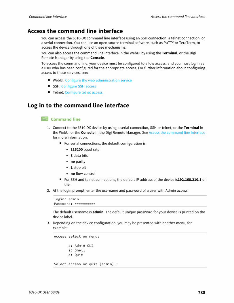
Command line interface Access the command line interface
6310-DX User Guide 788
Access the command line interfaceYou can access the 6310-DX command line interface using an SSH connection, a telnet connection, ora serial connection. You can use an open-source terminal software, such as PuTTY or TeraTerm, toaccess the device through one of these mechanisms.You can also access the command line interface in the WebUI by using the Terminal, or the DigiRemote Manager by using the Console.To access the command line, your device must be configured to allow access, and you must log in asa user who has been configured for the appropriate access. For further information about configuringaccess to these services, see:
n WebUI: Configure the web administration servicen SSH: Configure SSH accessn Telnet: Configure telnet access
Log in to the command line interface
Command line
1. Connect to the 6310-DX device by using a serial connection, SSH or telnet, or the Terminal inthe WebUI or the Console in the Digi Remote Manager. See Access the command line interfacefor more information.
n For serial connections, the default configuration is:l 115200 baud ratel 8 data bitsl no parityl 1 stop bitl no flow control
n For SSH and telnet connections, the default IP address of the device is192.168.210.1 onthe .
2. At the login prompt, enter the username and password of a user with Admin access:
login: adminPassword: **********
The default username is admin. The default unique password for your device is printed on thedevice label.
3. Depending on the device configuration, you may be presented with another menu, forexample:
Access selection menu:
a: Admin CLIs: Shellq: Quit
Select access or quit [admin] :
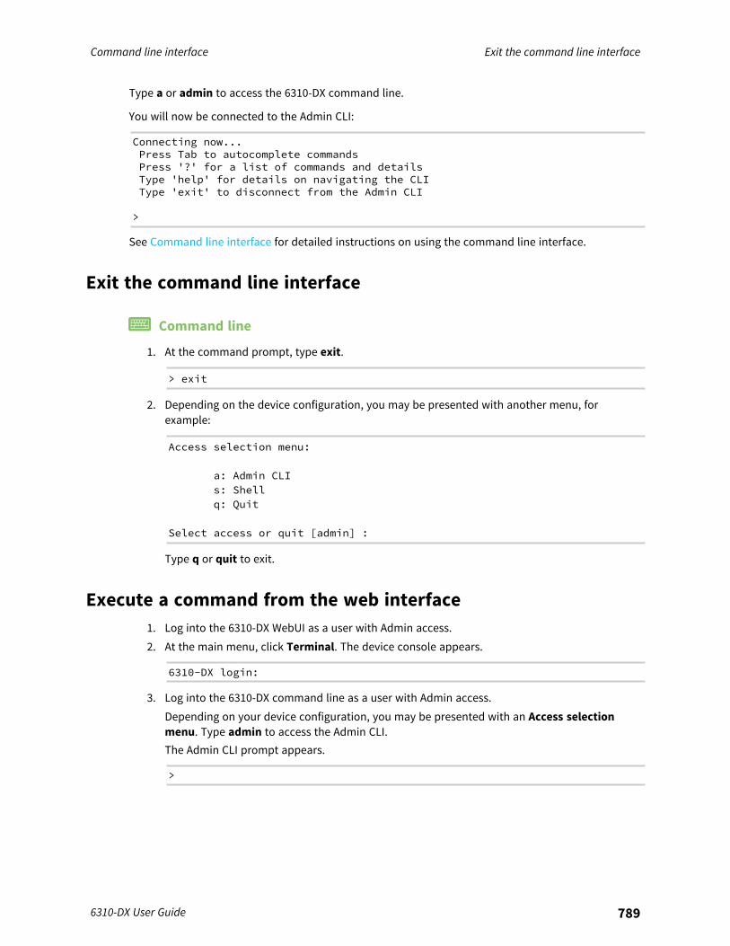
Command line interface Exit the command line interface
6310-DX User Guide 789
Type a or admin to access the 6310-DX command line.
You will now be connected to the Admin CLI:
Connecting now...Press Tab to autocomplete commandsPress '?' for a list of commands and detailsType 'help' for details on navigating the CLIType 'exit' to disconnect from the Admin CLI
>
See Command line interface for detailed instructions on using the command line interface.
Exit the command line interface
Command line
1. At the command prompt, type exit.
> exit
2. Depending on the device configuration, you may be presented with another menu, forexample:
Access selection menu:
a: Admin CLIs: Shellq: Quit
Select access or quit [admin] :
Type q or quit to exit.
Execute a command from the web interface1. Log into the 6310-DX WebUI as a user with Admin access.2. At the main menu, click Terminal. The device console appears.
6310-DX login:
3. Log into the 6310-DX command line as a user with Admin access.Depending on your device configuration, you may be presented with an Access selectionmenu. Type admin to access the Admin CLI.The Admin CLI prompt appears.
>
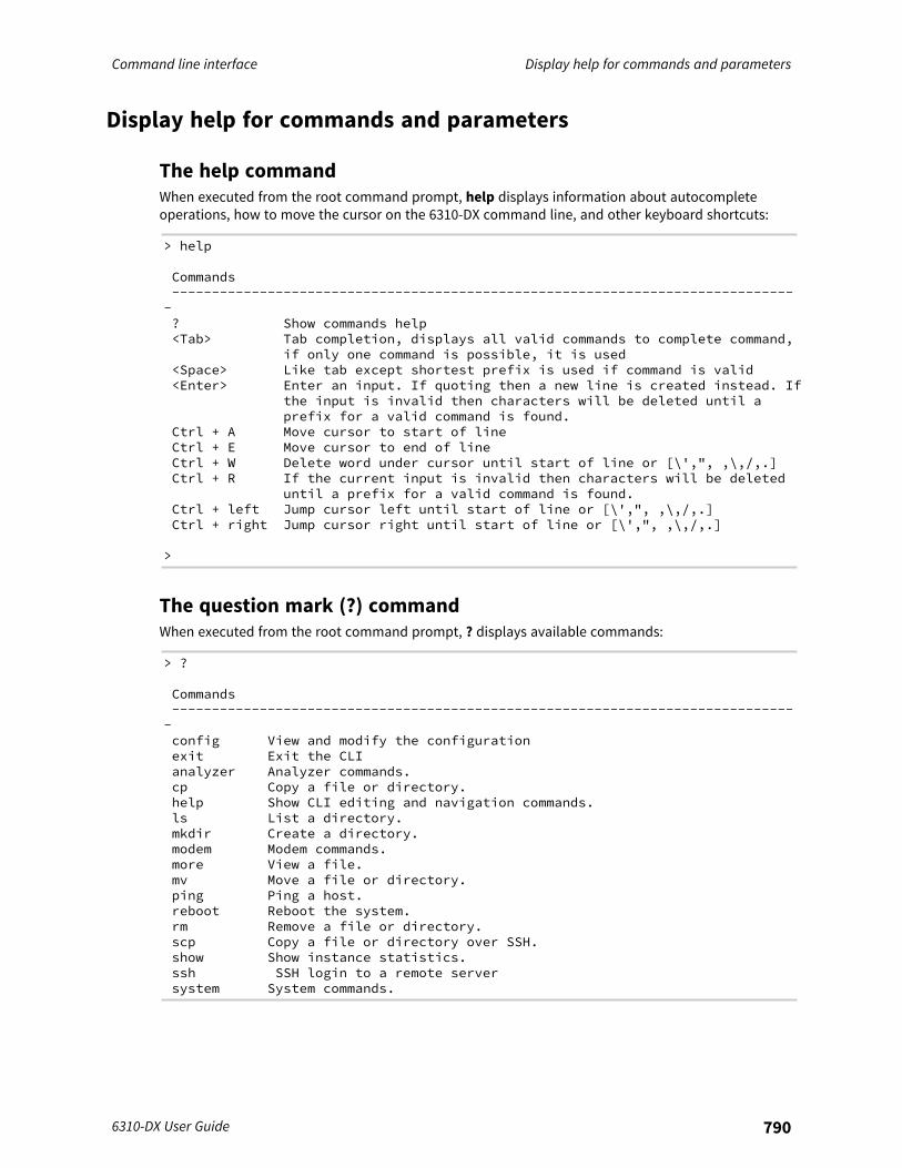
Command line interface Display help for commands and parameters
6310-DX User Guide 790
Display help for commands and parameters
The help commandWhen executed from the root command prompt, help displays information about autocompleteoperations, how to move the cursor on the 6310-DX command line, and other keyboard shortcuts:
> help
Commands-------------------------------------------------------------------------------? Show commands help<Tab> Tab completion, displays all valid commands to complete command,
if only one command is possible, it is used<Space> Like tab except shortest prefix is used if command is valid<Enter> Enter an input. If quoting then a new line is created instead. If
the input is invalid then characters will be deleted until aprefix for a valid command is found.
Ctrl + A Move cursor to start of lineCtrl + E Move cursor to end of lineCtrl + W Delete word under cursor until start of line or [\',", ,\,/,.]Ctrl + R If the current input is invalid then characters will be deleted
until a prefix for a valid command is found.Ctrl + left Jump cursor left until start of line or [\',", ,\,/,.]Ctrl + right Jump cursor right until start of line or [\',", ,\,/,.]
>
The question mark (?) commandWhen executed from the root command prompt, ? displays available commands:
> ?
Commands-------------------------------------------------------------------------------config View and modify the configurationexit Exit the CLIanalyzer Analyzer commands.cp Copy a file or directory.help Show CLI editing and navigation commands.ls List a directory.mkdir Create a directory.modem Modem commands.more View a file.mv Move a file or directory.ping Ping a host.reboot Reboot the system.rm Remove a file or directory.scp Copy a file or directory over SSH.show Show instance statistics.ssh SSH login to a remote serversystem System commands.
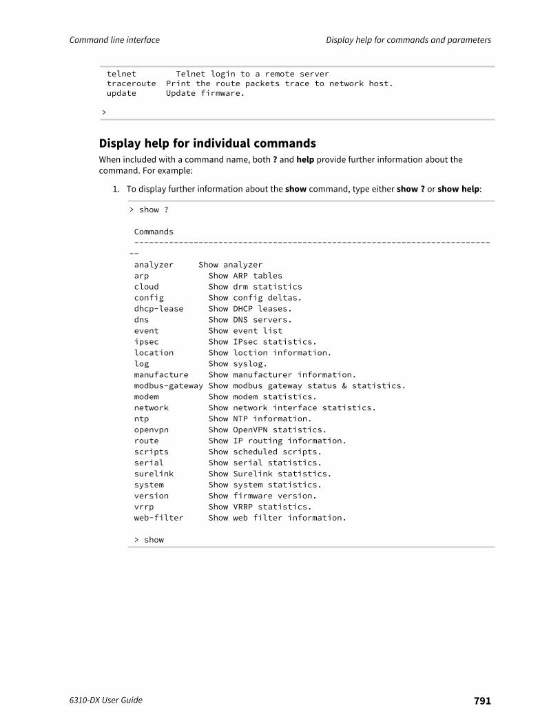
Command line interface Display help for commands and parameters
6310-DX User Guide 791
telnet Telnet login to a remote servertraceroute Print the route packets trace to network host.update Update firmware.
>
Display help for individual commandsWhen included with a command name, both ? and help provide further information about thecommand. For example:
1. To display further information about the show command, type either show ? or show help:
> show ?
Commands--------------------------------------------------------------------------analyzer Show analyzerarp Show ARP tablescloud Show drm statisticsconfig Show config deltas.dhcp-lease Show DHCP leases.dns Show DNS servers.event Show event listipsec Show IPsec statistics.location Show loction information.log Show syslog.manufacture Show manufacturer information.modbus-gateway Show modbus gateway status & statistics.modem Show modem statistics.network Show network interface statistics.ntp Show NTP information.openvpn Show OpenVPN statistics.route Show IP routing information.scripts Show scheduled scripts.serial Show serial statistics.surelink Show Surelink statistics.system Show system statistics.version Show firmware version.vrrp Show VRRP statistics.web-filter Show web filter information.
> show
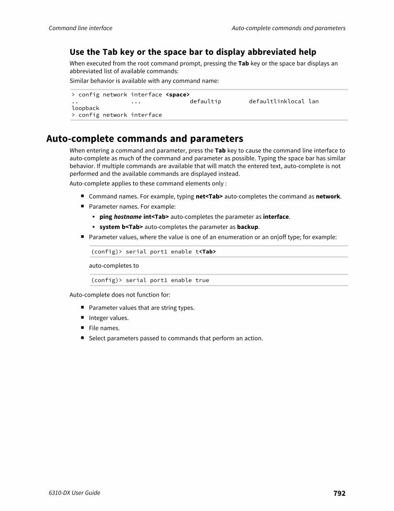
Command line interface Auto-complete commands and parameters
6310-DX User Guide 792
Use the Tab key or the space bar to display abbreviated helpWhen executed from the root command prompt, pressing the Tab key or the space bar displays anabbreviated list of available commands:Similar behavior is available with any command name:
> config network interface <space>.. ... defaultip defaultlinklocal lanloopback> config network interface
Auto-complete commands and parametersWhen entering a command and parameter, press the Tab key to cause the command line interface toauto-complete as much of the command and parameter as possible. Typing the space bar has similarbehavior. If multiple commands are available that will match the entered text, auto-complete is notperformed and the available commands are displayed instead.Auto-complete applies to these command elements only :
n Command names. For example, typing net<Tab> auto-completes the command as network.n Parameter names. For example:
l ping hostname int<Tab> auto-completes the parameter as interface.l system b<Tab> auto-completes the parameter as backup.
n Parameter values, where the value is one of an enumeration or an on|off type; for example:
(config)> serial port1 enable t<Tab>
auto-completes to
(config)> serial port1 enable true
Auto-complete does not function for:
n Parameter values that are string types.n Integer values.n File names.n Select parameters passed to commands that perform an action.
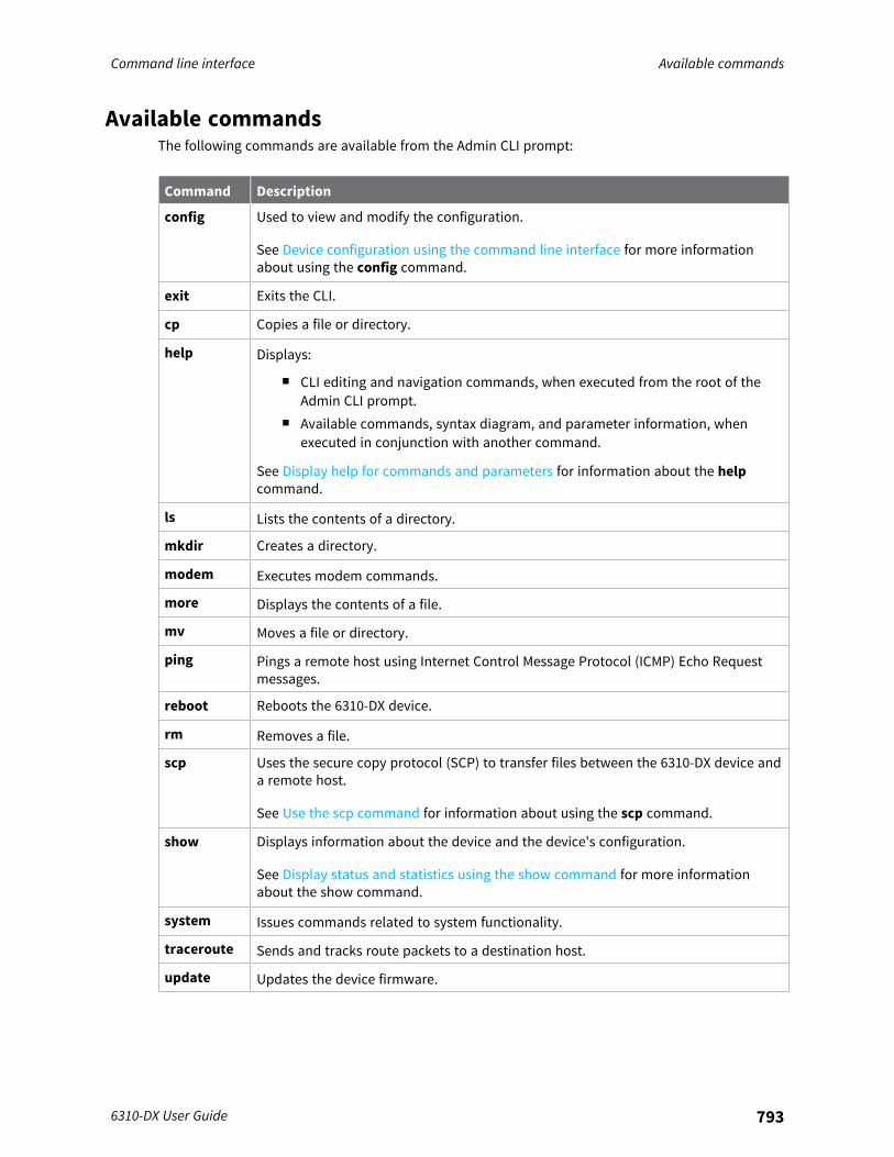
Command line interface Available commands
6310-DX User Guide 793
Available commandsThe following commands are available from the Admin CLI prompt:
Command Description
config Used to view and modify the configuration.
See Device configuration using the command line interface for more informationabout using the config command.
exit Exits the CLI.
cp Copies a file or directory.
help Displays:
n CLI editing and navigation commands, when executed from the root of theAdmin CLI prompt.
n Available commands, syntax diagram, and parameter information, whenexecuted in conjunction with another command.
See Display help for commands and parameters for information about the helpcommand.
ls Lists the contents of a directory.
mkdir Creates a directory.
modem Executes modem commands.
more Displays the contents of a file.
mv Moves a file or directory.
ping Pings a remote host using Internet Control Message Protocol (ICMP) Echo Requestmessages.
reboot Reboots the 6310-DX device.
rm Removes a file.
scp Uses the secure copy protocol (SCP) to transfer files between the 6310-DX device anda remote host.
See Use the scp command for information about using the scp command.
show Displays information about the device and the device's configuration.
See Display status and statistics using the show command for more informationabout the show command.
system Issues commands related to system functionality.
traceroute Sends and tracks route packets to a destination host.
update Updates the device firmware.
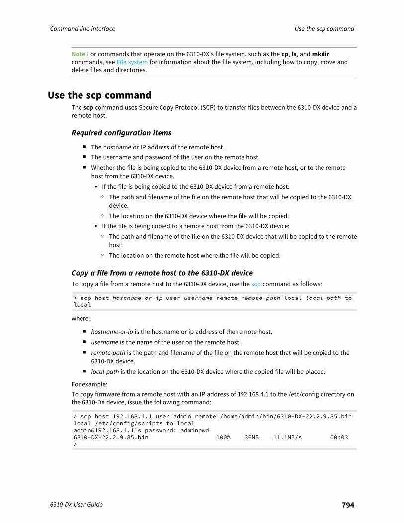
Command line interface Use the scp command
6310-DX User Guide 794
Note For commands that operate on the 6310-DX's file system, such as the cp, ls, and mkdircommands, see File system for information about the file system, including how to copy, move anddelete files and directories.
Use the scp commandThe scp command uses Secure Copy Protocol (SCP) to transfer files between the 6310-DX device and aremote host.
Required configuration items
n The hostname or IP address of the remote host.n The username and password of the user on the remote host.n Whether the file is being copied to the 6310-DX device from a remote host, or to the remote
host from the 6310-DX device.l If the file is being copied to the 6310-DX device from a remote host:
o The path and filename of the file on the remote host that will be copied to the 6310-DXdevice.
o The location on the 6310-DX device where the file will be copied.l If the file is being copied to a remote host from the 6310-DX device:
o The path and filename of the file on the 6310-DX device that will be copied to the remotehost.
o The location on the remote host where the file will be copied.
Copy a file from a remote host to the 6310-DX deviceTo copy a file from a remote host to the 6310-DX device, use the scp command as follows:
> scp host hostname-or-ip user username remote remote-path local local-path tolocal
where:
n hostname-or-ip is the hostname or ip address of the remote host.n username is the name of the user on the remote host.n remote-path is the path and filename of the file on the remote host that will be copied to the
6310-DX device.n local-path is the location on the 6310-DX device where the copied file will be placed.
For example:To copy firmware from a remote host with an IP address of 192.168.4.1 to the /etc/config directory onthe 6310-DX device, issue the following command:
> scp host 192.168.4.1 user admin remote /home/admin/bin/6310-DX-22.2.9.85.binlocal /etc/config/scripts to [email protected]'s password: adminpwd6310-DX-22.2.9.85.bin 100% 36MB 11.1MB/s 00:03>
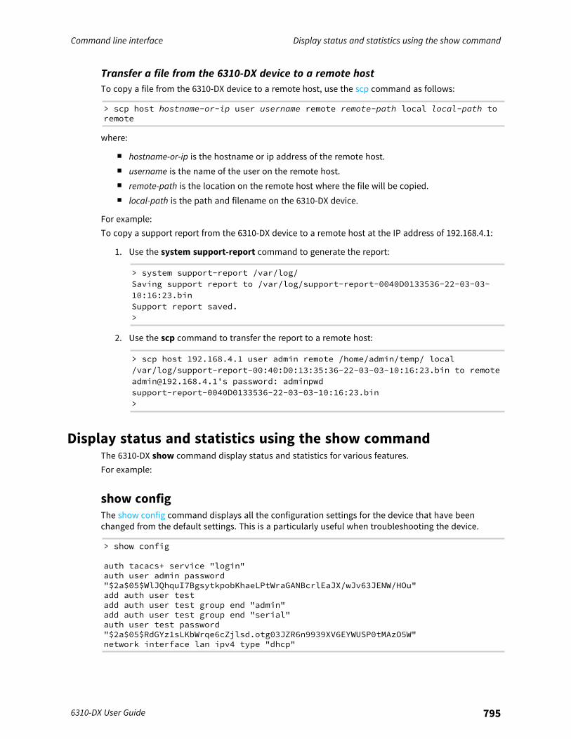
Command line interface Display status and statistics using the show command
6310-DX User Guide 795
Transfer a file from the 6310-DX device to a remote hostTo copy a file from the 6310-DX device to a remote host, use the scp command as follows:
> scp host hostname-or-ip user username remote remote-path local local-path toremote
where:
n hostname-or-ip is the hostname or ip address of the remote host.n username is the name of the user on the remote host.n remote-path is the location on the remote host where the file will be copied.n local-path is the path and filename on the 6310-DX device.
For example:To copy a support report from the 6310-DX device to a remote host at the IP address of 192.168.4.1:
1. Use the system support-report command to generate the report:
> system support-report /var/log/Saving support report to /var/log/support-report-0040D0133536-22-03-03-10:16:23.binSupport report saved.>
2. Use the scp command to transfer the report to a remote host:
> scp host 192.168.4.1 user admin remote /home/admin/temp/ local/var/log/support-report-00:40:D0:13:35:36-22-03-03-10:16:23.bin to [email protected]'s password: adminpwdsupport-report-0040D0133536-22-03-03-10:16:23.bin>
Display status and statistics using the show commandThe 6310-DX show command display status and statistics for various features.For example:
show configThe show config command displays all the configuration settings for the device that have beenchanged from the default settings. This is a particularly useful when troubleshooting the device.
> show config
auth tacacs+ service "login"auth user admin password"$2a$05$WlJQhquI7BgsytkpobKhaeLPtWraGANBcrlEaJX/wJv63JENW/HOu"add auth user testadd auth user test group end "admin"add auth user test group end "serial"auth user test password"$2a$05$RdGYz1sLKbWrqe6cZjlsd.otg03JZR6n9939XV6EYWUSP0tMAzO5W"network interface lan ipv4 type "dhcp"
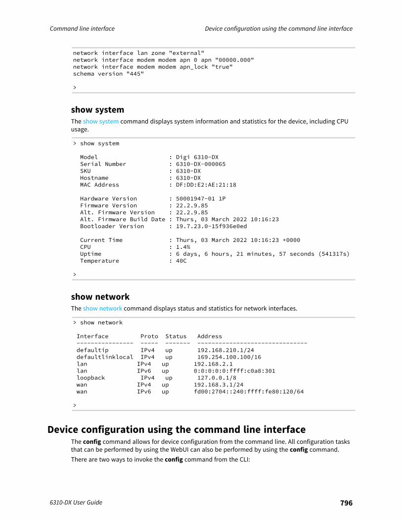
Command line interface Device configuration using the command line interface
6310-DX User Guide 796
network interface lan zone "external"network interface modem modem apn 0 apn "00000.000"network interface modem modem apn_lock "true"schema version "445"
>
show systemThe show system command displays system information and statistics for the device, including CPUusage.
> show system
Model : Digi 6310-DXSerial Number : 6310-DX-000065SKU : 6310-DXHostname : 6310-DXMAC Address : DF:DD:E2:AE:21:18
Hardware Version : 50001947-01 1PFirmware Version : 22.2.9.85Alt. Firmware Version : 22.2.9.85Alt. Firmware Build Date : Thurs, 03 March 2022 10:16:23Bootloader Version : 19.7.23.0-15f936e0ed
Current Time : Thurs, 03 March 2022 10:16:23 +0000CPU : 1.4%Uptime : 6 days, 6 hours, 21 minutes, 57 seconds (541317s)Temperature : 40C
>
show networkThe show network command displays status and statistics for network interfaces.
> show network
Interface Proto Status Address---------------- ----- ------- -------------------------------defaultip IPv4 up 192.168.210.1/24defaultlinklocal IPv4 up 169.254.100.100/16lan IPv4 up 192.168.2.1lan IPv6 up 0:0:0:0:0:ffff:c0a8:301loopback IPv4 up 127.0.0.1/8wan IPv4 up 192.168.3.1/24wan IPv6 up fd00:2704::240:ffff:fe80:120/64
>
Device configuration using the command line interfaceThe config command allows for device configuration from the command line. All configuration tasksthat can be performed by using the WebUI can also be performed by using the config command.There are two ways to invoke the config command from the CLI:
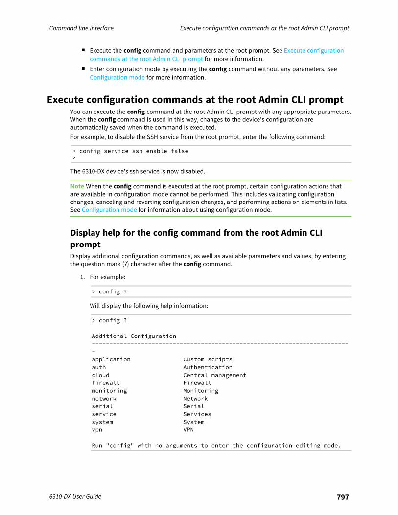
Command line interface Execute configuration commands at the root Admin CLI prompt
6310-DX User Guide 797
n Execute the config command and parameters at the root prompt. See Execute configurationcommands at the root Admin CLI prompt for more information.
n Enter configuration mode by executing the config command without any parameters. SeeConfiguration mode for more information.
Execute configuration commands at the root Admin CLI promptYou can execute the config command at the root Admin CLI prompt with any appropriate parameters.When the config command is used in this way, changes to the device's configuration areautomatically saved when the command is executed.For example, to disable the SSH service from the root prompt, enter the following command:
> config service ssh enable false>
The 6310-DX device's ssh service is now disabled.
Note When the config command is executed at the root prompt, certain configuration actions thatare available in configuration mode cannot be performed. This includes validating configurationchanges, canceling and reverting configuration changes, and performing actions on elements in lists.See Configuration mode for information about using configuration mode.
Display help for the config command from the root Admin CLIpromptDisplay additional configuration commands, as well as available parameters and values, by enteringthe question mark (?) character after the config command.
1. For example:
> config ?
Will display the following help information:
> config ?
Additional Configuration--------------------------------------------------------------------------application Custom scriptsauth Authenticationcloud Central managementfirewall Firewallmonitoring Monitoringnetwork Networkserial Serialservice Servicessystem Systemvpn VPN
Run "config" with no arguments to enter the configuration editing mode.
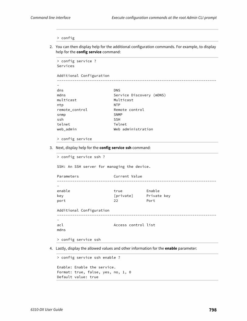
Command line interface Execute configuration commands at the root Admin CLI prompt
6310-DX User Guide 798
> config
2. You can then display help for the additional configuration commands. For example, to displayhelp for the config service command:
> config service ?Services
Additional Configuration--------------------------------------------------------------------------dns DNSmdns Service Discovery (mDNS)multicast Multicastntp NTPremote_control Remote controlsnmp SNMPssh SSHtelnet Telnetweb_admin Web administration
> config service
3. Next, display help for the config service ssh command:
> config service ssh ?
SSH: An SSH server for managing the device.
Parameters Current Value--------------------------------------------------------------------------enable true Enablekey [private] Private keyport 22 Port
Additional Configuration--------------------------------------------------------------------------acl Access control listmdns
> config service ssh
4. Lastly, display the allowed values and other information for the enable parameter:
> config service ssh enable ?
Enable: Enable the service.Format: true, false, yes, no, 1, 0Default value: true

Command line interface Configuration mode
6310-DX User Guide 799
Current value: true
> config service ssh enable
Configuration modeConfiguration mode allows you to perform multiple configuration tasks and validate the changes priorto saving them. You can cancel all changes without saving them at any time. Configuration changesdo not take effect until the configuration is saved.
Enable configuration modeTo enable configuration mode, at the root prompt, enter the config command without anyparameters:
> config(config)>
When the command line is in configuration mode, the prompt will change to include (config), toindicate that you are currently in configuration mode.
Enter configuration commands in configuration modeThere are two ways to enter configuration commands while in configuration mode:
n Enter the full command string from the config prompt.For example, to disable the ssh service by entering the full command string at the configprompt:
(config)> service ssh enable false(config)>
n Execute commands by moving through the configuration schema.For example, to disable the ssh service by moving through the configuration and thenexecuting the enable false command:
1. At the config prompt, enter service to move to the service node:
(config)> service(config service)>
2. Enter ssh to move to the ssh node:
(config service)> ssh(config service ssh)>
3. Enter enable false to disable the ssh service:
(config service ssh)> enable false(config service ssh)>
See Move within the configuration schema for more information about moving within theconfiguration.
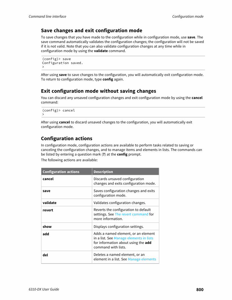
Command line interface Configuration mode
6310-DX User Guide 800
Save changes and exit configuration modeTo save changes that you have made to the configuration while in configuration mode, use save. Thesave command automatically validates the configuration changes; the configuration will not be savedif it is not valid. Note that you can also validate configuration changes at any time while inconfiguration mode by using the validate command.
(config)> saveConfiguration saved.>
After using save to save changes to the configuration, you will automatically exit configuration mode.To return to configuration mode, type config again.
Exit configuration mode without saving changesYou can discard any unsaved configuration changes and exit configuration mode by using the cancelcommand:
(config)> cancel>
After using cancel to discard unsaved changes to the configuration, you will automatically exitconfiguration mode.
Configuration actionsIn configuration mode, configuration actions are available to perform tasks related to saving orcanceling the configuration changes, and to manage items and elements in lists. The commands canbe listed by entering a question mark (?) at the config prompt.The following actions are available:
Configuration actions Description
cancel Discards unsaved configurationchanges and exits configuration mode.
save Saves configuration changes and exitsconfiguration mode.
validate Validates configuration changes.
revert Reverts the configuration to defaultsettings. See The revert command formore information.
show Displays configuration settings.
add Adds a named element, or an elementin a list. See Manage elements in listsfor information about using the addcommand with lists.
del Deletes a named element, or anelement in a list. See Manage elements
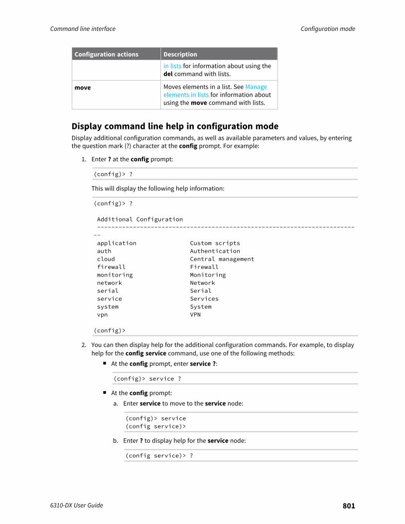
Command line interface Configuration mode
6310-DX User Guide 801
Configuration actions Description
in lists for information about using thedel command with lists.
move Moves elements in a list. See Manageelements in lists for information aboutusing the move command with lists.
Display command line help in configuration modeDisplay additional configuration commands, as well as available parameters and values, by enteringthe question mark (?) character at the config prompt. For example:
1. Enter ? at the config prompt:
(config)> ?
This will display the following help information:
(config)> ?
Additional Configuration--------------------------------------------------------------------------application Custom scriptsauth Authenticationcloud Central managementfirewall Firewallmonitoring Monitoringnetwork Networkserial Serialservice Servicessystem Systemvpn VPN
(config)>
2. You can then display help for the additional configuration commands. For example, to displayhelp for the config service command, use one of the following methods:
n At the config prompt, enter service ?:
(config)> service ?
n At the config prompt:a. Enter service to move to the service node:
(config)> service(config service)>
b. Enter ? to display help for the service node:
(config service)> ?
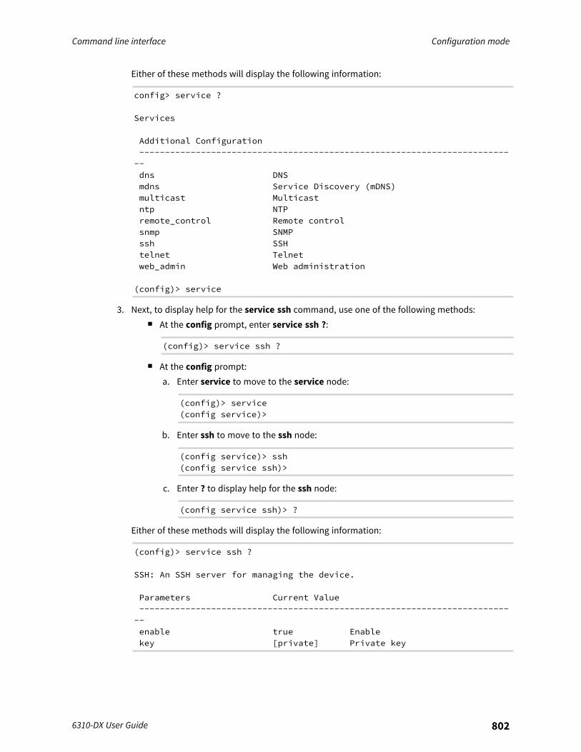
Command line interface Configuration mode
6310-DX User Guide 802
Either of these methods will display the following information:
config> service ?
Services
Additional Configuration--------------------------------------------------------------------------dns DNSmdns Service Discovery (mDNS)multicast Multicastntp NTPremote_control Remote controlsnmp SNMPssh SSHtelnet Telnetweb_admin Web administration
(config)> service
3. Next, to display help for the service ssh command, use one of the following methods:n At the config prompt, enter service ssh ?:
(config)> service ssh ?
n At the config prompt:a. Enter service to move to the service node:
(config)> service(config service)>
b. Enter ssh to move to the ssh node:
(config service)> ssh(config service ssh)>
c. Enter ? to display help for the ssh node:
(config service ssh)> ?
Either of these methods will display the following information:
(config)> service ssh ?
SSH: An SSH server for managing the device.
Parameters Current Value--------------------------------------------------------------------------enable true Enablekey [private] Private key
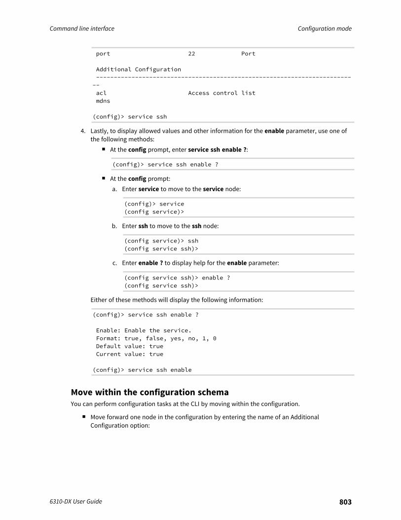
Command line interface Configuration mode
6310-DX User Guide 803
port 22 Port
Additional Configuration--------------------------------------------------------------------------acl Access control listmdns
(config)> service ssh
4. Lastly, to display allowed values and other information for the enable parameter, use one ofthe following methods:
n At the config prompt, enter service ssh enable ?:
(config)> service ssh enable ?
n At the config prompt:a. Enter service to move to the service node:
(config)> service(config service)>
b. Enter ssh to move to the ssh node:
(config service)> ssh(config service ssh)>
c. Enter enable ? to display help for the enable parameter:
(config service ssh)> enable ?(config service ssh)>
Either of these methods will display the following information:
(config)> service ssh enable ?
Enable: Enable the service.Format: true, false, yes, no, 1, 0Default value: trueCurrent value: true
(config)> service ssh enable
Move within the configuration schemaYou can perform configuration tasks at the CLI by moving within the configuration.
n Move forward one node in the configuration by entering the name of an AdditionalConfiguration option:
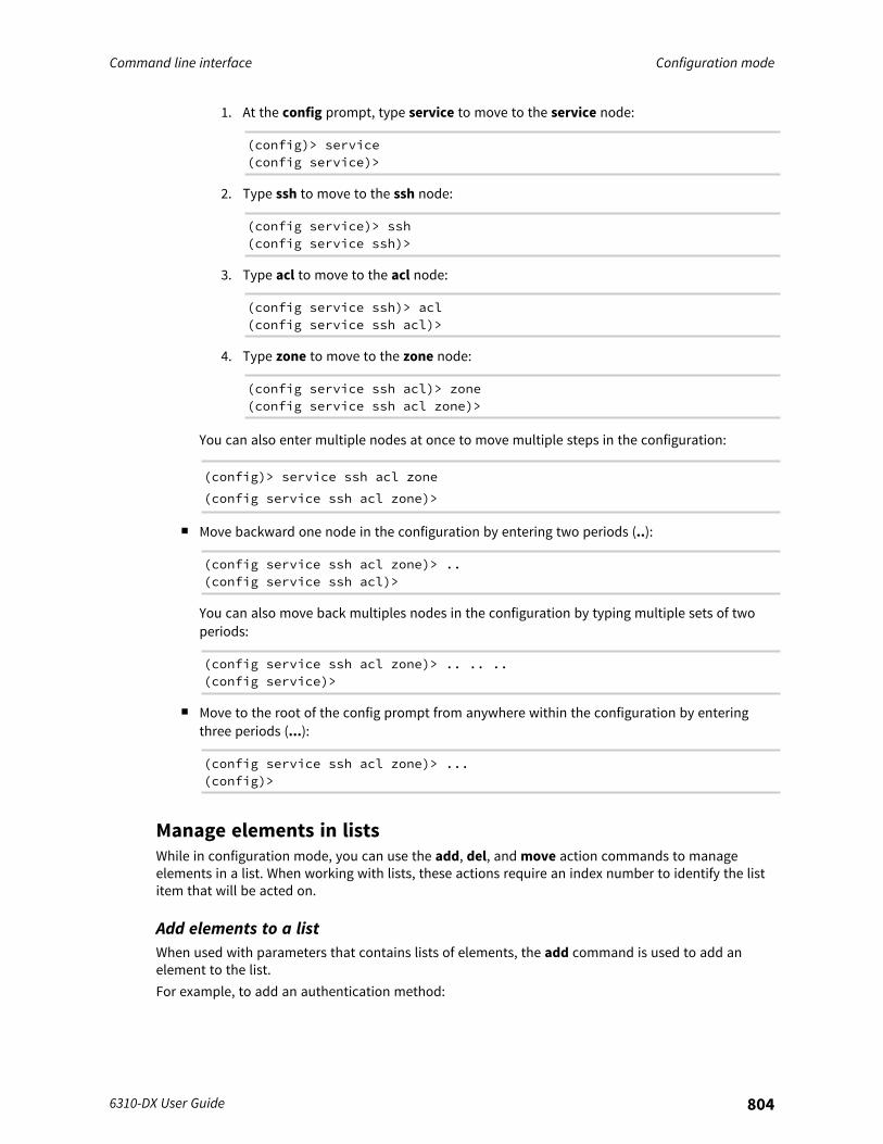
Command line interface Configuration mode
6310-DX User Guide 804
1. At the config prompt, type service to move to the service node:
(config)> service(config service)>
2. Type ssh to move to the ssh node:
(config service)> ssh(config service ssh)>
3. Type acl to move to the acl node:
(config service ssh)> acl(config service ssh acl)>
4. Type zone to move to the zone node:
(config service ssh acl)> zone(config service ssh acl zone)>
You can also enter multiple nodes at once to move multiple steps in the configuration:
(config)> service ssh acl zone
(config service ssh acl zone)>
n Move backward one node in the configuration by entering two periods (..):
(config service ssh acl zone)> ..(config service ssh acl)>
You can also move back multiples nodes in the configuration by typing multiple sets of twoperiods:
(config service ssh acl zone)> .. .. ..(config service)>
n Move to the root of the config prompt from anywhere within the configuration by enteringthree periods (...):
(config service ssh acl zone)> ...(config)>
Manage elements in listsWhile in configuration mode, you can use the add, del, and move action commands to manageelements in a list. When working with lists, these actions require an index number to identify the listitem that will be acted on.
Add elements to a listWhen used with parameters that contains lists of elements, the add command is used to add anelement to the list.For example, to add an authentication method:
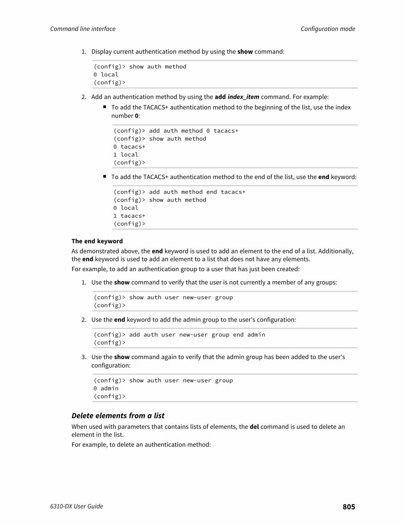
Command line interface Configuration mode
6310-DX User Guide 805
1. Display current authentication method by using the show command:
(config)> show auth method0 local(config)>
2. Add an authentication method by using the add index_item command. For example:n To add the TACACS+ authentication method to the beginning of the list, use the index
number 0:
(config)> add auth method 0 tacacs+(config)> show auth method0 tacacs+1 local(config)>
n To add the TACACS+ authentication method to the end of the list, use the end keyword:
(config)> add auth method end tacacs+(config)> show auth method0 local1 tacacs+(config)>
The end keywordAs demonstrated above, the end keyword is used to add an element to the end of a list. Additionally,the end keyword is used to add an element to a list that does not have any elements.For example, to add an authentication group to a user that has just been created:
1. Use the show command to verify that the user is not currently a member of any groups:
(config)> show auth user new-user group(config)>
2. Use the end keyword to add the admin group to the user's configuration:
(config)> add auth user new-user group end admin(config)>
3. Use the show command again to verify that the admin group has been added to the user'sconfiguration:
(config)> show auth user new-user group0 admin(config)>
Delete elements from a listWhen used with parameters that contains lists of elements, the del command is used to delete anelement in the list.For example, to delete an authentication method:
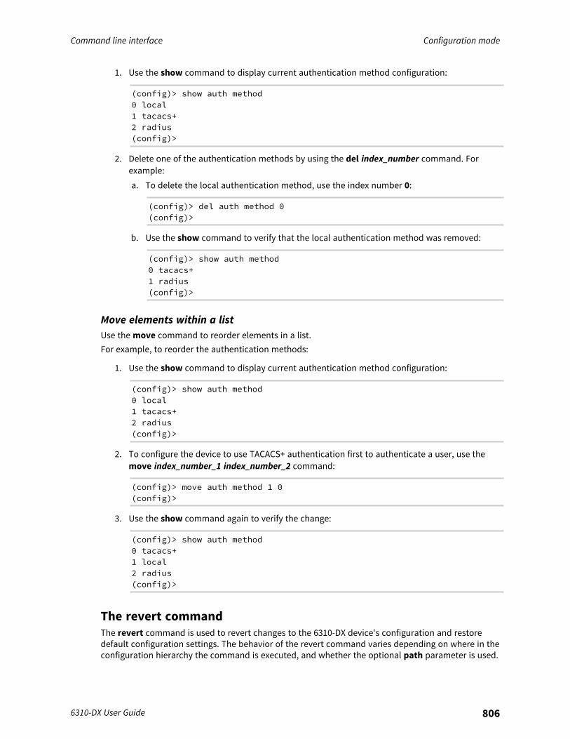
Command line interface Configuration mode
6310-DX User Guide 806
1. Use the show command to display current authentication method configuration:
(config)> show auth method0 local1 tacacs+2 radius(config)>
2. Delete one of the authentication methods by using the del index_number command. Forexample:a. To delete the local authentication method, use the index number 0:
(config)> del auth method 0(config)>
b. Use the show command to verify that the local authentication method was removed:
(config)> show auth method0 tacacs+1 radius(config)>
Move elements within a listUse the move command to reorder elements in a list.For example, to reorder the authentication methods:
1. Use the show command to display current authentication method configuration:
(config)> show auth method0 local1 tacacs+2 radius(config)>
2. To configure the device to use TACACS+ authentication first to authenticate a user, use themove index_number_1 index_number_2 command:
(config)> move auth method 1 0(config)>
3. Use the show command again to verify the change:
(config)> show auth method0 tacacs+1 local2 radius(config)>
The revert commandThe revert command is used to revert changes to the 6310-DX device's configuration and restoredefault configuration settings. The behavior of the revert command varies depending on where in theconfiguration hierarchy the command is executed, and whether the optional path parameter is used.
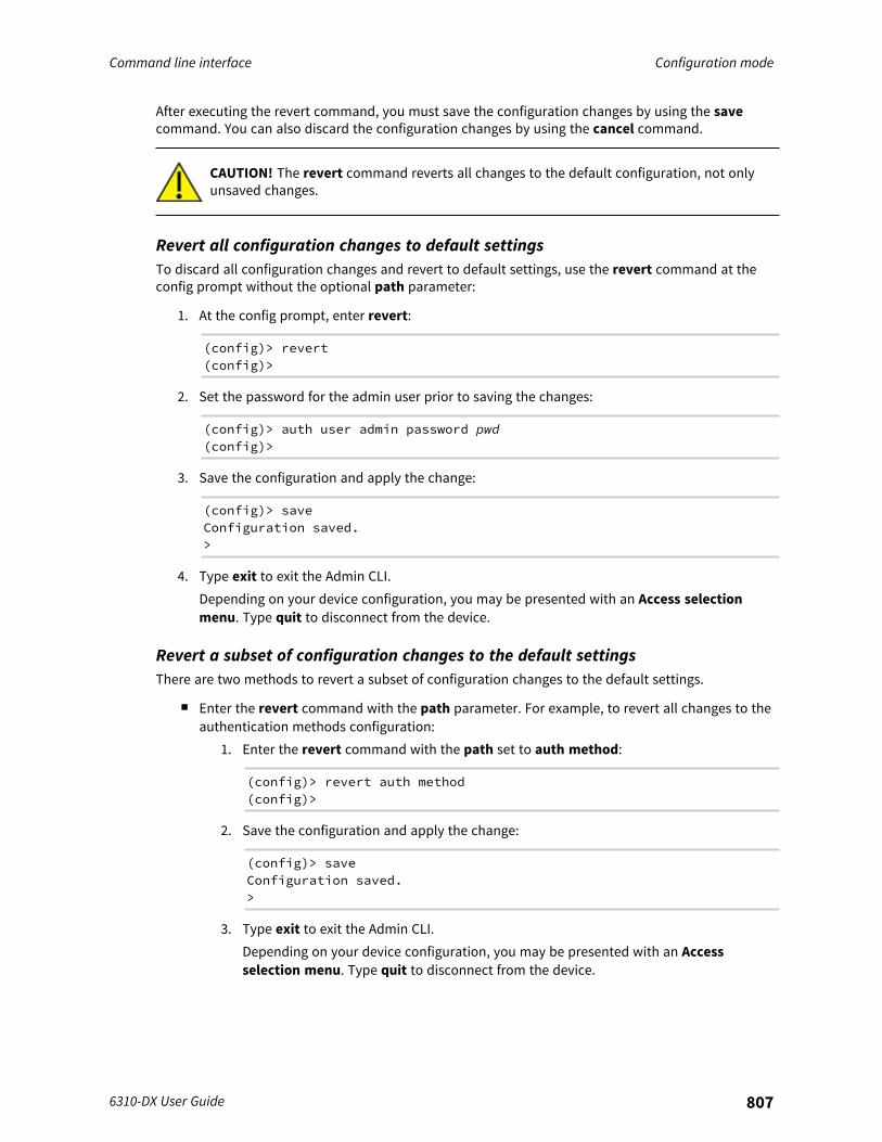
Command line interface Configuration mode
6310-DX User Guide 807
After executing the revert command, you must save the configuration changes by using the savecommand. You can also discard the configuration changes by using the cancel command.
CAUTION! The revert command reverts all changes to the default configuration, not onlyunsaved changes.
Revert all configuration changes to default settingsTo discard all configuration changes and revert to default settings, use the revert command at theconfig prompt without the optional path parameter:
1. At the config prompt, enter revert:
(config)> revert(config)>
2. Set the password for the admin user prior to saving the changes:
(config)> auth user admin password pwd(config)>
3. Save the configuration and apply the change:
(config)> saveConfiguration saved.>
4. Type exit to exit the Admin CLI.Depending on your device configuration, you may be presented with an Access selectionmenu. Type quit to disconnect from the device.
Revert a subset of configuration changes to the default settingsThere are two methods to revert a subset of configuration changes to the default settings.
n Enter the revert command with the path parameter. For example, to revert all changes to theauthentication methods configuration:
1. Enter the revert command with the path set to auth method:
(config)> revert auth method(config)>
2. Save the configuration and apply the change:
(config)> saveConfiguration saved.>
3. Type exit to exit the Admin CLI.Depending on your device configuration, you may be presented with an Accessselection menu. Type quit to disconnect from the device.
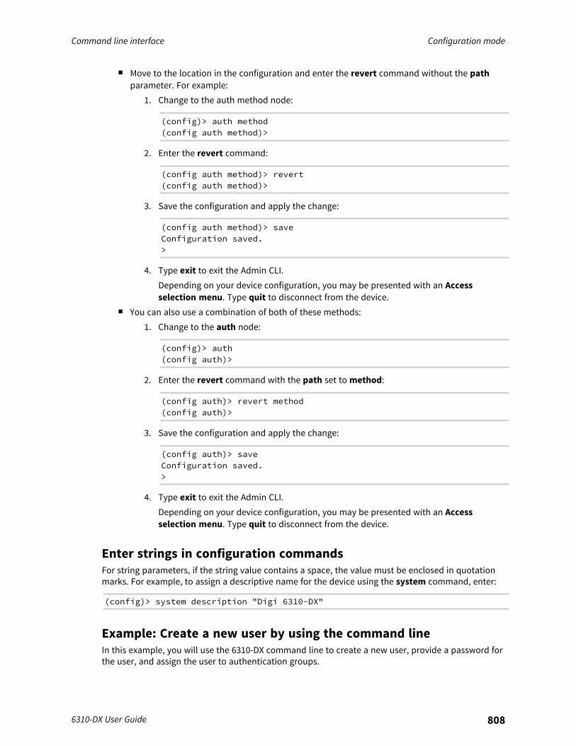
Command line interface Configuration mode
6310-DX User Guide 808
n Move to the location in the configuration and enter the revert command without the pathparameter. For example:
1. Change to the auth method node:
(config)> auth method(config auth method)>
2. Enter the revert command:
(config auth method)> revert(config auth method)>
3. Save the configuration and apply the change:
(config auth method)> saveConfiguration saved.>
4. Type exit to exit the Admin CLI.Depending on your device configuration, you may be presented with an Accessselection menu. Type quit to disconnect from the device.
n You can also use a combination of both of these methods:1. Change to the auth node:
(config)> auth(config auth)>
2. Enter the revert command with the path set to method:
(config auth)> revert method(config auth)>
3. Save the configuration and apply the change:
(config auth)> saveConfiguration saved.>
4. Type exit to exit the Admin CLI.Depending on your device configuration, you may be presented with an Accessselection menu. Type quit to disconnect from the device.
Enter strings in configuration commandsFor string parameters, if the string value contains a space, the value must be enclosed in quotationmarks. For example, to assign a descriptive name for the device using the system command, enter:
(config)> system description "Digi 6310-DX"
Example: Create a new user by using the command lineIn this example, you will use the 6310-DX command line to create a new user, provide a password forthe user, and assign the user to authentication groups.
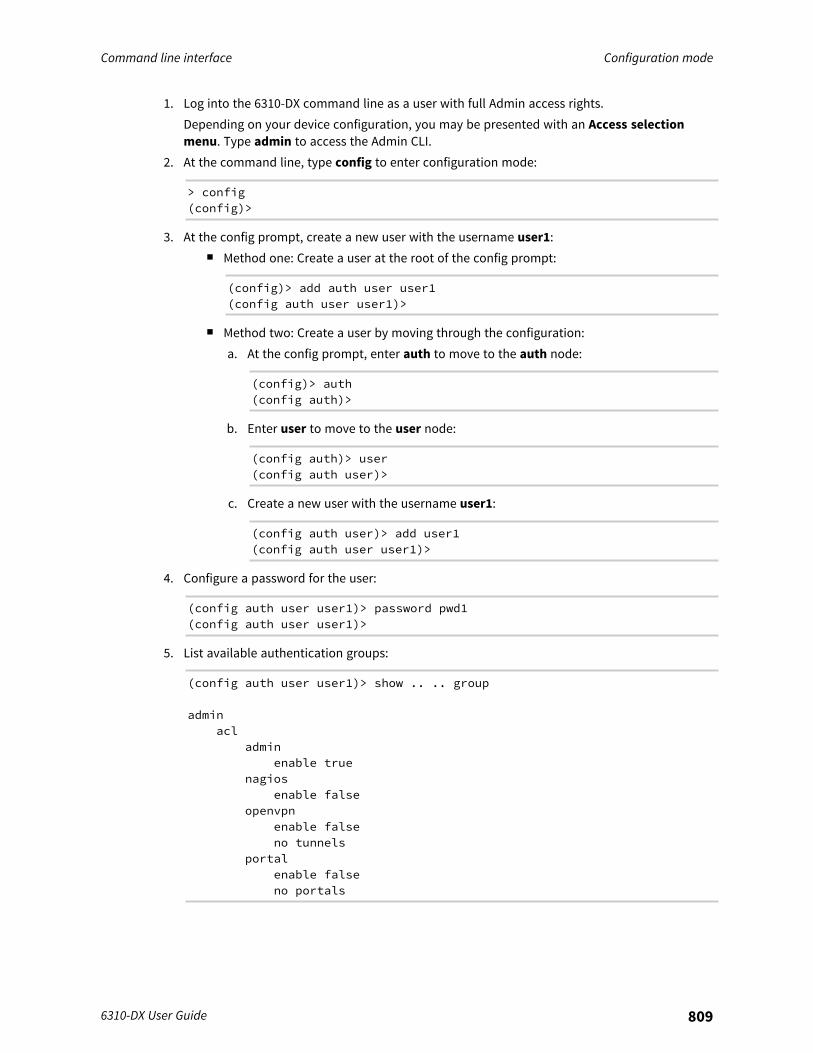
Command line interface Configuration mode
6310-DX User Guide 809
1. Log into the 6310-DX command line as a user with full Admin access rights.Depending on your device configuration, you may be presented with an Access selectionmenu. Type admin to access the Admin CLI.
2. At the command line, type config to enter configuration mode:
> config(config)>
3. At the config prompt, create a new user with the username user1:n Method one: Create a user at the root of the config prompt:
(config)> add auth user user1(config auth user user1)>
n Method two: Create a user by moving through the configuration:a. At the config prompt, enter auth to move to the auth node:
(config)> auth(config auth)>
b. Enter user to move to the user node:
(config auth)> user(config auth user)>
c. Create a new user with the username user1:
(config auth user)> add user1(config auth user user1)>
4. Configure a password for the user:
(config auth user user1)> password pwd1(config auth user user1)>
5. List available authentication groups:
(config auth user user1)> show .. .. group
adminacl
adminenable true
nagiosenable false
openvpnenable falseno tunnels
portalenable falseno portals
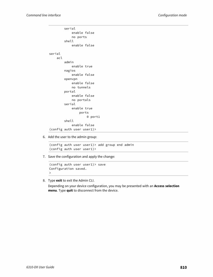
Command line interface Configuration mode
6310-DX User Guide 810
serialenable falseno ports
shellenable false
serialacl
adminenable true
nagiosenable false
openvpnenable falseno tunnels
portalenable falseno portals
serialenable true
ports0 port1
shellenable false
(config auth user user1)>
6. Add the user to the admin group:
(config auth user user1)> add group end admin(config auth user user1)>
7. Save the configuration and apply the change:
(config auth user user1)> saveConfiguration saved.>
8. Type exit to exit the Admin CLI.Depending on your device configuration, you may be presented with an Access selectionmenu. Type quit to disconnect from the device.

Command line interface Command line reference
6310-DX User Guide 811
Command line reference
analyzer clear 812analyzer save 813analyzer start 813analyzer stop 813clear dhcp-lease ip-address 813clear dhcp-lease mac 813container create 814container delete 814cp 814help 814ls 816mkdir 817modem at 817modem at-interactive 817modem firmware check 817modem firmware list 817modem firmware ota check 818modem firmware ota list 818modem firmware ota update 818modem firmware update 818modem pin change 819modem pin disable 819modem pin enable 819modem pin status 820modem pin unlock 820modem puk status 820modem puk unlock 820modem reset 821modem scan 821modem sim-slot 821monitoring 821monitoring metrics upload 822more 822mv 822ping 822reboot 824rm 825scp 826show analyzer 826show arp 826show cloud 826show config 827show containers 827show dhcp-lease 827show dns 827show event 827show hotspot 828show ipsec 828show l2tp lac 828show l2tp lns 828show l2tpeth 829show location 829
Command line interface Command line reference
6310-DX User Guide 812
show log 829show manufacture 829show modbus-gateway 829show modem 830show nemo 830show network 830show ntp 830show openvpn client 831show openvpn server 831show route 831show serial 831show scripts 832show surelink interface 832show surelink ipsec 832show surelink openvpn 832show system 833show usb 833show version 833show vrrp 833show web-filter 833speedtest 834ssh 834system backup 834system disable-cryptography 835system duplicate-firmware 835system factory-erase 835system find-me 835system firmware ota check 836system firmware ota list 836system firmware ota update 836system firmware update 836system power ignition off_delay 836system restore 837system script start 837system script stop 837system serial clear 837system serial save 838system serial show 838system serial start 838system serial stop 838system support-report 838system time set 839system time sync 839system time test 839telnet 839traceroute 840
analyzer clearClears the traffic captured by the analyzer.
Syntax
analyzer clear <name>
Command line interface Command line reference
6310-DX User Guide 813
Parametersname: Name of the capture filter to use.
analyzer saveSaves the current captured traffic to a file.
Syntax
analyzer save <name> <filename>
Parametersname: Name of the capture filter to use.filename: The filename to save captured traffic to. The file will be saved to the device's/etc/config/analyzer directory.
analyzer startStart a capture session of packets on this devices interfaces.
Syntax
analyzer start <name>
Parametersname: Name of the capture filter to use.
analyzer stopStops the traffic capture session.
Syntax
analyzer stop <name>
Parametersname: Name of the capture filter to use.
clear dhcp-lease ip-addressClear the DHCP lease for the specified IP address.
Syntax
clear dhcp-lease ip-address ADDRESS
Parametersaddress: An IPv4 or IPv6 address
clear dhcp-lease macClear the DHCP lease for the specified MAC address.
Command line interface Command line reference
6310-DX User Guide 814
Syntax
clear dhcp-lease mac ADDRESS
Parametersaddress: 12-digit, colon-delimited MAC address [00:11:22:AA:BB:CC]
container createCreate a LXC container from a given image. This process creates a copy of the image, so the orginalimage may be deleted after creating the container without breaking the container.
Syntax
container create <path>
Parameterspath: Filepath for container image to be created. .
container deleteDelete a LXC container. This will remove the LXC container configuration and the container image.
Syntax
container delete <container>
Parameterscontainer: Filepath for container image to be created. This process creates a copy of the image, so theorginal image may be deleted after creating the container without breaking the container.
cpCopy a file or directory.
Syntax
cp <source> <destination> [force]
Parameterssource: The source file or directory to copy.destination: The destination path to copy the source file or directory to.force: Do not ask to overwrite the destination file if it exists.
helpShow CLI editing and navigation commands.
Syntax
help

Command line interface Command line reference
6310-DX User Guide 815
ParametersNone
Command line interface Command line reference
6310-DX User Guide 816
lsList a directory.
Syntax
ls <path> [show-hidden]
Parameterspath: List files and directories under this path.show-hidden: Show hidden files and directories. Hidden filenames begin with '.'.
Command line interface Command line reference
6310-DX User Guide 817
mkdirCreate a directory. Parent directories are created as needed.
Syntax
mkdir <path>
Parameterspath: The directory path to create.
modem atSend an AT command to the modem and display the response.
Syntax
modem at <cmd> [name STRING] [imei STRING]
Parameterscmd: The AT command string.name: The configured name of the modem to execute this CLI command on.imei: The IMEI of the modem to execute this CLI command on.
modem at-interactiveStart an AT command session on the modem's AT serial port.
Syntax
modem at-interactive [name STRING] [imei STRING]
Parametersname: The configured name of the modem to execute this CLI command on.imei: The IMEI of the modem to execute this CLI command on.
modem firmware checkInspect /opt/[MODEM_MODEL]/Custom_Firmware/ directory for new modem firmware file.
Syntax
modem firmware check [name STRING] [imei STRING]
Parametersname: The configured name of the modem to execute this CLI command on.imei: The IMEI of the modem to execute this CLI command on.
modem firmware listList modem firmware files found in the /opt/[MODEM_MODEL]/ directory.
Command line interface Command line reference
6310-DX User Guide 818
Syntax
modem firmware list [name STRING] [imei STRING]
Parametersname: The configured name of the modem to execute this CLI command on.imei: The IMEI of the modem to execute this CLI command on.
modem firmware ota checkQuery the Digi firmware server for the latest remote modem firmware version.
Syntax
modem firmware ota check [name STRING] [imei STRING]
Parametersname: The configured name of the modem to execute this CLI command on.imei: The IMEI of the modem to execute this CLI command on.
modem firmware ota listQuery the Digi firmware server for a list of modem firmware versions.
Syntax
modem firmware ota list [name STRING] [imei STRING]
Parametersname: The configured name of the modem to execute this CLI command on.imei: The IMEI of the modem to execute this CLI command on.
modem firmware ota updatePerform FOTA (firmware-over-the-air) update. The modem will be updated to the latest modemfirmware image unless a specific firmware version is specified.
Syntax
modem firmware ota update [name STRING] [imei STRING] [version STRING]
Parametersname: The configured name of the modem to execute this CLI command on.imei: The IMEI of the modem to execute this CLI command on.version: Firmware version name.
modem firmware updateUpdate modem firmware using local firmware file. The modem will be updated to the firmwarespecified in the /opt/[MODEM_MODEL]/Custom_Firmware/ directory unless a specific firmware versionis specified.
Command line interface Command line reference
6310-DX User Guide 819
Syntax
modem firmware update [name STRING] [imei STRING] [version STRING]
Parametersname: The configured name of the modem to execute this CLI command on.imei: The IMEI of the modem to execute this CLI command on.version: Firmware version name.
modem pin changeChange the SIM's PIN code.Warning: Attempting to use an incorrect PIN code may PUK lock the SIM.
Syntax
modem pin change <old-pin> <new-pin> [name STRING] [imei STRING]
Parametersold-pin: The SIM's PIN code.new-pin: The PIN code to change to.name: The configured name of the modem to execute this CLI command on.imei: The IMEI of the modem to execute this CLI command on.
modem pin disableDisable the PIN lock on the SIM card that is active in the modem.Warning: Attempting to use an incorrect PIN code may PUK lock the SIM.
Syntax
modem pin disable <pin> [name STRING] [imei STRING]
Parameterspin: The SIM's PIN code.name: The configured name of the modem to execute this CLI command on.imei: The IMEI of the modem to execute this CLI command on.
modem pin enableEnable the PIN lock on the SIM card that is active in the modem. The SIM card will need to beunlocked before each use.Warning: Attempting to use an incorrect PIN code may PUK lock the SIM.
Syntax
modem pin enable <pin> [name STRING] [imei STRING]
Parameterspin: The SIM's PIN code.
Command line interface Command line reference
6310-DX User Guide 820
name: The configured name of the modem to execute this CLI command on.imei: The IMEI of the modem to execute this CLI command on.
modem pin statusPrint the PIN lock status and the number of PIN enable/disable/unlock attempts remaining. The SIMwill be PUK locked when there are no remaining retries.
Syntax
modem pin status [name STRING] [imei STRING]
Parametersname: The configured name of the modem to execute this CLI command on.imei: The IMEI of the modem to execute this CLI command on.
modem pin unlockTemporarily unlock the SIM card with a PIN code. Set the PIN field in the modem interface'sconfiguration to unlock the SIM card automatically before use.Warning: Attempting to use an incorrect PIN code may PUK lock the SIM.
Syntax
modem pin unlock <pin> [name STRING] [imei STRING]
Parameterspin: The SIM's PIN code.name: The configured name of the modem to execute this CLI command on.imei: The IMEI of the modem to execute this CLI command on.
modem puk statusPrint the PUK status and the number of PUK unlock attempts remaining.
Syntax
modem puk status [name STRING] [imei STRING]
Parametersname: The configured name of the modem to execute this CLI command on.imei: The IMEI of the modem to execute this CLI command on.
modem puk unlockUnlock the SIM with a PUK code from the SIM provider.
Syntax
modem puk unlock <puk> <new-pin> [name STRING] [imei STRING]
Command line interface Command line reference
6310-DX User Guide 821
Parameterspuk: The SIM's PUK code.new-pin: The PIN code to change to.name: The configured name of the modem to execute this CLI command on.imei: The IMEI of the modem to execute this CLI command on.
modem resetReset the modem hardware (reboot it). This can be useful if the modem has stopped responding tothe network or is behaving inconsistently.
Syntax
modem reset [name STRING] [imei STRING]
Parametersname: The configured name of the modem to execute this CLI command on.imei: The IMEI of the modem to execute this CLI command on.
modem scanList of carriers present in the network.
Syntax
modem scan [name STRING] [imei STRING]
Parametersname: The configured name of the modem to execute this CLI command on.imei: The IMEI of the modem to execute this CLI command on.
modem sim-slotShow or change the modem's active SIM slot. This applies only to modems with multiple SIM slots.
Syntax
modem sim-slot <slot> [name STRING] [imei STRING]
Parametersslot: The SIM slot to change to.name: The configured name of the modem to execute this CLI command on.imei: The IMEI of the modem to execute this CLI command on.
monitoringCommands to clear the device's status or systems.
Command line interface Command line reference
6310-DX User Guide 822
monitoring metricsDevice metrics commands.
uplaodImmediately upload current device health metrics. Functions as if a scheduled upload was triggered.
Parameters
None
monitoring metrics uploadImmediately upload current device health metrics. Functions as if a scheduled upload was triggered.
Syntax
monitoring metrics upload
ParametersNone
moreView a file.
Syntax
more <path>
Parameterspath: The file to view.
mvMove a file or directory.
Syntax
mv <source> <destination> [force]
Parameterssource: The source file or directory to move.destination: The destination path to move the source file or directory to.force: Do not ask to overwrite the destination file if it exists.
pingPing a host using ICMP echo.
Command line interface Command line reference
6310-DX User Guide 823
Syntax
ping <host> [interface STRING] [source STRING] [ipv6] [size INTEGER] [countINTEGER] [broadcast]
Parametershost: The name or address of the remote host to send ICMP ping requests to. If broadcast is enabled,can be the broadcast address.interface: The network interface to send ping packets from when the host is reachable over a defaultroute. If not specified, the system's primary default route will be used.source: The ping command will send a packet with the source address set to the IP address of thisinterface, rather than the address of the interface the packet is sent from.ipv6: If a hostname is defined as the value of the 'host' parameter, use the hosts IPV6 address.size: The number of bytes sent in the ICMP ping request. (Minimum: 0, Default: 56)count: The number of ICMP ping requests to send before terminating. (Minimum: 1, Default: 100)broadcast: Enable broadcast ping functionality.

Command line interface Command line reference
6310-DX User Guide 824
rebootReboot the system.
ParametersNone
Command line interface Command line reference
6310-DX User Guide 825
rmRemove a file or directory.
Syntax
rm <path> [force]
Parameterspath: The path to remove.force: Force the file to be removed without asking.
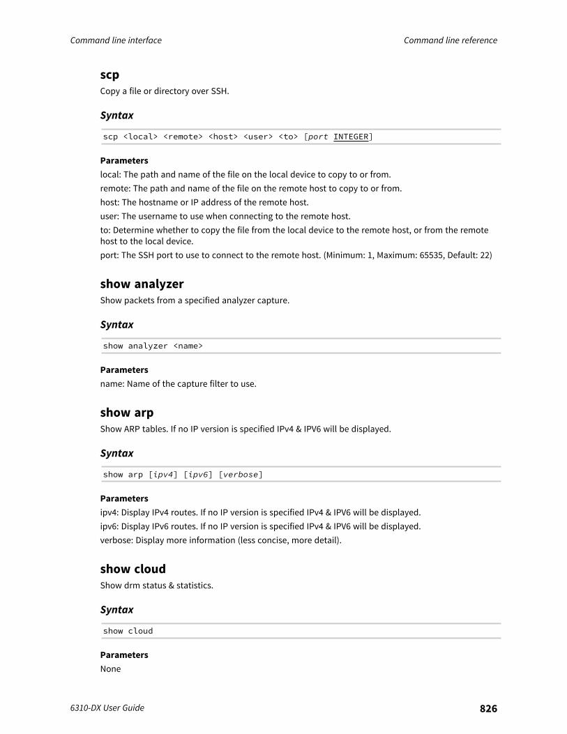
Command line interface Command line reference
6310-DX User Guide 826
scpCopy a file or directory over SSH.
Syntax
scp <local> <remote> <host> <user> <to> [port INTEGER]
Parameterslocal: The path and name of the file on the local device to copy to or from.remote: The path and name of the file on the remote host to copy to or from.host: The hostname or IP address of the remote host.user: The username to use when connecting to the remote host.to: Determine whether to copy the file from the local device to the remote host, or from the remotehost to the local device.port: The SSH port to use to connect to the remote host. (Minimum: 1, Maximum: 65535, Default: 22)
show analyzerShow packets from a specified analyzer capture.
Syntax
show analyzer <name>
Parametersname: Name of the capture filter to use.
show arpShow ARP tables. If no IP version is specified IPv4 & IPV6 will be displayed.
Syntax
show arp [ipv4] [ipv6] [verbose]
Parametersipv4: Display IPv4 routes. If no IP version is specified IPv4 & IPV6 will be displayed.ipv6: Display IPv6 routes. If no IP version is specified IPv4 & IPV6 will be displayed.verbose: Display more information (less concise, more detail).
show cloudShow drm status & statistics.
Syntax
show cloud
ParametersNone
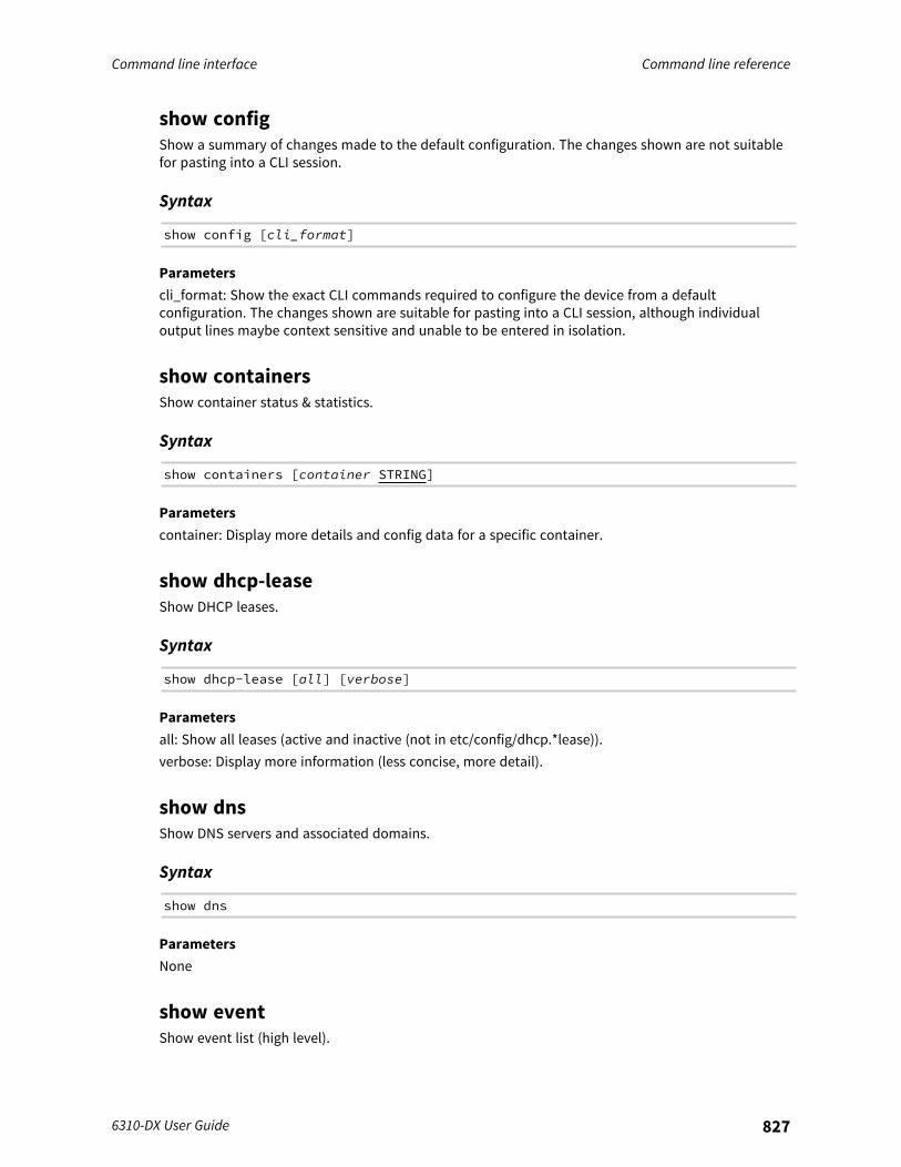
Command line interface Command line reference
6310-DX User Guide 827
show configShow a summary of changes made to the default configuration. The changes shown are not suitablefor pasting into a CLI session.
Syntax
show config [cli_format]
Parameterscli_format: Show the exact CLI commands required to configure the device from a defaultconfiguration. The changes shown are suitable for pasting into a CLI session, although individualoutput lines maybe context sensitive and unable to be entered in isolation.
show containersShow container status & statistics.
Syntax
show containers [container STRING]
Parameterscontainer: Display more details and config data for a specific container.
show dhcp-leaseShow DHCP leases.
Syntax
show dhcp-lease [all] [verbose]
Parametersall: Show all leases (active and inactive (not in etc/config/dhcp.*lease)).verbose: Display more information (less concise, more detail).
show dnsShow DNS servers and associated domains.
Syntax
show dns
ParametersNone
show eventShow event list (high level).
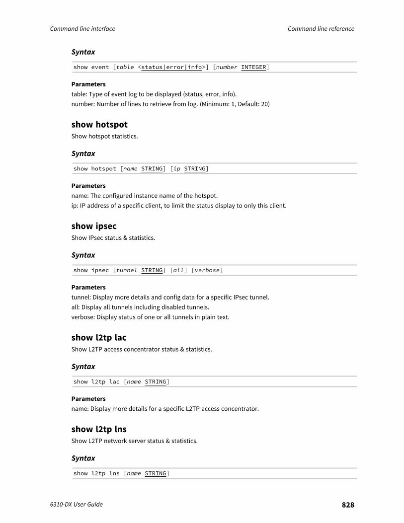
Command line interface Command line reference
6310-DX User Guide 828
Syntax
show event [table <status|error|info>] [number INTEGER]
Parameterstable: Type of event log to be displayed (status, error, info).number: Number of lines to retrieve from log. (Minimum: 1, Default: 20)
show hotspotShow hotspot statistics.
Syntax
show hotspot [name STRING] [ip STRING]
Parametersname: The configured instance name of the hotspot.ip: IP address of a specific client, to limit the status display to only this client.
show ipsecShow IPsec status & statistics.
Syntax
show ipsec [tunnel STRING] [all] [verbose]
Parameterstunnel: Display more details and config data for a specific IPsec tunnel.all: Display all tunnels including disabled tunnels.verbose: Display status of one or all tunnels in plain text.
show l2tp lacShow L2TP access concentrator status & statistics.
Syntax
show l2tp lac [name STRING]
Parametersname: Display more details for a specific L2TP access concentrator.
show l2tp lnsShow L2TP network server status & statistics.
Syntax
show l2tp lns [name STRING]
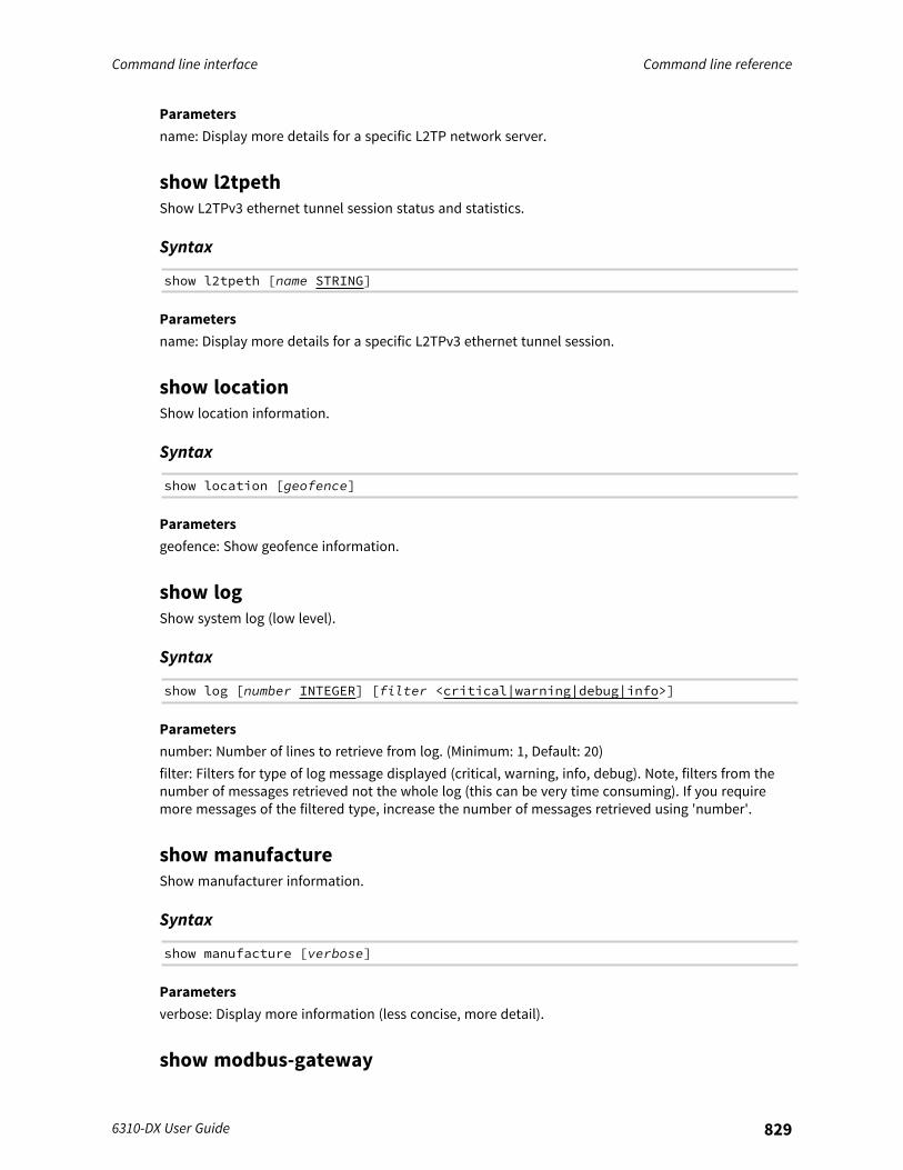
Command line interface Command line reference
6310-DX User Guide 829
Parametersname: Display more details for a specific L2TP network server.
show l2tpethShow L2TPv3 ethernet tunnel session status and statistics.
Syntax
show l2tpeth [name STRING]
Parametersname: Display more details for a specific L2TPv3 ethernet tunnel session.
show locationShow location information.
Syntax
show location [geofence]
Parametersgeofence: Show geofence information.
show logShow system log (low level).
Syntax
show log [number INTEGER] [filter <critical|warning|debug|info>]
Parametersnumber: Number of lines to retrieve from log. (Minimum: 1, Default: 20)filter: Filters for type of log message displayed (critical, warning, info, debug). Note, filters from thenumber of messages retrieved not the whole log (this can be very time consuming). If you requiremore messages of the filtered type, increase the number of messages retrieved using 'number'.
show manufactureShow manufacturer information.
Syntax
show manufacture [verbose]
Parametersverbose: Display more information (less concise, more detail).
show modbus-gateway
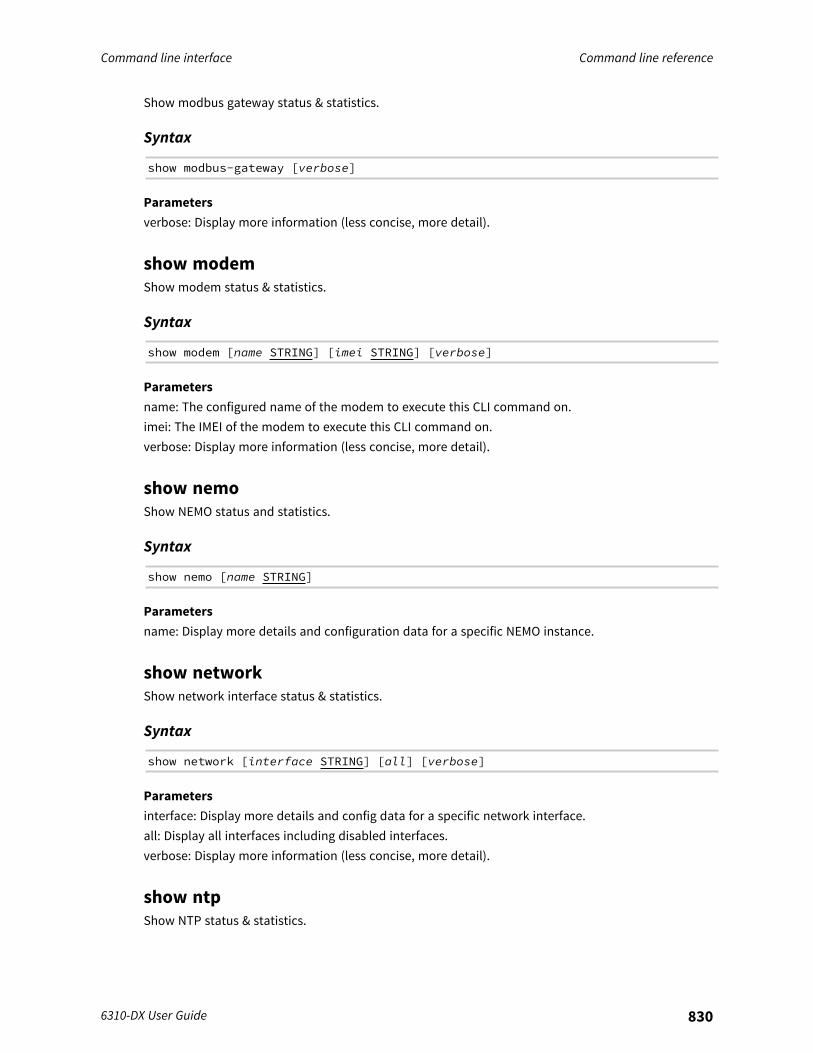
Command line interface Command line reference
6310-DX User Guide 830
Show modbus gateway status & statistics.
Syntax
show modbus-gateway [verbose]
Parametersverbose: Display more information (less concise, more detail).
show modemShow modem status & statistics.
Syntax
show modem [name STRING] [imei STRING] [verbose]
Parametersname: The configured name of the modem to execute this CLI command on.imei: The IMEI of the modem to execute this CLI command on.verbose: Display more information (less concise, more detail).
show nemoShow NEMO status and statistics.
Syntax
show nemo [name STRING]
Parametersname: Display more details and configuration data for a specific NEMO instance.
show networkShow network interface status & statistics.
Syntax
show network [interface STRING] [all] [verbose]
Parametersinterface: Display more details and config data for a specific network interface.all: Display all interfaces including disabled interfaces.verbose: Display more information (less concise, more detail).
show ntpShow NTP status & statistics.

Command line interface Command line reference
6310-DX User Guide 831
Syntax
show ntp
ParametersNone
show openvpn clientShow OpenVPN client status & statistics.
Syntax
show openvpn client [name STRING] [all]
Parametersname: Display more details and config data for a specific OpenVPN client.all: Display all clients including disabled clients.
show openvpn serverShow OpenVPN server status & statistics.
Syntax
show openvpn server [name STRING] [all]
Parametersname: Display more details and config data for a specific OpenVPN server.all: Display all servers including disabled servers.
show routeShow IP routing information.
Syntax
show route [ipv4] [ipv6] [verbose]
Parametersipv4: Display IPv4 routes.ipv6: Display IPv6 routes.verbose: Display more information (less concise, more detail).
show serialShow serial status & statistics.
Syntax
show serial [port STRING]
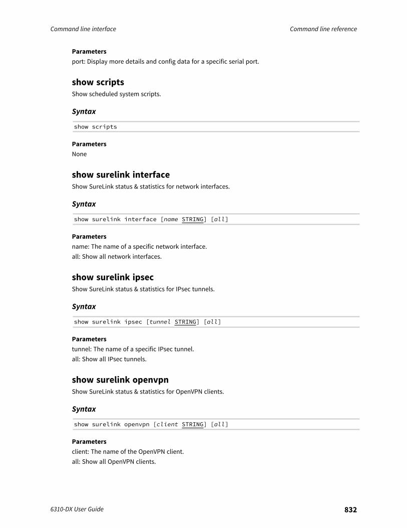
Command line interface Command line reference
6310-DX User Guide 832
Parametersport: Display more details and config data for a specific serial port.
show scriptsShow scheduled system scripts.
Syntax
show scripts
ParametersNone
show surelink interfaceShow SureLink status & statistics for network interfaces.
Syntax
show surelink interface [name STRING] [all]
Parametersname: The name of a specific network interface.all: Show all network interfaces.
show surelink ipsecShow SureLink status & statistics for IPsec tunnels.
Syntax
show surelink ipsec [tunnel STRING] [all]
Parameterstunnel: The name of a specific IPsec tunnel.all: Show all IPsec tunnels.
show surelink openvpnShow SureLink status & statistics for OpenVPN clients.
Syntax
show surelink openvpn [client STRING] [all]
Parametersclient: The name of the OpenVPN client.all: Show all OpenVPN clients.
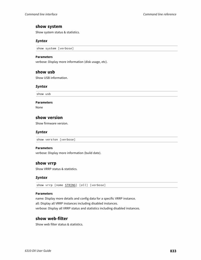
Command line interface Command line reference
6310-DX User Guide 833
show systemShow system status & statistics.
Syntax
show system [verbose]
Parametersverbose: Display more information (disk usage, etc).
show usbShow USB information.
Syntax
show usb
ParametersNone
show versionShow firmware version.
Syntax
show version [verbose]
Parametersverbose: Display more information (build date).
show vrrpShow VRRP status & statistics.
Syntax
show vrrp [name STRING] [all] [verbose]
Parametersname: Display more details and config data for a specific VRRP instance.all: Display all VRRP instances including disabled instances.verbose: Display all VRRP status and statistics including disabled instances.
show web-filterShow web filter status & statistics.
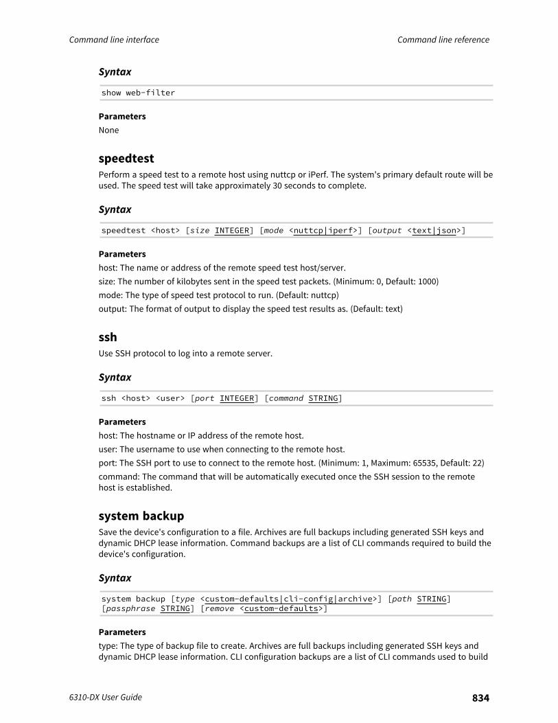
Command line interface Command line reference
6310-DX User Guide 834
Syntax
show web-filter
ParametersNone
speedtestPerform a speed test to a remote host using nuttcp or iPerf. The system's primary default route will beused. The speed test will take approximately 30 seconds to complete.
Syntax
speedtest <host> [size INTEGER] [mode <nuttcp|iperf>] [output <text|json>]
Parametershost: The name or address of the remote speed test host/server.size: The number of kilobytes sent in the speed test packets. (Minimum: 0, Default: 1000)mode: The type of speed test protocol to run. (Default: nuttcp)output: The format of output to display the speed test results as. (Default: text)
sshUse SSH protocol to log into a remote server.
Syntax
ssh <host> <user> [port INTEGER] [command STRING]
Parametershost: The hostname or IP address of the remote host.user: The username to use when connecting to the remote host.port: The SSH port to use to connect to the remote host. (Minimum: 1, Maximum: 65535, Default: 22)command: The command that will be automatically executed once the SSH session to the remotehost is established.
system backupSave the device's configuration to a file. Archives are full backups including generated SSH keys anddynamic DHCP lease information. Command backups are a list of CLI commands required to build thedevice's configuration.
Syntax
system backup [type <custom-defaults|cli-config|archive>] [path STRING][passphrase STRING] [remove <custom-defaults>]
Parameterstype: The type of backup file to create. Archives are full backups including generated SSH keys anddynamic DHCP lease information. CLI configuration backups are a list of CLI commands used to build
Command line interface Command line reference
6310-DX User Guide 835
the device's configuration. (Default: archive)path: The file path to save the backup to. (Default: /var/log/)passphrase: Encrypt the archive with a passphrase.remove: Remove a backup file.
system disable-cryptographyErase the device's configuration and reboot into a limited mode with no cryptography available. Thedevice's shell will be accessible over Telnet (port 23) at IP address 192.168.210.1. To return the deviceto normal operation, perform the configuration erase procedure with the device's ERASE button twiceconsecutively.
Syntax
system disable-cryptography
ParametersNone
system duplicate-firmwareDuplicate the running firmware to the alternate partition so that the device will always boot the samefirmware version.
Syntax
system duplicate-firmware
ParametersNone
system factory-eraseErase the device to restore to factory defaults. All configuration and automatically generated keys willbe erased.
Syntax
system factory-erase
ParametersNone
system find-meFind Me function to flash LEDs on this device to help users locate the unit.
Syntax
system find-me <state>

Command line interface Command line reference
6310-DX User Guide 836
Parametersstate: Find Me control to flash cellular-related LEDs.
system firmware ota checkQuery the Digi firmware server for the latest device firmware version.
Syntax
system firmware ota check
ParametersNone
system firmware ota listQuery the Digi firmware server for a list of device firmware versions.
Syntax
system firmware ota list
ParametersNone
system firmware ota updatePerform FOTA (firmware-over-the-air) update. The device will be updated to the latest firmwareversion unless the version argument is used to specify the firmware version.
Syntax
system firmware ota update [version STRING]
Parametersversion: Firmware version name.
system firmware updateUpdate the current firmware image. Upon reboot the new firmware will be run.
Syntax
system firmware update <file>
Parametersfile: Firmware filename and path.
system power ignition off_delayUpdate the current ignition off delay without changing the configuration.
Command line interface Command line reference
6310-DX User Guide 837
Syntax
system power ignition off_delay <off_delay>
Parametersoff_delay: Ignition power off delay. Format: number{h|m|s}, Max: 18h. (Minimum: 0s, Maximum: 18h)
system restoreRestore the device's configuration from a backup archive or CLI commands file.
Syntax
system restore <path> [passphrase STRING]
Parameterspath: The path to the backup file.passphrase: Decrypt the archive with a passphrase.
system script startRun a manual script. Scripts that are disabled, not a manual script, or already running can not be run.
Syntax
system script start <script>
Parametersscript: Script to start.
system script stopStop an active running script. Scripts scheduled to run again will still run again (disable a script toprevent it from running again).
Syntax
system script stop <script>
Parametersscript: Script to stop.
system serial clearClears the serial log.
Syntax
system serial clear <port>

Command line interface Command line reference
6310-DX User Guide 838
Parametersport: Serial port.
system serial saveSaves the current serial log to a file.
Syntax
system serial save <port> <filename>
Parametersport: Serial port.filename: The filename to save the serial log. The file will be saved to the device's /etc/config/serialdirectory.
system serial showDisplays the serial log on the screen.
Syntax
system serial show <port>
Parametersport: Serial port.
system serial startStart logging data on a serial port.
Syntax
system serial start <port> [size INTEGER]
Parametersport: Serial port.size: Maximum size of serial log. (Default: 65536)
system serial stopStart logging data on a serial port.
Syntax
system serial stop <port>
Parametersport: Serial port.
system support-report
Command line interface Command line reference
6310-DX User Guide 839
Save a support report to a file and include with support requests.
Syntax
system support-report [path STRING]
Parameterspath: The file path to save the support report to. (Default: /var/log/)
system time setSet the local date and time using the timezone set in the system.time.timezone config setting.
Syntax
system time set <datetime>
Parametersdatetime: The date in year-month-day hour:minute:second format (e.g "2021-09-26 12:24:48").
system time syncPerform a NTP query to the configured server(s) and set the local time to the first server thatresponds.
Syntax
system time sync
ParametersNone
system time testTest the configured NTP server(s) for connectivity. This test will not affect the device's current localdate and time.
Syntax
system time test
ParametersNone
telnetUse Telnet protocol to log into a remote server.
Syntax
telnet <host> [port INTEGER]
Command line interface Command line reference
6310-DX User Guide 840
Parametershost: The hostname or IP address of the remote host.port: The telnet port to use to connect to the remote host. (Minimum: 1, Maximum: 65535, Default: 23)
traceroutePrint the route packets trace to network host.
Syntax
traceroute <host> [ipv6] [gateway STRING] [interface STRING] [first_ttlINTEGER] [max_ttl INTEGER] [port INTEGER] [nqueries INTEGER] [src_addr STRING][tos INTEGER] [waittime INTEGER] [pausemsecs INTEGER] [packetlen INTEGER][debug] [dontfragment] [icmp] [nomap] [bypass]
Parametershost: The host that we wish to trace the route packets for.ipv6: If a hostname is defined as the value of the 'host' parameter, use the hosts IPV6 address.gateway: Tells traceroute to add an IP source routing option to the outgoing packet that tells thenetwork to route the packet through the specified gateway.interface: Specifies the interface through which traceroute should send packets. By default, theinterface is selected according to the routing table.first_ttl: Specifies with what TTL to start. (Minimum: 1, Default: 1)max_ttl: Specifies the maximum number of hops (max time-to-live value) traceroute will probe.(Minimum: 1, Default: 30)port: Specifies the destination port base traceroute will use (the destination port number will beincremented by each probe). A value of -1 specifies that no specific port will be used. (Minimum: -1,Default: -1)nqueries: Sets the number of probe packets per hop. A value of -1 indicated. (Minimum: 1, Default: 3)src_addr: Chooses an alternative source address. Note that you must select the address of one of theinterfaces. By default, the address of the outgoing interface is used.tos: For IPv4, set the Type of Service (ToS) and Precedence value. Useful values are 16 (low delay) and8 (high throughput). Note that in order to use some TOS precedence values, you have to be superuser. For IPv6, set the Traffic Control value. A value of -1 specifies that no value will be used.(Minimum: -1, Default: -1)waittime: Determines how long to wait for a response to a probe. (Minimum: 1, Default: 5)pausemsecs: Minimal time interval between probes. (Minimum: 0, Default: 0)packetlen: Total size of the probing packet. Default 60 bytes for IPv4 and 80 for Ipv6. A value of -1specifies that the default value will be used. (Minimum: -1, Default: -1)debug: Enable socket level debugging.dontfragment: Do not fragment probe packets.icmp: Use ICMP ECHO for probes.nomap: Do not try to map IP addresses to host names when displaying them.bypass: Bypass the normal routing tables and send directly to a host on an attached network.

Antenna notes and solutions Command line reference
6310-DX User Guide 841
Antenna notes and solutions
This chapter contains the following topics:
Antenna terminology 842Physical specifications 842Antennas tested by Digi 842
Antenna notes and solutions Antenna terminology
6310-DX User Guide 842
Antenna terminologyElectronics require antennas to convert data into RF signals (and vice versa). They are coupled withradio transmitters and/or receivers to process the information that is carried over cellular bands.Antenna design and functionality has evolved over time:
n Internal antennas: An antenna can be concealed within the casing of a device, as seen withmost smart phones. Internal antennas are potentially more prone to interference due to theclose grouping of electrical components.
n External antennas: Situating antennas further away from the rest of the circuit board can helpalleviate interference due to electrical components by maximizing a device's natural reach.Instead of sitting inside the device directly next to the modem or transceiver, they screw intoplace using SMA connectors and protrude from the equipment (think "rabbit ears").
n MIMO: Multiple-Input and Multiple-Output (MIMO) technology expands the throughput capacityof a transceiver by leveraging multiple antennas to simultaneously convert RF signals into data(or vice versa), providing faster transfer speeds as a result. Think of it (loosely) as CarrierAggregation for antennas—once again combining individual lanes into a single, coordinatedsuperhighway. Networks must leverage MIMO antenna transmission to be technicallyconsidered 4G.
Physical specificationsMany Digi devices use industry-standard female SMA connectors to affix antennas to the internalcellular radio. External antennas improve clarity when compared to internal antennas, which areprone to electromagnetic interference.An extension coaxial cable can also enhance the reach of a device; however, that cabling causesattenuation—or a degradation in signal quality—due to the distance the signal travels. Significantattenuation typically begins at 30 feet of cabling.Certain Digi products are designed to provide the ability to place the unit where reception is best(moving the radio is always preferred). This allows the device to capture optimal Radio Frequency (RF)before converting it to IP packets and transmit data via Ethernet cabling, an approach that yieldsincreased performance and cost savings over coax cabling.Digi can also provide a battery pack for site surveys, creative mounting options, and a (passive)Power-over-Ethernet (PoE) injector to provide an efficient, flexible deployment at the lowest possiblecost. Most Digi clients will not require third-party antennas unless deploying without PoE. It is alwayspreferred to mount a PoE unit on an external wall via Ethernet and use the shortest coax cablerequired to run the external antenna to the outside of a building.
CRITICAL NOTE: Test the signal strength outside of the building to ensure you have cellularcoverage in the area prior to any cabling work. Tip: Use the site survey battery to do this.
Antennas tested by DigiNote Antenna information has been compiled by Digi to assist clients in finding and sourcing anantenna solution to best meet their application and business needs. The information on availabilityand pricing is for planning purposes only and may vary. Clients should test and validate their ownapplications prior to selecting an antenna for their project.
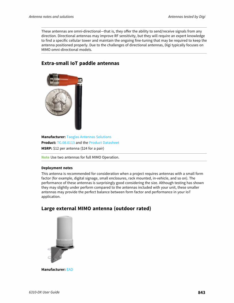
Antenna notes and solutions Antennas tested by Digi
6310-DX User Guide 843
These antennas are omni-directional—that is, they offer the ability to send/receive signals from anydirection. Directional antennas may improve RF sensitivity, but they will require an expert knowledgeto find a specific cellular tower and maintain the ongoing fine-tuning that may be required to keep theantenna positioned properly. Due to the challenges of directional antennas, Digi typically focuses onMIMO omni-directional models.
Extra-small IoT paddle antennas
Manufacturer: Taoglas Antennas SolutionsProduct: TG.08.0113 and the Product DatasheetMSRP: $12 per antenna ($24 for a pair)
Note Use two antennas for full MIMO Operation.
Deployment notesThis antenna is recommended for consideration when a project requires antennas with a small formfactor (for example, digital signage, small enclosures, rack mounted, in-vehicle, and so on). Theperformance of these antennas is surprisingly good considering the size. Although testing has shownthey may slightly under perform compared to the antennas included with your unit, these smallerantennas may provide the perfect balance between form factor and performance in your IoTapplication.
Large external MIMO antenna (outdoor rated)
Manufacturer: EAD
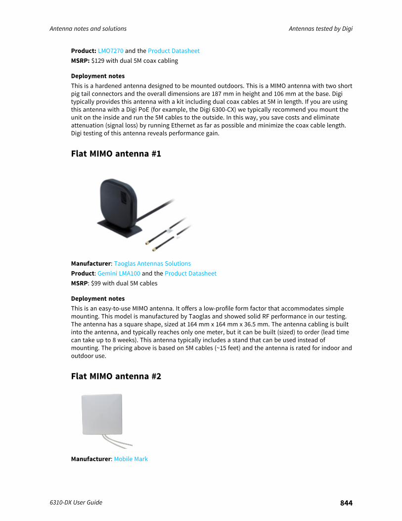
Antenna notes and solutions Antennas tested by Digi
6310-DX User Guide 844
Product: LMO7270 and the Product DatasheetMSRP: $129 with dual 5M coax cabling
Deployment notesThis is a hardened antenna designed to be mounted outdoors. This is a MIMO antenna with two shortpig tail connectors and the overall dimensions are 187 mm in height and 106 mm at the base. Digitypically provides this antenna with a kit including dual coax cables at 5M in length. If you are usingthis antenna with a Digi PoE (for example, the Digi 6300-CX) we typically recommend you mount theunit on the inside and run the 5M cables to the outside. In this way, you save costs and eliminateattenuation (signal loss) by running Ethernet as far as possible and minimize the coax cable length.Digi testing of this antenna reveals performance gain.
Flat MIMO antenna #1
Manufacturer: Taoglas Antennas SolutionsProduct: Gemini LMA100 and the Product DatasheetMSRP: $99 with dual 5M cables
Deployment notesThis is an easy-to-use MIMO antenna. It offers a low-profile form factor that accommodates simplemounting. This model is manufactured by Taoglas and showed solid RF performance in our testing.The antenna has a square shape, sized at 164 mm x 164 mm x 36.5 mm. The antenna cabling is builtinto the antenna, and typically reaches only one meter, but it can be built (sized) to order (lead timecan take up to 8 weeks). This antenna typically includes a stand that can be used instead ofmounting. The pricing above is based on 5M cables (~15 feet) and the antenna is rated for indoor andoutdoor use.
Flat MIMO antenna #2
Manufacturer: Mobile Mark
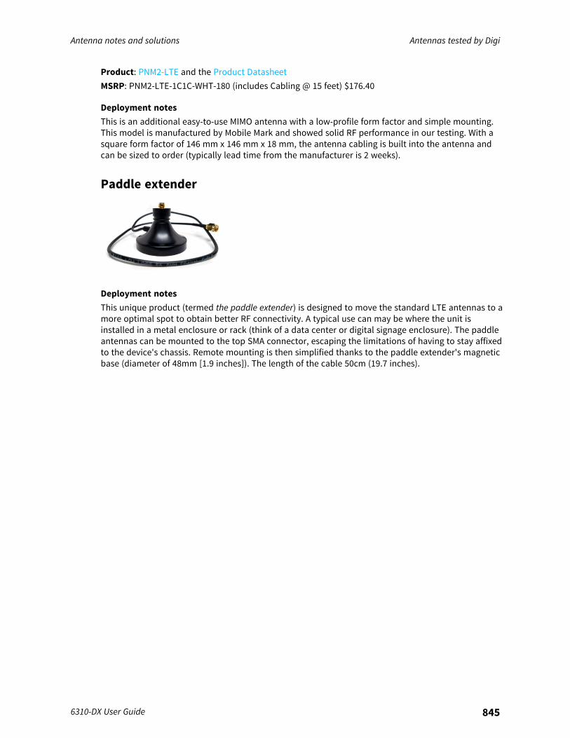
Antenna notes and solutions Antennas tested by Digi
6310-DX User Guide 845
Product: PNM2-LTE and the Product DatasheetMSRP: PNM2-LTE-1C1C-WHT-180 (includes Cabling @ 15 feet) $176.40
Deployment notesThis is an additional easy-to-use MIMO antenna with a low-profile form factor and simple mounting.This model is manufactured by Mobile Mark and showed solid RF performance in our testing. With asquare form factor of 146 mm x 146 mm x 18 mm, the antenna cabling is built into the antenna andcan be sized to order (typically lead time from the manufacturer is 2 weeks).
Paddle extender
Deployment notesThis unique product (termed the paddle extender) is designed to move the standard LTE antennas to amore optimal spot to obtain better RF connectivity. A typical use can may be where the unit isinstalled in a metal enclosure or rack (think of a data center or digital signage enclosure). The paddleantennas can be mounted to the top SMA connector, escaping the limitations of having to stay affixedto the device's chassis. Remote mounting is then simplified thanks to the paddle extender's magneticbase (diameter of 48mm [1.9 inches]). The length of the cable 50cm (19.7 inches).