fedos e/dx operating manual - lutz-jesco
TRANSCRIPT
FEDOS E/DXPiston Dosing Pump
DosingConveying
Control
Liquids
Gases
Systems
Operating ManualRead this operating manual before using the equipment.To be retained for future reference.
EN02
Contents1. General and Safety Instructions ................................................................................................................................32. General .......................................................................................................................................................................7
2.1 Proper intended use .......................................................................................................................................... 72.2 Structure of the dosing pump ............................................................................................................................. 7
3. Function .....................................................................................................................................................................84. Dimensioned drawings ..............................................................................................................................................95. Technical data ..........................................................................................................................................................10
5.1 Electric motor data .......................................................................................................................................... 125.2 Technical data, ATE servomotor FEDOS E (optional) ............................................................................................ 13
6. Delivery characteristic curves ................................................................................................................................147. Installation ...............................................................................................................................................................15
7.1 General information ......................................................................................................................................... 157.2 Installation location .......................................................................................................................................... 167.3 Electrical connection of the dosing pump .......................................................................................................... 167.4 Wiring diagrams for ATE servomotor for stroke length adjustment ....................................................................... 187.5 Level monitoring .............................................................................................................................................. 197.6 Pressure control and safety valves .................................................................................................................... 197.7 Injection nozzle installation ............................................................................................................................... 207.8 Installation example ......................................................................................................................................... 20
8. Operation ..................................................................................................................................................................218.1 Stroke length adjustment ................................................................................................................................. 218.2 FEDOS DX operating elements.......................................................................................................................... 218.3 Switching on/off .............................................................................................................................................. 218.4 Operating mode selection ................................................................................................................................ 218.5 Alarm .............................................................................................................................................................. 228.6 Other settings.................................................................................................................................................. 238.7 Factory setting ................................................................................................................................................ 238.8 Connections and cable assignments ................................................................................................................. 23
9. Start-up ....................................................................................................................................................................259.1 Start up of FEDOS E with ATE servomotor .......................................................................................................... 25
10. Shutdown ...............................................................................................................................................................2610.1 Disposal of old equipment .............................................................................................................................. 26
Device revision ............................................................................................................................................................2611. Maintenance ..........................................................................................................................................................27
11.1 Lubrication .................................................................................................................................................... 2711.2 Maintenance of the bearings .......................................................................................................................... 2711.3 Maintenance of the ATE servomotor (optional) ................................................................................................. 2711.4 Replacing the piston ...................................................................................................................................... 2711.5 Valves ........................................................................................................................................................... 29
12. Explosion-proof dosing pumps .............................................................................................................................3212.1 General ......................................................................................................................................................... 3212.2 Special conditions.......................................................................................................................................... 32
13. Troubleshooting .....................................................................................................................................................3314. Spare parts .............................................................................................................................................................3415. External vent (optional) .........................................................................................................................................40Index.............................................................................................................................................................................41Declaration of no objection .........................................................................................................................................42Warranty claim.............................................................................................................................................................43CE declaration of conformity ......................................................................................................................................44
2 | Operating Manual FEDOS E/DX | Contents
1. General and Safety Instructions1.1 GeneralThis operating manual contains basic instructions to be followed during installation, operation and mainte-nance. It is therefore essential for the assembler and the relevant technical personnel/operating company to read this operating manual prior to installation and start-up. It must remain accessible at the place of installation of the system for reference at all times.
Besides the general safety instructions in this "Safety" section, the special safety instructions in the other sections are also to be followed.
1.2 Identification of safety instructions in the operating manualFailure to follow the safety instructions in this operating manual may result in personal injury or damage to the environment and the system. Safety instructions are identified by the following symbols:
DANGER!Indicates an immediate danger. Failure to follow this instruction will lead to death or extremely serious injuries.
WARNING!Indicates a potentially hazardous situation. Failure to follow this instruction may lead to death or severe injury.
CAUTION!Indicates a potentially hazardous situation. Failure to follow this instruction may lead to minor injury or dam-age to property.
ATTENTION! or NOTICE!Failure to follow these safety instructions may endanger the machine and its functions.
IMPORTANT!This refers to additional information to facilitate operation and ensure the smooth running of the equipment.
Information attached directly to the dosing pump, such as• cable markings• markings for fluid connections
must be followed without fail and must remain fully legible at all times.
1.3 Personnel qualifications and trainingThe personnel employed for operation, maintenance, inspection, and installation must be suitably qualified for this work. The responsibilities, areas of competence and personnel supervision must be clearly defined by the operating company. Personnel who do not have the required know-how must be duly trained and instructed. If necessary, this can also be done by the manufacturer/supplier on behalf of the operating company. In addition, the operating company must ensure that the personnel are fully familiar with, and have understood the contents of this operating manual.
1.4 Important safety instructionsWhen installing and using this electrical device, basic safety precautions should always be followed, includ-ing the following:
ATTENTION!Read and follow all instructions! Keep this operating manual for future reference!
WARNING!To reduce the risk of injury, do not permit children to use this product unless they are closely supervised at all times.
General and Safety Instructions | Operating Manual FEDOS E/DX | 3
WARNING!Risk of electric shock. Connect the device only to a socket outlet with earthing contact protected by a ground fault circuit interrupter (GFCI). Consult a qualified electrician if you are uncertain whether the socket is protected by a GFCI. Do not bury the cable. Secure cable to avoid damage by lawn mowers, hedge trimmers and other equip-ment.
WARNING!To reduce the risk of electric shock, replace the cable immediately if damaged.
WARNING!To reduce the risk of electric shock, do not use extension lead to connect unit to electric supply; use an appropriately located socket outlet.
1.5 Hazards due to failure to follow safety instructionsFailure to follow the safety instructions may endanger not only persons, but also the environment and the device. Failure to follow the safety instructions may invalidate any damage claims.
The following hazards in particular may result:• Failure of major equipment functions• Failure of required maintenance and repair methods.• Danger to persons due to electrical, mechanical and chemical effects.• Danger to the environment due to leakage of hazardous substances.
1.6 Safety awareness at workThe safety instructions contained in this operating manual must be observed. The operating company is responsible for ensuring compliance with local safety regulations. Faults that may affect safety must be repaired immediately.
1.7 Safety instructions for the operating company/operatorLeakages of hazardous substances (e.g. aggressive, poisonous) must be disposed of in such a way that they do not pose a risk to persons and the environment. Legal requirements must be observed.
Risks from electric current must be excluded (for further details, refer to the VDE1) regulations and regula-tions of the local public utilities). 1) German Association for Electrical, Electronic & Information Technologies
Separate regulations must be observed if the FEDOS E is operated in potentially explosive atmospheres. The operating company must determine the explosion hazard (area classification) and select the appropriate equipment. Further information can be found in paragraph 7.1 (Installation), paragraph 7.4 (Electrical con-nection) and section 12 (Explosion-proof dosing pumps).
1.8 Safety instructions for inspection, maintenance and installation workThe operating company must ensure that all maintenance, inspection and installation work is carried out by authorised and duly qualified personnel, who have read and understood this operating manual.
Any work on the machine must only be carried out after it has been brought to a complete stop. Always follow the procedure specified in the operating manual for shutting down the dosing pump/system.
Dosing pumps or systems which convey hazardous media must be decontaminated.
All safety and protective equipment must be reattached and activated immediately after the work has been completed.
CAUTION!Particular caution is required during repair work with the operation of the FEDOS E in potentially explosive atmospheres. Due to the risk of sparking, care must be taken to prevent metal parts or tools knocking against one another. When repairing, it is better to move the dosing pump out of the area with a potentially explosive atmosphere.
4 | Operating Manual FEDOS E/DX | General and Safety Instructions
Those points specified in chapter 7.2 "Installation location" and section 9. "Start-up" must be observed before setting into operation.
1.9 Unauthorised modification and production of spare partsThe device may only be modified or converted in consultation with the manufacturer. Use only the manufac-turer's spare parts and accessories. Otherwise the warranty is invalidated.
1.10 Inadmissible operating practicesAny methods of operation which contradict chapter 2 "Proper intended use" are inadmissible and will result in the expiry of all liability claims.
1.11 Dosing of chemicals
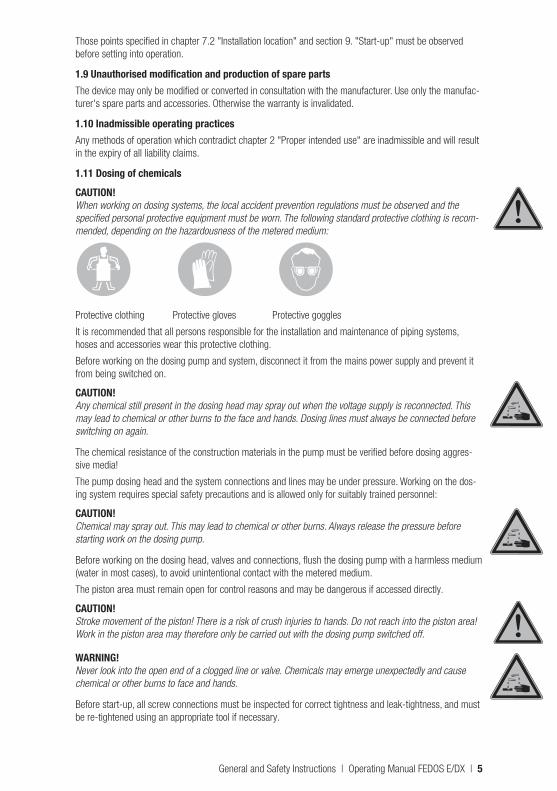
CAUTION!When working on dosing systems, the local accident prevention regulations must be observed and the specified personal protective equipment must be worn. The following standard protective clothing is recom-mended, depending on the hazardousness of the metered medium:
Protective clothing Protective gloves Protective goggles
It is recommended that all persons responsible for the installation and maintenance of piping systems, hoses and accessories wear this protective clothing.
Before working on the dosing pump and system, disconnect it from the mains power supply and prevent it from being switched on.
CAUTION!Any chemical still present in the dosing head may spray out when the voltage supply is reconnected. This may lead to chemical or other burns to the face and hands. Dosing lines must always be connected before switching on again.
The chemical resistance of the construction materials in the pump must be verified before dosing aggres-sive media!
The pump dosing head and the system connections and lines may be under pressure. Working on the dos-ing system requires special safety precautions and is allowed only for suitably trained personnel:
CAUTION!Chemical may spray out. This may lead to chemical or other burns. Always release the pressure before starting work on the dosing pump.
Before working on the dosing head, valves and connections, flush the dosing pump with a harmless medium (water in most cases), to avoid unintentional contact with the metered medium.
The piston area must remain open for control reasons and may be dangerous if accessed directly.
CAUTION!Stroke movement of the piston! There is a risk of crush injuries to hands. Do not reach into the piston area! Work in the piston area may therefore only be carried out with the dosing pump switched off.
WARNING!Never look into the open end of a clogged line or valve. Chemicals may emerge unexpectedly and cause chemical or other burns to face and hands.
Before start-up, all screw connections must be inspected for correct tightness and leak-tightness, and must be re-tightened using an appropriate tool if necessary.
General and Safety Instructions | Operating Manual FEDOS E/DX | 5
CAUTION!If connections at the dosing head are loosened during operation, for venting or other reasons, leaking chemicals must be removed properly. Only in this way is it possible to effectively avoid the risk of injuries caused by chemicals and corrosion at the dosing pump.
ATTENTION!If changing the chemical, check the materials in the pump and other system parts for chemical resistance. If there is a danger of chemical reaction between the different media, clean thoroughly beforehand.
IMPORTANT!To operate the pump, mount the fan cowl in order to ensure sufficient cooling of the motor.
The protection class of the control unit is only ensured if the connection ports are protected by caps or the standard connectors are inserted.
DANGER!Risk of burns. Shock wave: parts may fly off and cause fatal injury. FEDOS DX must not be used in poten-tially explosive atmospheres under any circumstances.
CAUTION!Under certain operating conditions, the drive motor of the DX version might heat up considerably. This may cause burns to the hands. To avoid unintentional contact, provide an appropriate safety device.
WARNING!
Lethal voltage!Proceed with caution when carrying out adjustment work on the inside of the ATE servomotor (optional for FEDOS E). Connections and internal limit switches might be live. Additional limit switches in the ATE drive may be under voltage (live) even when the auxiliary voltage is switched off. After installing the ATE servomo-tor or before start-up, re-attach the cover.
1.12 TransportationNo special devices are required for transportation of the dosing pumps. However, it is advisable to choose a transport method appropriate for the weight of the dosing pumps (e.g. transport trolley). If transporting with the oil drained, the dosing pump should preferably be placed in the horizontal position. Otherwise, stability must be ensured by screwing it onto the transport frame.
1.13 Scope of delivery
IMPORTANT!Carefully unpack the dosing pump and any accompanying accessories ordered, so that small parts are not left inside the packaging. Compare the delivery content with the delivery note immediately. If there are any discrepancies, determine the cause.
The following are part of the scope of delivery:• Dosing pump FEDOS E or DX• Suction and discharge side connections• Gear oil• 2x cables (for FEDOS DX)• Operating Manual• ATE servomotor (optional)• Separate fan (optional)
6 | Operating Manual FEDOS E/DX | General and Safety Instructions
2. General2.1 Proper intended useThe device is intended for the following purpose only: the conveying and dosing of chemicals.
Operating safety is guaranteed only if the device is used for its intended purpose. All other types of use are prohibited and will invalidate the warranty. The operating conditions described in chapter 5 "Technical Data" must be observed!
2.2 Structure of the dosing pump
c
a
h
b
i o p q
g
k
n
m
l
f
e
j
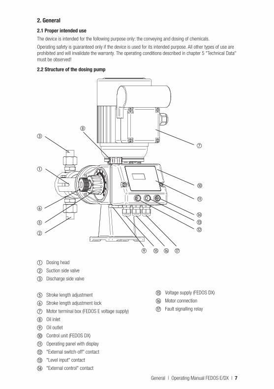
a Dosing head
b Suction side valve
c Discharge side valve
e Stroke length adjustment
f Stroke length adjustment lock
g Motor terminal box (FEDOS E voltage supply)
h Oil inlet
i Oil outlet
j Control unit (FEDOS DX)
k Operating panel with display
l "External switch-off" contact
m "Level input" contact
n "External control" contact
o Voltage supply (FEDOS DX)
p Motor connection
q Fault signalling relay
General | Operating Manual FEDOS E/DX | 7
3. FunctionPiston dosing pumps of the FEDOS series are used in industry, in the process engineering sector, as well as in water conditioning and the treatment of waste water.
FEDOS EThe FEDOS E is used when no control is required for constant dosing. For this the voltage supply is connect-ed directly to the terminal box of the motor. To adapt the dosing capacity the stroke length can be adjusted manually from 0 … 100%, or the motor speed is controlled by means of a separate frequency converter. The FEDOS E is optionally available with remote electrical stroke-length adjustment (ATE servomotor).
The FEDOS E can be operated in Zone 1 potentially explosive atmospheres if the corresponding drive is taken into account. Further information can be found in section 12.
FEDOS DXThe "intelligent" FEDOS DX is used if the dosing pump is to be integrated in controls or automatic control systems. It enables versatile adaptation to a variety of different control signals and system monitoring equipment. The signals required for external activation of the dosing pump can be from simple potential-free N.O. contacts of water meters or controllers, or analogue 0/4 … 20 mA signals. For contact actuation (pulse control), the stroke frequency can be adapted by division or multiplication. For internal operation (own stroke), the dosing pump can be adjusted continuously between 0 and max. 142 strokes/min, depending on version.
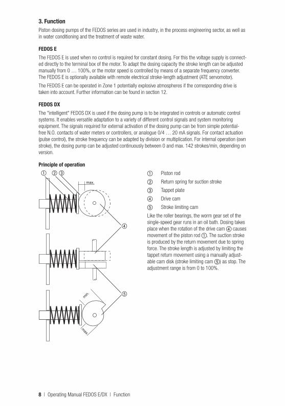
Principle of operationa Piston rod
b Return spring for suction stroke
c Tappet plate
d Drive cam
e Stroke limiting cam
Like the roller bearings, the worm gear set of the single-speed gear runs in an oil bath. Dosing takes place when the rotation of the drive cam d causes movement of the piston rod a. The suction stroke is produced by the return movement due to spring force. The stroke length is adjusted by limiting the tappet return movement using a manually adjust-able cam disk (stroke limiting cam e) as stop. The adjustment range is from 0 to 100%.
a b c
d
emin.
max.
max.
8 | Operating Manual FEDOS E/DX | Function
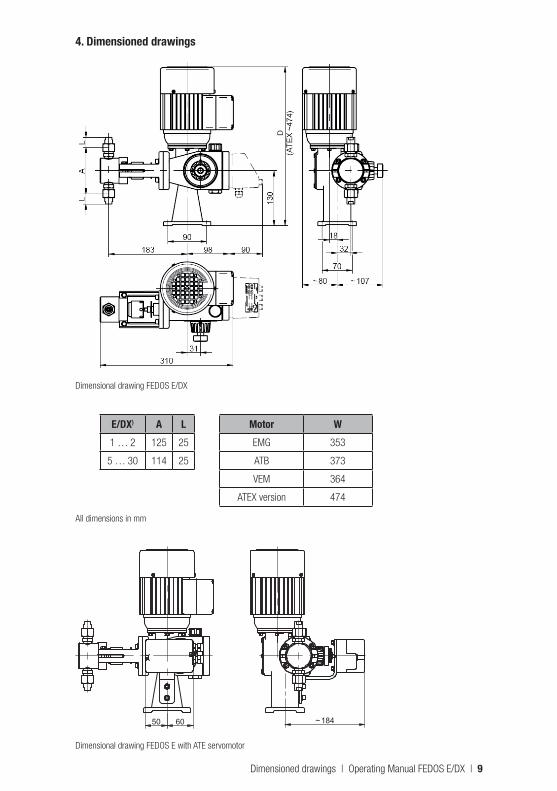
4. Dimensioned drawings
D
Dimensional drawing FEDOS E/DX
E/DX) A L1 … 2 125 25
5 … 30 114 25
Motor WEMG 353
ATB 373
VEM 364
ATEX version 474
All dimensions in mm
184~50 60
Dimensional drawing FEDOS E with ATE servomotor
Dimensioned drawings | Operating Manual FEDOS E/DX | 9

5. Technical data
FEDOS E/DX 01 03 06 1 21) 51) 81) 171) 301)
Delivery rate at max. pressure
l/h 0,17 0,31 0,63 1,42 2,13 4,8 8,5 17 31,5
Stroke volume ml/stroke
0,11 0,25 0,25 0,56 1 2 3,7
Max. pressure bar 40 25
max. pressure 3) bar 100 80 - -
Stroke frequency rpm 26 48 95 142
Piston-Ø mm 4 6 9 12 17 23
Stroke length mm 9
Suction lift mbar 800
max. supply pressure ∑ static + dynamic
mbar 500
max. ambient tempera-ture2)
°C 40
Power output E (3~) W 50 250
Power output DX (1~) W 120
Weight kg 11 16
1) E/DX 2…30 not for 60Hz operation, special sizes E/DX 2A … 30A available for 60 Hz operation. The details about delivery rate and stroke frequency are also applicable for 60 Hz operation. 2) Media temperature 60 °C, short time 80 °C. 3) High-pressure version
Dimensioning of the linesThe following approximate values are applicable for the dimensioning (maximum length) of suction and pressure lines:• 2 m for peak flow velocity of 0.5 … 0.7 m/s• 10 m for peak flow velocity of 1.0 … 1.5 m/s
(without pulsation damper or suction pressure regulator, and without overdimensioning of the line).
This is applicable to chemicals with a maximum viscosity of 20 mPAS (the highest viscosity is at lowest system temperature, for example in case of delivery in winter) and with a maximum density of 1100 kg/m³. The maximum flow velocity is calculated as follows: Q x π / A (Q = flow rate, A = line diameter).
For all other chemicals and installation situations please refer to the seminar documents of the manufactur-er "Kleine Einführung in die Dosiertechnik" (Short introduction into dosing technology) or to other applicable guidelines from specialist literature on fluid dynamics (i.e. Kalide ISBN 3-446-13092-6).
Avoid overloading of the pump, the piping or the instruments.
10 | Operating Manual FEDOS E/DX | Technical data
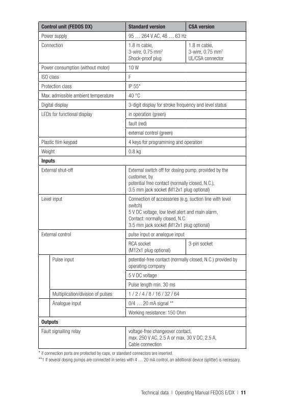
Control unit (FEDOS DX) Standard version CSA versionPower supply 95 … 264 V AC, 48 … 63 Hz
Connection 1.8 m cable,3-wire, 0.75 mm2
Shock-proof plug
1.8 m cable,3-wire, 0.75 mm2
UL/CSA connector
Power consumption (without motor) 10 W
ISO class F
Protection class IP 55*
Max. admissible ambient temperature 40 °C
Digital display 3-digit display for stroke frequency and level status
LEDs for functional display in operation (green)
fault (red)
external control (green)
Plastic film keypad 4 keys for programming and operation
Weight 0.8 kg
InputsExternal shut-off External switch off for dosing pump, provided by the
customer, bypotential free contact (normally closed, N.C.),3.5 mm jack socket (M12x1 plug optional)
Level input Connection of accessories (e.g. suction line with level switch)5 V DC voltage, low level alert and main alarm, Contact: normally closed, N.C.3.5 mm jack socket (M12x1 plug optional)
External control pulse input or analogue input
RCA socket(M12x1 plug optional)
3-pin socket
Pulse input potential-free contact (normally closed, N.C.) provided by operating company
5 V DC voltage
Pulse length min. 30 ms
Multiplication/division of pulses 1 / 2 / 4 / 8 / 16 / 32 / 64
Analogue input 0/4 … 20 mA signal **
Working resistance: 150 Ohm
OutputsFault signalling relay voltage-free changeover contact,
max. 250 V AC, 2.5 A or max. 30 V DC, 2.5 A, Cable connection
* if connection ports are protected by caps, or standard connectors are inserted. **1 If several dosing pumps are connected in series with 4 … 20 mA control, an additional device (splitter) is necessary.
Technical data | Operating Manual FEDOS E/DX | 11
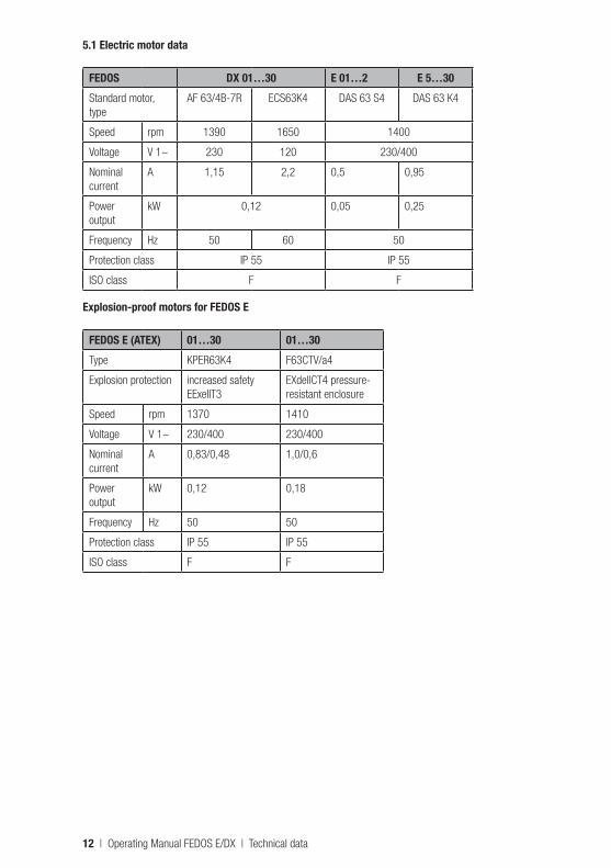
5.1 Electric motor data
FEDOS DX 01…30 E 01…2 E 5…30Standard motor, type
AF 63/4B-7R ECS63K4 DAS 63 S4 DAS 63 K4
Speed rpm 1390 1650 1400
Voltage V 1~ 230 120 230/400
Nominal current
A 1,15 2,2 0,5 0,95
Power output
kW 0,12 0,05 0,25
Frequency Hz 50 60 50
Protection class IP 55 IP 55
ISO class F F
Explosion-proof motors for FEDOS E
FEDOS E (ATEX) 01…30 01…30Type KPER63K4 F63CTV/a4
Explosion protection increased safety EExeIIT3
EXdellCT4 pressure-resistant enclosure
Speed rpm 1370 1410
Voltage V 1~ 230/400 230/400
Nominal current
A 0,83/0,48 1,0/0,6
Power output
kW 0,12 0,18
Frequency Hz 50 50
Protection class IP 55 IP 55
ISO class F F
12 | Operating Manual FEDOS E/DX | Technical data
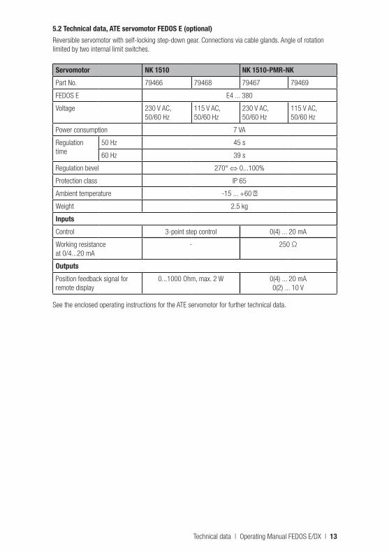
5.2 Technical data, ATE servomotor FEDOS E (optional)Reversible servomotor with self-locking step-down gear. Connections via cable glands. Angle of rotation limited by two internal limit switches.
Servomotor NK 1510 NK 1510-PMR-NKPart No. 79466 79468 79467 79469
FEDOS E E4 ... 380
Voltage 230 V AC, 50/60 Hz
115 V AC, 50/60 Hz
230 V AC, 50/60 Hz
115 V AC, 50/60 Hz
Power consumption 7 VA
Regulation time
50 Hz 45 s
60 Hz 39 s
Regulation bevel 270° ⇔ 0...100%
Protection class IP 65
Ambient temperature -15 ... +60 ℃
Weight 2.5 kg
InputsControl 3-point step control 0(4) ... 20 mA
Working resistance at 0/4...20 mA
- 250 Ω
OutputsPosition feedback signal for remote display
0...1000 Ohm, max. 2 W 0(4) ... 20 mA0(2) ... 10 V
See the enclosed operating instructions for the ATE servomotor for further technical data.
Technical data | Operating Manual FEDOS E/DX | 13
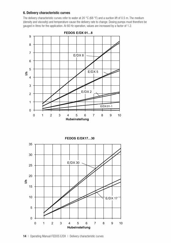
6. Delivery characteristic curvesThe delivery characteristic curves refer to water at 20 °C (68 °F) and a suction lift of 0.5 m. The medium (density and viscosity) and temperature cause the delivery rate to change. Dosing pumps must therefore be gauged in litres for the application. At 60 Hz operation, values are increased by a factor of 1.2.
0
1
2
3
4
5
6
7
8
9
0 1 2 3 4 5 6 7 8 9 10
l/h
Hubeinstellung
FEDOS E/DX 01...8
E/DX 01-1
E/DX 2
E/DX 5
E/DX 8
0
5
10
15
20
25
30
35
0 1 2 3 4 5 6 7 8 9 10
l/h
Hubeinstellung
FEDOS E/DX17...30
E/DX 17
E/DX 30
14 | Operating Manual FEDOS E/DX | Delivery characteristic curves
7. Installation7.1 General informationLocal rules and regulations must be taken into account when selecting a dosing pump for designing a system, and for installation and operation. This applies to the selection of the appropriate materials for the dosing pump, the handling of chemicals, and electrical installation.
Before installing the pump in areas with a potentially explosive atmosphere, the dosing pump must be checked to ensure that it meets the minimum requirements set by the applicable explosion protection regulations. For this purpose, the data on the dosing pump rating plate must be compared with the local requirements.
The technical specifications of the dosing pump (section 5) must also be taken into consideration, and the system designed accordingly (e.g. pressure loss for pipe dimensions i.e. nominal diameter and length).
The designer and operating company are responsible for ensuring that the entire system, including the dosing pump, is designed in such a way that no lasting damage occurs to system equipment or buildings in the event of chemical leakage due to the failure of wearing parts (e.g. wear of the packing) or burst hoses. If the chemical system represents a potential source of danger, the installation must be designed in such a way that no unreasonable consequential damage occurs, even if the dosing pump fails. We therefore recommend installing leakage monitors and collecting pans.
CAUTIONThe FEDOS E/DX may not be used for dosing combustible and flammable fluids. For constructional reasons piston pumps are not leakage-free. This must be taken into account in the design of the process and the plant.
To increase dosing accuracy and ensure functional reliability, we recommend installing additional valves and accessories. These include pressure control valves, pressure relief valves, leakage monitors and low level indicators, as shown in the installation examples.
Always use appropriate tools for installation work. To avoid damage, never apply excessive force.
IMPORTANT!To prevent seizing, threaded stainless steel parts (e.g. dosing head and valves) must be lubricated before being assembled (e.g. with PTFE spray).
ATTENTION!Check the lubricant for compatibility with the chemical.
7.1.1 Installation of FEDOS E with ATE servomotorThe ATE servomotor is connected to the dosing pump and adjusted at the factory. When installing, sufficient installation space of at least 150 mm must be provided in order to allow later maintenance.
The electrical connection of the ATE drive must be made in accordance with locally applicable requirements and may only be carried out by technical personnel. The wiring diagrams (chapter 7.4) show the standard connection variant.
Cable type and cross-section must be chosen according to the motor data.
The cable passage through the housing must be made professionally. We recommend using gland con-nections with strain-relief clamp. The required protection class must be ensured by professional-standard installation of the electrical connections.
ATTENTION!Note that the ATE servomotor can only be actuated when the main drive motor of the dosing pump is run-ning. This means that the ATE servomotor must be locked electrically. Otherwise, the adjusting eccentric will suffer excessive wear, or be destroyed.
Installation | Operating Manual FEDOS E/DX | 15
7.2 Installation locationThe installation location of the dosing pump must be easily accessible by operating and service personnel.
ATTENTION!Ambient temperatures above 40 °C are not permitted. Radiant heat from apparatus and heat exchangers must be shielded so that heat from the dosing pump can be dissipated sufficiently. Avoid exposure to direct sunlight. If the dosing pump is installed outside, provide a roof to protect it from the effects of weather.
Install the pump so that the suction and discharge valves are in vertical position. To ensure stability, the dosing pump must be screwed onto an appropriate surface. The system piping must not exert any force on the connections and valves of the dosing pump. To avoid dosing errors at the end of the process, the dosing pump must be locked electrically and hydraulically.
7.3 Electrical connection of the dosing pumpThe electrical connection of the dosing pump must be made according to local rules and regulations and may only be carried out by qualified technical personnel. Cable type and cross-section of the supply lines must be chosen according to the motor data. The cable passage to the motor terminal box must be made professionally. We recommend using gland connections with strain-relief clamp. The required protection class must be ensured by professional-standard installation of the electrical connections.
For external switch-off of the dosing pump, see paragraph 8.3.
ATTENTION! Dosing pumps with explosion-proof motors must be installed and commissioned by specialists qualified to work with equipment intended for use in potentially explosive atmospheres. The user is responsible for ensuring that explosion-proof motors are connected correctly. Both the motor and the dosing pump must be grounded to prevent electrostatic discharges.
DANGER!Risk of burns. Shock wave: parts may fly off and cause fatal injury. FEDOS DX must not be used in a poten-tially explosive atmosphere under any circumstances. The electrical connection of the dosing pump must be made according to local rules and regulations and may only be carried out by qualified technical personnel.
NOTE!The dosing pump must be plugged into a grounded power outlet. The 230 V AC version of the FEDOS DX is connected by a shockproof earthing-pin plug. The 115 V AC ver-sion is equipped with a UL/CSA plug.
NOTE!Signal cables must not be laid parallel to high-voltage current lines or mains cables. Lay supply and signal lines in separate channels. An angle of 90° is required at line crossings. If signal lines are more than 2 meters long, shielded cables must be used.
ATTENTION!To avoid premature wear of the gear, always ensure the correct rotation direction of the motor: counter-clockwise (to the left), looking toward the fan wheel.
16 | Operating Manual FEDOS E/DX | Installation
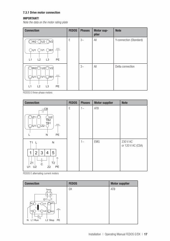
7.3.1 Drive motor connection
IMPORTANT!Note the data on the motor rating plate
Connection FEDOS Phases Motor sup-plier
Note
W2 U2 V2
U1 V1 W1
L1 L2 L3 PE
E 3~ All Y-connection (Standard)
W2 U2 V2
U1 V1 W1
L1 L2 L3 PE
3~ All Delta connection
FEDOS E three-phase motors
Connection FEDOS Phases Motor supplier Note
Z1TB2
U2
U1 Z2TB1
L N PE
CB E 1~ ATB
U1Z1
U2 PEC
1 2 3 4 5
T1 L N
T2Z2
1~ EMG 230 V AC or 120 V AC (CSA)
FEDOS E alternating current motors
Connection FEDOS Motor supplier
U2V2
U1
W2
L2 StopL1 Run PEN
W1 V1
L
C
Temp. DX ATB
Installation | Operating Manual FEDOS E/DX | 17
Connection FEDOS Motor supplier
U1Z1
U2 PEC L
1 2 3 4 5
T1 L1 L2 N
T2Z2
Run StopDX EMG
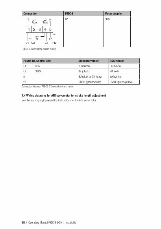
FEDOS DX alternating curent motors
FEDOS DX Control unit Standard version CSA versionL1 RUN BR (brown) BK (black)
L2 STOP BK (black) RD (red)
N BU (blue) or GY (grey) WH (white)
PE GN/YE (green/yellow) GN/YE (green/yellow)
Connection between FEDOS DX control unit and motor
7.4 Wiring diagrams for ATE servomotor for stroke length adjustmentSee the accompanying operating instructions for the ATE servomotor.
18 | Operating Manual FEDOS E/DX | Installation
7.5 Level monitoringIf a level monitor is connected, the jack plug has to be covered by a plastic sleeve in order to maintain the protection class. The required sleeve is part of the level monitor (also in combination with a suction line).
With the level monitor connected, the dosing pump stops if the chemical level in the supply tank is low, in order to prevent air bubbles from entering the suction line and the dosing head. The red LED is lit. As soon as the level contact closes again, the dosing pump restarts.
The level sensor must be designed as a max. N.O. contact.
FEDOS is equipped with a 2-stage level monitor. When the first contact breaks (low level alert), the red LED begins to flash. The dosing pump continues to operate. The fault signalling relay is actuated. The dosing pump only stops when the second contact breaks (main alarm). The red LED is lit continuously.
The "low level alert" function is not available when using a 2-pin connector and a simple float switch.
NOTE!A dummy plug (Part No. 29115) must be attached if a float switch is not connected. The dosing pump is delivered with a dummy plug already attached. If a float switch is to be connected, the dummy plug has to be removed before inserting the jack plug.
7.6 Pressure control and safety valvesPressure control valves are used to optimise the dosing process. They are used:• to increase the dosing accuracy in the case of fluctuating backpressure.• when the dosing lines are long, in order to prevent excess delivery, since the accelerated medium
continues moving due to its own inertia even after the delivery stroke has ended.• to prevent siphoning, if the supply pressure is higher than system pressure.
Pressure relief and safety valves are used for overload protection of the dosing pump and the associated valves and lines. They prevent inadmissible pressure rises in the delivery side system of the dosing pump; for example, if shutoff valves close while the pump is running, or if the injection nozzle is clogged.
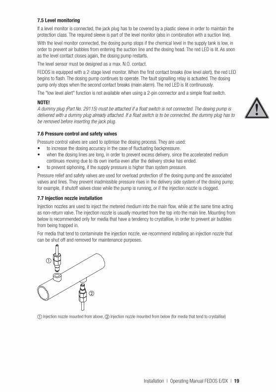
7.7 Injection nozzle installationInjection nozzles are used to inject the metered medium into the main flow, while at the same time acting as non-return valve. The injection nozzle is usually mounted from the top into the main line. Mounting from below is recommended only for media that have a tendency to crystallise, in order to prevent air bubbles from being trapped in.
For media that tend to contaminate the injection nozzle, we recommend installing an injection nozzle that can be shut off and removed for maintenance purposes.
a
b
a Injection nozzle mounted from above, b Injection nozzle mounted from below (for media that tend to crystallise)
Installation | Operating Manual FEDOS E/DX | 19
1
2
3
4
5
67
8
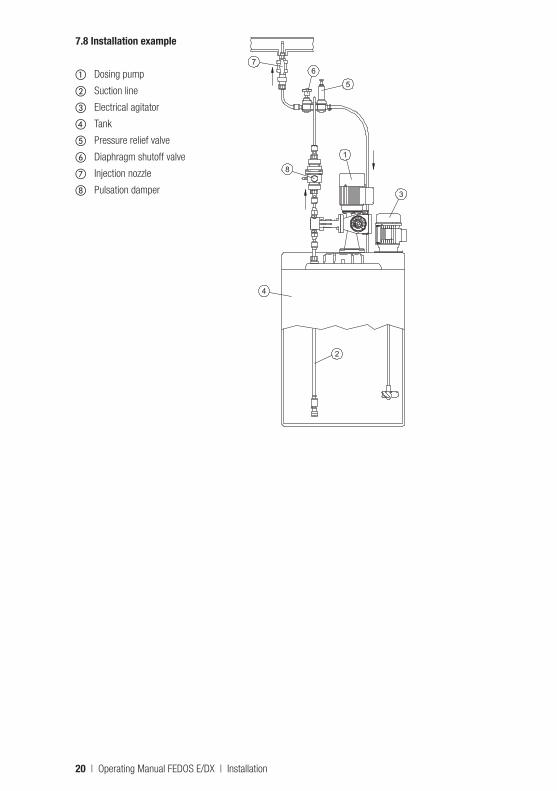
7.8 Installation example
a Dosing pump
b Suction line
c Electrical agitator
d Tank
e Pressure relief valve
f Diaphragm shutoff valve
g Injection nozzle
h Pulsation damper
20 | Operating Manual FEDOS E/DX | Installation
8. Operation8.1 Stroke length adjustment
ATTENTION!The stroke length must not be adjusted when the dosing pump is at a standstill!
Proceed as follows to adjust the stroke length:1. Turn the mounting screw on the adjusting knob counterclockwise (to the left) to loosen it.2. Set the stroke length to the required value according to the delivery characteristic curves (section 6).3. Retighten the mounting screw without changing the stroke length setting.
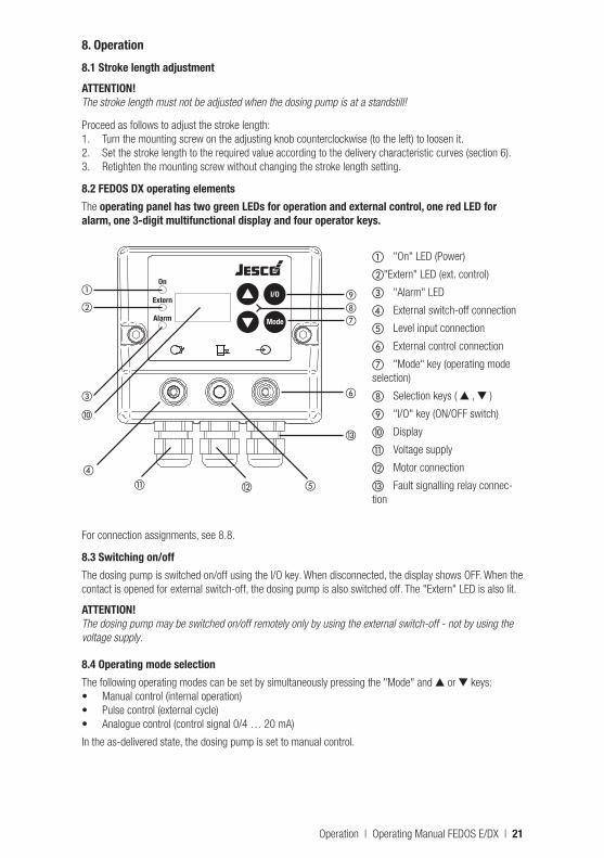
8.2 FEDOS DX operating elementsThe operating panel has two green LEDs for operation and external control, one red LED for alarm, one 3-digit multifunctional display and four operator keys.
a "On" LED (Power)
b"Extern" LED (ext. control)
c "Alarm" LED
d External switch-off connection
e Level input connection
f External control connection
g "Mode" key (operating mode selection)
h Selection keys ( ▲ , ▼ )
i "I/O" key (ON/OFF switch)
j Display
k Voltage supply
l Motor connection
m Fault signalling relay connec-tion
For connection assignments, see 8.8.
8.3 Switching on/offThe dosing pump is switched on/off using the I/O key. When disconnected, the display shows OFF. When the contact is opened for external switch-off, the dosing pump is also switched off. The "Extern" LED is also lit.
ATTENTION!The dosing pump may be switched on/off remotely only by using the external switch-off - not by using the voltage supply.
8.4 Operating mode selectionThe following operating modes can be set by simultaneously pressing the "Mode" and ▲ or ▼ keys:• Manual control (internal operation)• Pulse control (external cycle)• Analogue control (control signal 0/4 … 20 mA)
In the as-delivered state, the dosing pump is set to manual control.
On
Extern
Alarm Mode
I/O
MEMDOS DX
a
d
e
f
ghi
j
b
c
k l
m
Operation | Operating Manual FEDOS E/DX | 21
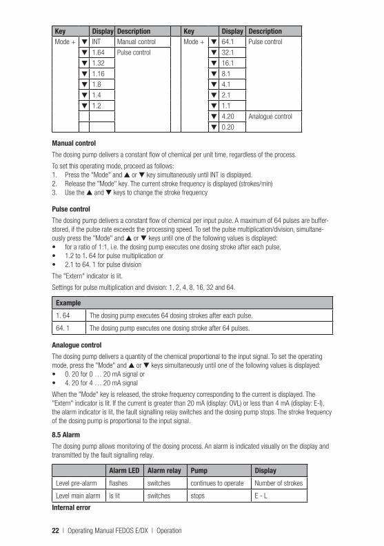
Key Display Description Key Display DescriptionMode + ▼ INT Manual control Mode + ▼ 64.1 Pulse control
▼ 1.64 Pulse control ▼ 32.1
▼ 1.32 ▼ 16.1
▼ 1.16 ▼ 8.1
▼ 1.8 ▼ 4.1
▼ 1.4 ▼ 2.1
▼ 1.2 ▼ 1.1
▼ 4.20 Analogue control
▼ 0.20
Manual controlThe dosing pump delivers a constant flow of chemical per unit time, regardless of the process.
To set this operating mode, proceed as follows:1. Press the "Mode" and ▲ or ▼ key simultaneously until INT is displayed.2. Release the "Mode" key. The current stroke frequency is displayed (strokes/min)3. Use the ▲ and ▼ keys to change the stroke frequency
Pulse controlThe dosing pump delivers a constant flow of chemical per input pulse. A maximum of 64 pulses are buffer-stored, if the pulse rate exceeds the processing speed. To set the pulse multiplication/division, simultane-ously press the "Mode" and ▲ or ▼ keys until one of the following values is displayed:• for a ratio of 1:1, i.e. the dosing pump executes one dosing stroke after each pulse,• 1.2 to 1. 64 for pulse multiplication or• 2.1 to 64. 1 for pulse division
The "Extern" indicator is lit.
Settings for pulse multiplication and division: 1, 2, 4, 8, 16, 32 and 64.
Example1. 64 The dosing pump executes 64 dosing strokes after each pulse.
64. 1 The dosing pump executes one dosing stroke after 64 pulses.
Analogue controlThe dosing pump delivers a quantity of the chemical proportional to the input signal. To set the operating mode, press the "Mode" and ▲ or ▼ keys simultaneously until one of the following values is displayed:• 0. 20 for 0 … 20 mA signal or• 4. 20 for 4 … 20 mA signal
When the "Mode" key is released, the stroke frequency corresponding to the current is displayed. The "Extern" indicator is lit. If the current is greater than 20 mA (display: OVL) or less than 4 mA (display: E-I), the alarm indicator is lit, the fault signalling relay switches and the dosing pump stops. The stroke frequency of the dosing pump is proportional to the input signal.
8.5 AlarmThe dosing pump allows monitoring of the dosing process. An alarm is indicated visually on the display and transmitted by the fault signalling relay.
Alarm LED Alarm relay Pump DisplayLevel pre-alarm flashes switches continues to operate Number of strokes
Level main alarm is lit switches stops E - L
Internal error
22 | Operating Manual FEDOS E/DX | Operation
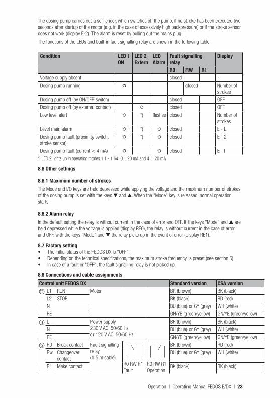
The dosing pump carries out a self-check which switches off the pump, if no stroke has been executed two seconds after startup of the motor (e.g. in the case of excessively high backpressure) or if the stroke sensor does not work (display E-2). The alarm is reset by pulling out the mains plug.
The functions of the LEDs and built-in fault signalling relay are shown in the following table:
Condition LED 1ON
LED 2Extern
LEDAlarm
Fault signalling relay
Display
R0 RW R1Voltage supply absent closed -Dosing pump running closed Number of
strokesDosing pump off (by ON/OFF switch) closed OFFDosing pump off (by external contact) closed OFF
Low level alert *) flashes closed Number of strokes
Level main alarm *) closed E - L
Dosing pump fault (proximity switch, stroke sensor)
*) closed E - 2
Dosing pump fault (current < 4 mA) closed E - I*) LED 2 lights up in operating modes 1.1 - 1.64; 0…20 mA and 4… 20 mA
8.6 Other settings
8.6.1 Maximum number of strokesThe Mode and I/O keys are held depressed while applying the voltage and the maximum number of strokes of the dosing pump is set with the keys ▼ and ▲. When the "Mode" key is released, normal operation starts.
8.6.2 Alarm relayIn the default setting the relay is without current in the case of error and OFF. If the keys "Mode" and ▲ are held depressed while the voltage is applied (display RE0), the relay is without current in the case of error and OFF, with the keys "Mode" and ▼ the relay picks up in the event of error (display RE1).
8.7 Factory setting• The initial status of the FEDOS DX is "OFF".• Depending on the technical specifications, the maximum stroke frequency is preset (see section 5).• In case of a fault or "OFF", the fault signalling relay is not picked up.
8.8 Connections and cable assignmentsControl unit FEDOS DX Standard version CSA versionl L1 RUN Motor BR (brown) BK (black)
L2 STOP BK (black) RD (red)N BU (blue) or GY (grey) WH (white)PE GN/YE (green/yellow) GN/YE (green/yellow)
k L Power supply230 V AC, 50/60 Hzor 120 V AC, 50/60 Hz
BR (brown) BK (black)N BU (blue) or GY (grey) WH (white)
PE GN/YE (green/yellow) GN/YE (green/yellow)
m R0 Break contact Fault signalling relay (1.5 m cable)
R0 RW R1Fault
R0 RW R1Operation
BR (brown) RD (red)Rw Changeover
contactBU (blue) or GY (grey) WH (white)
R1 Make contact BK (black) BK (black)
Operation | Operating Manual FEDOS E/DX | 23
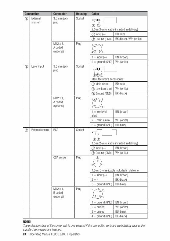
Connection Connector Housing Cabled External
shut-off3.5 mm jack plug
Socket
a b2.5 m 3-wire (cable included in delivery)
a Input (+) RD (red)
b Ground (GND) BK (black) / WH (white)
M12 x 1, A coded(optional)
Plug
1 = input (+) BN (brown)2 = ground (GND) WH (white)
e Level input 3.5 mm jack plug
Socket
ab cManufacturer's accessories
a Main alarm RD (red)
b Low level alert WH (white)
c Ground (GND) BK (black)
M12 x 1, A coded(optional)
Plug
1 = low level alert
BN (brown)
2 = main alarm WH (white)
3 = ground (GND) BU (blue)
f External control RCA Socket
a b1.5 m 2-wire (cable included in delivery)
a Input (+) BN (brown)
b Ground (GND) WH (white)
CSA version Plug
1.5 m, 3-wire (cable included in delivery)1 = input (+) BN (brown)2 = - BK (black)3 = ground (GND) BU (blue)
M12 x 1, B coded(optional)
Plug
1 = ground (GND) BN (brown)2 = pulses WH (white)3 = pulses BU (blue)4 = ground (GND) BK (black)
NOTE!The protection class of the control unit is only ensured if the connection ports are protected by caps or the standard connectors are inserted.
24 | Operating Manual FEDOS E/DX | Operation
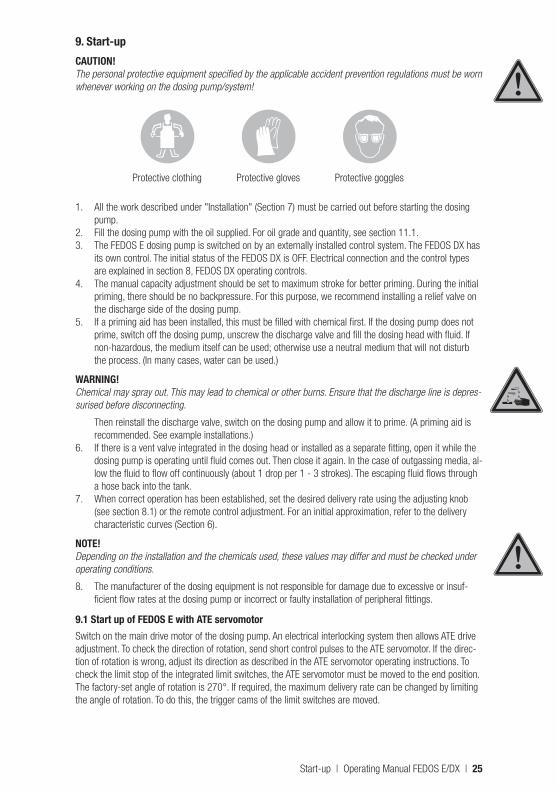
9. Start-upCAUTION!The personal protective equipment specified by the applicable accident prevention regulations must be worn whenever working on the dosing pump/system!
Protective clothing Protective gloves Protective goggles
1. All the work described under "Installation" (Section 7) must be carried out before starting the dosing pump.
2. Fill the dosing pump with the oil supplied. For oil grade and quantity, see section 11.1.3. The FEDOS E dosing pump is switched on by an externally installed control system. The FEDOS DX has
its own control. The initial status of the FEDOS DX is OFF. Electrical connection and the control types are explained in section 8, FEDOS DX operating controls.
4. The manual capacity adjustment should be set to maximum stroke for better priming. During the initial priming, there should be no backpressure. For this purpose, we recommend installing a relief valve on the discharge side of the dosing pump.
5. If a priming aid has been installed, this must be filled with chemical first. If the dosing pump does not prime, switch off the dosing pump, unscrew the discharge valve and fill the dosing head with fluid. If non-hazardous, the medium itself can be used; otherwise use a neutral medium that will not disturb the process. (In many cases, water can be used.)
WARNING!Chemical may spray out. This may lead to chemical or other burns. Ensure that the discharge line is depres-surised before disconnecting.
Then reinstall the discharge valve, switch on the dosing pump and allow it to prime. (A priming aid is recommended. See example installations.)
6. If there is a vent valve integrated in the dosing head or installed as a separate fitting, open it while the dosing pump is operating until fluid comes out. Then close it again. In the case of outgassing media, al-low the fluid to flow off continuously (about 1 drop per 1 - 3 strokes). The escaping fluid flows through a hose back into the tank.
7. When correct operation has been established, set the desired delivery rate using the adjusting knob (see section 8.1) or the remote control adjustment. For an initial approximation, refer to the delivery characteristic curves (Section 6).
NOTE!Depending on the installation and the chemicals used, these values may differ and must be checked under operating conditions.
8. The manufacturer of the dosing equipment is not responsible for damage due to excessive or insuf-ficient flow rates at the dosing pump or incorrect or faulty installation of peripheral fittings.
9.1 Start up of FEDOS E with ATE servomotorSwitch on the main drive motor of the dosing pump. An electrical interlocking system then allows ATE drive adjustment. To check the direction of rotation, send short control pulses to the ATE servomotor. If the direc-tion of rotation is wrong, adjust its direction as described in the ATE servomotor operating instructions. To check the limit stop of the integrated limit switches, the ATE servomotor must be moved to the end position. The factory-set angle of rotation is 270°. If required, the maximum delivery rate can be changed by limiting the angle of rotation. To do this, the trigger cams of the limit switches are moved.
Start-up | Operating Manual FEDOS E/DX | 25
10. ShutdownBefore starting any maintenance work or before long downtimes, drain the chemicals from the dosing pump and rinse it thoroughly with a neutral medium.
CAUTION!Excess chemicals must be disposed of properly. Observe the applicable accident prevention regulations and wear personal protective equipment.
Protective clothing Protective gloves Protective goggles
CAUTION!The dosing pump must be disconnected from the voltage supply and secured to prevent it being restarted.
CAUTION!Before disconnecting the discharge line from the pump discharge valve, release the pressure so that chemicals do not spray out.
The discharge and suction valves should be unscrewed in order to drain the dosing head.
10.1 Disposal of old equipmentIf the equipment is being disposed of, it should be washed thoroughly. Residual chemicals should be dis-posed of properly. The equipment was manufactured in accordance with the ROHS guideline and the waste electrical equipment legislation. The manufacturer will take care of disposal if the equipment is returned free of charge. It should not be disposed of as domestic waste!
Device revisionThis operating manual applies to the following devices:
Device RevisionFEDOS E/DX 01…30 06/2004
It contains all the technical information required for installation, start-up and maintenance. Should you have any questions or require further information regarding this operating manual, please contact the manufac-turer or its official national representative.
26 | Operating Manual FEDOS E/DX | Shutdown
11. MaintenanceThese dosing pumps are produced to the highest quality standards, and have a long service life. Neverthe-less some parts are subject to wear caused by operation (e.g. piston, valve seats, valve balls). Regular visual inspections are therefore necessary in order to ensure a long operating life. Regular maintenance will protect the dosing pump from operation interruptions. The manufacturer recommends maintenance once per year, provided the local regulations do not specify more frequent maintenance.
11.1 LubricationThe piston dosing pump FEDOS E/DX requires little maintenance. The dosing pump gear is lubricated with gear oil of viscosity class ISO-VG460 according to DIN 51519 (corresponds to SAE 140 according to DIN 51512). The first filling, which is supplied with the product, is to be replaced after 5,000 operating hours or 1 year, whichever comes first. Further oil changes should be conducted after 10,000 operating hours or 2 years, whichever comes first. The filling capacity is about 0.25 l for gears. The actually quantity of gear oil required can be determined by checking the min.-max. markings of the oil-measuring stick.
ATTENTION! FEDOS DX: To avoid damaging the proximity switch inside the gear housing, the dosing pump must be switched off before removing the oil dipstick.
11.2 Maintenance of the bearingsThe upper bearing of the pinion shaft is a sealed and permanently lubricated ball bearing. The other rolling bearings in the gearing, and the plain bearings of the diaphragm rod, are lubricated by the gear oil. The oil also performs a heat dissipation function.
All bearings must be examined for wear after 10000 hours of operation. The service life of the rolling bear-ings depends on the applied loads.
11.3 Maintenance of the ATE servomotor (optional)The ATE servomotor comes with lifetime lubrication ex factory. Nevertheless, regular inspections are recom-mended if the drive is operated in tough operating conditions, for example in high ambient temperatures or continuous operation. To re-lubricate the ATE gear, use molybdenum disulphite, for example "Molykote BR2plus" or "OKS400".
11.4 Replacing the piston
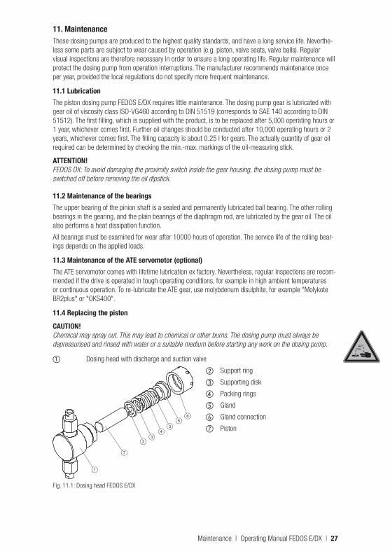
CAUTION!Chemical may spray out. This may lead to chemical or other burns. The dosing pump must always be depressurised and rinsed with water or a suitable medium before starting any work on the dosing pump.
a Dosing head with discharge and suction valve
b Support ring
c Supporting disk
d Packing rings
e Gland
f Gland connection
g Piston
Fig. 11.1: Dosing head FEDOS E/DX
1
7
23
43
56
Maintenance | Operating Manual FEDOS E/DX | 27
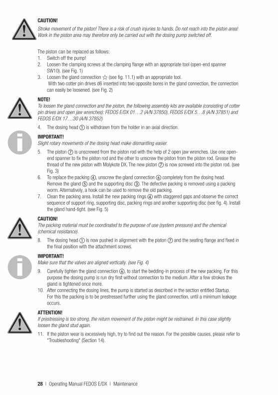
CAUTION!Stroke movement of the piston! There is a risk of crush injuries to hands. Do not reach into the piston area! Work in the piston area may therefore only be carried out with the dosing pump switched off.
The piston can be replaced as follows:1. Switch off the pump!2. Loosen the clamping screws at the clamping flange with an appropriate tool (open-end spanner
SW10). (see Fig. 1) 3. Loosen the gland connection ? (see fig. 11.1) with an appropriate tool.
With two cotter pin drives d6 inserted into two opposite bores in the gland connection, the connection can easily be loosened. (see Fig. 2)
NOTE!To loosen the gland connection and the piston, the following assembly kits are available (consisting of cotter pin drives and open jaw wrenches): FEDOS E/DX 01…2 (A/N 37850), FEDOS E/DX 5…8 (A/N 37851) and FEDOS E/DX 17…30 (A/N 37852)
4. The dosing head a is withdrawn from the holder in an axial direction.
IMPORTANT! Slight rotary movements of the dosing head make dismantling easier.
5. The piston g is unscrewed from the piston rod with the help of 2 open jaw wrenches. Use one open-end spanner to fix the piston rod and the other to unscrew the piston from the piston rod. Grease the thread of the new piston with Molykote DX. The new piston g is now screwed into the piston rod. (see Fig. 3)
6. To replace the packing d, unscrew the gland connection f completely from the dosing head. Remove the gland e and the supporting disc c. The defective packing is removed using a packing worm. Alternatively, a hook can be used to remove the old packing.
7. Clean the packing area. Install the new packing rings d with staggered gaps and observe the correct sequence of support ring, supporting disc, packing rings and another supporting disc (see fig. 4). Install the gland hand-tight. (see Fig. 5)
CAUTION! The packing material must be coordinated to the purpose of use (system pressure) and the chemical (chemical resistance).
8. The dosing head a is now pushed in alignment with the piston g and the seating flange and fixed in the final position with the attachment screws.
IMPORTANT! Make sure that the valves are aligned vertically. (see Fig. 4)
9. Carefully tighten the gland connection f, to start the bedding-in process of the new packing. For this purpose the dosing pump is run dry first without connection to the medium. After a few strokes the gland is tightened once more.
10. After connecting the dosing lines, the pump is started as described in the section entitled Startup. For this the packing is to be prestressed further using the gland connection, until a minimum leakage occurs.
ATTENTION! If prestressing is too strong, the return movement of the piston might be restrained. In this case slightly loosen the gland stud again.
11. If the piston wear is excessively high, try to find out the reason. For the possible causes, please refer to "Troubleshooting" (Section 14).
28 | Operating Manual FEDOS E/DX | Maintenance
11.5 ValvesThe dosing pump valves must be cleaned regularly.
NOTE!When screwing the valves into the dosing head, observe the tightening torque of 2 Nm ±20 %.
CAUTION!Chemical may spray out. This may lead to chemical or other burns. The dosing pump must always be depressurised and rinsed with water or a suitable medium before starting any work on the dosing pump.
NOTE!Dirty valves will affect the dosing accuracy.
11 2
3
5
4
Maintenance | Operating Manual FEDOS E/DX | 29
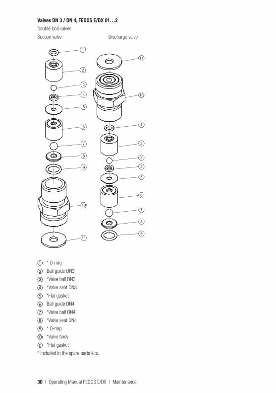
Valves DN 3 / DN 4, FEDOS E/DX 01…2Double-ball valves
Suction valve Discharge valveSaugventil Druckventil
1
2
3
4
5
6
7
8
9
10
11
11
10
1
2
3
4
5
6
7
8
9
a * O-ring
b Ball guide DN3
c *Valve ball DN3
d *Valve seat DN3
e *Flat gasket
f Ball guide DN4
g *Valve ball DN4
h *Valve seat DN4
i * O-ring
j *Valve body
k *Flat gasket
* included in the spare parts kits.
30 | Operating Manual FEDOS E/DX | Maintenance
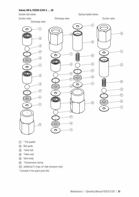
Valves DN 6, FEDOS E/DX 5 … 30Double-ball valves Spring-loaded valves
Suction valve Discharge valve Suction valve Discharge valve
1
5
1
4
7*
3
2
1
4
7*
3
2
5
1
2
3
7*
4
1
2
3
7*
4
1
Saugventil Druckventil
a * Flat gasket
b Ball guide
c *Valve ball
d *Valve seat
e Valve body
f *Compression spring
(g additional O-rings, for high-pressure only)
* included in the spare parts kits
Saugventil Druckventil
1
2
6
3
7*
4
1
5
5
1
2
6
3
7*
4
1
Maintenance | Operating Manual FEDOS E/DX | 31
12. Explosion-proof dosing pumps12.1 GeneralThe FEDOS E explosion-proof dosing pump is an electro-motor-driven, explosion-proof piston dosing pump of equipment category 2, group II.
In combination with an explosion-proof motor (Ex II 2 G E Ex e II T3 or Ex II 2 G E Ex d/de IIB/IIC T4) it is used for dosing fluids in Zone 1 potentially explosive atmospheres. The dosing pump carries the Ex mark "Ex II 2 G c k T4 03 ATEX D085".
ATTENTION!The dosing pump is not intended for dosing gaseous media or solids.
DANGER!Risk of burns. Shock wave: parts may fly off and cause fatal injury. FEDOS DX must not be used in poten-tially explosive atmospheres under any circumstances.
12.2 Special conditionsThe minimum requirements for the zone classification must be ensured if using the dosing pump in areas with a potentially explosive atmosphere. The dosing pump itself and the motor must meet the minimum requirements.
CAUTION!The FEDOS E may not be used for dosing combustible and flammable fluids.
32 | Operating Manual FEDOS E/DX | Explosion-proof dosing pumps
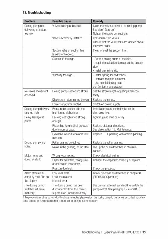
13. Troubleshooting
Problem Possible cause RemedyDosing pump not delivering or output too low.
Valves leaking or blocked. Clean the valves and vent the dosing pump.See also "Start-up"Tighten the screw connections.
Valves incorrectly installed. Reassemble the valves. Ensure that the valve balls are located above the valve seats.
Suction valve or suction line leaking or blocked.
Clean or seal the suction line.
Suction lift too high. - Set the dosing pump at the inlet.- Install the pulsation damper on the suction side.- Install a priming aid.
Viscosity too high. - Install spring-loaded valves.- Increase the pipe diameter.- Use special dosing head>> Contact manufacturer
No stroke movement observed
Dosing pump set to zero stroke. Set the stroke length adjusting knob cor-rectly.
Diaphragm return spring broken. Replace the spring.Power supply interrupted. Switch on power supply.
Dosing pump delivery rate too high
Pressure on suction side too high (pump siphoning).
Install a pressure control valve on the discharge line.
Heavy leakage at piston
Packing not tightened strong enough.
Tighten gland stud carefully.
Piston has longitudinal grooves due to normal wear.
Replace piston and packing.See also section 12, Maintenance.
Excessive wear due to abrasive medium.
Replace PTFE packing with Aramid packing.
Dosing pump very noisy.
Roller bearing defective. Replace the roller bearing.No oil in the gearing, or too little Top up the oil as described in "Mainte-
nance".Motor hums and does not start.
Wrongly connected. Check electrical wiring.Capacitor defective, wrong size or connected incorrectly.
Connect the capacitor correctly or replace.
Pressure too high. Check the process.Alarm states indi-cated by red LEDs on the display.
Low level alertLevel main alarmInternal error
Check functions as described in chapter 8 (FEDOS DX Operation).
The dosing pump switches off auto-matically.
The dosing pump has been disconnected from the power supply in an uncontrolled way.
Use only an external switch-off to switch the pump on/off. See paragraph 7.4 and 8.3
If the problem cannot be solved with the above remedies, please return the dosing pump to the factory or contact our After-Sales Service for further assistance. Repairs will be carried out immediately.
Troubleshooting | Operating Manual FEDOS E/DX | 33
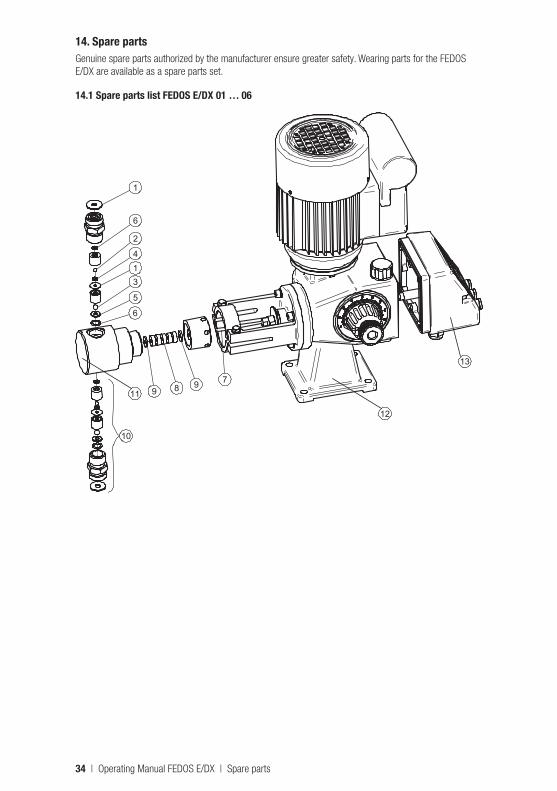
14. Spare partsGenuine spare parts authorized by the manufacturer ensure greater safety. Wearing parts for the FEDOS E/DX are available as a spare parts set.
14.1 Spare parts list FEDOS E/DX 01 … 06
1
6
2
413
6
5
7989
10
11
12
13
34 | Operating Manual FEDOS E/DX | Spare parts
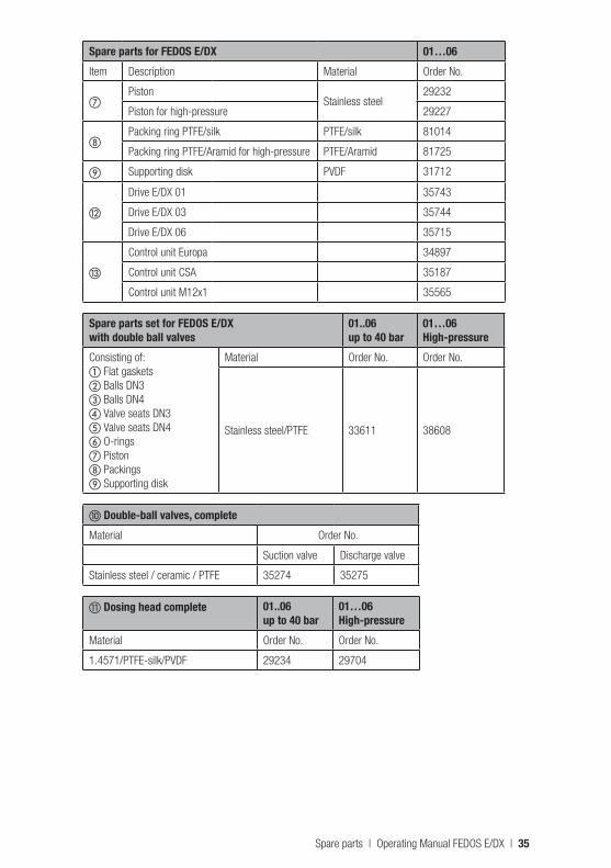
Spare parts for FEDOS E/DX 01…06Item Description Material Order No.
gPiston
Stainless steel29232
Piston for high-pressure 29227
hPacking ring PTFE/silk PTFE/silk 81014
Packing ring PTFE/Aramid for high-pressure PTFE/Aramid 81725
i Supporting disk PVDF 31712
l
Drive E/DX 01 35743
Drive E/DX 03 35744
Drive E/DX 06 35715
m
Control unit Europa 34897
Control unit CSA 35187
Control unit M12x1 35565
Spare parts set for FEDOS E/DX with double ball valves
01..06up to 40 bar
01…06High-pressure
Consisting of:a Flat gasketsb Balls DN3 c Balls DN4d Valve seats DN3e Valve seats DN4f O-ringsg Pistonh Packingsi Supporting disk
Material Order No. Order No.
Stainless steel/PTFE 33611 38608
j Double-ball valves, completeMaterial Order No.
Suction valve Discharge valve
Stainless steel / ceramic / PTFE 35274 35275
k Dosing head complete 01..06up to 40 bar
01…06High-pressure
Material Order No. Order No.
1.4571/PTFE-silk/PVDF 29234 29704
Spare parts | Operating Manual FEDOS E/DX | 35
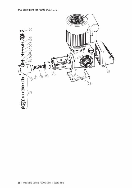
14.2 Spare parts list FEDOS E/DX 1 … 2
6
5
3
1
4
2
6
1
7989
10
11
12
13
36 | Operating Manual FEDOS E/DX | Spare parts
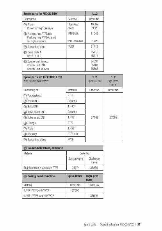
Spare parts for FEDOS E/DX 1…2Description Material Order No.
g Piston Piston for high pressure
Stainless steel
10602 99520
h Packing ring PTFE/silk Packing ring PTFE/Aramid for high pressure
PTFE/silk PTFE/Aramid
81046
81726
i Supporting disc PVDF 31713
l Drive E/DX 1 Drive E/DX 2
35715 35714
m Control unit Europa Control unit CSA Control unit M 12x1
34897 35187 35565
Spare parts set for FEDOS E/DX with double ball valves
1..2 up to 40 bar
1..2 High-pres-
sure
Consisting of: Material Order No. Order No.
a Flat gaskets PTFE
37689 37689
b Balls DN3 Ceramic
c Balls DN4 1.4401
d Valve seats DN3 Ceramic
e Valve seats DN4 1.4571
f O-rings PTFE
g Piston 1.4571
h Packings PTFE-silk
i Supporting discs PVDF
j Double-ball valves, complete Material Order No.
Suction valve Discharge valve
Stainless steel / ceramic / PTFE 35274 35275
k Dosing head complete up to 40 bar High-pres-sure
Material Order No. Order No.
1.4571/PTFE-silk/PVDF 37500
1.4571/PTFE-Aramid/PVDF 37540
Spare parts | Operating Manual FEDOS E/DX | 37
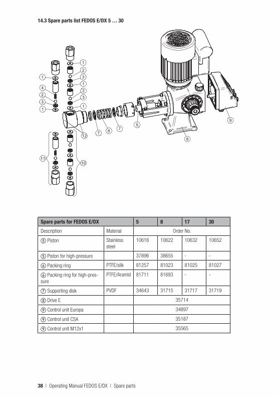
14.3 Spare parts list FEDOS E/DX 5 … 30
1
32
132
1
1
3
2
4
1
8
9
12
767
5
1011
Spare parts for FEDOS E/DX 5 8 17 30Description Material Order No.
e Piston Stainless steel
10616 10622 10632 10652
e Piston for high-pressure 37896 38655 - -
f Packing ring PTFE/silk 81257 81023 81025 81027
f Packing ring for high-pres-sure
PTFE/Aramid 81711 81693 - -
g Supporting disk PVDF 34643 31715 31717 31719
h Drive E 35714
i Control unit Europa 34897
i Control unit CSA 35187
i Control unit M12x1 35565
38 | Operating Manual FEDOS E/DX | Spare parts
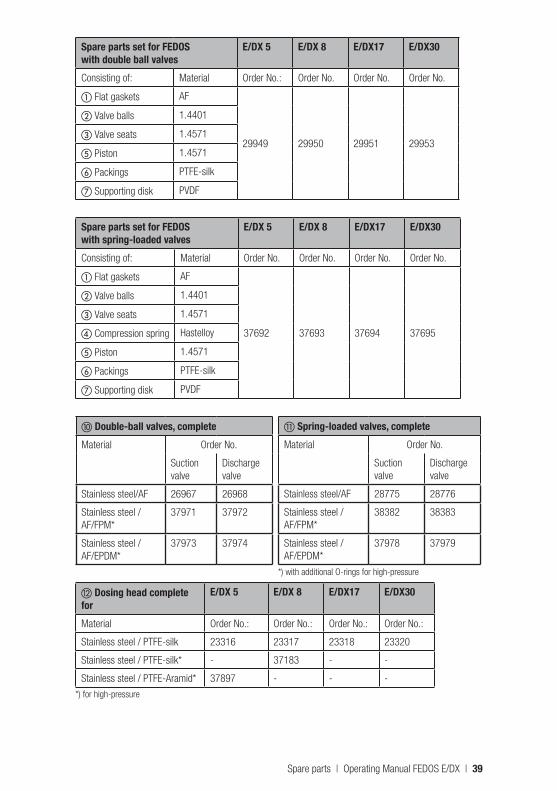
Spare parts set for FEDOS with double ball valves
E/DX 5 E/DX 8 E/DX17 E/DX30
Consisting of: Material Order No.: Order No. Order No. Order No.
a Flat gaskets AF
29949 29950 29951 29953
b Valve balls 1.4401
c Valve seats 1.4571
e Piston 1.4571
f Packings PTFE-silk
g Supporting disk PVDF
Spare parts set for FEDOSwith spring-loaded valves
E/DX 5 E/DX 8 E/DX17 E/DX30
Consisting of: Material Order No. Order No. Order No. Order No.
a Flat gaskets AF
37692 37693 37694 37695
b Valve balls 1.4401
c Valve seats 1.4571
d Compression spring Hastelloy
e Piston 1.4571
f Packings PTFE-silk
g Supporting disk PVDF
j Double-ball valves, completeMaterial Order No.
Suction valve
Discharge valve
Stainless steel/AF 26967 26968
Stainless steel / AF/FPM*
37971 37972
Stainless steel / AF/EPDM*
37973 37974
l Dosing head complete for
E/DX 5 E/DX 8 E/DX17 E/DX30
Material Order No.: Order No.: Order No.: Order No.:
Stainless steel / PTFE-silk 23316 23317 23318 23320
Stainless steel / PTFE-silk* - 37183 - -
Stainless steel / PTFE-Aramid* 37897 - - -
*) for high-pressure
k Spring-loaded valves, completeMaterial Order No.
Suction valve
Discharge valve
Stainless steel/AF 28775 28776
Stainless steel / AF/FPM*
38382 38383
Stainless steel / AF/EPDM*
37978 37979
*) with additional O-rings for high-pressure
Spare parts | Operating Manual FEDOS E/DX | 39
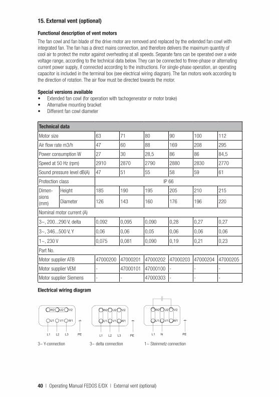
15. External vent (optional)
Functional description of vent motorsThe fan cowl and fan blade of the drive motor are removed and replaced by the extended fan cowl with integrated fan. The fan has a direct mains connection, and therefore delivers the maximum quantity of cool air to protect the motor against overheating at all speeds. Separate fans can be operated over a wide voltage range, according to the technical data below. They can be connected to three-phase or alternating current power supply, if connected according to the instructions. For single-phase operation, an operating capacitor is included in the terminal box (see electrical wiring diagram). The fan motors work according to the direction of rotation. The air flow must be directed towards the motor.
Special versions available• Extended fan cowl (for operation with tachogenerator or motor brake)• Alternative mounting bracket • Different fan cowl diameter
Technical dataMotor size 63 71 80 90 100 112
Air flow rate m3/h 47 60 88 169 208 295
Power consumption W 27 30 28,5 86 86 84,5
Speed at 50 Hz (rpm) 2910 2870 2790 2880 2830 2770
Sound pressure level dB(A) 47 51 55 58 59 61
Protection class IP 66
Dimen-sions (mm)
Height 185 190 195 205 210 215
Diameter 126 143 160 176 196 220
Nominal motor current (A)
3~, 200...290 V, delta 0,092 0,095 0,090 0,28 0,27 0,27
3~, 346...500 V, Y 0,06 0,06 0,05 0,06 0,06 0,06
1~, 230 V 0,075 0,081 0,090 0,19 0,21 0,23
Part No.
Motor supplier ATB 47000200 47000201 47000202 47000203 47000204 47000205
Motor supplier VEM - 47000101 47000100 - - -
Motor supplier Siemens - - 47000303 - - -
Electrical wiring diagram
L1 L2 L3 PE L1 L2 L3 PE
L1 N PE
W2 U2 V2
U1 V1 W1
W2 U2 V2
U1 V1 W1
W2 U2 V2
U1 V1 W1
L1 L2 L3 PE L1 L2 L3 PE
L1 N PE
W2 U2 V2
U1 V1 W1
W2 U2 V2
U1 V1 W1
W2 U2 V2
U1 V1 W1
L1 L2 L3 PE L1 L2 L3 PE
L1 N PE
W2 U2 V2
U1 V1 W1
W2 U2 V2
U1 V1 W1
W2 U2 V2
U1 V1 W1
3~ Y-connection 3~ delta connection 1~ Steinmetz connection
40 | Operating Manual FEDOS E/DX | External vent (optional)
IndexAAlarm ...........................................................................22Alarm relay ...................................................................23Analogue control ...........................................................22Approximation initiator ...................................................27Area with a potentially explosive atmosphere ..................15
BBearings .......................................................................27
CCable assignments ........................................................23Chemical leakage .........................................................15Control unit ...................................................................11
DDelivery characteristic curves ........................................14Diaphragm replacement ................................................27Dimensioned drawings ....................................................9Dosing head ...................................................................7Dosing of chemicals ........................................................5
EElectric motor data ........................................................12Explosion-proof .............................................................32Explosion-proof motors ..................................................12
FFactory setting ..............................................................23Fault ............................................................................33Function .........................................................................8
IInjection nozzle .............................................................20Installation ....................................................................15Installation example ......................................................20Installation location .......................................................16
LLevel input ....................................................................21Level monitoring ...........................................................19Lubrication ...................................................................27
MMaintenance .................................................................27Manual control ..............................................................22
NMax. number of strokes .................................................23
OOil inlet...........................................................................7Oil outlet.........................................................................7Selection of operating mode ..........................................21Operation .....................................................................21
PPressure control and safety valves .................................19Protective clothing...........................................................5Pulse control.................................................................22
RRevision .......................................................................26
SSeparate fan .................................................................40Servomotor ...................................................................13Shutdown .....................................................................26Spare parts ...................................................................34
Start up ........................................................................25Structure of the dosing pump...........................................7Switching on/off ............................................................21
TTechnical data ..............................................................10Troubleshooting ............................................................33
VValves ..........................................................................29
WWiring diagram for electronics .......................................23Wiring diagram for the drive motor .................................17
YY-connection .................................................................17
Index | Operating Manual FEDOS E/DX | 41
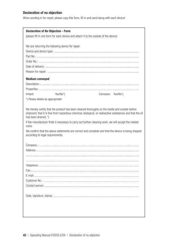
Declaration of no objectionWhen sending in for repair, please copy this form, fill in and send along with each device!
Declaration of No Objection - Form(please fill in one form for each device and attach it to the outside of the device)
We are returning the following device for repair:
Device and device type: .............................................................................................................
Part No.: ...................................................................................................................................
Order No.: ................................................................................................................................
Date of delivery: ........................................................................................................................
Reason for repair: .....................................................................................................................
Medium conveyedDescription: ...............................................................................................................................
Properties: .................................................................................................................................
Irritant: Yes/No*) Corrosive: Yes/No*)
*) Please delete as appropriate!
We hereby certify that the product has been cleaned thoroughly on the inside and outside before shipment, that it is free from hazardous chemical, biological, or radioactive substances and that the oil has been drained. *)
If the manufacturer finds it necessary to carry out further cleaning work, we will accept the related costs.
We confirm that the above statements are correct and complete and that the device is being shipped according to legal requirements.
Company: ..................................................................................................................................
Address: ....................................................................................................................................
.................................................................................................................................................
.................................................................................................................................................
Telephone: .................................................................................................................................
Fax: ...........................................................................................................................................
E-mail: ......................................................................................................................................
Customer No.: ...........................................................................................................................
Contact person: .........................................................................................................................
Date, signature, stamp: ..............................................................................................................
42 | Operating Manual FEDOS E/DX | Declaration of no objection
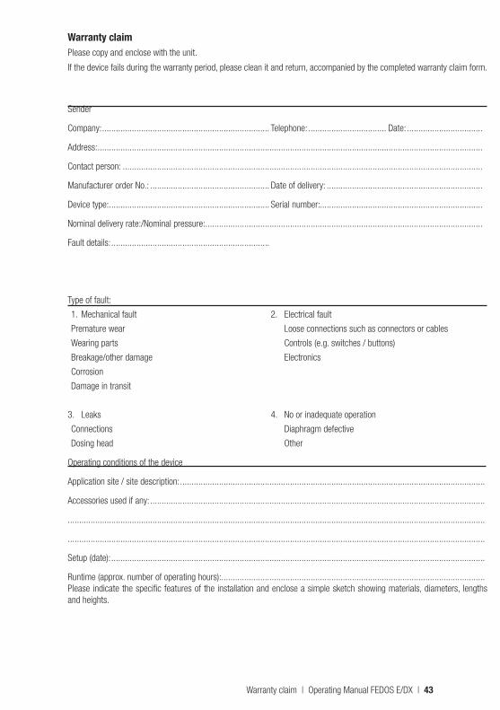
Warranty claimPlease copy and enclose with the unit.
If the device fails during the warranty period, please clean it and return, accompanied by the completed warranty claim form.
Sender
Company: ......................................................................... Telephone: .................................. Date: .................................
Address: ........................................................................................................................................................................
Contact person: .............................................................................................................................................................
Manufacturer order No.: .................................................... Date of delivery: ....................................................................
Device type: ...................................................................... Serial number:.......................................................................
Nominal delivery rate:/Nominal pressure: .........................................................................................................................
Fault details: .....................................................................
Type of fault:
1. Mechanical fault 2. Electrical fault
Premature wear Loose connections such as connectors or cables
Wearing parts Controls (e.g. switches / buttons)
Breakage/other damage Electronics
Corrosion
Damage in transit
3. Leaks 4. No or inadequate operation
Connections Diaphragm defective
Dosing head Other
Operating conditions of the device
Application site / site description: .....................................................................................................................................
Accessories used if any: ..................................................................................................................................................
......................................................................................................................................................................................
......................................................................................................................................................................................
Setup (date): ...................................................................................................................................................................
Runtime (approx. number of operating hours): ...................................................................................................................Please indicate the specific features of the installation and enclose a simple sketch showing materials, diameters, lengths and heights.
Warranty claim | Operating Manual FEDOS E/DX | 43
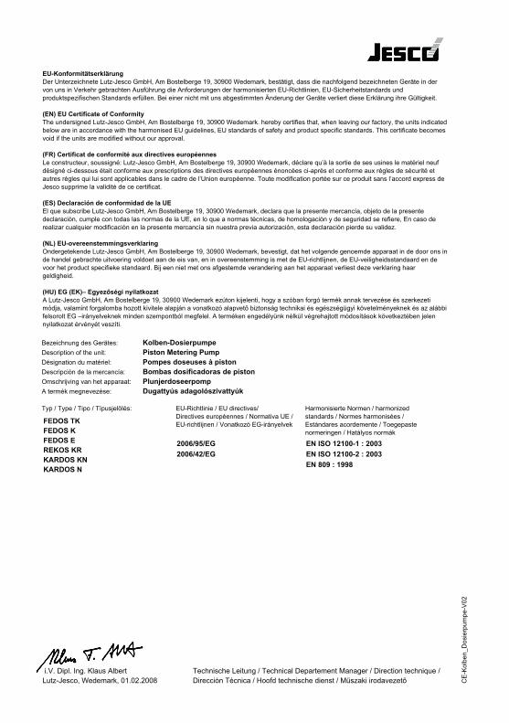
CE declaration of conformity
CE
-Kol
ben_
Dos
ierp
umpe
-V02
FEDOS TKFEDOS KFEDOS EREKOS KRKARDOS KNKARDOS N
2006/95/EG2006/42/EG
EU-KonformitätserklärungDer Unterzeichnete Lutz-Jesco GmbH, Am Bostelberge 19, 30900 Wedemark, bestätigt, dass die nachfolgend bezeichneten Geräte in der von uns in Verkehr gebrachten Ausführung die Anforderungen der harmonisierten EU-Richtlinien, EU-Sicherheitstandards und produktspezifischen Standards erfüllen. Bei einer nicht mit uns abgestimmten Änderung der Geräte verliert diese Erklärung ihre Gültigkeit.
(EN) EU Certificate of ConformityThe undersigned Lutz-Jesco GmbH, Am Bostelberge 19, 30900 Wedemark. hereby certifies that, when leaving our factory, the units indicatedbelow are in accordance with the harmonised EU guidelines, EU standards of safety and product specific standards. This certificate becomesvoid if the units are modified without our approval.
(FR) Certificat de conformité aux directives européennesLe constructeur, soussigné: Lutz-Jesco GmbH, Am Bostelberge 19, 30900 Wedemark, déclare qu’à la sortie de ses usines le matériel neuf désigné ci-dessous était conforme aux prescriptions des directives européennes énoncées ci-après et conforme aux règles de sécurité et autres règles qui lui sont applicables dans le cadre de l’Union européenne. Toute modification portée sur ce produit sans l’accord express deJesco supprime la validité de ce certificat.
(ES) Declaración de conformidad de la UEEl que subscribe Lutz-Jesco GmbH, Am Bostelberge 19, 30900 Wedemark, declara que la presente mercancía, objeto de la presente declaración, cumple con todas las normas de la UE, en lo que a normas técnicas, de homologación y de seguridad se refiere, En caso de realizar cualquier modificación en la presente mercancía sin nuestra previa autorización, esta declaración pierde su validez.
(NL) EU-overeenstemmingsverklaringOndergetekende Lutz-Jesco GmbH, Am Bostelberge 19, 30900 Wedemark, bevestigt, dat het volgende genoemde apparaat in de door ons inde handel gebrachte uitvoering voldoet aan de eis van, en in overeenstemming is met de EU-richtlijnen, de EU-veiligheidsstandaard en de voor het product specifieke standaard. Bij een niet met ons afgestemde verandering aan het apparaat verliest deze verklaring haar geldigheid.
(HU) EG (EK)– Egyezőségi nyilatkozatA Lutz-Jesco GmbH, Am Bostelberge 19, 30900 Wedemark ezúton kijelenti, hogy a szóban forgó termék annak tervezése és szerkezeti módja, valamint forgalomba hozott kivitele alapján a vonatkozó alapvető biztonság technikai és egészségügyi követelményeknek és az alábbifelsorolt EG –irányelveknek minden szempontból megfelel. A terméken engedélyünk nélkül végrehajtott módosítások következtében jelen nyilatkozat érvényét veszíti.
Kolben-DosierpumpePiston Metering PumpPompes doseuses à pistonBombas dosificadoras de pistonPlunjerdoseerpompDugattyús adagolószivattyúk
Bezeichnung des Gerätes:Description of the unit:Désignation du matériel:Descripción de la mercancía:Omschrijving van het apparaat:A termék megnevezése:
Typ / Type / Tipo / Típusjelölés:
(IT) Dichiarazione di conformità alle norme UELa sottoscritta Lutz-Jesco GmbH, Am Bostelberge 19, 30900 Wedemark, certifica che il prodotto qui de seguito indicato, nei modelli da noi commercializzati, è conforme alle direttive armonizzate UE nonché agli standard di sicurezza e agli standard specifici di prodotto. Qualunque modifica apportata al prodotto senza nostra specifica autorizzazione invalida la presente dichiarazione.
(PT) Certificado de conformidade da UEOs abaixo mencionados Lutz-Jesco GmbH, Am Bostelberge 19, 30900 Wedemark, por este meio certificam que aosair da fábrica o aparelho abaixo mencionado está de acordo com as directrizes harmonizadas da UE, padrões desegurança e de produtos específicos. Este certificado ficará nulo se a unidade for modificada sem a nossa aprovação.
(DK) EU Overensstemmelse certifikatUndertegnede Lutz-Jesco GmbH, Am Bostelberge 19, 30900 Wedemark, bekræfter hermed, at enheder listet herunder, ved retningslinier, EU sikkerhedsstandarder og produktspecifikationsstandarder. Dette certifikat træder duaf kraft hvis enhederne er ændret uden vor godkendelse.
(PL)CD1
(CZ)CD1
(SE)heft
(FI)
EU-Richtlinie / EU directives/Directives européennes / Normativa UE /EU-richtlijnen / Vonatkozó EG-irányelvek
EN ISO 12100-1 : 2003EN ISO 12100-2 : 2003EN 809 : 1998
Harmonisierte Normen / harmonizedstandards / Normes harmonisées /Estándares acordemente / Toegepastenormeringen / Hatályos normák
i.V. Dipl. Ing. Klaus AlbertLutz-Jesco, Wedemark, 01.02.2008
Technische Leitung / Technical Departement Manager / Direction technique /Dirección Técnica / Hoofd technische dienst / Műszaki irodavezető
Descrizione del prodotto:
Direttive UE:
Conformità completa:
Direzione Tecnica
CE-Kolben_Dosierpumpe-V02
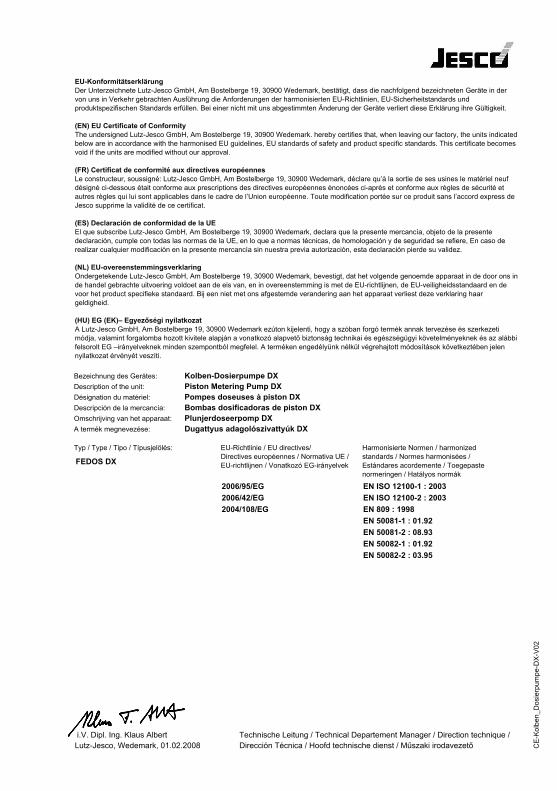
CE
-Kol
ben_
Dos
ierp
umpe
-DX
-V02
FEDOS DX
2006/95/EG2006/42/EG2004/108/EG
EU-KonformitätserklärungDer Unterzeichnete Lutz-Jesco GmbH, Am Bostelberge 19, 30900 Wedemark, bestätigt, dass die nachfolgend bezeichneten Geräte in der von uns in Verkehr gebrachten Ausführung die Anforderungen der harmonisierten EU-Richtlinien, EU-Sicherheitstandards und produktspezifischen Standards erfüllen. Bei einer nicht mit uns abgestimmten Änderung der Geräte verliert diese Erklärung ihre Gültigkeit.
(EN) EU Certificate of ConformityThe undersigned Lutz-Jesco GmbH, Am Bostelberge 19, 30900 Wedemark. hereby certifies that, when leaving our factory, the units indicatedbelow are in accordance with the harmonised EU guidelines, EU standards of safety and product specific standards. This certificate becomesvoid if the units are modified without our approval.
(FR) Certificat de conformité aux directives européennesLe constructeur, soussigné: Lutz-Jesco GmbH, Am Bostelberge 19, 30900 Wedemark, déclare qu’à la sortie de ses usines le matériel neuf désigné ci-dessous était conforme aux prescriptions des directives européennes énoncées ci-après et conforme aux règles de sécurité et autres règles qui lui sont applicables dans le cadre de l’Union européenne. Toute modification portée sur ce produit sans l’accord express deJesco supprime la validité de ce certificat.
(ES) Declaración de conformidad de la UEEl que subscribe Lutz-Jesco GmbH, Am Bostelberge 19, 30900 Wedemark, declara que la presente mercancía, objeto de la presente declaración, cumple con todas las normas de la UE, en lo que a normas técnicas, de homologación y de seguridad se refiere, En caso de realizar cualquier modificación en la presente mercancía sin nuestra previa autorización, esta declaración pierde su validez.
(NL) EU-overeenstemmingsverklaringOndergetekende Lutz-Jesco GmbH, Am Bostelberge 19, 30900 Wedemark, bevestigt, dat het volgende genoemde apparaat in de door ons inde handel gebrachte uitvoering voldoet aan de eis van, en in overeenstemming is met de EU-richtlijnen, de EU-veiligheidsstandaard en de voor het product specifieke standaard. Bij een niet met ons afgestemde verandering aan het apparaat verliest deze verklaring haar geldigheid.
(HU) EG (EK)– Egyezőségi nyilatkozatA Lutz-Jesco GmbH, Am Bostelberge 19, 30900 Wedemark ezúton kijelenti, hogy a szóban forgó termék annak tervezése és szerkezeti módja, valamint forgalomba hozott kivitele alapján a vonatkozó alapvető biztonság technikai és egészségügyi követelményeknek és az alábbifelsorolt EG –irányelveknek minden szempontból megfelel. A terméken engedélyünk nélkül végrehajtott módosítások következtében jelen nyilatkozat érvényét veszíti.
Kolben-Dosierpumpe DXPiston Metering Pump DXPompes doseuses à piston DXBombas dosificadoras de piston DXPlunjerdoseerpomp DXDugattyus adagolószivattyúk DX
Bezeichnung des Gerätes:Description of the unit:Désignation du matériel:Descripción de la mercancía:Omschrijving van het apparaat:A termék megnevezése:
Typ / Type / Tipo / Típusjelölés:
(IT) Dichiarazione di conformità alle norme UELa sottoscritta Lutz-Jesco GmbH, Am Bostelberge 19, 30900 Wedemark, certifica che il prodotto qui de seguito indicato, nei modelli da noi commercializzati, è conforme alle direttive armonizzate UE nonché agli standard di sicurezza e agli standard specifici di prodotto. Qualunque modifica apportata al prodotto senza nostra specifica autorizzazione invalida la presente dichiarazione.
(PT) Certificado de conformidade da UEOs abaixo mencionados Lutz-Jesco GmbH, Am Bostelberge 19, 30900 Wedemark, por este meio certificam que aosair da fábrica o aparelho abaixo mencionado está de acordo com as directrizes harmonizadas da UE, padrões desegurança e de produtos específicos. Este certificado ficará nulo se a unidade for modificada sem a nossa aprovação.
(DK) EU Overensstemmelse certifikatUndertegnede Lutz-Jesco GmbH, Am Bostelberge 19, 30900 Wedemark, bekræfter hermed, at enheder listet herunder, ved retningslinier, EU sikkerhedsstandarder og produktspecifikationsstandarder. Dette certifikat træder duaf kraft hvis enhederne er ændret uden vor godkendelse.
(PL)CD1
(CZ)CD1
(SE)heft
(FI)
EU-Richtlinie / EU directives/Directives européennes / Normativa UE /EU-richtlijnen / Vonatkozó EG-irányelvek
EN ISO 12100-1 : 2003EN ISO 12100-2 : 2003EN 809 : 1998EN 50081-1 : 01.92EN 50081-2 : 08.93EN 50082-1 : 01.92EN 50082-2 : 03.95
Harmonisierte Normen / harmonizedstandards / Normes harmonisées /Estándares acordemente / Toegepastenormeringen / Hatályos normák
i.V. Dipl. Ing. Klaus AlbertLutz-Jesco, Wedemark, 01.02.2008
Technische Leitung / Technical Departement Manager / Direction technique /Dirección Técnica / Hoofd technische dienst / Műszaki irodavezető
Descrizione del prodotto:
Direttive UE:
Conformità completa:
Direzione Tecnica
CE-Kolben_Dosierpumpe-DX-V02
CE
-Kol
ben_
Dos
ierp
umpe
-Ex-
V02
Fedos E - EX
2006/95/EG2006/42/EG94/9/EG
EU-KonformitätserklärungDer Unterzeichnete Lutz-Jesco GmbH, Am Bostelberge 19, 30900 Wedemark, bestätigt, dass die nachfolgend bezeichneten Geräte in der von uns in Verkehr gebrachten Ausführung die Anforderungen der harmonisierten EU-Richtlinien, EU-Sicherheitstandards und produktspezifischen Standards erfüllen. Bei einer nicht mit uns abgestimmten Änderung der Geräte verliert diese Erklärung ihre Gültigkeit.
(EN) EU Certificate of ConformityThe undersigned Lutz-Jesco GmbH, Am Bostelberge 19, 30900 Wedemark. hereby certifies that, when leaving our factory, the units indicatedbelow are in accordance with the harmonised EU guidelines, EU standards of safety and product specific standards. This certificate becomesvoid if the units are modified without our approval.
(FR) Certificat de conformité aux directives européennesLe constructeur, soussigné: Lutz-Jesco GmbH, Am Bostelberge 19, 30900 Wedemark, déclare qu’à la sortie de ses usines le matériel neuf désigné ci-dessous était conforme aux prescriptions des directives européennes énoncées ci-après et conforme aux règles de sécurité et autres règles qui lui sont applicables dans le cadre de l’Union européenne. Toute modification portée sur ce produit sans l’accord express deJesco supprime la validité de ce certificat.
(ES) Declaración de conformidad de la UEEl que subscribe Lutz-Jesco GmbH, Am Bostelberge 19, 30900 Wedemark, declara que la presente mercancía, objeto de la presente declaración, cumple con todas las normas de la UE, en lo que a normas técnicas, de homologación y de seguridad se refiere, En caso de realizar cualquier modificación en la presente mercancía sin nuestra previa autorización, esta declaración pierde su validez.
(NL) EU-overeenstemmingsverklaringOndergetekende Lutz-Jesco GmbH, Am Bostelberge 19, 30900 Wedemark, bevestigt, dat het volgende genoemde apparaat in de door ons inde handel gebrachte uitvoering voldoet aan de eis van, en in overeenstemming is met de EU-richtlijnen, de EU-veiligheidsstandaard en de voor het product specifieke standaard. Bij een niet met ons afgestemde verandering aan het apparaat verliest deze verklaring haar geldigheid.
(HU) EG (EK)– Egyezőségi nyilatkozatA Lutz-Jesco GmbH, Am Bostelberge 19, 30900 Wedemark ezúton kijelenti, hogy a szóban forgó termék annak tervezése és szerkezeti módja, valamint forgalomba hozott kivitele alapján a vonatkozó alapvető biztonság technikai és egészségügyi követelményeknek és az alábbifelsorolt EG –irányelveknek minden szempontból megfelel. A terméken engedélyünk nélkül végrehajtott módosítások következtében jelen nyilatkozat érvényét veszíti.
Explosionsgeschützte Kolben-DosierpumpeExplosion proofed Piston Metering PumpPompes doseuses à piston EXBombas dosificadoras de piston EXExplosieveilige Membraandoseerpomp EXDugattyus adagolószivattyúk robbanásbiztos kivitelben EX
Bezeichnung des Gerätes:Description of the unit:Désignation du matériel:Descripción de la mercancía:Omschrijving van het apparaat:A termék megnevezése:
Typ / Type / Tipo / Típusjelölés:
(IT) Dichiarazione di conformità alle norme UELa sottoscritta Lutz-Jesco GmbH, Am Bostelberge 19, 30900 Wedemark, certifica che il prodotto qui de seguito indicato, nei modelli da noi commercializzati, è conforme alle direttive armonizzate UE nonché agli standard di sicurezza e agli standard specifici di prodotto. Qualunque modifica apportata al prodotto senza nostra specifica autorizzazione invalida la presente dichiarazione.
(PT) Certificado de conformidade da UEOs abaixo mencionados Lutz-Jesco GmbH, Am Bostelberge 19, 30900 Wedemark, por este meio certificam que aosair da fábrica o aparelho abaixo mencionado está de acordo com as directrizes harmonizadas da UE, padrões desegurança e de produtos específicos. Este certificado ficará nulo se a unidade for modificada sem a nossa aprovação.
(DK) EU Overensstemmelse certifikatUndertegnede Lutz-Jesco GmbH, Am Bostelberge 19, 30900 Wedemark, bekræfter hermed, at enheder listet herunder, ved retningslinier, EU sikkerhedsstandarder og produktspecifikationsstandarder. Dette certifikat træder duaf kraft hvis enhederne er ændret uden vor godkendelse.
(PL)CD1
(CZ)CD1
(SE)heft
(FI)
EU-Richtlinie / EU directives/Directives européennes / Normativa UE /EU-richtlijnen / Vonatkozó EG-irányelvek
EN ISO 12100-1 : 2003EN ISO 12100-2 : 2003EN 809 : 1998EN 13463-1 : 2001
Harmonisierte Normen / harmonizedstandards / Normes harmonisées /Estándares acordemente / Toegepastenormeringen / Hatályos normák
i.V. Dipl. Ing. Klaus AlbertLutz-Jesco, Wedemark, 01.02.2008
Technische Leitung / Technical Departement Manager / Direction technique /Dirección Técnica / Hoofd technische dienst / Műszaki irodavezető
Descrizione del prodotto:
Direttive UE:
Conformità completa:
Direzione Tecnica
ATEX-Registrier-Nr. :Fedos E: Ex II 2 G c k T4 04 ATEX D041
CE-Kolben_Dosierpumpe-Ex-V02

Notes
Notes | Operating Manual FEDOS E/DX | 47
Lutz-Jesco GmbHAm Bostelberge 1930900 WedemarkGermany
Telephone: +49 5130 5802-0Fax: +49 5130 [email protected]/de
Austria
Lutz-Jesco GmbH
Aredstraße 7/22544 LeobersdorfAustria
Telephone: +43 2256 62180Fax: +43 2256 [email protected]
Netherlands
Lutz-Jesco Nederland B.V.
Nijverheidstraat 14 C2984 AH RidderkerkNetherlands
Telephone: +31 180 499460Fax: +31 180 [email protected]
USA
Lutz-JESCO America Corp.
55 Bermar ParkRochester, NY 14624USA
Telephone: +1 585 426-0990Fax: +1 585 [email protected]
East Asia
Lutz-JescoEast Asia Sdn Bhd6 Jalan Saudagar U1/16Hicom Glenmarie Industrial Park40150 Shah Alam /SelangorMalaysia
Telephone: +603 5569 2322Fax: +603 5569 [email protected]
Middle East
Lutz-Jesco Middle East FZE
P.O. Box 9614SAIF-Free Zone CenterSharjahUAE
Telephone: +971 6 5572205Fax: +971 6 [email protected]
Order No. BA-10706-02-V06Subject to technical changesand inaccuracies© Lutz-Jesco GmbH 05.2014Printed in Germany
Hungary
Lutz-Jesco Üzletág
Vasvári P. u. 9.9024 GyörHungary
Telephone: +36 96 523046Fax: +36 96 [email protected]
Great Britain
Lutz-Jesco (GB) Ltd.
Gateway EstateWest Midlands FreeportBirmingham B26 3QDGreat Britain
Telephone: +44 121 782 2662Fax: +44 121 782 [email protected]