cisco mobility express user guide for release 8 · cisco mobility express user guide for release...
TRANSCRIPT
Cisco Mobility Express User Guide for Release 8.2First Published: November 30, 2015
Americas HeadquartersCisco Systems, Inc.170 West Tasman DriveSan Jose, CA 95134-1706USAhttp://www.cisco.comTel: 408 526-4000 800 553-NETS (6387)Fax: 408 527-0883

THE SPECIFICATIONS AND INFORMATION REGARDING THE PRODUCTS IN THIS MANUAL ARE SUBJECT TO CHANGE WITHOUT NOTICE. ALL STATEMENTS,INFORMATION, AND RECOMMENDATIONS IN THIS MANUAL ARE BELIEVED TO BE ACCURATE BUT ARE PRESENTED WITHOUT WARRANTY OF ANY KIND,EXPRESS OR IMPLIED. USERS MUST TAKE FULL RESPONSIBILITY FOR THEIR APPLICATION OF ANY PRODUCTS.
THE SOFTWARE LICENSE AND LIMITEDWARRANTY FOR THE ACCOMPANYING PRODUCT ARE SET FORTH IN THE INFORMATION PACKET THAT SHIPPED WITHTHE PRODUCT AND ARE INCORPORATED HEREIN BY THIS REFERENCE. IF YOU ARE UNABLE TO LOCATE THE SOFTWARE LICENSE OR LIMITED WARRANTY,CONTACT YOUR CISCO REPRESENTATIVE FOR A COPY.
The Cisco implementation of TCP header compression is an adaptation of a program developed by the University of California, Berkeley (UCB) as part of UCB's public domain versionof the UNIX operating system. All rights reserved. Copyright © 1981, Regents of the University of California.
NOTWITHSTANDINGANYOTHERWARRANTYHEREIN, ALL DOCUMENT FILES AND SOFTWARE OF THESE SUPPLIERS ARE PROVIDED “AS IS"WITH ALL FAULTS.CISCO AND THE ABOVE-NAMED SUPPLIERS DISCLAIM ALL WARRANTIES, EXPRESSED OR IMPLIED, INCLUDING, WITHOUT LIMITATION, THOSE OFMERCHANTABILITY, FITNESS FORA PARTICULAR PURPOSEANDNONINFRINGEMENTORARISING FROMACOURSEOFDEALING, USAGE, OR TRADE PRACTICE.
IN NO EVENT SHALL CISCO OR ITS SUPPLIERS BE LIABLE FOR ANY INDIRECT, SPECIAL, CONSEQUENTIAL, OR INCIDENTAL DAMAGES, INCLUDING, WITHOUTLIMITATION, LOST PROFITS OR LOSS OR DAMAGE TO DATA ARISING OUT OF THE USE OR INABILITY TO USE THIS MANUAL, EVEN IF CISCO OR ITS SUPPLIERSHAVE BEEN ADVISED OF THE POSSIBILITY OF SUCH DAMAGES.
Any Internet Protocol (IP) addresses and phone numbers used in this document are not intended to be actual addresses and phone numbers. Any examples, command display output, networktopology diagrams, and other figures included in the document are shown for illustrative purposes only. Any use of actual IP addresses or phone numbers in illustrative content is unintentionaland coincidental.
Cisco and the Cisco logo are trademarks or registered trademarks of Cisco and/or its affiliates in the U.S. and other countries. To view a list of Cisco trademarks, go to this URL: http://www.cisco.com/go/trademarks. Third-party trademarks mentioned are the property of their respective owners. The use of the word partner does not imply a partnershiprelationship between Cisco and any other company. (1110R)
© 2015 Cisco Systems, Inc. All rights reserved.

C O N T E N T S
C H A P T E R 1 About Cisco Mobility Express 1
Overview of Cisco Mobility Express 1
Supported Cisco Aironet Access Points 1
Supported Software Images 2
C H A P T E R 2 Getting Started 5
Prerequisites for Setting Up and Accessing Cisco Mobility Express 5
Starting the Initial Configuration Wizard 6
Using the Initial Configuration Wizard 7
Checking if an AP has CAPWAP Lightweight AP Software or Cisco Mobility Express
Software 11
Upgrading from CAPWAP Lightweight AP Software Release 15.3.3-JBB1 to 15.3.3-JBB5 or
newer 12
Converting from CAPWAP Lightweight AP 15.3.3-JBB5 or newer to Cisco Mobility Express
Software 13
Preparing APs to Associate with the Master AP 14
Logging in to Cisco Mobility Express 14
Understanding the Mobility Express Controller Web Interface 16
C H A P T E R 3 Monitoring the Mobility Express Network 19
About the Cisco Mobility Express Monitoring Service 19
Customizing the Network Summary View 21
Viewing and Managing WLAN Users 22
Viewing WLANs 23
Viewing the Details of Configured WLANs 23
Customizing Access Points Table View 23
Viewing Details of Clients 24
Understanding the Mobility State Graphic 24
Cisco Mobility Express User Guide for Release 8.2 iii

Performing a Client Ping Test 24
Capturing Client Packets 25
Viewing Details of Rogue Devices (Clients and Access Points) 26
Viewing Details of Interferers 26
Customizing the Access Point Performance View 27
Adding Widgets to Customize Access Point Performance View 28
Removing Widgets to Customize Access Point Performance View 28
Customizing the Client Performance View 29
Adding Widgets to Customize Client Performance View 30
Removing Widgets to Customize Client Performance View 30
C H A P T E R 4 Specifying Wireless Settings 31
Setting Up WLANs and WLAN Users 31
About WLANs in a Cisco Mobility Express Network 31
Adding a WLAN 32
Enabling and Disabling WLANs 35
Editing and Deleting WLANs 35
Viewing and Managing WLAN Users 36
Managing Associated Access Points 37
Administering Access Points 37
Creating a Customized Login Page for Guest WLAN Users 39
C H A P T E R 5 Managing the Network 41
Setting the Management Access Interface 41
Managing Administrator Accounts 42
Adding an Admin Account 42
Editing an Admin Account 43
Deleting an Admin Account 43
Setting Date and Time 44
Using NTP Servers to Automatically Set the Date and Time 44
Adding and Editing NTP Servers 44
Deleting and Disabling NTP Servers 45
Configuring Date and Time Manually 45
Updating the Cisco Mobility Express Software 45
Guidelines for Preparing a TFTP Server 46
Cisco Mobility Express User Guide for Release 8.2iv
Contents
Performing the Software Update 47
C H A P T E R 6 Using Advanced Settings and Operations 49
Managing SNMP 49
Setting Up System Message Logging 49
Resetting the Mobility Express Controller 51
Rebooting the Mobility Express Controller 51
Saving Controller Configuration 52
A P P E N D I X A Controller CLI Commands 53
About Supported CLI Commands 53
Using the CLI Initial Configuration Wizard 54
Application Visibility Commands 56
CleanAir Commands 56
Controller Image Upgrade Commands 57
DNS Commands 57
Migration Commands 57
NTP Commands 58
UX Regulatory Domain Commands 58
VRRP Commands 59
WGB Commands 59
A P P E N D I X B Appendix 61
Cisco Mobility Express Solution Features and Specifications 61
Supported Browsers 61
Cisco Mobility Express Controller Failover and Master AP Election Process 62
How an Access Point is Added to the Cisco Mobility Express Network 63
Predownloading an Image to an Access Point 63
Converting an AP from Mobility Express to CAPWAP Lightweight Software 63
RF Parameter Optimization Settings 64
Related Documents 65
FAQs 65
Cisco Mobility Express User Guide for Release 8.2 v
Contents

Cisco Mobility Express User Guide for Release 8.2vi
Contents

C H A P T E R 1About Cisco Mobility Express
• Overview of Cisco Mobility Express, page 1
• Supported Cisco Aironet Access Points, page 1
• Supported Software Images, page 2
Overview of Cisco Mobility ExpressThe CiscoMobility Express wireless network solution provides the virtualWLC functionality that is currentlybundled into the Cisco Aironet 1850 Series and 1830 Series access points (APs). This functionality providesa simplified Wi-Fi architecture with enterprise-level WLAN capability to small and medium deployments.
In the CiscoMobility Express wireless network solution, one AP, running the CiscoMobility Express wirelesscontroller, is designated as the master AP. Other APs, referred to as subordinate APs, associate themselveswith this master AP.
The master AP operates as a WLC to manage and control the subordinate APs, besides operating as an AP toserve clients. The subordinate APs behave as normal lightweight APs to serve clients.
For a list of supported APs, see Supported Cisco Aironet Access Points, on page 1.
The CiscoMobility Express solution provides most of the features of aWLC and has the capability to interfacewith the following:
• Cisco Prime Infrastructure—For simplified network management, including managing AP groups.
• Cisco Identity Services Engine—For advanced policy enforcement.
• Cisco Mobility Services Engine—For providing presence-level data as well as an advanced spectrumsolution.
Supported Cisco Aironet Access PointsIn Cisco Mobility Express Release , the following APs are supported.
Cisco Mobility Express User Guide for Release 8.2 1

APs Supported as SubordinatesAPs Supported as Masters (support integrated WLCcapability)
• Cisco Aironet 700i Series
• Cisco Aironet 700w Series
• Cisco Aironet 1600 Series
• Cisco Aironet 1700 Series
• Cisco Aironet 2600 Series
• Cisco Aironet 2700 Series
• Cisco Aironet 3500 Series
• Cisco Aironet 3600 Series
• Cisco Aironet 3700 Series
• Cisco Aironet 1850 Series
• Cisco Aironet 1830 Series
1
1 APs supported as master APs can function as subordinate APs also .
Supported Software ImagesAP models that are supported as masters can be ordered with either of the following as the defaultfactory-shipped software:
• A Cisco Mobility Express software image. These models have model numbers (or Product IDs) endingin C.
• A lightweight AP software image, based on the Control and Provisioning of Wireless Access Points(CAPWAP) protocol, for joining a wireless controller. You can manually convert these models on siteto have a CiscoMobility Express software image. For information about this conversion, see Convertingfrom CAPWAP Lightweight AP 15.3.3-JBB5 or newer to Cisco Mobility Express Software, on page13.
AP models that are supported only as subordinates require a CAPWAP-based lightweight AP software image.
The Cisco Mobility Express software for your AP model can be downloaded from:
https://software.cisco.com/download/navigator.html:
From theDownload Softwarewindow, browse to your APmodel and then selectMobility Express Softwareto view a list of currently available software, with the latest the top. The software releases are labeled asfollows to help you determine which release to download:
• Early Deployment (ED)—These software releases provide new features, new hardware platform support,and bug fixes.
• Maintenance Deployment (MD)—These software releases provide bug fixes and ongoing softwaremaintenance.
• Deferred (DF)—These software releases have been deferred. We recommend that you migrate to anupgraded release.
Cisco Mobility Express User Guide for Release 8.22
About Cisco Mobility ExpressSupported Software Images

Cisco Mobility Express software for Cisco Wireless Release 8.2 is as follows:For AP 1830For AP 1850ReleaseSoftware Type and
Purpose
AIR-AP1830-K9-8.2.100.1.tarAIR-AP1850-K9-8.2.100.1.tar8.2.100.1Mobility Expresscontroller-capable APsoftware to be used forconversion fromLightweight AccessPoints only.
AIR-AP1830-K9-ME-8-2-100-1.zipAIR-AP1850-K9-ME-8-2-100-1.zip8.2.100.1Access Point imagebundle, to be used forupdating MEcontroller software andimages of supportedaccess points.
Cisco Mobility Express User Guide for Release 8.2 3
About Cisco Mobility ExpressSupported Software Images

Cisco Mobility Express User Guide for Release 8.24
About Cisco Mobility ExpressSupported Software Images

C H A P T E R 2Getting Started
• Prerequisites for Setting Up and Accessing Cisco Mobility Express, page 5
• Starting the Initial Configuration Wizard, page 6
• Using the Initial Configuration Wizard , page 7
• Checking if an AP has CAPWAP Lightweight AP Software or Cisco Mobility Express Software, page11
• Upgrading from CAPWAP Lightweight AP Software Release 15.3.3-JBB1 to 15.3.3-JBB5 or newer,page 12
• Converting fromCAPWAPLightweight AP 15.3.3-JBB5 or newer to CiscoMobility Express Software,page 13
• Preparing APs to Associate with the Master AP, page 14
• Logging in to Cisco Mobility Express , page 14
• Understanding the Mobility Express Controller Web Interface, page 16
Prerequisites for Setting Up and Accessing Cisco MobilityExpress
• You must not have other Cisco wireless controllers, neither appliance nor virtual, in the same network,during setup or during daily operation of a Cisco Mobility Express network.
The Cisco Mobility Express controller cannot interoperate or co-exist with other wireless controllers inthe same network. Ensure that there no wireless controllers, other than the Cisco Mobility Expresscontroller, in the network.
• Decide on the first access point (AP) to be set up. The first AP to be set up should be one that supportsthe Cisco Mobility Express wireless controller functionality. This is to ensure that this AP can act as themaster AP, and the other APs can then connect to it. This will ensure that the pre-definedCiscoAirProvision Service Set Identifier (SSID) is advertised only by the master AP and by other APs.
• Ensure that the AP is properly installed as per its Hardware Installation Guide.
Cisco Mobility Express User Guide for Release 8.2 5

• Ensure that a DHCP server is present and accessible in the network. The Mobility Express controlleruses an external DHCP server for IP address management of the access points and the wireless clients.
• The initial setup of the Cisco Mobility Express controller can be done only through the controllerconfiguration wizard and over Wi-Fi.
You require a Wi-Fi-enabled laptop to connect to the pre-defined CiscoAirProvision SSID advertisedby the master AP. You cannot access this SSID through a wired network.
• Your laptop should have a compatible browser. For a list of browsers compatible with the CiscoMobilityExpress wireless controller web interface and the initial configuration wizard, see Supported Browsers,on page 61.
• If your network is using universal regulatory domain access points, then you will need prime the accesspoint to the right regulatory domain, before the APs start serving clients. See theCisco Aironet UniversalAP Priming and Cisco AirProvision User Guide, at this URL: http://www.cisco.com/c/en/us/td/docs/wireless/access_point/ux-ap/guide/uxap-mobapp-g.html.
After these prerequisites are met, proceed to Starting the Initial Configuration Wizard, on page 6.
A CLI-based Initial Configuration Wizard is also available, but recommended only for advanced users.See Using the CLI Initial Configuration Wizard, on page 54.
Note
Starting the Initial Configuration Wizard
Step 1 Boot the AP that has controller capability. This AP should either be a 1850 or a 1830 series AP.It will be a few minutes before the CiscoAirProvision SSID starts broadcasting after initially powering up the AP. Oncethe CiscoAirProvision SSID starts broadcasting, the AP's status LED start cycling through green, red, and amber.
Step 2 Connect the Wi-Fi-enabled laptop to the CiscoAirProvision SSID advertised by the AP, using Wi-Fi. The password ispassword.The laptop gets an IP address from the subnet 192.168.1.0/24.
Step 3 Using a supported browser, go to http://192.168.1.1, which is redirected to the initial configuration wizard.The initial configuration wizard’s admin account window is displayed in your browser.
What to Do Next
If the initial configuration wizard's admin account window is displayed, then proceed to Using the InitialConfiguration Wizard, else proceed to Checking if an AP has CAPWAP Lightweight AP Software or CiscoMobility Express Software, on page 11.
Cisco Mobility Express User Guide for Release 8.26
Getting StartedStarting the Initial Configuration Wizard

Using the Initial Configuration WizardThe initial configuration wizard helps you configure certain basic parameters on your CiscoMobility Expresswireless LAN controller, and thereby gets your Cisco Mobility Express network running.
Use the following sections as a reference for the data that you enter in the initial configuration wizard.
Initial Configuration Wizard Opening window
Figure 1: Cisco Mobility Express Initial Configuration Wizard Opening Window
The banner on this window shows the name of the AP model on which the Cisco Mobility Express wirelesscontroller is being configured, for example, Cisco Aironet 1830 Series Mobility Express.
Create an admin account on the controller by specifying the following parameters and then clickStart:
• Enter an administrative username. You can enter up to 24 ASCII characters.
• Enter a password. You can enter up to 24 ASCII characters.When specifying a password, ensure the following:
• The password must contain characters from at least three of the following classes, lowercase letters,uppercase letters, digits, and special characters.
• No character in the password can be repeated more than three times consecutively.
• The new password must not be the same as the associated username or the username reversed.
• The password must not be cisco, ocsic, or any variant obtained by changing the capitalization ofthe letters in the word Cisco. In addition, you cannot substitute 1, I, or ! for i, 0 for o, or $ for s.
Cisco Mobility Express User Guide for Release 8.2 7
Getting StartedUsing the Initial Configuration Wizard

Step 1—Set Up Your Controller
Figure 2: Setting Up Your Controller
Specify the following basic parameters for setting up your controller:
• System Name—Enter the name that you want to assign to this controller.
• Country—Enter the country where this Cisco Mobility Express network is located.
• Date and Time—Specify the date. By default, your device's system time is applied here. You canmanually edit the time, if required.
• Timezone—Select your time zone.
• NTP Server—To have the date and time set automatically using an Network Time Protocol (NTP)server, you can enter the IPv4 address or the FQDN name of the NTP server here.
By default three NTP servers are automatically created. The default FQDN names of the NTP serversare:
• 0.ciscome.pool.ntp.org, with NTP Index value 1.
• 1.ciscome.pool.ntp.org, with NTP Index value 2.
• 2.ciscome.pool.ntp.org, with NTP Index value 3.
The IPv4 address or the FQDN name, which you specify here, will be applied to the server with NTPIndex 1, thereby overwriting its default FQDN, 0.ciscome.pool.ntp.org . For editing NTP server details,go toManagement > Time.
•Management IP Address—Enter the IP address for managing the controller.
• Subnet Mask—Enter the subnet mask for the controller.
• Default Gateway—Enter the default gateway for the controller.
Step 2—Create Your Wireless Networks
You set up the following two networks here:
• Employee Network—AWi-Fi network for employees and regular day-to-day users of the network.This is not meant for guests.
Cisco Mobility Express User Guide for Release 8.28
Getting StartedUsing the Initial Configuration Wizard

• Guest Network—AWi-Fi network for guest users.
In the Employee Network section, specify the following parameters:
• Network Name—Specify the SSID for your Employee network.
• Security—You can choose eitherWPA2 Personal that uses pre-shared key (PSK) authentication orWPA2 Enterprise (also called 802.1x), which requires a RADIUS server for authentication.
• Pass Phrase—If you have chosen WPA2 Personal security, specify the PSK here.
• Authentication Server IP Address—If you have chosenWPA2 Enterprise security, enter the IP addressof the RADIUS server.
• Shared Secret—Enter the password for the RADIUS server.
• VLAN—ChooseManagement VLAN (VLAN 0) or create a New VLAN (with a VLAN ID rangingfrom 1 to 4096).
• VLAN ID—Specify the VLAN ID for the new VLAN here.
• DHCP Server Address—This is optional.
Figure 3: Employee Network with WPA2 Enterprise Security Chosen
Figure 4: Employee Network with WPA2 Personal Security Chosen
In the Guest Network section, specify the following parameters:
• Network Name—Specify the SSID for your Guest network.
Cisco Mobility Express User Guide for Release 8.2 9
Getting StartedUsing the Initial Configuration Wizard
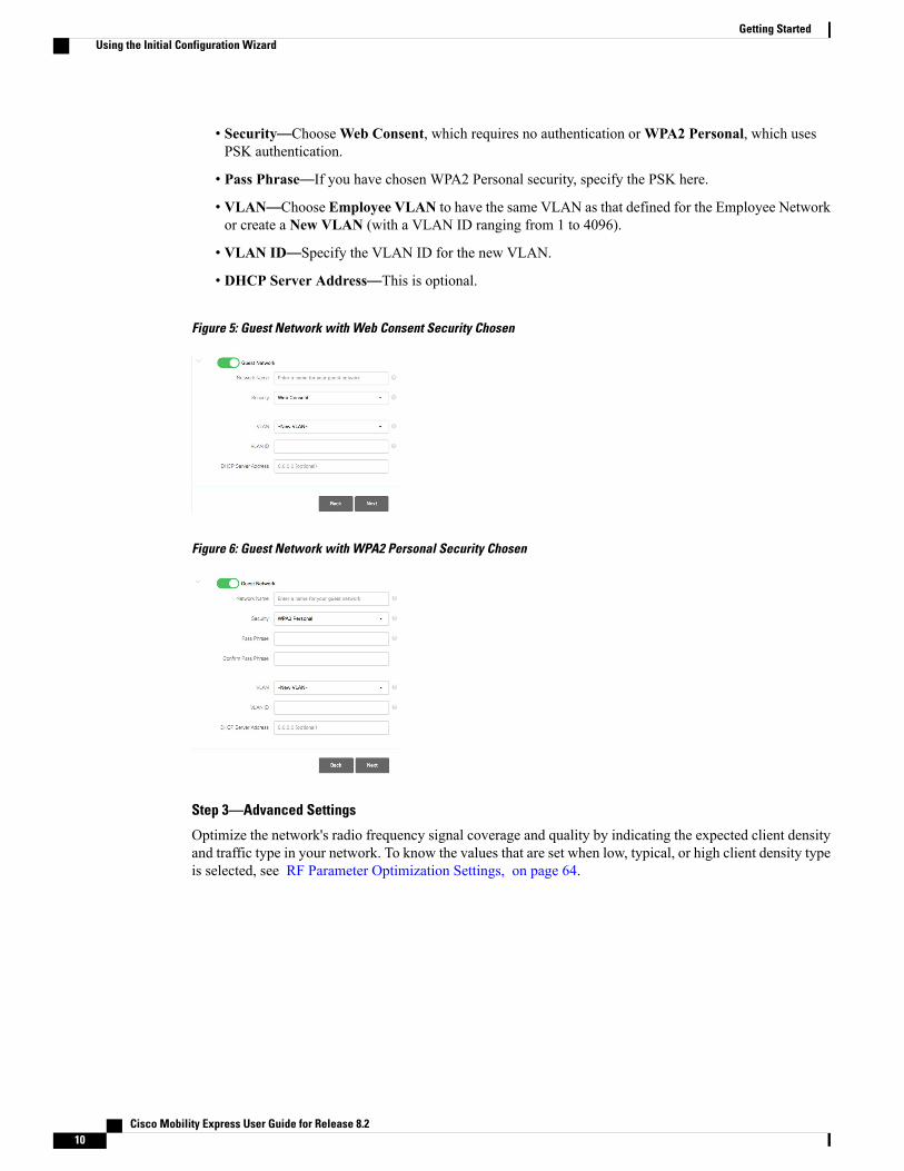
• Security—ChooseWeb Consent, which requires no authentication orWPA2 Personal, which usesPSK authentication.
• Pass Phrase—If you have chosen WPA2 Personal security, specify the PSK here.
• VLAN—Choose Employee VLAN to have the same VLAN as that defined for the Employee Networkor create a New VLAN (with a VLAN ID ranging from 1 to 4096).
• VLAN ID—Specify the VLAN ID for the new VLAN.
• DHCP Server Address—This is optional.
Figure 5: Guest Network with Web Consent Security Chosen
Figure 6: Guest Network with WPA2 Personal Security Chosen
Step 3—Advanced Settings
Optimize the network's radio frequency signal coverage and quality by indicating the expected client densityand traffic type in your network. To know the values that are set when low, typical, or high client density typeis selected, see RF Parameter Optimization Settings, on page 64.
Cisco Mobility Express User Guide for Release 8.210
Getting StartedUsing the Initial Configuration Wizard

If you do not enable RF Parameter Optimization during the initial configuration wizard, then client densityis set to Typical (the default value), and RF traffic type is set to Data (the default value).
Note
Figure 7: RF Parameter Optimization
Once you apply these configuration settings, the access point reboots and the controller restarts. You can nowproceed to Logging in to Cisco Mobility Express , on page 14.
Checking if an AP has CAPWAP Lightweight AP Software orCisco Mobility Express Software
Both the Cisco 1850 Series and 1830 Series APs can be ordered with a factory-shipped CAPWAP lightweightAP software or a Cisco Mobility Express controller software. However, you can convert a CAPWAP AP toCisco Mobility Express software, and vice-versa, on site. To determine if your AP has a Cisco MobilityExpress image or CAPWAP Lightweight AP image, follow these steps:
Step 1 Connect to the console port of the AP, using an RJ-45 cable.Step 2 Log in to the AP using the username Cisco and password Cisco. Both are case-sensitive.
This is the default factory-shipped username and password on all Cisco Aironet APs.
Step 3 Enter the sh version command on the AP console.Step 4 Check the command output for the AP Image Type and AP Configuration fields. There are three possible scenarios,
as shown in the following table:
What to Do Next
What to do NextFields and Their Values in the Output
No conversion is required. Reboot the AP and proceedto Starting the Initial ConfigurationWizard, on page6.
AP Image Type: MOBILITY EXPRESS IMAGE
AP Configuration: MOBILITY EXPRESS CAPABLE
Cisco Mobility Express User Guide for Release 8.2 11
Getting StartedChecking if an AP has CAPWAP Lightweight AP Software or Cisco Mobility Express Software

What to do NextFields and Their Values in the Output
This means that the AP has the Cisco MobilityExpress software, but is running in CAPWAPlightweight AP configuration. Proceed to Upgradingfrom CAPWAP Lightweight AP Software Release15.3.3-JBB1 to 15.3.3-JBB5 or newer, on page 12.
AP Image Type: MOBILITY EXPRESS IMAGE
AP Configuration: NOT MOBILITY EXPRESS CAPABLE
This means that the AP has a CAPWAP lightweightAP software and not the Cisco Mobility Expresssoftware. Proceed to Converting from CAPWAPLightweight AP 15.3.3-JBB5 or newer to CiscoMobility Express Software, on page 13.
The AP Image Type and AP Configuration fieldsare not present in the output
Upgrading from CAPWAP Lightweight AP Software Release15.3.3-JBB1 to 15.3.3-JBB5 or newer
Your AP is an 1850 series access point with Lightweight AP software release 15.3.3-JBB1, for CiscoWirelessController Software Release 8.1.111.0. You will need to upgrade the software to Lightweight AP softwarerelease 15.3.3-JBB5 (released for Cisco Wireless Controller Software Release 8.1.122.0) or newer releases,using the following procedure.
The following procedure shows an upgrade to the 8.1.122.0 release, and hence uses the correspondingsoftware files. Ensure that you use the appropriate software file depending on the release you are upgradingto.
Note
Before You Begin
• A TFTP server and a DHCP server should be configured and accessible.
• Ensure that the AP does not associate itself with an existingWLCwhile you are performing this upgrade.
Step 1 Download the AIR-AP1850-K9-ME-8-1-122-0.zip file from Cisco.com to the TFTP server.The file downloaded here is the access point image bundle, to be used for software update and/or supported access pointsimages.
Step 2 Unzip the file and extract the contents.Step 3 Connect to the console port of the AP.Step 4 Log in to the AP console using the username Cisco and password Cisco. Both are case-sensitive.
This is the default factory-shipped username and password on all Cisco Aironet APs.
Step 5 In the AP console command line interface, enter enable .Step 6 Enter archive download-sw /reload tftp://<tftp server's ip address>/AIR-AP1850-K9-ME-8-1-122-0/ap1g4,
Alternatively, you can use the command ap-type mobility-express tftp://<tftp server ip-address>/ap1g4
Cisco Mobility Express User Guide for Release 8.212
Getting StartedUpgrading from CAPWAP Lightweight AP Software Release 15.3.3-JBB1 to 15.3.3-JBB5 or newer

The AP reboots from the new Mobility Express software image.
What to Do Next
Proceed to Converting from CAPWAP Lightweight AP 15.3.3-JBB5 or newer to Cisco Mobility ExpressSoftware, on page 13.
Converting from CAPWAP Lightweight AP 15.3.3-JBB5 or newerto Cisco Mobility Express Software
Your AP is either a Cisco 1850 Series or a 1830 Series APwith Lightweight AP software Release 15.3.3-JBB5,for Cisco WLC Software Release 8.1.122.0, or a newer software. You need to convert its software to CiscoMobility Express configuration-capable software.
The following procedure shows a conversion from the 8.1.122.0 Lightweight AP release, and hence usesthe corresponding software files. Ensure that you use the appropriate software file depending on the releaseyou are converting from.
Note
Before You Begin
• A TFTP server and a DHCP server should be configured and accessible.
• Ensure that there are no Cisco WLCs, physical or virtual, in the network while you are performing thisupgrade. The AP must not interface with any other wireless controller while you are performing thisupgrade.
Step 1 Download the AIR-AP1850-K9-ME-8-1-122-0.zip software file from Cisco.com to the TFTP server.The file downloaded here is the access point image bundle, to be used for software update and/or supported access pointsimages.
Step 2 Connect to the console port of the AP, using an RJ-45 cable.Step 3 Log in to the AP using the username Cisco and password Cisco. Both are case-sensitive.
This is the default factory-shipped username and password on all Cisco Aironet APs
Step 4 To convert the AP from CAPWAP lightweight AP software Release 15.3.3-JBB5 to Cisco Mobility Express software,use the command ap-type mobility-express tftp://<tftp server ip-address>/<filename with path from root on the TFTPserver> command.The AP reboots, comes back online, and tries to join a controller for about 5 minutes. After this, the AP continues toboot into Mobility Express mode and starts broadcasting the CiscoAirProvison SSID.
Cisco Mobility Express User Guide for Release 8.2 13
Getting StartedConverting from CAPWAP Lightweight AP 15.3.3-JBB5 or newer to Cisco Mobility Express Software

What to Do Next
Proceed to Starting the Initial Configuration Wizard, on page 6.
Preparing APs to Associate with the Master APFollow this procedure to enable a newAP to associate itself with the CiscoMobility Express wireless controlleron the master AP, and thereby enabling it to join the Cisco Mobility Express network.
Before You Begin
• A master AP with Cisco Mobility Express wireless controller should be up and running.
• If the AP that has to be prepared to associate with the master AP is a universal regulatory domain AP,then it should be primed using the Cisco AirProvision mobile application. For more information, seethe Cisco Aironet Universal AP Priming and Cisco AirProvision User Guide at:
http://www.cisco.com/c/en/us/td/docs/wireless/access_point/ux-ap/guide/uxap-mobapp-g.html
Step 1 Download the latest CiscoMobility Express bundle from Cisco.com to the TFTP server. This pack is either in .zip format(for Windows) or .tar format (Linux or Mac OSX) and contains the software images for all the supported APs.
Step 2 Unzip the software pack to a folder on the TFTP server.Step 3 Provide the path to the folder in theManagement > Software Update > File Path field.Step 4 Perform a software update. For more information, see Performing the Software Update.
What to Do Next
Managing Associated Access Points, on page 37
Logging in to Cisco Mobility Express
Step 1 Open a browser and enter https://<ip address> in your browser's address bar to access the Cisco Mobility ExpressWireless LAN Controller login page. This IP address is the one you have specified for managing the Cisco MobilityWireless Express controller.
Cisco Mobility Express User Guide for Release 8.214
Getting StartedPreparing APs to Associate with the Master AP

The Cisco Mobility Express controller uses a self-signed certificate for HTTPs. Therefore, all browsers will display awarning and ask you whether you wish to proceed with an exception or not when the certificate is presented to thebrowser. Accept the warning in order to access the Mobility ExpressWireless LAN Controller login page.
Figure 8: Cisco Mobility Express Wireless LAN Controller Web Interface Login
Step 2 Click Login.Step 3 Enter admin user credentials to log in.
What to Do Next
After you log in, the default landing page is the Network Summary window. For more information, seeAbout the Cisco Mobility Express Monitoring Service, on page 19.
Cisco Mobility Express User Guide for Release 8.2 15
Getting StartedLogging in to Cisco Mobility Express

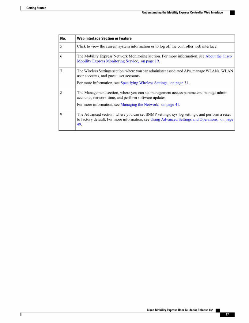
Understanding the Mobility Express Controller Web InterfaceThe following figure illustrates the opening page and the general layout of the Mobility Express controllerweb interface.
Figure 9: Mobility Express Controller Web Interface
Web Interface Section or FeatureNo.
The side pane of the web interface. This is main navigational pane using which you can navigateto the various sub-sections in the web interface.
1
The title of the web interface. It indicates the AP model of the master AP (on which the integratedcontroller functionality is currently operating)
2
Search for an AP or client using its MAC address.3
Click to save the current controller configuration to the NVRAM. For more information, seeSaving Controller Configuration, on page 52.
4
Cisco Mobility Express User Guide for Release 8.216
Getting StartedUnderstanding the Mobility Express Controller Web Interface
Web Interface Section or FeatureNo.
Click to view the current system information or to log off the controller web interface.5
The Mobility Express Network Monitoring section. For more information, see About the CiscoMobility Express Monitoring Service, on page 19.
6
TheWireless Settings section, where you can administer associated APs, manageWLANs,WLANuser accounts, and guest user accounts.
For more information, see Specifying Wireless Settings, on page 31.
7
The Management section, where you can set management access parameters, manage adminaccounts, network time, and perform software updates.
For more information, see Managing the Network, on page 41.
8
The Advanced section, where you can set SNMP settings, sys log settings, and perform a resetto factory default. For more information, see Using Advanced Settings and Operations, on page49.
9
Cisco Mobility Express User Guide for Release 8.2 17
Getting StartedUnderstanding the Mobility Express Controller Web Interface

Cisco Mobility Express User Guide for Release 8.218
Getting StartedUnderstanding the Mobility Express Controller Web Interface
C H A P T E R 3Monitoring the Mobility Express Network
• About the Cisco Mobility Express Monitoring Service, page 19
• Customizing the Network Summary View, page 21
• Viewing the Details of Configured WLANs, page 23
• Customizing Access Points Table View, page 23
• Viewing Details of Clients, page 24
• Viewing Details of Rogue Devices (Clients and Access Points), page 26
• Viewing Details of Interferers, page 26
• Customizing the Access Point Performance View, page 27
• Customizing the Client Performance View, page 29
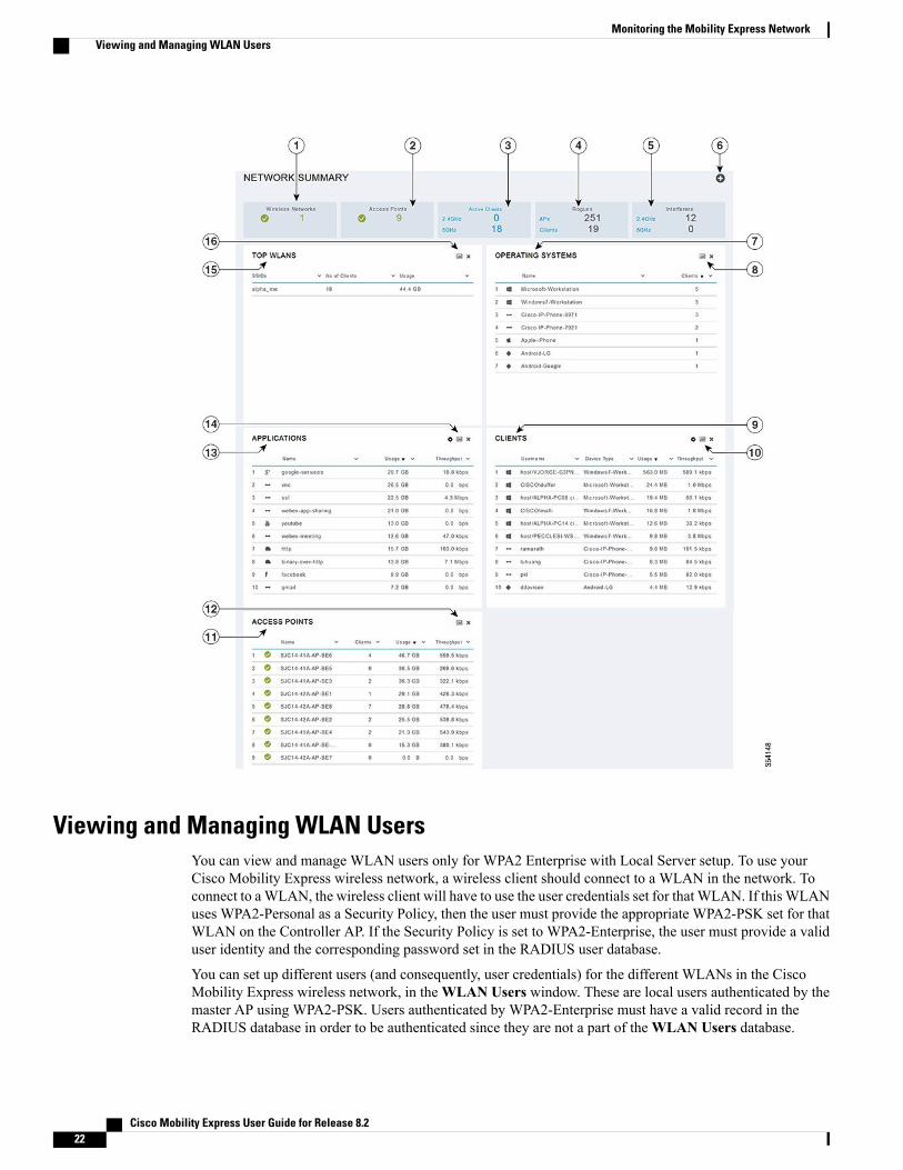
About the Cisco Mobility Express Monitoring ServiceThe Cisco Mobility Express Monitoring service enables the master AP to monitor the WLANs and all theconnected and unconnected devices on the network.
TheMonitoring service offers the following capabilities through the Network Summary andWirelessDashboard tabs:
• View details of configured WLANs.
• View list of top WLANs based on traffic and associated clients.
• View details of APs in the network.
• View details of clients operating actively at either 2.4 GHz or 5 GHz.
• View summary of client device-operating systems and applications running on these devices.
• View detailed listing of rogue clients and APs.
• View details of various interferers in the network on the 2.4GHz and 5 GHz radio frequencies.
• Monitor the performance of APs in the network.
• Monitor the performance of clients in the network.
Cisco Mobility Express User Guide for Release 8.2 19

Note • All the parameters on the Network Summary window are read-only parameters.
• This page is automatically refreshed every 30 seconds.
Cisco Mobility Express User Guide for Release 8.220
Monitoring the Mobility Express NetworkAbout the Cisco Mobility Express Monitoring Service

Customizing the Network Summary ViewYou can customize the Network Summary view by adding or removing widgets. The data displayed in thevarious widgets can be viewed either in the doughnut format or in the tabular format by toggling the displayicon on the top right corner of the individual widgets.
Figure 10: Network Summary Widgets - Tabular view
Figure 11: Network Summary Widgets - Doughnut view
Cisco Mobility Express User Guide for Release 8.2 21
Monitoring the Mobility Express NetworkCustomizing the Network Summary View
Viewing and Managing WLAN UsersYou can view and manage WLAN users only for WPA2 Enterprise with Local Server setup. To use yourCisco Mobility Express wireless network, a wireless client should connect to a WLAN in the network. Toconnect to aWLAN, the wireless client will have to use the user credentials set for that WLAN. If this WLANuses WPA2-Personal as a Security Policy, then the user must provide the appropriate WPA2-PSK set for thatWLAN on the Controller AP. If the Security Policy is set to WPA2-Enterprise, the user must provide a validuser identity and the corresponding password set in the RADIUS user database.
You can set up different users (and consequently, user credentials) for the different WLANs in the CiscoMobility Express wireless network, in theWLAN Users window. These are local users authenticated by themaster AP using WPA2-PSK. Users authenticated by WPA2-Enterprise must have a valid record in theRADIUS database in order to be authenticated since they are not a part of theWLAN Users database.
Cisco Mobility Express User Guide for Release 8.222
Monitoring the Mobility Express NetworkViewing and Managing WLAN Users

Viewing WLANsTheWLAN Configuration window lists all the WLANs that are currently configured on the master AP’scontroller, along with the following details for each WLAN:
• Active—Whether the WLAN is enabled or disabled.
• Name—Name of the WLAN
• Security Policy
• Radio Policy
The total number of activeWLANs is displayed at the top of the page. If the list of WLANs spans multiplepages, you can browse these pages by clicking the page number links or the forward and backward icons.
Tip
Viewing the Details of Configured WLANs
Step 1 ChooseMonitoring > Network Summary.A count of the configured WLANs is displayed in theWireless Networks summary window.
Step 2 In theWireless Networks summary window, click the status icon or count display icon to view high-level details of thecorresponding WLAN, such as the Active status, Name, Security Policy, and Radio Policy.You can also add new WLANs from this page. For details, see Adding a WLAN, on page 32.
Customizing Access Points Table View
Step 1 ClickMonitoring > Network Summary > Access Points.The Access Points view page appears.
Step 2 In theAccess Points view page, toggle between the 2.4GHz and 5GHz tabs to view a tabular listing of the access pointsoperating at the respective radio frequencies.
Step 3 (Optional) Click the downward facing arrow on the top right of the column header to select columns to be hidden orshown in the table view. hide or show desired or to filter the table view based on desired parameters.
Step 4 (Optional) Click the downward facing arrow on the top right of the column header to filter the table view based on desiredparameters.
Cisco Mobility Express User Guide for Release 8.2 23
Monitoring the Mobility Express NetworkViewing WLANs

Viewing Details of Clients
Step 1 ClickMonitoring > Network Summary.A summary of all active clients is displayed in the Active Clients summary section. These clients are either 802.11 b/g/nclients operating at 2.4 GHz or 802.11 a/n/ac clients operating at 5 GHz.
Step 2 In the Active Clients summary section, click the count display icon to view high-level details of the client device.The information shown includes:
• General details.
• Connectivity status graphic.
• Top applications on the client that are using the network connection.
• Mobility State graphic.
• Network, QoS, Security and Policy details.
• Client ping and packet capture tests.
Click the downward facing arrow on the top right of the column headers to customize the details displayed in the tableeither to hide or show desired columns or to filter the table view based on desired parameters.
Understanding the Mobility State GraphicThe Mobility State graphic for a client shows the following details:
• Name of the wireless LAN controller, with it's IP address and the model number of the AP on which itis running.
• Name of the AP through which the client is connected to the controller, along with the type of connection(for example, Flexconnect), the AP's IP address, and the AP's model number.
• Nature of connection between the AP and the client. For example, wireless 802.11n 5 GHz connection.
• Name of the client, type of client (for example, Microsoft Workstation), VLAN ID of the client, and theclient's IP address.
Performing a Client Ping TestYou can perform a ping test on the client to determine the latency or delay between the controller and theclient. This is an Internet Control Message Protocol (ICMP) based test. Using the ping test you can know theconnectivity as well as the latency between the controller and the client.
To start the test, click Start. The latency in milliseconds is represented graphically.
Cisco Mobility Express User Guide for Release 8.224
Monitoring the Mobility Express NetworkViewing Details of Clients

Capturing Client PacketsThe Client Packet Capture feature allows network administrators to capture packets flowing to, through, andfrom an AP, while the AP continues to operate normally. The packets are captured and exported to an FTPserver, where you can do an offline analysis by using a tool such as Wireshark. This feature facilitatestroubleshooting by helping to gather information about the packet format, application analysis, and security.
Points to Note
• Packet capture can be enabled for only one client at a time.
• The packets are captured and dumped in the order of arrival or transmission of packets, except forbeacons and probe responses. The packet capture contains information such as channel, RSSI, data rate,SNR, and timestamp. Each packet is appended with additional information from the AP.
• A file is created on the FTP server for each AP based on AP name, controller name and timestamp.
• If the FTP transfer time is slower than the packet rate, some of the packets may not appear in the capturefile.
• If the buffer on the AP does not contain any packets, a dummy packet is dumped to keep the connectionalive.
• If the FTP transfer fails or FTP connection is lost during packet capture, the AP stops capturing packets,notifies with an error message and SNMP trap, and a new FTP connection is established.
• Not all packets in the air are captured, but only those that reach the radio driver.
• Before you start ensure that you have an FTP server, that is reachable by the AP. The captured packetsare dumped to this FTP server.
Performing the Packet Capture
1 ChooseMonitoring > Network Summary > Clients.
2 On the Client View page, under Client Test, click the Packet Capture tab.
3 Under Capture Point, specify the following details:
• APName—The name of the AP which will be the capture point. The capture point is a traffic transitpoint where the packets are captured. You can specify only an AP as the capture point
• Time—Specify the time period for packet capture. The range is from 1 to 60 minutes.
4 Under Capture Filters, specify the types of packets that need to be captured. You have the followingtypes:
• Control Packets
• Data Packets
• Dot1x
• IAPP
• Management Packets
Cisco Mobility Express User Guide for Release 8.2 25
Monitoring the Mobility Express NetworkCapturing Client Packets

• ARP
• Multicast frames
• Broadcast frames
• All IP
• TCP with matching port number
• UDP with matching port number
5 Under FTP Details, specify the following details of the FTP server to which the captured packets aredumped:
• IP Address
• Path of the folder on the FTP server where the packets are to be dumped
• Username and Password for access to the FTP server
6 Click Start.
The Client Status icon is Green when a packet capture is in progress. It is Red otherwise.
Viewing Details of Rogue Devices (Clients and Access Points)
Step 1 ClickMonitoring > Network Summary.A summary of rogue APs and clients is displayed in the Rogues summary window.
Step 2 In theRogues summary window, click the count display icon to view high-level details of the rogue devices (unmanagedneighboring APs or clients).
Viewing Details of Interferers
Step 1 ClickMonitoring > Network Summary.A summary of all non-WiFi interfering devices is displayed in the Interferers summary window. These interferers mayeither be operating at 2.4 GHz or at 5 GHz.
Step 2 In the Interferers summary window, click the count display icon to view high-level details of the interfering device.
Cisco Mobility Express User Guide for Release 8.226
Monitoring the Mobility Express NetworkViewing Details of Rogue Devices (Clients and Access Points)

Customizing the Access Point Performance ViewYou can customize the AP Performance view by adding or removing widgets.
Figure 12: Wireless Dashboard - AP Performance
Cisco Mobility Express User Guide for Release 8.2 27
Monitoring the Mobility Express NetworkCustomizing the Access Point Performance View

Adding Widgets to Customize Access Point Performance View
Step 1 ChooseMonitoring >Wireless Dashboard > AP Performance.Step 2 Click the Add Widget icon on the top right hand side of the AP Performance window.Step 3 Click to select the widgets that you want to add:
• Channel Utilization—Top APs
• Interference—Top APs
• Client Load—Top APs
• Coverage—Bottom APs
Step 4 Click Close.The AP Performance window is refreshed with the new widgets.
Removing Widgets to Customize Access Point Performance View
Step 1 ChooseMonitoring >Wireless Dashboard > AP Performance.Step 2 Click the Delete Widget icon on the top right hand side of the widgets that you want to delete.
The AP Performance window does not display the deleted widgets.
Cisco Mobility Express User Guide for Release 8.228
Monitoring the Mobility Express NetworkAdding Widgets to Customize Access Point Performance View

Customizing the Client Performance ViewYou can customize the Client Performance view by adding or removing widgets.
Figure 13: Wireless Dashboard - Client Performance
Cisco Mobility Express User Guide for Release 8.2 29
Monitoring the Mobility Express NetworkCustomizing the Client Performance View
Adding Widgets to Customize Client Performance View
Step 1 ChooseMonitoring >Wireless Dashboard > Client Performance.
Step 2 Click the Add Widget icon on the top right hand side of the Client Performance window.
Step 3 Click to select the widgets that you want to add:
• Signal Strength
• Signal Quality
• Connection Rate
• Client Connections
Step 4 Click Close.The Client Performance window is refreshed with the new widgets.
Removing Widgets to Customize Client Performance View
Step 1 ChooseMonitoring >Wireless Dashboard > Client Performance.Step 2 Click the Delete Widget icon on the top right hand side of the widgets that you want to delete.
The Client Performance window does not display the deleted widgets.
Cisco Mobility Express User Guide for Release 8.230
Monitoring the Mobility Express NetworkAdding Widgets to Customize Client Performance View

C H A P T E R 4Specifying Wireless Settings
• Setting Up WLANs and WLAN Users, page 31
• Managing Associated Access Points, page 37
• Creating a Customized Login Page for Guest WLAN Users, page 39
Setting Up WLANs and WLAN Users
About WLANs in a Cisco Mobility Express NetworkYou can create and manage Wireless Local Area Networks (WLANs) through theWLAN Configurationwindow. ChooseWireless Settings > WLAN Users.
The total number of active WLANs is displayed at the top of theWLAN Configuration window along witha list of all the WLANs currently configured on the master AP's controller. This list displays the followingdetails for each WLAN:
•Whether the WLAN is enabled or disabled.
• Name of the WLAN.
• Security Policy on WLAN.
• Radio Policy on WLAN.
Guidelines and Limitations for Setting Up WLANs
• You can associate up to 16 WLANs with the Cisco Mobility Express controller. Cisco recommends amaximum of 4 WLANs. The controller assigns all the configured WLANs to all the connected APs.
• Each WLAN has a unique WLAN ID, a unique profile name, and an SSID.
• The WLAN name and SSID can have up to 32 characters. Spaces are not allowed in the WLAN profilename and SSID.
• Each connected AP advertises only the WLANs that are in an Enabled state. The APs do not advertisedisabled WLANs.
Cisco Mobility Express User Guide for Release 8.2 31

• The controller uses different attributes to differentiate between WLANs with the same SSID.
• Peer-to-peer blocking does not apply to multicast traffic.
• You cannot map a WLAN to VLAN0, and you cannot map VLANs 1002 to 1006.
• Dual-stack clients with static IPv4 addresses are not supported.
•When creating WLANs with the same SSID, create a unique profile name for each WLAN.
Adding a WLAN
Step 1 ChooseWireless Settings >WLANs.TheWLAN Configuration window is displayed.
Step 2 To create a new WLAN, click Add New WLAN.The Add New WLAN window is displayed.
Step 3 Under the General tab, set the following parameters:
•WLAN ID—From the drop-down list, choose an ID number for this WLAN.
• Profile Name—Enter up to 32 characters for the profile name to be assigned to this WLAN. The profile namemust be unique.
• SSID—Enter up to 32 characters for the SSID to be assigned to this WLAN.
• Admin State—From the drop-down list, choose Enabled to enable this WLAN. Otherwise choose Disabled. Thedefault is Enabled.
• Radio Policy—The radio policy allows you to optimize the RF settings for all the APs associated with a WLAN.The selected radio policy applies to the 802.11 radios. Each radio policy specifies which part of the spectrum theWLAN is advertised on, whether it is on 2.4 GHz (the 802.11b or 802.11g modes) or on 5GHz (802.11a mode) orboth.
Set the RF profiles for APs that are associated with the controller. Choose one of the following from the RadioPolicy drop-down list:
• All (default)
• 802.11a only
• 802.11a/g
• 802.11g only
• 802.11b/g
Step 4 Under theWLAN Security tab, set the following parameters:
• Security—Choose one of the following security authentication options from this drop-down list:
• Guest—The controller can provide guest user access on WLANs which are specifically designated for useby guest users. To set this WLAN exclusively for guest user access, choose the Security as Guest.
Cisco Mobility Express User Guide for Release 8.232
Specifying Wireless SettingsAdding a WLAN
You can set the authentication for guest users by choosing one of the following options in the GuestAuthentication drop-down list:
• Require Username and Password—This is the default option. Choose this option to authenticate guestsusing the username and password which you can specify for guest users of this WLAN, underWirelessSettings > WLAN Users. For more information, see Viewing and Managing WLAN Users, on page36.
• Display Terms&Conditions—Choose this option to allow guests access to theWLANupon acceptanceof displayed terms and conditions. This option allows guest users to access the WLANwithout enteringa username and password.
• Require Email Address—Choose this option, if you want guest users to be prompted for their e-mailaddress when attempting to access the WLAN. Upon entering a valid email address, access it provided.This option allows guest users to access the WLAN without entering a username and password.
• Open—This option stands for Open authentication, which allows any device to authenticate and then attemptto communicate with an AP. Using open authentication, any wireless device can authenticate with the AP.
•WPA2 Personal—This option stands for Wi-Fi Protected Access 2 with pre-shared key (PSK). WPA2Personal is a method used for securing your network with the use of a PSK authentication. The PSK isconfigured separately both on the controller AP, under the WLAN security policy, and on the client. WPA2Personal does not rely on an authentication server on your network. This option is used when you do not havean enterprise authentication server. If you choose this option, then specify the PSK in the Shared Key field.
•WPA2 Enterprise—This option stands for Wi-Fi Protected Access 2, with a local authentication server ora RADIUS server. This is the default option.
To have a local authentication method, choose AP in the Authentication Server drop-down list. This optionis a Local EAP authentication method that allows users and wireless clients to be authenticated locally. Thecontroller in the master AP serves as the authentication server and the local user database, which removesdependence on an external authentication server.
To have a RADIUS server-based authentication method, choose External Radius in the AuthenticationServer drop-down list. RADIUS is a client/server protocol that enables communication with a central serverto authenticate users and authorize their access to the WLAN. You can specify up to two RADIUSauthentication servers. For each server you need to specify the following details:
• RADIUS IP—IPv4 address of the RADIUS server
• RADIUS Port—Enter the communication port of the RADIUS server. The default value is 1812.
• Shared Secret—Enter the secret key used by the RADIUS server, in ASCII format.
Step 5 Under the VLAN & Firewall tab, in the Use VLAN Tagging drop-down list, choose Yes to enable VLAN tagging ofpackets. Then, choose aVLAN ID from the drop-down list, to use for the tagging. By default VLANTagging is disabled.By enabling VLAN Tagging, the chosen VLAN ID is inserted into a packet header in order to identify which VLAN(Virtual Local Area Network) the packet belongs to. This enables the controller to use the VLAN ID to determine whichVLAN to send a broadcast packet to, thereby providing traffic separation between VLANs.
Step 6 If you have chosen to enable VLAN Tagging, then you have an option to enable a firewall for the WLAN based onAccess Control Lists (ACLs). An ACL is a set of rules used to limit access to a particular WLAN to control data trafficto and from wireless clients or to the controller CPU to control all traffic destined for the CPU.
Cisco Mobility Express User Guide for Release 8.2 33
Specifying Wireless SettingsAdding a WLAN

To enable an ACL-based firewall:
1 In the Enable Firewall drop-down list, choose Yes.
2 In the ACL Name field, enter a name for the new ACL. You can enter up to 32 alphanumeric characters. The ACLname must be unique.
3 Click Apply.
4 To set rules for the ACL, click Add Rule.
Note that ACL rules are applied to the VLAN. Multiple WLANs can use the same VLAN, hence inheriting ACL rules,if any.
Configure a rule for this ACL as follows:
1 From the Action drop-down list, choose Deny to cause this ACL to block packets or Permit to cause this ACL toallow packets. The default is Permit. The controller can permit or deny only IP packets in an ACL. Other types ofpackets (such as ARP packets) cannot be specified.
2 From the Protocol drop-down list, choose the protocol ID of the IP packets to be used for this ACL. These are theprotocol options:
• Any—Any protocol (this is the default value)
• TCP—Transmission Control Protocol
• UDP—User Datagram Protocol
• ICMP—Internet Control Message Protocol
ESP—IP Encapsulating Security Payload
• AH—Authentication Header
• GRE—Generic Routing Encapsulation
• IP in IP—Internet Protocol (IP) in IP (permits or denies IP-in-IP packets)
• Eth Over IP—Ethernet-over-Internet Protocol
• OSPF—Open Shortest Path First
• Other—Any other Internet Assigned Numbers Authority (IANA) protocol. If you choose Other, enter thenumber of the desired protocol in the Protocol text box. You can find the list of available protocols in the IANAwebsite.
3 In the Dest. IP/Mask field, enter the IP address and netmask of the specific destination.
4 If you have chosen TCP or UDP, you will need specify a Destination Port. This destination port can be used byapplications that send and receive data to and from the networking stack. Some ports are designated for certainapplications such as Telnet, SSH, HTTP, and so on.
5 From theDSCP drop-down list, choose one of these options to specify the differentiated services code point (DSCP)value of this ACL. DSCP is an IP header text box that can be used to define the quality of service across the Internet.You can choose:
• Any—Any DSCP (this is the default value)
• Specific—A specific DSCP from 0 to 63, which you enter in the DSCP edit box
Cisco Mobility Express User Guide for Release 8.234
Specifying Wireless SettingsAdding a WLAN

6 Click the Apply icon to commit your changes.
Step 7 Quality of service (QoS) refers to the capability of a network to provide better service to selected network traffic overvarious technologies. The primary goal of QoS is to provide priority, including dedicated bandwidth, controlled jitterand latency (required by some real-time and interactive traffic), and improved loss characteristics.The Cisco Mobility Express controller supports the following four QoS levels. Under the QoS tab, from the QoSdrop-down list, choose one of the following QoS levels:
• Platinum (Voice)—Ensures a high quality of service for voice over wireless.
• Gold (Video)—Supports high-quality video applications.
• Silver (Best Effort)—Supports normal bandwidth for clients.
• Bronze (Background)—Provides the lowest bandwidth for guest services.
Step 8 Application Visibility classifies applications using the Network-Based Application Recognition (NBAR2) engine, andprovides application-level visibility in wireless networks. Application Visibility enables the controller to detect andrecognize more than 1000 applications and perform real-time analysis, and monitor network congestion and networklink usage. This feature contributes to the Applications By Usage statistic in theMonitoring > Network Summary.To enable Application Visibility, choose Enabled (the default option) from the Application Visibility drop-down list.Otherwise, choose Disabled.
Step 9 Click Apply.
What to Do Next
You can proceed to creating or editing user accounts for this WLAN. See Viewing and Managing WLANUsers, on page 36.
Enabling and Disabling WLANs
Step 1 ChooseWireless Settings >WLANs.TheWLAN Configuration window is displayed.
Step 2 Click the Edit icon adjacent to the WLAN you want to enable or disable.The Edit WLAN window is displayed.
Step 3 Choose General > Admin State and select Enabled or Disabled, as required.Step 4 Click Apply.
Clicking Apply after creating a new WLAN or editing an existing one always enables the WLAN irrespectiveof whether it was previously enabled or disabled.
Note
Editing and Deleting WLANsChooseWireless Settings >WLANs. In the window that is displayed, perform one of the following actions:
Cisco Mobility Express User Guide for Release 8.2 35
Specifying Wireless SettingsEnabling and Disabling WLANs
• To edit a WLAN, click the Edit icon adjacent to it.
• To delete a WLAN, click the Delete icon adjacent to it.
Viewing and Managing WLAN UsersTo view and manage WLAN users, chooseWireless Settings >WLAN Users.
TheWLAN Users window is displayed, along with the total number of WLAN users configured on thecontroller. It also lists all the WLAN users in the network along with the following details for each:
• User name—Name of the WLAN user.
• Guest user—If this checkbox is selected, then this is a guest user account with a limited validity of only86400 seconds (or 24 hours) from the time of its creation.
•WLAN Profile—The WLANs that this user can connect to.
• Password—The password to be used when connecting to a WLAN.
• Description—Additional details or comments about the user.
You can view and manage WLAN users only for the WPA2 Enterprise with Local Server setup. To use yourCisco Mobility Express wireless network, a wireless client should connect to a WLAN in the network. Toconnect to aWLAN, the wireless client will have to use the user credentials set for that WLAN. If this WLANuses WPA2-Personal as a Security Policy, then the user must provide the appropriate WPA2-PSK set for thatWLAN on the Controller AP. If the Security Policy is set to WPA2-Enterprise, the user must provide a validuser identity and the corresponding password set in the RADIUS user database.
Adding a WLAN User
To add a WLAN user, click Add WLAN User, and then fill in the following details:
• User name—Specify a name for WLAN user account.
• Guest user—Select this checkbox if this is meant to be a guestWLAN user account. You can also specifythe validity of this account from the time of its creation, in seconds, theLifetime field. The default valueis 86400 seconds (that is, 24 hours). You can specify a lifetime value from 60 to 31536000 seconds (thatis, 1 minute to 1 year).
•WLAN Profile—Select the WLAN that this user can connect to. From the drop-down list, choose aparticular WLAN, or choose AnyWLAN to apply this account for all WLANs set up on the controller.
This drop-down list is populated with theWLANs which have been configured underWireless Settings> WLANs. For information on adding WLANs, see Adding a WLAN, on page 32.
• Password—The password to be used when connecting to a WLAN.
• Description—Additional details or comments on the user.
Editing a WLAN User
To edit a WLAN user, click the Edit icon adjacent to the WLAN user whose details you want to edit andmake the necessary changes.
Cisco Mobility Express User Guide for Release 8.236
Specifying Wireless SettingsViewing and Managing WLAN Users

Deleting a WLAN User
To delete a WLAN user, click the Delete icon adjacent to the WLAN user you want to delete. and then clickOk in the confirmation dialog box.
Managing Associated Access PointsChooseWireless Settings > Access Points. The Access Points Administration window is displayed. Thenumber of APs associated with the controller is displayed at the top of the window, along with the followingdetails:
•Manage—The icons shown below indicate whether the AP is acting as Primary Controller (or MasterAP) or a subordinate AP.
Figure 14: Primary Controller (or Master AP) icon
Figure 15: Subordinate AP icon
• Location—Location of the AP.
• Name—Name of the AP.
• IP Address—IP address of the AP.
• AP MAC—The MAC address of the AP.
• Up Time—Shows how long the AP has been associated to the controller.
• AP Model—The model number of the access point.
Administering Access Points
Step 1 ChooseWireless Settings > Access Points.The Access Points Administration window is displayed. You can only administer those APs that are associated to thecontroller.
Step 2 Click the Edit icon adjacent to the AP you want to manage.The Edit window with the General tab is displayed.
Step 3 Under the General tab, you can edit the following AP parameters:
Cisco Mobility Express User Guide for Release 8.2 37
Specifying Wireless SettingsManaging Associated Access Points
• IP Configuration—Choose Obtain from DHCP to let the IP address of the AP be assigned by a DHCP serveron the network, or choose to have a Static IP address. If you choose to have a static IP address, then you can editthe IP Address, Subnet Mask, and Gateway fields.
• AP Name—Edit the name of the AP. This is a free text field.
• Location—Edit a location for the AP. This is a free text field.
The following non-editable AP parameters are also displayed under the General tab:
• Operating Mode—For a master AP, this field shows AP & Controller. For other associated APs, this field showsAP Only.
• AP MAC address
• AP Model number
• IP Address of the access point (non-editable only if Obtain from DHCP has been selected).
• Subnet mask (non-editable only if Obtain from DHCP has been selected).
• Gateway (non-editable only if Obtain from DHCP has been selected).
Step 4 (Only for the master AP) Under the Controller tab, you can manually edit the following controller parameters for theintegrated Mobility Express wireless LAN controller:
• System Name—Edit the name that you have assigned to this controller. You can enter up to 31 ASCII characters.The system name is first specified during the initial configuration wizard.
• IP Address—This IP address decides the login URL to the controller's web interface. The URL is in the formathttps://<ip address>. If you change this IP address, the login URL also changes.
• Subnet Mask
• Country Code—You can set the country code for the controller and all associated APs using this drop-down list.Once you apply your changes, the country codes on all subordinate APs are automatically changed, the APs rebootand come back online with the new country code, and rejoin the controller. However the change will not be appliedon the controller and the master AP until the master AP is manually rebooted.
Step 5 Under the 802.11 b/g/n tab, you can set the following parameters:
• Admin Mode—Enabled or Disabled. This enables or disables the corresponding radio on the AP (2.4 GHz for802.11 b/g/n)
• Channel—Automatic, 1 to 11.
Selecting Automatic enables Dynamic Channel Assignment. This means that channels are dynamically assignedto each AP, under the control of the master AP. This prevents neighboring APs from broadcasting over the samechannel and prevents interference and other communication problems. For the 2.4 GHz radio, 11 channels areoffered in the U.S. and up to 14 in other parts of the world. However, only 1-6-11 can be considered non-overlappingif they are used by neighboring APs.
Assigning a specific value statically assigns a channel to that AP.
• Channel Width—20 MHz
The channel width for 2.4 GHz can only be 20 MHz.
Cisco Mobility Express User Guide for Release 8.238
Specifying Wireless SettingsAdministering Access Points

Channel bonding groups the channels by 2 or 4 for a single radio stream. This increases the speed and the throughput.Because the number of channels is insufficient in 2.4 GHz, channel bonding cannot be used to enable multiplenon-overlapping channels.
• Transmit Power—Automatic, 1 to 8.
This is a logarithmic scale of the transmit power, that is the transmission energy used by the AP, with 1 being thehighest, 2 being half of it, 3 being 1/4th, and so on.
Selecting Automatic adjusts the radio transmitter output power based on the varying signal level at the receiver.This allows the transmitter to operate at less than maximum power for most of the time; when fading conditionsoccur, transmit power will be increased as required until the maximum is reached.
Step 6 Under the 802.11 a/n/ac tab, you can set the following parameters:
• Admin Mode—Enabled or Disabled. This enables or disables the corresponding radio on the AP (5 GHz for802.11a/n/ac).
• Channel—Automatic, 36, 40, 44, 48, 52, 56, 60, 64, 100, 104, 108, 112, 116, 132, 136, 140, 149, 153, 157, 161,165.
For the 5 GHz radio, up to 23 non-overlapping channels are offered.
Assigning a specific value statically assigns a channel to that AP.
• Channel Width—20, 40, 80 MHz
The channel width for 5 GHz can be set to 20, 40, or 80 MHz, if channel bonding is used.
• Transmit Power—1 to 8.
This is a logarithmic scale of the transmit power, that is the transmission energy used by the AP, with 1 being thehighest, 2 being half of it, 3 being 1/4th, and so on.
Selecting Automatic adjusts the radio transmitter output power based on the varying signal level at the receiver.This allows the transmitter to operate at less than maximum power for most of the time; when fading conditionsoccur, transmit power will be increased as required until the maximum is reached.
Step 7 Click Apply to save your changes and exit.
Creating a Customized Login Page for Guest WLAN UsersAfter your have met the aforementioned prerequisites, follow these steps to create a customized login pagewhich applies to all guest users:
Before You Begin
To allow a guest user the access to your network:
1 Set up a new WLAN or decide on an existing WLAN, to which you will provide access for guest users.
You can also specifically set up a WLAN exclusively for guest access. This is done by setting theWLANSecurity as Guest for that WLAN. For more information, see Adding a WLAN, on page 32.
Cisco Mobility Express User Guide for Release 8.2 39
Specifying Wireless SettingsCreating a Customized Login Page for Guest WLAN Users
2 Set up a guest user account. Go toWireless Settings > WLAN Users, and set up an account with theGuest User check box selected. For more information, see Viewing and Managing WLAN Users, onpage 36.
Step 1 ChooseWireless Settings > Guest WLAN.The Guest WLAN page is displayed. The number of Guest WLANs currently set up in the network is displayed at thetop of the page.
Step 2 In the window that is displayed, set the following parameters:
• Display Cisco Logo—This field is set to Yes by default. To hide the Cisco logo that appears at the top-right cornerof the default window, chooseNo. This field is set toYes by default. However, you do not have an option to displayany other logo.
• Redirect URLAfter Login— To have guest users redirected to a particular URL (such as the URL for your company)after login, enter the URL in this field. You can enter up to 254 characters.
• Page Headline—The default headline isWelcome to the Cisco Wireless Network. To create your own headline onthe login page, enter the desired text in this field. You can enter up to 127 characters.
• Page Message— The default message is Cisco is pleased to provide the Wireless LAN infrastructure for yournetwork. Please login and put your air space to work. To create your own message on the login page, enter thedesired text in this field, You can enter up to 2047 characters.
Step 3 Click Apply.
Cisco Mobility Express User Guide for Release 8.240
Specifying Wireless SettingsCreating a Customized Login Page for Guest WLAN Users

C H A P T E R 5Managing the Network
• Setting the Management Access Interface, page 41
• Managing Administrator Accounts, page 42
• Setting Date and Time, page 44
• Updating the Cisco Mobility Express Software, page 45
Setting the Management Access InterfaceThe Management Access Interface is the default interface for in-band management of the controller andconnectivity to enterprise services. It is also used for communication between the controller and access points(APs). The management interface has the only consistently pingable in-band interface IP address on thecontroller. You can access the web interface of the controller by entering the management interface IP addressof the controller in your browser's address bar.
For APs, the controller requires one management interface to control all inter-controller communications andone AP manager interface to control all controller-to-access point communications, regardless of the numberof ports.
To enable or disable the different types of management access to the controller:
Step 1 ChooseManagement > Access.TheManagement Access window is displayed. The number of enabled management types are displayed at the top ofthe window.
Step 2 You can enable or disable the following types of management access to the controller, by choosing the appropriate optionfrom the drop-down list:
• HTTP Access—To enable HTTP access mode, which allows you to access the controller GUI usinghttp://<ip-address> through a web browser, choose Enabled from the HTTP Access drop-down list. Otherwise,choose Disabled.
The default value is Disabled.HTTP access mode is not a secureconnection.
Note
Cisco Mobility Express User Guide for Release 8.2 41

• HTTPs Access—To enable HTTPS access mode, which allows you to access the controller GUI usinghttp://ip-address through a web browser, choose Enabled from the HTTPS Access drop-down list. Otherwise,choose Disabled.
The default value is Enabled.HTTPs access mode is a secureconnection.
Note
• Telnet Access—To enable Telnet access mode, which allows remote access to the controller’s CLI using yourlaptop’s command prompt, choose Enabled from the Telnet Access drop-down list. Otherwise, choose Disabled.
The default value is Disabled.Telnet access mode is not a secureconnection.
Note
• SSHv2 Access—To enable Secure Shell Version 2 (SSHv2) access mode, which is a more secure version of Telnetthat uses data encryption and a secure channel for data transfer, chooseEnabled from the SSHv2 Access drop-downlist. Otherwise, choose Disabled.
The default value is Enabled.The SSHv2 access mode is a secureconnection.
Note
Step 3 Click Apply to save your changes.
Managing Administrator AccountsYou require administrative (or admin) user accounts for logging in to the controller user interface, forconfiguring the controller, and for viewing configuration information. This prevents unauthorized users fromaccessing or configuring the controller.
Adding an Admin Account
Step 1 ChooseManagement > Admin Accounts.The Admin Accounts window is displayed, and lists all the admin accounts present on the Cisco Mobility Expresscontroller. The total count of admin accounts on the controller is displayed at the top of the window.
Step 2 Click Add New User to add a new admin user.Step 3 Set the following parameters as required:
• Account name—The login user name used by the administrative user. Admin account names must be unique.
• Access—Set one of the following access privileges for the administrator:
• Read-Only—This option creates an administrative account with read-only privileges. The admin user canview the controller configuration but cannot make any changes to the configuration.
Cisco Mobility Express User Guide for Release 8.242
Managing the NetworkManaging Administrator Accounts

• Read-Write—This option creates an administrative account with read and write privileges. The admin usercan view and make changes to the controller configuration.
• Password—Enter a password for the administrative user account, based on the following rules:
• Passwords are case sensitive.
• The password should contain a minimum of eight characters from at least three of the following classes:lowercase letters, uppercase letters, digits, and special characters.
• No character in the password can be repeated more than three times consecutively.
• The password should not contain the word Cisco or a management username. The password should not beany variant of these words, obtained by reversing the letters of these words, or by changing the capitalizationof letters, or by substituting 1, |, or ! or substituting 0 for o or substituting $ for s.
Step 4 Click Apply to save your changes.
Editing an Admin Account
Step 1 ChooseManagement > Admin Accounts.The Admin Accounts page is displayed, along with the list of all the admin accounts present on the Cisco MobilityExpress controller. The total count of admin accounts on the controller is displayed at the top of the page.
Step 2 Click the Edit icon adjacent to the account you want to edit.Step 3 Modify the admin account parameters, as required. For descriptions of these parameters, see Adding an Admin Account,
on page 42.Step 4 Click Apply.
Deleting an Admin Account
Step 1 ChooseManagement > Admin Accounts.The Admin Accounts window is displayed, along with the list of all the admin accounts present on the Cisco MobilityExpress controller. The total count of admin accounts on the controller is displayed at the top of the page.
Step 2 Click the Delete icon adjacent to the account you want to delete.Step 3 Click Ok in the confirmation dialog box.
Cisco Mobility Express User Guide for Release 8.2 43
Managing the NetworkEditing an Admin Account

Setting Date and TimeThe date and time on the Cisco Mobility Express controller is first set when running the initial configurationsetup wizard of the controller. You can either enter the date and time manually or you can specify a NetworkTime Protocol (NTP) server that sets the time and date.
Using NTP Servers to Automatically Set the Date and TimeYou can have up to three Network Time Protocol (NTP) servers, to which the controller can automaticallysync to set the date and time.
By default three NTP servers are automatically created. The default FQDN names of the NTP servers are:
• 0.ciscome.pool.ntp.org, with NTP Index value 1.
• 1.ciscome.pool.ntp.org, with NTP Index value 2.
• 2.ciscome.pool.ntp.org, with NTP Index value 3.
You can specify the IPv4 address or the FQDN name of an NTP server during the initial configuration wizard.This will be applied to the server having NTP Index 1, thereby overwriting its default FQDN,0.ciscome.pool.ntp.org . For editing NTP server details, go toManagement > Time.
Adding and Editing NTP ServersYou can have up to three Network Time Protocol (NTP) servers, using which the controller can automaticallyset the date and time.
Step 1 ChooseManagement > Time.The Time Settings window is displayed, with the set time zone shown at the top of the page. The current date and timeare displayed in the Set Time Manually field. Existing NTP servers, if any, are listed in the order of their NTP Indexvalues.
Step 2 In the NTP Polling Interval field, specify the polling interval, in seconds. To edit an existing NTP server, click itsadjacent Edit icon.
Step 3 You can add or edit the following values for an NTP server:
• NTP Index—Specify an NTP Index value to set the priority of the NTP server. NTP Index values can be set from1 to 3, in the order of decreasing priority. The controller will try and sync with the NTP server with the highestpriority first, until the specified polling interval time runs out. If the sync is successful, the controller does notcontinue trying to sync with any remaining NTP servers. If the sync is unsuccessful, then the controller will try tosync with the next NTP server.
• NTP Server—Specify the IPv4 address or the fully qualified domain name (FQDN) for the NTP server. Whenyou specify an FQDN, a DNS lookup is done. If the lookup fails, an error will be logged in the Syslog server. The
Cisco Mobility Express User Guide for Release 8.244
Managing the NetworkSetting Date and Time

controller will continue to resolve this FQDN and errors will be logged until you change the NTP configuration orspecify a valid FQDN.
Step 4 Click Apply.
Deleting and Disabling NTP ServersTo delete an NTP server, chooseManagement > Time. In the Time Settings page that is displayed, clickthe Delete icon adjacent the NTP server you want to delete. Click OK in the confirmation dialog, and thenclick Apply.
To disable setting the date and time using NTP servers, you will need to delete all configured NTP serversby following the above process.
Configuring Date and Time Manually
Step 1 ChooseManagement > Time.The Time Settings window is displayed, with the set time zone shown at the top of the page. The current date and timeare displayed in the Set Time Manually field.
These fields cannot be edited if the NTP State is set toEnable.
Note
Step 2 From the NTP State drop-down list, choose Disable.Step 3 From the Time Zone drop-down list, choose your local time zone.
When you choose a time zone that uses Daylight Saving Time (DST), the controller automatically sets its system clockto reflect the time change when DST occurs. In the U.S., DST starts on the second Sunday in March and ends on thefirst Sunday in November.
Step 4 Select the Set Time Automatically from Current Location check box to set the time based on the time zone specified.Step 5 In the Set Time Manually field:
• Click the calendar icon and choose the month, day, and year.
• Click the clock icon and specify the time, in hour and minutes.
Step 6 Click Apply.
Updating the Cisco Mobility Express SoftwareTo view the current software version of your Cisco Mobility Express controller:
• Click the gear icon at the top-right corner of the web interface, and then click System Information.
Cisco Mobility Express User Guide for Release 8.2 45
Managing the NetworkConfiguring Date and Time Manually
• ChooseManagement > Software Update.
This displays the Software Update window, with the current software version number displayed at thetop.
You can update the Cisco Mobility Express controller software using the controller's web interface. This willprevent the current configurations on the Cisco Mobility Express controller from being deleted.
A software update ensures that both the internal controller software and the AP software on all the associatedAPs are updated. APs that have older Cisco Mobility Express AP software, on joining the master AP afterthe software upgrade are automatically upgraded to the latest Cisco Mobility Express AP software. This isbecause, during the software update process, the latest CiscoMobility Express software for all CiscoMobilityExpress-supported APs that are associated with the controller is also downloaded. An AP joining the controllercompares its CiscoMobility Express software version with that on the master AP and if a mismatch is detected,the new AP requests for a software upgrade. The master AP facilitates the transfer of the new software fromthe TFTP server or the HTTP path, to the new AP.
Downloading a newer version of the Cisco Mobility Express software image from the TFTP server to theCisco Mobility Express network that has to be upgraded can take around 5 minutes per AP. The softwaredownload happens in the background, without impacting the network. The upgrades are automatically sequencedto ensure that the network performance is not impacted by software update.
The software of up to five access points can be concurrently updated.Note
Guidelines for Preparing a TFTP ServerFollow these guidelines while preparing the TFTP server for hosting the Cisco Mobility Express softwarefile:
• Ensure that the TFTP server supports extended TFTP for file sizes greater than 32 MB. Some TFTPservers that support files of this size are tftpd32 and the TFTP server within the Cisco Prime Infrastructure.
• If you attempt to download the controller software and your TFTP server does not support files of thissize, the following error message appears:
TFTP failure while storing in flash.
• If you are upgrading through the distribution system network port, the TFTP server can be on the samesubnet or a different subnet because the distribution system port is routable.
Ensure that the TFTP server always has the same Cisco Mobility Express software bundle as that on theCisco Mobility Express controller, or the latest software bundle.
Note
Cisco Mobility Express User Guide for Release 8.246
Managing the NetworkGuidelines for Preparing a TFTP Server

Performing the Software Update
Before You Begin
• Decide whether you are using TFTP or HTTP for the software update.If your network consists of only 1850, 1830, or both models of access points (which support ap1g4images), then you can perform the update via TFTP or HTTP. If you have other supported AP modelsin your network, then you can use only TFTP for the update.
• If you are using a TFTP server for the software update, then the TFTP server should be configured andaccessible. See Guidelines for Preparing a TFTP Server, on page 46.
• A computer that can access Cisco.com and the TFTP server should be available.
Step 1 Get the controller software image by following these steps:a) Using a computer, browse to the Cisco Download Software page at: http://www.cisco.com/cisco/software/
navigator.html.b) Browse to your AP model and clickMobility Express Software to view the list of currently available software, with
the latest release at the top.c) Choose a software release number.d) Click the filename.e) Click Download.f) Read Cisco’s End User Software License Agreement and then click Agree.g) Save the file to your computer's hard drive.h) Copy the file from your computer's hard drive and extract them to the default directory on your TFTP server.
Step 2 From the Cisco Mobility Express controller web interface, chooseManagement > Software Update.The Software Update window, with the current software version number, is displayed.
Step 3 In the Transfer Mode drop-down list, choose TFTP or HTTP as required.Step 4 If you have chosen TFTP as the transfer mode then:
a) In the IP Address (IPv4) field, enter the IP address of the TFTP server.b) In the File Path field, enter the TFTP server directory path of the software file, along with the name of the file.
Step 5 If you have chosen HTTP as the transfer mode, then click the Browse button adjacent the File Path field, and thenbrowse to and choose the software file.The file name of the software file appears in the File Path field
Step 6 Click Apply to save the parameters that you have specified.These parameters will remain saved unless you specifically change them in future. You do not have to enter theseparameters afresh for the next software update.
Step 7 You can perform the update right away or schedule it for a later time.
• To proceed with the update right away, click Update Now, and then click Ok in the confirmation dialog.The top section of the page indicates the status of the download. Do not manually power down or reset the controlleror any AP during this process; otherwise, you might corrupt the software image.
Cisco Mobility Express User Guide for Release 8.2 47
Managing the NetworkPerforming the Software Update
The Preimage Download Status section of the page shows the status of the pre-image download to the APs in thenetwork.
After the pre-image download is complete, click Reboot to reboot the controller.
• To perform the update at a later time, up to a maximum of 5 days from the current date, specify the later date andtime in the Set Reboot Time field, and then click Schedule Later. After the preimage download is complete, thecontroller automatically reboots.
For more information on the Preimage Download feature, see Predownloading an Image to an Access Point, on page63.
Step 8 Log in to the controller and verify the controller software version in the Software Update window.
Cisco Mobility Express User Guide for Release 8.248
Managing the NetworkPerforming the Software Update

C H A P T E R 6Using Advanced Settings and Operations
• Managing SNMP, page 49
• Setting Up System Message Logging, page 49
• Resetting the Mobility Express Controller, page 51
• Rebooting the Mobility Express Controller, page 51
• Saving Controller Configuration, page 52
Managing SNMPSimple NetworkManagement Protocol Version 2 (SNMPv2) is a protocol for network management. It is usedfor collecting information from, and configuring and managing all the devices in the network.
To enable SNMPv2 Access, choose Enabled from the SNMPv2 Access drop-down list. Otherwise, chooseDisabled. The default is Disabled.
To configure an SNMP community with read-only privileges, in the Read-Only Community field, enter aname for the community. The default is Public.
To configure an SNMP community with read-write privileges, in the Read-Write Community field, enter aname for the community. The default is Private.
To enable the SNMP Trap Receiver tool that receives, logs, and displays SNMP traps sent from networkdevices, choose Enabled from the SNMP Trap drop-down list. The default is Disabled.
To connect to an SNMP server, specify the IP address of the server in the SNMP Server IP field.
Setting Up System Message LoggingThe System Message Logging feature logs the system events to a remote server called a Syslog server. Eachsystem event triggers a Syslog message containing the details of that event.
If the System Message Logging feature is enabled, the controller sends a syslog message to the syslog serverconfigured on the controller.
Cisco Mobility Express User Guide for Release 8.2 49

Before You Begin
Set up a Syslog server in your network before starting with the following procedure.
Step 1 Choose Advanced > Logging.The Logging Setup window appears.
Step 2 From the Syslog Logging drop-down list, choose Enabled. The default is Disabled.The System Message Logging feature is enabled.
Step 3 In the Syslog Server IP field, enter the IPv4 address of the server to which the syslog messages are to be sent.Step 4 Set the severity level for filtering syslog messages to the syslog server. From the Logging Level drop-down list, set the
severity level by choosing one of the following (given in the order of severity):
• Emergencies (Highest severity)
• Alerts
• Critical
• Errors (Default)
•Warnings
• Notifications
• Informational
• Debugging (Lowest severity)
After a syslog level is set, only messages with a severity equal to or more than the set level are sent to the syslog server.
Step 5 To set the facility for outgoing syslog messages to the syslog servers, choose one of the following options from theSyslog Facility drop-down list:
• Kernel = Facility level 0
• User Process = Facility level 1
• Mail = Facility level 2
• System Daemons = Facility level 3
• Authorization System = Facility level 4
• Syslog = Facility level 5 (default value)
• Line Printer = Facility level 6
• USENET = Facility level 7
• Unix-to-Unix Copy = Facility level 8
• Cron = Facility level 9
• FTP Daemon = Facility level 11
• System Use 12 = Facility level 12
• System Use 13 = Facility level 13
Cisco Mobility Express User Guide for Release 8.250
Using Advanced Settings and OperationsSetting Up System Message Logging
• System Use 14 = Facility level 14
• System Use 15 = Facility level 15
• Local Use 0 = Facility level 16
• Local Use 1 = Facility level 17
• Local Use 2 = Facility level 18
• Local Use 3 = Facility level 19
• Local Use 4 = Facility level 20
• Local Use 5 = Facility level 21
• Local Use 6 = Facility level 22
• Local Use 7 = Facility level 23
• Authorization System (Private) = Facility level 24
Step 6 Click Apply.
Resetting the Mobility Express ControllerThis operation can be performed only by Admin users.
To reset your Cisco Mobility Express wireless LAN controller to its default factory-shipped parameters:
1 Choose Advanced > Reset to Factory Default.This opens theRESETMOBILITY EXPRESS CONTROLLERTO FACTORYDEFAULTwindow.
2 Click Continue to:
• Erase the Cisco Mobility Express controller configuration parameters to their factory default valuesand reboot the Cisco Mobility Express wireless LAN controller.
• Reset and reboot the master AP to it's default factory-shipped configuration.
After the Mobility Express Controller reboots, proceed to Starting the Initial Configuration Wizard, on page6.
Rebooting the Mobility Express ControllerAt any time, you can reboot the controller by choosingManagement > Software Update, and then clickingRestart.
Cisco Mobility Express User Guide for Release 8.2 51
Using Advanced Settings and OperationsResetting the Mobility Express Controller

Saving Controller ConfigurationAccess points have two kinds of memory, the active, but volatile, RAM, and the nonvolatile RAM (NVRAM).During normal operation, the current configuration of the Cisco Mobility Express controller resides on theRAM of the master AP. During a reboot, the volatile RAM is completely erased, but the data on the NVRAMis retained.
At any time, you can save the CiscoMobility Express controller's configuration from the RAM to the NVRAMof the master AP. This ensures that in the event of a reboot, the controller can restart with the last savedconfiguration.
To save the controller's current configuration from the RAM to the NVRAM, click Save Configuration atthe top-right corner of the Cisco Mobility Express web interface, and then click Ok.
Upon successful saving of the configuration, a message conveying the same is displayed.
Cisco Mobility Express User Guide for Release 8.252
Using Advanced Settings and OperationsSaving Controller Configuration
A P P E N D I X AController CLI Commands
• About Supported CLI Commands, page 53
• Using the CLI Initial Configuration Wizard, page 54
• Application Visibility Commands, page 56
• CleanAir Commands, page 56
• Controller Image Upgrade Commands, page 57
• DNS Commands, page 57
• Migration Commands, page 57
• NTP Commands, page 58
• UX Regulatory Domain Commands, page 58
• VRRP Commands, page 59
• WGB Commands, page 59
About Supported CLI CommandsFor supported features in a mobility express release, the mobility express controller software supports mostCLI commands that are supported by wireless LAN Controllers in the same Cisco Unified Wireless NetworkSoftware Release version. However, there are several CLI commands and procedures which are specific to,or behave differently on, the Mobility Express controller. These commands and procedures are given in thefollowing sections.
The Cisco Wireless Controller Command Reference guides, for Cisco Unified Wireless Network SoftwareReleases, are listed at the following URL: http://www.cisco.com/c/en/us/support/wireless/wireless-lan-controller-software/products-command-reference-list.html
Cisco Mobility Express User Guide for Release 8.2 53

Using the CLI Initial Configuration WizardBefore You Begin
• Connect to the console port of the access point to perform the following procedure.
• The available options appear in brackets after each configuration parameter. The default value appearsin all uppercase letters.
• If you enter an incorrect response, the controller provides you with an appropriate error message, suchas “Invalid Response,” and returns you to the wizard prompt.
• Press the hyphen key if you ever need to return to the previous command line.
Step 1 When prompted to terminate the autoinstall process (the CLI Initial Configuration Wizard), wait for 30 seconds. TheCLI Initial Configuration Wizard begins after 30 seconds.To terminate and exit the process, enter yes.
The wizard downloads a configuration file from a TFTP server and then loads the configuration onto the controllerautomatically.
Step 2 Enter the Administrative Username and Administrative password to be assigned to this controller. You can enter upto 24 ASCII characters for each.The following is the password policy:
• The password must contain characters from at least three of the following classes:
• Lowercase letters
• Uppercase letters
• Digits
• Special characters
• No character in the password must be repeated more than three times consecutively.
• The new password must not be the same as the associated username and not be the username reversed.
• The password must not be cisco, ocsic, or any variant obtained by changing the capitalization of letters of the wordCisco. In addition, you cannot substitute 1, I, or ! for i, 0 for o, or $ for s.
Step 3 Enter the System Name, which is the name that you want to assign to the controller. You can enter up to 31 ASCIIcharacters.
Step 4 Enter the code for the country in which the Mobility Express network is located.Enter help to view the list of available countrycodes.
Note
Step 5 If you want the controller to receive its time setting from an external Network Time Protocol (NTP) server when it powersup, enter YES to configure an NTP server. Otherwise, enter no.If you entered YES, then enter the NTP server's IP address.
If you entered no, then enter the following to manually set the time and date:
Cisco Mobility Express User Guide for Release 8.254
Controller CLI CommandsUsing the CLI Initial Configuration Wizard
• Enter the date in MM/DD/YY format.
• Enter the time in HH:MM:SS format.
Step 6 Enter the timezone location index to set the timezone. Enter help for a list of timezones listed by their indexes.Step 7 Enter the IP address of the management interface.
The management interface is the default interface for in-band management of the controller and connectivityto enterprise services.
Note
Step 8 Enter the IP address of the management interface subnet mask.Step 9 Enter the IP address of the default gateway router.Step 10 To enable the Employee Network, enter YES. Otherwise enter no.
If you have entered YES, then enter the following:
1 Employee Network Name (SSID)
2 Employee VLAN Identifier (0 = untagged)
3 Employee Network Security. You can enter PSK or enterprise.
4 If you have entered Employee Network Security as enterprise, specify the following:
• RADIUS Server's Address.
• RADIUS Server's Port.
• RADIUS Server's Secret (password).
5 If you have entered Employee Network Security as PSK, specify the following:
• Enter PSK Pass phrase (8 to 38 characters).
• Re-Enter PSK Pass phrase (8 to 38 characters).
Step 11 To enable the Guest Network, enter YES. Otherwise enter no.If you have entered YES, then enter the following:
1 Guest Network Name (SSID).
2 Guest VLAN Identifier (0 = untagged).
3 Guest Network Security. You can enterWEB_CONSENT or psk.
4 If you have entered Guest Network Security as PSK, specify the following:
• Enter Guest Pass phrase (8 to 38 characters).
• Re-Enter Guest Pass phrase (8 to 38 characters).
Step 12 To enable RF Parameter Optimization, enter YES. Otherwise, enter no.If you have entered YES, then enter the following:
1 Client Density. You can enter TYPICAL, Low, or High, as per your requirement.
2 Traffic with Voice. You can enter NO or yes, as per your requirement.
Cisco Mobility Express User Guide for Release 8.2 55
Controller CLI CommandsUsing the CLI Initial Configuration Wizard
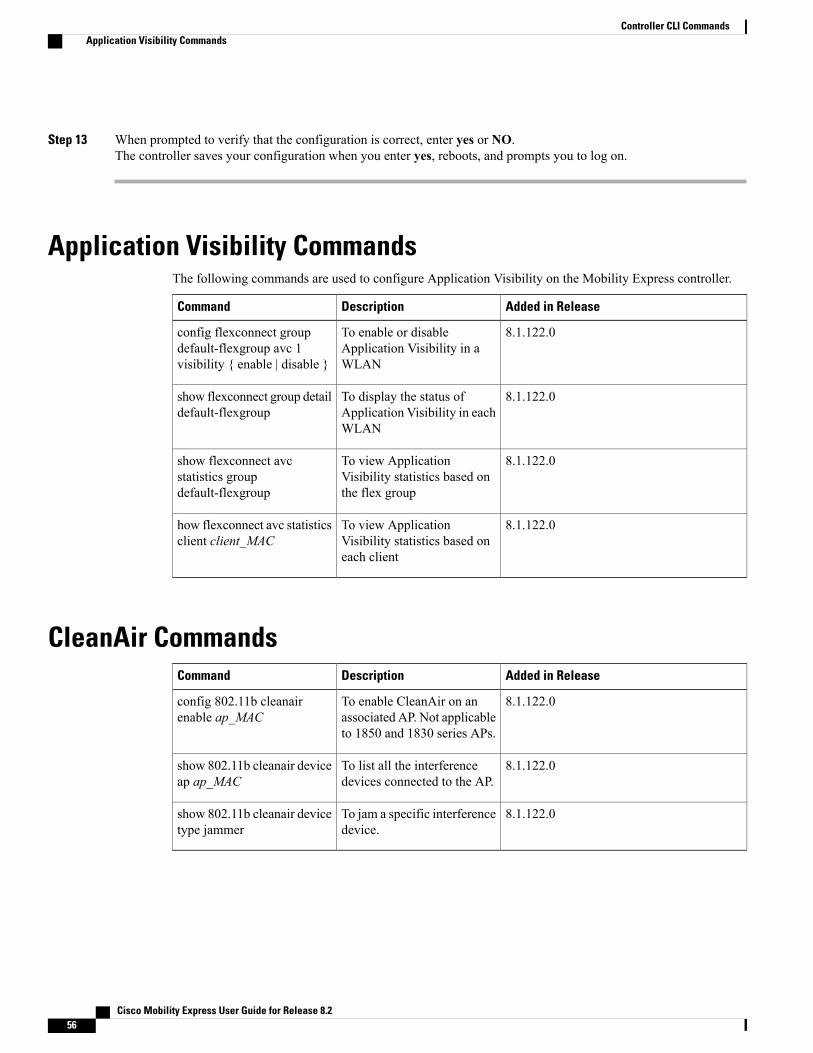
Step 13 When prompted to verify that the configuration is correct, enter yes or NO.The controller saves your configuration when you enter yes, reboots, and prompts you to log on.
Application Visibility CommandsThe following commands are used to configure Application Visibility on the Mobility Express controller.
Added in ReleaseDescriptionCommand
8.1.122.0To enable or disableApplication Visibility in aWLAN
config flexconnect groupdefault-flexgroup avc 1visibility { enable | disable }
8.1.122.0To display the status ofApplication Visibility in eachWLAN
show flexconnect group detaildefault-flexgroup
8.1.122.0To view ApplicationVisibility statistics based onthe flex group
show flexconnect avcstatistics groupdefault-flexgroup
8.1.122.0To view ApplicationVisibility statistics based oneach client
how flexconnect avc statisticsclient client_MAC
CleanAir CommandsAdded in ReleaseDescriptionCommand
8.1.122.0To enable CleanAir on anassociated AP. Not applicableto 1850 and 1830 series APs.
config 802.11b cleanairenable ap_MAC
8.1.122.0To list all the interferencedevices connected to the AP.
show 802.11b cleanair deviceap ap_MAC
8.1.122.0To jam a specific interferencedevice.
show 802.11b cleanair devicetype jammer
Cisco Mobility Express User Guide for Release 8.256
Controller CLI CommandsApplication Visibility Commands

Controller Image Upgrade CommandsThe following commands are used when performing a Mobility Express controller software image upgrade.
Added in ReleaseDescriptionCommand
8.1.122.0To set the path of the softwareimage on the TFTP server
transfer download ap-imagesimagePath image_path
8.1.122.0To set the file transfer modeas TFTP
transfer download ap-imagesmode tftp
8.1.122.0To specify the IP address ofthe TFTP server
transfer download ap-imagesserverIp ipv4_address
8.1.122.0To save the configuration andstart the image download
transfer download start
8.1.122.0To debug the transfer anddownload with all subcommands enabled
debug transfer all { enable |disable }
8.1.122.0To debug transfer downloadof TFTP
debug transfer tftp { enable |disable }
8.1.122.0To debug transfer tracedebug transfer trace { enable| disable }
DNS CommandsAdded in ReleaseDescriptionCommand
8.2.100.1To configure the default DNSservers.
config network dns default
8.2.100.1To view a network summary,with the default DNS serverslisted, if they are enabled.
show network summary
Migration CommandsThe following commands are used for converting an AP fromMobility Express software image to LightweightCAPWAP AP software image, and vice-versa.
Cisco Mobility Express User Guide for Release 8.2 57
Controller CLI CommandsController Image Upgrade Commands

Added in ReleaseDescriptionCommand
8.1.122.0To convert ap-type fromMobility Express toCAPWAP
ap-type capwap
8.1.122.0To convert ap-type fromCAPWAP to MobilityExpress, when running anMobility Express softwareimage
ap-type mobilityexpresstftp://tftp_server/file_name
8.1.122.0To convert all APs to typeCAPWAP simultaneouslyfrom the switch
config ap unifiedmodeswitch_nameswitch_IP_address
NTP CommandsAdded in ReleaseDescriptionCommand
8.2.100.1To configure the fullyqualified domain name of theNTP server having, forexample here, NTP index 1.
config time ntp server 1FQDN_of_server
8.2.100.1To configure the IP addressof the NTP server having, forexample here, NTP index 2.
config time ntp server 2NTP_Server_IP_address
UX Regulatory Domain CommandsAdded in ReleaseDescriptionCommand
8.1.122.0To disable WLAN 1config wlan disable 1
8.1.122.0To enable asuniversal-ap-admin for wlan1
config wlanuniversal-ap-admin enable 1
8.1.122.0To enable WLAN 1config wlan enable 1
8.1.122.0To show the present countryconfigured ( US, IN, etc ) ifnot UX.
show ap summary
Cisco Mobility Express User Guide for Release 8.258
Controller CLI CommandsNTP Commands

VRRP CommandsThe following Virtual Router Redundancy Protocol (VRRP) commands are used during the Mobility Expresscontroller failover and for the master AP.
Added in ReleaseDescriptionCommand
8.1.122.0To configure the master APthat has been elected to takeover as the new master AP
config apnext-preferred-master
8.1.122.0To display the status of themaster AP
show apnext-preferred-master
8.1.122.0To clear the configuration ofthe master AP
clear ap next-preferred-master
WGB CommandsThe following show commands can be used to view details of workgroup bridges (WGBs).
Added in ReleaseDescriptionCommand
8.1.122.0To display the summary ofworkgroup bridges
show wgb summary
8.1.122.0To display the details of aspecific workgroup bridge
show wgb detailWGB_MAC
Cisco Mobility Express User Guide for Release 8.2 59
Controller CLI CommandsVRRP Commands

Cisco Mobility Express User Guide for Release 8.260
Controller CLI CommandsWGB Commands
A P P E N D I X BAppendix
• Cisco Mobility Express Solution Features and Specifications, page 61
• Supported Browsers, page 61
• Cisco Mobility Express Controller Failover and Master AP Election Process, page 62
• How an Access Point is Added to the Cisco Mobility Express Network, page 63
• Predownloading an Image to an Access Point, page 63
• Converting an AP from Mobility Express to CAPWAP Lightweight Software, page 63
• RF Parameter Optimization Settings, page 64
• Related Documents, page 65
• FAQs, page 65
Cisco Mobility Express Solution Features and SpecificationsFor a full listing of the CiscoMobility Express Solution's technical specifications, supported and unsupportedfeatures, and interoperability information, see the Release Notes for CiscoWireless Controllers and LightweightAccess Points for Cisco Wireless Release 8.1.120.0, at this URL: http://www.cisco.com/c/en/us/td/docs/wireless/controller/release/notes/crn81mr2.html
Supported BrowsersSupported Browsers and VersionsOperating System
• Internet Explorer 10 and later
• Mozilla Firefox 33 and later
• Google Chrome 38 and later
Microsoft Windows
Cisco Mobility Express User Guide for Release 8.2 61

Supported Browsers and VersionsOperating System
• Safari 7 and later
• Mozilla Firefox 33 and later
• Google Chrome 38 and later
Apple Mac OS
Cisco Mobility Express Controller Failover and Master APElection Process
Mobility Express Controller Redundancy for Failover
In a Cisco Mobility Express network, not all the APs may have the capability to work as a master AP. Seethe Supported Cisco Aironet Access Points, on page 1 to know which AP models are capable of workingas a master AP.
In order to have Cisco Mobility Express controller redundancy to enable a failover, your network must havetwo or more active APs with master AP capability. In the event of a failover, one of these other APs willautomatically be elected as a master. The newly elected Master will have the same IP and configuration asthe original Master. From an administrator perspective, there will be no difference between the original Masterand the newly elected Master in case of a failover.
Clients that connect to the master AP will lose connectivity during a failover.Note
Master AP Election Process
In a Cisco Mobility Express AP network, when the master AP shuts down, one of the other master-capableAPs in this deployment is automatically designated as the master AP. The automatic selection of the masterAP among the Cisco Mobility Express-enabled APs is as per an internal automatic master election process.This process is used to both detect the failure of the master AP and to designate the new master AP amongthe eligible APs. This process is based on Virtual Router Redundancy Protocol (VRRP) and algorithmicallydetermines the next master AP, based on the following parameters listed in the order of descending precedence:
• The AP configured as VRRP master, using the VRRP command config ap next-preferred-master onthe controller's CLI.
• The AP with the least load in terms of the number of associated clients associated.
• Among APs with a similar client load, the AP with the lowest MAC address.
Cisco Mobility Express User Guide for Release 8.262
AppendixCisco Mobility Express Controller Failover and Master AP Election Process

How an Access Point is Added to the Cisco Mobility ExpressNetwork
When a supported AP that is running a CAPWAP lightweight AP software is added to the Cisco MobilityExpress network, it will start with the CAPWAP State: Discover advertisements on boot up. The CiscoMobilityExpress controller running on Master AP will respond to the advertisement and the new AP will go throughthe process of joining the CiscoMobility Express controller. If the AP being added is running the same version,it will straightaway join the Cisco Mobility Express network. However, if the AP is running an image olderthan the one running on the Cisco Mobility Express, the controller will download the corresponding CiscoMobility Express-capable AP image from the TFTP server.
For information on performing a software update, see Updating the Cisco Mobility Express Software.
Predownloading an Image to an Access PointTominimize network outages, an upgrade software image is downloaded to the access point from the controllerwithout resetting the access point or losing network connectivity. This means that, first the upgrade image tothe controller is downloaded and then the image is downloaded to the access point while the network is stillup. When the controller reboots, the access points are disassociated and reboot. The controller comes up first,followed by the access points, all with their upgraded images. Once the controller responds to the discoveryrequest sent by an access point with its discovery response packet, the access point sends a join request.
Converting an AP from Mobility Express to CAPWAP LightweightSoftware
If you wish to convert your AP that is running Mobility Express controller, to a CAPWAP Lightweightdeployment (that is, in a unified wireless network), follow these steps:
1 Connect to the Console Port, Telnet or SSH to the AP.
2 Login to the Mobility Express controller console.
3 In the Mobility Express controller console, use the command apciscoshell to connect to the AP console.
4 Login to the AP console using the username Cisco and password Cisco. Both are case-sensitive.
5 Enter enable.
6 Enter the command ap-type capwap, and confirm .
This converts the AP to CAPWAP Lightweight configuration-ready. This AP can no more function as aMobility Express master AP, unless it is converted back.
Cisco Mobility Express User Guide for Release 8.2 63
AppendixHow an Access Point is Added to the Cisco Mobility Express Network

RF Parameter Optimization SettingsWhen making the RF Parameter Optimization settings during the initial configuration wizard, use theinformation in the following table to select the right settings for your deployment. The following table showsthe default values when low, typical, or high client density type is selected.
If you do not enable RF Parameter Optimization during the initial configuration wizard, then client densityis set to Typical (the default value), and RF traffic type is set to Data (the default value).
Note
Low Density(For coverage inopen spaces)
High Density(Where throughputis most important)
Typical(For enterprisedeployments.Default profile.)
Dependency
HighestHigherDefaultGlobal per bandTX Power
TPC Threshold:
• -60 dB for 5GHz
• -65 dB for 2.4GHz
TPC Min: -10 dB
TPC Max: Defaultat 30 dB
TPC Threshold:
• -65 dB for 5GHz
• -70 dB for 2.4GHz
TPC Min: +7 dB
TPC Max: Defaultat 30 dB
TPCMin: Default at-10 dB
TPC Max: Defaultat 30 dB
Specific RF profileper band
TPC Threshold,TPC Min, and TPCmax
(These parametersare equivalent to TXPower)
LowMedium (RX-SOP)Default (Automatic)Global per band(AdvancedRX-SOP)
RF profiles
RX Sensitivity
Default (0)Default (0)Default (0)Global per band
802.11 a only(hidden)
RF Profiles
CCA Threshold
Higher (Data: -90Voice:-90)
Default (Data: -80Voice: -80)
Default (Data: -80Voice: -80)
Global per band
Data and voiceRSSI
RF Profiles
Coverage RSSIThreshold
Cisco Mobility Express User Guide for Release 8.264
AppendixRF Parameter Optimization Settings

Low Density(For coverage inopen spaces)
High Density(Where throughputis most important)
Typical(For enterprisedeployments.Default profile.)
Dependency
Lower (2)
Lower (1 to 3)
Default (3)Default (3)Global per band(CoverageException)
RF Profiles(Coverage HoleDetection)
Coverage ClientCount
CCK rates enabled
1,2, 5.5, 6, 9, 11, 12Mbp enabled
12 Mbp mandatory
9 Mbp supported
1,2, 5.5, 6, 11 Mbpdisabled
12 Mbp mandatory
9 Mbp supported
1,2, 5.5, 6, 11 Mbpdisabled
Global per band(network)
RF Profiles
Data Rates
Related DocumentsCisco Mobility Express Release Notes
http://www.cisco.com/c/en/us/td/docs/wireless/controller/release/notes/crn81mr2.html
Cisco Wireless Controller Command Reference, Release 8.1
http://www.cisco.com/c/en/us/td/docs/wireless/controller/8-1/cmd-ref/b_cr81.html
Cisco Aironet 1850 Series Access Points Hardware Installation Guide
http://www.cisco.com/c/en/us/td/docs/wireless/access_point/1850/hardware/guide/ap1850hwguide.html
Cisco Aironet 1830 Series Access Points Getting Started Guide
http://www.cisco.com/c/en/us/td/docs/wireless/access_point/1830/quick/guide/ap1830getstart.html
Cisco Aironet Universal AP Priming and Cisco AirProvision User Guide
http://www.cisco.com/c/en/us/td/docs/wireless/access_point/ux-ap/guide/uxap-mobapp-g.html
FAQsWhich access points can host the Mobility Express wireless LAN controller function and which accesspoints can be managed by it?
See Supported Cisco Aironet Access Points, on page 1.
Cisco Mobility Express User Guide for Release 8.2 65
AppendixRelated Documents

What controller-based modes does the Mobility Express wireless LAN controller function support?
Access points managed by the Mobility Express solution will operate with Centralized Control Plane andDistributed Data Plane, similar to the AireOS FlexConnect mode.
What are the licensing requirements for Mobility Express?
The Cisco Mobility Express solution does not require any licenses for access points.
Can I expand the scale of access points and convert to a wireless controller deployment?
Yes, you can simply point the Access Points to the WLAN controller IP address as the primary controller.This is independent of modes. TheWLAN controller will push the right AP image and respective configuration.For detailed information, see Converting an AP from Mobility Express to CAPWAP Lightweight Software,on page 63.
If my deployment needs to downsize to 25 access points or less, can they convert from existing controller-baseddeployment to Mobility Express?
Yes. You can convert your wireless controller-based deployment to Mobility Express, as long as yourdeployment has access points capable of hosting the Mobility Express controller functionality, such as CiscoAironet 1850 or 1830 series access points.
Where can I get more information on the Cisco Mobility Express solution?
Go to http://www.cisco.com/go/mobilityexpress.
Cisco Mobility Express User Guide for Release 8.266
AppendixFAQs