cisco mobility express deployment guide release 8 · cisco mobility express deployment guide...
TRANSCRIPT

Cisco Mobility Express Deployment Guide Release 8.5First Published: 2017-08-03
Americas HeadquartersCisco Systems, Inc.170 West Tasman DriveSan Jose, CA 95134-1706USAhttp://www.cisco.comTel: 408 526-4000 800 553-NETS (6387)Fax: 408 527-0883

THE SPECIFICATIONS AND INFORMATION REGARDING THE PRODUCTS IN THIS MANUAL ARE SUBJECT TO CHANGE WITHOUT NOTICE. ALL STATEMENTS,INFORMATION, AND RECOMMENDATIONS IN THIS MANUAL ARE BELIEVED TO BE ACCURATE BUT ARE PRESENTED WITHOUT WARRANTY OF ANY KIND,EXPRESS OR IMPLIED. USERS MUST TAKE FULL RESPONSIBILITY FOR THEIR APPLICATION OF ANY PRODUCTS.
THE SOFTWARE LICENSE AND LIMITEDWARRANTY FOR THE ACCOMPANYING PRODUCT ARE SET FORTH IN THE INFORMATION PACKET THAT SHIPPED WITHTHE PRODUCT AND ARE INCORPORATED HEREIN BY THIS REFERENCE. IF YOU ARE UNABLE TO LOCATE THE SOFTWARE LICENSE OR LIMITED WARRANTY,CONTACT YOUR CISCO REPRESENTATIVE FOR A COPY.
The Cisco implementation of TCP header compression is an adaptation of a program developed by the University of California, Berkeley (UCB) as part of UCB's public domain versionof the UNIX operating system. All rights reserved. Copyright © 1981, Regents of the University of California.
NOTWITHSTANDINGANYOTHERWARRANTYHEREIN, ALL DOCUMENT FILES AND SOFTWARE OF THESE SUPPLIERS ARE PROVIDED “AS IS"WITH ALL FAULTS.CISCO AND THE ABOVE-NAMED SUPPLIERS DISCLAIM ALL WARRANTIES, EXPRESSED OR IMPLIED, INCLUDING, WITHOUT LIMITATION, THOSE OFMERCHANTABILITY, FITNESS FORA PARTICULAR PURPOSEANDNONINFRINGEMENTORARISING FROMACOURSEOFDEALING, USAGE, OR TRADE PRACTICE.
IN NO EVENT SHALL CISCO OR ITS SUPPLIERS BE LIABLE FOR ANY INDIRECT, SPECIAL, CONSEQUENTIAL, OR INCIDENTAL DAMAGES, INCLUDING, WITHOUTLIMITATION, LOST PROFITS OR LOSS OR DAMAGE TO DATA ARISING OUT OF THE USE OR INABILITY TO USE THIS MANUAL, EVEN IF CISCO OR ITS SUPPLIERSHAVE BEEN ADVISED OF THE POSSIBILITY OF SUCH DAMAGES.
Any Internet Protocol (IP) addresses and phone numbers used in this document are not intended to be actual addresses and phone numbers. Any examples, command display output, networktopology diagrams, and other figures included in the document are shown for illustrative purposes only. Any use of actual IP addresses or phone numbers in illustrative content is unintentionaland coincidental.
Cisco and the Cisco logo are trademarks or registered trademarks of Cisco and/or its affiliates in the U.S. and other countries. To view a list of Cisco trademarks, go to this URL: http://www.cisco.com/go/trademarks. Third-party trademarks mentioned are the property of their respective owners. The use of the word partner does not imply a partnershiprelationship between Cisco and any other company. (1110R)
© 2017 Cisco Systems, Inc. All rights reserved.
C O N T E N T S
C H A P T E R 1 Cisco Mobility Express Overview 1
Supported Cisco Aironet® Access Points 1
Master Access Points 2
Subordinate Access Points 3
Cisco Mobility Express Scale Limits 4
Cisco Mobility Express Supported Features 5
Supported Software Release and Interoperability 5
C H A P T E R 2 Deploying Cisco Mobility Express 7
Pre-requisites for Deploying Mobility Express Solution 7
Connecting Mobility Express capable Access Point to the network 7
Determining image on the Access Point 9
Conversion 11
Converting Access Point from CAPWAP to Cisco Mobility Express 11
Converting Access Point from Cisco Mobility Express to CAPWAP 13
C H A P T E R 3 Configuring Cisco Mobility Express controller 15
CLI Setup Wizard 15
Over-the-Air Setup Wizard 16
Network Plug and Play 18
Introduction 18
Pre-requisites 18
APIC-EM discovery options 18
Configuring APIC-EM / Network PnP server 19
Site Pre-Provisioning Workflow 19
Importing Cisco Mobility Express configuration file to Network PnP 19
Creating a Project 20
Cisco Mobility Express Deployment Guide Release 8.5 iii
Adding Cisco Mobility Express capable Access Point to the Project and associating
the controller config 21
APIC-EM Network Plug and Play Deployment Options with Cisco Mobility Express 22
APIC-EM controller in Private Cloud 23
Cloud Plug and Play Connect redirect to APIC-EM controller 23
Cloud Plug and Play Device Redirect Provisioning Workflow 24
Obtain a Smart Account 24
Create APIC-EM Controller Profile 25
Adding Cisco Mobility Express capable Access Point to the Devices list 28
Connecting Cisco Mobility Access Points 31
C H A P T E R 4 Using internal DHCP server on Cisco Mobility Express 33
Creating a DHCP Scope 33
C H A P T E R 5 Configuring Cisco Mobility Express for Site Survey 37
Introduction 37
Pre-requisites 37
Configuring Mobility Express for Site Survey using CLI 38
C H A P T E R 6 Creating Wireless Networks 41
WLANs 41
Creating Employee WLANs 42
Creating Employee WLAN with WPA2 Personal 42
Creating Employee WLAN using WPA2 Enterprise with External Radius Server 42
Creating Employee WLAN with WPA2 Enterprise and Authentication Server as AP 43
Creating Employee WLAN with WPA2 Enterprise/External RADIUS and MAC
Filtering 43
Creating Guest WLANs 44
Creating Guest WLAN with Captive Portal on CMX Connect 44
Creating Guest WLAN with Internal Splash Page 45
Creating Guest WLAN with External Splash Page 46
Internal Splash Page for Web Authentication 47
Using default internal guest portal 47
Using customized internal guest portal 47
Centralized NAT on Guest WLANs 48
Cisco Mobility Express Deployment Guide Release 8.5iv
Contents

Managing WLAN Users 49
Adding MAC for Local MAC Filtering on WLANs 50
WLAN Passpoint Support 50
C H A P T E R 7 Managing Services with Cisco Mobility Express 53
Application Visibility and Control 53
Enabling Application Visibility on WLAN 53
Enabling Application Control on WLAN 54
Adding Application Control from Network Summary Page 54
Adding Application Control from Applications Page 54
iOS Optimized WiFi connectivity and Fast Lane 54
Configuring Optimized WiFi Connectivity 54
Configuring Fast Lane 56
Cisco Mobility Express with CMX Cloud 57
Cisco CMX Cloud 57
Cisco CMX Cloud Solution Compatibility Matrix 57
Minimum requirements for Cisco CMX Cloud deployment 57
Enabling CMX Cloud Service on Mobility Express for Presence Analytics 57
Configuring Site on CMX Cloud for Presence Analytics 58
C H A P T E R 8 Managing the Cisco Mobility Express Deployment 59
Managing Access Points 59
Adding Access Points to Cisco Mobility Express Network 60
Configuring Management Access 61
Managing Admin Accounts 62
Managing TACACS+ and RADIUS Servers 63
Adding TACACS+ Servers 63
Adding RADIUS Servers 64
Managing Admin User Priority 64
Managing TIME on Cisco Mobility Express 65
Configuring NTP Server 65
Updating Cisco Mobility Express Software 66
Software Update using cisco.com Transfer Mode 66
Software Update using HTTP Transfer Mode 67
Software Update using TFTP Transfer Mode 69
Cisco Mobility Express Deployment Guide Release 8.5 v
Contents

Upgrading from WebUI 69
Upgrading from CLI 70
Managing Advanced RF Parameters 71
CALEA Support 72
C H A P T E R 9 Master AP Failover and Electing a new Master 73
Master AP Failover 73
Electing a new Master Access Point 74
Cisco Mobility Express Deployment Guide Release 8.5vi
Contents

C H A P T E R 1Cisco Mobility Express Overview
With more devices attaching to the network and more bandwidth-intensive applications in use, mobile usagecontinues to rise. How do small and medium-sized businesses with little or no IT staff keep pace withunexpected growth?
The Cisco Mobility Express Solution is specifically designed to help small and medium-sized businesseseasily and cost-effectively deliver enterprise-class wireless access to both employees and customers. It is avirtual Wireless LAN controller function embedded on Cisco Aironet® 1560, 1815W, 1815I,1830, 1850,2800 and 3800 series 802.11ac Wave 2 Access Points. With the Cisco Mobility Express Solution, small andmid-sized networks can now enjoy the same quality user experiences as large enterprises.
Cisco Mobility Express Solution is an on-premise, managed Wi-Fi solution that:
• Is ideal for small and medium-sized deployments of up to 100 access points.
• Provides an easy, over-the-air deployment in under 10 minutes. In addition, one can use Network Plugand Play to bring up a new site.
• Removes the need for a physical controller while supporting Cisco's advanced features.
• Is supported on Cisco Aironet® 1560, 1815W, 1815I, 1815M, 1830, 1850, 2800 and 3800 Series802.11ac Wave 2 Access Points.
• Can control other Aironet® access points, such as the 1700, 2700, and 3700 Series.
• Can be used to perform Site Survey.
• Is the Next Generation Autonomous. 802.11ac Wave 2 Access Point do not support the legacyautonomous mode.
• Industry-leading Cisco technology allows small and medium-sized networks to reduce the number ofdevices needed to enjoy enterprise-grade Wi-Fi. Advanced features such as Guest, BYOD and CiscoHigh Density Experience (HDX) are activated by default for compatible access points, making thedeployment process even easier. CMX can be added to gain presence-based services and deep analytics.
• Supported Cisco Aironet® Access Points, page 1
Supported Cisco Aironet® Access PointsCisco Mobility Express solution consists of the following components:
Cisco Mobility Express Deployment Guide Release 8.5 1

• Master Access Point - Cisco Aironet® 1560, 1815W, 1815I, 1815M,1830, 1850, 2800 and 3800 Series802.11ac Wave 2 Access Points running the virtual Wireless LAN Controller function.
• Subordinate Access Points - Cisco Aironet® Access Points which are managed by Master Access Pointsimilar to how a Wireless LAN Controller manages Access Points.
Master Access Point functions as Wireless LAN Controller, manages Subordinate Access Points and alsoserves clients at the same time.
Note
Master Access PointsCisco Aironet® Access Points which support the Wireless LAN Controller function and operate as MasterAccess points are listed in the table below:
Table 1: Cisco Aironet® Access Points capable of operating as Master Access Points
Supported Model NumbersMaster Access Points
AIR-AP1540I-x-K9
AIR-AP1540D-x-K9
Cisco Aironet® 1540 Series
AIR-AP1562I-x-K9
AIR-AP1562E-x-K9
AIR-AP1562D-x-K9
Cisco Aironet® 1560 Series
AIR-AP1815I-x-K9CCisco Aironet® 1815I Series
AIR-AP1815M-x-K9CCisco Aironet® 1815M Series
AIR-AP1815W-x-K9CCisco Aironet® 1815W Series
AIR-AP1832I-x-K9CCisco Aironet® 1830 Series
AIR-AP1852I-x-K9C
AIR-AP1852E-x-K9C
Cisco Aironet® 1850 Series
AIR-AP2802I-x-K9C
AIR-AP2802E-x-K9C
Cisco Aironet® 2800 Series
AIR-AP3802I-x-K9C
AIR-AP3802E-x-K9C
Cisco Aironet® 3800Series
Cisco Mobility Express Deployment Guide Release 8.52
Cisco Mobility Express OverviewMaster Access Points

The -x- in the other model numbers is a placeholder for the actual letter indicating the model's regulatorydomain. For information on regulatory domains, see http://www.cisco.com/c/dam/assets/prod/wireless/wireless-compliance-tool/index.html
Note
Subordinate Access PointsCisco Aironet® Access Points which operate as Subordinate Access Points and serve clients are listed in thetable below:
Table 2: Cisco Aironet® Access Points capable of operating as Subordinate Access Points
Supported Model NumbersMaster Access Points
AIR-CAP702I-x-K9Cisco Aironet® 700i Series
AIR-CAP702W-x-K9Cisco Aironet® 700w Series
AIR-AP1540I-x-K9
AIR-AP1540D-x-K9
Cisco Aironet® 1540 Series
AIR-AP1562I-x-K9
AIR-AP1562E-x-K9
AIR-AP1562D-x-K9
Cisco Aironet® 1560Series
AIR-CAP1602I-x-K9
AIR-CAP1602E-x-K9
Cisco Aironet® 1600 Series
AIR-CAP1702I-x-K9Cisco Aironet® 1700 Series
AIR-AP1810W-x-K9Cisco Aironet® 1810 Series
AIR-AP1815I-x-K9CCisco Aironet® 1815I Series
AIR-AP1815M-x-K9CCisco Aironet® 1815M Series
AIR-AP1815W-x-K9CCisco Aironet® 1815W Series
AIR-AP1832I-x-K9CCisco Aironet® 1830 Series
AIR-AP1852I-x-K9C
AIR-AP1852E-x-K9C
Cisco Aironet® 1850 Series
AIR-CAP2602I-x-K9
AIR-CAP2602E-x-K9
Cisco Aironet® 2600 Series
AIR-CAP2702I-x-K9
AIR-CAP2702E-x-K9
Cisco Aironet® 2700 Series
Cisco Mobility Express Deployment Guide Release 8.5 3
Cisco Mobility Express OverviewSubordinate Access Points
Supported Model NumbersMaster Access Points
AIR-AP2802I-x-K9C
AIR-AP2802E-x-K9C
Cisco Aironet® 2800 Series
AIR-CAP3602I-x-K9
AIR-CAP3602E-x-K9
Cisco Aironet® 3600 Series
AIR-CAP3702I-x-K9
AIR-CAP3702E-x-K9
Cisco Aironet® 3700 Series
AIR-AP3802I-x-K9C
AIR-AP3802E-x-K9C
Cisco Aironet® 3800 Series
The -x- in the other model numbers is a placeholder for the actual letter indicating the model's regulatorydomain. For information on regulatory domains, see http://www.cisco.com/c/dam/assets/prod/wireless/wireless-compliance-tool/index.html
Note
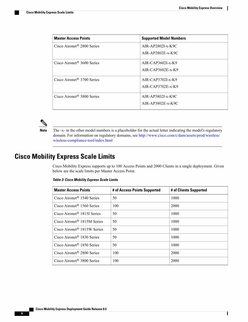
Cisco Mobility Express Scale LimitsCisco Mobility Express supports up to 100 Access Points and 2000 Clients in a single deployment. Givenbelow are the scale limits per Master Access Point.
Table 3: Cisco Mobility Express Scale Limits
# of Clients Supported# of Access Points SupportedMaster Access Points
100050Cisco Aironet® 1540 Series
2000100Cisco Aironet® 1560 Series
100050Cisco Aironet® 1815I Series
100050Cisco Aironet® 1815M Series
100050Cisco Aironet® 1815W Series
100050Cisco Aironet® 1830 Series
100050Cisco Aironet® 1850 Series
2000100Cisco Aironet® 2800 Series
2000100Cisco Aironet® 3800 Series
Cisco Mobility Express Deployment Guide Release 8.54
Cisco Mobility Express OverviewCisco Mobility Express Scale Limits

If there are more than 50 Access Points in aMobility Express network, theMaster AP(running theWirelessLAN controller function) can service a maximum of 20 clients. This limit only applies to Master AP andnot any other Access Point in the Mobility Express network.
Note
Cisco Mobility Express Supported FeaturesSee Supported features section in Release notes
Supported Software Release and InteroperabilityAireOS® Release
• Cisco Mobility Express solution is supported from AireOS® Release 8.1.121.0 and later.
Cisco Prime Infrastructure
• PI Release 3.0.1 and later.
Connected Mobility Experiences (CMX)
• CMX Connect is supported starting AireOS® Release 8.3.100.0 for both On-Prem and CMX clouddeployments.
• CMX Presence Analytics is supported starting AireOS® Release 8.1.121.0 for On-Prem and CMXRelease 10.2 and later. CMX Presence analytics in the cloud is supported starting AireOS® Release8.3.102.0.
Cisco Identity Services Engine (ISE)
• ISE Release 1.4 and later. 802.1x authentication is supported.
Cisco Mobility Express Deployment Guide Release 8.5 5
Cisco Mobility Express OverviewCisco Mobility Express Supported Features

Cisco Mobility Express Deployment Guide Release 8.56
Cisco Mobility Express OverviewSupported Software Release and Interoperability

C H A P T E R 2Deploying Cisco Mobility Express
• Pre-requisites for Deploying Mobility Express Solution, page 7
• Connecting Mobility Express capable Access Point to the network, page 7
• Determining image on the Access Point, page 9
• Conversion, page 11
Pre-requisites for Deploying Mobility Express Solution1 Youmust not have other CiscoWireless LANControllers; neither appliance nor virtual in the same network
during set up or during daily operation of a Cisco Mobility Express network. The Mobility Expresscontroller cannot interoperate or co-exist with other Wireless LAN Controllers in the same network.
2 Decide on the first Access Point to be configured as a Master Access Point. This Access Point should becapable of supporting the Wireless LAN Controller function.
3 A DHCP server must be available on the network so that Access Points and clients can obtain an IPAddress. Starting AireOS® Release 8.3.102.0 or later, one can configure a DHCP server on the MasterAccess Point as well but this is typically used for Site Survey.
Connecting Mobility Express capable Access Point to thenetwork
Depending on the deployment, Mobility Express capable Access Points can be connected to an access portor a trunk port on the switch.
If Access Points andWLANs are all on the same network,Mobility Express capable Access Points can connectto an access port on the switch as shown below.
Cisco Mobility Express Deployment Guide Release 8.5 7

On Mobility Express, management traffic is untagged. If Access Points and WLANs are all on differentVLANs, Mobility Express capable Access Points will connect to a trunk port on the switch and traffic forindividualWLANs will be switched locally on individual VLANs. Shown below is a deployment with AccessPoints and WLANs on different VLANs.
Cisco Mobility Express Deployment Guide Release 8.58
Deploying Cisco Mobility ExpressConnecting Mobility Express capable Access Point to the network

interface GigabitEthernet1/0/37description » Connected to Master AP «switchport trunk native vlan 40switchport trunk allowed vlan 10,20,30,40switchport mode trunk
Determining image on the Access PointThe Cisco Aironet® 1560, 1815, 1830, 1850, 2800 and 3800 series access points can either have CAPWAPimage or the Cisco Mobility Express image which is capable of running the virtual Wireless LAN controllerfunction on the Access Point.
To determine the image and capability of an Access Point, follow the procedure below:
Procedure
Step 1 Login to the Access Point CLI using a console and type AP#show version and check the full output of showversion. The default login credentials are Username:cisco and Password:cisco.
Step 2 If show version output does not display AP Image Type and APConfiguration parameters as highlightedbelow, it means that AP is running the CAPWAP image and a conversion to CiscoMobility Express is requiredif you want to run the controller function on the Access Point. To convert from a CAPWAP Access Point toMobility Express, go to Conversion section.
Cisco Mobility Express Deployment Guide Release 8.5 9
Deploying Cisco Mobility ExpressDetermining image on the Access Point

cisco AIR-AP1852E-UXK9 ARMv7 Processor rev 0 (v71) with 997184/525160K bytes of memory.Processor board ID RFDP2BCR021AP Running Image : 8.2.100.0Primary Boot Image : 8.2.100.0Backup Boot Image : 8.1.106.33AP Image type : MOBILITY EXPRESS IMAGEAP Configuration : MOBILITY EXPRESS CAPABLE0 Gigabit Ethernet interfaces0 802.11 RadiosRadio FW version . 1401b63d12113073a3C08aa67f0c039c0NSS FW version : NSS.AK.1.0.c4-0Z026-E_cust C-1.24160
If the show version displays AP Image Type: MOBILITY EXPRESS IMAGE and AP Configuration:NOTMOBILITYEXPRESSCAPABLE , it means that even though the Access Point has the CiscoMobilityExpress image, it is configured to run as a CAPWAP Access Point. In this case Access Point will not run thecontroller function and will not participate in the Master Election process upon failure of the active MasterAP.
cisco AI R-AP1852E-UXK9 ARMv7 Processor rev 0 (v7I) with 997184/726252K bytes of memory.Processor board ID RFDP2BCR021AP Running Image : 8.2.101.0Primary Boot Image : 8.2.100.0Backup Boot Image : 8.1.106.33AP Image type : MOBILITY EXPRESS IMAGEAP Configuration : NOT MOBILITY EXPRESS CAPABLE
For this AP to run the controller function, AP Configuration has to be changed to MOBILITY EXPRESSCAPABLE . To change the APConfiguration, execute the following command from the APCLI. AP#ap-typemobility-express tftp://
Access Point will reboot and after it comes up, it will be capable of running the controller function. You cancheck the output of show version again to confirm that AP Configuration has changed to MOBILITYEXPRESS CAPABLE .
If the show version displays AP Image Type: MOBILITY EXPRESS IMAGE and AP Configuration:MOBILITY EXPRESS CAPABLE , it means that the Access Point has the Mobility Express image and iscapable of running the controller function. For this scenario, the output of the show version is shown below:
cisco AIR-AP3802I-B-K9 ARMv7 Processor rev 1 (v7l) with 1028384/255032K bytes of memory.Processor board ID FCW2034NXAVAP Running Image : 8.4.2.66Primary Boot Image : 8.4.2.66Backup Boot Image : 8.4.2.34AP Image type : MOBILITY EXPRESS IMAGEAP Configuration : MOBILITY EXPRESS CAPABLE1 Multigigabit Ethernet interfaces1 Gigabit Ethernet interfaces2 802.11 RadiosRadio Driver version : 9.0.5.5-W8964Radio FW version : 9.1.8.1NSS FW version : 2.4.18
Cisco Mobility Express Deployment Guide Release 8.510
Deploying Cisco Mobility ExpressDetermining image on the Access Point

ConversionOne can convert an Access Point running CAPWAP to Cisco Mobility Express and vice versa.
Converting Access Point from CAPWAP to Cisco Mobility ExpressCisco Mobility Express support on 11ac Wave 2 Access Points is introduced in different AireOS releases andit is important to note that before an Access Point can be converted to Mobility Express, it must have theminimumAireOS CAPWAP image which supported CiscoMobility Express capability for that Access Point.Given below is theminimumAireOS release for an Access Point which will support conversion fromCAPWAPto Cisco Mobility Express.
Table 4: Minimum AireOS release supporting Cisco Mobility Express
Minimum AireOS Release with CAPWAP imageAccess Point
Release 8.5 or laterCisco Aironet® 1540Series
Release 8.4 or laterCisco Aironet® 1560 Series
Release 8.4 or laterCisco Aironet® 1815I Series
Release 8.5 or laterCisco Aironet® 1815M Series
Release 8.4 or laterCisco Aironet® 1815W Series
Release 8.1 MR2 or laterCisco Aironet® 1830 Series
Release 8.1 MR2 or laterCisco Aironet® 1850 Series
Release 8.3 or laterCisco Aironet® 2800 Series
Release 8.3 or laterCisco Aironet® 3800 Series
If the CAPWAP image on the Access Point is older than theminimumAireOS release capable of supportingCisco Mobility Express, Access Point MUST first join a WLC running the minimum AireOS release orhigher to upgrade its CAPWAP image. After the CAPWAP image of the AP has been upgraded, conversionof AP from CAPWAP to Mobility Express can be performed.
Note
To perform a conversion on an Access Point running CAPWAP to Mobility Express, follow the procedurebelow:
Procedure
Step 1 Download the conversion image for the Access Point from cisco.com to the TFTP server. It is a tar file. Donot untar the file. The following table lists the Cisco Mobility Express software for Cisco Wireless Release8.5.100.0.
Cisco Mobility Express Deployment Guide Release 8.5 11
Deploying Cisco Mobility ExpressConversion

Table 5: Conversion tar file for Access Points
Software to be used only for Conversion from UnifiedWireless Network Lightweight AP Software to CiscoMobility Express
Access Points supported as Master AP
AIR-AP1540-K9-8-5-103-0.tarCisco Aironet® 1540 Series
AIR-AP1560-K9-8-5-103-0.tarCisco Aironet® 1560 Series
AIR-AP1815-K9-8-5-103-0.tarCisco Aironet® 1815I Series
AIR-AP1815-K9-8-5-103-0.tarCisco Aironet® 1815M Series
AIR-AP1815-K9-8-5-103-0.tarCisco Aironet® 1815W Series
AIR-AP1830-K9-8-5-103-0.tarCisco Aironet® 1830 Series
AIR-AP1850-K9-8-5-103-0.tarCisco Aironet® 1850 Series
AIR-AP2800-K9-8-5-103-0.tarCisco Aironet® 2800 Series
AIR-AP3800-K9-8-5-103-0.tarCisco Aironet® 3800 Series
Step 2 Login to the Access Point.Step 3 Execute AP#show version on the Access Point CLI. From the show version output, you can determine the
AP Image type and AP Configuration and can then proceed with the conversion
Case 1: If the AP Image type is MOBILITY EXPRESS IMAGE and AP configuration is NOTMOBILITY EXPRESS CAPABLE, enter the command below to change the AP Configuration toMOBILITY EXPRESS CAPABLE .
AP#ap-type mobility-express
Since the Access Point has AP Image type: MOBILITY EXPRESS IMAGE, a new image willnot be downloaded. After the command is executed, the Access Point will reboot and after it comesup, the AP Configuration will be changed toMOBILITY EXPRESS CAPABLE.
Note
Case 2 : If the AP Image type and AP Configuration are not available, it means that the AP is runningCAPWAP image. To do the conversion, execute the command below:AP#ap-type mobility-express tftp://<TFTP Server IP>/<path to tar file>
Example:
AP#ap-type mobility-express tftp://10.18.22.34/AIR-AP1850-K9-8.1.120.0.tar
Starting the ME image download...It may take few minutes to finish the download.
Image downloaded, writing to flash...do PREDOWNLOAD, part1 is active partsh: CHECK_ME: unknown operandImage start 0x40355008 size 0x01dae41a file size 0x01dae7caKey start 0x42103422 size 0x00000230Sinature start 0x42103652 size 0x00000180Verify returns 0btldr rel is 16 vs 16, does not need update
Cisco Mobility Express Deployment Guide Release 8.512
Deploying Cisco Mobility ExpressConverting Access Point from CAPWAP to Cisco Mobility Express
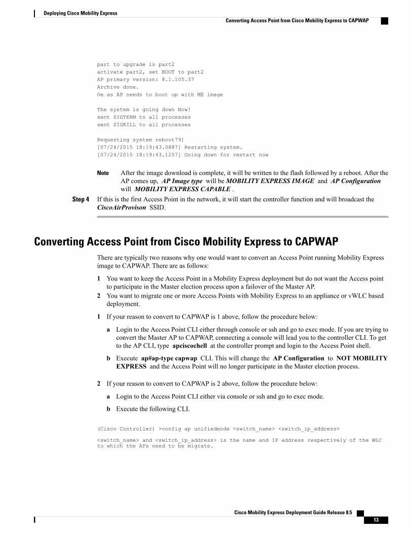
part to upgrade is part2activate part2, set BOOT to part2AP primary version: 8.1.105.37Archive done.Oe as AP needs to boot up with ME image
The system is going down Now!sent SIGTERM to all processessent SIGKILL to all processes
Requesting system reboot79][07/24/2015 18:19:43.0887] Restarting system.[07/24/2015 18:19:43.1257] Going down for restart now
After the image download is complete, it will be written to the flash followed by a reboot. After theAP comes up, AP Image type will beMOBILITY EXPRESS IMAGE and AP Configurationwill MOBILITY EXPRESS CAPABLE .
Note
Step 4 If this is the first Access Point in the network, it will start the controller function and will broadcast theCiscoAirProvison SSID.
Converting Access Point from Cisco Mobility Express to CAPWAPThere are typically two reasons why one would want to convert an Access Point running Mobility Expressimage to CAPWAP. There are as follows:
1 You want to keep the Access Point in a Mobility Express deployment but do not want the Access pointto participate in the Master election process upon a failover of the Master AP.
2 You want to migrate one or more Access Points with Mobility Express to an appliance or vWLC baseddeployment.
1 If your reason to convert to CAPWAP is 1 above, follow the procedure below:
a Login to the Access Point CLI either through console or ssh and go to exec mode. If you are trying toconvert the Master AP to CAPWAP, connecting a console will lead you to the controller CLI. To getto the AP CLI, type apciscochell at the controller prompt and login to the Access Point shell.
b Execute ap#ap-type capwap CLI. This will change the AP Configuration to NOT MOBILITYEXPRESS and the Access Point will no longer participate in the Master election process.
2 If your reason to convert to CAPWAP is 2 above, follow the procedure below:
a Login to the Access Point CLI either via console or ssh and go to exec mode.
b Execute the following CLI.
(Cisco Controller) >config ap unifiedmode <switch_name> <switch_ip_address>
<switch_name> and <switch_ip_address> is the name and IP address respectively of the WLCto which the APs need to be migrate.
Cisco Mobility Express Deployment Guide Release 8.5 13
Deploying Cisco Mobility ExpressConverting Access Point from Cisco Mobility Express to CAPWAP

The above command converts all connected Access Points with AP Configuration: MOBILITYEXPRESS CAPABLE to AP Configuration: NOT MOBILITY EXPRESS CAPABLE . When thiscommand is issued, the APs are reloaded, and they come back up and look for the controller(switch_ip_address) to join.
Note
Cisco Mobility Express Deployment Guide Release 8.514
Deploying Cisco Mobility ExpressConverting Access Point from Cisco Mobility Express to CAPWAP
C H A P T E R 3Configuring Cisco Mobility Express controller
There are multiple ways one can configure a Cisco Mobility Express controller. They are as follows:
1 CLI Setup Wizard2 Over–the–Air Setup Wizard3 Network Plug and Play
• CLI Setup Wizard, page 15
• Over-the-Air Setup Wizard, page 16
• Network Plug and Play, page 18
• APIC-EM Network Plug and Play Deployment Options with Cisco Mobility Express, page 22
• Connecting Cisco Mobility Access Points, page 31
CLI Setup WizardTo use the Setup Wizard from CLI, you must connect to the console port of the Access Point. The defaultparameters for the console ports are 9600 baud, eight data bits, one stop bit, and no parity. The console portsdo not support hardware flow control.
After connecting to the console port on the Access Point, power up the Access Point. After a few minutes,Access Point will start the Controller.
To configure the Mobility Express controller, follow the steps as shown in the example below:System Name [Cisco_2c:3a:40] (31 characters max): me-wlcEnter Country Code list (enter 'help' for a list of countries) [US]:
Configure a NTP server now? [YES][no]: noConfigure the system time now? [YES][no]: no
Note! Default NTP servers will be used
Management Interface IP Address: 40.40.40.10Management Interface Netmask: 255.255.255.0Management Interface Default Router: 40.40.40.1Cleaning up Provisioning SSIDCreate Management DHCP Scope? [yes][NO]: yesDHCP Network : 40.40.40.0DHCP Netmask : 255.255.255.0Router IP: 40.40.40.1
Cisco Mobility Express Deployment Guide Release 8.5 15

Start DHCP IP address: 40.40.40.11Stop DHCP IP address: 40.40.40.254DomainName :DNS Server : [OPENDNS][user DNS]Create Employee Network? [YES][no]: YESEmployee Network Name (SSID)?: WestAutoBody-EmployeeEmployee VLAN Identifier? [MGMT][1-4095]: MGMTEmployee Network Security? [PSK][enterprise]: PSKEmployee PSK Passphrase (8-38 characters)?: Cisco123Re-enter Employee PSK Passphrase: Cisco123Create Guest Network? [yes][NO]: YESGuest Network Name (SSID)?: WestAutoBody-GuestGuest VLAN Identifier? [EMPLOYEE][1-4095]: EMPLOYEEGuest Network Security? [WEB-CONSENT][psk]: WEB-CONSENTCreate Guest DHCP Scope? [yes][NO]: NOEnable RF Parameter Optimization? [YES][no]: YESClient Density [TYPICAL][Low][High]: TYPICALTraffic with Voice [NO][Yes]: Yes
Configuration correct? If yes, system will save it and reset. [yes][NO]: yesCleaning up Provisioning SSID
The Access Point will reboot and after it comes back up, login to the Mobility Express controller WebUIfrom the browser using https://<mangement_ip_address> Cisco Mobility Express controller uses aself-signed certificate for HTTPS. Therefore, all browsers display a warning message and asks whetheryou wish to proceed with an exception or not when the certificate is presented to the browser. Accept therisk and proceed to access the Mobility Express Wireless LAN Controller login page.
Note
Over-the-Air Setup WizardOver-the-air is a simple and easy way to configureMobility Express out of the box. Over-the-Air provisioningcan be done using a WiFi enabled device or the Cisco Wireless app which can be downloaded from AppStore for iOS devices and Play Store for Android Devices. The Cisco Wireless app provides a minimum setof configurable options to deploy Mobility Express in just a few minutes.
Procedure
Step 1 When the LED on the Access Point chirps green, connect a WiFi enabled laptop to the CiscoAirProvisionSSID. The default password is password. The laptop will get an IP address from subnet 192.168.1.0/24.
CiscoAirProvision SSID is broadcast at2.4GHz.
Note
Step 2 Open a web browser and browse to http://mobilityexpress.cisco. This will redirect to configuration wizardand the admin account page will appear.
Step 3 Create an admin account on the controller by specifying the following parameters and then click on the Startbutton.
• Enter the admin username. Maximum up to 24 ASCII characters.
• Enter the password. Maximum up to 24 ASCII characters. When specifying a password, ensure that:
◦The password must contain characters from at least three of the following classes – lowercaseletters, uppercase letters, digits, special characters.
Cisco Mobility Express Deployment Guide Release 8.516
Configuring Cisco Mobility Express controllerOver-the-Air Setup Wizard

◦No character in the password can be repeated more than three times consecutively.
◦The new password must not be the same as the associated username and the username reversed.
◦The password must not be cisco, ocsic, or any variants obtained by changing the capitalization ofletters of the word Cisco. In addition, you cannot substitute 1, I, or ! for i, 0 for o, or $ for s.
Step 4 In the Set up Your Controller section, configure the following:
• Enter the System Name
• Select the Country from the drop-down list
• Date and Time should be auto-filled but one can manually configure it as well
• Select the Timezone from the drop-down list
• Enter the IP address of NTP Server if there is one available. If left blank, NTP Pools will be automaticallyconfigured
• Enter the Management IP Address of the controller
• Enter the Subnet Mask
• Enter the Default Gateway
Step 5 Disable Enable DHCP Server(Management Network) if an external DHCP server is being used. If internalDHCP server on the Mobility Express controller has to be used, specify the DHCP server related information.
Step 6 Click Next.Step 7 In the Create Your Wireless Network, under Employee Network, configure the following:
• Enter the Network Name
• Select Security as WPA2 Personal or WPA2 Enterprise from the drop-down list
• If WPA2 Personal is selected, enter the Passphrase
Step 8 One can also enable RF Parameter Optimization and configure the following:
• Move the Client Density slider as needed
• From the Traffic Type, select Data or Data and Voice
Step 9 Click Next.Step 10 Confirm the settings on the page and click on the Apply button. The Access Point will reboot and after it
comes up, it will run the controller.The Access Point will reboot and after it comes back up, login to the Mobility Express controllerWebUI from the browser using https:<management_ip_address>.CiscoMobility Express controlleruses a self-signed certificate for HTTPS. Therefore, all browsers display a warning message and askswhether you wish to proceed with an exception or not when the certificate is presented to the browser.Accept the risk and proceed to access the Mobility Express Wireless LAN Controller login page.
Note
Cisco Mobility Express Deployment Guide Release 8.5 17
Configuring Cisco Mobility Express controllerOver-the-Air Setup Wizard
Network Plug and Play
IntroductionThe Cisco Network Plug and Play solution provides a simple, secure, unified, and integrated offering forenterprise network customers to ease new site rollouts for provisioning Cisco Mobility Express. The solutionallows use of Cloud Redirection service, on-prem, or combination which provide a unified approach toprovision enterprise networks comprised of Cisco Mobility Express, Cisco routers, switches, with a near zerotouch deployment experience.
You can use the Cisco Network Plug and Play application to pre-provision the site and add Cisco MobilityExpress capable access points to the site. This includes entering access point information and uploading acontroller configuration file for virtual controller which will run on Mobility Express capable access points.
When an installer installs and powers up the Cisco Mobility Express capable access points, it auto-discoversthe Cisco APIC-EM controller by using the DHCP, DNS or cloud redirection service. After the auto-discoveryprocess is complete, the AP downloads the controller configuration file from local PnP server, or communicateswith the cloud redirection service for direction to target PnP server.
Pre-requisites1 APIC-EM Release 1.4 or later with Cisco Network Plug and Play, virtually hosted in a Cisco UCS or
equivalent server.2 Access Points–Cisco 802.11ac Wave 2 access points running Cisco Mobility Express software.3 Controller Configuration–CiscoMobility Express controller configuration file to be uploaded on Network
PnP.
APIC-EM discovery options1 DHCP server configured with option 43 to allow Cisco Mobility Express capable access points to
auto-discover the APIC-EM controller (option 43 is not required if only testing cloud redirection). DHCPoption 43 consists of a string value that is a configured DHCP server: option 43 ascii"5A1N;B2;K4;I192.168.1.123;J80"
192.168.1.123 is the IP address of the APCI-EM ServerNote
2 On–prem PnP server can be added to DNS using ‘pnpserver.yourlocal.domain’ If DHCP discovery failsto get the IP address of the APIC-EM controller, for example, because option 43 is not configured, theCisco Plug and Play Agent falls back on a DNS lookup method. Based on the network domain namereturned by the DHCP server, it constructs a fully qualified domain name (FQDN) for the APIC-EMcontroller, using the preset hostname pnpserver. For example, if the DHCP server returns the domain name" customer.com ", the Cisco Plug and Play IOS Agent constructs the FQDN "pnpserver.customer.com ".It then uses the local name server to resolve the IP address for this FQDN
Cisco Mobility Express Deployment Guide Release 8.518
Configuring Cisco Mobility Express controllerNetwork Plug and Play

3 Cloud redirection service requires a connection to the internet, and valid DNS server that can resolve‘devicehelper.cisco.com’. The cloud redirection service redirect Cisco Mobility Express Access Point toAPIC-EM.
Configuring APIC-EM / Network PnP server
Site Pre-Provisioning WorkflowCisco Network Plug and Play allows you to pre-provision and plan for new sites. When you create a new site,Cisco Network Plug and Play enables you to pre-provision Cisco Mobility Express access point(s) controller,configuration file, product ID, and product serial # for selected Access Points. This simplifies and acceleratesthe time that it takes to get a site fully functional.
For detailed info pm PnP Config about other functionality, see http://www.cisco.com/c/en/us/support/cloud-systems-management/one-enterprise-network-controller/products-installation-and-configuration-guides-list.html
To pre-provision a site on your network, perform these steps:
1 Importing Cisco Mobility Express controller configuration file to Network PnP2 Creating a Project3 Adding Cisco Mobility Express capable Access Point to the Project and associating the controller config.
Importing Cisco Mobility Express configuration file to Network PnP
Procedure
Step 1 Login to APIC-EM controller and navigate to Network Plug and Play > ConfigurationsStep 2 Click on Upload to upload the controller configurationStep 3 Select a controller configuration file from your local machine
Cisco Mobility Express Deployment Guide Release 8.5 19
Configuring Cisco Mobility Express controllerConfiguring APIC-EM / Network PnP server

Creating a Project
Procedure
Step 1 Navigate to Network Plug and Play > Projects.Step 2 Enter the name for the Project and click on the Add button.
Step 3 Click on the Create button to create the Project.
Cisco Mobility Express Deployment Guide Release 8.520
Configuring Cisco Mobility Express controllerConfiguring APIC-EM / Network PnP server

Adding Cisco Mobility Express capable Access Point to the Project and associating thecontroller config
Procedure
Step 1 Navigate to Network Plug and Play > Projects.Step 2 Click on Add button under Project Devices.Step 3 In the Add Device window, enter the following:
• Device Name–Enter the device name; unique for each site
• Product ID–Select the Access Point device ID from the drop-down list
• Serial Number–Enter the Serial Number of the Mobility Express Access Point
• Config–You can either upload a new configuration or select the configuration file which was addedearlier
Step 4 Click on the Add button.
Cisco Mobility Express Deployment Guide Release 8.5 21
Configuring Cisco Mobility Express controllerConfiguring APIC-EM / Network PnP server

APIC-EM Network Plug and Play Deployment Options withCisco Mobility Express
There are two deployment options supported for deploying Cisco Mobility Express with Network Plug andPlay.
APIC-EM controller in Private Cloud
Cloud Plug and Play Connect redirect to APIC-EM controller
Cisco Mobility Express Deployment Guide Release 8.522
Configuring Cisco Mobility Express controllerAPIC-EM Network Plug and Play Deployment Options with Cisco Mobility Express

APIC-EM controller in Private CloudIn this deployment option, there will be an On-Prem APIC-EM controller which can be discovered by CiscoMobility Express Access Points using option 43 or DNS discovery.
Figure 1: APIC-EM controller in Private Cloud flow
Option 43 points to APIC-EM controller IP address. To configure DHCP scope with Option 43, it is importantfollow the format as shown below. In the example below, 192.168.1.123 is the IP address of APIC-EMcontrollerip dhcp pool pnp_device_poolnetwork 192.168.1.0 255.255.255.0default-router 192.168.1.1option 43 ascii "5A1N;B2;K4;I192.168.1.123;J80"
To discover APIC-EM controller using the DNS discovery options, configure the DNS server and domainname on the DHCP scope.ip dhcp pool pnp_device_poolnetwork 192.168.1.0 255.255.255.0default-router 192.168.1.1domain-name cisco.comdns-server 172.20.229.8
Cloud Plug and Play Connect redirect to APIC-EM controllerCloud re-direction service uses Cisco public hosted cloud to re-direct Cisco Mobility Express capable accesspoints to APIC-EM controller. The minimal requirement is that the Mobility Express Access Points networkhave DHCP and DNS, and connectivity reachable to Cisco public cloud. There is no need to configure Option
Cisco Mobility Express Deployment Guide Release 8.5 23
Configuring Cisco Mobility Express controllerAPIC-EM controller in Private Cloud

43 on DHCP scope with this deployment option. A simple test would be to obtain DHCP address and ping'devicehelper.cisco.com' from where the Mobility Express AP will be deployed.
Figure 2: Cloud Plug and Play Device Redirect to APIC-EM controller flow
Cloud Plug and Play Device Redirect Provisioning WorkflowThis section describes the steps to redirect Cisco Mobility Express Access Points to APIC-EM controllerusing Cloud Plug and Play Connect service.
To configure cloud Plug and Play connect redirect service, perform the following steps:
1 Obtain a Smart Account2 Create APIC-EM Controller Profile3 Adding Mobility Express capable Access Point to the Devices list4 Associate Mobility Express capable Access Point to APIC-EM Controller profile
For detailed info on PnP Config about other functionality, see https://www.cisco.com/c/en/us/support/cloud-systems-management/one-enterprise-network-controller/products-installation-and-configuration-guides-list.html
Obtain a Smart Account
Procedure
Step 1 Go to http://software.cisco.comStep 2 Request a Smart Account or Log In (existing Smart Account holders)
Cisco Mobility Express Deployment Guide Release 8.524
Configuring Cisco Mobility Express controllerCloud Plug and Play Device Redirect Provisioning Workflow

Create APIC-EM Controller Profile
Procedure
Step 1 Go to http://software.cisco.com and loginStep 2 Navigate to Provisioning > Plug and Play Connect
Cisco Mobility Express Deployment Guide Release 8.5 25
Configuring Cisco Mobility Express controllerCloud Plug and Play Device Redirect Provisioning Workflow

Step 3 Click on Controller Profiles. Select a Virtual Account. If you do have one, create a Virtual Account first.Step 4 Click on the Add Profile to create a new controller profile.
Step 5 Select Controller Type as PNP Server from the drop-down list and click on Next.
Step 6 Enter the following and click Next.
1 Profile Name
2 Description
3 Select IPv4 or IPv6, HTTP or HTTPS and enter the IP address if the PNP Server
If you select HTTPS, then you would have import a SSL certificate. Also, optionally one can enterinformation of the secondary controller.
Note
Cisco Mobility Express Deployment Guide Release 8.526
Configuring Cisco Mobility Express controllerCloud Plug and Play Device Redirect Provisioning Workflow

Step 7 Review the entries and click on Submit button to add the Controller Profile and finally click Done.
Cisco Mobility Express Deployment Guide Release 8.5 27
Configuring Cisco Mobility Express controllerCloud Plug and Play Device Redirect Provisioning Workflow

Adding Cisco Mobility Express capable Access Point to the Devices list
Procedure
Step 1 Navigate to Provisioning > Plug and Play Connect. Click on Devices.Step 2 Click on Devices. Select a Virtual Account. If you do have one, create a Virtual Account first.Step 3 Click on Add Devices button to add a new device (Mobility Express Access Point).
Step 4 Import a csv file with the Device info or select Enter Device info manually. Click Next.
Cisco Mobility Express Deployment Guide Release 8.528
Configuring Cisco Mobility Express controllerCloud Plug and Play Device Redirect Provisioning Workflow

Step 5 Click on Identify Device button. The Identify Device window will pop up. Enter Serial Number, select BasePID, and Controller Profile(created earlier). Click on the Save button followed by Next button.
Cisco Mobility Express Deployment Guide Release 8.5 29
Configuring Cisco Mobility Express controllerCloud Plug and Play Device Redirect Provisioning Workflow
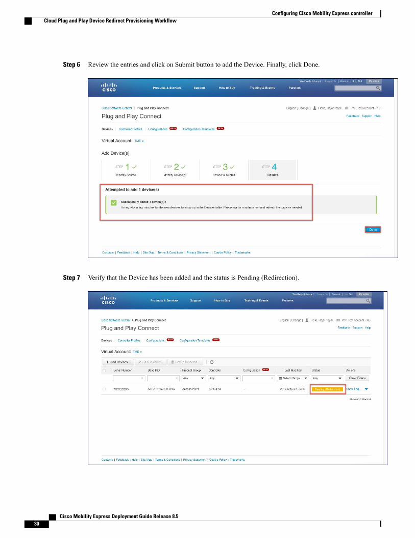
Step 6 Review the entries and click on Submit button to add the Device. Finally, click Done.
Step 7 Verify that the Device has been added and the status is Pending (Redirection).
Cisco Mobility Express Deployment Guide Release 8.530
Configuring Cisco Mobility Express controllerCloud Plug and Play Device Redirect Provisioning Workflow

Connecting Cisco Mobility Access PointsTo bring up a new Mobility Express site, make sure that Plug and Play service has been configured withMobility Express Access Points with related controller configuration. If APIC-EM controller in Private Clouddeployment option is used, Option 43 or DNS discovery on DHCP scope must be configured. If Cloud Plugand Play Connect redirect to APIC-EM controller deployment option is used, make sure all the relatedconfiguration on Cloud Plug and Play Connect has also been done for successful redirect to APIC-EMcontroller.
Now, it is time to connect theMobility Express Access Points at the site. Onemay connect one or more AccessPoints at a site. It is important to note that if multiple Mobility Express Access Points are connected at a site,Master Election will happen first and only after Master Access Point has been elected, it will initiatecommunication with the Network Plug and Play service and download the controller configuration fileregardless of the deployment option. The other Access Points will not initiate communicate with the NetworkPlug and Play service. After the controller configuration file has been downloaded on the Access Point, it willreboot and after it comes up, it will run the controller. The rest of the Access Points at the site will join thisMaster Access Point as Subordinate Access Points.
Cisco Mobility Express Deployment Guide Release 8.5 31
Configuring Cisco Mobility Express controllerConnecting Cisco Mobility Access Points

Cisco Mobility Express Deployment Guide Release 8.532
Configuring Cisco Mobility Express controllerConnecting Cisco Mobility Access Points

C H A P T E R 4Using internal DHCP server on Cisco MobilityExpress
Starting Release 8.3.102.0, one can enable internal DHCP Server and create scopes for Access Points andWLANs. A total of 17 DHCP scopes are supported on Cisco Mobility Express. Using the internal DHCPserver also enables Cisco Mobility Express to be used for performing Site Survey without the need of anexternal DHCP server.
Using a mix of Internal DHCP server and External DHCP server at the same time in a Mobility ExpressDeployment is not supported at this time.
Note
• Creating a DHCP Scope, page 33
Creating a DHCP ScopeInternal DHCP server can be enabled and DHCP scope created during Day 0 from Setup Wizard as well asin Day 1 using the controller WebUI. Typically, one would create DHCP scopes in Day 1 if they want toassociate the scopes with WLANs.
To create a scope and associate it to a WLAN using the controller WebUI, follow the procedure below:
Procedure
Step 1 Navigate to Wireless Settings > DHCP Server > Add new Pool . The Add DHCP Pool window will popup.
Step 2 On the Add DHCP Pool window. Enter the following fields:
• Enter the Pool Name for the WLAN
• Enable the Pool Status
• Enter the VLAN ID for the WLAN
• Enter the Lease Period for the DHCP clients. Default is 1 Day
Cisco Mobility Express Deployment Guide Release 8.5 33

• Enter the Network/Mask
• Enter the Start IP for the DHCP pool
• Enter the End IP for the DHCP pool
If the scope is for client devices connecting to the Centralized NAT, one must selectMobilityExpress Controller for Default Gateway
Note
• Enter the Default Gateway for the DHCP pool
• Enter the Gateway IP for the DHCP pool
• Enter the Domain Name (Optional) for the DHCP pool
• For Name Servers, select User Defined if one needs to enter IP addresses of Name Servers or selectOpenDNS in which case OpenDNS Name Server IP addresses are automatically populated
Step 3 Click Apply.Step 4 After creating the scope, it is time to assign the VLAN mapped to the DHCP scope to the WLAN. To assign
a VLAN to WLAN, navigate toWireless Settings > WLANs .Step 5 If the WLAN does not exist, create a WLAN or if one does exist, edit the existing WLAN and click on the
VLAN and Firewall tab.Step 6 On the VLAN and Firewall tab, configure the following:
• Select Network(Default) for Client IP Management orMobility Express Controller if this scope isfor Centralized NAT'ed WLAN
• Select Yes to Use VLAN Tagging
• Enter the Native VLAN ID
• Select theDHCPScopewhich was created previously for theWLAN.VLAN ID should be automaticallypopulated after the DHCP scope is selected
Cisco Mobility Express Deployment Guide Release 8.534
Using internal DHCP server on Cisco Mobility ExpressCreating a DHCP Scope

Step 7 Click Apply.
Cisco Mobility Express Deployment Guide Release 8.5 35
Using internal DHCP server on Cisco Mobility ExpressCreating a DHCP Scope

Cisco Mobility Express Deployment Guide Release 8.536
Using internal DHCP server on Cisco Mobility ExpressCreating a DHCP Scope

C H A P T E R 5Configuring Cisco Mobility Express for SiteSurvey
• Introduction, page 37
IntroductionCisco 802.11ac Wave 2 access points are capable of running Cisco Mobility Express which a virtual wirelesscontroller function embedded on an Access Point.
Cisco Mobility Express access point running the wireless controller function will also provide wirelessconnectivity to the clients. It also supports internal DHCP server which enables Access Point to be used forSite Survey.
Pre-requisites1 Access Points–Cisco 802.11ac Wave 2 access points running Cisco Mobility Express software. The
following APs support Cisco Mobility Express:
Release supporting Site Survey capabilityAccess Point
AireOS® Release 8.5 and later1540 Series
AireOS Release 8.3.111.0 and later1560 Series
AireOS Release 8.4 and later1815I Series
AireOS® Release 8.5 and later1815M Series
AireOS Release 8.4 and later1815W Series
AireOS Release 8.3.111.0 and later1830 Series
AireOS Release 8.3.111.0 and later1850 Series
AireOS Release 8.3.111.0 and later2800 Series
AireOS Release 8.3.111.0 and later3800 Series
Cisco Mobility Express Deployment Guide Release 8.5 37
2 Power Source–Depending on the Access Point being used for Site Survey, one can use a power adapteror a battery pack capable of providing sufficient power to the Access Point.
3 Console Cable(Optional)–Cisco Mobility Express can be configure using the CLI or Over-the-air. Forconfiguring Cisco Mobility Express via CLI, a console connect to the Access Point would be required.
Configuring Mobility Express for Site Survey using CLI
Procedure
Step 1 Connect to the console of the Access Point.Step 2 Power up the Access Point using a power adapter or battery pack.Step 3 Wait for the Access Point to boot up completely such that it is running the Wireless Controller and is waiting
to be configured.Step 4 Configure the Wireless Controller using the CLI Setup Wizard:
For Site Survey, a DHCP server is required and is supported on Cisco Mobility Express. DHCPServer configuration highlighted below is mandatory if you want to enable DHCP server on CiscoMobility Express.
Note
Would you like to terminate autoinstall? [yes]:yesEnter Administrative User Name (24 characters max):adminEnter Administrative Password (3 to 24 characters max):Cisco123Re-enter Administrative Password: Cisco123System Name:[Cisco_3a:d2:b4] (31 characters max):me-wlcEnter Country Code list(enter ‘help’ for a list of countries)[US]:USConfigure a NTP server now?[YES][no]:noConfigure the system time now?[YES][no]:yesEnter the date in MM/DD/YY format:02/28/17Enter the time in HH:MM:SS format:11:30:00Enter timezone location index(enter ‘help’ for a list of timezones):5Management Interface IP Address: 10.10.10.2Management Interface Netmask: 255.255.255.0Management Interface Default Router: 10.10.10.1Create Management DHCP Scope?[yes][NO]:yesDHCP Network: 10.10.10.0DHCP Netmask: 255.255.255.0Router IP: 10.10.10.1Start DHCP IP address: 10.10.10.10Stop DHCP IP address: 10.10.10.250DomainName: mewlc.localDNS Server:[OPENDNS][user DNS]OPENDNSCreate Employee Network?[YES][no]:yesEmployee Network Name(SSID)?:site_surveyEmployee VLAN Identifier?[MGMT][1-4095]:MGMTEmployee Network Security?[PSK][enterprise]:PSKEmployee PSK Passphrase (8-38 characters)?: Cisco123Re-enter Employee PSK Passphrase: Cisco123Re-enter Employee PSK Passphrase: Cisco123Create Guest Network? [yes][NO]:NO
Cisco Mobility Express Deployment Guide Release 8.538
Configuring Cisco Mobility Express for Site SurveyConfiguring Mobility Express for Site Survey using CLI

Enable RF Parameter Optimization?[YES][no]:noConfiguration correct? If yes, system will save it and reset.[yes][NO]:yes
Step 5 Wait for the Access Point to boot up completely. After the Wireless controller has started, log back in to thecontroller using administrative username or password configured during the initial setup wizard.
Step 6 (Optional): During the CLI setup wizard, Employee Network Security was configured to PSK. This can bedisabled for easy association of clients and also disable SSID broadcast to avoid unwanted clients from joiningthe SSID. To disable PSK and SSID broadcast, enter the following commands in the Controller CLI.
(Cisco Controller)>config wlan disable 1(Cisco Controller)>config wlan security wpa disable 1(Cisco Controller)>config wlan broadcast-ssid disable wlan 1(Cisco Controller)>config wlan enable 1(Cisco Controller)>save config
Step 7 To configure channel, TX power, and channel bandwidth for the radios, disable the radio first, make thechanges and then re-enable it.To change the 2.4GHz radio to channel 6, follow the steps below:
(Cisco Controller)>config 802.11b disable <ap name>(Cisco Controller)>config 802.11b channel <ap name> <ap name> 6(Cisco Controller)>config 802.11b enable <ap name>
To change the 2.4GHz radio Transmit Power to power level 3, follow the steps below:
(Cisco Controller)>config 802.11b disable <ap name>(Cisco Controller)>config 802.11b txPower <ap name> <ap name> 3(Cisco Controller)>config 802.11b enable <ap name>
To change the 5 GHz radio to channel 44, follow the steps below:
(Cisco Controller)>config 802.11a disable <ap name>(Cisco Controller)>config 802.11a channel <ap name> <ap name> 44(Cisco Controller)>config 802.11a enable <ap name>
To change the 5 GHz radio Transmit Power to level 5, follow the steps below:(Cisco Controller)>config 802.11a disable <ap name>(Cisco Controller)>config 802.11a txPower <ap name> <ap name> 5(Cisco Controller)>config 802.11a enable <ap name>
To change the 5 GHz radio channel width to 40MHz, follow the steps below:(Cisco Controller)>config 802.11a disable <ap name>(Cisco Controller)>config 802.11a chan_width <ap name> 40(Cisco Controller)>config 802.11a enable <ap name>
If 2800 and 3800 series access points are being used for Site Survey, please note the following with respectto the XOR radio.
1 Default operation state of XOR radio is 2.4GHz.
2 One can configure the XOR radio on internal (I) Access Points from 2.4GHz to 5 and vice versa. On anexternal (E) Access Point, one must have an external antenna plugged into the DART connector prior tochanging any configuration on the XOR radio.
3 When the XOR (2.4 GHz) radio is configured to operate at 5GHz, 100MHz frequency separation is requiredfrom dedicated 5GHz radio.
4 When the XOR radio is configured to operate in 5GHzmode on an internal (I) Access Points, the Transmitpower (tx) power will be fixed and cannot be modified.
Cisco Mobility Express Deployment Guide Release 8.5 39
Configuring Cisco Mobility Express for Site SurveyConfiguring Mobility Express for Site Survey using CLI
To configure the XOR (2.4GHz) radio to operate at 5GHz on 2800 and 3800 Series Access Points, followthe steps below:
(Cisco Controller) >config 802.11-abgn disable ap(Cisco Controller) >config 802.11-abgn role ap manual client-serving(Cisco Controller) >config 802.11-abgn band ap ap 5GHz(Cisco Controller) >config 802.11-abgn enable ap
To configure the XOR radio operating at 5 GHz to channel 40, follow the steps below:
(Cisco Controller) >config 802.11-abgn disable ap(Cisco Controller) >config 802.11-abgn channel ap ap 40(Cisco Controller) >config 802.11-abgn enable ap
To configure the XOR radio operating at 5 GHz channel width to 40MHz, follow the steps below:
(Cisco Controller) >config 802.11-abgn disable ap(Cisco Controller) >config 802.11-abgn chan_width ap 40(Cisco Controller) >config 802.11-abgn enable ap
Cisco Mobility Express Deployment Guide Release 8.540
Configuring Cisco Mobility Express for Site SurveyConfiguring Mobility Express for Site Survey using CLI
C H A P T E R 6Creating Wireless Networks
• WLANs, page 41
• Creating Employee WLANs , page 42
• Creating Guest WLANs, page 44
• Internal Splash Page for Web Authentication, page 47
• Managing WLAN Users, page 49
• Adding MAC for Local MAC Filtering on WLANs, page 50
WLANsCisco Mobility Express solution supports a maximum of 16 WLANs. Each WLAN has a unique WLAN ID(1 through 16), a unique Profile Name, SSID, and can be assigned different security policies.
Access Points broadcast all active WLAN SSIDs and enforce the policies that you define for each WLAN.
A number of WLAN Security options are supported on Cisco Mobility Express solution and are outlinedbelow:
1 Open
2 WPA2 Personal
3 WPA2 Enterprise (External RADIUS, AP)
For Guest WLAN, a number of capabilities are supported:
1 CMX Guest Connect
2 WPA2 Personal
3 Captive Portal (AP)
4 Captive Portal (External Web Server)
Cisco Mobility Express Deployment Guide Release 8.5 41
Creating Employee WLANs
Creating Employee WLAN with WPA2 Personal
Procedure
Step 1 Navigate toWireless Settings >WLANs and then click on Add newWLAN button. The Add newWLANWindow will pop up.
Step 2 In the Add new WLAN window, on the General page, configure the following:a) Enter the Profile Name.b) Enter the SSID.
Step 3 Click on the WLAN Security and configure the following:a) Select Security asWPA2 Personal.b) Enter the Passphrase and Confirm PassPhrase.
Step 4 Click Apply.
Creating Employee WLAN using WPA2 Enterprise with External Radius Server
Procedure
Step 1 Navigate toWireless Settings >WLANs and then click on Add newWLAN button. The Add newWLANWindow will pop up.
Step 2 In the Add new WLAN window, on the General page configure the following:a) Enter the Profile Name.b) Enter the SSID.
Step 3 Click on theWLAN Security and configure the following:a) Select Security Type asWPA2 Enterprise.b) Select Authentication Server as External Radius.
Step 4 Add the Radius server and configure the following:
• Enter the Radius IP
• Enter the Radius Port
• Enter the Shared Secret
• Click on tick icon
Cisco Mobility Express Deployment Guide Release 8.542
Creating Wireless NetworksCreating Employee WLANs

Step 5 Click Apply.
Creating Employee WLAN with WPA2 Enterprise and Authentication Serveras AP
Procedure
Step 1 Navigate toWireless Settings >WLANs and then click on Add newWLAN button. The Add newWLANWindow will pop up.
Step 2 In the Add new WLAN window, on the General page configure the following:a) Enter the Profile Name.b) Enter the SSID.
Step 3 Click on theWLAN Security and configure the following:a) Select Security asWPA2 Enterprise.b) Select Authentication Server as AP.
AP is the Master AP running the controller function. In this use case, controller is theAuthentication Server and therefore Local WLAN user account must exist to onboard the clients.
Note
Step 4 Click the Apply.
Creating Employee WLAN with WPA2 Enterprise/External RADIUS and MACFiltering
Procedure
Step 1 Navigate toWireless Settings >WLANs and then click on Add new WLAN button. The Add new WLANWindow will pop up.
Step 2 In the Add new WLAN window, on the General tab, configure the following:
• Enter the Profile Name
• Enter the SSID
Step 3 Click on theWLAN Security tab and configure the following:
• EnableMAC Filtering
• Select Security Type asWPA2 Enterprise
• Select Authentication Server as External RADIUS
• Select RADIUS Compatibility from the drop-down list
Cisco Mobility Express Deployment Guide Release 8.5 43
Creating Wireless NetworksCreating Employee WLAN with WPA2 Enterprise and Authentication Server as AP

• SelectMAC Delimiter from the drop-down list
Step 4 Add the Radius server and configure the following:
• Enter the Radius IP
• Enter the Radius Port
• Enter the Shared Secret
• Click on tick icon.
Step 5 Click Apply.
Creating Guest WLANsMobility Express controller can provide guest user access on WLANs which are specifically designated foruse by guest users. To set this WLAN exclusively for guest user access, enable theGuest Network under theWLAN Security tab.
Creating Guest WLAN with Captive Portal on CMX Connect
Procedure
Step 1 Navigate toWireless Settings >WLANs and then click on Add new WLAN button. The Add new WLANWindow will pop up.
Step 2 In the Add new WLAN window, on the General tab, configure the following:
• Enter the Profile Name
• Enter the SSID
Step 3 Enable the Guest Network under theWLAN Security tab.Step 4 Select Captive Portal as CMX Connect.Step 5 Enter Captive Portal URL.
Captive Portal URLmust have the following format: https://yya7lc.cmxcisco.com/visitor/loginwhereyya7lc is your Account ID.
Note
Step 6 Click Apply.Additional steps are required on CMX Cloud to create the Captive Portal, Site with Access Pointsand associating Captive Portal to the Site.
Note
Cisco Mobility Express Deployment Guide Release 8.544
Creating Wireless NetworksCreating Guest WLANs

Creating Guest WLAN with Internal Splash PageThere is an internal splash page built into the Mobility Express controller which can be used to onboard theclients connecting to Guest WLANs. This internal splash page can also be customized by uploading acustomized bundle. To upload a customized internal splash page, navigate toWireless Settings > GuestWLANs. Select Page Type as Customized and click on the Upload button to upload a customized pagebundle.
For internal splash page, Cisco Mobility Express supports multiple options for Access Type. They are asfollows:
1 Local User Account2 Web Consent3 Email Address4 RADIUS5 WPA2 Personal
Procedure
Step 1 Navigate toWireless Settings >WLANs and then click on Add new WLAN button. The Add new WLANWindow will pop up.
Step 2 In the Add new WLAN window, on the General tab, configure the following:
• Enter the Profile Name
• Enter the SSID
Step 3 Enable the Guest Network under theWLAN Security tab.Step 4 Select Captive Portal as Internal Splash Page.Step 5 Select one of the following Access Type as needed:
1 Local User Account–Splash Page will present the user to enter username and password which must beauthenticated by the controller before network access is granted. Local WLAN users must be created onthe controller to onboard the Guest clients.
2 Web Consent–Splash Page will present the user to acknowledge before network access is granted.
3 Email Address–Splash Page will present the user to enter the email address before network access isgranted.
4 RADIUS–Splash Page will present the user to enter username and password which must be authenticatedby the RADIUS server before network access is granted. Select Access Type as RADIUS and enter theRADIUS server configuration.
5 WPA2 Personal–This is an example of L2 + L3 (Web Consent). Layer 2 PSK security authentication willhappen first followed by Splash Page which will present the user to acknowledge before network accessis granted. Select Access Type asWPA2 Personal and enter the Passphrase.
Step 6 Click Apply.
Cisco Mobility Express Deployment Guide Release 8.5 45
Creating Wireless NetworksCreating Guest WLAN with Internal Splash Page

Creating Guest WLAN with External Splash PageAn external splash page is one which resides on an external Web Server. Similar to the internal splash page,Cisco Mobility Express supports multiple options for Access Type with external splash page. They are asfollows:
1 Local User Account
2 Web Consent
3 Email Address
4 RADIUS
5 WPA2 Personal
Procedure
Step 1 Navigate toWireless Settings >WLANs and then click on Add new WLAN button. The Add new WLANWindow will pop up.
Step 2 In the Add new WLAN window, on the General tab, configure the following:
• Enter the Profile Name
• Enter the SSID
Step 3 Enable the Guest Network under theWLAN Security tab.Step 4 Select Captive Portal as External Splash Page.Step 5 Select one of the following Access Type as needed:
1 Local User Account–Splash Page will present the user to enter username and password which must beauthenticated by the controller before network access is granted. Local WLAN users must be created onthe controller to onboard the Guest clients.
2 Web Consent–Splash Page will present the user to acknowledge before network access is granted.
3 Email Address–Splash Page will present the user to enter the email address before network access isgranted.
4 RADIUS–Splash Page will present the user to enter username and password which must be authenticatedby the RADIUS server before network access is granted. Select Access Type as RADIUS and enter theRADIUS server configuration.
5 WPA2 Personal–This is an example of L2 + L3 (Web Consent). Layer 2 PSK security authentication willhappen first followed by Splash Page which will present the user to acknowledge before network accessis granted. Select Access Type asWPA2 Personal and enter the Passphrase.
Step 6 Click Apply.
Cisco Mobility Express Deployment Guide Release 8.546
Creating Wireless NetworksCreating Guest WLAN with External Splash Page

Internal Splash Page for Web AuthenticationCiscoMobility Express supports a default internal guest portal that comes built-in and also a customized page,which can be imported by the user.
Using default internal guest portalTo use the default Guest Portal Page or import a customized Guest Portal page, follow the procedure below:
Procedure
Step 1 Navigate toWireless Settings > Guest WLANs.Step 2 Configure the following on the Guest WLAN page:
• Page Type–Select as Internal (Default).
• Preview–You can Preview the page by clicking on the Preview button.
• Display Cisco Logo–To hide the Cisco logo that appears in the top right corner of the default page, youcan choose No. This field is set to Yes by default.
• Redirect URL After Login–To have the guest users redirected to a particular URL (such as the URLfor your company) after login, enter the desired URL in this text box. You can enter up to 254 characters.
• Page Headline–To create your own headline on the login page, enter the desired text in this text box.You can enter up to 127 characters. The default headline is Welcome to the Cisco Wireless Network.
• Page Message–To create your own message on the login page, enter the desired text in this text box.You can enter up to 2047 characters. The default message is Cisco is pleased to provide the WirelessLAN infrastructure for your network. Please login and put your air space to work.
Step 3 Click Apply.
Using customized internal guest portalIf a customized guest portal has to be presented to guest users, a sample page can be downloaded fromcisco.com which can then be edited and imported to the Cisco Mobility Express controller. After the page hasbeen edited and ready to be uploaded to the Cisco Mobility Express controller, follow the steps below.
Procedure
Step 1 Navigate toWireless Settings > Guest WLANs.Step 2 Configure the following on the Guest WLAN page:
• Page Type–Select as Customized.
Cisco Mobility Express Deployment Guide Release 8.5 47
Creating Wireless NetworksInternal Splash Page for Web Authentication

• Customized page Bundle–Click on the Upload button to upload the he customized page bundle to theMobility Express controller.
• Preview–You can Preview the Guest portal by clicking on the Preview button.
• Redirect URL After Login–To have the guest users redirected to a particular URL (such as the URLfor your company) after login, enter the desired URL in this text box. You can enter up to 254 characters.
Step 3 Click Apply.
Centralized NAT on Guest WLANsManaged Service Providers provide managed WiFi services at Hotels, Retail locations with 1 - 70 APs onsite with up 300 or more concurrent wireless clients. In such locations aggregate throughput is limited byWAN connectivity and is typically less than 250 Mbps. Use of external DHCP server for clients is limited toback office devices/clients due to scale limitations. For Guest devices, expectation is to use internal DHCPserver on Master AP so that and all guest traffic can be routed via the Master Access Point.
To configure centralized NAT on Guest WLANs, follow the procedure below:
Procedure
Step 1 Add a DHCP Pool for theWLANwhich has to bed NAT'ed. To create the scope, navigate toWireless Settings> DHCP Server > Add new Pool. The Add DHCP Pool window will pop up. On the Add DHCP Poolwindow, configure the following:
• Enter the Pool Name for the WLAN
• Enable the Pool Status
Cisco Mobility Express Deployment Guide Release 8.548
Creating Wireless NetworksCentralized NAT on Guest WLANs

• Enter the VLAN ID for the WLAN
• Enter the Lease Period for the DHCP clients. Default is 1 Day
• Enter the Network/Mask
• Enter the Start IP for the DHCP pool
• Enter the End IP for the DHCP pool
• Enter the Default Gateway for the DHCP poolIf the scope is for client devices connecting to the Centralized NAT, one must selectMobilityExpress Controller for Default Gateway.
Note
• Enter the Domain Name (Optional) for the DHCP pool
• For Name Servers, select User Defined if one needs to enter IP addresses of Name Servers or selectOpenDNS in which case OpenDNS Name Server IP addresses are automatically populated
• Click Apply.
Step 2 To createWLAN, navigate toWireless Settings >WLANs.On theAdd newWLAN orEditWLANwindow,click on the VLAN and Firewall tab and configure the following:
• For Client IP Management, selectMobility Express Controller
• Check the Peer to Peer Block to disable communication between two clients on that WLAN
• Enter the Native VLAN ID
• Select the DHCP Scope which was created for Guest clients on the Mobility Express controller
: The VLAN for thisWLAN should be configured on all the switch ports to which APs are connected.Note
Step 3 Click Apply.
Managing WLAN UsersCiscoMobility Express supports creation of local user accounts. These users can be authenticated forWLANsconfigured to use Security as WPA2 Enterprise with Authentication Server set to AP or Guest WLANsconfigured to use internal or external splash page with Access Type as Local User Account.
To create local user accounts, follow the procedure below:
Procedure
Step 1 Navigate toWireless Settings >WLAN Users and then click on Add WLAN User button.Step 2 Configure the following for the WLAN user:
• User Name–Enter the username
• Guest User–For Guest user, enable the Guest User checkbox
Cisco Mobility Express Deployment Guide Release 8.5 49
Creating Wireless NetworksManaging WLAN Users

• Lifetime–For Guest User, define the user account validity. Default is 86400 seconds (or, 24 hours) fromthe time of its creation.
• WLAN Profile–Select the WLAN to which the user will connect
• Password–Enter the password for the user account
• Description–Additional details or comments for the user account
• Click on tickicon.
Adding MAC for Local MAC Filtering on WLANsCisco Mobility Express supports MAC Filtering on WLANs on controller as well as with external RADIUS.MAC addresses can be added to the controller and be eitherWhitelisted or Blacklisted. To addMAC addressesto the controller, follow the procedure below:
Procedure
Step 1 Navigate toWireless Settings >WLAN Users and click on Local MAC Addresses.Step 2 Click Add MAC Address.Step 3 In the Add MAC Address window, configure the following:
• MAC Address–Enter the MAC Address of the device
• Description–Enter the description
• Type–Select whether this MAC has to be WhitleList of BlackList
• Profile Name–Select the WLAN to which the user will connect
Step 4 Click Apply.
WLAN Passpoint SupportStarting Release 8.5, Cisco Mobility Express will add support for Passpoint onWLANs. Access Points whichsupports IEEE 802.11u-based network information and phone client devices that are certified for WiFiAlliance's are able to work together to support the Passpoint functionality.
The 802.11u enabled phone client devices discover and select target AP based on the information gatheredduring the pre-association stage from an 802.11u-enabled AP/Cisco Mobility Express controller. A phoneclient device has pre-provisioned network information such as home OI Information, realm name and domainname, presented as configuration file inside the phone client device. In addition, the phone client device mayobtain home network information using the IMSI data derived from the inserted SIM/USIM card.
Cisco Mobility Express Deployment Guide Release 8.550
Creating Wireless NetworksAdding MAC for Local MAC Filtering on WLANs

The 802.11u AP provides various information listings that provide the HotSpot owner details, roaming partners,realm list, 3GPP cellular information, and domain name. The realm list also provides listings of the realmname and its associated EAP authentication type mappings. Knowing this information is essential for thephone client device so that correct EAP credential exchange may take place.
Through theWLAN configuration, single SSID andmultiple SSIDwill be configured with necessary Passpointinformation. This additional Passpoint information will be added on beacon or probe response information,so that Passpoint-enabled phone client device can detect and query AP to get further information. During thequery process, standard protocol format called ANQP-Access Network Query Protocol-is followed. Here, theprotocol describes the standard 2-way or 4-way handshake process to get enough information from the APand ANQP server to determine the best AP that the phone client device can authenticate and associate with.This handshake process is called GAS-Generic Advertisement Service-protocol that is defined on IEEE802.11u standard.
To configure Passpoint, follow the procedure below:
Procedure
PurposeCommand orAction
EnableExpert View
Step 1
on CiscoMobilityExpress.Expert Viewis availableon the topbanner of theCiscoMobilityExpressWebUI asshownbelow. Thiswill enablethe 802.11uand Hotspot2.0 tabs onthe WLANs.
To configure802.11u and
Step 2
Hotspot 2.0on WLAN,navigate toWirelessSettings >WLANs. Onthe Add newWLAN orEdit WLAN
Cisco Mobility Express Deployment Guide Release 8.5 51
Creating Wireless NetworksWLAN Passpoint Support

PurposeCommand orAction
window,click on the802.11u taband Hotspot2.0 tab toenter therelevantconfiguration.
ClickApply.Step 3
Cisco Mobility Express Deployment Guide Release 8.552
Creating Wireless NetworksWLAN Passpoint Support

C H A P T E R 7Managing Services with Cisco Mobility Express
There are a number of services supported in a Cisco Mobility Express deployment. In this section, thefollowing Services will be covered.
• Application Visibility and Control, page 53
• iOS Optimized WiFi connectivity and Fast Lane, page 54
• Cisco Mobility Express with CMX Cloud, page 57
Application Visibility and ControlNetwork Based Application Recognition (NBAR) provides application-aware control on a wireless networkand enhances manageability and productivity. It also extends Cisco's Application Visibility and Control (AVC)as an end-to-end solution, which gives a complete visibility of applications in the network and allows theadministrator to take some action on the same.
NBAR is a deep-packet inspection technology, which supports stateful L4 - L7 classification. The key usecases for NBAR are capacity planning, network usage base lining and better understanding of what applicationsare consuming bandwidth. Trending of application usage helps network admin improve quality of experienceby protecting key applications from bandwidth-hungry applications when there is congestion on the network,capability to prioritize or de-prioritize, and drop certain application traffic. The AVC/NBAR2 engineinteroperates with QoS settings on the specific WLAN.
Enabling Application Visibility on WLANTo configure Application Visibility on a WLAN, follow the procedure below:
Procedure
To enable Application Visibility on WLAN, navigate toWireless Settings > WLANs. On the Add newWLAN or Edit WLAN window, click on the Traffic Shaping tab. To enable Application Visibility on thisWLAN, select Enabled for Application Visibility Control.
Cisco Mobility Express Deployment Guide Release 8.5 53

Enabling Application Control on WLANAfter Application Visibility has been enabled on the WLAN, one can add control for various applications.There are two way to add control for applications. One can either add control directly from the Applicationswidget on the Network Summary page or one can navigate toMonitoring > Applications and add controlfor applications as needed.
Adding Application Control from Network Summary Page
Procedure
Step 1 Add the Applications widget on the Network Summary Page. To add the Applications widget, click on the+ icon on the right of the Network Summary banner. Select the Applications widget. The Applicationswidget will display the top 10 applications being browsed by the clients in the Mobility Express network.
Step 2 Click on the application you wish to add control. TheAdd AVCRulewindow will pop up. Select theAction.Action can beMark,Drop orRate Limit. ForMark, one can select DSCP as Platinum, Gold, Silver, Bronzeor Custom. If custom is selected, one has to specific he DSCP value. For Rate Limit, one can specify theAverage Rate and Burst Rate for the application.
Step 3 Select one or more AVC Profile/SSID combinations.Step 4 Click Apply.
Adding Application Control from Applications Page
Procedure
Step 1 Navigate toMonitoring > Applications Page.Step 2 Click on the application you wish to add control. TheAdd AVCRulewindow will pop up. Select theAction.
Action can beMark,Drop orRate Limit. ForMark, one can select DSCP as Platinum, Gold, Silver, Bronzeor Custom. If custom is selected, one has to specific he DSCP value. For Rate Limit, one can specify theAverage Rate and Burst Rate for the application.
Step 3 Select one or more AVC Profile/SSID combinations.Step 4 Click Apply.
iOS Optimized WiFi connectivity and Fast Lane
Configuring Optimized WiFi Connectivity802.11r enabled WLAN provides faster roaming for wireless client devices. It is desired that iOS devicesrunning iOS 10 will be able to join a WLAN with 11r enabled for better roaming experience. However, if 11r
Cisco Mobility Express Deployment Guide Release 8.554
Managing Services with Cisco Mobility ExpressEnabling Application Control on WLAN

is enabled on a WLAN, the legacy devices that do not recognize the FT AKM's beacons and probe responseswill not be able to join the WLAN. We need a way to identify the Client device capability and allow 11rcapable device to join on the WLAN as an FT enabled device and at the same time to allow legacy device tojoin as an 11i/WPA2 device.
Cisco Mobility Express Release 8.4 will enable 802.11r on an 802.11i-enabled WLAN selectively for iOSdevices. The capable iOS devices will identify this functionality and perform an FTAssociation on theWLAN.The Cisco Wireless infrastructure will allow FT association on the WLAN from devices that can negotiateFT association on a non-FTWLAN. In addition, with Mobility Express running AireOS 8.4, 802.11k and 11vfeatures are enabled by default on an SSID. These features help clients roam better by telling them when toroam and providing them with information about neighboring APs so that no time is wasted scanning whenroaming is needed. Since iOS devices support dual band, the 802.11k neighbor list is updated on dual-band,adaptively for iOS devices.
To configure 11k, r, v on a WLAN, follow the procedure below:
Procedure
Step 1 Enable Expert View on Cisco Mobility Express. Expert View is available on the top banner of the CiscoMobility ExpressWebUI as shown below and enabled various configurable parameters which are not availablein Standard view.
Step 2 Navigate toWireless Settings >WLANs. On the Add new WLAN or Edit WLAN window, click on theAdvanced tab. Configure 802.11k, r, v as needed on this page.
Cisco Mobility Express Deployment Guide Release 8.5 55
Managing Services with Cisco Mobility ExpressConfiguring Optimized WiFi Connectivity

Step 3 Click Apply.
Configuring Fast LaneApple iOS device mark QoS as per IETF recommendations. With Mobility Express running AireOS 8.5, onecan enable the Fastlane feature from CLI, which enables several beneficial functions:
• Your WLC QoS configuration is optimized globally to better support real-time applications
• iOS 10 devices can send upstream voice traffic without the requirement to performWMMTSPEC/TCLASnegotiation. The infrastructure will honor the voice marking for these devices.
• You can apply a QoS profile to your iOS 10 devices, and decide which applications should receive QoSmarking upstream, and which applications should be sent as best effort or background.
To configure Fast Lane on a WLAN from UI, follow the procedure below:
Cisco Mobility Express Deployment Guide Release 8.556
Managing Services with Cisco Mobility ExpressConfiguring Fast Lane

Procedure
Step 1 To enable Application Visibility on WLAN, navigate toWireless Settings > WLANs. On the Add newWLAN or Edit WLANwindow, click on the Traffic Shaping tab. To enable Fastlane on this WLAN, selectEnabled for Fastlane.
Step 2 Click Apply.
Cisco Mobility Express with CMX Cloud
Cisco CMX CloudCisco Connected Mobile Experiences Cloud (Cisco CMX Cloud) is an simple and scalable offering whichenables delivery of wireless guest access and in-venue analytics, integrating seamlessly with Cisco wirelessinfrastructure.
This cloud-delivered Software-as-a-Service (SaaS) offering is quick to deploy and intuitive to use. It is basedon CMX 10.x code and is compatible with CiscoMobility Express Release 8.3. It offers the following services:
• Connect for Guest Access-Providing an easy-to-use guest-access solution for visitors through a customportal using various authenticationmethods including social, self-registration, and Short Message Service(SMS).
• Presence Analytics-Detecting all Wi-Fi devices (the "devices") in the venue and providing analytics ontheir presence, including dwell times, new vs. repeat visitors, and peak time.
Cisco CMX Cloud Solution Compatibility Matrix• Cisco Mobility Express running AireOS Release 8.3 and later
• All Cisco Mobility Express supported Access Points
Minimum requirements for Cisco CMX Cloud deploymentBelow are the minimum requirements for CMX Cloud deployment:
1 Verify Cisco CMX Cloud Solution Compatibility Matrix above.2 Recommended browser is Chrome 45 or later.3 Signup at https://cmxcisco.com for 60 day trial or go to Cisco CommerceWorkspace (CCW) and purchase
license for your choice of CMX Cloud service
Enabling CMX Cloud Service on Mobility Express for Presence AnalyticsAfter CMX Cloud Account has been created, next step is to configure and enable the CMX Cloud Service onMaster Access Point so that it can send data to the CMX Cloud. To configure, follow the procedure below:
Cisco Mobility Express Deployment Guide Release 8.5 57
Managing Services with Cisco Mobility ExpressCisco Mobility Express with CMX Cloud

Procedure
Step 1 On Cisco Mobility Express WebUI, navigate to Advanced > CMX.Step 2 Enter the CMX Server URL (Site URL).Step 3 Enter the CMX Server Token (Account Token).Step 4 Click Apply.
Click the Test Link button to verify connectivity from Master AP to CMX Cloud Site using theconfigured information.
Tip
Configuring Site on CMX Cloud for Presence AnalyticsTo create a site and add Access Points to the site in CMX Cloud for Presence Analytics, follow the procedurebelow:
Procedure
Step 1 Login to CMX Cloud account at https://cmscisco.com/Step 2 Navigate toManage > Cloud EnabledWLC and verify that the IP address of the WLC shows up on the list.Step 3 Navigate to PRESENCE ANALYTICS >Manage. You should be in the Sites pane. Click on the Add Site
button to create a site.Step 4 In the NEW SITE window, configure the following details:
• Enter the Name for the site
• Enter the Address for the site
• Select Timezone from the drop-down list
• Select the Signal Strength Threshold for Ignore, Passerby, and Visitors
• Enter theMinimum Dwell Time for Visitor (minutes)
Step 5 Click Save to create the Site.Step 6 After the Site is created, click on Access Points under PRESENCE ANALYTICS >Manage.Step 7 Select the Access Points and add them to the Site by clicking on Add to Site button and selecting the Site
from the drop-down list.Step 8 Finally, navigate to Presence Analytics dashboard. Select the Site you created. Within a few minutes, you
should begin to see Presence data get populated.
Cisco Mobility Express Deployment Guide Release 8.558
Managing Services with Cisco Mobility ExpressConfiguring Site on CMX Cloud for Presence Analytics

C H A P T E R 8Managing the Cisco Mobility ExpressDeployment
• Managing Access Points, page 59
• Adding Access Points to Cisco Mobility Express Network, page 60
• Configuring Management Access , page 61
• Managing Admin Accounts , page 62
• Managing TACACS+ and RADIUS Servers, page 63
• Managing TIME on Cisco Mobility Express, page 65
• Updating Cisco Mobility Express Software, page 66
• CALEA Support, page 72
Managing Access PointsStarting Release 8.4, Cisco Mobility Express supports up to 100 Access Points. To view the list or modifyparameters on an Access Points, follow the procedure below:
Procedure
Step 1 Navigate toWireless Settings > Access Points.The first Access Point with the P icon is the Master AP and the rest of them are Subordinate AccessPoints.
Note
Step 2 To modify the parameters on an access point, click on the Edit button. The Access Point window will comeup displaying the General parameters about the Access Point.
• Operating Mode(Read only field)-For a master AP, this field displays AP & Controller. For otherassociated APs, this field displays AP only.
• AP Mac(Read only field)–Displays the MAC address of the Access Point.
• AP Model(Read only field)-Displays the model details of the Access Point.
Cisco Mobility Express Deployment Guide Release 8.5 59

• IP Configuration–Choose Obtain from DHCP to allow the IP address of the AP be assigned by a DHCPserver on the network, or choose Static IP address. If you choose Static IP address, then you can editthe IP Address, Subnet Mask, and Gateway fields.
• AP Name–Edit the name of access point. This is a free text field.
• Location–Edit the location for the access point. This is a free text field.
Step 3 Under the Controller tab (Available only for Master AP), one can modify the following parameters:
• System Name–Enter the System Name for Mobility Express
• IP Address–IP address decides the login URL to the controller's web interface. The URL is in https://<ipaddress> format. If you change this IP address, the login URL also changes.
• Subnet Mask–Enter the Subnet Mask.
• Country Code–Enter the Country Code.
Step 4 Under Radio 1 (2.4 GHz) and Radio 2 (5 GHz), one can edit the following parameters:
• Admin Mode–Enabled/Disabled. This enables or disables the corresponding radio on the AP (2.4 GHzfor 802.11 b/g/n or 5 Ghz for 802.11 a/n/ac).
• Channel–Default is Automatic. Automatic enables Dynamic Channel Assignment. This means thatchannels are dynamically assigned to each AP, under the control of the Mobility Express controller.This prevents neighboring APs from broadcasting over the same channel and hence prevents interferenceand other communication problems. For the 2.4GHz radio, 11 channels are offered in the US, up to 14in other parts of the world, but only 1-6-11 can be considered non-overlapping if they are used byneighboring APs. For the 5GHz radio, up to 23 non-overlapping channels are offered. Assigning aspecific value statically assigns a channel to that AP.
◦802.11 b/g/n–1 to 11.
◦802.11 a/n/ac –40, 44, 48, 52, 56, 60, 64, 100, 104, 108, 112, 116, 132, 136, 140, 149, 153, 157,161, 165.
• Channel Width - 20 MHz for 2.4GHz and for 20, 40 and 80 for 5 GHz.
• Transmit Power - 1 to 8. The default value is Automatic.
This is a logarithmic scale of the transmit power, that is the transmission energy used by the AP, 1 being thehighest,2 being half of it, 3 being 1/4th and so on. Selecting Automatic adjusts the radio transmitter outputpower based on the varying signal level at the receiver. This allows the transmitter to operate at less thanmaximum power for most of the time; when fading conditions occur, transmit power will be increased asneeded until the maximum is reached.
Step 5 Click Apply.
Adding Access Points to Cisco Mobility Express NetworkWhen adding Access Points to Cisco Mobility Express network, the following have to be considered:
Cisco Mobility Express Deployment Guide Release 8.560
Managing the Cisco Mobility Express DeploymentAdding Access Points to Cisco Mobility Express Network

Software Version on the Access Point–If the software version of the access point, which is being added, isdifferent than what is on the Master AP, a software download of the code running on the Master Access Pointhas to happen on the Access Point being added. For the newAccess Point to download the code that is runningon the Master Access Point, one of the following has to be configured:
• TFTP server details and the Access Point images path information has to be configured on the SoftwareUpdate page.
• If the Master AP has 8.3.102.0 or later code, one can configure the Cisco.com login credentials on theSoftware Update page and the code on the new Access Point will be automatically downloaded fromcisco.com when an Access Point joins.
For Software download to take place directly from Cisco.com, the Master AP should be the one with theSMARTNet Contract.
Note
Procedure
Step 1 Download the Access Point image zip file from cisco.com on a TFTP server. The bundle version must be thesame as the one running on the Master AP. Unzip the file to extract the individual Access Point images.
Step 2 Navigate toManagement > Software Update. Select TFTP for Transfer Mode and configure the TFTPParameters.(OR)
Step 3 Navigate toManagement > Software Update. Select Cisco.com as the Transfer Mode and configureparameters related to the Cisco.com user account.
Step 4 Connect the AP to the network. When the AP boots up, it obtains an IP address from the DHCP server. If theAP version matches the one on Master AP, it joins. However, if the version on the AP being added is differentthan then one on the Master AP, it starts to download the image from either the configured TFTP server orcisco.com. After the image download is complete, the AP will reboot and join the Master AP.
During the image download there is no service interruption. After the image download is complete,the AP automatically re-boots and join the Master AP.
Note
Configuring Management AccessThe Management Access Interface on the Mobility Express controller is the default interface for in-bandmanagement of the controller and connectivity to enterprise services. It is also used for communicationsbetween the controller and access points.
There are four types of Management Access supported on the Mobility Express controller.
1 HTTP Access–To enable HTTP access mode, which allows you to access the controller GUI usinghttp://<ip-address> through a web browser, choose Enabled from the HTTP Access drop-down list.Otherwise, choose Disabled. The default value is Disabled. HTTP access mode is not a secure connection.
2 HTTPS Access–To enable HTTPS access mode, which allows you to access the controller GUI usinghttp://ip-address through aweb browser, choose Enabled from theHTTPSAccess drop-down list. Otherwise,choose Disabled. The default value is Enabled. HTTPS access mode is a secure connection.
Cisco Mobility Express Deployment Guide Release 8.5 61
Managing the Cisco Mobility Express DeploymentConfiguring Management Access

3 Telnet Access–To enable Telnet access mode, which allows remote access to the controller's CLI usingyour laptop's command prompt, choose Enabled from the Telnet Access drop-down list. Otherwise, chooseDisabled. The default value is Disabled. The Telnet access mode is not a secure connection.
4 SSHv2 Access–To enable Secure Shell Version 2 (SSHv2) access mode, which is a more secure versionof Telnet that uses data encryption and a secure channel for data transfer, choose Enabled from the SSHv2Access drop-down list. Otherwise, choose Disabled. The default value is Enabled. The SSHv2 accessmode is a secure connection.
To enable or disable the different types of management access to the controller, follow the procedure below:
Procedure
Step 1 Navigate toManagement > Access.
Step 2 For the various Access Types, select either Enabled or Disabled.There must be at least one access enabled else admin user will locked out of Mobility ExpressController and will have to use console to make changes to provide access again.
Note
Step 3 Click Apply to submit changes.
Managing Admin AccountsCisco Mobility Express Cisco Mobility Express supports creation of admin accounts to prevent unauthorizedusers from reconfiguring the controller and viewing configuration. It supports the following three access levelsfor Admin user accounts:
1 Read/Write–Accounts with read and write privilege have full provisioning and monitoring capability2 Read only–Accounts with Read only privilege only have monitoring capability and can browse all screens3 LobbyAmbassador–ALobbyAmbassador can create andmanage guest user accounts on the CiscoMobility
Express. The lobby ambassador has limited configuration privileges and can access only the web pagesused to manage the guest accounts.
The local user database is limited to a maximum of 2048 entries, which is also the default value. Thisdatabase is shared by local management users (including lobby ambassadors), local network users (includingguest users), MAC filter entries, exclusion list entries. Together they cannot exceed the maximum value.
Note
To create admin users, follow the procedure below:
Procedure
Step 1 Navigate toManagement > Admin Accounts and click on the Add New User button.
Step 2 Enter the following to configure the admin user account.
• Account Name–Enter the admin user name. Username is case-sensitive and can contain up to 24 ASCIIcharacters. Username cannot contain spaces and must be unique.
Cisco Mobility Express Deployment Guide Release 8.562
Managing the Cisco Mobility Express DeploymentManaging Admin Accounts

• Access - Select Read/Write, Read Only or Lobby Ambassador access for the admin account.
• New Password & Confirm Password - Enter a password for the admin user account, in-keeping withthe following rules:
◦Passwords are case sensitive and cannot contain spaces
◦The password should contain a minimum of 8 characters from ALL of the following classes:
◦Lowercase letters
◦Uppercase letters
◦Digits
◦Special characters
◦No character in the password can be repeated more than three times consecutively
◦The password should not contain the word Cisco or a management username. The passwordshould also not be any variant of these words, obtained by reversing the letters of these words,or by changing the capitalization of letters, or by substituting 1, |, or ! or substituting 0 for oor substituting $ for s.
Step 3 Click tick icon.
Managing TACACS+ and RADIUS ServersStarting Release 8.5, Cisco Mobility Express will support up to Six RADIUS and Three TACACS Servers.To configure RADIUS and TACACS+ Servers, enable Expert View on Cisco Mobility Express. ExpertView is available on the top banner of the Cisco Mobility Express WebUI as shown below and enabledvarious configurable parameters which are not available in Standard view.
Adding TACACS+ Servers
Procedure
Step 1 Navigate toManagement > Admin Accounts.Step 2 To add TACACS+ servers, click on TACACS+ tab. Click on the Add TACACS+ Authentication Server
button and enter the following:
• Server Index–Select 1 through 3
Cisco Mobility Express Deployment Guide Release 8.5 63
Managing the Cisco Mobility Express DeploymentManaging TACACS+ and RADIUS Servers
• State–Enable the state
• Server IP Address–Enter the IPv4 address of the TACACS+ server
• Shared Secret–Enter the shared secret
• Port Number–Enter the port number being used for communicating with the TACACS+ server
• Server Timeout–Enter the server timeout
Step 3 Do the same of the RAIDUS Authorization Servers.
Adding RADIUS Servers
Procedure
Step 1 Navigate toManagement > Admin Accounts.Step 2 To add RADIUS servers, click on RADIUS tab. Click on the Add RADIUS Authentication Server button
and enter the following:
• Server Index–Select 1 thru 6
• State–Enable the state
• Server IP Address–Enter the IPv4 address of the RADIUS server
• Shared Secret–Enter the shared secret
• Port Number–Enter the port number being used for communicating with the RADIUS server
• Server Timeout–Enter the server timeout
Step 3 Do the same of the RAIDUS Authorization Servers.
Managing Admin User PriorityPrior to Release 8.5, admin accounts on Cisco Mobility Express were created locally on the controller. InRelease 8.5 TACACS+ and RADIUS servers can also be used for authentication admin users.
When multiple databases are configured, it is important to configure the admin account user priority. Toconfigure the priority, follow the Procedure below.
Procedure
Step 1 Enable Expert View on Cisco Mobility Express. Expert View is available on the top banner of the CiscoMobility ExpressWebUI as shown below and enables various configurable parameters which are not availablein Standard view.
Cisco Mobility Express Deployment Guide Release 8.564
Managing the Cisco Mobility Express DeploymentAdding RADIUS Servers

Step 2 Navigate toManagement > Admin Accounts and click on theManagement User Priority Order.By default, the local database is always queried first. If the username is not found, the controllerswitches to the RADIUS server if configured for RADIUS or to the TACACS+ server if configuredfor TACACS+. The default setting is local and then RADIUS.
Note
Step 3 To change the priority, between TACACS+ and RADIUS, click on either and move UP or DOWN. Pleasenote Local Admin Accounts cannot be moved to Priority 3. It can only be either 1 or 2.
Managing TIME on Cisco Mobility ExpressThe system date and time on the Cisco Mobility Express controller is typically configured when running theinitial Wireless Express setup wizard.
Configuring NTP ServerUp to three Network Time Protocol (NTP) servers can be configured to sync date and time if one was notconfigured during the Wireless Express setup. Time Zone can be configured to offset the clock.
To configure Time Zone and NTP servers, follow the procedure below:
Procedure
Step 1 Navigate toManagement > Time.Step 2 Choose the desired Time Zone .Step 3 Enter the NTP Polling Interval. The polling interval ranges from 3600 to 604800 seconds.Step 4 To add an NTP server, click Add NTP Server button and configure the following:
• NTP Index–It can be 1, 2 or 3.
• NTP Server - This can be the NTP Server IP address, NTP Server Name or pool. A maximum of threeNTP Servers are supported.
• Click tick icon.
Synchronization of the date and time with the NTP Server occurs each time the controller rebootsand at each user-defined polling interval.
Note
Cisco Mobility Express Deployment Guide Release 8.5 65
Managing the Cisco Mobility Express DeploymentManaging TIME on Cisco Mobility Express

Updating Cisco Mobility Express SoftwareCisco Mobility Express controller software update can be performed using the controller's web interface.Software update ensures that both the controller software and all the Access Points associated are updated.
An AP joining the controller compares its software version with theMaster AP version and incase of mismatch,the new AP requests for a software update. For software update, one must configure the Transfer Mode andcorresponding details on the Software Update page.
Master AP does not have AP images. It facilitates the transfer of new software from the configuredTransfer Mode to the Access Points requesting for Software Update.
Note
Software download on the Access Points is automatically sequenced to ensure that not more than 5 APs aredownloading the software simultaneously and the queue refreshes till all the Access Points requiring upgradehave downloaded the new image.
Starting Release 8.3.100.0, Cisco Mobility Express supports the following Transfer Mode for SoftwareUpdate:
Cisco.com–Cisco.com transfer mode is introduced in 8.3.100.0. In this software update method, the softwareimage can be directly streamed from cisco.com to the individual Access Points. Internet access required forthis transfer mode and EULA and SMARTNet contract requirements have to be met for this transfer mode.
HTTP–HTTP transfer mode is supported if the Mobility Express Network has the same model of AccessPoints. Use HTTP as the transfer mode for Software Update using the AP file from a local machine.
If there is a mix of Access Points in the Mobility Express network, Software Update via cisco.com orTFTP Transfer Method should be used.
Note
TFTP–TFTP transfer mode can be used to perform Software Update on a Mobility Express Network. MasterAP facilitates transfer of image from the TFTP server to the individual Access Points. The AP images arestored and served from the TFTP server upon request.
There is no service interruption during pre-image download. After pre-image download is complete onall APs, a Manual or scheduled reboot of Mobility Express network can be triggered.
Note
Software Update using cisco.com Transfer ModeSoftware Update via Cisco.comworks for all Access Points supported in a CiscoMobility Express Deployment.Below requirements must be met to initiate a Software Update from cisco.com.
• Internet access is required for software download from cisco.com to APs. However, no proxy is required.
• A valid cisco.com (CCO) account with username & password required.
• EULA acceptance on a per user basis. OnlyMaster AP (not all APs in the network) must have SMARTNetcontract else Software Update will not start.
Cisco Mobility Express Deployment Guide Release 8.566
Managing the Cisco Mobility Express DeploymentUpdating Cisco Mobility Express Software

Software Update from cisco.com is supported via GUI only.Note
In order to perform Software Update using cisco.com Transfer Mode, follow the procedure below:
Procedure
Step 1 To perform Software Update via Cisco.com, navigate toManagement > Software Update and configure thefollowing:
• Select Cisco.com for Transfer Mode.
• Enter Cisco.com Username.
• Enter Cisco.com Password.
• Enable Automatically Check for Updates. Check is done once in 30 days.
• Click on theCheck Now button to retrieve the Latest Software Release and the Recommended SoftwareRelease from Cisco.com.
Step 2 Click Apply.
Step 3 Click Update to initiate software update wizard.Step 4 In the Software Update Wizard, select the Recommended Software Release or Latest Software Release. Click
Next.Step 5 Select Update Now to initiate software update immediately or Schedule the Update for Later.
If Schedule the Update for Later is selected, configure the Set Update Time field.Note
Step 6 Click on the Auto Restart checkbox if automatic restart of all access points in the network is desired afterthe software update is finished. Click Next.
Step 7 Click Confirm to start the software update.To monitor the download progress on individual Access Points, expand the Predownload image status.
Software Update using HTTP Transfer ModeIf you have the same model of Access Points in the Mobility Express deployment, HTTP Transfer mode canbe used to perform Software Update. For HTTP Transfer mode, one can simply upload the Access Pointupgrade image from the local machine. To perform Software Update using HTTP Transfer Mode, follow theprocedure below:
Procedure
Step 1 Download the AP Image bundle from cisco.com to the local machine. The table below points to Release8.5.103.0 images.
Cisco Mobility Express Deployment Guide Release 8.5 67
Managing the Cisco Mobility Express DeploymentSoftware Update using HTTP Transfer Mode

Step 2 Access Point image bundle. Contains individual APimages to be used for Software Update
Access Point
AIR-AP1540-K9-ME-8-5-103-0.zipCisco Aironet® 1540 Series
AIR-AP1560-K9-ME-8-5-103-0.zipCisco Aironet® 1560 Series
AIR-AP1815-K9-ME-8-5-103-0.zipCisco Aironet® 1815I Series
AIR-AP1815-K9-ME-8-5-103-0.zipCisco Aironet® 1815M Series
AIR-AP1815-K9-ME-8-5-103-0.zipCisco Aironet® 1815W Series
AIR-AP1830-K9-ME-8-5-103-0.zipCisco Aironet® 1830 Series
AIR-AP1850-K9-ME-8-5-103-0.zipCisco Aironet® 1850 Series
AIR-AP2800-K9-ME-8-5-103-0.zipCisco Aironet® 2800 Series
AIR-AP3800-K9-ME-8-5-103-0.zipCisco Aironet® 3800 Series
The above images are for AireOSRelease 8.4.100.0. The image bundle would be different for differentreleases.
Note
Step 3 Unzip the AP Image bundle to extract individual AP Images.Mapping of Access Points to their correspondingimages is shown below:
Access Point ImageAccess Point
ap1g5Cisco Aironet® 1540 Series
ap3g3Cisco Aironet® 1560 Series
ap1g5Cisco Aironet® 1815I Series
ap1g5Cisco Aironet® 1815M Series
ap1g5Cisco Aironet® 1815W Series
ap1g4Cisco Aironet® 1830 Series
ap1g4Cisco Aironet® 1850 Series
ap3g3Cisco Aironet® 2800 Series
ap3g3Cisco Aironet® 3800 Series
Step 4 To perform Software Update via HTTP Transfer Mode, navigate toManagement > Software Update andconfigure the following:
• Select HTTP for Transfer Mode
• Browse to the local AP image, corresponding to the Access Point in your network
• Click on the Auto Restart checkbox if automatic restart of all access points in the network is desiredafter the software update is finished
Cisco Mobility Express Deployment Guide Release 8.568
Managing the Cisco Mobility Express DeploymentSoftware Update using HTTP Transfer Mode

Step 5 Click Apply.Step 6 Click on Updateto initiate software update.
Software Update using TFTP Transfer ModeSoftware Update via TFTP Transfer Mode works for all Access Points supported in a Cisco Mobility ExpressDeployment. You would need a TFTP server which can communicate with the Master Access Point to usethis upgrade method. This update method is supported from controller WebUI as well as CLI.
Upgrading from WebUITo perform Software Update using TFTP Transfer mode from WebUI, follow the procedure below:
Procedure
Step 1 Download the AP Image bundle from cisco.com to the TFTP server.Step 2 Unzip the AP Image bundle to extract individual AP Images.Step 3 To perform Software Update via TFTP Transfer Mode, navigate toManagement > Software Update and
configure the following:
• Select TFTP for Transfer Mode.
• Enter the IP Address of the TFTP server in the IP Address (IPv4) field.
• Enter the File Path to the unzipped AP images on the TFTP Server.
The most commonmistake made is entering this path correctly. It is important that this path be enteredcorrectly before going to the next step. Do not point to individual AP image. You need to only pointto the directory which contains the AP images.
Note
Step 4 Click Apply.Step 5 Click Update Now to initiate software update.
To Schedule Update at a later time, user must select a date and time in Set Update Time field andthen click on the Schedule Later button. It is recommended that the Set Reboot Time should be atleast 2 hours from the time pre-image download was initiated. This will ensure that pre-imagedownload on all Access Points in the Mobility Express Network has completed.
Note
Cisco Mobility Express Deployment Guide Release 8.5 69
Managing the Cisco Mobility Express DeploymentSoftware Update using TFTP Transfer Mode
Upgrading from CLI
Procedure
Step 1 Login to AP running Mobility Express controller via SSH or Telnet(if it is enabled).Step 2 Specify the datatype.
(Cisco Controller) >transfer download datatype ap-image
Step 3 Specify the transfer mode.(Cisco Controller) >transfer download ap-images mode tftp
Step 4 Specify the IP address of the TFTP server.(Cisco Controller) >transfer download ap-images serverIp <IP addr>
Step 5 Specify the path of the AP images on the TFTP server.(Cisco Controller) >transfer download ap-images imagePath <path to AP images>
Themost commonmistake made is entering this path correctly. It is important that this path be enteredcorrectly before going to the next step. Do not point to individual AP image. You need to only pointto the directory which contains the AP images.
Note
Step 6 Start pre-downloading of the image on the APs.(Cisco Controller) >transfer download startMode........................................... TFTPData Type...................................... ap-imageTFTP Server IP................................. 10.1.1.77TFTP Packet Timeout............................ 10TFTP Max Retries............................... 10TFTP Path...................................... ap_bundle_8.1.112.30/This may take some time.Are you sure you want to start? (y/N) yTFTP Code transfer starting.Triggered APs to pre-download the image.Reboot the controller once AP Image pre-download is complete
Step 7 Check the pre-download status by executing the CLI below.(Cisco Controller) >show ap image all
Total number of APs............... 3Number of APs
Initiated.........................1Predownloading....................2Completed predownloading..........0Not Supported.....................0Failed/BackedOff to Predownload...0
Primary Backup Predownload Predownload Next Retry Retry FailureAP Name Image Image Status Version Time Count Reason–––––––––––––– –––––––––– –––––––-- –––––––– ––––––––– ––––––– –––– –––––AP6412.256e.0e78 8.1.112.21 8.1.112.21 Predownloading –– NA NAAPAOEC.F96C.D640 8.1.112.21 8.1.112.21 Predownloading –– NA NA3600-gemini 8.1.112.21 8.1.112.21 Predownloading –– NA
Cisco Mobility Express Deployment Guide Release 8.570
Managing the Cisco Mobility Express DeploymentSoftware Update using TFTP Transfer Mode

Step 8 Wait for the pre-image download to complete on the Access Points.(Cisco Controller) >show ap image allTotal number of APs............... 3Number of APs
Initiated.........................1Predownloading....................2Completed predownloading..........0Not Supported.....................0Failed/BackedOff to Predownload...0
Primary Backup Predownload Predownload Next Retry Retry FailureAP Name Image Image Status Version Time Count Reason–––––––––––––– –––––––––– –––––––-- –––––––– ––––––––– ––––––– –––– –––––AP6412.256e.0e78 8.1.112.21 8.1.112.21 Complete –– NA NAAPAOEC.F96C.D640 8.1.112.21 8.1.112.21 Complete –– NA NA3600-gemini 8.1.112.21 8.1.112.21 Complete –– NA
Step 9 After the pre-download is complete, issue a reset system as shown below.(Cisco Controller) >reset systemThe system has unsaved changes.Would you like to save them now? (y/N) yConfiguration Saved!System will now restart!
Managing Advanced RF ParametersCisco Mobility supports a number RF Parameters which can be configured the administrator to optimize theirnetwork deployment. To manage advanced RF Parameters, follow the procedure below:
Procedure
Step 1 Enable Expert View on Cisco Mobility Express. Expert View is available on the top banner of the CiscoMobility ExpressWebUI as shown below and enabled various configurable parameters which are not availablein Standard view.
Step 2 Under Advanced RF Parameters, the following parameters are available:
• 2.4 GHz Band - This is a global setting and can be enabled or disabled.
• 5.0 GHz Band - This is a global setting and can be enabled or disabled.
• Automatic Flexible Radio Assignment - If there are 2800 and 3800 series access points in the CiscoMobility Express deployment which supports Flexible Radio Assignment, one can choose to enable ordisable it.
• Optimized Roaming–This is a global setting and can be enabled or disabled.
Cisco Mobility Express Deployment Guide Release 8.5 71
Managing the Cisco Mobility Express DeploymentManaging Advanced RF Parameters
• Event Driven RRM–This is a global setting and can be enabled or disabled.
• CleanAir Detection–CleanAir is supported on 2800 and 3800 series access points and one can chooseto enable or disable it.
• 5.0 GHz Channel Width–Global setting is configured to best but one can select 20, 40, 80 or 160 MHzfor channel width.
• 2.4 GHz Data Rates–Move the slider to disable/enable data rates in the 2.4 GHz band
• 5.0 GHz Data Rates–Move the slider to disable/enable data rates in the 5.0 GHz band
• Select DCA Channels–One can select (click on individual channels) the channels to be included inDCA for both 2.4 GHz and 5.0 GHz band
Green with an underline below the channel indicates that it is selected.Note
Step 3 Click Apply.
CALEA SupportSupport for The Communications Assistance for LawEnforcement Act (CALEA) is available in CiscoMobilityExpress starting Release 8.5. To configure CALEA Server, follow the procedure below:
Procedure
Step 1 Enable Expert View on Cisco Mobility Express. Expert View is available on the top banner of the CiscoMobility Express WebUI as shown below.
Step 2 Navigate to Advanced > Controller Tools. Click on the CALEA Tab and configure the following:
• Enable the CALEA status
• Enter the CALEA server IP address and Port
• Enter the Sync interval in minutes
• Enter the Venue information
Step 3 Click Apply.
Cisco Mobility Express Deployment Guide Release 8.572
Managing the Cisco Mobility Express DeploymentCALEA Support

C H A P T E R 9Master AP Failover and Electing a new Master
Cisco Mobility Express is supported on Cisco 1560, 1815I, 1815M, 1815W, 1830, 1850, 2800 and 3800series Access Points. If you have a mix of these Access Points in a Cisco Mobility Express deployment, theMaster AP election process determines which of the supported Access Point will be elected to run MobilityExpress controller function in case of a Failover of the Active Master AP. VRRP is used to detect the failureof Master AP which initiates the election of a new Master.
Mobility Express uses MAC 00-00-5E-00-01-VRID where VRID is 1 so if there are other instances ofVRRP running in the environment, use VRID other than 1 for those instances.
Note
• Master AP Failover, page 73
• Electing a new Master Access Point, page 74
Master AP FailoverTo have redundancy in the Mobility Express network, it must have two or more Mobility Express capableAccess Points. These Access Points should have AP Image type as MOBILITY EXPRESS IMAGE and APConfiguration as MOBILITY EXPRESS CAPABLE. In an event of a failure of Master AP, another MobilityExpress capable AP is elected as a Master automatically. The newly elected Master AP has the same IP andconfiguration as the original Master AP.
Given Access Point models support different scale limits in terms of the number of Access Points supported,it is highly recommended to have at least two or more Access Points which support the same scale limits.For example, if you need to support scale of 100 Access Points, you should have at least two or more ofeither 3800, 2800 or a combination of both.
Note
Access Points, which have the Mobility Express Image but AP Configuration, is NOT MOBILITYEXPRESS CAPABLE, will not participate in the Master AP election process.
Note
Cisco Mobility Express Deployment Guide Release 8.5 73

Electing a new Master Access PointMaster election process is based on a set of priorities. When an active Master Access Point fails, the electionprocess gets initiated and it elects the Access Point with the highest priority as the Master AP.
During the Master Election process, even though the Master AP running the controller function is down,the remaining Access Points will fall into Standalone mode and will continue to service connected clientsand switch data traffic locally. After the new Master is elected, the Standalone Access points will moveto connected mode.
Note
As mentioned above, Master Access Point election is based on a set of priorities. The priorities are as follows:
Procedure
Step 1 User Defined Master–User can select an Access Point to be the Master Access Point. If such a selection ismade, no newMaster will be elected in case of a failure of the active Master. After five minutes, if the currentMaster is still not active, it will be assumed dead and Master Election will begin to elect a new Master. Tomanually define a Master, follow the procedure below:a) Navigate toWireless Settings > Access Points.b) From the list of Access Points, click Edit icon of the Access Point which you would like to select as the
Master AP.c) Under the General tab, click onMake me Controller button.d) Click Yes on the Confirmation window.
The previous Master will reboot and the selected Access Point will immediately launch thecontroller and become the active Master.
Note
Step 2 Next PreferredMaster - Admin can configure theNext PreferredMaster fromCLI.When this is configuredand the active Master AP fails, the one configured as the Next Preferred Master will be elected as a Master.To configure the Next Preferred Master, follow the procedure below:a) Login to the CLI of the controller.b) Execute the following CLI:
To configure the Next Preferred Master, execute the following CLI:
(Cisco Controller) >config ap next-preferred-master <Cisco AP><Cisco AP> Enter the name of the Cisco AP
To see the Next Preferred Master, execute the following CLI:
(Cisco Controller) >show ap next-preferred-master
To clear the Next Preferred Master, execute the following CLI:
Cisco Controller) >clear ap next-preferred-master
Step 3 Most Capable Access Point– If the first two priorities are not configured, Master AP election algorithm willselect the new Master based on the capability of the Access Point. For example, 3800 is the most capablefollowed by 2800, 1850, 1830 and finally the 1815 Series.
All 1815 Series Access Points have the same capability.Note
Cisco Mobility Express Deployment Guide Release 8.574
Master AP Failover and Electing a new MasterElecting a new Master Access Point

Step 4 Least Client Load– If here are multiple Access Points with the same capability i.e. multiple 3800 Accesspoints, the one with least client load is elected as the Master Access Point.
Step 5 Lowest MAC Address–If all of the Access Points are the same and have the same client load, then AccessPoint with the lowest MAC will be elected as a Master.
Cisco Mobility Express Deployment Guide Release 8.5 75
Master AP Failover and Electing a new MasterElecting a new Master Access Point

Cisco Mobility Express Deployment Guide Release 8.576
Master AP Failover and Electing a new MasterElecting a new Master Access Point