at – pipe umbrella system - dsi tunneling
TRANSCRIPT
AT – Pipe Umbrella System
Groundbreaking Forepoling Technology

– Advances in weak or heavily sheared ground
– Ground conditions prone to subsidence
– Advances in fault zones, sediments, or talus
– Frequently changing ground conditions
– Portal sections
– Re-excavation of collapsed drifts or tunnels
– Urban Tunneling
Fields of Application
Single AT – Pipe Umbrella Single AT – Pipe Umbrella with Double Overlap
Double AT – Pipe Umbrella Cross Section under an AT – Pipe Umbrella
2
Contents
Fields of Application 2
Introduction 4
Main Advantages 4
System Components 4
Pipe Umbrella Design 5
Support Effect 5
Design Criteria 5
Pipe Connection Types 6
Standard Threaded Connection 6
Squeezed Connection 6
Squeezing Unit 6
Nipple Coupling 6
Comparison Pipe Connections 7
Groundbreaking Technology 8
Enhanced Working Safety 8
Proven Cycle Time Savings 9
Improved Load-Bearing Capacity 10
Optimized Quality 11
Utilization Rate 11
Specifications SI Units 12
Specifications US Customary Units 13
Self-Drilling Installation Technology 14
Installation Method 14
Starter Unit 14
Installation Procedure Using the AT – Pipe Umbrella Automation Unit 15
AT – Pipe Umbrella Automation Unit 16
Main Advantages 16
Mechanized Installation – Selection of the Required Degree 16
Comparison of Pipe Consumption and Over-Excavation 17
Assembly Groups – Squeezing Unit 18
Assembly Groups – Threading Unit 19
Mounted Assembly Groups 20
Accessories 21
Mechanized Tunneling 21
References 22
AT – Pipe Umbrella System at a Glance 23
3

The AT – Pipe Umbrella System is a pre-support measure used in weak ground conditions in conventional as well as mechanized Tunneling.
Long forepoling using the pipe umbrella or canopy method is typically applied to increase safety and stability in the work-ing area of standard advance operations, portals, and for re-excavating collapsed sections.
Another application is ground improve-ment and waterproofing in combination with all tunnel construction methods.
Pipe umbrella pipes – installed into the ground prior to excavation – increase the stability in the working area by trans-ferring loads in the longitudinal direc-tion and decrease excavation induced deformations. DSI Underground has developed a superior pipe connection type which allows the reduction of instal-lation cycle times while increasing the load-bearing capacity.
State-of-the art pipe umbrella support systems are installed self-drilling where the casing provides an immediate
support of the borehole, compared tow outdated pre-drilling systems where borehole drilling and pipe installation takes place in two different working steps.
Fully mechanized installation is becom-ing a mandatory safety standard in the global Tunneling business. DSI Underground is the leading system supplier in the development and appli-cation of safe and efficient pipe umbrella installation technology.
Introduction
Main Advantages
– Supreme safety due to fully mecha-nized installation
– Efficient self-drilling installation tech-nology
– The fastest pipe umbrella system on the market
– Installation with conventional drilling machines
– Implementation of pipe umbrella drill-ing with on-site personnel
– Reliable and robust system compo-nents
– Piecewise pipe installation allows flexible lengths
– Simple application in confined space
– Superior load-bearing capacity of innovative pipe couplings
System Components
Consumables – Starter unit with drill bit
– Pipe umbrella pipes
– Injection valves
Multiple-Use Accessories – Drill bit adapter
– Drill steel
– Grouting packer
4

Design Criteria
There are two common design criteria for the load transfer of pipe umbrella pipes:
– Maximum elastic moment My of both the standard pipe and the pipe con-nection – pure elastic design.
– Elastic moment My of the standard pipe in combination with the ultimate moment Mult of the pipe connection – elastic-plastic design.
For both criteria, parameters relevant for design (My and Mult) are productspe-cific and must be verified by adequate certificates from the manufacturer before installation.
In case plastic material reserves of steel are activated by plastic joints in the pipe connection area, a safety factor of at least 1.3 to the tested value Mult is recommended:
– Mult, pipe connection ≥ 1.3 My, standard pipe
This allows an elastic calculation and dimensioning of standard pipe umbrella pipes featuring state-of-the-art pipe con-nections without any further reduction of the load-bearing capacity.
Support Effect
Pipe umbrella support systems with a typical installation length in the range of 12 [m] to 18 [m] are considered to be a long forepoling system. From a design perspective, supporting measures can be divided into three different effects:
– Subdivision of the unsupported zone in the open span of the working area
– Radial supporting effect
– Longitudinal supporting effect
Their interaction results in the support of the working area and face region. Loads in this critical section are transferred by each single umbrella pipe in the longi-tudinal direction to its foundations – the ground ahead of excavation and the already installed primary lining.
Pipe umbrella pipes are primarily loaded by bending. Therefore, the relevant design parameter is the maximum elastic moment of the system. The bench-mark criterion is the performance of the weakest link, which usually is the pipe connection.
Volkmann & Schubert 2010
supported section foundation ground foundationL2L1
excavation direction
load 45° - /2
45° + /2
Pipe Umbrella Design
5

Standard Threaded Connection
For a standard threaded connection, outside and inside threads are cut into both ends of each pipe umbrella pipe. This connection type reduces the cross-section of the pipe in the thread-ed area. This way, the section modulus is decreased as well. The internal pipe diameter in the connection area stays constant.
Besides the geometrical conditions of the thread, the overall quality of threaded pipes is a concern for the load-bearing capacity. In general, calibrated pipes reach a higher resistance against bend-ing than non-calibrated ones.
Squeezed Connection
A squeezed connection consists of a prefabricated reduced male pipe end which is force-fitted with its female counter piece using a hydraulic clamping cylinder. In the coupling area, the cross section stays constant and the section modulus is decreased. The internal
pipe diameter in the connection area is reduced.
This pipe connection type can be recommended where a pipe umbrella is installed because of its static load-bear-ing capacity.
Nipple Coupling
Nipple couplings consist of an additional threaded steel nipple that is pressed and welded into both ends of the pipe umbrella pipes. This connection type ensures that the second moment of in-ertia of the coupling is not lower than the second moment of inertia of the default
pipe. The internal pipe diameter in the connection area is reduced.
This pipe connection type can be recom-mended for advances where enhanced static load-bearing capacity is required and settlement limitations are part of the design.
Squeezing Unit
– Application in combination with default drilling machines
– Easy to handle and remote-controlled
– Safe and rapid pipe connection
– Hydraulically driven
Pipe Connection Types
6

Comparison Pipe Connections
Criterion Standard Threaded Connection Squeezed Connection Nipple Coupling
Connection typeOutside and inside thread is cut into the ends of the pipe umbrella pipes
Reduced pipe end force-fitted with its counter piece
Threaded steel nipple, pressed and welded into both ends of
pipe umbrella pipes
Static influenceSignificant reduction of pipe
cross-section and section modulus in the thread connection area
Constant cross section and reduced section modulus in the coupling area
Second moment of inertia at the coupling is not lower than the second
moment of inertia of the standard pipe
Elastic behaviorStiffness and strength are consid-
erably lower than those of standard pipes
Reduction of the stiffness against bending in the connection area
Stiffness and strength are adequate to standard pipes
Ultimate behaviorRupture load of connections can be
lower than elastic load of stand-ard pipes
Ultimate load is higher than the elastic design load of a standard pipe
(> 1.5)
Rupture load of connections high-er than standard pipe
Recommended usageInstallation of measurement instru-mentations or ground improving
injections
Pipe umbrella with a designed static load-bearing capacity
Projects where settlement limitations are part of the design
7

Enhanced working safety Proven cycle time savings
Squeezed Connection
Improved load-bearing capacity Optimized quality and utilization rate
Enhanced Working Safety
– Remote-controlled operation allows a safe pipe connection
– Reduction of physical labor required
– No “hands on” during the pipe con-necting working step
– Integrated drill rod wrench allows safe manipulation of drill stee
Conventional (Threaded) Installation Squeezed Connection
Manual connection of MF pipe umbrella pipes: chain pipe wrench
Remote-controlled pipe connection using a hydraulic cylinder assembly
Manual connection and disconnection of MF drill rods: drill rod wrench
Centralized connection and remote-controlled drill steel disconnection
Direct exposure of personnel to moving drilling tools and hydraulic drifter
Limitation of personnel exposed to the operation range of the hydraulic hammer
Groundbreaking Technology
8

Proven Cycle Time Savings
– Faster connection process than for standard threads
– Elimination of delays due to jammed or damaged pipes
– Total time savings of approx. 3 hours for an exemplary pipe umbrella (15 pipe umbrella drills, each 18 [m] long)
– Experience: 5% difficult threaded connections (outliers) which require additional handling time
Parameter UnitStandard Threaded
ConnectionSqueezed Connection Time Savings
No. of pipes [1] 15
Single pipe length [m] 3
Umbrella length [m] 18
No. of connections [1] 75
Single connecting time [min] 3.5 1.5 2
Single delay time [min] 10 0 10
No. of difficult connections [1] 5% 0% ---
Total connecting time [min] 262.5 112.5 150
Total delay time [min] 37.5 0 37.5
Sum [min] 300 112.5 187.5
9

Improved Load-Bearing Capacity
– Load-transfer based design criteria: Elastic and plastic moments of the pipe connection
– Design criterion 1: Maximum elastic moment My of the pipe connection is improved
– Design criterion 2: Significantly higher ultimate moment Mult of the pipe con-nection than the elastic design load (standard pipe)
– Example: Comparison pipe couplings AT – 114.3 x 6.3 [mm], steel grade S/E 355 (355 [N/mm²] or 51.5 [ksi])
0 1 2 3 4 5 6 7 8 9 10
Ben
ding
mom
ent [
kNm
]
Elastic design load without safety factors
Deflection in the middle of the sample [mm]
45
40
35
30
25
20
15
10
5
0
Standard threaded connection
Squeezed connection
Nipple coupling
Grouted default pipe
Analytic calculation default pipe (elastic range)
Analytic calculation default pipe (plastic range)
Bending Tests: Comparison Pipe Couplings AT – 114.3 x 6.3 [mm]
10

Utilization Rate
– Performance-based design approach - Enhanced load-bearing capa-city allows reduction of pipe wall thickness compared to threaded connections - Significant material savings poten-tial with simultaneous increase in performance
- Lower transport weight increases efficiency of logistics - Easier handling procedures due to decreased weight of single umbrella pipes
- Exemplary parameter study: AT – 139 Pipe Umbrella System with different connection types and wall thicknesses
Parameter UnitStandard Threaded Connec-
tion (Calibrated Pipes)Squeezed Connection
Change Threaded to Squeezed Connection
Pipe dimensions [mm] 139.7 x 8.0 139.7 x 10 139.7 x 6.3
Unit weight [kg/m] 26.0 32.0 20.7 -20% / -35%
Max. elastic moment My [kNm] 14.1 18.4 20.4 +45% / +11%
Optimized Quality
Standard Threaded Connection Squeezed Connection
Significant difference between default and calibrated pipes which are provided by DSI Underground
Error-free system
Sufficient thread strength extremely dependent on the quality of the threading
Verified quality for every single pipe connection
Additional impacts on the threads during installationRobust system and high-strength pipe connection designed for the
special demands of the construction industry
11

Specifications SI Units
System 1)Steel
Grade 2)
Modulus of Elasticity
Yield Strength
Outer Diameter
Wall Thickness
WeightSection Modulus
Second Moment of Area
Tipo [N/mm²] [N/mm2] [mm] [mm] [kg/m] [cm3] [cm4]
AT – 76
E355 or S355 210.000 355
76.1 6.3 10.8 22 85
AT – 8988.9 5.0 10.4 26 11688.9 6.3 12.8 32 14088.9 8.0 16.0 38 168
AT – 114114.3 5.0 13.5 45 257114.3 6.3 16.8 55 313114.3 8.0 21.0 66 379
AT – 139
139.7 5.0 16.6 69 481139 .7 6.3 20.7 84 589139.7 8.0 26.0 103 720139.7 10.0 32.0 123 862
AT – 168168.3 10.0 39.0 186 1,564168.3 12.5 48.0 222 1,868168.3 16.0 60.1 267 2,244
Maximum Elastic Moment My 3)
Ultimate (Plastic) Moment Mult
3)
System 1)Outer
DiameterWall Thick-
nessStandard
PipeNipple
CouplingsSqueezed
ConnectionThreaded Connection
(Calibrated Pipes)Squeezed
Connection 4)
Tipo [mm] [mm] [kNm] [kNm] [kNm] [kNm] [kNm]
AT – 76 76.1 6.3 7.9 N/A N/A 2.9 N/A
AT – 8988.9 5.0 9.3 N/A 5.9 N/A > 1588.9 6.3 11.2 N/A 6.5 4.1 > 20*88.9 8.0 13.4 N/A N/A 5.4 N/A
AT – 114114.3 5.0 16.0 16.0 10.5 N/A > 27*114.3 6.3 19.4 19.3 12.1 6.9 > 35*114.3 8.0 23.6 19.3 13.2 9.3 > 35
AT – 139
139.7 5.0 24.4 24.4 17.5 N/A > 44139.7 6.3 29.9 29.9 20.4 10.4 > 50*139.7 8.0 36.6 36.6 23.3 14.1 > 60*139.7 10.0 43.8 38.8 N/A 18.4 N/A
AT – 168168.3 10.0 66.0 66.0 N/A 26.0 N/A168.3 12.5 78.8 69.7 N/A 33.5 N/A168.3 16.0 94.7 N/A N/A 43.2 N/A
1) Deviating structural properties are available on request. Commonly used sys-tems are bold marked. Non-applicable combinations (system and connection type) are indicated by “N/A”.
2) Steel grade S355 according to EN 10025-2 or E355 according to EN 10296-1. Alternatively, a carbon steel with a minimum yield strength of 355 [N/mm²] is required.
3) Values for My and Mult are product-specific and verified by DSI Underground inspection certificates. Laboratory test reports are available on request.
4) Values determined in the course of laboratory bending tests are indicated with an asterisk, all other ones are calculated.
12
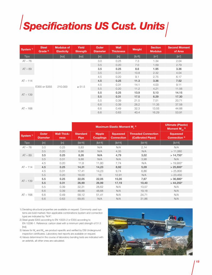
Specifications US Cust. Units
System 1)Steel
Grade 2)
Modulus of Elasticity
Yield Strength
Outer Diameter
Wall Thickness
WeightSection Modulus
Second Moment of Area
Tipo [ksi] [ksi] [in] [in] [lb/ft] [in3] [in4]
AT – 76
E355 or S355 210.000 ≥ 51.5
3.0 0.25 7.3 1.34 2.04
AT – 893.5 0.20 7.0 1.59 2.793.5 0.25 8.6 1.95 3.363.5 0.31 10.8 2.32 4.04
AT – 1144.5 0.20 9.1 2.75 6.174.5 0.25 11.3 3.36 7.524.5 0.31 14.1 4.03 9.11
AT – 139
5.5 0.20 11.2 4.21 11.565.5 0.25 13.9 5.13 14.155.5 0.31 17.5 6.29 17.305.5 0.39 21.5 7.51 20.71
AT – 1686.6 0.39 26.2 11.35 37.586.6 0.49 32.3 13.55 44.886.6 0.63 40.4 16.29 53.91
Maximum Elastic Moment My 3)
Ultimate (Plastic) Moment Mult
3)
System 1)Outer
DiameterWall Thick-
nessStandard
PipeNipple
CouplingsSqueezed
ConnectionThreaded Connection
(Calibrated Pipes)Squeezed
Connection 4)
Tipo [in] [in] [lbf·ft] [lbf·ft] [lbf·ft] [lbf·ft] [lbf·ft]
AT – 76 3.0 0.25 5,83 N/A N/A 2,14 N/A
AT – 893.5 0.20 6,86 N/A 4,35 N/A > 11,0603.5 0.25 8,26 N/A 4,79 3,02 > 14,750*3.5 0.31 9,88 N/A N/A 3,98 N/A
AT – 1144.5 0.20 11,8 11,80 7,74 N/A > 19,900*4.5 0.25 14,31 14,23 8,92 5,09 > 25,800*4.5 0.31 17,41 14,23 9,74 6,86 > 25,800
AT – 139
5.5 0.20 18,00 18 12,91 N/A > 23,4505.5 0.25 22,05 22,05 15,05 7,67 > 36,880*5.5 0.31 26,99 26,99 17,19 10,40 > 44,250*5.5 0.39 32,31 28,62 N/A 13,57 N/A
AT – 1686.6 0.39 48,68 48,68 N/A 19,18 N/A6.6 0.49 58,12 51,41 N/A 24,71 N/A6.6 0.63 69,85 N/A N/A 31,86 N/A
1) Deviating structural properties are available on request. Commonly used sys-tems are bold marked. Non-applicable combinations (system and connection type) are indicated by “N/A”.
2) Steel grade S355 according to EN 10025-2 or E355 according to EN 10296-1. Reference: carbon steel with a minimum yield strength of 51.5 [ksi].
3) Values for My and Mult are product-specific and verified by DSI Underground inspection certificates. Laboratory test reports are available on request.
4) Values determined in the course of laboratory bending tests are indicated with an asterisk, all other ones are calculated.
13

Installation Method
The AT – Pipe Umbrella System is installed:
– Self-drilling
– Piecewise
– With conventional drilling machines
– By hydraulic, rotary-percussive drilling
Cooling, flushing, and backflow of the cuttings takes place inside the casing pipes by using water or an air-water mist. Self-drilling installation features the smallest possible stress relaxation due to an immediate support of the borehole wall during installation and an accurate installation due to a minimized annular gap.
The length of piecewise installed pipe umbrella pipes can be adjusted accord-ing to project or machinery requirements.
Starter Unit
One important factor in the success of the AT – Pipe Umbrella Support System is the starter unit:
– Single-use full face drill bits ensure the same quality for each drilling process
– Stable drilling direction due to stable drill bit orientation
– Simple connection and disconnection of the drilling adapter
– Proven back-flushing of water inside umbrella pipes
– Loss or blocking of a drill bit is impos-sible – optimum pre-conditions for achieving the total drilling depth every time
– Starter unit (drill) bit can be adapted to given ground conditions
Self-Drilling Installation Technology
14
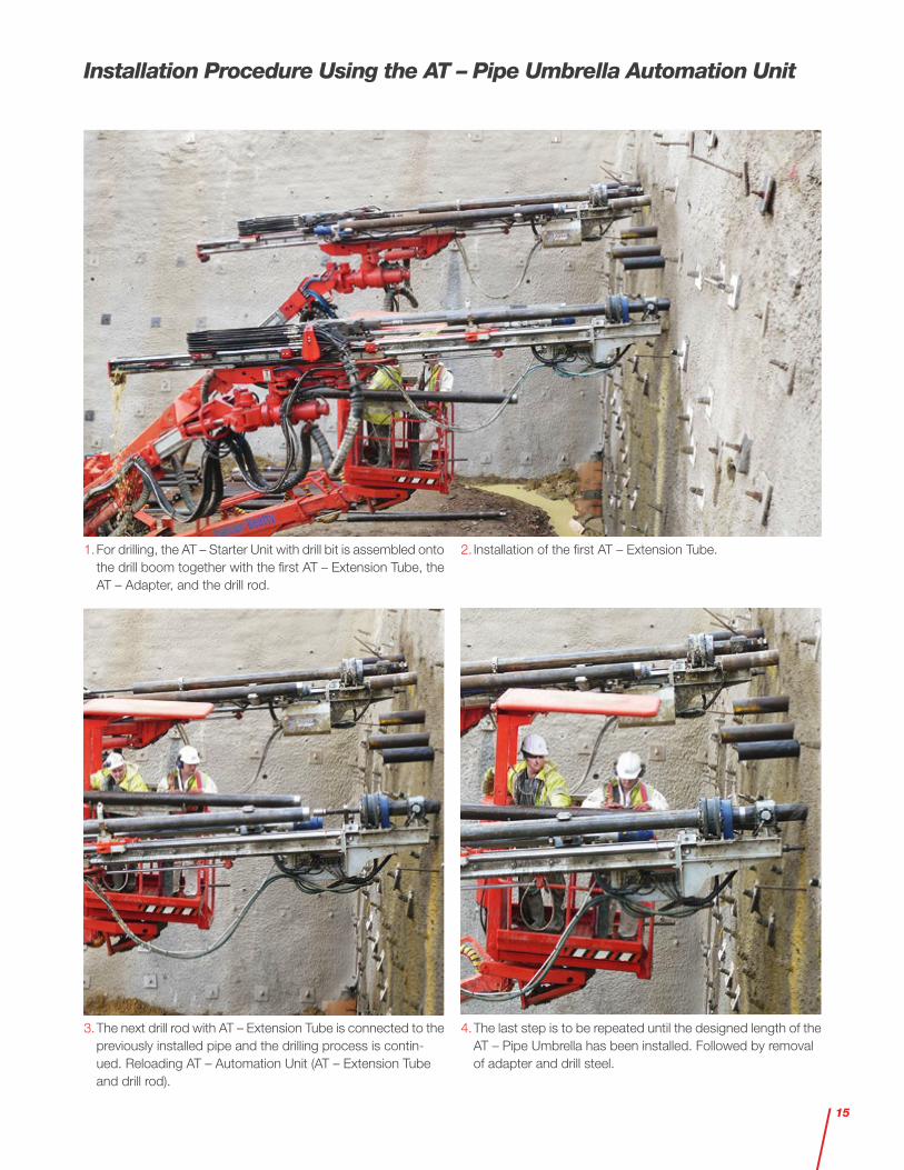
Installation Procedure Using the AT – Pipe Umbrella Automation Unit
1. For drilling, the AT – Starter Unit with drill bit is assembled onto the drill boom together with the first AT – Extension Tube, the AT – Adapter, and the drill rod.
2. Installation of the first AT – Extension Tube.
3. The next drill rod with AT – Extension Tube is connected to the previously installed pipe and the drilling process is contin-ued. Reloading AT – Automation Unit (AT – Extension Tube and drill rod).
4. The last step is to be repeated until the designed length of the AT – Pipe Umbrella has been installed. Followed by removal of adapter and drill steel.
15
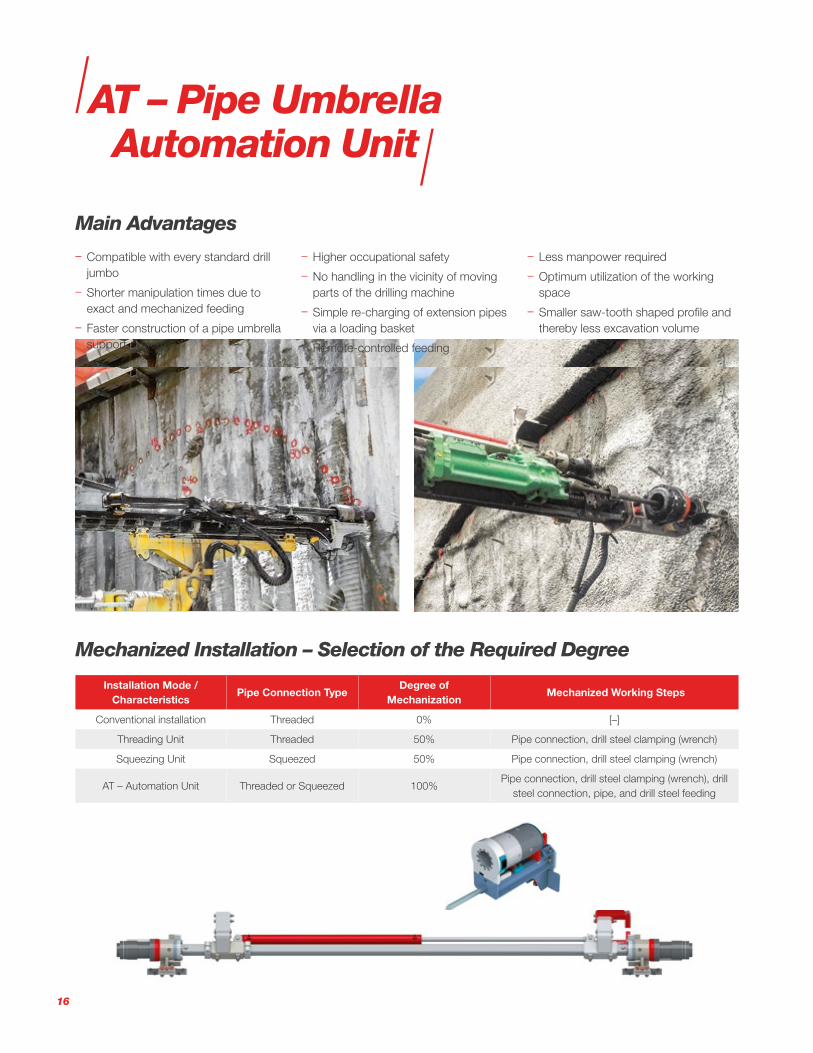
Mechanized Installation – Selection of the Required Degree
Installation Mode / Characteristics
Pipe Connection TypeDegree of
Mechanization Mechanized Working Steps
Conventional installation Threaded 0% [–]
Threading Unit Threaded 50% Pipe connection, drill steel clamping (wrench)
Squeezing Unit Squeezed 50% Pipe connection, drill steel clamping (wrench)
AT – Automation Unit Threaded or Squeezed 100%Pipe connection, drill steel clamping (wrench), drill
steel connection, pipe, and drill steel feeding
AT – Pipe Umbrella Automation Unit
Main Advantages
– Compatible with every standard drill jumbo
– Shorter manipulation times due to exact and mechanized feeding
– Faster construction of a pipe umbrella support system
– Higher occupational safety
– No handling in the vicinity of moving parts of the drilling machine
– Simple re-charging of extension pipes via a loading basket
– Remote-controlled feeding
– Less manpower required
– Optimum utilization of the working space
– Smaller saw-tooth shaped profile and thereby less excavation volume
16

Comparison of Pipe Consumption and Over-Excavation
– Different pipe umbrella lengths, con-ventional and mechanized installation
– Top heading excavation with 6 [m] (19.5 [ft]) radius and 1 [m] (3.3 [ft]) advance length
– AT – 114 Pipe Umbrella, axial pipe distance 500 [mm] (19.5 [in]), overlap 3.5 [m] (11.5 [ft])
Pipe um-
brella length
L
Pipes per um-brella
Exca-vation steps
per um-brella
Pipes in-
stalled per um-brella
Pipes installed per [m] tunnel
Mechanized Installation Conventional Installation
Head-room A
Inclina-tion α
Over-excavation sawtooth
Head-room B
Inclina-tion β
Over-excavation sawtooth
[m] [1] [1] [m] [m] [%] [mm] [°] [m³] [m³/m] [mm] [°] [m³] [m³/m]
12
30
8 360 45.0 100%
300
6.0 63.1 7.9
600
8.1 89.2 11.2
15 11 450 40.9 91% 4.4 85.6 7.8 5.9 121.1 11.0
18 14 540 38.6 86% 3.5 108.1 7.7 4.7 153.0 10.9
[ft] [1] [1] [ft] [ft] [%] [in] [°] [ft³] [ft³/ft] [in] [°] [ft³] [ft³/ft]
39.4
30
8 1,181 147.6 100%
11,8
6.0 2,228 279
23.6
8.1 3,15 394
49.2 11 1,476 134.2 91% 4.4 3,023 275 5.9 4,277 389
59.1 14 1,772 126.5 86% 3.5 3,818 273 4.7 5,403 386
Mechanized Installation
Conventional Installation
L
α A
70%
L
βA
100%
17

Assembly Groups – Squeezing Unit
Squeezing Unit
Loading Unit and Pipe Feeding System
Center Guide
Electric Control Cabinet Squeezing Unit
Hydraulic Control Box Squeezing Unit Pipe Deposit Remote Control
Specifications SI UnitsCharacteristics / Assembly Group Dimensions Weight
(L x W x H) [mm] [kg]Pipe deposit 1,040 x 230 x 350 28
Squeezing unit 1,165 x 380 x 750 200Loading unit and pipe feeding system 3,650 x 460/780 x 430/570 160
Center guide 155 x 260 x 230 12Hydraulic control box squeezing unit 550 x 275 x 345 60
Electric control cabinet squeezing unit 395 x 615 x 355 35Remote control 250 x 140 x 180 2.3
Characteristics Unit Value RemarksTotal weight (gross) [kg] 500 - 520 Deviations possible, depending on the type
Electric supply [V] 24 DCHydraulic supply [L/min] 20 - 25 At approx. 200 [bar]
Specifications US Customary UnitsCharacteristics / Assembly Group Dimensions Weight
(L x W x H) [in] [lb]Pipe deposit 40.9 x 9.1 x 13.8 62
Squeezing unit 45.9 x 15.0 x 29.5 441Loading unit and pipe feeding system 143.7 x 18.1/30.7 x 16.9/22.4 353
Center guide 6.1 x 10.2 x 9.1 27Hydraulic control box squeezing unit 21.6 x 10.8 x 13.8 133
Electric control cabinet squeezing unit 15.6 x 24.2 x 14.0 77Remote control 9.8 x 5.5 x 7.1 5
Characteristics Unit Value RemarksTotal weight (gross) [lb] 1,100 - 1,150 Deviations possible, depending on the type
Electric supply [V] 24 DCHydraulic supply [gal/min] 5.3 - 6.6 At approx. 2,900 [psi]
18

Assembly Groups – Threading Unit
Threading Unit with Centering and Clamping Device
Loading Unit and Pipe Feeding System
Center Guide
Electric Control Cabinet Threading Unit
Hydraulic Control
Box Threading Unit Pipe Deposit Remote Control
Specifications SI UnitsCharacteristics / Assembly Group Dimensions Weight
(L x W x H) [mm] [kg]Pipe deposit 1,040 x 230 x 350 28
Threading unit with centering and clamping device 1,165 x 370 x 740 160Loading unit and pipe feeding system 3,650 x 460/780 x 430/570 160
Center guide 155 x 260 x 230 12Hydraulic control box threading unit 550 x 275 x 345 60
Electric control cabinet threading unit 395 x 615 x 355 35Remote control 250 x 140 x 180 2.3
Characteristics Unit Value RemarksTotal weight (gross) [kg] 460 - 490 Deviations possible, depending on the type
Electric supply [V] 24 DCHydraulic supply [L/min] 15 - 20 At approx. 170 [bar]
Characteristics Unit Value RemarksTotal weight (gross) [lb] 1,010 - 1,080 Deviations possible, depending on the type
Electric supply [V] 24 DCHydraulic supply [gal/min] 4.0 - 5.3 At approx. 2,500 [psi]
Specifications US Customary UnitsCharacteristics / Assembly Group Dimensions Weight
(L x W x H) [in] [lb]Pipe deposit 40.9 x 9.1 x 13.8 62
Threading unit with centering and clamping device 45.9 x 14.6 x 29.1 353Loading unit and pipe feeding system 143.7 x 18.1/30.7 x 16.9/22.4 353
Center guide 6.1 x 10.2 x 9.1 27Hydraulic control box threading unit 21.6 x 10.8 x 13.8 133
Electric control cabinet threading unit 15.6 x 24.2 x 14.0 77Remote control 9.8 x 5.5 x 7.1 5
19

Mounted Assembly Groups
(Squeezing or) Threading Unit with Centering
and Clamping Device
AT – Starter Unit with Drill Bit
Ground
Center Guide Hydraulic Drifter
Loading Unit and Pipe Feeding System with
AT – Extension Tube and Drill RodHydraulic Control Box
Drill Boom
Pipe Deposit with
AT – Extension Tube
and Drill Rod
20

The AT – Pipe Umbrella Support System can be combined with fiberglass or PVC extension pipes for application in mecha-nized Tunneling.
Mechanized Tunneling
– Injection flow-pressure meter
– Injection packer
– Grout mixing pump
– DYWI® Inject Systems
– Fishing tab
– Drill rod wrench
– Chain pipe wrench
– Online chain inclinometer measurements
– Online fiber glass measurements
– Rock drilling equipment: shank adapter, coupling, and coupling adapter
Accessories
21

– Volkmann, G.M. & W. Schubert 2007: “Geotechnical Model for Pipe Roof Supports in Tunneling.” In proceed-ings of the 33rd ITA-AITES World Tunneling Congress, Underground Space - the 4th Dimension of Me-tropolises, Volume 1. eds. J. Bartak, I.Hrdina, G.Romancov, J. Zlamal, Prague, Czech Republic, 5-10 May 2007, Taylor & Francis Group, ISDN: 978-0- 415-40802. app. 755-760
– Volkmann, G.M. & W. Schubert, 2008: “Tender Document Specifications for Pipe Umbrella Installation Methods.” In proceedings of the 34th ITA-AITES World Tunneling Congress, Agra, India, 22-24 September 2008, pp. 285-293
– Volkmann G.M. & Schubert W. 2010: “A load and load transfer model for pipe umbrella support.” In pro-ceedings of EUROCK 2010, Rock Mechanics in Civil and Environmen-tal Engineering – Zhao, Labiouse, Dudt & Mathier (eds), © 2010 Taylor & Francis Group, London, ISBN 978-0-415-58654-2, pp. 379-382
– Volkmann, G.M. 2013: “The AT – Casing System – more than a Pipe Umbrella System.” In proceedings of the 12th International Conference Underground Construc-tion Prague 2013. Czech Republic, Prague, 22–24 April 2013, ISBN: 978-80-260-3868-9
– Volkmann, G.M. 2014: “Development of State-of-the-Art Connection Types for Pipe Umbrella Support Systems.” In proceedings of the 15th Australasian Tunneling Conference 2014, Sydney, Australia, 17-19 September 2014, pp. 333-338
– Volkmann, G.M., Moritz, B., Schnei-der, K.M., 2015: “Application of the Pipe Umbrella Support System at the Koralm Tunnel KAT 3.” In Underground Design and Construction Conference 2015, Eds. G. Bridges, W.L. Siu & A. Dias, Hong Kong, Chi-na, 11-12 September 2015, The In-stitute of Materials, Minerals and Mining (Hong Kong Branch), ISBN 978-988-18778-8-8, pp. 313-321
– Volkmann, G.M. 2017: “Function, Design, and Specifications for Pipe Umbrella Support Systems.” Doctoral Thesis, Graz University of Technology, Department of Civil Engi-neering, Institute for Rock Mechanics and Tunneling, Graz, Austria
– Volkmann G.M. & D. Glantschnegg, 2017: “Optimization Potential Regarding Safety, Material, and Installation Time for Pipe Umbrella Installation Meth-ods.” In proceedings of the 16th Aus-tralasian Tunnelling Conference 2017, Challenging Underground Space: Bigger, Better, More, 30 October – 1 November 2017; Sydney, Australia
– AT – Pipe Umbrella geometry calcu-lator
– Installation manual for the AT – Pipe Umbrella System
References
22

Self-Drilling Groundbreaking
Mechanized Proprietary
Squeezed Connection
Branded Patented
System Solution
AT – Pipe Umbrella System at a Glance
23

0447
2-1/
01.2
0-w
eb s
c
Please note: This brochure serves basic information purposes only. Technical data and information provided herein shall be considered non-binding and may be subject to change without notice. We do not assume any liability for losses or damages attributed to the use of this technical data and any improper use of our products. Should you require further information on particular products, please do not hesitate to contact us.
USA
DSI Tunneling LLC 1032 East Chestnut Street KY 40204 Louisville USA
Phone +1-502-473 1010
www.dsitunneling.com
Canada
DSI Underground Canada Ltd. 3919 Millar Avenue SK S7P 0C1 Saskatoon Canada
Phone +1-306-244 6244
DSI Underground Canada Ltd. 15 Toulouse Crescent ON P2B 0A5 Sturgeon Falls Canada
Phone +1-705-753-4872
www.dsiunderground.ca