104 aae - introduction to cad (submission c) (1)
TRANSCRIPT
COVENTRY UNIVERSITY
104 AAE: Introduction to CAD
Aashish Gopi, Anmol Rattan, Ammar Mansoor and Kruti Joshi 12-18-2015
1 | P a g e
Table of Contents ABSTRACT .......................................................................................................................................................... 2
INTRODUCTION ................................................................................................................................................. 2
CRITICAL FACTORS ............................................................................................................................................. 4
Factor of Safety ............................................................................................................................................. 4
Second Moment of Area ............................................................................................................................... 4
Weight Optimization ..................................................................................................................................... 4
Cost Optimization .......................................................................................................................................... 4
Data Optimization ......................................................................................................................................... 4
METHODOLOGY ................................................................................................................................................. 5
INTRODUCTION TO CAD PHASE ........................................................................................................................ 5
RESEARCH PHASE .............................................................................................................................................. 6
DESIGN PHASE ................................................................................................................................................... 8
‘Protocol One’ ................................................................................................................................................ 8
‘Protocol Two’ ............................................................................................................................................... 9
‘AG’ ................................................................................................................................................................ 9
‘Quad Copter’ .............................................................................................................................................. 10
FEA PHASE ....................................................................................................................................................... 12
FEA results for Protocol One ....................................................................................................................... 12
FEA results for Protocol Two ....................................................................................................................... 16
FEA results for Quad Copter ....................................................................................................................... 19
FEA results for AG ........................................................................................................................................ 22
MODIFICATION PHASE .................................................................................................................................... 25
‘Tiger Moth.18’ ............................................................................................................................................ 25
FEA results for ‘Tiger moth.18’ ................................................................................................................... 26
CONCLUSION ................................................................................................................................................... 28
Recommendation for future designs .......................................................................................................... 28
LIST OF REFERENCES ........................................................................................................................................ 29
TECHNICAL DRAWINGS ................................................................................................................................... 30

2 | P a g e ABSTRACT An aircraft consists of several integral parts working together in a synchronized manner in order to carry out several integral operations. Two of the components that play an integral role are the engine bracket and the honeycomb core. This report focuses on our group’s choice between designing and performing finite element analysis on an engine bracket or the honeycomb core and the steps taken to narrow down to the final element.
INTRODUCTION The engine bracket, usually constructed with an alloy of aluminium, titanium and vanadium metals is expected to be lightweight and able to take a high amount of stress. The honeycomb core, also constructed with an alloy of aluminium and several other metals is an array of complex hexagonal structures, has high compression rates with high stiffness to weight ratio with low density and is used in control surfaces and interior components. The challenge given was to choose between designing an engine bracket or honeycomb core and performing finite element analysis and later modifying the designs to obtain the best design suitable for their respective roles on an aircraft. The engine bracket gives an engineer freedom to experiment with the designing aspect of the CATIA-V5 software, allowing one to modify and learn various aspects that would not be possible while designing a honeycomb core. However, the honeycomb core has a complex finite element analysis component, which introduces a designer to a different element of CATIA-V5, which is not possible while working with an engine bracket. The industrial applications of designing and working with an engine bracket appeared to be more appealing while compared to a honeycomb core and hence we decided to work with an engine bracket.
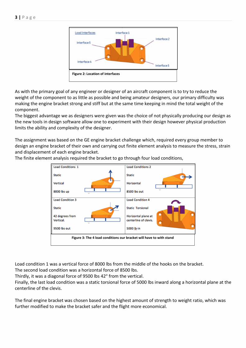
We were handed a template engine bracket which is displayed as “figure 1”. The challenge was to modify the given design or design a new bracket but without changing the different interfaces as described in “figure 2”.
Figure 1: shows A basic template of an engine bracket
3 | P a g e
As with the primary goal of any engineer or designer of an aircraft component is to try to reduce the weight of the component to as little as possible and being amateur designers, our primary difficulty was making the engine bracket strong and stiff but at the same time keeping in mind the total weight of the component. The biggest advantage we as designers were given was the choice of not physically producing our design as the new tools in design software allow one to experiment with their design however physical production limits the ability and complexity of the designer. The assignment was based on the GE engine bracket challenge which, required every group member to design an engine bracket of their own and carrying out finite element analysis to measure the stress, strain and displacement of each engine bracket. The finite element analysis required the bracket to go through four load conditions,
Load condition 1 was a vertical force of 8000 lbs from the middle of the hooks on the bracket. The second load condition was a horizontal force of 8500 lbs. Thirdly, it was a diagonal force of 9500 lbs 42° from the vertical. Finally, the last load condition was a static torsional force of 5000 lbs inward along a horizontal plane at the centerline of the clevis. The final engine bracket was chosen based on the highest amount of strength to weight ratio, which was further modified to make the bracket safer and the flight more economical.
Figure 3: The 4 load conditions our bracket will have to with stand
Figure 2: Location of interfaces

4 | P a g e
CRITICAL FACTORS
Factor of Safety
To provide a margin of design over the theoretical design capacity, in order to allow for uncertainties during the design process, a ratio known as the Factor of Safety (F.o.S) is used (RoyMech, 2008). The uncertainty could be present either in calculations, material strengths or any other component of the design process.
Therefore if component needs to withstand 200N and an F.o.S of 2 is used, then it is designed with strength to support of 400N. For aircraft components a factor of between 1.0-3.0 is used. Second Moment of Area
The second moment of area is also known as the moment of inertia of a shape. It is directly related to the cross-sectional area of a body and its displacement from the centroid (reference point). Once the centroid is located, the more important structural properties of the shape can be calculated. The second moment of area can also be defined as a measure of the 'efficiency' of a shape to resist bending caused by loading.
Altogether, “the second moment of area is a measure of a shape's resistance to change” (BuildRight,n.d).
Weight Optimization
According to Varun and Sandip (2012), optimization is a process of finding an optimal solution satisfying a given number of constraints. Therefore one could say that weight optimization is a process of reducing the weight of an object without compromising its other properties like strength. Cost Optimization Similar to weight optimization, cost optimization can be defined as a process of reducing the manufacturing cost of an object without compromising other factors. Sobieszczanski-Sobieski and Haftka in their paper published in 1997, wrote “”Very few instances can be found in which aerospace vehicle systems are optimized for their total performance, including cost”, implying cost to be one of the lesser important factor. Data Optimization Data optimization is important, since larger files can be harder to analyze. During the GE bracket challenge it was found that meshing couldn’t be done for larger files during the analysis phase (GE jet engine bracket challenge,2014).
FoS = Strength of Component / Load on component

5 | P a g e
METHODOLOGY Our entire process of designing a jet engine bracket and modifying it to make it suitable and fit for its purpose can be summarized in six different phases:
INTRODUCTION TO CAD PHASE Shortly after being introduced to the assigned coursework, it became extremely clear that at the beginner’s level designing complex components such as the jet engine bracket would be a real milestone. With this in mind, we commenced by following lecture tutorials and books to familiarize ourselves with the CATIA V5 user interface, workbenches, menus and toolbars, the specification tree and various different action approaches (Systems, n.d.). Each member of the group grasped sufficient knowledge to design a simple CAD model progressively by completing the different stages of the tutorial exercises in the specified order. This allowed us to acquire greater proficiency in the functioning of the CATIA V5 software. Some of the results from the tutorial exercises are displayed below.
Figure 4, displays of one of the very first basic component that a group member designed while learning the basics of designing. While making the shaft the pad function was first introduced. In addition, figure 5 shows the design of a simple shaft with a hole. Designing this allowed us to explore the hole and pad function. Moreover, figure 6 is an image of a screw; while designing this, several other functions such as chamfering and edge fillet were introduced to us.
Introduction to CAD Phase
Research Phase
Design Phase FEA Phase Modification
PhaseDecision and Conclusion
Figure 4 Basic component (shaft) Figure 5: Basic Component (shaft with a hole)
Figure 6: Basic component (screw)

6 | P a g e RESEARCH PHASE Succeeding from the introduction phase, when we were confident with the fundamentals of CATIA V5, we moved ahead by carrying out comprehensive research into the previously held GE jet engine bracket challenge. The motive of the research was to discover the purpose of engine brackets, contemporary designs, weight reduction techniques, advantages of additive manufacturing and to analyze the winning designs from the GE jet engine bracket challenge. During our research, we found out that the process that uses digital 3D design data to build up a component in layers by depositing material is known as additive manufacturing. It is very commonly known as 3D printing (EOS, 2015). We also learnt that subtractive manufacturing is the process that manufactures a part by cutting away portions of useless material. Our research revealed that although additive manufacturing has major advantages, it is not always the best method for the project. Many factors need to be considered by companies before choosing the type of process for a particular project.
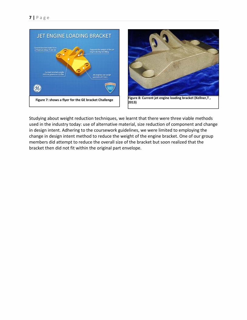
In 2013, GE announced an open challenge for engineers worldwide to optimize their current jet engine bracket design and then the top ten optimized engine brackets were then additively manufactured and tested for the four different specified load conditions (GrabCAD, n.d.). Our coursework required us to complete the GE engine bracket challenge (Figure 7). After researching, we could safely conclude that engine brackets also commonly known as loading brackets are one of the many load-carrying parts of the jet engine that were previously designed using conventional manufacturing techniques and therefore they have not been fully optimized for weight and performance in the past (GrabCAD, n.d.). By applying CAD skills efficiently, a light jet engine bracket fit for its purpose of supporting a large weight was to be designed: the aim was now clear. As Figure 8 shows, the current bracket which is made of a titanium alloy does support the weight of the jet engine but weighs a massive 2051.66 grams which when reduced can lead to an immense mass cut-down for the jet engine.
ADVANTAGES OF ADDITIVE MANUFACTURING
DISADVANTAGES OF ADDITIVE MANUFACTURING
More cost efficient as it’s cheaper to print a complex part instead of a cube of the same size.
3D printing can be time consuming.
Changes can be made easily using the original cad file.
Post-processing is necessary in most cases as dimensional accuracy is limited.
Less skill required in the actual manufacturing process in order to manufacture a part with specific dimensions.
Knowledge in component design is essential.
Reduced material waste as only the required material is used.
Layering can cause mechanical issues in the product. Table 1 Advantages and Disadvantages of Additive Manufacturing (Composited manufacturing magazine, 2014)
7 | P a g e
Studying about weight reduction techniques, we learnt that there were three viable methods used in the industry today: use of alternative material, size reduction of component and change in design intent. Adhering to the coursework guidelines, we were limited to employing the change in design intent method to reduce the weight of the engine bracket. One of our group members did attempt to reduce the overall size of the bracket but soon realized that the bracket then did not fit within the original part envelope.
Figure 8: Current jet engine loading bracket (Kellner,T , 2013)
Figure 7: shows a flyer for the GE bracket Challenge
8 | P a g e
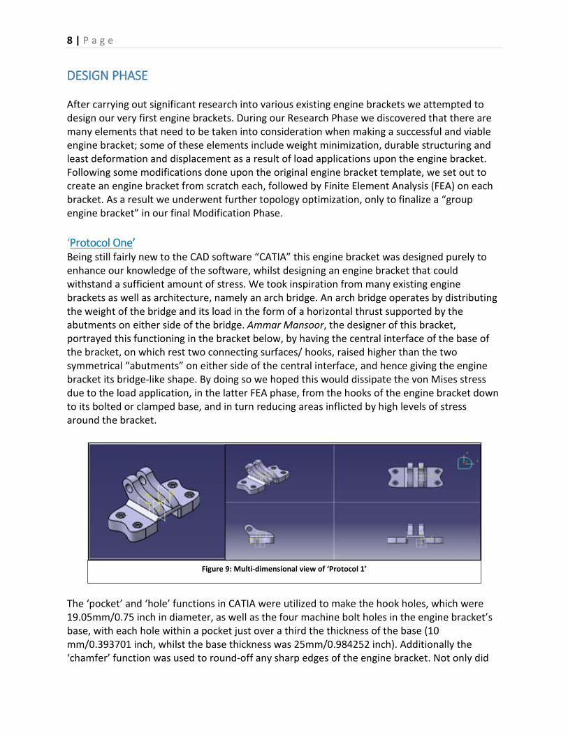
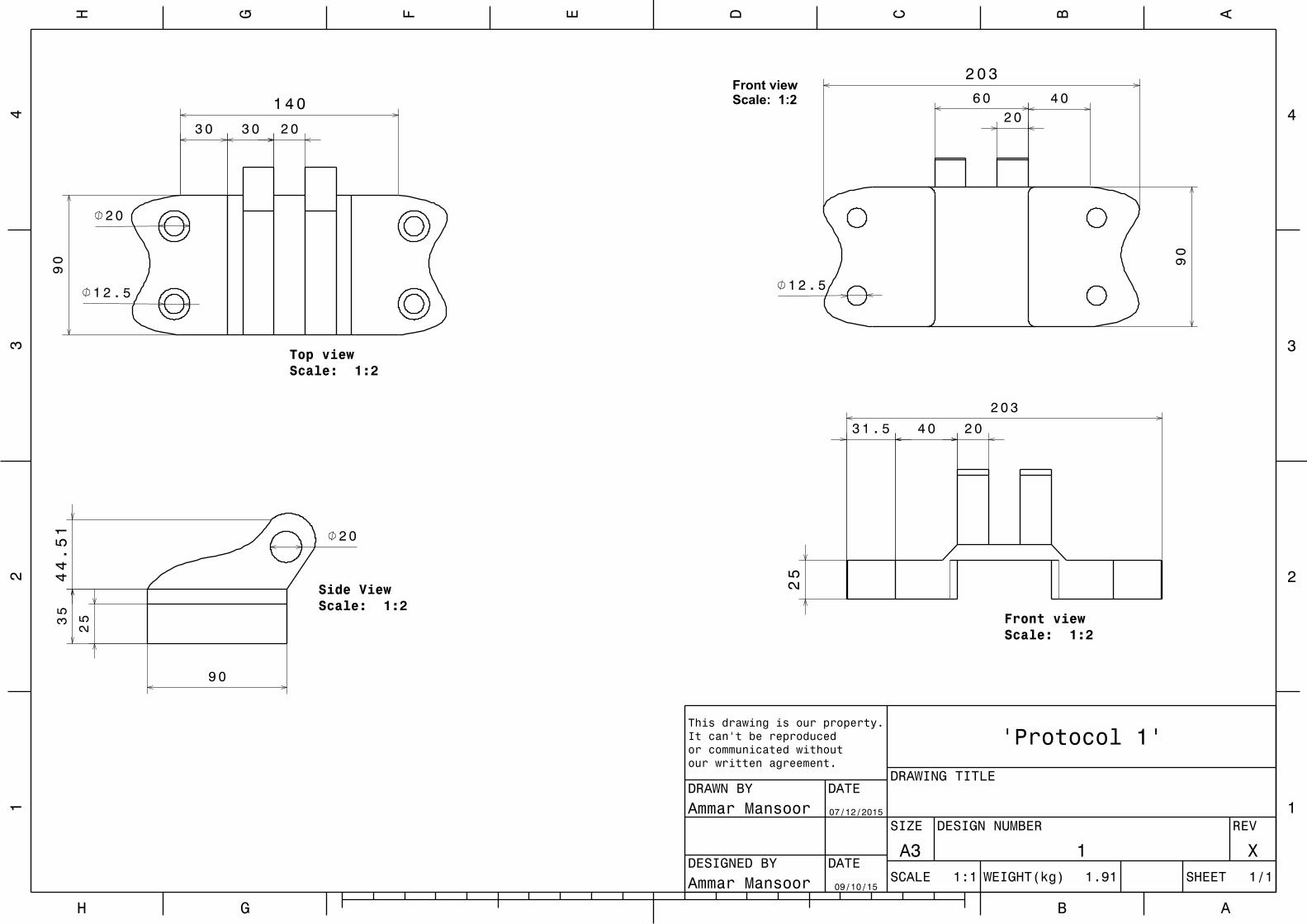
DESIGN PHASE After carrying out significant research into various existing engine brackets we attempted to design our very first engine brackets. During our Research Phase we discovered that there are many elements that need to be taken into consideration when making a successful and viable engine bracket; some of these elements include weight minimization, durable structuring and least deformation and displacement as a result of load applications upon the engine bracket. Following some modifications done upon the original engine bracket template, we set out to create an engine bracket from scratch each, followed by Finite Element Analysis (FEA) on each bracket. As a result we underwent further topology optimization, only to finalize a “group engine bracket” in our final Modification Phase. ‘Protocol One’ Being still fairly new to the CAD software “CATIA” this engine bracket was designed purely to enhance our knowledge of the software, whilst designing an engine bracket that could withstand a sufficient amount of stress. We took inspiration from many existing engine brackets as well as architecture, namely an arch bridge. An arch bridge operates by distributing the weight of the bridge and its load in the form of a horizontal thrust supported by the abutments on either side of the bridge. Ammar Mansoor, the designer of this bracket, portrayed this functioning in the bracket below, by having the central interface of the base of the bracket, on which rest two connecting surfaces/ hooks, raised higher than the two symmetrical “abutments” on either side of the central interface, and hence giving the engine bracket its bridge-like shape. By doing so we hoped this would dissipate the von Mises stress due to the load application, in the latter FEA phase, from the hooks of the engine bracket down to its bolted or clamped base, and in turn reducing areas inflicted by high levels of stress around the bracket.
The ‘pocket’ and ‘hole’ functions in CATIA were utilized to make the hook holes, which were 19.05mm/0.75 inch in diameter, as well as the four machine bolt holes in the engine bracket’s base, with each hole within a pocket just over a third the thickness of the base (10 mm/0.393701 inch, whilst the base thickness was 25mm/0.984252 inch). Additionally the ‘chamfer’ function was used to round-off any sharp edges of the engine bracket. Not only did
Figure 9: Multi-dimensional view of ‘Protocol 1’
9 | P a g e
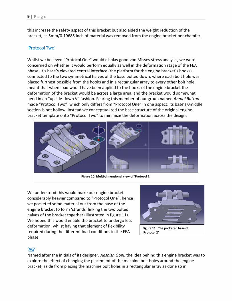
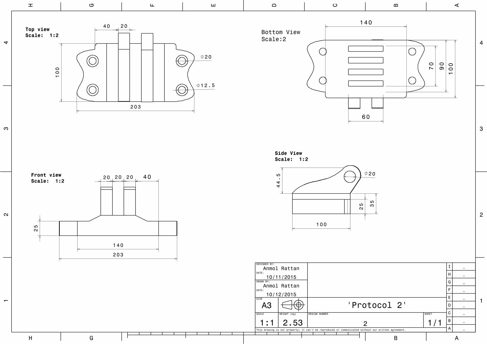
this increase the safety aspect of this bracket but also aided the weight reduction of the bracket, as 5mm/0.19685 inch of material was removed from the engine bracket per chamfer. ‘Protocol Two’ Whilst we believed “Protocol One” would display good von Misses stress analysis, we were concerned on whether it would perform equally as well in the deformation stage of the FEA phase. It’s base’s elevated central interface (the platform for the engine bracket’s hooks), connected to the two symmetrical halves of the base bolted down, where each bolt hole was placed furthest possible from the hooks and in a rectangular array to every other bolt hole, meant that when load would have been applied to the hooks of the engine bracket the deformation of the bracket would be across a large area, and the bracket would somewhat bend in an “upside-down V” fashion. Fearing this member of our group named Anmol Rattan made “Protocol Two”, which only differs from “Protocol One” in one aspect: its base’s 0middle section is not hollow. Instead we conceptualized the base structure of the original engine bracket template onto “Protocol Two” to minimize the deformation across the design.
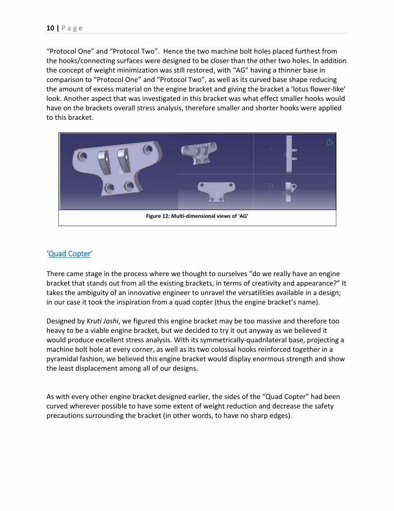
We understood this would make our engine bracket considerably heavier compared to “Protocol One”, hence we pocketed some material out from the base of the engine bracket to form ‘strands’ linking the two bolted halves of the bracket together (illustrated in figure 11). We hoped this would enable the bracket to undergo less deformation, whilst having that element of flexibility required during the different load conditions in the FEA phase. ‘AG’ Named after the initials of its designer, Aashish Gopi, the idea behind this engine bracket was to explore the effect of changing the placement of the machine bolt holes around the engine bracket, aside from placing the machine bolt holes in a rectangular array as done so in
Figure 10: Multi-dimensional view of ‘Protocol 2’
Figure 11: The pocketed base of ‘Protocol 2’
10 | P a g e
“Protocol One” and “Protocol Two”. Hence the two machine bolt holes placed furthest from the hooks/connecting surfaces were designed to be closer than the other two holes. In addition the concept of weight minimization was still restored, with “AG” having a thinner base in comparison to “Protocol One” and “Protocol Two”, as well as its curved base shape reducing the amount of excess material on the engine bracket and giving the bracket a ‘lotus flower-like’ look. Another aspect that was investigated in this bracket was what effect smaller hooks would have on the brackets overall stress analysis, therefore smaller and shorter hooks were applied to this bracket.
‘Quad Copter’ There came stage in the process where we thought to ourselves “do we really have an engine bracket that stands out from all the existing brackets, in terms of creativity and appearance?” It takes the ambiguity of an innovative engineer to unravel the versatilities available in a design; in our case it took the inspiration from a quad copter (thus the engine bracket’s name). Designed by Kruti Joshi, we figured this engine bracket may be too massive and therefore too heavy to be a viable engine bracket, but we decided to try it out anyway as we believed it would produce excellent stress analysis. With its symmetrically-quadrilateral base, projecting a machine bolt hole at every corner, as well as its two colossal hooks reinforced together in a pyramidal fashion, we believed this engine bracket would display enormous strength and show the least displacement among all of our designs. As with every other engine bracket designed earlier, the sides of the “Quad Copter” had been curved wherever possible to have some extent of weight reduction and decrease the safety precautions surrounding the bracket (in other words, to have no sharp edges).
Figure 12: Multi-dimensional views of ‘AG’

11 | P a g e
Figure 13: Multi-dimensional views of ‘Quad Copter’
12 | P a g e
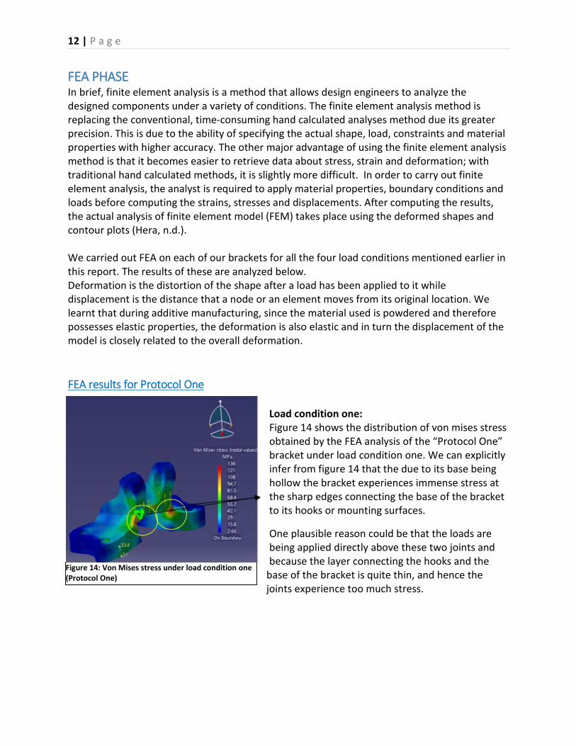
FEA PHASE In brief, finite element analysis is a method that allows design engineers to analyze the designed components under a variety of conditions. The finite element analysis method is replacing the conventional, time-consuming hand calculated analyses method due its greater precision. This is due to the ability of specifying the actual shape, load, constraints and material properties with higher accuracy. The other major advantage of using the finite element analysis method is that it becomes easier to retrieve data about stress, strain and deformation; with traditional hand calculated methods, it is slightly more difficult. In order to carry out finite element analysis, the analyst is required to apply material properties, boundary conditions and loads before computing the strains, stresses and displacements. After computing the results, the actual analysis of finite element model (FEM) takes place using the deformed shapes and contour plots (Hera, n.d.). We carried out FEA on each of our brackets for all the four load conditions mentioned earlier in this report. The results of these are analyzed below. Deformation is the distortion of the shape after a load has been applied to it while displacement is the distance that a node or an element moves from its original location. We learnt that during additive manufacturing, since the material used is powdered and therefore possesses elastic properties, the deformation is also elastic and in turn the displacement of the model is closely related to the overall deformation. FEA results for Protocol One
Load condition one: Figure 14 shows the distribution of von mises stress obtained by the FEA analysis of the “Protocol One” bracket under load condition one. We can explicitly infer from figure 14 that the due to its base being hollow the bracket experiences immense stress at the sharp edges connecting the base of the bracket to its hooks or mounting surfaces.
One plausible reason could be that the loads are being applied directly above these two joints and because the layer connecting the hooks and the
base of the bracket is quite thin, and hence the joints experience too much stress.
Figure 14: Von Mises stress under load condition one (Protocol One)

13 | P a g e
We witnessed the mounting surfaces getting pulled apart and the base getting compressed in size. Figure 15 is a relevant evidence for this deformation.
Load condition two:
On applying static load horizontally, the bracket seems to get compressed and bends from its central line of symmetry. The mounting surfaces get pulled back and stretch horizontally as a result of the horizontal loads and due to this the overall vertical height of the bracket drops significantly. Figure 16 reveals that the surface connecting the mounting surfaces to the base of the bracket is pushed downwards. The sharp edges
continue to experience greater stresses.
Figure 17 shows the stresses around the holes of the bracket. This is something we did not witness with load condition one
Figure 15: Deformation under load condition one (Protocol One)
Figure 16: Von mises stress under load condition two (protocol One)
Figure 17: Von mises zoomed in (protocol One)

14 | P a g e
On applying static load horizontally, the bracket seems to get compressed and bends from its central line of symmetry. The mounting surfaces get pulled back and stretch horizontally as a result of the horizontal loads and due to this the overall vertical height of the bracket drops significantly
Load condition three:
Figure 19 shows that there is high level of stress around the holes and the area between the two mounting surfaces. We assume this is a consequence of the surface connecting the mounting layer to the base of the bracket being thin.
We do not see any significant deformation of the bracket under load condition three. This could be partly due to the loads being applied at an angle of 42 degrees from the vertical (close to 45 degrees): the deformation due to vertical load cancels out the deformation due to horizontal loads since the loads are almost equally distributed vertically and horizontally.
Figure 18: Deformation under load condition two (Protocol One)
Figure 19: Von mises stress under load condition three (Protocol One)
Figure 20: Deformation under load condition three (Protocol One)
15 | P a g e
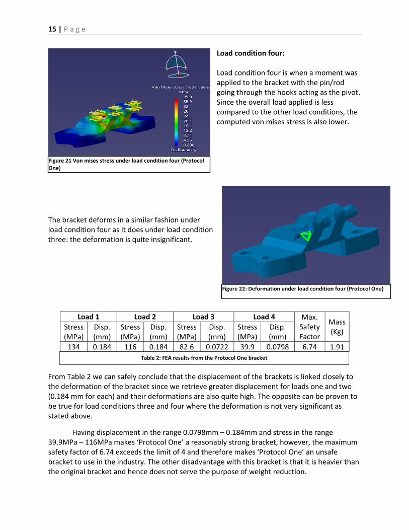
Load condition four: Load condition four is when a moment was applied to the bracket with the pin/rod going through the hooks acting as the pivot. Since the overall load applied is less compared to the other load conditions, the computed von mises stress is also lower.
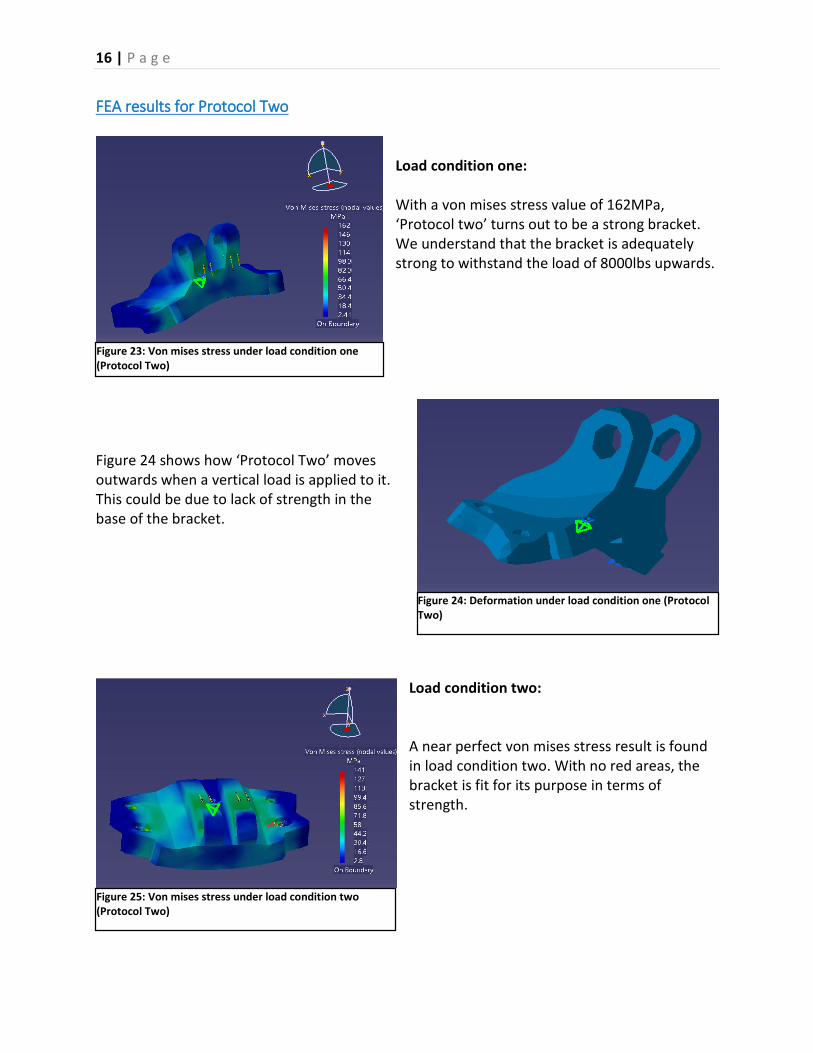
The bracket deforms in a similar fashion under load condition four as it does under load condition three: the deformation is quite insignificant.
From Table 2 we can safely conclude that the displacement of the brackets is linked closely to the deformation of the bracket since we retrieve greater displacement for loads one and two (0.184 mm for each) and their deformations are also quite high. The opposite can be proven to be true for load conditions three and four where the deformation is not very significant as stated above.
Having displacement in the range 0.0798mm – 0.184mm and stress in the range 39.9MPa – 116MPa makes ‘Protocol One’ a reasonably strong bracket, however, the maximum safety factor of 6.74 exceeds the limit of 4 and therefore makes ‘Protocol One’ an unsafe bracket to use in the industry. The other disadvantage with this bracket is that it is heavier than the original bracket and hence does not serve the purpose of weight reduction.
Load 1 Load 2 Load 3 Load 4 Max. Safety Factor
Mass (Kg) Stress
(MPa) Disp. (mm)
Stress (MPa)
Disp. (mm)
Stress (MPa)
Disp. (mm)
Stress (MPa)
Disp. (mm)
134 0.184 116 0.184 82.6 0.0722 39.9 0.0798 6.74 1.91
Figure 22: Deformation under load condition four (Protocol One)
Table 2: FEA results from the Protocol One bracket
Figure 21 Von mises stress under load condition four (Protocol One)
16 | P a g e
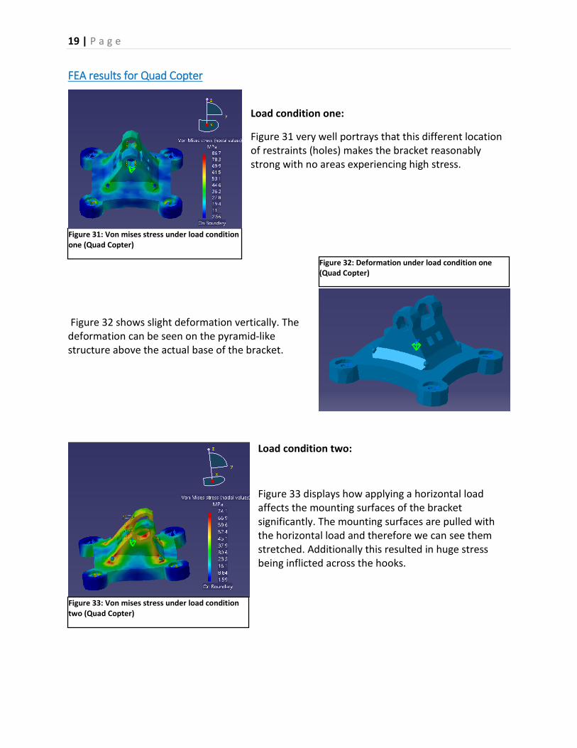
FEA results for Protocol Two Load condition one: With a von mises stress value of 162MPa, ‘Protocol two’ turns out to be a strong bracket. We understand that the bracket is adequately strong to withstand the load of 8000lbs upwards.
Figure 24 shows how ‘Protocol Two’ moves outwards when a vertical load is applied to it. This could be due to lack of strength in the base of the bracket.
Load condition two: A near perfect von mises stress result is found in load condition two. With no red areas, the bracket is fit for its purpose in terms of strength.
Figure 23: Von mises stress under load condition one (Protocol Two)
Figure 24: Deformation under load condition one (Protocol Two)
Figure 25: Von mises stress under load condition two (Protocol Two)

17 | P a g e
From figure 26, it is clearly visible that the base of the bracket has twisted. There is also a large displacement of the mounting surfaces from their original positions. The reason for this could be that the mounting surfaces are slightly elevated; they are not attached to the base of the bracket directly.
Load condition three: Figure 27 shows further evidence for the high level of strength of the bracket. Although the von mises stress value drops slightly compared to load conditions one and two, the bracket is still sufficiently strong.
Figure 28 shows that there is not any noticeable deformation in the ‘Protocol Two’ bracket under the applied torsional force.
Figure 27: Von mises stress under load condition three (Protocol Two)
Figure 28: Deformation under load condition three (Protocol Two)
Figure 26 Deformation under load condition two (Protocol Two)

18 | P a g e
Load condition four: Under load condition four, the mounting surface of the bracket experience stress due to the rod placed for the purpose of torsional analysis.
Under load condition four, ‘Protocol Two’ shows infinitesimally small deformation which reinforces on the overall strength of the bracket.
Table 3 shows that ‘Protocol Two’ has values of von mises stress ranging from 50.5 – 141 which makes it a strong bracket.
Additionally, the small displacement range (between 0.0738 and 0.146) only adds to making ‘Protocol Two’ a good solution in terms of strength.
The maximum safety factor of 5.575 is still too high for the component to be used in an aircraft.
Load 1 Load 2 Load 3 Load 4 Max. Safety Factor
Mass (Kg) Stress
(MPa) Disp. (mm)
Stress (MPa
Disp. (mm)
Stress (MPa)
Disp. (mm)
Stress (MPa)
Disp. (mm)
162 0.146 141 0.145 72.3 0.0467 50.5 0.0738 5.575 2.534kg
Figure 30: Deformation under load condition four (Protocol Two)
Figure 29: Von mises stress under load condition four (Protocol Two)
Table 2: FEA results from Protocol Two bracket
19 | P a g e
FEA results for Quad Copter
Load condition one:
Figure 31 very well portrays that this different location of restraints (holes) makes the bracket reasonably strong with no areas experiencing high stress.
Figure 32 shows slight deformation vertically. The deformation can be seen on the pyramid-like structure above the actual base of the bracket.
Load condition two:
Figure 33 displays how applying a horizontal load affects the mounting surfaces of the bracket significantly. The mounting surfaces are pulled with the horizontal load and therefore we can see them stretched. Additionally this resulted in huge stress being inflicted across the hooks.
Figure 31: Von mises stress under load condition one (Quad Copter)
Figure 32: Deformation under load condition one (Quad Copter)
Figure 33: Von mises stress under load condition two (Quad Copter)

20 | P a g e
Figure 34 brings to our notice that applying the load horizontally makes the pyramid-like structure on the base of the bracket sink into the bracket. The stretching of the mounting surface, previously seen in load condition one, prevails.
Load condition three: When the load is applied at the specified angle, high stress can be observed at the point where the mounting surfaces are attached with the base of the bracket.
Figure 36 shows similar results to that of load condition two although the intensity of deformation is lower.
Load condition four:
The red sections in figure 37 are on the rod used for the purpose of torsional analysis. Other than that, the ‘Quad Copter’ bracket is quite strong, perhaps because of the bulky pyramid-like structure in the centre of the bracket.
Figure 35: Von mises stress under load condition three (Quad Copter)
Figure 36: Deformation under load condition three (Quad Copter)
Figure 37: Von mises stress under load condition four (Quad Copter)
Figure 34: Deformation under load condition two (Quad Copter)

21 | P a g e
There is a very slight deformation at the top of the mounting surfaces under load condition four. The bracket is very strong otherwise.
Although the displacement of the Quad Copter bracket is relatively small (0.0493mm to 0.102mm), it’s mass and safety factors are too high and therefore the bracket design is unsuccessful.
Load 1 Load 2 Load 3 Load 4 Max. Safety Factor
Mass (Kg) Stress
(MPa) Disp. (mm)
Stress (MPa)
Disp. (mm)
Stress (MPa)
Disp. (mm)
Stress (MPa)
Disp. (mm)
86.7 0.0493 74.1 0.102 124 0.087 46.5 0.057 7.284 2.35kg
Figure 38: Deformation under load condition four Quad Copter)
Table 3 FEA results from the Quad Copter bracket
22 | P a g e
FEA results for AG
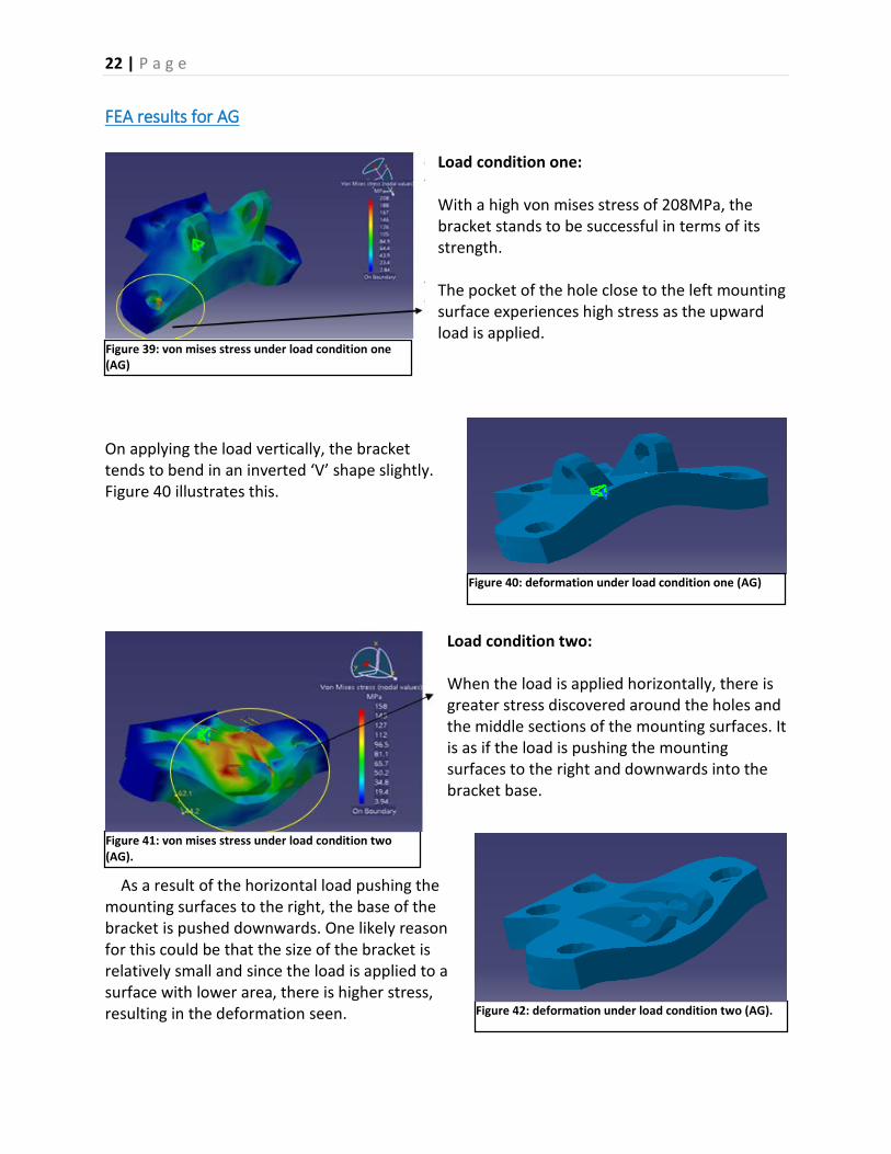
Load condition one: With a high von mises stress of 208MPa, the bracket stands to be successful in terms of its strength. The pocket of the hole close to the left mounting surface experiences high stress as the upward load is applied.
On applying the load vertically, the bracket tends to bend in an inverted ‘V’ shape slightly. Figure 40 illustrates this.
Load condition two: When the load is applied horizontally, there is greater stress discovered around the holes and the middle sections of the mounting surfaces. It is as if the load is pushing the mounting surfaces to the right and downwards into the bracket base.
As a result of the horizontal load pushing the mounting surfaces to the right, the base of the bracket is pushed downwards. One likely reason for this could be that the size of the bracket is relatively small and since the load is applied to a surface with lower area, there is higher stress, resulting in the deformation seen.
Figure 41: von mises stress under load condition two (AG).
Figure 42: deformation under load condition two (AG).
Figure 39: von mises stress under load condition one (AG)
Figure 40: deformation under load condition one (AG)

23 | P a g e
Load condition three: The mounting surfaces of the bracket experience excess stress. The overall base of the bracket can also be observed to have stretched a little.
Apart from the slight deformation on the mounting surfaces, the bracket remains intact.
Load condition four: Similar to the previous bracket the rod used for the torsional analysis gets bent. The bracket shows a massive von mises stress of 333MPa, making it one of the strongest made.
There is no deformation on the actual bracket.
Figure 43: von mises stress under load condition three (AG)
Figure 44: deformation under load condition three (AG)
Figure 45: von mises stress analysis under load condition four (AG)
Figure 46: deformation under load condition four (AG)
24 | P a g e
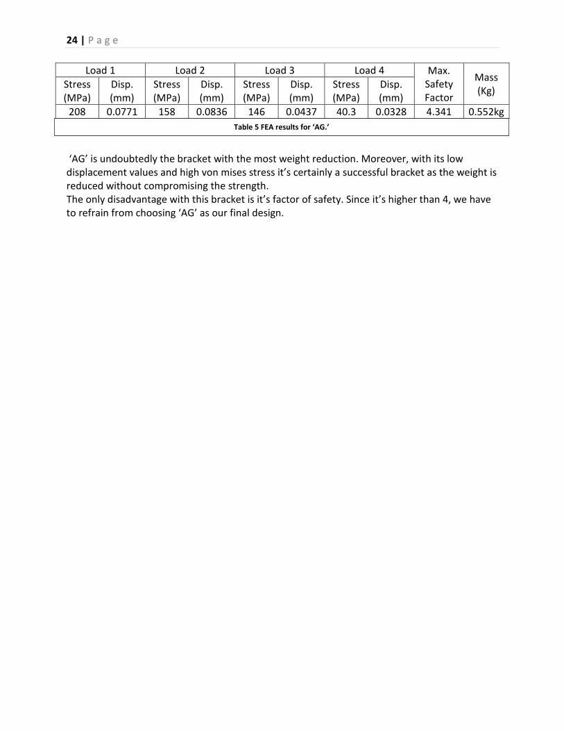
‘AG’ is undoubtedly the bracket with the most weight reduction. Moreover, with its low displacement values and high von mises stress it’s certainly a successful bracket as the weight is reduced without compromising the strength. The only disadvantage with this bracket is it’s factor of safety. Since it’s higher than 4, we have to refrain from choosing ‘AG’ as our final design.
Load 1 Load 2 Load 3 Load 4 Max. Safety Factor
Mass (Kg) Stress
(MPa) Disp. (mm)
Stress (MPa)
Disp. (mm)
Stress (MPa)
Disp. (mm)
Stress (MPa)
Disp. (mm)
208 0.0771 158 0.0836 146 0.0437 40.3 0.0328 4.341 0.552kg Table 5 FEA results for ‘AG.’
25 | P a g e
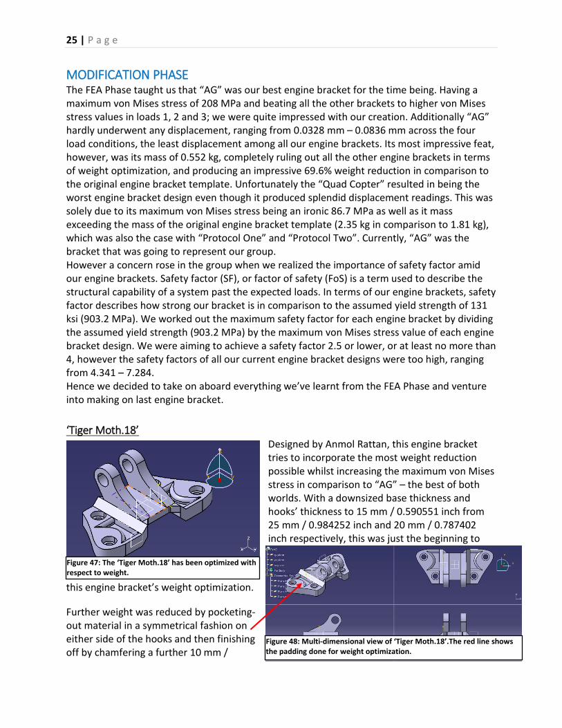
MODIFICATION PHASE The FEA Phase taught us that “AG” was our best engine bracket for the time being. Having a maximum von Mises stress of 208 MPa and beating all the other brackets to higher von Mises stress values in loads 1, 2 and 3; we were quite impressed with our creation. Additionally “AG” hardly underwent any displacement, ranging from 0.0328 mm – 0.0836 mm across the four load conditions, the least displacement among all our engine brackets. Its most impressive feat, however, was its mass of 0.552 kg, completely ruling out all the other engine brackets in terms of weight optimization, and producing an impressive 69.6% weight reduction in comparison to the original engine bracket template. Unfortunately the “Quad Copter” resulted in being the worst engine bracket design even though it produced splendid displacement readings. This was solely due to its maximum von Mises stress being an ironic 86.7 MPa as well as it mass exceeding the mass of the original engine bracket template (2.35 kg in comparison to 1.81 kg), which was also the case with “Protocol One” and “Protocol Two”. Currently, “AG” was the bracket that was going to represent our group. However a concern rose in the group when we realized the importance of safety factor amid our engine brackets. Safety factor (SF), or factor of safety (FoS) is a term used to describe the structural capability of a system past the expected loads. In terms of our engine brackets, safety factor describes how strong our bracket is in comparison to the assumed yield strength of 131 ksi (903.2 MPa). We worked out the maximum safety factor for each engine bracket by dividing the assumed yield strength (903.2 MPa) by the maximum von Mises stress value of each engine bracket design. We were aiming to achieve a safety factor 2.5 or lower, or at least no more than 4, however the safety factors of all our current engine bracket designs were too high, ranging from 4.341 – 7.284. Hence we decided to take on aboard everything we’ve learnt from the FEA Phase and venture into making on last engine bracket. ‘Tiger Moth.18’
Designed by Anmol Rattan, this engine bracket tries to incorporate the most weight reduction possible whilst increasing the maximum von Mises stress in comparison to “AG” – the best of both worlds. With a downsized base thickness and hooks’ thickness to 15 mm / 0.590551 inch from 25 mm / 0.984252 inch and 20 mm / 0.787402 inch respectively, this was just the beginning to
this engine bracket’s weight optimization. Further weight was reduced by pocketing-out material in a symmetrical fashion on either side of the hooks and then finishing off by chamfering a further 10 mm /
Figure 47: The ‘Tiger Moth.18’ has been optimized with respect to weight.
Figure 48: Multi-dimensional view of ‘Tiger Moth.18’.The red line shows the padding done for weight optimization.

26 | P a g e
0.393701 inch material from the edges of the pockets at 45 degrees, leaving no room for excess material. The idea of having a middle hollow part of the base was preserved from “Protocol One” in this design, as well as having the two of the machine bolt holes closer to each other than the other two holes, as that seemed to be the key to “AG”’s temporary success. Different to “AG”, however, longer and taller hooks were fused in this design.
FEA results for ‘Tiger moth.18’
With the load applied vertically, there is a tiny spot (red area) under excess stress near the left mounting surface. The other parts of the bracket remain reasonably strong.
The high stress around the holes of bracket base can also be seen under load condition three. Under load condition four, high stress is observed where the mounting surfaces are attached to the elevated base.
Figure 49: von mises stress under load condition one (Tiger Moth.18)
Figure 50: von mises stress under load condition two (Tiger Moth.18)
Figure 51: von mises stress under load condition three (Tiger Moth.18)
Figure 52: von mises stress under load condition four (Tiger Moth.18)

27 | P a g e
It is clearly conspicuous from the images above that the bracket is highly sustainable as there is negligible deformation under all the four load conditions.
Figure 53: Deformation under load condition one (Tiger Moth.18)
Figure 54: Deformation under load condition two (Tiger Moth.18)
Figure 55: Deformation under load condition three(Tiger Moth.18)
Figure 56: Deformation under load condition four (Tiger Moth.18)

28 | P a g e
CONCLUSION
Load 1 Load 2 Load 3 Load 4 Max. Safety Factor
Mass (Kg) Stress
(MPa) Disp. (mm)
Stress (MPa)
Disp. (mm)
Stress (MPa)
Disp. (mm)
Stress (MPa)
Disp. (mm)
306 0.171 297 0.306 145 0.119 101 0.101 2.95 1.109
As we can see from Table 6, ‘Tiger Moth.18’ stands out among the other bracket designs due to its low safety factor of 2.95. The design satisfies the minimal displacement measure -within the range 0.101mm -0.306mm. Furthermore, the reduction of mass to 1.109kg only adds to making ‘Tiger Moth.18’ the most sustainable engine bracket designed within our group.
While using CATIA V5 for finite element analysis, it became apparent that the computed results were not very accurate since the default meshing used is not symmetrical which makes the elements in the finite element model unevenly distributed around the node. The other major limitation, we had to overcome was that of carrying out FEA on a component assembled of multiple parts: ‘Protocol One’ was initially an assembled component however we were required to re-design it as one part as the material was getting applied to different parts.
Recommendation for future designs Weight optimization should be done on a larger scale since only 2 out of our 5 brackets have lesser weight than the base bracket. The ‘AG’ was able to achieve a weight reduction of 72.84% but its FEA was below standards. On the other hand, the ’Tiger moth.18’ was able to achieve a weight reduction of 45.5% and still handle the 4 different load conditions reasonably well. There is enough evidence from the analysis of the FEA results to conclude with the ‘Tiger moth.18’ as our final bracket. However for future designs, firstly, location of holes or interface could be changed to provide better strength. From the figure, it is quite clear that there is only negligible amount of stress acting on interfaces 1 and 2 (refer to figure). Moving it closer to the hooks might minimize the deformation.
Table 6 FEA results for ‘Tiger Moth.18’
Interface 1 and
Figure 57: Interface 1 and 2 should be moved closer to the hooks (Tiger Moth.18)

29 | P a g e
LIST OF REFERENCES
• Abbott, D., Carter, W., Erno, D. and et.al. , (2014). The GE Aircraft Engine Bracket Challenge: An Experiment in Crowdsourcing for Mechanical Design Concepts. 1st ed. [ebook] pp.1402-1411. Available at: http://sffsymposium.engr.utexas.edu/sites/default/files/2014-110-Carter.pdf [Accessed 15 Dec. 2015].
• ACMA, (2014). Pros and Cons of Additive Manufacturing | Composites Manufacturing Magazine. [online] Composites Manufacturing Magazine. Available at: http://compositesmanufacturingmagazine.com/2014/10/pros-cons-additive-manufacturing/ [Accessed 12 Dec. 2015].
• Ahuja, V. and Hazra, S. (2012). Application of Optimization Techniques in Reducing the Weight of Engine Mounting Bracket. 1st ed. [ebook] Maruti Suzuki India and HTC, pp.1-8. Available at: http://www.altairatc.com/india/previous-events/2012/papers-2012/o-os-09_application_of_optimization_techniques_marutisuzuki.pdf [Accessed 14 Dec. 2015].
• Beardmore, R. (2015). Factors of Safety. [online] Roymech.co.uk. Available at:
http://www.roymech.co.uk/Useful_Tables/ARM/Safety_Factors.html [Accessed 16 Dec. 2015].
• Build Right, (2015). Second moment of area (I). [online] Build Right. Available at:
https://www.dlsweb.rmit.edu.au/toolbox/buildright/content/bcgbc4010a/03_properties/02_section_properties/page_003.htm [Accessed 18 Dec. 2015].
• EOS, (2015). Additive Manufacturing: 3D printed parts from CAD data. [online] Eos.info.
Available at: http://www.eos.info/additive_manufacturing [Accessed 18 Dec. 2015].
• GrabCad, (2015). CAD collaboration solution that accelerates product development - GrabCAD. [online] Grabcad.com. Available at: https://grabcad.com/ [Accessed 12 Dec. 2015].
• Haftka, R. and Sobieszczanski-Sobieski, J. (1997). Multidisciplinary aerospace design
optimization: survey of recent developments. Structural Optimization, 14(1), pp.1-23.
• Kellner, T. (2013). Jet Engine Bracket from Indonesia Wins 3D Printing Challenge - GE Reports. [online] GE Reports. Available at: http://www.gereports.com/post/77131235083/jet-engine-bracket-from-indonesia-wins-3d-printing/ [Accessed 9 Dec. 2015].
AH BG
DE CF BG AH
33
22
44
11
DESIGNED BY DATE
DRAWN BY DATE
This drawing is our property.It can't be reproducedor communicated withoutour written agreement.
SCALE 1:1 WEIGHT(kg) SHEET
SIZE REV
X
DRAWING TITLE
1.91
A31/1Ammar Mansoor
Ammar Mansoor 07/12/2015
09/10/15
'Protocol 1'
1DESIGN NUMBER
12.5
20
90
140
30 30 20
Top viewScale: 1:2
25
203
31.5 40 20
Front viewScale: 1:2
Side ViewScale: 1:2
20
90
35
25
44.51
Front viewScale: 1:2203
12.5
90
6020
40
AH BG
DE CF BG AH
33
22
44
11
This drawing is our property; it can't be reproduced or communicated without our written agreement.
SCALE
1:1WEIGHT (kg) SHEET
SIZE
DATE:
DESIGNED BY:
DATE:
A _
B _
C _
D _
E _
F _
G _
H _
I _
2.53
A3
1/1
Anmol Rattan
10/11/2015DRAWN BY:
Anmol Rattan
10/12/2015
'Protocol 2'
2
DESIGN NUMBER
203
40 20
100
Top viewScale: 1:2
12.5
20
Front viewScale: 1:2
140
25
202020
203
40
44.5
Side ViewScale: 1:2
20
25 35
1 00
Bottom ViewScale:2
60
70
100
1 40
90

AH BG
DE CF BG AH
33
22
44
11
DESIGNED BY DATE
DRAWN BY DATE
This drawing is our property.It can't be reproducedor communicated withoutour written agreement.
SCALE 1:1 WEIGHT(kg) SHEET
SIZE DRAWING NUMBER REV
X
DRAWING TITLE
2.35
A31/1
Kruti Joshi 15/11/2015
'Quad copter'
3
Kruti Joshi15/12/2015
Front viewScale: 1:2
26
16
20
90
20
90
9 0
40
7030
30
20
Bottom viewScale: 1:2
170
40
32.5
2 0
Side ViewScale: 1:2
36.1
409040
AH BG
DE CF BG AH
33
22
44
11
This drawing is our property; it can't be reproduced or communicated without our written agreement.
SCALE
1:1WEIGHT (kg) SHEET
SIZE
DESIGNED BY:
DATE:
A _
B _
C _
D _
E _
F _
G _
H _
I _
0.55
A3
1/1
Aashish Gopi
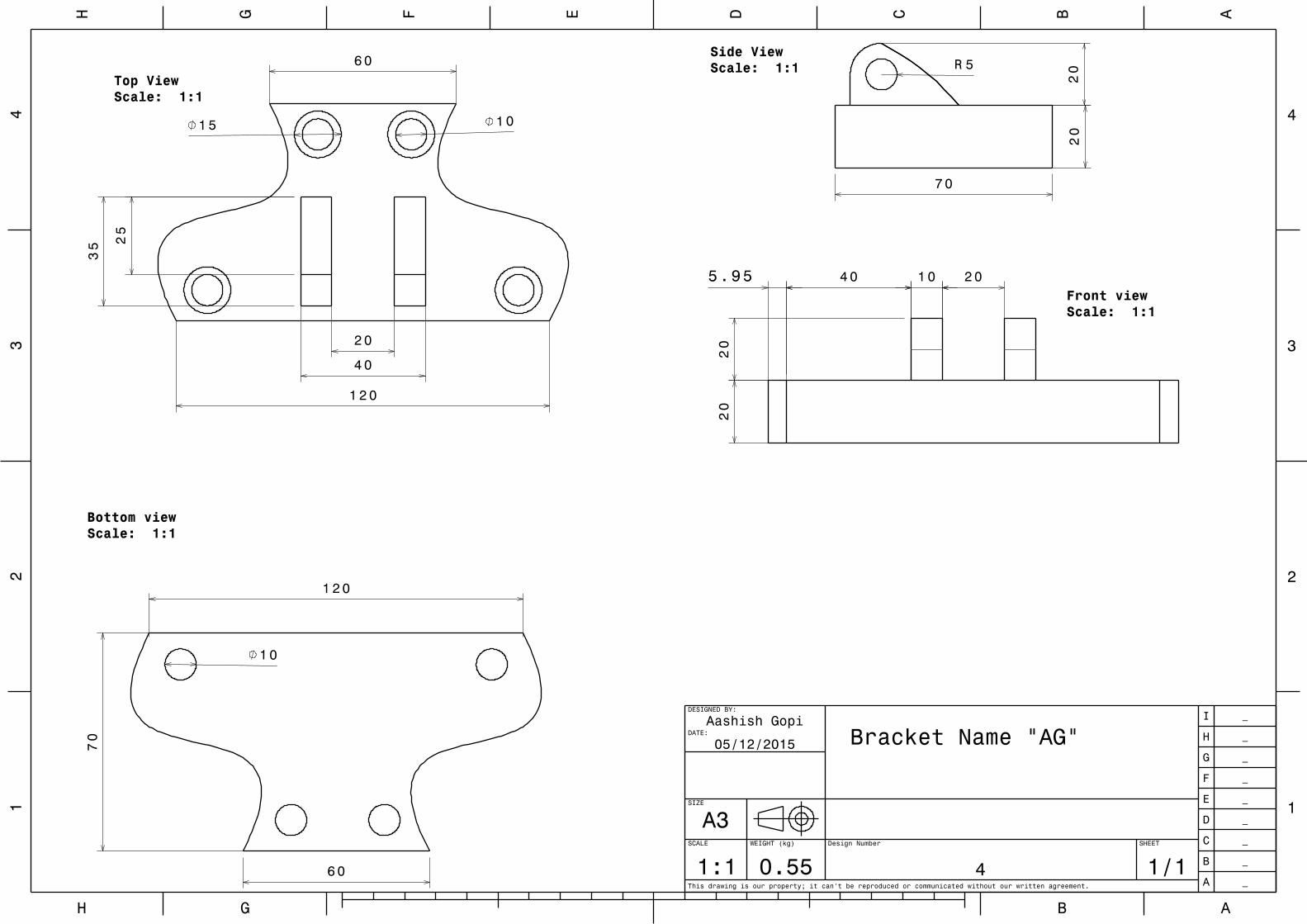
05/12/2015 Bracket Name "AG"
4
Design Number
40 10 20
20
5.95
20
Front viewScale: 1:1
20
20
7 0
5RSide ViewScale: 1:160
120
20
40
35 25
1 5 10
Top ViewScale: 1:1
Bottom viewScale: 1:1
120
60
70
10

AH BG
DE CF BG AH
33
22
44
11
This drawing is our property; it can't be reproduced or communicated without our written agreement.
SCALE
1:1WEIGHT (kg) SHEET
SIZE
DATE:
DESIGNED BY:
DATE:
A _
B _
C _
D _
E _
F _
G _
H _
I _
1.11
A3
1/1
Anmol Rattan
Drawn By07/12/2015
10/12/2015
Anmol Rattan
'Tiger Moth.18'
5
DESIGN NUMBER
1 5
30
Top ViewScale: 1:2 40
20
90
12.5
30
10
38.96070.2
18.75
Front ViewScale: 1:2Side View
Scale: 1:219.1
28.8
90
87.1
BottomViewScale: 1:2 30
12.5
90
60
15
40