wecc criterion tpl-001-wecc-crt-3 · wecc criterion – tpl-001-wecc-crt-3 transmission system...
TRANSCRIPT

WECC Criterion
TPL-001-WECC-CRT-3
WESTERN ELECTRICITY COORDINATING COUNCIL 155 North 400 West, Suite 200
Salt Lake City, Utah 84103-1114
A. Introduction
1. Title: Transmission System Planning Performance
2. Number: TPL-001-WECC-CRT-3
3. Purpose: To facilitate coordinated near-term and long-term transmission planning within the Interconnection of the Western Electricity Coordinating Council (WECC), and to facilitate the exchange of the associated planning information for normal and abnormal conditions.
This document applies to all transmission planning studies conducted within the Interconnection of the Western Electricity Coordinating Council (WECC).
This is a planning criterion. This document does not designate the entity responsible for system remediation.
4. Applicability:
4.1. Functional Entities:
4.1.1. Planning Coordinator
4.1.2. Transmission Planner
4.2. Facilities
4.2.1. This document applies to Bulk Electric System (BES) Facilities.
4.2.2. The following buses are specifically excluded from this WECC Criterion:
4.2.2.1. Non-BES buses
4.2.2.2. Line side series capacitor buses
4.2.2.3. Line side series reactor buses
4.2.2.4. Dedicated shunt capacitor buses
4.2.2.5. Dedicated shunt reactor buses
4.2.2.6. Metering buses, fictitious buses, or other buses that model point of interconnection solely for measuring electrical quantizes; and,
4.2.2.7. Other buses specifically excluded by each Planning Coordinator or Transmission Planner internal to their system
5. Effective Date: September 21, 2016
WECC Criterion – TPL-001-WECC-CRT-3 Transmission System Planning Performance Page 2 of 12
W E S T E R N E L E C T R I C I T Y C O O R D I N A T I N G
C O U N C I L
B. Requirements and Measures
WR1. Each Transmission Planner and Planning Coordinator shall use the following default base planning criteria, unless otherwise specified in accordance with Requirements WR2 and WR3:
1.1. Steady-state voltages at all applicable Bulk-Electric System (BES) buses shall stay within each of the following limits:
1.1.1. 95 percent to 105 percent of nominal for P01 event (system
normal pre-contingency event powerflow); 1.1.2. 90 percent to 110 percent of nominal for P1-P72 events
(post-contingency event powerflow).
1.2. Post-Contingency steady-state voltage deviation at each applicable BES bus serving load shall not exceed 8% for P1 events.
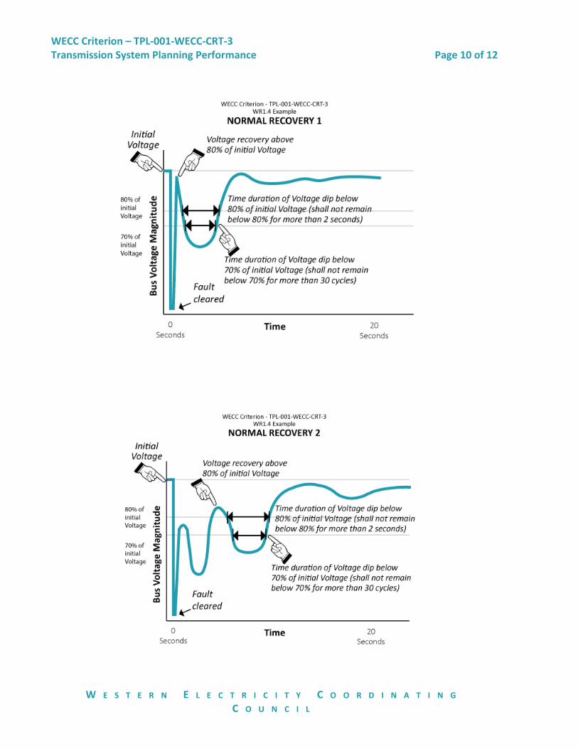
1.3. Following fault clearing, the voltage shall recover to 80% of the pre-contingency voltage within 20 seconds of the initiating event for all P1 through P7 events, for each applicable BES bus serving load.
1.4. Following fault clearing and voltage recovery above 80%, voltage at each applicable BES bus serving load shall neither dip below 70% of pre-contingency voltage for more than 30 cycles nor remain below 80% of pre-contingency voltage for more than two seconds, for all P1 through P7 events.
1.5. For Contingencies without a fault (P2.1 category event), voltage dips at each applicable BES bus serving load shall neither dip below 70% of pre-contingency voltage for more than 30 cycles nor remain below 80% of pre-contingency voltage for more than two seconds.
1.6. All oscillations that do not show positive damping within 30-seconds after the start of the studied event shall be deemed unstable.
WM1. Each Transmission Planner and Planning Coordinator will have evidence that it used the base criteria in its Planning Assessment specified in Requirement WR1, unless otherwise allowed in accordance with Requirements WR2 and WR3.
1 P0 through P7 refers to the categories of contingencies identified in Table 1 of NERC Standard TPL-001-4, Transmission System Planning Performance Requirements. 2 Previously cited
WECC Criterion – TPL-001-WECC-CRT-3 Transmission System Planning Performance Page 3 of 12
W E S T E R N E L E C T R I C I T Y C O O R D I N A T I N G
C O U N C I L
WR2. Each Transmission Planner and Planning Coordinator that uses a more stringent criterion than that stated in Requirement WR1 shall apply that criterion only to its own system, except where otherwise agreed upon by all other planning entities to which the more stringent criterion was applied.
WM2. Each Transmission Planner and Planning Coordinator that uses a more stringent criterion in its planning assessment than that stated in Requirement WR1 and applied that criterion to other systems will have evidence of agreement from all other planning entities to which the more stringent criteria was applied.
WR3. Each Transmission Planner and Planning Coordinator that uses a less stringent criterion than that stated in Requirement WR1 shall allow other Transmission Planners and Planner Coordinators to have the same impact on that part of the system for the same category of planning events (e.g., P1, P2).
WM3. Each Transmission Planner and Planning Coordinator that uses a less stringent criterion than that stated in Requirement WR1 will have evidenced that it allowed other Transmission Planners and Planner Coordinators to have the same impact on that part of the system for the same category of planning events (e.g., P1, P2).
WR4. Each Transmission Planner and Planning Coordinator shall use the following threshold criteria to identify the potential for Cascading or uncontrolled islanding. An entity is allowed to use these criteria to identify instability due to Cascading or uncontrolled islanding as long as it does not impose it on others:
When a post contingency analysis results in steady-state facility loading that is either in excess of a known BES facility trip setting, or exceeds 125% of the highest seasonal facility rating for the BES facility studied. If the trip setting is known to be different than the 125% threshold, the known setting should be used.
When transient stability voltage response occurs at any applicable BES bus outside of the criteria stated in Requirement WR1.3 of this document.
When either unrestrained successive load loss occurs or unrestrained successive generation loss occurs.
WM4. Each Transmission Planner and Planning Coordinator will have evidence that it
used the indicators of Requirement WR4 to identify the potential for Cascading or uncontrolled islanding.

WECC Criterion – TPL-001-WECC-CRT-3 Transmission System Planning Performance Page 4 of 12
W E S T E R N E L E C T R I C I T Y C O O R D I N A T I N G
C O U N C I L
WR5. Each Transmission Planner and Planning Coordinator shall use the following minimum criteria when identifying voltage stability:
5.1. For transfer paths, all P0-P1 events shall demonstrate a positive reactive power margin at a minimum of 105 percent of transfer path flow.
5.2. For transfer paths, all P2-P7 events shall demonstrate a positive reactive power margin at a minimum of 102.5 percent of transfer path flow.
5.3. For load areas, all P0-P1 events shall demonstrate a positive reactive power margin at a minimum of 105 percent of forecasted peak load.
5.4. For load areas, all P2-P7 events shall demonstrate a positive reactive power margin at a minimum of 102.5 percent of forecasted peak load.
WM5. Each Transmission Planner and Planning Coordinator will have evidenced that it used the minimum criteria identified in Requirement WR5 to identify voltage stability.
WR6. Each Transmission Planner and Planning Coordinator that uses study criteria different from the base criteria in Requirement WR1 shall make its criteria available upon request within 30 days.
WM6. Each Transmission Planner and Planning Coordinator that uses study criteria different from the base criteria in Requirement WR1 will have evidence that it made its criteria available upon request, as required in Requirement WR6.
WECC Criterion – TPL-001-WECC-CRT-3 Transmission System Planning Performance Page 5 of 12
W E S T E R N E L E C T R I C I T Y C O O R D I N A T I N G
C O U N C I L
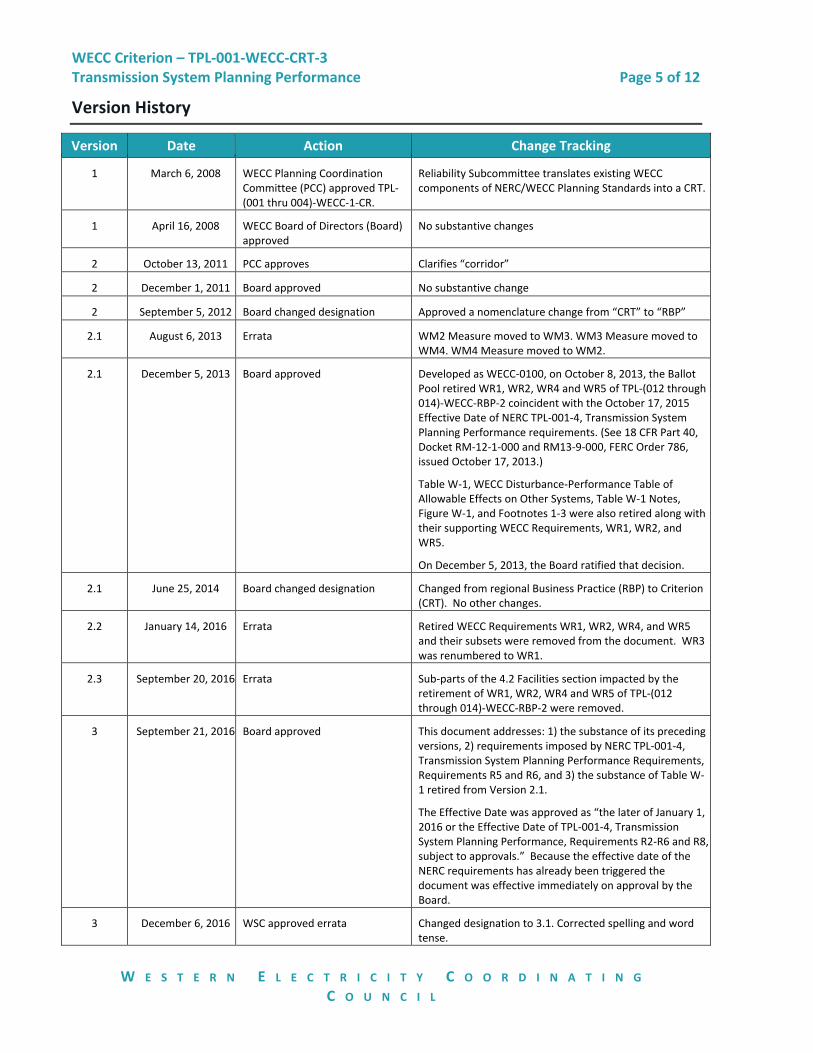
Version History
Version Date Action Change Tracking
1 March 6, 2008 WECC Planning Coordination Committee (PCC) approved TPL-(001 thru 004)-WECC-1-CR.
Reliability Subcommittee translates existing WECC components of NERC/WECC Planning Standards into a CRT.
1 April 16, 2008 WECC Board of Directors (Board) approved
No substantive changes
2 October 13, 2011 PCC approves Clarifies “corridor”
2 December 1, 2011 Board approved No substantive change
2 September 5, 2012 Board changed designation Approved a nomenclature change from “CRT” to “RBP”
2.1 August 6, 2013 Errata WM2 Measure moved to WM3. WM3 Measure moved to WM4. WM4 Measure moved to WM2.
2.1 December 5, 2013 Board approved Developed as WECC-0100, on October 8, 2013, the Ballot Pool retired WR1, WR2, WR4 and WR5 of TPL-(012 through 014)-WECC-RBP-2 coincident with the October 17, 2015 Effective Date of NERC TPL-001-4, Transmission System Planning Performance requirements. (See 18 CFR Part 40, Docket RM-12-1-000 and RM13-9-000, FERC Order 786, issued October 17, 2013.)
Table W-1, WECC Disturbance-Performance Table of Allowable Effects on Other Systems, Table W-1 Notes, Figure W-1, and Footnotes 1-3 were also retired along with their supporting WECC Requirements, WR1, WR2, and WR5.
On December 5, 2013, the Board ratified that decision.
2.1 June 25, 2014 Board changed designation Changed from regional Business Practice (RBP) to Criterion (CRT). No other changes.
2.2 January 14, 2016 Errata Retired WECC Requirements WR1, WR2, WR4, and WR5 and their subsets were removed from the document. WR3 was renumbered to WR1.
2.3 September 20, 2016 Errata Sub-parts of the 4.2 Facilities section impacted by the retirement of WR1, WR2, WR4 and WR5 of TPL-(012 through 014)-WECC-RBP-2 were removed.
3 September 21, 2016 Board approved This document addresses: 1) the substance of its preceding versions, 2) requirements imposed by NERC TPL-001-4, Transmission System Planning Performance Requirements, Requirements R5 and R6, and 3) the substance of Table W-1 retired from Version 2.1.
The Effective Date was approved as “the later of January 1, 2016 or the Effective Date of TPL-001-4, Transmission System Planning Performance, Requirements R2-R6 and R8, subject to approvals.” Because the effective date of the NERC requirements has already been triggered the document was effective immediately on approval by the Board.
3 December 6, 2016 WSC approved errata Changed designation to 3.1. Corrected spelling and word tense.

WECC Criterion – TPL-001-WECC-CRT-3 Transmission System Planning Performance Page 6 of 12
W E S T E R N E L E C T R I C I T Y C O O R D I N A T I N G
C O U N C I L
Disclaimer
WECC receives data used in its analyses from a wide variety of sources. WECC strives to source
its data from reliable entities and undertakes reasonable efforts to validate the accuracy of the
data used. WECC believes the data contained herein and used in its analyses is accurate and
reliable. However, WECC disclaims any and all representations, guarantees, warranties, and
liability for the information contained herein and any use thereof. Persons who use and rely on
the information contained herein do so at their own risk.

WECC Criterion – TPL-001-WECC-CRT-3 Transmission System Planning Performance Page 7 of 12
W E S T E R N E L E C T R I C I T Y C O O R D I N A T I N G
C O U N C I L
Attachments
Attachment A
Not Used

WECC Criterion – TPL-001-WECC-CRT-3 Transmission System Planning Performance Page 8 of 12
W E S T E R N E L E C T R I C I T Y C O O R D I N A T I N G
C O U N C I L
Rationale
A Rationale section is optional. If Rationale Boxes were used during the development of this
project, the content of those boxes appears below.
Rationale for Requirement WR1
This is a planning criterion.
WR1 addresses NERC TPL R5 and R6.
WR1 is designed to state the base planning criteria the system must meet – unless an individual entity or group of entities has different criteria. WECC Requirements WR2 and WR3 allow for entities to have different criteria.
Neither WR2 nor WR3 changes the WR1 default; rather, WR2 and WR3 allow for deviation from the WR1 default. WR2 allows for a more stringent approach without changing the WR1 default. A more stringent approach may be used in accordance with WR2 so long as all the affected parties agree. Similarly, WR3 allows deviation from the default with the additional protection that when used, other Transmission Planners and Planning Coordinators are allowed to use the same criteria on that part of the system for the same category of planning events (e.g., P1 and P2).
In the context of Requirement WR1, the word “nominal” carries its common definition and could be, for example, either the base voltage or the operating voltage as established in the entity’s Planning Assessment. This means that nominal may have a varying definition or use from one entity to the next. If an entity does not specify what is nominal, the default use of the term nominal defaults to the kilo-volt class that is specified in the WECC Base Case, with the exception of the 500 kilo-vote class, in which case the default nominal would be specified as 525 kilo-volt.
Requirement WR1.1.2 refers to the post automatic equipment adjustment effect prior to manual adjustment.
Rationale for Requirement WR1.2
For purposes of this document, a BES bus that is serving load is the bus with direct transformation from BES-level voltage to distribution-level voltage that serves load.
In developing WR1.2, the drafting team was aware that eight percent is not the only practical percentage for use. Historically, stakeholders reported successfully using percentages between five and ten whereas others reported being under a regulatory mandate to use eight percent. To accommodate both positions the team selected the eight percent.
By default, only automatic post-contingency actions occurring in the studied timeframe are considered when calculating voltage deviation. This would include, among other things,

WECC Criterion – TPL-001-WECC-CRT-3 Transmission System Planning Performance Page 9 of 12
W E S T E R N E L E C T R I C I T Y C O O R D I N A T I N G
C O U N C I L
capacitor or reactor switching. For purposes of WR1.2, automatic generally means a programmed response not manually initiated.
For P1 there is no high voltage deviation requirement. For P2-P7, there is no low or high voltage deviation requirement. It is implied that P2 through P7 events don’t require a voltage deviation beyond meeting the requirements in WR1.1.2.
For purposes of this document, a BES bus that is serving load is the bus with direct transformation from BES-level voltage to distribution-level voltage that serves load.
The following illustrations apply to WR1.3 and WR1.4, and not WR1.2.
The following diagrams are offered for illustrative purposes. They are not designed to depict all possible voltage trajectories.
WECC Criterion – TPL-001-WECC-CRT-3 Transmission System Planning Performance Page 10 of 12
W E S T E R N E L E C T R I C I T Y C O O R D I N A T I N G
C O U N C I L

WECC Criterion – TPL-001-WECC-CRT-3 Transmission System Planning Performance Page 11 of 12
W E S T E R N E L E C T R I C I T Y C O O R D I N A T I N G
C O U N C I L
Rationale for Requirement WR1.5 and 1.6
For purposes of this document, a BES bus that is serving load is the bus with direct transformation from BES-level voltage to distribution-level voltage that serves load.
The intent is not to require that transient stability simulations be run out to 30-seconds in all cases in order to ensure the system is stable and positively damped. Shorter runs are permissible if it can be shown that applicable criteria can be met within a shorter time frame.
For purposes of Requirement WR1.6, positive damping in stability analysis is demonstrated by showing that the amplitude of power angle or voltage magnitude oscillations after a minimum of 10 seconds is less than the initial post-contingency amplitude. In any case, results that do not show positive damping within a 30-second time frame are considered to be undamped.
The 30-second window is a general reference and does not refer to any specific time window.
Rationale for Requirement WR2
Planning Assessment is a NERC defined term. As stated in the Purpose statement, this document applies to all transmission planning studies conducted within the Interconnection of the Western Electricity Coordinating Council (WECC).
The rationale for Requirement WR2 is to ensure that the planning entity does not impose more stringent requirements on systems other than their own. It may use more stringent criteria on its own system but may not impose more stringent criteria on others.
Transmission Planners and Planning Coordinators may mutually agree to use study criteria that is more stringent than that described in this document.
Rationale for Requirement WR3
The rationale is to ensure equity between planning entities. (Availability of differing criteria is addressed in Requirement WR6.)
Rationale for Requirement WR4
Requirement WR4 is designed to establish screening criteria that when exceeded may require further investigation of instability. The Requirement is not intended to show the presence of Cascading or instability. An entity is allowed to use these criteria for instability if they choose without imposing it on others.
The term Cascading in WR4 is the NERC defined term.
WECC Criterion – TPL-001-WECC-CRT-3 Transmission System Planning Performance Page 12 of 12
W E S T E R N E L E C T R I C I T Y C O O R D I N A T I N G
C O U N C I L
In WR4, Bullet 1, the 125% threshold is imported from the Peak RC System Operating Limits Methodology. The 125% threshold should only be used for facilities where the trip setting is not known. If the trip setting is known that known setting should be used. For example, if the known trip setting is 150% of the continuous rating, this should take precedence over the 125% of the highest rating.
The specific amounts of unrestrained load loss addressed in WR4, Bullet three, are not specified in this document. Because of the breadth of the possible permutations, the amount should be left to the sound engineering judgment of the planning entity.
Rationale for Requirement WR5
Requirement WR5 addresses “what” must be achieved and does not address “how” to do it.
For a review of “how” to achieve the goals, please refer to:
The WECC Voltage Stability Assessment Methodology
WECC Guide to WECC/NERC Planning Standards I.D: Voltage Support and Reactive Power, Prepared by: Reactive Reserve Working Group (RRWG), Under the auspices of Technical Studies Subcommittee (TSS); Approved by TSS, March 30, 2006
Additional guidance is contained in Section 2.2 Voltage Stability of the Guide to WECC/NERC Planning Standards 1.D, Voltage Support and reactive Power, March 30, 2006.
The intent of Requirement WR5 is to ensure the voltage stability of transfer paths as well as the system as a whole during peak load or peak transfer conditions. A margin on real power flow is used as a test for voltage stability. A positive reactive power margin can be demonstrated by a valid steady state power flow solution.
Power flow solutions refer to post contingency conditions where the actions of reactive devices and load tap changers should be modeled for the appropriate time frame being studied.
There is a higher likelihood of occurrence of a P0 to P1 category event; therefore, a higher margin (105%) is used. For P2-P7, there is a lower likelihood of occurrence; therefore, the lower margin (102.5%) is used.
Rationale for Requirement WR6
Requirement WR6 ensures the free flow of information between entities.