voltage ride-through white paper 5-25-07 tpl-001-wecc-crt-3 voltage ride-through...may 25, 2007 ·...
TRANSCRIPT

5-25-07
May 25, 2007 The Technical Basis for the New WECC Voltage Ride-Though (VRT) Standard
A White Paper Developed by the Wind Generation Task Force1 (WGTF)
Notes
• Due to the complexity of the subject matter being addressed by this white paper, both footnotes and technical references will be utilized within the document. Footnotes have been identified in the document by superscript numbers (1 through 13), while all references are identified by either [Ref x] or Reference [x] nomenclature and are listed on Page 33.
• When reviewing the paper, references to generating plant, wind plant or wind farm should be considered synonymous with each other.
Executive Summary The sensitivity of the voltage protection on wind generators has created a distinct risk of sympathetic tripping2 of entire wind plants due to common electrical faults on the transmission system. While the need for generating plants to ride-through3
low voltage disturbances was initially associated with wind generating plants and has fostered the development of regional and National low voltage ride-through (LVRT) standards, it is the intent of the Wind Generation Task Force that a new4 Voltage Ride-Through Standard be developed for the Western Electricity Coordinating Council (WECC), which addresses the entire voltage excursion boundary (low voltage, voltage recovery and high voltage) that all new generating plants (or repowered generating plants) interconnected to the Western Interconnection after the date defined in the proposed VRT Standard must meet.
This white paper was drafted to provide the technical justification for developing a new VRT Standard for the WECC. Such a new standard would help to maintain the reliability of the Western Interconnection due to the technical challenges that have surfaced as a result of integrating hundreds of megawatts of wind generation. In developing a new WECC VRT Standard, the goal of the WGTF was to:
1 The Wind Generation Task Force is comprised of the following members: Craig Quist (PacifiCorp) – Chairman,
Jorge Chacon (SCE), Abraham Ellis (PNM), Tom Green (PSC), John Kehler (AESO), Shamir Ladhani (ENMAX), Joe Seabrook (PSE), Chuck Stigers (NWE), Karl Schneider (BPA), Matthew Stoltz (BEPC), Joe Tarantino (SMUD), and Chifong Thomas (PG&E). Additionally, this document was reviewed by the Technical Studies Subcommittee (TSS), as well as Baj Agrawal (APS) and Ben Morris (PG&E) of the Reliability Subcommittee (RS).
2 This generator tripping phenomenon was initially identified within WECC via a white paper [Ref 1] entitled “The
Need for Voltage Ride-Through Performance Standards for Wind Turbines”, dated February 28, 2003, that was developed by Jeff Mechenbier (PNM) and Craig Quist (PacifiCorp).
3 Voltage ride-through is defined as the ability of a generating facility to avoid sympathetic tripping during the low
voltage excursion that is evident immediately following a transmission system fault or during voltage recovery and subsequent high voltage excursion that may immediately follow fault clearing.
4 In April 2006, the WECC Board approved the “WECC Low Voltage Ride Through Standard” [Ref 3]. This previous
standard is the predecessor to the new WECC VRT Standard that is currently being developed.

The Technical Basis for the New WECC VRT Standard Page 2 of 33
5-25-07
1. Bring the WECC Low Voltage Ride Through (LVRT) Standard [Ref 3] in-line with Federal Energy Regulatory Commission (FERC) Order No. 661-A [Ref 4], specifically, zero volts for 9 cycles.
2. Define a boundary5 for the “voltage recovery” excursion that occurs between the time a transmission fault is cleared and the time the transmission voltage returns to 90% (0.90 pu) of the nominal voltage, in which new generating plants are required to remain on-line.
3. Define a boundary for the high voltage excursion that occurs between the time a transmission fault is cleared and the time the transmission voltage returns to 110% (1.10 pu) of the nominal voltage, in which new generating plants are required to remain on-line.
Conclusions
Based on the findings of this white paper, the following conclusions were reached:
1. While the current LVRT Standards (FERC and WECC) have helped bridge the gap between wind generation and transmission needs, the new WECC VRT Standard should address many of the “blind spots” in the standards; thereby bring the utility and wind generation industries closer together.
2. While the new VRT Standard is intended to supersede the existing WECC Low Voltage Ride-Through Standard; it is not intended to supersede existing Regional, National or Industry standards or guides (Off-Nominal Frequency Standard, Planning Standards, ANSI Standards, IEEE Guides, etc.) that have previously been developed to maintain the reliability of the transmission system or outline protection requirements for synchronous generators.
3. The new VRT Standard (Figure 1, red border) should include the low voltage period following a disturbance, the voltage recovery period, and the high voltage period following a disturbance.
4. An Application Guide (see Section C) has been developed to outline how to use and apply the new VRT Curve. The Application Guide combined with the new VRT Curve will provide the two key elements that are necessary to define the new VRT Standard
5. While there have been many independent international evaluations that resulted in the development of a wide range of fault ride-through curves, the new WECC LVRT Curve appears to be comparable to most of the boundaries defined by the international standards.
6. The German utility (E.ON Netz) standard [Ref 5] has defined voltage control requirements that are applied when the terminal voltage exceeds a dead band of ±10% around the current operating point. The WGTF believes that wind plant steady-state and dynamic voltage control needs to be addressed in a follow-on investigation.
5 While much progress was made by American Wind Energy Association (AWEA) and National Electric Reliability
Corporation (NERC) in reaching an agreement concerning the wording of the LVRT joint resolution that was proposed to the FERC, ultimately this joint resolution and the resulting FERC Order 661-A [Ref 4] did not address the “voltage recovery” boundary that followed fault clearing.

The Technical Basis for the New WECC VRT Standard Page 3 of 33
5-25-07
7. The new VRT Standard is not expected to impose any additional requirements on synchronous generator protection schemes.
8. The new standard should be applied uniformly to both synchronous and induction (including asynchronous) generating plants.
Key Items for Consideration by the VRT Standard Drafting Team
During the review of white paper, it became apparent that specific information and recommendations needed to be forwarded to the VRT Standard Drafting Team to make them aware of specific issues that should be addressed during the new standard drafting process. These key items have been listed below:
1. It is evident from reviewing the comments provided under Section B.8.3 of Attachment 7, that 6 months may not be adequate to meet next cycle of wind turbines in the interconnection queue. Based on additional inputs, the VRT Standards Drafting Team should be aware that generally, a lead time of 18 to 24 months is required for orderly design, procurement, testing, and certification in current market conditions, where product for 2009 delivery is now substantially under way, and any changes may be unduly difficult and costly. Some advanced notification concerning a new standard that is imminent may shorten this period.
2. The white paper Application Guide indicates that:
“Existing individual generator units that are interconnected to the network at the time of the adoption of this Standard are exempt from meeting this Standard until they are replaced or repowered.”
It is highly recommended that the VRT Standard Drafting Team work with AWEA members to develop a guideline, similar to the German E.ON Netz STI solution, to transition outdated technologies to be less susceptible to sympathetic tripping, than is currently implemented. Such a transition of older technologies will help to support a goal of 20% renewable resources in the future.

The Technical Basis for the New WECC VRT Standard Page 4 of 33
5-25-07
A. Introduction: The sensitivity of the voltage protection on wind generators has created a distinct risk of sympathetic tripping of entire wind plants due to common electrical faults on the transmission system. While the need for generating plants to ride-through low voltage disturbances was initially associated with wind generating plants and has fostered the development of regional and National low voltage ride-through (LVRT) standards, it is the intent of the WGTF that a new VRT Standard be developed for the WECC, which addresses the entire voltage excursion boundary (low voltage, voltage recovery and high voltage) that all future generating plants interconnected to the Western Interconnection must meet.
This white paper was drafted to provide the technical justification for developing a new VRT Standard for the WECC. Such a new standard would help to maintain the reliability of the Western Interconnection due to the technical challenges that have surfaced as a result of integrating hundreds of megawatts of wind generation. In developing a new WECC VRT Standard, the goal of the WGTF was to:
1. Bring the WECC Low Voltage Ride-Through (LVRT) Standard (see Attachment 3) in-line with FERC Order No. 661-A (see Attachment 4), specifically, zero volts for 9 cycles.
2. Define a boundary for the “voltage recovery” excursion that occurs between the time a transmission fault is cleared and the time the transmission voltage returns to 90% (0.90 pu) of the nominal voltage, in which new generating plants are required to remain on-line.
3. Define a boundary for the high voltage excursion that occurs between the time a transmission fault is cleared and the time the transmission voltage returns to 110% (1.10 pu) of the nominal voltage, in which new generating plants are required to remain on-line.
While the current LVRT Standards (FERC and WECC) have helped to bridge the gap between wind generation capabilities and transmission system needs, the new WECC VRT Standard should address many of the “blind spots” in the current standards; thereby bringing the utility and wind generation industries closer together.
In support of this white paper, the technical references identified within the document are listed on Page 33. Additionally, Attachment 1 through 5 includes copies of References [1] through [5], respectively; while Attachment 6 includes a communications between General Electric (GE) and the WGTF concerning high voltage impacts on wind turbines, and Attachment 7 includes the responses to comments and questions that were raised during the development of this white paper.
B. Discussion: In defining the new VRT Standard, it is important to understand how transmission systems respond during the full range of voltage perturbations that follow a disturbance. To address the entire voltage ride-through boundary6 that a generating plant will be required to remain on-line prior to, during, and following a disturbance; four specific voltage boundaries will be defined in this document (see Figure 1). These voltage boundaries include Normal and
6 For purpose of this white paper, it was assumed that the voltage ride-through boundaries (see Figure 1) are
referenced to the generating plant point of interconnection (POI), assumed to be the high-side of the generating plant step-up transformer, not the individual generator terminals.

The Technical Basis for the New WECC VRT Standard Page 5 of 33
5-25-07
Figure 1 Voltage Ride-Through Boundaries
Emergency Conditions - Voltage Tolerance Boundaries, the LVRT – Three Phase Fault Clearing Boundary, the LVRT - Voltage Recovery Boundary and, HVRT - High Voltage Boundary. Each of the four voltage boundaries are described in Sections B.1 through B.4, respectively. To complete the boundary discussion, Section B.5 will then define a composite VRT Curve, which is made up of information from each of the voltage boundaries. Finally, an Application Guide will be defined in Section C, thereby providing the last of the two key elements that are necessary to define a new VRT Standard.
For reference purposes, a sample disturbance voltage trace for a 3-phase fault with 3 cycle clearing is included on Figure 1. This voltage trace illustrates that following a system disturbance, voltages at a generator POI may traverse each of the voltage ride-through boundaries previously discussed.
1. Normal and Emergency Voltage Conditions - Voltage Tolerance Boundaries This section will specifically address the normal and emergency voltage range boundaries [Ref 6] that new generating plants would be required to stay on-line within. By operating within the voltage boundaries defined in this section of the white paper, adverse impacts to customer equipment will be avoided.
The only national standard that addresses utilization voltage regulation is ANSI C84.1-2006 [Ref 7]. Its title is American National Standard for Electric Power Systems and Equipment – Voltage Ratings (60 Hertz). The first version, published in 1954, was a combination of two standards, one from the Edison Electric Institute (EEI) that represents utilities and the second from the National Electrical Manufactures Association (NEMA). This standard establishes normal voltage ratings for utilities to regulate the service delivery and it establishes operating tolerances at the point of use. The design and operation of power systems and the design of equipment to be supplied from such systems should be coordinated with respect to

The Technical Basis for the New WECC VRT Standard Page 6 of 33
5-25-07
these voltages. In doing so, the equipment will perform satisfactorily in conformance with product standards throughout the range of actual utilization voltages that will be encountered on the system. These limits applied to sustained voltage levels and not to momentary voltage excursions that may occur from such causes as switching operations, fault clearing, motor starting currents, etc.
To further this objective, the ANSI C84.1 – 2006 standard establishes, for each nominal system voltage, two ranges for service voltage and utilization voltage variations, designated as Range A and Range B, the limits of which are illustrated in Figure 2 based on a 120 volt nominal system.
Figure 2 – Notes: (a) These shaded portions of the ranges do not apply to circuits supplying lighting
loads.
(b) This shaded portion of the range does not apply to 120-600 volt systems.
(c) The difference between minimum service and minimum utilization voltages is intended to allow for voltage drop in the customer’s wiring system. This difference is greater for service at more than 600 volts to allow for additional voltage drop in transformations between service voltage and utilization equipment.
Basically, the Range A service voltage range is plus or minus 5% of nominal. The Range B utilization voltage range is plus 6% to minus 13% of nominal.
For Range A, the occurrence of service voltage outside of these limits should be infrequent. Utilization equipment shall be designed and rated to give fully satisfactory performance throughout this range (A). Range B includes voltages above and below Range A limits that necessarily result from practical design and operating conditions on supply or user systems, or both. Although such conditions are a part of practical operations, they shall be limited in extent, frequency, and
Figure 2 Voltage Ranges, ANSI C84.1 – 2006

The Technical Basis for the New WECC VRT Standard Page 7 of 33
5-25-07
duration. When they occur, on a sustained basis, corrective measures shall be undertaken within a reasonable time to improve voltages to meet Range A requirements.
Insofar as practicable, utilization equipment shall be designed to give acceptable performance in the extremes of the range of utilization voltages, although not necessarily as good of performance as in Range A.
It should be recognized that because of conditions beyond the control of the supplier or user, or both, there will be infrequent and limited periods when sustained voltages outside Range B limits will occur. Utilization equipment may not operate satisfactorily under these conditions, and protective devices may operate to protect the equipment.
ANSI C84 does not explain that typically, the nameplate nominal voltage is not the same as the utility nominal voltage. Referring to Table 1, ANSI also does not explain that in general, NEMA recommends that all electrical appliances and motors should operate at nameplate plus or minus 10% satisfactorily, however not necessarily at an optimum condition. The reason that the nameplate nominal is lower than the service entrance voltage is the acknowledgement that there will be a voltage drop within the electrical distribution system of the end users premises. The National Electric Code allows for up to a 5% drop. There can be a <3% drop in a feeder and an additional <3% drop in individual branch circuits.
Utilities actively regulate distribution voltages by means of tap changing regulators and by switching capacitors to follow changes in load. These voltage changes are small incremental steps that are necessary to keep the service delivery voltage within an acceptable range as customers add and subtract load during the day. This slow regulation maintains a sustained voltage range. A sustained voltage range usually means a period greater than two minutes.
Based on the National Steady-State Voltage Regulation Standards noted above, utilities have defined engineering standards that outline acceptable voltage bands for steady-state (continuous) and emergency operation. For example, for steady-state operating conditions, the minimum steady-state voltage is generally 95% (0.95 pu) and the maximum operating voltage is generally 105% (1.05 pu). Additionally, for outage and emergency conditions, the minimum operating voltage is generally 90% (0.90 pu), and the maximum operating voltage is generally 110% (1.10 pu). These voltage ranges may vary slightly depending on system configuration and
Table 1 National Steady-State Voltage Regulation Standards
Service UtilizationStandard -5%, +5% -13%, +6% Motor -10%, +10%
120 114 - 126 104.4 - 127.2 115 103.5 - 126.5208 197.6 - 218.4 181 - 220.5 200 180 - 220240 228 - 252 208.9 - 254.4 230 207 - 253277 263.2 - 290.9 241 - 293.6480 256 - 504 417.6 - 508.8 460 414 - 506
bandwidth 10% bandwidth 19% bandwidth 20%
ANSI NEMAName PlateNominal

The Technical Basis for the New WECC VRT Standard Page 8 of 33
5-25-07
predominant operating conditions.
2. LVRT – Three-Phase Fault Clearing Boundary This section will specifically address the “bolted” three-phase fault boundary with normal clearing, in which generators are required to remain in-service. In defining this boundary, the following assumptions were made:
• Generators are required to remain in-service during a three-phase fault with normal clearing, unless clearing the fault effectively disconnects the generator from the system.
• This requirement does not apply to faults that occur between the generator terminals and the high-side of the generating plant step-up transformer.
In determining the length of time for the three-phase fault clearing boundary, a survey was sent to WGTF members and the results are noted in Table 2. These study results included data points from a very wide portion of the Western Interconnection and are considered a representative sample. This table lists the average clearing times7 for three-phase faults located on or near the high-side (within Zone 18) of the generator step-up transformer.
In reviewing Table 2, it is evident from the information provided that while the three-phase fault clearing times range from 3 cycles to 12 cycles, a majority of the clearing times will be less than 9 cycles. As FERC Order 661a has identified a 9 cycle clearing time for three phase-faults, measured on the high side of the generating plant step-up transformer, it is recommended that 9 cycles be adopted by WECC as the maximum length of time that the voltage at the high-side of the step-up transformer be as low as zero volts for a Zone 1 three-phase fault. (Please see qualifications below.)
7 Clearing time includes relay, communication and breaker operation times combined.
8 Distance relays responds to input quantities (current and voltage) as a function of the electrical circuit distance
between the relay location and the point of fault in a transmission line. If the fault is located within 75% of the distance from the relay location and the end of the line, the fault is considered a Zone 1 fault; however, if the fault is located over 75% of the distance from the relay to the end of the line (up to 25% the length of the next line), the fault is considered a Zone 2 fault.
Table 2
Company 500 kV 345 kV 230 kV 161-138 kV 115-100 kV 69-50-44 kV
Company A 4 4-5
Company B 3 N/A 5 5 6 6
Company C 3 3-4 5 5 N/A 6
Company D N/A 3-4 4-6 4-6 6-7
Company E 6 6
Company F 6-8 6-8 8-12
Zone 1 Three-Phase Faults with Normal Clearing (Cycles)

The Technical Basis for the New WECC VRT Standard Page 9 of 33
5-25-07
LVRT Three-Phase Fault Clearing Period Qualifications:
• While the new standard has identified a 9 cycle clearing time for Zone 1 three-phase faults, the actual clearing time required for a generating plant will be specific to the generating plant location as determined and documented by the transmission provider.
• If the clearing time for Zone 1 three-phase faults is greater than 9 cycles, the generating plant may disconnect from the transmission system.
• If the Zone 1 three-phase fault is cleared within 9 cycles and any generator within the generating facility is sympathetically tripped, either during the fault clearing period, fault recovery periods or high voltage ride-through period, this tripping event will be considered in violation of the VRT Standard.
• Generators may be tripped after the fault clearing period if this action is intended as part of a special protection scheme (SPS).
3. LVRT – Voltage Recovery Boundary This section will specifically address the voltage recovery boundary that covers the time period between when the three-phase fault is cleared and the time the system returns to 90% (0.90 pu) voltage. In defining this boundary, the following assumptions were made:
• The shape of the voltage recovery boundary will be determined based on Zone 29 three-phase faults with normal clearing.
Note: A Zone 2 three-phase fault with normal clearing was selected because (a) a three-phase fault would be the most severe Zone 2 fault, and (b) normal clearing time was selected because it is the most prevalent clearing time and is considered the most reasonable approach. If the clearing time for a breaker failing to open had been selected, the same fault could extend for as long as 20 to 30 cycles.
• Normal communications status will be assumed.
• Generators are required to remain in-service during the voltage recovery period.
• During the post-fault transient period, generators are also required to remain in-service for the low voltage excursion specified in WECC Table W-1 [Ref 11], as applied to the load bus.
• Generators may trip within the voltage recovery boundary if this action is intended as part of a SPS scheme.
In defining the voltage recovery boundary, the technical study findings provided by PG&E, PacifiCorp, Basin Electric and AESO were compiled and evaluated. These findings are summarized on Table 3 and illustrated in Figure 3.
These study results include data points from a very wide portion of the Western Interconnection and are considered a representative sample.
9 Please refer to Footnote 8.

The Technical Basis for the New WECC VRT Standard Page 10 of 33
5-25-07
Also included on Figure 3 are curves that represent the current WECC LVRT Standard (black) and a partial red curve that represents the lower edge of the steady-state voltage boundary plus the new LVRT the three-phase fault clearing period boundary. It is evident from examining the Zone 2 three-phase fault with normal clearing study result data points and the “partial” LVRT Standard (red line) that the current WECC LVRT Standard does not effectively address the voltage recovery period.
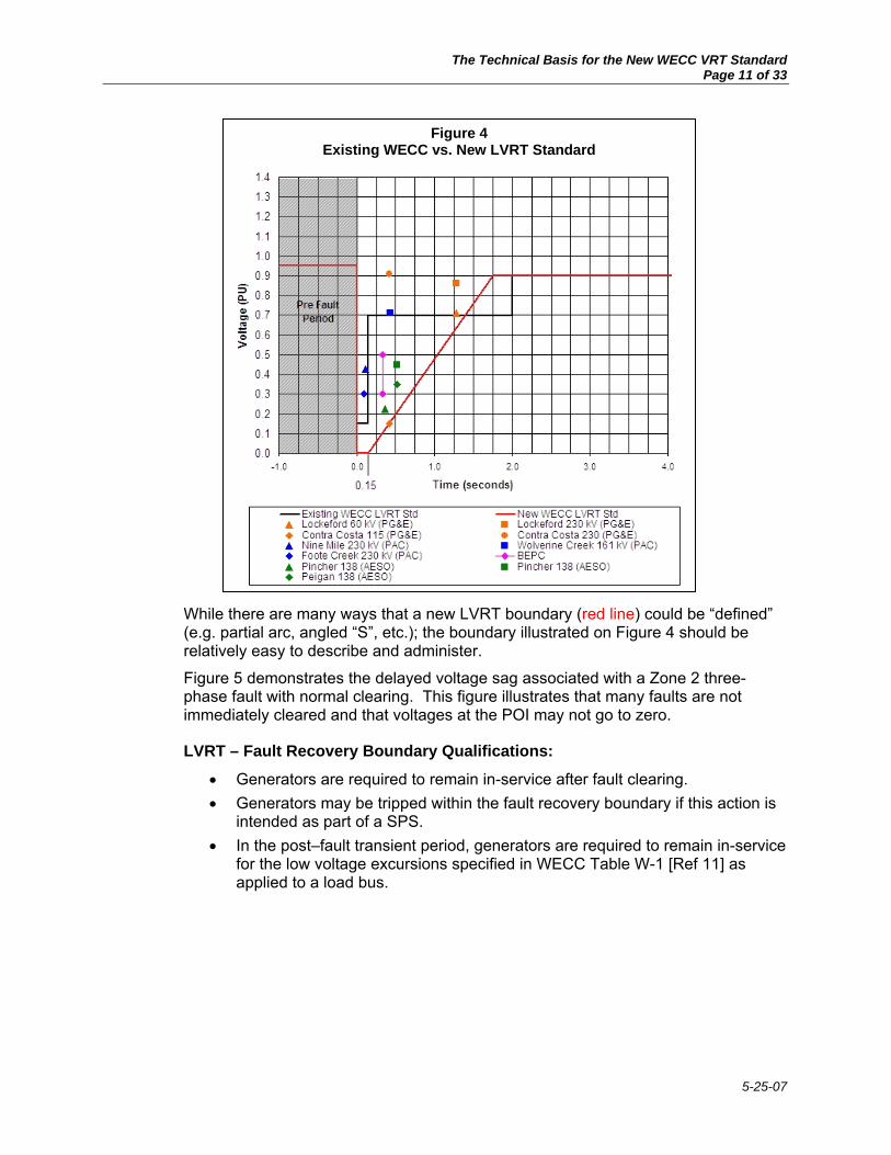
In Figure 4, the new LVRT curve (red line) has been expanded to represent the low voltage ride-through composite boundary for all three voltage boundaries (steady-state normal/emergency, three phase fault clearing period and voltage recovery period) defined earlier in this paper. It is evident from examining Figure 4 that the new low voltage ride-though boundary is a very good fit for the test points provided.
Table 3
Cycles Seconds Voltage77.0 1.2833 0.71 Lockeford 60 kV (PG&E)77.0 1.2833 0.86 Lockeford 230 kV (PG&E)25.0 0.4167 0.15 Contra Costa 115 (PG&E)25.0 0.4167 0.91 Contra Costa 230 (PG&E)7.0 0.1167 0.425 Nine Mile 230 kV (PAC)
25.8 0.4300 0.710 Wolverine Creek 161 kV (PAC) 8/18/2006 Email From Dean Miller5.5 0.0917 0.300 Foote Creek 230 kV (PAC)
20.0 0.3333 0.3 BEPC20.0 0.3333 0.5 BEPC22.2 0.3700 0.225 Pincher 138 (AESO) 2/16/2004 ABB Report for AESO31.2 0.5200 0.45 Pincher 138 (AESO) Table 2-1, Cases 2, 5 & 1431.2 0.5200 0.35 Peigan 138 (AESO)
Data Source
8/24/2006 Email From Matt Stultz
3/26/2006 Email from Chifong Thomas
Zone 2 Three-Phase Faults with Normal ClearingBus
Figure 3 Existing LVRT Standard with Zone 2 Relay Results Added
The Technical Basis for the New WECC VRT Standard Page 11 of 33
5-25-07
While there are many ways that a new LVRT boundary (red line) could be “defined” (e.g. partial arc, angled “S”, etc.); the boundary illustrated on Figure 4 should be relatively easy to describe and administer.
Figure 5 demonstrates the delayed voltage sag associated with a Zone 2 three-phase fault with normal clearing. This figure illustrates that many faults are not immediately cleared and that voltages at the POI may not go to zero.
LVRT – Fault Recovery Boundary Qualifications:
• Generators are required to remain in-service after fault clearing. • Generators may be tripped within the fault recovery boundary if this action is
intended as part of a SPS. • In the post–fault transient period, generators are required to remain in-service
for the low voltage excursions specified in WECC Table W-1 [Ref 11] as applied to a load bus.
Figure 4 Existing WECC vs. New LVRT Standard

The Technical Basis for the New WECC VRT Standard Page 12 of 33
5-25-07
4. HVRT – High Voltage Boundary This section will specifically address the high voltage ride-through boundary that covers the high voltage period, which may occur immediately following the fault clearing period and end when the system returns to 110% (1.10 pu) voltage.
While much emphasis has been placed on wind plants riding-through the low voltage period, which immediately follows a system disturbance, little or no emphasis has been placed on the potential for high voltage excursions that may cause wind plants to trip. These high voltage excursions near wind plants may be magnified due to the high level of shunt capacitors that are installed within the wind plant for power factor correction or voltage control.
Based on the results of detailed dynamic stability studies, electric utility and consulting engineers have identified conditions where wind plants may trip as a result of the high voltage excursion, which may be evident immediately following the fault clearing period. (It is not uncommon to hear planning engineers and consultants say “If the low voltage doesn’t trip the wind plant, the resulting high voltage swing will.”)
For example, PacifiCorp recently performed the following simulation at Jim Bridger Power Plant during the evaluation of a new wind plant in southern Idaho:
• Disturbance: Three-phase (3 cycles) Jim Bridger 345 kV fault with loss of the Jim Bridger-Borah 345 kV line and all associated special protection schemes,
Figure 5 New WECC LVRT Standard vs. Zone 2 Three-Phase Fault
w/Normal Clearing

The Technical Basis for the New WECC VRT Standard Page 13 of 33
5-25-07
including tripping of one Bridger unit (562 MW).
• Results: Loss of the transmission line and subsequent generator tripping resulted in high voltages at Goshen 161 kV (see Figure 6), which caused certain wind turbines to trip (see Figure 7). The wind turbines in this simulation tripped due to local protective relays detecting a high voltage swing that exceeded “standard” wind turbine trip settings. During the high voltage perturbation, Goshen 161 kV bus voltage exceeded 1.1 pu for more than 0.05 seconds (3 cycles).
While high voltage excursions on the transmission system can occur following fault clearing, the sympathetic tripping of generation due to the high voltage excursions have not been seen in technical studies until recent wind generation interconnection studies. This (undesirable) tripping is due to the desire on the part of wind turbine manufacturers to protect the turbine-generator and associated equipment during high voltage events.
Figure 6 High Voltage Excursion at Goshen 161kV – Following the Loss of Bridger – Borah 345
kV line

The Technical Basis for the New WECC VRT Standard Page 14 of 33
5-25-07
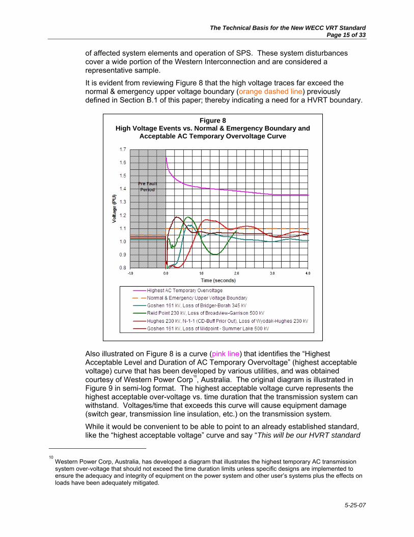
In reviewing the needs for a WECC High Voltage Ride-Through (HVRT) standard, a voltage vs. time plot was developed (see Figure 8) that depicts both the normal & emergency upper voltage boundary (discussed in Section B.1 above) along with high voltage traces for the following system disturbances:
• The Goshen 161 kV bus voltage response, resulting from a Bridger 345 kV three-phase fault and loss of the Bridger – Borah 345 kV line. As part of an SPS for this fault, Bridger Unit 2 was dropped.
• The Reid Point 230 kV bus voltage response, resulting form a Broadview 500 kV three-phase fault and loss of the Broadview – Garrison 500 kV line. As part of an SPS for this fault, Colstrip Unit 3 was dropped.
• The Hughes 230 kV bus voltage response, resulting from the prior outage of the Wyodak – Carr Draw 230 kV line and subsequent Wyodak 230 kV three-phase fault and loss of the Wyodak – Hughes 230 kV line.
• The Goshen 161 kV bus voltage response, resulting from a Midpoint 500 kV three-phase fault and loss of the Midpoint – Summer Lake 500 kV line. As part of an SPS for this fault, Bridger Units 3 and 4 were dropped.
These high voltage traces were provided in response to a data request sent to members of both the WGTF and TSS. Each of the high voltage excursions resulted from separate three-phase faults with normal fault clearing, followed by the removal
Figure 7 Wind Turbine Tripping Due to High Voltages (>1.1 pu) at Goshen 161 kV
The Technical Basis for the New WECC VRT Standard Page 15 of 33
5-25-07
of affected system elements and operation of SPS. These system disturbances cover a wide portion of the Western Interconnection and are considered a representative sample.
It is evident from reviewing Figure 8 that the high voltage traces far exceed the normal & emergency upper voltage boundary (orange dashed line) previously defined in Section B.1 of this paper; thereby indicating a need for a HVRT boundary.
Also illustrated on Figure 8 is a curve (pink line) that identifies the “Highest Acceptable Level and Duration of AC Temporary Overvoltage” (highest acceptable voltage) curve that has been developed by various utilities, and was obtained courtesy of Western Power Corp10, Australia. The original diagram is illustrated in Figure 9 in semi-log format. The highest acceptable voltage curve represents the highest acceptable over-voltage vs. time duration that the transmission system can withstand. Voltages/time that exceeds this curve will cause equipment damage (switch gear, transmission line insulation, etc.) on the transmission system.
While it would be convenient to be able to point to an already established standard, like the “highest acceptable voltage” curve and say “This will be our HVRT standard
10
Western Power Corp, Australia, has developed a diagram that illustrates the highest temporary AC transmission system over-voltage that should not exceed the time duration limits unless specific designs are implemented to ensure the adequacy and integrity of equipment on the power system and other user’s systems plus the effects on loads have been adequately mitigated.
Figure 8 High Voltage Events vs. Normal & Emergency Boundary and
Acceptable AC Temporary Overvoltage Curve

The Technical Basis for the New WECC VRT Standard Page 16 of 33
5-25-07
too...”, it is evident from examining Figure 8 that this curve depicts a much higher standard than WECC should adopt for the HVRT standard. However, from reviewing Figure 8, we now have a feel for the highest acceptable over-voltage vs. time duration that the transmission system can withstand vs. high voltage excursions that may occur on a transmission system, within the Western Interconnection, following a system disturbance.
As WECC is not the first entity that has identified the need to develop a HVRT Standard, the question needs to be asked: What HVRT curves have been established by other National or International utilities? In reviewing the technical paper entitled “Comparison of International Regulations for Connection of Wind Turbines to the Network” [Ref 2], the following characteristics (voltage vs. time) of three different international high voltage fault ride-through standards were summarized:
• In Ireland, the Electricity Supply Board National Grid (ESBNG) has determined 113% voltage as the highest voltage boundary of the HVRT standard.
• In Denmark, the Eltra & Elkraft TSO’s (Eltra&Elkraft) have identified 120% voltage as the voltage boundary of the HVRT standard. After 0.2 seconds, the standard drops to 110% voltage.
• In Scotland, the Scottish Power Transmission & Distribution and Scottish Hydro-Electric (Scottish) have established a 120% voltage as the highest voltage boundary of the HVRT standard. After 800 seconds, the standard drops to 110% voltage.
Each of these standards was developed based on a careful review of transmission system needs vs. the capability of the wind turbines. The specific characteristics of each of these international standards have been plotted on Figure 10. Additionally,
Figure 9

The Technical Basis for the New WECC VRT Standard Page 17 of 33
5-25-07
high voltage traces (previously illustrated on Figure 8) have also been added to Figure 10, for comparison purposes.
In reviewing Figure 10, it is apparent that the high voltage traces exceed the characteristics of the Irish and Danish HVRT Standards, but are just below 1.2 pu, the characteristics of the Scottish HVRT Standard. Therefore, at this stage of the analysis it is assumed that the new WECC HVRT Standard would not exceed the characteristics (120% voltage for 800 seconds) of the Scottish HVRT Standard.
Assuming that WECC adopts an upper voltage limit of 120% (1.20 pu) for the HVRT curve, the question then needs to be asked: What should be the shape of the HVRT curve? The answer to this question has two components:
Figure 10 High Voltage Ride-Through Curves

The Technical Basis for the New WECC VRT Standard Page 18 of 33
5-25-07
• As overvoltage conditions following fault clearing can damage wind turbines and associated equipment, the WGTF believes that the new HVRT standard should remain at the 120% (1.20 pu) for a relatively short period of time.
• In defining the new WECC HVRT Standard, the high voltage boundary will need to circumscribe the high voltage portion of the high voltage traces illustrated in Figure 10. Otherwise, if the high voltage boundary drops below or bisects the high voltage traces, there will be conditions within WECC where system disturbances would result in wind turbine tripping due to high voltage excursions.
Therefore, based on a combination of the Scottish HVRT Standard and the general shape of the high voltage traces characteristic of the Western Interconnection, the HVRT boundary should be shaped (dashed red line) as noted in Figure 10.
Note: Based on subsequent analysis that was performed in Section E (Synchronous Generator Performance vs. New WECC Voltage Ride-Through Standard) of this white paper, a blue line was added to Figure 10 that represents synchronous generator relay settings (Inverse-Time Volts/Hertz Relay Settings with Fixed-Time Unit). As the new VRT Standard will need to be applied to all new generating plants (both synchronous and non-synchronous), the high voltage boundary was adjusted to avoid conflicts with the blue line. Please refer to Section E of this white paper for further details.
While there are a myriad of ways that the HVRT boundary (dashed red line) could have been “defined” (e.g. partial arc, angled “S”, etc.); the boundary illustrated on Figure 10 should be relatively easy to describe and administer.
HVRT Boundary Qualifications:
• Generators are required to remain in-service after fault clearing. • Generators may be tripped within the fault recovery boundary if this action is
intended as part of a SPS.
Potential Impacts of the new WECC HVRT Boundary on Wind Plant Facility Loss-of-Life During the development of this white paper, the WGTF received a comment from a wind turbine manufacturer that indicated a concern with "loss of life" of wind plant facilities during high voltage conditions.
The WGTF does not believe that loss-of-life is an issue because the HVRT boundary described in the white paper will not exceed 1.20 pu, as measured at the high side of the generating plant step-up transformer. This limit was determined based on voltage "swells" that resulted from remote disturbances on the power system. Other system events such as single line-to-ground faults in the utility medium voltage system (most common cause) can also result in voltage swells, but of a lesser voltage magnitude. Additionally, as the remote disturbance will not cause an "impulsive transient" (or voltage spikes) at the POI, loss of life to wind plant facilities due to high voltage should not be an issue.
In support of this response, the following excerpt(s) from Reference [8] are provided:

The Technical Basis for the New WECC VRT Standard Page 19 of 33
5-25-07
“There is no industry (IEEE or IEC) consensus or recommendation for equipment tolerance requirements for short duration overvoltages also called voltage swell or temporary over voltage (TOV), which is the most damaging type of overvoltage. The TOV category includes both Short Duration Variations and Long Duration Variations as noted in the table on the table [#4] below.”
Equipment Tolerance to Over Voltage Events “Rarely does a manufacturer provide any information regarding overvoltage limits of equipment, except in stating the steady-state voltage requirement, typically with a +5% or +10% fluctuation tolerance. This steady-state tolerance is of little use when trying to predict the response of equipment to (for example) a 120% voltage swell, which is quite common.
The figure [#11] to the right shows the results of an over-voltage test conducted by LTE Laboratories of the Canadian utility Hydro Quebec on common residential electrical appliances, such as televisions, video cassette recorders, digital clocks, answering machines and microwave ovens. Key observations from the figure are: For 1-cycle events, most of the appliances were not damaged at voltages less than 250V (208% of 120V). For 10-cycle and 100-cycle events, most equipment was not damaged at voltages less than 200V (166% of 120V).”
Therefore, as indicated by the red line that has been added to Figure 11, in the
Figure 11 Test Results Showing Overvoltage Immunity of
Common Residential Equipment
120% of Nominal
Table 4 Categories and Type Characteristics of Short- and Long-Duration
Overvoltage-Related RMS Voltage Violations as per IEEE-1159

The Technical Basis for the New WECC VRT Standard Page 20 of 33
5-25-07
unlikely event that the 120% (1.20 pu) voltage swell did propagate into the wind plant facilities – it is anticipated that no equipment damage would occur.
WGTF and GE Communications During the time period that the high voltage portion of the white paper was being developed, email communications concerning impacts of high voltages on wind turbines occurred. A copy of one portion of the email communications “thread” is provided in Attachment 6.
It is evident from this communication with General Electric that high voltage events are being addressed by wind turbine manufacturers based in part on requirements developed in Europe.
5. New Voltage Ride-Through Curve With the discussions provided in Sections B.1 through B.4, we have now completed defining the entire voltage boundary of the new Voltage Ride – Through Curve (see Figure 12). The general comments below augment the information provided on the new VRT Curve. To understand how to use the new VRT Curve, an Application Guide is provided in Section C. The Application Guide outlines the rules for applying the new VRT Curve. By combining the new VRT Curve with the Application Guide, the two key elements that are necessary to define the new VRT Standard have been provided.
Figure 12 New WECC Voltage Ride-Through Standard

The Technical Basis for the New WECC VRT Standard Page 21 of 33
5-25-07
New VRT Curve - General Comments: For the completed curve, the following general comments are provided:
• There are many ways that the boundary (red line) for the VRT Standard could have been “defined”; however, the boundary illustrated on Figure 12 should be relatively easy to describe and administer.
• Preliminary versions of the VRT Standard depicted the LVRT and the HVRT portions of the standard starting at different time periods, with time zero being the event initiation time. Based on the findings of recent technical studies, both the LVRT and the HVRT boundaries should begin at the same time, with time zero being the event initiation time.
While the alignment of the two boundaries was puzzling at first to the WGTF, it became evident during the analysis that high voltage excursion will generally occur at a location remote from the fault location and may appear very quickly, due to the actions of high speed SPS, such as generator tripping.
• As discussed in Section D below, the new VRT Curve, which is developed based on WECC system characteristics, appears to be comparable to the boundaries defined by the international standards.
C. New VRT Standard Application Guide During development of the white paper, it became apparent that an Application Guide would be needed to outline how to use and apply the new VRT Curve. While there may be many qualifying statements that could be included within the Application Guide, previous important assumptions and qualifications that were identified within Sections B.1 through B.4 of the white paper have been compiled and are summarized below. Additionally, specific wording from the existing WECC LVRT Standard (noted by blue letters) have been inserted within the Application Guide to aid the transitioning from the existing WECC LVRT Standard to the New VRT Standard.
It is firmly understood by the WGTF that the intent of this white paper was to provide the technical justification for a new VRT Standard for the WECC; however, as this Application Guide combined with the new VRT Curve will provide the two key elements that are necessary to define the new VRT Standard, the wording in the Application Guide below are such that it could be applied directly to the new VRT Standard. It is ultimately up to the VRT Standard Drafting Team to determine which portions of the Application Guide will be included in the new VRT Standard.
Each of the assumptions and qualification identified below (applicable for either synchronous or nonsynchronous generating plants) should be considered when evaluating the performance of new generating plants with the VRT Standard.
• For each of the voltage boundaries defined within the VRT Standard, the following shall apply:
o These standards are applied to the generator (or plant) interconnection point (assumed to be the high-side of the generating plant step-up transformer), not the generator terminals.
o Due to the myriad of transmission configurations that may be connected to the interconnection point and the wide variety of possible generating plant layouts, this Standard can be met by the performance of the generators or by installing additional equipment (e.g., SVC, etc.) within the generating facility.

The Technical Basis for the New WECC VRT Standard Page 22 of 33
5-25-07
o These requirements do not apply to faults that would occur between the generator terminals and the high side of the generator step-up transformer.
o Generators may be tripped after fault initiation if this action is intended as part of a special protection system scheme (SPS).
o Normal communications status will be assumed.
• Within the VRT Standard fault clearing boundary, generators are required to remain in-service during system faults (faults with normal clearing, that extend no more than 9 cycles) unless clearing the fault effectively disconnects the generator from the system.
o The actual clearing time required for a generating plant will be specific to the generating plant location as determined and documented by the transmission provider.
o If the clearing time for Zone 1 three-phase faults is greater than 9 cycles, the generating plant may disconnect from the transmission system.
o If the Zone 1 three-phase fault is cleared within 9 cycles and any generator within the generating facility is sympathetically tripped, either during the fault clearing period, fault recovery periods or high voltage ride-through period, this tripping event should be considered in violation of the VRT Standard.
• Within the VRT Standard fault recovery and high voltage boundaries,
o generators are required to remain in-service after fault clearing.
o In the post–fault transient period, generators are required to remain in-service for the low voltage excursions specified in WECC Table W-1 [Ref 11] as applied to a load bus.
• General Applicability Guide Requirements
o The VRT Standard is intended to supersede the existing WECC Low Voltage Ride-Through Standard; however, it does not supersede existing Regional, National or Industry standards or guides (Off-Nominal Frequency Standard, Planning Standards, ANSI Standards, IEEE Guides, etc.) that have previously been developed to maintain the reliability of the transmission system or outline protection requirements for synchronous generators.
o This Standard does not apply to a site where the sum of the installed capabilities of all machines is less than 10 MVA, unless it can be proven that reliability concerns exist.
o This Standard does not apply to any generation with interconnected voltage levels that are less than 60 kV.
o Existing individual generator units that are interconnected to the network at the time of the adoption of this Standard are exempt from meeting this Standard until they are replaced or repowered.

The Technical Basis for the New WECC VRT Standard Page 23 of 33
5-25-07
D. New WECC VRT Standard vs. International Fault Ride-Through Standards It would have been preferable to compare the new WECC VRT Standard with the voltage trip settings11 of specific wind turbines; however, it became evident during correspondence (both written and verbal) with the American Wind Energy Association (AWEA) in 2006 that such information would be difficult if not impossible to obtain and/or publish as part of this document. For competitive purposes, wind turbine manufacturers have kept voltage trip settings very “close to the vest”; generally sharing them only after a data “nondisclosure agreement” has been executed. Therefore, what will be used for comparison with the new WECC VRT Standard will be recent technical papers (Ref [2] & [5]) that summarize existing international grid codes12 – fault ride-through (FRT) requirements.
Reference [2] was presented at the 2004 Nordic Wind Power Conference and provides a very good reference for all international voltage protection standards. Subsequent to the presentation of the paper, the German E.ON Netz (E.ON) FRT standard was updated in 2005 [Ref 5]. While information on which these reference papers were based may have changed or the proposals might have been modified, overall the references are still considered to be an excellent technical source.
The behavior of wind turbines during and after different disturbances is briefly discussed in Reference [10]. In the past, for areas with insignificant wind power penetration, small wind farms were allowed to disconnect from the system during the fault in order to protect themselves. However, with the advent of large wind farms located on key transmission paths, the immediate disconnection of large wind farms could put additional stress on an already perturbed transmission system.
High short-circuit current, under- and overvoltages during and after the fault can damage wind turbines and associated equipment. The relay protection system of the wind farm is therefore designed to meet two goals:
• Comply with the requirements for normal network operation and support the network during and after the fault;
• Secure the wind farm against damage from the impacts of faults in the network.
In Figure 13, the under- and overvoltage protection requirements for five European countries, including the new German E.ON Netz FRT requirements, are compared13 with the new WECC VRT Standard. In this figure, the new WECC VRT Standard was denoted as a dashed red line for both the LVRT and HVRT portion of the curves.
The most important aspects of the FRT portion of the connection requirements and guidelines for each of the five European countries are summarized in Reference [2] and [5], and include:
11
Such a comparison would have taken into account that the WECC VRT Standard is measured at the wind plant POI and the wind turbine trip settings are measured at the terminals of the wind turbine.
12 The objectives of the International grid codes are to secure efficiency and reliability of power generation and
transmission, to regulate rights and responsibilities of the entities acting in the electricity sector. 13
In performing this comparison, the new WECC VRT Standard was reformatted (semi-log format) and combined with data from Reference [2], Figure 4 (excluding the German E.ON Netz curve) and illustrated on Figure 13. In addition, data from Reference [5], Figure 3, which illustrated the new German E.ON Netz fault ride-through curves, were also added to Figure 13.

The Technical Basis for the New WECC VRT Standard Page 24 of 33
5-25-07
• Eltra’s (Denmark) requirements (low voltage only) apply to wind plants connected to the transmission networks with voltage levels above 100 kV. Additionally, these requirements are very prescriptive and outline required wind plant response to specific faults types, and locations.
• Eltra&Elkraft (Western and Eastern Denmark), these two TSO’s have defined (high & low voltage) requirements for wind plants connected after 1-07-2004 to networks with voltage levels lower than 100 kV. Additionally, these requirements are very prescriptive and outline required wind plant response to specific faults types, clearing times and locations.
Figure 13 New WECC VRT Standard vs. International FRT Standards

The Technical Basis for the New WECC VRT Standard Page 25 of 33
5-25-07
Figure 14 New German E.ON Netz Fault Ride Through – Short Time Interruption (STI) Behavior
• Scottish (Scottish Power Transmission & Distribution and Scottish Hydro-Electric) – guidance note for the connection of wind farms applies to all wind plants with registered capacity ≥ 5 MW, irrespective of the connection voltage level. This (high & low voltage) guidance note is a proposal to changes in the Scottish Grid Code regarding connection of wind farms.
• SvK (Sweden) connection requirements (low voltage only) concern all wind turbines or wind farms with rated power > .3 MW, up to 100 MW and above.
• ESBNG (Electric Supply Board National Grid in Ireland) has an elaborate proposal for connection of wind farms. This proposal is (high & low voltage) mainly a clarification of how the existing grid code should be interpreted for connection of wind farms, although some requirements are specially adapted to make it easier for wind farms to comply with.
• E.ON Netz (Germany) - The first Grid Code for wind turbines was introduced in 2003. However, in 2005 German transmission grid operators, together with wind turbine manufacturers and several research institutes conducted detailed investigations about further development of wind power utilization in Germany and the consequences on system stability, operation and grid extension. The results of this investigation resulted in the development of a new (low voltage only) Grid Code (see Figure 14).
The special focus of the new E.ON Grid Code was directed to the old wind power plants built before 2003 and was not capable of fulfilling Grid Code requirements. The objective was to enable the plants after a minimum retrofitting to withstand voltage dips and thus to avoid tripping following network faults. The main differences between the new and old Grid Code can be summarized as follows:
o Zero voltage for about 150 milliseconds at the grid connection point has to be considered in the future.
o The total duration of the low voltage period referred in the Grid Code is reduced to 1.5 seconds.
o STI (Short Time Interruption) is introduced and always required when the low voltage period is shorter than 1.5 seconds and FRT is not possible without tripping.
o Wind turbines have to ensure that after FRT power generation will continue within the shortest possible time. For this purpose, the required minimum power gradients were defined.

The Technical Basis for the New WECC VRT Standard Page 26 of 33
5-25-07
o Voltage support is required when the terminal voltage exceeds a dead band of
±10% around the current operating point. Additional information concerning the E.ON voltage support requirements can be found in Reference [5].
Ultimately, the new Grid code changed the FRT requirements by taking into account realistic grid behavior and also innovative FRT solutions of modern wind turbines.
Upon careful review of the information provided in References [2] & [5], as well as Figure 13, the following conclusions were reached:
• Of the various FRT standards reviewed, the E.ON standard appeared to be the most elaborate, allowing for STI of wind turbines during portions of the low voltage excursion. While this is an interesting concept, it was evident that STI was adopted to help bring older wind turbines closer to meeting the newer FRT standard. The WGTF’s understanding is that wind turbines with new technology connected to the E.ON system are required to meet the lower FRT curve without STI.
• The E.ON standard also defines voltage control requirements that are applied when the terminal voltage exceeds a dead band of ±10% around the current operating point. The WGTF believes that wind plant steady-state and dynamic voltage control needs to be addressed in a follow-on investigation.
• There have been many independent international evaluations that have resulted in the development of a wide range of fault ride-through curves; however, the new WECC VRT curve appears to fall within the boundaries defined by the international standards, while taking into account WECC system characteristics. Specifically,
o The maximum length of time that the voltage will be as low as zero volts is nine cycles (150 ms) for the WECC and E.ON standards. For the Scottish standard voltage will be as low as zero volts for 8.4 cycles (140 ms) and the SvK (Sweden) standard is as low as zero volts for 15 cycles (250 ms).
o The new WECC LVRT curve appears to approach the same recovery slope as the E.ON standard.
o The HVRT portion of the new WECC VRT standard does not exceed the 120% high voltage band that is prevalent with two other standards. Of these standards, the WECC VRT standard exceeds the high voltage time period of the Eltra&Elkraft (Denmark) standard; however, the WECC VRT standard is well below the Scottish high voltage time period.
The new WECC VRT Standard voltage boundary fits within most of the “foot print” of the international FRT standards, when they are reviewed in their entirety.
E. Synchronous Generator Performance vs. New WECC Voltage Ride-Through Standard To address voltage ride-through performance of synchronous generators the Technical Studies Subcommittee and Reliability Subcommittee sent out a survey to the WECC Member Systems to determine how many synchronous generators have tripped over the past 10 years. A summary of the responses is tabulated in Table 5, and illustrated on Figure 15. As noted in the table, 36 responses were received, covering at least 575 generators, of which ten responses, covering at least 319 generators, provided specific generator tripping (or non-tripping) event data. This data indicated that 15 generator trips had occurred over the period. Of the 15 trips reported, eight of the trips were due to errors.
Although some of the generator trip information did not contain enough information to make

The Technical Basis for the New WECC VRT Standard Page 27 of 33
5-25-07
a complete graphical representation, Figure 15 was been developed utilizing available information from the survey to illustrate where the trip/no-trip data would fit on a voltage vs. time scale. In addition, a note has been added that indicates: “Eight additional generators tripped; however, not enough data was available to identify on the graph.” It is apparent that even though a total of 15 generator trips were reported, this is less than ½ of one percent of all of the generators within WECC.
In the end, the survey demonstrated that as a whole, synchronous generating plants have very few trips. Additionally, of the trips reported, a majority were due to errors.
In addition to compiling data from the survey, an evaluation was made to determine if there were any existing IEEE (or ANSI) standards that covered synchronous generator protection. As part of this review it became apparent that Section 4.5.4.2 (single or dual fixed time
Table 5 WECC Generator Tripping Survey Results
Number of Responses
Number of Responseshaving No Applicable Information
Number of comments that disagree with standard
Number of submittals that reported tripping
Number of submittals that reported no trips
Number of Trips due to an Error in settings or in equipment
36 21 6 15 18 8
Two submittals did not provide any information concerning the trips.
Tripping Ranges
Number that Tripped in each range
Number that did not trip
Number Tripped due to Error
Tripped in ≤5 cycles
Tripped in >5 cycles
0%-15% 3 8 2 3 015%-50% 1 2 1 1 050%-100% 3 5 2 1 3No Info 4 3 2 1 2
Types of Generators
Number that Tripped
Number that did not Trip
Tripped due to Error
Tripped in ≤5 cycles
Tripped in >5 cycles
Hydro 10 6 5 1 4Nuclear 1 2 1 1 0Steam 0 5 0 0 0Gas 0 4 0 0 0CombinedCycle 3 1 2 3 0Wind 1 0 0 0 1
Types of GeneratorsPercent Voltage Hydro Nuclear Steam Gas
CombinedCycle Wind
0%-15% 0 1 0 0 2 0
15%-50% 0 0 0 0 1 0
50%-100% 7 0 0 0 0 0
No Info 3 0 0 0 0 1
Types of GeneratorsPercent Voltage Hydro Nuclear Steam Gas
CombinedCycle Wind
0%-15% 2 2 0 4 0 0
15%-50% 2 0 0 0 0 0
50%-100% 0 0 4 0 1 0
No Info 2 0 1 0 0 1
31 Generators were reported on
Trip
ping
Ran
ges
Surv
ival
Ran
ges
Two Generators were tripped due to other reasons.Reasons were: Loss of Auxiliary Power, and turbine contactors, 34.5 kV string fdr breaker did not trip

The Technical Basis for the New WECC VRT Standard Page 28 of 33
5-25-07
volts/hertz relays) and Section 4.5.4.3 (inverse time volts/hertz relay) of IEEE Standard C37-102 [Ref 10] addresses relay protection that may be provided with (synchronous) generating units.
Per Section 4.5.4.2 (Single or dual fixed time volts/hertz relays):
“Several forms of protection are available and may be provided with the generating unit. One form used is a single V/Hz relay set at 110% of normal which alarms and trips in 6s. A second form of fixed time protection uses two relays to better match the generating unit V/Hz capability.
The first relay is set at 118-120% V/Hz and energizes an alarm and timer set to trip in 2-6 s. The second relay is set at 110% V/Hz and energizes an alarm and timer set to trip just below the permissible generator and/or transformer operating time at the V/Hz setting of the first relay (for example, 10%). This is typically 45-60 s. Refer to figure 4.5.4-1 [see Figure 16] for a dual level V/Hz setting example.
Typical V/Hz relays are single phase devices that are connected to the generator voltage transformer. Since a voltage transformer fuse failure can give an incorrect voltage indication, complete and redundant protection can be provided by connecting one set of relays to voltage transformers which supply the voltage regulator and connecting a second set of relays to a different set of voltage transformers such as those used for metering or relaying functions. Strong consideration should be given to applying two
Figure 15 New VRT Standard vs. Synchronous Generator Performance

The Technical Basis for the New WECC VRT Standard Page 29 of 33
5-25-07
V/Hz relays connected to separate vts on large or critical generators.”
Additionally, per section 4.5.4.3 (Inverse time volts/hertz relay):
“A V/Hz relay with an inverse characteristic can be applied to protect a generator and/or transformer from excessive level of V/Hz. A minimum operating level of V/Hz and time delay can usually be set to provide a close match to the combined generator-transformer V/Hz characteristics. The manufacturers’ V/Hz limitations should be obtained if possible, and used to determine the combined characteristic.
One version of the V/Hz relay has an inverse time characteristic and a separate definite time delay unit. This unit can be connected to trip or alarm and extend the ability of the relay characteristic to match the V/Hz characteristic of a generator-transformer combination. Refer to figure 4.5.4-2 [see Figure 17] for a setting example of a V/Hz relay with an inverse characteristic. When the transformed-rated voltage is equal to the generator-rated voltage, the above schemes supplied with the generator can protect both the generator and the transformer. In many cases, however, the rated transformer voltage is lower than the rated generator voltage and may result in a more limiting V/Hz characteristic. Therefore, both the generator and the transformer V/Hz characteristics should be determined with protection applied for the most restrictive curve.”
The most limiting aspect of each of the relay characteristics illustrated in Figure 16 and 17 have been plotted on Figure 15 as green and blue lines, respectively. It became apparent when comparing these curves with the VRT curve, high voltage boundary, for Revision 4 of this white paper that the “inverse-time V/Hz relay with fixed-time unit” entered the proposed VRT Curve high voltage boundary. Therefore, the new VRT Curve high voltage boundary was reevaluated and adjustments to the proposed boundary were made to Figures 10, 12, 13 and 15. It is evident in reviewing Figure 15 that the new VRT Standard will not conflict with the V/Hz relay curves defined in Sections 4.5.4.2 and 4.5.4.3 of IEEE Standard C37-
Figure 16 Example of Setting for Dual Fixed-Time V/Hz Relays
(From IEEE Std C37-102 [Ref 10], Figure 4.5.4-1)

The Technical Basis for the New WECC VRT Standard Page 30 of 33
5-25-07
102. Therefore, the new VRT Standard is not expected to impose any additional requirements on synchronous generator protection schemes.
F. Comments and Responses: During the review of this white paper, specific comments and questions relating to this document or application of the new VRT Standard were raised. These have been included in Attachment 7 of this white paper.
G. Conclusions: Based on the findings of this white paper, the following conclusions were reached:
1. While the current LVRT Standards (FERC and WECC) have helped bridge the gap between wind generation and transmission needs, the new WECC VRT Standard should address many of the “blind spots” in the standards; thereby bring the utility and wind generation industries closer together.
2. While the new VRT Standard is intended to supersede the existing WECC Low Voltage Ride-Through Standard; it is not intended to supersede existing Regional, National or Industry standards or guides (Off-Nominal Frequency Standard, Planning Standards, ANSI Standards, IEEE Guides, etc.) that have previously been developed to maintain the reliability of the transmission system or outline protection requirements for synchronous generators.
3. The new VRT Standard (see Figure 12) should include the low voltage period following a disturbance, the voltage recovery period, and the high voltage period following a disturbance.
4. An Application Guide has been developed to outline how to use and apply the new VRT Curve. The Application Guide combined with the new VRT Curve will provide
Figure 17 Example of Setting for Inverse-Time V/Hz Rely with Fixed-Time Unit
(From IEEE Std C37-102 [Ref 10], Figure 4.5.4-2)

The Technical Basis for the New WECC VRT Standard Page 31 of 33
5-25-07
the two key elements that are necessary to define the new VRT Standard
5. While there have been many independent international evaluations that resulted in the development of a wide range of fault ride-through curves, the new WECC LVRT Curve appears to be comparable to most of the boundaries defined by the international standards.
6. The E.ON Netz standard [Ref 5] has defined voltage control requirements that are applied when the terminal voltage exceeds a dead band of ±10% around the current operating point. The WGTF believes that wind plant steady-state and dynamic voltage control needs to be addressed in a follow-on investigation.
7. The new VRT Standard is not expected to impose any additional requirements on synchronous generator protection schemes.
8. The new standard should be applied uniformly to both synchronous and induction (including asynchronous) generating plants.
H. Key Items for Consideration by the VRT Standard Drafting Team During the review of the white paper, it became apparent that specific information and recommendations needed to be forwarded to the VRT Standard Drafting Team to make them aware of specific issues that should be addressed during the new standard drafting process. These key items have been listed below:
1. It is evident from reviewing the comments provided under Section B.8.3 of Attachment 7, that 6 months may not be adequate to meet next cycle of wind turbines in the interconnection queue. Based on additional inputs, the VRT Standards Drafting Team should be aware that generally, a lead time of 18 to 24 months is required for orderly design, procurement, testing, and certification in current market conditions, where product for 2009 delivery is now substantially under way, and any changes may be unduly difficult and costly. Some advanced notification concerning a new standard that is imminent may shorten this period.
2. The white paper Application Guide indicates that:
“Existing individual generator units that are interconnected to the network at the time of the adoption of this Standard are exempt from meeting this Standard until they are replaced or repowered.”
It is highly recommended that the VRT Standard Drafting Team work with AWEA members to develop a guideline, similar to the German E.ON Netz STI solution, to transition outdated technologies to be is less susceptible to sympathetic tripping, than is currently implemented. Such a transition of older technologies will help to support a goal of 20% renewable resources in the future.
I. Follow-On Investigations: Additional standards may need to be developed by WECC to assure a seamless integration of wind generation on the Western Interconnection, specifically:
• The E.ON standard [Ref 5] has defined voltage control requirements that are applied when the terminal voltage exceeds a dead band of ±10% around the current operating point. The WGTF believes that wind plant steady-state and dynamic voltage control needs to be addressed in a follow-on investigation.
• In reviewing various International Grid Codes [Ref 2] and E.ON standard [Ref 5], the

The Technical Basis for the New WECC VRT Standard Page 32 of 33
5-25-07
topics noted below were discussed in detail. The WGTF believes that each of these topics are worthy of a follow-on investigation.
o Active Power Control
o Off-Nominal Frequency Range and Control
o Voltage
Reactive Power Compensation and Voltage Quality
o Communication
WGTF 5/25/07

The Technical Basis for the New WECC VRT Standard Page 33 of 33
5-25-07
Reference Documents To assist the reader, a complete list of all technical documents that were referenced within the white paper is provided below. Electronic copies of the first five references have also been included within the appendices for this report.
1. The Need for Voltage Ride-Through Performance Standards for Wind Turbines, February 28, 2003; a white paper developed by Jeff Mechenbier (Public Service Company of New Mexico) and Craig Quist (PacifiCorp). This document has been included as Attachment 1.
2. Comparison of International Regulations for Connection of Wind Turbines to the Network, by Matevosyan, J., Ackermann, T., Bolik, S., Söder, L.; presented at the Nordic Wind Power Conference – 2004. This document has been included as Attachment 2.
3. WECC Low Voltage Ride Through Standard, Approved by WECC Board April 2005. This document has been included as Attachment 3.
4. FERC ORDER No. 661-A, Section A.i: Low Voltage Ride-Through (LVRT) Capability, December 12, 2005. Excerpt from this document have been included as Attachment 4.
5. Advanced Grid Requirements for the Integration of Wind Turbines into the German Transmission System, by Udo Bachmann, Vattenfall European Transmission, Germany; Istwan Erlich, University of Duisburg-Essen, Germany; and Wilhelm Winter, E.ON Netz, Germany. A copy of this document has been included as Attachment 5.
6. Voltage Tolerance Boundary, a technical paper developed by Pacific Gas and Electric (PG&E). (This paper can be found on the internet at the following address: http://www.pge.com/docs/pdfs/biz/power_quality/power_quality_notes/voltage_tolerance.pdf.)
7. ANSI C84 – 2006: American National Standard for Electric Power Systems and Equipment – Voltage Ratings (60 HZ), Approved December 6, 2006
8. Defining Overvoltage Tolerance Requirements, by Dr. Arshad Mansoor, EPRI Solutions – PEAC Test Laboratory, Rev 01-03.12.2005
9. J.G. Slootweg, E. de Varies, Inside wind turbines – Fixed vs. variable speed, Renewable Energy World, Vol. 6, No 1, 2003 [online]. (This paper can be found on the internet at: http://jxj.base10.ws/magsandj/rew/2003_01/inside_wind.html)
10. IEEE Std C37.102-1995: IEEE Guide for AC Generator Protection, by Power System Relay Committee of the IEEE Power Engineering Society, Approved December 12, 1995
11. NERC/WECC Planning Standards, Reliability Criteria, December 2004, Part I, Page 12

5-25-07
ATTACHMENT 1 A LVRT White Paper Developed by Jeff Mechenbier (Public Service Company of New
Mexico) and Craig Quist (PacifiCorp) for the WECC TSS and RS Subcommittees
February 28, 2003 The Need for Voltage Ride-Through Performance Standards for Wind Turbines
IMPORTANT: This white paper is work in progress and is for discussion purposes only.
Introduction The sensitivity of the voltage protection on wind generators creates a distinct risk of sympathetic tripping of entire wind farms due to common electrical faults on the transmission system. This sympathetic tripping is not unique to any particular wind generator manufacturer. The current generation of wind turbines is very sensitive to grid faults for a couple of reasons:
Historically, when wind generation amounted to a small portion of the generation mix, the "safe play" from the perspective of the power system operators was to have wind turbines disconnect during abnormal system conditions. In part this was done to avoid islands of load being connected just to wind generation since wind farms were primarily on the distribution system. Only very recently has wind generation become a large enough portion of the generation mix in some control areas for questions relating to loss of generation to become relevant. At these higher penetration levels the interconnections are made at the transmission level.
Depending on the type of wind turbine technology there are a number of reasons why the wind turbines may trip.
Conventional induction generators - undervoltage relays are set to trip the units to avoid the potential for over-speeding the machine beyond its pull-out torque at which point the machine races away.
Doubly-fed induction generators - the control and protection of converter power electronics that can lead to the tripping of the unit within a cycle on severe under-voltage conditions.
Currently, there are no performance standards (WECC or NERC) in place requiring that a wind farm generator or any generator must stay on line for faults that may cause low voltage at the generator terminals. As the installed capacity of wind farms increases, the potential impact on system reliability of sympathetic tripping will become even more significant. WECC needs to consider developing standards to address this issue.
This white paper attempts to establish the need to adopt a WECC voltage ride-through performance criterion to address the sympathetic tripping of wind generators due to electrical faults on the transmission system. This position is based on several technical considerations as well as operating experience obtained through discussions with other transmission operators. There are technical options to reduce the risk of sympathetic tripping to allow the wind generators to ride-through for faults that cause low voltage at the generator terminals: (a) for conventional induction generators, the installation of fast-acting reactive power
Attachment 1 The Need for Voltage Ride-Through Performance Standards for Wind Turbines
Page 2 of 5
5-25-07
support systems (e.g., SVC or STATCOM) and proper coordination of undervoltage relays and (2) for the doubly-fed induction generator type machines, modifications to control and hardening of the converter.
As a general principle, the interconnection of generators should not introduce adverse operating impacts to the existing transmission system. Sympathetic tripping of wind farms is at odds with this principle because the loss of transmission lines, combined with the simultaneous loss of entire wind farms could result in increased impacts to the transmission system.
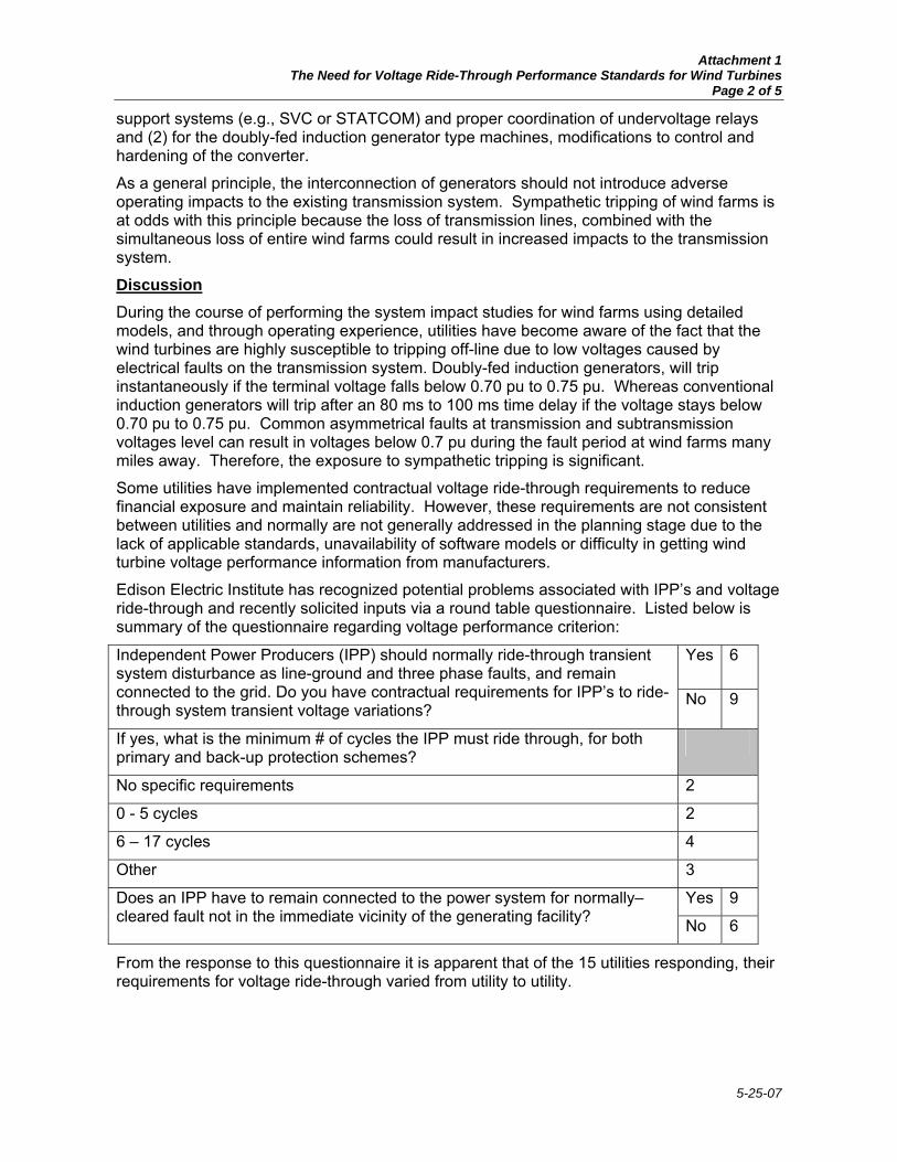
Discussion During the course of performing the system impact studies for wind farms using detailed models, and through operating experience, utilities have become aware of the fact that the wind turbines are highly susceptible to tripping off-line due to low voltages caused by electrical faults on the transmission system. Doubly-fed induction generators, will trip instantaneously if the terminal voltage falls below 0.70 pu to 0.75 pu. Whereas conventional induction generators will trip after an 80 ms to 100 ms time delay if the voltage stays below 0.70 pu to 0.75 pu. Common asymmetrical faults at transmission and subtransmission voltages level can result in voltages below 0.7 pu during the fault period at wind farms many miles away. Therefore, the exposure to sympathetic tripping is significant.
Some utilities have implemented contractual voltage ride-through requirements to reduce financial exposure and maintain reliability. However, these requirements are not consistent between utilities and normally are not generally addressed in the planning stage due to the lack of applicable standards, unavailability of software models or difficulty in getting wind turbine voltage performance information from manufacturers.
Edison Electric Institute has recognized potential problems associated with IPP’s and voltage ride-through and recently solicited inputs via a round table questionnaire. Listed below is summary of the questionnaire regarding voltage performance criterion:
Yes 6 Independent Power Producers (IPP) should normally ride-through transient system disturbance as line-ground and three phase faults, and remain connected to the grid. Do you have contractual requirements for IPP’s to ride-through system transient voltage variations?
No 9
If yes, what is the minimum # of cycles the IPP must ride through, for both primary and back-up protection schemes?
No specific requirements 2
0 - 5 cycles 2
6 – 17 cycles 4
Other 3
Yes 9 Does an IPP have to remain connected to the power system for normally–cleared fault not in the immediate vicinity of the generating facility? No 6
From the response to this questionnaire it is apparent that of the 15 utilities responding, their requirements for voltage ride-through varied from utility to utility.

Attachment 1 The Need for Voltage Ride-Through Performance Standards for Wind Turbines
Page 3 of 5
5-25-07
Voltage ride-through for wind turbines is significant enough that European utilities have started to address this issue. For example, ELTRA of Denmark has defined the following specifications for interconnecting wind farms to the transmission network
1:
In all operational situations the wind farm shall be able to withstand the following fault sequences without being disconnected. The requirements do not apply to faults on a radial connection to the wind farm:
Three-phase fault on a random line or transformer with definitive disconnection without any attempt at reclosing (A typical fault sequence will be occurrence of fault, disconnection of the fault and line/transformer, no automatic reclosing. The fault clearing time will typically be 0.10 seconds, but in some places it may be longer).
Two-phase fault on a random line with unsuccessful reclosing (A typical fault sequence will be occurrence of fault, disconnection of the fault and line, period of deionization, unsuccessful automatic reclosing with definitive disconnection of the fault and the line. The fault clearing time will typically be 0.1 seconds, the period of deionization 0.3 seconds and the fault clearing time at the unsuccessful reclosing 0.1 – 0.5 seconds).
In addition, Germany has also proposed an interconnection performance standard2 that
would require the wind generator to ride through a very low voltage level for 0.15 seconds (See Figure 1). In discussions with wind turbine manufacturers, it is evident that most wind turbines will not be able to meet this voltage performance criterion without significant improvements to the existing technology.
Figure 1
ERCOT is in the process of developing a voltage and reactive requirement that requires generator units to remain connected to the system for the transmission line fault (three-phase, single-phase, or phase-to-phase) on any line connected to the generator’s transmission interconnect bus.
WECC policy states that a control area operator should be able to withstand the loss of the largest generator by having sufficient spinning reserve on-line on its own system or through a 1 Specifications for Connecting Wind Farms to the Transmission Network, ELTRA doc no. 74174, April 26, 2000
2 Netzanschlussregeln der E.ON Netz GmbH (Nord) Stand 01.12.2001, December 2001

Attachment 1 The Need for Voltage Ride-Through Performance Standards for Wind Turbines
Page 4 of 5
5-25-07
reserve sharing pool. One consequence of regularly losing all or part of the generation at a wind farm due to sympathetic tripping from the outage of transmission lines or other generators is the adverse impact on control area performance. A fault that trips a nearby generation unit plus a significant amount of wind generation (via sympathetic tripping) would result in a more severe system imbalance on the control area. This could potentially increase the magnitude of the largest hazard, which has both reliability and financial implications.
If the installed capacity of wind generation increases without adhering to a ride-through criterion, the system would have to deal with the risk of losing all of the on-line wind generation within a single wind farm or multiple wind farms within a large geographic area due to a near-by system fault. The effects of this loss of generation on a system or small control area could be very significant.
Further, the issue of tripping of generators was addressed by FERC in 2001 in Docket #ER00-3435-000, which dealt with Carolina Power & Light’s (CP&L) Open Access Transmission Tariff amendment to incorporate a formalized generator interconnection procedure. In particular, the following language cited by FERC in the CP&L rehearing order
3
clearly supports the notion that a voltage ride-through requirement for generators is consistent with the NERC planning standards. Segments of the FERC’s order are cited below.
CP&L proposed, “… to assess the ability of proposed generating facilities to remain in synchronism (i.e., the generating facilities remain connected to CP&L's transmission system) as a result of various system events (i.e., faults, outages, and voltage transients) through a stability study.”
Dynegy disagreed and “…argues that to the extent the result of the instability is generator specific, the interconnection customer should be able to determine whether it wants to bear the risk of being tripped off line, pay for transient stability related upgrades, or install power stabilizing equipment at its facility to maintain transient stability”. Additionally, Dynegy asserts that the same option should be available with respect to similar "reliability-related" costs identified by the Interconnection Facilities Study…”
“In its answer, CP&L argues that Dynegy’s proposal to trip generators off-line is inconsistent with the North American Electric Reliability Council’s (NERC) planning standards, which requires that a system must be configured so that stability is maintained in the event of specified faults on the system. CP&L also argues that if Dynegy’s proposal were adopted, the loss of a single transmission element could result in a double contingency: the loss of the transmission element and the loss of the generator, which is in violation of NERC standards. Moreover, CP&L asserts that the instability and subsequent tripping of the generator will jeopardize system reliability by placing an immediate additional burden on the system, because the system must adjust to the double contingency while serving the generator’s load until the generator can either arrange for another energy source or curtail the loads of its customers.”
“The Commission finds that CP&L has adequately explained that the generator tripping proposal would be at odds with NERC requirements and would create situations where reliability was impaired even further during stability events.”
The CP&L case squarely addresses the issue at hand by concluding that the loss of a single transmission element and subsequent loss of the generator could jeopardize system
3 See Carolina Power & Light Company, 93 FERC 61,032 (2001), order denying reh'g, 94 FERC 61,165 (2001)

Attachment 1 The Need for Voltage Ride-Through Performance Standards for Wind Turbines
Page 5 of 5
5-25-07
reliability by placing an immediate additional burden on the system, which must adjust to the double contingency while serving the generators’ load until the generator either comes back on-line, arranges for another energy source or curtail the loads of its customers. It would be inconsistent with Good Utility Practice to allow interconnection of a generator on a basis that does not meet NERC reliability standards.
Listed below are responses from two predominate power system consultants concerning voltage ride-through criterion:
Consultant #1:
“As a general view, it is certainly reasonable to design a system on the basis of generators remaining on line after a transmission system fault. To my knowledge all utilities perform planning studies on that basis. Security of the bulk power system would be degraded if this were not the case.”
“If a particular generating facility were susceptible to tripping on transmission faults, then it would be an exception to the normal practice and should be evaluated on a case-by-case basis. In this evaluation, both the near-term and long-term implications should be considered with respect to system security. While the near-term might be somewhat predictable, the long-term might be quite uncertain. It behooves the generating entity to provide as good a ride-through capability as reasonable for the technology. While the facility may initially operate under certain contractual relationships that insulate the owner from impact, in the long run the quality of the generation facility in this regard will affect its financial returns.”
Consultant #2:
“We think there should be criteria for tripping of generators. The criteria should be non-discriminatory to any generators and it is important that they are consistent with existing criteria and practice….”
“The generally accepted practice is that any power system should be able to withstand the loss of the largest generator by having sufficient spinning reserve on line. One consequence of the possibility of losing a generator on sympathetic tripping is that you need to have more spinning reserve than you would otherwise need to have. …In this case the spinning reserve needs to cover the loss of both generators, not just the largest unit. So there is a commercial (economic) implication here.”
“The loss of the energy due to the generator lost on sympathetic tripping is more of a commercial and contractual issue, provided that the loss of such a unit will not cause cascading outages or events in the system. For firm power contracts, I think the seller will have every incentive to minimize the outage time after tripping for commercial reasons if the power purchase contract is set up to deal with that and the power purchase contract should address this issue.”
Conclusion: WECC should consider implementing a voltage ride-through performance criterion for voltage sensitive generation sources, which would address the propensity of wind farms to trip sympathetically due to electrical faults on the transmission system. The proposed ride-through requirement can be comparable to the ride-through performance exhibited by standard synchronous generators.
JM/CQ 2/28/03

5-25-07
ATTACHMENT 2 TECHNICAL PAPER PRESENTED AT THE NORDIC WIND POWER CONFERENCE, 1-2
MARCH, 2004, CHALMERS UNIVERSITY OF TECHNOLOGY
Abstract— Power production from wind turbines has increased considerably during the last decade, therefore today’s wind turbines, which are typically set-up in wind farms, may have a significant influence on power system operation. Efficient and secure operation of power system is supported by grid codes, which is set of requirements to all network users (generators, customers, etc.). In Europe, several transmission network operators have introduced special interconnection requirements for the connection of wind farm. These requirements are mainly based on existing grid codes, initially written for conventional synchronous generators. This paper presents a comparison of interconnection requirements for wind farms outlined by transmission network operators in Denmark, Sweden, Germany, Scotland and Ireland.
Index Terms— wind power production, grid code,
connection requirements.
I. INTRODUCTION HE relationship of transmission system operator (TSO) with all users of the transmission system (generators,
customers, etc.) is set out in grid codes. The objectives of the grid codes are to secure efficiency and reliability of power generation and transmission, to regulate rights and responsibilities of the entities acting in the electricity sector.
In the past there were usually no wind power connected to power system or the percentage of wind power penetration was extremely small compared to total power production, therefore interconnection requirements for wind turbines (WT) or wind farms (WF) were originally not included in the grid codes. As wind power started to develop more actively in the end of 1980’s each network company that was facing the increasing amount of WF developed its own connection rules.
During the 1990s, those interconnection rules where harmonized on a national level, e.g. in Germany or Denmark This harmonization process often involved national network associations as well as national wind energy associations, which represented the interests of wind farm developers and owners.
In the recent years rapid development of wind turbine technology, Fig. 1, and increasing wind power penetration, Table 1, result in continuous reformulation of the connection requirements and creation of requirements for wind power even on transmission level. Some TSO still have unified requirements for all production units, which makes it very difficult for wind turbine producers and wind farm developers to fulfil. Other TSOs have defined special requirements for wind power based on existing requirements for conventional production units.
0
500
1000
1500
2000
2500
3000
3500
1980 1985 1990 1995 2000
First installation year
Cap
acity
(kW
)
0102030405060708090100
Dia
met
er (m
)
Rotor diameterCapacity
Fig. 1. Technology development of Vestas wind turbines.
Comparison of International Regulations for Connection of Wind Turbines to the Network
Julija Matevosyan*, Thomas Ackermann*, Sigrid Bolik** and Lennart Söder*
*Royal Institute of Technology, Dep. of Electrical Engineering, Stockholm 100 44
[email protected] , [email protected], [email protected] ** Vestas Wind Systems A/S, R&D department, E.F. Jacosenvej 7, DK-6950 Ringkøbing [email protected]
T

Attachment 2 Comparison of International Regulations for Connection of Wind Turbines to the Network
Page 2 of 8
5-25-07
TABLE 1 INCREASE OF WIND POWER PENETRATION IN SOME COUNTRIES
Country 1995 1999 2001 2002 2003 (June) Germany 1136 4445 8734 12001 12836 Spain 145 1530 3550 4830 5060 Denmark 619 1742 2456 2881 2916 Netherlands 236 410 523 678 803 Italy 25 211 700 788 800 UK 200 356 525 552 586 Sweden 67 220 318 328 364
Unfortunately, the continuously changing network
rules as well as the liberalization of the power marked make a comparison or evaluation of the already very complex interconnection rules very difficult and only a small amount of literature exists, see [1], [2]. A comparison of the existing interconnection rules can help:
• To solve or reduce controversies between wind farm developer and network operator regarding interconnection rules, see for instance [3], [4];
• Wind turbine producer to gain a better understanding about the existing rules, which may help to develop new hardware and control strategies.
• To provide an understanding of the relevant issues for those countries, regions or utilities that are still in the process of developing interconnection rules for wind farms. This might also help to harmonization of interconnection rules world-wide;
• To understand the difference between the national rules, which might lead to a European or even wider harmonization of interconnection rules;
In this section the most important aspects of connection requirements of TSOs in Denmark (Eltra) and (Eltra&Elkraft), E.on Netz one of five German TSO’s (E.ON), Electricity Supply Board National Grid in Ireland (ESBNG), TSO in Sweden (SvK) and guidance note of Scottish Power Transmission & Distribution and Scottish Hydro-Electric (Scottish) for WF are discussed and compared. These documents generally contain minimum requirements by TSO to the WF owner (or generally power producer) to ensure the properties essential for power system operation regarding security of supply, reliability and power quality.
Eltra's requirements apply to WF connected to transmission networks with voltage levels above 100 kV [5].
Eltra&Elkraft requirements are elaborated by the two Danish TSOs Eltra (Western Denmark) and Elkraft System (Eastern Denmark). The requirements concern wind farms connected after 1.07.2004 to networks with
voltage levels lower than 100 kV [6]. Scottish guidance note apply to all WF with
registered capacity ≥ 5 MW, i.e. apply irrespective of the connection voltage level [7]. This guidance is a proposal to changes in Scottish grid code regarding connection of wind farms.
Similarly, connection requirements from SvK concern all wind turbines or wind farms with rated power >0.3 MW, up to 100 MW and above [8]. It should be pointed out that [8] states requirements to all production sources although with regards to some aspects, e.g. frequency control, special requirements are stated for wind power.
E.ON's requirements for connection of wind power are also a part of the grid code, similarly to SvK, some special requirements are stated for wind power. E.ON requirements are changing continuously in this paper [9] is used for comparison. It applies to WF connected to high voltage networks (60, 110 kV) and extra high voltage networks (220 kV, 380 kV).
Finally, ESBNG has elaborated a proposal for requirements to connection of wind farms [10]. This is mainly a clarification of how the existing grid code [11] should be interpreted for connection of WF, although some requirements are specially adapted to make it easier for WF to comply with.
II. COMPARISON OF CONNECTION REQUIREMENTS
A. Active Power Control The exchange of power in the grid has to be in balance. Changes in power supply or demand can lead to a temporary unbalance of the system and thereby affect operating conditions of power plants as well as consumers. To avoid long-term unbalanced conditions the power demand is predicted and power plants are adjusting their power production. The requirements to active power control are thus stated in order to ensure stable frequency in the system, prevent overloading of transmission lines, insure that power quality standards are fulfilled, avoid large voltage steps and inrush currents at start-up and shut down of WT.
Eltra’s and Eltra&Elkrat requirements to active power control state that 1minute average of production should be less or equal + 5% of maximum power of the WF, where production limit is a certain MW-value deduced from local values of e.g. frequency and/or voltage. E.ON and ESBNG require WF production be less than registered capacity at any time. Scottish guidance note states that registered capacity should not be exceeded over an appropriate averaging period.
In addition, Eltra and SvK require the technical possibility of a reduction to < 20% of maximum power

Attachment 2 Comparison of International Regulations for Connection of Wind Turbines to the Network
Page 3 of 8
5-25-07
in 2 sec (Eltra) or 5 sec (SvK) by individual control of each WT, when demanded. According to Eltra&Elkraft the rate of change of active power should be adjustable within a range of 10%-100% of registered capacity per minute. E.ON requires active power reduction of minimum 10% of registered capacity per minute.
ESBNG requires that in any 15-minute period active power output change is limited as follows: 5% of registered capacity per minute for WF < 100 MW, 4% per min for WF < 200 MW and 2% per minute for WF > 200 MW. In the Scottish guidance note maximum
power change is defined as 4 times registered capacity of WF per hour, for WF under 15 MW the limit is 60 MW per hour, while for MW above 150 MW the limit is 600 MW per hour. This is the average change of power output measured over any 10 minute period. However, the rate of change averaged over 1 minute should not exceed 3 times rate of change over 10 minute. In some regulations there are also requirements regarding start-up and shut down of WF. Eltra requires WF to have a signal clarifying the cause of former WF shut down that should be a part of logic managing start
up of WT for operation. Scottish, Eltra and E.ON requirements state that WF operation at start up and shut down should comply with voltage quality requirements. Additionally, Scottish guidance note require WF to comply with maximum power change rate described above. SvK states that high wind speed must not cause simultaneous stop of all wind turbines within WF, maximum permissible power reduction is 30 MW/min. Similarly, Scottish guidance note says no more than 25% of registered capacity may be tripped, phased reduction of output should be achieved over 30 minute
period. Fig. 2. Requirements to frequency range and frequency control
B. Frequency Range and Control
Frequency in the power system is an indicator of the balance between production and consumption. For the normal power system operation the frequency should be stable and close to its nominal value. In Europe the frequency is usually between 50±0.1Hz and falls out of 49-50.3 Hz range very seldom.
To keep the balance between production and
Eltr
not mentioned
53
52.5
52
51.5
51
50.5
50
49.5
49
48.5
48
47.5
47
disconnection after 0.3 s
10 s
5 min
25 min
94%
95%
96
98%
continuous
100,6%
106%
1 min
disconnection after 0.3 s
not mentioned
95%
>30 min
< 5% power reduc.
volt. 95-105%
continuous volt. 90-105%
99,4
volt. 85-90% or 105-110% <10% power reduction, >1 hour
volt. 90-105% continuous
102
not mentioned
>30 min
reduced power
volt. 95-105%
110%
SvK(>20
disconnectionwithin max
1s
20
continuous
100,8%
104%
Power reduction 2% per 0.1 Hz
disconnection
within max 1s
Scotland ESB
not mentioned
95%
>30 min
< 5% power reduc.
volt. 90-105%
continuousvolt. 90-105%
110%
>30 min
reduced power
volt. 90-105%
102%
98%
SvK(<20
not mentioned
101%
continuous
not mentioned
E.ON
94%
20 s
99%
60 min
104%
60 min
95% 95%
fast automatic disconnection
99%
Time limited power reduction 1% per 0.1 Hz
10 min
20 min
30 min
101%
continuous
Power reduction4% per 0.1 Hz
fast automatic disonnection
94%
95%
Eltra&Elkr
disconnection after 0.2 s
>25 min
95%
96%
continuous
106%
> 1 min
disconnection after 0.2 s
99.4%
100.6%
10 s
5 min 96%
volt 106-110%, 1h volt 85-90%, 1h

Attachment 2 Comparison of International Regulations for Connection of Wind Turbines to the Network
Page 4 of 8
5-25-07
consumption primary and secondary control is used. The primary control units increase/decrease their generation until the balance between production and consumption is restored and frequency has stabilized, although it is lower than nominal and primary control reserves are partly used. The time span for this control is 1-30 seconds. In order to restore the frequency to its nominal value and release used primary reserves the secondary control is employed with time span 10-15 min. The secondary control thus results in slower increase/decrease of generation. In some countries automatic generation control is used in other countries the secondary control is accomplished manually by request from the system operator.
At normal operation the power output of a WF can vary 10-15 % of installed capacity within 15 minutes; this could lead to additional imbalances between production and consumption in the system. Considerably larger variations of power production may occur at and after extreme wind conditions.
The requirements to frequency operation range come from the experience with conventional synchronous generators that have stability problems due to frequency changes. The induction machines have no such problems and therefore frequency operation range is more an issue of a control strategy [2].
ESBNG requires WF to include primary frequency control possibility of 3-5% (as required for thermal power plants) into control of WF power output. ESBNG and some other regulations also require WF to be able to participate in secondary frequency control. This can be achieved at overfrequencies by shutting down of some WTs within WF or by pitch control. Since wind cannot be controlled, power production at normal frequency would be intentionally kept lower than possible, so that the WF is able to provide secondary control at underfrequencies. Fig. 2 illustrates the requirements to frequency change tolerance and frequency control in the considered countries.
C. Voltage
1) Reactive Power Compensation Utility and customers equipment is designed to
operate at certain voltage rating. Voltage regulators and control of reactive power at the generators and consumers connection point are used in order to keep the voltage within the required limits and avoid voltage stability problems. WTs should also contribute to voltage regulation in the system; the requirements either concern a certain voltage range that should be maintained at the point of connection of WT or WF, or certain reactive power compensation that should be provided.
Requirements regarding reactive power compensation is defined in terms of power factor range and shown for the considered countries in Fig. 3. In most regulations a power factor is defined either only at registered capacity or for the whole production range. ESBNG also, states the requirements for the registered capacity, however, same reactive power output (MVAr) is required from the WF bellow the registered capacity as well.
E.ON regulation additionally requires that the stages for reactive power compensation are ≤ 0.5% of the registered capacity. Smaller steps than 25 kVAr are not required. The purpose of this regulation is to avoid high in-rush currents due to switching transient and comply with permissible voltage steps.
In the Swedish regulations (SvK) the demand for reactive power compensation is expressed in terms of permissible voltage range. According to this regulations large (> 100 MW) and medium size (20-50 MW) wind farms should be able to maintain automatic regulation of reactive power with voltage as reference value. Reference value should be adjustable within at least ±10% of nominal operating voltage.
2) Voltage quality
Voltage quality assessment of the WF is based on the following concepts:
• Rapid voltage changes: single rapid (f=0.03-0.3 Hz) change of voltage RMS value, where voltage change is of certain duration (e.g. occur at switching in the wind farm)
• Voltage flicker: low frequency (up to approx. 17 Hz ) voltage disturbances
• Harmonics: periodic voltage or current disturbances with frequencies n⋅50 Hz, where n is an integer.
Voltage variations and harmonics can damage or shorten the lifetime of the utility and customer equipment. Voltage flicker causes visible variations of light intensity in bulb lamps. Mainly the compared documents refer to existing voltage quality standards, although some special rules are stated for wind power. Scottish guidance note, Eltra and Eltra&Elkraft (50-60 kV) requirements state that rapid voltage changes should be generally less than 3% of nominal voltage at the WF connection point. Eltra also puts additional requirements on rapid voltage changes depending on frequency of change (until a frequency of 10 times per hour < 2.5%, until a frequency 100 times per hour < 1.5%). Eltra and Eltra&Elkraft regulations also define special requirements for long term and short-term flicker and harmonic distortion [5].
3) Tap changers The tap-changing transformers are used to maintain

Attachment 2 Comparison of International Regulations for Connection of Wind Turbines to the Network
Page 5 of 8
5-25-07
predetermined voltage levels. In E.ON regulations it is recommended to equip the
WF with a tap changing grid transformer so the transformer ratio can be varied and the voltage at the point of connection to the network can be controlled.
Similarly, Scottish guidance note states that wind farms with capacity of 100 MW and above shall have manual control tap changing transformers to allow the grid control to dispatch the desired reactive power output. Wind farms between 5 MW and 100 MW may use this method if they have their own transformer, or may use other methods of controlling reactive power agreed with Scottish Power at the application stage.
ESBN requires that each transformer that connects a WF to the network shall have on-load tap changer. The tap step should not alter the voltage ratio at the HV terminals by more than
• 2.5% on the 110 kV system • 1.6% on the 220 kV to 400 kV systems
D. Protection Behaviour of the wind turbines during and after
different disturbances is briefly discussed e.g. in [12]. With insignificant wind power penetration, small WF can be allowed to disconnect during the fault in order to protect itself. However this does not apply to large WFs. If the fault occurs in the network the immediate disconnection of large WFs would put additional stress on already perturbed system.
After large disturbances it may happen that several transmission lines are disconnected and parts of the network may be isolated (or islanded); imbalance between production and consumption may occur in this part of the network. As a rule wind farms are not required to disconnect, in this case as long as the certain voltage and frequency limits are not exceeded. Eltra's regulations additionally require WF to take part in frequency control (secondary control) in island conditions. E.ON does not require island capabilities for wind farms.
High short-circuit currents, under- and overvoltages during and after the fault can also damage WTs and associated equipment. The relay protection system of the WF should therefore be designed to pursue two goals: • Comply with requirements for normal network
operation and support the network during and after the fault;
• Secure WF against damage from the impacts occurring at faults in the network
In Fig. 4 the requirements regarding under- and overvoltage protection and requirements for islanding are compared. Although WF protection regarding e.g.
over- and underfrequency, over- and undervoltage etc., is not treated separately in some regulations it is entailed that WF protection system comply with the requirements discussed in the preceding subsections.
Eltra and Eltra&Elkraft regulations also state special requirements to fault tolerance. Eltra requires WF to stay connected to the system at 3-phase faults on a random line or transformer with definitive disconnection without any attempt at re-closing; 2-phase fault on a random line or transformer with unsuccessful re-closing. Eltra&Elkraft requires WFs to stay connected to the system during a 3-phase fault in the transmission network for 100 ms; 2-phase faults and 2-phase to ground faults for 100 ms followed by another fault in 300-500 ms with duration of 100 ms. WT should have enough capacity to fulfill this requirements at minimum two 2- or 3-phase short circuits in 2 minutes; minimum six 2-or 3-phase short circuits with 5 minutes interval in between.
-10%
10%
30%
50%
70%
90%
110%
130%
0,01 0,1 1 10 100 1000Time (s)
Volta
ge (%
)
Svk > 100 MW EltraSvk < 100 MW E.ON Scotish Eltra&Elkraft ESBNG
Fig. 4. Requirements to under- and overvoltage tolerance.
E. Modeling and Verification Interaction between a power plant and the power
system during faults is usually verified by means of simulations. To make such simulations possible, WF owners are required to provide system operator with necessary models. To verify WF models and WF's response to faults in power system registration equipment shall also be installed.
Scottish guidance note and Eltra regulations state that models for WFs should be well documented and agree with the tests on corresponding WT prototypes. Eltra additionally requires models for each individual WT type in case if WF consists of several WT types.

Attachment 2 Comparison of International Regulations for Connection of Wind Turbines to the Network
Page 6 of 8
5-25-07
Scottish and Eltra regulations demand installation of fault recorder for verification. The recorded variables required by Eltra are: voltage, active/reactive power, frequency and current at a WF connection point; voltage active/reactive power, rotating speed for a single WT of each type within a WF. The recorded variables required in Scottish guidance note are: 3-phase currents, 3-phase voltages and wind speed. SvK requires detailed documentation of WF’s technical data.
Due to the fact that ESBNG mainly applies the same requirements to WF as to conventional power plants modeling issues are not treated yet. Eltra&Elkraft and E.ON regulations also do not treat WF modelling issue, although it could be expected in the future versions of the regulations.
F. Communication Unlike the other aspects of regulations discussed
above, requirements to the communication are quite similar in all considered documents. All regulations require voltage, active power, reactive power and operating status signals available from a WF. Scottish, Eltra, and ESBNG require also wind speed signal be available. Additionally, Scottish guidance note demand real-time wind direction, frequency control status (enabled/disabled), abnormalities resulting in WF tripping/start-up within 15 minutes. Similarly to Scottish guidance note, ESBNG requires wind direction, but also real-time temperature and pressure. Svk demands from WFs information about regulation capabilities. ESBNG and E.ON require WF transformer tap position.
Besides external signals from WFs the requirements to external control possibilities are also stated in some regulations. Some of these requirements were already mentioned in preceding subsections. SvK, Eltra, Eltra&Elkraft also state additional requirements to control possibilities. Svk states that WF > 20MW manual local or remote control within 15 min after the fault should be provided to make possible: disconnection from the network, connection to the network and regulation of active and reactive power output. Eltra and Eltra&Elkraft require possibility to connect/disconnect WT externally.
G. Application at Horns Rev In the following example, the control system for the newly installed Horns Rev offshore wind farm is briefly presented. The wind farm is the first wind farm that had to fulfil the requirements outlined by Eltra [5], the TSO in Western Denmark. The control system is currently being implemented therefore, practical experiences do not yet exist. The following information is based on [13].
The offshore wind farm Horns Rev is located approximately 15 km into the North Sea. The installed power is 160 MW divided onto 80 wind turbines laid out in a square pattern. The turbines are arranged in 10 columns with 8 turbines in each. Two columns make a cluster of 32 MW where the turbines are connected in series. Each cluster is connected to the offshore transformer substation where the 34-165 kV transformer is located. From an electrical point of view, new specifications and requirements for connecting large-scale wind farms to the transmission network had to be met in the project. As mentioned before, the TSO (Eltra) has formulated requirements for power control, frequency, voltage, protection, communication, verification, and tests. According to those requirements the wind farm must be able to participate in the control tasks on the same level as conventional power plants, constrained only by the limitations imposed at any time by the existing wind conditions. For example, during periods with reduced transmission capacity in the grid (e.g. due to service or replacement of components in the main grid) the wind farm might be required to operate at reduced power levels with all turbines running. Another aspect is that the WF must be able to participate in the regional balance control (secondary control). The general control principal of the WF has to consider that the control range of the WF depends on the actual wind speed. Furthermore, as the wind speed cannot be controlled, the power output of the WF can only be downregulated. For instance, if the wind speed is around 11 m/s, the power output from the WF can be regulated to any value between 0 MW and approximatly 125 MW. In the following some of the key elements of the overall control strategy are presented:
• Absolute Power Constraint control approach limits the total power output of the wind farm to a predefined setpoint.
• Balance Control approach allows to reduce the power production of the overall wind farm at a predefined rate and later to increase the overall power output , also at a predefined ramp rate.
• Power Rate Limitation control approach. This approach limits the increase in power production to a predefined setpoint, e.g. maximum increase in power production 2 MW per minute. It is important to emphasize that this approach does not limit the speed of power reduction, as the decrease in wind cannot be controlled. In some cases, however, this can be achieved when combined with the delta control approach.
• Delta Control reduces the amount of total power production of the wind farm by a predefined setpoint, e.g. 50 MW. Hence, if delta control is now combined with a balance control approach, the

Attachment 2 Comparison of International Regulations for Connection of Wind Turbines to the Network
Page 7 of 8
5-25-07
production of the WF can be briefly increased and decreased according to the power system requirements. A WF equipped with such a control approach can be used to supply automatic secondary control for a power system.
Absolute Power Constraint Balance Control
Power Rate Limitation Delta Control
time time time time
Power Power Power Power Possible production
Actual production
Fig. 4. Horns Rev control functions. Source [13] • Finally, Eltra also requires that a WF must be able
to participate in the frequency control. This is achieved by combining Delta Control with a frequency controller implemented directly in each individual turbine in the wind farm
H. Conclusions This paper presents a comparison of the existing
regulations for the interconnection of WFs with the power system. Most of the analysed documents are still under revision and will probably undergo some changes in future.
The comparison reveals that the regulations differ significantly between the countries. This depends on the properties of each power system, as well as experience, knowledge and policies of TSOs.
The requirements are based on existing grid codes written for conventional synchronous generators and most requirements are therefore well defined only for rated operation of WF (i.e. only some hours per year). It is necessary to define the requirements for the whole operating range of WF. To make it easier for WF manufacturers to comply with the interconnection regulations a more harmonised approach would be useful.
REFERENCES
[1] “Impact of Increasing Contribution of Dispersed Generation on the Power System”, CIGRE Study Committee No. 37, (WG 37-23), Final Report, Paris, September 1998.
[2] S. Bolik, “Grid requirements challenges for wind turbines”, Proceedings Fourth International Workshop on Large-Scale Integration of Wind Power and Transmission Networks for Offshore Wind Farms, Billund, Denmark, October 2003.
[3] W. Jörß, B. H. Joergensen, P. Löffler, P. E. Morthorst, M. Uyterlinde, E. V. Sambeek, T. Wehnert, ”Decentralised Power Generation in the Liberalised EU Power Energy Markets”, Results from DECENT Research Project, Springer, Heidelberg, Germany.
[4] W. Jörß, Project Coordinator, “DECENT – Decentralised Generation Technologies, Potentials, Success Factors and Impacts in the Liberalised EU Energy Markets”, Summary Report May 2002, compiled by Institute for Future Studies and Technology Assessment, Berlin, Germany.
[5] Specifications for Connecting Wind Farms to the Transmission Networks, Second Edition. Eltra, Fredericia, Denmark, 2002
[6] Vindmøller tilsluttet net med spændinger under100 kV. Teknisk forskrift for vindmøllers egenskaber og regulering, 15 Draft Version, DEFU, Lyngby, Denmark, 17 June 2003 [Online]. Available: http://www.eltr.dk.
[7] Guidance Note for the connection of wind farms, Scottish Hydro Electric Issue No. 2.1.4, December 2002.
[8] Affärsverket svenska kraftnäts föreskrifter om driftsäkerhetsteknisk utformning av produktionsanläggningar, Svenska Kraftnät, Stockholm, Sweden, 2004
[9] Netzanschlussregeln, Hoch- und Höchstspannung (English version: Grid Code, High and extra high voltage), E.on Netz GmbH, Bayreuth, Germany, August 2003 [Online]. Available: http://www.eon-netz.com/
[10] Grid Code, Draft Version 1.0, ESB National Grid, Ireland, February 2002.
[11] Wind farm connection requirements. ESB National Grid (2002). Draft Version 1.0, February 2002, Ireland
[12] J.G. Slootweg, E. de Varies, “Inside wind turbines - Fixed vs. variable speed”, Renewable energy world, Vol.6, No 1., 2003 [Online]. Available: http://www.jxj.com/magsandj/rew
[13] P. Christiansen, Jesper R. Kristoffersen, “The Wind Farm Main Controller and the Remote Control System of the Horns Rev Offshore Wind Farm”, in: Proceedings Fourth International Workshop on Large-Scale Integration of Wind Power and Transmission Networks for Offshore Wind Farms, October 2003, edited by J. Matevosyan and T. Ackermann, Royal Institute of Technology, Stockholm, Sweden.

5-25-07
ATTACHMENT 3 WECC LVRT Standard (Approved by the WECC Board, April 2005)
WECC Low Voltage Ride Through Standard
This Standard is being developed to address reliability concerns associated with un-planned generation tripping resulting from low voltage excursions following disturbances.
Standard
1. Generators are required to remain in-service during system faults (three phase faults with normal clearing and single line to ground faults with delayed clearing) unless clearing the fault effectively disconnects the generator from the system. This requirement does not apply to faults that would occur between the generator terminals and the high side of the generator step-up transformer or to faults that would result in a voltage lower than 0.15 per unit on the high side of the generator step-up transformer.
2. In the post–fault transient period, generators are required to remain in-service for the low voltage excursions specified in WECC Table W-1 as applied to a load bus. These performance criteria are applied to the generator interconnection point, not the generator terminals.
3. Generators may be tripped after the fault period if this action is intended as part of a special protection system
4. This Standard does not apply to a site where the sum of the installed capabilities of all machines is less than 10MVA, unless it can be proven that reliability concerns exist.
5. This Standard applies to any generation independent of the interconnected voltage level.
6. This Standard can be met by the performance of the generators or by installing additional equipment (e.g., SVC, etc.).
7. Existing individual generator units that are interconnected to the network at the time of the adoption of this Standard are exempt from meeting this Standard for the remaining life of the existing generation equipment. Existing individual generator units that are replaced are required to meet this Standard.

5-25-07
ATTACHMENT 4 Excerpt from FERC ORDER No. 661-A, Section A.1.: Low Voltage Ride-Though (LVRT)
Capability
113 FERC ¶ 61,254 UNITED STATES OF AMERICA
FEDERAL ENERGY REGULATORY COMMISSION 18 CFR Part 35
(Docket No. RM05-4-001; Order No. 661-A) Interconnection for Wind Energy
(Issued December 12, 2005) ~~~~~~~~~~~ APPENDIX G
INTERCONNECTION REQUIREMENTS FOR A WIND GENERATING PLANT
Appendix G sets forth requirements and provisions specific to a wind generating
plant. All other requirements of this LGIA continue to apply to wind generating plant
interconnections.
A. Technical Standards Applicable to a Wind Generating Plant
i. Low Voltage Ride-Through (LVRT) Capability
A wind generating plant shall be able to remain online during voltage disturbances up
to the time periods and associated voltage levels set forth in the standard below. The LVRT
standard provides for a transition period standard and a post-transition period standard.
Transition Period LVRT Standard
The transition period standard applies to wind generating plants subject to FERC
Order 661 that have either: (i) interconnection agreements signed and filed with the
Commission, filed with the Commission in unexecuted form, or filed with the Commission as
non-conforming agreements between January 1, 2006 and December 31, 2006, with a
scheduled in-service date no later than December 31, 2007, or (ii) wind generating turbines

Attachment 4 Excerpt from FERC ORDER No. 661-A, Section A.1.: Low Voltage Ride-Though (LVRT) Capability
Page 2 of 4
5-25-07
subject to a wind turbine procurement contract executed prior to December 31, 2005, for
delivery through 2007.
1. Wind generating plants are required to remain in-service during three-phase faults
with normal clearing (which is a time period of approximately 4 – 9 cycles) and single
line to ground faults with delayed clearing, and subsequent post-fault voltage
recovery to prefault voltage unless clearing the fault effectively disconnects the
generator from the system. The clearing time requirement for a three-phase fault will
be specific to the wind generating plant substation location, as determined by and
documented by the transmission provider. The maximum clearing time the wind
generating plant shall be required to withstand for a three-phase fault shall be 9
cycles at a voltage as low as 0.15 pu, as measured at the high side of the wind
generating plant step-up transformer (i.e. the transformer that steps the voltage up to
the transmission interconnection voltage or “GSU”), after which, if the fault remains
following the location-specific normal clearing time for three-phase faults, the wind
generating plant may disconnect from the transmission system.
2. This requirement does not apply to faults that would occur between the wind
generator terminals and the high side of the GSU or to faults that would result in a
voltage lower than 0.15 per unit on the high side of the GSU serving the facility.
3. Wind generating plants may be tripped after the fault period if this action is intended
as part of a special protection system.
4. Wind generating plants may meet the LVRT requirements of this standard by the
performance of the generators or by installing additional equipment (e.g., Static VAr
Compensator, etc.) within the wind generating plant or by a combination of generator
performance and additional equipment.

Attachment 4 Excerpt from FERC ORDER No. 661-A, Section A.1.: Low Voltage Ride-Though (LVRT) Capability
Page 3 of 4
5-25-07
5. Existing individual generator units that are, or have been, interconnected to the
network at the same location at the effective date of the Appendix G LVRT
6. Standard are exempt from meeting the Appendix G LVRT Standard for the remaining
life of the existing generation equipment. Existing individual generator units that are
replaced are required to meet the Appendix G LVRT Standard.
Post-transition Period LVRT Standard
All wind generating plants subject to FERC Order No. 661 and not covered by the transition
period described above must meet the following requirements:
1. Wind generating plants are required to remain in-service during three-phase faults
with normal clearing (which is a time period of approximately 4 – 9 cycles) and single
line to ground faults with delayed clearing, and subsequent post-fault voltage
recovery to prefault voltage unless clearing the fault effectively disconnects the
generator from the system. The clearing time requirement for a three-phase fault will
be specific to the wind generating plant substation location, as determined by and
documented by the transmission provider. The maximum clearing time the wind
generating plant shall be required to withstand for a three-phase fault shall be 9
cycles after which, if the fault remains following the location-specific normal clearing
time for three-phase faults, the wind generating plant may disconnect from the
transmission system. A wind generating plant shall remain interconnected during
such a fault on the transmission system for a voltage level as low as zero volts, as
measured at the high voltage side of the wind GSU.
2. This requirement does not apply to faults that would occur between the wind
generator terminals and the high side of the GSU.

Attachment 4 Excerpt from FERC ORDER No. 661-A, Section A.1.: Low Voltage Ride-Though (LVRT) Capability
Page 4 of 4
5-25-07
3. Wind generating plants may be tripped after the fault period if this action is intended
as part of a special protection system.
4. Wind generating plants may meet the LVRT requirements of this standard by the
performance of the generators or by installing additional equipment (e.g., Static VAr
Compensator) within the wind generating plant or by a combination of generator
performance and additional equipment.
5. Existing individual generator units that are, or have been, interconnected to the
network at the same location at the effective date of the Appendix G LVRT Standard
are exempt from meeting the Appendix G LVRT Standard for the remaining life of the
existing generation equipment. Existing individual generator units that are replaced
are required to meet the Appendix G LVRT Standard.

5-25-07
ATTACHMENT 5

Attachment 5 Advanced Grid Requirements for the Integration of Wind Turbines into the German Transmission System
Page 2 of 4
5-25-07

Attachment 5 Advanced Grid Requirements for the Integration of Wind Turbines into the German Transmission System
Page 3 of 4
5-25-07

Attachment 5 Advanced Grid Requirements for the Integration of Wind Turbines into the German Transmission System
Page 4 of 4
5-25-07

5-25-07
Attachment 6 WGTF and GE Communications
During the time period that the high voltage portion of the white paper was being developed, email communications concerning impacts of high voltages on wind turbines occurred. A copy of one portion of the email communications “string” is provided below: -----Original Message----- *EDITED TO REMOVE CONTACT INFORMATION* From: Walling, Reigh A (GE Infra, Energy) Sent: Thursday, March 22, 2007 7:36 AM To: Hansen, Dennis (PacifiCorp) Cc: Quist, Craig Subject: RE: Wind Turbine Overvoltage Limits Dennis, What aspect of wind turbine overvoltage limits are you seeking information about? Is it the "why" of overvoltage limits, or the "how" they are implemented? Reigh Walling Director, Energy Solutions GE Energy General Electric International, Inc. -----Original Message-----*EDITED TO REMOVE CONTACT INFORMATION* From: Quist, Craig [PacifiCorp) Sent: Thursday, March 22, 2007 12:01 PM To: Walling, Reigh A (GE Infra, Energy); Hansen, Dennis (NTO) Subject: RE: Wind Turbine Overvoltage Limits Mr. Walling, In responding to your questions, a little background would be good: WECC is in the process of developing a white paper that will be used as the basis for a new voltage ride-through standard for both wind turbines and synchronous generators. The new standard will cover both low voltage and high voltage periods, and from review of available technical information will be very comparable with existing International (German, Sweden, Ireland, Denmark and Scottish) standards.
(FYI: In 2006, the WECC Wind Generation Task Force approached American Wind Energy to obtain copies of existing voltage ride-through standards for existing and future wind generators. While the response we received was very polite, we effectively were told that the turbine manufacturers would not release this information to WECC - even if "nondisclosure" agreements were signed. We therefore had to rely on International technical papers that summarized various voltage ride-through standards that existed in Europe to use as a comparison with our proposed standard.)

Attachment 6 WGTF and GE Communications
Page 2 of 3
5-25-07
During the process of developing the HVRT portion of the white paper, we received a question from a wind turbine manufacturer (not GE) that raised a question about "loss of life" of wind plant facilities. (The HVRT standard described in the white paper will not exceed 1.20 pu, measured at the high side of the generating plant step-up transformer. This limit was based on voltage "swells" that resulted from remote disturbance in the power system.) Our intent in the paper is to indicate that the high voltage event will be a swell, rather than an "impulsive transient"; therefore, loss of life should not be an issue.
Any inputs you can provide concerning the impacts of voltage swells (>1.1 pu, but less than 1.2 pu, for ~30 cycles) would be greatly appreciated.
When this white paper is completed, it will be provided to members of the "Wind" community for their review and comment before the actual voltage ride-through standard is developed. The new standard will go through an ANSI type review process before it is finally approved.
I welcome any other questions or comments you may have.
__________________________________ Craig Quist, P.E. Principal Engineer, Transmission Planning PacifiCorp __________________________________
-----Original Message-----*EDITED TO REMOVE CONTACT INFORMATION*
From: Walling, Reigh A (GE Infra, Energy) Sent: Tuesday, April 03, 2007 12:10 PM To: Quist, Craig; Hansen, Dennis (NTO) Cc: Kuruvilla, Kuruvilla P (GE Infra, Energy); Miller, Nicholas W (GE Infra, Energy) Subject: RE: Wind Turbine Overvoltage Limits
Craig,
I apologize that it has taken a while for me to dig into the answer to this question. Basically, what I have determined is that the overvoltage specifications for our wind turbines were based on various grid code requirements, most of which first appeared in Europe. The Europeans have generally been ahead of North America in defining grid performance requirements for wind, and their codes have often been used as models for many of the North American interconnection requirements developed thereafter. Once the overvoltage specifications were determined, protection settings[s] were based on these requirements, with suitable margin allowed.
With the establishment of overvoltage ride through and trip levels, equipment specifications and applications have progressed with these levels as a given. I cannot say if any particular wind turbine equipment or system is particularly susceptible to damage or failure if this voltage is exceeded by a given amount or duration; this has not necessarily been tracked because the selected trip levels have defined an upper limit to overvoltage exposure. Once it has been determined that a component can withstand this defined maximum duty, there has not been the need to determine how much more duty it possibly could withstand. Thus, there has not been a need to evaluate the maximum acceptable temporary overvoltage withstand of the equipment.
You seem to make a distinction between swells and impulsive transients, with the implication that the former is less severe. For a given voltage magnitude, equipment effects tend to be

Attachment 6 WGTF and GE Communications
Page 3 of 3
5-25-07
aggravated by duration of exposure. So, I would expect that an "impulse" of a given magnitude is inherently less severe than a "swell" of the same magnitude.
I hope this has been informative,
Best regards,
Reigh Walling Director, Energy Consulting GE Energy General Electric International, Inc.

5-25-07
Attachment 7 Comments and Questions that Were Raised During Review of the
Voltage Ride-Through White Paper (Revisions 3, 4 and 5) Identified within this attachment are the comments and questions that have been received during the review of the VRT white paper, along with the corresponding responses from the WGTF. While less than a handful of typographical errors were identified during review of the VRT white paper, they will not be noted below because they are not germane to the overall content of the document.
Due to the reformatting that was recommended during TSS review and approval of the white paper, responses provided below will be based on section numbers and formatting of the white paper or this attachment.
A. Comments and Questions from WGTF Members and Others (Revision 3), prior to TSS Review: During the review of Revision 3 of the white paper by the WGTF and others, specific questions relating to the white paper or application of the new VRT Standard were raised. These questions, along with corresponding answers are provided below.
1. Baj Agrawal (APS): Question: I did not see any reference to what system voltage level and generator size this applies to. Hopefully it is not intended to apply it to distribution system connected small generators? It would be best if we limit the application of LVRT standards to transmission system connected generator of certain minimum size. These issues can be addressed in the standards but I would think it would make this white paper very comprehensive if we include this in here too.
Answer: The WGTF believes that paragraph 4 and 5, noted below; of the existing WECC LVRT Standard [Ref 3] partially address this concern:
#4. “This Standard does not apply to a site where the sum of installed capabilities of all machines is less than 10 MVA, unless it can be proven that reliability concerns exist."
#5 “This Standard applies to any generation independent of the interconnection voltage level.”
Additionally, the existing WECC LVRT Standard is silent concerning voltage level that the standard is applicable for. However, requiring voltage ride-through for small generators connected to lower voltage systems, such as radial distribution lines, is neither reasonable nor desirable.
Abe Ellis raised a similar concern in Section B.4 of this attachment.
ACTION REQUIRED: Recommended changes to the white paper: The white paper would be more comprehensive if is addressed voltage level and generator size. This recommendation has been reflected in the “Application Guide” section of the paper.

Attachment 7 Comments and Questions that Were Raised During Review of The Voltage Ride-Through White Paper (Revisions 3, 4 and 5)
Page 2 of 24
5-25-07
2. Chuck Stigers (NWE): Comment: Another issue WECC will need to consider is that as voltage recovery may take some time, the precise form of the "voltage dip" criterion used to evaluate transient voltage performance may need language added to state when "monitoring" for the first swing voltage dip should start. It is not plainly stated in our current reliability standards. With synchronous machines I've always used 3 cycles after fault clearing time as my arbitrary point to start monitoring. A slow recovery can lead to a "dip" before the recovery is complete. Maybe the RS will want to "weigh in" on this issue.
Response: While from a modeling standpoint this is an excellent issue to raise, ultimately the experience of the Transmission Planner will be utilized to determine when monitoring should be initiated.
No change to the white paper is recommended.
3. Joe Seabrook (PSE): Question: Section D of the white paper (Revision 3) compares the new WECC VRT Standard vs. International Fault Ride-Through Standards. In the German E.ON Grid Code discussion, under the list of main differences to the old Grid Code – Bullet #5 indicates: “Voltage support is required when the terminal voltage exceeds a dead band of ±10% around the current operating point.” Can you please provide additional information concerning this capability?
Answer: Based on this interest in the voltage support requirements of the German E.ON Netz Grid Code, References called out in the white paper will be reordered such that the technical paper that discusses this grid code is identified as Reference [5] and included as Attachment 5 of this paper.
ACTION REQUIRED: Recommended changes to the white paper: A copy of the technical paper that summarizes the new German E.ON Netz Grid Code has been provided as Attachment 5.
4. Ben Morris (PG&E): a. Question: The point-of-interconnection (POI) has been defined as the high-side of
the generating plant step-up transformer. What will be the impacts if the POI looking one direction is the high-side of the generating plant step-up transformer and looking the other direction is a radial line connecting to the transmission system? Answer: It should not matter if the POI is at the end of a radial line because facility additions or adjustments within the wind plant should be defined via technical studies such that the wind plant would meet the new standard. For example, if the wind plant is connected by a radial transmission line, higher voltages will be anticipated within the wind plant; therefore, transformer adjustment will be needed and reactive support will be defined to address these concerns.

Attachment 7 Comments and Questions that Were Raised During Review of The Voltage Ride-Through White Paper (Revisions 3, 4 and 5)
Page 3 of 24
5-25-07
ACTION REQUIRED: Recommended changes to the white paper: The “Application Guide” portion of the white paper has been modified to include a clarification concerning the POI location.
b. Question: When will the Wind Industry review the white paper?
Answer: At least one member of TSS is from the Wind Industry (Subbaiah Pasupulati of Oak Creek Energy Systems) and has provided excellent inputs. After TSS approves the document it will be provided to the VRT Standard Drafting Team, and comments will be received from Wind Industry participants on the team. At this time, a Q&A session with the WGTF will be scheduled to answer specific questions.
No change to the white paper is recommended.
c. Question: When should the new Voltage Ride-Through Standard become effective?
Answer: It is anticipated that most if not all existing wind turbines can meet the standard now - with add-on packages. Our guess is that a good time period for the new VRT Standard to become effective would be 6 months after WECC Board approval. WECC Standards Development Process requires posting for a total of at least 90 days before being voted on by PCC. (Also see the response to a similar question in Section B.8.3 of this attachment.)
ACTION REQUIRED Recommendation to the VRT Standard Drafting Team: It is evident from reviewing the questions and comments provided under Section B.8.3 of this attachment that 6 months may not be adequate to meet next cycle of wind turbines in the interconnection queue. This issue has been forwarded to the VRT Standard Drafting Team as part of the white paper recommendations (see Section H).
d. Question: There are many existing wind farms on the system. At what point will the older wind farms be required to meet the new standard?
Answer: This is an excellent question. Due to older wind plants using outdated technology, many would never meet the new VRT Standard; however, they should be required to meet the standard if a wind plant is “repowered” (i.e. when turbines are replaced). Additionally, there may be some middle ground. The German E.ON Netz fault ride-though standard (see Section D of the white paper) addresses a much more relaxed standard for such generators before a wind generator is repowered - allowing them to disconnect from the system (STI - Short Term Interruption) and reconnect within a prescribed period.
ACTION REQUIRED: Recommended changes to the white paper: The “Application Guide” (Section C) portion of the white paper has been modified to reflect: “Existing individual generator units that are interconnected to the network at the time of the adoption of this Standard are exempt from meeting this Standard until they are replaced or repowered.”

Attachment 7 Comments and Questions that Were Raised During Review of The Voltage Ride-Through White Paper (Revisions 3, 4 and 5)
Page 4 of 24
5-25-07
Additionally, a recommendation to the “Key Items for Consideration by the VRT Standard Drafting Team” (Section H) portion of the white paper had been updated to indicate that the “VRT Standard Drafting Team work with AWEA members to develop a guideline, similar to the German E.ON Netz STI solution, to transition outdated technologies to be is less susceptible to sympathetic tripping, than is currently implemented. Such a transition of older technologies will help to support a goal of 20% renewable resources in the future.”
B. Comments and Questions Associated with TSS Review of Revision 4 Based on a review of Revision 4 of the white paper by TSS, the following comments and questions were provided:
1. Mark Hansen (Idaho Power) - Verbally discussed prior to April 2007 TSS Meeting
a. Comment: Section E (Synchronous Generator Performance vs. New WECC Voltage Ride-Through Standard) makes a reference to IEEE Standard C37-102, Section 4.2.1. As current cannot be measured on the field winding, a voltage curve has been developed for monitoring overload conditions. As this curve reflects a field voltage rather than the stator voltage protection curve – it is not applicable to the analysis.
Response: It is recognized that Section 4.2.1 of IEEE Standard C37-102 is the incorrect section to use in comparing synchronous generator performance with the new standard. But rather, Sections 4.5.4.2 and 4.5.4.3 of the same document, which summarizes the generator manufacturers recommended (volts/hertz) protection curves, will be referenced in the white paper. These curves reflect actual relay settings that utilities use to protect synchronous generators.
ACTION REQUIRED: Recommended changes to the white paper: In Section E (Synchronous Generator Performance vs. New WECC Voltage Ride-Through Standard) a reference to IEEE Standard C37-102, Sections 4.5.4.2 and 4.5.4.3, had been added to reference the generator manufacturers recommended (volts/hertz) protection curves.
b. Question: Will a wind plant see voltages > 1.2 pu if the POI is at 1.2 pu?
Answer: This question is similar to one raised by Ben Morris in Section A.4.a of this document. By utilizing the results of technical study results, additions and adjustments should be made within wind plants so that the wind plant would meet the new standard. For example, if technical studies demonstrate that higher voltages will be prevalent on the transmission system POI, transformer adjustment will be needed and reactive support will be defined to address these concerns.
ACTION REQUIRED: Recommended changes to the white paper: The “Application Guide” portion of the white paper has been modified to include a clarification concerning the POI voltage and wind turbine voltages.

Attachment 7 Comments and Questions that Were Raised During Review of The Voltage Ride-Through White Paper (Revisions 3, 4 and 5)
Page 5 of 24
5-25-07
2. Joe Seabrook (PSE): Comment: Due to the significant information that is contained within the document, consideration should be given to including an “executive summary” at the start of the document.
Response: Addition of an executive summary will bring key items to the front of the white paper.
ACTION REQUIRED: Recommended changes to the white paper: An Executive Summary has been added to the front of the white paper.
3. Chifong Thomas (PG&E): a. Comment: While it is apparent that Section B.1 (Normal and Emergency Voltage
Conditions) of the white paper has been included to define how transmission operating conditions can affect end-use customers, this linkage needs to be more clearly discussed in the document.
Response: The white paper will be updated to provide a better transition between transmission operating conditions and the needs of end-use customers.
ACTION REQUIRED: Recommended changes to the white paper: Section B.1 of the white paper has been modified to improve the transition between transmission operating conditions and the end-use customer.
b. Comment: There are concerns that wind plants will trip due to overfrequency conditions. After the trip the frequency returns to normal, the wind turbine then returns to the system and overfrequency conditions reappear.
Response: The WGTF recognizes the interaction between many tripping actions on the system (voltage, frequency, etc.). This issue will be addressed during follow-on WGTF work efforts.
ACTION REQUIRED: Recommended changes to the white paper: The “Follow-On Investigations” (Section I) portion of the white paper has been modified to include a future evaluation of overfrequency response of wind turbines.
4. Abraham Ellis (PNM): Comment: Concerning voltage level and generator size that the new standard should be applicable to, some WECC Standards (PSS, Generator Testing) apply to generators interconnected to the transmission system at 60 kV or above.

Attachment 7 Comments and Questions that Were Raised During Review of The Voltage Ride-Through White Paper (Revisions 3, 4 and 5)
Page 6 of 24
5-25-07
Response: This comment is similar to the comment provided by Baj Agrawal in Section A.1 of this attachment. The white paper will include an “Application Guide” section that will address this concern.
See Section A.1 of this attachment for applicable updates that have been made to the white paper.
5. Tom Wiltzius (Sierra Pacific): Comment: Minor corrections were provided via a red-lined document.
Response: Corrections will be made to the white paper.
ACTION REQUIRED: Recommended changes to the white paper: The white paper has been updated to reflect changes recommended by SPP.
6. Jay Seitz (USBR): a. Comment: I think the requirements should be applicable to wind generation only.
The wind turbine/generators are different type (of) a machine than the synchronous machines on the system and I do not think we should fall into this line of thinking that all machines have to be treated the same. As the penetration of wind energy becomes more pronounced it will become more important that we recognize their differences. After all, I do not think the wind generator owners and operators want to be subject to all the requirements of the synchronous generator owners and operators.
There will be numerous reliability standards that will be applied to synchronous generation but not wind; for instance, the synchronous generators are required to maintain the system frequency; and as required by the by the Reliability Coordinator or Balancing Authority to maintain reliability, synchronous generation will be required to provide additional real power to the system.
The foreign voltage ride-through standards cited in the white paper apply to wind generation. Those jurisdictions are making the distinction between wind and synchronous generation.
Response: The WGTF recognizes that there are distinct technical differences between synchronous and induction (or asynchronous) generator technology. As we are in the process of developing the justification for a new voltage standard that will be applied across two distinctly different generation technologies, our approach has been to identify the “areas of intersection” when it comes to a voltage standard that can be applied to both synchronous and asynchronous generator technologies. It is apparent from reviewing Section E of the white paper that (on a volts vs. time % scale) the new VRT Standard will be positioned below the volts/hertz standard identified in Sections 4.5.4.2 and 4.5.4.3 of IEEE Std C37.102-1995 (IEEE Guide for AC Generator Protection). Therefore, it is anticipated that no adjustments will be required for synchronous generator trip setting to meet the new VRT Standard.

Attachment 7 Comments and Questions that Were Raised During Review of The Voltage Ride-Through White Paper (Revisions 3, 4 and 5)
Page 7 of 24
5-25-07
Additionally, as the white paper will include an “Application Guide” section that will describe the intended use of the new VRT Standard, concerns over misapplication of the new standard should be alleviated. For example, the Application Guide section will specifically define that voltages at the POI (assumed to be the high-side of the generating plant step-up transformer), following a (Zone 1 or Zone 2) three-phase fault with normal clearing, should be compared against the new VRT Standard.
ACTION REQUIRED: Recommended changes to the white paper: The “Application Guide” portion of the white paper has been updated to include a statement that the new standard will be applicable for either synchronous or nonsynchronous generating plants.
b. Comment: Suggest the paper include a clear statement that the requirements apply to new generation or machines that are being re-powered.
Response: This question is similar to the question raised by Ben Morris in Section A.4.d of this attachment. The white paper will include an “Application Guide” (Section C) of the white paper that will address this concern.
See Section A.4.d of this attachment for applicable updates that have been made to the white paper.
c. Comment: If new synchronous machines are included, and I strongly recommend they should not be, suggest language that allows protective relaying that will prevent a synchronous machine from going out-of-step1 as an exception.
Response: As the Application Guide section of the white paper will specifically define that voltages at the POI, following a (Zone 1 or Zone 2) three-phase fault with normal clearing should be compared with the new VRT Standard, out-of-step tripping of synchronous generators will not be an issue.
ACTION REQUIRED: Recommended changes to the white paper: A clarification has been added to the “Application Guide” portion of the white paper that indicates the new standard applies to voltages at the POI, following a (Zone 1 or Zone 2) three-phase fault with normal clearing should be compared with the new VRT Standard,
7. Chuck Stigers (NWE): Comment: Somewhere in the discussion it is important to help people see that if renewables are going to meet 20 percent of the energy use in WECC, and if a large portion of that is wind generation, then it could mean as much as 50-60 percent of the name plate generator capacity connected (intermittently) could be wind generation.
1 When two areas of a power system or two interconnected systems lose synchronism, the synchronous areas
should be separated in order to avoid equipment damage or a system-wide shutdown. Ideally, the system should be separated at such a point as to maintain a balance between load and generation in each of the separated areas. To accomplish this, out-of-step tripping must be used at the desired points of separation and out-of-step blocking used elsewhere to prevent separating the system in an indiscriminate manner.

Attachment 7 Comments and Questions that Were Raised During Review of The Voltage Ride-Through White Paper (Revisions 3, 4 and 5)
Page 8 of 24
5-25-07
Clearly, that could profoundly affect frequency control in WECC. It is not possible to go on treating wind as a "minor perturbation" with "different requirements" if there is that much "penetration" in the electricity supply. (Of course the reality may never reach these levels of penetration for other reasons beyond our control, but what we do should make sure that we can handle whatever comes.)
Response: This issue is similar to the off-nominal frequency issues raised by Chifong Thomas in Section B.3.b of this Attachment. This issue will be addressed during follow-on WGTF work efforts.
No change to the white paper is recommended.
8. Subbaiah Pasupulati (Oak Creek Energy Systems): The following comments were provided along with a separate attachment that identified proposed redlined changes to Revision 4 of the white paper, were received subsequent to the April 2007 TSS Meeting. Responses to specific issues raised in each of the documents will be inserted within the text of the letter or immediately following a given redlined notation. Because of the nature of the comments, some of the responses provided are explanatory in nature and did not result in specific changes to the white paper.
a. Introductory Comment: The VRT White Paper, Revision 4, submitted for vote by TSS on April 19, 2007 is a very good start toward a meaningful and needed white paper on this subject. The author(s) should be thanked for the substantial effort and good start.
It is very important that the white paper be technically solid and very focused on the technical issues being addressed, and be fully technology neutral. As currently drafted, the white paper has some important issues that must be modified before TSS should approve the document for use in generating a Standard.
Response: While in a perfect world this white paper would be “technology neutral” (a phrase not found within the white paper), such an effort would be very easy to accomplish by simply finding all synchronous generator standards and providing them to the Wind Industry, with a note that says “Meet these Standards.” As this approach would be a “no starter”, the WGTF effort has been to identify the “areas of intersection” when it comes to a voltage standard and hopefully apply it uniformly across the two technologies. For example, rather than applying the IEEE Guide for AC Generator Protection documented in white paper Section E to wind turbines, the WGTF has painstakingly compiled technical information to demonstrate a specific voltage ride-through curve to meet WECC needs.
No change to the white paper is recommended.
b. Introductory Comment: OCES strongly supports a well done white paper, but only after cleanup and greater documentation of some issues and the need, and all parties of interest review of the document. The white paper should not be approved until such changes are made,
Response: We appreciate your support of the white paper efforts and know through hard work, the ultimate VRT document approved by TSS will be a very good

Attachment 7 Comments and Questions that Were Raised During Review of The Voltage Ride-Through White Paper (Revisions 3, 4 and 5)
Page 9 of 24
5-25-07
technical product. Once TSS approves the document and it is forwarded to the VRT Standard Drafting Team for their review and comments, it is anticipated that further updates may be presented to TSS for their consideration.
Some modifications were made to the document after reviewing the requested changes in the letter.
Following are our concerns:
1. Comment: White paper has no discussion of an “Out of Step Relay” exception for conventional synchronous generators, and such an exception would be an unacceptable exclusion of the difficult standards that would then be imposed only on other technologies. The correct description of the application of the capability from the 4/19/07 Power Point is:
If the Zone 1 three-phase fault is cleared within 9 cycles and any generation within the generating facility is sympathetically tripped (including tripping of Out of step relay), either during the fault clearing period, fault recovery periods or high voltage ride-through period, this tripping event will be considered in violation of the VRT Standard, unless POI voltage is outside the boundary of the “No Trip Envelope”.
Response: Out-of-Step (OOS) Relay Protection has been employed in the electric power industry for many years to prevent damage to generator equipment due to system instability resulting when the bus voltage angle in one part of the system dramatically rotates in relation to another part of the system (see Attachment 7, Footnote 1).
The need to trip synchronous generators, due to a possible out-of-step conditions was initially raised by Jay Seitz (USBR) at the April 2007 TSS Meeting, and has been documented under Section B.6.c of this attachment. Following detailed discussions between the WGTF and USBR, it became apparent that an out-of-step exclusion would not be necessary because all evaluation using the new VRT Standard will assume normal clearing times. Please refer to the WGTF response provided in Section B.6.c of this attachment.
While the WGTF has developed a detailed white paper that effectively defines the need for and the boundaries of a new VRT Standard, which is intended to be applied to all new generation after a give date, this new standard will not supersede existing regional, National or industrial standards or guides (Off-Nominal Frequency Standard, Planning Standards, ANSI Standards, IEEE Guides, etc.) that have previously been defined to maintain the reliability of the transmission system or to provide protection for synchronous generating plants.
ACTION REQUIRED: Recommended changes to the white paper: Include a clarification in the “Application Guide” portion of the white paper that that new VRT Standard will not supersede existing regional or national standards or guides that have previously been defined to maintain the reliability of the transmission system or to provide protection for synchronous generating plants.

Attachment 7 Comments and Questions that Were Raised During Review of The Voltage Ride-Through White Paper (Revisions 3, 4 and 5)
Page 10 of 24
5-25-07
2. Comment: About affecting the life of equipment: The 1.2 pu Over Voltage may well be feasible for all generators, but in the short time available, has not been adequately checked, and should be. A primary consideration is the voltage withstands capability of power semiconductors, and their protective circuits. There are indications from the standards of some manufacturers that 1.2 pu is OK, but a broader feedback is needed.
Response: It is apparent some manufacturers have already tackled this problem and have developed a solution. While it is understood that high voltage could be a problem; once the standard is defined, equipment modifications can be made to meet the new standard. This is definitely an area where further discussion will be needed concerning when the new standard will take effect. Technical information discussing specific wind turbine electronics strengths and weaknesses would be welcomed.
No change to the white paper is recommended.
3. Comment: The lead time to comply with new standards must be reasonable and consistent with the circumstances. Generally, a lead time of 18 to 24 months is required for orderly design, procurement, testing, and certification in current market conditions, where product for 2009 delivery is now substantially under way, and any changes may be unduly difficult and costly.
Response: It is evident from reviewing the WGTF response in Section A.4.c of this attachment that implementation of a new VRT Standard may take longer than initially anticipated. While it may take 18-24 months to get a new design to market, if wind turbine manufacturers understand that a new standard is “on the horizon”, as long as the parameters are understood ahead of time, the overall product implementation time should be reduced.
ACTION REQUIRED: Recommendation to the VRT Standard Drafting Team: The “Key Items for Consideration by the VRT Standard Drafting Team” (Section H) of the white paper has been modified to indicate this timing concern.
4. Comment: There are discrepancies between the major international standards and the WECC curves. For example, E.ON has a time to return to normal of 1.5 seconds, compared to 1.8 seconds for WECC.
Response: This VRT Standard was developed specifically for use in WECC. In any case, the WGTF does not believe the difference between 1.5 seconds and 1.75 seconds in this part of the new VRT Standard is a significant issue as generator response (measured at the POI) should not come close to this portion of the boundary. If a generating plant is “pushing” this part of the VRT “envelope”, the system will be experiencing problems much more significant than loss of a few wind turbines.
This new VRT Standard was compared with International fault ride-through standards. (Our understanding has been that these standards would be a good “bench mark” because many of the International Grid Codes have already gone through critique by the wind turbine manufacturers.) The WECC VRT Standard is not expected to be exactly like the German, Irish or Scottish standards because it is

Attachment 7 Comments and Questions that Were Raised During Review of The Voltage Ride-Through White Paper (Revisions 3, 4 and 5)
Page 11 of 24
5-25-07
designed to meet minimum requirements for vastly different locations, and power system configurations. We propose that the WECC VRT Standard should not be modified to exactly mimic another standard, such as the German E.ON Netz standard.
No change to the white paper is recommended.
5. Comment: There is an important need to obtain more real event data, and data that better shows the need for critical low voltage conditions, justifying the substantial cost of compliance on some generator designs.
Response: Because of the unpredictability of major system events that would trigger such occurrences, power system monitoring equipment has been placed at strategic locations within WECC to capture voltage, current and frequency wave forms. Little of this high speed equipment is located in areas where wind plants are located. Even if the event recorders were located in “just the right” locations, it would require may years to capture, compile and analyze enough data to produce the level of data that was necessary to develop the new VRT Standard. The WGTF has relied heavily on actual relay settings and operations to develop the requirements for VRT in this paper. Therefore, developing a VRT Standard today will strike a balance between the need to interconnect the wind generators sooner rather than later and the need to maintain grid reliability. WECC Standards Development Process allows modification of a Standard as new data becomes available.
Can we rely on power system simulation tools to provide us the answers we need? These same tools are used to specify equipment sizing, setting and requirements for most if not all equipment purchased by utilities including synchronous generators. But are the simulations correct? Within WECC, the Modeling and Validation Work Group has been tasked with duplicating actual system disturbances and making recommendations concerning improvements to system representation. Through an ongoing update to system models, power system simulations have tracked very closely with previous system events. WECC system models are as accurate as any large system models in the world.
No change to the white paper is recommended.
6. Comment: As a fairness principle, these curves should look carefully at real need, and set the performance curves as tight as can be done and still achieve key reliability goals with the generators.
Response: The allowable voltage ride-through boundaries were defined based on the level of performance that is required to achieve the necessary system reliability. Maximum conditions in each of the voltage ranges were identified based on impacts on the end-use customers and system voltages swings. But what about the high voltage portion of the range? While the WECC dynamic stability voltage swing definition is based on what the end-use customer is capable of withstanding during a dynamic voltage swing; such information is not available for extreme high voltages in the electronics industry. As noted in the white paper, the Hydro Quebec information is the best available information that could be provided by members of the IEEE Voltage Quality Work Group. If we had used the high voltage facility limitations of the transmission system (similar to white paper Figure 9) to define the high voltage portion standard, high voltage ride-through requirements would have been

Attachment 7 Comments and Questions that Were Raised During Review of The Voltage Ride-Through White Paper (Revisions 3, 4 and 5)
Page 12 of 24
5-25-07
substantially greater – without significantly improving system reliability from what has been proposed in Figure 12.
No change to the white paper is recommended.
7. Comment: Overview of Need and Responsibility for proper performance criteria.
Issues A: A fundamental principle of the VRT Draft Document is that it apply equally and without discrimination to any and all generators. The purpose of the Document is to cause all new generation equipment to respond to out of normal conditions in such a way as to maintain system reliability. It is anticipated that such requirements will add cost to all new generators, and an objective of the requirements is that such cost not be increased without a strong, legitimate need.
A.1 Issue Summary: Apply equally and without discrimination to any and all generators
Response: Simply applying all existing standards for synchronous generators to all generators can satisfy the “fundamental principal” of applying equally and without discrimination to any and all generators. However, the WGTF has gone one step further. It approach has been to find the “areas of interaction” that can be applied across two distinctly different generation technologies.
As is evident by reviewing Figure 15 in Section E of the white paper, synchronous generators have a set of existing IEEE standards that they already have to meet. It is apparent that the new VRT Standard will not impact the existing standard. However, there appears to be no similar standards for asynchronous generators. Perhaps other wind turbine standards should be developed to maintain reliability to end users.
No change to the white paper is recommended.
A.2 Issue Summary: It is anticipated that such requirements will add cost to all new generators, an objective of the requirements is that such cost not be increased without a strong, legitimate need.
Response: It is anticipated to that meet the new standard, the cost of wind plants will increase. One of the comments provided by OCES identified “an objective of the requirements is that such a cost not be increased without a strong, legitimate need.” The WGTF believes that with the anticipated integration of tens of thousands of megawatts of wind generation to meet the 20% wind integration target in many areas, for a resource that is characterized by generators that sympathetically trip due to voltage perturbations on the power system – the addition of a voltage ride-through capability is a legitimate need. Once the new standard becomes effective, all new generators within WECC will be required to meet this standard. Therefore, the new VRT Standard will be applied “equally and without discrimination to any and all (new) generators”.
No change to the white paper is recommended.
Issue B: An extremely important factor that appears to not be considered is what level of performance is really required to achieve the necessary system reliability. All

Attachment 7 Comments and Questions that Were Raised During Review of The Voltage Ride-Through White Paper (Revisions 3, 4 and 5)
Page 13 of 24
5-25-07
systems are designed to continue to function adequately when a certain amount of generation is lost. Most generation is distributed across the grid in such a way that a severe close in fault of the type defining the most difficult parts of this document are likely to be seen by few generators, and serious effort should be expended to show there is a real need for these most severe conditions such as to require the costly broad application of the most severe requirements. Most likely all generators will experience a material cost increase to provide such performance capability. Certainly, whatever real requirements are needed to maintain system reliability should be determined and applied uniformly to all generators.
B.1 Issue Summary: “what level of performance is really required to achieve the necessary system reliability”
Response: The WGTF has painstakingly compiled technical data to demonstrate the specific voltage ride-through performance that is being proposed to meet WECC reliability needs. Without this VRT Standard, sympathetic tripping of multiple generators would be a credible contingency and must be addressed in interconnection and system assessment studies, and can result in more restrictive operation or higher investment, both could increase costs to generators. The new VRT Standard will provide a mechanism for increasing the level of wind penetration within the Western Interconnection while maintaining reliability for all users.
No change to the white paper is recommended.
B.2 Issue Summary: All systems are designed to continue to function adequately when a certain amount of generation is lost
Response: This may be true. However, with the increasing size of generating plants (both wind and synchronous) the unplanned tripping of generation during critical system conditions can significantly worsen the impacts of the disturbance and may ultimately cause the disturbance to propagate into other areas.
No change to the white paper is recommended.
B.3 Issue Summary: Most generation is distributed across the grid in such a way that a severe close in fault of the type defining the most difficult parts of this document are likely to be seen by few generators
Response: While most wind plants may be distributed across the transmission system, the locations are dictated by the wind resource availability. Many times these wind plants are located in some of the most remote locations where wind is prevalent and transmission facilities are weak. Additionally, with the advent of very large wind plants or clusters of wind plants within a tight geographical area, the concept that few wind plants will see disturbances that fall within the new VRT Standard is greatly reduced.
No change to the white paper is recommended.

Attachment 7 Comments and Questions that Were Raised During Review of The Voltage Ride-Through White Paper (Revisions 3, 4 and 5)
Page 14 of 24
5-25-07
B.4 Issue Summary: serious effort should be expended to show there is a real need for these most severe conditions such as to require the costly broad application of the most severe requirements
Response: Experience has shown that even when a real need for VRT capability have been demonstrated through technical studies, by identifying measurable degradation in system performance, the next question that is asked is “well how bad is it and can we live with the degradation”. Using the “real need for those most severe conditions” for individual wind plants as the measuring stick would miss the cumulative impacts. It has become very evident that this is not a “bright line” approach.
Entities such as the Alberta Electric System Operator have bridged this gap by performing 10 year “projected” wind interconnection studies and have demonstrated that taking into account future additions that the system will break unless voltage ride-through (and other capabilities) are added to each wind plant. They have then required that all wind plants added to the system to have necessary facilities to contribute to system reliability.
It is through this and other “cumulative” experiences within WECC that the WGTF is recommending that the new VRT Standard be applied to all new (and repowered) generation that comes on-line after the standard takes effect.
No change to the white paper is recommended.
B.5 Issue Summary: whatever real requirements are needed to maintain system reliability should be determined and applied uniformly to all generators.
Response: Absolutely, the intent is that after a given date all new (and repowered) generation would be required to comply with the new standard.
No change to the white paper is recommended.
Issue C: As voltage gets increasingly lower, and generators are operating at high levels of generation, it becomes increasingly difficult for any generator to stay connected and operating. With synchronous generators such can cause the generator to loose synchronization or to oscillate. With wind turbine generators, the generator can rapidly accelerate and reach unsafe voltages or other dangerous conditions. All such conditions can be managed at some cost, and the requirement to so perform must be reasonable and appropriate. The limits set must be set so that all generators can meet the same goals, with no exceptions.
Response: The WGTF welcomes any detailed technical information from reputable sources that describes this phenomenon. It is recognized that both synchronous generators and asynchronous wind turbines are radically different technologies that each have their challenges. Through WECC’s aggressive machine testing practices and with the addition of power system stabilizers (required in WECC for all generators equipped with suitable excitation systems) generator losses of synchronism or poorly damped oscillations are a very rare occurrence within the Western Interconnection.
No change to the white paper is recommended.

Attachment 7 Comments and Questions that Were Raised During Review of The Voltage Ride-Through White Paper (Revisions 3, 4 and 5)
Page 15 of 24
5-25-07
Issue D: The number of cycles at very low voltage is a major condition to design for suitable performance. Data shows 6 cycles will handle nearly all events, but the FERC requirement is set at up to 9 cycles and such is likely to be adopted here. While it may be premature to reduce from 9 cycles, it is important to note that such may be appropriate as future data is collected. The 9 cycle selection discussion implies that clearing times beyond 9 cycles may be the result of obsolete protective equipment, and if such is the case, the Transmission Operator or Owner should be required to repair or upgrade that equipment so as to maintain system reliability at the level being mandated of the generators who connect to that transmission system. Such a note will clarify the intent of these requirements and lead to more consistent shared responsibility by the proper party.
Response: While the data that was provided to support the white paper identified systems where the Zone 1 clearing time was greater than 6 cycles, technical studies have demonstrated that these systems are compliant with the NERC/WECC Planning Standards. With the addition of wind generation at some critical locations, violations of the NERC/WECC Planning Standards and possibly the new VRT Standard may occur.
What is being implied by this requested change to the new VRT Standard is that the TSO will have to increase the speed of system fault clearing up to the speed mandated by the generator or the new VRT Standard, irrespective of the interconnection location. Cost allocation for facility improvements will not be addressed in the white paper. Integration of new generating facilities on a transmission system requires detailed technical studies be performed to identify all facility additions or modification necessary to connect the new generating facility. One aspect of the studies would be the determination if a new generating facility would meet the requirements of the new VRT Standard. A cost vs. benefit analysis will determine if transmission facility modifications are less costly to implement than facility additions within a wind plant.
No change to the white paper is recommended.
8. Note on STI: Comment: It appears that the purpose of STI by E.ON is different than suggested in this document. It appears that another possible interpretation is that the STI region is an optional approach to VRT, and such should be verified. There may be technologies that can only ride through using the STI approach, and such may be sufficient for system reliability.
Response: Per Reference [5] of the white paper, which was coauthored by an E.ON Netz engineer, when the Grid Code was updated: “Special focus is directed to old wind power plants built before 2003 and not capable of fulfilling Grid Code requirements? The objective is to enable these plants after a minimum retrofitting to withstand voltage dips and thus to avoid tripping following network faults.”
No change to the white paper is recommended.
9. Comment: More work is needed to confirm the statements about the European standards mentioned in the draft, we also think at least one of the standards is superseded, we are working on talking to the Europeans and will try to get the feed back quickly.

Attachment 7 Comments and Questions that Were Raised During Review of The Voltage Ride-Through White Paper (Revisions 3, 4 and 5)
Page 16 of 24
5-25-07
Response: All information relating to International standards were obtained from the References [2] and [5]. The Scottish Standard may have been superseded; however, this change should not impact the new VRT Standard being proposed in the white paper. The WGTF would welcome a copy of any updated International Grid Codes.
No change to the white paper is recommended.
10. Comment: We have seen many manufacturers current capability on Voltage Ride through and see some of the manufacturers will have trouble with the proposed standard.
Response: The WGTF would welcome any inputs that you can provide from the various wind turbine manufacturers so that additional comparisons can be included in the white paper. However, one of the reasons for a standard is so that manufacturers can develop products capable of meeting the reliability needs of the customers. While it is reasonable to allow a period of time for implementation, it is not reasonable to degrade the grid reliability indefinitely unless the manufacturers can demonstrate that the technology is not feasible. In this case, some manufactures have already shown that VRT is feasible and available.
No change to the white paper is recommended.
OCES Recommended “Red Lined” Changes to Revision 4 of the white paper. In addition to the comments above, OCES provided redlined changes to Revision 4 of the white paper. These changes are summarized below (sequential numbers were added based on previous letter) and an applicable response from the WGTF is provided.
11. Comment: Page 2, Paragraph 3, the following change should be made to the first sentence: “In support of this white paper, the all technical references identified within the document are listed on Page 30.”
Response: Correction will be made to the white paper.
ACTION REQUIRED: Recommended changes to the white paper: Applicable edits to the white paper have been made.
12. Comment: Page 6, bullet 4, the phrase “Generators may be tripped after the fault clearing period if this action is part of a special protection scheme (SPS)” should be modified to read “Generators may be tripped after the fault initiation if this action is part of a special protection scheme (SPS)”
Response: Each of the specific voltage boundaries (fault clearing, recovery and high voltage) should each include a similar qualification. Ultimately, a general qualification will be included in the “Application Guide” portion of the document that discusses the composite VRT curve.

Attachment 7 Comments and Questions that Were Raised During Review of The Voltage Ride-Through White Paper (Revisions 3, 4 and 5)
Page 17 of 24
5-25-07
ACTION REQUIRED: Recommended changes to the white paper: Qualifications have been added to the high voltage boundary discussion in the “Application Guide” section of the white paper.
13. Comment: Page 9, Paragraph 3, strike the phrase: “It is not uncommon to hear planning engineers and consultants say “If the low voltage doesn’t trip the wind plant, the resulting high voltage swing will.”
Response: This is a true reaction that was evident in discussions among engineers.
No change to the white paper is recommended.
14. Comment: Pages 12 and 13, strike all references to the “Highest Acceptable Level and Duration of AC Temporary Overvoltage” curve – It is irrelevant to a discussion of generators.
Response: This reference was included to provide the reader with an idea of how high of a voltage magnitude the transmission system may be exposed to prior to damage occurring. If this curve had been selected as the bases for the new VRT Standard, the comments provided for this portion of the white paper would have been to defend why such a standard was needed.
No change to the white paper is recommended.
15. Comment: Page 13, Paragraph 2, third bullet – Preliminary information indicates Scottish Standard has been superseded.
Response: The WGTF would welcome receipt of the updated Scottish Standard.
No changes to the white paper are anticipated.
16. Comment: Page 14, second Paragraph, “sticky note” inserted that indicates – “It is weak to use Scottish Standard when real fault data indicates need for 1.2 pu. The real question is how to determine if 1.2 pu is adequate for power semiconductor equipment.”
Response: As wind turbine power semiconductor equipment information was not available from the wind turbine manufacturers, the WGTF made the assumption that “Each of these standards was determined based on a careful review of transmission system needs vs. the capability of the wind turbines.” (See Section B.4 of the white paper.) By relying on the hard work that was done in completing the International Grid Codes, much of the guess work was eliminated when it comes to determining if 1.2 pu was adequate for power semiconductor equipment.
No change to the white paper is recommended.
17. Comment: Page 15, Remove this material: “During the development of this white paper, the WGTF received a question from a wind turbine manufacturer concerning if the new HVRT boundary would result in "loss of life" of wind plant facilities. Answer: The HVRT boundary described in the white paper will not exceed 1.20 pu, as measured at the high side of the generating plant step-up transformer. This limit was determined based on voltage "swells" that resulted from remote disturbances on the

Attachment 7 Comments and Questions that Were Raised During Review of The Voltage Ride-Through White Paper (Revisions 3, 4 and 5)
Page 18 of 24
5-25-07
power system. Other system events such as single line-to-ground faults in the utility medium voltage system (most common cause) can also result in voltage swells, but of a lesser voltage magnitude. As the remote disturbance will not cause an "impulsive transient" (or voltage spikes) at the POI, loss of life to wind plant facilities due to high voltage should not be an issue.” It seems inappropriate for WECC to be making statements guaranteeing equipment performance.
Response: The request to strike this portion of the white paper is puzzling. No where in the statement did the WGTF state a guarantee, but rather included the phrase “loss of life of wind plant facilities due to high voltage should not be an issue.” This paragraph was followed-up with supporting information that was used to draw this conclusion.
As this information is not readily available from the wind turbine manufacturers, we assume that OCES is prepared to supply a statement concerning the impacts of high voltages on power electronics and can provide applicable technical documentation that validates the statement. Short of such a statement, the white paper will remain unchanged.
No change to the white paper is recommended.
18. Comment: Page 16, remove all high voltage quotations from Reference [7], (Defining Overvoltage Tolerance Requirements, by Dr. Arshad Mansoor, EPRI Solutions – PEAC Test Laboratory, Rev 01-03.12.2005), material is inappropriate.
Response: This information was provided by a noted member (or former member) of the IEEE Voltage Quality Work Group in response to questions raised concerning impacts of high voltages on customer equipment. The request to strike this information is again puzzling. As with the previous edits, we assume that OCES is prepared to supply a statement concerning the impacts of high voltages on power electronics and can provide applicable technical documentation that validates the statement. Short of such a statement, the white paper will remain unchanged.
No change to the white paper is recommended.
19. Comment: Page 16-18, remove the email communications “string” between Craig Quist (PacifiCorp) and Reigh Walling (Director, Energy Consulting, GE), this material is inappropriate for a white paper.
Response: The WGTF is perplexed concerning the request to strike this material from the white paper. This email string contains a verbatim communication applicable to the high voltage standard between the Chairman of the WGTF and a notable expert in high voltage impacts at General Electric. It was evident from his response, and copies to notable GE engineers such as Nick Miller, that much thought went into the answer. While some portions of the email may contain information about high voltage impacts to wind turbines that OCES may not be aware of, ultimately the communications is clear, concise and to the point. The WGTF can find no plausible reason to strike this email communication from the white paper; however, to improve the readability of the white paper, this email “thread” will be moved to a separate attachment of the white paper.

Attachment 7 Comments and Questions that Were Raised During Review of The Voltage Ride-Through White Paper (Revisions 3, 4 and 5)
Page 19 of 24
5-25-07
ACTION REQUIRED: Recommended changes to the white paper: To improve white paper readability, this email “thread” will be moved to a separate attachment of the white paper.
20. Comment: Page 19, reword the first sentence in Section D as Subbaiah has obtained and is passing on data obtained quickly from several manufacturers.
Response: The WGTF is encouraged that information may become available form several wind turbine manufacturers. .
No change to the white paper is recommended.
21. Comment: Page 22, “Sticky Note” concerning the New German E.ON Netz Fault Ride Through – STI Behavior figure: Note 1.5 seconds for E.ON vs. 1.8 for WECC, and E.ON has had substantial vetting.
Response: See response to Section B.8, Comment 4, of this attachment.
No change to the white paper is recommended.
22. Comment: Page 22, last paragraph – It is not clear that STI was adopted for that reason or only for that reason, this can be verified or determined, and there are reasons evident for STI in some new designs.
Response: We welcome any feed back from the German E.ON Netz utility. As noted in Section B.8, our response to Comment 8: Per Reference [8], which was coauthored by an E.ON Netz engineer, when the E.ON Grid Code was updated: “Special focus is directed to old wind power plants built before 2003 and not capable of fulfilling Grid Code requirements. The objective is to enable these plants after a minimum retrofitting to withstand voltage dips and thus to avoid tripping following network faults.”
No change to the white paper is recommended.
23. Comment: Page 23, Remove this (E.ON Standard Voltage Support Requirements) material and use appropriate procedures to address follow-on investigations. Additionally, since voltage control is beyond the scope of the white paper do not include it.
Response: While it is agreed that including any detailed discussion within the white paper concerning the Voltage Support Requirements of the new German E.ON Nets standard, based on previous interest raised concerning this topic (see Section A.3), white paper References will be reordered such that the technical paper that discusses this grid code is identified as Reference [5] and included as Attachment 5 of this paper.
See Section A.3 of this attachment for specific changes to the white paper.
24. Comment: Page 24, modify the second paragraph to read: “The new WECC VRT Standard voltage boundary fits well within most of the “foot print” of the International FRT Standards, when they are reviewed in their entirety.”
Response: Modification will be made to the white paper.

Attachment 7 Comments and Questions that Were Raised During Review of The Voltage Ride-Through White Paper (Revisions 3, 4 and 5)
Page 20 of 24
5-25-07
ACTION REQUIRED: Recommended changes to the white paper: Applicable edits to the white paper were made.
25. Comment: Page 25-26, remove the reference to IEEE Standard C37-102, this is not connected to the transmission system, it is not even AC. The material is irrelevant.
Response: This comment is similar to the comment provided by Mark Hansen in Section B.1.a of this attachment. It is recognized that Section 4.2.1 of IEEE Standard C37-102 is the incorrect section to use in comparing synchronous generator performance with the new standard. But rather, Sections 4.5.4.2 and 4.5.4.3 of the same document, which summarizes the generator manufacturers recommended (volts/hertz) protection curves, will be referenced in the white paper. These curves reflect actual relay settings that utilities use to protect synchronous generators.
See Section B.1.a for specific changes to the white paper
26. Comment: Page 28, answer to Ben Morris question “d” concerning use of short term interruption (STI) in the E.ON Netz standard – Need conformation, may be also another reason for mostly for other reasons.
Response: See response to Section 8, comment 8 of this attachment.
No change to the white paper is recommended.
27. Comment: Page 28, answer to Ben Morris question “d” concerning use of short term interruption (STI) in the E.ON Netz standard – cross-out last paragraph which states: “While it is anticipated as we will get much "push back" from the Wind Industry when we propose this retrofit for older wind farms - this "retrofit" would be one of the "thresholds" that would need to be crossed to achieve the "20% wind integration target" that the Wind Industry has proposed.”
Response: As the last paragraph of the response is considered an opinion, it will be removed from the response.
ACTION REQUIRED: Recommended changes to the white paper: Applicable edits to the white paper were made.
28. Comment: Page 28, strike out the third conclusion which states: “While the new VRT Standard will be applicable to new wind plants that become commercial after some specific date (TBD), consideration should be given to retrofitting older wind plants to meet a much more relaxed standard (similar to the STI portion of the German E.ON Netz standard).”
Response: Based on the technical information provided in this white paper and information summarized in Reference [5], this is a valid conclusion. Based on the level of discussion that has occurred concerning this topic, a specific recommendation to the VRT Standard Drafting Team will be made to work with

Attachment 7 Comments and Questions that Were Raised During Review of The Voltage Ride-Through White Paper (Revisions 3, 4 and 5)
Page 21 of 24
5-25-07
AWEA to develop a less restrictive standard for use in transitioning outdated technologies to a standard that is less susceptible to sympathetic tripping.
ACTION REQUIRED Recommendation to the VRT Standard Drafting Team: It is highly recommended that the VRT Standard Drafting Team work with AWEA members to develop a less restrictive standard, similar to the E.ON Netz STI solution, to transition outdated technologies to a standard that is less susceptible to sympathetic tripping, than is currently implemented. Such a transition of older technologies will help to support a goal of 20% renewable resources in the future.
29. Comment: Page 28, fifth conclusion should be reworded to read: “While there have been many independent International evaluations that resulted in the development of a wide range of fault ride-through curves, the new WECC LVRT Curve appears to fall well within most of the boundaries defined by the International Standards.”
Response: Modification will be made to the white paper.
ACTION REQUIRED: Recommended changes to the white paper: Applicable edits were made to the white paper.
30. Comment: Page 28, fifth conclusion, it is important to note it is outside the new E.ON curve duration of 1.5 seconds.
Response: Please see the response to Section B.8, comment 4 of this attachment.
No change to the white paper is recommended.
C. Comments and Questions Associated with the WGTF Review of Revision 5 Based on a review of Revision 5 of the white paper by the WGTF, the following comments and questions were provided:
1. Chifong Thomas (PG&E): Comment: Recommended changes and modifications identified via a red-lined document.
Response: Changes and modifications will be made to the white paper.
ACTION REQUIRED: Recommended changes to the white paper: Applicable red-lined changes recommended by PG&E were made to the white paper.
2. Abraham Ellis (PMN): a. Comment: I feel that the industry has accepted the argument that turbines need to
be more fault tolerant, and the majority are addressing the issue. The goal is to establish a requirement for all generators to tolerate certain high risk faults and
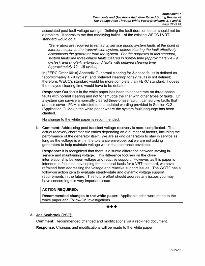
Attachment 7 Comments and Questions that Were Raised During Review of The Voltage Ride-Through White Paper (Revisions 3, 4 and 5)
Page 22 of 24
5-25-07
associated post-fault voltage swings. Defining the fault duration better should not be a problem. It seems to me that modifying bullet 1 of the existing WECC LVRT standard would do it:
"Generators are required to remain in service during system faults at the point of interconnection to the transmission system, unless clearing the fault effectively disconnects the generator from the system. For the purposes of this standard, system faults are three-phase faults cleared in normal time (approximately 4 - 9 cycles), and single-line-to-ground faults with delayed clearing time (approximately 12 - 15 cycles)."
In [FERC Order 661a] Appendix G, normal clearing for 3-phase faults is defined as "approximately 4 - 9 cycles", and "delayed clearing" for slg faults is not defined; therefore, WECC's standard would be more complete than FERC standard. I guess the delayed clearing time would have to be debated.
Response: Our focus in the white paper has been to concentrate on three-phase faults with normal clearing and not to “smudge the line” with other types of faults. Of a system can survive a normally cleared three-phase fault, it can survive faults that are less sever. PNM is directed to the updated wording provided in Section C.2 (Application Guide) in the white paper where the system fault language has been clarified.
No change to the white paper is recommended.
b. Comment: Addressing post transient voltage recovery is more complicated. The actual recovery characteristic varies depending on a number of factors, including the performance of the generator itself. We are asking generators to stay in service as long as the voltage is within the tolerance envelope, but we are not asking generators to help maintain voltage within that tolerance envelope.
Response: It is recognized that there is a subtle difference between staying in-service and maintaining voltage. This difference focuses on the close interrelationship between voltage and reactive support. However, as this paper is intended to focus on developing the technical basis for a VRT standard, we have refrained from addressing the voltage and reactive support issues. The WGTF has a follow-on action item to evaluate steady-state and dynamic voltage support requirements in the future. This future effort should address any issues you may have concerning this very important issue.
ACTION REQUIRED: Recommended changes to the white paper: Applicable edits were made to the white paper and Follow-On Investigations.
3. Joe Seabrook (PSE): Comment: Recommended changed and modifications via a red-lined document.
Response: Changes and modifications will be made to the white paper.

Attachment 7 Comments and Questions that Were Raised During Review of The Voltage Ride-Through White Paper (Revisions 3, 4 and 5)
Page 23 of 24
5-25-07
ACTION REQUIRED: Recommended changes to the white paper: Applicable red-lined changes recommended by PSE were made to the white paper.
4. Mark Graham (TSGT): a. Comment: On page 3, the word “immanent” should be “imminent”.
Response: Correction will be made to the white paper.
ACTION REQUIRED: Recommended changes to the white paper: Applicable red-lined changes recommended by TSGT were made to the white paper.
b. Comment: The requirement for 120% maximum voltage ride-through is measured at the high-side of the GSU. I can see why this location is specified, but could transformer fixed-tap settings ever result in higher than 120% of nominal at generator terminals with transformer high-side at 120%?
Response: Transformer tap setting should be based on the results of technical studies. It is possible to have an incorrectly set transformer and to encounter the condition you have identified.
No change to the white paper is recommended.
c. Comment: Why is the high voltage ride-through limit reduced in steps at 1, 2, and 3 seconds? The justification for this appears to be pseudo-empirical and arbitrary.
Response: While we could have identified a VRT curve that absolutely “hugged” the technical study results, our goal was to identify a curve that did not cross into the study results or the IEEE relay setting for synchronous generators, but, was relatively easy to define. The stair-stepped voltage was intentionally added to the diagram to bring the voltages down from 1.2 pu as quickly as possible while still meeting WECC needs.
No change to the white paper is recommended.
5. Chuck Stigers (NWE) a. Comment: I'm sending you a few "nits" I've picked in the white paper.
General Response: Applicable redlined changes and typographical corrections provided will be made to the white paper.
ACTION REQUIRED: Recommended changes to the white paper: Applicable edits were made to the white paper.

Attachment 7 Comments and Questions that Were Raised During Review of The Voltage Ride-Through White Paper (Revisions 3, 4 and 5)
Page 24 of 24
5-25-07
b. Comment: Page 25, Bullets on plant size, and voltage of interconnection need to be checked for logical consistency:
a. smaller than 10 MVA, on voltage less than 60 kV => na
b. smaller than 10 MVA, on voltage greater than 60 kV => ? we need to fix
c. larger than 10 MVA, on voltage less than 60 kV => ? we need to fix
d. larger than 10 MVA, on voltage greater than 60 kV => applies
Response: Thank you for identifying the “logic” shortcoming in this portion of the Application Guide. The following updated to the white paper will be made:
o This Standard does not apply to a site where the sum of the installed capabilities of all machines is less than 10 MVA, unless it can be proven that reliability concerns exist.
o This Standard does not apply to any generation with interconnected voltage levels that are less than 60 kV.
ACTION REQUIRED: Recommended changes to the white paper: Applicable edits were made to the Application Guide portion of the white paper.
5. Scott Inglebritson (SCL) Comment: Recommended changed and modifications via an email.
Response: Changes and modifications will be made to the white paper.
ACTION REQUIRED: Recommended changes to the white paper: Applicable edits were made to the white paper.