v1504 planning guide 000690 11-m09-2014€¦ · v1504 planning guide part no. 000690, 11-m09-2014...
TRANSCRIPT

V1504VERTICAL PLATFORM LIFT
PLANNING GUIDE
Applicable Codes:ASME A17.1ASME A18.1
CAN/CSA B355
11-m09-2014Part No. 000690

Copyright 2014Savaria CorporationAll rights reserved.
Printed in Canada
Purpose of This GuideThis guide assists architects, contractors, and lift professionals to incorporate the V1504 Vertical Platform Lift into a residential or public building design. The design and manufacture of the V1504 Vertical Platform Lift meets the requirements of the ASME A17.1, ASME A18.1 and CSA B355 Safety Standards.We recommend that you contact your local authority having jurisdiction to ensure that you adhere to all local rules and regulations pertaining to vertical platform lifts.IMPORTANT: This Planning Guide provides nominal dimensions and specifications useful for the initial planning of a vertical platform lift project. Dimensions and specifications are subject to change without notice due to continually evolving code and product applications.Before beginning actual construction, please consult Savaria Corporation or the authorized Savaria dealer in your area to ensure you receive your site-specific installation drawings with the dimensions and specifications for your project.Visit our website for the most recent V1504 drawings and dimensions.
How to Use This Guide1 Determine your client’s intended use of the lift.2 Determine the local code requirements.3 Determine the site installation parameters.4 Determine the cab type and hoistway size requirements.5 Plan for electrical requirements.
HistoryApril 6, 2010 - Initial releaseMay 16, 2011 - Updated “Travel speed” in Specifications table to 20 ft/min (0.1 m/s)June 17, 2011 - Added 24V battery backup to Options to Specifications table on page 5July 8, 2013 - Added Noise Level to Specifications table on page 4July 29, 2013 - Added optional 80” cab wall height to Specifications table on page 4October 7, 2013 - Added seat capacity to Specifications table on page 4November 12, 2013 - Revised drawings on pages 12 through 26 to include 42”-wide platformsDecember 5, 2013 - Revised enclosure drawings on pages 20 through 24February 12, 2014 - Added seat dimensions on page 27March 18, 2014 - Revised motor/drive information in Specifications table on page 5April 7, 2014 - Revised drawings on pages 20-24April 29, 2014May 29, 2014 - Added NOTE to page 27 specifying max seat capacity; Changed motor/drive specification on page 4 from 1 HP to 3 HPJune 9, 2014 - Added Remote Controller/Pump Box dimensions on page 28June 25, 2014 - Added door and gate drawings - pages 25 to 36July 28, 2014 - Added DuraSwing operator drawings - pages 37 to 40September 11, 2014 - Removed section “Additional Branch Circuit” from page 43
V1504 Planning Guide Part No. 000690, 11-m09-2014

4
SpecificationsV1504 Specifications
Specification Specification DataLoad capacity 750 lb (340 kg)
Seat capacity 330 lb (150 kg)
Maximum travel 23 ft (7 m)
Travel speed 20 ft/min (0.1 m/s)
Noise level (for typical installation) 72.9 dBA (up direction); 50.0 dBA (down direction) Measured at a height of 1m, distance of 1m, in front of the motor with all panels on
Levels serviced 2 (standard), 3, 4
Cab sizes 36'' x 48'' (914 mm x 1219 mm)
36'' x 54'' (914 mm x 1371 mm)
36'' x 60'' (914 mm x 1524 mm)
42'' x 48'' (1067 mm x 1219 mm)
42'' x 54'' (1067 mm x 1371 mm)
42'' x 60'' (1067 mm x 1524 mm)
Cab walls (height) Standard 42-1/8'' (1070 mm)
Optional 80” (2031 mm)
Cab access Enter/exit same side (platform Type 1L and 1R)
Front/rear access (platform Type 2)
90 degree access (platform Type 3 and 4)
Power supply 120 VAC, 20 A, 60 Hz, single phase
Motor/drive 2:1 chain hydraulic, 3 HP, gear-type motor for 110V
Control system Electronic-free relay logic controller
Tower Modular 8 ft (2.4 m) base guide rail assembly
Roller guide support
Pit depth requirement 3'' (76.2 mm)
Finish Beige electrostatic powder coat paint on all steel surfaces and vacuumed formed plastics
Standard features 115 VAC operation (115 VAC up direction; 12 VDC battery down direction)
Call/send stations at landings
Continuous-pressure type buttons
Operating control buttons on platform
Automatic battery recharging system (115 VAC)
Remote manual lowering device
Low-voltage controls
Limit switches
Handrail
Non-skid platform surface
No machine room required
Emergency stop button
V1504 Planning Guide Part No. 000690, 11-m09-2014

5
Safety features Platform gate
Safety underpan
Door locks
Safety brake
Emergency stop buttons
Manual lowering and battery lowering system
Options Platform gate with metal insert and electric strike
Top landing gate
Upper/lower landing door 80” (2032 mm)
Fire-rated, flush-mounted landing entrances
Folding seat on platform
Telephone on platform
Custom color
Fixed access ramp
Public building package
Outdoor package
Automatic safety ramp on platform (for outdoor model)
24V battery backup
Remote controller/pump box
V1504 Specifications
Specification Specification Data
Part No. 000690, 11-m09-2014 V1504 Planning Guide

6
Site Construction DetailsThe V1504 needs a wall that supports a minimum of 472 lb (2100 N) of pull out force at any bracket. The floor must be capable of supporting a load of 3200 lb (14.2 kN). See Figure 1. A wall with a combination of two columns of three 2x4’s, or a concrete or brick wall is required.
Figure 2 details a sample wooden support wall configuration
Figure 1: Wall/Floor Loading
Figure 2: Sample Wooden Support Wall Configuration
V1504 Planning Guide Part No. 000690, 11-m09-2014

7
Figure 3 illustrates the recommended steps for constructing a wooden hoistway.
Figure 3: Wooden Hoistway Construction - Recommended Steps
Part No. 000690, 11-m09-2014 V1504 Planning Guide

8
Figure 4 illustrates a sample concrete/steel structure configuration.
Figure 4: Sample Concrete/Steel Structure Configuration
V1504 Planning Guide Part No. 000690, 11-m09-2014
9
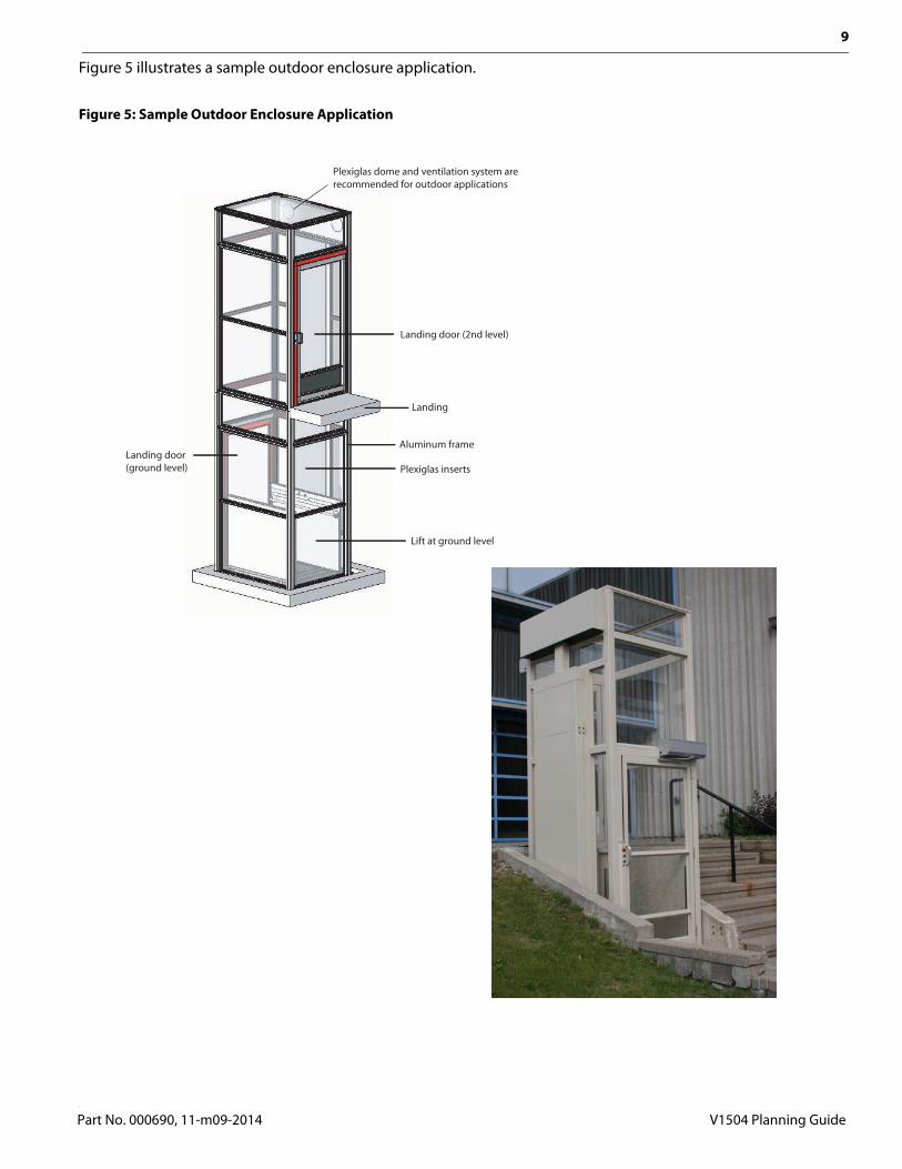
Figure 5 illustrates a sample outdoor enclosure application.
Figure 5: Sample Outdoor Enclosure Application
Part No. 000690, 11-m09-2014 V1504 Planning Guide

10
Figure 6 illustrates the site construction details for a typical outdoor application.
Figure 6: Sample Unenclosed Outdoor Application
Figure 7 illustrates the concrete slab detail for a typical outdoor application.
Figure 7: Concrete Slab Detail
V1504 Planning Guide Part No. 000690, 11-m09-2014

11
Cab Types
Type 1 CabsFor type 1 cabs, entry and exit are available from only one end of the platform.
Figure 8: Type 1 Left and Right
Type 2 CabsFor type 2 cabs, entry and exit are available from both ends of the platform.
Figure 9: Type 2
Type 3 and 4 CabsFor type 3 and 4 cabs, entry and exit are available from one end and one side of the platform.
Figure 10: Type 3 and 4
Type 1Lplatform
Entranceand Exit
Tow
er
Entranceand Exit
Type 1Rplatform To
wer
Type 2LplatformTo
wer
Entrance(Bottom)
Type 2Rplatform
Entrance(Bottom)
Exit (Top) Exit (Top)
Tow
er
Type 4platform
Entrance
Tow
erType 3platform To
wer
Entrance
Exit Exit
Part No. 000690, 11-m09-2014 V1504 Planning Guide

12
Drawings• Elevation and plan view, hoistway application (Type 1L)• Elevation and plan view, hoistway application (Type 1R)• Elevation and plan view, hoistway application (Type 2)• Elevation and plan view, hoistway application (Type 3)• Elevation and plan view, hoistway application (Type 3, 45” opening)• Elevation and plan view, hoistway application (Type 4)• Elevation and plan view, hoistway application (Type 4, 45” opening)• Elevation and plan view, enclosure application (Type 1L)• Elevation and plan view, enclosure application (Type 1R)• Elevation and plan view, enclosure application (Type 2)• Elevation and plan view, enclosure application (Type 3, 45” opening)• Elevation and plan view, enclosure application (Type 4, 45” opening)• Auto door, left-hand• Auto door, right-hand• Manual door, left-hand• Manual door, right-hand• Prodoor auto, left-hand• Prodoor auto, right-hand• Prodoor manual, left-hand• Prodoor manual, right-hand• Auto half gate, left-hand• Auto half gate, right-hand• Manual half gate, left-hand• Manual half gate, right-hand• DuraSwing on half gate, right-hand• DuraSwing on half gate, right-hand, 45” opening• DuraSwing on half gate, left-hand• DuraSwing on half gate, left-hand, 45” opening
• Seat dimensions• Remote controller/pump box dimensions
Note: Refer to the Architescts & Builders portion of our main website (www.savaria.com) for other door/gate sizes.
V1504 Planning Guide Part No. 000690, 11-m09-2014

13
Figure 11: Elevation and plan view, hoistway application (Type 1L)
Part No. 000690, 11-m09-2014 V1504 Planning Guide

14
Figure 12: Elevation and plan view, hoistway application (Type 1R)
V1504 Planning Guide Part No. 000690, 11-m09-2014

15
Figure 13: Elevation and plan view, hoistway application (Type 2)
Part No. 000690, 11-m09-2014 V1504 Planning Guide

16
Figure 14: Elevation and plan view, hoistway application (Type 3)
V1504 Planning Guide Part No. 000690, 11-m09-2014
17
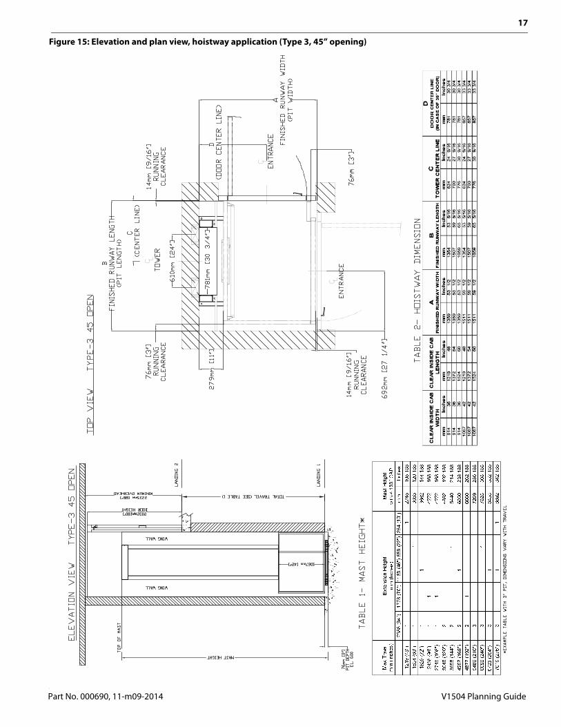
Figure 15: Elevation and plan view, hoistway application (Type 3, 45” opening)
Part No. 000690, 11-m09-2014 V1504 Planning Guide

18
Figure 16: Elevation and plan view, hoistway application (Type 4)
V1504 Planning Guide Part No. 000690, 11-m09-2014

19
Figure 17: Elevation and plan view, hoistway application (Type 4, 45” opening)
Part No. 000690, 11-m09-2014 V1504 Planning Guide

20
Figure 18: Elevation and plan view, enclosure application (Type 1L)
V1504 Planning Guide Part No. 000690, 11-m09-2014

21
Figure 19: Elevation and plan view, enclosure application (Type 1R)
Part No. 000690, 11-m09-2014 V1504 Planning Guide

22
Figure 20: Elevation and plan view, enclosure application (Type 2)
V1504 Planning Guide Part No. 000690, 11-m09-2014

23
Figure 21: Elevation and plan view, enclosure application (Type 3, 45” opening)
Part No. 000690, 11-m09-2014 V1504 Planning Guide

24
Figure 22: Elevation and plan view, enclosure application (Type 4, 45” opening)
V1504 Planning Guide Part No. 000690, 11-m09-2014

25
Figure 23: Auto door, left-hand
Part No. 000690, 11-m09-2014 V1504 Planning Guide

26
Figure 24: Auto door, right-hand
V1504 Planning Guide Part No. 000690, 11-m09-2014

27
Figure 25: Manual door, left-hand
Part No. 000690, 11-m09-2014 V1504 Planning Guide

28
Figure 26: Manual door, right-hand
V1504 Planning Guide Part No. 000690, 11-m09-2014

29
Figure 27: Prodoor auto, left-hand
Part No. 000690, 11-m09-2014 V1504 Planning Guide

30
Figure 28: Prodoor auto, right-hand
Part No. 000690, 11-m09-2014 V1504 Planning Guide

31
Figure 29: Prodoor manual, left-hand
V1504 Planning Guide Part No. 000690, 11-m09-2014
32
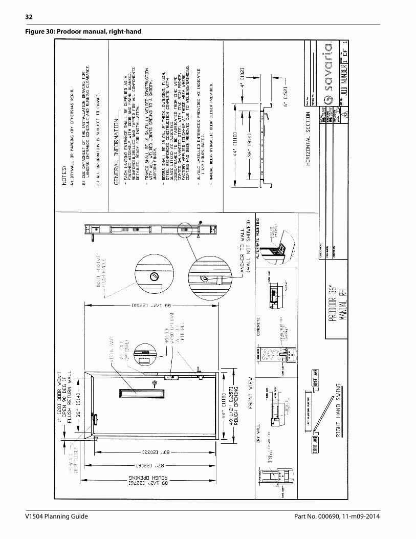
Figure 30: Prodoor manual, right-hand
V1504 Planning Guide Part No. 000690, 11-m09-2014

33
Figure 31: Auto half gate, left-hand
Part No. 000690, 11-m09-2014 V1504 Planning Guide

34
Figure 32: Auto half gate, right-hand
V1504 Planning Guide Part No. 000690, 11-m09-2014

35
Figure 33: Manual half gate, left-hand
Part No. 000690, 11-m09-2014 V1504 Planning Guide

36
Figure 34: Manual half gate, right-hand
V1504 Planning Guide Part No. 000690, 11-m09-2014

37
Figure 35: DuraSwing on half gate, right-hand
Part No. 000690, 11-m09-2014 V1504 Planning Guide

38
Figure 36: DuraSwing on half gate, right-hand, 45” opening
V1504 Planning Guide Part No. 000690, 11-m09-2014

39
Figure 37: DuraSwing on half gate, left-hand
Part No. 000690, 11-m09-2014 V1504 Planning Guide
40
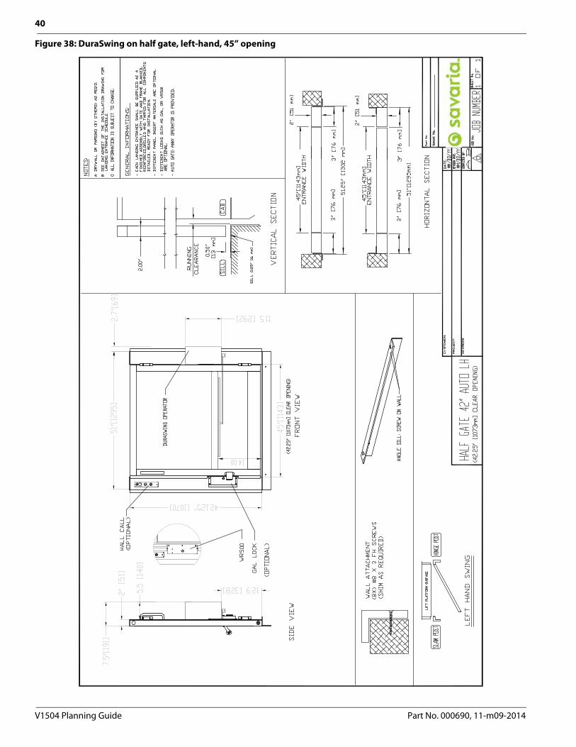
Figure 38: DuraSwing on half gate, left-hand, 45” opening
V1504 Planning Guide Part No. 000690, 11-m09-2014
41
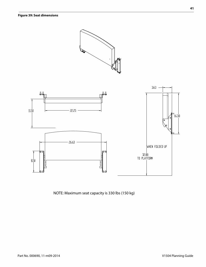
Figure 39: Seat dimensions
NOTE: Maximum seat capacity is 330 lbs (150 kg)
Part No. 000690, 11-m09-2014 V1504 Planning Guide

42
Figure 40: Remote controller/pump box dimensions
31.775”807 mm
48.3”1226 mm
10.1”256.2 mm
10.1”256.2 mm
31.8”808 mm
V1504 Planning Guide Part No. 000690, 11-m09-2014

43
PROVISIONS BY OTHERSGENERAL REQUIREMENTSHoistwayThe hoistway must be designed and built in accordance with the “safety standard for platform lifts and stairway chairlifts” or the “safety code for elevators and escalators” and all state and local codes.Plumb RunwayDue to close running clearances, the owner/agent must ensure that the hoistway and the pit (where provided) are level, plumb and square and are in accordance with the dimensions on the installation drawings.Minimum Overhead ClearanceThe owner/agent must ensure the minimum overhead clearance is in compliance with codes.Construction SiteThe owner/agent is required to provide all masonry, carpentry and drywall work as required and shall patch and make good (including finish painting) all areas where walls/floors may need to be cut, drilled or altered in any way to permit the proper installation of the lift.DimensionsThe contractor/customer is required to verify all dimensions and report any discrepancies to our office immediately.STRUCTURAL REQUIREMENTSFloor/Support Wall LoadsThe structural engineer is to ensure that the building and shaft will safely support all loads imposed by the lift equipment. Refer to the installation drawings for the loads imposed by the equipment.Mast to be Securely FastenedWhere required, the mast must be securely fastened to the structural support wall. Refer to the installation drawings for the loads imposed by the equipment. Where Doors are RequiredSuitable lintels must be provided by the owner/agent. Door frames are not designed to support overhead wall loads.ELECTRICAL REQUIREMENTSGeneralElectrical equipment and wiring must comply with Section 38 of CSA C22.1 (Canada) or Section 620 of NEC ANSI NFPA 70 (USA).Power SupplyA 120 VAC, 20A, 60 Hz, single-phase circuit through a fused disconnect with an auxiliary contact on the main power supply is required.LightingLighting of 100 lux minimum is required at platforms and landings. Lighting with a switch and electrical GFCI outlet is required in the hoistway pit.ENTRANCE REQUIREMENTSUpper Landing GatesWhere required, smooth solid barriers are to be supplied and installed on both sides of the entrance at the upper level and must be a minimum of 42” (1067 mm) high. The entrance assembly must be in place prior to this provision.Fascia Panel Below Upper Level EntranceWhere required, fascia panel must be fastened to a solid wall and be perpendicular to the floor and walls. Hoistway fascia is not self-supporting for long, continuous runs void of entrances. Adequate support for the fascia must be provided.Entrance AssembliesEntrance assemblies must be adjusted to align with the platform and interlock equipment. Others must allow an adequate opening.Return WallsReturn walls at the entrances must be built-in by others after the entrance assemblies are in place. The entrance assembly must be securely fastened to the walls by the contractor.
Part No. 000690, 11-m09-2014 V1504 Planning Guide

V1504Vertical Platform LiftPLANNING GUIDE
Part No. 000690Copyright 2014
Savaria CorporationLifts and Elevatorswww.savaria.com
Support2 Walker DriveBrampton, Ontario, L6T 5E1, CanadaToll free: (800) 791-7999Fax: (905) 791-2222