three-dimensional model of the railway rail uic-60 in … · niejednorodną struktur ... surface...
TRANSCRIPT
262 PRZEGLĄD ELEKTROTECHNICZNY (Electrical Review), ISSN 0033-2097, R. 86 NR 9/2010
Rail type
Mass [kg/m]
Strength factor Wx [mm3]
Moment of inertia Ix [mm4]
Height H [mm]
Foot width> S [mm]
Head width G [mm]
S49 49.43 240ˇ103 1819ˇ104 149 125 65.4 S54 54.54 262ˇ103 2073ˇ104 154 125 65.8
UIC 50 50.18 253.6ˇ103 1940ˇ104 152 125 68.6 UIC 54 54.43 279.19ˇ103 2127ˇ104 159 140 68.6 UIC 60 60.34 335.5ˇ103 3055ˇ104 172 150 70.6
Kamil KIRAGA, Elżbieta SZYCHTA
Technical University of Radom, Institute of Transport Systems and Electrical Engineering; 26-600 Radom; ul. Malczewskiego 29,
Three-dimensional model of the railway rail UIC-60 in Flux 3D software
Abstract. A three-dimensional model is presented of UIC-60 railway rail developed in Flux 3D software. The model helps to determine distribution of magnetic induction and magnetic intensity across the rail itself and in its environment. The model reflects the heterogeneous structure of a rail. Streszczenie: W artykule przedstawiony został trójwymiarowy model szyny kolejowej UIC-60 wykonany w programie Flux 3D. Model ten pozwala na określenie rozkładu indukcji magnetycznej i natężenia pola magnetyczne w szynie i jej otoczeniu. Prezentowany model uwzględnia niejednorodną strukturę wewnętrzną szyny. (Trójwymiarowy model szyny UIC-60 w programie Flux 3D) Keywords: 3D model of railway rail, Flux 3D, magnetic induction, magnetic field Słowa kluczowe: Model 3D szyny kolejowej, Flux 3D, indukcja magnetyczna, pole magnetyczne Introduction
Railway (stock) rails are fundamental design elements of a turnout beside switch points, sliding chairs or switching closure assemblies [1]. Rails are principally designed to set the proper travel direction of rolling stock wheel sets. Cross-sections of currently used rails are similar to double-tee bars (i.e. shapes of two letters ’T’ meeting with their vertical lines). This shape comprises the so-called head (the part along which rolling stock wheels move), web (double-tee bar centre), and foot (the part supporting the whole and carrying the load on to sleepers) [2]. Two main rail types are used on routes administered by Polish State Railways PKP PLK: 60E1 (formerly UIC60) and 60E1 (formerly S49 - marked yellow in Table 1). Characteristics of the basic rail types used in turnouts are presented in Table 1. Table 1. Rail types in use in European countries [6]
The particular types are characterised by the weight of a
running metre and cross-sectional dimensions. 49E1 (mass 49.39 kg/ running metre and cross-sectional surface 62.92 cm3) are used on routes with light rolling stock load. The reverse obtains for 60E1 (mass 60.21 kg/ running metre and cross-sectional surface 76.70 cm3) – these are used on heavily loaded routes where trains travel at speeds over 100 km/h.
Induction heating may be utilised to heat turnout rail. Flow of alternate current generates heat energy that results in increased rail temperature [5], thereby guaranteeing full operability of a turnout In spite of adverse weather conditions.
As part of research into development of a method of turnout induction heating, the following elements of a heating circuit must be analysed: structure of rail material, resistivity, and magnetic permeability of a rail, skin effects and penetration depth of the magnetic field into the rail structure, and discharge of active power in the zone of magnetic interactions with the rail. These parameters depend, inter alia, on magnetising current frequency and
are not defined by rail manufacturers (rails may come from different charges, may be produced by means of diverse rolling, straightening, and possibly hardening technologies), and require experimental determination of their value, e.g. as part of computer simulation or laboratory testing [3].
Rail structures contain percentage admixtures of other magnetic and non-magnetic materials that have relatively high impact on the electric and magnetic rail parameters under discussion [5,2] and which must be determined as their knowledge is required to develop an effective method of turnout heating. A three-dimensional rail model will therefore be of use in determination of these parameters and will help analyse magnetic and electric effects in a rail. Table 2 presents grades of steel used in rail manufacture. The grade references follow from applicable European and Polish standards (PN-EN 10027-1 and PN-EN10027-2). The symbols of materials rails are made of are based on rolling surface hardness, in Brinell degrees, with the added symbol of an element used to refine the rail
steel or in reinforcement heat treatment. Table 2 also includes references of previously used steel grades, of chemical compositions similar to the new steels, recommended by the EU in accordance with EN 13674-1:2003 (E) [6]. Two steel grades most
commonly used in Poland are highlighted: R260 (hardness range 260÷300 HB) and R350HT (hardness range 350÷390 HB, heat treated head) [1, 2]. Table 2. Rail steel markings [6]
Steel marking
Description Material number
Earlier marking
R200 Carbon-
manganese 1.0521 R0700
R220 Carbon-
manganese 1.0524 R0800
R260 Carbon-
manganese 1.0623
R0900; St90PA
R260Mn Carbon-
manganese 1.0624
R0900Mn; St90PB
R320Cr Low alloy 1.0915 R1100Cr
R350HT Heat treated
carbon-manganese
1.0631 R1200
R350LHT Low alloy heat
treated 1.0632
PRZEGLĄD ELEKTROTECHNICZNY (Electrical Review), ISSN 0033-2097, R. 86 NR 9/2010 263
The steels formerly used in rails contain 0.40 to 0.82% carbon, 0.60 to 1.70% manganese, 0.05 to 0.90% silica, and some additionally contain up to 1.30% chromium. The new steels recommended by the EU contain: carbon from 0.38 to 0.82%, manganese from 0.65 to 1.70%, silica from 0.13 to 1.12%, and some additionally contain up to 1.25% chromium. As steel is heated and cooled and temperatures change in rail manufacturing processes, structural transformations occur. In the final production process, a rail is hot rolled at temperatures of 700 – 900°C [2]. The (heterogeneous) structure and material properties of the rail result from such processes. Method of defining material properties in flux 3D The internal rail structure comprises several areas of varying magnetic properties. The head and web edges acquire different material properties at the time of rolling. The remaining part of the rail displays characteristics of a uniform material. Material properties have been tested at the Silesian University of Technology in Katowice. Laboratory testing involved sectors of UIC-60 rails, a total of 21 samples. Geometrical dimensions of these samples are shown in Figure 1.
Fig.1. Geometrical dimensions of tested material samples Separate material properties have been defined in respect of these areas (rail head, centre, and web edges) on the basis of results of laboratory testing of samples. Sample results and the magnetising prime curve in respect of a sample from the rail web edge are shown in Figure 2. Fig.2. Magnetising prime curve for a section taken from the rail web edge The method of defining material properties in Flux 3D is illustrated in Figure 3.
Fig.3. Method of defining material properties in Flux 3D software Three-dimensional model of UIC-60 rail
Normalised dimensions of the normal-gauge UIC-60 rail are presented in Figure 4.
Fig.4. Geometrical dimensions of the normal-gauge UIC-60 rail [4]
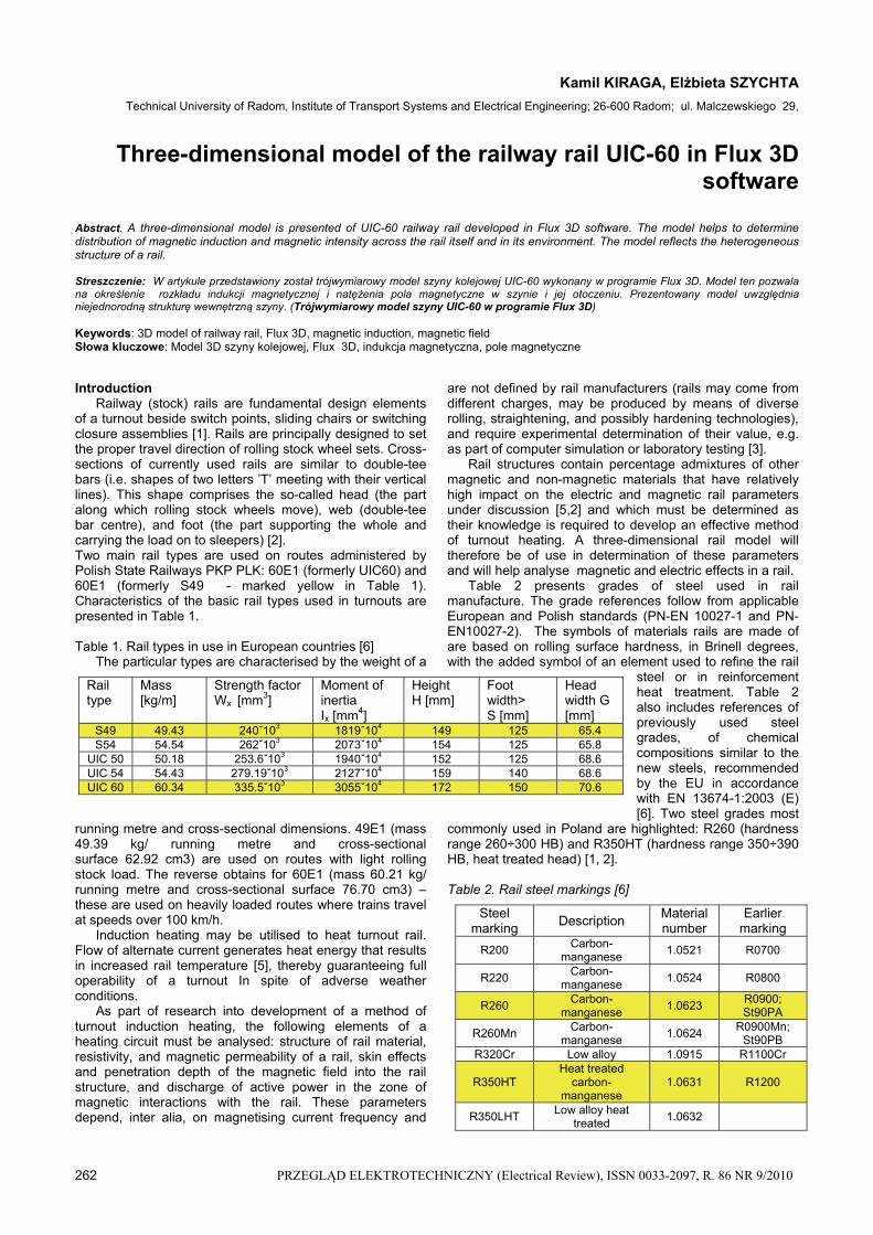
Based on the rail dimensions (Fig.4), a three-dimensional rail model was generated in Flux 3D (Fig.5). This model considers the varied internal structure of a rail. The head is marked red, the web’s side edges are pink, and the rail core is blue.
264 PRZEGLĄD ELEKTROTECHNICZNY (Electrical Review), ISSN 0033-2097, R. 86 NR 9/2010
Fig.5. Three-dimensional model of UIC-60 railway rail
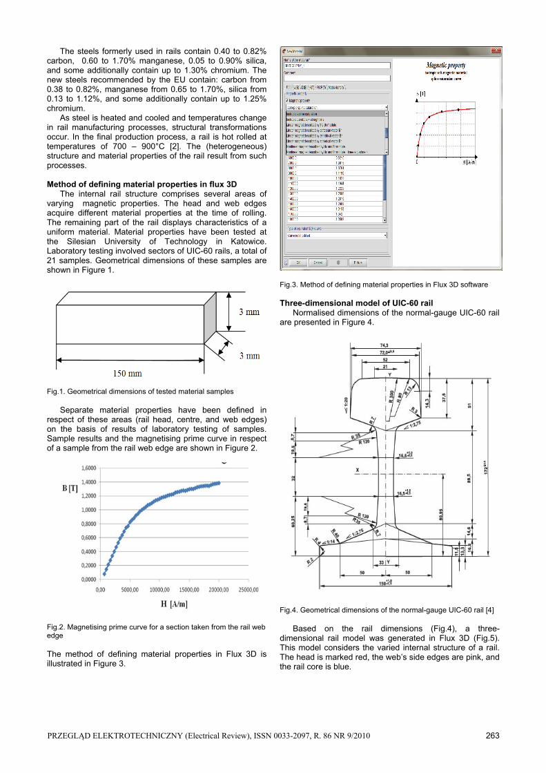
Flux 3D is employed, inter alia, to test electromagnetic effects in magnetic and non-magnetic materials, electrical machinery and equipment. A calculation grid is developed, generated, and then projected onto the model. Three grid types are available in the software: small, medium, and large. If a software-generated grid is not sufficiently precise and fails to comprise the entire model, new nodes can be added. The new nodes are created by halving the distances between the existing nodes of the grid already generated by the programme. The software will connect the nodes again. Consolidation of the grid lines, which implies doubling of nodes, increases precision of calculations in the simulation process since the calculations are executed for each node, which also prolongs the calculations. Figures 6 and 7 show the modified calculation grid for the rail model presented in Figure 5.
Fig.6. Analytical grid for the rail head – red
Fig.7. Analytical grid for the rail’s web edges – pink – and rail core - blue.
Magnetic rail properties at the time of simulation testing can be defined on the basis of the resulting model.
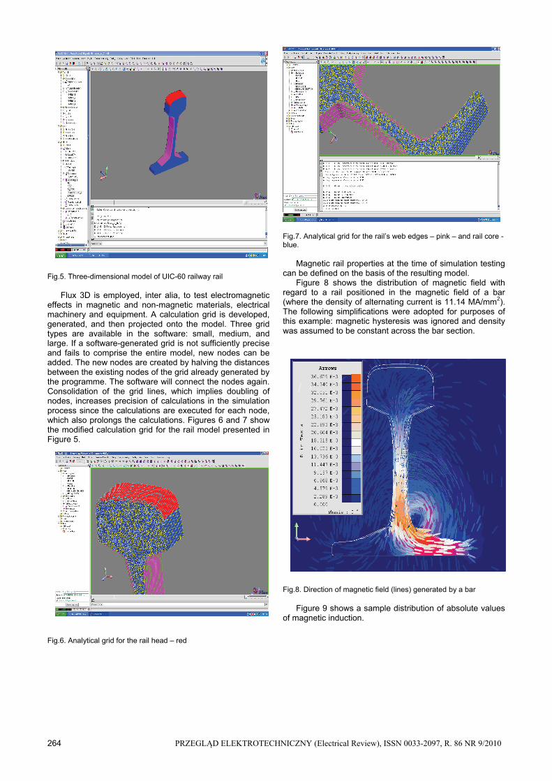
Figure 8 shows the distribution of magnetic field with regard to a rail positioned in the magnetic field of a bar (where the density of alternating current is 11.14 MA/mm2). The following simplifications were adopted for purposes of this example: magnetic hysteresis was ignored and density was assumed to be constant across the bar section.
Fig.8. Direction of magnetic field (lines) generated by a bar
Figure 9 shows a sample distribution of absolute values of magnetic induction.
PRZEGLĄD ELEKTROTECHNICZNY (Electrical Review), ISSN 0033-2097, R. 86 NR 9/2010 265
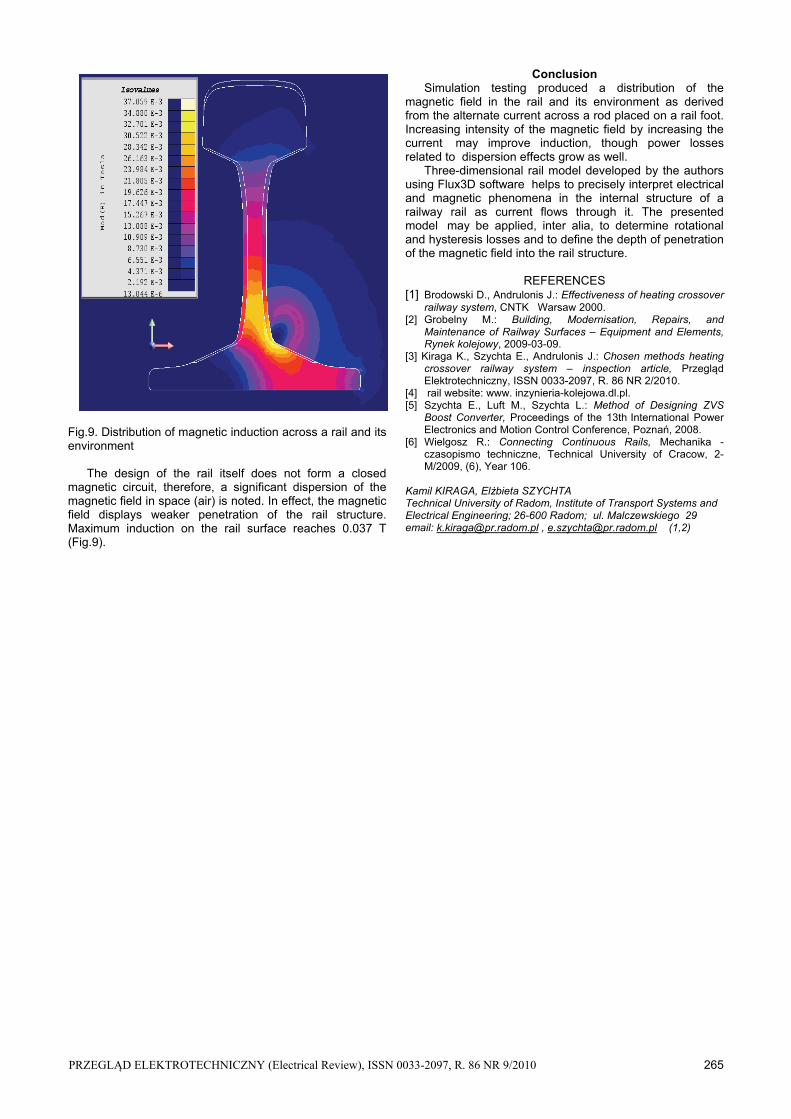
Fig.9. Distribution of magnetic induction across a rail and its environment
The design of the rail itself does not form a closed magnetic circuit, therefore, a significant dispersion of the magnetic field in space (air) is noted. In effect, the magnetic field displays weaker penetration of the rail structure. Maximum induction on the rail surface reaches 0.037 T (Fig.9).
Conclusion Simulation testing produced a distribution of the
magnetic field in the rail and its environment as derived from the alternate current across a rod placed on a rail foot. Increasing intensity of the magnetic field by increasing the current may improve induction, though power losses related to dispersion effects grow as well.
Three-dimensional rail model developed by the authors using Flux3D software helps to precisely interpret electrical and magnetic phenomena in the internal structure of a railway rail as current flows through it. The presented model may be applied, inter alia, to determine rotational and hysteresis losses and to define the depth of penetration of the magnetic field into the rail structure.
REFERENCES [1] Brodowski D., Andrulonis J.: Effectiveness of heating crossover
railway system, CNTK Warsaw 2000. [2] Grobelny M.: Building, Modernisation, Repairs, and
Maintenance of Railway Surfaces – Equipment and Elements, Rynek kolejowy, 2009-03-09.
[3] Kiraga K., Szychta E., Andrulonis J.: Chosen methods heating crossover railway system – inspection article, Przegląd Elektrotechniczny, ISSN 0033-2097, R. 86 NR 2/2010.
[4] rail website: www. inzynieria-kolejowa.dl.pl. [5] Szychta E., Luft M., Szychta L.: Method of Designing ZVS
Boost Converter, Proceedings of the 13th
International Power Electronics and Motion Control Conference, Poznań, 2008.
[6] Wielgosz R.: Connecting Continuous Rails, Mechanika - czasopismo techniczne, Technical University of Cracow, 2-M/2009, (6), Year 106.
Kamil KIRAGA, Elżbieta SZYCHTA
Technical University of Radom, Institute of Transport Systems and Electrical Engineering; 26-600 Radom; ul. Malczewskiego 29 email: [email protected] , [email protected] (1,2)