short form service manual - cim 6 controller - maersk line - …€¦ · · 2014-03-12short form...
TRANSCRIPT

Short form Service manual - cim 6 controller

Short form Service manual
CIM 6 controller information
major differences between the cim 5 and the cim 6 controller:
communication with the humidity sensor via communication bus - no analog signal output
12v rechargeable battery pack
main switch: lower max. current (new part number)
activation of contactors and valve coils - see detailed description later in this manual
automatic ventilation - optional feature
•
•
•
•
•
[2]

Short form Service manual
Operating temperature
-30˚C to +30˚C-22 F to +86 F
Ambient temperature
-30˚C to +50˚C-22˚F to +122˚F
model: Scu-40/Sci-40 with cim 6 controllerrefrigerant: r-134a charged with 4.5 kg/9.9 lb
[3]

Short form Service manual
Controller box view
fc/compressor
Phase direction
heat element
cond. fan low
cond. fan high
evap. fan low
evap. fan high
Phase direction
main circuit breaker
[4]
Short form Service manual
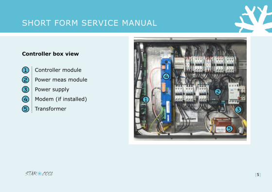
Controller box view
controller module
Power meas module
Power supply
modem (if installed)
transformer
[5]
Short form Service manual
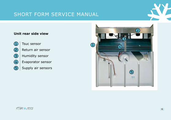
Unit rear side view
tsuc sensor
return air sensor
humidity sensor
evaporator sensor
Supply air sensors
[6]

Short form Service manual
Replacement of Tsuc sensor
remove Pvc cover to accesstsuc sensor
cut cable tie (one pcs). Sensor can then be removed When installing the new sensor, make sure to insert properly in tube and add new cable tie to make sure sensor/tube is properly insulated
[]

Short form Service manual
Replacement of air exchange sensor Remove the two finger screws on the butter fly and remove cover plate
remove the fourteen screws to loosen the black cover where the air ex-sensor is mounted
replace the sensor and install all the dismantled parts again
[8]

Short form Service manual
Air exchange sensor calibration
Close fresh air butterfly
in the service menu So5; con-figuration menu FO6; Press “enter” twice
calibration is completed
[9]

Short form Service manual
Transformer T1
transformer t1
measure supply voltage on terminal 1 and 2:
range -50 hz: 335 – 460 vac.range -60 hz: 390 – 525 vac.
[10]

Short form Service manual
Transformer output
measure output voltage on terminal 3 and 4 (2 vac):
range: 20 - 30 vac.
measure output voltage on terminal 5 and 6 (24 vac):
Range: 19 – 28 VAC.
[11]

Short form Service manual
Check Frequency Converter
frequency converter muSt always have the black foil mounted for protection of print, components and your safety
WarninG - hiGh voltaGe
[12]

Short form Service manual
Check Frequency Converter
if deviation between phases is more than 15 vac:
alarm ”523 fc phase loss” oralarm ”516 fc trip phase loss” will be given
range -50 hz: 335 – 460 vac.range -60 hz: 390 – 525 vac.
e.g. due to unstable power supply from the genset
[13]

Short form Service manual
Check Frequency Converter
a green light indicates fc is ok
A flashing green light indicates FC communicates with the controller
a red light indicates a problem
[14]

Short form Service manual
Check Frequency Converter
if a red light is on and alarm 00 ”fc missing” is displayed, the fc has an internal problem and must be replaced
the ”Warranty repair report” must be filled out and submitted to Star cool. the defective part must be properly tagged
[15]

Short form Service manual
Emergency operation
Dismount the frequency converter and connect the fc power 1 cable directly to the compressor supply terminals (W, v, u)
the 3 remaining terminals (Y, X, Z) have to be fitted with a wire-jumper.
[16]

Short form Service manual
Emergency operation
Go to Service menu and select “Configuration” (S05)
In “Configuration” menu scroll down to “fc type” (f03)
then press return and select “none”
note: remember to switch back to “Danfoss” in the “fc type” setting when a new fc is mounted
[1]

Short form Service manual
Temperature sensor check
Disconnect the X24 and X25 plugs on the controller module
all temperature readings must drop to -0 degrees celsius within a short time
if value is not reached then the controller has a problem and must be replaced
the “Warranty repair report” must be filled out and submitted to Star Cool.
[18]

Short form Service manual
Temperature sensor check
Dismount the current defective sensor(s) according to the wiring diagram inside the controller door
measure the voltage between the two terminals on the controller
range: 3.2 vDc - 3.4 vDc
temperature resistance check: value must be according to the resistance table in the ”opera-tion and Service manual”
[19]
Short form Service manual
Temperature sensor check
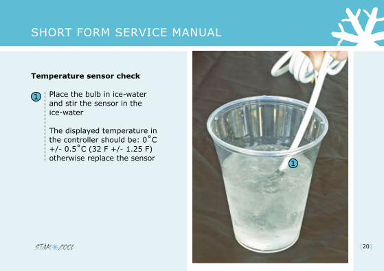
Place the bulb in ice-water and stir the sensor in the ice-water
the displayed temperature in the controller should be: 0˚C +/- 0.5˚C (32 F +/- 1.25 F) otherwise replace the sensor
[20]
Short form Service manual
Pressure transmitter check
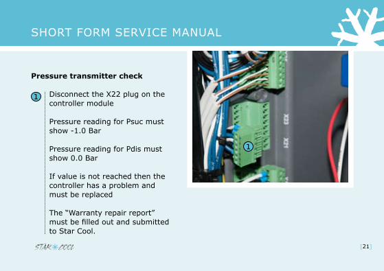
Disconnect the X22 plug on the controller module
Pressure reading for Psuc must show -1.0 Bar
Pressure reading for Pdis must show 0.0 Bar
if value is not reached then the controller has a problem and must be replaced
the “Warranty repair report” must be filled out and submitted to Star cool.
[21]

Short form Service manual
Pressure transmitter check
Dismount the current defect trans-mitter according to the wiring diagram inside the controller door
measure voltage between ground and 5 vDc for the transmitter. (according to the electrical wiring diagram)
Correct range: 4.80 > 5.05 VDC.
reconnect GnD and 5 vDc. check signal output from transmitter. compare it to gauge reading/value found in relevant table in the “operational and Service manual”.
[22]
Short form Service manual
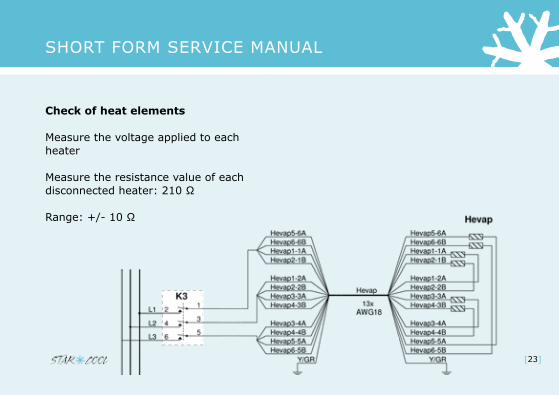
Check of heat elements
measure the voltage applied to each heater
measure the resistance value of each disconnected heater: 210 Ω
Range: +/- 10 Ω
[23]
Short form Service manual
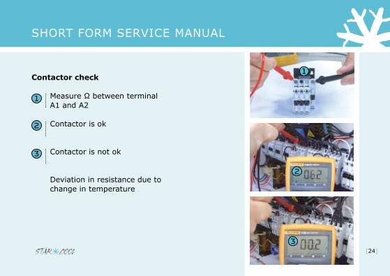
Contactor check
Measure Ω between terminal a1 and a2
contactor is ok
contactor is not ok
Deviation in resistance due to change in temperature
[24]
Short form Service manual
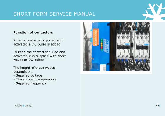
Function of contactors
When a contactor is pulled and activated a Dc-pulse is added
to keep the contactor pulled and activated it is supplied with short waves of Dc-pulses
the lenght of these waves depends on:- Supplied voltage- the ambient temperature- Supplied frequency
[25]

Short form Service manual
Function of contactors
to ensure constant functionality of a contactor it is every 6-10 seconds supplied with a revival Dc-pulse
When measuring output with a volt meter expect to measure 3.5 - 6.5 vDc if output is ok (a1 - a2)
notice: When sending out the revival pulse the reading briefly raises
[26]

Short form Service manual
Change of parts
always regard your personal safety as high priority
always switch off the main circuit breaker and disconnect power cable when working on the unit
[2]

Short form Service manual
Notes
[28]

Short form Service manual
Notes
[29]

Short form Service manual
Contacts
Internet www.starcool.dk Spare parts / orders [email protected]
Technical Hot line 24/7 +45 73 64 35 00
[30]