model cim-1000 dualformat ani...
TRANSCRIPT
MODEL CIM-1000 DUALFORMAT ANI
ENCODER
GE Star® AND MDC-1200® IDENTIFICATION ENCODER
Instruction Manual Manual Number 05 40 1000
Rev 080107
© 2005 – 2008 Cimarron Technologies Corp., Escondido, CA, USA. All rights reserved. No part of this manual may be reproduced in any way without the express written permission of Cimarron Technologies Corporation.

MODEL CIM-1000 ANI ENCODER © 2005 - 2008 Cimarron Technologies Corporation All rights reserved Cimarron Technologies Inc. 934 S. Andreasen Suite G Escondido, CA 92029 USA Voice: 760-738-3282 FAX: 760-480-0233 Email: [email protected] Web: www.cimtechcorp.com Cimarron Technologies Corporation is a licensee of the Motorola MDC-1200® Protocol technology. MDC-1200® is a registered trademark of Motorola Inc. GE Star® is a registered trademark of General Electric Corporation Manual revision CIM-1000 080107
T a b l e o f C o n t e n t s C H A P T E R 1 Features and Capabilities _________________________ 6
What Is the CIM-1000 _______________________________________________________ 6 Capabilities ________________________________________________________________ 6 Specifications ______________________________________________________________ 8
C H A P T E R 2 Installation_____________________________________ 9 Typical Radio Installation ____________________________________________________ 9 Quick Start Installation ______________________________________________________ 9 Quick Start Installation _____________________________________________________ 10 Physical Installation________________________________________________________ 10 Radio Connections _________________________________________________________ 10 Radio connection Definitions ________________________________________________ 11
A+ ___________________________________________________________________________ 11 A- ____________________________________________________________________________ 11 Microphone Mute Output__________________________________________________________ 11 KEY Output ____________________________________________________________________ 11 PTT Input______________________________________________________________________ 11 Sidetone Output _________________________________________________________________ 12 Emergency Input ________________________________________________________________ 12 Man-Down Input ________________________________________________________________ 12 Aux Output ____________________________________________________________________ 12 Sleep Input _____________________________________________________________________ 13 Aux Input ______________________________________________________________________ 13 Tone Control Output _____________________________________________________________ 13 Data Output ____________________________________________________________________ 13
Pad Information ___________________________________________________________ 13 Jumper Information _______________________________________________________ 14 Jumper Definitions_________________________________________________________ 14 Jumper K Configuration ____________________________________________________ 14
Time out timer applications ________________________________________________________ 14 Deviation Adjustment ______________________________________________________ 15
C H A P T E R 3 Programming__________________________________ 16 Navigating the Portable Programmer Display Screens ___________________________ 17
Programming Tree _______________________________________________________________ 18 Home and the Primary Functions____________________________________________________ 19 ID Type and Memory Functions ____________________________________________________ 20 Common Functions ______________________________________________________________ 22 Radio Interface Functions _________________________________________________________ 23 Transmit Mode__________________________________________________________________ 24 Emergency Functions_____________________________________________________________ 25 Man-Down Functions ____________________________________________________________ 26
Programming using the CIM-CABLE _________________________________________ 27 Group Menu Level_______________________________________________________________ 28
Programmable Parameter Definitions _________________________________________ 30
Signaling Type and ID Selection______________________________________________ 30 Signaling Type Selection __________________________________________________________ 30 Secondary ANI ID’s _____________________________________________________________ 30
GE Star®_________________________________________________________________ 30 GE Star® format type ____________________________________________________________ 30 GE Star® PTT ID, Emergency ID ___________________________________________________ 30 ANI Message ___________________________________________________________________ 30 Emergency Message _____________________________________________________________ 30 TOT Message___________________________________________________________________ 30 Man-Down Message _____________________________________________________________ 30 Preamble Length ________________________________________________________________ 31
MDC-1200® ______________________________________________________________ 31 MDC-1200® PTT ID, Emergency ID ________________________________________________ 31 ANI Message ___________________________________________________________________ 31 Emergency Message _____________________________________________________________ 31
Common _________________________________________________________________ 31 Location: ______________________________________________________________________ 31 PTT ANI repeat timer: ____________________________________________________________ 31 Sidetone with PTT ANI: __________________________________________________________ 31 Un-key courtesy tone: ____________________________________________________________ 32 PTT Message Becomes Critical_____________________________________________________ 32 Preamble Fills Attack Delay _______________________________________________________ 32
Radio Interface____________________________________________________________ 32 Attack Delay: ___________________________________________________________________ 32 Time out timer: _________________________________________________________________ 32 Critical Channel Revert: __________________________________________________________ 32 Key Follows PTT________________________________________________________________ 32 Multiple Function Output _________________________________________________________ 32
Transmit Control Output ________________________________________________________ 32 Critical Channel Revert_________________________________________________________ 33
Output Level ___________________________________________________________________ 33 PTT Input Active Level ___________________________________________________________ 33 Sleep Input _____________________________________________________________________ 33
Transmit Mode____________________________________________________________ 33 Conventional ___________________________________________________________________ 33 Trunked _______________________________________________________________________ 33 Trunk Debounce ________________________________________________________________ 33 Trunk Key Time_________________________________________________________________ 34 Trunk Time Out _________________________________________________________________ 34 Trunk Channel Acquired Active Level _______________________________________________ 34
Emergency _______________________________________________________________ 34 Number of repeat emergency transmissions: ___________________________________________ 34 Repeat Delay:___________________________________________________________________ 34 Activation Delay ________________________________________________________________ 34 Emergency TX warning tone: ______________________________________________________ 34 Active State ____________________________________________________________________ 34 Open Microphone Monitor on Emergency TX time _____________________________________ 34 Open Microphone Monitor on Emergency RX time _____________________________________ 35
Man-Down _______________________________________________________________ 35 Number of repeat Man-Down transmissions ___________________________________________ 35 Repeat Delay ___________________________________________________________________ 35 Active State ____________________________________________________________________ 35 Man-Down Warning Delay ________________________________________________________ 35
Man-Down Activation Delay_______________________________________________________ 35 Open Microphone Monitor on Man-Down TX time _____________________________________ 35 Open Microphone Monitor on Man-Down RX time _____________________________________ 36
C H A P T E R 4 Operation _____________________________________ 37 ANI-ID __________________________________________________________________ 37 Time-out-timer ____________________________________________________________ 37 Emergency _______________________________________________________________ 37 Man-Down _______________________________________________________________ 37 Status____________________________________________________________________ 38 Canned Messages __________________________________________________________ 38 Dual ID Capability_________________________________________________________ 38
C H A P T E R 5 Technical Information __________________________ 39 GE Star® Format Selections _________________________________________________ 39 Format Definitions _________________________________________________________ 39 GE Star® Message Descriptions______________________________________________ 39 MDC-1200® Message Type__________________________________________________ 40 Trunking Operation________________________________________________________ 41
Systems where Trunk Key Time and Trunk Timeout are set to the same value (LTR): __________ 41 Emergency __________________________________________________________________ 41 PTT ANI beginning send not “Key follows PTT” ____________________________________ 41 PTT ANI end send not “Key follows PTT” _________________________________________ 42 PTT ANI beginning send with “Key follows PTT” ___________________________________ 42 PTT ANI end send with “Key follows PTT” ________________________________________ 42
Systems where Trunk Key Time and Trunk Timeout are not set to the same value (MPT and others):______________________________________________________________________________ 42
Emergency __________________________________________________________________ 42 PTT ANI beginning send not “Key follows PTT” ____________________________________ 43 PTT ANI end send not “Key follows PTT” _________________________________________ 43 PTT ANI beginning send with “Key follows PTT” ___________________________________ 43 PTT ANI end send with “Key follows PTT” ________________________________________ 44
Schematic ________________________________________________________________ 45 Parts List_________________________________________________________________ 46
C H A P T E R 6 Troubleshooting________________________________ 47 Installation Hints __________________________________________________________ 47 Isolating System Problems __________________________________________________ 47 Equipment Problems _______________________________________________________ 47
Radio Keys and Stays Keyed_______________________________________________________ 47 Radio Keys up but stays Keyed only for Duration of ANI ________________________________ 47 ANI goes out at “End” Regardless of Programming _____________________________________ 47 ID Decoded is not the same as Programmed ___________________________________________ 48
C H A P T E R 7 Product Support________________________________ 49
Chapter 1 Features and Capabilities 6
C H A P T E R 1 Features and Capabilities
What Is the CIM-1000 The Cimarron Technologies' Model CIM-1000, ANI/Emergency ID Encoder is a dual format encoder. It can be programmed to operate in GE Star® or MDC-1200® modes. The unit provides Automatic Numeric Identification (ANI) of a specific radio transmitter each time the microphone press-to-talk (PTT) switch is activated and is capable of transmitting other data messages as well. Typically the unit is programmed to encode “Stuck-Microphone”, “Emergency”, and “Man-Down” messages but can be preprogrammed for any valid special message. The Model CIM-1000 can also be used as a monitoring or alarm transmission module by programming status and “canned” messages and interpreting them as sensor inputs at the decoding site. Wiring connections to the host radio is the same for all available formats.
Capabilities • Identify every transmission source
• Reduce nuisance and obscene transmissions
• Emergency and Man-Down situations instantly identified
• Microphone monitoring mode
• Trunking compatible
• Stuck microphone identification
• Time-Out-Timer with alert tone
• ANI identification at beginning, End or Both
• Audible Man-Down alert
• Dual ID capability
• Flexible message coding allows special signaling capabilities
• Programmable with a hand-held programmer wirelessly
• Programmable by computer with a serial port adapter cable
• Capable of zero attack delay. Fastest possible encode
• Continuous data mode assists with system calibration
• Able to be used as a status encoder for both MDC-1200® and GE Star®
• Increased trunking flexibility compatible with latest trunking schemes
• Very low current consumption
• Extended ID range MDC-1200® ID’s to DEEE and GE Star® to 16,383
• Software controlled output adjustment – no more potentiometer to fail.
• Sine wave output provides cleaner system functioning and compliance

Chapter 1 Features and Capabilities 7
In order to realize these capabilities the CIM-1000 must be correctly installed and programmed. Some features may require additional equipment not supplied. The CIM-1000 is programmed with “defaults” which allow compatibility with most installations when received from the factory. The device is programmed via the Cimarron Technologies CIM-IRP handheld IR programmer. Power must be applied to the CIM-1000 during programming. Programming is easily accomplished in installed devices. The CIM-1000 can also be programmed via the CIM-Cable and a computer running terminal emulation software like Hyperterm or Procomm. Using the CIM-Cable, the attached CIM-1000 is powered via the computer serial port.
Chapter 1 Features and Capabilities 8
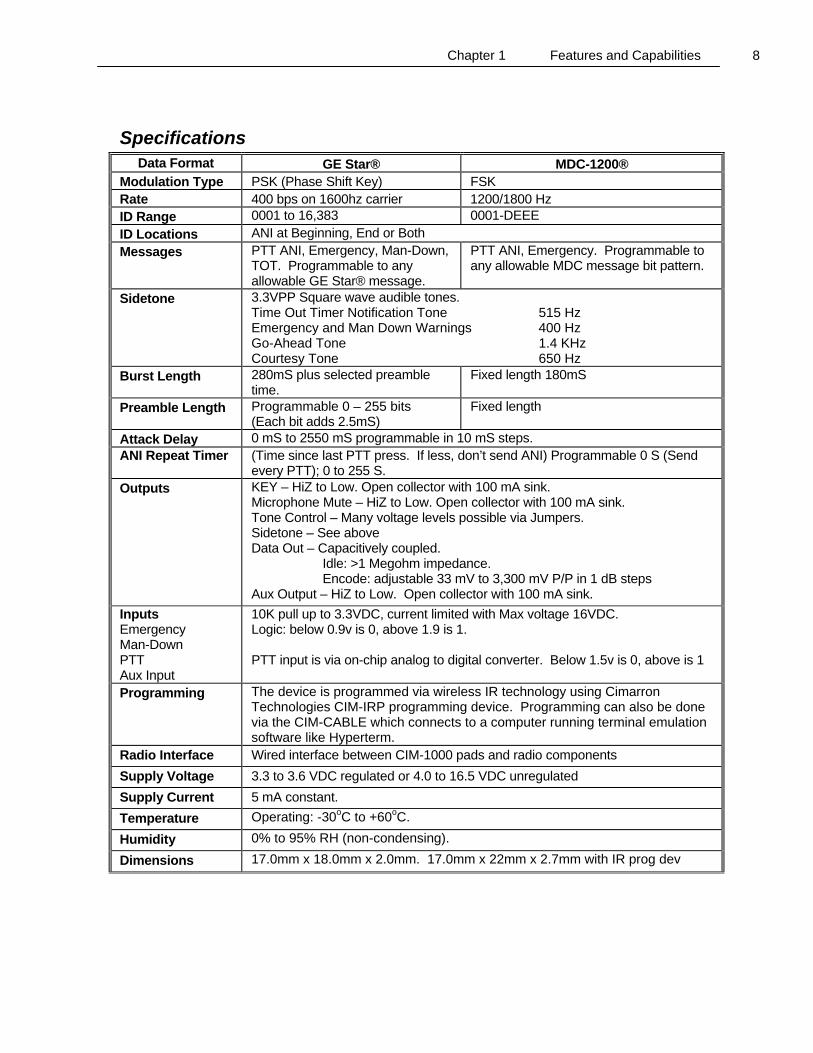
Specifications Data Format GE Star® MDC-1200®
Modulation Type PSK (Phase Shift Key) FSK Rate 400 bps on 1600hz carrier 1200/1800 Hz ID Range 0001 to 16,383 0001-DEEE ID Locations ANI at Beginning, End or Both Messages PTT ANI, Emergency, Man-Down,
TOT. Programmable to any allowable GE Star® message.
PTT ANI, Emergency. Programmable to any allowable MDC message bit pattern.
Sidetone 3.3VPP Square wave audible tones. Time Out Timer Notification Tone 515 Hz Emergency and Man Down Warnings 400 Hz Go-Ahead Tone 1.4 KHz Courtesy Tone 650 Hz
Burst Length 280mS plus selected preamble time.
Fixed length 180mS
Preamble Length Programmable 0 – 255 bits (Each bit adds 2.5mS)
Fixed length
Attack Delay 0 mS to 2550 mS programmable in 10 mS steps. ANI Repeat Timer (Time since last PTT press. If less, don’t send ANI) Programmable 0 S (Send
every PTT); 0 to 255 S. Outputs
KEY – HiZ to Low. Open collector with 100 mA sink. Microphone Mute – HiZ to Low. Open collector with 100 mA sink. Tone Control – Many voltage levels possible via Jumpers. Sidetone – See above Data Out – Capacitively coupled. Idle: >1 Megohm impedance. Encode: adjustable 33 mV to 3,300 mV P/P in 1 dB steps Aux Output – HiZ to Low. Open collector with 100 mA sink.
Inputs Emergency Man-Down PTT Aux Input
10K pull up to 3.3VDC, current limited with Max voltage 16VDC. Logic: below 0.9v is 0, above 1.9 is 1. PTT input is via on-chip analog to digital converter. Below 1.5v is 0, above is 1
Programming The device is programmed via wireless IR technology using Cimarron Technologies CIM-IRP programming device. Programming can also be done via the CIM-CABLE which connects to a computer running terminal emulation software like Hyperterm.
Radio Interface Wired interface between CIM-1000 pads and radio components Supply Voltage 3.3 to 3.6 VDC regulated or 4.0 to 16.5 VDC unregulated Supply Current 5 mA constant. Temperature Operating: -30oC to +60oC.
Humidity 0% to 95% RH (non-condensing).
Dimensions 17.0mm x 18.0mm x 2.0mm. 17.0mm x 22mm x 2.7mm with IR prog dev
Chapter 2 Installation 9
C H A P T E R 2 Installation
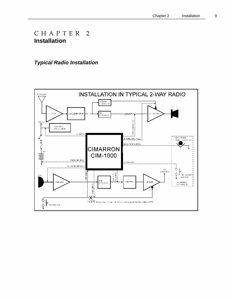
Typical Radio Installation
Chapter 2 Installation 10
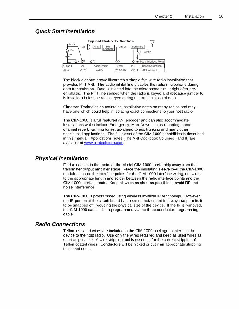
Quick Start Installation
The block diagram above illustrates a simple five wire radio installation that provides PTT ANI. The audio inhibit line disables the radio microphone during data transmission. Data is injected into the microphone circuit right after pre-emphasis. The PTT line senses when the radio is keyed and (because jumper K is installed) holds the radio keyed during the transmission of data. Cimarron Technologies maintains installation notes on many radios and may have one which could help in isolating exact connections to your host radio. The CIM-1000 is a full featured ANI encoder and can also accommodate installations which include Emergency, Man-Down, status reporting, home channel revert, warning tones, go-ahead tones, trunking and many other specialized applications. The full extent of the CIM-1000 capabilities is described in this manual. Applications notes (The ANI Cookbook Volumes I and II) are available at www.cimtechcorp.com.
Physical Installation Find a location in the radio for the Model CIM-1000, preferably away from the transmitter output amplifier stage. Place the insulating sleeve over the CIM-1000 module. Locate the interface points for the CIM-1000 interface wiring, cut wires to the appropriate length and solder between the radio interface points and the CIM-1000 interface pads. Keep all wires as short as possible to avoid RF and noise interference. The CIM-1000 is programmed using wireless invisible IR technology. However, the IR portion of the circuit board has been manufactured in a way that permits it to be snapped off, reducing the physical size of the device. If the IR is removed, the CIM-1000 can still be reprogrammed via the three conductor programming cable.
Radio Connections Teflon insulated wires are included in the CIM-1000 package to interface the device to the host radio. Use only the wires required and keep all used wires as short as possible. A wire stripping tool is essential for the correct stripping of Teflon coated wires. Conductors will be nicked or cut if an appropriate stripping tool is not used.
Chapter 2 Installation 11
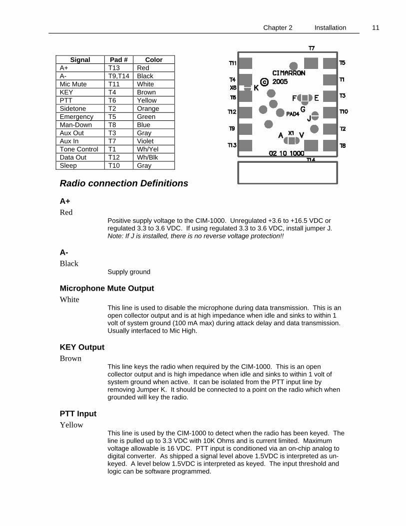
Signal Pad # Color
A+ T13 Red A- T9,T14 Black Mic Mute T11 White KEY T4 Brown PTT T6 Yellow Sidetone T2 Orange Emergency T5 Green Man-Down T8 Blue Aux Out T3 Gray Aux In T7 Violet Tone Control T1 Wh/Yel Data Out T12 Wh/Blk Sleep T10 Gray
Radio connection Definitions
A+ Red
Positive supply voltage to the CIM-1000. Unregulated +3.6 to +16.5 VDC or regulated 3.3 to 3.6 VDC. If using regulated 3.3 to 3.6 VDC, install jumper J. Note: If J is installed, there is no reverse voltage protection!!
A- Black
Supply ground
Microphone Mute Output White
This line is used to disable the microphone during data transmission. This is an open collector output and is at high impedance when idle and sinks to within 1 volt of system ground (100 mA max) during attack delay and data transmission. Usually interfaced to Mic High.
KEY Output Brown
This line keys the radio when required by the CIM-1000. This is an open collector output and is high impedance when idle and sinks to within 1 volt of system ground when active. It can be isolated from the PTT input line by removing Jumper K. It should be connected to a point on the radio which when grounded will key the radio.
PTT Input Yellow
This line is used by the CIM-1000 to detect when the radio has been keyed. The line is pulled up to 3.3 VDC with 10K Ohms and is current limited. Maximum voltage allowable is 16 VDC. PTT input is conditioned via an on-chip analog to digital converter. As shipped a signal level above 1.5VDC is interpreted as un-keyed. A level below 1.5VDC is interpreted as keyed. The input threshold and logic can be software programmed.
Chapter 2 Installation 12
Sidetone Output Orange
Capacitively coupled square wave 3.3 VPP signal output, to be interfaced to the radio audio amplifier input. A point should be selected that is not affected by the radio volume control. The CIM-1000 microprocessor activates this tone line under the following circumstances: If programmed for tone on Emergency or Man-Down, this line will be active to warn the user that an alarm message has or will be transmitted. If programmed for tone on PTT, this line will be active for the duration of the transmitted ANI data. This gives the operator audible notice (go-ahead) when the ANI burst is finished and un-clipped speech is possible. The “tone on PTT” application will require the addition of a series resistor to lower the amplitude. Tones are defined as follows: Time Out Timer Notification Tone 515 Hz Emergency and Man Down Warnings 400 Hz Go-Ahead Tone 1.4 KHz Courtesy Tone 650 Hz
Emergency Input Green
This line is used by the CIM-1000 to detect a manual emergency condition. The line is pulled up to 3.3 VDC with 10K Ohms and is current limited. Maximum voltage allowable is 16 VDC. As shipped a level below 0.9VDC is interpreted as active. The input can be software programmed for reverse logic. This line can alternately be used as a status or canned message.
Man-Down Input Blue
Man-Down activation input from external sensor or switch. This line is normally pulled high and grounding it activates the Man-Down condition. The line is pulled up to 3.3 VDC with 10K Ohms and is current limited. Maximum voltage allowable is 16 VDC. As shipped a level below 0.9 VDC is interpreted as active. The input can be software programmed for reverse logic. This line can alternately be used as a status or canned message.
Aux Output Gray
This dual function line can be programmed to perform one of the following two functions: 1. Transmit Control. Idle state is 3.3VDC. Active state occurs during all data burst transmissions. When active, it sinks to within 1 volt of system ground (100 mA max). Typically used to control a transmitter CTCSS, turning it off during ANI transmissions. 2. Critical Channel Revert. Similar to Data control but is active only during Emergency and Man-Down data transmissions. Typically used to change the radio channel to a “Home” channel before sending the Emergency or Man-Down message. Becomes active 50 mS before the Key line is activated. When active, it sinks to within 1 volt of system ground (100 mA max).
Chapter 2 Installation 13
Sleep Input Gray
An input to the CIM-1000 microprocessor. Will stop the CIM-1000 from modulating data when active. The line is pulled up to 3.3 VDC with 10K Ohms and is current limited. Maximum voltage allowable is 16 VDC. As shipped a level below 0.9 VDC is interpreted as active. The input can be software programmed for reverse logic. This is useful if ANI is desired on selected channels only.
Aux Input Violet
In trunking mode this line is used as channel acquired and is interfaced to a point in a trunking radio that changes state when granted access. The line is programmable for input sense (active high or active low). Some trunking radios have channel acquired logic which pulses while attempting to be granted access and then remain in a state showing access is granted. For this reason, the line is also programmable to set the debounce time so that pulsing is ignored. The unit will not transmit data until the specified time period has been exceeded.
Tone Control Output White/Yellow
This line is used to activate a radio amplifier or audio pass gate when Sidetone is being generated by the CIM-1000. Sidetone is not powerful enough to drive a radio speaker directly so the radio’s amplifier must be used. This multi-level output is very handy for controlling audio amplifier circuits in a radio. If sidetone is desired, the radio audio amp will need to be turned on for the duration of the tone. The following table defines the available output conditions. Refer to the Inactive/Active columns for the desired output then set the jumpers accordingly.
Jumper Selection Tone Control E F G A V Inactive Active
Out Out In In Out Low +3.3vdc In Out Out Out Out HiZ Low In Out Out In Out A+ Low In Out Out Out In +3.3vdc Low Out In Out In Out HiZ A+ Out In Out Out In HiZ +3.3vdc
Caution: Never connect jumpers A and V simultaneously! Damage will occur. Never connect jumpers E, F, and G simultaneously.
Data Output White/Black
Capacitor coupled ANI data output. To be connected to the radio transmitter microphone audio, between the pre-emphasis filter and the limiter. The output is adjustable from 0.03 to 3.3 VPP.
Pad Information In the radio connections table, wire color is described as well as pad numbers. Attach only the wires required for your particular radio installation. The drawing below provides pad locations and numbers.
Chapter 2 Installation 14
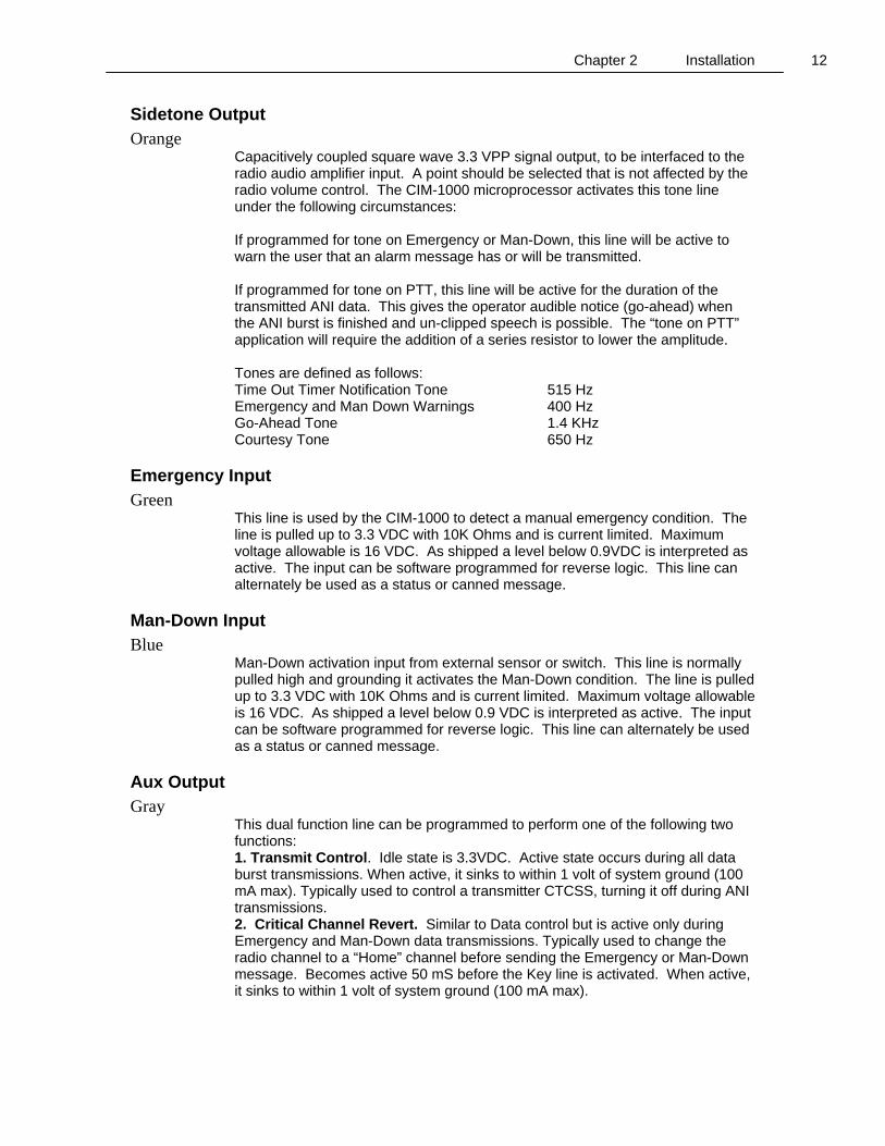
Jumper Information The CIM-1000 is supplied with jumper E installed. To install other jumpers, use a fine tip soldering iron and create a solder bridge. To remove a jumper, use the fine tip soldering iron and solder wick to wipe the jumper off.
Jumper Definitions
Jumper K Configuration Of all of the jumpers on the CIM-1000, this jumper will cause the most confusion. Jumper K connects the PTT and KEY lines together. Most applications will require K to be installed. When installed, the KEY wire is not used. The PTT wire now serves the dual function of PTT and KEY.
Time out timer applications Jumper K is removed on applications which require the CIM-1000 to serve as the transmit Time Out Timer (TOT). In this configuration, the radio keying function is routed through the CIM-1000. When the user pushes the PTT switch on the radio, the request goes to the CIM-1000. The CIM-1000 will immediately key or un-key the radio as requested by the user. If the PTT is held too long, the TOT will send the radio identification and then un-key the radio even if the user holds the PTT active. Once the user releases the radio PTT switch, the CIM-1000 TOT is reset and operation returns to normal. To enable the TOT feature, program
Jumper Usage A Supplies A+ voltage to Tone Control circuit. E Tone Control NPN open collector output. Additionally, install jumper A or V to obtain a 1Kohm
pull up resistor. Tone Control output will be pulled up to A+ or 3.3vdc depending on jumpers A and V.
F Tone Control PNP voltage output enable. Must also install jumper A or V to select between A+ or 3.3 VDC output.
G Tone Control direct output. Install jumper G if radio requires a simple 0 to 3.3v logic swing. J CIM-1000 supply voltage select.
Install jumper J if CIM-1000 is to be supplied by regulated 3.3vdc. Remove jumper J if CIM-1000 is to be supplied by un-regulated +3.6vdc or greater.
K PTT/KEY jumper. Install to connect PTT and Key lines. V Supplies 3.3v to Tone Control Circuit.
Chapter 2 Installation 15
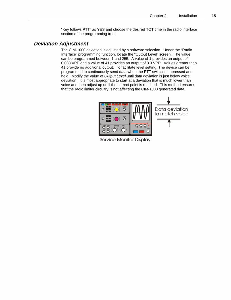
“Key follows PTT” as YES and choose the desired TOT time in the radio interface section of the programming tree.
Deviation Adjustment The CIM-1000 deviation is adjusted by a software selection. Under the “Radio Interface” programming function, locate the “Output Level” screen. The value can be programmed between 1 and 255. A value of 1 provides an output of 0.033 VPP and a value of 41 provides an output of 3.3 VPP. Values greater than 41 provide no additional output. To facilitate level setting, The device can be programmed to continuously send data when the PTT switch is depressed and held. Modify the value of Output Level until data deviation is just below voice deviation. It is most appropriate to start at a deviation that is much lower than voice and then adjust up until the correct point is reached. This method ensures that the radio limiter circuitry is not affecting the CIM-1000 generated data.
Chapter 3 Programming 16
C H A P T E R 3 Programming
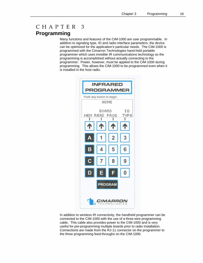
Many functions and features of the CIM-1000 are user programmable. In addition to signaling type, ID and radio interface parameters, the device can be optimized for the application’s particular needs. The CIM-1000 is programmed with the Cimarron Technologies hand-held portable programmer which uses invisible IR communications technology so the programming is accomplished without actually connecting to the programmer. Power, however, must be applied to the CIM-1000 during programming. This allows the CIM-1000 to be programmed even when it is installed in the host radio. In addition to wireless IR connectivity, the handheld programmer can be connected to the CIM-1000 with the use of a three-wire programming cable. This cable also provides power to the CIM-1000 and is very useful for pre-programming multiple boards prior to radio installation. Connections are made from the RJ-11 connector on the programmer to the three programming feed-throughs on the CIM-1000.
Chapter 3 Programming 17
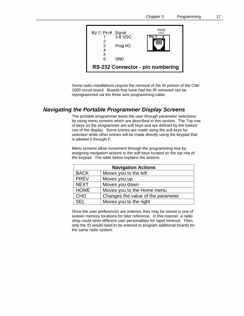
Some radio installations require the removal of the IR portion of the CIM-1000 circuit board. Boards that have had the IR removed can be reprogrammed via the three wire programming cable.
Navigating the Portable Programmer Display Screens The portable programmer leads the user through parameter selections by using menu screens which are described in this section. The Top row of keys on the programmer are soft keys and are defined by the bottom row of the display. Some entries are made using the soft keys for selection while other entries will be made directly using the keypad that is labeled 0 through F. Menu screens allow movement through the programming tree by assigning navigation actions to the soft keys located on the top row of the keypad. The table below explains the actions.
Navigation Actions BACK Moves you to the left PREV Moves you up NEXT Moves you down HOME Moves you to the Home menu CHG Changes the value of the parameter SEL Moves you to the right
Once the user preferences are entered, they may be stored in one of sixteen memory locations for later reference. In this manner, a radio shop could store different user personalities for rapid retrieval. Then, only the ID would need to be entered to program additional boards for the same radio system.
Chapter 3 Programming 18
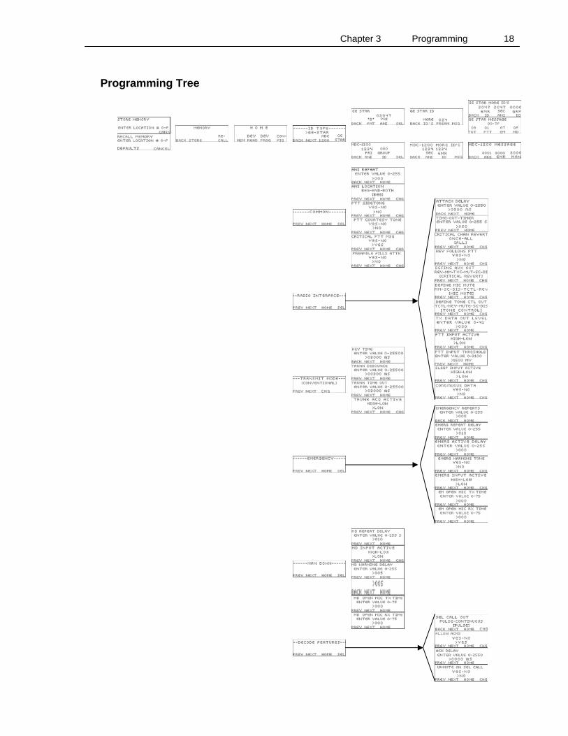
Programming Tree
Chapter 3 Programming 19
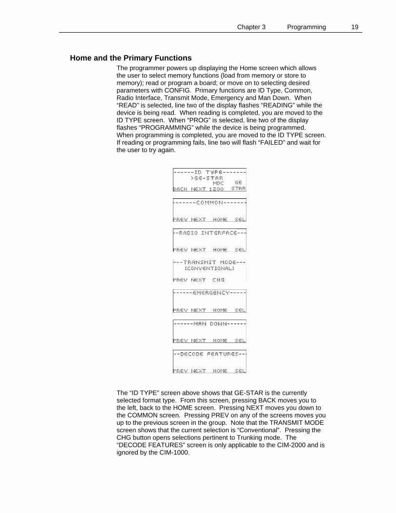
Home and the Primary Functions The programmer powers up displaying the Home screen which allows the user to select memory functions (load from memory or store to memory); read or program a board; or move on to selecting desired parameters with CONFIG. Primary functions are ID Type, Common, Radio Interface, Transmit Mode, Emergency and Man Down. When “READ” is selected, line two of the display flashes “READING” while the device is being read. When reading is completed, you are moved to the ID TYPE screen. When “PROG” is selected, line two of the display flashes “PROGRAMMING” while the device is being programmed. When programming is completed, you are moved to the ID TYPE screen. If reading or programming fails, line two will flash “FAILED” and wait for the user to try again.
The “ID TYPE” screen above shows that GE-STAR is the currently selected format type. From this screen, pressing BACK moves you to the left, back to the HOME screen. Pressing NEXT moves you down to the COMMON screen. Pressing PREV on any of the screens moves you up to the previous screen in the group. Note that the TRANSMIT MODE screen shows that the current selection is “Conventional”. Pressing the CHG button opens selections pertinent to Trunking mode. The “DECODE FEATURES” screen is only applicable to the CIM-2000 and is ignored by the CIM-1000.
Chapter 3 Programming 20
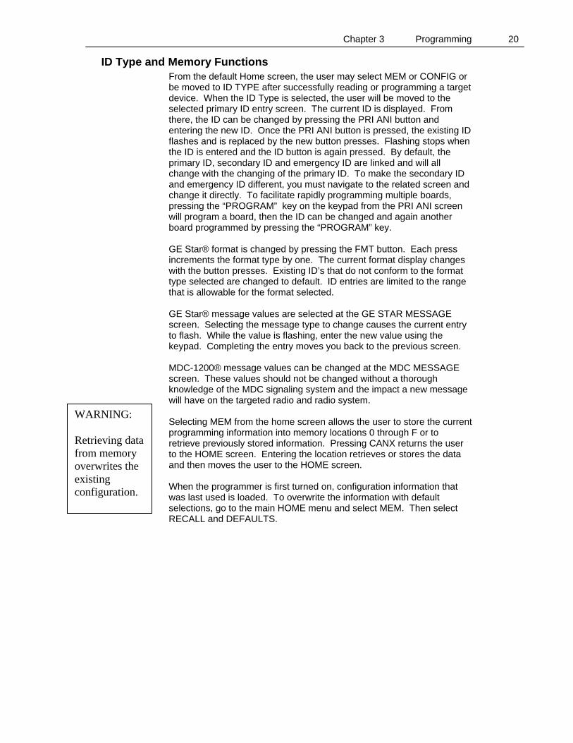
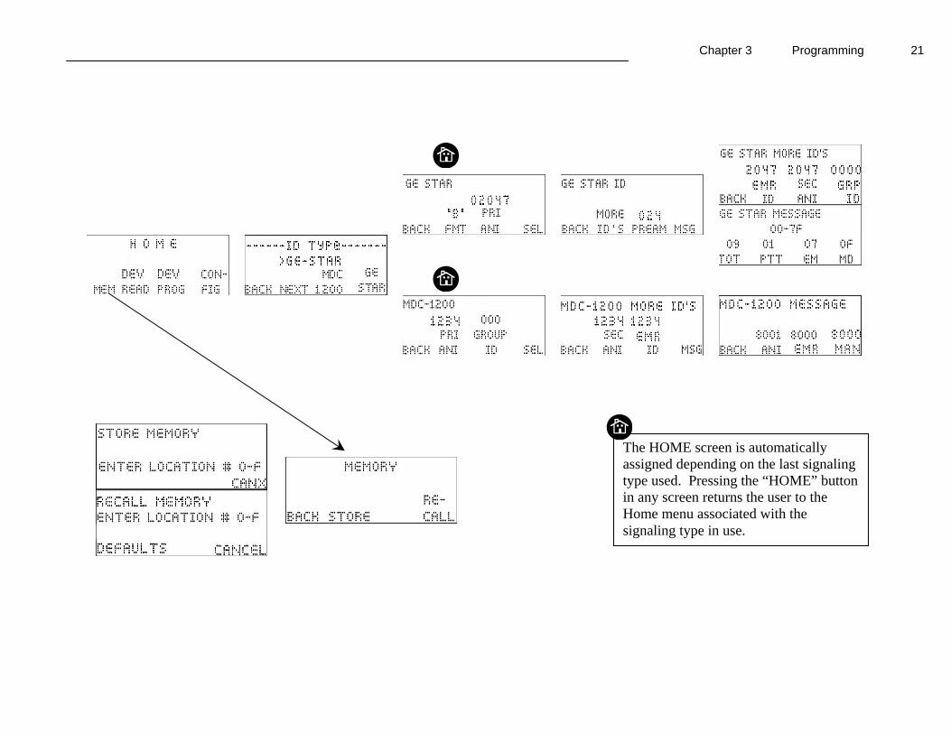
ID Type and Memory Functions From the default Home screen, the user may select MEM or CONFIG or be moved to ID TYPE after successfully reading or programming a target device. When the ID Type is selected, the user will be moved to the selected primary ID entry screen. The current ID is displayed. From there, the ID can be changed by pressing the PRI ANI button and entering the new ID. Once the PRI ANI button is pressed, the existing ID flashes and is replaced by the new button presses. Flashing stops when the ID is entered and the ID button is again pressed. By default, the primary ID, secondary ID and emergency ID are linked and will all change with the changing of the primary ID. To make the secondary ID and emergency ID different, you must navigate to the related screen and change it directly. To facilitate rapidly programming multiple boards, pressing the “PROGRAM” key on the keypad from the PRI ANI screen will program a board, then the ID can be changed and again another board programmed by pressing the “PROGRAM” key. GE Star® format is changed by pressing the FMT button. Each press increments the format type by one. The current format display changes with the button presses. Existing ID’s that do not conform to the format type selected are changed to default. ID entries are limited to the range that is allowable for the format selected. GE Star® message values are selected at the GE STAR MESSAGE screen. Selecting the message type to change causes the current entry to flash. While the value is flashing, enter the new value using the keypad. Completing the entry moves you back to the previous screen. MDC-1200® message values can be changed at the MDC MESSAGE screen. These values should not be changed without a thorough knowledge of the MDC signaling system and the impact a new message will have on the targeted radio and radio system. Selecting MEM from the home screen allows the user to store the current programming information into memory locations 0 through F or to retrieve previously stored information. Pressing CANX returns the user to the HOME screen. Entering the location retrieves or stores the data and then moves the user to the HOME screen. When the programmer is first turned on, configuration information that was last used is loaded. To overwrite the information with default selections, go to the main HOME menu and select MEM. Then select RECALL and DEFAULTS.
WARNING: Retrieving data from memory overwrites the existing configuration.
Chapter 3 Programming 21
The HOME screen is automatically assigned depending on the last signaling type used. Pressing the “HOME” button in any screen returns the user to the Home menu associated with the signaling type in use.
Chapter 3 Programming 22
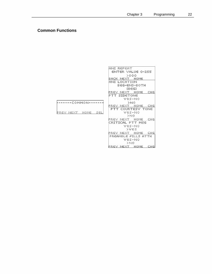
Common Functions
Chapter 3 Programming 23
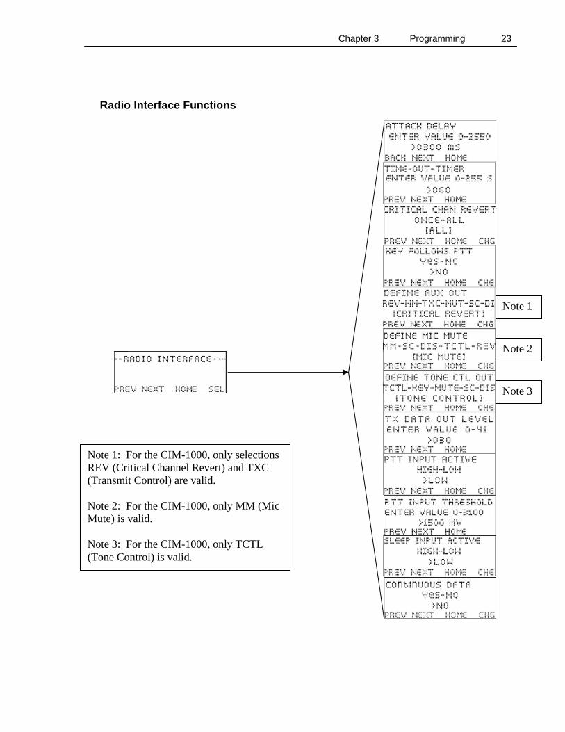
Radio Interface Functions
Note 1: For the CIM-1000, only selections REV (Critical Channel Revert) and TXC (Transmit Control) are valid. Note 2: For the CIM-1000, only MM (Mic Mute) is valid. Note 3: For the CIM-1000, only TCTL (Tone Control) is valid.
Note 1
Note 2
Note 3
Chapter 3 Programming 24
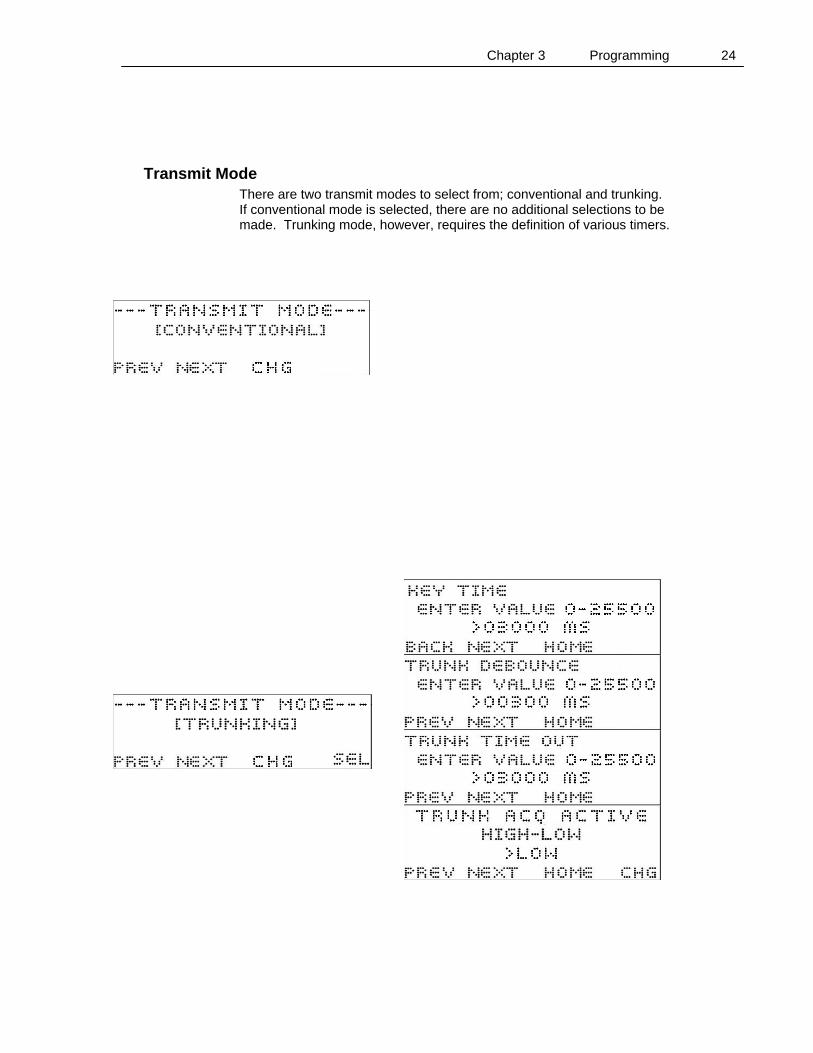
Transmit Mode There are two transmit modes to select from; conventional and trunking. If conventional mode is selected, there are no additional selections to be made. Trunking mode, however, requires the definition of various timers.
Chapter 3 Programming 25
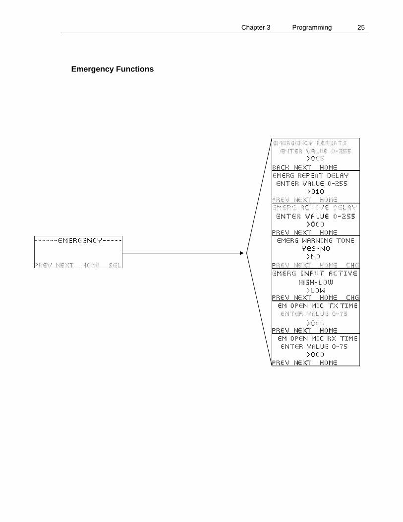
Emergency Functions
Chapter 3 Programming 26
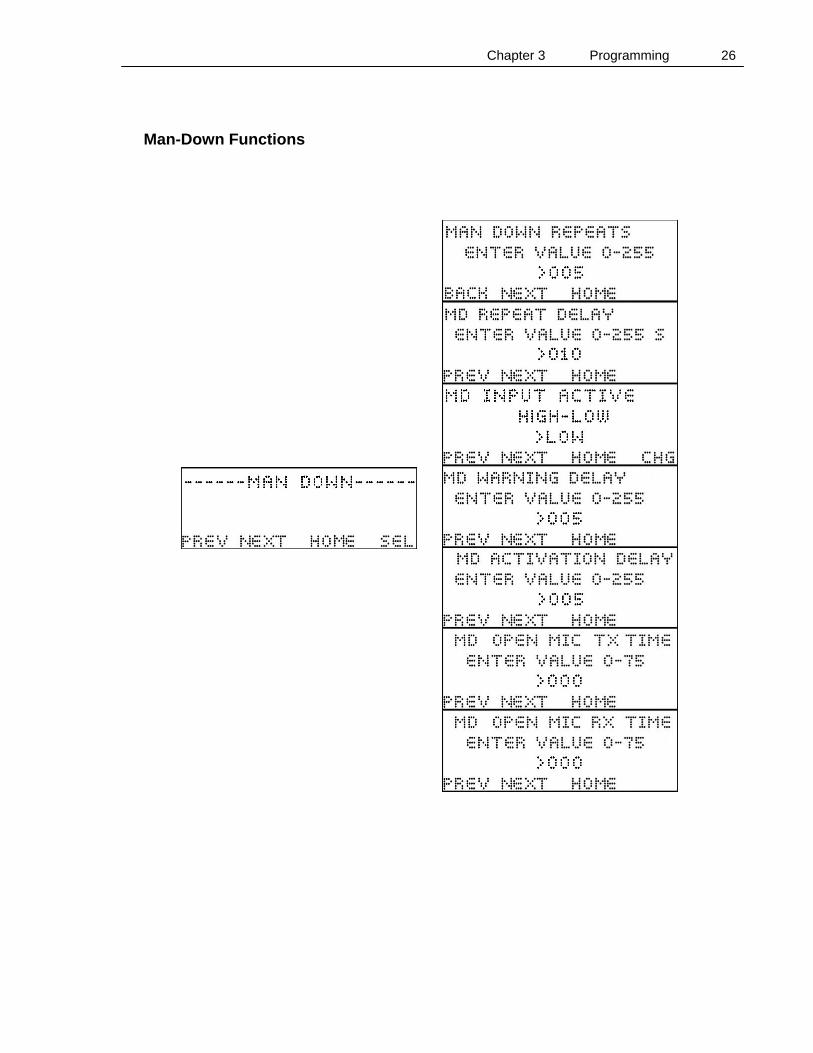
Man-Down Functions
Chapter 3 Programming 27
Programming using the CIM-CABLE The programming cable, CIM-CABLE, supports connection via a computer serial port with any computer running terminal emulation software. One such program that is included in most Microsoft operating systems is called Hyperterm. Hyperterm is usually accessed under “Programs”, “Accessories” and “Communications” in the windows start menu. Start the Hyperterm program on your computer by double clicking on Hyperterm.exe or selecting Hyperterm under the Communications menu selection. A New Connection window will open. Name the new connection “CIM1000”, select one of the available icons and click the “OK” button. A Connect To window will open. Under Connect Using, select “Direct to COM1” and click the “OK” button. A Port Settings window will open. Adjust the settings to match the below table and then click the “OK” button:
Parameter Value Bits per Second 9600
Data Bits 8 Parity None
Stop Bits 1 Flow Control None
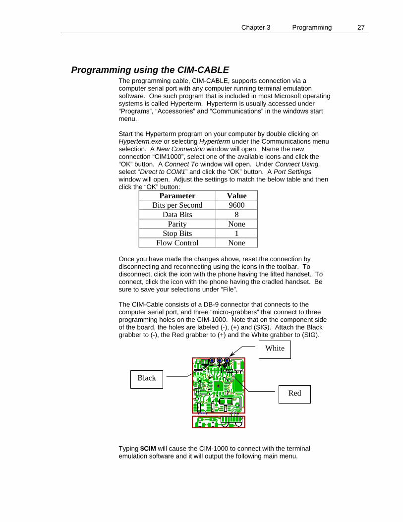
Once you have made the changes above, reset the connection by disconnecting and reconnecting using the icons in the toolbar. To disconnect, click the icon with the phone having the lifted handset. To connect, click the icon with the phone having the cradled handset. Be sure to save your selections under “File”. The CIM-Cable consists of a DB-9 connector that connects to the computer serial port, and three “micro-grabbers” that connect to three programming holes on the CIM-1000. Note that on the component side of the board, the holes are labeled (-), (+) and (SIG). Attach the Black grabber to (-), the Red grabber to (+) and the White grabber to (SIG). Typing $CIM will cause the CIM-1000 to connect with the terminal emulation software and it will output the following main menu.
White
Red
Black
Chapter 3 Programming 28
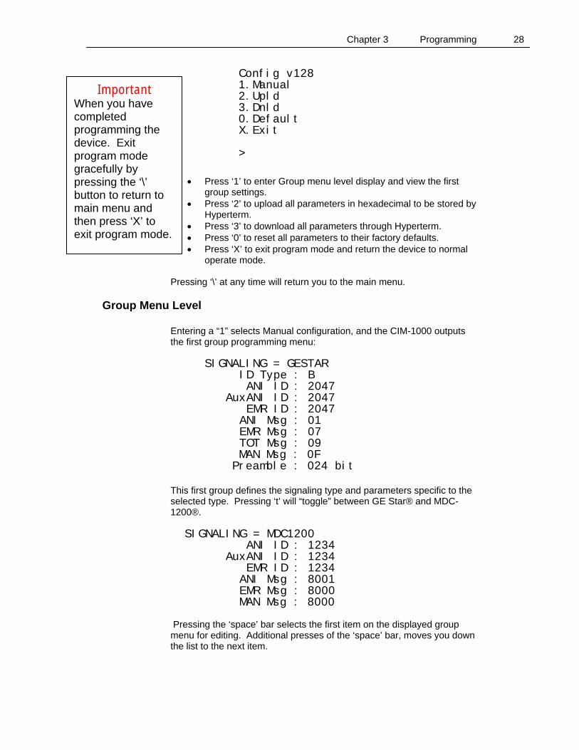
Config v128 1.Manual 2.Upld 3.Dnld 0.Default X.Exit
>
• Press ‘1’ to enter Group menu level display and view the first
group settings. • Press ‘2’ to upload all parameters in hexadecimal to be stored by
Hyperterm. • Press ‘3’ to download all parameters through Hyperterm. • Press ‘0’ to reset all parameters to their factory defaults. • Press ‘X’ to exit program mode and return the device to normal
operate mode. Pressing ‘\’ at any time will return you to the main menu.
Group Menu Level Entering a “1” selects Manual configuration, and the CIM-1000 outputs the first group programming menu:
SIGNALING = GESTAR ID Type : B ANI ID : 2047 AuxANI ID : 2047 EMR ID : 2047 ANI Msg : 01 EMR Msg : 07 TOT Msg : 09 MAN Msg : 0F
Preamble : 024 bit This first group defines the signaling type and parameters specific to the selected type. Pressing ‘t’ will “toggle” between GE Star® and MDC-1200®.
SIGNALING = MDC1200 ANI ID : 1234 AuxANI ID : 1234 EMR ID : 1234 ANI Msg : 8001 EMR Msg : 8000
MAN Msg : 8000 Pressing the ‘space’ bar selects the first item on the displayed group menu for editing. Additional presses of the ‘space’ bar, moves you down the list to the next item.
Important When you have completed programming the device. Exit program mode gracefully by pressing the ‘\’ button to return to main menu and then press ‘X’ to exit program mode.
Chapter 3 Programming 29
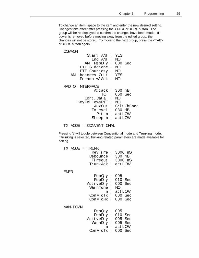
To change an item, space to the item and enter the new desired setting. Changes take effect after pressing the <TAB> or <CR> button. The group will be re-displayed to confirm the changes have been made. If power is removed before moving away from the edited group, the changes will not be stored. To move to the next group, press the <TAB> or <CR> button again.
COMMON Start ANI : YES End ANI : NO ANI RepDly : 000 Sec PTT Sidetone : NO PTT Courtesy : NO ANI becomes Crit : YES
Preamb w/Atk : NO
RADIO INTERFACE Attack : 300 mS TOT : 060 Sec Cont.Data : NO KeyFollowsPTT : NO AuxOut : CritChOnce TxLevel : 030 dB PttIn : actLOW SleepIn : actLOW TX MODE = CONVENTIONAL
Pressing ‘t’ will toggle between Conventional mode and Trunking mode. If trunking is selected, trunking related parameters are made available for editing.
TX MODE = TRUNK KeyTime : 3000 mS Debounce : 300 mS Timeout : 3000 mS TrunkAck : actLOW EMER RepQty : 005 RepDly : 010 Sec ActiveDly : 000 Sec WarnTone : NO In : actLOW OpnMicTx : 000 Sec OpnMicRx : 000 Sec MAN-DOWN RepQty : 005 RepDly : 010 Sec ActiveDly : 005 Sec WarnDly : 005 Sec In : actLOW OpnMicTx : 000 Sec
Chapter 3 Programming 30
OpnMicRx : 000 Sec
Programmable Parameter Definitions
Signaling Type and ID Selection
Signaling Type Selection The CIM-1000 is programmable to encode one of two signaling types. These types are GE Star® and MDC-1200®.
Secondary ANI ID’s Secondary ANI ID’s are used if the CIM-1000 is turned on while the radio PTT is pressed. If dual ID’s are not desired, program the primary ID and secondary ID with the same number.
GE Star®
GE Star® format type (A through P) This selection defines which of the sixteen GE Star® formats are in use.
GE Star® PTT ID, Emergency ID (1 – 16383) The actual maximum value depends on the GE Star® format type selected. Generally, the PTT ID, Emergency ID and Man-Down ID in GE Star® are the same; however, they could be programmed different if desired.
ANI Message This selection defines the four message bits and three status bits in the GE Star® payload. An ANI PTT ID message is hex 01. This could be changed to accommodate unique applications. Other message definitions are listed on page 39.
Emergency Message This selection defines the four message bits and three status bits in the GE Star® payload. An emergency message is hex 07. This could be changed to accommodate unique applications. Other message definitions are listed on page 39.
TOT Message This selection defines the four message bits and three status bits in the GE Star® payload. A TOT (Time-out-timer) message is hex 09. This could be changed to accommodate unique applications. Other message definitions are listed on page 39.
Man-Down Message This selection defines the four message bits ant three status bits in the GE Star® payload. A Man-down message is hex 0F. This could be

Chapter 3 Programming 31
changed to accommodate unique applications. Other message definitions are listed on page 39.
Preamble Length The original GE Star® format specified 16 preamble bits. However, it was determined that a 24 bit preamble significantly improved data muting reliability and 24 bits eventually became the standard. Some installations have opted to increase the preamble length while decreasing the attack delay. So the length can be programmed from 0 bits to 255.
MDC-1200®
MDC-1200® PTT ID, Emergency ID (1 – DEEE) Generally, the PTT ID and the Emergency ID are the same; however, they could be programmed different if desired. A radio ID cannot contain the character F nor can it begin with the character E as these are defined as wildcards.
ANI Message To increase flexibility of the CIM-1000 and enhance compatibility with existing communications systems, the format of encoded MDC-1200® messages can be modified. The default message type for a PTT ANI is represented by 0x8001
Emergency Message To increase flexibility of the CIM-1000 and enhance compatibility with existing communications systems, the format of encoded MDC-1200® messages can be modified. The default message type for an Emergency ANI is 0x8000.
Common The common section handles parameters that will be used in all available signaling formats.
Location: If programmed “Beginning”, the ID will be transmitted when the user keys the radio. If programmed “End”, the ID will be transmitted when the user un-keys the radio. If programmed “Both”, the ID will be transmitted both at the beginning and end of transmission
PTT ANI repeat timer: Used to reduce the amount of data transmissions during a conversation. If the selected time since the last PTT press is not exceeded, data is not transmitted with that PTT press.
Sidetone with PTT ANI: If programmed “Yes”, a tone will sound through the local speaker to advise the user to hold off talking. The tone helps to prevent “voice syllable clipping” which could occur if the user speaks during data transmission.
Chapter 3 Programming 32
Un-key courtesy tone: If programmed “Yes”, a tone will be transmitted when the user un-keys to inform listeners that they may now transmit.
PTT Message Becomes Critical If enabled, whenever the device is in critical mode (emergency cycle or Man-Down cycle), and the PTT button is pressed, the ANI message to be transmitted will be the associated critical message instead of a PTT ANI message.
Preamble Fills Attack Delay Typically, the attack delay is filled with silent carrier. If this selection is enabled, the attack delay period will be filled with the signaling format preamble and there will be no silent attack delay. After the programmed attack delay, one more duration of preamble will be transmitted to ensure reliable decoding.
Radio Interface The Radio Interface section handles parameters that relate to the correct interfacing of the board to the radio electronics.
Attack Delay: The period of time from when the user keys the radio and when the data begins to be transmitted is called the attack delay. This delay allows the communications system to stabilize and be ready for transmission.
Time out timer: If the radio is held keyed up for greater than the selected time, the ID is transmitted and the radio is automatically un-keyed.
Critical Channel Revert: If enabled, 50 mS prior to keying up to transmit an Emergency or a Man-Down, the Auxiliary output line (If it also is programmed for “Critical Channel Revert” will go low and stay low for the duration of the attack delay and data transmission.
Key Follows PTT Enabling Key Follows PTT makes the CIM-1000 key line echo the condition of the PTT line. So if the PTT line goes low, the key line will follow and stay in the condition until the PTT line again changes state. This is especially useful if you desire the CIM-1000 to un-key the radio at the expiration of the Time-Out-Timer time.
Multiple Function Output The multiple function output line can be programmed to serve one of two purposes as listed.
Transmit Control Output Transmit control output is typically used to control a transmitter CTCSS, turning it off during ANI transmissions. Idle state is 3.3VDC. When
Chapter 3 Programming 33
active, it sinks to within 1 volt of system ground (100 mA max). Active state occurs during attack delay and all data burst transmissions.
Critical Channel Revert Alternate channel control is similar to Data control but is active only during Emergency and Man-Down data transmissions. It is used to change the radio channel to a “Home” channel before sending the Emergency or Man-Down message. This line becomes active 50 mS before the Key line is activated for emergency and man-down transmissions. When active, it sinks to within 1 volt of system ground (100 mA max).
Output Level The data output level of the CIM-1000 is software adjustable. This level can be set by entering a number between 0 and 41. The default setting is 20. Although the configuration routine will permit an entry of between 0 to 255, the maximum output is achieved at a setting of 41. A setting of 21 provides approximately 0.33 Vpp unloaded. A setting of 41 provides the maximum of 3.3 VPP.
PTT Input Active Level PTT input is used to detect when the attached radio is busy transmitting. This line is programmable for an input sense of active high or active low.
Sleep Input This is useful if ANI is desired on selected channels only or when not desired on talk-around channels. This is an input to the CIM-1000 microprocessor. If the line becomes active, it will put the CIM-1000 to “sleep” preventing ANI activity. The active state is programmable for logic 1 or 0. It is normally pulled up to VCC.
Transmit Mode
Conventional If Conventional is selected, data is transmitted after the programmed attack delay.
Trunked If trunked mode is selected, the Channel Acquired input line of the CIM-1000 is used to detect when the trunking channel has been acquired and transmission is possible. In LTR systems, Trunk Key Time and Trunk Timeout should be the same. In MPT-1327, this timer allows the transmitter to be keyed and then un-keyed in order to request channel access. The time selected is the period the unit stays keyed for the request. The CIM-1000 will wait for the period designated in Trunk Timeout for a channel acquisition indication. When received, the unit will again key up and send out data.
Trunk Debounce Some trunking radios have channel acquired logic which pulses while attempting to be granted access and then remain in a state showing access is granted. For this reason, the line is programmable to set the
Chapter 3 Programming 34
debounce time so that pulsing is ignored. The unit will not transmit data until the specified time period has been exceeded.
Trunk Key Time Trunk Key sets the time the unit is keyed while awaiting channel acquisition.
Trunk Time Out Trunk Timeout sets the maximum amount of time that the unit will attempt to acquire a trunk. Once exceeded, the unit will quit attempts.
Trunk Channel Acquired Active Level This line is interfaced to a point in a trunking radio that changes state when granted access. The input is used to detect when the trunking channel has been acquired and transmission is possible.
Emergency
Number of repeat emergency transmissions: The number of times that an emergency message is to be repeated. If this is set to 255, the emergency cycle will continue until power is cycled on the host radio.
Repeat Delay: When in the emergency mode, if the number of repeat emergency transmissions is not “Zero”, this is the time that will be waited between emergency transmissions.
Activation Delay This timer designates the amount of time the emergency input must be held active before it is recognized by the board.
Emergency TX warning tone: If programmed “Yes”, a warning tone will sound through the local speaker to advise the user that an emergency message is being transmitted.
Active State The active state is programmable for logic 1 or 0. It is normally pulled up to VCC.
Open Microphone Monitor on Emergency TX time If not set to zero, once an emergency is activated, the radio will key up and transmit ambient noise for this period of time. It will then un-key and remain un-keyed for a programmed amount of time and then repeat the process. It will alternate between TX and RX throughout the emergency cycle. The length of the cycle is determined by the settings of “Number of repeat emergency transmissions“ and “Time between emergency repeats“. If the value is set to zero, there will be no open microphone monitor.
Chapter 3 Programming 35
Open Microphone Monitor on Emergency RX time If open microphone monitor on emergency TX time is not set to zero, the radio will remain unkeyed for this period of time between TX times.
Man-Down
Number of repeat Man-Down transmissions (0 to 255 repeats) The Man-Down message transmission will be repeated a programmed number of times with a programmed period between transmissions. The repeats will be transmitted regardless of radio status. If this is set to 255, the emergency cycle will continue until power is cycled on the host radio. A warning tone is sounded at the local radio speaker each time a man-down message is transmitted, unless man-down activation delay is set to zero.
Repeat Delay (0 to 255s) Repeated Man-Down transmissions will be separated by a programmed delay period between transmissions.
Active State The active state is programmable for logic 1 or 0. It is normally pulled up to VCC.
Man-Down Warning Delay (0 – 255 S) Once the CIM-1000 senses a Man-Down situation, this timer begins to run. If the radio is not up righted within this period of time, a warning tone lasting 1 second is sounded. If the radio is up righted, the warning timer resets. If the warning delay is set to zero, there will be no audible warning and the man-down message will be transmitted at the expiration of the man-down activation delay.
Man-Down Activation Delay (0 – 255 S) If the warning delay timer succeeds to complete its countdown and the warning tone is sounded, the activation delay timer begins to run. The activation delay timer is programmable 0 to 255 seconds. If the radio is not up righted within this period of time, the radio will key up and send a message to the base.
Open Microphone Monitor on Man-Down TX time (0s to 55s, 5s steps) If not set to zero, once a Man-Down is activated, the radio will key up and transmit ambient noise for this period of time. It will then un-key and remain un-keyed for a programmed amount of time and then repeat the process. It will alternate between TX and RX throughout the Man-Down cycle. The length of the cycle is determined by the settings of “Number of repeat Man-Down transmissions“ and “Time between Man-Down repeats“. If the value is set to zero, there will be no open microphone monitor.

Chapter 3 Programming 36
Open Microphone Monitor on Man-Down RX time (0s to 55s, 5s steps) If open microphone monitor on Man-Down TX time is not set to zero, the radio will remain un-keyed for this period of time between TX times.
Chapter 4 Operation 37
C H A P T E R 4 Operation
ANI-ID ANI (Automatic Numeric Identification) provides for digital identification of a transmission initiated by a transmitter's microphone switch (“Press-To-Talk” or “PTT” switch). This “digital burst” can occur when the switch is first pressed, or when the switch is released, or at both times. The burst time for most identifiers is approximately 1/3 second and, if transmitted upon pressing the PTT switch, and the user immediately begins to talk, may obliterate one or two syllables of spoken speech. To overcome this annoyance, the Model CIM-1000 is programmable to produce the burst either at the beginning or at the end of the voice transmission, or at both times. To further guard against voice-syllable clipping, the user may program a “PTT Sidetone“. When programmed and interfaced to receiver audio, this feature will provide an audible tone during the beginning transmission of the ANI-ID burst to alert the operator that data is being transmitted.
Time-out-timer When a mobile or portable radio inadvertently remains keyed due to a stuck microphone switch, it generally means that the radio frequency is unusable for communications. Unfortunately, this activity is sometimes deliberately caused by a field operator. Whenever a microphone switch is held closed for more than the designated time-out-timer time the CIM-1000 will sound a local warning tone and send the ID of the offending radio. The unit can also be installed in a manner that will automatically open the key line until the microphone switch is released.
Emergency The Emergency feature is generally used by law enforcement, security agencies and fire departments to automatically signal a life-threatening situation where it is difficult, impossible, or impractical to use voice. The emergency message is also frequently used by business and industrial users to signal a critical situation, such as a mechanical failure, over or under temperature (pressure, etc.), or extraordinary event. The CIM-1000 allows for programming whether the message should be repeated and at what intervals and for how long. In addition, during the emergency cycle the microphone of the sending radio can be monitored, and can alternate between monitoring and allowing the channel to be used for voice communications.
Man-Down The Man-Down feature is primarily for use by law enforcement, security agencies, and fire departments. It also finds uses in business and industry where individuals can be overcome by toxic fumes, lack of oxygen, etc. The Man-Down ID is generally initiated by closure of a mercury switch located within a hand-held radio when the radio is continuously tipped
Chapter 4 Operation 38
greater than 60 degrees from vertical. To guard against false “Man-Down” transmissions an initial pause of a few seconds is provided during which the closure must be constant. After this duration a short tone is produced via the radio's speaker. A second pause follows the tone to allow the radio to be placed in an upright position (in the event no actual “Man-Down” is occurring). Following the second pause the “Man-Down-ID” data burst is transmitted in the same manner as the “Emergency-ID”. The Man-Down mode also can include the microphone monitoring alternative. Transmission of a unique coding for the Man-Down message (in lieu of a general Emergency coding), and multiple choices of initiation, tone, and final pause times are available.
Status Status messages typically relate to the status of the field unit, such as “In Service”, “Out Of Service”, “On Break”, etc. and their appropriate meaning can be displayed at the decoding site equipped with a Cimarron Technologies C Plus decoder. The CIM-1000 is capable of transmitting status messages in lieu of the Man-Down, Emergency and PTT ANI as required.
Canned Messages “Canned” messages handle such communications as “Request-To-Talk”, “Priority-Request-To-Talk”, “Repeat Last Transmission”, “Repeat Address”, “10-4”, “Roger”, and other routine requests and responses. Their appropriate meaning can be displayed at the decoding site equipped with a Cimarron Technologies C Plus decoder. The CIM-1000 is capable of transmitting canned messages in lieu of the Man-Down, Emergency and PTT ANI as required.
Dual ID Capability The CIM-1000 can be programmed for two independent ID’s. If the radio is turned on with the PTT held down, the secondary ID is used until power is cycled on the radio. If the radio is turned on normally, without holding down the PTT switch, the first ID is used. This feature requires that the PTT line of the radio be split so that PTT operations are routed through the CIM-1000. The PTT line (Yellow) of the CIM-1000 will then be attached to the PTT button of the radio and the KEY line (Brown) of the CIM-1000 will be attached to the other side of the split. “Key follows PTT” must be programmed “YES” in the CIM-1000. Some radios have a zero ohm resistor or jumper that can be removed to split the PTT line. Others split the line with software programming. But some radios will need to have a trace cut to split the PTT line.
Chapter 5 Technical Information 39
C H A P T E R 5 Technical Information
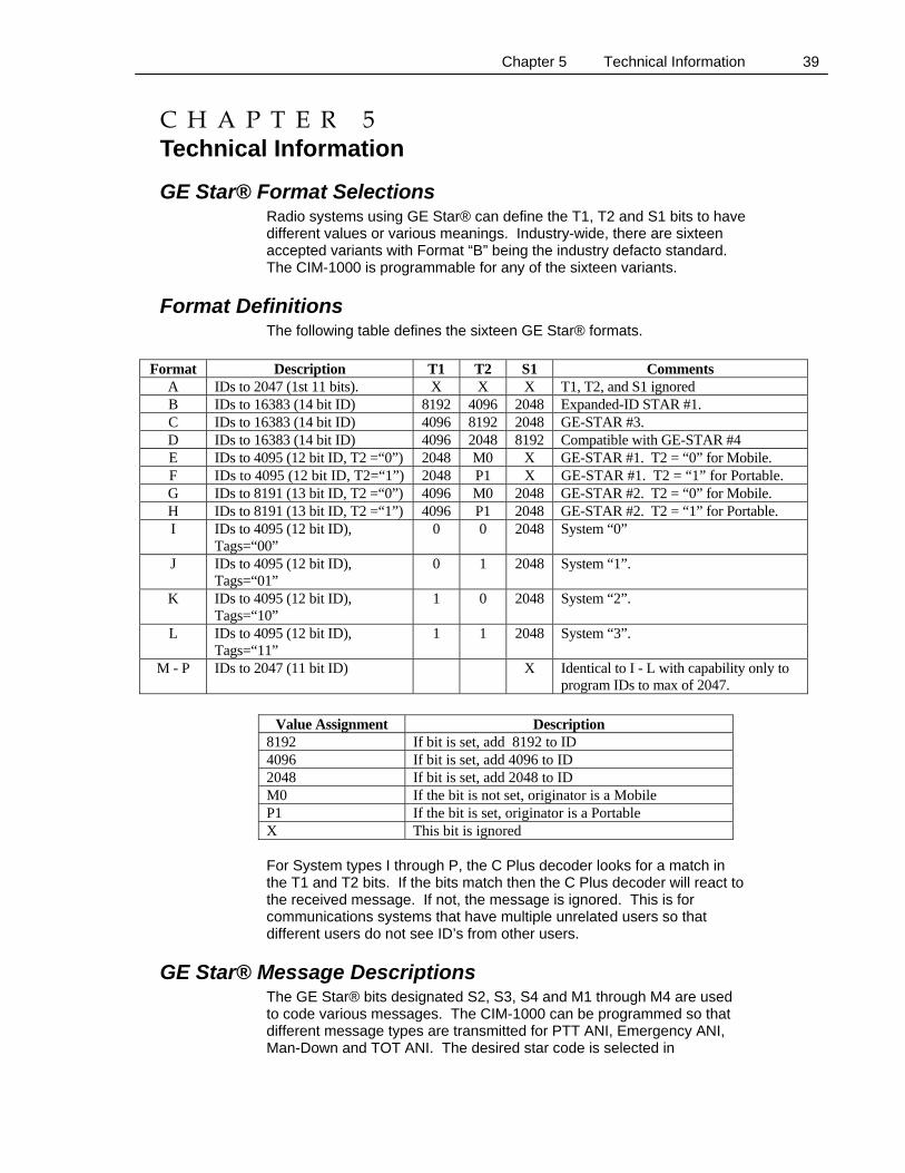
GE Star® Format Selections Radio systems using GE Star® can define the T1, T2 and S1 bits to have different values or various meanings. Industry-wide, there are sixteen accepted variants with Format “B” being the industry defacto standard. The CIM-1000 is programmable for any of the sixteen variants.
Format Definitions The following table defines the sixteen GE Star® formats.
Format Description T1 T2 S1 Comments
A IDs to 2047 (1st 11 bits). X X X T1, T2, and S1 ignored B IDs to 16383 (14 bit ID) 8192 4096 2048 Expanded-ID STAR #1. C IDs to 16383 (14 bit ID) 4096 8192 2048 GE-STAR #3. D IDs to 16383 (14 bit ID) 4096 2048 8192 Compatible with GE-STAR #4 E IDs to 4095 (12 bit ID, T2 =“0”) 2048 M0 X GE-STAR #1. T2 = “0” for Mobile. F IDs to 4095 (12 bit ID, T2=“1”) 2048 P1 X GE-STAR #1. T2 = “1” for Portable. G IDs to 8191 (13 bit ID, T2 =“0”) 4096 M0 2048 GE-STAR #2. T2 = “0” for Mobile. H IDs to 8191 (13 bit ID, T2 =“1”) 4096 P1 2048 GE-STAR #2. T2 = “1” for Portable. I IDs to 4095 (12 bit ID),
Tags=“00” 0 0 2048 System “0”
J IDs to 4095 (12 bit ID), Tags=“01”
0 1 2048 System “1”.
K IDs to 4095 (12 bit ID), Tags=“10”
1 0 2048 System “2”.
L IDs to 4095 (12 bit ID), Tags=“11”
1 1 2048 System “3”.
M - P IDs to 2047 (11 bit ID) X Identical to I - L with capability only to program IDs to max of 2047.
Value Assignment Description
8192 If bit is set, add 8192 to ID 4096 If bit is set, add 4096 to ID 2048 If bit is set, add 2048 to ID M0 If the bit is not set, originator is a Mobile P1 If the bit is set, originator is a Portable X This bit is ignored For System types I through P, the C Plus decoder looks for a match in the T1 and T2 bits. If the bits match then the C Plus decoder will react to the received message. If not, the message is ignored. This is for communications systems that have multiple unrelated users so that different users do not see ID’s from other users.
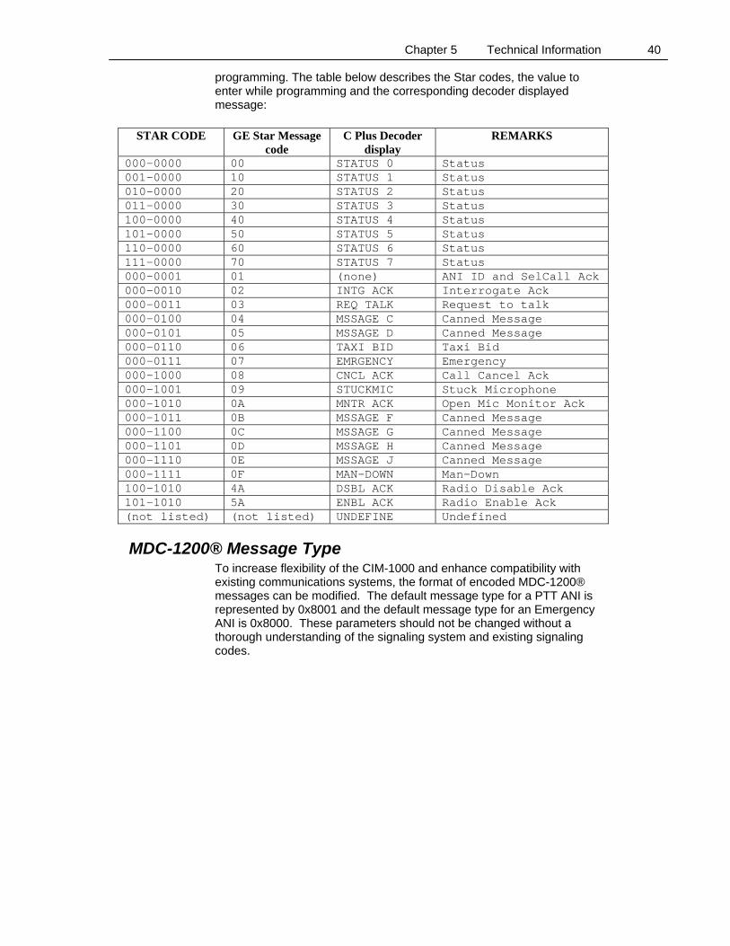
GE Star® Message Descriptions The GE Star® bits designated S2, S3, S4 and M1 through M4 are used to code various messages. The CIM-1000 can be programmed so that different message types are transmitted for PTT ANI, Emergency ANI, Man-Down and TOT ANI. The desired star code is selected in
Chapter 5 Technical Information 40
programming. The table below describes the Star codes, the value to enter while programming and the corresponding decoder displayed message:
STAR CODE GE Star Message
code C Plus Decoder
display REMARKS
000-0000 00 STATUS 0 Status 001–0000 10 STATUS 1 Status 010-0000 20 STATUS 2 Status 011-0000 30 STATUS 3 Status 100-0000 40 STATUS 4 Status 101-0000 50 STATUS 5 Status 110-0000 60 STATUS 6 Status 111-0000 70 STATUS 7 Status 000-0001 01 (none) ANI ID and SelCall Ack 000-0010 02 INTG ACK Interrogate Ack 000-0011 03 REQ TALK Request to talk 000-0100 04 MSSAGE C Canned Message 000-0101 05 MSSAGE D Canned Message 000-0110 06 TAXI BID Taxi Bid 000-0111 07 EMRGENCY Emergency 000-1000 08 CNCL ACK Call Cancel Ack 000-1001 09 STUCKMIC Stuck Microphone 000-1010 0A MNTR ACK Open Mic Monitor Ack 000-1011 0B MSSAGE F Canned Message 000-1100 0C MSSAGE G Canned Message 000-1101 0D MSSAGE H Canned Message 000-1110 0E MSSAGE J Canned Message 000-1111 0F MAN-DOWN Man-Down 100-1010 4A DSBL ACK Radio Disable Ack 101-1010 5A ENBL ACK Radio Enable Ack (not listed) (not listed) UNDEFINE Undefined
MDC-1200® Message Type To increase flexibility of the CIM-1000 and enhance compatibility with existing communications systems, the format of encoded MDC-1200® messages can be modified. The default message type for a PTT ANI is represented by 0x8001 and the default message type for an Emergency ANI is 0x8000. These parameters should not be changed without a thorough understanding of the signaling system and existing signaling codes.
Chapter 5 Technical Information 41
Trunking Operation In trunking mode, we will not transmit until we have been given permission. This is detected by the use of timers Trunk Debounce, Trunk Key Time and Trunk Timeout and sense line Aux IN. Here are a couple of scenarios that discuss operation.
Systems where Trunk Key Time and Trunk Timeout are set to the same value (LTR):
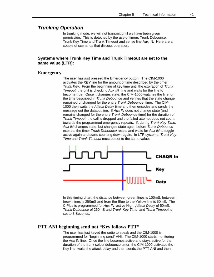
Emergency The user has just pressed the Emergency button. The CIM-1000 activates the KEY line for the amount of time described by the timer Trunk Key. From the beginning of key time until the expiration of Trunk Timeout, the unit is checking Aux IN line and waits for the line to become true. Once it changes state, the CIM-1000 watches the line for the time described in Trunk Debounce and verifies that the state change remained unchanged for the entire Trunk Debounce time. The CIM-1000 then waits the Attack Delay time and then encodes and sends the message out the dataout line. If Aux IN does not change state (and remains changed for the entire Trunk Debounce time) for the duration of Trunk Timeout the call is dropped and the failed attempt does not count towards the programmed emergency repeats. If, during Trunk Key Time, Aux IN changes state, but changes state again before Trunk Debounce expires, the timer Trunk Debounce resets and waits for Aux IN to toggle active again and starts counting down again. In LTR systems, Trunk Key Time and Trunk Timeout must be set to the same value.
In this timing chart, the distance between green lines is 100mS, between brown lines is 250mS and from the Blue to the Yellow line is 50mS. The C Plus is programmed for Aux IN active High, Attack Delay of 50mS, Trunk Debounce of 250mS and Trunk Key Time and Trunk Timeout is set to 3 Seconds.
PTT ANI beginning send not “Key follows PTT” The user has just keyed the radio to speak and the CIM-1000 is programmed for “beginning send” ANI. The CIM-1000 starts monitoring the Aux IN line. Once the line becomes active and stays active for the duration of the trunk select debounce timer, the CIM-1000 activates the Key line, waits the attack delay and then sends the PTT ANI and then
Chapter 5 Technical Information 42
deactivates the Key line. The radio remains keyed because the user is still pressing the PTT button. If the Aux IN line does not become active and remain active for the duration of the trunk select debounce timer, by the end of the Trunk Time out, the call is dropped.
PTT ANI end send not “Key follows PTT” The user has just keyed the radio to speak and the CIM-1000 is programmed for “end send” ANI. The CIM-1000 waits for the user to unkey the radio. The CIM-1000 then activates the KEY line for the amount of time described by the timer Trunk Key. From the beginning of key time until the expiration of Trunk Timeout, the unit is checking Aux IN line and waits for the line to become true. Once it changes state, the CIM-1000 watches the line for the time described in Trunk Debounce and verifies that the state change remained unchanged for the entire Trunk Debounce time. The CIM-1000 then waits the Attack Delay time and then encodes and sends the message out the dataout line. If Aux IN does not change state (and remain changed for the entire Trunk Debounce time) for the duration of Trunk Timeout the call is dropped. If, during Trunk Key Time, Aux IN changes state, but changes state again before Trunk Debounce expires, the timer Trunk Debounce resets and waits for Aux IN to toggle active again and starts counting down again.
PTT ANI beginning send with “Key follows PTT” The user has just keyed the radio to speak and the CIM-1000 is programmed for “beginning send” ANI. The CIM-1000 activates the key line and starts monitoring the Aux IN line. Once the line becomes active and stays active for the duration of the trunk select debounce timer, the CIM-1000 waits the attack delay and then sends the PTT ANI. The Key line remains active until the user releases the PTT button. If the Aux IN line does not become active within the time set in Trunk Timeout, the key line relaxes and the call is dropped. The user must rekey the radio to make another attempt. The value of Trunk Key (which is the same as the value of Trunk Timeout) is ignored.
PTT ANI end send with “Key follows PTT” The user has just keyed the radio to speak and the CIM-1000 is programmed for “end send” ANI. The CIM-1000 activates the key line and continues monitoring the PTT line. Once the line becomes inactive, the CIM-1000 sends the PTT ANI and then unkeys the radio. The values of Trunk Key Time, Trunk Timeout and Trunk Debounce time are ignored.
Systems where Trunk Key Time and Trunk Timeout are not set to the same value (MPT and others):
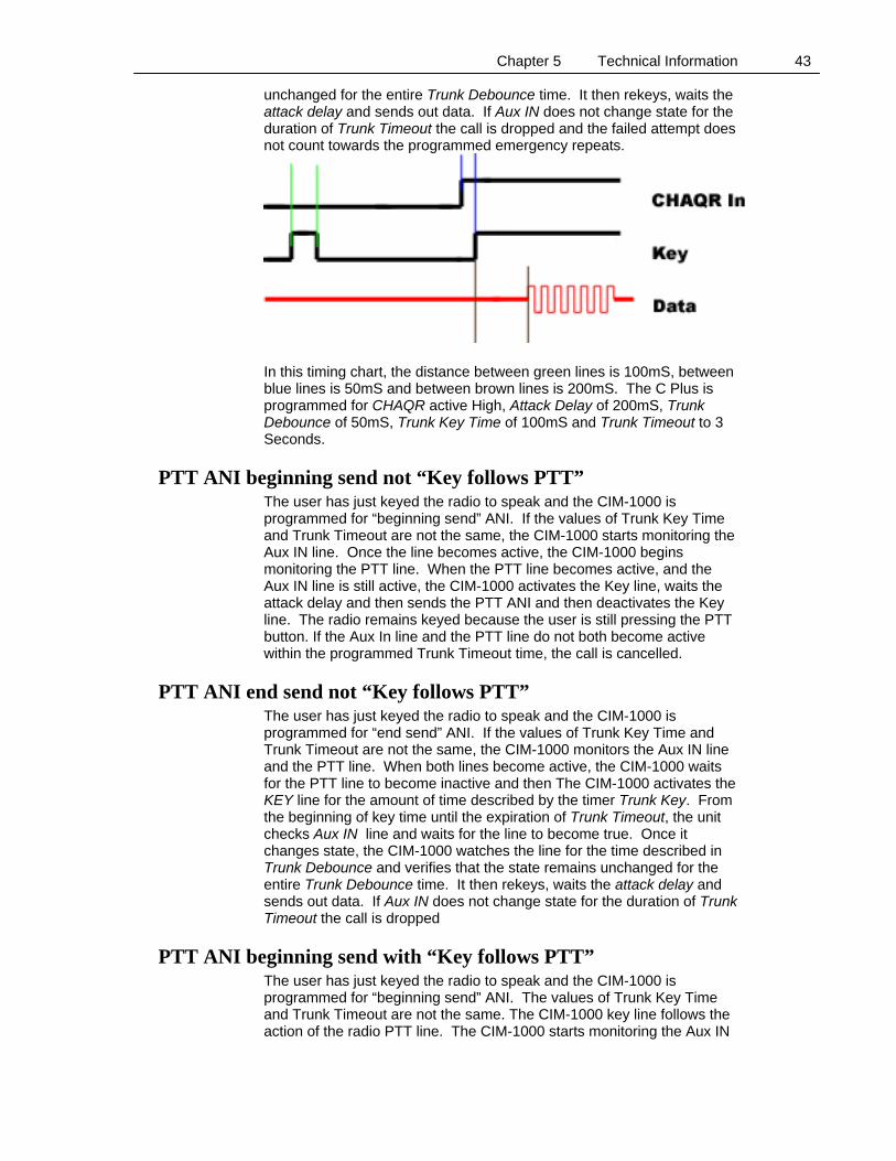
Emergency The user has just pressed the Emergency button. The CIM-1000 activates the KEY line for the amount of time described by the timer Trunk Key. From the beginning of key time until the expiration of Trunk Timeout, the unit checks Aux IN line and waits for the line to become true. Once it changes state, the CIM-1000 watches the line for the time described in Trunk Debounce and verifies that the state remains
Chapter 5 Technical Information 43
unchanged for the entire Trunk Debounce time. It then rekeys, waits the attack delay and sends out data. If Aux IN does not change state for the duration of Trunk Timeout the call is dropped and the failed attempt does not count towards the programmed emergency repeats.
In this timing chart, the distance between green lines is 100mS, between blue lines is 50mS and between brown lines is 200mS. The C Plus is programmed for CHAQR active High, Attack Delay of 200mS, Trunk Debounce of 50mS, Trunk Key Time of 100mS and Trunk Timeout to 3 Seconds.
PTT ANI beginning send not “Key follows PTT” The user has just keyed the radio to speak and the CIM-1000 is programmed for “beginning send” ANI. If the values of Trunk Key Time and Trunk Timeout are not the same, the CIM-1000 starts monitoring the Aux IN line. Once the line becomes active, the CIM-1000 begins monitoring the PTT line. When the PTT line becomes active, and the Aux IN line is still active, the CIM-1000 activates the Key line, waits the attack delay and then sends the PTT ANI and then deactivates the Key line. The radio remains keyed because the user is still pressing the PTT button. If the Aux In line and the PTT line do not both become active within the programmed Trunk Timeout time, the call is cancelled.
PTT ANI end send not “Key follows PTT” The user has just keyed the radio to speak and the CIM-1000 is programmed for “end send” ANI. If the values of Trunk Key Time and Trunk Timeout are not the same, the CIM-1000 monitors the Aux IN line and the PTT line. When both lines become active, the CIM-1000 waits for the PTT line to become inactive and then The CIM-1000 activates the KEY line for the amount of time described by the timer Trunk Key. From the beginning of key time until the expiration of Trunk Timeout, the unit checks Aux IN line and waits for the line to become true. Once it changes state, the CIM-1000 watches the line for the time described in Trunk Debounce and verifies that the state remains unchanged for the entire Trunk Debounce time. It then rekeys, waits the attack delay and sends out data. If Aux IN does not change state for the duration of Trunk Timeout the call is dropped
PTT ANI beginning send with “Key follows PTT” The user has just keyed the radio to speak and the CIM-1000 is programmed for “beginning send” ANI. The values of Trunk Key Time and Trunk Timeout are not the same. The CIM-1000 key line follows the action of the radio PTT line. The CIM-1000 starts monitoring the Aux IN
Chapter 5 Technical Information 44
line. Once the line becomes active the CIM-1000 waits for the PTT line to again become active, waits the attack delay and then sends the PTT ANI. The Key line follows the action of the radio PTT line. If the radio PTT line does not become active within Trunk Timeout of when the AUX IN line became active, the call is dropped.
PTT ANI end send with “Key follows PTT” The user has just keyed the radio to speak and the CIM-1000 is programmed for “end send” ANI. The values of Trunk Key Time and Trunk Timeout are not the same. The CIM-1000 key line follows the action of the radio PTT line. The CIM-1000 starts monitoring the Aux IN line. Once the line becomes active the CIM-1000 waits for the PTT line to again become active, then waits for the line to relax. When the radio PTT line relaxes, the CIM-1000 Key line remains active and sends the PTT ANI. The Key line then relaxes. If the radio PTT line does not become active within Trunk Timeout of when the AUX IN line became active, the call is dropped.
Chapter 5 Technical Information 45
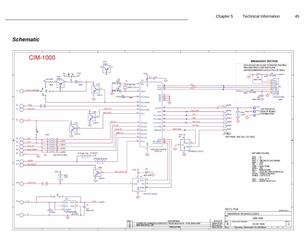
Schematic
Chapter 5 Technical Information 46
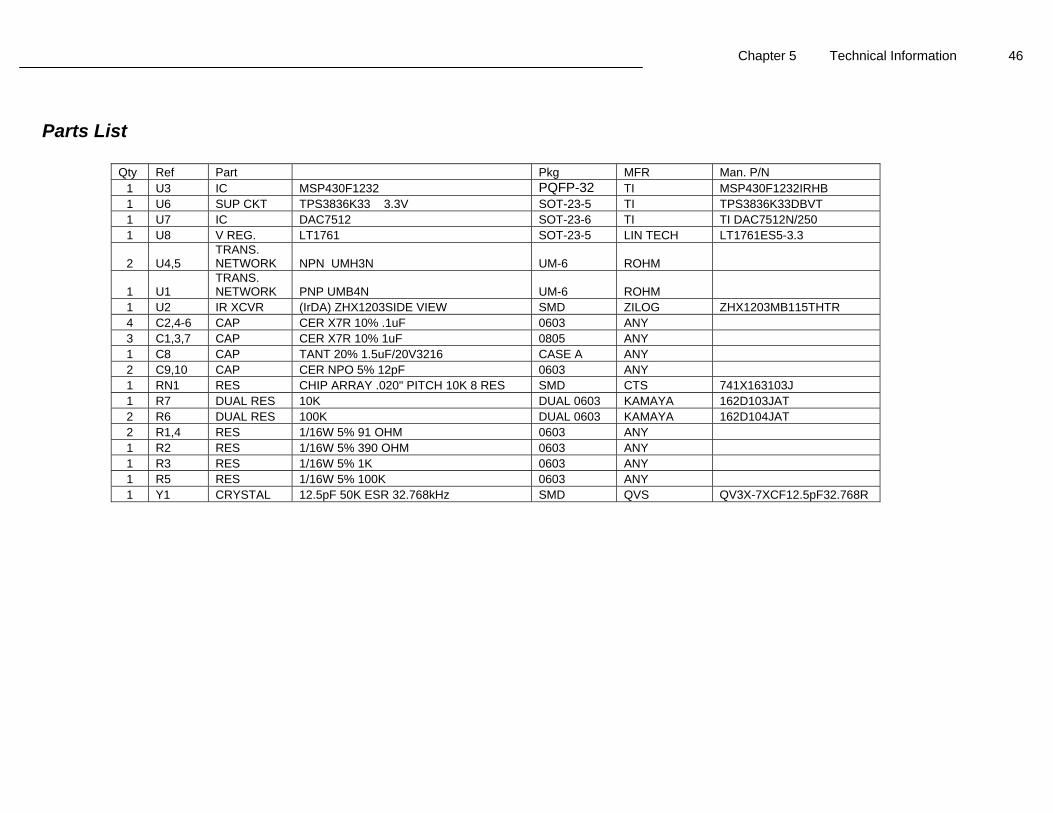
Parts List
Qty Ref Part Pkg MFR Man. P/N 1 U3 IC MSP430F1232 PQFP-32 TI MSP430F1232IRHB 1 U6 SUP CKT TPS3836K33 3.3V SOT-23-5 TI TPS3836K33DBVT 1 U7 IC DAC7512 SOT-23-6 TI TI DAC7512N/250 1 U8 V REG. LT1761 SOT-23-5 LIN TECH LT1761ES5-3.3
2 U4,5 TRANS. NETWORK NPN UMH3N UM-6 ROHM
1 U1 TRANS. NETWORK PNP UMB4N UM-6 ROHM
1 U2 IR XCVR (IrDA) ZHX1203SIDE VIEW SMD ZILOG ZHX1203MB115THTR 4 C2,4-6 CAP CER X7R 10% .1uF 0603 ANY 3 C1,3,7 CAP CER X7R 10% 1uF 0805 ANY 1 C8 CAP TANT 20% 1.5uF/20V3216 CASE A ANY 2 C9,10 CAP CER NPO 5% 12pF 0603 ANY 1 RN1 RES CHIP ARRAY .020" PITCH 10K 8 RES SMD CTS 741X163103J 1 R7 DUAL RES 10K DUAL 0603 KAMAYA 162D103JAT 2 R6 DUAL RES 100K DUAL 0603 KAMAYA 162D104JAT 2 R1,4 RES 1/16W 5% 91 OHM 0603 ANY 1 R2 RES 1/16W 5% 390 OHM 0603 ANY 1 R3 RES 1/16W 5% 1K 0603 ANY 1 R5 RES 1/16W 5% 100K 0603 ANY 1 Y1 CRYSTAL 12.5pF 50K ESR 32.768kHz SMD QVS QV3X-7XCF12.5pF32.768R
Chapter 6 Troubleshooting 47
C H A P T E R 6 Troubleshooting
Installation Hints The CIM-1000 must be programmed with your desires before it will work in your system. The CIM-1000 will be keying the associated transmitter and injecting audio into the radio. This point should be after pre-emphasis. It is very important to adjust data out to ensure the correct deviation level. The deviation level should be just marginally below that of voice. Keep in mind that most transmitters have limiter circuitry. Limiter circuits ensure that the radio will never over-deviate and violate FCC rules. The limiter does this by clipping the transmit audio. The output of the CIM-1000 must be adjusted to a point just below where limiter clipping occurs. If the limiter is allowed to function, the data will be distorted.
Isolating System Problems Today’s modern communication systems take advantage of many available resources. Voters, repeaters, various trunking protocols, scramblers and innumerable other devices make passing data substantially more difficult than it was in the “Simplex” days. Timing is very important. If you have system problems, the first place to spend your energies is with timing issues. Check attack delay in repeater systems. Start with a long delay that gives you 100% decode and then shorten it up. If you have trunking system problems using the CIM-1000, review the trunking information located on page 41 of this manual.
Equipment Problems
Radio Keys and Stays Keyed If the radio sends ANI data and then stays keyed even after releasing the PTT button, verify the condition of jumper K on the CIM-1000 and the programming parameter “Key follows PTT”. If you have “Key Follows PTT” enabled or jumper K connected when they should not be, this symptom could occur.
Radio Keys up but stays Keyed only for Duration of ANI This symptom is usually caused by incorrect conditions of the “Key follows PTT” parameter and CIM-1000 jumper K.
ANI goes out at “End” Regardless of Programming This symptom is usually caused by the “PTT Sense” being programmed opposite of how it should be or the voltage swing is insufficient. Use an O’scope to measure the level at the yellow (PTT) line when at rest and then when active (Keyed). The line should rest above 1.9VDC and go low when keyed if active low. It should rest below 0.9VDC and go above 1.9VDC when active if active high.

Chapter 6 Troubleshooting 48
ID Decoded is not the same as Programmed This occurs when the unit is in GE Star® mode and the CIM-1000 “format” is not set the same as the decoder. See page 39 for details.
Chapter 7 Product Support 49
C H A P T E R 7 Product Support
If you have any questions or comments about Cimarron products, please make use of our technical support hotline at (760) 738-3285. Cimarron Technologies Corporation 934 South Andreasen Drive, Suite G Escondido, CA 92029 Technical Support Hot-Line (760) 738-3285 [email protected] www.cimtechcorp.com
WARRANTY Cimarron Technologies Corporation warrants this product to be free from defects in material and workmanship for a period of three years from date of shipment. If a malfunction occurs due to defective material or workmanship, the product will be repaired or replaced (Cimarron's discretion) without charge if returned to the factory This warranty does not apply to any failure or damage caused by accident, neglect, unreasonable use, improper installation, or to alterations or modifications to the unit. Nor does the warranty extend to damage incurred by force majeure (natural causes) such as lightning, fire, floods, or other such catastrophes, nor to damage caused by environmental extremes, power surges and/or transients Cimarron Technologies Corporation makes no other warranty, either expressed or implied, with respect to this product. Cimarron Technologies Corporation specifically disclaims the implied warranties of merchantability and fitness for a particular purpose. Some states or provinces do not allow limitations on how long an implied warranty lasts, so the above limitation or exclusion may not apply to you. The remedies provided herein are customer's sole and exclusive remedies. In no event shall Cimarron Technologies Corporation be liable for any lost profits, direct, indirect, special, incidental, or consequential damages, whether based on contract, tort, or any other legal theory .
Index 50
I N D E X
A
Alternate channel control ..........................................12 ANI location .............................................................31 ANI repeat timer .......................................................31 Applications notes.....................................................10 Attack delay ........................................................32, 47 Audio inhibit .............................................................10 Automatic Numeric Identification ............................37
C
Canned messages ......................................................38 Capabilities .................................................................6 Channel acquired ......................................................13 CIM-CABLE ............................................................27 Common ...................................................................19 Computer serial port .................................................27 Conventional mode ...................................................33 Courtesy tone ............................................................32 Critical channel revert...................................12, 32, 33 Critical messages ......................................................32
D
Data control ..............................................................12 Data deviation.....................................................15, 47 Data output................................................................13 Data output level.......................................................33 Deviation adjustment ................................................15
E
Emergency ..........................................................19, 37 Emergency activation delay ......................................34 Emergency TX warning tone ....................................34
G
GE Star ANI message ...............................................30 GE Star emergency message.....................................30 GE Star format type ............................................30, 39 GE Star ID ................................................................30 GE Star man down message......................................30 GE Star message descriptions ...................................39 GE Star preamble length...........................................31 GE Star time out timer message................................30 GE Star® format .......................................................20 GE Star® message values .........................................20
H
Handheld programmer.............................................. 16 Home channel........................................................... 33 Home screen............................................................. 19 Hyperterm ................................................................ 27
I
ID Type .................................................................... 19 Installation hints ....................................................... 47 Installation notes ...................................................... 10 IR connectivity ......................................................... 16
J
Jumpers .................................................................... 14
K
Key follows PTT.......................................... 15, 32, 47
L
LTR systems ............................................................ 33
M
Man down .................................................... 19, 35, 37 Man down activation delay timer ............................. 35 Man down activation input....................................... 12 Man down message repeat ....................................... 35 Man down warning delay ......................................... 35 MDC ANI message .................................................. 31 MDC emergency message........................................ 31 MDC ID ................................................................... 31 MDC-1200 message type ................................... 31, 40 MDC-1200® message values................................... 20 Microphone monitoring............................................ 38 MPT-1327 ................................................................ 33 Multiple function output........................................... 32
N
Navigation actions.................................................... 17 Number of repeat emergency transmissions............. 34 Number of repeat man down transmissions.............. 35
Index 51
O
Open microphone monitor ..................................34, 35
P
Physical installation ..................................................10 Pre-emphasis.............................................................10 Primary ID ................................................................20 Product support .........................................................49 Programmable parameters ........................................31 Programmer memory locations .................................17 Programming ............................................................16 Programming by cable ..............................................27 Programming menu screens ......................................17 PTT input............................................................33, 47 PTT sidetone.............................................................37
Q
Quick Start Installation...........................................10
R
Radio connections...............................................10, 13 Radio interface..........................................................19 Repeaters ..................................................................47
S
Secondary ID ................................................20, 30, 38 Sidetone ....................................................................31
Signaling types ......................................................... 30 Simple installation.................................................... 10 Sleep......................................................................... 33 Status messages........................................................ 38 System problems ...................................................... 47
T
Time between emergency repeats ............................ 34 Time between man down repeats ............................. 35 Time out timer.............................................. 14, 32, 37 Timing...................................................................... 47 Transmit control output ............................................ 32 Transmit mode ......................................................... 19 Trunk channel acquired input................................... 34 Trunking mode ........................................13, 19, 33, 41 Typical radio installation ......................................... 9
U
User preferences....................................................... 17
V
Voice-syllable clipping ............................................ 37
W
Warranty ................................................................. 49