short form service manual - cim 5 controller - emr simplified · short form service manual...
TRANSCRIPT

Short form Service manual - cim 5 controller

Short form Service manual
Operating temperature
-30˚C to +30˚C-22 F to +86 F
Ambient temperature
-30˚C to +50˚C-22 F to +122 F
Model: SC-MCI40-WC, SC-MCI40, SCI-40 and SCU-40Refrigerant: R-134a Charged with 4.5 kg / 9.9 lb
[]

Short form Service manual
Controller box view
Phase direction
Phase direction
Heat element
Cond. fan low
Cond. fan high
Evap. fan low
Evap. fan high
FC/Compressor
Main circuit breaker
[]

Short form Service manual
Controller box view
Terminal block PCB
Power meas
Power in
Modem (if installed)
Transformer
[4]

Short form Service manual
Controller box view
Controller connections
Fuses: 2x 0.4/0.63 Amp.
3x 10 Amp.
Fuse: 6.3 Amp.
Recommended to raise
F1 and F2 to 0.63 Amp.
[5]

Short form Service manual
Unit rear side view
Tsuc sensor
Return air sensor
Humidity sensor
Evaporator sensor
Supply air sensors
[6]

Short form Service manual
Replacement of Tsuc sensor
Remove PVC Cover to accessTsuc sensor
Cut cable tie (one pcs). Sensor can then be removed When installing the new sensor, make sure to insert properly in tube
[]

Short form Service manual
Replacement of air exchange sensor Remove the two finger screws on the butter fly and remove cover plate
Remove the fourteen screws to loosen the black cover where the air ex-sensor is mounted
Replace the sensor and install all the dismantled parts again
[8]

Short form Service manual
Air exchange sensor calibration
Close fresh air butterfly
In the service menu SO5; Con-figuration menu FO6; Press “Enter” twice
Calibration is completed
[9]

Short form Service manual
Supply voltage measurements
Measure voltage output from the main circuit breaker
Measure voltage supplied to the power meas PCB
Range -50 Hz: 335 – 460 VACRange -60 Hz: 390 – 525 VAC
[10]

Short form Service manual
Supply voltage measurements
Measure the voltage output from the power meas PCB to the main circuit
Range -50 Hz: 335 – 460 VACRange -60 Hz: 390 – 525 VAC
[11]

Short form Service manual
Supply voltage measurements
Measure the voltage output from the power meas PCB to the transformer
Range -50 Hz: 335 – 460 VACRange -60 Hz: 390 – 525 VAC
[12]
Short form Service manual
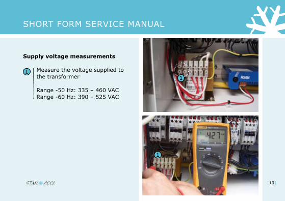
Supply voltage measurements
Measure the voltage supplied to the transformer
Range -50 Hz: 335 – 460 VACRange -60 Hz: 390 – 525 VAC
[13]
Short form Service manual
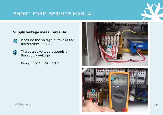
Supply voltage measurements
Measure the voltage output of the transformer 20 VAC
The output voltage depends on the supply voltage
Range: 15.3 – 24.3 VAC
[14]

Short form Service manual
Supply voltage measurements
Measure the voltage output from the transformer 24 VAC
The output voltage depends on the supply voltage
Range: 18.9 – 30.0 VAC
[15]

Short form Service manual
Check of 6,3 Amp fuse
Measure voltage from GND to top
of fuse
Fuse is ok
Range 18.9 - 30 VAC
Fuse is not ok
[16]

Short form Service manual
Check power to ON/OFF PCB
Measuring from ground to terminal 4 (see picture) shows that the controller is turned OFF
After turning ON, the voltage can be measured
Range 18.9 – 30.0 VAC
[17]

Short form Service manual
Check power to ON/OFF PCB
After turning ON you can read the voltage supplied through the ”ON/OFF” PCB on terminal 1 and 2
Range 15.3 – 24.3 VAC
[18]

Short form Service manual
Check Frequency Converter
Frequency converter MUST always have the black foil mounted for protection of print, components and your safety
WARNING - HIGH VOLTAGE
[19]

Short form Service manual
Check Frequency Converter
If deviation between phases is more than 15 VAC:
Alarm ”523 FC phase loss” orAlarm ”516 FC Trip phase loss” will be given
Range -50 Hz: 335 – 460 VACRange -60 Hz: 390 – 525 VAC
E.g. due to unstable power supply from the genset
[0]

Short form Service manual
Check Frequency Converter
A green light indicates FC is ok
A flashing green light indicates FC communicates with the controller
A red light indicates a problem
[21]

Short form Service manual
Check Frequency Converter
If a red light is ON and alarm 500 ”FC missing” is displayed, the FC has an internal problem and must be replaced
The ”Warrenty repair report” must be filled out and submitted to Star Cool. The defect part must be properly tagged
[]

Short form Service manual
Emergency operation
Dismount the frequency converter and connect the FC power 1 cable directly to the compressor supply terminals (W, V, U)
The 3 remaining terminals (Y, X, Z) have to be fitted with a wire-jumper.
[]

Short form Service manual
Emergency operation
Go to Service menu and select “Configuration” (S05)
In “Configuration” menu scroll down to “FC type” (F03)
Then press return and select “NONE”
Note: remember to switch back to “Danfoss” in the “FC type” setting when a new FC is mounted
[24]

Short form Service manual
Contactor check
Measure Ω between terminal A1 and A2
Contactor is ok
Contactor is not ok
Deviation in resistance due to change in temperature
[5]
Short form Service manual
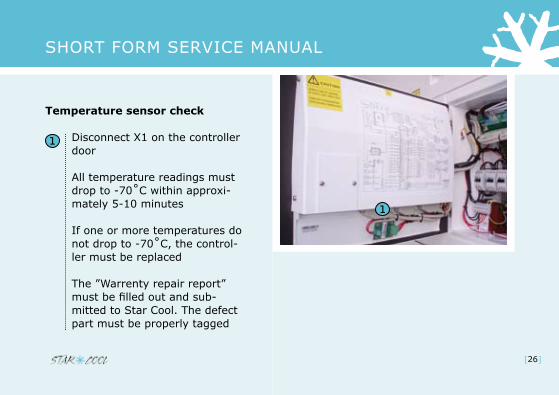
Temperature sensor check
Disconnect X1 on the controller door
All temperature readings must drop to -70˚C within approxi-mately 5-10 minutes
If one or more temperatures do not drop to -70˚C, the control-ler must be replaced
The ”Warrenty repair report” must be filled out and sub-mitted to Star Cool. The defect part must be properly tagged
[26]

Short form Service manual
Temperature sensor check
Dismount the current defect sensor(s) according to the wiring diagram inside the controller door
[]

Short form Service manual
Temperature sensor check
Measure the voltage between the two terminals on the PCB
Correct range: 4.80 > 5.05 VDC
[28]

Short form Service manual
Temperature sensor check
Measure the resistance of the disconnected sensor
Value must be according to the resistance table in the ”Operation and Service manual”
E.g. 32.65 kΩ = 0˚C /32 F
[29]
Short form Service manual
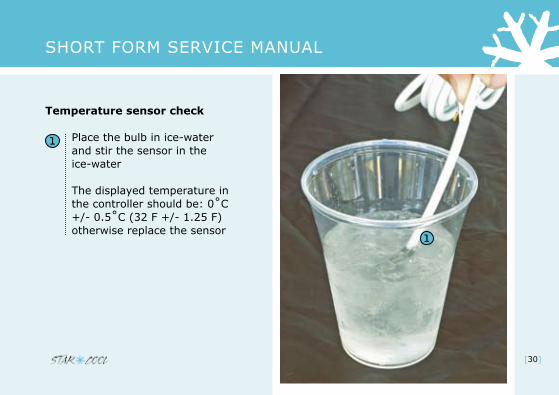
Temperature sensor check
Place the bulb in ice-water and stir the sensor in the ice-water
The displayed temperature in the controller should be: 0˚C +/- 0.5˚C (32 F +/- 1.25 F) otherwise replace the sensor
[0]

Short form Service manual
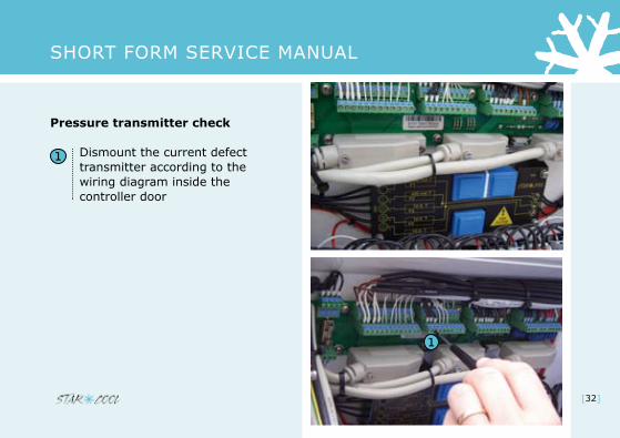
Pressure transmitter check
Disconnect X1 on the controller door
Psuc (and Peco) value must go to 14.7 or 12.0 Bar
Pdis value must go to 45.0 or 32.0 Bar
Values depends on transmitter type configured in configuration menu menu (FO7 and FO8) (NSK, AKS)
If the above mentioned values are not reached within 5-10 minutes, the control-ler module must be replaced
The ”Warrenty repair report” must be filled out and submitted to Star Cool. The defect part must be properly tagged
[31]
Short form Service manual
Pressure transmitter check
Dismount the current defect transmitter according to the wiring diagram inside the controller door
[]

Short form Service manual
Pressure transmitter check
Measure voltage between GND and 5 VDC for the transmitter. (According to the electrical wiring diagram)
Correct range:4.80 > 5.05 VDC
[]

Short form Service manual
Pressure transmitter check
Reconnect GND and 5 VDC wires for the transmitter
Measure voltage between signal wire and GND
Check signal output from trans-mitter. Compare it to gauge reading/value found in relevant table in the “Operational and Service manual”.
[34]

Short form Service manual
Check of heat elements
Measure the voltage (across each heater pair)
Measure the resistancevalue of each disconnected heater: 210 Ω (105 Ω as a pair)Value for tray heater: 400 Ω Range: +/- 10 Ω
5
4
Y/G
3
1
6
2
10
32
1211
9876
Hevap
45
1
14Y/G
13
X601
5
3 2
6
5
8
1
7
3
4
12
2
4
4
4
6 6
2
4
6
(15 x 0,75mm2 / 15 x AWG 18)
Hevap
23
45
67
89
1011
1213
14
K3
[5]

Short form Service manual
Change of parts
Always make sure to turn OFF the main circuit breaker and disconnect the power cable
[36]

Short form Service manual
Notes
[]
Short form Service manual
Contacts
Internet www.starcool.dk Spare parts / orders [email protected]
Technical Hot line 24/7 +45 73 64 35 00
[38]