robot lawn mower - open repository · maintenance/ landscaping companies. the effects would be...
TRANSCRIPT

Engineering Senior Design Project: Robotic Lawn Mower
Item Type text; Electronic Thesis
Authors Rickel, Jayson Anthony
Publisher The University of Arizona.
Rights Copyright © is held by the author. Digital access to this materialis made possible by the University Libraries, University of Arizona.Further transmission, reproduction or presentation (such aspublic display or performance) of protected items is prohibitedexcept with permission of the author.
Download date 17/07/2018 08:19:36
Link to Item http://hdl.handle.net/10150/321922


Robot Lawn Mower
Team AutoMow #1324 Boeing Mesa Helicopter Company
2013-2014 Engineering Senior Capstone
Ben Cohodas Brian Ball
Bryan Lizon Elena Jenkins Jayson Rickel Robert Hacker

Team AutoMow | University of Arizona | Final Report Page 2
Contents
Abstract ............................................................................................................ 5
Concept of Operations ..................................................................................... 5
Purpose of the project .......................................................................................... 5
Scope of the Project ............................................................................................ 5
Background .......................................................................................................... 5
Concept for the Proposed System ....................................................................... 7
System Overview ................................................................................................. 7
Operational Scenarios ......................................................................................... 8
System Requirements .................................................................................... 10
System Test and Verification .......................................................................... 12
Preliminary Design Review ............................................................................ 13
Design 1 ............................................................................................................. 13
Design 2 ............................................................................................................. 13
Design 3 ............................................................................................................. 14
Trade-Off Analysis ............................................................................................. 15
Sensitivity Analysis ............................................................................................ 15
PDR Findings ..................................................................................................... 16
Mechanical Subsystem .................................................................................. 17
Mechanical Overview ......................................................................................... 17
Rear Assembly .................................................................................................. 18
Rear Drive System ............................................................................................. 19
Rear Drive Motors .............................................................................................. 21
Rear Motor Analysis .......................................................................................... 22
Front Caster Assembly ...................................................................................... 23
Stress Analysis .................................................................................................. 25
Simulation of Caster Mount ............................................................................... 25
Simulation of Left Caster ................................................................................... 28
Simulation of Nose Cone ................................................................................... 30
Electrical Subsystem ...................................................................................... 34
Microcontroller ................................................................................................... 35
Remote Control .................................................................................................. 37
Compass ............................................................................................................ 38

Team AutoMow | University of Arizona | Final Report Page 3
Proximity Sensor ................................................................................................ 39
Motor Controller ................................................................................................. 40
Blade Motor Controller ....................................................................................... 42
Voltage Transformer .......................................................................................... 44
Power Management ........................................................................................... 45
Software Design ............................................................................................. 47
Cost Analysis .................................................................................................. 48
Acceptance Test Plans ................................................................................... 49
Functional .......................................................................................................... 49
Technology ........................................................................................................ 49
Performance ...................................................................................................... 50
Utilization of Resources ..................................................................................... 50
System Test Plan ............................................................................................... 51
Risk Analysis .................................................................................................. 52
Mitigation Plan ................................................................................................... 52
Precision ................................................................................................. 52
Cost ......................................................................................................... 53
Complexity .............................................................................................. 53
Size ......................................................................................................... 53
Power ...................................................................................................... 53
Damage to Lawn ..................................................................................... 53
Obtainability ............................................................................................ 54
Project Schedule Spring 2014 ........................................................................ 55
Conclusion ...................................................................................................... 56
Appendix ........................................................................................................ 57
Force Calculations ............................................................................................. 57
Solidworks Drawings ......................................................................................... 58
Rear Mounting Bracket ........................................................................... 58
Caster Mount ........................................................................................... 58
Front Wheel ............................................................................................. 59
Gearbox with shaft .................................................................................. 59
Left Caster ............................................................................................... 60
Right Caster ............................................................................................ 60

Team AutoMow | University of Arizona | Final Report Page 4
Motor Shaft Bushing ................................................................................ 61
Motor ....................................................................................................... 61
Nose Cone .............................................................................................. 62
Rear Pivot Shaft ...................................................................................... 62
Spur Gear ................................................................................................ 63
Rear Wheel ............................................................................................. 63
Team Member Responsibilities ......................................................................... 64

Team AutoMow | University of Arizona | Final Report Page 5
Abstract
Boeing Mesa Helicopter Company came up with the project idea of designing, fabricating, and demonstrating a robotic lawn mower that was self-guided without a need for human directional control. This document lays the foundation to the design phase of the project.
Concept of Operations
Purpose of the project
The purpose of creating an autonomous lawn mower is to create a better system for robotic lawn mowers. In today’s market, there are only lawn mowers that turn at random to cover the area, our design will minimize time spent mowing, energy used, and damage to delicate grass. Autonomous lawn mowers with the ability to be self-guiding would open a new market and revolutionize how a lawn is mowed.
Scope of the Project
The designed system will be an autonomous lawn mower built using a standard self-propelled lawn mower as its base. The system should have the ability to mow a square section of grass measuring 20 feet by 20 feet in the approximate time a human could mow the same section. The mower only needs enough power onboard to complete this task. The only user interface with the mower will be a manual start (pull cord or button) and a remote kill switch. The mower may use outside sources such as radio beacons or wires surrounding the section of grass to assist it in its objective. However, no human interaction will be necessary with these external components. The budget for this design and build will be from Boeing Mesa Helicopter Company totaling $3,500. This concept of operations will focus on the mowers requirements and its ability to fulfill the desired outcome.
Background
Prior to the invention of the lawnmower grazing animals and sickles were used to cut grass. The first lawn mower was invented almost two hundred years ago. There has been an ongoing evolution during this time period, as other technologies have been applied to the lawn mower. For much of the first century lawnmowers were primarily used on sports fields and vast gardens where a uniform cut lawn was desired or needed. As the popularity of sports that are played on grass increased, the popularity of the lawnmower spread. This also resulted in prices being reduced as more mowers were sold, and put them into reach of the general public.

Team AutoMow | University of Arizona | Final Report Page 6
Over the past two hundred years there have been three basic cutting designs for lawn mowers; cylinder, sickle, and rotary. There are many different variations and sizes for the different types including self-propelled, riding and robotic lawnmowers. Cylinder The Cylinder type or Real lawnmower is the earliest design, and is still around today although much evolved. These mowers have blades that revolve around a horizontal shaft that cuts the grass against a cutting bar, similarly to how a scissors works. This cutting action is superior to other types of mowers, because the grass is cut clean rather than being torn. This results in the grass healing quicker and no yellowing or browning of the tips. These mowers are powered by a geared mechanism that connects the blades to the wheels, as the machine is pushed the blades spin. The first models were made out of cast iron and were very cumbersome to operate. These types of mowers have made a resurgence, due to cut quality, being lighter, and easier to operate than previous models and produce no emissions or noise. Sickle Sickle mowers have a set of shearing reciprocating teeth mounted on a horizontal bar. These mowers are very dangerous as they have little if any guarding in place. The design of sickle mowers makes them ideal for cutting very tall grass. They were powered mechanically driven through a gear system by the wheels, or by an engine mounted on the machine. Due to the danger associated with these they became primarily used by farmers for cutting crops such as hay or wheat. The basic design of reciprocating teeth is still used in farm equipment today. Rotary Rotary lawnmowers have a vertical shaft that is powered by the motor. A blade is mounted on this shaft that when spinning creates a plane parallel to the lawn. This blade is angled to keep the grass upright as it cuts. Being the only action holding the blade of grass is this vacuum the blade of grass gets pushed by the cutting action, resulting in a potential tearing action. Modern rotary lawnmowers can be powered by either a gas engine or electric motor. All rotary lawnmowers have a shroud that encloses the rotating blade. Most of these shrouds are built out of steel, but on some electric mowers are made out of strong plastic. Aluminum is used on some expensive gas mowers to reduce weight. Many of these mowers are now self-propelled, with a variety of drive systems. The most common being a belt attached to the shaft of the motor just above the blade to drive the axle. Rotary mowers were first developed between 1920 and 1930, but did not see widespread development until the 1950s. The limiting factor was a lack of efficient small gas engines before that time.

Team AutoMow | University of Arizona | Final Report Page 7
Robot The robot lawnmower is the latest development in rotary lawnmowers. The robot mowers that are currently on the market are contained by a wire that lies just below the surface of the lawn that sets the perimeter of the area to be mowed. As the mower approaches this wire it senses the field created by the wire and changes course as to not leave the contained area. These mowers generally use a random pattern to mow the entire yard, and go over many areas multiple times. The technology is becoming more advanced with each new model produced. Many units will return to a docking station to recharge when mowing is completed.
Concept for the Proposed System
The proposed design consists of several alternatives: first, a radio frequency (RF) interferometry system, using several perimeter nodes to define a localized, virtual map of the area to be mowed; second, a system utilizing GPS with Real Time Kinematics (RTK), which uses an already established positioning system to allow the lawn mower to calculate its distance from a fixed point; and third, a sensor-based design that incorporates a digital compass, RPM (linear speed) sensors, as well as edge detection to navigate the required course. As with all designs each has its benefits and flaws: the first design is relatively inexpensive to build, but requires the construction of multiple nodes (i.e. increased failure points) and relies on amplitude measurement to calculate distance, which can be significantly impacted by environmental factors; the second design is the most accurate and requires the least effort to install and program – however, it is the most expensive method, and thus highly risky, as our budget would likely allow for only one to be purchased; lastly, the third design is cheap to build and utilizes easy-to-obtain parts, but involves many failure points and the increased likelihood of error being introduced into the system, which is something we cannot afford. Ultimately, the design we choose will likely be a combination of these systems, either working in tandem to increase the accuracy of our data or elements of one acting as a backup to the main system, providing essential redundancy and the reduction of error.
System Overview
The system that will be built is a robot lawn mower. Having the goal of cutting out all human interactions associated with mowing the lawn. The users of this system will lean towards those who do not have time in their day to mow the yard or for those users that would rather spend time during the day doing other activities. Or else they just are not physically capable of pushing a heavy lawn mower around. Businesses that would benefit the most by this new product are yard maintenance/ landscaping companies. The effects would be noticed by means of reduced direct labor cost. One person could show up at the clients yard set up the communication system start the mower and return later in the day to pick up the mower. The system needs to be able to mow a square 20’ x 20’ grass yard

Team AutoMow | University of Arizona | Final Report Page 8
in a timely manner similar to the duration required to normally mow the same space. It will showcase a complete hands-off interaction. The system will begin activating when the start button is pressed and mowing commences. The mowers location system will begin a short system diagnostic test after which is completed mowing will start. After all areas of the grass are trimmed the system shall send a signal that the task has been completed.
Operational Scenarios
Use Case: AutoMow Operation
ID: 1
Brief Description: This use case describes the flow of the system’s operation. The AutoMow will start up, mow the designated area, and then emit a signal to show that it is done mowing.
Primary Actor: User
Secondary Actors: Time
Precondition: The user has a lawn that needs to be mowed. The grass is no more than 5 inches tall and his lawn is a 20’ x 20’ square with a brick border.
Main Flow: a. Use case begins when the user disconnects the system from its charging station. b. User places the system somewhere in the designated 20’ x 20’ area. c. User starts the system. d. System mows the designated area. e. System emits signal when mowing has been completed. f. User shuts down the system. g. User moves system back to charging station. h. Use case ends when the User has reconnected the system to the charging station.
PostCondition: The lawn has been mowed.
Alternative Flow: c.1. System is unable to start due to mechanical issues. c.2. System is unable to start due to a loss of signal from sensors. d.1. System hits an obstacle or obstruction in the mowing path. d.2.1. Emergency shutdown is triggered. d.2.2. System ceases mowing and shuts down.

Team AutoMow | University of Arizona | Final Report Page 9
Use Case: Servicing AutoMow
ID: 2
Brief Description: User wishes to maintain the system for a routine mechanical check.
Primary Actor: User
Secondary Actors: None
Precondition: User has some mechanical knowledge and is able to use basic tools to maintenance the system. The system has been in use and is in need of a routine servicing in order to increase the safety of the machine.
Main Flow: a. Use case begins when the user removes the system from the charging station. b. User disables the battery by disconnecting it. c. User cleans top mower of dirt, debris, and grass. d. User places mower on its side to access undercarriage. e. User scrapes accumulated dirt, debris, and grass from underside of mower deck. f. User sharpens mower blade. g. User places mower upright off of its side. h. User inspects all wiring and drive system components for loose connections. i. User inspects all fasteners to ensure tight connections. j. User reconnects battery. k. Use case ends when the mower is placed back on the charging station.
PostCondition: System has been serviced and returned to the charging location.
Alternative Flow: h.1.1. User identifies loose wiring. h.1.2. User reconnects loose wiring. h.2.1. User identifies components missing. h.2.1. User contacts service department for further maintenance. i.1.1. User identifies loose connections. i.1.2. User tightens or reconnects connections. i.2.1. User identifies missing connections or broken components. i.2.2. User contacts service department for further maintenance.
Team AutoMow | University of Arizona | Final Report Page 10
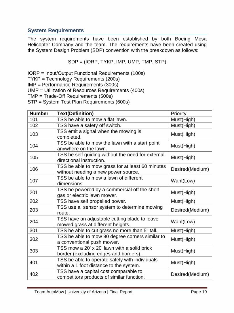
System Requirements
The system requirements have been established by both Boeing Mesa Helicopter Company and the team. The requirements have been created using the System Design Problem (SDP) convention with the breakdown as follows:
SDP = (IORP, TYKP, IMP, UMP, TMP, STP) IORP = Input/Output Functional Requirements (100s) TYKP = Technology Requirements (200s) IMP = Performance Requirements (300s) UMP = Utilization of Resources Requirements (400s) TMP = Trade-Off Requirements (500s) STP = System Test Plan Requirements (600s)
Number Text(Definition) Priority
101 TSS be able to mow a flat lawn. Must(High)
102 TSS have a safety off switch. Must(High)
103 TSS emit a signal when the mowing is completed.
Must(High)
104 TSS be able to mow the lawn with a start point anywhere on the lawn.
Must(High)
105 TSS be self guiding without the need for external directional instruction.
Must(High)
106 TSS be able to mow grass for at least 60 minutes without needing a new power source.
Desired(Medium)
107 TSS be able to mow a lawn of different dimensions.
Want(Low)
201 TSS be powered by a commercial off the shelf gas or electric lawn mower.
Must(High)
202 TSS have self propelled power. Must(High)
203 TSS use a sensor system to determine mowing route.
Desired(Medium)
204 TSS have an adjustable cutting blade to leave mowed grass at different heights.
Want(Low)
301 TSS be able to cut grass no more than 5" tall. Must(High)
302 TSS be able to mow 90 degree corners similar to a conventional push mower.
Must(High)
303 TSS mow a 20' x 20' lawn with a solid brick border (excluding edges and borders).
Must(High)
401 TSS be able to operate safely with individuals within a 1 foot distance to the system.
Must(High)
402 TSS have a capital cost comparable to competitors products of similar function.
Desired(Medium)

Team AutoMow | University of Arizona | Final Report Page 11
403 TSS have an operating cost of less than 10 dollars per 60 minutes of operating time.
Desired(Medium)
404
TSS have a blade safety requirement for walk-behind rotary lawn mowers in specifications with B71.1 of the American National Standards Institute.
Desired(Medium)
405 TSS be compliant with EPA 40 CFR part 1054 (Phase 3 Exhaust emission standards).
Want(Low)
406 TSS incorporate 3 or more TI analog ICs or 2 analog ICs and a TI processor.
Want(Low)
501 Overall system performance will account for 50% of the total score.
Desired(Medium)
502 Overall cost of the system will have a weight of 20% of the total score.
Desired(Medium)
503 Overall technology within the system will account for 30% of the total score.
Desired(Medium)
601 TSS mow a 20' x 20' lawn with a solid brick border (excluding edges and borders) with an acceptance within 10% of area.
Desired(Medium)
602 TSS have the safety switch triggered during operation.
Desired(Medium)
603 TSS be tested from 10 different starting locations in the designated 20'x20' area.
Desired(Medium)

Team AutoMow | University of Arizona | Final Report Page 12
System Test and Verification
Number Title Test Analysis Inspection
301 TSS be able to cut grass no more than 5" tall.
X X X
302 TSS be able to mow 90 degree corners similar to a conventional push mower.
X X X
303
TSS mow a 20' x 20' lawn with a solid brick border (excluding edges and borders).
X X X
401 TSS be able to operate safely with individuals within a 1 foot distance to the system.
--- --- X
402 TSS have a capital cost comparable to competitors products of similar function.
--- X ---
403 TSS have an operating cost of less than 10 dollars per 60 minutes of operating time.
--- X ---
404
TSS have a blade safety requirement for walk-behind rotary lawn mowers in specifications with B71.1 of the American National Standards Institute.
--- X X
405 TSS be compliant with EPA 40 CFR part 1054 (Phase 3 Exhaust emission standards).
--- X X
406 TSS incorporate 3 or more TI analog ICs or 2 analog ICs and a TI processor.
--- --- X

Team AutoMow | University of Arizona | Final Report Page 13
Preliminary Design Review
Design 1
Control: Global Positioning System (GPS) Drive: Rear independent drive with caster type steering The first design option is through using a GPS system to control the direction of the mower, and a rear independent drive system to power the movement. Using the GPS will make our system highly accurate while being easy to integrate. Some cons to the GPS system being that it is expensive and difficult to replace in the case of failure. This system uses two independent electric dc motors on the rear wheels that allow a zero turn radius. The front wheels will be a caster type with no mechanical parts involved. This will help keep weight down on the front of the mower. A con with this system is loss of traction while using only two wheels to drive the mower.
Figure 1 Rear Independent Drive
Design 2
Control: Beacon triangulation Drive: Four Motor Drive (AWD) This system would use three beacons on the corners of the lawn communicating with the system on the mower. Constantly communicating with the mower its position and relativity to the other beacons. This control system would be inexpensive to produce with easily obtainable parts. The system has cons in that it has medium accuracy and many parts to assemble increasing the build time. The mower would then be driven by four independent electric motors on each wheel. This would give our mower excellent traction while giving us a zero turn radius. Using four motors though increase weight and expenses.

Team AutoMow | University of Arizona | Final Report Page 14
Figure 2 Beacon Triangulation
Figure 3 Four Motor Drive
Design 3
Control: Sensor system (Accelerometers, Compass, Proximity) Drive: Rear Drive axle with conventional steering Design 2 is comprised of a control system that uses sensors on the sides of the mower to communicate where in the area the mower is located. They would let the system know when it is approaching a wall and when and where it can then turn. This system is inexpensive and easy to replace. The cons involved with this system include low to medium accuracy, medium failure points, provides relative position, and high levels of data to process. This control system will cause little lawn damage and reduce weight while using only one motor. The cons to this system will be a complicated steering assembly in the front end as well as fatigue in all the parts caused by vibration of mower and lawn.
Figure 4 Rear Axle Drive

Team AutoMow | University of Arizona | Final Report Page 15
Trade-Off Analysis
After determining the three designs, we created a set of criteria to base a tradeoff analysis. Based on our requirements and our stakeholder input the following weights and criteria were determined:
Precision – 40%
Cost – 10%
Complexity – 20%
Size – 5%
Power – 5%
Damage to Lawn – 10%
Obtainability – 10% Precision holds the highest weight of importance due to the size of the area of mowing. A 20’ x 20’ square is not that large and precision would be key. Although cost is often one of the most important criteria in industry, since all three designs would fall under the 3,500 total budget, cost received a weight of 10%. To compare each of the three designs, the following table was established with each design component being given a score from 1 to 5 (5 being the best possible outcome).
Table A Trade Off Analysis
In conclusion, the team determined that design 1 using the GPS as a control system and a rear independent drive system would give the most suitable outcome.
Sensitivity Analysis
To test if the design would be the best outcome in other situations, we changed the weights of the criteria to create a sensitivity analysis. In the following table, the weights of each of the criteria were changed. The weights were determined on the basis of if the mower was to become commercially sold. Cost becomes the highest value at 35%.

Team AutoMow | University of Arizona | Final Report Page 16
Table B Sensitivity Analysis
After the sensitivity analysis we find that design 1 is still the best option regardless of if the criteria weights would change. Knowing this, design 1 is proven to be flexible and suitable.
PDR Findings
Through our preliminary design review the best possible design based on the criteria set would be design 1. Design 1 is comprised of a global positioning system which is the most precise navigation system and a rear independent drive system which would allow for a zero turn radius and minimal lawn damage. Although the GPS system is one of the most expensive options, its precision and ease of integration makes design 1 the winning and most feasible option.
Team AutoMow | University of Arizona | Final Report Page 17
Mechanical Subsystem
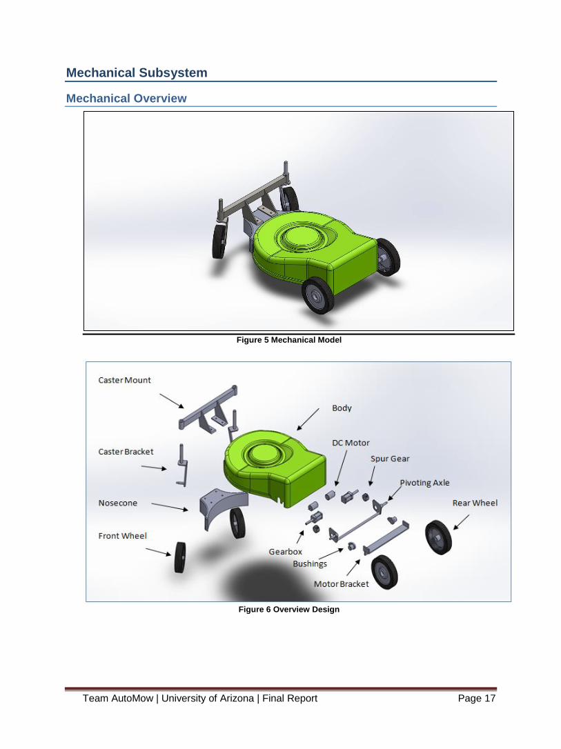
Mechanical Overview
Figure 5 Mechanical Model
Figure 6 Overview Design

Team AutoMow | University of Arizona | Final Report Page 18
Front Sub-Assembly
Caster Mount Caster Bracket (2) Nosecone Front Wheel(2)
Rear Sub-Assembly
DC Motor(2) Gearbox (2) Rear Wheel(2)
Spur Gear(2) Pivoting Axle Bushings(2)
Motor Bracket
Body
Shell
Rear Assembly
The rear assembly will work in tandem with the front caster assembly to provide the robot with exceptional mobility control. The components for this rear assembly are the pivoting rear axle system, drive system, and motor mount.
Figure 7 Rear Assembly
Rear Pivoting Axel with Bushings, Pivoting Shaft Throughout the functional requirements stages of the robot, the team decided that a desire for the system is to have the lawn mower be capable of easily changing blade heights. We decided to keep the height adjustment mechanism that is implemented on the stock Ryobi mower. Using this creative design allows the gearbox and motor system to be at a fixed position at all times no matter what height the user desires. The electric motors fixed and bushings supporting all the weight of the mower. This design cancels out all possible issues and concerns with alternating stress affecting the gearboxes performance and the overall lifetime. The following figure below displays the interface between the drive system and bushing that attaches to the pivoting axle shaft. The small hole

Team AutoMow | University of Arizona | Final Report Page 19
on the left is where the bolt connects the assembly to the mower body. The hole on the right is where the gearbox shaft is inserted and connects the spur gear to the end of the shaft by a metal clip. As the user pulls up or down on the height adjustment handle, the wheel pivots around the output shaft of the wheel motor.
Figure 8 Rear Pivoting Axle
Rear Drive System
The rear drive system is one of the most important systems of the design. Our sponsors set down a functional requirement that the lawn mower must be self-propelled. The rear drive system will provide the robot with the necessary power to generate any rapid movement while at the same time providing smooth controlling. The electric motors will operate based on the inputs received from the motor controller that is telling it what speed and direction to run. Two independent DC electric motors are both mounted with Banebot Gearboxes. They will turn the spur gear mounted at the end of the gear box shaft, which is secured by a key slot and metal clip. The spur gear will transfer the power to the wheel through the preexisting ring gear assembly currently in the inside of the rim on the rear wheel that came with the stock lawn mower. Each gearbox comes with the key slot pre machined from the manufacturer, thus cutting out the hassle of breaking welds to disassemble.

Team AutoMow | University of Arizona | Final Report Page 20
Figure 9 Rear Drive System
Motor Bracket The motor mount was designed to support the electric motors that drive the rear wheels. To mount the drive system to the supporting bracket, holes were drilled through the side of the bracket which is made of ANSI 1020 steel as showed in the figure below. To obtain a snug fit between the bracket and the motors, four bolts for each motor will go through the bracket and screw into the pre threaded holes on the gearbox that was previously machined by the manufacturer. Both drive motor systems are bolted down and tightened to 7 ft lbs of torque. The motor bracket is then welded to the inner surface of the shell body to give the motors a rigid support.
Figure 10 Motor Bracket
Team AutoMow | University of Arizona | Final Report Page 21
Rear Drive Motors
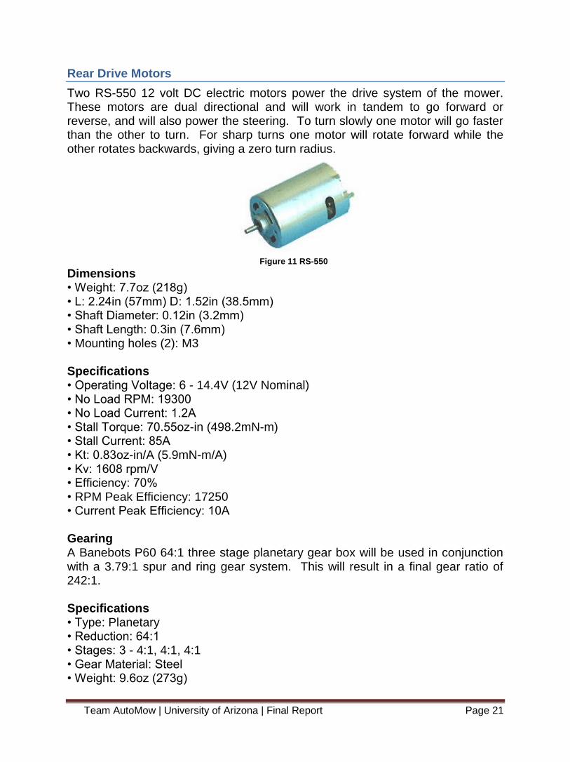
Two RS-550 12 volt DC electric motors power the drive system of the mower. These motors are dual directional and will work in tandem to go forward or reverse, and will also power the steering. To turn slowly one motor will go faster than the other to turn. For sharp turns one motor will rotate forward while the other rotates backwards, giving a zero turn radius.
Figure 11 RS-550
Dimensions • Weight: 7.7oz (218g) • L: 2.24in (57mm) D: 1.52in (38.5mm) • Shaft Diameter: 0.12in (3.2mm) • Shaft Length: 0.3in (7.6mm) • Mounting holes (2): M3 Specifications • Operating Voltage: 6 - 14.4V (12V Nominal) • No Load RPM: 19300 • No Load Current: 1.2A • Stall Torque: 70.55oz-in (498.2mN-m) • Stall Current: 85A • Kt: 0.83oz-in/A (5.9mN-m/A) • Kv: 1608 rpm/V • Efficiency: 70% • RPM Peak Efficiency: 17250 • Current Peak Efficiency: 10A Gearing A Banebots P60 64:1 three stage planetary gear box will be used in conjunction with a 3.79:1 spur and ring gear system. This will result in a final gear ratio of 242:1. Specifications • Type: Planetary • Reduction: 64:1 • Stages: 3 - 4:1, 4:1, 4:1 • Gear Material: Steel • Weight: 9.6oz (273g)

Team AutoMow | University of Arizona | Final Report Page 22
• Length: 2.3in (58.4mm) • Width (Square): 1.5 in (38.1mm) • Shaft Diameter: 0.50 in (12.7mm) • Shaft Length:1.5 in (38.1mm) • Shaft Key: 0.125 in (3.2mm) • Shaft End Tap: #10-32 • Mounting Holes (8): #10-32
Figure 12 Banebots
Figure 13 Banbots Details
Rear Motor Analysis
Combining the RS-550 motor with a stall torque of 70.55 in*ozf with the complete gearing system of planetary gearbox with spur and ring gear, the max torque at the wheel will be 1068 in*lbf per wheel. Combining both drive wheels this results in 2136 in*lbf of torque. The torque is greatest in a stalled condition at start up, and decreases linearly to zero at 79.65 RPM at the wheels.

Team AutoMow | University of Arizona | Final Report Page 23
Figure 14 Force Calculations
Since torque decreases linearly, acceleration also decreases linearly. Taking into account rolling resistance due from the grass the lawnmower has a top speed of 1.85 mph.
Figure 15 Force Calculations
Front Caster Assembly
The front caster assembly has six major components; the nose cone, caster mount, left caster, right caster, and front wheels. This design allows for the front wheels to turn from the dual drive motors, and function much like a shopping cart does. By having the pivot point of the casters located at the leading edge of the wheels the force to turn is minimized as the torque produced from a turning

Team AutoMow | University of Arizona | Final Report Page 24
motion on the lawnmower is larger than if the pivot shaft were located closer to the spindle of the caster.
Figure 16 Front Caster
This assembly also allows for adjustment of the cutting height of the lawnmower by using a pin and washer system on the casters that matches the height adjustment of the pivoting axle assembly in in the rear of the lawnmower. The new nose cone was designed to allow for a wheel stance that matches the base lawnmower, both in length and width. Thus resulting in no change to how close the mower can approach an obstacle. Due to the low speed and to save cost a bushing style pivot was chosen over a bearing system. All pivot areas and spindles will be treated with a dry graphite spray to reduce friction and prevent dust and dirt from accumulating if lubricated with grease. The front caster assembly will be attached to the mower body by welding the new nose cone in place of the existing one. A rectangular cut will be done to remove the existing nose cone from the stock mower body. The large curved arch on the new nose cone is the same radius as the mower body and will not affect blade clearence.
Figure 17 Unmodified Body

Team AutoMow | University of Arizona | Final Report Page 25
Figure 18 Modified Body
Stress Analysis
A finite element analysis was performed with the “Simulation Xpress Analysis Wizard” included on SolidWorks to complete a stress analysis on all of the major mechanical components on the front of the lawnmower, as these components were designed from scratch. Most of the mechanical components on the rear of the lawn mower were either used as designed or modified from the existing base lawnmower so a full structural analysis was not performed. The Finite element analysis was performed with a final weight of 200 pounds. This was done as a conservative measure considering the base mower weighs 87 pounds, and even with all modifications and new parts the final robotic lawnmower is expected to weigh between 100 and 125 pounds.
Simulation of Caster Mount
The caster mount Bolts to the front nosecone of the lawnmower with four 3/8 in bolts, and the left and right casters mount on each side of it. The mount allows for the front wheels to pivot freely as they track from imputes by the independent DC wheel motors. The material chosen for the caster mount is AISI 1015 steel.
Figure 19 Caster Mount

Team AutoMow | University of Arizona | Final Report Page 26
For the finite element analysis, the base was set in a fixed position, and a 50 pound force was applied to the bottom of each caster pivot point to simulate the force the mower will impart due to gravity.
Fixture name Fixture Image Fixture Details
Fixed-1
Entities: 2 face(s) Type: Fixed Geometry
Figure 20 Fixed Base
Load name Load Image Load Details
Force-1
Entities: 2 face(s) Type: Apply normal
force Value: 50 lbf
Figure 21 Applied Loads
A solid type mesh was used for the analysis with 7908 elements and 16056 nodes.
Figure 22 Mesh Caster Mount
The results of the finite element analysis show that a maximum von Mises Stress of 2646 psi occurred at node 10091 that resulted in a minimum factor of safety of

Team AutoMow | University of Arizona | Final Report Page 27
17.8. The maximum displacement of 0.0027 inches occurred at node 629 or the edge of the caster mount as expected.
Name Type Min Max Stress VON: von Mises Stress 0.00399056 psi
Node: 14038 2646.14 psi Node: 10091
Caster mount-SimulationXpress Study-Stress-Stress
Figure 23 Caster Mount Von Mises Stress
Name Type Min Max Displacement URES: Resultant Displacement 0 mm
Node: 1 0.0684827 mm Node: 629
Caster mount-SimulationXpress Study-Displacement-Displacement
Figure 24 Caster Mount Displacement
Team AutoMow | University of Arizona | Final Report Page 28
Simulation of Left Caster
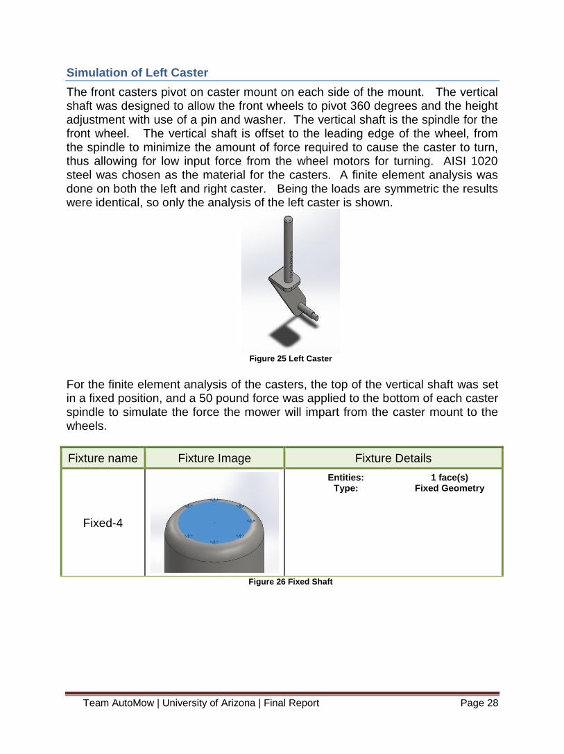
The front casters pivot on caster mount on each side of the mount. The vertical shaft was designed to allow the front wheels to pivot 360 degrees and the height adjustment with use of a pin and washer. The vertical shaft is the spindle for the front wheel. The vertical shaft is offset to the leading edge of the wheel, from the spindle to minimize the amount of force required to cause the caster to turn, thus allowing for low input force from the wheel motors for turning. AISI 1020 steel was chosen as the material for the casters. A finite element analysis was done on both the left and right caster. Being the loads are symmetric the results were identical, so only the analysis of the left caster is shown.
Figure 25 Left Caster
For the finite element analysis of the casters, the top of the vertical shaft was set in a fixed position, and a 50 pound force was applied to the bottom of each caster spindle to simulate the force the mower will impart from the caster mount to the wheels.
Fixture name Fixture Image Fixture Details
Fixed-4
Entities: 1 face(s) Type: Fixed Geometry
Figure 26 Fixed Shaft

Team AutoMow | University of Arizona | Final Report Page 29
Load name Load Image Load Details
Force-2
Entities: 1 face(s), 1 plane(s)
Reference: Top Plane Type: Apply force
Values: 50 lbf
Figure 27 Applied Loads
A solid type mesh was used for the analysis with 16424 elements and 27625 nodes.
Figure 28 Mesh Caster
The results of the finite element analysis show that a maximum von Mises Stress of 9395 psi occurred at node184991 that resulted in a minimum factor of safety of 5.4. The maximum displacement of 0.0209 inches occurred at node 238 or the end of the caster spindle as expected. Below show the von Mises Stress diagram.

Team AutoMow | University of Arizona | Final Report Page 30
Name Type Min Max Stress VON: von Mises Stress 0.0281868 psi
Node: 25742 9394.91 psi Node: 18499
left caster-SimulationXpress Study-Stress-Stress
Figure 29 Caster Von Mises Stress
Name Type Min Max Displacement URES: Resultant Displacement 0 mm
Node: 275 0.531337 mm Node: 238
left caster-SimulationXpress Study-Displacement-Displacement
Figure 30 Caster Displacement
Simulation of Nose Cone

Team AutoMow | University of Arizona | Final Report Page 31
The nose cone is a replacement to the existing front of the lawnmower. The nose cone was designed to facilitate having a zero turn mower, and is the mounting point for the front steering assembly. The design allows for the front casters to pivot 360 degrees without contact between the wheels and the nose cone. The nose cone will be welded to the existing lawnmower body after the current front is cut away from the mower body. AISI 1020 steel was chosen as the material to fabricate the nose cone from, due to the ductility and ease of welding.
Figure 31 Nose Cone
For the finite element analysis of the nose, the large arch was set in a fixed position, as this will be welded to the mower body. A 100 pound force was applied to the underside of the upper mounting surface where the caster mount will be bolted, to simulate the force between the mower body and the caster mount.
Fixture name Fixture Image Fixture Details
Fixed-1
Entities: 1 face(s) Type: Fixed Geometry
Figure 32 Nose Cone Fixed
Load name Load Image Load Details
Force-1
Entities: 4 face(s) Type: Apply normal
force Value: 100 lbf
Figure 33 Nose Cone Force
Team AutoMow | University of Arizona | Final Report Page 32
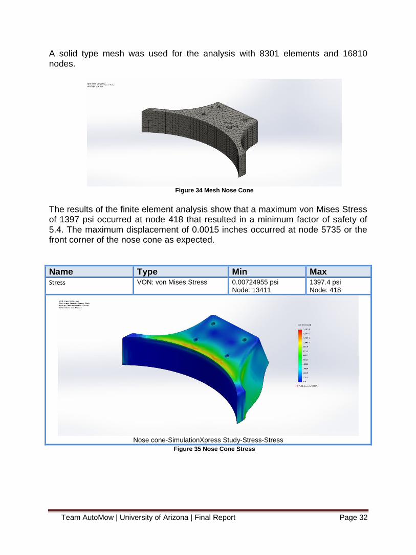
A solid type mesh was used for the analysis with 8301 elements and 16810 nodes.
Figure 34 Mesh Nose Cone
The results of the finite element analysis show that a maximum von Mises Stress of 1397 psi occurred at node 418 that resulted in a minimum factor of safety of 5.4. The maximum displacement of 0.0015 inches occurred at node 5735 or the front corner of the nose cone as expected.
Name Type Min Max Stress VON: von Mises Stress 0.00724955 psi
Node: 13411 1397.4 psi Node: 418
Nose cone-SimulationXpress Study-Stress-Stress
Figure 35 Nose Cone Stress

Team AutoMow | University of Arizona | Final Report Page 33
Name Type Min Max Displacement URES: Resultant Displacement 0 in
Node: 1387 0.00152774 in Node: 5735
Nose cone-SimulationXpress Study-Displacement-Displacement
Figure 36 Nose Cone Displacement
Team AutoMow | University of Arizona | Final Report Page 34
Electrical Subsystem
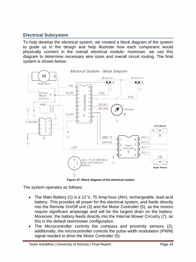
To help develop the electrical system, we created a block diagram of the system to guide us in the design and help illustrate how each component would physically connect in the overall electrical module; moreover, we use this diagram to determine necessary wire sizes and overall circuit routing. The final system is shown below:
Figure 37: Block diagram of the electrical system.
The system operates as follows:
The Main Battery (1) is a 12 V, 75 Amp-hour (Ahr), rechargeable, lead-acid battery. This provides all power for the electrical system, and feeds directly into the Remote On/Off unit (3) and the Motor Controller (5), as the motors require significant amperage and will be the largest drain on the battery. Moreover, the battery feeds directly into the Internal Mower Circuitry (7), as this is the default lawnmower configuration.
The Microcontroller controls the compass and proximity sensors (2); additionally, the microcontroller controls the pulse-width modulation (PWM) signal needed to drive the Motor Controller (5).

Team AutoMow | University of Arizona | Final Report Page 35
The Remote On/Off unit (3) turns the mower blade on and off via the Internal Mower Circuitry (7); it also turns the Microcontroller (2) on and off, allowing the wheel motors to be controlled independently from the blade motor.
The Proximity Sensors and Compass transmits this signal to the Microcontroller to be stored for future waypoint following.
The Motor Controller (5) receives its modulated signal from the Microcontroller (2), determining which way to turn, how fast to move, and whether to drive forward or in reverse. The motor controller’s power is derived directly from the Main Battery (1), and it feeds both Wheel Motors (9, 10).
The Internal Mower Circuitry (7) is the existing on-board circuitry that came with the lawnmower itself. This controls the recharge feature of the battery, as well the blade motor control and the existing on/off switch on the lawnmower handle (not shown).
The Blade Motor (8) is an existing motor that spins the lawnmower’s blade.
The Left and Right Wheel Motors (9 and 10, respectively) control the left and right wheels, respectively.
A summary of the main electrical parts and the actual components being used is provided below:
Electrical System Parameters
Main Battery (1) PG-12V75FR
Microcontroller (2) PIC24F64GA002
Remote On/Off (3) ETH008
GPS Module (4) Piksi
Motor Controller (5) Sabretooth 2x25
BEC (6) SportBEC
Internal Mower Circuitry (7)
Ryobi (part of mower)
Blade Motor (8) Ryobi (part of mower)
Wheel Motor - Left (9)
Wheel Motor - Right (10) Table C Electrical System Parameters
Microcontroller
In order to process the information from the peripheral devices such as the GPS and the remote control and make decisions for the control section of the system, we need to have a central processing unit mounted on our system. For this system, we will be using the PIC24FJXXGA002 (PIC24F) microcontroller as well

Team AutoMow | University of Arizona | Final Report Page 36
as the Microchip Starter Board that comes with the unit. Both of these devices are made by Microchip. We decided on this setup as opposed to other microcontrollers based on the fact that the compiler and board setup is easier to build on and understand than other choices. An image of the starter board and pin diagram for the microcontroller are shown below:
Figure 38 PIC24F Starter Board
Figure 39 PIC24F Pin Diagram
The board can run on either 5 Vdc or 3.3 Vdc, and we will drop the voltage off of the battery to support it. For our system, we will be expecting to use ports for the following devices:
Proximity Sensor (2)
Compass
Remote Control (1-3)
Motor Controller (2)
On this controller, we have 21 general ports that we can use as I/O ports, so there is plenty of space to work with on this device. As mentioned before, the microcontroller comes with a software package that includes a C compiler to

Team AutoMow | University of Arizona | Final Report Page 37
convert the code into the microcontroller’s format. An additional reason for picking this controller is that it can be powered via USB, so we can hook up a computer to power the chip during initial testing instead of using battery power. The price for the microcontroller itself is about $2, but the starter board with the processor makes the package worth about $50.
PIC24F Microcontroller
Input Voltage 3.3 - 5 V
Power Consumption ~2.5W
Software Language C
I/O Ports 21
Cost $50.00
Availability Immediate
Manufacturer Microchip Table D PIC 24F
Remote Control
In our design requirements, we are required to have a remote kill switch for our system. This would only need a simple RF transmitter and receiver. However, we also have some desired features that include being able to start the mower remotely as well as turning the mower blade on or off. For these sorts of features, we would need a more sophisticated RF receiver. The RF module we will be using is the ETH008 from Devantech. An image of the module and its pin diagram are shown below:
Figure 40 ETH008 Module

Team AutoMow | University of Arizona | Final Report Page 38
Figure 41 ETH008 Pin Diagram
This module has 8 relay outputs which is plenty for our requirements as well as any other uses we may find during the build and test phase. The module will need to be powered by 12 Vdc which will be achieved by stepping down the voltage from the main battery. From there, we can step the voltage down to 5 Vdc from the output in order to meeting the voltage constraints of the microcontroller. This relay can be controlled wirelessly via an Android or iOS device. Devantech has a free app for both operating systems that will allow the user to control any of the 8 relays with the touch of a button. Due to the fact that we’ll have control of 8 relays, this device is slightly more expensive (~$60), but we would like to have the system be open to more control for the user, and this device easily falls in our budget as well.
ETH008 Remote Relay Unit
Input Voltage 12 V
Input Current 500mA
Power Consumption ~6W
Relay Outputs 8
Cost $60.00
Availability Immediate
Manufacturer Devantech Table E ETH008 Remote Relay Unit
Compass
One part of our control system includes a compass module, specifically the HMC5883L 3-Axis Compass Module from Parallax. This compass chip is, as per its title, able to detect direction in all three directions, but for our purposes, we will only be using the direction vectors in the X and Y directions as we do not need to

Team AutoMow | University of Arizona | Final Report Page 39
know the Z component. This module interfaces with the controller via four lines, two of which are used for power and the other two are used for transmitting data between the modules. On the power side, the GRD pin connects directly to the microcontroller’s ground, and the VIN line can take a voltage anywhere from 2.7 to 6.5 volts. We will be using it at 5V in order to be consistent with the voltage that the microcontroller runs at.
On the data side of things, the microcontroller connects to the compass’ SDA and SCL line using simple digital I/O ports in order to communicate with the compass using the I2C protocol. This protocol involves the master (microcontroller) controlling the clock line (SCL) while the master and the slave trade off on using the bus (SDA) to communicate information. Using this line, we are able to receive the value (16 bits each) that represents the magnitude of the X direction and that of the Y direction. By taking an inverse tangent function in the code, we can take these two values and convert them into a heading that ranges from 0 to 360 degrees where 0/360 degrees is facing north. Finally, with this data, we know the direction the robotic lawn mower is facing, and we can adjust the speed of the wheels individually in order to mow in a straight line as well as make a half turn with more accuracy.
Proximity Sensor
A big problem with mowing a lawn automatically is making sure that the mower stays within the bounds of the lawn, and we have implemented proximity sensors as part of our control system in order to solve this issue. We will be integrating two Sharp GP2Y0A21 Distance Sensors on the front end of the mower in order to help detect when the mower is approaching the walls of the boundary. This module will be powered by the microcontroller by a 5V source and will also be directly grounded to it. The microcontroller will take an input from the proximity sensors that will be an analog signal from 0-5V that corresponds to how far away the robot is from the wall. The proximity sensors begin to output a voltage when the robot gets within 100cm of the wall, so this is more than sufficient for our purposes. The proximity sensor acts as a resistor that allows a higher voltage to pass through when we are closer to the object. When the voltage hits a certain threshold, we will know that it is time to square the robot up with the wall and perform a half turn in order to mow in the other direction. With these modules mounted on the front, the control system will be able to know when there’s a wall in front of the robot as well as be able to detect any other obstacles that may lie in the way of the robot as a safety feature.

Team AutoMow | University of Arizona | Final Report Page 40
Motor Controller
For our project, the motor controller will control the back wheels of the lawnmower, propelling it forward, backward, or in any direction by varying the speed at each wheel e.g. full power at the left wheel and no power at the right wheel will turn the robot immediately left. To accomplish this task, we need a rather robust controller, as our motors require relatively high continuous amperage (~5A each). Moreover, we need a responsive controller – a ‘laggy’ response is unacceptable when zero-radius turning is required and when the accuracy of our cutting pattern is imperative. Lastly, as we would like our design to be applicable to varying environments and terrains e.g. thicker grass, wet grass, etc., a motor controller that will provide constant, reliable current to our drive motors is essential.
Figure 42 Sabertooth 2x25 Motor Controller
Thus, the motor controller we chose for our design is the Sabertooth Dual 25A Regenerative Motor Driver. This motor controller has many key features that make it suitable for our needs, the most important of which is its power delivery. The Sabertooth can control two motors simultaneously, delivering 25A of continuous current to each (with a peak current of 50A). While this is certainly more current than we need, it provides the stability and robustness that we require while simultaneously ensuring that our motors will never burn out due to voltage drops (assuming an adequate battery). Moreover, the Sabertooth has added features that make it ideal for our project. For example, this motor controller has regenerative braking/reverse, a feature that recharges the onboard battery whenever the motors are reversed or slowed. As a result, we have the

Team AutoMow | University of Arizona | Final Report Page 41
ability to constantly recharge our battery by running our design backwards, allowing us to provide the same cutting pattern (in reverse) while reducing the need for the operator to manually recharge the battery i.e. plug it into an AC outlet for several hours. Another key feature of this motor controller is its ability to be controlled via multiple modes: R/C, analog, and serial. This flexibility allows our control method to change without having to significantly change the on-board hardware; for the purposes of future expandability, this is a desirable function to have. However, for our purposes, we will be using pulse-width modulation (PWM) via our microcontroller, which can be used in either the analog or serial modes. We will ultimately use the analog mode with the output of the microcontroller running through an RC filter (as per the Sabertooth’s specifications). And, as an added feature for these modes, the Sabertooth provides a set of DIP switches to manually change the settings of each mode (response, signal mixing, etc.), making it even simpler to tune our design as this does not have to be via software. Finally, the Sabertooth has some general characteristics that make it ideal for our design: it operates at a supersonic frequency (32 kHz), eliminating the ‘whine’ of the motor while it’s operating; it has onboard heat sinks and heat dissipation, additional elements that we will not have to design or purchase separately (leaving us with more time and more money to complete our design); it has a variable input voltage operating range (6-30V), giving us flexibility in choosing our power source; it does not require the motors to come to a complete stop before reversing, resulting in much smoother operation; and, it is available at many online retailers, resulting in a short lead time and little chance of unavailability. The only real consequence of choosing the Sabertooth 2x25 is its price: $125. However, given the total cost of the other components of our design relative to our funding, the Sabertooth has little overall budgetary impact, and its many positive features make it the ideal motor controller for our project.
Sabertooth 2x25 Motor Controller
Input Voltage (V) 6 - 30
Output Current - Continuous (A) 2x50
Output Current - Peak (A) 2x25
Cost $124.99
Availability Immediate
Manufacturer Dimension Engineering
Table F Sabertooth Motor Controller

Team AutoMow | University of Arizona | Final Report Page 42
Blade Motor Controller
For our project, we needed some means by which to electronically control our blade motor, as one of our requirements is that the system must have a ‘kill switch’ to deactivate itself should it get out of range, go off path, or present some other danger to people or the environment. Since the blade motor was originally activated via a mechanical pull chain (like any typical lawnmower), this device had to be completely novel to the design. Moreover, we needed something that could take in a low current digital signal (0-5V) and output a high current, higher voltage, DC signal. As a result, we decided to use a motor controller to achieve these goals
Figure 1: Syren 50A Motor Controller
Thus, the motor controller we chose for our design is the Syren 50A Motor Driver. This motor controller has many key features that make it suitable for our needs, the most important of which is its power delivery. The Sabertooth can control one motor, delivering 50A of continuous current (with a peak current of 100A). While

Team AutoMow | University of Arizona | Final Report Page 43
this is certainly more current than we need, it provides the stability and robustness that we require while simultaneously ensuring that our motors will never burn out due to voltage drops (assuming an adequate battery). Another important feature of this motor driver is that it’s part of the same family of motor controllers as the one we chose for our wheel motors: the Sabertooth 2x60. As a result of this, we are able to communicate with both drivers simultaneously using a single UART TX line on our microcontroller. By utilizing the simplified serial protocol, we can send the same signal to each input port (S1) on the respective motor controllers and control which one implements the command via setting the S2 pin either logic high or logic low. Thus, our communication scheme is greatly simplified, and does not require multiple PWM protocols or RC circuits. Additionally, utilizing a motor driver to control the blade motor provides us with the added benefit of being able to control the speed of the blade motor, a feature not found on the existing motor. While this was not one of our system requirements (or even a desired quality), we can potentially monitor the torque on the blade and adjust the speed accordingly, thus decreasing our overall power consumption. Or, we could implement a power-saving mode, where the blade ran at some fraction of its top speed – this setting could be adjusted manually by the user based on the type of lawn he has as well as some other environmental factors e.g. wet lawn, debris, etc. As with most things, these many benefits come at a cost – which, in this case, is the actual cost of the Syren, at $125. However, as with almost all of our other components, we have ample room in the budget for them, and the sheer volume of the benefits of the Syren outweigh its only real drawback.
Syren 50A Motor Controller
Input Voltage (V) 6 - 30
Output Current - Continuous (A) 50
Output Current - Peak (A) 100
Cost $124.99
Availability Immediate
Manufacturer Dimension Engineering

Team AutoMow | University of Arizona | Final Report Page 44
Voltage Transformer
As a result of replacing the onboard, 48V battery with a longer-life (higher amp-hr) 12V lead-acid battery, it was necessary to integrate the existing mower components with this new power source. Fortunately, we only had a single component that needed to be integrated into our new design; unfortunately, this was the blade motor, which resulted in several problems that were challenging to solve. Finding an existing 12V electric mower blade motor proved to be difficult and expensive; moreover, there was no guarantee that this new motor would integrate easily into our design, causing more potential complications. We also considered buying a relatively inexpensive, generic 12 V motor and modifying that to meet our needs. However, this idea was quickly rejected, as it would require additional time and expense through machining costs; additionally, we didn’t want to be responsible for any blade attachment failures due to improper design. Since we knew that the blade was designed for the motor we had, it was best to leave those components alone and reduce our liability.
Ultimately, we chose to use a high power 12V to 48V DC-DC transformer made by Current Logic. Utilizing this component provided a simple, plug-and-play solution that eliminated any machining and integration issues while allowing us to leave all of our existing components unmodified. The transformer also gives us a minor 1-2 second delay upon starting, ensuring that our blade motor is protected against an inrush of current. The only drawback to this solution is the price; however, with the removal of the very expensive GPS unit from the project, there is ample room in the budget for this component, especially considering its ease of integration.

Team AutoMow | University of Arizona | Final Report Page 45
Power Management
Of utmost importance in any electrical system is power management. Anything less than a painstakingly critical analysis of how power will be used and distributed amongst the system subcomponents can lead to serious part fatigue or total system failure. Taking this into consideration, we tried to analyze our system thoroughly, simplifying it as much as possible to reduce the chance of error. The first electrical system we designed used the lawnmower’s existing on-board power source: a 48V, 10 Ahr, rechargeable, lead-acid battery. However, the use of this battery began to complicate the system as we started to integrate the additional parts. For example, no other component could use 48V as its input voltage, requiring step-down transformers for the remaining system elements. This proved even more problematic as the wheel motors require significant current (especially when starting), forcing us to use a heavy-duty transformer that would have been expensive and difficult to obtain. Moreover, the original battery’s suggested run time was no more than 45 minutes – with the addition of the wheel motors, and the microcontroller, we conservatively calculated that the mower would run for a maximum of 30 minutes (though this was assuming we would completely discharge the battery, which would severely limit its lifespan) – in reality, it could probably run for no more than twenty minutes. To remedy these problems, we came up with two solutions: add another battery onto the design to power the additional components we will install, leaving the mower’s existing electrical system alone; or replace the on-board battery with a lower voltage, higher energy battery, as well as replace the 48V blade motor mower to something compatible with the new power source. While the former solution would be easier and cheaper to integrate, it would also add significantly more weight to the design, which in turn would require more torque from the wheel motors, and thus even more power. Also, it would require two different
12V-48V DC-DC Transformer
Input Voltage 12 V
Output Voltage 48 V
Output Power 500 W
Start Time Delay 1-2 sec
Efficiency 91%
Non-load Consumption <5W
MTBF 100,000 hrs
Cost $184.00
Availability Immediate
Manufacturer Current Logic

Team AutoMow | University of Arizona | Final Report Page 46
batteries to charge with two different chargers – this was an extremely undesirable tradeoff, especially for a non-technical end-user. Instead, we chose the latter solution: a new 12V, 75 Ahr, rechargeable, lead-acid battery that is capable of powering the whole system for several hours; and a 12 V blade motor that can output the necessary torque required by the original design. Stepping down to 12V has the added effect of allowing us to use the vast array of parts and components that utilize this voltage, as 48V parts were expensive and difficult to find. However, like the first solution, this design has its drawbacks, most notably the cost of purchasing a new battery and blade motor. Additionally, the extra time needed to integrate these new parts is a consequence of this choice, leaving us with less time to focus on other portions of the project. Ultimately though, we feel this is the best choice of the two, as it is a lighter, more compact and adaptable design, and the additional costs do not affect our budget in an impactful way. Moreover, the finished product will be something that looks like it was engineered, not patched together by hobbyists. A power analysis is shown below, comparing the effects of the two different batteries on the overall electrical system. It should be noted that the Percent (%) Usage and Operating Time metrics assume that the battery will be drained completely – to realize best performance, an 80% correction factor should be used.
Table G Power Management
Description Quantity Current (A) Voltage (V) Power (W)
Wheel Motors 2 5 12 120
Blade Motor 1 7 48 336
Microcontroller 1 0.5 5 2.5
Remote Control 1 0.5 12 6
Existing Mower 1 0.2 48 9.6
Circuitry
TOTAL 474.1
% of Power Usage 98.8%
Operating Time (hrs) 0.56
Description Quantity Current (A) Voltage (V) Power (W)
Wheel Motors 2 5 12 120
Blade Motor 1 15 12 180
Microcontroller 1 0.5 5 2.5
Remote Control 1 0.5 12 6
Existing Mower 1 1 12 12
Circuitry
TOTAL 320.5
% of Power Usage 35.6%
Operating Time (hrs) 2.88
and is taken into account by wheel motor
and GPS current draw, respectively
Power Management
Existing Onboard Battery = 48V, 10 Ah = 480 Whr (maximum)
New Onboard Battery = 12V, 75 Ah = 900 Whr (maximum)
Motor Controller/BEC power is negligible

Team AutoMow | University of Arizona | Final Report Page 47
Software Design
In order to control the system, there will need to be software implemented that the microcontroller will make its decisions off of. The code will be written in C, and we will be using the compiler software that comes with the microcontroller to get the code in a format that the microcontroller recognizes. The software has three unique inputs that are analyzed that then tell the motor controller which wheel to spin and at which speed. Initially, the mower starts in the forward direction. This is maintained until the two infra-red proximity sensors have reached a certain threshold, indicating that they are close to the border. At this point, the mower begins to turn to the left until the correct value from the compass is read. In theory, this should spin the mower around 180 degrees. At this point, the mower then drives forward until it again reaches the wall based on the proximity sensors. However, this time, the mower will turn right in order to ensure a serpentine pattern down the lawn. The mower will spin until the compass value is correctly read, and then it will start from the beginning. This pattern is run until a predetermined amount of time has passed so that the lawn can be properly mowed.

Team AutoMow | University of Arizona | Final Report Page 48
Cost Analysis
The budget for the project is established at 3,500 dollars. The following table depicts the total cost of the system with minimal redundancies:
Table H Cost Analysis
The total cost of the project was $3,031.82 which made the team $468.17 dollars under budget.
Part Name Purchased From Description QTY Unit Price Price
Mower Home Depot Ryobi Lawn Mower 1 $301.60 $301.60
Bearings McmasterCarr Front Caster Bearings 4 $23.77 $95.07
Microcontroller Microchip (in hand) PIC24F Microcontroller 1 $0.00 $0.00
Motor Controller Robotshop.com Sabertooth Dual 60A 6V-30V Regenerative Motor Driver 1 $189.99 $189.99
Motors Robotshop.com RS-550 Motor 19300rpm 12V 70.55oz-in 2 $6.75 $13.50
Gearbox Robotshop.com Banebot P60 gearbox Rs-540/550,1.5"shaft, mount 550, 64:1 2 $64.50 $129.00
Battery atbatt.com 12V 75 Ahr Rechargeable Battery (51 lbs) 1 $184.49 $184.49
Charger atbatt.com Battery Charger 1 $44.99 $44.99
Guide Wire PetsMart Invisible dog fence kit, 1 extra collar 1 $286.44 $286.44
Dc-Dc Conveter Current Logic 12V to 48V converter, 500W max, input/output 1 $230.78 $230.78
Sensor RobotMesh.com Sharp Distance Sensor(10-80cm) 4 $12.00 $48.00
Compass Module RobotMesh.com Parallax Compass Module 30Axis 2 $25.99 $51.98
Blade Motor O'Reilly 12 Volt DC Motor 1 $50.80 $50.80
Subtotal $1,626.64
Poster Design Day Poster Materials etc $300.00
Machine Shop AME CNC lathe caster steering etc $500.00
Raw Materials Industrial Metal Supply Steel, aluminum $85.30
Miscellaneous Bolts,Nuts,Pins,Drill bits, 12v relays,switch,Sandpaper. Etc $519.89
Total $3,031.83
Left to Purchase
Received Orders
Team AutoMow | University of Arizona | Final Report Page 49
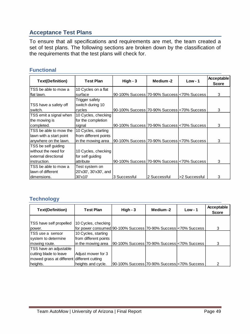
Acceptance Test Plans
To ensure that all specifications and requirements are met, the team created a set of test plans. The following sections are broken down by the classification of the requirements that the test plans will check for.
Functional
Technology
Text(Definition) Test Plan High - 3 Medium -2 Low - 1Acceptable
Score
TSS be able to mow a
flat lawn.
10 Cycles on a flat
surface 90-100% Success 70-90% Success <70% Success 3
TSS have a safety off
switch.
Trigger safety
switch during 10
cycles 90-100% Success 70-90% Success <70% Success 3
TSS emit a signal when
the mowing is
completed.
10 Cycles, checking
for the completion
signal 90-100% Success 70-90% Success <70% Success 3
TSS be able to mow the
lawn with a start point
anywhere on the lawn.
10 Cycles, starting
from different points
in the mowing area 90-100% Success 70-90% Success <70% Success 3
TSS be self guiding
without the need for
external directional
instruction.
10 Cycles, checking
for self guiding
attribute 90-100% Success 70-90% Success <70% Success 3
TSS be able to mow a
lawn of different
dimensions.
Test system on
20'x30', 30'x30', and
30'x10' 3 Successful 2 Successful >2 Successful 3
Text(Definition) Test Plan High - 3 Medium -2 Low - 1Acceptable
Score
TSS have self propelled
power.
10 Cycles, checking
for power consumed 90-100% Success 70-90% Success <70% Success 3
TSS use a sensor
system to determine
mowing route.
10 Cycles, starting
from different points
in the mowing area 90-100% Success 70-90% Success <70% Success 3
TSS have an adjustable
cutting blade to leave
mowed grass at different
heights.
Adjust mower for 3
different cutting
heights and cycle. 90-100% Success 70-90% Success <70% Success 2

Team AutoMow | University of Arizona | Final Report Page 50
Performance
Utilization of Resources
Text(Definition) Test Plan High - 3 Medium -2 Low - 1Acceptable
Score
TSS be able to cut grass
no more than 5" tall.
Cut grass at 3, 4,
and 5 inches. 90-100% Success 70-90% Success <70% Success 3
TSS be able to mow 90
degree corners similar to
a conventional push
mower.
10 Cycles,
comparing to
manually mowed
area
<3% additional
unmowed area
3-10% additional
unmowed area
>10%
additional
unmowed area 3
TSS mow a 20' x 20'
lawn with a solid brick
border (excluding edges
and borders).
10 Cycles, in a
20'x20' lawn 90-100% Success 70-90% Success <70% Success 3
Text(Definition) Test Plan High - 3 Medium -2 Low - 1Acceptable
Score
TSS be able to operate
safely with individuals
within a 1 foot distance
to the system.
Place object in path
of mower.
Stops mowing
function and
signals operator N/A
Does not stop
and comes into
contact with
object. 3
TSS have a capital cost
comparable to
competitors products of
similar function.
Compare cost of
system to 3 other
robotic lawn
mowers.
Costs more than
2,000 above retail
Between 0-2,000
above retail
At or below
retail cost 2
TSS have a blade safety
requirement for walk-
behind rotary lawn
mowers in specifications
with B71.1 of the
American National
Standards Institute.
Off the shelf mower
fulfills. Yes Unknown No 3
TSS incorporate 3 or
more TI analog ICs or 2
analog ICs and a TI
processor.
Identify components
in electrical system.
3 or more TI
analog Ics or 2
analog Ics and a
TI processor
2 or more TI
analog Ics or 1
analog Ics and a
Ti Processor
Less than
Medium value. 3

Team AutoMow | University of Arizona | Final Report Page 51
System Test Plan
Text(Definition) Test Plan High - 3 Medium -2 Low - 1Acceptable
Score
TSS mow a 20' x 20'
lawn with a solid brick
border (excluding edges
and borders) with an
acceptance within 10%
of area.
10 Cycles,
comparing to
manually mowed
area
<10% area
unmowed
(excluding edges
and borders)
10-20% area
unmowed
>20% area
unmowed 3
TSS be tested from 10
different starting
locations in the
designated 20'x20' area.
10 Cycles, starting
from different points
in the mowing area 90-100% Success 70-90% Success <70% Success 3

Team AutoMow | University of Arizona | Final Report Page 52
Risk Analysis
This risk analysis shows the current possible events leading into the spring semester. The left column showing the likelihood that the event will happen, the right showing the severity of the event happening. For example power is labeled as five and has a moderate 10 to 50 percent chance of occurring. If the event is to occur it would have a major consequence to the project.
Table I Risk Analysis
1. Precision 2. Cost 3. Complexity 4. Size 5. Power 6. Damage to Lawn 7. Obtainability
Mitigation Plan
If one of the events above is to occur we will then assess why it occurred. How we can prevent the event from occurring again. In the event that it has mechanical parts involved we will then assess if our design or parts need to be changed.
Precision
In the event that our GPS system is not as accurate as needed we have two different options. We will alter our programming method to account for the error involved with the control system. If does not fix the problem we will then visit different ways of directing our mower. The team was unable to obtain a GPS system as planned in the Critical Design Review. We then faced a lack of precision in the control system. In order to mediate the precision risk, we used two proximity sensors with the addition of a
Likelihood
Insignificant Minor Moderate Major Catastrophic
Almost Certain (>90%)
Likely(50%-90%) 7
Moderate (10%-50%) 3 5
Unlikely (3%-10%) 4 6 2
Rare (<3%) 1
Moderate
High
Extreme
Consequences

Team AutoMow | University of Arizona | Final Report Page 53
compass to provide a multi-level way for the control system to determine the mowing route.
Cost
In the event that a component we need is out of budget we will contact the vendor to see what discounts are offered for example if there is a chance of using our project to promote their product for a discount. If there is no discount offered we will then search for other vendors for the same product as well as look for possible used items. If there are no other vendors offering the item we will then research similar products that will fit our needs. This event is highly unlikely of happening as our design is well under the allotted $3500 budget.
Complexity
In the event that our design becomes to complicating in the fabrication or electrical process we will then assess our design. We will then either seek out advisement on how to complete the design and see if there is a better way. If the design is still too complex we will then reevaluate our design and possibly redesign our system and fabrication methods. This event has a moderate possibility as our electrical system is complex as it communicates with our sensor system and directs the mower to the correct path. This event has moderate consequences as we have many options on how to redesign our system.
Size
In the event our mower is too large and does not meet our requirements we will reevaluate our design. Starting with the mechanical components and seeing where size can be cut down. We do not however believe that this will be a high risk as we are keeping the width dimensions the same as the purchased mower.
Power
In the event that our system does not have enough power to power both the mower itself as well as our drive mowers we will then reevaluate our power needs. We will then discuss the replacement of our main battery or by adding an additional battery to power our drive system. This event has a moderate possibility and has a major consequence. We will then have to redesign our electrical system by adding additional batteries to our system.
Damage to Lawn
In the event of our system causing damage to the lawns surface we reevaluate our mechanical design. Starting with the rear drive system we will be looking for traction issues and wheel spin. We do not believe our drive system will cause wheel spin, but in the case of wheel spin we will increase the diameter of the rear wheels or turn down the speed of our drive motors. The caster front wheels we however to do not believe lawn damage will occur as there is no drive motors

Team AutoMow | University of Arizona | Final Report Page 54
powering them. This event is very unlikely of happening and a minor consequence to our project.
Obtainability
In the event that some of our parts are not obtainable or cannot not be acquired in time for the build time we will then look to other vendors. If other vendors cannot provide us with the required parts as well we will research for similar products that fulfill the requirements of the original part needed. This event is likely to happen in the time span that we will need parts, but with only minor consequence. Unfortunately the GPS system with the desired level of precision was not available from the vendor Swift Navigation. Swift Navigation advertises the only commercially available GPS with the high precision. The team dealt with this challenge by using other commercial off the shelf parts to construct another control system using different sensors.

Team AutoMow | University of Arizona | Final Report Page 55
Project Schedule Spring 2014
Through the spring 2014 semester, the team abided by the following schedule:
The after the conclusion of the CDR presentations the team ordered the required parts. Unfortunately we were unable to obtain the Piksi GPS module as planned in our CDR. Post CDR, the team was given assurance from Swift Navigation that the GPS would be released at the end of January and sent arrive within a week. Soon the team learned that they had issues with the software package that the GPS used and in mid-February we were notified by Swift Navigation that the GPS module would not be ready for shipping until late April. Since the team had been in contact with Swift Navigation since November, we were not hopeful that they would be able to supply us with the components we needed. After learning this, the team quickly moved to the option of using proximity sensors and a compass module to determine the correct path of mowing instead of relying on Swift Navigation to supply a GPS unit.

Team AutoMow | University of Arizona | Final Report Page 56
Despite being unable to obtain a GPS module, the team stayed on schedule through the electrical and mechanical system implementation due to the fact that the mechanical system would not change due to changes in the control system. Although we were on schedule in testing and analysis, the team did have to reduce the number of requirements that would be tested. For instance, the team was unable to test a full 20’x20’ plot of lawn; instead the team focused their efforts on a smaller path to show the full ability of the mower without having the larger plot of land.
Conclusion
In conclusion, the team has put together a product that could fulfill the requirements given by the customer. The mechanical subsystem is composed of two motors powering the rear wheels and caster front wheels to allow for a near zero turn radius. The electrical subsystem is comprised of proximity sensors and a compass module. This design was chosen due the ease of obtaining the parts, prior knowledge with using the proximity sensors, and relative accuracy. With all of the changes made in the control system, the team was unable to run tests on a full 20’x20’ area of lawn due to time constraints. To show the product’s functionality we setup and ran a looped path in the form of a figure eight. This shows the turning radius as well as the ability of the mower to be self-propelled. Although unable to test the full range of the mower, the team feels confident in the designs ability to fulfill the system requirements on a 20’x20’ plot of lawn. Through the year spent working on this project, the team learned how to deal with supplier issues, team work skills, and how a formal development process is like. With the supplier issues, the team learned how to change and adapt with challenges that arise in the design and fabrication process.

Team AutoMow | University of Arizona | Final Report Page 57
Appendix
Force Calculations

Team AutoMow | University of Arizona | Final Report Page 58
Solidworks Drawings
Rear Mounting Bracket
Caster Mount

Team AutoMow | University of Arizona | Final Report Page 59
Front Wheel
Gearbox with shaft

Team AutoMow | University of Arizona | Final Report Page 60
Left Caster
Right Caster

Team AutoMow | University of Arizona | Final Report Page 61
Motor Shaft Bushing
Motor

Team AutoMow | University of Arizona | Final Report Page 62
Nose Cone
Rear Pivot Shaft

Team AutoMow | University of Arizona | Final Report Page 63
Spur Gear
Rear Wheel

Team AutoMow | University of Arizona | Final Report Page 64
Team Member Responsibilities
Name: Elena Jenkins Role: Team Leader Contributions:
System Test and Verification
Trade-Off Analysis and Sensitivity Analysis
Acceptance Test Plans
Risk Analysis
Project Schedule Name: Ben Cohodas Role: Treasurer Contributions:
Mechanical Subsystem
Rear Assembly Name: Brian Ball Role: Scribe/Documentation Contributions:
Preliminary Design Review: Design 1, Design 2, Design 3
PDR Findings
Mitigation Plan
Front Cone fabrication Name: Jayson Rickel Role: Sponsor Contact Contributions:
Microcontroller, Remote Control
Software Design Name: Robert Hacker Role: Mechanical Lead Contributions:
Rear Drive Motors, Gearing, Front Caster Assembly
Stress Analysis and Simulation Name: Bryan Lizon Role: Electrical Lead Contributions:
Electrical Subsystem
Compass, Proximity Sensors, Motor Controller, Power Management

Team AutoMow | University of Arizona | Final Report Page 65
Team Collaboration:
System Requirements
Concept of Operations
Cost Analysis