refresh: a self-adaptation framework to support fault ... · refresh: a self-adaptation framework...
TRANSCRIPT

ReFrESH: A Self-Adaptation Framework to Support Fault Tolerance inField Mobile Robots
Yanzhe Cui, Richard M. Voyles, Joshua T. Lane, Mohammad H. Mahoor
Abstract— Mobile robots are being employed far more oftenin extreme environments, such as urban search and rescue,with greater levels of autonomy; yet recent studies on fieldrobotics show that numerous failure modes affect the reliabilityof the robot in meeting mission objectives. Therefore, faulttolerance is increasingly important for field robots operating inunpredictable environments to ensure safety and effectivenessof the system. This paper demonstrates a self-adaptation frame-work, ReFrESH, that contains mechanisms for fault detectionand fault mitigation. The goal of ReFrESH is to providediagnosable and maintainable infrastructure support, built intoa real-time operating system, to manage task performance inthe presence of unexpected uncertainties. ReFrESH augmentsthe port-based object framework by attaching evaluation andestimation mechanisms to each functional component so thatthe robot can easily detect and locate faults. In conjunction, atask level decision mechanism interacts with the fault detectionelements in order to generate and choose an optimal approachto mitigating faults. Moreover, to increase flexibility of the faulttolerance, ReFrESH provides self-adaptation support for bothsoftware and hardware functionality. To our knowledge, this isthe first framework to support both software and hardware self-adaptation. A demonstrative application of ReFrESH illustratesits applicability through a target tracking task deployed on amobile robot system.
I. INTRODUCTION
Robotic systems are playing increasingly important rolesin hostile and unpredictable environments often encounteredin space, military, and Urban Search and Rescue (USAR)operations [1]. Robots are appealing for such environmentsbecause they can be deployed both ahead of and in placeof human beings and perform tasks that humans cannot.However, studies on mobile robots used in the field haveshown a noticeable lack of reliability in real world conditions[2]. The worst case being that a robot becomes completelynonfunctional. Therefore, robots should be able to detect,isolate and even alleviate faults that result from both com-ponent failures and system configuration inadequacies.
Traditionally, to prevent or eliminate faults, system design-ers have adopted formal design and programming methodsin the design phase as well as performed verification andvalidation (V&V) in the testing phase [3]. The alternativeof fault tolerant is to identify faults dynamically and repairand validate them on the fly as a complement of V&V. Twosuch runtime fault tolerant techniques in the post-deployment
Yanzhe Cui is with the College of Engineering, Purdue University, WestLafayette, IN, 47907 USA [email protected]
Richard M. Voyles and Joshua T. Lane are with the Collegeof Technology, Purdue University, West Lafayette, IN, 47907 USArvoyles,[email protected]
Mohammad H. Mahoor is with the College of Engineering, Universityof Denver, Denver, CO, 80208 USA [email protected]
phase have been proposed to increase the reliability ofthese robots: the first is to provide redundancy-based faulttolerance, achieved either by adding mechanical and sensoryredundancy to a single robot or by deploying several identicalrobots at one time [4]; the second proposed solution isto support cooperation within a team of mobile robots ofdifferent functionalities so that task responsibilities may beredistributed in the event of an abnormal situation [5]. Thework presented in this paper focuses on the latter method,applied throughout the framework at multiple levels in thehierarchy. Thus, the aim here is to develop a self-adaptiveframework to support fault tolerance in cooperative fieldmobile robotic systems. Through dynamic self-adaptation,robots are capable of restoring themselves to normal func-tionality by distributing information and functionality acrossrobot boundaries. Extending this concept further, the self-adaptation framework can detect faults on the fly and defec-tive configurations can be altered to satisfy task requirements.We anticipate this framework to be used in conjunction withV&V to make systems highly tolerant of faults.
In order to generalize the framework to more easilyadapt to a wide variety of robot structures, we developeda four-layer self-adaptation framework, termed ReFrESH(Reconfiguration Framework for distributed Embedded sys-tems for Software and Hardware). While ReFrESH appearsto be a conventional layered architecture, it differs in thatit provides diagnosable and maintainable infrastructure sup-port, built into a real-time operating system (RTOS), to man-age functional requirements and non-functional requirementsacross each robot boundary in the presence of uncertainties inthe physical environment. In other words, ReFrESH exploresa reflective view of self-adaptive systems where the non-functional services, software/hardware functional compo-nents executing in a kernel, runtime component managementand dynamic self-adaptation within a robotic team are de-signed and implemented within the same paradigm: the Port-Based Objects (PBOs) [6], its real-time operating system(PBO/RT), and the Embedded Virtual Machine (EVM) [7].
An additional feature of ReFrESH is that it allows foreasier integration of both software and hardware functionali-ties in field programmable gate arrays (FPGAs). To our bestknowledge, ReFrESH is the first fault tolerant framework forrobot applications that supports both software and hardwareadaptation. We shall point out that a significant practicalproblem of distributing components across multiple robotsthrough a network is communication connectivity, latencyand jitter is currently being researched by ourselves [8] andby our collaborators at UPenn [7] and is beyond the scope
2014 IEEE/RSJ International Conference onIntelligent Robots and Systems (IROS 2014)September 14-18, 2014, Chicago, IL, USA
978-1-4799-6934-0/14/$31.00 ©2014 IEEE 1576
of this paper. Also, the specific details of software and hard-ware self-adaptation methods are not included in this paper.Interested readers can refer to our previous publications [9][10]. In this paper, we mainly present ReFrESH from theframework point of view.
II. RELATED WORK
A great deal of research in robotics has focused on thedevelopment of architectures. Each architecture that has beendeveloped for robotic systems tends to focus on providing thefault tolerance capability to the deployed robot or distributedrobot team.
ALLIANCE [11] is a software architecture that facilitatescooperative control of teams of mobile robots for faulttolerance. It is a fully distributed, behavior-based architecturethat allows each robot to select its appropriate action onthe fly. [12] presents a self-adaptive robotic architecturethat supports self-assembling components using a formalstatement of high-level system goals. It is one in whichcomponents automatically configure their interaction in away that is compatible with an overall architectural specifica-tion and achieves the goals of the system. [13] demonstratesan architecture-based self-adaptive system that focuses onsupporting runtime change of adaptation policies that aredecoupled from the architectures they relate to. Nevertheless,these architectures are not without their weakness: [11] doesnot support robotic self-adaptation; both [12] and [13] do notsupport distributed robotic teams; and all three approachescannot migrate verified code modules that are not pre-compiled into an existing executable.
The architecture described in this work trades formal spec-ifications of system behaviors for a higher degree of flexibil-ity and supports runtime self-adaptation through migratingand loading components among all heterogeneous robots ina team. Therefore, to support this migration capability acrossrobot boundaries, a virtual machine method is embedded intoour architecture.
There exist some outstanding virtual machines (VMs) formigrating software. Scylla [14] is a traditional VM adaptedfor embedded systems whose interaction is assumed to bebetween an end-user and a single isolated node in a network.It is not designed as an interface among the nodes them-selves. One physical machine exposes interfaces to a singlelogical machine. Mate [15] is a bytecode interpreter to run onmultiple nodes. It is a more customizable solution about VMbut it cannot adapt to component configuration dynamically.EVM [7] is being developed by our collaboration team, itconsists the systems software around the embedded real-timeoperating system (RTOS) in each node, which facilitates themechanisms to parametrically and programmatically controlthe operation of the node at runtime. It allows the controllogic to dynamically assign tasks to controllers at runtimethrough task and network slot migration, partitioning andreallocation. But EVM can only migrate bytecodes amongnodes. The architecture we propose makes up these limita-tions of the aforementioned VMs. It supports pre-compiled
functional components (object code snippets) distributedamong robots based on system and task specification.
III. DESIGN SCENARIO
The mobile robots we used in this work were developedin our lab [16]. Small size brings limitations in actuators,sensors, computational power and battery life (for example,the Hokuyo LIDAR is too bulky for them). These limitationsbased on size force us to find new ways of accomplishingcertain tasks: instead of having one robot, multiple robotsshould work together. This allows the requirements foractuators, sensors, and computational power to be split upbetween them. Therefore, to present the ReFrESH designconcept explicitly, an example scenario of searching forsurvivors with multi-robot teams is presented.
CameraImage
ProcessingActuator
R1 Dehazer
CameraImage
ProcessingActuator
R1
Infrared Actuator
R2
Image Processing
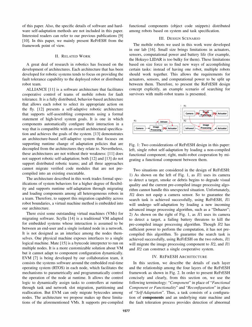
Fig. 1: Two considerations of ReFrESH design in this paper:left, single robot self-adaptation by loading a non-compiledfunctional component; right, multi-robot cooperation by mi-grating a functional component between them.
Two situations are considered in the design of ReFrESH:1) As shown on the left of Fig. 1, as R1 uses its camerato detect a target, smoke or debris begins to degrade visualquality and the current pre-compiled image processing algo-rithm cannot handle this unexpected situation. Unfortunately,R2 does not equip a camera sensor. So to guarantee thesearch task is achieved successfully, using ReFrESH, R1will undergo self-adaptation by loading a new incomingadvanced image processing algorithm, such as a “Dehazer”;2) As shown on the right of Fig. 1, as R1 uses its camerato detect a target, a failing battery threatens to kill thepre-compiled image processing algorithm. Though R2 hassufficient power to perform the computation, it has not pre-compiled this algorithm. To guarantee the search task isachieved successfully, using ReFrESH on the two robots, R1will migrate the image processing component to R2, and R1and R2 can construct a single cooperative system.
IV. REFRESH ARCHITECTURE
In this section, we describe the details of each layerand the relationship among the four layers of the ReFrESHframework as shown in Fig. 2. In order to present ReFrESHconcisely and clearly, from this section on, we use thefollowing terminology: “Component” in place of “FunctionalComponent or Functionality” and “Reconfiguration” in placeof “Self-Adaptation”. Thus, a task consists of a configura-tion of components and an underlying state machine andthe fault toleration process provides detection of abnormal
1577

components or configurations and alleviation of faults byaltering the task configuration through reconfiguration.
CPU FPGASensors/Actuators
Memory Power
Sensors/Actuators Dirvers Utility Drivers
EXECUTOR(EX)
SWEXT1_1
SWEXT1_m
...
HWEXT1_1
HWEXT1_n
...
SWEXTN_1
SWEXTN_m
...
HWEXTN_1
HWEXTN_n
...
...
...
...
...
EVALUATOR(EV)
SWEVT1_1
SWEVT1_m
...
HWEVT1_1
HWEVT1_n
...
SWEVTN_1
SWEVTN_m
...
HWEVTN_1
HWEVTN_n
...
...
...
...
...
ESTIMATOR(ES)
SWEST1_m+1
SWEST1_i
...
HWEST1_n+1
HWEST1_j
...
SWESTN_m+1
SWESTN_i
...
HWESTN_n+1
HWESTN_j
...
...
...
...
...
TaskT1 TaskTN... DeciderT1 DeciderTN... GeneratorT1 GeneratorTN...
Application Software Adaptation Software
Resource Layer
Interface Layer
Component Layer
Task Layer
Fig. 2: ReFrESH 4-layer framework.
A. Resource Layer - Non-Functional Services
The port-based object (PBO) is a software abstractionfor designing and implementing dynamically reconfigurablereal-time software. This forms the basis of a programmingmodel that uses domain-specific elemental units to providespecific, yet flexible, guidelines for integrating software com-ponents [6]. PBO specifies a mechanism for attaching meta-data to component assemblies through resource ports; suchas the communication information among sensors/actuatorsand the resource information about other subsystems. Thesemeta-data elements influence the task behavior by trigger-ing the execution of non-functional services. For example,through a resource service to retrieve the capability of anode, it is possible to show and define the performance con-straints of this node. Here, we choose the set CPU, FPGA,MEMORY, POWER, SENSORS/ACTUATORS as the charac-teristics of a node: the chosen “CPU” limits the maximumoperation cycle and computation capability; the particular“FPGA” used decides the area limitation(how many hardwarecomponents could be loaded); “MEMORY” restricts the datastream size and update rate; “POWER” decides the life ofa node; and equipped “SENSORS/ACTUATORS” limit thetask execution capabilities. All essential services performedby this level are the provision of non-functional requirements.
ReFrESH proposes two innovative approaches to integrat-ing such non-functional requirements into an application: 1)by implementing them as regular PBO components and 2)by providing an attachment mechanism for connecting thesenon-functional requirements to each running component. Byusing PBO components to satisfy non-functional require-ments, we provide an integrated solution where there isonly one paradigm for the implementation of a fault tolerantrobotic system.
B. Interface Layer - Data Transfer Services
This layer provides the driver and interface means ofproviding reliable data(packet) transfer services to the layer
above, the − Component Layer. Specifically, it provides apoint-to-point link of sensors/actuators and their correspond-ing operational components and builds a transfer channel forrequesting non-functional utility data.
C. Component Layer - Runtime Component Services
The most essential design target of ReFrESH is that itbetter supports fault tolerance. Thus, one of the cores of theReFrESH framework is a component layer which supportselemental services for component management. This layeris required to support robotic systems that have an inherentneed for runtime reconfiguration. ReFrESH allows for thecustomization of the execution policy associated with aseries of running components, (EXECUTOR (EX)). For thisframework, the PBO paradigm was augmented for hardwarecomponent implementation as well. Thus, in ReFrESH, atask could be composed of both software and hardwarecomponents that have a uniform inter-communication mech-anism.
To provide composable real-time components, ReFrESHencapsulates elemental building blocks into augmented ver-sions of real-time PBOs which are used to monitor andassess each EX. Additionally, to make a node capable ofevaluating and optimizing its own task performance from thecomponent perspective, ReFrESH creatively augments thecomponent viewpoint by introducing an “Evaluator” (EV)and an “Estimator” (ES). EV is a standard subroutine, thesame as EX, meaning that it runs continually as long asthe component it is attached to exists in a configuration. Byretrieving the non-functional requirements, EV assesses theperformance of the running component. Conversely, ES isinstantiated only if the current configuration has not satisfiedthe performance requirement and is used to assess thepotentially satisfying, non-running alternative components.The incorporation of EX,EV, and ES is termed a Super-PBOto show the distinction from the original PBO concept.
D. Task Layer - Configuration Generating Services
The task layer takes charge of determining the neces-sity for fault alleviation, re-assembling components basedon the requirements of a task, and generating an optimalconfiguration policy at runtime. Unlike a conventional tasklayer which only includes a state machine to control eachcomponent to satisfy the requirement of a task, such asby turning a component on/off; ReFrESH also extends thescope of the Task from the “execution” perspective to the“fault toleration” perspective by adding the “Decider” and“Generator” in order to support the capability of runtimereconfiguration.
To accomplish this, the ”Decider” first requests all compo-nent related performance information from the EV to judgewhether there is any reconfiguration requirement. If thereis a need for reconfiguration, which signifies that one ofthe components or the configuration as a whole are notsuitable for executing the current task, the “Generator” willbe instantiated. The ”Generator” executes in two phases:1) dependency analysis, which shows the construction of a
1578

configuration and decides if a component could be replacedor amended by another homogeneous functional component;and 2) functional assembly, which shows the process ofcombining required components to generate all potentialconfigurations. Since ReFrESH is based on the PBO kerneland PBO/RT provides flexible interfaces to control eachcomponent, it is convenient to analyze the dependency andlink the components in the configurations together. For thesegenerated configuration candidates, the corresponding ESwill be instantiated to estimate the performance of eachcomponent in each candidate for the current task whichhelps the “Decider” to produce an optimal configuration. Theimplementation details of each of the aforementioned basicservices in this level will be illustrated in section V.
V. REFRESH FAULT TOLERANCE AS A NEW DISCIPLINE
In Fig. 3 we show a framework schematic of the faulttolerant mechanisms contained in ReFrESH. PBO/RT In-terface is modeled after the Chimera Port-Based Objectinterface for subsystems servers (SBS). It provides a seriesof control for components, such as spawn task (sbsSpawn),turn on/off component (sbsControl) and set/get parametersof components (sbsSet/sbsGet). The Component Managermonitors the input and output signals of functional compo-nents, as well as the system resource consumption, whichit then compares to a high-level abstraction of the system.Specifically, the high-level abstracted view could trace thenon-functional requirement as the cause of the fault; such asCPU usage, system power consumption, or memory usage,through the interface layer to the bottom level resourcelayer. The Component Assembly Generator will generate allpossible configuration candidates based on the informationobtained from the Component Manager. Finally, accordingto the functional requirement of the current task and the non-functional requirement of the system nodes, the Configura-tion Decider is able to choose the optimal configuration fromthe set of configuration candidates. This management unit isdescribed in more detail in the following sections.
PBO/RT Interface:sbsSpawnsbsControl
sbsSetsbsGet
Component Assembly Generator
Configuration Decider
SoftwareComponents
HardwareComponents
Component Manager Super-PBOs (EX&EV&ES)
Fig. 3: The dataflow of ReFrESH supporting fault tolerance.
A. Fault Detection - Component Manager
1) Detecting Faults with Running Component Monitor -Evaluator: The EV monitors the performance of a specificcomponent in the system to provide for the detection offaults. The EV generates discrete readings by sampling the
signal according to a frequency set in PBO/RT; usuallythe same frequency as the EX it is attached to but thisis user defined. A component is evaluated based on howwell it implements its action in line with the demand of theoverarching task as well as how effectively it uses systemresources. In this paper, considering we want to support bothsoftware and hardware functional components, we chose a setof non-functional requirements in defining the non-functionalperformance of a component to be FPGA Area, Memory,CPU and Power. However, the user could add any parameterto this set. It is then up to the user to decide on whichfunctional aspect of the component it will be evaluated, suchas the error in a tracking algorithm on R1 in Section III,and the weight that it will hold against the non-functionalperformance. In particular systems a certain component maynot be vital to the execution of a task and only provides somesecondary functionality. In that case, it is more importantto the health of the system that the component consumesminimal resources, therefore the functional performance isgiven less weight.
Alg. V.1 presents pseudo code that demonstrates theattachment of the EV to the EX with the use of PBOsin PBO/RT. To ensure real-time monitoring of the activecomponent, we embed the evaluator initialization process inthe component turn on function. This way, when the taskactivates the component, the component’s evaluator will beactivated as well.
Algorithm V.1: PBO AUGMENTATION I - EV(i)
comment: Initialize and Run Component EXi
for i← 0 to N
do
EX IDi ←sbsSpawn(EX initi, Freqi, fRealT imei);
sbsControl(EX IDi, SBS ON);
comment: Attach EV to EX in EX Turn On Function
for i← 0 to Ndo sbsControl(EX IDi, SBS EV );
comment: Evaluate Running Component
for i← 0 to Ndo Ucomp(i) ← pf · wf + pn · wn;
2) Finding Fault Evidence: The utility of each compo-nent i, U(Compi), changes dynamically based on systemresource consumption and execution of their action and iscalculated by the evaluator at runtime. We know how muchof the resources a component in the configuration is expectedto use (denote by consumptionex,i), as this is set by theuser during component creation. We also know the amountof resources the system node is capable of supplying (denoteby capabilitynode). The spare resources available in the nodewith the current configuration are calculated by:
surplusnode = capabilitynode−∑
consumptionex,i. (1)
At runtime, we can request the resource information fromthe resource layer to measure how much of the resources the
1579
component is actually using, consumptionactual. To deter-mine the amount of surplus resources the component requiresto continue functioning, subtract the expected consumptionfrom the actual consumption.
consumptionreq = consumptionact − consumptionex
(2)Then we can calculate how efficiently the component is
utilizing the resource, r(i), by:
ur(i) =surplusnode − consumptionreq
surplusnode(3)
If the component requires no surplus of the resource it isperforming as expected and so the utility of that resource forthat component will be one. Intuitively, it is more importantfor the components to more efficiently use a resource withlittle surplus than a resource with a large surplus. Therefore,we assign weights to each resource by
wr(i) =(1− surplusnode,r(i))∑(1− surplusnode,r(i))
(4)
where surplusnode,r(i) is the surplus of resource r(i) on thespecified node. With these weight values, the non-functionalperformance, pn, of each component based on resourceconsumption is calculated as
pn =∑
(ur(i) · wr(i)). (5)
As was stated above, the utility of a component dependson both the functional and non-functional performance.
Ucomp(i) = pf · wf + pn · wn (6)
Here pf is the functional performance of the component,wf is the weight the user has given to the functionalperformance, and wn = 1−wf . Now we have the utility ofeach individual component in the configuration. To determinethe utility of the configuration as a whole, we simply takethe lowest utility among the components,
Uconf = min(Ucomp(i)). (7)
B. Fault Mitigation I - Component Assembly Generator
1) Generating Configuration Candidates: The process forcomponent assembly is based on component dependencyanalysis and functional assembly. A configuration is com-posed by instantiating a series of components and connectingtheir appropriate ports together. Component dependency de-fines the relationship between these components to show howtheir ports may be connected. The PBO concept providesa flexible component infrastructure based on port automatathat makes component dependency analysis easy to perform.Each PBO has input, output, and resource ports and processesdata from input to output as a result of a specific event.Communication between components is restricted to theinput and output ports since the port names can be used toperform bindings. Therefore, with component dependency
analysis we know which components in the system canbe connected and in what manner. With this informationit is straightforward to execute functional assembly. Wehave demonstrated the details for comprehensive componentanalysis and component runtime construction in [9], so wewill not illustrate them again here.
2) Pruning Configuration Candidates: At this point, theComponent Assembly Generator has created a list of everypossible configuration based solely on dependency analysis.To reduce computation complexity in the final decision, apruning procedure will shorten the candidate list based onthe non-functional requirements of the configuration. Thisprocess is performed by considering the physical propertiesof the system nodes:
CompRrequire 6 NodeRremain
R ∈ {Area,Memory, CPU, Power}
CompSensors/Actuatorsrequire
⋂Node
Sensors/Actuatorsequip = 1 (8)
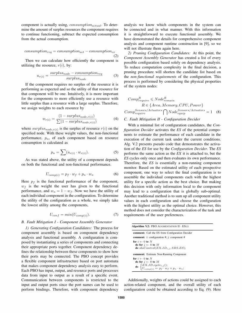
C. Fault Mitigation II - Configuration Decider
With a minimal list of configuration candidates, the Con-figuration Decider activates the ES of the potential compo-nents to estimate the performance of each candidate in theexecution of the current task under the current conditions.Alg. V.2 presents pseudo code that demonstrates the activa-tion of the ES for use by the Configuration Decider. The ESperforms the same action as the EX it is attached to, but theES cycles only once and then evaluates its own performance.Therefore, the ES is essentially a non-running componentmonitor. Based on the estimated utility of each prospectivecomponent, one way to select the final configuration is toassemble the individual components each with the highestutility for a specific action as the best choice. But makingthis decision with only information local to the componentmay lead to a configuration that is globally sub-optimal.Another traditional method is to sum up all component utilityvalues in each configuration and choose the configurationwith the highest utility as the optimal choice. However, thismethod does not consider the characterization of the task andrequirements of the user preferences.
Algorithm V.2: PBO AUGMENTATION II - ES(i)
comment: Call the ES from Configuration Decider
comment: i: configuration #; j: component #
for i← 0 to Ndo for j ← 0 to Mdo sbsControl(EX IDi,j , SBS ES);
comment: Estimate Non-Running Component
for i← 0 to Ndo for j ← 0 to M
do{EX ID cyclei,j();Ucomp(i) ← pf · wf + pn · wn;
Additionally, weights of actions could be assigned to eachaction-related component, and the overall utility of eachconfiguration could be obtained according to Eq. (9). Here
1580

k belongs to each action type, such as “visual servoing” and“move” actions; i shows the components that can implementk; and configj is the jth configuration candidate. Theoptimal configuration is then the configuration with thehighest value computed by Eq. (9).
U(configj) =∑
k∈actions
U(Compi) ·Wk (9)
VI. CASE STUDY ON MULTI-ROBOT TARGET TRACKING
To demonstrate the feasibility and flexibility of ReFrESH,we demonstrate two situation we assume in Section III. Inboth situations, the task is to track a target with a camera.The first situation consists of a single robot executing thistask while the second employs a team of two robots, callthem R1 and R2. For both situations, the initial configurationis deployed solely on R1 and consists of a visual sensorcomponent, a dehazing component implemented in hardware,a tracking algorithm component, and an actuator component.This initial configuration is shown in Fig. 4.
VisualSensor1 Dehazer-HW1 TrackingAlg1 Actuator1
Fig. 4: Sample Application Initial Configuration
A. Single Node Runtime Fault Detection & Mitigation
In this situation,R1 executes a target tracking task. Therobot is equipped with the four components contained in theinitial configuration as well as a secondary dehazing compo-nent that is implemented in software. Each implementationof the dehazing component has an advantage over the other.The hardware implementation is able to process at a fasterspeed since the FPGA is not limited by the CPU, but thesoftware implementation consumes far less power. The nodeinitially loads the hardware dehazing component since thebattery is fully charged and the system wants to process dataas fast as possible for smooth operation. At the start of thetask execution the field of view of the visual sensor is clearso the dehazing component is not needed and is thereforenot active. Suppose after some time smoke blows in frontof the visual sensor, obstructing the view of the target. Nowthe dehazing component needs to activate but by this timethe battery has depleted so much that there is not enoughpower to activate the hardware implementation. Detectingthis fault, the Configuration Manager sends a signal to theConfiguration Decider to begin the reconfiguration process.Because the node acts alone, there are only two configurationcandidates capable of executing this task; that using thehardware dehazing component and that using the softwaredehazing component. Because the software component con-sumes less power, it is intuitive that the decider will choosethis component for the new optimal configuration. The newconfiguration, shown in Fig. 5, is initialized and the faultdetected at runtime is mitigated.
VisualSensor1 Dehazer-SW1 TrackingAlg1 Actuator1
Fig. 5: Sample Application Single Node Reconfiguration
Fig. 6 depicts the performance of the system throughoutthis process based on the error in the tracking algorithm.We can see that the smoke blows in at around the 4.4second mark where the error exceeds the threshold. At thispoint the robot reconfigures the task to use the softwaredehazing component and the error very quickly drops backbelow the threshold. The process for self-reconfigurationin this situation is very short since there are only twoconfiguration candidates for the decider to consider and allof the components are contained on a single node so thereis no need for lengthy data communication.
Fig. 6: Single Node Reconfiguration Performance Based onTracking Error
B. Multiple Node Runtime Fault Detection & Mitigation
The use of multiple nodes in the proposed self-adaptationframework allows for more configuration candidates thus en-suring greater performance and reliability. For this situation,we suppose that the first node no longer contains a secondarysoftware implementation of the dehazing component, butinstead it can cooperate with a second node which doescontain one. The second node is also equipped with allof the components utilized in the initial configuration aswell. Once again as smoke blows in and the visual sensoris obstructed, the hardware dehazing component needs toactivate. But once again, by this point there is not enoughpower on node one to activate it and the fault is reported tothe Configuration Decider so that reconfiguration can begin.In this case there are many more candidates to considersince the two nodes can cooperate and share information,but because power consumption is still the main concern, theConfiguration Decider will select the optimal configurationas the one that substitutes the software dehazing componenton node two for the hardware dehazing component on nodeone. This configuration is shown in Fig. 7.
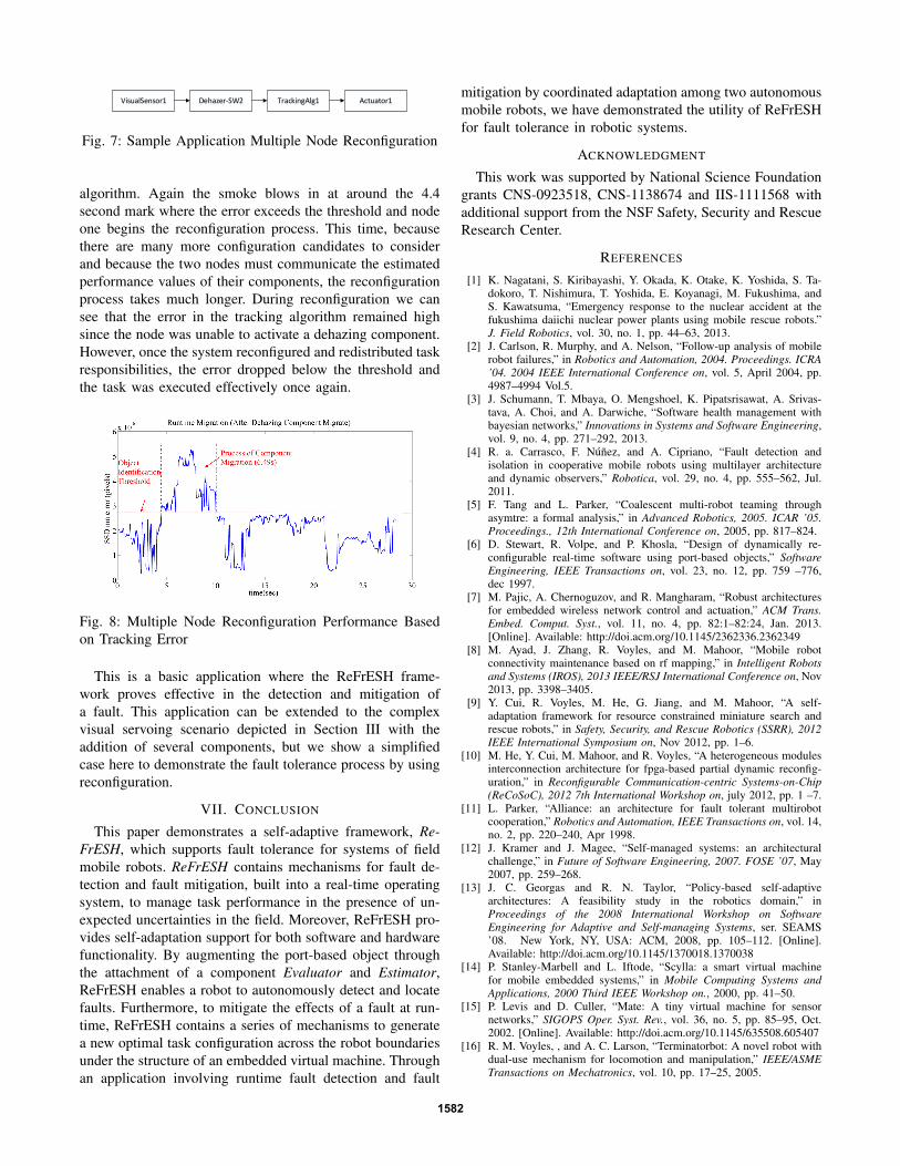
Fig. 8 depicts the performance of the multiple node systemthroughout this process based on the error in the tracking
1581
VisualSensor1 Dehazer-SW2 TrackingAlg1 Actuator1
Fig. 7: Sample Application Multiple Node Reconfiguration
algorithm. Again the smoke blows in at around the 4.4second mark where the error exceeds the threshold and nodeone begins the reconfiguration process. This time, becausethere are many more configuration candidates to considerand because the two nodes must communicate the estimatedperformance values of their components, the reconfigurationprocess takes much longer. During reconfiguration we cansee that the error in the tracking algorithm remained highsince the node was unable to activate a dehazing component.However, once the system reconfigured and redistributed taskresponsibilities, the error dropped below the threshold andthe task was executed effectively once again.
Fig. 8: Multiple Node Reconfiguration Performance Basedon Tracking Error
This is a basic application where the ReFrESH frame-work proves effective in the detection and mitigation ofa fault. This application can be extended to the complexvisual servoing scenario depicted in Section III with theaddition of several components, but we show a simplifiedcase here to demonstrate the fault tolerance process by usingreconfiguration.
VII. CONCLUSION
This paper demonstrates a self-adaptive framework, Re-FrESH, which supports fault tolerance for systems of fieldmobile robots. ReFrESH contains mechanisms for fault de-tection and fault mitigation, built into a real-time operatingsystem, to manage task performance in the presence of un-expected uncertainties in the field. Moreover, ReFrESH pro-vides self-adaptation support for both software and hardwarefunctionality. By augmenting the port-based object throughthe attachment of a component Evaluator and Estimator,ReFrESH enables a robot to autonomously detect and locatefaults. Furthermore, to mitigate the effects of a fault at run-time, ReFrESH contains a series of mechanisms to generatea new optimal task configuration across the robot boundariesunder the structure of an embedded virtual machine. Throughan application involving runtime fault detection and fault
mitigation by coordinated adaptation among two autonomousmobile robots, we have demonstrated the utility of ReFrESHfor fault tolerance in robotic systems.
ACKNOWLEDGMENT
This work was supported by National Science Foundationgrants CNS-0923518, CNS-1138674 and IIS-1111568 withadditional support from the NSF Safety, Security and RescueResearch Center.
REFERENCES
[1] K. Nagatani, S. Kiribayashi, Y. Okada, K. Otake, K. Yoshida, S. Ta-dokoro, T. Nishimura, T. Yoshida, E. Koyanagi, M. Fukushima, andS. Kawatsuma, “Emergency response to the nuclear accident at thefukushima daiichi nuclear power plants using mobile rescue robots.”J. Field Robotics, vol. 30, no. 1, pp. 44–63, 2013.
[2] J. Carlson, R. Murphy, and A. Nelson, “Follow-up analysis of mobilerobot failures,” in Robotics and Automation, 2004. Proceedings. ICRA’04. 2004 IEEE International Conference on, vol. 5, April 2004, pp.4987–4994 Vol.5.
[3] J. Schumann, T. Mbaya, O. Mengshoel, K. Pipatsrisawat, A. Srivas-tava, A. Choi, and A. Darwiche, “Software health management withbayesian networks,” Innovations in Systems and Software Engineering,vol. 9, no. 4, pp. 271–292, 2013.
[4] R. a. Carrasco, F. Nunez, and A. Cipriano, “Fault detection andisolation in cooperative mobile robots using multilayer architectureand dynamic observers,” Robotica, vol. 29, no. 4, pp. 555–562, Jul.2011.
[5] F. Tang and L. Parker, “Coalescent multi-robot teaming throughasymtre: a formal analysis,” in Advanced Robotics, 2005. ICAR ’05.Proceedings., 12th International Conference on, 2005, pp. 817–824.
[6] D. Stewart, R. Volpe, and P. Khosla, “Design of dynamically re-configurable real-time software using port-based objects,” SoftwareEngineering, IEEE Transactions on, vol. 23, no. 12, pp. 759 –776,dec 1997.
[7] M. Pajic, A. Chernoguzov, and R. Mangharam, “Robust architecturesfor embedded wireless network control and actuation,” ACM Trans.Embed. Comput. Syst., vol. 11, no. 4, pp. 82:1–82:24, Jan. 2013.[Online]. Available: http://doi.acm.org/10.1145/2362336.2362349
[8] M. Ayad, J. Zhang, R. Voyles, and M. Mahoor, “Mobile robotconnectivity maintenance based on rf mapping,” in Intelligent Robotsand Systems (IROS), 2013 IEEE/RSJ International Conference on, Nov2013, pp. 3398–3405.
[9] Y. Cui, R. Voyles, M. He, G. Jiang, and M. Mahoor, “A self-adaptation framework for resource constrained miniature search andrescue robots,” in Safety, Security, and Rescue Robotics (SSRR), 2012IEEE International Symposium on, Nov 2012, pp. 1–6.
[10] M. He, Y. Cui, M. Mahoor, and R. Voyles, “A heterogeneous modulesinterconnection architecture for fpga-based partial dynamic reconfig-uration,” in Reconfigurable Communication-centric Systems-on-Chip(ReCoSoC), 2012 7th International Workshop on, july 2012, pp. 1 –7.
[11] L. Parker, “Alliance: an architecture for fault tolerant multirobotcooperation,” Robotics and Automation, IEEE Transactions on, vol. 14,no. 2, pp. 220–240, Apr 1998.
[12] J. Kramer and J. Magee, “Self-managed systems: an architecturalchallenge,” in Future of Software Engineering, 2007. FOSE ’07, May2007, pp. 259–268.
[13] J. C. Georgas and R. N. Taylor, “Policy-based self-adaptivearchitectures: A feasibility study in the robotics domain,” inProceedings of the 2008 International Workshop on SoftwareEngineering for Adaptive and Self-managing Systems, ser. SEAMS’08. New York, NY, USA: ACM, 2008, pp. 105–112. [Online].Available: http://doi.acm.org/10.1145/1370018.1370038
[14] P. Stanley-Marbell and L. Iftode, “Scylla: a smart virtual machinefor mobile embedded systems,” in Mobile Computing Systems andApplications, 2000 Third IEEE Workshop on., 2000, pp. 41–50.
[15] P. Levis and D. Culler, “Mate: A tiny virtual machine for sensornetworks,” SIGOPS Oper. Syst. Rev., vol. 36, no. 5, pp. 85–95, Oct.2002. [Online]. Available: http://doi.acm.org/10.1145/635508.605407
[16] R. M. Voyles, , and A. C. Larson, “Terminatorbot: A novel robot withdual-use mechanism for locomotion and manipulation,” IEEE/ASMETransactions on Mechatronics, vol. 10, pp. 17–25, 2005.
1582