omnigrad m tr15, tc15 - endress+hauser · •particularly suitable for steam and gas applications...
TRANSCRIPT
TR15 Resistance thermometer (RTD)TC15 Thermometer with thermocouple (TC)
Application• Universal range of application• Particularly suitable for steam and gas applications with high process pressures
and temperatures• Measuring range:
– Resistance insert (RTD): –200 to 600 °C (–328 to 1 112 °F)– Thermocouple (TC): –40 to 1 100 °C (–40 to 2 012 °F)
• Static pressure range up to 400 bar (5 800 psi)• Degree of protection up to IP68
Head transmitter
All Endress+Hauser transmitters are available with enhanced accuracy and reliabilitycompared to directly wired sensors. Easy customizing by choosing one of thefollowing outputs and communication protocols:
• Analog output 4 to 20 mA• HART®
• PROFIBUS® PA• FOUNDATION Fieldbus™
Your benefits• High degree of flexibility thanks to modular design with standard terminal heads
as per DIN EN 50446 and customer-specific immersion lengths• High compatibility with a design according to DIN 43772• Extension neck to protect the head transmitter from overheating• Fast response time with reduced/tapered tip form• Types of protection for use in hazardous locations:
– Intrinsic Safety (Ex ia)– Non-sparking (Ex nA)
Products Solutions Services
Technical InformationOmnigrad M TR15, TC15Modular thermometer with extension neck,barstock thermowell, available with a flange or asa weld-in unit
TI01100T/09/EN/02.1371226928

Omnigrad M TR15, TC15
2
Function and system design
Measuring principle Resistance thermometer (RTD)
These resistance thermometers use a Pt100 temperature sensor according to IEC 60751. Thetemperature sensor is a temperature-sensitive platinum resistor with a resistance of 100 Ω at0 °C (32 °F) and a temperature coefficient α = 0.003851 °C-1.
There are generally two different kinds of platinum resistance thermometers:• Wire wound (WW): Here, a double coil of fine, high-purity platinum wire is located in a ceramic
support. This is then sealed top and bottom with a ceramic protective layer. Such resistancethermometers not only facilitate very reproducible measurements but also offer good long-termstability of the resistance/temperature characteristic within temperature ranges up to600 °C (1 112 °F). This type of sensor is relatively large in size and it is comparatively sensitive tovibrations.
• Thin film platinum resistance thermometers (TF): A very thin, ultrapure platinum layer,approx. 1 μm thick, is vaporized in a vacuum on a ceramic substrate and then structuredphotolithographically. The platinum conductor paths formed in this way create the measuringresistance. Additional covering and passivation layers are applied and reliably protect the thinplatinum layer from contamination and oxidation, even at high temperatures.
The primary advantages of thin film temperature sensors over wire wound versions are their smallersizes and better vibration resistance. A relatively low principle-based deviation of the resistance/temperature characteristic from the standard characteristic of IEC 60751 can frequently be observedamong TF sensors at high temperatures. As a result, the tight limit values of tolerance category A asper IEC 60751 can only be observed with TF sensors at temperatures up to approx. 300 °C (572 °F).For this reason, thin-film sensors are generally only used for temperature measurements in rangesbelow 400 °C (932 °F).
Thermocouples (TC)
Thermocouples are comparatively simple, robust temperature sensors which use the Seebeck effectfor temperature measurement: if two electrical conductors made of different materials are connectedat a point, a weak electrical voltage can be measured between the two open conductor ends if theconductors are subjected to a thermal gradient. This voltage is called thermoelectric voltage orelectromotive force (emf.). Its magnitude depends on the type of conducting materials and thetemperature difference between the "measuring point" (the junction of the two conductors) and the"cold junction" (the open conductor ends). Accordingly, thermocouples primarily only measuredifferences in temperature. The absolute temperature at the measuring point can be determinedfrom these if the associated temperature at the cold junction is known or is measured separately andcompensated for. The material combinations and associated thermoelectric voltage/temperaturecharacteristics of the most common types of thermocouple are standardized in the IEC 60584 andASTM E230/ANSI MC96.1 standards.
Omnigrad M TR15, TC15
3
Measuring system
A
= 20-250V DC/AC
» 50/60Hz
4...20 mA
24V DC / 30 mAB
C°C
A0010494
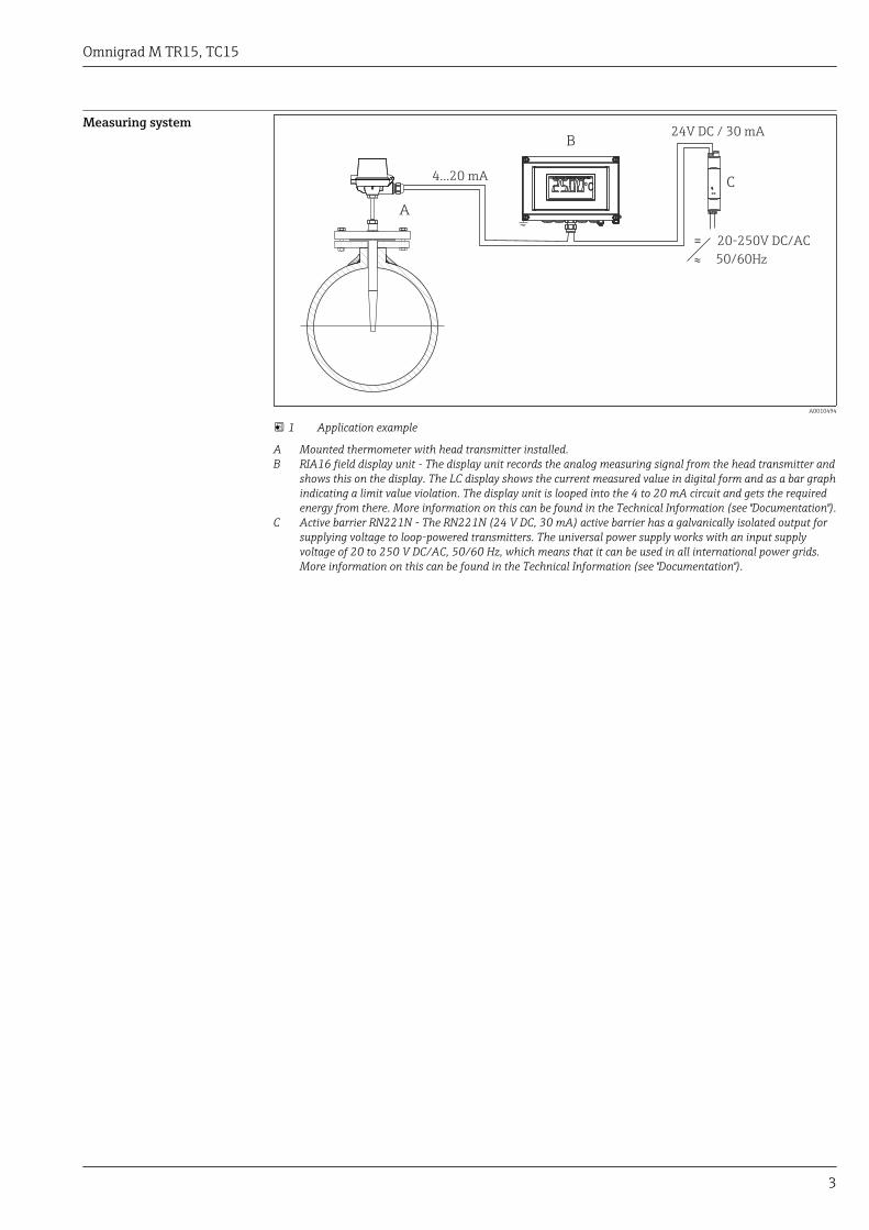
1 Application example
A Mounted thermometer with head transmitter installed.B RIA16 field display unit - The display unit records the analog measuring signal from the head transmitter and
shows this on the display. The LC display shows the current measured value in digital form and as a bar graphindicating a limit value violation. The display unit is looped into the 4 to 20 mA circuit and gets the requiredenergy from there. More information on this can be found in the Technical Information (see "Documentation").
C Active barrier RN221N - The RN221N (24 V DC, 30 mA) active barrier has a galvanically isolated output forsupplying voltage to loop-powered transmitters. The universal power supply works with an input supplyvoltage of 20 to 250 V DC/AC, 50/60 Hz, which means that it can be used in all international power grids.More information on this can be found in the Technical Information (see "Documentation").

Omnigrad M TR15, TC15
4
Equipment architecture
E
1 2
3
56
ILIL
L
10 mm
(0.4 in)
U
U1
5
46
A0011012
2 Thermometer design
1 Insert with head transmitter mounted (example with 3 mm (0.12 in))2 Insert with terminal block mounted (example with 6 mm (0.24 in))3 Terminal head4 Version without thermowell5 Thermowell from barstock material6 Process connection: with or without a flangeE Extension neck lengthL Total thermowell lengthIL Insertion lengthU Length of conical tipU1 Immersion length; length of the part of the thermowell in contact with the process from the tip to the sealing
surface of the flange
Thermometers from the Omnigrad M TR15 and TC15 series have a modular design. The terminalhead is used as a connection module for the mechanical and electrical connection of the insert. Theposition of the actual thermometer sensor in the insert ensures that it is mechanically protected. Theinsert can be exchanged and calibrated without interrupting the process. Either ceramic terminalblocks or transmitters can be fitted to the internal base washer. The thermowell is made frombarstock and is available with diameters measuring 18, 24 or 26 mm (0.71, 0.94 or 1.02 in). The tipof the thermowell is tapered. The thermometer is installed in the system (pipe or tank) using aflange connection or by welding the thermometer in place (→ 20).
Measurement range • RTD: –200 to 600 °C (–328 to 1 112 °F)• TC: –40 to 1 100 °C (–40 to 2 012 °F)
Performance characteristics
Operating conditions Ambient temperature
Terminal head Temperature in °C (°F)
Without mounted head transmitter Depends on the terminal head used and the cable gland or fieldbusconnector, see 'Terminal heads' section
With mounted head transmitter –40 to 85 °C (–40 to 185 °F)
With mounted head transmitter anddisplay
–20 to 70 °C (–4 to 158 °F)
Omnigrad M TR15, TC15
5
Process pressure (static)
Process connection Standard Max. process pressure
Weld-in version - ≤400 bar (5 800 psi)
Flange
EN1092-1 or ISO7005-1
20, 40, 50 or 100 bar depending on the flange pressure ratingPNxx
ANSI B16.5 150 or 300 psi depending on the flange pressure rating
JIS B 2220 20K, 25K or 40K depending on the flange pressure rating
Permitted flow velocity depending on the immersion length
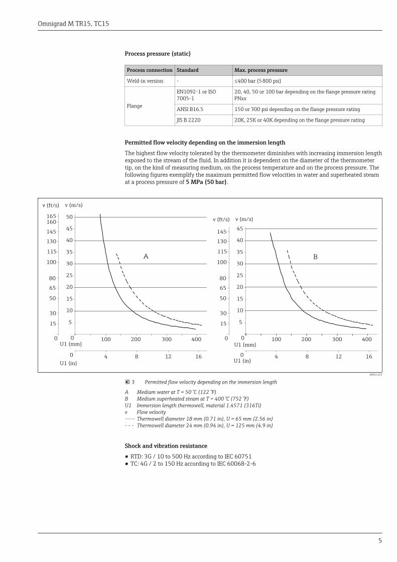
The highest flow velocity tolerated by the thermometer diminishes with increasing immersion lengthexposed to the stream of the fluid. In addition it is dependent on the diameter of the thermometertip, on the kind of measuring medium, on the process temperature and on the process pressure. Thefollowing figures exemplify the maximum permitted flow velocities in water and superheated steamat a process pressure of 5 MPa (50 bar).
0
5
10
15
20
25
30
35
40
45
100 200 300 400
v (m/s)
A B
0 4 8 12 16
0
15
30
50
65
80
100
115
130
145
v (ft/s)
U1 (mm)
U1 (in)
50165160
0
5
10
15
20
25
30
35
40
45
100 200 300 400
v (m/s)
0 4 8 12 16
0
15
30
50
65
80
100
115
130
145
v (ft/s)
U1 (mm)
U1 (in)
A0011123
3 Permitted flow velocity depending on the immersion length
A Medium water at T = 50 °C (122 °F)B Medium superheated steam at T = 400 °C (752 °F)U1 Immersion length thermowell, material 1.4571 (316Ti)v Flow velocity----- Thermowell diameter 18 mm (0.71 in), U = 65 mm (2.56 in)- - - Thermowell diameter 24 mm (0.94 in), U = 125 mm (4.9 in)
Shock and vibration resistance
• RTD: 3G / 10 to 500 Hz according to IEC 60751• TC: 4G / 2 to 150 Hz according to IEC 60068-2-6
Omnigrad M TR15, TC15
6
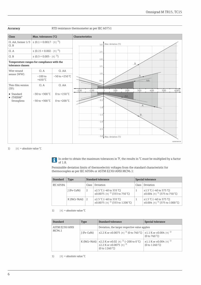
Accuracy RTD resistance thermometer as per IEC 60751
Class Max. tolerances (°C) Characteristics
Cl. AA, former 1/3Cl. B
± (0.1 + 0.0017 · |t| 1))
A
AA
-200 -100 0 100 200 300 400 500 600°C
0.5
1.0
1.5
2.0
B
2.5
3.0
- 0.5
- 1.0
- 1.5
- 2.0
- 2.5
- 3.0
B
A
AA
Max. deviation (°C)
Max. deviation (°C)
A0008588-EN
Cl. A ± (0.15 + 0.002 · |t| 1))
Cl. B ± (0.3 + 0.005 · |t| 1))
Temperature ranges for compliance with thetolerance classes
Wire woundsensor (WW):
Cl. A Cl. AA
–100 to+450 °C
–50 to +250 °C
Thin-film version(TF):
Cl. A Cl. AA
• Standard• iTHERM®
StrongSens
–30 to +300 °C
–30 to +300 °C
0 to +150 °C
0 to +200 °C
1) |t| = absolute value °C
In order to obtain the maximum tolerances in °F, the results in °C must be multiplied by a factorof 1.8.
Permissible deviation limits of thermoelectric voltages from the standard characteristic forthermocouples as per IEC 60584 or ASTM E230/ANSI MC96.1:
Standard Type Standard tolerance Special tolerance
IEC 60584 Class Deviation Class Deviation
J (Fe-CuNi) 2 ±2.5 °C (–40 to 333 °C)±0.0075 |t| 1) (333 to 750 °C)
1 ±1.5 °C (–40 to 375 °C)±0.004 |t| 1) (375 to 750 °C)
K (NiCr-NiAl) 2 ±2.5 °C (–40 to 333 °C)±0.0075 |t| 1) (333 to 1 200 °C)
1 ±1.5 °C (–40 to 375 °C)±0.004 |t| 1) (375 to 1 000 °C)
1) |t| = absolute value °C
Standard Type Standard tolerance Special tolerance
ASTM E230/ANSIMC96.1
Deviation, the larger respective value applies
J (Fe-CuNi) ±2.2 K or ±0.0075 |t| 1) (0 to 760 °C) ±1.1 K or ±0.004 |t| 1)
(0 to 760 °C)
K (NiCr-NiAl) ±2.2 K or ±0.02 |t| 1) (–200 to 0 °C)±2.2 K or ±0.0075 |t| 1)
(0 to 1 260 °C)
±1.1 K or ±0.004 |t| 1)
(0 to 1 260 °C)
1) |t| = absolute value °C
Omnigrad M TR15, TC15
7
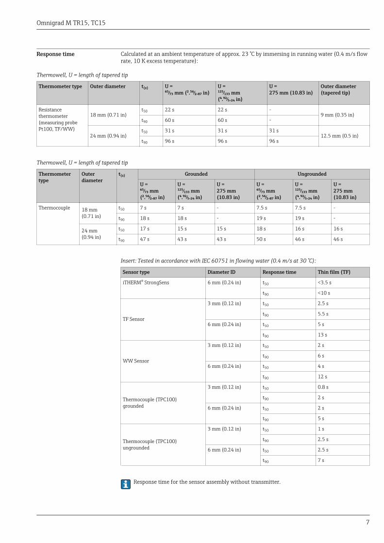
Response time Calculated at an ambient temperature of approx. 23 °C by immersing in running water (0.4 m/s flowrate, 10 K excess temperature):
Thermowell, U = length of tapered tip
Thermometer type Outer diameter t(x) U =⁶⁵⁄₇₃ mm (².⁵⁶⁄₂.₈₇ in)
U =¹²⁵⁄₁₃₃ mm(⁴.⁹²⁄₅.₂₄ in)
U =275 mm (10.83 in)
Outer diameter(tapered tip)
Resistancethermometer(measuring probePt100, TF/WW)
18 mm (0.71 in)t50 22 s 22 s -
9 mm (0.35 in)t90 60 s 60 s -
24 mm (0.94 in)t50 31 s 31 s 31 s
12.5 mm (0.5 in)t90 96 s 96 s 96 s
Thermowell, U = length of tapered tip
Thermometertype
Outerdiameter
t(x) Grounded Ungrounded
U =⁶⁵⁄₇₃ mm(².⁵⁶⁄₂.₈₇ in)
U =¹²⁵⁄₁₃₃ mm(⁴.⁹²⁄₅.₂₄ in)
U =275 mm(10.83 in)
U =⁶⁵⁄₇₃ mm(².⁵⁶⁄₂.₈₇ in)
U =¹²⁵⁄₁₃₃ mm(⁴.⁹²⁄₅.₂₄ in)
U =275 mm(10.83 in)
Thermocouple 18 mm(0.71 in)
t50 7 s 7 s - 7.5 s 7.5 s -
t90 18 s 18 s - 19 s 19 s -
24 mm(0.94 in)
t50 17 s 15 s 15 s 18 s 16 s 16 s
t90 47 s 43 s 43 s 50 s 46 s 46 s
Insert: Tested in accordance with IEC 60751 in flowing water (0.4 m/s at 30 °C):
Sensor type Diameter ID Response time Thin film (TF)
iTHERM® StrongSens 6 mm (0.24 in) t50 <3.5 s
t90 <10 s
TF Sensor
3 mm (0.12 in) t50 2.5 s
t90 5.5 s
6 mm (0.24 in) t50 5 s
t90 13 s
WW Sensor
3 mm (0.12 in) t50 2 s
t90 6 s
6 mm (0.24 in) t50 4 s
t90 12 s
Thermocouple (TPC100)grounded
3 mm (0.12 in) t50 0.8 s
t90 2 s
6 mm (0.24 in) t50 2 s
t90 5 s
Thermocouple (TPC100)ungrounded
3 mm (0.12 in) t50 1 s
t90 2.5 s
6 mm (0.24 in) t50 2.5 s
t90 7 s
Response time for the sensor assembly without transmitter.

Omnigrad M TR15, TC15
8
Insulation resistance • RTD:Insulation resistance according to IEC 60751 > 100 MΩ at 25 °C between terminals and sheathmaterial measured with a minimum test voltage of 100 V DC
• TC:Insulation resistance according to IEC 1515 between terminals and sheath material with a testvoltage of 500 V DC:– > 1 GΩ at 20 °C– > 5 MΩ at 500 °C
Dielectric strength Tested at a room temperature for 5 s:
• 6 mm (0.24 in): ≥1 000 V DC between terminals and insert sheath• 3 mm (0.12 in): ≥250 V DC between terminals and insert sheath
Self heating RTD elements are passive resistances that are measured using an external current. Thismeasurement current causes a self-heating effect in the RTD element itself which in turn creates anadditional measurement error. In addition to the measurement current, the size of the measurementerror is also affected by the temperature conductivity and flow velocity of the process. This self-heating error is negligible when an Endress+Hauser iTEMP® temperature transmitter (very smallmeasurement current) is connected.
Calibration Endress+Hauser provides comparison temperature calibration from–80 to +1 400 °C (–110 to +2 552 °F) based on the International Temperature Scale (ITS90).Calibrations are traceable to national and international standards. The calibration certificate isreferenced to the serial number of the thermometer. Only the insert is calibrated.
Insert:6 mm (0.24 in) and 3 mm (0.12 in)
Minimum insertion length of insert in mm (in)
Temperature range without head transmitter with head transmitter
–80 to –40 °C (–110 to –40 °F) 200 (7.87)
–40 to 0 °C (–40 to 32 °F) 160 (6.3)
0 to 250 °C (32 to 480 °F) 120 (4.72) 150 (5.91)
250 to 550 °C (480 to 1 020 °F) 300 (11.81)
550 to 1 400 °C (1 020 to 2 552 °F) 450 (17.72)

Omnigrad M TR15, TC15
9
Material Extension neck and thermowell.
The temperatures for continuous operation specified in the following table are only intended asreference values for use of the various materials in air and without any significant compressive load.The maximum operation temperatures are reduced considerably in some cases where abnormalconditions such as high mechanical load occur or in aggressive media.
Material name Short form Recommended max.temperature forcontinuous use inair
Properties
AISI 316L/1.44041.4435
X2CrNiMo17-12-2X2CrNiMo18-14-3
650 °C (1 202 °F) 1) • Austenitic, stainless steel• High corrosion resistance in general• Particularly high corrosion resistance in
chlorine-based and acidic, non-oxidizingatmospheres through the addition ofmolybdenum (e.g. phosphoric and sulfuricacids, acetic and tartaric acids with a lowconcentration)
• Increased resistance to intergranularcorrosion and pitting
• Compared to 1.4404, 1.4435 has evenhigher corrosion resistance and a lowerdelta ferrite content
AISI 316Ti/1.4571
X6CrNiMoTi17-12-2 700 °C (1 292 °F) • Properties comparable to AISI316L• Addition of titanium means increased
resistance to intergranular corrosion evenafter welding
• Broad range of uses in the chemical,petrochemical and oil industries as well asin coal chemistry
• Can only be polished to a limited extent,titanium streaks can form
AISI A105/1.0460
C22.8 450 °C (842 °F) • Heat-resistant steel• Resistant in nitrogen-containing
atmospheres and atmospheres that are lowin oxygen; not suitable for acids or otheraggressive media
• Often used in steam generators, water andsteam pipes, pressure vessels
DuplexSAF2205/1.4462
X2CrNiMoN22-5-3 300 °C (572 °F) • Austenitic ferritic steel with goodmechanical properties
• High resistance to general corrosion, pitting,chlorine-induced or transgranular stresscorrosion
• Comparatively good resistance tohydrogeninduced stress corrosion
Inconel600/2.4816
NiCr15Fe 1 100 °C (2 012 °F) • A nickel/chromium alloy with very goodresistance to aggressive, oxidizing andreducing atmospheres, even at hightemperatures
• Resistant to corrosion caused by chlorinegas and chlorinated media as well as manyoxidizing mineral and organic acids, seawater etc.
• Corrosion from ultrapure water• Not to be used in a sulfur-containing
atmosphere
HastelloyC276/ 2.4819
NiMo16Cr15W 1 100 °C (2 012 °F) • A nickel-based alloy with good resistance tooxidizing and reducing atmospheres, even athigh temperatures
• Particularly resistant to chlorine gas andchloride as well as to many oxidizingmineral and organic acids
Omnigrad M TR15, TC15
10
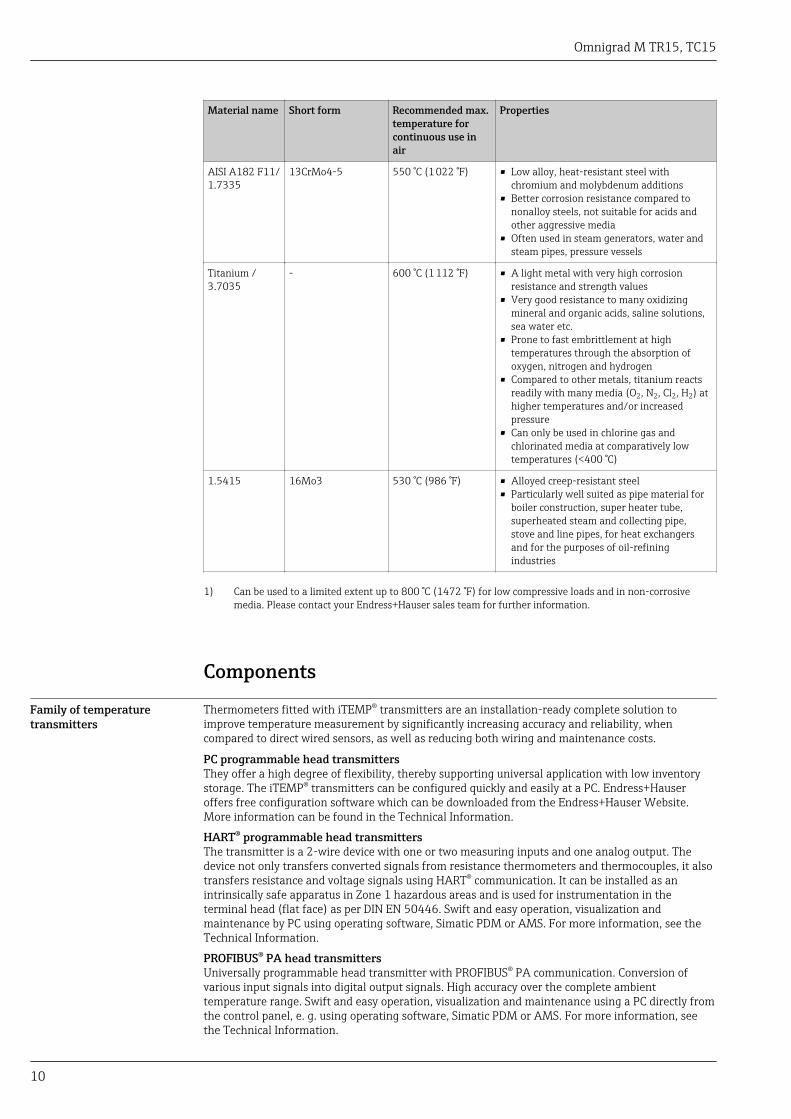
Material name Short form Recommended max.temperature forcontinuous use inair
Properties
AISI A182 F11/1.7335
13CrMo4-5 550 °C (1 022 °F) • Low alloy, heat-resistant steel withchromium and molybdenum additions
• Better corrosion resistance compared tononalloy steels, not suitable for acids andother aggressive media
• Often used in steam generators, water andsteam pipes, pressure vessels
Titanium /3.7035
- 600 °C (1 112 °F) • A light metal with very high corrosionresistance and strength values
• Very good resistance to many oxidizingmineral and organic acids, saline solutions,sea water etc.
• Prone to fast embrittlement at hightemperatures through the absorption ofoxygen, nitrogen and hydrogen
• Compared to other metals, titanium reactsreadily with many media (O2, N2, Cl2, H2) athigher temperatures and/or increasedpressure
• Can only be used in chlorine gas andchlorinated media at comparatively lowtemperatures (<400 °C)
1.5415 16Mo3 530 °C (986 °F) • Alloyed creep-resistant steel• Particularly well suited as pipe material for
boiler construction, super heater tube,superheated steam and collecting pipe,stove and line pipes, for heat exchangersand for the purposes of oil-refiningindustries
1) Can be used to a limited extent up to 800 °C (1472 °F) for low compressive loads and in non-corrosivemedia. Please contact your Endress+Hauser sales team for further information.
Components
Family of temperaturetransmitters
Thermometers fitted with iTEMP® transmitters are an installation-ready complete solution toimprove temperature measurement by significantly increasing accuracy and reliability, whencompared to direct wired sensors, as well as reducing both wiring and maintenance costs.
PC programmable head transmittersThey offer a high degree of flexibility, thereby supporting universal application with low inventorystorage. The iTEMP® transmitters can be configured quickly and easily at a PC. Endress+Hauseroffers free configuration software which can be downloaded from the Endress+Hauser Website.More information can be found in the Technical Information.
HART® programmable head transmittersThe transmitter is a 2-wire device with one or two measuring inputs and one analog output. Thedevice not only transfers converted signals from resistance thermometers and thermocouples, it alsotransfers resistance and voltage signals using HART® communication. It can be installed as anintrinsically safe apparatus in Zone 1 hazardous areas and is used for instrumentation in theterminal head (flat face) as per DIN EN 50446. Swift and easy operation, visualization andmaintenance by PC using operating software, Simatic PDM or AMS. For more information, see theTechnical Information.
PROFIBUS® PA head transmittersUniversally programmable head transmitter with PROFIBUS® PA communication. Conversion ofvarious input signals into digital output signals. High accuracy over the complete ambienttemperature range. Swift and easy operation, visualization and maintenance using a PC directly fromthe control panel, e. g. using operating software, Simatic PDM or AMS. For more information, seethe Technical Information.

Omnigrad M TR15, TC15
11
FOUNDATION Fieldbus™ head transmittersUniversally programmable head transmitter with FOUNDATION Fieldbus™ communication.Conversion of various input signals into digital output signals. High accuracy over the completeambient temperature range. Swift and easy operation, visualization and maintenance using a PCdirectly from the control panel, e.g. using operating software such as ControlCare from Endress+Hauser or NI Configurator from National Instruments. For more information, see the TechnicalInformation.
Advantages of the iTEMP® transmitters:• Dual or single sensor input (optionally for certain transmitters)• Unsurpassed reliability, accuracy and long-term stability in critical processes• Mathematical functions• Monitoring of the thermometer drift, sensor backup functionality, sensor diagnostic functions• Sensor-transmitter matching for dual sensor input transmitters, based on Callendar/Van Dusen
coefficients
Terminal heads All terminal heads have an internal shape and size in accordance with DIN EN 50446 flat face and athermometer connection of M24x1.5, G1/2" or 1/2" NPT thread. All dimensions in mm (in). Thecable glands in the diagrams correspond to M20x1.5 connections. Specifications without headtransmitter installed. For ambient temperatures with head transmitter installed, see "Operatingconditions" section.
TA30A Specification
107.5 (4.23)
68
.5 (
2.7
)
28
(1.1)78 (3.1)
15
.5 (
0.6
)
A0009820
• Available with one or two cable entries• Protection class: IP66/68 (NEMA Type 4x encl.)• Temperature: –50 to +150 °C (–58 to +302 °F) without cable
gland• Material: aluminum, polyester powder coated
Seals: silicone• Threaded cable entry: G ½", ½" NPT and M20x1.5;• Protection armature connection: M24x1.5• Head color: blue, RAL 5012• Cap color: gray, RAL 7035• Weight: 330 g (11.64 oz)• Ground terminal, internal and external• With 3-A® symbol
TA30A with display window Specification
107.5 (4.23)
91
.6 (
3.6
1)
28
(1.1)78 (3.1)
15
.5 (
0.6
)
A0009821
• Available with one or two cable entries• Protection class: IP66/68 (NEMA Type 4x encl.)• Temperature: –50 to +150 °C (–58 to +302 °F) without cable
gland• Material: aluminum, polyester powder coated
Seals: silicone• Threaded cable entry: G ½", ½" NPT and M20x1.5• Protection armature connection: M24x1.5• Head color: blue, RAL 5012
Cap color: gray, RAL 7035• Weight: 420 g (14.81 oz)• With TID10 display• Ground terminal, internal and external• With 3-A® symbol
Omnigrad M TR15, TC15
12
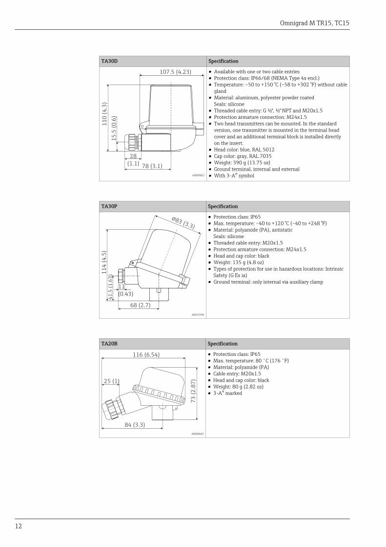
TA30D Specification
107.5 (4.23)
11
0 (
4.3
)
28
(1.1) 78 (3.1)
15
.5 (
0.6
)
A0009822
• Available with one or two cable entries• Protection class: IP66/68 (NEMA Type 4x encl.)• Temperature: –50 to +150 °C (–58 to +302 °F) without cable
gland• Material: aluminum, polyester powder coated
Seals: silicone• Threaded cable entry: G ½", ½" NPT and M20x1.5• Protection armature connection: M24x1.5• Two head transmitters can be mounted. In the standard
version, one transmitter is mounted in the terminal headcover and an additional terminal block is installed directlyon the insert.
• Head color: blue, RAL 5012• Cap color: gray, RAL 7035• Weight: 390 g (13.75 oz)• Ground terminal, internal and external• With 3-A® symbol
TA30P Specification
!83 (3.3)
11
4 (
4.5
)
11
(0.43)
68 (2.7)
41
.5 (
1.6
3)
A0012930
• Protection class: IP65• Max. temperature: –40 to +120 °C (–40 to +248 °F)• Material: polyamide (PA), antistatic
Seals: silicone• Threaded cable entry: M20x1.5• Protection armature connection: M24x1.5• Head and cap color: black• Weight: 135 g (4.8 oz)• Types of protection for use in hazardous locations: Intrinsic
Safety (G Ex ia)• Ground terminal: only internal via auxiliary clamp
TA20B Specification
116 (6.54)
25 (1)
84 (3.3)
73
(2
.87
)
A0008663
• Protection class: IP65• Max. temperature: 80 ˚C (176 ˚F)• Material: polyamide (PA)• Cable entry: M20x1.5• Head and cap color: black• Weight: 80 g (2.82 oz)• 3-A® marked
Omnigrad M TR15, TC15
13
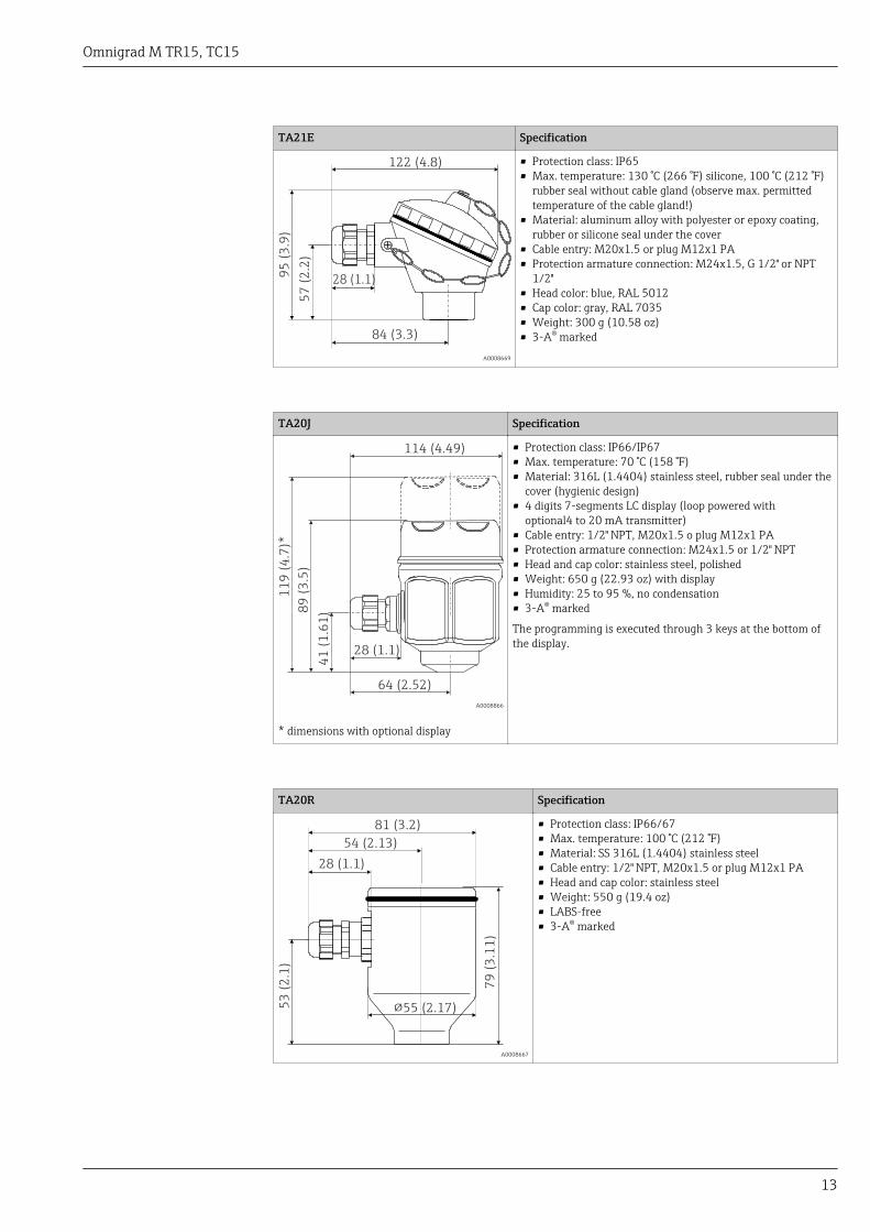
TA21E Specification
84 (3.3)
95
(3
.9)
57
(2
.2)
122 (4.8)
28 (1.1)
A0008669
• Protection class: IP65• Max. temperature: 130 °C (266 °F) silicone, 100 °C (212 °F)
rubber seal without cable gland (observe max. permittedtemperature of the cable gland!)
• Material: aluminum alloy with polyester or epoxy coating,rubber or silicone seal under the cover
• Cable entry: M20x1.5 or plug M12x1 PA• Protection armature connection: M24x1.5, G 1/2" or NPT
1/2"• Head color: blue, RAL 5012• Cap color: gray, RAL 7035• Weight: 300 g (10.58 oz)• 3-A® marked
TA20J Specification
114 (4.49)
11
9 (
4.7
)*
28 (1.1)
89
(3
.5)
41
(1
.61
)
64 (2.52)
A0008866
* dimensions with optional display
• Protection class: IP66/IP67• Max. temperature: 70 °C (158 °F)• Material: 316L (1.4404) stainless steel, rubber seal under the
cover (hygienic design)• 4 digits 7-segments LC display (loop powered with
optional4 to 20 mA transmitter)• Cable entry: 1/2" NPT, M20x1.5 o plug M12x1 PA• Protection armature connection: M24x1.5 or 1/2" NPT• Head and cap color: stainless steel, polished• Weight: 650 g (22.93 oz) with display• Humidity: 25 to 95 %, no condensation• 3-A® marked
The programming is executed through 3 keys at the bottom ofthe display.
TA20R Specification
79
(3
.11
)
53
(2
.1)
54 (2.13)
81 (3.2)
28 (1.1)
!55 (2.17)
A0008667
• Protection class: IP66/67• Max. temperature: 100 °C (212 °F)• Material: SS 316L (1.4404) stainless steel• Cable entry: 1/2" NPT, M20x1.5 or plug M12x1 PA• Head and cap color: stainless steel• Weight: 550 g (19.4 oz)• LABS-free• 3-A® marked

Omnigrad M TR15, TC15
14
Maximum ambient temperatures for cable glands and fieldbus connectors
Type Temperature range
Cable gland ½" NPT, M20x1.5 (non Ex) –40 to +100 °C (–40 to +212 °F)
Cable gland M20x1.5 (for dust ignition-proof area) –20 to +95 °C (–4 to +203 °F)
Fieldbus connector (M12x1 PA, 7/8" FF) –40 to +105 °C (–40 to +221 °F)
Omnigrad M TR15, TC15
15
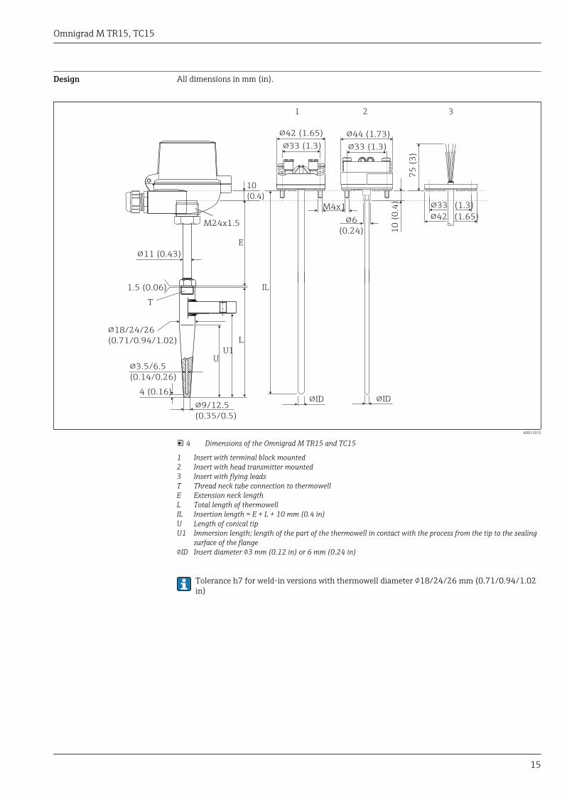
Design All dimensions in mm (in).
L
E
!33 (1.3)
!42 (1.65)
1 2 3
IL
U1U
!33 (1.3)
!44 (1.73)
10
(0.4)
M24x1.5
!11 (0.43)
M4x1 !33 (1.3)
!42 (1.65)
10
(0
.4)
75
(3
)
!6
(0.24)
T
1.5 (0.06)
!18/24/26
(0.71/0.94/1.02)
!3.5/6.5
(0.14/0.26)
4 (0.16)
!9/12.5
(0.35/0.5)
!ID !ID
A0011015
4 Dimensions of the Omnigrad M TR15 and TC15
1 Insert with terminal block mounted2 Insert with head transmitter mounted3 Insert with flying leadsT Thread neck tube connection to thermowellE Extension neck lengthL Total length of thermowellIL Insertion length = E + L + 10 mm (0.4 in)U Length of conical tipU1 Immersion length; length of the part of the thermowell in contact with the process from the tip to the sealing
surface of the flangeID Insert diameter 3 mm (0.12 in) or 6 mm (0.24 in)
Tolerance h7 for weld-in versions with thermowell diameter 18/24/26 mm (0.71/0.94/1.02in)

Omnigrad M TR15, TC15
16
Insert Depending on the application different inserts are available for the assembly:
Sensor Standard thin-film iTHERM® StrongSens Wire wound
Sensor design;connection method
1x Pt100, 3- or 4-wire, mineralinsulated
1x Pt100, 3- or 4-wire, mineralinsulated
1x Pt100, 3- or 4-wire,mineral insulated
2x Pt100, 3-wire, mineralinsulated
Vibration resistance ofthe insert tip Up to 3g Enhanced vibration resistance
> 60g Up to 3g
Measuring range;accuracy class
–50 to +400 °C(–58 to +752 °F), Class A or AA
–50 to +500 °C(–58 to +932 °F), Class A or AA –200 to +600 °C (–328 to +1 112 °F), Class A or AA
Diameter 3 mm (¹⁄₈ in), 6 mm (¹⁄₄ in) 6 mm (¹⁄₄ in) 3 mm (¹⁄₈ in), 6 mm (¹⁄₄ in)
Insert type TPR100 iTHERM® TS111 TPR100
TC
Selection in order code A B E F
Sensor design; material 1x K; INCONEL600 2x K; INCONEL600 1x J; 316L 2x J; 316L
Measuring range acc. to:
DIN EN 60584 –40 to 1 200 °C –40 to 750 °C
ANSI MC 96.1 0 to 1 250 °C 0 to 750 °C
TC Standard, accuracy IEC 60584-2; class 1ASTM E230-03; special
Insert type TPC100
Diameter 3 mm (0.12 in) or 6 mm (0.24 in), depending on the selected tip shape
Weight 1 to 5 kg (2.2 to 11 lbs) for standard options.

Omnigrad M TR15, TC15
17
Process connection Standard connection flange or as weld-in connection.
Flange with standard designation of the dimensions
L
D
K
d
b
f
A0010471
For detailed information on the flange dimensionsrefer to the following flange standards:
• ANSI/ASME B16.5• ISO 7005-1• EN 1092-1• JIS B 2220 : 2004
The flange material must be the same as of the stem ofthe thermowell. Models in Hastelloy® have flanges inbasic material 316L/1.4404 and a disc in Hastelloy® onthe surface in contact with the process media. Thestandard surface finish of the coupling side of flangesranges from 3.2 to 6.4 µm (Ra). Other types of flangescan be supplied on request.
Spare parts • The thermowell TW15 is available as spare part (→ 25)• The gasket set M24x1.5, aramid+NBR (material no. 60001329) is available as spare part• Inserts (→ 25)
– RTD insert TPR100– iTHERM® StrongSens TS111– TC insert TPC100
The inserts are made from mineral insulated cable (MgO) with a sheath in AISI316L/1.4404 (RTD)or Inconel600 (TC).
If spare parts are required, refer to the following equation:
Insertion length IL = E + L + 10 mm (0.4 in)
• Extension neck welded with threaded connection to terminal head. DIN flat face, differentconnections to separate thermowell, (order number TN15-...)
• Thermo-conductive paste HS340, 100 g (material no. 60007126)• Ceramic terminal block 3-wire (42 mm), 5 pieces (material no. 60005544)• Ceramic terminal block 6-wire (42 mm), 5 pieces (material no. 60005545)• Ceramic terminal block 4-wire (42 mm), 5 pieces (material no. 60007934)

Omnigrad M TR15, TC15
18
Wiring
Wiring diagrams for RTD Type of sensor connection
Head mounted transmitter TMT18x (single input)
3
5
6RTD
34
56
RTD
1
2
3-wire 4-wire
Power supply
head transmitter and
analog output 4 to 20 mA,
or bus connection
(red) (red)(red) (red)
(white) (white)(white)
mA
A0016433-EN
Head mounted transmitter TMT8x (dual input)
-
+
+1
-2
7
6
5
4
3
1
2
76
5
4
3
Sensor input 2 Sensor input 1
RTD - and 3-wire: 4RTD 3-wire:
Bus connection
and supply voltage
Display connection
red
white
red red
red
whitewhite
(black)
(black)
(yellow)
A0008848-EN
Terminal block mounted
1 x Pt1001 x Pt100 2 x Pt100
red
red
white
black
4 wires 3 wires 3 wires
white
red
red
black
yellow
red
white
red
white
A0008591-EN
Wiring diagrams for TC Thermocouple wire colors
As per IEC 60584 As per ASTM E230
• Type J: black (+), white (-)• Type K: green (+), white (-)
• Type J: white (+), red (-)• Type K: yellow (+), red (-)
Omnigrad M TR15, TC15
19
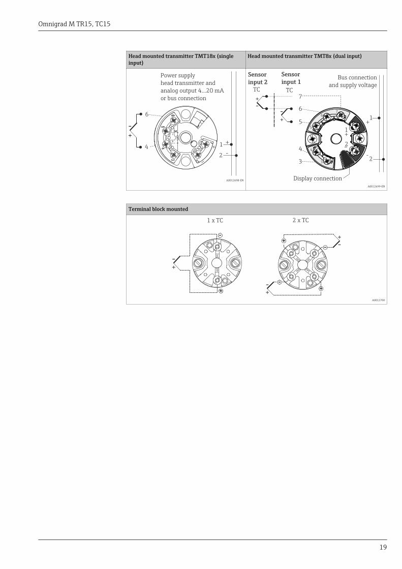
Head mounted transmitter TMT18x (singleinput)
Head mounted transmitter TMT8x (dual input)
-
+
6
4 1
2
Power supply
head transmitter and
analog output 4...20 mA
or bus connection
A0012698-EN
-
+
+1
-2
7
6
5
4
3
1
2
76
5
4
3
Sensor
input 2
Sensor
input 1Bus connection
and supply voltage
Display connection
TC TC
A0012699-EN
Terminal block mounted
1 x TC 2 x TC
-
+
-+
+
-
A0012700
Omnigrad M TR15, TC15
20
Installation conditions
Orientation No restrictions.
Installation instructions
L U1L
1
2
3
4
A0011013
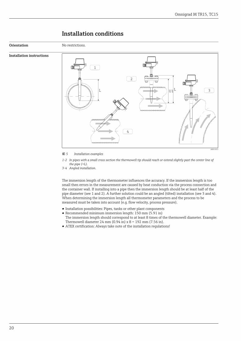
5 Installation examples
1-2 In pipes with a small cross section the thermowell tip should reach or extend slightly past the center line ofthe pipe (=L).
3-4 Angled installation.
The immersion length of the thermometer influences the accuracy. If the immersion length is toosmall then errors in the measurement are caused by heat conduction via the process connection andthe container wall. If installing into a pipe then the immersion length should be at least half of thepipe diameter (see 1 and 2). A further solution could be an angled (tilted) installation (see 3 and 4).When determining the immersion length all thermometer parameters and the process to bemeasured must be taken into account (e.g. flow velocity, process pressure).
• Installation possibilities: Pipes, tanks or other plant components• Recommended minimum immersion length: 150 mm (5.91 in)
The immersion length should correspond to at least 8 times of the thermowell diameter. Example:Thermowell diameter 24 mm (0.94 in) x 8 = 192 mm (7.56 in).
• ATEX certification: Always take note of the installation regulations!
Omnigrad M TR15, TC15
21
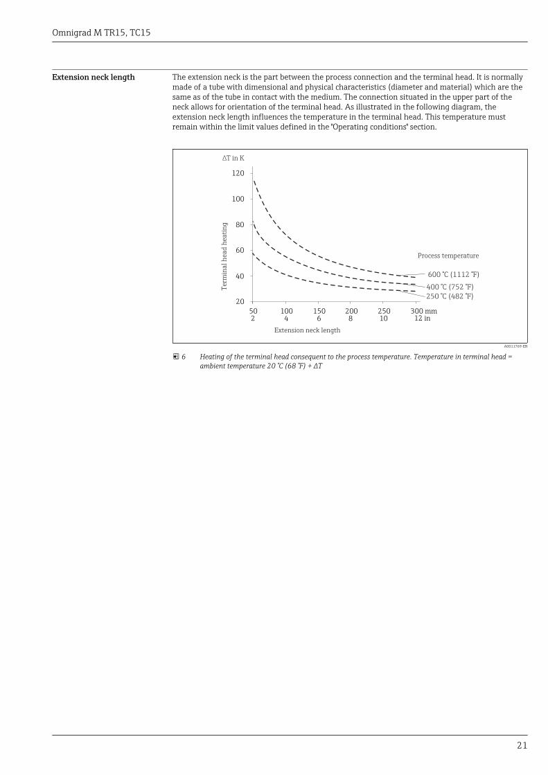
Extension neck length The extension neck is the part between the process connection and the terminal head. It is normallymade of a tube with dimensional and physical characteristics (diameter and material) which are thesame as of the tube in contact with the medium. The connection situated in the upper part of theneck allows for orientation of the terminal head. As illustrated in the following diagram, theextension neck length influences the temperature in the terminal head. This temperature mustremain within the limit values defined in the "Operating conditions" section.
∆T in K
20
40
60
80
100
120
50 100 150 200 250 300 mm
250 °C (482 °F)
400 °C (752 °F)
600 °C (1112 °F)
2 4 6 8 10 12 in
Extension neck length
Ter
min
al
hea
d h
eati
ng
Process temperature
A0011769-EN
6 Heating of the terminal head consequent to the process temperature. Temperature in terminal head =ambient temperature 20 °C (68 °F) + ΔT
Omnigrad M TR15, TC15
22
Certificates and approvals
CE Mark The device meets the legal requirements of the EC directives if applicable. Endress+Hauser confirmsthat the device has been successfully tested by applying the CE mark.
Hazardous area approvals For further details on the available Ex versions (ATEX, CSA, FM etc.), please contact your nearestEndress +Hauser sales organization. All relevant data for hazardous areas can be found in separateEx documentation.
Other standards andguidelines
• EN 60079: ATEX certification for hazardous areas• IEC 60529: Degree of protection of housing (IP code)• IEC 61010-1: Protection Measures for Electrical Equipment for Measurement, Control, Regulation
and Laboratory Procedures• IEC 60751: Industrial platinum resistance thermometers• IEC 60584 and ASTM E230/ANSI MC96.1: Thermocouples• DIN 43772: Thermowells• DIN EN 50446: Terminal heads• IEC 61326-1: Electromagnetic compatibility (EMC requirements)
PED approval The thermometer complies with paragraph 3.3 of the Pressure Equipment Directive 97/23/CE and isnot marked separately.
Material certification The material certificate 3.1 (according to EN 10204) can be requested separately. The "short form"certificate includes a simplified declaration with no enclosures of documents related to the materialsused in the construction of the single sensor and guarantees the traceability of the materials throughthe identification number of the thermometer. The data related to the origin of the materials cansubsequently be requested if necessary.
Test on thermowell Thermowell pressure tests are carried out in accordance with the specifications in DIN 43772. Withregard to thermowells with tapered or reduced tips that do not comply with this standard, these aretested using the pressure of corresponding straight thermowells. Sensors for use in hazardous areasare also always subjected to a comparative pressure during the tests. Tests according to otherspecifications can be carried out on request. The liquid penetration test verifies that there are nocracks in the welded seams of the thermowell.
Test report and calibration The "Factory calibration" is carried out according to an internal procedure in a laboratory of Endress+Hauser accredited by the European Accreditation Organization (EA) according to ISO/IEC 17025. Acalibration which is performed according to EA guidelines (SIT/Accredia or DKD/DAkks calibration)may be requested separately. The calibration is performed on the replaceable insert of thethermometer. In the case of thermometers without a replaceable insert, the entire thermometer -from the process connection to the tip of the thermometer - is calibrated.
Ordering informationDetailed ordering information is available from the following sources:• In the Product Configurator on the Endress+Hauser website: www.endress.com → Select country →
Instruments → Select device → Product page function: Configure this product• From your Endress+Hauser Sales Center: www.endress.com/worldwide
Product Configurator - the tool for individual product configuration• Up-to-the-minute configuration data• Depending on the device: Direct input of measuring point-specific information such as
measuring range or operating language• Automatic verification of exclusion criteria• Automatic creation of the order code and its breakdown in PDF or Excel output format• Ability to order directly in the Endress+Hauser Online Shop
Omnigrad M TR15, TC15
23
AccessoriesVarious accessories, which can be ordered with the device or subsequently from Endress+Hauser, areavailable for the device. Detailed information on the order code in question is available from yourlocal Endress+Hauser sales center or on the product page of the Endress+Hauser website:www.endress.com.
Communication-specificaccessories
Configuration kit TXU10 Configuration kit for PC-programmable transmitter with setup software andinterface cable for PC with USB portOrder code: TXU10-xx
Commubox FXA195HART
For intrinsically safe HART communication with FieldCare via the USB interface.
For details, see "Technical Information" TI00404F
Commubox FXA291 Connects Endress+Hauser field devices with a CDI interface (= Endress+HauserCommon Data Interface) and the USB port of a computer or laptop.
For details, see "Technical Information" TI00405C
HART Loop ConverterHMX50
Is used to evaluate and convert dynamic HART process variables to analog currentsignals or limit values.
For details, see "Technical Information" TI00429F and Operating InstructionsBA00371F
Wireless HART adapterSWA70
Is used for the wireless connection of field devices.The WirelessHART adapter can be easily integrated into field devices and existinginfrastructures, offers data protection and transmission safety and can be operatedin parallel with other wireless networks with minimum cabling complexity.
For details, see Operating Instructions BA061S
Fieldgate FXA320 Gateway for the remote monitoring of connected 4-20 mA measuring devices via aWeb browser.
For details, see "Technical Information" TI00025S and Operating InstructionsBA00053S
Fieldgate FXA520 Gateway for the remote diagnostics and remote configuration of connected HARTmeasuring devices via a Web browser.
For details, see "Technical Information" TI00025S and Operating InstructionsBA00051S
Field Xpert SFX100 Compact, flexible and robust industry handheld terminal for remote configurationand for obtaining measured values via the HART current output (4-20 mA).
For details, see Operating Instructions BA00060S
Service-specific accessories Accessories Description
Applicator Software for selecting and sizing Endress+Hauser measuring devices:• Calculation of all the necessary data for identifying the optimum measuring
device: e.g. pressure loss, accuracy or process connections.• Graphic illustration of the calculation results
Administration, documentation and access to all project-related data andparameters over the entire life cycle of a project.
Applicator is available:• Via the Internet: https://wapps.endress.com/applicator• On CD-ROM for local PC installation.
Omnigrad M TR15, TC15
24
Konfigurator+temperature Software for selecting and configuring the product depending on the measuringtask, supported by graphics. Includes a comprehensive knowledge database andcalculation tools:• For temperature competence• Quick and easy design and sizing of temperature measuring points• Ideal measuring point design and sizing to suit the processes and needs of a wide
range of industries
The Konfigurator is available:On request from your Endress+Hauser sales office on a CD-ROM for local PCinstallation.
W@M Life cycle management for your plantW@M supports you with a wide range of software applications over the entireprocess: from planning and procurement, to the installation, commissioning andoperation of the measuring devices. All the relevant device information, such asthe device status, spare parts and device-specific documentation, is available forevery device over the entire life cycle.The application already contains the data of your Endress+Hauser device. Endress+Hauser also takes care of maintaining and updating the data records.
W@M is available:• Via the Internet: www.endress.com/lifecyclemanagement• On CD-ROM for local PC installation.
FieldCare FDT-based plant asset management tool from Endress+Hauser.It can configure all smart field units in your system and helps you manage them. Byusing the status information, it is also a simple but effective way of checking theirstatus and condition.
For details, see Operating Instructions BA00027S and BA00059S
System components Accessories Description
Field display unit RIA16 The display unit records the analog measuring signal from the head transmitterand shows this on the display. The LC display shows the current measured value indigital form and as a bar graph indicating a limit value violation. The display unit islooped into the 4 to 20 mA circuit and gets the required energy from there.
For details, see the "Technical Information" document TI00144R/09/en
RN221N Active barrier with power supply for safe separation of 4-20 mA standard signalcircuits. Offers bidirectional HART transmission.
For details, see "Technical Information" TI00073R and Operating InstructionsBA00202R
RNS221 Supply unit for powering two 2-wire measuring devices solely in the non-Ex area.Bidirectional communication is possible via the HART communication jacks.
For details, see "Technical Information" TI00081R and Brief OperatingInstructions KA00110R

Omnigrad M TR15, TC15
25
DocumentationTechnical Information:• iTEMP® Temperature head transmitter
– TMT180, PC-programmable, single-channel, Pt100 (TI00088R/09/en)– PCP TMT181, PC-programmable, single-channel, RTD, TC, Ω, mV (TI00070R/09/en)– HART® TMT182, single-channel, RTD, TC, Ω, mV (TI078R/09/en)– HART®TMT82, two-channel, RTD, TC, Ω, mV (TI01010T/09/en)– PROFIBUS® PA TMT84, two-channel, RTD, TC, Ω, mV (TI00138R/09/en)– FOUNDATION FieldbusTM TMT85, two-channel, RTD, TC, Ω, mV (TI00134R/09/en)
• Inserts:– Resistance thermometer insert Omniset TPR100 (TI268t/02/en)– Thermocouple insert Omniset TPC100 (TI278t/02/en)– iTHERM® TS111 Insert for installation in thermometers (TI01014T/09/en)
• Thermowell:Thermowell for temperature sensors Omnigrad M TW15 (TI00265T/02/en)
• Application example:– RN221N Active barrier, for supplying loop-powered transmitters (TI073R/09/en)– RIA16 Field display unit, loop-powered (TI00144R/09/en)
Supplementary ATEX documentation:• Omnigrad TRxx, Omniset TPR100, TET10x, TPC100, TEC10x ATEX II 3GD EEx nA
(XA00044r/09/a3)• RTD/TC Thermometer Omnigrad TRxx, TCxx, TxCxxx, ATEX II 1GD or II 1/2GD Ex ia IIC T6...T1
(XA00072R/09/a3)• iTHERM® TS111, TM211 Omnigrad TST310, TSC310 Omniset TPR100, TPC100 IECEx Ex ia IIC
T6…T1 (XA00100R/09/a3)


www.addresses.endress.com