technical information rtd temperature sensor omnigrad m- tr 13
TRANSCRIPT
Technical InformationTI 259T/02/en60019738
RTD Temperature Sensoromnigrad M- TR 13
RTD assembly with flanged process connectionWith thermowell and replaceable insertPCP (4...20 mA), HART® or PROFIBUS-PA® electronics
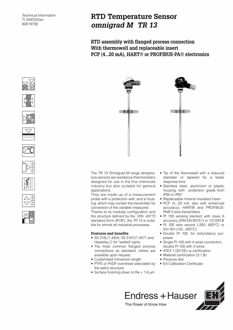
The TR 13 Omnigrad M range tempera-ture sensors are resistance thermometersdesigned for use in the fine chemicalsindustry but also suitable for generalapplications.They are made up of a measurementprobe with a protection well, and a hous-ing, which may contain the transmitter forconversion of the variable measured.Thanks to its modular configuration andthe structure defined by the DIN 43772standard (form 2F/3F), the TR 13 is suita-ble for almost all industrial processes.
Features and benefits• SS 316L/1.4404, SS 316Ti/1.4571 and
Hastelloy C for "wetted" parts• The most common flanged process
connections as standard; others areavailable upon request
• Customized immersion length• PTFE or PVDF oversheat selectable by
the sale’s structure• Surface finishing down to Ra < 1.6 µm
• Tip of the thermowell with a reduceddiameter or tapered for a fasterresponse time
• Stainless steel, aluminium or plastichousing, with protection grade fromIP65 to IP67
• Replaceable mineral insulated insert• PCP (4...20 mA, also with enhanced
accuracy), HART® and PROFIBUS-PA® 2-wire transmitters
• Pt 100 sensing element with class Aaccuracy (DIN EN 60751) or 1/3 DIN B
• Pt 100 wire wound (-200...600°C) orthin film (-50...400°C)
• Double Pt 100, for redundancy pur-poses
• Single Pt 100 with 4 wires connection, double Pt 100 with 3 wires
• ATEX 1 GD EEx ia certification• Material certification (3.1.B)• Pressure test• EA Calibration Certificate
omnigrad M TR 13
2 Endress+Hauser
Areas of application
• Fine chemicals industry• Light energy industry• Food industry• General industrial services
Function and system design
Measuring principle In the RTD (Resistance Temperature Detector) thermometers, the sensing element consists of anelectrical resistance with value of 100 Ω at 0°C (called Pt 100, in compliance with standard DINEN 60751) which increases at higher temperatures according to a coefficient characteristic of theresistor material (platinum). In industrial thermometers that comply with the DIN EN 60751 stand-ard, the value of this coefficient is α = 3.85*10-3 °C-1, calculated between 0 and 100°C.
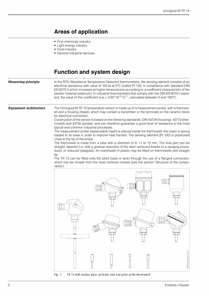
Equipment architecture The Omnigrad M TR 13 temperature sensor is made up of a measurement probe, with a thermow-ell and a housing (head), which may contain a transmitter or the terminals on the ceramic blockfor electrical connection.Construction of the sensor is based on the following standards: DIN 43729 (housing), 43772 (ther-mowell) and 43735 (probe), and can therefore guarantee a good level of resistance to the mosttypical and common industrial processes.The measurement probe (replaceable insert) is placed inside the thermowell; the insert is springloaded to its base in order to improve heat transfer. The sensing element (Pt 100) is positionedclose to the tip of the probe.The thermowell is made from a tube with a diameter of 9, 11 or 12 mm. The final part can bestraight, tapered (i.e. with a gradual reduction of the stem achieved thanks to a swaging proce-dure), or reduced (stepped). An oversheath in plastic may be fitted on thermowells with straighttip.The TR 13 can be fitted onto the plant (tube or tank) through the use of a flanged connection,which can be chosen from the most common models (see the section "Structure of the compo-nents").
Fig. 1: TR 13 with various types of heads and end parts of the thermowell
TR13
_G_d
d_0
7_xx
_01
omnigrad M TR 13
Endress+Hauser 3
The electrical structure of the thermometer always complies with DIN EN 60751 standard rules.The sensing element is available in two versions with a thin film (TF) or wire wound (WW), the latterwith a large measuring and accuracy range.The housing can be of different types and materials (plastic, painted aluminium alloy, stainlesssteel). The way in which it fits to thermowell and the cable gland ensure a minimum grade of IP65(Ingress Protection).
Material Wetted parts in SS 316L/1.4404, SS 316Ti/1.4571 or Hastelloy C.Oversheat in PVDF or PTFE.
Weight From 1.5 to 3.5 kg for standard options.
Electronics
The required type of output signal can be obtained by choosing the correct head-mounted trans-mitter. Endress+Hauser supplies "state-of-the-art" transmitters (the iTEMP® series) built in 2-wire tech-nology and with 4…20 mA output signal, HART® or PROFIBUS-PA®. All of the transmitters canbe easily programmed using a personal computer through the ReadWin® 2000 public domainsoftware (for transmitters 4…20 mA and HART®) or the Commuwin II software (for PROFIBUSPA®transmitters). The HART® transmitters can also be programmed with the hand-held operatingmodule DXR 275 (Universal HART® Communicator).A PCP (4…20 mA, TMT 180) model with enhanced accuracy is available.In the case of PROFIBUS-PA® transmitters, E+H recommends the use of PROFIBUS® dedicatedconnectors. The Weidmüller type (Pg 13.5 - M12) is provided as a standard option.For detailed information about transmitters, please refer to the relevant documentation (refer tothe TI codes at the end of the document).If a head-mounted transmitter is not employed, the sensor probe can be connected through theterminal block to a remote converter (i.e. DIN rail transmitter).
Performance
Operating conditions Ambient temperature (housing without head-mounted transmitter)• metal housings -40÷130°C• plastic housings -40÷85°C
Ambient temperature (housing with head-mounted transmitter) -40÷85°CAmbient temperature (housing with display) -20÷70°C
Process temperature Same of measurement range (see below).With oversheath 100°C
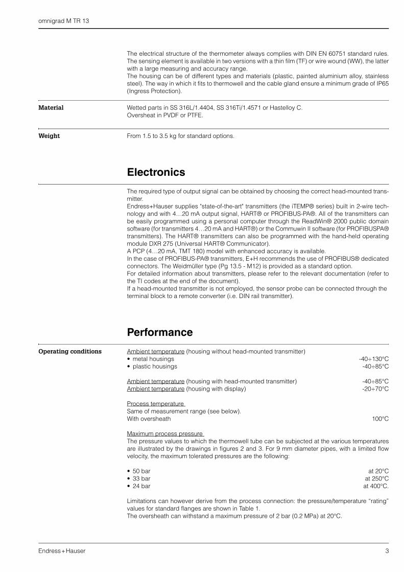
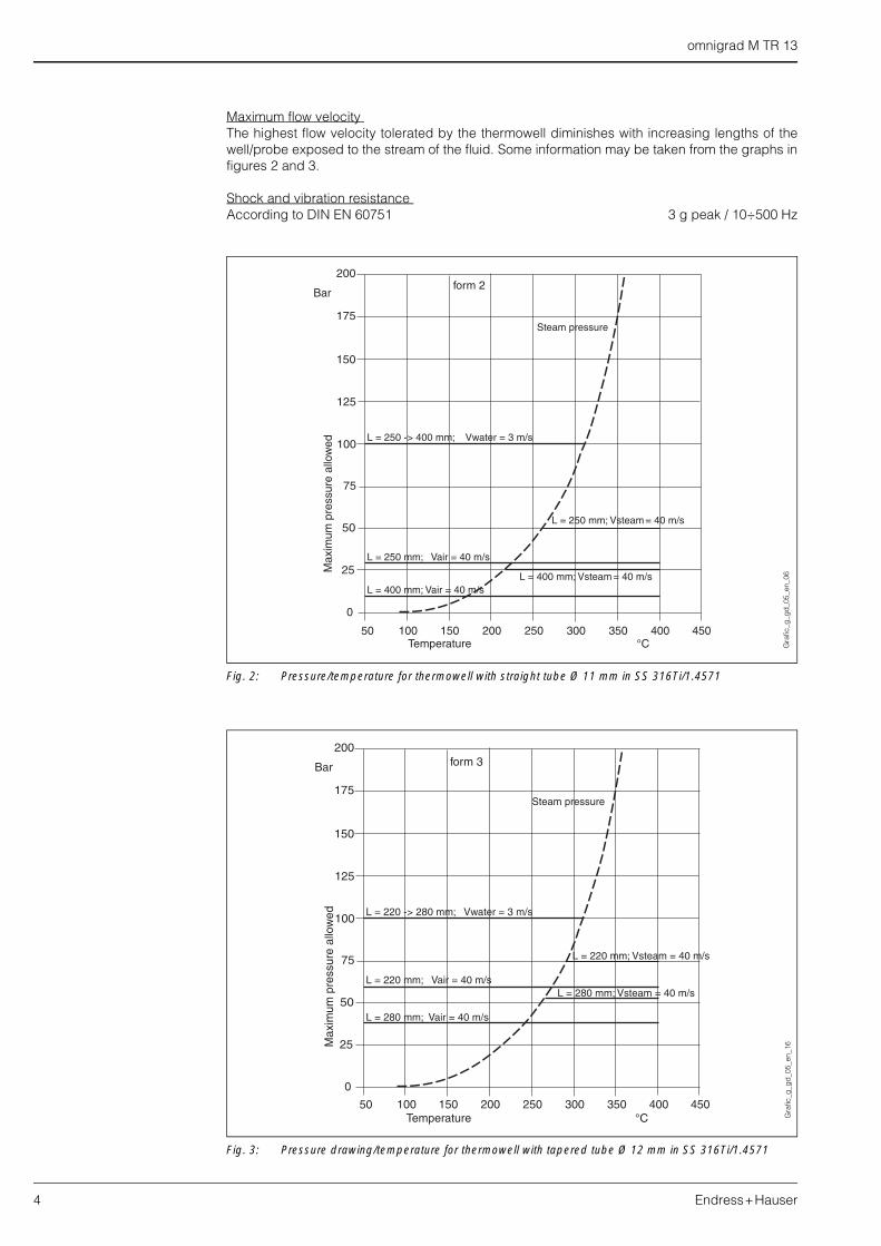
Maximum process pressure The pressure values to which the thermowell tube can be subjected at the various temperaturesare illustrated by the drawings in figures 2 and 3. For 9 mm diameter pipes, with a limited flowvelocity, the maximum tolerated pressures are the following:
• 50 bar at 20°C• 33 bar at 250°C• 24 bar at 400°C.
Limitations can however derive from the process connection: the pressure/temperature “rating”values for standard flanges are shown in Table 1.The oversheath can withstand a maximum pressure of 2 bar (0.2 MPa) at 20°C.
omnigrad M TR 13
4 Endress+Hauser
Maximum flow velocity The highest flow velocity tolerated by the thermowell diminishes with increasing lengths of thewell/probe exposed to the stream of the fluid. Some information may be taken from the graphs infigures 2 and 3.
Shock and vibration resistance According to DIN EN 60751 3 g peak / 10÷500 Hz
Fig. 2: Pressure/temperature for thermowell with straight tube Ø 11 mm in SS 316Ti/1.4571
Fig. 3: Pressure drawing/temperature for thermowell with tapered tube Ø 12 mm in SS 316Ti/1.4571
Gra
fic_g
_gd
_05_
en_0
6G
rafic
_g_g
d_0
5_en
_16
omnigrad M TR 13
Endress+Hauser 5
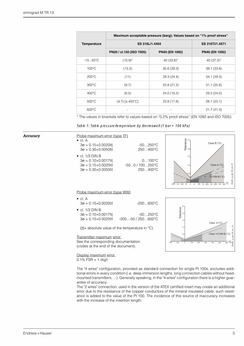
* The values in brackets refer to values based on “0.2% proof stress” (EN 1092 and ISO 7005)
Table 1: Table pressure/temperature by thermowell (1 bar = 100 kPa)
Accuracy Probe maximum error (type TF)• cl. A
3σ = 0.15+0.0020It| -50…250°C3σ = 0.30+0.0050ItI 250…400°C
• cl. 1/3 DIN B3σ = 0.10+0.0017It| 0…100°C3σ = 0.15+0.0020ItI -50...0 / 100...250°C3σ = 0.30+0.0050ItI 250…400°C
Probe maximum error (type WW)
• cl. A 3σ = 0.15+0.0020ItI -200…600°C
• cl. 1/3 DIN B3σ = 0.10+0.0017It| -50…250°C3σ = 0.15+0.0020ItI -200...-50 / 250…600°C
(|t|= absolute value of the temperature in °C)
Transmitter maximum error See the corresponding documentation (codes at the end of the document).
Display maximum error 0.1% FSR + 1 digit
The "4 wires" configuration, provided as standard connection for single Pt 100s, excludes addi-tional errors in every condition (i.e. deep immersion lengths, long connection cables without head-mounted transmitters, ...). Generally speaking, in the "4 wires" configuration there is a higher guar-antee of accuracy.The "2 wires" connection, used in the version of the ATEX certified insert may create an additionalerror due to the resistance of the copper conductors of the mineral insulated cable; such resist-ance is added to the value of the Pt 100. The incidence of this source of inaccuracy increaseswith the increase of the insertion length.
Temperature
Maximum acceptable pressure (barg); Values based on "1% proof stress"
SS 316L/1.4404 SS 316Ti/1.4571
PN20 / cl.150 (ISO 7005) PN40 (EN 1092) PN40 (EN 1092)
-10...50°C (15.9)* 40 (33.8)* 40 (37.3)*
100°C (13.2) 35.6 (29.3) 39.1 (33.8)
200°C (11) 29.3 (24.4) 34.1 (29.3)
300°C (9.7) 25.8 (21.2) 31.1 (25.8)
400°C (6.5) 24.0 (19.2) 29.2 (24.0)
500°C (4.7) [a 450°C] 22.8 (17.8) 28.1 (23.1)
600°C - - 21.7 (21.3)
Gra
fic_g
_gd
_05_
en_1
4G
rafic
_g_g
d_0
5_en
_01
omnigrad M TR 13
6 Endress+Hauser
Measurement range • Type TF -50…400°C• Type WW -200...600°C
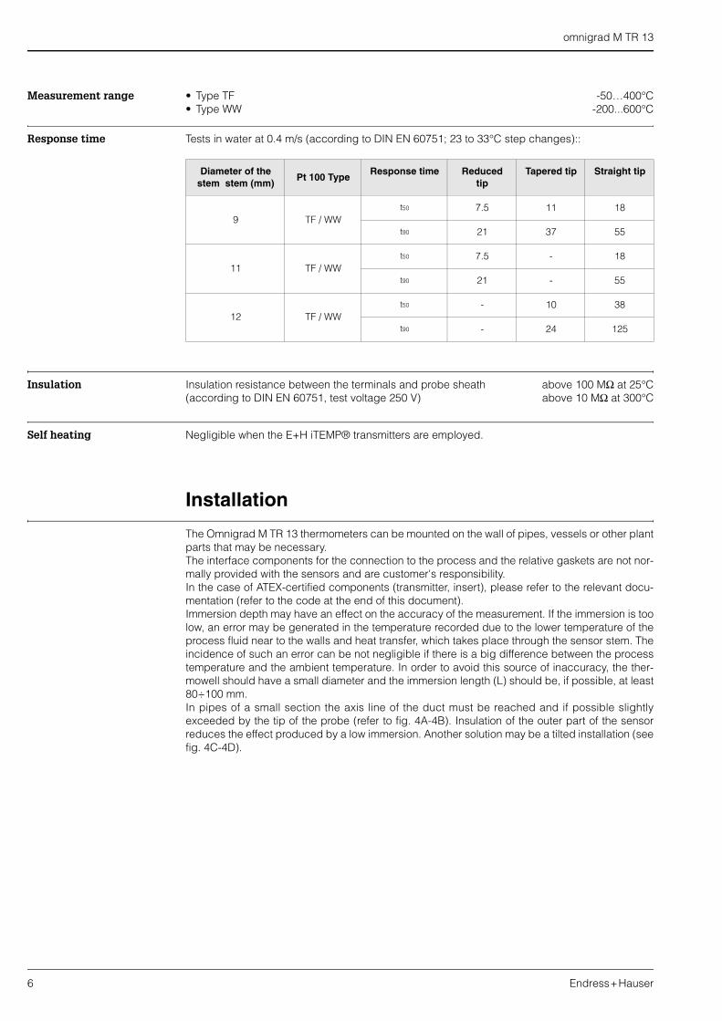
Response time Tests in water at 0.4 m/s (according to DIN EN 60751; 23 to 33°C step changes)::
Insulation Insulation resistance between the terminals and probe sheath above 100 MΩ at 25°C(according to DIN EN 60751, test voltage 250 V) above 10 MΩ at 300°C
Self heating Negligible when the E+H iTEMP® transmitters are employed.
Installation
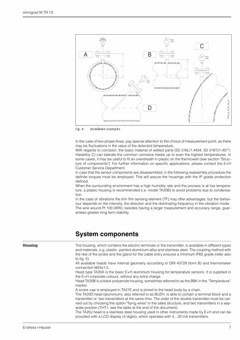
The Omnigrad M TR 13 thermometers can be mounted on the wall of pipes, vessels or other plantparts that may be necessary.The interface components for the connection to the process and the relative gaskets are not nor-mally provided with the sensors and are customer's responsibility.In the case of ATEX-certified components (transmitter, insert), please refer to the relevant docu-mentation (refer to the code at the end of this document).Immersion depth may have an effect on the accuracy of the measurement. If the immersion is toolow, an error may be generated in the temperature recorded due to the lower temperature of theprocess fluid near to the walls and heat transfer, which takes place through the sensor stem. Theincidence of such an error can be not negligible if there is a big difference between the processtemperature and the ambient temperature. In order to avoid this source of inaccuracy, the ther-mowell should have a small diameter and the immersion length (L) should be, if possible, at least80÷100 mm.In pipes of a small section the axis line of the duct must be reached and if possible slightlyexceeded by the tip of the probe (refer to fig. 4A-4B). Insulation of the outer part of the sensorreduces the effect produced by a low immersion. Another solution may be a tilted installation (seefig. 4C-4D).
Diameter of the stem stem (mm)
Pt 100 TypeResponse time Reduced
tipTapered tip Straight tip
9 TF / WWt50 7.5 11 18
t90 21 37 55
11 TF / WWt50 7.5 - 18
t90 21 - 55
12 TF / WWt50 - 10 38
t90 - 24 125
omnigrad M TR 13
Endress+Hauser 7
Fig. 4: Installation examples
In the case of two-phase flows, pay special attention to the choice of measurement point, as theremay be fluctuations in the value of the detected temperature.With regards to corrosion, the basic material of wetted parts (SS 316L/1.4404, SS 316Ti/1.4571,Hastelloy C) can tolerate the common corrosive media up to even the highest temperatures. Insome cases, it may be useful to fit an oversheath in plastic on the thermowell (see section "Struc-ture of components"). For further information on specific applications, please contact the E+HCustomer Service Department.In case that the sensor components are disassembled, in the following reassembly procedure thedefinite torques must be employed. This will assure the housings with the IP grade protectiondefined.When the surrounding environment has a high humidity rate and the process is at low tempera-ture, a plastic housing is recommended (i.e. model TA20B) to avoid problems due to condensa-tion.In the case of vibrations the thin film sensing element (TF) may offer advantages, but the behav-iour depends on the intensity, the direction and the dominating frequency in the vibration mode.The wire wound Pt 100 (WW), besides having a larger measurement and accuracy range, guar-antees greater long term stability.
System components
Housing The housing, which contains the electric terminals or the transmitter, is available in different typesand materials, e.g. plastic, painted aluminium alloy and stainless steel. The coupling method withthe rest of the probe and the gland for the cable entry ensures a minimum IP65 grade (refer alsoto fig. 5).All available heads have internal geometry according to DIN 43729 (form B) and thermometerconnection M24x1.5.Head type TA20A is the basic E+H aluminium housing for temperature sensors. It is supplied inthe E+H corporate colours, without any extra charge.Head TA20B is a black polyamide housing, sometimes referred to as the BBK in the “Temperature”market. A screw cap is employed in TA21E and is joined to the head body by a chain.The TA20D head (aluminium), also referred to as BUZH, is able to contain a terminal block and atransmitter or two transmitters at the same time. The order of the double transmitter must be car-ried out by choosing the option "flying wires" in the sales structure, and two transmitters in a sep-arate position (THT1, see the table at the end of the document).The TA20J head is a stainless steel housing used in other instruments made by E+H and can beprovided with a LCD display (4 digits), which operates with 4…20 mA transmitters.
TR13
_g_i
d_0
7_X
X_0
1
omnigrad M TR 13
8 Endress+Hauser
The TA20R is normally recommended by the Temperature division of E+H for hygienic applica-tions.The TA20W (BUS type) is a round blue/grey coloured head made of aluminium, with a clip for thecap closure. The cable gland M20x1.5 provided with the housings, is compatible with cables of a diameterbetween 5 and 9 mm.
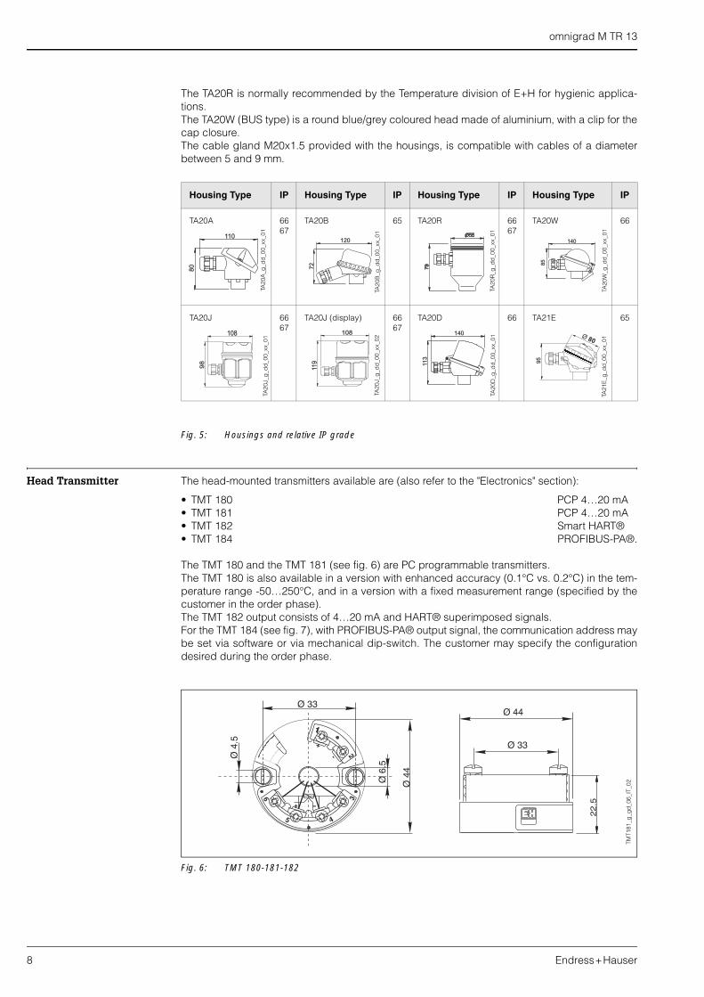
Fig. 5: Housings and relative IP grade
Head Transmitter The head-mounted transmitters available are (also refer to the "Electronics" section):
• TMT 180 PCP 4…20 mA • TMT 181 PCP 4…20 mA• TMT 182 Smart HART®• TMT 184 PROFIBUS-PA®.
The TMT 180 and the TMT 181 (see fig. 6) are PC programmable transmitters. The TMT 180 is also available in a version with enhanced accuracy (0.1°C vs. 0.2°C) in the tem-perature range -50…250°C, and in a version with a fixed measurement range (specified by thecustomer in the order phase).The TMT 182 output consists of 4…20 mA and HART® superimposed signals.For the TMT 184 (see fig. 7), with PROFIBUS-PA® output signal, the communication address maybe set via software or via mechanical dip-switch. The customer may specify the configurationdesired during the order phase.
Fig. 6: TMT 180-181-182
Housing Type IP Housing Type IP Housing Type IP Housing Type IP
TA20A 6667
TA20B 65 TA20R 6667
TA20W 66
TA20J 6667
TA20J (display) 6667
TA20D 66 TA21E 65
80
110
72
120
85
140
98
108
11
9
108
11
3
140
95
Ø80
TA20
A_g
_dd
_00_
xx_0
1
TA20
B_g
_dd
_00_
xx_0
1
TA20
J_g
_dd
_00_
xx_0
1
TA20
J_g
_dd
_00_
xx_0
2
TA20
R_g
_dd
_00_
xx_0
1
TA20
W_g
_dd
_00_
xx_0
1TA
21E
_g_d
d_0
0_xx
_01
TA20
D_g
_dd
_00_
xx_0
1
TMT1
81_g
_gd
_06_
IT_0
2
omnigrad M TR 13
Endress+Hauser 9
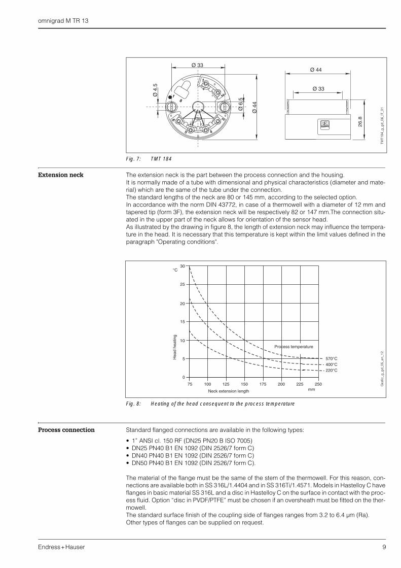
Fig. 7: TMT 184
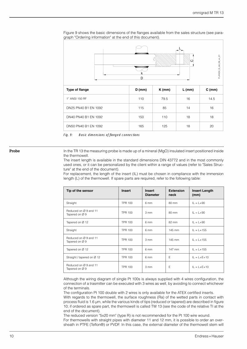
Extension neck The extension neck is the part between the process connection and the housing.It is normally made of a tube with dimensional and physical characteristics (diameter and mate-rial) which are the same of the tube under the connection.The standard lengths of the neck are 80 or 145 mm, according to the selected option.In accordance with the norm DIN 43772, in case of a thermowell with a diameter of 12 mm andtapered tip (form 3F), the extension neck will be respectively 82 or 147 mm.The connection situ-ated in the upper part of the neck allows for orientation of the sensor head.As illustrated by the drawing in figure 8, the length of extension neck may influence the tempera-ture in the head. It is necessary that this temperature is kept within the limit values defined in theparagraph "Operating conditions".
Fig. 8: Heating of the head consequent to the process temperature
Process connection Standard flanged connections are available in the following types:
• 1” ANSI cl. 150 RF (DN25 PN20 B ISO 7005)• DN25 PN40 B1 EN 1092 (DIN 2526/7 form C)• DN40 PN40 B1 EN 1092 (DIN 2526/7 form C)• DN50 PN40 B1 EN 1092 (DIN 2526/7 form C).
The material of the flange must be the same of the stem of the thermowell. For this reason, con-nections are available both in SS 316L/1.4404 and in SS 316Ti/1.4571. Models in Hastelloy C haveflanges in basic material SS 316L and a disc in Hastelloy C on the surface in contact with the proc-ess fluid. Option “disc in PVDF/PTFE” must be chosen if an oversheath must be fitted on the ther-mowell. The standard surface finish of the coupling side of flanges ranges from 3.2 to 6.4 µm (Ra). Other types of flanges can be supplied on request.
Ø4.
5
Ø44
Ø 33
Ø6.
5
6
5 4
3
2
1
-
+
18
-+ 26
.8
Ø 44
Ø 33
TMT1
84_g
_gd
_06_
IT_0
1G
rafic
_g_g
d_0
5_en
_12
omnigrad M TR 13
10 Endress+Hauser
Figure 9 shows the basic dimensions of the flanges available from the sales structure (see para-graph "Ordering information" at the end of this document).
Fig. 9: Basic dimensions of flanged connections
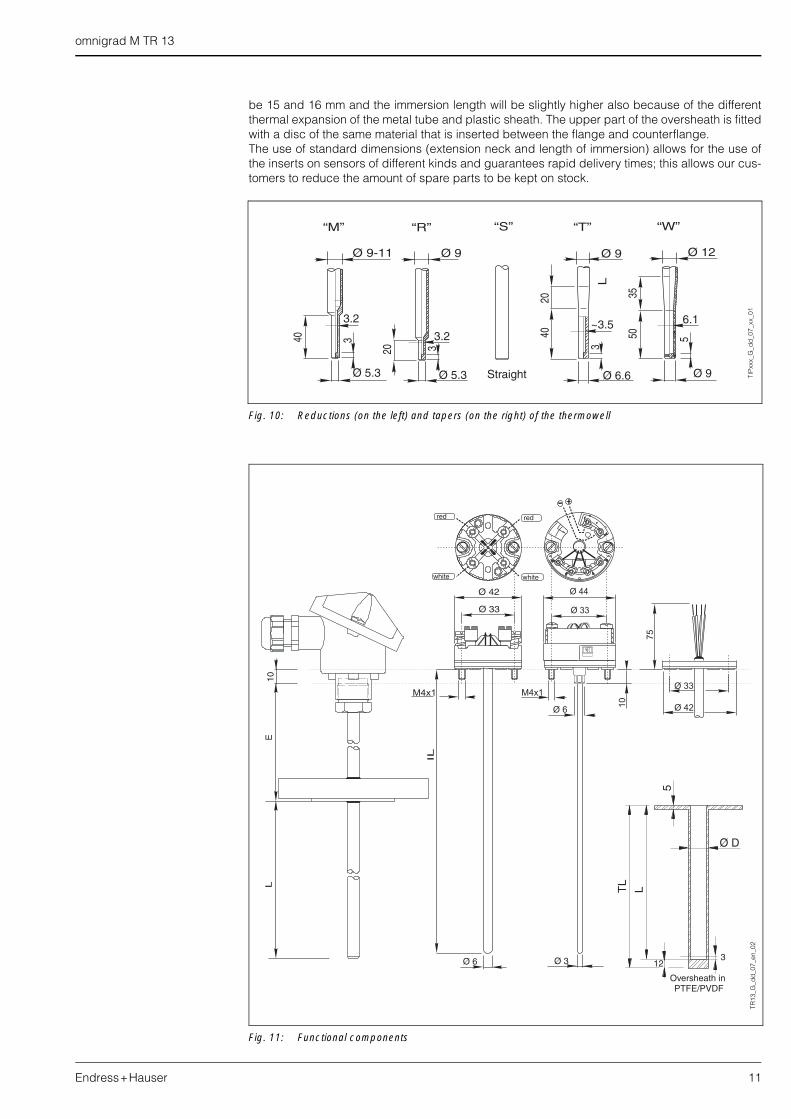
Probe In the TR 13 the measuring probe is made up of a mineral (MgO) insulated insert positioned insidethe thermowell. The insert length is available in the standard dimensions DIN 43772 and in the most commonlyused ones, or it can be personalized by the client within a range of values (refer to "Sales Struc-ture" at the end of the document).For replacement, the length of the insert (IL) must be chosen in compliance with the immersionlength (L) of the thermowell. If spare parts are required, refer to the following table:
Although the wiring diagram of single Pt 100s is always supplied with 4 wires configuration, theconnection of a trasmitter can be executed with 3 wires as well, by avoiding to connect whicheverof the terminals.The configuration Pt 100 double with 2 wires is only available for the ATEX certified inserts.With regards to the thermowell, the surface roughness (Ra) of the wetted parts in contact withprocess fluid is 1.6 µm, while the various kinds of tips (reduced or tapered) are described in figure10; if ordered as spare part, the thermowell is called TW 13 (see the code of the relative TI at theend of the document).The reduced version "5x20 mm" (type R) is not recommended for the Pt 100 wire wound.For thermowells with straight pipes with diameter 11 and 12 mm, it is possible to order an over-sheath in PTFE (Teflon®) or PVDF. In this case, the external diameter of the thermowell stem will
Type of flange D (mm) K (mm) L (mm) C (mm)
1” ANSI 150 RF 110 79.5 16 14.5
DN25 PN40 B1 EN 1092 115 85 14 16
DN40 PN40 B1 EN 1092 150 110 18 18
DN50 PN40 B1 EN 1092 165 125 18 20
C
D
k
L
FLA
NG
X_G
_dd
_09_
xx_0
1
Tip of the sensor Insert Insert Diameter
Extension neck
Insert Length (mm)
Straight TPR 100 6 mm 80 mm IL = L+90
Reduced on Ø 9 and 11Tapered on Ø 9
TPR 100 3 mm 80 mm IL = L+90
Tapered on Ø 12 TPR 100 6 mm 82 mm IL = L+90
Straight TPR 100 6 mm 145 mm IL = L+155
Reduced on Ø 9 and 11Tapered on Ø 9
TPR 100 3 mm 145 mm IL = L+155
Tapered on Ø 12 TPR 100 6 mm 147 mm IL = L+155
Straight / tapered on Ø 12 TPR 100 6 mm E IL = L+E+10
Reduced on Ø 9 and 11Tapered on Ø 9
TPR 100 3 mm E IL = L+E+10
omnigrad M TR 13
Endress+Hauser 11
be 15 and 16 mm and the immersion length will be slightly higher also because of the differentthermal expansion of the metal tube and plastic sheath. The upper part of the oversheath is fittedwith a disc of the same material that is inserted between the flange and counterflange.The use of standard dimensions (extension neck and length of immersion) allows for the use ofthe inserts on sensors of different kinds and guarantees rapid delivery times; this allows our cus-tomers to reduce the amount of spare parts to be kept on stock.
Fig. 10: Reductions (on the left) and tapers (on the right) of the thermowell
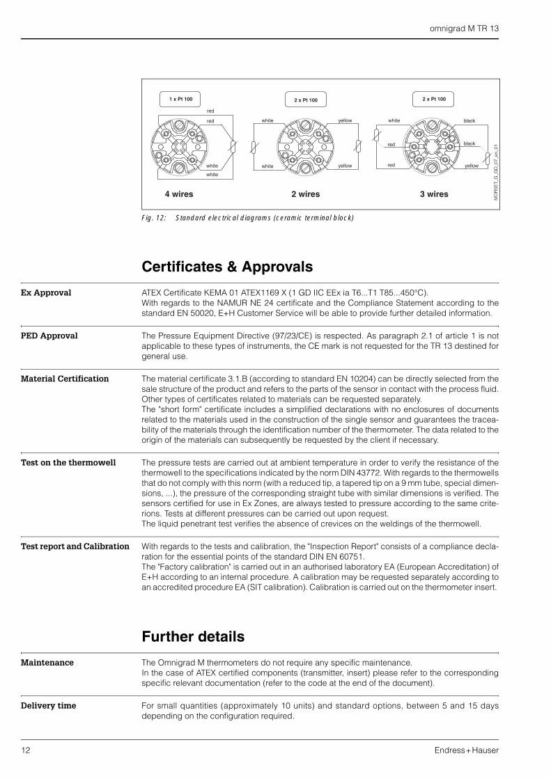
Fig. 11: Functional components
TIP
xxx_
G_d
d_0
7_xx
_01
TR13
_G_d
d_0
7_en
_02
omnigrad M TR 13
12 Endress+Hauser
Fig. 12: Standard electrical diagrams (ceramic terminal block)
Certificates & Approvals
Ex Approval ATEX Certificate KEMA 01 ATEX1169 X (1 GD IIC EEx ia T6...T1 T85...450°C).With regards to the NAMUR NE 24 certificate and the Compliance Statement according to thestandard EN 50020, E+H Customer Service will be able to provide further detailed information.
PED Approval The Pressure Equipment Directive (97/23/CE) is respected. As paragraph 2.1 of article 1 is notapplicable to these types of instruments, the CE mark is not requested for the TR 13 destined forgeneral use.
Material Certification The material certificate 3.1.B (according to standard EN 10204) can be directly selected from thesale structure of the product and refers to the parts of the sensor in contact with the process fluid.Other types of certificates related to materials can be requested separately. The "short form" certificate includes a simplified declarations with no enclosures of documentsrelated to the materials used in the construction of the single sensor and guarantees the tracea-bility of the materials through the identification number of the thermometer. The data related to theorigin of the materials can subsequently be requested by the client if necessary.
Test on the thermowell The pressure tests are carried out at ambient temperature in order to verify the resistance of thethermowell to the specifications indicated by the norm DIN 43772. With regards to the thermowellsthat do not comply with this norm (with a reduced tip, a tapered tip on a 9 mm tube, special dimen-sions, ...), the pressure of the corresponding straight tube with similar dimensions is verified. Thesensors certified for use in Ex Zones, are always tested to pressure according to the same crite-rions. Tests at different pressures can be carried out upon request.The liquid penetrant test verifies the absence of crevices on the weldings of the thermowell.
Test report and Calibration With regards to the tests and calibration, the "Inspection Report" consists of a compliance decla-ration for the essential points of the standard DIN EN 60751. The "Factory calibration" is carried out in an authorised laboratory EA (European Accreditation) ofE+H according to an internal procedure. A calibration may be requested separately according toan accredited procedure EA (SIT calibration). Calibration is carried out on the thermometer insert.
Further details
Maintenance The Omnigrad M thermometers do not require any specific maintenance. In the case of ATEX certified components (transmitter, insert) please refer to the correspondingspecific relevant documentation (refer to the code at the end of the document).
Delivery time For small quantities (approximately 10 units) and standard options, between 5 and 15 daysdepending on the configuration required.
MO
RS
ET_
G_G
D_0
7_en
_01
omnigrad M TR 13
Endress+Hauser 13
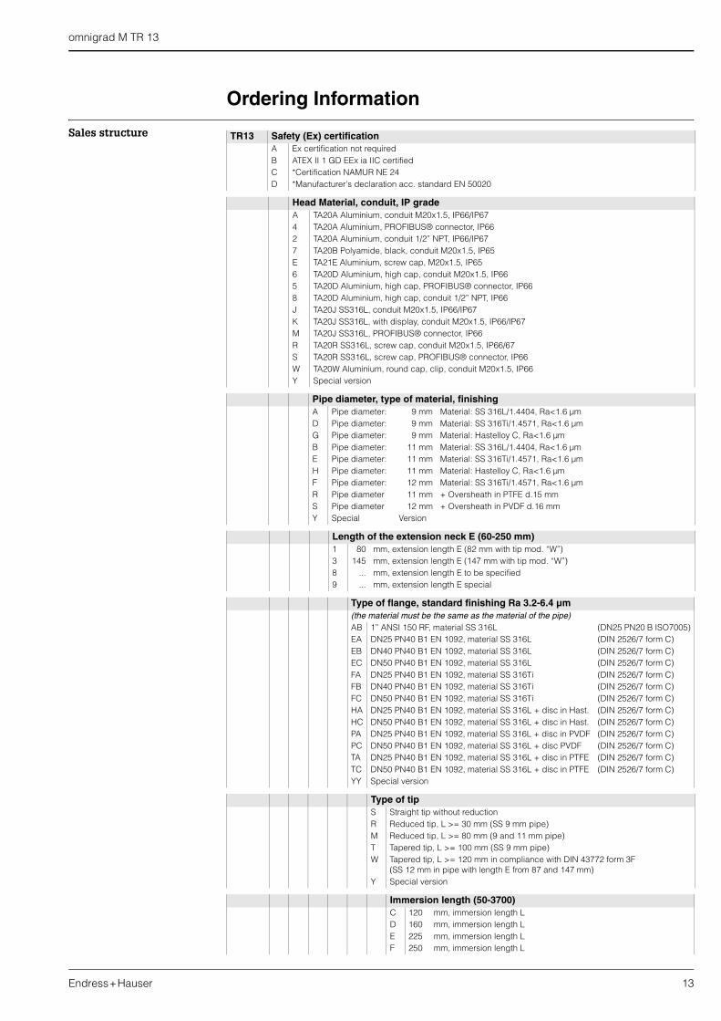
Ordering Information
Sales structure TR13 Safety (Ex) certification A Ex certification not requiredB ATEX II 1 GD EEx ia IIC certified C *Certification NAMUR NE 24 D *Manufacturer's declaration acc. standard EN 50020
Head Material, conduit, IP gradeA TA20A Aluminium, conduit M20x1.5, IP66/IP674 TA20A Aluminium, PROFIBUS® connector, IP662 TA20A Aluminium, conduit 1/2” NPT, IP66/IP677 TA20B Polyamide, black, conduit M20x1.5, IP65E TA21E Aluminium, screw cap, M20x1.5, IP656 TA20D Aluminium, high cap, conduit M20x1.5, IP665 TA20D Aluminium, high cap, PROFIBUS® connector, IP668 TA20D Aluminium, high cap, conduit 1/2” NPT, IP66J TA20J SS316L, conduit M20x1.5, IP66/IP67K TA20J SS316L, with display, conduit M20x1.5, IP66/IP67M TA20J SS316L, PROFIBUS® connector, IP66R TA20R SS316L, screw cap, conduit M20x1.5, IP66/67S TA20R SS316L, screw cap, PROFIBUS® connector, IP66W TA20W Aluminium, round cap, clip, conduit M20x1.5, IP66Y Special version
Pipe diameter, type of material, finishingA Pipe diameter: 9 mm Material: SS 316L/1.4404, Ra<1.6 µmD Pipe diameter: 9 mm Material: SS 316Ti/1.4571, Ra<1.6 µmG Pipe diameter: 9 mm Material: Hastelloy C, Ra<1.6 µmB Pipe diameter: 11 mm Material: SS 316L/1.4404, Ra<1.6 µmE Pipe diameter: 11 mm Material: SS 316Ti/1.4571, Ra<1.6 µmH Pipe diameter: 11 mm Material: Hastelloy C, Ra<1.6 µmF Pipe diameter: 12 mm Material: SS 316Ti/1.4571, Ra<1.6 µmR Pipe diameter 11 mm + Oversheath in PTFE d.15 mmS Pipe diameter 12 mm + Oversheath in PVDF d.16 mmY Special Version
Length of the extension neck E (60-250 mm)1 80 mm, extension length E (82 mm with tip mod. “W”)3 145 mm, extension length E (147 mm with tip mod. “W”)8 ... mm, extension length E to be specified9 ... mm, extension length E special
Type of flange, standard finishing Ra 3.2-6.4 µm(the material must be the same as the material of the pipe)AB 1” ANSI 150 RF, material SS 316L (DN25 PN20 B ISO7005)EA DN25 PN40 B1 EN 1092, material SS 316L (DIN 2526/7 form C)EB DN40 PN40 B1 EN 1092, material SS 316L (DIN 2526/7 form C)EC DN50 PN40 B1 EN 1092, material SS 316L (DIN 2526/7 form C)FA DN25 PN40 B1 EN 1092, material SS 316Ti (DIN 2526/7 form C)FB DN40 PN40 B1 EN 1092, material SS 316Ti (DIN 2526/7 form C)FC DN50 PN40 B1 EN 1092, material SS 316Ti (DIN 2526/7 form C)HA DN25 PN40 B1 EN 1092, material SS 316L + disc in Hast. (DIN 2526/7 form C)HC DN50 PN40 B1 EN 1092, material SS 316L + disc in Hast. (DIN 2526/7 form C)PA DN25 PN40 B1 EN 1092, material SS 316L + disc in PVDF (DIN 2526/7 form C)PC DN50 PN40 B1 EN 1092, material SS 316L + disc PVDF (DIN 2526/7 form C)TA DN25 PN40 B1 EN 1092, material SS 316L + disc in PTFE (DIN 2526/7 form C)TC DN50 PN40 B1 EN 1092, material SS 316L + disc in PTFE (DIN 2526/7 form C)YY Special version
Type of tipS Straight tip without reductionR Reduced tip, L >= 30 mm (SS 9 mm pipe)M Reduced tip, L >= 80 mm (9 and 11 mm pipe)T Tapered tip, L >= 100 mm (SS 9 mm pipe)W Tapered tip, L >= 120 mm in compliance with DIN 43772 form 3F
(SS 12 mm in pipe with length E from 87 and 147 mm)Y Special version
Immersion length (50-3700)C 120 mm, immersion length LD 160 mm, immersion length LE 225 mm, immersion length LF 250 mm, immersion length L
omnigrad M TR 13
14 Endress+Hauser
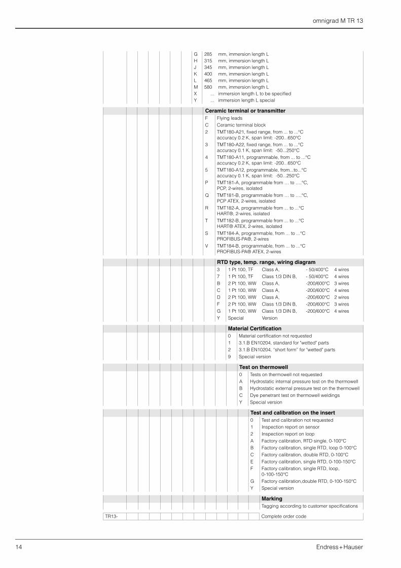
G 285 mm, immersion length LH 315 mm, immersion length LJ 345 mm, immersion length LK 400 mm, immersion length LL 465 mm, immersion length LM 580 mm, immersion length LX ... immersion length L to be specifiedY ... immersion length L special
Ceramic terminal or transmitterF Flying leadsC Ceramic terminal block2 TMT180-A21, fixed range, from ... to ...°C
accuracy 0.2 K, span limit: -200...650°C3 TMT180-A22, fixed range, from ... to ...°C
accuracy 0.1 K, span limit: -50...250°C4 TMT180-A11, programmable, from ... to ...°C
accuracy 0.2 K, span limit: -200...650°C5 TMT180-A12, programmable, from...to...°C
accuracy 0.1 K, span limit: -50...250°CP TMT181-A, programmable from … to ….°C,
PCP, 2-wires, isolatedQ TMT181-B, programmable from … to ….°C,
PCP ATEX, 2-wires, isolatedR TMT182-A, programmable from ... to ...°C
HART®, 2-wires, isolatedT TMT182-B, programmable from ... to ...°C
HART® ATEX, 2-wires, isolatedS TMT184-A, programmable, from ... to ...°C
PROFIBUS-PA®, 2-wiresV TMT184-B, programmable, from ... to ...°C
PROFIBUS-PA® ATEX, 2-wires
RTD type, temp. range, wiring diagram3 1 Pt 100, TF Class A, - 50/400°C 4 wires7 1 Pt 100, TF Class 1/3 DIN B, - 50/400°C 4 wiresB 2 Pt 100, WW Class A, -200/600°C 3 wiresC 1 Pt 100, WW Class A, -200/600°C 4 wiresD 2 Pt 100, WW Class A, -200/600°C 2 wiresF 2 Pt 100, WW Class 1/3 DIN B, -200/600°C 3 wiresG 1 Pt 100, WW Class 1/3 DIN B, -200/600°C 4 wiresY Special Version
Material Certification 0 Material certification not requested1 3.1.B EN10204, standard for "wetted" parts2 3.1.B EN10204, “short form” for "wetted" parts9 Special version
Test on thermowell0 Tests on thermowell not requestedA Hydrostatic internal pressure test on the thermowellB Hydrostatic external pressure test on the thermowellC Dye penetrant test on thermowell weldingsY Special version
Test and calibration on the insert0 Test and calibration not requested1 Inspection report on sensor2 Inspection report on loopA Factory calibration, RTD single, 0-100°CB Factory calibration, single RTD, loop 0-100°CC Factory calibration, double RTD, 0-100°CE Factory calibration, single RTD, 0-100-150°CF Factory calibration, single RTD, loop,
0-100-150°CG Factory calibration,double RTD, 0-100-150°CY Special version
Marking Tagging according to customer specifications
TR13- Complete order code
omnigrad M TR 13
Endress+Hauser 15
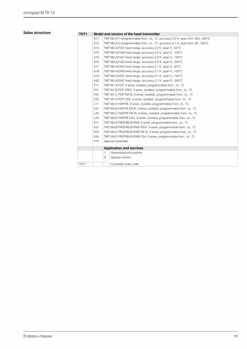
Sales structure THT1 Model and version of the head transmitterA11 TMT180-A11 programmable from...to...°C, accuracy 0.2 K, span limit -200...650°C
A12 TMT180-A12 programmable from...to...°C, accuracy 0.1 K, span limit -50...250°C
A13 TMT180-A21AA fixed range, accuracy 0.2 K, span 0...50°C
A14 TMT180-A21AB fixed range, accuracy 0.2 K, span 0...100°C
A15 TMT180-A21AC fixed range, accuracy 0.2 K, span 0...150°C
A16 TMT180-A21AD fixed range, accuracy 0.2 K, span 0...250°C
A17 TMT180-A22AA fixed range, accuracy 0.1 K, span 0...50°C
A18 TMT180-A22AB fixed range, accuracy 0.1 K, span 0...100°C
A19 TMT180-A22AC fixed range, accuracy 0.1 K, span 0...150°C
A20 TMT180-A22AD fixed range, accuracy 0.1 K, span 0...250°C
F11 TMT181-A PCP, 2-wires, isolated, programmable from...to...°C
F21 TMT181-B PCP ATEX, 2-wires, isolated, programmable from...to...°C
F22 TMT181-C PCP FM IS, 2-wires, isolated, programmable from...to...°C
F23 TMT181-D PCP CSA, 2-wires, isolated, programmable from...to...°C
L11 TMT182-A HART®, 2-wires, isolated, programmable from...to...°C
L21 TMT182-B HART® ATEX, 2-wires, isolated, programmable from...to...°C
L22 TMT182-C HART® FM IS, 2-wires, isolated, programmable from...to...°C
L23 TMT182-D HART® CSA, 2-wires, isolated, programmable from...to...°C
K11 TMT184-A PROFIBUS-PA®, 2-wires, programmable from...to...°C
K21 TMT184-B PROFIBUS-PA® ATEX, 2-wires, programmable from...to...°C
K23 TMT184-C PROFIBUS-PA® FM IS, 2-wires, programmable from...to...°C
K24 TMT184-D PROFIBUS-PA® CSA, 2-wires, programmable from...to...°C
YYY Special transmitter
Application and services1 Assembled into position
9 Special version
THT1- Complete order code
Endress+HauserGmbh+Co.Instruments InternationalP.O. Box 2222D-79574 Weil am RheinGermany
Tel. (07621) 975-02Tx 773926Fax (07621) 975 345http://[email protected]
cl/02
Subject to modification
TI 259T/02/en/07.0260019738FM+SGML 6.0
Supplementary Documentation
RTD Thermometers omnigrad TST - general information TI 088T/02/en Terminal housings - Omnigrad TA 20 TI 072T/02/en Temperature head transmitter iTEMP® Pt TMT 180 TI 088R/09/en Temperature head transmitter iTEMP® PCP TMT 181 TI 070R/09/en Temperature head transmitter iTEMP® HART® TMT 182 TI 078R/09/en Temperature head transmitter iTEMP® PA TMT 184 TI 079R/09/en RTD insert for temperature sensor - Omniset TPR100 TI 268T/02/en Thermowell for temperature sensor - Omnigrad M TW 13 TI 264T/02/it Thermowell Oversheaths TI 233T/02/en Safety instructions for use in hazardous areas XA 003T/02/z1 E+H Thermolab - Calibration certificates for
industrial thermometers. RTD and thermocouples TI 236T/02/en