technical information omnigrad s tr66 - endress · ti284t/02/en 71078770 technical information...
TRANSCRIPT

TI284T/02/en
71078770
Technical Information
Omnigrad S TR66
Modular RTD assembly, flameproof
Bar stock-thermowell, with thread or flange
Application
• Heavy duty applications
• Oil & Gas processing industry
• Measuring range: -200...600 °C (-328...1115 °F)
• Static pressure range up to 500 bar (7250 PSI)
• Protection class: up to IP 68
Head transmitters
All Endress+Hauser transmitters are available with
enhanced accuracy, reliability and cost effectiveness
compared to directly wired sensors. Easy customizing by
choosing one of the following outputs and protocols:
• Analog output 4...20 mA
• HART®
• PROFIBUS® PA
• FOUNDATION Fieldbus™
Your benefits
• High flexibility based on modular assembly with a
terminal head and customized immersion length
• Extension neck for head transmitter heat protection
• Types of protection for use in hazardous locations:
Flameproof (Ex d)
Intrinsic Safety (Ex ia)
Non-Sparking (Ex nA)
Dust ignition proof (protection by enclosure)
4 0

TR66
2 Endress+Hauser
Function and system design
Measuring principle The Resistance Temperature Detector (RTD) element consists of an electrical resistance with a value of 100 Ω
at 0 °C (32 °F). It is commonly known as Pt100 and is in compliance with IEC 60751. This resistance value
increases at higher temperatures according to the characteristics of the resistor material (platinum). These kind
of sensors are called Positive Temperature Coefficient elements (PTC).
The coefficient is fixed with α = 0.00385 °C-1, calculated between 0 and 100 °C (32 and 212 °F), according
to ITS90 (International Temperature Scale 1990).
Wire wound platinum resistance thermometers (WW) consist of hair thin highly purified platinum wire double
wound inside a ceramic carrier. This is then sealed top and bottom with a ceramic protective layer. The
measurements achieved by these resistance thermometers are not only very reproducible, but also have long
term resistance/temperature characteristic stability within temperature ranges up to 600 °C (1112 °F). This
sensor type is relatively large in its dimensions and is also not very resistant to vibration.
Thin film platinum resistance thermometers (TF) consist of an precise amount of platinum which is vaporized
under vacuum onto a ceramic substrate to a thickness of 1 μm. This is then protected by a glass layer. The
advantages are: smaller dimensions than wire wound and greatly improved vibration resistance. Thin film
resistances (TF) are flat, microscopic versions of the wire wound types (WW) with a measurement relevant
difference:
The temperature expansion behavior of the different layers of this structure leads to minimal mechanical
stresses. Temperature changes in thin film resistances (TF) cause the desired temperature relevant changes of
the resistor as well as minimal tension stress related resistance changes. Through this the resistance/
temperature characteristic of most thin film platinum resistance thermometers (TF) differs considerably from
the standard characteristics at higher temperatures. Thin film resistances are therefore used for temperature
measurement in ranges below 500 °C (932 °F).
Measuring system
a0010191
Example of an application of the thermometer
A Built-in RTD assembly TR66 with head transmitter
B RIA 261 Field display
– The display measures an analog measurement signal and indicates this on the display. The display is connected
in a 4 to 20 mA current loop and also derives its supply from the loop. The volt drop is almost negligible
(< 2.5 V). The dynamic internal resistance (load) makes sure that independently from the loop current, the
maximum volt drop is never exceeded. The analog signal at the input is digitalized, analyzed, and shown in the
rear illuminated display. For details see Technical Information (see "Documentation").
C Active barrier RN221N
– The RN221N active barrier (24 V DC, 30 mA) has an galvanically isolated output for supplying voltage to loop
powered transmitters. The power supply has a wide-range input for mains power, 20 to 250 V DC/AC,
50/60 Hz to be used in any electrical circuit. For details see Technical Information (see "Documentation").

TR66
Endress+Hauser 3
Equipment architecture
a0010220
Equipment architecture of the Omnigrad S TR66
The Omnigrad S TR66 RTD assemblies are modularly constructed. The terminal head serves as a connection
module for the extension neck to the thermowell in the process as well as for the mechanical and electrical
connection of the measuring insert. The actual RTD sensor element is fitted in and mechanically protected
within the insert. The insert can be exchanged and calibrated even during the process. Either ceramic terminal
blocks or transmitters can be fitted to the internal base washer. Where required, threads or flanges can be fixed
onto the thermowell.
Measurement range -200 ... 600 °C (-328...1112 °F) according to IEC 60751
Performance characteristics
Operating conditions Ambient temperature
1 Insert TPR100 with ∅ 3 mm (0.12 in) or 6 mm (0.24 in)
with mounted head transmitter, for example.
For applications in non-hazardous areas
N Extension neck length
2 Insert TPR300 with ∅ 3 mm (0.12 in) or 6 mm (0.24 in)
with mounted ceramic terminal block, for example.
For applications in hazardous areas
T Thermowell lag
3 Terminal head U Immersion length
4 Extension neck A Thermowell length (= U + T)
5 Thread or flange as process connection IL Insertion length = U + T + N + 41 mm (1.6 in)
6 Thermowell from bar stock material
Terminal head Temperature in °C (°F)
Without mounted head transmitter Housing, material aluminum -40 to 100 ºC (-40 to 212 °F)
With mounted head transmitter -40 to 85 °C (-40 to 185 °F)

TR66
4 Endress+Hauser
Process pressure
The pressure values to which the thermowell can be subjected at the various temperatures are illustrated by
the figures below.
a0010219-en
Maximum permitted process pressure for thermowell
A Thermowell with ∅ D1 = 30 mm (1.18 in)
B Thermowell with ∅ D1 = 35 mm (1.38 in)
P Process pressure
T Process temperature
! Note!
Descriptions of the thermowell dimensions ∅ Q1, ∅ Q2, ∅ Df and U see Page 9.
Shock and vibration resistance
4g / 2 to 150 Hz as per IEC 60068-2-6
Process pressure for thermowell (A)
is valid for the following thermowell
dimensions:
• ∅ Q1 ≥ 20 mm (0.8 in)
• ∅ Q2 ≥ 14 mm (0.55 in)
• ∅ Df ≥ 7 mm (0.3 in)
• max. flow rate = 15 m/s (49 ft/s) for immersion depth U = 200 mm (7.87 in)
Process pressure for thermowell (B)
is valid for for the following thermo-
well dimensions:
• ∅ Q1 ≥ 25 mm (0.98 in)
• ∅ Q2 ≥ 18 mm (0.71 in)
• ∅ Df ≥ 7 mm (0.3 in)
• max flow rate = 20 m/s (65.6 ft/s) for immersion depth U = 200 mm (7.87 in)
TR66
Endress+Hauser 5
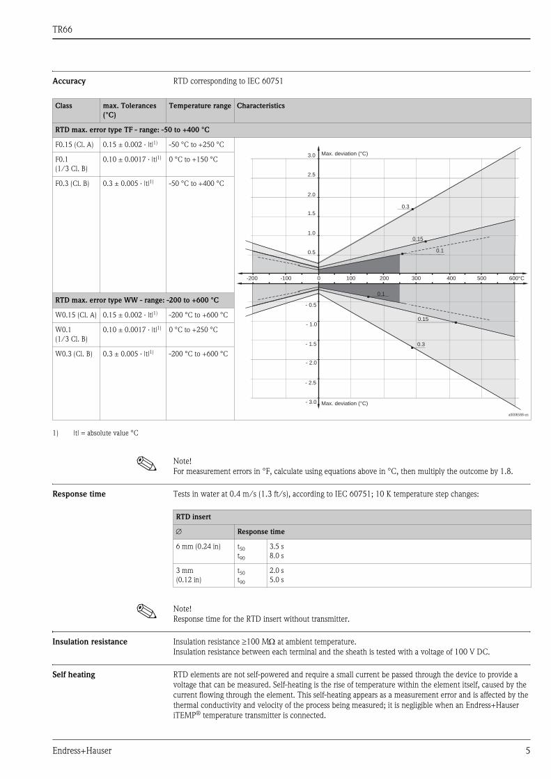
Accuracy RTD corresponding to IEC 60751
! Note!
For measurement errors in °F, calculate using equations above in °C, then multiply the outcome by 1.8.
Response time Tests in water at 0.4 m/s (1.3 ft/s), according to IEC 60751; 10 K temperature step changes:
! Note!
Response time for the RTD insert without transmitter.
Insulation resistance Insulation resistance ≥100 MΩ at ambient temperature.
Insulation resistance between each terminal and the sheath is tested with a voltage of 100 V DC.
Self heating RTD elements are not self-powered and require a small current be passed through the device to provide a
voltage that can be measured. Self-heating is the rise of temperature within the element itself, caused by the
current flowing through the element. This self-heating appears as a measurement error and is affected by the
thermal conductivity and velocity of the process being measured; it is negligible when an Endress+Hauser
iTEMP® temperature transmitter is connected.
Class max. Tolerances
(°C)
Temperature range Characteristics
RTD max. error type TF - range: -50 to +400 °C
F0.15 (Cl. A) 0.15 ± 0.002 · |t|1) -50 °C to +250 °C
a0008588-en
F0.1
(1/3 Cl. B)
0.10 ± 0.0017 · |t|1) 0 °C to +150 °C
F0.3 (Cl. B) 0.3 ± 0.005 · |t|1) -50 °C to +400 °C
RTD max. error type WW - range: -200 to +600 °C
W0.15 (Cl. A) 0.15 ± 0.002 · |t|1) -200 °C to +600 °C
W0.1
(1/3 Cl. B)
0.10 ± 0.0017 · |t|1) 0 °C to +250 °C
W0.3 (Cl. B) 0.3 ± 0.005 · |t|1) -200 °C to +600 °C
1) |t| = absolute value °C
0.15
0.1
-200 -100 0 100 200 300 400 500 600°C
0.5
1.0
1.5
2.0
0.3
2.5
3.0
- 0.5
- 1.0
- 1.5
- 2.0
- 2.5
- 3.0 Max. deviation (°C)
Max. deviation (°C)
0.3
0.15
0.1
RTD insert
∅ Response time
6 mm (0.24 in) t50
t90
3.5 s
8.0 s
3 mm
(0.12 in)
t50
t90
2.0 s
5.0 s

TR66
6 Endress+Hauser
Calibration specifications The manufacturer provides comparison temperature calibration from -80 to +600 °C (-110 °F to 1112 °F) on
the International Temperature Scale of 1990 (ITS90). Calibrations are traceable to national and international
standards. The calibration report is referenced to the serial number of the thermometer.
Material
Insert: Ø 6 mm (0.24) Minimum insertion length IL in mm (inch)
Temperature range without head transmitter with head transmitter
-80 °C to -40 °C (-110 °F to -40 °F) 200 (7.87)
-40 °C to 0 °C (-40 °F to 32 °F) 160 (6.3)
0 °C to 250 °C (32 °F to 480 °F) 120 (4.72) 150 (5.91)
250 °C to 550 °C (480 °F to 1020 °F) 300 (11.81)
550 °C to 650 °C (1020 °F to 1202 °F) 400 (15.75)
Insert: Ø 3 mm (0.12 in) Minimum insertion length IL in mm (inch)
Temperature range without head transmitter with head transmitter
-80 °C to -40 °C (-110 °F to -40 °F) 200 (7.87)
-40 °C to 0 °C (-40 °F to 32 °F) 160 (6.3)
0 °C to 150 °C (32 °F to 300 °F) 80 (3.15) 110 (4.33)
150 °C to 250 °C (300 °F to 480 °F) 110 (4.33) 140 (5.51)
250 °C to 550 °C (480 °F to 1020 °F) 300 (11.81)
550 °C to 650 °C (1020 °F to 1202 °F) 400 (15.75)
Material Short description max. application
temperature
Features and benefits
SS 316L/1.4404 X2CrNiMo 17 13 2 800 °C (1472 °F) • Austenitic, stainless steel
• High corrosion resistance
• High resistance at low temperatures
• Optimal corrosion resistance in an acid, non oxydizing environment
(e.g. phosphorous and sulphuric acids in low concentration and at low temperatures)
• Not resistant to chloride at high temperatures
SS 316Ti/1.4571 X6CrNiMoTi 17 12 2 800 °C (1472 °F) • Austenitic, stainless steel
• High corrosion resistance
• High resistance at low temperatures
• Optimal corrosion resistance in an acid, non oxydizing environment (e.g. phosphorous and
sulphuric acids in low concentration and at low temperatures)
• Not resistant to chloride at high temperatures
SS 316/1.4401 X5CrNiMo 17 12 2 800 °C (1472 °F) • Austenitic, stainless steel
• High corrosion resistance
• High resistance at low temperatures
• Optimal corrosion resistance in an acid, non oxydizing environment
(e.g. phosphorous and sulphuric acids in low concentration and at low temperatures)

TR66
Endress+Hauser 7
Transmitter specifications
Transmitter long-term
stability
≤ 0.1 °C/year (≤ 0.18 °F / year) or ≤ 0.05% / year
Data under reference conditions; % relates to the set span. The larger value applies.
System components
Family of temperature
transmitters
Measurement assemblies with iTEMP® transmitters are an installation ready solution to improve the
functionality of temperature measurement by increasing accuracy and reliability when compared to direct
wired sensors. Overall installation costs are lower than with direct wired sensors, since an inexpensive pair of
signal (4 to 20 mA) wires can be run over long distances.
PC programmable devices TMT180 and TMT181
PC programmable head transmitters offer you extreme flexibility and help control costs with the ability to stock
one device and program it for your needs. Regardless of your choice of output, all iTEMP® transmitters can be
configured quickly and easily with a PC. To help you with this task, Endress+Hauser offers free software
ReadWin® 2000 which can be downloaded from our website. Go to www.readwin2000.com to download
ReadWin® 2000 today. For details see Technical Information.
HART® TMT182 head transmitter
HART® communication is all about easy, reliable data access and getting better information more
inexpensively. iTEMP® transmitters integrate seamlessly into your existing control system and provide painless
access to preventative diagnostic information.
Configuration with a DXR275 or 375 hand-held or a PC with configuration program (FieldCare, ReadWin®
2000) or configure with AMS or PDM. For details, see Technical Information.
TMT180
PCP
Pt100
TMT181
PCP
Pt100, TC, Ω, mV
TMT182
HART®
Pt100, TC, Ω, mV
TMT84 PA / TMT85 FF
Pt100, TC, Ω, mV
Measurement accuracy 0.2 °C (0.36 °F), optional
0.1 °C (0.18 °F) or 0.08%
0.2 °C (0.36 °F) or 0.08% 0.1 °C (0.18 °F)
% is related to the adjusted measurement range (the larger value applies)
Sensor current Ι ≤ 0.6 mA Ι ≤ 0.2 mA Ι ≤ 0.3 mA
Galvanic isolation
(input/output)
- Û = 3.75 kV AC U = 2 kV AC
Type of transmitter Specification
iTEMP® TMT18x
R09-TMT182ZZ-06-06-xx-en-001
• Material: Housing (PC), Potting (PUR)
• Terminals: Cable up to max. max. ≤ 2.5 mm2 / 16 AWG (secure screws) or
with wire end ferrules
• Eyelets for easy connection of a HART®-handheld terminal with alligator
clips
• Degree of protection NEMA 4 (see also type of terminal head)
Details see Technical Information (see chapter ’Documentation’)

TR66
8 Endress+Hauser
PROFIBUS® PA TMT84 head transmitter
Universally programmable head transmitter with PROFIBUS® PA communication. Converting various input
signals into a digital output signal. High accuracy in the total ambient temperature range. Swift and easy
operation, visualization and maintenance using a PC direct from the control panel, e. g. using operating
software such as FieldCare, Simatic PDM or AMS. DIP switch for address setting, makes start up and
maintenance safe and reliable.
Benefits are: dual sensor input, highest reliability in harsh industrial environments, mathematic functions,
thermometer drift monitoring, sensor back-up functionality, sensor diagnosis functions and sensor-transmitter
matching by accepting Callendar Van Dusen constants. For details, see Technical Information.
! Note!
The previous model PROFIBUS® PA TMT184 head transmitter will be available for a transition time.
FOUNDATION Fieldbus™ TMT85 head transmitter
Universally programmable head transmitter with FOUNDATION fieldbus™ communication. Converting
various input signals into a digital output signal. High accuracy in the total ambient temperature range. Swift
and easy operation, visualization and maintenance using a PC direct from the control panel, e. g. using
operating software such as ControlCare from Endress+Hauser or the NI Configurator from National
Instruments.
Benefits are: dual sensor input, highest reliability in harsh industrial environments, mathematic functions,
thermometer drift monitoring, sensor back-up functionality, sensor diagnosis functions and sensor-transmitter
matching by accepting Callendar Van Dusen constants. For details, see Technical Information.
Terminal head Internal geometry according to DIN 43729, form B. It is compliant with EN 50014/18 and EN 50281-1-1
standards (EEx-d certification for explosion proof type of protection).
All dimensions in mm (inch).
Type of transmitter Specification
iTEMP® TMT84 and TMT85
a0007301-en
• Spring range L ≥ 5 mm (0.2"), see Pos. A
• Fixing elements for detachable measured value display, see Pos. B
• Interface for contacting measured value display, see Pos. C
• Material (RoHS-compliant)
Housing: PC
Potting: PU
• Terminals:
Screw terminals (cable up to max. ≤ 2.5 mm2 / 16 AWG)
or spring terminals (e. g. from 0.25 mm2 to 0.75 mm2/ 24 AWG to 18 AWG
for flexible wires with wire-end ferrules with plastic ferrule)
• Degree of protection NEMA 4 (see also type of terminal head)
Details see Technical Information (see chapter ’Documentation’)
A
C
24
.1(0
.95
”)
33
(1.3
”)
∅4
4(1
.73
”)
∅7
(0.2
8”)
∅5 (0.2”)
B
TA21H Specification
a0010194
• Protection class: IP66 to IP68
• Tapped hole spacing: 33 mm (1.30") for the measuring insert
• Max. temperature: 100 °C (212 °F) rubber
(observe max. permitted temperature of the cable gland!)
• Material: aluminum alloy; rubber seal under the cover
• Single or double threaded cable entry:
½" NPT, ¾" NPT, M20 or G½"
• Extension neck / thermowell connection:
M24x1.5, G½" or ½" NPT
• Head color: blue
• Cap color: grey
• Weight: 600 g (21.16 oz)

TR66
Endress+Hauser 9
Thermowell All dimensions in mm (inches).
a0010230
Dimensions of the Omnigrad S TR66
The thermowell is the component of the RTD assembly that must tolerate most of the mechanical stress
transmitted by the process. It is made from a round bar and supplied in different materials and dimensions,
according to the chemical/physical characteristics of the process: corrosion, temperature, pressure and speed
of the fluid.
The thermowell consists of three parts:
• The lag, usually with a cylindrical shape and standard diameters of 30 or 35 mm (1.18 or 1.38 in) and lengths
of 70/100 mm (2.76/3.94 in), represents the external part of the thermowell and is connected with the
terminal head by means of a neck (usually a nipple, type N or nipple-union-nipple, type NUN).
• The immersed part (identified as U), with a conical or cylindrical shape is situated next to the process
connection in direct contact with the process fluid. The standard diameter of the area below the fitting is 20
or 25 mm (0.79 or 0.98 in).
• The threaded or flanged process connection is the part inserted between the lag and the immersed part and
guarantees the mechanical and hydraulic sealing of the assembly and plant.
The external finishing of the thermowell stem is available with a standard value of Ra = 1.6 mm (different
finishes are available on request).
" Caution!
The total standard length (U + T) of the thermowell must never exceed 1200 mm (47.3 in), the maximum
drilling limit; higher lengths are available only on request.
1 Insert with mounted terminal block IL Insertion length = U + T + N + 41 mm (1.61 in)
2 Insert with head mounted transmitter N Extension neck length
3 Flying leads T Thermowell lag
∅ ID Insert diameter U Immersion length
A Thermowell length
∅ D1 Thermowell diameter at the thermometer connection ∅ Df Thermowell internal hole
∅ Q1 Thermowell external diameter at the flange or
thread connection
∅ Q2 Thermowell tip external diameter

TR66
10 Endress+Hauser
Weight From 1.5 to 5.5 kg (3.3 to 12.1 lbs) for standard options.
Process connection The standard process connections are threaded or flanged. When the process connection is threaded, the
connection material is the same as that of the thermowell.
On the other hand if the connection is flanged the materials can differ:
SS 316/1.4401or ASTM A105/St 52.3 U standard material.
On request, it is possible to also select different materials, finishings and connections.
Type and dimension of the process connections (ASME B16.5, ANSI B1.20.1). All dimensions in mm (inch).
Spare parts The measuring probe (generally Pt100) consists of a thermometric insert:
• TPR100 for general purpose and intrinsically safe model
• TPR300 for explosion-proof model
Both of the probes are made in mineral insulated cable (MgO), with a sheath in 316L/1.4401 stainless steel.
The insertion length (IL) of the insert can be chosen within a standard range from 50 to 1000 mm (1.97 to
39.4 in), see "Caution" on Page 9. Inserts with a insertion length IL > 1000 mm (39.4 in) can be supplied after
a technical verification of the specific application by our service organization.
When replacing the insert it is necessary to refer to the following table to obtain the correct insertion length IL
(applicable only to standard thickness well bottoms). It is calculated by adding the total thermowell length
(immersion lenght U + lag T) to the extension neck length (N) used.
Type Ø D1 Ø D2 Ø D3 Ø D4 No. of
holes
S1 S2 S3 A A1
a0010224
Flange 1” ANSI 150 RF SO1) -
50.8
(2)
107.9
(4.25)
15.9
(0.63)
4
1.6
(0.06)
17.5
(0.7)
- - -
1” ANSI 300 RF SO -
123.8
(4.9)
19.0
(0.75)
27.0
(1.1)
- - -
1” ANSI 600 RF SO - 6.4 - 27.0
(1.1)
- -
1½” ANSI 150 RF SO -
73
(2.9)
127 (5) 15.9
(0.63) 1.6
(0.06)
22.2
(0.9)
- - -
1½” ANSI 300 RF SO -
155.6
(6.1)
22.2
(0.85)
30.2
(1.2)
- - -
1½” ANSI 600 RF SO - 6.4
(0.25)
- 31.7
(1.25)
- -
2” ANSI 300 RF SO -
92.1
(3.6)
165.1
(6.5)
19.0
(0.75)8
1.6
(0.06)
33.3
(1.3)
- - -
2” ANSI 600 RF SO - 6.4
(0.25)
- 36.5
(1.44)
- -
Thread ½" NPT ≥ 21.4
(0.84)
- - - - - - - 19.9
(0.78)
8.1
(0.32)
¾" NPT ≥ 26.7
(1.1)
- - - - - - - 20.2
(0.79)
8.6
(0.34)
1) RF SO: Raised Face Slip On flange (flat flange with sealing face).
Insert model Ø Extension
neck type
Extension neck length N Insertion length IL
TPR100 / TPR3003 mm (0.12 in) or
6 mm (0.24 in)
N 69 mm (2.71 in)
IL = U+T+ N + 41 mm (1.61 in)N 109 mm (4.3 in)
NUN 148 mm (5.8 in)

TR66
Endress+Hauser 11
Wiring
Wiring diagrams Type of sensor connection
Installation conditions
Orientation No restrictions for installation orientation.
Head mounted transmitter TMT18x (single input)
T09-TH1112xx-04-xx-XX-ae-000
Head mounted transmitter TMT84 and TMT85 (dual input)
a0008848-en
Terminal block mounted
a0008591-en

TR66
12 Endress+Hauser
Installation instructions
a0010222-en
Installation examples
A - B: In pipes with a small cross section the thermowell tip should reach or extend slightly past the center line of the pipe
(= U).
C - D: Angled installation.
The immersion length of the thermometer influences the accuracy. If the immersion length is too small then
errors in the measurement are caused by heat conduction via the process connection and the container wall.
If installing into a pipe then the immersion length must be at least half of the pipe diameter.
For best installation follow the rule: h ~ d; U > D/2 + h. As far as corrosion is concerned, the base material for
parts in contact with the fluid is able to withstand the most common corrosive agents up to the highest
temperatures. For further information on specific applications, contact our service organization. Disassembled
components of the sensors must be reassembled with the recommended clamping torques in order to ensure
the appropriate IP protection class within the terminal head coupling.
! Note!
When operating in small nominal bore pipes it must be guaranteed that the thermowell tip is long enough to
go over the pipe centre line (see figure above, A and B). A further solution could be an angled (tilted) installation
(see figure above, C and D). When determining the immersion length all thermometer parameters and the
process to be measured must be taken into account (e.g. flow velocity, process pressure).
The counterparts for process connections and gaskets, when required, are not supplied with the sensor and
must be purchased separately.

TR66
Endress+Hauser 13
Extension neck length The extension neck is the part between the thermowell connection and the terminal head.
The connection situated in the upper part of the neck allows for orientation of the terminal head. The neck is
constituted by a tube assembled to hydraulic hardware (nipples or joints) that is suitable to allow the adjustment
of the sensor to the thermowell. In addition to the standard versions listed below, it is also possible to order the
extension neck by specifying the desired length (see “Product structure” at the end of this document). The
standard neck lengths N and the versions of the extension neck can be selected among the following options:
As illustrated in the following figure, the extension neck length may influence the temperature in the terminal
head. It is necessary that this temperature is kept within the limit values defined in the chapter "Operating
conditions".
a0008623-en
Heating of the terminal head consequent to the process temperature
Certificates and approvals
CE Mark The device meets the legal requirements of the EC directives if applicable. Endress+Hauser confirms that the
device has been successfully tested by applying the CE mark.
Hazardous area approvals For further details on the available Ex versions (ATEX, CSA, FM, etc.), please contact your nearest
Endress+Hauser sales organisation. All relevant data for hazardous areas can be found in separate Ex
documentation. If required, please request copies from us or your Endress+Hauser sales organisation.
Other standards and
guidelines
• IEC 60529:
Degrees of protection by housing (IP-Code).
• IEC 61010-1:
Safety requirements for electrical measurement, control and laboratory instrumentation.
• IEC 60751:
Neck version Material Neck length N Thread Thread length C
a0010216
N
SS 316 or A 105
69 mm (2.72 in)
½" NPT M 8 mm (0.31 in)
109 mm (4.3 in)
NUN 148 mm (5.83 in)

TR66
14 Endress+Hauser
• IEC 60751:
Industrial platinum resistance thermometer
• EN 50014/18:
Electrical apparatus for potentially explosive atmospheres - General requirements/flameproof enclosure ’d’
• EN 50281-1-1:
Electrical apparatus protected by enclosures
• IEC 61326-1:
Electromagnetic compatibility (EMC requirements)
PED approval The Pressure Equipment Directive (97/23/CE) is respected. As paragraph 2.1 of article 1 is not applicable to
these types of instruments, the CE mark is not requested for the RTD assembly destined for general use.
Material certification The material certificate 3.1 (according to standard EN 10204) can be requested separately. The "short form"
certificate includes a simplified declaration with no enclosures of documents related to the materials used in
the construction of the single sensor and guarantees the traceability of the materials through the identification
number of the thermometer. The data related to the origin of the materials can subsequently be requested by
the client if necessary.
Test on thermowell The pressure tests are carried out at ambient temperature in order to verify the resistance of the thermowell.
Tests at different pressures can be carried out upon request.
Test report and calibration The "Factory calibration" is carried out in an EA (European Accreditation) authorized laboratory of
Endress+Hauser according to an internal procedure. A calibration may be requested separately according to an
EA accredited procedure (SIT calibration). Calibration is carried out on the thermometer insert.
Ordering information
Product structure RTD thermometer TR66
Approval:
A Non-hazardous area
C ATEX II 1/2 GD EEx ia IIC
E ATEX II 2 GD EEx d IIC
H ATEX II 3 GD EEx nA II
K TIIS Ex ia IIC T4
L TIIS Ex ia IIC T6
M ATEX II 1/2 GD EEx d IIC
Head:
A TA21H Alu, IP66
Y Special version, to be specified
Cable Entry:
A 1x ½" NPT
B 2x ½" NPT
C 1x ¾" NPT
D 2x ¾" NPT
E 1x M20x1.5
F 2x M20x1.5
Y Special version, to be specified
Neck Length N; Material; Fitting:
B 69 mm; 316; N ½" NPT M
C 109 mm; 316; N ½"NPT M
E 148 mm; 316; N ½" NPT M
F 69 mm; A105; N ½" NPT M
G 109 mm; A105; N ½" NPT M
J 148 mm; A105; N ½" NPT M
Y ..... mm, as specified
Thermowell Material:
B 316Ti
C 316
D 316L
Y Special version, to be specified

TR66
Endress+Hauser 15
This ordering information can give an overview about the available order options. The Endress +Hauser sales
organization can provide detailed ordering information and information on the order code.
Extension T; D1; Df; Q1; Q2:
1 70 mm; 30 mm; 7 mm; 20 mm; 14 mm
2 75 mm; 35 mm; 7 mm; 24 mm; 14 mm
6 100 mm; 35 mm; 8 mm; 25 mm; 18 mm
9 .... mm, as specified
Immersion length U:
X .... mm
Y .... mm, as specified
Process Connection:
CA Flange 1" ANSI 150 RF SO; A105
CB Flange 1" ANSI 150 RF SO; B16.5;JPI; 316
CC Flange 1" ANSI 300 RF SO; A105
CD Flange 1" ANSI 300 RF SO; B16.5;JPI; 316
CE Flange 1" ANSI 600 RF SO; A105
CF Flange 1" ANSI 600 RF SO; 316
CG Flange 1½" ANSI 150 RF SO; A105
CH Flange 1½" ANSI 150 RF SO; B 16.5; JPI; 316
CJ Flange 1½" ANSI 300 RF SO; A105
CK Flange 1½" ANSI 300 RF SO; B 16.5; JPI; 316
CL Flange 1½" ANSI 600 RF SO; A105
CM Flange 1½" ANSI 600 RF SO; 316
CQ Flange 2" ANSI 300 RF SO; A105
CS Flange 2" ANSI 600 RF SO; A105
CT Flange 2" ANSI 600 RF SO; 316
CV Flange 2" ANSI 300 RF SO; 316
JA Flange 10K25A RF, JIS B 2220, 316
JB Flange 10K40A RF, JIS B 2220, 316
JC Flange 10K50A RF, JIS B 2220, 316
JD Flange 20K25A RF, JIS B 2220, 316
JE Flange 20K40A RF, JIS B 2220, 316
JF Flange 20K50A RF, JIS B 2220, 316
YY Special version, to be specified
11 Thread ¾" NPT-M
22 Thread 1" NPT-M
44 Thread R ¾", JIS B 0203, 316
Head Transmitter; Range:
B TMT84 PA
C Terminal block
D TMT85 FF
F Flying leads
G TMT181 (PCP); temp. range to be specified
H TMT182 (HART, SIL2); temp. range to be specified
2 TMT180-A21 fix; 0.2 K, temp. range to be specified, Span limit -200/650 °C
3 TMT180-A22 fix; 0.1 K, temp. range to be specified, Span limit -50/250 °C
4 TMT180-A11 PCP; 0.2 K, temp. range to be specified, Span limit -200/650 °C
5 TMT180-A12 PCP; 0.1 K, temp. range to be specified, Span limit -50/250 °C
RTD; wire; meas. range; class: validity:
A 1x Pt100 WW; 3; -200/600 °C; A: -200/600 °C
B 2x Pt100 WW; 4; -200/600 °C; A: -200/600 °C
C 1x Pt100 WW; 4; -200/600 °C; A: -200/600 °C
F 2x Pt100 WW; 3; -200/600 °C; 1/3B: 0/250 °C
G 1x Pt100 WW; 4; -200/600 °C; 1/3B: 0/250 °C
Y Special version, to be specified
2 1x Pt100 TF; 3; -50/400 °C; A: -50/250 °C
3 1x Pt100 TF; 4; -50/400 °C; A: -50/250 °C
6 1x Pt100 TF; 3; -50/400 °C; 1/3B: 0/150 °C
7 1x Pt100 TF; 4; -50/400 °C; 1/3B: 0/150 °C
Additional option:
Y Special version, to be specified
0 Not needed
TR66- ← Order code (complete)
TR66
Documentation
• Technical information Omnigrad TA20, TA21 Temperature Measuring Technology Terminal heads for
mounting on thermowells of resistance thermometers and thermocouples (TI072t/02/en)
• Technical information RTD Insert for Temperature Sensor omniset TPR100 (TI268t/02/en)
• Technical information Temperature head transmitter iTEMP® PCP TMT181 (TI070r/09/en)
• Technical information Temperature head transmitter iTEMP® Pt TMT180 (TI088r/09/en)
• Technical information Temperature head transmitter iTEMP® HART® TMT182 (TI078r/09/en)
• Technical information Temperature head transmitter iTEMP® PA TMT84 (TI138r/09/en)
• Technical information Temperature head transmitter iTEMP® TMT85 FF (TI134r/09/en)
• Hazardous area supplementary documentation:
RTD/TC Thermometer and inserts Omnigrad TRxx, TCxx, TSTxxx, TxCxxx
Omniset TPR100, TET10x, TPC100, TECxxx ATEX II1GD or II 1/2GD (XA072r/09/a3)
Omnigrad S TR/TC 6x Thermometer ATEX II1/2, 2GD or II2G EEx d IIC T5, T6 (XA014t/02/a3)
Application example: • Technical information Field display RIA261 (TI083r/09/en)
• Technical information Active barrier with power supply RN221N (TI073R/09/en)
Instruments International
Endress+HauserInstruments International AGKaegenstrasse 24153 ReinachSwitzerland
Tel. +41 61 715 81 00Fax +41 61 715 25 [email protected]
TI284T/02/en/07.08
71078770
FM+SGML 6.0 ProMoDo