technical information thermocouple thermometer omnigrad s ... · thermocouple thermometer omnigrad...
TRANSCRIPT
Technical InformationTI 277T/02/en60022269
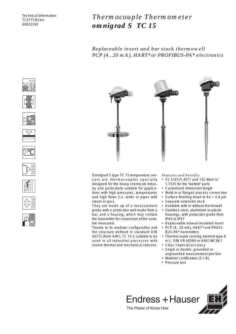
Thermocouple Thermometeromnigrad S -TC 15
Replaceable insert and bar stock thermowellPCP (4...20 mA), HART® or PROFIBUS-PA® electronics
Omnigrad S type TC 15 temperature sen-sors are thermocouples special lydesigned for the heavy chemicals indus-try and particularly suitable for applica-tions with high pressures, temperaturesand high flows (i.e. tanks or pipes withsteam or gas).They are made up of a measurementprobe with a protection well made from abar, and a housing, which may containthe transmitter for conversion of the varia-ble measured.Thanks to its modular configuration andthe structure defined in standard DIN43772 (form 4/4F), TC 15 is suitable to beused in all industrial processes withsevere thermal and mechanical stresses.
Features and benefits• SS 316Ti/1.4571 and 13CrMo4-5/
1.7335 for the "wetted" parts• Customized immersion length• Weld-in or flanged process connection• Surface finishing down to Ra < 0.8 µm• Separate extension neck• Available with or without thermowell• Stainless steel, aluminium or plastic
housings, with protection grade from IP65 to IP67
• Replaceable mineral insulated insert• PCP (4...20 mA), HART® and PROFI-
BUS-PA® transmitters• Thermocouple sensing element type K
or J, DIN EN 60584 or ANSI MC96.1• Class 1/special accuracy• Single or double, grounded or
ungrounded measurement junction• Material certification (3.1.B)• Pressure test
omnigrad M TC 15
2 Endress+Hauser
Areas of application
Heavy industrial processes and in particular applications where steam and gases are processedat high pressures and temperatures; for example those carried out in the following sectors:• chemical industry • energy industry.
Function and system design
Measuring principle The thermocouple thermometer’s sensing element consists of two metal wires that are homoge-neous but different one from the other and insulated along their entire length. The two wires arewelded together at one end, known as the “measurement or hot junction”. The other end, wherethe wires are free, is known as the “cold or reference junction” and is connected to a electromotiveforce measurement circuit where the force is generated by the different thermoelectric power ofeach of the thermocouple’s wires if there is a temperature difference between the hot joint (T1)and the cold joint (Seebeck effect). The cold junction has to be “compensated” with reference tothe temperature of 0°C (T0). The function that links the electromotive force to the temperatures T1and T0 is a curve whose characteristics depend on the materials used in the construction of thethermocouple. Some thermocouples curves, and particularly those most reliable for the purposesof industrial readings, are those compliant with standards DIN EN 60584 and ANSI MC96.1.
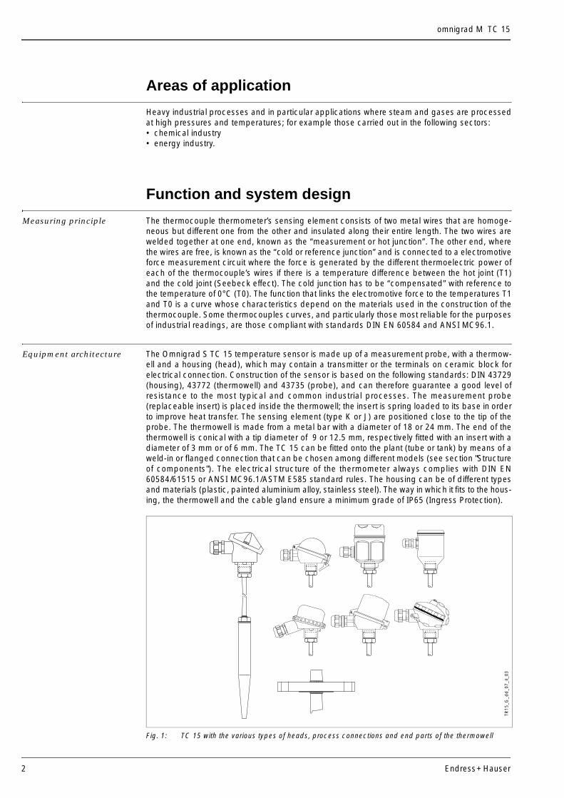
Equipment architecture The Omnigrad S TC 15 temperature sensor is made up of a measurement probe, with a thermow-ell and a housing (head), which may contain a transmitter or the terminals on ceramic block forelectrical connection. Construction of the sensor is based on the following standards: DIN 43729(housing), 43772 (thermowell) and 43735 (probe), and can therefore guarantee a good level ofresistance to the most typical and common industrial processes. The measurement probe(replaceable insert) is placed inside the thermowell; the insert is spring loaded to its base in orderto improve heat transfer. The sensing element (type K or J) are positioned close to the tip of theprobe. The thermowell is made from a metal bar with a diameter of 18 or 24 mm. The end of thethermowell is conical with a tip diameter of 9 or 12.5 mm, respectively fitted with an insert with adiameter of 3 mm or of 6 mm. The TC 15 can be fitted onto the plant (tube or tank) by means of aweld-in or flanged connection that can be chosen among different models (see section "Structureof components"). The electrical structure of the thermometer always complies with DIN EN60584/61515 or ANSI MC96.1/ASTM E585 standard rules. The housing can be of different typesand materials (plastic, painted aluminium alloy, stainless steel). The way in which it fits to the hous-ing, the thermowell and the cable gland ensure a minimum grade of IP65 (Ingress Protection).
Fig. 1: TC 15 with the various types of heads, process connections and end parts of the thermowell
TR15
_G_d
d_0
7_it_
03
omnigrad M TC 15
Endress+Hauser 3
Material Wetted parts in SS 316Ti/1.4571 or 13CrMo4-5/1.7335.
Weight From 1 to 5 kg for standard options.
Electronics
The required type of output signal can be obtained by choosing the correct head-mounted trans-mitter. Endress+Hauser supplies “state-of-the-art” transmitters (the iTEMP® series) built in 2-wire tech-nology and with 4…20 mA output signal, HART® or PROFIBUS-PA®. All of the transmitters can beeasily programmed using a personal computer through the ReadWin® 2000 and FieldCare publicdomain softwares (for transmitters 4…20 mA and HART®), or the CommuWin II software (forPROFIBUS PA® transmitters). The HART® transmitters can also be programmed with the hand-held operating module DXR 275 (Universal HART® Communicator). In the case of PROFIBUS-PA® transmitters, E+H recommends the use of PROFIBUS® dedicatedconnectors. The Weidmüller type (Pg 13.5 - M12) is provided as a standard option. For detailedinformation about transmitters, please refer to the relevant documentation (refer to TI codes at theend of the document). If a head-mounted transmitter is not employed, the sensor probe may be connected through theterminal block to a remote converter (i.e. DIN rail transmitter).
Performance
Operating conditions Ambient temperature (housing without head-mounted transmitter)• metal housings -40÷130°C• plastic housings -40÷85°C
Ambient temperature (housing with head-mounted transmitter) -40÷85°CAmbient temperature (housing with display) -20÷70°C
Process temperatureIt is restricted by the thermowell material:• SS 316 Ti/1.4571 < 800°C• 13CrMo4-5/1.7335 < 800°C.
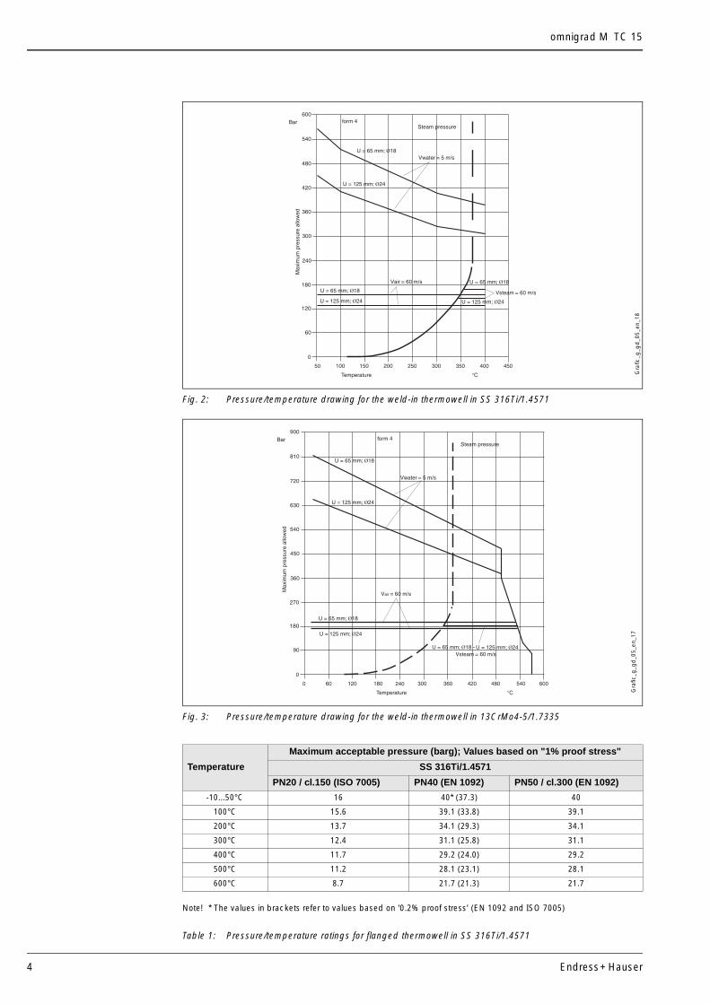
Maximum process pressureThe pressure values to which the thermowell can be subjected at the various temperatures areillustrated by the drawings in figures 2 and 3 and by table 1.
Maximum flow velocityThe highest flow velocity tolerated by the thermowell diminishes with increasing lengths of thewell/probe exposed to the stream of the fluid. Some information can be acquired from the drawingin figure 2.
Shock and vibration resistanceAccording to DIN EN 60751 3 g peak / 10÷500 Hz
omnigrad M TC 15
4 Endress+Hauser
Fig. 2: Pressure/temperature drawing for the weld-in thermowell in SS 316Ti/1.4571
Fig. 3: Pressure/temperature drawing for the weld-in thermowell in 13CrMo4-5/1.7335
Note! * The values in brackets refer to values based on '0.2% proof stress’ (EN 1092 and ISO 7005)
Table 1: Pressure/temperature ratings for flanged thermowell in SS 316Ti/1.4571
Temperature
Maximum acceptable pressure (barg); Values based on "1% proof stress"
SS 316Ti/1.4571
PN20 / cl.150 (ISO 7005) PN40 (EN 1092) PN50 / cl.300 (EN 1092)
-10...50°C 16 40* (37.3) 40
100°C 15.6 39.1 (33.8) 39.1
200°C 13.7 34.1 (29.3) 34.1
300°C 12.4 31.1 (25.8) 31.1
400°C 11.7 29.2 (24.0) 29.2
500°C 11.2 28.1 (23.1) 28.1
600°C 8.7 21.7 (21.3) 21.7
Gra
fic_g
_gd
_05_
en_1
8G
rafic
_g_g
d_0
5_en
_17
omnigrad M TC 15
Endress+Hauser 5
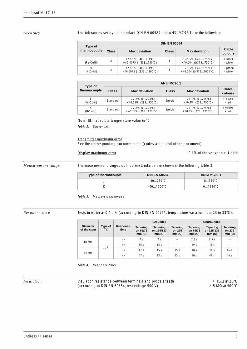
Accuracy The tolerances set by the standard DIN EN 60584 and ANSI MC96.1 are the following:
Note! ItI = absolute temperature value in °C
Table 2: Tolerances
Transmitter maximum errorSee the corresponding documentation (codes at the end of the document).
Display maximum error 0.1% of the set span + 1 digit
Measurement range The measurement ranges defined in standards are shown in the following table 3:
Table 3: Measurement ranges
Response time Tests in water at 0.4 m/s (according to DIN EN 60751; temperature variation from 23 to 33°C):
Table 4: Response times
Insulation Insulation resistance between terminals and probe sheath > 1GΩ at 25°C(according to DIN EN 60584, test voltage 500 V) > 5 MΩ at 500°C
Type of thermocouple
DIN EN 60584
Class Max deviation Class Max deviationCable
colours
J(Fe-CuNi)
2+/-2.5°C (-40...333°C)
+/-0.0075 |t| (333...750°C)1
+/-1.5°C (-40...375°C)+/-0.004 |t| (375...750°C)
+ black- white
K(NiCr-Ni)
2+/-2.5°C (-40...333°C)
+/-0.0075 |t| (333...1200°C)1
+/-1.5°C (-40...375°C)+/-0.004 |t| (375...1000°C)
+ green- white
Type of thermocouple
ANSI MC96.1
Class Max deviation Class Max deviationCable
colours
J(Fe-CuNi)
Standard+/-2.2°C (0...293°C)
+/-0.75%o(293...750°C)Special
+/-1.1°C (0...275°C)+/-0.4%o(275...750°C)
+ black- red
K(NiCr-Ni)
Standard+/-2.2°C (0...293°C)
+/-0.75%o(293...1250°C)Special
+/-1.1°C (0...275°C)+/-0.4%o(275...1250°C)
+ yellow- red
Type of thermocouple DIN EN 60584 ANSI MC96.1
J -40...750°C 0...750°C
K -40...1200°C 0...1250°C
Diameter of the stem
Type of TC
Response time
Grounded Ungrounded
Tapering on 65/73mm (U)
Tapering on 125/133
mm (U)
Tapering on 275 mm (U)
Tapering on 65/73mm (U)
Tapering on 125/133
mm (U)
Tapering on 275 mm (U)
18 mm
J, K
t50 7 s 7 s -- 7.5 s 7.5 s --
t90 18 s 18 s -- 19 s 19 s --
24 mmt50 17 s 15 s 15 s 18 s 16 s 16 s
t90 47 s 43 s 43 s 50 s 46 s 46 s
omnigrad M TC 15
6 Endress+Hauser
Installation
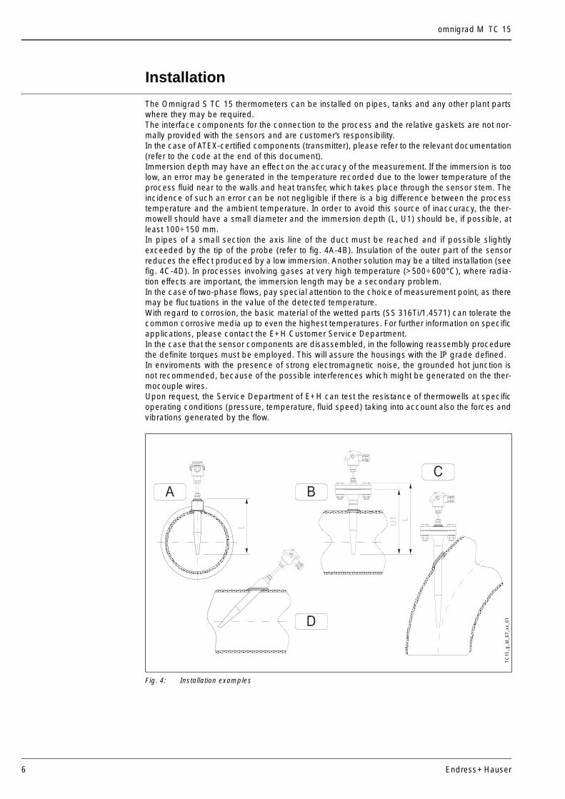
The Omnigrad S TC 15 thermometers can be installed on pipes, tanks and any other plant partswhere they may be required.The interface components for the connection to the process and the relative gaskets are not nor-mally provided with the sensors and are customer’s responsibility. In the case of ATEX-certified components (transmitter), please refer to the relevant documentation(refer to the code at the end of this document). Immersion depth may have an effect on the accuracy of the measurement. If the immersion is toolow, an error may be generated in the temperature recorded due to the lower temperature of theprocess fluid near to the walls and heat transfer, which takes place through the sensor stem. Theincidence of such an error can be not negligible if there is a big difference between the processtemperature and the ambient temperature. In order to avoid this source of inaccuracy, the ther-mowell should have a small diameter and the immersion depth (L, U1) should be, if possible, atleast 100÷150 mm.In pipes of a small section the axis line of the duct must be reached and if possible slightlyexceeded by the tip of the probe (refer to fig. 4A-4B). Insulation of the outer part of the sensorreduces the effect produced by a low immersion. Another solution may be a tilted installation (seefig. 4C-4D). In processes involving gases at very high temperature (>500÷600°C), where radia-tion effects are important, the immersion length may be a secondary problem.In the case of two-phase flows, pay special attention to the choice of measurement point, as theremay be fluctuations in the value of the detected temperature.With regard to corrosion, the basic material of the wetted parts (SS 316Ti/1.4571) can tolerate thecommon corrosive media up to even the highest temperatures. For further information on specificapplications, please contact the E+H Customer Service Department.In the case that the sensor components are disassembled, in the following reassembly procedurethe definite torques must be employed. This will assure the housings with the IP grade defined. In enviroments with the presence of strong electromagnetic noise, the grounded hot junction isnot recommended, because of the possible interferences which might be generated on the ther-mocouple wires.Upon request, the Service Department of E+H can test the resistance of thermowells at specificoperating conditions (pressure, temperature, fluid speed) taking into account also the forces andvibrations generated by the flow.
Fig. 4: Installation examples
aaaaaaaaaaaaaaaa
aaaaaa
aaaaaa
aaaaaaaaaaaaaaaaaaaaaaaaaa
aaaaaaaaaaaaaaaaaa
aaaaaaaaaaaaaaaaaaaaaaaaaaaaaaaaaaaaaaaaaaaaaaaaaaaaaaaaaaaaaaaaaaaaaa
TC15
_g_i
d_0
7_xx
_01
omnigrad M TC 15
Endress+Hauser 7
System components
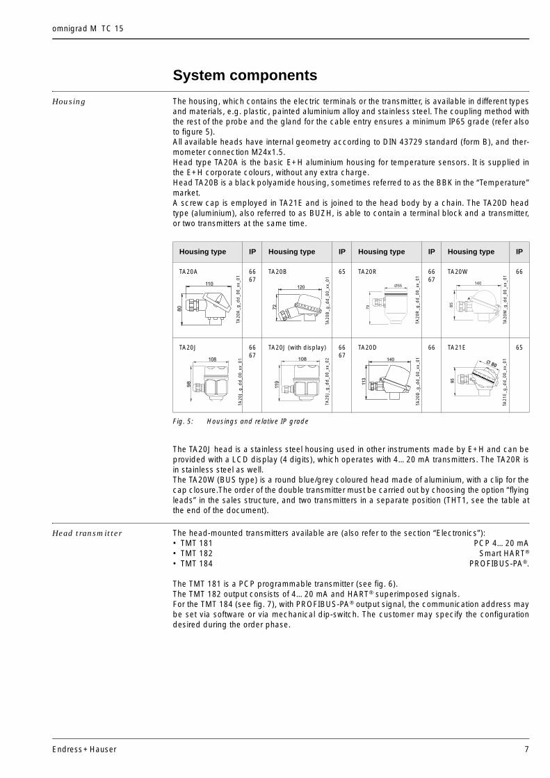
Housing The housing, which contains the electric terminals or the transmitter, is available in different typesand materials, e.g. plastic, painted aluminium alloy and stainless steel. The coupling method withthe rest of the probe and the gland for the cable entry ensures a minimum IP65 grade (refer alsoto figure 5).All available heads have internal geometry according to DIN 43729 standard (form B), and ther-mometer connection M24x1.5.Head type TA20A is the basic E+H aluminium housing for temperature sensors. It is supplied inthe E+H corporate colours, without any extra charge. Head TA20B is a black polyamide housing, sometimes referred to as the BBK in the “Temperature”market. A screw cap is employed in TA21E and is joined to the head body by a chain. The TA20D headtype (aluminium), also referred to as BUZH, is able to contain a terminal block and a transmitter,or two transmitters at the same time.
Fig. 5: Housings and relative IP grade
The TA20J head is a stainless steel housing used in other instruments made by E+H and can beprovided with a LCD display (4 digits), which operates with 4…20 mA transmitters. The TA20R isin stainless steel as well. The TA20W (BUS type) is a round blue/grey coloured head made of aluminium, with a clip for thecap closure.The order of the double transmitter must be carried out by choosing the option “flyingleads” in the sales structure, and two transmitters in a separate position (THT1, see the table atthe end of the document).
Head transmitter The head-mounted transmitters available are (also refer to the section “Electronics”):• TMT 181 PCP 4…20 mA• TMT 182 Smart HART®
• TMT 184 PROFIBUS-PA®.
The TMT 181 is a PCP programmable transmitter (see fig. 6).The TMT 182 output consists of 4…20 mA and HART® superimposed signals.For the TMT 184 (see fig. 7), with PROFIBUS-PA® output signal, the communication address maybe set via software or via mechanical dip-switch. The customer may specify the configurationdesired during the order phase.
Housing type IP Housing type IP Housing type IP Housing type IP
TA20A 6667
TA20B 65 TA20R 6667
TA20W 66
TA20J 6667
TA20J (with display) 6667
TA20D 66 TA21E 65
80
110
72
120
79
Ø55
85
140
98
108
119
10811
3140
95
Ø80
TA20
A_g
_dd
_00_
xx_0
1
TA20
B_g
_dd
_00_
xx_0
1
TA20
J_g
_dd
_00_
xx_0
1
TA20
J_g
_dd
_00_
xx_0
2
TA20
R_g
_dd
_00_
xx_0
1
TA20
W_g
_dd
_00_
xx_0
1TA
21E
_g_d
d_0
0_xx
_01
TA20
D_g
_dd
_00_
xx_0
1
omnigrad M TC 15
8 Endress+Hauser
Fig. 6: TMT 181-182
Fig. 7: TMT 184
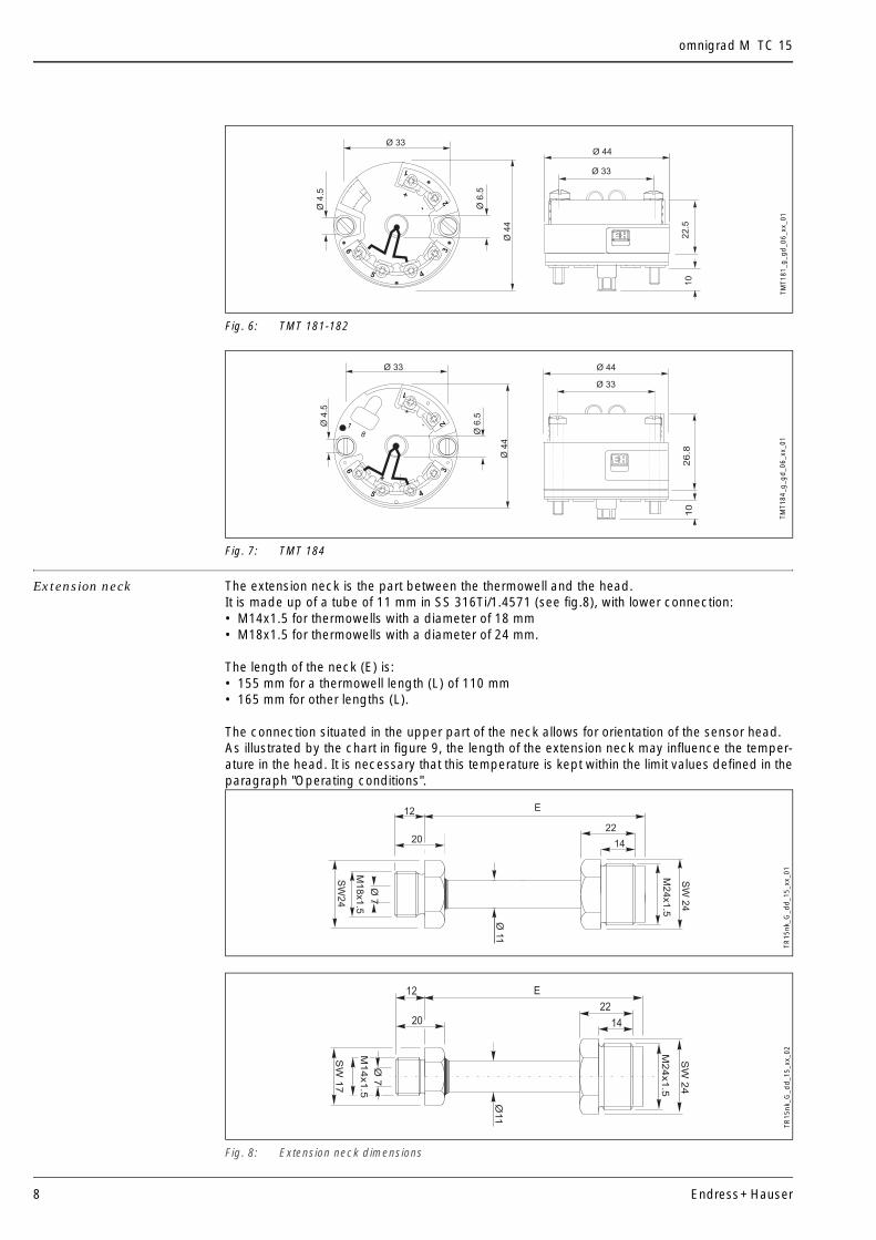
Extension neck The extension neck is the part between the thermowell and the head.It is made up of a tube of 11 mm in SS 316Ti/1.4571 (see fig.8), with lower connection: • M14x1.5 for thermowells with a diameter of 18 mm• M18x1.5 for thermowells with a diameter of 24 mm.
The length of the neck (E) is:• 155 mm for a thermowell length (L) of 110 mm• 165 mm for other lengths (L).
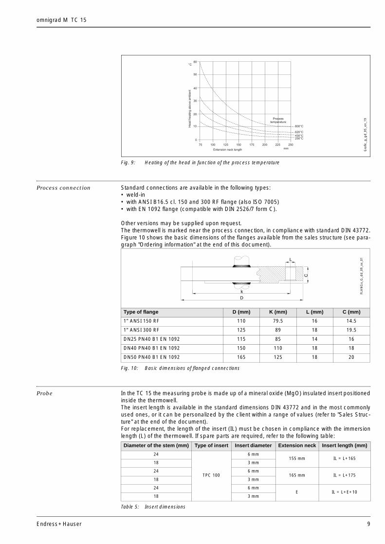
The connection situated in the upper part of the neck allows for orientation of the sensor head.As illustrated by the chart in figure 9, the length of the extension neck may influence the temper-ature in the head. It is necessary that this temperature is kept within the limit values defined in theparagraph "Operating conditions".
Fig. 8: Extension neck dimensions
6
5 4
32
1
-
+
10
22.5
Ø4
.5
Ø 33
Ø6
.5
Ø4
4
Ø 44
Ø 33
TMT1
81_g
_gd
_06_
xx_0
1
Ø4
.5
Ø4
4
Ø 33
Ø6
.5
6
5 4
32
1
-
+
18
-+
26
.8
Ø 33
10
Ø 44
TMT1
84_g
_gd
_06_
xx_0
1
Ø11
M1
8x1
.5
SW
24
Ø7
20
12 E
22
14
SW
24
M2
4x1
.5
TR15
nk_G
_dd
_15_
xx_0
1
SW
24
M24x1.5
20
12
14
22
SW
17
M14x1.5
Ø7
Ø11
E
TR15
nk_G
_dd
_15_
xx_0
2
omnigrad M TC 15
Endress+Hauser 9
Fig. 9: Heating of the head in function of the process temperature
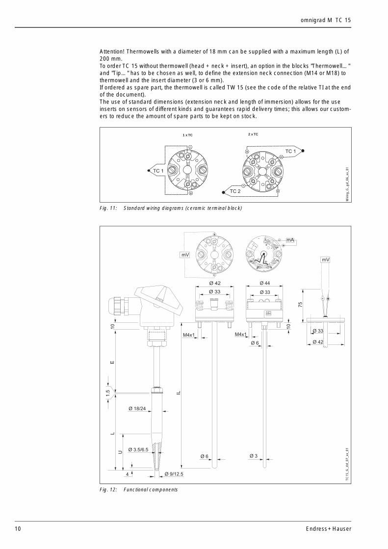
Process connection Standard connections are available in the following types:• weld-in• with ANSI B16.5 cl. 150 and 300 RF flange (also ISO 7005)• with EN 1092 flange (compatible with DIN 2526/7 form C).
Other versions may be supplied upon request.The thermowell is marked near the process connection, in compliance with standard DIN 43772.Figure 10 shows the basic dimensions of the flanges available from the sales structure (see para-graph "Ordering information" at the end of this document).
Fig. 10: Basic dimensions of flanged connections
Probe In the TC 15 the measuring probe is made up of a mineral oxide (MgO) insulated insert positionedinside the thermowell. The insert length is available in the standard dimensions DIN 43772 and in the most commonlyused ones, or it can be personalized by the client within a range of values (refer to "Sales Struc-ture" at the end of the document).For replacement, the length of the insert (IL) must be chosen in compliance with the immersionlength (L) of the thermowell. If spare parts are required, refer to the following table:
Table 5: Insert dimensions
10
20
30
40
°C
0
100 125 150 175 20075
mmExtension neck length
He
ad
he
atin
ga
bo
ve
am
bie
nt
430°C250°C
50
60
Processtemperature
225 250
620°C
800°C
Gra
fic_g
_gd
_05_
en_1
9
Type of flange D (mm) K (mm) L (mm) C (mm)
1” ANSI 150 RF 110 79.5 16 14.5
1” ANSI 300 RF 125 89 18 19.5
DN25 PN40 B1 EN 1092 115 85 14 16
DN40 PN40 B1 EN 1092 150 110 18 18
DN50 PN40 B1 EN 1092 165 125 18 20
C
D
k
L
FLA
NG
x_G
_dd
_09_
xx_0
1
Diameter of the stem (mm) Type of insert Insert diameter Extension neck Insert length (mm)
24
TPC 100
6 mm155 mm IL = L+165
18 3 mm
24 6 mm165 mm IL = L+175
18 3 mm
24 6 mmE IL = L+E+10
18 3 mm
omnigrad M TC 15
10 Endress+Hauser
Attention! Thermowells with a diameter of 18 mm can be supplied with a maximum length (L) of 200 mm.To order TC 15 without thermowell (head + neck + insert), an option in the blocks "Thermowell…" and "Tip…" has to be chosen as well, to define the extension neck connection (M14 or M18) to thermowell and the insert diameter (3 or 6 mm).If ordered as spare part, the thermowell is called TW 15 (see the code of the relative TI at the endof the document).The use of standard dimensions (extension neck and length of immersion) allows for the use inserts on sensors of different kinds and guarantees rapid delivery times; this allows our custom-ers to reduce the amount of spare parts to be kept on stock.
Fig. 11: Standard wiring diagrams (ceramic terminal block)
Fig. 12: Functional components
1 x TC 2 x TC
+-
TC 1
+
TC 1
TC 2 +
-
-
Wiri
ng_G
_gd
_06_
xx_0
1
M4x1
Ø 33
Ø 6
10
75
Ø 33
Ø 42
Ø 44
6
5 4
32
1
-
+
-
+
Ø 42
mV
mA
-+
- +
-
+
mV
Ø 33
Ø 6
M4x1
Ø 3
10
LE
1.5
Ø 18/24
U
Ø 9/12.54
Ø 3.5/6.5
aaaaaaaaaaaaaaaaaa a a a a a a a a
IL
TC15
_G_d
d_0
7_xx
_01
omnigrad M TC 15
Endress+Hauser 11
Certificates & Approvals
PED approval The Pressure Equipment Directive (97/23/CE) is respected. As paragraph 2.1 of article 1 is notapplicable to these types of instruments, the 4 mark is not requested for the TC 15 destined forgeneral use.
Material certification The material certificate 3.1.B (according to standard EN 10204) can be directly selected from thesales structure of the product and refers to the parts of the sensor in contact with the process fluid.Other types of certificates related to materials can be requested separately.The “short form” certificate includes a semplified declaration with no enclosures of documentsrelated to the materials used in the construction of the single sensor and guarantees the tracea-bility of the materials through the identification number of the thermometer. The data related to theorigin of the materials can subsequently be requested by the client if necessary.
Test on thermowell The pressure tests are carried out at ambient temperature in order to verify the resistance of thethermowell to the specifications indicated by the norm DIN 43772. With regards to the thermowellsthat do not comply with this norm (with a reduced tip, a tapered tip on a 9 mm tube, special dimen-sions, ...), the pressure of the corresponding straight tube with similar dimensions is verified. Testsat different pressures can be carried out upon request.The liquid penetrant test verifies the absence of crevices on the weldings of the thermowell.
Further details
Maintenance The Omnigrad S thermometers do not require any specific maintenance. In the case of ATEX certified components (transmitter) please refer to the corresponding specificrelevant documentation (refer to the code at the end of the document).
Delivery time For small quantities (10÷15 units) and standard options, between 10 and 15 days depending onthe configuration required.
omnigrad M TC 15
12 Endress+Hauser
Ordering information
Sales structure TC15- Safety (Ex) certification A No Ex certificate required
Selection of combination1 Complete assembly2 Thermometer without thermowell with extension neck
Housing material, cable entry, IP gradeA TA20A Aluminium, conduit M20x1.5, IP66/IP674 TA20A Aluminium, PROFIBUS® connector, IP662 TA20A Aluminium, conduit 1/2” NPT, IP66/IP677 TA20B Polyamide, black, conduit M20x1.5, IP65E TA21E Aluminium, screw cap, M20x1.5, IP656 TA20D Aluminium, high cap, conduit M20x1.5,IP665 TA20D Aluminium, high cap, PROFIBUS® connector, IP668 TA20D Aluminium, high cap, conduit 1/2” NPT, IP66J TA20J SS 316L, conduit M20x1.5, IP66/IP67K TA20J SS 316L, with display, conduit M20x1.5, IP66/IP67M TA20J SS 316L, PROFIBUS® connector, IP66R TA20R SS 316L, screw cap, conduit M20x1.5, IP66/IP67S TA20R SS 316L, screw cap, PROFIBUS® connector, IP66W TA20W Aluminium, round cap, clip, conduit M20x1.5, IP66Y Special version
Neck length E (60-250mm) SS 316Ti/1.45711 155 mm extension neck E (only L = 110 mm)2 165 mm extension neck E 8 ... mm extension neck E to specify9 ... mm special neck length E
Thermowell diam. D, D1 and d, material finishing Ra < 1.6 µm0 Without thermowell, only insetA D = 24 mm, SS 316Ti/1.4571, Ra <=1.6 µmB D = 24 mm, 13CrMo4-5/1.7335, Ra <=1.6 µmC D = 18 mm, SS 316Ti/1.4571, Ra <=1.6 µmD D = 18 mm, 13CrMo4-5/1.7335, Ra <=1.6 µm1 D = 24 mm, SS 316Ti/1.4571, Ra <=0.8 µm2 D = 18 mm, SS 316Ti/1.4571, Ra <=0.8 µmY Special version
Tip diameter D1, bore diameter d1 D1=12.5 mm, d=6.5 mm, (6 mm insert), (M18x1.5 neck/thermowell connection)2 D1=9 mm, d=3.5 mm, (3 mm inset), (M14x1.5 neck/thermowell connection)
Lengths L, U, U1 (100-1000 mm)A 110 mm= L, U=65 mm, U1=0 mm; form 4B 110 mm= L, U=73 mm, U1=0 mm; form 4C 140 mm= L, U=65 mm, U1=0 mm; form 4D 170 mm= L, U=133 mm, U1=0 mm; form 4E 200 mm= L, U=125 mm, U1=0 mm; form 4F 200 mm= L, U=65 mm, U1=130 mm; form 4FG 260 mm= L, U=125 mm, U1=190 mm; form 4FH 410 mm= L, U=275 mm, U1=340 mm; form 4FJ 200 mm= L, U=65 mm, U1=0 mm; form 4K 260 mm= L, U=125 mm, U1=0 mm; form 4Y ... Special length L= ..., U= ..., U1= ..., on request
Flange type, std. finishing Ra 3.2-6.4 µm0 No flange selected (weld-in connection)1 1” ANSI 150 RF flange SS 316Ti (DN25 PN20 B ISO 7005)2 1” ANSI 300 RF flange SS 316Ti (DN25 PN50 B ISO 7005)A DN25 PN40 B1 EN 1092 flange SS 316Ti (DIN 2526/7 form C)B DN40 PN40 B1 EN 1092 flange SS 316Ti (DIN 2526/7 form C)C DN50 PN40 B1 EN 1092 flange SS 316Ti (DIN 2526/7 form C)Y Special version
Terminal type or built-in trasmitterF Flying leadsC Ceramic terminal blockP TMT181-A, programmable from … to …°C, PCP, 2-wire, isolatedQ TMT181-B, programmable from … to …°C, PCP ATEX, 2-wire, isolatedR TMT182-A, programmable from ... to ...°C, HART®, 2-wire, isolated
omnigrad M TC 15
Endress+Hauser 13
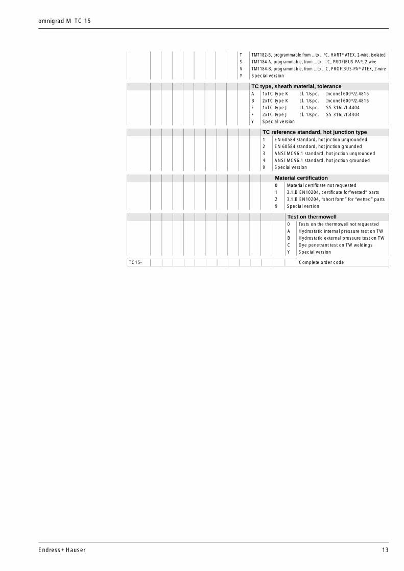
T TMT182-B, programmable from ...to ...°C, HART® ATEX, 2-wire, isolatedS TMT184-A, programmable, from ...to ...°C, PROFIBUS-PA®, 2-wireV TMT184-B, programmable, from ...to ...C, PROFIBUS-PA® ATEX, 2-wireY Special version
TC type, sheath material, toleranceA 1xTC type K cl. 1/spc. Inconel 600®/2.4816B 2xTC type K cl. 1/spc. Inconel 600®/2.4816E 1xTC type J cl. 1/spc. SS 316L/1.4404F 2xTC type J cl. 1/spc. SS 316L/1.4404Y Special version
TC reference standard, hot junction type1 EN 60584 standard, hot jnction ungrounded2 EN 60584 standard, hot jnction grounded3 ANSI MC96.1 standard, hot jnction ungrounded4 ANSI MC96.1 standard, hot jnction grounded9 Special version
Material certification0 Material certificate not requested 1 3.1.B EN10204, certificate for”wetted” parts2 3.1.B EN10204, “short form” for “wetted” parts 9 Special version
Test on thermowell0 Tests on the thermowell not requested A Hydrostatic internal pressure test on TWB Hydrostatic external pressure test on TWC Dye penetrant test on TW weldingsY Special version
TC15- Complete order code
omnigrad M TC 15
14 Endress+Hauser
Sales structure THT1 Model and version of the head transmitterF11 TMT181-A PCP 2-wire, isolated programmable from...to...°C
F21 TMT181-B PCP ATEX 2-wire, isolated programmable from...to...°C
F22 TMT181-C PCP FM IS 2-wire, isolated programmable from...to...°C
F23 TMT181-D PCP CSA 2-wire, isolated programmable from...to...°C
F24 TMT181-E PCP ATEX II3G EEx-nA 2-wire, isolated programmable from...to...°C
F25 TMT181-F PCP ATEX II3D 2-wire, isolated programmable from...to...°C
L11 TMT182-A HART® 2-wire, isolated programmable from...to...°C
L21 TMT182-B HART® ATEX 2-wire, isolated programmable from...to...°C
L22 TMT182-C HART® FM IS 2-wire, isolated programmable from...to...°C
L23 TMT182-D HART® CSA 2-wire, isolated programmable from...to...°C
L24 TMT182-E HART® ATEX II3G EEx-nA 2-wire, isolated programmable from...to...°C
L25 TMT182-F HART® ATEX II3D 2-wire, isolated programmable from...to...°C
K11 TMT184-A PROFIBUS-PA® 2-wire, isolated programmable from...to...°C
K21 TMT184-B PROFIBUS-PA® ATEX 2-wire, isolated programmable from...to...°C
K22 TMT184-C PROFIBUS-PA® FM IS 2-wire, isolated programmable from...to...°C
K23 TMT184-D PROFIBUS-PA® CSA 2-wire, isolated programmable from...to...°C
K24 TMT184-E PROFIBUS-PA® ATEX II3G EEx-nA 2-wire, isolated programmable from...to...°C
K25 TMT184-F PROFIBUS-PA® ATEX II3D 2-wire, isolated programmable from...to...°C
YYY Special transmitter
Application and services1 Assembled into position
9 Special version
THT1- Complete order code
omnigrad M TC 15
Endress+Hauser 15
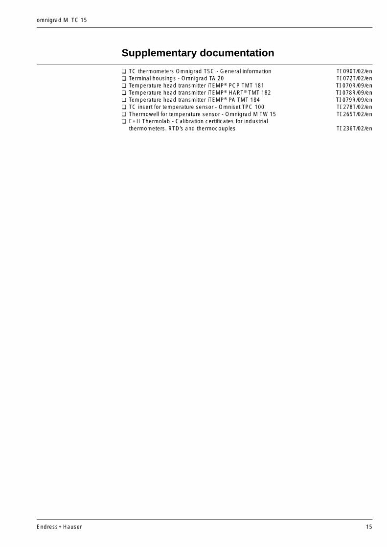
Supplementary documentation
TC thermometers Omnigrad TSC - General information TI 090T/02/en Terminal housings - Omnigrad TA 20 TI 072T/02/en Temperature head transmitter iTEMP® PCP TMT 181 TI 070R/09/en Temperature head transmitter iTEMP® HART® TMT 182 TI 078R/09/en Temperature head transmitter iTEMP® PA TMT 184 TI 079R/09/en TC insert for temperature sensor - Omniset TPC 100 TI 278T/02/en Thermowell for temperature sensor - Omnigrad M TW 15 TI 265T/02/en E+H Thermolab - Calibration certificates for industrial
thermometers. RTD’s and thermocouples TI 236T/02/en
Endress+Hauser GmbH+Co. KGInstruments InternationalP.O. Box 2222D-79574 Weil am RheinGermany
Tel. +49 7621 975 02Fax +49 7621 975 345http://[email protected]
cl/02
Subject to modification
TI 277T/02/en/02.0460022269FM+SGML 6.0