newsletter - mine closure 2016mineclosure2016.com/.../2014/12/newsletter_31_final_sm.pdfaustralian...
TRANSCRIPT

A U S T R A L I A N C E N T R E F O R G E O M E C H A N I C S V o l u m e N o . 3 1 D e c e m b e r 2 0 0 8
NEWSLETTER
The views expressed in this newsletter are those of the authors and may not necessarily reflect those of the Australian Centre for Geomechanics.
Continued page 2
Rock mechanics challenges in underground construction and mining
IntroductionIn mining, going deeper, increasing safety
standards, and aiming for high productivity demands engineering to maximise value. Lack of engineering for constructability when tunnelling in weak or brittle rock at depth often leads to unnecessary delays and extra costs. Furthermore, brittle failing rock at depth poses unique problems as stress-driven failure processes often dominate the tunnel behaviour. Such failure processes can lead to shallow unravelling or to strainbursting modes of instability that cause difficult conditions for tunnel contractors or difficult tunnelling conditions.
This paper, presented at ACG’s First Southern Hemisphere International Rock Mechanics Symposium (SHIRMS) summarises
lessons learned during the construction of deep Alpine tunnels and highlights implications that are of practical importance with respect to constructability. Special attention is given to issues of rock behaviour identification and to the selection of appropriate rock properties for underground construction in brittle failing ground. In the following pages some extracted highlights are presented.
• Challenges and opportunitiesInnovative solutions to overcome
related challenges offer opportunities for huge economic gains. For example, to go underground, one major mining company alone has to sink four to five shafts and advance on average between 50 and 80 km of
At Mine Closure 2009, attendees will exchange views and expertise with their peers practicing the diverse range of disciplines involved in mine closure activities: geotechnical, environmental, social, financial and regulatory.
Abstracts are due 16 February 2009.
www.mineclosure2009.com
9–11 September 2009Perth, Western Australia
Fourth International Conference
on Mine Closure
IN THIS EDITION • Rock mechanics challenges, Page 1• Heap leach materials, Page 7• Paste backfill, Page 10• Jarrah forest restoration, Page 14• Mine seismicity, Page 16• Rock stress measurements, Page 18• Deep mining, Page 21• Paste 2009, Page 24• ACG event schedule, Page 28
by Peter Kaiser, Centre for Excellence in Mining Innovation, Canada, and Bo Hyun Kim, Geomechanics Research Centre at MIRARCO, Laurentian University, Canada
Leinster Nickel Operation's newest underground mine – Cliffs Nickel Mine. Photograph courtesy of Evan Collis Photography
2 Australian Centre for Geomechanics • December 2008 Newsletter
Continued from page 1
© Copyright 2008. Australian Centre for Geomechanics (ACG), The University of Western Australia (UWA). All rights reserved. No part of this newsletter may be reproduced, stored or transmitted in any form without the prior written permission of the Australian Centre for Geomechanics, The University of Western Australia.
The information contained in this newsletter is for general educational and informative purposes only. Except to the extent required by law, UWA and the ACG make no representations or warranties express or implied as to the accuracy, reliability or completeness of the information contained therein. To the extent permitted by law, UWA and the ACG exclude all liability for loss or damage of any kind at all (including indirect or consequential loss or damage) arising from the information in this newsletter or use of such information. You acknowledge that the information provided in this newsletter is to assist you with undertaking your own enquiries and analysis and that you should seek independent professional advice before acting in reliance on the information contained therein.
tunnels per year.The value of these opportunities lies
primarily in the speed of construction, reduced risks, and enhanced long-term quality of the related infrastructure, i.e. less or little rehabilitation as mining affects the infrastructure. In civil engineering tunnelling, many projects suffer from costly delays; often as a result of engineering that does not facilitate optimal construction (Kaiser, 2006). It can be demonstrated that an increase in development rate can reduce the cost of large construction or mining projects by hundreds of millions of dollars. This economic opportunity and the related technical challenges are the driver for innovation and should guide our path of discovery in rock mechanics.
Anticipating the “true” rock behaviour – a primary geomechanics challenge
Fundamental to understanding rock behaviour is to carefully observe and then interpret field evidence. It has been found that spalling (or brittle failure) often dominates over shear failure and that this process is highly dependent on rock confinement (both from a strength as well as a rock dilation (bulking) perspective). It should therefore be anticipated that the strength and bulking behaviour near excavation surfaces should differ from those encountered at some distance from an excavation. It also follows that fractured rock loses its self-supporting capability (reduced stand-up time) and thus is more difficult to control during construction (Kaiser, 2006; 2007).
• Rock behaviour characterisationDuring a typical site characterisation
program much effort is expended in developing geological and rock mass models, whereby the spatial distributions of rock types (lithologies) as well as rock and rock mass properties (including in situ stress) and characteristics (including jointing, water, etc.) are examined and classified. However, it is not sufficient to
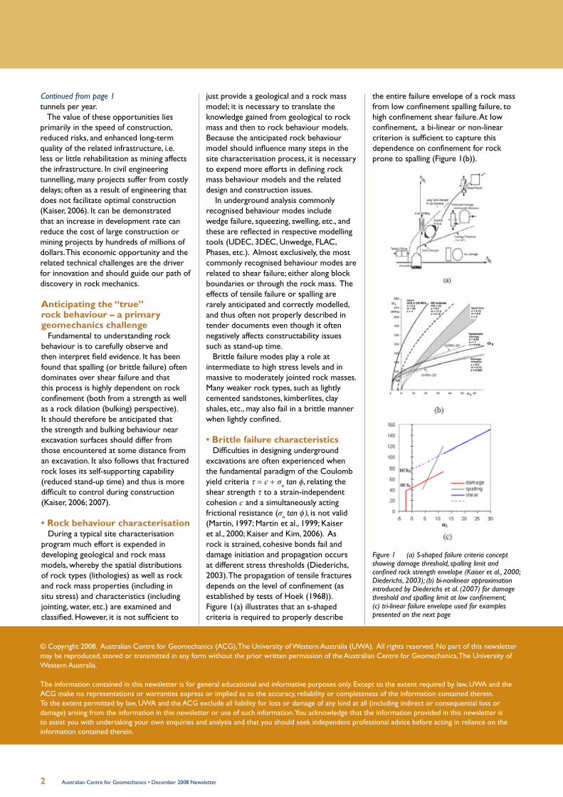
the entire failure envelope of a rock mass from low confinement spalling failure, to high confinement shear failure. At low confinement, a bi-linear or non-linear criterion is sufficient to capture this dependence on confinement for rock prone to spalling (Figure 1(b)).
Figure 1 (a) S-shaped failure criteria concept showing damage threshold, spalling limit and confined rock strength envelope (Kaiser et al., 2000; Diederichs, 2003); (b) bi-nonlinear approximation introduced by Diederichs et al. (2007) for damage threshold and spalling limit at low confinement; (c) tri-linear failure envelope used for examples presented on the next page
just provide a geological and a rock mass model; it is necessary to translate the knowledge gained from geological to rock mass and then to rock behaviour models. Because the anticipated rock behaviour model should influence many steps in the site characterisation process, it is necessary to expend more efforts in defining rock mass behaviour models and the related design and construction issues.
In underground analysis commonly recognised behaviour modes include wedge failure, squeezing, swelling, etc., and these are reflected in respective modelling tools (UDEC, 3DEC, Unwedge, FLAC, Phases, etc.). Almost exclusively, the most commonly recognised behaviour modes are related to shear failure; either along block boundaries or through the rock mass. The effects of tensile failure or spalling are rarely anticipated and correctly modelled, and thus often not properly described in tender documents even though it often negatively affects constructability issues such as stand-up time.
Brittle failure modes play a role at intermediate to high stress levels and in massive to moderately jointed rock masses. Many weaker rock types, such as lightly cemented sandstones, kimberlites, clay shales, etc., may also fail in a brittle manner when lightly confined.
• Brittle failure characteristicsDifficulties in designing underground
excavations are often experienced when the fundamental paradigm of the Coulomb yield criteria τ = c + σn tan φ, relating the shear strength τ to a strain-independent cohesion c and a simultaneously acting frictional resistance (σn tan φ), is not valid (Martin, 1997; Martin et al., 1999; Kaiser et al., 2000; Kaiser and Kim, 2006). As rock is strained, cohesive bonds fail and damage initiation and propagation occurs at different stress thresholds (Diederichs, 2003). The propagation of tensile fractures depends on the level of confinement (as established by tests of Hoek (1968)). Figure 1(a) illustrates that an s-shaped criteria is required to properly describe

3Australian Centre for Geomechanics • December 2008 Newsletter
Rock mechanicsThe practical relevance of an s-shaped
envelope, reaching into the high confinement range, is discussed by use of a tri-linear failure envelope approximation (Figure 1(c)) with a tension cut-off, a damage limit through USCI (lab test), a spalling limit with slope ks, and a shear strength envelope with an intercept, or apparent unconfined strength UCSII.
• Consequences of brittle failure on tunnel behaviour
Strength development near excavationsIn Figure 2 the radial or confinement
stress zone is nearly parallel to the excavation geometry, independent of the stress ratio K0. As a consequence, contours of equal rock strength are essentially parallel to the σ3-contours and the rock strength distribution in the radial direction is very similar for all three cases and for the walls as well as for the roof. For the tri-linear envelope of Figure 1(c), the spalling limit is reached at about 5 MPa and the shear failure envelope is reached at about 10 MPa. The development of σ3
in the wall for the three cases is shown in Figure 3(a) and the resulting strength development in the radial direction is illustrated by Figure 3(b) for the wall. Since the σ3-contours are essentially parallel to the tunnel boundary, nearly identical strength developments are applicable for the walls and roof.
The rock strength, for all three stress ratios, is relatively low near the excavation (to a depth of about 0.7 m for this case). It rapidly increases to about double strength at a depth of approximately 1.3 m, and then increases further, but at a lower rate. The tangential stress (σ1) for K0 = 1.33 is also shown in Figure 3(b) for the roof and walls. Due to the flat, reduced strength near the wall, the tangential stress exceeds the strength not just in the roof (where
it would be anticipated for K0 = 1.33) but also in the walls. Field evidence supports this as shallow stress-induced overbreaks were more widely distributed in the roof (Figure 3(c); Kaiser, 2007) than would be anticipated from conventional constitutive models.
For support design and support selection, it is therefore necessary to properly reflect the rock strength near the excavation and this can be approximated by a bi-linear or bi-nonlinear envelope (Diederichs, 2003; Diederichs et al., 2007). As elaborated in the keynote paper, for pillar stability assessment, however, it is necessary to consider all three parts of the s-shaped curve.
In the floor, the strength increases less rapidly, due to the deeper low confinement zone (Figure 2) thus promoting deeper tensile fracturing and spalling than in the walls and roof. This has several practical consequences in weaker rocks where the swelling or slaking potential may be enhanced by spalling fractures providing preferential water access (Kaiser and Kim, 2008a).
Strength development in pillarsFor pillar stability assessment it is
necessary to consider all three parts of the s-shaped curve (Figure 1(a) and (c)) if the confinement inside the pillar exceeds the σ3–value at the intersection of the spalling limit and the shear failure envelope (about σ3 = 10 MPa for case shown in Figure 1(c)).The higher confinement in the centre of the pillar will lead to higher strength. Further details are contained in the paper (Kaiser and Kim, 2008a).
Rock support for brittle failing rockAs illustrated by Figure 2, a low
confinement zone of more or less constant depth exists near an unsupported excavation. Even if the tunnel was
Figure 2 Minor principal stress contours (range 0–12 MPa) in elastic rock for K0 = 0.75, 1, 1.33
supported with shotcrete providing a radial support pressure (typically between 0 and 1 MPa), such a low confinement zone still exists. Hence, the damage threshold defines the rock strength near the excavation as shown in Figure 3(b). However, the strength rapidly increases as soon as the confinement is sufficient to reach the spalling limit (at about 0.7 m depth or ~5 MPa in Figure 3(b)).
Figure 3 (a) Radial stress distribution for K0 = 0.75, 1, 1.33; (b) rock strength development near excavation for tri-linear criteria (Figure 2(c)); (c) observed shallow stress-induced overbreak in 9 m tunnel excavated in moderately jointed rock
In addition to the effects noted here with respect to stress and strength distribution, there is also a significant impact of rock mass bulking adjacent to the opening which can impose large deformations to the ground support. This is covered in more detail in the paper.
Continued page 4

4 Australian Centre for Geomechanics • December 2008 Newsletter
Continued from page 3
Stand-up time managementStress-driven rock “fragmentation” in
the inner, low confinement shell creates broken rock with varying fragment size and shape distributions (Kaiser, 2007). This degradation can transform a good quality rock mass of say GSI > 65 to a damaged, fractured rock mass of 35 < GSI < 55 and, most importantly, from a continuum, or tight discontinuumm, to a loose discontinuum with often continuous open fractures and little to no cohesion.
When rock is excavated, the stress path eventually ends in a nearly unconfined state (in the spalling zone of Figure 1(a) for brittle rocks). According to the stand-up-time chart (Bieniawski, 1989), essentially permanent stability, with stand-up times of several months to greater than one year, can be achieved (for a 5–10 m wide tunnel) when RMR ≥ 65±5 or GSI ≥ 60±5. However, no or only very short stand-up times of a few hours can be achieved when RMR ≤ 40±5 or GSI ≤ 35±5. From a constructability perspective this implies that it is difficult to maintain stability of the inner shell when stress-driven fracturing causes rock degradation near the excavation. However, while it may be difficult to retain the broken rock, the demand on the support will often be rather limited due to stronger rock in the outer shell.
• Laboratory test data revisitedBased on the previously presented
consequences of brittle rock failure, it is clearly necessary to re-evaluate and reconsider constitutive models used in rock mechanics.
Both Coulomb and Hoek and Brown assume a steady increase in strength with increasing confinement; a linear increase for the former and a non-linear increase for the later. Furthermore, rock mass degradation, e.g. using GSI, does not change the form of the failure envelope, and various means for residual strength determination (Cai et al., 2006) also do not alter the shape of the peak strength envelope.
S-shaped failure criteria for brittle failing intact rock
While it has now been well established that an s-shaped failure criteria is needed to describe the rock mass strength (Figure 1(a)), a re-examination of laboratory test data, covered in more detail in the paper, shows that both the intact rock and rock
mass envelop is s-shaped for brittle failing rocks. Figure 4(a) presents data from a series of triaxial tests on a Quartzite. The scatter in the low confinement range (for < UCSI/10) is large and can be attributed to various degrees of sample disturbance and varying failure modes (breakage of intact rock near upper limit; failure along pre-existing weakness planes near lower limit; and mixed modes of failure near the fitted s-shaped line).
Until an s-shaped failure criterion for brittle rock is fully developed, the laboratory strength can, in the interim, be approximated by a tri-linear criteria as illustrated in Figure 1(c), used for the presented examples, or as superimposed on Figure 4(b) for the Quartzite (UCSI = 140±30 MPa; UCSII = 300±15 MPa; ks = 35 to 15 to 10 for intact to structurally controlled breaks).
Guidelines for design parameter selection for brittle intact rock
It is evident that design parameters for brittle failing rocks must be selected with extreme care and with the design problem in mind. Until an s-shaped failure criterion has been formalised, tested and is ready for use in numerical modelling, constitutive models and failure envelopes adopted for support design will have to differ from those used for pillar design. The average UCS for this rock (data not shown) is 95 MPa. Parameters for four approaches are listed in Table 1 and the corresponding non-linear envelopes are shown in Figure 4(c).
The obvious question arises: how to select the most appropriate intact rock strength envelope for this Quartzite? The mi-values for approach B and D are clearly out of the mi-range based on commonly recommended values for mi and thus would be rejected. However, based on the above presented discussion, an unusually high mi-value of 72 would clearly overall best represent the results from the laboratory testing program (Figure 4(c)).
Approach A and C: approximation using UCS data from laboratory tests and published mi-values
Modelling in mining is often based on UCS data only and mi is estimated from recommended property tables (Hoek, 2007). The resulting failure envelope (approach A) clearly underestimates the strength of the Quartzite in the high confinement range (> 10 MPa; Figure 4(c)) if the average UCS is used. On the other hand, if the UCS of only those tests with
Figure 4 Data from friable Quartzite (a) fitted s-curve for all data and upper and lower limit; (b) respective linearised approximations; (c) Hoek and Brown envelopes obtained by various fitting approaches with parameters listed in Table 1 (UCS and mi values shown in legend as UCS/mi)
intact breaks were used (approach C), then the resulting failure envelope clearly over-estimates the strength of the Quartzite in the low confinement range (< 10 MPa; Figure 4(c)). This envelope provides the maximum strength of the intact Quartzite.

5Australian Centre for Geomechanics • December 2008 Newsletter
Rock mechanics
Approach B and C: use of RocLab™When using any fitting procedure to
obtain Hoek and Brown parameters, data must cover the confinement range of σ3 = 0 to UCS/2. For the Quartzite above, fitting approaches to obtain Hoek and Brown parameters are only applicable for rocks with UCS < 120 MPa, thus parameters can, strictly speaking, not be obtained unless test data from higher confinements are available. Furthermore, RocLab™ limits mi to 50 and thus can and should not be used for rocks with distinct s-shaped failure behaviour.
Obtaining representative Hoek and Brown parameters for rocks with s-shaped failure behaviour
For rocks with distinct s-shaped failure behaviour, a best-fit Hoek and Brown parameter set can be obtained by linear regression in the (σ1 – σ3)
2/UCS versus σ3 space (approach D; forcing linear regression line through (σ1 – σ3)
2/UCS = 1). However, it must be noted that the corresponding mi-value (mi = 72 for the Quartzite) is unusually high and that standard approaches to obtain the rock mass strength (e.g. by GSI-based degradation) may no longer be applicable. Nevertheless, such a fitting approach will lead to a parameter set for the intact rock that is on average representative for the entire confinement range (with high uncertainty in the low confinement inner shell).
Sectional fitting for limited confinement ranges
For rocks with distinct s-shaped failure behaviour, it is therefore more appropriate to consider the confinement range relevant for a given engineering problem before fitting and selecting design parameters.
For support design, the rock behaviour near the excavation, in a confinement range of 0–5 MPa, is most relevant. From Figure 4(c), it follows that the parameter sets, between 95/24 to 139/24, or 120/24 on average with a standard deviation of about 40 MPa on UCS, would be appropriate for
the low confinement zone (inner shell). However, a cut-off as recommended by Diederichs et al. (2007), or with ks = 15–10, would have to be applied to prevent excessive depths of failure predictions. For the outer shell, parameters obtained by approach C would be most applicable.
S-shaped failure criteria for brittle failing rock masses
The rock and rock mass strength parameters for brittle failing rock should be established separately for low and high confinement zones and then applied to zones where each mode is dominating the rock behaviour (e.g. for inner and outer shell modelling). Procedures to obtain corresponding s-shaped failure envelopes for the rock mass, following the GSI approach, are under development (Kaiser and Kim, 2008b). If it is assumed that the currently adopted degradation approach to obtain the Hoek and Brown parameters s and mb for the rock mass is applicable, then it could be applied for each section of the s-curve (the low and the high confinement range) to obtain an s-shaped rock mass envelope as illustrated by Kaiser and Kim (2008b).
Nevertheless, rock and rock mass strength parameters for brittle failing rock should be established separately for low and high confinement zones and then applied to zones where each mode is dominating the rock behaviour (e.g. for inner and outer shell modelling).
Conclusions When mining in brittle ground, the rock
behaviour can change drastically when progressing to greater depth or when stresses change due to advancing mining fronts. This information must be presented in tender documents as it materially affects construction.
By observing and interpreting brittle rock behaviour, it is now possible to understand and anticipate the rock behaviour. As a consequence of brittle failure processes, stress breaks even good ground and disintegrates massive to moderately jointed
rock to cohesionless ground (at least in the inner shell). This leads to a quantum shift in construction difficulties and thus engineering must address this by providing appropriate ground control measures and excavation tools.
Design based on conventional failure criteria (Coulomb or Hoek and Brown) may mislead designers. This is of particular concern when numerical codes with conventional constitutive models and inappropriate strength parameters are adopted. As a consequence, failure may both be over- or under-predicted depending on which part of the s-shaped behaviour dominates the rock strength parameter selection.
Due to the distinctly different behaviour in the inner shell, extreme care must be taken when using measurements from the low confinement zone to determine confined rock parameters (e.g. for pillar design). There is a distinct possibility that back-analyses will significantly underestimate the confined rock mass strength and thus potentially lead to conservative pillar designs.
With respect to anticipating underground construction difficulties, it is most important to recognise that the rock and rock mass strength near the excavation may be significantly reduced for brittle rock near the excavation (in the inner shell). Hence, spalling, limited stand-up time of the inner shell, and high potential for overbreak should be anticipated. Equipment (e.g. type of TBM) is to be selected to properly manage these unfavourable rock behaviour modes.
In summary, spalling processes must be understood when selecting excavation and support techniques; they must be appropriate to manage broken ground.
The full version of this paper is available in the ACG’s First Southern Hemisphere International Rock Mechanics Symposium proceedings. Article references are available from the ACG.
4
Peter Kaiser, CEOCentre for Excellence in Mining Innovation,Sudbury, Canada
Bo Hyun Kim,Geomechanics Research Centre at MIRARCO, Laurentian University, Canada

6 Australian Centre for Geomechanics • December 2008 Newsletter
SHIRMS2008
st Southern Hemisphere International Rock Mechanics Symposium1
SHIRMS was hosted by the Australian Centre for Geomechanics in collaboration with the CSIRO, the University of Newcastle and the University of Western Australia in Perth in September 2008. For the first time ever, rock mechanics practitioners and researchers from the civil, mining, fundamental and petroleum industries were brought together to reflect and exchange their views on the latest rock mechanics technologies and developments.
SHIRMS was attended by more than 240 delegates from countries such as Canada, Chile, China, Germany, Japan, Netherlands, Russia, South Africa and the USA.
Keynote and invited speakers were: Ted Brown (presented by David Starr), Peter Cundall, Maurice Dusseault, Peter Kaiser, Alex Mendecki, Philip Pells, Sergei Stanchits and Boris Tarasov. More than 100 papers are featured in the two volume symposium proceedings: Volume one (Mining and Civil), and Volume Two (Fundamental and Petroleum).
The ACG hosted the symposium with the generous support and encouragement from it’s sponsors, namely Rio Tinto, BHP Billiton Nickel West, Geovert Pty Ltd and the ISRM.
To order your copy of the SHIRMS proceedings, please go to www.acg.uwa.edu.au/shop
Rock mechanics
6–7 May 2009, Novotel Langley Hotel, Perth, Western Australia
First International Seminar on Safe and Rapid Development Mining
www.srdm.com.au
Why are today’s developments similar to those 30 years ago? Haven't we got better techniques for breaking rock? Don't we have better equipment for hauling it up the decline? Are we spending much more time on ground support? Are the Canadian or Scandinavian mining industries developing faster than Australia? What role will automation play in future mines? Are there smarter systems today that we are not using like ground support, scaling techniques, equipment etc. that improves our productivity? Can this be done safely?
The two-day seminar will provide participants with ample opportunity to discuss their particular objectives and projects with representatives from around the world. SRDM should appeal to operators, civil engineers working in underground space, mining engineers, geotechnical engineers, equipment manufacturers and suppliers, contractors and mine management, all of whom have a vested interest in achieving safe and rapid development.
Who should attend?
The CSIRO’s Mine Automation Workshop will focus on rock breaking and mapping techniques that are already gaining application with some of the world's biggest miners.
The ACG’s International Forum on Development Productivity will see leaders in the excavation business discuss their approaches to achieving the development rates which most operations aspire to. The forum’s theme is "duelling nations" where representatives from Scandinavia, Canada and Australia will present their views of how to maximise production.
Associated events
The ACG First International Seminar on Safe and Rapid Development Mining (SRDM) has accepted more than 30 technical abstracts which will address many of the questions raised above.
6–7 May 2009, Novotel Langley Hotel, Perth, Western Australia
Submission of papers: 12 December 2008
CSIRO Mine Automation Workshop:4 May 2009
International Forum on Development Productivity: 5 May 2009
Safe and Rapid Development Mining ‘09: 6–7 May 2009
Key dates
SRDM presents a great opportunity for people who are planning, developing, and funding projects to get together with equipment manufacturers, contractors, miners and operators to discuss where the industry should go.
Principal Sponsor
Major Sponsor
Safe & RapidDevelopmentMining 2009

7Australian Centre for Geomechanics • December 2008 Newsletter
Heap leach
Early Bird registration
expires 4 August 2008
Hydrogeomechanical behaviour of laterite nickel heap leach materials by David Williams, Golder Associates Pty Ltd
BackgroundHeap leaching has been employed
on gold, copper and uranium mines for over four decades, as it can provide an attractive alternative to more complex metallurgical extraction processes. Heap leaching typically involves stacking crushed ore on an impermeable plastic and/or clay lined pad, where it is irrigated with a leach solution that percolates through the heap and leaches out the precious metal(s). The leachate is collected at the base of the heap, from where it is transferred to a process plant for refining.
The heap leach extraction process can take many weeks to several months to complete, depending upon the metal being leached and the particular ore characteristics. However, in times of higher processing and waste management costs, as well as the recent focus on designing for closure, heap leaching has become an attractive option for many low grade deposits. While the recovery via heap leaching is not as efficient as other typical process technologies, there are significant advantages in terms of reduced capital and operating costs.
Heap leaching of laterite nickel ore
In recent times, there has been a significant focus on the possibility of heap leaching laterite nickel ores. For example, European Nickel (in Turkey) and Minara Resources (in Australia) have both established laterite nickel demonstration heap leach pads during the past three years. These, and other laterite nickel mining companies, are giving serious consideration to pursuing the heap leach approach.
Laterite nickel ore stacking on heap pad
Source: www.minara.com.au
Laterite Nickel Ore Stacking on Heap Pad
The heap leaching of laterite nickel ore presents some significant challenges that are not common to the leaching of gold, copper or uranium ores. Besides the challenges associated with the metallurgical composition of the leachate (e.g. high iron and other unwelcome metals), there are some interesting issues that need to be considered in relation to the flow of liquor through the agglomerated material, and in relation to the geotechnical performance of the material. Of particular importance is the propensity for the material to change in character as the ore is leached. The spent ore (or residue) may have significantly different properties to the agglomerated feed ore placed on the heap.
Technical research and input to several projects carried out over the past three years now allows for reasonable predications of the “hydrogeomechanical” behaviour of laterite nickel heap leach materials and associated heap performance.
Heap leach testworkIt is important to have a clear
understanding of the behaviour of the candidate heap leach material(s), as the successful operation of a heap leach facility is dependant on appropriate design criteria. From a geotechnical perspective, the key parameters that need to be understood in order to interpret how the material will behave in the heap are the permeability and the shear strength.
The permeability of the material is paramount, and is directly related to the robustness and particle size distribution of the agglomerates. The shear strength of the agglomerates is dependent on their degree of saturation. Under full saturation, and with only nominal applied loading, agglomerates may collapse completely, resulting a marked decrease in permeability. Saturation increases the pore pressure between particles and between agglomerates, leading to a reduction in the frictional resistance and (apparent) cohesion, thus reducing the shear strength of the material. The degree of saturation within a heap is dependent on the relationship between the leachate application rate and the permeability of the agglomerated material. Therefore, as the
permeability of the material plays a key role in all aspects of geotechnical performance, this property is typically the principal focus of heap leach test programmes.
To facilitate selection of an appropriate heap height for a given application rate, load-percolation testing is carried out. The aim of the test is to determine the maximum load that can be applied to the sample before flooding (full saturation) occurs, assuming a constant leachate application rate.
Load-percolation/load-permeability apparatus
Load-permeability testing is also carried out to provide an estimate of the likely (saturated) permeability of a heap leach sample, and how the permeabilities may change (decrease) with increasing height of heap. The load-permeability testing represents a “worst case” scenario, reflecting permeabilities at the base of a theoretical heap, assuming rapid inundation, poor drainage and sufficient overburden stress, whereby loss of structure (slumping) produces a more homogenous material with higher density and lower permeability.
Sample after load-permeability testing
Continued page 8
Load- percolation / load- permeability apparatus

8 Australian Centre for Geomechanics • December 2008 Newsletter
Continued from page 7
Testwork interpretationThe physics associated with liquor flow
through, and the mechanical response of the agglomerated ore is complex. Consequently, the interpretation of the testwork results requires an understanding and an application of soil mechanics beyond the principles that are traditionally applied. This is because flow through (and between) the agglomerated ore material (and subsequent residue) will generally be in an unsaturated state, and the strength and permeability of soils in an unsaturated state are complex to represent and model. The application of appropriate responses depends upon the use of non-linear equations that are not readily solved.
It is also noted that it is anticipated that the material will change in character over time as the ore is leached and decrepitates, culminating in the final “residue” material. Care thus needs to be exercised in applying material properties derived from testing of the material at the “start” condition (agglomerated ore) to a model that requires properties as leaching proceeds, and at the “end” condition (residue).
Initial settlements upon inundation of about 15% can be expected and subsequent decrepitation of the ore can result in mass losses of about 30%. These physical processes impact significantly on the properties of the materials. In the commonly applied equation in soil mechanics wGs = Sre, the solids specific gravity (Gs) is assumed to remain constant and the void ratio (e) is selected at a specific material state and assumed to be constant. In a lateritic nickel heap leaching process, the solids density decreases significantly throughout the leaching cycle and the void ratio initially decreases and then increases as material is lost from the voids without any significant subsequent volume change. This means that, for a given application rate, the degree of saturation (Sr) will initially increase markedly as the heap wets up (increasing w) and settles (decreasing e), and will then decrease somewhat as the material loses mass (decreasing Gs). Thereafter Sr will depend upon the changes in material permeability as it decrepitates, as indicated by the typical time – saturation relationship for a leach cycle (see Figure 1).
0.3
0.4
0.5
0.6
0.7
0.8
0.9
1
0 1 2 3 4 5 6 7 8
Time (months)
Satu
ratio
n R
atio
e decreasing & w increasing Gs decreasing
wGs = Sre
Figure 1 Soil mechanics equation wGs = Sre
In addition to these considerations, the specific gravity of the leach solution will be significantly greater than unity, which is typically not accounted for in the relationships discussed previously, where the specific gravity of the pore fluid is assumed to be that of water. Care therefore needs to be taken when applying the relationship to account for the higher density of the pore fluid (leachate).
In recent years the soil–water characteristic curve (SWCC) has been identified as the key to the practical implementation of unsaturated soil mechanics into geotechnical engineering practice, since the direct determination of unsaturated soil parameters is difficult and time consuming. The SWCC can be defined as the relationship between the amount of water in a soil and the suction in the soil (see Figure 2).
0
5
10
15
20
25
30
35
0.1 1.0 10 100 1000 10,000 100,000 1000,000
Gra
vim
etric
wat
er c
onte
nt, w
(%
)
Soil suction (kPa)
Air entry value
Boundary effect zone
Transition zone
Residual zone
Residual condition
Inflection point
Figure 2 Typical SWCC plot
The SWCC can be used to reliably estimate the relationship between suction (or degree of saturation) and the material permeability. It is, however, important to note that the SWCC is representative of a soil at a particular density (and hence porosity). Changes in density will influence the shape of the SWCC and hence, the permeability and storage capacity of the material.
Heap leach
“The heap leach extraction process can take many weeks to many months to complete.”

9Australian Centre for Geomechanics • December 2008 Newsletter
ConclusionWhilst heap leaching of laterite nickel
ores appears to be an attractive alternative to other, more costly, methods of metal extraction, the hydrogeomechanical properties of the agglomerated laterite ores need to be understood in order to select an appropriate heap height and application rate. The fact that the material continuously changes its properties as it leaches presents a significant challenge to the designers and requires significant testwork to be carried out ahead of heap design.
The properties of the spent ore in the heap (residue) are likely to differ somewhat from the feed ore and particular care needs to be taken to check that the heap can meet expectations throughout the entire leach cycle. This requires testwork to be carried out on the residue as well as the feed ore. Care needs to be taken to minimise disturbance to the residue when it is extracted from the test leach columns, as the residual agglomerates are likely to be weak. A change in structure of the residue from the in-column state to that tested in the load-permeability and load-percolation moulds is likely to produce erroneous results.
The situation is further complicated by the presence in laterite nickel heaps of a “dual porosity” system – i.e. the porosity of the individual agglomerates and the porosity of the stacked material as a whole. The leaching process requires leachate to pass through the heap, but to flow into and through the agglomerates without resulting in “channelling” (internal erosion) occurring. The modelling and understanding of this process still requires some further research.
Nevertheless, the test methods and interpretations that have evolved over the past three years now allow for the estimation of reasonable material parameters for use in laterite nickel heap design. The next challenges lie in considering the requirements for multi-lift heaps and the effects of the dual porosity system on hydrogeomechanical performance and metal recovery.
David Williams, Principal, Golder Associates Pty Ltd
This ACG training DVD will provide guidance to personnel involved in the management and operation of tailings storage facilities that will facilitate the adoption of accepted best practices for the management of mine tailings.
To purchase your copy go towww.acg.uwa.edu.au/shop
Tailings — From Concept to Closure
BackgroundWhether the mining industry is in a
boom period or a downturn, the universal truth is that there is rarely money to be made out of tailings management. The reality is that it is invariably solely a cost to a company. An understandable management approach is one in which cost minimisation is the sole criterion for successful tailings management.
However, as has occurred time and time again, decisions based purely on minimising costs have led to major structural failures and disastrous environmental releases. Within the past 2½ years there have been at least three failures of tailings storage facilities resulting in fatalities, as well as many more minor incidents, all of which serve to tarnish the image of the mining industry. At a time when media and public scrutiny of incidents such as this is becoming more intense, the continuing licence to operate, as well as obtaining clearance for new developments, is being threatened by stakeholder perceptions of the dangers posed by mine waste storage facilities.
Seminar objectivesThis seminar will tackle the full range
of issues that constitute risks in the management of mining wastes, particularly tailings and waste rock. It will provide a forum where practitioners, researchers and regulators can debate key shortcomings in our current understanding of the performance of mining waste storage facilities and associated risks faced by owners and operators of these facilities. Aside from presentation of papers by selected authors, there will be a series of workshop sessions tackling specific issues of relevance, as well as a number
of keynote lectures from international speakers to ensure the state-of-the-art is presented at this seminar.
Seminar themesAbstracts are now invited for
consideration for presentation at the seminar, which has the following broad themes:
Improvements in design of tailings • storage facilitiesDam break analysis: appropriate tools • and calibrated case studiesAppropriate in situ testing techniques• The application of geosynthetics in • mine waste managementUse of mining waste in backfilling of • mining voidsMitigating the impacts of geochemical • problemsNew approaches to the management • of waste rockAccounting for climate change• Sustainable closure and the concept • of designing for perpetuityImproved management and • operational strategies to minimise riskCase studies•
When considering submission of an abstract, authors are reminded of the overall theme of the seminar: reducing risk in the management of mining waste. The driving goal of this seminar is that delegates come away with a number of new ideas and potential solutions to dealing with their mining waste issues in a way that minimises the impacts of these facilities on communities and the environment.
Abstracts are due 22 February 2010. For abstract guidelines and event updates please contact the ACG via [email protected].
ACG First International Seminar on the Reduction of Risk in the Management of Tailings and Mine Waste
Mine waste

Preliminary results from an investigation into the effect of application of effective stress to cemented paste backfill during curing by Matt Helinski of the ACG and Phillip Norris, Andy Fourie and Martin Fahey
from The University of Western Australia
BackgroundWith the rapid decline in commodity
prices, mine operators are searching for ways to reduce direct costs and increase production efficiencies. As part of the ACG-administered research project “Effective stress approach to mine backfill”, the authors are applying a fundamental understanding of the cemented minefill deposition processes involved in deposition to quantify why in situ paste fill strengths are typically much greater than equivalent samples cured in the laboratory. We are working towards developing rigorous methods for curing cemented mine backfill samples in the laboratory to more appropriately represent in situ curing conditions, with the aim of being able to use the higher strengths in design. This article presents some encouraging results from this study.
In an article in the May 2006 issue (as well as Helinski et al. , 2006; Helinski et al., 2007a; Fourie et al., 2007), we presented the theory behind the consolidation of cementing paste backfill. In addition, modelling results showed that with fine-grained paste backfills where the rate of rise in the stope is rapid, cement hydration can significantly influence the consolidation of cemented paste backfill, which in turn influences the development of effective stress and the resulting bulkhead stress. This article elaborates on this fundamental understanding, applying it to the issue of the rate that effective stress develops in the paste during hydration.
The first part of the article discusses experimental studies that were undertaken to determine the consequence of curing paste fill samples under effective vertical stress (σ΄v). These are not unique, since other researchers (Blight, 2000; Consoli et al., 2003) have demonstrated that the application of stress during curing increases strength. However, in the current work, the focus is on the interaction between σ΄v and curing, and at what stage of curing is the application of σ΄v the most effective. The second part of the article focuses on
developing a rational approach to curing samples under σ΄v such that operators can take advantage of the higher in situ strengths without introducing additional risk into the mining environment.
Laboratory testworkThe experimental component of this
project used loading frames to apply σ΄v to the samples under well-controlled conditions. Figures 1(a) and 1(b) present a photograph and schematic showing this equipment. The key features of the equipment are the (gold-coloured) split moulds, which can be clamped to prevent lateral displacement; the hangers, which are used to apply vertical total stress to the top cap throughout the curing period; and the back pressure tubes, which are used to maintain a constant pore water backpressure throughout the curing period. At the completion of the curing period, the load was removed and the samples were taken from the split moulds for unconfined compressive strength (UCS) testing.
(a)
(b)
Figure 1 (a) A photograph and (b) schematic showing the experimental setup
Within the cemented backfill in a stope, effective stress develops gradually, with the rate of development being governed by the coupling between consolidation and hydration, as will be explained later. Thus, whereas the experiments of Consoli et al. (2003) involved applying an effective stress right at the start of the experiment, in our experiments we applied the effective stress gradually, since that is what occurs within a stope.
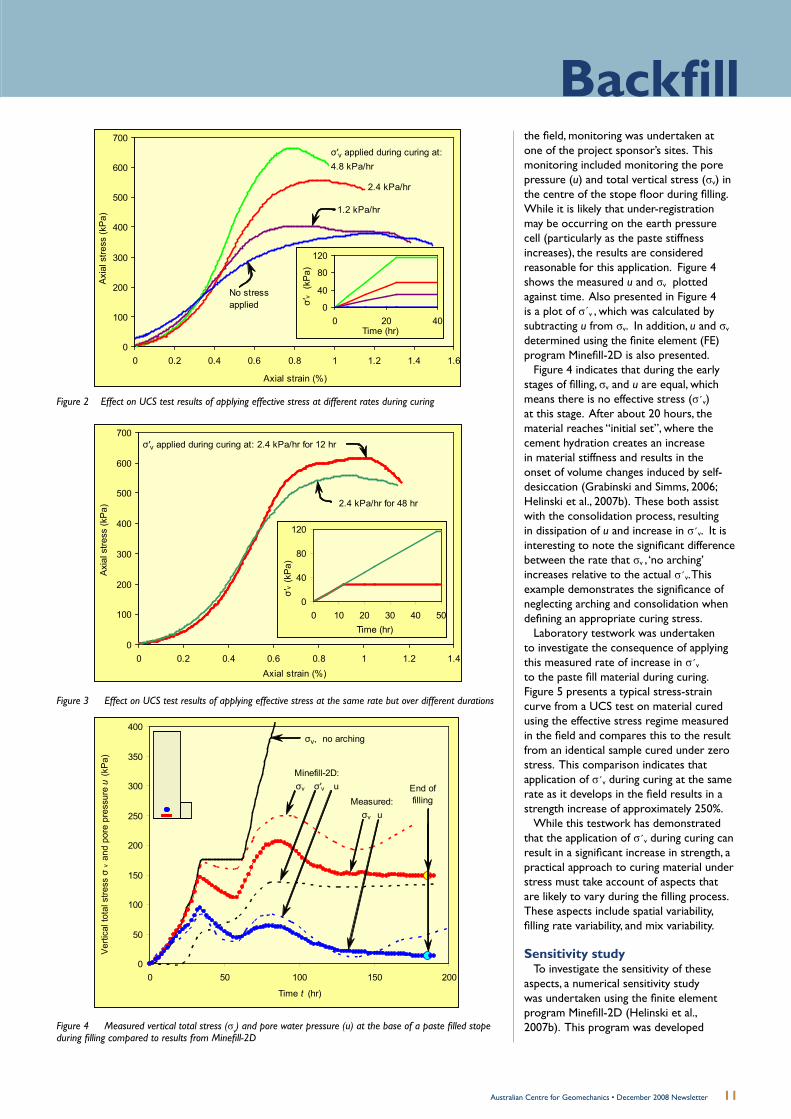
The first experiment involved applying σ΄v
at varying rates for a given duration. The rate at which effective stress was applied was varied from 0 to 4.8 kPa/hr for a period of 24 hours, with each sample being left to cure under the final value of σ΄v for a further 27 days prior to UCS testing. The stress-strain curves from all of the UCS tests are presented in Figure 2.
Figure 2 indicates that the application of σ΄v during curing can create a significant increase in strength. It is also clear from Figure 2 that, as the rate of application of σ΄v increases, the resulting strength also increases.
The second experimental study involved applying σ΄v at a constant rate of 2.4 kPa/hr over periods of 12 or 48 hours, before curing these samples for 28 days prior to UCS testing. Figure 3 presents the stress-strain curves from these UCS tests on these samples.
Figure 3 indicates that the application of σ΄v during the early stages of curing has the most significant influence on the resulting strength. This result is not unexpected, because the application of σ΄v during the earlier stages of curing would have the most significant impact on any volumetric changes within the sample. Overall, this work shows that understanding the rate at which σ΄v develops in a stope during this early stage of curing is critical.
Field monitoring and numerical analysis
To gain an understanding of the rate at which σv develops within a stope in
10 Australian Centre for Geomechanics • December 2008 Newsletter
0
100
200
300
400
500
600
700
0 0.2 0.4 0.6 0.8 1 1.2 1.4 1.6
Axial strain (%)
Axi
al s
tress
(kP
a)
No stress applied
2.4 kPa/hr
σ′v applied during curing at:4.8 kPa/hr
1.2 kPa/hr
0
40
80
120
0 20 40Time (hr)
σ′v
(kP
a)
Figure 2 Effect on UCS test results of applying effective stress at different rates during curing
0
100
200
300
400
500
600
700
0 0.2 0.4 0.6 0.8 1 1.2 1.4Axial strain (%)
Axi
al s
tress
(kP
a) 2.4 kPa/hr for 48 hr
σ′v applied during curing at: 2.4 kPa/hr for 12 hr
0
40
80
120
0 10 20 30 40 50Time (hr)
σ′v (k
Pa)
Figure 3 Effect on UCS test results of applying effective stress at the same rate but over different durations
the field, monitoring was undertaken at one of the project sponsor’s sites. This monitoring included monitoring the pore pressure (u) and total vertical stress (σv) in the centre of the stope floor during filling. While it is likely that under-registration may be occurring on the earth pressure cell (particularly as the paste stiffness increases), the results are considered reasonable for this application. Figure 4 shows the measured u and σv plotted against time. Also presented in Figure 4 is a plot of σ΄v , which was calculated by subtracting u from σv. In addition, u and σv determined using the finite element (FE) program Minefill-2D is also presented.
Figure 4 indicates that during the early stages of filling, σv and u are equal, which means there is no effective stress (σ΄v) at this stage. After about 20 hours, the material reaches “initial set”, where the cement hydration creates an increase in material stiffness and results in the onset of volume changes induced by self-desiccation (Grabinski and Simms, 2006; Helinski et al., 2007b). These both assist with the consolidation process, resulting in dissipation of u and increase in σ΄v. It is interesting to note the significant difference between the rate that σv , ‘no arching’ increases relative to the actual σ΄v. This example demonstrates the significance of neglecting arching and consolidation when defining an appropriate curing stress.
Laboratory testwork was undertaken to investigate the consequence of applying this measured rate of increase in σ΄v to the paste fill material during curing. Figure 5 presents a typical stress-strain curve from a UCS test on material cured using the effective stress regime measured in the field and compares this to the result from an identical sample cured under zero stress. This comparison indicates that application of σ΄v during curing at the same rate as it develops in the field results in a strength increase of approximately 250%.
While this testwork has demonstrated that the application of σ΄v during curing can result in a significant increase in strength, a practical approach to curing material under stress must take account of aspects that are likely to vary during the filling process. These aspects include spatial variability, filling rate variability, and mix variability.
Sensitivity studyTo investigate the sensitivity of these
aspects, a numerical sensitivity study was undertaken using the finite element program Minefill-2D (Helinski et al., 2007b). This program was developed
0
50
100
150
200
250
300
350
400
0 50 100 150 200
Time t (hr)
Verti
cal t
otal
stre
ss σ
v an
d po
re p
ress
ure
u (k
Pa)
σv, no arching
Minefill-2D:σv σ′v u End of
fillingMeasured:σv u
Figure 4 Measured vertical total stress (σv) and pore water pressure (u) at the base of a paste filled stope during filling compared to results from Minefill-2D
Backfill
11Australian Centre for Geomechanics • December 2008 Newsletter

as part of this research project, and has been verified against laboratory-scale and field experiments, including the comparison presented in Figure 4 (Helinski 2007), where the numerical analysis was undertaken using properties that were derived experimentally and published in Helinski et al. (2007) prior to undertaking the field study.
To investigate the influence of the rate of vertical rise in a stope, a numerical analysis was undertaken where the rate of rise was increased from the actual rate in the field to 1.5 times the actual rate. The calculated σ΄v for the base case and that for the increased rate of rise case are plotted against time in Figure 6 for a point at the base of the stope.
Figure 6 indicates that, particularly during the early stages, the rate that σ΄v develops at this point is largely independent of the rate of rise. The reason for this is that “consolidation” (and hence development of σ΄v) in this case, is largely due to the cement hydration mechanism and is not due to contentional consolidation due to drainage. Therefore, increasing the filling rate increases σv, but creates an equivalent increase in u, and thus does not change σ΄v.
To illustrate the influence of spatial variability that the rate σ΄v develops at various elevations within the fill mass are plotted against curing time in Figure 7. This indicates that while the ultimate σ΄v varies for the different elevations, the rate at which σ΄v develops during the early stages of curing (i.e. 0 – 50 hours) is very similar at all elevations. Furthermore, because of the fine nature of paste fill, suctions can help maintain the σ΄v increase towards the fill surface. From the results presented in Figures 2 and 3, it is clear that this is the most critical period relating to the increase in strength due to curing stress. The similar responses observed in Figure 7 are likely to have occurred because the rate of consolidation is primarily dictated by cement hydration. Since this is occurring at the same rate everywhere, the development of σ΄v is also relatively constant.
The final sensitivity study presents the influence of cement content on the rate of development of σ΄v. In this study, the base case, with a cement content of 3.1%, is compared with the case where the cement content was reduced to 1.0%. Figure 8 presents the calculated σ΄v plotted against curing time for the two different cement contents. This indicates that a reduction in cement content can dramatically reduce the rate at which σ΄v develops. This result
0
50
100
150
200
250
300
350
0.0% 0.5% 1.0% 1.5%Axial strain (%)
Axi
al s
tress
(kP
a)
Cured under zero stress
Cured under σ′v
Figure 5 Effect of applying the vertical effective stress (σ΄v) measured in the field to a sample while being cured, compared to a sample cured under zero stress
0
50
100
150
200
0 20 40 60 80 100 120 140Time (hr)
Dev
elop
men
t of σ
′v in
Min
efill-
2D (k
Pa)
Base case rate of rise
σ′v
Base case rate of rise × 1.5
0
50
100
150
200
0 50 100 150
Curing time (hr)
Dev
elop
men
t of σ
′v in
Min
efill
-2D
(kP
a)
1 m
10 m20 m
30 m
1 m
10 m
20 m
30 m
Figure 6 Development of effective stress σ΄v at the base of a stope predicted from Minefill-2D: influence of filling rate (rate of rise)
Figure 7 Rate of development of effective stress σ΄v at different levels in a stope predicted from Minefill-2D
12 Australian Centre for Geomechanics • December 2008 Newsletter

0
40
80
120
160
200
0 25 50 75 100 125 150
Curing time (hr)
Dev
elop
men
t of σ
′v in
Min
efill
-2D
(kP
a)
3.1% cement
σ′v
1.0% cement
Figure 8 Development of effective stress σ΄v at the base of a stope predicted from Minefill-2D: influence of filling rate
is expected, because a reduction in cement content reduces the rate of increase in stiffness and the volume change due to self desiccation, which in turn reduces the rate of consolidation and, therefore, the rate at which σ΄v develops.
ConclusionOverall, this article has demonstrated the
following important points:When applied at rates measured in • the field, the application of effective stress during curing can create a 250% increase in strength. This is believed to be the prime reason for the commonly-observed phenomenon that the in situ strength of paste backfill are greater than corresponding samples cured in the conventional way.The magnitude of the strength • increase is dependent on the rate at which effective stress is applied during curing to the laboratory samples. Application of effective stress during • the early stages of curing has the most significant influence on the achieved strength.Results of the sensitivity analysis • indicate that in fine-grained paste with a high rate of rise, the rate that effective stress is applied in situ during curing, is unique regardless of the filling rate and location.
These conclusions provide encouragement that an approach for curing cemented paste backfill under effective stress can be developed, hence, allowing operators to benefit from savings in cement quantities, without introducing additional risk of paste instability.
It should be noted that these results are only applicable to paste backfill scenarios where consolidation is dictated by the cement hydration process. Conventional drainage type consolidation can act to increase or decrease the rate that effective stress is applied during curing.
BackfillMatt Helinski, Research Fellow,Australian Centre for Geomechanics
Andy Fourie, Professor, School of Civil and Resource Engineering, The University of Western Australia
Martin Fahey, Professor, School of Civil and Resource Engineering, The University of Western Australia
“When applied at rates measured in the field, the application of effective stress during curing can create a 250% increase in strength.”
In order to realise the full potential of this project, the group is seeking a PhD Candidate to take up an industry-funded scholarship. This scholarship would ideally suit someone with a soil mechanics background and an interest in mine tailings management. The nature of the project sponsorship allows for the student to work in a world renowned geotechnical research group, maintain a very good scholarship income (approx. AU$35K tax free), work along-side industry while maintaining a considerable amount of research autonomy.
PhD Studentship(Mine Backfill)
13Australian Centre for Geomechanics • December 2008 Newsletter
For any further information relating to this topic or the overall research project, please contact Dr Matt Helinski by email at [email protected] or telephone 0400 153962.
Article references are available on request from the ACG.
Project Sponsors

14 Australian Centre for Geomechanics • December 2008 Newsletter
Alcoa’s aim is a self-sustaining jarrah forest ecosystem
Fertiliser a conundrum for jarrah forest restoration after miningby Tim Morald, Centre for Land Rehabilitation, The University of Western Australia and Rachel Standish, Ecosystem Restoration Laboratory, Murdoch University
Mining and conservation are often considered to be incompatible land uses. Yet, economically important mineral deposits often occur in areas with high biodiversity and therefore, high conservation value. The challenge then is for mining companies to maintain or enhance the conservation value of these sites, especially with regard to rehabilitation or restoration after mining.
One such example is the northern jarrah forest south-east of Perth, Western Australia. It is botanically diverse; home to almost 800 plant species and it also contains vast bauxite reserves. Alcoa of Australia commenced mining here in 1963; they currently mine and restore approximately 600 hectares a year. Restoration is crucial because, among other considerations, their mining operations occur within Perth’s drinking water catchments. The forest is also important for conservation, recreation and timber production. In fact, much of Alcoa’s initial research into rehabilitation focused on their ability to return a productive forest. More recently, their aim has been
to return a self-sustaining jarrah forest ecosystem. This includes returning botanical diversity to pre- or unmined forest levels.
The soils in the jarrah forest are nutrient-poor, especially with regards to phosphorus. This has contributed to the high plant diversity and resulted in some interesting nutrient-acquisition strategies. These strategies include specialised root structures, such as cluster roots (particularly evident among the Proteaceae family). Another strategy common in many jarrah forest plants is the formation of mycorrhizal associations with fungi - whose fine hyphae can explore and extract nutrients from a much larger area than the plants own root system could.
At progressive mining companies like Alcoa, the restoration is regarded as part of the mining process. The first step in this process in bauxite mining is the removal of all vegetation. The soil is then stripped in two distinct layers: the organic rich topsoil (~15 cm); followed by the overburden (~35 cm) occurring between the cap-rock and the topsoil. The bauxite layer (including the cap-rock) which
averages 4.5 m depth is then mined. After completion of mining, the mine faces are battered down and the pit is landscaped to meld it with the surrounding unmined forest. The area is ripped to relieve mining related compaction. Then overburden and topsoil are returned. Final scarification is undertaken with a multiple tine and a diverse native seed mix is applied. The landscaping, soil return and seeding occur over summer when the soil is dry and fertiliser is applied by helicopter in the following spring.
So, whilst nutrients, principally phosphorus, are required to replace the nutrients lost during mining, some plant species adapted to nutrient-poor soils are sensitive to fertiliser application. Our concern was that increased fertility would reduce plant species diversity and alter species composition - in short, that we would lose biodiversity. To test this prediction we utilised a field experiment established by Alcoa in 1994, where high levels of phosphorus (P) had been applied at establishment.
The experiment was conducted in four restored pits, two pits at each of two Alcoa sites (Jarrahdale and Huntly). We selected treatments that had received no phosphorus (P) and two or three times the current rate (40 kg P/ha). All treatments received 80 kg/ha of nitrogen and comparisons were made to surrounding unmined forest.
Fourteen years after fertiliser application we sampled the soil to see if the effects of high fertiliser application were still apparent. We sampled from the ripline furrows because this is where the nutrients, leaf litter, seeds and moisture are generally concentrated. Incredibly, phosphorus in the P fertilised plots was still five to ten times higher than in unmined forest. This is despite 14 years of vegetation growth and nutrient uptake on these sites. The fertilised soil was also up to five times higher in nitrate concentration and was more acidic. These results could have implications for the species composition in the restored sites. Whilst good vegetation growth and litter accumulation was apparent at all restored sites, soil organic carbon pools (1.2 – 2.9%) were lower than in the unmined forest (3.4 – 5.5%).
So, have these differences in soil fertility affected the vegetation on the restored sites? To find out we monitored 80 m2 of vegetation in restored treatments and compared this to 80 m2 of unmined forest. We used an ordination of the vegetation data to compare species composition.
Cow
slip
Orc
hid
(Cal
aden
ia fl
ava)
. Pho
togr
aph
cour
tesy
of B
ianc
a Tay
lor
15Australian Centre for Geomechanics • December 2008 Newsletter
Mine closureRemarkably, after only 14 years and despite all the mining related soil handling processes, restored sites with no added phosphorus were similar to the unmined forest in terms of native plant species richness, diversity and evenness. In contrast, the sites which had P fertiliser applied (at two or three times the current rate), were not similar to the unmined forest for these same measures. The species composition of restored sites was different to unmined forest. Differences in composition between Huntly and Jarrahdale (for both forest and restored sites) were apparent, but differences between restoration treatments were not apparent.
Restoration is an important part of the mining process
Finally, we looked at density of understorey species because this is where most of the diversity in the jarrah forest stems from. We also compared density of the Proteaceae family because their sensitivity to phosphorus is well documented and this family is well represented in unmined forest. Density of Proteaceae was greater in unmined forest than in the restored sites. In the restored sites, density of both Proteaceae and understorey plants decreased with application of phosphorus. In other words, phosphorus application resulted in restored sites that were less similar to unmined forest.
In conclusion, this research found that phosphorus fertiliser applied at two to three times the current application rate was still evident in the soil after 14 years. We also found that for some vegetation measures, restored sites with no added phosphorus are more like unmined forest. These findings have implications for mine restoration in other parts of the world where mining takes place in low fertility
ecosystems. Further research aims to determine if botanical diversity of Alcoa’s restoration can be enhanced by amending the current fertiliser application practices.
These issues and many more (from geotechnical, to social, to financial, as well as ecological) will be part of the now well established Mine Closure Conference series run jointly by the Australian Centre for Geomechanics and the Centre for Land Rehabilitation. The conference will be returning to Perth in September 2009.
Those interested in biodiversity and ecology might also be interested in the pre-conference CLR Mining in Ecologically Sensitive Landscapes Seminar (www.clr.uwa.edu.au/).
Proceedings of the Third International Seminar on Mine Closure
14–17 October 2008Johannesburg, South Africa
Mine Closure 2008
These proceedings are a hard-bound, black and white publication featuring 81 papers comprising 905 pages.
www.acg.uwa.edu.au/shop
Fourth International Conference on Mine Closure
More than 330 delegates attended the First International Seminar on Mine Closure that was held in Perth, Western Australia in 2006. Following on from successful seminars held in Chile (2007) and South Africa (2008), the ACG and CLR are delighted to bring the Fourth International Conference on Mine Closure back to Perth in September 2009. Over 100 papers covering the topical geotechnical, social, financial and ecological mine closure issues are expected to be presented over the three day event. Abstracts are due 16th February. For conference themes, abstract guidelines and event updates please visit www.mineclosure2009.com
9–11 September 2009, Perth, Western Australia
Tim Morald,Research Officer,Centre for Land Rehabilitation, The University of Western Australia
Rachel Standish,Postdoctoral Fellow,Ecosystem Restoration Laboratory, Murdoch University
www.mineclosure2009.com

16 Australian Centre for Geomechanics • December 2008 Newsletter
Mine seismicity and rockburst risk management enters its next phase
writes Johan Wesseloo of the ACG
The closing of 2008 marks the successful completion of Phase 3 of the MERIWA sponsored “ACG Mine Seismicity and Rockburst Risk Management Project” (MSRRM). The project’s success is the result of a dedicated team consisting of Dan Heal (project leader), Paul Harris (software engineer), Yves Potvin (project manager) and the part-time involvement of Marty Hudyma (Itasca Canada) and Peter Mikula (Mikula Geotechnics). The ACG farewelled Dan in June 2008 and Johan Wesseloo was appointed the project leader of Phase 4 of the project (MSRRM4). Phase 4 will commence in January 2009.
Research conducted during MSRRM3 saw the development of several tools for the pro-active assessment of seismic hazard, excavation vulnerability and the potential for rockburst damage which enables the management of seismic risk. The successes of MSRRM3 also highlight the importance of addressing some knowledge gaps, and research in this area will continue in MSRRM4.
Mine seismicity is not only a hazard but also a valuable source of information about rockmass behaviour and its response to mining. This information is not fully utilised and further development will benefit the industry both financially and in terms of safety. MSRRM4 aims to advance the strategic use of seismic data and develop an increased understanding of seismic response to mining. It will consist of several sub-projects looking at a wide variety of topics.
The MS-RAP software, developed during previous phases of the MSRRM project, has proven to be a valuable means for technology transfer as the research results are implemented into the software and are then easily accessible to the project sponsors. This practice will continue to benefit the project sponsors with new additions and improvements.
MSRRM4 major research areas
Dynamic support classification For the effective design of dynamic
support systems, the in situ performance must be quantified. Several testing methods are being used to test support
components and systems in industry. These methods include: in situ testing, instrumented rockbursts, high quality case studies (Figure 1) and laboratory testing. To fully utilise the data from these tests, the relationship between the results of the different test methods and the in situ performance must be understood. This relationship between the laboratory and in situ performance will be examined in MSRRM4. Simulated rockbust testing will also be performed to add to the current database from this testing method.
Developing analysis techniques for integrated interpretation of seismic and other geotechnical data for cave management
Detailed analysis of high resolution seismic monitoring data from caving mines demonstrated enormous potential for using this data to track cave propagation and to better understand the caving process and seismic hazard in caving mines (Figure 2; Huydma et al., 2007a; 2007b). Analysis techniques and tools which will assist in engineering analysis and management of cave propagation and
Support damage after blast testing performed in Phase 3
Comparison of Ground Support Systems
0 1 2 3 4 5 6 7 8 9 10
Split Sets and Fibrecrete
Securabolts and Fibrecrete
Split Sets and Masterseal 845A
Split Sets and Mesh
Split Sets and Tunnelguard with Cone Bolts
Securabolts and Mesh with Fibrecrete
Split Sets and Mesh with Fibrecrete
Split Sets and Mesh with Cone Bolts
Split Sets and Mesh with Dynamic Cables
Gro
und
Supp
ort S
yste
m
Average Energy Demand for S3 Damage (kJ/m2)
Simulated Rockburst Data Actual Rockburst Data
Figure 1 In situ support capacity obtained from actual and simulated rockburst data in Phase 3

17Australian Centre for Geomechanics • December 2008 Newsletter
Mine seismicityseismic hazard in block and sublevel caving mines will be developed. These analysis techniques will combine seismic and other geotechnical data, such as cave draw, time domain reflectometry (TDR), borehole camera measurements and hydraulic radius, to provide new opportunities to interpret the interactions between mining activity and rock mass response. A “cave manager” will be developed in MS-RAP to allow sites to utilise some of these analysis techniques in day-to-day cave management, including tools for seismogenic zone tracking. These new tools will allow for the efficient collection of caving data feeding new research into cave mechanisms and fragmentation by caving.
Undercut Blast
Research into rock mass degradation Rock mass degradation is an important
safety concern as it affects the risk of rockfalls and seismically induced shakedowns. It is also an important economic concern as severe rock mass degradation can lead to dilution or sterilisation of ore. This project will investigate the use of the concentration of seismic events in a given volume of rock as an indicator of the amount of rock mass damage that has occurred.
Assessment of long-term seismic risk For long-term planning and management
of a mine, a quantification of the seismic risk and hazard for the “life-of-mine” plan is important. Such an assessment needs to be based on historical data and also needs to take into account the differences between historical and the future mining scenarios. This project aims to provide a probabilistic framework for using the seismic history of a mine to assess the mine’s future seismic hazards. The uncertainties governing the assessment of future seismicity will be accounted for and as such become a component that could be managed.
Regional seismic monitoring A number of regional seismic
monitoring networks were installed as part of MSRRM3. These networks provide locations of large seismic events more accurately than the existing Geoscience Australia national network and also provide information on seismic events occurring
Undercut Blast
Undercut Blast
Figure 2 Tracking of cave front through seismic activity
Figure 3 Recorded seismic events on the Kalgoorlie-Kambalda seismic network
within the networks, but external to mines (Figure 3). These regional seismic networks provide a valuable opportunity to investigate the anecdotal evidence of the coincidence of increased regional seismicity and mine seismicity and its possible coincidence with temporal changes in the in situ stress field.
Johan WesselooResearch Leader,Australian Centre for Geomechanics
MSRRM4 Major Sponsors
Minor Sponsors
Kirkland Lake Gold Inc., Canada; Codelco Chile; Newmont Asia Pacific; Oxiana Ltd; Gold Fields Australia; AngloGold Ashanti Ltd; Beasonsfield Gold; Newcrest Mining Ltd; Perilya Broken Hill Mine; Sir Samual Mines; Xstrata Nickel.
Sponsors are sought for the MSRRM4 project. For further information please contact the ACG via [email protected]

18 Australian Centre for Geomechanics • December 2008 Newsletter
Toowoomba Pilot Tunnel
The increasing importance of rock stress measurements in Australia
by Ian Hulls, Rob Walton, Simon Bailey and John Smith of Coffey Mining
Introduction
“Knowledge of the pre-excavation state of stress at a given location in the Earth’s crust is a prerequisite for the rational design of large underground excavations in rock” Brown and Hoek (1978)
Most articles about rock stresses start with a statement similar to the one above. Such a statement has even more relevance 30 years later, with the high reliance on powerful numerical models commonly used to carry out the design of underground and near-surface excavations. Good knowledge of the respective stress magnitudes, their directions and trend with depth is fundamental to the proper use of such modelling tools.
This article illustrates some important reasons why a single location stress measurement programme may not suit all sites, whether the geological setting is complex or relatively simple.

19Australian Centre for Geomechanics • December 2008 Newsletter
Rock stressHistory
The first rock stress measurements undertaken in Australia were carried out in 1957 at the site of the (then) future Tumut 2 underground power station in the Snowy Mountains, NSW. Between 1957 and 1971, over 1500 measurements to determine stresses in undisturbed rocks were made at over 65 test sites, in 32 different locations in Australia.
Initially, flat jacks (uniaxial measurement) were used to measure stresses in the walls and in the roofs of tunnels and caverns developed for hydro-electric projects and mines. From 1963, most stress measurements were made using borehole overcoring methods utilising various 2D and, finally, 3D measurement gauges. The Australian rock stress measurement database increased rapidly with the introduction of the 3D CSIRO Hollow Inclusion cell (HI cell), in the early 1970s, and the 2D hydraulic fracturing stress measurement technique, which allowed stress testing in boreholes drilled from the surface, in the late 1970s to early 1980s.
The first summary of rock stress measurements in Australia was made by Worotnicki and Denham (1976). They brought together all known stress measurements carried out in mines and tunnels and the inferred stress directions from focal mechanism solutions from five earthquakes in Australia. They concluded that, generally, the magnitude of the maximum horizontal stress was higher than the associated vertical stress, and the magnitude of the horizontal stresses and their rate of increase with depth in Australia were lower than the published data for Europe, but higher than the data for South Africa.
Over time, other researchers collated the rapidly expanding world wide stress measurement database. Brown and Hoek (1978) published the often referenced graphs of vertical stress versus depth and the variation in the ratio of average horizontal stress to vertical stress with depth below the surface. Brown and Windsor (1990), Denham and Windsor (1991), Enever et al (1999) and others expanded these themes.
Reference to the graphs of Brown and Hoek show a significant variation of measured stress for any depth. For example, at an approximate depth of 1000 m the average horizontal stress in Australia could be up to ±50% of the mean of the extreme values, and the vertical stress up to ±20% of the mean of the extreme values. These variations are much
greater at shallower depths. This is the reason why, at most sites, rock
stress measurements are carried out as early as possible in the excavation design process.
In recent years, Coffey Mining’s Measurement Group has carried out a large number of stress measurement projects in Australia. The following case studies demonstrate the measurement of “unexpected” stresses in three locations in Australia. The results shown here are from overcoring tests using the latest version of the HI cell. All site work and analyses were overseen by staff highly experienced in rock stress measurement techniques, particularly in the use of HI cells.
Case study 1: Toowoomba Pilot Tunnel
The in situ rock stress condition was recently measured at the Toowoomba Bypass Pilot Tunnel. The two boreholes in which measurements were carried out were located at the base of a high strength 20 m thick basalt layer, which was overlain by a low strength claystone and a layer of highly to slightly weathered jointed basalt. The two test sites, about 70 m below the surface, were separated by approximately 7.5 m, horizontally.
The measured maximum principal stress was sub-horizontal, trending approximately north-south and parallel to a nearby irregular, but generally north-south trending, escarpment approximately 500 m to the east of the tunnel. This result was not unexpected.
However, the maximum and intermediate principal stresses measured at one location were about twice that measured at the other location; the magnitude of the measured principal stresses from the four tests ranged from 14 to 32 MPa. The vertical stress determined from the four tests was 2 to 3.5 times that expected from the depth of overburden.
It was concluded that the multiple interlaying of strong and weak sub-horizontal layers significantly affected the stresses at this location.
Had stress measurements not been
undertaken in this instance, the high vertical stress would not have been discovered until well after tunnel construction had commenced.
Case study 2: Ballarat East Gold Mine
In early 2007, the rock stress condition was measured at two levels at the Ballarat East Gold Mine. The vertical stress component at both sites was near equal to, or higher than the major horizontal stress component. These results were consistent with the situation of the significantly folded and altered sandstone and siltstone units that contain the quartz hosted gold deposits at Ballarat. The measured vertical stress was largely in agreement with the stress calculated from the mass of the super incumbent rock.
In mid-2008, a second set of stress measurements was undertaken at lower levels in the mine, again at two sites. The measured orientation of the principal stresses was consistent between sites and to the orientation of the principal stresses measured in 2007.
The measured vertical stress component at one of the sites was reasonably close to the theoretical value (within ±15%, from three tests), while at the other site (from two tests) the vertical stress component was 55% and 95% higher than that expected from the overburden rock.
Another important result from the 2008 test programme was that the minor principal stress magnitude was close to zero for four of the five tests. The magnitude of minor stress from the fifth test was also low at less than 4 MPa. The direction of all of these low stresses was approximately north-south along the strike of the gross fold hinge. It was concluded that the north-south stress at some locations could have been inhibited by slip on puggy fault zones striking at low angle to this stress direction.
Stress measurement, in this case, showed clearly that there was potential for a lack of confinement in the north-south direction, which could lead to instability problems in the backs.
Site 1
Site 2NS
Site 1
Site 2NS
Figure 1 Illustration of a possible explanation for the anomalously low N-S σ3 values based on fold geometry. Both sites are located adjacent to N-S convex bends in bedding (green). N-S compression (white arrows) could induce local extension (black arrows, grey areas)

20 Australian Centre for Geomechanics • December 2008 Newsletter
Sem
inar
Principal Sponsor
Site 1
N
S
Site 1
N
S
Figure 2 Illustration of a possible explanation for the anomalously low N-S σ3 values based on fault geometry. Transmission of N-S compression (white arrows) along the fold hinge line (green dashed line) could be inhibited by slip on slightly oblique, puggy fault zones (black line)
Figure 3 Photographs showing (A) a slightly open E-W striking vertical joint in the north drive level, (B, C & D) puggy clay infill in the west-dipping fault and (E) branching geometry of the fault
Case study 3: Copper mine in central-western NSW
The copper deposit is located within a monotonous turbidite sequence of Ordovician age comprised of meta-sedimentary rocks called the Girilambone beds. The sequence has been metamorphosed to greenschist facies and is extremely deformed. The region is dominated by overall north-south structural trends lying within a wedge shaped block. Mineralisation has been interpreted to be approximately conformable with foliation, which strikes approximately north-south on the mine grid. The deposit dips at varying angles towards the east.
Three stress measurement programmes have been carried out over the past three years at 250, 400 and 545 m below the surface. Overcoring tests at the three levels produced significantly differing principal stress directions both within the same level of the mine (at opposite ends of the orebody) and at the differing vertical separations.
From 15 tests undertaken at six sites the maximum principal stress (σ1) is sub-horizontal, with the dip of any of the measured stresses no greater than 38º. However, the direction of σ1 varied from site to site:
At 250 m below the surface the • direction is SSW, sub-parallel to the orebody at that level.At one site 400 m below the • surface the direction is SE – SSE, sub-perpendicular to the orebody at that level and sub-parallel to the NW fault set.At another site 400 m below the • surface the direction is NE – ENE, sub-parallel to the orebody at that level.At three sites 545 m below the • surface (north end, south end and central orebody) the direction is WSW or perpendicular to the orebody and dipping sub-parallel to the orebody.
Also, from the tests carried out at the three levels there was significant deviation in the measured vertical stress compared to the expected vertical stress calculated from the super incumbent rocks.
With the geological knowledge to date, it is thought that these significant variations from site to site may be caused by the influence of a quartzite block contained within the upper sections of the orebody. It has been well documented that zones
of higher strength and/or higher modulus rock attract a higher proportion of the regional stress field. This large irregular shaped quartzite inclusion may be affecting magnitudes and rotating the local stress field within the upper sections of the orebody. It is interesting to note that the most recent program at the 545 m level was undertaken below the known extent of this quartzite zone and, at all three sites at this level, the principal stress direction returned to the general east-west trend of the western NSW area.
This is a good example of the variability of stress regime in a complex geological environment.
SummaryThe results from all three sites presented
in the case studies clearly demonstrate that the rock stress condition at any given location should be well measured and the results carefully considered in the overall geological context.
The extensive stress measurement experience gained by Coffey Mining staff over the past 35 years also endorses the requirement for regular stress measurement programmes. Stress measurement history gained from various sites has shown that the use of a reliable, consistent and repeatable stress measurement technique such as HI cell overcoring is highly beneficial.
The data obtained is fundamental to good modelling and understanding of rock mass behaviour. This leads to an efficient design of all mining systems for modern Australian mines.
In summary, a well planned stress measurement programme, undertaken at regular intervals during a mine’s lifespan, will deliver significant economic and safety benefits.
Article references are available on request.
Rob Walton,Principal,(Instrumentation)Coffey Mining
John Smith, Associate,(Geology)Coffey Mining

21Australian Centre for Geomechanics • December 2008 Newsletter
NewsDeep mining
Ground movement amplification around underground excavationsby Michel Van Sint Jan F., and Nicolás Alviña T., Pontificia Universidad Católica de Chile, Chile
The presence of an underground excavation can produce a significant change in the pattern of particle movement due to a rockburst. Field evidence suggests that the peak particle velocity (PPV) may be amplified several times along the boundary of an underground excavation when compared with the PPV of the same tremor measured in the rock mass away from the excavation perimeter.
A two-dimensional numerical analysis of wave propagation, using the finite element method (FEM), is being developed as part of a research effort to understand the reasons for wave amplification at the boundary of an underground opening. The model considers a wave propagating through an elastic, isotropic and homogeneous material. Energy absorbing elements were implemented along the boundaries of the 120*85 m model in order to simulate the propagation of the seismic wave beyond the limits of the said model.
Initial runs have shown that at a distance of 45 m from the source, the wave front is almost perpendicular to the direction of propagation for a distance of approximately 8 m at each side of the axis of propagation (see Figure 1).
Dis
tanc
e (m
)
Time (milliseconds)
Figure 1 Shape of the wave front along a vertical section 45 m away from the source
Thus, the source was located at a distance of 50 m from the border of the excavation. In order to study interaction effect, either a single excavation or multiple excavations were studied. Two excavation shapes, a circular and a horseshoe tunnel shown in Figure 2, as well as three different diameters or widths have been considered: 4, 6 and 8 m.
In order to cover the frequency range typical of rockbursts, the input movement was a sinusoidal compression wave with frequency varying in the range of 5 to 250 Hz. The modulus of elasticity of the rock mass was 30, 50 or 70 GPa.
It was found that when the source is to the left of the point located at position 270° in the perimeter of the excavation, the ground response along the perimeter was almost the same for both shapes shown in Figure 2. As expected, the response of the horseshoe shaped tunnel is dependant upon the orientation of the input.
Figure 2 Shape of the excavations included in the study

22 Australian Centre for Geomechanics • December 2008 Newsletter
The results for a single circular tunnel are shown in Figure 3. The horizontal axis is the position along the perimeter and the vertical axis is the ratio between the PPV along the radial direction at the point in border to the PPV along the same direction at the same point without the excavation. The largest amplifications are computed at 0° and 180° from the incident wave, indicating that they are associated with the shear wave.
Figure 3 Maximum amplification of particle velocity in the radial direction along the perimeter of a circular excavation subjected to a sinusoidal input with frequency varying from 5 to 250 Hz
The influence of the frequency is shown in Figure 4, where the maximum PPV amplification is shown for each frequency, independently of the location where it occurs.
From Figures 3 and 4 it can be concluded that, within the values tested, PPV amplification increases with an expanding diameter of the excavation and with decreasing modulus of elasticity. Further analysis shows that an annulus of fractured rock around the excavation, with smaller modulus of elasticity, results in an additional increase of PPV amplification. Thus, a first conclusion from the analyses suggests that good blasting procedures would tend to reduce the PPV along the perimeter of tunnels excavated in hard rock. Care has to be taken with this conclusion because it would be expected that a large body of fractured rock with a reduced modulus of elasticity should also have a larger damping ratio than the rock with higher modulus. Our analysis was carried out with a constant damping ratio, we feel that if the annulus with reduced modulus is of small width compared to the diameter of the excavation, the error in our results is not significant.
Figure 4 Maximum radial PPV amplification as a function of the input frequency and the radius of the excavation
Our analyses show that other factors, such as the shape of the excavation, an annulus of fragmented rock and the presence of other excavations, may result in further amplification of the PPV to more than 25 times the PPV of the incoming wave.
In summary, numerical models of wave propagation suggest that PPV around the perimeter of an isolated underground excavation in hard rock may be amplified by a factor of 6 to 12 depending on the location of the point and the frequency of the incoming wave.
AcknowledgementsThe research reported has been partly
funded by Codelco Chile, División El Teniente. The contributions of Eduardo Rojas and César Pardo are greatly appreciated.
Michel Van Sint Jan F.,Professor of Geotechnical Engineering,Pontificia Universidad Católica de Chile, Chile
Nicolás Alviña T.,Graduate Student,School of Engineering,Pontificia Universidad Católica de Chile, Chile
Please contact Professor Michel van Sint Jan at the Pontificia Universidad Católica, Chile via [email protected] for further information.
Fifth International Seminar on
Deep and High Stress Mining
The Deep Mining International Seminar series provides a forum for the industry, academics and researchers to share information, experience and ideas on deep and high stress mining.
Papers are called in the following areas:Planning and design • Ventilation• Blasting • Risk and safety• Seismicity and seismological analysis• Numerical modelling• Ground support and ground behaviour• Observations and monitoring• Case studies•
7–9 October 2009, Sheraton Hotel, Santiago, Chile
0° 90° 180° 270° 360°0
5
10
15
Am
plifi
catio
n pp
v/pp
v ref.
r =2m
0° 90° 180° 270° 360°
r =3m
0° 90° 180° 270° 360°
r =4m
E =30 [G P a] E =50 [G P a] E =70 [G P a]
50 100 150 200
r =4m
50 100 150 200
r =3m
f [Hz ]50 100 150 200
0
5
10
15
Am
plifi
catio
n pp
v/pp
v ref.
r =2m
E =30 [G P a] E =50 [G P a] E =70 [G P a]
It is also interesting to note that for excavations with radii of 3 and 4 m, the largest PPV amplifications tend to result at a frequency of 100 Hz, independent of the modulus of elasticity used in these analyses.
Authors are invited to submit a 500 word abstract by 23 March 2009 to

23Australian Centre for Geomechanics • December 2008 Newsletter
Deep mining
ACG Second International Symposium on Block and Sublevel Caving
20–22 April 2010, Novotel Langley Hotel, Perth, Australia
Submission of Abstracts 31 August 2009
As mining companies strive to position themselves into the lower quadrant on their respective commodities producers’ costs, the strategic importance for these companies to add cave mines to their portfolio of assets is growing. Thus, the number of large caving mines, caving projects and feasibility studies increases. The increasing industry focus on cave mining and the engineering work required to mitigate the technical risks has stimulated new waves of research in this area.Themes • Undercutting • Caving mechanics • Fragmentation • Sublevel caving method • Block and panel caving methods • Cave design and layouts • Mine equipment • Numerical modelling • Ground support • Caving under existing mines • Preconditioning
Associated Event: ACG Preconditioning Workshop, 19 April 2010.
www.caving 2010.com
The ACG continues to be pioneering force in providing industry with world-class geotechnical research. Outcomes of our projects are utilised to promote safer mining practices, operating efficiencies and to meeting community expectations for sustainable development.
Professor Yves Potvin, director, ACG, The University of Western Australia initiated the High Energy Absorption (HEA) Mesh project in 2005. The ACG has developed a new high energy absorption mesh to tackle the challenges presented by deep and high stress mining conditions and mechanised mining.HEA mesh is a “specialty” mining surface support product designed to cater for extreme ground conditions such as high energy seismic events and squeezing ground. The product is expected to be readily embraced by industry as in comparison to existing ground support systems such as mesh and shotcrete. HEA Mesh is cost-effective, can be rapidly installed and deform significantly, and is also capable of supporting heavy loads.The product is a cable bolt that is laced and overlaid with a sheet of regular or crinkled weld-mesh. The key features of HEA Mesh are:
It has a high load bearing capacity – • approximately 17 t. The mesh can accommodate • significant deformation as the cable can stretch over its entire length. Laboratory tests have shown that a • 2.4 x 3.0 m sheet can deform more than 800 mm before breaking a single wire or weld.Ease of installation. Underground • trials demonstrate that the mesh can be installed with a jumbo as easily and rapidly as currently available commercial sheet weld-mesh.
These key features present an effective force to address extreme ground conditions such as high energy seismic
events and squeezing ground. HEA Mesh is designed to promote an efficient load sharing between the surface support and the reinforcement. As the rock surface moves in (wall closure), it pulls the mesh which is contained by the cable web. As the cables are solidly attached to the bolts, the load is then transferred to the bolt and shared between all the bolts and the cable.
The HEA mesh is currently at the late stage of development with OneSteel Ltd investigating the practicalities and economics of its commercial nature. The product will undergo further laboratory and field trials next year to refine the effectiveness of the cable-mesh technology.Dr Potvin was delighted to be awarded the Inventor of the Year Award in the Ready for Market category.
“The sudden and powerful nature of mining-induced seismic events makes them extremely hazardous for a mining company’s workforce, resources and productivity. HEA Mesh is designed to assist operations to mitigate the risks associated with rockburst and seismicity. The ACG is pleased to be acknowleged by the Department of Industry Resources of WA for it’s innovation in technology design”.
For more information, please email [email protected]
HEA Mesh
Professor Yves Potvin,Director, Australian Centre for Geomechnics
www.acg.uwa.edu.au/shopacgsales@acg,uwa.edu.au
Tel: +61 8 6488 3300Fax: +61 8 6488 1130
24 Australian Centre for Geomechanics • December 2008 Newsletter
Paste 2009
by Sergio Barrera, Arcadis Geotecnica, Chile
The 12th International Seminar on Paste and Thickened Tailings will address some aspects of design and management of thickened tailings that present important issues such as the ability to predict tailings beach slopes, the need to standardise nomenclature and methods of setting rheological parameters, determination of the pumping limit using centrifugal pumps, disclosure of the results of the different pilot tests performed at different mines, and disclosure of the practical problems encountered in the operation of thickened tailings.
It is worth recounting the evolution process of the application of this technology in Chile. However, given that these comments have a ‘personal’ connotation and not knowing the full details of some of the experiments performed up-to-date, it is very probable that some facts will be omitted, which, in our judgment, should not affect the main picture.
Thickened tailings (TT) technology was promoted in the 70s by Professor Eli Robinsky and had certain applications in the 1980s. Professor Robinsky undertook studies for Chilean mining companies, namely Codelco’s Salvador minesite, that did not lead to major practical applications. This technology was not really used until the mid 80s when it was adopted by the bauxite industry - where it was much more important to discharge tailings or ‘red mud’ with the least amount of water. This need propelled the investigation and development of new thickeners capable of obtaining significantly higher solids concentrations.
In the mid 90s this new equipment, together with the increasing environmental pressure, made TT technology more viable, and a series of evaluation and pre-feasibility studies were conducted. At the same time, some engineering companies developed their own specialised groups in this area. Towards the end of the 1990s there was a
growing interest in this technology, which encountered several obstacles:
How to characterise the • tailings behaviour at high solids concentrations.Inexistence of cases of industrial • applications (benchmarking).Increasing presence of large-scale • production mining operations.
This situation led a group of professionals to organise and participate in international seminars with the objective to compile, share and discuss experiences in this field and, most importantly, identify critical aspects. This was the seed that gave birth to a series of seminars initiated by the Australian Centre fo Geomechanics, the next of which will be held in Viña del Mar, Chile. Chile previously hosted two paste seminars, in 2002 and 2005.
In Chile the issue of water supply to mining operations has become increasingly critical. Water saving has become more important than other aspects that initially
21–24 April 2009Viña del Mar, Chile
12th International Seminar on Paste and Thickened tailings

25Australian Centre for Geomechanics • December 2008 Newsletter
Paste
These proceedings are a hard-bound, black and white publication featuring 35 papers comprising 400 pages.To order your copy go to www.acg.uwa.edu.au/shop
determined the selection of thickened tailings deposits, such as minimum surface of the impoundment and minimum volume of the containment dam. This situation provided an additional impulse for further studies of this tailings management technology. In fact, it is from this time on that practically all studies of new impoundments, as well as expansions of existing deposits, have included evaluation studies of alternatives that considered some form of increasing the concentration of solids in tailings.
At this time the Chilean regulating authority has issued a new design and construction decree for tailings impoundments where this new technology is explicitly identified as well as the requirements it must comply with. Moreover, various NGOs have responded positively to this new technology, considering it an advance in the water consumption and management and an example of how mining can help the environment.
The result of all these studies has led to two main courses of actions. Firstly, an increase in the solids concentration of tailings to values between 55 and 60%, using high rate thickeners (HRT).There is
a group of expansion projects where the technical-economical solution resulted in the modification of existing thickeners and adding HRT-type thickeners.
Secondly, an increase in the solids concentration of tailings to above 65%, using high compression thickeners (HCT).
Three projects are currently being developed:
Esperanza Project of Antofagasta • Minerals. This is an impoundment for 1 130 million t for 124 000 TPD located southeast of the Sierra Gorda city, Antofagasta region, that will receive tailings at a 67% solids concentration. Collahuasi Demonstration Plant for • 10,000 TPD of Minera Doña Ines de Collahuasi mining company. It is currently at start-up and is expected to achieve around 70% of solids concentration.Chinchorro Paste Tailings • Impoundment of Minera Las Cenizas. This is an impoundment for 10 million t for 2,500 TPD located near the town of Cabildo, which was already approved by CONAMA (Chilean Environmental Agency) and other government agencies.
Keeping in mind that the scarcity of water is a major issue not only in Chile but in many other parts of the world, the need to study technologies that reduce water losses is crucial. Paste 2009 gives the opportunities for professionals from throughout the world to participate by sharing new advances in tailings management.
For information about Paste 2009, Chile, please visit www.paste2009.com/evento_2009/
This revised second edition features two new chapters on slurry chemistry and reagents.
To order your copy go to: www.acg.uwa.edu.au/shop
Sergio Barrera,ConsultantArcadis Geotecnica, Chile

26 Australian Centre for Geomechanics • December 2008 Newsletter
27 - 30 September 2009Burswood Entertainment Complex, Perth, Western Australia
www.chemeca2009.com
Engineering our Future: Are we up to the Challenge?
InvitationOn behalf of the Organising Committee, it is my pleasure to invite you to join us at Chemeca 2009 in Perth.
Our world is full of challenges and new challenges emerge every day. Some are potential threats to our continued existence. Some are amazing opportunities to improve our world and fulfil a profound purpose and some are small enough to affect local communities or individuals. In all cases, Engineers of all disciplines have the capability and the duty to contribute to sustainable solutions. Chemeca 2009 “Engineering our Future: Are We Up to the Challenge?” will provide an opportunity for presentations from both academia and industry, facilitating the meaningful exchange of innovative ideas amongst the chemical engineering community and inspiring all participants to contribute to the future.
What better place to be inspired than Perth? The capital of Western Australia is emerging as a vibrant and forward looking city. The resources boom has generated both opportunity and challenges and, without doubt, Perth is the place to be.
Join us for a program of presentations, conversations, debates and, above all, new inspiration.
Through your participation, let Chemeca 2009 be the catalyst that inspires us all to accept the
challenge of “Engineering our Future”.
Thys HeynsConference Chair Chemeca 2009
Organising Committee
Thys Heyns – Conference ChairMing Ang – Co-Deputy Chair
Peter Snowsill – Co-Deputy ChairClaire Butler
Peter HayRoger KelsonJon LangfordYee-Kwong LeongPeter McEwenDavid MontgomeryMoses Tade
Important DatesAbstract submission closed Friday, 20 February 2009Abstract notification to authors & request for papers
Friday, 20 March 2009
Paper submission deadline Friday, 19 June 2009Notification of review outcome & schedule notification
Friday, 3 July 2009
Early registration deadline Friday, 31 July 2009Accommodation deadline Friday, 21 August 2009
Conference VenueBurswood Entertainment Complex
Nestled on the banks of the scenic Swan River in Perth, only 10 minutes from the domestic and international airports and a short 5 minutes from the CBD, Burswood is surrounded by 100 hectares of superbly landscaped gardens and parklands. Among the Complex’s many world class luxuries is the 24-hour casino, 9 restaurants and 6 bars, the Burswood Theatre, the Burswood Dome and the world-class Burswood Park Public Golf Course.
Perth - Your Host City
Perth is Western Australia’s vibrant riverside capital. A city with an easygoing lifestyle and friendliness second to none. Perth flanks the broad reaches of the Swan River and is bordered by the Indian Ocean to the west and the Darling Ranges to the east. A sophisticated yet casual city, there are museums, art galleries, parks, restaurants and a wealth of shops to explore. The city offers a diversity of hotels, motels, serviced apartments and self-catering accommodation, often at a cost structure which compares most favourably with other Australian cities.
Connecting flights throughout Australia are frequent with direct flights from many of the major regional western pacific cities on a
daily basis. Regular scheduled air coach services provide the ideal source of
transportation to discover this vast State.
Who should attend?The Conference will interest
all those who contribute to the advancement of technology and the
process industries, including scientists, engineers, manufacturers, suppliers and service professionals.
Why attend? Chemeca 2009 will not only be a showcase for new knowledge but also a forum to discuss the latest development in current issues. It is an excellent opportunity to share innovation. The industry and academia leaders will present their visions for the future of our profession, especially in the Australasian context. Chemeca 2009 also provides the opportunity for the technology and service providers to promote their products and services to a learned audience. The diverse range of delegates, papers and presentations can inspire synergies and collaborations between academia and industry.
First Announcement & Call for Abstracts
This conference will facilitate the exchange
of ideas amongst the chemical engineering
community. Abstracts are due 20 February
2009. For conference themes, abstract
guidelines and event updates, please visit
www.chemeca2009.com
The Eastern Australia Ground Control Group (EAGCG) hosted a two-day Managing Geotechnical Hazards workshop and AGM in Melbourne in September 2008. More than 80 attendees discussed experience and expertise in geotechnical hazard management in underground and open cut Australian and Canadian mines. Keynote speakers included: Peter Kaiser, Malcolm Bridges, Don Jones and Alan Bye. The next EAGCG meeting will be held in May 2009. For further details please contact the committee at [email protected]
CHEMECA 200927–30 September 2009Burswood Entertainment Complex,Perth, Western Australia
The ACG launches its new online Shop!It’s hard to keep up with ever-growing technology but the ACG is delighted to announce we’ve built an online shop where you can purchase products at the click of a button.
Now you can order and pay for your training products and publications online!
ACG Symposium and Event Proceedings
Unable to attend the ACG’s continuing education courses? Keep abreast of the latest geotechnical advances by ordering the proceedings for many ACG symposia, courses, seminars and workshops. You also have the option to purchase individual papers from the proceedings.
Visit the Shop today!
www.acg.uwa.edu.au/shop

27Australian Centre for Geomechanics • December 2008 Newsletter
ACG updateThe ACG team at The University of Western Australia continues to grow!
Phil Dight, Professor of Geotechnical Engineering
Dr Phil Dight was appointed Professor of Geotechnical Engineering at the ACG in August 2008. Previously Phil was a senior principal with Coffey Mining Pty Ltd which bought the company that he had been involved with (BFP) for over 20 years.
Training and further educationPhil has a long history of involvement in
courses on ground support in conjunction with the ACG director Yves Potvin. Phil has also coordinated many metalliferous and coal mining open pit geomechanics courses, presenting the latest approaches to the practice of open pit design and numerical analysis. Phil undertakes ground awareness training at mine sites, predominantly on an operator level. He recently became involved in an initiative by the ACG for developing an education taskforce in conjunction with industry to address the gap between the excellent masters courses (designed to create specialist geotechnical engineers) already run by universities such as Curtin University and the University of New South Wales, and people looking to entering the geotechnical area from other disciplines such as geology, civil engineering, mining, and mechanical engineering.
Research Phil is actively involved in the ACG’s
“High Resolution Seismic Monitoring in Open Pit Mines” research project. This project initially tested the use of microseismicity in open pits to detect the onset of new structures which may provide early warning of collapse. Many useful lessons came out of the pilot project and these lessons are being used
to guide the next phase of this exciting project. It is clear that the generation of new structures is intimately related to in situ stress. Phil has also been involved with the borehole stress measurement techniques using deformation rate analysis (DRA). Using this measurement technique, in conjunction with Professor Arcady Dyskin, the University of Western Australia, the ability to determine the anisotropic modulus and Poisson's ratio has been realised. This is an extremely important breakthrough as anisotropy has significant impacts on the widely regarded HI cell stress measurement results which have not been widely taken into account. Research into in this area is supported by Rio Tinto, BHP Billiton Nickel West and Vale. Participation from other companies that recognise anisotropy as an issue is welcome. Additionally, as the DRA technique recognises both the in situ stress and the Kaiser effect, there is an initiative to examine the stress levels experienced ahead of the cave back in block caving mines. The ACG has already commenced a review of ground support behaviour in squeezing ground. Initial test work has been commissioned to examine the behaviour of particular ground support. A major issue in open pit wall stability is the influence of blast damage and the way in which blasting can open up structures within the final wall. Research work in this area will combine with the microseismic project to examine the extent of loosened ground behind the pit wall - as it is this area that is most likely to be involved in pit wall failures. The issue of corrosion within barrel and wedge anchors has been one that has been vexatious in the mining industry. Phil has been involved in the development of a corrosion resistant barrel and wedge anchor which is now finding implementation in mining environments. If you are interested in any of these initiatives and would like to support ACG research, please contact the ACG.
Matt Helinski, Research Associate
Bec Hitchings,Communications Manager
In May 2008, the Centre welcomed Bec Hitchings onboard as our Communications Manager. With her strong communications and graphic design background, Bec is responsible for the ACG websites and publications development, as well as managing the Centre’s promotional material. Prior to commencing with the ACG, Bec worked as the publishing coordinator as well as the graphic designer, editor and proofreader for all Central TAFE study guides.
Bel Doley,PublicationsOfficer
Bel Doley joined the team in June 2008 as our Publications Officer. Bel is responsible for coordinating the ACG’s publications including the ACG’s suite of symposium, seminar and course proceedings. Bel also develops material to support the ACG’s various training and education events. Before joining the ACG team Bel worked as a desktop publisher for both the Deptartment of Environment and Conservation and Department of Education and Training.
Dr Matt Helinski joined the ACG in 2007 continuing his work on the ACG’s “An Effective Stress Approach to Minefill”
research project. Matt is a civil engineer who graduated from the University of Newcastle in 1999. After five years industrial experience in the field of mine backfill and tailings Matt returned to university to complete PhD studies in the field of mine backfill geomechanics. In addition, Matt currently works as a senior backfill consultant with Revell Resources where he specialises in the geotechnical aspects associated with tailings and mine backfill.

28 Australian Centre for Geomechanics • December 2008 Newsletter
ACG Event Schedule*Managing Seismic Risk in Mines Short Course Perth, 24 March 2009
Practical Rock Mechanics in Mining Short Course Perth, 25–26 March 2009
CSIRO Automation Concepts in Mining Development Headings Workshop Perth, 4 May 2009
International Forum on Development Productivity Perth, 5 May 2009
First International Seminar on Safe and Rapid Development Mining Perth, 6–7 May 2009
Geotechnical Engineering in Open Pit Mines Seminar Brisbane, 9–11 June 2009
CSIRO Open Pit Mining Geomechanics Research Applications Seminar Brisbane, 12 June 2009
Blasting for Stable Slopes Short Course Perth, 15–16 July 2009
Preparing and Implementing a Tailings Storage Facility Operations Manual Workshop Perth, 8 September 2009
Fourth International Conference on Mine Closure Perth, 9–11 September 2009
Mine Backfill Seminar Perth, 10 November 2009
Advanced Ground Support in Underground Mining Seminar Perth, 11–13 November 2009
Practical Soil Mechanics in Mining Short Course Perth, 1 December 2009
Tailings Management for Operators Seminar Perth, 2–3 December 2009
Preconditioning Workshop Perth, 19 April 2010
Second International Seminar on Block and Sublevel Caving Perth, 20–22 April 2010
First International Seminar on the Reduction of Risk in the Management of Tailings and Mine Waste Perth, 6–10 September 2010
* The ACG event schedule is subject to change. For event updates, please visit www.acg.uwa.edu.au/events_and_courses
Australian Centre for Geomechanics PO Box 3296 – Broadway, Nedlands, Western Australia, AUSTRALIA 6009Ph + 61 8 6488 3300 Fax +61 8 6488 1130 [email protected] www.acg.uwa.edu.au
ACG POSITION VACANCyACG Principal – Environmental Geomechanics
The ACG, The University of Western Australia invites expressions of interest for the position of ACG Principal - Environmental Geomechanics (Professorial Fellow). This appointment is a full-time position based at the ACG, The University of Western Australia, Perth, Western Australia.
The position is responsible for the development and maintenance of Australian mining research projects in environmental geomechanics, mine backfill, paste and thickened tailings, soil mechanics, mine closure and rehabilitation, and tailings management and decommissioning. The appointee is expected to collaborate with industry, private consulting firms, universities and other research organisations. The successful applicant is to initiate, develop and lead environmental geomechanics international mining symposiums and events, training products, and publications. He/she is expected to have a PhD in geomechanics or equivalent, an extensive publication list in environmental geomechanics, and a proven track record for attracting funding for research.
Please contact the ACG via [email protected] for further details. All qualified candidates are encouraged to apply.
FestiveSeasonWishesThe ACG team wish you and
your family a very Merry Christmas and a wonderful New Year. We thank you
for your support and encouragement during 2008
and look forward to an exciting 2009.
Our office will be closed from Wednesday 24th December 2008, reopening Monday 5th
January 2009.