introduction - scotsman ice manuals/cme855a.pdfshould be flat, with no wrinkles, to provide a good...
TRANSCRIPT
INTRODUCTIONThis manual is intended as a reference for theinstallation of a Scotsman ice maker modelsCME855 and the CME1000.
TABLE OF CONTENTSSPECIFICATIONS . . . . . . . . . . . . . . . . . . . . . . . . . . . . . . . . . . . . . . . . . page 2
UTILITY CONNECTION LOCATIONS . . . . . . . . . . . . . . . . . . . . . . . . . . . . . . . page 3
FOR THE INSTALLER: Environmental Limitations . . . . . . . . . . . . . . . . . . . . . . . . page 4
FOR THE INSTALLER: Machine & Bin Assembly . . . . . . . . . . . . . . . . . . . . . . . . . page 5
STACKING TWO UNITS . . . . . . . . . . . . . . . . . . . . . . . . . . . . . . . . . . . . . . page 6
FOR THE PLUMBER . . . . . . . . . . . . . . . . . . . . . . . . . . . . . . . . . . . . . . . . page 7
FOR THE ELECTRICIAN: Electrical Connections . . . . . . . . . . . . . . . . . . . . . . . . page 8
FOR THE INSTALLER: Final Check List . . . . . . . . . . . . . . . . . . . . . . . . . . . . . . page 9
INITIAL START UP . . . . . . . . . . . . . . . . . . . . . . . . . . . . . . . . . . . . . . . . . page 10
ADJUSTMENT OF THE TIMER & SWITCH ASSEMBLY . . . . . . . . . . . . . . . . . . . . . page 12
REFRIGERATION SYSTEM OPERATION . . . . . . . . . . . . . . . . . . . . . . . . . . . . page 13
WATER SYSTEM OPERATION . . . . . . . . . . . . . . . . . . . . . . . . . . . . . . . . . . page 14
COMPONENT DESCRIPTION . . . . . . . . . . . . . . . . . . . . . . . . . . . . . . . . . . . page 15
SERVICE SPECIFICATIONS: CME855A . . . . . . . . . . . . . . . . . . . . . . . . . . . . . page 17
SERVICE SPECIFICATIONS: CME1000A . . . . . . . . . . . . . . . . . . . . . . . . . . . . . page 18
CLEANING . . . . . . . . . . . . . . . . . . . . . . . . . . . . . . . . . . . . . . . . . . . . . page 19
SERVICE DIAGNOSIS . . . . . . . . . . . . . . . . . . . . . . . . . . . . . . . . . . . . . . . page 21
REMOVAL AND REPLACEMENT . . . . . . . . . . . . . . . . . . . . . . . . . . . . . . . . . page 23
REFRIGERATION SERVICE . . . . . . . . . . . . . . . . . . . . . . . . . . . . . . . . . . . . page 25
LIQUID CHARGING . . . . . . . . . . . . . . . . . . . . . . . . . . . . . . . . . . . . . . . . page 26A Service Parts List and the WiringDiagrams are located in the center of thismanual, printed on yellow paper.
CME855A & CME1000A
October, 1994Page 1
Serial NumberPlate BehindFront Panel
Air In
Air Out
SPECIFICATIONS
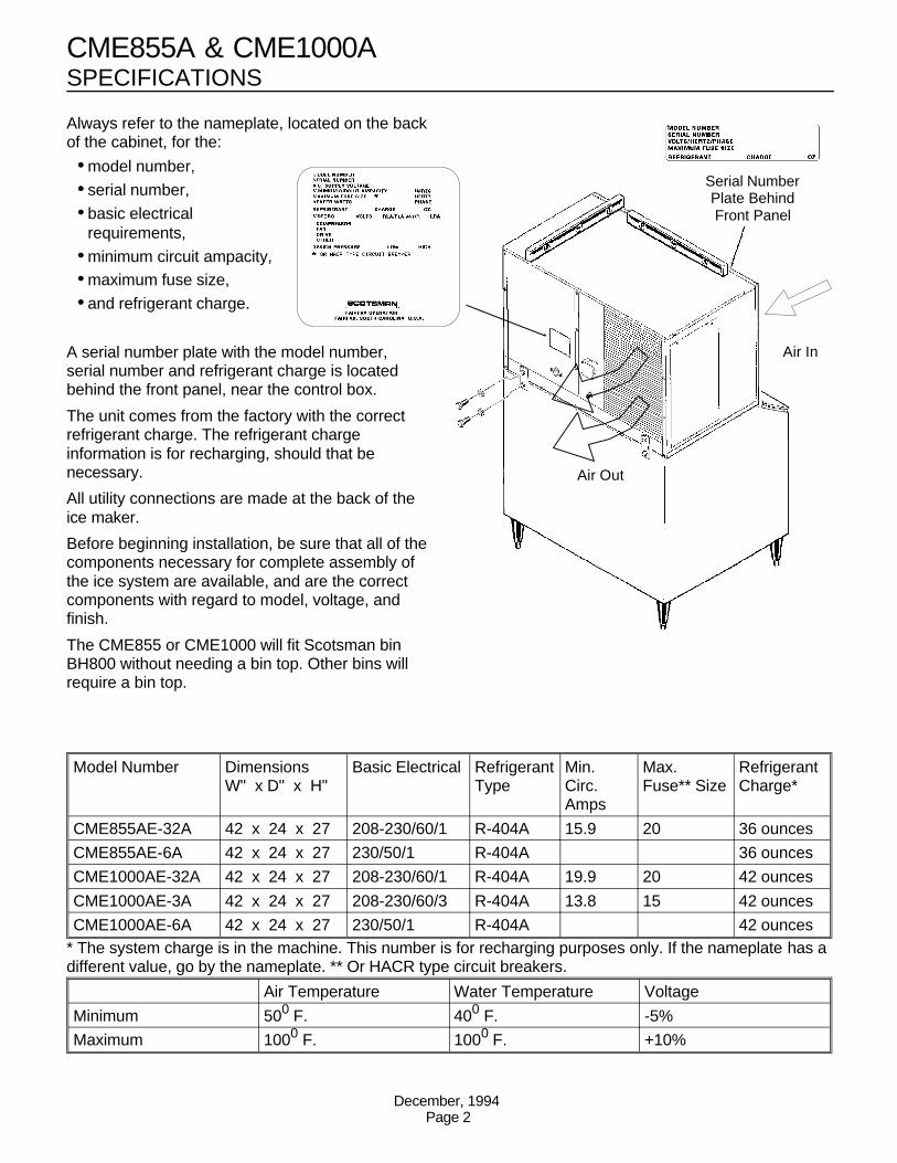
Always refer to the nameplate, located on the backof the cabinet, for the:
••model number, ••serial number, ••basic electrical
requirements, ••minimum circuit ampacity,••maximum fuse size, ••and refrigerant charge.
A serial number plate with the model number,serial number and refrigerant charge is locatedbehind the front panel, near the control box.
The unit comes from the factory with the correctrefrigerant charge. The refrigerant chargeinformation is for recharging, should that benecessary.
All utility connections are made at the back of theice maker.
Before beginning installation, be sure that all of thecomponents necessary for complete assembly ofthe ice system are available, and are the correctcomponents with regard to model, voltage, andfinish.
The CME855 or CME1000 will fit Scotsman binBH800 without needing a bin top. Other bins willrequire a bin top.
Model Number DimensionsW" x D" x H"
Basic Electrical Refrigerant Type
Min.Circ.Amps
Max.Fuse** Size
RefrigerantCharge*
CME855AE-32A 42 x 24 x 27 208-230/60/1 R-404A 15.9 20 36 ounces
CME855AE-6A 42 x 24 x 27 230/50/1 R-404A 36 ounces
CME1000AE-32A 42 x 24 x 27 208-230/60/1 R-404A 19.9 20 42 ounces
CME1000AE-3A 42 x 24 x 27 208-230/60/3 R-404A 13.8 15 42 ounces
CME1000AE-6A 42 x 24 x 27 230/50/1 R-404A 42 ounces* The system charge is in the machine. This number is for recharging purposes only. If the nameplate has adifferent value, go by the nameplate. ** Or HACR type circuit breakers.
Air Temperature Water Temperature Voltage
Minimum 500 F. 400 F. -5%
Maximum 1000 F. 1000 F. +10%
CME855A & CME1000A
December, 1994Page 2
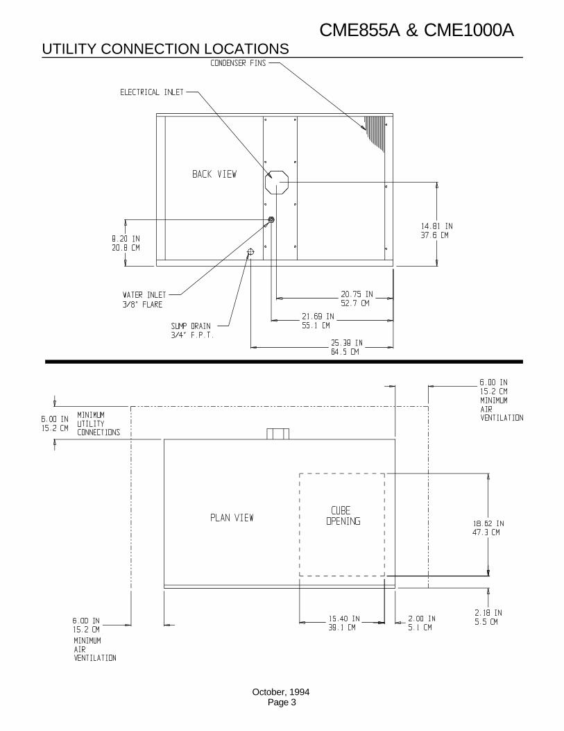
UTILITY CONNECTION LOCATIONSCME855A & CME1000A
October, 1994Page 3
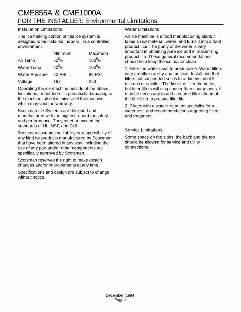
FOR THE INSTALLER: Environmental LimitationsInstallation Limitations
The ice making portion of this ice system isdesigned to be installed indoors , in a controlledenvironment.
Minimum Maximum
Air Temp 500F. 1000F.
Water Temp 400F. 1000F.
Water Pressure 20 PSI 80 PSI
Voltage 197 253
Operating the ice machine outside of the abovelimitations, or outdoors, is potentially damaging tothe machine; also it is misuse of the machine,which may void the warranty.
Scotsman Ice Systems are designed andmanufactured with the highest regard for safetyand performance. They meet or exceed thestandards of UL, NSF, and CUL.
Scotsman assumes no liability or responsibility ofany kind for products manufactured by Scotsmanthat have been altered in any way, including theuse of any part and/or other components notspecifically approved by Scotsman.
Scotsman reserves the right to make designchanges and/or improvements at any time.
Specifications and design are subject to changewithout notice.
Water Limitations
An ice machine is a food manufacturing plant; ittakes a raw material, water, and turns it into a foodproduct, ice. The purity of the water is veryimportant in obtaining pure ice and in maximizingproduct life. These general recommendationsshould help keep the ice maker clean:
1. Filter the water used to produce ice. Water filtersvary greatly in ability and function. Install one thatfilters out suspended solids to a dimension of 5microns or smaller. The finer the filter the better,but finer filters will clog sooner than course ones. Itmay be necessary to add a course filter ahead ofthe fine filter to prolong filter life.
2. Check with a water treatment specialist for awater test, and recommendations regarding filtersand treatment.
Service Limitations
Some space on the sides, the back and the topshould be allowed for service and utilityconnections.
CME855A & CME1000A
December, 1994Page 4
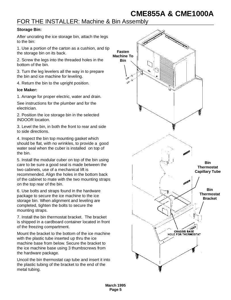
FOR THE INSTALLER: Machine & Bin AssemblyStorage Bin:
After uncrating the ice storage bin, attach the legsto the bin:
1. Use a portion of the carton as a cushion, and tipthe storage bin on its back.
2. Screw the legs into the threaded holes in thebottom of the bin.
3. Turn the leg levelers all the way in to preparethe bin and ice machine for leveling.
4. Return the bin to the upright position.
Ice Maker:
1. Arrange for proper electric, water and drain.
See instructions for the plumber and for theelectrician.
2. Position the ice storage bin in the selectedINDOOR location.
3. Level the bin, in both the front to rear and sideto side directions.
4. Inspect the bin top mounting gasket whichshould be flat, with no wrinkles, to provide a goodwater seal when the cuber is installed on top ofthe bin.
5. Install the modular cuber on top of the bin usingcare to be sure a good seal is made between thetwo cabinets, use of a mechanical lift isrecommended. Align the holes in the bottom backof the cabinet to mate with the two mounting strapson the top rear of the bin.
6. Use bolts and straps found in the hardwarepackage to secure the ice machine to the icestorage bin. When alignment and leveling arecompleted, tighten the bolts to secure themounting straps.
7. Install the bin thermostat bracket. The bracketis shipped in a cardboard container located in frontof the freezing compartment.
Mount the bracket to the bottom of the ice machinewith the plastic tube inserted up thru the icemachine base from below. Secure the bracket tothe ice machine base using 3 thumbscrews fromthe hardware package.
Uncoil the bin thermostat cap tube and insert it intothe plastic tubing of the bracket to the end of themetal tubing.
FastenMachine To
Bin
BinThermostat
Bracket
BinThermostat
Capillary Tube
CME855A & CME1000A
March 1995Page 5
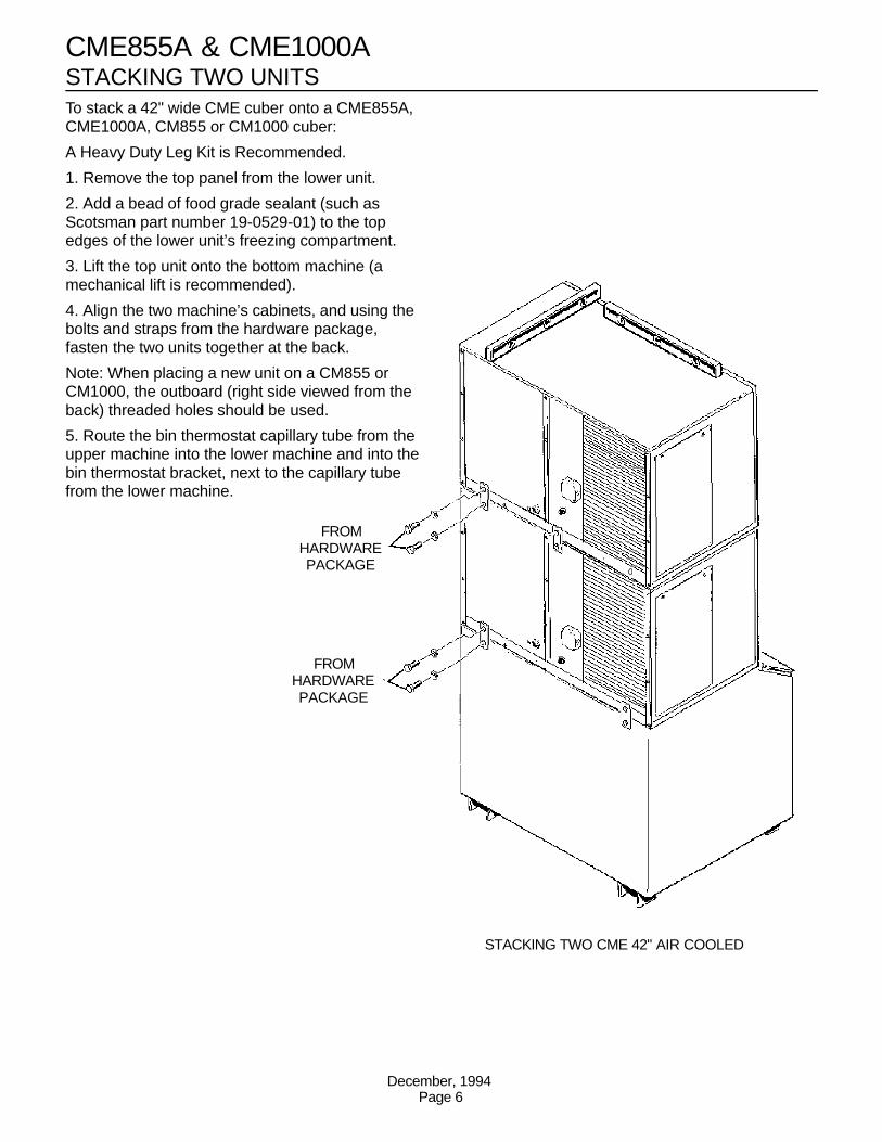
FROMHARDWAREPACKAGE
FROMHARDWAREPACKAGE
STACKING TWO CME 42" AIR COOLED
STACKING TWO UNITSTo stack a 42" wide CME cuber onto a CME855A,CME1000A, CM855 or CM1000 cuber:
A Heavy Duty Leg Kit is Recommended.
1. Remove the top panel from the lower unit.
2. Add a bead of food grade sealant (such asScotsman part number 19-0529-01) to the topedges of the lower unit’s freezing compartment.
3. Lift the top unit onto the bottom machine (amechanical lift is recommended).
4. Align the two machine’s cabinets, and using thebolts and straps from the hardware package,fasten the two units together at the back.
Note: When placing a new unit on a CM855 orCM1000, the outboard (right side viewed from theback) threaded holes should be used.
5. Route the bin thermostat capillary tube from theupper machine into the lower machine and into thebin thermostat bracket, next to the capillary tubefrom the lower machine.
CME855A & CME1000A
December, 1994Page 6
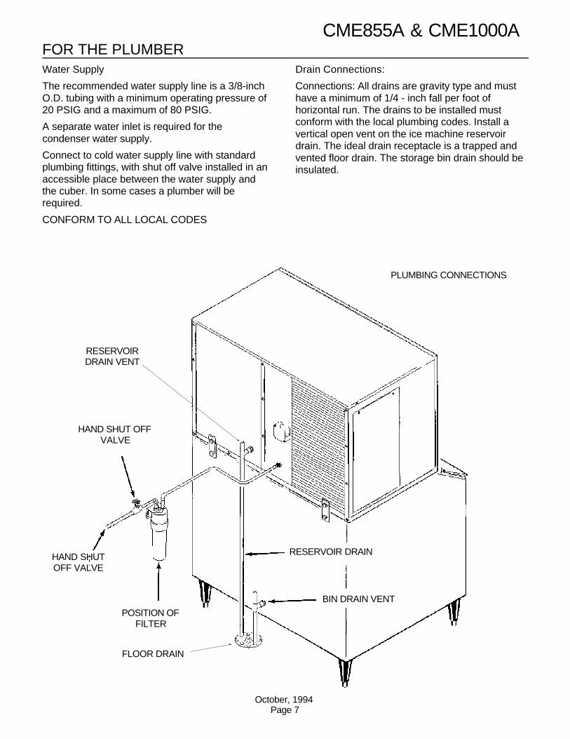
FOR THE PLUMBERWater Supply
The recommended water supply line is a 3/8-inchO.D. tubing with a minimum operating pressure of20 PSIG and a maximum of 80 PSIG.
A separate water inlet is required for thecondenser water supply.
Connect to cold water supply line with standardplumbing fittings, with shut off valve installed in anaccessible place between the water supply andthe cuber. In some cases a plumber will berequired.
CONFORM TO ALL LOCAL CODES
Drain Connections:
Connections: All drains are gravity type and musthave a minimum of 1/4 - inch fall per foot ofhorizontal run. The drains to be installed mustconform with the local plumbing codes. Install avertical open vent on the ice machine reservoirdrain. The ideal drain receptacle is a trapped andvented floor drain. The storage bin drain should beinsulated.
RESERVOIRDRAIN VENT
BIN DRAIN VENT
HAND SHUT OFFVALVE
HAND SHUTOFF VALVE
POSITION OFFILTER
FLOOR DRAIN
RESERVOIR DRAIN
PLUMBING CONNECTIONS
CME855A & CME1000A
October, 1994Page 7
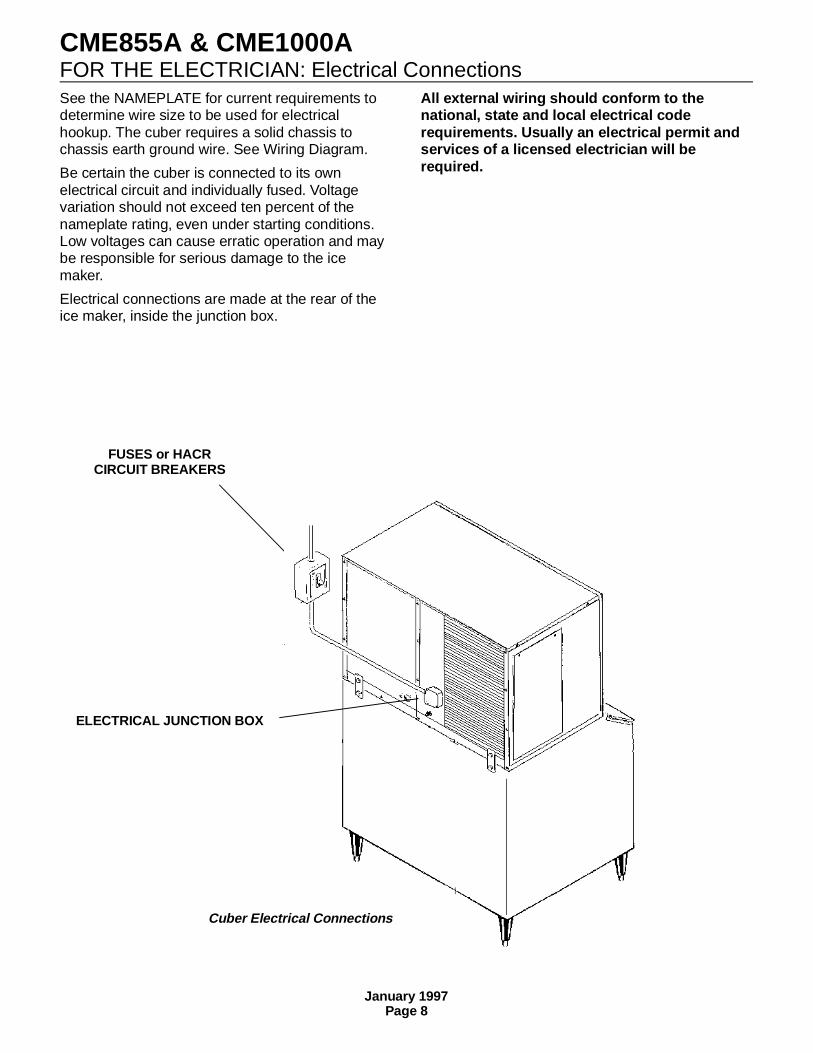
FOR THE ELECTRICIAN: Electrical Connections See the NAMEPLATE for current requirements todetermine wire size to be used for electricalhookup. The cuber requires a solid chassis tochassis earth ground wire. See Wiring Diagram.
Be certain the cuber is connected to its ownelectrical circuit and individually fused. Voltagevariation should not exceed ten percent of thenameplate rating, even under starting conditions.Low voltages can cause erratic operation and maybe responsible for serious damage to the icemaker.
Electrical connections are made at the rear of theice maker, inside the junction box.
All external wiring should conform to thenational, state and local electrical coderequirements. Usually an electrical permit andservices of a licensed electrician will berequired.
FUSES or HACRCIRCUIT BREAKERS
ELECTRICAL JUNCTION BOX
Cuber Electrical Connections
CME855A & CME1000A
January 1997Page 8
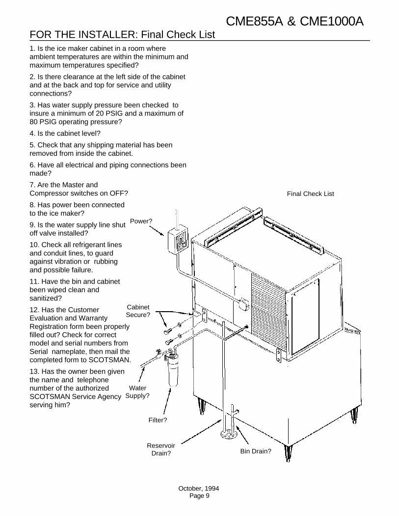
FOR THE INSTALLER: Final Check List1. Is the ice maker cabinet in a room whereambient temperatures are within the minimum andmaximum temperatures specified?
2. Is there clearance at the left side of the cabinetand at the back and top for service and utilityconnections?
3. Has water supply pressure been checked toinsure a minimum of 20 PSIG and a maximum of80 PSIG operating pressure?
4. Is the cabinet level?
5. Check that any shipping material has beenremoved from inside the cabinet.
6. Have all electrical and piping connections beenmade?
7. Are the Master andCompressor switches on OFF?
8. Has power been connectedto the ice maker?
9. Is the water supply line shutoff valve installed?
10. Check all refrigerant linesand conduit lines, to guardagainst vibration or rubbingand possible failure.
11. Have the bin and cabinetbeen wiped clean andsanitized?
12. Has the CustomerEvaluation and WarrantyRegistration form been properlyfilled out? Check for correctmodel and serial numbers fromSerial nameplate, then mail thecompleted form to SCOTSMAN.
13. Has the owner been giventhe name and telephonenumber of the authorizedSCOTSMAN Service Agencyserving him?
Power?
Bin Drain?Reservoir
Drain?
Filter?
WaterSupply?
CabinetSecure?
Final Check List
CME855A & CME1000A
October, 1994Page 9
INITIAL START UPIce Maker:
1. Remove screws and front panel.
2. Remove two screws and the control box cover.
3. Remove the evaporator cover.
4. Locate two toggle switches on the front of thecontrol box. Check that the Master ON/OFF switchand the Compressor ON-OFF switch are in theOFF position.
5. OPEN the water supply line shut off valve.
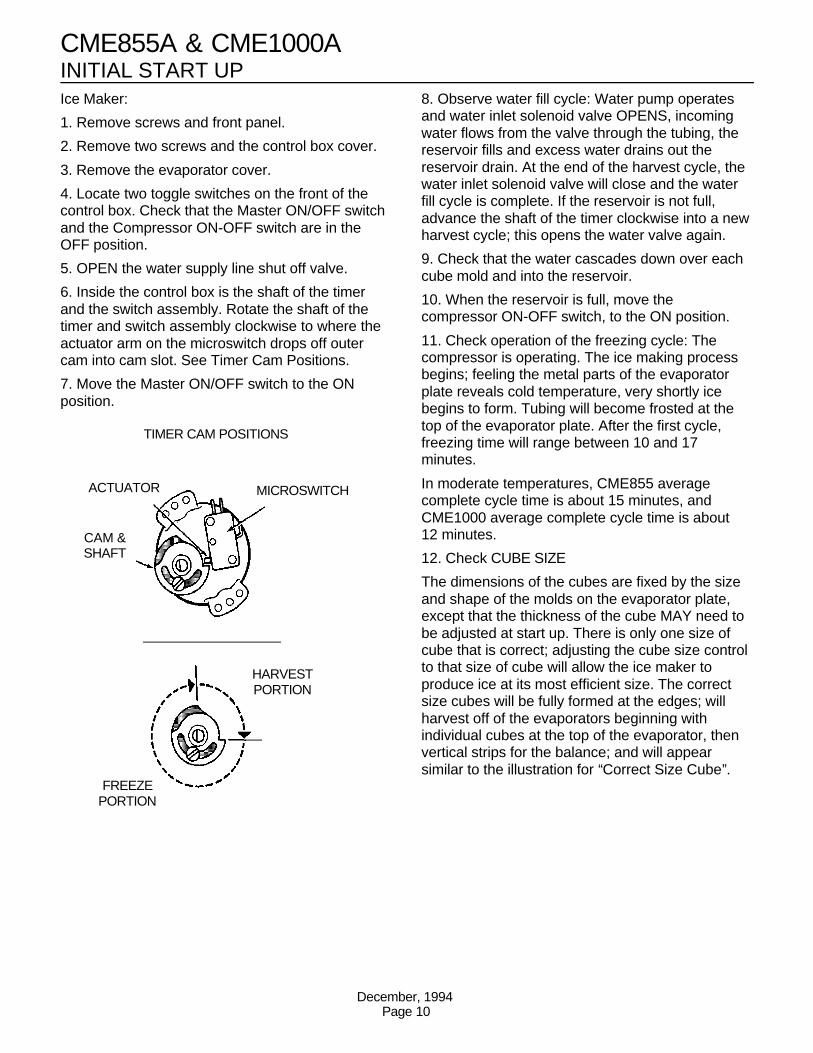
6. Inside the control box is the shaft of the timerand the switch assembly. Rotate the shaft of thetimer and switch assembly clockwise to where theactuator arm on the microswitch drops off outercam into cam slot. See Timer Cam Positions.
7. Move the Master ON/OFF switch to the ONposition.
8. Observe water fill cycle: Water pump operatesand water inlet solenoid valve OPENS, incomingwater flows from the valve through the tubing, thereservoir fills and excess water drains out thereservoir drain. At the end of the harvest cycle, thewater inlet solenoid valve will close and the waterfill cycle is complete. If the reservoir is not full,advance the shaft of the timer clockwise into a newharvest cycle; this opens the water valve again.
9. Check that the water cascades down over eachcube mold and into the reservoir.
10. When the reservoir is full, move thecompressor ON-OFF switch, to the ON position.
11. Check operation of the freezing cycle: Thecompressor is operating. The ice making processbegins; feeling the metal parts of the evaporatorplate reveals cold temperature, very shortly icebegins to form. Tubing will become frosted at thetop of the evaporator plate. After the first cycle,freezing time will range between 10 and 17minutes.
In moderate temperatures, CME855 averagecomplete cycle time is about 15 minutes, andCME1000 average complete cycle time is about12 minutes.
12. Check CUBE SIZE
The dimensions of the cubes are fixed by the sizeand shape of the molds on the evaporator plate,except that the thickness of the cube MAY need tobe adjusted at start up. There is only one size ofcube that is correct; adjusting the cube size controlto that size of cube will allow the ice maker toproduce ice at its most efficient size. The correctsize cubes will be fully formed at the edges; willharvest off of the evaporators beginning withindividual cubes at the top of the evaporator, thenvertical strips for the balance; and will appearsimilar to the illustration for ‘‘Correct Size Cube’’.
TIMER CAM POSITIONS
MICROSWITCHACTUATOR
CAM &SHAFT
HARVESTPORTION
FREEZEPORTION
CME855A & CME1000A
December, 1994Page 10
INITIAL START UPAdjust for the correct size if needed:
To produce SMALLER sized ice cubes:
Locate cube size control knob in the front of thecontrol box. Rotate this knob one eighth of a turncounter clockwise. Observe size of the ice cubesin the next ice cube harvest and adjust again ifneeded, until the correct ice cube is achieved.
To produce LARGER ice cubes:
Locate cube size control on the front of the controlbox. Rotate the knob one eighth of a turnclockwise. Observe size of ice cubes in the nextcube harvest and adjust again if needed, untilcorrect the ice cube size is achieved.
13. Check Harvest Time. The machine mustharvest all cubes before returning to a freeze cycle.
Increase the harvest time if there is less than 15seconds of harvest time after the last cube hasfallen into the bin.
Decrease the harvest time if there is much morethan 15 seconds of harvest time after the last cubehas fallen into the bin. Note: Harvest time isdependent upon the water and air temperatures atthe ice machine. Do not adjust harvest time tooshort, as this will cause a freeze up.
See the next page for detailed harvest timeadjustment instructions.
14. Check BIN THERMOSTAT
With the ice maker in the harvest cycle, hold iceagainst the metal tube of the bin thermostatbracket. The ice machine will shut off only at theend of the harvest cycle.
Remove the ice and within a few minutes the icemachine should restart.
15. Replace all panels, the machine is ready forautomatic operation.
16. Fill out and mail in the Customer Evaluationand Warranty Registration Form.
Explain to the user the specifications, operationand maintenance requirements of the ice machine.
Inform the user of the name and telephonenumber of the local service contact.
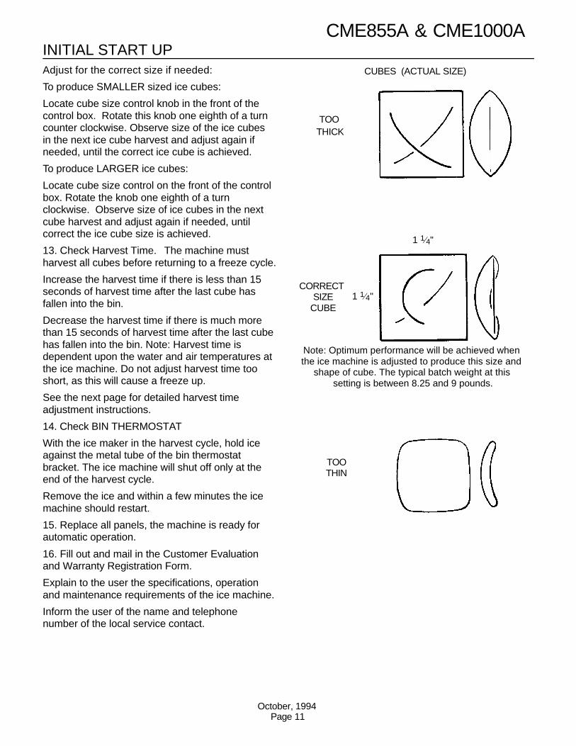
TOO THICK
CORRECT SIZE
CUBE
TOOTHIN
1 1⁄4"
1 1⁄4"
CUBES (ACTUAL SIZE)
Note: Optimum performance will be achieved whenthe ice machine is adjusted to produce this size and
shape of cube. The typical batch weight at thissetting is between 8.25 and 9 pounds.
CME855A & CME1000A
October, 1994Page 11
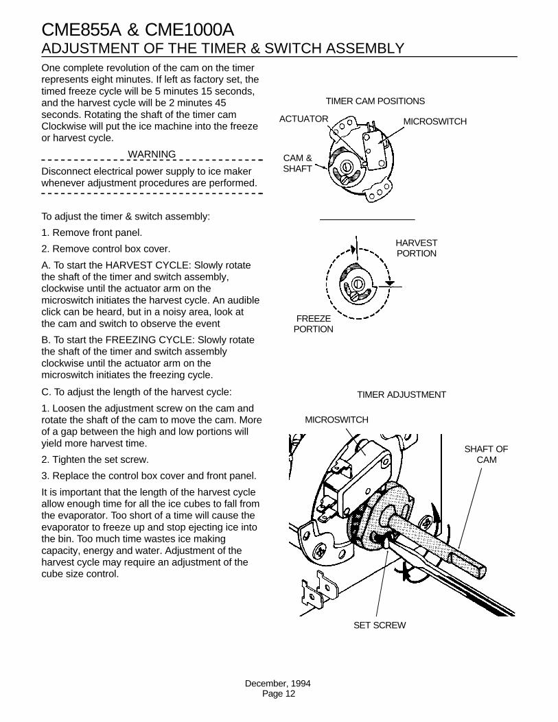
ADJUSTMENT OF THE TIMER & SWITCH ASSEMBLYOne complete revolution of the cam on the timerrepresents eight minutes. If left as factory set, thetimed freeze cycle will be 5 minutes 15 seconds,and the harvest cycle will be 2 minutes 45seconds. Rotating the shaft of the timer camClockwise will put the ice machine into the freezeor harvest cycle.
WARNING
Disconnect electrical power supply to ice makerwhenever adjustment procedures are performed.
To adjust the timer & switch assembly:
1. Remove front panel.
2. Remove control box cover.
A. To start the HARVEST CYCLE: Slowly rotatethe shaft of the timer and switch assembly,clockwise until the actuator arm on themicroswitch initiates the harvest cycle. An audibleclick can be heard, but in a noisy area, look atthe cam and switch to observe the event
B. To start the FREEZING CYCLE: Slowly rotatethe shaft of the timer and switch assemblyclockwise until the actuator arm on themicroswitch initiates the freezing cycle.
C. To adjust the length of the harvest cycle:
1. Loosen the adjustment screw on the cam androtate the shaft of the cam to move the cam. Moreof a gap between the high and low portions willyield more harvest time.
2. Tighten the set screw.
3. Replace the control box cover and front panel.
It is important that the length of the harvest cycleallow enough time for all the ice cubes to fall fromthe evaporator. Too short of a time will cause theevaporator to freeze up and stop ejecting ice intothe bin. Too much time wastes ice makingcapacity, energy and water. Adjustment of theharvest cycle may require an adjustment of thecube size control.
TIMER CAM POSITIONS
MICROSWITCHACTUATOR
CAM &SHAFT
HARVESTPORTION
FREEZEPORTION
TIMER ADJUSTMENT
MICROSWITCH
SHAFT OFCAM
SET SCREW
CME855A & CME1000A
December, 1994Page 12
DrierThermostatic
Expansion Valve
Hot Gas Valve
Condenser
SuctionLine
EvaporatorsCompressor
HotGasLine
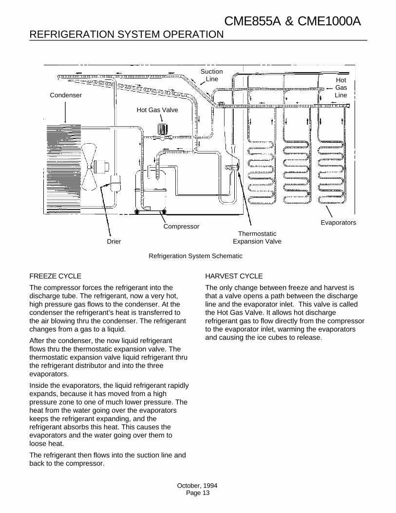
Refrigeration System Schematic
REFRIGERATION SYSTEM OPERATION
FREEZE CYCLE
The compressor forces the refrigerant into thedischarge tube. The refrigerant, now a very hot,high pressure gas flows to the condenser. At thecondenser the refrigerant’s heat is transferred tothe air blowing thru the condenser. The refrigerantchanges from a gas to a liquid.
After the condenser, the now liquid refrigerantflows thru the thermostatic expansion valve. Thethermostatic expansion valve liquid refrigerant thruthe refrigerant distributor and into the threeevaporators.
Inside the evaporators, the liquid refrigerant rapidlyexpands, because it has moved from a highpressure zone to one of much lower pressure. Theheat from the water going over the evaporatorskeeps the refrigerant expanding, and therefrigerant absorbs this heat. This causes theevaporators and the water going over them toloose heat.
The refrigerant then flows into the suction line andback to the compressor.
HARVEST CYCLE
The only change between freeze and harvest isthat a valve opens a path between the dischargeline and the evaporator inlet. This valve is calledthe Hot Gas Valve. It allows hot dischargerefrigerant gas to flow directly from the compressorto the evaporator inlet, warming the evaporatorsand causing the ice cubes to release.
CME855A & CME1000A
October, 1994Page 13
Evaporators
Water Manifold andDistributors
Reservoir
Water Pump
Drain
Inlet Water Valve
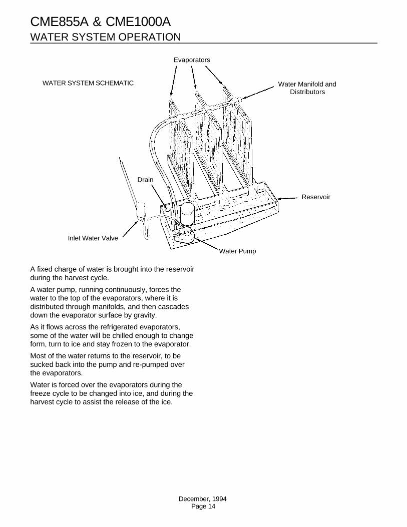
WATER SYSTEM SCHEMATIC
WATER SYSTEM OPERATION
A fixed charge of water is brought into the reservoirduring the harvest cycle.
A water pump, running continuously, forces thewater to the top of the evaporators, where it isdistributed through manifolds, and then cascadesdown the evaporator surface by gravity.
As it flows across the refrigerated evaporators,some of the water will be chilled enough to changeform, turn to ice and stay frozen to the evaporator.
Most of the water returns to the reservoir, to besucked back into the pump and re-pumped overthe evaporators.
Water is forced over the evaporators during thefreeze cycle to be changed into ice, and during theharvest cycle to assist the release of the ice.
CME855A & CME1000A
December, 1994Page 14

COMPONENT DESCRIPTIONCompressor Contactor
The compressor contactor carries the compressorline current. The compressor contactor coil haspower whenever the ice machine is making orharvesting ice.
Cube Size Control
This reverse acting (closes on temperature fall)thermostat determines how long the freezing cyclewill be. The cube size control closes it’s contactswhen the evaporator & suction line cools to the settemperature. When the cube size control closes, itconnects power to the timer motor. A variation inheat load (either ambient air or incoming watertemperature) will affect the efficiency of therefrigeration system, and that will vary the length oftime it takes the evaporators to cool to thetemperature at which the cube size control is set toclose, which, in turn, will affect the overall cycletime. See CUBE SIZE ADJUSTMENT BEFOREattempting to adjust the control.
Relay
The multi-function, three pole, double throw, relayplugs into a socket on the printed circuit board inthe control box. When the relay coil has power, themachine is in a freeze cycle, and when power isremoved from the coil, the machine will be in theharvest cycle.
The relay also by-passes the bin control during theharvest and freeze cycles, preventing the icemaker from shutting off in the middle of a cycle.The bypass action allows only complete freezeand harvest cycles; the only time that the icemaker can shut off on bin control is as the end ofthe harvest cycle.
Timer - Timer & Switch Assembly
The timer begins to turn when activated by thecube size control. The outer surface, or largediameter lobe of the timer cam, determines thelength of time for finish freezing of the ice cubes,while the inner surface, or small diameter lobe,determines length of the harvest cycle. Thesingle-pole, double throw microswitch on the timercontrols the power to the plug in relay coil, makingit either the freezing or harvest cycle. Themicroswitch is actuated by the cams connected tothe timer motor. The timer cam can be adjusted tovary the defrost time, as required. One completerotation of the cam will take eight minutes.
Hot Gas Solenoid Valve
The hot gas solenoid valve opens only during theharvest cycle. When it opens, it diverts the hotdischarge gases so that they flow directly into theevaporator plates, by-passing the condenser andthermostatic expansion valve. The hot gases warmthe evaporators, releasing the ice cubes from theice cube molds. The hot gas solenoid valve isinstalled in a branch of the discharge line, andwhen the timer switches the ice machine into theharvest cycle, the energized solenoid coil lifts thevalve stem within the valve body, allowing the hotdischarge gas to be diverted to the evaporators.
High Temperature Cut Out
This temperature sensor is located next to the hotgas valve, on the outlet side.
Cut Out is 140oF., Cut In is 110oF.
During normal operation, it does not affect the icemachine, but it will shut the machine off if the hotgas line overheats. It is an automatic reset.
CME855A & CME1000A
October, 1994Page 15
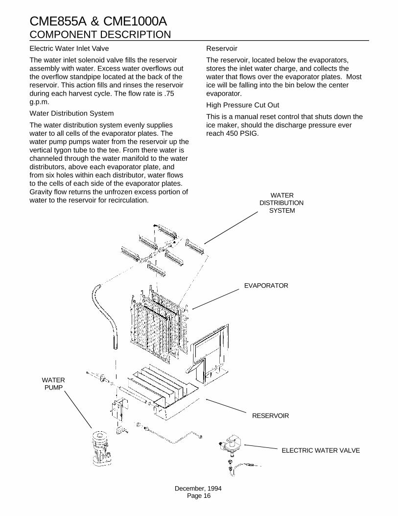
COMPONENT DESCRIPTIONElectric Water Inlet Valve
The water inlet solenoid valve fills the reservoirassembly with water. Excess water overflows outthe overflow standpipe located at the back of thereservoir. This action fills and rinses the reservoirduring each harvest cycle. The flow rate is .75g.p.m.
Water Distribution System
The water distribution system evenly supplieswater to all cells of the evaporator plates. Thewater pump pumps water from the reservoir up thevertical tygon tube to the tee. From there water ischanneled through the water manifold to the waterdistributors, above each evaporator plate, andfrom six holes within each distributor, water flowsto the cells of each side of the evaporator plates.Gravity flow returns the unfrozen excess portion ofwater to the reservoir for recirculation.
Reservoir
The reservoir, located below the evaporators,stores the inlet water charge, and collects thewater that flows over the evaporator plates. Mostice will be falling into the bin below the centerevaporator.
High Pressure Cut Out
This is a manual reset control that shuts down theice maker, should the discharge pressure everreach 450 PSIG.
WATERDISTRIBUTION
SYSTEM
RESERVOIR
ELECTRIC WATER VALVE
EVAPORATOR
WATERPUMP
CME855A & CME1000A
December, 1994Page 16
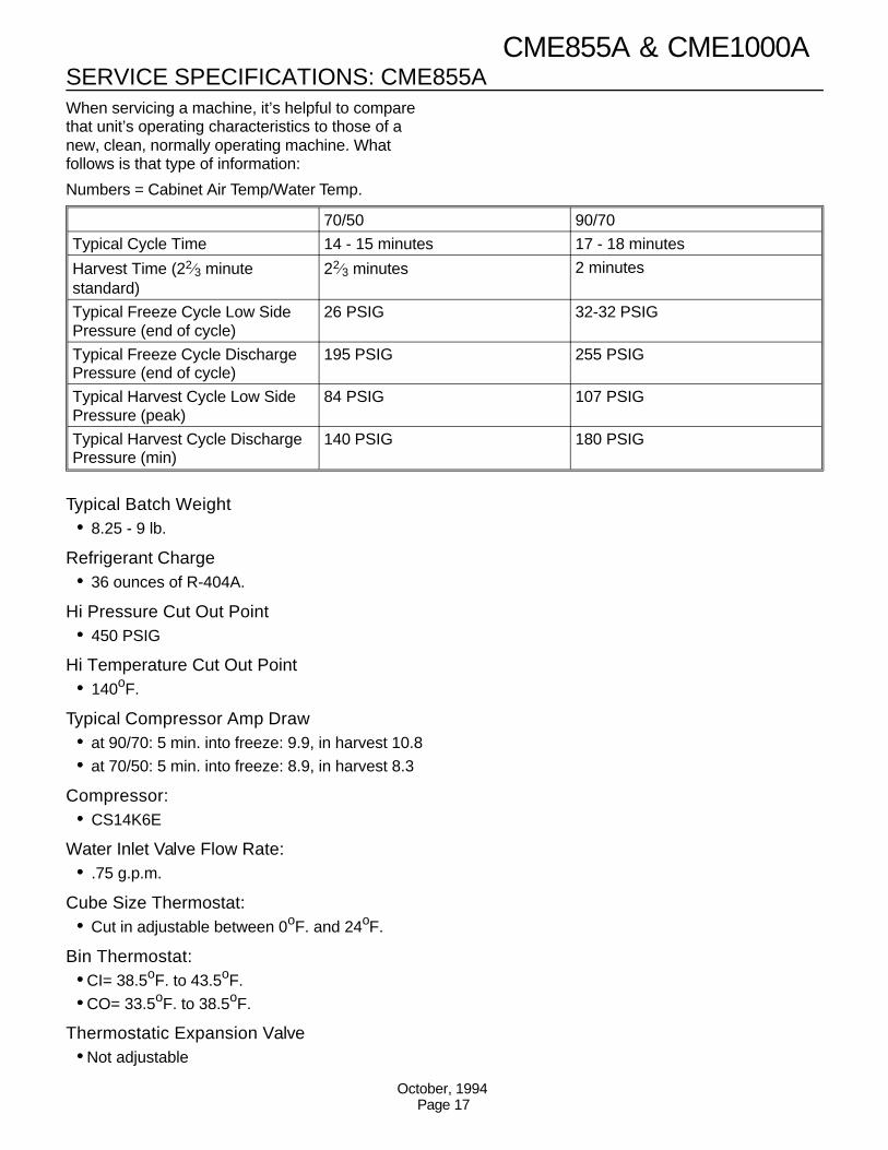
SERVICE SPECIFICATIONS: CME855AWhen servicing a machine, it’s helpful to comparethat unit’s operating characteristics to those of anew, clean, normally operating machine. Whatfollows is that type of information:
Numbers = Cabinet Air Temp/Water Temp.
Typical Batch Weight•• 8.25 - 9 lb.
Refrigerant Charge•• 36 ounces of R-404A.
Hi Pressure Cut Out Point•• 450 PSIG
Hi Temperature Cut Out Point•• 140oF.
Typical Compressor Amp Draw•• at 90/70: 5 min. into freeze: 9.9, in harvest 10.8•• at 70/50: 5 min. into freeze: 8.9, in harvest 8.3
Compressor:•• CS14K6E
Water Inlet Valve Flow Rate:•• .75 g.p.m.
Cube Size Thermostat:•• Cut in adjustable between 0oF. and 24oF.
Bin Thermostat:••CI= 38.5oF. to 43.5oF. ••CO= 33.5oF. to 38.5oF.
Thermostatic Expansion Valve••Not adjustable
70/50 90/70
Typical Cycle Time 14 - 15 minutes 17 - 18 minutes
Harvest Time (22⁄3 minutestandard)
22⁄3 minutes 2 minutes
Typical Freeze Cycle Low SidePressure (end of cycle)
26 PSIG 32-32 PSIG
Typical Freeze Cycle DischargePressure (end of cycle)
195 PSIG 255 PSIG
Typical Harvest Cycle Low SidePressure (peak)
84 PSIG 107 PSIG
Typical Harvest Cycle DischargePressure (min)
140 PSIG 180 PSIG
CME855A & CME1000A
October, 1994Page 17
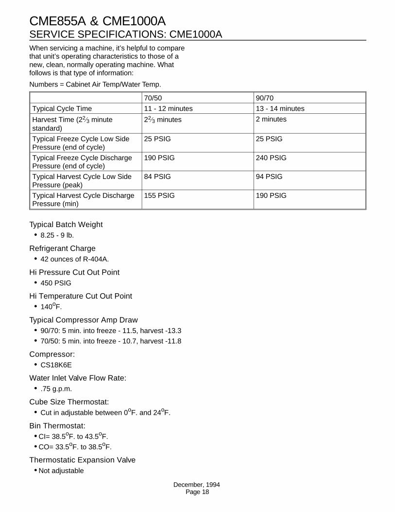
SERVICE SPECIFICATIONS: CME1000AWhen servicing a machine, it’s helpful to comparethat unit’s operating characteristics to those of anew, clean, normally operating machine. Whatfollows is that type of information:
Numbers = Cabinet Air Temp/Water Temp.
Typical Batch Weight•• 8.25 - 9 lb.
Refrigerant Charge•• 42 ounces of R-404A.
Hi Pressure Cut Out Point•• 450 PSIG
Hi Temperature Cut Out Point•• 140oF.
Typical Compressor Amp Draw•• 90/70: 5 min. into freeze - 11.5, harvest -13.3•• 70/50: 5 min. into freeze - 10.7, harvest -11.8
Compressor:•• CS18K6E
Water Inlet Valve Flow Rate:•• .75 g.p.m.
Cube Size Thermostat:•• Cut in adjustable between 0oF. and 24oF.
Bin Thermostat:••CI= 38.5oF. to 43.5oF. ••CO= 33.5oF. to 38.5oF.
Thermostatic Expansion Valve••Not adjustable
70/50 90/70
Typical Cycle Time 11 - 12 minutes 13 - 14 minutes
Harvest Time (22⁄3 minutestandard)
22⁄3 minutes 2 minutes
Typical Freeze Cycle Low SidePressure (end of cycle)
25 PSIG 25 PSIG
Typical Freeze Cycle DischargePressure (end of cycle)
190 PSIG 240 PSIG
Typical Harvest Cycle Low SidePressure (peak)
84 PSIG 94 PSIG
Typical Harvest Cycle DischargePressure (min)
155 PSIG 190 PSIG
CME855A & CME1000A
December, 1994Page 18
CLEANING
A Scotsman Ice System represents a sizable investment of time and money in any company’s business. Inorder to receive the best return for that investment, it MUST receive periodic maintenance.Maintenance and Cleaning should be scheduled at a minimum of twice per year.
CLEANING: ICE MAKER
1. Remove front panel.
2. Switch the Wash/Off/Ice switch to OFF.
3. Remove the front liner.
4. Remove and discard all ice from the storage bin.
5. Locate the reservoir drain and drain thereservoir. If the reservoir doesn’t drain completely,disconnect the pump hose attached to the waterdistributors and place the end of the hose in abucket. Switch the Wash/Off/Ice switch to Wash,and allow the pump to discharge the rest of thewater. Reattach the hose to the water distributors.
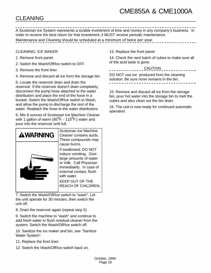
6. Mix 8 ounces of Scotsman Ice Machine Cleanerwith 1 gallon of warm (950F. - 1150F.) water andpour into the reservoir until full.
7. Switch the Wash/Off/Ice switch to ‘‘wash’’. Letthe unit operate for 30 minutes, then switch theunit off.
8. Drain the reservoir again (repeat step 5)
9. Switch the machine to ‘‘wash’’ and continue toadd fresh water to flush residual cleaner from thesystem. Switch the Wash/Off/Ice switch off.
10. Sanitize the ice maker and bin, see ‘‘SanitizeWater System’’.
11. Replace the front liner.
12. Switch the Wash/Off/Ice switch back on.
13. Replace the front panel
14. Check the next batch of cubes to make sure allof the acid taste is gone.
CAUTION
DO NOT use ice produced from the cleaningsolution. Be sure none remains in the bin.
15. Remove and discard all ice from the storagebin, pour hot water into the storage bin to melt thecubes and also clean out the bin drain.
16. The unit is now ready for continued automaticoperation.
Scotsman Ice MachineCleaner contains acids.These compounds maycause burns. If swallowed, DO NOTinduce vomiting. Givelarge amounts of wateror milk. Call Physicianimmediately. In case ofexternal contact, flushwith water. KEEP OUT OF THEREACH OF CHILDREN.
CME855A & CME1000A
October, 1994Page 19
CLEANINGSANITIZE WATER SYSTEM
1. Remove and discard all ice from the bin.
2. Remove front panel.
3. Drain the reservoir
4. Prepare 2 gallons of an approved sanitizersolution in accordance with the instructions on thepackage, or use the following instructions for useof household bleach, if it meets local codes:
Mix a sanitizing solution of 1 ounce of householdbleach to 2 gallons of water.
5. Pour 1 gallon of the sanitizer into the ice makerreservoir.
6. Move the Wash/Off/Switch switch to ‘‘Wash’’,and allow the solution to circulate for a MINIMUMof 5 minutes.
7. Move the Wash/Off/Switch switch to ‘‘Off’’.
8. Remove the drain plug and drain the reservoir.
9. Using a clean sponge and the remainder of thesanitizer solution, wipe the interior of theevaporator cover and the inside of the storage bin,taking care to wipe all surfaces that are normally incontact with ice.
10. Replace the evaporator cover. Replace thefront panel.
11. Move the master switch to ON.
SANITIZE ICE STORAGE BIN
This procedure is to be done monthly
1. Remove and discard all ice from the bin.
2. Switch the ice maker off.
2. Prepare 2 gallons of an approved sanitizersolution in accordance with the instructions on thepackage, or use the following instructions for useof household bleach, if it meets local codes: Mix asanitizing solution of 1 ounce of household bleachto 2 gallons of water.
3. Using clean rubber gloves and a clean cloth,wipe all interior surfaces of the ice machine andice storage bin with the sanitizing solution.Immerse any small parts in the sanitizing solutionand wash the parts, flushing the solutionthoroughly in, over and through all parts andsurfaces of the parts being cleaned.
4. Allow to air dry.
5. Switch the ice machine back on.
CME855A & CME1000A
December, 1994Page 20
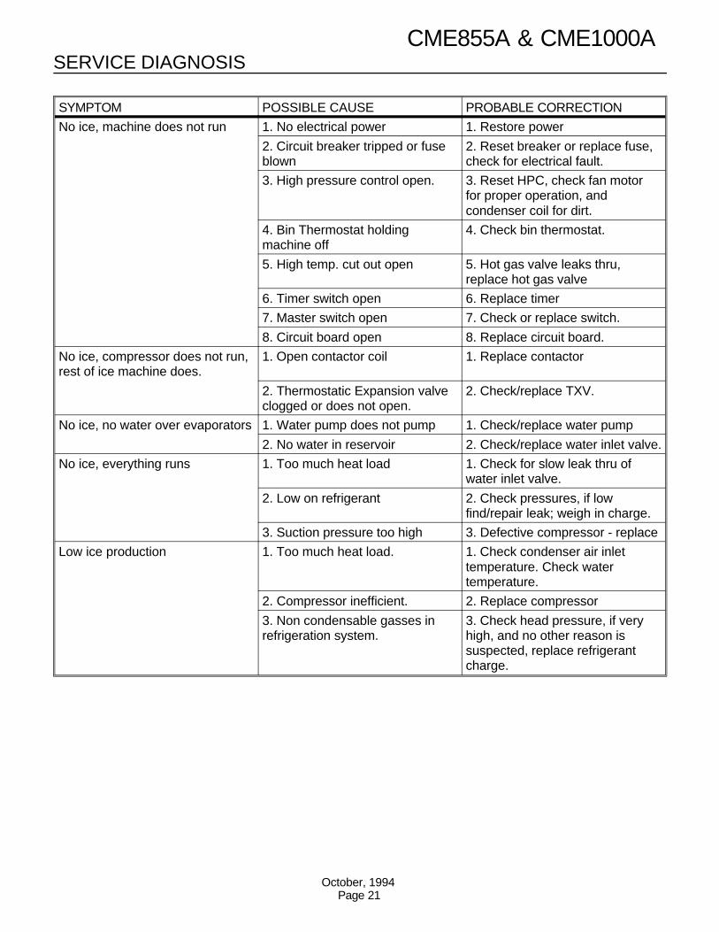
SERVICE DIAGNOSIS
SYMPTOM POSSIBLE CAUSE PROBABLE CORRECTION
No ice, machine does not run 1. No electrical power 1. Restore power
2. Circuit breaker tripped or fuseblown
2. Reset breaker or replace fuse,check for electrical fault.
3. High pressure control open. 3. Reset HPC, check fan motorfor proper operation, andcondenser coil for dirt.
4. Bin Thermostat holdingmachine off
4. Check bin thermostat.
5. High temp. cut out open 5. Hot gas valve leaks thru,replace hot gas valve
6. Timer switch open 6. Replace timer
7. Master switch open 7. Check or replace switch.
8. Circuit board open 8. Replace circuit board.
No ice, compressor does not run,rest of ice machine does.
1. Open contactor coil 1. Replace contactor
2. Thermostatic Expansion valveclogged or does not open.
2. Check/replace TXV.
No ice, no water over evaporators 1. Water pump does not pump 1. Check/replace water pump
2. No water in reservoir 2. Check/replace water inlet valve.
No ice, everything runs 1. Too much heat load 1. Check for slow leak thru ofwater inlet valve.
2. Low on refrigerant 2. Check pressures, if lowfind/repair leak; weigh in charge.
3. Suction pressure too high 3. Defective compressor - replace
Low ice production 1. Too much heat load. 1. Check condenser air inlettemperature. Check watertemperature.
2. Compressor inefficient. 2. Replace compressor
3. Non condensable gasses inrefrigeration system.
3. Check head pressure, if veryhigh, and no other reason issuspected, replace refrigerantcharge.
CME855A & CME1000A
October, 1994Page 21
SERVICE DIAGNOSISSYMPTOM POSSIBLE CAUSE PROBABLE CORRECTION
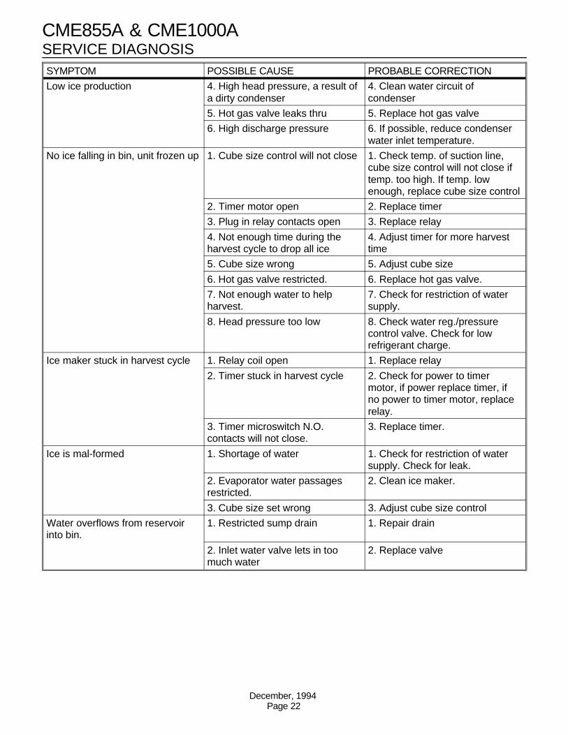
Low ice production 4. High head pressure, a result ofa dirty condenser
4. Clean water circuit ofcondenser
5. Hot gas valve leaks thru 5. Replace hot gas valve
6. High discharge pressure 6. If possible, reduce condenserwater inlet temperature.
No ice falling in bin, unit frozen up 1. Cube size control will not close 1. Check temp. of suction line,cube size control will not close iftemp. too high. If temp. lowenough, replace cube size control
2. Timer motor open 2. Replace timer
3. Plug in relay contacts open 3. Replace relay
4. Not enough time during theharvest cycle to drop all ice
4. Adjust timer for more harvesttime
5. Cube size wrong 5. Adjust cube size
6. Hot gas valve restricted. 6. Replace hot gas valve.
7. Not enough water to helpharvest.
7. Check for restriction of watersupply.
8. Head pressure too low 8. Check water reg./pressurecontrol valve. Check for lowrefrigerant charge.
Ice maker stuck in harvest cycle 1. Relay coil open 1. Replace relay
2. Timer stuck in harvest cycle 2. Check for power to timermotor, if power replace timer, ifno power to timer motor, replacerelay.
3. Timer microswitch N.O.contacts will not close.
3. Replace timer.
Ice is mal-formed 1. Shortage of water 1. Check for restriction of watersupply. Check for leak.
2. Evaporator water passagesrestricted.
2. Clean ice maker.
3. Cube size set wrong 3. Adjust cube size control
Water overflows from reservoirinto bin.
1. Restricted sump drain 1. Repair drain
2. Inlet water valve lets in toomuch water
2. Replace valve
CME855A & CME1000A
December, 1994Page 22
REMOVAL AND REPLACEMENT
Cube Size Control
To remove the cube size control:
1. Remove front panel.
2. Remove cover from control box.
3. Trace capillary tube, from the cube size controlto the refrigerant suction line.
4. Remove the coiled capillary tube bulb from thetube well on the suction line.
5. Remove electrical leads from the cube sizecontrol.
6. Remove screws and the cube size control. Toreplace the cube size control, reverse the removalprocedure. Be certain to re-insulate the cube sizecontrol bulb.
Water Distributor Tubes And Manifold Tubes
To remove the water distributor tube and manifoldtube:
1. Pull out to unsnap catches and remove the frontpanel.
2. Remove the evaporator cover.
3. Slide the water distributor tube to the front about1/8-inch along the top of the evaporator plate, untilthe water distributor tube can be unsnapped fromthe flexible notch and lifted upward to the rightside.
4. Unsnap and disconnect water distributor tubesfrom the water manifold section. To replace thewater distributor tubes and manifold tubes, reversethe removal procedure.
BE SURE the notches in the water manifold tubesproperly engage the alignment keys in the tee. BESURE the water distributor tube is securelyfastened at the notch at both sides of theevaporator plate.
Check identical attachment for the left waterdistributor tube and notch; also, that thedistributor/manifold connections at the top centerof each evaporator plate is snug against the top ofthe plate.
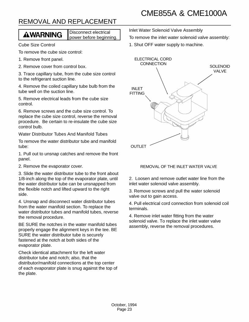
Inlet Water Solenoid Valve Assembly
To remove the inlet water solenoid valve assembly:
1. Shut OFF water supply to machine.
2. Loosen and remove outlet water line from theinlet water solenoid valve assembly.
3. Remove screws and pull the water solenoidvalve out to gain access.
4. Pull electrical cord connection from solenoid coilterminals.
4. Remove inlet water fitting from the watersolenoid valve. To replace the inlet water valveassembly, reverse the removal procedures.
ELECTRICAL CORDCONNECTION
SOLENOIDVALVE
OUTLET
REMOVAL OF THE INLET WATER VALVE
INLETFITTING
Disconnect electricalpower before beginning.
CME855A & CME1000A
October, 1994Page 23
REMOVAL AND REPLACEMENT
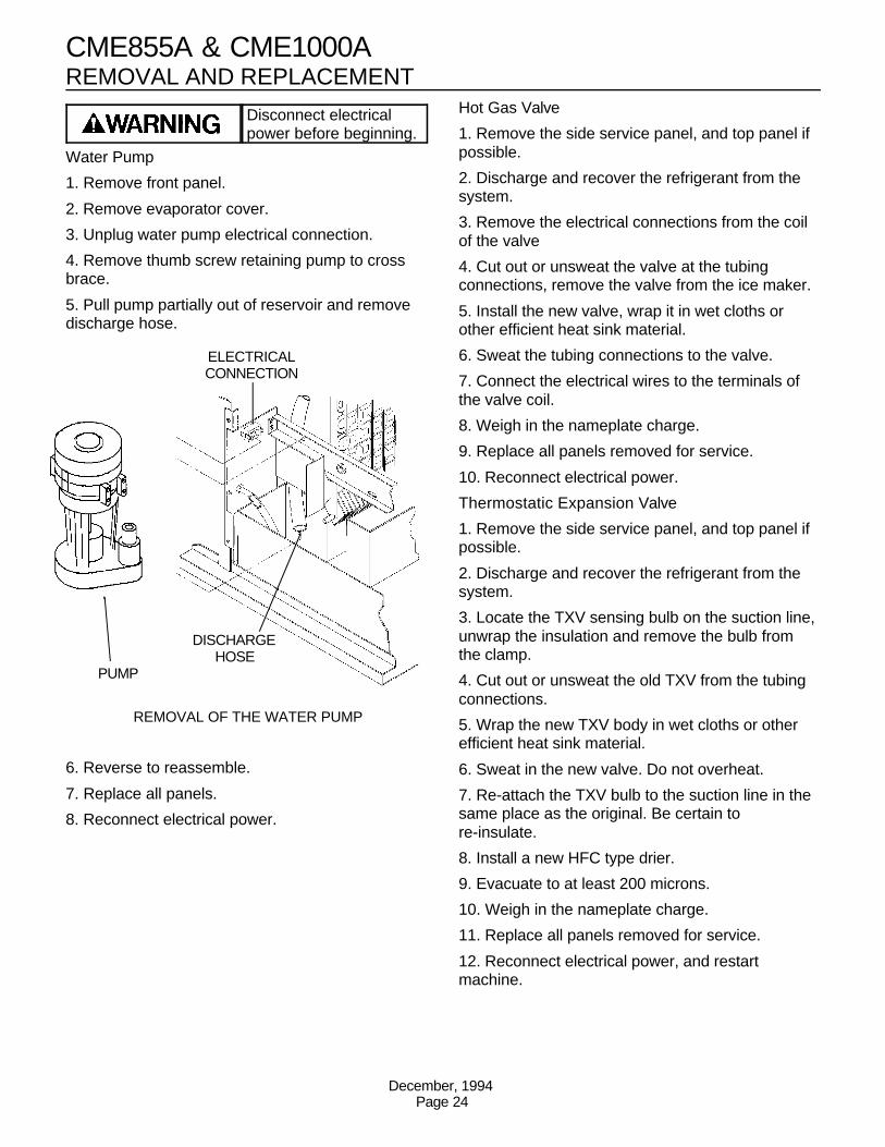
Water Pump
1. Remove front panel.
2. Remove evaporator cover.
3. Unplug water pump electrical connection.
4. Remove thumb screw retaining pump to crossbrace.
5. Pull pump partially out of reservoir and removedischarge hose.
6. Reverse to reassemble.
7. Replace all panels.
8. Reconnect electrical power.
Hot Gas Valve
1. Remove the side service panel, and top panel ifpossible.
2. Discharge and recover the refrigerant from thesystem.
3. Remove the electrical connections from the coilof the valve
4. Cut out or unsweat the valve at the tubingconnections, remove the valve from the ice maker.
5. Install the new valve, wrap it in wet cloths orother efficient heat sink material.
6. Sweat the tubing connections to the valve.
7. Connect the electrical wires to the terminals ofthe valve coil.
8. Weigh in the nameplate charge.
9. Replace all panels removed for service.
10. Reconnect electrical power.
Thermostatic Expansion Valve
1. Remove the side service panel, and top panel ifpossible.
2. Discharge and recover the refrigerant from thesystem.
3. Locate the TXV sensing bulb on the suction line,unwrap the insulation and remove the bulb fromthe clamp.
4. Cut out or unsweat the old TXV from the tubingconnections.
5. Wrap the new TXV body in wet cloths or otherefficient heat sink material.
6. Sweat in the new valve. Do not overheat.
7. Re-attach the TXV bulb to the suction line in thesame place as the original. Be certain tore-insulate.
8. Install a new HFC type drier.
9. Evacuate to at least 200 microns.
10. Weigh in the nameplate charge.
11. Replace all panels removed for service.
12. Reconnect electrical power, and restartmachine.
PUMP
DISCHARGEHOSE
ELECTRICALCONNECTION
REMOVAL OF THE WATER PUMP
Disconnect electricalpower before beginning.
CME855A & CME1000A
December, 1994Page 24
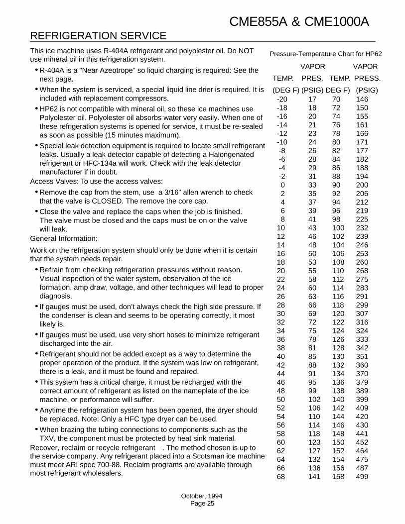
VAPOR VAPOR
TEMP. PRES. TEMP. PRESS.
(DEG F) (PSIG) DEG F) (PSIG)-20 17 70 146-18 18 72 150-16 20 74 155-14 21 76 161-12 23 78 166-10 24 80 171 -8 26 82 177 -6 28 84 182 -4 29 86 188 -2 31 88 194 0 33 90 200 2 35 92 206 4 37 94 212 6 39 96 219 8 41 98 22510 43 100 23212 46 102 23914 48 104 24616 50 106 25318 53 108 26020 55 110 26822 58 112 27524 60 114 28326 63 116 29128 66 118 29930 69 120 30732 72 122 31634 75 124 32436 78 126 33338 81 128 34240 85 130 35142 88 132 36044 91 134 37046 95 136 37948 99 138 38950 102 140 39952 106 142 40954 110 144 42056 114 146 43058 118 148 44160 123 150 45262 127 152 46464 132 154 47566 136 156 48768 141 158 499
Pressure-Temperature Chart for HP62This ice machine uses R-404A refrigerant and polyolester oil. Do NOTuse mineral oil in this refrigeration system.
••R-404A is a "Near Azeotrope" so liquid charging is required: See thenext page.
••When the system is serviced, a special liquid line drier is required. It isincluded with replacement compressors.
••HP62 is not compatible with mineral oil, so these ice machines usePolyolester oil. Polyolester oil absorbs water very easily. When one ofthese refrigeration systems is opened for service, it must be re-sealedas soon as possible (15 minutes maximum).
••Special leak detection equipment is required to locate small refrigerantleaks. Usually a leak detector capable of detecting a Halongenatedrefrigerant or HFC-134a will work. Check with the leak detectormanufacturer if in doubt.
Access Valves: To use the access valves:
••Remove the cap from the stem, use a 3/16" allen wrench to checkthat the valve is CLOSED. The remove the core cap.
••Close the valve and replace the caps when the job is finished.The valve must be closed and the caps must be on or the valvewill leak.
General Information:
Work on the refrigeration system should only be done when it is certainthat the system needs repair.
••Refrain from checking refrigeration pressures without reason.Visual inspection of the water system, observation of the iceformation, amp draw, voltage, and other techniques will lead to properdiagnosis.
••If gauges must be used, don’t always check the high side pressure. Ifthe condenser is clean and seems to be operating correctly, it mostlikely is.
••If gauges must be used, use very short hoses to minimize refrigerantdischarged into the air.
••Refrigerant should not be added except as a way to determine theproper operation of the product. If the system was low on refrigerant,there is a leak, and it must be found and repaired.
••This system has a critical charge, it must be recharged with thecorrect amount of refrigerant as listed on the nameplate of the icemachine, or performance will suffer.
••Anytime the refrigeration system has been opened, the dryer shouldbe replaced. Note: Only a HFC type dryer can be used.
••When brazing the tubing connections to components such as theTXV, the component must be protected by heat sink material.
Recover, reclaim or recycle refrigerant . The method chosen is up tothe service company. Any refrigerant placed into a Scotsman ice machinemust meet ARI spec 700-88. Reclaim programs are available throughmost refrigerant wholesalers.
REFRIGERATION SERVICECME855A & CME1000A
October, 1994Page 25
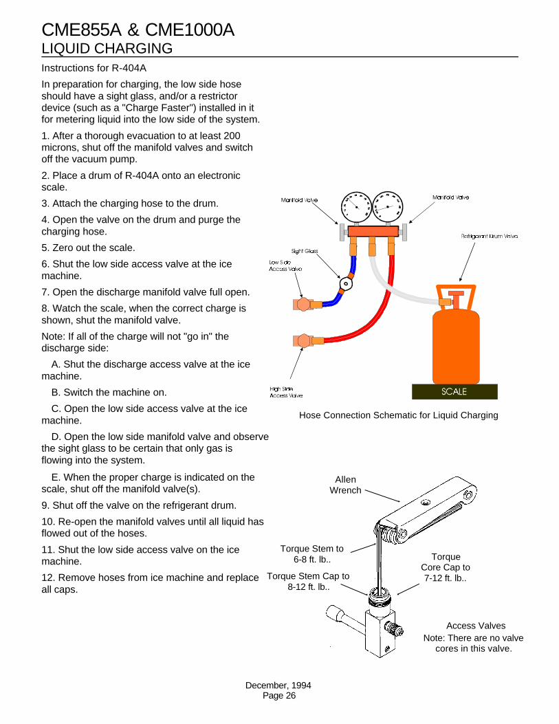
LIQUID CHARGING Instructions for R-404A
In preparation for charging, the low side hoseshould have a sight glass, and/or a restrictordevice (such as a "Charge Faster") installed in itfor metering liquid into the low side of the system.
1. After a thorough evacuation to at least 200microns, shut off the manifold valves and switchoff the vacuum pump.
2. Place a drum of R-404A onto an electronicscale.
3. Attach the charging hose to the drum.
4. Open the valve on the drum and purge thecharging hose.
5. Zero out the scale.
6. Shut the low side access valve at the icemachine.
7. Open the discharge manifold valve full open.
8. Watch the scale, when the correct charge isshown, shut the manifold valve.
Note: If all of the charge will not "go in" thedischarge side:
A. Shut the discharge access valve at the icemachine.
B. Switch the machine on.
C. Open the low side access valve at the icemachine.
D. Open the low side manifold valve and observethe sight glass to be certain that only gas isflowing into the system.
E. When the proper charge is indicated on thescale, shut off the manifold valve(s).
9. Shut off the valve on the refrigerant drum.
10. Re-open the manifold valves until all liquid hasflowed out of the hoses.
11. Shut the low side access valve on the icemachine.
12. Remove hoses from ice machine and replaceall caps.
Hose Connection Schematic for Liquid Charging
Torque Stem Cap to8-12 ft. lb..
Torque Stem to6-8 ft. lb.. Torque
Core Cap to7-12 ft. lb..
Access ValvesNote: There are no valve
cores in this valve.
AllenWrench
CME855A & CME1000A
December, 1994Page 26