introduction - scotsman; ice
TRANSCRIPT

CSE60
June 2001Page 1
INTRODUCTION
Service Parts lists and Wiring diagrams are located in the center of this manual, printed onyellow paper.
This manual was printed on recycled paper.
Keep this manual for future reference.
Note the Warning symbol, it marks a possible hazard.
This service manual covers the installation,operation, maintenance and service of this icemachine.
Table of Contents
SPECIFICATIONS· · · · · · · · · · · · · · · · · · · · · · · · · · · · · · · · · · · · · · · · · Page 2
FOR THE INSTALLER · · · · · · · · · · · · · · · · · · · · · · · · · · · · · · · · · · · · · · Page 3
FOR THE PLUMBER · · · · · · · · · · · · · · · · · · · · · · · · · · · · · · · · · · · · · · · Page 4
INSTALLATION · · · · · · · · · · · · · · · · · · · · · · · · · · · · · · · · · · · · · · · · · · Page 5
INITIAL START UP · · · · · · · · · · · · · · · · · · · · · · · · · · · · · · · · · · · · · · · · Page 6
HOW IT WORKS: · · · · · · · · · · · · · · · · · · · · · · · · · · · · · · · · · · · · · · · · · Page 7
COMPONENT LOCATION · · · · · · · · · · · · · · · · · · · · · · · · · · · · · · · · · · · · Page 8
HOW IT WORKS: · · · · · · · · · · · · · · · · · · · · · · · · · · · · · · · · · · · · · · · · · Page 9
HOW IT WORKS: · · · · · · · · · · · · · · · · · · · · · · · · · · · · · · · · · · · · · · · · · Page 10
HOW IT WORKS: · · · · · · · · · · · · · · · · · · · · · · · · · · · · · · · · · · · · · · · · · Page 11
OPERATION & ADJUSTMENT: OPERATING CHARACTERISTICS · · · · · · · · · · · · · · · Page 12
GRAPH OF SYSTEM PRESSURES · · · · · · · · · · · · · · · · · · · · · · · · · · · · · · · Page 13
SANITIZING AND CLEANING · · · · · · · · · · · · · · · · · · · · · · · · · · · · · · · · · · Page 14
SERVICE DIAGNOSIS · · · · · · · · · · · · · · · · · · · · · · · · · · · · · · · · · · · · · · Page 15
SERVICE DIAGNOSIS · · · · · · · · · · · · · · · · · · · · · · · · · · · · · · · · · · · · · · Page 16
REMOVAL AND REPLACEMENT· · · · · · · · · · · · · · · · · · · · · · · · · · · · · · · · · Page 17
REMOVAL AND REPLACEMENT· · · · · · · · · · · · · · · · · · · · · · · · · · · · · · · · · Page 18

CSE60
June 2001Page 2
2 .2"
3/4" HOSE COUPLINGTHREAD
2 .2"
1 .76"
POWERCORD
25/32" OD
18"
3.83"
20.5"
5" to5.5"
SPECIFICATIONS
The finish is stainless steel with a galvanizedback panel. Minimum circuit ampacity is used todetermine wire size per national electric code.Refrigerant type is R-134a.
OPERATING REQUIREMENTS:
MINIMUM MAXIMUM
Air Temperature 500
F. 1000
F.
Water Temperature 400
F. 1000
F.
Water Pressure 20 PSIG 100 PSIG
Voltage 103.5V 126.5V
Scotsman Ice Systems are designed andmanufactured with the highest regard for safetyand performance. They meet or exceed thestandards of UL, CUL and NSF.
Scotsman assumes no liability or responsibilityof any kind for products manufactured byScotsman that have been altered in any way,including the use of any parts and/or othercomponents not specifically approved byScotsman.
Scotsman reserves the right to make designchanges and/or improvements at any time.Specifications and designs are subject tochange without notice.
SCOTSMAN
MODEL
SERIAL
AMP REFRIGERANT
PHASEHz
Oz
VOLT
NAMEPLATE LOCATION
SPECIFICATIONS
17 9/16"
5 .4"
28 9/16"
Refrigerant Charge is 9 ½ oz of R-134a. Alwaysgo by the nameplate.
Model Number DimensionsH" X W" X D"
W/out legs
Cube
Size
Basic
Electrical
Max. Fuse Size
CSE60A-1A 28.56 X 18 X 20.5 Medium 115/60/1 15

CSE60
June 2001Page 3
COOL AIR INTAKE
WARM AIR DISCHARGE
FOR THE INSTALLER
Location:
Prior consideration for the location shall include:
�Indoors, with a minimum room temperature of50
0F. and a maximum room temperature of
1000F.
�Water temperature to the machine should bebetween 40
0F. and 100
0F.
�Service Access. Allow enough space at theback of the cabinet for the utilities to beconnected. Allow enough space for themachine to be pulled out from its installedlocation. Do not build a floor in front of themachine that would prevent its removal.
�Air circulation: The front panel MUST remainunobstructed. Do not block with any type ofdoor or curtain.
If the unit is built in, it will pull air in from the rightside of the front panel, and exhaust it out the leftside of the front panel. If the left side of themachine is left open, warm air will be dischargedfrom the left side panel.
IF BUILT IN, THIS SIDESHOULD BE TIGHT AGAINSTTHE CABINET TO PREVENT
AIR RECIRCULATION

CSE60
December 2005Page 4
ELECTRICAL
1. Locate the nameplate on the lower rear paneland check that the location source voltage andcapacity are correct for this unit. The unit isequipped with a grounded plug connection.
Under no circumstances must the ground postbe altered or removed.
Extension cords are not permitted.
Be certain that the ice maker is connected to itsown electrical circuit and is individually fused.The maximum allowable voltage variation shouldnot exceed ten percent of the nameplate rating.
All external wiring should conform to the
National, State, and local electrical code
requirements. Usually an electrical permit andthe services of a licensed electrician will berequired to install the receptacle.
FOR THE PLUMBER
Water supply and drain connections.
1. The recommended water supply line is a 3/8"o.d. copper tube, the water pressure must havea minimum incoming pressure of 20 psig.
2. Connect the tubing to the 3/4" GAS / BSPP
thread water inlet fitting at the back of the icemaker. An adapter is available, the part numbersare: F733219-03 and F640134-00.
3. Install a shut off valve in the incoming waterline near the ice maker so that the water can beshut off for service.
4. Connect a gravity drain line to the drainconnection at the ice maker. A minimum slopeof 1/4" fall per foot of horizontal run isrecommended. Install the drains per the localcodes.
Note: Although soft, easily kinked vinyl tubing isnot recommended for a drain, a short length of¾” ID vinyl tubing is required to connect a rigiddrain tube to the 20 mm (25/32”) fitting on theback of the machine.
A vent is recommended on the highest point ofthe drain tube, and the drain tubing must be rigidpipe. Do NOT use flexible tubing for the entiredrain system. A short section of ¾ “ ID flexibletubing and suitable hose clamps may be used tointerconnect a rigid drain system to the .78” OD(20 mm) plastic drain fitting on the ice machine.
POWERSUPPLY
WATERSUPPLY
ADAPTER
(FIELD SUPPLIED)
DRAIN
LEVEL THEUNIT
POWERCORD
SHUTOFF
WATER FILTER
(FIELD SUPPLIED)

CSE60
June 2001Page 5
LEVEL?
POWER?
WATER?
DRAINS?
INSTALLATION
FINAL CHECK
1. Is the Cabinet level?
2. Have all the electrical and piping connectionsbeen made?
3. Has the voltage been tested and checkedagainst the nameplate rating?
4. Is the unit plugged into a separate electricalcircuit?
5. Is the water supply line shut off valve installedand is the water turned on?
6. Have the bin interior, and the cabinet exteriorbeen wiped clean?
7. Are all internal parts in place, including thespray platform and curtain?
8. Have the internal refrigerant lines beenchecked for rubbing and chaffing?
9. Has the machine been installed where it isindoors, in a controlled environment, withadequate air circulation around the machine,and where it can be serviced?

CSE60
June 2001Page 6
INITIAL START UP
1. Open water supply valve.
2. Move electrical breaker or switch to the onposition.
3. Remove front panel.
4. Check the cube size control shaft, it should bein a preset cube size position. If not, turn itclockwise until the unit comes on. Note: cubesize adjustments may be required. Start with theshaft in the “mid” position.
5. The machine will go thru a “dry” cycle, this willtake about 10 minutes. Then the water fill andharvest cycle will begin.
6. Observe the water fill cycle:
�The water inlet valve opens.
�Incoming water flows from the valve throughthe tubing to the top of the ice maker.
�Water flows around the inverted ice cubecups and drains through holes into thereservoir.
�The reservoir begins to fill up with water.
�Water continues to enter the machine andoverflows a standpipe in the reservoir anddown the drain.
This will take about 3 minutes. After that thefreeze cycle will begin.
7. Check the operation of the freezing cycle:
�Compressor is running.
�Water pump is spraying water through thespray nozzles.
�Ice making begins, the water gets very cold,and ice begins to form in the cube molds.
8. Check that the plastic curtain assembly hangsdown evenly in the opening and that no largestreams of water are passing through.
Note: Some water will drip from the reservoir asthe machine runs. This is normal.
9. After about 20 minutes the machine will beginto release the ice, this is called the harvestcycle.
Observe the first cube harvest:
�Check the size of the ice cubes.
Note: The normal size of the ice cube has a 1/4"depression in the wide end.
If the cubes are not filled out, adjust the machineto make larger ice cubes by turning the cubesize control shaft clockwise.
If the cubes are overfilled, adjust the machine tomake smaller ice cubes by turning the cube sizecontrol counter-clockwise.
In both cases, the next cycle of cubes harvestedmust be observed, and further corrections maybe needed.
If the ice cubes are cloudy, an extreme watercondition may exist. Confirm that they arecloudy by placing them in a glass of cold water.If, in the water, they remain cloudy, you maywant to have the water tested by a watertreatment specialist.
If the ice cubes are cloudy only on the bottom orin the center, the machine may be running out ofwater before the end of the freezing cycle.
10. Test the bin full shut off. To test this, holdsome ice on the bin thermostat bracket (thestainless steel tube on the left side of the icestorage bin). The ice maker should stop within afew minutes of having ice on that tube.
11. Fill out the Warranty Registration andCustomer Evaluation form, and mail it toScotsman.
12. Make sure the user understands theoperation and maintenance requirements for theice maker. Leave the service manual and thename of the local Scotsman service agency withthe user.

CSE60
June 2001Page 7
HOW IT WORKS:
COMPONENT DESCRIPTION
Cube Size Control
The cube size control is located in front of thecontrol box, behind the front panel. The sensingcapillary tube of the cube size control is routedout of the control box into its bulb holder on theevaporator coil. It is a reverse actingtemperature control with double throw contacts.Turning its knob all the way counterclockwisealso shuts off the ice maker.
The control determines the length of the freezingcycle and correspondingly the size of the cube.A lower setting will produce a smaller cube, anda higher setting will make a larger cube. Thecube size control changes its contacts when theevaporator reaches its preset temperature,starting the harvest cycle. When the sensingtube of the cube size control reaches the highpreset temperature, the contacts change again,restarting the freeze cycle.
Compressor Toggle Switch.
The compressor toggle switch is located on theside of the control box. When moved to the ONposition, it makes a circuit to the compressor.When moved to the OFF position, the othercomponents will still operate.
High Temperature Cut Out
This control senses the temperature of thedischarge line and will open to stop theoperation of the ice machine should thedischarge temperature exceed the presetmaximum (175
oF). After it cools to 140
oF. it must
then be manually reset to restart the machine bypushing the button at the front of the control box.
Water Pump
The water pump operates during the freezingcycle only, pumping water through the spraynozzles into the inverted spray cups.
Inlet Water Solenoid Valve
The water solenoid valve, located in the backpanel of the unit, is energized only during theharvest or cleaning cycles. When energized itallows a metered amount of water to flow intothe machine (.21 g.p.m.) This water flows to thetop of the evaporator and then down into thereservoir.
Bin Thermostat Control
The bin thermostat control body is located infront of the control box just beside the cubesize control. The thermostat sensing tube islocated in the ice storage bin on the left side wallwhere is automatically shuts the ice maker offwhen the bin is full and restarts when ice isremoved. Factory settings are 1 degree C (36degrees F) cut out and 4 degrees C (39 degreesF) cut in. It can be adjusted by turning theadjustment screw visible through the control boxcover.
Hot Gas Valve Assembly
The hot gas valve assembly is comprised of twoparts, the valve body and the coil. These partsare located on the discharge line of thecompressor and are activated by the cube sizecontrol (harvest cycle). When the coil of the hotgas valve is energized, it magnetically lifts theplunger in the hot gas valve body. This allowshot refrigerant gas to by-pass the condenser andgo directly to the evaporator.
Spray Platform and Chute
The spray system used on this unit is of thestationary type. The water is forced by thewater pump into the platform chamber andsprayed into the inverted cup molds through aset of six spray nozzles.
Fan Motor
The fan motor is electrically connected throughthe cube size control and runs only during thefreezing cycle.
Hermetic Motor Compressor
The compressor is a vapor pump, forcingrefrigerant gas throughout the refrigerationsystem.

CSE60
June 2001Page 8
SPRAY PLATFORM
WATERPUMP
EVAPORATOR
BIN DRAIN
CLEAN / OPERATESWITCH
WATERINLET
VALVE
HOT GAS
VALVECOMPRESSOR
CUBESIZE
&
ON/OFF
BIN LEVEL
CONTROLTUBE
BINTHERMOSTAT
CONTROLBOX
RESERVOIR
FILL TUBE
WATER RESERVOIR
COMPONENT LOCATION
High TempCut Out

CSE60
June 2001Page 9
HOW IT WORKS:
WATER
Freezing cycle
The refrigeration process creates coldtemperatures within the evaporator coils andremoves heat from the water sprayed up into theinverted ice cube cups. When enough heat isremoved, the water changes into ice, and formswhere it is the coldest: in the ice cube cups.
Minerals contained in the supply water will notfreeze and are drained away. Mostly pure waterwill be frozen into the ice cubes.
During the freezing cycle, the compressor, fanmotor, and water pump are operating. Water iscontinuously freezing or being sprayed andrecirculated. When evaporator temperature islowered to the cold temperature setting of thecube size control, it ends the freezing cycle andstarts the harvest cycle.
Harvest cycle
The hot gas valve opens and hotrefrigerant gas is discharged into theevaporator.
The inlet water valve opens and a freshsupply of water flows to the top of theevaporator and then drains into thereservoir.
The ice cubes have been released fromthe inverted cube cups in theevaporator by the warming effect of thehot refrigerant gas condensing in theevaporator tubing, plus the incomingwater flowing around the inverted cups.The released ice cubes drop onto thespray platform and through the curtainassembly into the ice storage bin.
The cube size control thermostat senses thewarmer temperatures of the harvest cycle, andat a preset temperature, opens the circuit to thehot gas and inlet water valves. Both valves thenclose.
The harvest cycle is complete, and the freezingcycle restarts.
The automatic ice making process continuesuntil the bin is full of ice, and the bin thermostatsenses a colder temperature.
The bin thermostat then opens the circuit to allcomponents and the automatic ice makingprocess stops.
WATERPUMP, ONDURINGFREEZE
DRAINS
WATER TOEVAPORATOR
INLET WATERVALVE, OPEN
DURINGHARVEST
WATER
SPRAY

CSE60
June 2001Page 10
HOW IT WORKS:
REFRIGERATION
FREEZE CYCLE
The ice cubes are formed in an inverted moldthat is refrigerated.
The refrigeration process begins at thecompressor. There, refrigerant vapor iscompressed and flows from the compressorthrough the discharge line as a hightemperature, high pressure gas. In the dischargeline there is a strainer with two outlets, oneleads to the condenser, and one to a solenoidvalve. Because the solenoid valve is closed, thegas flows to the condenser, where heat istransferred from the refrigerant to the air passingthrough the condenser. The refrigerant thencondenses into a high pressure liquid.
From the condenser, the liquid refrigerant flowsthrough the liquid line, and the liquid linefilter-drier. After the filter drier, the liquidrefrigerant enters the metering device, acapillary tube. After passing the restriction ofthe capillary tube, the refrigerant enters an areaof relative low pressure, the evaporator. In thetubing of the evaporator, the liquid refrigerantexpands and evaporates, absorbing heat fromthe evaporator tubing and anything in contactwith it such as water sprayed against it.
The refrigerant, now a low pressure, lowtemperature vapor, flows into the accumulator,which traps excess liquid refrigerant. The vapor,now primarily a gas, goes through the suctionline tube to the compressor where the cycle isrepeated.
EVAPORATOR
ACCUMULATOR
CAPILLARY TUBE
COMPRESSORSTRAINER
CONDENSER
FILTER-DRIER
DISCHARGE LINE
LIQUID
LINE
SUCTION
LINE
Refrigeration System Schematic
CSE60
June 2001Page 11
EVAPORATOR
ACCUMULATOR
CAPILLARY TUBE
COMPRESSORSTRAINER
CONDENSER
FILTER-DRIER
DISCHARGE LINE
LIQUID
LINE
SUCTION
LINE
HOT GAS
SOLENOID
(OPEN)
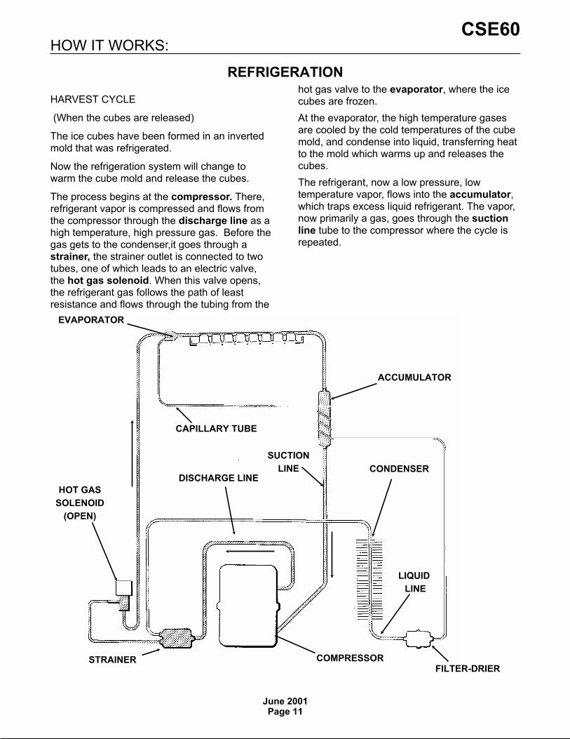
HOW IT WORKS:
REFRIGERATION
HARVEST CYCLE
(When the cubes are released)
The ice cubes have been formed in an invertedmold that was refrigerated.
Now the refrigeration system will change towarm the cube mold and release the cubes.
The process begins at the compressor. There,refrigerant vapor is compressed and flows fromthe compressor through the discharge line as ahigh temperature, high pressure gas. Before thegas gets to the condenser,it goes through astrainer, the strainer outlet is connected to twotubes, one of which leads to an electric valve,the hot gas solenoid. When this valve opens,the refrigerant gas follows the path of leastresistance and flows through the tubing from the
hot gas valve to the evaporator, where the icecubes are frozen.
At the evaporator, the high temperature gasesare cooled by the cold temperatures of the cubemold, and condense into liquid, transferring heatto the mold which warms up and releases thecubes.
The refrigerant, now a low pressure, lowtemperature vapor, flows into the accumulator,which traps excess liquid refrigerant. The vapor,now primarily a gas, goes through the suctionline tube to the compressor where the cycle isrepeated.
CSE60
June 2001Page 12
ADJUSTMENT OF THE BIN THERMOSTATCONTROL
Adjust the bin thermostat when the ice makerturns off too soon (ice level low) or when it turnsoff too late (ice storage bin overfills.)
To increase the ice level in the storage bin:
�Rotate the bin thermostat adjustment screw(located under front panel on control boxcover) clockwise one eight turn at a time untilthe ice level that the machine maintains iscorrect.
To decrease the ice level in the storage bin:
�Rotate the bin thermostat adjustment screwcounterclockwise one eight turn at a time untilthe ice level is correct.
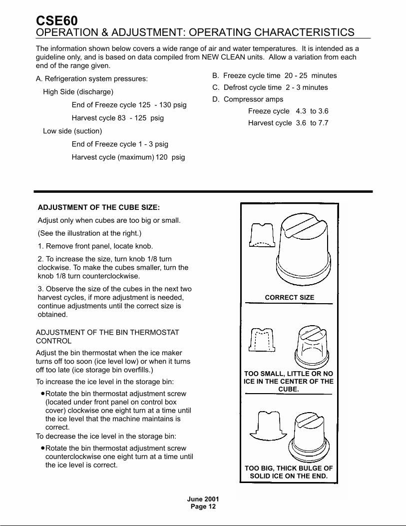
CORRECT SIZE
TOO SMALL, LITTLE OR NOICE IN THE CENTER OF THE
CUBE.
TOO BIG, THICK BULGE OFSOLID ICE ON THE END.
ADJUSTMENT OF THE CUBE SIZE:
Adjust only when cubes are too big or small.
(See the illustration at the right.)
1. Remove front panel, locate knob.
2. To increase the size, turn knob 1/8 turnclockwise. To make the cubes smaller, turn theknob 1/8 turn counterclockwise.
3. Observe the size of the cubes in the next twoharvest cycles, if more adjustment is needed,continue adjustments until the correct size isobtained.
OPERATION & ADJUSTMENT: OPERATING CHARACTERISTICS
The information shown below covers a wide range of air and water temperatures. It is intended as aguideline only, and is based on data compiled from NEW CLEAN units. Allow a variation from eachend of the range given.
A. Refrigeration system pressures:
High Side (discharge)
End of Freeze cycle 125 - 130 psig
Harvest cycle 83 - 125 psig
Low side (suction)
End of Freeze cycle 1 - 3 psig
Harvest cycle (maximum) 120 psig
B. Freeze cycle time 20 - 25 minutes
C. Defrost cycle time 2 - 3 minutes
D. Compressor amps
Freeze cycle 4.3 to 3.6
Harvest cycle 3.6 to 7.7

GRAPH OF SYS TEM PRES SURESCSE60
June 2001Page 13
This graph shows the system pressures during one full cycle at 90oF. Air and 70oF. water.
CSE60
0
50
100
150
200
250
300
350
0 2 4 6 8 10 12 14 16 18 20 22 24 0 2
Time
Low Side
High Side
Typical ice weight per batch: 1 lb. 1 oz.

CSE60
November 2004Page 14
1. Remove the ice from the bin.
2. Remove front panel.
3. Rotate control knob counter clockwise to the Offposition.
4. Turn off the water supply to the ice machine.
5. Remove top panel.
6. Remove plastic panel (evaporator cover) thatcovers evaporator section.
7. Remove curtain by pulling forward on the left end,and then pulling the curtain to the left and out of themachine.
8. Lift up spray platform, locate stand pipe to the rightof the opening, and pull it out to drain the reservoir.Return the standpipe, spray platform, and curtain totheir original positions.
9. Mix approximately 3 ounces (1/10 liter) ofScotsman Ice Machine Cleaner with 1.5 quarts (1.5liter) of warm (95-115
oF.) potable water, and pour this
solution over the evaporator section (bright metaltubing and inverted cups in white plastic tray at thetop of the ice machine).
10. Return the evaporator cover removed in step 6 toits normal position.
11. Rotate the control knob to the Normal position.
12. Operate the machine with the cleaning toggleswitch in the Operation position for 5 minutes.
13. Switch the cleaning toggle switch to the Cleaningposition and operate the machine for 1 minute.
14. Repeat steps 12 and 13 three times. After thethird time rotate the control knob counter clockwise tothe Off position.
15. Remove evaporator cover. Pour hot water overthe entire surface of the evaporator section. Returnevaporator cover to its original position.
16. Pour hot water into the bin to melt any iceproduced during cleaning, and to clean out the drain.Wipe the interior of the bin with mild soap and hotwater, rinse with cold water.
To sanitize, mix a locally approved sanitizer solutionand perform steps 17-31. A possible sanitizer solutionmay be obtained by mixing 1 ounce of household
bleach with 2 gallons of warm (95-115oF) water.
17. Remove plastic panel (evaporator cover) thatcovers evaporator section.
18. Remove curtain by pulling forward on the left end,and then pulling the curtain to the left and out of themachine.
19. Lift up spray platform, locate stand pipe to theright of the opening, and pull it out to drain thereservoir. Return the standpipe, spray platform, andcurtain to their original positions.
20. Pour sanitizer solution over the evaporatorsection (bright metal tubing and inverted cups in whiteplastic tray at the top of the ice machine).
21. Spray or wash the bottom of the evaporator coverand the edges of the evaporator section with thesanitizing solution.
22 Return the evaporator cover removed in step 17to its normal position.
23. Rotate the control knob to the Normal position.
24. Operate the machine with the cleaning toggleswitch in the Operation position for 4 minutes.
25. Switch the cleaning toggle switch to the Cleaningposition and operate the machine for 1 minute.
26. Repeat steps 23 and 24 five times. After the fifthtime rotate the control knob counter clockwise to theOff position.
27. Remove evaporator cover. Pour sanitizer solutionover the entire surface of the evaporator section andwash or spray the evaporator cover bottom withsanitizer. Return evaporator cover to its originalposition.
28. Remove curtain, lift up spray platform, locatestand pipe to the right of the opening, and pull it out todrain the reservoir.
29. Thoroughly spray or wipe the interior of the icestorage bin, bottom of the evaporator cover and all ofthe spray platform with the sanitizing solution.
30. Completely immerse the curtain in the sanitizingsolution.
31. Return the standpipe, spray platform, evaporatorcover and curtain to their original positions.
32. Reconnect water supply.
33. Rotate control knob to its original position. Switchthe cleaning toggle switch to the Cleaning position fortwo minutes and then switch it to the Operationposition. Operate the machine until one batch of icehas been released into the bin. Pour warm water overthe ice to melt it.
34. Return the front panel to its original position andsecure with the original screws.
Scotsman Ice MachineCleaner contains acids.These compounds maycause burns. Ifswallowed, DO NOTinduce vomiting. Givelarge amounts of wateror milk. Call Physicianimmediately. In case ofexternal contact, flushwith water. KEEP OUTOF THE REACH OFCHILDREN.
SANITIZING AND CLEANING: In Place Cleaning
CSE60
June 2001Page 15
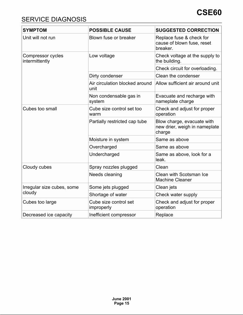
SYMPTOM POSSIBLE CAUSE SUGGESTED CORRECTION
Unit will not run Blown fuse or breaker Replace fuse & check forcause of blown fuse, resetbreaker.
Compressor cyclesintermittently
Low voltage Check voltage at the supply tothe building.
Check circuit for overloading.
Dirty condenser Clean the condenser
Air circulation blocked aroundunit
Allow sufficient air around unit
Non condensable gas insystem
Evacuate and recharge withnameplate charge
Cubes too small Cube size control set toowarm
Check and adjust for properoperation
Partially restricted cap tube Blow charge, evacuate withnew drier, weigh in nameplatecharge
Moisture in system Same as above
Overcharged Same as above
Undercharged Same as above, look for aleak.
Cloudy cubes Spray nozzles plugged Clean
Needs cleaning Clean with Scotsman IceMachine Cleaner
Irregular size cubes, somecloudy
Some jets plugged Clean jets
Shortage of water Check water supply
Cubes too large Cube size control setimproperly
Check and adjust for properoperation
Decreased ice capacity Inefficient compressor Replace
SERVICE DIAGNOSIS

CSE60
June 2001Page 16
SYMPTOM POSSIBLE CAUSE SUGGESTED CORRECTION
Poor harvest Too short defrost Replace cube size control
Not enough water Check water supply
Hot gas valve does not work Replace
Inlet water valve plugged Clean or replace
Air and water temp too low Try to change location
No harvest Cube size control does notwork
Replace
Hot gas valve does not work Replace
Water inlet valve does notwork
Replace
Excessive water in ice storagebin
Drain plugged Clean drain
SERVICE DIAGNOSIS

CSE60
June 2001Page 17
Cube SizeControl
Cube Size Control Tube. Locateand Secure in its Original
Position
REMOVAL AND REPLACEMENT
Bin Thermostat
1. Unplug the ice maker to disconnect electricalpower.
2. Remove screws and cabinet front panel.
3. Remove screws and control box cover,disconnect electrical wires from bin thermostatcontrol.
4. Dismount bin thermostat from the control box
5. Remove rear panel.
6. Pull bin thermostat capillary line from tube inice storage bin. Remove complete control fromice machine.
7. Replace with new control in reverse order ofremoval.
Cube Size Control
1. Unplug the ice maker to disconnect electricalpower.
2. Remove screws and cabinet top, front, andrear panels.
3. Pull knob from cube size control shaft.Remove screws and control box cover to gainaccess to the cube size control body. Removescrews and dismount cube size control fromcontrol box. Disconnect electrical wires fromcube size control.
4. At the top of the machine, unclip cube sizethermostat tube holder from evaporator, (retainclips and tube assembly.) Pull cube size controlcapillary tube from the tube, and removecomplete cube size control from the ice maker.
5. Insert capillary tube on new thermostat intotube holder, be sure that the end caps are inplace.
6. Reverse the removal procedures to reinstallthe cube size control. Adjust as needed.
Refrigeration System
Any time the refrigeration system is opened, thedrier must be replaced, the system evacuatedand the exact charge measured into the system.Any other procedure is NOT CORRECT, and willresult in substandard performance.
Electrical Shock Hazard.
Disconnect electricalpower before beginning.
CSE60
June 2001Page 18
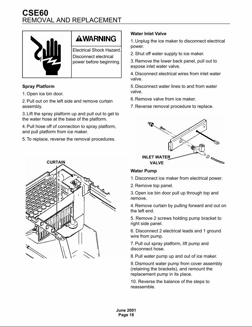
CURTAIN
INLET WATER
VALVE
Spray Platform
1. Open ice bin door.
2. Pull out on the left side and remove curtainassembly.
3. Lift the spray platform up and pull out to get tothe water hose at the base of the platform.
4. Pull hose off of connection to spray platform,and pull platform from ice maker.
5. To replace, reverse the removal procedures.
Water Inlet Valve
1. Unplug the ice maker to disconnect electricalpower.
2. Shut off water supply to ice maker.
3. Remove the lower back panel, pull out toexpose inlet water valve.
4. Disconnect electrical wires from inlet watervalve.
5. Disconnect water lines to and from watervalve.
6. Remove valve from ice maker.
7. Reverse removal procedure to replace.
Water Pump
1. Disconnect ice maker from electrical power.
2. Remove top panel.
3. Open ice bin door pull up through top andremove.
4. Remove curtain by pulling forward and out onthe left end.
5. Remove 2 screws holding pump bracket toright side panel.
6. Disconnect 2 electrical leads and 1 groundwire from pump.
7. Pull out spray platform, lift pump anddisconnect hose.
8. Pull water pump up and out of ice maker.
9. Dismount water pump from cover assembly(retaining the brackets), and remount thereplacement pump in its place.
10. Reverse the balance of the steps toreassemble.
REMOVAL AND REPLACEMENT
Electrical Shock Hazard.
Disconnect electricalpower before beginning.