dxn 107 dxn 207 - scotsman ice systems · the scotsman dxn 107 and dxn 207 counter cubelet ice...
TRANSCRIPT
Page 1Page 1
DXN 107DXN 207
R290 Version
Electroniccounter cubelet
ice dispenser
REV. 06/2018
SERVICE MANUAL
Scotsman Ice SrlVia Lainate, 31 - 20010 Pogliano M.se - Milano - ItalyTel. +39-02-93960.1 (Aut. Sel.)- Telefax +39-02-93550500Direct Line to Service & Parts:Phone +39-02-93960350 - Fax +39-02-93540449Website: www.scotsman-ice.itE-Mail: [email protected]
ISO 9001 - Cert. n. 0080
Page 3Page 3
Page 2Page 2
TABLE OFCONTENTS
235
777788
99
1820
1111121213
2225
Table of contents pageSpecifications DXN 107Specifications DXN 207
GENERAL INFORMATION AND INSTALLATION
IntroductionUnpacking and InspectionLocation and levellingElectrical connectionsWater supply and drain connectionsFinal check list
OPERATING INSTRUCTIONS
Start upOperational checks
PRINCIPLE OF OPERATION (How it works)
Water circuitRefrigerant circuitMechanical systemOperating pressuresComponents description
WIRING DIAGRAM AND SERVICE DIAGNOSTIC
Wiring diagram - Dispensing board versionService diagnosis
MAINTENANCE AND CLEANING INSTRUCTIONS
GeneralCleaning instructions of water system

Page 3Page 3
SPECIFICATIONS
ice making capacity
ELECTRONIC COUNTER CUBELET DISPENSER DXN 107
Important operating requirements:
MIN MAX- Air temperature 10°C (50°F) 38°C (100°F)- Water temperature 10°C (50°F) 35°C (95°F)- Water pressure 1 bar (14 psi) 5 bars (70 psi)- Electr. voltagevariations fromvoltagerating specifiedon nameplate -10% +10%
NOTE. The daily ice-making capacity is directly related to the condenser air inlet temperature, watertemperature and age of the machine.To keep your SCOTSMAN CUBELET DISPENSER at peak performance levels, periodicmaintenance checks must be carried out as indicated on page 22 of this manual.
32
38
10
21
70
69
68
67
66
65
64
63
62
61
60
59
58
57
56
55
54
53
52
51
50
49
48
47
46
45
44
43
42
41
40
39
38
37
36
35
K g .
10 °C27 21 15
°Co
o
AIR COOLED MODELS
WATER TEMPERATURE
AM
BIE
NT
TE
MP
ER
AT
UR
E
ICE
PR
OD
UC
ED
PE
R 2
4 H
RS
.
32

Page 4Page 4
Start Electric power cons.Amps Kwh per 24 HRBasic electr. Amps Watts (*) Nr. of wires Amps fuse
SPECIFICATIONS
Model Cond. unit FinishIce bin
capWater req.lt/24 HR (*)
DXN 107 - MACHINE SPECIFICATIONS
230/50/1 0,5 N.A. 300 7,2 3 x 1.5 mm2 10
DXN 107 AS Air S. Steel 5 Kg 44,5
(*) Ambient t. 32°C / Water t. 21°C
Page 5Page 5
SPECIFICATIONS
ice making capacity
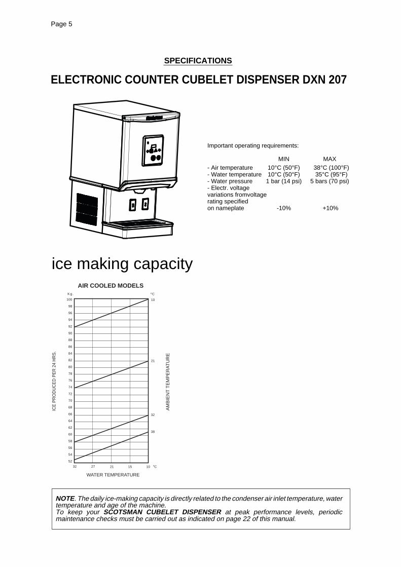
ELECTRONIC COUNTER CUBELET DISPENSER DXN 207
Important operating requirements:
MIN MAX- Air temperature 10°C (50°F) 38°C (100°F)- Water temperature 10°C (50°F) 35°C (95°F)- Water pressure 1 bar (14 psi) 5 bars (70 psi)- Electr. voltagevariations fromvoltagerating specifiedon nameplate -10% +10%
NOTE. The daily ice-making capacity is directly related to the condenser air inlet temperature, watertemperature and age of the machine.To keep your SCOTSMAN CUBELET DISPENSER at peak performance levels, periodicmaintenance checks must be carried out as indicated on page 22 of this manual.
32
38
10
21
100
98
96
94
92
90
88
86
84
82
80
78
76
74
72
70
68
66
64
62
60
58
56
54
52
K g .
10 °C27 21 15
°Co
o
AIR COOLED MODELS
WATER TEMPERATURE
AM
BIE
NT
TE
MP
ER
AT
UR
E
ICE
PR
OD
UC
ED
PE
R 2
4 H
RS
.
32
Page 6Page 6
Basic electr. Amps Watts Nr. of wires Amps fuseStart Electric power cons.Amps Kwh per 244 Kg
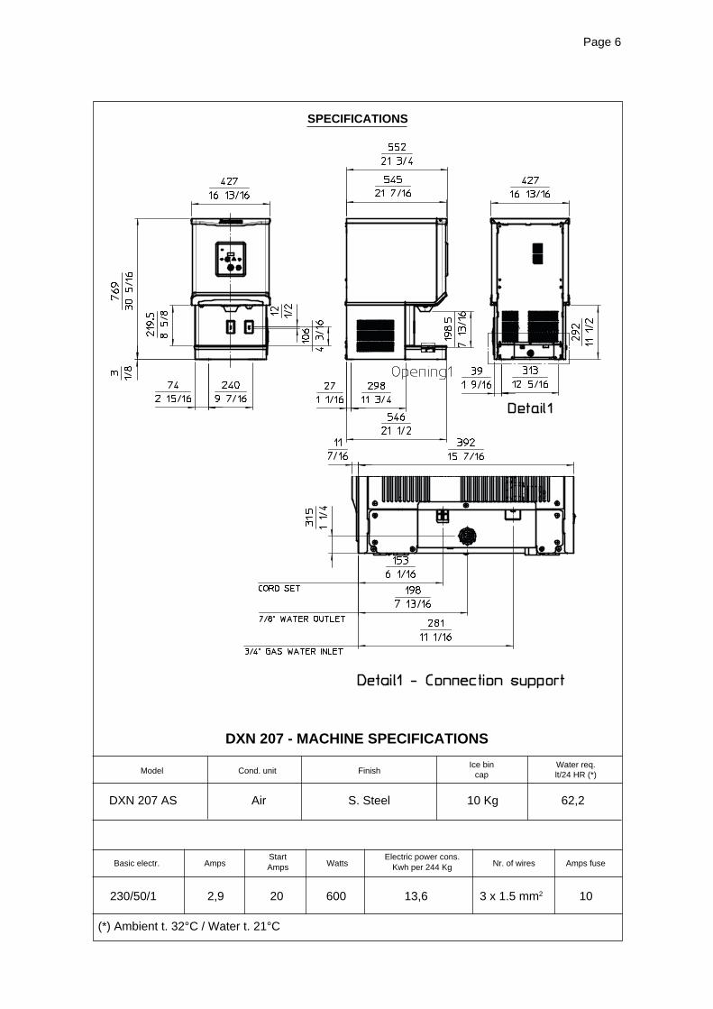
SPECIFICATIONS
Model Cond. unit FinishIce bin
capWater req.lt/24 HR (*)
DXN 207 - MACHINE SPECIFICATIONS
230/50/1 2,9 20 600 13,6 3 x 1.5 mm2 10
DXN 207 AS Air S. Steel 10 Kg 62,2
(*) Ambient t. 32°C / Water t. 21°C
Page 7Page 7
GENERAL INFORMATION AND INSTALLATION
A. INTRODUCTION
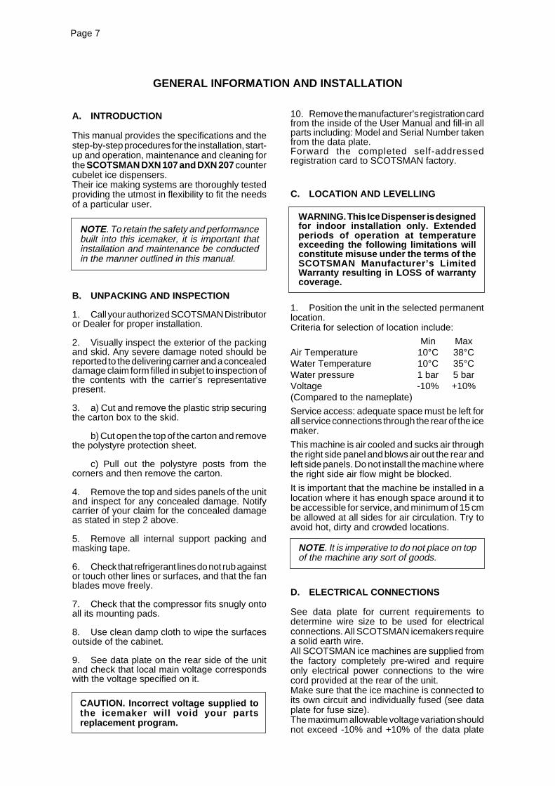
This manual provides the specifications and thestep-by-step procedures for the installation, start-up and operation, maintenance and cleaning forthe SCOTSMAN DXN 107 and DXN 207 countercubelet ice dispensers.Their ice making systems are thoroughly testedproviding the utmost in flexibility to fit the needsof a particular user.
NOTE. To retain the safety and performancebuilt into this icemaker, it is important thatinstallation and maintenance be conductedin the manner outlined in this manual.
B. UNPACKING AND INSPECTION
1. Call your authorized SCOTSMAN Distributoror Dealer for proper installation.
2. Visually inspect the exterior of the packingand skid. Any severe damage noted should bereported to the delivering carrier and a concealeddamage claim form filled in subjet to inspection ofthe contents with the carrier’s representativepresent.
3. a) Cut and remove the plastic strip securingthe carton box to the skid.
b) Cut open the top of the carton and removethe polystyre protection sheet.
c) Pull out the polystyre posts from thecorners and then remove the carton.
4. Remove the top and sides panels of the unitand inspect for any concealed damage. Notifycarrier of your claim for the concealed damageas stated in step 2 above.
5. Remove all internal support packing andmasking tape.
6. Check that refrigerant lines do not rub againstor touch other lines or surfaces, and that the fanblades move freely.
7. Check that the compressor fits snugly ontoall its mounting pads.
8. Use clean damp cloth to wipe the surfacesoutside of the cabinet.
9. See data plate on the rear side of the unitand check that local main voltage correspondswith the voltage specified on it.
CAUTION. Incorrect voltage supplied tothe icemaker will void your partsreplacement program.
10. Remove the manufacturer’s registration cardfrom the inside of the User Manual and fill-in allparts including: Model and Serial Number takenfrom the data plate.Forward the completed self-addressedregistration card to SCOTSMAN factory.
C. LOCATION AND LEVELLING
WARNING. This Ice Dispenser is designedfor indoor installation only. Extendedperiods of operation at temperatureexceeding the following limitations willconstitute misuse under the terms of theSCOTSMAN Manufacturer’s LimitedWarranty resulting in LOSS of warrantycoverage.
1. Position the unit in the selected permanentlocation.Criteria for selection of location include:
Min MaxAir Temperature 10°C 38°CWater Temperature 10°C 35°CWater pressure 1 bar 5 barVoltage -10% +10%(Compared to the nameplate)
Service access: adequate space must be left forall service connections through the rear of the icemaker.
This machine is air cooled and sucks air throughthe right side panel and blows air out the rear andleft side panels. Do not install the machine wherethe right side air flow might be blocked.
It is important that the machine be installed in alocation where it has enough space around it tobe accessible for service, and minimum of 15 cmbe allowed at all sides for air circulation. Try toavoid hot, dirty and crowded locations.
NOTE. It is imperative to do not place on topof the machine any sort of goods.
D. ELECTRICAL CONNECTIONS
See data plate for current requirements todetermine wire size to be used for electricalconnections. All SCOTSMAN icemakers requirea solid earth wire.All SCOTSMAN ice machines are supplied fromthe factory completely pre-wired and requireonly electrical power connections to the wirecord provided at the rear of the unit.Make sure that the ice machine is connected toits own circuit and individually fused (see dataplate for fuse size).The maximum allowable voltage variation shouldnot exceed -10% and +10% of the data plate

Page 8Page 8
rating. Low voltage can cause faulty functioningand may be responsible for serious damage tothe overload switch and motor windings.
NOTE. All external wiring should conform tonational, state and local standards andregulations.
Check voltage on the line and the ice maker’sdata plate before connecting the unit.
E. WATER SUPPLY AND DRAINCONNECTIONS
GENERAL
When choosing the water supply for the ice flakerconsideration should be given to:
a) Length of run
b) Water clarity and purity
c) Adequate water supply pressure
Since water is the most important single ingredientin producting ice you cannot emphasize toomuch the three items listed above.Low water pressure, below 1 bar may causemalfunction of the ice maker unit.Water containing excessive minerals will tend toproduce scale build-up on the interior parts of thewater system while too soft water (with too locontents of mineral salts), will produce a veryhard flaker ice.
PLUMBING CONNECTIONS MUSTCONFORM TO ALL APPLICABLE CODES
CONNECT TO POTABLE WATER ONLY
DXN 107 - 207 have the possibility to have thewater connections through the bottom base orthrough the rear bottom side of the machine. Inthis second case it is necessary to remove therear bottom small panel.
WATER SUPPLY
Connect the 3/4" GAS male of the water inletfitting, using the flexible tube supplied to the coldwater supply line with regular plumbing fittingand a shut-off valve installed in an accessibleposition between the water supply line and theunit.If water contains a high level of impurities, it isadvisable to consider the installation of anappropriate water filter or conditioner.
WATER DRAIN
The recommended drain tube is a plastic orflexible tube with 18 mm (3/4") I.D. which runs toan open trapped and vented drain. When thedrain is a long run, allow 3 cm pitch per meter(1/4" pitch per foot).Install a vertical open vent on drain line high pointat the unit drain connection to ensure gooddraining.The ideal drain receptacle is a trapped andvented floor drain.
NOTE. The water supply and the water drainmust be installed to conform with the localcode. In some case a licensed plumber and/or a plumbing permit is required.
F. FINAL CHECK LIST
1. Is the unit in a room where ambienttemperatures are within a minimum of 10°C(50°F) even in winter months?
2. Is there at least a 15 cm (6") clearancearound the unit for proper air circulation?
3. Is the unit level?
4. Have all the electrical and plumbingconnections been made, and is the water supplyshut-off valve open?
5. Has the voltage been tested and checkedagainst the data plate rating?
6. Has the water supply pressure been checkedto ensure a water pressure of at least 1 bar(14 psi).
7. Check all refrigerant lines and conduit linesto guard against vibrations and possible failure.
8. Has the owner/user been given the UserManual and been instructed on the importance ofperiodic maintenance checks?
9. Has the Manufacturer’s registration cardbeen filled in properly? Check for correct modeland serial number against the serial plate andmail the registration card to the factory.
10. Has the owner been given the name and thephone number of the authorized SCOTSMANService Agency serving him?

Page 9Page 9
OPERATING INSTRUCTIONS
After having correctly installed the ice dispenserand completed the plumbing and electricalconnections, perform the following Start-Uppro cedure
START UP
A. Open the water supply shutoff valve andgive power by the ON/OFF green push button,the machine enters in the starting delay time withtwo complete purge and refill of the waterreservoir, dØ1 (purge time) and dØ2 (refill time)code monitor this condition on display.
NOTE: Every time the unit is put under power,after being kept for some time in shut-offconditions (electrically disconnected) thedelay or stand-by period will be 10 minutes.The machine will run an auto calibration ofice level control showingFØ2 code for fewseconds. Every restart from other operatingconditions with the unit electrically connectedit will take only 3 minutes of delay
B. Elapsed the starting delay time, the unitstarts operating (FØ4 code appears on displayfor few seconds) with the activation in sequenceof the following components:GEAR REDUCERCOMPRESSOR (after 5 minutes)FAN MOTOR Kept under control by thecondenser temperature sensor which has itsprobe within the condenser fins.The Bin Empty light is ON during all start up/delaytime and for the first minutes of operation.
NOTE ONLY FOR AUTHORIZED TECHNICIANTo by-pass the start-up delay perform thefollowing procedure:• During the delay time press and hold for 5seconds both ICE and WATER capacitivekeys simultaneously then release.• As soon as “tSt” will appear on display keeppressed the same capacitive keys until theunits starts the operation.
C. Five minutes after the compressor start up,the ice begins dropping down in the storage bin,ice can be dispensed as soon as the Bin Emptylight disappear.
D. The unit will stop the operation when thestorage bin is full of ice and the infrared beam ofthe ice level control is interrupted for 10 secondscontinuously.
E. Every 12 hours of operation the units willmake an automatic purge and refill of the waterreservoir and freezer to prevent the growth ofbacteria and algae when machine is not workingfor many hours (Night-time and/or Bin fullcondition).
OPERATION CHECKS UPON THE UNITSTART UP
F. Remove service panels and if necessaryinstall the refrigerant service gauges on thecorresponding Service valves to check both theHI and LO refrigerant pressures.
NOTE. The condenser temperature sensor,which is located within the condenser fins,keeps the head (condensing) pressurebetween two preset values.In case of condenser clogging such to preventthe proper flow of the cooling air or, in casethe fan motor is out of operation, the condensertemperature rises and when it reaches 70°C(160°F) the condenser temperature sensorshuts-off the ice maker with the consequentlight-up of ALARM CODE AØ8. After havingdiagnosed the reason of the temperature riseand removed its cause, it is necessary toproceed as per the previous “NOTE” to startup again the operation of the ice maker.
NOTE. If, after ten minutes from thecompressor start-up, the evaporating tem-perature has not dropped down to a valuelower than -0°C (30°F) the evaporating tem-perature sensor detects such an abnormalsituation and stops consequently the unitoperation.In this circustance, the ALARM CODE AØ6.After having diagnosed and eliminated thecause of the poor evaporating temperature(insufficient refrigerant in the system orinoperative compressor or evaporator sensor)it is necessary to restart the unit. The unit,before resuming the total operation, will gothrough the usual STAND-BY period.
G. Check for the correct CUT-OUT andCUT-IN of the float reservoir water level sen-sors by shutoff the valve on the water supply line.This will cause a gradual decrease of the waterlevel in the float reservoir and as soon as the levelgets below the sensors, the unit stops to operateand the ALARM CODE AØ1 will glow on display.
NOTE. The water level sensor detects thepresence of sufficient water in the float reservoirand confirms it to the micro processor bymaintaining a low voltage current flow betweenthe two sensors using the water as conductor.
WARNING. The use of de-mineralizedwater (water with no salt content) havingan electrical conductivity lower than 30µS, will cause the ability of the watersensors to vanish with the consequentCUT-OUT of the flaker operations and theglowing of the ALARM CODE AØ1 ofshortage of water, even though that wateris indeed in the reservoir.
After this, open the water supply line shutoffvalve to fill up again the float reservoir.
Page 10Page 10
After 10 minutes the unit resumes its totaloperation with the immediate start-up of the gearmotor and, 2 seconds later, of the compressor.
H. Check for the correct operation of theelectronic eye for the ice bin level control, byplacing one hand between the sensing “eyes”located under the storage bin cover, to interruptthe light beam. This interruption after 10 secondscauses the shutoff of the unit. Allow the resumptionof the light beam previously interrupted and after10 seconds the unit will resume - through the 3minutes STAND-BY period - ice making process.
NOTE. The ICE LEVEL CONTROL (INFRA-RED SYSTEM) is independent of the tempe-rature however, the reliability of its detectioncan be affected by dirt and scale sedimentwhich may deposit directly on the light sourceand on the receiver.To prevent any possible ice maker malfunction,due to negative affection of the light detector,it is advisable to follow the instructions for theperiodical cleaning of the light sensorelements as detailed in the MAINTENANCEAND CLEANING PRO-CEDURES.
I. SETTING OF ICE DISPENSING TIME(ONLY ICE)
The dispensing time of the ice is factory set at 3”but it is possible to modify it choosing between:• From 1” up to 15”• ContinuousTo change this time perform the following proce-dure:Open the water supply line shutoff valve and givepower by moving the main switch to ON positionand push green ON/OFF button on the machine.Push the Red Alarm button on the display for 10seconds to enter in the Program Menu, use thearrows to select “S” then press ICE button toconfirmPress arrow to select time 1..2..3.. up to 15seconds or CON for Continuous , then push ICEto confirm.Push WATER button for 5 seconds to ESC.
J. SETTING OF DISPENSING MODEThe unit can dispense ice only or ice and waterand it is also possible modify this settingperforming the following procedure:Push the Red Alarm button on the display for 10seconds to enter in the Program Menu, use thearrows to select “H” then press ICE button toconfirmPress arrows to select “on” for dispensing wateractivated or “off” for dispensing water disabled,then push ICE to confirm.Push WATER button for 5 seconds to ESC.
K. SETTING OF THE DISPENSINGOPERATION
DXN 100-200 can be provided with two differentversions not interchangeable:• Touch (No Optical Dispensing Devices installed)
• Touchless ( With Optical Dispensing Devicesinstalled)
The initial setting is already made in factoryaccording with the version of the unit, in case ofreplacement of the P.C. Board perform thefollowing procedure to set up the dispensingoperation accordingly:Push the Red Alarm button on the display for 10seconds to enter in the Program Menu, use thearrows to select “F” then press ICE button toconfirmPress arrows to select “tch” for Touch version or“tcL” for Touchless version , then push ICE toconfirm.Push WATER button for 5 seconds to ESC.
L. CHECK OF THE DISPENSINGOPERATING MECHANISM
After having properly completed the above set upprocedures, check the correct operation of thedispensing mechanism:
Touchless Version:a) Place a glass or carafe in front of one of the
two Optical Dispensing Devices (Ice and/orWater)
b) The dispensing drive motor and/or the watersolenoid valve starts to operate with ice and/or water discharged through the bottom plasticspouts
c) The drive motor remains in operation as persetting dispensing time; the water inletsolenoid valve remains in continuousoperation unless the glass of carafe isremoved.
Touch Version:d) Place a glass or carafe under the plastic
spouts (Ice and/or Water)e) Push ICE or WATER button , the dispensing
drive motor and/or the water solenoid valvestarts to operate with ice and/or waterdischarged through the bottom plastic spouts
c) The drive motor remains in operation as persetting dispensing time; the water inletsolenoid valve remains in continuousoperation unless the WATER button isreleased.
NOTE. When ice is not dispensed formore than 30 minutes with the dispenserin operation and compressor energized,the drive motor will be activated for twoseconds to rotate the vane in order toprevent ice block in the bin and optimizethe ice level in the storage bin.
M. If previously installed, remove the refrigerantservice gauges and re-fit the unit service panelspreviously removed.
N. Instruct the owner/user on the generaloperation of the ice machine and about thecleaning and care it requires.
Page 11Page 11
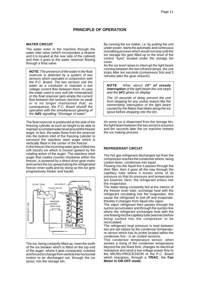
WATER CIRCUITThe water enter in the machine through thewater inlet valve (which incorporates a strainerand it is located at the rear side of the cabinet)and then it goes to the water reservoir flowingthrough a float valve.
NOTE. The presence of the water in the floatreservoir is detected by a system of twosensors which operates in conjunction withthe P.C. Board. The two sensors use thewater as a conductor to maintain a lowvoltage current flow between them. In casethe water used is very soft (de-mineralized)or the float reservoir gets empty the currentflow between the sensors become so weakor is no longer maintained that, asconsequence, the P.C. Board shutoff theoperation with the simultaneous glowing ofthe AØ1 signalling “Shortage of water”.
The float reservoir is positioned at the side of thefreezing cylinder at such an height to be able tomaintain a constant water level around the freezerauger. In fact, the water flows from the reservoirinto the bottom inlet of the freezing cylinder tosorround the stainless steel auger which isvertically fitted in the center of the freezer.In the freezer the incoming water gets chilled intosoft (slush) ice which is moved upward by therotating action of the auger. The stainless steelauger that rotates counter-clockwise within thefreezer, is powered by a direct drive gear motorand carries the ice upward along the refrigeratedfreezer inner walls and by doing so the ice getsprogressively thicker and harder.
The ice, being costantly lifted up, meet the toothof the ice breaker which is fitted on the top endof the auger, where it gets compacted, crackedand forced to change from vertical into horizontalmotion to be discharged out, through the icespout, into the storage bin.
By running the ice maker, i.e. by putting the unitunder power, starts the automatic and continuousicemaking process which would not stop until theice storage bin gets filled-up to the level of thecontrol “eyes” located under the storage bincover.As the ice level raises to interrupt the light beamrunning between the two infrared lamps, the unitstops after ten seconds (compressor first and 3minutes later the gear reducer).
NOTE. After about 10" of steadyinterruption of the light beam the unit stopsand the bF1 glows on display.
The 10 seconds of delay prevent the unitfrom stopping for any undue reason like themomentarily interruption of the light beamcaused by the flakes that slides along the icespout before dropping into the bin.
As some ice is dispensed from the storage bin,the light beam between the two sensors resumesand ten seconds later the ice machine restartsthe ice making process.
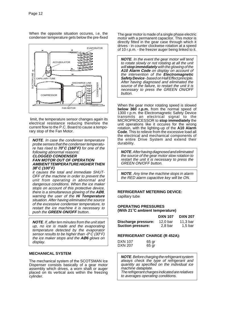
REFRIGERANT CIRCUIT
The hot gas refrigerant discharged out from thecompressor reaches the condenser where, beingcooled down, condenses into liquid.Flowing into the liquid line it passes through thedrier filter, then it goes all the way through thecapillary tube where it looses some of itspressure so that its pressure and temperatureare lowered. Next, the refrigerant enters intothe evaporator.The water being constantly fed at the interior ofthe freezer inner tube, exchange heat with therefrigerant circulating into the evaporator, thiscause the refrigerant to boil-off and evaporate,thereby it changes from liquid into vapor.The vapor refrigerant then passes through thesuction accumulator and through the suction linewhere the refrigerant exchanges heat with theone flowing into the capillary tube (warmer) beforebeing sucked into the compressor to berecirculated.The refrigerant heat pressure is kept betweentwo pre-set values by the condenser temperatu-re sensor which has its probe located within thecondenser fins - in air cooled versions.This condenser temperature sensor, whensenses a rising of the condenser temperaturebeyond the pre-fixed limit, changes its electricalresistance and send a low voltage power flow tothe MICRO-PROCESSOR of the P.C. Boardwhich energizes, through a TRIAC, the FanMotor in ON-OFF mode.
PRINCIPLE OF OPERATION
FREEZER
FLOAT TANK
FLOAT VALVE
WA
TE
R IN
LET
LIN
E
ICE SPOUT
FREEZERWATERFEED LINE
Page 12Page 12
When the opposite situation occures, i.e. thecondenser temperature gets below the pre-fixed
limit, the temperature sensor changes again itselectrical resistance reducing therefore thecurrent flow to the P.C. Board to cause a tempo-rary stop of the Fan Motor.
NOTE. In case the condenser temperatureprobe senses that the condenser temperatu-re has rised to 70°C (160°F) for one of thefollowing abnormal reasons:CLOGGED CONDENSERFAN MOTOR OUT OF OPERATIONAMBIENT TEMPERATURE HIGHER THEN38°C (100°F)it causes the total and immediate SHUT-OFF of the machine in order to prevent theunit from operating in abnormal anddangerous conditions. When the ice makerstops on account of this protective device,there is a simultaneous glowing of the AØ8,warning the user of the Hi Temperaturesituation. After having eliminated the sourceof the excessive condenser temperature, torestart the ice machine it is necessary topush the GREEN ON/OFF button.
NOTE. If, after ten minutes from the unit startup, no ice is made and the evaporatingtemperature detected by the evaporatorsensor results to be higher than -0°C (30°F)the ice maker stops and the AØ6 glows ondisplay.
MECHANICAL SYSTEM
The mechanical system of the SCOTSMAN IceDispenser consists basically of a gear motorassembly which drives, a worn shaft or augerplaced on its vertical axis within the freezingcylinder.
The gear motor is made of a single phase electricmotor with a permanent capacitor. This motor isdirectly fitted in the gear case through which itdrives - in counter clockwise rotation at a speedof 10 r.p.m. - the freezer auger being linked to it.
NOTE. In the event the gear motor will tendto rotate slowly or not rotating at all the unitwill stop immediately with the glowing of theA10 Alarm Code on display on account ofthe intervention of the ElectromagneticSafety Device - based on Hall Effect principle.After having diagnosed and eliminated thesource of the failure, to restart the unit it isnecessary to press the GREEN ON/OFFbutton.
When the gear motor rotating speed is slowedbelow 360 r.p.m. from the normal speed of1300 r.p.m. the Electromagnetic Safety Devicetransmits an electrical signal to theMICROPROCESSOR to stop immediately theunit operations like it occures for the wrongrotation, with the lighting-up of the A10 AlarmCode . This to relieve from the excessive load allthe electrical and mechanical components ofthe entire Drive System and extend theirdurability.
NOTE. After having diagnosed and eliminatedthe source of the gear motor slow rotation torestart the unit it is necessary to press theGREEN ON/OFF button.
NOTE. Any time the machine stops in alarmthe RED alarm capacitive key will be ON.
REFRIGERANT METERING DEVICE:capillary tube
OPERATING PRESSURES(With 21 °C ambient temperature)
DXN 107 DXN 207Discharge pressure: 12,0 bar 11,3 barSuction pressure: 2,8 bar 1,5 bar
REFRIGERANT CHARGE (R 452A):
DXN 107 65 grDXN 207 65 gr
NOTE. Before charging the refrigerant systemalways check the type of refrigerant andquantity as specified on the individual icemachine dataplate.The refrigerant charges indicated are relativesto averages operating conditions.
ACCUMULATOR
CAPILLARY TUBE
COMPRESSOR
DISCHARGE LINE
CO
ND
EN
SE
R
SU
CT
ION
LIN
E
FAN MOTOR
EVAPORATOR

Page 13Page 13
COMPONENT DESCRIPTION
A. EVAPORATOR TEMPERATURESENSOR - BLACK 2 POLES CONNECTOR- MANUAL RESET
The evaporator sensor probe is inserted into itstube well, which is welded on the evaporatoroutlet line. It detects the temperature of therefrigerant on the way out from the evaporatorand signals it by suppying a low voltage currentflow to the P.C. Board Micro-Processor.According to the current received, the micro-processor let the ice maker to continue itsoperations or not. In case the evaporating tem-perature, after 10 minutes from the unit start-up,does not go below 0°C (32°F) the evaporatorsensor signal reaching the microprocessor issuch to stop immediately the unit operation, withthe AØ2 Alarm Code on display.
B. WATER LEVEL SENSOR - RED TWOPOLES CONNECTOR - AUTOMATICRESET
This sensor system consist of two small stainlesssteel rods vertically fitted on the inner face of thereservoir cover and electrically connected to thelow voltage circuit of the P.C. Board. When thecover of the reservoir is positioned in its place thetips of both the rods dip into the reservoir waterand detects and signals its presence by supplypower back to the P.C. Board.
NOTE. In the event of shortage of water inthe reservoir or, in case the water used is toosoft (de-mineralized) to cause greaterresistence to the current flow (conductivitylower than 30 µS) this sensor system causesthe shutoff of the machine , to protect it fromrunning with an interrupted or inadequatewater supply.In this situation the AØ1 alarm code ondisplay will glow to warn of the machineshutoff and the reason why.
C. CONDENSER TEMPERATURE SENSOR- WHITE TWO POLES CONNECTOR -MANUAL RESET
The condenser temperature sensor probe,located within the condenser fins detects thecondenser temperature variations and signalsthem by supplying current, at low voltage, to theP.C. BOARD.In relation to the different current received, themicro processor of the P.C. BOARD supplies,through a TRIAC, the power at high voltage tothe fan motor so that it can cool the condenserand reduce its temperature.In the event the condenser temperature risesand reaches 70°C the current arriving to themicro processor is such to cause an immediateand total stop of the machine operation with theglowing of the AØ3 Alarm Code on display.
NOTE. To restart the unit after the shutoffcaused by the hi condenser temperature, itis necessary (after having remedied to thecauses of unit stoppage) to switch OFF andON the power line main disconnect Switch.
D. GEAR MOTOR ROTATION AND SPEEDSENSOR - RED FOUR POLESCONNECTOR - MANUAL RESET
This safety device is housed on top of the DriveMotor and detects - based on Hall Effect principle- the rotating speed and rotating direction of thedrive Motor.Should the rotating speed drop below1300 r.p.m. the magnitude measured by thisdevice is such to signal to the microprocessor tostop the unit and light-up A1Ø Alarm Code. Thesame reaction occures when the drive motor willtend to rotate in the wrong direction(counterclockwise) or it doesn't rotate at all.
NOTE. To restart the unit after the shutoffcaused by this safety device, it is necessaryfirst to eliminate the cause that has generatedthe intervention of the device and switchOFF and ON the power line main disconnectswitch.
E. ICE LEVEL CONTROL – BLACK FOURPOLES CONNECTOR – AUTOMATIC RESET
The electronic ice bin level control, located underthe plastic bin cover, has the function to stop theoperation of the ice machine when the light beambetween the light source and the sensor getsinterrupted by the ice which accumulates in thespout. When the light beam gets interrupted foras long as 10 seconds, the compressor stopsimmediately and the drive motor keeps on workingby 3' delay then stops. On the display appearsBF1 code to monitor the full ice bin situation. The10 seconds of initial delay prevents that anyminimum interruption of the light beam due to theregular ice chuting through the ice spout maystop the operation of the unit. As soon as the iceis dispensed out with the resumption of the lightbeam for 10 seconds between the two infraredsensor of ice level control a BF2 code appearson display. After that, the unit resume its operationwith the standard starting delay.
AUTOMATIC CALIBRATION OF THE ICELEVEL CONTROL
The P.C. BOARD performs the AutomaticCalibration with the Infrared Optical Ice LevelControl at any start-up of the machine throughthe ON/OFF Green Push button except when thebin is already full of ice during the restart.Every time power is provide to the PC Board, itchecks automatically the physical condition ofthe Optical Ice Level Control and self-adjust thecurrent transmitted so to assure the correctoperation of the Optical Ice Level Control.FØ2 will appear on display during this phase.
Page 14Page 14
F. ICE/WATER OPTICAL DISPENSING DEVICES(ONLY FOR TOUCH LESS VERSION)
Located on the front of the dispensing area itconsists of the combination of an infraredTransmitter and Receiver.When a glass or a carafe is placed in front of theInfrared sources, the optical device transmits asignal to the PC Board that is equivalent toactivate the dispensing drive motor which, in turn,put in rotation a dispensing vane that pushes theice towards a rectangular opening located in thebottom of the storage bin.Elapsed the dispensing time or after have removedthe glass/carafe, the infrared resume its originalcondition switching off the dispensing drive motor.
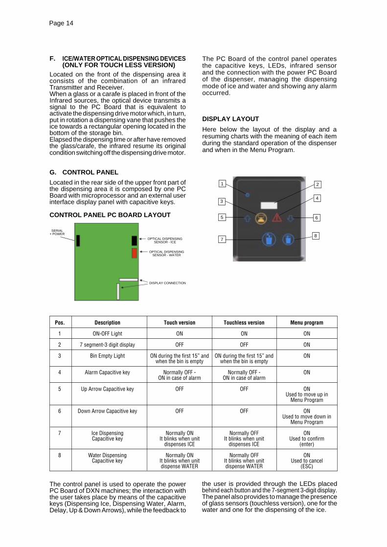
G. CONTROL PANEL
Located in the rear side of the upper front part ofthe dispensing area it is composed by one PCBoard with microprocessor and an external userinterface display panel with capacitive keys.
CONTROL PANEL PC BOARD LAYOUT
The PC Board of the control panel operatesthe capacitive keys, LEDs, infrared sensorand the connection with the power PC Boardof the dispenser, managing the dispensingmode of ice and water and showing any alarmoccurred.
DISPLAY LAYOUT
Here below the layout of the display and aresuming charts with the meaning of each itemduring the standard operation of the dispenserand when in the Menu Program.
The control panel is used to operate the powerPC Board of DXN machines; the interaction withthe user takes place by means of the capacitivekeys (Dispensing Ice, Dispensing Water, Alarm,Delay, Up & Down Arrows), while the feedback to
the user is provided through the LEDs placedbehind each button and the 7-segment 3-digit display.The panel also provides to manage the presenceof glass sensors (touchless version), one for thewater and one for the dispensing of the ice.
Pos. Description Touch version Touchless version Menu program
1 ON-OFF Light ON ON ON
2 7 segment-3 digit display OFF OFF ON
3 Bin Empty Light ON during the first 15” and ON during the first 15” and ONwhen the bin is empty when the bin is empty
4 Alarm Capacitive key Normally OFF - Normally OFF - ONON in case of alarm ON in case of alarm
5 Up Arrow Capacitive key OFF OFF ONUsed to move up in
Menu Program
6 Down Arrow Capacitive key OFF OFF ONUsed to move down in
Menu Program
7 Ice Dispensing Normally ON Normally OFF ONCapacitive key It blinks when unit It blinks when unit Used to confirm
dispenses ICE dispenses ICE (enter)
8 Water Dispensing Normally ON Normally OFF ONCapacitive key It blinks when unit It blinks when unit Used to cancel
dispense WATER dispense WATER (ESC)
SERIAL+ POWER
OPTICAL DISPENSINGSENSOR - ICE
OPTICAL DISPENSINGSENSOR - WATER
DISPLAY CONNECTION
4
6
8
1
3
5
7
2
Page 15Page 15
MENU PROGRAM
Through the menu program it is possible thesetting of the machine operating parameters,and view/clear some counters.To enter in MENU program, press the ALARMbutton, even if it is OFF for 10‘’. Entering in theprogramming mode the display will turn ON allLEDs except ALARM and DELAY. Use the UP
and DOWN capacitive keys to navigate throughthe menu and choice of parameter values, ICEkey is used to select and confirm the selection,WATER key to cancel or ESC.Pushing the ICE key the selected value will flashand will be saved as the current value for theparameter and return to the list main parameters.Push WATER key for more than 5 seconds toreturn to operating mode.
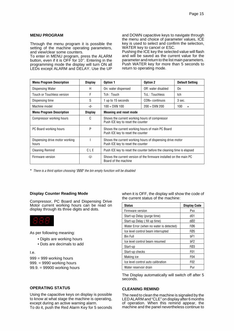
Display Counter Reading Mode
Compressor, PC Board and Dispensing DriveMotor current working hours can be read ondisplay through its three digits and dots.
As per following meaning:
• Digits are working hours• Dots are decimals to add
I.e.
999 = 999 working hours999. = 9990 working hours99.9. = 99900 working hours
OPERATING STATUS
Using the capacitive keys on display is possibleto know at what stage the machine is operating,except during an active warning alarm.To do it, push the Red Alarm Key for 5 seconds
when it is OFF, the display will show the code ofthe current status of the machine:
Status Display Code
Firmware version PxxStart-up Delay (purge time) d01Start-up Delay ( fill up time) dØ2Water Error (when no water is detected) FØ6Ice level control beam interrupted FØ5Bin Full bF1Ice level control beam resumed bF2Start-up FØ3Start-up checks F01Making ice F04Ice level control auto calibration F02
Water reservoir drain Pur
The Display automatically will switch off after 5seconds.
CLEANING REMIND
The need to clean the machine is signaled by theLED ALARM and “CLE” on display after 6 monthsof operation. When this remind appear, themachine and the panel nevertheless continue to
Menu Program Description Display Option 1 Option 2 Default Setting
Dispensing Water H On: water dispensed Off: water disabled On
Touch or Touchless version F Tch : Touch TcL : Touchless tch
Dispensing time S 1 up to 15 seconds CON= continuos 3 sec.
Machine model -d- 100 = DXN 100 200 = DXN 200 100
Menu Program Description Display Meaning and reset mode
Compressor working hours C Shows the current working hours of compressorPush ICE key to reset the counter
PC Board working hours P Shows the current working hours of main PC BoardPush ICE key to reset the counter
Dispensing drive motor working I Shows the current working hours of dispensing drive motorhours Push ICE key to reset the counter
Cleaning Remind C L E Push ICE key to reset the counter before the cleaning time is elapsed
Firmware version -U- Shows the current version of the firmware installed on the main PCBoard of the machine
*
* There is a third option choosing "ØØØ" the bin empty function will be disabled
Page 16Page 16
The three LEDS, placed in a row in the center ofthe P.C. BOARD, monitor the following situations:
Green ON/OFF = Power ON or OFF
Green LINK = Normally ON; detects theconnection with the control panel interface board
Red ALARM = Normally OFF; will be ON in caseof any alarm
I. FLOAT RESERVOIR
The float reservoir consists of a plastic water panon which is fitted a float valve with its settingscrew. The float valve modulate the incomingwater flow to maintain a constant water level inthe reservoir, level that corresponds to the one inthe freezing cylinder to ensure proper iceformation and fluidity.On the inner side of the reservoir cover are fittedthe two water level sensors which detects thepresence or the shortage of water in the reservoir.
NOTE. It is very important to make sure ofthe correct fitting of the cover on the reservoirin order to enable the sensor to efficientlycontrol the water situation avoiding undueshutoff interventions.
J. FREEZING CYLINDER (EVAPORATOR)
The freezing cylinder is made of a stainless steelvertical tube with an inner evaporating chamberand in its interior is located the auger whichrotates on its vertical axis and it is maintainedaligned by the top permanently lubricatesbushings. A water seal system is located in thebottom part of the freezer.The water constantly flowing into the cylinderbottom part, freezes into ice when in contact withthe cylinder inner walls. The ice is then lifted upby the rotating auger and compacted and forcedout by the ice breaker.
K. ICE BREAKER
The ice breaker is made by several rectangularopenings where the ice is forced to passthrough.By undergoing this, the ice looses its excess ofwater content so it drops into the bin in hard drybits of ice.
L. DRIVE GEAR MOTOR
This motoreducer is made of a single phaseelectric motor with permanent capacitor directlyfitted on a gear box.The drive motor rotor is kept aligned on itsvertical axis by two ball bearings permanentlylubricated. The gear case contains a train ofthree spur gears the first one of which is in fiberto limit the noise level. All the three gears areencased in case bearings and are covered bylubricant oil.
function normally. To reset the remind, go intoalarm (by pressing the ALARM key for 5‘’) andwhile displaying the “CLE” condition simply pressthe ALARM button for more than 5‘’. Thecompletion of the reset signal is confirmed by 3flashes of “rES” on display.
ALARM CONDITION
All the alarm codes are signaled by the ALARMkey; push it for more than 5 seconds to turns ONthe display, which shows the code alarm inprogress.The alarm codes are the following:
Alarm CodeNo Water A01Evaporator Sensor out of order A02Condenser Sensor out of order A03Optical dispensing Sensor out of order (ICE) A04Optical dispensing Sensor out of order (WATER) A05Too High Evaporator Temperature (> 0°C) A06Too Low Evaporator Temperature (< - 30°C) A07Too High Condensing Temperature (> 70°C) A08Too Low Condensing/Ambient Temperature (<3°C) A09No /Wrong Rotation Alarm A10Too High Condensing Temperature at start-up ( > 55°C) A11Test Alarm A14Ice level control out of order A15Cleaning Remind (6 months) CLE
After 5‘’ the display will turn off and only the keysof the standard operation will remain lighted .
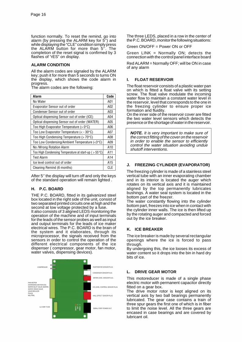
H. P.C. BOARD
THE P.C. BOARD, fitted in its galvanized steelbox located in the right side of the unit, consist oftwo separated printed circuits one at high and thesecond at low voltage protected by a fuse.It also consists of 3 aligned LEDS monitoring theoperation of the machine and of input terminalsfor the leads of the sensor probes as well as inputand output terminals for the leads of ice makerelectrical wires. The P.C. BOARD is the brain ofthe system and it elaborates, through itsmicroprocessor, the signals received from thesensors in order to control the operation of thedifferent electrical components of the icedispenser ( compressor, gear motor, fan motor,water valves, dispensing devices).
Page 17Page 17
Two seal rings, one fitted on the rotor shaft andthe other on the output shaft keep the gear casesealed.Hovewer, the interior can be inspected andserviced by unbolting the two halves of thealuminium gear case housing.The gear reducer output is connected to thefreezer auger that engages themselves only ifturned in the correct direction namely,conterclockwise.
M. FAN MOTOR (Air cooled version)
The fan motor is controlled through the P.C.BOARD and the TRIAC by the condenser tem-perature sensor. Normally it operates to drawcooling air through the condenser fins.In cold ambient situation, the fan motor can runat intermittance as the condenser pressure mustbe kept between two corresponding headpressure values.
N. COMPRESSOR
The hermetic compressor is the heart of therefrigerant system and it is used to circulate andretrieve the refrigerant throughout the entiresystem. It compresses the low pressurerefrigerant vapor causing its temperature to riseand become high pressure hot vapor which isthen released through the discharge valve.
O. ICE DISPENSER DRIVE MOTOR
Located on the lower side of the storage bin, itturn by a milled shaft the dispensing vane placedinside the round storage bin.By rotating, the dispensing vane pushes the icetowards the bottom rectangular opening so toforce the nugget ice to go through the bottomoutlet spout.
P. STORAGE BIN
Round shaped it is located in the front of the icemachine and has the main reason to store the ice
produced by the evaporator till it reaches itsmaximum level controlled by an infrared opticalsystem. In its bottom is placed the ice spout aswell as the water drain hole.Inside the ice spout opening is also located thewater outlet tube connected to the solenoid val-ve.
Q. DISPENSING WATER SOLENOID VALVE
Normally closed and located in the upper left sidebehind the front panel, it is energized andcontrolled by the P.C. Board, it allows a meteredquantity of not chilled water to be dispensedthrough its spout.
R. WATER INLET SOLENOID VALVE
Normally open and located in the lower side ofthe rear panel, it is energized and controlled bythe P.C. Board, it allows the entrance of the waterin water circuit of the machine for the iceproduction.
S. WATER DRAIN SOLENOID VALVE
Normally closed and located in the lower side ofthe rear panel, it is energized and controlled bythe P.C. Board during the purge procedure duringevery start-up of the machine when it is switchedON and every twelve hours of operation. It drainall the water from the reservoir and freezer toprevent the growth of bacteria and algae whenmachine is not working for many hours (Night-time and/or Bin full condition).
T. SAFETY P.C. BOARD
Located on the rear side of the machine, it isconnected with safety switch and ON/OFF greenpush button to let them work with low voltage forsafety reason.
Page 18Page 18
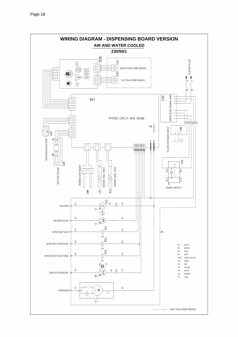
WIRING DIAGRAM - DISPENSING BOARD VERSIONAIR AND WATER COOLED
230/50/1
Page 19Page 19
Page 20Page 20
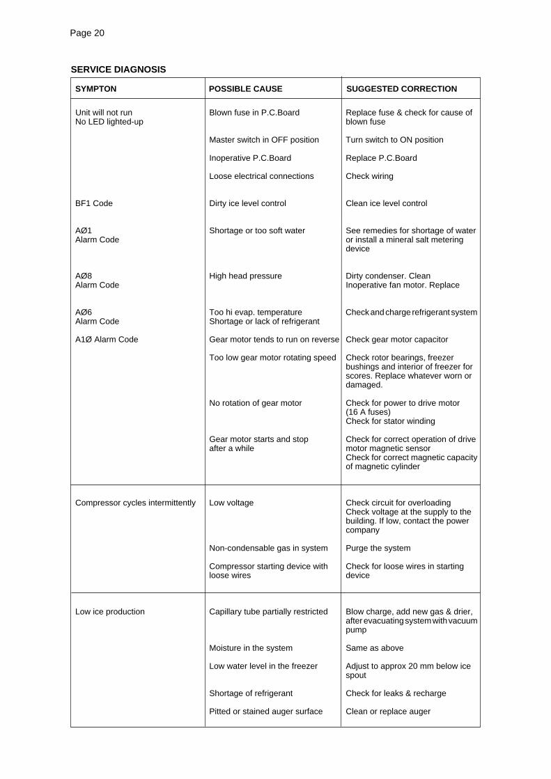
SYMPTON POSSIBLE CAUSE SUGGESTED CORRECTION
Unit will not run Blown fuse in P.C.Board Replace fuse & check for cause ofNo LED lighted-up blown fuse
Master switch in OFF position Turn switch to ON position
Inoperative P.C.Board Replace P.C.Board
Loose electrical connections Check wiring
BF1 Code Dirty ice level control Clean ice level control
AØ1 Shortage or too soft water See remedies for shortage of waterAlarm Code or install a mineral salt metering
device
AØ8 High head pressure Dirty condenser. CleanAlarm Code Inoperative fan motor. Replace
AØ6 Too hi evap. temperature Check and charge refrigerant systemAlarm Code Shortage or lack of refrigerant
A1Ø Alarm Code Gear motor tends to run on reverse Check gear motor capacitor
Too low gear motor rotating speed Check rotor bearings, freezerbushings and interior of freezer forscores. Replace whatever worn ordamaged.
No rotation of gear motor Check for power to drive motor(16 A fuses)Check for stator winding
Gear motor starts and stop Check for correct operation of driveafter a while motor magnetic sensor
Check for correct magnetic capacityof magnetic cylinder
Compressor cycles intermittently Low voltage Check circuit for overloadingCheck voltage at the supply to thebuilding. If low, contact the powercompany
Non-condensable gas in system Purge the system
Compressor starting device with Check for loose wires in startingloose wires device
Low ice production Capillary tube partially restricted Blow charge, add new gas & drier,after evacuating system with vacuumpump
Moisture in the system Same as above
Low water level in the freezer Adjust to approx 20 mm below icespout
Shortage of refrigerant Check for leaks & recharge
Pitted or stained auger surface Clean or replace auger
SERVICE DIAGNOSIS
Page 21Page 21
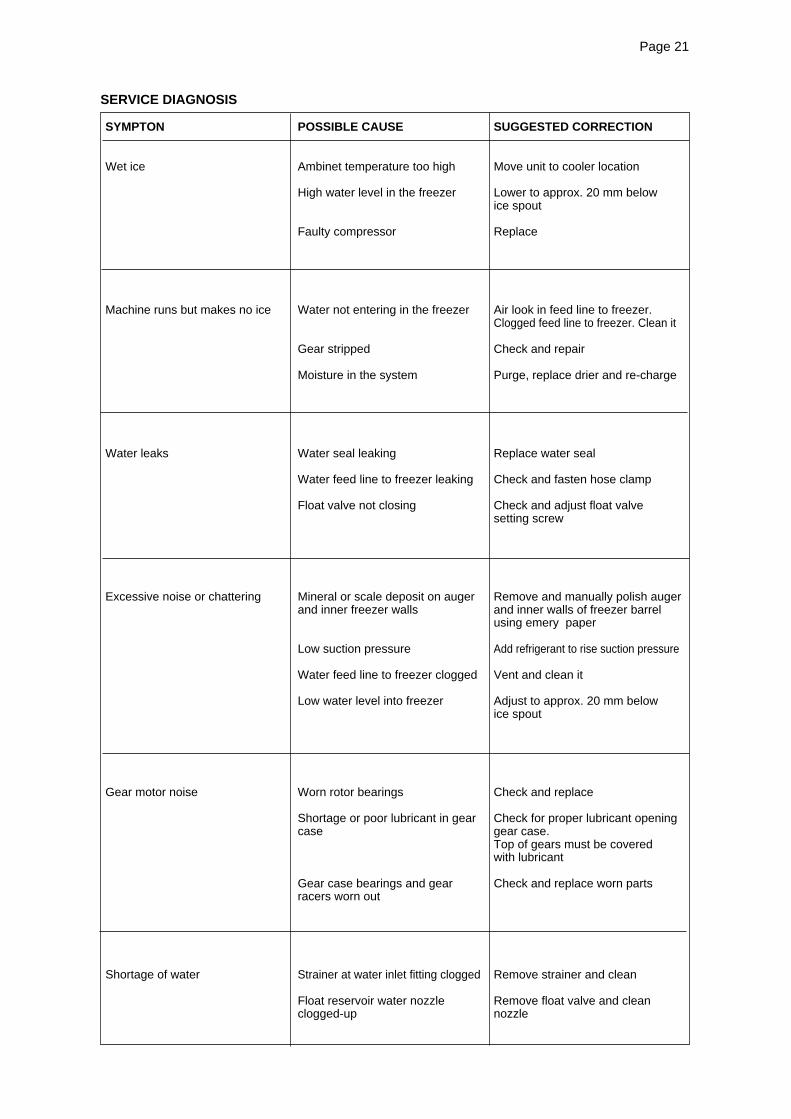
SYMPTON POSSIBLE CAUSE SUGGESTED CORRECTION
Wet ice Ambinet temperature too high Move unit to cooler location
High water level in the freezer Lower to approx. 20 mm belowice spout
Faulty compressor Replace
Machine runs but makes no ice Water not entering in the freezer Air look in feed line to freezer.Clogged feed line to freezer. Clean it
Gear stripped Check and repair
Moisture in the system Purge, replace drier and re-charge
Water leaks Water seal leaking Replace water seal
Water feed line to freezer leaking Check and fasten hose clamp
Float valve not closing Check and adjust float valvesetting screw
Excessive noise or chattering Mineral or scale deposit on auger Remove and manually polish augerand inner freezer walls and inner walls of freezer barrel
using emery paper
Low suction pressure Add refrigerant to rise suction pressure
Water feed line to freezer clogged Vent and clean it
Low water level into freezer Adjust to approx. 20 mm belowice spout
Gear motor noise Worn rotor bearings Check and replace
Shortage or poor lubricant in gear Check for proper lubricant openingcase gear case.
Top of gears must be coveredwith lubricant
Gear case bearings and gear Check and replace worn partsracers worn out
Shortage of water Strainer at water inlet fitting clogged Remove strainer and clean
Float reservoir water nozzle Remove float valve and cleanclogged-up nozzle
SERVICE DIAGNOSIS
Page 22Page 22
MAINTENANCE AND CLEANING INSTRUCTION
A. GENERAL
The periods and the procedures for maintenanceand cleaning are given as guides and are not tobe construed as absolute or invariable.Cleaning, especially, will vary depending uponlocal water and ambient conditions and the icevolume produced; and, each icemaker must bemaintained individually, in accordance with itsparticular location requirements.
WARNING: Before proceeding with anycleaning and maintenance operation,make sure that electrical power has beendisconnected.
CAUTION. DO NOT use a pressurizedwater jet system for the cleaning of themachine
B. DAILY MAINTENANCE
It must be performed by the end user and consistsof cleaning and sanitizing of the frame and thedispensing parts of the unit.
1. Wipe the exterior of the machine with adisposable sanitizing wipe using a specif icproduct for Stainless Steel cleaning.
2. Remove the ice and water spouts
And allow to soak in a sanitizing solutionfor 10 minutes, then rinse well with freshwater.
3. Pour hot soapy water or sanitizing solutioninto the drain pan ensuring not to overf low thetray.
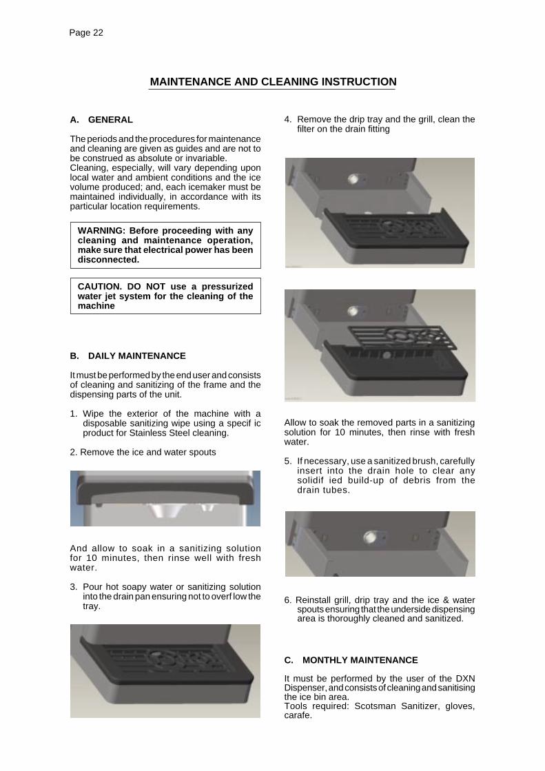
4. Remove the drip tray and the grill, clean thefilter on the drain fitting
Allow to soak the removed parts in a sanitizingsolution for 10 minutes, then rinse with freshwater.
5. If necessary, use a sanitized brush, carefullyinsert into the drain hole to clear anysolidif ied build-up of debris from thedrain tubes.
6. Reinstall grill, drip tray and the ice & waterspouts ensuring that the underside dispensingarea is thoroughly cleaned and sanitized.
C. MONTHLY MAINTENANCE
It must be performed by the user of the DXNDispenser, and consists of cleaning and sanitisingthe ice bin area.Tools required: Scotsman Sanitizer, gloves,carafe.
Page 23Page 23
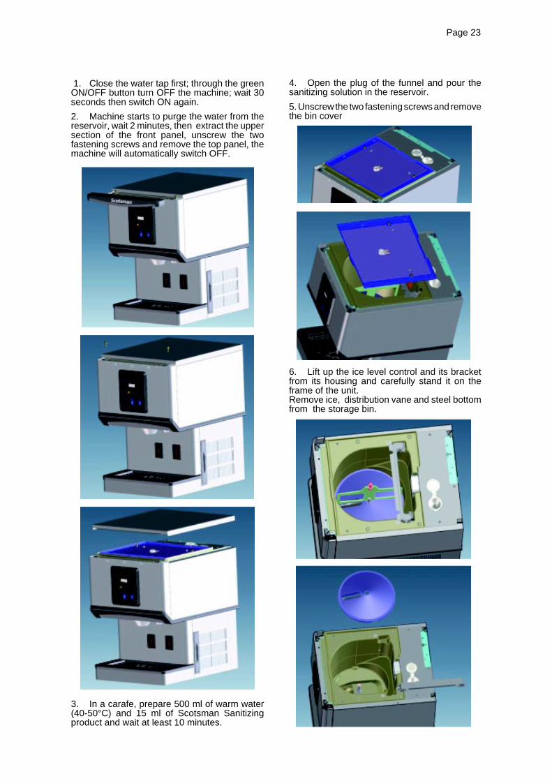
1. Close the water tap first; through the greenON/OFF button turn OFF the machine; wait 30seconds then switch ON again.
2. Machine starts to purge the water from thereservoir, wait 2 minutes, then extract the uppersection of the front panel, unscrew the twofastening screws and remove the top panel, themachine will automatically switch OFF.
3. In a carafe, prepare 500 ml of warm water(40-50°C) and 15 ml of Scotsman Sanitizingproduct and wait at least 10 minutes.
4. Open the plug of the funnel and pour thesanitizing solution in the reservoir.
5. Unscrew the two fastening screws and removethe bin cover
6. Lift up the ice level control and its bracketfrom its housing and carefully stand it on theframe of the unit.Remove ice, distribution vane and steel bottomfrom the storage bin.
Page 24Page 24
7. Using the same carafe, prepare again 500ml of warm water (40-50°C) and 15 ml ofScotsman Sanitizing product and pour of thesolution on the internal sides of the storage bin.
8. Using a sanitised disposable cloth, clean theice bin and rinse with clean water.
9. Close the funnel plug and reinstall all thepreviously removed panels and parts by followingthe procedure in reverse order, paying attentionthat both the steel bottom and the upper shaft ofthe blade are properly seated.
10. Remove, clean and reinstall the air filter locatedon the right side panel, then open the water tap.
11. Remove, clean and re-install the snorkel locatedin the water dispensing tube using the specialkey (P/N SC 651647 02) supplied to all DXN.
NOTE. Once the cleaning operations arecompleted, switch on the equipment; the iceproduction process will start after a delay often minutes. Make sure that the first producedice doesn’t taste slightly acid; in any caseempty the bin by pressing the dispensingbutton and dispose of the ice produced duringthe first 10 minutes.
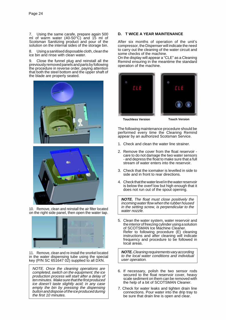
D. T WICE A YEAR MAINTENANCE
After six months of operation of the unit’scompressor, the Dispenser will indicate the needto carry out the cleaning of the water circuit andsome checks of the machine.On the display will appear a “CLE” as a CleaningRemind ensuring in the meantime the standardoperation of the machine.
The following maintenance procedure should beperformed every time the Cleaning Remindappear by an authorized Scotsman Service.
1. Check and clean the water line strainer.
2. Remove the cover from the float reservoir -care to do not damage the two water sensors- and depress the float to make sure that a fullstream of water enters into the reservoir.
3. Check that the icemaker is levelled in side toside and in front to rear directions.
4. Check that the water level in the water reservoiris below the overf low but high enough that itdoes not run out of the spout opening.
NOTE. The float must close positively theincoming water flow when the rubber housedin the setting screw, is perpendicular to thewater nozzle.
5. Clean the water system, water reservoir andthe interior of freezing cylinder using a solutionof SCOTSMAN Ice Machine Cleaner.Refer to following procedure (E) cleaninginstructions and after cleaning will indicatefrequency and procedure to be followed inlocal areas.
NOTE. Cleaning requirements vary accordingto the local water conditions and individualuser operation.
6. If necessary, polish the two sensor rodssecured to the float reservoir cover, heavyscale sediment on them can be removed withthe help of a bit of SCOTSMAN Cleaner.
7. Check for water leaks and tighten drain lineconnections. Pour water into the drip tray tobe sure that drain line is open and clear.
Touch VersionTouchless Version
Page 25Page 25
8. Check the ice level control sensor to test shut-off. Put your hand between the light sourceand the receiver so to cut off the light beamfor at least 10 seconds. This should cause theimmediate bin full condition with a bF1 ondisplay. The compressor stops immediatelyand the gear reducer three minutes later.Within few seconds from the removal of thehand from between the sensor lights the icemaker resume its operation with the standard8 minutes of the start-up delay.
NOTE. The ice level control uses devicesthat sense light, therefore they must be keptclean enough so they can “see”. Every monthclean/wipe the sensing “eyes” with a cleansoft cloth.
9. Check for refrigerant leaks and for properfrost line, which should frost as far as approx.20 cm (8") from the compressor. Whendoubtful about refrigerant charge, installrefrigerant gauges on correspondingSchräder valves and check for correctrefrigerant pressures.(See Operating pressure at page 12 of thismanual).
10. Check that fan blades move freely and arenot touching any surfaces.
11. Turn the ice dispensing spout and remove it.Wash and sanitize it as shown at point B
12. Remove the drip tray and grill for washingand sanitizing as shown at point B.
E. CLEANING INSTRUCTIONS OFWATER SYSTEM
1. Empty the ice storage bin trough thedispensing button , then switch OFF the unitfrom the green ON/OFF push button.
2. Remove the top panel and later the top coverof storage bin.
3. Close the water shutoff valve on water line.
4. Remove the left side panel to gain access tothe water reservoir.
5. Remove the float reservoir cover and with apiece of copper wire jump the two water levelsensors.
6. Switch ON the unit to purge and drain out allwater from the freezer.
CLEANING
7. Prepare the cleaning solution by diluting in aplastic container two liters of warm water(45°- 50°C) with a 0,2 liters of SCOTSMANIce Machine Cleaner.
WARNING. The SCOTSMAN Ice MachineCleaner contains Phosphoric andHydroxyacetic acids. These compoundsare corrosive and may cause burns ifswallowed, DO NOT induce vomiting.Give large amounts of water or milk. CallPhysician immediately. In case of externalcontact flush with water. KEEP OUT OFTHE REACH OF CHILDREN
8. Pour the cleaning solution into the waterreservoir funnel till reaches the proper level.
9. After 15 minutes switch ON the Master switchto start the unit.
10. Wait till the machine starts to discharge ice,then continue to slowly pour the cleaningsolution into the water reservoir funnel takingcare to maintain the level just below the overflow.
NOTE. The ice made with the cleaningsolution is slushy and colored also, it maytend to loose fluidity creating some resistancein being elevated and extruded; this situationcan be heard by the cracking noise made bythe ice. Should this occur it is recommendedto stop for few minutes the ice machine inorder to allow the ice in the freezer to partiallymelt.
11. When all the cleaning solution has beenused, open the water shutoff valve to allow newfresh water to flow into the reservoir. Let the unitto continue to run until the ice resumes thenormal color and hardness.
12. Stop the icemaker and pour warm water onthe ice deposited into the storage bin to melt it up.
NOTE. DO NOT use ice produced with thecleaning solution. Be sure none remains inthe bin.
SANITATION
13. Once completed the cleaning procedureperform the monthly storage bin sanitizingprocedure as described at point (C).
NOTE. DO NOT use ice produced with thesanitizing solution.
REMEMBER. To prevent the accumulationof undesirable bacteria it is necessary tosanitize the interior of the storage binwith an anti-algae disinfectant solutionevery once or at least twice a week.