new ef series - scotsman ice uk
TRANSCRIPT

Page 1Page 1
SERVICE MANUAL
NEWEF SERIES
S
Electronic flakerswith storage
REV. 04/2017
Scotsman Ice SrlVia Lainate, 31 - 20010 Pogliano M.se - Milano - ItalyTel. +39-02-93960.1 (Aut. Sel.)- Telefax +39-02-93550500Direct Line to Service & Parts:Phone +39-02-93960350 - Fax +39-02-93540449Website: www.scotsman-ice.itE-Mail: [email protected]
ISO 9001 - Cert. n. 0080

LED STATUS REASON WHY – SIGNIFICATION – SIGNIFICATO – Beschreibung
ON STEADY FIXE
FISSO Ständig an
UNIT OFF AT BIN FULL CABINE PLAINE
CONTENITORE PIENO Maschine AUS, Speicher voll!
BLINKING SLOW CLIGNOTANT LENT LAMPEGG. LENTO
Blinkt langsam
I/R BEAM CUTTED FAISCEAU INFRA ROUGE CELLULE NIVEAU GLACE INTERROMPU
RAGGIO INFRAROSSO INTERROTTO Lichtschranke unterbrochen!
BLINKING FAST CLIGNOTANT RAPIDE LAMPEGG. VELOCE
Blinkt schnell
I/R ON AFTER TRIP OFF AT BIN FULL FAISCEAU INFRA ROUGE CELLULE NIVEAU GLACE ETABLI
RAGGIO INFRAROSSO RIPRISTINATO INTERROTTO Speicher entleert, Maschine startet gleich!
ON STEADY FIXE
FISSO Ständig an
NO WATER MANQUE D’EAU
MANCANZA ACQUA Kein Wasser!
ON STEADY FIXE
FISSO Ständig an
TOO HI DISCHARGE PRESSURE/TEMPERATURE COUPURE HP
FERMATA ALTA TEMP. CONDENSAZIONE Zu hoher Kondensationsdruck
BLINKING CLIGNOTANT
LAMPEGGIANTE Blinkt
DELAY AT START UP (3 min. or 60 min. according to the Jumper setting) TEMPORISATION AU DEMARRAGE (3 min ou 60 min. selon le reglage du chavalier)
RITARDO PARTENZA (3' o 60’ in funzione della regolazione del ponticello) 3 min. oder 60 min. Startverzögerung je nach Jumper Konfig.!
BLINKING 3 TIMES AND REPEAT CLIGNOTANT 3 FOIS ET NOUVEAU
LAMPEGGIANTE 3 VOLTE BLINKT 3 MAL und wiederholen
TOO LOW ROOM TEMP (< +3°C) COUPURE TRES BASSE TEMP. AMBIANTE (< +3°C)
FERMATA TEMP. AMBIENTE BASSA (< +3°C) Zu hoher Raumtemp. < +3°C!
ON STEADY FIXE
FISSO Ständig an
NO, SLOW OR WRONG ROTATION OF DRIVE MOTOR MOTOREDUCTEUR TOURNE A L'ENVERS, NE TOURNE PAS, OU TROP LENTEMENT
MOTORE RIDUTTORE GIRA AL CONTRARIO, NON GIRA O GIRA LENTAMENTE Keine, zu langsame oder schwere Getriebrotation!
BLINKING CLIGNOTANT
LAMPEGGIANTE Blinkt
TOO HI EVAP. TEMP. (> 0C°) AFTER 10' FROM START UP OR TOO LOW EVAP. TEMP. (< -25°C) COUPURE TEMP. EVAP. >0°C APRES 10' DE FONCTIONNEMENT OU TEMP. EVAP. <-25°C
TEMP. EVAP >0 °C DOPO 10' DA INIZIO FUNZIONAMENTO O INFERIORE A -25°C Zu hohe Verd.temp. > 0°C 10 min. nach dem Start oder zu niedrige Verd.temp. < -25°C
ON STEADY FIXE
FISSO Ständig an BLINKING
CLIGNOTANT LAMPEGGIANTE
Blinkt
CONDENSER SENSOR OUT OF ORDER SONDE CONDENSEUR HS
SONDA CONDENSATORE MALFUNZIONANTE Kondensatorfühler defekt!
EVAPORATOR SENSOR OUT OF ORDER SONDE EVAPORATEUR HS
SONDA EVAPORATORE MALFUNZIONANTE Verdampferfühler defekt!
BLINKING ALTERNATE CLIGNOTANT ALTERNE’
LAMPEGGIANTE ALTERNATO Blinkt im Wechsel!
OPTICAL ICE LEVEL CONTROL OUT OF ORDER CELLULE INFRAROUGE NIVEAU GLACE HS
SONDA ALL’INFRAROSSO LIVELLO GHIACCIO MALFUNZIONANTE Lichtschranke defekt!
BLINKING CLIGNOTANT
LAMPEGGIANTE Blinkt
6 OR 12 MONTHS WATER SYSTEM CLEANING REMIND (according to the Jumper setting) RAPPEL NETTOYAGE SYSTÉME HYDAULIQUE APRÉS 6 OU 2 MOIS (selon reglage. chavalier) RICHIAMO PULIZIA CIRCUITO IDRICO DOPO 6 O 12 MESI (In funzione regolazione ponticello)
6 oder 12 Monate Reinigungshinweis für Wassersystem je nach Jumper Konfig.!
BLINKING IN SEQUENCE CLIGNOTTANT EN SEQUENCE LAMPEGGIANTE IN SEQUENZA
Blinken nacheinander!
PURGE CYCLE IN OPERATION (Only on units equipped with purge valve) CYCLE D’ÉVACUATION EAU EN FONCTION (Seulement dans les machine equipées avec vanne de vidange
eau) SISTEMA SCARICO ACQUA IN FUNZIONE (Solo negli apparecchi dotati di valvola di scarico)
Spülzyklus läuft, bei Maschinen mit Ablaßventil! BLINKING
CLIGNOTANT LAMPEGGIANTE
Blinken
UNIT OFF DUE TO THE JUMPER ON TEST CONTACTS MACHINE A L’ÂRRET – CONTACTS TEST FERMÉES
MACCHINA FERMA – CONTATTI TEST CHIUSI Jumper Konfig. Im Testmodus!
PUSH AND HOLD THE RED LIGHTED SWITCH OR THE PC BOARD BUTTON FOR MORE OF 5 SECONDS WITH MACHINE IN OPERATION TILL THE SWITCHING OFF OF THE TWO YELLOW LEDS TO RESTART THE CLEANING REMIND COUNTDOWN
APPUYER SUR LE BOUTON ROUGE OU SUR LE BOUTON DE LA CARTE POUR 5 SECONDES AVEC LA MACHINE EN FONCTIONNEMENT JUSQU’A L’ETEINTE DE LES DEUX LEDS JAUNE POUR REINITIALISER L'ALARME JUSQU'AU PROCHAIN DETARTRAGE
PREMERE IL PULSANTE ROSSO O IL PULSANTE DELLA SCHEDA PER PIU' DI 5" CON LA MACCHINA IN FUNZIONE FINO ALLO SPEGNIMENTO DEI DUE LED GIALLI PER FAR RIPARTIRE IL CONTEGGIO PER LA PROSSIMA DISINCROSTAZIONE
Drücken und halten Sie den roten Schalter oder den push button auf der Elektronik, für mehr als 5 Sekunden wenn die Maschine in Betrieb ist, bis die 2 gelben LED´s auf der Elektronik nicht mehr leuchten! Der Erinnerungszyklus für die Reinigung ist somit zurückgesetzt und startet neu!

Page 2Page 2
TABLE OFCONTENTS
Table of contents page 2Specifications EF 103 3Specifications EF 124 5Specifications EF 156 7Specifications EF 206 9
GENERAL INFORMATION AND INSTALLATION
Introduction 11Unpacking and Inspection 11Location and levelling 11Electrical connections 11Water supply and drain connections 12Final check list 13Installation practice 13
OPERATING INSTRUCTIONS
Start up 14Operational checks 16
PRINCIPLE OF OPERATION (How it works)
Water circuit 20Refrigerant circuit 20Mechanical system 22Operating pressures 23Components description 24
ADJUSTMENT, REMOVAL AND REPLACEMENT PROCEDURES
Adjustment of the evaporator water level 29Replacement of evaporator temperature sensor 29Replacement of condenser temperature sensor 29Replacement of ice level light control 29Replacement of the gear motor rotation and speed sensor 29Replacement of the reservoir water level sensor 30Replacement of P.C. Board 30Replacement of the ice spout 30Replacement of the auger, water seal, bearings and coupling 30Replacement of the gear motor assy 31Replacement of fan motor 31Replacement of drier 32Replacement of the freezing cylinder 32Replacement of air cooled condenser 32Replacement of water cooled condenser 32Replacement of water regulating valve (water cooled models) 33Replacement of compressor 33Replacement of the gear motor magnetic sensor 33Wiring diagram 34Service diagnosis 36
MAINTENANCE AND CLEANING INSTRUCTIONS
General 38Icemaker 38Cleaning instructions of water system 38

Page 3Page 3
SPECIFICATIONS
ice making capacity
ELECTRONIC FLAKER MODEL EF 103
Important operating requirements:
MIN MAX- Air temperature 10°C (50°F) 40°C (100°F)- Water temperature 5°C (40°F) 40°C (100°F)- Water pressure 1 bar (14 psi) 5 bars (70 psi)- Electr. voltagevariations fromvoltagerating specifiedon nameplate -10% +10%
NOTE. The daily ice-making capacity is directly related to the condenser air inlet temperature, watertemperature and age of the machine.To keep your SCOTSMAN FLAKER at peak performance levels, periodic maintenance checksmust be carried out as indicated on page 36 of this manual.
10
21
32
38
10
21
105
103
101
99
97
95
93
91
89
87
85
83
81
79
77
75
73
71
69
67
65
K g .
10 °C27 21 15
°Co
o
AIR COOLED MODELS
WATER TEMPERATURE
AM
BIE
NT
TE
MP
ER
AT
UR
E
ICE
PR
OD
UC
ED
PE
R 2
4 H
RS
.
32
WATER COOLED MODELS
32
38
110
108
106
104
102
100
98
96
94
92
90
88
86
84
82
80
78
76
74
72
70
K g .
10 °C27 21 15
°Co
o
WATER TEMPERATURE
AM
BIE
NT
TE
MP
ER
AT
UR
E
ICE
PR
OD
UC
ED
PE
R 2
4 H
RS
.
32
Page 4Page 4
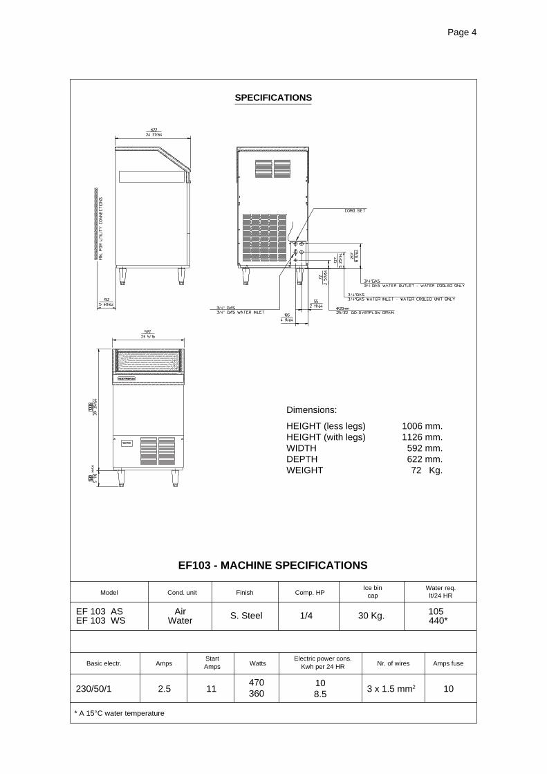
S. Steel 1/4 30 Kg.
Start Electric power cons.Amps Kwh per 24 HRBasic electr. Amps Watts Nr. of wires Amps fuse
SPECIFICATIONS
Model Cond. unit Finish Comp. HPIce bin
capWater req.lt/24 HR
EF103 - MACHINE SPECIFICATIONS
Dimensions:
HEIGHT (less legs) 1006 mm.HEIGHT (with legs) 1126 mm.WIDTH 592 mm.DEPTH 622 mm.WEIGHT 72 Kg.
* A 15°C water temperature
230/50/1 2.5 11 3 x 1.5 mm2 10
EF 103 AS Air 105**EF 103 WS Water 440*
470360
108.5

Page 5Page 5
SPECIFICATIONS
ice making capacity
ELECTRONIC CUBELET MODEL EF 124
NOTE. With the unit in “built-in” conditions, the ice production is gradually reduced in respect to thelevels shown in the graph, up to a maximum of 10% at room temperatures higher than 32°C.The daily ice-making capacity is directly related to the condenser air inlet temperature, watertemperature and age of the machine.To keep your SCOTSMAN CUBELET at peak performance levels, periodic maintenance checksmust be carried out as indicated on page 36 of this manual.
Important operating requirements:
MIN MAX- Air temperature 10°C (50°F) 40°C (100°F)- Water temperature 5°C (40°F) 35°C (90°F)- Water pressure 1 bar (14 psi) 5 bars (70 psi)- Electr. voltagevariations fromvoltagerating specifiedon nameplate -10% +10%
32
38
10
21
120
118
116
114
112
110
108
106
104
102
100
98
96
94
92
90
88
86
84
82
80
78
76
74
K g .
10 °C27 21 15
°Co
o
AIR COOLED MODELS
WATER TEMPERATURE
AM
BIE
NT
TE
MP
ER
AT
UR
E
ICE
PR
OD
UC
ED
PE
R 2
4 H
RS
.
32
38
10
21
121
119
117
115
113
111
109
107
105
103
101
99
97
95
93
91
89
87
85
83
K g .
10 °C27 21 15 o
WATER COOLED MODELS
WATER TEMPERATURE
AM
BIE
NT
TE
MP
ER
AT
UR
E
ICE
PR
OD
UC
ED
PE
R 2
4 H
RS
.
32
°Co
Page 6Page 6
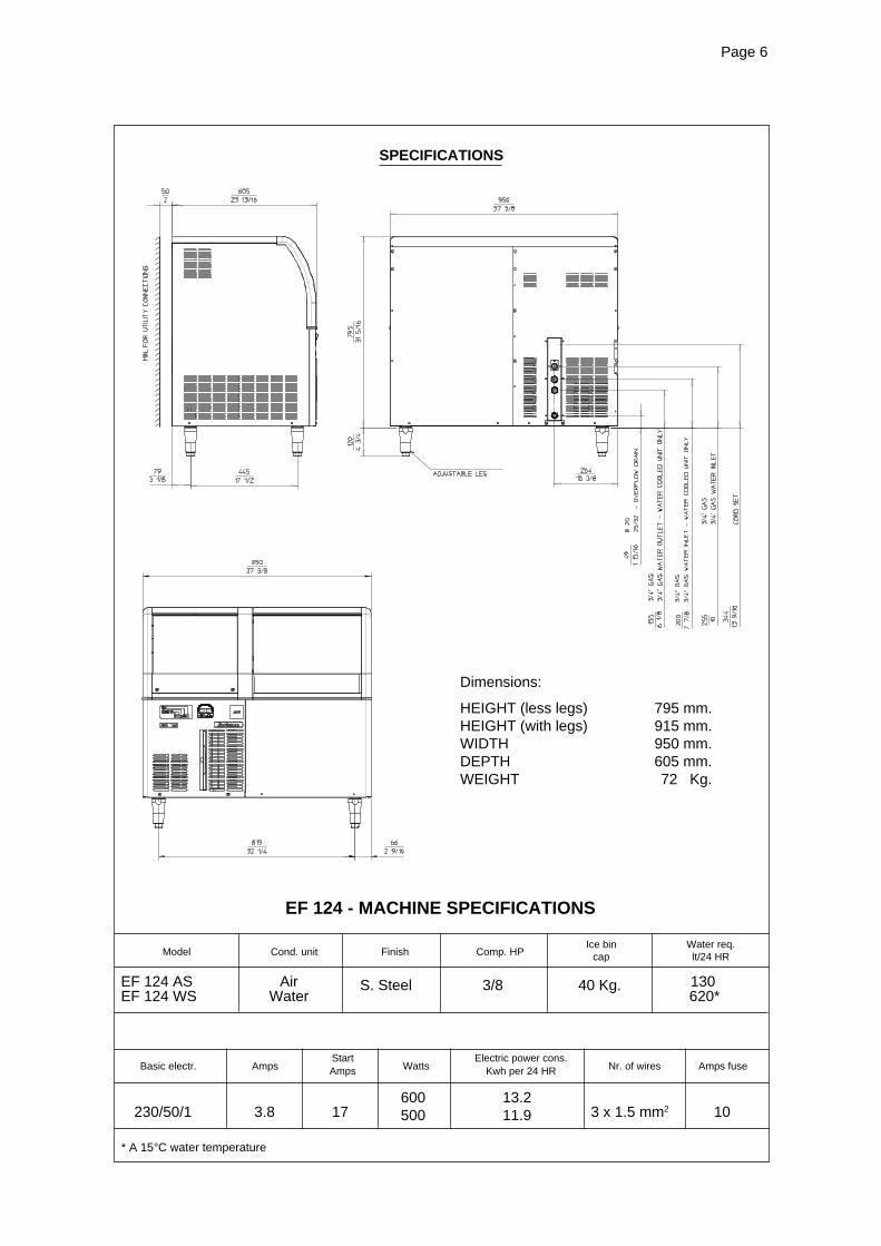
Start Electric power cons.Amps Kwh per 24 HRBasic electr. Amps Watts Nr. of wires Amps fuse
SPECIFICATIONS
Model Cond. unit Finish Comp. HPIce bin
capWater req.lt/24 HR
EF 124 - MACHINE SPECIFICATIONS
Dimensions:
HEIGHT (less legs) 795 mm.HEIGHT (with legs) 915 mm.WIDTH 950 mm.DEPTH 605 mm.WEIGHT 72 Kg.
230/50/1 3.8 17 3 x 1.5 mm2 10
S. Steel 3/8 40 Kg.EF 124 AS Air 130**EF 124 WS Water 620*
* A 15°C water temperature
600500
13.211.9

Page 7Page 7
SPECIFICATIONS
ice making capacity
ELECTRONIC FLAKER MODEL EF 156
NOTE. With the unit in “built-in” conditions, the ice production is gradually reduced in respect to thelevels shown in the graph, up to a maximum of 10% at room temperatures higher than 32°C.The daily ice-making capacity is directly related to the condenser air inlet temperature, watertemperature and age of the machine.To keep your SCOTSMAN FLAKER at peak performance levels, periodic maintenance checksmust be carried out as indicated on page 36 of this manual.
Important operating requirements:
MIN MAX- Air temperature 10°C (50°F) 40°C (100°F)- Water temperature 5°C (40°F) 40°C (100°F)- Water pressure 1 bar (14 psi) 5 bars (70 psi)- Electr. voltagevariations fromvoltagerating specifiedon nameplate -10% +10%
32
38
1021
150
146
142
138
134
130
126
122
118
114
110
106
102
98
K g .
10 °C27 21 15
°Co
o
AIR COOLED MODELS
WATER TEMPERATURE
AM
BIE
NT
TE
MP
ER
AT
UR
E
ICE
PR
OD
UC
ED
PE
R 2
4 H
RS
.
32
WATER COOLED MODELS
3238
10
21
K g .
10 °C27 21 15
°Co
o
WATER TEMPERATURE
AM
BIE
NT
TE
MP
ER
AT
UR
E
ICE
PR
OD
UC
ED
PE
R 2
4 H
RS
.
32
160
156
152
148
144
140
136
132
128
124

Page 8Page 8
Start Electric power cons.Amps Kwh per 24 HRBasic electr. Amps Watts Nr. of wires Amps fuse
SPECIFICATIONS
Model Cond. unit Finish Comp. HPIce bin
capWater req.lt/24 HR
EF 156 - MACHINE SPECIFICATIONS
Dimensions:
HEIGHT (less legs) 1006 mm.HEIGHT (with legs) 1126 mm.WIDTH 950 mm.DEPTH 605 mm.WEIGHT 88 Kg.
230/50/1 3.8 17 650 14.7 3 x 1.5 mm2 10
S. Steel 3/8 60 Kg.EF156 AS Air 160**EF156 WS Water 1000*
* A 15°C water temperature

Page 9Page 9
SPECIFICATIONS
ice making capacity
ELECTRONIC FLAKER MODEL EF 206
Important operating requirements:
MIN MAX- Air temperature 10°C (50°F) 40°C (100°F)- Water temperature 5°C (40°F) 40°C (100°F)- Water pressure 1 bar (14 psi) 5 bars (70 psi)- Electr. voltagevariations fromvoltagerating specifiedon nameplate -10% +10%
NOTE. The daily ice-making capacity is directly related to the condenser air inlet temperature, watertemperature and age of the machine.To keep your SCOTSMAN FLAKER at peak performance levels, periodic maintenance checksmust be carried out as indicated on page 36 of this manual.
32
38
10
21
200
196
192
188
184
180
176
172
168
164
160
156
152
148
144
140
136
132
128
124
K g .
10 °C27 21 15
°Co
o
AIR COOLED MODELS
WATER TEMPERATURE
AM
BIE
NT
TE
MP
ER
AT
UR
E
ICE
PR
OD
UC
ED
PE
R 2
4 H
RS
.
32
32
38
10
21
202
200
198
196
194
192
190
188
186
184
182
180
178
176
174
172
170
168
166
164
162
160
158
156
154
K g .
10 °C27 21 15 o
WATER COOLED MODELS
WATER TEMPERATURE
AM
BIE
NT
TE
MP
ER
AT
UR
E
ICE
PR
OD
UC
ED
PE
R 2
4 H
RS
.
32
°Co
Page 10Page 10
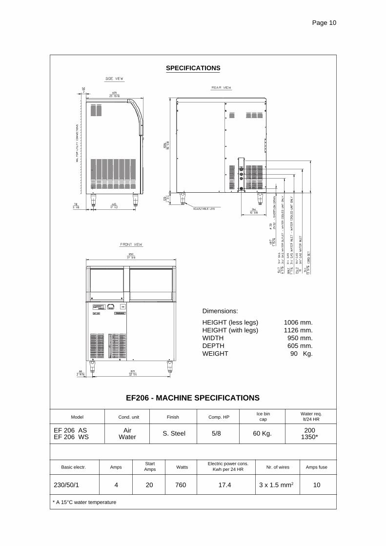
Start Electric power cons.Amps Kwh per 24 HRBasic electr. Amps Watts Nr. of wires Amps fuse
SPECIFICATIONS
Model Cond. unit Finish Comp. HPIce bin
capWater req.lt/24 HR
EF206 - MACHINE SPECIFICATIONS
Dimensions:
HEIGHT (less legs) 1006 mm.HEIGHT (with legs) 1126 mm.WIDTH 950 mm.DEPTH 605 mm.WEIGHT 90 Kg.
* A 15°C water temperature
230/50/1 4 20 760 17.4 3 x 1.5 mm2 10
S. Steel 5/8 60 Kg.EF 206 AS Air 200**EF 206 WS Water 1350*

Page 11Page 11
GENERAL INFORMATION AND INSTALLATION
A. INTRODUCTION
This manual provides the specifications and thestep-by-step procedures for the installation, start-up and operation, maintenance and cleaning forthe SCOTSMAN EF series icemakers.The Electronic Flakers are quality designed,engineered and manufactured.Their ice making systems are thoroughly testedproviding the utmost in flexibility to fit the needsof a particular user.
NOTE. To retain the safety and performancebuilt into this icemaker, it is important thatinstallation and maintenance be conductedin the manner outlined in this manual.
B. UNPACKING AND INSPECTION
1. Call your authorized SCOTSMAN Distributoror Dealer for proper installation.
2. Visually inspect the exterior of the packingand skid. Any severe damage noted should bereported to the delivering carrier and a concealeddamage claim form filled in subjet to inspection ofthe contents with the carrier’s representativepresent.
3. a) Cut and remove the plastic strip securingthe carton box to the skid.
b) Cut open the top of the carton and removethe polystyre protection sheet.
c) Pull out the polystyre posts from thecorners and then remove the carton.
4. Remove the front and the rear panels of theunit and inspect for any concealed damage.Notify carrier of your claim for the concealeddamage as stated in step 2 above.
5. Remove all internal support packing andmasking tape. (Leg package and water inlet andoutlet hoses are located in the storage bincompartment).
6. Check that refrigerant lines do not rub againstor touch other lines or surfaces, and that the fanblades move freely.
7. Check that the compressor fits snugly ontoall its mounting pads.
8. Use clean damp cloth to wipe the surfacesinside the storage bin and the outside of thecabinet.
9. See data plate on the rear side of the unitand check that local main voltage correspondswith the voltage specified on it.
CAUTION. Incorrect voltage supplied tothe icemaker will void your partsreplacement program.
10. Remove the manufacturer’s registration cardfrom the inside of the User Manual and fill-in allparts including: Model and Serial Number takenfrom the data plate.Forward the completed self-addressedregistration card to SCOTSMAN EUROPEfactory.
11. If necessary fit the four legs into their seatson the machine base and adjust them to thedesired level.
C. LOCATION AND LEVELLING
WARNING. This Ice Flaker is designed forindoor installation only. Extended periodsof operation at temperature exceedingthe following limitations will constitutemisuse under the terms of the SCOTSMANManufacturer’s Limited Warrantyresulting in LOSS of warranty coverage.
1. Position the unit in the selected permanentlocation.Criteria for selection of location include:a) Minimum room temperature 10°C (50°F)and maximum room temperature 40°C (100°F).b) Water inlet temperatures: minimum 5°C(40°F) and maximum 35°C (90°F).c) Well ventilated location for air cooled models(Clean the air cooled condenser at frequentintervals).d) Service access: adequate space must beleft for all service connections through the rear ofthe ice maker. A minimum clearance of 15 cm(6") must be left at the sides of the unit for routingcooling air drawn into and exhausted out of thecompartment to maintain proper condensingoperation of air cooled models.
2. Level the unit in both the left to right and frontto rear directions.
D. ELECTRICAL CONNECTIONS
See data plate for current requirements todetermine wire size to be used for electricalconnections. All SCOTSMAN icemakers requirea solid earth wire.
Page 12Page 12
All SCOTSMAN ice machines are supplied fromthe factory completely pre-wired and require onlyelectrical power connections to the wire cordprovided at the rear of the unit.Make sure that the ice machine is connected toits own circuit and individually fused (see dataplate for fuse size).The maximum allowable voltage variation shouldnot exceed -10% and +10% of the data platerating. Low voltage can cause faulty functioningand may be responsible for serious damage tothe overload switch and motor windings.
NOTE. All external wiring should conform tonational, state and local standards andregulations.
Check voltage on the line and the ice maker’sdata plate before connecting the unit.
E. WATER SUPPLY AND DRAINCONNECTIONS
GENERAL
When choosing the water supply for the ice flakerconsideration should be given to:a) Length of runb) Water clarity and purityc) Adequate water supply pressure
Since water is the most important single ingredientin producting ice you cannot emphasize toomuch the three items listed above.Low water pressure, below 1 bar may causemalfunction of the ice maker unit.Water containing excessive minerals will tend toproduce scale build-up on the interior parts of thewater system while too soft water (with too locontents of mineral salts), will produce a veryhard flaker ice.
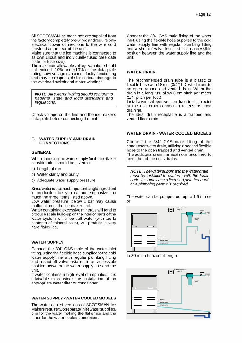
WATER SUPPLY
Connect the 3/4" GAS male of the water inletfitting, using the flexible hose supplied to the coldwater supply line with regular plumbing fittingand a shut-off valve installed in an accessibleposition between the water supply line and theunit.If water contains a high level of impurities, it isadvisable to consider the installation of anappropriate water filter or conditioner.
WATER SUPPLY - WATER COOLED MODELS
The water cooled versions of SCOTSMAN IceMakers require two separate inlet water supplies,one for the water making the flaker ice and theother for the water cooled condenser.
Connect the 3/4" GAS male fitting of the waterinlet, using the flexible hose supplied to the coldwater supply line with regular plumbing fittingand a shut-off valve installed in an accessibleposition between the water supply line and theunit.
WATER DRAIN
The recommended drain tube is a plastic orflexible hose with 18 mm (3/4") I.D. which runs toan open trapped and vented drain. When thedrain is a long run, allow 3 cm pitch per meter(1/4" pitch per foot).Install a vertical open vent on drain line high pointat the unit drain connection to ensure gooddraining.The ideal drain receptacle is a trapped andvented floor drain.
WATER DRAIN - WATER COOLED MODELS
Connect the 3/4" GAS male fitting of thecondenser water drain, utilizing a second flexiblehose to the open trapped and vented drain.This additional drain line must not interconnect toany other of the units drains.
NOTE. The water supply and the water drainmust be installed to conform with the localcode. In some case a licensed plumber and/or a plumbing permit is required.
The water can be pumped out up to 1.5 m riseor
to 30 m on horizontal length.
POWER
WATER INLET
WATER DRAIN
HAND DISCONNECT
SWITCH
WATER
FILTER
WATER
VALVE
POWER
WATER INLET
WATER DRAIN
HAND DISCONNECT
SWITCH
WATER
FILTER
WATER
VALVE

Page 13Page 13
7. Have the bolts holding the compressor downbeen checked to ensure that the compressor issnugly fitted onto the mounting pads?8. Check all refrigerant lines and conduit linesto guard against vibrations and possible failure.
9. Have the bin liner and cabinet been wipedclean?
10. Has the owner/user been given the UserManual and been instructed on the importance ofperiodic maintenance checks?
11. Has the Manufacturer’s registration cardbeen filled in properly? Check for correct modeland serial number against the serial plate andmail the registration card to the factory.
12. Has the owner been given the name and thephone number of the authorized SCOTSMANService Agency serving him?
F. FINAL CHECK LIST
1. Is the unit in a room where ambienttemperatures are within a minimum of 10°C(50°F) even in winter months?
2. Is there at least a 15 cm (6") clearancearound the unit for proper air circulation?
3. Is the unit level? (IMPORTANT)
4. Have all the electrical and plumbingconnections been made, and is the water supplyshut-off valve open?
5. Has the voltage been tested and checkedagainst the data plate rating?
6. Has the water supply pressure been checkedto ensure a water pressure of at least 1 bar(14 psi).
G. INSTALLATION PRACTICE
WARNING. This icemaker is not designed for outdoor installation and will not function inambient temperatures below 10 °C (50°F) or above 40 °C (100°F).This icemaker will malfunction with water temperatures below 5 °C (40°F) or above 35 °C(90°F).

Page 14Page 14
2
1L
N
COM
PRES
SOR
9
10
11
12
13
3
4
5
6
7
8
CONTACTOR COIL
GEAR MOTOR
FAN MOTOR
ELECTRONICCARD
RELAYS
TRIAC
RESET
S E
N S
O R
S
DATA
PRO
CESS
OR
WATERLEVEL
GEAR MOTOR ROTATION
CONDENSER TEMP.
EVAPORATOR TEMP.
ICE LEVEL CONTROL
TRANSF.
T>1°C
OPERATING INSTRUCTIONS
B. Elapsed the 3 minutes - stand by period - theunit starts operating with the activation insequence of the following assemblies:GEAR MOTORCOMPRESSORFAN MOTOR (if unit is an air cooled version)kept under control by the condenser temperatu-re sensor which has its probe within the condenserfins (Fig.2).
C. After 2 or 3 minutes from the compressorstart up, observe that flaker ice begins droppingoff the ice spout to fall into the storage bin.
NOTE. The first ice bits that drop into the icestorage bin are not so hard as the evaporatingtemperature has not yet reached the correctoperating value. It is necessary to allow theice - just made - to cure itself and wait forabout ten minutes for the evaporating tem-perature to reach the correct value so tomake more hard bits of ice.
L
N
11
10
9
1
2
7
8
6
5
4
3
13
12
FIG. 1
START UP
After having correctly installed the ice maker andcompleted the plumbing and electricalconnections, perform the following “Start-up”procedure.
A. Open the water supply line shutoff valve andput the unit under electrical power by moving themain switch, on the power supply line, to the ONposition.The first LED - GREEN - will glow to signal thatunit is under power.
NOTE. Every time the unit is put underpower, after being kept for sometime in shut-off conditions (electrically disconnected) theRED LED will blink for 3 minutes after whichthe unit will start up with the immediateoperation of the gear motor assembly and,after few seconds, of the compressor assy(Fig.1).

Page 15Page 15
FIG. 2
2
1L
N
COM
PRES
SOR
9
10
11
12
13
3
4
5
6
7
8
CONTACTOR COIL
GEAR MOTOR
FAN MOTOR
ELECTRONICCARD
RELAYS
TRIAC
RESET
S E
N S
O R
S
WATERLEVEL
GEAR MOTOR ROTATION
CONDENSER TEMP.
EVAPORATOR TEMP.
ICE LEVEL CONTROL
TRANSF.
T 40÷50°C
DATA
PRO
CESS
ORL
N
11
10
9
1
2
7
8
6
5
4
3
13
12
FIG. 3
2
1L
N
COM
PRES
SOR
9
10
11
12
13
3
4
5
6
7
8
CONTACTOR COIL
GEAR MOTOR
FAN MOTOR
ELECTRONICCARD
RELAYS
TRIAC
RESET
S E
N S
O R
S
WATERLEVEL
GEAR MOTOR ROTATION
CONDENSER TEMP.
EVAPORATOR TEMP.
ICE LEVEL CONTROL
TRANSF.
T>75°C
DATA
PRO
CESS
OR
L
N
11
10
9
1
2
7
8
6
5
4
3
13
12

Page 16Page 16
FIG. 4
2
1L
N
COM
PRES
SOR
9
10
11
12
13
3
4
5
6
7
8
CONTACTOR COIL
GEAR MOTOR
FAN MOTOR
ELECTRONICCARD
RELAYS
TRIAC
RESET
S E
N S
O R
S
WATERLEVEL
GEAR MOTOR ROTATION
CONDENSER TEMP.
EVAPORATOR TEMP.
ICE LEVEL CONTROL
TRANSF.
DATA
PRO
CESS
OR
L
N
11
10
9
1
2
7
8
6
5
4
3
12
13
NOTE. If, after ten minutes from thecompressor start-up, the evaporating tem-perature has not dropped down to a valuelower than -1°C (30°F) due to an insufficientquantity of refrigerant in the system, theevaporating temperature sensor detects suchan abnormal situation and stops consequentlythe unit operation (drive motor keeps onworking for 3' delay then stops).In this circustance, the 5th warning YELLOWLED will blink.
The machine will remain in OFF mode forone hour then it will restart automatically.In case the unit trips OFF again in alarm for3 times in 3 hours, the machine SHUTS OFFDEFINITIVELY. After having diagnosed andeliminated the cause of the poor evaporatingtemperature (insufficient refrigerant in thesystem, etc.) it is necessary to unplug andplug in again to restart the machine.The unit, before resuming the total operation,will go through the usual 3 minutes STAND-BY period.
OPERATION CHECKS UPON THE UNITSTART UP
D. Remove front service panel and if necessaryinstall the refrigerant service gauges on thecorresponding Service valves to check both theHI and LO refrigerant pressures.
NOTE. On air cooled models, the condensertemperature sensor, which is located withinthe condenser fins, keep the head (conden-sing) pressure between 17 and 18 bar.In case of condenser clogging such to preventthe proper flow of the cooling air or, in casethe fan motor is out of operation or shortageof water in the water cooled condenser, thecondenser temperature rises and when itreaches 70°C (160°F) - for air cooled version- and 60°C (140°F) - for water cooled version- the condenser temperature sensor shuts-off the ice maker (drive motor keeps onworking for 3' delay then stops) with theconsequent light-up of the RED WARNINGLIGHT (Fig.3).
The machine will remain in OFF mode forone hour then it will restart automatically.In case the unit trips OFF again in alarm for3 times in 3 hours, the machine SHUTS OFFDEFINITIVELY.After having diagnosed the reason of thetemperature rise and removed its cause, it isnecessary to proceed as per the previous“NOTE” to start up again the operation of theice maker.
E. Check for the correct CUT-OUT andCUT-IN of the float reservoir water levelsensors by first shutting closed the water shutoffvalve on the water supply line.

Page 17Page 17
FIG. 5
2
1L
N
COM
PRES
SOR
9
10
11
12
13
3
4
5
6
7
8
CONTACTOR COIL
GEAR MOTOR
FAN MOTOR
ELECTRONICCARD
RELAYS
TRIAC
RESET
S E
N S
O R
S
WATERLEVEL
GEAR MOTOR ROTATION
CONDENSER TEMP.
EVAPORATOR TEMP.
ICE LEVEL CONTROL
TRANSF.
DATA
PRO
CESS
OR
L
N
11
10
9
1
2
7
8
6
5
4
3
12
13
This will cause a gradual decrease of the waterlevel in the float reservoir and as soon as the levelgets below the sensors, the flaker stops to ope-rate (drive motor keeps on working by 3' delaythen stops) and the YELLOW warning LED willglow to signal the shortage of water (Fig. 4).
NOTE. The water level sensor detects thepresence of sufficient water in the floatreservoir and confirms it to the microprocessor by maintaining a low voltagecurrent flow between the two sensors usingthe water as conductor.
WARNING. The use of de-mineralizedwater (water with no salt content) havingan electrical conductivity lower than 30µS, will cause the ability of the watersensors to vanish with the consequentCUT-OUT of the flaker operations and theglowing of the YELLOW LED of shortageof water, even though that water is indeedin the reservoir.
After this, open the water supply line shutoffvalve to fill up again the float reservoir, theYELLOW LED goes off while the RED LEDstarts blinking .After 3 minutes the unit resumes its total operationwith the immediate start-up of the gear motorand, 2 seconds later, of the compressor.
F. Check for correct operation of the ice levelcontrol, by putting some ice so to cut the lightbeam of the sensing eyes.This interruption will cause an immediate blinkingof the Bin Full YELLOW LED located on the frontof the P.C. Board and after about 10 secondscauses the shutoff of the unit (compressor firstand 3' later the gear reducer) with the simulta-neous lighting (steady) of the Same LEDsignalling the full bin situation (Fig. 5).
Remove the ice bin so to allow the resumption ofthe light beam previously interrupted. After about10 seconds the flaker will resume - through the 3minutes STAND-BY period - the ice makingprocess with the extinguishing of the YELLOWLED.
NOTE. The ICE LEVEL CONTROL(INFRA-RED SYSTEM) is independent ofthe temperature however, the reliability ofits detection can be affected by externallight radiations or by any sort of dirt andscale sediment which may depositdirectly on the light source and on thereceiver.To prevent any possible ice makermalfunction, due to negative affection ofthe light detector, it is advisable to locatethe unit where it is not reached by anydirect light beam or light radiation, alsoit is recommended to keep the bin doorconstantly closed .

Page 18Page 18
NOTE. During the life of the machine the IceLevel Control may require a recalibrationmainly when the glass of the two optical eyesare covered by a thin lay of scale.To do it just follow the following procedure:• With unit OFF push and old the Reset
Button of the PC Board• Give power to the machine through the
Green Master Switch• Hold the PC Board Reset Button till the
leds start to blink/flash (more or less 10seconds)
• Release the PC Board Reset ButtonThe Optical Ice Level Control is nowrecalibrated.Check for the correct operation of the OpticalIce Level Control by plasing a handfull of icein between the two eyes.The Bin Full yellow led must start to blink/flash immediately and, 10 seconds later, themachine must trip OFF.
G. If previously installed, remove the refrigerantservice gauges and re-fit the unit service panelspreviously removed.
H. Instruct the owner/user on the generaloperation of the ice machine and about thecleaning and care it requires.
PWD SYSTEM
COMPONENTS
The components of the Pump Out Water DrainSystem are
• Sealed water tank• PC Board & Sensor• Sealed Water Pump• Check Valve
OPERATION
All water coming from the overflow, and from themelted ice is collected inside the Sealed WaterReservoir.
As soon as the water into the Sealed WaterReservoir reaches the maximum level, the twometal pins close the electrical contact throughthe water, transmitting a low voltage current tothe PC Board.
The PC Board activates the Water DrainPump for 15 seconds pumping out most ofthe water contained into the Sealed WaterReservoir.
The water can be pumped out up to 1.5 m riseor
to 30 m on horizontal length.
A Check Valve, located on the water drain hose,
POWER
WATER INLET
WATER DRAIN
HAND DISCONNECT
SWITCH
WATER
FILTER
WATER
VALVE
POWER
WATER INLET
WATER DRAIN
HAND DISCONNECT
SWITCH
WATER
FILTER
WATER
VALVE

Page 19Page 19
prevents the coming back of the dischargedwater.
SCHEMATIC SYSTEM
Storage bin
Overflow draintube
Storage bindrain tube
Water tankinlet fitting
Sealedwatertank
Waterpump
Checkvalve
Vented tubeWater
levelsensors
Drain out
Drain fitting
Page 20Page 20
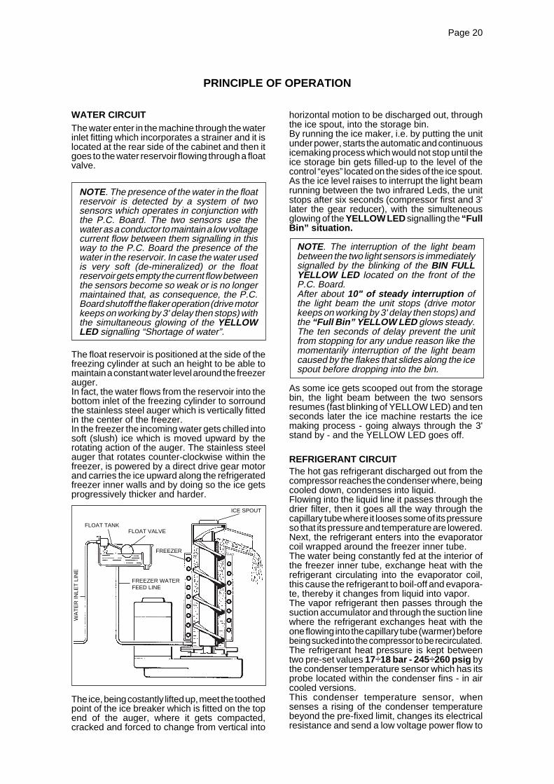
WATER CIRCUITThe water enter in the machine through the waterinlet fitting which incorporates a strainer and it islocated at the rear side of the cabinet and then itgoes to the water reservoir flowing through a floatvalve.
NOTE. The presence of the water in the floatreservoir is detected by a system of twosensors which operates in conjunction withthe P.C. Board. The two sensors use thewater as a conductor to maintain a low voltagecurrent flow between them signalling in thisway to the P.C. Board the presence of thewater in the reservoir. In case the water usedis very soft (de-mineralized) or the floatreservoir gets empty the current flow betweenthe sensors become so weak or is no longermaintained that, as consequence, the P.C.Board shutoff the flaker operation (drive motorkeeps on working by 3' delay then stops) withthe simultaneous glowing of the YELLOWLED signalling “Shortage of water”.
The float reservoir is positioned at the side of thefreezing cylinder at such an height to be able tomaintain a constant water level around the freezerauger.In fact, the water flows from the reservoir into thebottom inlet of the freezing cylinder to sorroundthe stainless steel auger which is vertically fittedin the center of the freezer.In the freezer the incoming water gets chilled intosoft (slush) ice which is moved upward by therotating action of the auger. The stainless steelauger that rotates counter-clockwise within thefreezer, is powered by a direct drive gear motorand carries the ice upward along the refrigeratedfreezer inner walls and by doing so the ice getsprogressively thicker and harder.
The ice, being costantly lifted up, meet the toothedpoint of the ice breaker which is fitted on the topend of the auger, where it gets compacted,cracked and forced to change from vertical into
PRINCIPLE OF OPERATION
horizontal motion to be discharged out, throughthe ice spout, into the storage bin.By running the ice maker, i.e. by putting the unitunder power, starts the automatic and continuousicemaking process which would not stop until theice storage bin gets filled-up to the level of thecontrol “eyes” located on the sides of the ice spout.As the ice level raises to interrupt the light beamrunning between the two infrared Leds, the unitstops after six seconds (compressor first and 3'later the gear reducer), with the simulteneousglowing of the YELLOW LED signalling the “FullBin” situation.
NOTE. The interruption of the light beambetween the two light sensors is immediatelysignalled by the blinking of the BIN FULLYELLOW LED located on the front of theP.C. Board.After about 10" of steady interruption ofthe light beam the unit stops (drive motorkeeps on working by 3' delay then stops) andthe “Full Bin” YELLOW LED glows steady.The ten seconds of delay prevent the unitfrom stopping for any undue reason like themomentarily interruption of the light beamcaused by the flakes that slides along the icespout before dropping into the bin.
As some ice gets scooped out from the storagebin, the light beam between the two sensorsresumes (fast blinking of YELLOW LED) and tenseconds later the ice machine restarts the icemaking process - going always through the 3'stand by - and the YELLOW LED goes off.
REFRIGERANT CIRCUITThe hot gas refrigerant discharged out from thecompressor reaches the condenser where, beingcooled down, condenses into liquid.Flowing into the liquid line it passes through thedrier filter, then it goes all the way through thecapillary tube where it looses some of its pressureso that its pressure and temperature are lowered.Next, the refrigerant enters into the evaporatorcoil wrapped around the freezer inner tube.The water being constantly fed at the interior ofthe freezer inner tube, exchange heat with therefrigerant circulating into the evaporator coil,this cause the refrigerant to boil-off and evapora-te, thereby it changes from liquid into vapor.The vapor refrigerant then passes through thesuction accumulator and through the suction linewhere the refrigerant exchanges heat with theone flowing into the capillary tube (warmer) beforebeing sucked into the compressor to be recirculated.The refrigerant heat pressure is kept betweentwo pre-set values 17÷18 bar - 245÷260 psig bythe condenser temperature sensor which has itsprobe located within the condenser fins - in aircooled versions.This condenser temperature sensor, whensenses a rising of the condenser temperaturebeyond the pre-fixed limit, changes its electricalresistance and send a low voltage power flow to
ICE SPOUT
FLOAT TANKFLOAT VALVE
FREEZER
FREEZER WATERFEED LINE
WA
TE
R IN
LET
LIN
E

Page 21Page 21
FIG. 6
2
1L
N
COM
PRES
SOR
9
10
11
12
13
3
4
5
6
7
8
CONTACTOR COIL
GEAR MOTOR
FAN MOTOR
ELECTRONICCARD
RELAYS
TRIAC
RESET
S E
N S
O R
S
WATERLEVEL
GEAR MOTOR ROTATION
CONDENSER TEMP.
EVAPORATOR TEMP.
ICE LEVEL CONTROL
TRANSF.
T<1°C
DATA
PRO
CESS
OR
the MICRO-PROCESSOR of the P.C. Boardwhich energizes, through a TRIAC, the FanMotor in ON-OFF mode.When the opposite situation occures, i.e. thecondenser temperature gets below the pre-fixed
NOTE. In case the condenser temperature probesenses that the condenser temperature hasrised to 70°C (160°F) - on air cooled versions- or 60°C (140°F) - on water cooled versions -for one of the following abnormal reasons:CLOGGED CONDENSER (Air cooled version)INSUFFICIENT FLOW OF COOLINGWATER (Water cooled version)FAN MOTOR OUT OF OPERATION (Aircooled version)AMBIENT TEMPERATURE HIGHER THEN43°C (110°F)it causes the total and immediate SHUT-OFFof the machine (drive motor keeps on workingby 3' delay then stops) in order to prevent theunit from operating in abnormal and dangerousconditions. When the ice maker stops onaccount of this protective device, there is asimultaneous glowing of the RED LED, warningthe user of the Hi Temperature situation. Themachine will remain in OFF mode for one hourthen it will restart automatically. In case the unittrips OFF again in alarm for 3 times in 3 hours,the machine SHUTS OFF DEFINITIVELY.After having eliminated the source of theexcessive con-denser temperature, to restartthe ice machine it is necessary to unplug andplug in again. The RED LED starts blinkingand three minutes later the flaker unit resumeits normal operating mode. The condensertemperature sensor has a further safetyfunction which consist in preventing the unitfrom operating in Lo-ambient conditions i.e.when the condenser body temperature -equivalent to the ambient temperature - islower then 1 °C 34°F (Fig.6). As soon as theambient temperature rises up to 5°C (40°F)the PC Board will automatically restarts themachine through the three minutes delay time.
L
N
11
10
9
1
2
7
8
6
5
4
3
12
13
limit, the temperature sensor changes again itselectrical resistance reducing therefore the currentflow to the P.C. Board to cause a temporary stopof the Fan Motor.On the water cooled versions, the refrigeranthead pressure is kept at the constant value of17 bar (245 psig) by the metered amount ofwater passing through the condenser which isregulated by the action of the Water RegulatingValve that has its capillary tube connected to theliquid refrigerant line. As pressure increases, thewater regulating valve opens to increase the flowof cooling water to the condenser.
ACCUMULATOR
CAPILLARY TUBE
COMPRESSOR
DISCHARGE LINE
CO
ND
EN
SE
R
SU
CT
ION
LIN
E
FAN MOTOR
EVAPORATOR

Page 22Page 22
directly fitted in the gear case through which itdrives - in counter clockwise rotation at a speedof 9.5 r.p.m. - the freezer auger being linked to itby the ratched coupling.
NOTE. In the event the gear motor will tendto rotate in the wrong direction (counter-clockwise) or not rotating at all or rotating atlower speed the unit will stop immediatelywith the glowing of the WARNING YELLOWLED on account of the intervention of theElectromagnetic Safety Device - based onHall Effect principle.
The machine will remain in OFF mode forone hour then it will restart automatically.In case the unit trips OFF again in alarm for3 times in 3 hours, the machine SHUTS OFFDEFINITIVELY.After having diagnosed and eliminated thesource of the failure, to restart the unit it isnecessary to switch OFF and ON the powerline main disconnnect switch (Fig. 7).The RED LED will start blinking and after3 minutes the ice maker will resume its totaloperations by running first the gear motorand then the compressor.
FIG. 7
2
1L
N
COM
PRES
SOR
9
10
11
12
13
3
4
5
6
7
8
CONTACTOR COIL
GEAR MOTOR
FAN MOTOR
ELECTRONICCARD
RELAYS
TRIAC
RESET
S E
N S
O R
S
WATERLEVEL
GEAR MOTOR ROTATION
CONDENSER TEMP.
EVAPORATOR TEMP.
ICE LEVEL CONTROL
TRANSF.
DATA
PRO
CESS
OR
L
N
11
10
9
1
2
7
8
6
5
4
3
12
13
The refrigerant suction or Lo-pressure sets - innormal ambient conditions (21 °C) - on the valueof 2.4 - 2.6 bar (35 - 38 psig) after few minutesfrom the unit start-up.This value can vary of 0.1 or 0.2 bar (1.5 ÷3 psig)in relation to the water temperture variationsinfluencing the freezer cylinder.
NOTE. If, after ten minutes from the unit startup, no ice is made and the evaporatingtemperature detected by the evaporatorsensor results to be higher than -1°C (30°F)the ice maker stops (compressor first and 3'later the gear reducer) and the 5THWARNING YELLOW LED blinks.The machine will remain in OFF mode forone hour then it will restart automatically.In case the unit trips OFF again in alarm for3 times in 3 hours, the machine SHUTS OFFDEFINITIVELY.
MECHANICAL SYSTEM
The mechanical system of the SCOTSMANFlaker machines consists basically of a gearmotor assembly which drives, through a ratchedcoupling, a worn shaft or auger placed on itsvertical axis within the freezing cylinder.The gear motor is made of a single phase electricmotor with a permanent capacitor. This motor is
Page 23Page 23
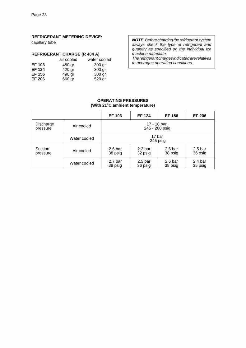
REFRIGERANT METERING DEVICE:capillary tube
REFRIGERANT CHARGE (R 404 A)air cooled water cooled
EF 103 450 gr 300 grEF 124 420 gr 300 grEF 156 490 gr 300 grEF 206 660 gr 520 gr
NOTE. Before charging the refrigerant systemalways check the type of refrigerant andquantity as specified on the individual icemachine dataplate.The refrigerant charges indicated are relativesto averages operating conditions.
OPERATING PRESSURES(With 21 °C ambient temperature)
EF 103 EF 124 EF 156 EF 206
Discharge 17 - 18 bar pressure 245 - 260 psig
17 bar 245 psig
Suction 2.6 bar 2.2 bar 2.6 bar 2.5 bar pressure 38 psig 32 psig 38 psig 36 psig
2.7 bar 2.5 bar 2.6 bar 2.4 bar39 psig 36 psig 38 psig 35 psig
Air cooled
Water cooled
Air cooled
Water cooled
Page 24Page 24
COMPONENTS DESCRIPTION
A. GREEN MASTER SWITCH PUSHBUTTON
Located in the front of the machine it’s used toswitch ON and OFF the unit by pushing its greenpush button. When ON, its green light is ON aswell.
B. RED ALARM/RE-SET PUSH BUTTON
Located in the front of the machine (just besidethe Master Switch) it works in conjuction with thePC Board and it’s activated when:
• Consensing temperature is higher then 70°C(air cooled version) - ON steady with machinein OFF mode
• Consensing temperature is higher then 60°C(water cooled version) - ON steady withmachine in OFF mode
• Condenser sensor out of order - Blinkingtwice and repeat with machine in OFF mode
• Condenser air filter need to be cleaned - ONsteady with machine in ON mode
• Water system need to be cleaned - Slowblinking with machine in ON mode.
• Pump discharge system out of order - Blinkingfast with machine in OFF mode
On the first two cases it’s possible to Re-Set theoperation of the machine pushing and hold theRed Alarm Re-Set Button by 5" till the Red Lightis OFF.
On the third case, it’s necessary first to replacethe condenser sensor then, push and hold for 5"the Red Re-Set Button.
On the last case (Pump discharge system) toRe-Set switch OFF and ON the machine.
C. EVAPORATOR TEMPERATURESENSOR
The evaporator sensor probe is inserted into itstube well, which is welded on the evaporatoroutlet line, it detects the temperature of therefrigerant on the way out from the evaporatorand signals it by suppying a low voltage currentflow to the P.C. Board Micro-Processor.According to the current received, the micro-processor let the ice maker to continue itsoperations. In case the evaporating temperatu-re, after 10 minutes from the unit start-up, doesnot go below -1°C (30°F) due to shortage ofrefrigerant in the system the evaporator sensorsignal reaching the microprocessor is such tostop immediately the unit operation (drive motorkeeps on working by 3' delay then stops), with the5th Warning YELLOW LED that blinks.
NOTE. The machine will remain in OFFmode for one hour then it will restartautomatically.In case the unit trips OFF again in alarm for3 times in 3 hours, the machine SHUTS OFFDEFINITIVELY.To restart the unit after the shutoff caused bythe hi evaporating temperature, it is neces-sary to switch OFF and ON the power linemain disconnect Switch.
D. WATER LEVEL SENSOR
This sensor system consist of two small stainlesssteel rods vertically fitted on the inner face of thereservoir cover and electrically connected to thelow voltage circuit of the P.C. Board.When the cover of the reservoir is positioned inits place the tips of both the rods dip into thereservoir water and detects and signals itspresence by making use of its electricalresistance.
NOTE. In the event of shortage of water inthe reservoir or, in case the water used is toosoft (de-mineralized) to cause greaterresistence to the current flow (conductivitylower than 30 µS) this sensor system causesthe shutoff of the machine (drive motorkeeps on working by 3' delay then stops), toprotect it from running with an interrupted orinadequate water supply. In this situation theYELLOW LED will glow to warn of themachine shutoff and the reason why.
E. CONDENSER TEMPERATURE SENSOR
The condenser temperature sensor probe,located within the condenser fins (air cooledversion) or in contact with the tube coil (watercooled version) detects the condenser tempera-ture variations and signals them by supplyingcurrent, at low voltage, to the P.C. BOARD.In case the condenser temperature sensordetects a temperature at the condenser lowerthan +1°C (33°F) that signify that the ambienttemperature is at the same value, therefore it istoo low for the correct unit operation, the sensorsignals to the microprocessor to stop immediatelyor to do not start the unit operations up to themoment that the ambient temperature will rise tomore acceptables conditions (5°C).In the air cooled versions, in relation to thedifferent current received, the micro processor ofthe P.C. BOARD supplies, through a TRIAC, thepower at high voltage to the fan motor so that itcan cool the condenser and reduce its tempera-ture.In the event the condenser temperature risesand reaches 70°C or 60°C the current arriving tothe micro processor is such to cause an imme-diate and total stop of the machine operation(drive motor keeps on working by 3' delay thenstops).
Page 25Page 25
NOTE. The machine will remain in OFF modefor one hour then it will restart automa-tically.In case the unit trips OFF again in alarm for3 times in 3 hours, the machine SHUTS OFFDEFINITIVELY.To restart the unit after the shutoff caused bythe hi condenser temperature, it is necessaryto switch OFF and ON the power line maindisconnect Switch.
F. GEAR MOTOR ROTATION AND SPEEDSENSOR
This safety device is housed on top of the DriveMotor and detects - based on Hall Effect principle- the rotating speed and rotating direction of thedrive Motor.Should the rotating speed drop below1300 r.p.m. the magnitude measured by thisdevice is such to signal to the microprocessor tostop the unit and light-up the YELLOW LED.About the same reaction occures when the drivemotor will tend to rotate in the wrong direction(counterclockwise) situation that, if it occures,will greatly affect all the freezer and gear reducercomponents.
NOTE. The machine will remain in OFF modefor one hour then it will restart automa-tically.In case the unit trips OFF again in alarm for3 times in 3 hours, the machine SHUTS OFFDEFINITIVELY. To restart the unit after theshutoff caused by this safety device, it isnecessary first to eliminate the cause thathas generated the intervention of the deviceand then switch OFF and ON the power linemain disconnect switch.
G. ICE BIN LEVEL LIGHT CONTROL
The electronic ice bin level control, located intothe ice spout, has the function to stop the operationof the ice machine when the light beam betweenthe light source and the sensor gets interruptedby the flake ice which accumulates in the spout.When the light beam is interrupted the Bin FullYELLOW LED located in the front of the P.C.BOARD blinks; in case the light beam gets
interrupted for as long as 10 seconds, the icemachine stops (drive motor keeps on working by3' delay then stops) with the glowing-up of the2nd YELLOW LED to monitor the full ice binsituation. The 10 seconds of delay prevents thatany minimum interruption of the light beam dueto the regular ice chuting through the ice spoutmay stop the operation of the unit.
NOTE. During the life of the machine the IceLevel Control may require a recalibrationmainly when the glass of the two optical eyesare covered by a thin lay of scale.To do it just follow the following procedure:• With unit OFF push and old the Reset
Button of the PC Board• Give power to the machine through the
Green Master Switch• Hold the PC Board Reset Button till the
leds start to blink/flash (more or less 10seconds)
• Release the PC Board Reset ButtonThe Optical Ice Level Control is nowrecalibrated.Check for the correct operation of the OpticalIce Level Control by plasing a handfull of icein between the two eyes.The Bin Full yellow led must start to blink/flash immediately and, 10 seconds later, themachine must trip OFF.
As soon as the ice is scooped out (with theresumption of the light beam between the twoinfrared sensor of ice level control) 10 secondslater the ice machine resumes its operation withthe simul-taneous extinguishing the 2nd YELLOWLED.
H. P.C. BOARD (Data processor)
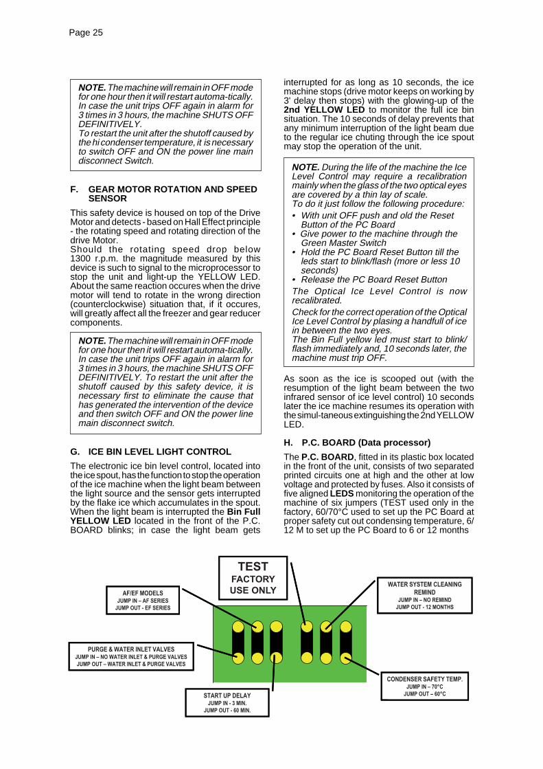
The P.C. BOARD , fitted in its plastic box locatedin the front of the unit, consists of two separatedprinted circuits one at high and the other at lowvoltage and protected by fuses. Also it consists offive aligned LEDS monitoring the operation of themachine of six jumpers (TEST used only in thefactory, 60/70°C used to set up the PC Board atproper safety cut out condensing temperature, 6/12 M to set up the PC Board to 6 or 12 months

Page 26Page 26
remind opf the water system cleaning, PURGE toactivate the operation of the Purge SolòenoidValve (used only on the machine equipped withpurge Solenoid Valve), PWD ON to set up theoperation of the Water Drain Pump (used only onEFC series) and 3'/60? To set up the PC Board for3 or 60 minutes delay at start up as detailed herebelow.Moreover the PC Board is equipped with inputterminals for the leads of the sensor probes as
well as input and output terminals for the leads ofthe ice maker electrical wires.The P.C. BOARD is the brain of the system andit elaborates, through its micro processor, thesignals received from the sensors in order tocontrol the operation of the different electricalcomponents of the ice maker (compressor, gearmotor, etc.).The five LEDS, placed in a row in the front of theP.C. BOARD, monitor the following situations:

Page 27Page 27
I. JUMPERS
The Flaker PC Board is equipped by three jumpers:
J1
PURGE Used on machine equipped with WaterPurge Valve to purge out the waterfrom the water system every 12 hoursand when the machine restart from theBin FullJUMP OUT - Purge activatedJUMP IN - Purge disactivated
PWD Used to Pump Out the water by meansof the Progressive Water Pumpsupplied as a kitJUMP IN - No Progressive Water Pumpinstalled/in operationJUMP OUT - Progressive Water Pumpinstalled/in operation
3’/60’ Delay time at start upJUMP IN - 3 minutes delayJUMP OUT - 60 minutes delay
J2
TEST Factory use ONLY6/12 M Cleaning remind for the water system -
Red Light blinks/flashes with machineONJUMP IN - No remindJUMP OUT - 12 months set up
60/70°C Set up of the Safety CondensingTemperature SensorJUMP IN - 70°CJUMP OUT - 60°C
TO BY-PASS THE 3'/60' STAND BY TIME, SYMPLY JUMP "TEST" CONTACTS WITH PCB ENERGIZED
J. EXTERNAL SWITCHES SOCKETConnected to the external Green Master andRed Alarm Reset Switches, it receives powerfrom the Master Switch as well as it providespower to the Red Alarm switch in order to signalany possible uncorrect operation condition of themachine as clogged air filter (air cooled versiononly) or short/missing of condensing water (watercooled version) as detailed at item B.It signal also the time for the cleaning of the watersystem of the machine, cleaning that can bechange, according to the local water conditions,from six month (standard - Jump In) to twelvemonths (Jump Out).Once cleaned the water system, it’s necessary tocancel the time stored into the PC Board bypushing and hold for more then 5" the Red AlarmRe-Set Button till it stops to blink.
K. FLOAT RESERVOIRThe float reservoir consists of a plastic water panon which is fitted a float valve with its settingscrew. The float valve modulate the incomingwater flow to maintain a constant water level inthe reservoir, level that corresponds to the one inthe freezing cylinder to ensure proper ice formationand fluidity.On the inner side of the reservoir cover are fittedthe two water level sensors which detects thepresence or the shortage of water in the reservoir.
NOTE. It is very important to make sure of thecorrect fitting of the cover on the reservoir inorder to enable the sensor to efficiently controlthe water situation avoiding undue shutoffinterventions.

Page 28Page 28
L. FREEZING CYLINDER (EVAPORATOR)
The freezing cylinder is made of a stainless steelvertical tube on which exterior is wrapped aroundthe cooling coil with the evaporating chamberand in its interior is located the auger whichrotates on its vertical axis and it is maintainedaligned by the top and bottom bearings. A waterseal system is located in the bottom part of thefreezer while at the top end is fitted the icebreaker.The water constantly flowing into the cylinderbottom part, freezes into ice when in contact withthe cylinder inner walls. The ice is then lifted up bythe rotating auger and compacted and forced outby the ice breaker.
M. ICE BREAKER
The ice breaker is fitted in the freezer upper partit has two breaker teeth to break the ice and withits slanted shape from the rear tooth to the frontone it compacts and forces the ice out in anhorizontal way. By undergoing this, the ice loosesits excess of water content so it drops into the binin hard dry bits of ice.In the ice breaker it is housed the top bearingwhich is made of two rolls bearings positioned towithstand the auger axial and radial loads. Thisbearing is lubricated with a food grade - waterresistant grease.
NOTE. It is advisable to check the conditionsof both the lubricant grease and the topbearing every six months.
N. DRIVE GEAR MOTOR
This motoreducer is made of a single phaseelectric motor with permanent capacitor directlyfitted on a gear box.The drive motor rotor is kept aligned on its verticalaxis by two ball bearings permanently lubricated.The gear case contains a train of three spur gearsthe first one of which is in fiber to limit the noise
level. All the three gears are encased in casebearings and are covered by lubricant grease(MOBILPLEX IP 44).Two seal rings, one fitted on the rotor shaft andthe other on the output shaft keep the gear casesealed.Hovewer, the interior can be inspected andserviced by unbolting the two halves of thealuminium gear case housing.The gear reducer output shaft is connected to thefreezer auger by a ratched coupling which ismade of two toothed halves that engagesthemselves only if turned in the correct directionnamely, conterclockwise.
O. FAN MOTOR (Air cooled version)
The fan motor is controlled through the P.C.BOARD and the TRIAC by the condenser tempe-rature sensor. Normally it operates to draw coolingair through the condenser fins.In cold ambient situation, the fan motor can runat intermittance as the condenser pressure mustbe kept between two corresponding headpressure values 17÷18 bar-245÷260 psig.
P. WATER REGULATING VALVE(Water cooled version)
This valve controls the head pressure in therefrigerant system by regulating the flow of watergoing to the condenser.As pressure increases, the water regulating val-ve opens to increase the flow of cooling water.
Q. COMPRESSOR
The hermetic compressor is the heart of therefrigerant system and it is used to circulate andretrieve the refrigerant throughout the entiresystem. It compresses the low pressurerefrigerant vapor causing its temperature to riseand become high pressure hot vapor which isthen released through the discharge valve.

Page 29Page 29
NOTE. Read the instructions thoroughlybefore performing any of the followingadjustment or removal and replacement pro-cedure.
A. ADJUSTEMENT OF THE EVAPORATORWATER LEVEL
The correct water level in the freezing cylinder isabout 25 mm. (1") below the ice dischargeopening. Low water level causes excessive straininside the freezer assembly due to a faster freezingrate.
When the water level is above or below thecorrect one, adjustment can be performed toRaise or Lower the water level by raising orlowering at the measure required, the waterreservoir and its mounting bracket.1. To Raise the water level:a. Loosen and remove the screw securing themounting bracket of the water reservoir to the unitcabinet and raise the water reservoir to the correctlevel.b. Thread the mounting screw in the correspondinghole and tighten it.2. To Lower the water level follow the aboveindications to lower to the correct level the waterreservoir assembly.
WARNING. Be sure the electrical powersupply circuit breaker and the inlet watersupply are OFF, before starting any of thefollowing Removal and Replacementprocedures as a precaution to preventpossible personal injury or damage to theequipments.
B. REPLACEMENT OF EVAPORATORTEMPERATURE SENSOR
1. Remove the front and top panels.
2. Remove the insulation from the refrigeranttubing, connecting the freezer to the accumulator,to gain access to the sensor probe well and beable to pull out from this well the sensor probe.
3. Trace the condenser sensor terminal plug(blue) on the left side of the control box andremove it from its socket by carefully pulling outthe terminal plug securing clip.
4. To install the replacement evaporator sensorfollow the above steps in reverse.
C. REPLACEMENT OF CONDENSERTEMPERATURE SENSOR
1. Remove the front panel.
2. Trace the condenser sensor probe locatedwithin the condenser fins on air cooled versionand withtrow it.On water cooled version remove it by openingthe plastic strap (reusable) securing the probe tothe refrigerant liquid line.
3. Trace the condenser sensor terminal plug(black) on the left side of the control box andremove it from its socket by carefully pulling outthe terminal plug securing clip.
4. To install the replacement condenser sensorfollow the above steps in reverse.
D. REPLACEMENT OF THE ICE LEVELLIGHT CONTROL
1. Remove the front and top panels.
2. Trace the ice level light control terminal plug(black and with four terminal pins) on the left sideof the control box and draw it out from its socketby carefully slackening the fastening tie.
3. Unloose the two screws holding the opticalice level control to the upper side of the spout andremove it.
4. To install the replacement ice level lightcontrol follow the above steps in reverse.
E. REPLACEMENT OF THE GEAR MOTORROTATION AND SPEED SENSOR
1. Remove the front and top panels.
ADJUSTMENT, REMOVAL AND REPLACEMENT PROCEDURES

Page 30Page 30
2. Unloose the three screws securing the plasticcover to the gear motor speed sensor housingand remove it.
3. Unloose the two screws securing the sensorto the plastic housing and withdraw it from itsseat.
4. Trace the gear motor speed sensor terminalplug (red with four pins) on the left side of thecontrol box and draw it out from its socket bycarefully slackening the fastening tie.
5. To install the replacement gear motor rotationand speed sensor follow the above steps inreverse.
F. REPLACEMENT OF THE RESERVOIRWATER LEVEL SENSOR
1. Remove the front and top panels.
2. Unloose the two nuts securing the wire leadsto the two water level sensor rods located on thewater reservoir plastic cover.
3. Trace the water level sensor terminal plug(red) on the left side of the control box and drawit out from its socket by carefully slackening thefastening tie.
4. To install the replacement water level sensorfollow the above steps in reverse.
G. REPLACEMENT OF P.C. BOARD
1. Remove front panel.
2. Remove all sensor terminal plugs, locatedon the left side of P.C. Board, by carefully releasingthem out from their sockets clips.
3. Disconnect the terminal board connectionplug from the rear side of P.C. BOARD thenunloose the four screws holding the same to theplastic control box and remove it.
4. To install the replacement P.C. BOARD followthe above steps on reverse.
NOTE. In case the TEST contacts are jumpedtogether (it is a possibility when PC Board isreplace as spare parts), the machine startsup immediately with all the electrical parts(compressor, drive motor and fan motor starttogether with no delay).This for 3 minutes then the machine stopswith all LEDs blinking.
H. REPLACEMENT OF THE ICE SPOUT
1. Remove the top panel.
2. Slacken and remove the two metal strapsthat hold tight the polystyre insulations againstthe freezer upper part.
3. Remove the optical ice level control.
4. Unloose and remove the two screws and thespout from the freezer cylinder.
5. To install the replacement spout followprevious steps in reverse.
I. REPLACEMENT OF THE AUGER, WATERSEAL, BEARINGS AND COUPLING
1. Remove the front, side and top panels.
2. Follow the steps at item H to remove the icespout.
3. Grasp the wire cap hook at the top of thefreezer and pull out the auger and attached cap,ice breaker, bearings and O rings, at the top ofthe auger, and the top half of the water seal at theauger bottom.
NOTE. If the auger cannot be pulled out,proceed to steps 9 and 10 of this paragraph,to gain access to the auger bottom. Then,with a rowhide mallet or placing a piece ofwood on the bottom end of the auger, tap thisbottom to break loose the auger and be ablethen to pull it out as in step 3 above.
4. With a circlip plier remove the retaining ringand cap hook from the ice breaker.
5. Unloose and remove cap screw and removethe ice breaker from the auger.
6. Clean away the old grease from the interiorof the ice breaker and inspect the conditions ofthe O ring; if torn or worn replace it.
7. Inspect the bearing pressed into the top ofthe ice breaker and if worn do not hesitate toreplace it.
WARNING. The top bearing assembly worksin critical conditions for what concern itslubrication status as it is haused in the icebreaker where the formation of a greatrate of condensation is usual. Therefore itis important to apply on it an ample coa-ting of Food grade Waterproof GreaseP/N 263612.00 before installing the breakerand cap hook in place.
0.5-1.0 mm

Page 31Page 31
NOTE. Install the upper bearing into the icebreaker starting by the radial portion thatmust be fitted with the flat surface facing up.Apply some lubricant (grease) on the uppersurface then install the rollers cage with thesmaller openings of the same facing up so toleave a small gap between plastic cage andflat surface of the botton portion of the bearing(see drawing).
Apply some move lubricant then place theS.S. trust washer.
J. REPLACEMENT OF THE GEAR MOTORASSY
1. Remove the rear side and top panels.
2. Remove the three bolts and washerssecuring the gear reducer base to the unit chassis,then remove bolts and lockwashers which attachthe bottom of the aluminium adaptor to the gearreducer case cover.
3. Disconnect the electrical leads from theelectromagnetic safety device located on top ofdrive motor.
4. Trace and disconnect the electric wires leadsof the drive motor. Lift and remove the entiregear motor assembly.
5. To install the replacement gear motor assyfollow the above steps in reverse.
K. REPLACEMENT OF FAN MOTOR
1. Remove front and side panels.
2. Remove screws and yellow green groundwire. Trace the electrical leads of fan motor anddisconnect them.
3. Remove the bolts securing the fan motorbracket to the cabinet base and then remove theassembly.
4. To install the replacement fan motor followthe above steps in reverse.
NOTE. When installing a new fan motorcheck that the fan blades do not touch anysurface and move freely.
8. Slide off from the auger bottom the upperhalf of the water seal.
NOTE. Any time the auger is removed forreplacement or inspection use extra care inhandling the water seal parts, so no dirt orforeign matters are deposited on the surfacesof the seal. If there is any doubt about theeffectiveness of the water seal or O ring donot hesitate to REPLACE THEM.
9. Unloose and remove the three bolts andlockwashers which attach the freezer assy to thealuminium adaptor.
10. Raise the freezer assy off the adaptor, secureit out of the way to allow room to work. Using asuitable lenght and size wooden dowel or stickinserted through the top of the open freezer, tapthe lower half of the water seal and the lowerbearing out the bottom of the freezer.
NOTE. It is good practice to replace thewater seal assy and both the top and thebottom bearings any time the auger isremoved.To facilitate this, SCOTSMAN EUROPEService makes available a service KitP/N 001028.07 which includes besides theabove mentioned parts, the ice breaker O ringand a can of food grade waterproof grease.
11. Reach through the adaptor and remove thecoupling parts.
12. Check both the coupling halves for chippingand wear and do not hesitate to replace them.
13. To install the ratched coupling, the waterseal, the bearings and auger follow previoussteps in reverse.
NOTE. It is very important to provide correct/proper lubrication of the inside bore of theupper semi-coupling as well as to the externalsurfaces of the teeth as shown on the herebelow photo.The correct lubrication allows the upper semi-coupling to move it down, by the load of theupper spring, in case of any rising up duringits rotation.

Page 32Page 32
L. REPLACEMENT OF DRIER
1. Remove front and side panels.
2. Recover the refrigerant from the system andtransfer it in a container so to reclaim or recycleit.
3. Unsolder the capillary tube and the refrigerantline from the two ends of the drier.
4. To install the replacement drier removefactory seals and solder the refrigerant lines andthe capillary tube taking precautions to NOTOVERHEAT the drier body.
5. Thoroughly evacuate the system to removemoisture and non condensable after drierreplacement.
6. Charge the system with refrigerant 134 A byweight (see data plate of machine) and check forleaks.
7. Replace panels previously removed.
M. REPLACEMENT OF THE FREEZINGCYLINDER
1. Follow the steps at item H to remove the icespout.
2. Remove the clamp fastening the water hoseto the water inlet port of the freezer assy. Placea water pan under this water inlet port thendisconnect the water hose and collect all waterflowing from freezer and from water hose.
3. Withdraw the evaporator sensor probe fromthe its holder as stated in item B.
4. Recover the refrigerant from the system andtransfer it in a container so to reclaim or recycle it.
5. Unsolder and disconnect the capillary tubeand the accumulator/suction line assy from theoutlet line of the freezing cylinder.
6. Remove the three bolts and washerssecuring the gear reducer base to the unit chassis,then remove bolts and lockwashers which attachthe bottom of the aluminium adaptor to the gearreducer case cover.
7. Lift the freezer up and off the gear motorassembly, then if necessary remove thealuminium adaptor by removing the threemounting screws and lockwashers.
NOTE. It is imperative to install a replace-ment drier whenever the sealed refrigerationsystem is open.Do not replace the drier until all other repairsor replacements have been completed.
8. To install the replacement evaporator followthe above steps in reverse.
NOTE. Thoroughly evacuate the system toremove moisture and non condensables afterevaporator replacement.
N. REPLACEMENT OF AIR COOLEDCONDENSER
1. Remove front and side panels.
2. Remove from the condenser fins thecondenser ambient temperature sensor probes.
3. Remove the two bolts attaching thecondenser to the base.
4. Recover the refrigerant from the system andtransfer it in a container so to reclaim or recycle it.
5. Unsolder the refrigerant lines from thecondenser and remove it from the unit.
NOTE. It is imperative to install a replace-ment drier whenever the sealed refrigerationsystem is open.Do not replace the drier until all other repairsor replacements have been completed.
6. To install the replacement condenser followthe above steps in reverse.
NOTE. Thoroughly evacuate the system toremove moisture and non condensables aftercondenser replacement.
O. REPLACEMENT OF WATER COOLEDCONDENSER
1. Remove front and side panels.
2. Remove the condenser temperature sensorprobes from condenser.
3. Remove bolts which secure the condenserto the unit base.
4. Remove the corbin clamps and disconnectthe plastic hoses from the water cooled condenser.
5. Recover the refrigerant from the system andtransfer it in a container so to reclaim or recycleit.
6. Unsolder the refrigerant lines from thecondenser and remove it from the unit.
NOTE. It is imperative to install a replace-ment drier whenever the sealed refrigerationsystem is open.Do not replace the drier until all other repairsor replacements have been completed.
7. To install the replacement condenser followthe above steps in reverse.
Page 33Page 33
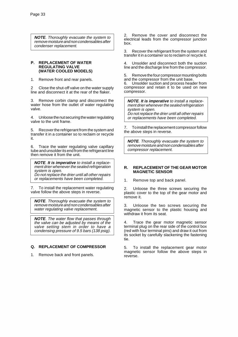
NOTE. Thoroughly evacuate the system toremove moisture and non condensables aftercondenser replacement.
P. REPLACEMENT OF WATERREGULATING VALVE(WATER COOLED MODELS)
1. Remove front and rear panels.
2 Close the shut-off valve on the water supplyline and disconnect it at the rear of the flaker.
3. Remove corbin clamp and disconnect thewater hose from the outlet of water regulatingvalve.
4. Unloose the nut securing the water regulatingvalve to the unit frame.
5. Recover the refrigerant from the system andtransfer it in a container so to reclaim or recycleit.
6. Trace the water regulating valve capillarytube and unsolder its end from the refrigerant linethen remove it from the unit.
NOTE. It is imperative to install a replace-ment drier whenever the sealed refrigerationsystem is open.Do not replace the drier until all other repairsor replacements have been completed.
7. To install the replacement water regulatingvalve follow the above steps in reverse.
NOTE. Thoroughly evacuate the system toremove moisture and non condensables afterwater regulating valve replacement.
NOTE. The water flow that passes throughthe valve can be adjusted by means of thevalve setting stem in order to have acondensing pressure of 9.5 bars (138 psig).
Q. REPLACEMENT OF COMPRESSOR
1. Remove back and front panels.
2. Remove the cover and disconnect theelectrical leads from the compressor junctionbox.
3. Recover the refrigerant from the system andtransfer it in a container so to reclaim or recycle it.
4. Unsolder and disconnect both the suctionline and the discharge line from the compressor.
5. Remove the four compressor mounting boltsand the compressor from the unit base.6. Unsolder suction and process header fromcompressor and retain it to be used on newcompressor.
NOTE. It is imperative to install a replace-ment drier whenever the sealed refrigerationsystem is open.Do not replace the drier until all other repairsor replacements have been completed.
7. To install the replacement compressor followthe above steps in reverse.
NOTE. Thoroughly evacuate the system toremove moisture and non condensables aftercompressor replacement.
R. REPLACEMENT OF THE GEAR MOTORMAGNETIC SENSOR
1. Remove top and back panel.
2. Unloose the three screws securing theplastic cover to the top of the gear motor andremove it.
3. Unloose the two screws securing themagnetic sensor to the plastic housing andwithdraw it from its seat.
4. Trace the gear motor magnetic sensorterminal plug on the rear side of the control box(red with four terminal pins) and draw it out fromits socket by carefully slackening the fasteningtie.
5. To install the replacement gear motormagnetic sensor follow the above steps inreverse.

Page 34Page 34
WIRING DIAGRAMAIR AND WATER COOLED
230/50-60/1

Page 35Page 35
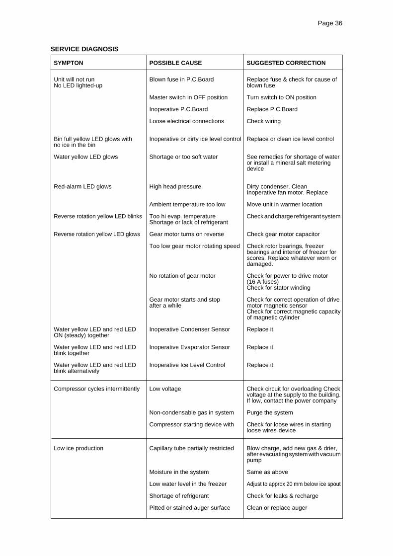
Page 36Page 36
SYMPTON POSSIBLE CAUSE SUGGESTED CORRECTION
Unit will not run Blown fuse in P.C.Board Replace fuse & check for cause ofNo LED lighted-up blown fuse
Master switch in OFF position Turn switch to ON position
Inoperative P.C.Board Replace P.C.Board
Loose electrical connections Check wiring
Bin full yellow LED glows with Inoperative or dirty ice level control Replace or clean ice level controlno ice in the bin
Water yellow LED glows Shortage or too soft water See remedies for shortage of wateror install a mineral salt meteringdevice
Red-alarm LED glows High head pressure Dirty condenser. CleanInoperative fan motor. Replace
Ambient temperature too low Move unit in warmer location
Reverse rotation yellow LED blinks Too hi evap. temperature Check and charge refrigerant systemShortage or lack of refrigerant
Reverse rotation yellow LED glows Gear motor turns on reverse Check gear motor capacitor
Too low gear motor rotating speed Check rotor bearings, freezerbearings and interior of freezer forscores. Replace whatever worn ordamaged.
No rotation of gear motor Check for power to drive motor(16 A fuses)Check for stator winding
Gear motor starts and stop Check for correct operation of driveafter a while motor magnetic sensor
Check for correct magnetic capacityof magnetic cylinder
Water yellow LED and red LED Inoperative Condenser Sensor Replace it.ON (steady) together
Water yellow LED and red LED Inoperative Evaporator Sensor Replace it.blink together
Water yellow LED and red LED Inoperative Ice Level Control Replace it.blink alternatively
Compressor cycles intermittently Low voltage Check circuit for overloading Checkvoltage at the supply to the building.If low, contact the power company
Non-condensable gas in system Purge the system
Compressor starting device with Check for loose wires in startingloose wires device
Low ice production Capillary tube partially restricted Blow charge, add new gas & drier,after evacuating system with vacuumpump
Moisture in the system Same as above
Low water level in the freezer Adjust to approx 20 mm below ice spout
Shortage of refrigerant Check for leaks & recharge
Pitted or stained auger surface Clean or replace auger
SERVICE DIAGNOSIS

Page 37Page 37
SYMPTON POSSIBLE CAUSE SUGGESTED CORRECTION
Wet ice Ambinet temperature too high Move unit to cooler location
High water level in the freezer Lower to approx. 20 mm belowice spout
Faulty compressor Replace
Machine runs but makes no ice Water not entering in the freezer Air look in feed line to freezer.Clogged feed line to freezer. Clean it
Gear stripped Check and repair
Moisture in the system Purge, replace drier and re-charge
Water leaks Water seal leaking Replace water seal
Water feed line to freezer leaking Check and fasten hose clamp
Float valve not closing Check and adjust float valvesetting screw
Spout leaking Tighten screws holding the spout
Excessive noise or chattering Mineral or scale deposit on auger Remove and manually polish augerand inner freezer walls and inner walls of freezer barrel
using emery paper
Low suction pressure Add refrigerant to rise suction pressure
Water feed line to freezer clogged Vent and clean it
Low water level into freezer Adjust to approx. 20 mm belowice spout
Gear motor noise Worn rotor bearings Check and replace
Shortage or poor lubricant in gear Check for proper lubricant openingcase gear case.
Top of gears must be coveredwith lubricant
Gear case bearings and gear Check and replace worn partsracers worn out
Shortage of water Strainer at water inlet fitting clogged Remove strainer and clean
Float reservoir water nozzle Remove float valve and cleanclogged-up nozzle
SERVICE DIAGNOSIS

Page 38Page 38
MAINTENANCE AND CLEANING INSTRUCTION
A. GENERAL
The periods and the procedures for maintenanceand cleaning are given as guides and are not tobe construed as absolute or invariable.Cleaning, especially, will vary depending uponlocal water and ambient conditions and the icevolume produced; and, each icemaker must bemaintened individually, in accordance with itsparticular location requirements.
B. ICEMAKER
The following maintenance should be scheduledat least two times per year on these icemakers.
1. Check and clean the water line strainer.
2. Remove the cover from the float reservoir -care to do not damage the two water sensors -and depress the float to make sure that a fullstream of water enters into the reservoir.
3. Check that the icemaker is levelled in side toside and in front to rear directions.
4. Check that the water level in the waterreservoir is below the overflow but high enoughthat it does not run out of the spout opening.
NOTE. The float must close positively theincoming water flow when its fulcrum, housingthe setting screw, is perpendicular to thewater nozzle.
5. Clean the water system, water reservoirand the interior of freezing cylinder using asolution of SCOTSMAN Ice Machine Cleaner.Refer to procedure C cleaning instructions andafter cleaning will indicate frequency and proce-dure to be followed in local areas.
NOTE. Cleaning requirements varyaccording to the local water conditions andindividual user operation.
6. If required, polish the two sensor rodssecured to the float reservoir cover, heavy scalesediment on them can be removed with the helpof a bit of SCOTSMAN Cleaner plain.
7. With the ice machine and fan motor OFF onair cooled models, clean condenser using vacuumcleaner, whisk broom or non metallic brush takingcare to do not damage the condenser/ambienttemperature sensor.
8. Check for water leaks and tighten drain lineconnections. Pour water down bin drain line tobe sure that drain line is open and clear.
9. Check the ice level control sensor to testshut-off. Put some ice in front of the ice levelcontrol so to cut off the light beam for at least 10seconds.This should cause the immediate blinking of theBin Full YELLOW LED located in the front of P.C.Board and, 10seconds later, the total stopping ofthe ice maker with the simultaneous light up ofthe Full Bin Yellow LED (steady).
NOTE. Test the operation of the Ice LevelControl using ice NOT HAND.
Within few seconds from the removal of the icebetween the sensor lights the ice maker resumeits operation.
NOTE. The ice level control uses devicesthat sense light, therefore they must be keptclean enough so they can “see”.
10. Check for refrigerant leaks and for properfrost line, which should frost as far as approx. 20cm (8") from the compressor.When doubtful about refrigerant charge, installrefrigerant gauges on corresponding Schrädervalves and check for correct refrigerant pressures.(See Operating pressure at page 20 of thismanual).
11. Check that fan blades move freely and arenot touching any surfaces.
12. Remove the retaining ring and the hook andcap from the top of the freezer assembly theninspect the top bearing, wipe clean of all greaseand apply a coating of food grade water proofgrease P/N 263612.00
NOTE. It is recommended to use only foodgrade and waterproof grease to lubricate thefreezer top bearing.
13. Check the quality of ice. Ice flakes should bewet when formed, but will cure rapidily to normalhardness in the bin.
NOTE. It is not abnormal for some water toemerge from the ice spout with the flaker ice.
C. CLEANING INSTRUCTIONS OF WATERSYSTEM
1. Switch OFF the Master disconnect switchon the power line.
2. Remove all ice stored in the bin to prevent itfrom getting contaminated with the cleaningsolution.

Page 39Page 39
3. Shut close the water shutoff valve on waterline.
4. Remove the top panels to gain access to thewater reservoir.
5. Remove the float reservoir cover and with apiece of copper wire jump the two water levelsensors.
6. Place a water pan under the freezer waterinlet port, disconnect the water hose from thisport and allow the water from the freezer to flowinto the pan previously positioned.Then refit the water hose to the freezer waterinlet port.
7. Prepare the cleaning solution by diluting ina plastic container one or two liters of warmwater (45°-50°C) with a 0,1-0,2 liters ofSCOTSMAN Ice Machine Cleaner.
WARNING. The SCOTSMAN Ice MachineCleaner contains Phosphoric andHydroxyacetic acids. These compoundsare corrosive and may cause burns ifswallowed, DO NOT induce vomiting.Give large amounts of water or milk. CallPhysician immediately. In case of externalcontact flush with water. KEEP OUT OFTHE REACH OF CHILDREN
8. Switch ON the Master switch to start the unitthen pour the cleaning solution into the floatreservoir.
9. Wait for about three minutes for the unit tostart operating, then continue to slowly pour thecleaning solution into the water reservoir takingcare to maintain the level just below the overflow.
NOTE. The ice made with the cleaningsolution is slushy and coloured also, it maytend to loose fluidity creating some resistencein being elevated and extruded; this situationcan be heard by the creacking noise made bythe ice.Should this occure it is recommended to stopfor few minutes the ice machine in order toallow the ice in the freezer to partially melt.
10. When all the cleaning solution has beenused up, open the water shutoff valve to allownew fresh water to flow into the reservoir. Let theunit to continue to run until the ice resumes thenormal colour and hardness.
11. Stop the icemaker and pour warm water onthe ice deposited into the storage bin to melt it up.
NOTE. DO NOT use ice produced with thecleaning solution. Be sure none remains inthe bin.
12. Pour into the water reservoir 1 cc. (approx20 drops) of Scotsman Sanitiser (Antialgae P/N264000.00) then switch the unit ON.
13. Left the unit running for approx 10 minutesthen remove the copper wire used to jump thetwo sensors for the water level and place backcorrectly the cover on the float reservoir.
NOTE. DO NOT use ice produced with thesanitising solution.
14. With a sponge moisted with a sanitisingsolution, wipe clean all the bin interior surfaces.
REMEMBER. To prevent the accumulationof undesirable bacteria it is necessary tosanitise the interior of the storage bin with ananti-algae disinfectant solution every week.