ii 774010 eu allampair.co.uk/wp-content/uploads/media/panasonic/vrf/...6 1. general this booklet...
TRANSCRIPT
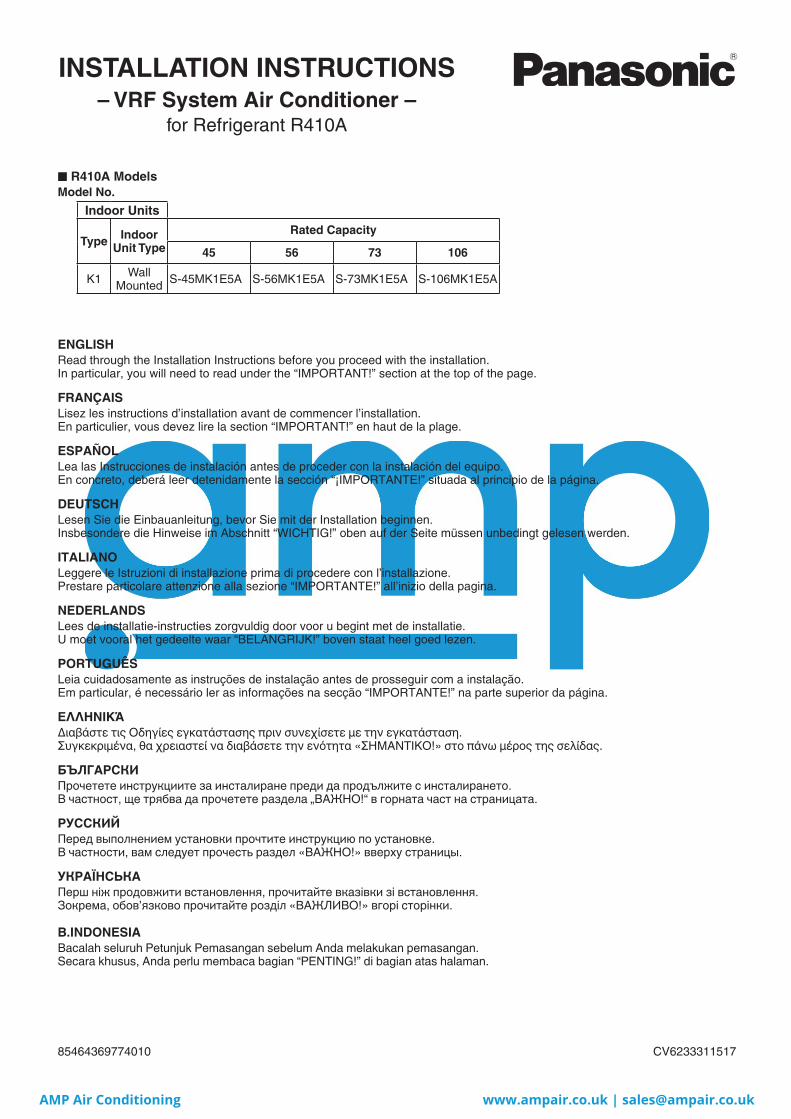
– VRF System Air Conditioner –
■ R410A ModelsModel No.
Indoor Units
Type Indoor Unit Type
Rated Capacity
45 56 73 106
K1 Wall Mounted S-45MK1E5A S-56MK1E5A S-73MK1E5A S-106MK1E5A
ENGLISHRead through the Installation Instructions before you proceed with the installation. In particular, you will need to read under the “IMPORTANT!” section at the top of the page.
FRANÇAISLisez les instructions d’installation avant de commencer l’installation.En particulier, vous devez lire la section “IMPORTANT!” en haut de la plage.
ESPAÑOLLea las Instrucciones de instalación antes de proceder con la instalación del equipo.En concreto, deberá leer detenidamente la sección “¡IMPORTANTE!” situada al principio de la página.
DEUTSCHLesen Sie die Einbauanleitung, bevor Sie mit der Installation beginnen.Insbesondere die Hinweise im Abschnitt “WICHTIG!” oben auf der Seite müssen unbedingt gelesen werden.
ITALIANOLeggere le Istruzioni di installazione prima di procedere con l’installazione.Prestare particolare attenzione alla sezione “IMPORTANTE!” all’inizio della pagina.
NEDERLANDSLees de installatie-instructies zorgvuldig door voor u begint met de installatie.U moet vooral het gedeelte waar “BELANGRIJK!” boven staat heel goed lezen.
PORTUGUÊSLeia cuidadosamente as instruções de instalação antes de prosseguir com a instalação.Em particular, é necessário ler as informações na secção “IMPORTANTE!” na parte superior da página.
ΕΛΛΗΝΙΚΆΔιαβάστε τις Οδηγίες εγκατάστασης πριν συνεχίσετε με την εγκατάσταση.Συγκεκριμένα, θα χρειαστεί να διαβάσετε την ενότητα «ΣΗΜΑΝΤΙΚΟ!» στο πάνω μέρος της σελίδας.
БЪЛГАРСКИПрочетете инструкциите за инсталиране преди да продължите с инсталирането.В частност, ще трябва да прочетете раздела „ВАЖНО!“ в горната част на страницата.
РУССКИЙПеред выполнением установки прочтите инструкцию по установке.В частности, вам следует прочесть раздел «ВАЖНО!» вверху страницы.
УКРАЇНСЬКАПерш ніж продовжити встановлення, прочитайте вказівки зі встановлення.Зокрема, обов’язково прочитайте розділ «ВАЖЛИВО!» вгорі сторінки.
B.INDONESIABacalah seluruh Petunjuk Pemasangan sebelum Anda melakukan pemasangan. Secara khusus, Anda perlu membaca bagian “PENTING!” di bagian atas halaman.
for Refrigerant R410A
INSTALLATION INSTRUCTIONS
CV623331151785464369774010
II_774010_EU_all.indb 1II_774010_EU_all.indb 1 2013/12/03 13:58:052013/12/03 13:58:05
AMP Air Conditioning www.ampair.co.uk | [email protected]

2
IMPORTANT! Please Read Before StartingThis air conditioner must be installed by the sales dealer or installer.This information is provided for use only by authorized persons.
For safe installation and trouble-free operation, you must:● Carefully read this instruction booklet before beginning.● Follow each installation or repair step exactly as shown.● This air conditioner shall be installed in accordance with
National Wiring Regulations.● Pay close attention to all warning and caution notices
given in this manual.
WARNINGThis symbol refers to a hazard or unsafe practice which can result in severe personal injury or death.
CAUTIONThis symbol refers to a hazard or unsafe practice which can result in personal injury or product or property damage.
If Necessary, Get HelpThese instructions are all you need for most installation sites and maintenance conditions. If you require help for a special problem, contact our sales/service outlet or your certified dealer for additional instructions.
In Case of Improper InstallationThe manufacturer shall in no way be responsible for improper installation or maintenance service, including failure to follow the instructions in this document.
SPECIAL PRECAUTIONS
WARNING When Wiring
ELECTRICAL SHOCK CAN CAUSE SEVERE PERSONAL INJURY OR DEATH. ONLY A QUALIFIED, EXPERIENCED ELECTRICIAN SHOULD ATTEMPT TO WIRE THIS SYSTEM.
• Do not supply power to the unit until all wiring and tubing are completed or reconnected and checked.
• Highly dangerous electrical voltages are used in this system. Carefully refer to the wiring diagram and these instructions when wiring. Improper connections and inadequate grounding can cause accidental injury or death.
• Connect all wiring tightly. Loose wiring may cause overheating at connection points and a possible fire hazard.
• Provide a power outlet to be used exclusively for each unit.
• Provide a power outlet exclusively for each unit, and full disconnection means having a contact separation in all poles must be incorporated in the fixed wiring in accordance with the wiring rules.
• To prevent possible hazards from insulation failure, the unit must be grounded.
When Transporting
Be careful when picking up and moving the indoor and outdoor units. Get a partner to help, and bend your knees when lifting to reduce strain on your back. Sharp edges or thin aluminum fins on the air conditioner can cut your fingers.
When Installing…
Select an installation location which is rigid and strong enough to support or hold the unit, and select a location for easy maintenance.…In a RoomProperly insulate any tubing run inside a room to prevent “sweating” that can cause dripping and water damage to walls and floors.
CAUTIONKeep the fire alarm and the air outlet at least 1.5 m away from the unit.
…In Moist or Uneven LocationsUse a raised concrete pad or concrete blocks to provide a solid, level foundation for the outdoor unit. This prevents water damage and abnormal vibration.…In an Area with High WindsSecurely anchor the outdoor unit down with bolts and a metal frame. Provide a suitable air baffle.…In a Snowy Area (for Heat Pump-type Systems)Install the outdoor unit on a raised platform that is higher than drifting snow. Provide snow vents.…At least 2.5 mIndoor unit of this air conditioner shall be installed in a height of at least 2.5 m.…In laundry roomsDo not install in laundry rooms. Indoor unit is not drip proof.
II_774010_EU_all.indb 2II_774010_EU_all.indb 2 2013/12/03 13:58:172013/12/03 13:58:17
AMP Air Conditioning www.ampair.co.uk | [email protected]

3
EN
GL
ISHWhen Connecting Refrigerant Tubing
WARNING
• When performing piping work do not mix air except for specified refrigerant (R410A) in refrigeration cycle. It causes capacity down, and risk of explosion and injury due to high tension inside the refrigerant cycle.
• Refrigerant gas leakage may cause fire.
• Do not add or replace refrigerant other than specified type. It may cause product damage, burst and injury, etc.
• Ventilate the room well, in the event that is refrigerant gas leaks during the installation. Be careful not to allow contact of the refrigerant gas with a flame as this will cause the generation of poisonous gas.
• Keep all tubing runs as short as possible.
• Use the flare method for connecting tubing.
• Apply refrigerant lubricant to the matching surfaces of the flare and union tubes before connecting them, then tighten the nut with a torque wrench for a leak-free connection.
• Check carefully for leaks before starting the test run.
• Do not leak refrigerant while piping work for an installation or re-installation, and while repairing refrigeration parts. Handle liquid refrigerant carefully as it may cause frostbite.
When Servicing
• Turn the power OFF at the main power box (mains) before opening the unit to check or repair electrical parts and wiring.
• Keep your fingers and clothing away from any moving parts.
• Clean up the site after you finish, remembering to check that no metal scraps or bits of wiring have been left inside the unit being serviced.
WARNING• This product must not be
modified or disassembled under any circumstances. Modified or disassembled unit may cause fire, electric shock or injury.
• Do not clean inside the indoor and outdoor units by users. Engage authorized dealer or specialist for cleaning.
• In case of malfunction of this appliance, do not repair by yourself. Contact the sales dealer or service dealer for repair.
CAUTION• Do not touch the air
inlet or the sharp aluminum fins of the outdoor unit. You may get injured.
• Ventilate any enclosed areas when installing or testing the refrigeration system. Escaped refrigerant gas, on contact with fire or heat, can produce dangerously toxic gas.
• Confirm after installation that no refrigerant gas is leaking. If the gas comes in contact with a burning stove, gas water heater, electric room heater or other heat source, it can cause the generation of poisonous gas.
Others
WARNING
CAUTION
• Do not sit or step on the unit, you may fall down accidentally.
• Do not touch the air inlet or the sharp aluminum fins of the outdoor unit. You may get injured.
• Do not stick any object into the FAN CASE. You may be injured and the unit may be damaged.
NOTICE
The English text is the original instructions. Other languages are translations of the original instructions.
II_774010_EU_all.indb 3II_774010_EU_all.indb 3 2013/12/03 13:58:372013/12/03 13:58:37
AMP Air Conditioning www.ampair.co.uk | [email protected]

4
IMPORTANT INFORMATION REGARDING THE REFRIGERANT USEDThis product contains fluorinated greenhouse gases covered by the Kyoto Protocol. Do not vent gases into the atmosphere.
Refrigerant type: R410AGWP(1) value: 1975(1)GWP = global warming potential
Periodical inspections for refrigerant leaks may be required depending on European or local legislation. Please contact your local dealer for more information.
Sample label: MF2 type outdoor unit
Please fill in with indelible ink,■ 1 the factory refrigerant charge of the product■ 2 the additional refrigerant amount charged in the field and■ 1 + 2 the total refrigerant chargeon the refrigerant charge label supplied with the product.
The filled out label must be adhered in the proximity of the product charging port (e.g. onto the inside of the service cover).
1
4
2
3
5 6
kg
kg
kg
* English text printed on this label is original. Each language label will be sealed on this original text.
1. Factory refrigerant charge of the product: see unit name plate2. Additional refrigerant amount charged in the field3. Total refrigerant charge4. Contains fluorinated greenhouse gases covered by the Kyoto Protocol5. Outdoor unit6. Refrigerant cylinder and manifold for charging
II_774010_EU_all.indb 4II_774010_EU_all.indb 4 2013/12/03 13:58:402013/12/03 13:58:40
AMP Air Conditioning www.ampair.co.uk | [email protected]
5
EN
GL
ISH
IMPORTANT! . . . . . . . . . . . . . . . . . . . . . . . . . . . . . . . . . . . . . . 2
Please Read Before Starting
IMPORTANT INFORMATION REGARDING THE REFRIGERANT USED . . . . . . . . . . . . . . . . . . . . . . . . . . . 4
1. GENERAL . . . . . . . . . . . . . . . . . . . . . . . . . . . . . . . . . . . . . . 6
1-1. Tools Required for Installation (not supplied)
1-2. Accessories Supplied with Unit
1-3. Type of Copper Tube and Insulation Material
1-4. Additional Materials Required for Installation
2. SELECTING THE INSTALLATION SITE . . . . . . . . . . . . . . 6
2-1. Indoor Unit
3. HOW TO INSTALL THE INDOOR UNIT . . . . . . . . . . . . . . . 7
3-1. Remove the Rear Panel from the Unit
3-2. Make a Hole
3-3. Install the Rear Panel on the Wall
3-4. Removing and Installing the Grille
3-5. Shape the Indoor Side Tubing
3-6. Wiring Instructions
3-7. Mounting
3-8. Drain Hose
4. ELECTRICAL WIRING . . . . . . . . . . . . . . . . . . . . . . . . . . . 14
4-1. General Precautions on Wiring
4-2. Recommended Wire Length and Wire Diameter for Power Supply System
4-3. Wiring System Diagrams
■ For stranded wiring
■ Examples of shield wires
■ Wiring samples
5. HOW TO PROCESS TUBING . . . . . . . . . . . . . . . . . . . . . 18
5-1. Connecting the Refrigerant Tubing
5-2. Connecting Tubing Between Indoor and Outdoor Units
5-3. Insulating the Refrigerant Tubing
5-4. Taping the Tubes
5-5. Finishing the Installation
6. HOW TO INSTALL TIMER REMOTE CONTROLLER OR HIGH-SPEC WIRED REMOTE CONTROLLER(OPTIONAL PART) . . . . . . . . . . . . . . . . . . . . . . . . . . . . . . 19
NOTE
Refer to the Operating Instructions attached to the optional Timer Remote Controller or optional High-Spec Wired Remote Controller.
7. APPENDIX . . . . . . . . . . . . . . . . . . . . . . . . . . . . . . . . . . . . 20
■ Name of Parts
■ Care and Cleaning
■ When Using Wireless Remote Controller Instead of Wired Remote Controller
■ Troubleshooting
■ Tips for Energy Saving
Page Page
CONTENTS
II_774010_EU_all.indb 5II_774010_EU_all.indb 5 2013/12/03 13:58:412013/12/03 13:58:41
AMP Air Conditioning www.ampair.co.uk | [email protected]
6
1. GENERALThis booklet briefly outlines where and how to install the air conditioning system. Please read over the entire set of instructions for the indoor units and make sure all accessory parts listed are with the indoor units before beginning.
1-1. Tools Required for Installation (not supplied)1. Flathead screwdriver
2. Phillips head screwdriver
3. Knife or wire stripper
4. Tape measure
5. Carpenter’s level
6. Sabre saw or keyhole saw
7. Hacksaw
8. Core bits
9. Hammer
10. Drill
11. Tube cutter
12. Tube flaring tool
13. Torque wrench
14. Adjustable wrench
15. Reamer (for deburring)
1-2. Accessories Supplied with Unit
Part Name Figure Q’ty
Tapping screwTruss-headPhillips
4 × 20 mm8
Tapping screwTruss-headPhillips
4 × 10 mm2
Flare insulation 1
1-3. Type of Copper Tube and Insulation MaterialIf you wish to purchase these materials separately from a local source, you will need:
1. Deoxidized annealed copper tube for refrigerant tubing.Cut each tube to the appropriate lengths +30 cm to 40 cm to dampen vibration between units.
2. Foamed polyethylene insulation for copper tubes as required to precise length of tubing. Wall thickness of the insulation should be not less than 8 mm.
3. Use insulated copper wire for field wiring. Wire size varies with the total length of wiring. Refer to 4. ELECTRICAL WIRING for details.
CAUTION
Check local electrical codes and regulations before obtaining wire. Also, check any specified instructions or limitations.
1-4. Additional Materials Required for Installation1. Refrigeration (armored) tape
2. Insulated staples or clamps for connecting wire (See your local codes.)
3. Putty
4. Refrigeration tubing lubricant
5. Clamps or saddles to secure refrigerant tubing
6. Scale for weighing
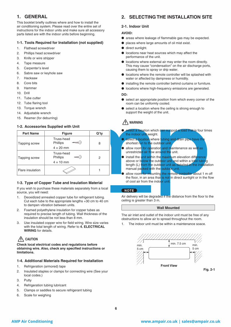
2. SELECTING THE INSTALLATION SITE
2-1. Indoor Unit
AVOID:
● areas where leakage of flammable gas may be expected.
● places where large amounts of oil mist exist.
● direct sunlight.
● locations near heat sources which may affect the performance of the unit.
● locations where external air may enter the room directly. This may cause “condensation” on the air discharge ports, causing them to spray or drip water.
● locations where the remote controller will be splashed with water or affected by dampness or humidity.
● installing the remote controller behind curtains or furniture.
● locations where high-frequency emissions are generated.
DO:
● select an appropriate position from which every corner of the room can be uniformly cooled.
● select a location where the ceiling is strong enough to support the weight of the unit.
WARNING
● select a location which can support a load that is four times the indoor unit weight.
● select a location where tubing and drain pipe have the shortest run to the outdoor unit.
● allow room for operation and maintenance as well as unrestricted air flow around the unit.
● install the unit within the maximum elevation difference above or below the outdoor unit and within a total tubing length (L) from the outdoor unit as detailed in the installation manual packed with the outdoor unit.
● allow room for mounting the remote controller about 1 m off the floor, in an area that is not in direct sunlight or in the flow of cool air from the indoor unit.
NOTE
Air delivery will be degraded if the distance from the floor to the ceiling is greater than 3 m.
Wall Mounted
The air inlet and outlet of the indoor unit must be free of any obstructions to allow air to spread throughout the room.
1. The indoor unit must be within a maintenance soace.
Front View
min. 7.5 cm min. 5 cm
min. 5 cm
Fig. 2-1
II_774010_EU_all.indb 6II_774010_EU_all.indb 6 2013/12/03 13:58:442013/12/03 13:58:44
AMP Air Conditioning www.ampair.co.uk | [email protected]
7
EN
GL
ISH
Set screw only for transportation
Fig. 3-1
Fig. 3-2
Fig. 3-3
Fig. 3-4
Fig. 3-5
Rear panel
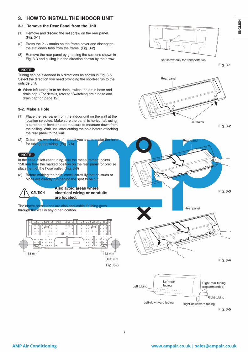
3. HOW TO INSTALL THE INDOOR UNIT3-1. Remove the Rear Panel from the Unit
(1) Remove and discard the set screw on the rear panel.(Fig. 3-1)
(2) Press the 2 marks on the frame cover and disengage the stationary tabs from the frame. (Fig. 3-2)
(3) Remove the rear panel by grasping the sections shown in Fig. 3-3 and pulling it in the direction shown by the arrow.
NOTE
Tubing can be extended in 6 directions as shown in Fig. 3-5. Select the direction you need providing the shortest run to the outside unit.
● When left tubing is to be done, switch the drain hose and drain cap. (For details, refer to “Switching drain hose and drain cap” on page 12.)
3-2. Make a Hole
(1) Place the rear panel from the indoor unit on the wall at the location selected. Make sure the panel is horizontal, using a carpenter’s level or tape measure to measure down from the ceiling. Wait until after cutting the hole before attaching the rear panel to the wall.
(2) Determine which side of the unit you should make the hole for tubing and wiring. (Fig. 3-6)
NOTE
In the case of left-rear tubing, use the measurement points 158 mm from the marked position on the rear panel for precise placement of the hose outlet. (Fig. 3-6)
(3) Before making the hole, check carefully that no studs or pipes are directly run behind the spot to be cut.
CAUTIONAlso avoid areas where electrical wiring or conduits are located.
The above precautions are also applicable if tubing goes through the wall in any other location.
158 mm 132 mm
Unit: mm
Fig. 3-6
marks
Rear panel
Rear panel
Left tubing
Left-rear tubing
Left-downward tubing Right-downward tubing
Right tubing
Right-rear tubing (recommended)
II_774010_EU_all.indb 7II_774010_EU_all.indb 7 2013/12/03 13:58:482013/12/03 13:58:48
AMP Air Conditioning www.ampair.co.uk | [email protected]

8
(4) Using a sabre saw, keyhole saw or hole-cutting drill attachment, cut a hole in the wall. See Table 3-1 and Fig. 3-7.
Table 3-1
Hole Dia.
80 mm
(5) Measure the thickness of the wall from the inside edge to the outside edge and cut PVC pipe at a slight angle 6 mm shorter than the thickness of the wall. (Fig. 3-8)
(6) Place the plastic cover over the end of the pipe (for indoor side only) and insert the pipe in the wall. (Fig. 3-9)
3-3. Install the Rear Panel on the Wall
Be sure to confirm that the wall is strong enough to suspend the unit.
There are a number of screw holes on the rear panel.
Using the 8 screw holes with mark is recommended to attach the rear panel securely to the wall.
NOTE
Be sure to install the unit within the range of the wall.
If Wooden Wall(1) Attach the rear panel to the wall with the 8 screws
provided. (Fig. 3-10)
If you are not able to line up the holes in the rear panel with the beam locations marked on the wall, use rawl plugs or toggle bolts to go through the holes on the panel or drill 5 mm dia. holes in the panel over the stud locations and then mount the rear panel.
(2) Double check with a carpenter’s level or tape measure that the panel is level. This is important to install the unit properly. (Fig. 3-11)
(3) Make sure the panel is flush against the wall. Any space between the wall and unit will cause noise and vibration.
NOTE
Hole should be made at a slight downward slant to the outdoor side.
Fig. 3-7
Fig. 3-8
Fig. 3-9
Fig. 3-10
Fig. 3-11
Outdoor side
Indoor side
PVC pipe (Locally purchased)
Cut at slight angle
INSIDE OUTSIDE
Plastic cover (Locally purchased)
PVC pipe
Slight angle
Wall
II_774010_EU_all.indb 8II_774010_EU_all.indb 8 2013/12/03 13:58:552013/12/03 13:58:55
AMP Air Conditioning www.ampair.co.uk | [email protected]
9
EN
GL
ISH
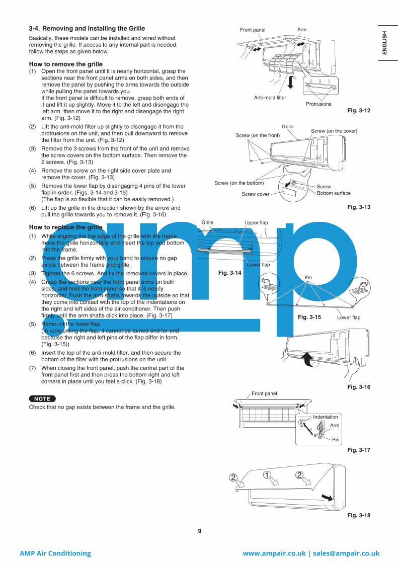
3-4. Removing and Installing the GrilleBasically, these models can be installed and wired without removing the grille. If access to any internal part is needed, follow the steps as given below.
How to remove the grille(1) Open the front panel until it is nearly horizontal, grasp the
sections near the front panel arms on both sides, and then remove the panel by pushing the arms towards the outside while pulling the panel towards you.If the front panel is difficult to remove, grasp both ends of it and lift it up slightly. Move it to the left and disengage the left arm, then move it to the right and disengage the right arm. (Fig. 3-12)
(2) Lift the anti-mold filter up slightly to disengage it from the protrusions on the unit, and then pull downward to remove the filter from the unit. (Fig. 3-12)
(3) Remove the 3 screws from the front of the unit and remove the screw covers on the bottom surface. Then remove the 2 screws. (Fig. 3-13)
(4) Remove the screw on the right side cover plate and remove the cover. (Fig. 3-13)
(5) Remove the lower flap by disengaging 4 pins of the lower flap in order. (Figs. 3-14 and 3-15) (The flap is so flexible that it can be easily removed.)
(6) Lift up the grille in the direction shown by the arrow and pull the grille towards you to remove it. (Fig. 3-16)
How to replace the grille(1) While aligning the top edge of the grille with the frame,
move the grille horizontally and insert the top and bottom into the frame.
(2) Press the grille firmly with your hand to ensure no gap exists between the frame and grille.
(3) Tighten the 6 screws. And fix the removed covers in place.
(4) Grasp the sections near the front panel arms on both sides, and hold the front panel so that it is nearly horizontal. Push the arm shafts towards the outside so that they come into contact with the top of the indentations on the right and left sides of the air conditioner. Then push firmly until the arm shafts click into place. (Fig. 3-17)
(5) Remount the lower flap.(In remounting the flap, it cannot be turned end for end because the right and left pins of the flap differ in form. (Fig. 3-15))
(6) Insert the top of the anti-mold filter, and then secure the bottom of the filter with the protrusions on the unit.
(7) When closing the front panel, push the central part of the front panel first and then press the bottom right and left corners in place until you feel a click. (Fig. 3-18)
NOTE
Check that no gap exists between the frame and the grille.
Front panel
Anti-mold filter
Arm
Protrusions
Grille
Screw (on the front)Screw (on the cover)
Screw (on the bottom)ScrewBottom surfaceScrew cover
Grille Upper flap
Lower flap
Pin
Lower flap
Fig. 3-12
Fig. 3-13
Fig. 3-16
Fig. 3-17
Fig. 3-18
Pin
Front panel
Indentation
Arm
Fig. 3-14
Fig. 3-15
II_774010_EU_all.indb 9II_774010_EU_all.indb 9 2013/12/03 13:58:582013/12/03 13:58:58
AMP Air Conditioning www.ampair.co.uk | [email protected]

10
3-5. Shape the Indoor Side Tubing(1) Arrangement of tubing by direction
a) Right or left tubing
Cut out the corner of the right/left frame with a hacksaw or the like. (Figs. 3-19 and 3-20)
b) Right-rear or left-rear tubing
In this case, the corner of the frame need not be cut.
(2) To mount the indoor unit on the rear panel:
Hang the 3 mounting slots of the unit on the upper tabs of the rear panel. (Fig. 3-21)
3-6. Wiring Instructions
General precautions on wiring(1) Before wiring, confirm the rated voltage of the unit as
shown on its nameplate, then carry out the wiring closely following the wiring diagram.
(2) Provide a power outlet to be used exclusively for each unit, with a power supply disconnect and circuit breaker for overcurrent protection provided in the exclusive line.
(3) To prevent possible hazards due to insulation failure, the unit must be grounded.
(4) Each wiring connection must be done tightly and in accordance with the wiring system diagram. Wrong wiring may cause the unit to misoperate or become damaged.
(5) Do not allow wiring to touch the refrigerant tubing, compressor, or any moving parts of the fan.
(6) Unauthorized changes in the internal wiring can be very dangerous. The manufacturer will accept no responsibility for any damage or misoperation that occurs as a result of such unauthorized changes.
Fig. 3-19
Fig. 3-20
Fig. 3-21
Grille
Grille
Left tubing outlet
Right tubing outlet
II_774010_EU_all.indb 10II_774010_EU_all.indb 10 2013/12/03 13:59:032013/12/03 13:59:03
AMP Air Conditioning www.ampair.co.uk | [email protected]
11
EN
GL
ISH
Fig. 3-27 Fig. 3-24
Fig. 3-25
Fig. 3-23
Fig. 3-22
Refrigerant tubing
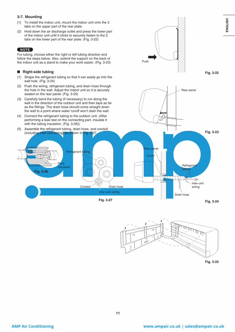
3-7. Mounting(1) To install the indoor unit, mount the indoor unit onto the 3
tabs on the upper part of the rear plate.
(2) Hold down the air discharge outlet and press the lower part of the indoor unit until it clicks to securely fasten to the 2 tabs on the lower part of the rear plate. (Fig. 3-22)
NOTE
For tubing, choose either the right or left tubing direction and follow the steps below. Also, extend the support on the back of the indoor unit as a stand to make your work easier. (Fig. 3-23)
■ Right-side tubing(1) Shape the refrigerant tubing so that it can easily go into the
wall hole. (Fig. 3-24)
(2) Push the wiring, refrigerant tubing, and drain hose through the hole in the wall. Adjust the indoor unit so it is securely seated on the rear panel. (Fig. 3-25)
(3) Carefully bend the tubing (if necessary) to run along the wall in the direction of the outdoor unit and then tape as far as the fittings. The drain hose should come straight down the wall to a point where water runoff won’t stain the wall.
(4) Connect the refrigerant tubing to the outdoor unit. (After performing a leak test on the connecting part, insulate it with the tubing insulation. (Fig. 3-26)).
(5) Assemble the refrigerant tubing, drain hose, and conduit (including inter-unit wiring) as shown in Fig. 3-27.
Fig. 3-26
Flare insulation
Conduit
Inter-unit wiring
Drain hose
Push
Rear panel
Rear panel
Cover
Refrigerant tubing
Inter-unitwiring
Drain hose
II_774010_EU_all.indb 11II_774010_EU_all.indb 11 2013/12/03 13:59:042013/12/03 13:59:04
AMP Air Conditioning www.ampair.co.uk | [email protected]

12
■ Left-side tubing(1) Lead the tubing and drain hose through the wall, allowing
sufficient length for connection. Then bend the tubing using a tube bender to make the attachment. (Fig. 3-28)
(2) Switch the drain hose and drain cap.
Switching drain hose and drain cap (a) Locate the drain hose and the drain cap. (Fig. 3-29)
(b) Remove the screw fastening the drain hose on the right side, and pull out the drain hose to remove it. (Fig. 3-29)
(c) Apply moderate force to pull off the drain cap on the left side. (If you cannot pull it off by hand, use a long-nose pliers.)
(d) Reattach the drain hose to the left side and the drain cap to the right side. (Fig. 3-30)
Drain hose Slide the drain hose fully onto the drain pan outlet. (It will
be easy to slide when water is added.) Check that the screw holes in the drain bracket and the drain pan outlet are aligned and securely in contact, then fasten them with the screw. (After attaching the drain hose, check that it is attached securely.) (Fig. 3-31)
Drain cap Use a Phillips head screwdriver to push the drain cap in
firmly. (If it is difficult to push in, wet the cap with water first.)
(3) Install the indoor unit on the rear panel.
(4) Connect the tubing and wiring led inside from outdoors.
(5) After completing a leak test, bundle the tubing together with armoring tape and store it inside the tubing storage area at the back of the indoor unit and hold it with clamps. (Figs. 3-30 and 3-32)
Fig. 3-28
Fig. 3-29
Fig. 3-30
Fig. 3-31
Fig. 3-32
Hole in wall
Rear panel
Bent part Narrow tube Wide tube
Drain cap
Drain hose
Clamp
Clamp
Drain hose
Drain cap
Drain pan outlet
Drain bracket
Drain hose
Screw
Screw hole
Drain hose
Drain bracket Screw
Refrigerant tubing
Inter-unit wiring
Conduit
II_774010_EU_all.indb 12II_774010_EU_all.indb 12 2013/12/03 13:59:082013/12/03 13:59:08
AMP Air Conditioning www.ampair.co.uk | [email protected]
13
EN
GL
ISH
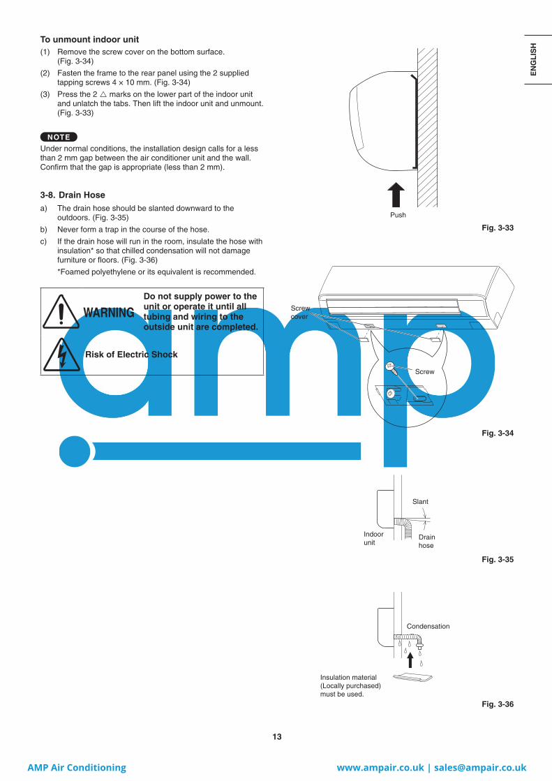
To unmount indoor unit(1) Remove the screw cover on the bottom surface.
(Fig. 3-34)
(2) Fasten the frame to the rear panel using the 2 supplied tapping screws 4 × 10 mm. (Fig. 3-34)
(3) Press the 2 marks on the lower part of the indoor unit and unlatch the tabs. Then lift the indoor unit and unmount. (Fig. 3-33)
NOTE
Under normal conditions, the installation design calls for a less than 2 mm gap between the air conditioner unit and the wall.Confirm that the gap is appropriate (less than 2 mm).
3-8. Drain Hosea) The drain hose should be slanted downward to the
outdoors. (Fig. 3-35)
b) Never form a trap in the course of the hose.
c) If the drain hose will run in the room, insulate the hose with insulation* so that chilled condensation will not damage furniture or floors. (Fig. 3-36)
*Foamed polyethylene or its equivalent is recommended.
WARNINGDo not supply power to the unit or operate it until all tubing and wiring to the outside unit are completed.
Risk of Electric Shock
Fig. 3-33
Push
Screw cover
Fig. 3-34
Fig. 3-35
Fig. 3-36
Screw
Slant
Drain hose
Indoor unit
Condensation
Insulation material (Locally purchased) must be used.
II_774010_EU_all.indb 13II_774010_EU_all.indb 13 2013/12/03 13:59:122013/12/03 13:59:12
AMP Air Conditioning www.ampair.co.uk | [email protected]

14
4. ELECTRICAL WIRING
4-1. General Precautions on Wiring (1) Before wiring, confirm the rated voltage of the unit as
shown on its nameplate, then carry out the wiring closely following the wiring diagram.
(2) Provide a power outlet to be used exclusively for each unit, and a power supply disconnect and circuit breaker for overcurrent protection should be provided in the exclusive line.
(3) To prevent possible hazards from insulation failure, the unit must be grounded.
(4) Each wiring connection must be done in accordance with the wiring system diagram. Wrong wiring may cause the unit to misoperate or become damaged.
(5) Do not allow wiring to touch the refrigerant tubing, compressor, or any moving parts of the fan.
(6) Unauthorized changes in the internal wiring can be very dangerous. The manufacturer will accept no responsibility for any damage or misoperation that occurs as a result of such unauthorized changes.
(7) Regulations on wire diameters differ from locality to locality. For field wiring rules, please refer to your LOCAL ELECTRICAL CODES before beginning.
You must ensure that installation complies with all relevant rules and regulations.
(8) To prevent malfunction of the air conditioner caused by electrical noise, care must be taken when wiring as follows:
● The remote control wiring and the inter-unit control wiring should be wired apart from the inter-unit power wiring.
● Use shielded wires for inter-unit control wiring between units and ground the shield on both sides.
(9) If the power supply cord of this appliance is damaged, it must be replaced by a repair shop designated by the manufacturer, because special-purpose tools are required.
4-2. Recommended Wire Length and Wire Diameter for Power Supply System
Indoor unit
Type(B) Power supply Time delay fuse or
circuit capacity2.5 mm2
K1 Max. 150 m 10-16 A
Control wiring(C) Inter-unit
(between outdoor and indoor units)
control wiring
(D) Remote control wiring
(E) Control wiring for group control
0.75 mm2
(AWG #18)Use shielded wiring*
0.75 mm2
(AWG #18)0.75 mm2
(AWG #18)
Max. 1,000 m Max. 500 m Max. 200 m (Total)
NOTE* With ring-type wire terminal.
II_774010_EU_all.indb 14II_774010_EU_all.indb 14 2013/12/03 13:59:152013/12/03 13:59:15
AMP Air Conditioning www.ampair.co.uk | [email protected]

15
EN
GL
ISH
4-3. Wiring System Diagrams
NOTE
(1) Refer to Section 4-2. “Recommended Wire Length and Wire Diameter for Power Supply System” for the explanation of “B”, “C”, “D” and “E” in the above diagram.
(2) The basic connection diagram of the indoor unit shows the terminal boards, so the terminal boards in your equipment may differ from the diagram. (Fig. 4-2)
(3) Refrigerant Circuit (R.C.) address should be set before turning the power on.
(4) Regarding R.C. address setting, refer to the installation instructions supplied with the remote controller (optional). Auto address setting can be executed by remote controller automatically. Refer to the installation instructions supplied with the remote controller (optional).
WARNING
This equipment must be properly earthed.
Fig. 4-2
L N U1 U2
5P terminal board
Power supply
K1 Type
Unitcontrol
line
Fig. 4-1
ex.) MF2 Type
U2
U1
R2
R1
L
N
R2
R1
R2
R1
R2
R1
2
1
2
1
U2
U1
L
N
U2
U1
L
N
U2
U1
L
N
2
1
2
1
2
1
D
E
C
B
LN
LN
LN
LN
2
1
B
B
B
C
D
D
C
2
1
L1L2L3N
2
1
L1L2L3N
CL1
L2
L3
N
L1
L2
L3
N
U2
U1
Power supply220/230/240V ~50/60Hz
Power supply220/230/240V ~50/60Hz
Power supply220/230/240V ~50/60Hz
Power supply220/230/240V ~50/60Hz
Remote controller
Remote controller
Remote controller
WHT BLK
WHT BLK
WHT BLK
Power supply380/400/415V, 3 N~, 50Hz
Power supply380/400/415V, 3 N~, 50Hz
Ground
Ground
Ground
Ground
Ground
Ground
Ground
Ground
Ground
Ground
Ground
Ground
Ground
Outdoor unit INV unit
Outdoor unit INV unit
Indoor unit (No. 1)
Indoor unit (No. 3)
Indoor unit (No. 2)
Indoor unit (No. n)
Inter-outdoor-unit control wiring
Group control:
Ground
Ground
II_774010_EU_all.indb 15II_774010_EU_all.indb 15 2013/12/03 13:59:192013/12/03 13:59:19
AMP Air Conditioning www.ampair.co.uk | [email protected]
16
CAUTION
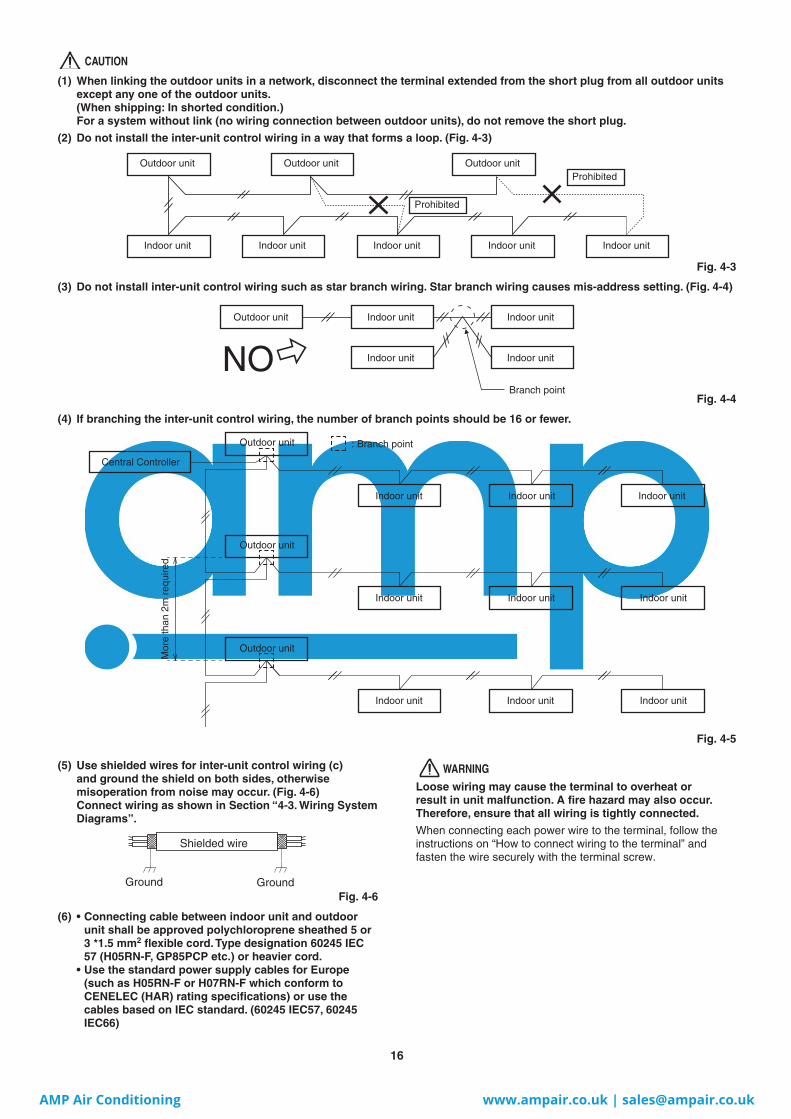
(1) When linking the outdoor units in a network, disconnect the terminal extended from the short plug from all outdoor units except any one of the outdoor units. (When shipping: In shorted condition.) For a system without link (no wiring connection between outdoor units), do not remove the short plug.
(2) Do not install the inter-unit control wiring in a way that forms a loop. (Fig. 4-3)
Outdoor unit Outdoor unit Outdoor unit
Indoor unit Indoor unit Indoor unit Indoor unit
Prohibited
Prohibited
Indoor unit
Fig. 4-3
(3) Do not install inter-unit control wiring such as star branch wiring. Star branch wiring causes mis-address setting. (Fig. 4-4)
Fig. 4-4
(4) If branching the inter-unit control wiring, the number of branch points should be 16 or fewer.
Central Controller
Outdoor unit
Outdoor unit
Indoor unit
Indoor unit
Indoor unit Indoor unit Indoor unit
Indoor unit Indoor unit
Indoor unit Indoor unit
Outdoor unit
: Branch point
Mor
e th
an 2
m r
equi
red
Fig. 4-5
Outdoor unit Indoor unitIndoor unit
Indoor unitIndoor unitNOBranch point
(5) Use shielded wires for inter-unit control wiring (c) and ground the shield on both sides, otherwise misoperation from noise may occur. (Fig. 4-6)Connect wiring as shown in Section “4-3. Wiring System Diagrams”.
Fig. 4-6
(6) • Connecting cable between indoor unit and outdoor unit shall be approved polychloroprene sheathed 5 or 3 *1.5 mm2 flexible cord. Type designation 60245 IEC 57 (H05RN-F, GP85PCP etc.) or heavier cord.
• Use the standard power supply cables for Europe (such as H05RN-F or H07RN-F which conform to CENELEC (HAR) rating specifications) or use the cables based on IEC standard. (60245 IEC57, 60245 IEC66)
WARNINGLoose wiring may cause the terminal to overheat or result in unit malfunction. A fire hazard may also occur. Therefore, ensure that all wiring is tightly connected.
When connecting each power wire to the terminal, follow the instructions on “How to connect wiring to the terminal” and fasten the wire securely with the terminal screw.
Shielded wire
Ground Ground
II_774010_EU_all.indb 16II_774010_EU_all.indb 16 2013/12/03 13:59:252013/12/03 13:59:25
AMP Air Conditioning www.ampair.co.uk | [email protected]

17
EN
GL
ISH
Stranded wire
Ring pressure terminal Screw and
Special washer
Ring pressure terminal
Terminal board
Ring pressure terminal
ScrewSpecial washer
Wire
Wire
Insulation tape
8 mm
Insulation tape
Shield mesh
Shield mesh
Str
ip 1
0 m
m
Fig. 4-7 Fig. 4-8
Fig. 4-9
Fig. 4-10
Fig. 4-11
Fig. 4-12
How to connect wiring to the terminal
■ For stranded wiring(1) Cut the wire end with cutting pliers,
then strip the insulation to expose the stranded wiring about 10 mm and tightly twist the wire ends. (Fig. 4-7)
(2) Using a Phillips head screwdriver, remove the terminal screw(s) on the terminal board.
(3) Using a ring connector fastener or pliers, securely clamp each stripped wire end with a ring pressure terminal.
(4) Place the ring pressure terminal, and replace and tighten the removed terminal screw using a screwdriver. (Fig. 4-8)
■ Examples of shield wires(1) Remove cable coat not to scratch braided shield. (Fig. 4-9)
(2) Unbraid the braided shield carefully and twist the unbraided shield wires tightly together. Insulate the shield wires by covering them with an insulation tube or wrapping insulation tape around them. (Fig. 4-10)
(3) Remove coat of signal wire. (Fig. 4-11)
(4) Attach ring pressure terminals to the signal wires and the shield wires insulated in Step (2). (Fig. 4-12)
■ Wiring samples
K1 type
L1
R1 R2
L2 N U1 U2
Functional ground screw (External Electronic Expansion Valve Kit and Schedule Timer)*
Protective ground screw
Use this screw when connecting the shield for the Inter-unit control wiring to ground.
* As to functional ground screw and protective ground screw, remove the fixture screw and resin cover. Then, carry out earth ground work.
Power Supply
Fixture screw for resin cover
Resin cover
Inter-unit Control Wiring
Remote Control Wiring
II_774010_EU_all.indb 17II_774010_EU_all.indb 17 2013/12/03 13:59:302013/12/03 13:59:30
AMP Air Conditioning www.ampair.co.uk | [email protected]

18
5. HOW TO PROCESS TUBING
5-1. Connecting the Refrigerant Tubing
Use of the Flaring Method
Many of conventional split system air conditioners employ the flaring method to connect refrigerant tubes that run between indoor and outdoor units. In this method, the copper tubes are flared at each end and connected with flare nuts.
Flaring Procedure with a Flare Tool
(1) Cut the copper tube to the required length with a tube cutter. It is recommended to cut approx. 30 – 50 cm longer than the tubing length you estimate.
(2) Remove burrs at each end of the copper tubing with a tube reamer or file. This process is important and should be done carefully to make a good flare. Be sure to keep any contaminants (moisture, dirt, metal filings, etc.) from entering the tubing. (Figs. 5-1 and 5-2)
AfterBefore
Deburring
Coppertubing
Reamer
Fig. 5-1 Fig. 5-2
NOTE
When reaming, hold the tube end downward and be sure that no copper scraps fall into the tube. (Fig. 5-2)
(3) Remove the flare nut from the unit and be sure to mount it on the copper tube.
(4) Make a flare at the end of the copper tube with a flare tool. (Fig. 5-3)
Flare nut
Copper tubing
Flare toolFig. 5-3
NOTE
A good flare should have the following characteristics:
● inside surface is glossy and smooth● edge is smooth● tapered sides are of uniform length
Caution Before Connecting Tubes Tightly
(1) Apply a sealing cap or water-proof tape to prevent dust or water from entering the tubes before they are used.
(2) Be sure to apply refrigerant lubricant (ether oil) to the inside of the flare nut before making piping connections. This is effective for reducing gas leaks. (Fig. 5-4)
Apply refrigerant lubricant.
Fig. 5-4
(3) For proper connection, align the union tube and flare tube straight with each other, then screw on the flare nut lightly at first to obtain a smooth match. (Fig. 5-5)
Flare nutUnion
Fig. 5-5
● Adjust the shape of the liquid tube using a tube bender at the installation site and connect it to the liquid tubing side valve using a flare.
Cautions During Brazing
● Replace air inside the tube with nitrogen gas to prevent copper oxide film from forming during the brazing process. (Oxygen, carbon dioxide and Freon are not acceptable.)
● Do not allow the tubing to get too hot during brazing. The nitrogen gas inside the tubing may overheat, causing refrigerant system valves to become damaged. Therefore allow the tubing to cool when brazing.
● Use a reducing valve for the nitrogen cylinder.
● Do not use agents intended to prevent the formation of oxide film. These agents adversely affect the refrigerant and refrigerant oil, and may cause damage or malfunctions.
5-2. Connecting Tubing Between Indoor and Outdoor Units
(1) Tightly connect the indoor-side refrigerant tubing extended from the wall with the outdoor-side tubing.
(2) To fasten the flare nuts, apply specified torque.
Indoor Unit Tubing Connection ( 1, 2... n-1)
Indoor unit type 45 56 73 106Gas tubing (mm) ø12.7 ø15.88
Liquid tubing (mm) ø6.35 ø9.52
● When removing the flare nuts from the tubing connections, or when tightening them after connecting the tubing, be sure to use 2 adjustable wrenches or spanners. (Fig. 5-6) If the flare nuts are over-tightened, the flare may be damaged, which could result in refrigerant leakage and cause injury or asphyxiation to room occupants.
Outdoor unit
Torque wrench
SpannerIndoor unit
Fig. 5-6
II_774010_EU_all.indb 18II_774010_EU_all.indb 18 2013/12/03 13:59:362013/12/03 13:59:36
AMP Air Conditioning www.ampair.co.uk | [email protected]

19
EN
GL
ISH
● For the flare nuts at tubing connections, be sure to use the flare nuts that were supplied with the unit, or else flare nuts for R410A (type 2). The refrigerant tubing that is used must be of the correct wall thickness as shown in the table below.
Tube diameter Tightening torque(approximate) Tube thickness
ø6.35 (1/4") 14 – 18 N · m{140 – 180 kgf · cm} 0.8 mm
ø9.52 (3/8") 34 – 42 N · m{340 – 420 kgf · cm} 0.8 mm
ø12.7 (1/2") 49 – 61 N · m{490 – 610 kgf · cm} 0.8 mm
ø15.88 (5/8") 68 – 82 N · m{680 – 820 kgf · cm} 1.0 mm
ø19.05 (3/4") 100 – 120 N · m{1000 – 1200 kgf · cm} 1.0 mm
Because the pressure is approximately 1.6 times higher than conventional refrigerant pressure, the use of ordinary flare nuts (type 1) or thin-walled tubes may result in tube rupture, injury, or asphyxiation caused by refrigerant leakage.
● In order to prevent damage to the flare caused by over-tightening of the flare nuts, use the table above as a guide when tightening.
● When tightening the flare nut on the liquid tube, use an adjustable wrench with a nominal handle length of 200 mm.
5-3. Insulating the Refrigerant Tubing
Tubing Insulation
● Thermal insulation must be applied to all units tubing, including distribution joint (field supply).
Two tubes arranged together
Liquid tubing Gas tubing
Insulation
Fig. 5-7
* For gas tubing, the insulation material must be heat resistant to 120°C or above. For other tubing, it must be heat resistant to 80°C or above.
Insulation material thickness must be 10 mm or greater.
If the conditions inside the ceiling exceed DB 30°C and RH 70%, increase the thickness of the gas tubing insulation material by 1 step.
CAUTION
If the exterior of the outdoor unit valves has been finished with a square duct covering, make sure you allow sufficient space to access the valves and to allow the panels to be attached and removed.
NOTE
Gas Leakage DetectorNote that the gas leakage detector should be capable of detecting the refrigerant R410A.
Air PurgingRefer to “AIR PURGING” in the separate Installation Instructions for the outdoor unit in regard to air purging with a vacuum pump (for test run) preparation.
Taping the fl are nutsCover up the tubing connections with the supplied flare insulator. Then fasten the insulator at both ends with the vinyl clamps (field supply).
Insulation material
The material used for insulation must have good insulation characteristics, be easy to use, be age resistant, and must not easily absorb moisture.
Never grasp the drain or refrigerant connecting outlets when moving the unit.
CAUTION
After a tube has been insulated, never try to bend it into a narrow curve because it can cause the tube to break or crack.
5-4. Taping the Tubes(1) At this time, the refrigerant tubes (and electrical wiring
if local codes permit) should be taped together with armoring tape in 1 bundle. To prevent condensation from overflowing the drain pan, keep the drain hose separate from the refrigerant tubing.
(2) Wrap the armoring tape from the bottom of the outdoor unit to the top of the tubing where it enters the wall. As you wrap the tubing, overlap half of each previous tape turn.
(3) Clamp the tubing bundle to the wall, using 1 clamp approx. each meter. (Fig. 5-9)
Insulated tubes Drain hose
Clamp
Fig. 5-8
NOTEDo not wind the armoring tape too tightly since this will decrease the heat insulation effect. Also ensure that the condensation drain hose splits away from the bundle and drips clear of the unit and the tubing.
5-5. Finishing the InstallationAfter finishing insulating and taping over the tubing, use sealing putty to seal off the hole in the wall to prevent rain and draft from entering. (Fig. 5-9)
Apply putty here
Tubing
Fig. 5-9
6. HOW TO INSTALL TIMER REMOTE CONTROLLER OR HIGH-SPEC WIRED REMOTE CONTROLLER (OPTIONAL PART)
NOTE
Refer to the Operating Instructions attached to the optional Timer Remote Controller or optional High-Spec Wired Remote Controller.
II_774010_EU_all.indb 19II_774010_EU_all.indb 19 2013/12/03 13:59:452013/12/03 13:59:45
AMP Air Conditioning www.ampair.co.uk | [email protected]

20
<How to clean the filter>1. Remove the air filter from the air intake grille.2. Use a vacuum cleaner to remove light dust. If there is
sticky dust on the filter, wash the filter in lukewarm, soapy water, rinse it in clean water, and dry it.
<How to remove the filter>
Casing and Grille (Indoor Unit)
Clean the casing and grille of the indoor unit with a vacuum cleaner brush, or wipe them with a clean, soft cloth.If these parts are stained, use a clean cloth moistened with a mild liquid detergent. When cleaning the grille, be careful not to force the vanes out of place.
Anti-Mold Filter
The anti-mold filter behind the front panel should be checked and cleaned at least once every two weeks.
How to remove the anti-mold fi lter
1. Grasp both ends of the front panel and pull forward and up to open the front panel.
Front panel
ProtrusionsAnti-mold filter
2. Lift the anti-mold filter up slightly to disengage it from the protrusions on the unit.
3. Pull downward to remove the filter from the unit.
Cleaning
Use a vacuum cleaner to remove light dust. If there is sticky dust on the filter, wash the filter in lukewarm, soapy water, rinse it in clean water, and dry it.
How to replace the anti-mold fi lter
1. Insert the top of the anti-mold filter, and then secure the bottom of the filter with the protrusions on the unit.
2. Close the front panel by pushing the center of the front panel and then pressing both edges until the panel clicks into place.
1 22
7. APPENDIX
■ Name of PartsAir intake
Air discharge
■ Care and Cleaning
WARNING
● For safety, be sure to turn the air conditioner off and also to disconnect the power before cleaning.
● Do not pour water on the indoor unit to clean it. This will damage the internal components and cause an electric shock hazard.
Air intake and discharge side (Indoor unit)
Clean the air intake and discharge side of the indoor unit with a vacuum cleaner brush, or wipe them with a clean, soft cloth.
If these parts are stained, use a clean cloth moistened with water. When cleaning the air discharge side, be careful not to force the vanes out of place.
CAUTION
● Never use solvents or harsh chemicals when cleaning the indoor unit. Do not wipe plastic parts using very hot water.
● Some metal edges and the fins are sharp and may cause injury if handled improperly; be especially careful when you clean these parts.
● The internal coil and other components of outdoor unit must be cleaned regularly. Consult your dealer or service center.
Air filter
The air filter collects dust and other particles from the air and should be cleaned at regular intervals as indicated in the table below or when the filter indication ( ) on the display of the remote controller (wired type) shows that the filter needs cleaning. If the filter gets blocked, the efficiency of the air conditioner drops greatly.
Type K1
Period 2 weeks
NOTE
The frequency with which the filter should be cleaned depends on the environment in which the unit is used.
II_774010_EU_all.indb 20II_774010_EU_all.indb 20 2013/12/03 13:59:512013/12/03 13:59:51
AMP Air Conditioning www.ampair.co.uk | [email protected]

21
EN
GL
ISH
Cleaning the main unit and remote controller
● Wipe clean using a soft, dry cloth.● To remove stubborn dirt, moisten a cloth in warm water no
hotter than 40 °C, wring thoroughly, and then wipe.● The front panel can be removed in order to wash it with
water.
Removing and remounting the front panel
Removing
Open the front panel until it is nearly horizontal, grasp the sections near the front panel arms on both sides, and then remove the panel by pushing the arms towards the outside while pulling the panel towards you. If the front panel is difficult to remove, grasp both ends of it and lift it up slightly. Move it to the left and disengage the left arm, then move it to the right and disengage the right arm.
Front panel Arm
CAUTION
● Certain metal edges and the condenser fins are sharp and may cause injury if handled improperly; special care should be taken when you clean these parts.
● The internal coil and other components must also be cleaned periodically. Consult your dealer or service center.
Care: After a prolonged idle period
Check the indoor and outdoor unit air intakes and outlets for blockage; if there is a blockage, remove it.
Care: Before a prolonged idle period
● Operate the fan for half a day to dry out the inside.
● Disconnect the power supply and also turn off the circuit breaker.
● Clean the air filter and replace it in its original position.
● Outdoor unit internal components must be checked and cleaned periodically. Contact your local dealer for this service.
■ When Using Wireless Remote Controller Instead of Wired Remote Controller
Wall Mounted (K1 Type)
When the wireless remote controller is to be used, slide the switch (S011) on the indoor unit control PCB to the ON position.
● If this setting is not made, an alarm will occur. (The operation lamp on the display blinks.)
Setting statusON: Wireless: main, Wired: sub
OFF: Wired: main, Wireless: sub (at shipment)Slide
II_774010_EU_all.indb 21II_774010_EU_all.indb 21 2013/12/03 13:59:542013/12/03 13:59:54
AMP Air Conditioning www.ampair.co.uk | [email protected]

22
■ Troubleshooting
If your air conditioner does not work properly, first check the following points before requesting service. If it still does not work properly, contact your dealer or a service center.
● Indoor unit
Symptom Cause
Noise
Sound like streaming water during operation or after operation
● Sound of refrigerant liquid flowing inside unit ● Sound of drainage water through drain pipe
Cracking noise during operation or when operation stops.
Cracking sound due to temperature changes of parts
OdorDischarged air is smelled during operation.
Indoor odor components, cigarette odor and cosmetic odor accumurated in the air conditioner and its air is discharged. Unit inside is dusty. Consult your dealer.
DewdropDewdrop gets accumurated near air discharge during operation
Indoor moisture is cooled by cool wind and accumulated by dewdrop.
Fog
Fog occurs during operation in cooling mode. (Places where large amounts of oil mist exist at restaurants.)
● Cleaning is necessary because unit inside (heat exchanger) is dirty. Consult your dealer as technical engineering is required.
● During defrost operation
Fan is rotating for a while even though operation stops.
● Fan rotating makes operation smoothly. ● Fan may sometimes rotates because of drying heat exchanger due to
settings.
Wind-direction changes while operating.Wind-direction setting cannot be made.Wind-direction cannot be changed.
● When air discharge temperature is low or during defrost operation, horizontal wind flow is made automatically.
● Flap position is occasionally set up individually. ● When long-hour operation is made with fixed wind-direction, wind-
direction is controlled automatically and flap position is occasionally changed.
When wind-direction is changed, flap operates several times and stops at designated position.
When wind-direction is changed, flap operates after searching for standard position.
Dust Dust accumulation inside indoor unit is discharged.
● Outdoor unit
Symptom Cause
No operation
When power is turned ON instantly.Operation is not activated for the first approx. 3 minutes because compressor protection circuit is activated.
When operation is stopped and resumed immediately.
Noise Noise often occurs in heating mode.During defrost operation
Steam Steam often occurs in heating mode.
When stopped by remote controller, outdoor unit fan is sometimes operating for a while even though outdoor compressor is stopped.
Fan rotating makes operation smoothly.
II_774010_EU_all.indb 22II_774010_EU_all.indb 22 2013/12/03 14:00:082013/12/03 14:00:08
AMP Air Conditioning www.ampair.co.uk | [email protected]
23
EN
GL
ISH
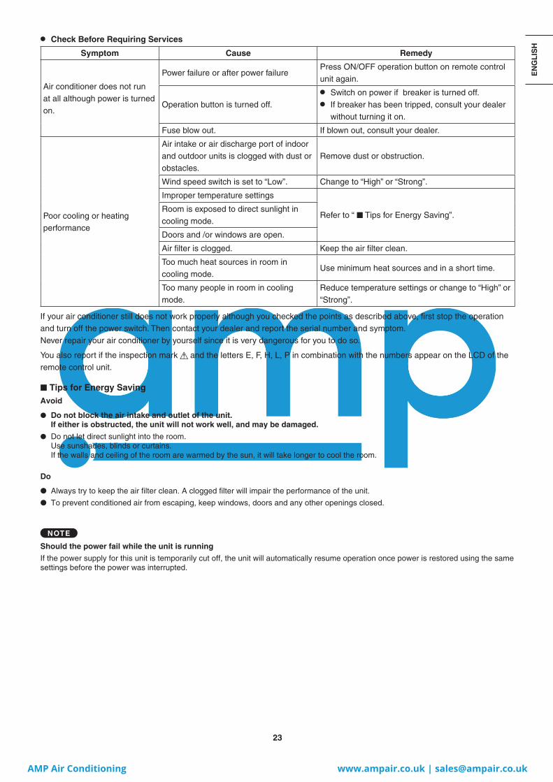
● Check Before Requiring Services
Symptom Cause Remedy
Air conditioner does not run at all although power is turned on.
Power failure or after power failurePress ON/OFF operation button on remote control unit again.
Operation button is turned off.
● Switch on power if breaker is turned off. ● If breaker has been tripped, consult your dealer
without turning it on.
Fuse blow out. If blown out, consult your dealer.
Poor cooling or heating performance
Air intake or air discharge port of indoor and outdoor units is clogged with dust or obstacles.
Remove dust or obstruction.
Wind speed switch is set to “Low”. Change to “High” or “Strong”.
Improper temperature settings
Refer to “ ■ Tips for Energy Saving”.Room is exposed to direct sunlight in cooling mode.
Doors and /or windows are open.
Air filter is clogged. Keep the air filter clean.
Too much heat sources in room in cooling mode.
Use minimum heat sources and in a short time.
Too many people in room in cooling mode.
Reduce temperature settings or change to “High” or “Strong”.
If your air conditioner still does not work properly although you checked the points as described above, first stop the operation and turn off the power switch. Then contact your dealer and report the serial number and symptom. Never repair your air conditioner by yourself since it is very dangerous for you to do so.
You also report if the inspection mark and the letters E, F, H, L, P in combination with the numbers appear on the LCD of the remote control unit.
■ Tips for Energy SavingAvoid
● Do not block the air intake and outlet of the unit. If either is obstructed, the unit will not work well, and may be damaged.
● Do not let direct sunlight into the room. Use sunshades, blinds or curtains. If the walls and ceiling of the room are warmed by the sun, it will take longer to cool the room.
Do
● Always try to keep the air filter clean. A clogged filter will impair the performance of the unit.
● To prevent conditioned air from escaping, keep windows, doors and any other openings closed.
NOTE
Should the power fail while the unit is running
If the power supply for this unit is temporarily cut off, the unit will automatically resume operation once power is restored using the same settings before the power was interrupted.
II_774010_EU_all.indb 23II_774010_EU_all.indb 23 2013/12/03 14:00:142013/12/03 14:00:14
AMP Air Conditioning www.ampair.co.uk | [email protected]

24
– NOTE –
II_774010_EU_all.indb 24II_774010_EU_all.indb 24 2013/12/03 14:00:182013/12/03 14:00:18
AMP Air Conditioning www.ampair.co.uk | [email protected]

85464369774010DC1213-0Printed in Japan
II_774010_EU_all.indb 268II_774010_EU_all.indb 268 2013/12/03 14:08:112013/12/03 14:08:11
AMP Air Conditioning www.ampair.co.uk | [email protected]