geophysical applications to solid waste … applications to solid waste analysis peter j....
TRANSCRIPT

GEOPHYSICAL APPLICATIONS TO SOLID WASTE ANALYSIS
Peter J. Hutchinson, PhD, PGLaura S. Barta
The Hutchinson Group, Ltd.4280 Old William Penn HighwayMurrysville, Pennsylvania 15668
Proceedings of the Sixteenth International Conference on Solid Waste Technology and ManagementPhiladelphia, PA U.S.A., December 10-13, 2000 Editors: Zandi, I.; Mersky, R.L.; Shieh W.K.
Pp. 2-68 to 2-78ISSN 1091-8043

Geophysical Applications to Solid Waste Analysis
Peter J. Hutchinson, PhD, PGThe Hutchinson Group, Ltd.4280 Old William Penn Highway
Murrysville, [email protected]
Laura S. BartaThe Hutchinson Group, Ltd.4280 Old William Penn Highway
Murrysville, [email protected]
Abstract: Case studies of regional landfills show that electromagnetic geophysicalmethods can accurately and inexpensively define boundaries and thickness of waste.Degradation of putrescible solid waste generates conductive leachate that can be imaged witha frequency-domain terrain conductivity meter. Terrain conductivity measurements can bemodified through a simple algorithm based upon native soil conductivity to produce planmaps showing a detailed three-dimensional image of the waste mass. Further, seismic recordsand borings confirm that a linear relationship exists between measured waste terrainconductance and thickness of waste. Consequently, waste volume can be estimated to within15% of the true mass volume by employing terrain conductivity mapping.
Keywords: geophysical methods; terrain conductivity; waste boundaries; waste thickness;waste volume
IntroductionElectromagnetic terrain conductivity surveys have been useful for landfill investigations formany years. These inexpensive surveys can delineate waste, conductive fluids, and buriedmetal; and provide a three-dimensional overview of the buried waste. Degradation of organicmaterial in field-saturated conditions produces a terrain conductance signature that is elevatedabove background conditions. The elevated signature, through simple mathematicaloperations, can locate waste, delineate the waste boundary and provide a rough estimate ofdepth of waste. The footprint of the landfill can be used with the terrain conductivityestimation of the depth to waste to calculate an in-place waste volume.
2-68

Electromagnetic terrain conductivityElectromagnetic terrain conductivity (EM) surveys have been employed for landfillinvestigations for over 20 years (McNeill, 1980). Advantages of electromagnetic terrainconductivity survey mapping over other geophysical methods include: excellent resolution inconductivity; no current injection problems; simple multi-layered earth calculations; and easy,rapid measurements. Disadvantages of EM for exploratory investigations are few but include:limited dynamic range; setting and maintaining the instrument zero; and limited verticalsounding capability.
EM surveys are principally used for landfill boundary detection (Mack and Maus, 1986;McQuown et al., 1991; Rumbaugh et al., 1987; Scaife, 1990; Stenson, 1988) and detection ofleachate contaminant plumes (Hall and Pasicznyk, 1987; Mack and Maus, 1986; Russell,1990; Walther et al., 1986). Several workers have been successful in using EM surveys toidentify volatile organic plumes such as gasoline (Fawcett, 1989; Olhoeft, 1986; Olhoeft andKing, 1991; Saunders and Cox, 1987). McNeill (1990) contends that "...EM measurementswill also undoubtedly be used to assist in locating new sanitary landfills..." (p.209).
While groundwater monitoring wells are aerially limited and are a somewhat expensivesentinel strategy, EM surveys have proven to be inexpensive and effective for establishingcompliance (McNeill, 1990; Rumbaugh et al., 1987). EM surveys can also be used to monitorthe efficacy of a treatment system (Medlin and Knuth, 1986).
The electrical conductivity of soil is a function of the porosity, permeability, and fluids in thepore spaces (McNeill, 1980). Degradation of putrescible solid waste generates conductiveleachate that fills pore spaces and can be easily imaged with a frequency-domain terrainconductivity meter (Hutchinson 1994). The absolute values of conductivity obtained in asurvey are not necessarily diagnostic but the variations in conductivity can be used to identifyanomalies (Benson et al., 1988).
The field-collected electromagnetic terrain conductivity measurements can be modifiedthrough a simple algorithm based upon native soil conductivity to produce plan maps showingwaste boundaries. Further, case studies of regional landfills confirm that a linear relationshipexists between measured waste (terrain) conductivity and thickness of waste. Thisrelationship can be used to estimate waste volume without the need for seismic reflectionsurveys (the most effective geophysical tool for measuring depth of waste) or for intrusivemethods (i.e., borings).
Tool GeometryThe EM meter consists of a transmitter coil that radiates an electromagnetic field (Figure 1).The electromagnetic field induces eddy currents in the earth that generate a secondaryelectromagnetic field that is proportional to the magnitude of the current flowing within thecoil. Quadrature and in-phase components of the secondary magnetic field are captured by
2-69

the receiver in the form of an output voltage that is linearly related to subsurface conductivity(McQuown et al., 1991). The quadrature phase component (terrain conductivity) is measuredin milliSeimens/meter (mS/m) and provides a measurement of soil conductivity (Figure 2).The in-phase mode, measured in parts per thousand (ppt), is responsive to highly conductive,buried metallic objects.
Figure 1 Schematic diagram of the electromagnetic surveying method (Grant and West,1965).
Figure 2 Electromagnetic terrain conductivity map (in mS/m) of Laurel Ridge Landfill,Lily, Kentucky (in feet). The higher conductivity values (>40 mS/m) representareas of buried waste.
The terrain conductivity value is an average conductivity of the effective depth of the surveytool. The effective depth is determined to be about 1.5 times the intercoil spacing (i.e., the
2-70

distance between the receiving and the transmitting coils). The Geonics EM31-DL terrain conductivity meter, with an intercoil spacing of 12 feet, has an effective penetration depth of 18 feet in the vertical dipole mode (Geonics Limited, 1994). The tool measures the bulk conductivity of the entire skin depth specified by the intercoil spacing (18 feet for the EM31-DL). Consequently, the tool averages the response determined through the skin depth such that the response at a depth of 4.8 feet gives maximum contribution to the secondary magnetic field but that at 18 feet there is still a contribution to the bulk conductivity (McNeill, 1980). Near-surface material has a very small contribution to the secondary magnetic field and the orientation of the dipoles in a vertical coplanar fashion is insensitive to near-surface changes in conductivity. This phenomenon, however, is not true for surface soundings where high layer conductivities dramatically decrease the depth of penetration (Weber and Flatmen, 1986). Normalized Data Presentation Conductivity values of soil vary considerably (Benson et al. 1988; McNeill 1980; Schutts and Nichols 1991). Jordan et al. (1991) found that wet clay has a conductivity of 20 to 80 mS/m and they considered 30 mS/m an acceptable number for conductivity readings in wet clay. Fill materials have been observed to have a terrain conductivity of greater than 45 mS/m (Hutchinson 1998, McQuown et al., 1991). A simple algorithm, based upon the background conductivity of soil at the site, can be used to normalize the EM data to a background value. The conversion is plotted in decibels (dB) from the following equation (Greenhouse and Slaine, 1983):
Where, �Ãarb is the background value for terrain conductivity, c is a constant value, Fapp is the measured apparent conductivity, and L is the apparent terrain conductivity. The logarithmic ratio has the advantage of producing whole numbers based on expected (i.e., background) conditions at the site. Negative numbers indicate sub-background conditions whereas positive numbers indicate a condition that is above the background conductivity for the site soil. Greenhouse et al. (1989) indicate that 6 dB is a factor of 2 above background. The normalized presentation of the surveyed area displays the landfill margins effectively (Figure 3).
2-71
=
arb
LogxcLσσ app
10
184075doc 10/8/02 4:08 PM Page 1 (Black plate)

Figure 3 Apparent terrain conductivity map (in dB) of Amelia County Landfill,Winterham, Virginia (in feet). Note that trench locations are approximate andthat readings of 6 dB or greater represent waste placed in trenches.
Further, we found that a linear relationship exists between the apparent terrain conductivityand depth of waste. The relationship is based upon the theory that a thick accumulation offield-saturated waste (i.e., greater mass) generates a stronger response than a thin deposit ofwaste. Consequently, a linear relationship exists between the apparent conductivity and wastethickness. This relationship between apparent conductivity and waste thickness is governedby many variables that can minimize the calculation of depth of waste, including; pockets offerrous and non-ferrous debris, old waste, pit-burned waste, low field-saturated conditions,thick soil cover, and weak background conductivity characterization. This relationship,however, has been tested against boring-derived waste depths and seismically-derived wastedepths and found to be a useful and inexpensive method to derive waste thickness andvolume. Errors relating to the use of this method will usually be less than actual conditions,by virtue of how the information is processed. Consequently, this method provides a wastevolume that is within 15% of the actual waste mass volume.
Case StudiesAmelia County Landfill is a small closed and clay-capped trench-type waste containmentfacility. An EM survey was conducted to determine the source of offsite landfill gas withinthe trenches, since the locations of the trenches had not been surveyed (Figure 3).Subsequently, landfill gas extraction wells were installed into the waste mass. The boringsshow that the EM-derived depth to waste was slightly greater than that observed from the welllogs (Figure 4).
2-72

Figure 4 Waste thickness map (in feet) based on apparent terrain conductivity forAmelia County Landfill, Winterham, VA showing depth of waste (in feet)from gas extraction borings.
The discrepancy between the derived thickness and the measured thickness is based upon thevagaries of the waste mass (i.e., partial saturation, concentrations of ferrous and non-ferrousmaterial). The waste thickness derived from the terrain conductivity measurements is basedupon the strength of the signal, which is based upon the decomposition of the waste.
Interestingly, the derived thickness map shows that in the pit access ramp areas (western sideof the western trenches) the thickness of waste thins (Figure 4). Nevertheless, assuming thatthe western pits were filled evenly with 38 feet of waste, the western pits hold an estimated100,000 cubic yards of waste. The EM-derived calculations show that the waste mass isestimated at 85,000 cubic yards, which is 85% of the inferred waste volume, assuming thatthe trenches are evenly filled with waste.
At McKean County Landfill, PA, depth of waste was derived from multiply-stacked single-fold seismic reflection records. The depth of waste derived from the apparent conductivitesagreed well with seismically-derived depth of waste (Figure 5). The depth of waste for theseismic reflection record was provided by a time-depth conversion at the first “break”between the base of waste and the underlying soil.
2-73
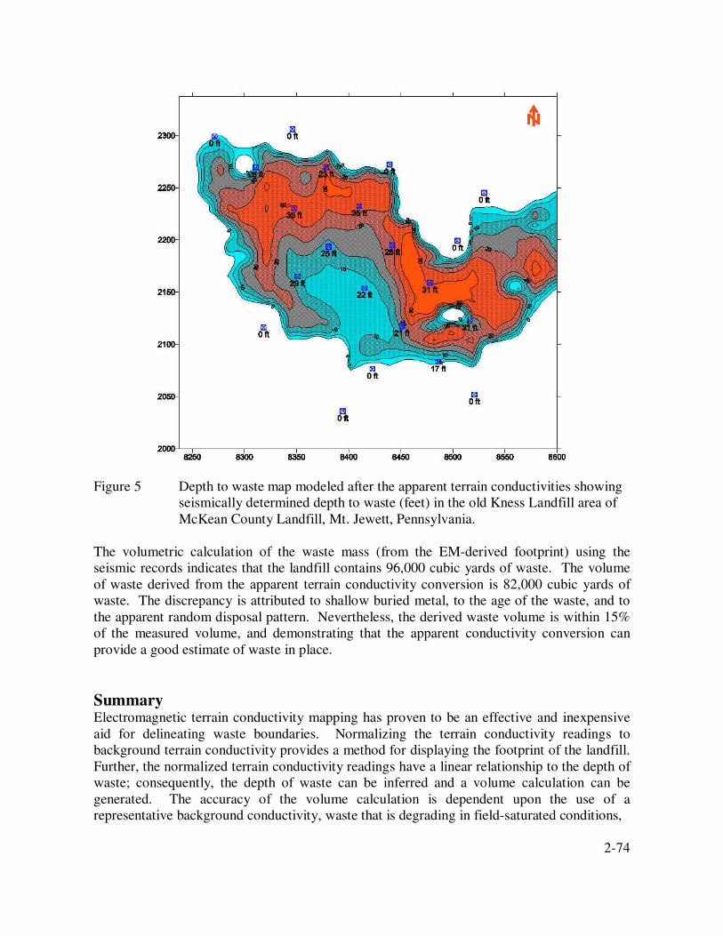
Figure 5 Depth to waste map modeled after the apparent terrain conductivities showingseismically determined depth to waste (feet) in the old Kness Landfill area ofMcKean County Landfill, Mt. Jewett, Pennsylvania.
The volumetric calculation of the waste mass (from the EM-derived footprint) using theseismic records indicates that the landfill contains 96,000 cubic yards of waste. The volumeof waste derived from the apparent terrain conductivity conversion is 82,000 cubic yards ofwaste. The discrepancy is attributed to shallow buried metal, to the age of the waste, and tothe apparent random disposal pattern. Nevertheless, the derived waste volume is within 15%of the measured volume, and demonstrating that the apparent conductivity conversion canprovide a good estimate of waste in place.
SummaryElectromagnetic terrain conductivity mapping has proven to be an effective and inexpensiveaid for delineating waste boundaries. Normalizing the terrain conductivity readings tobackground terrain conductivity provides a method for displaying the footprint of the landfill.Further, the normalized terrain conductivity readings have a linear relationship to the depth ofwaste; consequently, the depth of waste can be inferred and a volume calculation can begenerated. The accuracy of the volume calculation is dependent upon the use of arepresentative background conductivity, waste that is degrading in field-saturated conditions,
2-74

and limited cultural noise. The depth to waste measurement and the volumetric calculation ofwaste can be collected non-intrusively and inexpensively and provide the landfill operatorwith an estimate of waste-in-place to within a reasonable degree of accuracy.
2-75

ReferencesBenson, R., R. A. Glaccum and M. R. Noel. (1988). Geophysical Techniques for SensingBuried Wastes and Waste Migration. National Water Well Association Dublin, OH, 236 pp.
Fawcett, J. D. (1989). Hydrogeologic assessment, design and remediation of a shallowgroundwater contaminated zone. In, Proceedings of the Third National Outdoor ActionConference on Aquifer Restoration, Ground Water Monitoring and Geophysical Methods. ed.Pp. 591-605. National Water Well Association, Orlando.
Geonics Limited. (1994). EM31 Operating Manual (For Models With Two Digital Meters).Geonics Limited.
Grant, F. S. and G. F. West (1965) Interpretation Theory in Applied Geophysics. New York:McGraw-Hill.
Greenhouse, J. P., M. E. Monier-Williams, N. Ellert and D. D. Slaine. (1989). Paper 53,Geophysical methods in groundwater contamination studies. In, Garland, G. D., ed. Pp. 666-677. Proceedings of Exploration '87: Third Decennial International Conference onGeophysical and Geochemical Exploration for minerals and Groundwater, Queen's Printer forOntario, Toronto, Canada.
Greenhouse, J. P. and D. D. Slaine. (1983). The uses of reconnaissance electromagneticmethods to map contaminant migration. Ground Water Monitoring Review. 3: 47-59.Gretsky, P., R. Barbour and G. S. Asimenios. (1990). Geophysics, pit surveys reduceuncertainty. Pollution Engineering. 22(6): 102-108.
Hall, D. W. and D. L. Pasicznyk. (1987). Application of seismic refraction and terrainconductivity methods at a ground water pollution site in North-Central New Jersey. In, FirstNational outdoor Action Conference on Aquifer Restoration, Ground Water Monitoring andGeophysical Methods. Graves, B., J. H. Lehr, K. Butcher, P. Alcorn, L. Ammerman, P.Williams, M. Renz and V. Shelton, ed. Pp. 505-524. National Water Well Association, LasVegas, Nevada.
Heald, S. R. (1992). Peering beneath the surface. Pollution Engineering. 22(10): 44-47.
Heath, R. C. (1988). Hydrogeologic settings of regions. In, Back, W., J. S. Rosenshein and P.R. Seaber, ed. Pp. 15-23. Hydrogeology, The Geological Society of America, Boulder, CO.
Hutchinson, P. J. (1995) The geology of landfills. Environmental Geosciences: Vol 2(1): 2-14.
Jordan, T. E., D. G. Leask, D. D. Slaine, I. N. MacLeod and T. M. Dobush. (1991). The use ofhigh resolution electromagnetic methods for reconnaissance mapping of buried wastes. In,Proceedings of the Fifth National Outdoor Action Conference on Aquifer Restoration, GroundWater Monitoring and Geophysical Methods, May 13-16, 1991. ed. Pp. 846-861. Water WellJournal Publishing Co., Las Vegas, NV.
2-76

Mack, T. J. and P. E. Maus. (1986). Detection of contaminant plumes in ground water ofLong Island, New York, by electromagnetic terrain-conductivity surveys. USGS. Water-Resources Investigations. 86-4045. 39 pp.
McNeill, J. D. (1980). Electromagnetic terrain conductivity measurement at low inductionnumbers. Geonics Limited. Technical Note. TN-6. 1-15 pp.
McNeill, J. D. (1990). Use of electromagnetic methods for groundwater studies. In, Ward, S.H., ed. Pp. 191-218. Geotechnical and Environmental Geophysics, Society of ExplorationGeophysicists, Tulsa, OK.
McQuown, M. S., S. R. Becker and P. T. Miller. (1991). Subsurface characterization of alandfill using integrated geophysical techniques. In, Proceedings of the Fifth NationalOutdoor Action Conference on Aquifer Restoration, Ground Water Monitoring andGeophysical Methods, May 13-16, 1991. ed. Pp. 933-946. Water Well Journal Publishing Co.,Las Vegas, NV.
Medlin, E. and M. Knuth. (1986). Monitoring the effects of a ground water recovery systemwith EM. In, Surface and Borehole Geophysical Methods and Ground Water InstrumentationConference and Exposition. Graves, B. J., J. H. Lehr, K. Butcher, T. E. Owen and M.Mathews, ed. Pp. 368-378. National Water Well Association, Denver, CO.
Monier-Williams, M. E., J. P. Greenhouse, J. M. Mendes and N. Ellert. (1990). Terrainconductivity mapping with topographic corrections at three waste disposal sites in Brazil. In,Ward, S. H., ed. Pp. 41-55. Geotechnical and Environmental Geophysics, Society ofExploration Geophysicists, Tulsa, OK.
Olhoeft, G. R. (1986). Direct detection of hydrocarbon and organic chemicals with groundpenetrating radar and complex resistivity. In, Proc. of the NWWA/API Conf. on PetroleumHydrocarbons and Organic Chemicals in Ground Water - Prevention, Detection andRestoration. ed. Pp. 284-305. National Water Well Association, Dublin OH, Houston, TX.
Olhoeft, G. R. and T. V. V. King. (1991). Mapping subsurface organic compoundsnoninvasively by their reactions with clays. In, Proc. 4th Toxic Substances TechnicalMeeting. ed. Pp. 1-18. Monterey, CA.
Rumbaugh, J. O., III, J. A. Caldwell and S. T. Shaw. (1987). A geophysical ground watermonitoring program for a sanitary landfill: Implementation and preliminary analysis. In, FirstNational outdoor Action Conference on Aquifer Restoration, Ground Water Monitoring andGeophysical Methods. Graves, B., J. H. Lehr, K. Butcher, P. Alcorn, L. Ammerman, P.Williams, M. Renz and V. Shelton, ed. Pp. 623-641. National Water Well Association, LasVegas, Nevada.
Russell, G. M. (1990). Application of geophysical techniques for assessing groundwatercontamination near a landfill at Stuart, Florida. In, 1990 FOCUS Conference on EasternRegional Ground Water Issues. ed. Pp. 211-225. NWWA, Springfield, Mass.
2-77

Saunders, W. R. and S. A. Cox. (1987). Use of an electromagnetic Induction technique insubsurface hydrocarbon investigations. In, First National outdoor Action Conference onAquifer Restoration, Ground Water Monitoring and Geophysical Methods. Graves, B., J. H.Lehr, K. Butcher, P. Alcorn, L. Ammerman, P. Williams, M. Renz and V. Shelton, ed. Pp.585-601. National Water Well Association, Las Vegas, Nevada.
Scaife, J. E. (1990). Using geophysical techniques in environmental site assessments.Municipal & Industrial Water & Pollution Control. CXXVIII(4): 4-5.
Schutts, L. D. and D. G. Nichols. (1991). Surface geophysical definition of ground watercontamination and buried waste: Case studies of electrical conductivity and magneticapplications. In, Proceedings of the Fifth National Outdoor Action Conference on AquiferRestoration, Ground Water Monitoring and Geophysical Methods, May 13-16, 1991. ed. Pp.889-903. Water Well Journal Publishing Co., Las Vegas, NV.
Stenson, R. W. (1988). Electromagnetic data acquisition techniques for landfill investigations.In, Symposium on the Application of Geophysics to Engineering Problems. ed. Pp. 735-746.The Society of Engineering & Mineral Exploration Geophysics, Golden, CO.
Walther, E. G., A. M. Pitchford and G. R. Olhoeft. (1986). A strategy for detecting subsurfaceorganic contaminants. In, Proc. on Petroleum Hydrocarbons and Organic Chemicals inGround Water - Prevention, Detection and Restoration. ed. Pp. 357-381. National Water WellAssociation, Houston, TX.
Weber, D. D. and G. T. Flatmen. (1986). Statistical approach to groundwater contaminationmapping with electromagnetic induction: A case study. In, Surface and BoreholeGeophysical Methods and Ground Water Instrumentation Conference and Exposition. Graves,B. J., J. H. Lehr, K. Butcher, T. E. Owen and M. Mathews, ed. Pp. 315-333. National WaterWell Association, Denver, CO.
2-78