for the powered sailplane stemme s 10-v -...
TRANSCRIPT

Stemme AG – Flugplatzstrasse F2 Nr 7 - D-15344 Strausberg / Germany
A4010121_B21.doc Doc. No. A40-10-121
MAINTENANCE MANUAL
for the powered sailplane STEMME S 10-V
Document No. A40-10-121
Date of Issue: Sept. 06, 1994
This Maintenance Manual is based on the original in the German language.
Model: STEMME S 10-V Serial number: 14-
Type Certificate: EASA.A.054 (former LBA 846) Registration:
Non-standard equipment or systems with effect to the contents of this manual, if installed, are entered in the table on the next page.
Doc. print info: 104 pages total, pages in sections: 0:6, 1:1, 2:2, 3:10, 4:3, 5:7, 6:5, 7:13, 8:9, 9:3, 10:1, 11:1, 12:39, A:1, B:1, C:1

Maintenance Manual STEMME S10-V Date of Issue: Sept. 06,1994 Page: ii
Amendment No.: 0 Date:---
A4010121_B21.doc Doc. No. A40-10-121
0.1 Deviations from the Basic Maintenance Manual for the Model:
The Aircraft specified below is fitted, in accordance with the entries in the list, with equipment or systems in-stalled as an alternative to the equipment of the standard version. Resulting additional text has been included in the Maintenance Manual under the specified revision numbers; the text passages relating to the standard version have been crossed out. The necessary amendments to the text are described in further detail in the associated LBA approved Service Bulletins.
The procedure of amending the Manual in the case of installation of alternative equipment is described in fur-ther detail in Section 9.3.
The licensed inspector certifies by his signature that this Maintenance Manual complies with the data speci-fied in the following document and with the associated Aircraft.
Valid for STEMME S10-V, serial no.:
Affected Component Am. No. SB-Number Date Approval
Maintenance Manual STEMME S10-V Date of Issue: Sept. 06,1994 Page: iii-1
Amendment No.: 11 Date: Sep. 09, 2003
A4010121_B21.doc Doc. No. A40-10-121
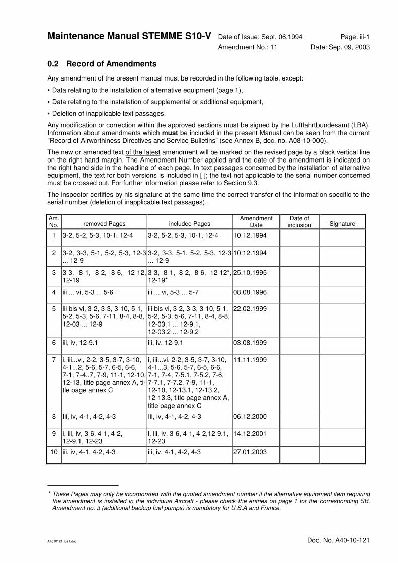
0.2 Record of Amendments
Any amendment of the present manual must be recorded in the following table, except:
• Data relating to the installation of alternative equipment (page 1),
• Data relating to the installation of supplemental or additional equipment,
• Deletion of inapplicable text passages.
Any modification or correction within the approved sections must be signed by the Luftfahrtbundesamt (LBA). Information about amendments which must be included in the present Manual can be seen from the current "Record of Airworthiness Directives and Service Bulletins" (see Annex B, doc. no. A08-10-000).
The new or amended text of the latest amendment will be marked on the revised page by a black vertical line on the right hand margin. The Amendment Number applied and the date of the amendment is indicated on the right hand side in the headline of each page. In text passages concerned by the installation of alternative equipment, the text for both versions is included in [ ]; the text not applicable to the serial number concerned must be crossed out. For further information please refer to Section 9.3.
The inspector certifies by his signature at the same time the correct transfer of the information specific to the serial number (deletion of inapplicable text passages).
Am. No. removed Pages included Pages
Amendment Date
Date of inclusion Signature
1 3-2, 5-2, 5-3, 10-1, 12-4 3-2, 5-2, 5-3, 10-1, 12-4 10.12.1994
2 3-2, 3-3, 5-1, 5-2, 5-3, 12-3 ... 12-9
3-2, 3-3, 5-1, 5-2, 5-3, 12-3 ... 12-9
10.12.1994
3 3-3, 8-1, 8-2, 8-6, 12-12, 12-19
3-3, 8-1, 8-2, 8-6, 12-12*, 12-19*
25.10.1995
4 iii ... vi, 5-3 ... 5-6 iii ... vi, 5-3 ... 5-7 08.08.1996
5 iii bis vi, 3-2, 3-3, 3-10, 5-1, 5-2, 5-3, 5-6, 7-11, 8-4, 8-8, 12-03 ... 12-9
iii bis vi, 3-2, 3-3, 3-10, 5-1, 5-2, 5-3, 5-6, 7-11, 8-4, 8-8, 12-03.1 ... 12-9.1, 12-03.2 ... 12-9.2
22.02.1999
6 iii, iv, 12-9.1 iii, iv, 12-9.1 03.08.1999
7 i, iii...vi, 2-2, 3-5, 3-7, 3-10, 4-1...2, 5-6, 5-7, 6-5, 6-6, 7-1, 7-4..7, 7-9, 11-1, 12-10, 12-13, title page annex A, ti-tle page annex C
i, iii...vi, 2-2, 3-5, 3-7, 3-10, 4-1...3, 5-6, 5-7, 6-5, 6-6, 7-1, 7-4, 7-5.1, 7-5.2, 7-6, 7-7.1, 7-7.2, 7-9, 11-1, 12-10, 12-13.1, 12-13.2, 12-13.3, title page annex A, title page annex C
11.11.1999
8 Iii, iv, 4-1, 4-2, 4-3 Iii, iv, 4-1, 4-2, 4-3 06.12.2000
9 i, iii, iv, 3-6, 4-1, 4-2, 12-9.1, 12-23
i, iii, iv, 3-6, 4-1, 4-2,12-9.1, 12-23
14.12.2001
10 iii, iv, 4-1, 4-2, 4-3 iii, iv, 4-1, 4-2, 4-3 27.01.2003
* These Pages may only be incorporated with the quoted amendment number if the alternative equipment item requiring the amendment is installed in the individual Aircraft - please check the entries on page 1 for the corresponding SB. Amendment no. 3 (additional backup fuel pumps) is mandatory for U.S.A and France.

Maintenance Manual STEMME S10-V Date of Issue: Sept. 06,1994 Page: iii-2
Amendment No.: 21 Date: Jan. 10, 2014
A4010121_B21.doc Doc. No. A40-10-121
Am. No. removed Pages included Pages
Amendment Date
Date of inclusion Signature
11 iii; iv; 4-1; 4-2; 4-3 iii-1; iii-2; 4-1; 4-2; 4-3 Sep 09. 2003
12 iii-2; iv; 4-1; 4-2; 4-3; iii-2; iv; 4-1; 4-2; 4-3; March 03. 2005
13 iii-2, iv, v, vi, 3-9, 4-1..4-3, 5-4, 5-6, 7-2, 7-8, 9-1, 9-2, 9-3
iii-2, iv, v, vi, 3-9, 4-1..4-3, 5-4, 5-6, 7-2, 7-8, 9-1, 9-2, 9-3, 9-4, 9-5
May 25. 2005
14 i, iii-2, iv, 4-1..4-3, 6-6, 7-7.2, 12-23, 12-24
i, iii-2, iv, 4-1..4-3, 6-6, 7-7.2, 12-23, 12-24
Nov 30. 2007
15 iii-2, iv, 4-1...4-3 iii-2, iv, 4-1...4-3 Nov 24. 2008
16 iii-2, iv, 4-1...4-3 iii-2, iv, 4-1...4-3
17 iii-2, iv, 5-1...5-7 iii-2, iv, 5-1...5-7 June 07. 2011
18 iii-2, iv, 4-1...4-3 iii-2, iv, 4-1...4-3 April 04. 2012
19 iii-2, iv, 4-1...4-3 iii-2, iv, 4-1...4-3 Aug 13. 2012
20 iii-2, iv, v, vi, 4-1...4-3, 5-1…5-7
iii-2, iv, v, vi, 4-1, 5-1…5-8
Oct. 15, 2012
21 iii-2, iv, 3-7, 7-9, 9-1, 9-2, 9-3, 9-4
iii-2, iv, 3-7, 7-9.1, 7-9.2, 9-1, 9-2, 9-3, 9-4
Jan. 10, 2014

Maintenance Manual STEMME S10-V Date of Issue: Sept. 06,1994 Page: iv
Amendment No.: 21 Date: Jan. 10, 2014
A4010121_B21.doc Doc. No. A40-10-121
0.3 List of Effective Pages
This record is valid for the Serial No. specified on the title page. Changes on the Maintenance Manual are in-cluded ex works if dated before production inspection. Amendments concerning alternative equipment is pro-vided only if mentioned on page 1. Following amendments must be added by hand.
Page am. no. date
i 14 30.11.2007
ii -
iii-1 11 09.09.2003
iii-2 21 10.01.2014
iv 21 10.01.2014
v 20 15.10.2012
vi 20 15.10.2012
1-1 -
2-1 -
2-2 7 11.11.1999
3-1 -
3-2 5 22.02.1999
3-3 5 22.02.1999
3-4 -
3-5 7 11.11.1999
3-6 9 14.12.2001
3-7 21 10.01.2014
3-8 -
3-9 13 25.05.2005
3-10 7 11.11.1999
4-1 20 15.10.2012
5-1 20 15.10.2012
5-2 20 15.10.2012
5-3 20 15.10.2012
5-4 20 15.10.2012
5-5 20 15.10.2012
5-6 20 15.10.2012
5-7 20 15.10.2012
5-8 20 15.10.2012
6-1 -
6-2 -
6-3 -
6-4 -
6-5 7 11.11.1999
6-6 14 30.11.2007
7-1 7 11.11.1999
7-2 13 25.05.2005
7-3 -
7-4 7 11.11.1999
Page am. no. date
7-5.1 7 11.11.1999
7-5.2 7 11.11.1999
7-6 7 11.11.1999
7-7.1 7 11.11.1999
7-7.2 14 30.11.2007
7-8 13 25.05.2005
7-9.1 21 10.01.2014
7-9.2 21 10.01.2014
7-10 -
7-11 5 22.02.1999
8-1 3 25.10.1995
8-2 3 25.10.1995
8-3 -
8-4 5 22.02.1999
8-5 -
8-6 3 25.10.1995
8-7 -
8-8 5 22.02.1999
8-9
9-1 21 10.01.2014
9-2 21 10.01.2014
9-3 21 10.01.2014
9-4 21 10.01.2014
9-5 13 25.05.2005
10-1 1 10.12.1994
11-1 7 11.11.1999
12-1 -
12-2 -
12-3.1 5 22.02.1999
12-3.2 5 22.02.1999
12-4.1 5 22.02.1999
12-4.2 5 22.02.1999
12-5.1 5 22.02.1999
12-5.2 5 22.02.1999
12-6.1 5 22.02.1999
12-6.2 5 22.02.1999
12-7.1 5 22.02.1999
12-7.2 5 22.02.1999
12-8.1 5 22.02.1999
Page am. no. date
12-8.2 5 22.02.1999
12-9.1 9 14.12.2001
12-9.2 5 22.02.1999
12-10 7 11.11.1999
12-11 -
12-12 -
12-13.1 7 11.11.1999
12-13.2 7 11.11.1999
12-13.3 7 11.11.1999
12-14 -
12-15 -
12-16 -
12-17 -
12-18 -
12-19 -
12-20 -
12-21 -
12-22 -
12-23 14 30.11.2007
12-24 14 30.11.2007
12-25 -
12-26 -
12-27 -
12-28 -
12-29 -
12-30 -
title page Annex A
7 11.11.1999
title page Annex B
-
title page Annex C
7 11.11.1999

Maintenance Manual STEMME S10-V Date of Issue Sept. 06, 1994 Page: v
Amendment No.: 20 Date: Oct. 15. 2012
A4010121_B21.doc-v/27.01.14 14:14/27.01.14 14:14 Doc. No: A40-10-121
0.4 Contents
0.1 Deviations from the Basic Maintenance Manual for the Model: ii
0.2 Record of Amendments iii
0.3 List of Effective Pages iv
0.4 Contents v
1. General Remarks on Maintenance 1-1
2. Brief Description and Technical Data 2-1
3. Description of Assemblies 3-1
3.1 Cell, Primary and Secondary Structures 3-1
3.1.1 Wing 3-1
3.1.2 Fuselage and Cockpit 3-1
3.1.3 Tail Unit 3-3
3.2 Control System 3-3
3.3 Power Plant (figure 3.3) 3-4
3.3.1 Engine 3-4
3.3.2 Fuel system (fig. 3.3.2.a) 3-4
3.3.3 Lubrication System 3-5
3.3.4 Cooling System 3-5
3.3.5 Induction System 3-5
3.3.6 Exhaust System 3-5
3.3.7 Power-Plant Controls and Instruments 3-5
3.3.8 Fire Protection 3-6
3.3.9 Engine Cowlings 3-6
3.3.10 Propeller 3-6
3.3.11 Drivetrain System 3-8
3.4 Landing Gear 3-8
3.4.1 Main Landing Gear (figure 3.4.1) 3-8
3.4.2 Tail Wheel 3-9
3.5 Flight Instruments, Pressure System (figure 3.5.a) 3-9
3.6 Electrical System (figures 3.6.a, b, c, d, e and 3.6.f) 3-9
3.7 Communication and Navigation Equipment 3-11
3.8 Oxygen Equipment 3-11
4. Airworthiness Limitations Section 4-1
5. Checks 5-1
5.1 Life-Limited Components 5-1
5.2 Pre-Flight Checks 5-1
5.3 Periodical Checks, Inspection Lists 5-1
5.4 Check Lists for Periodical Inspections 5-2
5.4.1 Wing 5-2
5.4.2 Fuselage Front Section 5-2
5.4.3 Cockpit 5-2
5.4.4 Centre Section of Fuselage 5-3
5.4.5 Tail Boom 5-4
5.4.6 Empennage 5-4
5.4.7 Powerplant - except Propeller and Drivetrain System 5-5
5.4.8 Propeller 5-6
5.4.9 Drivetrain System 5-6
5.4.10 Main Landing Gear 5-7
5.4.11 Tail Wheel 5-7
5.4.12 Flight Instruments and Pressure System 5-7
5.4.13 Electrical System 5-7
5.4.14 Radio and Navigation Equipment 5-7
5.4.15 Oxygen System 5-8
5.4.16 Completition works 5-8

Maintenance Manual STEMME S10-V Date of Issue Sept. 06, 1994 Page: vi
Amendment No.: 20 Date: Oct. 15. 2012
A4010121_B21.doc-vi/27.01.14 14:14/27.01.14 14:14 Doc. No: A40-10-121
5.5 Special Inspections 5-8
5.5.1 Inspection following an Impact Landing or a Wing Tip Landing 5-8
5.5.2 Inspection following an Impact to the rotating Propeller 5-8
6. Maintenance Instructions, Tolerances, Adjustment Data for the Aircraft 6-1 6.1 General Information 6-1
6.2 Ground Towing, Supporting Points, and Lifting of Aircraft 6-1
6.3 Determination of the Empty Weight and Corresponding Centre of Gravity; Information on Weight Limits 6-1
6.4 Control System 6-4
6.4.1 Deflection of Control Surfaces, Control System Friction, and Pilot Forces 6-4
6.4.2 Masses and Moments of the Control Surfaces 6-4
6.4.3 Slackness of Control System Bearings 6-5
6.5 Lubrication Chart 6-5
6.6 Tightening Moments for Screw Joints 6-5
7. Maintenance Instructions, Tolerances, Adjustment Data for Assemblies / Equipment 7-1 7.1 Airframe 7-1
7.1.1 Wing 7-1
7.1.2 Fuselage and Cockpit 7-1
7.1.3 Tail Unit 7-2
7.2 Control System 7-2
7.3 Powerplant 7-2
7.3.1 Engine 7-2
7.3.2 Fuel System 7-2
7.3.3 Oil System 7-3
7.3.4 Cooling System 7-3
7.3.5 Induction System 7-3
7.3.6 Controls/Instruments 7-3
7.3.7 Fire Protection 7-3
7.3.8 Engine Cowlings 7-3
7.3.9 Propeller 7-3
7.3.10 Drivetrain System 7-7
7.4 Landing Gear 7-8
7.4.1 Main Landing Gear 7-8
7.4.2 Tail Wheel 7-10
7.5 Flight Control Instruments and Pitot and Static Pressure System 7-10
7.6 Electrical System 7-10
7.7 Radio and Navigation Equipment 7-11
7.8 Oxygen Equipment 7-11
8. List of cockpit placards and their position 8-1
9. Equipment 9-1 9.1 Minimum Equipment List 9-1
9.2 Supplementary Equipment 9-2
9.3 Additional Equipment and Systems 9-2
9.3.1 Alternative Equipment 9-2
9.3.2 Additional Equipment 9-3
9.3.3 Optional Equipment 9-5
10. List of Special Tools 10-1
11. List of Maintenance Documents for Parts Approved Independently from the Aircraft 11-1
12. Figures referring to the previous Sections 12-1
Annex A: Supplementary Instructions for Maintenance and Care, Maintenance Instructions
Annex B: Service Bulletins, Airworthiness Directives
Annex C: Documents (Inspection and Operation Reports)

Maintenance Manual STEMME S 10-V Date of Issue: Sept. 06, 1994 Page 1-1
Amendment: - Date: -
A4010121_B21.doc-1-1/27.01.14 14:14/27.01.14 14:14 Doc. No: A40-10-121
1. General Remarks on Maintenance
The legal owner of the powered glider STEMME S10-V is obliged to ensure that, according to the specific na-tional laws and regulations, the maintenance of the Aircraft follows the instructions of this manual. Among others, there are
• checks and inspections,
• adjustments,
• exchange of fluids and lubricants,
• exchange of parts after expiry of their service life,
• minor repairs.
All maintenance work must be documented.
The manufacturer has to be informed immediately in the case of any change of ownership. The message must be confirmed by the manufacturer, so that all information concerning airworthiness can be given to the legal owner.
For maintenance work the following documents are relevant:
1. This Maintenance Manual for the powered glider STEMME S10-V,
2. The "Operating and Maintenance Manual Limbach L 2400 and Series",
3. The "Flight Manual for the powered glider STEMME S10-V",
4. Maintenance instructions for the "L'Hotellier" ball and swivel joints (in Annex to this Maintenance Manual),
5. Manufacturer's documents referring to the equipment listed in the equipment list of the corresponding S/N.
The amount of maintenance work depends on the utilisation of the Aircraft, the climate, airfield conditions, storing facilities and other factors, irrespective of the periodic checks. Under sandy operating condition, e.g., it might be necessary to clean all filters before any operation. In coastal or rainy regions attention has to be paid on the conservation of the Aircraft. The instructions in this manual are valid for normal conditions and use.
Use only spare parts from the manufacturer or according to his requirements.
In the case of any incident endangering airworthiness the manufacturer must be informed immediately.
Maintenance work must be carried out by qualified personnel.
For the conversion of technical data the following factors have been used:
1 lb. 0.4536 kg 1 lbf ft 1.356 Nm
1 dr. 1.772 g 1 hp 0.7457 kW
1lbf =1 lb.(wt) 4.45 N 1 kts 1.852 km/h
1in. 25.4 mm 1 mph 1.609 km/h
1ft. 0.3048 m 1 U.S.gal. 3.785 l
1 sqft. 0.0929 m2 1 p.s.i. 0.06895 bar
The translation of the text and the conversion of technical data are according to our best knowledge and judgement, however, the original version in German is authoritative.

Maintenance Manual STEMME S10-V Date of Issue: Sept. 06, 1994 Page 2-1
Amendment: - Date: -
A4010121_B21.doc-2-1/27.01.14 14:14/27.01.14 14:14 Doc. No: A40-10-121
2. Brief Description and Technical Data
The STEMME S10-V is a twin-seat high performance powered sailplane with an innovative propulsion con-cept and a sophisticated aerodynamic design. The wing is a carbon fibre reinforced composite design. The fuselage is manufactured as a hybrid construction (carbon, kevlar, glass) with an extremely rigid steel tube framework in the centre of force introduction. The seats are arranged side by side and equipped with dual controls.
The wing is attached to the fuselage in the upper third section of the fuselage behind the cockpit. The wing consists of a one-part central wing equipped with flaps and Schempp-Hirth air brakes as well as two outboard wings with continuous ailerons.
The tail unit is designed as a T-tail.
The two-leg landing gear is electrically extended and retracted and is equipped with hydraulic disc brakes. The tail wheel is steered with the pedals.
The engine is located in the fuselage in a central steel tube framework near the aeroplane centre of gravity. The engine power is transmitted via a composite material shaft and a transmission gear unit to a foldable propeller in the fuselage nose. The electrically operated variable pitch propeller is folded in soaring flight and is covered by the retractable nose cone (propeller dome).
One fuel tank is located in each outboard area of the central wing.
Technical Data (general drawing figure 2.a)
Wing
wing span 23.00 m 75.5 ft.
central wing span 9.90 m 32.5 ft.
wing area 18.74 m² 201.7 sqft.
aspect ratio 28.22
dihedral angle 0.75°
sweep of central wing leading edge 0°
sweep of outboard wing leading edge up to the bend 0°
airfoil: laminar profile HQ41/14.35
Air Brakes (two-storied Schempp-Hirth air brakes on wing upper side only)
length 1.50 m 59 in.
area 0.22 m² 2.37 sqft.
maximum height above wing upper side 0.16 m 6.3 in.
Wing Flaps
span 4.39 m 14.4 ft.
area 0.75 m² 8.07 sqft.
flap positions: - 10°
- 5°
0°
+ 5°
+ 10°
(L) + 16°
Ailerons
span 5.80 m 19 ft.
area 0.68 m² 7.32 sqft.
Fuselage
length 8.42 m 27.6 ft.
width 1.18 m 3.9 ft.
clear cockpit width 1.16 m 3.8 ft.
clear cockpit height 0.93 m 3.1 ft.
height at tail unit 1.75 m 5.7 ft.

Maintenance Manual STEMME S10-V Date of Issue: Sept. 06, 1994 Page 2-2
Amendmen No.: 7 Date: Nov. 11, 1999
A4010121_B21.doc-2-2/27.01.14 14:14/27.01.14 14:14 Doc. No: A40-10-121
Vertical Tail
height 1.60 m 5.2 ft.
total area 1.51 m² 16.25 sqft.
area of rudder 0.52 m² 5.60 sqft.
airfoil FX 71-L-150/35
Horizontal Tail
span 3.10 m 10.2 ft.
total area 1.46 m² 15.72 sqft.
area of elevator 0.36 m² 3.88 sqft.
aspect ratio 6,58
airfoil FX 71-L-150/25
Landing Gear
2 main wheels with brake discs/ rim of wheel 127x127-30
tire size (standard / wide tire): 5.00-5 / 6.00-5
wheel track (standard / wide tire) 1.15 m / 1.16m 3.77 ft. / 3.8 ft
tail wheel (steerable), tire size 210 x 65
wheel base 5.46 m 17.9 ft.
Power-Plant
engine Limbach L 2400 EB 1.D or Limbach L 2400 EB 1.AD1
take-off power (3400 rpm) 69 kW 92.5 hp
gear transmission ratio i=1.18
Variable-pitch Propeller
specification STEMME 10 AP-V
diameter extracted DPA 1.61 m 63.4 in
retracted DPE 0.647 m 25.47 in
Weight of the propeller mP 9350 g 20.61 lb
overall Weight of the propeller blade mB 650 g ± 10 g 1.433±0.022 lbs
(incl. outer-casing of the needle bearing and rubber buffers)
max. propeller RPM nP 2881 min-1
propeller pitch take-off position βP -3.3°
cruise position βP +3.1° max. current consumption of the resistor element Imax 10 A
Weights (see also figure 6.3.)
maximum allowable Weight 850 kg 1874 lb.
empty Weight 640 kg 1411 lb.
maximum Weight of non-structural parts 570 kg 1257 lb.
total useful load (occupants, fuel, baggage) 210 kg 463 lb.
Ballast: For pilot Weights between 121 and 154 lb. (55 and 70 kg; including parachute), the defined Ballast Weight of 13.2 lb. (6 kg) must be attached to the right-hand rudder pedal support.
For distribution of the useful load, please refer to the weight and balance sheet in the Flight Manual. The empty weight stated does not include any additional equipment. The total useful load will be reduced depend-ing on equipment.
In-flight Centre-of-Gravity Range
10 in. to 16.5 in. (254 to 420 mm) aft of datum (central wing leading edge, see form weight report, fig. 6.3.a)
For further technical data, please refer to the Flight Manual.
1 please refer to Limbach Service Bulletin no. 17 for change of engine type designation
Maintenance Manual STEMME S10-V Date of Issue: Sept. 06, 1994 Page 3-1
Amendment No.: - Date: -
A4010121_B21.doc-3-1/27.01.14 14:14/27.01.14 14:14 Doc. No: A40-10-121
3. Description of Assemblies
3.1 Cell, Primary and Secondary Structures
The primary structure includes:
• wing spars, root ribs, and wing spar boxes
• wing shells
• central fuselage framework
• tail boom and vertical stabiliser
• front section of fuselage
• horizontal stabiliser
• fittings
The secondary structure includes:
• control surfaces
• cowlings, cooling air system ducts, cockpit components
3.1.1 Wing
Structural design: Carbon fibre reinforced plastic (CFRP) sandwich shell, CFRP spars.
Three wing sections: central wing with a span of 32.5 ft. (9.90 m), two outboard wing sections with a span of 21.5 ft. (6.55 m) each. Attachment to the fuselage by means of four sliding bolts, attachment central wing to outboard wings with one sliding bolt each.
For disassembly, the wing has to be lifted vertically. Removable cowling to cover the wing/fuselage attach-ment. Beneath the cowling, free access to the wing attachment, control system joints and the combined ai-leron/flap controls.
Flaps over the total span of the central wing, ailerons over the total span of outboard wings. Articulation of flaps and ailerons on the lower side. Symmetrical and asymmetrical cross connection of flap and aileron con-trols.
Two-storied Schempp-Hirth air brakes on wing upper side.
Flaps and ailerons slots are sealed with elastic adhesive tape and skid layer on the wing upper side and with textile tape on the lower side. A boundary layer turbulator (adhesive 60° zigzag tape, leading edge at 69% of chord, 12 x 0.5 mm / 0.47 x 0.02 in.) on the wing lower side ensures a defined flow transition (special equip-ment).
3.1.2 Fuselage and Cockpit
Modular construction of three assemblies with bolted joints: front section of fuselage (CFP-aramid-glass con-struction), central fuselage framework with cowlings, tail boom (CFP construction).
The loads from the fuselage front section, wing, landing gear, power-plant and tail unit are introduced into the central fuselage framework.
Cockpit: Two seats arranged side by side. Console between the seats. Seat backs adjustable step by step, dual controls.
One-piece canopy hinged at the front and held in opened position by gas springs. Three locks on both sides to be operated by one locking lever on each side; "Röger"-hook on the rear/top. Emergency jettisoning: Open both locking levers and pull T-shaped handle for emergency opening (red, on the instrument panel). The canopy hinge opens and the canopy is lifted by means of a gas spring by approximately 4 in. (100 mm). The Röger hook must remain closed, since it is the axis of rotation until the canopy is jettisoned.
Cockpit ventilation via nozzle in the instrument panel, canopy ventilation via openings in the canopy frame.
Instrument board with three separate panels.
Two four-point harnesses with central locks.

Maintenance Manual STEMME S10-V Date of Issue: Sept. 06, 1994 Page 3-2
Amendment No.: 5 Date: Feb. 22, 1999
A4010121_B21.doc-3-2/27.01.14 14:14/27.01.14 14:14 Doc. No: A40-10-121
3.1.3 Tail Unit
Horizontal Tail
T-arrangement.
stabiliser as sandwich construction of CFRP, elevator made of CFRP.
elevator slot sealed by elastic tape.
Boundary layer turbulator (adhesive 60° zigzag tape , leading edge at 65% of chord, 12 x 0.5 mm / 0.47 x 0.02 in.) on upper and lower side for defined flow transition.
Vertical Tail
Stabiliser as a sandwich construction of CFP, rudder as a sandwich construction of GFP.
rudder slot sealed by elastic tape with integrated zigzag turbulator (combi-tape).
integrated COM antenna in the rudder.
3.2 Control System
Pitch Control (figure 3.2.a)
Both control sticks are coupled by a connection tube. The control movements are transmitted via push-pull rods to the end of the tail boom and then straight up to the elevator fitting. In the tail boom, the push-pull rod is supported by linear motion ball bearings. The (adjustable) longitudinal control stops are in the middle of the connection tube beneath the right control system cover in the cockpit.
Pitch Trim (figure 3.2.a)
The powered sailplane is trimmed by means of an adjustable spring system in the cockpit, acting upon the connection tube of the longitudinal control.
Wing Flap Control System (figures 3.2.b and 3.2.c)
Both flap control levers are coupled by a torsional connecting tube. Control inputs are transmitted from this torsional connecting tube via push-pull rods to a "mixing shaft" in the central fuselage. From this "mixing shaft", the control inputs are transmitted via bellcranks, push-pull rods and quick release couplings (up to Se-rial No. 14-003 or 14-055 M: L´Hotellier connectors) to the control rods in the wing. The control rods in the wing are supported by means of linear motion ball bearings. Control movement is transmitted to the flap drive fittings via bell cranks.
From Serial No. 14-004 or 14-056 M and if SB A31-10-015 has been carried out: At the flap mounted flap drive of the mixer unit, the wing flap control system is supported by a gas spring against the central fuselage framework. This is to prevent force loads on the flap lever at flap settings according to the optimum speed range. At the same time, intermittent loads are kept away from the flap lever and the click-stop device by the viscosity damping of the gas spring in both directions. Flap positions are set in a gate for the drive lever of the connection tube in the cockpit.
Lateral Control (figures 3.2.d and 3.2.e)
The control sticks are cross-connected beneath the torsional connecting tube of the longitudinal control to a bell-crank in the centre. From the bellcrank, the control input is transmitted via push-pull rods to the "mixing shaft" in the central fuselage. Via this "mixing shaft", bell-crank levers, push-pull rods and quick release cou-plings (up to Serial No. 14-003 or 14-055 M: L´Hotellier connectors), the control rods in the wing are moved. Both sides of the central wing contain a straight-through control rod supported by several linear motion ball bearings and equipped with a further quick release coupling at the attachment of the central wing to the out-board wings. From the push-pull rods in the outboard wing, the control movement is transmitted via two bell-crank levers to the drive fittings of the ailerons.
By means of the "mixing shaft", the ailerons are moved together with flap position changes and the flaps are moved together with aileron deflections. The percentage of co-movement depends on the position of the con-trol surfaces. The lateral control stops (adjustment screws) are located in the cockpit beneath the covers of the control system well, on the elevator connection tube at the left and right side.
Maintenance Manual STEMME S10-V Date of Issue: Sept. 06, 1994 Page 3-3
Amendment No.: 5 Date: Feb. 22, 1999
A4010121_B21.doc-3-3/27.01.14 14:14/27.01.14 14:14 Doc. No: A40-10-121
Operation of Air Brakes (figures 3.2.f and 3.2.g)
The hand-levers to operate the air brakes are coupled by means of a connection tube. Travel of the levers is transmitted via push-pull rods and bell-cranks to a driving lever (elbow lever) in the centre fuselage, from which it is transmitted via push-pull rods and quick release couplings (up to Serial No. 14-003 or 14-055 M: L´Hotellier connectors) to push-pull rods in the wing, which then move the air brakes. The push-pull rods in the wing are supported by linear motion ball bearings.
The fully retracted position of the airbrakes is barred by an adjustable over-centre-locking of the driving lever. The stop for the fully extended position of the air brakes is at the driving lever in the centre fuselage.
Directional Control (figure 3.2.h)
From the left and the right rudder pedal support, the control cables are led through the central fuselage to the tail boom entrance. At this point, the control cables of the left pedals and the right pedals meet to be directed further to the rudder driving lever. From the rudder driving lever, the tail wheel is steered via a spring connec-tion. The directional control stops are mounted on the lower rudder support, the pertinent adjustment screws are located at the rudder on the drive fitting.
3.3 Power Plant (figure 3.3)
3.3.1 Engine
Type: Limbach L 2400 EB1.D or L 2400 EB1.AD (please refer to Limbach SB no. 17 for change of engine type designation).
Engine Description: please refer to Engine Operating and Maintenance Manual "Limbach L 2400 and models"
Forward Engine Mount: by means of a separate steel tube beam in vibration absorbing elements in the forward lateral framework junctions
Rear Engine Mount: at the rear engine flange on top by means of two vibration absorbing elements on the upper transversal tube of the framework.
3.3.2 Fuel system (fig. 3.3.2.a)
The powered sailplane is equipped with two independent fuel systems connected to each other only beyond the fuel pumps and each supplying fuel to both carburettors in parallel. Each system comprises a fuel shut-off valve, a water trap, a coarse filter and a fine filter. [An optional backup system (required for export to USA and France) consists of two additional electrically driven fuel pumps, each piped in parallel to the respective main pump. Both backup pumps are switched with a mutual switch]
3a. General view: figures 3.3.2.a (piping)
and 3.6.c (wiring). One fuel tank is installed in each outboard area of the central wing between spar and lead-ing edge. The fuel tanks are made of a hybrid laminate. To ensure long-time resistance, the internal surfaces of the tanks are coated with a fuel-resistant protection film "Scotch Clad 776" (3M Company; MIL-D-1795-B).
The fuel is supplied from the tank through a pipe of relatively large cross section to the central wing root. At this point, a finger strainer combined with a flexible hose fitting is installed. From this flexible hose fitting, the fuel line - equipped with a fine filter - is conducted to the water separator. A flexible hose of 0.4 in. (10 mm) internal diameter leading to the drainer in the wheel well serves as a water trap. The fuel line is directed from the water separator via the associated shut-off valve to the fuel pumps. Beyond those, both systems are cross-connected and then piped on to the distribution line of the carburettors. The main pump of the left hand fuel system is mechanically driven from the engine (and located on it), the right hand system is provided with an electrically driven main pump.

Maintenance Manual STEMME S10-V Date of Issue: Sept. 06, 1994 Page 3-4
Amendment No.: - Date: -
A4010121_B21.doc-3-4/27.01.14 14:14/27.01.14 14:14 Doc. No: A40-10-121
The fuel tank vent is located close to the filler cap . From this point, an aluminium tube Ø 8 x 1 mm is in-stalled over a length of 5.25 ft. (1.60 m) towards the fuselage and then back to the wing attachment point. The fuel tank vent discharges on the wing lower side at the attachment. The discharge opening is tapered by 45° towards flight direction (thus ramming intake).
3.3.3 Lubrication System
A thermostat-controlled oil cooler (switching point 176°F / 80°C) is installed in the main oil flow of the engine. The oil cooler is located on the left side of the central fuselage framework. The connection to the fittings on the engine is achieved by means of flexible hoses with metal reinforcement and a fire-resistant sheathing.
3.3.4 Cooling System
The engine is cooled by ram air. The air inlets are to the left and to the right side of the central fuselage cowl-ings. From these inlets, the cooling air flows directly to the cylinder heads. A minor portion of the cooling air is blown into the engine compartment through several openings. On the left side of the central fuselage cowling, the cooling air duct is continued to the oil cooler. The cooling air outlet is located in the lower cowling of the central fuselage. Both inlet flaps and the waste air flap are synchronously operated by means of bowden ca-bles, which are directed into the cockpit and attached to a bell-crank in the left leg room (behind the cover). This bell-crank which closes the flaps is actuated together with the propeller dome control. All three flaps are opened by means of springs attached to the flaps when the propeller dome is opened, corresponding to the release of the bell-crank.
In order to prevent rapid cooling of the engine during high cruising speeds, the aperture angle of the air inlet flaps can be reduced by means of a lever within the cockpit. Three reduction settings are available, whereby the middle step would normally be chosen. The other two steps are provided for extreme variations in tem-perature. It is not possible, to close the flap completely during powered flight. The reduction mechanism is connected to the operation of the propeller dome; closing the dome also closes the air inlet flaps under all cir-cumstances, and they return to the last setting when the dome is re-opened. Both mechanisms are coupled by means of a bell crank situated within the left foot well which is operated alternately by the propeller-dome mechanism as well as the air inlet operating lever.
3.3.5 Induction System
The screens of the engine induction system are mounted on the firewall. The air is supplied through air inlets at the upper end of the vertical stabiliser, through the tail boom and air inlets in the front and central areas of the fuselage. From the induction system screens, the air is supplied through a spiral hose duct to the carbu-rettors.
3.3.6 Exhaust System
The arrangement of the exhaust system can be seen from the general view figure 3.3:
The exhaust manifolds are directed beneath the engine with slight lateral displacement rearwards to a muf-fler. Drip pans are installed beneath the carburettors in order to collect possible fuel leakage and to divert leaking fuel around the exhaust manifold. The exhaust gases discharge from the muffler directly down through the lower engine cowling.
The whole exhaust system is made of corrosion resistant steel. It is attached exclusively to the engine.
3.3.7 Power-Plant Controls and Instruments
Power and choke are controlled via bowden cables led from the carburettors over the engine to the central console in the cockpit. Operation from the cockpit is achieved by means of a lever with adjustable friction.
The cowl flaps are moved simultaneously with the lever for opening and closing the propeller dome.
The power-plant instruments are located on the right face of the instrument panel.

Maintenance Manual STEMME S10-V Date of Issue: Sept. 06, 1994 Page 3-5
Amendment No.: 7 Date: Nov. 11, 1999
A4010121_B21.doc-3-5/27.01.14 14:14/27.01.14 14:14 Doc. No: A40-10-121
3.3.8 Fire Protection
To the front, upwards and rearwards, the engine including the exhaust system and the induction system (ex-cept for induction system screens) is separated by means of a fire-wall from the remaining parts of the pow-ered sailplane. The firewall is made of corrosion resistant steel sheet of .01 in. (0,38 mm) thickness.
The engine compartment is enclosed at the sides and below by the engine cowlings. The internal surfaces of the cowlings are treated with a fire protection coating.
3.3.9 Engine Cowlings
The engine cowling is formed by the lateral and the lower parts of the central fuselage cowling. The cowlings are connected to each other and to the fuselage front section and to the tail boom by means of Camlock snap fasteners.
3.3.10 Propeller (fig. 3.3.10, 3.3.11 and 3.3.12)
General
The articulated propeller consists of a central part and two propeller blades hinged to this central unit. The ar-ticulation axle is aligned so that the propeller blades are movable in the plane of rotation of the propeller. When the propeller is not running, the blades are folded inwards by means of springs. The central part of the propeller is manufactured from high tempered aluminium. The propeller blades are manufactured from car-bon, kevlar and laminated glass.
When the engine is started, the blades unfold automatically by centrifugal force. Soft rubber stops protect the blades in case of possible overswing. The final folding position of the propeller blades is also cushioned by rubber stops (buffers). The propeller blades may be retracted in any conceivable setting within the range of pitch.
In the folded position, the propeller dome (the nose cone) can be retracted so that there is no longer a gap between the nose cone and the fuselage. The propeller is then completely enclosed within the contours of the fuselage, thereby achieving optimum performance in soaring flight. Folding is conducted automatically by springs when the propeller is stopped.
Propeller pitch changes are effected electrically. Two settings are provided: take-off setting (fine-pitch) and cruise setting (course pitch). When the propeller is in the take-off setting, the take-off indicator lights up green.
Construction of the Variable Pitch Propeller
The numerical positions in the following text refer to illustration A 10-10AP-V (see figure 3.3.10 and 3.3.11).
The propeller blades (1) are hinged in a forked mounting plate (4). The complete assembly, consisting of the fork, blade and hub, is rotated in order to set the pitch-angle of the blade.
The hollow axle (3) houses the rotating spring (23) to fold the blade. The drive train to the blade is directed via a claw lever (22) that fits into the aperture in the propeller blade which takes the buffer-stop.
Electrically heated expanding servo-elements (15) actuate the pitch change mechanism. On achieving their activating temperature, these expanding servo elements drive a piston that in turn changes the propeller pitch.
The elements actuating the pitch change are double redundant and are connected mechanically by a cou-pling ring (12) so that both propeller blades achieve an identical change in pitch.
Propeller blades
The propeller blades are manufactured from FRP (fibre reinforced plastic) material in a twin shell construc-tion. The shells are of hybrid laminate type (glass, carbon, aramid). PU-tape is affixed to the leading edges for further protection against debris.
Regulation of pressure is achieved by connecting all the cavities in each blade by 1 mm Ø apertures in the tips of the blades. These apertures also serve to drain the cavities within the blades of condensed moisture by centrifugal force.

Maintenance Manual STEMME S10-V Date of Issue: Sept. 06, 1994 Page 3-6
Amendment No.: 9 Date: Dec. 14, 2001
A4010121_B21.doc-3-6/27.01.14 14:14/27.01.14 14:14 Doc. No: A40-10-121
Variable Pitch Mechanism
When disconnected from the power supply (in the unheated condition), the piston of the servo element (15) is pressed inwards by the swing arm (14) compressing the spring (20). Thereby moving the propeller blade into the take-off setting via the pushrod (13), the synchronising ring (12) and the connector (11).
Heating the servo-elements by passing current through the heating coil (16) exerts pressure on the piston that forces the swing-arm/pushrod system in the almost fully extended position, thus rotating the propeller blade against the spring towards a courser pitch. With increasing revolutions, the fly-weight (19) produces in-creasing force in the same direction. There are no circumstances under which the force of the fly-weight alone exerts the counteractive force of the spring and the aerodynamic restoring moment. In the case of heating element failure, the start position of the propeller is achieved automatically under all operating condi-tions.
The transmission of pitch changes to the fork is effected by the drive pin (10) which is attached to the fork by a cam-gear to ensure high accuracy of the propeller blade pitch angle setting of both blades.
The serviceable setting range of the servo-elements is 0.476 in. (12.1.mm). The stop setting is adjusted so that the piston is fully retracted. The limit for the end position stop switch is 6.4º. A mechanical stop is ad-
justed so that only minimal override of the end position switch setting is possible (<0.1º). The piston travel caused by the two-point control system causes minimal but unavoidable changes in the propeller blade pitch angle because of the gear ratio. This has no influence on the propeller behaviour.
The blade hinges are equipped with needle bearings.
The expansion Element and Control System
The expansion element is heated electrically; cooling is achieved by convection and heat dissipation. The electric current is transferred to the propeller by a sliding ring contact ring . The expansion elements operate only in the single direction, towards high pitch angles. The propeller blades are rotated in the direction of small pitch angles by the return spring at the lever mechanism as well as by the Weight and aerodynamic forces on the blades.
When the propeller switch in the cockpit is turned to the cruise setting, the expansion elements are heated with an application of about 50 Watts (assuming that the engine is running and the landing gear is retracted). The elements are heated to a temperature of 55º C, which is where the working stroke begins. As soon as the end position stop switch reaches its final position, the heating current to both elements is switched off. The propeller then is in the cruise setting and is held in this position by a two-point control system. If the pro-peller switch is set to take-off position, the heating current is switched off and the expansion elements are al-lowed to cool down.
By providing dual functions and alternative combinations for all the important elements, the control system is fully redundant.
Heat insulation of the operating elements is optimised in so far as the time for a full change of pitch in either direction will not exceed 5 minutes under any operating conditions (from idle to full power) at a specific exter-nal air temperature of -30º C to +38º C. The typical time for a full change of pitch is about 2´30´´.
The supply of electrical current to the propeller is disconnected (pitch setting for take-off) when the propeller is set to take-off or when the landing-gear switch is set to “Off“ or when the propeller dome handle is unlocked. Thus, it is ensured that the propeller is always in the correct setting for take-off, whatever the set-ting of the propeller switch may be. When the landing-gear is extended in preparation for landing, the propel-ler is set appropriately in the “Take-off“ position for an emergency touch and go. The end stop switch also disconnects the complete electricity supply to the engine and the to the propeller when the propeller dome is closed so that electricity is not dissipated when soaring.
In order to check the pitch range mechanism, a push-button that can be operated from outside is provided on the right hand side (in flight direction) of the gear frame. This button connects the battery power, when master switch is on, directly to the propeller sliding contact rings so that the expansion elements are heated and the propeller is brought into the cruise setting. When the cruise setting is achieved, the stop switch disconnects the electrical current to the heating elements. For this check, the push-button must be activated for about 3 to 4 minutes to heat the expansion elements. On releasing the push-button, the elements cool down and the propeller returns in the start position.

Maintenance Manual STEMME S10-V Date of Issue: Sept. 06, 1994 Page 3-7
Amendment No.: 21 Date: Jan. 10, 2014
A4010121_B21.doc-3-7/27.01.14 14:14/27.01.14 14:14 Doc. No: A40-10-121
Identification of the Propeller System and its Sub-Assemblies
Propeller (complete assembly): 10 AP-V / XXXXX / YYYY
Propeller blade: 10 AP-VB / XXXXX - ZZ
X: Order number of the production batch (corresponds to the manufac-turer’s number for the complete propeller assembly)
Y: Month and year of manufacture, four digits.
Z: Production batch serial number, two digits.
3.3.11 Drivetrain System
The drivetrain comprises:
• Clutch on the engine side: a force transmitting clutch operated by direction and speed. In addition, the clutch has integrated positive elements to allow torsional and angular flexibility as well as longitudinal flexibility. Since the clutch transmits the torque by friction, it simultaneously serves as an overload protec-tion.
• Drive shaft is manufactured in carbon fibre reinforced composite material.
• Flexible coupling on transmission gear side: flexible coupling with elastic angular and torsional flexibility. Lateral flexibility is eliminated by means of a centring bearing.
• Transmission unit: one-stage quintuple high performance V-belt transmission unit with maintenance-free sealed bearings. The belt pulleys are subjected to a special hard anodising process. The transmission unit is supported in the foremost fuselage frame by four mounts with non-linear characteristics for vibration absorption.
3.4 Landing Gear
3.4.1 Main Landing Gear (figure 3.4.1)
Left and right landing gear legs each supported by two sleeve bearings at the front and rear in the central fu-selage framework, swivel axis in flight direction. Trailing arms hinged with sleeve bearings in the legs. Elas-tomere spring bars in the rear tube of the leg.
Retraction and extension with one electric spindle drive for each side. Retraction: in succession - first the left landing gear leg, then the right one together with the gear door, and then the left gear door. Extension: first the left gear door, then the right landing gear leg including gear door, and then the left leg.
The gear-down position is locked by radius struts. Retraction and extension by means of electric spindle drives, one each side. Electric stop switches for "gear down" position: on the corresponding strut. Electric stop switches for "gear up" position: at the front of the wheel well on the corresponding side. Indication of "gear down" position by one green LED (light emitting diode) each for the left and the right gear leg on the right face of the instrument panel. During extension and retraction of the landing gear legs, the cor-responding LED blinks red. With the landing gear in the retracted position, the diodes extinguish and the posi-tion of the spindle drives is fixed by means of blocking brakes of the spindle drive motors. The brakes are locked by springs and released electrically during operation of the spindle drives.
The wheel well is covered by two landing gear doors; the right-hand door is coupled via a spring element di-rectly to the right gear leg. The left-hand door is closed via the right landing gear as well, operated by a bow-den cable and a radius strut during the last part of the retraction sequence.
Electric landing gear warning: acoustic warning activated by switches on the air brakes control shaft beneath the left stick cover.
The disk brakes on the main L/G wheels are operated hydraulically. The main cylinder for both the left and right wheel is located on the LH control stick, on RH stick optional. The pressure line from the main brake cyl-inder to the brake callipers of the wheel brake in the center fuselage are designed as metal-shielded brake hoses. The brake fluid reservoir is located in the landing-gear bay, cabin rear wall. The parking brake valve to set and to release the parking brake is located on the floor panel console in front of the LH control stick. The parking brake valve is operated by a lever respectively rotary handle. The brake action is simultaneously on both main wheels. Maximum brake pressure for the system layout is 115 bar / 1668 psi, maximum allowed system pressure is 200 bar / 2900 psi. Only for hydromechanical Brake System: The master cylinder for both the left and right wheel is located in the wheel well at the front wall (pressure line to the wheel cylinders by short metal tube, T-type distributor and metal-shielded brake hoses). The connection to the hand operating lever on the left stick (right stick optional) is made by a bowden cable, adjustable at the master cylinder. The hand lever can be locked in the operated position for use as a parking brake.

Maintenance Manual STEMME S10-V Date of Issue: Sept. 06, 1994 Page 3-8
Amendment No.: - Date: -
A4010121_B21.doc-3-8/27.01.14 14:14/27.01.14 14:14 Doc. No: A40-10-121
Main Landing Gear Emergency Extension
Mechanical emergency extension system: By operating two pulls, the connection of the electric landing gear spindle drive to the operating arm is successively released via bowden cables. The landing gear legs extend by gravity to the "gear down" position. The operating arms are pressed into the locked position by means of spring clips. For operation, the mentioned sequence must be followed: right gear leg first, then the left gear leg. The right landing gear leg is equipped with a mechanism in order to prevent the legs from getting stuck in case of incorrect operation (i.e. left leg first).
3.4.2 Tail Wheel
Tail wheel is steerable with the rudder pedals and is connected to the rudder by springs.
3.5 Flight Instruments, Pressure System (figure 3.5.a)
Instruments: see equipment list.
The pitot pressure, the static pressure and the total energy compensation are measured by means of a bar probe in the propeller dome. The ducts are directed to the instrument panel. The static pressure measured by the bar probe may not be used for the airspeed indicator!
In addition, static pressure is measured primarily for the airspeed indicating system on both sides of the tail boom. This duct is also directed to the instrument panel. All ducts are equipped with water traps/filters.
3.6 Electrical System (figures 3.6.a, b, c, d, e and 3.6.f)
The electrical system is supplied by a main battery and a generator. The main battery is installed within the front end of the tail-boom (behind the engine).
The capacity of the 12V main battery is 35Ah or 26Ah, depending on the Aircraft equipment. The generator is rated at 55A or 33A at 12V, depending on the Aircraft equipment installed. The relevant equipment is listed in the equipment list of the specific Aircraft.
An auxiliary 12V battery with a capacity of 6.5Ah is optional and normally installed in the upper vertical tail. Access is obtained by removing the horizontal stabiliser. Depending upon weight and balance, and also upon the specific manufacturer’s Serial No., this battery may also be installed within the left foot well. The auxiliary battery is intended to power the avionics, especially during soaring flight. If the main fuse is triggered, the avi-onics bus is automatically connected to the auxiliary battery, if installed.
All current circuits and electric instruments are protected by circuit breakers. The primary circuits are pro-tected by safety fuses, situated under the instrument panel cover. The maximum Ampere rating of the pri-mary circuits is 30A.
Master Switch: cuts all current sources from the main bus. In case of failure of the main current circuit, the avionic instruments are automatically switched over to the auxiliary bat-tery (if installed).
Subordinate Switches:
Engine Master Switch Switches all engine components ON or OFF (starter, propeller, variable pitch mechanism, engine instruments, etc.). This switch is coupled to the propeller dome lock and is automatically (involuntarily) activated when the propeller dome lever is in the inserted position and is then pressed downwards (locked - ON) or is pulled upwards (unlocked - OFF).
Engine Emergency Switch: Overrides the Engine Master Switch and hence enables the engine to be re-started during flight in the event of an Engine Master Switch failure. The Engine Emergency Switch is fitted with a mechanical safety catch.
CAUTION: With the Engine Emergency Switch ON and the propeller dome CLOSED never operate the starter. Otherwise, the dome and possi-bly the propeller blade tips may be damaged.
Maintenance Manual STEMME S10-V Date of Issue: Sept. 06, 1994 Page 3-9
Amendment No.: 13 Date: May 25. 2005
A4010121_B21.doc-3-9/27.01.14 14:14/27.01.14 14:14 Doc. No: A40-10-121
Starter: Push-button for the electric starter. This switch is locked if the ignition is turned on before the starter is activated. After each unsuccessful attempt to start the engine, the ignition must be switched off first, before the starter can be re-activated.
Ignition: ON / OFF.
The ignition switch connects the Aircraft electrical ground with the magnetos. This is independent of the Master Switch or the Engine Master Switch. When the ignition is switched ON, the starter solenoid circuit is disconnected by a secondary switch level in order to prevent damage to the engine and propeller in the event of incor-rect starting procedures.
Propeller Variable Pitch: TAKE OFF / CRUISE
The cruise setting leads to variable power consumption. The propeller is discon-nected from the electric power source in the TAKE OFF setting of when the landing gear is not retracted, the propeller blades then rotate in the take-off setting. The take-off setting of the propeller blades (not the switch position!) is indicated by a green light under the switch as soon as the Master Switch and the Engine Master Switches are ON.
Avionics: to switch "ON" / "OFF" all flight and navigation instruments electrically energised. During operation of the starter, the avionics are switched off or switched over to the auxiliary battery (if installed).
Avionics supply: Connects the avionics bus to the auxiliary battery instead of the main battery. The following settings are recommended:
-Powered flight: setting: Main battery
-Soaring flight: setting: Auxiliary battery
Landing gear switch: Upper position: gear up
Lower position: gear down
Centre position: Circuit disconnected from electrical system.
ACL (optional): ON / OFF - only active when the Engine Master Switch is positioned ON
(Anti-Collision Light, ACL).
Position lights (optional): ON / OFF - only active when the Engine Master Switch is positioned ON.
Auxiliary Battery (optional)
Location: In the upper part of the vertical fin or in the left-hand foot-well.
Utilisation: Preferably during soaring flight to avoid inadvertently depleting the main battery while soaring and to ensure sufficient capacity of the main battery to re-start the engine.
Switch Positions: The switch AVIONICS SUPPLY switches from the Main to the Auxiliary battery. Alterna-tively, automatic switch-over during starter operation or when the main circuit breaker trig-gers.
Charging: By the generator during powered flight. Charging via the external plug only charges the main battery; the auxiliary battery must be charged separately via a direct charger connec-tion (max. charge voltage is 14.7V).
CAUTION: If the auxiliary battery is removed (but registered in the Equipment List), airworthiness is lost due to changes in Weight and Balance. The Aircraft cannot be operated until the Equipment List and Weight and Balance have been corrected.

Maintenance Manual STEMME S10-V Date of Issue: Sept. 06, 1994 Page 3-10
Amendment No.: 9 Date: Dec. 14, 2001
A4010121_B21.doc-3-10/27.01.14 14:14/27.01.14 14:14 Doc. No: A40-10-121
3.7 Communication and Navigation Equipment
The mid part of the instrument panel is designed to house the avionics. Without additional certification, Equipment may only be installed if listed in the Minimum-, Supplementary or Additional Parts Lists in Sec-tion 9 of this manual and certified in association to the STEMME S10. Changes of the equipment may only be done using the original wiring kits and following the installation instructions of the airframe manufacturer. This is also relevant for equipment approved for operation in powered sailplanes or equipment without certification requirements due to possible influence on power consumption, electromagnetic influence and structural characteristics of the instrument panel.
Any installation of equipment in the instrument panel has to comply with the Weight limits (without structural alteration max. 22 lbs (10 kg) additionally to the engine control instruments). The equipment list has to be changed accordingly, the changes in c.g. have to be investigated and documented in an updated Weight and Balance Report.
The loudspeaker is installed at the cockpit backwall above the left baggage compartment. The flexible micro-phone is installed at the middle console between the backrests. This microphone may be switched off for head-set operation to reduce motor noise transmission.
Locations of the antennas:
• The VHF radio antenna is installed in the rudder.
• The VOR-antenna is installed on the cockpit floor (aramid shell).
• The transponder antenna is installed in the forward part of the tail boom or at the propeller dome.
3.8 Oxygen Equipment
One or maximum two oxygen system mountings (optional equipment) for one oxygen bottle each are in-stalled in the upper baggage compartment. The mountings are suitable for oxygen bottles from various manufacturers, provided the diameter is within a minimum of 132 mm / 5.2 in. and the total length including regulator is approx. 450 mm / 17.7 in. through a maximum of 520 mm / 20.5 in..
The certification of the powered glider does not include a certain oxygen system and fulfilment of the re-quirements must be demonstrated to the authority by the supplier or the facility, which modified the a/c (nor-mally as a modification of a single a/c).

Maintenance Manual STEMME S10-V Date of Issue: Sept. 06, 1994 page: 5-1
Amendment No.: 20 Date: Oct. 15. 2012
A4010121_B21.doc-5-1/27.01.14 14:14/27.01.14 14:14 Doc. No: A40-10-121
5. Time Limits / Maintenance Checks
Inspections, preventive maintenance work and repairs must be carried out by qualified personnel. In any case, the specific national laws and regulations are obligatory.
In the USA, the provisions of FAR 43 must be observed. After the Annual Inspection, the Aircraft must be ap-proved for return to service by a person who is authorised according to FAR 43 and 65. Major repairs, major alterations and rebuilding (as provided by FAR 43) must be performed and approved for return to service by appropriately rated mechanics or maintenance organisations.
5.1 Life-limited Components
For Life limited parts refer to the Airworthiness Limitations section of the manufacturer documentation (appli-cable Maintenance Manual, Service Bulletin etc.) for permissible service life limits prescribed by the respec-tive manufacturer. These items must be entered in the form Review of Operating times.
5.2 Pre- Flight Checks
See Flight Manual.
5.3 Periodical Checks, Inspection Lists
The intervals for general maintenance tasks depend on operating conditions, climate, hangarage, etc. Not-withstanding the conditions mentioned above, at least the following periodical checks must be performed:
• Type 1a after the first 25 operating hours
• Type 1b after the first 50 operating hours and every further 50 operating hours
• Type 2 after the first 100 operating hours and every further 100 operating hours
• Type 3 annually
The items to be checked are given in the following "Check List for Periodical Inspection". A detailed descrip-tion of maintenance procedures, adjustment data, tolerances etc. may be found in section 6 (for details of the complete Aircraft) and section 7 (for specific assemblies).
In addition, special inspections which may be prescribed by the manufacturer or by the Airworthiness Author-ity must be performed in accordance with the issued directives (i. g. SB or AD).
Unscheduled Maintenance for propeller assembly, engine drive section and reduction gear components:
An unscheduled overhaul or replacement additional to expiration of the stated time limit is necessary in each case of:
• Impact stop (possible ground touch of the propeller);
• Non- observance of the periodical inspections as they are fixed in the Maintenance Manual,
In case of damaging by ground contact, bird strike, stone strike or similar which require a „large repair“, the manufacturer decides which parts of the complete drive system are affected and if a repair may be practica-ble or if an overhaul or replacement has to be performed.

Maintenance Manual STEMME S10-V Date of Issue: Sept. 06, 1994 page: 5-2
Amendment No.: 20 Date: Oct. 15. 2012
A4010121_B21.doc-5-2/27.01.14 14:14/27.01.14 14:14 Doc. No: A40-10-121
5.4 Check Lists for Periodical Inspections
CAUTION: Read maintenance instructions (sections 6 & 7) before carrying out adjustments
Inspection Type
Type and Subject of Inspection
Typ
e 1
a
Typ
e 1
b
Typ
e 2
Typ
e 3
5.4.1 Wing
1. Check surface for damage and cracks, look out for signs of hidden structural damage, check registration marks, renew if necessary.
X X
2. Check drain and vent outlets. X X
3. At the wing roots: inspect tank fitting for proper sealing, check plug-in connec-tion of fuel gauge.
X X
4. Inspect function of tank ventilation, proper sealing of filler caps, check wing for signs of fuel escaped from the tanks
X X X
5. Inspect wing fittings, grease slightly, check play, check locks of wing attach-ment bolts
X X X
6. Check flap and aileron bearings for correct play, function and corrosion, clear-ances between components and clearance between components and wing spanwise 0.12± 0.02 in. (3 ± 0.5 mm). Check upper and lower gap sealings.
X
7. Check all control rods and bearings in the area of the wing root; check quick release couplings - is the spring cotter fastened unlooseable to the quick re-lease coupling? Up to Serial No. 14-003 or 14-55 M: Check and maintenance of the L´Hotellier connectors according manufacturer’s instructions (Annex A).
X X X
8. Check and maintenance of the L´Hotellier connectors of the aileron push rods at the inner-to-outer wing attachments according manufacturer’s instructions (Annex A). Is the spring cotter fastened unlooseable to the connector?
X X X
9. Remove the fairings on the flap and aileron link rods and inspect the bell-cranks in the wing for tight fit of all screw joints, cracks, deformation and other defects. Use an endoscope or an inspection mirror.
X X
10. From Serial No. 14-004 or 14-056 M on: Check swaged terminals of all control rods for embrittlement or incipient cracks (longitudinal and peripheral direc-tion). Checked all fork ends for cracks, especially in the fork-root/cheek blend-ing area.
X X
11. Inspect air brakes for correct retracted position and ease of operation, check screw joints for tight fit.
X X
5.4.2 Fuselage Front Section
1. Inspect surface for damage and cracks, look out for signs of hidden structural damage; check fuselage, especially lower surface for damage caused by stone impact.
X X
2. Check static pressure ports. X X X
3. Propeller dome locking: check function, check safe locking specially in pow-ered flight position (the propeller dome lever has to be fully engaged for starter circuit connection by the switch installed in the locking system).
X X X X
4. Check condition of propeller dome push tube; play perpendicular to the flight direction must be less than 0.12 in. (3 mm) (at the dome tip)
X X
5.4.3 Cockpit
1. Inspect the canopy for damage and proper functioning of the locking mechanism. Grease in case of stiff operation.
X X X
2. Emergency jettisoning system: functional check. The compressed gas spring must have a minimum strength of 34 lbf (150 N).
X
3. Check lateral gas springs for proper operation: canopy must remain in the opened position.
X
4. Inspect safety harnesses and their attachment points. X

Maintenance Manual STEMME S10-V Date of Issue: Sept. 06, 1994 page: 5-3
Amendment No.: 20 Date: Oct. 15. 2012
A4010121_B21.doc-5-3/27.01.14 14:14/27.01.14 14:14 Doc. No: A40-10-121
Inspection Type
Type and Subject of Inspection
Typ
e 1
a
Typ
e 1
b
Typ
e 2
Typ
e 3
5. Check movement and neutral position of the control sticks. Check operation of all control surfaces, including flaps, air brakes and trim controls. In any case of jamming within the range of operation, the reason has to be investigated and eliminated. From Serial No. 14-004 or 14-056 M and if SB A31-10-015 has been carried out: Counterforce at the flap lever in "L" position must be 28 ± 6 lbf (125 ± 25 N), damping must be perceivable in both directions.
X X X
6. Remove left and right hand control system covers, check for foreign objects. Check proper condition of bearings and all joints for tight fit. Inspect rods and bell-cranks for damage, incipient cracks and deformation.
X X
7. From Serial No. 14-004 or 14-056 M: Check swaged terminals of all control rods for embrittlement or incipient cracks (longitudinal and peripheral direc-tion). Checked all fork ends for cracks, especially in the fork-root/cheek blend-ing area.
X X
8. Inspect condition and attachment of instruments, switches, circuit breakers, fuses and wiring.
X X X X
9. Flexible hoses of ventilation, heating and instruments: Check condition and in-stallation.
X X
10. Inspect humidity/dust filters in the instrument hose system and replace if nec-essary.
X
11. Inspect rudder pedals and cables, check adjustment mechanism. X X X
12. Seats: check condition, attachment and adjustment mechanism. X X X
13. Check condition of battery(ies), connections, and installation X
14. Functional check of propeller brake and propeller positioning system. X X X
5.4.4 Centre Section of Fuselage
1. Inspect central fuselage framework for damage, corrosion and chafe marks. X
2. Check condition of framework / tailboom attachment points and tight fit of screw joints.
X
3. Check condition of lower attachment points framework / front fuselage section and tight fit of screw joints.
X
4. Inspect all control rods and levers in the central fuselage for tight fit of all joints, proper condition of the bearings, damage, scratches and deformation.
X X X
5. From Serial No. 14-004 or 14-056 M and if SB A31-10-015 has been carried out: Ensure perfect condition of flap relief gas spring and tight fit at the hinge points.
X X
6. Check condition, fit and locks of middle section cowlings. X X X

Maintenance Manual STEMME S10-V Date of Issue: Sept. 06, 1994 page: 5-4
Amendment No.: 20 Date: Oct. 15. 2012
A4010121_B21.doc-5-4/27.01.14 14:14/27.01.14 14:14 Doc. No: A40-10-121
Type and Subject of Inspection
Inspection Type
Typ
e 1
a
Typ
e 1
b
Typ
e 2
Typ
e 3
5.4.5 Tail Boom
1. Inspect surface for damage and cracks, look out for signs of hidden structural damage, check lower surface for damage caused by stone impact, check reg-istration marks and renew if necessary, check drain outlets.
X X
2. Check static pressure ports and flexible hoses from the tail boom via the cen-tral fuselage to the cockpit
X X X
3. Check elevator bell-cranks positioned at the foot of the vertical fin via both in-spection hatches with an endoscope to ascertain tight fit of all connections as well as damage, scratches and deformation.
X
4. From Serial No. 14-004 or 14-056 M: Check swaged terminals of all control rods for embrittlement or incipient cracks (longitudinal and peripheral direc-tion). Checked all fork ends for cracks, especially in the fork-root/cheek blend-ing area.
X X
5. Check joints of the rudder control cables at the beginning of the tail boom. X X
5.4.6 Empennage
1. Check vertical stabiliser and rudder surface for damage and cracks, look out for signs of hidden structural damage, check nationality and registration marks (renew if necessary), check drain outlets
X X
2. Inspect rudder supports for firm attachment, check especially the lower support for cracks and deformation. Check play of the hinges. Check split pin lock.
X X X
3. Inspect connection of the antenna cable (rudder, bottom) X
4. Check rudder cables and their attachment X X X
5. Check rudder stops, especially for unobstructed rudder deflection in case of tail wheel blockage.
X X X
6. Check horizontal stabiliser front fitting for sufficient spring tension and ease of operation of the lock bolt. Inspect for fatigue cracks and corrosion.
X X X
7. Inspect Horizontal Stabiliser rear fitting for wear of pins/bushings, fatigue cracks (especially in the vicinity of welding and cut-outs in the fixing plates), ax-ial and radial clearance, corrosion.
X X X
8. Check tight fit of all bolt connections of both HS fittings. X X
9. Check bolt connection of elevator push-pull rod to rear HS fitting. X X X
10. Check HS fittings for slackness after attaching the HS (section 7.1.3). X X
11. Inspect HS and elevator for damage and cracks, look out for signs of hidden structural damage. Check drain outlets.
X X
12. Check deflection of rudder and elevator (for Control Surface adjustment data, see section 12)
X

Maintenance Manual STEMME S10-V Date of Issue: Sept. 06, 1994 page: 5-5
Amendment No.: 20 Date: Oct. 15. 2012
A4010121_B21.doc-5-5/27.01.14 14:14/27.01.14 14:14 Doc. No: A40-10-121
Type and Subject of Inspection
Inspection Type
Typ
e 1
a
Typ
e 1
b
Typ
e 2
Typ
e 3
5.4.7 Powerplant - except Propeller and Drivetrain System
The hours given in this list are engine operating hours.
Caution: In excess of the inspections listed below, the instructions of the engine manufacturer given in the Engine Operating and Maintenance Manual are mandatory. LIMBACH pre-scribes an additional periodical engine check after every 25 operating hours.
1. Check engine mounting X X
2. Check fuel lines and fittings for leak tightness (fuel leakage) X X X
3. Check conditions of fuel lines (in particular cracks in the outer surface) X X X
4. Check function of the electric fuel pumps. X X
5. Exchange fine filters, clean coarse filters (in tank connector at the wing root; open clamp on wing side and remove finger strainer)
X X
6. Inspect oil lines, fire protection hose and fittings to oil cooler and engine for leaks, improper condition (consider service life limit) and looseness. Check sealing cuff at the left cowling to the oil cooler for proper sealing.
X X X
7. Check proper function and settings of air inlet flaps, controlled via cowl flap lever. Settings approx. 2, 2.8, 3.5 in. (5, 7, 9 cm). The flaps must not jam and fully opened position must be reached safely. Sealing cuff of the cooling air ducts in the side cowling must be in contact with the cooling air box of the en-gine
X X X X
8. Inspect flexible hose between the air filters and the carburettors for proper condition and tight fit.
X X X
9. Check the exhaust system for sealing, cracks and correct attachment X X
10. Throttle/choke control: make sure that the extreme positions in the carburettors are achieved. Check attachment of control cables and bowden cable casings. Check condition of return springs on the carburettors.
X X X
11. Functional check of engine instruments X X X
12. Check fire wall steel sheets for proper condition and tight fit. X X X

Maintenance Manual STEMME S10-V Date of Issue: Sept. 06, 1994 page: 5-6
Amendment No.: 20 Date: Oct. 15. 2012
A4010121_B21.doc-5-6/27.01.14 14:14/27.01.14 14:14 Doc. No: A40-10-121
Inspection Type
Type and Subject of Inspection
Typ
e 1
a
Typ
e 1
b
Typ
e 2
Typ
e 3
5.4.8 Propeller
The hours given in this list are engine operating hours.
1. Visual inspection of load bearing elements (hub and forks, blade suspension) for cracks, corrosion and other damage.
X X X X
2. Check of the complete propeller assembly with respect to loose parts, loose bolt connections or other apparent damage.
X X X X
3. Check rubber stops within the blades and on the hub for cracks. X X X X
4. Visual inspection of the propeller blades for cracks or other damage, especially at the tips of the blades, at the bonding seam and in the vicinity of the stop buffer. Repair leading edge protection tape if necessary (use material supplied by the manufacturer only!)
X X X X
5. Check initial tension in the spring of the propeller folding mechanism. X X X X
6. Check the propeller blade ventilation and water drain apertures for possible blockage.
X X X X
7. Check propeller blade pitch adjustment in the take-off and cruise configuration. Check respective setting of both blades and check for discrepancies.
X X X
8. Operational check of the pitch change mechanism, using the push-button on the gear strut (Master switch on!); check pitch change time in both directions.
X X X X
9. Operational check of the take-off position indicator light and check pre setting before reaching take-off position.
X X X X
10. Check setting and sufficient tension of the carbon brushes, replace if neces-sary. Check for excessive abrasion (copper dust); clean sliding rings with alco-hol.
X X X X
5.4.9 Drivetrain System
The hours given in this list are engine operating hours.
1. Clutch on engine side: check for tight fit on engine flange, check thickness of clutch linings: at least 0.08 in. (2 mm).
X X X
2. Check function of clutch (turn the propeller by hand: smooth movement in the normal running direction, more roughly to the opposite)
X X X
3. Inspect torsionally flexible couplings (rubber elements) for tight fit, embrittle-ment and cracks in the rubber
X X X
4. Check the splined sliding joint for tight fit. Observe section 6.5. X X X
5. Propeller brake: check thickness of brake band lining: at least 0.06 in. (1.5 mm). Check smooth operation of the actuation mechanism.
X X
6. Check condition and tension of V-belts: For each belt, press-in depth 0.15 in. (3.7 mm) with a press-down force of 11.2 lbf. (50 N) applied half-way between the axes. If necessary, adjust V-belts and fit new safety lock wire.
X X X X
7. Check tight fit and securing of gearbox suspension. Check shockmounts for proper condition - rubber material must be free of embrittlement.
X X X
8. Check transmission gear bearings for running noise and lubricant leakage (turn the propeller by hand).
X X X

Maintenance Manual STEMME S10-V Date of Issue: Sept. 06, 1994 page: 5-7
Amendment No.: 20 Date: Oct. 15. 2012
A4010121_B21.doc-5-7/27.01.14 14:14/27.01.14 14:14 Doc. No: A40-10-121
Inspection Type
Type and Subject of Inspection
Typ
e 1
a
Typ
e 1
b
Typ
e 2
Typ
e 3
5.4.10 Main Landing Gear
1. Inspect the main landing gear legs and trailing arms for deformation and pos-sible cracks as an result of overloads
X X X X
2. Check the linear actuators for external damages. X X X
3. Inspect the screw joint of the complete landing gear X X X
4. Check main landing gear tires for poor condition and creep markings. Tire
pressure: [45 - 48 p.s.i. (3.1 - 3.3 bar)] 5s
[36 - 39 p.s.i. (2.5 - 2.7 bar), if optional
wide tires installed] 5a
X X X X
5. Functional check of trailing arm spring suspension. X X
6. Wheel bearings: check for ease of operation and play. X X X
7. Inspect brake master and wheel cylinders. Check hoses and tubes for proper guidance, chafe marks and leakage.
X X X
8. Inspect brake discs and brake linings (at least 0.06 in. / 1.5 mm). X X
9. Check brake fluid level (replace fluid once in two years). X X X
10. Check efficiency of brakes, adjust break or vent break system if required. X X X X
11. Clean and grease hinges of landing gear doors. X X
12. Functional check of the landing gear (support the Aircraft on trestles); check stop switches, fit of gear doors, bowden cables for emergency release and the release mechanism on the brace strut.
X X X
13. Inspect the operating mechanism of the LH landing gear door, including bow-den cable, for improper operation and poor condition.
X X X
14. Check landing gear position indicator and warning system X X X X
15. Functional check of landing gear Emergency Extension Mechanism X
5.4.11 Tail Wheel
1. Check tail wheel unit for ease of operation and play. X X
2. Check condition of tire, pressure (40.6±2.9 p.s.i. / 2.8±0.2 bars) and creep markings.
X X X X
3. Inspect wheel fork, including bearing. X X X
4. Check spring coupling between tail wheel and rudder. X X X
5.4.12 Flight Instruments and Pressure System
1. Check condition and function - if applicable service life limits - of the flight con-trol instruments (see Equipment List)
X
2. Check adjustment of the stall warning every second Type 3 inspection X
5.4.13 Electrical System
1. Inspect wiring and conduits for improper routing, insecure mounting and obvi-ous defects of electric components.
X
2. Inspect condition of main battery (among others voltage drop during starter op-eration).
X
5.4.14 Radio and Navigation Equipment
1. Inspect radio and navigation equipment for improper installation and insecure mounting (observe equipment list). Check service life limits if applicable.
X
2. Check each antenna installed X
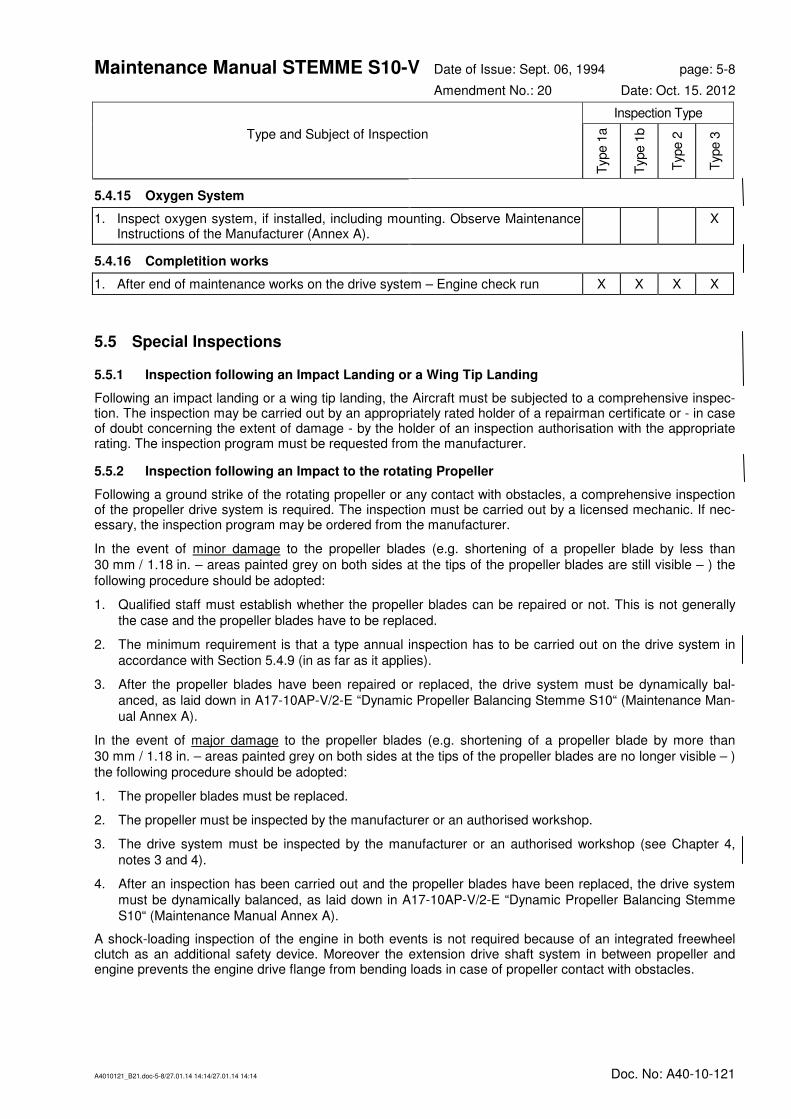
Maintenance Manual STEMME S10-V Date of Issue: Sept. 06, 1994 page: 5-8
Amendment No.: 20 Date: Oct. 15. 2012
A4010121_B21.doc-5-8/27.01.14 14:14/27.01.14 14:14 Doc. No: A40-10-121
Inspection Type
Type and Subject of Inspection
Typ
e 1
a
Typ
e 1
b
Typ
e 2
Typ
e 3
5.4.15 Oxygen System
1. Inspect oxygen system, if installed, including mounting. Observe Maintenance Instructions of the Manufacturer (Annex A).
X
5.4.16 Completition works
1. After end of maintenance works on the drive system – Engine check run X X X X
5.5 Special Inspections
5.5.1 Inspection following an Impact Landing or a Wing Tip Landing
Following an impact landing or a wing tip landing, the Aircraft must be subjected to a comprehensive inspec-tion. The inspection may be carried out by an appropriately rated holder of a repairman certificate or - in case of doubt concerning the extent of damage - by the holder of an inspection authorisation with the appropriate rating. The inspection program must be requested from the manufacturer.
5.5.2 Inspection following an Impact to the rotating Propeller
Following a ground strike of the rotating propeller or any contact with obstacles, a comprehensive inspection of the propeller drive system is required. The inspection must be carried out by a licensed mechanic. If nec-essary, the inspection program may be ordered from the manufacturer.
In the event of minor damage to the propeller blades (e.g. shortening of a propeller blade by less than 30 mm / 1.18 in. – areas painted grey on both sides at the tips of the propeller blades are still visible – ) the following procedure should be adopted:
1. Qualified staff must establish whether the propeller blades can be repaired or not. This is not generally the case and the propeller blades have to be replaced.
2. The minimum requirement is that a type annual inspection has to be carried out on the drive system in accordance with Section 5.4.9 (in as far as it applies).
3. After the propeller blades have been repaired or replaced, the drive system must be dynamically bal-anced, as laid down in A17-10AP-V/2-E “Dynamic Propeller Balancing Stemme S10“ (Maintenance Man-ual Annex A).
In the event of major damage to the propeller blades (e.g. shortening of a propeller blade by more than 30 mm / 1.18 in. – areas painted grey on both sides at the tips of the propeller blades are no longer visible – ) the following procedure should be adopted:
1. The propeller blades must be replaced.
2. The propeller must be inspected by the manufacturer or an authorised workshop.
3. The drive system must be inspected by the manufacturer or an authorised workshop (see Chapter 4, notes 3 and 4).
4. After an inspection has been carried out and the propeller blades have been replaced, the drive system must be dynamically balanced, as laid down in A17-10AP-V/2-E “Dynamic Propeller Balancing Stemme S10“ (Maintenance Manual Annex A).
A shock-loading inspection of the engine in both events is not required because of an integrated freewheel clutch as an additional safety device. Moreover the extension drive shaft system in between propeller and engine prevents the engine drive flange from bending loads in case of propeller contact with obstacles.

Maintenance Manual STEMME S10-V Date of Issue: Sept. 06, 1994 page: 6-1
Amendment No.: - Date: -
A4010121_B21.doc-6-1/27.01.14 14:14/27.01.14 14:14 Doc. No: A40-10-121
6. Maintenance Instructions, Tolerances, Adjustment Data for the Aircraft
6.1 General Information
-
6.2 Ground Towing, Supporting Points, and Lifting of Aircraft
The Aircraft may only be towed in flight direction, since the tail wheel runs in a castering fork, the lateral de-flection of which is limited to 30° in both directi ons.
For ground towing, two ropes of textile material of at least 33 ft. (10 m) each are needed. They must be at-tached to the front struts of the main landing gear at the lowest possible points (pay attention to the hydraulic brake hoses!). The cockpit must be manned with an instructed person. The Aircraft must be towed at walking pace.
For manoeuvring on the ground, the manufacturer offers a tail wheel dolly. In exceptional cases, the Aircraft may be pushed backwards over a short distance without a tail wheel dolly, if the rudder is directed.
The supporting points to lift the whole Aircraft are situated on the wing lower sides under the wing spar at a distance of approximately 3.3 ft. (1 m) from the fuselage (the position of the wing spar must be determined by light tapping). If supported at the tail wheel, the fuselage rear end must be lifted approximately 1.6 ft. (0.5 m).
The wing must be supported over an area of at least 8 in. x 12 in. (200 x 300 mm, the longer side in direction of the wing span). A plywood sheet of 2 in. (50 mm) thickness with a felt layer of 0.6 to 0.8 in. (15 to 20 mm) thickness or adequate material must be used. The support under the plywood sheet centre must be flexible so that the wing rests evenly upon the plywood sheet.
The stands must be capable of reliably carrying the Aircraft weight and be sufficiently stable. The under-wing support must be non-skid.
CAUTION: Ensure that the wing stands are evenly lifted and correctly positioned, since otherwise the wing shell and spar will be deformed or even destroyed.
Lowering the Aircraft must be performed evenly; during both lifting and lowering, the wing chord should al-ways remain in a nearly horizontal position.
The fuselage with the wing removed may be supported as follows:
• either in a felt-lined, fitted rigid tray of a width of 40 in. (1 m) and a length of 16 in. (0.4 m). directly in front of the landing gear doors
• or by removing the front wing attachment bolts and replacing them by round bars of St 37 (soft steel) or similar, Ø 0.78 ±.004 in. (19.8 ± 0.1mm), length 12 in. (300 mm). The bars must be inserted 6 in. (150 mm) and must be locked against displacement.
6.3 Determination of the Empty Weight and Corresponding Centre of Gravity; Information on Weight Limits
This section provides procedures to determine a/c empty weight, component weights and CG at empty weight and the certified weight and CG limits. To perform the inspection, the STEMME form "Weight and Balance Report" (for form refer to section 12, fig. 6.3.a/b) should be used. Procedure and formula to deter-mine CG from weighed data are stated in the form.
The list of verified equipment, on which weighing was based, must be entered in the weight and balance re-port and must correspond to the list in the inspection report. Any inspection documentation can be found in Annex C of this Maintenance Manual.

Maintenance Manual STEMME S10-V Date of Issue: Sept. 06, 1994 page: 6-2
Amendment No.: - Date: -
A4010121_B21.doc-6-2/27.01.14 14:14/27.01.14 14:14 Doc. No: A40-10-121
CAUTION: Amended data of empty weight, maximum load or minimum load must be entered in the
"Weight and Balance Report / Permitted Payload Range" in section 6.2 of the Flight Man-
ual and confirmed by an authorised inspector before operating the powered glider. In ad-
dition, the placard on the centre console in the cockpit must be corrected accordingly.
Definitions: Reference datum is the plane, that is touching the leading edge of the centre wing and is
perpendicular to the upper edge of a wedge, measuring 1.000 : 84, (4°50') on the tail cone.
Following items and fluids must be included when determining empty weight and CG:
Aircraft Logbook, Flight Manual, seat cushions and backrests with cushions or equivalent upholstery, standard tool-kit (baggage compartment behind backrest), 3.5 l / 0.92 US gal / 0.77 imp.gal of engine oil, and unusable fuel in wing tanks (3 l / 0.79 US gal / 0.66 imp.gal). For positions and other limiting conditions refer to the "Weight and Balance Report" (Fig. 6.3.a/b).
Following an a/c repair, painting or modification of equipment, it always must be checked, if component weights, empty weight and CG at empty weight are still within certified limits. If weight and arm of removed or installed equipment is known exactly, change of empty weight and CG can be calculated. For calculation of empty weight CG, the arm of removed or installed equipment or components is to be entered into the Weight and Balance Report. Formula:
xm x m x m x
mneu
alt alt zus zus zus zus
neu
=⋅ + ⋅ + ⋅ + ⋅ ⋅⋅
1 1 2 2
Herein, malt and xalt are empty weight and CG at empty weight, respectively, according to last weighing re-port, mzus and xzus weight and arms of added components with ref. to Datum, mneu and xneu the resulting new total empty weight and new total empty CG. Minimum load due to the modification can be taken from the fol-lowing figure.
CAUTION: Basically the arms of weights in front of the Datum must be counted negative, those aft of the
Datum positive for any calculations.
If the effect of a modification or repair cannot be calculated (e. g. when having painted or following a repair of the composite-structure) the a/c must be weighed again.
To keep empty weight CG for unchanged minimum load within certified limits, it may be necessary to install ballast at the front gear frame or at the aft part of the tail wheel bay (rear web of fin). The required weight of the ballast can be calculated:
m mx x
x xBallast alt
neu alt
Ballast neu
=−
−,
where malt and xalt are empty weight and CG prior to the modification, xneu the target for CG at empty weight and xBallast the arm of the ballast weight (in front or aft of RP). It must be observed, that the maximum weight which can be installed at the rear web of the vertical fin is structurally limited to 2.7 kg / 5.95 lbs.
This procedure may be used also to position the CG for good soaring performance at high payload in the cockpit. Following this a higher minimum cockpit load must be taken into account and a reinforcement of the rear web of the vertical fin may be required.
If a revision proved the a/c to be "tail-heavy“, the minimum load mP, min for an unchanged empty weight mleer and CG position xleer can alternatively be determined by following formula:
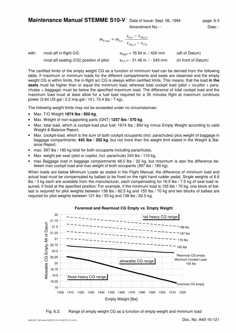
Maintenance Manual STEMME S10-V Date of Issue: Sept. 06, 1994 page: 6-3
Amendment No.: - Date: -
A4010121_B21.doc-6-3/27.01.14 14:14/27.01.14 14:14 Doc. No: A40-10-121
m mx x
x xP leer
leer flug h
flug h P h
,min
,
, ,
= ⋅−
−
with: most aft in-flight CG: xflug,h = 16.54 in. / 420 mm (aft of Datum)
most aft seating (CG) position of pilot: xP,h = - 21.46 in. / - 545 mm (in front of Datum)
The certified limits of the empty weight CG as a function of minimum load can be derived from the following table. If maximum or minimum loads for the different compartments and seats are observed and the empty weight CG is within limits, the in-flight a/c CG is always within certified limits. This means, that the load in the
seats must be higher than or equal the minimum load, whereas total cockpit load (pilot + co-pilot + para-
chutes + baggage) must be below the specified maximum load. The difference of total cockpit load and the maximum load must at least allow for a fuel load required for a 30 minutes flight at maximum continuos power (2.64 US gal / 2.2 imp.gal / 10 l, 15.4 lbs / 7 kg).
The following weight limits may not be exceeded under no circumstances:
• Max. T/O Weight 1874 lbs / 850 kg,
• Max. Weight of non-supporting parts (GNT) 1257 lbs / 570 kg,
• Max. total load, which is cockpit-load plus fuel: 1874 lbs / 850 kg minus Empty Weight according to valid Weight & Balance Report,
• Max. cockpit-load, which is the sum of both cockpit occupants (incl. parachutes) plus weight of baggage in baggage compartments: 445 lbs / 202 kg, but not more than the weight limit stated in the Weight & Bal-ance Report,
• max. 397 lbs / 180 kg total for both occupants including parachutes,
• Max. weight per seat (pilot or copilot, incl. parachute) 243 lbs / 110 kg,
• max Baggage load in baggage compartments 48.5 lbs / 22 kg, but maximum is also the difference be-tween max cockpit load and max weight of both occupants (397 lbs / 180 kg).
When loads are below Minimum Loads as stated in the Flight Manual, the difference of minimum load and actual load must be compensated by ballast to be fixed on the right hand rudder pedal. Single weights of 6.6 lbs / 3 kg each are available from the manufacturer, each compensating for 16.5 lbs / 7.5 kg of seat load re-quired, if fixed at the specified position. For example, if the minimum load is 155 lbs / 70 kg, one block of bal-last is required for pilot weights between 138 lbs / 62.5 kg and 155 lbs / 70 kg and two blocks of ballast are required for pilot weights between 121 lbs / 55 kg and 138 lbs / 62.5 kg.
Foremost and Rearmost CG Empty vs. Empty Weight
foremost CG empty
Rearmost CG empty
Minimum Cockpit Load:
155 lbs
165 lbs
176 lbs
187 lbs
198 lbs
19
19.25
19.5
19.75
20
20.25
20.5
20.75
21
21.25
21.5
21.75
22
1400 1410 1420 1430 1440 1450 1460 1470 1480 1490 1500 1510 1520
Empty Weight [lbs]
Allo
wable
CG
Em
pty
Aft
of
Datu
m
Nose heavy CG range
tail heavy CG range
allowable CG range
Fig. 6.3: Range of empty weight CG as a function of empty weight and minimum load

Maintenance Manual STEMME S10-V Date of Issue: Sept. 06, 1994 page: 6-4
Amendment No.: - Date: -
A4010121_B21.doc-6-4/27.01.14 14:14/27.01.14 14:14 Doc. No: A40-10-121
Empty Weight Allowable Limits of Empty Weight CG aft of DATUM
foremost Rearmost, Corresponding to Minimum Load Required:
70 kg 155 lb 75 kg 165 lb 80 kg 176 lb 85 kg 187 lb 90 kg 198 lb
[kg] [lb] [mm] [in] [mm] [in] [mm] [in] [mm] [in] [mm] [in] [mm] [in]
638 1406.5 514.6 20.26 525.9 20.7 533.4 21 541 21.3 548.6 21.6 556.1 21.89
640 1410.9 513.8 20.23 525.5 20.69 533.1 20.99 540.6 21.28 548.2 21.58 555.7 21.88
642 1415.4 513 20.2 525.2 20.68 532.7 20.97 540.2 21.27 547.8 21.57 555.3 21.86
644 1419.8 512.2 20.17 524.9 20.67 532.4 20.96 539.9 21.26 547.4 21.55 554.9 21.85
646 1424.2 511.4 20.13 524.6 20.65 532 20.94 539.5 21.24 547 21.54 554.4 21.83
648 1428.6 510.6 20.1 524.2 20.64 531.7 20.93 539.1 21.22 546.6 21.52 554 21.81
650 1433 509.3 20.05 523.9 20.63 531.3 20.92 538.8 21.21 546.2 21.5 553.6 21.8
652 1437.4 508 20 523.6 20.61 531 20.91 538.4 21.2 545.8 21.49 553.2 21.78
654 1441.8 506.7 19.95 523.3 20.6 530.7 20.89 538 21.18 545.4 21.47 552.8 21.76
656 1446.2 505.5 19.9 523 20.59 530.3 20.88 537.7 21.17 545 21.46 552.4 21.75
658 1450.6 504.2 19.85 522.7 20.58 530 20.87 537.3 21.15 544.7 21.44 552 21.73
660 1455 503 19.8 522.3 20.56 529.7 20.85 537 21.14 544.3 21.43 551.6 21.72
662 1459.4 501.7 19.75 522 20.55 529.3 20.84 536.6 21.13 543.9 21.41 551.2 21.7
664 1463.9 500.5 19.7 521.7 20.54 529 20.83 536.3 21.11 543.5 21.4 550.8 21.68
666 1468.3 499.3 19.66 521.4 20.53 528.7 20.81 535.9 21.1 543.2 21.39 550.4 21.67
668 1472.7 498.1 19.61 521.1 20.52 528.3 20.8 535.6 21.09 542.8 21.37 550 21.65
670 1477.1 496.9 19.56 520.8 20.5 528 20.79 535.2 21.07 542.4 21.35 549.6 21.64
672 1481.5 495.7 19.52 520.5 20.49 527.7 20.78 534.9 21.06 542.1 21.34 549.2 21.62
674 1485.9 494.5 19.47 520.2 20.48 527.4 20.76 534.5 21.04 541.7 21.33 548.9 21.61
676 1490.3 493.3 19.42 519.9 20.47 527.1 20.75 534.2 21.03 541.3 21.31 548.5 21.59
678 1494.7 492.1 19.37 519.6 20.46 526.7 20.74 533.9 21.02 541 21.3 548.1 21.58
680 1499.1 490.9 19.33 519.3 20.44 526.4 20.72 533.5 21 540.6 21.28 547.7 21.56
682 1503.5 489.8 19.28 519 20.43 526.1 20.71 533.2 20.99 540.3 21.27 547.3 21.55
684 1507.9 488.6 19.24 518.8 20.43 525.8 20.7 532.9 20.98 539.9 21.26 547 21.54
686 1512.4 487.4 19.19 518.5 20.41 525.5 20.69 532.5 20.96 539.6 21.24 546.6 21.52
688 1516.8 486.3 19.15 518.2 20.4 525.2 20.68 532.2 20.95 539.2 21.23 546.2 21.5
Table 6.3: Range of Empty Weight CG as a Function of Empty Weight and Minimum Load
6.4 Control System
6.4.1 Deflection of Control Surfaces, Control System Friction, and Pilot Forces
Measurement procedures and design values are listed in the Rigging Report. Form see fig. 6.4.1.a.
6.4.2 Masses and Moments of the Control Surfaces
After repair and re-painting of the control surfaces, the masses and taildown moments must be checked. If the allowable tolerances are exceeded, the manufacturer must be contacted.
The allowable masses and moments of the control surfaces are stated in fig. 6.4.2.a "Control Surface Masses and Hinge Moments Report". The form also contains the procedures to evaluate the moments.

Maintenance Manual STEMME S10-V Date of Issue: Sept. 06, 1994 page: 6-5
Amendment No.: 7 Date: Nov. 11, 1999
A4010121_B21.doc-6-5/27.01.14 14:14/27.01.14 14:14 Doc. No: A40-10-121
6.4.3 Slackness of Control System Bearings
For each control surface, a maximum slackness between the cockpit control and control surface is permitted. It is measured at the point used for measurement of the relevant control deflection (fig. 6.4.1.a). For measur-ing, the controls are fixed in the cockpit controls.
allowable slackness
ailerons 0.1 in. (2.5mm)
wing flaps 0.1 in. (2.5 mm)
elevator 0.1 in. (2.5 mm)
6.5 Lubrication Chart
Lubricants:
For slide bearings steel-on-steel and anti-friction bearings, use lubricants and oils on an MoS2 basis. For bearings containing brass, bronze or copper components, only MoS2-free lubricants and oils shall be used.
Bearings of the Control System and Control Surfaces:
The control system bearings in the fuselage and in the wing are provided with permanent greasing and do not require any service for a long time.
The control surface hinges (except the rudder hinge) are protective coated and normally lubrication is not re-quired. However, lubrication may be necessary under aggressive environmental conditions when the bolts show first signs of corrosion (in this case use MoS2-free lubricant).
The rudder hinges must be lubricated depending on the degree to which they are exposed to contamination (especially the lower hinge).
Connection of the propeller shaft to the Clutch on the Engine Side (splined sliding joint):
Shafts without hard film coating (Glaencer Spicer, MAN in some cases): (MoS2-free) lubrication during special inspection.
Shafts with hard film coating: Commercially available Teflon spray or non-acid grease can be used for lubrication if there is only mi-nor damage to the hard film coating.
Caution: Typical identification for drive shafts without hard film coating is the blank metall surface on
the splined joint.
Canopy Lock:
Always keep well-greased (MoS2-free lubricant, since rod bearing within the canopy frame is made of brass).

Maintenance Manual STEMME S10-V Date of Issue: Sept. 06, 1994 page: 6-6
Amendment No.: 14 Date: Nov. 30, 2007
A4010121_B21.doc-6-6/27.01.14 14:14/27.01.14 14:14 Doc. No: A40-10-121
6.6 Tightening Moments for Screw Joints
The tightening torques listed below apply to hexagon nuts, hexagon bolts and hexagon socket screws of quality class 8.8 or higher:
THREAD TIGHTENING TORQUE
Non-self-locking connection Self-locking connection
[Nm] [lbf ft] [Nm] [lbf ft]
M4 1.8+10%
1.33+10%
2.7-10% 2.0-10%
M5 3.6+10%
2.65+10%
5.2-10% 3.8-10%
M6 6.4+10%
4.72+10%
9.4-10% 6.9-10%
M8 16+10%
11.8+10%
22-10% 16-10%
M10 32+10%
23.6+10%
42-10% 31-10%
M12 57+10%
42.0+10%
72-10% 53-10%
M14 92+10%
67.8+10%
115-10% 85-10%
The above tightening torques are reduced by 25% if LOCTITE or lubricated bolted joints are used.
Important: Take due note of the differing data for the respective assembly units (see Chapter 7)
Non-standard tightening torques include the following (for example):
Item Designation Loctite
Tightening torque
[Nm] [Lbf ft]
1. M8 connecting clutch and propeller flange of the engine without 22 16
2. M10 connecting clutch and forked sleeve of the extension shaft
without 35 25.8
3. M10 connecting extension shaft and forked sleeve (trans-mission)
243 35 25.8
4. M10 connecting forked sleeve and transmission 243 35 25.8
5. M8 connecting transmission in the gear bracket without 25 18
6. M8 fastening screws of the propeller hub on the transmis-sion case flange
without 1st step: 10 2nd step: 30
1st step: 7.4 2nd step: 22.1
7. M8 locking nut on the fork Warning: - not included in normal maintenance
without 20 14.7
8. Reduced-shaft bolt fastening the fork on the propeller hub Warning: - screw thread lubricated. - not included in normal maintenance
without 1st step: 50 2nd step: 16
1st step: 36.9 2nd step: 11.8
Important: The screw locking Loctite 638 is substituted by Loctite 243.
Maintenance Manual STEMME S10-V Date of Issue: Sept. 06, 1994 page: 7-1
Amendment No.: 7 Date: Nov. 11, 1999
A4010121_B21.doc-7-1/27.01.14 14:14/27.01.14 14:14 Doc. No: A40-10-121
7. Maintenance Instructions, Tolerances, Adjustment Data for Assemblies / Equipment
7.1 Airframe
7.1.1 Wing
Clearance of Wing / Fuselage Attachments:
• axial: maximum of 0.016 in. (0.4 mm)
• radial: maximum of 0.006 in. (0.15 mm)
Clearance of Inner-to-Outer-Wing Attachments:
• front and rear bolts, axial: maximum of 0.012 in. (0.3 mm) each
• front and rear bolts, radial: maximum of 0.008 in. (0.2 mm) each
• main bolt, radial: maximum of 0.006 in. (0.15 mm), bearings of spar boxes and spar stubs
• spar stub bolts, axial: maximum of 0.08 in. (2 mm), spar stub bolts, radial: maximum of 0.008 in. (0.2 mm)
These clearances are maximum allowable wears. If exceeded, the relevant bolt must be replaced (the shear bolts at the inner-outer wing connection are provided with a thread). Check bushes for size, roundness and surface quality (striations). If necessary the bushes must be reamed out and over size bolts, available from the manufacturer, must be used.
CAUTION Upon replacement of the bolts secure with LOCTITE type 638.
7.1.2 Fuselage and Cockpit
Test of canopy emergency jettisoning system:
In flight configuration, carry out jettisoning procedure in accordance with the instructions in the Flight Manual. The canopy must be supported by two assistants standing to the right and to the left at the front of the Air-craft.
Re-installation of the canopy:
1. Unscrew the ball head bolted joint of the pneumatic springs which hold the canopy open.
2. Loosen the M8 nuts on the fuselage side of the canopy-hinge by two revolutions.
3. Use a punch to brace the gas spring within the hinge (opening spring) and push the head half way under the side-wall so that the spring is fixed in place. If required, use a wooden block as support between the bonding seam to the hinge and the lower stationary part of the fuselage (the guide tube).
4. Turn the locking lever lengthways in the direction of flight (“Unlocked“ position).
5. Two assistants are needed to hold the canopy in the open position and to ensure the precise position of he hinges one to the other.
6. Turn the locking lever through 90° (as far as the stop); check through inspection window. Tighten M8 nut.
7. Screw the springs holding the canopy open back into the ball heads.
8. Arm the opening mechanism by inserting a screw driver into the hole provided and press the gas spring forward until a distinct click is audible.
Warning: If the gas spring is not initialized as described before, the canopy will not open when jettisoning is
released during flight.

Maintenance Manual STEMME S10-V Date of Issue: Sept. 06, 1994 page: 7-2
Amendment No.: 13 Date: May 25. 2005
A4010121_B21.doc-7-2/27.01.14 14:14/27.01.14 14:14 Doc. No: A40-10-121
7.1.3 Tail Unit
During inspection of the horizontal tail mountings, check the backlash of the horizontal tail attachment by the following procedure:
• move horizontal tail tip forward and aft and up and down
• take hold of the mid section of the horizontal tail fin, push up and down
If excessive backlash is found, the bolts and fittings must be measured. Maximum allowable backlash of horizontal tail fittings:
forward fitting: vertically 0.006 in. (0.15 mm) horizontally 0.004 in. (0.1 mm)
rear fitting vertically 0.006 in. (0.15 mm) horizontally 0.006 in. (0.15 mm)
7.2 Control System
Position of stops of the control systems: see description in section 3.2
Adjustment data: see fig. 6.4.1.
7.3 Powerplant
7.3.1 Engine
Maintenance of the engine in accordance with the instructions of the Operating and Maintenance Manual for Flight Engines "Limbach L 2400 and Series".
Adjustment of the carburettors: For access from the top, remove cover in the upper fire wall.
Access to the fuel pump: Remove cover in the upper fire wall.
Access to the mounting attachment of accessories (generator, magneto): remove lateral and lower engine cowlings.
Removal of Engine:
• disconnect battery
• remove front and rear fire wall sheets
• remove V-supports of the frame below the engine
• loosen clutch on engine side and push it forward on the sliding joint (attention: do not lose bushes of screw joints).
• remove muffler
• disconnect electrical wiring, fuel hoses above the firewall, bowden cables, oil hoses on the engine and air induction hoses
• support the engine. Then loosen front engine mount at the attachment to the frame, loosen rear engine support (attention: mark the distance bushes left/right for reinstallation)
• lower down engine
Installation of Engine:
In the opposite order as removal.
7.3.2 Fuel System
Check all fuel lines in the fuel system for tight fit and leak tightness. Check the fuel lines for conditions. A in-dication for high wear and the necessary replacement are cracks in the outer surface.
For replacement of the fuel hoses after expiration of the allowable time in service, remove or lift the upper parts of the fire wall.

Maintenance Manual STEMME S10-V Date of Issue: Sept. 06, 1994 page: 7-3
Amendment No.: - Date: -
A4010121_B21.doc-7-3/27.01.14 14:14/27.01.14 14:14 Doc. No: A40-10-121
7.3.3 Oil System
When removing the oil cooler, mark its original position.
For reinstallation of the oil cooler, check fitting with the sealing cuff of the cooling air ducts.
7.3.4 Cooling System
The position of the cooling flap can be set by the cowl flap lever in three settings for which the opening dis-tances should be 2, 2.8 and 3.5 in. (5, 7, and 9 cm). The bowden cables to operate the cowl flaps are ad-justed behind the left foot well covers.
The fully opened position is limited by stops. The opening force exerted by the springs attached to the flaps must be 1.8 to 3.4 lbf. (8 - 15 N) for the air inlet flaps and 4.5 to 6.7 lbf. (20 to 30 N) for the air outlet flap with the flaps pressed shut.
In the closed position, the lower air outlet flap is pulled against a stop leaving a gap of about 0.4 in. (10 mm). With the flap in the opened position, the bowden cable has no tension. The bowden cable can be adjusted behind the covering of the left leg room or above the flap.
7.3.5 Induction System
Cleaning of the filters:
Refer to the Operating and Maintenance Manual for Limbach Flight Engine.
7.3.6 Controls/Instruments
The bowden cables for power and choke setting can be adjusted on the carburettors and/or at the attach-ments to the power and choke control levers in the cockpit.
The power plant instruments do not require maintenance. Summary: see Equipment List.
Zero calibration of the cylinder head temperature indicator is based on 20°C (temperature of the refer ence point, i.e. the soldered joints connecting the lines from the instrument to the thermocouples inside the fuse-lage).
7.3.7 Fire Protection
Retouching of damaged coating: Remove damaged area down to the laminate, apply three layers of fire pro-tection paint and cover with clear varnish.
7.3.8 Engine Cowlings
Sealings on air ducts must be in close contact with the engine and oil cooler respectively. Replace them in case of embrittlement.
7.3.9 Propeller
General:
The complete propeller variable pitch mechanism (including all mechanical and electrical components) is double redundant and is able to operate each propeller blade separately. Both systems are coupled to each other through a mechanical coupling ring and an electrical backup system. The mechanism hence is fully re-dundant. In order to prevent incorrect assembly, all parts relevant for the variable pitch of one propeller blade are marked with a red dot. All other parts remain unmarked.
Propeller pitch can be changed manually for inspection and maintenance purposes by swinging the blades
approx. 90° outward, gripping the blades in the outer third of their length and pressing them against the direc-tion of flight (fine pitch) or in direction of flight (course pitch). See also details in Flight Manual S10-V, Sec-tion 4, Daily Checks.
Adjustment of the propeller or its electric system may only be performed by the manufacturer or by qualified and authorised personnel. All results of inspection adjustment including changes in setting must be entered in a Report of Adjustment Settings according to the sample form in Fig. 7.3.9.a. The last valid report must be filed together with the Operational Documentation (Annex C).
Maintenance Manual STEMME S10-V Date of Issue: Sept. 06, 1994 page: 7-4
Amendment No.: 7 Date: Nov. 11, 1999
A4010121_B21.doc-7-4/27.01.14 14:14/27.01.14 14:14 Doc. No: A40-10-121
Repair, overhaul and inspection of structural damage to the variable pitch propeller or to its subsidiary as-semblies after an operational interruption may only be performed by the manufacturer or by a facility author-ised by the manufacturer.
Balancing the variable pitch propeller or its assemblies may only be performed by the manufacturer or by an authorised and licensed FBO according to the specific instructions and using appropriate equipment. Balanc-ing weights have to be applied for static or dynamic balancing. Their arrangement must be entered in the Rigging Report as laid down in the “Propeller Rigging Report” form (Fig. 7.3.9.a/b) or A17-10AP-V/2-E (An-nex A).
In the case of damage of one propeller blade only, a suitable exchange blade may possibly be obtained from the manufacturer. The latest Report of Adjustment Settings must be transmitted to the manufacturer and in this case, re-balancing may not be necessary.
Adjustment and Inspection Results, Tolerances:
Changes in pitch angle: ∆β = 6° 24’ ± 15'
Settings, measurement taken at the propeller blade mounting fork with ref-erence to zero setting (this is when the axis of the joint is parallel to the pro-peller axis of rotation.
Take-Off setting: -3° 18’ ± 5'
Cruise setting: +3° 6’ ± 10'
Initial tension of the contact spring for the take-off position stop switch ≈ 0.2 mm / 0.0079 in. (1/3 turn of the contact screw)
Duration of pitch change in each direction at ambient temperature 15° ... 25°C and battery voltage of not less than 12 V unde r loaded conditions
max. 3 Min.
Unbalance: Permissible total static residual unbalance Permissible dynamic unbalance
200 g mm / 44.4 dr. in. see A17-10AP-V/2-E
Permissible total residual unbalance 200 g mm / 44.4 dr. in.
Permissible travel of the blade tips in the direction of flight 4 mm / 0.16 in.
Track at propeller blade joint (difference between both forks, measurement taken opposite the position ‘upper left gear mount’)
0.3 mm / .012 in.
Track at propeller blade tips (difference between both blades) 3 mm / 0.12 in.
Removal of the Propeller Unit:
• Remove the propeller dome: remove left and right foot-well covers. Loosen clamp bolt on the support tube of the propeller dome, pull off pressure lines, pull nose-cone off to the front.
• Unscrew the front cover of the variable pitch mechanism.
• Unscrew both sides of the electric covers (three M3 bolts).
• Disconnect the power supply to the electric element on both sides.
• Disconnect the drive pin (10) from the fork (4), (one M5 bolt , one M8 nut , one of the two adjustment screws (25), the secondary adjustment screw remains secured to facilitate finding the original position).
CAUTION A counter-weight balancing washer may be attached to the inside of the fork by means of an M5
bolt. This washer must be replaced at the same place on re-assembly.
• Loosen both bolts (M6 with secure washers) to separate the variable pitch mechanism from the hub cen-trepiece (18). Remove the variable pitch mechanism to the front.
• Loosen the six M8 bolts (three bolts in each group secured with safety wire) with which the propeller hub is attached at the gearward side. Remove the hub (with the propeller to the front).

Maintenance Manual STEMME S10-V Date of Issue: Sept. 06, 1994 page: 7-5.1
Amendment No.: 7 Date: Nov. 11, 1999
A4010121_B21.doc-7-5/27.01.14 14:14/27.01.14 14:14 Doc. No: A40-10-121
Installation of the Propeller Unit
• Clean and degrease the propeller and the transmission gear flange with an appropriate solvent. The torque is transmitted by friction fit, therefore, the surfaces must be even, clean and free from grease.
• Inspect threaded bushes in the transmission gear flange for visible damage.
• Insert carbon brushes fully into their supports and temporarily fix with adhesive tape (or similar) to avoid damage on the brushes and their supports when the hub is fitted to the gear flange.
• Tighten the M8 bolts securing the hub to the gear flange, using crosswise a torque wrench in two steps:
Step 1: torque 10 Nm / 7.4 lbf ft
Step 2: torque 30 Nm / 22.1 lbf ft
then secure groups of three bolts together using safety wire (diameter 0.8 mm / 0.03 in.).
• Mount variable pitch mechanism on the hub centrepiece (18) and fasten with bolts (two M6 bolts with lock-ing washers). Pay attention to red marks.
• Release carbon brushes and check contact and appropriate pressure on the respective slip rings.
• Bolt the drive pin (10) onto both sides of the fork (4). Attach M5 bolts first and then screw on the M8 bolts loosely, then tighten the loose adjustment screw (25) and secure by countering. Then tighten the M5 bolt and the M8 nut (using a torque wrench, torque 14.7 lbf ft / 20 Nm). Secure the adjustment screws with safety wire.
CAUTION: If necessary, bolt the counter-weight balancing washer back at the inside of the fork.
If both adjustment screws are loose at the beginning of this job, the propeller must be adjusted again (see ‘Checking and Adjusting the Variable Pitch Propeller’).
Spring Tension of the Propeller Folding Mechanism:
• Inspection of the spring pre-load for each blade: after the propeller has been installed, keep turning it until the nose edge of the (folded) lower propeller blade is in a horizontal position. The static holding force (not the lift-off force) on the rubber catch in this position must be 1.7 N ± 0.1 N (0.38 lbf. ± 0.02lbf.) (approx. 30 mm / 1.18 in. away from the tip of the propeller blade measured with a spring balance or weight). Even after swinging out slightly it must return to the fully folded position of its own accord. Move the propeller to the appropriate position before repeating the measurement on the other propeller blade.
• Removal of the propeller blades (to renew the lubrication of the blade bearings, installation in the reverse order):
Note: Completely remove and reinstall the first blade before removing the second blade.
1. Unscrew the union nut of the hollow axle using a flat, size 30 nut wrench (approx. 4.5 mm / 0.18 in. thick) while holding the hollow axle fast with a flat, size 22 nut wrench (approx. 4.5 mm / 0.18 in). Do NOT un-screw the castellated nut.
2. Twist the hollow axle (in an anti-clockwise direction) until the spring is no longer pre-loaded (approx. 1½ turns) and then press it out. Make sure the blade does not drop off when doing so and then remove the blade from the fork (Warning: 2 thrust plate).
3. If necessary, dismantle the hollow axle (now undoing the castellated nut), clean, lubricate and reassem-ble it.

Maintenance Manual STEMME S10-V Date of Issue: Sept. 06, 1994 page: 7-5.2
Amendment No.: 7 Date: Nov. 11, 1999
A4010121_B21.doc-7-5/27.01.14 14:14/27.01.14 14:14 Doc. No: A40-10-121
4. Push out the inner ring of the blade bearing, remove and clean the needles, inspect them for any dam-age, insert the 34 original needles with special grease in the outer ring, then push the inner ring back in.
CAUTION: Under no circumstances must the needles and the inner rings of the two blade bear-
ings be mixed up. Should this nevertheless occur, send the entire (dismantled) propel-ler to the manufacturer immediately. The needles and inner rings generally have differ-ent tolerances to cater for bearing clearance.
• Setting the spring pre-load: the spring pre-load is generated by twisting the spiral torsion spring (23), i.e. by twisting the pre-mounted hollow axle (3) against the fork (4). Renew the safety plate beforehand: re-move the M4 locking screw for the safety plate (beneath the union nut of the hollow axle), undo the union nut (see above: Dismantling and …), renew the safety plate, screw the union nut tight again. Twist the hol-low axle to achieve the required spring load. Drill a hole in the new safety plate (diameter 4.3 mm / 0.17 in.) so that the locking screw can be mounted in the required position of the hollow axle (secure the lock-ing screw by screwing it tight with a self-locking nut and locking compound). Secure the union nut through the safety plate. Check the function (see above).

Maintenance Manual STEMME S10-V Date of Issue: Sept. 06, 1994 page: 7-6
Amendment No.: 7 Date: Nov. 11, 1999
A4010121_B21.doc-7-6/27.01.14 14:14/27.01.14 14:14 Doc. No: A40-10-121
Checking and Adjusting the Variable Pitch Propeller:
• The basic setting of the blade-angle is performed by the manufacturer or by a facility or FBO
authorised by the manufacturer to perform repair work on the variable pitch propeller.
• The propeller unit must be positioned in the take-off setting. Check to confirm that the variable pitch mechanism is at the stop in the take-off setting by pressing the half opened propeller blade to the rear (against the direction of flight), so that the expanding element (15) is completely compressed. No relevant further movement in the direction of fine pitch should be possible.
• Check the propeller setting angle for take-off with a precision protractor with a nonius scale. Turn the pro-peller to an approx. Vertical position, place the static arm of the protractor to the lower left on the gear base-plate, rotate the movable arm to an approx. Vertical position, then rotate the propeller clockwise until both fork cheeks are in their operating position (see Fig. 3.3.12). Lock protractor and read off result. The
setting angle is - 3° 18’ ± 5’. The acceptable difference in blade angle settings of both blades is 10’.
• Precision adjustment of the propeller setting angle (e.g. adjusting the tolerance of the propeller blades) is accomplished by means of two adjustment screws (25). During adjustment, the M5 screw and the M8 nut are not fully tightened, and the drive pin is only set loosely.
• Tighten the M5 securing bolt and the M8 nut. Tighten the adjustment screw and counter. Check the torque of the M8 nut (14.7 lbf ft / 20 Nm) with a torque wrench. Re-check the setting angle and secure adjust-ment screw with safety wire.
• Check the functionality of the variable pitch mechanism by rotating the propeller 90° against the fork by pulling on the blades near the tip to the front without using too much force. The propeller must return in the direction of cruise setting and, after releasing the blade, the spring tension must return the blade to the stop in the take-off position.
• Activate the variable pitch mechanism into the cruise setting by pressing the push button at the gear strut for 3 - 4 minutes until the fly-weights (19) are forced against the stop.
• Check the setting angle of the propeller blades in the cruise setting (the method corresponds to measur-
ing the take-off setting. +3° 6’ ± 10’ is mandatory.
CAUTION While measuring, ensure that the propeller is in the cruise setting. Reset by activating the push
button on the gear strut.
• For technical reasons, after successfully having adjusted the take-off setting, the cruise setting must be adjusted so that it is within the permissible limits. If this cannot be achieved, damage of excessive deterio-ration may be presumed. In this case, repair must be performed by the manufacturer or by a facility or FBO authorised by the manufacturer.
General Aspects of the Electrical Circuit
• An expansion element is supplied with an electric power of 50W through a heating resistor. The supply period is determined mechanically by an adjustable end-contact. Overheating is prevented by an NTC-resistor in connection with an electronic control circuit.
• Components with a larger power consumption such as landing lights cannot be turned on in the cruise set-ting. The propeller cannot be brought into the cruise setting until the landing gear is up and in a locked po-sition.
• Possible radio disruption caused by the slip ring contact is prevented by suppression condensers. The generator circuit is provided with radio disturbance suppression. In the case of excessive radio distur-bance, the carbon brushes and the slip rings should be cleaned with alcohol and checked for damage.
• Carbon brushes that can be pressed in the support by less than 0.39 in. / 10 mm should be replaced (use only parts supplied by the manufacturer). Remove abrasion dust from slip rings with alcohol.

Maintenance Manual STEMME S10-V Date of Issue: Sept. 06, 1994 page: 7-7.1
Amendment No.: 7 Date: Nov. 11, 1999
A4010121_B21.doc-7-7/27.01.14 14:14/27.01.14 14:14 Doc. No: A40-10-121
• The function of the electrical variable pitch propeller can be checked while the landing gear is extended and the engine is shut down using the push button at the gear strut. The master switch must be on.
Adjustment of the electrical switch for the take-off setting indicator and stop switch:
• Remove lid of the adjusting unit and both lids of the electronic module.
• Adjustment of the cruise setting stop switch: the contact screws at both rocker arms should be adjusted in a way to ensure light pressure (0.0079 in. / 0.2 mm) on the stop switch in the closed position. To achieve this, the propeller should be put in the cruise setting with the push button. Maintaining this setting, the con-tact bolts should be adjusted so that the contact screw just is in contact with the contact plate (use an ohmmeter more than once). Finally secure contact screw.
• Adjusting the take-off setting switch: allow the elements to cool down and check if the pitch change mechanism is at the stop in the take-off setting by pressing the half opened propeller blade to the rear, completely compressing the expansion element (15). The contact bolt protruding approx. 1.38 in. / 35 mm out of the switch socket should be adjusted so that there is only light contact between the flat lower sur-face of the bolt head and the contact spring (14), fitted at the rocker arm (check with ohmmeter or with the take-off setting indicator in the cockpit). Then rotate the bolt 1/3 of a revolution (0.0079 in. / 0.2 mm) fur-ther in (in the direction of the contact), counter and secure with sealing paint.
• Check of the take-off setting indicator: the take-off setting indicator in the cockpit must light up if the pro-peller is in the take-off setting. If the propeller is reset by hand in the direction of the cruise setting (pres-sure should be applied near the tip of the half unfolded propeller blade, pulling the blade to the front), the take-off setting indicator must turn off within a light change in angle.
Dynamic balancing of the propeller
After repairing or replacing parts or carrying out maintenance on the propeller, which put the dynamic balanc-ing at risk (e.g. replacing or repairing the propeller blades, replacing the propeller forks, replacing the blade coupling parts), the propeller must be dynamically balanced, as laid down in Manufacturer’s Instruction A17-10AP-V/2-E (see Annex A).
The dynamic balancing must be recorded in Annex C of this Maintenance Manual.


Maintenance Manual STEMME S10-V Date of Issue: Sept. 06, 1994 page: 7-8
Amendment No.: 13 Date: May 25. 2005
A4010121_B21.doc-7-8/27.01.14 14:14/27.01.14 14:14 Doc. No: A40-10-121
7.4 Landing Gear
7.4.1 Main Landing Gear
Check the main landing gear legs and the trailing arms for deformations and possible cracks as an result of
overloads.
Adjustment Data: see fig. 3.4.1.a
Functional Check:
Support the Aircraft (clearance between the main wheels and the ground must be approximately 1.6 in. / 40 mm), remove upper cowling of the central fuselage.
Checking procedure:
• Inspect screw joints (torque paint);
• check wheels for smooth turning;
• joint heads of the operating arms should not be jammed;
• the articulations of the spindles and the operating arms must have play;
• installation of the landing gear emergency release system without kinks/collisions;
• landing gear stop switches on the operating arms: check for halfway position and proper functioning, in-spect wiring / connection;
• retraction of left landing gear leg:
Check if the landing gear contacts surrounding components,
Brake tube must have regular bends, must not jam.
Stop switch adjustment: 0.08 to 0.2 in. (2 - 5 mm) clearance between the landing gear leg and the shaft hous-ing.
The stop switch must be positioned in the middle of the landing gear strut.
Joint heads of the operating arm must not be jammed
Articulation between the spindle and the operating arm must not jam
• extension of left landing gear leg:
check if the operating arm returns to its correct over-centre-locked position, if necessary adjust the switch.
• retraction of right landing gear leg:
(separated from the left side - for this purpose, actuate left stop switch "retracted")
Check if the leg contacts surrounding components.
Brake tube must have regular bends, must not jam.
The stop switch must be positioned in the middle of the landing gear strut.
Joint heads of the operating arm must not be jammed.
Articulation between the spindle and the operating arm must not jam.
• extension of right landing gear leg:
check for correctly over-centre-locked position of the operating arm.
• retraction of both landing gear legs:
Collision check.
Align stop switch on the right landing gear leg for a clearance of 0.08 to 0.12 in. (2 - 3 mm) between both gear legs;
• check of landing gear doors:
Smooth operation of gear doors
Fit of gear doors
Clearance between gear doors and wheels 0.4 to 0.6 in. (10 - 15 mm).
• retract landing gear with the upper cowling of the central fuselage mounted:
Check clearance between the drive spindles and the cowling
the bowden cables of the emergency release system may not be buckled or get stuck

Maintenance Manual STEMME S10-V Date of Issue: Sept. 06, 1994 page: 7-9.1
Amendment No.: 21 Date: Jan. 10, 2014
A4010121_B21.doc-7-9/27.01.14 14:14/27.01.14 14:14 Doc. No: A40-10-121
• endurance test: retract and extend the landing gear some times as required (at intervals of 2 minutes) with intermediate checks each time:
- inspect supports of switches
- inspect switches (attachment), damage
- listen to spindle motor noise
- if necessary, adjust brake bands
- look out for chafe spots on the brake tubes
- check for stress-strain loads acting on the wiring.
Functional Check of Emergency Undercarriage Extension: (fig. 7.4.1.a)
• support the Aircraft and landing gear up.
• Landing gear switch “NEUTRAL”.
• actuate the EMERGENCY-UNDERCARRIAGE handles ( in sequence 1-2). Actuating force is 22.5 to 45 lbf. (100 - 200 N). The landing gear legs must remain in the extended position (function of spring clips on the operating arms).
• remounting of the operating arm joints to the spindles: landing gear switch "DOWN", move the spindles by means of the stop switches on the operating arms, until their relative position to the articulations is correct.
• introduce latch lever and shift it into the operating position, introduce release elbow lever, lock with spring element. Afterwards perform a functional check: retract and extend the landing gear once.
Tires
The tires must be replaced at the latest, when the profiles are worn thin. Pay attention to the slip marks rim/tire. Apply Loctite to the attachment screws on the wheel axles.
Attention: The left wheel attachment bolt has a left hand thread.
Refilling and Ventilation of Hydraulic Brake System (TOST Brake System)
• Refill with brake fluid DOT 4.
• Install transparent flexible hose and drain bottle at the three venting ports of the parking brake valve and at the left and right brake calliper
• Open the venting valve of the parking brake valve.
• Refill brake fluid by plastic injection nozzle to the brake fluid reservoir in landing gear bay (use sealed adapter) until the brake fluid passing through the transparent flexible hose at the parking brake valve is free of bubbles. If required release/remove RH brake lever and slightly swing with upside down attitude.
• Close venting valve at the parking brake valve.
• Open venting valve at the LH brake calliper.
• With continuous refilling of brake fluid to the brake fluid reservoir as required pump the brake fluid through the hydraulic brake system by operation of the RH brake lever until the brake fluid passing through the transparent flexible hose at the venting valve of the LH brake calliper is free of bubbles. If required release/remove LH brake lever and slightly swing in upside down attitude.
• Close venting valve at the LH brake calliper.
• Open venting valve at the RH brake calliper.
• With continuous refilling of brake fluid to the brake fluid reservoir as required pump the brake fluid through the hydraulic brake system by operation of the RH brake lever until the brake fluid passing through the transparent flexible hose at the venting valve of the RH brake calliper is free of bubbles.
• Close venting valve at the RH brake calliper.
• Operate LH and RH brake lever for inspection. => A clear pressure point has to identifiable during operation! Otherwise repeat ventilation procedure!
• Reinstall brake lever (if applicable).
• Remove transparent flexible hose and check final brake fluid level at brake fluid reservoir.
• Perform functional check of brake system with pre-flight check according Flight Manual, Ch. 4.

Maintenance Manual STEMME S10-V Date of Issue: Sept. 06, 1994 page: 7-9.2
Amendment No.: 21 Date: Jan. 10, 2014
A4010121_B21.doc-7-10/27.01.14 14:14/27.01.14 14:14 Doc. No: A40-10-121
Adjustment and Ventilation of the Wheel Brake System (Hydromechanical Brake System):
The brakes (actuating lever mounted at the control panel) are equipped with an adjustment mechanism situ-ated on the bowden cable ends above the master brake cylinder (within the landing gear well).
If the braking efficiency remains poor, the second step is to bleed the hydraulic system:
• Before bleeding make sure that the level of the brake fluid is near “MIN” (use DOT 4 brake fluid).
• Fill a plastic syringe (approx. 300 ml) and a transparent tube (Di = 6 mm / 0.24 in.) with brake fluid and
fasten them to the nipple of the bleeder on the brake clamp.
• Open the bleeder slowly using an open-jaw spanner (width ¼‘‘). Inject the brake fluid into the system with
the help of the syringe. Brake fluid and air are discharged from the system into the reserve container in
the process. Close the air bleeder.
• Repeat the process until only brake fluid is discharged. Carry out the bleeding on both wheels one after
the other. Make sure that the excess brake fluid is sucked out of the reserve container.
The same procedure must be applied in the case of brake fluid replacement.
Replacement of Brake Linings
The wheel brake jaws are provided with brake linings to the right and to the left side of the brake disc. For re-placement of the brake linings, the brake jaws can be removed after loosening of both 1/4" screws.
The pads with the riveted brake lining can now be replaced by new ones. The linings must be replaced at the latest shortly before the attachment rivets are exposed.
Caution: Do not actuate the brake while brake jaws are removed. Otherwise, the brack piston are gouged and make reassembly difficult.

Maintenance Manual STEMME S10-V Date of Issue: Sept. 06, 1994 page: 7-10
Amendment No.: - Date: -
A4010121_B21.doc-7-10/27.01.14 14:14/27.01.14 14:14 Doc. No: A40-10-121
Removal and Installation of Landing Gear Legs
• Loosen all attachments to the frame.
• Remove locking screws in front of the main bearings.
• Push the bearing bolts out to the front and to the rear, respectively.
Installation is carried out in the reverse order.
7.4.2 Tail Wheel
After removal of the wheel fork: Do not grease the upper bearing. Friction is needed in order to prevent tail wheel flutter.
For tire replacement, watch out for the slip mark. The tire wears down within a relatively short time, since dur-ing manoeuvring on the ground, the high inertia moment of the wing span of 75.5 ft. (23 m) counteracts the steering force.
7.5 Flight Control Instruments and Pitot and Static Pressure System
Maintenance of the flight instruments is to be performed in accordance with the instructions given by the manufacturer concerned (see Equipment List, Annex A).
Upon changing of equipment and before return to service, the equipment list and, if relevant, the weight and
balance report must be updated. A following inspection must establish and sign for compliance with the type.
If equipment not included in the Maintenance Manual was installed, compliance with the relevant airworthi-
ness requirements must be shown to the relevant Aviation authority prior to the installation (modification to
the individual Aircraft, "major modification").
Calibration of the Stall Warning System:
• Functional check on the ground:
− shunt the pneumatic push button, which releases the stall warning at approximately 33 kts / 60 km/h (connect the device to + 12 V on the main bus).
− Turn the adjustment screw on the panel (labelled "stall warning") until the acoustic warning is actuated.
• In-flight calibration:
− Fly with a centre of gravity position in the rear range with a total Weight of 1874 lb. (850 kg).
− Configuration for the calibration: Wing flap position L, landing gear and air brakes retracted, engine running at 3000 rpm, horizontal flight, not above 3300 ft. (1000 m) MSL. 1. Maintain a speed of 45 kts / 83 km/h. Turn adjustment screw until the acoustic warning is actuated.
Check several times. 2. Wing flap position 0°, the warning must operate at 47 ± 1.5 kts / 87 ± 3 km/h.
Maintenance of the Static Pressure System: (see fig. 3.5.a)
Inspect and clean the pressure ports: bar probe on the propeller dome, the opening for the stall warning posi-tioned below and two openings in the tail boom (to the left and to the right) 8.83 ft. (2.69 m) rear of the wing leading edge.
Flexible hoses and fine filter plugs are to be replaced in case of contamination, embrittlement or cracks. If moisture has accumulated in the flexible hoses, they must be removed and can be reused after they have been dried completely.
7.6 Electrical System
Regulator voltage: maximum of 14.7 V. Voltage drop of a charged battery as new at approximately 15° C dur-ing starter operation: 2 V.
For maintenance of the main battery, please refer to the manufacturer’s instructions (Annex A).

Maintenance Manual STEMME S10-V Date of Issue: Sept. 06, 1994 page: 7-11
Amendment No.: 5 Date: Feb. 22, 1999
A4010121_B21.doc-7-11/27.01.14 14:14/27.01.14 14:14 Doc. No: A40-10-121
7.7 Radio and Navigation Equipment
Maintenance in accordance with the instructions of the manufacturer (see Annex A).
Upon changing of equipment and before return to service, the equipment list and, if relevant, the weight and
balance report must be updated. A following inspection must establish and sign for compliance with the type.
If equipment not included in the Maintenance Manual was installed, compliance with the relevant airworthi-
ness requirements must be shown to the relevant Aviation authority prior to the installation (modification to
the individual Aircraft, "major modification").
7.8 Oxygen Equipment
Oxygen System Mounting:
Check the oxygen system mounting, if installed as optional equipment, for condition and tight fit of compo-
nents.
Oxygen System:
Perform maintenance on the oxygen system in accordance with the instructions of the manufacturer (see An-
nex A).


Maintenance Manual STEMME S10-V Date of Issue: Sept. 06, 1994 page: 8-2
Amendment No.: 3 Date: Oct. 25, 1995
A4010121_B21.doc-8-2/27.01.14 14:14/27.01.14 14:14 Doc. No: A40-10-121
22 25 3a
[ ]

Maintenance Manual STEMME S10-V Date of Issue: Sept. 06, 1994 page: 8-3
Amendment No.: - Date: -
A4010121_B21.doc-8-3/27.01.14 14:14/27.01.14 14:14 Doc. No: A40-10-121
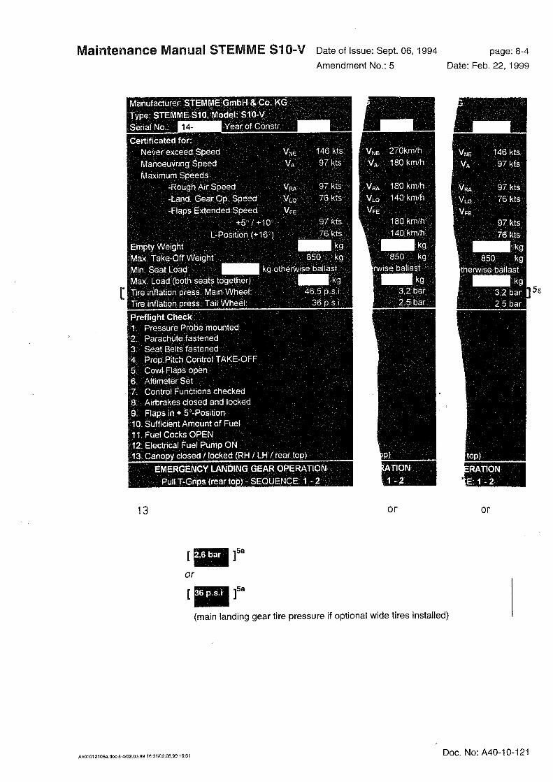

Maintenance Manual STEMME S10-V Date of Issue: Sept. 06, 1994 page: 8-5
Amendment No.: - Date: -
A4010121_B21.doc-8-5/27.01.14 14:14/27.01.14 14:14 Doc. No: A40-10-121

Maintenance Manual STEMME S10-V Date of Issue: Sept. 06, 1994 page: 8-6
Amendment No.: 3 Date: Oct. 25, 1995
A4010121_B21.doc-8-6/27.01.14 14:14/27.01.14 14:14 Doc. No: A40-10-121
[ ] 3a
25
BACKUP FUEL PUMPS ON

Maintenance Manual STEMME S10-V Date of Issue: Sept. 06, 1994 page: 8-7
Amendment No.: - Date: -
A4010121_B21.doc-8-7/27.01.14 14:14/27.01.14 14:14 Doc. No: A40-10-121

Maintenance Manual STEMME S10-V Date of Issue: Sept. 06, 1994 page: 8-8
Amendment No.: 5 Date: Feb. 22, 1999
A4010121_B21.doc-8-8/27.01.14 14:14/27.01.14 14:14 Doc. No: A40-10-121
[ ] 5a
[ ] 5a
[ ] 5a
(if optional 60 l fuel
tanks installed)
FUEL
2 x 15.8 US gal.
FUEL
2 x 13.2 imp. gal.
or
or
FUEL
2 x 60 l
[ ] s
[ ] s
FUEL
2 x 11.9 US gal.
FUEL
2 x 9.9 imp. gal.
or
or
FUEL
2 x 45 l
Oxygen Cylinder Mounting:
max 20 lbs per cylinder [ ]
5a
4
Oxygen Cylinder Mounting:
max 9 kg per cylinder
BAGGAGE ONLY LIGHT ITEMS
TOTAL - 4.4 LB.
BAGGAGE ONLY LIGHT ITEMS
TOTAL - 2 KG. or
[ ]5a
BAGGAGE max 22 lb.
or BAGGAGE max 10 kg.

Maintenance Manual STEMME S10-V Date of Issue: Sept. 06, 1994 page: 8-9
Amendment No.: - Date: -
A4010121_B21.doc-8-9/27.01.14 14:14/27.01.14 14:14 Doc. No: A40-10-121
reserved

Maintenance Manual STEMME S10-V Date of Issue Sept. 06, 1994 page: 9-1
Amendment No.: 21 Date: Jan. 10, 2014
A4010121_B21.doc-9-1/27.01.14 14:14/27.01.14 14:14 Doc. No: A40-10-121
9. Equipment
9.1 Minimum Equipment List
Subject Manufacturer Type TC No., Specification No.
Range
Airspeed Indicator Winter 6FMS4 TS10.210/15 up to 300 km/h/ 180 mph / 160 kts
Winter 6FMS5 TS10.210/16
Winter 7FMS4 TS10.210/19
Winter 7FMS5 TS10.210/20
Altimeter Winter 4FGH10 TS10.220/46 up to 10,000 m/ 30,000 ft
Winter 4FGH20 TS10.220/47
Winter 4FGH40 TS10.220/48 up to 20,000 ft
Winter 4HM6 TS10.220/44 up to 6,000 m
up to 20,000 ft
PZL W-12S FD-3/75
Compass Airpath C2300 - -
PZL B-13 FD19/77 -
Ludolph FK16 10.410/3 -
Ludolph FK5 10.410/1 -
Hamilton HI400 TSO C7c Type 1 -
Presesion Aviation Inc.
PAI-700 TSO
Stall Warning Sys-tem
Westerboer Speed Control - -
Revolution Counter VDO 333.230/009/1 - up to 4000 min-1
Engine hour meter Winter FSZM TS-GW 1510 -
VDO 331.811/010/2 - -
Oil pressure meter VDO 350.271/031/7 - up to 10 bar
Oil temp. meter VDO 310.274/082/1 - up to 150 °C
Fuel contents meter VDO 301.271/036/1 - 0 ··· 4/4
Cylinder head tem-perature meter
Limbach 170.215/001 - up to 375 °C
Four-element straps Gadringer BaGu 5203
SchuGu 2700
40.070/32
40.071/05
Schroth Automatic Shoulder
belt, left
Automatic Shoulder
belt, right
SL/1-08-C702
(with stop)
SR/1-08-C702
(with stop)
Back-cushion One per seat, compressed 2 in. (50 mm) thick (if no parachute, minimum 2 in. thick, is used)
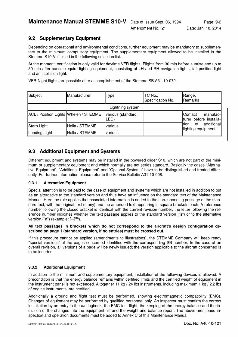
Maintenance Manual STEMME S10-V Date of Issue Sept. 06, 1994 Page: 9-2
Amendment No.: 21 Date: Jan. 10, 2014
A4010121_B21.doc-9-2/27.01.14 14:14/27.01.14 14:14 Doc. No: A40-10-121
9.2 Supplementary Equipment
Depending on operational and environmental conditions, further equipment may be mandatory to supplemen-
tary to the minimum compulsory equipment. The supplementary equipment allowed to be installed in the
Stemme S10-V is listed in the following selection list.
At the moment, certification is only valid for daytime VFR flights. Flights from 30 min before sunrise and up to
30 min after sunset require lighting equipment, consisting of LH and RH navigation lights, tail position light
and anti collision light.
VFR-Night flights are possible after accomplishment of the Stemme SB A31-10-072.
Subject Manufacturer Type TC No.,
Specification No.
Range,
Remarks
Lightning system
ACL / Position Lights Whelen / STEMME various (standard,
LED)
Contact manufac-
turer before installa-
tion of additional
lighting equipment Stern Light Hella / STEMME various
Landing Light Hella / STEMME various
9.3 Additional Equipment and Systems
Different equipment and systems may be installed in the powered glider S10, which are not part of the mini-
mum or supplementary equipment and which normally are not series standard. Basically the cases “Alterna-
tive Equipment”, "Additional Equipment" and "Optional Systems" have to be distinguished and treated differ-
ently. For further information please refer to the Service Bulletin A31-10-008.
9.3.1 Alternative Equipment
Special attention is to be paid to the case of equipment and systems which are not installed in addition to but
as an alternative to the standard version and thus have an influence on the standard text of the Maintenance
Manual. Here the rule applies that associated information is added to the corresponding passage of the stan-
dard text, with the original text (if any) and the amended text appearing in square brackets each. A reference
number following the closed bracket is identical with the current revision number, the letter following the ref-
erence number indicates whether the text passage applies to the standard version ("s") or to the alternative
version ("a") (example: [···]3a).
All text passages in brackets which do not correspond to the aircraft's design configuration de-
scribed on page 1 (standard version, if no entries) must be crossed out.
If this procedure cannot be applied (amendments to illustrations), the STEMME Company will keep ready "special versions" of the pages concerned identified with the corresponding SB number. In the case of an overall revision, all versions of a page will be newly issued; the version applicable to the aircraft concerned is to be inserted.
9.3.2 Additional Equipment
In addition to the minimum and supplementary equipment, installation of the following devices is allowed. A
precondition is that the energy balance remains within certified limits and the certified weight of equipment in
the instrument panel is not exceeded. Altogether 11 kg / 24 lbs instruments, including maximum 1 kg / 2.2 lbs
of engine instruments, are certified.
Additionally a ground and flight test must be performed, showing electromagnetic compatibility (EMC).
Changes of equipment may be performed by qualified personnel only. An inspector must confirm the correct
installation by an entry in the a/c-logbook, the EMC-test flight, the keeping of the energy balance and the in-
clusion of the changes into the equipment list and the weight and balance report. The above-mentioned in-
spection and operation documents must be added to Annex C of this Maintenance Manual.

Maintenance Manual STEMME S10-V Date of Issue Sept. 06, 1994 Page: 9-3
Amendment No.: 21 Date: Jan. 10, 2014
A4010121_B21.doc-9-3/27.01.14 14:14/27.01.14 14:14 Doc. No: A40-10-121
Subject Manufacturer Type TC No.,
Specification No.
Range,
Remarks
Compass Bohli 46-MFK-1
Mechanical Variome-
ter
various various
VHF-COM various various all approved
TSO/ETSO equip-
ment with
57 mm / 2 ¼ in stan-
dard ring cutout
Contact TC holder
before installation of
any TSO/ETSO
equipment with dif-
ferent size/design
Intercom PS Engineering PM 1000 II and mechanical
identical,
all equipment, which
is fix mountable to
the instrument panel
due to its own chas-
sis or due to a suit-
able installation
frame
TELEX Pro Com 4
Sigtronics SPA-400 TSO
Flightcom 403-MC
Flightcom ATC-2
Transponder various various all approved
TSO/ETSO equip-
ment with
57 mm / 2 ¼ in stan-
dard ring cutout or
159 mm / 6 ¼ in
standard rectangle
cutout
Contact TC holder
before installation of
any TSO/ETSO
equipment with dif-
ferent size/design
Encoder various various all approved
TSO/ETSO equip-
ment
Emergency Trans-
mitter (ELT)
various various all approved
TSO/ETSO equip-
ment
GPS & Moving Map various various all equipment, which
is fix mountable to
the instrument panel
due to its own chas-
sis or due to a suit-
able installation
frame
EFIS Dynon Avionics EFIS D-10
System
Garmin G3X System Contact TC holder
before installation

Maintenance Manual STEMME S10-V Date of Issue Sept. 06, 1994 page: 9-4
Amendment No.: 21 Date: Jan. 10, 2014
A4010121_B21.doc-9-4/27.01.14 14:14/27.01.14 14:14 Doc. No: A40-10-121
Subject Manufacturer Type TC No.,
Specification No.
Range,
Remarks
Electronic Vario,
Soaring Computer
various various all equipment, which
is fix mountable to
the instrument panel
due to its own chas-
sis or due to a suit-
able installation
frame
Collision warning
system
various various
VHF NAV (VOR) various various all approved
TSO/ETSO equip-
ment with
57 mm / 2 ¼ in stan-
dard ring cutout
Contact TC holder
before installation of
any TSO/ETSO
equipment with dif-
ferent size/design
Horizon various various all approved
TSO/ETSO equip-
ment, which is fix
mountable to the in-
strument panel due
to its own chassis or
due to a suitable in-
stallation frame
Turn and Bank
Indicator
various various
Directional Gyro R.C.Allen RCA15AK-2
Fire Warning System Stemme Series equipment
Voltmeter/Ammeter Filser SR001 Series equipment

Maintenance Manual STEMME S10-V Date of Issue Sept. 06, 1994 page: 9-5
Amendment No.: 13 Date: May 25, 2005
A4010121_B21.doc-9-5/27.01.14 14:14/27.01.14 14:14 Doc. No: A40-10-121
9.3.3 Optional Systems
Optional systems are not normally included in the Maintenance Manual. To each of these systems delivered
by STEMME, a Service Bulletin approved by the LBA is assigned, providing the information necessary for
correct installation and inspection (e. g. Serial No.'s, Documents, supplementary procedures). If installation
requires additional instructions, an installation instruction is provided. If flight operation requires additional in-
formation, supplements to the Flight Manual are provided. Information required for maintained airworthiness
are published as maintenance instructions, to be inserted in the Annex A of this Maintenance Manual and
added to the list of maintenance instructions on the cover sheet of Annex A.
The document no. Of the Service Bulletin and relevant documents are always identical except for the prefix
(A31- Service Bulletin, A34- Installation Instruction, A36- Flight Manual Supplement).

Maintenance Manual STEMME S10-V Date of Issue Sept. 06, 1994 page: 10-1
Amendment No.: 1 Date: Dec. 10, 1994
A4010121_B21.doc-10-1/27.01.14 14:14/27.01.14 14:14 Doc. No: A40-10-121
10. List of Special Tools
• Precision protractor for propeller blade setting angle adjustment
• Torque wrench
• Magneto timer
• Valve clearance gauge
• Sparking plug wrench
• Special tool to compress the gas-strut to relieve flap pressure (Part No.: 00SW-RMF)

Maintenance Manual STEMME S10-V Date of Issue Sept. 06, 1994 page: 11-1
Amendment No.: 7 Date: Nov. 11, 1999
A4010121_B21.doc-11-1/27.01.14 14:14/27.01.14 14:14 Doc. No: A40-10-121
11. List of Maintenance Documents for Parts Approved Independently from the Aircraft
• Operating and Maintenance Manual Limbach L 2400 and series, flight engine for powered sailplanes and very light Aircraft.
Annex A comprises:
• Manufacturer's maintenance documents for all instruments specified in the equipment list for the serial number indicated on the title page;
• Procedural instruction “Dynamic balancing of the Stemme S 10“ A17-10AP-V/2-E.
• "Minor repair to components of fibrous composite material" - a repair guide by the STEMME Company for the S10.
• "Information on service actions for UP Vorgelat T30 / UP Vorgelat T35" - a guide to the preventive care of Aircraft surfaces by MGS-Scheufler;
• Instructions for the maintenance of "L'Hotellier" ball and swivel joints;
• Maintenance instructions by STEMME as entered in the list below. This list must comprise at least those Maintenance Instructions relating to the additional equipment installed (refer to the record of accomplished SB's/AD's under Annex B).
• Maintenance instructions relevant for Supplementary Equipment delivered by STEMME must be enlisted on
the title page of Annex A and attached, if the Supplementary Equipment is installed in the serial number.

Maintenance Manual STEMME S10-V Date of Issue Sept. 06, 1994 page: 12-1
Amendment No.: 0 Date: -
A4010121_B21.doc-12-1/27.01.14 14:14/27.01.14 14:14 Doc. No: A40-10-121
12. Figures referring to the previous Sections
The numbering system of the figures corresponds to the numbers of the section containing the first reference to the figure. If several illustrations relate to one section, they are designated .a, .b, etc.

Maintenance Manual STEMME S10-V Date of Issue Sept. 06, 1994 page: 12-2
Amendment No.: 0 Date: -
A4010121_B21.doc-12-2/27.01.14 14:14/27.01.14 14:14 Doc. No: A40-10-121


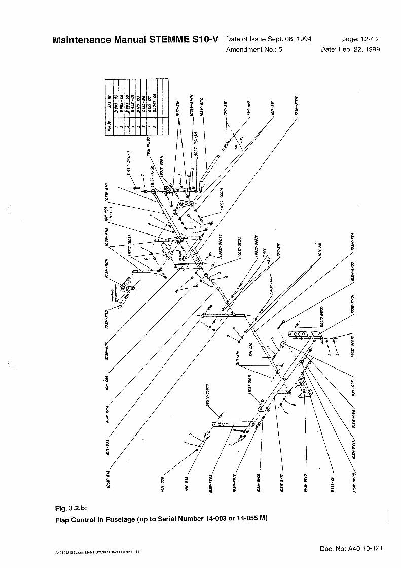


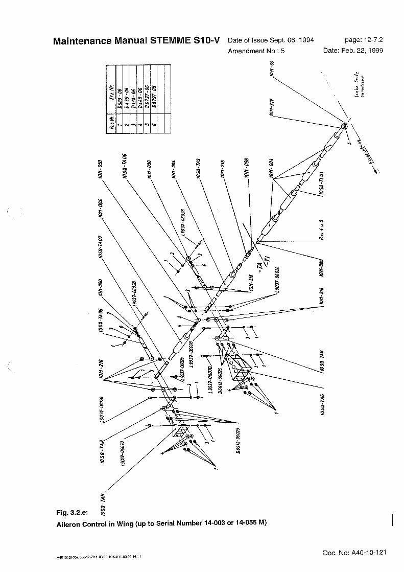

Maintenance Manual STEMME S10-V Date of Issue Sept. 06, 1994 page: 12-8.1
Amendment No.: 9 Date: Dec. 14, 2001
A4010121_B21.doc-12-8/27.01.14 14:14/27.01.14 14:14 Doc. No: A40-10-121
Fig. 3.2.f:
Airbrake Control in Fuselage (from Serial Number 14-004 or 14-056 M on)
Einkleben: BK-steuerung im Rumpf


Maintenance Manual STEMME S10-V Date of Issue Sept. 06, 1994 page: 12-10
Amendment No.: 7 Date: Nov. 11, 1999
A4010121_B21.doc-12-10/27.01.14 14:14/27.01.14 14:14 Doc. No: A40-10-121
Fig. 3.2.h:
Rudder Control


Maintenance Manual STEMME S10-V Date of Issue Sept. 06, 1994 page: 12-13.2
Amendment No.: 7 Date: Nov. 11, 1999
A4010121_B21.doc-12-13/27.01.14 14:14/27.01.14 14:14 Doc. No: A40-10-121
Fig. 3.3.11
Propeller fork mounting

Maintenance Manual STEMME S10-V Date of Issue Sept. 06, 1994 page: 12-13.3
Amendment No.: 7 Date: Nov. 11, 1999
A4010121_B21.doc-12-13/27.01.14 14:14/27.01.14 14:14 Doc. No: A40-10-121
Fig. 3.3.12
Positions of balancing weights
„Red“ Side
Reference point
for propeller adjustment
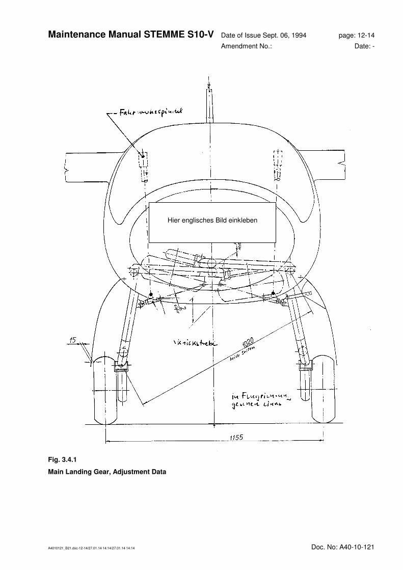
Maintenance Manual STEMME S10-V Date of Issue Sept. 06, 1994 page: 12-14
Amendment No.: Date: -
A4010121_B21.doc-12-14/27.01.14 14:14/27.01.14 14:14 Doc. No: A40-10-121
Fig. 3.4.1
Main Landing Gear, Adjustment Data
Hier englisches Bild einkleben

Maintenance Manual STEMME S10-V Date of Issue Sept. 06, 1994 page: 12-15
Amendment No.: 9 Date: Dec. 14, 2001
A4010121_B21.doc-12-15/27.01.14 14:14/27.01.14 14:14 Doc. No: A40-10-121
Fig. 3.5.a:
Pressure System, Line Scheme

Maintenance Manual STEMME S10-V Date of Issue Sept. 06, 1994 page: 12-16
Amendment No.: 9 Date: Dec. 14, 2001
A4010121_B21.doc-12-16/27.01.14 14:14/27.01.14 14:14 Doc. No: A40-10-121
Abbreviations in Fig. 3.5.a mean:
A: TEK-connection (pitot tube)
B: static pressure connection
(pitot-tube)
C: total pressure connection
D: static pressure connection
(both sides of tail boom)
E: static pressure connection (op-
tional, both sides of cockpit)
F: flask connection
Certified installations:
Device line remarks
1 Altimeter B
2 Air speed indicator C, D
3 Variometer (except for Bohli 68 PVF1 and
Bohli 68 PVF2)
A, F jet compensated (TEK)
B, F not compensated
E, F not compensated
4 Variometer Bohli 68 PVF1 (without inter-
nal expansion diaphragm)
C, E, F only, if no variometer acc. (3) installed
5 Variometer Bohli 68 PVF2 (with internal
expansion diaphragm)
C, E
6 E-variometer or gliding computer B, C, (A)
or: C, E, (A)
line A may be required depending on
type
7 Coded altimeter D
NOTE: Any line must be as short as possible. The water/separator filters must always be located in front of
the device and in front of any junction.
Fig. 3.5.b
Pressure System, Legend


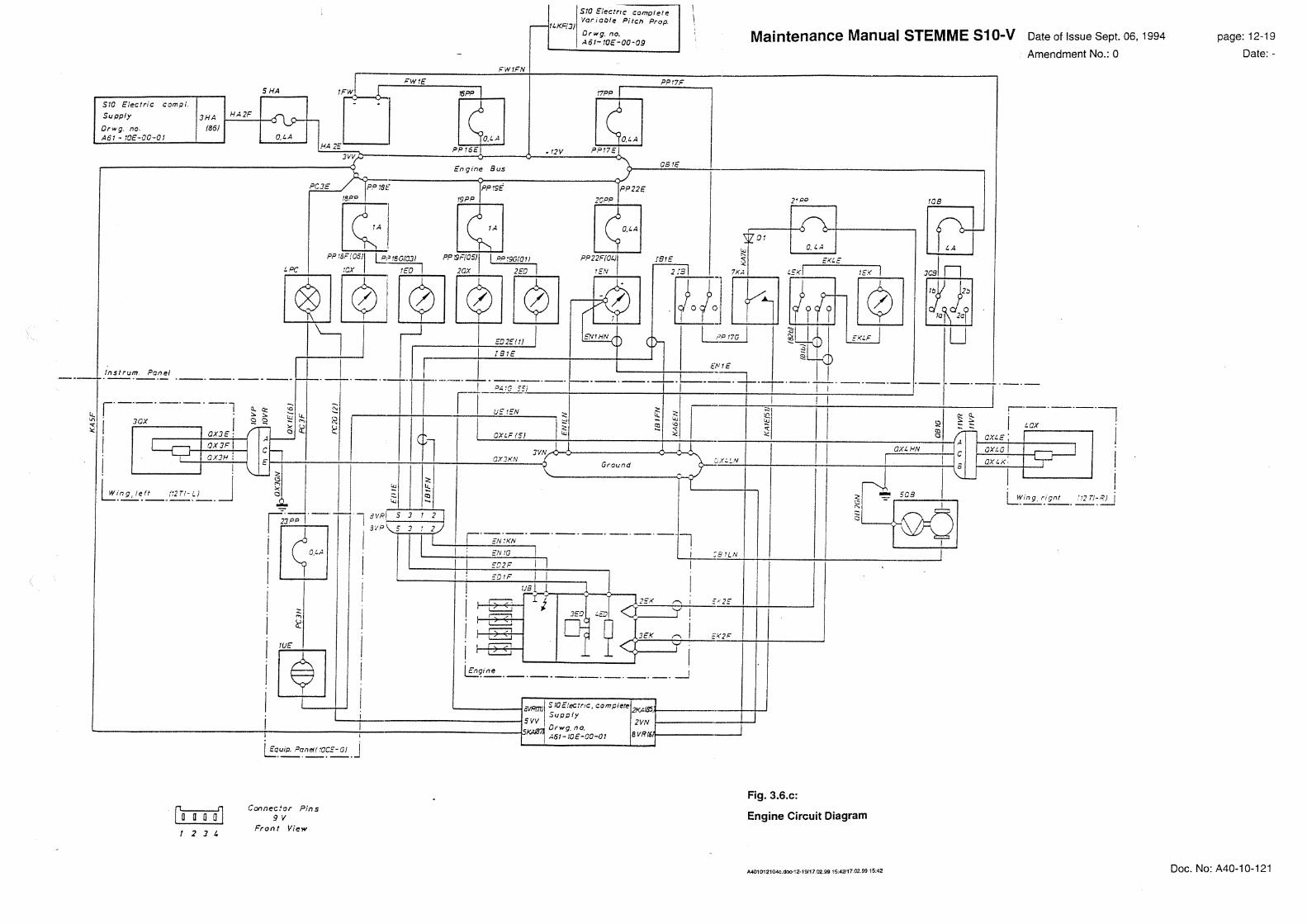


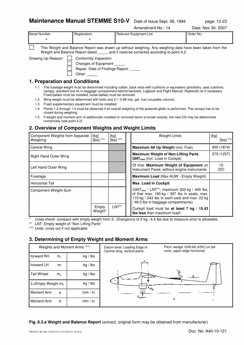
Maintenance Manual STEMME S10-V Date of Issue Sept. 06, 1994 page: 12-23
Amendment No.: 14 Date: Nov 30. 2007
A4010121_B21.doc-12-23/27.01.14 14:14/27.01.14 14:14 Doc. No: A40-10-121
Serial Number:
- Registration:
- Relevant Equipment List:
Order No.:
This Weight and Balance Report was drawn up without weighing. Any weighing data have been taken from the Weight and Balance Report dated and if need be corrected according to point 4.2.
Drawing Up Reason: Conformity Inspection
Changes of Equipment
Repair. Date of Findings Report:
Other:
1. Preparation and Conditions 1.1 The fuselage weight must be determined including rudder, back rests with cushions or equivalent upholstery, seat cushions,
canopy, standard tool kit in baggage compartment behind backrest, Logbook and Flight Manual. Replenish oil if necessary. Fixed ballast must be installed, loose ballast must be removed.
1.2 Wing weight must be determined with bolts and 3 l / 0.66 imp. gal. fuel (unusable volume).
1.3 Fixed supplementary equipment must be installed.
1.4 Points 1.2 through 1.4 must be observed if an overall weighing of the powered glider is performed. The canopy has to be closed during weighing.
1.5 If weight and moment arm of additionally installed or removed items is known exactly, the new CG may be determined numerically (see point 4.2)
2. Overview of Component Weights and Weight Limits
Component Weights from Separate Weighing
[kg] [lbs] ***
[kg] [lbs] ***
Weight Limits [kg] [lbs] ***
Central Wing Maximum All Up Weight (incl. Fuel) 850 (1874)
Right Hand Outer Wing Maximum Weight of Non-Lifting Parts
GNTmax (incl. Load in Cockpit)
570 (1257)
Left Hand Outer Wing Of that: Maximum Weight of Equipment on Instrument Panel, without engine instruments
10 (22)
Fuselage Maximum Load (Max AUW - Empty Weight)
Horizontal Tail Max. Load in Cockpit
(GNTmax - LNT**; maximum 202 kg / 445 lbs, of that max. 180 kg / 397 lbs in seats, max. 110 kg / 243 lbs in each seat and max. 22 kg / 48.5 lbs in baggage compartments)
Cockpit load must be at least 7 kg / 15,43 lbs less than maximum load!
Component Weight Sum
Empty Weight*
LNT**
* cross-check: compare with empty weight from 3.; Divergence of 2 kg / 4.4 lbs due to measure error is allowable.
** LNT: Empty weight of "Non Lifting Parts"
*** Units: cross out if not applicable
3. Determining of Empty Weight and Moment Arms
Weights and Moment Arms ***:
forward RH mr kg / lbs
forward LH ml kg / lbs
Tail Wheel ms kg / lbs
Σ=Empty Weight me kg / lbs
Moment Arm a mm / in.
Moment Arm b mm / in.
Fig. 6.3.a Weight and Balance Report (extract, original form may be obtained from manufacturer)
Datum level: Leading Edge of Central wing, vertical plane
Pitch: wedge 1000:84 (4°50') on tail cone, upper edge horizontal

Maintenance Manual STEMME S10-V Date of Issue Sept. 06, 1994 page: 12-24
Amendment No.: 14 Date: Nov 30. 2007
A4010121_B21.doc-12-24/27.01.14 14:14/27.01.14 14:14 Doc. No: A40-10-121
4. Determining of Empty Weight Center of Gravity
4.1 After Weighing:
xm b
ma
S
S
e
=⋅
+ [mm / in.]*** ⇒ S
x =
⋅
+ = [mm / in.]***
4.2 After Changes, without Weighing:
Following changes have been made on the powered glider:
Install. / Removal
Item Weight (
+/-)
m = [kg / lbs]*** Moment Arm (
+/-)
x = [mm / in.]*** Moment (
+/-)
M =[mm kg / in. lbs]***
Sum mzus= Sum Mzus=
NOTE: Count weight installed positive, weights removed negative. Count moment arms aft of datum positive, in front of datum negative.
xm x M
mS neu
alt alt zus
neu
,
=⋅ +
[mm / in.] ⇒
neuSx
,
= ⋅ +
= mm / in. ***
5. Definition of Minimum Load Required
With Empty Weight determined: kg / lbs***
and the empty weight CG aft of datum: mm / in. ***
the Minimum Load Required is ****: kg / lbs***
*** Units: cross out if not applicable
****According to Maintenance Manual, Section 6.3
Site, Date Stamp Sign Job Leader
Inspector Statement: All measured data are within the allowable ranges and correspond to the production and maintenance instructions of the type.
Site, Date Stamp Sign Inspector
Fig. 6.3.b Weight and Balance Report (extract, original form may be obtained from manufacturer)

Maintenance Manual STEMME S10-V Date of Issue Sept. 06, 1994 page: 12-25
Amendment No.: 0 Date: -
A4010121_B21.doc-12-25/27.01.14 14:14/27.01.14 14:14 Doc. No: A40-10-121
Serial No.:
Registration: Order No.:
Drawing Up Reason: Conformity Inspection
Inspection. Date of Finding Report: ____________________________________________
Other: ___________________________________________________________________
1. Angle of Incidence
The following rated values and actual values of the angles of incidence apply to the upper edge of a wedge 1000:84 on the straight part of the tail cone, with its vertex in flight direction.
Inspection of the angle of incidence is required for the Conformity Inspection and an Inspection following a heavy land-ing, furthermore after Major Repair, if wing and/or tail mountings have been affected.
Wing Chord: + 2.5° ± 0.2° °
Horizontal Tail Chord: -0.5° ± 0.2° °
Secondary Condition: The difference of actual angles of incidence wing/horizontal tail must be
between 1.7° and 2.4°
°
2. Control Surface Deflections
Positive values (+) indicate full control surface deflections downward or left, negative Values (-) indicate deflections up-ward or right.
Elevator: Measuring point is trailing edge of inner rib of elevator (140 mm / 5.51 in. from hinge line).
Full Deflection - 48 +2
/-5 mm
(-1.89 +0.08
/-0.2 in.)
[mm / in.]* + 48 +5
/-2 mm
(+1.89 +0.2
/-0.08 in.)
[mm / in.]*
Trim: Trim setting neutral, elevator deflection must be 0 ± 5 mm (0 ± 0.2 in.) [mm / in.]*
Rudder: Measuring point is lower rear corner of control surface (420 mm / 16.5 in. from hinge line)
Full Deflection: +220 ± 15 mm
(+8.7 ± 0.6 in.)
[mm / in.]* -220 ± 15 mm
(-8.7 ± 0.6 in.)
[mm / in.]*
Wing Flaps and Ailerons:
Flap
Lever
Control Stick
Measurement points:
1) aileron: inner rib of the control surface, 163 mm / 6.42 in. from hinge line.
2) wing flap: inner rib of the control surface, 175 mm / 6.89 in. from hinge line. Position Position left aileron left wing flap right wing flap right aileron
mm (in.) [mm / in.]* mm (in.) [mm / in.]* mm (in.) [mm / in.]* mm (in.) [mm / in.]*
- 10° neutral -31 ± 4 (-1.22 ± 0.16)
-31 ± 4 (-1.22 ± 0.16)
- 5° neutral -15 ± 4 (-0.6 ± 0.16)
-15 ± 4 (-0.6 ± 0.16)
0
left
neutral
right
-48 ± 4 (-1.89 ± 0.16)
0 ± 2 (0 ± 0.08)
+27 ± 3 (1.06 ±0.12)
0 ± 2 (0 ± 0.08)
0 ± 2 (0 ± 0.08)
+27 ± 3 (+1.06 ± 0.12)
0 ± 2 (0 ± 0.08)
-48 ± 4 (-1.89 ±0.16)
+ 5° neutral +15 ± 4 (+0.6 ± 0.16)
+15 ± 4 (+0.6 ± 0.16)
+ 10° neutral +31 ± 4 (+1.22 ± 0.16)
+31 ± 4 (+1.22 ± 0.16)
L (+16°) neutral +51 ± 4 (+2 ± 0.16)
+51 ± 4 (+2 ± 0.16)
*Units: delete as applicable
Fig. 6.4.1.a
Rigging Report, Page 1 (extract, original form may be obtained from manufacturer)

Maintenance Manual STEMME S10-V Date of Issue Sept. 06, 1994 page: 12-26
Amendment No.: 0 Date: -
A4010121_B21.doc-12-26/27.01.14 14:14/27.01.14 14:14 Doc. No: A40-10-121
3. Friction in Control System
Static friction is to be measured as follows: measuring point at the operating lever / control stick, mid of the
grip; measure the force being reached when the system sets going - three times in both directions. The aver-
age of the higher values from each measurement is to be entered.
Prior to measuring trim should be positioned so as to centre the stick approximately. To balance the "stick
forward" force of the downspring, the trim lever has to be locked at the rear, nearly fully "tail heavy" position.
Elevator 5 ± 2 N (1.1 ± 0.45 lbf) [N / lbf]*
Aileron 15 +5
/-8 N (3.4 +1.1
/-1.8 lbf) [N / lbf]*
Rudder (tail wheel off the ground!) 25 +5
/-8 N (5.6 +1.1
/-1.8 lbf) [N / lbf]*
4. Pilot Forces
Following forces must be measured on ground. Measuring points for airbrake and wing flap forces are the respective
handles, for down-spring / trim spring forces the uppermost finger notch of the control stick handle.
Airbrake over-centre lock and unlock 150 + 50 N
(34 + 11 lbf)
with 20°C [N / lbf]* with [°C]
Wing Flap: Counter force in position L 125 ± 25 N
(28 ± 6 lbf)
with 20°C [N / lbf]* with [°C]
Wing Flap: with jerky movement damping per-
ceptible in both directions? YES NO
*Units: delete as applicable
Site, Date Stamp Sign
Fig. 6.4.1.a
Rigging Report, Page 1 (extract, original form may be obtained from manufacturer)

Maintenance Manual STEMME S10-V Date of Issue Sept. 06, 1994 page: 12-27
Amendment No.: 0 Date: -
A4010121_B21.doc-12-27/27.01.14 14:14/27.01.14 14:14 Doc. No.: A40-10-022
Serial No.:
Registration: Order No.:
Control
Mass of Control Surface
Hinge Moment of Control Surface
Force at trailing edge
Surface Rated
kg (lb)
Reading*
kg / lb
Rated
Ncm (lbf ft)
Reading*
Ncm / lbf ft
Rated Value
N (lbf) Reading*
N / lbf
left right left right Measuring point left right
Aileron 3.3 (7.28)
to
4.5 (9.92)
132 (0.97)
to
175 (1.28)
9.2 (2.07) to 12.2 (2.74)
at inner operating rod.
r = 14.3 cm (5.63 in.)
Wing Flap 3.5 (7.72)
to
4.7 (10.36)
200 (1.47)
to
272 (1.99)
11.6 (2.61) to 15.8 (3.55)
at operating rod
r = 17.2 cm (6.77 in.)
Elevator** 0.75 (1.65)
to
0.92 (2.0)
28 (0.21)
to
31 (0.23)
2.0 (0.45) to 2.2 (0.5)
at inner end rib
0.92 (2.0)
to
1.13 (2.49)
28 (0.21)
to
35 (0.25)
2.0 (0.45) to 2.5 (0.56)
at inner end rib
r = 14.0 cm (5.51 in.)
Rudder 2.6 (5.73)
to
4.0 (8.82)
182 (1.33)
to
224 (1.64)
4.3 (0.967) to 5.3 (1.19)
at bottom rear corner
r = 42.5 cm (16.7 in.)
*Units: delete as applicable, Reading Error: ≤ 2.5 % acceptable **left and right half of elevator separately
Measuring of Static Hinge Moment
The relation between hinge moment and force is:
static hinge moment M = F • r,
wherein F is the force measured at the trailing edge of the control surface, and r is the horizontal distance be-
tween trailing edge and hinge axis. F may be measured with a spring balance or another suitable scale with
an error in measurement not exceeding 2.5%.
The friction of the hinge bearing should be less than 2.5 % of the maximum permissible hinge moment. If the
detached control surface is curved to the front or to the back at least three points should be used to ensure
that the curvature is eliminated and thus cannot falsify the measurement.
Measuring Procedure with Attached Control Surface (not applicable with rudder):
The surface is to be kept in horizontal position by means of the spring balance. Then move the balance
slowly upwards (by hand) and enter the force and direction of movement in the record at which the control
surface overcomes the static friction and starts going (e.g.: 11.2 N ↑ ).
After that, starting from the horizontal position again, the spring scale is to be slowly lowered until the control
surface starts moving. Note again force and direction (e.g. 10.8 N ↓ ).
Both results must be within the limits given in the above table.
Inspector Statement
The control surface masses and hinge moments are within the allowable ranges and correspond to the pro-
duction- and maintenance instruction of the type.
Site, Date Stamp Sign
Fig. 6.4.2.a
Masses and Moments of Control Surfaces (extract, original form may be obtained from manufacturer)
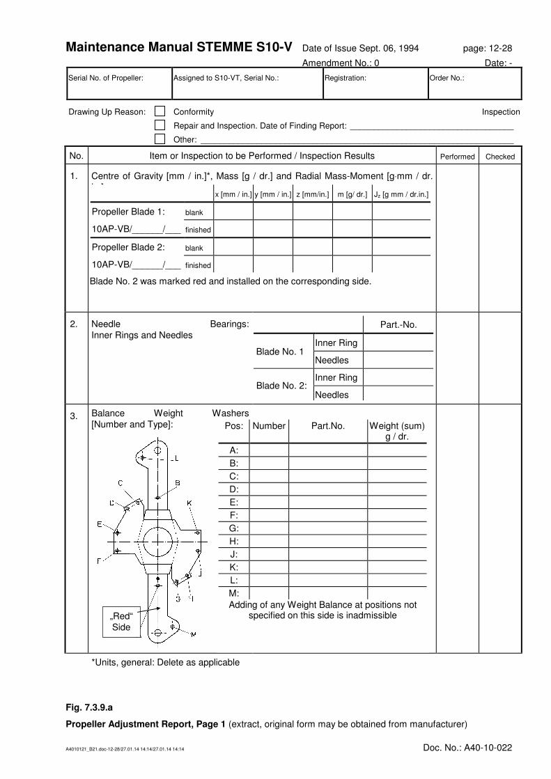
Maintenance Manual STEMME S10-V Date of Issue Sept. 06, 1994 page: 12-28
Amendment No.: 0 Date: -
A4010121_B21.doc-12-28/27.01.14 14:14/27.01.14 14:14 Doc. No.: A40-10-022
Fig. 7.3.9.a
Propeller Adjustment Report, Page 1 (extract, original form may be obtained from manufacturer)
Serial No. of Propeller: Assigned to S10-VT, Serial No.: Registration: Order No.:
Drawing Up Reason: Conformity Inspection
Repair and Inspection. Date of Finding Report: ___________________________________
Other: ___________________________________________________________________
No. Item or Inspection to be Performed / Inspection Results Performed Checked
1. Centre of Gravity [mm / in.]*, Mass [g / dr.] and Radial Mass-Moment [g⋅mm / dr.
in.]:
2. Needle Bearings:
Inner Rings and Needles
3. Balance Weight Washers
[Number and Type]:
*Units, general: Delete as applicable
x [mm / in.] y [mm / in.] z [mm/in.] m [g/ dr.] Jz [g mm / dr.in.]
Propeller Blade 1: blank
10AP-VB/______/___ finished
Propeller Blade 2: blank
10AP-VB/______/___ finished
Blade No. 2 was marked red and installed on the corresponding side.
Pos: Number Part.No. Weight (sum) g / dr.
A:
B:
C:
D:
E:
F:
G:
H:
J:
K:
L:
M:
Adding of any Weight Balance at positions not specified on this side is inadmissible
Part.-No.
Inner Ring
Needles
Inner Ring
Needles
Blade No. 1
Blade No. 2:
„Red“
Side

Maintenance Manual STEMME S10-V Date of Issue Sept. 06, 1994 page: 12-29
Amendment No.: 0 Date: -
A4010121_B21.doc-12-29/27.01.14 14:14/27.01.14 14:14 Doc. No.: A40-10-021
No. Item or Inspection to be Performed / Inspection Results (Continued) Performed Checked
4. Propeller All Up Weight [g / dr.]
(incl. Front Cover):
5. Play in Blade Bearings [mm / in.]
(Measured in Direction of Rotation
Axle):
a) at fork:
(rated: No perceptible play)
b) at blade tips:
(maximum 4 mm / 0.157 in.)
6. Track of Propeller Blades [mm / in.]
(Difference between Axial Position of
Both Blades):
a) at folding joint:
(maximum 0.3 mm / 0.012 in.)
b) at Blade tips:
(maximum 3 mm / 0.12 in.)
7. Propeller Fork Incidence Angle [ °]: a) T/O-Set ting:
(Rated: -3.3°±5')
b) Cruise-Setting:
(Rated: +3.1°±10')
8. Static Return Force when Blade Ro-
tated to Cruise Position
(Blade in 90°-Position; Measuring
point on blade tip)
a) Blade 1:
b) Blade 2:
9. Duration to Change Pitch [s]
(15 - 25°C, 12 V Operation Voltage): a) T/O- ➾ Cruise Setting:
(Rated: 180 s)
b) Cruise - ➾ T/O-Setting:
(Rated: 180 s)
10. Propeller Blade Force on Rubber Stop
[N/ lbf]
(Propeller folded, Leading edge hori-
zontal).
a) Blade 1:
(Rated: 1.7 ± 0.1 N / 0.38 ± 0.02 lbf)
b) Blade 2:
(Rated: 1.7 ± 0.1 N / 0.38 ± 0.02 lbf)
11. Only during inspection: Check smooth
movement of pitch control bearing in
hub. If hard movement or rejected
bearing found: disassembly and visu-
ally inspect thrust bearing, if neces-
sary change bearing. Grease and ad-
just for no-clearance and smooth
movement when assembling.
finding:
Site, Date Stamp Sign
Fig. 7.3.9.b
Propeller Adjustment Report, Page 2 (extract, original form may be obtained from manufacturer)

Maintenance Manual STEMME S10-V Date of Issue Sept. 06, 1994 page: 12-30
Amendment No.: 0 Date: -
A4010121_B21.doc-12-30/27.01.14 14:14/27.01.14 14:14 Doc. No.: A40-10-021
Fig. 7.4.1.a
Emergency Release Mechanism
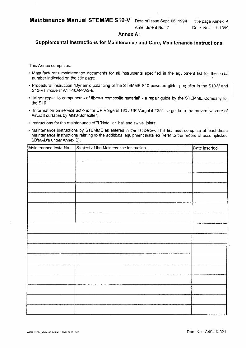
Maintenance Manual STEMME S10-V Date of Issue Sept. 06, 1994 title page Annex: B
Amendment No.: 0 Date: -
A4010121_B21.doc-B/27.01.14 14:14/27.01.14 14:14 Doc. No.: A40-10-021
Annex B:
Service Bulletins, Airworthiness Directives
This Annex comprises:
• The "List of Airworthiness Directives and Service Bulletins" issued by the manufacturer for the Aircraft type STEMME S10 (document no. A31-10-000),
• The record of accomplished SB's / AD's for this serial number,
• All Service Bulletins already accomplished as well as those still to be accomplished.

Maintenance Manual STEMME S10-V Date of Issue Sept. 06, 1994 title page Annex: C
Amendment No.: 7 Date: Nov. 11, 1999
A4010121_B21.doc-C/27.01.14 14:14/27.01.14 14:14 Doc. No.: A40-10-021
Annex C
Documents (Inspection and Operations Documents)
This Annex comprises all original documents for the serial number indicated on the title page which may be of importance to maintenance and repair. Those documents are listed in the table below.
CAUTION: Upon any Repair or Inspection the Maintenance Manual must be submitted including a
complete Annex of documents, to allow inspection reporting and continuing of operative
documentation in accordance with the rules.
New documents which must be added (e.g. new weight and balance record, revised equipment list or inspec-tion certificates for instruments newly installed) are to be filed in this Annex. Documents which are no longer relevant should be kept in a separate file (service records).
Document always if any
Certificate of “Conformity Inspection” X
Certificate of Avionic-Inspection X
last Certificate of Inspection for continued airworthiness X
last Certificate of Inspection for continued airworthiness (Avionic) X
latest records of conformity inspection or inspection for continued airworthiness X
latest records of Avionik-Inspection or inspection for continued airworthiness (Avionic) X
Release Certificate – engine X
Release Certificate – propeller X
Inspection Certificate for any instruments installed according to the equipment list (except
for engine instruments and other instruments not subject to certification)
X
log sheets for engine, propeller, front gear, clutch, drive shaft X
review of operating times X
current equipment list X
latest rigging report (controls) X
latest rigging report (variable pitch propeller) X
latest report of dynamic balancing X
latest weight and balance record X
supplement sheet to the weight and balance record X
report "control surface masses and hinge moments" X
latest report on compass compensation X
flight report related to the production inspection or to the last inspection for continuing airworthiness X
modifications to the individual aircraft ("major modification") X
list of constructional deviations ("minor modifications") X