flight manual stemme s 10-v - assets.stemme.deassets.stemme.de/service/s10/english/manuals/flight...
TRANSCRIPT

Flight Manual STEMME S 10-V Date of Issue Sept. 06, 1994 page: ii
Amendment No.: 5 Date:March 20 2003
A4010111_07a.doc-ii/07/03/2014 15:39:00/07/03/2014 15:39:00 doc.no. A40-10-111
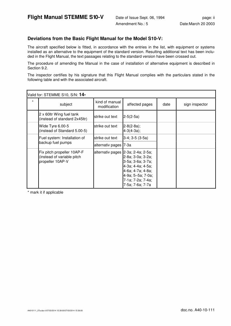
Deviations from the Basic Flight Manual for the Model S10-V:
The aircraft specified below is fitted, in accordance with the entries in the list, with equipment or systems
installed as an alternative to the equipment of the standard version. Resulting additional text has been inclu-
ded in the Flight Manual, the text passages relating to the standard version have been crossed out.
The procedure of amending the Manual in the case of installation of alternative equipment is described in
Section 9.2.
The inspector certifies by his signature that this Flight Manual complies with the particulars stated in the
following table and with the associated aircraft.
Valid for: STEMME S10, S/N: 14-
* subject
kind of manual
modification affected pages date sign inspector
2 x 60ltr Wing fuel tank
(instead of standard 2x45ltr) strike out text 2-5(2-5a)
Wide Tyre 6.00-5
(instead of Standard 5.00-5)
strike out text 2-8(2-8a);
4-3(4-3a);
Fuel system: Installation of
backup fuel pumps
strike out text 3-4; 3-5 (3-5a)
alternativ pages 7-3a
Fix pitch propeller 10AP-F
(instead of variable pitch
propeller 10AP-V
alternativ pages 2-3a; 2-4a; 2-5a;
2-8a; 3-0a; 3-2a;
3-5a; 3-6a; 3-7a;
4-3a; 4-4a; 4-5a;
4-6a; 4-7a; 4-8a;
4-9a; 5–5a; 7-0a;
7-1a; 7-2a; 7-4a;
7-5a; 7-6a; 7-7a
* mark it if applicable


Flight Manual STEMME S 10-V Date of Issue Sept. 06, 1994 page: iv
Amendment No.: 7 Date: Jan. 10, 2014
A4010111_07a.doc-iv/07/03/2014 15:39:00/07/03/2014 15:39:00 doc.no. A40-10-111
0.2 List of Effective Pages
This record is valid only for the Serial No. specified on the title page.
Page LBA-
appr.
Am.
No.
Amendment
Date
i
ii 5 Mar. 20, 2003
iii-1 6 May. 25, 2005
iii-2 7 Jan. 10, 2014
iv 7 Jan. 10, 2014
v
1-0
1-1 5 Mar. 20, 2003
1-2 5 Mar. 20, 2003
1-3
2-0 X 5 Mar. 20, 2003
2-1 X
2-2 X
2-3* X
2-3a* X 5 Mar. 20, 2003
2-4* X 6 May. 25, 2005
2-4a* X 6 May. 25, 2005
2-5* X 6 May. 25, 2005
2-5a* X 6 May. 25, 2005
2-6 X 5 Mar. 20, 2003
2-7 X 5 Mar. 20, 2003
2-8* X 5 Mar. 20, 2003
2-8a* X 5 Mar. 20, 2003
3-0* X
3-0a* X 5 Mar. 20, 2003
3-1 X
3-2* X
3-2a* X 5 Mar. 20, 2003
3-3 X
3-4 X 5 Mar. 20, 2003
3-5* X 5 Mar. 20, 2003
3-5a* X 5 Mar. 20, 2003
3-6* X 6 May. 25, 2005
Page LBA-
appr.
Am.
No.
Amendment
Date
3-6a* X 6 May. 25, 2005
3-7* X
3-7a* X 5 Mar. 20, 2003
4-0 X
4-1 X 3 Dec. 05, 1994
4-2 X 7 Jan. 10, 2014
4-3* X 7 Jan. 10, 2014
4-3a X 7 Jan. 10, 2014
4-4* X
4-4a* X 5 Mar. 20, 2003
4-5* X
4-5a* X 5 Mar. 20, 2003
4-6* X 7 Jan. 10, 2014
4-6a* X 7 Jan. 10, 2014
4-7* X 6 May. 25, 2005
4-7a* X 6 May. 25, 2005
4-8* X
4-8a* X 5 Mar. 20, 2003
4-9* X 7 Jan. 10, 2014
4-9a* X 7 Jan. 10, 2014
4-10 X 7 Jan. 10, 2014
4-11 X
5-0 X 5 Mar. 20, 2003
5-1 X
5-2 X
5-3 X
5-4 5 Mar. 20, 2003
5-5* 5 Mar. 20, 2003
5-5a* 5 Mar. 20, 2003
6-0
6-1
7-0*
7-0a* 5 Mar. 20, 2003
Page LBA-
appr.
Am.
No.
Amendment
Date
7-1* 7 Jan. 10, 2014
7-1a* 7 Jan. 10, 2014
7-2*
7-2a* 5 Mar. 20, 2003
7-3*
7-3a* 5 Mar. 20, 2003
7-4*
7-4a* 5 Mar. 20, 2003
7-5* 6 May. 25, 2005
7-5a* 6 May. 25, 2005
7-6*
7-6a* 5 Mar. 20, 2003
7-7* 5 Mar. 20, 2003
7-7a* 5 Mar. 20, 2003
8-0
8-1 7 Jan. 10, 2014
9-0
9-1 5 Mar. 20, 2003
9-2 5 Mar. 20, 2003
* strike out not applicable
pages! (installation of
alternative equipment see
page ii)

Flight Manual STEMME S 10-V Date of Issue Sept. 06, 1994 page: v
Amendment No.: 0 Date:-
A4010111_07a.doc-v/07/03/2014 15:39:00/07/03/2014 15:39:00 doc.no. A40-10-111
0.3 Contents
Section 1 - General
Section 2 - Limitations
Section 3 - Emergency Procedures
Section 4 - Normal Operating Procedures
Section 5 - Performance
Section 6 - Mass and Balance
Section 7 - Description of the powered Glider and its Systems and Equipment
Section 8 - Handling, Servicing and Maintenance
Section 9 - Supplements

Flight Manual STEMME S 10-V Date of Issue Sept. 06, 1994 page: 1-0
Amendment No.: 0 Date:-
A4010111_07a.doc-1-0/07/03/2014 15:39:00/07/03/2014 15:39:00 doc.no. A40-10-111
Section 1 - General
1.1 Introduction 1-1
1.2 Certification Basis 1-1
1.3 Warnings, Cautions and Notes 1-1
1.4 Description and Technical Data 1-2

Flight Manual STEMME S 10-V Date of Issue Sept. 06, 1994 page: 1-1
Amendment No.: 5 Date:Mar. 20, 2003
A4010111_07a.doc-1-1/07/03/2014 15:39:00/07/03/2014 15:39:00 doc.no. A40-10-111
1.1 Introduction
This flight manual was compiled to give pilots and instructors all necessary information for a safe, appropriate
and performance-optimised operation of the motor glider.
The manual includes all the data required to be furnished to the pilot by JAR-22. It further contains a number
of other data and operating hints which may be useful to the pilot from the manufacturer's point of view.
For the conversion of technical data the following factors have been used:
1 lb. 0.4536 kg 1 ftlb. 0.1356 Nm
1 dr. 1.772 g 1 hp 0.7457 kW
1lbf =1 lb.(wt) 4.45 N 1 kts 1.852 km/h
1in. 25.4 mm 1 mph 1.609 km/h
1ft. 0.3048 m 1 Imp.gal. 4.546 l
1 sqft. 0.0929 m2 1 p.s.i. 0.06895 bar
100 fpm 0.5081 m/s
1.2 Certification Basis
This powered sailplane with the works reference STEMME S10 has originally been approved by the Luftfahrt-
Bundesamt in accordance with Joint Airworthiness Requirements for Sailplanes and Powered Sailplanes
JAR-22, effective through change 4.
The Type Certification No. 846 has been issued on Dec. 31, 1990.
The model Stemme S10-V is derived from the base type Stemme S10.
The model STEMME S 10-V is optional equipped with the variable pitch propeller 10AP-V or with the fix pitch
propeller 10AP-F, derived from the variable pitch propeller, which replaces the original fixed pitch propeller
10AP-N of the basic model STEMME S10, and can be folded-in and covered by the nose cone just as that.
The Type Certificate for the model STEMME S 10-V has been issued on Sept. 16, 1994.
Category of Airworthiness: "Utility".
Noise Certification Basis for the model S10-V:
equipped with variable pitch propeller 10AP-V:
"Lärmschutzforderungen für Luftfahrzeuge (LSL)" (Noise Protection Requirements for Aircraft; German
equivalent to and based on the ICAO, Annex 16), dated 1.1.1991, published in the "Bundesanzeiger
Jahrgang 43, No. 54a, dated 19.03.1991" (Federal Gazette, year 43), certification chapter VI.
equipped with fix pitch propeller 10AP-F:
"Lärmschutzforderungen für Luftfahrzeuge (LSL)" (Noise Protection Requirements for Aircraft; German
equivalent to and based on the ICAO, Annex 16), dated 1.1.1991, published in the "Bundesanzeiger
Jahrgang 43, No. 54a, dated 19.03.1991" (Federal Gazette, year 43), certification chapter X.
1.3 Warnings, Cautions and Notes
Remarks in the manual of particular importance to flight safety and handling have been specially marked by
use of one of the following terms:
Warning: means that the non-observation of the corresponding procedure leads to an immediate or
important degradation of the flight safety.
Caution: means that the non-observation of the corresponding procedure leads to a minor or to a more or
less long-term degradation of the flight safety.
Note: draws attention on any special item not directly related to safety but which is important or
unusual.

Flight Manual STEMME S 10-V Date of Issue Sept. 06, 1994 page: 1-2
Amendment No.: 5 Date:Mar. 20, 2003
A4010111_07a.doc-1-2/07/03/2014 15:39:00/07/03/2014 15:39:00 doc.no. A40-10-111
1.4 Description and Technical Data
The STEMME S10-V is a two-seat high performance motor glider with an innovative propulsion concept and
highly finished aerodynamic shape. The seats are arranged side-by-side (forward of the wing) and are
equipped with dual controls.
The wing is mounted to the fuselage in the upper third. It consists of an inner wing with flaps and Schempp-
Hirth air brakes and two outer wings with continuous ailerons.
The tailplane is designed as a "T"-type.
The two-wheel main landing gear can be retracted electrically and contains hydraulic brakes.
The engine is mounted in the fuselage in a central steel tubing frame near the aircraft's Centre of Gravity.
Engine power is transmitted via a prop shaft made of composites and a reduction gearbox to the jointed
propeller in the fuselage nose. The propeller is folded in during soaring flight and covered by the movable
nose cone (propeller dome).
Electrical heatable expansion joints actuate the variable pitch propeller 10AP-V from the take-off position to
the cruise position. The movement back to the take off position after propeller control switch-off is realized by
spring forces.
The fix pitch propeller 10AP-F is directly derived from the variable pitch propeller, where the same propeller
blades 10AP-VB are used. They are fixed in the take off position of the variable pitch propeller.
One fuel tank is placed in each of the two outer sections of the inner wing.
Technical data:
length of fuselage 27.6 ft. 8.42 m
height 5.74 ft. 1.75 m
wing span 75.5 ft. 23.00 m
wing area 201.72 sqft. 18.74 m2
aspect ratio 28.22
mean aerodynamic wing chord 2.86 ft. 0.873 m
airfoil HQ 41/14.35 (laminar profile)
max. weight 1874 lb. 850 kg
max. wing loading 9.29 lb./sqft. 45.36 kg/m2
engine Limbach L 2400 EB1.AD
gear box ratio i = 1.18
propeller variable pitch propeller STEMME 10AP-V
optional fix pitch propeller Stemme 10AP-F
propeller diameter 5.35 ft ± 0.12 in
1630 mm ± 3 mm
propeller pitch take-off setting cruise setting (only 10AP-V)
2.99 ft 4.51 ft
91.4 cm 137.6 cm
angle of incidence of prop. blades
(β, versus plane of rotation):
take-off setting cruise setting(only 10AP-V)
14.6° 21°
angle of incidence prop. blades (inspection limit) (only 10AP-V) -3.3° / +3.1°


Flight Manual STEMME S 10-V Date of Issue Sept. 06, 1994 page: 2-0
Amendment No. 5 Date:March 20. 2003
LBA-approved
A4010111_07a.doc-2-0/07/03/2014 15:39:00/07/03/2014 15:39:00 doc.no. A40-10-111
Section 2 - Limitations
2.1 Introduction 2-1
2.2 Airspeed 2-1
2.3 Airspeed Indicator Markings 2-2
2.4 Power-Plant 2-3
2.5 Power-Plant Instrument Markings 2-3
2.6 Masses (Weights) 2-4
2.7 Centre of Gravity 2-4
2.8 Approved Manoeuvres 2-4
2.9 Manoeuvring Load Factors (Maximum G-loading) 2-4
2.10 Flight Crew 2-4
2.11 Kinds of Operation 2-4
2.12 Minimum Equipment List 2-4
2.13 Fuel 2-5
2.14 Other Limitations 2-5
2.15 Cabin Placards with Operation Limits 2-6
2.15.1 Instrumenten Panel Layout 2-6
2.15.2 Cabin Placards with Operation Limits 2-7

Flight Manual STEMME S 10-V Date of Issue Sept. 06, 1994 page: 2-1
Amendment No. 0 Date: --
LBA-approved
A4010111_07a.doc-2-1/07/03/2014 15:39:00/07/03/2014 15:39:00 doc.no. A40-10-111
2.1 Introduction
This section includes operating limitations, instrument markings and the information signs which are
necessary for the safe operation of the motorglider, its engine, standard systems and standard equipment.
The operating limitations included in this section and in section 9 have been approved by the LBA.
2.2 Airspeed
The airspeed limitations and their importance for the use of the aircraft are shown as follows:
Speed IAS Remarks
VNE Never exceed speed (maximum per-
missible airspeed in calm weather, with
flap positions 0°, -5° and -10° only)
146 knots
168 mph
270 km/h
This speed must not be exceeded and the control
movement must be not more than 1/3rd.
VRA Maximum airspeed in rough air 97 knots
112 mph
180 km/h
Do not exceed this speed except in smooth air and then
only with caution. Examples of rough air are lee-wave
rotors, thunderclouds etc.
VA Calculated manoeuvring speed 97 knots
112 mph
180 km/h
Above this limit the controls must not be moved fully or
abruptly because the motorglider structure could be over-
stressed under certain conditions.
VFE Permissible maximum airspeed for
operation of flaps:
• positive position +5°, +10°
• Landing position L (+16°)
97 knots
112 mph
180 km/h
76 knots
87 mph
140 km/h
These airspeeds may not be exceeded in the flap position
indicated.
VLO Permissible maximum airspeed for the
operation of the landing gear
76 knots
87 mph
140 km/h
At airspeeds in excess of this airspeed the landing gear
may not be lowered or raised.

Flight Manual STEMME S 10-V Date of Issue Sept. 06, 1994 page: 2-2
Amendment No. 0 Date: --
LBA-approved
A4010111_07a.doc-2-2/07/03/2014 15:39:00/07/03/2014 15:39:00 doc.no. A40-10-111
2.3 Airspeed Indicator Markings
The following table gives the airspeed indicator markings and the meaning of the colours (AUW = all-up weight).
Marking IAS (Value
or Range)
Meaning
White arc
46-97 knots 53-112 mph 85-180 km/h
Positive flap operation range. (Lower limit is 1.1 VS0 in landing configuration with maximum AUW. Upper limit is the maximum airspeed with positive flap position.)
Green arc
49-97 knots 56-112 mph 90-180 km/h
Normal operating range.
(Lower limit is speed 1.1VS1 at max. AUW and most forward C.G. position with flaps neutral; upper limit is rough air speed.)
Yellow arc
97-146 knots 112-168 mph 180-270 km/h
Manoeuvres must be conducted with caution and only in smooth air.
L
76 knots 87 mph
140 km/h
Max. permissible airspeed with flaps in landing position and for landing gear operation.
Red line
146 knots 168 mph 270 km/h
Max. airspeed for all operations.
Blue line
62 knots 71 mph
115 km/h
Best rate of climb speed VY.
Yellow triangle
59 knots 68 mph
110 km/h
Approach speed at max. AUW.

Flight Manual STEMME S 10-V Date of Issue Sept. 06, 1994 page: 2-3
Amendment No. 0 Date: --
LBA-approved
A4010111_07a.doc-2-3/07/03/2014 15:39:00/07/03/2014 15:39:00 doc.no. A40-10-111
2.4 Power-Plant
Engine manufacturer: LIMBACH Flugmotoren GmbH & Co. KG, Kotthausener
Straße 5, D-53639 Königswinter, Germany
Engine type: L 2400 EB1.AD
Take-off power: 92.5 hp / 69 kW
Take-off rpm, max. permissible for 5 min.: 3400 rpm
Continuous rpm, max. permissible: 3000 rpm
Cylinder head temperature, max. permissible: 482°F / 250°C
Oil temperature, max. permissible: 248°F / 120°C
Oil pressure, minimum: 14.5 p.s.i. / 1 bar
Oil pressure, max. permissible: 101.5 p.s.i. / 7 bar
Lubricants and all other engine related data: refer to "Operating and Maintenance Manual LIMBACH
L 2400 and series".
Propeller manufacturer: STEMME
Propeller type: 10AP-V
2.5 Power-Plant Instrument Markings
The following table shows the markings of the engine instruments and the meaning of the colours used.
Instrument Red line = Minimum limit
Green arc = Normal
Operating Range
Yellow arc = Caution Range
Red line = Maximum
Limit
Tachometer1)
[rpm] - 1200···3000 3000···3400 3400
Oil temperature2)
[deg. C]
[deg. F]
- 50···120
122···248
···50
···122
120
248
Cyl. head Temp.2)
[deg. C]
[deg. F]
- 150···250
302···482
···150
···302
250
482
Oil pressure3)
[bar]
[p.s.i.]
1
14.5
1···7
14.5···101.5
-
-
7
101.5
Fuel quantity gauge: "0" at white line = empty
Red point (beyond "full" mark) means: "no electrical connection"
Notes:
1) reading error ± 50rpm
2) display in [°C]
3) display in [bar]

Flight Manual STEMME S 10-V Date of Issue Sept. 06, 1994 page: 2-3a
Amendment No. 5 Date: March 20. 2003
LBA-approved
A4010111_07a.doc-2-3/07/03/2014 15:39:00/07/03/2014 15:39:00 doc.no. A40-10-111
2.4 Power-Plant
Engine manufacturer: LIMBACH Flugmotoren GmbH & Co. KG, Kotthausener
Straße 5, D-53639 Königswinter, Germany
Engine type: L 2400 EB1.AD
Take-off power: 92.5 hp / 69 kW
Take-off rpm, max. permissible for 5 min.: 3400 rpm
Continuous rpm, max. permissible: 3000 rpm
Cylinder head temperature, max. permissible: 482°F / 250°C
Oil temperature, max. permissible: 248°F / 120°C
Oil pressure, minimum: 14.5 p.s.i. / 1 bar
Oil pressure, max. permissible: 101.5 p.s.i. / 7 bar
Lubricants and all other engine related data: refer to "Operating and Maintenance Manual LIMBACH
L 2400 and series".
Propeller manufacturer: STEMME
Propeller type: 10AP-F
2.5 Power-Plant Instrument Markings
The following table shows the markings of the engine instruments and the meaning of the colours used.
Instrument Red line = Minimum limit
Green arc = Normal
Operating Range
Yellow arc = Caution Range
Red line = Maximum
Limit
Tachometer1)
[rpm] - 1200···3000 3000···3400 3400
Oil temperature2)
[deg. C]
[deg. F]
- 50···120
122···248
···50
···122
120
248
Cyl. head Temp.2)
[deg. C]
[deg. F]
- 150···250
302···482
···150
···302
250
482
Oil pressure3)
[bar]
[p.s.i.]
1
14.5
1···7
14.5···101.5
-
-
7
101.5
Fuel quantity gauge: "0" at white line = empty
Red point (beyond "full" mark) means: "no electrical connection"
Notes:
1) reading error ± 50rpm
2) display in [°C]
3) display in [bar]

Flight Manual STEMME S 10-V Date of Issue Sept. 06, 1994 page: 2-4
Amendment No. 6 Date: May 25. 2005
LBA-approved
A4010111_07a.doc-2-4/07/03/2014 15:39:00/07/03/2014 15:39:00 doc.no. A40-10-111
2.6 Masses (Weights)
maximum permissible take-off weight: 1874 lb. / 850 kg
maximum permissible landing weight: 1874 lb. / 850 kg
maximum mass of all non-lifting parts: 1256.5 lb. / 570 kg
maximum mass in luggage compartment: 48.5 lb. / 22 kg
2.7 Centre of Gravity
The limits of the in-flight centre of gravity are:
• forward limit: 10 in. / 254 mm aft of reference plane
• rear limit: 16.5 in. / 420 mm aft of reference plane
In this the reference plane is the vertical reference plane which contains the leading edge of the inner wing at
given angle of the longitudinal axis (refer to maintenance manual).
2.8 Approved Manoeuvres
The motorglider is certificated in the "Utility" category (normal soaring flight).
2.9 Manoeuvring Load Factors (Maximum G-loading)
The following manoeuvring load factors (g) must not be exceeded:
• up to manoeuvring speed 97 kts / 180 km/h: positive: 5.3 g; negative: 2.65 g.
• up to maximum airspeed 146 kts / 270 km/h: positive: 4.0 g; negative: 1.5 g.
2.10 Flight Crew
The crew of the S10 consists of 2 persons; the lowest crew number is one person.
(For solo operations): When operated solo, the left seat is for the pilot in charge.
2.11 Kinds of Operation
• Flights according to VFR by day.
• Flights in IFR and/or icing conditions are not permitted.
• Aerobatics and cloud flying are not permitted.
• For VFR-Night Flights a additional euipment is required within the provisions of the national law. Required
base for VFR-Night Flights is the accomplishment of the Stemme SB A31-10-072.
Caution: Night flights are limited to the vicinity of active airfields that are approved for night flight operation
(range of glide ratio).
2.12 Minimum Equipment List
1 Airspeed indicator
1 Altimeter
1 Stall warning system
1 Magnetic direction indicator
1 Tachometer
1 Take-off pitch position indicator (green light, indicating that the propeller blade pitch required for take-off is
reached)

Flight Manual STEMME S 10-V Date of Issue Sept. 06, 1994 page: 2-4a
Amendment No. 6 Date: May 25. 2005
LBA-approved
A4010111_07a.doc-2-4/07/03/2014 15:39:00/07/03/2014 15:39:00 doc.no. A40-10-111
2.6 Masses (Weights)
maximum permissible take-off weight: 1874 lb. / 850 kg
maximum permissible landing weight: 1874 lb. / 850 kg
maximum mass of all non-lifting parts: 1256.5 lb. / 570 kg
maximum mass in luggage compartment: 48.5 lb. / 22 kg
2.7 Centre of Gravity
The limits of the in-flight centre of gravity are:
• forward limit: 10 in. / 254 mm aft of reference plane
• rear limit: 16.5 in. / 420 mm aft of reference plane
In this the reference plane is the vertical reference plane which contains the leading edge of the inner wing at
given angle of the longitudinal axis (refer to maintenance manual).
2.8 Approved Manoeuvres
The motorglider is certificated in the "Utility" category (normal soaring flight).
2.9 Manoeuvring Load Factors (Maximum G-loading)
The following manoeuvring load factors (g) must not be exceeded:
• up to manoeuvring speed 97 kts / 180 km/h: positive: 5.3 g; negative: 2.65 g.
• up to maximum airspeed 146 kts / 270 km/h: positive: 4.0 g; negative: 1.5 g.
2.10 Flight Crew
The crew of the S10 consists of 2 persons; the lowest crew number is one person.
(For solo operations): When operated solo, the left seat is for the pilot in charge.
2.11 Kinds of Operation
• Flights according to VFR by day.
• Flights in IFR and/or icing conditions are not permitted.
• Aerobatics and cloud flying are not permitted.
• For VFR-Night Flights a additional euipment is required within the provisions of the national law. Required
base for VFR-Night Flights is the accomplishment of the Stemme SB A31-10-072.
Caution: Night flights are limited to the vicinity of active airfields that are approved for night flight operation
(range of glide ratio).
2.12 Minimum Equipment List
1 Airspeed indicator
1 Altimeter
1 Stall warning system
1 Magnetic direction indicator
1 Tachometer

Flight Manual STEMME S 10-V Date of Issue Sept. 06, 1994 page: 2-5
Amendment No. 6 Date: May 25. 2005
LBA-approved
A4010111_07a.doc-2-5/07/03/2014 15:39:00/07/03/2014 15:39:00 doc.no. A40-10-111
1 Engine elapsed time indicator
1 Oil pressure indicator
1 Oil temperature indicator
2 Fuel quantity indicators
1 Cylinder head temperature indicator
2 Four-element straps
1 Parachute or back-cushion (2.0 in / 50 mm compressed) per pilot
1 Starter Relay Warning Light (UK CAA requirement)
2.13 Fuel
Total capacity of fuel tanks (±5%): [2 times 9.9 Imp. gal / 45.0 l]1s
[2 times 13.2 Imp. gal / 60.0 l]3a
Unusable fuel quantity 2 times 0.3 Imp. gal / 1.5 l
Permissible octane rating and fuel types:
• AVGAS 100 LL, aviation fuel
• MOGAS (or car fuel super grade, min. 96 OCT. (RON)
The engine manufacturer recommends that at temperatures in excess of 68°F / 20°C. only AVGAS
100LL is used.
When stowing the aircraft for longer than one month it is recommended to drain the tank if MOGAS has been
used. MOGAS or car fuel have varying compositions, and it is not known how this might affect the long term
service life of the tanks.
2.14 Other Limitations
As an upper limit for the operation of the variable pitch propeller a temperature of 100°F(+38°C) has been
proved. The pitching mechanism is managed by heating or cooling of two thermo-elements and is influenced
by OAT. It starts actuating at 131°F (55°C). For th is reason the green blade position indicator is to be
observed during take-off. Launching should not be attempted if the indicator is not illuminated.
The only permitted colour for the aircraft exterior painting is white due to the necessity of protecting the
structure from high temperatures caused by sunlight (approved up to 129°F). For coloured warning paint ings
the areas of the propeller dome and the wing tips or optional installed winglets are to be used.
For the glazing of the canopy the use of material of an accepted type is permitted only. The luminous
transmittance value of these materials may not be less then 70 per cent and colours may not be falsified.
These characteristics may not be reduced by the use of tinted canopies.
The luggage load must not exceed 22 lb. (10 kg) in each of the compartments at the sides of the cabin and
4.4 lb. (2 kg) in the centre compartment. Single pieces weighing more than 1.1 lb. must be fastened securely
and must load the bottom of the luggage compartment on a sufficient area.
1 (s) Standard, (a) when equipped with enlarged fuel tanks according to Modification Bulletin A30-92-077. The text
which does not apply to the specific A/C is to be struck out.

Flight Manual STEMME S 10-V Date of Issue Sept. 06, 1994 page: 2-5a
Amendment No. 6 Date: May 25. 2005
LBA-approved
A4010111_07a.doc-2-6/07/03/2014 15:39:00/07/03/2014 15:39:00 doc.no. A40-10-111
1 Engine elapsed time indicator
1 Oil pressure indicator
1 Oil temperature indicator
2 Fuel quantity indicators
1 Cylinder head temperature indicator
2 Four-element straps
1 Parachute or back-cushion (2.0 in / 50 mm compressed) per pilot
1 Starter Relay Warning Light (UK CAA requirement)
2.13 Fuel
Total capacity of fuel tanks (±5%): [2 times 9.9 Imp. gal / 45.0 l]1s
[2 times 13.2 Imp. gal / 60.0 l]3a
Unusable fuel quantity 2 times 0.3 Imp. gal / 1.5 l
Permissible octane rating and fuel types:
• AVGAS 100 LL, aviation fuel
• MOGAS (or car fuel super grade, min. 96 OCT. (RON)
The engine manufacturer recommends that at temperatures in excess of 68°F / 20°C. only AVGAS
100LL is used.
When stowing the aircraft for longer than one month it is recommended to drain the tank if MOGAS has been
used. MOGAS or car fuel have varying compositions, and it is not known how this might affect the long term
service life of the tanks.
2.14 Other Limitations
The only permitted colour for the aircraft exterior painting is white due to the necessity of protecting the
structure from high temperatures caused by sunlight (approved up to 129°F). For coloured warning paint ings
the areas of the propeller dome and the wing tips or optional installed winglets are to be used.
For the glazing of the canopy the use of material of an accepted type is permitted only. The luminous
transmittance value of these materials may not be less then 70 per cent and colours may not be falsified.
These characteristics may not be reduced by the use of tinted canopies.
The luggage load must not exceed 22 lb. (10 kg) in each of the compartments at the sides of the cabin and
4.4 lb. (2 kg) in the centre compartment. Single pieces weighing more than 1.1 lb. must be fastened securely
and must load the bottom of the luggage compartment on a sufficient area.
1 (s) Standard, (a) when equipped with enlarged fuel tanks according to Modification Bulletin A30-92-077. The text
which does not apply to the specific A/C is to be struck out.


Flight Manual STEMME S 10-V Date of Issue Sept. 06, 1994 page: 2-7
Amendment No. 5 Date: March 20. 2003
LBA-approved
A4010111_07a.doc-2-7/07/03/2014 15:39:00/07/03/2014 15:39:00 doc.no. A40-10-111
2.15.2 Cabin Placards with Operation Limits
This section provides cabin placards with operation limits and their location in the cockpit.
Note: Other cabin placards see Maintenance Manual! (Doc.-No.: A40-10-121)
Fig. 2-2: Placards position in the cockpit

Flight Manual STEMME S 10-V Date of Issue Sept. 06, 1994 page: 2-8
Amendment No. 5 Date: March 20. 2003
LBA-approved
A4010111_07a.doc-2-8/07/03/2014 15:39:00/07/03/2014 15:39:00 doc.no. A40-10-111
1(s) Standard, (a) if Wide Tyre installed. Not applicable text must be crossed out.
Manufacturer: STEMME GmbH & Co. KG
Type: STEMME S 10 Model: S10-V
Serial No.: 14- Year of Constr.:
Certificated for:
Never exceed Speed: VNE 146 kts
Manoeuvring Speed: VA 97 kts
Rough Air Speed VRA 97 kts
Flaps Extended Speed VFE
+5° /+10° 97 kts
L Position (+16°) 76 kts
Land. Gear Operation Speed VLO 76 kts
Empty Weight: kg
Max. Take-Off Weight: 850 kg
Min. Seat Load: kg, otherwise Ballast
Max. Load (both seats together): kg
Tyre inflation press. Main Wheel: 46,5 p.s.i.
Tyre inflation press. Tail Wheel: 41 p.s.i.
Preflight Check:
1. Pressure Probe mounted
2. Parachute fastened
3. Seat Belts fastened
4. Cowl Flaps open
5. Prop. Pitch Control TAKE-OFF
6. Altimeter set
7. Control Functions checked
8. Airbrakes closed and locked
9. Flaps in + 5°-Position
10. Sufficient Amount of Fuel
11. Both Fuel Cocks open
12. Electr. Fuel Pump on
13. Canopy closed/locked (LH / RH /rear top)
Emergency Landing Gear Operation:
Pull T-Grips (rear top Sequence: 1 – 2
① On the Centre Console
37.7 p.s.i.
[ ]1s
[ ]1a
[ft MSL] [kts]
10.000 139
13.000 132
16.500 125
19.500 118
26.000 105
33.000 93
39.500 81
②Instrument panel
(near Air speed indicator)
Baggage
max. 10 kg
③ and ⑤
Baggage compartment
(behind LH and RH Seat)
Baggage Only light items Total: max. 2 kg
④ Baggage compartment
(rear top)

Flight Manual STEMME S 10-V Date of Issue Sept. 06, 1994 page: 2-8a
Amendment No. 5 Date: March 20. 2003
LBA-approved
A4010111_07a.doc-2-8/07/03/2014 15:39:00/07/03/2014 15:39:00 doc.no. A40-10-111
1(s) Standard, (a) if Wide Tyre installed. Not applicable text must be crossed out.
Manufacturer: STEMME GmbH & Co. KG
Type: STEMME S 10 Model: S10-V
Serial No.: 14- Year of Constr.:
Certificated for:
Never exceed Speed: VNE 146 kts
Manoeuvring Speed: VA 97 kts
Rough Air Speed VRA 97 kts
Flaps Extended Speed VFE
+5° /+10° 97 kts
L Position (+16°) 76 kts
Land. Gear Operation Speed VLO 76 kts
Empty Weight: kg
Max. Take-Off Weight: 850 kg
Min. Seat Load: kg, otherwise Ballast
Max. Load (both seats together): kg
Tyre inflation press. Main Wheel: 46,5 p.s.i.
Tyre inflation press. Tail Wheel: 41 p.s.i.
Preflight Check:
1. Pressure Probe mounted
2. Parachute fastened
3. Seat Belts fastened
4. Cowl Flaps open
5. Altimeter set
6. Control Functions checked
7. Airbrakes closed and locked
8. Flaps in + 5°-Position
9. Sufficient Amount of Fuel
10. Both Fuel Cocks open
11. Electr. Fuel Pump on
12. Canopy closed/locked (LH / RH /rear top)
Emergency Landing Gear Operation:
Pull T-Grips (rear top Sequence: 1 – 2
① On the Centre Console
37.7 p.s.i.
[ ]1s
[ ]1a
[ft MSL] [kts]
10.000 139
13.000 132
16.500 125
19.500 118
26.000 105
33.000 93
39.500 81
②Instrument panel
(near Air speed indicator)
Baggage
max. 10 kg
③ and ⑤
Baggage compartment
(behind LH and RH Seat)
Baggage Only light items Total: max. 2 kg
④ Baggage compartment
(rear top)

Flight Manual STEMME S 10-V Date of Issue Sept. 06, 1994 page: 3-0
Amendment No. 0 Date: --
LBA-approved
A4010111_07a.doc-3-0/07/03/2014 15:39:00/07/03/2014 15:39:00 doc.no. A40-10-111
Section 3 - Emergency Procedures
3.1 Introduction 3-1
3.2 Canopy Jettison 3-1
3.3 Bailing out 3-1
3.4 Stall Recovery 3-1
3.5 Spin Recovery 3-1
3.6 Spiral Dive Recovery 3-2
3.7 Flight under Icing Conditions 3-2
3.8 Take-Off Interrupt 3-2
3.9 Overshooting in Landing Configuration with Propeller in Cruise Position 3-2
3.10 Off-field Landing 3-3
3.11 Emergency Landing 3-3
3.11.1 Emergency Landing with Retracted Landing Gear 3-3
3.11.2 Emergency Landing with only one Landing Gear Leg deployed 3-3
3.11.3 Emergency Landing on Water (Ditching) 3-4
3.12 Systems Malfunctions 3-4
3.12.1 Engine Malfunctions 3-4
3.12.2 Fire 3-4
3.12.3 Fuel Pump Malfunctions 3-5
3.12.4 Propeller Pitch Control Malfunctions 3-5
3.12.5 Propeller Vibrations 3-6
3.12.6 Landing Gear Malfunctions - Emergency Let-Down 3-6
3.12.7 Main Electrical Supply Malfunction 3-6
3.12.8 Generator Malfunctions 3-7

Flight Manual STEMME S 10-V Date of Issue Sept. 06, 1994 page: 3-0a
Amendment No. 5 Date: March 20 2003
LBA-approved
A4010111_07a.doc-3-0/07/03/2014 15:39:00/07/03/2014 15:39:00 doc.no. A40-10-111
Section 3 - Emergency Procedures
3.1 Introduction 3-1
3.2 Canopy Jettison 3-1
3.3 Bailing out 3-1
3.4 Stall Recovery 3-1
3.5 Spin Recovery 3-1
3.6 Spiral Dive Recovery 3-2a
3.7 Flight under Icing Conditions 3-2a
3.8 Take-Off Interrupt 3-2a
3.9 deleted
3.10 Off-field Landing 3-3
3.11 Emergency Landing 3-3
3.11.1 Emergency Landing with Retracted Landing Gear 3-3
3.11.2 Emergency Landing with only one Landing Gear Leg deployed 3-3
3.11.3 Emergency Landing on Water (Ditching) 3-4
3.12 Systems Malfunctions 3-4
3.12.1 Engine Malfunctions 3-4
3.12.2 Fire 3-4
3.12.3 Fuel Pump Malfunctions 3-5a
3.12.4 deleted
3.12.5 Propeller Vibrations 3-6a
3.12.6 Landing Gear Malfunctions - Emergency Let-Down 3-6a
3.12.7 Main Electrical Supply Malfunction 3-6a
3.12.8 Generator Malfunctions 3-7a

Flight Manual STEMME S 10-V Date of Issue Sept. 06, 1994 page: 3-1
Amendment No. 0 Date: --
LBA-approved
A4010111_07a.doc-3-1/07/03/2014 15:39:00/07/03/2014 15:39:00 doc.no. A40-10-111
3.1 Introduction
Section 3 provides checklists and amplified procedures for coping with emergencies that may occur.
Remark: The abbreviation PPC is used for Propeller Pitch Control.
3.2 Canopy Jettison
• Canopy lock: OPEN left and right levers (do not open the rear top one!)
• Pull red emergency canopy release handle (centre of instrument console)
• The canopy will be pushed upwards by a gas spring. If necessary push manually.
Warning: The rear canopy lock must be locked when the canopy is jettisoned! It functions such that the
canopy is only lifted at the front and is torn away by wind forces.
3.3 Bailing out
• Release central lock of straps after canopy jettison.
• Bail out sideways, if possible pushing away from underneath wing to avoid collision with tail plane.
3.4 Stall Recovery
The occurrence of stall depends on the wing-flap setting and the take-off mass; be aware of stall effects
beginning with 46 kts (53 mph / 85 km/h).
Beginning of stall (wings level as well as in turning flight) can be recognised by:
• During powered flight: acoustic signal by the electric stall warning device.
• During soaring flight: clearly distinguishable buffeting of the control stick.
If in a deep stall the stick is not moved forward and therefore the effective angle of attack continues to be
increased, a rolling motion and, dependent on the C.G. position, spin can occur.
Method of stall recovery:
• Move stick forward and wait for speed increase
• Level the wings with ailerons and rudder.
3.5 Spin Recovery
Spin of the STEMME S10 is stopped by a standard recovery manoeuvre:
• Apply rudder opposite to the turn
• Move stick forward until turning stops
• Centralise rudder
• Pull out of dive with caution.
A maximum loss of height per spin-turn of 500 ft (150 m) must be considered.
Spinning with the flaps in "L" position is not allowed for structural reasons. If tendencies of spin occur in this
configuration push flap lever to position (+10°) or further and stop spinning by standard spin recovery
manoeuvre.
Note: With a rear C.G. position the spinning is accompanied by pitching movements.

Flight Manual STEMME S 10-V Date of Issue Sept. 06, 1994 page: 3-2
Amendment No. 0 Date: --
LBA-approved
A4010111_07a.doc-3-2/07/03/2014 15:39:00/07/03/2014 15:39:00 doc.no. A40-10-111
3.6 Spiral Dive Recovery
In middle and forward C.G. positions the aircraft has tendencies to go directly or after some spinning-turns
into a spiral dive.
Spiral dive is stopped by the following manoeuvre:
• stop the rotation with aileron and rudder together against turning direction;
• pull out of dive with caution (observe airspeed).
Warning: Do mind the never exceed airspeed VNE= 146 kts (168 mph / 270 km/h) during pull out!
Note: If the aircraft stops spinning by itself, it can be in a spiral dive afterwards.
3.7 Flight under Icing Conditions
Flights under icing conditions are not recommended. Nevertheless if you find yourself without intention in
atmospheric zones with icing conditions remember the following: Under icing conditions ice particles can
accumulate on wing, empennage, control surfaces and propeller blades, especially on flights in high altitudes.
Additionally the visibility can be seriously impaired by ice accumulation on the canopy surface.
It is recommended to start immediately an emergency descent to lower flight levels by the following actions:
• Engine IDLE
• Airbrakes EXTENDED
• Landing gear LOWERED (mind the speed limit: 75 kts / 87 mph / 140 km/h)
Warning: Ice accumulation can put up stall speeds and influence flutter behaviour.
3.8 Take-Off Interrupt
If a take-off interrupt is urgently required during rolling for technical or traffic control reasons, the following
actions are recommended:
• Throttle CLOSED (pulled)
• Airbrakes EXTENDED
• Elevator control PULLED to lower the tail
• Wheel brakes ACTIVATED with caution
Warning: If the remaining runway is too short and not free of obstacles:
Shut fuel cocks and set ignition OFF.
3.9 Overshooting in Landing Configuration with Propeller in Cruise Position
If an overshooting in landing configuration for reasons of safety is necessary and the variable pitch propeller
is not in position TAKE OFF as usually required (i.e. green pitch position indicator is not illuminated) set the
following actions:
• Engine FULL POWER
• Airbrakes CLOSED and LOCKED
• Elevator control PULL moderately to change to a shallow climb angle
• Landing gear RETRACTED
• Flaps - change to position +5°
• PPC switch position TAKE-OFF
Recommended airspeed for overshooting with propeller in cruise position 64kts / 74mph / 120km/h.

Flight Manual STEMME S 10-V Date of Issue Sept. 06, 1994 page: 3-2a
Amendment No. 5 Date: March 20. 2003
LBA-approved
A4010111_07a.doc-3-1/07/03/2014 15:39:00/07/03/2014 15:39:00 doc.no. A40-10-111
3.6 Spiral Dive Recovery
In middle and forward C.G. positions the aircraft has tendencies to go directly or after some spinning-turns
into a spiral dive.
Spiral dive is stopped by the following manoeuvre:
• stop the rotation with aileron and rudder together against turning direction;
• pull out of dive with caution (observe airspeed).
Warning: Do mind the never exceed airspeed VNE= 146 kts (168 mph / 270 km/h) during pull out!
Note: If the aircraft stops spinning by itself, it can be in a spiral dive afterwards.
3.7 Flight under Icing Conditions
Flights under icing conditions are not recommended. Nevertheless if you find yourself without intention in
atmospheric zones with icing conditions remember the following: Under icing conditions ice particles can
accumulate on wing, empennage, control surfaces and propeller blades, especially on flights in high altitudes.
Additionally the visibility can be seriously impaired by ice accumulation on the canopy surface.
It is recommended to start immediately an emergency descent to lower flight levels by the following actions:
• Engine IDLE
• Airbrakes EXTENDED
• Landing gear LOWERED (mind the speed limit: 75 kts / 87 mph / 140 km/h)
Warning: Ice accumulation can put up stall speeds and influence flutter behaviour.
3.8 Take-Off Interrupt
If a take-off interrupt is urgently required during rolling for technical or traffic control reasons, the following
actions are recommended:
• Throttle CLOSED (pulled)
• Airbrakes EXTENDED
• Elevator control PULLED to lower the tail
• Wheel brakes ACTIVATED with caution
Warning: If the remaining runway is too short and not free of obstacles:
Shut fuel cocks and set ignition OFF.
3.9 deleted

Flight Manual STEMME S 10-V Date of Issue Sept. 06, 1994 page: 3-3
Amendment No. 0 Date: --
LBA-approved
A4010111_07a.doc-3-3/07/03/2014 15:39:00/07/03/2014 15:39:00 doc.no. A40-10-111
3.10 Off-field Landing
If an off-field landing is necessary for technical or flight safety reasons, be careful in the choice of the landing
field in respect to the conditions and load bearing capabilities of the ground.
If the load bearing capabilities of the ground are considered sufficient a landing in the sailplane
configuration according to actions described in sections 4.5.4 and 4.5.5 is recommended.
A landing in deep ground with weak load bearing capabilities is associated with considerable risks; if the
landing nevertheless is unavoidable a prior retraction of the landing gear is recommended to minimise the
risks. (see section 3.11.1)
3.11 Emergency Landing
3.11.1 Emergency Landing with Retracted Landing Gear
In all cases in which serious landing gear malfunctions cannot be corrected by an emergency deployment, as
well as in unavoidable off-field landings with deep ground, a landing with retracted landing gear is
recommended in the following sequences:
• Fuel cocks SHUT
• Ignition OFF (if possible wait until carburettor reservoirs are empty)
• Wing flaps +10°
• Approach path shallow path angle, if possible without the use of airbrakes in the final stages.
• Elevator control pull moderately for a smooth pull-out to avoid stalling.
Warning: In a landing with retracted landing gear the energy absorption is a minimum compared to a
normal landing, therefore in all cases allow a safety margin above minimum speeds to avoid
stalling.
3.11.2 Emergency Landing with only one Landing Gear Leg deployed
Landings on only one wheel have been carried out several times without damage to pilot and aircraft.
In all cases in which serious landing gear malfunctions cannot be corrected and the landing gear position
indicator lights show only one landing gear leg deployed, try to get confirmation on this status by a ground
station or another aircraft.
For a one-wheel landing the following actions are recommended (landing in gliding configuration!):
• Fuel cocks SHUT
• Ignition OFF (if possible wait until carburettor reservoirs are empty)
• Propeller RETRACTED
• Wing flaps position L
• Elevator control pull moderately for a smooth pull-out
• Level horizon with aileron and rudder controls during rolling on the landing field.
• Be aware of wing-dropping and a turn in the final stage of rolling - allow sufficient space.

Flight Manual STEMME S 10-V Date of Issue Sept. 06, 1994 page: 3-4
Amendment No. 5 Date: March 20. 2003
LBA-approved
A4010111_07a.doc-3-4/07/03/2014 15:39:00/07/03/2014 15:39:00 doc.no. A40-10-111
3.11.3 Emergency Landing on Water (Ditching)
An emergency landing on water is accompanied with risks and should only be undertaken as last possibility.
If a ditching is unavoidable, it is recommended to land in the sailplane configuration and, due to the special
design of the landing gear, with the landing gear retracted.
Caution: Be aware that a sailplane has the tendency to dive into the water instead of gliding on its surface
and that the cockpit is pressed shut under the water surface.
3.12 Systems Malfunctions
3.12.1 Engine Malfunctions
An engine malfunction due to carburettor icing has not been assessed up to now, because preheated
induction air is taken directly from the engine compartment.
After an engine malfunction during cruise flight the following checks and actions are recommended:
• Fuel reserves CHECKED
• Fuel cocks both OPEN
• Electrical fuel pump ON (filling of fuel lines takes up to 5 min.)
• Circuit breaker fuel pump CHECKED
• Fuel Backup-System: ON (on the right side of panel, ventilation process takes up to 5 min. )
• Re-start engine with normal in-flight starting procedure (see sect. 4.5.3).
• Be prepared for off-field landing or landing on the next airfield, if re-start is not possible.
Caution: When re-starting engine in flight: Propeller may turn despite non-running engine because both
are separated by the centrifugal clutch. Check the rev-counter for indicated engine revolutions.
If when trying to restart the engine in flight the starter does not work, this may be due to pilot error or to a
malfunction of the engine master switch (which is coupled with the propeller dome locking mechanism).
Act as follows:
• Check if ignition switch is OFF. After an unsuccessful engine restart the ignition must be switched off for a
short time (otherwise the starter will not operate).
• Check if propeller-dome actuation lever is locked in forward position. Try to push grip down.
Correct position is confirmed if voltmeter indicates at least 12 V and red charging light is illuminated.
• If starter still does not respond the engine master switch may be by-passed by setting the engine bus
back-up switch (on the very right hand side of the instrument panel). For this action the locking pin must
be removed first.
• If it is still impossible to start engine prepare for an off-field landing.
3.12.2 Fire
If during operation of the aircraft smoke or smell of burning can be observed, the following procedure is
recommended:
During flight:
• Fuel cocks both CLOSED
• Main switch OFF
• Engine FULL THROTTLE (in order to empty fuel lines and carburettor reservoir)
• Emergency descent immediately introduced: Airbrakes deployed, Landing gear extended.
• Be prepared for off-field landing.
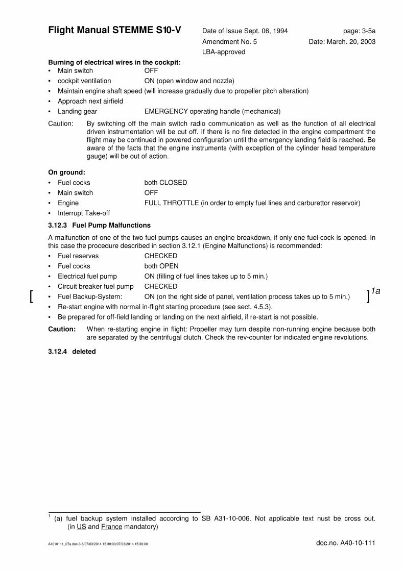
1 (a) fuel backup system installed according to SB A31-10-006. Not applicable text nust be cross out.
(in US and France mandatory)
[ ]1a

Flight Manual STEMME S 10-V Date of Issue Sept. 06, 1994 page: 3-5
Amendment No. 5 Date: March. 20, 2003
LBA-approved
A4010111_07a.doc-3-5/07/03/2014 15:39:00/07/03/2014 15:39:00 doc.no. A40-10-111
Burning of electrical wires in the cockpit:
• Main switch OFF
• cockpit ventilation ON (open window and nozzle)
• Maintain engine shaft speed (will increase gradually due to propeller pitch alteration)
• Approach next airfield
• Landing gear EMERGENCY operating handle (mechanical)
Caution: By switching off the main switch radio communication as well as the function of all electrical
driven instrumentation will be cut off. If there is no fire detected in the engine compartment the
flight may be continued in powered configuration until the emergency landing field is reached. Be
aware of the facts that the engine instruments (with exception of the cylinder head temperature
gauge) will be out of action and the propeller will alter its pitch angle to take-off position
automatically within 2 - 5 min. (this is also not indicated).
On ground:
• Fuel cocks both CLOSED
• Main switch OFF
• Engine FULL THROTTLE (in order to empty fuel lines and carburettor reservoir)
• Interrupt Take-off
3.12.3 Fuel Pump Malfunctions
A malfunction of one of the two fuel pumps causes an engine breakdown, if only one fuel cock is opened. In
this case the procedure described in section 3.12.1 (Engine Malfunctions) is recommended:
• Fuel reserves CHECKED
• Fuel cocks both OPEN
• Electrical fuel pump ON (filling of fuel lines takes up to 5 min.)
• Circuit breaker fuel pump CHECKED
• Fuel Backup-System: ON (on the right side of panel, ventilation process takes up to 5 min. )
• Re-start engine with normal in-flight starting procedure (see sect. 4.5.3).
• Be prepared for off-field landing or landing on the next airfield, if re-start is not possible.
Caution: When re-starting engine in flight: Propeller may turn despite non-running engine because both
are separated by the centrifugal clutch. Check the rev-counter for indicated engine revolutions.
3.12.4 Propeller Pitch Control Malfunctions
In case of a malfunction of the propeller pitch control the propeller blades go to take-off position, which is the
lowest possible pitch position. No unsafe situation is caused by this failure, the following procedure is
recommended:
• Check circuit breaker of propeller pitch control
• If necessary continue flight in take off position
Caution: Cruise flight with propeller in take-off position reduces the flight speed and the range
(Reconsider your filed flight plan).
1 (a) fuel backup system installed according to SB A31-10-006. Not applicable text nust be cross out.
(in US and France mandatory)
[ ]1a
Flight Manual STEMME S 10-V Date of Issue Sept. 06, 1994 page: 3-5a
Amendment No. 5 Date: March. 20, 2003
LBA-approved
A4010111_07a.doc-3-6/07/03/2014 15:39:00/07/03/2014 15:39:00 doc.no. A40-10-111
Burning of electrical wires in the cockpit:
• Main switch OFF
• cockpit ventilation ON (open window and nozzle)
• Maintain engine shaft speed (will increase gradually due to propeller pitch alteration)
• Approach next airfield
• Landing gear EMERGENCY operating handle (mechanical)
Caution: By switching off the main switch radio communication as well as the function of all electrical
driven instrumentation will be cut off. If there is no fire detected in the engine compartment the
flight may be continued in powered configuration until the emergency landing field is reached. Be
aware of the facts that the engine instruments (with exception of the cylinder head temperature
gauge) will be out of action.
On ground:
• Fuel cocks both CLOSED
• Main switch OFF
• Engine FULL THROTTLE (in order to empty fuel lines and carburettor reservoir)
• Interrupt Take-off
3.12.3 Fuel Pump Malfunctions
A malfunction of one of the two fuel pumps causes an engine breakdown, if only one fuel cock is opened. In
this case the procedure described in section 3.12.1 (Engine Malfunctions) is recommended:
• Fuel reserves CHECKED
• Fuel cocks both OPEN
• Electrical fuel pump ON (filling of fuel lines takes up to 5 min.)
• Circuit breaker fuel pump CHECKED
• Fuel Backup-System: ON (on the right side of panel, ventilation process takes up to 5 min.)
• Re-start engine with normal in-flight starting procedure (see sect. 4.5.3).
• Be prepared for off-field landing or landing on the next airfield, if re-start is not possible.
Caution: When re-starting engine in flight: Propeller may turn despite non-running engine because both
are separated by the centrifugal clutch. Check the rev-counter for indicated engine revolutions.
3.12.4 deleted
1 (a) fuel backup system installed according to SB A31-10-006. Not applicable text nust be cross out.
(in US and France mandatory)
[ ]1a

Flight Manual STEMME S 10-V Date of Issue: Sept. 06, 1994 page: 3-6
Amendment No.: 6 Date: May 25. 2005
LBA-approved
A4010111_07a.doc-3-6/07/03/2014 15:39:00/07/03/2014 15:39:00 doc.no. A40-10-111
3.12.5 Propeller Vibrations
Excessive vibrations of the propeller can be caused by a local damage of the propeller or an unsteady
rotation of the engine. It is recommended immediately to reduce the rotational speed of the engine. If the
vibration still continues, the following procedure is recommended:
• Engine IDLE
• Ignition OFF
• Airspeed reduce to about 62 kts / 71 mph / 115 km/h
• Propeller pull brake, position propeller, pull back and lock propeller dome
• Be prepared for off-field landing or landing on the next airfield.
3.12.6 Landing Gear Malfunctions - Emergency Let-Down
The landing gear down condition is confirmed by "GREEN" on both landing gear indicators. If this is not the
case after a usual time for gear lowering of up to max. 45 sec., the following procedure is recommended.
• check circuit breaker (next to switch) and push if necessary. If this is not successful:
• Operate LANDING GEAR EMERGENCY RELEASE. For this purpose two handles are found on the
cockpit rear wall between the pilot's heads (T-grips labelled 1 and 2).
Caution: For an unimpeded emergency lowering the following sequence has to be adhered to strictly!
• Main landing gear lever NEUTRAL
• pull T-grip No. 1 forcefully (RH in direction of flight); wait for locking kick - right landing gear leg is lowered.
• pull T-grip No. 2 forcefully (LH in direction of flight); wait for locking kick - left landing gear leg is lowered.
• The lowered condition is to be confirmed by observers on the ground.
• If the landing gear is not fully deployable, even manually, an emergency landing according to section
3.11.1 or 3.11.2 is to be carried out.
Caution: Re-retracting of the landing gear is not possible after an emergency deployment.
3.12.7 Main Electrical Supply Malfunction
A malfunction of the main electrical supply can be caused by short circuit in one of the different system
circuits. In this case the radio communication and all electrical driven instruments except of the cylinder head
temperature gauge are cut off. The supply for the electrically driven propeller pitch control is interrupted and
the propeller blades move automatically into take-off position. However the take-off pitch position will not be
indicated. The following procedure is recommended:
• Main circuit breaker CHECK (pull and push the breaker)
• Engine rotational speed OBSERVE (rpm increases gradually due to change in propeller pitch)
• Be prepared for a landing on the next airfield
• Landing gear lower by operating mechanical EMERGENCY GRIPS
Caution: Information about engine shaft speed will be available only acoustically or by the relation of IAS
to throttle setting (depending on pilot's experience). Avoid engine overspeeding!

Flight Manual STEMME S 10-V Date of Issue: Sept. 06, 1994 page: 3-6a
Amendment No.: 6 Date: May 25. 2005
LBA-approved
A4010111_07a.doc-3-6/07/03/2014 15:39:00/07/03/2014 15:39:00 doc.no. A40-10-111
3.12.5 Propeller Vibrations
Excessive vibrations of the propeller can be caused by a local damage of the propeller or an unsteady
rotation of the engine. It is recommended immediately to reduce the rotational speed of the engine. If the
vibration still continues, the following procedure is recommended:
• Engine IDLE
• Ignition OFF
• Airspeed reduce to about 62 kts / 71 mph / 115 km/h
• Propeller pull brake, position propeller, pull back and lock propeller dome
• Be prepared for off-field landing or landing on the next airfield.
3.12.6 Landing Gear Malfunctions - Emergency Let-Down
The landing gear down condition is confirmed by "GREEN" on both landing gear indicators. If this is not the
case after a usual time for gear lowering of up to max. 45 sec., the following procedure is recommended.
• check circuit breaker (next to switch) and push if necessary. If this is not successful:
• Operate LANDING GEAR EMERGENCY RELEASE. For this purpose two handles are found on the
cockpit rear wall between the pilot's heads (T-grips labelled 1 and 2).
Caution: For an unimpeded emergency lowering the following sequence has to be adhered to strictly!
• Main landing gear lever NEUTRAL
• pull T-grip No. 1 forcefully (RH in direction of flight); wait for locking kick - right landing gear leg is lowered.
• pull T-grip No. 2 forcefully (LH in direction of flight); wait for locking kick - left landing gear leg is lowered.
• The lowered condition is to be confirmed by observers on the ground.
• If the landing gear is not fully deployable, even manually, an emergency landing according to section
3.11.1 or 3.11.2 is to be carried out.
Caution: Re-retracting of the landing gear is not possible after an emergency deployment.
3.12.7 Main Electrical Supply Malfunction
A malfunction of the main electrical supply can be caused by short circuit in one of the different system
circuits. In this case the radio communication and all electrical driven instruments except of the cylinder head
temperature gauge are cut off.
The following procedure is recommended:
• Main circuit breaker CHECK (pull and push the breaker)
• Engine rotational speed OBSERVE
• Be prepared for a landing on the next airfield
• Landing gear lower by operating mechanical EMERGENCY GRIPS
Caution: Information about engine shaft speed will be available only acoustically or by the relation of IAS
to throttle setting (depending on pilot's experience). Avoid engine overspeeding!

Flight Manual STEMME S 10-V Date of Issue: Sept. 06, 1994 page: 3-7
Amendment No.: 0 Date: --
LBA-approved
A4010111_07a.doc-3-7/07/03/2014 15:39:00/07/03/2014 15:39:00 doc.no. A40-10-111
3.12.8 Generator Malfunctions
A malfunction of the generator is indicated by illumination of the red charge indicator light during engine
operation. This causes a gradual battery discharge which is delayed by switching off electrical consumers
that have a minor priority or a high energy consumption. The propeller pitch control will be switched off by an
installed protection device and will move to take-off position automatically within 2-5 min. (observe indicator
light). The propeller pitch control switch will not work! In this case the following procedure is recommended:
• Generator circuit-breaker CHECK - push if released
• Electrical circuits
not necessary for flight OFF
• Be prepared for landing on the next airfield.
Caution: Cruise flight with propeller in take-off position reduces the flight speed and the range
(Reconsider your filed flight plan!). Generator failure has no effect on engine operation.

Flight Manual STEMME S 10-V Date of Issue: Sept. 06, 1994 page: 3-7a
Amendment No.: 5 Date: March 20, 2003
LBA-approved
A4010111_07a.doc-3-7/07/03/2014 15:39:00/07/03/2014 15:39:00 doc.no. A40-10-111
3.12.8 Generator Malfunctions
A malfunction of the generator is indicated by illumination of the red charge indicator light during engine
operation. This causes a gradual battery discharge which is delayed by switching off electrical consumers
that have a minor priority or a high energy consumption. The propeller pitch control will be switched off by an
installed protection device and will move to take-off position automatically within 2-5 min. (observe indicator
light). The propeller pitch control switch will not work! In this case the following procedure is recommended:
• Generator circuit-breaker CHECK - push if released
• Electrical circuits
not necessary for flight OFF
• Be prepared for landing on the next airfield.
Caution: Generator failure has no effect on engine operation.

Flight Manual STEMME S 10-V Date of Issue: Sept. 06, 1994 page: 4-0
Amendment No.: 0 Date: ---
LBA-approved
A4010111_07a.doc-4-0/07/03/2014 15:39:00/07/03/2014 15:39:00 doc.no. A40-10-111
Section 4 - Normal Operating Procedures
4.1 Introduction 4-1
4.2 Rigging and De-Rigging 4-1
4.2.1 Fuselage 4-1
4.2.2 Wing 4-1
4.2.3 Horizontal Tail 4-1
4.2.4 Fuselage 4-2
4.3 Daily Inspection 4-2
4.3.1 Engine 4-2
4.3.2 Wing connector area 4-2
4.3.3 Propeller / Propeller Dome 4-2
4.3.4 Landing gear 4-3
4.3.5 Wings 4-3
4.3.6 Empennage 4-3
4.3.7 Fuselage 4-3
4.3.8 Cockpit 4-3
4.4 Pre-Flight Inspection 4-0
4.4.1 Checks before getting on board 4-0
4.4.2 Checks before engine start up 4-0
4.5 Normal Operating Procedures and Recommended Airspeeds 4-1
4.5.1 Engine Starting, Warming-up and Taxiing Procedures 4-1
4.5.2 Take-off and Climb 4-2
4.5.3 Cruise and cross-country flight 4-3
4.5.4 Change-over of flight conditions (powered or gliding flight) 4-4
4.5.5 Approach 4-5
4.5.6 Landing 4-6
4.5.7 High Altitude Flight 4-6
4.5.8 Flight in Rain 4-7
4.5.9 Aerobatics 4-7
4.5.10 Flight in strong Turbulence 4-7
4.5.11 Flight with one Fuel Tank empty 4-7

Flight Manual STEMME S 10-V Date of Issue: Sept. 06, 1994 page: 4-1
Amendment No.: 3 Date: Dec. 05, 1994
LBA-approved
A4010111_07a.doc-4-1/07/03/2014 15:39:00/07/03/2014 15:39:00 doc.no. A40-10-111
4.1 Introduction
This section provides a checklist as well as a description of the normal operating procedures. For normal
operating procedures in connection with supplemental or additional equipment please refer to section 9.
Remark: The abbreviation PPC is used for Propeller Pitch Control.
4.2 Rigging and De-Rigging
4.2.1 Fuselage
• clean and grease all bolts and bushings as well as the control connections.
• Place fuselage on lowered landing gear. Examine locking of folding struts of the landing gear legs.
• Put flap lever in position "L".
• Remove side cowlings and the cover between the wings.
4.2.2 Wing
• Rest inner wing on the fuselage. Take care not to jam fuel lines and connecting cables.
• Insert wing pins with operating lever (on-board tools) against the stop in the bushings of the inner wing
and secure.
• Connect the operating rods for flaps, a ileron and air brake on both sides and secure push-wedges of the
quick connectors with spring pin through the control pinholes.
• Connect wing tank quick connectors to the fuselage mounted fuel lines. To guarantee good sealing, the
connecting elements must be clean.
Caution: Pay attention to correct (i.e. audible) engagement of the connection. Pull to test for secure fit!
• Insert plug for the electrical connector of the fuel sender unit into the bushing in the wing root rib; lock
bayonet connector.
• Push left wing into the spar pocket of the inner wing leaving 40 mm. disengaged.
• Connect aileron push rods and secure the push wedge of the quick connector with a spring pin through
the control pinhole. If position lights are fitted, plug in connectors.
• Push outer wing in further and observe the engagement of the wing pin in the bushings of the inner wing.
When bolts are snugly fitted to the bushings, insert the main bolt fore-aft using the rigging tool and push
until the safety pin is in line with the opening in the main bolt. Extract the rigging tool. The safety pin, which
is sticking out on the upper side of the wing will then insert itself under spring load and fits flush with the
upper side of the wing to secure the main bolt of the outer wing.
Caution: The main bolt of the wing connection is secured by a safety pin, that immerses completely in the
contour of the upper surface of the wing in the secured position. The safety pin must not
protrude above the surface!
• Proceed in same manner when rigging right outer wing.
4.2.3 Horizontal Tail
• The elevator is provided with an automatic connector. It is pushed from the front on to the fuselage
centring bolts until the front fitting tongue fits into the receptacle slot. Then unlock the receptacle with the
on-board rigging tool, push the tailplane downwards into the fitting until the spring bolt is freed. The spring
bolt must engage. It must not stick out beyond the leading edge of the fin. Only then the connection is
secure.
• Additionally the correct fitting of the tailplane is to be checked by pushing the leading edge upwards.

Flight Manual STEMME S 10-V Date of Issue: Sept. 06, 1994 page: 4-2
Amendment No.: 7 Date: Jan. 10, 2014
LBA-approved
A4010111_07a.doc-4-2/07/03/2014 15:39:00/07/03/2014 15:39:00 doc.no. A40-10-111
4.2.4 Fuselage
• Fit cowlings. Following this, engage the bowden cables for the cooling air intakes.
Note: Carry out daily inspection according to sect. 4.3.1 and 4.3.2 before fitting cowlings.
4.3 Daily Inspection
Before commencing flight duties the responsible pilot has to carry out a visual inspection of the motorglider in
the following order (switch off ignition and main switch beforehand!):
4.3.1 Engine
• check oil contents (min: lower mark, maxi: upper mark), on flights in excess of 8 hours at least middle
position;
• remove upper and both lateral portions of the cowling;
• refill oil, if necessary (please refer to the engine operating manual for the oil grade);
• visual inspection of the engine - inspect cooling air ducts for foreign bodies,
• Inspection of all fuel lines of engine and wing connection area for leakage. The check shall be performed
with fuel pressure. For the test switch ON Master switch (with Ignition switch OFF, landing gear DOWN),
electrical fuel pump (RH fuel tank) ON, Check with fuel cocks LH and RH tanks OPEN and CLOSED.
• refit lateral portions of the cowling;
• cooling air flaps: check for proper function by operating the Propeller dome (move forwards and
backwards several times);
• cooling air flap control: check for proper function by operating several times;
• fuel tank vent opening unobstructed (underside of outer wing connection);
• visual inspection of fuel contents through fuel cap;
• drain fuel system by pressing both drainers in the landing gear well:
remove as much fuel as is necessary to make sure that possible dirt and water has been removed. For
this both main cocks must be opened.
• drained fuel is to be collected in a vessel and examined for water and dirt.
Caution: For complete drainage of the tanks the aircraft must be kept level for a few hours before and
during the drainage.
Check that drainers close properly again and do not leak. If they leak the reason could be dirt in
the fuel.
Draining of fuel increases the danger of fire. Make sure before engine start up that immediate
fire risk does not exist.
4.3.2 Wing connector area
• Wing pins secured (Fokker needles)
• controls connected and safety pins fitted for ailerons, flaps and air brakes
• controls free of obstructions
• fuel lines and electrics connected
• foreign body inspection
• re-fit upper cowling
4.3.3 Propeller / Propeller Dome
• Check engine master switch for proper functioning: Are engine electrics switched off (red generator light
extinguished and voltmeter reading "0"), when propeller dome operation handle is unlocked in the forward
position of dome (and vice versa)?
• Visual inspection of propeller assembly. Check for loose connections and local damages;
• Propeller blades free of damage, protecting strip on leading edge in good condition?
• Propeller blades can be moved freely from inner stop to outer stop?

Flight Manual STEMME S 10-V Date of Issue: Sept. 06, 1994 page: 4-3
Amendment No.: 7 Date: Jan. 10, 2014
LBA-approved
A4010111_07a.doc-4-3/07/03/2014 15:39:00/07/03/2014 15:39:00 doc.no. A40-10-111
• Check pitch control mechanism for ease of movability by extending one blade up to approx. 90° and pul l
blade tip in flight direction (induce force into the outer third of blade and give a slight support to blade root
hinge). Doing so, the blade suspension is subject to a torque around its longitudinal axis and the control
mechanism is forced to move the complete working travel. It must return easily to the initial position when
the blade tip is released.
• Check clearance in power transmission path of pitch control mechanism by pushing blade tip (in 90°
position) slightly in and counter flight direction. There must be no significant rotation of the suspension
forks before the control mechanism is set going. Check both blades one after the other.
• Extend blades successively into fully deployed position and check play of articulation needle bearing - in
and counter flight direction, as well as in pitch direction (torsion around the longitudinal axis of the blade).
A total of 4 mm play at the blade tips is acceptable, in pitch direction the play must be nearly zero.
• Fold propeller. Push blade mounting at the hinge back and forward with moderate force. By doing so
observe (a) the variable pitch bearing and (b) the bearing in the gear. There must be no significant
clearance in either of these bearings.
Note: The described simple checks may be useful to detect sudden, rough changes. Since the gearbox is
able to move as a whole due its flexible suspension (shockmounts), exact results cannot be
expected with these methods. For further information please refer to the Maintenance Manual.
4.3.4 Landing gear
• Air pressure: main wheels [46.5 ±1.5 p.s.i. (3.2 ±0.1 bar)]1s [37.7 ±1.5 p.s.i. (2.6 ±0.1 bar)]1a
• tailwheel 36 ±3 p.s.i. (2.5 ±0.2 bar)
• Check tyre slip marks and tread
• Both landing gear indicators "GREEN"?
• Examine elements for emergency landing gear release. Check attachment of spindles to radius struts.
Locking plate attaching spring in correct position? Are cables drawn downward completely (min. 30mm
overhang)? Are cable coverings unobstructed, able to move and not jammed or blocked?
• Examine position switches for foreign bodies and dirt. Position switch for gear deployed/locked is located
placed on the radius strut and the one for gear retracted at the support plate on the forward frame strut.
• Brake fluid: Check quantity. Brake fluid reservoir is located in the landing-gear bay, cabin rear wall.
4.3.5 Wings
• Check aileron, flaps and air brakes for condition, unobstructed movement and play (axial and radial; limits
see maintenance manual).
• Check inner-to-outboard wing connection - safety bolt must be flush with wing surface.
4.3.6 Empennage
• Check tail plane for proper rigging - front arresting bolt (coloured red) must not protrude from leading edge
of the vertical fin.
• Examine rudder and elevator for unobstructed movement and damage.
4.3.7 Fuselage
• Examine for damage.
• Check statics on both sides of tail boom (and, if installed, at the left and right cockpit walls).
• Check pressure sender units of stall warning system on propeller dome below pitot-static probe.
4.3.8 Cockpit
• Canopy emergency release locked (arresting bolt on central canopy mounting in marked position?)
• Clean canopy with care. Examine cockpit for foreign bodies.
1 (s) Standard, (a) with wide tyre landing gear. The text which does not apply to the specific A/C is to be
struck out.

Flight Manual STEMME S 10-V Date of Issue: Sept. 06, 1994 page: 4-3a
Amendment No.: 7 Date: Jan. 10, 2014
LBA-approved
A4010111_07a.doc-4-4/07/03/2014 15:39:00/07/03/2014 15:39:00 doc.no. A40-10-111
• Unfold propeller blades one after the other und check the following:
1) Push the propeller blade tip in and against the flight direction. This check can give information about a
possible abrasion in the needle bearing of the blade suspension. A clearance of 0.16 in./4 mm on the
blade tip is acceptable.
2) Twist the propeller blade along the propeller blade longitudinal axis. The clearance must be nearly null.
• Fold the propeller. Push the propeller at the hinge of the blade mounting back and forward with moderate
force. By doing so observe the bearing in the gear. There must be no significant clearance in either of
these bearings.
Note: The described simple checks may be useful to detect sudden, rough changes. Since the gearbox is
able to move as a whole due its flexible suspension (shockmounts), exact results cannot be
expected with these methods. For further information please refer to the Maintenance Manual.
4.3.4 Landing gear
• Air pressure: main wheels [46.5 ±1.5 p.s.i. (3.2 ±0.1 bar)]1s [37.7 ±1.5 p.s.i. (2.6 ±0.1 bar)]1a
• tailwheel 36 ±3 p.s.i. (2.5 ±0.2 bar)
• Check tyre slip marks and tread
• Both landing gear indicators "GREEN"?
• Examine elements for emergency landing gear release. Check attachment of spindles to radius struts.
Locking plate attaching spring in correct position? Are cables drawn downward completely (min. 30mm
overhang)? Are cable coverings unobstructed, able to move and not jammed or blocked?
• Examine position switches for foreign bodies and dirt. Position switch for gear deployed/locked is located
placed on the radius strut and the one for gear retracted at the support plate on the forward frame strut.
• Brake fluid: Check quantity. Brake fluid reservoir is located in the landing-gear bay, cabin rear wall.
4.3.5 Wings
• Check aileron, flaps and air brakes for condition, unobstructed movement and play (axial and radial; limits
see maintenance manual).
• Check inner-to-outboard wing connection - safety bolt must be flush with wing surface.
4.3.6 Empennage
• Check tail plane for proper rigging - front arresting bolt (coloured red) must not protrude from leading edge
of the vertical fin.
• Examine rudder and elevator for unobstructed movement and damage.
4.3.7Fuselage
• Examine for damage.
• Check statics on both sides of tail boom (and, if installed, at the left and right cockpit walls).
• Check pressure sender units of stall warning system on propeller dome below pitot-static probe.
4.3.8 Cockpit
• Canopy emergency release locked (arresting bolt on central canopy mounting in marked position?)
• Clean canopy with care. Examine cockpit for foreign bodies.
1 (s) Standard, (a) with wide tyre landing gear. The text which does not apply to the specific A/C is to be
struck out.

Flight Manual STEMME S 10-V Date of Issue: Sept. 06, 1994 page: 4-4
Amendment No.: 0 Date: --
LBA-approved
A4010111_07a.doc-4-4/07/03/2014 15:39:00/07/03/2014 15:39:00 doc.no. A40-10-111
4.4 Pre-Flight Inspection
4.4.1 Checks before getting on board
• Has daily inspection been carried out?
• Check oil content and replenish if necessary.
• Check fuel content: With wings in horizontal position insert dip stick (appr. 8 in.) into tank to the bottom. If both tanks indicate a readout of appr. 0.4 in, fuel content is sufficient for take-off and a minimum cruise
time of 30 min.
• Fit pitot tube into the opening of the nose cone, twisting it slightly.
• Grease the opening from time to time with a thin coating of Vaseline (to seal systems from each other).
Note: It is recommended to secure the pitot tube with adhesive tape or with a suitable plastic sleeve of
about 1 in. / 25 mm length.
Warning: If the pitot tube is missing, the air speed indicator will under-read substantially when below 54
kts / 100 km/h (indicating error up to 50%)!
4.4.2 Checks before engine start up
• Rudder pedals and seat back adjusted to pilot size.
• Parachutes properly fitted (if available), shoulder and lap belts secured.
• Canopy locked (left, right and top rear).
• Propeller dome pushed forward and locked.
• Cooling air flaps OPEN (T-handle in most forward position).
• PPC switch TAKE-OFF.
• Fuel cocks LH and RH tank "OPEN".
• Fuel contents gauges: LH and RH fuel tank must both indicate a sufficient amount. If a fuel gauge is not
connected, the indicator will deflect full-scale (on red marking, beyond 4/4).
• Control check.
• Altimeter adjusted.

Flight Manual STEMME S 10-V Date of Issue: Sept. 06, 1994 page: 4-4a
Amendment No.: 5 Date: March 20. 2003
LBA-approved
A4010111_07a.doc-4-4/07/03/2014 15:39:00/07/03/2014 15:39:00 doc.no. A40-10-111
4.4 Pre-Flight Inspection
4.4.1 Checks before getting on board
• Has daily inspection been carried out?
• Check oil content and replenish if necessary.
• Check fuel content: With wings in horizontal position insert dip stick (appr. 8 in.) into tank to the bottom. If both tanks indicate a readout of appr. 0.4 in, fuel content is sufficient for take-off and a minimum cruise
time of 30 min.
• Fit pitot tube into the opening of the nose cone, twisting it slightly.
• Grease the opening from time to time with a thin coating of Vaseline (to seal systems from each other).
Note: It is recommended to secure the pitot tube with adhesive tape or with a suitable plastic sleeve of
about 1 in. / 25 mm length.
Warning: If the pitot tube is missing, the air speed indicator will under-read substantially when below 54
kts / 100 km/h (indicating error up to 50%)!
4.4.2 Checks before engine start up
• Rudder pedals and seat back adjusted to pilot size.
• Parachutes properly fitted (if available), shoulder and lap belts secured.
• Canopy locked (left, right and top rear).
• Propeller dome pushed forward and locked.
• Cooling air flaps OPEN (T-handle in most forward position).
• Fuel cocks LH and RH tank "OPEN".
• Fuel contents gauges: LH and RH fuel tank must both indicate a sufficient amount. If a fuel gauge is not
connected, the indicator will deflect full-scale (on red marking, beyond 4/4).
• Control check.
• Altimeter adjusted.

Flight Manual STEMME S 10-V Date of Issue: Sept. 06, 1994 page: 4-5
Amendment No.: 0 Date: --
LBA-approved
A4010111_07a.doc-4-5/07/03/2014 15:39:00/07/03/2014 15:39:00 doc.no. A40-10-111
4.5 Normal Operating Procedures and Recommended Airspeeds
4.5.1 Engine Starting, Warming-up and Taxiing Procedures
Starting Up
• With cold engine - Choke ON
• Throttle position IDLE (pulled).
• Propeller area free of persons and obstacles.
• Master switch ON
• PPC switch TAKE-OFF
• Electrical fuel pump (RH fuel tank) ON. Pump noise OK (clicking with reducing frequency if fuel cock
OPEN)
• Operate starter push button until propeller blades are folded out and turn regularly. Only then:
• Ignition switch ON.
• As soon as engine fires, release starter switch. If engine has not fired after 10 seconds, ignition OFF and
repeat operation. Without switching off ignition first, engine starting is impossible.
Caution: Switching the ignition ON before the propeller blades are deployed completely results in
unnecessary loading of the propulsion system ( in particular of propeller blades) and should be
really avoided.
• Adjust engine revolutions to between 1,500 and 2,000 rpm (reduce choke until engine runs smoothly, then
choke OFF).
• Check oil pressure (GREEN arc, minimum 14.5 p.s.i. (1 bar); with cold engine at low rpm a value of 44 to
73 p.s.i. (3 to 5 bar is normal).
Warning: If the lowest required engine oil pressure is not indicated within 10 seconds, stop engine
immediately!
• Check extinguishing of alternator charging light
If the engine does not fire up after operating the starter five times, there is a possibility of too much petrol in
the cylinders. In this case Choke OFF, throttle fully forward and operate starter. When blades are folded out,
ignition switch ON and operate starter until engine fires. Stop this procedure after 15 seconds the latest, wait
one minute and repeat start up attempt.
Should this method be without success, remove the sparking plugs to dry out.
Note: The construction of the propulsion system does not permit turning over of the engine by hand.
A warm engine is to be started without choke and with some throttle.
Warming up and Power Check
• Operate wheel brakes and pull elevator up to stop.
• Check engine fuel pump: electrical fuel pump (right hand tank) OFF and right fuel cock OFF. After 2 to 3
minutes there should be no drop in engine rpm.
• Warm up engine with 1500 - 2000 rpm.
• Wait for oil temperature to reach 122°F / 50°C.
• Check engine revolutions at full throttle (3000 ±100 rpm);
PPC switch position: TAKE-OFF.
• Check cylinder head temperatures (switch over) and oil pressure - GREEN range?
• Electrical fuel pump ON and right fuel cock ON.

Flight Manual STEMME S 10-V Date of Issue: Sept. 06, 1994 page: 4-5a
Amendment No.: 5 Date: March 20 2003
LBA-approved
A4010111_07a.doc-4-5/07/03/2014 15:39:00/07/03/2014 15:39:00 doc.no. A40-10-111
4.5. Normal Operating Procedures and Recommended Airspeeds
4.5.1 Engine Starting, Warming-up and Taxiing Procedures
Starting Up
• With cold engine - Choke ON
• Throttle position IDLE (pulled).
• Propeller area free of persons and obstacles.
• Master switch ON
• Electrical fuel pump (RH fuel tank) ON. Pump noise OK (clicking with reducing frequency if fuel cock
OPEN)
• Operate starter push button until propeller blades are folded out and turn regularly. Only then:
• Ignition switch ON.
• As soon as engine fires, release starter switch. If engine has not fired after 10 seconds, ignition OFF and
repeat operation. Without switching off ignition first, engine starting is impossible.
Caution: Switching the ignition ON before the propeller blades are deployed completely results in
unnecessary loading of the propulsion system ( in particular of propeller blades) and should be
really avoided.
• Adjust engine revolutions to between 1,500 and 2,000 rpm (reduce choke until engine runs smoothly, then
choke OFF).
• Check oil pressure (GREEN arc, minimum 14.5 p.s.i. (1 bar); with cold engine at low rpm a value of 44 to
73 p.s.i. (3 to 5 bar is normal).
Warning: If the lowest required engine oil pressure is not indicated within 10 seconds, stop engine
immediately!
• Check extinguishing of alternator charging light
If the engine does not fire up after operating the starter five times, there is a possibility of too much petrol in
the cylinders. In this case Choke OFF, throttle fully forward and operate starter. When blades are folded out,
ignition switch ON and operate starter until engine fires. Stop this procedure after 15 seconds the latest, wait
one minute and repeat start up attempt.
Should this method be without success, remove the sparking plugs to dry out.
Note: The construction of the propulsion system does not permit turning over of the engine by hand.
A warm engine is to be started without choke and with some throttle.
Warming up and Power Check
• Operate wheel brakes and pull elevator up to stop.
• Check engine fuel pump: electrical fuel pump (right hand tank) OFF and right fuel cock OFF. After 2 to 3
minutes there should be no drop in engine rpm.
• Warm up engine with 1500 - 2000 rpm.
• Wait for oil temperature to reach 122°F / 50°C.
• Check engine revolutions at full throttle (3000 ±100 rpm).
• Check cylinder head temperatures (switch over) and oil pressure - GREEN range?
• Electrical fuel pump ON and right fuel cock ON.

Flight Manual STEMME S 10-V Date of Issue: Sept. 06, 1994 page: 4-6
Amendment No.: 7 Date: Jan. 10, 2014
LBA-approved
A4010111_07a.doc-4-6/07/03/2014 15:39:00/07/03/2014 15:39:00 doc.no. A40-10-111
Taxiing
• Observe taxiing area.
• Seating position as well as wing geometry do not allow the crew to observe the outer wing further than to
the leading edge sweep-back. This blind spot must be considered absolutely during taxiing.
• When taxiing slowly, operate wheel brakes carefully.
• Depending on surface conditions and because of the large moment of inertia the function of the tailwheel
steering is delayed.
• To avoid damaging the propeller, taxi on surfaces with loose stones and gravel using low revolutions.
4.5.2 Take-off and Climb
Checks before take off
• Full throttle check: attained engine rotational speed with PPC switch in TAKE-OFF position: 3000 ±100
rpm.
• Choke OFF
• Canopy LOCKED (LH, RH, rear)
• Trim NEUTRAL
• Fuel cocks both OPEN
• Electrical fuel pump ON
• Check engine control instruments
• PPC switch TAKE-OFF (Indicator GREEN)
• Cooling air flaps OPEN
• Flaps position +5°
• Air brakes LOCKED
Warning: If engine rotational speed under full throttle is below 2900 rpm, there is either an engine
malfunction (if propeller pitch indicator shines GREEN) or propeller is not in take-off position
(indicator extinguished). However there is a serious defect. Do not take-off.
Warning: It is urged with emphasis not to take-off during rain or with wet wings! (See also Section 4.5.8)
Caution: Always check open fuel cocks carefully. When fuel cocks are closed, the engine will run on for
about 1 - 3 minutes. Closed fuel cocks may lead to a loss of engine power in the take-off phase.
Caution: Because of the design of the fuel system both fuel tanks must contain a fuel quantity sufficient
for take-off.
Caution: Before taxiing from taxi-hold position to take off position, pay attention that the parking brake is
deactivated (lever is in OFF position respectively parking brake unlocked). The parking brake
shall not be used on the runway anymore.
To release the parking brake turn rotary handle to OFF position respectively unlock the brake
lever, use brake lever simultaneously if required.

Flight Manual STEMME S 10-V Date of Issue: Sept. 06, 1994 page: 4-6a
Amendment No.: 7 Date: Jan. 10, 2014
LBA-approved
A4010111_07a.doc-4-6/07/03/2014 15:39:00/07/03/2014 15:39:00 doc.no. A40-10-111
Taxiing
• Observe taxiing area.
• Seating position as well as wing geometry do not allow the crew to observe the outer wing further than to
the leading edge sweep-back. This blind spot must be considered absolutely during taxiing.
• When taxiing slowly, operate wheel brakes carefully.
• Depending on surface conditions and because of the large moment of inertia the function of the tailwheel
steering is delayed.
• To avoid damaging the propeller, taxi on surfaces with loose stones and gravel using low revolutions.
4.5.2 Take-off and Climb
Checks before take off
• Full throttle check: attained engine rotational speed: 3000 ±100 rpm.
• Choke OFF
• Canopy LOCKED (LH, RH, rear)
• Trim NEUTRAL
• Fuel cocks both OPEN
• Electrical fuel pump ON
• Check engine control instruments
• Cooling air flaps OPEN
• Flaps position +5°
• Air brakes LOCKED
Warning: If engine rotational speed under full throttle is below 2900 rpm, there may be an engine
malfunction. However there is a serious defect. Do not take-off.
Warning: It is urged with emphasis not to take-off during rain or with wet wings! (See also Section 4.5.8)
Caution: Always check open fuel cocks carefully. When fuel cocks are closed, the engine will run on for
about 1 - 3 minutes. Closed fuel cocks may lead to a loss of engine power in the take-off phase.
Caution: Because of the design of the fuel system both fuel tanks must contain a fuel quantity sufficient
for take-off.
Caution: Before taxiing from taxi-hold position to take off position, pay attention that the parking brake is
deactivated (lever is in OFF position respectively parking brake unlocked). The parking brake
shall not be used on the runway anymore.
To release the parking brake turn rotary handle to OFF position respectively unlock the brake
lever, use brake lever simultaneously if required.

Flight Manual STEMME S 10-V Date of Issue: Sept. 06, 1994 page: 4-7
Amendment No.: 6 Date: May 25. 2005
LBA-approved
A4010111_07a.doc-4-7/07/03/2014 15:39:00/07/03/2014 15:39:00 doc.no. A40-10-111
Take-off and Climb
• Line up aircraft with runway. Operate throttle smoothly and not jerkily. Keep elevator pulled to neutral
position at this stage. If on rough runways pitch oscillations occur, keep the elevator steady in a neutral
position. In general no counter-measures should be made.
• Lift tailwheel at about 40 kts / 75 km/h by slight pushing. Lift off at 46 kts / 85 km/h. Gain airspeed in
horizontal flight up to appr. 62 kts / 115 km/h and initiate transition to climb and maintain speed.
• The best rate of climb is at 62 kts / 71 mph / 115 km/h.
Note: On short airfields or such with obstacles in the departure area the initial climb phase can be
managed at VX = 56 kts (65 mph, 104 km/h; best angle of climb). Regarding take-off distance
this method leads to an improved altitude gain. The data of the take-off distance table (see sect.
5.2.3) are valid for this case. Respecting safety no lower airspeeds should be selected, however
there are no advantages in take-off distance at lower speeds.
Caution: Observe oil and cylinder head temperature during climb. To reduce unnecessary engine loads,
airspeed should be increased as soon as possible, but at the latest when temperature limits are
reached (248°F and 482°F / 120°C and 250°C).
• Retract landing gear at a safe height. During retraction of landing gear the two lights, each related to one
gear, flash RED (first left one, then right one). The left-hand landing gear door gets closed by the right-
hand gear.
• The landing gear is retracted when both lights are extinguished. Check automatic circuit breaker (on left-
hand side of landing gear switch), press button if necessary. Main landing gear lever in position “Retract”.
Caution: If the automatic circuit breaker of the landing gear releases during retraction, a not properly
retracted position of the gear will not be indicated due to both lights darkening. On trying to
deploy the landing gear, this might be noticed too late and could lead to a crash-landing.
4.5.3 Cruise and cross-country flight
Horizontal and cruising flight (powered flight)
• PPC switch position CRUISE. The complete change-over takes between 2 and 5 minutes, depending on
OAT. Cruise position is not indicated.
• Cooling air flaps on CRUISE. This reduces the maximum air inlet opening to avoid excess cooling at low
revolutions and high airspeeds. There are three positions available, the middle of which guarantees
optimum engine temperatures under any normal conditions. The other positions are provided for extreme
OAT conditions.
• Recommended cruising RPM 2.000 - 3.000 rpm
• Cruising speeds, fuel consumption and range values are given in section 5.3.1.
• Fuel can continue to be drawn from both fuel tanks or either the left or right hand tank. When fuel is taken
from both tanks it is to be noted that the fuel is not drawn evenly. When switching over to the left hand fuel
tank the fuel pump should be switched off, because this tank is serviced by the mechanical engine fuel
pump. When switching over to the right hand fuel tank, switch on the fuel pump.
Warning: If the electrical fuel pump is not switched on during fuel consumption out of the RH tank only,
the engine will stop immediately.

Flight Manual STEMME S 10-V Date of Issue: Sept. 06, 1994 page: 4-7a
Amendment No.: 6 Date: May 25. 2005
LBA-approved
A4010111_07a.doc-4-7/07/03/2014 15:39:00/07/03/2014 15:39:00 doc.no. A40-10-111
Take-off and Climb
• Line up aircraft with runway. Operate throttle smoothly and not jerkily. Keep elevator pulled to neutral
position at this stage. If on rough runways pitch oscillations occur, keep the elevator steady in a neutral
position. In general no counter-measures should be made.
• Lift tailwheel at about 40 kts / 75 km/h by slight pushing. Lift off at 46 kts / 85 km/h. Gain airspeed in
horizontal flight up to appr. 62 kts / 115 km/h and initiate transition to climb and maintain speed.
• The best rate of climb is at 62 kts / 71 mph / 115 km/h.
Note: On short airfields or such with obstacles in the departure area the initial climb phase can be
managed at VX = 56 kts (65 mph, 104 km/h; best angle of climb). Regarding take-off distance
this method leads to an improved altitude gain. The data of the take-off distance table (see sect.
5.2.3) are valid for this case. Respecting safety no lower airspeeds should be selected, however
there are no advantages in take-off distance at lower speeds.
Caution: Observe oil and cylinder head temperature during climb. To reduce unnecessary engine loads,
airspeed should be increased as soon as possible, but at the latest when temperature limits are
reached (248°F and 482°F / 120°C and 250°C).
• Retract landing gear at a safe height. During retraction of landing gear the two lights, each related to one
gear, flash RED (first left one, then right one). The left-hand landing gear door gets closed by the right-
hand gear.
• The landing gear is retracted when both lights are extinguished. Check automatic circuit breaker (on left-
hand side of landing gear switch), press button if necessary. Main landing gear lever in position “Retract”.
Caution: If the automatic circuit breaker of the landing gear releases during retraction, a not properly
retracted position of the gear will not be indicated due to both lights darkening. On trying to
deploy the landing gear, this might be noticed too late and could lead to a crash-landing.
4.5.3 Cruise and cross-country flight
Horizontal and cruising flight (powered flight)
• Close the cowl flaps. This reduces the maximum air inlet opening to avoid excess cooling at low
revolutions and high airspeeds. There are three positions available, the middle of which guarantees
optimum engine temperatures under any normal conditions. The other positions are provided for extreme
OAT conditions.
• Recommended cruising RPM 2.000 - 3.000 rpm
• Cruising speeds, fuel consumption and range values are given in section 5.3.1.
• Fuel can continue to be drawn from both fuel tanks or either the left or right hand tank. When fuel is taken
from both tanks it is to be noted that the fuel is not drawn evenly. When switching over to the left hand fuel
tank the fuel pump should be switched off, because this tank is serviced by the mechanical engine fuel
pump. When switching over to the right hand fuel tank, switch on the fuel pump.
Warning: If the electrical fuel pump is not switched on during fuel consumption out of the RH tank only,
the engine will stop immediately.

Flight Manual STEMME S 10-V Date of Issue: Sept. 06, 1994 page: 4-8
Amendment No.: 0 Date: --
LBA-approved
A4010111_07a.doc-4-8/07/03/2014 15:39:00/07/03/2014 15:39:00 doc.no. A40-10-111
4.5.4 Change-over of flight conditions (powered or gliding flight)
General
Because of the special propulsion concept the flight characteristics of the STEMME S10 alter only slightly
when the configuration is changed from powered to gliding flight or vice-versa.
Regardless of the high reliability, one should not depend solely on the propulsion system. Principally the
aircraft should be flown during gliding flight with the same safety strategy with regard to outlandings as if no
propulsion system were available.
Change-over from powered flight to gliding flight
• reduce air speed approx. 49 kts / 56 mph / 90 km/h
• ignition OFF
• pull propeller brake within 1 minute after ignition OFF until propeller stops
Warning: Long windmilling of the propeller will overheat and damage the clutch. While windmilling the
airspeed should never exceed 76 kts / 87 mph / 140 km/h.
• Position propeller: after the automatic folding-in action of the propeller, pull the positioning handle
smoothly but not too fast. The propeller is positioned when handle has been pulled fully to the stop.
• When the positioning handle is pulled too fast the propeller may turn beyond the permissible position. The
propeller dome cannot then be retracted. In this case repeat positioning operation.
Caution: If in doubt do not pull the propeller dome hard because this might damage the propeller
blades. Instead, ensure the dome is fully forward then reposition the propeller slowly.
• Pull back and lock propeller dome.
• PPC switch TAKE-OFF.
• Cooling air flaps OPEN (in preparation of re-starting engine, on a fresh opening of the dome
the cooling air flaps will move to fully opened position)
• Switch off unused electrical consumers.
• Switch avionics to additional battery (if fitted).
Caution: Particularly on long gliding flights it is important to keep only absolutely necessary electrical
consumers. When the main battery is exhausted, the landing gear may not be lowered
electrically and an engine re-start is not possible.
Change-over from gliding flight to powered flight
• Airspeed less than 76 kts / 87 mph / 140 km/h
• Open and lock propeller dome
• Cooling air flaps OPEN
• Master switch ON
• With cold engine choke ON
• Throttle position IDLING (pulled)
• Fuel cock OPEN
• When selecting RH tank, electrical fuel pump ON
• Operate starter push button until propeller blades are extended completely and turn evenly. Only then:
• Ignition ON
• As soon as engine fires, release ignition switch. If engine has not fired after 10 seconds, ignition OFF and
repeat procedure. Without switching off ignition first, engine starting is impossible.
Caution: If the engine has been shut down for more than 5 minutes, the propeller blades will be in take-off
position after re-start, irrespective of the

Flight Manual STEMME S 10-V Date of Issue: Sept. 06, 1994 page: 4-8a
Amendment No.: 5 Date: March 20. 2003
LBA-approved
A4010111_07a.doc-4-9/07/03/2014 15:39:00/07/03/2014 15:39:00 doc.no. A40-10-111
4.5.4 Change-over of flight conditions (powered or gliding flight)
General
Because of the special propulsion concept the flight characteristics of the STEMME S10 alter only slightly
when the configuration is changed from powered to gliding flight or vice-versa.
Regardless of the high reliability, one should not depend solely on the propulsion system. Principally the
aircraft should be flown during gliding flight with the same safety strategy with regard to outlandings as if no
propulsion system were available.
Change-over from powered flight to gliding flight
• reduce air speed approx. 49 kts / 56 mph / 90 km/h
• ignition OFF
• pull propeller brake within 1 minute after ignition OFF until propeller stops
Warning: Long windmilling of the propeller will overheat and damage the clutch. While windmilling the
airspeed should never exceed 76 kts / 87 mph / 140 km/h.
• Position propeller: after the automatic folding-in action of the propeller, pull the positioning handle
smoothly but not too fast. The propeller is positioned when handle has been pulled fully to the stop.
• When the positioning handle is pulled too fast the propeller may turn beyond the permissible position. The
propeller dome cannot then be retracted. In this case repeat positioning operation.
Caution: If in doubt do not pull the propeller dome hard because this might damage the propeller
blades. Instead, ensure the dome is fully forward then reposition the propeller slowly.
• Pull back and lock propeller dome.
• Cooling air flaps OPEN (in preparation of re-starting engine, on a fresh opening of the dome
the cooling air flaps will move to fully opened position)
• Switch off unused electrical consumers.
• Switch avionics to additional battery (if fitted).
Caution: Particularly on long gliding flights it is important to keep only absolutely necessary electrical
consumers. When the main battery is exhausted, the landing gear may not be lowered
electrically and an engine re-start is not possible.
Change-over from gliding flight to powered flight
• Airspeed less than 76 kts / 87 mph / 140 km/h
• Open and lock propeller dome
• Cooling air flaps OPEN
• Master switch ON
• With cold engine choke ON
• Throttle position IDLING (pulled)
• Fuel cock OPEN
• When selecting RH tank, electrical fuel pump ON
• Operate starter push button until propeller blades are extended completely and turn evenly. Only then:
• Ignition ON
• As soon as engine fires, release ignition switch. If engine has not fired after 10 seconds, ignition OFF and
repeat procedure. Without switching off ignition first, engine starting is impossible.

Flight Manual STEMME S 10-V Date of Issue: Sept. 06, 1994 page: 4-9
Amendment No.: 7 Date: Jan. 10, 2014
LBA-approved
A4010111_07a.doc-4-9/07/03/2014 15:39:00/07/03/2014 15:39:00 doc.no. A40-10-111
position of the pitch control selector. If CRUISE position is selected, pitch variation begins with
engine starting.
Caution: If starter fails during re-starting attempt, refer to emergency procedures, section 3.12.1.
Caution: After the engine has fired up, check cylinder head temperatures (max. 250°C) after a time with
reference to the power setting. In case the opening of the cooling air flaps fails, there is the
danger that the engine will overheat with subsequent failure.
4.5.5 Approach
The landing can be done either in gliding or in powered configuration. The following approach procedure
applies for landing in powered configuration. Please ignore the engine related items (printed in italics) for
landings in gliding configuration.
• PPC switch position: TAKE-OFF
Caution: The change-over of propeller pitch can take up to 5 min, therefore the propeller pitch control
has to be activated in time. If, in case of an overshooting, the propeller is not in take-off
position, be aware of a considerably reduced rate of climb.
• Cooling air flaps OPEN
• Throttle IDLING
• Tanks both OPEN (Electric Fuel Pump ON)
• The approach must be set up in such a manner that the runway can be reached without engine power.
• Lower the landing gear on the downwind leg (takes about 30 seconds) and wait for GREEN of the check
lights. During lowering the two landing gear lights flash RED (first right one, then left one).
Warning: Before landing check parking brake lever to be in OFF position respectively brake lever to be
unlocked. A landing with parking brake set results in uncontrollable braking and in worst case in
a locking of the wheels.
Caution: In case of lacking indication after operating the landing gear switch check automatic circuit
breaker (left hand of switch) and push button if necessary. If both indicator lights are not GREEN
after up to 45 seconds, operate emergency let-down (refer 3.12.6).
Note: When the airbrakes are deployed, a horn can be heard and both check lights flash RED if the
landing gear is not completely lowered.
• Flap position L (+16°)
• Approach speed 59 kts / 68 mph / 110 km/h.
• Propeller pitch indicator GREEN
• If take-off pitch position is not indicated within an adequate time (i.e. up to 5 minutes) check propeller pitch
position as follows:
Airspeed: 59 kts / 110 km/h
Throttle: full power
If the engine revolution comes in the range 3200 ±100 rpm, TAKE-OFF position has been reached.
Warning: If the rotational speed of the engine in the full-throttle check does not reach the defined value the
propeller is not in TAKE-OFF position. In case of an overshooting, be aware of a considerably
reduced rate of climb (refer to sect. 5.3.2). In this case it is recommended to do another circuit
and to check the position of the propeller pitch control switch and circuit breaker.
Warning: In rain increase approach speed by 10 %! (see section 4.5.8).
Caution: In turbulent conditions and strong wind approach with flap position +10° or +5° to achieve better
effectiveness of the ailerons. Increase approach speed by 10%.

Flight Manual STEMME S 10-V Date of Issue: Sept. 06, 1994 page: 4-9a
Amendment No.: 7 Date: Jan. 10, 2014
LBA-approved
A4010111_07a.doc-4-9/07/03/2014 15:39:00/07/03/2014 15:39:00 doc.no. A40-10-111
Caution: If starter fails during re-starting attempt, refer to emergency procedures, section 3.12.1.
Caution: After the engine has fired up, check cylinder head temperatures (max. 250°C) after a time with
reference to the power setting. In case the opening of the cooling air flaps fails, there is the
danger that the engine will overheat with subsequent failure.
4.5.5 Approach
The landing can be done either in gliding or in powered configuration. The following approach procedure
applies for landing in powered configuration. Please ignore the engine related items (printed in italics) for
landings in gliding configuration.
• Cooling air flaps OPEN
• Throttle IDLING
• Tanks both OPEN (Electric Fuel Pump ON)
• The approach must be set up in such a manner that the runway can be reached without engine power.
• Lower the landing gear on the downwind leg (takes about 30 seconds) and wait for GREEN of the check
lights. During lowering the two landing gear lights flash RED (first right one, then left one).
Warning: Before landing check parking brake lever to be in OFF position respectively brake lever to be
unlocked. A landing with parking brake set results in uncontrollable braking and in worst case in
a locking of the wheels.
Caution: In case of lacking indication after operating the landing gear switch check automatic circuit
breaker (left hand of switch) and push button if necessary. If both indicator lights are not GREEN
after up to 45 seconds, operate emergency let-down (refer 3.12.6).
Note: When the airbrakes are deployed, a horn can be heard and both check lights flash RED if the
landing gear is not completely lowered.
• Flap position L (+16°)
• Approach speed 59 kts / 68 mph / 110 km/h.
Warning: In rain increase approach speed by 10 %! (see section 4.5.8).
Caution: In turbulent conditions and strong wind approach with flap position +10° or +5° to achieve
better effectiveness of the ailerons. Increase approach speed by 10%.

Flight Manual STEMME S 10-V Date of Issue: Sept. 06, 1994 page: 4-10
Amendment No.: 0 Date: Jan. 10, 2014
LBA-approved
A4010111_07a.doc-4-10/07/03/2014 15:39:00/07/03/2014 15:39:00 doc.no. A40-10-111
4.5.6 Landing
• Control angle of glide with airbrakes.
• Do not round out too low (high landing gear). Reduce airspeed in horizontal flight to the minimum flying
speed, pull the stick and put down with main landing gear and tail wheel simultaneously.
• Hold stick pulled after ground contact. Leave airbrakes extended. Operate wheel brakes according to
situation. Operate rudder with caution.
After reaching the parking position:
• Parking brake SET (turn lever to ON position and operate brake afterwards) respectively
LOCK brake lever
• Avionics switch OFF
• Engine (for cooling down) IDLE for about 1 min.
• Ignition OFF
• Electrical fuel pump OFF
• Engine master switch OFF
• Master switch OFF
• When parking for longer periods on inclined ground use wheel chocks.
Caution: In the case of an off-field landing the pilot may choose, depending on the condition of the
ground, either to land with deployed or with retracted landing gear. Landings on a smooth
ground surface with a retracted landing gear have been performed without injuring the crew or
damaging the motorglider (crew was fastened by seat-belts).
4.5.7 High Altitude Flight
Justification of flutter behaviour of the type STEMME S 10 has been performed at altitudes of 2000 m MSL
(6500 ft) and above. Based on these tests the maximum airspeed VNE has been established as indicated
airspeed (IAS) between 0 and 6500 ft MSL with 146 kts (168 mph / 270 km/h; IAS = TAS at 6500 ft MSL).
In order to avoid exceeding of the maximum permissible true airspeed above 6500 ft MSL the maximum
permissible indicated airspeed is reduced with increasing altitude. This is due to the installed airspeed in-
dicator system, the reading of which depends on the pitot/static air pressure and thus also on the air density
which decreases with increasing altitude. Based on the ICAO-Standard Atmosphere (ISA) reduction - deviat-
ing from the ASI marking - is established in the following steps:
from 6500 ft / 2.000 m MSL up to VNE (TAS) = 146 kts (168 mph / 270 km/h) corresponds to
[ft MSL] [m MSL] [kts (IAS)] [mph (IAS)] [km/h (IAS)]
10.000 3.000 139 159 257
13.000 4.000 132 151 244
16.500 5.000 125 144 231
19.500 6.000 118 136 219
26.000 8.000 105 121 195
33.000 10.000 93 107 173
39.500 12.000 81 93 150
The above speed limits are to be observed with special care since freedom of flutter for the type
STEMME S 10 can be guaranteed only up to these values.

Flight Manual STEMME S 10-V Date of Issue: Sept. 06, 1994 page: 4-11
Amendment No.: 0 Date: --
LBA-approved
A4010111_07a.doc-4-11/07/03/2014 15:39:00/07/03/2014 15:39:00 doc.no. A40-10-111
4.5.8 Flight in Rain
Rain, hoarfrost and ice on wing and control surfaces change the flight aerodynamics of the aircraft, therefore
the following procedures for unintended flight in rain are recommended:
• Increase flight speed to at least 10% above any given minimum speed limits.
• Be aware that the climb rate decreases by up to 50%.
• Be aware that the maximum cruise speed decreases by up to 30% with consequences to maximum range
and flight planning (re-consider your filed flight plan!).
Warning: The take-off run increases by up to 50% of the normal take-off run, therefore it is urged with
emphasis, not to take off with wet wings and during rain.
4.5.9 Aerobatics
Aerobatics are not permitted.
4.5.10 Flight in strong Turbulence
Remember the maximum flight speed for strong turbulence when crossing zones of strong turbulence and in
flights along cloudbanks and reduce your flight speed within the GREEN ARC of your airspeed indicator. Air
brakes can be used up to VNE until a reduction of speed to lower than 97 kts / 112 mph / 180 km/h is
completed.
4.5.11 Flight with one Fuel Tank empty
Flying with one fuel tank empty causes an asymmetric distribution of the masses around the roll axis. Its
influence on flight characteristics and controllability was regarded as small during the flight tests due to the
position of the fuel tanks in the inner wing.
As a supplemental aspect of safety a margin of 6 kts (6mph / 10 km/h) with reference to the normal minimum
airspeeds is recommended during flight in this configuration.
Warning: Taking-off with one empty fuel tank should be avoided with regard to the special features of the
fuel system. In this case there will be no safety resources if one fuel pump fails. In addition, the
fuel flow could be interrupted if the wing is not kept level.

Flight Manual STEMME S 10-V Date of Issue Sept. 06, 1994 page: 5-0
Amendment No.: 5 Date: March 20. 2003
LBA-approved
A4010111_07a.doc-5-0/07/03/2014 15:39:00/07/03/2014 15:39:00 doc.no. A40-10-111
Section 5 - Performance
5.1 Introduction 5-1
5.2 Approved Data 5-1
5.2.1 Airspeed Indicator System Calibration 5-1
5.2.2 Stall Speeds 5-2
5.2.3 Take-Off Performance 5-2
5.3 Additional Information (non-approved) 5-4
5.3.1 Performance in Powered Flight 5-4
5.3.2 Climbing performance 5-5
5.3.3 Demonstrated Crosswind Performance 5-5
5.3.4 Flight Polar 5-5
5.3.5 Noise Data 5-5


Flight Manual STEMME S 10-V Date of Issue Sept. 06, 1994 page: 5-2
Amendment No.: 0 Date: --
LBA-approved
A4010111_07a.doc-5-2/07/03/2014 15:39:00/07/03/2014 15:39:00 doc.no. A40-10-111
5.2.2 Stall Speeds
The stall speeds of the STEMME S 10 depend on its present configuration: engine ON/OFF, engine
revolutions, flap position, landing gear UP/DOWN, total all-up weight (AUW) - therefore a variety of factors
which can be combined.
With wing flap positions neutral or positive and with 1874 lb. / 850 kg AUW the stall speeds are found in-
between the following limits (IAS):
42 kts (48 mph / 77 km/h) - engine switched off, propeller covered
- wing flap in position L
- landing gear lowered
-.air brakes closed
47 kts (54 mph / 87 km/h) - engine idling
- flap position neutral (0)
- landing gear lowered
- air brakes open
Caution: The STEMME S 10 is equipped with an acoustic stall warning system which operates only during
powered flight. During gliding flight the stall is indicated by aerodynamic characteristics of the
aircraft.
Warning: If the electrical voltage falls below 11.5 V, through a battery charging defect, the stall warning will
not work correctly. In this case the airspeed must be monitored and the flight terminated
immediately.
5.2.3 Take-Off Performance
The following table lists take-off runs and take-off distances to 50 feet altitude for dry, hard surface with the
parameters pressure altitude and OAT. The recorded distance values are based on the take-off procedure as
defined in sect. 4.5.2 (best angle of climb, VX = 104 km/h) and further on the following parameters:
• Take-off mass: 850 kg,
• Zero wind,
• Hard, dry runway surface,
• Runway slope 0°.
For runways with other than hard, dry surface the following additions have to be calculated:
• Grass surface (level, hard and dry, short grass) +20%
• Wet grass additional +10%
• High grass (max. 3 inch) additional +20%
• Weak, deep surface additional +50%
• Snow and Water surface additional +30%
Warning: It is strongly urged not to take off during rain or with wet wings! See also section 4.5.8.

Flight Manual STEMME S 10-V Date of Issue Sept. 06, 1994 page: 5-3
Amendment No.: 0 Date: --
LBA-approved
A4010111_07a.doc-5-3/07/03/2014 15:39:00/07/03/2014 15:39:00 doc.no. A40-10-111
Take-off run and take-off distance (up to 15 m/50 ft) on hard, dry and level surface:
Pressure altitude
above MSL
OAT Take-off run Take-off distance
(15 m / 50 ft)
[m] [ft] [°C] [°F] [m] [ft] [m] [ft]
0 0 -15 5 187 614 294 965
0 32 218 715 342 1122
15 59 251 823 395 1296
30 86 288 945 453 1486
38 100 308 1010 485 1591
500 1640 -15 5 220 722 346 1135
0 32 256 840 402 1319
15 59 295 968 464 1522
30 86 338 1109 531 1742
38 100 362 1188 569 1867
1000 3280 -15 5 259 850 407 1335
0 32 301 988 473 1552
15 59 347 1138 546 1791
30 86 397 1302 624 2047
38 100 425 1394 669 2195
1500 4920 -15 5 305 1001 480 1575
0 32 354 1161 557 1827
15 59 408 1339 642 2106
30 86 467 1532 734 2408
38 100 500 1640 787 2582
2000 6560 -15 5 360 1181 566 1857
0 32 418 1371 657 2156
15 59 481 1578 757 2484
30 86 550 1804 865 2838
38 100 589 1932 926 3038
2500 8200 -15 5 425 1394 669 2195
0 32 493 1617 779 2556
15 59 568 1864 893 2930
30 86 649 2129 1020 3346
38 100 694 2277 1092 3583
3000 9840 -15 5 503 1650 791 2595
0 32 583 1913 918 3012
15 59 671 2201 1056 3465
30 86 766 2513 1205 3953
38 100 820 2690 1290 4232

Flight Manual STEMME S 10-V Date of Issue Sept. 06, 1994 page: 5-4
Amendment No. 5 Date: March 20. 2003
A4010111_07a.doc-5-4/07/03/2014 15:39:00/07/03/2014 15:39:00 doc.no. A40-10-111
5.3 Additional Information (non-approved)
5.3.1 Performance in Powered Flight
Cruising performance, Fuel flow, Range
Following table may be filled by the holder/operator for the individual powered glider, based on sufficient statistical operation data. However, this table remains without obligation.
The following configuration will be recommended:
• Full opened cowl flaps (unfavourable setting),
• Landing gear UP,
• Flaps: –10°.
Fuel Consumption and Endurance Table for STEMME S10-V S/N: 14- maximum usable fuel quantity:
Density alt. ft / m
RPM [1/min] vIAS kts / km/h
vTAS kts / km/h
Fuel flow US gal/h / Imp.gal/h
/ l/h
max. endurance
1)
[h:min]
3300 / 1000
3300 / 1000
3300 / 1000
3300 / 1000
3300 / 1000
3300 / 1000
6600 / 2000
6600 / 2000
6600 / 2000
6600 / 2000
6600 / 2000
6600 / 2000
9900 / 3000
9900 / 3000
9900 / 3000
9900 / 3000
9900 / 3000
9900 / 3000
1) Maximum endurance (without reserve fuel) for a max. usable fuel quantity (see also section 2.4.1). The max. usable fuel quantity has to be measured for each individual powered glider because due to the FRP-built fuel tanks and due
to not exactly horizontal levelled wings during refueling there may occur differences in the max. fuel quantity by ±5%.
If tanks are not full, flight time available may be estimated:
flight time available ≈≈≈≈ max. flight time (refer to table/diagram) ×××× fuel available //// max. usable fuel quantity
Range without reserve fuel can be estimated with flight time available and true airspeed:
Range ≈ flight time available ×××× vTAS (refer to table/diagram)

Flight Manual STEMME S 10-V Date of Issue Sept. 06, 1994 page: 5-5
Amendment No. 5 Date: March 20. 2003
A4010111_07a.doc-5-5/07/03/2014 15:39:00/07/03/2014 15:39:00 doc.no. A40-10-111
5.3.2 Climbing performance
Data are based on maximum take-off mass, maximum take-off power and a flight speed of 62 kts / 71 mph /
115 km/h .
Propeller pitch position: TAKE-OFF (Variable pitch propeller and fix pitch propeller):
Pressure altitude [ft]
[m]
MSL 1640
500
3280
1000
6560
2000
9840
3000
13120
4000
16400
5000
Rate of climb [fpm / m/s] 610 / 3.1 592 / 3.0 552 / 2.8 493 / 2.5 394 / 2.0 256 / 1.3 138 / 0.7
The service ceiling is 17,400 ft (5300 m). [Remaining climb rate ≈ 100 ft/min (0,5 m/s)]
Propeller pitch position: CRUISE (Variable pitch propeller):
Pressure altitude [ft]
[m]
1640
500
3280
1000
6560
2000
Rate of climb [fpm / m/s] 197 / 1.0 157 / 0.8 98 / 0.5
5.3.3 Demonstrated Crosswind Performance
Taxiing, take-off and landing have been demonstrated up to a cross wind component of 16 kts (30 km/h).
5.3.4 Flight Polar
Fig. 5-1:Speed polars for wing loadings 7.8 and 9.3 lb./sqft.(38 and 45 kg/m2)
5.3.5 Noise Data
Fly-over noise measurements according to the "Laermschutzforderungen fuer Luftfahrzeuge (LSL)" (Noise Protection Requirements for
Aircraft; German equivalent to and based on the ICAO, Annex 16), dated 1.1.1991, published in the "Bundesanzeiger Jahrgang 43, Nr.
54a, dated 19.03.1991" (Federal Gazette, year 43). Additionally the measurement and evaluation has been carried out according to the
standards of FAR 36.
Measured noise level according to chapter IV: 59.3 dB(A). [Limit value LSL: 67.3 dB(A), ICAO: 71.3 dB(A)]
Measured noise level according to chapter X: 66.9 dB(A). [Limit value LSL: 73.9 dB(A), ICAO: 80.9 dB(A)]
Measured noise level according to FAR 36: 64.9 dB(A). [Limit value: 76.3 dB(A)]

Flight Manual STEMME S 10-V Date of Issue Sept. 06, 1994 page: 5-5a
Amendment No. 5 Date: March 20. 2003
A4010111_07a.doc-5-6/07/03/2014 15:39:00/07/03/2014 15:39:00 doc.no. A40-10-111
5.3.2 Climbing performance
Data are based on maximum take-off mass, maximum take-off power and a flight speed of 62 kts / 71 mph /
115 km/h .
Pressure altitude [ft]
[m] MSL
1640
500
3280
1000
6560
2000
9840
3000
13120
4000
16400
5000
Rate of climb [fpm / m/s] 610 / 3.1 592 / 3.0 552 / 2.8 493 / 2.5 394 / 2.0 256 / 1.3 138 / 0.7
The service ceiling is 17,400 ft (5300 m). [Remaining climb rate ≈ 100 ft/min (0,5 m/s)]
5.3.3 Demonstrated Crosswind Performance
Taxiing, take-off and landing have been demonstrated up to a cross wind component of 16 kts (30 km/h).
5.3.4 Flight Polar
Fig. 5-1:Speed polars for wing loadings 7.8 and 9.3 lb./sqft.(38 and 45 kg/m2)
5.3.5 Noise Data
Fly-over noise measurements according to the "Laermschutzforderungen fuer Luftfahrzeuge (LSL)" (Noise Protection Requirements for
Aircraft; German equivalent to and based on the ICAO, Annex 16), dated 1.1.1991, published in the "Bundesanzeiger Jahrgang 43, Nr.
54a, dated 19.03.1991" (Federal Gazette, year 43).
Measured noise level according to chapter X: 66.8 dB(A). [Limit value LSL: 73.9 dB(A), ICAO: 80.9 dB(A)]
Flight Manual STEMME S 10-V Date of Issue Sept. 06, 1994 page: 6-0
Amendment No. 0 Date: --
A4010111_07a.doc-6-0/07/03/2014 15:39:00/07/03/2014 15:39:00 doc.no. A40-10-111
Section 6 - Mass and Balance
6.1 Introduction 6-1
6.2 Mass and Balance Record / permitted payload range 6-1

Flight Manual STEMME S 10-V Date of Issue Sept. 06, 1994 page: 6-1
Amendment No. 0 Date: --
A4010111_07a.doc-6-1/07/03/2014 15:39:00/07/03/2014 15:39:00 doc.no. A40-10-111
6.1 Introduction
This section contains the payload range within which the aircraft may be safely operated.
Procedures for weighing the motorglider and the calculation method for establishing the permitted payload
range and a comprehensive list of all mandatory equipment available for this aircraft are contained in the
Maintenance Manual Sect. 6.3 (Doc. No. A40-10-121).
For the individual aircraft to which this manual pertains, the list of equipment installed at the time of the last
weighing, and the original equipment list and weighing record, are contained in the same Maintenance
Manual, Appendix C (service records).
6.2 Weight and Balance Report / permitted Payload Range
The following table shows the maximum and minimum payload in the cockpit and the permissible total
payload. The difference between the two values is the permissible fuel mass. As far as the permitted load
ranges are not exceeded, no pre-flight C.G. calculation is to be performed.
The data contained in the table are calculated on the basis of the most recent weighing report.
Valid for Serial No. 14-
Date of
most recent
Empty mass
Empty mass
C.G.
Cockpit payload
(occupants + baggage)
Total
payload 3)
Approved
weighing
report
[kg] [lb.] 4)
aft of datum
[mm] [in] 4)
minimum 1)
[kg] [lb.] 4)
maximum 2)
[kg] [lb.] 4)
[kg] [lb.] 4)
Date Sign
1) With pilot weights (including parachute) between 121.5 lb. (55 kg) and the minimum cockpit payload
stated above the ballast weight specified by the manufacturer must be fitted on the right hand rudder
pedal in the foremost position. Items of 6.6 lb. / 3 kg are available, each compensating a lack of 16.5 lb.
(7.5 kg) of cockpit load at the pilot's position.
2) Calculated each time during weighing according to the calculating rule of the maintenance manual. In
each case max. pilot mass 396 lb. / 180 kg and not in excess of 242 lb. (110 kg) per seat (including
parachute).
3) This is cockpit payload plus mass of fuel. Calculated each time during weighing according to the
calculating rule of the maintenance manual.
4) Please enter the value with the correct unit.

Flight Manual STEMME S 10-V Date of Issue Sept. 06, 1994 page: 7-0
Amendment No. 0 Date: --
A4010111_07a.doc-7-0/07/03/2014 15:39:00/07/03/2014 15:39:00 doc.no. A40-10-111
Section 7 - Description of the powered Glider and its Systems and Equipment
7.1 Introduction 7-1
7.2 Cockpit Controls 7-1
7.3 Instrumentation 7-1
7.4 Air-Brakes 7-1
7.5 Baggage Compartment 7-2
7.6 Power-Plant 7-2
7.7 Fuel System 7-3
7.8 Electrical System 7-4
7.9 Variable Pitch Propeller 7-5
7.9.1 General 7-5
7.9.2 Operational Principles 7-5
7.9.3 Construction 7-6
7.9.4 Special Remarks on Operation 7-6
7.9.5 Technical Data and Operation Limits 7-7
7.9.6 Protective Circuits 7-7

Flight Manual STEMME S 10-V Date of Issue Sept. 06, 1994 page: 7-0a
Amendment No. 5 Date: March 20. 2003
A4010111_07a.doc-7-0/07/03/2014 15:39:00/07/03/2014 15:39:00 doc.no. A40-10-111
Section 7 - Description of the powered Glider and its Systems and Equipment
7.1 Introduction 7-1a
7.2 Cockpit Controls 7-1a
7.3 Instrumentation 7-1a
7.4 Air-Brakes 7-1a
7.5 Baggage Compartment 7-2a
7.6 Power-Plant 7-2a
7.7 Fuel System 7-3
7.8 Electrical System 7-4a
7.9 Fix Pitch Propeller 10AP-F 7-5a
7.9.1 General 7-5a
7.9.2 Operational Principles 7-5a
7.9.3 Construction 7-6a
7.9.4 deleted
7.9.5 Technical Data and Operation Limits 7-7a
7.9.6 deleted

Flight Manual STEMME S 10-V Date of Issue Sept. 06, 1994 page: 7-1
Amendment No.: 7 Date: Jan. 10, 2014
A4010111_07a.doc-7-1/07/03/2014 15:39:00/07/03/2014 15:39:00 doc.no. A40-10-111
7.1 Introduction
This section provides description and operation advice of the motorglider and its systems and equipment.
Refer to section 9, Supplements, for details of optional systems and equipment.
7.2 Cockpit Controls
Each seat has a control stick and rudder pedals, and a brake and flap lever on the left hand side.
Canopy lock: One operating lever on left and one on right side of the canopy frame, as well as one at rear top
(whose function is the retention of the canopy for the first phase of the emergency canopy release).
Emergency canopy jettison: in addition to the side locking levers there is a pull handle (red T-grip) in the
control segment of the instrument panel (centre face lower portion).
The brake for the main landing gear brake is operated with the hand lever fitted to the LH control stick.
Separate lever/rotary handle for parking brake valve on the floor panel console in front of the LH control stick
respectively lock LH brake lever with a pin to set parking brake. The same system for the RH stick is
available as an option.
The tail wheel is steered by the rudder pedals.
Trim, throttle and choke lever, and the PPC (Propeller Pitch Control) switch are placed on a console between
the seats.
The fuel cocks are fitted next to each other on a console between the seat backs.
The operating elements for retraction and deployment of the propeller are combined in the lower middle area
(foot) of the instrument panel:
• handle to open, lock and close the propeller dome,
• handle to brake the propeller after switching off the engine (T-grip),
• handle to position the propeller so that it fits under the propeller dome (T-grip).
The handle for cooling air flap operation (to reduce engine cooling in cruise condition, 3 settings are
available) can be found on the left of the propeller position handle.
Ventilation:
• Cabin: ventilation nozzle in the lower middle area (foot) of the instrument panel.
• Canopy: knob in the control segment of the instrument panel.
7.3 Instrumentation
The instrument panel is divided into three faces:
• in the left face the flight control instruments are fitted: ASI with indicating range of minimum 27 kts
(31 mph / 50 km/h) up to 162 kts (186 mph / 300 km/h), altimeter, magnetic compass and supplemental
and optional equipment.
• the centre face is used for radio and navigational instrumentation and for further optional equipment.
• in the right face the instruments for engine monitoring and on-board electrical system are fitted.
7.4 Air-Brakes
Double paddle Schempp-Hirth air brakes are fitted on the upper surface of the inner wing.
The over-centre-lock for the operating mechanism is found in the fuselage centre section.


Flight Manual STEMME S 10-V Date of Issue Sept. 06, 1994 page: 7-4
Amendment No. 0 Date: --
A4010111_07a.doc-7-4/07/03/2014 15:39:00/07/03/2014 15:39:00 doc.no. A40-10-111
7.8 Electrical System
The electrical system is supplied by a master battery and a generator. The master battery is placed in the
forward end of the tail boom, behind the engine.
A backup battery, which is available as an option, is fitted in the vertical fin below the stabilizer (also possible
in the left footwell, depending on mass distribution of the S/N). It is provided for electrical supply of the
avionics, in particular during gliding flight. If the main circuit breaker is released, the avionics bus is
automatically switched over to the backup battery (if fitted).
Current circuits of all electrical consumers are protected by automatic circuit breakers. The primary circuits of
the relays are protected by fuses located under the instrument panel covering.
In addition to the following descriptions of the switching functions, refer to section 2.15 (Instrument Panel
Design and Cabin Placards).
Master Switch: Disconnects all power supply from the main bus bar.
Lesser Ranking Switches:
Engine bus master switch: Switches the electrical engine equipment (starter, propeller pitch control,
engine instruments etc.) on master battery and generator ON / OFF. This
switch is coupled with the propeller dome lock in such a manner that, with the
propeller dome in the OPEN position, it is automatically operated when the
propeller dome operating handle is unlocked (OFF) or locked (ON).
Engine bus back-up switch: Enables to restart the engine in flight in case of a malfunction of the engine
master switch. It provides a mechanical operation catch.
Starter: Push button for the electric engine starter. Button is cut off, if ignition is
switched on before starter operation. After an unsuccessful re-starting
attempt, ignition must be switched off before a new starter operation.
Ignition: ON / OFF
The Ignition switch connects aircraft ground to the magneto which is
principally independent from the master or engine master switch. The second
level kills the starter relay circuit (when operated), to prevent engine and
propeller from damage due to false start-up procedure.
PPC switch: TAKE-OFF / CRUISE (propeller pitch control);
In CRUISE position there is current flow of varying quantity (current
regulator). In TAKE-OFF position, or when the landing gear is deployed, or
when the engine is stopped, the line is killed (propeller goes to TAKE-OFF
position within 5 minutes max.). When the propeller blades have reached the allowable pitch range for take-off, this (not the switch position!) is indicated
by an illuminated green light next to the corresponding switch position, if
master switch and engine master switch are ON.
Avionics: Switches any electrically operated flight control and navigation equipment ON
/ OFF. During starter operation, the avionics are switched off (or switched
over to the backup battery, if fitted).
Avionics supply: Switches avionics bus from main battery to back-up battery. Tip:
- Powered flight: Position main battery
- Gliding flight: Position back-up battery

Flight Manual STEMME S 10-V Date of Issue Sept. 06, 1994 page: 7-5
Amendment No. 6 Date: May 25. 2005
A4010111_07a.doc-7-5/07/03/2014 15:39:00/07/03/2014 15:39:00 doc.no. A40-10-111
Landing gear switch: – Upper position: RETRACT
− Lower position: LOWER
− Centre position: Circuit disconnected from electrical system.
ACL (optional): ON / OFF - only operative with engine master switch ON
(Anti-Collision Light).
Position lights (optional): ON / OFF - only operative with engine master switch ON.
Back-up battery (optional):
• Mounting position: top of vertical fin below the stabiliser or in the left footwell (depending on trim
requirements)
• Function: Supplies the avionics bus instead of the master battery.
• Use: preferred during gliding flight. With this, unintentional discharging of the master battery
during gliding flight is prevented and the charge is secured for engine re-start.
• Switching: by switch-over from master to back-up battery with switch labelled "AVIONICS
SUPPLY". Or automatically during starter operation, or when the main circuit breaker
pops out.
• Charging: through generator or externally (max. charge voltage 14.7 V).
Note: At low proportions of powered flight in total flight time the back-up battery is not charged
adequately by the generator. During external charging only the main battery is charged, for
technical reasons charging of the back-up battery is not possible. In this case it must be charged
separately (max. charge voltage 14.7 V).
Warning: Do not fly if the back-up battery is removed while still recorded in the equipment list. The
corresponding CG calculations and Weight & Balance documentation will be invalid and the
motorglider will not be airworthy. Unless the equipment list is corrected and new weight and
balance documents are prepared, flying is not permitted.
7.9 Variable Pitch Propeller
7.9.1 General
The two-blade variable pitch propeller 10AP-V for the model S10-V has two operating positions: TAKE-OFF
and CRUISE. Once rotation has stopped the blades fold inwards and, whatever the present pitch angle, can
be enclosed by retraction of the nose-cone exactly as the fixed pitch propeller version. In this configuration
the STEMME S 10-V is prepared for high-performance gliding flight.
In both operating positions TAKE-OFF (low pitch) and CRUISE (high pitch), the pitch of the blades is set for
the different flight speeds and therefore optimised performance for take-off, climb and cruise is achieved.
7.9.2 Operational Principles
The principle of the folding mechanism is very similar to the one of the fixed pitch propeller. The propeller
folds, z-shaped, in the plane of rotation and can then be covered by closing the propeller dome. In addition,
the blade suspension - two forks made of specially treated aluminium alloy - are pivoted in the propeller hub.
The shifting of the blade suspension forks by 6.4° from take-off to cruise position is performed electrically.
The electric power (8 Amp.) is transferred by a pair of slip rings and heats up two thermo-elements which
expand above a certain temperature. They then actuate a piston and a mechanism to turn the propeller

Flight Manual STEMME S 10-V Date of Issue Sept. 06, 1994 page: 7-6
Amendment No. 0 Date: --
A4010111_07a.doc-7-6/07/03/2014 15:39:00/07/03/2014 15:39:00 doc.no. A40-10-111
blades which are geared together by a synchronisation ring. The high pitch position (CRUISE) is sustained by
a position-dependent two-point regulator for the heating circuit and is supported by two fly-weights, the force
of which increases with propeller rpm. The temperature corresponding to the cruise position is about 158°F
(70°C), limited to 185°F (85°C) by means of a prote ction circuit.
The turnback of the blades after switching to TAKE-OFF commences with cooling down of the thermo-
elements and terminates at 131°F (55°C); it needs a bout 1 to 4 minutes depending on OAT and propeller
rpm. It is achieved by springs, supported by the aerodynamic forces which always try to turn the blades to low
pitch, the stronger the higher the rotational speed. This way there is always a balance of forces with a bias
towards the low pitch direction, and only a relatively small operating force is needed to shift and sustain the
cruise position.
The heating circuit is disconnected by the PPC switch or by one of two limit switches, indicating either
"landing gear deployed" or "propeller dome open but not locked". This way it is guaranteed that the propeller
always is in take-off position when required, independent of the actual PPC switch position.
The maximum time required for full change in pitch position in each direction in an OAT range between -22°F
and +100°F (-30°C and +38°C) remains below 5 min. E xperience in service showed under all normal
atmospheric conditions a mean time for the full pitch travel of 2½ min. with only little divergence.
7.9.3 Construction
The propeller hub and the blade suspension forks and, for the most part, the pitch control unit, are made of
aluminium alloys. Protection against corrosion is achieved by anodization. The blades are suspended in full
needle bearings, the fork pivot bearing for the blade pitch rotation is a combination of two grooved full ball
bearings for the shear forces and an axial needle bearing.
The propeller blades are made of fibre reinforced plastic (FRP), constructed of two composite shells. Shear
forces, centrifugal forces and bending moments are transferred by a double-spar to the suspension eye at
the blade root. The spar flanges are of carbon rovings and are integral part of the shells, the four webs are of
GFRP. In the root area the spar rovings are looped around the eye bushing for best transition of the forces
from the blade to the suspension hub. Protection against erosion is achieved by means of an impact resistant
resin coating at the leading edge (the gluing is made of the same material) and, additionally, a PU-tape on the
leading edge of the blade. Ventilation is provided by a small opening in the blade tip.
Retraction of the blades is accomplished by a coupling lever and torque springs, located in the hinge axis.
The required bias of the springs is achieved by twisting the axis before final fastening.
The entire pitch control mechanism is located in front of the plane of the blades. Attachment to the blades is
achieved by two couplings which allow fine adjustment of the pitch angle and thus ensure synchronisation of
the two blades.
7.9.4 Special Remarks on Operation
The change in propeller pitch from TAKE-OFF to CRUISE and back is controlled by heating (or cooling down
respectively) of two thermo-elements. Characteristics of the thermo-elements are inevitably influenced by
OAT. The external heat isolation is optimised so that the time required for the full change in pitch for each
direction and under any OAT within the specified limits of -22°F to +100°F (-30°C to +38°C) does not e xceed
5 minutes.
Times required for the change in pitch in both directions on a standard day (+60°F / +15°C) have been found
on repeated tests to be around 2½ min.
To avoid an overshoot in the landing configuration but with the propeller in cruise position, the propeller pitch
control is to be switched to TAKE-OFF at least 5 minutes before entering the airfield traffic pattern. The green
take-off position indicator light should be illuminated before penetration of the airfield traffic pattern.
Additionally the procedures described in sections 3 and 4 must be followed.

Flight Manual STEMME S 10-V Date of Issue Sept. 06, 1994 page: 7-7
Amendment No. 5 Date: March 20. 2003
A4010111_07a.doc-7-7/07/03/2014 15:39:00/07/03/2014 15:39:00 doc.no. A40-10-111
7.9.5 Technical Data and Operation Limits
• Max. rotational speed propeller 2881 rpm
• according to maxi. rot. engine speed 3400 rpm
• Range of pitch angle 6.4°
• Voltage min. 12 V, max. 14.7 V
• Current input max. 10 Amp.
• Circuit breaker 15 Amp.
7.9.6 Protective Circuits
Protection of discharge of the main battery: The current supply for the heating circuit is monitored by a
power relay which is actuated by DF (regulator circuit) of the generator, i.e. under the most probable
malfunctions of the charging circuit it is not possible to operate the propeller in cruise position, in order to
prevent the battery from discharging.
Protection against overheating: The maximum temperature of the thermo element is limited to 185°F
(85°C) by means of a protective circuit with an NTC -Resistor integrated in the actuation element.
Protection of the main bus: Electrical consumer circuits with a high current input (e.g. landing lights) are
disconnected from the main bus in the cruise position of the propeller pitch control switch.
Protection against radio interference: Radio interference which may be caused by the commutator is
prevented by an interference suppresser condenser.
Test circuit: A test circuit can be activated by pressing a push button at the front bulkhead. Doing so, the
propeller pitch control is operated on the ground and with the engine stopped in order to verify the correct
functioning of the variable pitch propeller.

Flight Manual STEMME S 10-V Date of Issue Sept. 06, 1994 page: 7-1a
Amendment No.: 7 Date: Jan. 10, 2014
A4010111_07a.doc-7-8/07/03/2014 15:39:00/07/03/2014 15:39:00 doc.no. A40-10-111
7.1 Introduction
This section provides description and operation advice of the motorglider and its systems and equipment.
Refer to section 9, Supplements, for details of optional systems and equipment.
7.2 Cockpit Controls
Each seat has a control stick and rudder pedals, and a brake and flap lever on the left hand side.
Canopy lock: One operating lever on left and one on right side of the canopy frame, as well as one at rear top
(whose function is the retention of the canopy for the first phase of the emergency canopy release).
Emergency canopy jettison: in addition to the side locking levers there is a pull handle (red T-grip) in the
control segment of the instrument panel (centre face lower portion).
The brake for the main landing gear brake is operated with the hand lever fitted to the LH control stick.
Separate lever/rotary handle for parking brake valve on the floor panel console in front of the LH control stick
respectively lock LH brake lever with a pin to set parking brake. The same system for the RH stick is
available as an option.
The tail wheel is steered by the rudder pedals.
Trim, throttle and choke lever are placed on a console between the seats.
The fuel cocks are fitted next to each other on a console between the seat backs.
The operating elements for retraction and deployment of the propeller are combined in the lower middle area
(foot) of the instrument panel:
• handle to open, lock and close the propeller dome,
• handle to brake the propeller after switching off the engine (T-grip),
• handle to position the propeller so that it fits under the propeller dome (T-grip).
The handle for cooling air flap operation (to reduce engine cooling in cruise condition, 3 settings are
available) can be found on the left of the propeller position handle.
Ventilation:
• Cabin: ventilation nozzle in the lower middle area (foot) of the instrument panel.
• Canopy: knob in the control segment of the instrument panel.
7.3 Instrumentation
The instrument panel is divided into three faces:
• in the left face the flight control instruments are fitted: ASI with indicating range of minimum 27 kts
(31 mph / 50 km/h) up to 162 kts (186 mph / 300 km/h), altimeter, magnetic compass and supplemental
and optional equipment.
• the centre face is used for radio and navigational instrumentation and for further optional equipment.
• in the right face the instruments for engine monitoring and on-board electrical system are fitted.
7.4 Air-Brakes
Double paddle Schempp-Hirth air brakes are fitted on the upper surface of the inner wing.
The over-centre-lock for the operating mechanism is found in the fuselage centre section.


Flight Manual STEMME S 10-V Date of Issue Sept. 06, 1994 page: 7-4a
Amendment No. 5 Date: March 20. 2003
A4010111_07a.doc-7-11/07/03/2014 15:39:00/07/03/2014 15:39:00 doc.no. A40-10-111
7.8 Electrical System
The electrical system is supplied by a master battery and a generator. The master battery is placed in the
forward end of the tail boom, behind the engine.
A backup battery, which is available as an option, is fitted in the vertical fin below the stabilizer (also possible
in the left footwell, depending on mass distribution of the S/N). It is provided for electrical supply of the
avionics, in particular during gliding flight. If the main circuit breaker is released, the avionics bus is
automatically switched over to the backup battery (if fitted).
Current circuits of all electrical consumers are protected by automatic circuit breakers. The primary circuits of
the relays are protected by fuses located under the instrument panel covering.
In addition to the following descriptions of the switching functions, refer to section 2.15 (Instrument Panel
Design and Cabin Placards).
Master Switch: Disconnects all power supply from the main bus bar.
Lesser Ranking Switches:
Engine bus master switch: Switches the electrical engine equipment (starter, engine instruments etc.)
on master battery and generator ON / OFF. This switch is coupled with the
propeller dome lock in such a manner that, with the propeller dome in the
OPEN position, it is automatically operated when the propeller dome
operating handle is unlocked (OFF) or locked (ON).
Engine bus back-up switch: Enables to restart the engine in flight in case of a malfunction of the engine
master switch. It provides a mechanical operation catch.
Starter: Push button for the electric engine starter. Button is cut off, if ignition is
switched on before starter operation. After an unsuccessful re-starting
attempt, ignition must be switched off before a new starter operation.
Ignition: ON / OFF
The Ignition switch connects aircraft ground to the magneto which is
principally independent from the master or engine master switch. The second
level kills the starter relay circuit (when operated), to prevent engine and
propeller from damage due to false start-up procedure.
Avionics: Switches any electrically operated flight control and navigation equipment ON
/ OFF. During starter operation, the avionics are switched off (or switched
over to the backup battery, if fitted).
Avionics supply: Switches avionics bus from main battery to back-up battery. Tip:
- Powered flight: Position main battery
- Gliding flight: Position back-up battery

Flight Manual STEMME S 10-V Date of Issue Sept. 06, 1994 page: 7-5a
Amendment No. 6 Date: May 25. 2005
A4010111_07a.doc-7-12/07/03/2014 15:39:00/07/03/2014 15:39:00 doc.no. A40-10-111
Landing gear switch: – Upper position: RETRACT
− Lower position: LOWER
− Centre position: Circuit disconnected from electrical system.
ACL (optional): ON / OFF - only operative with engine master switch ON
(Anti-Collision Light).
Position lights (optional): ON / OFF - only operative with engine master switch ON.
Back-up battery (optional):
• Mounting position: top of vertical fin below the stabiliser or in the left footwell (depending on trim
requirements)
• Function: Supplies the avionics bus instead of the master battery.
• Use: preferred during gliding flight. With this, unintentional discharging of the master battery
during gliding flight is prevented and the charge is secured for engine re-start.
• Switching: by switch-over from master to back-up battery with switch labelled "AVIONICS
SUPPLY". Or automatically during starter operation, or when the main circuit breaker
pops out.
• Charging: through generator or externally (max. charge voltage 14.7 V).
Note: At low proportions of powered flight in total flight time the back-up battery is not charged
adequately by the generator. During external charging only the main battery is charged, for
technical reasons charging of the back-up battery is not possible. In this case it must be charged
separately (max. charge voltage 14.7 V).
Warning: Do not fly if the back-up battery is removed while still recorded in the equipment list. The
corresponding CG calculations and Weight & Balance documentation will be invalid and the
motorglider will not be airworthy. Unless the equipment list is corrected and new weight and
balance documents are prepared, flying is not permitted.
7.9 Fix Pitch Propeller
7.9.1 General
The propeller is designed as a “FIX-PITCH-Propeller. It means the propeller blades are fixed in one position.
The fix pitch propeller is derived from the variable pitch propeller 10AP-V. The propeller blades 10AP-VB are
used, but they are fixed in the take-off position. The performance parameters of the variable pitch propeller in
take-off posotion can be achieved.
Once rotation has stopped the blades fold inwards and can be enclosed by retraction of the nose-cone. In
this configuration the STEMME S 10-V is prepared for high-performance gliding flight.
7.9.2 Operational Principles
The principle of the folding mechanism is very similar to the one of the varaible pitch propeller 10AP-V. The
propeller folds, z-shaped, in the plane of rotation and can then be covered by closing the propeller dome.

Flight Manual STEMME S 10-V Date of Issue Sept. 06, 1994 page: 7-6a
Amendment No. 5 Date: March 20. 2003
A4010111_07a.doc-7-13/07/03/2014 15:39:00/07/03/2014 15:39:00 doc.no. A40-10-111
7.9.3 Construction
The propeller central part with integrated blade suspension is made of aluminium alloys. Protection against
corrosion is achieved by anodization. The blades are suspended in full needle bearings.
The propeller blades are made of fibre reinforced plastic (FRP), constructed of two composite shells. Shear
forces, centrifugal forces and bending moments are transferred by a double-spar to the suspension eye at
the blade root. The spar flanges are of carbon rovings and are integral part of the shells, the four webs are of
GFRP. In the root area the spar rovings are looped around the eye bushing for best transition of the forces
from the blade to the suspension hub. Protection against erosion is achieved by means of an impact resistant
resin coating at the leading edge (the gluing is made of the same material) and, additionally, a PU-tape on the
leading edge of the blade. Ventilation is provided by a small opening in the blade tip.
Retraction of the blades is accomplished by a coupling lever and torque springs, located in the hinge axis.
The required bias of the springs is achieved by twisting the axis before final fastening.
7.9.4 deleted
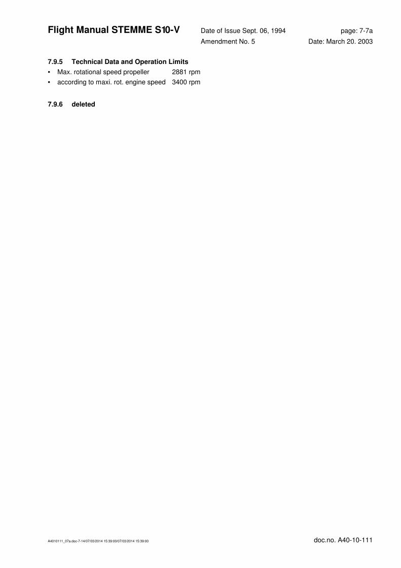
Flight Manual STEMME S 10-V Date of Issue Sept. 06, 1994 page: 7-7a
Amendment No. 5 Date: March 20. 2003
A4010111_07a.doc-7-14/07/03/2014 15:39:00/07/03/2014 15:39:00 doc.no. A40-10-111
7.9.5 Technical Data and Operation Limits
• Max. rotational speed propeller 2881 rpm
• according to maxi. rot. engine speed 3400 rpm
7.9.6 deleted

Flight Manual STEMME S 10-V Date of Issue Sept. 06, 1994 page: 8-0
Amendment No. 0 Date: --
A4010111_07a.doc-8-0/07/03/2014 15:39:00/07/03/2014 15:39:00 doc.no. A40-10-111
Section 8 - Handling, Servicing and Maintenance
8.1 Introduction 8-1
8.2 Powered Sailplane Inspection Periods 8-1
8.3 Alterations or Repairs to the Powered Sailplane 8-1
8.4 Ground Handling / Road Transport 8-1
8.5 Cleaning and Care 8-1

Flight Manual STEMME S 10-V Date of Issue Sept. 06, 1994 page: 8-1
Amendment No.: 7 Date: Jan. 10, 2014
A4010111_07a.doc-8-1/07/03/2014 15:39:00/07/03/2014 15:39:00 doc.no. A40-10-111
8.1 Introduction
This section deals with manufacturer's recommended procedures for proper ground handling and servicing of
the powered sailplane. It also identifies certain inspection and maintenance requirements which must be
followed if the motorglider is to retain that new-plane performance and dependability. It is wise to follow a
planned schedule of lubrication and preventive maintenance based on climatic and flying conditions
encountered.
8.2 Powered Sailplane Inspection Periods
Airframe: (refer to maintenance manual STEMME S10-V) shortest interval: 50h
Engine: (refer to engine maintenance manual) shortest interval: 50h
Drivetrain System: (refer to maintenance manual STEMME S10-V) shortest interval: 50h
Propeller: (refer to maintenance manual STEMME S10-V) shortest interval: 50h
For UK: in addition, all requirements of the Light Aircraft Maintenance Schedule (LAMS) issued by the CAA
are to be completed for 50 hour, 150 hour and Annual Checks.
Note the prescribed inspection after the first 25 h of operation (refer to maintenance manual STEMME S10-V
for the extent of inspection - Document No A40 - 10 - 121 ).
8.3 Alterations or Repairs to the Powered Sailplane
For standard maintenance and minor repairs please refer to the Maintenance Manual, Doc. No. A40-10-121.
The manufacturer must be contacted concerning major repairs.
8.4 Ground Handling / Road Transport
• Parking: SET parking brake (turn lever to ON position and operate brake afterwards) respectively LOCK
pin at brake lever with brake activated (on LH stick, optionally also RH).
Pay attention to the wings being levelled when fuel tanks are full; otherwise there is some leakage through
the tank vents.
• Tie down: screw eyelet into the thread on the bottom surface of the inner wing ends and tie down
vertically.
• Pushing backwards: guide on fin and only push on inner wing.
• Road transport: see manual for trailer.
8.5 Cleaning and Care
It is suggested not to leave the aircraft outside unnecessarily, since even after a few short weeks the
polyester paint can become brittle and crack due to the UV radiation.
The surface and other parts require regular servicing. Detailed suggestions are found in the maintenance
manual.
Flight Manual STEMME S 10-V Date of Issue Sept. 06, 1994 page: 9-0
Amendment No. 0 Date: --
A4010111_07a.doc-9-0/07/03/2014 15:39:00/07/03/2014 15:39:00 doc.no. A40-10-111
Section 9 - Supplements
9.1 Introduction 9-1
9.2 Alternative Equipment 9-1
9.3 Supplemental and Additional Equipment, List of inserted Supplements 9-2
Flight Manual STEMME S 10-V Date of Issue Sept. 06, 1994 page: 9-1
Amendment No. 5 Date: March 20. 2003
A4010111_07a.doc-9-1/07/03/2014 15:39:00/07/03/2014 15:39:00 doc.no. A40-10-111
9.1 Introduction
This section contains the appropriate supplements if various items of optional equipment and systems that
are not part of the standard version are installed in the individual aircraft to which this Flight Manual relates.
With these supplements, the pilot is provided with the additional information and instructions required for safe
and efficient operation.
The installation of optional equipment is always based on a Service Bulletin. The pertinent supplemental
information will be issued in the form of alternativ pages or Flight Manual insert and in the case of a retrofit
will be supplied together with the retrofit kit. Alternativ pages must be inserted instead of standard pages. The
insert (Doc.-No.: A36-SB-No.) is to be filed following page 9-2 (cover page of Section 9.3).
For information on amendments or supplements to the Manuals in the case of optional equipment or systems
please refer also to the Service Bulletin A31-10-008.
The accomplishment of any SB having an effect on the Flight Manual is to be certified prior to the next
flight in the aircraft's log book and in the record of accomplished SBs/ADs by an approved holder of an
Inspection Authorisation. This signature also covers a review of the Flight Manual.
9.2 Alternative Equipment
Special attention is to be paid to the case of equipment and systems which are not installed in addition to but as an alternative to the standard version and thus have an influence on the standard text of the Flight
Manual (Sections 1 to 8). Here the rule applies that associated instructions and information are added to the
corresponding passage of the standard text, with the original text (if any) and the amended text each
appearing in square brackets. A superscript following the closed bracket is identical with the current revision
number, the letter following the superscript indicates whether the text passage applies to the standard version
("s") or to the alternative version ("a") (example: [...]1a).
All text passages in brackets that do not correspond to the aircraft's design configuration described
on page ii (standard version, if no entries) must be deleted.
If this procedure cannot or shall not be applied (Section 3/Emergency Procedures and amendments to
illustrations), the STEMME Company will keep ready "Alternative Pages" of the pages concerned. The
insertation of alternative pages will be indentified by strike out of standard pages (pages without “a”) in the
“List of Effective Pages” (see section 0.2). This procedure is applicable for installation of supplemental or
additional equipment ex work or later installation.

Flight Manual STEMME S 10-V Date of Issue Sept. 06, 1994 page: 9-2
Amendment No. 5 Date: March 20. 2003
A4010111_07a.doc-9-2/07/03/2014 15:39:00/07/03/2014 15:39:00 doc.no. A40-10-111
9.3 Supplemental and Additional Equipment, List of inserted Supplements
Supplemental and additional equipment have no influence on the contents of Sections 1 through 8 of the
Flight Manual. They may, however, require additional instructions, which have been inserted in the present
Flight Manual following this page and entered in the list below.
Manual supplements by the STEMME Company are always based on a Service Bulletin. The document
number of a Flight Manual supplement and associated SB are always identical except for the prefix
(A31-··· Service Bulletin, A36-··· supplement to Manual).
Document No. Subject of the SB or Title of the inserted Document Date inserted