final summary report drainage system evalutation … of mesa drainage system evaluation - phase ii...
TRANSCRIPT

ATION PHASE I1
pa County, Arizona
Concentration Point 109A - combined Quarter Section Map Numbers 107B,D,108A,B,C,D,109A,116A,B,D
Outfall ID MH-624 ,
Drainage Area 0.14 sq miles Areas with 100% Retention 1.75 sq miles
Total Area 1.89 sq miles
Step 1: Determine Weighted dunoff Coefficient (C)
Description of Land Use Runoff Coefficient (C)
Total 90.8 acres 87.6 acres (reduced)". Weighted Runoff Coefficient* =
Step 2: Determine Time of Concentration (T,)
L = Length of the Longest Flow Path in feet ........................... 13,210 feet ............................... K b = Watershed Resistance Coefficient*" 0.050
S = Watercourse Slope in feettmile ...................................... 79.2 Wmile
Iterative Process to Determine Tc and Rainfall Intensity (I)
Step 3: Calculate Peak Discharge ('Q)
Q = CIA
C = Runoff Coefficient (weighted) .......................................... 0.80 ................... I
= Rainfall Intensity in incheslhour (1 0-yr storm). 2.1 0 inlhr = Rainfall intensity in incheslhour (100-yr storm) ................... 3.24 inlhr
A = Drainage Area* (contributing areas only) in acres ................ 87.6 acres ........................................... Q z o = 10-yr Peak Discharge in cfs 147 cfs .......................................... Qloo = 100-yr Peak Discharge in cfs 227 cfs
* The drainage area is reduced by 25% of the medium density and medium to low density residentlal areas to account for retention occurfng
within walled back yards. Thk reduced drainage area is used when calculating the weighted runoff coefflcIent,
as well as the peak discharge. **For the purposes of this study, the watershed resistance coefficient is constant for all drainage areas.
NAGE SYSTEM NALUATION - PHASE I! Rational Method Calculation Sheet Source: Drainage Design Manual for Maricopa County, Arizona
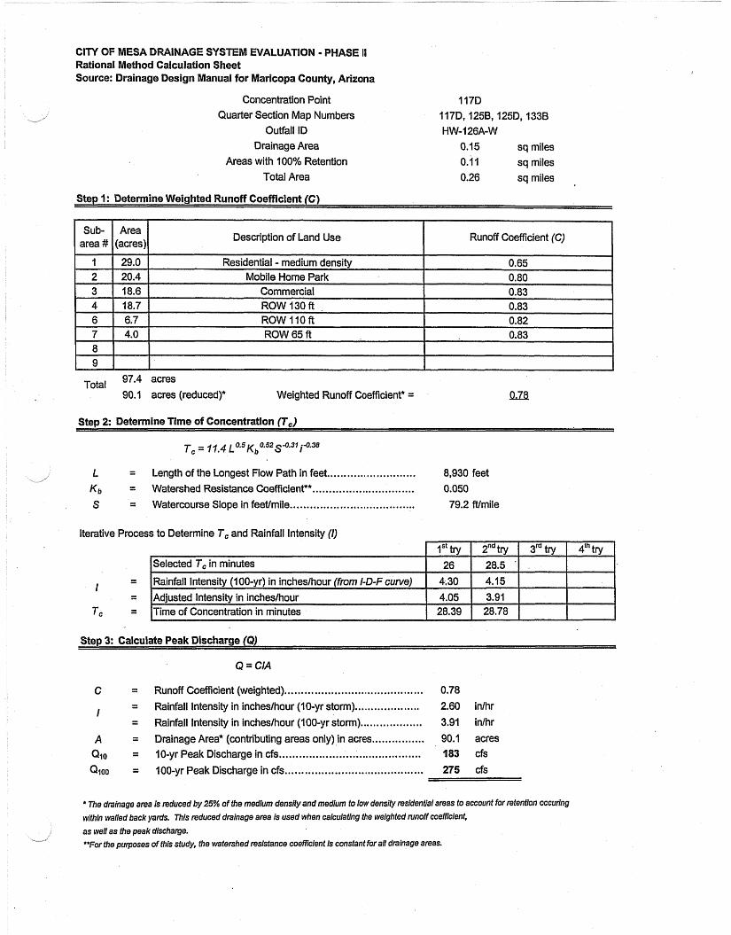
Concentration Point 117D Quarter Section Map Numbers
Outfall ID Drainage Area 0.15 sq miles
Areas with 100% Retention 0.1 I sq miles Total Area 0.26 sq miles ,
Step 1: Determine Weighted Runoff Coefficient (C)
Description of Land Use Runoff Coefficient (C)
Total 97.4 acres 90.1 acres (reduced)" Weighted Runoff Coefficient* = IZZ8
Stew 2: Determine Time of Concentration (7,)
........................... L = Length of the Longest Flow Path in feet 8,930 feet s"
............................... K b = Watershed Resistance Coefficient** 0.050 ...................................... S = Watercourse Slope in feetlmile 79.2 ft/mile
Iterative Process to Determine T, and Rainfall lntensity (I)
- - I - -
Tc - -
Q = CIA
......................................... Runoff Coefficient (weighted).
Rainfall intensity in incheslhour (10-yr storm) .................... Rainfall Intensity in incheslhour (IOO-yr storm) ...................
.............. Drainage Area* (contributing areas only) in acres., ........................................... IO-yr Peak Discharge in cfs
........................................ 100-yr Peak Discharge in cfs..
0.78
2.60 inlhr
3.91 inlhr
90.1 acres 183 cfs
275 cfs
* The drainage area is reduced by 25% of the medium densify and medium to low density residential areas to account for retention occuring
within walled back yards. This reduced drainage area is used when calculating the weighted runoff coemcient,
as well as the peak discharge. **For the purposes of this study, the watershed resistance coefncient is constant for all drainage areas.
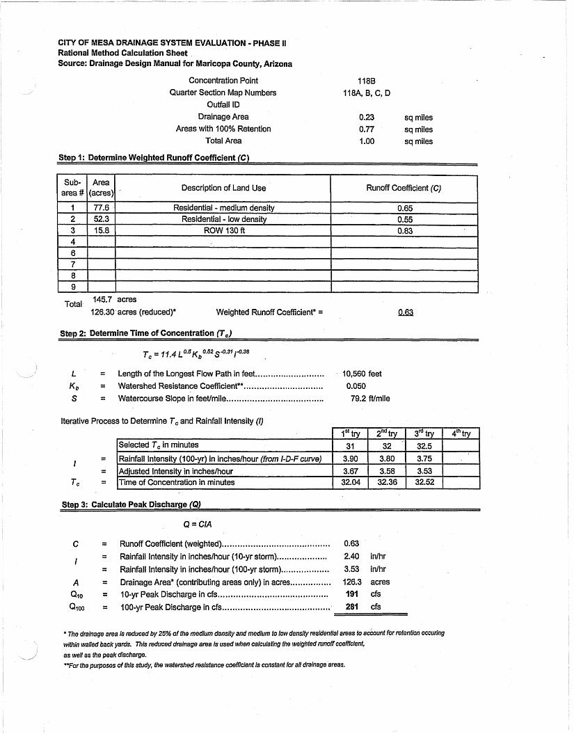
CIN OF MESA DRAINAGE SYSTEM EVALUATION - PHASE II Rational Method Calculation Sheet Source: Drainage Design Manual for aricopa County, Arizona
Concentration Point Quarter Section Map Numbers
Outfall ID Drainage Area
Areas with 100% Retention Total Area
0.23 sq miles 0.77 sq miles 1 .OO sq miles
Step 1: Determine Weighted Runoff Coefficient (C)
Description of Land Use I Runoff Coefficient (C) I Residential - low densi
Total 145.7 acres
126.30 acres (reduced)* Weighted Runoff Coefficient* =
S t e ~ 2: Determine Time of Concentration (T,)
L. = Length of the Longest Flow Path in feet ........................... 10,560 feet ............................... K ~ J = Watershed Resistance Coefficient** 0.050
S = Watercourse Slope in feetlmile ...................................... 79.2 ft/mile
Iterative Process to Determine Tc and Rainfall Intensity (1)
- - I - -
TC - -
Step 3: Calculate Peak Discharge (Q)
Q = CIA
C = Runoff Coefficient (weighted). .................................... 0.63 .................... I = Rainfall Intensity in incheslhour (10-yr storm) 2.40 inlhr
= Rainfall Intensity in incheslhour (100-yr storm) ...............,... 3.53 inlhr
A = Drainage Area* (contributing areas only) in acres ..............,. 126.3 acres ........................................... Qlo = 10-yr Peak Discharge in cfs 191 cfs ......................... ......... Qioo = 100-yr Peak Discharge in cfs ... 281 cfs
* The drainage area is reduced by 25% of the medium dens@ and medium to low density residential areas to account for retention occuring within wailed back yanls. This reduced drainage area is used when calculating the weighted runoff coefficient,
as well as the peak discharge. HFor the purposes of this study, the watershed resisfance coeti7clent is constant for all drainage areas.
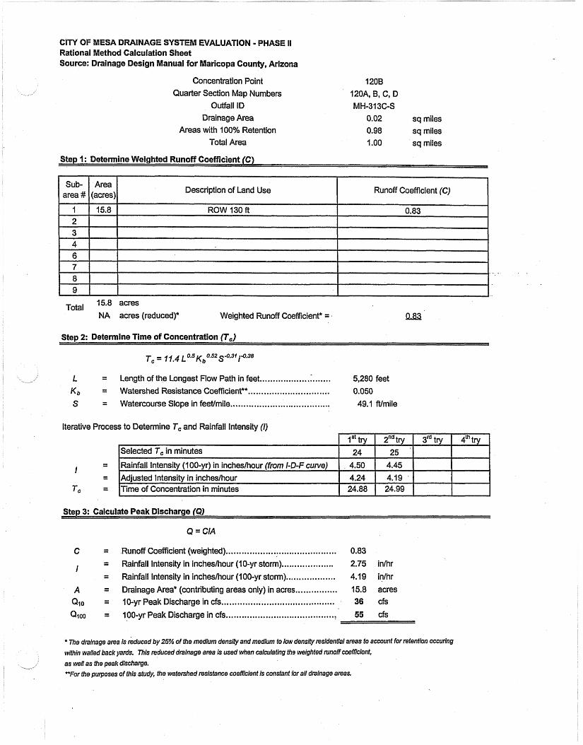
CITY OF MESA DRAINAGE SYSTEM Rational Method Calculation Sheet Source: Drainage Design Manual for Maricopa County, Arizona
Concentration Point 1208 Quarter Section Map Numbers 120A, B, C, D
Outfall ID MH-313C-S Drainage Area 0.02 sq miles
Areas with 100% Retention 0.98 sq miles Total Area I .OO sq miles
Step I: Determine Weighted Runoff Coefficient (C)
Runoff Coefficient
I .
Total 15.8 acres
NA acres (reduced)* Weighted Runoff Coefficient* = 1283,
Step 2: Determine Time of Concentration (7,) P
Tc = 1f,4 ~ 0 . 5 ~ ~ " 5 2 ~ " 3 1 i-0.38
L = Length of the Longest Flow Path in feet ................... :. ...... 5,280 feet ............................... K b = Watershed Resistance Coefficient** 0.050
...................................... S = Watercourse Slope in feet/mile 49.1 Nmile
Iterative Process to Determine 7, and Rainfall lntensity (I)
- I
- - -
Tc - -
Step 3: Calculate Peak Discharge (9)
Q = CIA
........................................ C = .Runoff Coefficient (weighted).. 0.83 ................... I = Rainfall Intensity in incheslhour (1 0-yr storm). 2.75 inlhr
= Rainfall Intensity in incheslhour ( I 00-yr storm). .................. 4.1 9 inihr
A = Drainage Area* (contributing areas only) in acres ................ 15.8 acres ........................................... QIO = 10-yr Peak Discharge in cfs 36 cfs
Q ~ o o = 100-yr Peak Discharge in cfs ..,......................................t 55 cfs
* The drainage area is reduced by 25% of the medium density and medium to low density residential areas fo account for retention occuring
within walled back yards. This reduced drainage area Is used when calculating the weighted runoff coefficient,
as well as the peak discharge.
*For the purposes of this study, the watershed resistance coefficient is consfant for all drainage areas.
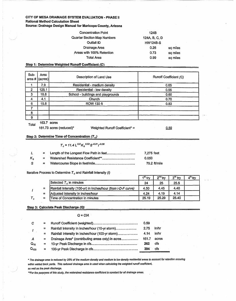
Rational Method Calculation Sheet Source: Drainage Design Manual for Maricopa County, Arizona
Concentration Point 1248 Quarter Section Map Numbers 124A, B, C, D
Outfall ID HWl24B-S Drainage Area 0.26 sq miles
Areas with 100% Retention 0.73 sq miles Total Area 0.99 sq miles
Step I: Determine Weighted Runoff Coefficient (C)
Description of Land Use Runoff Coefficient (C) I
Total 163.7 acres
161.73 acres (reduced)* Weighted Runoff Coefficient* = Qsi!
Step 2: Determine Time of Concentration (7,)
I. = Length of the Longest Flow Path in feet ........................... 7,275 feet
............................... K b = Watershed Resistance Coefficient*" 0.050 S = Watercourse Slope in feetlmile ...................................... 79.2 Wrnile
Iterative Process to Determine 7, and Rainfall Intensity (I)
Step 3: Calculate Peak Discharge (Qj
Q = CIA
Runoff Coefficient (weighted). ......................................... Rainfall Intensity in incheslhour ( I O-yr storm) .................... Rainfall Intensity in incheslhour (1 00-yr storm) ................... Drainage Area* (contributing areas only) in acres ................
........................................ 10-yr Peak Discharge in cfs...
........................................ 100-yr Peak Discharge in cfs..
0.59 2.75 inlhr
4.14 in/hr
161.7 acres 262 cfs
394 cfs
* The drainage area is reduced by 25% of the medium density and medium fo kw density residential areas to account for refentlon occuring wa in walled back yards. This reduced drainage area is used when calculating the weighted runoff coefnclent,
as well as the peak discharge. **For the purposes of this study, the watershed resistance coefncient is constant for all drainage areas. .
INAGE SYSTEM EVALUATION - PHASE II Rational Method Calculation Sheet Source: Drainage Design Manual for Maricopa County, Arizona
Concentration Point Quarter Section Map Numbers
Outfall ID Drainage Area
Areas with 100% Retention Total Area
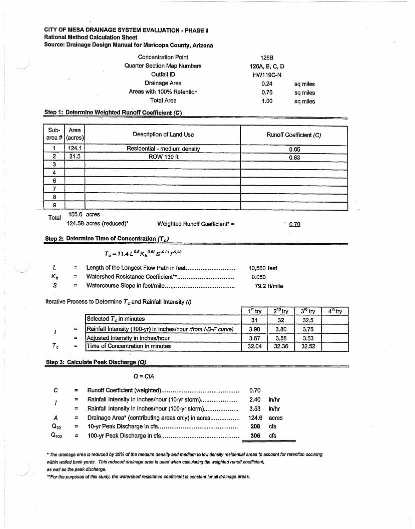
126B 126A, B, C, D HWI 19C-N
0.24 sq miles 0.76 sq miles 1 .OO sq miles
Step I: Determine Weighted Runoff CoefTicient (C)
Description of Land Use Runoff Coefficient (C)
Total 155.6 acres
124.58 acres (reduced)* Weighted Runoff Coefficient* = !LZQ
Step 2: Determine Time of Concentration (T,) L
L = Length of the Longest Flow Path in feet ........................... 10,560 feet
............................... Kb = Watershed Resistance Coefficient** 0.050 ...................................... S = Watercourse Slope in feetimile 79.2 Wmile
Iterative Process to Determine Tc and Rainfall Intensity (I)
Step 3: Calculate Peak Discharge (9)
Q = CIA
C = Runoff Coefficient (weighted) .......................................... 0.70 ................... 1 = Rainfall Intensity in incheslhour (10-yr storm). 2.40 inlhr
= Rainfall Intensity in incheslhour (100-yr storm) ............,...... 3.53 inlhr
................ A = Drainage Area* (contributing areas only) in acres 124.6 acres ..................... ................... Qlo = 10-yr Peak Discharge in cfs .., 20
.......................................... QIOO = 100-yr Peak Discharge in cfs 306 cfs
* The drainage area is reduced by 25% of the medium densify and medium to low densify residential areas to account for retention occuring within walled back yards. This reduced drainage area is used when calculating the weighted runoff coefficient,
as well as the peak discharge. **For the purposes of this study, the watershed resistance coefficient is constant for all drainage areas.

INAGE SYSTEM NALUATIO Rational Method Calculation Sheet Source: Drainage Design Manual for Maricopa County, Arizona
Concentration Point 1278 Quarter Section Map Numbers 1276,127D
Outfall ID MH-513 Drainage Area 0.01 sq miles
Areas with 100% Retention 0.12 sq miles Total Area 0.13 sq miles
Step I: Determine Weighted Runoff Coefficient (C)
Description of Land Use Runoff Coefficient (C)
Total 8.4 acres
NA acres (reducedy Weighted Runoff Coefficient* = Qa.@
Step 2: Determine Time of Concentration (7,)
Tc = 77.4 ~ 0 ~ 5 ~ ~ 0 . 6 2 ~ 4 . 3 f j.0.38
L = Length of the Longest Flow Path in feet ........................... 2,800 feet
............................... K b = Watershed Resistance Coefficient*" 0.050 ...................................... S = Watercourse Slope in feetlmile 49.1 ft/mile
Iterative Process to Determine T, and' Rainfall lntensity (I)
Step 3: Calculate Peak Discharge (Q)
Q = CIA
C = Runoff Coefficient (weighted) ......................................... 0.83 ........... ........
I = Rainfall Intensity in incheslhour (10-yr storm) ; 3.60 inlhr .................. = Rainfall Intensity in inches/hour (1 00-yr storm). 5.28 inlhr
A = Drainage Area* (contributing areas only) in acres ................ 8.4 acres ........................................... Qlo = 10-yr Peak Discharge in cfs 25 cfs ......................................... Qzoo = 100-yr Peak Discharge in cfs 37 cfs
* 7he drainage area Is reduced by 25% of the medium density and medium to low densify residential areas to account for retention occuring
within walled back yards. This reduced drainage area is used when calculating the weighted runoff coefficient,
as well as the peak discharge. e
**For the purposes of this study, the watershed resistance coeMcIent is constant for all ddnage areas.

ll'Y OF MESA DRAINAGE SYSTEM EVALUATION a PHAS ational Method Calculation Sheet
Source: Drainage Design Manual for Maricopa County, Arizona
Concentration Point 1318 Quarter Section Map Numbers 131 B
Outfall ID HW-125C-S Drainage Area 0.01 sq miles
Areas with 100% Retention 0.04 sq miles Total Area 0.05 sq miles
Step 1: Determine Weighted Runoff Coefficient (C)
Description of Land Use Runoff Coefficient (C)
Total 4.8 acres NA acres (reducedy Weighted Runoff Coefficient* =
Step 2: Determine Time of Concentration fl,) i
L = Length of the Longest Flow Path in feet ........................... 1,800 feet ............................... K b = Watershed Resistance Coefficiente* 0.050
S = Watercourse Slope in feetlmile ...................................... 79.2 Nmile
Iterative Process to Determine T, and Rainfall intensity (I)
I = l~ainfall Intensity (100-yr) in incheslhour OM i-D-F curve) 1 6.50 1 6.75 1 6.78 1 I I I 1
Step 3: Calculate Peak Discharge (9)
Q = CIA
C = Runoff Coefficient (weighted) ......................................... 0.83 ....................
i = Rainfall Intensity in inches/hour (10-yr storm) 4.37 inlhr ................... = Rainfall intensity in incheslhou~ (100-yr storm) 6.39 inlhr
A = Drainage Area* (contributing areas only) in acres ................ 4.8 acres .......................................... Qlo = 10-yr Peak Discharge in cfs. 17 cfs .......................................... Qioo = 100-yr Peak Discharge in cfs 25 cfs
* me drainage area is reduced by 25% of fhe medium density and medium to low densify residential areas to account for retention occuring
within walled back yanls. This reduced drainage area is used when calculating the weighted runoff coefficient,
as well as the peak dischar?ge. **For the purposes of this study, the watershed resistance coeMcient is constant for all drainage areas.
C I N OF MESA DRAINAGE SYSTEM LUATION - PHASE II Rational Method Calculation Sheet Source: Drainage Design Manual for Maricopa County, Arizona
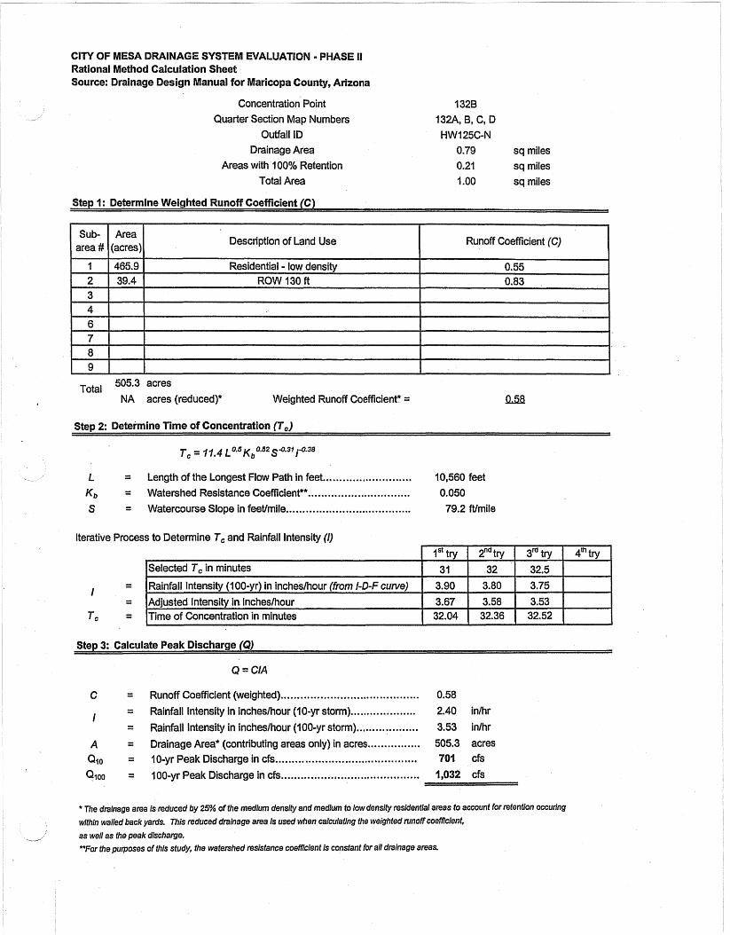
Concentration Point 1328 Quarter Section Map Numbers 132A, B, C, D
Outfail ID HWl25C-N Drainage Area 0.79 sq miles
Areas with 100% Retention 0.21 sq miles Total Area 1 .OO sq miles
Step 1: Determine Weighted Runoff Coefficient (C)
Description of Land Use Runoff Coefficient (C)
Total 505.3 acres
NA acres (reduced)* Weighted Runoff Coefficient* =
Step 2: Determine Time of Concentration (T,)
L = Length of the Longest Flow Path in feet ........................... 10,560 feet ............................... K b = Watershed Resistance Coefficiente* 0.050
S = Watercourse Slope in feetimile ...................................... 79.2 ft/mile
Iterative Process to Determine T, and Rainfall Intensity (I)
Q = CIA
C = Runoff Coefficient (weighted) .......................................... 0.58 .................... I
= Rainfall Intensity in incheslhour (10-yr storm) 2.40 inkr
= Rainfall Intensity in incheslhour (100-yr storm) ................... 3.53 inlhr
A = Drainage Area* (contributing areas only) in acres ................ 505.3 acres ........................................... Qlo = 10-yr Peak Discharge in cfs 701 cfs .......................................... QIOO = 100-yr Peak Discharge in cfs 1,032 cfs
* 730 dralnage area Is reduced by 25% of the medium density and medlum fo [ow density residential areas to account for retention occuring
within walled back yards. This reduced drainage area is used when calculating the weighted runoff coefficIenf,
as well as the peak dlscharge. *For the purposes of thls study, the watershed resistance coefficient is constant for all drainage areas.

CITY OF MESA DRAINAGE SYSTEM Rational Method Calculation Sheet Source: Drainage Design Manual for Maricopa County, Arizona
Concentration Point Quarter Section Map Numbers
Ouffall ID NA Drainage Area 0.22 sq miles
Areas with 100% Retention 0.00 sq miles Total Area 0.22 sq miles
Step 1: Determine Weighted Runoff Coefficient (6)
Description of Land Use Runoff Coefficient (C)
Total 137.8 acres 107.8 acres (reduced)* Weighted Runoff Coefficient* = - 0.63
Step 2: Determine Time of Concentration (7,)
........................... L = Length of the Longest Flow Path in feet 3,500 feet
Kb = Watershed Resistance Coefficient*" ............................... 0.050
S = Watercourse Slope in feetlmile ...................................... 79.2 ft/mile
Iterative Process to Determine Tc and Rainfall lntensity (I)
Step 3: Calculate Peak Discharge (Q)
Q = CIA
C = Runoff Coefficient (weighted). .......................... ;. ............. 0.63
................... I = Rainfall Intensity in incheslhour (10-yr storm). 3.62 inlhr
= . Rainfall Intensity in incheslhour (100-yr storm) ................... 5.37 inlhr
A = Drainage Area* (contributing areas only) in acres... .........,.,. 107.8 acres ........................................... Qlo = 10-yr Peak Discharge in cfs 2
Qioo = 100-yr Peak Discharge in cfs .......................................... 367 cfs
* The drainage area is reduced by 25% of the medium density and medium to low density residential areas to account for retention accuring within walled back yank This reduced drainage area is used when calculating the weighted nrnoff coefficient,
as well as the peak discharge. "For the purposes of tftis study, the watershed resistance coefficient is constant for all drainage areas.

CITY OF MESA DRAINAGE SYSTEM EVALUATION - PHASE II Rational Method Calculation Sheet Source: Drainage Design Manual for Maricopa County, Arizona
Concentration Point 133A - combined Quarter Section Map Numbers 133A, 132A,B,C, &D, 131 0
Outfall ID HW-I 25C-S Drainage Area 1.01 sq miles
Areas with 100% Retention 0.25 sq miles Total Area 1.26 sq miles
Step I: Determine Weighted Runoff Coefficient (C)
Description of Land Use Runoff Coefficient (C)
Total 649..1 acres
61 9.1 acres (reduced)" Weighted Runoff Coefficient* =
Step 2: Determine Time of Concentration (T,)
L = Length of the Longest Flow Path in feet ........................... 11,780 feet ............................... K b = Watershed Resistance Coefficient** 0.050
S = Watercourse Slope in feetlmile ...................................... 79.2 Wmile
Iterative Process to Determine 7, and Rainfall Intensity (I)
- - I - -
Tc - -
Step 3: Calculate Peak Discharge (Q)
Q = CIA
C = Runoff Coefficient (weighted).. ....................................... 0.59 .................... I = Rainfall Intensity in incheslhour (10-yr storm) 2.30 inlhr
= Rainfall Intensity in incheshour (100-yr storm) ................... 3.34 inhr
A = Drainage Area* (contributing areas only) in acres ................ 619.1 acres ........................................... Qlo = 10-yr Peak Discharge in cfs 833 cfs .......................................... Qloo = 100-yr Peak Discharge in cfs 1,210 cfs
* The drainage area is reduced by 25% of the medium density and medium to low density residential areas to account for retention occuring
within wailed back yards. This reduced drainage area is used when calculafing the weighfed runoff coefficient,
as well as the peak discharge.
**For the purposes of this study, the watershed msistance coefficient is constant for all drainage areas.

INAGE SYSTEM EVALUATION - PHASE II Rational Method Calculation Sheet Source: Drainage Design Manual for Maricopa County, Arizona
Concentration Point Quarter Section Map Numbers
Outfall ID Drainage Area 0.01 sq miles
Areas with 100% Retention 0.40 sq miies Total Area 0.41 sq miles
Step 1: Determine Weighted Runoff Coefficient (C)
Description of Land Use Runoff Coefficient (C)
Total 7.8. NA
acres acres (reduced)? Weighted Runoff Coefficient* = QJXi
Step 2: Determine Time of Concentration (T,)
Tc = 11.4 L 0.6 Kb 0.52 S-0.37 i4.38
L = Length of the Longest Flow Path in feet ........................... 2,600 feet
............................... K b = Watershed Resistance Coefficient** 0.050 S = Watercourse Slope in feetfmile ...................................... 79.2 Wmile
Iterative Process to Determine Tc and Rainfall Intensity (I)
- - I - .n.
Tc - -
Step 3: Calculate Peak Discharge (9)
Q = CIA
C = Runoff Coefficient (weighted).. ..................................... 0.83 ................... I = Rainfall Intensity in incheslhour (1 0-yr storm). 4.00 inlhr ................... = Rainfall Intensity in incheslhour (100-yr storm) 6.03 inlhr
A = Drainage Area* (contributing areas only) in acres ................ 7.8 acres ........................................... Qlo = 10-yr Peak Discharge in cfs 26 cfs ........................................ Q i o o = 100-yr Peak Discharge in cfs 39 cfs
* The drainage area is reduced by 25% of the medium densfly and medium to low density residential areas to account for retention occuring
within walled back yards. 7111s reduced drainage area is used when calculatlng the weighted runoff coefficient,
as well as the peak dischame. **For the purposes of this study, the watershed resistance coefficient is constant for aN drainage areas.
INAGE SYSTEM EVALUATION - PHASE II ational Method Calculation Sheet
Source: Drainage Design Manual for Maricopa County, Arizona
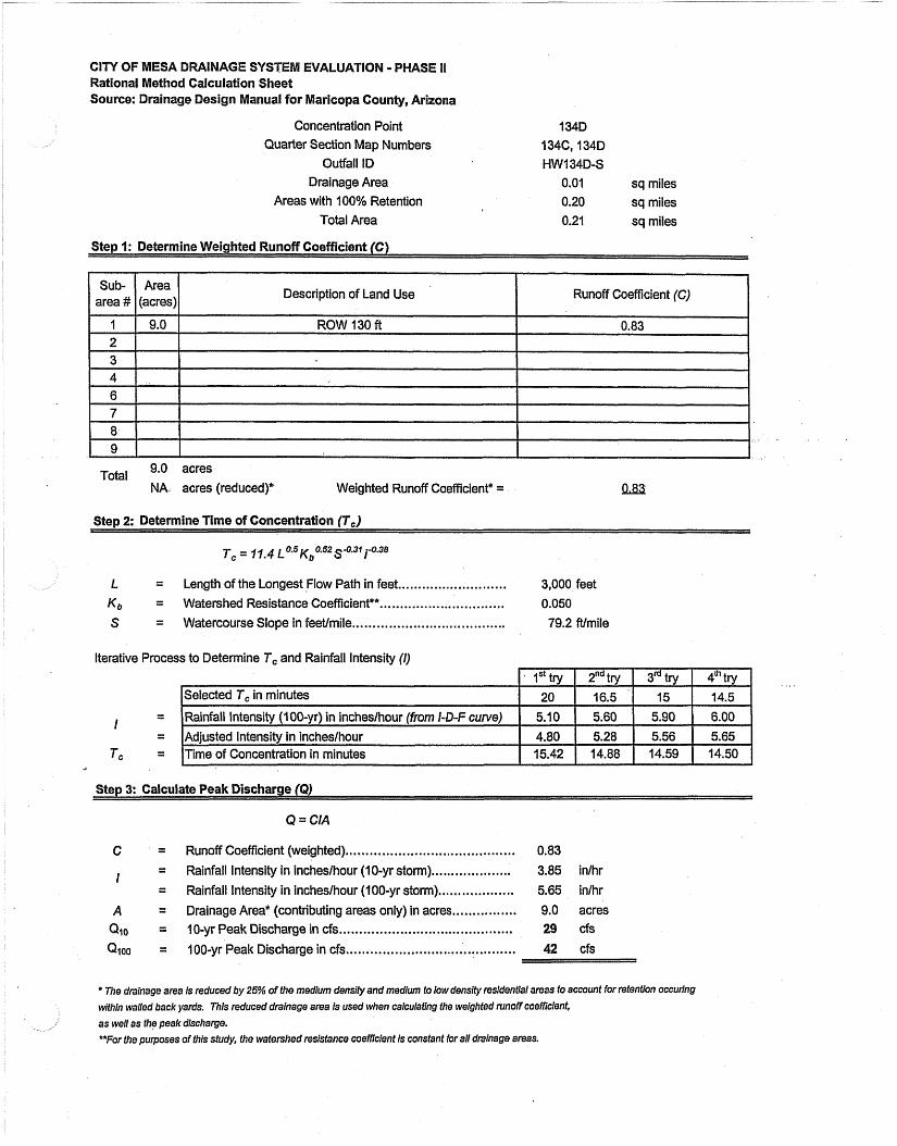
Concentration Point 134D Quarter Section Map Numbers 134C, 134D
Outfall ID HW 1 34D-S Drainage Area 0.01 sq miles
Areas with 100% Retention 0.20 sq miles L
Total Area 0.21 sq miles
Step 1: Determine Weighted Runoff Coefficient (C)
Description of Land Use Runoff Coefficient (C)
Total 9.0 acres
NA acres (reduced)* Weighted Runoff Coefficient* =
Step 2: Determine Time of Concentration (7,)
L = Length of the Longest Flow Path in feet ........................... 3,000 feet ............................... Kb = Watershed Resistance Coefficient** 0.050
S = Watercourse Slope in feetlmile ...................................... 79.2 ft/mile
Iterative Process to Determine T, and Rainfall Intensity (I)
Q = CIA
C = RunoffCoefficient(weighted) .......................................... 0.83
.................... I = Rainfall Intensity in incheslhour (10-yr storm) 3.85 idhr = Rainfall Intensity in inches/hour (1 00-yr storm).. ................. 5.65 inlhr
A = Drainage Area* (contributing areas only) in acres ................ 9.0 acres ......................................... Qlo = I 0-yr Peak Discharge in cfs.. 29 d s
.......................................... Qioo = 100-yr Peak Discharge in cfs 42 cfs
* The drainage area is reduced by 25% of the medium density and medium to low density resldential areas to account for retention occuring within walled back yards. This reduced drainage area is used when calculating the weighted runoff coefficient,
as well as the peak discharge. **For the purposes of this study, the watershed resistance coefficient is constant for all drainage areas.

INAGE SYSTEM NALUATI Rational Method Calculation Sheet Source: Drainage Design Manual for Maricopa County, Arizona
Concentration Point 1358 Quarter Section Map Numbers 135B, 135D
Outfall ID MH-1270-N Drainage Area 0.02 sq miles
Areas with 100% Retention 0.48 sq miles Total Area 0.50 sq miles
Step 1: Determine Weighted Runoff Coefficient (C)
I J
Total 15.8 acres
NA acres (reducedy Weighted Runoff Coefficient* = a83,
Ster, 2: Determine Time of Concentration ff,)
L = Length of the Longest,Flow Path in feet ........................... 5,280 feet
............................... Kb = Watershed Resistance Coefficiente* 0.050
S = Watercourse Slope in feeffmile ..................................... 49.1 Wmile
Iterative Process to Determine Tc and Rainfall Intensity (I)
Step 3: Calculate Peak Discharge (Q)
Q = CIA
C = Runoff Coefficient (weighted) .......................................... 0.83 .................... I = Rainfall Intensity in incheslhour (10-yr storm) 2.75 inlhr ................... = Rainfall Intensity in incheslhour (100-yr storm) 4.19 idhr
A = Drainage Area* (contributing areas only) in acres ................ 15.8 acres .......................................... Q f o = 10-yr Peak Discharge in ds 36 cfs
..................... ................ Q ~ o o = 100-yr Peak Discharge in cfs .... 55 cfs
* The drainage area is reduced by 25% of fhe medium densily and medium to low density resldenUa1 areas to account for retention occuring
Wthin walled back yards. This reduced drainage area is used when calculating the weighted runoff coefficient,
-& as well as the peak discharge.
HFor the purposes of this study, the watekhed resistance coefncfenf is constant for all drainage areas.

NAGE SYSTEM EVALUATION - PWAS Rational Method Calculation Sheet Source: Drainage Design Manual for Maricopa County, Arizona
Concentration Point 1398 Quarter Section Map Numbers 139B, 139D
Outfall ID HW-1248-S Drainage Area 0.01 sq miles
Areas with 100% Retention 0.30 sq miles Total Area 0.31 sq miles
Step I: Determine Weighted Runoff Coefficient (C)
Total 4.2 acres
NA . acres (reduced)* Weighted Runoff Coefficient* = QAU
S t e ~ 2: Determine Time of Concentration (7,)
L = Length of the Longest Flow Path in feet ........................... 1,400 feet
............................... Kb = Watershed Resistance Coefficient*" 0.050 ...................................... S = Watercourse Slope in feevmile 79.2 ft/mile
Iterative Process to Determine Tc and Rainfall Intensity (I)
Step 3: Calculate Peak Discharge (Q)
Q = CIA
.......................................... C = Runoff Coefficient (weighted) 0.83 .................... I = Rainfall Intensity in incheslhour ( I 0-yr storm) 4.50 inlhr
.................. = Rainfall Intensity in incheslhour ( I 00-yr storm). 6.95 inihr
A = Drainage Area* (contributing areas only) in acres ................ 4.2 acres ........................................... Qlo = 10-yr Peak Discharge in cfs 16 cfs ......................................... QIOO = 100-yr Peak Discharge in cfs. 24 cfs
* 7716 drainage area is reduced by 25% of the medium density and medium to low density residential areas to account for retention occuring
within walled back yards. This reduced drainage area is used when calculating the weighted runoff coefficient,
as well as the peak discharge. T o r the purposes of this sfudy, the watershed resistance coefficient is constant for aN drainage areas.
C I N OF MESA DRAINAGE SYSTEM EVALUATION - PHASE I1 Rational Method Calculation Sheet Source: Drainage Design Manual for Maricopa County, Arizona
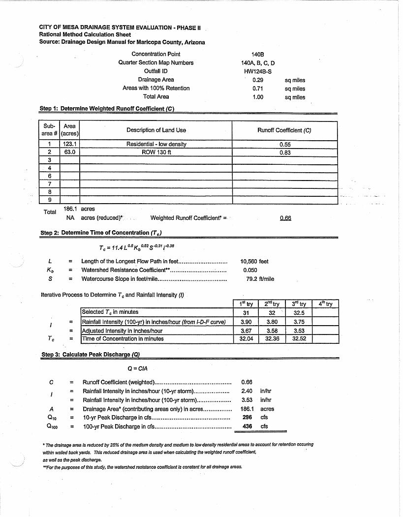
Concentration Point 1408 Quarter Section Map Numbers 140A, B, C, D
Outfail ID HW124B-S Drainage Area 0.29 sq miles
Areas with 100% Retention 0.71 sq miles Total Area 1 .OO sq miles
Step 1: Determine Weighted Runoff Coefficient (C)
area #. (acres) I Sub- I Area I Description of Land Use Runoff Coefficient (C)
Total 186.1 acres
NA acres (reduced)* Weighted Runoff Coefficient* = QAB
Step 2: Determine Time of Concentration (7,)
L = Length of the Longest Flow Path in feet ........................... 10,560 feet
K b = Watershed Resistance Coefficiente*.. ;. ..... 0.050 ...................... ...................................... S = Watercourse Slope in feetlmiie 79.2 ftlmile
Iterative Process to Determine Tc and Rainfall lntensity (I)
- I
.,.r
- - T c - -
Step 3: Calculate Peak Discharge (Q)
Q = CIA
C = Runoff Coefficient (weighted) .......................................... 0.66
.................... I = Rainfall Intensity in incheslhour (10-yr storm) 2.40 inlhr
= Rainfall Intensity in incheslhour (1 00-yr storm) ................... 3.53 inlhr
A = Drainage Area* (contributing areas only) in acres... ............. 186.1 acres
Qzo = 10-yr Peak Discharge in cfs ........................................... 296 cfs
......................................... QIOO = 100-yr Peak Discharge in cfs. 436 cfs
* The drainage area is reduced by 25% of the medium densify and medium to low density residential areas to account for retention occuring
wlfhin wakd back yards. 7his reduced drainage area is used when calculating the weighted runoff coefficient,
as well as the peak discharge. i - **For the purposes of thls sfudy, the watershed resistance coefficient Is constant for all drainage areas.
c l n OF MESA DRAINAGE SYSTEM EVALUATION - PHAS Rational Method Calculation Sheet Source: Drainage Design Manual for Maricopa County, Arizona
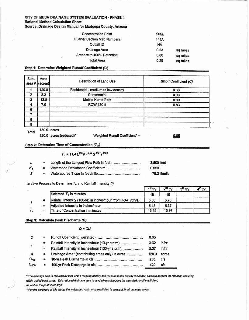
Concentration Point 141A Quarter Section Map Numbers 141A
Outfall ID NA Drainage Area 0.23 sq miles
Areas with 100% Retention 0.06 sq miles Total Area 0.29 sq miles
Step I: Determine Weighted Runoff Coefficient (C)
t I I I
Description of Land Use Runoff Coefficient (C)
Total 150.0 acres 120.0 acres (reduced)* Weighted Runoff Coefficient* =
Sten 2: Determine Time of Concentration (T,)
L = Length of the Longest,Flow Path in feet ........................... 3,500 feet ............................... K b = Watershed Resistance Coefficiente* 0.050
S = Watercourse Slope in feetlmile .................................... 79.2 Wmile
Iterative Process to Determine Tc and Rainfall Intensity (I)
Step 3: Calculate Peak Discharge (Q)
Q = CIA
C = Runoff Coefficient (weighted). ......................................... 0.65 ................. I = Rainfall Intensity in incheslhour (10-yr storm).,. 3.62 inlhr
= Rainfall Intensity in incheslhour (100-yr storm) ................... 5.37 inlhr .............. A = Drainage Area* (contributing areas only) in acres.. 120.0 acres
Q.ro = 10-yr Peak Discharge in cfs ........................................... 283 cfs
QIOO = 100-yr Peak Discharge in cfs .......................................... 420 cfs
* m e drainage area is reduced by 25% of the medium density and medium to low density residential areas to account for retention occuring within walled back yards. This reduced drainage area is used when calculating the weighted runoff coefficient,
as well as the peak discharge. **For the purposes of thls study, the watershed resistance coefficient is constant for all drainage areas,
UATION - PHASE II
copa County, Arizona
Concentration Point Quarter Section Map Numbers
Outfall ID Drainage Area '
Areas with 100% Retention Total Area
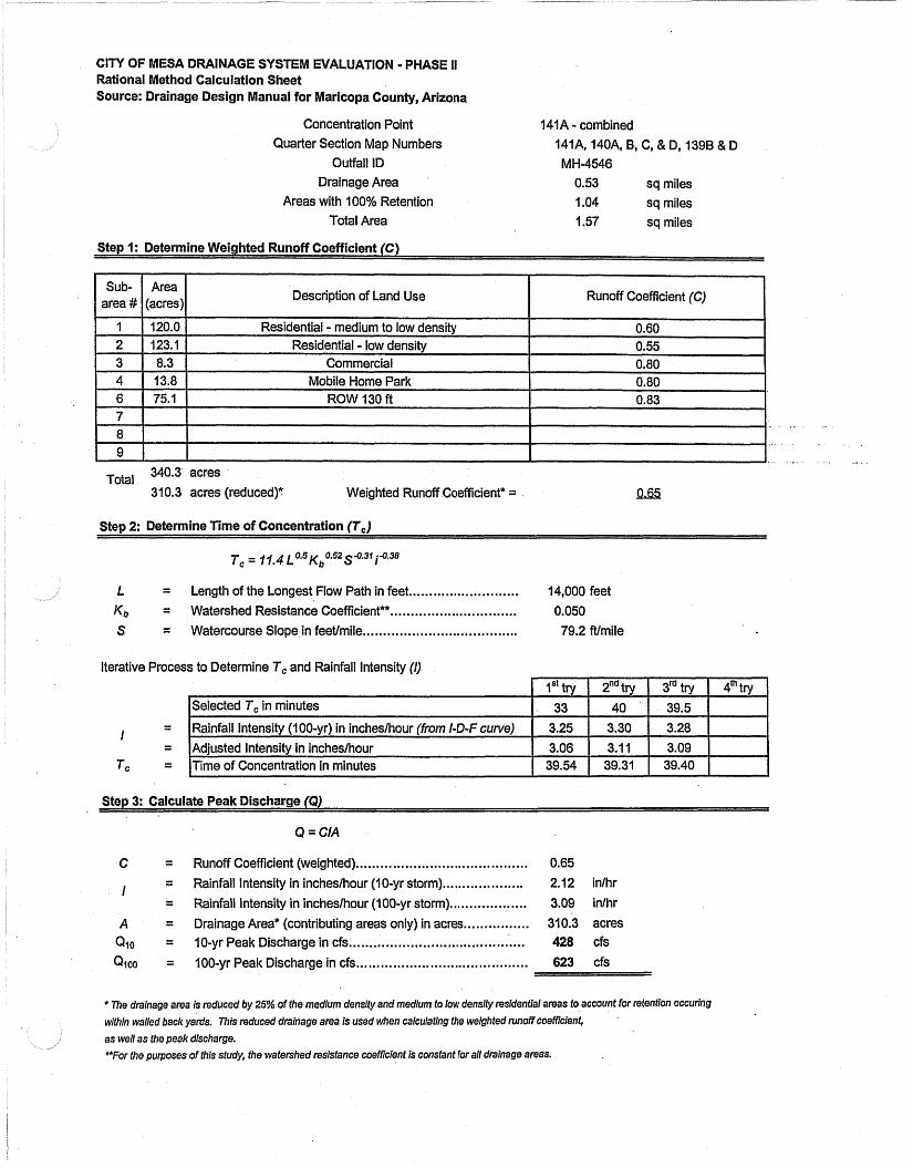
141A - combined 141A, 140A, B, C, & D, 1398 & D MH-4546
0.53 sq miles 1.04 sq miles 1.57 sq miles
Step I: Determine Weighted Runoff Coefficient (C)
area # I Sub- (acres) Area I Description of Land Use Runoff Coefficient (C)
Total 340.3 acres
31 0.3 acres (reduced)" Weighted Runoff Coefficient* = QvkY2
Sten 2: Determine Time of Concentration f f , 1
T, = 11.4 ~ 0 . 5 ~ ~ 0 . 5 2 ~ 5 . 3 1 i5.38
L = Length of the Longest Flow Path in feet ........................... 14,000 feet ............................... K b = Watershed Resistance Coefficient** 0.050
...................................... S = Watercourse Slope in feetimile 79.2 ft/miie
Iterative Process to Determine Tc and Rainfall Intensity (I)
Step 3: Calculate Peak Discharge (Q)
Q = CIA
C = Runoff Coefficient (weighted). ....................................... 0.65 .................... I = Rainfall Intensity in inchesthour (10-yr storm) 2.12 inlhr
= Rainfall Intensity in incheslhour (1 00-yr storm). .................. 3.09 inlhr
A = Drainage Area* (contributing areas only) in acres ................ 310.3 acres Qlo = 10-yr Peak Discharge in cfs ......................... ., ............... 428 cfs
QIOO = 100-yr Peak Discharge in cfs .......................................... 623 cfs
* me drainage area is reduced by 25% of the medium density and medium to low densify residential areas to account for retention occuring
within walled back yards. This reduced drainage area is used when calculaffng the welghfed runoff coemcient,
as well as the peak discharge. HFor the purposes of this sfudy, the watershed resisfance coefficient is constant for all drainage areas.
CITY OF MESA DRAINAGE SYSTEM Rational Method Calculation Sheet Source: Drainage Design Manual for Maricopa County, Arizona
Concentration Point Quarter Section Map Numbers
Outfail ID ,
Drainage Area Areas with 100% Retention
Total Area
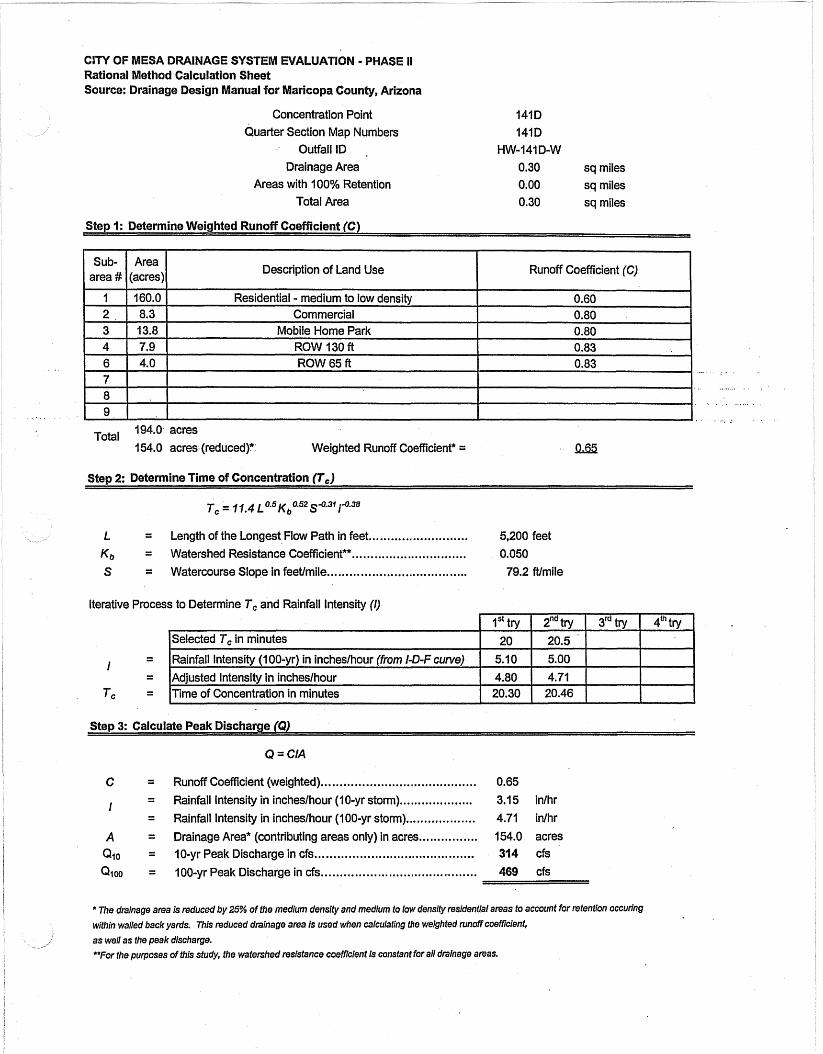
1410 14lD
HW-141 D-W 0.30 sq miles 0.00 sq miles 0.30 sq miles
Step 1: Determine Weighted Runoff Coefficient (C)
Description of Land Use Runoff Coefficient (C)
Total 194.0 acres
154.0 acres (reduced)* Weighted Runoff Coefficient* =
Step 2: Determine Time of Concentration (7,)
T, = 77.4 ~ 0 . 5 ~ ~ 0 . 5 2 ~ 4 . 3 1 i4.38
L = Length of the Longest Flow Path in feet ........................... 5,200 feet
............................... K b = Watershed Resistance Coefficient*" 0.050
S = Watercourse Slope in feetlmile ...................................... 79.2 ftlmile
Iterative Process to Determine Tc and Rainfall Intensity (I)
- I
- - -
Tc - -
Step 3: Calculate Peak Discharge (Q)
Q = CIA
C = Runoff Coefficient (weighted) ......................................... 0.65 .................... I = Rainfall Intensity in inchesthour (10-yr storm) 3.1 5 inlhr
= Rainfall Intensity in inchesthour (100-yr storm) ................... 4.71 inlhr
A = Drainage Area* (contributing areas only) in acres ................ 154.0 acres ........................................... Qlo = 10-yr Peak Discharge in cfs 314 cfs
.......................................... Qtoo = 100-yr Peak Discharge in cfs 469 cfs
* The drainage area is reduced by 25% of the medium density and medium to low density residenfial areas to account for retention occuring
within walled back yards. This reduced drainage area is used when calculating the weighted runoff coefficient,
as well as the peak discharge. **For the purposes of this study, the wafershed resistance coefficient is constant for all drainage areas.

INAGE SYSTEM EVALUATION - PHAS Rational Method Calculation Sheet Source: Drainage Design Manual for Maricopa County, Arizona
Concentration Point 1428 Quarter Section Map Numbers 142B
Outfall ID , HW-134B-S Drainage Area 0.07 sq miles
Areas with 100% Retention 0.07 sq miles Total Area 0.14 sq miles
Step I: Determine Weighted Runoff Coefficient (C)
Description of Land Use Runoff Coefficient (C)
Total 45.8 acres .
NA acres (reduced)?: : Weighted Runoff Coefficient* =.
Step 2: Determine Time of Concentration (T,)
L = Length of the Longest Flow Path in feet ........................... 2,500 feet ............................... K b = Watershed Resistance Coefficient** 0.050
S = Watercourse Slope in feetJmile ...................................... 79.2 Wmile
Iterative Proces ; to Determine Tc and Rainfall Intensity (I)
Step 3: Calculate Peak Discharge (Q)
Q = CIA
C = Runoff Coefficient (weighted) .......................................... 0.65
................... I = Rainfall Intensity in incheslhour ( I O-yr storm). 4.00 inlhr
= Rainfall Intensity in incheslhour (IOO-yr storm) ................... 6.03 inlhr
A = Drainage Area* (contributing areas only) in acres ................ 45.8 acres ........................................... Q ~ o = 10-yr Peak Discharge in cfs 11 ......................................... Qioo = 100-yr Peak Discharge in cfs 179 cfs
* The drainage area is reduced by 25% of the medium density and medium to low density residential areas to account for refentlon occurfng within walled back yards. This reduced drainage area is used when calculating the weighted runoff coefficient, as well as the peak discharge. T o r the purposes of this study, the watershed resistance coefhcient is constant for all drainage areas.
INAGE SYSTEM EVALUATION PHASE It Rational Method Calculation Sheet Source: Drainage Design Manual for Maricopa County, Arizona
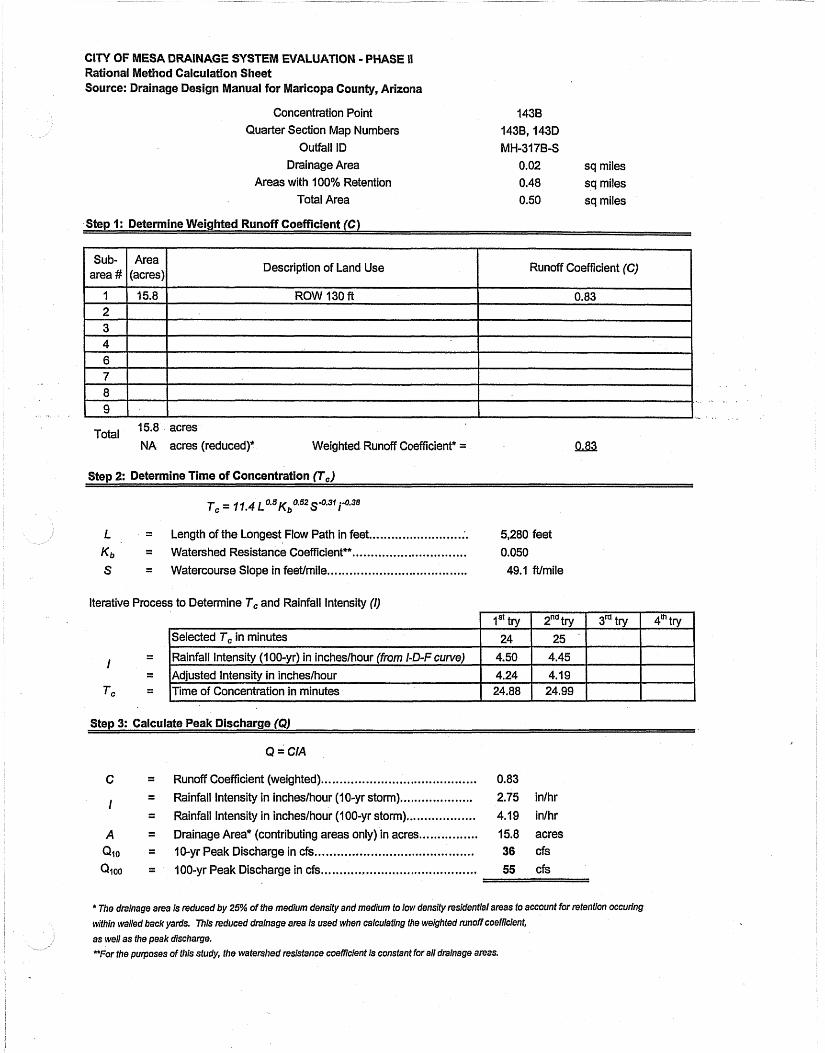
Concentration Point Quarter Section Map Numbers
Outfall ID Drainage Area sq miles
Areas with 100% Retention sq miles Total Area sq miles
Step 1: Determine Weighted Runoff Coefficient (C)
Description of Land Use Runoff Coefficient (C)
15.8 acres Total NA acres (reduced)* Weighted Runoff Coefficient* = aL8;2,
Step 2: Determine Tina of Concentration (T,)
L = Length of the Longest Flow Path in feet ......................... :. 5,280 feet ............................... K b = Watershed Resistance Coefficient** 0.050
S = Watercourse Slope in feetlmile. ....................... , ........... 49.1 Wmile
Iterative Process to Determine Tc and Rainfall Intensity (I)
- I
- - -
Tc - -
Step 3: Calculate Peak Discharge (Q)
Q = CIA
C = Runoff Coefficient (weighted) ........................................ 0.83 .................... i = Rainfall Intensity in incheslhour (10-yr storm) 2.75 inlhr
= Rainfall Intensity in incheslhour ( I OO-yr storm) ................... 4.19 inlhr
A = Drainage Area* (contributing areas only) in acres. ............... 15.8 acres ........................................... Qlo = 10-yr Peak Discharge in cfs 36 cfs
Q i o o = 100-yr Peak Discharge in cfs .......................................... 55 cfs
* The drainage area is reduced by 25% of the medium densify and medium to low densify residential areas to account for retention occurlng
within walled back yards. This reduced drainage area is used when calculating the weighted runoff coefficient,
as well as the peak discharge. **For the purposes of this study, the watershed resistance coefficient is constant for all drainage areas.

EVALUATION - PHASE ll
Maricopa County, Arizona
Concentration Point 3128 - combined Quarter Section Map Numbers 312A,B,C,D, 313A,B,C,D, 314A,B,C,D
Ouffall ID MH-313B-S Drainage Area 0.1 1 sq miles
Areas with 100% Retention 2.70 sq miles Total Area 2.81 sq miles
Description of Land Use Runoff Coefficient (C)
72.5 acres Total NA acres (reduced)? Weighted Runoff Coefficient* = QLa
tep 2: Determine Time of Concentration (T,)
T, = 11,4 ~ 0 . 5 ~ ~ 0 . 5 2 ~ - 0 . 3 1 i-0.38
L = Length of the Longest Flow Path in feet ........................... 14,060 feet
............................... K b = Watershed ~esistance Coefficient** 0.050 S = Watercourse Slope in feetlmile ...................................... 49.1 Wmile
Iterative Process to Determine T, and Rainfall Intensity ( I f .
Step 3: Calcuiate Peak Discharge (Q)
Q = CIA
C = Runoff Coefficient (weighted) ....................................... 0.83
.................... I = Rainfall Intensity in incheslhour (10-yr storm) 1.83 inlhr
= Rainfall Intensity in incheslhour (100-yr storm) ................... 2.70 inlhr
............. A = Drainage Area* (contributing areas only) in acres... 72.5 acres .......................................... Qlo = 10-yr Peak Discharge in cfs. 110 cfs
.......................................... Qioo = 100-yr Peak Discharge in cfs 162 cfs
* The dralnage area is reduced by 25% of the medium density and medium to low denslty residential areas to account for refenffon occuring
wifhin walled back yards. This reduced drainage area is used when calculating the welghted runoff coefficient,
as well as the peak discharge. *For the purposes of this study, fhe watershed resistance coefficient is constant for aN drainage areas.

INAGE SYSTEM EVALUATION * PHAS Rational Method Calculation Sheet Source: Drainage Design Manual for Maricopa County, Arizona
Concentration Point 31 38 Quarter Section Map Numbers 313A, B, C, D
Outfall ID MH-3136-S Drainage Area 0.05 sq miles
Areas with 100% Retention 0.95 sq miles Total Area 1 .OO sq miles
Step 1: Determine Weighted Runoff Coefficient (6)
Description of Land Use Runoff Coefficient (C)
TotaZ 31.6 acres
NA acres (reducedy Weighted Runoff Coefficient* = !uB Sten 2: Determine Time of Concentration lT, 1
L = Length of the Longest Flow Path in feet ........................... 5,280 feet
K b = Watershed Resistance Coefficient** ......,.... ;. 0.050 .................. ...................................... S = Watercourse Slope in feeffmile 49.1 Wmiie
Iterative Proces s to Determine Tc and Rainfall lntensity (I)
Step 3: Calculate Peak Discharge (Q)
Q = CIA
C = Runoff Coefficient (weighted) ..................................... 0.83
................... I = Rainfall Intensity in incheslhour ( I 0-yr storm). 2.75 inlhr = Rainfall Intensity in incheslhour ( I 00-yr storm).,. ................ 4.19 inlhr
A = Drainage Area* (contributing areas only) in acres. ............... 31.6 acres ........................................... Qlo = 10-yr Peak Discharge in cfs 72 cfs
Qioo = 400-yr Peak Discharge in cfs .......................................... 110 cfs
* The drainage area is reduced by 25% of the medium density and medium to low density residential areas to account for retenflon occuring
within walled back yards. This reduced drainage area is used when calculafing the weighted runoff coemcient,
as well as the peak discharge. **For the purposes of this study, the watershed resisfance coemcient is constant for all drainage areas.

INAGE SYSTEM EVALUATIO Rational Method Calculation Sheet Source: Drainage Design Manual for Maricopa County, Arizona
Concentration Point 314B Quarter Section Map Numbers 314A, B, C, D
Outfall ID MH-313C-S Drainage Area 0.05 sq miles
Areas with 100% Retention 0.95 sq miles Total Area 1 .OO sq miles
Step 1: Determine Weighted Runoff Coefficient (C)
Runoff Coefficient
Total 31.6 acres
NA acres (reduced)* Weighted Runoff Coefficient* =
Step 2: Determine Time of Concentration (T,)
T, = 11.4 ~ 0 . 5 ~ ~ 0 . 5 2 ~5.3' i-0.38
........................... 1 = Length of the Longest Flow Path in feet 5,280 feet ............................... K b = Watershed Resistance Coefficiente* 0.050
...................................... S = Watercourse Slope in feetlmile 49.1 ft/mile
Iterative Process to Determine Tc and Rainfall Intensity (I)
Step 3: Calculate Peak Discharge (Q)
Q = CIA
C = Runoff Coefficient (weighted). ......................................... 0.83
.................... I = Rainfall Intensity in incheslhour ( I O-yr storm) 2.75 in/hr = Rainfall Intensity in incheslhour (I OO-yr storm) ................... 4.19 inlhr
A = Drainage Area* (contributing areas only) in acres ................ 31.6 acres ........................................... Qio = 10-yr Peak Discharge in cfs 72 cfs
QIQO = 100-yr Peak Discharge in cfs .......................................... 110 cfs 1
* The drainage area is reduced by 25% of the medium density and medium to low density residential areas to account for retention occudng
wifhin walled back yards. This reduced drainage area is used when calculating fhe weighted runoff coefncient,
as well as the peak discharge. **For the purposes of this study, the watershed resistance coefficient is constant for all drainage areas.

Source: Drainage Design Manual for Maricopa County, Arizona
Concentration Point 317B - combined Quarter Section Map Numbers 143B, D, 144, B, C, D & 317A, B, C, D
Outfail ID Mti-317B-S Drainage Area 0.07 sq miles
Areas with 100% Retention 2.43 sq miles Total Area 2.50 sq miles
Step 1: Determine Weighted Runoff Coefficient (C) i
area Sub # I (acres) Area I Description of Land Use Runoff Coefficient (C)
Total 47.4 acres .
NA acres (reduced)* Weighted Runoff Coefficient* = QJE!
L = Length of the Longest Flow Path in feet ........................... 17,060 feet ............................... K b = Watershed Resistance Coefficient** 0.050
S = Watercourse Slope in feetlmile ...................................... 49.1 ft/mile
Iterative Process to Determine Tc and Rainfall lntensity (I)
I = l~ainfall Intensity (100-yr) in incheslhour (from I-5-F curve) 1 2.90 1 2.70 1 2.66 1 1
Step 3: Calculate Peak Discharge (Q)
Q = CIA
C = Runoff Coefficient (weighted). ......................................... 0.83 .................... I = Rainfall Intensity in inchesihour (10-yr storm) 1.69 inlhr
= Rainfall Intensity in incheslhour (100-yr storm) ................... 2.51 inlhr
A = Drainage Area* (contributing areas only) in acres ................ 47.4 acres .......................................... (210 = 10-yr Peak Discharge in cfs. 66 cfs
....................................... (2100 = 100-yr Peak Discharge in cfs... 99 cfs
* The drainage area is reduced by 25% of fhe medium density and medium to low density resldenfial areas to account for retention occuring
within walled back yards. This reduced drainage area Is used when calculaflng the weighted runoff coemcient,
as well as the peak discharge.
*"For the purposes of this study, fhe watershed &stance coefficient is constant for all drainage ateas.
Page I
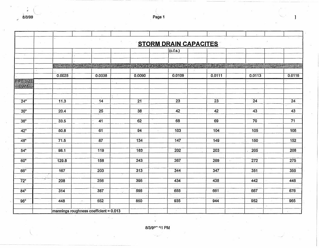
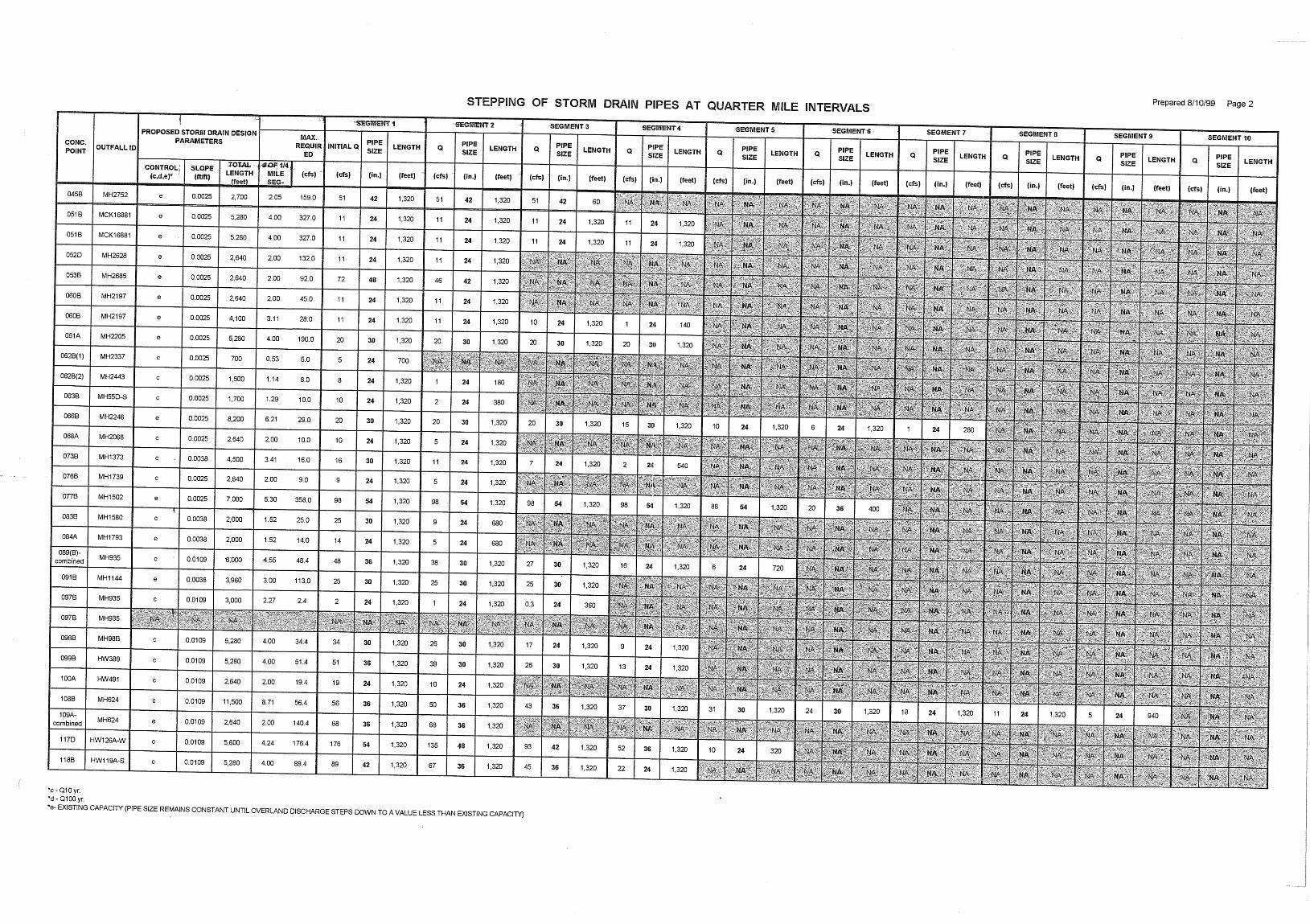
. 96" , 448 552 1 850 , 935 , 944 952 ' 965
rnannings roughness coefficient = 0.013 I I I


9f 17199 PROPOSED STORM D IN DIAMETER AT OUTFALL Page 1
1184.20 1194.20 1 4000 0.0025 1 W I Tempe Storm Sewer Road to Main Street
1000.00 100250 1000 0.0025 60 Main Street at the Tempe Canal
,94.24 1207.44 5280 0.0025 54 University Drive: Dobson Road to Alma School Road
1194.56 1 1202.56 1 3200 1 0.0025 1 48 1 Baseline: Alma School Road to Extension
1212.61 1 1215.91 1 1320 1 0.00'25 1 42 1 Road: Main Street
121223 1215.53 1320 0.0025 30 Alma School Road: Railroad track to Broadway Road
1000.00 1031.75 12700 0.0025 84 Lehi: Center to Gilbert
1207.68 1 121268 1 2000 I 0.0025 1 48 1 Bmadway Road to 2nd Street
10oo~OO 1 1003.50 1 ,400 1 0.0025 1 36 1 Mesa Drive: Lehi to Future Red Mountain Freeway
Mesa Drive: Bates Road to McKellips i I I
36 Mesa Drive: Tempe Canal to McKeilips
1229.24 1 1230.49 1 500 1 0.0025 1 24 1 Mesa Drive: Ternpecanalto Brown Road
1229.24 1 1234.24 1 2000 / 0.0025 1 30 1 Mesa Drive: 8th Streetto Brown Road I I
1232.77 1239.37 2640 0.0025 36 Mesa Drive 8th Street to University
1217.47 1222.47 2000 0.0025 48 Mesa Drive: 2nd Street to Broadway
1000.00 I 1005.00 I 2000 I 0.0025 1 42 1 Stlpley Red FreMy lehi Road
1251.96 1 1253.96 1 800 1 0.0025 1 24 1 Stapley Southern Canal to McKellips
1 1251.96 1 1265.16 1 5280 1 0.0025 1 36 1 Stapley Brown Roadta McKellips
3 1230.70 1240.95 4100 0.0025 36 * University: Consolidated Canal to Staple]
*a-llO'R.O.W. "c-Q10 TI-130'R.0.W. *d-a100 "e - MIST. OUTFALL CAPACITY * - ASSUMED ADEQUATE CAPACITY

911 7199 PROPOSED STORM D IN DIAMETER AT OUTFALL Page 2
Stapley Drive: Main Street to Broadway
Broadway: Harris to Stapley
Gilbert Road: Brown to McKellips
Brown: Lindsay to Giibert
University: Lindsay to a p p m 25th Street
Broadway Road: Consolidated Canal to Gilbert Road
University: Eastern Canal to Lindsay
Lindsay: 8th Street to University
Main Street Val Vista to Lindsay
Southern: Consolidated Canal to Lindsay
Southern: Consolidated Canal to 32nd Street
Lindsay: US 60 to Baseline
Val Vista: Southern Canal to McKellips
Val Vista: Brown Road to Adobe
Greenfield Road: Red Mountain Freeway to McDoweli
University: RWCD Canal to Greenfield Road
Broadway Road: RWCD Canal to Greenfield Road
Higley Road: McLellan to Brown Road
Higley Road: Brown Road to Adobe
McDoweli Road: Power Road to Recker
Recke~ McKellips to 114 mile north of Brown Road
Power Road: Future Red Mountain Freeway to McDowell
McDowell Road: Salt-Gila Aqueduct to Power Road
Power Road: McDowell to McKellips
Power Road: McKellips to Brown Road
Power Road: Brown Road to Adobe
Lhiversity: Hawes to Sossaman
Sossaman: University to Apache Boulevard
Broadway Road: Crisrnon to Ellsworth
"a-110' R.O.W. 'c-Q10 "b-130'R.0.W. *d-Q100 *e - EXIS. OUTFALL CAPACITY * - ASSUMED ADEQUATE CAPACITY

Page 3
University. Crismon to Salt-Gila Aqueduct
Ellsworth: U S 60 to Baseline Road
University: Meridia
Elriot Ellsworth to RWCD Canal
Hawes: Guadalupe to Elliot
i
\ *a-llO'R.O.W. % - G I 0 a - 130. R.O.W. -d - a l o o f - EXIST. OUTFALL CAPAC17Y * - ASSUMED ADEQUATE CAPACTPI


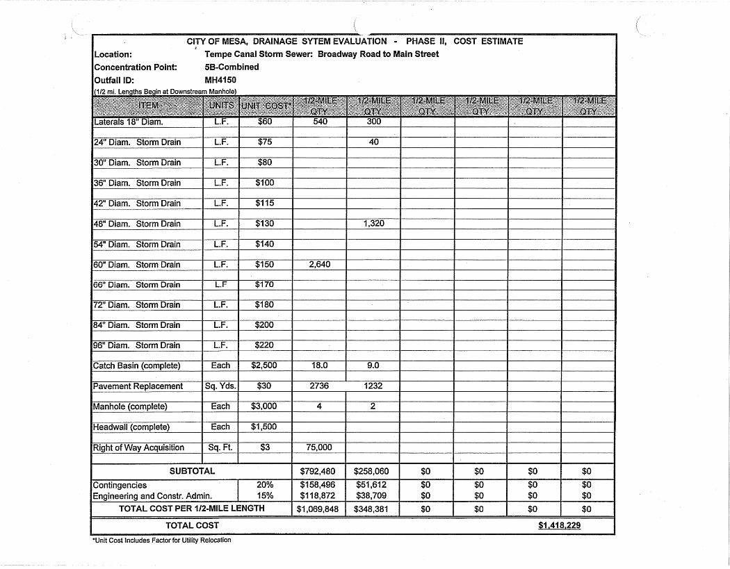
Location: Concentration Point: 5B-Corn bined
TOTAL COST $1,418,229
'Unit Cost lncludes Factor for Utility Relocation

Location: Concentration Point: 005C Outfall ID: MH4150
*Unit Cost Includes Factor for Utility Relocation
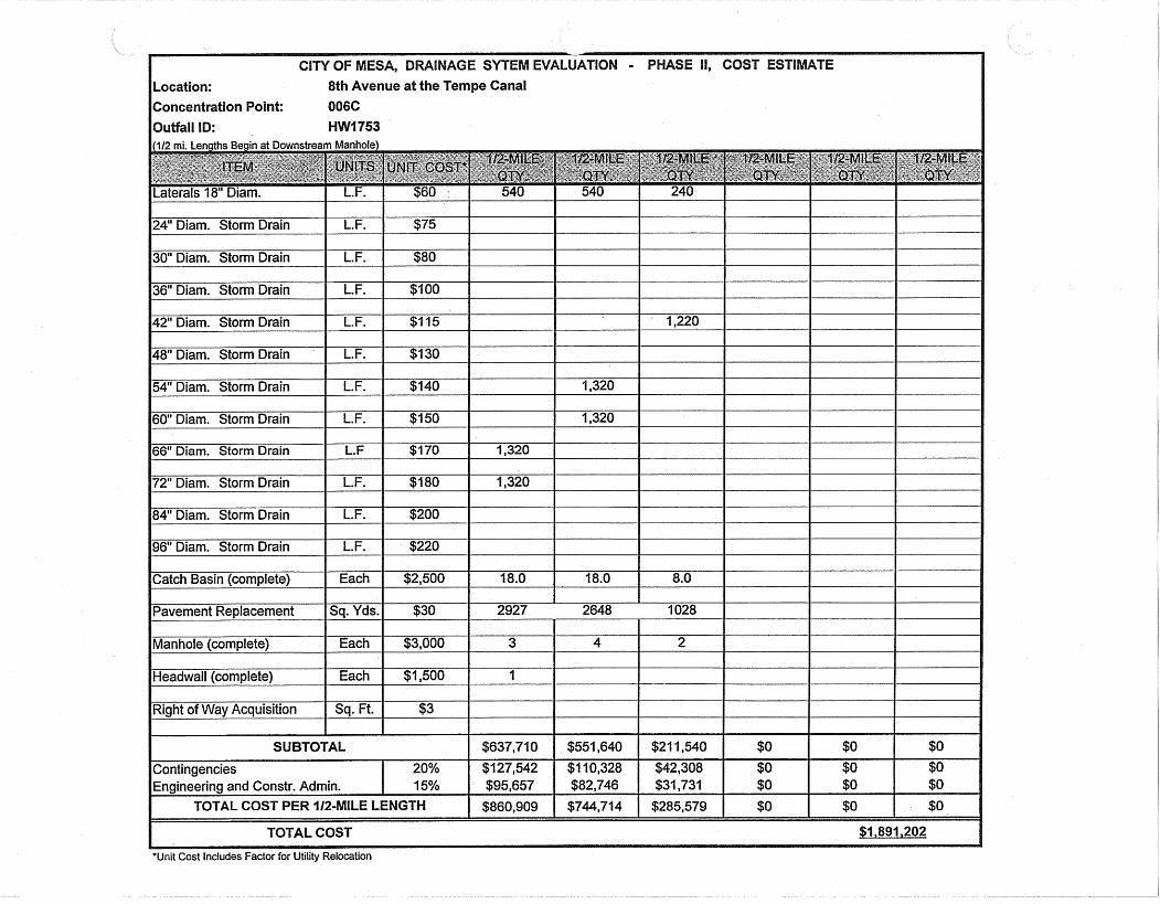
Location: 8th Avenue at the Tempe Canal
Concentration Point: 006C
Outfall ID:
*Unit Cost includes Factor for Utility Relocation
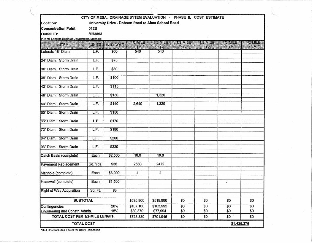
Location: University Drive - Dobson Road to Alma School Road
Concentration Point: 01 28 Outfall ID: MH3893
*Unit Cost Includes Factor for Utility Relocation