dynojet research 2191 mendenhall drive north las vegas, nv
TRANSCRIPT

i403-411 2006 Roadliner/Stratoliner - PCIII USB - 1i417-411 www.powercommander.com
2006 Yamaha Roadliner / StratolinerInstallation Instructions
Dynojet Research 2191 Mendenhall Drive North Las Vegas, NV 89081 (800) 992-4993 www.powercommander.com
Parts List1 Power Commander1 USB Cable1 Wire Tap1 CD-ROM1 Installation Guide1 Power Adapter2 Power Commander Decals2 Dynojet Decals2 Velcro® Strip1 Alcohol Swab
You can also download the PowerCommander software and latest mapsfrom our web site at:
www.powercommander.com
The ignition MUST be turnedOFF before installation!
PLEASE READ ALL DIRECTIONS BEFORE STARTING INSTALLATION
Button Adjustment Display
Faceplate Buttons
USB PortExpansion Port
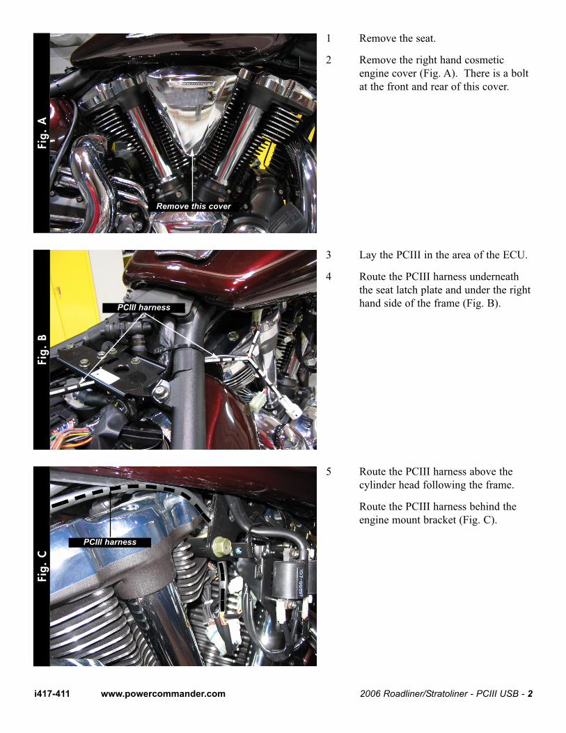
1 Remove the seat.
2 Remove the right hand cosmeticengine cover (Fig. A). There is a boltat the front and rear of this cover.
3 Lay the PCIII in the area of the ECU.
4 Route the PCIII harness underneaththe seat latch plate and under the righthand side of the frame (Fig. B).
5 Route the PCIII harness above thecylinder head following the frame.
Route the PCIII harness behind theengine mount bracket (Fig. C).
Fig.
AFi
g. B
Fig.
C
2006 Roadliner/Stratoliner - PCIII USB - 2i417-411 www.powercommander.com
Remove this cover
PCIII harness
PCIII harness
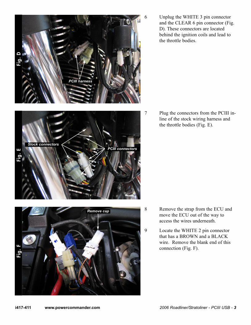
6 Unplug the WHITE 3 pin connectorand the CLEAR 6 pin connector (Fig.D). These connectors are locatedbehind the ignition coils and lead tothe throttle bodies.
7 Plug the connectors from the PCIII in-line of the stock wiring harness andthe throttle bodies (Fig. E).
8 Remove the strap from the ECU andmove the ECU out of the way toaccess the wires underneath.
9 Locate the WHITE 2 pin connectorthat has a BROWN and a BLACKwire. Remove the blank end of thisconnection (Fig. F).
Fig.
DFi
g. E
Fig.
F
2006 Roadliner/Stratoliner - PCIII USB - 3i417-411 www.powercommander.com
PCIII harness
Stock connectorsPCIII connectors
Remove cap
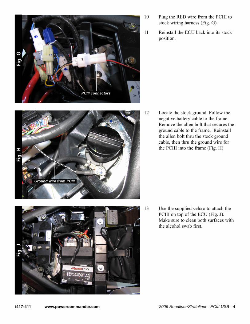
10 Plug the RED wire from the PCIII tostock wiring harness (Fig. G).
11 Reinstall the ECU back into its stockposition.
12 Locate the stock ground. Follow thenegative battery cable to the frame.Remove the allen bolt that secures theground cable to the frame. Reinstallthe allen bolt thru the stock groundcable, then thru the ground wire forthe PCIII into the frame (Fig. H)
13 Use the supplied velcro to attach thePCIII on top of the ECU (Fig. J).Make sure to clean both surfaces withthe alcohol swab first.
Fig.
GFi
g. H
Fig.
J
2006 Roadliner/Stratoliner - PCIII USB - 4i417-411 www.powercommander.com
PCIII connectors
Ground wire from PCIII
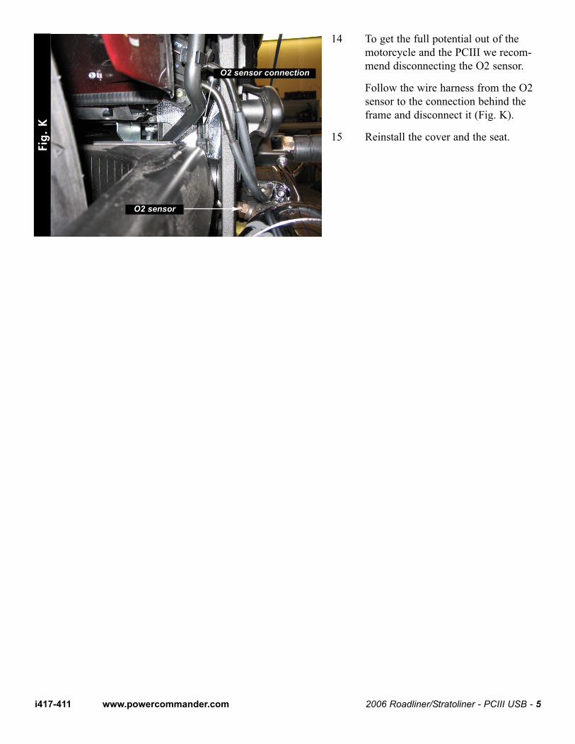
14 To get the full potential out of themotorcycle and the PCIII we recom-mend disconnecting the O2 sensor.
Follow the wire harness from the O2sensor to the connection behind theframe and disconnect it (Fig. K).
15 Reinstall the cover and the seat.
Fig.
K
2006 Roadliner/Stratoliner - PCIII USB - 5i417-411 www.powercommander.com
O2 sensor connection
O2 sensor