u.s. geological survey (usgs) - safety evaluation report
TRANSCRIPT

Safety Evaluation Report
Renewal of the Facility Operating License for the United States Geological Survey TRIGA Research Reactor
License No. R-113 Docket No. 50-274 United States Geological Survey, Department of the Interior
U.S. Nuclear Regulatory Commission Office of Nuclear Reactor Regulation October 2016

i
ABSTRACT
This safety evaluation report (SER) summarizes the findings of a safety review conducted by the staff of the U.S. Nuclear Regulatory Commission (NRC), Office of Nuclear Reactor Regulation. The NRC staff conducted its review in response to a timely application filed by the U.S. Geological Survey, Department of the Interior (USGS or the licensee) for a 20-year renewal of the Facility Operating License No. R-113 to continue to operate the U.S. Geological Survey Training, Research, Isotope Production, General Atomics (TRIGA) Research Reactor (GSTR or the facility). The facility is located in Denver, Colorado. In its safety review, the NRC staff considered information submitted by the licensee, including past operating history recorded in the licensee’s annual reports to the NRC, inspection reports prepared by NRC staff, and firsthand observations. On the basis of its safety and environmental review, the NRC staff concludes that the licensee can continue to operate the facility for the term of the renewed facility license, in accordance with the license, without endangering the health and safety of the public, the GSTR staff, or the environment.

ii
TABLE OF CONTENTS
TABLE OF CONTENTS ................................................................................................................ ii
LIST OF TABLES ......................................................................................................................... vi
LIST OF FIGURES ...................................................................................................................... vii
ABBREVIATIONS AND ACRONYMS ......................................................................................... viii
TECHNICAL PARAMETERS AND UNITS .................................................................................. xi
1 INTRODUCTION .................................................................................................................. 1-1
1.1 Overview .................................................................................................................. 1-1
1.2 Summary and Conclusions on Principal Safety Considerations .............................. 1-4
1.3 General Facility Description ..................................................................................... 1-5
1.4 Shared Facilities and Equipment .............................................................................. 1-7
1.5 Comparison with Similar Facilities ............................................................................ 1-7
1.6 Summary of Operations ........................................................................................... 1-7
1.7 Compliance with the Nuclear Waste Policy Act of 1982 ........................................... 1-8
1.8 Facility Modifications and History ............................................................................. 1-8
1.9 Financial Considerations .......................................................................................... 1-9
1.9.1 Financial Ability to Operate the Reactor ....................................................... 1-9
1.9.2 Financial Ability to Decommission the Facility ............................................ 1-11
1.9.3 Foreign Ownership, Control, or Domination ............................................... 1-12
1.9.4 Nuclear Indemnity ....................................................................................... 1-12
1.9.5 Financial Consideration Conclusions ......................................................... 1-12
1.10 Facility Operating License Possession Limits ........................................................ 1-13
2 REACTOR DESCRIPTION .................................................................................................. 2-1
2.1 Summary Description ............................................................................................... 2-1
2.1.1 Introduction ................................................................................................... 2-1
2.1.2 Summary of Reactor Data ............................................................................ 2-1
2.1.3 Experimental Facilities .................................................................................. 2-3
2.2 Reactor Core ............................................................................................................ 2-8
2.2.1 Reactor Fuel ............................................................................................... 2-16
2.2.2 Control Rods ............................................................................................... 2-21
2.2.3 Neutron Moderator and Reflector ............................................................... 2-25

iii
2.2.4 Neutron Startup Source .............................................................................. 2-26
2.2.5 Core Support Structure ............................................................................... 2-26
2.3 Reactor Tank or Pool ............................................................................................. 2-27
2.4 Biological Shield ..................................................................................................... 2-29
2.5 Nuclear Design ....................................................................................................... 2-31
2.5.1 Normal Operating Conditions ..................................................................... 2-32
2.5.2 Reactor Core Physics Parameters ............................................................. 2-34
2.5.3 Reactivity Coefficients ................................................................................ 2-39
2.5.4 Operating Limits ......................................................................................... 2-41
2.6 Thermal-Hydraulic Design ...................................................................................... 2-48
2.7 Fuel Storage ........................................................................................................... 2-52
2.8 Reactor Description Conclusions ........................................................................... 2-54
3 RADIATION PROTECTION PROGRAM AND WASTE MANAGEMENT ............................ 3-1
3.1 Radiation Protection ................................................................................................. 3-1
3.1.1 Radiation Sources ........................................................................................ 3-1
3.1.2 Radiation Protection Program ...................................................................... 3-6
3.1.3 ALARA Program ........................................................................................... 3-9
3.1.4 Radiation Monitoring and Surveying ........................................................... 3-10
3.1.5 Radiation Exposure Control and Dosimetry ............................................... 3-12
3.1.6 Contamination Control ................................................................................ 3-13
3.1.7 Environmental Monitoring ........................................................................... 3-14
3.2 Radioactive Waste Management ........................................................................... 3-14
3.2.1 Radioactive Waste Management Program ................................................. 3-15
3.2.2 Radioactive Waste Controls ....................................................................... 3-15
3.2.3 Release of Radioactive Waste ................................................................... 3-16
3.3 Radiation Protection Program and Waste Management Conclusions ................... 3-17
4 ACCIDENT ANALYSES ....................................................................................................... 4-1
4.1 Accident Analysis, Initiating Events and Determination of Consequences .............. 4-1
4.1.1 The Maximum Hypothetical Accident ........................................................... 4-1
4.1.2 Failed Fueled Experiment ............................................................................. 4-9
4.1.3 Insertion of Excess Reactivity ..................................................................... 4-11
4.1.4 Loss of Coolant Accident ............................................................................ 4-15
4.1.5 Loss of Coolant Flow .................................................................................. 4-18

iv
4.1.6 Mishandling or Malfunction of Fuel ............................................................. 4-20
4.1.7 Experimental Malfunction ........................................................................... 4-21
4.1.8 Loss of Normal Electrical Power ................................................................. 4-22
4.1.9 External Events .......................................................................................... 4-22
4.1.10 Mishandling or Malfunction of Equipment ................................................... 4-23
4.2 Accident Analysis and Determination of Consequences ........................................ 4-23
5 TECHNICAL SPECIFICATIONS .......................................................................................... 5-1
5.1 Definitions ................................................................................................................. 5-1
5.2 Safety Limits (SL) and Limiting Safety System Settings (LSSS) .............................. 5-4
5.2.1 TS 2.1 Safety Limit–Fuel Element Temperature .......................................... 5-4
5.2.2 TS 2.2 Limiting Safety System Setting ......................................................... 5-5
5.3 Limiting Conditions for Operation ............................................................................. 5-5
5.3.2 TS 3.2 Reactor Control and Safety System .................................................. 5-6
5.3.3 TS 3.3 Reactor Primary Tank Water ............................................................ 5-6
5.3.4 TS 3.4 This Section Intentionally Left Blank ................................................. 5-6
5.3.5 TS 3.5 Ventilation and Confinement System ................................................ 5-6
5.3.6 TS 3.6 This section intentionally left blank ................................................... 5-8
5.3.7 TS 3.7 Radiation Monitoring Systems and Effluents .................................... 5-8
5.3.8 TS 3.8 Limitations on Experiments ............................................................... 5-8
5.3.9 TS 3.9 This section intentionally left blank ................................................... 5-9
5.4 TS 4. Surveillance Requirements ............................................................................. 5-9
5.4.0 TS 4.0 General ............................................................................................. 5-9
5.4.1 TS 4.1 Reactor Core Parameters ............................................................... 5-10
5.4.2 TS 4.2 Reactor Control and Safety Systems .............................................. 5-12
5.4.3 TS 4.3 Reactor Primary Tank Water .......................................................... 5-13
5.4.4 TS 4.4 This section intentionally left blank ................................................. 5-14
5.4.5 TS 4.5 Ventilation and Confinement System .............................................. 5-14
5.4.6 TS 4.6 This section intentionally left blank ................................................. 5-15
5.4.7 Radiation Monitoring System ...................................................................... 5-15
5.4.8 Experimental Limits .................................................................................... 5-16
5.5 Design Features ..................................................................................................... 5-16
5.5.1 TS 5.1 Site and Facility Description ............................................................ 5-16
5.5.2 TS 5.2 Reactor Coolant System ................................................................. 5-18

v
5.5.3 TS 5.3 Reactor Core and Fuel .................................................................... 5-18
5.5.4 TS 5.4 Fuel Storage ................................................................................... 5-18
5.6 Administrative Controls .......................................................................................... 5-18
5.6.1 TS 6.1 Organization .................................................................................... 5-19
5.6.2 TS 6.2 Review and Audit ............................................................................ 5-23
5.6.3 TS 6.3 Radiation Safety .............................................................................. 5-25
5.6.4 TS 6.4 Procedures ...................................................................................... 5-26
5.6.5 TS 6.5 Experiment Review and Approval ................................................... 5-26
5.6.6 TS 6.6 Required Actions ............................................................................. 5-27
5.6.7 TS 6.7 Reports ........................................................................................... 5-28
5.6.8 TS 6.8 Records ........................................................................................... 5-30
5.7 Conclusions ............................................................................................................ 5-32
6 CONCLUSIONS ................................................................................................................... 6-1
7 REFERENCES ..................................................................................................................... 7-1

vi
LIST OF TABLES
Table 2-1 Key Reactor Parameters for the GSTR LCC and OCC ................................ 2-2
Table 2-2 Key Technical Specifications Setpoints/Limits ............................................. 2-3
Table 2-3 GSTR Stainless Steel Fuel Parameters ..................................................... 2-14
Table 2-4 Reactor Core Inventory .............................................................................. 2-15
Table 2-5 GSTR Measured and Calculated OCC Reactivity Parameters .................. 2-35
Table 2-6 GSTR Shutdown Margin Confirmatory Calculations .................................. 2-38
Table 3-1 USGS COMPLY Dose Results for Routine Ar-41 Releases ........................ 3-3
Table 3-2 USGS Ar-41 Releases - Annual Reports ...................................................... 3-5
Table 3-3 GSTR Radiation Monitoring Equipment ....................................................... 3-8
Table 4-1 GSTR and NRC Estimates of MHA Source Term Nuclide Inventory ........... 4-3
Table 4-2 Total MHA Release Fractions ....................................................................... 4-4
Table 4-3 MHA Occupational Worker Dose Estimates Restricted Areas ..................... 4-7
Table 4-4 MHA Public Dose to an Individual in Unrestricted Areas .............................. 4-7
Table 4-6 GSTR Inventory for Failed Fueled Experiment ........................................... 4-10
Table 4-7 Failed Fueled Experiment Dose Assessment ............................................. 4-11
Table 4-8 GSTR Pulse Results ................................................................................... 4-13
Table 4-9 NRC Staff Confirmatory Pulse Results ....................................................... 4-13
Table 4-10 Confirmatory Analysis of the Uncontrolled Rod Withdrawal ....................... 4-15
Table 4-11 Dose Rate to a Worker within the Reactor Room ....................................... 4-17
Table 4-12 Dose Rate to an Individual in the Vicinity of the Reactor Building .............. 4-17
Table 4-13 Dose Rate to a Member of the Public at the DFC ...................................... 4-18

vii
LIST OF FIGURES
Figure 2-1 GSTR Lower Grid Plate ................................................................................ 2-9
Figure 2-2 GSTR Core Location Map .......................................................................... 2-10
Figure 2-3 Graphic of GSTR Stainless-Steel Clad Fuel ............................................... 2-14
Figure 2-4 The GSTR LCC .......................................................................................... 2-15
Figure 2-5 The GSTR OCC ......................................................................................... 2-16
Figure 2-6 Phase Diagram for Uranium-Zirconium-Hydride Fuel (Ref. 56) ................. 2-18
Figure 2-7 GSTR Calculated LCC Power Distribution (kWt/fuel element) ................... 2-33
Figure 2-8 GSTR Calculated OCC Power Distribution (kWt/fuel element) .................. 2-34
Figure 2-9 GSTR Fuel Temperature Coefficient for the OCC and LCC ....................... 2-40
Figure 2-10 Confirmatory Fuel Temperature Coefficient ............................................... 2-41
Figure 2-11 Schematic of the subchannel used for DNBR analysis .............................. 2-49
Figure 4-1 GSTR Analysis of a $3.00 Pulse ................................................................ 4-13

viii
ABBREVIATIONS AND ACRONYMS ALARA as low as reasonably achievable
Am-Be americium-beryllium
AOO anticipated operational occurences
API American Petroleum Institute
Ar-41 Argon-41
ARM area radiation monitor
Br Bromine
CAM continuous air monitor
CFR Code of Federal Regulations
CHF critical heat flux
CSC control system console
DAC data acquisition control
DCF dose conversion factor
DDE direct dose equivalent
DF design feature
DFC Denver Federal Center
DNBR departure from nucleate boiling ratio
ENDF Evaluated Nuclear Data Files
EPA Environmental Protection Agency
FGR Federal Guidance Report
FTC fuel temperature coefficient
GA General Atomics
GSTR Geological Survey TRIGA Reactor
HEPA high-efficiency particulate air
I Iodine
IFE instrumented fuel element
ISG interim staff guidance
LCC limiting core configuration

ix
LCO limiting condition for operation
LEU low-enriched uranium
LOCA loss of coolant accident
LRA license renewal application
LSSS limiting safety system setting
MHA maximum hypothetical accident
MCNP5 Monte Carlo particle transport code
NESHAP National Emission Standards for Hazardous Air Pollutants
N-16 Nitrogen-16
NRC Nuclear Regulatory Commission
OCC operating core configuration
PCS primary coolant system
PDR Public Document Room
PSP physical security plan
PTS pneumatic transfer system
RAI request for additional information
RF release fraction
RG Regulatory Guide
ROC Reactor Operations Committee
RTD resistance temperature detector
RTR research and test reactor
SAR safety analysis report
SDM shutdown margin
SER safety evaluation report
SL safety limit
SNM special nuclear material
SR surveillance requirement
SRM staff requirements memorandum
SRO senior reactor operator

x
TID Technical Information Document
T-H Thermal-hydraulic
TEDE total effective dose equivalent
TNT trinitrotoluene
TRIGA Training, Research, Isotope, General Atomics
TS technical specification
UBC Uniform Building Code
UPS uninterruptible power supply
URW uncontrolled rod withdrawal
USGS U.S. Geological Survey
UZrHx uranium-zirconium hydride

xi
TECHNICAL PARAMETERS AND UNITS
$ a unit of reactivity where absolute reactivity is divided by the total effective delayed neutron fraction or unit of currency
Ci curies
cfm cubic feet per minute
cm centimeter
cmm cubic meter per minute
cpm counts per minute
°C temperature in degree(s) Celsius
°F temperature degree(s) Fahrenheit
°K temperature degree(s) Kelvin
g gram
hr hour
kWt kilowatts thermal
in inch(es)
ft3 cubic feet
ft foot (feet)
m meter
MeV mega-electron volts
mrem milli-roentgen equivalent in man
MWd megawatt days
MW-hr megawatt-hours
MWt megawatt thermal
m/s meter per second
μmhos/cm micromhos per centimeter
pH potential of hydrogen
rem Roentgen equivalent in man
W Watts
W/m2 -C watts per square meter °C
wt% weight percent
yr year
αF fuel temperature coefficient
∆k/k absolute reactivity

1-1
1 INTRODUCTION
1.1 Overview
By letter dated January 5, 2009, as supplemented on November 24, 2010; February 11, March 28, May 12, June 29, July 27, August 30, September 26, October 31, and November 30, 2011; January 3, January 27, March 28, April 27, May 18, May 31, June 29, July 31, August 30, and November 16, 2012; February 8, May 17, and October 31, 2013; February 19, November 3, and November 24, 2014; September 8, 2015; and January 22, April 1, September 12, and September 22, 2016, the U.S. Geological Survey, Department of the Interior (USGS or the licensee) submitted a license renewal application (LRA) containing a safety analysis report (SAR) to the U.S. Nuclear Regulatory Commission (NRC or the Commission) for a 20-year renewal of the Class 104c Facility Operating License No. R-113 (NRC Docket No. 50-274) for the U.S. Geological Survey Training, Research, Isotope, General Atomics (TRIGA) Research Reactor (GSTR or “the facility”). A Notice of Opportunity for Hearing was published on February 5, 2016 (81 FR 6302). Title 10 of the Code of Federal Regulations (10 CFR) 50.51(a) states that “[e]ach license will be issued for a fixed period of time to be specified in the license but in no case to exceed 40 years from the date of issuance.” The NRC issued a Construction Permit No. CPRR-102 on October 10, 1967, which authorized the construction of the TRIGA Mark 1 reactor at the USGS site. Facility Operating License No. R-113 (the license), was issued on February 24, 1969, for a period of 40 years from the issuance of the Construction Permit, expiring on October 10, 2007. The licensee applied to recapture the time between the issuance of the Construction Permit and the Facility Operating License. By letter dated June 16, 2005, the Facility Operating License expiration date was extended from October 10, 2007, to February 24, 2009, by issuance of Amendment No. 10, (a copy can be found in the NRC’s Agencywide Documents Access and Management System (ADAMS), Accession No. ML050810198). As provided in the timely renewal provision contained in 10 CFR 2.109(a), the licensee is permitted to continue operation of the GSTR under the terms and conditions of the current license until the NRC staff completes action on the LRA. Renewal of the facility operating license would authorize continued operation of the GSTR for an additional 20 years. The GSTR facility was licensed in 1969 as a research reactor facility to operate at a steady-state power level not to exceed 1.0 megawatt-thermal (MWt) power and to pulse the reactor with a reactivity insertion not to exceed $3.00 reactivity. The licensee submitted its initial application on January 13, 1967, to construct and operate a TRIGA Mark I reactor on its site at the Denver Federal Center (DFC) in Lakewood, Colorado. Initial criticality was achieved in February 1969. A list of facility modifications and license amendments is provided in Section 1.7 of this safety evaluation report (SER). The NRC staff based its review of the request to renew the GSTR facility operating license on the information contained in the LRA, as well as supporting supplements and the licensee’s responses to the NRC staff’s request for additional information (RAI). The LRA, by letter dated January 5, 2009 (Ref. 1), includes a SAR, with proposed technical specifications (TSs) (Chapter 14 of the SAR), the Operator Requalification Program, and an Environmental Report. The NRC staff sent RAIs by letters dated September 29, 2010 (Ref. 2); March 21 (Ref. 3), and October 2, 2012 (Ref. 4); March 7 (Ref. 5) and July 15, 2013 (Ref. 6); August 25, 2014 (Ref. 7); September 10, 2015 (Ref. 8); and February 8, (Ref. 9) and June 28, 2016 (Ref. 82).

1-2
The licensee provided RAI responses by letters dated November 24, 2010 (Ref. 10); February 11 (Ref. 11), March 28 (Ref. 12), May 12, (Ref. 13), June 29 (Ref. 14), July 27 (Ref. 15), August 30 (Ref. 16), September 26 (Ref. 17), October 31 (Ref. 18), and November 30, 2011 (Ref. 19); January 3, (Ref. 20), January 27 (two letters, Refs. 21 and 22), March 28 (Ref. 23), April 27 (Ref. 24), May 18 (Ref. 25), May 31 (Ref. 26), June 29 (Ref. 27), July 31 (Ref. 28), August 30 (Ref. 29), and November 16, 2012 (Ref. 30); February 8, (Ref. 31), May 17 (Ref. 32), and October 31, 2013 (Ref. 33); November 3 (Ref. 34), and November 24, 2014 (Ref. 35); September 8, 2015 (Ref. 36); and January 22 (Ref. 37), April 1 (Ref. 64), September 12 (Ref. 83), and September 22, 2016 (Ref. 84). Throughout this SER, statements referring to the SAR mean the SAR provided in the January 5, 2009 submittal (Ref. 1). Although the LRA indicated that no changes to the physical security plan (PSP), emergency plan (EP), and operator requalification program were needed as a result of the LRA request, the NRC staff reviewed these plans to ensure that they were consistent with current NRC regulations and guidance. The results of the NRC staff review of the PSP, EP, and operator requalification program are discussed below. The NRC staff’s review also included information from USGS annual reports for 2010 though 2015 (Ref. 38) and NRC inspection reports (IRs) issued in 2010 though 2016 (Ref. 39). The NRC staff conducted site visits on March 24, 2010, and August 3-4, 2015, to observe facility conditions and to discuss NRC staff RAIs and licensee’s RAI responses. With the exception of the USGS PSP, portions of the SAR, RAI responses, and the EP that contain security-related information, the material pertaining to this review may be examined or copied, for a fee, at the NRC’s Public Document Room (PDR), Room 01-F21, One White Flint North, 11555 Rockville Pike, Rockville, Maryland 20852. The NRC maintains ADAMS, which provides text and image files of NRC’s public documents. Publicly available documents related to this license renewal may be accessed online through the NRC’s Public Library, ADAMS Public Documents collection at http://www.nrc.gov/reading-rm/adams.html. If you do not have access to ADAMS or if you experience problems accessing the documents in ADAMS, contact the NRC PDR staff by telephone at 1-800-397-4209 or 301-415-4737, or send an e-mail to the PDR at [email protected]. The PSP and material containing security-related information are protected from public disclosure under 10 CFR 73.21, “Protection of Safeguards Information: Performance Requirements,” and 10 CFR 2.390(d). Since portions of the SAR, RAI responses, and the EP contain security-related information and are protected from public disclosure, redacted versions are provided to the public in ADAMS. Section 7, “References,” of this SER contains the dates and associated ADAMS accession numbers of the licensee’s renewal application and related supplements. In conducting its review, the NRC staff evaluated the facility against the requirements in the regulations, including 10 CFR Part 20, “Standards for Protection against Radiation,” 10 CFR Part 30, “Rules of General Applicability to Domestic Licensing of Byproduct Material,” 10 CFR Part 50, “Domestic Licensing of Production and Utilization Facilities,” 10 CFR Part 51, “Environmental Protection Regulations for Domestic Licensing and Related Regulatory Functions,” 10 CFR Part 70, “Domestic Licensing of Special Nuclear Material,” and 10 CFR Part 73, “Physical Protection of Plants and Materials;” the recommendations of applicable regulatory guides; and relevant accepted industry standards, such as the American National Standards Institute/American Nuclear Society (ANSI/ANS)-15 series. The NRC staff also considered the recommendations contained in NUREG-1537, “Guidelines for Preparing and Reviewing Applications for the Licensing of Non-Power Reactors,” issued February 1996

1-3
(Ref. 40). Because there are no specific accident-related regulations, applicable NUREGs, and regulatory guides (RGs) for research reactors, the NRC staff compared calculated dose values for accidents against the requirements in 10 CFR Part 20. In SECY-08-0161, “Review of Research and Test Reactor License Renewal Applications,” dated October 24, 2008 (Ref. 41), NRC staff provided the Commission with information regarding plans to revise the review process for LRAs for research and test reactors (RTRs). The Commission issued its staff requirements memorandum (SRM) for SECY-08-0161, dated March 26, 2009 (Ref. 42). The SRM directed the NRC staff to streamline the renewal process for such reactors, using some combination of the options presented in SECY-08-0161. The SRM also directs the NRC staff to implement a graded approach whose scope is commensurate with the risk posed by each facility. The graded approach incorporates elements of the alternative safety review approach discussed in Enclosure 1 of SECY-08-0161. In the alternative safety review approach, used in this SER, the NRC staff considered the results of past NRC staff reviews. A basic requirement, as contained in the SRM, is that licensees must be in compliance with applicable regulatory requirements. The NRC staff developed RTR Interim Staff Guidance (ISG)-2009-001, “Interim Staff Guidance on the Streamlined Review Process for License Renewal of Research Reactors,” (Ref. 43) to assist in the review of LRAs. The streamlined review process is a graded approach based on licensed power level. Under the streamlined review process, the facilities are divided into two tiers. Facilities with a licensed power level of 2 MWt and greater, or requesting a power level increase, would undergo a full review using NUREG-1537. Facilities with a licensed power level less than 2 MWt would undergo a focused review that centers on the most safety-significant aspects of the LRA and relies on past NRC reviews for certain safety findings. The NRC staff issued a draft of the ISG for comment, and the NRC staff considered public comments in its development of the final ISG. The NRC staff conducted the USGS LRA review using the guidance in the final ISG, dated October 15, 2009 (Ref. 43). Since the licensed power level for the GSTR is less than 2 MWt, the NRC staff performed a focused review of the licensee’s LRA. Specifically, the NRC focused on reactor design and operation, accident analysis, TSs, radiation protection, waste management programs, financial requirements, environmental assessment, and changes to the facility made after submittal of the application. In the LRA, the licensee indicated no changes were needed to the USGS PSP. However, as part of its review of the LRA, the NRC staff reviewed the PSP entitled, “Revision XVI of the Physical Security Plan for the U.S. Geological Survey TRIGA Reactor Facility,” provided by letter dated August 20, 2014 (Ref. 44), as revised in accordance with 10 CFR 50.54(p)(2). The NRC staff issued RAIs to the licensee by letter dated April 25, 2016 (Ref. 79), and the licensee provided its responses by letter dated June 14, 2016 (Ref. 80), including a revised PSP. The NRC staff reviewed the revised PSP, found that it meets the applicable regulations, and concludes that the USGS PSP, dated August 2016, is acceptable. The licensee maintains the program to provide physical protection of the facility and its special nuclear material (SNM) in accordance with the requirements of 10 CFR Part 73. Changes to the PSP can be made, by the licensee, in accordance with 10 CFR 50.54(p), as long as those changes do not decrease the effectiveness of the plan. In addition, the NRC staff performs routine inspections of the licensee’s compliance with the requirements of the PSP. The NRC staff’s review of the GSTR IRs for the past several years identified no violations of the PSP requirements.

1-4
The licensee is required to maintain the EP, in compliance with 10 CFR 50.54(q) and Appendix E to 10 CFR Part 50, “Emergency Planning and Preparedness for Production and Utilization Facilities,” which provides reasonable assurance that the licensee will continue to be prepared to assess and respond to emergency events. As part of the LRA review, the NRC staff reviewed the GSTR EP, Revision 13, dated October 2013, and issued RAIs by letter dated January 28, 2014 (Ref. 45). The licensee provided its responses by letter dated May 15, 2014 (Ref. 46). An updated GSTR Emergency Plan, Revision 14, was provided by letter dated May 30, 2014 (Ref. 47). The NRC staff completed its review and, by letter dated July 9, 2014 (Ref. 48), acknowledged that the GSTR EP, Revision 14, dated May 2014, remains compliant with the regulations and is consistent with applicable guidance. The NRC staff performs routine inspections of the licensee’s compliance with the requirements of the EP, and no violations have been identified in recent years. As part of the LRA review, the NRC staff reviewed the GSTR Reactor Operator Requalification Program, provided with the LRA (Ref. 1). The NRC staff issued RAIs by letter dated January 22, 2014 (Ref. 49). By letter dated February 19, 2014 (Ref. 50), the licensee provided a revised GSTR Reactor Operator Requalification Program. The NRC staff reviewed and approved the GSTR Reactor Operator Requalification Program, dated February 2014, by letter dated March 27, 2014 (Ref. 51). The NRC staff separately evaluated the environmental impacts of the renewal of the license for the GSTR in accordance with 10 CFR Part 51. The NRC staff published an Environmental Assessment and Finding of No Significant Impact in the Federal Register on June 14, 2016 (81 FR 38739), which concluded that renewal of the GSTR license will not have a significant effect on the quality of the human environment. The purpose of this SER is to summarize the findings of the GSTR safety review and to delineate the technical details considered in evaluating the radiological safety aspects for continued operation. The GSTR is licensed at a maximum steady-state power level of 1,000 kilowatt-thermal (kWt) and short duration power pulses with reactivity insertions not to exceed $3.00. This SER was prepared by Geoffrey Wertz, Project Manager in the NRC’s Office of Nuclear Reactor Regulation (NRR), Division of Policy and Rulemaking, Research and Test Reactors Licensing Branch, and Lois Kosmas, a Financial Analyst in the NRC’s NRR, Division of Inspection and Regional Support, Financial and International Projects Branch. Energy Research, Inc., the NRC’s contractor, also provided input to this SER.
1.2 Summary and Conclusions on Principal Safety Considerations
The NRC staff’s review and evaluation considers the information submitted by the licensee, including past operating history recorded in the licensee’s annual reports to the NRC, as well as IRs prepared by the NRC staff. On the basis of this evaluation and resolution of the principal issues reviewed for the GSTR, the NRC staff concludes the following:
• The design and use of the reactor structures, systems, and components important to safety during normal operation discussed in Chapter 4 of the SAR, as supplemented, in accordance with the TSs, are safe, and safe operation can reasonably be expected to continue.

1-5
• The facility will continue to be useful in the conduct of teaching, research, training, and radionuclide production activities, as described in SAR Section 1.3.
• The licensee considered the expected consequences of a broad spectrum of postulated
credible accidents and a maximum hypothetical accident (MHA), emphasizing those that could lead to a loss of integrity of fuel element cladding and a release of fission products. The licensee performed analyses, using conservative assumptions, of the most serious credible accidents and the MHA and determined that the calculated potential radiation doses for the facility staff, and members of the public, would not exceed 10 CFR Part 20 doses for unrestricted areas.
• The licensee’s management organization, conduct of training, and research activities, in
accordance with the TSs, are adequate to ensure safe operation of the facility. • The systems provided for the control of radiological effluents, when operated in
accordance with the TSs, are adequate to ensure that releases of radioactive materials from the facility are within the limits of the Commission’s regulations and are as low as reasonably achievable (ALARA).
• The licensee’s TSs, which provide limits controlling operation of the facility, offer a high
degree of assurance that the facility will be operated safely and reliably. No significant degradation of the reactor has occurred, as discussed in Chapter 4 of the SAR, as supplemented, and the TSs will continue to help ensure that no significant degradation of safety-related equipment will occur.
• The licensee has reasonable access to sufficient resources to cover operating costs and
eventually to decommission the reactor facility. • The licensee maintains a PSP for the facility and it’s SNM, in accordance with the
requirements of 10 CFR Part 73, which provides reasonable assurance that the licensee will continue to provide the physical protection of the facility and it’s SNM.
• The licensee maintains an EP in compliance with 10 CFR 50.54(q) and Appendix E to
10 CFR Part 50, which provides reasonable assurance that the licensee will continue to be prepared to assess and respond to emergency events.
• The licensee’s procedures for training its reactor operators and the operator
requalification plan give reasonable assurance that the licensee will continue to have qualified staff that can safely operate the reactor.
On the basis of these findings, the NRC staff concludes that there is reasonable assurance that the licensee can continue to operate the GSTR in accordance with the Atomic Energy Act (AEA) of 1954, as amended NRC regulations, and the renewed facility operating license without endangering public health and safety, facility personnel, or the environment. The issuance of the renewed license will not be inimical to the common defense and security.
1.3 General Facility Description
The GSTR facility is located in Building 15, of the DFC, in Lakewood, Colorado, approximately 10 miles (16.1 kilometers) west of Denver, Colorado, as described in the GSTR SAR Chapter 2.

1-6
The city of Lakewood has a population of approximately 142,000 people. The DFC houses 28 different U.S. government agencies, in 44 federal buildings, and has a daytime population of approximately 6,200 people. Construction of Building 15 was completed in 1966, and was constructed in accordance with the building code applicable during construction. Building 15 is a steel and concrete structure, has approximately 27,000 square feet (2,500 square meters), contains the GSTR reactor room (bay) and adjoining control room, an isotope processing and storage room, radioisotope counting laboratories, a variety of other radioisotope research laboratories, and has office space for up to 40 USGS professional and technical staff. Building 15 is maintained in accordance with local fire codes, is equipped with an active fire protection and suppression system, and receives periodic fire safety inspections. A fire and safety management facility assessment survey was completed in 2005, and the results indicated that the GSTR facility building passed the evaluations for fire control, egress, and general fire safety, as provided in the SAR, Appendix 9-A (Ref. 1). The GSTR, described in SAR Chapter 3 (Ref. 1), is a heterogeneous light-water-cooled, graphite-reflected pool-type nuclear reactor fueled with low-enriched uranium (LEU) TRIGA fuel. The TRIGA fuel used at GSTR is a solid uranium-zirconium hydride (UZrHx), where the “x” in the UZrHx represents the hydrogen to zirconium ratio. The hydrogen content is important because it influences many attributes of fuel behavior. The TRIGA fuel can be composed of 8.5 weight percent (wt%) uranium (U) with stainless-steel clad, 12 wt% U with stainless-steel clad, or 8 wt% U with aluminum clad. The moderator is the zirconium hydride contained in the fuel and light water that also serves as the coolant, which circulates through the core by natural convection. These fuel elements are arranged in a circular grid and submerged in the reactor pool under approximately 20 feet (ft) (6.1 meters (m)) of water. The core is reflected by both the reactor pool water, and a graphite reflector located at the periphery of the reactor core. The maximum allowable steady-state power level is 1.0 MWt, and it can pulse in accordance with the limits in the TSs with reactivity additions not to exceed $3.00. Significant features of the GSTR include:
• three standard control rods and their electro-magnetic drive systems, • one transient control rod and electro-pneumatic drive system, and • irradiation facilities including a central thimble, a cadmium-lined irradiation tube, a
pneumatic transfer system (PTS) a rotating rack, a pump tube, a beam tube, and other movable dry tubes.
The GSTR core is located at the bottom of the reactor tank under approximately 20 ft (6.1 m) of water. Cooling of the reactor core occurs by natural convection of coolant through the core, with the heated coolant rising out of the core and into the bulk pool water. The pool is cooled by the heat removal system which transfers heat to the secondary system by pumping primary coolant through the tube-side of a 1,000 kWt rated shell and tube heat exchanger. The secondary system circulates water through the shell-side of the heat exchanger and a forced-air cooling tower. Forced air is directed perpendicular to the water flow in the cooling tower to cool the water. During operation, the secondary system is maintained at a higher pressure than the primary system to minimize the likelihood of primary system contamination entering the secondary system, and ultimately the environment in the unlikely event of a heat exchanger failure. Make-up water to the cooling tower is by the city water system and is automatically added as needed by a float valve. In SAR Section 9.1.2 (Ref. 1), the licensee describes the reactor room ventilation system which provides outside air to the reactor room and operates independent of the GSTR and the

1-7
laboratories located within the reactor building. The incoming air travels through a heating coil, cooling coil, filter, supply fan, manual damper, automatic fire damper, and automatic damper to restrict release of airborne radioactive particles. The air then discharges into the reactor room through two diffuser ducts near the ceiling. The exhaust air exits the reactor room through one of two exhaust systems. The two exhaust systems are the main exhaust and the emergency exhaust system, used during normal operations and emergency situations, respectively. The main exhaust extends approximately 67.5 inches (in) (1.6 m) above the roof of the building, which places the exhaust approximately 22.6 ft (6.9 m) above the ground outside Building 15. The emergency exhaust system extends approximately 69.0 in (1.7 m) above the roof of the building, which places the exhaust approximately 22.8 ft (6.9 m) above the ground outside Building 15. The reactor room air is discharged at a nominal flow rate of 1,000 cubic feet per minute (cfm) (28.32 cubic meter per minute (cmm)) through the main exhaust system and at a nominal flow rate of 700 cfm (19.82 cmm) through the emergency exhaust system. The reactor room ventilation systems are operated manually from the control room. When the emergency exhaust system is operated, the normal exhaust system stops and the air supply to the reactor room is isolated so the reactor room pressure is negative relative to reactor facility and the outside air pressure.
1.4 Shared Facilities and Equipment
In Section 1.5 SAR (Ref. 1), the licensee describes the GSTR shared utilities that include electrical power, heating, cooling, potable water, and sewerage with other areas located in Building 15. The electrical power for the GSTR is supplied from the site electrical power system and controlled by GSTR staff. The design of the GSTR does not require building electrical power, or any other shared utilities, to safely shut down the reactor or to maintain the reactor in a safe shutdown condition. During the NRC staff site visits, no shared utility concerns were noted or identified. 1.5 Comparison with Similar Facilities In Section 1.5 of the SAR (Ref. 1), the licensee provides general statements regarding the TRIGA type nuclear reactors built by General Atomics (GA). The GA TRIGA is one of the most widely used research and training reactors in the United States. TRIGA reactors exist in a variety of configurations and capabilities (Ref. 52). The GSTR is very similar in design to TRIGA reactors at the University of Texas – Austin, Oregon State University, and Dow Chemical Company. Instruments and controls used in the GSTR are similar in principle to most non-power reactors licensed by the NRC. The pool size and experimental facility configuration differ among the four reactors, but basic reactor behavior and accident analyses are similar.
1.6 Summary of Operations
The GSTR facility was licensed in 1969 as a research reactor facility to operate at a steady state power level not to exceed 1.0 MWt power and to pulse the reactor with a reactivity insertion not to exceed $3.00 reactivity. The licensee submitted its initial application on January 13, 1967, to construct and operate a TRIGA Mark I reactor on its site at the DFC in Lakewood, Colorado. Initial criticality was achieved in February 1969. A list of facility modifications and license amendments is provided in Section 1.7 of this SER. In the SAR Section 1.6 the licensee indicated that the GSTR provides a unique and valuable tool for a wide variety of research applications and serves as an excellent source of neutrons and/or gamma rays. The GSTR has a number of irradiation facilities providing a wide range of

1-8
neutron flux levels and neutron flux qualities, which are sufficient to meet the needs of most researchers. The typical operating power level for the GSTR is 1 MW. The average energy output per year is approximately 27 mega-watt-days. As an indication of operating tempo, operational statistics for reporting year 2007 were provided in SAR Table 1.1. Based on the analysis presented in this SAR, there are no limitations on the operating schedule. The NRC staff’s review also included information from USGS annual reports for 2010 though 2015 (Ref. 38) and NRC IRs issued in 2010 through 2016 (Ref. 39). No violations were identified.
1.7 Compliance with the Nuclear Waste Policy Act of 1982
Section 302(b)(1)(B) of the Nuclear Waste Policy Act of 1982, 42 U.S.C.§10222(b)(1)(B), specifies that the NRC may require, as a precondition to issuing or renewing an operating license for a research or test reactor, that the licensee enter into an agreement with the U.S. Department of Energy (DOE) for the disposal of high-level radioactive wastes and spent nuclear fuel. In its response to RAI No.1 (Ref. 83), the licensee provided its agreement with DOE, “United States Department of Energy and the United States Geological Services for Enriched Uranium SNM Interagency Agreement Number 1012, Amendment 0003,” entered on September 30, 2015. In this agreement, the USGS obtained a commitment from DOE to accept the fuel at cessation of operation. By entering into this an agreement with DOE, the licensee has satisfied the applicable requirements of the Nuclear Waste Policy Act of 1982.
1.8 Facility Modifications and History
The NRC staff’s review of the USGS LRA included a review of all of the facility changes made to the GSTR facility since the Facility Operating License No. R-113 was issued on February 24, 1969, authorizing operation of the GSTR. The GSTR achieved initial criticality in February 1969, as a 1.0 MWt research reactor, primarily used to conduct research and analysis of soils and minerals. The licensee provided a comprehensive list of the GSTR facility modifications and license amendments in SAR Section 1.8 (Ref. 1), and in responses to specific RAIs. A significant change to the GSTR was the installation of a new tank liner in 1988, and the NRC staff’s review is described below. GSTR Tank Liner Installation 1987 - 1988 As described in NRC IR 50-274/88-01 (Ref. 53), in March 1987, the licensee identified several small leaks in the originally-installed aluminum reactor pool liner, caused by corrosion. After attempts to patch the leaks were unsuccessful, the licensee ceased reactor operations on October 2, 1987, until a new reactor tank liner could be designed and installed. The new liner was installed in accordance with the requirements in 10 CFR 50.59, “Changes, Tests, and Experiments.” Prior NRC approval was not required before installation because the modified liner did not meet the definition of “change” in 10 CFR 50.59(a)(1). In its RAI responses (Ref. 16), the licensee describes the new liner, which was designed and installed to fit within the space provided by the existing liner. An annular gap of approximately 4 in (10.4 centimeter (cm)) was provided around the circumference, as well as at the base, between the original liner and the new liner, in order to fit the new liner in the existing space. Twelve structural ribs were welded to the liner base, extending outward radially from the center, to support the new liner and reactor core. The reactor core is supported by a triangular base,

1-9
which sits on pads that are located directly over three of the 12 structural ribs, separated by 120 degrees arc. The design considerations for the new liner included using the applicable standards of the American Society of Mechanical Engineers Boiler and Pressure Vessel code, including a temperature range of 150 degrees Fahrenheit (°F) (65 degrees Celsius (°C)) to 50 °F (10 °C), and application of the Uniform Building Code (UBC) Seismic Zone 1 (applicable to Lakewood Colorado). Additional design and construction information can be found in Ref. 16. The NRC staff reviewed the licensee’s 10 CFR 50.59 evaluation and inspected the installed liner. Prior NRC approval was not required because the modified liner did not change the design function or meet the criteria in 10 CFR 50.59(c)(1). The GSTR resumed operation on November 17, 1988 (Ref. 53). The licensee installed a ground water sampling well. The location was determined by an USGS hydrologist to be downstream of the reactor tank at a distance of 180 ft (55 m). The licensee states that samples taken over a five year period for tritium, from 1987 to 1991, which would have been the best isotopic indicator for tank leakage since tritium travels with ground water, indicated no tritium, as provided in its responses to RAIs (Ref. 11). More recently, the NRC staff noted the replacement liner during its site visits to discuss the LRA review, and saw that the liner appeared to function as intended by its design. No leaks were observed, and radiation levels remained ALARA around the annulus. In summary, the NRC staff finds that most of the modifications to the GSTR, since the issuance of the Facility Operating License on February 24, 1969, involved technological upgrades to instrumentation, replacement of the reactor tank liner, and TS amendments to allow the use of new TRIGA fuels. All of the modifications were subject to evaluation under 10 CFR 50.59, to ensure there was no prior NRC approval required and impact on the safety of the GSTR. Furthermore, the NRC staff reviewed the licensee’s annual operating reports from 2010 through 2015 (Ref. 38) and NRC inspection reports (IRs) from 2010 through 2016 (Ref. 39) that documented the licensee’s change review process. The NRC staff’s reviews indicated that these changes were performed, in accordance with the requirements of 10 CFR 50.59. The NRC staff concludes that all changes, tests and experiments appear to be reasonable and appropriate. The license amendments, as described in SAR Section 1.8, have been issued. Furthermore, the licensee did not request any changes to its facility as part of this license renewal request.
1.9 Financial Considerations
1.9.1 Financial Ability to Operate the Reactor
The regulation, 10 CFR 50.33(f), states:
Except for an electric utility applicant for a license to operate a utilization facility of the type described in § 50.21(b) or § 50.22, [an application shall state] information sufficient to demonstrate to the Commission the financial qualification of the applicant to carry out, in accordance with regulations of this chapter, the activities for which the permit or license is sought.

1-10
The regulation, 10 CFR 50.33(f)(2), states “[A]pplicants to renew or extend the term of an operating license for a nonpower reactor shall include the financial information that is required in an application for an initial license.” The GSTR is a Class 104c research and development facility that does not qualify as an “electric utility,” as defined in 10 CFR 50.2, “Definitions,” since it does not generate or distribute electricity and recover the cost of this electricity, either directly or indirectly, through rates established by the entity itself or by a separate regulatory authority. Therefore, the USGS must meet the financial qualification requirements pursuant to 10 CFR 50.33(f), and is subject to a full financial qualification review. This means the USGS must provide information that demonstrates that it possesses or has reasonable assurance of obtaining the funds necessary to cover estimated operating costs for the period of the license. The USGS must also submit estimates for the total annual operating costs for each of the first 5 years of facility operations from the expected license renewal date and indicate the source(s) of funds to cover those costs. By letter dated April 1, 2016 (Ref. 64), the licensee provided updated projected operating costs for the GSTR for each of the fiscal years (FYs) 2016 through 2020, which are estimated to range from $454,300 in FY 2016 to $482,100 in FY 2020. According to the licensee, its primary sources of funding to cover the GSTR operating costs will come from direct funding from the USGS programs, user fees from internal USGS users, and from user fees from external, non-USGS users. The licensee expects that these funding sources will continue for the aforementioned FYs. Consistent with the guidance provided in NUREG-1537, the NRC staff finds the estimated operating costs for the GSTR and the projected sources of funds to be reasonable since they are consistent with past operating costs and projections. The NRC staff finds that the licensee has demonstrated reasonable assurance of obtaining the necessary funds to cover the estimated facility operation costs for the period of the renewed facility operating license and has met the acceptance criteria on financial assurance for operations under NUREG-1537. Accordingly, the NRC staff finds that the licensee has met the financial qualifications requirements in 10 CFR 50.33(f) and that it is financially qualified to engage in the proposed activities at GSTR for the license renewal period. Based on its review, NRC staff finds that the licensee has demonstrated reasonable assurance of obtaining the necessary funds to cover the estimated facility operation costs for the GSTR for the period of the renewed license. Accordingly, the NRC staff has determined that the USGS has met the financial qualification requirements pursuant to 10 CFR 50.33(f), consistent with the guidance provided in NUREG-1537, and therefore is financially qualified to engage in the proposed activities regarding the GSTR facility. GSTR is currently licensed as a facility that is useful in research and development under Section 104.c of the AEA, 42 U.S.C. § 2234(c). The regulation, 10 CFR 50.21(c), provides for issuance of a license to a facility which is useful in the conduct of research development activities if no more than 50 percent of the annual cost of owning and operating the facility is devoted to production of materials, products, or the sale of services, other than research and development or education or training. SAR Section 1.3 states that the GSTR facility is used for teaching, training, research and radionuclide production. Radionuclides are produced for research, class applications and commercial use. Research associated with the reactor typically involves isotope production, neutron activation analysis, geochronology, and fission track radiography. Because 10 CFR 50.21(c) requires that the majority of USGS operating costs be funding by non-commerical uses and GSTR is operated and primarily funded by the U.S.

1-11
Government, the NRC staff concludes that the GSTR can be renewed as a Section 104.c license.
1.9.2 Financial Ability to Decommission the Facility
The regulations in 10 CFR 50.33(k) state “[A]n application for an operating license…for a production or utilization facility, [must provide] information in the form of a report, as described in § 50.75, indicating how reasonable assurance will be provided that funds will be available to decommission the facility.” The regulations in 10 CFR 50.75(d)(1) require that: “[E]ach non-power reactor applicant for or holder of an operating license for a production or utilization facility shall submit a decommissioning report as required by § 50.33(k) of this part.” The decommissioning report must contain a cost estimate for decommissioning the facility, the funding method(s) to be used to provide funding assurance for decommissioning, and a description of the means for adjusting the cost estimate and associated funding level periodically over the life of the facility. The acceptable methods for providing the financial assurance for decommissioning are specified in 10 CFR 50.75(e)(1). By letter dated August 12, 2010 (Ref. 78), the licensee provided a decommissioning cost estimate (DCE) of $4.14 million (in 2010 dollars). Within “Table 1: Summary of Costs,” the licensee summarized the DCE under the following categories: (1) planning, calculations, and inventories; (2) fuel transportation to DOE site; (3) dismantling, decontamination, and disposal; (4) preparation and miscellaneous expenses; and (5) a contingency factor of 25 percent. According to the licensee, its DCE for the GSTR was developed using the NRC minimum formula for estimating decommissioning costs as stated in the regulations in 10 CFR 50.75(c), which considered adjustments to costs associated with labor, energy, and waste disposal. NUREG-1307, Rev. 13, “Report on Waste Burial Charges,” and the most recent U.S. Department of Labor-Bureau of Labor Statistics data were also used by the licensee and NRC staff in updating and independently reviewing the USGS DCE. The licensee stated, in part, it intends to update the DCE for the period of the renewed license using the same methodology described above. In its letter dated April 1, 2016, the licensee provided an updated DCE of $4.9 million (in 2015 dollars). Based on the NRC staff’s review of the information submitted by the USGS regarding decommissioning of the GSTR, the NRC staff finds the DCE to be reasonable. The licensee has elected to use a statement of intent (SOI) to provide financial assurance, as allowed by 10 CFR 50.75(e)(1)(iv) for a Federal, State, or local government licensee. The SOI must contain or reference a cost estimate for decommissioning and indicate that funds for decommissioning will be obtained when necessary. The licensee provided an SOI, dated October 1, 2010, (ADAMS Accession No. ML102800254), which stated, in part, that, should the licensee decide to decommission its TRIGA reactor, the funds needed to pay for decommissioning would be requested sufficiently in advance to prevent any delay of required activities. As discussed above, the DCE at that time was $4.14 million (for the DECON option) and has since been updated to $4.9 million (2015 dollars). To support the SOI and qualifications for its use, the licensee stated that the USGS, an entity of the U.S. Department of the Interior (DOI), is a Federal government organization, and included documentation to corroborate this statement. The licensee also provided information supporting the USGS’s representation that the decommissioning funding obligations for the GSTR are backed by the full faith and credit of the U.S. Government. The licensee also provided

1-12
information verifying that the current Director, as the signator of the SOI, is authorized to execute contracts on its behalf. Consistent with the acceptance criteria in NUREG-1537, the NRC staff reviewed the licensee’s information on decommissioning funding, as described above, and finds that UGSG is a Federal government licensee under 10 CFR 50.75(e)(1)(iv), the SOI is acceptable to provide financial assurance, the DCE is reasonable, and the means for adjusting the DCE and associated funding level periodically over the life of the facility is reasonable to indicate that funds will be obtained when necessary. The NRC staff notes that any future adjustment of the DCE must incorporate, among other things, changes in costs due to availability of disposal facilities, and that the licensee has an obligation under 10 CFR 50.9, “Completeness and accuracy of information,” to update any changes in the projected cost, including changes in costs resulting from increased disposal options.
1.9.3 Foreign Ownership, Control, or Domination
Section 104d of the AEA, as amended prohibits the NRC from issuing a license under Section 104 of the AEA to “any corporation or other entity if the Commission knows or has reason to believe it is owned, controlled, or dominated by an alien, a foreign corporation, or a foreign government.” The regulation in 10 CFR 50.38, “Ineligibility of certain applicants,” similarly states this prohibition. According to the application, the USGS is a Federal Government entity within DOI, and is not owned, controlled, or dominated by an alien, a foreign corporation, or a foreign government. The Geological Survey was established by U.S. Congress through the Organic Act of March 3, 1879 (20 Stat. 394; 43 U.S.C. 31). Because USGS is a bureau within the U.S. Government, the NRC has no reason to believe it is foreign owned, controlled, or dominated.
1.9.4 Nuclear Indemnity
The NRC staff notes that the licensee currently has an indemnity agreement with the Commission. It expires only when Facility Operating License No. R-113 expires, provided all radioactive material has been removed from the location and transportation of radioactive material from the location has ended. Therefore, the licensee will continue to be a party to the present indemnity agreement following issuance of the renewed license. Under 10 CFR 140.51, “Scope,” the USGS, as a Federal Government licensee, is not required to furnish financial protection. The Commission will indemnify the USGS for any claims arising out of a nuclear incident under the Price-Anderson Act, Section 170 of the AEA, as amended, and in accordance with the provisions under its indemnity agreement pursuant to 10 CFR 140.94, “Appendix D-Form of indemnity agreement with Federal agencies,” for up to $500 million. Also, because the licensee is not a power reactor, it is not required to purchase property insurance under 10 CFR 50.54(w).
1.9.5 Financial Consideration Conclusions
As described above, the NRC staff reviewed the financial status of the licensee and concludes that there is reasonable assurance that the necessary funds will be available to support the continued safe operation of the GSTR and, when necessary, to shut down the facility and carry out the decommissioning activities. In addition, the NRC staff concludes that there are no foreign ownership, control or domination issues, or insurance issues that would preclude the issuance of a renewed license.

1-13
1.10 Facility Operating License Possession Limits The renewal of the Facility Operating License No. R-113, for the GSTR authorizes the receipt, possession, and use of special nuclear, byproduct and source materials. SNM consists of such material as the U-235 in the reactor fuel, SNM in neutron detectors, and SNM produced by operation of the reactor. Byproduct material consists of such material as activation products produced by operation of the reactor in the fuel, experiments, and reactor structure and the antimony-beryllium and polonium-beryllium neutron startup sources. Source material consists of material for reactor based experiments, sources for calibration of detectors, and reference sources for use in reactor-based analytical techniques. The NRC issued License Amendment No. 12 to the GSTR license on March 23, 2016. (Ref. 67) The amendment revised the SNM, byproduct and source material possession limits. The licensee has requested no changes to the facility material possession limits as stated in License Amendment No. 12.

2-1
2 REACTOR DESCRIPTION
2.1 Summary Description
2.1.1 Introduction
The GSTR is a natural convection water-cooled TRIGA type pool reactor with a graphite reflector, as described in the SAR Section 4.1 (Ref. 1). The reactor core is located near the bottom of a water-filled aluminum pool tank liner that has an outside diameter of 7 ft 7 in (2.3 m) and a depth of about 25 ft 3 in (7.7 m). The liner rests inside an aluminum tank that has an outside diameter of 8 ft (2.4 m) and a depth of 24 ft 10 in (7.6 m). There is approximately 20 ft (6.1 m) of water above the core which provides biological shielding for GSTR staff at the top of the tank. The tank holds approximately 8,000 gallons (30,283 liters) of water. The reactor can be operated in a steady-state mode by either manual or automatic control. Many TRIGA reactors, including the GSTR, are designed and equipped to operate in the pulse mode where a control rod is rapidly removed from the core resulting in a high power level for a very short period of time. The reactor can also operate in square wave (S.W.) mode where a rapid reactivity increase, by withdraw of the transient control rod, raises the GSTR power to the licensed full power level of 1.0 MWt. The reactor power is regulated by inserting or withdrawing neutron-absorbing control rods. The safety of TRIGA reactors has been demonstrated by the extensive experience gained from TRIGA designs used throughout the world. TRIGA fuel is characterized by a strongly negative prompt temperature coefficient characteristic of U-ZrH fuel moderator elements that contributes to safe operation. A series of GA and U.S. NRC reports discuss such features as: reactor kinetic behavior (GA-7882, “Kinetic Behavior of TRIGA Reactors, dated March 31, 1967 (Ref. 54251)); fission product retention (NUREG-1282, “Safety Evaluation Report on High-Uranium Content, Low-Enriched Uranium-Zirconium Hydride Fuels for TRIGA Reactors,” issued August 1987 (Ref. 55), and “The U-ZrxH Alloy: Its Properties and Use in TRIGA Fuel,” M.T. Simnad, 1980 (Ref. 56)); and accident analysis (NUREG/CR-2387, “Credible Accident Analyses for TRIGA and TRIGA-Fueled Reactors,” issued April 1982 (Ref. 57)).
2.1.2 Summary of Reactor Data
The licensee provided updated neutronics and thermal-hydraulics (T-H) analyses in responses to RAIs (Refs. 29, 31, and 32). In the neutronics analysis, the licensee followed the guidance provided in NUREG-1537, Section 4.5.1, to establish a limiting core configuration (LCC). The LCC is defined in NUREG-1537 as the core configuration that would yield the highest power density using the fuel authorized for use in the reactor. The LCC establishes limiting operating conditions and represents a core that typically has not been configured by the licensee, but could be under the approved TSs. The configuration of the GSTR LCC is defined in the licensee’s response to RAI No. 9 (Ref. 32). The licensee also provided the reactor core configuration information indicative of a typical GSTR operational core configuration (OCC), for use in the reactor core analyses (neutronic and T-H) (Ref. 32). The OCC is an as-built core that provides benchmarking information for reactor neutronic and T-H calculations. The results of the OCC analyses are compared to measurements which help to validate that the codes and methods used are accurate. Using the same codes and methods for the OCC to analyze the LCC helps to provide confidence in the

2-2
predicted results of the LCC analysis. The OCC power level used to provide a comparison between measured and calculated values was 915 kWt. This was the maximum power level attainable by the GSTR at the time of the LRA review due to the depletion of the TRIGA fuel and limited availability of replacement TRIGA fuel. Table 2-1 below presents the basic design parameters and results for the GSTR LCC and OCC. Table 2-2 presents several key core parameters, TS setpoints/limits.
Table 2-1 Key Reactor Parameters for the GSTR LCC and OCC
Parameter LCC OCC
Number of Fuel Elements in Core 110 122
Number of Control Rod Fuel Followers
3 3
Number of Control Rods in Core 4 4
Licensed Power 1,000 kWt 1,000 kWt
Maximum Fuel Temperature 556 °F not reported
Maximum Rod Power (kWt) 22.2 kW @ 1,100 kWt 14.0 kW @ 915 kWt
Average Rod Power (kWt)1 9.73 kW @ 1,100 kWt 7.32 kW @ 915 kWt
Peak-to-average fuel element factor 2.28 @ 1,100 kWt 1.91 @ 915 kWt
Departure from Nucleate Boiling Ratio (DNBR) at maximum pool temperature
2.16 @ 1,100 kWt not reported
Effective Delayed Neutron Fraction 0.00728 0.00728
Calculated Measured Calculated 2 Measured 2
Shim-1 Control Rod Worth -$2.42 n/a -$2.16 -$2.22
Shim-2 Control Rod Worth -$2.31 n/a -$2.25 -$2.34
Regulating Control Rod Worth -$4.32 n/a -$3.36 -$3.49
Transient Control Rod Worth -$2.65 n/a -$2.06 -$2.06
Excess Reactivity +$6.18 n/a +$4.84 +$4.87
Shutdown Reactivity, all control rods inserted
-$5.52 n/a -$4.99 -$5.24
Shutdown Reactivity, Regulating control rod out
-$1.20 n/a -$1.63 -$1.75
1 calculated by the NRC staff. 2 calculated and measured control rod worth’s are at @ 915 kWt; the typical operating power.

2-3
Table 2-2 Key Technical Specifications Setpoints/Limits
Item Setpoint/Limit Related TS
Reactor power trip setpoint, steady state 1,100 kWt TS 2.2
Reactor power interlock setpoint for pulse initiation 1 kWt TS 3.2.3
Excess reactivity limit +$7.00 TS 3.1.1.2
Shutdown margin requirement -$0.30 TS 3.1.1.1
Aluminum clad fuel temperature safety limit (SL) 500 °C TS 2.1
Stainless-Steel clad fuel temperature SL 1,150 °C TS 2.1
Control rod scram time limit (motor driven control rods)
1 second TS 3.2.1
Control rod scram time limit (pneumatically driven control rod)
2 seconds TS 3.2.1
Maximum control rod withdrawal rate 0.9535 cm per second
(cm/second) TS 3.2.1
Maximum reactivity pulse limit $3.00 TS 3.1.2
Absolute reactivity worth for a moveable experiment $1.00 TS 3.8.1
Absolute reactivity worth for single secured experiment
$3.00 TS 3.8.1
Maximum tank bulk water temperature 60 °C TS 3.3
Maximum tank water level below top lip of tank 24 in TS 3.3
Maximum tank water conductivity Less than 5 micro-mhos per cm
TS 3.3
2.1.3 Experimental Facilities
In SAR Section 10.2, the licensee describes the GSTR experimental facilities. The GSTR facility has multiple in-core irradiation facilities which facilitate a broad range of experimental activities. These facilities include a rotary specimen rack assembly, a central thimble, vertical irradiation tubes, a PTS, and an 8 in (20 cm) beam tube. A brief description of each follows: The GSTR rotary specimen rack assembly, commonly called a “Lazy Susan,” is a device that is integral to the radial graphite reflector assembly, and which can be rotated (repositioned) manually from the reactor bridge, or by an electric motor which provides continuous rotation around the core. Specimens are loaded into containers and then into the Lazy Susan by gravity, and removed by use of a fishing-pole type device. Up to 40 specimen containers may be loaded into the Lazy Susan. Samples may be inserted and removed while the reactor is operating at power. The central thimble is an irradiation location in the central lattice position of the reactor core which provides the maximum amount of neutron flux for sample irradiation. A special tube, made from aluminum is constructed to accommodate samples.

2-4
The central thimble is usually water-filled (pool coolant), but can be air-filled to provide irradiations for vertical beam applications. The samples are lowered into the central thimble by use of a cable or aluminum rod. The GSTR experimental facilities also include the use of vertical irradiation tubes which are located in a rack mounted to the exterior of the graphite reflector. One of these tubes is aluminum for the bottom 12 ft (3.5 m) and polyethylene tubing for the top section. The second tube is an all-aluminum dry tube. The pump tube can also be used as a vertical irradiation tube as it provides a source of streaming neutrons and gamma particles. The pump tube has an outside diameter of 6 in (15.2 cm) in the upper section and 3 in (7.6 cm) in the lower 5 ft (1.5 m) section and uses a lead and borated polymer plug to reduce radiation streaming when not in use. The samples are lowered and retrieved from the vertical tubes by a fishing-pole type device, also used with the Lazy Susan. The PTS is used for the production of short-lived radioisotopes that need to be transferred to and from the core rapidly. Specimens can be irradiated in both the core and reflector regions. The specimen capsule, called a rabbit, is installed within a tube and is driven by the force of dry, compressed helium into reactor core. Directional movement is controlled by means of a vacuum system that moves the rabbit. Samples originate and terminate (after irradiation) in a separate counting room. The 8 in (20.3 cm) beam tube provides an irradiation cavity for irradiating larger specimens. The tube consists of an 8 in (20.3 cm) diameter aluminum pipe, with a welded aluminum bottom and two sealed flanges to provide for an air-tight enclosure for irradiations. The beam tube is normally stored out of the reactor tank when not in use. When located in the reactor tank, it is flooded with reactor pool water to provide radiation shielding. Reactor pool water can be evacuated from the tube during irradiations by pressuring the top of the tube, and allowing the reactor pool water to leave a vent designed for this purpose. A lead weight is placed at the bottom of the tube to provide stability and position pins are provided at fixed vertical intervals inside the tube to allow the placement of an irradiation platform at the desired vertical position. A shielding plug is used during operation of the beam tube to reduce neutron and gamma levels emanating from the top of the beam tube into the reactor room. Radial positioning of the tube is accomplished by moving the tube on a trolley system and pinning the trolley at the desired location. The NRC staff finds that the GSTR irradiation facilities are typical of TRIGA reactors and are appropriate for use as described in the GSTR SAR, Section 10.2, in accordance with the applicable TSs, which follow.
TS 3.8.1 Reactivity Limits
TS 3.8.1 states:
Specifications.
1. The reactor shall not be operated unless the following conditions governing experiments exist:
a. The absolute reactivity worth of any single movable experiment shall be less than $1.00; and

2-5
b. The absolute reactivity worth of any single secured experiment shall be less than $3.00; and c. The sum of the absolute reactivity worth for all experiments shall be less than $5.00.
TS 3.8.1, Specification 1.a, helps ensure that the limit of $1.00 absolute reactivity worth imposed on the reactivity worth of any single moveable experiment will prevent an unexpected prompt criticality. TS 3.8.1, Specification 1.a, helps to ensure that if an experiment is moved during operation, the reactivity worth will not have an unacceptable reactivity effect on the reactor. The NRC staff reviewed TS 3.8.1, Specification 1.a and finds that the value of $1.00 is acceptable because it is bounded by the pulsing analysis for a $3.00 insertion that the NRC staff evaluates and finds acceptable in Section 4.1.3 of this SER. Based on the information above, the NRC staff finds TS 3.8.1, Specification 1.a, acceptable. TS 3.8.1, Specification 1.b, helps ensure a $3.00 reactivity worth limit on the reactivity worth of any single secured experiment. Because the experiment is held stationary in the reactor, the likelihood that it would move away from the core to produce an undesirable step increase in reactivity is minimized. The NRC staff reviewed TS 3.8.1, Specification 1.b and finds that the reactivity worth limit of $3.00 is acceptable because, if the experiment is inadvertently moved, it will not have an unacceptable effect on the reactor as it is bounded by the pulsing analysis for a $3.00 insertion that the NRC staff evaluates and finds accepatable in Section 4.1.3 of this SER. Based on the information above, the NRC staff finds TS 3.8.1, Specification 1.b, acceptable. TS 3.8.1, Specification 1.c, helps ensure that the proposed limit of the sum of the absolute value reactivity worth of all individual experiments is less than $5.00. The purpose of TS 3.8.1, Specification 1.c, is to have total experiment reactivity worth be consistent with the limit on excess reactivity and shutdown margin (SDM). The NRC staff finds that this value is permissible if the licensee demonstrates that it does not violate the TS limit on excess reactivity and SDM. See Section 2.5.2 of this SER for the NRC staff’s review of excess reactivity and SDM. The NRC staff reviewed the reactivity limits in TS 3.8.1, Specifications 1.a through 1.c, above, and determined that these specifications are based on evaluations of reactivity insertions performed for the GSTR. The NRC staff finds that the supporting analyses, both the licensee’s and the NRC staff’s confirmatory calculations, discussed in this SER Section 4.1.3, demonstrate that the TS value of $3.00 reactivity worth results in peak fuel temperatures that are less than the pulsing SL of 830 °C (1,520 °F), and thus, the TS limits help to protect the GSTR against fuel failure resulting from potential experimental reactivity events. The NRC staff also finds that TS 3.8.1, Specifications 1.a, 1.b, and 1.c, are consistent with the guidance provided in NUREG-1537 and ANSI/ANS 15.1 2007, “The Development of Technical Specifications for Research Reactors” (Ref. 58). Therefore, based on the information above, the NRC staff concludes that TS 3.8.1, Specifications 1.a. through 1.c, are acceptable.

2-6
TS 3.8.2 Materials
TS 3.8.2 states:
Specifications.
1. The reactor shall not be operated unless the following conditions governing experiments exist:
a. Explosive materials, such as gunpowder, TNT, or nitroglycerin, in quantities greater than 25 milligrams TNT-equivalent shall not be irradiated in the reactor or irradiation facilities. Explosive materials in quantities less than or equal to 25 milligrams TNT-equivalent may be irradiated provided the pressure produced upon detonation of the explosive has been calculated and/or experimentally demonstrated to be less than half the design pressure of the container; b. Each fueled experiment shall be controlled such that the total inventory of 131I-135I in the experiment is no greater than 1.5 curies and the total inventory of 90Sr in the experiment is no greater than 5 millicuries; and c. Experiments containing corrosive materials shall be doubly encapsulated. The failure of an encapsulation of material that could damage the reactor shall result in removal of the sample and physical inspection of potentially damaged components.
TS 3.8.2, Specification 1.a, helps ensure that potentially explosive material is limited to 25 milligrams trinitrotoluene (TNT)-equivalent, such that an inadvertent detonation will not damage the reactor or reactor components. Explosive material greater than 25 milligrams TNT-equivalent may not be irradiated. Explosive material up to 25 milligrams TNT-equivalent may be irradiated, provided the pressure produced on detonation of the explosive has been calculated or experimentally demonstrated to be less than half the design pressure of the irradiation container. For this small amount of explosive, a calculation can be used instead of an experiment. Also, TS 3.8.2, Specification 1.a, helps to ensure that no damage to the fuel cladding will result from an experiment containing explosive material. The NRC staff finds that this specification is consistent with the recommendations provided in RG 2.2, “Development of Technical Specifications for Experiments in Research Reactors,” issued November 1973 (Ref. 59), and consistent with the guidance provided in NUREG-1537, Appendix 14.1, Section 3.8.2. Based on the information above, the NRC staff finds TS 3.8.2, Specification 1.a, acceptable. TS 3.8.2, Specification 1.b, helps ensure that the limits on the allowable inventory of iodine and strontium isotopes in a fueled experiment are sufficient to limit any potential radiological doses to the GSTR workers and any members of the public, from a postulated failed fueled experiment, to the values allowed in 10 CFR Part 20. Iodine isotopes 131 to 135 are limited to 1.5 curies (Ci), and strontium isotope 90 is limited to 5 millicuries. The licensee provided a detailed analysis of the potential radiological doses to the workers and to members of the public from a release at the TS limits in its response to RAI No. 28 (Ref. 35). The NRC staff reviewed the licensee’s analysis, and performed confirmatory dose calculations, and finds that the potential radiological dose consequences of a failed fuel experiment were less than the postulated MHA, and as a result the doses were also less than the limits in 10 CFR Part 20. The results of the NRC staff’s review are discussed in SER Section 4.1.2. Additionally, the NRC staff noted that GSTR procedures for the fueled experiment approval process and the

2-7
guidelines for the Reactor Operations Committee (ROC) require a detailed review prior to the irradiation of fissile material. GSTR procedures also require irradiated fissile material to be double-encapsulated and receive at least a 12-hour decay time before handling after irradiation in order to allow for decay of radioisotopes. Based on the information above, the NRC staff finds TS 3.8.2, Specification 1.b, acceptable. TS 3.8.2, Specification 1.c, helps ensure that experiments that contain materials that could be corrosive to reactor systems are double-encapsulated, and that the failure of any such experiment shall result in the removal of the experiment and a physical inspection of any potentially damaged components. The NRC staff reviewed TS 3.8.2, Specification 1.c and finds that TS 3.8.2, Specification 1.c is consistent with the guidance provided in NUREG-1537, Appendix 14.1, Section 3.8.2, and ANSI/ANS-15.1-2007. Based on the information above, the NRC staff concludes that TS 3.8.2, Specification 1.c, is acceptable. The NRC staff finds that TS 3.8.2, Specifications 1.a through 1.c, helps establish limits on materials used in GSTR experiments, and are consistent with the guidance provided in NUREG-1537 and ANSI/ANS-15.1-2007. Based on the information above, the NRC staff concludes that TS 3.8.2, Specifications 1.a through 1.c, are acceptable.
TS 3.8.3 Failures and Malfunctions
TS 3.8.3 states:
Specifications.
1. Where the possibility exists that the failure of an experiment (except fueled experiments) under normal operating conditions of the experiment or reactor, credible accident conditions in the reactor, or possible accident conditions in the experiment could release radioactive gases or aerosols to the reactor bay or the unrestricted area, the quantity and type of material in the experiment shall be limited such that the airborne radioactivity in the reactor bay or the unrestricted area will not result in exceeding the applicable dose limits in 10 CFR 20, assuming that:
a. 100% of the gases or aerosols escape from the experiment;
b. If the effluent from an irradiation facility exhausts through a holdup tank which closes automatically on high radiation level, at least 10% of the gaseous activity or aerosols produced will escape; c. If the effluent from an irradiation facility exhausts through a filter installation designed for greater than 99% efficiency for 0.3 micron particles, at least 10% of these aerosols can escape; and d. For materials whose boiling point is above 130 °F and where vapors formed by boiling this material can escape only through an undisturbed column of water above the core, 10% of these vapors can escape.
TS 3.8.3, Specifications 1.a through 1.d, help ensure that the source term calculations are conservative such that if an experiment failure or malfunction should occur, the gases or aerosols released will not result in exceeding the dose limits of 10 CFR Part 20. The NRC staff reviewed TS 3.8.3, Specifications 1.a through 1.d, and finds that TS 3.8.3, Specifications 1.a

2-8
through 1.d, helps ensure that the radiological consequences of experiment failure are adequately considered and the quantity of material introduced is limited and properly controlled by the GSTR staff. In addition, the NRC staff finds that the assumptions provided in TS 3.8.3, Specifications 1.a through 1.d, are consistent with the guidance provided in NUREG-1537, Appendix 14.1, Section 3.8.3. Therefore, based on the information above, the NRC staff concludes that TS 3.8.3, Specifications 1.a through 1.d, are acceptable. The NRC staff finds that the GSTR experimental facilities are typical of TRIGA reactors and that their use is properly controlled by TSs 3.8.1, 3.8.2, and 3.8.3. Furthermore, based on the information above, the NRC staff concludes that the GSTR experimental facilities and TSs 3.8.1, 3.8.2, and 3.8.3, are acceptable.
2.2 Reactor Core
SAR Section 4.2 provides a description of the GSTR core and its constituent components. In response to RAI No. 1 (Ref. 16), the licensee describes the modification to the reactor core that includes a reactor leveling stand that was made when the new reactor tank was installed in 1988. This stand supports the reactor core on the bottom of the replacement tank. There is approximately 20 ft (6.1 m) of water above the core that provides coolant and shielding. The control rod drives are mounted at the top of the tank on a bridge structure that spans the diameter of the tank. The reactor core assembly consists of upper and lower core plates that are mounted to the stand. In addition, the aluminum-clad graphite reflector is similarly mounted to the stand. The current GSTR core contains 122 TRIGA fuel assemblies inserted into the core plate lattice positions (see Figure 2-1 and Figure 2-2 below). The fuel arrangement is a circular lattice. The GSTR uses both stainless-steel and aluminum clad TRIGA fuel elements. Neutron reflection in the radial direction is provided by 10.2 in (25.4 cm) (radial thickness) of graphite that is clad in aluminum. The height of the graphite in the reflector is about 22 in (55.9 cm). The grid plates have 127 positions for fuel elements, experiments, graphite moderator elements, and control rods arranged in six concentric rings (A1, B1-B6, C1-C12, D1-D18, E1-E24, F1-F30, and G1-G36). Location A1 is required per TS 3.1.3 to be occupied by a non-fueled central thimble. The GSTR lower grid plate is shown in Figure 2-1 as is provided in the response to RAI No. 5 (Ref. 10). The supplied drawing also provides, in tabular form, the as-designed location of all lattice positions (not reproduced here) and all dimensions are in inches.

2-9
Figure 2-1 GSTR Lower Grid Plate
The GSTR core locations are described in SAR Table 4.3 and their orientation to Figure 2-1 were confirmed with USGS staff during the NRC staff’s site visit and the resulting information is used to provide a to-scale drawing by the NRC staff as Figure 2-2 below.

2-10
Figure 2-2 GSTR Core Location Map
The reactor power is controlled by using four control rods: a regulating rod, two shim rods, and a transient rod. Their typical orientation in the core (C4, C10, D1 and D10, respectively) is also indicated in Figure 2-2. Additional information on the GSTR controls rods is provided in SER Section 2.2.1. The reactor core is cooled by natural convection of the demineralized water that is within the reactor tank. A diffuser nozzle on the return line from the heat exchanger provides water discharge at a high velocity and at an elevation that is just above the upper core plate. The water circulation pattern induced by this method of injection has the effect of reducing the dose at the pool surface from the nitrogen-16 isotope (N-16) formed in the water as it passes through the core by lengthening the time it takes for the N-16 to reach the pool water surface. This provides additional time for decay of the relatively short-lived N-16 (which has a 7-second half-life).

2-11
TS 5.3.1 Reactor Core TS 5.3.1 states:
Specifications.
1. The core shall be an arrangement of TRIGA uranium-zirconium hydride fuel-moderator elements positioned in the reactor grid plate. 2. The TRIGA core assembly shall consist of stainless-steel clad fuel elements (8.5 to 12.0 wt% uranium), aluminum-clad fuel elements (8.0 wt% uranium), or a combination thereof. 3. The fuel shall be arranged in a close-packed configuration except for single element positions occupied by in-core experiments, irradiation facilities, graphite dummies, aluminum dummies, stainless steel dummies, control rods, and startup sources. The core may also contain two separated experiment positions in the D through E rings, each occupying a maximum of three fuel element positions. 4. G-ring grid positions may be empty (water filled). 5. The reflector, excluding experiments and irradiation facilities, shall be graphite, water, or a combination of graphite and water. A reflector is not required if the core has been defueled.
TS 5.3.1, Specification 1, helps ensure that only TRIGA fuel elements are used on the GSTR reactor core grid plate. The NRC staff reviewed TS 5.3.1, Specification 1 and finds that this specification is important to help ensure that the GSTR core consists of TRIGA fuel elements that have been evaluated in the SAR, and approved for use. TS 5.3.1, Specification 2, helps ensure that the fuel elements used in the GSTR have fuel composition, in weight percent, and cladding material that are consistent with the analysis in the SAR. The NRC staff reviewed TS 5.3.1, Specification 2 and finds that this specification is important to help ensure that the GSTR core consists of TRIGA fuel elements that have been evaluated in the SAR, and approved for use. TS 5.3.1, Specification 3, helps ensure that the fuel is arranged in a close-packed configuration (i.e., no unused or open internal core positions that have only water in the lattice location). The NRC staff reviewed TS 5.3.1, Specification 3 and finds that this specification helps to ensure that the core configuration is consistent with the assumption and analysis provided in the SAR, and, more specifically, that any power peaking is properly controlled and unexpected or excessive power densities will not exist or occur. The core lattice positions may be occupied with components as described in the TSs. TS 5.3.1, Specification 4, helps ensure that the grid positions in the G-ring (the outer ring on the core plate) can be open water-filled locations. The ring can also be filled with fuel and other components in accordance with TS 5.3.1, Specification 3. The NRC staff reviewed TS 5.3.1, Specification 4 and finds that this specification is consistent with the assumptions and analysis in the SAR, and the neutronic analysis provided in Section 2.5 of this SER. The NRC staff also finds that the outer ring being water filled does not appreciably alter the conditions of reflection

2-12
for the core that are defined in the SAR and the neutronic analysis discussed in Section 2.5 of this SER, which was evaluated by the NRC staff and found acceptable. TS 5.3.1, Specification 5, helps ensure that the reflector consisting of graphite, water, or a combination of both, is provided in the core configuration when the reactor is fueled, and not required when the core is defueled. The NRC staff reviewed TS 5.3.1, Specification 5 and finds that this specification is consistent with the assumptions and analysis in the SAR and the neutronic analysis discussed in Section 2.5 of this SER, which was evaluated by the NRC staff and acceptable. The NRC staff reviewed TS 5.3.1, Specifications 1 through 5, and finds that TS 5.3.1 characterizes the GSTR core configuration, and are consistent with the assumptions and analyses described in the SAR. The NRC staff also finds that TS 5.3.1, Specifications 1 through 5, helps ensure that excessive power densities will not result from an unanalyzed core configuration, and that only authorized reactor fuel and core components consistent with the descriptions provided in SAR are used. The NRC staff finds that TS 5.3.1, Specifications 1 through 5, helps ensure that GSTR core components and configurations are properly controlled. Based on the information above, the NRC staff concludes that TS 5.3.1, Specifications 1 through 5, are acceptable. TS 3.1.3 Core Configuration Limitations TS 3.1.3 states:
Specifications.
1. Aluminum-clad fuel shall only be loaded in the F and G rings of the core. 2. There shall be at least 110 fuel elements in the core (not including fuel-followed
control rods). 3. There shall not be a fuel element in the central thimble. 4. Fuel shall not be inserted or removed from the core unless the reactor is subcritical by more than the calculated worth of the most reactive fuel assembly being moved. 5. Control rods shall not be manually removed from the core unless the core has been shown to be subcritical with all control rods in the full-out position.
TS 3.1.3, Specification 1 helps ensure that the aluminum clad fuel is limited to the F and G rings of the core grid plate (outer two rings). The NRC staff reviewed TS 3.1.3, Specification 1 and finds that this specification helps ensure that the aluminum clad fuel elements are located only in the outer rings of the reactor core where the power generated (and peak fuel temperature) in each fuel element will be lower than if the fuel elements are located in more central core rings (i.e., A through E rings). The licensee evaluated the fuel temperatures of both stainless-steel and aluminum clad fuel in its response to RAI No. 3 (Ref. 27) and indicated that the peak fuel temperature for an aluminum fuel element located in the F or G rings is 292 °C (557.6 °F), which is below the SL of 500 °C (932 F). The NRC staff also finds that this specification will help ensure that aluminum-clad fuel assemblies will be limited to lower power and temperature than if they were located in more internal locations of the core. The NRC staff performed an independent confirmatory analysis of the aluminum clad fuel and found that the temperature for

2-13
an 8.0 kWt fuel element was 275 °C (527 °F), and a 7.0 kWt fuel element was 255 °C (491 °F). The licensee’s maximum power level for an aluminum clad fuel element in the F and G rings was 7.1 kWt discussed in Section 2.5.1 of this SER, which was evaluated by the NRC staff and acceptable. TS 3.1.3, Specification 2, helps ensure that the minimum number of fuel elements in the core is 110 elements. The NRC staff finds that requiring at least 110 fuel elements in the core will limit the power produced and peak fuel temperature in the fuel elements. For a given reactor power, the power produced in each fuel element tends to decrease as the number of fuel elements in the core increases. The NRC staff finds requiring at least 110 elements in the reactor core helps ensure that the assumptions and analysis in the SAR is met. TS 3.1.3, Specification 3, helps ensure that no fuel element will be located in the central grid location in the core, i.e., the central thimble location, A1. The NRC staff finds that by restricting fuel elements from the central thimble (A1) location, the allowable flow area for cooling the B ring fuel is increased and consistent with the analysis in the SAR. TS 3.1.3, Specification 4, helps ensure that no fuel is inserted or removed from the core unless the reactor is subcritical by more than the worth of the most reactive fuel element. The NRC staff finds that TS 3.1.3, Specification 4 helps to ensure that the GSTR configuration conditions assumed in the SAR are properly controlled, and is consistent with the guidance provided in NUREG-1537. TS 3.1.3, Specification 5 helps ensure that no control rod can be removed from the core unless the core has been shown to be subcritical with all control rods in the full-out position. The NRC staff finds that TS 3.1.3, Specification 5 helps ensure that there is sufficient negative reactivity necessary in the core before a control rod can be removed, and is consistent with the guidance provided in NUREG-1537. The NRC staff’s review and evaluation finds that the core configuration limits provided by TS 3.1.3 are acceptable as discussed in Sections 2.5 and 2.6 of this SER. The NRC staff also finds that TS 3.1.3 helps to ensure that the GSTR configuration conditions assumed in the SAR are properly controlled, and are consistent with the guidance provided in NUREG-1537 and ANSI/ANS-15.1-2007. Based on the information above, the NRC staff concludes that TS 3.1.3, is acceptable. OCC and LCC The NRC staff reviewed the GSTR OCC and LCC analysis methodology and performed confirmatory calculations. A description of the dimensions used by the licensee to develop the models for the OCC and LCC analyses, as well as those obtained by the NRC staff from the fuel vendor, GA, is provided in Figure 2-3 and Table 2-3 below.

2-14
Figure 2-3 Graphic of GSTR Stainless-Steel Clad Fuel
Table 2-3 GSTR Stainless Steel Fuel Parameters
Parameter GSTR SAR (in) GA (in) Clad outside diameter 1.470 1.478 Clad thickness 0.020 0.020 Fuel meat outside diameter 1.430 1.435 Fuel meat inside diameter 0.25 0.225 Zirconium rod outside diameter not stated 0.225
The fuel elements used in the GSTR neutronics analysis are described in SAR Chapter 4, as supplemented by the responses to RAI No. 8 (Ref. 19), RAI Nos. 9 and 11 (Ref. 29), and RAI No. 10 (Ref. 30). In SAR Section 4.2.2, the licensee provides information for control rods. The GSTR power level is controlled by using the regulating rod, shim 1 and shim 2 control rods, and the transient rod. The regulating and shim control rods are fuel-follower control rods which have a fuel material integral to the control rod and the fuel material replaces the neutron absorbing material (graphite impregnated boron carbide) when the control rod is withdrawn from the reactor core. The transient rod is pneumatically driven, has an air-filled (no fuel) follower region, and is used for pulsing operations. The transient rod is also used as a control rod during steady state operation. Boron carbide provides a strong neutron absorber. The licensee also provided additional details on the characteristics of the control rods in its responses to RAI No. 8, RAI No. 9, RAI No. 10, and RAI No. 11 (Ref. 18, Ref. 28, Ref. 31, and Ref. 29). The licensee provided an updated OCC and LCC analyses in its RAI responses (Ref. 32). The fuel components used in the updated OCC and LCC models are provided in Table 2-4 below.

2-15
Table 2-4 Reactor Core Inventory
Core Item Number in the OCC Number in the LCC
fuel, stainless-steel 12 wt% 8 16 (fresh)
fuel, stainless-steel 8.5 wt% 75 94
fuel, aluminum 8.5 wt% 39 0
control rods 4 4
empty peripheral positions 0 12
central thimble 1 1
total 127 111
The license used the configuration shown in Figure 2-4, as the LCC for the neutronics analysis. The peak fuel element power is located in lattice position B1, with a limiting power of 22.18 kWt. The calculated excess reactivity is for the LCC is $6.18.
Figure 2-4 The GSTR LCC

2-16
Figure 2-5 The GSTR OCC
The NRC staff reviewed the GSTR OCC and LCC and finds that these configurations are consistent with the design of the current operating core, and the guidance provided in NUREG-1537, Section 4.5.1, to identify the highest power density of any core arrangement which can be configured for the LCC. The NRC staff finds that the combination of TS 5.3 and the licensee’s neutronics analysis are satisfactory to help ensure that control over actual operational core loadings is maintained consistent with the analysis in the SAR and RAI responses. The NRC staff finds that the licensee has acceptably described the LCC and OCC used in the GSTR LRA, including design characteristics and limits, and the constituents, materials, and components for the OCC and LCC. The OCC was reviewed against the current core configuration and available fuel types, and found to be representative of available operating GSTR cores. The LCC is the core configuration that has the highest power density allowable and the licensee uses this configuration to demonstrate the acceptable behavior and performance of the GSTR reactor throughout the updated SAR. The NRC staff reviewed the methodology used by the licensee to calculation the limiting power and finds that the result is comparable to other 1.0 MWt TRIGA reactors. Based on the information above, the NRC staff finds that the GSTR OCC and LCC are acceptable.
2.2.1 Reactor Fuel
In SAR Section 4.2.1, the licensee describes fuel that are used at the GSTR. TRIGA fuel is a solid, homogeneous mixture of uranium-zirconium hydride alloy where the uranium is enriched to less than 20 percent U-235. The fuel composition is described as “UZrHx” where the “x” is the hydrogen-to-zirconium atom ratio. Stainless-steel clad fuel elements utilize “x” having a nominal value of 1.6 and aluminum clad fuel elements have a nominal value of 1.0. Stainless steel clad TRIGA fuel is unique in that it has a hole drilled through the center of the active fuel section; a close-fit zirconium rod is inserted in this hole during fabrication and the zirconium rod is used in the final assembly process to control the hydrogen stoichiometry.

2-17
The TRIGA fuel material height is 15 in (38.1 cm) for the stainless-steel clad fuel elements and 14 in (35.6 cm) for the aluminum clad fuel elements. The fuel material is solid uranium-zirconium hydride, UZrH1.6 with 8.5 wt% uranium or 12 wt% uranium for the stainless-steel clad, and UZrH1.0 with 8 wt% uranium for the aluminum clad fuel elements. The aluminum clad fuel elements have a cladding thickness of 0.030 in (0.076 cm) and the stainless-steel elements have a cladding thickness of 0.020 in (0.05 cm). Two graphite reflectors are inserted inside the fuel element, above and below the fuel, to serve as neutron reflectors. Stainless-steel or aluminum end fixtures are attached to both ends of the fuel element to fit the fuel element in the upper and lower core grid plates. TRIGA fuel is characterized by:
• a thermal feedback that contributes to safe operation (Ref. 53), • a high degree of fission product retention (Ref. 54, 55), and • the ability to withstand water quenching with no adverse reaction (Ref. 57).
The strongly negative prompt temperature coefficient is a characteristic of uranium-zirconium hydride fuel-moderator elements. As the fuel temperature increases, this coefficient quickly responds with a sizable negative change in core reactivity. NUREG-1282 (Ref. 55) provides regulatory approval for TRIGA fuel. As described in the neutronics analysis, the current GSTR fuel inventory is of 2 types. There are aluminum-clad fuel elements with UZrH1.0 fuel and stainless-steel clad elements with UZrH1.6 fuel. The stoichiometry of the fuel (i.e., the ratio of hydrogen to zirconium) is important. Figure 2-6 illustrates the UZrH fuel matrix phase diagram for a range of fuel stoichiometry. This diagram is reproduced from the Simnad report (Ref. 56) that is referenced in NUREG-1282. During operation, fission product gases and dissociation of the hydrogen and zirconium build up a gas inventory in the interstitial spaces of the fuel matrix. Limiting the maximum fuel temperature in aluminum-clad fuel elements with UZrH1.0 fuel helps ensure that the fuel matrix does not undergo a phase transition that could challenge the cladding integrity. Limiting the maximum fuel temperature in stainless-steel clad elements with UZrH1.6 fuel limits the gas pressure in the fuel element that could challenge the cladding integrity.

2-18
Figure 2-6 Phase Diagram for Uranium-Zirconium-Hydride Fuel (Ref. 56)
NUREG-1537 provides guidance that the peak fuel temperature limit for aluminum-clad (UZrH1.0) fuel elements is 500 °C (932 °F) and for stainless-steel clad (UZrH1.6) fuel elements is 1,150 °C (2,102 °F). The principal physical barrier to the release of radionuclides for TRIGA reactors is the fuel element cladding, and the most important parameter to maintain the fuel cladding integrity is the fuel element temperature. A loss in the integrity of the fuel cladding may occur if there is a buildup of excessive pressure between the fuel and the cladding which could occur if the fuel temperature exceeds the SL. The fuel temperature and the ratio of H to Zr in the alloy determine the magnitude of this pressure. TS 2.1 Safety Limit-Fuel Element Temperature TS 2.1 states:
Specifications.
1. The temperature in an aluminum-clad TRIGA fuel element shall not exceed 500 °C under any mode of operation.
2. The temperature in a stainless-steel clad TRIGA fuel element shall not exceed 1,150 °C.

2-19
The NRC staff reviewed TS 2.1, Specification 1, and finds that TS 2.1, Specification 1 establishes the SL for the GSTR aluminum clad fuel elements, which is consistent with the guidance provided in NUREG-1537, Appendix 14.1, for aluminum-clad TRIGA fuel elements. Since the GSTR fuel inventory includes aluminum-clad fuel elements, the selection of 500 °C (932 °F) as the SL for the aluminum-clad GSTR fuel is adequate to ensure that the aluminum-clad fuel element temperature limit is maintained to protect the integrity of the aluminum fuel cladding. The SL provides a reasonable margin to the temperature at which phase changes could take place in the aluminum-clad U-ZrH1.0 fuel (approximately 530 °C (986 °F)) (Ref.40). This phase change can cause distortion in the fuel element and possible clad failure because the fuel swells as it changes phase. The safety margin is enhanced further by the implementation of TS 3.1.3 which helps to ensure that the aluminum clad fuel elements are placed in lower power, and thus lower temperature locations, by restricting placement to the outer rings of the GSTR core lattice. Based on the information above, the NRC staff concludes TS 2.1, Specification 1, acceptable. The NRC staff reviewed TS 2.1, Specification 2, and finds that TS 2.1, Specification 2, establishes the SL for the GSTR stainless-steel clad fuel elements, which is consistent with the guidance provided in NUREG-1537, Appendix 14.1, for stainless-steel TRIGA fuel elements. In SAR Section 4.5, the licensee states that the SL for the stainless-steel clad, high-hydride TRIGA fuel is based primarily on experimental evidence obtained during high-performance reactor tests on this fuel (Ref.55). These data indicate that the stress in the cladding caused by the hydrogen pressure from the disassociation of the UZrH fuel matrix will remain below the stress limit, provided that the temperature of the fuel does not exceed 1,150 °C (2,102 °F) and the fuel cladding is water cooled (Ref. 55). NUREG-1537 provides guidance that states that a peak fuel temperature limit of 1,150 °C (2,102 °F) for stainless-steel-clad fuel elements is acceptable. The NRC staff also finds that this specification is adequate to ensure that the stainless-steel-clad fuel element temperature limit maintains the integrity of the fuel cladding by preventing excessive hydrogen dissociation pressures within the fuel matrix. This limit is based on the guidance in NUREG-1282 (Ref. 55). Based on the information above, the NRC staff concludes that TS 2.1, Specification 2, acceptable. The licensee has adopted SLs from the guidance provided in NUREG-1537. The use of these SLs have been evaluated with the GSTR neutronic and T-H analyses provided in Section 2.6 of this SER, which was evaluated by the NRC staff and found acceptable. The NRC staff finds that the use of these SLs provides reasonable assurance that the fuel utilized in GSTR can operate safely during normal and accident conditions (see Chapter 4 of this SER) without a loss of fuel barrier integrity (cladding). Based on the information above, the NRC staff finds TS 2.1, Specifications 1 and 2, acceptable. TS 3.1.4 Fuel Parameters TS 3.1.4 states:
Specifications.
1. The reactor shall not operate with damaged fuel elements, except for the purpose of locating damaged fuel elements.
2. A fuel element shall be considered damaged and must be removed from the core if:
a. The transverse bend exceeds 0.0625 inches over the length of the cladding;

2-20
b. Its length exceeds its original length by 0.10 inch for stainless-steel clad fuel or 0.50 inch for aluminum-clad fuel; c. A cladding defect exists as indicated by release of fission products; d. Visual inspection identifies significant bulges, pitting, or corrosion; and e. 235U burnup is calculated to be greater than 50% of initial content.
The NRC staff reviewed TS 3.1.4 and finds that TS 3.1.4 establishes requirements for operation of the GSTR fuel. Specifically, TS 3.1.4, Specification 1, states that the GSTR may not operate with damaged fuel elements, except as necessary to locate the damaged fuel elements. The NRC staff finds that clad failures that have occurred in TRIGA reactors have shown that fission products usually escape from the fuel cladding only when the reactor is in operation. The heat produced during operation provides a driving force for the escape of the fission products. Therefore, the reactor needs to be operated to detect which fuel element has failed. The criteria for determination of a damaged or unacceptable fuel element is provided in TS 3.1.4, Specifications 2.a through 2.e, discussed below. TS 3.1.4, Specification 2.a, establishes the transverse bend limit of 0.0625 in (0.158 cm), which the NRC staff finds consistent with the guidance provided in NUREG-1537, Appendix 14.1 for aluminum clad fuel elements (0.0625 in) (0.158 cm) and more conservative than the guidance for stainless-steel fuel elements (0.125 in) (0.35 cm). TS 3.1.4, Specification 2.b, establishes the elongation limit of 0.10 in (0.25 cm) for stainless-steel clad fuel and 0.50 in (1.3 cm) for aluminum-clad fuel. The NRC staff finds that the values selected are consistent with the guidance provided in NUREG-1537, Appendix 14.1 for aluminum clad fuel elements (0.5 in) (1.3 cm) and more conservative than the guidance for stainless-steel fuel elements (0.125 in) (0.35 cm). TS 3.1.4, Specification 2.c, establishes the criterion for a damaged fuel element associated with a cladding defect as indicated by a release of radionuclides. The NRC staff finds that this criterion is consistent with the guidance provided in NUREG-1537, Appendix 14.1. TS 3.1.4, Specification 2.d, establishes the criteria for a damaged fuel element associated with a bulge, pitting, or corrosion. The NRC staff finds that these criteria are consistent with the guidance provided in NUREG-1537, Appendix 14.1. TS 3.1.4, Specification 2.e, establishes the fuel element burnup limitation. The NRC staff finds that this limitation is consistent with the guidance provided in NUREG-1537, Appendix 14.1. The NRC staff reviewed the GSTR fuel element criteria, as discussed in SAR Section 4.2.1, and finds the limits provided by TS 3.1.4, Specifications 2.a through 2.e, help ensure that operation of the GSTR remain consistent with the assumptions and analyses described in the SAR. The NRC staff also finds that TS 3.1.4, Specifications 2.a through 2.e, are consistent with the guidance provided in NUREG-1537, Appendix 14.1. Based on the information above, the NRC staff concludes that TS 3.1.4, Specification 1 and Specifications 2.a through 2.e, are acceptable.

2-21
TS 5.3.3 Reactor Fuel TS 5.3.3 states:
Specifications.
1. Aluminum-clad TRIGA fuel. The individual unirradiated aluminum-clad fuel elements shall have the following characteristics:
a. Uranium content: nominally 8.0 wt% with a 235U enrichment of less than 20%; b. Hydrogen-to-zirconium atom ratio nominally 1 to 1; and
c. Cladding is aluminum of a nominal 0.030 inch thickness.
2. Stainless-steel clad TRIGA fuel. The individual unirradiated standard TRIGA fuel elements shall have the following characteristics:
a. Uranium content: nominal range of 8.5 to 12.0 wt% with a 235U enrichment of less than 20%;
b. Hydrogen-to zirconium atom ratio nominally between 1.6 to 1 and 1.7 to 1; and
c. Cladding is 304 stainless steel of a nominal 0.020 inch thickness.
TS 5.3.3, Specifications 1 and 2, establish design criteria for the GSTR fuel elements. TS 5.3.3, Specifications 1 and 2, provide the nominal uranium content, hydrogen-to-zirconium ratio and cladding material type and thickness, for aluminum and stainless-steel fuel elements, respectively. In SAR Section 4.2, the licensee provides the description of the design and SL of the fuel elements and gives the technological and safety-related bases for these limits. The licensee discussed the constituents, materials, and components for the fuel elements. The NRC staff reviewed and finds that the description in the SAR provides sufficient details of the fuel elements used in the GSTR. The NRC staff reviewed and finds that the limits provided by TS 5.3.3, Specifications 1 and 2, are consistent with the assumptions and analysis described in the SAR, Section 4.2, the criteria in NUREG-1282 (Ref. 55), the GA TRIGA fuel design specifications (Ref. 57), and the TRIGA fuel element design information in NUREG-1537. The NRC finds that the description in the SAR provides sufficient details of the fuel elements used in the GSTR. The SAR includes the design and SLs of the fuel elements and clearly gives the technological and safety-related bases for these limits. Based on the information above, the NRC staff concludes that TS 5.3.3, Specifications 1 and 2, are acceptable.
2.2.2 Control Rods
In SAR Section 4.2.2, the licensee provides a description of the GSTR control rods as having three motor-driven control rods (one regulating rod and two shim rods) and one pneumatic (transient) control rod.

2-22
Motor-Driven Control Rods The fuel-follower control rods (known as the Regulating, Shim-1, and Shim-2) are located in the D-ring and C-ring of the GSTR core, and pass through 1.505 in (3.82 cm) diameter holes in the top and bottom grid plates. The exterior cladding of the control rods is sealed stainless-steel, in the shape of a cylindrical tube approximately 43 in (109.2 cm) long with a diameter of approximately 1.375 in (3.50 cm). The upper section of the rod contains graphite 6.5 in (16.5 cm) long, the neutron absorber section follows in the next 15 in (38.1 cm). The neutron absorber material is graphite impregnated with boron carbide. After the neutron absorber is the fuel follower section, which consists of 15 in (38.1 cm) of UZrH fuel, and the final (bottom) section has 6.5 in (16.5 cm) of graphite. An aluminum safety plate attached to the shroud beneath the lower grid plate is designed to prevent the control rod, if accidentally disconnected from its drive, from dropping far enough out of the core to compromise the negative reactivity provided by the control rod. Each motor-driven control rod has a drive that consists of a stepping motor, a magnetic rod-coupler, a rack and pinion gear system, and a potentiometer used to provide an indication of rod position. The pinion gear engages a rack that is attached to a draw-tube which supports an electromagnet. The magnet engages a chrome plated armature attached above the water level to the end of a connecting rod that fits into the connecting tube. The connecting tube extends down to the control rod. The magnet, its drawtube, the armature, and the upper portion of the connecting rod are housed in a tubular barrel. The barrel extends below the control rod drive mounting plate with the lower end of the barrel serving as a mechanical stop to limit the downward travel of the control rod drive assembly. The lower section of the barrel contains an air snubber to dampen the shock of the control rod when rapidly inserted (reactor scram). The air snubber section de-accelerates the rod during the last 3 in (7.6 cm) of insertion travel. Each motor-driven control rod is held to the drive mechanism by electro-magnets, which de-energize during a scram to allow the control rod to drop into the core by the force of gravity. As such, a loss of power event will also cause the control rods to scram. The three GSTR motor-driven control rods (Regulating, Shim-1, and Shim-2) have scram capability. A control rod can be withdrawn from the reactor core only when the electromagnet is energized. The vertical position of each control rod is displayed on the operator console. Pneumatic-Driven Control Rod In SAR Section 7.3.1, the licensee describes the transient control rod (also called the pulse rod). The transient control rod is located in the C-ring and consists of a solid rod of boron-carbide impregnated graphite used as a neutron poison. The transient control rod assembly is about 37 in (94 cm) long and clad in a 1.25 in (3.17 cm) aluminum cylinder. The borated graphite poison section is 15 in (38.1 cm) long. The transient control rod has an air-filled follower section 21 in (53 cm) long. The transient control rod is guided laterally in the core by a thin-walled aluminum guide tube that passes through the upper and lower grid plates and is attached and supported by the aluminum safety plate located beneath the lower core grid plate. The transient control rod pneumatic withdrawal from the core (rapidly) can be adjusted from 0 to a maximum of 15 in (38.1 cm) to provide the desired amount of reactivity insertion for the pulse. The transient rod is operated by a pneumatic/electric drive. A connecting rod couples the transient rod to a piston rod assembly. The piston resides within an externally threaded cylinder. A ball screw nut acts on these external threads to raise or lower the cylinder. Rotation of the ball screw nut is accomplished by a worm gear coupled to an AC motor. A potentiometer

2-23
is gear-driven by the worm gear shaft to provide rod position indication. A hydraulic shock absorber is incorporated into the top of the cylinder. Air from a compressor is connected to a normally-closed port of a three-way air solenoid valve. The common port is connected to the transient control rod drive cylinder below the piston. The normally-open port is vented. When the air solenoid valve is energized, air pressure is placed on the bottom of the piston causing the piston to be brought in contact with the shock absorber. The resulting reactivity insertion is dependent on the position of the cylinder prior to applying air. With air applied, energizing the motor in the up or down direction will cause the cylinder, piston, and control rod to move up or down as a unit. The GSTR transient control rod has scram capability. Scram of the transient rod is accomplished by de-energizing the air solenoid valve. This vents the air pressure under the piston and results in the control rod dropping. As illustrated in SAR Figure 7.5, limit switches provide for sensing cylinder up, cylinder down, and rod down. A bracket extends over the top of the cylinder. A switch on the bracket opens a contact in the up circuitry when the shock absorber assembly contacts it. The bracket itself is substantial enough to stall the motor should the switch contact fail to open. Automatic Power Level Control System SAR Section 7.3.2 describes the GSTR Automatic Power Level Control System (or servo system). The system consists of a servo amplifier that utilizes three inputs: (1) a signal from a power channel for reactor power (2), the reactor period signal from the NM1000 power channel; and (3), the power demand control setting on the control panel. In Automatic mode of operation, the servo system will use the data acquisition control (DAC) computer to compare the reactor power signal against the power demand setting in order to produce a power error. When used to increase reactor power, the servo system will adjust the regulating rod position to reduce the power error signal by increasing the reactor power. The servo system will maintain a stable reactor period (e.g. about 10 seconds) when reactor power is being increased. To reduce hunting of the regulating control rod during steady-state operation, a dead band is incorporated in the system. The power error signal is used by the DAC computer to determine which direction the regulating control rod needs to move to minimize the power error and maintain the desired reactor power. Since the regulating control rod speed is variable in automatic control, it will move slowly for small errors and it will move quickly for large errors. In its response to RAI No. 1 (Ref. 64), the licensee indicated that the servo system demand cannot be set above the licensed power limit of 1.0 MWt, and all rod control interlocks (TS 3.2.3, Table 3.3) apply during the servo system operation. The speed of motion (insertion or withdraw) of the regulating rod is controlled by the direct current provided by the control rod control system. The servo system would be disabled and the regulating rod returned back to manual control by the reactor operator if a short period condition (e.g., 2.5 seconds or less) would occur. The NRC staff reviewed the details of the GSTR servo system as describe in SAR Section 7.3.2 and finds that it is similar to servo systems at other TRIGA research reactors. Additionally, since the control rod speed in the automatic mode (servo) remains controlled by the control rod control system, any malfunction would be limited to the reactivity change as described in the Excess Reactivity Insertion analysis discussed in Section 4.1.3 of this SER, which the NRC staff evaluated and found acceptable. Additionally, the licensee added a reactivity insertion rate limit to TS 3.2.1, Specification 2.c. Based on the information above, the NRC staff finds the GSTR Automatic Power Level Control System (servo) is adequately described by the SAR, any

2-24
malfunction is bounded by the Excess Reactivity Analysis, and its reactivity is limited by TS 3.2.1, Specification 2.c. TS 3.2.1 Control Rods
TS 3.2.1 states:
Specifications.
1. The reactor shall not be operated unless all control rods are operable.
2. Control rods shall not be considered operable if:
a. Physical damage is apparent to the rod or rod drive assembly and it does not respond normally to control rod motion signals; or b. The scram time exceeds 1 second for any shim or regulating rod or the scram time exceeds 2 seconds for the transient rod; or c. The maximum reactivity insertion rate of any shim or regulating rod exceeds $0.29 per second.
TS 3.2.1, Specification 1, helps ensure that the reactor will not be operated unless all control rods are operable. The NRC staff finds that TS 3.2.1, Specification 1 helps ensure that the excess reactivity and SDM required by the SAR analyses can be ensured for all operation and is consistent with the guidance provided in NUREG-1537. TS 3.2.1, Specifications 2.a through 2.c, establish conditions required for the GSTR control rods to be considered operable. TS 3.2.1, Specification 2.a, states that a control rod is not operable if physical damage is apparent or if the control rod does not respond normally to control rod motion signals. The NRC staff reviewed and finds that TS 3.2.1, Specification 2.a, is consistent with the guidance provided in NUREG-1537. TS 3.2.1, Specification 2.b, provides a requirement for the control rod scram times. It states a control rod is not operable if the scram time for the regulating or shim control rods exceeds 1-second or 2-second for the transient control rod. The NRC staff reviewed and finds that TS 3.2.1, Specification b, is consistent with the guidance provided in NUREG-1537, Appendix 14.1, that the maximum scram time should be specified for each scrammable control rod and the scram times are consistent with the analysis in the SAR for the negative reactivity required, as a function of time, to terminate a reactivity addition event. In addition, these scram times are consistent with the uncontrolled rod withdrawal (URW) accident analysis which the NRC staff evaluates and finds acceptable in Section 4.1.3 of this SER, and are acceptable. TS 3.2.1, Specification 2.c, helps establish the maximum reactivity insertion rate of $0.29 per second which is consistent with the assumption used in the SAR for the Insertion of Excess Reactivity accident scenario which the NRC staff evaluates and finds acceptable in Section 4.1.3 of this SER.

2-25
TS 3.2.1 establishes the conditions for control rod operability for the GSTR. The NRC staff reviewed and finds that TS 3.2.1 helps ensure that GSTR control rod operability is maintained consistent with the guidance provided in NUREG-1537, and assumptions used in the SAR for the URW and Insertion of Excess Reactivity accident scenarios. Based on the information above, the NRC staff concludes that TS 3.2.1, is acceptable.
TS 5.3.2 Control Rods
TS 5.3.2 states:
Specifications.
1. The shim and regulating control rods shall have scram capability and contain borated graphite, B4C powder or boron, with its compounds in solid form as a poison, in aluminum or stainless steel cladding. These rods may incorporate fueled followers.
2. The transient control rod shall have scram capability and contain borated graphite, B4C powder or boron, with its compounds in a solid form as a poison in an aluminum or stainless steel cladding. The transient rod drive mechanism shall have an adjustable upper limit to allow a variation of reactivity insertions. This rod may incorporate an aluminum-or air-follower.
TS 5.3.2, Specification 1, establishes the design requirements for regulating and shim control rods that utilize borated graphite in solid form, are contained in stainless steel or aluminum cladding, and may incorporate fueled followers. TS 5.3.2, Specification 1, also requires the control rods to be scrammable. TS 5.3.2, Specification 2, establishes the design requirements for the transient control rod that it utilize borated graphite in solid form, is contained in an aluminum cladding, and has an air-filled or aluminum follower. The upper limit of the transient rod is adjustable to allow the reactivity insertion amount of a pulse to be varied depending on the experimental needs. TS 5.3.2, Specification 2, also requires the transient control rod to be scrammable. The NRC staff reviewed TS 5.3.1, and finds that the criteria provided in TS 5.3.2, Specifications 1 and 2, helps ensure that the GSTR control rods comply with the assumptions and analyses provided in the SAR. The NRC staff also finds that the specifications for the control rods regarding the materials, components, and specifications are consistent with the information provided in SAR Section 4.2.2. The analysis discussed in Section 2.5 of this SER (see Table 2-6) indicates that the GSTR control rods can control and shut down the GSTR from any operating condition allowed by the TSs. Based on the information above, the NRC staff concludes that TS 5.3.2, Specifications 1 and 2, are acceptable.
2.2.3 Neutron Moderator and Reflector
In SAR Section 4.2.3, the licensee provides a description of the GSTR neutron moderator and reflector. Additional details were provided in the licensee’s response to RAI No. 3 (Ref. 27). The moderator consists of contributions from the hydrogen in the fuel matrix and the reactor pool water surrounding the fuel elements, and is sufficient to slow (moderate) the fission neutron energy to the thermal neutron level. The reactor pool water acts as both a moderator and reflector, in addition to being used as a coolant. Within each fuel element, two graphite reflectors are inserted inside the fuel element, above and below the fuel, to serve as neutron

2-26
reflectors. Additionally, the reflector surrounding the core consists of the ring-shaped block of graphite. The reflector ring assembly rests on the reflector platform. The inside diameter of the reflector ring is approximately 21.625 in (55 cm), with a radial thickness of 10.2 in (26 cm) and a height of 22 in (56 cm). Welded aluminum provides a shell around the graphite and prevents water intrusion and contact with the graphite. The reflector ring is part of the Lazy Susan rotating specimen rack. Based on its review of the information provided in the SAR and as discussed above, the NRC staff finds that the moderator and reflector elements used in the GSTR are consistent with other TRIGA reactors. The NRC staff reviewed the constituents, materials, and components for the reflector elements and moderator and concludes that they are consistent with the description provided in the SAR and modeled adequately by the licensee’s analysis. Based on the information above, the NRC staff concludes that the GSTR moderator and reflector elements are acceptable.
2.2.4 Neutron Startup Source
In SAR Section 4.2.4, the licensee provides a description of the neutron startup source, and additional details were provided by the licensee’s response to RAI No. 4 (Ref. 10). The primary function of the neutron source is to provide a stable, sufficient source of neutrons for reactor startup. The neutron source used at the GSTR is a 3.16 curie (Ci) americium-beryllium (Am-Be), cylindrical-shaped, double encapsulated source. The licensee states that the radioactive half-life of the americuim-241 is approximately 432.7 years so there are no significant burnup concerns with maintaining the source strength over the renewal period. The source is located in the core, and remains there during operation, but can be removed for training, maintenance, or to verify the source interlock. The neutron source helps to ensure that the TS 3.2.3, Specification 1, Table 3.3, interlock for the NM1000 is properly working. The interlock will prevent withdraw of control rods unless the NM1000 power monitor is reading above the interlock setpoint of 1x10⁻⁷ percent of full power. During the daily checklist reactor pre-start checks, the source is removed from its storage location and the power monitoring instrument, NM1000, is allowed to drop below the 1x10⁻⁷ percent of full power which enables the rod withdraw interlock. The NRC staff reviewed the information described above and finds that the licensee has adequately described the Am-Be neutron startup source used in the GSTR. Based on the information above, the NRC staff concludes that the GSTR neutron startup source is appropriate for use in the GSTR, and acceptable.
2.2.5 Core Support Structure
SAR Section 4.2.5 provides a description of the GSTR core support structure, as supplemented by the licensee’s responses to RAI No. 5 (Ref. 10), RAI No. 10 (Ref. 31), and RAI No. 11 (Ref. 29). The reactor core structure is supported by a triangular tripod base which is attached to the reactor tank liner at three points directly above three of the 12 support ribs that are welded to the bottom side of the tank liner. The GSTR reflector also rests on the triangular base and provides the support for the two grid plates and the safety plate. The core support tripod has been analyzed for stresses during normal operation and design seismic loading, and was designed to support the core structure and all associated components. The design analysis for the seismic event used the guidance of American Petroleum Institute (API) 650, Appendix E,

2-27
Zone 1 (Seismic Design of Liquid Storage Tanks). The API guidance was converted to UBC values so that the requirements of both codes were met. The GSTR core support grid plate provides coolant flow passages for each fuel element, has slots for additional cooling and the central thimble region remains open (no fuel element). A detailed discussion of the GSTR coolant flow is provided in Section 4.1.5 of this SER. Based on the information provided in the SAR and described above, the NRC staff finds that the GSTR core support structure components are typical of TRIGA reactors, will be capable of maintaining the GSTR fuel element geometry acceptable for all anticipated operating and accident conditions, and will provide adequate coolant flow to the fuel elements. Therefore, the NRC staff concludes that the GSTR core support structure is acceptable.
2.3 Reactor Tank or Pool
In SAR Section 4.3, the licensee describes the reactor core location at the bottom of the freestanding aluminum tank that is centered within the concrete shield structure (described in SAR Section 4.4, as supplemented by the responses to RAI No. 1 (Ref. 16) and RAI No. 6 (Ref. 18)). The original tank was replaced with a tank liner after developing a leak in 1988. A description of the modification is provided in Section 1.7 of this SER. The tank has an outside diameter of 7 ft 7¼ in (232 cm), a depth of 25 ft 1¼ in (7.65 m), and a thickness of ¼ in (0.635 cm). The inner sections for the tank has continuous welded joints. The joint integrity was verified by x-ray testing, pressure testing, dye penetrant checking, and soap bubble leak testing. The tank is filled with demineralized water and provides approximately 20 ft (6.1 m) of water shielding above the top of the reactor. The tank holds approximately 8,435 gallons (31,929 liters) of demineralized water. The vertical pump tube is the only penetration in the reactor tank, which penetrates the tank at the bottom in order to provide access to the bottom annulus region between the bottom of the tank and the original reactor tank liner, to check for possible water accumulation. An eductor pump is available to insert into the pump tube if it is needed to remove water from the annulus. The tube penetration through the aluminum bottom was sealed by welding the aluminum tube to the bottom. A shield plug is inserted at the top. The GSTR is a natural convection water-cooled pool type reactor. The reactor pool is open to the atmosphere. The GSTR core is cooled by natural circulation of the reactor tank water. Based on the size of the pool and licensed power rating (1,000 kWt) of the GSTR, operation of the primary coolant system (PCS) is not required as a safety system for the facility, but is used to maintain efficient reactor operation and water quality. TS 3.3, Specification a, limits the temperature of the coolant to 60 °C (140 °F) (discussed in Section 2.4 of this SER). The water in the reactor pool is used to moderate and reflect neutrons in the reactor, to cool the fuel elements during reactor operation, and to shield against the radiation coming from the operating reactor core. The primary cooling system is used to remove the heat from the primary coolant generated during operation, remove any particulate and soluble impurities, maintain low conductivity, maintain control of potential of hydrogen (pH), maintain optical clarity, and shield radiation generated in the core. Siphon breaks are located in the primary system piping 22 in (56 cm) below the normal water level and a monitoring system alerts the operator via an alarm on a low water level condition (described in Section 5.2 of the SAR).

2-28
TS 5.2 Reactor Coolant System
TS 5.2 states:
Specifications.
1. The reactor core shall be cooled by natural convective water flow.
2. The tank water inlet and outlet pipes to the heat exchanger and to the demineralizer shall be equipped with siphon breaks 14 feet above the top of the core or higher. NOTE: These specifications are not required to be met if the reactor core has been
defueled. TS 5.2, Specification 1, helps ensure that the reactor core is cooled by natural convective water flow. The NRC staff reviewed and finds that TS 5.2, Specification 1, is consistent with the analysis assumptions used in the SAR Section 4.6. The NRC staff reviewed the licensee’s analysis and licensee’s response to RAI No. 12 (Ref. 32). The NRC staff performed confirmatory calculations, as discussed in Section 2.6 of this SER, and finds that natural convection cooling is sufficient to cool the GSTR core. The NRC staff also finds that the licensee’s T-H analysis establishes that natural convection flow provides acceptable cooling to the GSTR under all intended modes of operation, including anticipated transients and accidents (as discussed in Section 4.1.5 of this SER, which the NRC staff evaluated and found acceptable). Based on the information above, the NRC staff finds that TS 5.2, Specification 1, is acceptable. TS 5.2, Specification 2, helps ensure that a design feature (DF) (anti-siphon breaks) is required to prevent the pool water from inadvertently being drained or pumped out of the tank by the primary pool coolant system, as described in the SAR, Section 5.2. Based on the information above, the NRC staff finds TS 5.2, Specification 2, acceptable. TS 5.2, Note indicated that TS 5.2, Specifications 1 and 2 are not required to be met if the reactor core has been defueled. The note was unclear if TS 5.2 needs to be met if the core was unloaded of fuel but fuel is stored in the fuel storage racks in the pool. In its response to RAI No. 24 (Ref. 83), the licensee states that pool water requirements that must be met if fuel is stored in the storage racks in the pool are provided in TS 3.3, Specification 1.b and TS 5.4, Specification 2. The licensee also indicates that per TS 5.4, Specification 3, if fuel is stored in water, regardless of whether it is in the pool or not, the water quality must be maintained according to TS 3.3, Specification 1.b. In addition, the requirement for sufficient cooling medium is required by TS 5.4, Specification 2, whether it is air or water. The NRC staff evaluates TS 3.3 and TS 5.4 and finds them acceptable (discussed in Section 2.4 and Section 2.7 of this SER, respectively). Based on the information above, the NRC staff finds the TS 5.2, Note acceptable. The NRC staff reviewed and finds that the DFs of the PCS and the associated analysis provide reasonable assurance of fuel integrity under all reactor conditions allowed by the TSs. The NRC staff also finds that the system is designed to remove sufficient fission heat from the fuel to allow all GSTR operation within the fuel temperature limits of the TSs. The NRC staff also finds that TS 5.2, Specifications 1 and 2, help to maintain DFs for the GSTR reactor coolant system consistent with the assumptions and analysis provided in the licensee’s RAI responses and in the SAR. Based on the information above, the NRC staff concludes that TS 5.2 is acceptable.

2-29
2.4 Biological Shield
In SAR Section 4.4, as supplemented by the licensee’s response to RAI No. 7 (Ref. 19), the licensee provides a description of the biological shield for the GSTR. The reactor tank, when filled with water, acts as a biological shield. The core is located at the bottom of the aluminum reactor pool coolant tank that extends approximately 25 ft (7.62 m) underground. The core is surrounded radially by approximately 0.9 ft (27 cm) of graphite and 2 ft (0.61 m) of water, vertically by approximately 20 ft (6.1 m) of water from the top grid plate, and approximately 1.33 ft (40 cm) of water below the core. The tank rests on top of a 3 ft (0.91 m) thick concrete slab on top of an approximately 8 ft (2.4 m) thick concrete base. The tank is surrounded radially by 4 ft (1.2 m) of reinforced concrete. The pump tube has a large shield plug with lead and neutron shielding to minimize the dose on top of the reactor tank. Also, the void between the tank and liner has a lead wrap on top of the tank to minimize streaming dose. The reactor pool water and surrounding concrete support act as the biological shield for the reactor. The biological shield minimizes soil activation and the radiation dose around the reactor tank by attenuating the flux of neutrons and gammas from the core. As discussed in SAR Section 11.1.7, environmental monitoring is provided to ensure compliance with 10 CFR Part 20 and the TSs. Installed monitoring systems include area radiation monitors (ARMs) and airborne contamination monitors. The facility has maintained a comprehensive environmental and facility monitoring program for approximately 35 years. The licensee states that the program provides monitoring results demonstrating that the operation of the facility imposes an insignificant impact on local radiation levels and radiation exposure around the GSTR facility. The NRC staff reviewed the USGS annual reports for the GSTR for 2010 through 2015 (Ref. 38) and finds that the annual releases of radioactive materials to the environment were below the allowable limits of 10 CFR Part 20. The NRC staff also reviewed the corresponding NRC IRs issued in 2010 through 2016 (Ref. 39) and finds that these reports contained no contradictory findings. The NRC staff reviewed the GSTR biological shield and finds that the description provided in the SAR, as supplemented by the licensee’s response to RAI No. 7 (Ref. 19), are typical of other TRIGA reactors and consistent with the observations made by the NRC staff during site visits. The results of facility operations, as reported in the licensee’s annual reports or observed by the NRC staff during inspections, as documented in the IRs, indicate the biological shield acceptably limits radiation exposure from the reactor. Based on the information above, the NRC staff concludes that the GSTR biological shield is acceptable.
TS 3.3 Reactor Primary Tank Water
TS 3.3 states:
Specifications.
1. The reactor primary water shall exhibit the following parameters:
a. The bulk tank water temperature shall not exceed 60 °C; b. The conductivity of the tank water shall be less than 5 μmhos/cm when averaged over a one month period;

2-30
c. The reactor shall not be operated, and an alarm which is audible to the reactor operator shall sound if the tank water level is more than 24 inches below the top lip of the reactor tank; and d. The reactor shall not be operated if the radioactivity of the pool water exceeds the limits of 10 CFR 20 Appendix B Table 3 for radioisotopes with half-lives >24 hours. NOTE: These specifications are not required to be met if the reactor fuel has been removed from the tank.
TS 3.3, Specification 1.a, helps establish a limit on the reactor bulk water temperature of 60 °C (140 °F). The NRC staff reviewed and finds this limit is the temperature assumption used by the licensee in its T-H analysis (Section 2.6 of this SER), and its accident analyses (Section 4.1.3 of this SER). In its response to RAI No. 24.7 (Ref. 36), the licensee also states that this temperature limit also helps to prevent the breakdown of water treatment resins important to maintaining the reactor pool coolant water chemistry and purity. Based on the information above, the NRC staff finds TS 3.3, Specification 1.a, acceptable. TS 3.3, Specification 1.b, helps ensure a limit on pool water conductivity in order to minimize the potential for corrosion of reactor components. The NRC staff reviewed and finds that a limit of 5 μmhos/cm is consistent with the guidance provided in NUREG-1537, Section 5.4. In its response to RAI No. 22 (Ref. 36), the licensee indicates that the experience at many research reactor facilities has shown that maintaining the conductivity within the limit specified above provides acceptable control of corrosion as a small rate of corrosion continuously occurs in any water-metal system. Limiting this rate extends the longevity and integrity of the fuel clad. It also helps to ensure the heat transfer between the clad and coolant will not degrade because of oxide buildup. Based on its review of the information above, the NRC staff finds TS 3.3, Specification 1.b, acceptable. TS 3.3, Specification 1.c, helps ensure a minimum reactor pool water level is available to provide core cooling and shielding and an audible alarm that will alert the reactor operator if the water level is too low. TS 3.3, Specification 1.c, helps ensure a limit of water above 24 in (61 cm) below the top of the tank, which provides approximately 18 ft 4 in (5.58 m) of water above the top of the GSTR core (Ref. 36). The NRC staff reviewed TS 3.3, Specification 1.c, and finds that TS 3.3, Specification 1.c, is consistent with assumptions described in SAR Section 11.1.1.1.2, the licensee’s response to RAI No. 24.7 (Ref. 36), and is consistent with the confirmatory analysis provided in Section 4.1.4 of this SER, which the NRC staff evaluated and found acceptable. An analysis of radiation doses was provided in the licensee’s responses to RAI No. 17.1 (Ref. 30) and RAI No. 17.2 (Ref. 14), which demonstrated acceptable radiation doses following a loss of coolant from the tank starting from this initial depth of water. Based on the information above, the NRC staff finds TS 3.3, Specification 1.c, acceptable. TS 3.3, Specification 1.d, helps ensure that the radioactive content of the reactor primary water remains low and known in the event of any pool or primary coolant leakage. Radioisotopes with half-lives of less than or equal to 24 hours are not controlled by TS 3.3, Specification 1.d. The NRC staff finds that because the reactor tank is in-ground, transport times of leaked primary coolant through the earth will be slow allowing for substantial decay of short lived radioisotopes. The NRC reviewed TS 3.1, Specification 1.d and finds that the pool water radioactive value for isotopes with a half-life of greater than 24 hours is limited by the values in 10 CFR 20 Appendix B Table 3 and is consistent with the guidance provided in NUREG-1537, Section 5.2.

2-31
The NRC reviewed TS 3.3, Specifications 1.a through 1.d, and finds that the limits on the reactor primary tank water will help ensure that assumptions used in the safety analyses are maintained, and that adequate chemical quality controls are in place for the primary coolant to limit corrosion of the fuel cladding, and other essential reactor components in the PCS. Based on the information above, the NRC staff concludes that TS 3.3, Specifications 1.a through 1.d, are acceptable.
2.5 Nuclear Design
The reactor design bases, as described in the SAR Chapter 4, as supplemented, are established by the maximum operational capability for the fuel elements and fuel element configurations. The TRIGA reactor system has five major areas that define the reactor design bases:
• fuel temperature limits established by the fuel developer and accepted by the NRC • prompt temperature reactivity coefficient and the effect it has on pulsing and reactor
transients • control rod worths and their effect on pulsing, transients and SDM • pool water temperature effect on steady state DNBR and reactor transients • reactor power and the effect it has upon steady state DNBR and reactor transients
Subsequent sections of this SER discuss how the analysis performed by the licensee for the GSTR demonstrates acceptable compliance with the design basis requirements. NUREG-1537 indicates that the SL is based on the fuel temperature, which, because of the large negative temperature coefficient of reactivity of the TRIGA fuel, contributes to the safety of the TRIGA reactor. A limit on fuel temperature ensures GSTR operation within the assumptions described in the SAR, as well as below the fuel temperature SL, and helps ensure that the fuel cladding integrity is maintained. The licensee describes the methods used in the neutronic design of the GSTR in its response to RAI No. 8 (Ref. 19), which used the Monte Carlo particle transport code (MCNP5) version 1.60. MCNP5 is used extensively in the research reactor community to simulate a wide range of particle transport scenarios from reactor design problems to shielding and dosimetry calculations. MCNP is well known for its ability to model complex geometries. An example of such geometries is the GSTR reactor core lattice (see Figure 2-1 of this SER) that indicates non-uniform radial and azimuthal lattice positions in the B, D, and E rings relative to the other rings. The NRC staff reviewed and finds that MCNP is acceptable for modeling the USGS core. In its response to RAI No. 8 (Ref. 19), the licensee indicates that RELAP5 was used for computational fluid dynamics calculations (Ref. 60). RELAP5 uses a finite difference algorithm to determine the thermo-hydraulic properties of a user-defined geometry, and has the capability to represent both steady-state and transient conditions. RELAP5 uses a one-dimensional two-fluid model to represent a two-phase system comprised of water, and possibly some non-condensable components in the steam phase, or soluble components in the liquid phase. A series of eight equations solve eight variables within the T-H system. These variables are pressure, internal energies (for both liquid and gas phases), vapor volume faction, velocities (both liquid and gas), non-condensable quality, and boron density. The issues of non-condensable quality and boron density are not applicable to TRIGA reactor analysis. RELAP5 calculates the temperature and heat flux at each node of a heat structure. A heat generation term can also be applied to a node, or distributed throughout a heat structure to

2-32
represent heat generation (such as within a heating coil or fuel rod). Every heat structure has two boundary conditions. These can be set to hydraulic volumes (to represent an interface between the heat structure and fluid), constant power fluxes, constant temperatures, insulated boundaries, or reflecting boundaries (representing the center of a cylinder). The NRC staff reviewed and finds that RELAP5 is acceptable for modeling the GSTR core. NRC Staff Confirmatory Neutronic Methods The NRC staff used the WIMS-ANL code (Ref. 61) to perform the confirmatory neutronic analysis. This program uses a 69 group library, specifically developed for RTR neutronic analysis, and has neutron cross-sections across a wide range of temperatures (300 - 1,600 degrees Kelvin (°K) (80 - 2,420 °F) (26 - 1,326 °C), which are representative of the fission neutron energy spectra of TRIGA fuel. For this analysis, the NRC staff used the WIMS-ANL code to evaluate the behavior of the prompt fuel temperature thermal feedback. The applicability of the WIMS-ANL code is demonstrated by comparison of the NRC staff’s confirmatory analysis, as provided in Section 2.5.3 of this SER, (and depicted in SER Figure 2-10), with the reference calculations performed by the licensee and the fuel vendor (GA) in GA-7882 (Ref. 54). Based on the information above, the NRC staff concludes that the use of the WIMS-ANL code is acceptable for performing the neutronic analysis of the GSTR. NRC Staff Confirmatory Thermal-Hydraulic Methods The NRC staff used the TRACE computer code (Ref. 62) to evaluate the T-H analysis of the GSTR core.
2.5.1 Normal Operating Conditions
The LCC core fuel loading and MCNP power distribution calculation are provided in the licensee’s response to RAI No. 9 (Ref. 32). The MCNP power distribution calculation is reproduced in Figure 2-7, below. The LCC peak fuel element power is 22.18 kWt. The calculation was done with an assumed GSTR power of 1,100 kWt and 113 fuel elements which gave an average fuel element power of 9.73 kWt. The peak to average fuel element power ratio is 2.28.

2-33
Figure 2-7 GSTR Calculated LCC Power Distribution (kWt/fuel element) The OCC core fuel loading and MCNP power distribution calculation are provided in the licensee’s response to RAI No. 9 (Ref. 32). The MCNP power distribution is reproduced in Figure 2-8, below. The OCC peak fuel element power is 14.0 kWt. The calculation was done with an assumed GSTR power of 915 kWt and 125 fuel elements in the core which gave an average fuel element power of 7.32 kWt. The peak to average fuel element power ratio is 1.91.

2-34
Figure 2-8 GSTR Calculated OCC Power Distribution (kWt/fuel element)
The NRC staff reviewed the licensee’s use of MCNP for the GSTR for core analysis and finds that the MCNP code to be appropriate and reasonable. Based on the information above, the NRC staff concludes that the analysis provided in the GSTR SAR, as updated by its RAI responses, demonstrates that the power distribution of the OCC is bounded by the power distribution of the LCC.
2.5.2 Reactor Core Physics Parameters
The core physics parameters for the OCC and LCC are discussed in this section of the SER. Calculational Methodology In its response to RAI No. 10 (Ref. 31), the licensee states that the GSTR core performance was evaluated by modeling the core using MCNP5 version 1.60. The OCC calculations were performed at a power level of 915 kWt, which is a typical operating power and is where operational measurements are available. The LCC calculations were made at the TS 2.2 limiting safety system setting (LSSS) setpoint of 1,100 kWt. The NRC staff reviewed the modeling techniques and assumptions and finds that they were acceptable and appropriately implemented. The NRC staff also reviewed the level of accuracy used to model GSTR physical attributes and finds that the level of detail presented is acceptable. Excess reactivity, SDM, and control rod worth evaluations are discussed in greater detail below:

2-35
Excess Reactivity, SDM, and Control Rod Worth In its response to RAI No. 9 (Ref. 32), the licensee provides the calculated and measured control rod worths and excess reactivity which are summarized in Table 2 5, below. The NRC staff validated the licensee’s MCNP core model by comparing calculated excess reactivity and control rod worths with the corresponding measured values in the OCC. The control rod worth comparisons, between calculated and measured, indicated numerical agreement within 4 percent. The SDM was derived by utilizing the measured core excess reactivity with all controls rods inserted except the maximum worth control rod withdrawn out of the core, which is consistent with the definition of SDM provided in NUREG-1537. The calculated excess reactivity determined was less than the limit in TS 3.1.1.2 (+$7.00), and the SDM is greater than the limit in TS 3.1.1.1 (-$0.30). In its response to RAI No. 24.3 (Ref. 32), the licensee provides the methodology used to calibrate the reactivity worth of the control rods. Control rod calibrations, which result in integral control rod worth curves, are performed by starting the subject control rod at the bottom of its motion and then performing a series of step insertions of approximately $0.25 until the control rod is at the top of its range. Each step insertion is preceded by having the reactor exactly critical. This process can take several hours to perform for a single control rod. The control rod worth curve is then created by starting at the reference zero point which is at the control rod's bottom stop. The NRC staff reviewed this methodology and finds it acceptable for the determination of control rod worth measurement because the reactivity is established at each point of criticality (k-effective = 1). Additionally, the measured values are in close agreement (within 2 to 3 percent) of the calculated values, as shown in Table 2-5 below, which also demonstrates that the analytical method used to determine the calculated values is acceptable.
Table 2-5 GSTR Measured and Calculated OCC Reactivity Parameters
Component Calculated ($) Measured ($)
Excess reactivity ($) 4.84 4.87
Shim-1 control rod -2.16 -2.22
Shim-2 control rod -2.25 -2.34
Regulating control rod -3.36 -3.49
Transient control rod -2.06 -2.06
The NRC staff reviewed and finds that the degree of agreement between measured and calculated control rod worth estimates (within 4 percent) and excess reactivity (within $0.03) is acceptable, and, also validates the licensee’s modeled MCNP core versus the actual OCC. On the basis of its review of the information provided in Table 2-5 above, the NRC staff concludes that the core parameters calculated by MCNP for the LCC conditions can reasonably be expected to have similar levels of accuracy.

2-36
Excess Reactivity NUREG-1537 states that excess reactivity is important because it is a component of the SDM evaluation. In addition, the change in excess reactivity with burnup is expected to be predictable and consistent and this change may be reviewed over time to monitor for reactivity anomalies. It is also important to be able to track changes in excess reactivity as core configuration and experiment loadings change.
TS 3.1.1.2 Core Excess Reactivity
TS 3.1.1.2 states:
Specifications.
1. The maximum available excess reactivity shall not exceed $7.00 at reference core conditions.
TS 3.1.1.2, Specification 1 helps establish a limit on excess reactivity allowing operational flexibility while limiting the reactivity available for reactivity addition accidents. The maximum excess reactivity helps establish a basis for ensuring that an adequate SDM is available by control rod insertion. The NRC staff reviewed TS 3.1.1.2, Specification 1, and finds that the available excess reactivity of $7.00 at reference core conditions is acceptable based its review of the SDM analysis described below. The NRC staff also finds that the SDM value specified in TS 3.1.1.1, SDM, is supported by analyses in the SAR. Furthermore, the NRC staff finds that the use of the reference core conditions provided in TS 3.1.1.2, Specification 1 is consistent with the guidance provided in NUREG-1537 and ANSI/ANS-15.1-2007. Based on the information above, the NRC staff concludes that TS 3.1.1.2 is acceptable. Shutdown Margin The definition of the SDM, as described in NUREG-1537, is the amount by which the reactor must be subcritical following a scram or trip, with the largest worth control rod, with scram capability, and all other control rods without scram capability assumed to remain in their highest worth position, which is typically fully withdrawn. NUREG-1537 provides a recommended value of -$0.50. If the licensee selects this value (-$0.50), then the licensee’s SDM calculations are typically performed using calculated control rod worths that do not incorporate any uncertainty or bias. The NRC staff noted that this is also reasonable in the case of the GSTR since the previously discussed calculated control rod worths are so close to the measured values of the OCC. This gives confidence that the LCC control rod worths that are calculated for the LCC are similarly distributed. In its response to RAI No. 24.3 (Ref. 32), the licensee provided a description of the control rod calibrations, which result in integral control rod worth curves. The calibrations are performed by starting the subject control rod at the bottom of its motion and then performing a series of step insertions of approximately $0.25 until the control rod is at the top of its range. Each step insertion is preceded by having the reactor exactly critical. The process takes several hours to perform for a single control rod. The control rod worth curve is then created by starting at the reference zero point which is at the control rod's bottom stop. There is no error in this zero point. Each step insertion then has an error of 2.2 percent to 2.5 percent of the reactivity for

2-37
that insertion. Since the control rods are only partially raised when doing the SDM measurement, the error in the control rod worth measurement is only the error associated with the movement of the control rod from the bottom stop (zero reference point) to that critical rod position. The error associated with the movement of the control rod from that critical rod position to the top of its range is not a factor in the SDM determination. The maximum error in the SDM calculation, assuming all rod calibration errors are in the most non-conservative direction, was $0.159. The NRC staff reviewed the licensee’s calculations to determine the measurement error in the SDM calculation, and finds that the methods for the calculations are appropriate, and the resulting measurement error of $0.159 appears accurate. Furthermore, as provided in the guidance in NUREG-1573, the SDM limit should be set so that the licensee can to determine the SDM experimentally. The NRC staff finds that the measurement error of $0.159, which is approximately half or the proposed TS SDM of limit of $0.30, provides sufficient margin to allow the licensee to determine the SDM of $0.30. Based on the information above, the NRC staff concludes that a SDM limit of $0.30 is acceptable. NUREG-1537 states that the basis for the SDM in reactor analysis has traditionally been related to reactor behavior arising from anticipated operational occurrences (AOO). Examples of such AOOs have included temperature reduction events, and unanticipated control rod removal events. RTRs would include events associated with experiment malfunction or mispositioning. The determination of acceptability of the facility design is determined by the response of safety systems and operator actions, or some combination, that must provide a reasonable assurance of safety. For the GSTR, the potential for the mispositioning of experiments has been analyzed. The NRC staff evaluated this event and considers that the a rapid, or gradual, mispositioning of experiments would result in a reactivity insertion that would be limited by TS 3.8.1, and is bounded by the pulsing analysis presented in SER Section 4.1.3, which the NRC staff evaluates and finds acceptable. The pulsing analysis demonstrates that a reactivity pulse of $3.00 would not challenge the fuel SL, assuming that TS required equipment responded as required. In its response to RAI No. 12 (Ref. 32), the licensee provides the sequence of events, including the watchdog timer scram of the control rods To demonstrate that the SDM requirement is met for the LCC, the licensee has calculated the individual control rod worths. The guidance in NUREG-1537, Section 4.5.1, recommends that the licensee use the operating characteristics established in the LCC (e.g., control rod worths), to demonstrate that the SDM requirement can be achieved under any operating conditions and all appropriate accident scenarios. Shutdown Margin Confirmatory Analysis The NRC staff performed a confirmatory analysis of the GSTR SDM using information provided in the GSTR SAR (Ref. 1), as supplemented in the licensee’s response to RAI No. 9 (Ref. 32). The licensee provided both LCC and OCC calculated control rod worths. Table 2-6 below provides the results of the NRC staff’s SDM confirmatory analysis. These results show that the actual core shutdown reactivity (ρS) is more negative than the SDM requirement (ρSDM) with the contribution from the maximum worth control rod removed. In the case of the GSTR, where the Regulating control rod is the largest worth control rod in either measurements or calculations this can be expressed as:

2-38
ρS=-ρX+ρSH1+ρSH2+ρR+ρT+ρE
ρS ≤ -$0.50
where the applicable values are contained in Table 2-6.
Table 2-6 GSTR Shutdown Margin Confirmatory Calculations
Calculation
Number
(strongest rod
withdrawn)
Initial Excess
Reactivity (ρx)
TS 3.1.1.2
Calculated Control Rod Worths Exp. (ρE)
TS 3.8.1(a)
Calculated Shutdown Reactivity
(ρS)
SDM Req. (ρSDM)
TS 3.1.1.1
Shim1 (ρSH1)
Shim2 (ρSH2)
Reg. (ρR)
Trans.
(ρT)
LCC Core
1 +$7.00 -$2.42 -$2.31 stuck
out* -$2.65 +$1.00 $0.62 -$0.30
Operational Core
2 +$4.84 -$2.16 -$2.25 stuck
out* -$2.06 +$1.00 -$0.63 -$0.30
For the LCC core in the SDM calculation above, the positive reactivity worth of the core excess, as provided by TS 3.1.1.2 and of an experiment, as provided by TS 3.8.1, Specification a, is offset by the calculated negative reactivity worths of the control rods minus the maximum worth rod (Regulating rod). The calculated shutdown reactivity ($0.62) does not satisfy the proposed SDM requirement of TS 3.1.1.1, and would have to be corrected by limiting the initial excess reactivity, ρX, or reducing experiment reactivity, ρE. For the OCC core in this reactivity confirmatory calculation, the measured values of the excess reactivity and control rod worths are used, and the resulting shutdown reactivity is -$0.63, which satisfies the proposed SDM requirement of TS 3.1.1.1.
TS 3.1.1.1 Shutdown Margin
TS 3.1.1.1 states:
Specifications.
1. The reactor shall not be operated unless the shutdown margin provided by the control rods is at least $0.30 with the following conditions:
a. Irradiation facilities and experiments in place and all movable experiments in their most reactive state; b. The most reactive control rod fully-withdrawn; and

2-39
c. The reactor in the reference core condition where there is no 135Xe poison present and the core is at ambient temperature. Calculations may be performed to determine a “no 135Xe poison” reactivity condition.
The TS 3.1.1.1 establishes the requirement that the SDM must be at least $0.30 in conjunction with Specifications 1.a through 1.c. TS 3.1.1.1, Specification 1.a, helps ensure that the SDM includes the irradiation facilities and experiments in place and all movable experiments in their most reactive state, which ensures that the reactivity of any experiments is evaluated in the SDM determination as experiments have an effect on core reactivity. The NRC staff reviewed TS 3.1.1.1, Specification 1.a and finds that it is consistent with the guidance provided in NUREG-1537, Appendix 14.1. Based on the information above, the NRC staff finds TS 3.1.1.1, Specification 1.a, acceptable. TS 3.1.1.1, Specification 1.b, helps ensure that SDM evaluations include the assumption that the most reactive control rod remains fully withdrawn, is unable to perform its intended function to insert when in receipt of a scram signal, and the remaining control rods are sufficient to ensure that the GSTR can be shutdown. The NRC staff reviewed TS 3.1.1.1, Specification 1.b and finds that it is consistent with the guidance provided in NUREG-1537, Appendix 14.1. Based on the information above, the NRC staff finds TS 3.1.1.1, Specification 1.b, acceptable. TS 3.1.1.1, Specification 1.c, helps ensure that the SDM evaluations are performed with the reactivity of the reference condition which includes no reactivity from the presence of 135Xe (poison) and the reactor is at ambient temperature. The NRC staff reviewed TS 3.1.1.1, Specification 1.c and finds it is consistent with the guidance provided in NUREG-1537, Appendix 14.1. Based on the information above, the NRC staff finds TS 3.1.1.1, Specification 1.c, acceptable. The NRC staff finds that the licensee has properly defined SDM consistent with the guidance provided in NUREG-1537, and that the licensee’s reactivity analysis of the OCC and LCC demonstrate that the required SDM can be obtained. The NRC staff also finds that TS 3.1.1.1, Specifications 1.a through 1.c, are consistent with the guidance provided in NUREG-1537, Appendix 14.1. Based on the information above, the NRC staff concludes that TS 3.1.1.1, Specifications 1.a through 1.c, are acceptable.
2.5.3 Reactivity Coefficients
SAR Section 4.1 describes a significant feature of a TRIGA reactor which is the large, prompt, negative fuel temperature coefficient (FTC) of reactivity, resulting from the intrinsic characteristics of the UZrH fuel matrix at elevated temperatures. This negative temperature coefficient results primarily from the neutron-energy spectrum hardening properties of the fuel matrix at elevated temperatures, which increases the leakage of neutrons from the fuel bearing material into the water moderator material, where they are absorbed preferentially. This reactivity decrease is a prompt effect because the fuel and zirconium hydride are mixed homogeneously; thus, the zirconium hydride temperature rises essentially simultaneously with fuel temperature, which is directly related to reactor power. An additional contribution to the prompt, negative temperature coefficient is the Doppler broadening of the U-238 resonances at high temperatures, which increases nonproductive neutron capture in these resonances, and reduces the neutron multiplication. This causes a reactivity decrease which is a prompt effect. Because of this large, prompt, negative FTC, a step insertion of reactivity results in a rapid rise in power, followed by an increase in fuel temperature which then overcompensates for the

2-40
reactivity insertion with a larger negative reactivity feedback. This dampens any power excursion before the electronic or mechanical reactor safety systems, or the actions of the reactor operator can take place. Also, changes of reactivity resulting in a change in fuel temperature during steady-state operation can be rapidly compensated for by this feedback effect, thus limiting the reactor steady-state power level. More details on the physics described above are discussed in a GA report, GA-4314 (Ref. 56). The FTC represents the change in reactivity per degree change in the fuel temperature. It is calculated by varying the fuel temperature while keeping the other core parameters fixed, and using the resulting eigenvalues to calculate an effective coefficient. The licensee’s estimate of the FTC at various fuel temperatures is graphically displayed in the neutronics analysis from its response to RAI No. 9 (Ref. 32), and is displayed in Figure 2-9 below.
Figure 2-9 GSTR Fuel Temperature Coefficient for the OCC and LCC
Confirmatory FTC Analysis The NRC staff performed a series of confirmatory calculations of the FTC using the computer code WIMS-ANL (Ref. 61) of a unit cell in an infinite lattice. In this model, a central rod region is used for stainless-steel clad fuel elements which contains a zirconium rod. The physical dimensions for the model are taken from the GSTR SAR. WIMS-ANL uses a 69 group library specifically developed for RTR analysis, and has nuclear cross-sections at a wide range of temperatures. The cross-sections used were representative of the energy spectra for TRIGA fuel. The calculations were performed at seven temperatures of interest (31, 150, 300, 400, 600, 800, and 1,000 °C) (88, 302, 572, 752, 1,112, 1,472, and 1,832 °F, respectively) where a pair of eigenvalue calculations was performed (e.g., for 150 °C (302 °F), calculations are performed at 145 °C (293 °F) and 155 °C (311 °F)). The coefficients were calculated at each temperature of interest. Buckling values are selected to provide exactly critical conditions at 31 °C (88 °F) and were then unchanged as temperatures were increased.

2-41
The reactivity was calculated using:
With units for αF of $/degree C. The NRC staff confirmatory calculation results are provided in Figure 2-10 below, which include GA results and the licensee’s results. The confirmatory analysis performed using WIMS-ANL utilized a cross-section library derived from Evaluated Nuclear Data Files (ENDF)/B-VI that was developed specifically for RTRs, and thus more representative of expected behavior than the GA-7882 values.
Figure 2-10 Confirmatory Fuel Temperature Coefficient
The values obtained in the NRC staff’s confirmatory analysis are from unit cell calculations that do not credit the additional negative reactivity from core leakage effects. The licensee analysis includes these effects and the NRC staff accepts these results as being representative of expected GSTR behavior. Based on a review of the licensee’s FTC analysis, and in comparison to GA and confirmatory calculations performed by the NRC staff, the NRC staff finds that the FTC analysis performed by the licensee is consistent, follows the same order and trend, and is acceptable for use in safety analysis models used to support analysis provided by the licensee for the GSTR license renewal.
2.5.4 Operating Limits
The regulation in 10 CFR 50.36(d)(1) require the licensee to specify SLs and LSSSs. The regulation defines SLs as limits upon important process variables necessary to reasonably protect the integrity of the physical barriers that guard against the uncontrolled release of
)(1
12
12
12
TTkk
kk
effF −
×
−
= ×
βα

2-42
radioactivity. LSSSs for nuclear reactors are defined as settings for automatic protective devices related to those variables that have significant safety functions. Where a LSSS is given for a variable on which an SL is placed, the setting must be chosen so that automatic protective actions will correct the abnormal situation before an SL is exceeded. Review of the SLs are discussed in SER Section 2.2.1. In addition, since GSTR is a pulsing reactor, the licensee follows the guidance provided by GA (Ref. 74) which sets the fuel temperature limit for pulsed operation at 830 °C (1,526 °F). The licensee’s TSs include an LSSS to help ensure that there is a considerable margin of safety before the SLs specified above are reached. The LSSS is required for the operation of the reactor under 10 CFR 50.36, “Technical specifications,” and represents the limiting values for settings of the safety channels by which point protective action must be initiated. The LSSS TS must be chosen so that automatic protective action will terminate the abnormal situation before the SL is reached. Because the LSSSs are analytical limits, the protective channels may be set to actuate at more conservative values. The more conservative values may be established as limiting conditions for operation (LCOs). Because the fuel temperature limit is established as a safety parameter in SAR Section 4.5.4.1, the NRC staff finds that the associated protective channels are the percent power and linear power channels. (The logarithmic channel is an additional monitoring channel, but it does not have a safety function; therefore, it is not protective). The setpoint for the protective channels corresponds to 1,100 kWt and is acceptable.
TS 2.2 Limited Safety System Setting (LSSS)
TS 2.2 states:
Specifications.
1. The limiting safety system setting shall be a steady state thermal power of 1.1 MW.
TS 2.2, Specification 1 establishes the LSSS for the GSTR pertaining to reactor thermal power. In its response to RAI No.12 (Ref. 32), the licensee states that it used the RELAP5 code to calculate the maximum fuel temperature for operation at 1,100 kWt using an assumed reactor pool water coolant inlet temperature of 60 °C (140 °F). The licensee’s analysis of the LCC determined that the maximum fuel element power was calculated to be 22.2 kWt with a corresponding maximum fuel temperature of 556 °C (1,033 °F); the maximum fuel element cladding temperature was 137 °C (278 °F), and the DNBR was 2.16 using the Bernath correlation. The NRC staff reviewed the licensee’s response to RAI No. 12 and finds these calculated conditions are within the bounds established for this fuel type consistent with the guidance provided in NUREG-1537, Appendix 14.1. Aluminum clad fuel elements are limited to the F and G rings in accordance with the requirements of TS 3.1.3. Fuel placement in these rings limits the potential power levels and temperatures to less than the SL of 500 °C (932 °F) provided in TS 2.1 which the NRC staff evaluates and finds acceptable in Section 2.2.1 of this SER. The fuel temperature during pulsing is limited by TS 3.1.2 to a pulse reactivity of $3.00. Analysis performed by both the licensee and NRC indicate that the fuel temperature remains below the limit of 830 °C (1,526 °F), which the NRC staff evaluates and finds acceptable in Section 4.1.3 of this SER. The licensee provided a DNBR analysis supporting this power level which is discussed in SER Section 2.6 along with the NRC staff confirmatory analysis. The

2-43
NRC staff reviewed the licensee’s methodology and results and finds that TS 2.2, Specification 1 provides an acceptable margin to the SLs. The NRC staff finds that TS 2.2, Specification 1 helps ensure that GSTR conditions are properly controlled, and the limit is consistent with the guidance provided in NUREG-1537, Appendix 14.1. Based on the information above, the NRC staff concludes that TS 2.2, Specification 1 is acceptable. Reactor Measuring Channels In SAR Section 7.2.3.1, the licensee discusses the NM1000, NP1000 and NPP1000 measuring channels. The fission chamber for the NM1000 wide range instrument is connected to analog circuitry. The NM1000 provides a log display with continuous indication of power from 1x10⁻⁸ to 100 percent of full power on the console display, the analog bar graph display, and the console chart recorder. The reactor period signal is generated by the microprocessor assembly of the NM1000, and displayed on the console display and analog bar graph display. The period signal is used by the Automatic Power Level Control System to maintain power level changes within acceptable parameters. The NP1000 channel provides a linear power signal to the console display and analog bar graph display. These displays are scaled at 0 to 120 percent of full power. A bi-stable circuit provides scram and alarm functions if the high power setpoint is exceeded. The detector input to the NP1000 safety channel is disabled during pulse mode operations. A separate bi-stable circuit provides a scram signal to the reactor protection system upon a loss of detector high voltage. The NPP1000 pulsing channel displays peak power from a pulse on the scale of 0 to 2,000 MW on the analog bar graph and a scale of 0 to 2,400 MW on the console display. An analog bar graph display of integrated energy is also provided with a scale of 0 to 30 MW-seconds. A graphical display of a pulse is available on the console display, along with text information on the pulse number, pulse time and date, full-width at half-maximum power, peak power, integrated power, minimum period, and peak fuel temperature. The pulsing channel is enabled when the pulse mode switch is pressed, and all interlock conditions are met. The pulse data collection is performed by the DAC computer and it begins when the pulse rod “Fire” button is depressed. This also enables the peak hold circuit and starts a one-minute timer. The peak power and energy displays are reset at the end of the one-minute period. The peak power is also recorded on the console data recorder. The NPP1000 channel contains bi-stable circuits that will produce a scram and alarm output for the conditions of the steady-state high power setpoint being exceeded and for loss of high voltage. There are two fuel temperature channels in the reactor instrumentation system, so two thermocouples may be connected at one time. The two thermocouples may be from the same instrumented fuel element (IFE) or from two different IFEs. Fuel temperature is displayed on the console display, console analog bar graphs and on the console data recorder. No scrams are provided for the fuel temperature channels. In SAR Section 7.2.3.2, the licensee discusses how the temperature of the bulk pool water is measured by a resistance temperature detector (RTD) and a thermometer. The thermometer is a local readout device only. The RTD is mounted to the top of the reactor tank and the probe extends about 18 in (45.7 cm) below the top of the tank and into the water. It sends a signal to the console for display as the pool water temperature. A temperature alarm circuit on the pool water channel will annunciate an audible and visual alarm on the console if the water temperature exceeds 58 °C (136 °F) providing an opportunity to take action before reaching the

2-44
TS limit of 60 °C (140 °F). Two additional RTDs are located in the primary piping, one on the inlet to the heat exchanger and one on the outlet of the heat exchanger. The temperature signals from these detectors are sent to the console for display as the pool outlet water temperature and the pool inlet water temperature. These primary piping RTDs will not display accurate temperatures for the primary cooling water if the primary pump is not operating. The NRC staff reviewed SAR Section 7.2.3.1, and as described above, finds that the measuring channels described in the GSTR SAR are appropriate for safe operation and provide an acceptable level of diversity and redundancy. The NRC staff also finds that these measuring channels are consistent with the guidance provided in NUREG-1537, Appendix 14.1.
TS 3.2.2 Reactor Measuring Channels
TS 3.2.2 states:
Specifications.
1. The reactor shall not be operated in the specified mode unless the minimum number of power measuring channels listed in Table 3.1 is operable.
Table 3.1 Minimum Measuring Channels
Measuring Channel Effective Mode
S.S. Pulse S.W.
Power level (NP1000 and NPP1000) 2 - 2
Pulse power level (NPP1000) - 1 -
Power level (NM1000) 1 - 1
Water temperature 1 1 1
TS 3.2.2, Specification 1 establishes the requirement to ensure the operability of the Measuring Channels listed in TS 3.2.2, Specification 1, Table 3.1 when the reactor is operating. The licensee states that the GSTR measuring channels support safe operation by providing sufficient information to the operator to control the operation of the reactor. The NRC staff reviewed the measuring channels, and finds that the measuring channels provide console instrumentation indicating reactor power level, coolant temperature, and coolant level. The NRC staff also finds that the measuring channels are consistent with the assumptions used in the normal operation and accident scenarios analyzed for GSTR in the SAR and as described in Chapter 4 of this SER. The S.W. mode of operation, common to TRIGA reactors, involves a rapid withdraw of the transient control rod and a rapid increase in the reactor power to a preset level, which could be as high as the licensed limit of 1,000 kWt. The NRC staff also finds that TS 3.2.2, Specification 1 helps to ensure that GSTR instrumentation required for safe operation are properly controlled, and the measuring channels are consistent with the guidance provided in NUREG-1537. Based on the information above, the NRC staff concludes that TS 3.2.2, Specification 1, is acceptable.

2-45
Reactor Protection System SAR Section 7.4 discusses the reactor protection system, which consists of scram circuits and interlocks. The licensee states that the scram function on the GSTR is to de-energize the magnets on the motor-driven control rods and de-energize the air solenoid valve for the transient control rod. The design objective is that all 4 control rods insert on a scram signal, which is consistent with the DFs of the TS (discussed in Section 2.2.2 of this SER). TS 3.2.3 Reactor Safety System
TS 3.2.3 states:
Specifications.
1. The reactor shall not be operated unless the minimum number of safety channels described in Table 3.2 and interlocks described in Table 3.3 are operable.
Table 3.2 Minimum Reactor Safety Channels
Safety Channel Function Effective Mode
S.S. Pulse S.W.
Power level SCRAM @ 1.1. MW(t) or less 2 - 2
Preset timer SCRAM <15 sec after pulse initiation - 1 -
Console SCRAM button SCRAM 1 1 1
High voltage SCRAM on loss of nominal operating voltage to the NP1000 and NPP1000 power channels
2 1 2
Watchdog SCRAMs Scram within 8 seconds upon lack of response in DAC or CSC computer (one scram circuit per computer)
2 2 2

2-46
Table 3.3 Minimum Interlocks
Interlock Function Effective Mode
S.S. Pulse S.W.
NM1000 Power level Prevents control rod withdrawal at <10-7% power
1 - -
Transient Rod Cylinder Prevents application of air unless fully inserted
1 - -
1kW Pulse interlock Prevents entering pulse mode above 1 kW
1 - -
Shim and Regulating rod drive circuits
Prevents simultaneous manual withdrawal of two rods
1 - 1
Shim and Regulating rod drive circuits
Prevents withdrawal of any rod except Transient Rod
- 1 -
TS 3.2.3, Specification 1 establishes requirements to help ensure that the minimum number of safety channels, interlocks, and their associated setpoints specified in TS 3.2.3, Specification 1 Tables 3.2 and 3.3 are operable when the reactor is operating. Each is discussed below. Power Level Scram Setpoint The Power Level Scram setpoint is established at the LSSS of 1,100 kW (or less). This power level is used consistently as the limiting maximum steady-state power used in the MHA analysis (discussed in Section 4.1.1 of this SER, which was evaluated by the NRC staff and found acceptable) and DNBR analysis (discussed in Section 2.6 of this SER, which was evaluated by the NRC staff and found acceptable). Each scenario resulted in acceptable consequences with the fuel temperature remaining below the SL of 1,150 °C (2,102 °F), as discussed in Section 2.2.1 of this SER. The calculated peak fuel temperature provided in the response to RAI No. 12 (Ref. 32) was 556.17 °C (1.033 °F) for stainless steel clad fuel elements with the LCC at 1,100 kW steady-state power. The peak power for the OCC aluminum clad fuel element (in the F and G rings) scaled to an operating power of 1.1 MWt was 8.54 kWt which results in a peak fuel temperature of 368 °C (694 °F), which is below the SL of 500 °C (932 °F). The NRC staff reviewed the licensee’s analysis and the methodology, and finds the results are consistent with other RTRs with a licensed power level of 1 MWt. Based on the information above, the NRC staff concludes the Power Level Scram setpoint of 1,100 kWt, acceptable. Preset Timer Scram Setpoint The Preset Timer Scram setpoint of 15 seconds or less after pulse initiation helps ensure that the Regulating and Shim control rods are scrammed after the completion of a power pulse. In its response to RAI No. 12 (Ref. 32), the licensee provides the analysis for this setpoint which demonstrated that the resulting transient fuel element temperature remained below the governing pulse TS 3.1.2, Specification 1 discussed in Section 4.1.3 of this SER, which was evaluated by the NRC staff and found acceptable. The limit of $3.00 established for pulsing was based on the pulsing fuel temperature limit of 830 °C (1,526 °F), and the scram setpoint of 15 seconds is an assumption in that analysis. Based on the information in the pulse analysis, discussed above and discussed in SER Section 4.1.3, the NRC staff concludes the Preset Timer Scram setpoint of 15 seconds or less after pulse initiation, is acceptable.

2-47
High-Voltage Scram Setpoint The High-Voltage Scram setpoint actuates an automatic scram upon loss of high voltage power to the GSTR core power level measuring channels, the NP1000 and NPP1000 power channels. This helps ensure that the accuracy of reactor core power measurement instruments that provide an input to the power level scram are maintained. The NRC staff finds that the LCO setpoint for the automatic trip on loss of high voltage is consistent with the guidance in NUREG-1537, Part 1, Chapter 14, Appendix 14.1, Table 14.1. Based on the information above, the NRC staff concludes that the High-Voltage Scram Setpoint, is acceptable. Watchdog (DAC or CSC) SCRAM The Watchdog Scram pertains to the communications that take place between the DAC and the control system console (CSC) computer and provides a scram if communications are interrupted for more than 8 seconds. The 8-second time is consistent with the timing of Watchdog scram systems on other TRIGA reactor consoles, as provided by the licensee in its RAI responses (Ref. 65). The NRC staff reviewed the GSTR Watchdog scram function and finds that it is consistent with the design on other TRIGA reactors (GA TRIGA). Based on the information provided, the NRC staff concludes that the Watchdog (DAC to CSC) SCRAM, is acceptable. The NRC staff finds that the safety channels presented in TS 3.2.3, Specification 1, Table 3.2, and the minimum number of operable channels required during operation appropriate to support safe operation of GSTR. These safety channels employ an acceptable level of diversity and redundancy, support the analysis assumptions in the updated SAR, and satisfy the guidance in NUREG-1537, Appendix 14.1. Based on the information above, the NRC staff concludes that TS 3.2.3, Specification 1, Table 3.2, is acceptable. Interlocks In SAR Section 14.3.2.3, the licensee provides a description of the GSTR interlocks, which are controls that prevent an action unless a specified condition or set of conditions are satisfied. TS 3.2.3, Specification 1, Table 3.3, Minimum Interlocks, provided the following LCO Interlocks: NM1000 Power Level; Transient Rod Cylinder; 1 kWt Pulse Interlock; and Shim and Regulating Rod Drive Circuits (pulsing and steady-state operation). The NM1000 Power Level Interlock prevents control rod withdraw unless the NM1000 measuring channel is reading at lease 1x10⁻⁷ percent power. This interlock helps ensure that the NM1000 power level channel is working, by detecting sufficient source neutrons, prior to reactor startup. The Transient Rod Cylinder Interlock prevents the application of air to the transient control rod drive mechanism unless the drive cylinder is fully inserted and is designed to prevent pulsing the reactor in steady-state mode. The 1 kWt Pulse Interlock prevents the application of a pulse unless the reactor is below 1 kWt power which limits the magnitude of the pulse. The Shim and Regulating Rod Drive Circuits Interlocks provide an interlock in the steady-state mode of operation that limits the control rod withdraw to a single control rod which is designed to limit the amount of positive reactivity which can be added to the core. The interlock in the pulse mode of operation prevents the withdrawal of a shim or regulating control rod when the reactor console switch is in the pulse mode. This interlock prevents a pulse from occurring on a positive reactor period. The NRC staff reviewed the interlocks and finds that they are consistent with interlocks provided on other pulsing TRIGA reactors, and are also consistent with the guidance provided in NUREG-1537, Part 1, Chapter 14, Appendix 14.1, Table 14.2.

2-48
Based on the information discussed above, the NRC staff finds the interlocks presented in TS 3.2.3, Specification 1, Table 3.3, Minimum Interlocks is acceptable. TS 3.2.3, Specification 1 establishes requirements for safety channels and interlocks that are required to support operation of GSTR. The NRC staff finds that TS 3.2.3, Specification 1, including Tables 3.2 and 3.3, helps to ensure that GSTR operating conditions are properly controlled by automated safety equipment. The NRC staff concludes that TS 3.2.3, Specification 1, Tables 3.2 and 3.3, are acceptable. The NRC staff reviewed the information provided in the SAR, and the licensee’s responses to RAIs regarding the GSTR nuclear design, and finds that the OCC and LCC are properly defined and analyzed, and appropriate methods have been utilized to characterize the neutronic performance of the core. Furthermore, the NRC staff finds that the GSTR nuclear design as described in the SAR is typical of other TRIGA reactors, was properly documented in the SAR, and its important DFs are properly implemented in the TSs. Based on the information above, the NRC staff concludes that the GSTR nuclear design is acceptable.
2.6 Thermal-Hydraulic Design
The guidance provided in NUREG-1537, Section 4.6, recommends that the DNBR ratio should be greater than 2.0. An important parameter in the T-H design of a reactor is the critical heat flux (CHF). This parameter describes the heat flux associated with the DNBR using calculated results manipulated by a correlation. The CHF is used to characterize the minimum departure from DNBR, which is the minimum ratio of the CHF to the maximum calculated heat flux that occurs for a radial slice of the cladding over the heated fuel axially. Results of the Licensee’s T-H Analysis In its response to RAI No. 12 (Ref. 32), the licensee describe the GSTR DNBR analysis which used the RELAP5 code. RELAP5 calculates the flow through the coolant channels adjacent to the fuel elements and the heat transfer from the fuel into its associated coolant channel. The parameters calculated by RELAP5 include the axial coolant temperature and void fraction distributions in the coolant channel and the cladding and fuel temperature distributions. These quantities are used to calculate the CHF. The licensee’s RELAP5 model for the GSTR (Ref. 32) used a single hot channel model with its associated coolant and heat structure (the hot fuel element) for the core DNB analysis. The hot channel flow is driven by natural circulation. The buoyancy driving head is provided by a downcomer that is the same height as the hot channel. A transfer pipe connects the bottom of the downcomer to the bottom of the hot channel. Time dependent volumes provide the pressure and pool temperature boundary conditions at the top of the downcomer and hot channel. The model assumes that there is no cross flow from adjacent channels into the hot channel. The model’s assumption is conservative since higher values of temperature and lower margins to the DNBR are calculated when cross flow between adjacent channels is ignored. This is because hot sub-channels draft flow in from adjacent cooler sub-channels when crossflow between sub-channels is allowed. The inner region of the GSTR LCC was operating at a power level of 1,100 kWt (Ref. 32), and is reproduced in Figure 2-7 of this SER. The peak fuel temperature provided was 556.17 °C (1,033 °F) with a minimum DNBR of 2.16. The steady state T-H performance of the GSTR was determined for the reactor operating at 1,100 kWt with a water inlet temperature of 60 °C (140 °F). This corresponds to the TS 3.3 limit for the pool temperature which is established to be a maximum of 60 °C (140 °F). Since the measurement of this temperature is taken from near the top of the pool surface, this temperature will be higher than the temperature of the coolant entering the

2-49
core from the return line of the heat exchanger, and using this value as the limit introduces a level of conservatism. The maximum power fuel rod in a typical subchannel is described for the GSTR under steady-state conditions. Figure 2-11 below illustrates the GSTR subchannel configuration. The licensee uses the Bernath correlation in RELAP-3D to determine the minimum DNBR. The power in the hottest rod at which CHF is predicted to occur is also calculated as is the maximum fuel temperature in the hottest rod. The average fuel element power is 9.82 kWt in the LCC. The ratio of the power in the maximum power fuel element to the average fuel element was 2.28. Similarly, the ratio of the maximum fuel element power at the peak axial location to the average power at that location is 1.240. The hottest fuel rod power, in the GSTR LCC, is 22.2 kWt. The NRC staff noted that previous approvals for TRIGA reactors have established that this correlation conservatively predicts DNBR when compared with other correlations.
Figure 2-11 Schematic of the subchannel used for DNBR analysis
The NRC staff noted the significant power density increase for the B and C rings in the LCC compared to the current OCC (operating at 915 kWt) as shown in Figure 2-8 (Ref. 32). The NRC staff finds that the power density increase would also be expected for the OCC core scaled up to the LSSS power of 1.1 MW. The NRC staff finds that the LCC also has a qualitatively different radial power profile than the OCC. The highest power rods are in the B ring of the proposed LCC and they are in the C ring of the OCC. The RELAP5 model used by the licensee was based on the average flow area and hydraulic diameter for the B ring of the circular core arrangement of fuel elements. As seen in Figure 2-7 of this SER, the B ring contains the highest power fuel elements in the LCC. Using the average hydraulic conditions for the B ring provides some measure of the thermal margins but, the NRC staff finds that it does not analyze the limiting sub-channel conditions as has been traditionally done in TRIGA safety analysis (Ref. 63). The power to flow area ratio is significantly higher for the triangular shaped sub-channels between the B and C rings and between the B ring and the central thimble than it is for the B ring average quantity. A summary of the geometric

2-50
parameters and the average fuel rod power for the inner core region are shown in Table 2.7 below.
Table 2.7 GSTR T-H Analysis Channel Parameters and Fuel Element Power
Sub-channel location
Flow Area per rod (m2)
Hydraulic
Diameter (m)
Rod Power for OCC (kWt) at:
Rod Power for LCC at
1.1 MWt (kWt)
Power to Flow Area Ratio for LCC
915 kWt 1.1 MWt
B ring average 5.85532E-4 1.9967E-2 11.2 13.5 21.8 37,231
B ring – Thimble 4.62E-4 1.0416E-2 11.3 13.6 22.0 47,619
B ring – C ring 4.084E-4 1.388E-2 12.1 14.5 21.0 51,420
The NRC staff performed an independent T-H analysis of the GSTR and provides the results below. Results of the NRC Staff’s T-H Analysis - DNBR The NRC staff used TRACE to perform confirmatory calculations of the GSTR steady-state operating limits using a limiting hot sub-channel approach, which is the typical GA TRIGA reactor safety analyses. The parameters in Table 2.7 above indicate that the triangular sub-channels between the B ring and the C ring have the highest power to flow area ratio. The hydraulic diameter is smaller for the B ring – Thimble sub-channels than it is for the triangular B ring – C ring sub-channels. The NRC staff TRACE calculations were performed at the TS limit of 60 °C (140 °F) for the bulk pool temperature in order to determine the limiting sub-channel geometry power limits using the geometric parameters listed in Table 1. The results are provided in Table 2.8 below. Table 2.8 – GSTR Inner Core Geometry Stability Limits at 60 °C (140 °F) core inlet temperature
Sub-channel location
Flow Area per rod (FA) (m2)
Hydraulic Diameter (m)
Rod Power (kWt) at the stability limit
DNBR at the stability limit
B ring average 5.85532E-4 1.9967E-2 17.0 3.53
B ring – Thimble 4.62E-4 1.0416E-2 15.0 2.55
B ring – C ring 4.084E-4 1.388E-2 14.5 3.23
The hot sub-channel reaches a flow stability limit using a core inlet temperature equal to the maximum bulk pool temperature of 60 °C (140 °F) at a hot channel power per rod of 14.5 kWt. The power thresholds for the flow stability limit are higher for the B ring – Thimble sub-channel and B ring average channels. The DNBR for the B ring – Thimble sub-channel is lower than the DNBR for the B ring – C ring sub-channel. That means that the core could be either DNB limited or flow stability limited depending on the fuel loading pattern. Based the information above, the NRC staff finds that the current GSTR OCC can operate within flow stability and DNBR limits at the current pool temperature TS limit of 60 °C (140 °F), but the proposed LCC

2-51
will reach flow stability limits below the power levels provided in the licensee’s T-H analysis (22.0 kWt shown in Table 2.7 of this SER). The TRACE code was used to calculate the power limit in the hot channel as a function of bulk pool temperature and core inlet temperature. The GSTR reactor pool coolant (bulk) water temperature is measured above the elevation where the water from the heat exchanger is returned to the pool. Because of that, the core inlet temperature is less than the reactor pool coolant water temperature. The licensee provided data (Ref. 37) of the relationship of the core inlet temperature to the reactor pool coolant water temperature. The NRC staff developed a linear regression fit of the licensee’s data which gives the following relationship between the reactor pool coolant temperature and the core inlet temperature, in °C: − = 0.1899 − 4.2062 The NRC staff calculations indicated that the hot channel reaches a flow stability limit that is dependent on the pool temperature. The results of the calculations are provided in Table 2.9 below. The calculation results show that the current OCC can operate within flow stability DNBR limits at the current pool temperature TS limit of 60 °C (140 °F).
Table 2.9 - Stability Limit versus Bulk Pool and Core Inlet Temperature
Reactor Pool Water Temperature (°C)
TS 3.3, Specification 1.a.
Core Inlet Temperature
(correlation)
(°C)
TRACE Hot Channel Rod Power (kWt) at Stability Limit in B ring – C ring sub-channel
TRACE DNBR at Stability Limit in B ring – Thimble sub-channel
Peak Fuel Element Temperature
(°C)
40 36.61 23.5 660
45 40.66 22.0 2.15 628
50 44.71 20.5 Between
2.15 and
2.55
596
55 48.76 19 563
60 52.81 17.5 530
60.0 14.5 2.55
The proposed GSTR LCC has fuel rod powers that result in TRACE sub-channels that exceed the flow stability limit at the reactor pool water temperature of 60 °C (140 °F). In order to provide a fuel rod power level limit large enough to prevent the LCC fuel element power from exceeding the hot channel stability limit (22 kWt), the NRC staff performed an analysis of the reactor pool water temperature versus fuel rod power, as shown in Figure 2.9 above, using the correlation for the core inlet temperature. The results indicate that the reactor pool water would need to be limited to less than 45 °C (113 °F) for the LCC fuel element power of 22.0 kWt to be stable, as shown in Table 2.9 above. The DNBR ratio calculated by TRACE using the Bernath correlation at the power level of 22.0 kWt was 2.15 in the limiting B-ring-Thimble sub-channel at a pool temperature of 45 °C (113 °F). The DNBR was between 2.15 and 2.55 in the intervening reactor pool water temperatures between 45 °C and 60 °C (113 °F and 140 °F). These values are consistent with the guidance provided in NUREG-1537 of a DNBR of 2 or greater. The NRC staff finds that the GSTR OCC

2-52
meets appropriate core steady state operating limits at the pool temperature TS limit of 60 °C (140 °F). The NRC staff also finds that for the proposed LCC core, the licensee would need to revise the limit in TS 3.3, Specification 1.a, for the reactor pool temperature to lower than 60 °C (140 °F). The NRC staff also calculated the maximum steady state fuel temperature at the stability limit. The fuel temperatures for the stainless steel clad elements are also listed in Table 2.9 of this SER. Peak fuel temperatures are sensitive to the gap conductivity in the fuel. The NRC staff calculations used a gap conductivity of 2,840 watts per square meter °C (W/m2-C). Experimental data from instrumented TRIGA fuel elements indicate that gap conductivities for elements with the power level in the current calculations are higher than 2,840 W/m2-C (Ref. 77). The NRC staff calculated temperatures (530 °C to 660 °C) (986 °F to 1220 °F) are significantly less than the stainless steel clad fuel SL of 1,150 °C (2,102 °F). The GSTR core also contains aluminum clad fuel. The licensee’s SL for this fuel is 500 °C (932 °F). The aluminum clad fuel in the OCC operates at a higher rod power than the aluminum clad fuel in the LCC. The peak power OCC aluminum clad fuel rod scaled to a core operating power of 1.1 MWt is 8.54 kWt. The highest calculated fuel temperature for an aluminum clad element operating at 8.54 kWt is 368 °C (694 °F). This is well below the SL of 500 °C (932 °F) for aluminum clad fuel. The NRC staff was unable to validate the licensee’s T-H results for the LCC, and performed an independent T-H analysis which verified the acceptability of the USGS OCC. As indicated in Table 2.9, the USGS OCC reaches the flow stability limits at the given Hot Channel Rod Powers versus Reactor Pool Water Temperature. Based on the information above, the NRC staff concludes that the T-H analyses for the GSTR OCC is acceptable.
2.7 Fuel Storage
In SAR Section 9.2.1, the licensee describes the GSTR fuel storage, which includes fuel storage racks located in the reactor pool tank and racks locate in fuel storage pits. The racks in the reactor pool tank have two designs: a hexagonal rack that can hold up to 19 fuel elements; and, a linear rack that can hold up to 10 fuel elements. The racks used in the storage pits are identical to the hexagonal racks in the reactor pool tank. All stored fuel elements are cooled by natural convection of the reactor pool tank water, or demineralized water in the storage pits. Shielding for the fuel elements in the reactor pool tank is provided by the reactor pool tank water and concrete biological shield, and by concrete for the storage pits. SAR Section 9.2.1 states that the “multiplication constant in each rack was measured,” to be less than 0.9 for fully loaded racks. In its response to RAI No. 3 (Ref. 64), the licensee provided an analysis, performed by the fuel vendor, GA, which demonstrated that the k-effective for the 19 fuel element hexagonal rack was less than 0.80 for TRIGA fuel elements of 8.5 wt% U. In its response to RAI No. 2 (Ref. 83), the licensee provided the results of its MCNP analysis of the 19 fuel element hexagonal rack with 12 wt% U fresh fuel, which indicated that the k-effective was 0.88149, with a standard deviation of 0.00059. As such, the 68 percent, 95 percent and 99 percent confidence intervals are below the limit of TS 5.4, Specification 1, k-effective of 0.90.

2-53
The NRC staff reviewed the licensee’s responses to the RAIs, and finds that the k-effective values provided were calculated using acceptable methods (MCNP), and the resulting k-effectives appear correct. The NRC staff finds that the calculated k-effectives are below the k-effective value provided in the guidance in ANSI/ANS-15.1-2007 (k-effective < 0.90). Based on the information provided above, the NRC staff concludes that the licensee’s fuel storage analysis is acceptable. TS 5.4 Fuel Storage
TS 5.4 states:
Specifications.
1. All fuel elements and fueled devices shall be stored in a geometrical array where the k-effective is less than 0.9 for all conditions of moderation and reflection. 2. Irradiated fuel elements and fuel devices shall be stored in an array which will permit sufficient natural convection cooling by water or air such that the temperature of the fuel element or fueled device will not exceed design values. 3. If stored in water, the water quality shall be maintained according to TS 3.3, Specification 1.b.
TS 5.4, Specification 1, helps establishes the limit of reactivity of stored fuel elements and fueled devices to less than a k-effective of 0.9 for all conditions of moderation and reflection. The NRC staff reviewed and finds that TS 5.4, Specification 1, provides a margin of safety that is reasonable and typical for TRIGA facilities, and is consistent with the guidance provided in ANSI/ANS-15.1-2007. Based on the information above, the NRC staff finds TS 5.4, Specification 1, acceptable. TS 5.4, Specification 2, helps ensure that irradiated fuel elements and fuel devices shall be stored in an array which will permit sufficient natural convection cooling by water or air such that the temperature of the fuel element or fueled device will not exceed design values. The NRC staff reviewed and finds that TS 5.4, Specification 2, is consistent with other TRIGA facilities, and consistent with the guidance provided in ANSI/ANS-15.1-2007. Based on the information above, the NRC staff finds TS 5.4, Specification 2, acceptable. TS 5.4, Specification 3, helps to ensure that any stored fuel elements, if stored in water, are stored in water that meets the conductivity limits associated with the fuel in the core, as provided in TS 3.3, Specification 1.b. TS 5.4, Specification 3, helps ensure that the fuel cladding is maintained in storage consistent with the water quality requirements for reactor fuel, and provides assurance that the fuel can returned to use in the reactor, if needed. The NRC staff reviewed and finds that this requirement is consistent with the guidance provided in NUREG-1537, Appendix 14.1. Based on the information above, the NRC staff finds TS 5.4, Specification 3, acceptable. TS 5.4, Specifications 1 through 3, helps establishes controls for fuel storage. The NRC staff reviewed and finds that TS 5.4, Specifications 1 through 3, helps to ensure that appropriate requirements are applied to stored fuel are consistent with the guidance provided in NUREG-1537. The NRC staff concludes that TS 5.4, Specifications 1 through 3, are acceptable.

2-54
2.8 Reactor Description Conclusions
Based on the above considerations, the NRC staff concludes that the licensee presented adequate information and analyses to demonstrate the technical ability to configure and operate the GSTR core without undue risk to public health and safety or the environment. The NRC staff’s review included studying the faclity’s design and installation, controls and safety instrumentation, operating procedures, and operating limitations, as identified in the TSs. The NRC staff concludes that the T-H analyses in the GSTR SAR, as supplemented, demonstrates that the GSTR core has adequate safety margins for T-H conditions. The NRC staff reviewed the steady-state operation and pulse analyses for the GSTR core and finds that the maximum core fuel temperature remains below the limit set by the known mechanical and thermal properties of the fuel. On this basis, the NRC staff concludes that the reactor design, reactor core components, reactivity limits, and related surveillance requirements provide reasonable assurance that the reactor will be operated safety in accordance with the TSs.

3-1
3 RADIATION PROTECTION PROGRAM AND WASTE MANAGEMENT
3.1 Radiation Protection
Activities involving radiation at the GSTR are controlled under the radiation protection program which must meet the requirements of 10 CFR Part 20. The licensee has used the guidance of ANSI/ANS-15.11-1993; R2004, “Radiation Protection at Research Reactor Facilities.” (Ref. 65) in its radiation protection program. The regulation, 10 CFR 20.1101, “Radiation protection programs,” specifies, in part, that each licensee shall develop, document, and implement a radiation protection program and shall use, to the extent practical, procedures and engineering controls based on sound radiation protection principles to achieve occupational doses and doses to members of the public that ALARA. The basic aspects of the radiation protection program include occupational and general public exposure limits, surveys and monitoring, and personnel dosimetry. The NRC inspection program routinely reviews radiation protection and radioactive waste management at the GSTR. The NRC staff reviewed the USGS annual reports for 2010 through 2015 (Ref. 38), NRC IRs issued in 2010 through 2016 (Ref. 39), and the USGS Radioactive Material Control procedures. The NRC staff finds that the licensee’s radiation protection program demonstrates that adequate measures are in place to minimize radiation exposure to GSTR staff and the public, and to provide adequate protection against operational releases of radioactivity to the environment.
3.1.1 Radiation Sources
Radiation sources at the GSTR are discussed in Section 11.1.1 of the SAR. The NRC staff reviewed the descriptions of potential radiation sources, including the inventories of each physical form and their locations. The review of radiation sources included identification of potential radiation hazards as presented in Chapters 11 and 13 of the SAR, and verification that the hazards were accurately depicted and comprehensively identified.
3.1.1.1 Airborne Radiation Sources
In SAR Section 11.1.1.1, the licensee identifies argon-41 (Ar-41) and N-16 as the only airborne radioisotopes produced during normal reactor operations. Ar-41 results principally from irradiation of the air in experimental facilities and dissolved air in the reactor pool water. At the GSTR, Ar-41 is primarily produced in the PTS and the rotating specimen rack (Lazy Susan) and N-16 is produced when oxygen in the reactor pool water passes through the reactor core and absorbs a fast neutron produced by U-235 fission. Occupational Dose The dose rate at the top of the reactor pool is mainly from Ar-41, with a small contribution from N-16. As described in the SAR, Section 11.1.1.1, the license uses an N-16 diffuser system, which directs a flow of water downwards and across the top of the core area. This significantly slows the upward flow of heated water containing the N-16 from the reactor core by breaking up the thermal plume of buoyant hot water. The additional travel time for the N-16 to reach the pool surface, combined with the short half-life (7 seconds) reduces the concentration of N-16 to result in a negligible dose to any occupational workers at the reactor pool surface.

3-2
In SAR Section 11.1.1.11, as supplemented in its response to RAI No. 24.9 (Ref. 32), the licensee provides information for Ar-41 exposure, which states that the source of Ar-41 that contributes to occupational radiation exposure is that generated in, and released from, the reactor tank and the rotary specimen rack into the reactor room. TS 3.7.2, Specification 1 limited the annual average concentration of Ar-41 discharged into an unrestricted area to 4.8E 6 µCi/ml at the point of discharge. In its confirmatory calculation, the NRC staff used the concentration of Ar-41 specified by TS 3.7.2, Specification 1, to be present in the reactor room during normal operations, and used the SAR Section 11.1.1.1.1 estimate of 8 hours per week for an occupational worker to be exposed, to calculate an estimated annual total effective dose equivalent (TEDE) of 1,664 milli-roentgen equivalent in man (mrem), which is well below the regulatory limit of 5,000 mrem in 10 CFR 20.1201. The results of the NRC staff confirmatory calculation shows that, with the assumed Ar-41 concentration and worker’s stay time, there is more than a factor of 3 margin to the 10 CFR Part 20 dose limit. The NRC staff notes that the maximum concentration of Ar-41 in the reactor room is greater than the derived air concentration in 10 CFR Part 20, Appendix B, Table 1, which will limit the stay time in the reactor room. The licensee monitors Ar-41 releases and the exposure to GSTR staff to ensure that dose limits in 10 CFR Part 20 are maintained. Additionally, TS 3.7.1, Specification 1, requires that radiation monitoring equipment be in operation at specific locations, including the reactor bridge above the pool, and that the equipment provide information about radiation levels to the reactor operator. The NRC staff reviewed the maximum annual reported occupational doses, from 1987 through 2015, and found that the doses were within the limits of 10 CFR 20.1201 (5,000 mrem/yr). The maximum reported whole body doses ranged from 10 to 260 mrem/yr, and maximum extremity doses ranged from 35 to 1,883 mrem/yr. Therefore, based on the information above, the NRC staff finds that the occupational dose estimates, based on the annual average release limit for Ar-41 in TS 3.7.2, Specification 1, and an 8-hour per week estimated occupational exposure time, satisfies the requirements of 10 CFR Part 20. Dose to Members of the Public The licensee provided the results of the Ar-41 releases in its responses to RAI No. 24.9 (Ref. 32) and RAI No. 26 (Refs. 25 and 30), including the actual and postulated radiological doses to workers and members of the public at the licensee’s facility or within the boundary (fence line) of the DFC, and to the nearest member of the public located outside (at the fence line) the DFC. In its postulated radiological dose calculations, the licensee assumed a source term of 4.8 E-6 microcuries per milliliter (μCi/ml), which is the allowed limit in TS 3.7.2, Specification 1, and an exhaust flow rate of 1,000 cfm, which is the nominal ventilation flow value as provided in SAR Section 9.1.2. At the given concentration and flow rate, the maximum potential release of Ar-41 in a year of continuous operation of the GSTR would be 71.44 Ci. To evaluate the potential annual dose from the release of 71.44 Ci of Ar-41, the licensee uses the Environmental Protection Agency (EPA) approved COMPLY computer code (Ref. 66). A required input to this code includes the minimum exhaust elevation. The licensee used a value of 19.7 ft (6 m), which is more conservative than the limit in TS 5.1, Specification 3, of a minimum exhaust elevation of 21 ft (6.4 m). The NRC staff reviewed the effluent release height and the exhaust stack flow rate and finds that these values are appropriate for performing the Ar-41 release dose calculations.

3-3
The COMPLY code provides four levels of dose analysis (Levels 1 through 4) with increasing sophistication required at each advancing level. Level 1 uses a method that assumes no dispersion from the point of release to location of the most exposed person, assumes all food consumed is grown at that location, and that the location is contaminated with the released material. The NRC staff reviewed the licensee’s results for the USGS Ar-41 releases at the TS limit and concludes that the code required additional analysis at Level 2. The COMPLY Level 2 analysis uses a method that uses additional release characteristics for the determination of dispersion factors. Level 2 assumes a neutral atmospheric stability (Stability Class D) with additional site-specific information on the height of release, distance from the release, wind speed (2 meter/s) (6.6 ft/s), and the building height and width (if the release height is less than 2.5 times of the building height) to calculate a site specific dispersion factor at a given location from the point of release. The model assumes for each location (indicated in Table 3-1 below) that, on the average, the wind blows toward this location 25 percent of the time annually. The NRC staff finds that this assumption is conservative because the wind rose data for the Denver airport shows that about 16 percent of the time the wind blows toward the north with an average wind speed of 4.2 m/s. The next highest wind direction is from north with an average frequency of 7.0 percent and a wind speed of 4.4 m/s. The NRC staff reviewed the assumptions and results of the COMPLY Level 2 analysis of USGS Ar-41 release calculations and finds that the use of COMPLY Level 2 is acceptable for this application, the assumptions are consistent with the design of the facility, and the results satisfy the Level 2 criteria. The licensee performed dose calculations, for the routine release of Ar-41, for several locations to ensure that the analysis accounted for any individuals present at the DFC, and the maximum exposed member of the public, located just outside the fence, who could be exposed for an entire year. The location of maximum exposed individual was just outside the DFC fence at a location of 475 m (591 ft) from the reactor building release point. The results of the licensee’s dose calculations are tabulated in Table 3-1 below.
Table 3-1 USGS COMPLY Dose Results for Routine Ar-41 Releases
Location Description
Distance from GSTR
(m)
Dose
(mrem/yr)
Occupancy Factor
Dose with Occupancy
Factor (mrem/yr)
Building 15 - south door 11 135.0 22.8% 30.78
Building 15 - south door 11 135.0 5.0% 6.75
Emergency Assembly Area 32 16.7 22.8% 3.81
Building 21 - east entrance 49 10.4 22.8% 2.37
Average of eastern intersections 100 4.1 22.8% 0.93
Building 16 - west entrance 175 1.8 22.8% 0.41
Northern frontage road 475 0.3 Not Applicable 0.3
All locations in the above table, with the exception of the location that is 475 m (1,558 ft) from the facility, are located on the DFC and in an area where no member of the public would be able to stay indefinitely. The location at a distance of 475 m (1,558 ft) is the nearest distance to a

3-4
location that a member of the public could stay indefinitely (i.e., a full year of exposure). This location is at the fence of the DFC. The calculated annual doses to the individuals within the DFC were adjusted by considering the potential occupancy factor based on a 2,000-hour working hours per year (40 hours per week for 50 weeks per year), or an occupancy factor of 22.8 percent. The licensee states in its response to RAI No. 24.9 (Ref. 32), that an occupancy factor of 22.8 percent for the Building 15 - south door was excessive because of monitoring, security protocols, and general use of that location did not permit an individual to remain in that location for a normal working period. The licensee provides a more realistic occupancy factor for the Building 15 – south door based on an individual being in that location for 1.75 hours each day of the year that public access is allowed on the DFC. This results in an occupancy factor of approximately 5 percent. During its site visits as part of the license renewal review, the NRC staff reviewed the licensee’s selected locations for the calculated doses and the occupancy factors. The NRC staff also reviewed COMPLY code input parameters, as provided by the licensee’s response to RAI No. 24.9 (Ref. 32). At COMPLY Level 2, the wind is assumed to blow toward the receptor 25 percent of the time. The NRC staff reviewed the available wind rose data for the Denver International Airport which is the data closest in proximity to the DFC, and finds that the typical wind velocity is approximately 4 m/s (13.1 ft/s) and the typical direction frequency is closer to 10 to 15 percent, both of which, if used, would further reduce the estimated doses calculated by the COMPLY code. On the basis of its review, the NRC staff finds that the license used acceptable calculation methodology and accurately calculated the potential doses to members of the public, both inside and immediately adjacent to the outside of the DFC, used valid assumptions for the locations and occupancy factors that reflect actual working conditions at the DFC. Furthermore, the maximum annual radiation dose calculated from the routine release of Ar-41 to a member of the public at the DFC is approximately 7 mrem at the Building 15 south door, and to a member of the public at the nearest location just outside the DFC, is approximately 0.3 mrem. The calculated doses at both locations demonstrate compliance by the licensee with the limit of 100 mrem/yr in 10 CFR 20.1301, “Dose limits for individual members of the public,” and the ALARA constraint limit of 10 mrem/yr of 10 CFR 20.1101(d). TS 3.7.2 Effluents TS 3.7.2 states:
Specifications.
1. The annual average concentration of 41Ar discharged into the unrestricted area shall not exceed 4.8 x 10⁻⁶ μCi/ml at the point of discharge.
TS 3.7.2, Specification 1 establishes a limit on the discharge of Ar-41 to the unrestricted area. The potential doses to members of the public from the continuous release of this concentration for a year were calculated and determined to be limited to a maximum dose of 7 mrem, which demonstrates compliance with the limits in 10 CFR Part 20. Based on this analysis, the NRC staff finds that the production and control of the GSTR routine airborne radiation sources and atmospheric effluent releases of Ar-41 meets the requirements of 10 CFR Part 20. Based on the information above, the NRC staff finds TS 3.7.2, Specification 1 acceptable.

3-5
The NRC staff reviewed the Ar-41 releases reported in the USGS annual reports for 2000-2007 and the results are tabulated in Table 3-2. The NRC staff notes that the releases, based on actual GSTR operation by megawatt-hours (MW-hr) are significantly less than the value used in the Ar-41 dose calculations (71.44 Ci), which indicates that the actual doses to the maximally exposed member of the public will be 1 mrem/yr or less as discussed in SER Section 3.2.3. The NRC staff finds that the licensee’s dose estimates are in compliance with 10 CFR Part 20, and do not pose a significant risk to public health and safety or the environment. The analysis discussed in SER Section 3.1.5 also demonstrates that occupation dose is below regulatory limits. Therefore, the NRC staff finds that normal operation of the GSTR is within the limits of 10 CFR Part 20.
Table 3-2 USGS Ar-41 Releases - Annual Reports
Year GSTR
Operation
(MW-hr)
Ar-41 Released
(Ci) Year
GSTR Operation
(MW-hr)
Ar-41 Released
(Ci)
TS 5.1 Limit (Ci)
2000 736.396 2.910 2008 605.991 3.600
71.44
2001 719.942 4.868 2009 493.639 3.600
2002 821.731 2.442 2010 712.61 4.905
2003 669.148 2.289 2011 765.635 7.491
2004 688.585 1.718 2012 1191.117 12.607
2005 471.131 2.993 2013 1058.435 13.017
2006 449.419 2.046 2014 549.917 8.663
2007 645.282 4.670 2015 692.935 10.332
3.1.1.2 Liquid Radioactive Sources SAR Section 11.1.1.2, indicates that no liquid radioactive material is routinely produced or used in normal operations, except for neutron activation product impurities in the primary coolant. Impurities in the primary coolant become activated by neutrons as they pass through the reactor core. Most of this material is captured in mechanical filtration or ion exchange in demineralizer resins and therefore, is handled as solid waste. Licensee policy prohibits the release of liquid radioactivity as an effluent. Therefore, the primary coolant does not represent a source of exposure to the general public. The NRC inspections of the USGS Radioactive Material Control procedures, including those for liquid radioactive sources, determined that the licensee’s program was acceptably directed toward the protection of public health and safety, and no violations or deviations were noted (Ref. 39). The NRC IR reports noted that GSTR facility operations were conducted in accordance with license and regulatory requirements, and were within the specified regulatory and TS limits. Based on the information above, the NRC staff finds that liquid radioactive sources from continued normal operation of the GSTR are acceptably controlled, and do not pose a hazard to the public or GSTR operating personnel.

3-6
3.1.1.3 Solid Radioactive Sources
USGS holds NRC Materials License No. 05-01399-08, issued on July 24, 2015, and is valid until July 31, 2025, for NRC licensed materials, and is required to have a radiation protection program approved by the NRC. USGS License Amendment No. 12, issued by the NRC, dated March 23, 2016 (Ref. 67), restated the license conditions from the Materials License in the Part 50 Reactor License No. R-113, and which allowed GSTR to more efficiently control and maintain licensed material under the control of the reactor staff. The primary radioactive sources at the GSTR facility are the TRIGA fuel and the 3 Ci Am-Be neutron start up source. The use of the TRIGA fuel and Am-Be start up source is controlled by TSs. The bulk of other solid radioactive sources is activation of reactor components from normal operation of the reactor and the waste generated by the reactor during the conduct of research and experiments. The waste is usually held for decay, with a small quantity infrequently disposed of through burial. The NRC staff reviewed NRC IRs for the past 5 years documenting the review of the USGS Radioactive Material Control procedures, including those for solid radioactive sources. The NRC IRs concluded that the licensee’s program was acceptable, directed toward the protection of public health and safety, and no violations or deviations were identified (Ref. 39). The IRs documented that operations were conducted in accordance with license and regulatory requirements, and were within the specified regulatory and TS requirements. Based on the information above, the NRC staff finds that solid radioactive sources from continued normal operation of the GSTR are acceptably controlled, and do not pose a hazard to the public or operating personnel.
3.1.2 Radiation Protection Program
The regulations in 10 CFR 20.1101, requires each licensee to develop, document, and implement a radiation protection program, commensurate with the scope and extent of the license, and to use, to the extent practical, procedures and controls based on sound radiation protection principles to achieve occupational doses and doses to members of the public that are ALARA. The GSTR radiation protection program is described in SAR Chapter 11 and the GSTR Reactor Operations Manual Section 8, “Radiation Protection Program.” The licensee states that activities involving radiation at the GSTR are controlled under the radiation protection program, which must meet the requirements of 10 CFR 20.1101. TS 6.3 Radiation Safety
TS 6.3 states:
The Reactor Supervisor, in coordination with the Reactor Health Physicist, shall be responsible for implementation of the radiation safety program. The requirements of the radiation safety program are established in 10 CFR 20. The program should use the guidelines of the ANSI/ANS 15.11-2009, “Radiation Protection at Research Reactor Facilities.”
The NRC staff reviewed TS 6.3 and finds that TS 6.3 is consistent with the guidance provided in NUREG-1537 and ANSI/ANS-15.1-2007. On this basis, the NRC staff concludes that TS 6.3, is, therefore, acceptable.

3-7
SAR Chapter 11 states that the GSTR radiation protection program is maintained and implemented by the Reactor Health Physicist. The program is designed to be compliant with NRC and state regulations, and to follow the guidelines in ANSI/ANS-15.11-2009 (Ref. 65). The implementation of this standard helps ensure that the goal of the program is to limit radiation exposures to employees and the public, and radioactivity releases, to a level that is ALARA without unnecessarily restricting the operation of the facility. The Reactor Health Physicist is overseen by the ROC. This committee has sufficient authority to influence changes in operations necessary to protect employees and the public from the hazards of ionizing radiation. The Reactor Health Physicist is also responsible for providing an annual audit of the radiation protection program for content and implementation and reporting those findings. The Reactor Health Physicist is responsible for training and instructing the operation staff for radiation protection, including the use of personnel and area monitoring equipment. Personnel who need access to the facility, but who are not reactor staff, are either escorted by trained personnel or provided facility access through training. Radiation training for licensed operators and operating staff is integrated with the training and requalification program, which includes training on the ALARA principle. Specific training requirements of 10 CFR Part 19, “Notices, Instructions and Reports to Workers: Inspections and Investigations,” 10 CFR Part 20, the GSTR radiation protection program and the emergency plan are included in the radiation training. The NRC staff reviewed the GSTR radiation protection program and finds that it complies with 10 CFR Part 20 regulations and is consistent with the guidance provided in NUREG-1537 and ANSI/ANS-15.11-2009. Program Controls and Responsibilities SAR Section 11.1.2.2, provides the following principles central to the GSTR Radiation Protection Program:
• The Reactor Health Physicist is required to perform quarterly reviews of occupational exposures to personnel within the reactor facility.
• The Reactor Supervisor is required to perform an audit of the staff radiation exposures and radioactive material releases from the facility annually.
• The ROC is required to review the effectiveness of the radiation protection program annually and suggest changes that might reduce overall exposures or releases.
• Reactor staff members are encouraged to make suggestions and recommendations to the Reactor Supervisor for changes to equipment or procedures that would achieve reductions in radiation exposure.
• The following radiation exposures are cause for an administrative review, by the Reactor Supervisor and Reactor Administrator, of the facility radiation protection program:
o Individual acute or monthly whole body exposure of more than 500 mrem. o Individual acute or monthly extremity exposure of more than 1,000 mrem. o Acute or monthly committed dose equivalent to any organ of more than
1,000 mrem. o Acute whole body exposure of more than 25 mrem to a facility visitor.
The NRC staff finds that the program controls and responsibilities, as described in the SAR, are acceptable and appropriate to support the GSTR radiation protection program.

3-8
Health Physics Training SAR Section 11.1.2.3, indicates that the GSTR radiation protection program requires that all personnel who routinely enter restricted areas must receive training in radiation protection sufficient for the work they perform or shall be escorted by an individual who has received such training. No training is required for occasional visitors with escorts or persons in uncontrolled or unrestricted areas. All individuals associated with the health physics functions of the reactor facility are given initial training that is comprehensive and appropriate. The NRC staff finds that the health physics training, as described in the SAR, is acceptable and appropriate to support the GSTR Radiation Protection Program. Records SAR Section 11.1.2.4, indicates that the GSTR radiation protection records are under the control of the Reactor Health Physicist. All such records are retained for at least three years. Records that are kept at least five years include: reportable occurrences, TS surveillance items, radiation surveys and contamination surveys, and reviews and audits. Records of radioactive effluents, environmental monitoring, personnel radiation exposure and locations of inaccessible contamination are retained for the life of the facility. Logbooks are maintained by the Reactor Health Physicist, detailing the results of wipe surveys, radiation surveys, records of radioactive samples transferred from the reactor facility, and records of radioactive materials removed and/or discharged from the reactor facility. The NRC staff finds that the health physics recordkeeping is acceptable and appropriate to support the GSTR radiation protection program. Monitoring Equipment SAR Section 11.1.6.1, SAR Table 11.1 describes the equipment used in the GSTR Radiation Protection Program and it is provided in Table 3-3 below. The NRC staff reviewed the equipment listed and finds that it is typical monitoring equipment commonly used at TRIGA reactor sites. The NRC staff also finds that the equipment listed is acceptable for the characterization of radiation measurements that are required at the GSTR facility including the site boundary.
Table 3-3 GSTR Radiation Monitoring Equipment
Item Location Function
Continuous Air Monitor Reactor Top Airborne Particulate
Continuous Air Monitor Effluent Stack Airborne Particulate and Gas
Area Radiation Monitors Various locations in reactor bay
Measure ambient gamma radiation fields
Portable Ion Chamber Survey Meters
Reactor Bay and Control room
Measure beta/gamma exposure rates
Portable Pancake-Probe GM Survey Meters
Reactor Bay and Control room
Measure beta/gamma surface contamination
Gamma R Survey Meters Control Room Measure gamma exposure rates
Neutron Survey Meter Reactor Bay Measure neutron dose rates

3-9
Alpha Survey Meter Control Room Measure alpha surface contamination
HPGe Gamma Spectroscopy System
Room 157 Gamma spectroscopy
Gas Flow Proportional Counter
Reception Area Measure alpha/beta contamination on swipes
Hand-and-Foot Monitors Reception Area Measure potential contamination on hands and feet prior to leaving radiation restricted areas
Direct Reading Pocket Dosimeters
Reception Area Measure personnel gamma dose
TLDs Various on-site and off-site locations
Measure environmental gamma radiation doses
The NRC staff reviewed the GSTR radiation protection program and finds that it complies with 10 CFR Part 20 regulations and is consistent with the guidance provided in NUREG-1537 and ANSI/ANS-15.11-2009. The NRC staff reviewed the NRC IRs for the past several years, which include detailed review of the GSTR radiation protection program, and found no significant safety issues. The NRC staff finds that the GSTR radiation protection program complies with 10 CFR 20.1101(a), is implemented in an acceptable manner, and provides reasonable assurance that, for all facility activities, the program will protect the public, the operating staff, and the environment from unacceptable radiation exposures. On the basis of its review, the NRC staff concludes that the radiation protection program is acceptable.
3.1.3 ALARA Program
SAR Section 11.1.5, provides a description of the objectives, policies, management commitments, implementations, design factors, operational factors, and program reviews for the GSTR ALARA Program. To comply with 10 CFR 20.1101(b), the licensee has established and implemented a policy that all operations are to be planned and conducted in a manner to keep all exposures ALARA. The licensee states that the objective of the ALARA Program is to maintain exposures of radiation and releases of radioactive effluents at levels that are ALARA and within the established limits of the NRC and USGS. Specifically, the occupational dose ALARA objective for the GSTR is an annual limit of one rem and an average of no more than 0.5 rem per year for the maximally exposed worker under normal conditions. For the public, the ALARA objective is 50 mrem per year, direct exposure, to any member of the public. The ALARA goal for facility effluents is 10 mrem per year to the nearest public receptor. The licensee also states that implementation of the ALARA Program is the responsibility of the Reactor Health Physicist. The policies established are expected to follow ALARA policies, provide training, and establish and maintain restricted areas. Furthermore, implementation should ensure that radiation, contamination and effluent levels are not gradually increasing at the GSTR. The established policies are also expected to require the performance of radiological safety planning as an integral part of operations planning and to communicate all equipment and supply needs to the Reactor Supervisor to ensure adequate resources. The Reactor Health Physicist may stop any operation if radiation safety concerns are raised by any member of the GSTR staff. The Reactor Health Physicist also reviews personnel exposure

3-10
records, environmental monitoring, and radiological effluents at least quarterly to ensure that the ALARA policy and objectives are met. The NRC staff reviewed NRC IRs for the GSTR, which include detailed oversight of the facility’s ALARA program as outlined in Reactor Operations Manual, Section 8, “Radiation Protection Program” (Ref. 39) and finds that the program provided guidance for keeping doses ALARA and was consistent with the requirements in 10 CFR Part 20. The NRC staff reviewed the NRC IRs and 5 years of GSTR annual reports with attention to radioactive effluents and personnel occupational exposure. The NRC staff finds that releases to the environment and radiation doses to GSTR staff were consistent with those at other similar reactor facilities which demonstrates that the ALARA program is functioning adequately. The NRC staff finds that the GSTR ALARA program complies with 10 CFR 20.1101. Based on the information above, the NRC staff concludes that the ALARA program is functioning adequately and provides reasonable assurance that radioactive effluents, and personnel and public doses, will continue to be minimized during the renewed license period. On this basis, the NRC staff concludes that the GSTR ALARA program is acceptable.
3.1.4 Radiation Monitoring and Surveying
The regulation, 10 CFR 20.1501(a), requires each licensee to make (or cause to be made) radiation surveys that have the following characteristics:
1. may be necessary for the licensee to comply with the regulations; and
2. are reasonable under the circumstances to evaluate the following:
i. the magnitude and extent of radiation levels; ii. concentrations or quantities of radioactive material; and iii. the potential radiological hazards.
The regulation, 10 CFR 20.1501(b), requires licensees to ensure that instruments and equipment used for quantitative radiation measurements (e.g., dose rate and effluent monitoring) are calibrated periodically for the radiation measured. SAR Section 11.1, states that radiation monitoring shall be performed for the detection and evaluation of occupational and public radiation exposures resulting from facility operations. The program is directed by the Reactor Health Physicist and includes personnel monitoring, area monitoring, contamination monitoring, airborne radioactivity monitoring, liquid monitoring, environmental monitoring, and emergency radiation monitoring. Details of radiation monitoring are outlined in the Reactor Operations Manual, Section 8.4, “Radiation Monitoring,” and Section 8.5, “Instrumentation.” SAR Section 11.1.6.4, describes radiation monitoring at GSTR which includes two airborne radioactivity monitors. A continuous air monitor (CAM) provides continuous radiation monitoring of airborne radioactivity in the reactor room and an Ar-41 monitor provides continuous radiation monitoring of Ar-41 in the exhaust stack effluent. The reactor room CAM, located in the control room, sweeps air from the reactor room, reads the activity, and discharges the air back to the reactor room. The reactor room CAM has a low-level alarm at 5,000 counts per minute (cpm). The low-level alarm setpoint is chosen by the licensee to be set at a higher level than normally encountered during routine reactor operations and can vary. The CAM also has a high-level

3-11
alarm at 10,000 cpm, which causes the ventilation system to switch from normal operation to emergency mode, and initiates a building evacuation alarm. An indication is provided locally on the CAM and at the reactor console. The Ar-41 monitor which samples the exhaust effluent provides an indication of the Ar-41 released in the exhaust stack. Grab samples are obtained weekly to identify any other radionuclides in the exhaust stream. ARMs, also described as Radiation Area Monitors in the SAR and TSs, are fixed gamma-sensitive detectors provided throughout the GSTR facility where potential radioactive material activities may occur. The ARMs provide local radiation readings at 19 locations around the GSTR facility, and have a high-level alarm between 2 and 50 mrem/hr. The ARMs alarm mainly due to the movement of irradiated samples. The radiation monitoring equipment is calibrated annually (not to exceed 15 months). TS 3.7.1 Radiation Monitoring Systems TS 3.7.1 states:
Specifications.
1. The reactor shall not be operated unless the minimum number of radiation monitoring channels listed in Table 3.4 is operating. Each channel except for the Environmental Dosimeters shall have a readout in the control room and be capable of sounding an audible alarm.
Table 3.4: Minimum Radiation Monitoring Channels* Radiation Monitoring Channel Number Continuous Air Monitor sampling reactor bay air 1 Radiation Area Monitor in reactor bay 1 Environmental Dosimeter outside reactor facility 3 41Ar Monitor sampling the stack exhaust 1
*The Continuous Air Monitor or the Radiation Area Monitor may be out-of-service for up to 2 hours for calibration, maintenance, troubleshooting, or repair. During this out-of-service time, no experiments or maintenance activities shall be conducted which could directly result in alarm conditions (e.g., airborne releases or high radiation levels), and the ventilation system shall be operating. A portable, gamma-sensitive ion chamber, with display visible from the control room, may be utilized as a temporary substitute for the required Radiation Area Monitor (but not for the Continuous Air Monitor) for a period up to 60 days. Calculations may be performed to determine 41Ar releases as a function of reactor operating history as a temporary substitute for the required 41Ar monitor for a period up to 60 days.
TS 3.7.1, Specification 1 helps to establish the minimum radiation monitoring requirements for operation at the GSTR. TS 3.7.1, Specification 1, Table 3.4 provides the required monitoring channels and their minimum number of channels to support operation at the GSTR. The NRC staff reviewed TS 3.7.1, Specification 1, Table 3.4, and finds that the channels and minimum numbers presented in Table 3.4 are typical of other TRIGA facilities and consistent with the guidance provided in NUREG-1537, Appendix 14.1.

3-12
The footnote to TS 3.7.1, Specification 1, Table 3.4, provides an exception to the minimum radiation monitoring requirements. The footnote would allow the licensee to perform maintenance-type activities for a limited period of time (2 hours) without requiring the reactor to shut down. A portable, gamma-sensitive ion chamber may be used as a substitute for the ARM for up to 60 days to allow for repair or replacement of the system. The NRC staff reviewed this exception and finds that the footnote is similar to other TRIGA reactors, and provides a reasonable time period to perform maintenance with unduly impacting the facility’s operation. The NRC staff finds that TS 3.7.1, Specification 1 helps to ensure that GSTR radiation monitoring channels are properly controlled and they are consistent with the guidance provided in NUREG-1537, and are properly described in the SAR. Based on the information above, the NRC staff finds that TS 3.7.1, Specification 1 is acceptable. The NRC inspections reviewed radiation monitoring, as outlined in Reactor Operations Manual Section 8.4, “Radiation Monitoring,” and Section 8.5, “Instrumentation,” and concluded that surveys were completed and documented acceptably to permit an evaluation of the radiation hazards, and radiation survey and monitoring equipment was maintained and calibrated as required. The IRs concluded that the licensee was conducting radiation monitoring and surveying in accordance with the regulatory requirements. The NRC staff finds that the licensee’s equipment is appropriate for detecting the types and intensities of radiation likely to be encountered within the facility at appropriate frequencies to help ensure compliance with 10 CFR 20.1501(a) and (b). Therefore, the NRC staff concludes that the GSTR radiation monitoring and surveying programs are acceptable.
3.1.5 Radiation Exposure Control and Dosimetry
SAR Section 4.4, as supplemented by the licensee’s response to RAI No. 7 (Ref. 19), provides details on the biological shielding of the GSTR. This shielding is based on the combination of the reactor pool tank water and the supporting concrete structure. An ARM provides an indication of radiation readings on the reactor bridge. The ventilation system maintains the reactor room at negative pressure with respect to outside areas and helps to lower the concentration of Ar-41, and any N-16 present (minimal amount released), to levels that satisfy the occupational dose limits in 10 CFR 20.1201. The regulation in 10 CFR 20.1502 requires monitoring of workers likely to receive, in one year from sources external to the body, a dose in excess of 10 percent of the specified limits. In SAR Section 11.1.6.1, the licensee states that it uses whole-body badges sensitive to both gamma and neutron radiation, and these are assigned to reactor staff and experimenters. Gamma sensitive self-reading pocket dosimeters are assigned to visitors. Finger ring thermoluminescent dosimeters are provided for extremity monitoring, as needed. Portable radiation monitoring equipment is available for use, as needed. Personnel protective equipment is used as needed. Facilities and equipment to decontaminate persons are available, if needed. Procedures exist that govern the use of this equipment. The licensee also states that it uses survey meters to measure dose rates from radiation fields, and these measured rates are posted where required. These provisions help ensure that external and internal radiation monitoring of all individuals required to be monitored meets the requirements of 10 CFR Part 20 and the goals of the facility ALARA program. SAR Section 11.1.3 describes radiation hazards associated with GSTR operation. Materials removed from the reactor are monitored with survey instruments with the monitoring conducted

3-13
by health physics personnel. Radioactive materials are labeled and packaged before removal from the reactor facility. Approval by a GSTR staff member is granted before radioactive materials are removed from the GSTR facility. This requires that the recipient possess a proper radioactive material license before the material is transferred. All transfers of byproduct material are recorded on facility Radioisotope Request and Receipt forms. SAR Section 11.1.2.2, states that the senior reactor operator (SRO), who is in charge of each reactor experiment, and the Reactor Health Physicist are responsible for assuring that each operation is in compliance with the ALARA policy. This compliance is accomplished through the radiation protection program. The radiation protection program provides training, establishes restricted areas, declares guidelines for pregnant women, plans special exposures, determines emergency response and exposure guidelines, and sets personnel dosimetry requirements for all GSTR staff. SAR Section 11.1.5, discusses how exposure control is accomplished, specifically, by using good practices in the conduct of operations. The licensee provided the following list of items, in the “Operations Planning,” section of the SAR, for consideration prior to routine and special operations:
• Maintain an awareness of possible mechanical problems that could result in the exposure to radiation, contamination and airborne radioactive materials;
• Taking advantage of radioactive decay benefits; • Considering the feasibility of reducing the radiation levels by draining, flushing, or
otherwise decontaminating or relocating the component of interest; • Controlling the location of personnel pathways; • Using assessments of abnormal occurrences and considering appropriate responses; • Using portable or temporary shielding; • Using of portable or temporary ventilation systems; • Utilizing preoperational briefings for staff assigned to perform tasks in high radiation
areas; • Performing dry runs on mockup equipment to find potential problems and train staff; • Using of special communications equipment; • Ensuring the availability of sufficient and proper radiation monitoring equipment; • Reviewing personnel dose action levels for management consideration.
The NRC staff reviewed NRC IRs for the past 5 years of the GSTR radiation protection program, which indicated that notices and postings met regulatory requirements; personnel were wearing dosimetry as required, recorded doses were well within NRC’s regulatory limits, and the Radiation Protection Training Program was acceptable. The NRC staff also reviewed the maximum annual reported occupational doses, for 1987 through 2015, and found that the doses were within the limits of 10 CFR 20.1201 (5,000 mrem/yr). The maximum reported whole body doses ranged from 10 to 260 mrem/yr, and maximum extremity doses ranged from 35 to 1,883 mrem/yr. Based on the information above, the NRC staff concludes that the licensee’s control of personnel exposures and dosimetry, is acceptable.
3.1.6 Contamination Control
SAR Section 11.1.6.3, and the GSTR Reactor Operations Manual, describes the GSTR Contamination Control Program. The licensee states that wipe surveys are taken at numerous facility locations for detecting gross alpha and beta and to determine if loose contamination is

3-14
present greater than 450 pico-Ci per 100 square cm (cm2) beta activity or 200 pCi/100 cm2 alpha activity. Personnel exiting the reactor room monitor hands, feet and any other potentially contaminated body areas. Routine monitoring of radiation levels is performed at least weekly using a portable instrument of the accessible areas in the facility where radioactivity levels may change significantly. These areas are primarily in the reactor room, sample storage areas, the demineralizer tank, the demineralizer pre-filter, and the reactor tank perimeter. Materials, tools and equipment that are used in areas where contamination is likely to be present are surveyed before leaving the facility. This survey shall include a wipe test for removable contamination and monitoring for fixed contamination. The NRC staff reviewed the licensee’s annual operating reports for 2010 though 2015 (Ref. 38) and NRC IRs issued in 2010 through 2016 (Ref. 39), and finds that adequate controls exist to prevent the spread of radiological contamination within the facility. The NRC staff also noted that GSTR health physics staff members had completed required surveys and that any contamination detected in concentrations above established action levels was noted and the area was decontaminated. Furthermore, the NRC staff finds that the licensee used proper techniques during the survey, and the surveys were acceptably completed and documented. Based on the information above, the NRC staff concludes that GSTR contamination control measures are appropriate, effective, and acceptable.
3.1.7 Environmental Monitoring
SAR Section 11.1.6, describes the GSTR Environmental Monitoring Program, which is under the direction of the Reactor Health Physicist. The licensee states that the purpose of the Environmental Monitoring Program is to monitor radiation and contamination levels in the environment in order to assess the effect of effluents from the operation of GSTR. The program relies on release records, analyses of stack samples from the CAM, environmental TLDs, and biennial soil and water samples. TS 3.7.1, Specification 1 (discussed in Section 3.1.4 of this SER) requires the use of environmental TLDs which measure and record the direct radiation at selected locations around the facility biennially. Soil and water samples are also obtained from locations near the facility. The results of the environmental monitoring are provided in the GSTR annual operating reports, as required by TS 6.7.1, Specification f (discussed in Section 5.6.7.1 of this SER). The NRC staff reviewed the environmental doses, as reported in the GSTR annual operating reports, for 2010 through 2015, and finds that the results indicate, that the radiological exposure to the environment, as a result of the operation of GSTR, are generally between 50 mrem and 100 mrem. The background (natural) radiation level is generally 200 mrem. The NRC staff concludes that the environmental dose values are low compared to background radiation, and that continued operation of GSTR does not adversely affect the environmental radiation levels. The NRC staff also reviewed the results of NRC IRs issued in 2010 though 2016 and finds that gaseous effluent releases were within the specified regulations and TSs, no liquid discharges had occurred within the past two years, and that the environmental protection program was in accordance with NRC requirements. Based on the information above, the NRC staff concludes that the GSTR environmental monitoring program has the capability to assess the radiological impact of the GSTR facility to the environment, and is acceptable.
3.2 Radioactive Waste Management
SAR Section 11.2 describe the GSTR Facility Radioactive Waste Management. The licensee states that the objective of the radioactive waste management program is to ensure that

3-15
radioactive waste is minimized, and that it is properly review handled, stored and disposed of. The GSTR health physics staff is responsible for administering the radioactive waste management program which also includes any records associated with the program. All records are retained for the life of the facility. The GSTR Environmental Report, provided as part of the LRA (Ref. 1) states that liquid radioactive wastes, not including ion resins, are disposed of by evaporating the water and disposing of the residue as solid waste. Infrequently contaminated water collected from under the replacement tank is collected and is also evaporated. There are typically no liquid discharges related to reactor operation. The GSTR Environmental Report also describes the disposal of solid waste. It states that the major portion of solid radioactive wastes that are disposed of as solid waste includes clean-up resins from the demineralizer systems and filters used in treating water for the demineralizer system. Other solid radioactive wastes include, for example, absorbent paper, plastic gloves, spent samples, some contaminated laboratory apparatuses, and spent standards. Some routine maintenance activities result in solid radioactive waste. Solid wastes also include irradiated samples, lab equipment and anti-contamination clothing associated with reactor experiments, surveillance, or maintenance operations.
3.2.1 Radioactive Waste Management Program
SAR Section 11.2.1 describes radioactive waste storage. The licensee states that liquid and solid radioactive wastes are collected and stored in restricted areas or kept under the control of reactor staff members. Disposal of solid radioactive waste from the reactor facility is made through licensed waste disposal facilities. Collection, packaging and labeling of wastes are in accordance with the NRC and Department of Transportation regulations. The Reactor Health Physicist is responsible for proper waste packaging, labeling, disposal and record maintenance. The NRC staff reviewed SAR Section 11.2 and the NRC IRs and finds that acceptable controls are in place to prevent uncontrolled personnel exposures from radioactive waste operations, and that the necessary accountability is provided to prevent unauthorized release of radioactive waste. The NRC staff also finds that the program for the monitoring, storing, or transferring radioactive liquids, gases and solids was consistent with applicable regulatory requirements. Radioactive material was monitored and released when below acceptable limits or was acceptably shipped to a waste processing facility for disposition under the licensee’s Materials License. Furthermore, NRC staff finds that the principles of ALARA were acceptably maintained and implemented. Based on the information above, the NRC staff concludes that the GSTR radioactive waste management program is acceptable.
3.2.2 Radioactive Waste Controls
SAR Section 11.2.2 describes radioactive waste as generally any item or substance which is no longer of use to the facility and which contains, or is suspected of containing, radioactivity above natural background radioactivity. Equipment and components are categorized as waste by the GSTR staff, and radioactive waste is initially segregated at the point of origin from items that will not be considered waste. The NRC staff reviewed SAR Section 11.2.2 and the NRC IRs and finds that the program for monitoring, storing, or transferring radioactive liquids, gases, and solids was consistent with applicable regulatory requirements and the principles of ALARA were acceptably implemented to minimize radioactive waste releases. The NRC staff also finds that monitoring equipment

3-16
was acceptably maintained and calibrated and records were current and acceptably maintained. Solid radioactive waste was stored and packaged in metal drums, and disposal is coordinated through a waste broker. No waste is retained or permanently stored or disposed of on site at the GSTR facility. Based on its review of the information described above, the NRC staff concludes that acceptable procedures are in place to monitor the radiation exposure from radioactive waste, and to perform required handling operations. Furthermore, the NRC staff concludes that the GSTR facility has adequate radioactive waste controls in place to monitor the radiation exposure from radioactive waste, to perform required handling operations, and prepare the material for transfer to offsite disposal.
3.2.3 Release of Radioactive Waste
SAR Sections 11.2.3 and 11.2.4 describe the release of solid and liquid waste, respectively. The licensee states that solid waste is generated from reactor maintenance operations and irradiations of various experiments. The amount of solid waste is generally on the order of 4 cubic ft per year. No solid radioactive waste is intended to be retained or permanently stored on site. Appropriate radiation monitoring instrumentation will be used for identifying solid radioactive waste. Radioactive waste is packaged in metal drums within the GSTR facility. The waste is disposed of properly through a waste disposal broker. The licensee also states that it is the GSTR's policy not to routinely release radioactive liquid waste. Normal operations of the GSTR do not produce liquid radioactive waste, and if so, the liquid waste is contained locally and disposed of properly. The NRC Inspection Program routinely reviews radioactive waste management including gaseous, liquid, and solid waste procedures. The NRC staff reviewed the licensee’s annual operating reports for the period 2000 through 2015 and finds that the estimated Ar-41 gaseous effluents ranged from 2.4 percent (in 2004) to 18.5 percent (in 2013) of the allowable annual releases. Tritium gaseous effluents were estimated based on the evaporation of reactor coolant water during each year and were typically less than 1 percent of the allowable annual releases. Licensee annual operating reports also indicate that about 7.5 to 15 cubic ft of solid radioactive waste is generated each year. The NRC staff reviewed the NRC IRs and finds that gaseous releases were monitored as required, were acceptably documented, and were within the annual 10 mrem dose constraints of 10 CFR 20.1101(d), 10 CFR Part 20 Appendix B concentrations and the relevant TS limits. The effective dose equivalent to the maximally exposed member of the public as estimated using the COMPLY code have typically been less than 1 mrem/yr. The NRC staff also finds that GSTR records show that all solid radioactive waste was shipped to a waste processing facility for disposition under the licensee’s Byproduct Materials License. The licensee’s response to RAI No. 27 (Ref. 24) confirms that normal operation of the GSTR does not produce liquid radioactive waste, and that it is the GSTR policy to have no routine releases of liquid waste. There is no direct path for radioactive liquids to reach the sanitary sewer. Occasionally small quantities of liquid samples, liquid standards, decontamination waste, and reactor tank water wastes are produced. These wastes are mixed with cement or evaporated in a controlled fume hood prior to disposal as solid waste. The only significant release to the sanitary sewer occurred when the reactor tank was drained in 1988 to install a new tank liner. The water was characterized and verified to be within 10 CFR Part 20 limits. The Denver Waste Water Management Division was contacted and accepted disposal of the

3-17
water to the sanitary sewer. There are no future plans to dispose of quantities of liquid radioactive waste. The NRC staff reviewed the information provided in the SAR, and discussed above, and concludes that the GSTR has adequate controls in place to control or eliminate releases of radioactive material into the environment.
3.3 Radiation Protection Program and Waste Management Conclusions
On the basis of its evaluation of the information presented in the SAR, as supplemented by responses to RAIs, observations of the licensee’s operations, information in licensee annual reports to the NRC, and results of the NRC inspection program, the NRC staff concludes the following regarding the GSTR radiation protection program and waste management:
• The GSTR radiation protection program complies with the requirements in 10 CFR 20.1101(a). The program is acceptably implemented, and provides reasonable assurance that the facility staff, the environment, and the public are protected from unacceptable radiation exposures.
• Radiation sources and effluents are acceptably characterized and controlled. The
radiation protection organization has acceptable lines of authority and communication to carry out the program.
• The systems provided for the control of radiological effluents, when operated in
accordance with the TSs, are acceptable to ensure that releases of radioactive materials from the facility are within the limits of the Commission’s regulations and are ALARA.
• The GSTR ALARA radiation protection program complies with the requirements of
10 CFR 20.1101(b) and uses the guidelines of ANSI/ANS-15.11-R2009 to reduce radiation exposures. A review of historical radiation doses and current controls for radioactive material in the GSTR facility provides reasonable assurance that radiation doses to the environment, the public, and GSTR facility staff will be ALARA.
• The results of radiation surveys performed at the GSTR facility, doses to the persons
issued dosimetry, and results of the environmental monitoring program help verify that the radiation protection and ALARA programs are effective.
• The licensee acceptably identifies and describes potential radiation sources and
controls them. • Facility design and operational procedures limit the production and release of Ar-41
and N-16 and control the potential for facility staff and public radiation exposures. Conservative calculations of the quantities of these gases released into restricted and unrestricted areas give reasonable assurance that doses to the GSTR staff and public will be below applicable 10 CFR Part 20 limits.

3-18
• The facility radioactive waste management program provides reasonable assurance that radioactive waste released from the facility will neither exceed applicable regulations nor pose an unacceptable radiation risk to the environment and the public.
The NRC staff reviewed the GSTR radiation protection program and waste management summary as described in the GSTR SAR Chapter 11, as supplemented, and finds that the GSTR staff implemented adequate and sufficient measures to minimize radiation exposure to workers and the public. Furthermore, the NRC staff concludes that there is reasonable assurance that the GSTR radiation protection and waste management programs will provide acceptable radiation protection to the workers, the public and the environment during the license renewal period.
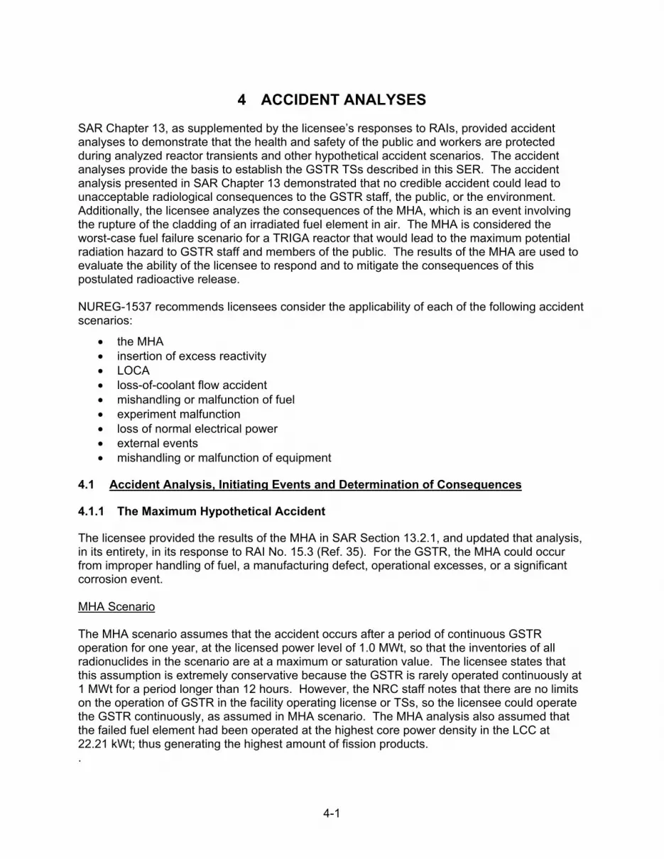
4-1
4 ACCIDENT ANALYSES
SAR Chapter 13, as supplemented by the licensee’s responses to RAIs, provided accident analyses to demonstrate that the health and safety of the public and workers are protected during analyzed reactor transients and other hypothetical accident scenarios. The accident analyses provide the basis to establish the GSTR TSs described in this SER. The accident analysis presented in SAR Chapter 13 demonstrated that no credible accident could lead to unacceptable radiological consequences to the GSTR staff, the public, or the environment. Additionally, the licensee analyzes the consequences of the MHA, which is an event involving the rupture of the cladding of an irradiated fuel element in air. The MHA is considered the worst-case fuel failure scenario for a TRIGA reactor that would lead to the maximum potential radiation hazard to GSTR staff and members of the public. The results of the MHA are used to evaluate the ability of the licensee to respond and to mitigate the consequences of this postulated radioactive release. NUREG-1537 recommends licensees consider the applicability of each of the following accident scenarios:
• the MHA • insertion of excess reactivity • LOCA • loss-of-coolant flow accident • mishandling or malfunction of fuel • experiment malfunction • loss of normal electrical power • external events • mishandling or malfunction of equipment
4.1 Accident Analysis, Initiating Events and Determination of Consequences
4.1.1 The Maximum Hypothetical Accident
The licensee provided the results of the MHA in SAR Section 13.2.1, and updated that analysis, in its entirety, in its response to RAI No. 15.3 (Ref. 35). For the GSTR, the MHA could occur from improper handling of fuel, a manufacturing defect, operational excesses, or a significant corrosion event. MHA Scenario The MHA scenario assumes that the accident occurs after a period of continuous GSTR operation for one year, at the licensed power level of 1.0 MWt, so that the inventories of all radionuclides in the scenario are at a maximum or saturation value. The licensee states that this assumption is extremely conservative because the GSTR is rarely operated continuously at 1 MWt for a period longer than 12 hours. However, the NRC staff notes that there are no limits on the operation of GSTR in the facility operating license or TSs, so the licensee could operate the GSTR continuously, as assumed in MHA scenario. The MHA analysis also assumed that the failed fuel element had been operated at the highest core power density in the LCC at 22.21 kWt; thus generating the highest amount of fission products. .

4-2
The MHA analysis scenario assumed that, at the time of clad failure, all of the gaseous radionuclides that had accumulated in the gap were available for release including the noble gases and halogen fission products. To maximize the concentration of radionuclides released, the licensee assumed that the element was removed from the core instantaneously after irradiation, and the noble gases and halogen fission products instantly and uniformly mixed with the reactor room air. In addition, the licensee assumed that the concentration of radionuclides remained constant, with no dilution due to ventilation flow, or radioactive decay, for the durations used (2 and 5 minutes) to calculate the potential doses for the occupational workers in the reactor room. In the event of an actual significant release of radionuclides in the reactor room, the GSTR facility emergency exhaust would be activated by the reactor room CAM, and any radionuclides would be exhausted through the emergency exhaust stack, at a height of 6.9 m (22.8 ft) above the ground, and at the designed nominal emergency exhaust flow rate of 800 cfm (3.78E5 cubic centimeters per second). Based on the reactor room free volume of 310 cubic meters (m3) (10,947 cubic feet (ft3)), the emergency exhaust system would require 15.6 minutes to expel one volume of air. However, for the MHA accident scenario analysis, the licensee conservatively assumed that all gaseous fission products in the reactor room were instantaneously released to the outside environment, at ground level, except for some short lived radioisotopes (Bromine (Br)-86, Br-87 and Iodine (I)-136, as explained in the Dose Calculations section below). The NRC staff reviewed the assumptions for MHA accident scenario analysis dose calculations for both occupational workers and members of the public, and finds that since all radionuclides are instantly released with no reduction in concentration allowed for decay, the MHA assumptions used by the licensee are conservative and will result in MHA dose calculations that over estimate the potential MHA doses. Nuclide Inventory To determine the MHA source term radionuclide inventories, the licensee assumed the GSTR operated continuously for a year, at the licensed power level of 1.0 MWt, and the release is from a 12 wt% U-235 fuel element producing a power of 22.21 kW (LCC). This is the hypothetical MHA failed fuel element for the GSTR. The licensee used the failed fuel element noble and halogen gaseous fission product inventories using the saturation nuclide inventory from the Oregon State University MHA analysis (Ref. 76). The NRC staff reviewed the licensee’s MHA source term radionuclide inventory analysis and performed confirmatory calculations using information on fission yields in order to determine the maximum or saturation fission gas inventory for the MHA source term. Table 4 1 below provides a comparison of estimates of radionuclide inventories for select halogens and noble gases, from: 1) the licensee; 2) estimated by the NRC staff from information in NUREG/CR-2387, “Credible Accident Analyses for TRIGA and TRIGA Fueled Reactors,” (Ref. 57); and 3) calculated by the NRC staff using typical fission product yields for U-235. Although some differences are observed in the estimated inventories, the NRC staff finds that the overall results are consistent for the isotopes that contribute most to radiological dose (Iodine, Krypton and Xenon isotopes). Based on the information above, the NRC staff concludes that the licensee’s estimate of the MHA source term inventory is acceptable.

4-3
Table 4-1 GSTR and NRC Estimates of MHA Source Term Nuclide Inventory
Nuclides Licensee Estimate
of MHA Source Term (Ci)
MHA Source Term Estimate from
NUREG/CR–2387 (Ci)
NRC Staff Confirmatory Estimate of MHA Source Term (Ci)
Br-82 29.6 n/a 0.01
Br-83 103.4 n/a 103
Br-84m 3.9 n/a 6
Br-84 192.8 n/a 193
Br-85 254.2 n/a 243
Br-86 379.9 n/a 349
Br-87 493.1 n/a 388
I-131 557.3 600 554
I-132 831.1 923 826
I-133 1292.1 1073 1287
I-134 1517.0 1413 1486
I-135 1261.4 1229 1209
I-136 1218.1 n/a 475
Kr-83m 103.4 69 103
Kr-85m 254.2 159 243
Kr-85 16.3 3 53
Kr-87 493.1 306 483
Kr-88 690.0 438 686
Kr-89 912.1 539 886
Xe-131m 10.3 n/a 6
Xe-133m 31.6 22 37
Xe-133 1254.4 1261 1288
Xe-135m 194.2 332 233
Xe-135 1261.4 569 1255
Xe-137 1192.9 n/a 1174
Xe-138 1304.7 n/a 1225

4-4
Release Fractions The licensee calculates the releases of noble gases and halogens from the fuel element matrix UZrH to fuel element gap using the GA developed correlation for fission product release (Ref. 68). This correlation estimates the release fraction (RF) based on the average fuel temperature. GA experiments determined that the RF is constant at 1.5E-5 for fuel temperatures below 300 °C (572 °F), and increases exponentially for temperatures above 300 °C (572 °F). The licensee estimates a volume averaged fuel temperature of 300.6 °C (573.0 °F) in the MHA fuel element and calculated a RF of 1.53E-5 using the following GA correlation, where T is the average fuel temperature in °C.
The licensee assumed that the fuel clad failure occurs in the air, and the available fuel gap inventory of both the noble gases and halogens release directly into the reactor room. This assumption is conservative for halogens (e.g., iodines) because they are chemically active and typically become trapped by materials with which they come into contact. The guidance typically used (Technical Information Document (TID) 14844, “The Calculations of Distance Factors for Power and Test Reactor Sites,” March 1962 (Ref. 69) and RG 3.33, “Assumptions Used for Evaluating the Potential Radiological Consequences of Accidental Nuclear Criticality in a Fuel Reprocessing Plant,” issued April 1977 (Ref. 70)) indicates that most iodines either will not become airborne, or will not remain airborne after they are released. The licensee used this guidance to support its assumption that only 50 percent of the halogen inventory in the fuel gap is released into the reactor room air, and 50 percent of the halogen inventory in the reactor room air is released to the outside environment as the other 50 percent of the halogens will remain in the reactor building due to electrostatic attachment to structural surfaces (plate-out). This results in the assumption that 25 percent of the halogens in the gap are released to the outside environment. If the cladding fails in the water, which is the most likely scenario, then the fraction available for release to the air and environment will be much lower. The NRC staff finds that the licensee’s MHA assumptions regarding the fractions of halogens released into the reactor room air and outside environment are consistent with the guidance stated above.
Table 4-2 Total MHA Release Fractions
Release Fractions Release to the Reactor
Room Release to the Environment
Noble Gases 1.53E-5 1.53E-5
Halogens 7.63E-6 3.81E-6
Table 4-2 provides expected RFs of noble gases and halogens to the reactor room. The RFs to the environment will be 50 percent of the values for halogens due to retention and plate-out as discussed above; however, noble gases pass through the reactor room, without any retention, into the environment. Based on the information above, the NRC staff concludes that the licensee’s MHA RFs are acceptable.

4-5
Atmospheric Dispersion The licensee selected various locations within the DFC for facilities near the reactor, and locations at the DFC fence line and beyond (i.e., nearest resident and a school) for members of the public further away from the GSTR. The licensee used the general Gaussian plume diffusion model to calculate nuclide concentrations at selected downwind distances, using the Department of Energy HOTSPOT Version 2.07.2 computer code (Ref. 71). For dose calculations using the HOTSPOT code, the licensee assumed that the atmospheric condition was moderately stable (stability class F) and that the wind speed, at a height of 10 m (32.8 ft), was typically 3.84 m/s (12.6 ft/s). Given the atmospheric stability class F and an assumed standard terrain (rural [open-country] condition), HOTSPOT calculated the dispersion factors in lateral (y-axis) and axial (z-axis) dimensions for the selected distances. The HOTSPOT code assumes a release duration of 10 minutes. This duration is different from that indicated in the MHA scenario (i.e., instantaneous release), but the 10-minute duration is the default option for sampling time inside the code. This default time is also used for an explosive-release accident, which is an instantaneous release. Note that in the HOTSPOT code, concentrations downwind from a source decrease with an increasing sampling time, primarily because of a larger lateral dispersion factor (y-axis) which is due to an increasing meander of the wind direction. The NRC staff finds that the use of the HOTSPOT computer code and the assumptions for GSTR accident analysis are acceptable. Dose Calculations The licensee calculated the potential MHA TEDE dose for an occupational worker in the reactor room, and public TEDE doses at selected locations outside the reactor building. For the occupational dose calculations, the licensee follows the derived air concentration method provided in 10 CFR Part 20, Appendix B. Boundary conditions for these calculations included the following assumptions: (a) failure of the hottest fuel element; (b) no radioactive decay; and, (c) a reactor room free volume of 310 m3 (10,948 ft3 ). Other parameters used in the dose calculations included a breathing rate of 0.02 m3/minute (333 cubic centimeters per second) which is consistent with the value given in Appendix B to 10 CFR Part 20; and stay times of 2 and 5 minutes for the occupational workers. For the public doses outside the reactor room, the licensee used dose conversion factors (DCFs) for the inhalation and submersion external exposure pathways from the U.S. EPA Federal Guidance Report (FGR) No. 11, “Limiting Values of Radionuclide Intake and Air Concentration, and Dose Conversion Factors for Inhalation, Submersion, and Ingestion,” issued September 1988 (Ref. 72). These DCFs are part of the input data that is internal to HOTSPOT. In addition, the licensee did not consider the contribution from the very short-half-lives isotopes such as Br-86, Br-87 and I-136. These isotopes have half-lives of less than 84 seconds, which is a very short time compared to the time that it would take the contaminated air within the reactor room to travel out of the reactor room into the environment in an actual release from the emergency exhaust system. These isotopes will not significantly contribute to actual offsite doses. The NRC staff finds these assumptions by the licensee are acceptable. The licensee provided estimates of the potential radiological TEDE doses to individuals within the reactor room, and to the public at specified distances from the reactor in its response to RAI No.15.3 (Ref. 35). The licensee’s radiological dose estimates are summarized in Tables 4-3 and 4-4, which follows the NRC staff confirmatory analysis of MHA.

4-6
The licensee assumptions are summarized below:
Restricted area inside the GSTR reactor room and control room (Table 4-3):
• the occupational workers will be exposed to the airborne gaseous fission products with no reduction due to radioactive decay;
• the normal ventilation system is off, and no credit is taken for any reduction in radioisotope concentration by operation of the emergency ventilation system;
• an evacuation time of 2 and 5 minutes is needed for the occupational workers to secure the reactor to a safe condition.
Unrestricted area outside the GSTR facility for members of the public, within and beyond the DFC (total of 8 locations) (Table 4-4 below):
• the emergency ventilation system is operating to transport the gaseous fission products outside the reactor room (but the release is assumed to be instantaneous) with no reduction in the radioisotope inventory due to decay or dilution;
• the release is assumed to occur at ground level; • the default option (for sampling time) inside the HOTSPOT code is used
(10 minutes). NRC Staff Confirmatory Analysis of MHA The NRC staff performed confirmatory calculations of the potential MHA TEDE doses in order to demonstrate the adequacy of the licensee’s submitted information. The NRC staff confirmatory MHA TEDE dose calculations were performed using the assumptions, geometry, and source term inventory consistent with the information in the SAR, as supplemented by licensee responses to RAIs. The confirmatory calculations were compared to licensee’s results, and are provided in Tables 4-3 and 4-4. The occupational worker and public TEDE doses were calculated for the individuals in the reactor room and at eight locations outside the reactor room, both within and outside the DFC, as described in Table 4-4. The NRC staff calculated the occupational TEDE doses in the reactor room using the derived air concentration method with the licensee’s source term inventory. The NRC staff calculated the TEDE for the individuals outside the reactor room using the licensee’s source term isotope inventory and DCFs from FGR No. 11 (for inhalation) and FGR No. 12. “External Exposure to Radionuclides in Air, Water, and Soil,” issued September 1993 (Ref. 73) (for submersion). The radiological doses were also calculated using the saturation inventories of the source term isotope inventory listed in Table 4-1 (NRC Staff Confirmation Estimate column), along with the DCFs from FGR No. 11 and FGR No.12. The NRC staff confirmatory analyses confirm the validity of the licensee’s MHA TEDE dose calculation results as well as provide insights into the significance of dose differences due to the use of various methods used to determine the initial MHA source term isotope inventory. The results of the confirmatory calculations confirm that the differences in doses related to differences in inventories between saturation values versus values provided by the licensee to be about 10 percent. Therefore, the NRC staff finds that the licensee’s estimated radionuclide inventories are acceptable and conservative relative to the actual operation of the GSTR (i.e., full power operation for a complete year). Additional conservatism includes the lack of an isotope decay.

4-7
The NRC staff confirmatory analysis of the public dose used the GSTR estimate for the nuclide inventory and atmospheric conditions. The results in Tables 4-3 and 4-4, demonstrate consensus between the different methods, and represent a maximum value for potential MHA TEDE doses to occupational workers and members of the public. The MHA TEDE results are also below the limits in 10 CFR 20.1201 and 10 CFR 20.1301, respectively.
Table 4-3 MHA Occupational Worker Dose Estimates Restricted Areas
Time
(minutes)
Total Effective Dose Equivalent (mrem)
GSTR NRC Staff Confirmatory NRC Limit
2 227 206 5,000
5 566 514
Table 4-4 MHA Public Dose to an Individual in Unrestricted Areas
Location Distance
(m)
TEDE (mrem)
GSTR NRC Staff
Confirmatory NRC Limit
Building 15 - south door 11 27 27
100
Emergency Assembly Area 32 3.1 5.2
Building 21 - east entrance 49 2.2 4.2
Average of eastern intersections 100 1.3 1.6
Building 16 - west entrance 175 0.51 0.55
Building 16 - west entrance 200 0.40 0.43
Building 16 - west entrance 250 0.26 0.27
Nearest Unrestricted Location (outside fence)
475 0.075 0.076
Residence 640 0.042 0.042
School 720 0.033 0.034
The dose calculations are performed at the selected distances from the reactor and are not directionally dependent. The dose calculations provide doses that would occur at the perimeters of circles from the reactor (ignoring any structures or obstacles that in fact provide significant shielding). Dose calculations in the reactor room can be considered as a bounding dose to other individuals within the connected buildings, because any air leakage into other locations from the reactor room will result in a lower exposure. As shown above, the postulated MHA non-occupational dose to any member of the public is low, and less than the regulatory limit.

4-8
Ventilation System Failure Direct Dose Equivalent calculation The NRC staff also considered a scenario where the ventilation system failed to operate in either normal or emergency mode, which resulted in the MHA radionuclides being contained within the reactor room. This is an extreme assumption because it does not credit building attenuation, building leakage, or radioactive decay, which would reduce any potential doses. However, given these assumptions allows a bounding calculation for the direct dose equivalent (DDE) from the direct shine (no plume) of the radioisotopes released into the reactor room at the initial onset of the MHA. The NRC staff dose calculations to members of the public at locations within the DFC at 11 m (36 ft), 32 m (105 ft), and 100 m (328 ft), and at the nearest unrestricted area at 475 m (1,558 ft), used the direct radiation from the entire inventory of radionuclides released into the reactor room (no leakage). The calculations conservatively assume no shielding attenuates the released radionuclides by the 1-foot concrete around the GSTR building. Furthermore, the calculations assume the building can be represented by a point source with the radiation emitted uniformly in all directions and each disintegration is conservatively accompanied by one 1.0 mega-electron volts (MeV) photon (gamma rays). Table 4-5 below summarizes the calculated DDE dose rates at the selected locations. Furthermore, assuming no radioisotope decay, the calculated dose rate will remain constant for the year (which is very conservative given that all except Kr-85 will decay out after two months), the dose to an individual at the unrestricted area, 475 m (1,558 ft), would be 3.89 mrem. This is well below the dose limit of 100 mrem/year per the 10 CFR 20.1301. If decay is factored into the dose estimate, the annual dose to a member of the public at the 457 m (1,558 ft) location, would be 0.0027 mrem.
Table 4-5 NRC Staff DDE Dose Ventilation System Failure
Location Distance
(m)
TEDE (mrem/hour)
Direct Dose Equivalent
Building 15 - south door 11 8.3E-01
Emergency Assembly Area 32 9.8E-02
Average of eastern intersections 100 1.0E-02
Nearest Unrestricted Location (outside fence) 475 4.44E-04
The NRC staff notes that its analysis of this scenario provides useful insights into the MHA. Assuming a time of 15 minutes to remove the radioactive gas from the reactor room with the emergency exhaust system, the MHA contribution from direct shine does not significantly increase doses outside the GSTR building when added to the dose from the effluent released from the stack. Thus, the doses to an individual located outside the GSTR reactor room during the initial MHA scenario are primarily from the release. The NRC staff finds, based on its review of the licensee’s dose calculations, and the results of the NRC staff’s confirmatory calculation, that the MHA dose results above demonstrate that the maximum TEDE doses are well below the occupational limits in 10 CFR 20.1201 and the public dose limits in 10 CFR 20.1301. Based on the information above, the NRC staff concludes that the dose consequences of the GSTR MHA are acceptable.

4-9
4.1.2 Failed Fueled Experiment
The licensee provided the results of the failed fueled experiment in SAR Section 13.2.6.2. The analysis provided the iodine isotopes released due to a failed fueled experiment and indicated that the limit of 1.5 Ci of iodine isotopes, as specified in TS 3.8.2, was acceptable as it was bounded by the MHA analysis, which provides an iodine inventory of 6,677 Ci. However, the NRC staff noted that the amount of iodine released in the MHA failed fuel element accident was a lower amount (approximately 83 mCi) because the iodine isotope release inventory is modified by the temperature dependent RF of the fuel. Additionally, the failure of a fuel element assumes an atmospheric release to the reactor room. The SAR did not identify whether the failed fueled experiment scenario occurred in the same location, or if it had the potential to occur in the laboratory area or in transit with greater radiological consequences. Consequently, the NRC staff asked the licensee to clarify its analysis. In its response to RAI No. 28 (Ref. 35), the licensee clarified the initial conditions, or assumptions, pertaining to the failure fueled experiment accident scenario. The fissile material was irradiated for a period long enough to accumulate 1.5 Ci of the isotopes I-131 through I-135 in the sample at the time of reactor shutdown. No credit was assumed for retention of the I-131 through I-135 due to encapsulation. However, a decay time of 5 minutes was used based on procedure control, as required by the USGS ROC, that a sample may not be unloaded from the irradiation facility until at least 5 minutes of decay have occurred (Ref. 35). The worst case location for the fueled experiment failure was in air in the reactor room. Fueled experiment samples are unloaded from the reactor and allowed to decay in a shielded storage location in the reactor room before they are released for analysis. This additional decay time would reduce the consequences of a container leak, but was not included as an assumption. The opening of a fueled experiment sample container is done in a high-efficiency particulate air (HEPA)-filtered fume hood, which also limits the release, but is not considered as part of the accident scenario as the release is into the air in the reactor room. In its response to RAI No. 28 (Ref. 35), the licensee also provided an updated inventory based on the assumptions described above, which was estimated to be 1.14 Ci of xenon isotopes, 1.59 Ci of halogens (of which 1.48 Ci is due to iodine isotopes), and 1.64 Ci of noble gases. Thus, the accident source term, following the 5-minute decay, is reproduced in Table 4-6 below.
4-10
Table 4-6 GSTR Inventory for Failed Fueled Experiment
Isotope Activity after 5 minutes (Ci) Isotope Activity after 5 minutes (Ci)
Br-82 8.04×10⁻³ Kr-83m 2.73×10⁻²
Br-83 2.75×10⁻² Kr-85m 6.83×10⁻²
Br-84m 5.97×10⁻⁴ Kr-85 4.45×10⁻³
Br-84 4.70×10⁻² Kr-87 1.28×10⁻¹
Br-85 2.07×10⁻² Kr-88 1.84×10⁻¹
Br-86 2.44×10⁻³ Kr-89 8.26×10⁻²
Br-87 3.25×10⁻³ Xe-131m 2.81×10⁻³
1-131 1.52×10⁻¹ Xe-133m 8.58×10⁻³
1-132 2.20×10⁻¹ Xe-133 3.41×10⁻¹
1-133 3.51×10⁻¹ Xe-135m 4.21×10⁻²
1-134 3.86×10⁻¹ Xe-135 3.41×10⁻¹
1-135 3.40×10⁻¹ Xe-137 1.31×10⁻¹
1-136 2.74×10⁻² Xe-138 2.78×10⁻¹
The licensee used the HOTSPOT code (Ref. 71) to calculate potential doses from the fueled experiment failure accident analysis. The analysis is discussed below, and the dose results are summarized in Table 4-7 which follows. NRC Staff Confirmatory Dose Calculations The NRC staff performed confirmatory calculations also using HOTSPOT code. The halogens and noble gas inventories that were used in the calculations (following the assumed 5-minute decay time) were approximately 3,600 times lower than the MHA failed fuel element inventory, but were proportional indicating that the source term had been correctly decayed. The licensee’s analysis used the accidental release of the halogens and noble gases in a failed fueled experiment to the reactor room, and calculated the occupational dose for a 2-minute exposure (before evacuating the reactor room). The licensee assumed that 100 percent of the halogens were released into the reactor room (for the occupational dose calculation compared to a RF to the reactor room of 7.63E-6 for the MHA), and that 50 percent of the halogens in the reactor room air were reduced by plate-out on surfaces of the reactor room before evacuation. The NRC staff finds that the plate-out assumption is inconsistent with the assumption of a 100 percent release. The NRC staff’s finds that the 2-minute interval is too short for 50 percent of the halogens to plate-out, which is an assumption appropriate only for the dose calculations outside the reactor room. Because the NRC staff calculation did not use the 50 percent plate-out assumption, the occupational dose for a 2-minute exposure was calculated to be 3,930 mrem TEDE rather than the 2,300 mrem TEDE calculated by the licensee. However, the NRC staff finds that both results are below the 10 CFR 20.1201 limit of 5,000 mrem. Additionally, NRC staff also performed confirmatory dose calculations for members of the public based on the failed fueled experiment release, using the HOTSPOT parameters listed in the licensee’s responses. As presented in Table 4-7, the licensee’s and the NRC staff’s

4-11
confirmatory dose calculations are in close agreement for many of the locations. The NRC staff noted some minor differences in a few locations between the NRC staff calculated results and the licensee dose results, and determined that the differences arose from assumptions used in the HOTSPOT code model. The NRC staff finds that the differences in doses are small, and all the dose results are acceptable because the public exposure doses are below the limit in 10 CFR 20.1301.
Table 4-7 Failed Fueled Experiment Dose Assessment
Location Distance (meter)
Licensee TEDE (mrem)
NRC Staff Confirmatory TEDE
(mrem)
Building 15 south door 11 0.0 0.0
Emergency assembly area 32 0.0 0.0
Building 21 east entrance (West of Building 15)
49 1.1E-7 1.5E-9
Average of eastern intersections 100 0.1 0.036
Building 16 west entrance 175 0.94 0.83
Building 16 west entrance 200 1.1 1.1
Building 16 west entrance 250 1.3 1.4
Nearest Unrestricted Location 475 0.88 1.1
Residence 640 0.6 0.73
School 720 0.51 0.62
The NRC staff reviewed the licensee’s failed fueled experiment accident scenario and calculations for the resulting occupational doses to the workers and to any members of the public outside the reactor facility. The NRC staff finds that, for the failed fueled experiment analysis, the licensee used conservative assumptions for the initial conditions, the source term inventories used were appropriate, and the licensee’s calculated doses were consistent with the results of the NRC staff’s independent confirmatory analysis. Based on the information above, the NRC staff finds the failed fueled experiment analysis results for the occupational doses to the workers within the limits in 10 CFR 20.1201 and doses to members of the public outside the GSTR facility are within the limits of 10 CFR 20.1301. Based on the information above, the NRC staff concludes that the dose consequences from the GSTR failed fueled experiment are acceptable.
4.1.3 Insertion of Excess Reactivity
The insertion of excess reactivity event can be an initiating event that could lead to fuel element failure or the failure of an experiment, and the consequences can result in physical changes to the core (e.g., cladding breach) or become a radiological event. The analysis of this postulated accident will also be used to demonstrate the acceptability of pulsing the GSTR. The guidance provided in NUREG-1537, Section 13.1.2, recommends the evaluation of both a rapid and a slow reactivity insertion event. The rapid insertion event relies upon the FTC to limit the

4-12
reactivity insertion rate and protect the fuel temperature SL. The slow insertion event is used to demonstrate the acceptability of the TS LCO setpoints for the reactor trip system power level scram (TS 3.2.3, Specification 1) and the control rod insertion time (TS 3.2.1, Specifications 2.b and 2.c) to help ensure that the GSTR fuel T-H limits are met. Rapid Reactivity Insertion - Pulse Analysis In SAR Section 13.2.2, supplemented by response to RAI No. 12 (Ref. 32), the licensee provided a description of the sequence of events for performing a pulse in the GSTR, and the results of its analysis. The pulse begins with the reactor at a bulk water temperature that is less than 60 °C (140 °F) and a steady state power of 1 kWt or less. The shim and regulating control rods are in a banked position to maintain a critical condition. TS 4.1, Specification 5, limits the reactivity worth of the transient control rod to less than $3.00 for the scheduled pulse. The pulse is initiated by the reactor operator from the control board when the transient rod is pneumatically ejected from the core. The full length transient rod travel time is approximately 0.2 seconds. The reactivity insertion (transient rod ejection) is maintained for 1.5 seconds before the transient rod is inserted back into the reactor core in the next 2 seconds. Fifteen seconds following the initiation of the initial pulse, the reactor scrams on the preset timer setting in accordance with TS 3.2.3, Specification 1, which rapidly adds approximately $5.00 of negative reactivity into the reactor core (1 second). During the pulse, the reactor power rapidly increases and heats up the fuel. The rapid rise in fuel temperature results in a prompt negative reactivity insertion from the negative FTC inherent in TRIGA fuel elements, which terminates the reactivity event, not from the insertion of control rods. The licensee performed pulse calculations using the RELAP5 (Ref. 74) point kinetics model to demonstrate the response of the GSTR. The reactor core was modelled using 2 flow channels that represented a hot rod channel and an average channel representing the rest of the core. The calculation sets the reactivity feedback values as the fuel temperatures and fluid conditions of the bottom node in the average rod heat structure and flow channel. The licensee states that this will give conservative results for the peak power and peak fuel temperature because the negative Doppler reactivity feedback is significantly under-estimated since more integrated power is needed to raise the low power region of the fuel to a temperature high enough to compensate for the inserted reactivity. The GSTR calculation for the peak fuel temperature should provide results that bound any actual values in the core because of the conservative values used for reactivity feedback. The licensee calculated a value of 747 °C (1,377 °F) for a $3.00 pulse using power peaking factors from the LCC at the TS pool temperature limit of 60 °C (140 °F). The calculated peak fuel temperature is significantly lower than the recommended pulsing temperature limit of 830 °C (1,526 °F). The licensee’s RELAP model results are provided in Figure 4-1, and Table 4-8 below, for various pulse reactivity insertions. In all cases, including the maximum reactivity value of $3.00, the maximum fuel temperature attained remains below the pulse fuel temperature limit of 830 °C (1,526 °F, or 1,103 °K) as shown in Figure 4-1 below).

4-13
Figure 4-1 GSTR Analysis of a $3.00 Pulse
Table 4-8 GSTR Pulse Results
Pulse Reactivity $3.00 $2.75 $2.50 $2.00
Peak Power (MWt) 1,971 1,793 1671 938
Peak Centerline Temp. (°C) 747 717 624 581
NRC Staff Confirmatory Pulse Analysis The NRC staff analyzed the GSTR pulse event using a TRACE model with the sequence of events for pulse mode operation provided in the licensee’s response to RAI No. 12. Even though the LCC transient control rod is worth $2.648, the TRACE model used the TS 3.1.2, Specification 1, reactivity worth of $3.00, which is more conservative. The banked position of the mechanical control rods allows $5.05 of negative reactivity to be available for insertion when scrammed. Calculations were performed with the initial coolant temperature at 30 °C and 60 °C. Table 4-9 below provides the confirmatory pulse results which demonstrate agreement with the licensee’s results, and, indicate that the TRIGA fuel temperature limit for pulsing is maintained below 830 °C (1,526 °F), for a maximum pulse reactivity of $3.00.
Table 4-9 NRC Staff Confirmatory Pulse Results
Pulse Reactivity $3.00 $3.00
Peak Power (MWt) 1,985 1,765
Peak Centerline Temp. (°C) 741 732
Initial Coolant Temp. (°C) 30 60

4-14
The NRC staff also evaluated the aluminum clad fuel elements since the SL is 500 °C (932 °F), which is less than the pulsing limit of 830 °C (1,526 °F). TS 3.1.3, Specification 1, limits the aluminum clad fuel to the F and G ring locations. The NRC staff analysis of the maximum fuel element power in the F and G ring locations found the peak fuel element power of 7.1 kWt (Figure 2-8 of the SER). The NRC staff analysis of the aluminum clad fuel elements indicated that the maximum temperature for an element at 7.0 kWt was 255 °C (491 °F) and 275 °C (527 °F) for an element at 8.0 kWt, and thus, well below the SL of 500 °C (932 °F). Based on the information above, the NRC staff finds that the stainless steel clad fuel elements remain below the pulsing temperature limit of 830 °C (1,526 °F), and the aluminum clad fuel elements, due to their location in the F and G rings, remain below the pulsing temperature limit of 500 °C (932 °F). Slow Reactivity Insertion - Uncontrolled Rod Withdrawal In its response to RAI No. 14.2 (Ref. 28), the licensee describes the RELAP model used to analyze the slow reactivity insertion event, or URW event. The licensee assumed that there is a malfunction of a single control rod drive electrical controller that causes one control rod to be withdrawn from low power. The analysis was based on the following assumptions:
• initial power 1 kWt, • bulk water temperature 60 °C (140 °F), • channel flow area 8.382 cm2 (1.299 square in) • control rod withdrawal speed 0.9535 cm/s (22.5 in/minute), • the uncontrolled rod is continuously withdrawn, • the scram setpoint is 1,100 kWt (TS 2.2), • mechanical control rod insertion time 1 second, • pneumatic control rod insertion time 2 seconds, • control rod worths calculated by MCNP for the LCC, • GSTR FTC included.
The licensee states that the peak power attained is 2.27 MWt and occurs 13.6 seconds after the control rod withdraw begins. This event occurs quickly such that the heat transfer conditions are essentially adiabatic and the maximum fuel temperature attained was calculated to be approximately 77 °C (171 °F), which is well below the TS 2.2 SL for either stainless steel clad fuel (1,150 °C) (2,102 °F) or aluminum clad fuel (500 °C) (932 °F). NRC Staff Confirmatory of the Slow Reactivity Insertion Event The NRC staff performed an independent confirmatory calculation using the TRACE model with physical dimensions obtained from the SAR and licensee’s response to RAI No. 14.2 (Ref. 32). For the URW event, the initial conditions include the GSTR is just critical with an excess reactivity of $6.184 (LCC). Since the regulating control rod is the maximum worth rod, it is the control rod that will be fully withdrawn, at a maximum speed of 0.9535 cm/s as provided in the licensee’s response to RAI No.14.2, (Ref. 32). The regulating rod withdrawal continues until the high power scram signal at 1,100 kW (TS 2.2, Specification 1) occurs 8.7 seconds later. At this point in the event analysis, the regulating control rod, along with the shim-1, and shim-2 control rods insert in 1 second and the transient control rod inserts in 2 seconds. All the control rod insertion times are consistent with the limits in TS 3.2.1, Specification 2.b.

4-15
The results of the analysis indicate that the fuel temperatures remain low and the DNBR is greater than 2.00 at all times during the transient. The licensee’s calculated fuel temperatures, and the NRC staff’s confirmatory calculations of the fuel temperatures are summarized in Table 4-10 below.
Table 4-10 Confirmatory Analysis of the Uncontrolled Rod Withdrawal
Parameter Licensee NRC Staff Confirmatory
Peak Power 2.27 MWt at 13.6 s 2.606 MWt at 8.8 s
Peak Fuel Temperature 77°C 60.6°C at 8.9 s
Based on its confirmatory calculation, the NRC staff finds that the peak power reached does not pose a challenge to the fuel temperature SL in TS 2.2, Specification 1, for the slow reactivity insertion URW event. Furthermore, the analysis demonstrates that the limits provided in TS 3.2.1, Specification 2.b, of the transient control rod scram time of 2 seconds, the Shim-1, Shim-2, and regulating control rod scram time of 1 second; and the control rod withdrawal rate of 0.9535 cm/s (0.031 ft/s), and the FTC determined by the licensee, are all acceptable since the TS 3.2.1, and FTC were used as assumptions in the analysis. The NRC staff also finds that the licensee’s analysis of both the rapid and slow reactivity insertion events use reasonable assumptions, acceptable methods, and arrive at acceptable conclusions when conducted in accordance with the limits in the TS. Based on the information above, the NRC staff finds the insertion of excess reactivity analysis acceptable.
4.1.4 Loss of Coolant Accident
The GSTR loss of coolant accident (LOCA) analysis was described in SAR Section 13.2.3, and updated in responses to RAI No. 17 (Ref. 14 and Ref. 30). The reactor pool tank is discussed in Section 2.3 of this SER. The licensee states that the two scenarios that could lead to a loss of coolant from the reactor tank would be siphoning or failure of reactor tank liner. Siphon breaks in the piping in the tank would limit the reactor tank coolant loss such that 20 ft (6.1 m) of water would remain above the top of the core. A reactor tank liner failure would result in reactor pool water filling the annual space between the tank liner and the original tank which was formed by a liner applied to the surface of an in-ground concrete enclosure. Both scenarios would completely uncover the reactor core, but would result in actuation of the reactor tank water level alarm, TS 3.3, Specification 1.c, and operator action to restore reactor pool tank water. As such, this scenario analyzed below is highly unlikely, but is performed to demonstrate the acceptability of the GSTR TRIGA fuel to an extreme condition where cooling is lost, and to demonstrate that the dose rates from the unshielded core are properly mitigated by the design of the GSTR core in-ground location. The licensee provided an analysis in Section 8.6 of its initial GSTR license application SAR (1967) that indicated the maximum fuel temperature, following full power operation, with only air cooling of the fuel, will be 780 °C (1,436 °F). A subsequent study by the fuel vendor, GA, and described in NUREG/CR-2387 (Ref. 57) finds that the LOCA analysis would not result in cladding failure as the instantaneous loss of coolant would cause the reactor to shutdown (on loss of moderation), and the radiative heat loss from the fuel would only raise the fuel temperature about 110 °C (230 °F). As such, the aluminum clad fuel at GSTR, which operates in the F ring at a maximum power level of 7.1 kWt, and 255 °C (491 °F) would remain below the SL of 500 °C (932 °F). The peak fuel temperature of the LCC is 556 °C (1,032 °F) for a fuel

4-16
element at a power of 22 kWt, and is also, well below the SL of 1,150 °C (2,102 °F). As such, the LOCA is not expected to result in loss of cladding integrity or release of radioactivity. However, a LOCA would reduce the coolant shielding resulting in radiological doses from direct shine of the GSTR core. This analysis is discussed below: Doses from the GSTR Uncovered Core The licensee provided the results of its analysis of the radiation levels following a LOCA in its response to RAI No. 17 (Ref. 30). The licensee assumed a total loss of reactor pool coolant following a continuous year of operation at 1,110 kWt in order to generate the maximum fuel inventory radioactivity. The analysis considered the reactor as a point source of 1.0 MeV photons, emanating from disintegrations of fission product isotopes with no attenuation through the fuel, fuel element, and core structure, and included scatter from the reactor room roof. (Note: for the 295 m (968 ft) location, the licensee assumed an attenuation factor due to a 1 ft (0.3 m) thick cement slab for that location only). For the scattered radiation within the reactor building, the licensee assumed a thick concrete-slab ceiling to ensure a conservative scattering dose. The licensee calculated the scattered photon flux at a farthest point from the reactor pool within the reactor room using a single-scatter albedo method and Klein-Nishina formula for scattering cross section. The licensee provided a closed form equation for calculating the scattered dose in the reactor room and locations outside of the reactor building. The exposure rates (roentgen per hour (R/hr)) were calculated for several locations listed below.
• Reactor grating above the top of the reactor tank, • Reactor room - 16 ft (4.9 m) from the tank center, • Building 15 south door - 11 m (36 ft) from the tank center, • Emergency Assembly Area - 32 m (105 ft) from the tank center, • Average of Eastern Intersections - 100 m (328 ft) from the tank center, • DFC - 295 m (968 ft) from the tank center, and • Outside the DFC (fence line) - 475 m (1,558 ft) from the tank center.
The licensee states, in its response to RAI No. 17 that the reactor grating dose rate is from direct radiation due to the location being directly above the core. The dose rates at all the other locations are due to scattering effects from the reactor building. The licensee also calculated the radiation exposure rates over several time periods to demonstrate the reduction due to decay. The licensee’s assumption of the gamma ray energy of 1.0 MeV results in a direct conversion of radiation exposure rates in rem/hr to radiation absorbed dose in R/hr (e.g., 1.0 R/hr equals 1.0 rem/hr). A summary of the licensee’s calculations, and the NRC staff’s confirmatory calculations, are provided in Table 4-11, Table 4-12, and Table 4-13 below. Table 4-11 below provides the licensee’s calculated dose rates for occupational workers in the reactor room, and NRC staff’s confirmatory dose rate calculations. The hypothetical LOCA event cannot occur instantaneously, however, for the LOCA analysis dose calculations, the direct radiation dose rate above the tank was calculated using the dose rate from the GSTR 10 seconds following full power operation and after a sudden and complete loss of reactor pool coolant water. The dose rate from the GSTR core was then used to generate the scattered radiation that results from the activation of the reactor bay structure and components, also shown in Table 4-11 below. The location identified for the maximum scattered radiation expected to an individual in the vicinity of the reactor following the LOCA was the reactor room location 16 ft (4.8 m) from the reactor. The dose calculation results indicate that the potential

4-17
dose rates are low and any expected evacuation (typically 2 to 5 minutes) would result in a potential total dose to a worker of less than 3 mrem. This value is well below the 5,000 mrem limit in 10 CFR 20.1201.
Table 4-11 Dose Rate to a Worker within the Reactor Room
Time after LOCA
Reactor Room – direct radiation
grating above the tank cover
(R/hr or rem/hr)
Reactor Room - scattered radiation
16 ft from the tank center (R/hr or rem/hr)
Licensee NRC Staff Confirmatory
Licensee NRC Staff Confirmatory
10 seconds 7.12 E+4 7.94 E+4 7.01 6.90
1 hour 1.93 E+4 2.16 E+4 1.90 1.87
1 day 8.48 E+3 9.45 E+3 0.83 0.82
1 week 4.55 E+3 5.07 E+3 0.45 0.44
1 month 2.50 E+3 2.78 E+3 0.25 0.24
Table 4-12 Dose Rate to an Individual in the Vicinity of the Reactor Building
Selected locations outside reactor building
(meters)
Scatter radiation
(mR/hr or mrem/hr)
Licensee NRC Staff Confirmatory
Building 15 south door (11 m) 0.516 0.513
Emergency Assembly Area (32 m) 0.063 0.064
Average of Eastern Intersections (100 m) 0.00295 0.0030
Dose rates for members of the public within the DFC are provided in Table 4-12 above. As such, the applicable dose limit is 100 mrem/yr as required by 10 CFR 20.1301. However, individuals within the DFC are under the control of licensee and the Federal Protective Services, and can be relocated during an emergency, such as a LOCA, as provided in Section 3.1.2 of the USGS emergency plan (Ref. 47), should radiological conditions warrant. Assuming an hour for evacuation, the dose rates above would not result in a dose of greater than 0.5 mrem, which is below the 100 mrem limit in 10 CFR 20.1301. Table 4-13 below provides dose rates for members of the public in an unrestricted area. In its analysis, the licensee used 295 m (968 ft) as the nearest distance to an unrestricted area for the LOCA analysis, but corrected that distance in its response to RAI No. 24.9 (Ref. 32) for the MHA analysis, to indicate that the nearest location for a member of the public to remain indefinitely was actually 475 meters (1,558 ft). The NRC staff finds that an update to the LOCA analysis was not necessary as the results for the location at 295 m (968 ft) were less than the limit specified in 10 CFR 20.1301 of 100 mrem/yr. Using the maximum dose rate at 10 seconds (1.35 E-4 mrem/hr), a member of the public at the 295 m (968 ft) location would receive about 1.0 mrem in a year. The NRC staff finds that the licensee’s results also show the rapid decline in the dose rate over time, as short-lived radionuclides decay, which further reduces the total

4-18
dose which could be received by a member of the public. Within one hour, the dose rate decreased over 70 percent, and continued to decline. As such, the 1.0 mrem result is a very conservative over-estimate of the potential dose.
Table 4-13 Dose Rate to a Member of the Public at the DFC
Time after LOCA
Scatter radiation – at 295 meters from the tank center
(mR/hr or mrem/hr)
Scatter radiation – at 475 meters from the tank center
(mR/hr or mrem/hr)
Licensee NRC Staff Confirmatory
Licensee NRC Staff Confirmatory
10 seconds 1.35 E-4 1.48 E-4 n/a 3.4 E-5
1 hour 3.66 E-5 4.02 E-5 n/a 9.4 E-6
1 day 1.60 E-5 1.76 E-5 n/a 4.1 E-6
1 week 8.60 E-6 9.45 E-6 n/a 2.2 E-6
1 month 4.72 E-6 5.19 E-6 n/a 1.2 E-6
NRC Staff Confirmatory Calculations The NRC staff performed confirmatory analyses using alternative sources for various input parameters (i.e., concrete mass attenuation coefficient, air mass absorption coefficient for various gamma ray energy), and calculated scatter doses within the reactor room and at select locations outside of the reactor building as provided in Table 4-11, Table 4-12, and Table 4-13. The NRC staff finds that the dose rates calculated indicate a difference between the licensee and the NRC staff of approximately 10 percent, and this is likely attributable to the selection of the gamma-ray energy dependent parameters. The NRC staff finds that the confirmatory calculation results are in close agreement with the licensee’s which validates the licensee’s methods and results. The NRC staff reviewed the licensee’s LOCA analysis, including the methods used and the resulting exposure and dose rates, and finds that the licensee’s method provided a reasonable approach in determining the scattered dose without the need for a complex geometric modeling of the reactor building. Overall, the NRC staff finds the dose rate results to be similar given the uncertainties in the estimated parameters. The NRC staff also finds that these results indicate that the dose rates to the public from scattered radiation are small, and would result in doses to the workers or members of the public in amounts less than the limits in 10 CFR Part 20. Based on the information above, the NRC staff finds that the licensee’s LOCA analysis and the results are acceptable.
4.1.5 Loss of Coolant Flow
In SAR Section 13.2.4, the licensee states that loss of coolant flow could occur due to failure of a key component in the reactor primary or secondary cooling system (e.g., a pump), loss of electrical power, or blockage of a coolant flow channel. Operator error could also cause loss of coolant flow. The GSTR tank holds approximately 8,000 gallons (30,283 liters) of water. At a steady-state power level of 1 MWt, the bulk water temperature would increase adiabatically at a rate of about 0.47°C/min. Under these conditions, the operator has ample time to reduce the

4-19
power and place the heat-removal system back into operation before a high temperature is reached in the reactor bulk water. The GSTR has visual indications available to indicate that the primary water pump is off, the secondary water pump is off, and/or the cooling tower fans are off. These will allow the operator to observe an abnormal condition, along with the primary water temperature alarm setpoint of 58 °C (136 °F). There is sufficient coolant in the reactor pool to absorb the decay heat from the reactor without the need for the primary or secondary cooling system. In its analysis, the licensee states that and it would take about 85 minutes for the water in the tank to reach the 100 °C (212 °F), or start boiling, if the pool cooling system fails and the operator takes no action to shut down the reactor. And, it would take about 15 hours for the tank water level to boil down to the top of the core. As the volume water level drops past the top of the core, the negative void coefficient of reactivity would shut down the reactor and the reactor could be air cooled (discussed in the LOCA analysis in Section 4.1.4 of this SER). Makeup water could be easily provided from external sources by the operators. The SAR also addressed the issue of a cooling channel flow blockage. The NRC staff reviewed the description of the GSTR core support grid plates provided in SAR Section 4.2.5, and supplemented by the licensee’s response to RAI No. 5 (Ref. 10), which indicate that coolant flow passages are available for each fuel element, slots are provided for additional cooling, and a fuel element is not allowed in the central thimble location (TS 3.1.3, Specification 3). The GSTR core is cooled by an overall pool/reactor natural circulation flow loop. The driving pressure difference for this flow circulation is the difference in the density head between the cold pool water outside and adjacent to the core and the warmer flow through the core. In natural convection flow circulation, the channel flow is a function of the fuel element heat produced. A high heat input yields a high flow rate and a lower heat input yields a lower channel flow rate. Hot fuel elements adjacent to cooler fuel elements or adjacent to large flow channels could have lower channel flow rates as well. The licensee’s description of the GSTR reactor in SAR Section 4.2.5, and in its response to RAI No. 5, indicate that the GSTR is a circular pitch core where each ring of the core has fuel elements arranged in circular rows. This fuel element geometry is a combination of regular and irregular fuel element/channel configurations. The fuel elements in the A through C rings form either a nearly triangular pattern or a nearly square pattern. Rods in the outer rings generally form four-sided rectangular cusps. The GSTR core support grid plate does not have uniformly placed holes beneath each fuel element that provide coolant to that fuel element. Instead, in the inner half of the grid plate, rings A through D have circumferential slots and an array of holes that provide coolant to the fuel elements. The flow through the remaining rows is provided by cross-flow from the inner rows, and cross-flow coming from the skirt area between the edge of the lower core plate and the reflector assembly. The NRC staff reviewed the GSTR core and finds that the reactor coolant flow allowed by the numerous flow paths (the circumferential slots and coolant holes, as well as the core coolant cross flow and reactor skirt cross flow) provides ample means for coolant flow to cool the reactor should a flow blockage event occur as it is highly unlikely that a flow blockage event could not simultaneously restrict enough flow paths as described above to cause fuel damage. The NRC staff finds that the GSTR design of the reactor core coolant flow would ensure sufficient continuing cooling of all fuel elements given a flow blockage event. Additionally, the NRC staff finds that the loss of pool cooling would result in a slow temperature increase, which would be corrected by the GSTR reactor operators.

4-20
The NRC staff reviewed the licensee’s Loss of Coolant Flow analysis and finds that a loss of pool cooling would require a long duration of time to support boiling, and numerous alarms (bulk water temperature, water level, water flow, and radiation monitors) would alert the reactor operators to shut down the reactor and restore pool cooling. The NRC staff finds that the a loss of coolant flow due to a flow channel blockage would be unlikely since the core design provides for alternate cooling paths for coolant to cool the fuel. The NRC staff also finds that if the GSTR core became uncovered, fuel damage would be unlikely as discussed in the LOCA analysis in Section 4.1.4 of this SER, and the radiological consequences would be less significant than those previously evaluated in the MHA analysis, as discussed in Section 4.1.1 of this SER. Based on the information above, the NRC staff finds the licensee’s loss of coolant flow analysis acceptable.
4.1.6 Mishandling or Malfunction of Fuel
The licensee provided a description of its analysis of mishandling or malfunction of fuel in SAR Section 13.2.5, and in its responses to RAI No. 18 (Ref. 21) and RAI No. 15.3 (Ref. 35), which stated that mishandling or malfunction of the fuel could lead to a single fuel element failure in the pool water. The licensee identified the following scenarios: (1) fuel handling accident, such as a fuel drop under the water; (2) failure of the fuel cladding due to a manufacturing defect, or corrosion; and (3) overheating of the fuel with the subsequent cladding failure (due to loading of the aluminum-clad fuel in the inner ring). The licensee evaluated a cladding failure of a single fuel element in the reactor pool as part of the MHA scenario, and because most of the halogens will remain in the primary coolant in the reactor pool, the radiological doses are much lower than those for the MHA which involves the failure of a fuel element in the air. The licensee assumed that 95 percent of the halogens released from the cladding gap will remain in the reactor pool coolant water and be deposited in the demineralizer. The licensee calculated the dose rate to a worker from the demineralizer tank, assuming a 1 MeV gamma ray energy at a distance of 1 ft (0.3 m) to be 270 mrem/hr. The remaining 5 percent of the halogens are released to the reactor room air. The licensee calculated the dose to an occupational worker in the reactor room, which included both the submersion dose from the isotopes released to the reactor room air and the DDE from the demineralizer tank, for a fuel element failure in the reactor tank pool water. The dose was 95 mrem for a 2-minute duration and 237 mrem for a 5-minute duration. The licensee concluded that the occupational doses would be well below the 10 CFR 20.1201 limit of 5,000 mrem. The NRC staff performed confirmatory dose calculations of the DDE to a worker from the demineralizer tank, using the radioactive inventory of the hottest fuel element in Section 4.1.1 of this SER, assuming 1 MeV gamma ray energy, for a fuel element failure within the pool water. The calculated confirmatory dose rate was 315 mrem/hr. The NRC staff also used the attenuation provided by the 0.5 in (1.27 cm) of lead shielding from the design of the demineralizer tank and the calculated confirmatory dose rate was 215 mrem/hr, and the dose to a worker for a 2-minute period was 7 mrem and 18 mrem for a 5-minute period. The NRC staff reviewed the licensee’s analysis of a mishandling or malfunction of a fuel element, and performed confirmatory dose calculations of the demineralizer dose rated. The NRC staff finds that the consequences of a fuel element failure in the reactor pool tank water are bounded by the MHA, the doses associated with the event are less than the limit in 10 CFR 20.1201, and the analysis of the mishandling or malfunction of fuel is typical of other

4-21
TRIGA facilities. Based on the information above, the NRC staff concludes that the licensee’s mishandling or malfunction of fuel analysis is acceptable.
4.1.7 Experimental Malfunction
The licensee provided a description of its evaluation of the experimental malfunction in SAR Section 13.2.6, which indicated that an experiment malfunction could result from three primary causes: (1) an unexpected reactivity insertion; (2) a release of material from a specimen container; and (3) detonation. The licensee controls and limits experiment reactivity by TS 3.8.1, Specification 1.a, to prevent a step change in reactivity greater than $1.00 for unsecured experiments. This is well below the maximum reactivity limit of $3.00 evaluated earlier under Section 4.1.3 of this SER, and found acceptable. The licensee limits the introduction of corrosive materials, as required by TS 3.8.2, Specification 1.c, which requires double encapsulation. This TS helps ensure that it is highly unlikely that a failure of a double encapsulation experiment device could occur and release corrosive material into the coolant system. The NRC staff finds that the TS helps ensure that an anticipated failure of a double capsule is highly unlikely and, therefore, acceptable. TS 3.8.2, Specification 1.a, establishes the requirement to limit the use of explosive material in the GSTR to 25 milligrams TNT equivalent, and states that quantities less than 25 milligrams may be irradiated provided that the pressure produced in the experiment container shall be demonstrated to be less than the design pressure of the container. This is consistent with the guidance provided in RG 2.2 (Ref. 72) and NUREG-1537, and, therefore is acceptable. The licensee limits the consequences of a release of I-131 to I-135 to 1.5 Ci in TS 3.8.2, Specification 1.b. The NRC staff reviewed TS 3.8.2, Specification 1.b and finds that the consequence of a malfunction of an experiment containing 1.5 Ci of iodine (I-131 through I-135) into the air or in water are consistent with the MHA analysis (discussed in Section 4.1.2 of this SER). Therefore, the occupational and public doses from such a release would be well below the limits set in 10 CFR 20.1201 and 10 CFR 20.1301, and, therefore, are acceptable. The licensee indicated in SAR Section 13.2.6.2, that there are two main sets of procedures and regulatory requirements focused on ensuring that the experiments are safe to implement (i.e., the experiment will not fail, will not damage the reactor, or lead to radioactivity release). These requirements and limitations are in the TSs and GSTR operating procedures associated with the review of all reactor experiments. The review process of a proposed experiment includes a safety analysis that assesses the complete range of safety issues such as the generation of radionuclides; the reactivity worth of the experiment; material properties such as chemical, physical, and corrosive characteristics of each experiment; and potential failures and malfunctions. The NRC staff reviewed the licensee’s analysis of experiment malfunction and finds the potential failure modes are consistent with the safety analysis of other TRIGA reactors, and the licensee’s TSs provide limits to help ensure the consequences of a potential experimental malfunction are limited. Based on the information above, the NRC staff concludes that the results of the licensee’s analysis of a failure of an experiment at the GSTR facility are acceptable.

4-22
4.1.8 Loss of Normal Electrical Power
The licensee provided the analysis for the loss of normal electrical power in SAR Chapter 8 and Section 13.2.7. The licensee states that emergency electrical power is not necessary to safely shut down the reactor and maintain it in a safe shutdown condition. The GSTR facility does employ a backup emergency power system which a 5 kilo-Volt-Amps battery powered uninterruptible power supply (UPS) inverter that provides power to instrumentation allowing the operator to monitor the shutdown of the reactor should normal electrical power be lost. The backup power UPS can continue to supply power for a few days. The radiation area monitor is equipped with self-contained battery backup to ensure continuous monitoring of the reactor room. Numerous hand-held battery powered emergency lights are also located throughout the facility to allow for inspection of the reactor, and orderly evacuation. A natural gas powered generator is also available to support operation of those electrical loads on the UPS if an extended electrical outage were to occur. The licensee also indicated, that in the event of a loss of normal electrical power, all mechanical control rod magnets would de-energize and the control rods would then insert into the core automatically by gravity within 1 second. The transient control rod would similarly insert within 2 seconds once the air solenoid is de-energized. Upon loss of electrical power, the primary and secondary coolant pumps would stop. Reactor decay heat would be dissipated through natural circulation in the reactor pool. There is sufficient coolant in the reactor pool to absorb the decay heat from the reactor without the need for the primary or secondary cooling system. The NRC staff reviewed the loss of normal electrical power and finds that a loss of normal electric power poses no undue risk to the operation of the GSTR. Backup power is available from a battery powered UPS and the GSTR can safety shutdown and remain in a safe shutdown condition without emergency power. Based on the information above, the NRC staff concludes that the results of the licensee’s analysis of loss of normal electrical power analysis are acceptable.
4.1.9 External Events
The licensee provided the analysis for external events in SAR Sections 2.3 through 2.5, Section 3, and Section 13.2.8. The licensee states that hurricanes, tornadoes, and floods are virtually non-existent at the facility. The facility is approximately 1,200 miles (1,931 kilometers) from a coastline, so hurricanes or tsunamis are not possible. Between 1887 and 1996, one tornado, a magnitude F2 on the Fujita scale, occurred in the Lakewood, Colorado area in 1981. GSTR is approximately 5 miles (8 kilometers) from the nearest river, so river flooding is not possible. And seismically induced flooding is also not possible since there are no lakes or dams nearby. The Lakewood, Colorado, area is considered a low to moderate risk for seismic activity which could cause damage. About 30 earthquakes have occurred in the past 100 years. Most have been less than 3.0 magnitude on the Richter scale: the largest being 5.3. The GSTR facility was built to the UBC, Seismic Zone 1, which is applicable to the GSTR location. The reactor tank liner was replaced to the same code in 1989, as described in Section 1.7 of this SER. Since the reactor tank and liner are located below grade, an earthquake is not considered to cause significant core damage or a LOCA. In an earthquake with significant severity, the consequences to the GSTR facility are not expected to cause events more severe than the MHA. A severe earthquake accident may result in loss of normal electric power as discussed in Section 4.1.8 of this SER, which results in a reactor trip, but no damage to the fuel cladding.

4-23
The NRC staff reviewed the licensee’s evaluation of external events as described in the SAR, and finds that hurricanes, tornadoes, floods, and seismic events do not pose a threat to the GSTR building or structure. The seismic activity in the area is low, and the building was designed and built for the expected seismicity in the region. An earthquake with significant severity could cause loss of normal electrical power or a LOCA, but consequences to the GSTR facility are not expected to result in events more severe than the events analyzed in the MHA. The consequence of a LOCA is not expected to result in clad failure, and should one occur, its consequences would be bounded by the analysis for the MHA. Based on this information, the NRC staff concludes that the licensee’s analysis of the consequences of external events is bounded by the MHA analysis and is acceptable.
4.1.10 Mishandling or Malfunction of Equipment
The licensee provided the analysis for mishandling or malfunction of equipment in SAR Section 13.2.9. The licensee states that no credible accident initiating events were identified for this accident class. Situations involving an operator error at the reactor controls, a malfunction or loss of safety-related instruments or controls, and an electrical fault in the control rod system were anticipated at the reactor design stage. As a result, many safety features, such as control system interlocks and automatic reactor shutdown circuits, were designed into the overall TRIGA Control System (in SAR Chapter 7). TRIGA fuel also incorporates a number of safety features (in SAR Chapter 4) which, together with the features designed into the control system, assure safe reactor response, including in some cases reactor shutdown. Malfunction of the confinement system would have the greatest impact during the MHA, if used to lessen the impact of such an accident. However, no safety considerations at the GSTR depend on the confinement system. Rapid leaks of liquids have previously been addressed in SAR Section 13.2.3. Although no damage to the reactor occurs as a result of these leaks, the details of the previous analyses provide a more comprehensive explanation. The NRC staff reviewed the results of the licensee’s analysis of a mishandling or malfunction of equipment as described in the SAR for the GSTR facility, and finds the licensee’s analysis of the malfunction of equipment consistent with the description of other GSTR accident analyses, and malfunctions identified at other TRIGA reactors. The NRC staff finds the loss of confinement similar to the event considered as part of the MHA analysis for the doses to an unrestricted area. Based on the information above, the NRC staff concludes that the results of the licensee’s analysis of the mishandling or malfunction of equipment are acceptable.
4.2 Accident Analysis and Determination of Consequences
The NRC staff reviewed the licensee’s postulated and analyzed accident scenarios at the GSTR facility. The NRC staff concludes that the license has postulated and analyzed sufficient accident-initiating events and scenarios. On the basis of its evaluation of the information in the licensee’s SAR, as supplemented, the NRC staff concludes the following:
• The licensee considered the expected consequences of a sufficiently broad spectrum of postulated credible accidents and an MHA, emphasizing those that could lead to a loss of integrity of fuel element clad and a release of fission products.
• The licensee analyzed the most significant credible accidents and the MHA and
determined that, under conservative assumptions, the most significant credible accidents and the MHA will not result in occupational radiation exposure of the GSTR staff or

4-24
radiation exposure to a member of the public in excess of the applicable 10 CFR Part 20 limits.
• The licensee employed appropriate methods for accident analysis and consequence
analysis.
• For accidents involving insertions of excess reactivity, the licensee demonstrated that a pulse reactivity limit of $3.00 will result in peak fuel temperatures below the TS SL of 1,150 °C (2,102 °F) for stainless-steel clad fuel elements and below the TS SL of 500 °C (932 °F) for aluminum-clad fuel elements.
• Licensee calculations, including assumptions, demonstrated that a LOCA would not
result in unacceptable fuel element temperatures. The reactor can be safely cooled with all fuel elements in an air environment. Doses to individuals evacuating the reactor room and at the site boundary are calculated to be below the 10 CFR Part 20 limits.
• External events that would lead to fuel failure are unlikely.
• The licensee accident analysis confirms the acceptability of the licensed power of 1.0 MWt including the response to anticipated transients and accidents.
• The licensee accident analysis confirms the acceptability of the assumptions stated in the individual analyses provided in the SAR, as supplemented.
The NRC staff reviewed the radiation source term and MHA calculations for the GSTR. The NRC staff finds the calculations, including the assumptions, demonstrated that the source term assumed and other boundary conditions used in the analysis are acceptable. The radiological consequences to the public and occupational workers at the GSTR meet the requirements in 10 CFR Part 20. The licensee reviewed the postulated accident scenarios provided in NUREG-1537 and did not identify any other accidents with fission product release consequences not bounded by the MHA. The GSTR DFs and administrative restrictions found in the TSs help to prevent the initiation of accidents and mitigate associated consequences. Therefore, based on its review, the NRC staff concludes that there is reasonable assurance that no credible accident would cause significant radiological risk and the continued operation of the GSTR poses no undue risk to the GSTR staff, the public or the environment duiring the license renewal period.

5-1
5 TECHNICAL SPECIFICATIONS
In this section of the SER, the NRC staff provides its evaluation of the licensee’s proposed TSs. The GSTR TSs define specific features, characteristics, and conditions governing the safe operation of the GSTR facility. TSs are explicitly included in the renewal license as Appendix A. The NRC staff reviewed the format and content of the TSs for consistency with the guidance provided in NUREG-1537, Part 1, Chapter 14, Appendix 14.1, and ANSI/ANS-15.1-2007. The NRC staff specifically evaluated the content of the proposed TSs to determine if it meets the requirements in 10 CFR 50.36. The NRC staff also relied on the references provided in NUREG-1537 and the ISG (Ref. 43) to perform this review.
5.1 Definitions
The licensee proposed the following definitions to be generally consistent with the guidance provided in NUREG-1537 and ANSI/ANS 15.1 2007. The licensee’s proposed TSs include minor modifications to, and some additional facility-specific, definitions. TS 1.2 Definitions TS 1.2 states:
Audit: A quantitative examination of records, procedures or other documents. Channel: A channel is the combination of sensing, signal processing, and outputting devices which are connected for the purpose of measuring the value of a parameter. Channel Calibration: A channel calibration is an adjustment of the channel such that its output corresponds with acceptable accuracy to known values of the parameter which the channel measures. Calibration shall encompass the entire channel, including equipment actuation, alarm, or trip and shall include a Channel Test. Channel Check: A channel check is a qualitative verification of acceptable performance by observation of channel behavior. This verification, where possible, shall include comparison of the channel with other independent channels or systems measuring the same variable. Channel Test: A channel test is the introduction of a signal into the channel for verification that it is operable. Confinement: Confinement means an enclosure of the reactor bay which is designed to limit the release of effluents from the enclosure to the external environment through controlled or defined pathways. Control Rod: A control rod is a device fabricated from borated graphite, B4C powder or boron and/or fuel which is used to establish neutron flux changes and to compensate for routine reactivity losses. A control rod may be coupled to its drive unit allowing it to perform a safety function when the coupling is disengaged. Types of control rods shall include:
1. Regulating Rod (Reg Rod): The regulating rod is a control rod having an electric motor drive and scram capabilities. It may have a fueled-follower section. Its position may be varied manually or by the servo-controller.

5-2
2. Shim Rod: A shim rod is a control rod having an electric motor drive and scram capabilities. It may have a fueled-follower section. Its position is varied manually. 3. Transient Rod: The transient rod is a control rod having an electric motor and pneumatic cylinder drive with scram capabilities. It can be rapidly ejected from the reactor core to produce a pulse or its position may be varied manually. It may have an air-filled follower.
Excess Reactivity: Excess reactivity is that amount of reactivity that would exist if all control rods were moved to the maximum reactive condition from the point where the reactor is exactly critical (keff=1) at reference core conditions. Experiment: Any operation, hardware, or target (excluding devices such as detectors) which is designed to investigate non-routine reactor characteristics or which is intended for irradiation within an irradiation facility. Hardware rigidly secured to a core or shield structure so as to be a part of their design to carry out experiments is not normally considered an experiment. Specific experiments shall include:
1. Secured Experiment: A secured experiment is any experiment or component of an experiment that is held in a stationary position relative to the reactor core by mechanical means. The restraining forces must be substantially greater than those to which the experiment might be subjected by hydraulic, pneumatic, buoyant, or other forces which are normal to the operating environment of the experiment, or by forces that can arise as a result of credible malfunctions.
2. Movable Experiment: A movable experiment is one that is not secured and intended to be moved while near or inside the core during reactor operation.
Instrumented Fuel Element: An instrumented fuel element is a special fuel element in which one or more thermocouples have been embedded for the purpose of measuring the fuel temperatures during reactor operation. Irradiation Facilities: Irradiation facilities shall mean vertical tubes, rotating specimen rack, pneumatic transfer system irradiation tubes, sample-holding dummy fuel elements and any other in-tank device intended to hold an experiment. Licensed Area: Rooms 149-152, 154, 157, 158, B10, B10B, and B11 of Building 15, the area inside the wrought iron fence and south cooling tower wall that is near the SW corner of Building 15; and Room 2 of Building 10. Measured Value: The measured value is the value of a parameter as it appears on the output of a channel. Operable: A system or component shall be considered operable when it is capable of performing its intended function. Operating: Operating means a component or system is performing its intended function. Pulse Mode: Pulse mode shall mean any operation of the reactor with the mode selector in the pulse position.

5-3
Reactivity Worth of an Experiment: The reactivity worth of an experiment is the value of the reactivity change that results from the experiment being inserted into or removed from its intended position. Reactor Operating: The reactor is operating whenever it is not secured or shut down. Reactor Operator: An individual who is licensed to manipulate the controls of a reactor. Reactor Safety Systems: Reactor safety systems are those systems, including their associated input channels, which are designed to initiate, automatically or manually, a reactor scram for the primary purpose of protecting the reactor. Reactor Secured: The reactor is secured when:
1. Either there is insufficient moderator available in the reactor to attain criticality or there is insufficient fissile material present in the reactor to attain criticality under optimum available conditions of moderation and reflection;
2. Or all the following conditions exist:
a. All neutron-absorbing control devices are fully inserted or other safety devices are in their shutdown position, as required by technical specifications;
b. The console key switch is in the off position, and the key is removed from the key switch;
c. No work is in progress involving; core fuel, in-tank core structure, installed control rods, or control rod drives unless they are physically decoupled from the control rods; and
d. No experiments are being moved or serviced that have, on movement, a reactivity worth exceeding one dollar.
Reactor Shutdown: The reactor is shut down if it is subcritical by at least one dollar in the reference core condition with the reactivity worth of all installed experiments included. Reference core condition: The condition of the core when it is at ambient temperature (cold, 18-25 °C) and the reactivity worth of 135Xe is less than $0.01. Review: A qualitative examination of records, procedures or other documents. Safety Channel: A safety channel is a measuring channel in the reactor safety system. Scram time: Scram time is the elapsed time between the initiation of a scram and the instant that the control rod reaches its fully-inserted position. Senior Reactor Operator: An individual who is licensed to direct the activities of reactor operators. Such an individual is also a reactor operator.

5-4
Should, Shall, and May: The word "shall" is used to denote a requirement; the word "should" is used to denote a recommendation; and the word "may" denotes permission, neither a requirement nor a recommendation. Shutdown Margin: Shutdown margin shall mean the minimum shutdown reactivity necessary to provide confidence that the reactor can be made subcritical by means of the control and safety systems and will remain subcritical without further operator action, starting from any permissible operating condition with the most reactive rod is in its most reactive position. Square-Wave Mode (S.W. Mode): The square-wave mode shall mean any operation of the reactor with the mode selector in the square-wave position. Steady-State Mode (S.S. Mode): Steady-state mode shall mean operation of the reactor with the mode selector in the manual or auto position. Surveillance Intervals: Allowable surveillance intervals shall not exceed the following:
1. Quinquennial - interval not to exceed 70 months.
2. Biennial - interval not to exceed 30 months.
3. Annual - interval not to exceed 15 months.
4. Semi-annual - interval not to exceed 7.5 months.
5. Quarterly - interval not to exceed 4 months.
6. Monthly - interval not to exceed 6 weeks.
7. Weekly - interval not to exceed 10 days.
Unscheduled Shutdown: An unscheduled shutdown is defined as any unplanned shutdown of the reactor caused by actuation of the reactor safety system, operator error, equipment malfunction, or a manual shutdown in response to conditions that could adversely affect safe operation, not including shutdowns that occur during testing or checkout operations.
The definitions above are either standard definitions used in research reactor TSs or are facility-specific definitions that the NRC staff finds to be consistent with the guidance provided in NUREG-1537 and ANSI/ANS-15.1-2007. Based on the information above, the NRC staff concludes that the licensee’s TS definitions are acceptable.
5.2 Safety Limits (SL) and Limiting Safety System Settings (LSSS)
5.2.1 TS 2.1 Safety Limit–Fuel Element Temperature
TS 2.1, Safety Limit – Fuel Element Temperature, is evaluated and found acceptable in SER Section 2.2.1.

5-5
5.2.2 TS 2.2 Limiting Safety System Setting
TS 2.2, Limiting Safety System Setting, is evaluated and found acceptable in SER Section 2.5.4. 5.3 Limiting Conditions for Operation 5.3.1 TS 3.1 Reactor Core Parameters
5.3.1.1 TS 3.1.1 Steady State Operation
5.3.1.1.1 TS 3.1.1.1 Shutdown Margin TS 3.1.1.1, Shutdown Margin, is evaluated and found acceptable in SER Section 2.5.2. 5.3.1.1.2 TS 3.1.1.2 Core Excess Reactivity TS 3.1.1.2, Core Excess Reactivity, is evaluated and found acceptable in SER Section 2.5.2.
5.3.1.2 TS 3.1.2 Pulse Mode Operation
TS 3.1.2 states:
Specifications.
1. The reactivity to be inserted for pulse operation shall be determined and limited by a mechanical stop on the transient rod, such that the reactivity insertion shall not exceed $3.00.
TS 3.1.2, Specification 1, establishes a reactivity limit on GSTR pulsing. The licensee provided the analysis for GSTR pulsing operation in its response to RAI No. 12 (Ref. 32). The NRC staff reviewed the licensee’s analysis (discussed in Section 4.1.3 of this SER), and finds that a $3.00 pulse can be conducted without exceeding 830 °C (1,526 °F) or the TS 2.1, Specification 1, SL of 500 °C (932 °F) for aluminum clad fuel. The pulse analysis also used the FTC determined from the LCC to demonstrate that this reactivity feedback is sufficient to terminate a pulse event. The NRC staff finds that the design and functional description of the transient rod system in the SAR, and the limits in TS 3.1.2, Specification 1, provide reasonable assurance that pulses will be limited to consequences that maintain fuel integrity. The NRC staff also finds that TS 3.1.2, Specification 1 provides adequate controls limiting the reactivity insertions for pulse mode operation at the GSTR. The NRC staff finds that TS 3.1.2, Specification 1 is consistent with the guidance provided in NUREG-1537. Based on the information above, the NRC staff concludes TS 3.1.2, Specification 1 is acceptable.
5.3.1.3 TS 3.1.3 Core Configuration Limitations
TS 3.1.3, Core Configuration Limitation, is evaluated and found acceptable in SER Section 2.2.
5.3.1.4 TS 3.1.4 Fuel Parameters
TS 3.1.4, Fuel Parameters, is evaluated and found acceptable in SER Section 2.2.1.

5-6
5.3.2 TS 3.2 Reactor Control and Safety System
5.3.2.1 TS 3.2.1 Control Rods
TS 3.2.1, Control Rods, is evaluated and found acceptable in SER Section 2.2.2.
5.3.2.2 TS 3.2.2 Reactor Measuring Channels
TS 3.2.2, Reactor Measuring Channels, is evaluated and found acceptable in SER Section 2.5.4. 5.3.2.3 TS 3.2.3 Reactor Safety System TS 3.2.3, Reactor Safety System, is evaluated and found acceptable in SER Section 2.5.4.
5.3.3 TS 3.3 Reactor Primary Tank Water
TS 3.3, Reactor Primary Tank Water, is evaluated and found acceptable in SER Section 2.4.
5.3.4 TS 3.4 This Section Intentionally Left Blank
5.3.5 TS 3.5 Ventilation and Confinement System
TS 3.5 states:
Specifications.
1. The reactor shall not be operated unless a facility ventilation system is operating and the reactor bay pressure is maintained negative with respect to surrounding areas by at least 0.1" water pressure except for short periods of time (not to exceed 2 hours) for system troubleshooting, maintenance and movement of personnel or equipment through open doors, provided the CAM is operating. The normal mode ventilation system is considered operable if:
a. The normal exhaust fan is operating; and b. The reactor bay is sufficiently confined to allow a minimum differential pressure of 0.1” water column to be maintained by the normal exhaust fan.
2. The reactor bay ventilation system shall operate in the emergency mode, with all exhaust air passing through a HEPA filter, whenever a high level continuous air monitor (CAM) alarm is present due to airborne particulate radionuclides emitted from the reactor or samples in the reactor bay. The emergency mode ventilation system is considered operable if:
a. The emergency exhaust fan is operating; and b. The reactor bay is sufficiently confined to allow a minimum differential pressure of 0.1” water column to be maintained by the emergency exhaust fan.

5-7
3. Movement of irradiated fuel or fueled experiments with significant fission product inventory outside of containers, systems, or storage areas within the reactor bay shall not be performed unless the ventilation system is operating as described in TS 3.5, Specifications 1 and 2. If there is a failure of the ventilation system while movement of these materials is being performed, the material shall be placed in an appropriate location until the ventilation system is made operable. 4. Core or control rod work that could cause a change in reactivity of more than one dollar shall not be performed unless the ventilation system is operating as described in TS 3.5, Specifications 1 and 2. If there is a failure of the ventilation system while this work is being performed, the material that could cause the change in reactivity shall be placed in an appropriate location until the ventilation system is made operable. 5. Movement of experiments within the core that could reasonably cause a change of total worth of more than one dollar shall not be performed unless the ventilation system is operating as described in TS 3.5, Specifications 1 and 2. If there is a failure of the ventilation system while movement of these experiments is being performed, the material shall be placed in an appropriate location until the ventilation system is made operable.
TS 3.5, Specification 1, helps ensure the requirement that the ventilation system is operable in normal mode when the reactor is operating. TS 3.5, Specification 1.a, helps ensure that the normal exhaust fan is operating when the ventilation system is operating. TS 3.5, Specification 1.b, helps ensure that, when the normal ventilation system is operating, the reactor bay differential pressure of 0.1 in (0.25 cm) of water column will be maintained to ensure a sufficient negative pressure with respect to the outside air pressure. TS 3.5, Specification 1, allows a short period (not to exceed 2 hours) for the normal ventilation system to be shut down for maintenance or movement of equipment through the doors. The NRC staff finds this provision acceptable since it places a definitive time limit (2 hours) for system restoration and allows maintenance and operation activities to proceed without unduly restricting reactor operation. Any significant release that may occur within the 2 hour period is bounded by the TSs or the results of the MHA (discussed in Sections 2.1.3 and 4.1 of this SER). The NRC staff reviewed TS 3.5, Specification 1 and finds that TS 3.5, Specification 1 is consistent with the system design and operation as described in SAR Section 9.1.2. The NRC staff also finds that TS 3.5, Specification 1 provides ventilation flow during normal operation that removes Ar-41 from the reactor bay which reduces exposure to the GSTR workers and other staff. Operation of the ventilation system in normal mode also supports the GSTR ALARA program by reducing the potential occupational exposure due to Ar-41 during normal operation. Based on the information above, the NRC staff finds that TS 3.5, Specification 1, is acceptable. TS 3.5, Specification 2, helps to ensure that the ventilation system will be operated in emergency mode if a high level CAM alarm actuates. Operation in emergency mode forces all ventilation air from the reactor bay through HEPA which help to trap airborne radioactive particles and minimize the potential release of radioactive effluents from the GSTR facility. TS 3.5, Specification 2.a, helps ensure that the emergency exhaust fan is operating in order for the emergency ventilation system to be considered operating. TS 3.5, Specification 2.b, helps ensure that, when the emergency ventilation system is operating, the reactor bay differential pressure of 0.1 in (0.25 cm) of water column will be maintained to ensure a sufficient negative pressure with respect to the outside air pressure.

5-8
The NRC staff reviewed TS 3.5, Specification 2, and finds that TS 3.5, Specification 2, is consistent with the design as described in SAR Section 9.1.3. The NRC staff also finds that TS 3.5, Specification 2, will help ensure that any potential release of radioactive effluents will be minimized by discharge through a HEPA filter prior to release to the environment. Furthermore, the NRC staff finds that TS 3.5, Specification 2, is consistent with the assumptions used in the MHA dose calculation for both occupational and public doses, as described in Section 4.1 of this SER. Based on the information above, the NRC staff concludes that TS 3.5, Specification 2, is acceptable. TS 3.5, Specifications 3, 4, and 5 helps ensure that the ventilation system is in effect during movement of irradiated fuel or fueled experiments, core or control rod work, or experiments with the potential for airborne release, so that if a potential radioactive release occurred, the consequence would be minimized. The NRC staff reviewed TS 3.5, Specifications 3, 4, and 5 and finds that TS 3.5, Specifications 3, 4, and 5 helps provide additional barrier to limit the spread of airborne radioactive material and are consistent with the guidance provided in NUREG-1537 and ANSI/ANS-15.1-2007. TS 3.5, Specifications 1 through 5, help to provide controls for proper operation of the GSTR ventilation system, and are consistent with the description in the SAR, the guidance provided in NUREG-1537 and ANSI/ANS-15.1-2007. Based on the information above, the NRC staff concludes that TS 3.5, Specifications 1 through 5, are acceptable.
5.3.6 TS 3.6 This section intentionally left blank
5.3.7 TS 3.7 Radiation Monitoring Systems and Effluents
5.3.7.1 TS 3.7.1 Radiation Monitoring Systems
TS 3.7.1, Radiation Monitoring Systems, is evaluated and found acceptable in SER Section 3.1.4.
5.3.7.2 TS 3.7.2 Effluents
TS 3.7.2, Effluents, is evaluated and found acceptable in SER Section 3.1.1
5.3.8 TS 3.8 Limitations on Experiments
5.3.8.1 TS 3.8.1 Reactivity Limits
TS 3.8.1, Reactivity Limits, is evaluated and found acceptable in SER Section 2.1.3.
5.3.8.2 TS 3.8.2 Materials
TS 3.8, Materials, is evaluated and found acceptable in SER Section 2.1.3.
5.3.8.3 TS 3.8.3 Failures and Malfunctions
TS 3.8.3, Failures and Malfunctions, is evaluated and found acceptable in SER Section 2.1.3.

5-9
5.3.9 TS 3.9 This section intentionally left blank
5.4 TS 4. Surveillance Requirements
5.4.0 TS 4.0 General
TS 4.0 states: Specifications.
1. Surveillance requirements may be deferred during reactor shutdown (except TS 4.3 Specifications 1 and 3, and TS 4.7 Specifications 1, 2, 3, and 4). However, they shall be completed prior to reactor startup unless reactor operation is required for performance of the surveillance. Such surveillance shall be performed as soon as practical after reactor startup. Scheduled surveillance which cannot be performed with the reactor operating may be deferred until a planned reactor shutdown.
2. Any additions or modifications to the ventilation system, the core and its associated support structure, the pool or its penetrations, the primary coolant system, the rod drive mechanism or the reactor safety system shall be made and tested to assure that the systems will meet their functional requirements in accordance with manufacturer specifications or specifications reviewed by the ROC. A system shall not be considered operable until after it is successfully tested.
3. The reactor control and safety systems, pool water level alarm, and radiation monitoring systems shall be tested to be operable after the completion of non-routine maintenance of the respective items.
TS 4.0, Specification 1, helps ensure that deferred surveillances are accomplished in a planned and organized manner. Also, surveillances of the reactor tank pool water level and conductivity and the CAM are not deferred during an extended shutdown. The NRC staff reviewed TS 4.0, Specification 1, and finds that this specification helps ensure that these systems and measurements, which are important to maintaining the integrity of the GSTR systems during extended shutdown conditions, are properly maintained. The NRC staff also finds that TS 4.0 Specification 1, is consistent with the guidance provided in NUREG-1537, Appendix 14.1, Section 4.0. TS 4.0, Specification 2, helps ensure that additions, modifications, or maintenance are completed in accordance with original specifications of the GSTR TRIGA, or specifications that were reviewed by the ROC. The NRC staff finds this TS helps to maintain the design basis of the GSTR and is consistent with the guidance provided in NUREG-1537, Appendix 14.1, Section 4.0. TS 4.0, Specification 3, helps ensure that surveillances of specified systems are completed after maintenance. The NRC staff finds this specification is consistent with the guidance provided in NUREG-1537, Appendix 14.1, Section 4.0. TS 4.0, Specifications 1 through 3, help ensure that the quality of systems and components will be maintained to their original design specifications. The NRC staff finds that TS 4.0, Specifications 1 through 3, provide appropriate GSTR surveillance practices, and are consistent with the guidance provided in NUREG-1537 and ANSI/ANS-15.1-2007. Furthermore, TS 4.0
5-10
helps ensure that the quality of systems and components are maintained, the GSTR facility operation will be conducted within SLs, and the LCOs will be satisfied. Therefore, based on the information above, the NRC staff concludes that TS 4.0, Specifications 1 through 3, are acceptable.
5.4.1 TS 4.1 Reactor Core Parameters
TS 4.1 states: Specifications.
1. A channel calibration shall be made of the power level monitoring channels by the calorimetric method at least annually. 2. The total reactivity worth of each control rod shall be measured annually or following a change in core or control rod configuration that is expected to change the total reactivity worth of that control rod by more than $0.30 (not including transient fission product poison effects). 3. The maximum reactivity insertion rate of a control rod shall be measured annually or following a change in core or control rod configuration that is expected to change the total reactivity worth of that control rod by more than $0.30 (not including transient fission product poison effects). 4. The core shutdown margin shall be determined at least annually and following a change in core or control rod configuration that is expected to change the shutdown margin by more than $0.30 (not including transient fission product poison effects). 5. The core excess reactivity shall be determined annually or following a change in core or control rod configuration that is expected to change the excess reactivity by more than $0.30 (not including transient fission product poison effects). 6. The transient rod and drive mechanism shall be tested and inspected at least annually. 7. Verification of core configuration to include aluminum-clad fuel only in the F and G rings of the core and to have a minimum of 110 elements in the core shall be determined by visual means prior to each day of operation. 8. All fuel elements shall be inspected for damage or deterioration and measured for length and transverse bend at least at quinquennial intervals or if 500 pulses have been performed since the last fuel inspection. 9. For each month during which pulsing is performed, the relationship between peak fuel temperature and inserted reactivity shall be determined.
NOTE: These checks are not required if reactor fuel has been removed from the tank.
TS 4.1, Specification 1, helps ensure that the channel calibration is performed annually in order to support the operability of the power measuring channels in TS 3.2.2, Specification 1. The NRC staff reviewed TS 4.1, Specification 1 and finds that TS 4.1, Specification 1, helps to

5-11
ensure the operability of the required measuring channels, and also is consistent with the guidance provided in NUREG-1537 and ANSI/ANS-15.1-2007. TS 4.1, Specification 2, helps require that the reactivity worth of each control rod is evaluated periodically to support the GSTR control and shutdown requirements in TS 3.1.1.1, Specification 1. The NRC staff reviewed TS 4.1, Specification 2 and finds that TS 4.1, Specification 2, helps ensure the GSTR SDM requirements are maintained, and is consistent with the guidance provided in NUREG-1537 and ANSI/ANS-15.1-2007. TS 4.1, Specification 3, helps ensure that the maximum reactivity insertion rate of the control rods is maintained following any significant change in core or control rod configuration. The NRC staff reviewed TS 4.1, Specification 3 and finds that TS 4.1, Specification 3, helps ensure that the control rod drive speeds are consistent with the reactivity insertion analysis discussed in Section 4.1.2 of this SER. The NRC staff also finds TS 4.1, Specification 3 consistent with the guidance provided in NUREG-1537 and ANSI/ANS-15.1-2007. TS 4.1, Specification 4, helps ensure that the SDM is evaluated to support TS 3.1.1.1, Specification 1, annually or whenever a reactivity change of $0.30 or more in the core configuration is made. The NRC staff reviewed TS 4.1, Specification 4, and finds that the licensee’s use of $0.30 to account for core configuration changes within the annual period is large enough to provide relief from the SR for small changes that would typically not involve fuel or control rods, but small enough that a core configuration change that does involve fuel or control rods would require a SDM verification. The NRC staff also finds that the annual evaluation period is consistent with the guidance provided in NUREG-1537 and ANSI/ANS-15.1-2007. TS 4.1, Specification 5, helps ensure that the core excess reactivity is evaluated to support TS 3.1.1.2, Specification 1, annually or whenever a reactivity change of $0.30 or more in the core configuration is made. The NRC staff reviewed TS 4.1, Specification 5, and finds that the licensee’s use of $0.30 to account for core configuration changes within the annual period is large enough to provide relief from the SR for small changes that would typically not involve fuel or control rods, but small enough that a core configuration change that does involve fuel or control rods would require a core excess reactivity verification. The NRC staff also finds that the annual evaluation period is consistent with the guidance provided in NUREG-1537 and ANSI/ANS-15.1-2007. TS 4.1, Specification 6, helps ensure that the transient control rod mechanical stop is properly set to limit the insertion of reactivity for a pulse in support of TS 3.1.2, Specification 2 whenever pulsing is scheduled. The NRC staff reviewed TS 4.1, Specification 6 and finds that the surveillance frequency is appropriately based on the schedule to perform a pulse and is consistent with the guidance provided in NUREG 1537, and ANSI/ANS-15.1-2007. TS 4.1, Specification 7, helps ensure that aluminum-clad fuel is located in only in the F and G rings of the core, and that at least 110 fuel elements are in the core, prior to each day’s operation, in support of TS 3.1.3. The NRC staff reviewed TS 4.1, Specification 7 and finds that TS 4.1, Specification 7 is consistent with the OCC evaluation discussed in Section 2.2 of this SER. TS 4.1, Specification 8, requires that the fuel elements be inspected for deterioration and measured for length and bend in support of TS 3.1.4, Specifications 2.a through 2.e, quinquennially (every 5 years) or if 500 pulses have been performed. In its response to

5-12
RAI No. 17.d (Ref. 83), the licensee states that it considers fuel movement operations to pose a higher hazard risk to damage fuel and create a greater potential for safety problems than routine operations. In addition, the licensee indicates that it has not had a fuel element fail a periodic inspection, but instead has identified 3 failed fuel elements (1 FFCR and 2 IFEs) during normal operation, and not as part of the routine fuel element inspection. Fuel element failures are typically identified due to an increase in reactor pool water radioactivity. Furthermore, the licensee indicates that it performs less than 5 pulses per year on average. The guidance provided in NUREG-1537, Part 1, Chapter 14, Appendix 14.1, Section 4.1, item (6), states that, if the reactor is pulsed infrequently (less than 10 times per year), the annual inspection guidance may be relaxed. The NRC staff reviewed the licensee’s response to RAI No. 17.d (Ref. 83), and finds that TS 4.1, Specification 8, provides reasonable assurance that the fuel inspection periodicity cited is effective to identify any fuel failures not identified as part of normal operation. TS 4.1, Specification 9, helps ensure that for each month during which pulsing is performed, the relationship between peak fuel temperature and inserted reactivity will be determined to confirm that reactor performance has not changed over time. The NRC staff reviewed TS 4.1, Specification 9 and finds that TS 4.1, Specification 9 is consistent with the guidance provided in NUREG-1537 and ANSI/ANS-15.1-2007. Based on the information above, the NRC staff concludes that TS 4.1, Specifications 1 through 9, are acceptable.
5.4.2 TS 4.2 Reactor Control and Safety Systems
TS 4.2 states:
Specifications.
1. The control rods shall be visually inspected for damage or deterioration at least biennially. 2. The scram time shall be measured at least annually or after any work (not including routine limit switch adjustments) is performed on a control rod drive. 3. A channel test of each of the reactor safety system channels in Table 3.2 for the intended mode of operation shall be performed prior to each day's operation or prior to each operation extending more than one day. The same channel tests shall be performed after modifications or repairs to the scram channels to ensure operability of the respective channels. 4. A channel test of items in Table 3.2 and 3.3 shall be performed at least semi-annually, except for those two items required solely for pulse mode operation, which shall be channel tested during each startup for pulse mode operation. The two items required solely for pulse mode operation are the Preset timer scram in Table 3.2 and the control rod interlock in Table 3.3 that prevents withdrawal of any rod except the Transient Rod. NOTE: These specifications are not required if the reactor fuel has been removed from
the tank. TS 4.2, Specification 1, requires the control rods to be visually inspected for damage or deterioration at least biennially, to support TS 3.2.1, Specification 2.a. The NRC staff reviewed

5-13
and finds that TS 4.2, Specification 1, helps ensure the operability of the control rods, and is consistent with the guidance provided in NUREG-1537 and ANSI/ANS-15.1-2007. TS 4.2, Specification 2, requires the control rod scram times to be measured at least annually or after any repair or non-routine maintenance (except routine limit switch adjustments) is performed on a control rod drive, in support of TS 3.2.1, Specification 2.b. The NRC staff reviewed TS 4.2, Specification 2 and finds that TS 4.2, Specification 2, helps ensure the operability of the control rods, and is consistent with the guidance provided in NUREG-1537 and ANSI/ANS-15.1-2007. TS 4.2, Specification 3, requires that the reactor safety channels be operable by performing channel tests prior to each day’s operation, and after repairs or modifications to the scram channels, in support of TS 3.2.3, Reactor Safety System. The NRC staff reviewed TS 4.2, Specification 3 and finds that TS 4.2, Specification 3, helps to ensure that the operability of the safety channels, and is consistent with the guidance provided in NUREG-1537 and ANSI/ANSI 15.1-2007. TS 4.2, Specification 4, requires that the safety channels and interlocks be verified to be operable in TS 3.2.3, as specified for pulsing, or semi-annually otherwise. The NRC staff reviewed TS 4.2, Specification 4 and finds that TS 4.2, Specification 4 helps ensure that the operability of the safety channels and interlocks is maintained, and is consistent with the guidance provided in NUREG-1537 and ANSI/ANS-15.1-2007. Based on the information above, the NRC staff concludes that TS 4.2, Specifications 1 through 4, are acceptable.
5.4.3 TS 4.3 Reactor Primary Tank Water
TS 4.3 states:
Specifications.
1. A channel test of the reactor tank water level alarm setpoint shall be performed at least semi-annually. 2. A channel check of the reactor tank bulk water temperature alarm setpoint shall be performed quarterly. A channel calibration of the reactor tank bulk water temperature system shall be performed at least annually. 3. The reactor tank water conductivity shall be measured monthly. Multiple measurements taken in one month shall be averaged to determine the monthly value. 4. The pool water radioactivity shall be measured at least quarterly. NOTE: These specifications are not required if the reactor fuel has been removed from
the tank. TS 4.3, Specification 1, requires that the reactor tank water level alarm be operable by performing a channel test semi-annually, in order to support TS 3.3, Specification 1.c. The NRC staff reviewed TS 4.3, Specification 1 and finds that TS 4.3, Specification 1 helps to ensure that

5-14
the operability of the reactor coolant system, and the surveillance period is consistent with the guidance provided in NUREG-1537 and ANSI/ANS-15.1-2007. TS 4.3, Specification 2, requires that the reactor tank bulk water temperature alarm be operable by performing a channel check quarterly, and a channel calibration annually, in order to support TS 3.3, Specification 1.a. The NRC staff reviewed TS 4.3, Specification 2 and finds that TS 4.3, Specification 2 helps to ensure that the operability of the reactor coolant system is maintained, and the surveillance period is consistent with the guidance provided in NUREG-1537 and ANSI/ANS-15.1-2007. TS 4.3, Specification 3, requires that the reactor tank water conductivity be measured monthly in order to support TS 3.3, Specification 1.b. Also, multiple measurements taken in one month can be averaged to determine the monthly value. The NRC staff reviewed TS 4.3, Specification 3and finds that TS 4.3, Specification 3 helps to ensure appropriate conductivity conditions are maintained to preserve the integrity of the fuel elements and other core components in contact with the reactor pool primary tank water, and is consistent with the guidance provided in NUREG-1537 and ANSI/ANS-15.1-2007. TS 4.3, Specification 4, requires that the pool water radioactivity be measured quarterly in order to support TS 3.3, Specification 1.d. The NRC staff reviewed TS 4.3, Specification 4 and finds that TS 4.3, Specification 4 helps to ensure the radioactive content of the reactor primary water tank remains low and known in the event of any pool or primary coolant leakage, and is consistent with the guidance provided in NUREG-1537 and ANSI/ANS-15.1-2007. Based on the information above, the NRC staff concludes that TS 4.3, Specifications 1 through 4, are acceptable.
5.4.4 TS 4.4 This section intentionally left blank
5.4.5 TS 4.5 Ventilation and Confinement System
TS 4.5 states:
Specifications.
1. A channel check of the reactor bay ventilation shall be performed prior to each day's operation or prior to each operation extending more than one day. 2. A channel test of the reactor bay ventilation system's ability to automatically switch to the emergency mode upon actuation of the CAM high alarm and to provide a reactor bay minimum differential pressure of 0.1” water column shall be performed quarterly.
TS 4.5, Specification 1, requires that the reactor bay ventilation system be operable by performing a channel check prior to reactor operation, and to support TS 3.5, Specification 1. The NRC staff reviewed TS 4.5, Specification 1 and finds that TS 4.5, Specification 1 helps to ensure the operability of the reactor bay ventilation, and is consistent with the guidance provided in NUREG-1537 and ANSI/ANS-15.1-2007. TS 4.5, Specification 2, requires that the reactor bay ventilation system be able to switch to emergency mode upon receipt of a high alarm on the CAM and to provide a reactor bay minimum differential pressure by performing a channel test quarterly, and to support TS 3.5, Specification 2. The NRC staff reviewed TS 4.5, Specification 2 and finds that TS 4.5,

5-15
Specification 2 helps to ensure the operability of the emergency ventilation system, and is consistent with the guidance in NUREG-1537 and ANSI/ANS-15.1-2007. Based on the information above, the NRC staff concludes that TS 4.5, Specifications 1 and 2, are acceptable.
5.4.6 TS 4.6 This section intentionally left blank
5.4.7 Radiation Monitoring System
TS 4.7 states:
Specifications.
1. A channel check of the radiation area monitor, continuous air monitor, and 41Ar monitor shall be performed monthly. 2. A channel test of the continuous air monitor shall be performed quarterly. 3. A channel calibration of the radiation area monitor and continuous air monitor and 41Ar monitor shall be performed annually. 4. The environmental dosimeters shall be changed and evaluated at least annually.
TS 4.7, Specification 1, requires the operability of the radiation area monitor, continuous air monitor, and 41Ar monitor by requiring a monthly channel check. The NRC staff reviewed TS 4.7, Specification 1 and finds that TS 4.7, Specification 1 helps ensure that the radiation area monitor, the continuous air monitor and the 41Ar monitor are operable, and in support of TS 3.7, Specification 1, Table 3.4. The channel check testing frequency is consistent with the guidance provided in NUREG-1537 and ANSI/ANS-15.1-2007. TS 4.7, Specification 2, requires the operability of the continuous air monitor by the performance of a quarterly channel test. The NRC staff reviewed TS 4.7, Specification 2 and finds that TS 4.7, Specification 2 helps ensure operability of the CAM, in support of TS 3.7, Table 3.4. The NRC staff also finds that the channel testing frequency is consistent with the guidance provided in NUREG-1537 and ANSI/ANS-15.1-2007. TS 4.7, Specification 3, requires the operability of the radiation area monitor, the CAM, and the Ar-41 monitor, by requiring a channel calibration annually. The NRC staff reviewed TS 4.7, Specification 3 and finds that TS 4.7, Specification 3 helps ensure operability of the radiation area monitor, CAM and Ar-41 monitor by requiring an annual channel calibration, in support of TS 3.7, Specification 1, Table 3.4. The NRC staff also finds that the calibration frequency is consistent with the guidance provided in NUREG-1537 and ANSI-15.1-2007. TS 4.7, Specification 4, requires that the environmental dosimeters are changed and evaluated annually in order to assess any environmental radiological doses due to the operation of the GSTR. The NRC staff reviewed TS 4.7, Specification 4 and finds that TS 4.7, Specification 4 helps ensure that any anomalies in the GSTR effluent are identified so corrective action can be implemented. The NRC staff also finds that the annually evaluation period is consistent with the guidance provided in NUREG-1537 and ANSI/ANS-15.1-2007.

5-16
Based on the information above, the NRC staff concludes that TS 4.7, Specifications 1 through 4, are acceptable.
5.4.8 Experimental Limits
TS 4.8 states the following:
Specifications.
1. The reactivity worth of an experiment shall be estimated or measured, as appropriate, before routine reactor operation with that experiment to ensure that the limits of TS 3.8.1 are not exceeded. 2. An experiment shall not be installed in the reactor or its irradiation facilities unless a safety analysis has been performed and reviewed for compliance with TS 3.8.2 and TS 3.8.3 by the Reactor Supervisor or ROC in full accord with TS 6.2.3, and the procedures which are established for this purpose.
TS 4.8, Specification 1, requires that the reactivity worth of an experiment be estimated or measured prior to reactor operation with the experiment in order to ensure that the reactivity limits in TS 3.8.1, Specifications 1.a and 1.b, are satisfied. The NRC staff reviewed TS 4.8, Specification 1 and finds that TS 4.8, Specification 1 helps ensure that the reactivity worth of an experiment is within the limits of TS 3.8.1, Specifications 1.a and 1.b. The NRC staff also finds that TS 4.8, Specification 1 is consistent with the guidance provided in NUREG-1537 and ANSI/ANS-15.1-2007. TS 4.8, Specification 2, requires that an experiment not be installed in the reactor or irradiation facility unless a safety analysis has been performed and reviewed for compliance to TS 3.8.2, Specification 1 and TS 3.8.3, Specification 1 by the reactor supervisor or ROC in accordance with TS 6.5, and that procedures are established. The NRC staff noted TS 6.5, Experiment Review and Approval, includes a review in accordance with the requirements of 10 CFR 50.59. Modifications and experiments are subject to evaluation under 10 CFR 50.59, to ensure there is no prior NRC approval required and no impact on the safety of the GSTR. The NRC staff reviewed and finds that TS 4.8, Specification 2, helps ensure that experiments are reviewed for compliance to TS 3.8.2, Specification 1, and TS 3.8.3, Specification 1, and that procedures are available. The NRC staff also finds that TS 4.8, Specification 2, is consistent with the guidance provided in NUREG-1537 and ANSI/ANS-15.1-2007. Based on the information above, the NRC staff concludes that TS 4.8, Specifications 1 and 2, are acceptable.
5.5 Design Features
5.5.1 TS 5.1 Site and Facility Description
TS 5.1 states:
Specifications.
1. The licensed area shall be the following locations on the Denver Federal Center:
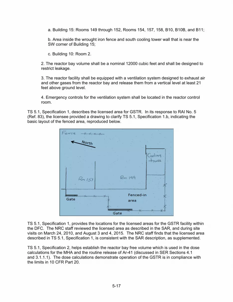
5-17
a. Building 15: Rooms 149 through 152, Rooms 154, 157, 158, B10, B10B, and B11; b. Area inside the wrought iron fence and south cooling tower wall that is near the SW corner of Building 15; c. Building 10: Room 2.
2. The reactor bay volume shall be a nominal 12000 cubic feet and shall be designed to restrict leakage. 3. The reactor facility shall be equipped with a ventilation system designed to exhaust air and other gases from the reactor bay and release them from a vertical level at least 21 feet above ground level. 4. Emergency controls for the ventilation system shall be located in the reactor control room.
TS 5.1, Specification 1, describes the licensed area for GSTR. In its response to RAI No. 5 (Ref. 83), the licensee provided a drawing to clarify TS 5.1, Specification 1.b, indicating the basic layout of the fenced area, reproduced below.
TS 5.1, Specification 1, provides the locations for the licensed areas for the GSTR facility within the DFC. The NRC staff reviewed the licensed area as described in the SAR, and during site visits on March 24, 2010, and August 3 and 4, 2015. The NRC staff finds that the licensed area described in TS 5.1, Specification 1, is consistent with the SAR description, as supplemented. TS 5.1, Specification 2, helps establish the reactor bay free volume which is used in the dose calculations for the MHA and the routine release of Ar-41 (discussed in SER Sections 4.1 and 3.1.1.1). The dose calculations demonstrate operation of the GSTR is in compliance with the limits in 10 CFR Part 20.

5-18
TS 5.1, Specification 3, requires that a ventilation system be available to exhaust air and other gases from the facility and release the gases from a vent point at least 21 ft (6.1 m) above the ground. The NRC staff reviewed the requirements associated with the ventilation system release point (discussed in SER Sections 4.1 and 3.1.1.1) used in the MHA and Ar-41 dose calculations and finds that the results demonstrate operation of the GSTR within the limits of 10 CFR Part 20. TS 5.1, Specification 4, requires that the emergency controls for the ventilation be located in the reactor control room. The NRC staff reviewed and finds the location of the emergency controls located in the reactor control room effective to allow the reactor operators to actuate the emergency ventilation system operation if necessary without entering the reactor room. The NRC staff also finds that TS 5.1, Specification 4 is consistent with the guidance provided in NUREG-1537. The NRC staff reviewed TS 5.1, Specifications 1 through 4, and finds that the GSTR site and facility description to be consistent with the SAR, assumptions used in the dose calculations for the MHA and Ar-41 releases, and guidance provided in NUREG-1537. Based on the information above, the NRC staff concludes that TS 5.1, Specifications 1 through 4, are acceptable.
5.5.2 TS 5.2 Reactor Coolant System
TS 5.2, Reactor Coolant System, is evaluated and found acceptable in SER Section 2.3.
5.5.3 TS 5.3 Reactor Core and Fuel
5.5.3.1 TS 5.3.1 Reactor Core
TS 5.3.1, Reactor Core, is evaluated and found acceptable in SER Section 2.2.
5.5.3.2 TS 5.3.2 Control Rods
TS 5.3.2, Control Rods, is evaluated and found acceptable in SER Section 2.2.2.
5.5.3.3 TS 5.3.3 Reactor Fuel
TS 5.3.3, Reactor Fuel, is evaluated and found acceptable in SER Section 2.2.1.
5.5.4 TS 5.4 Fuel Storage
TS 5.4, Fuel Storage, is evaluated and found acceptable in SER Section 2.7.
5.6 Administrative Controls
TS 6.0, Administrative Controls, provides requirements for the conduct of GSTR operations. The administrative controls presented in TS 6.0 include responsibilities, facility organization, staff qualifications, training, the safety committee, operational reviews and audits, procedures, required actions, reports, and records. The primary guidance for the development of administrative controls for research reactor operation is NUREG-1537 and ANSI/ANS-15.1-2007. The GSTR Administrative Control TSs

5-19
are based on this guidance. The wording of some of proposed TSs is similar, but not identical, to that in NUREG-1537 and ANSI/ANS 15.1 2007. However, as discussed below, the NRC staff considered these instances and determined that the licensee’s proposed administrative controls meet the intent of the guidance and are acceptable.
5.6.1 TS 6.1 Organization
TS 6.1 states: Individuals at the various management levels, in addition to being responsible for the policies and operation of the reactor facility, shall be responsible for safeguarding the public and facility personnel from undue radiation exposures and for adhering to all requirements of the operating license, technical specifications, and federal regulations. The minimum qualification for all members of the reactor operating staff shall be in accordance with ANSI/ANS 15.4, "Selection and Training of Personnel for Research Reactors."
TS 6.1, helps ensure that GSTR organizational responsibilities are adequate for the safe operation of the facility, and for adhering to all requirements of the facility operating license, TSs, and federal regulations. The minimum qualifications are consistent with the guidance provided in NUREG-1537 and ANSI/ANS 15.4. The NRC staff review TS 6.1 and finds that TS 6.1 provides the GSTR organization and responsibilities consistent with the guidance provided in NUREG-1537, and ANSI/ANS-15.4. Based on the information above, the NRC staff concludes TS 6.1 is acceptable. 5.6.1.1 TS 6.1.1. Structure TS 6.1.1 states:
The reactor administration shall be related to the USGS structure as shown in Figure 1. TS 6.1.1 helps to ensure that the GSTR organization structure is delineated, as described in TS 6.1.1, and in Figure 5.1 below (GSTR TS Figure 1). The NRC staff noted that in the proposed Figure 1, the Radiation Safety Committee Chairperson and Health Physics Staff have been replaced with Reactor Health Physicist. In its response to RAI No. 29.d, the licensee states that as a result of License Amendment No. 12, which allowed the transfer of non-GSTR produced byproduct and source material from the USGS Materials License No. 05-01399-08 to the USGS GSTR Facility Operating License No. R-113, certain licensed material is no longer under the purview of the Radiation Safety Committee Chairman. The oversight of the Radiation Safety Committee was transferred to the ROC. The Reactor Health Physicist reports to the Reactor Supervisor (level 2) and has a line of communication to the SRO in-charge (level 3). The NRC staff reviewed TS 6.1.1, Figure 1 and finds that Figure 1 identifies the reporting and communication relationships between the organization units for the GSTR facility and is consistent with the guidance provided in NUREG-1537 and ANSI/ANS 15.1-2007. On the basis of the information above, the NRC staff concludes that TS 6.1.1 and TS Figure 1, is acceptable.

5-20
Director
U.S. Geological Survey
Reactor Administrator (level 1) Review/Audit
Reactor Operations Committee
Reactor Health Reactor Supervisor Physicist (level 2)
Senior Reactor Operator-in-charge (level 3) Reactor Staff (level 4)
Senior Reactor Operators Reactor Operators
Line of Responsibility Line of Communication
Figure 1: Administrative Structure
Figure 5-1 Figure 1 Administrative Structure
5.6.1.2 TS 6.1.2 Responsibility
TS 6.1.2 states: Responsibility for the safe operation of the reactor facility shall be with the chain of command established in Figure 1. Individuals at the various management levels, in addition to having responsibility for the policies and operation of the reactor facility, shall be responsible for safeguarding the public and facility personnel from undue radiation exposures and for adhering to all requirements of the operating license, the established charter, and the technical specifications.
The following specific organizational levels and responsibilities shall exist:

5-21
1. Reactor Administrator (Level 1): The Reactor Administrator is responsible to the USGS Director and is responsible for guidance, oversight, and management support of reactor operations; 2. Reactor Supervisor (Level 2): The Reactor Supervisor reports to the Reactor Administrator and is responsible for directing the activities of the Reactor Operators and Senior Reactor Operators and for the day-to-day operation and maintenance of the reactor; 3. Senior Reactor Operator-in-charge (Level 3): The Senior Reactor Operator-in-charge reports to the Reactor Supervisor. This person is primarily involved in the oversight and direct manipulation of reactor controls, oversight and direct operation and maintenance of reactor related equipment, and oversight of recovery from unplanned shutdowns; and 4. Reactor Operator (Level 4): Other Senior Reactor Operators and Reactor Operators report to Senior Reactor Operator-in-charge and the Reactor Supervisor and are primarily involved in the direct manipulation of reactor controls, monitoring of instrumentation, and direct operation and maintenance of reactor-related equipment.
TS 6.1.2, Specifications 1 through 4, help ensure that the GSTR specific organization levels positions and responsibilities are maintained. The NRC staff reviewed TS 6.1.2, Specifications 1 through 4 and finds that the organizational and position responsibilities stated in TS 6.1.2, Specifications 1 through 4, are consistent with the guidance provided in NUREG-1537 and ANSI/ANS-15.1-2007. Based on the information above, the NRC staff concludes that TS 6.1.2, Specifications 1 through 4, are acceptable.
5.6.1.3 TS 6.1.3 Staffing
TS 6.1.3 states:
1. The minimum staffing when the reactor is not secured shall be:
a. A Licensed Operator in the control room; b. A second person present within the Denver Federal Center who is able to carry out prescribed instructions;
c. If neither of these two individuals is a Senior Reactor Operator, a Senior Reactor Operator shall be readily available on call. Readily available on call means an individual who:
i. Has been specifically designated and the designation is known to the operator on duty; ii. Can be contacted by phone, within 5 minutes, by the operator on duty; and iii. Is capable of getting to the reactor facility within a reasonable time under normal conditions (e.g., 30 minutes or within a 15-mile radius).
d. A list of management personnel, radiation personnel, and reactor staff along with their contact information shall be available to the operator on duty.

5-22
2. Events requiring the direction of a Senior Reactor Operator
a. Initial approach to critical after each completed shutdown checklist; b. Initial approach to power after each completed shutdown checklist; c. All fuel or control rod relocations within the reactor core region; d. Relocation of any in-core components (other than normal control rod movements) or experiment with a reactivity worth greater than one dollar; or e. Recovery from an unscheduled shutdown or an unscheduled significant (>50%) power reduction.
TS 6.1.3, Specification 1, helps ensure that minimum staffing requirements are implemented when the reactor is not secured, such that at least two individuals, one a licensed reactor operator, are at the facility; that a licensed reactor operator or SRO is in the control room; that the an SRO is readily available, and a list of GSTR staff and contact information is available to the on-duty operator. TS 6.1.3, Specification 1, is consistent with the guidance provided in NUREG-1537 and ANSI/ANS-15.1-2007.
TS 6.1.3, Specification 1.b requires the presence of a second person within the DFC who is able to carry out prescribed instructions. The NRC staff noted that the DFC appears to be much larger than the facility complex intended in the guidance in ANSI/ANS-15.1-2007. In its response to RAI No. 31.a, the licensee states that the DFC is a controlled access facility and the travel time to the GSTR from any other building location on the DFC is no more than 5 minutes. The NRC staff reviewed TS 6.1.3, Specification 1.b and finds 5 minutes is a reasonable time have a second person present to carry out prescribed instructions. The NRC staff reviewed TS 6.1.3, Specification 1, and finds that it is consistent 10 CFR 50.54(k), and the guidance provided in NUREG-1537 and ANSI/ANS-15.1-2007. TS 6.1.3, Specification 2, helps ensure that the reactor supervisor, who must be an SRO, is able to be present for certain reactor operations. The regulation, 10 CFR 50.54(m)(1), states:
“A senior operator licensed pursuant to part 55 of this chapter shall be present at the facility or readily available on call at all times during its operation, and shall be present at the facility during initial start-up and approach to power, recovery from an unplanned or unscheduled shut-down or significant reduction in power, and refueling, or as otherwise prescribed in the facility license.”
The NRC staff reviewed TS 6.1.3, Specification 2, and finds that it is consistent with 10 CFR 50.54(m)(1), and the guidance provided in NUREG-1537 and ANSI/ANS-15.1-2007. Based on the information above, the NRC staff concludes that TS 6.1.3, Specifications 1 and 2, are acceptable.

5-23
5.6.1.4 TS 6.1.4 Selection and Training of Personnel
TS 6.1.4 states:
The selection, training and requalification of operations personnel shall follow the guidance of ANSI/ANS 15.4, "Selection and Training of Personnel for Research Reactors."
TS 6.1.4 helps ensure acceptable criteria for the training and requalification program for operations personnel. The licensee used ANSI/ANS-15.4-2007, “Selection and Training of Personnel for Research Reactors,” (Ref. 75), as guidance for selecting and training GSTR staff personnel. The NRC staff reviewed TS 6.1.4, and finds that the requirements in TS 6.1.4 are consistent with the guidance provided in NUREG-1537, and ANSI/ANS-15.4-2007. Based on the information above, the NRC staff concludes that TS 6.1.4 is acceptable.
5.6.2 TS 6.2 Review and Audit
TS 6.2 states:
The ROC shall meet at least semi-annually for the purpose of providing their primary responsibility of review and audit of the safety aspects of reactor facility operations.
TS 6.2 helps ensure that the review and audit function is properly delineated as a responsibility of the ROC. The NRC staff reviewed TS 6.2, and finds that TS 6.2 is consistent with the guidance provided in NUREG-1537 and ANSI/ANS-15.1-2007. Based on the information above, the NRC staff concludes that TS 6.2 is acceptable.
5.6.2.1 TS 6.2.1 Composition and Qualifications
TS 6.2.1 states:
The ROC shall be composed of at least four voting members, including the Chairman. All members of the Committee shall be knowledgeable in subject matter related to reactor operations. To expedite Committee business, a Committee Chairman shall be appointed. The Committee shall be appointed by the USGS Director. No definite term of service shall be specified; but should a vacancy occur in the Committee, the Director shall appoint a replacement. The remaining members of the Committee shall be available to assist the Director in the selection of new members. The Reactor Supervisor shall be an ex-officio member of the Committee, and the Reactor Supervisor shall be the only non-voting member of the Committee. The ROC shall report to the Reactor Administrator.
TS 6.2.1 helps ensure that the ROC composition, qualifications, and operation, are adequate. The NRC staff reviewed TS 6.2.1 and finds that the requirements in TS 6.2.1 are consistent with the guidance provided in NUREG-1537 and ANSI/ANS-15.1-2007. On this basis, the NRC staff concludes that TS 6.2.1 is acceptable.

5-24
5.6.2.2 TS 6.2.2 Charter and Rules
TS 6.2.2 states:
The ROC consists of USGS members and non-USGS members, and the Committee shall meet at least semi-annually. The review and audit functions shall be conducted in accordance with an established charter for the Committee as written in the USGS Manual. Dissemination and review of Committee minutes shall be done within 60 days of each respective Committee meeting. A quorum for review, audit, and approval purposes shall consist of not less than one-half of the voting membership where the operating staff does not constitute a majority. The Chairperson or an alternate must be present at all meetings in which the official business of the committee is being conducted. Approvals by the committee shall require an affirmative vote by a majority of the non-USGS members present and an affirmative vote by a majority of the USGS members present.
TS 6.2.2 establishes the ROC rules. The charter for the ROC is provided in the USGS Manual. The NRC staff reviewed TS 6.2.2 and finds that the charter and rules for the ROC, as stated in TS 6.2.2, are consistent with the guidance provided in NUREG-1537 and ANSI/ANS-15.1-2007. On this basis, the NRC staff concludes that TS 6.2.2 is acceptable.
5.6.2.3 TS 6.2.3 Review Function
TS 6.2.3 states:
The following items shall be reviewed: 1. Determinations that proposed changes in the facility, and procedures, and the conduct of tests or experiments are allowed without prior authorization by the NRC, as detailed in 10 CFR 50.59; 2. All new procedures and major revisions thereto having safety significance, proposed changes in reactor facility equipment, or systems having safety significance; 3. All new experiments or classes of experiments that could have reactivity or safety significance; 4. Proposed changes in technical specifications, license, or charter; 5. Violations of technical specifications, license, or charter. Violations of internal procedures or instructions having safety significance; 6. Operating abnormalities having safety significance; 7. Reportable occurrences listed in TS 6.7.2; and 8. Audit reports.

5-25
A written report or minutes of the findings and recommendations of the review shall be submitted to the Reactor Administrator and the ROC within 3 months after the review has been completed.
TS 6.2.3 establishes the ROC review functions to help ensure the safety of facility operation. The NRC staff reviewed TS 6.2.3 and finds that the ROC review functions as specified in TS 6.2.3 are consistent with the guidance provided in NUREG-1537 and ANSI/ANS-15.1-2007. Based on the information above, the NRC staff concludes that TS 6.2.3 is acceptable. 5.6.2.4 TS 6.2.4 Audit Function TS 6.2.4 states:
The audit function shall include selective (but comprehensive) examination of operating records, logs, other documents, and the reactor facility. Discussions with cognizant personnel and observation of operations should be used also as appropriate. In no case shall the individual immediately responsible for the area perform an audit in that area. The following items shall be audited:
1. Facility operations for conformance to the technical specifications and applicable license conditions: at least once per calendar year (interval between audits not to exceed 15 months); 2. The retraining and requalification program for the operating staff: at least once every other calendar year (interval between audits not to exceed 30 months); 3. The results of action taken to correct those deficiencies that may occur in the reactor facility equipment, systems, structures, or methods of operations that affect reactor safety: at least once per calendar year (interval between audits not to exceed 15 months); and 4. The reactor facility emergency plan, implementing procedures, and security plan: at least once every other calendar year (interval between audits not to exceed 30 months).
Deficiencies uncovered that affect reactor safety shall immediately be reported to the Reactor Administrator. A written report of the findings of the audit shall be submitted to the Reactor Administrator and the ROC within 3 months after the audit has been completed.
TS 6.2.4 establishes the ROC audit function’s scope and indepence requirements. The NRC staff reviewed TS 6.2.4 and finds that the ROC audit functions as specified in TS 6.2.4 are consistent with the guidance provided in NUREG-1537 and ANSI/ANS-15.1-2007. Based on the information above, the NRC staff concludes that TS 6.2.4 is acceptable.
5.6.3 TS 6.3 Radiation Safety
TS 6.3, Radiation Safety, is evaluated in Section 3.1.2 of this SER and is acceptable.

5-26
5.6.4 TS 6.4 Procedures
TS 6.4 states: Written operating procedures shall be prepared, reviewed, and approved prior to initiating any of the activities listed in this section. The procedures shall be reviewed by the ROC and approved by the Reactor Supervisor, and such reviews and approvals shall be documented in a timely manner. Substantive changes to the procedures shall be made effective only after documented review by the ROC and approval by the Reactor Supervisor. Minor modification to the original procedures that do not change their original intent may be made by the Reactor Supervisor. Temporary deviations from the procedures may be made by the responsible SRO or Reactor Supervisor in order to deal with special or unusual circumstances or conditions. Such deviations shall be documented and reported within 24 hours or the next working day to the Reactor Supervisor. Procedures shall be in effect and in use for the following items:
1. Surveillance checks, calibrations, and inspections that are required by Technical Specifications or those that may have an effect on reactor safety; 2. Startup, operation and shutdown of the reactor; 3. Implementation of emergency and security plans; 4. Core changes and fuel movement; 5. Performing maintenance on major components that could affect reactor safety; 6. Administrative controls for operations, maintenance, and experiments that could affect reactor safety or core reactivity; 7. Radiation protection, including ALARA requirements; and 8. Use, receipt and transfer of licensed radioactive material, if appropriate.
TS 6.4, Specifications 1 through 8, helps ensure that the operational procedures for the GSTR are properly delineated and controlled. The NRC staff notes that all changes to procedures including minor modifications and temporary deviations are subject to 10 CFR 50.59 requirements. The NRC staff reviewed TS 6.4, Specifications 1 through 8 and finds that the scope and contents of specifications provided in TS 6.4 are consistent with the guidance provided in NUREG-1537 and ANSI/ANS 15.1-2007. Based on the information above, the NRC staff concludes that TS 6.4, Specifications 1 through 8, are acceptable.
5.6.5 TS 6.5 Experiment Review and Approval
TS 6.5 states:
1. All experiments proposed for the reactor will be either Class I or Class II experiments and shall be reviewed in accordance with the 10 CFR 50.59 review requirements. The review and classification of the proposed experiments shall be the responsibility of the Reactor Supervisor.

5-27
2. Class I experiments include all experiments that have been run previously or that are minor modifications to a previous experiment. These are experiments which involve small changes in reactivity, no external shielding changes, and/or limited amounts of radioisotope production. The Reactor Supervisor has the authority to approve the following:
a. Experiments for which there exists adequate precedence for assurance of safety; b. Experiments which represent less than that amount of reactivity worth necessary for prompt criticality; or c. Experiments in which any significant reactivity worth is stable and mechanically fixed, that is, securely fastened or bolted to the reactor structure.
3. Class II experiments include all new experiments and major modifications of previous experiments. These experiments must be reviewed and approved by the ROC before being run. These experiments may involve larger changes in reactivity, external shielding changes, and/or larger amounts of radioisotope production.
TS 6.5 helps ensure acceptable management control over and safety review of GSTR experiments. TS 6.5 provides requirements for the review and approval of different types of experiments before being performed at the GSTR and specifies the scope of the analysis to be submitted for ROC review. The NRC staff reviewed and finds that the specifications provided in TS 6.5 are consistent with the guidance provided in NUREG-1537 and ANSI/ANS-15.1-2007. Based on the information above, the NRC staff finds TS 6.5 acceptable.
5.6.6 TS 6.6 Required Actions
5.6.6.1 TS 6.6.1 Actions to be Taken in Case of Safety Limit Violation
TS 6.6.1 states:
In the event a safety limit is exceeded:
1. The reactor shall be shutdown and reactor operation shall not be resumed until authorized by the NRC; 2. An immediate notification of the occurrence shall be made to the Reactor Supervisor, Reactor Administrator, and ROC; and 3. A report, and any applicable follow-up report, shall be prepared and submitted to the NRC. The report shall describe the following:
a. Applicable circumstances leading to the violation including, when known, the cause and contributing factors; b. Effects of the violation upon reactor facility components, systems, or structures and on the health and safety of personnel and the public; and c. Corrective action to be taken to prevent recurrence.

5-28
TS 6.6.1, Specifications 1 through 3, help ensure that the proper actions are taken if a SL violation occurs. TS 6.6.1 requires the facility to shut down in the event that an SL is exceeded. The facility may not resume operation without authorization from the NRC. The violation also must be reported to the ROC and NRC. The reporting requirement is detailed in TS 6.7.2, specifying that the NRC must be notified within 24 hours by telephone and a report is required to be submitted to the NRC within 14 days. TS 6.6.1, Specification 3.c, specifies that corrective actions are to be taken to prevent recurrence. The NRC staff reviewed and finds that the specifications in TS 6.6.1 are consistent with the guidance provided in NUREG-1537 and ANSI/ANS-15.1-2007, and 10 CFR 50.36(c)(1) requirement for actions to be taken when a SL is exceeded. Based on this information, the NRC staff concludes that TS 6.6.1 is acceptable.
5.6.6.2 TS 6.6.2 Actions to Be Taken in the Event of an Occurrence of the Type Identified in Section 6.7.2 Other than a Safety Limit Violation
TS 6.6.2 states the following:
For all events which are required by Technical Specifications to be reported to the NRC within 24 hours under TS 6.7.2, except a safety limit violation, the following actions shall be taken:
1. The reactor shall be secured and the Reactor Supervisor notified; 2. Operations shall not resume unless authorized by the Reactor Supervisor; 3. The ROC shall review the occurrence at their next scheduled meeting; and 4. Where appropriate, a report shall be submitted to the NRC in accordance with TS 6.7.2.
TS 6.6.2 helps ensure that the proper actions are taken following an event identified in TS 6.7.2 other than a SL violation. TS 6.6.2 requires the GSTR to be shut down in the event of a reportable occurrence. The event and corrective actions taken also must be reported to the Reactor Supervisor. The reporting requirement is also detailed in TS 6.7.2, specifying that the NRC must be notified no later than the following working day by telephone and a report must be submitted to the NRC within 14 days. The NRC staff reviewed TS 6.6.2 and finds that the actions the licensee proposes are consistent with the guidance in NUREG-1537 and ANSI/ANS-15.1-2007. Based on the information above, the NRC staff concludes that TS 6.6.2 is acceptable.
5.6.7 TS 6.7 Reports
5.6.7.1 TS 6.7.1 Annual Operating Report
TS 6.7.1 states: An annual report covering the previous calendar year shall be created and submitted, no later than March 31 of the year following the report period, by the Reactor Supervisor to the NRC consisting of:
1. A brief summary of operating experience including the energy produced by the reactor and the hours the reactor was critical;

5-29
2. The number of unplanned shutdowns, including corrective actions taken (when applicable); 3. A tabulation of major preventative and corrective maintenance operations having safety significance; 4. A brief description, including a summary of the safety evaluations, of changes in the facility or in procedures and of tests and experiments carried out pursuant to 10 CFR 50.59; 5. A summary of the nature and amount of radioactive effluents released or discharged to the environs beyond the effective control of the licensee as measured at or prior to the point of such release or discharge. The summary shall include to the extent practicable an estimate of individual radionuclides present in the effluent. If the estimated average release after dilution or diffusion is less than 25% of the concentration allowed or recommended, a statement to this effect is sufficient; 6. A summarized result of environmental surveys performed outside the facility; 7. A summary of exposures received by facility personnel and visitors where such exposures are greater than 25% of that allowed; and 8. Results of fuel inspections (when performed).
TS 6.7.1, Specifications 1 through 8, helps ensure that adequate annual reporting information is provided to the NRC. TS 6.7.1 provides requirements for the status of the facility, major changes, radiation exposures, and other pertinent information to be provided to the NRC. The NRC staff reviewed and finds that TS 6.7.1, Specifications 1 through 8, provide GSTR annual operating report requirements that are consistent with guidance provided in NUREG-1537 and ANSI/ANS-15.1-2007. Based on the information above, the NRC staff concludes that TS 6.7.1, Specifications 1 through 8, are acceptable.
5.6.7.2 TS 6.7.2 Special Reports
TS 6.7.2 states: In addition to the requirements of applicable regulations, and in no way substituting therefore, reports shall be made by the Reactor Supervisor to the NRC as follows:
1. A report within 24 hours by telephone, confirmed by digital submission or fax to the NRC Operations Center if requested, and followed by a report in writing to the NRC, Document Control Desk, Washington, D.C. within 14 days that describes the circumstances associated with any of the following:
a. Any release of radioactivity above applicable limits into unrestricted areas, whether or not the release resulted in property damage, personal injury, or exposure; b. Any violation of a safety limit; c. Operation with the actual safety system setting less conservative than the LSSS;

5-30
d. Operation in violation of a Limiting Condition for Operation; e. Malfunction of a required reactor safety system component which renders or could render the system incapable of performing its intended safety function unless the malfunction or condition is caused by maintenance, then no report is required; f. Any unanticipated or uncontrolled change in reactivity greater than $1.00. Reactor trips resulting from a known cause are excluded; g. An observed inadequacy in the implementation of either administrative or procedural controls, such that the inadequacy causes or could have caused the existence or development of a condition which results or could result in operation of the reactor outside the specified safety limits; or h. Abnormal and significant degradation in reactor fuel, cladding, or coolant boundary
2. A report within 30 days in writing to the NRC, Document Control Desk, Washington, D.C. of:
a. Permanent changes in the facility organization involving Level 1-2 personnel; or b. Significant changes in the transient or accident analyses as described in the Safety Analysis Report.
TS 6.7.2, Specifications 1 and 2, helps ensure that special reporting requirements met. The NRC staff reviewed TS 6.7.2, Specifications 1 and 2, and finds that the special report requirements are consistent with the guidance provided in NUREG-1537 and ANSI/ANS-15.1-2007. Based on the information above, the NRC staff concludes that TS 6.7.2, Specifications 1 and 2, are acceptable.
5.6.8 TS 6.8 Records
5.6.8.1 TS 6.8.1 Records to be Retained for a Period of at Least Five Years or for the Life of the Component Involved if Less than Five Years
TS 6.8.1 states:
1. Normal reactor operation (but not including supporting documents such as checklists, data sheets, etc., which shall be maintained for a period of at least two years); 2. Principal maintenance activities; 3. Reportable occurrences; 4. Surveillance activities required by the Technical Specifications; 5. Reactor facility radiation and contamination surveys; 6. Experiments performed with the reactor;

5-31
7. Fuel inventories, receipts, and shipments; 8. Approved changes to the operating procedures; and 9. ROC meetings and audit reports.
TS 6.8.1, Specifications 1 through 9, helps ensure that certain records are retained for five years or an appopriate lesser period. The NRC staff reviewed TS 6.8.1, Specifications 1 through 9, and finds that the record requirements consistent with the guidance provided in NUREG-1537 and ANSI/ANS -15.1-2007. Based on the information above, the NRC staff concludes that TS 6.8.1, Specifications 1 through 9 are acceptable.
5.6.8.2 TS 6.8.2 Records to be Retained for at Least One Operator License Term
TS 6.8.2 states the following:
1. Records of retraining and requalification of Reactor Operators and Senior Reactor Operators shall be retained for at least one license term; and 2. Records of retraining and requalification of licensed operators shall be maintained while the individual is employed by the licensee, or until that operator’s license is renewed, whichever is shorter.
TS 6.8.2, Specifications 1 and 2 help ensure that cetain records are retained for at least one certification cycle. The NRC staff reviewed TS 6.8.2, Specifications 1 and 2 and finds that the record retention requirements stated in TS 6.8.2, Specifications 1 and 2 are consistent with the guidance provided in NUREG-1537 and ANSI/ANS-15.1- 2007. Based on the information above, the NRC staff concludes TS 6.8.2, Specifications 1 and 2 are acceptable.
5.6.8.3 TS 6.8.3 Records to be Retained for the Lifetime of the Reactor Facility
TS 6.8.3 states:
1. Gaseous and liquid radioactive effluents released to the environs; 2. Offsite environmental monitoring surveys;
3. Reviews and reports pertaining to a violation of the safety limit, the limiting safety system setting, or a limiting condition of operation; 4. Radiation exposures for all personnel monitored; and 5. Drawings of the reactor facility.
TS 6.8.3, Specifications 1 through 5, help to ensure that the appropriate records are retained for the lifetime of the facility. The NRC staff reviewed TS 6.8.3, Specifications 1 through 5 and finds that TS 6.8.3, Specifications 1 through 5 provide a description of the records which need to be retained for the lifetime of the facility, and are consistent with the guidance provided in NUREG-1537 and ANSI/ANS-15.1-2007. Based on the information above, the NRC staff concludes TS 6.8.3, Specifications 1 through 5 are acceptable.

5-32
5.7 Conclusions
The NRC staff reviewed and evaluated the proposed TSs as part of its review of the LRA for Facility Operating License No. R-113, NRC Docket No. 50-274. The TSs define certain features, characteristics, oraganizatinal, reporting requirments, and conditions governing the operation of the GSTR facility. The TSs are explicitly included in the renewed license as Appendix A. The NRC staff reviewed and evaluated the content of the TSs to determine whether the TSs meet the requirements in 10 CFR 50.36. Based on its review, the NRC staff concludes that the proposed TSs do meet the requirements of the regulations. The NRC staff also reviewed the format and content of the proposed TSs for consistency with the guidance in NUREG-1537 and ANSI/ANS-15.1-2007 and finds that the proposed TSs are consistent with these guidance. The NRC staff concludes that the GSTR TS are acceptable for following reasons: • To satisfy the requirements of 10 CFR 50.36(a), the licensee provided proposed TSs with
the LRA. As required by the regulation, a summary statement of the bases or reasons for the TSs were submitted. The summary bases are included in the TSs, but shall not be part of the TSs as required by 10 CFR 50.36(a)(1).
• The GSTR is a facility of the type described in 10 CFR 50.21(c); therefore, 10 CFR 50.36(b),
requires that the facility operating license include TSs. To satisfy the requirements of 10 CFR 50.36(b), the licensee provided proposed TSs derived from analyses in the GSTR SAR, as supplemented by responses to RAIs.
• The proposed TSs acceptably implement the recommendations of NUREG-1537, and
ANSI/ANS-15.1-2007, by using definitions that are acceptable. • The proposed TS specify SLs on the fuel temperature and an LSSS for the reactor
protection system to preclude reaching the SLs and satify 10 CFR 50.36(c)(1) requirements.
• The proposed TSs contain limiting conditions for operation on each item that meets one or more of the criteria specified in 10 CFR 50.36(c)(2)(ii).
• The proposed TSs contain surveillance requirements that satisfy the requirements of
10 CFR 50.36(c)(3).
• The proposed TSs contain design features that satisfy the requirements of 10 CFR 50.36(c)(4).
• The proposed TSs contain administrative controls that satisfy the requirements for
10 CFR 50.36(c)(5). The proposed GSTR administrative controls contain requirements for initial notification, written reports, and records that satisfy 10 CFR 50.36(c)(1), (2), and (7); and hat the NRC staff deemed necessary in accordance with 10 CFR 50.36(c)(8).

5-33
The NRC staff reviewed the proposed TSs and finds the proposed TSs acceptable and concludes that normal operation of the GSTR within the limits of the proposed TSs will not result in radiation exposures in excess of the limits specified in 10 CFR Part 20 for members of the public or for the GSTR staff. The NRC staff concludes that the proposed TSs provide reasonable assurance that the GSTR will be operated as analyzed in the SAR, as supplemented by RAI responses, and that adherence to the proposed TSs during the license renewal period will limit the likelihood of malfunctions and the potential accident scenarios discussed in Chapter 4, “Accident Analysis,” of this SER.

6-1
6 CONCLUSIONS
On the basis of its evaluation of the LRA as discussed in the previous chapters of this SER, the NRC staff concludes the following: • The application for license renewal, dated January 5, 2009, as supplemented on
November 24, 2010; February 11, March 28, May 12, June 29, July 27, August 30, September 26, October 31, and November 30, 2011; January 3, January 27, March 28, April 27, May 18, May 31, June 29, July 31, August 30, and November 16, 2012; February 8, May 17, and October 31, 2013; February 19, November 3, and November 24, 2014; September 8, 2015, and January 22, April 1, September 12, and September 22, 2016, complies with the standards and requirements of the AEA and the Commission’s rules and regulations set forth in Title 10 of the Code of Federal Regulations.
• The facility will operate in conformity with the application, as supplemented, as well as the
provisions of AEA of 1954, as amended, and the rules and regulations of the NRC. • There is reasonable assurance that (1) the activities authorized by the renewed license can
be conducted at the designated location without endangering the health and safety of the public and (2) such activities will be conducted in compliance with the rules and regulations of the NRC.
• The facility will continue to be useful in the conduct of research and development activities.
• The licensee is technically and financially qualified to engage in the activities authorized by
the renewed facility operating license, in accordance with the rules and regulations of the NRC.
• The applicable provisions of 10 CFR Part 140, “Financial Protection Requirements and Indemnity Agreements,” have been satisfied.
• The issuance of this license is in accordance with 10 CFR Part 51, “Environmental
Protection Regulations for Domestic Licensing and Related Regulatory Functions,” of the NRC’s regulations and all applicable requirements have been satisfied.
• The receipt, possession and use of byproduct and special nuclear materials as authorized
by this facility operating license will be in accordance with the NRC's regulations in 10 CFR Part 30, “Rules of General Applicability to Domestic Licensing of Byproduct Material,” and 10 CFR Part 70, “Domestic Licensing of Special Nuclear Material.”
• The issuance of the renewed facility operating license will not be inimical to the common
defense and security or to health and safety of the public.

7-1
7 REFERENCES
1. U.S. Geological Survey, Redacted - “Revised Safety Analysis Report, Technical Specifications, and Environmental Report to Support License Renewal,” January 5, 2009, ADAMS Accession No. ML092120136.
2. U.S. Nuclear Regulatory Commission, Request for Additional Information,
September 29, 2010, ADAMS Accession No. ML102510077. 3. U.S. Nuclear Regulatory Commission, Request for Additional Information,
March 21, 2012, ADAMS Accession No. ML12075A001. 4. U.S. Nuclear Regulatory Commission, Request for Additional Information,
October 2, 2012, ADAMS Accession No. ML12270A415. 5. U.S. Nuclear Regulatory Commission, Request for Additional Information,
March 7, 2013, ADAMS Accession No ML13059A027. 6. U.S. Nuclear Regulatory Commission, Request for Additional Information,
July 15, 2013, ADAMS Accession No. ML13190A052. 7. U.S. Nuclear Regulatory Commission, Request for Additional Information,
August 25, 2014, ADAMS Accession No. ML14211A586. 8. U.S. Nuclear Regulatory Commission, Request for Additional Information,
September 10, 2015, ADAMS Accession No. ML15252A009. 9. U.S. Nuclear Regulatory Commission, Request for Additional Information,
February 8, 2016, ADAMS Accession No. ML16027A134. 10. U.S. Geological Survey, “Response to the RAI Concerning R-113 License Renewal,”
November 24, 2010, ADAMS Accession No. ML103340090. 11. U.S. Geological Survey, “Response to Letter of February 1, 2011 Concerning R-113
License Renewal,” February 11, 2011, ADAMS Accession No. ML110480046. 12. U.S. Geological Survey, “Response to Questions 23.1, 23.2, and 23.3 of the
Referenced RAI,” March 28, 2011, ADAMS Accession No. ML110950059. 13. U.S. Geological Survey, “United States Geological Survey - Response to
Questions 22.1, 22.2, 25.1, 25.2, 25.3, 25.4 and 25.6 of the Referenced RAI,” May 12, 2011, ADAMS Accession No. ML11138A027.
14. U.S. Geological Survey, “Response to Questions 17.1 and 17.2 of the Referenced
RAI,” June 29, 2011, ADAMS Accession No. ML11181A305. 15. U.S. Geological Survey, “Response to Question 2 of the Referenced RAI,”
July 27, 2011, ADAMS Accession No. ML11214A091.

7-2
16. U.S. Geological Survey, “Response to Question 1 of the Referenced RAI,” August 30, 2011, ADAMS Accession Nos.: ML152500522 (package), ML11250A172 - RAI response; ML11250A173 – Attachment 2, Design Calculations.
17. U.S. Geological Survey, “Response to Question 20 of the Referenced RAI,”
September 26, 2011, ADAMS Accession No. ML11277A013. 18. U.S. Geological Survey, “Response to Question 6 of the Referenced RAI,”
October 31, 2011, ADAMS Accession No. ML11314A106. 19. U.S. Geological Survey, “Response to Questions 7 and 8 of the Referenced RAI,”
November 30, 2011, ADAMS Accession No. ML113460014. 20. U.S. Geological Survey, “Response to Question 15.3 of the Referenced RAI,”
January 3, 2012, ADAMS Accession No. ML120240003. 21. U.S. Geological Survey, “Response to Question 18 of the Referenced RAI,”
January 27, 2012, ADAMS Accession No. ML12039A173. 22. U.S. Geological Survey, “Response to Question 15.2 of the Referenced RAI,”
January 27, 2012, ADAMS Accession No. ML12068A138. 23. U.S. Geological Survey, “Response to Question 14 of the Referenced RAl,”
March 28, 2012, ADAMS Accession No. ML12100A097. 24. U.S. Geological Survey, “Response to Question 16 of the Referenced RAI,”
April 27, 2012, ADAMS Accession No. ML12128A429. 25. U.S. Geological Survey, “Responses to Questions 26 and 27 of the Referenced RAI,”
May 18, 2012, ADAMS Accession No. ML12151A407. 26. U.S. Geological Survey, “Responses to Question 14 of the Referenced RAI,”
May 31, 2012, ADAMS Accession No. ML12160A064. 27. U.S. Geological Survey, “Response to Question 3 of the Referenced RAI,”
June 29, 2012, ADAMS Accession No. ML12200A055. 28. U.S. Geological Survey, “Response to Question 21 of the Referenced RAI,”
July 31, 2012, ADAMS Accession No. ML12220A525. 29. U.S. Geological Survey, “Responses are provided to Questions 9, 10, 11, 12, 15.1,
23.4, 24, and 25.5; along with a corrected copy of the proposed Technical Specifications (Chapter 14) of the SAR,” August 30, 2012, ADAMS Accession No. ML12251A231.
30. U.S. Geological Survey, “Responses are provided to Questions of the subject RAI,”
November 16, 2012, ADAMS Accession No. ML12334A001. 31. U.S. Geological Survey, “Follow-up responses from questions of phone conference
on 12/20/12,” February 8, 2013, ADAMS Accession No. ML13052A179.

7-3
32. U.S. Geological Survey, “Follow-up Safety Analysis responses from questions of phone conference on 3/21/13,” May 17, 2013, ADAMS Accession No. ML3162A662.
33. U.S. Geological Survey, "Follow-up Safety Analysis responses from letter dated
July 15, 2013,” October 31, 2013, ADAMS Accession No. ML13311A047. 34. U.S. Geological Survey, “Submission of revised Technical Specifications
(Chapter 14),” November 3, 2014, ADAMS Accession No. ML14325A646. 35. U.S. Geological Survey, “Responses to RAI questions 15.3 and 28,”
November 24, 2014, ADAMS Accession No. ML14338A196. 36. U.S. Geological Survey, “Revision of Proposed Technical Specifications,”
September 8, 2015, ADAMS Accession No. ML15261A042. 37. U.S. Geological Survey, “Responses to RAI questions 1a, 1b, and 1c,”
January 22, 2016, ADAMS Accession No. ML16042A575. 38. U.S. Geological Survey, Annual Reports: ADAMS Accession No. ML110400023,
2010; ADAMS Accession No. ML12030A094, 2011; ADAMS Accession No. ML13037A105, 2012; ADAMS Accession No. ML14051A529, 2013; ADAMS Accession No. ML15043A032, 2014; ADAMS Accession No. ML16032A166, 2015.
39. U.S. Nuclear Regulatory Commission, United States Geological Survey - NRC
Routine Inspection Reports: ADAMS Accession No. ML16124B029, 2016; ADAMS Accession No. ML15127A622, 2015; ADAMS Accession No. ML14155A404, 2014; ADAMS Accession No. ML13155A473, 2013; ADAMS Accession No. ML12138A149, 2012; ADAMS Accession No. ML111430012, 2011; ADAMS Accession No. ML101230468.
40. U.S. Nuclear Regulatory Commission, “Guidelines for Preparing and Reviewing
Applications for the Licensing of Non-Power Reactors,” NUREG 1537, Parts 1 and 2, February 1996, ADAMS Accession Nos. ML042430055 and ML042430048.
41. U.S. Nuclear Regulatory Commission, SECY-08-0161, “Review of Research and
Test Reactor License Renewal Applications,” October 24, 2008, ADAMS Accession No. ML082550140.
42. U.S. Nuclear Regulatory Commission, Staff Requirements Memorandum for
SECY-08-0161, March 26, 2009, ADAMS Accession No. ML090850159. 43. “Interim Staff Guidance for the Streamlined Research Reactor License Renewal
Process,” A. Adams to K. Brock, October 15, 2009, ADAMS Accession No. ML092240256 and ML092240244.
44. USGS Revision XVI of the Physical Security Plan, August 20, 2014, ADAMS
Accession No. ML14245A013. 45. U.S. Nuclear Regulatory Commission, Request for Additional Information,
January 28, 2014, ADAMS Accession No. ML14032A795.

7-4
46. USGS Emergency Plan Redacted RE: Response to Emergency Plan Question for License Renewal Review, May 15, 2014, ADAMS Accession No. ML14148A240.
47. USGS Emergency Plan, Redacted, Revision 14, May 30, 2014, ADAMS Accession
No. ML16090A164. 48. U.S. Nuclear Regulatory Commission, USGS Emergency Plan Review for License
Renewal, July 9, 2014, ADAMS Accession No. ML14183A425. 49. U.S. Nuclear Regulatory Commission, Request for Additional Information, RE:
Operator Requalification Program, January 22, 2014, ADAMS Accession No. ML14014A123.
50. USGS Responses to Operator Requalification Program Questions,
February 19, 2014, ADAMS Accession No. ML14070A040. 51. U.S. Nuclear Regulatory Commission, Approval of the USGS Operator
Requalification Program, March 27, 2014, ADAMS Accession No. ML14084A515. 52. General Atomics, “TRIGA Reactors,” GEN-10, February 2003,
http://www.ga-esi.com/triga/. 53. U.S. Nuclear Regulatory Commission, Inspection Report 50-274/88-01,
December 5, 1988, ADAMS Accession Nos.: ML103500004 – cover letter, ML103500003 – Attachment B, NRC Inspection Report.
54. General Atomics, GA 7882, “Kinetic Behavior of TRIGA Reactors,” March 31, 1967,
ADAMS Accession No. ML082380271. 55. U.S. Nuclear Regulatory Commission, “Safety Evaluation Report on High-Uranium
Content, Low-Enriched Uranium-Zirconium Hydride Fuels for TRIGA Reactors,” NUREG 1282, August 1987, ADAMS Accession No. ML050480199.
56. General Atomics, GA-4314, “The U-ZrHx Alloy: Its Properties and Use in TRIGA
Fuel,” M.T. Simnad, 1980. 57. U.S. Nuclear Regulatory Commission, “Credible Accident Analyses for TRIGA and
TRIGA-Fueled Reactors,” NUREG/CR-2387, April 1982. 58. American National Standards Institute/American Nuclear Society,
ANSI/ANS-15.1-2007, “The Development of Technical Specifications for Research Reactors,” ANS, LaGrange Park, IL.
59. U.S. Nuclear Regulatory Commission, Regulatory Guide 2.2, “Development of
Technical Specifications for Experiments in Research Reactors,” November 1973. 60. “RELAP5/MOD3.3 Code Manual Volume II: Appendix A, Input Requirements”
prepared for Division of Systems Research, U.S. NRC, Information Systems Laboratories, Inc., October 2010.
61. ANL/TD/TM99-07, “WIMS-ANL User Manual,” Rev. 6, February 2004.

7-5
62. NUREG/IA-0242, “Qualification of the Three-Dimensional Thermal Hydraulic Model
of TRACE using Plant Data,” April 2011, ADAMS Accession No. ML11108A046. 63. “TRIGA Reactor Thermal-Hydraulic Study,” TRD 070.01006.04 Rev. A, Argonne
National Laboratory, by General Atomics-ESI, J. Bolin, April 2008. 64. U.S. Geological Survey, Redacted, “Request for Additional Information dated
February 8, 2016,” April 1, 2016, ADAMS Accession No. ML16110A008. 65. ANSI/ANS-15.11-1993; R2004, “Radiation Protection at Research Reactor
Facilities.” 66. EPA 520/1-89-003, “User's Guide for the Comply Code,” Revision 2. 67. U.S. Nuclear Regulatory Commission, U.S. Geological Survey – Issuance of
Amendment No. 12 to Facility Operating License No. R-113 to Modify the Source, Byproduct and Special Nuclear Material Possession Limits, March 23, 2016, ADAMS Accession No. ML14294A649.
68. N. L. Baldwin, F. C. Foushee, and J. S Greenwood, “Fission Product Release from
TRIGA-LEU Reactor Fuels,” October 1980. 69. TID-14884, “The calculations of Distance Factors for Power and Test Reactor Sites,”
J. J. DiNunno et al, Technical Information Document, U.S. Atomic Energy Commission, March 1962.
70. Regulatory Guide 3.33, “Assumptions Used for Evaluating the Potential Radiological
Consequences of Accidental Nuclear Criticality in a Fuel Reprocessing Plant,” U.S. Nuclear Regulatory Commission, April 1977.
71. S. G. Homann, “HOTSPOT Health Physics Code Version 2.07.2 User’s Guide,”
LLNL-SM-482991, National Atmospheric Release Advisory Center, Lawrence Livermore National Laboratory, September 8, 2011.
72. Federal Guidance Reports No. 11, “Limiting Values of Radionuclide Intake and Air
Concentration, and Dose Conversion Factors for Inhalation, Submersion, and Ingestion,” EPA-502/1-88-020, U.S. Environmental Protection Agency, September 1988.
73. Federal Guidance Reports No. 12, “External Exposure to Radionuclides in Air,
Water, and Soil,” EPA-402-R-93-081, U.S. Environmental Protection Agency, September 1993.
74. “Pulsing Temperature Limit for TRIGA LEU Fuel,” TRD 070.01006.05, Rev. A,
Argonne National Laboratory, by General Atomics-ESI, A. Veca, April 2008. 75. American National Standards Institute/American Nuclear Society,
ANSI/ANS 15.4-2007, “Selection and Training of Personnel for Research Reactors,” ANS, LaGrange Park, IL.

7-6
76. U.S. Nuclear Regulatory Commission, “Safety Evaluation Report, Oregon State University License Renewal Review,” September 10, 2008, ADAMS Accession No. ML082540035.
77. Ucar, Dundar. "Modeling and Design of a New Core-Moderator Assembly and
Neutron Beam Ports for the Penn State Breazeale Nuclear Reactor (PSBNR)." PhD Dissertation, The Pennsylvania State University, 2013 and Mesquita, Amir Zacharias. "Experimental Heat Transfer Analysis of the IPR-R1 TRIGA Reactor." Proceedings of the Third World TRIGA Users Conference.
78. U.S. Geological Survey, “Response to RAI Concerning Financial Qualification,”
August 12, 2010, ADAMS Accession No. ML102300385. 79. U.S. Geological Survey, “Request for Additional Information for the Review of the
Physical Security Plan Regarding the License Renewal of the U.S. Geological Survey TRIGA Research Reactor,” April 25, 2016, ADAMS Accession No. ML16112A003.
80. U.S. Geological Survey, “Responses to Questions on the Physical Security Plan,
June 14, 2016, ADAMS Accession No. ML16172A064. 81. U.S. Nuclear Regulatory Commission, Request for Additional Information,
June 28, 2016, ADAMS Accession No. ML16147A642. 82. U.S. Geological Survey, “Request for Additional Response Time For RAI
Clarifications,” September 6, 2016, ADAMS Accession No. ML16251A001.
83. U.S. Geological Survey, “Responses to Request for Additional Information dated June 28, 2016,” September 12, 2016, ADAMS Accession No. ML16277A216.
84. U.S. Geological Survey, “Responses to Email Questions from Mr. Wertz dated September 10, 2016,” September 22, 2016, ADAMS Accession No. ML16273A304.