irrigation papers - usgs publications repository
TRANSCRIPT
DEPAKTMENT OF THE INTEKIOK
WATER-SUPPLY
IRRIGATION PAPERS
OF THE
UNITED STATES GEOLOGICAL SURVEY
ISTo. 33
STORAGE OF WATER ON GILA RIVER, ARIZONA. LIPPINCOTT
WASHINGTONGOVERNMENT PRINTING OFFICE
1900
IRRIGATION REPORTS.
The following list contains titles and brief descriptions of the principal reports relating to water supply and irrigation, prepared by the United States GeologicalSurvey since 1890:
1890.
First Annual Report of the United States Irrigation Survey, 1890; octavo, 123 pp.Printed as Part II, Irrigation, of the Tenth Annual Report of the United States Geolog
ical Survey, 1888-89. Contains a statement of the origin of the Irrigation Survey, awpre- liminary report on the organization and prosecution of the survey of the arid lands for purposes of irrigation, and report of work done during 1890.
1891.
Second Annual Report of the United States Irrigation Survey, 1891; octavo, 395 pp.Published as Part II, Irrigation, of the Eleventh Annual Report of the United States
Geological Survey, 1889-90. Contains a description of the hydrography of the arid region and of the engineering operations carried on by the Irrigation Survey during 1890: also the statement of the Director of the Survey to the House Committee on Irrigation, and other papers, including a bibliography of irrigation literature. Illustrated by 89 plates and 4 figures.
Third Annual Report of the United States Irrigation Survey, 1891; octavo, 576 pp.Printed as Part II of the Twelfth Annual Report of the United States Geological Survey,
>rt upon the location and survey of reservoir sites during the fiscalIt'30-91. Contains'-Reporyear ended June 30, 1891," by A. H. Thompson; ' Hydrography of the arid regions.'' by F. H. Newell; "Irrigation in India," by Herbert M. Wilson. Illustrated by 93 plates and 190 figures.
Bulletins of the Eleventh Census of the United States upon irrigation, prepared by F. H. Newell; quarto.
No. 35, Irrigation in Arizona; No. 60, Irrigation in New Mexico; No. 85, Irrigation in Utah: No. 107, Irrigation in Wyoming; No. 153, Irrigation in Montana; No. 157, Irrigation in Idaho: No. 163. Irrigation in Nevada; No. 178, Irrigation in Oregon; No. 193, Artesian wells for irrigation; No. 198, Irriga tion in Washington.
1893.
Irrigation of western United States, by F. H. Newell; extra census bulletin No. 23, September 9, 1892: quarto, 22 pp.
Contains tabulations showing the total number, average size, etc., of irrigated holdings, the total area and average size of irrigated farms in the subhumid regions, the percentage of number of farms irrigated, character of crops, value of irrigated lands, the average cost of irrigation, the investment and profits, together with a resume of the water supply and a, description of irrigation by artesian wells. Illustrated by colored maps, showing the location and relative extent of the irrigated areas.
1893.
Thirteenth Annual Report of the United States Geological Survey, 1891-92, Part III, Irrigation, 1893; octavo, 486 pp.
Consists of three papers: "Water siipply for irrigation," by F. H. Newell; "American irrigation engineering" and "Engineering results of the Irrigation Survey," by Herbert M. Wilson; "Construction of topographic maps and selection and survey of reservoir sites," by A. H. Thompson. Illustrated by 77 plates and 119 figures.
A geological reconnaissance in central Washington, by Israel Cook Russell, 1893; octavo, 108 pp., 15 plates. Bulletin No. 108 of the United States Geological Survey; price, 15 cents.
Contains a description of the examination of the geologic structure in and adjacent to the drainage basin of Yakima River, and the great plains of the Columbia to the east of this area, with special reference to the occurrence of artesian waters.
1894.
Report on agriculture by irrigation in the western part of the United States at the Eleventh Census, 1890, by F. H. Newell, 1894; quarto, 283 pp.
Consists of a general description of the condition of irrigation in the United States, the area irrigated, cost of works, their value and profits; also describes the water supply, the value of water, of artesian wells, reservoirs, and other details; then takes up each State and. Territory in order, giving a general description of'the condition of agriculture by irri gation, and discusses the physical conditions and local peculiarities in each county.
Fourteenth Annual Report of the United States Geological Survey, 1892-93, in two parts; Part II, Accompanying papers, 1894; octavo, 597 pp.
Contains papers on "Potable waters of the eastern United States," by W J HcGee "Natural mineral waters of the United States," by A. C. Peale; "Results of stream meas urements," by F. H. Newell. Illustrated by maps and diagrams.
IKK 33 (Continued on third page of cover.)
DEPARTMENT OF THE INTEBIOB
WATER-SUPPLY
AND
IRRIGATION PAPERS
OF THE
UNITED STATES GEOLOGICAL SURVEY
ISFo. 33
WASHINGTONaOTEKNMENT PKINTING OFFICE
1900
OTITED STATES GEOLOGICALCHARLES D. WALCOTT, DIRECTOR
STORAGE OF WATER
GIL A RIVER, ARIZONA
BY
JOSETPH BARLOW LIPPINOOTT
WASHINGTONGOVERNMENT PRINTING OFFICE
1900
CONTENTS.Page.
Letter of transmittal -..--. ..........................................^... 7Existing conditions........_...__....______.___.____-..---_-..---._------- 9
Location of reservation ............... ..........._...---.----.-..---.-- 9Description of tribes .._..-.-_ ..____._._.._.._____.-_.-.--_----------- 9Decrease of water supply -_-__----.__-................._....--.._----.. 10Necessity for relief ............ ........ ............-.---..-....-... 12Investigation in 1896........ ........._-...-..- ..._----..----.---.-.-. 13Investigation in 1899..-.---......-..........-.-.-...-..----.--..------- 14Amount of water required.............___..-.-_...-.------ ----------- 17
Water supply ........_.............................-..-. ................ 18Precipitation.._._,_--..,..._........._....._.......-.--..-... -------- 18Subdivisions of the drainage basin ..........-...--.-...-...-----.----- 21Relative flow at San Carlos and the Buttes .__.__-....----.-.---- ..... 22Measurements of Gila River at the Buttes, Arizona ........ .....-._-. 25Evaporation--.--.-------.-.--.......-......................_--.....-.. 32Spillway provisions -.--..-......-............-.--. .................. 34
Silt ... .___-._--.--..-_.-._.-..-.-.._._._ .--..-......-..--. .--.- ------ 35Explorations for bed rock at the Buttes -... _...........:....-----.-.--..-. 42
Diamond core drill _--..-._..__.--_._.______.-____.-._-,-... --------- 43Cost of operating.------..-.--. ..............-.--..-..--.---.-.-.--.-. 46
Buttes reservoir .--..--_-.--.-..-.-...................--..--. ------------ 48Exploration for foundations of dam...-........._..-......-.!.-.---.-- 48Quality of bed rock....-..--.__.--___._. .................-.---.-..-..-. 49Quarry tests... -.---.--.----._-_........--..-.........-----.-.----.-. 51Type of dam adopted ........................... -____..,--.-_-...---.. 54Method of excavation for foundations...-...-.. .....-.-..-_--..-.--_- 58Building materials, sand, and gravel... __-.-._.--.-.,.--------------- 58Capacity and cost of the Buttes reservoir. - __...____.--._-.----..--.-- 59
Diversion canal below the Buttes dam_..................---..---..-.--.--. 61Exploration at the Dikes...... .--.._..____..____.-._..___-.__-...---..--- 62Riverside reservoir ........................ ._...-_......--...--.-.- ...-. 62
Proposed dam at Riverside ._._..______.__. _.--... .................. 63Method of construction .......................... ..--.-.-.....--..--- 64Capacity and cost -..-.. ___-.-.......... .............. ... ....---.... 65
San Carlos reservoir ....--...--....-..-........ -..--...-.--..---..---....-.-. 66Proposed dam at San Carlos..--...._-.._..._.._--.--___---.--. ....... 69Material for dam _.__.._._..___._.__._._.._.__._._______.......___.___ 71Details of dam. -..._.--.......___._________-_-.__.___.__....._...._... 72Capacity and cost....._..... --.-...-.-...................-.--.---.--- 73
G-uthrie reservoir.-........-........--_....-.....................--....-.. 77Queen Creek reservoir ._.._.-_....-._________-__.._....._._.....-......... 79
Bed rock at dam site............. .................................^ 81Cement, by Edward Duryee ....... ............................_-........ 82Irrigablelands .-..---._--.-..-...-._.._..--......_......,_---- . ........ 90Distribution canals .........................._... ........... ..._...--.---_ 91Organization of irrigation district-.-. ............... .........,.----.---.- 91Summary .._____..._.___.__._.._.___.____________..._.____....... .... .... 92Recommendations .............. ..-.. .,..,.,...,...-......-.-.---...-_- 95
5
ILLUSTRATIONS.Page.
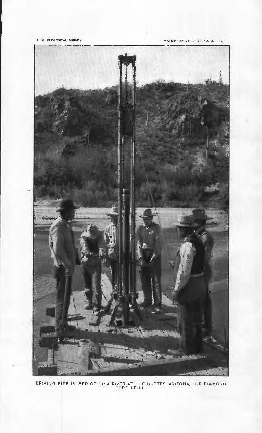
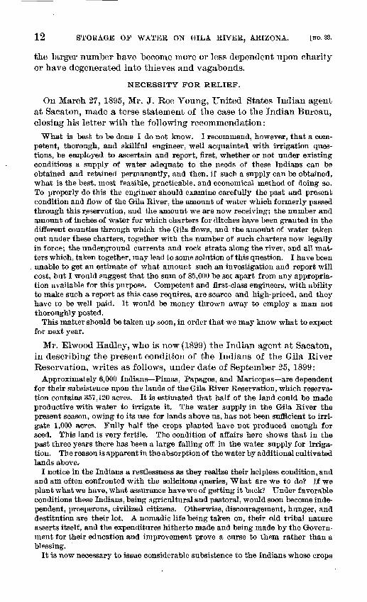
PLATE I. Driving pipe in bed of Gila River at the Buttes, Arizona, for dia mond-core drill--.--._._.....---.._.-- ......... ..-.-......- 9
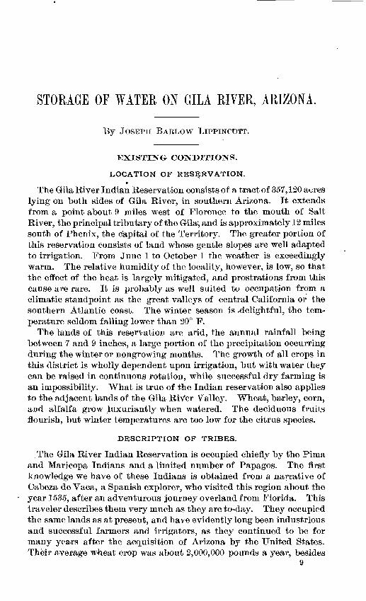
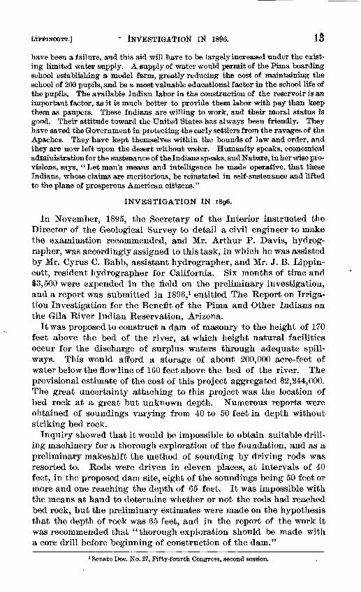
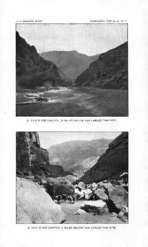
II. A, Gila River Canyon, 15 miles below San Carlos dam site; B,Gila River Canyon, 8 miles below San Carlos dam site......... 16
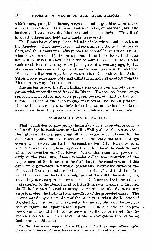
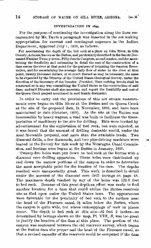
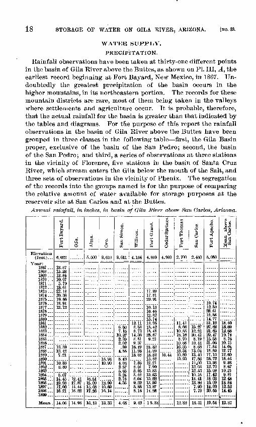
III. A, Location of rainfall stations in basin of Gila River, Arizona;B, rainfall and run off in Gila Basin.....___.--.-.-_...-. ..... 18
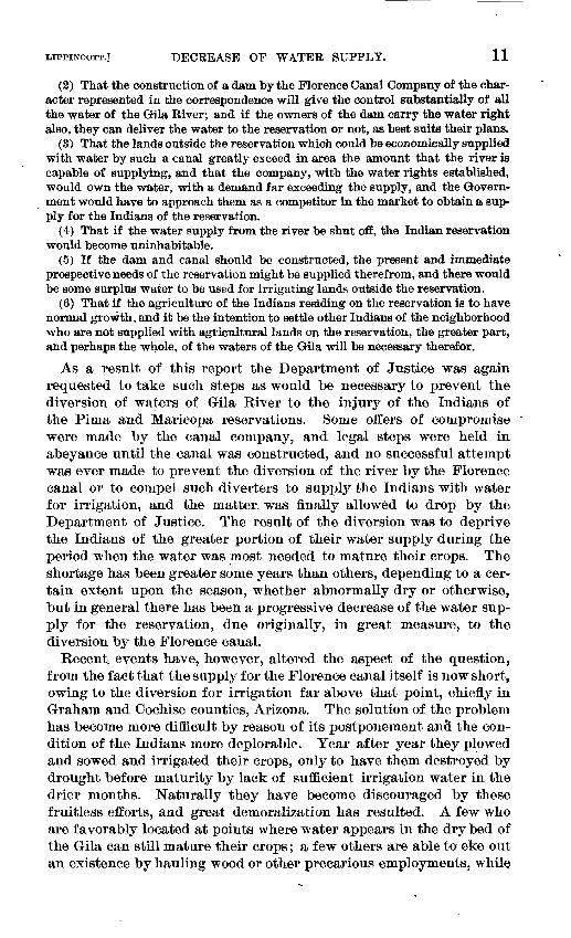
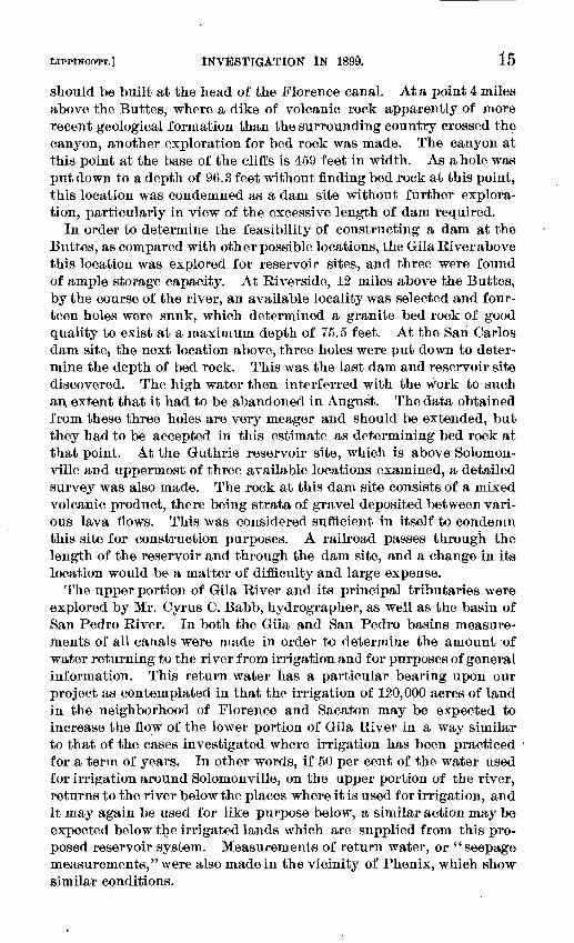
IV. Annual rainfall at eighteen stations in basin of Gila River....... 20V. A, Buttes dam site, looking upstream; proposed quarries on left;
spillway on left of center of field; B, Buttes dam site, looking upstream from upper toe ._,_..__..______._-.--.-.._.---.__._ 24
VI. A, Rating curve for Gila River at the Buttes, Arizona, applied from November 25, 1898, to July 10, 1899; B, discharge of Gila River at the Buttes, Arizona, 1889-1899. .............. ....... 26
VII. A, Diamond-core drill party at work; B, Buttes reservoir site.... 42VIII. At Rating curve for Gila River at the Buttes, used from July 20
to August 10, 1899; B, location of borings at Buttes dam site... 44IX. Contour map of Buttes dam site, showing plan of dam and loca
tion of quarry tests.._... ......... .......................... 46X. A, Result of quarry test at cliff on right bank below Buttes dam
site; B, dam site on Queen Creek.... .......................... 48XI. A, Elevation of end wall of Buttes dam; B, maximum cross section
of proposed dam at the Buttes, Arizona ..._._..--....__..._.-- 50XII. Elevation of Buttes dam, looking upstream..... ................ 52
XIII. Cross sections of tower and outlet tunnel, Buttes dam ........... 54 XIV. A, Cross section of low-water tunnel, Buttes dam; B, maximum
cross section of wasteway, Buttes dam; C, location of borings at Riverside dam site ..........-.--..---....---...--- ........ 56
XV. Map of Buttes reservoir site....-..-----_...-......--.--.----.-.- 58XVI. Contour map of Riverside dam site. . ......-.....---.-..--.---. 60
XVII. A, Riverside dam site; B, Riverside reservoir site............... 62XVIII. Contour map of Riverside reservoir site _....._.._._._.___.___ » 64
XIX. San Carlos dam site, looking upstream.......................... 66XX. Contour map of San Carlos dam site ............. ..---.......-. 68
XXI. Elevation of San Carlos dam and wasteways ....... ........... 70XXII. Maximum cross section of San Carlos dam with towers removed.. 72
XXIII. A, Cross section of wasteway of San Carlos dam; B, details oftowers for San Carlos dam............. ._.-.-.-----.-_--...-. 72
XXIV. Cross section of San Carlos dam through tower.................. 72XXV. A, San Carlos dam site, looking downstream; B, left abutment of
San Carios dam site .... ............... .... ............... 74XXVI. A, Inlet valve for San Carlos dam; B, horizontal section of main
tower of San Carlos dam, showing arrangement of valves...... 74XXVII. Contour map of San Carlos reservoir site ...-..---.--....-- . . 76
XXVIII. Contour map of the grounds of the San Carlos Indian agency and, military post, showing location of buildings..-......-..-.....- 76
XXIX. Contour map of Guthrie reservoir site...-......-.-.-..--.....--. 78XXX. Contour map of Guthrie dam site.... .... ...................... 78
XXXI. Contour map of Queen Creek reservoir site...... .-....-......-- 80XXXII. A, Location of borings at Queen Creek dam site; B, capacity
curves of the proposed reservoirs on Gila River. Arizona....... 82XXXIII. York Canyon on Gila River at Guthrie dam site.....----.. ...-, 90
6
LETTER OF TRANSMITTAL.
DEPARTMENT OF TH& INTERIOR, UNITED STATES GEOLOGICAL SURVEY,
DIVISION OF HYDROGRAPHY, WasJiington, December 1, 1899.
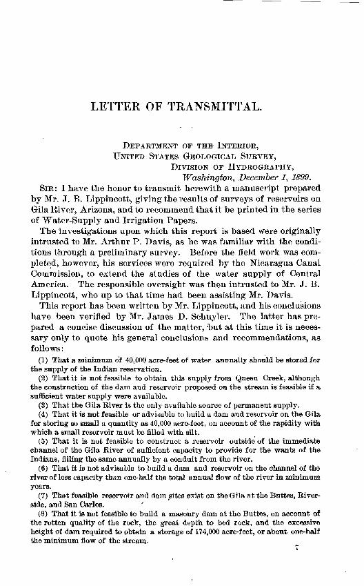
SIR: I have the honor to transmit herewith a manuscript prepared by Mr. J. B. Lippincott, giving the results of surveys of reservoirs on Gila River, Arizona, and to recommend that it be printed in the series of Water-Supply and Irrigation Papers.
The investigations upon which this report is based were originally intrusted to Mr. Arthur P. Davis, as he was familiar with the condi tions through a preliminary survey. Before the field work was com pleted, however, his services were required by the Nicaragua Canal Commission, to extend the studies of the water supply of Central America. The responsible oversight was then intrusted to Mr. J. B. Lippincott, who up to that time had been assisting Mr. Davis.
This report has been written by Mr. Lippincott, and his conclusions have been verified by Mr. James D. Schuyler. The latter has pre pared a concise discussion of the matter, -but at this time it is neces sary only to quote his general conclusions and recommendations, as follows:
(1) That a minimum of 40,000 acre-feet of water annually should be stored for the supply of the Indian reservation.
(2) That it is not feasible to obtain this supply from Queen Creek, although the construction of the dam and reservoir proposed on the stream is feasible if a sufficient water supply were available.
(3) That the Gila River is the only available soiirce of permanent supply.(4) That it is not feasible or advisable to build a dam and reservoir on the Gila
for storing so small a quantity as 40,000 acre-feet, on account of the rapidity with which a small reservoir must be filled with silt.
(5) That it is not feasible to construct a reservoir outside of the immediate channel of the Gila River of sufficient capacity to provide for the wants of the Indians, filling the same annually by a conduit from the river.
(6) That it is not advisable to build a dam and reservoir on the channel of the river of less capacity than one-half the total annual flow of the river in minimum years.
(7) That feasible reservoir and dam vsites exist on the Gila at the Buttes, River side, and San Carlos. '
(8) That it is not feasible to build a masonry dam at the Buttes, on account of the rotten quality of the rock, the great depth to bed rock, and the excessive height of dam required to obtain a storage of 174,000 acre-feet, or about one-half the minimum flow of the stream.
8 LETTER OF TRANSMITTAL.
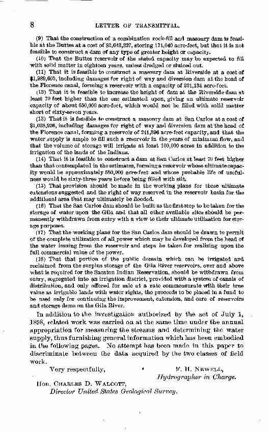
(9) That the construction of a combination rock-fill and masonry dam is feasi ble at the Buttes at a cost of $3,643,327, storing 174,040 acre-feet, but that it is not feasible to construct a dam of any type of greater height or capacity.
(10) That the Buttes reservoir of the stated capacity may be expected to fill with solid matter in eighteen years, unless dredged or sluiced out.
(11) That it is feasible to construct a masonry dam at Riverside at a cost of $1,989,605, including damages for right of way and diversion dam at the head of the Florence canal, forming a reservoir with a capacity of 221,134 acre-feet.
(12) That it is feasible to increase the height of dam at the Riverside dam at least 70 feet higher than the one estimated upon, giving an ultimate reservoir capacity of about 650,000 acre-feet, which would not be filled with solid matter short of sixty-seven years.
(13) That it is feasible to construct a masonry dam at San Carlos at a cost of $1,038,926, including damages for right of way and diversion dam at the head of the Florence canal, forming a reservoir of 241,396 acre-feet capacity, and that the water supply is ample to fill such a reservoir in the years of minimum flow, and that the volume of storage will irrigate at least 100,000 acres in addition to the irrigation of the lands of the Indians.
(14) That it is feasible to construct a dam at San Carlos at least 70 feet higher than that contemplated in the estimates, forming a reservoir whose ultimate capac ity would be approximately 550,000 acre-feet and whose probable life of useful ness would be sixty-three years before being filled with silt.
(15) That provision should be made in the working plans for these ultimate extensions suggested and the right of way reserved in the reservoir basin for the additional area that may ultimately be flooded.
(16) That the San Carlos dam should be built as the first step to betaken for the storage of water upon the G-ila and that all other available sites should be per manently withdrawn from entry with a view to their ultimate utilization for stor age purposes.
(17) That the working plans for the San Carlos dam should be drawn to permit of the complete utilization of all^power which may be developed from the head of the water issuing from the reservoir and steps be taken for realizing upon the full commercial value of the power.
(18) That that portion of the public domain which can be irrigated and reclaimed from the surplus storage of the G-ila River reservoirs, over and above what is required for the Sacaton Indian Reservation, should be withdrawn from entry, segregated into an irrigation district, provided with a system of canals of distribution, and only offered for sale at a rate commensurate with their true value as irrigable lands with water rights, the proceeds to be placed in a fund to be used only for continuing the improvement, extension, and care of reservoirs and storage dams on the G-ila River.
In addition to the investigation authorized by the act of July 1, 1898, related work was carried on at the same time under the annual appropriation for measuring the streams and determining the water supply, thus furnishing general information which has been embodied in the following pages. No attempt has been made in this paper to discriminate between the data acquired by the two classes of field work.
Very respectfully, « F. H. NEWELL,Hydrographer in Charge.
Hon. CHARLES D. WALCOTT,Director United States Geological Survey.
U. S. GEOLOGICAL SURVEY WATER-SUPPLY PAPER NO. 33 PL.
DRIVING PIPE IN BED OF GILA RIVER AT THE BUTTES, ARIZONA, FOR DIAMONDCORE DRILL
STORAGE OF WATER ON GILA RIVER, ARIZONA.
By JOSEPH BARLOW LIPPINCOTT.
EXISTING CONDITIONS.
LOCATION OF RESERVATION.*
The Gila River Indian Reservation consists of a tract of 357,120 acres lying on both sides of Gila River, in southern Arizona. It extends from a point about 9 miles west of Florence to the mouth of Salt River, the principal tributary of the Gila;, and is approximately 12 miles south of Phenix, the capital of the Territory. The greater portion of this reservation consists of land whose gentle slopes are well adapted to irrigation. From June 1 to October I the weather is exceedingly warm. The relative humidity of the locality, however, is low, so that the effect of the heat is largely mitigated, and prostrations from this cause are rare. It is probably as well suited to occupation from a climatic standpoint as the great valleys of central California or the southern Atlantic coast. The winter season is -delightful, the tem perature seldom falling lower than 20° F.
The lands of this reservation are arid, the annual rainfall being between 7 and 9 inches, a large portion of the precipitation occurring during the winter or nongrowing months. The growth of all crops in this district is wholly dependent upon irrigation, but with water they can be raised in continuous rotation, while successful dry farming is an impossibility. What is true of the Indian reservation also applies to the adjacent lands of the Gila River Valley. Wheat, barley, corn, and alfalfa grow luxuriantly when watered. The deciduous fruits nourish, but winter temperatures are too low for the citrus species.
DESCRIPTION OF TRIBES.
The Gila River Indian Reservation is occupied chiefly by the Pima and Maricopa Indians and a limited number of Papagos. The first knowledge we have of these Indians is obtained from a narrative of Cabeza de Vaca, a Spanish explorer, who visited this region about the year 1535, after an adventurous journey overland from Florida. This traveler describes them very much as they are to-day. They occupied the same lands as at present, and have evidently long been industrious and successful farmers and irrigators, as they continued to be for many years after the acquisition of Arizona by the United States. Their average wheat crop was about 2,000,000 pounds a year, besides
9
10 STORAGE OP WATER ON GILA RIVER, ARIZONA. [NO. 33.
which corn, pumpkins, beans, sorghum, and vegetables were raised in large quantities. They manufactured ollas, or earthen jars, and baskets and wove very fine blankets and cotton fabrics. They lived in small villages and held their lands in severalty.
The Pirnas have always been friends of the whites and enemies of the Apaches. They gave succor and assistance to the early white set tlers, and their doors were always open to peaceable whites or Indians when hard pressed by the savage foe. It is their boast that their hands were never stained by the white man's blood. It was under such conditions that they were joined, about a century ago, by the Maricopas, who came as fugitives from the more powerful Yuma tribe. When the belligerent Apaches gave trouble to the settlers, the United States troops sometimes obtained substantial aici and comfort from the Pimas in the way of subsistence.
The agriculture of the Pinia Indians was carried on entirely by irri gation with water diverted from Gila River. These tribes have always supported themselves, and their progress toward civilization has been regarded as one of the encouraging features of the Indian problem. During the last ten years, their irrigating water having been taken away from them, they have lapsed into indolence, want, and vice.
DECREASE OF WATER SUPPLY.
Their condition of prosperity, industry, and independence contin ued until, by the settlement of the Gila Valley above the reservation, the water supply was partly cut off and began to be deficient for the cultivated lands on the reservation. No. very serious shortage occurred, however, until after the construction of the Florence canal and its diversion dam, heading about 15 miles above the eastern limit of the reservation on Gila River. When this canal was projected, early in the year 1886, Agent Wheeler called the attention of the Department of the Interior to the fact that if the construction of this canal were permitted, it "would'practically destroy the farms of the Pima and Maricopa Indians living on the river," and that the effect would be to render the Indians helpless and destitute, the water being absolutely necessary to their existence. On March 2,1886, the subject was referred by the Department to the Attorney-General, who directed the United States district attorney for Arizona to take the necessary steps to protect the Indians from the effects of the projected canal. The matter was delayed until July of the same year, when the Director of the Geological Survey was instructed by the Secretary of the Interior to investigate and report to the Department the effect which the pro posed canal would be likely to have upon the water supply for the Indian reservation. As a result of the investigation the following facts were established: .
(1) That the water supply of the Pima and Maricopa reservations tinder present conditions is no more than sufficient for the wants of the Indians.
LIPPINCOTT.] DECREASE OF WATER SUPPLY. 11
(2) That the construction of a dam by the Florence Canal Company of the char acter represented in the correspondence will give the control substantially of all the water of the Gila River; and if the owners of the dam carry the water right also, they can deliver the water to the reservation or not, as best suits their plans.
(3) That the lands outside the reservation which could be economically supplied with water by such a canal greatly exceed in area the amount that the river is capable of supplying, and that the company, with the water rights established, would own the water, with a demand far exceeding the supply, and the Govern ment would have to approach them as a competitor in the market to obtain a sup ply for the Indians of the reservation.
(4) That if the water supply from the river be shut off, the Indian reservation would become uninhabitable.
(5) If the dam and canal should be constructed, the present and immediate prospective needs of the reservation might be supplied therefrom, and there would be some surplus water to be used for irrigating lands outside the reservation.
(6) That if the agriculture of the Indians residing on the reservation is to have normal growth, and it be the intention to settle other Indians of the neighborhood who are not supplied with agricultural lands on the reservation, the greater part, and perhaps the whole, of the waters of the Gila will be necessary therefor.
As a result of this report the Department of Justice was again requested to take such steps as would be necessary to prevent the diversion of waters of Gila River to the injury of the Indians of the Pi ma and Maricopa reservations. Some offers of compromise were made by the canal company, and legal steps were held in abeyance until the canal was constructed, and no successful attempt was ever made to prevent the diversion of the river by the Florence canal or to compel such diverters to supply the Indians with water for irrigation, and the matter, was finally allowed to drop by the Department of Justice. The result of the diversion was to deprive the Indians of the greater portion of their water supply during the period when the water was most needed to mature their crops. The shortage has been greater some years than others, depending to a cer tain extent upon the season, whether abnormally dry or otherwise, but in general there has been a progressive decrease of the water sup ply for the reservation, due originally, in great measure, to the diversion by the Florence canal.
Recent, events have, however, altered the aspect of the question, from the fact that the supply for the Florence canal itself is now short, owing to the diversion for irrigation far above that point, chiefly in Graham and Coehise counties, Arizona. The solution of the problem has become more difficult by reason of its postponement and the con dition of the Indians more deplorable. Year after year they plowed and sowed and irrigated their crops, only to have them destroyed by drought before maturity by lack of sufficient irrigation water in the drier months. Naturally they have become discouraged by these fruitless efforts, and great demoralization has resulted. A few who are favorably located at points where water appears in the dry bed of the Gila can still mature their crops; a few others are able to eke out an existence by hauling wood or other precarious employments, while
12 STORAGE OF WATER ON GILA RIVER, ARIZONA. [NO. 33.
the larger number have become more or less dependent upon charity or have degenerated into thieves and vagabonds.
NECESSITY FOR RELIEF.
On March 27, 1895, Mr. J. Roe Young, United States Indian agent at Sacaton, made a terse statement of the case to the Indian Bureau, closing his letter with the following recommendation:
What is best to be done I do not know. I recommend, however, that a com petent, thorough, and skillful engineer, well acquainted with irrigation ques tions, be employed to ascertain and report, first, whether or not under existing conditions a supply of water adequate to the needs of these Indians can be obtained and retained permanently, and then, if such a supply can be obtained, what is the best, most feasible, practicable, and economical method of doing so. To properly do this the engineer should examine carefully the past and present condition and flow of the Gila River, the amount of water which formerly passed through this reservation, and the amount we are now receiving; the number and amount of inches of water for which charters for ditches have been granted in the different counties through which the Gila flows, and the amount of water taken out under these charters, together with the number of such charters now legally in force; the underground currents and rock strata along the river, and all mat ters which, taken together, may lead to some solution of this question. I have been unable to get an estimate of what amount such an investigation and report will cost, but I would suggest that the sum of $5,000 be set apart from any appropria tion available for this purpose. Competent and first-class engineers, with ability to make such a report as this case requires, are scarce and high-priced, and they have to be well paid. It would be money thrown away to employ a man not thoroughly posted.
This matter should be taken up soon, in order that we may know what to expect for next year.
Mr. Elwood Hadley, who is now (1899) the Indian agent at Sacaton, in describing the present condition of the Indians of the Gila River Reservation, writes as follows, under date of September 25, 1899:
Approximately 6,000 Indians Pimas, Papagos, and Maricopas are dependent for their subsistence upon the lands of the Gila River Reservation, which reserva tion contains 357,120 acres. It is estimated that half of the land could be made productive with water to irrigate it. The water supply in the Gila River the present season, owing to its use for lands above us, has not been sufficient to irri gate 1,000 acres. Fully half the crops planted have not produced enough for seed. This land is very fertile. The condition of affairs here shows that in the past three years there has been a large falling off in the water supply for irriga tion. The reason is apparent in the absorption of the water by additional cultivated lands above,
I notice in the Indians a restlessness as they realize their helpless condition, and and am often confronted with the solicitous queries, What are we to do? If we plant what we have, what assurance have we of getting it back? Under favorable conditions these Indians, being agricultural and pastoral, would soon become inde pendent, prosperous, civilized citizens. Otherwise, discouragement, hunger, and destitution are their lot. A nomadic life being taken on, their old tribal nature asserts itself, and the expenditures hitherto made and being made by the Govern ment for their education and improvement prove a curse to them rather than a blessing.
It is now necessary to issue considerable subsistence to the Indians whose crops
iNVESTIGAtlOtf lit 1896. i&
have been a failure, and this aid will have to be largely increased under the exist ing limited water supply. A supply of water would permit of the Pima boarding school establishing a model farm, greatly reducing the cost of maintaining the school of 200 pupils, and be a most valuable educational factor in the school life of the pupils. The available Indian labor in the construction of the reservoir is an important factor, as it is much better to provide them labor with pay than keep them as paupers. These Indians are willing to work, and their moral status is good. Their attitude toward the United States has always been friendly. They have saved the Government in protecting the early settlers from the ravages of the Apaches. They have kept themselves within the bounds of law and order, and they are now left upon the desert without water. Humanity speaks, economical administration for the sustenance of the Indians speaks, and Nature, in her wise pro visions, says, " Let man's means and intelligence be made operative, that these Indians, whose claims are meritorious, be reinstated in self-sustenance and lifted to the plane of prosperous American citizens."
INVESTIGATION IN 1896.
In November, 1895, the Secretary of the Interior instructed the Director of the Geological Survey to detail a civil engineer to make the examination recommended, and Mr. Arthur P. Davis, hydrog- rapher, was accordingly assigned to this task, in which he was assisted by Mr. Cyrus C. Babb, assistant hydrographer, and Mr. J. B. Lippin- cott, resident hydrographer for California. Six months of time and $3,500 were expended in the field on the preliminary investigation, and a report was submitted in 1896,1 entitled The Report on Irriga tion Investigation for the Benefit of the Pima and Other Indians on the Gila River Indian Reservation, Arizona.
It was proposed to construct a dam of masonry to the height of 170 feet above the bed of the river, at which height natural facilities occur for the discharge of surplus waters through adequate spill ways. This would afford a storage of about 200,000 acre-feet of water below the flow line of 160 feet above the bed of the river. The provisional estimate of the cost of this project aggregated $2,244,000. The great uncertainty attaching to this project was the location of bed rock at a great but unknown depth. Numerous reports were obtained of soundings varying from 40 to 50 feet in depth without striking bed rock.
Inquiry showed that it would be impossible to obtain suitable drill ing machinery for a thorough exploration of the foundation, and as a preliminary makeshift the method of sounding by driving rods was resorted to. Rods were driven in eleven places, at intervals of 40 feet, in the proposed dam site, eight of the soundings being 50 feet or more and one reaching the depth of 65 feet. It was impossible with the means at hand to determine whether or not the rods had reached bed rock, but the preliminary estimates were made on the hypothesis that the depth of rock was 65 feet, and in the report of the work it was recommended that "thorough exploration should be made with a core drill before beginning of construction of the dam."
1 Senate Doc. No. 27, Fifty-fourth Congress, second session.
14 stoRAGE OP WATER otf GIL A RivEit, ARIZONA. CNO.&'
INVESTIGATION IN 1899.
For the purpose of continuing the investigation along the lines rec ommended by Mr. Davis a paragraph was inserted in the act making appropriation for current and contingent expenses in the Indian Department, approved July 1, 1898, as follows:
For ascertaining the depth of the bed rock at a place on Gila River, in Gila County, Arizona, known as the Buttes, and particularly described in the Senate Doc ument Number Twenty-seven, Fifty-fourth Congress, second session, and for ascer taining the feasibility and estimating in detail the cost of the construction of a dam across the river at that point for the purpose of irrigating the Sacaton Reser vation, and for ascertaining the average daily flow of water in the river at that point, twenty thousand dollars, or so much, thereof as may be necessary, the same to be expended by the Director of the United States Geological Survey, under the direction of the Secretary of the Interior: Provided, That nothing herein shall be construed as in any way committing the United States to the construction of said dam; and said Director shall also ascertain and report the feasibility and cost of the Queen Creek project mentioned in said Senate document.
In order to carry out the provisions of this act stream measure ments were begun on Gila River at the Buttes and on Queen Creek at the site of the proposed dam, in November, 1898, and have been maintained to date (October, 1899). As the site at the Buttes was inaccessible by heavy wagons, a road was built to facilitate the trans portation of machinery to the site for drilling. Bids were invited by advertisement for the exploration of bed rock, but were rejected, as it was found that the amount of drilling desirable would, under the most favorable proposal, cost more than the available funds. Two diamond drills, a few diamonds, and two pipe-driving machines were loaned to the Survey for this work by the Nicaragua Canal Commis sion, and borings were begun at the Buttes in January, 1899.
Twenty-five holes were put down to bed rock at the Buttes with a diamond core drilling apparatus. These holes were distributed up and down the narrow portions of the canyon in order to determine the most acceptable point for the location of the dam. The depths reached were unexpectedly great. This work is described in detail under the account of the diamond core drill borings on page 48. The maximum depth reached by any of the holes was 122.6 feet to bed rock. Because of this great depth an effort was made to find another location for a dam that could utilize the Buttes reservoir site as filed upon under the United States laws. The appearances were favorable for the proximity of bed rock to the surface near the head of the Florence canal, 3^ miles below the Buttes, where the canyon is quite wide, but where outcroppings of rock in places occur. The depth to bed rock at this site 82 feet 2 inches as determined by borings shown on the map, PL VIII, B, was too great to justify the location of the dam at this place. The portion of the canyon was contoured between the old reservoir survey, which began at the Buttes dam site proper and the head of the Florence canal, so that a revised capacity of the reservoir could be computed if the dam
LIPPINCOTT.] INVESTIGATION IN 1899. 15
should be built at the head of the Florence canal. At a point 4 miles above the Buttes, where a dike of volcanic rock apparently of more recent geological formation than the surrounding country crossed the canyon, another exploration for bed rock was made. The canyon at this point at the base of the cliffs is 459 feet in width. As a hole was put down to a depth of 96.3 feet without finding bed rock at this point, this location was condemned as a dam site without further explora tion, particularly in view of the excessive length of dam required.
In order to determine the feasibility of constructing a dam at the Buttes, as compared with other possible locations, the Gila River above this location was explored for reservoir sites, and three were found of ample storage capacity. At Riverside, 12 miles above the Buttes, by the course of the river, an available locality was selected and four teen holes were sunk, which determined a granite bed rock of good quality to exist at a maximum depth of 75.5 feet. At the San Carlos dam site, the next location above, three holes were put down to deter mine the depth of bed rock. This was the last dam and reservoir site discovered. The high water then interferred with the work to such an. extent that it had to be abandoned in August. The data obtained from these three holes are very meager and should be extended, but they had to be accepted in this estimate as determining bed rock at that point. At the Guthrie reservoir site, which is above Soloinon- ville and uppermost of three available locations examined, a detailed survey was also made. The rock at this dam site consists of a mixed volcanic product, there being strata of gravel deposited between vari ous lava flows. This was considered sufficient in itself to condemn this site for construction purposes. A railroad passes through the length of the reservoir and through the dam site, and a change in its location would be a matter of difficulty and large expense.
The upper portion of Gila River and its principal tributaries were explored by Mr. Cyrus C. Babb, hydrographer, as well as the basin of San Pedro River. In both the Gila and San Pedro basins measure ments of all canals were made in order to determine the amount 'of water returning to the river from irrigation and for purposes of general information. This return water has a particular bearing upon our project as contemplated in that the irrigation of 120,000 acres of land in the neighborhood of Florence and Sacaton may be expected to increase the flow of the lower portion of Gila River in a way similar to that of the cases investigated where irrigation has been practiced for a term of years. In other words, if 50 per cent of the water used for irrigation around Solomonville, on the upper portion of the river, returns to the river below the places where it is used for irrigation, and it may again be used for like purpose below, a similar action may be expected below the irrigated lands which are supplied from this pro posed reservoir system. Measurements of return water, or "seepage measurements," were also made in the vicinity of Phenix, which show similar conditions.
16 STORAGE OP WATER ON GILA RIVER, ARIZONA. [NO. 33.
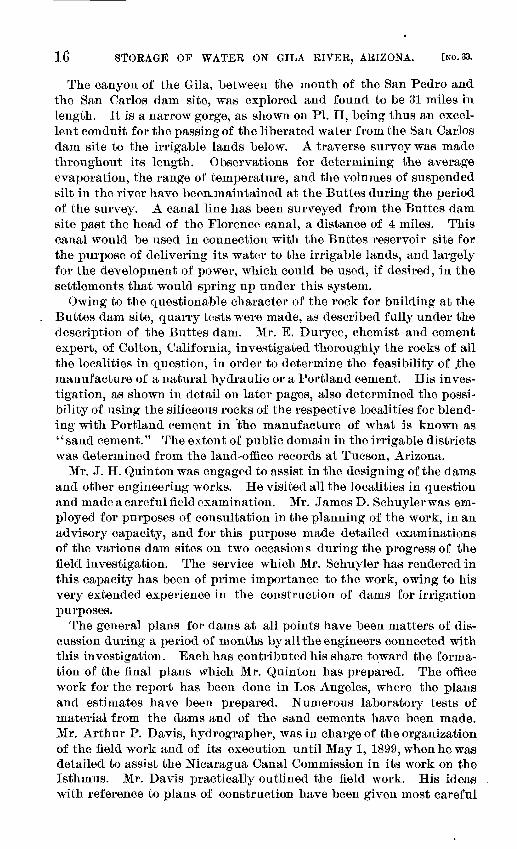
The canyon of the Gila, between the mouth of the San Pedro and the San Carlos dam site, was explored and found to be 31 miles in length. It is a narrow gorge, as shown on PL II, being thus an excel lent conduit for the passing of the liberated water from the San Carlos dam site to the irrigable lands below. A traverse survey was made throughout its length. Observations for determining the average evaporation, the range of temperature, and the volumes of suspended silt in the river have beeiLinaintained at the Buttes during the period of the survey. A canal line has been surveyed from the Buttes dam site past the head of the Florence canal, a distance of 4 miles. This canal would be used in connection with the Buttes reservoir site for the purpose of delivering its water to the irrigable lands, and largely for the development of power, which could be used, if desired, in the settlements that would spring up under this system.
Owing to the questionable character of the rock for building at the Buttes dam site, quarry tests were made, as described fully under the description of the Buttes dam. Mr. E. Duryee, chemist and cement expert, of Colton, California, investigated thoroughly the rocks of all the localities in question, in order to determine the feasibility of .the manufacture of a natural hydraulic or a Portland cement. His inves tigation, as shown in detail on later pages, also determined the possi bility of using the siliceous rocks of the respective localities for blend ing with Portland cement in 'the manufacture of what is known as '' sand cement." The extent of public domain in the irrigable districts was determined from the land-office records at Tucson, Arizona.
Mr. J. H. Quinton was engaged to assist in the designing of the dams and other engineering works. He visited all the localities in question and made a careful field examination. Mr. James D. Schuylerwas em ployed for purposes of consultation in the planning of the work, in an advisory capacity, and for this purpose made detailed examinations of the various dam sites on two occasions during the progress of the field investigation. The service which Mr. Schuyler has rendered in this capacity has been of prime importance to the work, owing to his very extended experience in the construction of dams for irrigation purposes.
The general plans for dams at all points have been matters of dis cussion during a period of months by all the engineers connected with this investigation. Each has contributed his share toward the forma tion of the final plans which Mr. Quinton has prepared. The office work for the report has been done in Los Angeles, where the plans and estimates have been prepared. Numerous laboratory tests of material from the dams and of the sand cements have been made. Mr. Arthur P. Davis, hydrographer, was in charge of the organization of the field work and of its execution until May 1, 1899, when he was detailed to assist the Nicaragua Canal Commission in its work on the Isthmus. Mr. Davis practically outlined the field work, His ideas with reference to plans of construction have been given most careful
U. S. GEOLOGICAL SURVEY WATER-SUPPLY PAPER NO. 33 PL. II
A. GILA RIVER CANYON, 15 MILES BELOW SAN CARLOS DAM SITE.
. GILA RIVER CANYON, 8 MILES BELOW SAN CARLOS DAM SITE.
LIPPINCOTT.] AMOUNT OP WATER REQUIRED. ^ 17
consideration in reaching final conclusions, and to him is due the credit, in large part, for the successful carrying out of the work and for its breadth and scope.
AMOUNT OF WATER REQUIRED.
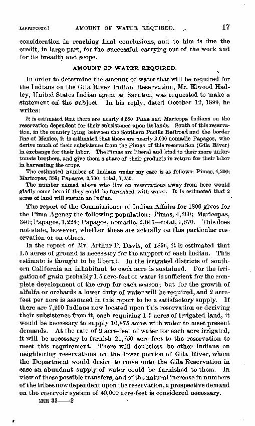
In order to determine the amount of water that will be required for the Indians on the Gila River Indian Reservation, Mr. Elwood Had- ley, United States Indian agent at Sacaton, was requested to make a statement on the subject. In his reply, dated October 12, 1899, he writes:
It is estimated that there are nearly 4,500 Pima and Maricppa Indians on the reservation dependent for their subsistence upon its lands. South of this reserva tion, in the country lying between the Southern Pacific Eailroad and the border line of Mexico, it is estimated that there are nearly 2,000 nomadic Papagos, who derive much of their subsistence from the Pimas of this reservation (Gila Eiver) in exchange for their labor. The Pimas are liberal and kind to their more unfor tunate brothers, and give them a share of their products in return for their labor in harvesting the crops.
The estimated number of Indians under my care is as follows: Pimas, 4,200; Maricopas, 350; Papagos, 2,700; total, 7,350.
The number named above who live on reservations away from here would gladly come here if they could be furnished with water. It is estimated that 2 acres of land will sustain an Indian.
The report of the Commissioner of Indian Affairs for 1896 gives for the Pima Agency the following population: Pimas, 4,260; Maricopas, 340; Papagos, 1,224; Papagos, nomadic, 2,046 total, 7,870. This does not state, however, whether these are actually on this particular res ervation or on others.
In the report of Mr. Arthur P. Davis, of 1896, it is estimated that 1.5 acres of ground is necessary for the support of each Indian. This estimate is thought to be liberal. In the irrigated districts of south ern California an inhabitant to each acre is sustained. For the irri gation of grain probably 1.5 acre-feet of water is sufficient for the com plete development of the crop for each season; but for the growth of alfalfa or orchards a lower duty of water will be^equired, and 2 acre- feet per acre is assumed in this report to be a satisfactory supply. If there are 7,250 Indians now located upon this reservation or deriving their subsistence from it, each requiring 1.5 acres of irrigated land, it would be necessary to supply 10,875 acres with water to meet present demands. At the rate of 2 acre-feet of water for each acre irrigated, it will be necessary to furnish 21,750 acre-feet to the reservation to meet this requirement. There will doubtless be other Indians on neighboring reservations on the lower portion of Gila River, whom the Department would desire to move onto the Gila Reservation in case an abundant supply of water could be furnished to them. In view of these possible transfers, and of the natural increase in numbers of the tribes now dependent upon the reservation, a prospective demand on the reservoir system of 40,000 acre-feet is considered necessary.
inn 33 2
18 STORAGE OF WATER ON GlLA RlVfiR, ARIZONA. [NO.
WATER SUPPLY.
PRECIPITATION.
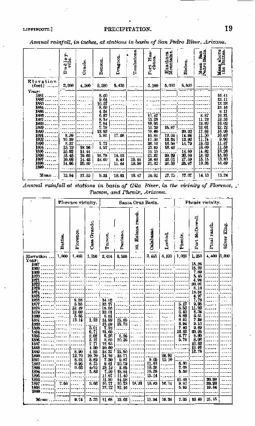
Rainfall observations have been taken at thirty-one different points in the basin of Gila River above the Buttes, as shown on PL III, A, the earliest record beginning at Fort Bayard, New Mexico, in 1867. Un doubtedly the greatest precipitation of the basin occurs in the higher mountains, in its northeastern portion. The records for these mountain districts are rare, most of them being taken in the valleys where settlements and agriculture occur. It is probable, therefore, that the actual rainfall for the basin is greater than that indicated by the tables and diagrams. For the purpose of this report the rainfall observations in the basin of Gila River above the Buttes have been grouped in three classes in the following table first, the Gila Basin proper, exclusive of the basin of the San Pedro; second, the basin of the San Pedro; and third, a series of observations at three stations in the vicinity of Florence, five stations in the basin of Santa Cruz River, which stream enters the Gila below the mouth of the Salt, and three sets of observations in the vicinity of Phenix. The segregation of the records into the groups named is for the purpose of comparing the relative amount of water available for storage purposes at the reservoir site at San Carlos and at the Buttes.
Annual rainfall, in incJies, in basin of Gila River above San Carlos, Arizona.
Elevation
Year:1867...1868...1869...1870...1871 ...1873...1873...1874...1875 ...1876...1877...1878...1879...1880...1881...1883...1883...1884... 1885...1886...1887...1888...1889...1890...1891...1893...1898...1894... 1895... 1896...1897 u.1898...1899...
Fort Bayard.
6,023
13.8715.3312.8410.075.79
13.6133.1830.3819.6618.9413.13
13.5913.437.31
10.308.80
8.67 14.45M osir.oo18.31
14.08
33
.......
.......
"is.'ii"17.8714.4415.33
14.98
03a <
5,500
-
.......
.......
"ia."5i"15.0915.6817.36
16.13
d ^ O
3,610
.......
15.9410.90
"13.99"
10.6916.14
13.33
San Simon.
3,611
6.507.15
10.37 3.393.03
.994.55
8.434.04 3.575.653.34 3.78 4.36
4.65
Willcox.
4 164'
13.118.588.73
14.38 8.519.37
16.4911.9313.68
7.36 8.013.955.88 8.04 9.335.668.16
9.43
Fort Grant.
4,860
17.9917.8130.91
10.1316.4613 8315.7418.9615.4315.4835.67 9.31
34.3314.3013.3315.8813.31 T.90
13.8513.53 13.30 15.9913.8714.36
15.34
Cedar Springs.
i onn
.......
16.44
.......
.......
Fort Thomas
<> 7nn
11.418.66
10.8518.168.70
10.8616.3513.3410.8913.93
.......
13.33
San Carlos,
3,450
15.3713.3130.41 8.19
10.448.68
13.0413.40ir.seJl.OO 13.0513.5310.15 14.41 13.887.907.79
13.31
Fort Apache.
5,050
19.7413.5038.6118.5814.7781.1237.6331.6539.47 15.5831.0617.8418.8917.1036.7313.36 13.7015.0817.43 18.03 16.0914.9330.55
19.54
Mean above San Carlos.
18.4013.6913.6819.748.76
10.7514.04]2.7713.6016.469.888.67
10.319.81
13.48 13.8413.5214.45
*
13.87
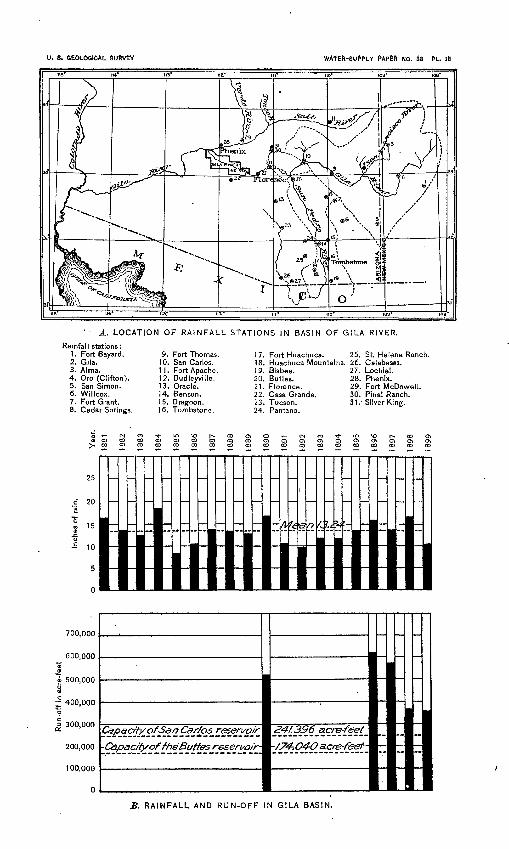
U. S. GEOLOGICAL SURVEY WAfEfc-SUPPLY PAPtft NO. 63 PL. Ill
A. LOCATION OF RAINFALL STATIONS IN BASIN OF GILA RIVER.
Rainfall stations:1. Fort Bayard.2. Gila.3. Alma.4. Oro (Clifton).5. San Simon.6. Willcox.7. Fort Grant.8. Cedar Springs.
9. Fort Thomas. 1 7. Fort Huachuca. 25. St. Helena Ranch.10. San Carlos. 18. Huachuca Mountains. 26. Calabasas.11. Fort Apache. 19. Bisbee. 27. Lochiel.12. Dudleyville. 20. Buttes. 28. Phenix.13. Oracle. 21. Florence. 29. Fort McDowell.14. Benson. 22. Casa Grande. 30'. Pinal Ranch.15. Dragoon. 23. Tucson. 31. Silver King.16. Tombstone. 24. Pantano.
700,000
600,000 "S
<£i 500,000S
~ 400,000<£ o
J 300,000
200,000
100,000
0
Capacity of San Car/ps reservoir
-Capacity of fheButfes resen/o/r
Z4/.396 acre-feet
/74-.O4-O acre-feef
B. RAINFALL AND RUN-OFF IN GILA BASIN.
LIPPINCOTT.] PRECIPITATION. 19
Annual rainfall, in inches, at stations in basin of San Pedro River, Arizona.
Elevation (feet)...
Year:1881 .......1882.-- ...1883.......1884 1885---..-.1886.- .1887 1888----1889 1890.......1891 1892 1893 1894 1895 1896 1897 1898 1899
Mean . . .
Dudley-ville.
2,360
8.5910.298.37
15.1215.9315.4510.0314. Ofi
13.34
Oracle.
4,500
18.3614 4419 6214.4320.89
17.55
Benson.
3,580
8.609.64
10.578.694.246.278.197 JU7.78
13.835.81
7.714.57
16.7818.60
9.21
Dragoon.
5,436
17.38
16.038.41
11 44
13.31
Tombstone.
13.4413.50
13.47
3 .M§ -I1fa
5,100
11.4715.2819.9515.8919.6010.8411.5020.1613.9514.1501 2716.6821.82
16.31
Huachuca Mountains.
5,000
15.87
12.0412.2416.5816.48
20.3922 0126.38
17.75
J"
.
5,500
20.2314.3413.9214.79
14.8020.8617.5925.87
17.67
Mean San Pedro Basin.
8.8711.7313.8913.0117.8811.5011.7413.5213.6914.8318.6315.1519.36
14.13
Mean above the Buttes.
16.4413.1112.3818.168.11
10.2113.5313.0212.7216.9310.639.90
11.8711.5813.2615.9313.8316.69
13.24
Annual rainfall at stations in basin of Gila River, in tJte vicinity of Florence, Tucson, and Phenix, Arizona.
Elevation ... Year:
1887 ........1868. .1869 1870 1871 18731878 1874 1875 1876 1877 1878 1879 1880 1881 1883
1884 1885. ......1886.- 1887 1888 *|QQQ
1890.... 1891. ...... 1892 1893 1894 1895 1896 1897 1898....... 1899.......
Florence vicinity.
Buttes.
1,600
...
.......
-------
"7."59"
Florence.
1,493
9.335.35
13.4912.02 5.35
12.14
. ......
12'. 70 8.24 9.95 9.63
9.74
Casa Grande.
1,396
.......
1.73
3.01 9.712.02 5.12 7.714.30 4.25
10.70 3.62 8.75 4.-92 5.83
"sfos"
5.33
Santa Cruz Basin.
Tucson.
3,404
114 0213.77 16.6612.01 6.61
14.92 15.597.78
15.03 5.26 8.59
12.9510.60 18.37 14.16 7.30 9.61
13.12 7.29
11.07 11.39 10.77 13.72
11.68
d
3,538
........
15.65 15.73
"8."96'
10.36
"i5."50
18.71 9.87
10.79 3.35
18.84 11.40 14.58 10.73 13.16
13.62
St. Helena ranch.
.......
.......
...
.......
"Is.'sV
Calabasas.
3,445
-
.......
.......
.......
1L83 10.28 10.29 15.14
"io'ss"
11.34
Lochiel.
5,100
.......
.......
..:....
.......
.......26.90 15.10
19.38
Phenix vicinity.
Phecix.
1,068
5.178.526.40 6.838.91 6.947.40
12.833.77 5.78
.......
5.50 7.68 5.50
"io.'is"9.87 5.95
7.35
1 1fa
1,250
15.3615.22 7.695.454.94
20.01 8.13
16.844.97 7.739.88
11 928.34 6.617.24 9.109.89
20.B5 8.30 8.08
10.3211.9112.78
-----
10.48
Final ranch.
4,400
.......
.......
.......
.......
.......
lass"33.23 19.84
21.15
Silver King.
3,800
......
......
.....
......
......
......
......
20 STORAGE OF WATER ON GILA RIVER, ARIZONA. [NO. 33.
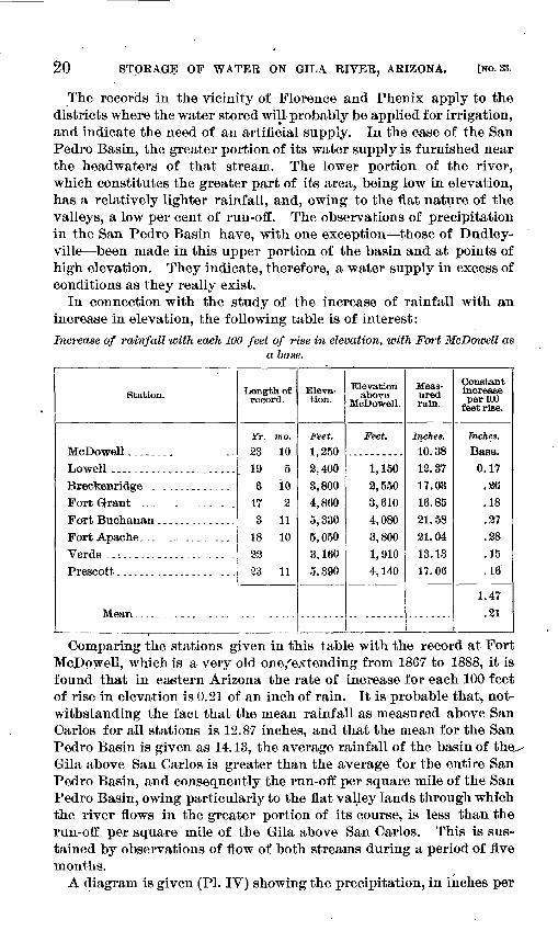
The records in the vicinity of Florence and Phenix apply to the districts where the water stored will-probably be applied for irrigation, and indicate the need of an artificial supply. In the case of the San Pedro Basin, the greater portion of its water supply is furnished near the headwaters of that stream. The lower portion of the river, which constitutes the greater part of its area, being low in elevation, has a relatively lighter rainfall, and, owing to the flat nature of the valleys, a low per cent of run-off. The observations of precipitation in the San Pedro Basin have, with one exception those of Dudley- ville been made in this upper portion of the basin and at points of high elevation. They indicate, therefore, a water supply in excess of conditions as they really exist.
In connection with the study of the increase of rainfall with an increase in elevation, the following table is of interest:Increase of rainfall with each 100 feet of rise in elevation, with Fort McDoioell as
a base.
Station.
Lowell ----__._.-.----..--,..Breckenridge . . .. . ...........Fort Grant ._..--..-......._.Fort Buchanan ..............Fort Apache _ . . _ __....____.Verde ..^.. ................ -Prescott ........... ..... ...
Length of record.
Yr. mo. 23 10
19 5
6 10
17 23 11
18 10
2223 11
Eleva tion.
Feet.
1,250
2,400
3,8004,8605,330
5,0503,1605.390
Elevation above
McDowell.
Feet.
1,150
2,550
3,610
4,0803,8001,910
4,140
Meas ured rain.
Inches. 10.38
13.3717.03
16.8521.5821.0413.1317.06
Constant increase per LOO
feet rise.
Inches.
0.17.86.18.27.28.15.16
1.47 .21
Comparing the stations given in this table with the record at Fort McPowell, which is a very old one,'extending from 1867 to 1888, it is found that in eastern Arizona the rate of increase for each 100 feet of rise in elevation is 0.21 of an inch of rain. It is probable that, not withstanding the fact that the mean rainfall as measured above San Oarlos for all stations is 12.87 inches, and that the mean for the San Pedro Basin is given as 14.13, the average rainfall of the basin of the,- Gila above San Carlos is greater than the average for the entire San Pedro Basin, and consequently the run-off per square mile of the San Pedro Basin, owing particularly to the flat valley lands through whfch the river flows in the greater portion of its course, is less than the run-off per square mile of the Gila above San Oarlos. This is sus tained by observations of flow of both streams during a period of five months.
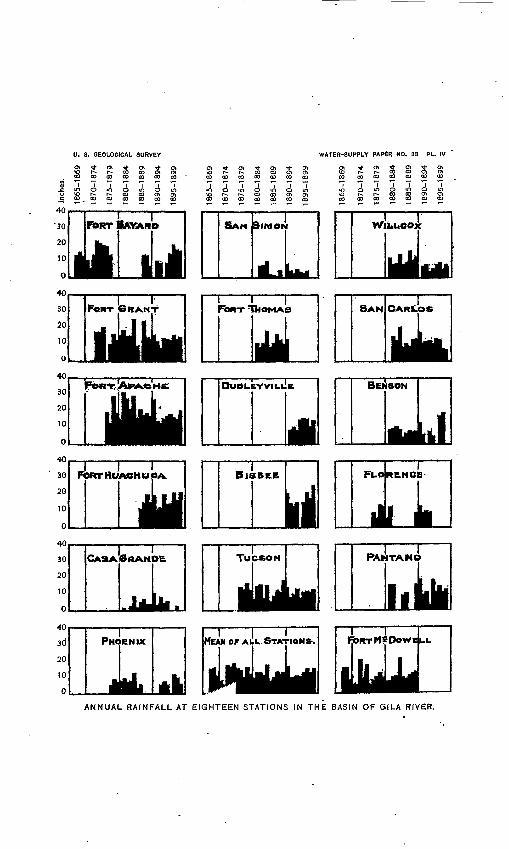
A diagram is given (PL IV) showing the precipitation, in inches per
U. 8. GEOLOGICAL SURVEY
00 00 CO 00 CO 00
01 ^- oo 01
co oo oo co oo
WATER-SUPPLY PAPER NO.
Ot *co atco co
00 CO 00 OO 00 OO 00 00 CO 00 00 OO 03
ANNUAL RAINFALL AT EIGHTEEN STATIONS IN THE BASIN OF GILA RIVER.
LIPPINCOTT.] SUBDIVISIONS OF THE DRAINAGE BASIN. 21
annum, during the years when observations of the rainfall were made at various typical stations. For 1899 the figures are estimated after September 1. Data were had from the records of the Signal Service and of the Weather Bureau showing the amount of precipitation: each month at each of the eighteen stations named in the table, but they are considered too voluminous for publication. The table of annual rainfall in the basin of the Gila is compiled from this mass of detail. After careful consideration it was deemed impossible to give an average rainfall for the basin based on probable rainfall at various elevations. The'means given in the table and diagrams are the direct means of the stations at which observations were made, each being given equal weight in the years when its record occurs. In the case of the upper portion of the Gila the mean has not been extended back of 1881, as sufficient data do not exist upon which to base an accurate deduction. The few points at which observations were taken prior to 1881 would probably indicate a greater rainfall for the basin than existed, owing to their relatively great elevation. In like manner, the record of the San Pedro is not extended back of 1836.
SUBDIVISIONS OF THE DRAINAGE BASIN.
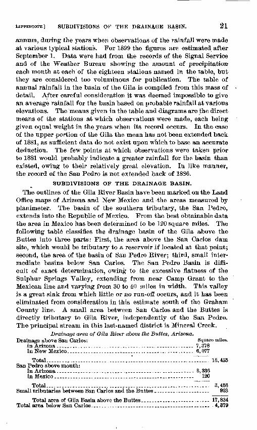
The outlines of the Gila River Basin have been marked on the Land Office maps of Arizona and New Mexico and the areas measured by planimeter. The basin of the southern tributary, the San Pedro, extends into the Republic of Mexico. From the best obtainable data the area in Mexico has been determined to be 120 square miles. The following table classifies the drainage basin of the Gila above the Buttes into three parts: First, the area above the San Carlos dam site, which would be tributary to a reservoir if located at that point; second, the area of the basin of San Pedro River; third, small inter mediate basins below San Carlos. The San Pedro Basin is dim- cult of exact determination, owing to the excessive flatness of the Sulphur Springs Valley, extending from near Camp Grant to the Mexican line and varying from 30 to 40 miles in width. This valley js a great sink from which little or no run-off occurs, and it has been eliminated from consideration in this estimate south of the Graham County line. A small area between San Carlos and the Buttes is directly tributary to Gila River, independently of the San Pedro. The principal stream in this last-named district is Mineral Creek.
Drainage area of Gila River above tJie Buttes, Arizona,Drainage above San Carlos: Square ndies.
In Arizona..._ ..^........................................... 7,378In New Mexico.. ..................^........................... 6,077
Total.--... -....-...-.....__.,.._-.....----------_-------------- 13,455San Pedro above mouth:
In Arizona...__..._.... _.__...._..__...__.__..-...-. - . 3,336in Mexico...............,____.___._._.__._____._.__._._.-__..- 120
Total................................ __.__.....__.._..,---.:-~77I 3,456Small tributaries between San Carlos and the Buttes _.-.,_............... 933
Total area of Gila Basin above the Buttes................. ...... 17,834Total area below San Carlos,................_._..._.._.......... 4,879
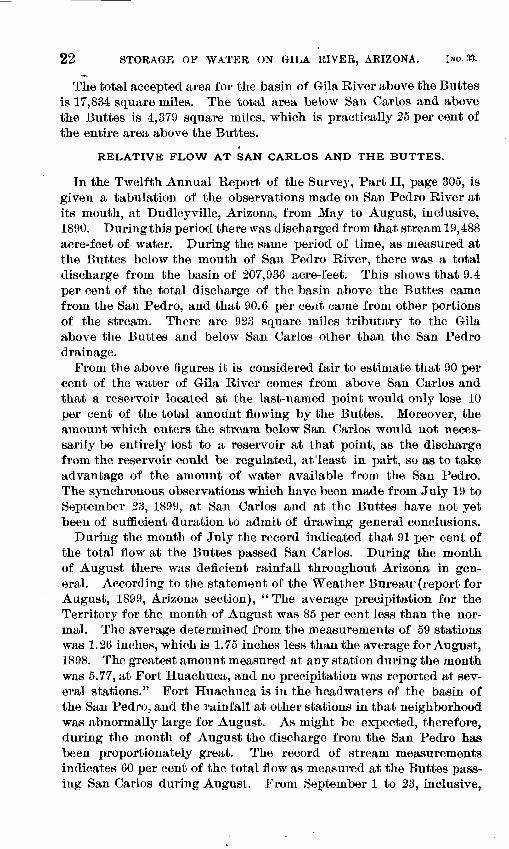
22 STORAGE OF WATER ON GILA RIVER, ARIZONA. [NO. 33.
The total accepted area for the basin of Gila River above the Buttes is 17,834 square miles. The total area below San Carlos and above the Buttes is 4,379 square miles, which is practically 25 per cent of the entire area above the Buttes.
RELATIVE FLOW AT SAN CARLOS AND THE BUTTES.
In the Twelfth Annual Report of the Survey, Part II, page 305, is given a tabulation of the observations made on San Pedro River at its mouth, at Dudleyville, Arizona, from May to August, inclusive, 1890. Duringthis period there was discharged from that stream 19,488 acre-feet of water. During the same period of time, as measured at the Buttes below the mouth of San Pedro River, there was a total discharge from the basin of 207,936 acre-feet. This shows that 9.4 per cent of the total discharge of the basin above the Buttes came from the San Pedro, and that 90.6 per cent came from other portions of the stream. There are 923 square miles tributary to the Gila above the Buttes and below San Carlos other than the San Pedro drainage.
From the above figures it is considered fair to estimate that 90 per cent of the water of Gila River comes from above San Carlos and that a reservoir located at the last-named point would only lose 10 per cent of the total amount flowing by the Buttes. Moreover, the amount which enters the stream below San Carlos would not neces sarily be entirely lost to a reservoir at that point, as the discharge from the reservoir could be regulated, at least in part, so as to take advantage of the amount of water available from the San Pedro. The synchronous observations which have been made from July 19 to September 23, 1899, at San Carlos and at the Buttes have not yet been of sufficient duration to admit of drawing general conclusions.
During the month of July the record indicated that 91 per cent of the total flow at the Buttes passed San Carlos. During the month of August there was deficient rainfall throughout Arizona in gen eral. According to the statement of the Weather Bureau-(report for August, 1899, Arizona section), "The average precipitation for the Territory for the month of August was 85 per cent less than the nor mal. The average determined from the measurements of 59 stations was 1.26 inches, which is 1.75 inches less than the average for August, 1898. The greatest amount measured at any station during the month was 5.77, at Fort Huachuca, and no precipitation was reported at sev eral stations." Fort Huachuca is in the headwaters of the basin of the San Pedro, and the rainfall at other stations in that neighborhood was abnormally large for August. As might be expected, therefore, during the month of August the discharge from the San Pedro has been proportionately great. The record of stream measurements indicates 60 per cent of the total flow as measured at the Buttes pass ing San Carlos during August. From September 1 to 23, inclusive,
EELATIVE FLOW AT SAN CARLOS AND THE BUTTES. 23
there was 59 per cent at San Carlos. No rainfall records for Septem ber, 1899, are at present (October 3, 1899) available.
The record for the four months given in 1890 indicates 90 per cent of the total flow at the Buttes available at San Carlo®, and during the two complete months (July 19 to September 23) when the meas urements were maintained in 1899 at both places a mean of 74 per cent was available at San Carlos, or an average for the entire period of six months of 83 per cent at San Carlos.
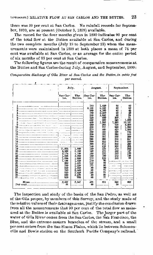
The following figures are the result of comparative measurements at. the Buttes and San Carlos during July, August, and September, 1899:
Comparative discharge of Gila River at San Carlos and the Buttes, in cubic feetper second.
i
I. ................ ..............23.. .......................... ,....i. ................................6. .............................. ..6..... ...................... ......7.................................8. ............................. ...9. ............................ ....
10. .......................... ......11. ...............................12 ...,........-.....-......__.......13. ...................... ..........14.................................15. ............................ _.._16. .......................... ......17...... ......................... ...IS.................................19. ............................ ....20. ............................ ....31...1.............. ..............2233. ................................3425. ................................2627................................28. ................................2930.................................31. ...............................
July.
San Car los.
11,9766,568 3,174 1,836 1,836 1,498
960 780 840 750 960 590 520
3,407 91
TheButtes.
1,800 8,700 4,100 2,260 1,900 1,550 1,445 1,550 1,550 3,640 2,440 2,475
995
2,647
August.
San Car los.
780 3,188
960 780 530 520 590 460 680 530 370 330 330 260 260 200 200 140 140 140 140 140 110 110 110 110
80 80
140 80 80
405 60
The Buttes.
1,850 2,850 4,100 3,260 1,040
930 660
1,380 905717460 515 397 397 280 215 315 310 270 175 135 100 113 90 89 80 80 70n6077
671
September.
San Car los.
80 80 80 80 80
230 290
7,920 780 530 410 330 290 230 200 200 200 200 170 140 110110 110
55559
The Buttes.
60 50 45 42 24 31
1,300 10,187 2,923 1,950 1,383
734 510 399 357 288 249 205 202 147 130 126 99
933-
The inspection and study of the basin of the San Pedro,- as well as of the Gila proper, by members of this Survey, and the study made of the relative values of their drainage areas, justify the conclusion drawn from all the measurements that 90 per cent of the total flow as meas ured at the Buttes is available at San Carlos. The larger part of the water of Gila River comes from the San Carlos, the San Francisco, the Blue, and the extreme eastern branches of the stream, and a small per cent enters from the San Simon Plains, which lie between Solomon- ville and Bowie station on the Southern Pacific Company's railroad.
24 STORAGE OP WATER ON GILA RIVER, ARIZONA. [NO. 33.
Wherever irrigation is practiced a certain portion of the water is permanently lost by evaporation from the surface of the ground or from the leaves of the growing plants. Another portion of the water used for irrigation, varying in amount from 20 to 50 per cent, depend ing upon the nature of the soil and the slopes of the irrigated lands toward the drainage lines, sinks into the ground. This is known as seepage or return water. It fills the pores in the soil, gradually rais ing the water plane until it flows into natural drainage lines and becomes again available for irrigation. In the Solomonville Valley, in the Gila River Narrows, below the Sanchez ditch, there was, on April 15, 1899, 237 second-feet of water. Within a distance of 40.7 miles below this point there was diverted in ditches 429.8 second-feet of water. A small amount of water is wasted back into the river from these ditches, but the actual amount used for irrigation is 64 per cent in excess of the amount available for that purpose at the highest point of diversion. In other words, an amount equal to 64 per cent of the water found at the head works on April 15,1899, found its way through underground courses back into the river.
In the valley of the Salt River, near Phenix, there was 40 per. cent more water used for irrigation in June, 1899, than was flowing in the river at the highest point of diversion at the head works of the Arizona Canal. It must be remembered in this connection, however, that during the months of July and August there is a much larger volume of water diverted for irrigation than on the dates when these measure ments were made, and that a larger amount of water is used on other occasions for the irrigation of these lands than is indicated in this report.
In order to determine the actual ratio between the return water and the amount applied to irrigation the average annual quantity used for irrigation for a term of years should be determined. This amount is at present unknown. It is, however, fair to assume that a substan tial percentage of all water used for irrigation finds its way back into the channel of the two streams named above. This may be as high as 25 per cent, as it is known to be greater in other localities. Because of the exceedingly slow movement through soil the discharge is regu lated and is of a constant nature. For instance, the flow of Los Angeles River, in California, which receives its water supply from the sand and gravel beds of the San Fernando Valley, which under ground reservoir is charged with intermittent floods, has not varied in amount during the last three years to exceed 15 per cent.
It may be confidently expected that as a result of the irrigation of 120,000 acres of lands in the Gila River Valley between Florence and Sacaton 20 or 25 per cent of the water used in this irrigation will return to the channel of Gila River and will be available for further use at lower points on this stream. This would be sufficient to irri-
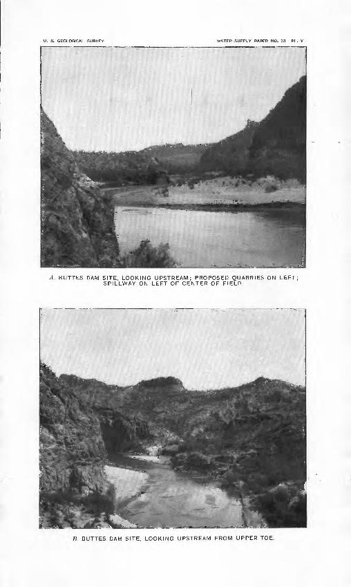
U. S. GEOLOGICAL SURVEY WATER-SUPPLY PAPER NO. 33 PL. V
BUTTES DAM SITE, LOOKING UPSTREAM; PROPOSED QUARRIES ON LEFT; SPILLWAY ON LEFT OF CENTER OF FIELD.
B. BUTTES DAM SITE, LOOKING UPSTREAM FROM UPPER TOE.
MEASUREMENTS OP GILA EIVEB. 25
gate from 24,000 to 30,000 acres of land, in addition to the areas esti mated as capable of being served from a reservoir on Gila River.
MEASUREMENTS OF GILA RIVER AT THE BUTTES, ARIZONA.
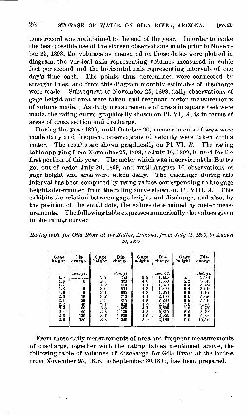
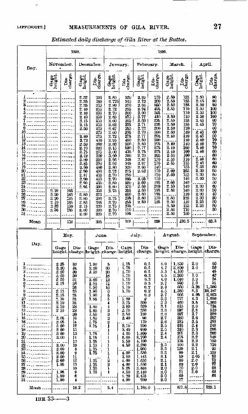
Gila River leaves the mountains and enters the plains at a point 15 miles above Florence, known as the Buttes. At this place the river is in a canyon, which, is approximately 450 feet wide, its bed being covered with sand and gravel to a maximum depth of 123 feet. Beyond this point, until it forms a junction with its principal tribu tary, Salt River, it loses in volume. A gaging station was established here and the amount of water available from the basin was accurately determined by the Geological Survey from August 26,1889^ to August 31, 1890, but the work was stopped at the end of this time by lack of available funds. The results of these measurements are given in the Twelfth Annual Report, Part II, Irrigation, pages 306 to 309, and fol lowing tables, and are shown graphically on PI. VI, B. A gap occurs in the record from August, 1890, to August, 1895. In the Ml of 1895 measurements were begun by the reestablishment of a station at the Buttes above Florence, at the same point that observations were made during the years 1889 and 1890.
From August 1,1895, to December 10,1895, gage heights and depths were observed by W. Richins, and occasional estimates of velocity were made, and with these data and the measurements made subsequent to the middle of December the daily discharge for the months of August, September, and November, and the early part of December, 1895, has been ascertained. These results can be regarded only in the light of approximations and do not compare in value with those following December 10. Measurements were continued throughout the year 1896 by W. J. Brash, daily readings of the gage being taken and current-meter measurements made from one to three times a week. The data obtained for the period following December 10, 1895, and extending to October, 1896, are of a high degree of accuracy.
During the year 1897 measurements were continued at this station by W. J. Brash and Albert T. Colton, forty-nine measurements of discharge being taken, the last measurement being made on October 24, 1897. Mr. Brash, who was connected with this work in 1896 and 1897, died in the fall of 1897, and no other person residing in that immediate locality, it was not possible, with funds available, to have the gage rod read daily.
Measurements were made between March 7 and October 10, 1898, by Albert T. Colton, and subsequent to November 14 by Cyrus C. Babb and others connected with the present investigation. Sixteen meter measurements of discharge were thus made, as shown by the dia gram, PL VI, B, prior to.November 25,1898. After this time a contin-
STORAGE OF WATER ON GtLA RIVER, ARIZONA. [NO. 33.
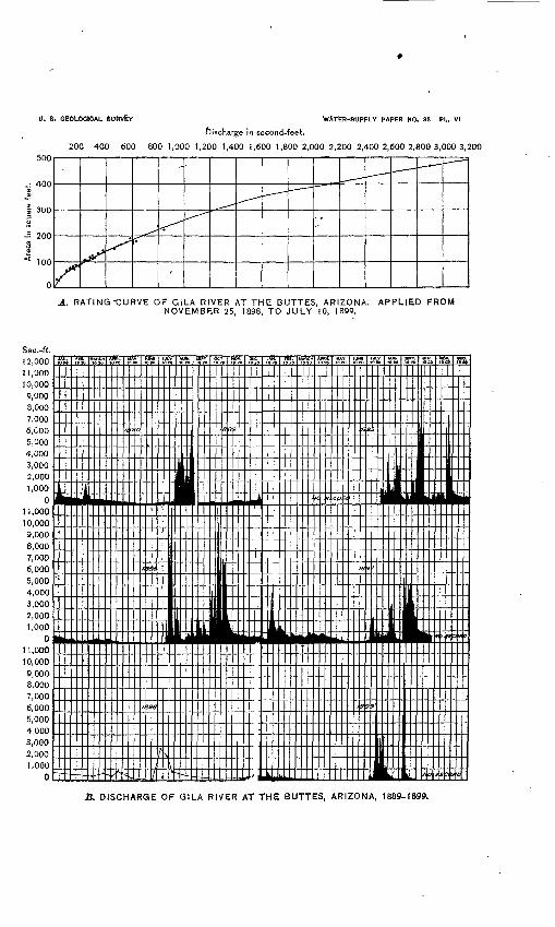
uous record was maintained to the end of the year. In order to make the best possible use of the sixteen observations made prior to Novem ber 25, 1898, the volumes as measured on those dates were plotted in diagram, the vertical axis representing volumes measured in cubic feet per second and the horizontal axis representing intervals of one day's time each. The points thus determined were connected by straight lines, and from this diagram monthly estimates of discharge were made. Subsequent to November 25, 1898, daily observations of gage height and area were taken and frequent meter measurements of volume made. As daily measurements of areas in square feet were made, the rating curve graphically shown on PI. VI, A, is in terms of areas of cross section and discharge.
During the year 1899, until October 20, measurements of area were made daily and frequent observations of velocity were taken with a meter. The results are shown graphically on PL VI, B. The rating table applying from November 25,1898, to July 10,1899, is used for the first portion of this year. The meter which was in service at the Buttes got out of order July 20, 1899, and until August 10 observations of gage height and area were taken daily. The discharge during this interval has been computed by using values corresponding to the gage heights determined from the rating curve shown on PL VIII, A. This exhibits the relation between gage height and discharge, and also, by the position of the small dots, the values determined by meter meas urements. The following table expresses numerically the values given in the rating curve:
Rating table for Gila River at the Buttes, Arizona, from July 11,1899, to August10, 1899.
Gage height.
1.51,6i.r1.81.92.02.12 2as2.4:
2.53.6
Dis charge.
Sec.-ft.
0159
1525406090
130180
Gage height.
2.72.82.93.03.13.23.33.43.53.63.73.8
Dis charge.
Sec. -ft.250320410500605710815920
1,0251,1301,2351,340
Gage height.
3.94.04.14 24^34.44.54.64.74.84.95.0
Dis charge.
Sec.- ft.1,4451,5501,6701,8001,9508,1002,2608,4402,6252,8102,9953,180
Gage height.
5.15.25.35.45.56.06 57.07.58.08.59.0
Dis charge.
Sec.-ft.3.3B43,5483,7323,9164,1005,0205,9406,8607,7808,7009,620
10,540
From these daily measurements of area and frequent measurements of discharge, together with the rating tables mentioned above, the following table of volumes of discharge for Gila River at the Buttes from November 25, 1898, to September 30,1899, has been prepared.
0. 8. GEOLOGtCAL SURVfeV WATER-SUPPLY PAPER NO. 33 PL. VI
Bischarge in second-feet.
200 400 600 800 1,000 1,200 1,400 1,600 1,800 2,000 2,200 2,4002,6002,8003,0003,200
A. RATING-CURVE OF GiLA RIVER AT THE BUTTES, ARIZONA. APPLIED FROM NOVEMBER 25, 1898, TO JULY 10, 1899.
JB. DISCHARGE OF GILA RIVER AT THE BUTTES, ARIZONA, 1889-1899.
LIPPINCOTT.] MEASUREMENTS OF GIL A EIVEE.
Estimated daily discharge of Oila River at the Buttes,
27
Day.
1898.
November.
C8 60 CJ'S
December.
cb'3rd
.53 fc PJ
January.
es so ° *PJ
February.
OJTIS3
March. April.
10.11.12.13.14.15.16.17.18.19.20.21.22.23.24.25.26.27.28.29.30.31.
Mean
2.322.352.352.402.402.402.452.452.50
3.102.202.202.103 222.30
105165135165150195
2.602.722.502.702.752.732.802.852.902.902.872.902.902.95
2.802.802.853.752.802.80
195195215255235255255255375275275410300330275320330390480480435410435390335275300345320300320
2.802.7712.802.722.702.652.602.623.672.602.722.953.303.153.003.002.952.932.802.722.702.702.802.802.75
2.752.702.752.702.70
320345370255300275255275255235275480800500435390345345320375255235330370255300235255235170185
2.722.882.942.902.772.692.712.722.702.772.803.803 772. 753.702.672.672.662.62
2.652.602.602.602.602.602.50
170200550455345410235235200300255300375275375255170170140170170170155200155155170135
2.502.502.502.50
3.502.502.502.502.502.40
2.402.403.402.502.552.55
2.602.60
2.602.502.50
2.502.503.502.502.50
135155155110110110155155110140140140140100100100110155155155155140140140140140125110135110100
2.502.452.502.502.502.502.452.45
2.452.452.402.402.403.40
2.402.402.352.302.302.30
2.302.302.303.302.252.25
909090
100100100807060605070707060
605060505060504030303030
152 305 318 130.5 62.3
Day.
height.
May.
Dis charge
Gageheight.
June. July.
Dis charge
Gage height.
Dis charge.
August.
Gage Discharge, height.
September.
Gage Dis charge.
Mean.
2.252.202.202.202.202.15
2.152.152.102.103.103.10
3.053.053.003.003.003.00
3.003.003.003.003.001.95
1.951.901.90 4
18.2
1.903.202.10
3.001.951.901.901.901.85
1.801.801.801.801.751.75
1.751.751.751.751.751.75
1.751.751.751.75
5302016121116655443
1.751.751.701.701.701.701.701.70
1.803.753.803.702.503.40
2.703.404.308.005.504.50
4.003.904.004.005.354.504.204.00
5.4
0.50.50.50.30.30.30.20.30.22
300330350130
90170250920
1,8008,7004,1002,2601,9001,5501,4451,5501,5503,6402,4402,475
990
1,188.0
4.0 4.7 5.5 4.5 4.0 3.7 3.3 4.5 3.7 3.3 3.3 3.1
2. 8 2.7 2.6 2.5 2.5 2.4 2.4
2.32.32.33 12.12.12.03.02.02.0
1,8502,8504,1002,3601,040
905717
515397
215315210207175135100130
90
70716077
671.8
2.0 2.0
1.91.91.98.288.34.954.33.53.02.82.72.62.52.42.32.32.22.22.22.12.12.052.02.02.02.0
605045432481
1,30010,1872,9231,9501,382
734510399357
14913012699
1081 93
7277
IRE 33-
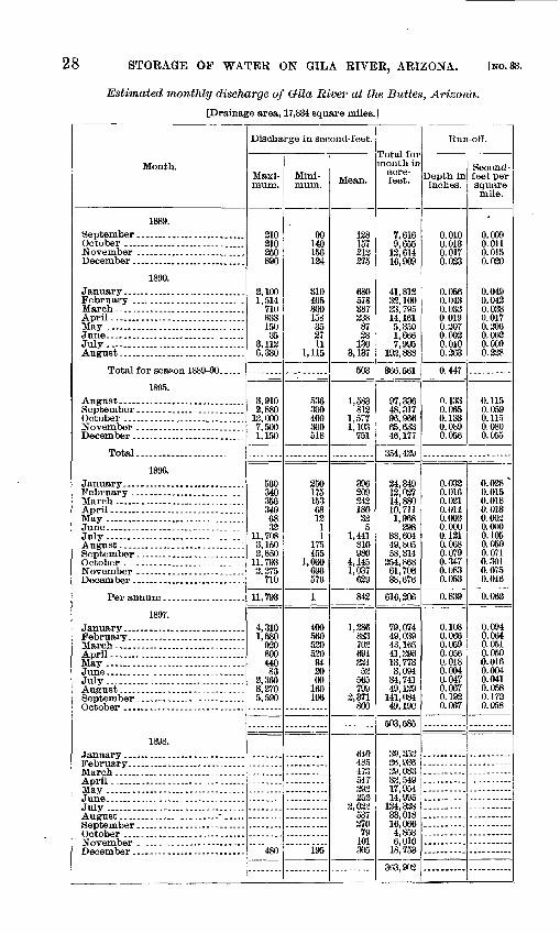
28 STORAGE OF WATER ON GIL A RIVER, ARIZONA. [NO. 33.
Estimated monthly discharge of Grila River at the Buttes, Arizona.
[Drainage area, 17,834 square miles. 1
Month.
1889.
October ............................November ....................
1890.
February ...... _ ........
July ................................
1895.
November ........................
Total.. ...................
1896.
May .............. .._. __
July...............................
Per annum ...................
1897.
February. ..........................
April....... ........................
1898.
July ...... ....-..-. ........
November
Discharge in second-feet.
Maxi mum.
210 210 250 890
2,100 1,514
710 333 150 35
3,112 6,330
3,9102,880
13,000 7,500 1,150
560 340 356 340 68 32
11,708 3,150 3,850
11,793 3,375
710
11,793
4,310 1,580
920 800 440 83
2,360 3,370 5,590
480
Mini mum.
90 140 156 124
310405 300 158 35 27 11
1,115
536 300 400 300 518
250 175 153 68 12
1 1
175 455
1,030 696 576
1
400 560 530 530
94 20 00
160 106
195
Mean.
138157313 375
680 5T8 387 238
87 38
130 3,137
503
1,583 812
1,577 1,103
751
396 209 243 180 32
5 1,441
810 980
4,145 1,037
639
842
1,386883 702 694 234
53 565 799
2,371 800
640485 473 547 393 353
2,023537 270 79
101 305
Total for month in
acre- feet.
7,616 9,655
12,614 16,909
41,813 32,100 23,795 14, 161 5,a50 1,666 7,995
192,888
366,561
97,336 48,317 96, 966 65,63346,177
354,429
24,34912,037 14,880 10,711 1,968
298 88,604 49,805 58,314
254,868 61,706 38,676
616,306
79,074 49,039 43,165 41,296 13,773 3,094
34,741 49,139
141,084 49,190
503,585
39,352 36,936 39,083 32,549 17,954 14,995
124,338 33,018 16,066 4,858 6,010
18,753
363.903
Run-off.
Depth in inches.
0.010 0.013 0.017 0.033
0.056 0.043 0.033 0.019 0.307 0.003 0.010 0.363
0.447
0.133 0.065 0.133 0.089 0.056
0.033 0.016 0.021 0.014 0.002 0.000 0.121 0.068 0.079 0.347 0.083 0.053
0.839
0.108 0.066 0.059 0.056 0.018 0.004 0.047 0.067 0.193 0.067
Second- feet pei- square mile.
0.009 0.011 0.015 0.030
0.049 0.043 0.028 0.017 0.306 0.002 0.009 0.238
0.115 0.059 0. 1150.080 0.055
0.038^
0.015 0.018 0.013 0.003 0.0(10 0.105 0.059 0.071 0.301 0.075 0.046
0.062
0.094 0.064 0.051 0.050 0.016 0.004 0.041 0.058 0.173 0.058
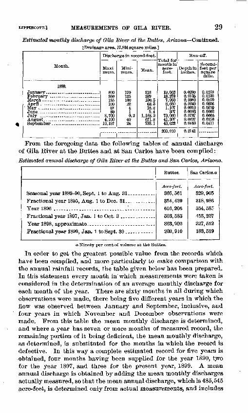
LIPMHCOTT.] MEASUREMENTS OF GILA RIVER. 29
Estimated monthly discharge of Gila River at the Buttes, Arizona Continued. ^Drainage area, 17,834 square miles.]
Month.
1899.
April. --- .- ....-............
July ...............................
Discharge in second-feet.
Maxi mum.
800 550 155 100 38 30
8,700 4,100
10,187
Mini mum.
170 135 100 30 4 1 0.2
60 24
Mean.
318 239 130.5 62.3 18.2 5.4
1,188.2 671.8 733.1
Total for month in
acre- feet.
19,552 13,273 7,993 3,689 1,107
307 73,060 41,307 43,632
203,910
Run-off.
Depth in inches.
0.0309 0.0135 0.0080 0.0040 0.0010 0.0003 0.0767 0.0437 0.0460
O.S141
Second- feet per squaremile.
0.0178 0.0130 0.0070 0.0036 0.0010 0.0003 0.0666 0.0376 0.0411
From the foregoing data the following tables of annual discharge of Gila River at the Buttes and at San Carlos have been compiled:Estimated annual discharge of Gila River at the Buttes and San Carlos, Arizona.
Seasonal year 1889-90, Sept. 1 to Aug. 81 ...........Fractional year 1895, Aug. 1 to Dec. 31. ............Year 1896 ............................ .I.... ......Fractional year 1897, Jan. 1 to Oct. 8 ..............Year 1898, approximate..... -..---.., ..............Fractional year 1899, Jan. 1 to Sept. 30 ...........
Buttes.
Acre-feet. 866,561
354,429616,206503, 585363,902208,910
San Carlos.a
Acre- feet. 329,905
318, 986554, 585453,227827,512183,519
a Ninety per cent of volume at the Buttes.
In order to get the greatest possible value from the records which have been compiled, and more particularly to make comparison with the annual rainfall records, the table given below has been prepared. In this statement every month in which measurements were taken is considered in the determination of an average monthly discharge for each month of the year. There are sixty months in all during which observations were made, there being five different years in which the fiow was observed between January and September, inclusive, and four years in which November and December observations were made. From this table the mean monthly discharge is determined, and where a year has seven or more months of measured record, the remaining portion of it being deficient, the mean monthly discharge, as determined, is substituted for the months in which the record is defective. In this way a complete estimated record for five years is obtained, four months having been supplied for the year 1890, two for the year 1897, and three for the present year, 1899. A mean annual discharge is obtained by adding the mean monthly discharges actually measured, so that the mean annual discharge, which is 485,545 acre-feet, is determined only from actual measurements, and includes
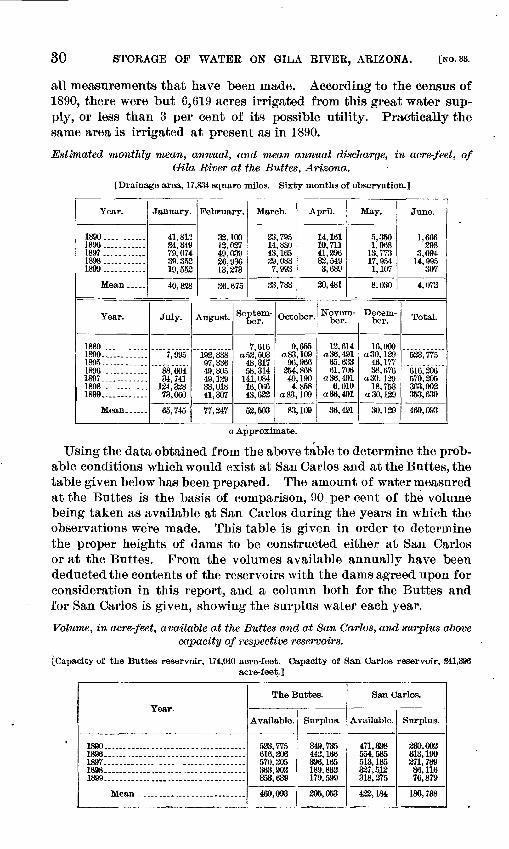
30 STORAGE OF WATER ON GILA RIVER, ARIZONA. [NO. 33.
all measurements that have been made. According to the census of 1890, there were but 6,619 acres irrigated from this great water sup ply, or less than 3 per cent of its possible utility. Practically the same area is irrigated at present as in 1890.
Estimated monthly mean, annual, and mean annual discharge, in acre-feet, of Oila River at the Buttes, Arizona.
[Drainage area, 17,834 square miles. Sixty months of observation.]
Year.
1890.... ......1896...........1897 ...._......1898...........1899...........
Mean .....
Year.
1889............1890.............1895............1896............1897............1898 ...........1899............
Mean......
January.
41,812 24,349 79,074 39,352 19,553
40,838
July.
7,995
88,604 34,741
134,338 73,060
65,745
February.
33,100 12,037 49,039 26,936 13,273
26,675
August.
192,888 97,336 49,805 49,129 33,018 41,307
77,347
March.
23,795 14,880 43,165 29,083 7,993
23,783
Septem ber.
7,616 a 52, 503
48,317 58,314
141,084 16,066 43,622
52,503
April.
14,161 10, 711 41,296 33,5493,689
20,481
October.
9,655 a 83, 109
96,966 254,868 49,190 4,858
a83, 109
83,109
May.
5,350 1,968
13, 773 17,954 1,107
8,030
Novem ber.
12,614 a 36, 491
65,633 61,706
a 36, 491 6,010
a 36, 491
36,491
Decem ber.
16,909 a 30, 129
46,177 38,676
a 30, 139 18,753
a30,129
30,129
June.
1,686 398
3,094 14,995
307
4.073
Total.
523, 775
616,306 570,205 363,903 353,639
469,093
a Approximate.
Using the data obtained from the above table to determine the prob able conditions which would exist at San Carlos and at the Buttes, the table given below has been prepared. The amount of water measured at the Buttes is the basis of comparison, 90 per cent of the volume being taken as available at San Carlos during the years in which the observations were made. This table is given in order to determine the proper heights of dams to be constructed either at San Carlos or at the Buttes. From the volumes available annually have been deducted the contents of the reservoirs with the dams agreed upon for consideration in this report, and a column both for the Buttes and for San Carlos is given, showing the surplus water each year.
Volume, in acre-feet, available at the Buttes and at San Carlos, and surplus above capacity of respective reservoirs.
[Capacity of the Buttes reservoir, 174,040 acre-feet. Capacity of San Carlos reservoir, 341,396acre-feet.]
Year.
1890....................................1896....................................1897 .......... .... ................18981899...................................
The Buttes.
Available.
533,775 616,206 570,205 363,902 353,639
469,093
Surplus.
349,735 442,166 396,165 189,862 179, 599
395,053
San Carlos.
Available.
471,398 554,585 513, 185 337,512 318,375
433,184
Surplus.
330,003 313,190271,78986, lie76,879
180,788
LTPPINCOTT.] MEASUREMENTS OP GILA EIVEE. 31
In order to make a comparison between the years in which observa tions of volumes discharged at the Buttes were made and years in which rainfall records were taken in the basin of Glla River, the diagram on PI. Ill, B, is given. The rainfall data for this diagram is taken from the summary given on page 19, and is the mean for the entire basin of Gila River above the Buttes. The record begins in 1881 and extends to 1899, inclusive, covering eighteen years of rainfall record, that for 1899 being estimated for the period after September 1. Below the record of rainfall, which is in inches of depth, is given, for correspond ing years, the volume discharged in acre-feet. It is desirable to deter mine whether years in which discharge measurements were made were years of excessive or deficient rainfall. It will be seen that the year 1897 is one of approximately average rainfall, and that in this year twice as much water was available for storage, either at San Carlos or at the Buttes, as the reservoirs could hold. The year 1898 was one of excessive rainfall, but it shows less run-off than the year 1897. This is probably accounted for by the nature of the storms occurring in the basin during that period, a greater portion of the water being absorbed by the ground and evaporated in 1898. The run-off from a hard rain is relatively higher than the run-off resulting from a slow rain or a gentle shower.
There is no record of discharge for the years of markedly deficient rainfall, unless it be the present year, 1899, for which the record is incomplete. During the first eight months of the year 1899 the rain fall for the portion of the basin above San Carlos was 6.40 inches, or 75 per cent of the mean. During this same period the precipitation for the San Pedro stations was 96 per cent of the mean. To August 1 the rainfall for the entire basin was 80 per cent of the usual precipita tion. This would indicate for the present year a probable mean rain fall of 10.59 for the basin. The year for which we have the lowest record, as determined by our table, is 1885, when the average rainfall for the basin was 8.11 inches. This comparison is quite rough, but it gives some idea of the general conditions.
It will be seen from the above that the year 1899 is among the years of low run-off and rainfall. Numerous people were asked concerning the relative dryness of the year 1899 in Arizona. There was a unani mous verdict expressed to the effect that it was the driest year which they have had in the last ten, as regards both rainfall and the amount of water in the streams. From the table of volumes available at the Buttes and at San Carlos, the surplus which is estimated for the year 1899 is seen to be 179,599 acre-feet at the Buttes and 76,879 acre-feet at San Carlos. There is still a margin for drier years than the ones through which we have just passed.
It is, of course, impossible to predict absolutely that either of the reservoirs as projected would always be filled, but there is probability, if not certainty, that in all ordinary years, in all years of excessive rainfall, and in all years of ordinary drought the reservoirs will be
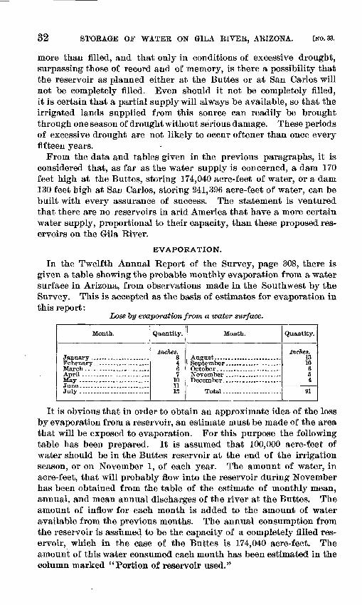
32 STORAGE OF WATER ON GILA RIVER, ARIZONA. [NO. 33.
more than filled, and that only in conditions of excessive drought, surpassing those of record and of memory, is there a possibility that the reservoir as planned either at the Buttes or at San Carlos will not be completely filled. Even should it not be completely filled, it is certain that a partial supply will always be available, so that the irrigated lands supplied from this source can readily be brought through one season of drought without serious damage. These periods of excessive drought are not likely to occur oftener than once every fifteen years.
From the data and tables given in the previous paragraphs, it is considered that, as far as the water supply is concerned, a dam 170 feet high at the Buttes, storing 174,040 acre-feet of water, or a dam 130 feet high at San Carlos, storing 241,396 acre-feet of water, can be built with every assurance of success. The statement is ventured that there are no reservoirs in arid America that have a more certain water supply, proportional to their capacity, than these proposed res ervoirs on the Gila River.
EVAPORATION.
In the Twelfth Annual Report of the Survey, page 308, there is given a table showing the probable monthly evaporation from a water surface in Arizona, from observations made in the Southwest by the Survey. This is accepted as the basis of estimates for evaporation inthis report:
Loss by evaporation from a water surface.
Month.
July .........................
Quantity.
Inches. 3461
101113
Month.
Total.....................
Quantity.
Inches. 1310654
91
It is obvious that in order to obtain an approximate idea of the loss by evaporation from a reservoir, an estimate must be made of the area that will be exposed to evaporation. For this purpose the following table has been prepared. It is assumed that 100,000 acre-feet of water should be in the Buttes reservoir at the end of the irrigation season, or on November 1, of each year. The amount of water, in acre-feet, that will probably flow into the reservoir during November has been obtained from the table of the estimate of monthly mean, annual, and mean annual discharges of the river at the Buttes. The amount of inflow for each month is added to the amount of water available from the previous months. The annual consumption from the reservoir is assumed to be the capacity of a completely filled res ervoir, which in the case of the Buttes is 174,040 acre-feet. The amount of this water consumed each month has been estimated in the column marked "Portion of reservoir used."
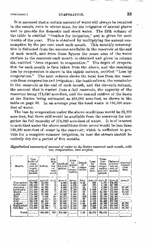
LIPPINCOTT.] EVAPORATION.
It is assumed that a certain amount of water will always be required in the canals, even in winter time, for the irrigation of annual plants and to provide for domestic and stock water. The fifth column of the table is entitled "Outflow for irrigation," and is given for each month of the year. This is obtained by multiplying the annual con sumption by the per cent used each month. This monthly consump tion is deducted from the amount available in the reservoir at the end of each month, and from these figures the mean area of the water surface in the reservoir each month is obtained and given in column six, entitled "Area exposed to evaporation." The depth of evapora tion for each month is then taken from the above, and the resulting loss by evaporation is shown in the eighth column, entitled "Loss by evaporation." The next column shows the total loss from the reser voir from evaporation and irrigation; the tenth column, the remainder in the reservoir at the end of each month, and the eleventh column, the amount that is wasted from a full reservoir, the capacity of the reservoir being 174,040 acre-feet, and the annual outflow of the basin at the Buttes being estimated as 469,093 acre-feet, as shown in the table on page 30. In an average year the total waste is 198,590 acre- feet of water.
The loss by evaporation under the above conditions would be 22,370 acre-feet, but there still would be available from the reservoir for irri gation its full capacity of 174,040 acre-feet of water. It is of interest to note that under the above conditions there never would be less than 132,320 acre-feet of water in the reservoir, which is sufficient to pro vide for a complete summer irrigation, in case the stream should be entirely dry for a period of five months.
Hypothetical summary of amount of water in the Buttes reservoir each month, with use, evaporation, and surplus.
Month,
January...February .March...-.April ..... .
July.......August....SeptemberOctober . . .
Total
Contents of reser voir at begin ning ofmonth.
Acre-ft. 100,000133,030157,950174,040174,040174,040174 040155,200132,3'JO172,660174,040174,040
Inflow.
Acre-ft. 36,50030,10040,80026,70033,80020,5008,0304,070
65,74077,30052,50083,100
469,040
Fortion of
res er
voirused.
P.ct. 222579
14141313118
100
Outflow for irri gation.
Acre-ft. 3 4803 4803,4808,700
12, 18015,66024,37024.37022,63022,63019,14013,920
174 040
ex posed
to evapo-
Acres. 2,3502,8003,0703,1503,1503,1503,0002,8002,7703,150
, 3,1503,150
Depth of
evapo ration.
Feet. 0.42
.333
.25
.333
.50
.58
.83392
1.001.08
.833
.50
7.58
Loss by
evap ora tion.
Acre ft 990700770
1,0501,5801,8302,5002,5802,7703,4002,6201,580
22,370
Totalloss
from evapo ration
and irrigation.
Acre ft 4,4704,1804,2609,750
13,76017,49036,87026,95025,40026,03021,76015,500
196,410
Balance in reser voir at end of month.
Acre-ft. 132,030157,950174,040174,040174,040174,040155,200132,320172,660174,040174,040174,040
Amount wasted over dam.
Acre-ft.
20,46016,95010,0403,010
49,79030,74067,600
34 STORAGE OP WATER ON GILA RIVER, ARIZONA. [NO. 33.
As the conditions above named are all assumed, the figures used are round numbers. It is probable that a more complete knowledge of'the stream will permit of a greater annual consumption by irriga tion than the capacity of the reservoir alone would indicate. ' The driest year of which we have any record would permit the use of 174,040 acre-feet of water from the Buttes reservoir, with a substan tial reserve.
Accurate observations of evaporation are always difficult to obtain, owing to variation in wind velocities and general exposure of the evap orating pan. The effort should be made to have conditions in the evaporation pan that would be similar to those existing in the reser voir, from which the loss from this source is to be determined. For this reason it is necessary to float the evaporation pan in the river or in a canal, and the fluctuations of the water surface are often so great that the pan is frequently either upset or entirely lost. Rain falling on the pan has also to be considered, and it is known that the amount of catchment in a pan 3 feet square is relatively larger than the catchment in a standard rain gage, the diameter of whose cup is 8 inches. In the Twelfth Annual Report of the Survey, page 235, is given a statement of some evaporation observations made in the Southwest. These do not cover complete months and may be mis leading.
Observations of evaporation from graduated tubes were made at the Buttes from January to July, 1899. These tubes were exposed in the shade, and the wind was prevented from acting directly on the water's surface. The results obtained are of doubtful value and are not used. In July, 1899, an evaporating pan was floated in. the river at the Buttes, but the record was so much interfered with by high water upsetting the pan that it is considered unreliable. Later the attempt was made to float the pan in an artificial pond.
SPILLWAY PROVISIONS.
The accompanying illustrations, Pis. V, IX, and XII, exhibit the conditions at the Buttes dam site, and show the principal features of the proposed spillway. In the report by Mr. Davis, of 1896, he deter mined the maximum flood that would have to be provided for at the dams in this stream, as follows:
The first consideration in plans for a dam under the circumstances here pre sented is the provision for a safe and adequate spillway. The large catchment area of this stream, its mountainous character, the paucity of soil and vegetation on these mountains, exposing considerable area of bare rock on steep slopes, and the sudden and violent nature of the summer rainstorms indicate the necessity of a spillway of large proportions. What this capacity should be is recognized as one of the important and difficult problems. The best evidence thus far obtained regarding past freshets on this river was kindly furnished by Mr. Albert T. Col-
LIPPINCOTT.] SILT. 35
ton. The greatest rise so far recorded on the Gila River occurred on the 22d of February, 1891. Considerable evidence was obtained that no such flood has occurred since a date many years before the advent of the white man. Irrigating ditches supposed to be extremely old were overflowed and destroyed. Lands were overflowed that had retained no evidence of any previous inundation.
On June 12, 1892, about sixteen months after this flood, Mr. Golton found marks of high water on both banks of the river far above any of the ordinary freshets, which he attributed to the great flood. This point was about 3J miles below the head of the Florence canal, or approximately 6 miles below the Buttes. With his level he took a cross section of the river at this point and measured the slope of the channel. The cross section He obtained was 6,600 square feet. The slope measured was 10.56 feet per mile. The channel was sandy and free of brush or large bowlders or other obstructions for a distance of 300 feet above and 300 feet below the cross section. This information, meager as it is, is the best we have upon which to estimate the discharge of the river at that time.
The difficulty in obtaining correct results of this discharge lies in the uncer tainty of the retarding effect of the channel upon the flow of the water. This retarding effect in a rough river bed is very great. Assuming this quantity as small as it could possibly be, a computation of the discharge was made, using Kutter's formula. The factor of roughness designated in the formula as " n " was taken as 0.025. Not that this was considered the correct factor, as it is almost certainly too small, but by assuming the smallest possible value of "n" we obtain the largest discharge, and it is the largest discharge that should be provided for in the construction of a spillway. It is thought, therefore, that this computation will give conservative results, and that a spillway based upon the discharge obtained would be safe. The result obtained was 102,566 cubic feet per second. And it is to accommodate this discharge that the spillway is planned. It will be seen at once that no such spillway could be economically provided artificially, and that the accommodation of the topography to the provision of this spillway is one important determining feature of the location and height of the dam.
SILT.
The following further quotation is made from the same report of Mr. Davis:
The amount of solid material carried by such a stream as the Gila can be learned only by impounding ib. As it is considerable, it is obvious that a reservoir built on this water course will eventually fill with solid matter unless means are provided for its removal. No entirely sufficient plan for this purpose has ever been put in eperation. It is usually assumed, and often with truth, that the life of the reser voir is sufficiently long to justify its construction even though it will eventually fill and have its usefulness destroyed. This disposition of the problem, however, is not applicable to the present case. The amount of material carried by this stream is too large and the necessity of the reservoir to the life of the district to be irrigated from it is too vital to justify this convenient solution or, rather, eva sion of the problem.
The most astonishing accounts are obtained from the inhabitants of this region of the quantity of silt carried in suspension by this stream when in flood. Many people in their emphatic expressions place the quantity at one-half the volume, though, of course, this is impossible. It is said, however, that in the months of July and August, when the surface of the ground is exceedingly dry, when it has been ground to powder even in the most isolated and apparently inaccessible
36 STORAGE OF WATER ON GILA RIVER, ARIZONA. [NO. 33.
localities by range cattle and horses in search of grass, when the great torrential "cloud-bursts," to which this country is subject, fall upon such ground and rush off the steep slopes into the stream with prodigious velocity, the amount of silt carried in suspension by the roaring torrent is very great.*******
Attempts have been made, however, by private parties from time to time to measure the amount of suspended material. The most important and reliable of these measurements were those made by Mr. Albert T. Colton in the month ending August 7, 1893, and by Mr. W. Richins at the Buttes. Mr. Colton found the per centage of silt by volume averaged 2.2 per cent. As these observations were taken and reduced by Mr. Colton, who is a competent engineer, they are adopted as cor rect. The observations by Mr. Richins extended from July 29 to December 31, 1895. They were taken by the following method:
A sample of the water was poured into a slender glass tube until it reached the height of 100 divisions on a convenient scale, and was then allowed to settle several days, until the main portion of the water was clear. The height of the sediment on the same scale was then read and the result recorded as the percent age of mud carried by the water. The existence of this record, and the ease with which more of such observations could be taken, made it important that an approximate relation be established between the volume of this mud and that of the actual solid matter it contained. For this purpose several laboratory determi nations have been made with muddy sampJes of Gila water by settling and read ing the volume of mud as above and then drying the residue at 100° C. and deter mining its volume.
These observations indicate an average ratio of dry matter to mud of about one- fifth, and this factor has been used to reduce the mud observations of Mr. Richins to solid matter.*******
It should be remembered that these observations take no account of material that is rolled on the bottom of the stream.
On page 32 of Mr. Davis's report of 1896 a table is given showing the percentage of mud and solid matter carried each day from July 29 to December 31 in Gila River at the Buttes. The following table gives, in columns Nos. 3 and 4, this percentage of mud and of solids. In column No. 2 the number of acre-feet discharged on corresponding dates is given, and columns Nos. 5 and 6 give the number of acre-feet of mud and solids for the same dates. During this period the volume of water discharged at the Buttes was 360,523 acre-feet, and from the table it is found that 37,984 acre-feet of mud was carried in suspension, by this water. This, reduced by the ratio of 5 to 1, as adopted by Mr. Da vis, gives 7,704 acre-feet of solids. The average amount of mud during this period is 10.5 per cent.
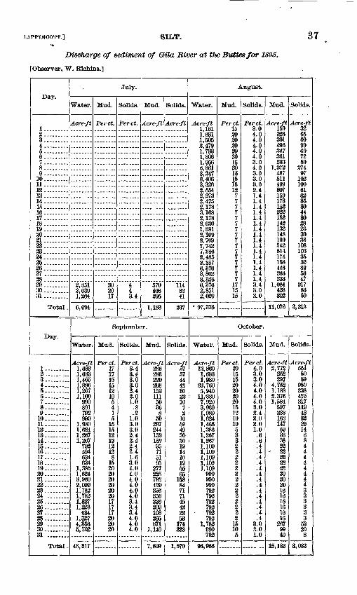
tiTPPINCOTT.] SILT. 37
Discharge of sediment of Oila River at the B*tttes/or 1895+
[Observer, "W. Richins.]
Day.
1.........23. ........4.........5. ....6.. ....7. ...... ..8.........9. ...... ..
10. ........11.........12.........13.........14.........15. .....16.........17.........18.........19.........30.........21 .........32.........23.........24.........25.........36.........27.........28.........39.........30.........31.........
Total .
Day.
1. ........23.........4.........5.........6.........7 .......8.........9.........
10. .-..11. 12-.....-..13 14. ...... ..15. 16.........17. . 18- ....19.. ....2031. . 33. ....23..... 24... ......25. 2627. .38 .2930. ....31 ........
Total.
July.
Water.
Acre-ft
2,851 2,039 1,304
6,094
Mud.
Perct.
2020 17
Solids.
Perct.
4 4 3.4
Mud.
Acre-ft
570 408 205
1,183
Solids.
Acre-ft
114 82 41
337
September.
Water.
Acre-ft 1,683 1,683 1,465 1,386 1,367 1 109
990 891 793 990
1,980 1,624 1,367 1,367
792 594 634 634
1,386 1,634 3,960 2,099 1,782 1,783 1,327 1,228
634 1,327 4,356 5,703
48,317
Mud.
Perct. 17 17 15 15 12 10 5 4 1 5
15 15 12 13 13 12 8
15 30 30 20 20 20 20 17 17 17 20 20 30
Solids.
Perct. 3.4 3.4 3.0 3.0 2.4 3.0 1.0
.8
.2 1.0 3.0 3.0 2.4 3.4 3.4 3.4 1.6 3.0 4.0 4.0 4.0 4.0 4.0 4.0 3.4 3.4 3.4 4.0 4.0 4.0
Mud.
Acre-ft 286 386 220 208 153 111
50 36 8
50 397 244 153 153 95 71 51 95
277 325 792 420 356 356 236 209 108 265 871
1,140
7,809
Solids.
Acre-ft 57 57 44 43 30 32 10
7 2
10 59 49 30 30 19 14 10 19 55 65
158 84 71 71 45 42 33 53
174 328
1,579
August.
"Water.
Acre-ft 1,161 1,631 1,505 2,479 1,733 1,806 1,956 6,861 3,347 3,406 3,326 2,554 2,273 2,475 2,178 3,168 2,178 2,030 1,881 2,109 2,709 7,742 7,346 2,485 2,257 6,376 3,802 3,326 6,376 2,851 2,030
-97,336
Mud.
Perct. 15 20 20 20 20 20 15 30 15
B12 7 7 7 7 7 7 7 7 7 7 7 7 7 7 7 7
17 15 15
Solids.
Perct. 3.0 4.0 4.0 4.0 4.0 4.0 3.0 4.0 3.0 3.0 3.0 3.4 1.4 1.4 1.4 1.4 1.4 1.4 1.4 1.4 1.4 1.4 1.4 1.4 1.4 1.4 1.4 1.4 3.4 3.0 3.0
Mud.
Acre-ft 159 336 301 496 347 361 293
1,372 487 511 499 307 159 173 152 323 153 142 132 148 190 542 514 174 158 446 266 233
1,084 428 302
11,076
Solids.
Acre-ft 32 65 60 99 69 72 59
374 97
103 100 61 33 35 30 44 30 38 26 30 38
108 103 35 32 89 53 47
317 86 60
2,213
October.
"Water.
Acrr.-ft 13,860 1,683 1,980
33,760 5,940
11.-880 7,920 3,960 1,980 1,634 1,465 1,386 1,367 1,367 1,109 1,109 1,109 1,109 1,109
990 990 990 792 792 792 793 793 792
1,782 990 793
96,966
Mud.
Perct. 30 15 15 30 30 20 20 15 1? 10 10 5 3 3 2 2 2 2 2 2 2 2 2 2 2 2 2 2
15 10 5
Solids.
Perct. 4.0 3.0 3.0 4.0 4.0 4.0 4.0 3.0 2.4 2.0 2.0 1.0 .6 .6 .4 .4 .4 .4 .4 .4 .4 .4 .4 .4 .4 .4 .4 .4
3.0 2.0 1.0
Mud.
Acre-ft 2,772
353 397
4,753 1,188 2,376 1,584
597 338 163 147 69 38 38 33
- 33 33 33 32 20 30 30 16 16 16 16 16 16
267 99 40
15,182
Solids.
Acre-ft 554
50 59
950 338 475 317 119 48 32 39 14
8 8 4 4 4 4 4 4 4 4 3 3 3 3 3 3
53 30 8
3,033
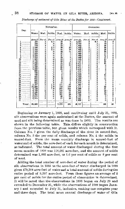
38 STORAGE OF WATER ON GILA RIVER, ARIZONA. [NO. 33.
Diselwrge of sediment of Gila River at the Suites for 1895 Continued.
Day.
1. ....... .2. ........3.........4. ........5-- . 67.........8.........9. ........
10.........11. ........12.........13........14.........15.........16.........17 .........18.........19. ........30.........31..... .2223..... ...24.........2526. ........273839.........30-.....,..31. ........
Total -
November.
Water.
Acre-ft 792 792 793
1,980 1,823 1,823 1,328 1,228 1,238 1,109 1,109 1,833 1,980 1,833 1,228
990 792 792 634 634 634 594
2,277 14,850 4,753 4,753 4,158 3,366 2,970 3,574
65,633
Mud.
Per ct. 5 3 3 5 5 3 3 3 3 3 3 3 '3
3 3 0 0 0 0 0 0 3 5 5 5 3 3 3 3 3
Solids.
Per ct. 1.0 .6 .6
1.0 1.0 .6 .6 .6 .4 .4 .4 .6 .6 .4 .4 .0 .0 .0 .0 .0 .0 .6
1.0 1.0 1.0 .6 .6 .6 .6 .4
Mud.
Acre-ft 40 34 34 99 91 55 37 37 25 32 33 55 59 36 35
0 0 0 0 0 0
18 114 743 338 143 135 101 89 51
3,273
Solids.
Acre-ft 8 5 5
20 18 11 7 7 5 4 4
11 12
7 5 0 0 0 0 0 0 4
23 149 148
38 25 30 18 10
554
December.
Water.
Acre-ft. 2,277 3,020 1,833 1,833 1,823 1,832 1,663 1,663 1,663 1,525 1,527 1,471 1,471 1,471 1,416 1,416 1,416 1,360 1,360 1,360 1,305 1,349 1,360 1,471 1,360 1,305 1,249 1,192 1,137 1,081 1,036
46,177
Mud.
Per ct.2 3 o2 2 2 1 1 1 1 1 1 0 0 0 0 01 1 100 02 2 1 1 1 0 0 0
Solids.
Per ct. 0.4 .4 .4 .4 .4 .4 .2 .2 .2 .3 .2 .3 .0 .0 .0 .0 .0 .3 .2 .2 .0 .0 .0 .4 .4 .2 2'.2
.0
.0
.0
Mud.
Acre-ft
40 36 36 36 36 17 17 17 15 15 15
0 0 0 0 0
14 14 14 0 0 0
39 37 13 13 12 0 0 0
461
Solids.
Acre-ft 9 8 ' 7 7 7 7 3 3 3 3 3 3 0 0 0 0 0 3 3 3 0 0 0 6 4 3 2 3 0 0 0
89
Beginning on January 1, 1899, and continuing until July 31, 1899, silt, observations were again maintained at the Buttes, the amount of mud and silt being determined as was done in 1895. The results are shown in the following table. T-his^differs slightly in construction from the previous table, but gives results which correspond with it. Column No. 2 gives the daily discharge of the river in second-feet, column No. 3 the per cent of solids, and column No. 4 the solids in second-feet. From the mean monthly discharge in second-feet of water and of solids, the acre-feet of each for each month is determined, as indicated. The total amount of water discharged during the first seven months of 1899 was 118,981 acre-feet, and the amount of solids determined was 1,893 acre-feet, or 1.6 per cent of solids or 8 per cent of mud.
Adding the total number of acre-feet of water during the period of silt observations in 1895 to the acre-feet of water discharged in 1899 gives 479,504 acre-feet of water and a total amount of solids during the entire period of 9,597 acre-feet. From these figures an average of 2 per cent of solids for the entire period of observation is determined. It will be noted that the observations in 1895 began on July 29 and extended to December 31, while the observations of 1899 began Janu ary 1 and extended to July 31, inclusive, making one complete year and three days. The total mean annual discharge of water of Gila
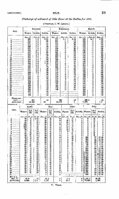
UPPINCOTT.] SILT. 39
Discharge of sediment of Gila River at the Buttes for 1899.
[Observer, C. "W. Lemon.]
Day.
12-.13..14..15..16..17..18..19.. 30.. 21.. 33.. 33..24:..
35..36..37..
29.30.31.
Mean,sec.-feet.-__-
Acre-feet
January.
Water. Solids. Solids.
Sec.-ft. 330 345 370 255 300 375 355 375 355 235 375 480 800 500 435 390 345 345 330 375 255 235 320 370 255 300 235 355 235 170 185
Per ct. 1.0 1.0 1.0 1.0 1.0 1.0 1.0 1.0 1.0 1.0 1.0 1.0 1.0 1.0 1.0 1.0 1.0 1.0 1.0
'.2
2 '.3
.2
31819,552
Sec.-ft. 0.64
.69
.74
.51
.60
.55
.51
.55
.51 '.47 .55 .96
1.60 1.00 .87 .78
.16
.10
.09
.19
.15
.10
.13
.14
.15
.14
.03 .04
30
February.
Water. Solids. Solids
Sec.-ft. 170 200 550 455 345 410 235 235 300 300 255 300 375 375 375 355 170 170 140 170 170 170 155 200 155 155 170 125
Per ct. 0.1 .1 .3 .3 .2 .2 .1 .2 .1 .1 .1 .1 .1 .5 .8 .4 .4 .4 .4 .3 .3 .3 .3 .3 .2 2e)'.2
13,273
Sec.-ft. 0.03
.04
.33
.39
.16
.16
.05
.09
.04
.06
.05
.06
.05
.37
.44
.30
.14
.14
.11
.10
.10
.10
.09
.13
.06
.06
.07
.05
.137
March.
Water.
Sec.-ft. 135 155 155 110 110 110 155 155 110 140 140 140 140 100 100 100 110 155 155 155 155 140 140 140 140 140 135 110 135 110 100
Solids. Solids.
Perct. 0.1 .1 .1
ll .1 .1 .1 .1 .1 .1 .1 .1 .1 .1 .1 .1 .1 .1 .1 .1 .1 .1 .1 .1 .1 .1 .1 .1 .1 .1
130.5
8ec.-ft. 0.03 .03 .03 .03 .03 .03 .03 .03 .03 .03 .03 .03 .03 .03 .03 .03
.03
.03
.03
.03
.03
.02
.03
.03
.02
.02
.121.0
Day. Water So1' So1- Water.
April.
Water.
May.
Sol ids. Solids. Water.
June.
Sol ids. Solids.
July.
Water. ;Sol ids. Solids.
_10..11.. 13..13 _.1415..16..17 ..18 __19..20.. 31 .. 32__ 33._ 24._ 25__
27........28........39........30........31..... Mean,
sec.-ft.Acre-feet
Sec.-ft. 90 90 90
100 100 100 80 70 60 60 50 70 70 70 60 60 60 60 60 50 60 50 50 60 50 40 30 30 30 30
P.ct. T. T. T. T. T. T. T. T. T. T. T. T. T. T. T. T. T. T. T. T. T. T. T. T. T. T. T. T. T. T.
S.-ft.0.01
.01
.01
.01
.01
.01
.01
.01
.01
.01
.01
.01
.01
.01
.01
.01
.01
.01
.01
.01
.01
.01
.01
.01
.01
.01
.01
.01
.01
.01
Sec.-ft. 38 3430
. 3031282635242434232320161413131314ItW
1089
11131310
P.ct.T.T.T.T.T.T.T.T.T.T.T.T.T.T.T.T.T.T.T.T.T.T. -T.T.T.T.T.T.T.T.T.
Sec.-ft. 0 0 0 0 0 0 0 0 0 0 0 0 0 0 0 0 0 0 0 0 0 0 0 0 0 0 0 0 0 0 0
Sec.-ft. 5
36 28 16 13 11 16 6 5 5 4 4
P.ct. T. T. T. T. T. T. T. T. T. T. T. T. T. T. T. T. T. T. T. T. T. T. T. T. T. T. T. T. T.
Sec.-ft. 0 0 0 0 0 0 0 0 0 0 0 0 0 0 0 0 0 0 0 0 0 0 0 0 0 0 0 0 0
8ec.-ft. 5 5 5 3 3 3 2 2 2 2
300 330 250 130 90 170 350 930
1,800 8,700 4,100 3,360
900550,
1,4451,5501,5503,6402,4403,475
990
P.ct.T.T.T.T.T.T.T.T.T.T. 27 26 30 30 18 13 24 10 22 14 1014151010
87
10151013
Sec.-ft.
000000000
16.2018.6410.005.203.244.08
12.0018.4079.30
343.6082.0063.2857.0031.0028.9024.8021.7073.8073.3049.5033.76
63.3 .01 1.0
18.31,107
T. Trace.
5.430.7
1,188.373,060
30.211,854
40 STORAGE OF WATER ON GILA RIVER, ARIZONA. INO. 33.
River at the Buttes has been determined as 469,093 acre-feet. If 2 per cent of this volume be considered as solids, it will indicate an annual discharge of solids of 9,382 acre-feet, which corresponds very closely with the 9,597 acre-feet determined in the twelve months dur ing which observations occurred.
The capacity of the Buttes reservoir, with the dam 150 feet high to the spillway, is 174,040 acre-feet. If 9,711 acre-feet of solid matter is delivered to the reservoir each month, and it all settles in passing through the basin, this reservoir would fill with solid matter in eighteen and six-tenths years. The mean annual flow of water of Gila River at San Carlos has been determined as 422,184 acre-feet. If 2 per cent of this volume is solids, there would be delivered to the reservoir 8,443 acre-feet of solids per annum. The capacity of the San Carlos reservoir, with the dam as planned, 130 feet high to the spillway, is 241,396 acre-feet. If 8,443 acre-feet of solid matter should be delivered to this reservoir each year and should be depos ited therein, it would fill in twenty-eight and five-tenths years.
These figures show the exceeding gravity of the silt proposition on Gila River. No other stream is known in America which carries such large volumes of debris. It is evident that some provision must be made to avoid the destruction of the reservoir or the building of the dam would be useless. It would be cruel to develop a civilization upon irrigation which would have to be destroyed at the end of a gen eration. It is extremely fortunate that there is more than one reser voir site on Gila River the water from which would be available for irrigation in the neighborhood of the Gila River Indian Reservation. If a dam should be constructed at San Carlos and the reservoir become filled with silt, it would be possible to construct at the end of the twenty-eight and five-tenths years a second dam at Riverside of equal capacity, and after that reservoir became filled with silt the dam at the Buttes could be built. A fourth reservoir site of considerable value may be found at Guthrie, above the Solomonville Valley, on the same stream, and of large capacity. In the case of all these dams the capacity increases very rapidly with an increased height of dam. For instance, if the Buttes dam should be raised 10 feet above the 150-foot contour, its capacity would be increased 33,755 acre-feet; and if raised 20 feet, its capacity would be increased 72,355 acre-feet. If the San Carlos dam should be increased in height 20 feet, its storage capacity would be increased 135,780 acre-feet. It would therefore be possible to very greatly increase the storage capacity of these res ervoirs by building the dams to greater heights as the basin filled with mud. The spillways of the San Carlos dam, as planned, could be raised 1.24 feet in height, increasing the capacity of the reservoir to that extent at .small cost, without endangering the structure.
The silt which is carried by Gila River is exceedingly light and requires a number of days to settle in a test tube, and it is believed that
LIPPINCOTT.] SILT. 41
a portion of it will remain in suspension until it is carried over the spill way or through, the gates. As irrigation is practiced on the flat lands of the Gila Valley the water plane in that district will be raised much nearer to the surface than it is now, and less irrigation will be necessary. Numerous points are known in the San Joaquin Valley, in California, where water could not be obtained in wells prior to irri gation, and where now, after twenty years of irrigation, water is stand ing at the surface. Near Fresno, California, the water plane has risen to such an extent that but one irrigation a year is needed on the vineyards.
When the irrigation country has developed to the extent that all water available from the reservoir is required, and when the reservoir has reached the point where the silting endangers the community, it probably will be advisable to construct a large storm channel around the margin of the reservoir and above the maximum water line to carry as much as possible of the water of the river. Such portion of the water as is needed for irrigation below can be passed through this canal without stopping in the reservoir and may be diverted at the proper point near the irrigated fields. This canal could be constructed of large section for the first portion of its course and the section after wards reduced. A spillway should be located at the point where the canal is reduced in capacity and the excessive water be drawn from the top of the canal into the reservoir. A larger portion of the sedi ment which would travel in the bottom of the channel would remain in the conduit, and the clarified water would be discharged into the reservoir. A velocity may be maintained in the remaining portion of the canal sufficient to carry the silt through it to the river below the dam.
The suggested canal, being above the maximum water line, would provide an effective head for hydraulic giants for sluicing the silt which had previously been deposited in the reservoir. On favorable occasions, when the reservoir was practically empty, this sluicing or washing out of the basin could be practiced. On July 11,1899, there was 27 per cent of mud in Gila River at the Buttes. This is the greatest amount of sediment ever observed in this river. From this it will be seen that the suspended matter is exceedingly light, and it would therefore be possible to move large quantities of this loose mud with hydraulic giants and carry it in temporary flumes, or even in the river channel itself, through openings in the dam. Experience with light silt in constructed reservoirs elsewhere shows the greatest deposits to occur where the water is deepest, which is near the dam. Here is also the greatest storage capacity of the basin.
The drop from the storm canal to the bed of the river below the dam would probably be not less than 150 feet. If 500 cubic feet of water per second should be discharged through this canal, over 8,475 theoretical horsepower could be developed. During certain periods
42 STORAGE OP WATER ON GILA RIVER, ARIZONA. [NO. 33.
of the year Gila River is almost dry, and this power would not be available from the canal; but when such occasions existed in the river the reservoir would necessarily be drawn upon for irrigation, and power could be obtained from the discharge from the reservoir. It is possible that from 2,000 to 5,000 horsepower could be developed in this manner. The section of Arizona in the neighborhood of San Carlos is highly mineralized. Copper mines of great value are to be found at Globe and at Riverside. New and effective processes have been discovered for reducing copper matte electrically. Fuel is high priced. On the above basis it is reasonable to presume that when the time arrives for the building of the storm canal around the reservoir sufficient revenue can be obtained from power to pay the interest on the cost of construction of the storm ditch. This power could also be used in cleaning out the reservoir with hydraulic dredges.
While the deposit of silt in the reservoir is probably the most seri ous question in connection with the impounding of water on the Gila, it is believed, on the basis of the above arguments, that the situation could be controlled and that the reservoir may be made to do service through a long period of years, if not indefinitely.
EXPLORATIONS FOB BED BOCK AT THE BUTTES.
The material that covers the bed rock at the Buttes and at Queen Creek is a sand and gravel saturated with water in the bed of a can yon, through which varying volumes of water might be expected to be discharged, ranging from 100 cubic feet per second to 1,000 cubic feet per second during the periods of low water on the river. These low stages of the river might be expected to exist from the 1st of April to the 1st of July, after which violent floods of much greater volume would probably occur at the Buttes dam site.
On Queen Creek large bowlders occur at the surface, and although the stream might be expected to be entirely dry during corresponding dates, after that time violent floods might occur any day. Great reticence was felt on the part of everyone in giving figures that should be regarded as even roughly approximate for this work. Numerous well drillers were interviewed in San Francisco and in southern Cali fornia, and none cared to bid, under the conditions. Two methods of going to bed rock were suggested one by means of open shafts, and the other by the use of the diamond core drill. Only one bid was received in reply to proposals, and that at the rate of $15 per linear foot. This was rejected as too high. It was admitted by all that the diamond core drill would work accurately and easily in solid rock, but when it came to going through bowlders of varying size it was conceded to be exceedingly difficult, if not wholly impracticable.
As stated above, the one bid was rejected, and the Geological Survey carried on this work at the points in question, and succeeded in thoroughly solving the problem, largely owing to the experience which Mr. Arthur P. Davis had acquired in work in Nicaragua.
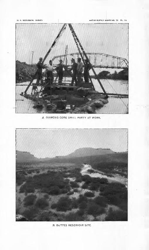
U. S. GEOLOGICAL SURVEY WATER-SUPPLY PAPER NO. 33 PL. VII
A. DIAMOND-CORE DRILL PARTY AT WORK.
_B. BUTTES RESERVOIR SITE.
LIPPINCOTT.] EXPLORATIONS FOR BED ROCK AT THE BUTTES. 43
DIAMOND CORE DRILL.
As this work was somewhat unique, it will be of interest to give its progress in detail, together with a description of the tools employed. In considering the matter of going down with a shaft the most serious problems would be the water encountered. In working with a shaft the river would have to be carried in a flume by the works for a long distance. A large pump would have to be kept going constantly in the shaft, and it is doubtful if under the most favorable conditions it would be able to handle the amount of water which would be encoun tered. Pumps with valves would be barred on account of the large amount of sand suspended in the water. It was estimated that it would cost $46 per vertical foot to sink shafts under these conditions. This would permit of putting down about four holes at the Buttes with the funds available, with bed rock at from 75 to 123 feet. The actual cost of sinking 170 linear feet of shaft at the mouths of one of the canyons of a southern California river, in an attempt to determine bed rock, was $35.87 per foot, the depths in this case varying from 15 to 30 feet, and the material through which the shafts were sunk con sisting of sand and bowlders. This included the labor of building 700 feet of flume, but not the cost of the lumber, which was furnished by the company for all work. There was pumped from these shafts with a 100-horsepower boiler and engines over 100,000 gallons per hour, and yet the water could not be kept down, and the deepest shaft had finally to be abandoned before bed rock was reached.
The best estimate that could be obtained of the cost of sinking by means of the diamond core drills, as furnished by San Francisco con tractors, was $12.69 per linear foot, 400 feet to be sunk, but they would not offer a bid even on these figures.
The following letter from Mr. T. F. Richardson, department engi neer, dam and aqueduct department, metropolitan water board, of Boston, is of interest as bearing on this subject:
We had two diamond drills, one manufactured by the M. C. Bullock Manufac turing Company, of Chicago, called the Badger drill. This drill was intended for prospecting in tunnels, but was fitted up especially for us for surface work. This machine cost us $900, which included one set of diamonds worth about $200, and the necessary fittings to put down a If-inch hole about 200 feet.
Our second machine was bought from the Sullivan Machinery Company, of Clare- mont, New Hampshire, and was called "S-510." This cost was $1,132.80, but no diamonds were included. The two machines were fitted for and were capable of doing about the same amount of work, but the net cost of the Sullivan machine was over $400 more than that of the Bullock machine.
Our work here was very difficult, as the bottom of our gorge was blocked up with large bowlders, and we found it necessary to use several sizes of bits, namely, ££-inch, If-inch, If-inch. We also had to fit up so as to be able to put down li-inch casing, using diamond bits to bore it down, the purpose of the casing being to bore through bowlders and gravel, so as to be able to work a ^f-inch bit inside of it. Altogether we had two quite complete outfits for doing all kinds of work up to If-inch bits.
IRE 33 4
44 STORAGE OF WATER ON GILA RIVER, ARIZONA. [NO. 33.
The repairs necessary to the machines were not very large, the principal cost of repairs being for new bit blanks and for core lifters; but in order to do the work successfully it is necessary to have quite a number of appliances outside of the actual machines, and these cost considerable money. Our total outlay for machines was $3,625. In addition to this we spent $3,873 for diamonds, but we have at thee present time about $700 worth of diamonds on hand, leaving the net cost of the diar monds about $3,173.
When we started in on our diamond-drill work the cost of diamonds was $19 per carat; but at the time we finished the cost of diamonds had risen to $36 per carat, and I believe the price is about $36 at the present time (August, 1898).
The total amount which we drilled was 2,814 feet, the deepest hole being 286 feet deep, and the average depths of holes about 60 feet. The amount accom plished per day was from 0 to 32 feet,'the average amount being probably about 10 or 12 feet per day.
The cost of drilling varies very largely, both with the hardness of the rock and the condition of the rock as to being seamy.
Following is the cost of labor, diamonds, and coal for drilling, principally with, If-inch bits, through three different kinds of rock:
Drilling 324.2 feet of rather hard, tough diorite rock:Labor .............. ................................._.......... $341.25Diamonds..--.-....-._._........................... ............ 74.30Coal.........................._ ...... ._._...__..-........._...._ 17.50
Total...... ........ .... ......................................... 433.05Cost per foot ....................................................... 1.34
(86.6 feet of this was drilled with If-inch bit, and 237.6 feet was drilledwith 1-S-inch bit.)Drilling 150.7 feet of very hard syenite rock:
Labor.....,.-.-.......:......-........-.........--.........,.-..... 158.00Diamonds..._......_..............._...._..--.... ............ 298.69Coal.....--..--...........-.-.---..--..--..--.--....-..--..-.--.-... 10.50*
Total............................................. ............. 467.19Cost per foot...---..---.. ..-.-..-.-....-._..-...-..-..,.. ..._. 3.10
(Size of drill, If inches.)
Drilling 286.1 feet of soft schist rock:Labor.......... ....... .--.-..-_....-...........-....___..-....- 190.00Diamonds..-.--.--.--...-.-..--...-------.--,------....-..--..----. 87.75Coal.........-..-..-.-.-....-.--.-------.-.-.---.-.-..---..--....... 11.50
Total......................... .............. ..................... 289.25Cost per foot........ ____..._--.-_-.___.._..--._...-.-....... ...... 1.01
(Size of drill, If inches.)
You will notice that- there is a large variation in the cost of drilling through different kinds of rock. The costs as given do not include more or less lost time, and the depreciation on diamonds due to their being of smaller size after being used. Finally they get so small as to be valueless. Depreciation of plant is also not included.
Regarding the best size of hole for prospecting purposes, this depends largely on the work which you have in hand. If I were fitting up for similar work to what we did here, and only expected to fit up one size of hole, I should fit up prob ably for If-inch bit.
When I speak of If-inch bits, I mean bits that give cores of about this size, though generally the cores are somewhat smaller than the sizes noted.
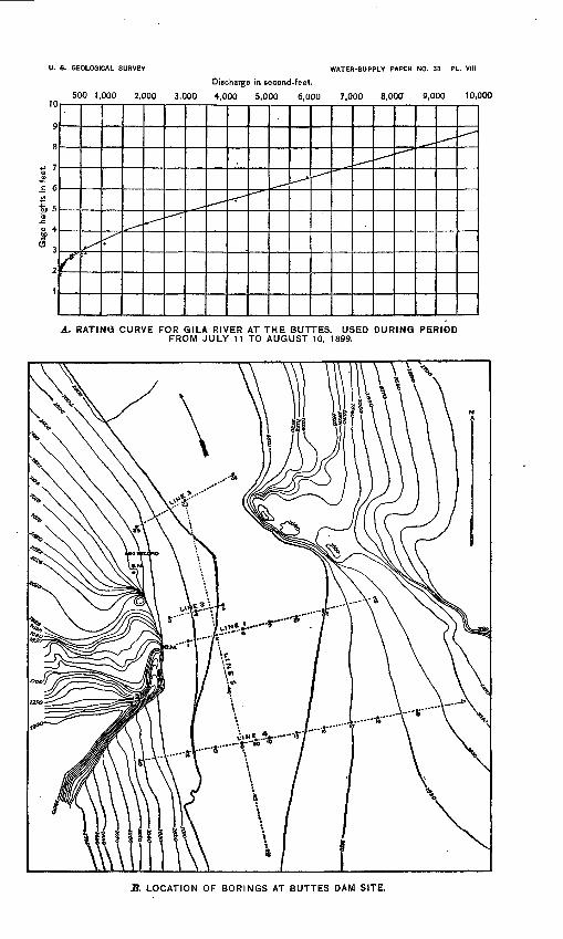
U. 8. GEOLOGICAL SURVEY WATER-SUPPLY PAPER NO. 33 PL. VIII
Discharge in second-feet.
500 1,000 2,000 3,000 4,000 5,000 6,000 7,000 8,000 9,000 10,00010
A. RATING CURVE FOR GILA RIVER AT THE BUTTES. USED DURING PERIOD FROM JULY 11 TO AUGUST 10, 1899.
3. LOCATION OF BORINGS AT BUTTES DAM SITE.
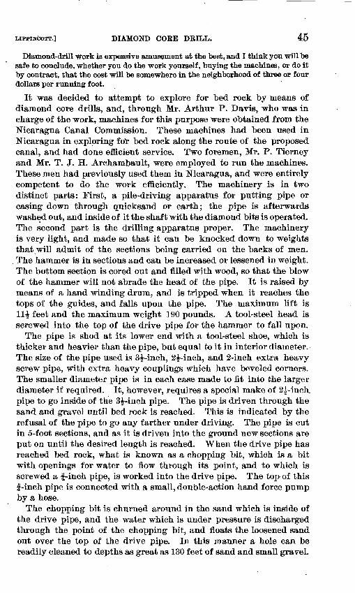
MPPINCOTT.] DIAMOND CORE DRILL. 45
Diamond-drill work is expensive amusement at the best, and I think you will be safe to conclude, whether you do the work yourself, buying the machines, or do it by contract, that the cost will be somewhere in the neighborhood of three or four dollars per running foot.
It was decided to attempt to explore for bed rock by means of diamond core drills, and, through Mr. Arthur P. Davis, who was in charge of the work, machines for this purpose were obtained from the Nicaragua Canal Commission. These machines had been used in Nicaragua in exploring foir bed rock along the route of the proposed canal, and had done efficient service. Two foremen, Mr. P. Tierney and Mr. T. J. H. Archambault, were employed to run the machines. These men had previously used them in Nicaragua, and were entirely competent to do the work efficiently. The machinery is in two distinct parts: First, a pile-driving apparatus for putting pipe or casing down through quicksand or earth; the pipe is afterwards washed out, and inside of it the shaft with the diamond bits is operated. The second part is the drilling apparatus proper. The machinery is very light, and made so that it can be knocked down to weights that will admit of the sections being carried on the backs of men.
. The hammer is in sections and can be increased or lessened in weight. The bottom section is cored out and filled with wood, so that the blow of the hammer will not abrade the head of the pipe. It is raised by means of a hand winding drum, and is tripped when it reaches the tops of the guides, and falls upon the pipe. The maximum lift is 11£ feet and the maximum weight 190 pounds. A tool-steel head is screwed into the top of the drive pipe for the hammer to fall upon.
The pipe is shod at its lower end with, a tool-steel shoe, which is thicker and heavier than the pipe, but equal to it in interior diameter. The size of the pipe used is 3^-inch, 2i-inch, and 2-inch extra heavy screw pipe, with extra heavy couplings which have beveled corners. The smaller diameter pipe is in each case made to fit into the larger diameter if required. It, however, requires a special make of 2^-inch, pipe to go inside of the 3^-inch pipe. The pipe is driven through the sand and gravel until bed rock is reached. This is indicated by the refusal of the pipe to go any farther under driving. The pipe is cut in 5-foot sections, and as it is driven into the ground new sections are put on until the desired length is reached. When the drive pipe has reached bed rock, what is known as a chopping bit, which is a bit with openings for water to flow through its point, and to which is screwed a f-inch pipe, is worked into the drive pipe. The top of this f-inch pipe is connected with a small, double-action hand force pump by a hose.
The chopping bit is churned around in the sand which is inside of the drive pipe, and the water which is under pressure is discharged through the point of the chopping bit, and floats the loosened sand out over the top of the drive pipe. In this manner a hole can be readily cleaned to depths as great as 130 feet of sand and small gravel.
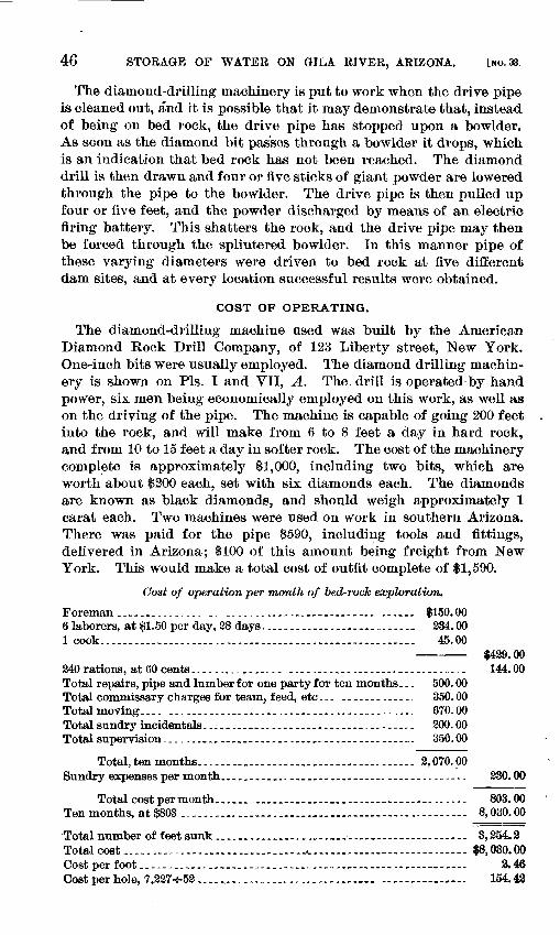
46 STORAGE OF WATER ON GILA RIVER, ARIZONA. lwo.33.
The diamond-drilling machine^ is put to work when the drive pipe is cleaned out, and it is possible that it may demonstrate that, instead of being on bed rock, the drive pipe has stopped upon a bowlder. As soon as the diamond bit passes through a bowlder it drops, which is an indication that bed rock has not been reached. The diamond drill is then drawn and four or five sticks of giant powder are lowered through the pipe to the bowlder. The drive pipe is then pulled up four or five feet, and the powder discharged by means of an electric firing battery. This shatters the rock, and the drive pipe may then be forced through the splintered bowlder. In this manner pipe of these varying diameters were driven to bed rock at five different dam sites, and at every location successful results were obtained.
COST OF OPERATING.
The diamond-drilling machine used was built by the American Diamond Rock Drill Company, of 123 Liberty street, New York. One-inch bits were usually employed. The diamond drilling machin ery is shown on Pis. I and VII, A. The. drill is operated by hand power, six men being economically employed on this work, as well as on the driving of the pipe. The machine is capable of going 200 feet into the rock, and will make from 6 to 8 feet a day in hard rock, and from 10 to 15 feet a day in softer rock. The cost of the machinery complete is approximately $1,000, including two bits, which are worth about $200 each, set with six diamonds each. The diamonds are known as black diamonds, and should weigh approximately 1 carat each. Two machines were used on work in southern Arizona. There was paid for the pipe $590, including tools and fittings, delivered in Arizona; $100 of this amount being freight from New York. This would make a total cost of outfit complete of $1,590.
Cost of operation per month of bed-rock exploration.
Foreman.--.....----...--... .........-.......... ........... $150.006 laborers, at $1.50 per day, 28 days............................ 234.001 cook....................................................... 45.00
$429.00 240 rations, at 60 cents................ ................................ 144.00Total repairs, pipe and lumber for one party for ten months... 500.00 Total commissary charges for team, feed, etc... --.--.---.-.. 350.00 Total moving.... ........................................... 670.00Total sundry incidentals.......__......._...-._......... 200.00Total supervision....-.---.....----.-----..,.--.---.----..-... 350.00
Total,ten months...---.._-..--.-.---_----------.----.- 2,070.00Sundry expenses per month...._-.-_....._....._.....-.. _.----.------- 230.00
Total cost per month...... ..................................... 803.00Ten months, at $803 .................................................. 8,030.00
Total number of feet sunk ..........................__.............. 3,254.2Total cost ........^......................^...,........................ $8,030.00Cost per foot-.-----.-.-.......----...--... .................... ,... 2.46Costperhole, 7,227-5-52 ................... ............ ............... 154.48
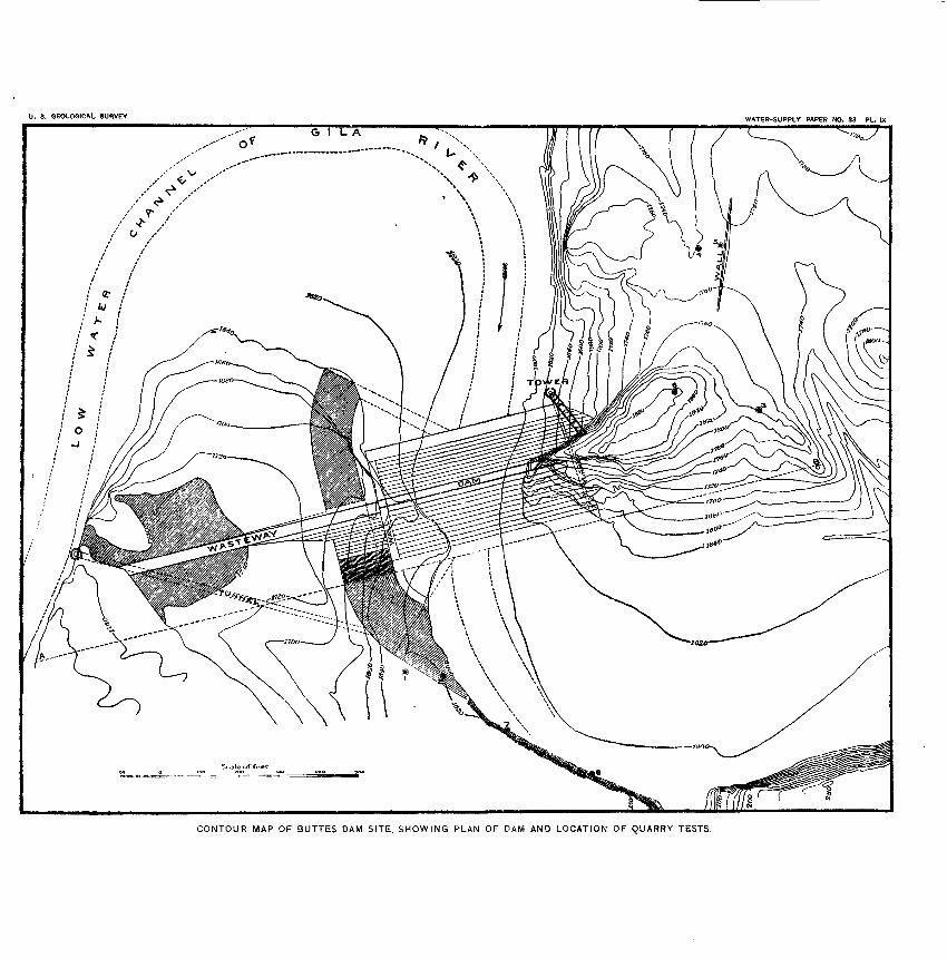
U. 8. GEOLOGICAL SURVEY WATER-SUPPLY PAPER NO. 33 PL. IX
CONTOUR MAP OF BUTTES DAM SITE, SHOWING PLAN OF DAM AND LOCATION OF QUARRY TESTS.
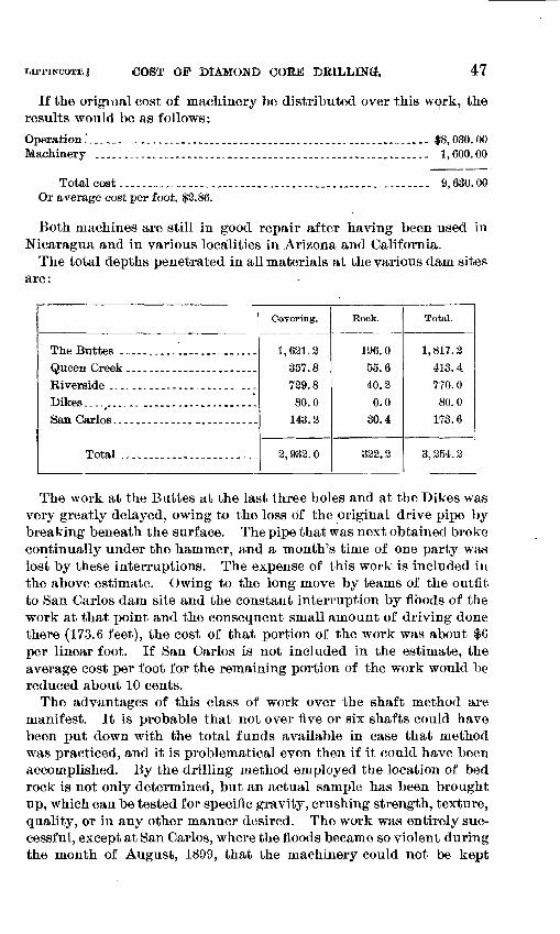
LIPPINCOTT.J COST OF DIAMOND COSE DRILLING^ 47
If the original cost of machinery be distributed over this work, the results would be as follows:Operation............................................................ $8,030.00Machinery .......................................................... 1,600.00
Total cost.--.._.,_..Or average cost per foot,
9,630.00
Both machines are still in good repair after having been used in Nicaragua and in various localities in Arizona and California.
The total depths penetrated in all materials at the various dam sites are:
The Buttes.-----.---.. ..... ......Queen Creek ......... _ ...........Riverside ....--.__---.._...-... ...Dikes.... ...... .....-..--_--.....-.San Carlos. .--...-.----. -._.-.-..--
Total ........................
Covering.
1,621.3357.8729.880.0
143.2
2, 932. 0
Rock.
196.0
55.6
40.20.0
30.4
322.2
Total.
1,817.2
413.4
770.0
80.0
173.6
3, 254. 2
The work at the Buttes at the last three holes and at the Dikes was very greatly delayed, owing to the loss of the original drive pipe by breaking beneath the surface. The pipe that was next obtained broke continually under the hammer, and a month's time of one party was lost by these interruptions. The expense of this work is included in the above estimate. Owing to the long move by teams of the outfit to San Carlos dam site and the constant interruption by floods of the work at that point and the consequent small amount of driving done there (173.6 feet), the cost of that portion of the work was about $6 per linear foot. If San Carlos is not included in the estimate, the average cost per foot for the remaining portion of the work would be reduced about 10 cents.
The advantages of this class of work over the shaft method are manifest. It is probable that not over five or six shafts could have been put down with the total funds available in case that method was practiced, and it is problematical even then if it could have been accomplished. By the drilling method employed the location of bed rock is not only determined, but an actual sample has been brought up, which can be tested for specific gravity, crushing strength, texture, quality, or in any other manner desired. The work was entirely suc cessful, except at San Carlos, where the floods became so violent during the month of August, 1899, that the machinery could not be kept
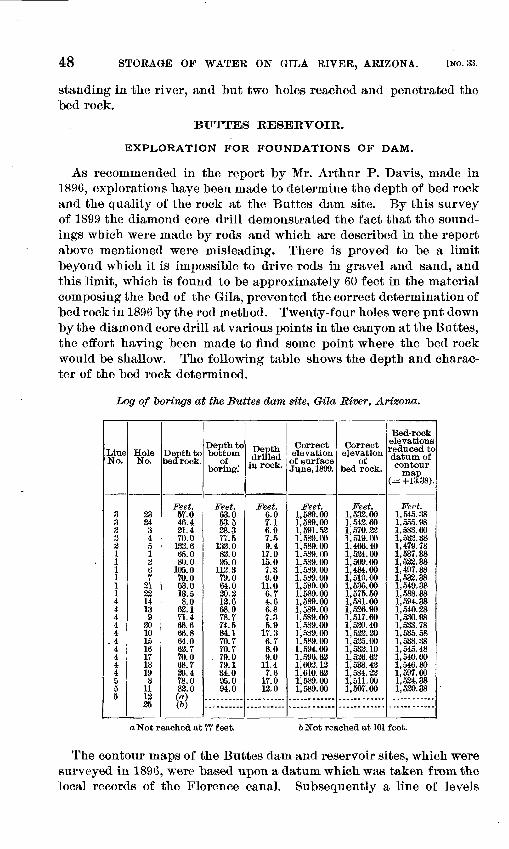
48 STORAGE OP WATER ON GILA RIVER, ARIZONA. [NO. 33.
standing in the river, and but two holes reached and penetrated the bed rock.
BUTTES RESERVOIR.
EXPLORATION FOR FOUNDATIONS OF DAM.
As recommended in the report by Mr. Arthur P. Davis, made in 1896, explorations have been made to determine the depth of bed rock and the quality of the rock at the Buttes dam site. By this survey of 1899 the diamond core drill demonstrated the fact that the sound ings which were made by rods and which are described in the report above mentioned were misleading. There is proved to be a limit beyond which it is impossible to drive rods in gravel and sand, and this limit, which is found to be approximately 60 feet in the material composing the bed of the Gila, prevented the correct determination of bed rock in 1896 by the rod method. Twenty-four holes were put down by the diamond core drill at various points in the canyon at the Buttes, the effort having been made to find some point where the bed rock would be shallow. The following table shows the depth and charac ter of the bed rock determined.
Log of Tmrings at the Buttes dam site, (Mla River, Arizona.
Line No.
3323311111144444
. 44444555
Hole No.
33343451g67
313314139
301015161718198
111335
Depth to bedrock.
Feet.57.046.431.470.0
133.665.080.0
105.070.053.013.58.0
62.171.468.666.864.063.770.068.736.478.083.0(a)(6)
Depth to bottom
of boring."
Feet.63.053.528.377.5
133.083.095.0
113.379.064.030.313.668.978.774.584.170.770.7
. 79.079.134.095.094.0
Depth drilled
in rock.
Feet.6.0r.i6.97.59.4
17.015.07.39.0
11.06.74.66.87.35.9
17.36.78.09.0
11.47.6
17.013.0
Correct elevation of surface June, 1899.
Feet.1,589.001,589.001,591.531,589.001,589.001,589.001,589.001,589.001,589.001,589.001,589.001,589.001,589.001,589.001,589.001,589.001,589.001,594.001,596.631,603.131,610.631,589.001,589.00
Correct elevation
of bed rock.
Feet.1,533.001,543.601,570.331,519.001,466.401,534.001,509.001,484.001,519.001,536.001,575.501,581.001,536.901,517.601,530.401,533.201,535.001,533.101,536.621,533.421,584.221,511.001,507.00
Bed-rockelevations reduced to datum of contour
map(= +13.38).
Feet.1,545.381,555.981,583.601,532.381,479.781,537.381,522.381, 417.381,533.381,549.381,588.881,594.381,540.281,530.981,533.781,535.581,538.381,545.481,540.001,546.801,597.601,534.381,530.38
a Not reached at 77 feet. 6 Not reached at 101 feet.
The contour maps of the Buttes dam and reservoir sites, which were surveyed in 1896, were based upon a datum which was taken from the local records of the Florence canal. Subsequently a line of levels
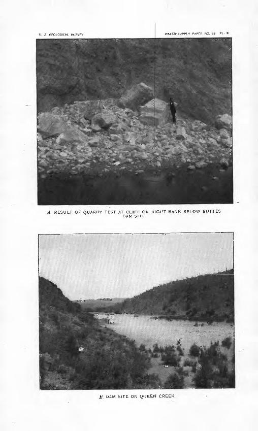
U. S. GEOLOGICAL SURVEY WATER-SUPPLY PAPER NO. 33 PL. X
A RESULT OF QUARRY TEST AT CLIFF ON RIGHT BANK BELOW BUTTESDAM SITE.
B. DAM SITE ON QUEEN CREEK.
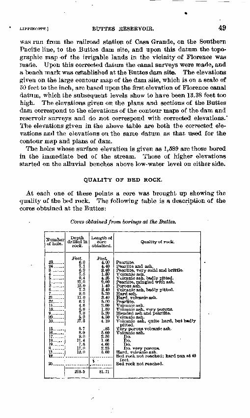
LIPPINCOTT.] BUTTES EESERVOIR. 49
was run from the railroad station of Casa Grande, on the Southern Pacific line, to the Buttes dam site, and upon this datum the topo graphic map -of the irrigable lands in the vicinity of Florence was made. Upon this corrected datum the canal surveys were made, and a bench mark was established at the Buttes dam site, The elevations given on the large contour map of the dam site, which is on a scale of 50 feet to the inch, are based upon the first elevation of Florence canal datum, which the subsequent levels show to have been 18.38 feet too high. The elevations given on the plans and sections of the Buttes dam correspond to the elevations of the contour maps of the dam and reservoir surveys and do not correspond with corrected elevations.* The elevations given in the above table are both the corrected ele vations and the elevations on the same datum as that used for the contour map and plans of dam.
The holes whose surface elevation is given as 1,589 are those' bored in the immediate bed of the stream. Those of higher elevations started on the alluvial benches above low-water level on either side.
QUALITY OF BED ROCK.
At each one of these points a core was brought up showing the quality of the bed rock. The following table is a description of the cores obtained at the Buttes:
Cores obtained from borings at the Buttes,
Number of hole.
23...... 34...... 3-.. .4-.-....5.......I.......
6.......7--. .21...... 32 TA-"."~.
13...... 9.......30..... 10.....
15... . 16... .17... . 18... . 19... .. 8.......U...... 13......
35
Depth drilled in
rock.
Feet. 6.0 7.1 6.9
9.417.015.07.39.0
11.0 6.7 4.6 6.8 7.35.9
17.3
6.7 8.0 9.0
11.4 7.6
17.013.0
316.5
Length of core
obtained.
Feet. 4.00 4.40 3.401.304.359.001.403.405.303.40 5.00 3.00 1.80 5.304.50 4.10
.85 5.00 2.50 1.66 4.00 2 355.00
* '-
81.71
Quality of rock.
Pearlifce. Pearlite and ash.
Hard, volcanic ash. Pearlite. Volcanic ash. Volcanic ash, very porous.
Volcanic ash. Volcanic ash, quite hard, but badly
pitted. Very porous volcanic ash. Volcanic ash.
Do. Do. Do.
Hard, volcanic ash.
feet.
50 STORAGE OF WATER ON GILA RIVER, ARIZONA. [NO. 33.
The location of these borings is shown on PI. VIII, B, these being arranged in five different rows. At the relative location of each hole a figure has been placed on the diagram corresponding to the number given in the above tables. The point marked "B. M." shows the posi tion of the bronze bench mark set in the face of the cliff. It is the initial point of the survey for the location of the borings. At the point marked "Gr" is a steel gad seven-eighths of an inch in diameter, set in the rock.
In taking out many of the cores it was found that, while the drill had entered the rock for distances of from 6 to 12 feet, the cores extracted were very much less in length, owing to the crumbling of the rock as it was cut. The bed rock varies between a volcanic glass, or obsidian called pearlite, and a porous ash. The obsidian is exceed ingly hard, but the ashy material is full of holes, quite soft, being readily cut with a knife, and of a crumbling nature. A total depth of 216.5 feet was bored into the bed rock, and but 81.71 feet of core obtained therefrom, or only 38 per cent of the total length of the core was of such material as would permit of its extraction from the holes. It is but fair to assume that the remaining 62 per cent is of a poorer class of material than that which was extracted.
The following table gives crushing tests which were made in the laboratory of the city engineer's office at Los Angeles, California. The crushing limit of the machine used is 2,565 pounds per square inch. This would be equivalent to 184.7 tons per square foot. A good many of the samples could not be crushed on the machine, but it has been considered that all rock which could not be crushed with this pressure is reliable and could be accepted as a satisfactory founda tion material. The poorest rock is undoubtedly that portion of the core which has gone to pieces under the action of the diamond drill, and which could not be extracted. Tests were obtained from the samples as low as 79.5 tons per square foot. It may therefore be assumed that the tests made are of the better class of rock, and that if any of the samples indicate a weakness below the limit of safety it would justify the abandonment of the bed rock as a proper foundation for a cement-masonry dam. The assumed maximum height of the dam being 170 feet above the bed of the stream, and 123 feet to bed rock below the same, or a total height of 293 feet, the base would have to be made so wide in order to keep the pressure at the outside toe within safe limits that the cost would be prohibitory. Some of the cores having crushed with 80 tons pressure per square foot, a rubble- masonry dam is abandoned for this site. Crushing tests were made by J. W. Kobinette and S. G. Bennett. Specimens were 1 inch long and 1 inch in diameter.
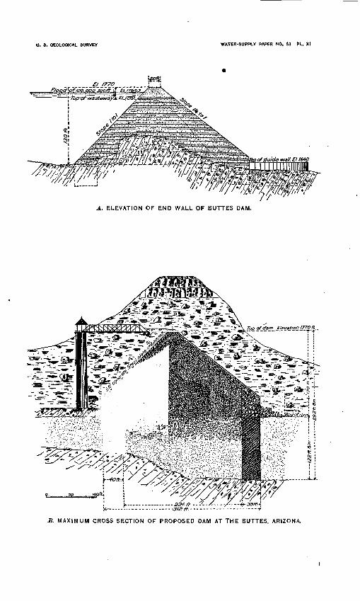
U. S. GEOLOGICAL SURVEY WATER-SUPPLY PAPER NO. S3 PL. XI
A. ELEVATION OF END WALL OF BUTTES DAM.
-312 #..
S. MAXIMUM CROSS SECTION OF PROPOSED DAM AT THE BUTTES, ARIZONA.
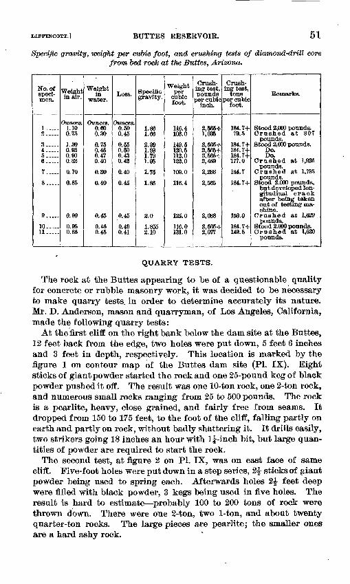
LIPPINOOTT.] BUTTES RESERVOIR. 51
Specific gravity, weight per cubic foot, and crushing tests of diamond-drill core from bed rock at the Buttes, Arizona.
No. ofspeci men.
1. .2.....
3.. 4.....5.....6.....
7.....
8.....
9.....
10.. 11.....
Weight in air.
Ounces.1.100.75
1.300.950.900.82
0.70
0.85
0.90
0.950.86
Weight in
water.
Ounces.o.eo0.30
0.750.450.4,70.40
0.30
0.40
0.45
0.460.45
Loss.
Ounces.0.500.45
0.550.500.430.42
0.40
0.45
0.45
0.490.41
Specificgravity.
1.861.66
2.391.931.791.95
1.75
1.86
2.0
1.8552.10
Weight per
cubic foot.
116.4103.0
149.5120.5112.0133.0
109.0
116.4
125.0
116.0131.0
Crush ing test, pounds
per cubic inch.
2,565+1,035
2,565+2,565+2,565+2,469
2,288
2,565
2,088
2,565+2,077
Crush ing test,
tons per cubic
foot.
184.7+79.5
184.7+184.7+184.7+177.0
164.7
184.7+
150.0
184.7+149.5
Remarks.
Stood 2,000 pounds.Crushed at 807
pounds.Stood 2,000 pounds.
Do.Do.
Crushed at 1,926pounds.
Crushed at 1,785pounds.
Stood 2,000 pounds,but developed longitudinal crackafter being takenout of testing machine.
Crushed at 1,629 .pounds.
Stood 2,000 pounds.Crushed at 1,620
pounds.
QUARRY TESTS.
The rock at the Buttes appearing to be of a questionable quality for concrete or rubble masonry work, it was decided to be necessary to make quarry tests, in order to determine accurately its nature. Mr. D. Anderson, mason and quarryman, of Los Angeles, California, made the following quarry tests:
At the first cliff on the right bank below the dam site at the Buttes, 12 feet back from the edge, two holes were put down, 5 feet 6 inches and 3 feet in depth, respectively. This location is marked by the figure 1 on contour map of the Buttes dam site (PL IX). Eight sticks of giant powder started the rock and one 25-pound keg of black powder pushed it off. The result was one 10-ton rock, one 2-ton rock, and numerous small rocks ranging from 25 to 500 pounds. The rock is a pearlite, heavy, close grained, and fairly free from seams. It dropped from 150 to 175 feet, to the foot of the cliff, falling partly on earth and partly on rock, without badly shattering it. It drills easily, two strikers going 18 inches an hour with 1^-inch bit, but large quan tities of powder are required to start the rock.
The second test, at figure 2 on PI. IX, was on east face of same cliff. Five-foot holes were put down in a step series, 2£ sticks of giant powder being used to spring each. Afterwards holes 2£ feet deep were filled with black powder, 3 kegs being used in five holes. The result is hard to estimate probably 100 to 200 tons of rock were thrown down. There were one 2-ton, two 1-ton, and about twenty quarter-ton rocks. The large pieces are pearlite; the smaller ones are a hard ashy rock.
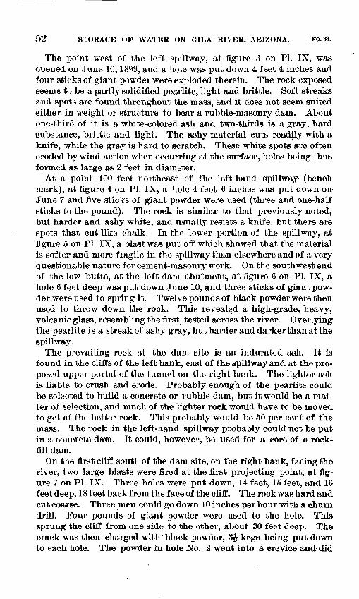
52 STORAGE OP WATER ON GILA RIVER, ARIZONA. [NO. 33.
The point west of the left spillway, at figure 3 on PI. IX, was opened on June 10,1899, and a hole was put down 4 feet 4 inches and four sticks of giant powder were exploded therein. The rock exposed seems to be a partly solidified pearlite, light and brittle. Soft streaks and spots are found throughout the mass, and it does not seem suited either in weight or structure to bear a rubble-masonry dam. About one-third of it is a white-colored ash and two-thirds is a gray, hard substance, brittle and light. The ashy material cuts readily with a knife, while the gray is hard to scratch. These white spots are often eroded by wind action when occurring at the surface, holes being thus formed as large as 2 feet in diameter.
At a point 100 feet northeast of the left-hand spillway (bench mark), at figure 4 on PI. IX, a hole 4 feet 6 inches was put down on- June 7 and five sticks of giant powder were used (three and one-half sticks to the pound). The rock is similar to that previously noted, but harder and ashy white, and usually resists a knife, but there are spots that cut like chalk. In the lower portion of the spillway, at figure 5 on PI. IX, a blast was put off which showed that the material is softer and more fragile in the spillway than elsewhere and of a very questionable nature for cement-masonry work. On the southwest end of the low butte, at the left dam abutment, at figure 6 on PL IX, a hole 6 feet deep was put down June 10, and three sticks of giant pow der were used to spring it. Twelve pounds of black powder were then used to throw down the rock. This revealed a high-grade, heavy, volcanic glass, resembling the first, tested across the river. Overlying the pearlite is a streak of ashy gray, but harder and darker than at the spillway.
The prevailing rock at the dam site is an indurated ash. It is found in the cliffs of the left bank, east of the spillway and at the pro posed upper portal of the tunnel on the right bank. The lighter ash is liable to crush and erode. Probably enough of the pearlite could be selected to build a concrete or rubble dam, but it would be a mat ter of selection, and much of the lighter rock would have to be moved to get at the better rock. This probably would be 50 per cent of the mass. The rock in the left-hand spillway probably could not be put in a concrete dam. It could, however, be used for a core of a rock- fill dam.
On the first cliff south of the dam site, on the right bank, facing the river, two large blasts were fired at the first projecting point, at fig ure 7 on PL IX. Three holes were put down, 14 feet, 15 feet, and 16 feet deep, 18 feet back from the face of the cliff. The rock was hard and cut coarse. Three men could go down 10 inches per hour with a churn drill. Four pounds of giant powder were used to the hole. This sprung the cliff from one side to the other, about 30 feet deep. The crack was then charged with black powder, 3£ kegs being put down to each hole. The powder in hole No. 2 went into a crevice and did
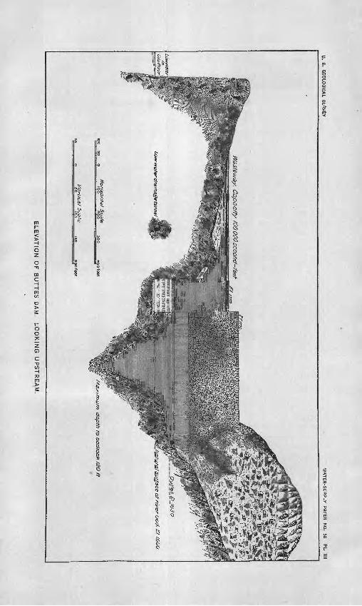
U.
8.
GE
OLO
SIC
AL
SU
RV
EY
WA
TE
R-S
UP
PLY
P
AP
ER
N
O.
33 P
L
XII
§li?
^^f^
Sip
|^W
asteway. C
apac/ty
/DO
000 se
con
d-fe
et
ELE
VA
TIO
N
OF
B
UT
TE
S
DA
M,
LO
OK
ING
U
PS
TR
EA
M.
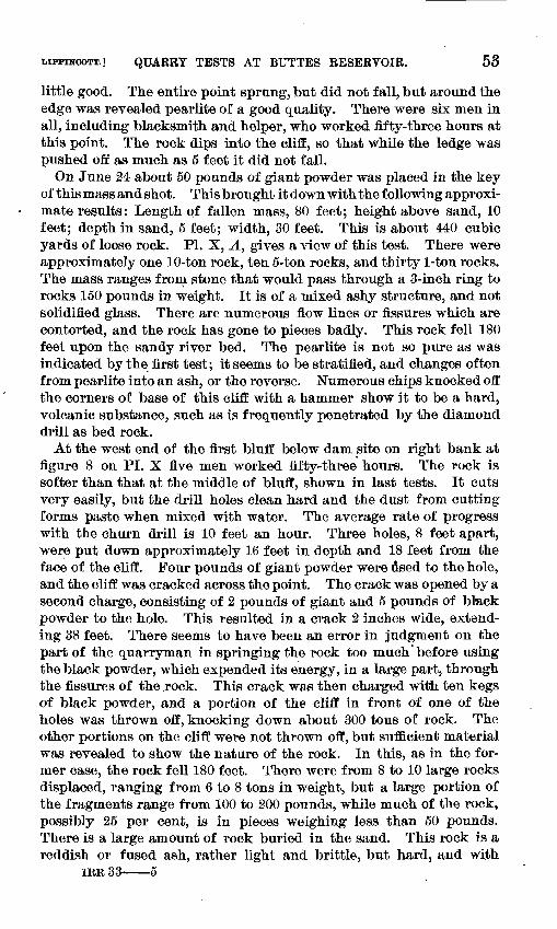
MPPINCOTT.] QUARRY TESTS AT BUTTES RESERVOIR. 53
little good. The entire point sprung, but did not fall, but around the edge was revealed pearlite of a good quality. There were six men in all, including blacksmith and helper, who worked fifty-three hours at this point. The rock dips into the cliff, so that while the ledge was pushed off as much as 5 feet it did not fall.
On June 24 about 50 pounds of giant powder was placed in the key of this mass and shot. This brought it d own with the following approxi mate results: Length of fallen mass, 80 feet; height above sand, 10 feet; depth in sand, 5 feet; width, 30 feet. This is about 440 cubic yards of loose rock. PI. X, A, gives a view of this test. There were approximately one 10-ton rock, ten 5-ton rocks, and thirty 1-ton rocks. The mass ranges from stone that would pass through a 3-inch ring to rocks 150 pounds in weight. It is of a mixed ashy structure, and not solidified glass. There are numerous flow lines or fissures which are contorted, and the rock has gone to pieces badly. This rock fell 180 feet upon the sandy river bed. The pearlite is not so pure as was indicated by the first test; it seems to be stratified, and changes often from pearlite into an ash, or the reverse. Numerous chips knocked off the corners of base of this cliff with a hammer show it to be a hard, volcanic substance, such as is frequently penetrated by the diamond drill as bed rock.
At the west end of the first bluff below dam site on right bank at figure 8 on PI. X five men worked fifty-three hours. The rock is softer than that at the middle of bluff, shown in last tests. It cuts very easily, but the drill holes clean hard and the dust from cutting forms paste when mixed with water. The average rate of progress with the churn drill is 10 feet an hour. Three holes, 8 feet apart, were put down approximately 16 feet in depth and 18 feet from the face of the cliff. Four pounds of giant powder were used to the hole, and the cliff was cracked across the point. The crack was opened by a second charge, consisting of 2 pounds of giant and 5 pounds of black powder to the hole. This resulted in a crack 2 inches wide, extend ing 38 feet. There seems to have been an error in judgment on the part of the quarryman in springing the rock too much before using the black powder, which expended its energy, in a large part, through the fissures of the .rock. This crack was then charged with, ten kegs of black powder, and a portion of the cliff in front of one of the holes was thrown off, knocking down about 300 tons of rock. The other portions on the cliff were not thrown off, but sufficient material was revealed to show the nature of the rock. In this, as in the for mer case, the rock fell 180 feet. There were from 8 to 10 large rocks displaced, ranging from 6 to 8 tons in weight, but a large portion of the fragments range from 100 to 200 pounds, while much of the rock, possibly 25 per cent, is in pieces weighing less than 50 pounds. There is a large amount of rock buried in the sand. This rock is a reddish or fused ash, rather light and brittle, but hard, and with
IKE 33- 5
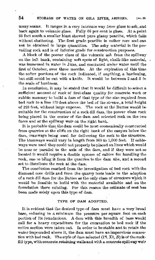
54 STORAGE OF WATEE ON GILA EIVEE, AEIZONA. [NO. 33.
many seams. It ranges in a very intricate way from glass bo ash, and back again to volcanic glass. Fully 66 per cent is glass. At a point 25 feet south a smaller blast showed pure glassy pearlite, which falls without shattering. The first grade pearlite is rather rare and can not be obtained in large quantities. The ashy material is the pre vailing rock and is of inferior grade for construction purposes.
A block of the poorer class of the volcanic ash from the spillway on the left bank, containing soft spots of light, chalk-like material, was immersed in water in June, and continued under water until the first of October, over three months. At the expiration of this time the softer portions of the rock indicated, if anything, a hardening, but still could be cut with a knife. It would be between 2 and 3 in the scale of hardness.
In conclusion, it may be stated that it would be difficult to select a sufficient amount of rock of first-class quality for concrete work or rubble masonry to build a dam of that type of the size required from bed rock to a line 170 feet above the bed of the stream, a total height of 223 feet, without large expense. The rock at the Buttes would be suitable for the construction of a rock-fill dam, the poorer class rock being placed in the center of the dam and selected rock on the two faces and at the spillway weir on the right bank.
It is probable that the dam could be most economically constructed from quarries at the cliffs on the right bank of the canyon below the dain, tramways being used for delivering the rock to the structure. The tramways would vary in length from 500 to 1,000 feet. If cable- ways were used they could not properly be placed on lines which would be near or parallel to the axis of the dam, and if they were not so located it would require a double system of cables for handling the rock, one to bring it from the quarries to the dam site, and a second set to distribute the rock at the dam.
The conclusion reached from the investigation of bed rock with the diamond core drills and from the quarry tests leads to the adoption of a rock-fill dam for the Buttes as the only class of structure which it would be feasible to build with the material available and on the foundation there existing. For this reason the estimate of cost has been made solely upon this type of dam.
TYPE OF DAM ADOPTED.
It is evident that the desired type of dam must have a very broad base, reducing to a minimum the pressure per square foot on each portion of its foundations. A dam with this breadth of base would call for a heavy expenditure for the excavation to bed rock if the entire section were taken out. In order to be stable and to retain the water impounded above it, the dam must have an impervious connec tion with bed rock. The style of dam selected (PI. XI, B) is of the rock- fill type, with concrete retaining walls and with a concrete spillway weir
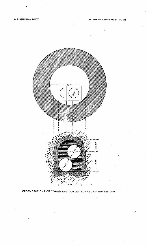
I). 8. GEOLOGICAL SURVEY WATER-SUPPLY PAPER NO. S3 PL. XIII
CROSS SECTIONS OF TOWER AND OUTLET TUNNEL OF BUTTES DAM.
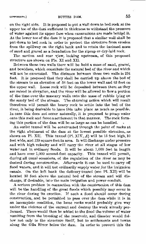
LIPPINGOTT.] BUTTES DAM. 55
on the right side. It is proposed to put a wall down to bed rock at the upper toe of the dairi sufficient in thickness to withstand the pressure of water against its upper face when excavations are made behind it. At the lower toe of the dam it is proposed that a similar wall shall be put down to bed rock in order to protect the structure from erosion from the spillway on the right bank and to retain the inclosed mass of sand and gravel as a foundation for the riprap or dry-laid rock.
The section and rear view, looking upstream, of this proposed structure are shown on Pis. XI and XII.
Between these two walls there will be held a mass of sand, gravel, and bowlders, which constitute the natural bed of the river and which will not be excavated. The distance between these two walls is 234 feet. It is proposed that they shall be carried up above the bed of the stream to an elevation of 58 feet on the lower wall and 63 feet on the upper wall. Loose rock will be deposited between them as they are raised in elevation, and the river will be allowed to flow a portion of the time over the masonry walls onto the mass of rubble lying on the sandy bed of the stream. The churning action which will result therefrom will permit the heavy rock to settle into the bed of the river, it being desirable to have this take place as much as possible. In case this does not occur naturally, it is proposed to pump water onto this rock and force a settlement in that manner. The rock form ing this portion of the dam will be as large as can be handled.
An outlet tunnel will be constructed through the point of rocks at the right abutment of the dam at the lowest possible elevation, as shown on PI. XII. This tunnel (PI. XIV, A) will be 15 feet high, 10 feet wide, and 139 square feet in area. It will discharge under pressure and with high velocity and will carry the river at all stages of low water and in ordinary floods. It will be about 1,000 feet in length and have over 1,000 second-feet capacity. This tunnel will permit, during all usual occasions, of the regulation of the river as may be desired during construction. Afterwards it can be used to carry off flood waters, and it will not ordinarily supply water for the irrigation canals. On the left bank the delivery tunnel (see PI. XII) will be located 30 feet above the natural bed of the stream and will dis charge, if desirable, in* o the main irrigation and power conduit.
A serious problem in connection with the construction of this dam will be the handling of the great floods which possibly may occur in the river during its erection. If such a flood should occur during construction, and be permitted to pass over the dam while it is in an incomplete condition, the loose rocks would probably give way under the violence of the current and destroy the work already per formed. There would then be added to the flood the volume of water resulting from the bursting of the reservoir, and disaster would fol low not only to the structure itself, but to settlements and towns along the Gila River below the dam. In order to prevent this the
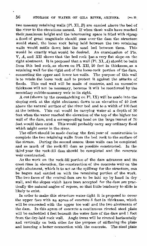
56 STORAGE OF WATER ON GILA RIVER, ARIZONA. [NO. 33.
two masonry retaining walls (PI. XI, B) are carried above the bed of the river to the elevations named. If when these walls have reached their ̂ maximum height and the intervening space is filled with, riprap a flood of great magnitude should pass over the dam the structure «rould stand, the loose rock being held between the two retaining walls would settle down into the sand bed between them. This would be exactly what would be desired. An examination of Pis. V, A, and XII shows that the bed rock has a very flat slope on the right abutment. It is proposed that a wall (PI. XI, A) should be built from this bed rock, as shown on PL XII, 20 feet in thickness, as a retaining wall for the right end of the loose-rock portion of the dam, connecting the upper and lower toe walls. The purpose of this wall is to retain the loose rock and to protect it against the attacks of floods. This end wall will be made of concrete, and an excessive thickness will not be necessary, because it will be reenforced by the secondary rubble-masonry weir to its right.
A cut (shown by the crosshatching on PI. IX) will be made into the sloping rock at the right abutment down to an elevation of 40 feet above the natural surface of the river bed and to a width of 100 feet at the bottom. This cut would be carrying water at a depth of 30 feet when the water reached the elevation of the top of the higher toe wall of the dam, and a corresponding head on the large tunnel of 70 feet would then exist. This would probably carry any ordinary flood which might occur in the river.
The effort should be made during the first year of construction to complete the two retaining walls from the bed rock to the surface of the stream. During the second season these walls can be completed and as much of the rock-fill dam as possible constructed. In the third year the rock-fill dam should be completed and the concrete weir constructed.
As the work on the rock-fill portion of the dam advances and its crest rises in elevation, the construction of the concrete weir on the right abutment, which is to act as the spillway for the structure, can be begun and carried on with the remaining portion of the work. The two faces of the central dam are to be laid up by hand in dry wall, and the slopes which have been accepted for the dam are prac tically the natural angles of repose, so that little tendency to slide is likely to exist.
In order to make this structure water-tight it is proposed to cover the upper face with an apron of concrete 5 feet in thickness, which will be connected with the upper toe wall and the two abutments of the dam. In this apron of concrete a continuous riveted steel plate will be embedded 4 feet beneath the water face of the dam and 1 foot from the dry-laid rock wall. Angle irons will be riveted horizontally and vertically on both sides for the purpose of stiffening the plate and insuring a better connection with the concrete. The steel plate
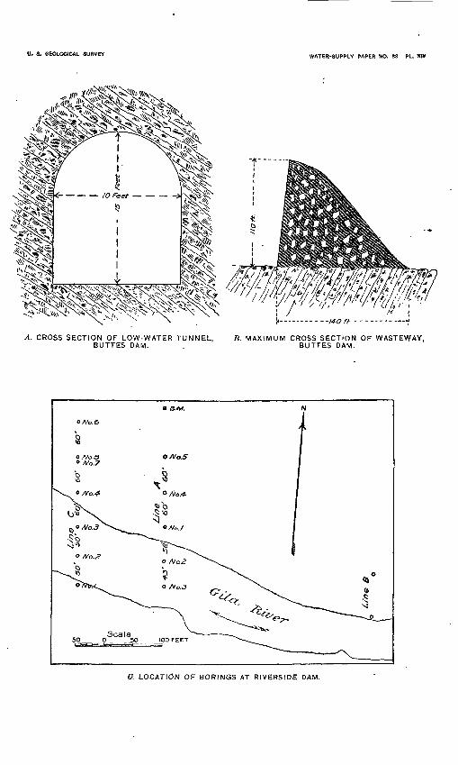
U. S. GEOLOGICAL SURVEY WATER-SUPPLY PAPER NO. 33 PL. Xftf
A. CROSS SECTION OF LOW-WATER TUNNEL, B. MAXIMUM CROSS SECTION OF WASTEWAY, BUTTES DAM. . BUTTES DAM.
O. LOCATION OF BORINGS AT RIVERSIDE DAM.
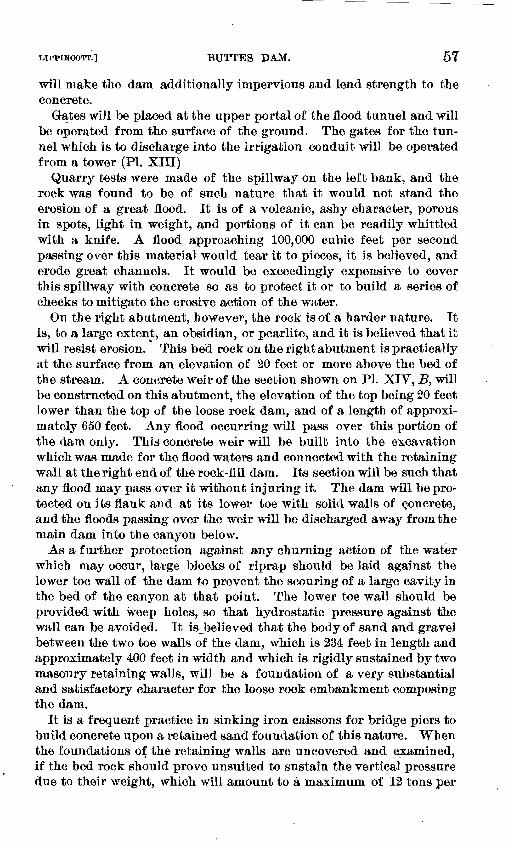
IJPPINCOTT.] BUTTES DAM. 57
will make the dam additionally impervious and lend strength to the concrete.
Gates will be placed at the upper portal of the flood tunnel and will be operated from the surface of the ground. The gates for the tun nel which is to discharge into the irrigation conduit will be operated from a tower (PI. XIII)
Quarry tests were made of the spillway on the left bank, and the rock was found to be of such nature that it would not stand the erosion of a great flood. It is of a volcanic, ashy character, porous in spots, light in weight, and portions of it can be readily whittled with a knife. A flood approaching 100,000 cubic feet per second passing over this material would tear it to pieces, it is believed, and erode great channels. It would be exceedingly expensive to cover this spillway with concrete so as to protect it or to build a series of checks to mitigate the erosive action of the water.
On the right abutment, however, the rock is of a harder nature. It is, to a large extent, an obsidian, or pearlite, and it is believed that it will resist erosion. This bed rock on the right abutment is practically at the surface from an elevation of 20 feet or more above the bed of the stream. A concrete weir of the section shown on PI. XIV, B, will be constructed on this abutment, the elevation of the top being 20 feet lower than the top of the loose rock dam, and of a length of approxi mately 650 feet. Any flood occurring will pass over this portion of the dam only. This concrete weir will be built into the excavation which was made for the flood waters and connected with the retaining wall at the right end of the rock-fill dam. Its section will be such that any flood may pass over it without injuring it. The dam will be pro tected on its flank and at its lower toe with solid walls of concrete, and the floods passing over the weir will be discharged away from the main dam into the canyon below.
As a further protection against any churning action of the water which may occur, large blocks of riprap should be laid against the lower toe wall of the dam to prevent the scouring of a large cavity in the bed of the canyon at that point. The lower toe wall should be provided with weep holes, so that hydrostatic pressure against the wall can be avoided. It is believed that the body of sand and gravel between the two toe walls of the dam, which is 234 feet in length and approximately 400 feet in width and which is rigidly sustained by two masonry retaining walls, will be a foundation of a very substantial and satisfactory character for the loose rock embankment composing the dam.
It is a frequent practice in sinking iron caissons for bridge piers to build concrete upon a retained sand foundation of this nature. When the foundations of the retaining walls are uncovered and examined, if the bed rock should prove unsuited to sustain the vertical pressure due to their weight, which will amount to a maximum of 12 tons per
58 STORAGE OF WATEK ON GILA KIVEK, ARIZONA. [NO. 33.
square foot, then the walls will have to be broadened at their base to the proper width to reduce the pressure to the desired limits
It is believed that a dam could be constructed at the Buttes on the plan outlined that would be a reliable and creditable engineering structure, but the expense would be great, as is shown in the estimate.
METHOD OF EXCAVATION FOR FOUNDATIONS.
The most serious difficulty in connection with the construction of a dam at the Buttes will be in the excavation for foundations. The plan suggested is the sinking of a series of open caissons. These will be put down as for bridge pier work. They would be weighted on top, and the excavation made probably below water by means of buckets on an endless chain or some similar method. As the excava tion in the sand and gravel would progress, the caissons would sink on account of the superimposed weight, and new sections would then be fitted to the top as it went down. The borings with the diamond core drill did not indicate bowlders of large size, and it is believed that these caissons could be put down without serious trouble. The attempt would not be made to keep them pumped out until they reached bed rock, when pumping would be resorted to, the bed rock would be cleaned and examined, and after everything was clear they would be filled with concrete.
A row of these caissons, tangent to each other, would be put down at the upper face of the upper toe wall, and another at the lower face of the upper toe wall, each row being braced against the other. The bed rock where the upper toe wall would be put down is at a maxi mum depth of 71 feet, and is better than the average bed rock which intervenes between the two retaining walls. At the lower toe wall the bed rock is largely pearlite, and is at a maximum depth of 122.6 feet. The principal trouble in putting down these foundations will be in handling the volume of water to be encountered. Bed rock is nearer the surface at the upper toe than elsewhere. The wall would be naturally put down first here, and this would greatly relieve the vol ume of water to be handled at the lower toe wall. The two rows of caissons liaving been placed, the sand and gravel intervening would then be excavated. When the excavation is completed for the upper toe wall between the cylinders, the concrete to constitute the wall would then be placed in solid mass. A similar construction would be followed at the lower toe wall. With the two toe walls completed, the riprap would be placed between them and allowed to sink to the greatest depth possible into the sand.
BUILDING MATERIALS, SAND AND GRAVEL.
A drainage line enters the Gila River at a distance of about 2,000 feet above the dam site, which carries the discharge from an area lying south of the reservoir site. This drainage line for a distance of
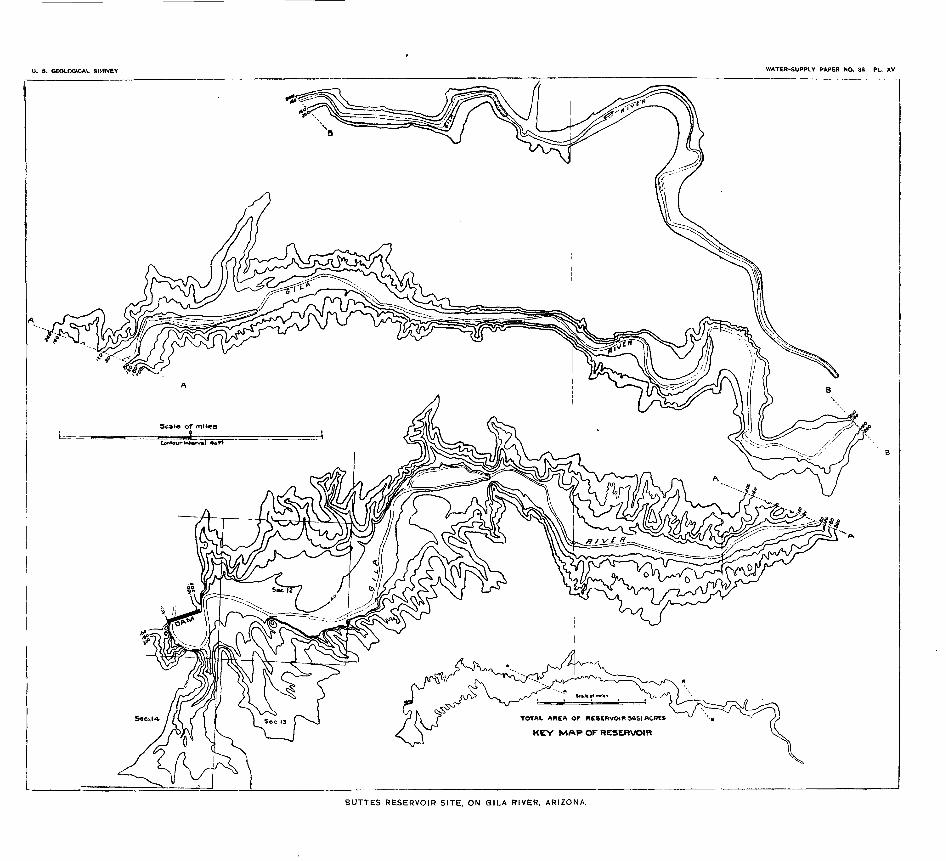
U. S. GEOLOGICAL SURVEY WATER-SUPPLY PAPER NO. 33 PL. XV
TOTAL AREA OF RESERVOIR 5651 ACRES
KEY MAP OF RESERVOIR
BUTTES RESERVOIR SITE, ON GILA RIVER, ARIZONA.
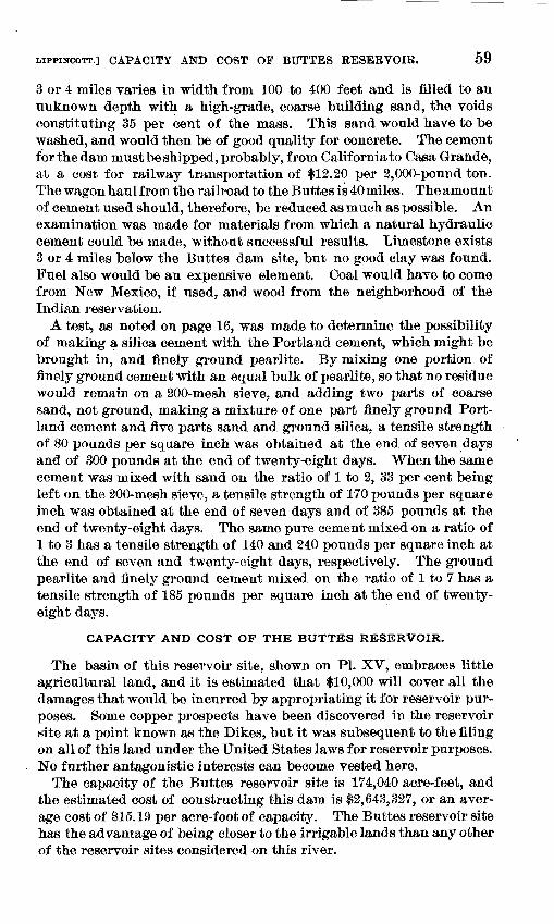
CAPACITY AND COST OF BUTTES RESERVOIR. 59
3 or 4 miles varies in width from 100 to 400 feet and is filled to an unknown depth with a high-grade, coarse building sand, the voids constituting 35 per cent of the mass. This sand would have to be washed, and would then be of good quality for concrete. The cement forthedam must be shipped, probably, from California to Casa Grande, at a cost for railway transportation of $12.20 per 2,000-pound ton. The wagon haul from the railroad to the Buttes is 40 miles. The amount of cement used should, therefore, be reduced as much as possible. An examination was made for materials from which a natural hydraulic cement could be made, without successful results. Limestone exists 3 or 4 miles below the Buttes dam site, but no good clay was found. Fuel also would be an expensive element. Coal would have to come from New Mexico, if used, and wood from the neighborhood of the Indian reservation.
A test, as noted on page 16, was made to determine the possibility of making a silica cement with the Portland cement, which might be brought in, and finely ground pearlite. By mixing one portion of finely ground cement with an equal bulk of pearlite, so that no residue would remain on a 200-mesh sieve, and adding two parts of coarse sand, not ground, making a mixture of one part finely ground Port land cement and five parts sand and ground silica, a tensile strength of 80 pounds per square inch was obtained at the end of seven days and of 300 pounds at the end of twenty-eight days. When the same cement was mixed with sand on the ratio of 1 to 2, 33 per cent being left on the 200-mesh sieve, a tensile strength of 170 pounds per square inch was obtained at the end of seven days and of 385 pounds at the end of twenty-eight days. The same pure cement mixed on a ratio of 1 to 3 has a tensile strength of 140 and 240 pounds per square inch at the end of seven and twenty-eight days, respectively. The ground pearlite and finely ground cement mixed on the ratio of 1 to 7 has a tensile strength of 185 pounds per square inch at the end of twenty- eight days.
CAPACITY AND COST OF THE BUTTES RESERVOIR.
The basin of this reservoir site, shown on PL XV, embraces little agricultural land, and it is estimated that $10,000 will cover all the damages that would be incurred by appropriating it for reservoir pur poses. Some copper prospects have been discovered in the reservoir site at a point known as the Dikes, but it was subsequent to the filing on all of this land under the United States laws for reservoir purposes. No further antagonistic interests can become vested here.
The capacity of the Buttes reservoir site is 174,040 acre-feet, and the estimated cost of constructing this dam is $2,643,327, or an aver age cost of 115.19 per acre-foot of capacity. The Buttes reservoir site has the advantage of being closer to the irrigable lands than any other of the reservoir sites considered on this river.
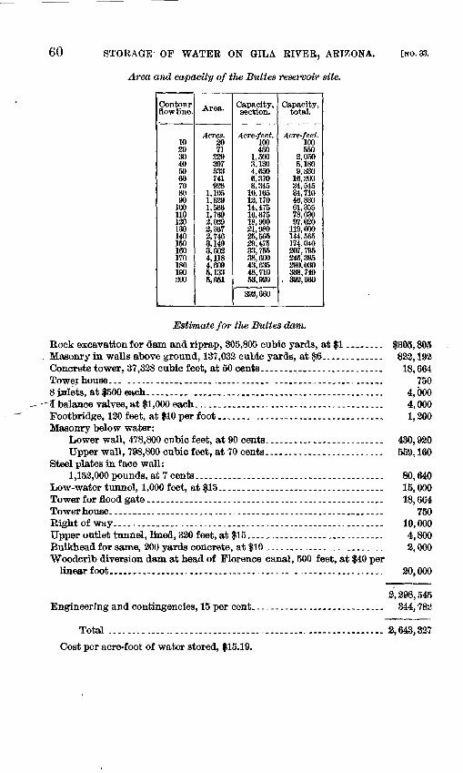
60 STORAGE- OF WATER ON GILA RIVER, ARIZONA.
Area and capacity of the Buttes reservoir site.
[NO. 33.
Contour flow line.
102030405060708090
100110120130140150160170180190300
Area.
Acres. 20 71
533741938
1,1051,3291,5661,7693,0393,3673,7463,1493,6034,1184,6095,1335,651
Capacity, section.
Acre-feet.100450
1,5003,1304,6506,3708,345
10,16512,17014,47516,67518,99031,98025,56529,47533,75538,60043,63548, no53,920
393,660
Capacity, total.
Acre-feet.100550
2,0505,180
16,30024,54534,71046,88061,35578,03097,030
119,000144,565174,040207,795246,395290,030338,740392,660
Estimate for the Buttes dam.
Bock excavation for dam and riprap, 305,805 cubic yards, at $1........ $305,805Masonry in walls above ground, 137,033 cubic yards, at $6........-._.. 822.192Concrete tower. 37,328 cubic feet, at 50 cents. ........_,.....-_.._..._. 18,664Towerhouse... ...... ... ...._,.._.__ ..._.._.....,._,..__. 7508 jnlets, at$500each.-.-.............................................. 4,000
~~£ balance valves, at $1,000 each..................-.........-.-.--_.._._ 4,000Footbridge, 120 feet, at $10 per foot....... -..-.-...-._.-......_..--.-. 1,200Masonry below water:
Lower wall, 478,800 cubic feet, at 90 cents......................... 430,920Upper wall, 798,800 cubic feet, at 70 cents.,....................... 559,160
Steel plates in face wall:1,152,000pounds, at 7 cents........................................ 80,640
Low-water tunnel, 1,000 feet, at $15..-----.-----.....-..-.--...-.-.--- 15,000Tower for flood gate _..-...._--._..-_.__..-.-...-._..--....---....._.. 18,664Towerhouse...-__....-.--.........._.........-................,.... 750Right of way.............. ........................................... 10,000Upper outlet tunnel, lined, 320 feet, at $15....,........................ 4,800Bulkhead for same, 200 yards concrete, at $10 ......................... 2,000Woodcrib diversion dam at head of Florence canal, 500 feet, at $40 per
linear foot...................................... ................... 20,000
2,298,545 Engineering and contingencies, 15 per cent.-----------.........-..--.- 344,782
Total .......................................................... 2,643,327
Cost per acre-foot of water stored, $15.19.
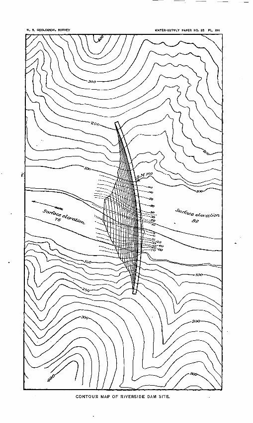
0. 8. GEOLOGICAL SURVEV WATER-SUPPLY PAPER NO. 38 PL. XVI
CONTOUR MAP OF RIVERSIDE DAM SITE.
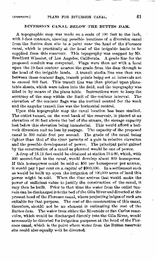
LIPPINCOTT.] PLANS FOB DIVERSION CANAL. 61
DIVERSION CAJSTAL BELOW THE BUTTES DAM.
A topographic map was made on a scale of 100 feet to the inch, with 5-foot contours, showing possible locations of a diversion canal from the Buttes dam site to a point near the head of the Florence canal, which is practically at the head of the irrigable lands to be supplied from this reservoir. This topography was mapped by Mr. Bradford Wheeler, of Los Angeles, California. A grade line for the proposed conduit was computed. Flags were then set with a level upon the 10-foot contour nearest the grade from the dam through to the head of the irrigable lands. A transit stadia line was then run between these contour flags, transit points being set at intervals not to exceed 500 feet. This transit line was then plotted upon plane- table sheets, which were taken into the field, and the topography was filled in by means of the plane table. Instructions were to keep the accuracy of the map within the limit of the contour interval. The elevation of the contour flags was the vertical control for the work and the angular transit line was the horizontal control.
Upon this topographic map the canal location has been studied. The outlet tunnel, on the west bank of the reservoir, is placed at an elevation of 30 feet above the bed of the stream, the storage capacity lost below this elevation being immaterial. This would afford a bed rock diversion and no loss by seepage. The capacity of the proposed canal is 500 cubic feet per second. The grade of the canal being
lighter than that of the river permits of a gain in relative elevation and the possible development of power. The principal point gained by the construction of a canal as planned would be one of power.
A drop of 18.11 feet could be obtained at station 79+80, which, with 500 second-feet in the canal, would develop about 800 horsepower. If this horsepower could be sold at $50 per horsepower per annum, it would pay 5 per cent on a capital of $800,000. In a settlement such as would be built up upon the irrigation of 100,000 acres of land this power might be sold. When the time arrives that would make the power of sufficient value to justify the construction of the canal, it may then be built. Prior to that time the water from the outlet tun nels can be discharged into the bed of the Gila River and diverted at the present head of the Florence canal, where projecting ledges of rock are suitable for that purpose. The cost of the construction of this canal, therefore, should not be an element in estimating the cost of the Buttes dam. The water from either the Riverside or San Carlos reser voirs, which would be discharged directly into the Gila River, would necessarily be diverted for irrigation purposes at the head of the Flor ence canal, which is the point where water from the Buttes reservoir site could also equally well be diverted.
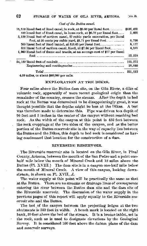
62 STORAGE OF WATER ON GILA RIVER, ARIZONA. [NO. 33.
Cost of tlie Buttes canal.
15,510 lineal feet of lined canal, in rock, at $8.80 per lineal foot......... $136,488400 lineal feet of lined canal, in loose rock, at $6.73 per lineal foot.... 2,692
5,120 lineal feet of earthen canal, 57 cubic yards excavation, per linealfoot, at 30 cents per cubic yard, $1.71 per lineal foot............ 8,755
580 lineal feet of lined tunnel, at $10.65 per lineal foot....--.....-...- 6,177610 lineal feet of earthen canal, lined, at $7.94 per lineal foot......... 4,848
1,960 lineal feet of flume and trestle, at an average cost of $17 per linealfoot .......................................................... 33,320
24,180 lineal feet of conduit,,.....................................-. 192,275Engineering and contingencies.................................. 28,840
Total..................................................... 221,1154.59 miles, or about $48;000 per mile.
EXPLORATION AT THE DIKES.
Four miles above the Buttes dam site, on the Gila River, a dike of volcanic rock, apparently of more recent geological origin than the remainder of the country, crosses the stream. After the depth to bed rock at the Buttes was determined to be disappointingly great, it was thought possible that the depths might be less at the Dikes. A test was therefore made to determine this. Pipe was driven to a depth of 96 feet and 3 inches in the center of the canyon without reaching bed rock. As the width of the canyon at this point is 459 feet between the rock croppings at the two sides of the canyon, and as the better portion of the Buttes reservoir site in the way of capacity lies between the Buttes and the Dikes, this depth to bed rock is considered as hav ing condemned that location for the construction of a dam.
RIVERSIDE RESERVOIR.
The Riverside reservoir site is located on the Gila River, in Final County, Arizona, between the mouth of the San Pedro and a point one- half mile below the mouth of Mineral Creek and 12 miles above the Buttes (PI. XVIII.) The dam site is in a canyon one-half mile below the mouth of Mineral Creek. A view of this canyon, looking down stream, is shown on PI. XVII, A.
The water supply at this point will be practically the same as that at the Buttes. There are no streams or drainage lines of consequence entering the river between the Buttes dam site and the dam site of the Riverside reservoir. The discussion of the water supply in the previous pages of this report will apply equally to the Riverside res ervoir site and the Buttes.
The bed,of the canyon between the projecting ledges at the two abutments is 350 feet in width. A bench mark is located on the right bank, 20 feet above the bed of the stream. It is a bronze tablet, set in the rock, such as is used to designate elevations by the Geological Survey. It is considered 100 feet above the datum plane of the dam and reservoir surveys.
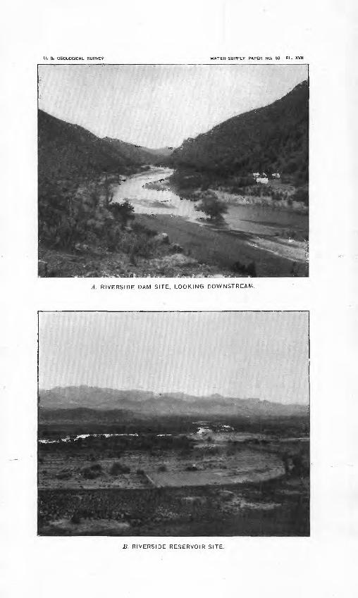
U. S. GEOLOGICAL SURVEY WATER-SUPPLY PAPER NO. 33 PL. XVII
A. RIVERSIDE DAM SITE, LOOKING DOWNSTREAM.
B. RIVERSIDE RESERVOIR SITE.
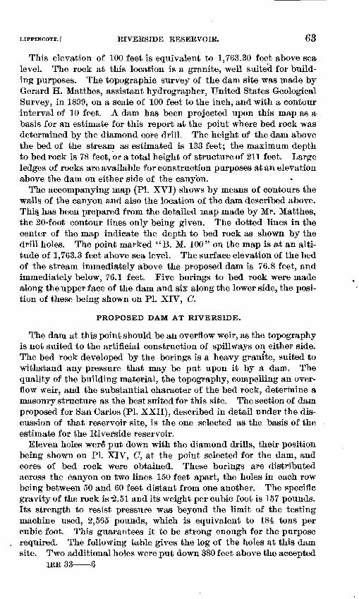
LIPPINCOTT.] RIVERSIDE RESERVOIR. 63
This elevation of 100 feet is equivalent to 1,763.30 feet above sea level. The rock at this location is a granite, well suited for build ing purposes. The topographic survey of the dam site was made by Gerard H. Matthes, assistant hydrographer, United States Geological Survey, in 1899, on a scale of 100 feet to the inch, and with a contour interval of 10 feet. A dam has been projected upon this map as a basis for an estimate for this report at the point where bed rock was determined by the diamond core drill. The height of the dam above the bed of the stream as estimated is 133 feet; the maximum depth to bed rock is 78 feet, or a total height of structure of 211 feet. Large ledges of rocks are available for construction purposes at an elevation above the dam on either side of the canyon.
The accompanying map (PL XVI) shows by means of contours the walls of the canyon and also the location of the dam described above. This has been prepared from the detailed map made by Mr. Matthes, the 20-foot contour lines only being given. The dotted lines in the center of the map indicate the depth to bed rock as shown by the drill holes. The point marked " B. M. 100 " on the map is at an alti tude of 1,763.3 feet above sea level. The surface elevation of the bed of the stream immediately above the proposed dam is 76.8 feet, and immediately below, 76.1 feet. Five borings to bed rock were made along the upper face of the dam and six along the lower side, the posi tion of these being shown on PL XIV, C.
PROPOSED DAM AT RIVERSIDE.
The dam at this point should be an overflow weir, as the topography is not suited to the artificial construction of spillways on either side. The bed rock developed by the borings is a heavy granite, suited to withstand any pressure that may be put upon it by a dam. The quality of the building material, the topography, compelling an over flow weir, and the substantial character of the bed rock, determine a masoniy structure as the best suited for this site. The section of dam proposed for San Carlos (PL XXII), described in detail under the dis cussion of that reservoir site, is the one selected as the basis of the estimate for the Riverside reservoir.
Eleven holes were" put down with the diamond drills, their position being shown on PL XIV, (7, at the point selected for the dam, and cores of bed rock were obtained. These borings are distributed across the canyon on two lines 150 feet apart, the holes in each row being between 50 and 60 feet distant from one another. The specific gravity of the rock is -2.51 and its weight per cubic foot is 157 pounds. Its strength to resist pressure was beyond the limit of the testing machine used, 2,565 pounds, which is equivalent to 184 tons per cubic foot. This guarantees it to be strong enough for the purpose required. The following table gives the log of the holes at this dam site. Two additional holes were put down 380 feet above the accepted
IRR 33 6
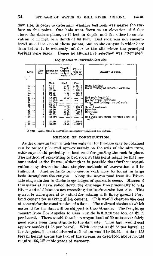
64 STORAGE OF WATER ON GILA RIVER, ARIZONA. [NO. 33.
dam site, in order to determine whether bed rock was nearer the sur face at this point. One hole went down to an elevation of 6 feet above the datum plane, or 76 feet in depth, and the other to an ele vation of 11 feet, or a depth of 68 feet. Bed rock was not encoun tered at either one of these points, and as the canyon is wider here than below, it is evidently inferior to the site where the principal borings were made. Hence no alternative selection was attempted.
Log of Jioles at Riverside dam site.
Line.
A.... A.... A... A-- A... B...B...B-_.B C . O - C-. C . C.
C- C.-..
HoleNo.
1 2 3 4 5 12341 2 3 4 5
67
Depth to bed rock.
Feet. 74.0 75.5 37.00 33.75 16.00 48.00+44.334-31.004-73.504-84.00 49.00 69.0064. as65.004-
37.00 63.00
Depth drilled in bed rock. -
Feet. 1.33 5.00 4.00 4.35
.66 3.00
3.00 3.00 3.35 5.16
3.35 10.75
Eleva tion of
bedrock.
Feet. 1,667.3 1,664.7 1,713.1 1,713.3 1,734.1
1,716.9 1,690.41,670.7 1,673.7
1,739.01,683.9
Quality of rock.
Hard driving. Hard driving at 50 feet; bowlders.
Do.Gravel and sand. Bowlder. Bowlders.
Do.
cliff.
NOTE. Add 1,663.3 to elevation on contour maps for sea datum.
METHOD OF CONSTRUCTION.
As the quarries from which the material for the dam may be obtained can be properly located approximately on the axis of the structure, cableways could probably be best used for putting the rock in place. The method of excavating to bed rock at this point might be that rec ommended at the Buttes, although it is possible that further investi gation may determine that simpler methods of excavation will be sufficient. Sand suitable for concrete work may be found in large beds throughout the canyon. Along the wagon road from the River side stage station to Globe large ledges of quartzite occur. Masses of this material have rolled down the drainage line practically to Gila River and at distances not exceeding 4 miles from'the darn site. This quartzite whon ground is suited for mixing with finely ground Port land cement for making silica cement. This would cheapen the cost of cement for the construction of a dam. The railroad station to which material for the dam will be shipped is Casa Grande. The freight on cement from Los Angeles to Casa Grande is $12.20 per ton, or $2.32 per barrel.. There would then be a wagon haul of 50 miles over fairly good roads from Casa Grande to the dam site. This haul would cost approximately $1.35 per barrel. With cement at $2.85 per barrel at Los Angeles, the cost delivered at the dam would be $6.52. A dam 133 feet in height across the bed of the stream, as described above, would require 186,147 cubic yards of masonry.
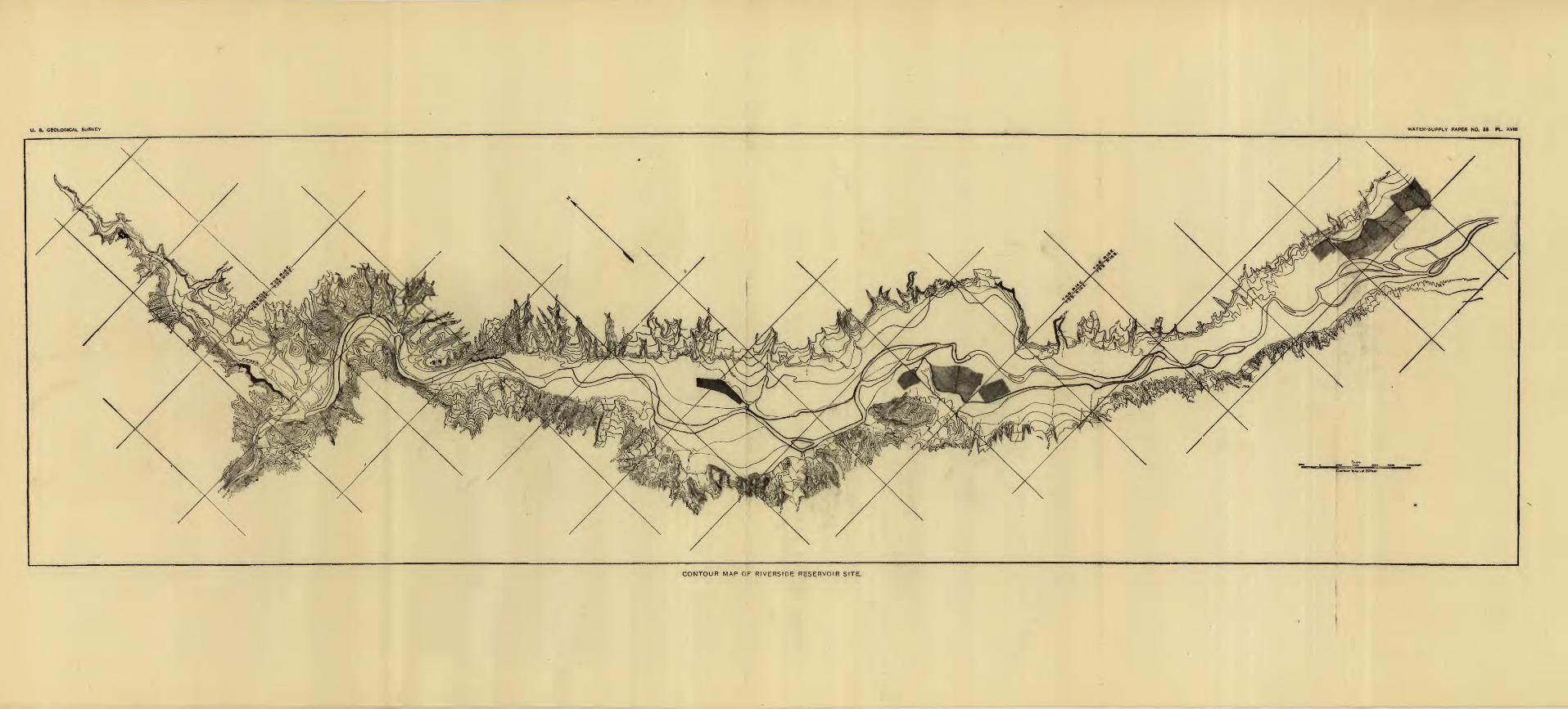
O. 8. GEOLOGICAL SURVEY WATER-SUPPLY PAPER NO. 33 PL. XVIII
CONTOUR MAP OF RIVERSIDE RESERVOIR SITE,
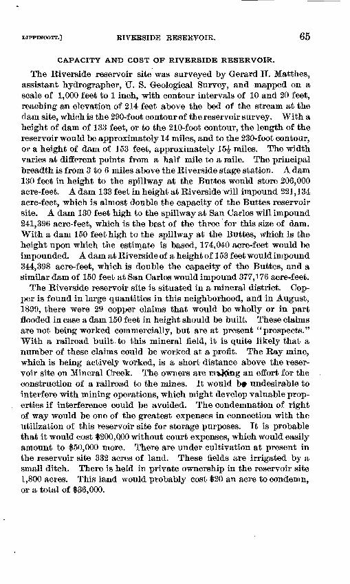
LIPPINCOTT.] RIVERSIDE RESERVOIR. 65
CAPACITY AND COST OF RIVERSIDE RESERVOIR.
The Riverside reservoir site was surveyed by Gerard H. Matthes, assistant hydrographer, U. S. Geological Survey, and mapped on a scale of 1,000 feet to 1 inch, with contour intervals of 10 and 20 feet, reaching an elevation of 214 feet above the bed of the stream at the dam site, which is the 290-foot contour of the reservoir survey. With a height of dam of 133 feet, or to the 210-foot contour, the length of the reservoir would be approximately 14 miles, and to the 230-foot contour, or a height of dam of 153 feet, approximately 15|- miles. The width varies at different points from a half mile to a mile. The principal breadth is from 3 to 6 miles above the Riverside stage station. A dam 130 feet in height to the spillway at the Buttes would store 206,000 acre-feet. A dam 133 feet in height at Riverside will impound 221,134 acre-feet, which is almost double the capacity of the Buttes reservoir site. A dam 130 feet high to the spillway at San Carlos will impound 241,396 acre-feet, which is the best of the three for this size of dam. With a dam 150 feet high to the spillway at the Buttes, which is the height upon which the estimate is based, 174,040 acre-feet would be impounded. A dam at Riverside of a height of 153 feet would impound 344,398 acre-feet, which is double the capacity of the Buttes, and a similar dam of 150 feet at San Carlos would impound 377,176 acre-feet.
The Riverside reservoir site is situated in a mineral district. Cop per is found in large quantities in this neighborhood, and in August, 1899, there were 29 copper claims that would be wholly or in part flooded in case a dam 150 feet in height should be built. These claims are not being worked commercially, but are at present "prospects." With a railroad built.to this mineral field, it is quit© likely that a number of these claims could be worked at a profit. The Ray mine, which is being actively worked, is a short distance above the reser voir site on Mineral Creek. The owners are Ei&Ki»g an effort for the construction of a railroad to the mines. It would b« undesirable to interfere with mining operations, which might develop valuable prop erties if interference could be avoided. The condemnation of right of way would be one of the greatest expenses in connection with the utilization of this reservoir site for storage purposes. It is probable that it would cost $200,000 without court expenses, which would easily amount to $50,000 more. There are under cultivation at present in the reservoir site 332 acres of land. These fields are irrigated by a small ditch. There is held in private ownership in the reservoir site 1,800 acres. This land would probably cost $20 an acre to condemn, or a total of $36,000.
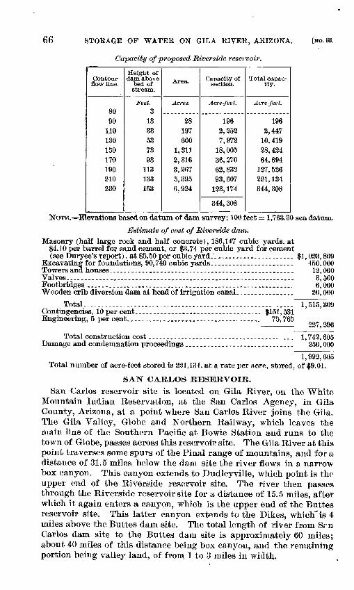
66 STOEAGE OP WATEE ON GILA EIVER, ARIZONA. [NO. 33.
Capacity of proposed Riverside reservoir.
Contour flow line.
8090
110130150170190210230
Height of dam above
bed of stream.
Feet. 3
1333537393
113133153
Area.
Acres.
28197600
1,3112,3163,9675,3956,924
Capacity of section.
Acre-feet.
1962,2527,972
18,00536, 27062, 83293, 607
133, 174
344, 308
Total capac- ity.
Acre feet.
1962,447
10, 41928, 42464, 694
127, 526221, 134344,308
NOTE. Elevations based on datum of dam survey; 100 feet = 1,763.30 sea datum.
Estimate of cost of Riverside dam.Masonry (half large rock and half concrete), 186,147 cubic yards, at
$4.10 per barrel for sand cement, or $3.74 per cubic yard for cement (see Duryee's report), at $5.50 per cubic yard.'...................... $1,023,809------- -- - - - - --........ 450,000
.......... 12,000.......... 3,500.......... 6,000.......... 20,000
Excavating for foundations, 90,740 cubic yards. Towers and houses.....-.-..._.......................Valves...................__.........................Footbridges ............ ....._.........................Wooden crib diversion dam at head of irrigation canal.
Total.-....-..-...,-...-.-----.--.........-..-,.-........ ..... 1,515,309Contingencies, 10 per cent........... __................... $151,531Engineering, 5 per cent.................,...-.-..---.-...... 75,765
227,296
Total construction cost .................^.................. ... 1,742,605Damage and condemnation proceedings.........._.--.---...-........ 250,000
1,993,605 Total number of acre-feet stored is 231,134, at a rate per acre, stored, of $9.01.
SAN CARLOS RESERVOIR.San Carlos reservoir site is located on Gila River, on the White
Mountain Indian Reservation, at the San Carlos Agency, in Gila County, Arizona, at a point where San Carlos River joins the Gila. The Gila Valley, Globe and Northern Railway, which leaves the main line of the Southern Pacific at Bowie Station and runs to the town of Globe, passes across this reservoir site. The Gila River at this point traverses some spurs of the Final range of mountains, and for a distance of 31.5 miles below the dam site the river flows in a narrow box canyon. This canyon extends to Dudleyville, which point is the upper end of the Riverside reservoir site. The river then passes through the Riverside reservoir site for a distance of 15.5 miles, after which it again enters a canyon, which is the upper end of the Buttes reservoir site. This latter canyon extends to the Dikes, which'is 4 miles above the Buttes dam site. The total length of river from Srn Carlos dam site to the Buttes dam site is approximately 60 miles; about 40 miles of this distance being box canyon, and the remaining portion being valley land, of from 1 to 3 miles in width,
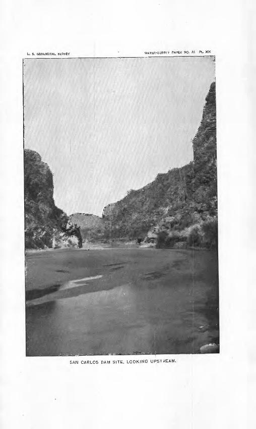
U. S. GEOLOGICAL SURVEY WATER-SUPPLY PAPER NO. 33 PL. XIX
SAN CARLOS DAM SITE, LOOKING UPSTREAM.
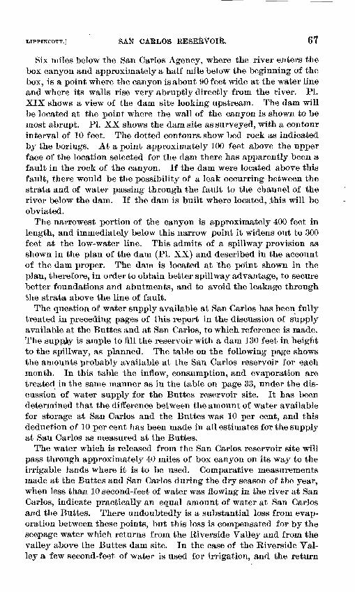
LIPPINCOTT.] SAiiT CARLOS RESERVOIR. 67
Six miles below the San Carlos Agency, where the river enters the box canyon and approximately a half mile below the beginning of the box, is a point where the canyon is about 90 feet wide at the water line and where its walls rise very abruptly directly from the river. PL XIX shows a view of the dam site looking upstream. The dam will be located at the point where the wall of the canyon is shown to be most abrupt. PI. XX shows the dam site as surveyed, with a contour interval of 10 feet. The dotted contours, show bed rock as indicated by the borings. At a point approximately 100 feet above the upper face of the location selected for the dam there has apparently been a fault in the rock of the canyon. If the dam were located above this fault, there would be the possibility of a leak occurring between the strata and of water passing through the fault to the channel of the river below the dam. If the dam is built where located, this will be obviated.
The narrowest portion of the canyon is approximately 400 feet in length, and immediately below this narrow point it widens out to 300 feet at the low-water line. This admits of a spillway provision as shown in the plan of the dam (PI. XX) and described in the account of the dam proper. The dam is located at Ihe po'int shown in the plan, therefore, in order to obtain better spillway advantage, to secure better foundations and abutments, and to avoid the leakage through the strata above "the line of fault.
The question of water supply available at San Carlos has been fully treated in preceding pages of this report in the discussion of supply available at the Buttes and at San Carlos, to which reference is made. The supply is ample to fill the reservoir with a dam 130 feet in height to the spillway, as planned. The table on the following page shows the amounts probably available at the San Carlos reservoir for each month. In this table the inflow, consumption, and evaporation are treated in the same manner as in the table on page 33, under the dis cussion of water supply for the Buttes reservoir site. It has been determined that the difference between the amount of water available for storage at San Carlos and the Buttes was 10 per cent, and this deduction of 10 per cent has been made in all estimates for the supply at San Carlos as measured at the Buttes.
The water which is released from the San Carlos reservoir site will pass through approximately 40 miles of box canyon on its way to the irrigable lands where it is to be used. Comparative measurements made at the Buttes and San Carlos during the dry season of the year, when less than 10 second-feet of water was flowing in the river at San Carlos, indicate practically an equal amount of water at San Carlos and the Buttes. There undoubtedly is a substantial loss from evap oration between these points, but this loss is compensated for by the seepage water which returns from the Riverside Valley and from the valley above the Buttes dam site. In the case of the Riverside Yal- ley a few second-feet of water is used for irrigation, and the return
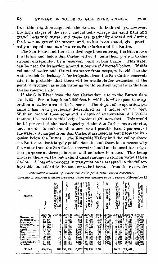
68 STOEAGE OF WATER ON GILA RIVER, ARIZONA. [NO. 33.
from this irrigation augments the stream. In both valleys, however, the high stages of the river undoubtedly charge the sand bars and gravel beds with water, and these are gradually drained Toff during the lower stages of the stream and, as has been stated, give practi cally an equal amount of water at San Carlos and the Buttes.
The San Pedro and the other drainage lines entering the Gila above the Buttes and below San Carlos will contribute their portion to this stream, unregulated by a reservoir built at San Carlos. This water can be used for irrigation around Florence if diverted below. If this volume of water and the return water from seepage is added to the water which is discharged for irrigation from the San Carlos reservoir site, it is probable that there will be available for irrigation at the point of diversion as much water as would be discharged from the San Carlos reservoir site.
If the Gila River from the San Carlos dam site to the Buttes dam site is 60 miles in length and 200 feet in width, it will expose to evap oration a water area of 1,454 acres. The depth of evaporation per annum has been previously determined as 91 inches, or 7.58 feet. With an area of 1,454 acres and a depth of evaporation of 7.58 feet there will be lost from this body of water 11,021 acre-feet. This would be 4.6 per cent of the total capacity of the San Carlos reservoir site, and, in order to make an allowance for all possible loss, 5 per cent of the water discharged from San Carlos is assumed as being lost for irri gation below the Buttes. The Riverside Valley and the valley above the Buttes are both largely public domain, and there is no reason why the water from the San Carlos reservoir should not be used for irriga tion purposes at these points, as well as below Florence. This being the case, there will be but a slight disadvantage in storing water at San Carlos. A loss of 5 per cent in transmission is accepted in the follow ing table and added to the amount to be liberated from the reservoir:
Estimated amount of water available from San Carlos reservoir,[Capacity of reservoir is 341,396 acre-feet; 100,000 feet assumed to be in reservoir November 1.]-
Mouth.
November ...December....January.. .... February.. ...
April.........May ..........
July..........
September...October ... ...
Total. ....
i o33 &
Acre-ft.32,84337,11736,745 34,00821,40518,4337,2373,665
59,17069,53247,25074,800
422,184
t-rt'8 2
&id0 O.g
O Kr,
go5AH
Per ct.222 579
14141313118
100
03bfi
1! *
Ow
§
Acre-ft4,8384,8384,838is, on
16,89821,73533,79533,79531,38131,38126,55419,313
241,396
aog-u .2
§.2.1h 02 hcL00 -^
<H 00 -U
§£ft
Acre-ft341341241 604845
1,0861,6901,6901,5691,5691,328
966
12,070:
S&RS53ll§o so.2ei'o bo
J°*
Acre-ft5,0695,0695,069
13,67517,74322,81135,48535,48533,95033,95037,88330,278
353,466
<fc0
?
a
(S
Feet.0.43
.333
.35
.333
.50
.58
.8392
1.001.08.83.50
7.58
o
og
M O<S p,
3
Acres.3,6504,1004,690 5,1305,3355,7604,6803,1104,0604,3704,9505,714
' fl J ^
g£03 02
IIJ«Acre-ft
1,533I,o531,173 1,7102,6123,3413,8842,8614,0604,7204,1092,857
34,211
J.6 Si*a > a o>^1
o fl d^00^ a'43g&^
Acre-ft6,6036,4336,243
14,38520,35526,15239,36938,34637,01037,67031,99123,135
287,477
A>£!§sip3 s
Acre-ft.136,240146,935177,438 187,061188,109180,390148,348113,567135,73716?, 579183,838034,501
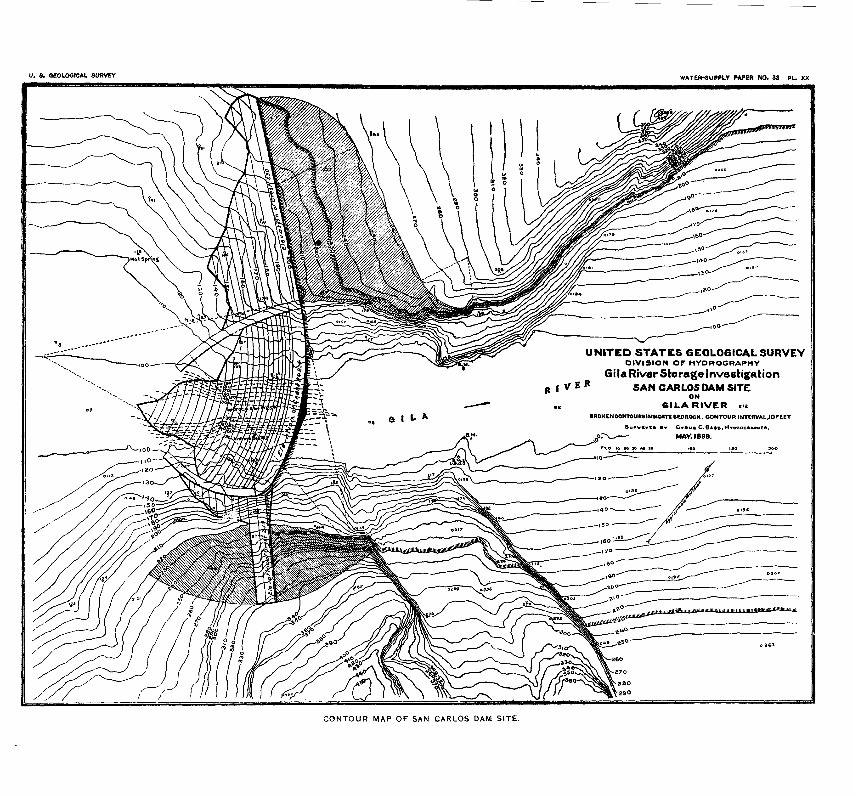
U. 8. GEOLOGICAL SURVEY WATEH-8Um.Y PAPER HO. 33 PL. XX
UNITED STATES GEOLOGICAL SURVEYDIVISION OF HYDROGRAPHY
Gila River Storage Investigation R f V E R SAN CARLOS DAM SITE
ON61 LA RIVER
MOKENCONTOUMINWCKn BEDROCK. CONTOUR INTtRVAL.IOftET
C.BA»»,H MAY. 1 899.
CONTOUR MAP OF SAN CARLOS DAM SITE.
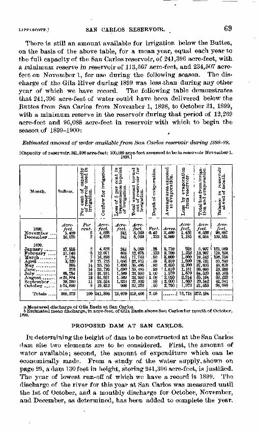
LIPPINCOTT.] SAN CAELOS RESERVOIR. 69
There is still an amount available for irrigation below the Buttes, on the basis of the above table, for a mean year, equal each year to the full capacity of the San Carlos reservoir, of 241,396 acre-feet, with a minimum reserve in reservoir of 113,567 acre-feet, and 234,507 acre- feet on November 1, for use during the following season. The dis charge of the Gila River during 1899 was less >than during any other year of which we have record. The following table demonstrates that 241,396 acre-feet of water could have been delivered below the Buttes from San Carlos from November 1, 1898, to October 31, 1899, with a minimum reserve in the reservoir during that period of 12,269 acre-feet and 96,088 acre-feet in reservoir with which to begin the season of 1899-1900:
Estimated amount of water available from San Carlos reservoir during 1898-99.
[Capacity of reservoir, 341,396 acre-feet; 100,000 acre-feet assumed to be in reservoir November 1,
Month.
1898. November ...December ....
1899. January.. _ . February .... March _ ....April .........May ..... _ ..June..........Julv -... ..August .September . - . October ......
TVvtale JLOucUD f ___
Inflow.
Acre-feet. 5,409
16,878
17,555 11,946 7,1943,320
996276
65,754a24,884
39,260674,800
368,272
!>>HiS""1
*1|B
o|§-W IU*rHsi~§i'^
oJ oA PH
Percent.
23
-579
14141313118
100
d.2
t"13
g1
rrt 33
0
Acre-feet. 4,8284,828
4,828 12,071 16,89831,73533,79533,79531,38131,38126.554 19,312
341,396
Sa-w'o a P.IB O
ll|
«M i-spM §'^
3-*°
Acre-feet.
241341
241 604845
1,0861,6901,6901,5691,5691,338
966
12,070
* o1
S j.£pO ss1^53S"-1 08^OM^ g'S00«
Acre-feet. 5,0695,069
5,069 12,67517,74323,81135,48535,48533,95033,95027,883 20,278
253,466
.§
"eg
1
1"o
s&
Feet. 0.43
.333
.35
.333
.50
.58
.83
.931.001.08
.83
.50
7.58
13M
ftgM-g C "cS
S h
Si®|o
%
Acres. 3,4603,560
3, no3,700 3,6003,3102,6501,6101,5702,0502,000 2,750
B_O
8o
^si 5"A
Acre-feet, 1,4531,185
938 1,233 1,8001,9202,2001,1811,5702,2141,680 1,373
18,718
, .boo
fcl
fl|
ItS"?"-1 S1 4 TO
^ flO O
Acre-feet. 6,5226,254
5,997 13,907 19,54324,73137,68536,66634,52035,16439,543 21,653
372,184
S-i'S
£5|§
SoCD fl
1-8
Acre-feet. 98,887
109,511
121,069 119, 108 106,75985,34848,65912,36943,50333,33342,94196,088
o Measured discharge of Gila Basin at San Carlos.6 Estimated mean discharge, in acre-feet, of Gila Basin above San Carlos for month of October,
1899.
PROPOSED DAM AT SAN CARLOS.
Iii determining the height of dam to be constructed at the San Carlos dam site two elements are to be considered. First, the amount of water available; second, the amount of expenditure which can be economically made. From a study of the water supply, shown on page 29, a dam 130 feet in height, storing 241,396 acre-feet, is justified. The year of lowest run-off of which we have a record is 1899. The discharge of the river for this year at San Carlos was measured until the 1st of October, and a monthly discharge for October, November, and December, as determined, has been added to complete the year.
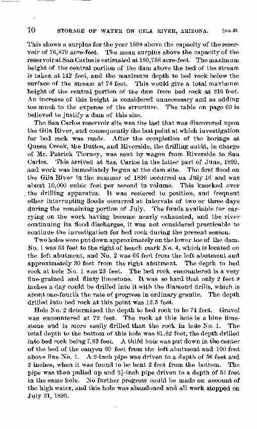
70 STORAGE OF WATER ON GILA RIVER, ARIZONA. [NO. 33.
This shows a surplus for the year 1899 above the capacity of the reser voir of 76,879 acre-feet. The mean surplus above the capacity of the reservoir at San Carlos is estimated at 180,788 acre-feet. The maximum height of the central portion of the dam above the bed of the stream is taken at 142 feet, and the maximum depth to bed rock below the surface of the stream at 74 feet. This would give a total maximum height of the central portion of the dam from bed rock at 216 feet. An increase of this height is considered unnecessary and as adding too much to the expense of the structure. The table on page 69 is believed to justify a dam of this size.
The San Carlos reservoir site was the last that was discovered upon the Gila River, and consequently the last point at which investigation for bed rock was made. After the completion of the borings at Queen Creek, the Buttes, and Riverside, the drilling outfit, in charge of Mr. Patrick Tierney, was sent by wagon from Riverside to San Carlos. This arrived at San Carlos in the latter part of June, 1899, and work was immediately begun at the dam site. The first flood on the Gila River in the summer of 1899 occurred on July 16 and was about 10,000 cubic feet per second in volume. This knocked over the drilling apparatus. It was restored to position, and frequent other interrupting floods occurred at intervals of two or three days during the remaining portion of July. The funds available for car rying on the work having become nearly exhausted, and the river- continuing its flood discharges, it was not considered practicable to continue the investigation for bed rock during the present season.
Two holes were put down approximately on the lower toe of the dam. No. 1 was 33 feet to the right of bench mark No. 4, which is located on the left abutment, and No. 2 was 66 feet from the left abutment and approximately 30 feet from the right abutment. The depth to bed rock at hole No. 1 was 23 feet. The bed rock encountered is a very fine-grained and flinty limestone. It was so hard that only 2 feet 9 inches a day could be drilled into it with the diamond drills, which is about one-fourth the rate of progress in ordinary granite. The depth drilled into bed rock at this point was 12.5 feet.
Hole No. 2 determined the depth to bed rock to be 74 feet. Gravel was encountered at 72 feet. The rock at this hole is a blue lime stone and is more easily drilled than the rock in hole No. 1. The total depth to the bottom of this hole was 81.82 feet, the depth drilled into bed rock being 7.82 feet. A third hole was put down in the center of the bed of the canyon 60 feet from the left abutment and 100 feet above line-No. 1. A 2-inch pipe was driven to a depth of 56 feet and 2 inches, when it was found to be bent 2 feet from the bottom. The pipe was then pulled up and 2^-inch pipe driven to a depth of 51 feet in the same hole. No further progress could be made on account of the high water, and this hole was abandoned and all work stopped on July 31, 1899.
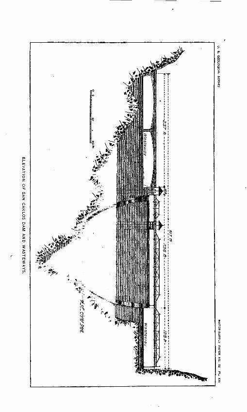
U.
S.
GE
OLO
GIC
AL
SU
RV
EY
WA
TE
R-S
UP
PLY
P
AP
ER
N
O.
33 P
L.
XX
I
ELE
VA
TIO
N
OF
S
AN
C
AR
LO
S
DA
M
AN
D
WA
ST
EW
AY
S.
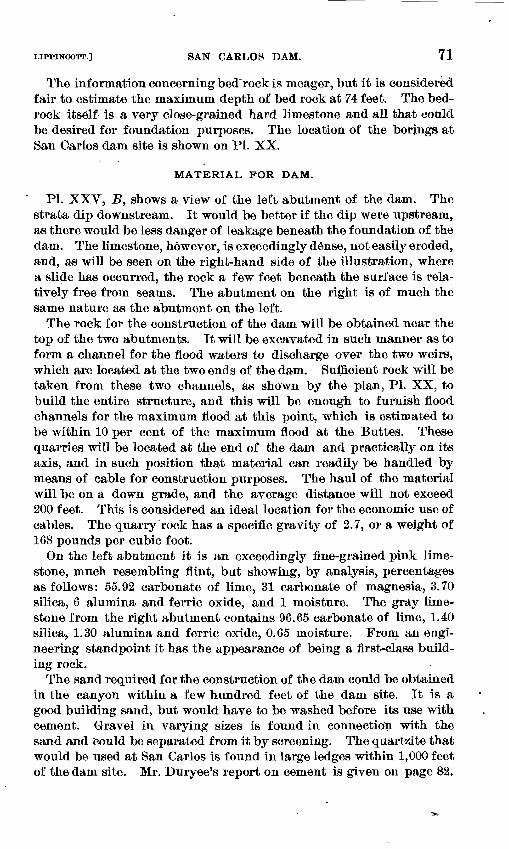
LIPPINCOTT.] SAN CARLOS DAM. 71
The information concerning bed rock is meager, but it is considered fair to estimate the maximum depth of bed rock at 74 feet. The bed rock itself is a very close-grained hard limestone and all that could be desired for foundation purposes. The location of the borings at San Carlos dam site is shown on PI. XX.
MATERIAL FOR DAM.
PL XXV, J5, shows a view of the left abutment of the dam. The strata dip downstream. It would be better if the dip were upstream, as there would be less danger of leakage beneath the foundation of the dam. The limestone, however, is exceedingly dense, not easily eroded, and, as will be seen on the right-hand side of the illustration, where a slide has occurred, the rock a few feet beneath the surface is rela tively free from seams. The abutment on the right is of much the same nature as the abutment on the left.
The rock for the construction of the dam will be obtained near the top of the two abutments. It will be excavated in such manner as to form a channel for the flood waters to discharge over the two weirs, which are located at the two ends of the dam. Sufficient rock will be taken from these two channels, as shown by the plan, PI. XX, to build the entire structure, and this will be enough to furnish flood channels for tlte maximum flood at this point, which is estimated to be within 10 per cent of the maximum flood at the Buttes. These quarries will be located at the end of the dam and practically on its axis, and in such position that material can readily be handled by means of cable for construction purposes. The haul of the material will be on a down grade, and the average distance will not exceed 200 feet. This is considered an ideal location for the economic use of cables. The quarry rock has a specific gravity of 2.7, or a weight of 168 pounds per cubic foot.
On the left abutment it is an exceedingly fine-grained pink lime stone, much resembling flint, but showing, by analysis, percentages as follows: 55.92 carbonate of lime, 31 carbonate of magnesia, 3.70 silica, 6 alumina and ferric oxide, and 1 moisture. The gray lime stone from the right abutment contains 96.65 carbonate of lime, 1.40 silica, 1.30 alumina and ferric oxide, 0.65 moisture. From an engi neering standpoint it has the appearance of being a first-class build ing rock.
The sand required for the construction of the dam could be obtained in the canyon within a few hundred feet of the dam site. It is a good building sand, but would have to be washed before its use with cement. Gravel in varying sizes is found in connection with the sand and could be separated from it by screening. The quartzite that would be used at San Carlos is found in large ledges within 1,000 feet of the dam site. Mr. Duryee's report on cement is given on page 82.
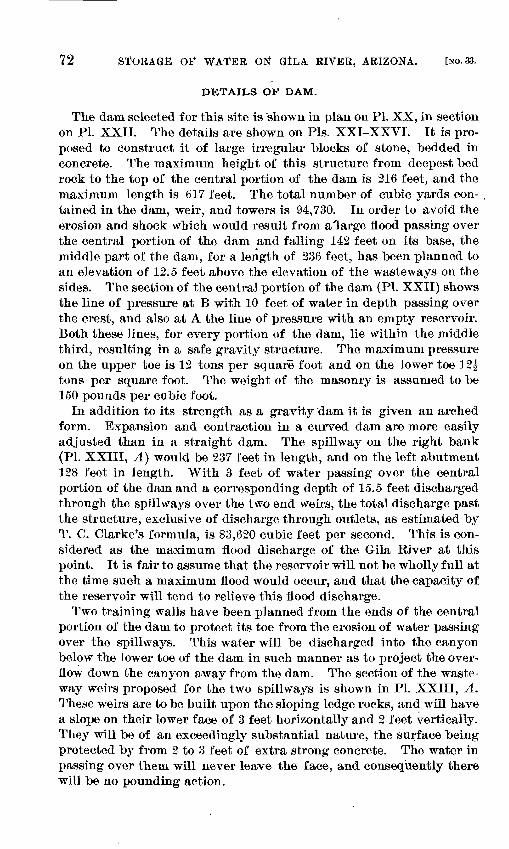
72 STORAGE OF WATER ON GlLA. RIVER, ARIZONA. [NO. 33.
DETAILS OF DAM.
The dam selected for this site is shown in plan on PL XX, in section on PL XXII. The details are shown on Pis. XXI-XXVI. It is pro posed to construct it of large irregular blocks of stone, bedded in concrete. The maximum height of this structure from deepest bed rock to the top of the central portion of the dam is 216 feet, and the maximum length is 617 feet. The total number of cubic yards con tained in the dam, weir, and towers is 94,730. In order to avoid the erosion and shock which would result from a large flood passing over the central portion of the dam and falling 142 feet on its base, the middle part of the dam, for a length of 236 feet, has been planned to an elevation of 12.5 feet above the elevation of the wasteways on the sides. The section of the central portion of the dam (PL XXII) shows the line of pressure at B with 10 feet of water in depth passing over the crest, and also at A the line of pressure with an empty reservoir. Both these lines, for every portion of the dam, lie within the middle third, resulting in a safe gravity structure. The maximum pressure on the upper toe is 12 tons per square foot and on the lower toe 12J tons per square foot. The weight of the masonry is assumed to be 150 pounds per cubic foot.
In addition to its strength as a gravity dam it is given an arched form. Expansion and contraction in a curved dam are more easily adjusted than in a straight dam. The spillway on the right bank (PL XXIII, A) would be 237 feet in length, and on the left abutment 128 feet in length. With 3 feet of water passing over the central portion of the dam and a corresponding depth of 15.5 feet discharged through the spillways over the two end weirs, the total discharge past the structure, exclusive of discharge through outlets, as estimated by T. C. Clarke's formula, is 83,620 cubic feet per second. This is con sidered as the maximum flood discharge of the Gila River at this point. It is fair to assume that the reservoir will not be wholly full at the time such a maximum flood would occur, and that the capacity of the reservoir will tend to relieve this flood discharge.
Two training walls have been planned from the ends of the central portion of the dam to protect its toe from the erosion of water passing over the spillways. This water will be discharged into the canyon below the lower toe of the dam in such manner as to project the over flow down the canyon away from the dam. The section of the waste- way weirs proposed for the two spillways is shown in PL XXIII, A. These weirs are to be built upon the sloping ledge rocks, and will have a slope on their lower face of 3 feet horizontally and 2 feet vertically. They will be of an exceedingly substantial nature, the surface being protected by from 2 to 3 feet of extra strong concrete. The water in passing over them will never leave the face, and consequently there will be no pounding action.
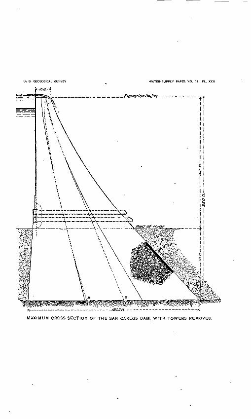
U. 8. GEOLOGICAL SURVEY WATER-SUPPLY PAPER NO. 33 PL. XXII
MAXIMUM CROSS SECTION OF THE SAN CARLOS DAM, WITH TOWERS REMOVED.
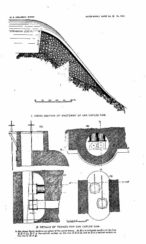
U. 8. GEOLOGICAL SURVEY WATER-SUPPLY PAPER NO. 33 PL. XXIII
A. CROSS SECTION OF WASTEWAY OF SAN CARLOS DAM.
B. DETAILS OF TOWERS FOR SAN CARLOS DAM.
In the above figure sections are given of the outlet tower. At B to a horizontal section on the line EFof D; ft C is the vertical section on the line CD of B, and at D is a vertical section on the line GH°i B-
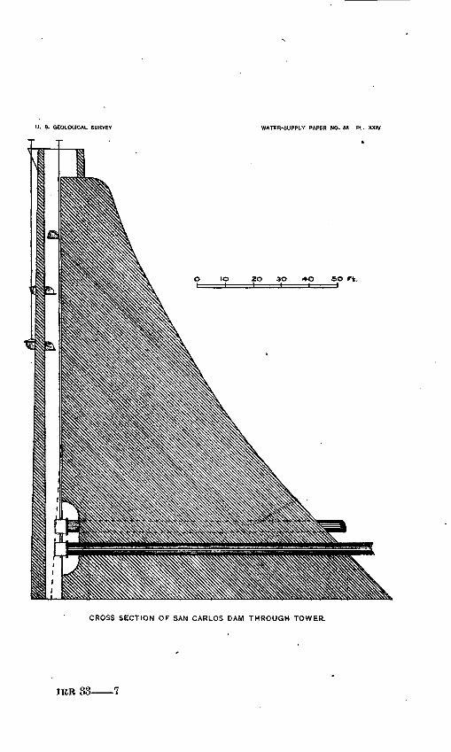
U. S. GEOLOGICAL SURVEY WATER-SUPPLY PAPER NO. 33 PL. XXIV
so rt.
CROSS SECTION OF SAN CARLOS DAM THROUGH TOWER.
33 7
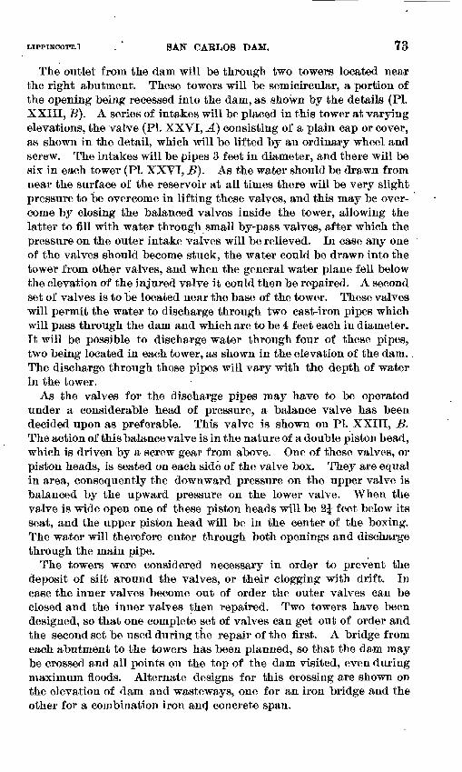
LippiNCOTT.1 . " SAN CAELOS DAM. 73
The outlet from the dam will be through two towers located near the right abutment. These towers will be semicircular, a portion of the opening being recessed into the dam, as shown by the details (PL XXIII, B). A series of intakes will be placed in this tower at varying elevations, the valve (PI. XXVI, A) consisting of a plain cap or cover, as shown in the detail, which will be lifted by an ordinary wheel and screw. The intakes will be pipes 3 feet in diameter, and there will be six in each tower (PL XXVI, B). As the water should be drawn from near the surface of the reservoir at all times there will be very slight pressure to be overcome in lifting these valves, and this may be over come by closing the balanced valves inside the tower, allowing the latter to fill with water through small by-pass valves, after which the pressure on the outer intake valves will be relieved. In case any one of the valves should become stuck, the water could be drawn into the tower from other valves, and when the general water plane fell below the elevation of the injured valve it could then be repaired. A second set of valves is to be located near the base of the tower. These valves will permit the water to discharge through two cast-iron pipes which will pass through the dam and which are to be 4 feet each in diameter. It will be possible to discharge water through four of these pipes, two being located in each tower, as shown in the elevation of the dam.. The discharge through these pipes will vary with the depth of water in the tower.
As the valves for the discharge pipes may have to be operated under a considerable head of pressure, a balance valve has been decided upon as preferable. This valve is shown on PL XXIII, B. The action of this balance valve is in the nature of a double piston head, which is driven by a screw gear from above. One of these valves, or piston heads, is seated on each side of the valve box. They are equal in area, consequently the downward pressure on the upper valve is balanced by the upward pressure on the lower valve. When the valve is wide open one of these piston heads will be 2£ feet below its seat, and the upper piston head will be in the center of the boxing. The water will therefore enter through both openings and discharge through the main pipe.
The towers were considered necessary in order to prevent the deposit of silt around the valves, or their clogging with drift. In case the inner valves become out of order the outer valves can be closed and the inner valves then repaired. Two towers have been designed, so that one complete set of valves can get out of order and the second set be used during the repair of the first. A bridge from each abutment to the towers has been planned, so that the dam may be crossed and all points on the top of the dam visited, even during maximum floods. Alternate designs for this crossing are shown on the elevation of dam and wasteways, one for an iron bridge and the other for a combination iron an4 concrete span.
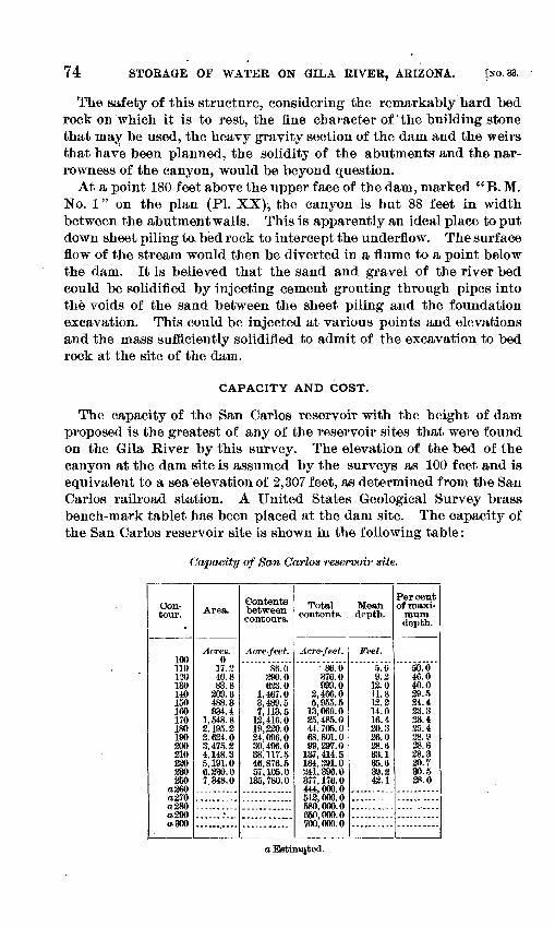
74 STORAGE OF WATER ON GILA RIVER, ARIZONA. [NO. 33.
The safety of this structure, considering the remarkably hard bed rock on which it is to rest, the fine character of the building stone that mav be used, the heavy gravity section of the dam and the weirs that have been planned, the solidity of the abutments and the nar rowness of the canyon, would be beyond question.
At a point 180 feet above the upper face of the dam, marked "B. M. No. 1" on the plan (PI. XX), the canyon is but 88 feet in width between the abutment walls. This is apparently an ideal place to put down sheet piling to. bed rock to intercept the underflow. The surface flow of the stream would then be diverted in a flume to a point below the dam. It is believed that the sand and gravel of the river bed could be solidified by injecting cement grouting through pipes into the voids of the sand between the sheet piling and the foundation excavation. This could be injected at various points and elevations and the mass sufficiently solidified to admit of the excavation to bed rock at the site of the dam.
CAPACITY AND COST.
The capacity of the San Carlos reservoir with the height of dam proposed is the greatest of any of the reservoir sites that were found on the Gila River by this survey. The elevation of the bed of the canyon at the dam site is assumed by the surveys as 100 feet and is equivalent to a sea elevation of 2,307 feet, as determined from the San Carlos railroad station. A United States Geological Survey brass bench-mark tablet has been placed at the dam site. The capacity of the San Carlos reservoir site is shown in the following table:
Capacity of San Carlos reservoir site.
Con tour.
100110130130140150160170180190200210220230250
a 360a 270a 280a290a 300
Area.
Acres.0
17.240.883.8
209.6488.3934.4
1,548.82,195.22,624.03,475.24,148.35,191.06,330.07.348.0
.-.- ......
...... ....
_.. _ » _
Contents between contours.
Acre-feet.
86.0290.0623.0
1,467.03.489.57; 113. 5
12,416.019,220.024,096.030, 496. 038,117.546,876.557,105.0
135,780.0...... ... _.--... ......
Total contents.
Acre-feet.
86.0376.0999.0
2,466.05,955.5
13,069.025,485.044, 705. 068, 801. 099,297.0
137,414.5184,291.0241,396.0377,176.0444,000.0512,000,0580,000.0650,000.0700,000.0
Mean depth.
Feet.
5.09.2
12.011.812.214.016.420.326.028.633.135.639.242.1
... _ _.._
...... -.. .
Percent of maxi
mum depth.
50.046.040.029.524.423.323.425.428.928.628.329.730.528.0
___. _ .....,..»- .--.
a Estimated.
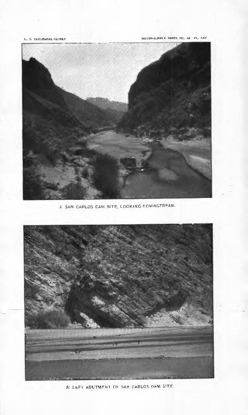
U. S. GEOLOGICAL SURVEY WATER-SUPPLY PAPER NO. 33 PL. XXV
A SAN CARLOS DAM SITE, LOOKING DOWNSTREAM.
LEFT ABUTMENT OF SAN CARLOS DAM SITE.
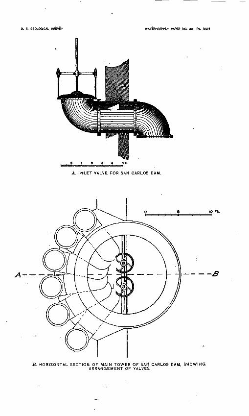
U. S. GEOLOGICAL SURVEY WATER-SUPPLY PAPER NO. 33 PL, XXVI
A. INLET VALVE FOR SAN CARLOS DAM.
10 Ft.
yt ... ___
B. HORIZONTAL SECTION OF MAIN TOWER OF SAN CARLOS DAM, SHOWING ARRANGEMENT OF VALVES.
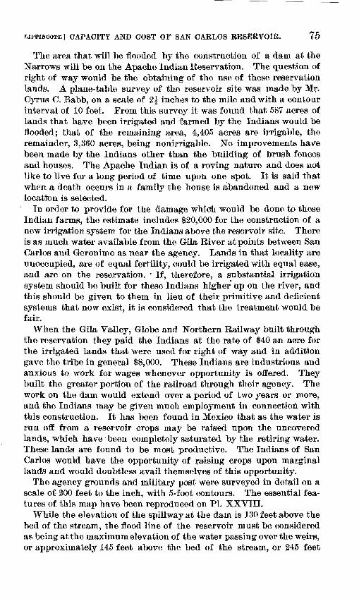
CAPACITY AND COST OF SAN CARLOS RESERVOIR. 75
The area that will be flooded by the construction of a dani at the Narrows will be on the Apache Indian Reservation. The question of right of way would be the obtaining of the use of these reservation lands. A plane-table survey of the reservoir site was made by Mr. Cyrus C. Babb, on a scale of 2|- inches to the mile and with a contour interval of 10 feet. From this survey it was found that 587 acres of lands that have been irrigated and farmed by the Indians would be flooded; that of the remaining area, 4,405 acres are irrigable, the remainder, 3,360 acres, being nonirrigable. No improvements have been made by the Indians other than the building of brush fences and houses. The Apache Indian is of a roving nature and does not like to live for a long period of time upon one spot. It is said that when a death occurs in a family the house is abandoned and a new location is selected.
In order to provide for the damage which would be done to these Indian farms, the estimate includes $20,000 for the construction of a new irrigation system for the Indians above the reservoir site. There is as much water available from the Gila River at points between San Carlos and Geronimo as near the agency. Lands in that locality are unoccupied, are of equal fertility, could be irrigated with equal ease, and are on the reservation. ' If, therefore, a substantial irrigation system should be built for these Indians higher up on the river, and this should be given to them in lieu of their primitive and deficient systems that now exist, it is considered that the treatment would be fair.
When the Gila Valley, Globe and Northern Railway built through the reservation they paid the Indians at the rate of $40 an acre for the irrigated lands that were used for right of way and in addition gave the tribe in general $8,000. These Indians are industrious and anxious to work for wages whenever opportunity is offered. They built the greater portion of the railroad through their agency. The work on the dam would extend over a period of two years or more, and the Indians may be given much employment in connection with this construction. It has been found in Mexico that as the water is run off from a reservoir crops may be raised upon the uncovered lands, which have been completely saturated by the retiring water. These lands are found to be most productive. The Indians of San Carlos would have the opportunity of raising crops upon marginal Lands and would doubtless avail themselves of this opportunity.
The agency grounds and military post were surveyed in detail on a scale of 200 feet to the inch, with 5-foot contours. The essential fea tures of this map have been reproduced on PI. XXVIII.
While the elevation of the spillway at the dam is 130 feet above the bed of the stream, the flood line of the reservoir must be considered as being at the maximum elevation of the water passing over the weirs, or approximately 145 feet above the bed of the stream, or 245 feet
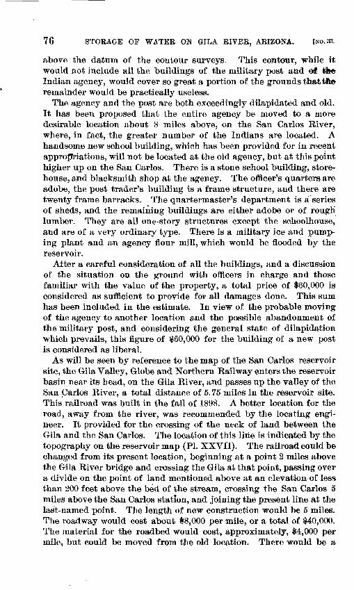
76 STORAGE OP WATER ON GILA RIVER, ARIZONA. [NO. 33.
above the datum of the contour surveys. This contour, while it would not include all the buildings of the military post and oi tkfr Indian agency, would cover so great a portion of the grounds that tie remainder would be practically useless.
The agency and the post are both exceedingly dilapidated and old. It has been proposed that the entire agency be moved to a more desirable location about 8 miles above, on the San Carlos River, where, in fact, the greater number of the Indians are located. A handsome new school building, which has been provided for in recent appropriations, will not be located at the old agency, but at this point higher up on the San Carlos. There is a stone school building, store house, and blacksmith shop at the agency. The officer's quarters are adobe, the post trader's building is a frame structure, and there are twenty frame barracks. The quartermaster's department is a series of sheds, and the remaining buildings are either adobe or of rough lumber. They are all one-story structures except the schoolhouse, and are of a very ordinary type. There is a military ice and pump ing plant and an agency flour mill, which would be flooded by the reservoir.
After a careful consideration of all the buildings, and a discussion of the situation on the ground with officers in charge and those familiar with the value of the property, a total price of $60,000 is considered as sufficient to provide for all damages done. This sum has been included in the estimate. In view of the probable moving of the agency to another location and the possible abandonment of the military post, and considering the general state of dilapidation which prevails, this figure of $60,000 for the building of a new post is considered as liberal.
As will be seen by reference to the map of the San Carlos reservoir site, the Gila Valley, Globe and Northern Railway enters the reservoir basin near its head, on the Gila River, and passes up the valley of the San Carlos River, a total distance of 5.75 miles in the reservoir site. This railroad was built in the fall of 1898. A better location for the road, away from the river, was recommended by the locating engi neer. It provided for the crossing of the neck of land between the Gila and the San Carlos. The location of this line is indicated by the topography on the reservoir map (PI. XXVII). The railroad could be changed from its present location, beginning at a point 2 miles above the Gila River bridge and crossing the Gila at that point, parsing over a divide on the point of land mentioned above at an elevation of less than 200 feet above the bed of the stream, crossing the San Carlos 5 miles above the San Carlos station, and joining the present line at the last-named point. The length of new construction would be 5 miles. The roadway would cost about 18,000 per mile, or a total of $40,000. The material for the roadbed would cost, approximately, $4,000 per mile, but could be moved from the old location. There would be a
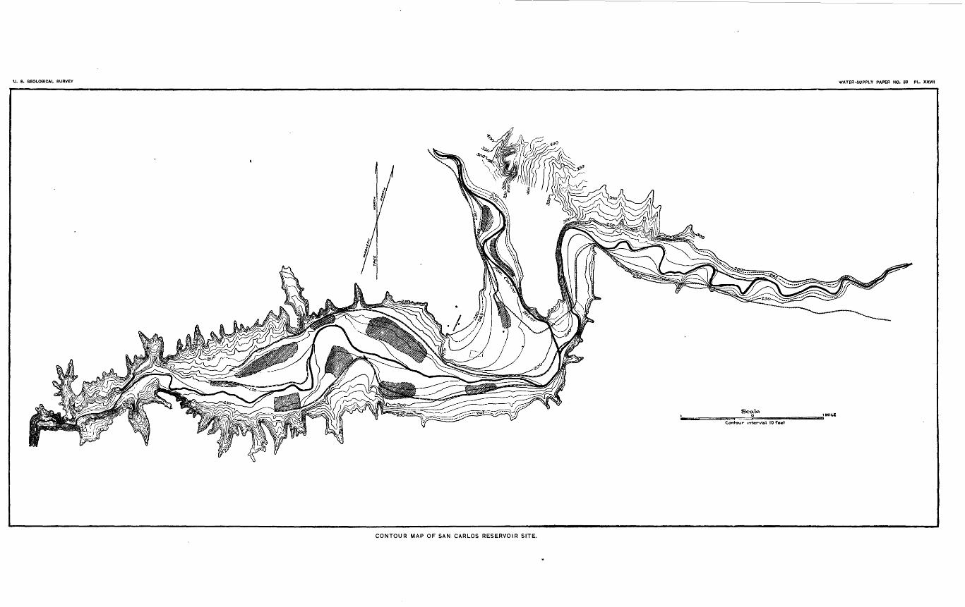
U. 8. GEOLOGICAL SURVEY WATER-SUPPLY PAPER NO. 38 PL. XXVII
Scale
Contour- interval 10 feet
CONTOUR MAP OF SAN CARLOS RESERVOIR SITE.
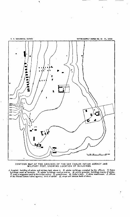
U. 8. GEOLOGICAL SURVEY WATER-SUPPLY PAPER NO. 33 PL. XXVIII
CONTOUR MAP OF THE GROUNDS OF THE SAN CARLOS INDIAN AGENCY AND MILITARY POST, SHOWING LOCATION OF BUILDINGS.
A, hospital; building of adobe and military tank above it. B, adobe buildings occupied by the officers. C, frame buildings used as barracks. D adobe buildings used as stables. E, school grounds; buildings mainly of adobe. F, huts or wigwams used by the Indian police. 6r, guardhouse. H, trader's Store. I, stone warehouses. J, offices of the United States Indian agency; built of adobe. K, shops and stables built of stone.
IJPPINCOTT.] GUTHEIE RESERVOIR. 77
saving of 4 miles in distance in the new line over the old, which should compensate for the moving. There would be two bridges to move, at an approximate cost of $10,000.
The Gila bridge contains thirty-three 16-foot bents and three small spans. The San Caiios bridge has thirty-four 16-foot bents. The total cost of moving this railroad has been estimated at $50,000. As all the material for the construction of the dam that will be shipped to San Carlos will have to pass over this railroad, including about 25,000 barrels of cement, and as the railroad will be shortened 5 miles without any serious additional grade and removed from a valley of two torrential streams, it would seem that this change of location might be readily arranged. The reason the railroad was placed in its present location was to enable it to reach the post and agency and secure that trade. With the agency removed, there would no longer be the occasion for its present location.
Estimate, San Carlos dam.
Bubble masonry, laid in concrete, 94,730 cubic yards, at $6 ......... $568,380.00NOTE. With sand cement, at $4.63 per barrel, or $4.28 per
cubic yard. (See Duryee's report.) This figure is based on halfof the mass being large rock and half concrete.
Excavation foundation, pumping, etc .....---...-............ ...... 150,000.001 semicircular tower, of concrete, 13,632 cubic feet, at 50 cents . -... 6,816.001 tower, same diameter inside, 60 feet high, 4,238 cubic feet, at 50 cents. 2,119.002 tower houses, including the semicircular bajse of concrete, at
$750 each..................".._..._..__._._.. ..................... 1,500.0010 inlets for towers, at $500 each................................... 5,000.002 balance valves, at $l,000each _............................ ...... 3,000.002 balance valves, at $750 each...... ......................... ------ 1,500.00610 linear feet of footbridge, at $10 ................................. 6,100.005 miles of railway, moved, at $10,000 per mile ........... .....-..- 50,000.00New irrigation system above the Indian agency ..-.-.-..--.---..-.. 20,000.00 Damage to agency and post buildings..-.-.._-......._,----..--...- 60,000.00Low water diversion tunnel _-..........................-....--.-..-. 10,000.00Wooden crib diversion dam at head of irrigation canal............. 20,000.00
903,415.00 Contingencies, 10 per cent..... ,. ........,.'.....-.....-.....-. 90,341.00Engineering, 5 per cent.--.-.-..------. ...... ..-.-..-.--.-.-... . 45,170.00
Total................... ... ............ . .......... ...... 1,038,926.00Total number of acre-feet stored is 241,396, at a rate of $4.80 per acre-foot.
GtTTHRIE RESERVOIR.
The Guthrie reservoir site is situated in Graham Bounty, Arizona, about 30 miles northeast of the town of Solomonville, on the Gila River. The dam site shown on PI. XXX is about 1 mile above the Coronado Ranch House, in what is known as York Canyon. This is approximately 4 miles above Guthrie and 13 miles below Dunean. The canyon is about 2,000 feet long, opening both above and below into broad valleys. The survey was made for a 140-foot dam, as a natural
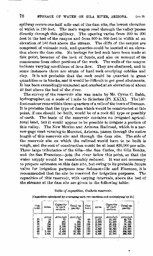
78 STORAGE of WATER ON GILA RITER, ARIZONA. [NO. 33.
spillway occurs one-half mile east of the dam site, the lowest elevation of which is 130 feet. The main wagon road through the valley passes directly through this spillway. The opening varies from 200 to 300 feet in the bed of the canyon and from 800 to 900 feet in width at an elevation of 140 feet above the stream. The cliffs of the canyon are composed of volcanic rock, and quarries could be located at an eleva tion above the dam site. No borings for bed rock have been made at this point, because of the lank of funds, and also on account of its remoteness from other portions of the work. The walls of the canyon indicate varying conditions of lava flow. They are shattered, and in some instances there are strata of hard rock overlying cobbles and clay. It is not probable that the rock could be quarried in great quantities or in blocks, and it would be difficult to get good abutments. It has been exceedingly contorted and crushed at an elevation of about 40 feet above the bed of the river.
The survey of the reservoir site was made by Mr. Cyrus C. Babb, hydrographer, on a scale of 1 mile to 2£ inches (PL XXIX). The 140- foot contour runs within three-quarters of a mile of the town of Duncan. It is probable that the type of dam which would be constructed at this point, if one should be built, would be of a rock-fill type or possibly of earth. The basin of the reservoir contains no irrigated agricul tural land, but it would appear to be possible to irrigate a portion of this valley. The New Mexico and Arizona Railroad, which is a nar row-gage road running to Morenci, Arizona, passes through the entire length of this reservoir site and through the dam site. The side of the reservoir site on which the railroad would have to be built is rough, and the cost of construction would be at least $20,000 per mile. Three large tributaries of the Gila the San Carlos, the Gila Bonita, and the San Francisco join the river below this point, so that the water supply would be considerably reduced. It was not necessary to prepare estimates on this dam site, but owing to its probable future value for irrigation purposes near Solomonville and Florence, it is recommended that the site be reserved for irrigation purposes. The capacities of this reservoir, with varying intervals, above the bed of the streams at the dam site are given in the following table:
Table of capacities, Guthrie reservoir.
[Capacities calculated by averaging each two sections and multiplying by 10.]
Con tour.
10 30 30 40 50 60 70
Area.
Acres. 14 '45
154 390 699
1,000 1,431
Capacity of each section.
Acre-feet. 70
295 995
2,730 5,445 8,495
12,155
Total ca pacity.
Acre-feet. 70
365 1,360 4,080 9,535
18,030 30,175
Con tour.
80 90
100 110 120 130' 140
Area.
Acres. 1,875 2,383 2,844 3,311 3,692 4,696 5,553
Capacity of each section.
Acre-feet. 16,530 21,290 36,135 30,775 36,365 43,290 51,340
Total ca pacity.
Acre-feet. 46,705 67,995 94,130
124,905 161,370 304,560 355,800
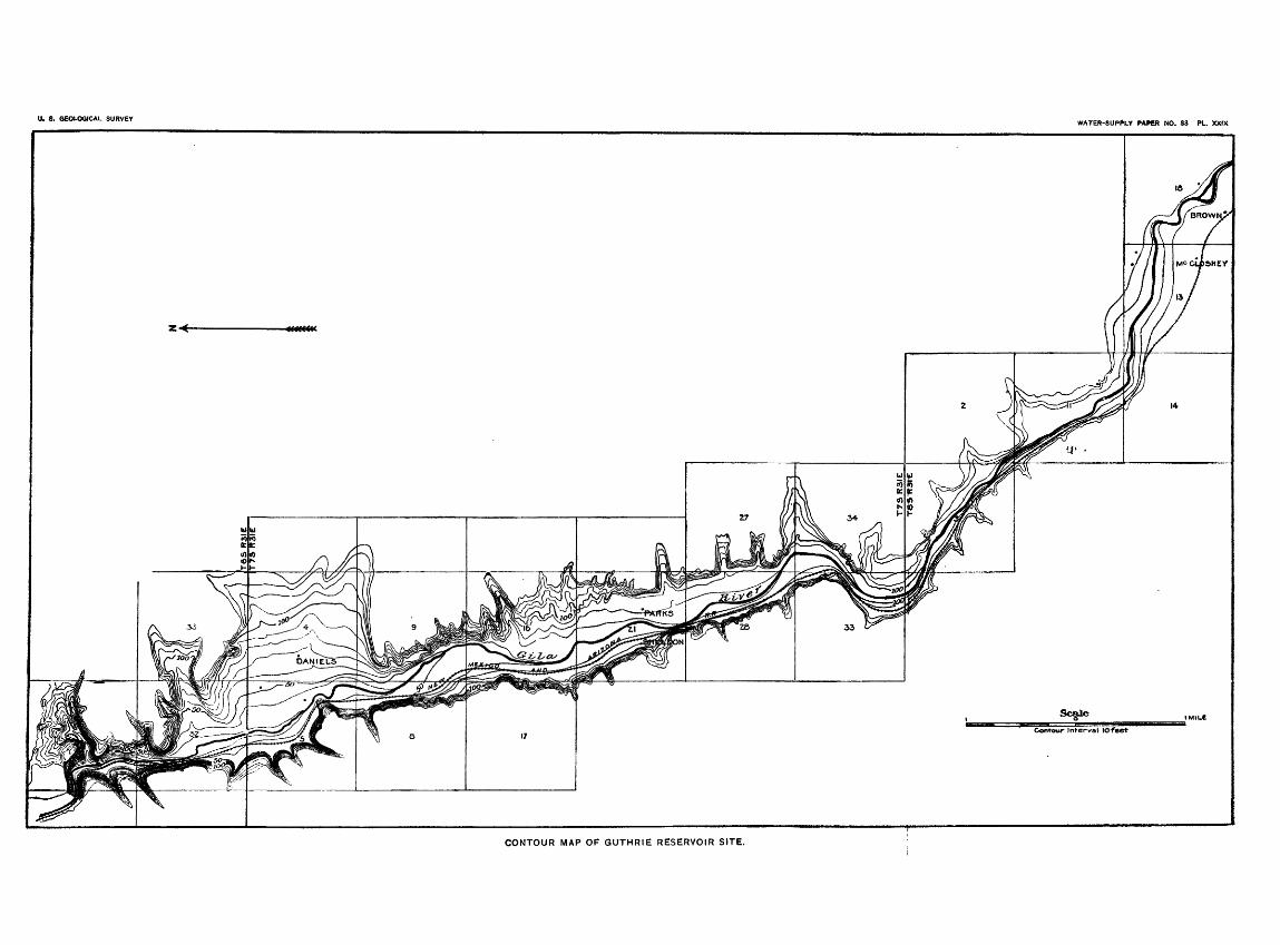
U. S. GEOLOGICAL SURVEYWATER-SUPPLY PAPER NO. 33 PL. XXIX
CONTOUR MAP OF GUTHRIE RESERVOIR SITE.
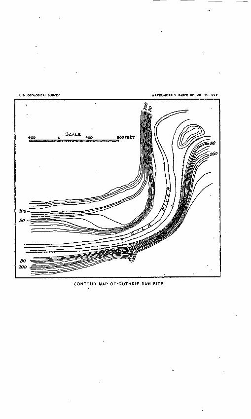
U. S. GEOLOGICAL SURVEY WATER-SUPPLY PAPER NO. 33 PL. XXX
400
CONTOUR MAP OF'GUTHRIE DAM SITE.
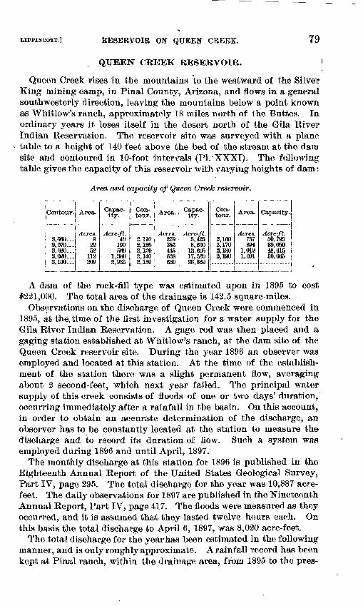
LIFPINCOTT.] RESERVOIR ON QUEEN CREEK. 79
QUEEN CKEEK BESEKVOIB. I
Queen Creek rises in the mountains to the westward of the Silver King mining camp, in Final County, Arizona, and flows in a general southwesterly direction, leaving the mountains below a point known as Whitlow's ranch, approximately 18 miles north of the Buttes. In ordinary years it loses itself in the desert north of the Gila River Indian Reservation. The reservoir site was surveyed with a plane table to a height of 140 feet above the bed of the stream at the dam site and contoured in 10-foot intervals (PL-XXXI). The following table gives the capacity of this reservoir with varying heights of dam:
Area and capacity of Queen Creek reservoir.
Contour.
2,060... 3,070... 2,080... 2,090... 8,100...
Area.
A ores. 8
83 52
112 209
Capac-itjT
Acre-ft. 40
190 560
1,380 3,985
Con tour.
2.110 3,120 3,130 2,140 8,150
Area.
Acres. 379 356 445 538 630
Capac ity.
Acre-ft. 5,435 8,600
12,605 17,520 23,360
Con tour.
2,160 2,170 3,180 2,190
Area.
Acres. 757 894
1,019 1,091
Capacity.
Aere-ft. 30,795 39,050 48,615 50,665
A dam of the rOck-flll type was estimated upon in 1895 to cost $221,000. The total area of the drainage is 142.5 square miles.
Observations on the discharge of Queen Creek were commenced in 1895, at the.time of the first investigation for a water supply for the Gila River Indian Reservation. A gage rod was then placed and a gaging station established at Whitlow's ranch, at the dam site of the Queen Creek reservoir site. During the year 1896 an observer was .employed and located at this station. At the time of the establish ment of the station there was a slight permanent flow, averaging about 2 second-feet, which next year failed. The principal water supply of this creek consists of floods of one or two days' duration, occurring immediately after a rainfall in the basin. On this account, in order to obtain an accurate determination of the discharge, an observer has to be constantly located at the station to measure the discharge and to record its duration of flow. Such a system was employed during 1896 and until April, 1897.
The monthly discharge at this station for 1896 is published in the Eighteenth Annual Report of the United States Geological Survey, Part IV, page 295. The total discharge for the year was 10,887 acre- feet. The daily observations for 1897 are published in the Nineteenth Annual Report, Part IV, page 417. The floods were measured as they occurred, and it is assumed that they lasted twelve hours each. On this basis the total discharge to April 6, 1897, was 8,020 acre-feet.
The total discharge for the year has been estimated in the following manner, and is only roughly approximate. A rainfall record has been kept at Pinal ranch, within the drainage area, from 1895 to the pres-
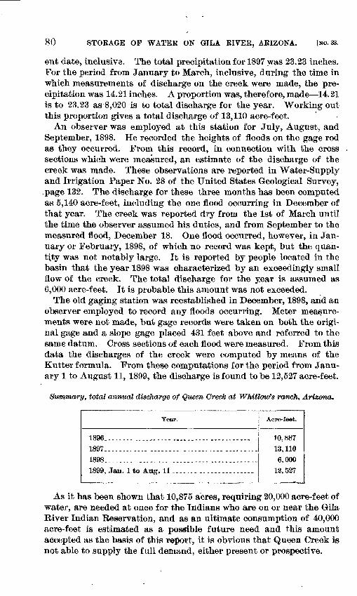
80 STORAGE OP WATER ON GILA RIVER, ARIZONA. [NO. 33.
ent date, inclusive. The total precipitation for 1897 was 23.23 inches. For the period from January to March, inclusive, during the time in which measurements of discharge on the creek were made, the pre cipitation was 14.21 inches. A proportion was, therefore, made 14.21 is to 23.23 as 8,020 is to total discharge for the year. Working out this proportion gives a total discharge of 13,110 acre-feet.
An observer was employed at this station for July, August, and September, 1898. He recorded the heights of floods on the gage rod as they occurred. From this record, in connection with the cross sections which were measured, an estimate of the discharge of the creek was made. These observations are reported in Water-Supply and Irrigation Paper No. 28 of the United States Geological Survey,
. page 132. The discharge for these three months has been computed as 5,140 acre-feet, including the one flood occurring in December of that year. The creek was reported dry from the 1st of March until the time the observer assumed his duties, and from September to the measured flood, December 18. One flood occurred, however, in Jan uary or February, 1898, of which no record was kept, but the quan tity was not notably large. It is reported by people located in the basin that the year 1898 was characterized by an exceedingly small flow of the creek. The total discharge for the year is assumed as 6,000 acre-feet. It is probable this amount was not exceeded.
The old gaging station was reestablished in December, 1898, and an observer employed to record any floods occurring. Meter measure ments were not made, but gage records were taken on both the origi nal gage and a slope gage placed 431 feet above and referred to the same datum. Cross sections of each flood were measured. From this data the discharges of the creek were computed by means of the Kutter formula. From these computations for the period from Janu ary 1 to August 11, 1899, the discharge is found to be 12,527 acre-feet.
Summary, total annual discharge of Queen Creek at Whitlow's ranch, Arizona.
Year.
1896.-.-.... .......--. .......... ........... .
1897.-...--. ................................
1898...-..-. ..... .............. .............1899, Jan. 1 to Aug. 11 ....... .. .............
Acre-feet.
10,887
13, 1106,000
13,537
As it has been shown that 10,875 acres, requiring 20,000 acre-feet of water, are needed at once for the Indians who are on or near the Gila River Indian Reservation, and as an ultimate consumption of 40,000 acre-feet is estimated as a possible future need and this amount accepted as the basis of this report, it is obvious that Queen Creek is not able to supply the full demand, either present or prospective.
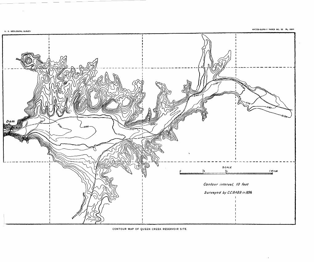
U. S. GEOLOGICAL SURVEYWATER-SUPPLY PAPER NO. 33 PL. XXXt
Contour interval, fO feet
Surveyed by C.C.BABB/n/896 I
CONTOUR MAP OF QUEEN CREEK RESERVOIR SITE.
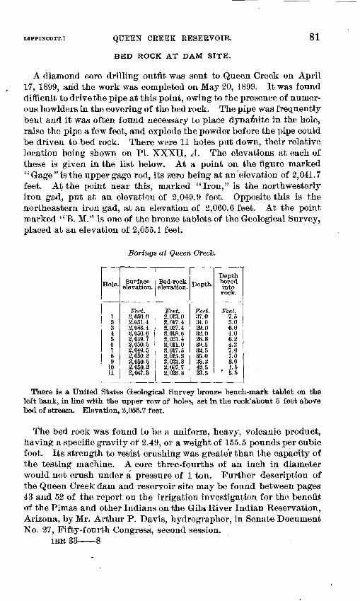
LIPPINCOTT.] QUEEN CREEK RESERVOIR.
BED ROCK AT DAM SITE.
81
A diamond core drilling outfit was sent to Queen Creek on April 17, 1899, arid the work was completed on May 20, 1899. It was found difficult to drive the pipe at this point, owing to the presence of numer ous bowlders in the covering of the bed rock. The pipe was frequently bent and it was often found necessary to place dynamite in the hole, raise the pipe a few feet, and explode the powder before the pipe could be driven to bed rock. There were 11 holes put down, their relative location being shown on PL XXXII, A. The elevations at each of these is given in the list below. At a point on the figure marked "Gage" is the upper gage rod, its zero being at an elevation of 2,041.7 feet. At the point near this, marked "Iron," is the northwesterly iron gad, put at an elevation of 2,049.9 feet. Opposite this is the northeastern iron gad, at an elevation of 2,060.6 feet. At the point marked " B. M." is one of the bronze tablets of the Geological Survey, placed at an elevation of 2,055.1 feet.
Borings at Queen Creek.
Hole.
123456789
1011
Surface elevation.
Bed-rock elevation.
Feet. Feet.3,050.0 3,013.03,051.4 3,017.43,053.4 , 3,037.42,050.62,049.73,050.52,049.53,050.23,050.52,050.33,047.3
3,018.63,021.43,011.03,017.53,015.22,023.33,007.73,033.8
Depth.
Feet.37.034.039.032.028.339.532.535.028.242.523.5
Depthbored intorock.
Feet.7.53.06.04.06.24 37!o7.03.01.5
' 5.5
There is a United States Geological Survey bronze bench-mark tablet on the left bank, in line with the upper row of holes, set in the rock"about 5 feet above bed of stream. Elevation, 2,055.7 feet.
The bed rock was found to be a uniform, heavy, volcanic product, having a specific gravity of 2.49, or a weight of 155.5 pounds per cubic foot. Its strength to resist crushing was greater than the capacity of the testing machine. A core three-fourths of an inch in diameter would not crush under a pressure of 1 ton. Further description of the Queen Creek dam and reservoir site may be found between pages 43 and 52 of the report on the irrigation investigation for the benefit of the Pimas and other Indians on the Gila River Indian Reservation, Arizona, by Mr. Arthur P. Davis, hydrographer, in Senate Document No. 27, Fifty-fourth Congress, second session.
IRR 33 8
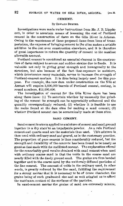
82 STORAGE OF WATER ON GILA RIVER, ARIZONA. [HO. 33.
CEMENT.
By EDWARD DURYEE.
Investigations were made under instructions from Mr. J. B. Lippin- cott, in order to ascertain means of lessening the cost of Portland cement in the construction of dams on the Gila River in Arizona. Owing to the remoteness of these proposed dams from lines of trans portation, the expense of bringing cement to the sites makes a notable addition to the cost over construction elsewhere, and it is therefore of great importance to reduce the quantity of cement to the smallest allowable amount.
Portland cement'is considered an essential element in the construc tion of dams subject to severe and sudden strains due to floods. It is valuable not only in giving great strength and homogeneity to the structure, but also because of the fact that exposure to moisture, which deteriorates many materials, serves to increase the strength of Portland-cement mortars. It is thus being largely used for this pur pose. For example, the new dam under construction on the Nile at Assuan will require 3,000,000 barrels of Portland cement, costing, in round numbers, $12,000,000.
The investigation of cement for the Gila River dams has been along three lines: (1) To ascertain whether by unusually fine grind ing of the cement its strength can be appreciably enhanced and the quantity correspondingly reduced; (2) whether it is feasible to use the rocks found at the dam sites for making a sand cement; (3) whether Portland cement can be economically made at these sites.
SAND CEMENT.
Sand cement is a term applied to a mixture of cement and sand ground together in a dry state'to an impalpable powder. As a rule Portland cement and quartz sand are the materials thus used. This mixture is then used with ordinary sand and gravel, as in the customary practice. The proportion of pure cement is thus considerably reduced, but the strength and durability of the concrete has been found to be nearly as great as that made with the undiluted cement. The explanation offered for the remarkably good results obtained with sand cement when used with ordinary coarse^ sand is that the voids in the coarse sand are nearly filled with the finely ground sand. The grains are thus bonded together and to the coarse sand by the uniformly diffused particles of the fine cement. The amount of voids in the ordinary sand, in other words, is greatly reduced by the fine sand, fulfilling the requirement for a strong mortar that it is necessary to be of dense character, the grains being of such graduated size and so well mingled as to afford the maximum contact of the surfaces of the particles.
In sand-cement mortar the grains of sand are extremely minute,
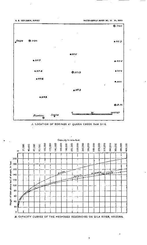
U. S. GEOLOQICAL SURVEY
Gage © iron
WATER-SUPPLY PAPER NO. 83 PL. XXXII
© Iron
O/vp/<?
N96
Bowlder ©
A. LOCATION OF BORINGS AT QUEEN CREEK DAM SITE.
Capacity in acre-feet.
8 8
200
£ 180
c 160
-o 120
S. CAPACITY CURVES OF THE PROPOSED RESERVOIRS ON GILA RIVER, ARIZONA.
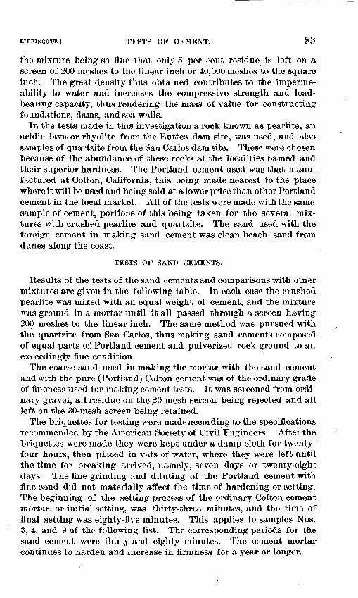
LIPPINCOTT.] TESTS OP CEMENT. 83
the mixture being so fine that only 5 per cent residue is left on a screen of 200 meshes to the linear inch or 40,000 meshes to the square inch. The great density thus obtained contributes to the imperme ability to water and increases the compressive strength and load- bearing capacity, thus rendering the mass of value for constructing foundations, dams, and sea walls.
In the tests made in this investigation a rock known as pearlite, an acidic lava or rhyolite from the Buttes dam site, was used, and also samples of quartzite from the San Carlos dam site. These were chosen because of the abundance of these rocks at the localities named and their superior hardness. The Portland cement used was that manu factured at Colton, California, this being made nearest to the place where it will be used and being sold at a lower price than other Portland cement in the local market. All of the tests were made with the same sample of cement, portions of this being taken for the several mix tures with crushed pearlite and quartzite. The sand used with the foreign cement in making sand cement was clean beach sand from dunes along the coast.
TESTS OF SAND CEMENTS.
Results of the tests of the sand cements and comparisons with otner mixtures are given in the following table. In each case the crushed pearlite was mixed with an equal weight of cement, and the mixture was ground in a mortar until it all passed through a screen having 200 meshes to the linear inch. The same method was pursued with the quartzite from San Carlos, thus making sand cements composed of equal parts of Portland cement and pulverized rock ground to an exceedingly fine condition.
The coarse sand used in making the mortar with the sand cement and with the pure (Portland) Colton cement was of the ordinary grade of fineness used for making cement tests. It was screened from ordi nary gravel, all residue on the.20-mesh screen being rejected and all left on the 30-mesh screen being retained.
The briquettes for testing were made according to the specifications recommended by the American Society of Civil Engineers. After the briquettes were made they were kept under a damp cloth for twenty- four hours, then placed in vats of water, where they were left until the time for breaking arrived, namely, seven days or twenty-eight days. The fine grinding and diluting of the Portland cement with fine sand did not materially affect the time of hardening or setting. The beginning of the setting process of the ordinary Colton cement mortar, or initial setting, was thirty-three minutes, and the time of final setting was eighty-five minutes. This applies to samples Nos. 3, 4, and 9 of the following list. The corresponding periods for the sand cement were thirty and eighty minutes. The cement mortar continues to harden and increase in firmness for a year or longer.
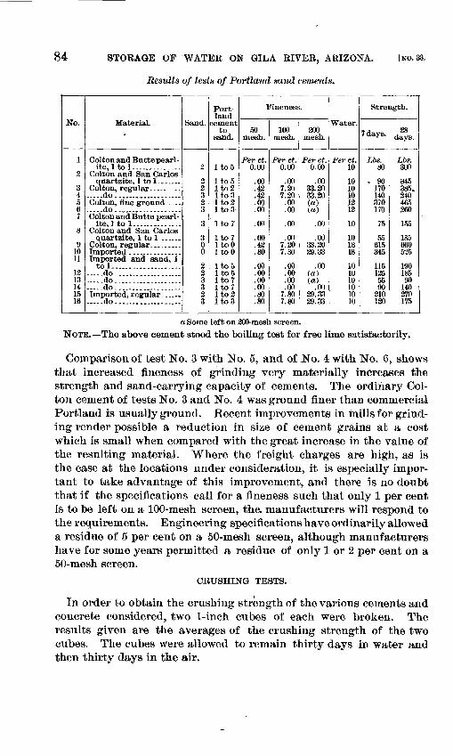
84 STORAGE OF ^WATER ON GILA RIVER, ARIZONA. [NO. 33.
Results of tests of Portland sand cements.
No.
1
2
34 567
8
9 10 11
12 13 14 15 16
Material.
Colton and Buttepearl- ite,ltol. .............
Colton and San Carlos
.....do.. __ ___ ......Colton, fine ground ....
Colton and Butte pearl- ite, 1 to 1. .............
Colton and San Carlos quartzite, 1 to 1 .......
Imported and sand, 1 to 1. .................. .
.....do. ..................
.....do................... ..do. ..................
. .do....... __ _ ...
Sand.
2 3 3 2 3
3
30 0
2 2 3 3 2 3
Port land
cement to
sand.
Ito5
Itoo Ito2 Ito3 Ito2 Ito3-
itorIto7 ItoO 1 toO
Ito5 Ito5 Ito7 Ito7 Ito2 Ito3
Fineness.
50 mesh.
Per ct. 0.00
.00
.43
.43
.00
.00
.00
.00
.43
.80
.00
.00
.00
.00
.80
.80
100 mesh.
Per ct. 0.00
.00 7.20 7.20
.00
.00
.00
.007.20 7.80
.00
.00
.00
.00 7.80 7.80
200 mesh.
Per ct. 0.00
.00 33.20 33.30(«) (a)
.00
.00 33.20 29.33
.00 (a) (a)
.00 29.33 29.33
Water.
Per ct. 10
10 10 10 13 12
10
10 18 18
10 10 10 10 10 10
Strength.
7 days.
Lbs. 80
- 90 170 140 370 170
75
55 615 345
115 125 55 90
210 120
28 days.
Lbs. 300
345 385. 240 465 260
155
185 660 525
190 185 90
140 270 175
a Some left on 200-mesh screen. NOTE. The above cement stood the boiling test for free lime satisfactorily.
Comparison of test No. 3 with No. 5, and of .No. 4 with No. 6, shows that increased fineness of grinding very materially increases the strength and sand-carrying capacity of cements. The ordinary Col ton cement of tests No. 3 and No. 4 was ground finer than commercial Portland is usually ground. Recent improvements in mills for grind ing render possible a reduction in size of cement grains at a cost which is small when compared with the great increase in the value of the resulting material. Where the freight charges are high, as is the case at the locations under consideration, it is especially impor tant to take advantage of this improvement, and there is no doubt that if the specifications call for a fineness such that only 1 per cent is to be left on a 100-mesh screen, the. manufacturers will respond to the requirements. Engineering specifications have ordinarily allowed a residue of 5 per cent on a 50-mesh screen, although manufacturers have for some years permitted a residue of only 1 or 2 per cent on a 50-mesh screen.
CRUSHING TESTS.
In order to obtain the crushing strength of the various cements and concrete considered, two 1-inch cubes of each were broken. The results given are the averages of the crushing strength of the two cubes. The cubes were allowed to remain thirty days in water and then thirty days in the air.
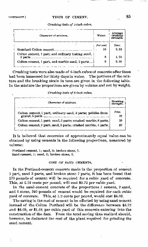
t-IPNNCOTT.] TESTS OP CEMENT.
Crushing tests of 1-inch cubes.
85
Character of mixture.
Standard Colton cement ..-.....-.-_.._.__.--_---..Colton cement, 1 part, and ordinary testing sand.
Colton cement, 1 part, and marble sand, 2 parts. ..
Water.
Per cent.
18
88
Average crashing strength.
Tons. 3.25
1.75
2.38
Crushing tests were also made of 6-inch cubes of concrete after these had been immersed for thirty days in water. The portions of the mix ture and the breaking strain in tons are given in the following table. In the mixture the proportions are given by volume and not by weight.
Crushing tests of 6-inch cubes.
Character of mixture.
Colton cement, 1 part; ordinary sand, 3 parts; pebbles from gravel, 6 parts. __._-._-._-....._..- ...... ...............
Colton cement, 1 part; sand, 3 parts; crushed marble, 6 parts. Colton cement, 1 part; sand, 2 parts; crushed marble, 5 parts .
Breaking strength.
Tons. 38
30
20
It is believed that concretes of approximately equal value can be obtained by using cements in the following proportions, measured by volume:
Portland cement, 1; sand, 3; broken stone, 7. Sand cement, 1; sand, 2; broken stone, 6.
COST OF SAND CEMENTS.
In the Portland-cement concrete made in the proportion of cement 1 part, sand 3 parts, and broken stone 7 parts, it has been found that 270 pounds of cement will be required for a cubic yard of concrete. This, at 2.12 cents per pound, will cost $5.72 per cubic yard.
In the sand-cement concrete of the proportions 1 cement, 2 sand, and 6 stone, 340 pounds of cement would be required for each cubic yard of concrete. This, at 1.2 cents per pound, would cost $4.08.
The saving in the cost of cement to be effected by using sand cement instead of the Colton Portland will be the difference between 15.72 and $4.08, or $1.64 per cubic yard of this concrete entering into the construction of the dam. From the total saving thus realized should, however, be deducted the cost of the plant required for grinding the sand cement.
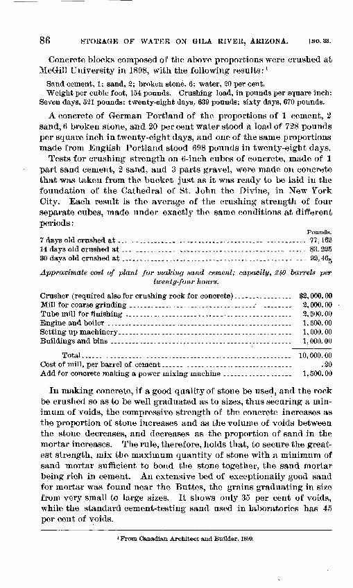
86 STORAGE OF WATER ON GILA RIVER, ARIZONA. [NO. 33.
Concrete blocks composed of the above proportions were crushed at McGill University in 1898, with the following results: 1
Sand cement, 1; sand, 2; broken stone, 6; water, 20 per cent. Weight per cubic foot, 154 pounds. Crushing load, in pounds per square inch:
Seven days, 521 pounds; twenty-eight days. 639 pounds; sixty days, 670 pounds.
A concrete of German Portland of the proportions of 1 cement, 2 sand, 6 broken stone, and 20 percent water stood a load of 728 pounds per square inch in twenty-eight days, and one of the same proportions made from English Portland stood 698 pounds in twenty-eight days.
Tests for crushing strength on 6-inch cubes of concrete, made of 1 part sand cement, 2 sand, and 3 parts gravel, were made on concrete that was taken from the bucket just as it was ready to be laid in the foundation of the Cathedral of St. John the Divine, in New York City. Each result is the average of the crushing strength of four separate cubes, made under exactly the same conditions at different periods:
Pounds. 7 days old crushed at................ ................................... 77,16214 days old crushed at ............... ............................. ..... 83,22530 days old crushed at .......__._....__._..._..._..,-...-.........-.- ... 92,46g
Approximate cost of plant for making sand cement; capacity, 2^0 barrels pertwenty-four hours.
Crusher (required also for crushing rock for concrete) --..-.-......-.. $2,000.00Mill for coarse grinding __..._.___...______.__.._.._._.___. ....... ̂ 2,000.00Tube mill for finishing ...._..._..___._......,-__.-_.___.__.._...._._ 2,500.00Engine and boiler .................................................... 1,500.00Setting up machinery.. --.....--..--...-......---.--....---.----..--. 1,000.00Buildings and bins .................................................. 1,000.00
Total...... .......... ........................................ 10,000.00Cost of mill, per barrel of cement -..-._ .-.-..-.-,-..-------..-..-.-- .20Add for concrete making a power mixing machine ..---...---..._.._. 1,500.00
In making concrete, if a good quality of stone be used, and the rock be crushed so as to be well graduated as to sizes, thus securing a min imum of voids, the compressive strength of the concrete increases as the proportion of stone increases and as the volume of voids between the stone decreases, and decreases as the proportion of sand in the mortar increases. The rule, therefore, holds that, to secure the great est strength, mix the maximum quantity of stone with a minimum of sand mortar sufficient to bond the stone together, the sand mortar being rich in cement. An extensive bed of exceptionally good sand for mortar was found near the Buttes, the grains graduating in size from very small to large sizes. It shows only 35 per cent of voids, while the standard cement-testing sand used in laboratories has 45 per cent of voids.
1 From Canadian Architect and Builder, 1899.
LIPPINCOTT.] MANUFACTURE OF CEMENT AT DAM SITES. 87
A large tube mill will grind 10 barrels of sand cement per hour to the requisite degree of fineness, at an estimated cost of 20 cents per barrel. The cost of power for grinding is calculated at 3 cents per horsepower per hour ;it the dam site.
I Cost of sand dement with Portland cement at $8 per barrel.
One-half barrel Portland ...........................'............-....,... $4.00One-half barrel crushed and coarse-ground quartzite ......,..--..---..--.- .18Grinding same in a tube mill _..______.. _______-_.__..._._-________ .-,. .20Royalty on account of sand-cement patent....._.,.-.-....--.--....-..---- .05
Total cost of sand cement per barrel (375 pounds)..........,_....... 4.43
The cost of sand cement per pound, quartzite being used as thesource of the sand cement, would therefore be 1.2 cents.. I '
The cost of the ini-1 per barrel of cement, 20 cents, is not included in the above.
It is estimated that the cost per barrel of Colton Portland cement, delivered at the dam site will be $8. This, for 375 pounds weightcement, would make the cement cost 2.12 cents per pound.
USE OF ROCKS AT THE DAM SITES.
For the purpose of ascertaining whether the rocks at the dam sites could be used in the manufacture of Portland cement the localities were visited and sanoi pies were obtained of those rocks which occurred in sufficient quantities to furnish a supply necessary for manufactur ing the large amounts of cement needed. In looking for the rawmaterials it must be tx>rne in mind that, chemically considered, Portland cement consists of a compound of tricalcium silicate and dical- cium aluminate, accompanied by small percentages of ferrate and sulphate of lime and traces of alkalies. It is made by grinding and burning together either natural or artificial mixtures of carbonate of lime,and silicate of alumina. Limestones, chalks, or marls usually furnish the carbonate of lime, and clays are the ordinary source of the alumina and silica. The mixtures are burned at a high tempera ture to a blackish clinker of a semivitrified character. After cooling, this clinker is reduced by grinding to an impalpable powder, in which form it is known by the generic name of Portland cement.
ROCKS AT RIVERSIDE DAM SITE.
Limestone (No. 3 in the following table) was obtained near River side ? on the road to the Pioneer mill, where it is found in large quan tities along the roadside. The rhyolite (No. 4 in the following table) was found 2 miles south of the Riverside site. It offered the closest approach to a suitable silicate of alumina that could be found.
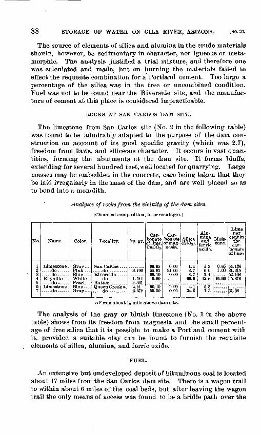
88 STORAGE OP WATER ON GILA RIVER, ARIZONA. [NO. 33.
The source of elements of silica and alumina in the crude materials should, however, be sedimentary in character, not igneous or meta- morphic. The analysis justified a trial mixture, and therefore one was calculated and made, but on burning the materials failed to effect the requisite combination for a Portland cement. Too large a percentage of the silica was in the free or uncombined condition. Fuel was not to be found near the Riverside site, and the manufac ture of cement at this place is considered impracticable.
ROCKS AT SAN CAKLOS DAM SITE.
The limestone from San Carlos site (No. 2 in the following table) was found to be admirably adapted to the purpose of the dam con struction on account of its good specific gravity (which was 2.7), freedom from flaws, and siliceous character. It occurs in vast quan tities, forming the abutments at the dam site. It forms bluffs, extending for several hundred feet,well located for quarrying. Large masses may be embedded in the concrete, care being taken that they be laid irregularly in the mass of the dam, and are well placed so as to bond into a monolith.
Analyses of rocks from the viciiiity of the dam sites,
[Chemical composition, in percentages.]
No.
1234567
Name.
.....do......
.--.do......
-...do......
Color.
Pink ...Blue....
Pearl.. .
Locality.
.....do.........
.. ...do. .........
Sp. gr.
2.709
1.5413.3613.812.678
Car bonate of lime, CaCO3.
96.6555.8093.109.60
90.1065.50
Car bonate of mag nesia.
0.0031.000.00
6.000.00
Silica (SiOs>.
1.43.74.7
60.9
4.i34.6
Alu mina and
ferric oxide.
1.36.01.4
13.6
5.81.3
Mois ture.
0.651.00
16.90
Limeper
cent in the car
bonateof lime.
54.13431.31553.1365. 376
31.08
a From about 1J- mile above dam site.
The analysis of the gray or bluish limestone (No. 1 in the above table) shows from its freedom from magnesia and the small percent age of free silica that it is possible to make a Portland cement with it, provided a suitable clay can be found to furnish the requisite elements of silica, alumina, and ferric oxide.
FUEL.
An extensive but undeveloped deposit of bituminous coal is located about 17 miles from the San Carlos dam site. There is a wagon trail to within about 6 miles of the coal beds, but after leaving the wagon trail the only means of access was found to be a bridle path over the
LippiNcoTT.3 FUEL FOR MAKING CEMENT.
hills. About ten years ago numerous prospectors' locations were made in the district, and shafts were sunk at a sufficient number of localities to prove the deposit to be of considerable extent. Most of the shafts have become filled with debris, but several were entered to depths of 15 to BO feet. They showed the body of coal to be in beds having a dip of about 60°, the beds being from 5 to 10 jfeet in thick ness, not of solid fuel, but showing seams of good coal interlaid with seams of slate and waste. In the bottom of the deepest shafts was found a good body of coal in a solid bed perhaps 5 feet thick. It was reported that at the time the prospecting was done on the claims some 30 tons were transported by wagons to the Southern Pacific Railroad and used in the locomotives, but that the cost of mining and transporting it to the railroad, with the crude means available at the time, was about $20 per ton.
Cement could be burned with the coal. The right to mine the coal for the use of the Government in this work could be secured readily and at a nominal cost. The cost of mining and transportation to San Carlos would, however, be high. In general practice 120 pounds of coal dust are used in burning 1 barrel of Portland cement.
Taking as a basis coal delivered at the dam site at $10 per ton, limestone at 40 cents per ton, and clay at 11.25 per ton, the cost of manufacturing Portland cement at the dam site would approximate 12.75 per barrel. The cost of erecting a plant with an output of 300 barrels of cement every twenty-four hours would be $75,000. Sup posing the amount of cement to be required in the construction of the dam to be 50,000 barrels, the cost per barrel, if made at the site, would be approximately as follows: First cost of plant, 175,000; cost of manufacturing 50,000 barrels, at $2.75, $137,500; total cost, $212,500; cost per barrel, $4.25.
With reference to the degree of reliability to be placed upon Port land cement made in new localities, it may be said that the manufac ture of this material has been put upon a scientific basis, such that the manufacturing chemist can predict the grade of cement to be made from the given materials and, by means of analyses of various rocks, can calculate suitable mixtures to produce the required result. The uniform system of testing cements recommended by the Ameri can Society .of Civil Engineers affords a reliable means of determining the intrinsic merits of the product. The old method of buying cements on the reputation of the maker has been succeeded by tests for determining the actual value. Portland cements of American make are being extensively manufactured and are of equal or even superior quality to the foreign-made cements. During the year 1899 it is estimated that 6,000,000 barrels of Portland cement have been used, of which four-fifths were of home manufacture. In spite of this fact, on account of the failure to find suitable clays at the various
90 STORAGE OF WATER ON GILA RIVER, ARIZONA. LNO. 33.
localities and also the difficulty of obtaining fuel, it is impracticable to manufacture Portland cement at the dam sites.
It is important, if Portland cement is used at the localities under consideration, that the specifications should require it to be ground so fine that not over 1 per cent residue shall remain on a 100-mesh screen.
Reliable sand cement can be made from the quartzite at San Carlos or the pearlite at the Buttes dam site by grinding with Colton (Port land) cement. A saving will result at the San Carlos dam site of $1.64 per cubic yard by making sand cement on the ground, this being exclusive of the cost of the plant for grinding.
IRRIGABI/E LANDS.
The location where the water which is impounded in the reservoir sites on the Gila River would be used is primarily on the Gila River Indian Reservation, which has been described in previous pages of this report, and which contains 357,120 acres of land, the greater portion being irrigable. South of this Indian reservation, intervening between the Southern Pacific Company's railroad and the point where the Gila River leaves the mountains, there are many thousand acres of high-grade agricultural land suitable for irrigation. The climate is adapted to the raising of diversified crops, the grade of the country is uniform and suitable for the application of water, and the so^il is exceedingly fertile. The .river, which carries a large amount of sedi ment containing many fertilizing materials, will keep these lands in a state of continuous productiveness. Without water this land is a desert and has no value. That it is of no tangible value in its present condition is proved by the fact that many thousands of acres which have been taken up at previous times under the desert-land act and homestead laws have been permitted to revert to the Government before title was perfected by the settler, even after expenditures had been made on the land.
An examination was made of the records of the United States land office at Tucson to determine what portion of this area outside of the reservation remains public domain. The area in the valley of the Gila between Dudleyville and Riverside was also inspected, as this valley should be segregated for reservoir purposes, and in case of the construction of a reservoir at San Carlos a portion of its water could be used for irrigation in this valley. Nineteen townships were exam ined, and it was found that 389,211 acres therein are still public domain and that 52,162 acres, lying mostly under the Florence canal which canal has a very deficient water right is held in private ownership. There is, therefore, three times the area of irrigable land that can be served on the Indian reservation alone and three times the area of public land off the reservation that can be supplied.
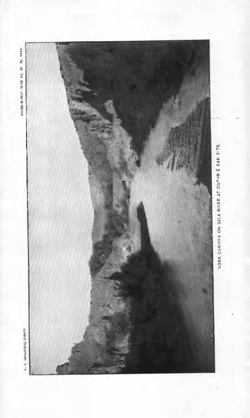
U.
S.
GE
OLO
GIC
AL
SU
RV
EY
WA
TE
R-S
UP
PLY
P
AP
ER
N
O.
33
PL.
X
XX
III
YO
RK
C
AN
YO
N
ON
G
ILA
R
IVE
R
AT
G
UT
HR
IE
DA
M
SIT
E.
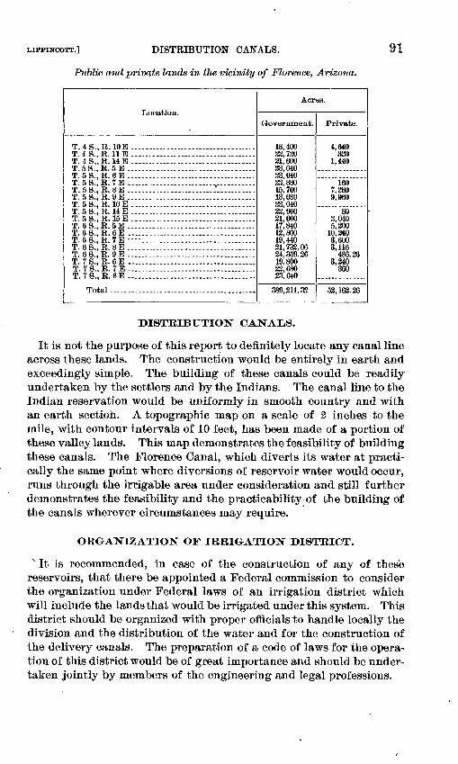
LIPPINCOTT,] DISTRIBUTION CANALS.
Public and private lands in the vicinity of Florence, Arizona.
91
T. 4 S.,B.10E ............ ............ ...........T.4S., B. HE ...................................T. 4S,,E. HE....-. - ........................T.5S., E. 5 E .................... .............T. 5 S.,R. 6 E -............... ................T. 5S., B. 7E .-...-. . -- ..-- .-...-...T. 5 S., E. 8 E ....... .................:...........T. 5S., E. 9E ....................................T. 5 S.,E. 10 E.. ............. ....................T. 5S.,E. 14E ...................................T. 5S., E. 15E.... ............................T.QS.^.&'E.. ..................................T. 6S.,E. 6E ....................................T. 6S., E. 7E ----- ....... ....................T. 68., E. 8 E. ...................................T. 6S., E. 9E ....................................T. rS., E. 6E ....................................T. 7S.,E. TE ....................................T. 78., E. 8 E.... ................................
Total.........................................
Acr
Government.
18,40023,72021,60033,04023,04022 88015,76013,08023,04022,96021,00017,84012,80019,44021,733.0624,359.2619.80022,68023.040
389,211.33
es.
Private.
4,640330
1,440
1607,2809,960
803,0405,200
10,2403,6003,116
486.263,240
360
53,163.26
DISTRIBUTION CANAiLS.
It is not the purpose of this report to definitely locate any canal line across these lands. The construction would be entirely in earth and exceedingly simple. The building of these canals could be readily undertaken by the settlers and by the Indians. The canal line to the Indian reservation would be uniformly in smooth country and with an earth sectioh. A topographic map on a scale of 2 inches to the mile, with contour intervals of 10 feet, has been made of a portion of these valley lands. This map demonstrates the feasibility of building these canals. The Florence Canal, which diverts its water at practi cally the same point where diversions of reservoir water would occur, runs through the irrigable area under consideration and still further demonstrates the feasibility and the practicability of the building of the canals wherever circumstances may require.
ORGANIZATION OF IRRIGATION DISTRICT.
> It is recommended, in case of the construction of any of these reservoirs, that there be appointed a Federal commission to consider the organization under Federal laws of an irrigation district which will include the lands that would be irrigated under this system. This district should be organized with proper officials to handle locally the division and the distribution of the water and for the construction of the delivery canals. The preparation of a code of laws for the opera tion of this district would be of great importance and should be under taken jointly by members of the engineering and legal professions.
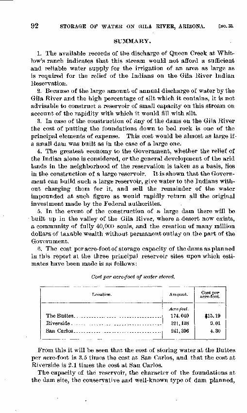
92 STORAGE OF WATER ON GILA RIVER, ARIZONA. [NO. 33.
SUMMARY.
1. The available records of the discharge of Queen Creek at Whit low's ranch indicates that this stream would not afford a sufficient and reliable water supply for the irrigation of an area as large as is required for the relief of the Indians on the Gila River Indian Reservation.
2. Because of the large amount of annual discharge of water by the Gila River and the high percentage of silt which it contains, it is not advisable to construct a reservoir of small capacity on this stream on account of the rapidity with which it would fill with silt.
3. In case of the construction of any of the danis on the Gila River the cost of putting the foundations down to bed rock is one of the principal elements of expense. This cost would be almost as large if- a small dam was built as in the case of a large one.
4. The greatest economy to the Government, whether the relief of the Indian alone is considered, or the general development of the arid lands in the neighborhood of the reservation is taken as a basis, lies in the construction of a large reservoir. It is shown that the Govern ment can build such a large reservoir, give water to the Indians with out charging them for it, and sell the remainder of the water impounded at such figure as would rapidly return all the original investment made by the Federal authorities.
5. In the event of the construction of a large dam there will be built up in the valley of the Gila River, where a desert now exists, a community of fully 40,000 souls, and the creation of many million dollars of taxable wealth without permanent outlay on the part of the Government.
6. The cost per acre-foot of storage capacity of the darns as planned in this report at the three principal reservoir sites upon which esti mates have been made is as follows:
Cost per acre-foot of water stored.
Location.
The Buttes. ............ .... .................Riverside -...-........._, ....,-.....-..... -San Carlos. .__. ...................._.........
Amount.
Acre-feet.
174, 040221,138241,396
Cost per acre-foot.
$15. 199.014.30
From this it will be seen that the cost of storing water at the Buttes per acre-foot is 3.5 times the cost at San Carlos, and that the cost at Riverside is 2.1 times the cost at San Carlos.
The capacity of the reservoir, the character of the foundations at the dam site, the conservative and well-known type of dam planned,
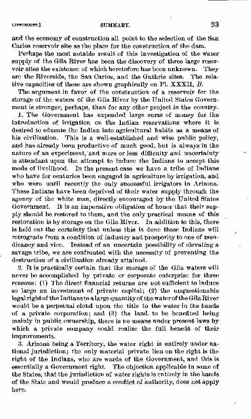
LIPPINCOTT.] SUMMARY. 93
and the economy of construction all point to the selection of the San Carlos reservoir site as the place for the construction,of the dam.
Perhaps the most notable result of this investigation of the water supply of the Gila River has been the discovery of three large reser voir sites the existence of which heretofore has been unknown. They are the Riverside, the San Carlos, and the Guthrie sites. The rela tive capacities of these are shown graphically on PI. XXXII, B.
The argument in favor of the construction of a reservoir for the storage of the waters of the Gila River by the United States Govern ment is stronger, perhaps, than for any other project in the country.
1. The Government has expended large sums of money for the introduction of irrigation on the Indian reservations where it is desired to educate the Indian into agricultural habits as a means of his civilization. This is a well-established and wise public policy, and has already been productive of much good, but is always'in the nature of an experiment, 'and more or less difficulty and uncertainty is attendant upon the attempt to induce the Indians to accept this mode of livelihood. In the present case we have a tribe of Indians who have for centuries been engaged in agriculture by irrigation, and who were until recently the only successful irrigators in Arizona. These Indians have been deprived of their water supply through the agency of the white man, directly encouraged by the United States Government. It is an imperative obligation of honor that their sup ply should be restored to them, and the only practical means of this restoration is by storage on the Gila River. In addition to this, there is held out the certainty that unless this is done these Indians will retrograde from a condition of industry and prosperity to one of men dicancy and vice. Instead of an uncertain possibility of elevating a savage tribe, we are confronted with the necessity of preventing the destruction of a civilization already attained.
2. It is practically certain that the storage of the Gila waters will never be accomplished by private or corporate enterprise for three reasons: (I) The direct financial returns are not sufficient to induce so large an investment of private capital; (2) the unquestionable legal right of the Indians to a large quantity of the water of the Gila River would be a perpetual cloud upon the title to the water in the hands of a private corporation; and (3) the land, to be benefited being mainly in public ownership, there is no means under present laws by which a private company could realize the full benefit of their improvements.
3. Arizona being a Territory, the water right is entirely under na tional jurisdiction; the only material private lien on the right is the right of the Indians, who are wards of the Government, and this is essentially a Government right. The objection applicable in some of the States, that the jurisdiction of water rights is entirely in the hands of the State and would produce a conflict of authority, does not apply here.
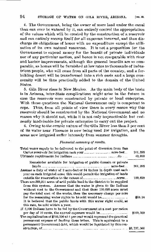
94 STORAGE OF WATER ON GILA RIVER, ARIZONA. [NO. 33.
4. The Government, being the owner of more land under the canal than can ever be watered by it, can entirely control the appropriation of the values which will be created by the construction of a reservoir and can entirely recoup itself for all expenses incurred, and thus dis charge its obligations of honor with no expenditure except the utili zation of its own natural resources. It is not a proposition for the Government to expend money for the benefit of private individuals nor of any particular section, and hence is not comparable with river and harbor improvements, although the general benefits are so com parable, as homes will be furnished at low rates to thousands of indus trious people, who will come from all parts of the country, and a for bidding desert will be transformed into a rich oasis and a large com munity will be thus practically added to the domain of the United States.
5. Gila River rises in New Mexico. As the main body of the basin is in Arizona, inter-State complications might arise in the future in case the reservoir were constructed by private or local enterprise. With these questions the National Government only is competent to cope. Thus, from all points of view there is every reason why this reservoir should be constructed by the National Government and no reason why it should not, while it is not only impracticable but emi nently inadvisable for private enterprise to carry out the project.
6. Owing to the erratic nature of the'Gila River less than 3 per cent of its water near Florence is now being used for irrigation, and the areas now irrigated suffer intensely from summer droughts.
Financial summary of results.
Total water supply to be delivered to the point of diversion from SanCarl os reservoir for irrigation each year .._.-....--..-.. acre-feet.. 241,396
Ultimate requirement for Indians ............................ .do. -.. 40,000
Remainder available for irrigation of public domain or private lands ............................... ................acre-feet-. 201,396
Assume a duty of water of 2 acre-feet or 24 inches in depth used each year on each irrigated acre; this would permit the irrigation of lands outside the reservation to the extent of.................-.._-acres._ 100,698
There are 389,211 acres of arid public land in the district to be supplied from this system. Assume that the water is given to the Indians without cost to the Government and that these 100,698 acres must pay the total cost of the works, then the necessary charge per acre for the remaining water rights to be sold would be................ . $10.24It is believed that the public lauds with this water right could, at this rate, be sold within a year.
If 3,000 Indians have to be fed by the Government at a cost per ration per day of 10 cents, the annual expenses would be,........_---...-. $109,500
The capitalization of $109,500 at 4 per cent would represent the practical permanent expense of feeding these tribes. This is equivalent to a permanent Government debt, which would be liquidated by this con struction, of...... ................................................ $2,737,500
LIPPINCOTT.] RECOMMENDATIONS. 95
The value of the 100,698 acres of irrigated public lands that would be taxable would be $50 per acre, or a total of.......................... $5,034,900
The saving, without expense to the Government, by irrigation of 20,000 acres of lands belonging to the Indians has been shown to be........ 2,737,500
Total increase in value, without public expense................_ 7.772,400There will also be a large increase in value of taxable town property, not esti
mated upon.
RECOMMENDATIONS.
1. Immediately withdraw from entry all the lands that may be irri gated from this source of supply pending further action by Congress on this matter.
2. Segregate all the reservoir sites on the Gila River that may be used for the irrigation of these lands. The Buttes and Queen Creek reservoir sites have already been segregated for this purpose. The Riverside, San Caiios, and Guthrie reservoirs should also be set aside.
3. Maintain observations on the Gila River.4. Construct the San Carlos dam.5. Give the Indians the water which they require without charge,
the Government to recoup itself for all expenditures from the sale of the remaining water rights.
6. Form a Federal irrigation district for the division of the water, which is to be delivered to the head of the irrigation canals, for the construction of these canals, and for the general administration of the district.
oo """"'" y
INDEX.
Page. Alma, rainfall at .......................... 18Analyses of rocks from vicinity of dam
Anderson, D., rock tests by --------------- 51Archambault, T.J.H.,mentioned -------- 45Babb,C.C., work of... .. .. - 13,15,25,78 Bed rock at Queen Creek, depth and
quality of --........................ 81Bed rock at San Carlos, quality of ---_... 70-71 Bed rock at the Bnttes, quality of -....__- 49-51Bennett, S. G., rock tests made by ------- 50Benson, rainfall at _---.___.._--_...._._.-- 19
rainf al 1 at, diagram showing ...._..- 30Bisbee, rainfall at -.-. ..-...-....... .- 19
rain Call at, diagram showing.......... 20Brash, W.J., work of-......---- .......... 25Buttes, analysis of rock from near the. - - 88
bed rock at the, quality of ....---.---. 49-51borings at dam site at the ............ 48borings at dam site at the, map show
ing location of -_-_.-..--_--_-..____ 44dam at the, description of proposed-- 54-58 dam site at the, map of--------------- 46dam site at the, plate showing views
of........ . .. ......-.. . 34diversion canal below the dam at the. 61-63 plates showing plans for dam at the -.50,52,
54,56 quarry tests at the ... .".... ...... 51-54rainfall at the.......................... 19reservoir at the s capacity and cost of. 59-60 reservoir at the, hypothetical table
showing amount of water in, for each month........................ 33
reservoir site at the, map of - --.... 58reservoir site at the, plate showing
View of.-^j*........................ 42water available at the, table showing. 30 work at the....... ......--.-.-.-.....- 14
Canal, diversion, below Bnttes dam, de scription of.................__.....__!. 61-62
Casa Grande, rainfall at --.--.-.-.... .... 19rainfall at, diagram show ing ......... 20
Cedar Springs, rainfall at................. 18Cement, investigation of.................. 82-90
manufacture of, at dam sites, discus sion of.............................. 87-90
Cements, cost of........................... 85-87tests of. ..... -.-..."..... ....,.... 83-85
Coal near San Carlos, prospects of....... 89Colton, A. T., observations by............ 35,36Davis, A. P., quoted on necessity of spill
way at the Buttes ................. 34-35quoted on silt carried by Gila River.. 35-36 reference to ...................._.... 81work of .............................. 7,13,16
Diamond core drill, plates showingmethod of driving pipe for ....... 9, 42
use and cost of... -...-.-..... ...- 43-48-Discharge of Gila River, diagram show
ing .. .............................. a&tables showing ............... 33,36,27-29,30
Dragoon, rainfall at....................... 19-Dudleyville, rainfall at ............... 19
rainfall at, diagram showing . .... 30 Duryee, E., article on cement by..... 83-90
work of ........................._.... 16Evaporation in Arizona.... .............. 33-34Florence, public and private lands in the
vicinity of-.--.--.-...-.---.--..-.. 91rainfall at.............................. 19-rainfall at, diagram showing ......... 30
Fort Apache, rainfall at ...... ._-_-_., ISrainfall at, diagram showing ......... 20
Fort Bayard, rainfall at .._.... _.-...-. 18rainfall at, diagram showing . .... 30
Fort Grant, rainfall at.................... 18rainfall at, diagram showing ......... 20
Fort Hnachuca, rainfall at........ ...- 19>rainfall at, diagram showing ......... 20
Fort McDowell, rainfall at ............... 19rainfall at, diagram showing ......... 30
Fort Thomas, rainfall at......------------ 18rainfall at, diagram showing ....__ 20
Foundations, method of excavation for. _ 58 Gila, rainf all at. ............. . ----- 18Gila River, borings at Buttes dam site on _ 48
discharge of, at the Bnttes, diagramshowing--.--.-......--- --.--...---. 26
drainage area of................-...--_ 21explorations along .............-.-.-* 15-16measurements of flow of.------..--.-- 23-33rainf all in basin of . ». --. ... 18-21rainfall and run-off in basin of, dia
gram showing ---...-.--_-----.--.- 18rainfall at stations in basin of, dia
gram showing .......--...._......- 20rainfall stations in basin of, plate
showing location of _........--...- 18silt carried by . ........................ 35-48views in canyon of, plate showing.... 16>
Gila River Indian Reservation, locationand climate of . ........---------.- 9
Guthrie, dam site at, map of.-.....-..--.. 78dam site at, plate showing view of... 90reservoir at, description of ------ - 77-78reservoir site at, map of. .......... 78
Hadley, E., description of conditions ofIndians by .................... 12-1S
statement by, as to amount of waterrequired for irrigation............ 17
Hnachuca Mountains, rainfall in......... 19>
97
98 INDEX.
Page. Indian tribes of the Gila River Reserva- .
tion ................................ 9-10Irrigation district, recommendation for
organization of .................... 91Lemon, C. W., observations by........... 39Lochiel, rainfall at ........................ 19Matthes, G. H., work of................... 63Oracle, rainfall at......................... 19Oro, rainf&a at............................ 18Pantano, rainfall at ....... ......... _- 19
rainfall at, diagram showing .-.....-- 20Phenix, rainfall at-.-.-... . .............. 19
rainfall at, diagram showing-......... 20Pima Agency, population of .............. 17Precipitation. See Rainfall.Quarry tests at the Buttes...-..- ........ 51-54Quarry test below Buttes dam site, plate
showing result of.................. 48Queen Creek, analyses of rocks from near. 88
bed rock at, depth to and quality of. - 81 borings at dam site at, plate showing
location of.......................... 83dam site on, plate showing view of-.. 48 discharge of ........................... 80reservoir at, description of............ 79-81reservoir site at, map of........... .. 80
Quinton, J. H., work of ................... 16Eainfall in Gila Basin ....... ............. 18-31Eainfall at stations in Gila River Basin,
diagram showing.................. 20Rainfall, table showing increase of, with
each 100 feet of elevation.......... 20Rainfall and run-off in Gila Basin, dia
gram showing -.......-.-........._ 18Rainfall stations in basin of Gila River,
plate showing location of ......... 18Rating curve for Gila River at the Buttes,
diagrams showing-........----...- 36,44Rating table for Gila River at the Buttes- 26 Reservoirs, diagram showing capacity of
proposed........... ............ 83Richardson, T. F., quoted on use of dia
mond core drill................ .... 43-45Richins, W., work of ... .................. 25,36Riverside, analyses of rocks from near .. 88
borings at dam site at, plate showinglocations of ---..._.-.--....---..... 56
capacity and cost of reservoir at..... 65-66dam at, description of proposed...... 63-64dam site at, map of.................... 60dam at, method of construction of.... 64-65dam site at, plate showing view of -... 6.3
Riverside, reservoir site at, descriptionOf...................................
reservoir site at, map of ......... ....reservoir site at, plate showing view
of.... ................... ..........work at ................ ............._..
Robinette, J. W., tests made by..........St. Helena ranch, rainfall at..............San Oarlos, analyses of rocks from near .
dam at, descriptions of.......... 69-71.dam at, material for .......... ........dam at, plates showing plans for .. 70.dam site at, map of....................dam site at, plates showing views of.rainfall at....--......-.------.--.-...-.rainfall at, diagram showing .........reservoir at, capacity and cost of ....reservoir si teat........................reservoir site at, map of ........water available at, table showing...work at ........................ ......
San Carlos Indian agency and military post, map of...... -_.-.-.-.--.......
San Pedro River, drainage area of........measurements of flow of..............rainfall in basin of ....................
San Simon, rainfall at............. ....rainfall at, diagram showing..........
Schuyler, J. D., recommendations of ....work of ........ j.....--..... . .......
Seepage water, estimate of amount of ....Silt carried by Gila River-.--_ . .........Silver King, rainfall at...... .............Spillway, provisions for, at Buttes dam
site -.-...... --.- ------------------Tests of cements ..........................Tests, quarry, at the Buttes ..............Tierney, P., mentioned ...................Tombstone, rainfall at ......_.. .........Tribes of the Gila River Indian Reserva
tions. .............--.....---.--.----Tucson, rainfall at ............... ......
rainfall at, diagram showing..........Water, amount required for irrigation .. Water supply of Gila River Indian Res
ervation, decrease of --.--.-.......Water supply in Gila Basin ..............Wheeler, B., work of......................Willcos, rainfall at........................
rainfall at, diagram showing .... ...York Canyon, plate showing view of......Young. J. R., recommendations of .......
63-63 64
62 15 50 19 88
73-74 71
72,74 68
66,74 18 20
74-776(5-69
76 30 15
7621
19 18 20
7-8 16
34-3535-42
19
83-8551-54
4519
9-10192017
10-13 18-35
61 18 30 flO
o
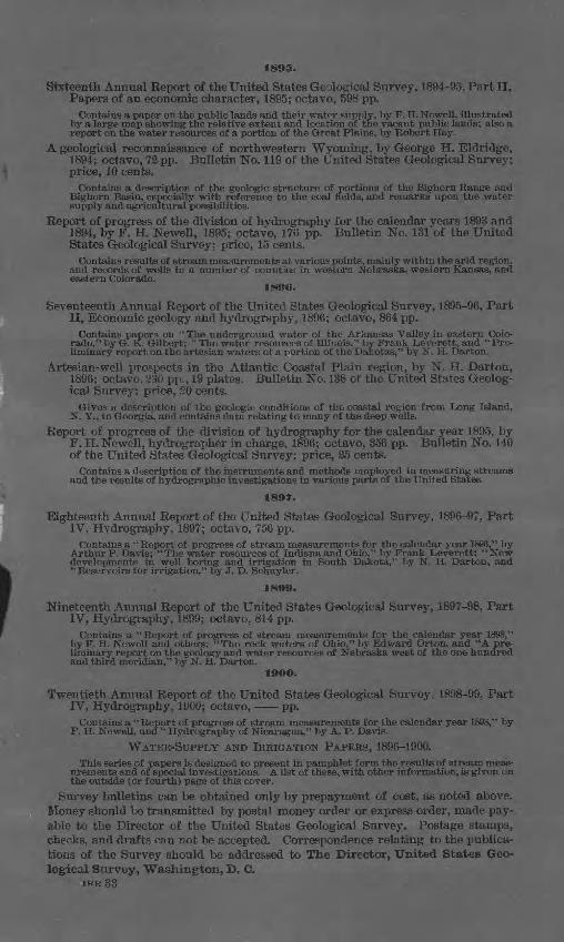
I
1895.
Sixteenth Annual Report of the United States Geological Survey, 1894-95, Part II, Papers of an economic character, 1895; octavo, 598 pp.
Contains a paper on the public lands and their water supply, by F. H. Newell, illustrated by a large map showing the relative extent and location of the vacant public lands; also a report on the water resources of a portion of the Great Plains, by Robert Hay.
A geological reconnaissance of northwestern Wyoming, by George H. Eldridge, 1894; octavo, 72 pp. Bulletin No. 119 of the United States Geological Survey; price, 10 cents.
Contains a description of the geologic structure of portions of the Bighorn Range and Bighorn Basin, especially with reference to the coal fields, and remarks upon the water supply and agricultural possibilities.
Report of progress of the division of hydrography for the calendar vears 1893 and 1894, by F. H. Newell, 1895; octavo, 176 pp. Bulletin No. 13l"of the United States Geological Survey; price, 15 cents.
Contains results of stream measurements at various points, mainly within the arid region, and records of wells in a number of counties in western Nebraska, western Kansas, and eastern Colorado.
1596.
Seventeenth Annual Report of the United States Geological Survey, 1895-96, Part II, Economic geology and hydrography, 1896; octavo, 864 pp.
Contains papers on " The underground water of the Arkansas Valley in eastern Colo rado," by G. K. Gilbert: "The water resources of Illinois," by Frank Leverett, and "Pre liminary report on the artesian waters of a portion of the Dakotas," by N. H. Darton.
Artesian-well prospects in the Atlantic Coastal Plain region, by N. H. Darton, 1896; octavo, 230 pp., 19 plates. Bulletin No. 138 of the United States Geolog ical Survey; price, 20 cents.
Gives a description of the geologic conditions of the coastal region from Long Island, N. Y., to Georgia, and contains data relating to many of the deep wells.
Report of progress of the division of hydrography for the calendar year 1895, by F. H. Newell, hydrographer in charge, 1896; octavo, 356 pp. Bulletin No. 140 of the United States Geological Survey; price, 25 cents.
Contains a description of the instruments and methods employed in measuring streams and the results of hydrographic investigations in various parts of the United States.
1597.
Eighteenth Annual Report of the United States Geological Survey, 1896-97, Part IV, Hydrography, 1897; octavo, 756 pp.
Contains a "Report of progress of stream measurements for the calendar year 1896," by Arthur P. Davis; "The water resources of Indiana and Ohio," by Frank Leverett: "New developments in well boring and irrigation in South Dakota," by N. H. Darton, and "Reservoirs for irrigation," by J. D. Schuyler.
1S99.
Nineteenth Annual Report of the United States Geological Survey, 1897-98, Part IV, Hydrography, 1899; octavo, 814 pp.
Contains a ''Report of progress of stream measurements for the calendar year 1898," by F. H. Newell and others; "The rock waters of Ohio," by Edward Orton, and "A pre liminary report on the geology and water resources of Nebraska west of the one hundred and third meridian," by N. H. Darton.
19OO.
Twentieth Annual Report of the United States Geological Survey, 1898-99, Part IV, Hydrography, 1900; octavo, pp.
Contains a "Report of progress of stream measurements for the calendar year 1898," by F. H. Newell, and " Hydrography of Nicaragua," by A. P. Davis.
WATER-SUPPLY AND IRRIGATION PAPERS, 1896-1900.This series of papers is designed to present in pamphlet form the results of stream meas
urements and of special investigations. A list of these, with other information, is given on the outside Cor fourth) page of this cover.
Survey bulletins can be obtained only by prepayment of cost, as noted above. Money should be transmitted by postal money order or express order, made pay able to the Director of the United States Geological Survey. Postage stamps, checks, and drafts can not be accepted. Correspondence relating to the publica tions of the Survey should be addressed to The Director, United States Geo logical Survey, Washington, D. C.
IRR33
WATER-SUPPLY AND IRRIGATION PAPERS.
1. Pumping water for irrigation, by Herbert M. Wilson, 1896.2. Irrigation near Phoenix, Arizona, by Arthur P. Davis, 1897.3. Sewage irrigation, by George W. Rafter, 1897.4. A reconnoissance in southeastern Washington, by Israel C. Russell, 1897.5. Irrigation practice on the Great Plains, by E. B. Cowgill, 1897.6. Underground waters of southwestern Kansas, by Erasmus Haworth, 1897.7. Seepage waters of northern Utah, by Samuel Fortier, 1897.8. Windmills for irrigation, by E. C. Murphy, 1897.9. Irrigation near Greeley, Colorado, by David Boyd, 1897.
10. Irrigation in Mesilla Valley, New Mexico, by F. C. Barker, 1898.11. River heights for 1896, by Arthur P. Davis, 1897.12. Water resources of southeastern Nebraska, by Nelson Horatio Darton, 1898.13. Irrigation systems in Texas, by William Ferguson Hutson, 1898.14. New tests of pumps and water lifts used in irrigation, by O. P. Hood, 1898.15. Operations at river stations, 1897, Part I, 1898.16. Operations at river stations, 1897, Part II, 1898.17. Irrigation near Bakersfield, California, by C. E. Grunsky, 1898.18. Irrigation near Fresno, California, by C. E. Grunsky, 1898.19. Irrigation near Merced, California, by C. E. Grunsky, 1899.20. Experiments with windmills, by Thomas O. Perry, 1899.21. Wells of northern Indiana, by Frank Leverett, 1899.22. Sewage irrigation, Part II, by George W. Rafter, 1899.23. Water-right problems in the Bighorn Mountains, by Elwood Mead, 1899.24. Water resources of the State of New York, Part I, by George W. Rafter, 1899.25. Water resources of the State of New York, Part II, by George W. Rafter, 1899.26. Wells of southern Indiana (continuation of No. 21), by Frank Leverett, 1899.27. Operations at river stations, 1898, Part I, 1899.28. Operations at river stations, 1898, Part II, 1899.29. Wells and windmills in Nebraska, by Erwin Hinckley Barbour, 1899.30. Water resources of the Lower Peninsula of Michigan, by Alfred C. Lane, 1899.31. Lower Michigan mineral waters, by Alfred C. Lane, 1899.32. Water resources of Puerto Rico, by H. M. Wilson, 1900.33. Storage of water on Gila River, Arizona, by J. B. Lippincott, 1900.In addition to the above, there are in various stages of preparation other papers
relating to the measurement of streams, the storage of water, the amount available from underground sources, the efficiency of windmills, the cost of pumping, and other details relating to the methods of utilizing the water resources of the coun try. Provision has been made for printing these by the following clause in the sundry civil act making appropriations for the year 1896-97:
Provided, That hereafter the reports of the Geological Survey in relation to the gaging of streams and to the methods of utilizing the water resources may be printed in octavo form, not to exceed 100 pages in length and 5,000 copies in num ber; 1,000 copies of which shall be for the official use of the Geological Survey, 1,500 copies shall be delivered to the Senate, and 2,500 copies shall be delivered to the House of Representatives, for distribution. [Approved June 11,1896; Stat. L., vol. 29, p. 453.]
The maximum number of copies available for the use of the Geological Survey is 1,000. This number falls far short of the demand, so that it is impossible to supply all requests. Attempts are made to send these pamphlets to persons who have rendered assistance in their preparation through replies to schedules or who have furnished data. Requests specifying a certain paper and stating a reason for asking for it are granted whenever practicable, but it is impossible to comply with general requests, such as to have all of the series sent indiscriminately.
Application for these papers should be made either to Members of Congress or to THE DIRECTOR,
UNITED STATES GEOLOGICAL SURVEY, IRR 33 Washington, D. Cf
\