thermofluids & mechanical system me6011: thermofluids assignment by ahmed osman k1129129...
TRANSCRIPT

.Thermofluids &Mechanical System
ME6011: ThermofluidsAssignment
By Ahmed Osman K1129129
Assignment Due Date: 24Th February 2014
Module Leader: Dr Homa Hadvinna
Assignment Markers: Dr Siaka Dembele & Dr Konstantin Volkov

Table of Contents
1.Question 1: By Dr Konstantin Volkov (30 marks) 32.Question 2: By Dr Konstantin Volkov (20 marks) 5
3.Question 3: By Dr Siaka Dembele (20 marks) 84.Question 4: By Dr Siaka Dembele (30 marks) 15
Page1
Dr Konstantin Volkov
The following were set by Dr Konstantin Volkov
1. Discuss how to enhance heat transfer between a solid and a fluid, and give qualitative analysis of feasibility of different ways in engineering practice. (30 Marks)
2. A 214 mm long, single rectangular copper fin of 110 mm widthand 5 mm thickness, has one end maintained at 125oC. The finis exposed to the surrounding air at 23 oC with a convectionheat transfer coefficient of 78 W/m2 oC. Neglecting heat transfer from the fin’s tip, and taking the thermal conductivity of copper to be 410 W/moC, Draw a sketch of a fin configuration including size and boundary conditions andcalculate:(20 marks)
a) The fin’s heat transfer rate.(5 marks)b) The fin’s effectiveness.( 5marks)c) The fin’s efficiency.(10 marks)
Total Marks of this section are:
50 marks
Page2
1.Discuss how to enhance heat transfer between a solid and a fluid, and give qualitative analysis offeasibility of different ways in engineering practice. (30 Marks)
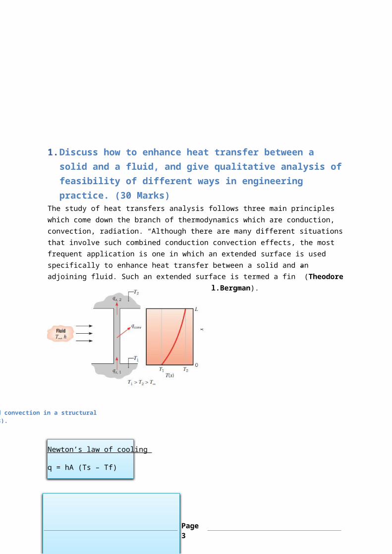
The study of heat transfers analysis follows three main principles which come down the branch of thermodynamics which are conduction, convection, radiation. “Although there are many different situationsthat involve such combined conduction convection effects, the most frequent application is one in which an extended surface is used specifically to enhance heat transfer between a solid and an adjoining fluid. Such an extended surface is termed a fin” (Theodore
l.Bergman).
Newton’s law of cooling
q = hA (Ts – Tf)
: Combined conduction and convection in a structural element. (Theodore L.Bergman 2008).
Page3
q: convective heat transferh: convective heat transfer coefficientA: surface areaTS: surface temperatureTf: free stream of temperature
Techniques to increase heat transfer
increasing the heat transfer coefficient decreasing the fluid’s temperature increasing the area of heat exchange
“Increasing the heat transfer coefficient will involve increasing the fluid’s velocity, which will mean increased pumping (of liquids)or blowing (of gases) costs. Decreasing the temperature of the fluidis usually out of the designer’s control as this is a process or environmental temperature. The third option, i.e. increasing the heat exchange area, could be implemented by using fins. Examples of fins include the arrangements of car radiators and motorcycles engine heads shows a schematic of two finned-tube arrangements” (Volkov 2014).
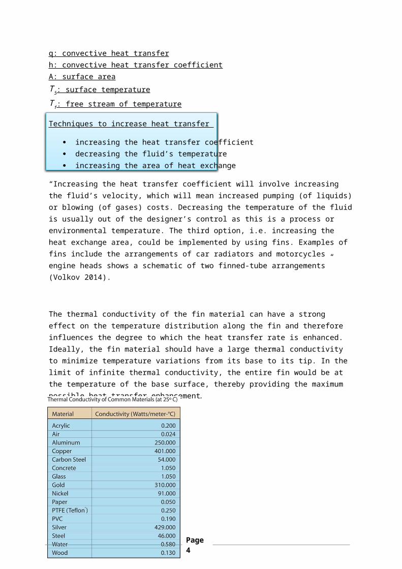
The thermal conductivity of the fin material can have a strong effect on the temperature distribution along the fin and therefore influences the degree to which the heat transfer rate is enhanced. Ideally, the fin material should have a large thermal conductivity to minimize temperature variations from its base to its tip. In the limit of infinite thermal conductivity, the entire fin would be at the temperature of the base surface, thereby providing the maximum possible heat transfer enhancement.
Page4
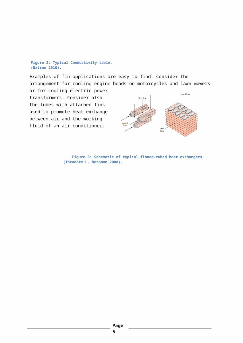
Examples of fin applications are easy to find. Consider the arrangement for cooling engine heads on motorcycles and lawn mowers or for cooling electric powertransformers. Consider alsothe tubes with attached finsused to promote heat exchangebetween air and the workingfluid of an air conditioner.
Figure 2: Typical Conductivity table. (Extron 2010).
Figure 3: Schematic of typical finned-tubed heat exchangers.(Theodore L. Bergman 2008).
Page5
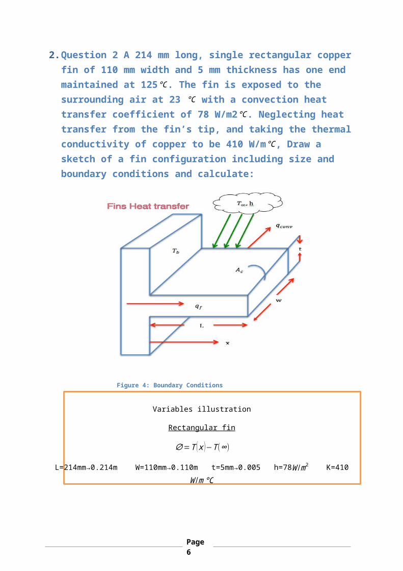
2.Question 2 A 214 mm long, single rectangular copperfin of 110 mm width and 5 mm thickness has one end maintained at 125℃. The fin is exposed to the surrounding air at 23 ℃ with a convection heat transfer coefficient of 78 W/m2℃. Neglecting heat transfer from the fin’s tip, and taking the thermalconductivity of copper to be 410 W/m℃, Draw a sketch of a fin configuration including size and boundary conditions and calculate:
Variables illustration
Rectangular fin
∅=T (x )−T(∞)
L=214mm→0.214m W=110mm→0.110m t=5mm→0.005 h=78W /m2 K=410W /m℃
Figure 4: Boundary Conditions
Page6
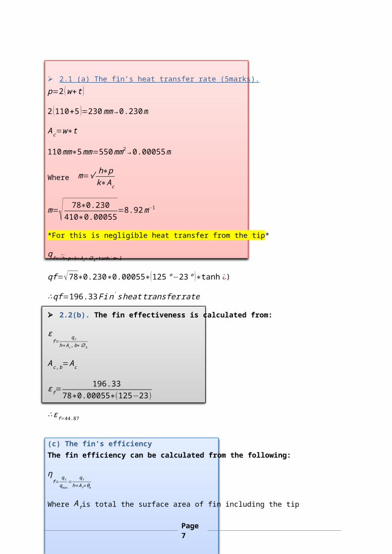
2.1 (a) The fin’s heat transfer rate (5marks). p=2 (w+t )
2 (110+5 )=230mm→0.230m
Ac=w∗t
110mm∗5mm=550mm2→0.00055m
Where m=√ h∗pk∗Ac
m=√ 78∗0.230410∗0.00055
=8.92m−1
*For this is negligible heat transfer from the tip*
qf=√h∗p∗k∗Ac∗∅b∗tanh¿m∗l
qf=√78∗0.230∗0.00055∗(125°−23° )∗tanh ¿)
∴qf=196.33Fin'sheattransferrate
2.2(b). The fin effectiveness is calculated from:
εf=
qf
h∗Ac,b∗∅b
Ac,b=Ac
εf=196.33
78∗0.00055∗(125−23)
∴εf=44.87
(c) The fin’s efficiencyThe fin efficiency can be calculated from the following:
ηf=
qf
qmax=
qf
h∗Af∗θb
Where Afis total the surface area of fin including the tip
Page7
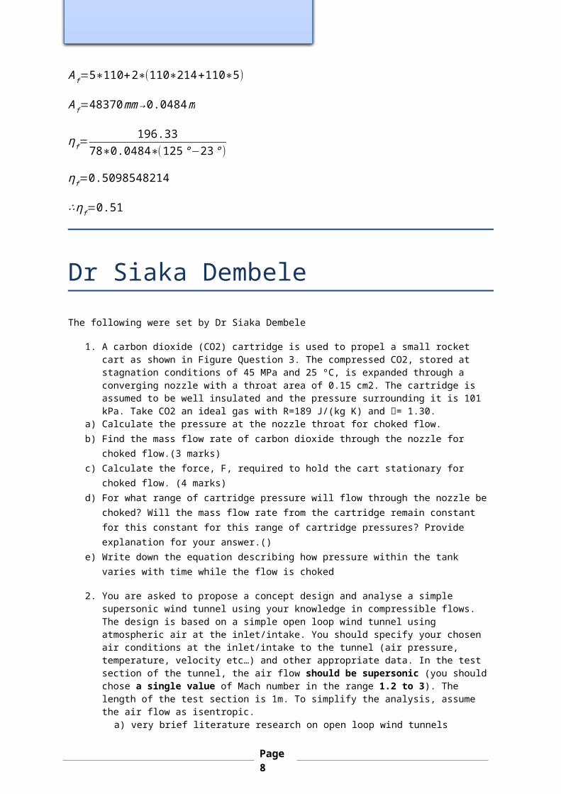
Af=5∗110+2∗(110∗214+110∗5)
Af=48370mm→0.0484m
ηf=196.33
78∗0.0484∗(125°−23°)
ηf=0.5098548214
∴ηf=0.51
Dr Siaka DembeleThe following were set by Dr Siaka Dembele
1. A carbon dioxide (CO2) cartridge is used to propel a small rocket cart as shown in Figure Question 3. The compressed CO2, stored at stagnation conditions of 45 MPa and 25 ºC, is expanded through a converging nozzle with a throat area of 0.15 cm2. The cartridge is assumed to be well insulated and the pressure surrounding it is 101 kPa. Take CO2 an ideal gas with R=189 J/(kg K) and = 1.30.
a) Calculate the pressure at the nozzle throat for choked flow.b) Find the mass flow rate of carbon dioxide through the nozzle for
choked flow.(3 marks)c) Calculate the force, F, required to hold the cart stationary for
choked flow. (4 marks)d) For what range of cartridge pressure will flow through the nozzle be
choked? Will the mass flow rate from the cartridge remain constant for this constant for this range of cartridge pressures? Provide explanation for your answer.()
e) Write down the equation describing how pressure within the tank varies with time while the flow is choked
2. You are asked to propose a concept design and analyse a simple supersonic wind tunnel using your knowledge in compressible flows. The design is based on a simple open loop wind tunnel using atmospheric air at the inlet/intake. You should specify your chosen air conditions at the inlet/intake to the tunnel (air pressure, temperature, velocity etc…) and other appropriate data. In the test section of the tunnel, the air flow should be supersonic (you should chose a single value of Mach number in the range 1.2 to 3). The length of the test section is 1m. To simplify the analysis, assume the air flow as isentropic.
a) very brief literature research on open loop wind tunnels
Page8
b) justification and selection of the components/parts of your proposed wind tunnel
c) specify and justify the selected dimensions of components/parts,d) finding the test section cross-sectional areae) Specify the pressure and temperature at several locations of the
wind tunnel, with analysisf) specify the mass flow rate of airg) simple sketch of wind tunnel with componentsh) any relevant analysis/discussion
Total Marks of this section
50 Marks
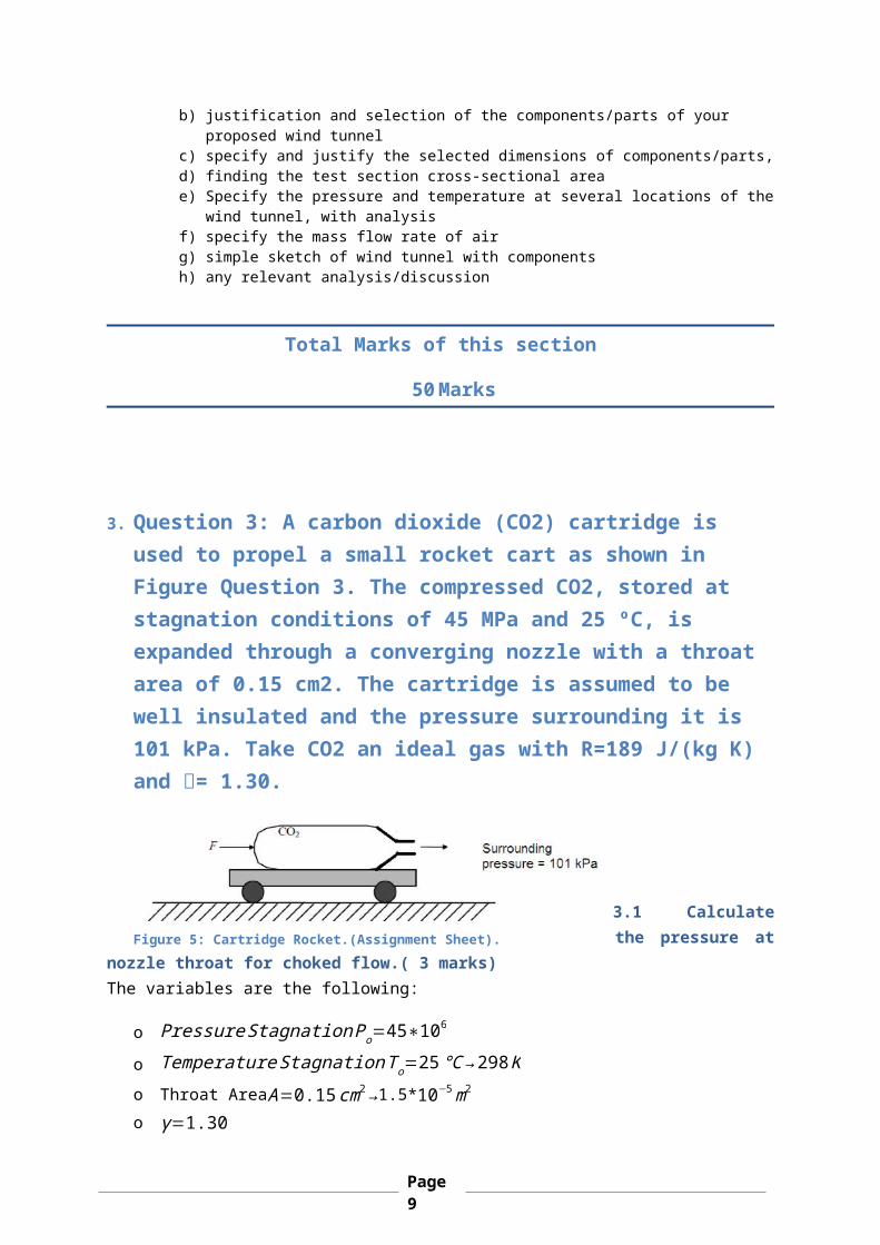
3. Question 3: A carbon dioxide (CO2) cartridge is used to propel a small rocket cart as shown in Figure Question 3. The compressed CO2, stored at stagnation conditions of 45 MPa and 25 ºC, is expanded through a converging nozzle with a throat area of 0.15 cm2. The cartridge is assumed to be well insulated and the pressure surrounding it is 101 kPa. Take CO2 an ideal gas with R=189 J/(kg K) and = 1.30.
3.1 Calculatethe pressure at
nozzle throat for choked flow.( 3 marks)The variables are the following:
o PressureStagnationPo=45∗106
o TemperatureStagnationTo=25℃→298Ko Throat AreaA=0.15cm2→1.5*10−5m2o γ=1.30
Figure 5: Cartridge Rocket.(Assignment Sheet).
Page9
o R=189J(kgK)
o Atmospheric pressure Ps=101∗103
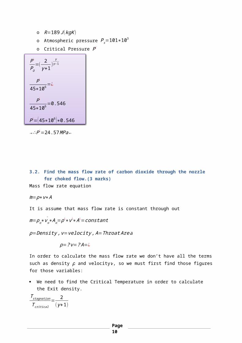
o Critical Pressure P¿
P¿
PO=(
2γ+1
)γ
γ−1
P¿
45∗106=¿
P¿
45∗106=0.546
P¿=(45∗106 )∗0.546
→∴P¿=24.57MPa←
3.2. Find the mass flow rate of carbon dioxide through the nozzle for choked flow.(3 marks)
Mass flow rate equation
m=ρ∗v∗A
It is assume that mass flow rate is constant through out
˙m=ρo∗vo∗Ao=ρ¿∗v¿∗A¿=constant
ρ=Density,v=velocity,A=ThroatArea
ρ=?v=?A=¿
In order to calculate the mass flow rate we don’t have all the termssuch as density ρ and velocityv, so we must first find those figuresfor those variables:
We need to find the Critical Temperature in order to calculate the Exit density.
TstagnationTcritical
= 2(γ+1)
Page10
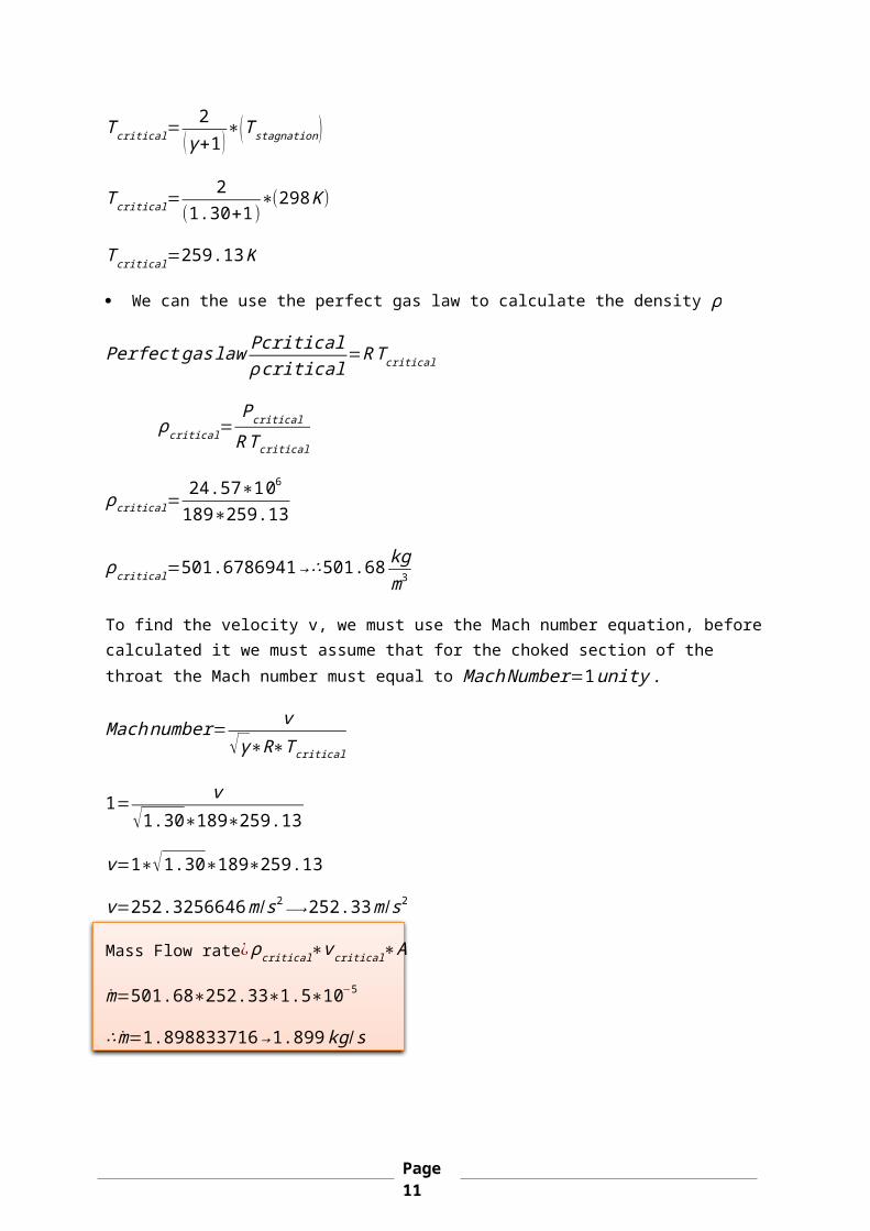
Tcritical=2
(γ+1)∗(Tstagnation)
Tcritical=2
(1.30+1)∗(298K)
Tcritical=259.13K
We can the use the perfect gas law to calculate the density ρ
Perfectgaslaw Pcriticalρcritical
=RTcritical
ρcritical=Pcritical
RTcritical
ρcritical=24.57∗106189∗259.13
ρcritical=501.6786941→∴501.68kgm3
To find the velocity v, we must use the Mach number equation, beforecalculated it we must assume that for the choked section of the throat the Mach number must equal to MachNumber=1unity.
Machnumber=v
√γ∗R∗Tcritical
1=v
√1.30∗189∗259.13
v=1∗√1.30∗189∗259.13
v=252.3256646m /s2⟶252.33m /s2
Mass Flow rate¿ρcritical∗vcritical∗A
m=501.68∗252.33∗1.5∗10−5
∴m=1.898833716→1.899kg/s
Page11
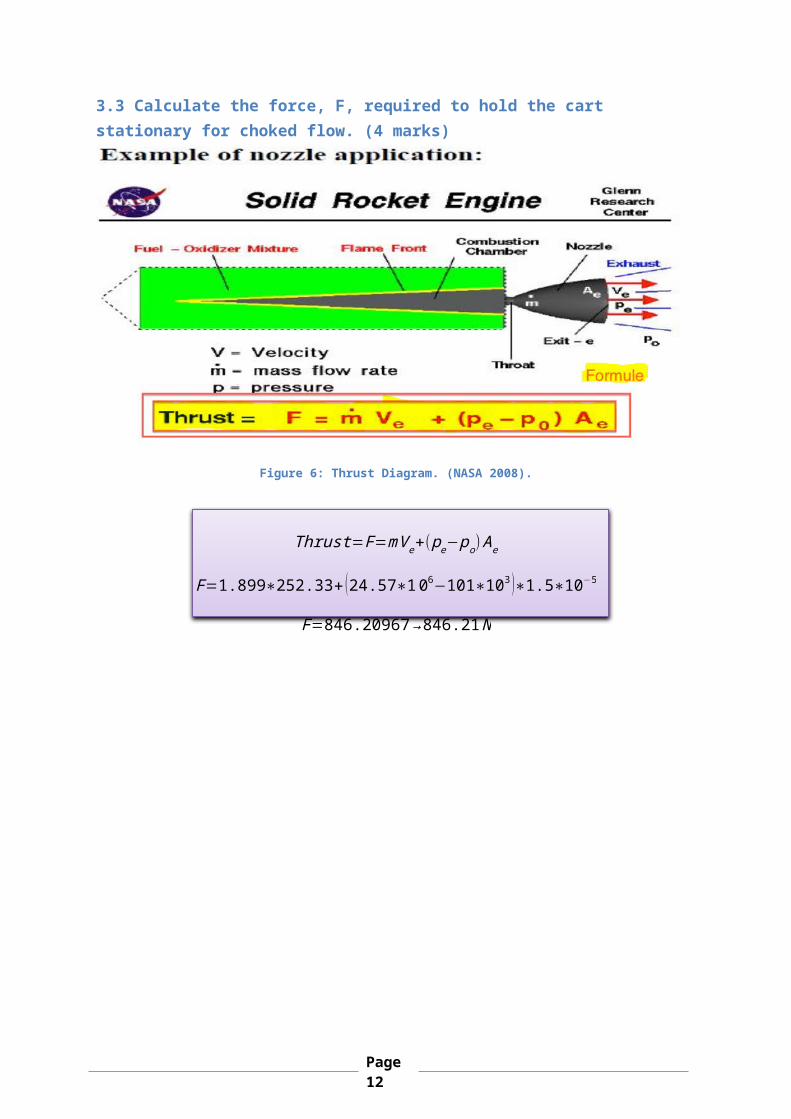
3.3 Calculate the force, F, required to hold the cart stationary for choked flow. (4 marks)
Figure 6: Thrust Diagram. (NASA 2008).
Thrust=F=mVe+(pe−po)Ae
F=1.899∗252.33+ (24.57∗106−101∗103 )∗1.5∗10−5
F=846.20967→846.21N
Page12
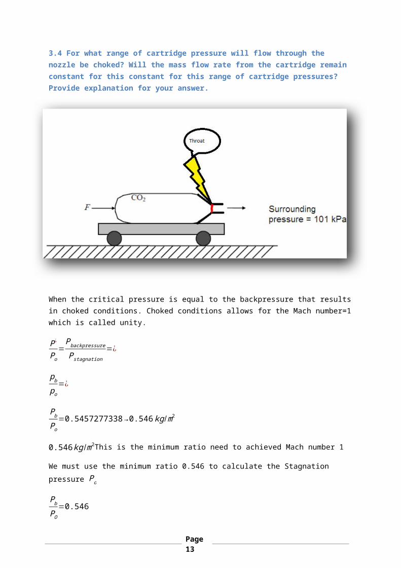
3.4 For what range of cartridge pressure will flow through the nozzle be choked? Will the mass flow rate from the cartridge remain constant for this constant for this range of cartridge pressures? Provide explanation for your answer.
When the critical pressure is equal to the backpressure that resultsin choked conditions. Choked conditions allows for the Mach number=1which is called unity.
P¿
Po=Pbackpressure
Pstagnation=¿
pbpo
=¿
PbPo
=0.5457277338→0.546kg/m2
0.546kg /m2This is the minimum ratio need to achieved Mach number 1
We must use the minimum ratio 0.546 to calculate the Stagnation pressure Po
PbPO
=0.546
Page13
Po=(101∗103)0.546
=184981.658
Po=¿ ¿184.98kg/m2
When Po<184.98kg /m2 this will cause the density to change which in turn allows for the mass flow rate to change well due the correlation with density.
m=Ae∗√γ∗Po∗ρo∗√ ¿
But if the Po≥184.98kg/m2that would allow for unity in throat section and would provide constant mass flow rate
3. (e) Write down the equation describing how pressure within the tank varies with time while the flow is choked.
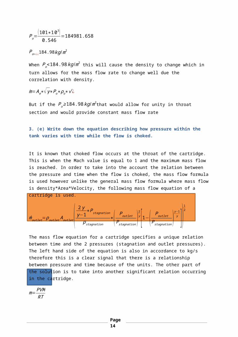
It is known that choked flow occurs at the throat of the cartridge. This is when the Mach value is equal to 1 and the maximum mass flow is reached. In order to take into the account the relation between the pressure and time when the flow is choked, the mass flow formulais used however unlike the general mass flow formula where mass flowis density*Area*Velocity, the following mass flow equation of a cartridge is used.
ṁoutlet=ρoutletAoutlet( 2γγ−1
∗Pstagnation
pstagnation∗( Poutlet
Pstagnation )2γ [1−( Poutlet
Pstagnation )γ−1γ ])
12
The mass flow equation for a cartridge specifies a unique relation between time and the 2 pressures (stagnation and outlet pressures). The left hand side of the equation is also in accordance to kg/s therefore this is a clear signal that there is a relationship between pressure and time because of the units. The other part of the solution is to take into another significant relation occurring in the cartridge.
m=PVMRT
Page14
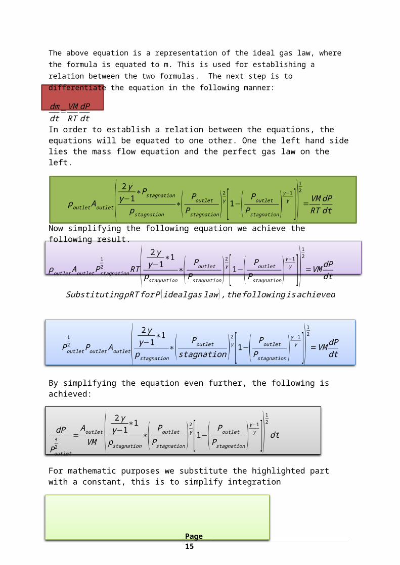
The above equation is a representation of the ideal gas law, where the formula is equated to m. This is used for establishing a relation between the two formulas. The next step is to differentiate the equation in the following manner:
dmdt
=VMRT
dPdt
In order to establish a relation between the equations, the equations will be equated to one other. One the left hand sidelies the mass flow equation and the perfect gas law on the left.
ρoutletAoutlet( 2γγ−1
∗Pstagnationpstagnation
∗( PoutletPstagnation)
2γ [1−( Poutlet
Pstagnation)γ−1γ ])
12
=VMRT
dPdt
Now simplifying the following equation we achieve the following result.
ρoutletAoutletPstagnation
12 RT( 2γ
γ−1∗1
pstagnation∗( PoutletPstagnation)
2γ [1−( Poutlet
Pstagnation)γ−1γ ])
12
=VM dPdt
SubstitutingρRTforP (idealgaslaw ),thefollowingisachieved
Poutlet
12 PoutletAoutlet( 2γ
γ−1∗1
pstagnation∗( Poutlet
stagnation )2γ [1−( Poutlet
Pstagnation )γ−1γ ])
12
=VMdPdt
By simplifying the equation even further, the following is achieved:
dP
Poutlet32
=Aoutlet
VM ( 2γγ−1
∗1
pstagnation∗( Poutlet
Pstagnation )2γ [1−( Poutlet
Pstagnation )γ−1γ ])
12
dt
For mathematic purposes we substitute the highlighted part with a constant, this is to simplify integration
Page15
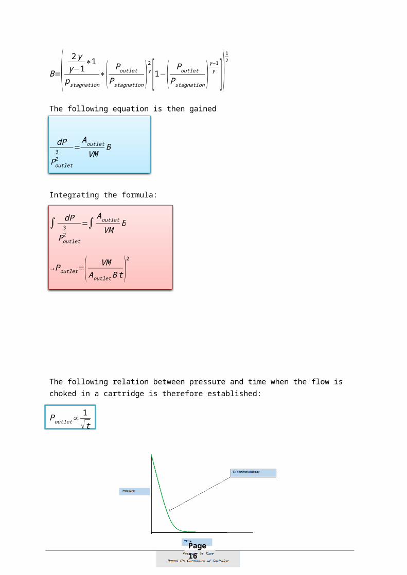
B=( 2γγ−1
∗1
pstagnation∗( PoutletPstagnation )
2γ [1−( Poutlet
Pstagnation )γ−1γ ])
12
The following equation is then gained
dP
Poutlet32
=Aoutlet
VMB
Integrating the formula:
∫ dP
Poutlet32
=∫Aoutlet
VMB
→Poutlet=( VMAoutletBt)
2
The following relation between pressure and time when the flow is choked in a cartridge is therefore established:
Poutlet∝1√t
Page16
According to the equation established, the following relationship between pressure and time is stated. The first is that when pressureapproaches infinity, time approaches the value 0 asymptotically. This occurs reversibly as when time approaches infinity, pressure approaches its minimal possible value.
AsPoutlet→∞,t≈0,similarly whent→∞,Poutlet≈0
To conclude this question, the pressure of the tank at time 0 is infinity. This is because at time zero the pressure is at the cartridge and then as time increases, the flow drives its way through the cartridge and exits. When the flow exits the cartridge at t=∞, the pressure is minimum.
Figure 7: Represent of Pressure Vs Time under choked conditions
Page17
4. Q4.You are asked to propose a concept design and analyse a simplesupersonic wind tunnel using your knowledge in compressible flows. The design is based on a simple open loop wind tunnel using atmospheric air at the inlet/intake. You should specify your chosen air conditions at the inlet/intake to the tunnel (airpressure, temperature, velocity etc...) and other appropriate data. In the test section of the tunnel, the air flow should be supersonic (you should chose a single value of Mach number in therange 1.2 to 3). The length of the test section is 1m. To simplify the analysis, assume the air flow as isentropic.
4.1 (1) Very brief literature research on open loop wind tunnelsWind tunnel have become significantly relative important in 21st century with wind engineering indirectly or directly. The use of wind tunnels is for variety different purpose such as their ability to test prototypes in early design stage due to the ability to storelarge amount of data. The single most important aspect of wind tunnels is their ability to accurately recreate the full complexity of full fluid flow.(Barlow 19)
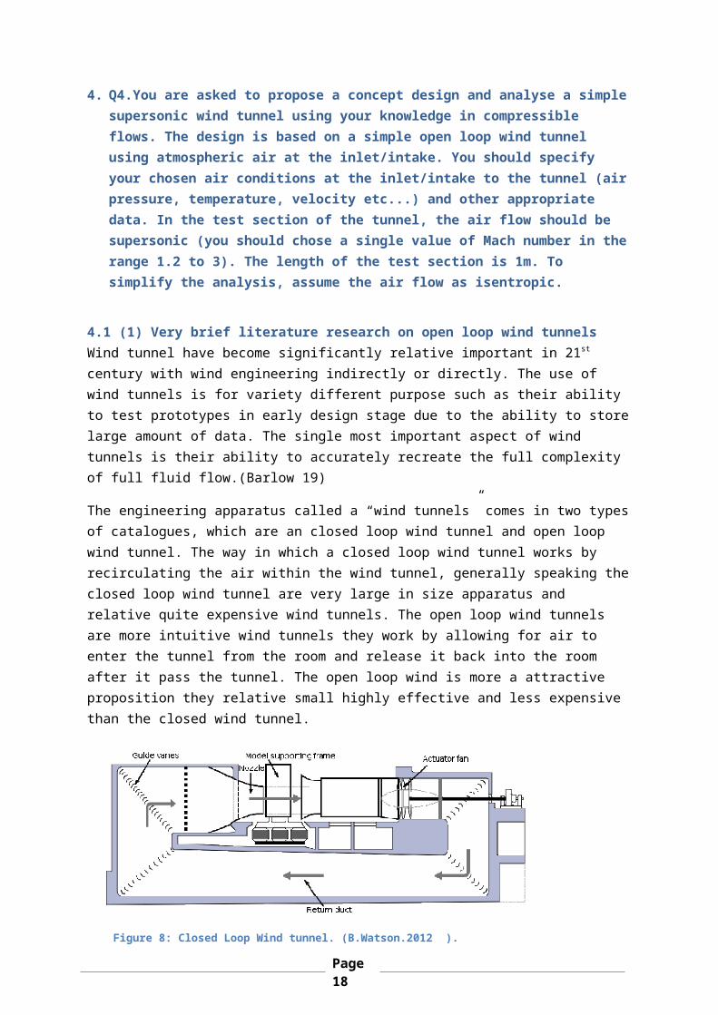
The engineering apparatus called a “wind tunnels” comes in two typesof catalogues, which are an closed loop wind tunnel and open loop wind tunnel. The way in which a closed loop wind tunnel works by recirculating the air within the wind tunnel, generally speaking theclosed loop wind tunnel are very large in size apparatus and relative quite expensive wind tunnels. The open loop wind tunnels are more intuitive wind tunnels they work by allowing for air to enter the tunnel from the room and release it back into the room after it pass the tunnel. The open loop wind is more a attractive proposition they relative small highly effective and less expensive than the closed wind tunnel.
Figure 8: Closed Loop Wind tunnel. (B.Watson.2012 ).
Page18
4.2. (B) Justification and selection of the components/parts of your proposed wind tunnel
The task is design a open loop wind tunnel which must between a range of Mach number 1.2-3 Supersonic flow. The length test section of the wind tunnel it be 1mm in length. Before I can justify the selections of components
o Settling Chamber
The significations of the settling the chamber is paramount to how the open loop wind tunnel functions. Settling chamber straightens the airflow around the object through taking the uneven turbulent .The settling chamber works by straighten the airflow around object; its main purpose is to reduce the uneven turbulent flow around an object. The uneven turbulent flow allows for
unpredictable forces to happen. The purpose of the settlingchamber is to reduce turbulent around the object that allows for better simulation conditions. The settling
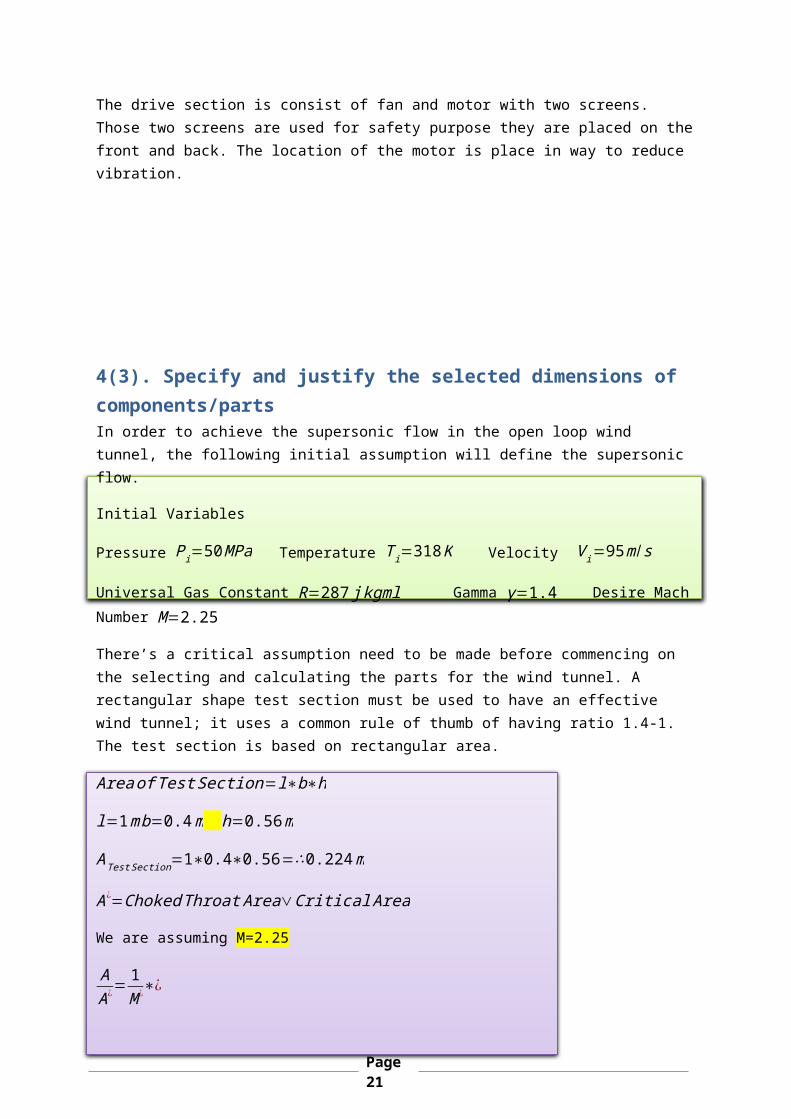
Figure 10: Typical Supersonic wind tunnel.(NASA 2008).
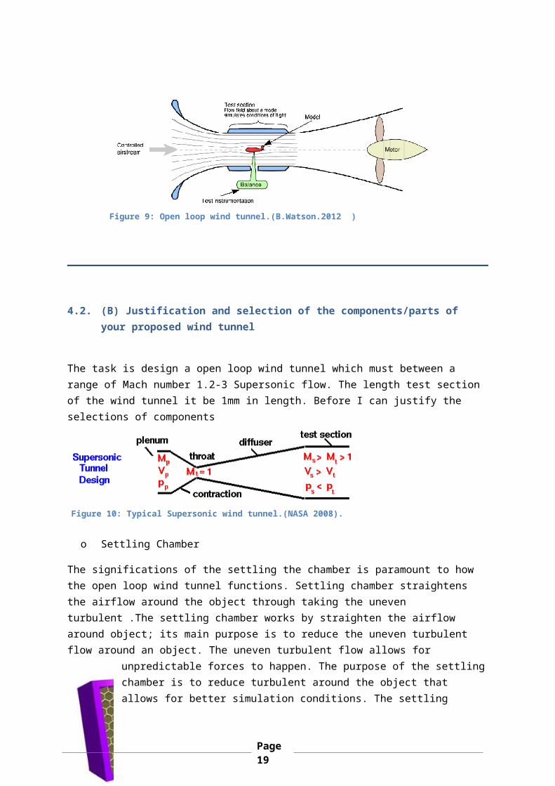
Figure 9: Open loop wind tunnel.(B.Watson.2012 )
Page19
chamber includes a honeycomb flow which acts like straightener that allows for a smooth airflow.
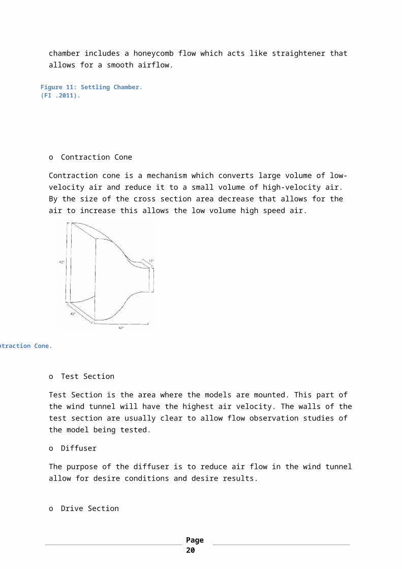
o Contraction Cone
Contraction cone is a mechanism which converts large volume of low-velocity air and reduce it to a small volume of high-velocity air. By the size of the cross section area decrease that allows for the air to increase this allows the low volume high speed air.
o Test Section
Test Section is the area where the models are mounted. This part of the wind tunnel will have the highest air velocity. The walls of thetest section are usually clear to allow flow observation studies of the model being tested.
o Diffuser
The purpose of the diffuser is to reduce air flow in the wind tunnelallow for desire conditions and desire results.
o Drive Section
:Contraction Cone.
Figure 11: Settling Chamber. (FI .2011).
Page20
The drive section is consist of fan and motor with two screens. Those two screens are used for safety purpose they are placed on thefront and back. The location of the motor is place in way to reduce vibration.
4(3). Specify and justify the selected dimensions of components/partsIn order to achieve the supersonic flow in the open loop wind tunnel, the following initial assumption will define the supersonic flow.
Initial Variables
Pressure Pi=50MPa Temperature Ti=318K Velocity Vi=95m /s
Universal Gas Constant R=287jkgml Gamma γ=1.4 Desire MachNumber M=2.25
There’s a critical assumption need to be made before commencing on the selecting and calculating the parts for the wind tunnel. A rectangular shape test section must be used to have an effective wind tunnel; it uses a common rule of thumb of having ratio 1.4-1. The test section is based on rectangular area.
AreaofTestSection=l∗b∗h
l=1mb=0.4m h=0.56m
ATestSection=1∗0.4∗0.56=∴0.224m
A ¿=ChokedThroatArea∨CriticalArea
We are assuming M=2.25
AA¿
=1M¿
∗¿
Page21

A ¿= 0.2241
2.25∗¿¿
Determining the inlet Area and Mach Number
MachNumber=VC⇢ V
√γ∗R∗Ti
M=95
√1.4∗287∗318=0.265
Ai
A¿= 1M¿
∗¿
Ainlet=A¿¿)
Ainlet=0.274¿¿)
Ainlet=∴0.597m2
InletArea=∴0.597m2ThroatArea=∴0.274m2TestSectionArea=0.56m2
4.4 Find the Test section cross-sectional area
The test section I used a rectangular shape. The rectangular formulais following equation
AreaTestSection=L∗b∗h
Will the rectangular shape test section there’s a rule of thumb withdimensioning of having it 1.4-1 ratio.
L=1m b=0.4
So in order to get the h we must apply the ratio to the base:b∗1.41
⇢0.4∗1.41
=0.56m
Atestsection=0.56m∗0.4m∗1m=0.224m2
Page22
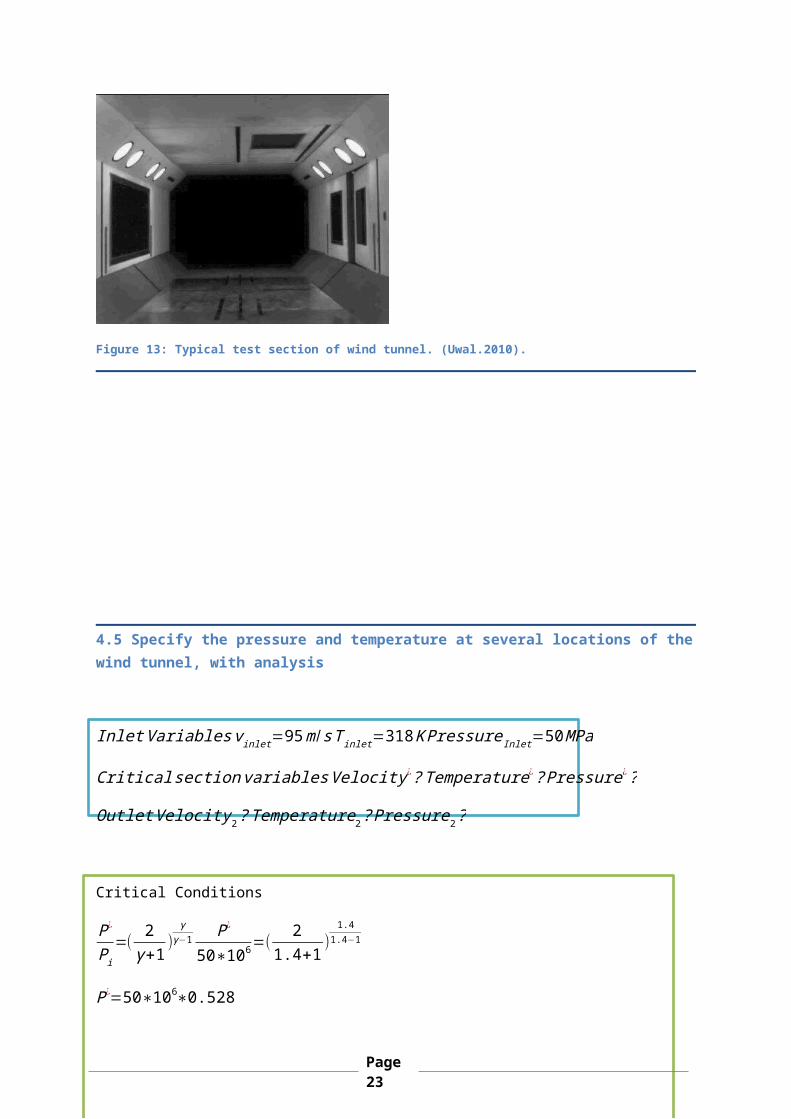
Figure 13: Typical test section of wind tunnel. (Uwal.2010).
4.5 Specify the pressure and temperature at several locations of thewind tunnel, with analysis
InletVariablesvinlet=95m /sTinlet=318KPressureInlet=50MPa
CriticalsectionvariablesVelocity¿?Temperature¿?Pressure¿?
OutletVelocity2?Temperature2?Pressure2?
Critical Conditions
P¿
Pi=(
2γ+1 )
γγ−1 P¿
50∗106=(2
1.4+1 )1.4
1.4−1
P¿=50∗106∗0.528
Page23
P¿=26.4∗106kg/m2
T¿
Ti=( 2
γ+1) T¿
318=( 2
1.4+1)
T¿=318∗5
6=265k
Now we need to find the critical Velocity, we assume Mach M=1 at thecritical for it to be at choked conditions.
V=M∗√γ∗R∗T¿=1∗√1.4∗287∗265=326.30m /s
Test Section Conditions
I specify the Test Conditions for Mach Number M=2.25
P¿
P=( 2
γ+1+γ−1γ+1
M2)γ
γ−1 26.4∗106
P=( 2
1.4+1+1.4−11.4+1
2.252)1.4
1.4−1
P=26.4¿106
6.1086 =4.322kg/m2
T¿
T=
2γ+1
+γ−1γ+1
M2 265T
=2
1.4+1+1.4−11.4+1
2.252
T=265
21.4+1+
1.4−11.4+1 2.25
2=158.012K
V=Mtestsection∗√γ∗R∗Ttestsection=2.25∗√1.4∗287∗158.012=566.934m /s
4.6 Specify the mass flow of air
m=ρinlet¿Ainlet∗Vinlet
Before calculating the mass flow rate I must calculate the density ρthat is the missing variable needed to calculate the mass flow. The perfect gas constant we will allow me to work out the
Pρ=R ¿TtestSection
Page24
ρ=PTestSection
RTTestSection ρ=
4.322∗106287∗158.012
=95.3043658kg/m3
˙m=95.3043658∗0.597∗158.012 = 3373.268293 kg/s
˙m=3373.268kg/s
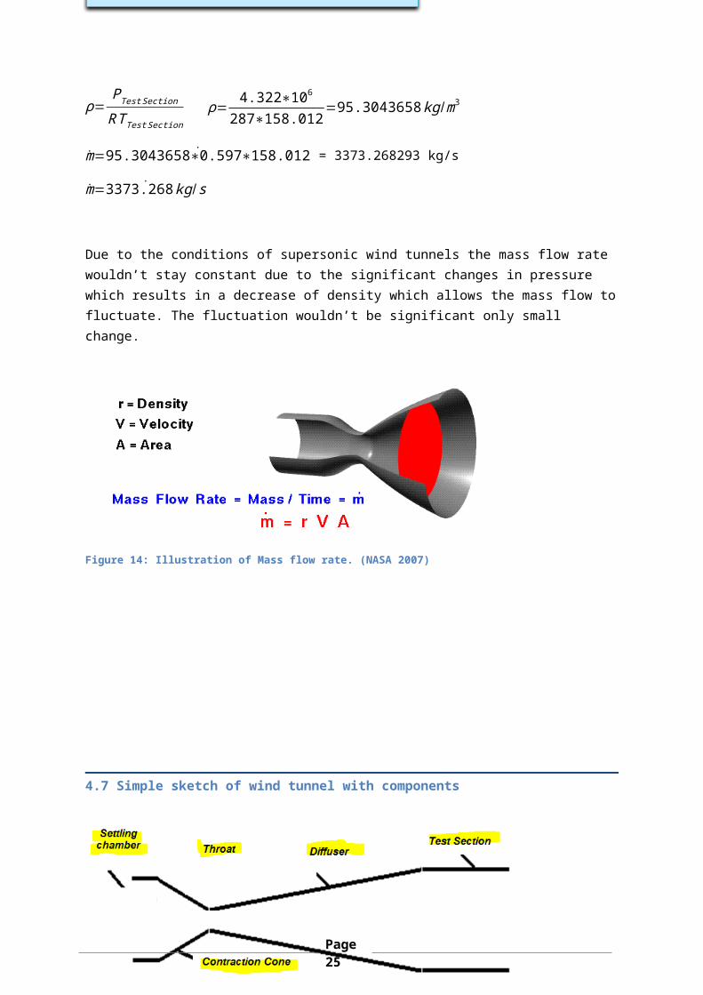
Due to the conditions of supersonic wind tunnels the mass flow rate wouldn’t stay constant due to the significant changes in pressure which results in a decrease of density which allows the mass flow tofluctuate. The fluctuation wouldn’t be significant only small change.
Figure 14: Illustration of Mass flow rate. (NASA 2007)
4.7 Simple sketch of wind tunnel with components
Page25
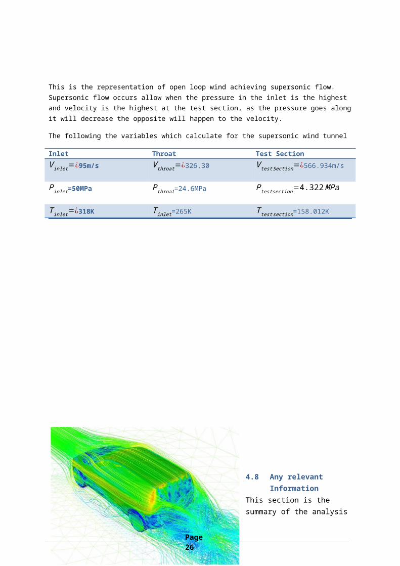
This is the representation of open loop wind achieving supersonic flow. Supersonic flow occurs allow when the pressure in the inlet is the highest and velocity is the highest at the test section, as the pressure goes alongit will decrease the opposite will happen to the velocity.
The following the variables which calculate for the supersonic wind tunnel
Inlet Throat Test SectionVinlet=¿95m/s Vthroat=¿326.30 VtestSection=¿566.934m/s
Pinlet=50MPa Pthroat=24.6MPa Ptestsection=4.322MPa
Tinlet=¿318K Tinlet=265K Ttestsection=158.012K
4.8 Any relevant Information
This section is the summary of the analysis
Page26
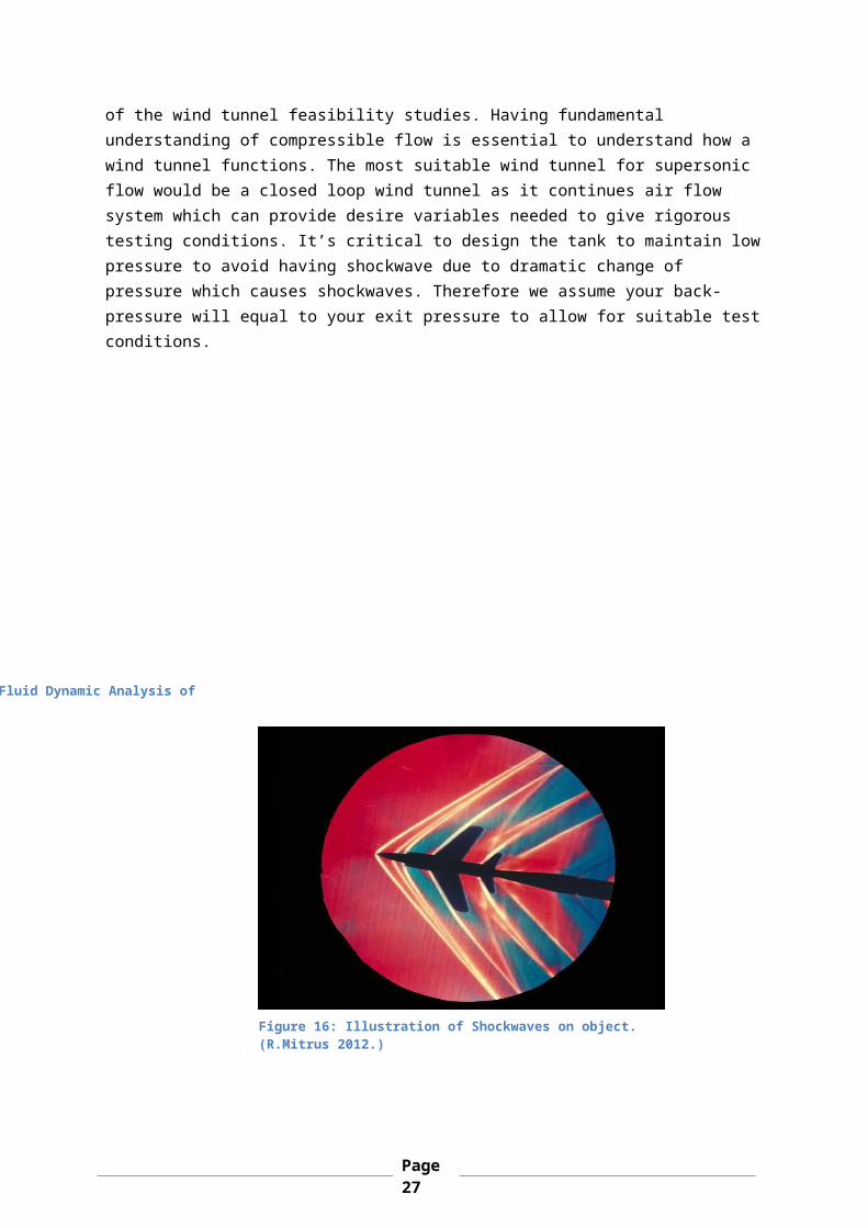
of the wind tunnel feasibility studies. Having fundamental understanding of compressible flow is essential to understand how a wind tunnel functions. The most suitable wind tunnel for supersonic flow would be a closed loop wind tunnel as it continues air flow system which can provide desire variables needed to give rigorous testing conditions. It’s critical to design the tank to maintain lowpressure to avoid having shockwave due to dramatic change of pressure which causes shockwaves. Therefore we assume your back-pressure will equal to your exit pressure to allow for suitable testconditions.
: Illustrational Computational Fluid Dynamic Analysis of
Figure 16: Illustration of Shockwaves on object. (R.Mitrus 2012.)
Page27
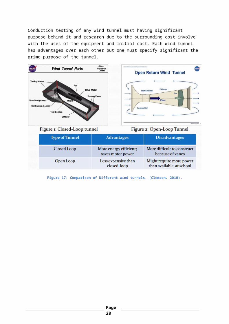
Conduction testing of any wind tunnel must having significant purpose behind it and research due to the surrounding cost involve with the uses of the equipment and initial cost. Each wind tunnel has advantages over each other but one must specify significant the prime purpose of the tunnel.
Figure 17: Comparison of Different wind tunnels. (Clemson. 2010).
Page28
Reference S.Lavine (2007). Fundamentals of Heat and Mass Transfer . 7th ed. United State of America: John Wiley and Son, Inc. p3.[Last Accessed 9th February 2014]
Unknown. (2010). Tunnel parts. Available: http://www.fi.edu/flight/first/tunnelparts/tunnel_tsect.html. Last accessed 20th Feb 2014.
B.Goldberg. (2008). Wind Tunnel. Available: http://www.tomcarlone.com/WindTunnelProject/WindTunnelReport.pdf. Last accessed 20th Feb 2014.
Hlene.G. (2008). Airplane. Available: https://www.grc.nasa.gov/www/k-12/airplane/tunnozd.html. Last accessed 20th Feb 2014.
Unknown. (2012). Test Select. Available: https://www.uwal.org/uwalinfo/techguide/testsect.htm. Last accessed 20th Feb 2014
C.David. (2013). Chilton Blog. Available: http://community.cengage.com/Chilton/blogs/davids_blog/archive/2013/02/27/a-history-of-the-invisible-wall-our-struggle-with-aerodynamics-part-3-aerodynamics-in-a-nutshell.aspx. Last accessed 20th Feb 2014.
R.Mitrus. (2012). ernst-machs-birth. Available: http://blog.pointwise.com/2012/02/17/ernst-machs-birthday-18-february-1838/. Last accessed 20th Feb 2014.
Unknown. (2010). Back Information. Available: http://www.clemson.edu/ces/cedar/images/e/ed/Background_Information_Chapman.pdf. Last accessed 20th Feb 2014.
Page29